BSI Standards Publication - Down The Line Group LTD
94
raising standards worldwide ™ NO COPYING WITHOUT BSI PERMISSION EXCEPT AS PERMITTED BY COPYRIGHT LAW BSI Standards Publication BS 8558:2011 Guide to the design, installation, testing and maintenance of services supplying water for domestic use within buildings and their curtilages – Complementary guidance to BS EN 806 Licensed copy:Bovis Lend Lease, 30/03/2012, Uncontrolled Copy, © BSI
-
Upload
khangminh22 -
Category
Documents
-
view
3 -
download
0
Transcript of BSI Standards Publication - Down The Line Group LTD

raising standards worldwide™
NO COPYING WITHOUT BSI PERMISSION EXCEPT AS PERMITTED BY COPYRIGHT LAW
BSI Standards Publication
BS 8558:2011
Guide to the design,installation, testing andmaintenance of servicessupplying water fordomestic use withinbuildings and theircurtilages – Complementaryguidance to BS EN 806
Licensed copy:Bovis Lend Lease, 30/03/2012, Uncontrolled Copy, © BSI

Publishing and copyright information
The BSI copyright notice displayed in this document indicates when the documentwas last issued.
© BSI 2011
ISBN 978 0 580 71654 6
ICS 91.140.60
The following BSI references relate to the work on this standard:Committee reference B/504Draft for comment 11/30228295 DC
Publication history
First published as BS 6700 April 1987Second edition, April 1997Third edition, December 2006First published as BS 8558 December 2011
Amendments issued since publication
Date Text affected
BS 8558:2011 BRITISH STANDARD
Licensed copy:Bovis Lend Lease, 30/03/2012, Uncontrolled Copy, © BSI
ContentsForeword iii
0 Introduction 11 Scope 32 Normative references 33 Terms and definitions 64 Guidance on BS EN 806-2 125 Guidance on BS EN 806-4 506 Guidance on BS EN 806-5 69
AnnexesAnnex A (normative) Examples of pumped systems 74Annex B (informative) Guidance on the calculation of hot water storagecapacity 80
Bibliography 83
List of figuresFigure 1 – Service pipe and components 7Figure 2 – Example of pipework for installation of water softener 20Figure 3 – Locations of stopvalves in blocks of flats with separate supply pipes toeach flat 24Figure 4 – Locations of stopvalves in blocks of flats supplied from a commonsupply pipe 24Figure 5 – Example of a pre-assembled external meter installation 26Figure 6 – Schematic example of a direct (vented) hot water system 28Figure 7 – Schematic example of an indirect (vented) hot water system 29Figure 8 – Schematic example of an indirect unvented (vented primary)hot water system 30Figure 9 – Schematic example of an indirect unvented (sealed primary)hot water system 31Figure 10 – Schematic example of a vented primary circuit with close coupledfeed and open vent 32Figure 11 – Typical examples of pipes entering buildings 39Figure 12 – Accessibility of pipework 43Figure 13 – Clear space needed above cisterns 45Figure 14 – Recommended positions of notching and drilling of solid timberfloor joists 57Figure 15 – Directions of thrusts developed in a pipeline due to internal pressure 60Figure 16 – Initial free chlorine concentration and contact period for tankdisinfection (see Table 13, columns 1 and 2) 65Figure 17 – Minimum residual free chlorine after contact period(see Table 13, column 3) 65Figure 18 – Cutting off redundant pipes 73Figure A.1 – Indirect boosting from break cistern to storage cistern 75Figure A.2 – Indirect boosting with pressure vessel 76Figure A.3 – Direct boosting 78Figure A.4 – Direct boosting with header and duplicate storage cisterns 79
List of tablesTable 1 – Cross references to the BS EN 806 series and this British Standard 1Table 2 – Drawing symbols for BS 8558 11Table 3 – Main pieces of legislation regarding Building and WaterRegulations 13
BRITISH STANDARD BS 8558:2011
© BSI 2011 • i
Licensed copy:Bovis Lend Lease, 30/03/2012, Uncontrolled Copy, © BSI

Table 4 – British Standards for stopvalves 23Table 5 – Design flow rates to outlet fitting and appliances 35Table 6 – Calculated minimum thickness of thermal insulation to protect copperpipes fixed inside premises for domestic cold water systems 40Table 7 – Calculated minimum thickness of thermal insulation to protect copperpipes fixed inside premises against freezing for commercial and institutionalapplications 41Table 8 – Examples of insulating materials 41Table 9 – Maximum permitted rates of energy loss from pipes 47Table 10 – Jointing of copper tube and stainless steel tube 52Table 11 – Thrust per bar internal pressure 60Table 12 – Bearing capacity of soils 60Table 13 – Chlorine contact period 66Table B.1 – Minimum sizes of storage vessel for case 1 81Table B.2 – Minimum sizes of storage vessel for case 2 82
Summary of pages
This document comprises a front cover, an inside front cover, pages i to iv,pages 1 to 86, an inside back cover and a back cover.
BRITISH STANDARDBS 8558:2011
ii • © BSI 2011
Licensed copy:Bovis Lend Lease, 30/03/2012, Uncontrolled Copy, © BSI
Foreword
Publishing information
This British Standard is published by BSI and came into effecton 31 December 2011. It was prepared by Technical Committee B/504,Water Supply. A list of organizations represented on this committee can beobtained on request to its secretary.
Supersession
Together with BS EN 806-1, BS EN 806-2, BS EN 806-3, BS EN 806-4 andBS EN 806-5, this British Standard supersedes BS 6700:2006+A1:2009, which iswithdrawn.
Information about this document
In the area of Domestic Water Supply, BS 6700 is the lead document until suchtime as BS EN 806-5 is published (scheduled for June 2012), at which pointBS 6700 will be withdrawn and BS 8558 will become the lead document. Thecontent of this British Standard was taken from BS 6700:2006+A1:2009, whichwill be withdrawn following the publication of BS EN 806 (all parts).
Presentational conventions
The guidance in this standard is presented in roman (i.e. upright) type. Anyrecommendations are expressed in sentences in which the principal auxiliaryverb is “should”.
Commentary, explanation and general informative material is presented insmaller italic type, and does not constitute a normative element.
Contractual and legal considerations
This publication does not purport to include all the necessary provisions of acontract. Users are responsible for its correct application.
Compliance with a British Standard cannot confer immunity from legalobligations.
In particular, attention is drawn to the following regulations which may beamended from time to time. The commentary in this British Standard reflectsthe state of the regulations in 2011.
• The Workplace (Health, Safety and Welfare) Regulations 1992 [1];
• The Water Supply (Water Quality) Regulations 2010 [2];
• The Electricity Safety, Quality and Continuity Regulations 2002 [3];
• The Control of Asbestos at Work Regulations 2002 [4];
• The Water Industry Act 1999 [5];
• The Health and Safety at Work etc. Act 1974 [6].
In this British Standard, the following national regulations, which apply toplumbing systems in premises to which a supply of public mains water has beenprovided, are referred to as the “Water Fittings Regulations” [7]:
• The Water Supply (Water Fittings) Regulations 1999, in England and Wales;
• The Water Byelaws 2004 (Scotland), in Scotland;
• The Water Supply (Water Fittings) Regulations (Northern Ireland) 2009, inNorthern Ireland.
BRITISH STANDARD BS 8558:2011
© BSI 2011 • iii
Licensed copy:Bovis Lend Lease, 30/03/2012, Uncontrolled Copy, © BSI

Additionally, the following national regulations are referred to as the“Building Regulations” [8]:
• The Building Regulations (England and Wales) 2010;
• The Building (Scotland) Regulations 2004;
• The Building Regulations (Northern Ireland) 2000.
BRITISH STANDARDBS 8558:2011
iv • © BSI 2011
Licensed copy:Bovis Lend Lease, 30/03/2012, Uncontrolled Copy, © BSI

0 IntroductionTable 1 provides cross references to the BS EN 806 series and thisBritish Standard.
Table 1 Cross references to the BS EN 806 series and this British Standard
BS EN 806 part and clause reference BS 8558 clausereference
BS EN 806 1:2000+A1Scope, Clause 1 No guidance givenNormative references, Clause 2 No guidance givenObjectives, Clause 3 No guidance givenCompetence and duties for design, construction and operation, Clause 4 No guidance givenTerms and definitions, Clause 5
distributing pipe, 5.3.4 3.13service pipe, 5.3.1 3.28service stopvalve, 5.4.2 3.29supply pipe, 5.3.2 3.36supply stopvalve, 5.4.3 3.37
Graphic symbols and abbreviations, Clause 6 No guidance givenExamples for the use of graphic symbols, Annex A No guidance givenBS EN 806-2:2005Scope, Clause 1 No guidance givenNormative references, Clause 2 No guidance givenGeneral requirements, Clause 3
Water supply, 3.1 4.2.1Private water supplies, Clause 4 No guidance givenAcceptable materials, Clause 5 4.2.2 and 4.2.4
Choice of material, 5.1 4.2.3Components, Clause 6 No guidance givenPipework inside buildings, Clause 7 No guidance givenCold potable water services, Clause 8 No guidance givenHot water systems, Clause 9 No guidance givenPrevention of bursting, Clause 10
Discharge pipes, 10.2.5 4.2.4Guidelines for water meter installations, Clause 11 No guidance givenWater conditioning, Clause 12 No guidance givenAcoustics, Clause 13 No guidance givenProtection of systems against temperatures external to pipes, fittings andappliances, Clause 14
No guidance given
Boosting, Clause 15 No guidance givenPressure reducing valves, Clause 16 No guidance givenCombined drinking water and fire fighting services, Clause 17 No guidance givenPrevention of corrosion damage, Clause 18 No guidance givenAdditional requirements for vented cold and hot water systems, Clause 19 No guidance givenList of acceptable materials (non-exhaustive), Annex A No guidance givenAspects for water conditioning, Annex B No guidance givenExtra guidance 4.3BS EN 806-3:2006Scope, Clause 1 No guidance given
BRITISH STANDARD BS 8558:2011
© BSI 2011 • 1
Licensed copy:Bovis Lend Lease, 30/03/2012, Uncontrolled Copy, © BSI

Table 1 Cross references to the BS EN 806 series and this British Standard
BS EN 806 part and clause reference BS 8558 clausereference
Normative references, Clause 2 No guidance givenTerms, symbols and units, Clause 3 No guidance givenPrinciples of pipe sizing calculations, Clause 4 No guidance givenSimplified method of pipe sizing, Clause 5 4.3.31Special-installations, Clause 6 No guidance givenExample for the determination of pipe sizes for standard-installations, Annex A No guidance givenDesign flow rates in relation to total flow rates, Annex B No guidance givenList of national pipe sizing methods, Annex C No guidance givenBS EN 806-4:2010Scope, Clause 1 No guidance givenNormative references, Clause 2 No guidance givenTerms and definitions, Clause 3 No guidance givenWork on site, Clause 4
General, 4.1 5.1.1General, 4.4.1 5.1.2Pipe materials and jointing methods, 4.4.2 5.1.3Underground pipe laying, 4.6 5.2.1Allowances for thermal movement and prevention of noise, 4.7.1 5.1.4Fixings for insulated piping, 4.7.2.6 5.1.5Piping passing through structures, 4.7.4 5.1.6Valves and taps, 4.8 5.1.7Record of installation, 4.9.3 5.1.8
Dissimilar metals, Clause 5 No guidance givenCommissioning, Clause 6
General, 6.1.1 5.1.9Pipe system material specifications, jointing procedures and pipe installation fordifferent types of materials, Annex A
No guidance given
Calculation and compensation for thermal effects of pipes, Annex B No guidance givenRecommended maximum spacings of fixings for metal pipes, Annex C No guidance givenExtra guidance 5.2BS EN 806-5:2012Scope, Clause 1 No guidance givenNormative references, Clause 2 No guidance givenTerms and definitions, Clause 3 No guidance givenGeneral, Clause 4 6.1.1 and 6.1.2Documentation, Clause 5 No guidance givenOperation, Clause 6 6.1.2 and 6.1.3Interruptions to operation and disconnection, Clause 7 No guidance givenResumption of supply, Clause 8 No guidance givenDamage and faults, Clause 9
Change in water quality, 9.1 6.1.4Alterations, extensions and refurbishment, Clause 10 No guidance givenAccessibility of fittings, Clause 11 No guidance givenMaintenance, Clause 12 No guidance givenAdditional requirements for vented systems, Clause 13
Cisterns, 13.1 6.1.5
BRITISH STANDARDBS 8558:2011
2 • © BSI 2011
Licensed copy:Bovis Lend Lease, 30/03/2012, Uncontrolled Copy, © BSI
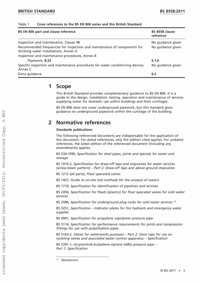
Table 1 Cross references to the BS EN 806 series and this British Standard
BS EN 806 part and clause reference BS 8558 clausereference
Inspection and maintenance, Clause 14 No guidance givenRecommended frequencies for inspection and maintenance of components fordrinking water installations, Annex A
No guidance given
Inspection and maintenance procedures, Annex BPipework, B.22 6.1.6
Specific inspection and maintenance procedures for water conditioning devices,Annex C
No guidance given
Extra guidance 6.2
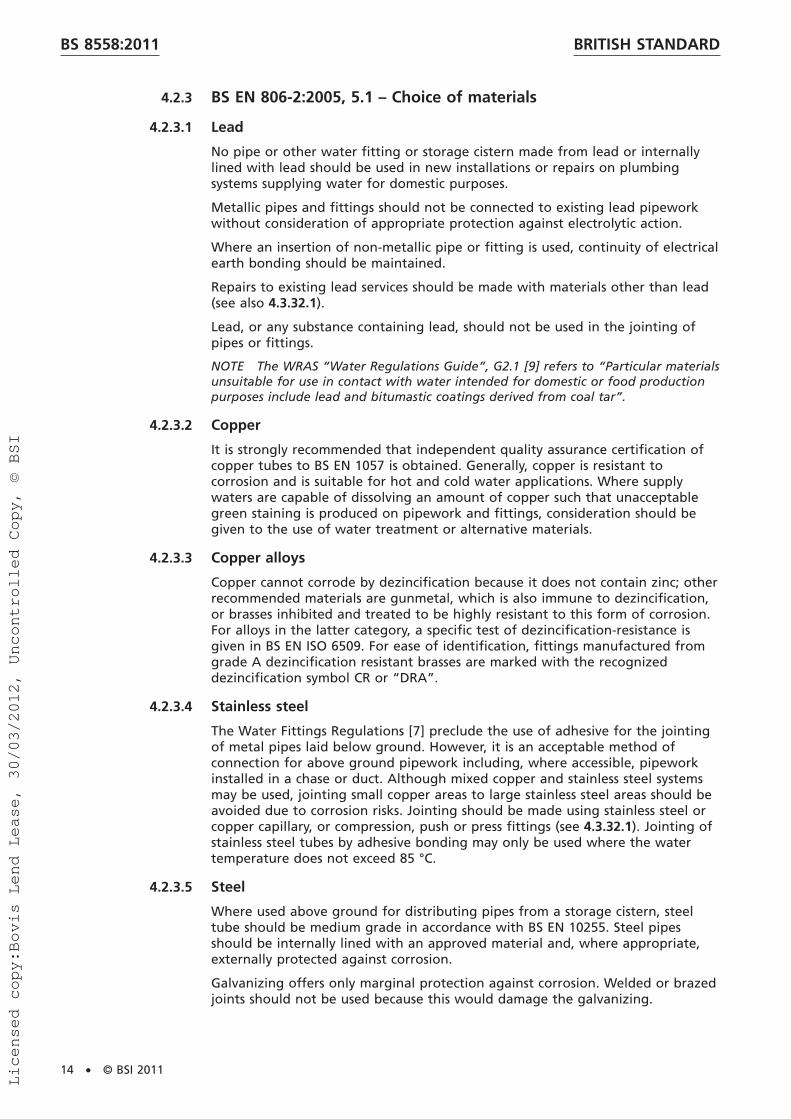
1 ScopeThis British Standard provides complementary guidance to BS EN 806. It is aguide to the design, installation, testing, operation and maintenance of servicessupplying water for domestic use within buildings and their curtilages.
BS EN 806 does not cover underground pipework, but this standard givesguidance on underground pipework within the curtilage of the building.
2 Normative referencesStandards publications
The following referenced documents are indispensable for the application ofthis document. For dated references, only the edition cited applies. For undatedreferences, the latest edition of the referenced document (including anyamendments) applies.
BS 534:1990, Specification for steel pipes, joints and specials for water andsewage
BS 1010-2, Specification for draw-off taps and stopvalves for water services(screw-down pattern) – Part 2: Draw-off taps and above-ground stopvalves
BS 1212 (all parts), Float operated valves
BS 1427, Guide to on-site test methods for the analysis of waters
BS 1710, Specification for identification of pipelines and services
BS 2456, Specification for floats (plastics) for float operated valves for cold waterservices
BS 2580, Specification for underground plug cocks for cold water services 1)
BS 3251, Specification – Indicator plates for fire hydrants and emergency watersupplies
BS 4991, Specification for propylene copolymer pressure pipe
BS 5114, Specification for performance requirements for joints and compressionfittings for use with polyethylene pipes
BS 5163-2, Valves for waterworks purposes – Part 2: Stem caps for use onisolating valves and associated water control apparatus – Specification
BS 5391-1, Acrylonitrile-butadiene-styrene (ABS) pressure pipe –Part 1: Specification
1) Obsolescent.
BRITISH STANDARD BS 8558:2011
© BSI 2011 • 3
Licensed copy:Bovis Lend Lease, 30/03/2012, Uncontrolled Copy, © BSI

BS 5392-1, Acrylonitrile-butadiene-styrene (ABS) fittings for use withABS pressure pipe – Part 1: Specification
BS 5412, Specification for low-resistance single taps and combination tapassemblies (nominal size 1⁄2 and 3⁄4) suitable for operation at PN 10 max. and aminimum flow pressure of 0.01 MPa (0.1 bar) 2)
BS 5422, Method for specifying thermal insulating materials for pipes, tanks,vessels, ductwork and equipment operating within the temperature range−40 °C to +700 °C
BS 5433, Specification for underground stopvalves for water services
BS 5493:1997, Code of practice for protective coating of iron and steel structuresagainst corrosion 3)
BS 5955-7, Plastics pipework (thermoplastics materials) – Part 7:Recommendations for methods of thermal fusion jointing 4)
BS 5970, Code of practice for thermal insulation of pipework and equipment inthe temperature range of −100 °C to +870 °C
BS 6280, Method of vacuum (backsiphonage) test for water-using appliances
BS 6283-2, Safety and control devices for use in hot water systems – Part 2:Specifications for temperature relief valves for pressures from 1 bar to 10 bar
BS 6920 (all parts), Suitability of non-metallic products for use in contact withwater intended for human consumption with regard to their effect on thequality of the water
BS 7291-2, Thermoplastics pipe and fitting systems for hot and cold water fordomestic purposes and heating installations in buildings – Part 2: Specificationfor polybutylene (PB) pipe and associated fittings
BS 7291-3, Thermoplastics pipe and fitting systems for hot and cold water fordomestic purposes and heating installations in buildings – Part 3: Specificationfor crosslinked polyethylene (PE-X) pipes and associated fittings
BS 8550, Guide for the auditing of water quality sampling
BS 8551, Provision and management of temporary water supplies and temporarydistribution networks (not including supplies in case of statutory emergencies) –Code of practice
BS EN 200, Sanitary tapware – Single taps and combination taps for water supplysystems of type 1 and type 2 – General technical specification
BS EN 246, Sanitary tapware – General specifications for flow rate regulators
BS EN 681-1:1996, Elastomeric seals – Material requirements for pipe joint sealsused in water and drainage applications – Part 1: Vulcanized rubber
BS EN 806-1:2000, Specifications for installations inside buildings conveyingwater for human consumption – Part 1: General
BS EN 806-2:2005, Specifications for installations inside buildings conveyingwater for human consumption – Part 2: Design
BS EN 806-3, Specifications for installations inside buildings conveying water forhuman consumption – Part 3: Pipe sizing – Simplified method
BS EN 806-4:2010, Specifications for installations inside buildings conveyingwater for human consumption – Part 4: Installation
2) Obsolescent.3) Obsolescent.4) Withdrawn.
BRITISH STANDARDBS 8558:2011
4 • © BSI 2011
Licensed copy:Bovis Lend Lease, 30/03/2012, Uncontrolled Copy, © BSI

BS EN 806-5:2012, Specification for installations inside buildings conveying waterfor human consumption – Part 5: Operation and Maintenance
BS EN 1057, Copper and copper alloys – Seamless, round copper tubes for waterand gas in sanitary and heating applications
BS EN 1254-2, Copper and copper alloys – Plumbing fittings – Fittings withcompression ends for use with copper tubes
BS EN 1254-3, Copper and copper alloys – Plumbing fittings – Part 3: Fittingswith compression ends for use with plastics pipes
BS EN 1490, Building valves – Combined temperature and pressure relief valves –Tests and requirements
BS EN 1491, Building valves – Expansion valves – Tests and requirements
BS EN 1567, Building valves – Water pressure reducing valves and combinationwater reducing valves – Requirements and tests
BS EN 10255, Non-alloy steel tubes suitable for welding and threading –Technical delivery conditions
BS EN 13959, Anti-pollution check valves – DN 6 to DN 250 inclusive Family E,type A, B, C, and D
BS EN 14451, Devices to prevent pollution by backflow of potable water –In-line anti-vacuum valves DN 8 to DN 80 – Family D, type A
BS EN 14814, Adhesives for thermoplastic piping systems for fluids underpressure – Specifications
BS EN 13076, Devices to prevent pollution by backflow of potable water –Unrestricted air gap – Family A – Type A
BS EN 13077, Devices to prevent pollution by backflow of potable water –Air gap with non-circular overflow (unrestricted) – Family A – Type B
BS EN 14451, Devices to prevent pollution by backflow of potable water –In-line anti-vacuum valves DN 8 to DN 80 – Family D, type A
BS EN 14623, Devices to prevent pollution by backflow of potable water –Air gaps with minimum circular overflow (verified by test or measurement) –Family A, type G
BS EN 29453, Soft solder alloys – Chemical compositions and forms
BS EN 60079-30-1, Explosive atmospheres – Part 30-1: Electrical resistance traceheating – General and testing requirements
BS EN 62395-1, Electrical resistance trace heating systems for industrial andcommercial applications – Part 1: General and testing requirements
BS EN ISO 1452-2, Plastics piping systems for water supply and for buried andabove-ground drainage and sewerage under pressure – Unplasticized poly(vinylchloride) (PVC-U) – Part 2: Pipes (ISO 1452-2:2009)
BS EN ISO 1452-3, Plastics piping systems for water supply and for buried andabove-ground drainage and sewerage under pressure – Part 3: Unplasticizedpoly(vinyl chloride) (PVC U) – Fittings
BS EN ISO 5667-1, BS 6068-6.1, Water quality – Sampling – Part 1: Guidance onthe design of sampling programmes and sampling techniques
BS EN ISO 15493, Plastics piping systems for industrial applications –Acrylonitrile-butadiene-styrene (ABS), unplasticized poly (vinyl chloride) (PVC-U)and chlorinated poly (vinyl chloride) (PVC-C) – Specifications for components andthe system – Metric series
BS EN ISO 17672, Brazing – Filler metals
BRITISH STANDARD BS 8558:2011
© BSI 2011 • 5
Licensed copy:Bovis Lend Lease, 30/03/2012, Uncontrolled Copy, © BSI

BS EN ISO 21003-2, Multilayer piping systems for hot and cold water installationsinside buildings – Part 2: Pipes
BS ISO 5667-5, Water quality – Sampling – Part 5: Guidance on sampling ofdrinking water from treatment works and piped distribution systems
Other publications
[N1] HEALTH AND SAFETY EXECUTIVE. Approved Code of Practice L8,Legionnaires’ disease – The control of Legionella bacteria in water systems –Approved Code of Practice and guidance. Sudbury: 2000. ISBN 9780717617722.
3 Terms and definitionsFor the purposes of this British Standard, the terms, definitions and symbols(see Table 2) given in BS EN 806-1:2000 apply, together with the following.
3.1 backflowmovement of the fluid from downstream to upstream within an installationcontrary to the intended direction of flow
3.2 buildingstructure (including a floating structure) of a permanent character or not, andmovable or immovable, connected to a water supply
3.3 cavity wallstructural or partition wall, formed by two upright parts of similar or dissimilarbuilding materials, suitably tied together with a gap formed between them,which might be (but need not be) filled with insulating material
3.4 chaserecess cut into an existing structure
3.5 cisternfixed, vented container for holding water at atmospheric pressure
3.6 communication pipepart of a service pipe for which the water supplier is responsible (see Figure 1)
3.7 composite fittingcombination of fittings or valves incorporated into one body
3.8 contaminationany reduction in chemical or biological quality of water due to a change intemperature or the introduction of polluting substances
3.9 coverpanel or sheet of rigid material fixed over a chase, duct or access point, ofsufficient strength to withstand surface loadings appropriate to its position
NOTE Except where providing access to joints or changes of direction (i.e. at aninspection access point), a cover may be plastered or screeded over.
3.10 cut-off endredundant or disconnected/capped pipework or a short length ofdisconnected/capped pipework
BRITISH STANDARDBS 8558:2011
6 • © BSI 2011
Licensed copy:Bovis Lend Lease, 30/03/2012, Uncontrolled Copy, © BSI

Figure 1 Service pipe and components
543
1
6 7
2
Key1 Main 5 Draining valve2 Service stopvalve 6 Communication pipe (water supplier’s responsibility)3 Boundary of property 7 Supply pipe (consumer’s responsibility)4 Supply stopvalve
NOTE 1 The service pipe includes the communication pipe and the supply pipe.
NOTE 2 The service stopvalve can be found inside the boundary.
3.11 dead leglength of pipe to a draw-off fitting where little or no flow might occur
NOTE This might include:
• seldom or infrequently used fittings and cisterns; and
• hot water distributing pipe leading to taps that are not part of a secondarycirculation system.
3.12 disinfectionspecialized cleansing technique that reduces the time it takes for biofilms toform or regrow by killing the majority of microbiological organisms capable ofinfestation
3.13 distributing pipepipe (other than a warning, overflow or flushing pipe) conveying water from astorage cistern or from hot water apparatus supplied from a cistern and underpressure from that cistern
[BS EN 806-1:2000, 5.3.4, modified]
3.14 ductenclosure designed to accommodate water pipes and fittings, and other servicesif required
BRITISH STANDARD BS 8558:2011
© BSI 2011 • 7
Licensed copy:Bovis Lend Lease, 30/03/2012, Uncontrolled Copy, © BSI

3.15 dwellingpremises, buildings or part of a building providing accommodation, including aterraced house, a semi-detached house, a detached house, a flat in a block offlats, a unit in a block of maisonettes, a bungalow, a flat within anynon-domestic premises, a maisonette in a block of flats, or any other habitablebuilding, and any caravan, vessel, boat or houseboat that can accommodate asingle family unit connected to the water supplier’s mains
3.16 expansion valvepressure activated valve designed to release expansion water from an unventedwater heating system
3.17 feed and expansion cisterncistern for supplying cold water to a hot water system without a separateexpansion cistern
3.18 flushing cisterncistern provided with a valve or device for controlling the discharge of thestored water into a water closet pan or urinal
3.19 infestationpresence or growth of sufficient organisms that adversely impacts water quality
3.20 inspection access pointposition of access to a duct or chase allowing inspection of the pipe or pipestherein by removing a cover fixed by removable fastenings that does notnecessitate the removal of surface plaster, screed or continuous surfacedecoration
3.21 overflow pipepipe from a cistern in which water flows only when the level in the cisternexceeds a predetermined level
3.22 potable waterwater suitable for human consumption that meets minimum legal requirementsfor wholesome water from mains or private extraction
NOTE Potable water is also known as wholesome water.
3.23 pressure relief valvepressure activated valve that opens automatically at a specified pressure todischarge fluid
3.24 primary circuitassembly of water fittings in which water circulates between a heat source anda primary heat exchanger inside a hot water storage vessel, and includes anyspace heating system
3.25 removable fasteningfastenings that can be removed readily and replaced without causing damage,including turn buckles, clips, magnetic or touch latches, coin operated screwsand conventional screws, but not nails, pins or adhesives
3.26 responsible personindividual appointed to take day-to-day responsibility for water quality and thecontrol of any identified risk, including Legionella or other waterborne bacteria
BRITISH STANDARDBS 8558:2011
8 • © BSI 2011
Licensed copy:Bovis Lend Lease, 30/03/2012, Uncontrolled Copy, © BSI

NOTE The appointed “responsible person” can be a manager, director, or havesimilar status and sufficient authority, competence and knowledge of the installationto ensure that all operational procedures are carried out in a timely and effectivemanner with a clear understanding of their duties and the overall health and safetymanagement structure and policy in the organization.
3.27 secondary circuitassembly of water fittings in which water circulates in supply pipes ordistributing pipes of a hot water storage system
3.28 service pipewater pipe which supplies water from the local main to the potable waterinstallation
NOTE In the UK, the WRAS “Water Regulations Guide” [9] defines “service pipe” as“so much of a pipe which is, or is to be, connected with a water main for supplyingwater from that main to any premises as is to be subjected to water pressure fromthat main, or would be so subject but for the closing of some valve” (see Figure 1).
[BS EN 806-1:2000, 5.3.1, modified]
3.29 service stopvalvewater supplier’s stopvalve, which is the first valve in the service pipe after orincluded in the connection point to the main
NOTE A stopvalve is usually fitted at the end of the communication pipe at or nearto the boundary of the property served (see Figure 1).
[BS EN 806-1:2000, 5.4.2, modified]
3.30 servicing valvevalve for shutting off, for the purpose of maintenance, the flow of water in apipe connected to a water fitting or appliance
3.31 sleeveenclosure of tubular or other section of suitable material designed to provide aspace through an obstruction to accommodate a single water pipe and to whichaccess to the interior can be obtained only from either end
3.32 stagnationprocess by which water quality deteriorates due to very low or zero movement
3.33 stagnant waterwater stored with very low or no movement resulting in water quality deviationoutside recommended control values
3.34 stopvalvevalve, other than a servicing valve, used for shutting off the flow of water in apipe
3.35 storage cisterncistern for storing water for subsequent use, not being a flushing cistern
3.36 supply pipewater pipe that conducts water from the supply stopvalve to connectiondraw-off points and connection points of appliances
NOTE A supply pipe can also be defined as that part of any service pipe for whichthe water supplier is not responsible (see Figure 1).
[BS EN 806-1:2000, 5.3.2, modified]
BRITISH STANDARD BS 8558:2011
© BSI 2011 • 9
Licensed copy:Bovis Lend Lease, 30/03/2012, Uncontrolled Copy, © BSI

3.37 supply stopvalvefirst stopvalve in the premises, which controls the downstream supply and maybe included in a water meter assembly
NOTE The first stopvalve in the building or premises to which it supplies, controlsthe whole of the supply to the building without shutting off the supply to any otherpremises (see Figure 1).
[BS EN 806-1:2000, 5.4.3, modified]
3.38 tankclosed vessel holding water at greater than atmospheric pressure
3.39 temperature relief valvevalve that opens automatically at a specified temperature to discharge fluid
3.40 terminal fittingwater outlet device
3.41 tundishfunnel for catching overflow or discharge
3.42 vent pipepipe, open to the atmosphere, which exposes the system to atmosphericpressure
3.43 walkway (or crawlway)enclosure similar to a duct, but of such size as to provide access to the interiorby persons through doors or manholes and which accommodates water pipesand fittings, and other services if required
3.44 warning pipepipe from a cistern in which water flows only when the level in the cistern isabout to exceed the predetermined overflow level to warn of impendingoverflow
NOTE Cisterns over 1 000 L require both a warning pipe and an overflow pipe.
3.45 water ageduration of a unit volume of water entering the building is retained for withinthe distribution system before use
3.46 wholesome watersee “potable water”
BRITISH STANDARDBS 8558:2011
10 • © BSI 2011
Licensed copy:Bovis Lend Lease, 30/03/2012, Uncontrolled Copy, © BSI

Table 2 Drawing symbols for BS 8558
Name SymbolAir release valve
Check valve or non-return valve
Circulating pump
Cold water storage cistern/feed cistern
Double check valve
Draining valve
Expansion (pressure) relief valve
Expansion vessel
Feed and expansion cistern
Float operated valve
Heat exchanger
Hot water storage vessel (cylinder)
Servicing valve
Stopvalve
Pressure reducing (limiting) valve
Temperature relief valve
Tundish
BRITISH STANDARD BS 8558:2011
© BSI 2011 • 11
Licensed copy:Bovis Lend Lease, 30/03/2012, Uncontrolled Copy, © BSI

4 Guidance on BS EN 806-2
4.1 Preliminary investigationsCOMMENTARY ON 4.1
Where water is to be supplied by a public water supplier, the Water FittingsRegulations [7] apply. The Water Fittings Regulations [7] apply whenever the workinvolves either a new service or the modification or disconnection of existingservices.
When designing plumbing installations, the Building Regulations [8] (particularlyApproved Documents G [10], J [11], L (all parts) [12], and P [13] in England andWales) apply.
For information on the control of Legionella, refer to the Health and SafetyExecutive’s (HSE) “Approved Code of Practice L8, Legionnaires’ disease – The controlof Legionella bacteria in water systems” [N1] and BS 8580. Further guidance isavailable for specific areas, see [14] and [15].
The following factors should be accounted for in the design:
a) the water supplier’s requirements, including those of notification;
b) the estimated daily consumption and the maximum and average flow ratesrequired, together with the estimated time of peak flow;
c) the location of the available supply;
d) the quality, quantity and pressure required and the available pressures atvarious times during a typical day;
e) the cold water storage capacity required;
f) the likelihood of ground subsidence, e.g. due to mining activities;
g) the likelihood of contamination of the site; and
h) transient or surge pressures that might arise during the operation of thesystem.
4.2 Guidance on specific BS EN 806-2 requirements
4.2.1 BS EN 806-2:2005, 3.1 – Water supply
COMMENTARY ON 4.2.1
Water systems within buildings and their curtilages are controlled by both buildingand water regulations. Different systems apply in different administrative areas ofthe UK; the main pieces of legislation are indicated in Table 3, but other legislationalso exists.
BRITISH STANDARDBS 8558:2011
12 • © BSI 2011
Licensed copy:Bovis Lend Lease, 30/03/2012, Uncontrolled Copy, © BSI

Table 3 Main pieces of legislation regarding Building and Water Regulations
Area Water Regulations Building RegulationsEngland Water Supply (Water Fittings)
Regulations 1999 [7]The BuildingRegulations (England andWales) 2010 [8], particularlyPart G to Schedule 1 and Part 7
Wales As England Until 31 December 2011,as England
Scotland The Scottish WaterByelaws 2004 [7]
The Building (Scotland)Regulations 2004 [8], particularlysection 4 of the Scottish BuildingStandards Technical Handbooks[16]
N Ireland Water Supply (Water Fittings)Regulations (NorthernIreland) 2009 [7]
The Building Regulations(Northern Ireland) 2010 [8] Part P
The Building Regulations [8] generally cover:
• health, safety and welfare of persons in and about buildings;
• accessibility of buildings; and
• water and energy efficiency of buildings.
Compliance with the Building Regulations [8] is enforced by building control bodies,often the local authority, but also private sector approved inspectors. The BuildingRegulations [8] only apply at the time that work is being carried out, with varioustypes of work (such as like-for-like replacement) being exempt.
The Water Fittings Regulations [7] prevent waste, misuse, undue consumption,contamination and erroneous measurement of water.
The Water Fittings Regulations [7] are enforced by the water supplier in its area ofsupply. They require the water system to conform to the regulations not only wheninstalled but also during operation, maintenance and decommissioning.
4.2.2 BS EN 806-2:2005, Clause 5 – Acceptable materials
The influence on water quality of the materials used in the construction of thewater service installation, and of those in contact with the installation, is givenin BS EN 806-2:2005, Clause 5.
Materials should be selected depending on the present and reasonablyforeseeable character of the water supply. Information on the character of thewater supply is available from the local water supplier.
Internal corrosion leading to premature failure of metal pipes can occur withcertain waters. External corrosion of pipes and fittings laid below ground can bea serious local problem depending on the particular ground conditions. Pipesand fittings should be protected against corrosion by using an internal lining, anexternal coating or by using a corrosion-resistant material. Where contaminationof the soil is suspected or where knowledge of the site raises concern, ananalysis of the soil should be obtained.
Only suitably approved materials or coatings should be used. The water suppliermay be consulted for advice on the choice of an effective lining or coatingmaterial.
BRITISH STANDARD BS 8558:2011
© BSI 2011 • 13
Licensed copy:Bovis Lend Lease, 30/03/2012, Uncontrolled Copy, © BSI
4.2.3 BS EN 806-2:2005, 5.1 – Choice of materials
4.2.3.1 Lead
No pipe or other water fitting or storage cistern made from lead or internallylined with lead should be used in new installations or repairs on plumbingsystems supplying water for domestic purposes.
Metallic pipes and fittings should not be connected to existing lead pipeworkwithout consideration of appropriate protection against electrolytic action.
Where an insertion of non-metallic pipe or fitting is used, continuity of electricalearth bonding should be maintained.
Repairs to existing lead services should be made with materials other than lead(see also 4.3.32.1).
Lead, or any substance containing lead, should not be used in the jointing ofpipes or fittings.
NOTE The WRAS “Water Regulations Guide”, G2.1 [9] refers to “Particular materialsunsuitable for use in contact with water intended for domestic or food productionpurposes include lead and bitumastic coatings derived from coal tar”.
4.2.3.2 Copper
It is strongly recommended that independent quality assurance certification ofcopper tubes to BS EN 1057 is obtained. Generally, copper is resistant tocorrosion and is suitable for hot and cold water applications. Where supplywaters are capable of dissolving an amount of copper such that unacceptablegreen staining is produced on pipework and fittings, consideration should begiven to the use of water treatment or alternative materials.
4.2.3.3 Copper alloys
Copper cannot corrode by dezincification because it does not contain zinc; otherrecommended materials are gunmetal, which is also immune to dezincification,or brasses inhibited and treated to be highly resistant to this form of corrosion.For alloys in the latter category, a specific test of dezincification-resistance isgiven in BS EN ISO 6509. For ease of identification, fittings manufactured fromgrade A dezincification resistant brasses are marked with the recognizeddezincification symbol CR or “DRA”.
4.2.3.4 Stainless steel
The Water Fittings Regulations [7] preclude the use of adhesive for the jointingof metal pipes laid below ground. However, it is an acceptable method ofconnection for above ground pipework including, where accessible, pipeworkinstalled in a chase or duct. Although mixed copper and stainless steel systemsmay be used, jointing small copper areas to large stainless steel areas should beavoided due to corrosion risks. Jointing should be made using stainless steel orcopper capillary, or compression, push or press fittings (see 4.3.32.1). Jointing ofstainless steel tubes by adhesive bonding may only be used where the watertemperature does not exceed 85 °C.
4.2.3.5 Steel
Where used above ground for distributing pipes from a storage cistern, steeltube should be medium grade in accordance with BS EN 10255. Steel pipesshould be internally lined with an approved material and, where appropriate,externally protected against corrosion.
Galvanizing offers only marginal protection against corrosion. Welded or brazedjoints should not be used because this would damage the galvanizing.
BRITISH STANDARDBS 8558:2011
14 • © BSI 2011
Licensed copy:Bovis Lend Lease, 30/03/2012, Uncontrolled Copy, © BSI

4.2.3.6 Plastics
4.2.3.6.1 General selection criteria and relevant standards
Coefficients of expansion for plastics pipes are greater than those for metalpipes, but this is generally not a problem where pipes are buried.
Below ground and in concealed locations above ground that are not accessiblewith hand tools, mechanical joints should be used rather than solvent cementjoints due to the difficulty in making satisfactory solvent cement joints in suchadverse conditions. Where mechanical joints are made with copper alloy fittings,they should be corrosion-resistant or immune. Where there is adequate access inpositions above ground, solvent cement joints may be used.
Taps should conform to BS 5412 5) or BS EN 200 and float operated valves shouldconform to BS 1212 (all parts).
Plastics pipework systems for pressure applications are not automaticallyinter-compatible, and there are no British Standards specifications for connectordimensions or methods of achieving a joint. Plastics pipework systems should becomprised of a proprietary system package with third party approval. Allnon-metallic materials should comply with BS 6920-1, BS 6920-2 and BS 6920-3.
4.2.3.6.2 Acetal
Fittings, mostly terminal water fittings, made from acetal are suitable for coldwater applications. Jointing carried out by mechanical or push fit methods issuitable.
4.2.3.6.3 Polybutylene (PB)
Pipes and fittings made from polybutylene (PB), conforming to BS 7291-1 andBS 7291-2 or BS EN ISO 15876 (all parts), are suitable for hot and cold waterapplications. The material is suitable where resistance to freezing temperaturesand abrasion is required.
PB cannot be solvent welded. Jointing by push fit, or other mechanical joints,crimped fittings or by thermal fusion is suitable.
4.2.3.6.4 Polyethylene (PE)
The use and installation of polyethylene (PE) pipelines for the supply of drinkingwater should be in accordance with BS 5955-7 6). Requirements for pipes arespecified in BS EN 12201-2. Copper alloy compression fittings for use withPE pipe should be in accordance with BS EN 1254-3 and joints should conform toBS 5114.
PE cold water storage cisterns conforming to BS 4213 are suitable for storageand expansion purposes.
PE cannot be solvent welded, but may be jointed by push fit or othermechanical joints, crimped fittings, or by thermal fusion.
4.2.3.6.5 Propylene copolymer (PP)
Polypropylene pipe for drinking water use should conform to series 1 ofBS 4991.
Propylene copolymer (PP) cannot be solvent welded. Cold water storage cisternsin PP conforming to BS 4213 are suitable for storage and expansion purposes.
Floats in PP for float operated valves should conform to BS 2456.
5) Obsolescent.6) Withdrawn.
BRITISH STANDARD BS 8558:2011
© BSI 2011 • 15
Licensed copy:Bovis Lend Lease, 30/03/2012, Uncontrolled Copy, © BSI

4.2.3.6.6 Crosslinked polyethylene (PE-X)
Pipes and fittings made from crosslinked polyethylene (PE-X) conforming toBS 7291-1 and BS 7291-3 or BS EN ISO 15875 (all parts), are suitable for hot andcold water applications. The material is particularly suitable where resistance tofreezing temperatures is required.
PE-X cannot be solvent welded, but may be jointed by push fit or othermechanical joints, crimped fittings, or by thermal fusion.
These include fittings made from a plastics material that meets the applicablerequirements of BS 7291 (all parts), and copper and copper-alloy compressionfittings conforming to BS EN ISO 21003-3, BS EN 1254-2 and/or BS EN 1254-3.
4.2.3.6.7 Unplasticized polyvinyl chloride (PVC-U)
PVC-U pipe should be in accordance with BS EN 1452-2 and the solvent cementsto be used with the pipe should be in accordance with BS EN 14814.
As PVC-U pipes become increasingly brittle with reducing temperatures,particular care should be taken in handling them at temperatures below 5 °C.
PVC-U may be solvent welded or jointed by push fit or other mechanical joints,or by thermal fusion.
4.2.3.6.8 Acrylonitrile butadiene styrene (ABS)
Pipes and fittings made from acrylonitrile butadiene styrene (ABS) conformingto BS 5391-1 and BS 5392-1, or to BS EN ISO 15493 are suitable for cold waterapplications.
ABS may be solvent welded or jointed by push fit or other mechanical joints.
4.2.3.7 Coating and lining materials
For the prevention of contact of water with unsuitable materials see 4.3.32.1.BS 5493 7) gives recommendations for the protective coating of iron and steelstructures, including pipes, fittings and cisterns. This should be consulted wheredetailed guidance is required. BS 5493 7) deals with non-saline water and isapplicable to domestic water installations. It provides typical times to firstmaintenance, general descriptions of recommended coatings and theirthicknesses. Other tables give more detailed information about the coatingsystems. Of particular relevance is BS 5493:1977, Table 3, note n) 7), whichconcerns fittings used with drinking water.
Internal protection of steel pipes should be in accordance withBS 534:1990, Clause 27.
4.2.3.8 Elastomeric materials
The materials of elastomeric sealing rings in contact with drinking water shouldconform to the requirements of types WA, WB or WE of BS EN 681-1:1996.See also 4.3.32.1.
4.2.4 BS EN 806-2:2005, Clause 5 – Acceptable materials and 10.2.5– Discharge pipes
Discharge pipes connected via a tundish to temperature or expansion reliefvalves in hot water systems should be capable of withstanding intermittent hotwater or steam discharges at system malfunction temperatures of 95 °C.
7) Obsolescent.
BRITISH STANDARDBS 8558:2011
16 • © BSI 2011
Licensed copy:Bovis Lend Lease, 30/03/2012, Uncontrolled Copy, © BSI

4.3 Supplementary guidance to BS EN 806-2
4.3.1 Extensions
If the existing supply is part of a common supply pipe, i.e. the supply pipe servesseveral properties, any additional demand, which includes extending theplumbing system or property, can have an adverse effect on pressure/flow andquality; the water supplier may require a separate service pipe to be provided.Where properties are being supplied with a new service from a water supplier’smain, it is strongly advised that a separate service pipe(s) should be providedwherever feasible; the water supplier normally requires this.
4.3.2 Water mains
Full information about proposals should be supplied as early as possible to thewater supplier. Site plans should be supplied showing the layout of roads,footpaths, buildings and boundaries. The work programme should provide forthe water supplier not laying a main until at least the line and level of the kerbare permanently established on site.
4.3.3 Ground movement
Ground movement can occur due to underground mining operations, naturalmovements of the earth’s strata or movement of superficial deposits. Thesemovements can occur in both the horizontal and vertical planes and vary inmagnitude over the affected area. The effects of undermining can be predictedwith reasonable accuracy by an appropriately qualified professional, such as asurveyor or geotechnical engineer, who should be consulted for advice on theadoption of precautionary measures. Movement of superficial deposits can bedue to seasonal swelling and shrinkage, settlement (especially where fibrousorganic soils are encountered) or slope stability failures. To enable an assessmentof likely ground movement, a site investigation should be conducted todetermine the ground conditions existing along the line of a proposedconstruction.
The extent of movements of superficial deposits can only be assessed byconsideration of the findings of a site investigation. Where ground orgroundwater level can move, a suitable type of flexible pipework should be,where practicable, “snaked” or undulated in the trench to accommodatemovement. Where the pipes or the joints are not sufficiently flexible toaccommodate movement in pipelines laid in recently disturbed ground,continuous longitudinal support should be provided.
When selecting the type of pipe or storage cistern, components of brittlematerials should be more carefully protected from movement than inherentlyflexible materials.
Telescopic joints may be used to provide for thermal movement in pipelines;angular deflections should be compensated for by using flexible type joints. Thecontinuity of gradient towards washouts and air valves can be affected bysubsidence. Where such a situation could occur, pipelines should be supportedand reasonable gradients between high and low points on the pipeline shouldbe ensured. Pipes passing through walls should be free to deflect.
4.3.4 Contamination
Where assessing a site, advice should be sought from the local authority, the siteowner and the water supplier. The previous uses of the site should be assessed,see the UK Water Industry Research Ltd’s (UKWIR), Guidance for the Selection ofWater Supply Pipes to be used in Brownfield Sites [17].
BRITISH STANDARD BS 8558:2011
© BSI 2011 • 17
Licensed copy:Bovis Lend Lease, 30/03/2012, Uncontrolled Copy, © BSI

Drinking water points should be located in areas intended for food preparationand consumption as well as for rooms provided for beverage making. Wherebeverage making facilities are not provided, drinking water points should besited in the vicinity of, but not inside, toilet areas or outside of buildings.
All drinking water fountains should be of the shrouded nozzle type, dischargingabove the spillover level of the bowl (see BS 6465-1).
NOTE Attention is drawn to the Workplace (Health, Safety and Welfare)Regulations 1992 [1] with respect to drinking water provision in offices and othercommercial buildings.
4.3.5 Dead legs
4.3.5.1 General
To reduce the risk of stagnation, the layout of pipework should be arranged,where possible, so that fittings downstream of a drinking water point haveregular use. Cut-off ends should not exceed twice the pipe diameter. This shouldprovide the most efficient water conservation measure. However, an overridingdesign consideration should be given to guidance on the control of Legionellabacteria in water systems. Where possible, terminal pipe lengths to outlets andappliances should be designed such that they meet the following thermalperformance criteria:
• Cold water
The water temperature should be below 20 °C after running the water forup to two minutes. The water should be below 20 °C at all times.
However, during a prolonged hot summer, the incoming water temperatureat some sites can become abnormally warm. If the incoming water isabove 20 °C, the water supplier should be informed. The building usershould be advised accordingly so that the information is available at thetime the system is handed over and Legionella risk assessments are carriedout.
• Hot water
The water temperature should be at least 50 °C within a minute of runningthe water.
If fitted, input to thermostatic mixing valves (TMVs), the water supply to theTMV temperature should be at least 50 °C within a minute of running thewater.
Where appropriate water leaving and returning to calorifier or hot waterstorage cistern, outgoing water should be at least 60 °C and returned to atleast 50 °C.
NOTE 1 For more detailed information, refer to the HSE’s “Approved Code ofPractice L8, Legionnaires’ disease – The control of Legionella bacteria in watersystems” [N1] and BS 8580.
Except in a house, all taps that are supplied with cold water that is not drinkingwater should be labelled “Not Drinking Water”.
To minimize the amount of water drawn off before sufficiently hot or coldwater arrives at the tap (which wastes both water and energy), dead legs shouldbe insulated and should not exceed 1.5 L.
NOTE 2 This guidance is based on balancing thermal efficiency and is notnecessarily a recommendation for reducing microbiological risks, see theHSE’s “Approved Code of Practice L8, Legionnaires’ disease – The control ofLegionella bacteria in water systems” [N1].
BRITISH STANDARDBS 8558:2011
18 • © BSI 2011
Licensed copy:Bovis Lend Lease, 30/03/2012, Uncontrolled Copy, © BSI

Dead legs of secondary circulation should not exceed 0.5 L. This also reduces therisk of stagnation, which can lead to a reduction in water quality.
If it can be reasonably foreseen that sections of the distribution circuits will beused at relatively low frequency compared to those pipe runs serving kitchens orshowers. Check valves should be fitted to prevent backflow from entering flowdrawn past the unions. Such design practice reduces the risk of relativelystagnant water contributing to biofilm colonization of such sensitive outlets andminimizes the associated contribution to Legionella and other microbiologicalcontamination.
4.3.5.2 Cut-off ends
Where systems are modified and services are removed from either hot or coldwater distribution networks, capped tails should not exceed a length of greaterthan two times the outside diameter of the service pipe, irrespective of thematerial of construction. This allows the smallest possible surface area to volumeratio available for the generation of biofilm pockets while maximizing theefficacy of disinfection procedures. This pipe length is also designed to allowpractical access for completing the required work. Where the 2:1 length todiameter ration is not achievable, e.g. where the cut-off tail extends through awall, reconfiguration of the system should be considered.
4.3.6 Water softeners
A separate unsoftened mains fed drinking water tap is recommended to ensurethat drinking water is always available and that it serves two purposes,see Figure 2. Firstly, it enables samples to be taken to verify the quality of theincoming supply either by the occupier or the water supplier. The water supplierhas an obligation to carry out compliance samples at mains water taps withinconsumer premises for compliance with water quality regulations. Secondly, theDepartment of Health recommends that unsoftened water should be availablefor both infant feed preparation, to help prevent hypernatraemia, and toreduce sodium intake in the general population.
NOTE 1 The Water Fittings Regulations [7] recommend that “All premises suppliedwith water for domestic purposes should have at least one conveniently situated tapfor the drawing of drinking water”.
NOTE 2 The parametric value for sodium of 200 mg/L stipulated in the WaterSupply (Water Quality) Regulations 2010 [2], is only exceeded when it is softened inareas where the water supply is extremely hard, viz. greater than 435 mg/L asCaCO3 (assuming zero sodium in the mains supply).
The installation of a water softener can adversely affect certain pipework,therefore manufacturer’s instructions should be consulted.
NOTE 3 For further information on installation of ion exchange water softeners,see the WRAS “IGN 9-07-01, Information for Installation of Ion Exchange WaterSofteners for Systems Supplying Water for Domestic Purposes” [18].
BRITISH STANDARD BS 8558:2011
© BSI 2011 • 19
Licensed copy:Bovis Lend Lease, 30/03/2012, Uncontrolled Copy, © BSI

Figure 2 Example of pipework for installation of water softener
3
2
71
54
2 2
69
8
Key1 Stopvalve 6 Drinking water tap2 Servicing valve 7 Water softener3 Check valve for single dwelling (a double check
valve assembly is required for all otherinstallations)
8 Supply pipe9 Draining valve
4 Pressure reducing or limiting valve if required5 Bypass valve
4.3.7 Type of system
Direct supply from a water main is recommended as inhalation of droplets oraerosols can occur when using supply via a storage system (see 4.3.32.2 onLegionella). Pressure and reliability of supply, particularly where dwellings arelocated at the extremity of the mains distribution system, should be assessedand documented.
The characteristics of direct supply from a water main are:
• smaller pipes may be used in most cases;
• the higher pressure that is usually available is more suitable forinstantaneous type shower heaters, hose taps and mixer fittings used inconjunction with a high pressure (unvented) hot water supply;
• where single outlet mixer fittings are used, measures to prevent backfloware necessary when used in conjunction with a low pressure (vented) hotwater supply; and
• where there is a lack of pressure, a pumped supply pipe might be necessary.This requires the written consent of the water supplier. Alternatively a breakcistern is required.
The characteristics of supply via a storage cistern are:
• availability of a reserve of water for use in case of interruption of the mainssupply;
• additional protection of the mains from contamination;
• reduced risk of water hammer and reduced noise from outlets, butadditional noise generated by the float operated valve controlling the watersupply to the cistern;
BRITISH STANDARDBS 8558:2011
20 • © BSI 2011
Licensed copy:Bovis Lend Lease, 30/03/2012, Uncontrolled Copy, © BSI
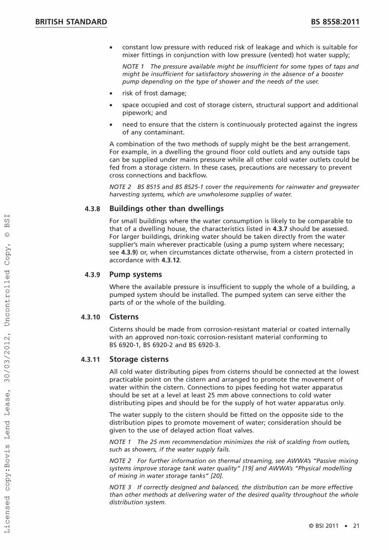
• constant low pressure with reduced risk of leakage and which is suitable formixer fittings in conjunction with low pressure (vented) hot water supply;
NOTE 1 The pressure available might be insufficient for some types of taps andmight be insufficient for satisfactory showering in the absence of a boosterpump depending on the type of shower and the needs of the user.
• risk of frost damage;
• space occupied and cost of storage cistern, structural support and additionalpipework; and
• need to ensure that the cistern is continuously protected against the ingressof any contaminant.
A combination of the two methods of supply might be the best arrangement.For example, in a dwelling the ground floor cold outlets and any outside tapscan be supplied under mains pressure while all other cold water outlets could befed from a storage cistern. In these cases, precautions are necessary to preventcross connections and backflow.
NOTE 2 BS 8515 and BS 8525-1 cover the requirements for rainwater and greywaterharvesting systems, which are unwholesome supplies of water.
4.3.8 Buildings other than dwellings
For small buildings where the water consumption is likely to be comparable tothat of a dwelling house, the characteristics listed in 4.3.7 should be assessed.For larger buildings, drinking water should be taken directly from the watersupplier’s main wherever practicable (using a pump system where necessary;see 4.3.9) or, when circumstances dictate otherwise, from a cistern protected inaccordance with 4.3.12.
4.3.9 Pump systems
Where the available pressure is insufficient to supply the whole of a building, apumped system should be installed. The pumped system can serve either theparts of or the whole of the building.
4.3.10 Cisterns
Cisterns should be made from corrosion-resistant material or coated internallywith an approved non-toxic corrosion-resistant material conforming toBS 6920-1, BS 6920-2 and BS 6920-3.
4.3.11 Storage cisterns
All cold water distributing pipes from cisterns should be connected at the lowestpracticable point on the cistern and arranged to promote the movement ofwater within the cistern. Connections to pipes feeding hot water apparatusshould be set at a level at least 25 mm above connections to cold waterdistributing pipes and should be for the supply of hot water apparatus only.
The water supply to the cistern should be fitted on the opposite side to thedistribution pipes to promote movement of water; consideration should begiven to the use of delayed action float valves.
NOTE 1 The 25 mm recommendation minimizes the risk of scalding from outlets,such as showers, if the water supply fails.
NOTE 2 For further information on thermal streaming, see AWWA’s “Passive mixingsystems improve storage tank water quality” [19] and AWWA’s “Physical modellingof mixing in water storage tanks” [20].
NOTE 3 If correctly designed and balanced, the distribution can be more effectivethan other methods at delivering water of the desired quality throughout the wholedistribution system.
BRITISH STANDARD BS 8558:2011
© BSI 2011 • 21
Licensed copy:Bovis Lend Lease, 30/03/2012, Uncontrolled Copy, © BSI

4.3.12 Large storage cisterns (over 1 000 L nominal capacity)
To avoid interruption of the water supply, storage should be provided by asystem of split compartments or multiple cisterns to facilitate repairs ormaintenance.
A washout pipe with the valve incorporated as close as practicable to the cisternshould not be connected to a drain, but may be arranged to discharge intoopen air above a drain in accordance with the requirements of a type AAairgap.
A washout pipe should be provided flush with the bottom of the cistern at itslowest point. Where practicable, the floor of the cistern should be laid to aslight fall to the washout pipe for cleaning purposes. The washout pipe outletshould be controlled by a suitable fullway valve and blanked off with a plug orflange when not in use.
Where it is not practical to operate delayed action ball valves to affectmaximum turnover on refilling, recirculating pump arrangements may beinstalled internally. This ensures that full mixing is induced and thermal columnseparation does not occur due to diurnal heating effects, which allow streamingof cold inlet water to track to diagonally opposite low level outlets.
These features are necessary to prevent localized columns of stagnant water inlarge cisterns and to maximize the distribution of disinfectant within the vessel.Correct use of these techniques can help assess the efficacy of the disinfectiondosing equipment. They also allow a more robust determination of the impactof water age on the residual disinfectant concentration at the extremes of thedistribution system.
Sometimes, particularly for a complex of buildings, because of the larger volumeof storage required or to provide the necessary head, it might be necessary tosupport the cistern in an independent structure outside the building(s).Although such a storage facility is often referred to as a tank or water tower, itis, by definition, a cistern.
Cisterns mounted outside buildings, whether fixed to the building itself orsupported on an independent structure, should be enclosed in a well-ventilated,but draughtproof, housing constructed to prevent ingress of birds, animals, andinsects. It should also allow access to the interior of the cistern by authorizedpersons for inspection and maintenance.
When installed below ground level, cisterns for storing water for domestic useare notifiable to the water supplier and consultation is essential beforeinstallation.
To maximize water turnover in buildings that have variable occupancy rates, e.g.schools over summer holidays, phased occupation of premises, the installation ofa variable height ball/control valve should be used.
4.3.13 Warning and overflow pipes
Where overflow and warning pipes discharge externally, they should bearranged to prevent the inward flow of cold air, for example, by turning downthe warning pipe into the cistern and below the water line except where thiscould interfere with the operation of the flushing mechanism or float operatedvalve in a WC flushing cistern, see the WRAS, IGN 9-04-04, Cold Water StorageCisterns – Design Recommendations for Mains Supply Inlets [21].
4.3.14 Stopvalves
Stopvalves fitted to supply pipes should conform to the relevant standard inTable 4.
BRITISH STANDARDBS 8558:2011
22 • © BSI 2011
Licensed copy:Bovis Lend Lease, 30/03/2012, Uncontrolled Copy, © BSI

Table 4 British Standards for stopvalves
Nominal size of pipe British StandardAbove ground Below ground
50 mm or smaller BS 1010-2 (BS EN 1213) BS 2580 8)
BS 2580 8) BS 543350 mm or larger BS 5163-2 BS 5163-2
NOTE Other stopvalves which satisfy the relevant requirements of the regulators’specification may be used.
The stopvalve components of composite fittings should conform to therequirements for stopvalves.
When a stopvalve is installed below ground, it should be enclosed in a suitableaccessible chamber.
For every building or part of a building to which a separately chargeable supplyof water is provided and in any premises occupied as a dwelling, whether or notseparately charged for a supply of water, a stopvalve should be provided thatcontrols the whole supply to those premises without shutting off the supply toany other premises. The stopvalve should, where practicable, be installed withinthe building or premises concerned in an accessible position above floor leveland close to the point of entry of the pipe supplying water to that premises,whether this be a supply pipe or a distributing pipe.
Where a common supply or distributing pipe provides water to two or morepremises, it should be fitted with a stopvalve that controls the water supply toall of the premises supplied by that pipe. The stopvalve should be installedeither inside or outside the building in a position to which every occupier of thepremises supplied has access.
A stopvalve should be installed in every pipe supplying water to any structureerected within the curtilage of a building but having no access from the mainbuilding. This stopvalve should be located in the main building as near aspracticable to the exit point of the supply pipe to the other structure or, if this isnot practicable, in the other structure itself as near as possible to the entry pointof the supply.
Where a building is divided into separately occupied parts, the supply to eachpart should be capable of being shut off by a second stopvalve installed outsidethat part, without shutting off the supply to other parts of the building, asshown in Figure 3 and Figure 4.
NOTE The principle for these recommendations is to provide a ready means ofisolating any private or common supply causing damage or nuisance, or for thepurpose of effecting repairs, replacements or alterations.
It should be ensured that the supply can be drained down by any occupier toavoid frost damage and to shut off their own supply or a supply in unoccupiedpremises causing damage or nuisance by using a stopvalve to which eachoccupier has ready access.
8) Obsolescent.
BRITISH STANDARD BS 8558:2011
© BSI 2011 • 23
Licensed copy:Bovis Lend Lease, 30/03/2012, Uncontrolled Copy, © BSI
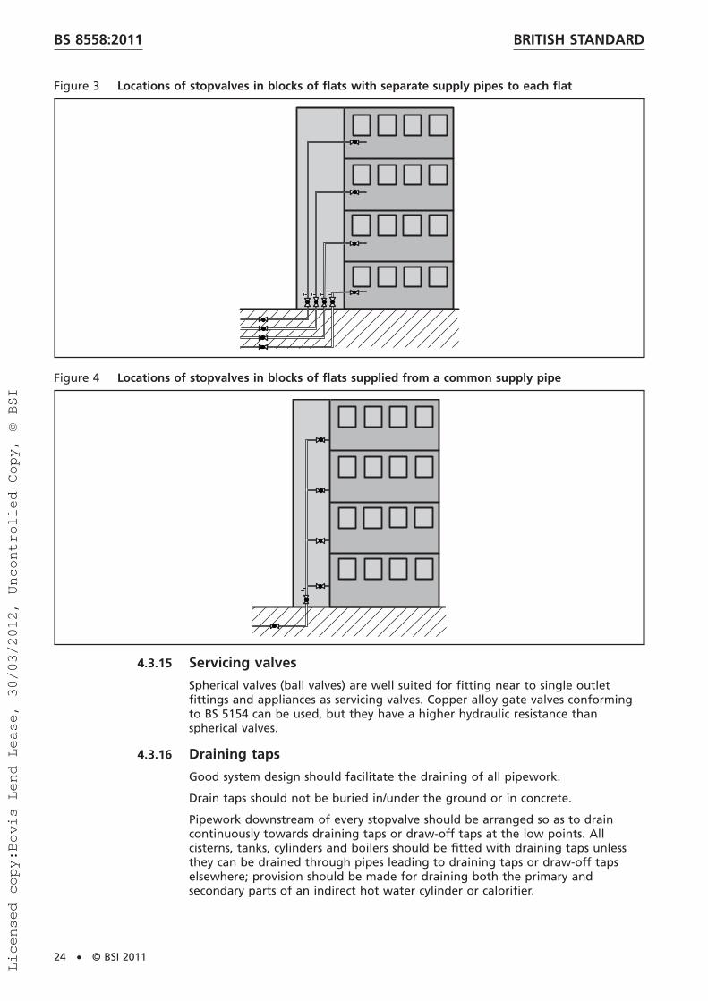
Figure 3 Locations of stopvalves in blocks of flats with separate supply pipes to each flat
Figure 4 Locations of stopvalves in blocks of flats supplied from a common supply pipe
4.3.15 Servicing valves
Spherical valves (ball valves) are well suited for fitting near to single outletfittings and appliances as servicing valves. Copper alloy gate valves conformingto BS 5154 can be used, but they have a higher hydraulic resistance thanspherical valves.
4.3.16 Draining taps
Good system design should facilitate the draining of all pipework.
Drain taps should not be buried in/under the ground or in concrete.
Pipework downstream of every stopvalve should be arranged so as to draincontinuously towards draining taps or draw-off taps at the low points. Allcisterns, tanks, cylinders and boilers should be fitted with draining taps unlessthey can be drained through pipes leading to draining taps or draw-off tapselsewhere; provision should be made for draining both the primary andsecondary parts of an indirect hot water cylinder or calorifier.
BRITISH STANDARDBS 8558:2011
24 • © BSI 2011
Licensed copy:Bovis Lend Lease, 30/03/2012, Uncontrolled Copy, © BSI

NOTE 1 Combined stopvalves and draining taps are a convenient way of providingfacilities for draining.
All draining taps should be capable of being fitted with removable hosepipesunless installed over a drain or discharging into a permanent draining pipe.
Draining taps should be used for draining purposes only. Where a draw-off tapis used for draining the installation, it should not be fitted with a hose unless ithas backflow protection. Outlets of hoses connected to draining taps should bearranged to discharge freely into the air. Hose outlets should not be allowed tobecome submerged.
NOTE 2 Attention is drawn to the Water Fittings Regulations [7].
For effective draining, it is essential that air enters the pipework freely; hotwater cylinders are liable to collapse if air cannot enter the system. Draw-offtaps, float operated valves and air inlet valves should be open when draining iscarried out. Where the taps and float operated valves in the system are notsuitably located for this purpose, special air inlet valves should be fitted inappropriate locations.
NOTE 3 Check valves and double check valve assemblies for backflow prevention atdraw-off taps, particularly those with flexible hoses, and other equipmentcan prevent air entering the system during draining.
4.3.17 Meters
Meters on the incoming supply to premises, for revenue charging purposes, areusually supplied and installed by the water supplier and sited by agreementbetween the consumer and the water supplier.
Where possible, meters should be installed at or near the street boundary of thepremises supplied, which is the limit of the responsibility of the water supplierfor maintenance of the service pipe.
The meter should be protected from the risk of damage by shock, vibration orfrost induced by the surroundings at the place of installation.
4.3.18 Bonding
The requirements for electrical bonding of copper pipework are given inBS 7671 (IET Wiring Regulations).
NOTE These regulations satisfy the requirements of the Electricity Safety, Qualityand Continuity Regulations [3].
4.3.19 External meters
External meters should be located so that access to them does not compromisesafety.
The type and size of the chamber and cover should be approved by the watersupplier. The size of the chamber should allow access to the meter such that it isreadily accessible for the purpose of reading, maintenance and replacement.
The clear opening of the surface box should be the same as the internaldimensions of the chamber, see Figure 5.
BRITISH STANDARD BS 8558:2011
© BSI 2011 • 25
Licensed copy:Bovis Lend Lease, 30/03/2012, Uncontrolled Copy, © BSI

Figure 5 Example of a pre-assembled external meter installation
12
4
5 6
7
14
3
8
11 12
13
109
105250
300
750
Key1 Ground level 8 Outlet reverse flow restrictor2 Frame and cover 9 Manifold3 Thermal insulation 10 Inlet stopvalve4 Meter chamber with adjustable top section 11 Outlet5 Register 12 Inlet6 Highest meter capsule point 13 Service pipe7 Meter capsule 14 Base
4.3.20 Internal meters
Where access to a meter is restricted, a remote readout device may be installedif the water supplier agrees.
Pipework should be adequately supported, leaving sufficient room for changingthe meter with the connections provided.
A second stopvalve or servicing valve should be installed downstream of themeter.
Where the installation of meters in exposed locations, e.g. garages subject tofrost, is unavoidable and agreed by the water supplier, adequate thermalinsulation in accordance with 4.3.35 should be provided, but not so as to impedereading or changing the meter.
BRITISH STANDARDBS 8558:2011
26 • © BSI 2011
Licensed copy:Bovis Lend Lease, 30/03/2012, Uncontrolled Copy, © BSI

4.3.21 Consumer non-revenue meters
The installation of consumer non-revenue meters should conformto 4.3.17 to 4.3.20 except that the water supplier need not be consulted.
NOTE In large buildings, consumer non-revenue meters may be used to assessconsumption through supplementary equipment such as softeners, water heatingplant or other automated fill equipment, e.g. closed systems.
4.3.22 Hot water services
Hot water storage and distribution should be as recommended in theHSE’s Approved Code of Practice L8, Legionnaires’ disease – The control ofLegionella bacteria in water systems [N1] (see also 4.3.32.2).
In particular, the whole water content of the calorifier, including that at thebase, should be heated to a temperature of 60 °C for one hour every day.
The water temperatures and delivery times recommended in the HSE’s ApprovedCode of Practice L8, Legionnaires’ disease – The control of Legionella bacteria inwater systems [N1] might not be achievable where hot water is provided byinstantaneous water heaters or combination boilers. However, the Legionella riskis considered to be acceptable provided that all of the following conditions aremet:
• the cold supply is directly from the supply pipe and under mains pressure;
• the volume of cold water pipework subject to heat gain (i.e. generallyabove ground pipework) is less than 1.0 L; and
• the volume of pipework from each hot water outlet to the heat source isless than 1.5 L.
NOTE The HSE’s guidance note “HSG 220, Health and Safety in Care Homes” [22]refers to scalding protection.
4.3.23 Storage type hot water systems
A summary of the main differences between vented and unvented systems is asfollows.
a) Vented systems: vented domestic hot water service systems are fed with coldwater from a storage cistern, which is situated above the highest outlet toprovide the necessary pressure in the system and which accommodatesexpansion of the water when it is heated. An open vent pipe runs from thetop of the hot water storage vessel to a point above the water storagecistern, into which it vents. Protection involving no mechanical devices isprovided by the open vent and the cistern. In addition, an energy cut-out orrelief system should be incorporated to minimize the consequences of amalfunction.
b) Unvented systems: unvented systems are usually supplied from the supplypipe but can be supplied from a storage cistern, either directly or through abooster pump. The main characteristics of unvented systems are as follows.
1) Explosion protection is provided by at least two independent safetydevices.
2) Systems depend upon pressure continuity and the hot water flowcannot be guaranteed if pressures fall.
3) In unvented systems supplied from a supply pipe, the absence of astorage cistern can reduce the risk of frost damage to property andremove the source of refill or float operated valve noise.
4) The safety aspects of unvented, storage type hot water systems aresubject to the requirements of the Building Regulations [8].
BRITISH STANDARD BS 8558:2011
© BSI 2011 • 27
Licensed copy:Bovis Lend Lease, 30/03/2012, Uncontrolled Copy, © BSI

Except for supplies to dual stream (biflow) fittings, mixing fittings should besupplied with comparable hot and cold water supply pressures. For TMVs,balanced pressures might not be required and the manufacturer’s instructionsshould be referred to for required operating pressure and temperature ranges.
4.3.24 Direct and indirect systems
This British Standard includes direct and indirect, vented and unvented systems.Figure 6, Figure 7, Figure 8 and Figure 9 illustrate the basic differences betweendirect and indirect, and between vented and unvented systems. These figuresare diagrammatic and should not be taken as complete designs; for simplicity,gravity circulation is shown and temperature controls and distribution pipeworkomitted.
Figure 6 Schematic example of a direct (vented) hot water system
1
13
14
2
4
12
7 8
10
3
5 6
11
9
10
1510
17
16
6
Key1 Vent pipe 10 Draining valve2 Cold water storage cistern 11 Hot water distributing pipes3 Warning pipe 12 Kitchen sink4 Cold water distributing pipe 13 Supply pipe5 Direct (vented) hot water storage vessel 14 Floor level6 Servicing valve 15 Stopvalve7 Bath 16 Heat source, e.g. boiler8 Wash basin 17 Cold feed pipe9 Primary circuit
BRITISH STANDARDBS 8558:2011
28 • © BSI 2011
Licensed copy:Bovis Lend Lease, 30/03/2012, Uncontrolled Copy, © BSI

Figure 7 Schematic example of an indirect (vented) hot water system
101211
13
1 23
4 5
76
89
16
14
5
99
19
15
18
17 18
20
Key1 Vent pipe 11 Supply pipe2 Cold water storage cistern 12 Kitchen sink3 Warning pipe 13 Floor level4 Indirect (vented) hot water storage vessel 14 Stopvalve5 Servicing valve 15 Heat source, e.g. boiler6 Bath 16 Heat exchanger7 Wash basin 17 Vent pipe8 Primary circuit 18 Cold feed pipe9 Draining valve 19 Feed and expansion cistern
10 Hot water distributing pipe 20 Air release valve
NOTE Inlet fitting and warning pipe to feed and expansion cistern not shown.
BRITISH STANDARD BS 8558:2011
© BSI 2011 • 29
Licensed copy:Bovis Lend Lease, 30/03/2012, Uncontrolled Copy, © BSI
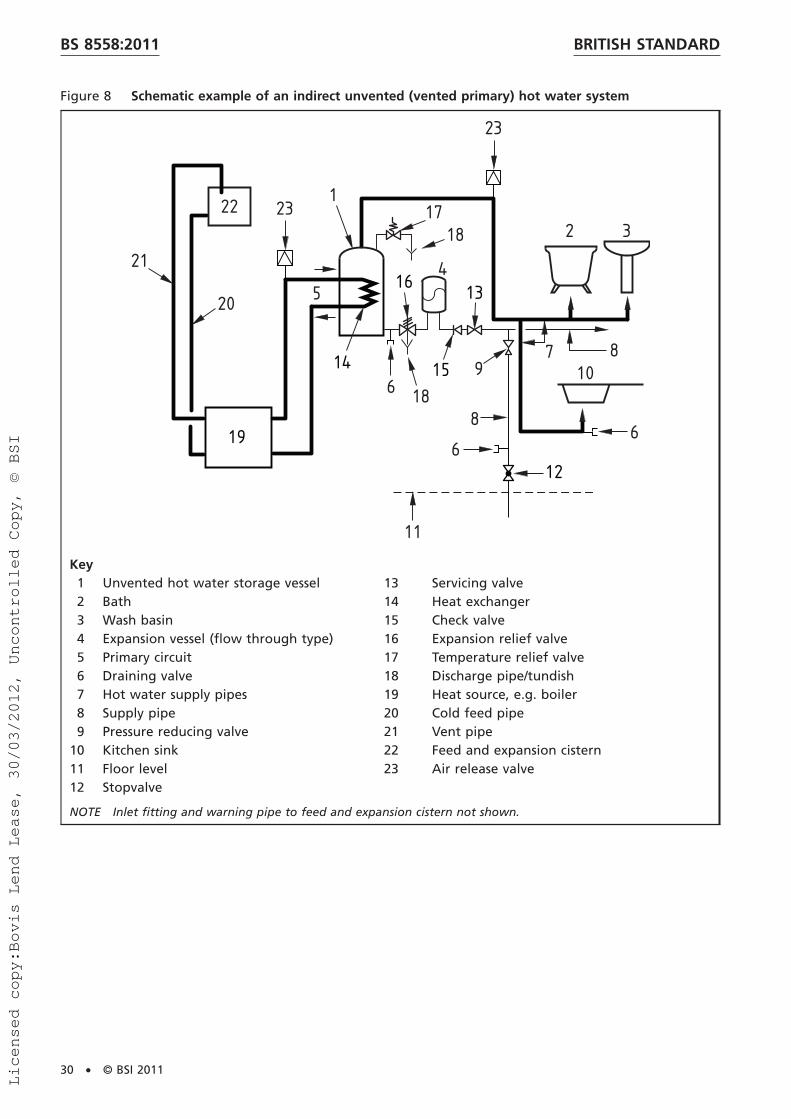
Figure 8 Schematic example of an indirect unvented (vented primary) hot water system
126
619
15
20
21
2 3
4
1
5
6
7 810
8
9
11
1817
18
14
13
22
16
23
23
Key1 Unvented hot water storage vessel 13 Servicing valve2 Bath 14 Heat exchanger3 Wash basin 15 Check valve4 Expansion vessel (flow through type) 16 Expansion relief valve5 Primary circuit 17 Temperature relief valve6 Draining valve 18 Discharge pipe/tundish7 Hot water supply pipes 19 Heat source, e.g. boiler8 Supply pipe 20 Cold feed pipe9 Pressure reducing valve 21 Vent pipe
10 Kitchen sink 22 Feed and expansion cistern11 Floor level 23 Air release valve12 Stopvalve
NOTE Inlet fitting and warning pipe to feed and expansion cistern not shown.
BRITISH STANDARDBS 8558:2011
30 • © BSI 2011
Licensed copy:Bovis Lend Lease, 30/03/2012, Uncontrolled Copy, © BSI

Figure 9 Schematic example of an indirect unvented (sealed primary) hot water system
1
2
3
4
5
67
8
16
14
13
12
9
1115
1510
14
1 13
17
18
Key1 Supply pipe 10 Main2 Hot water supply pipe 11 Double check valve B)
3 Expansion vessel (flow through type) 12 Check valve4 Pressure reducing valve 13 Servicing valve B)
5 Temporary connection to supply pipe for filling only 14 Draining valve6 Heat source, e.g. boiler 15 Stopvalve7 Expansion vessel (primary circuit) 16 Air release valve8 Temporary relief valve or combined temperature and pressure
relief valve17 Primary circuit18 Heat exchanger
9 Expansion relief valve A)
A) It is recommended to have a dosing and sampling point between the expansion relief valve and the heatsource to manage the closed system corrosion control chemicals.
B) The distance between the servicing valve and the double check valve should be as short as possible to preventstagnation.
4.3.25 Vented primary circuits
For domestic installations the vent should be not less than 19 mm bore. Wherethe vent pipe is not connected to the highest point in the primary circuit, an airrelease valve should be installed at that point, see Figure 10.
Close coupled feed and vent should only be used on the recommendation of theboiler manufacturers and installed in accordance with BS EN 12828 andBS EN 14336. Pipes should be installed to avoid air locks and laid to falls tofacilitate draining.
BRITISH STANDARD BS 8558:2011
© BSI 2011 • 31
Licensed copy:Bovis Lend Lease, 30/03/2012, Uncontrolled Copy, © BSI

When an installation is designed for combined central heating and domestic hotwater heating and the central heating circuit includes a circulating pump whilethe parallel circuit to the primary heater in the hot water storage vesseloperates by gravity circulation, the return pipes of the two circuits should beconnected to separate connections on the heat source or should be combined bymeans of an injector type fitting installed near the heat source, unless themanufacturer’s instructions specify otherwise.
Figure 10 Schematic example of a vented primary circuit with close coupled feed and open vent
1
4
14
2
3
5 6
7
8
9
10 11
12 13
15
Key1 Open safety vent 9 Circulating pump2 Minimum height 450 mm 10 Bypass with lockshield valve3 Feed and expansion cistern (see Note 2) 11 Heating circuit4 1 m minimum; 27.5 m maximum 12 Primary flow and return5 Cold feed pipe 13 150 mm maximum6 Primary circuit to cylinder 14 Heat source, e.g. boiler7 Hot water storage vessel 15 Air release valve8 Heat exchanger
NOTE 1 The close coupled feed and vent may only be used on the recommendation of the heat sourcemanufacturer.
NOTE 2 Inlet fitting and warning pipe to feed and expansion cistern not shown.
BRITISH STANDARDBS 8558:2011
32 • © BSI 2011
Licensed copy:Bovis Lend Lease, 30/03/2012, Uncontrolled Copy, © BSI

4.3.26 Sealed primary circuits
Pipes sizes in sealed primary circuits should conform to the relevantrecommendations for vented primary circuits in 4.2.26. In place of the expansioncistern and vent pipe, a sealed primary circuit should be fitted with anexpansion vessel of sufficient capacity to accommodate, with the pressuredifferentials involved, the increase in volume of the water content of the wholeof the primary system, including any space heating circuits, when heatedfrom 10 °C to 110 °C.
Indirect cylinders fitted in sealed primary circuits should have primary heaterssuitable for operating at a pressure of 35 kPa (0.35 bar) in excess of the pressurerelief valve setting. The safety of sealed primary circuits should always be inaccordance with the specific recommendations in 4.3.27 to 4.3.30 and 4.3.32.
4.3.27 Safety devices
Pressure relief valves, temperature relief valves, combined temperature andpressure relief valves, check valves, pressure reducing valves, anti-vacuum valvesand pipe interrupters should be fitted in accordancewith 4.3.28 to 4.3.30 and 4.3.32 and should conform to the relevant standardsfrom BS 6280, BS 6283-2, BS 6283-4, BS EN 1490, BS EN 1491, BS EN 13076,BS EN 13077, BS EN 13959, BS EN 14451 and BS EN 14623.
4.3.28 Energy control and safety devices
The Building Regulations [8] require at least two independent safety devices tobe used on stored hot water systems (vented and unvented) in addition to anythermostat used to control the temperature of the hot water. On ventedsystems, the vent acts as one safety device.
For systems that replenish water discharged through relief valves,e.g. a conventional storage water heater, the commonly used safety devices area temperature operated non-self-resetting thermal cut-out and a combinedtemperature and pressure relief valve. These safety devices have different modesof operation and act upon different aspects of the system, i.e. the temperatureoperated non-self-resetting thermal cut-out operates upon the source of energy,and the combined temperature and pressure relief valve dissipates energy bydischarging hot water. However, where there is no automatic replenishment, forexample with some water jacketed tube heaters, a combined temperature andpressure relief valve might not be suitable. To protect this type of appliance,two independent temperature operated non-self-resetting thermal cut-outs maybe used to shut off the flow to the primary heater.
Temperature relief valves, combined temperature and pressure relief valves,pressure relief valves, expansion valves, temperature operated non-self-resettingthermal cut-outs and thermostats should be accessible, and all controls/devicesshould be located to prevent unauthorized interference.
The discharge from relief valves should be conveyed safely and be visible so asto indicate a fault with the system.
NOTE Relief valves discharge hot water at a flow rate of typically 12 L/minto 20 L/min with the water at a temperature approaching boiling point.
Unvented systems storing less than 500 L should be in the form of aproprietary unit or package.
BRITISH STANDARD BS 8558:2011
© BSI 2011 • 33
Licensed copy:Bovis Lend Lease, 30/03/2012, Uncontrolled Copy, © BSI

4.3.29 Pressure control
For hot or cold water, all parts of the system should be capable of withstandingany hydraulic pressures to which it is, or is likely to be, subjected, including testpressures. The pressures in the system should never exceed the safe workingpressures of the component parts. Where necessary, the supply pressure shouldbe controlled by using break cisterns or pressure reducing valves in accordancewith BS EN 1567. If the supply to a storage type water heater is through apressure reducing valve of the type that permits backflow, the working pressurein the system should be assumed to be the maximum pressure upstream of thevalve.
Expansion and/or temperature and/or pressure relief valve ratings should be themaximum working pressure plus 50 kPa to 150 kPa (0.5 bar to 1.5 bar).
For unvented systems, provision should be made to accommodate expansion byeither:
a) allowing expansion water to travel back along the feed pipe, provided thatheated water cannot reach any communication pipe or branch feeding acold water outlet. Where such reverse flow is impeded by a stopvalve with aloose washer plate, this valve should be replaced by a valve with a fixedwasher plate, or a no less effective valve; or
b) providing an expansion vessel conforming to BS 6144, or an integral airspace to accommodate expansion water where reverse flow along the coldwater pipe is prevented, for example, by a check valve, some types ofpressure reducing valve, or a stopvalve with a loose washer plate. Thisexpansion vessel or integral air space should be sized in accordance with thevolume of water heated so that the pressure is limited to the maximumworking pressure for the system.
4.3.30 Maintenance of water level
The hot water delivery connection should be located at the top of the hot watercylinder in conjunction with a suitably located vent, or, for some unventedsystems, an anti-vacuum valve. Where hot water is delivered through asecondary circulating system, the hot water supply or distributing pipe should bearranged to be from the top of the vessel, or as near thereto as practicable, andalways above any primary flow connection.
NOTE Unintentional draining of a hot water system is dangerous as it might exposetemperature controls, impairing their operation, or the heating surfaces of theheater, which then becomes overheated. Where heating elements and controls aresituated in the upper part of a system, they are correspondingly more vulnerable toa fall in water level.
4.3.31 Pipe sizing
Simultaneous use of appliances can reduce flow rates, potentially below designvalues. It is important that the whole system should be designed so that flowrates are not reduced to such an extent as to adversely affect the satisfactoryfunctioning of the system. In particular, where the reduction in flow could affectthe temperature of water delivered to showers, measures should be taken toprotect the user against excessive water temperatures (see 4.3.22). In mostbuildings, appliances are rarely in simultaneous use, therefore for reasons ofeconomy, it is usual to provide for a demand less than the total demand of allappliances being in use at the same time.
BRITISH STANDARDBS 8558:2011
34 • © BSI 2011
Licensed copy:Bovis Lend Lease, 30/03/2012, Uncontrolled Copy, © BSI

The simultaneous demand can be determined from data derived by observationand experience of similar installations or by the application of probabilitytheory. A system of determination should be based on probability theory usingloading units and incorporating the flow rate required at the appliance, thelength of time in use, and the frequency of use. A method of pipe sizing isgiven in BS EN 806-3.
Flow rate for filling cold water storage cisterns can vary depending on theamount of storage provided, the pressure available from the source or main andwhether the supply is constant. Where other information is unavailable, amaximum of four hours filling time may be assumed.
In other than small, simple installations, such as single dwellings, pipe sizesshould be calculated using a recognized method of calculation, such as themethod given in BS EN 806-3.
Design flow rates are given in Table 5. The design rate is the desirable deliveryrate to the fitting or appliance. Table 5 is not intended for use as a guide tobuying fittings or appliances. Guidance on the selection of appropriateappliances can be found in BS 6465-3.
Table 5 Design flow rates to outlet fitting and appliances A), B)
Outlet fitting or appliance Rate of flow
L/sDesign rate Minimum rate
WC cistern (to fill in two minutes) 0.13 0.05WC flushing trough (per WC served) C) 0.15 0.10Urinal cistern (each position served) 0.004 0.002Washbasin 0.15 0.10Handbasin (spray or mixer taps) 0.05 0.03Bidet 0.10 0.10Bath (G 3⁄4) 0.50 0.20Shower head (15 mm) 0.20 0.10Kitchen sink (G 1⁄2) 0.20 0.10Kitchen sink (G 3⁄4) 0.30 0.20Washing machine 0.20 0.15Dish-washing machine D) 0.15 0.10
A) These figures can be used for sizing each individual pipe to the appliance referred to.
B) The choice of outlet fittings/appliances can affect the flow rate delivered at the outlet fitting/appliance.Manufacturer’s advice should be sought.
C) WC flushing troughs are recommended where anticipated use of WCs is more frequent than once per minute.
D) The manufacturer should be consulted for required flow rates and pressures to washing and dish-washingmachines for other than single dwellings.
4.3.32 Contamination
4.3.32.1 Prevention of contact of water with unsuitable materials
The Water Fittings Regulations [7] require that no material or substance, eitheralone or in combination with another material or substance that causes or islikely to cause contamination, should be used in a system that conveys water fordomestic or food production purposes. This does not apply where the waterdownstream of a terminal fitting is not required to be wholesome and asuitable arrangement or device to prevent backflow is installed.
BRITISH STANDARD BS 8558:2011
© BSI 2011 • 35
Licensed copy:Bovis Lend Lease, 30/03/2012, Uncontrolled Copy, © BSI

In areas of contaminated ground, approved copper tube with a factory appliedprotective plastics coating or plastic barrier pipe should be used, see UKWIR’s,Guidance for the Selection of Water Supply Pipes to be used inBrownfield Sites [17].
If a fluid (other than water) is used in any type of heating primary circuit whichtransfers heat to water for domestic use, or if an additive is used in water insuch a circuit, the liquid or additive should be non-toxic and non-corrosive.In larger building systems, water quality might require biocides formicrobiological control that are not non-toxic. Building systems should bechecked for crossover leaks at least annually.
Where non-potable water systems, e.g. rainwater harvesting systems, are used,checks should be carried out that there are no cross connections with thepotable system. A methodology for such a procedure is set out in BS 8525-1.Appropriate colouring and labelling should be used (see the WRAS, IGN 9-02-05Marking & Identification of Pipework for Water Reuse Systems [23]).
4.3.32.2 Prevention of contamination of drinking water by Legionella and othercolonizing microorganisms, such as Pseudomonas aeruginosa
To prevent the contamination of the system with Legionella, measures should betaken in the design, installation and operation of hot and cold water systems.Where possible, these should include the avoidance of:
• stagnation of water in pipes, cisterns and other storage vessels;
• water temperatures within the range of 20 °C to 45 °C;
• use of materials with the greatest potential to harbour or provide nutrientsfor bacteria and other organisms; and
NOTE WRAS approved materials are recommended.
• installation of fittings where aerosol formation can occur.
Legionella pneumophilia is the bacteria that causes Legionnaires’ disease. Peoplecatch Legionnaires’ disease by inhaling droplets of water, suspended in the air,which contain the bacteria. To determine the likelihood of any Legionellarelated problems, a risk assessment should be undertaken, for guidance seeBS 8580.
Good practice is assumed if the recommendations contained in the HSE’sApproved Code of Practice L8, Legionnaires’ disease – The control of Legionellabacteria in water systems [N1] are followed.
To reduce the risk of colonization of a water system the temperature of coldwater in pipes and cisterns should reach below 20 °C in less than two minutes;hot water should be stored and distributed at a temperature of not lessthan 60 °C with a temperature at the discharge point of 50 °C after one minute.
Hot and cold water pipework should be as short as practicable, especially whereit only serves infrequently used taps and fittings.
The Water Supply (Water Quality) Regulations [2] contains requirements for theuse of braided or flexible hoses in contact with drinking water.
4.3.33 Backflow prevention
4.3.33.1 General
Avoidance of backflow can be achieved by good system design and theprovision of suitable backflow prevention arrangements and devices, the type ofwhich depends on the fluid category to which the drinking water is discharged.A description of fluid risk categories is shown in Schedule 1 of the Water FittingsRegulations [7].
BRITISH STANDARDBS 8558:2011
36 • © BSI 2011
Licensed copy:Bovis Lend Lease, 30/03/2012, Uncontrolled Copy, © BSI

Wherever practicable, systems should be protected against backflow withoutreliance on mechanical backflow protection devices; this can often be achievedby point of use protection, such as a “tap gap” above the spillover level of anappliance.
To enable buckets and similar utensils to be filled, the outlet of the kitchen tapshould be not less than 275 mm above the bottom of the sink.
For further guidance, see the WRAS Water Regulations Guide [9] for detailedinformation on backflow protection or consult the local water supplier.
4.3.33.2 Secondary or zone backflow protection
Backflow protection should be in accordance with BS EN 1717. The local watersupplier can provide advice on the level of backflow protection that should beinstalled. Further information is available from the WRAS, IGN 9-04-05, Report ofthe Expert Group on the Risk of Contamination of the Public Water Supply byBackflow [24].
NOTE If contamination enters the public mains distribution system, theconsequences can be dire for public health. There could also be cost and legalimplications for the installer, occupier/company. There are some premises wherethere would be significant consequences from contamination of the public watersupply following a backflow incident. There are also certain installations that poseadditional risk of breach of backflow protection no matter how well the installationis managed and maintained. Particular risks are the presence of FluidCategory 5 alternative water supplies with pressurized systems at or above mainspressure.
On sites with buried pipework, the risk of inadvertent cross connection is greatlyincreased, particularly where accurate site layout drawings are not available;whole site or part site backflow protection should be used.
4.3.34 Protection of water pipes and fittings
4.3.34.1 General
Installations should be protected against conditions arising from adversetemperatures external to pipes, fittings and appliances. Protection should beprovided against:
a) ice formation in pipework and fittings;
b) heating of cold supply pipes;
c) condensation; and
d) thermal stresses.
Where the placing of pipes and fittings above ground outside buildings isunavoidable, these pipes and fittings should be protected by thermal insulationwith a weatherproof finish in accordance with 4.3.35. Where pipes rise from theground, the thermal insulation should extend to the depth below ground statedin 4.3.35.
To reduce the risk of bursting, interruption of supply, waste, leakage andconsequent damage to the pipes and building, the following should beprovided:
i) thermal insulation;
ii) trace heating tapes; or
iii) local heating; and
iv) adequate protection to prevent damage from any other cause including theenvironment they pass through.
BRITISH STANDARD BS 8558:2011
© BSI 2011 • 37
Licensed copy:Bovis Lend Lease, 30/03/2012, Uncontrolled Copy, © BSI
In winter, water might only just be above freezing point when delivered intothe consumer’s pipes and a further reduction in temperature could causefreezing.
Particularly vulnerable locations which require protection include those whereflow is very slow, infrequent or through small diameter pipes.
To prevent freezing of water services in buildings, the inside of the buildingshould be kept continuously warm by the provision and maintenance ofadequate heating. When the whole building is not heated, or where heating isonly intermittent, heating of water pipes and fittings (trace heating) or heatingtheir immediate surroundings (local heating) might be sufficient.
Alternatively, when buildings are not used in freezing conditions and no heatingis available, the plumbing system should be drained down (see the WRAS WaterRegulations Guide, G4.3 [9]). Where low temperatures persist, thermal insulationonly delays the onset of freezing. Its efficiency is dependent upon its thicknessand thermal conductivity in relation to the size of pipe, time of exposure,location and possibly wind chill factor.
In addition to thermal protection, pipework and fittings should also beprotected from their surroundings. This might be physical protection in the formof a casing or other measures applying either above or below ground.
The layout of the water service should be planned to avoid the following:
1) external locations above ground;
2) unheated spaces;
3) positioning near a window, air brick or other ventilator, external door, orany other place where cold draughts can occur; and
4) a chase or duct formed in an external wall.
Care should be taken in the control of temperatures where trace heating isinstalled with plastics pipes.
4.3.34.2 Underground pipes
Pipes laid underground outside buildings should be laid at a depth sufficient togive protection against freezing, which should be no less than 0.75 m but nogreater than 1.35 m. Where this cannot be achieved, the water supplier shouldbe consulted. Where the depth of cover is less than 0.75 m, thermal insulationshould be in accordance with 4.3.35 or with that agreed with the water supplier(see Figure 11).
Underground stopvalves should not be brought up to a higher level merely forease of access.
4.3.34.3 Pipes entering buildings
Where pipes rise from below the ground, waterproof thermal insulation shouldextend to at least 0.75 m below the ground, in accordancewith 4.3.35 (see Figure 11, 4.3.39 and 5.2.1.10).
BRITISH STANDARDBS 8558:2011
38 • © BSI 2011
Licensed copy:Bovis Lend Lease, 30/03/2012, Uncontrolled Copy, © BSI

Figure 11 Typical examples of pipes entering buildings A)
Dimensions in millimetres
750
<750
1
2
3
750
750
1
4
3
a) Rising pipe in duct less than 750 mmfrom face of external wall
b) Rising pipe in duct more than 750 mm from face ofexternal wall
750
5
6
2
3c) Rising pipe through ventilated suspended floor
Key1 Solid internal floor 4 Pipes laid in duct, no thermal insulation
required2 Pipes laid in duct with thermal insulation3 Sealed 5 Any distance
6 Suspended floor
A) Ideally, a duct should be constructed so that access to the interior can be obtained either throughout itslength or at specified points by removal of a cover or covers.
BRITISH STANDARD BS 8558:2011
© BSI 2011 • 39
Licensed copy:Bovis Lend Lease, 30/03/2012, Uncontrolled Copy, © BSI

4.3.34.4 Pipes and fittings inside buildings
Pipes and fittings should be thermally insulated in accordance with 4.3.35.Thermal insulation should be provided on the top and sides of any cistern.
Where pipes are attached to the inside faces of external walls in a part of abuilding that is heated, it should not be necessary to insulate them, but it isadvantageous to fix such pipes clear of the wall on brackets or clipped to a pipeboard.
To avoid thermal transfer between hot and cold pipes, it may be necessary toappropriately insulate.
Cold water pipes should be protected to prevent the formation of condensation.Where cold water pipes pass through areas of relatively high humidity,condensation forms unless prevented. Thermal insulation, as a measure toprevent condensation, is subject to the same recommendations as thermalinsulation against heat loss or gain (see 4.3.35).
4.3.35 Thermal insulation
Thermal insulating materials should conform to BS 5422 and should be installedin accordance with BS 5970.
Cold water pipes should be thermally insulated to the minimum thickness givenin Table 6 and Table 7.
Table 6 Calculated minimum thickness of thermal insulation to protect copper pipesfixed inside premises for domestic cold water systems
Outsidediameter
mm
Inside diameter(bore)
mm
Thermal conductivity at 0 °C
W/(m·K)
0.025 0.035 0.045 0.055Thickness of thermal insulation
mm15 13.6 30 62 124 24122 20.2 12 20 30 4328 26.2 8 12 17 2335 32.6 6 9 12 1542 39.6 5 7 9 11
BRITISH STANDARDBS 8558:2011
40 • © BSI 2011
Licensed copy:Bovis Lend Lease, 30/03/2012, Uncontrolled Copy, © BSI

Table 7 Calculated minimum thickness of thermal insulation to protect copper pipesfixed inside premises against freezing for commercial and institutionalapplications
Outsidediameter
mm
Inside diameter(bore)
mm
Thermal conductivity at 0 °C
W/(m·K)
0.025 0.035 0.045 0.055Thickness of thermal insulation
mm15.0 13.6 31 56 83 10922.0 20.2 13 21 31 4528.0 26.2 8 13 18 2435.0 32.6 7 9 13 1642.0 39.6 5 7 9 1254.0 51.6 4 5 7 876.1 73.1 3 4 5 6
108.0 105.0 2 3 3 4Above 108.0 mm outside diameterand flat surfaces
2 3 3 4
NOTE Water temperature, +5 °C; ambient temperature, −3 °C; evaluationperiod, 24 h; permitted ice formation 50%.
Thermal insulation slows down the impacts of frost or a hot environment, butdoes not prevent heat transfer from or into the water. Thermal insulation doesnot give complete protection if the temperature falls to or below freezing point.However, a suitable thickness of thermal insulation does delay the onset offreezing in cold environments and can reduce the rate of heat gain in relativelyhot environments.
The thickness of insulating materials specified in BS 5422, while givingprotection, is not considered practicable for protection of small diameter pipesfixed inside buildings. However, the thickness of insulating material identified inTable 8, under the appropriate thermal conductivity values, is consideredpracticable and suitable for small diameter pipework to provide reasonableprotection for pipes fixed inside normally occupied buildings.
Unless the thermal insulation material used is sufficiently impermeable to watervapour, a vapour barrier with a permeance not exceeding 0.05 g/(s·MN) shouldbe applied on the outside surface of the thermal insulation to protect againstdamage where necessary.
The gap between the thermal insulation material on the copper pipe should notexceed that recommended by the thermal insulation manufacturer to reduce therisk of under-lagging corrosion.
Table 8 Examples of insulating materials
Thermal conductivity
W/(m·K)
Material
Less than 0.020 Rigid phenolic foam0.021 to 0.035 Polyurethane foam0.040 to 0.055 Corkboard0.055 to 0.07 Exfoliated vermiculite (loose fill)
BRITISH STANDARD BS 8558:2011
© BSI 2011 • 41
Licensed copy:Bovis Lend Lease, 30/03/2012, Uncontrolled Copy, © BSI
Pipes passing through areas with no heating, such as basements, garages,roofspaces, etc., should have greater levels of protection.
Further advice on thermal insulation is given in the WRAS Water RegulationsGuide [9] and can be obtained from manufacturers. There are also thermalcalculation tools available, e.g. WRAS.
4.3.36 Local and trace heating
Electric trace heating should conform to BS EN 62395-1 and BS EN 60079-30-1,with electrical installation in accordance with BS 7671.
Any trace heating provided for the protection of any pipes or fittings should beadditional to, and not in substitution for, insulation recommendationsin 4.3.34 to 4.3.37.
Local heating, in conjunction with a frost thermostat, should only be used whereother methods of frost protection are unsuitable, e.g. for pipes in unheated roofspaces when it is inconvenient to drain them and the building is to be unheatedfor a period during the winter.
Where trace heating is provided, it should be fitted before the insulation isapplied.
4.3.37 Drainage of system to prevent frost damage
Arrangements should be provided for isolating and draining pipes and fittings(see 4.3.14 to 4.3.16).
Where a building is divided into parts, the pipes and fittings in each part shouldbe arranged so that they can be isolated and drained without affecting thesupply to any other part. Stopvalves and drain taps should be located inpositions convenient for use as close as practicable to the point of entry of thepipe into the building or part thereof.
Unless the stopvalve is installed within a normally heated building, it should beprotected against freezing in accordance with 4.3.34 to 4.3.36.
Every external standpipe, livestock watering appliance, garden tap, garage tap,or similar water fitting should be supplied through a stopvalve located in aposition convenient for use within a normally heated building or protectedagainst freezing and damage in accordance with 4.3.34 to 4.3.37.
The pipes and fittings in any part of a building not used in winter, any unheatedbuilding or part of a building, including any water-closet, garage orconservatory, or any other outbuilding, should be arranged to enable them tobe isolated and drained separately.
4.3.38 Accessibility of pipes and water fittings
The following factors should be assessed (see Figure 12).
a) The purpose for which the building is to be used: importance of aestheticconsiderations, consequences of leakage from inaccessible parts of thepipework and whether or not the system is subject to routine inspectionand maintenance.
b) The increase or decrease in capital or maintenance costs arising from theprovision of improved accessibility: ease of forming ducts or chases, changesto pipe runs, ease of provision of removable access panels or covers andavailability of multi-service walkways or crawlways in which water pipesmight be installed.
c) The pipework materials and jointing methods: reliability of joints, resistanceto both internal and external corrosion and the flexibility of pipe wheninserted in curved ducts or sleeves.
BRITISH STANDARDBS 8558:2011
42 • © BSI 2011
Licensed copy:Bovis Lend Lease, 30/03/2012, Uncontrolled Copy, © BSI

Figure 12 Accessibility of pipework
12
3
3
10
4
6
9
11
5
8 7
12
13
14b) Accessibility of pipes under suspended floors
15
16 17
18
19
2015
21
a) Accessibility of pipes under solid floors c) Accessibility of pipes in solid walls (see Note)
23
24 25
22
2
1
3
d) Accessibility of pipes in cavity walls A) e) Accessibility of pipes behind bath panels
BRITISH STANDARD BS 8558:2011
© BSI 2011 • 43
Licensed copy:Bovis Lend Lease, 30/03/2012, Uncontrolled Copy, © BSI

Figure 12 Accessibility of pipework
Key1 Removable cover (recommended
practice)14 Boards removable at intervals of not more than
two metres and at every joint for inspection ofwhole length of pipe
2 Floor finish 15 Surface finish3 Pipes in purpose-made chase 16 Removable cover over purpose-made duct4 Thermally insulated if an unheated
building17 For pipes fixed on the external face of an external
walls, thermally insulate the pipes5 Tiling or other surface finish over wood
or metal cover18 Wood or metal cover19 Plaster or tiling
6 Acceptable only where few joints areenclosed and pipe can be withdrawnfor examination
20 Internal wall21 Pipe in chase22 Cavity wall
7 Pipe in screed or purpose-made chase 23 Pipe in duct and thermally insulated8 Surface finish to floor 24 Plaster board and studding wall (internal)9 Only acceptable where few joints are
enclosed25 Pipe run within wall26 Bath
10 Pipe thermally insulated inpurpose-made duct under floor
27 Correct position for pipes B)
11 Acceptable only where few pipes canbe withdrawn for inspection
12 Ground floor13 Pipe thermally insulated
A) Except for the topmost arrangement, no pipes should be laid within a cavity.
B) They should be laid on the side of the bath adjacent to the removable panel.
NOTE For Figure 12c), this is only permitted in an internal wall and if pipe can be capped off orisolated if a leak becomes apparent.
4.3.39 Pipes passing through walls and floors
Where fire regulations and other considerations require the ends of sleeves tobe sealed, such sealing should be of a permanently flexible form to allowmovement of the pipe.
4.3.40 Underground stopvalves
Stopvalves installed on an underground pipe should be enclosed within a pipeguard or chamber under a surface box of the appropriate grade for the trafficloading according to the location, see BS 5834-2.
4.3.41 Above ground valves
For control valves where access is required for emergency purposes, access to thevalve should not require the use of tools to remove the access cover.
4.3.42 Cisterns
Every cistern should be placed and equipped so that the interior can beinspected and cleansed and the float operated valve can be maintained,see Figure 13. A clear space of not less than 350 mm should be providedbetween the top of the cistern and any ceiling or other obstruction above thecistern. For small cisterns the overhead, unobstructed space may be reducedto 225 mm provided no dimension of the cistern exceeds 450 mm in any plane.
BRITISH STANDARDBS 8558:2011
44 • © BSI 2011
Licensed copy:Bovis Lend Lease, 30/03/2012, Uncontrolled Copy, © BSI

Cistern into which a vent pipe terminates should be supported throughout thewhole of its base on a flat level platform capable of supporting the weight ofthe cistern when full to its brim. The platform should be extended beyond theoutside edges of the cistern by at least 150 mm. This advice should also befollowed where a metal or plastics cistern is replaced by one of largerdimensions.
Concealed cisterns, e.g. WC and urinal flushing cisterns, should be accessible forrepair/maintenance.
Figure 13 Clear space needed above cisterns
Dimensions in millimetres
350
350
1 14
0
350
350 350
350
11
2
2
3
a) Conventionally shaped cistern up to 1 000 L b) Plumbing units (see Note)
350
500
4 5
350
1 12 2c) Greater than 1 000 L capacity cistern withbolted-on lid
d) Hot water storage combination units
Key1 Cold water cistern 4 Access to float valve2 Hot water storage vessel 5 Access for inspection3 Handhole
NOTE Acceptable sizes and positions of handholes are given in BS 3198.
BRITISH STANDARD BS 8558:2011
© BSI 2011 • 45
Licensed copy:Bovis Lend Lease, 30/03/2012, Uncontrolled Copy, © BSI

4.3.43 Water economy
Attention is drawn to the Water Fittings Regulations [7] for the arrangement ofWC flushing and the Building Regulations [8] for requirements on waterefficiency.
The discharge of the flushing apparatus should be according to the design ofthe pan. Arbitrary reduction in the flush is not recommended.
NOTE Where modifications are made to existing systems, pipe and cistern size mayneed to be evaluated with regard to water quality.
4.3.44 Urinal flushing
In lightly used installations, a user-operated or actuated flush for individual stallsor bowls may be fitted for a water saving if each unit is used less frequentlythan the automatic flushing rate.
4.3.45 Waste plugs
Every waste outlet from a bath (other than a shower bath or shower tray),washbasin, sink or similar appliance should be provided with a well-fitting plugand retaining chain, pop-up plug, or an equally effective closure, except wherethe water supply is only from a fitting incapable of supplying water to awashing trough or basin at a rate exceeding 3.6 L/min per appliance, where it isfitted with self-closing taps, or where the appliance is for medical, dental orveterinary use and is intended for use with an unplugged waste.
4.3.46 Spray taps
Spray taps can save as much as 50% in both water consumption and fuel. Thespray is only for hand rinsing; spray taps should not be used in situations wherethere might be heavy fouling of basins by grease and dirt. Without regularattention, the spray head can become blocked over a period of time with anyquality of water, but more particularly with hard water. Self-cleansing velocitiescan rarely be satisfactorily achieved, particularly in long discharge pipes, so drainblockage due to a build up of grease and soap residue can occur, especially insoft water areas. Particularly good performances have been reported from areaswith water in the range of 100 mg/L to 135 mg/L total hardness.
Aerators should conform to BS EN 246. Although aerators are intended for thepurpose of improving the flow pattern, they can also reduce consumption byreducing the flow. However, aerators do have a minimum operating pressure,the value of which should be provided by the manufacturer.
Where spray taps are installed in an existing building as part of a refurbishmentor water saving initiative, existing storage and pipe sizing should be assessedwith regards to stratification and stagnation, which might have an impact onthe proliferation of Legionella (see the HSE’s Approved Code of Practice L8,Legionnaires’ disease – The control of Legionella bacteria in water systems [N1]).
Any enhanced risk of aerosol formation in spray taps should be assessed and thesystem designed accordingly.
4.3.47 Energy conservation: pipework and hot water storage
With the exception of certain solid fuel appliances, all hot water storage systemsshould be fitted with a thermostat to control the maximum water temperature.
All pipes forming part of a primary or secondary circulation system for supplyingdomestic hot water and all pipes supplying hot water to a tap or other outletthat is longer than two times the pipe diameter, should be thermally insulatedin accordance with BS 5422 or so that the energy loss under normal operatingconditions at no time exceeds the values given in Table 9.
BRITISH STANDARDBS 8558:2011
46 • © BSI 2011
Licensed copy:Bovis Lend Lease, 30/03/2012, Uncontrolled Copy, © BSI

Table 9 Maximum permitted rates of energy loss from pipes
Outside diameter of pipe A)
mm
Maximum energy loss
W/m2
10 67520 40030 28040 22050 and above 175
A) For intermediate values of pipe diameter, the corresponding maximum energy loss isfound by interpolation.
Where trace heating is used, it should be of the electric self-regulating typespecifically formulated for domestic hot water systems. The system shouldconform to BS EN 62395-1 and BS EN 60079-30-1.
Reducing the quantity and temperature of hot water heated and/or stored tomeet recommendations produces energy savings in addition to those achievedby thermal insulation and controls. Storage vessels should therefore be sized tomeet recommendations without excessive over capacity. Devices such as doubleelement or twin electric immersion heaters, or manually controlled economyvalves on directly heated gas circulator systems, that enable a reduced quantityof water to be heated when desired, should be fitted accordingly.
4.3.48 Scale control
Formation of scale in boilers and water heaters occurs due to the “hardness” ofthe water supply. Hard water contains dissolved minerals, mainly calcium,magnesium and associated anions bicarbonate, sulfate and chloride. When hardwater is heated, bicarbonate decomposes and calcium carbonate is deposited inthe heater and associated pipework. Whilst this can cause blockage andequipment failure, it also coats the heating surfaces, effectively insulating themso that the efficiency of the heater is impaired. Tests have shown that this canreduce the heater efficiency by up to 30%.
For primary circuits during final filling of the system, an appropriate chemicalwater treatment formulation should be added to the primary circuit to controlcorrosion and the formation of scale and sludge.
For secondary circuits (i.e. feed water to water heaters and the hot water circuitof combination boilers) in areas where water hardness is greater than 200 ppm,consideration should be given to fitting a base-exchange water softener, scaleinhibitor, continuous dosing or physical water conditioner.
4.3.49 Pumping cold water
Where mains pressure is insufficient to supply the upper floors of a building,mains supply to the lower floors without pumping should be considered. Wheremore than 12 L/min of water is to be pumped, the water supplier’s consentshould be obtained before the installation commences. The examples of pumpedsystems in Annex A should also be considered.
4.3.50 Bending of pipes
Rippling or excessive throating, and restricting the diameter of pipes whenforming bends should be avoided.
Where appropriate, purpose-designed equipment should be used.
BRITISH STANDARD BS 8558:2011
© BSI 2011 • 47
Licensed copy:Bovis Lend Lease, 30/03/2012, Uncontrolled Copy, © BSI
4.3.51 Above ground pipework
Adaptor couplings are available for jointing different materials covering a rangeof different jointing methods and including both direct and union typecouplings; these should be used whenever possible. Where suitable adaptors arenot available for the particular joint required, both materials should be adaptedto BS P threaded ends, which should be screwed together if male and female orconnected by a nipple, socket or union of a material compatible with the pipematerial that does not lead to corrosion.
4.3.52 Below ground pipework
Joints in buried pipework should be kept to the absolute minimum and jointsbetween pipes of different materials should be restricted to connectionsbetween large supply pipes similar to suppliers’ mains and pipes servingindividual buildings (see also 4.2.2).
Service connections to cast iron pipes should be made by drilling and tappingthe pipe and screwing in a copper alloy union ferrule.
When making service connections to unplasticized PVC pipes, a saddle should befixed round the larger pipe and a ferrule screwed into the saddle. Installersshould observe the manufacturer’s instructions. For fibre cement pipes, the samemethod should be used or a proprietary threadless ferrule should be used inaccordance with the manufacturer’s instructions.
Service connections to PE pipes should be made using either a saddle fusionfitting (for PE service pipes only) or a self-tapping saddle.
Pipes should be laid to ensure even support throughout their length and shouldnot rest on their sockets or on bricks, tiles, or other makeshift supports. Plasticspipes should be laid on a bed free from sharp stones.
Pipes should be kept clean and, immediately before laying each pipe and fitting,should be thoroughly cleansed internally and the open end temporarily cappeduntil jointing takes place. The joint surfaces should be clean. After laying andjointing, the leading end should remain capped.
Where permitted, the trench excavation should be backfilled at regular intervalsto prevent flotation of the capped pipes in case the trench becomes flooded.
Additional guidance on below ground pipework can be found in BS EN 805.
4.3.53 Location of pipes and valves
Location and position of underground pipes and valves should be recorded.Surface boxes should be marked to indicate what service is below them. Durablemarkers with stamped or set in indexes should be set up to indicate pipe service,size, position and depth below the surface. Indicator plates for hydrants shouldconform to BS 3251.
Marker tapes are available for use and are generally laid a short distance abovethe pipe in the trench.
4.3.54 Identification
In any building other than a single dwelling:
a) water piping should be self-coloured or colour banded in accordance withBS 1710; and
b) every supply pipe and every pipe for supplying water solely for fire fightingpurposes should be clearly and indelibly marked to distinguish them fromeach other and from every other pipe in the building.
BRITISH STANDARDBS 8558:2011
48 • © BSI 2011
Licensed copy:Bovis Lend Lease, 30/03/2012, Uncontrolled Copy, © BSI

The Water Fittings Regulations [7] require that any water fitting conveyingrainwater, recycled water, any fluid other than from a water supplier, or anyfluid that is not drinking water, is clearly identified so as to be easilydistinguished from any supply pipe or distributing pipe.
For further guidance, see WRAS IGN 9-02-05, Marking & Identification ofPipework for Water Reuse Systems [23] 9).
4.3.55 Inspection
The water supplier should be given the opportunity to carry out visualinspections.
All internal pipework should be inspected to ensure that it has been securelyfixed.
All cisterns, tanks, hot water cylinders and water heaters should be inspected toensure that they are properly supported and secured, that they are clean andfree from debris and that cisterns are provided with correctly fitting coversbefore testing takes place.
Unvented hot water storage installations, if not installed by a member of aCompetent Persons Scheme, should be notified to the Building Control Body toverify that they conform to Building Regulations [8] (see 4.2.1).
Before accepting a pipeline, a check should be made that valve and hydrantboxes are aligned, that operating keys are provided for the valves and, for deepvalves, that extension spindles are installed.
Where visual inspection of underground pipework is carried out, particularattention should be paid to the pipe bed, the line and level of the pipe,irregularities at joints, the correct fitting of air valves, washout valves, sluicevalves and other valves, warning/tracing tapes together with any other mainsequipment specified, including the correct installation of thrust blocks whererequired, to ensure that protective coatings are undamaged.
To guard against frost and mechanical damage due to traffic, ploughing oragricultural activities, trenches should be inspected to ensure that excavation isto the correct depth.
No part of the pipe trench should be backfilled until these conditions have beensatisfied and the installation seen to conform to the drawings and specifications,and the Water Fittings Regulations [7].
A person registered with a water industry approved Competent Persons Schemein accordance with the Water Fittings Regulations [7] can self-certify that theinstallation conforms to the Water Fittings Regulations [7].
4.3.56 Connection to water supply system
When all inspections and tests have been successfully completed and the systemaccepted from the installer, the water supplier should be informed that thesystem is available for permanent connection to the supply.
Each draw-off tap, shower fitting and float operated valve should be checkedfor rate of flow against the specified design requirements. Performance testsshould also be carried out on any connected specialist items to show that theymeet the requirements detailed in the specification.
9) Free to download from www.wras.co.uk
BRITISH STANDARD BS 8558:2011
© BSI 2011 • 49
Licensed copy:Bovis Lend Lease, 30/03/2012, Uncontrolled Copy, © BSI

4.3.57 Compatability
When carrying out renewals, the existing pipework should be identified andappropriate adaptors used, particularly where the original pipework is animperial size.
Pipes, fittings, components and materials from one manufacturer are not alwayscompatible with those of another manufacturer, even when they conform to thesame British Standard. This applies particularly to welding of plastics pipes,sockets for patent elastomeric ring joints and the threads on compressionfittings.
4.3.58 Thermal insulation
Any sub-standard insulation, damage to thermal insulation or fire stoppingrevealed during inspection should be rectified. Trace heating should also bechecked for continuity.
Where practicable, the integrity of thermal insulation used for frost protectionof supplies and boiler condensate drainage should be checked at the beginningof winter.
5 Guidance on BS EN 806-4
5.1 Guidance on specific BS EN 806-4 requirements
5.1.1 BS EN 806-4:2010, 4.1 – General
All materials and components used for the construction of a water systemshould be handled with sufficient care and attention to prevent theirdeterioration or the ingress of contaminants. Such deterioration can impair theirserviceability or affect the performance of the system impact on water quality.
Some pipes are manufactured from asbestos cement. Work on these pipes, incommon with work on all asbestos containing materials, is subject to the Controlof Asbestos at Work Regulations [4] and the overriding duty to keep exposureto asbestos dust as low as is reasonably practicable. Asbestos cement pipescontain about 10% white asbestos and might also contain 1% brown asbestos.These pipes are generally safe to handle, but precautions should be taken forcutting and grinding operations to keep dust generated to the minimum and toprevent people breathing in the dust. This may be achieved by the use ofdamping down and using hand rather than power tools. If in doubt, guidanceshould be sought from the Health and Safety Executive.
Manufacturer’s advice should be followed concerning how their products shouldbe loaded, transported, unloaded and stored. Pipes, fittings and components ofany material should be handled carefully to reduce damage.
Further details on workmanship on building sites may be obtained fromBS 8000-15.
5.1.2 BS EN 806-4:2010, 4.4.1 – General
Specially designed cutting tools should be used to limit tube distortion and thetube should be cut square to the axis.
Any tube ends that are distorted should be re-rounded using a suitable toolprior to the joint assembly.
BRITISH STANDARDBS 8558:2011
50 • © BSI 2011
Licensed copy:Bovis Lend Lease, 30/03/2012, Uncontrolled Copy, © BSI

5.1.3 BS EN 806-4:2010, 4.4.2 – Pipe materials and jointing methods
5.1.3.1 Copper pipes
5.1.3.1.1 Capillary solder joints
When making a capillary joint, the mating faces of the tube and fitting shouldbe abrasively cleaned with nylon cleaning pads or emery strip (not steel wool)and flux applied sparingly to the spigot. The joint may be made by proprietarycapillary fittings or made using a purpose-made swaging tool.
The ends of annealed tubes should always be re-rounded.
The type of fitting and jointing methods used should be in accordance withTable 10, using tin/copper alloy number 23 or number 24, or tin/silver alloynumber 28 or number 29, conforming to BS EN 29453.
BRITISH STANDARD BS 8558:2011
© BSI 2011 • 51
Licensed copy:Bovis Lend Lease, 30/03/2012, Uncontrolled Copy, © BSI

Tab
le10
Join
tin
go
fco
pp
ertu
be
and
stai
nle
ssst
eel
tub
e
Tub
eFi
ttin
gco
nfo
rmin
gto
BS
EN12
54-2
Oth
erm
eth
od
sC
om
pre
ssio
nty
pe
A no
n-
man
ipu
lati
veA
)
Co
mp
ress
ion
typ
eB
man
ipu
lati
veC
apill
ary
(so
ftso
ldie
r)(s
eeB
SEN
1254
-1)
Bra
zin
g(s
eeB
SEN
1254
-1o
rB
SEN
1254
-5)
Au
tog
eno
us
wel
din
gPr
ess
fitt
ing
sA
)Pu
shfi
ttin
gs
A)
An
nea
led
cop
per
tub
eco
nfo
rmin
gto
des
ign
atio
nR
220
inTa
ble
1o
fB
SEN
1057
:200
6B
)
Yes
(wit
hap
pro
pri
ate
tub
esu
pp
ort
liner
)
Yes
Yes
Yes
Yes
No
Yes
(mig
ht
req
uir
etu
be
sup
po
rtlin
er)
Hal
f-h
ard
cop
per
tub
eco
nfo
rmin
gto
des
ign
atio
nR
250
inTa
ble
1o
fB
SEN
1057
:200
6
Yes
Yes
Yes
Yes
Yes
Yes
Yes
Har
dco
pp
ertu
be
con
form
ing
tod
esig
nat
ion
R29
0in
Tab
le1
of
BS
EN10
57:2
006
Yes
No
Yes
Yes
No
Yes
Yes
Stai
nle
ssst
eel
tub
eco
nfo
rmin
gto
BS
EN10
312
Yes
Yes
No
Yes
Yes
Yes
Yes
A)
No
tto
be
use
du
nd
erg
rou
nd
.B
)Tu
be
tob
ere
-ro
un
ded
bef
ore
join
tin
g.
BRITISH STANDARDBS 8558:2011
52 • © BSI 2011
Licensed copy:Bovis Lend Lease, 30/03/2012, Uncontrolled Copy, © BSI

For capillary fittings, the joint should be heated until the solder, which is eitherconstrained within the fitting (integral ring) or is fed in with a solder stick orwire (end feed), flows by capillary attraction to fill the joint space. The WaterFittings Regulations [7] require the use of lead free solder only. The joint shouldremain untouched until the solder has cooled and solidified, but any surplus fluxon the assembly should be carefully removed. Use of excessive amounts of fluxshould be avoided; sparing use on the spigot is recommended to avoid the fluxentering the bore.
5.1.3.1.2 Capillary brazed joints
Brazed joints, either using capillary type joints formed by special tools or usingcopper alloy fittings, should be made with brazing alloys conforming toBS EN ISO 17672 together with a suitable flux where necessary.
5.1.3.1.3 Autogenous welding
Autogenous welded joints, either directly between tubes or using copper orcopper alloy fittings suitable for welding, should be made with a filler rod ofcopper or suitable zinc-free copper alloy together with a suitable flux.
5.1.3.1.4 Compression fittings (type A)
When completing the joint, it should not be over tightened. Manufacturer’sinstructions should be referred to for details.
Non-manipulative types of compression joint do not require any working of thetube end other than cutting square. The joint is made tight by means of a loosering or sleeve that grips the outside wall of the tube when the coupling nut istightened. Non-manipulative compression fittings are not suitable forinstallation below ground or for other inaccessible positions.
5.1.3.1.5 Compression fittings (type B)
For the manipulative type of compression joint, the end of the tube is flared,cupped or belled with special forming tools and compressed with a coupling nutagainst a shaped end of corresponding section on the fitting or a loose thimble.
5.1.3.1.6 Push fittings
To prevent movement before system pressurization, sufficient pipe clippingshould be provided when using push fittings.
5.1.3.1.7 Press/crimp fittings
No special recommendations.
5.1.3.2 Steel pipes
Welded joints should not be used where a protective lining can be damaged byheat.
Screwed joints in steel piping should be made with screwed socket joints usingwrought-iron, steel or malleable cast-iron fittings. A thread filler should be used.Hemp should not be used in conjunction with any jointing paste. Exposedthreads left after jointing should be painted or, where installed underground,thickly coated with bituminous or other suitable corrosion preventative inaccordance with BS 5493 10).
Flange joints should be made with screwed or welded flanges of steel orcast-iron using jointing rings and, if necessary, a suitable jointing paste.
10) Obsolescent.
BRITISH STANDARD BS 8558:2011
© BSI 2011 • 53
Licensed copy:Bovis Lend Lease, 30/03/2012, Uncontrolled Copy, © BSI

For flanged joints the nuts, should be carefully tightened, in opposite pairs, untilthe jointing ring or gasket is sufficiently compressed between the flanges for awatertight joint.
5.1.3.3 Stainless steel pipes
5.1.3.3.1 Compression fittings
Compression joints on plain ended stainless steel tube should be made withcopper alloy or stainless steel compression fittings (see Table 10).
5.1.3.3.2 Capillary fittings
Capillary joints on plain ended stainless steel tube should be made with copper,copper alloy, or stainless steel fittings using silver solder or brazing conformingto BS EN ISO 17672, but not soft solder.
5.1.3.3.3 Push fittings
To prevent movement before system pressurization, sufficient pipe clippingshould be provided when using push fittings.
5.1.3.3.4 Press/crimp fittings
No special recommendations.
5.1.3.4 Unplasticized PVC pipes
5.1.3.4.1 Mechanical joints
Mechanical joints in unplasticized PVC piping of nominal diameter DN2 andupwards should be made in accordance with BS EN ISO 1452-3, by the use ofpush fit integral elastomeric sealing rings, which are compressed when the plainended pipes are inserted into the adjoining sockets. The plain pipe ends shouldbe chamfered and the surfaces cleaned and lubricated.
The chamfered pipe end should be inserted fully into the adjoining socket(except where provision is to be made for expansion) or as far as any locatingmark put on the spigot end by the manufacturer. The sealing rings shouldconform to BS EN 681-1.
5.1.3.4.2 Compression joints
Compression joints should only be used with unplasticized PVC piping ofnominal diameter DN2 and smaller. The joints should be of thenon-manipulative type. Over tightening should be avoided.
5.1.3.4.3 Solvent cement welded joints
Solvent cement welded joints in unplasticized PVC piping should be made usinga solvent cement conforming to BS 4346-3 recommended by the pipemanufacturer. The dimensions of the spigots and sockets should conform toBS 4346 (all parts).
NOTE Joints may also be made using integral sockets formed in the pipes andsolvent cemented.
5.1.3.4.4 Flanged joints
Flanged joints used for connections to valves and fittings should use full-faceflanges or stub-flanges, both with corrosion-resistant or immune backing ringsand bolting. Where necessary, the joint should be wrapped with an approvedprotective material.
BRITISH STANDARDBS 8558:2011
54 • © BSI 2011
Licensed copy:Bovis Lend Lease, 30/03/2012, Uncontrolled Copy, © BSI

5.1.3.5 Polybutylene pipes
Mechanical joints in polybutylene pipes conforming to BS 7291-2 should bemade using fittings conforming to the same standard.
5.1.3.6 Polyethylene pipes
Mechanical joints should be made using either plastics or metal proprietarycompression fittings, e.g. brass or gunmetal. These should include liners tosupport the bore of the pipe except where the fitting’s manufacturer instructsotherwise.
Compatibility of the materials from which the pipe and fittings are made shouldbe established to ensure satisfactory jointing. The manufacturer’s instructionsshould be carefully followed.
Polyethylene piping should not be jointed by solvent cement welding.
5.1.3.7 Crosslinked polyethylene (PE-X) and multi-layered pipes
Mechanical joints should be made using either plastics or metal proprietarycompression fittings, e.g. brass or gunmetal. These should include liners tosupport the bore of the pipe except where the fitting’s manufacturer instructsotherwise.
Compatibility of the materials from which the pipe and fittings are made shouldbe established to ensure satisfactory jointing. The manufacturer’s instructionsshould be carefully followed.
Crosslinked pipes should not be jointed by solvent cement welding. Mechanicaljoints in piping should be made in accordance with BS 7291-3 andBS EN ISO 21003-2.
5.1.3.8 ABS pipes
5.1.3.8.1 Mechanical joints
Mechanical joints should be made using either plastics or metal proprietarycompression fittings that are recommended by the pipe manufacturer. Theseshould include liners to support the bore of the pipe except where the fitting’smanufacturer instructs otherwise.
5.1.3.8.2 Compression joints
Compression joints should only be used with ABS piping of nominal diameterDN2 (or 63 mm) and smaller. The joints should be of the non-manipulative type.Over tightening should be avoided.
5.1.3.8.3 Solvent cement welded joints
Solvent cement welded joints in ABS piping should be made using a solventcement recommended by the pipe manufacturer. The dimensions of the pipes,spigots and sockets should conform to BS 5391-1, BS 5392-1 or BS EN ISO 15493,as applicable.
NOTE Joints may also be made using integral sockets formed in the pipes andsolvent cemented.
5.1.3.8.4 Flanged joints
Flanged joints used for connections to valves and fittings for ABS piping shoulduse full-face flanges or stub-flanges, both with corrosion-resistant or immunebacking rings and bolting. Where necessary, the joint should be wrapped withan approved protective material.
BRITISH STANDARD BS 8558:2011
© BSI 2011 • 55
Licensed copy:Bovis Lend Lease, 30/03/2012, Uncontrolled Copy, © BSI
5.1.4 BS EN 806-4:2010, 4.7.1 – Allowances for thermal movement andprevention of noise
In installations that do not have limited straight runs and many bends andoffsets, allowance for expansion and contraction of the pipes should be made byforming expansion loops; this can be done by introducing changes of directionto avoid long straight runs or by fitting proprietary expansion joints.
This is particularly important where temperature changes are considerable,e.g. hot water distribution pipework, and where the pipe material has arelatively large coefficient of thermal expansion, e.g. plastics. In installationswith limited straight runs and many bends and offsets, thermal movement isaccommodated.
5.1.5 BS EN 806-4:2010, 4.7.2.6 – Fixings for insulated piping
Ducts and chases should be constructed as the building structure is erected andshould be finished to receive pipe fixings.
5.1.6 BS EN 806-4:2010, 4.7.4 – Piping passing through structures
Notching and boring of structural timbers is covered in the Building Regulations,Part A [8], by reference to BS EN 1995-1-1.
Structural timber joists should not be notched or drilled so that the integrity andstability of the structure is compromised.
The rules for notching and drilling of solid timber joists, see Figure 14 and thefollowing paragraph, do not apply to proprietary wood engineered joists or tometal web joists; manufacturer’s product and design literature should beconsulted.
For structural solid timber joists, notches and holes should be as small asnecessary to receive pipes. Notches should be U-shaped and formed by parallelcuts to previously drilled pilot holes. It is essential that structural members arenot weakened by indiscriminate notching and drilling. In this respect, thepositions of notches and holes are as important as their size and extent. Notchesand holes in solid timber floor and flat roof joists should be within the limitsshown in Figure 14; trimmers, trimmed, trimming joists and beams supportingfloor joists should not be notched or drilled unless justified by engineeringcalculation.
The sizing of structural timber members is covered by the BuildingRegulations [8], by reference to BS EN 1995-1-1 and, for certain solid timber joistmembers, by reference to BS 8103-3.
To prevent accidental damage or injury when inserting pipework belowsuspended floors, a visual inspection should be carried out beforehand toidentify the position of any electrical cables, junction boxes and ancillaryequipment.
Damage to the pipes by nails or screws should be prevented when re-fixingflooring. Where possible, the flooring should be appropriately marked to warnothers.
BRITISH STANDARDBS 8558:2011
56 • © BSI 2011
Licensed copy:Bovis Lend Lease, 30/03/2012, Uncontrolled Copy, © BSI

Figure 14 Recommended positions of notching and drilling of solid timber floor joists
< 0
.125
d
< 0
.125
d
L > 0.07
L < 0.25
L > 0.07
L < 0.25
1
L
2 d
2
50
-<
a) Limits for notching (see Note 1)
< 0.15 d
L< 0.2
L>0.1 < 0.15 d d
2
50
-<
b) Alternative limits for notching (see Note 1)
L < 0.4
L >0.25
0.5
d
0.5
d
L
3
4 5
6
d
250
-<
c) Limits for drilling (see Note 2)
BRITISH STANDARD BS 8558:2011
© BSI 2011 • 57
Licensed copy:Bovis Lend Lease, 30/03/2012, Uncontrolled Copy, © BSI

Figure 14 Recommended positions of notching and drilling of solid timber floor joists
Key1 Positions within which notching can occur, either
on top or bottom, without a design check4 Not closer than 3× diameter5 No hole to be closer than 100 mm to
any notch (and vice versa)2 Clear span simply supported joist (not a trimmer,
trimming joist or beam)6 Clear span
3 Holes not exceeding 0.25 d diameter may bepositioned on the centre line between 0.25 Land 0.4 L from a support without a design check
NOTE 1 This alternative notching can occur at both ends, either on top or bottom but not top and bottomtogether at one end, without a design check.
NOTE 2 The holes permitted on the centre line can occur as well as a notch on the top or bottom.
NOTE 3 For calculation, if d is greater than 250 mm then it is deemed to be 250 mm.
5.1.7 BS EN 806-4:2010, 4.8 – Valves and taps
Taps not fixed directly to an appliance should be screwed into a suitable pipefitting. The fitting or the pipe immediately adjacent to the tap should be firmlysecured to a support capable of preventing strain on the pipe and its jointswhen the tap is operated.
A backplate elbow to receive the tap, and a wall flange plugged and screwed tothe wall or support should be used.
5.1.8 BS EN 806-4:2010, 4.9.3 – Record of installation
To determine the identity and function of each valve in a system, adiagrammatic drawing should be provided for every installation, particularly fornon-domestic use. The building owner/occupier should be provided with copiesof the installation records.
5.1.9 BS EN 806-4:2010, 6.1.1 – General
5.1.9.1 General
Pneumatic pressure testing is possible, but not recommended due to the risk ofexplosion involved.
5.1.9.2 Timing of tests
Satisfactory completion of an interim test does not constitute a final test.
5.2 Supplementary guidance to BS EN 806-4
5.2.1 BS EN 806-4:2010, 4.6 – Underground pipe laying
5.2.1.1 General
Pipes should be laid to ensure even support throughout their length and shouldnot rest on their sockets or on bricks, tiles or other makeshift supports. Plasticspipes should be laid on a bed free from sharp stones slightly snaked in thetrench to accommodate movement.
Pipes should be laid true to line to the general contours of the ground and at asufficient depth for the pipe diameter to allow for the minimum cover belowfinished ground level.
BRITISH STANDARDBS 8558:2011
58 • © BSI 2011
Licensed copy:Bovis Lend Lease, 30/03/2012, Uncontrolled Copy, © BSI

5.2.1.2 Trench excavations
The bottom of trench excavations should be prepared to ensure a firm, evensurface so that the barrels of the pipes when laid are well-bedded for theirwhole length. Mud, rock projections, boulders, hard spots and local soft spotsshould be removed and replaced with selected fill material consolidated to therecommended level.
Where rock is encountered, the trench should be cut at least 150 mm deeperthan other ground and replaced with selected fill material consolidated to therecommended level.
5.2.1.3 Trench backfilling
When backfilling trenches, the pipes should be surrounded with suitablematerial consolidated to resist subsequent movement of the pipes. No largestones or sharp objects should be in contact with the pipes.
5.2.1.4 Ingress of dirt
Pipes should be kept clean; immediately before laying each pipe and fitting,they should be thoroughly cleansed internally and the open end temporarilycapped until jointing takes place. The joint surfaces should be kept clean. Afterlaying and jointing, the leading end should remain capped.
Flotation of the capped pipes should be prevented, in case the trench becomesflooded.
5.2.1.5 Hydrocarbon permeation risk
Water fittings laid in ground subject to spillage of hydrocarbons, such as oil,petrol or creosote, should be resistant to and/or protected from deterioration byexposure to such contaminants.
Guidance on the selection of pipe materials to be laid in contaminated ground isgiven in the UKWIR’s Guidance for the Selection of Water Supply Pipes to beused in Brownfield Sites [17].
5.2.1.6 Protective coatings
Coatings, sheathings or wrappings should be examined for damage, repairedwhere necessary, and made continuous before trench excavations are backfilled.
5.2.1.7 Restraint of pipes
Ripe restraints designed to resist the thrusts produced by the test pressure to beapplied should be installed at all changes of direction and blank ends, exceptwhere the method of jointing and normal trench backfill is adequate to preventlongitudinal movement. The magnitudes of these thrusts, which act in thedirections shown in Figure 15, should be calculated as follows:
Tend = AP
Tradial = APsin
θ
2
where:
Tend is the end thrust (in kN);
Tradial is the radial thrust at bends (in kN);
A is the cross-sectional area of the inside of socket (in m2);
P is the test pressure (in kPa);
θ is the angle of deviation of bend.
BRITISH STANDARD BS 8558:2011
© BSI 2011 • 59
Licensed copy:Bovis Lend Lease, 30/03/2012, Uncontrolled Copy, © BSI

Alternatively, when standard fittings are used, the thrusts should be calculatedby multiplying the values given in Table 11 by the test pressure (in bar).
Figure 15 Directions of thrusts developed in a pipeline due to internal pressure
1
2
Key1 Joint 2 Stop end
NOTE Figure 15 is based on a figure taken from the Chartered Institute of Plumbing and Heating Engineering(CIPHE) “Plumbing engineering services design guide” [25], by kind permission of CIPHE.
Table 11 Thrust per bar internal pressure
Nominalinternaldiameter ofpipe
mm
End thrust
kN
Radial thrust on bends of angle
kN
90° 45° 221⁄2° 111⁄4°
50 0.38 0.53 0.29 0.15 0.0775 0.72 1.02 0.55 0.28 0.15
100 1.17 1.66 0.90 0.46 0.24125 1.76 2.49 1.35 0.69 0.35150 2.47 3.50 1.89 0.96 0.49175 3.29 4.66 2.52 1.29 0.65200 4.24 5.99 3.24 1.66 0.84225 5.27 7.46 4.04 2.06 1.04250 6.43 9.09 4.92 2.51 1.26300 9.38 13.26 7.18 3.66 1.84350 12.53 17.71 9.59 4.89 2.46
Thrust blocks for the restraint of pipelines should have adequate bearing area toresist the thrust, calculated using the data given in Table 12 or from measuringsoil bearing capacity for horizontal thrusts made on site.
Table 12 Bearing capacity of soils
Soil type Safe bearing load
kN/m2
Soft clay 24Sand 48Sandstone and gravel 72Sand and gravel bonded with clay 96Shale 240
BRITISH STANDARDBS 8558:2011
60 • © BSI 2011
Licensed copy:Bovis Lend Lease, 30/03/2012, Uncontrolled Copy, © BSI

5.2.1.8 Valve chambers
Surface boxes should be provided to give access to operate valves and hydrants.They should be supported on concrete or brickwork, which should not beallowed to rest on the pipes, transmitting loads to them, allowance being madefor settlement.
Alternatively, vertical guard pipes or precast concrete sections should beprovided to enclose the spindles of valves. Brick or concrete hydrant chambersshould be constructed of sufficient dimensions to permit repairs.
5.2.1.9 Contamination
Precautions to avoid contamination of the supply pipe should be taken whenmaking a connection. Before connection and return to service, the pipe shouldbe flushed and, where necessary, disinfected.
5.2.1.10 Building entry
Underground pipes entering a building should do so at the level givenin 4.3.34.4 (see also 4.3.38 and 4.3.39).
Where a pipe enters a building, it should be accommodated in a sleeve that hasbeen solidly built in; the space between the pipe and the sleeve should be filledwith non-hardening, non-cracking, water-resistant thermal insulating materialfor a minimum length of 150 mm at both ends to prevent the passage of water,gas or vermin (see 4.3.34.3 and Figure 11).
5.2.2 Electrical bonding
No water pipe should be used as an electrode for earthing purposes, but allmetal pipes should have equipotential bonding applied, which connects to theinstallation main earth terminal as near as possible to the point of entry into thebuilding.
The connection should be mechanically and electrically sound and not subject tocorrosion.
Main equipotential bonding should be in a position where it is accessible, maybe visually observed and fitted with a warning label stating: “safety electricalconnection: do not remove”.
Earthing recommendations are given in BS 7430.
Supplementary equipotential bonding may be required in special locations,e.g. bathrooms.
Electrical installation requirements are given in BS 7671.
5.2.3 Flushing and disinfection
5.2.3.1 Flushing
Every new water service, cistern, distributing pipe, hot water cylinder or otherappliance, and any extension or modification to such a service should bethoroughly flushed with wholesome water before being put into service. Theprimary reason for this process is to remove any debris and organic matter,which encourages the growth of biofilms and subsequent deterioration of waterquality. Additionally, the process removes any excess of flux, which can causecorrosion of copper pipes if left in place under conditions of low or no flow.
Larger pipes, e.g. pipes with an ID greater than 50 mm, or where contaminationis suspected, should be disinfected after flushing.
BRITISH STANDARD BS 8558:2011
© BSI 2011 • 61
Licensed copy:Bovis Lend Lease, 30/03/2012, Uncontrolled Copy, © BSI

5.2.3.2 Pre-disinfection flushing
At the time of construction and before the disinfection it may be necessary toleave the water in the system. Where this is the case, a regular regime offlushing should be undertaken at every outlet twice weekly. This counteracts theeffect of stagnation at exposed copper surfaces, which can lead to corrosion andthe onset of blue water syndrome. Depending on the quality of the local waterover time, deposit of calcium salts are laid on the copper surfaces, which mightnegate the effects of localized corrosion.
This process is not a substitute for a full system disinfection before occupancy.
5.2.3.3 Disinfection
The timing of the disinfection process affects the water quality management ofa building. Where precautions are not taken, biofilms re-colonize tanks, cisternsand pipework shortly after disinfection. The speed of recolonization depends on:
• the temperature and microbiological quality of the incoming supply water;
• the materials of construction of the tanks, cisterns and distribution system;
• the influence of temperature at specific points in the distribution system;
• the residual disinfectant concentrations retained in the distribution systemon completion of the disinfection process; and
• the frequency of use of outlets.
NOTE Even materials fully compliant with Water Fittings Regulations [7] supportthe formation of biofilm to some extent. Different materials support differingthickness and growth rates relative to flow rate and temperature.
Where practicable, system disinfection should not be carried out untilimmediately before occupation. Disinfection should be carried out not morethan 30 days before the start of occupancy. Once disinfection has been carriedout, the system should be flushed weekly to maintain a flow of water. Thedesign of the flushing programme should be in accordance with theHSE’s Approved Code of Practice L8, Legionnaires’ disease – The control ofLegionella bacteria in water systems [N1].
Where more than 30 days elapse between the completion of system disinfectionand the start of occupancy, routine flushing should be carried out to mimicoccupancy. Where this flushing does not take place, the building should berepresentatively sampled and assessed for microbiological quality and evidenceof excessive accumulation. The following tests should be carried out:
• total viable counts (TVC) measured at 22 °C;
• TVC measured at 37 °C;
• Coliform bacteria;
• Pseudomonas aeruginosa;
• Legionella (species); and
• disinfection residuals (taken concurrently with the microbiological samples).
Where the results indicate that the system has deteriorated with an increase inmicrobiological counts, e.g. TVC results in excess of a 2 log difference above thatfound in incoming mains water, corrective action should be taken.
Where Pseudomonas aeruginosa or Coliform bacteria are present, the samplingpoint should be flushed and retested. If positive results persist, investigation intothe cause should be extended with a view to repeating the disinfection process.
Where Legionella is identified during this exercise, disinfection should berepeated.
BRITISH STANDARDBS 8558:2011
62 • © BSI 2011
Licensed copy:Bovis Lend Lease, 30/03/2012, Uncontrolled Copy, © BSI

5.2.3.4 Residual disinfection
After the disinfection process, a residual free chlorine concentration should beretained to delay the onset of biofilm formation in the system before normaluse is allowed. The residual should conform to the following criteria wherepossible.
a) The average residual chlorine for the building across all the representativesampling points should be between 0.3 mg/L and 0.1 mg/L free chlorine.
b) Between 1% and 10% of the samples should be between 1 mg/L and 2 mg/Lfree chlorine.
c) The maximum residual free chlorine concentration acceptable is 2 mg/L,which should not occur in more than 1% of the distribution samples.
d) The extremities of the distribution system benefit the most from retainedfree chlorine residuals above 1 mg/L.
e) Cisterns should be left with a residual free chlorine concentration of 2 mg/L.
Achieving these proportions precisely might not be possible under allcircumstances. Therefore acceptance of the retained residual free chlorineshould be left to the professional judgement of the responsible person at thetime of completion.
5.2.3.5 Disinfection
COMMENTARY ON 5.2.3.5
Flushing and disinfection are not a substitute for a high degree of cleanliness duringinstallation (see also 5.2.1.4).
For single dwellings and minor extensions or alterations in any premises, flushing isall that is normally recommended, unless contamination is suspected.
After flushing, systems should be disinfected in accordancewith 5.2.3.6 to 5.2.3.8 in the following situations:
a) in new installations (except private dwellings occupied by a single family);
b) where major extensions or alterations have been carried out;
c) where underground pipework has been installed (except where localizedrepairs only have been carried out or junctions have been inserted[see 5.2.3.7]);
d) where it is suspected that contamination might have occurred, e.g. foulingby sewage, drainage, animals or physical entry by site personnel for interiorinspection, painting or repairs; and
e) where a system has not been in regular use and not regularly flushed.
Where any pipework under mains pressure or upstream of any backflowprevention device within the installation is to be disinfected, the water suppliershould be informed. Chemicals used for disinfection of drinking waterinstallations should be appropriate for public drinking water systems and inaccordance with section 2.1 of Annex 2 of the Drinking Water Inspectorate’s Listof Approved Products for use in Public Water Supply in theUnited Kingdom [26] 11). The listing of a specific relevant standard for aparticular disinfectant does not imply that this disinfectant is suitable orrecommended for the proposed use; fitness for purpose of the chosendisinfectant should be ensured, including its effectiveness in controllingmicroorganisms in the proposed application.
11) www.dwi.gov.uk
BRITISH STANDARD BS 8558:2011
© BSI 2011 • 63
Licensed copy:Bovis Lend Lease, 30/03/2012, Uncontrolled Copy, © BSI
NOTE Attention is drawn to the Water Industry Act [5] for information oncontacting the relevant authority before water used to disinfect an installation isdischarged into a sewer.
Where water is to be discharged into a water course or into a drain leading tothe same, consent to discharge should be obtained from the appropriateauthority, i.e. the Environment Agency in England and Wales, the ScottishEnvironmental Protection Agency in Scotland and the Department of theEnvironment for Northern Ireland in Northern Ireland. The sequence ofdisinfection should be water mains, service pipes, cisterns and the internaldistribution system.
5.2.3.6 Cisterns with internal coatings
Because high chlorine concentrations and other disinfectants can adverselyaffect new coatings in cisterns and release chlorinated or other compounds intothe water, the coating should be thoroughly cured before disinfection takesplace and 50 mg/L chlorine concentration or the manufacturer’srecommendation for alternative approved disinfectants should not be exceeded.
All cisterns storing water for domestic purposes should be made from or linedwith material that is approved for contact with drinking water in the WRASWater fittings and materials directory [27] and or supporting documentationdemonstrating conformity to BS 6920 (all parts).
5.2.3.7 Localized repairs
Junctions or fittings for a localized repair inserted into an existing externalpipeline should be disinfected by immersion in a solution of sodium hypochloritecontaining 200 mg/L of available chlorine.
5.2.3.8 Safety
Systems, or parts of systems, should not be used during the disinfectionprocedure and all outlets should be marked with “DISINFECTION IN PROGRESS,DO NOT USE”.
To avoid the generation of toxic fumes, no other chemicals, e.g. toilet cleansers,should be added to the water until disinfection is complete. All building usersshould be informed of the disinfection before it takes place. This includes thosenot normally in attendance during working hours, i.e. cleaners and securityguards.
5.2.3.9 Disinfection procedure
5.2.3.9.1 General
The system to be disinfected should be thoroughly flushed before commencingthe disinfection procedure.
For supply pipes (including unvented hot water systems off the supply pipe)after flushing, disinfectant solution should be injected through a properlyinstalled injection point at the upstream end of the supply pipe until thedisinfectant solution discharged at the downstream end of the pipeline is equalto the initial concentration; the contact period then commences.
Disinfection should be carried out via a temporary connection incorporating theappropriate backflow prevention.
BRITISH STANDARDBS 8558:2011
64 • © BSI 2011
Licensed copy:Bovis Lend Lease, 30/03/2012, Uncontrolled Copy, © BSI

5.2.3.9.2 Methods using chlorine as a disinfectant
5.2.3.9.2.1 Chlorine dioxide
Once vessels have been mechanically cleaned internally and externally, theyshould be disinfected by making full contact of the inner surfaces usingwholesome cold water containing 21.0 mg/L chlorine dioxide (ClO2)(see Figure 16 and Figure 17, which illustrate the more likely practical times andconcentrations obtained using the equation Contact time (h) = 300/free chlorine(mg/L) graphically, which can be used as a “look-up chart” for practicalapplication; see also BS EN 12671).
NOTE Chlorine dioxide has the advantage of being effective against biofilms.
Figure 16 Initial free chlorine concentration and contact period for tank disinfection (see Table 13,columns 1 and 2)
11:00y
10:00
08:00
07:00
06:00
05:00
09:00
04:00
03:00
02:00
01:00
00:000 5 10 15 20 25 30 35 40 45 50 55
x
Figure 17 Minimum residual free chlorine after contact period (see Table 13, column 3)
11:00y
10:00
08:00
07:00
06:00
05:00
09:00
04:00
03:00
02:00
01:00
00:000 5 10 15 20 25 30 35
x
NOTE Minimum residual free chlorine measured at the end of the contact period.
BRITISH STANDARD BS 8558:2011
© BSI 2011 • 65
Licensed copy:Bovis Lend Lease, 30/03/2012, Uncontrolled Copy, © BSI

5.2.3.9.2.2 Free chlorine soaking
When disinfecting pillow tanks, chlorine dioxide solution should be introducedinto the vessel to separate both top and bottom surfaces of the tank, whileensuring contact of the sides and agitating the surfaces by moving the solutioninside the tank (walking in circles on top of the tank is a very effective method).
Another regularly used contact disinfectant is water containing up to 50 mg/L offree chlorine for the appropriate time given in Table 13 (see also Figure 16 andFigure 17). This disinfectant medium is satisfactory, but is less effective instripping biofilm and, over time, proves more difficult to obtain a satisfactorymicrobiological test result.
NOTE Table 13 was constructed using data from the equation:Contact time (h) = 300/free chlorine (mg/L).
Table 13 Chlorine contact period A)
1 2 3Initial free chlorineconcentration
mg/L
Contact period
h:min
Minimum residual free chlorinemeasured at the end of thecontact period
mg/L3.1 16:00 B) 1.95 10:00 3
10 05:00 615 03:20 920 02:30 1225 02:00 1530 01:40 1840 01:15 2450 C) 01:00 30
A) If the residual free chlorine measured at the end of the contact period is less than the values in Table 13, thisindicates an excessive chlorine demand and poor cleaning beforehand. Where this is the case, the disinfectionprocess should be repeated. After the allotted contact period, the loss of free chlorine should not exceed 40%.
B) Contact periods of greater than 16 h prove impractical under most circumstances when vessels are required foruse; this equates to a minimum practical residual free chlorine concentration of 1.9 mg/L.
C) 50 mg/L chlorine concentration should not be exceeded to avoid corrosion risks to copper.
NOTE 1 The information in Table 13 is reproduced using the disinfection criteria in BS 6700:1997, 3.1.10.4.1(superseded).
NOTE 2 The contact period commences when the entire volume, up to overflow concentration, is full ofdisinfectant solution at the required initial concentration.
5.2.3.9.3 Supplementary disinfection dosing
If the building system is designed to operate with the support of supplementarydisinfection equipment, or if such equipment is retrofitted to an existingbuilding, the designers and specifies of such equipment should consider:
a) the water storage capacity in the building with particular reference to thewater age;
b) the concentration and type of residual disinfectant present in the supplywater;
c) the natural disinfectant demand of the water;
d) the inherent quality factors attributable to the supply water that mightaffect the performance of the disinfectant to be added to the system;
BRITISH STANDARDBS 8558:2011
66 • © BSI 2011
Licensed copy:Bovis Lend Lease, 30/03/2012, Uncontrolled Copy, © BSI

e) the synergistic and additive effects of inherent supply disinfectant residualsand their effects on those to be added to the system;
f) the half-life of the disinfectant material to be added to the system; and
NOTE This is important for the maintenance of the minimum dose duringperiods of building inactivity, e.g. overnight, at weekends.
g) the effects of changes in water temperature on the efficacy of thedisinfectant to be applied.
Suitable backflow protection should be incorporated upstream of the injectionpoint.
Disinfectants do not remain stable and unchanged over the entire storageperiod under all circumstances of use and occupancy. Water softeners, differentmaterials of system construction and the process by which cisterns are filled allaffect the disinfectant residual achieved. These variables should be considered inthe dosing regime design.
5.2.3.9.4 Location of dosing equipment
Dosing equipment should be located at points in the system where the mosteffective deployment of disinfectant can be achieved. Where designingsupplementary disinfectant regimes, the minimum effective dose should beachievable over the minimum of a 24-hour period. Additionally, the minimumconcentration should be sustained during the designed water storage period atfull occupancy of a building.
At the time of building or plant commissioning, it should be demonstrated thateffective doses can be maintained over the longest period of predicted buildinginactivity proportionate to its functionality, e.g. a hospital might demonstrateactive occupancy over a weekend, an office block where water age increasesover those predicted for occupancy during a working day.
At the time of commissioning, a building-wide sampling plan should be draftedand a structured monitoring exercise carried out to demonstrate the efficacy ofthe equipment.
Contractual variations may be necessary to accommodate for modification orrefits if the building cannot be effectively tested due to low or no occupancy atthe time of commissioning of dosing equipment.
5.2.3.9.5 Sampling
Samples should be:
• appropriate for the specified purpose, i.e. microbiological assessment,chemical analysis or on-site testing;
• sufficient in number to be fully representative of the distribution system,sub-branches, tanks and cisterns as well as the condition to be evaluated,e.g. completion of a cleaning process, efficacy of distribution of disinfectant;and
• taken at a frequency which is representative of the time series to bedemonstrated, e.g. taking into account the growth rate of the organismwhen designing the monitoring scheme to check for potentialmicrobiological colonization.
For further guidance on sampling, see BS EN ISO 5667-3, BS ISO 5667-5,BS EN ISO 19458, BS 7592 and BS 6068-6.3.
Where alternative temporary supplies are used during construction, or at othernecessary times of deployment, sampling should be conducted in accordancewith BS ISO 5667-21.
BRITISH STANDARD BS 8558:2011
© BSI 2011 • 67
Licensed copy:Bovis Lend Lease, 30/03/2012, Uncontrolled Copy, © BSI
Where testing for disinfectant materials, appropriately calibrated test kits shouldbe used at the point of sampling. Test kits should be:
• within the operable shelf life as specified by the manufacturer;
• capable of providing results within the recommended control range of thesubstance being measured; and
• assessed and the results documented before use to determine theconsequences of any interfering substances, which should be understood bythe operator.
Field test kits should be used in accordance with BS 1427.
Where temporary water supplies have been used for system filling at the time ofconstruction or for supplementary provision when mains water is not available,the supply should also be monitored in accordance with BS 8551.
5.2.3.9.6 Sampling plan
Sampling is a necessary part of water quality management in buildings anddistribution systems. All sampling exercises should:
a) routinely assess compliance or efficacy and/or efficiency of a process,e.g. disinfection, thermal performance; and
b) determine change in water quality, both intended, e.g. addition of newitems of equipment such as a water softener, and unintended,e.g. infestation of Legionella bacteria.
Both types of assessment should have separate sampling plans prepared.Sampling plans should be able to provide sufficient information to satisfy thedata user’s requirements by establishing compliance with required specificationsand/or identifying the cause of changes in water quality. Sampling plans mayneed to be periodically varied to achieve this.
Sampling is important for the protection of public health as well as regulatoryand contractual compliance; a responsible person should be appointed tooversee sampling at the time of construction as well as during the operationaluse of a water system. To ensure the sampling results are used effectively, asampling plan should be prepared for agreement before the operations begin.
Sampling plans should be prepared in accordance with BS EN ISO 5667-1 andBS 6068-6.1.
The sampling plan should contain agreed sample locations identified on aschematic and documented in a list which forms the basis for assessment of:
a) the adequate distribution of disinfection materials at the time of initialapplication;
b) the efficacy of disinfection demand within the system after the allottedcontact time. In particular, the plan should be sufficient to demonstrate,with adequate samples, that there has not been excessive disinfectiondemand; and
c) there being no inherent surviving population of any resident microbiologicalpopulation represented by:
1) total viable counts (TVC) measured at 22°C;
2) TVC measured at 37°C;
3) Coliform bacteria; and
4) Pseudomonas aeruginosa.
BRITISH STANDARDBS 8558:2011
68 • © BSI 2011
Licensed copy:Bovis Lend Lease, 30/03/2012, Uncontrolled Copy, © BSI

5.2.3.9.7 Sampling and monitoring quality assurance
Regular sampling practice audits should be carried out to ensure that aresponsible person can verify the cleaning process or monitoring programme aspart of a building water safety plan (see the WHO’s Water safety inbuildings [28]). Water quality sampling practice should be audited in accordancewith BS 8550.
5.2.3.9.8 Water management log book
On completion of the disinfection process the following documentation shouldbe made available for use in the water management logbook at the time ofoccupancy:
a) a certificate of approval of the sampling plan signed by the responsibleperson.
b) certification of acknowledgement of the efficacy of disinfection (chlorinedemand is not excessive); and
c) certification that there is adequate residual disinfection available oncompletion of the cleaning process. This documentation should alsorecognize that there is no excess residual disinfectant above therecommended values.
Where the certification is part of a handover procedure, a nominatedresponsible person from all parties involved should indicate approval ofcompletion.
A portfolio of supporting information should be provided for the watermanagement logbook. This should contain, as a minimum:
• copies of all operator/supervisor field notes and instructions for cleaningand disinfection;
• copies of all field records of on-site tests;
• copies of custody documents and laboratory scheduling communications;
• records of flushing volumes;
• a copy of any sampling audits carried out together with notes of correctiveaction taken to mitigate any non-conformity;
• records of the free chlorine residuals achieved at the time of certificationfor the disinfection process;
• copies of material safety sheets for the disinfectants used; and
• any other relevant documentation which might provide assistance in theongoing management or assessment of water quality in the system.
6 Guidance on BS EN 806-5
6.1 Guidance on specific BS EN 806-5 requirements
6.1.1 BS EN 806-5:2012, Clause 4 – General
The degree of formalization of maintenance recommended depends upon thesize and use of the installation although the principles involved apply to allinstallations.
Maintenance of ducts does not normally apply to single dwellings, but otherrequirements should be satisfied by the owner of the building.
BRITISH STANDARD BS 8558:2011
© BSI 2011 • 69
Licensed copy:Bovis Lend Lease, 30/03/2012, Uncontrolled Copy, © BSI

NOTE For single dwellings, the responsibility for maintenance is normally thehouseholders. This includes identifying and correcting leakages and any dischargesfrom overflow pipes or regular discharges from any valves.
The owner of the building should be provided with maintenance instructionsand an accurate drawing of the installation, particularly showing where piperuns are concealed. Control valves should be clearly labelled. The labels shouldbe renewed or protected when redecorating. Any alterations should be recordedon inspection and a check made that these do not introduce undesirablefeatures or contravene statutory requirements.
The services of a competent person qualified to carry out the work should beobtained to carry out maintenance and repairs. Competence includes theappropriate skills and knowledge of the relevant statutory requirements relatingto water supply.
6.1.2 BS EN 806-5:2012, Clause 4 – General and Clause 6 – Operation
Except for single dwellings, checks should be made on the temperature of waterin pipes, cold water cisterns, hot water storage vessels, and the discharge fromtaps to ensure that they are within the limits listed in 4.3.28 to 4.3.30.
These checks should be carried out during the most adverse conditions,e.g. at the end of a weekend, during hot weather, full central heating load incold weather and during high draw-off in cold conditions. If the checks identifyunacceptable temperatures, additional thermal insulation or trace heatingshould be installed, or modifications or repairs to the system should be carriedout.
6.1.3 BS EN 806-5:2012, Clause 6 – Operation
When carrying out renewals, the existing pipework should be identified andappropriate adaptors used, particularly where the original pipework is animperial size.
Pipes, fittings, components and materials of one manufacturer are not alwayscompatible with those of another manufacturer, even when they conform to thesame British Standard. In particular, this applies to welding of plastics pipes,sockets for patent elastomeric ring joints and the threads on compressionfittings.
6.1.4 BS EN 806-5:2012, 9.1 – Change in water quality
Except for single dwellings, regular analyses of water samples at intervals notexceeding six months should be carried out wherever drinking water is stored.
Periodic chemical and bacteriological analysis of water samples is a useful guideto the condition of an installation. For new installations in large buildings orcomplexes and where extensive repairs or alterations have been carried out tosuch installations, water samples should be collected and analysed.
Disinfection of the water system should be undertaken;
a) for both the hot and cold water system, as described in 5.2.3; and
b) for the hot water system only, by thermal disinfection procedures (see theHSE’s Approved Code of Practice L8, Legionnaires’ disease – The control ofLegionella bacteria in water systems [N1]).
BRITISH STANDARDBS 8558:2011
70 • © BSI 2011
Licensed copy:Bovis Lend Lease, 30/03/2012, Uncontrolled Copy, © BSI

6.1.5 BS EN 806-5:2012, 13.1 – Cisterns
Cisterns, as points of debris collection and subsequent contamination, should beinspected to ensure that overflow and warning pipes are unobstructed, thatcovers are not airtight but exclude light and insects and are securely fixed, andthat there are no signs of leakage or deterioration likely to result in leakage.Cisterns storing drinking water should be inspected annually or more frequentlyif fouling is suspected. Cleaning and disinfection should take place annually orsooner if monitoring indicates deterioration in aesthetic or microbiologicalquality.
Overflow and warning pipes should be checked at least annually to ensure thatthey conform to 4.3.13. Cisterns should have all debris removed and they shouldbe emptied, cleaned and disinfected. Where drinking water has been stored inan inadequately protected cistern, microbiological testing should be carried out(see 6.1.4) and adequate protection installed. Metal cisterns showing signs ofleakage or corrosion should be replaced. Alternatively they may be repaired byinternal coating or lining in accordance with the manufacturer’s instructionswith a material conforming to BS 6920 (all parts) as suitable for use in contactwith drinking water. In cistern installations, a check should be made for stagnantwater. If stagnant water is found, the cistern(s) should be flushed and the flowconfiguration modified so that the flow displaces the whole of the contentscontinually when the cistern is in routine use. This check should be made byassessing the stored water age and carrying out microbiological analysistogether with checks on the concentration of residual disinfection.
Stagnation in cisterns occurs if the residual disinfection at any point in thesystem is below the value defined as the minimum recommended to prevent theformation of microbiological regrowth.
Measures should be taken in accordance with 4.3.32.2 to prevent thecolonization of the system with Legionella and Pseudomonas bacteria.
6.1.6 BS EN 806-5:2012, B.22 – Pipework
Pipes showing signs of serious external corrosion should be replaced. Thereplacement pipe should have suitable protection (e.g. factory plastics coated,spirally wrapped or sleeved with an impervious material) or should be of acorrosion-resistant material compatible with the remaining pipework.
6.2 Supplementary guidance to BS EN 806-5
6.2.1 Waste prevention
Self-closing taps, WCs with drop valves, flap valves or internal overflowarrangements, and flushing urinals should be monitored particularly closely.Where WCs with internal overflows are discharging at a low rate, it can bedifficult to witness the discharge. Similarly when urinals are flushing at anelevated frequency it can be difficult to detect.
For metered installations, the water meter provides an easy means ofmonitoring consumption.
The meter or meters should be read at regular intervals and the owner/occupieradvised if an unexplained increase in consumption is indicated.
6.2.2 Terminal fittings, valves and meters
In addition to preventing leakage, the free movement of infrequently used floatoperated valves, particularly those fitted to the feed and expansion cisterns ofhot water or space heating systems, should be checked at least annually.
BRITISH STANDARD BS 8558:2011
© BSI 2011 • 71
Licensed copy:Bovis Lend Lease, 30/03/2012, Uncontrolled Copy, © BSI

Spray heads on taps and showers should be cleaned and descaled periodically.This is dependent on the hardness of the local water supply, but should becarried out at least annually, see the HSE’s Approved Code of Practice L8,Legionnaires’ disease – The control of Legionella bacteria in water systems [N1].
Gland packings on taps should be tightened or renewed as necessary to preventany leakage while not impeding the normal operation of the fitting. Stopvalvesshould be operated at least once per year to ensure free movement of workingparts.
Any stiffness or leakage through the gland should be prevented by lubrication,adjustment or replacement of gland packings or seals. If there is any indicationof leakage past the seating, the valve should be rewashered, reseated orreplaced as necessary. If there is any indication that the waterway is blocked, thevalve should be dismantled, cleared and restored to good working order orreplaced.
All materials used should be suitable for contact with wholesome water.
Operation of easing gear, such as that found on temperature and pressure reliefvalves, can cause valves to leak.
Where necessary, meters (other than the water supplier’s meters) should beremoved for cleaning and renewal of worn parts, and recalibration.
Any indication of malfunction of a pressure control valve should be investigatedand corrected. Discharge from an expansion valve or from a cistern warningpipe indicates a possible malfunction of a pressure reducing valve, pressurelimiting valve or expansion vessel or control valve.
NOTE Discharge from warning pipes is generally associated with float valves.
Where a pressure gauge is fitted downstream of a pressure control valve, itsreading should be checked twice monthly and any changes investigated. Inaddition checks should be carried out for accuracy and, where necessary,recalibrated or replaced.
6.2.3 Ducts
Ducts should be kept accessible, clear of debris and free from vermin.
All access points should be checked to ensure that they have not beenobstructed. Inspections should be made twice monthly to detect any vermin anddetermine the need for disinfestation. Crawlways and subways should beinspected at intervals not exceeding six months. They should be checked forleakage from pipework, ingress of ground or surface water, and accumulation offlammable materials.
6.2.4 Disconnection of unused pipes and fittings
If any part of an installation becomes redundant, and, in particular, if anyappliance or fitting is disconnected other than for repair, maintenance orrenewal, all the pipework supplying water to the disconnected or unusedappliance or fitting should be disconnected at its source (see Figure 18).
It is undesirable and can be dangerous to have lengths of pipework containingstagnant water connected to the service installation. The Water FittingsRegulations [7] prescribe a maximum period of 60 days during which waterfittings may be disconnected for repair or renewal without disconnecting thepipework supplying them with water.
BRITISH STANDARDBS 8558:2011
72 • © BSI 2011
Licensed copy:Bovis Lend Lease, 30/03/2012, Uncontrolled Copy, © BSI

Figure 18 Cutting off redundant pipes
3
1 2
Key1 House 3 Correct point of disconnection after removal of appliance (such as outside WC)2 Outside WC
BRITISH STANDARD BS 8558:2011
© BSI 2011 • 73
Licensed copy:Bovis Lend Lease, 30/03/2012, Uncontrolled Copy, © BSI

Annex A(normative)
Examples of pumped systems
A.1 GeneralThere are many ways of using pumps to increase the water pressure available ina building. These can be divided into direct boosting and indirect boostingsystems. Indirect systems are more common than direct systems; the latter areoften prohibited by water suppliers because they reduce the mains pressureavailable to other consumers and can increase the risk of backflow.
However, where insufficient water pressure is available in the supply pipe andthe demand is less than 0.2 L/s or if the demand is greater and the watersupplier agrees, drinking water may be pumped directly off the supply pipe.
Booster pumps can cause excessive aeration; although this does not causedeterioration of water quality, the turbid appearance of aerated water cancause concern amongst consumers.
The provision of sampling taps on outlets from booster pumps is desirable. Thefollowing systems are given as examples:
a) indirect boosting to storage cistern;
b) indirect boosting with pressure vessel;
c) direct boosting; and
d) direct boosting to header and duplicate storage cisterns.
A.2 Indirect boosting to storage cisternWhere the water supplier insists on a break cistern being incorporated in theinstallation, the pumps should be fitted to the outlet from the break cistern.The effective capacity of the break cistern should be decided after considerationof the total water storage requirements and its location within the building, butshould be not less than 15 min of pump output. The cistern should not beoversized as this could result in stagnation of the water.
The water level in the storage cistern or cisterns is controlled by water levelswitches controlling the pumps. When the water level drops to a predeterminedvalue, the pumps start and are switched off when the water level reaches apoint approximately 50 mm below the float operated valve shut-off level.Additionally, a water level switch should be positioned in the break cistern tocut out the pumps when the level of water in the break cistern drops toapproximately 225 mm above the pump suction connection. This ensures thatthe pumps do not run dry (see Figure A.1).
A.3 Indirect boosting with pressure vesselIn buildings where a boosted supply serves a number of delivery points orstorage cisterns at various levels, e.g. in flats, it might not be practicable tocontrol the pumps by means of a number of level switches.
An alternative method of control is by use of a pneumatic pressure vessel whichcontains both air and water under pressure (see Figure A.2). Normally thepressure vessel, pumps and air compressor, together with all control equipmentare purchased as a packaged pressure set.
BRITISH STANDARDBS 8558:2011
74 • © BSI 2011
Licensed copy:Bovis Lend Lease, 30/03/2012, Uncontrolled Copy, © BSI

Figure A.1 Indirect boosting from break cistern to storage cistern
3
1
2
65
4
8 7 9
5
8 7
9
8
Key1 Stop pumping 6 Stop pumping2 Start pumping 7 Float operated valve3 Supply pipe 8 Servicing valve4 Duplicate pumping set 9 Warning pipe5 Break cistern
NOTE Figure A.1 does not show any additional backflow prevention devices that might berecommended in accordance with 4.3.32 to 4.3.33.
BRITISH STANDARD BS 8558:2011
© BSI 2011 • 75
Licensed copy:Bovis Lend Lease, 30/03/2012, Uncontrolled Copy, © BSI

Figure A.2 Indirect boosting with pressure vessel
15
17
14
16
18
5
6
9
4
78
10
1112
3
13
1
2
20 21
19
20 21
19
20 21
19
20
22
20
20
20
2020
1
BRITISH STANDARDBS 8558:2011
76 • © BSI 2011
Licensed copy:Bovis Lend Lease, 30/03/2012, Uncontrolled Copy, © BSI
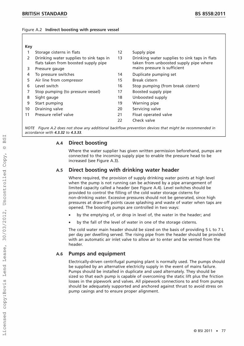
Figure A.2 Indirect boosting with pressure vessel
Key1 Storage cisterns in flats 12 Supply pipe2 Drinking water supplies to sink taps in
flats taken from boosted supply pipe13 Drinking water supplies to sink taps in flats
taken from unboosted supply pipe wheremains pressure is sufficient3 Pressure gauge
4 To pressure switches 14 Duplicate pumping set5 Air line from compressor 15 Break cistern6 Level switch 16 Stop pumping (from break cistern)7 Stop pumping (to pressure vessel) 17 Boosted supply pipe8 Sight gauge 18 Unboosted supply9 Start pumping 19 Warning pipe
10 Draining valve 20 Servicing valve11 Pressure relief valve 21 Float operated valve
22 Check valve
NOTE Figure A.2 does not show any additional backflow prevention devices that might be recommended inaccordance with 4.3.32 to 4.3.33.
A.4 Direct boostingWhere the water supplier has given written permission beforehand, pumps areconnected to the incoming supply pipe to enable the pressure head to beincreased (see Figure A.3).
A.5 Direct boosting with drinking water headerWhere required, the provision of supply drinking water points at high levelwhen the pump is not running can be achieved by a pipe arrangement oflimited capacity called a header (see Figure A.4). Level switches should beprovided to control the filling of the cold water storage cisterns fornon-drinking water. Excessive pressures should not be generated, since highpressures at draw-off points cause splashing and waste of water when taps areopened. The boosting pumps are controlled in two ways:
• by the emptying of, or drop in level of, the water in the header; and
• by the fall of the level of water in one of the storage cisterns.
The cold water main header should be sized on the basis of providing 5 L to 7 Lper day per dwelling served. The rising pipe from the header should be providedwith an automatic air inlet valve to allow air to enter and be vented from theheader.
A.6 Pumps and equipmentElectrically-driven centrifugal pumping plant is normally used. The pumps shouldbe supplied by an alternative electricity supply in the event of mains failure.Pumps should be installed in duplicate and used alternately. They should besized so that each pump is capable of overcoming the static lift plus the frictionlosses in the pipework and valves. All pipework connections to and from pumpsshould be adequately supported and anchored against thrust to avoid stress onpump casings and to ensure proper alignment.
BRITISH STANDARD BS 8558:2011
© BSI 2011 • 77
Licensed copy:Bovis Lend Lease, 30/03/2012, Uncontrolled Copy, © BSI

Transmission of pump and motor noise can be reduced by the use of flexibleconnections and anti-vibration mountings or pads. Small-power motors of thesquirrel cage induction type are suitable for most installations. Pumps and pipesshould be sized so as to minimize the risk of waterhammer from surge whenpumps are started and stopped.
A.7 Maintenance and inspectionA responsible person should oversee the proper execution of the scheme andthe owner/occupier should arrange for regular maintenance and inspection ofthe pumps and plant.
Figure A.3 Direct boosting
3
1
2
4
6
7
5 8
5
Key1 Stop pumping 5 Servicing valve2 Start pumping 6 Warning pipe3 Supply pipe 7 Cold water storage cistern4 Duplicate pumping set 8 Float operated valve
NOTE Figure A.3 does not show any additional backflow prevention devices that might be recommended inaccordance with 4.3.32 to 4.3.33.
BRITISH STANDARDBS 8558:2011
78 • © BSI 2011
Licensed copy:Bovis Lend Lease, 30/03/2012, Uncontrolled Copy, © BSI

All work and inspections carried out should be recorded in a suitable log book,which should be kept in the plant room.
Figure A.4 Direct boosting with header and duplicate storage cisterns
8
44
3
56
3
1
2
9
7
11
11 11
111212
11
10
10
Key1 Automatic air inlet valve 7 Drinking water supplies to sink taps in flats taken
from boosted supply pipe2 Upstand3 Stop pumping 8 Supply pipe4 Start pumping 9 Duplicate pumping set5 Drinking water header 10 Warning pipe6 Pipeline level switch 11 Servicing valve
12 Cold water storage cistern
NOTE 1 Figure A.4 does not show any additional backflow prevention devices that might be recommended inaccordance with 4.3.32 to 4.3.33.
NOTE 2 Warning pipe to cold water storage cistern not shown.
BRITISH STANDARD BS 8558:2011
© BSI 2011 • 79
Licensed copy:Bovis Lend Lease, 30/03/2012, Uncontrolled Copy, © BSI

NOTE Attention is drawn to the Health and Safety at Work etc. Act 1974 [6] withrespect to the inspection of pumps and plant.
Annex B(informative)
Guidance on the calculation of hot water storagecapacityThe storage capacity required to achieve an acceptable quality of servicedepends upon the rate of heat input to the stored hot water as well as on thepattern of use. The time M (in minutes) taken to heat a quantity of waterthrough a specified temperature rise is given by:
M 5�VT�
�14.3P�
where:
V is the volume of water heated (L);
T is the temperature rise (°C);
P is the rate of heat input to water (kW).
This equation ignores heat losses from the hot water storage vessel, since overthe relatively short times involved in reheating water after a draw-off has takenplace their effect is usually small.
For an electric immersion heater, a directly gas-fired storage water heater and adirect boiler system, the value of P is the output of the heating appliance.For an indirect boiler system, the value of P depends on the temperature of thestored water, since heat passes from the primary circuit to the secondary circuitat a faster rate when the secondary water is cold than when it is hot.For practical purposes a simple approximation by taking an average value for Pis usually sufficient. An indirect cylinder conforming to BS 1566-1 accepts heatinputs up to approximately 15 kW with pumped primary flow.
Typical values for P are:
• 3 kW for an electric immersion heater;
• 3 kW for a gas-fired circulator;
• 6 kW for a small boiler and direct cylinder;
• 10 kW for a medium boiler and indirect cylinder;
• 10 kW for a directly gas-fired storage water heater (domestic type); and
• 15 kW for a large domestic boiler and indirect cylinder.
The application of this equation to the sizing of hot water cylinders is bestillustrated by the following examples, in which figures have been rounded.
Examples of application:
Case 1. Small dwelling with one bath installed.
Maximum recommendation: one bath (60 L at 60 °C plus 40 L cold water)plus 10 L hot water at 60 °C for kitchen use followed by a second bath fillafter 25 min.
Therefore draw-off of 70 L at 60 °C followed after 25 min by 100 L at 40 °C isnecessary, which can be achieved by mixing hot at 60 °C with cold at 10 °C.
Assume good stratification, e.g. heating by the top-entry immersion heater.
To heat 60 L from 10 °C to 60 °C using a 3 kW input takes (60 × 50)/(14.3 × 3)= 70 min so the second bath has to be provided from storage. In 25 min thevolume of water heated to 60 °C is 14.3 × 3 × 25/50 = 21 L.
BRITISH STANDARDBS 8558:2011
80 • © BSI 2011
Licensed copy:Bovis Lend Lease, 30/03/2012, Uncontrolled Copy, © BSI

Therefore the minimum storage capacity to meet recommendationsis 70 + 60 − 21 = 109 L.
To heat 60 L from 10 °C to 60 °C using a 6 kW input takes (60 × 50)/(14.3 × 6)= 35 min so the second bath has to be provided from storage. In 25 min thevolume of water heated from 10 °C to 60 °C is 14.3 × 6 × 25/50 = 42 L.
Therefore the minimum storage capacity to meet the recommendationis 70 + 60 − 42 = 88 L.
To heat 60 L from 10 °C to 60 °C using 10 kW input takes (60 × 50)/(14.3 × 10)= 21 min so the second bath needs no storage and minimum storagerequirement to provide bath plus kitchen use, i.e. 70 L.
With 15 kW input of heat to the water, the storage volume could be reducedto 60 L since while the first bath is running, taking about 3 min, the heat inputto the water is sufficient to raise approximately 11 L water from 10 °C to 60 °C,so providing for kitchen use. This could be negated by mixing and is notrecommended for this duty.
Now assuming good mixing of the stored water, as occurs with heating by aprimary coil in an indirect cylinder, the temperature of the stored waterimmediately after the 70 L draw-off would be {60(V − 70) + (70 × 10)}/V, whichsimplifies to 60 − 3 500/V. The equation shows that heating for 25 min at 3 kWraises the temperature through 3 × 25 × 14.3/V or 1 072.5/V.
Since a water temperature of at least 40 °C is recommended to run a secondbath:
S60 − 3500
V D1 S1072.5
V D5 40 (or more)
where:
V 5 122 L
Using 6 kW heat input, the temperature rise in 25 min is 2 145/V, which gives aminimum size of 68 L. However, this does not meet the recommendationof 100 L at 40 °C for a bath. A vessel of 88 L capacity, which attains atemperature of approximately 44.5 °C after 25 min, is just sufficient, but forsimplicity a cylinder of about 100 L capacity is normally chosen.
For heat inputs of 10 kW and 15 kW, a 70 L hot water storage vessel is necessarywith the need to draw-off for bath and kitchen use dictating the minimumstorage capacity.
Therefore for case 1, the minimum sizes of storage vessel are given in Table B.1.
Table B.1 Minimum sizes of storage vessel for case 1
Heat input to water
kW
Minimum storage capacity
1With stratification With mixing
3 109 1226 88 88
10 70 7015 70 70
Case 2. A dwelling with two baths installed and having a maximumrecommendation of 130 L draw-off at 60 °C (two baths + 10 L for kitchen use)followed by a further bath (100 L at 40 °C) after 30 min.
The calculations follow the same procedures as for case 1 and the results forcase 2 are given in Table B.2.
BRITISH STANDARD BS 8558:2011
© BSI 2011 • 81
Licensed copy:Bovis Lend Lease, 30/03/2012, Uncontrolled Copy, © BSI

Table B.2 Minimum sizes of storage vessel for case 2
Heat input to water
kW
Minimum storage capacity
1With stratification With mixing
3 165 2606 140 200
10 130 13015 120 130
These calculations, which may be carried out for any particular situation,indicate the value of promoting stratification wherever possible and show theorder of savings in storage capacity that can be made without prejudice to thequality of the service to the user by increasing the heat input to the water.
BRITISH STANDARDBS 8558:2011
82 • © BSI 2011
Licensed copy:Bovis Lend Lease, 30/03/2012, Uncontrolled Copy, © BSI

BibliographyStandards publications
For dated references, only the edition cited applies. For undated references, thelatest edition of the referenced document (including any amendments) applies.
BS 1566-1, Copper indirect cylinders for domestic purposes – Part 1: Open ventedcopper cylinders – Requirements and test methods
BS 3198, Specification for copper hot water storage combination units fordomestic purposes
BS 4213, Cisterns for domestic use – Cold water storage and combined feed andexpansion (thermoplastic) cisterns up to 500 L – Specification
BS 5154, Specification for copper alloy globe, globe stop and check, check andgate valves
BS 5834-2, Surface boxes, guards and underground chambers for gas andwaterworks purposes – Part 2: Specification for small surface boxes
BS 6144, Specification for expansion vessels using an internal diaphragm, forunvented hot water supply systems
BS 6465-1, Sanitary installations – Part 1: Code of practice for the design ofsanitary facilities and scales of provision of sanitary and associated appliances
BS 6465-3, Sanitary installations – Part 3: Code of practice for the selection,installation and maintenance of sanitary and associated appliances
BS 7291 (all parts), Thermoplastics pipe and fitting systems for hot and coldwater for domestic purposes and heating installations in buildings
BS 7430, Code of practice for earthing
BS 7592, Sampling for Legionella bacteria in water systems – Code of practice
BS 7671, Requirements for electrical installations – IET Wiring Regulations –Seventeenth edition
BS 8000-15, Workmanship on building sites – Part 15: Code of practice for hotand cold water services (domestic scale)
BS 8103-3, Structural design of low-rise buildings – Part 3: Code of practice fortimber floors and roofs for housing
BS 8515, Rainwater harvesting systems – Code of practice
BS 8525-1, Greywater systems – Part 1: Code of practice
BS 8580, Water quality – Risk assessments for Legionella control – Code ofpractice
BS EN 805, Water supply – Requirements for systems and components outsidebuildings
BS EN 1057:2006, Copper and copper alloys – Seamless, round copper tubes forwater and gas in sanitary and heating applications
BS EN 1254-1, Copper and copper alloys – Plumbing fittings – Part 1: Fittingswith ends for capillary soldering or capillary brazing to copper tubes
BS EN 1254-5, Copper and copper alloys – Plumbing fittings – Part 5: Fittingswith short ends for capillary brazing to copper tubes
BS EN 1995-1-1, Eurocode 5 – Design of timber structures – Part 1-1: General –Common rules and rules for buildings
BS EN 10312, Welded stainless steel tubes for the conveyance of aqueous liquidsincluding water for human consumption – Technical delivery conditions
BRITISH STANDARD BS 8558:2011
© BSI 2011 • 83
Licensed copy:Bovis Lend Lease, 30/03/2012, Uncontrolled Copy, © BSI

BS EN 12201-2, Plastic piping systems for water supply – Polyethylene (PE) –Part 2: Pipes
BS EN 12671, Chemicals used for treatment of water intended for humanconsumption – Chlorine dioxide generated in situ
BS EN 12828, Heating systems in buildings – Design for water-based heatingsystems
BS EN 14336, Heating systems in buildings – Installation and commissioning ofwater based heating systems
BS EN ISO 5667-3, Water quality – Sampling – Part 3: Guidance on thepreservation and handling of samples
BS EN ISO 6509, Corrosion of metals and alloys – Determination ofdezincification resistance of brass
BS EN ISO 15875 (all parts), Plastics piping systems for hot and cold waterinstallations – Crosslinked polyethylene (PE-X)
BS EN ISO 15876 (all parts), Plastics piping systems for hot and cold waterinstallations – Polybutylene (PB)
BS EN ISO 19458, Water quality – Sampling for microbiological analysis
BS EN ISO 21003-3, Multilayer piping systems for hot and cold water installationsinside buildings – Part 3: Fittings
Other publications
[1] GREAT BRITAIN. The Workplace (Health, Safety and Welfare)Regulations 1992. London: The Stationery Office.
[2] GREAT BRITAIN. The Water Supply (Water Quality) Regulations 2010,as amended. London: The Stationery Office.
[3] GREAT BRITAIN. The Electricity Safety, Quality and ContinuityRegulations 2002, as amended. London: The Stationery Office.
[4] GREAT BRITAIN. The Control of Asbestos at Work Regulations 2002. London:The Stationery Office.
[5] GREAT BRITAIN. The Water Industry Act 1999. London: The Stationery Office.
[6] GREAT BRITAIN. The Health and Safety at Work etc. Act 1974. London:The Stationery Office.
[7] GREAT BRITAIN. The Water Supply (Water Fittings) Regulations 1999.London: The Stationery Office.
SCOTTISH WATER. The Water Byelaws (Scotland). Edinburgh, 2004.
NORTHERN IRELAND. The Water Supply (Water Fittings) Regulations(Northern Ireland) 2009. London: The Stationery Office.
[8] GREAT BRITAIN. The Building Regulations (England and Wales) 2010.London: The Stationery Office.
SCOTLAND. The Building (Scotland) Regulations 2004, as amended.Edinburgh: The Stationery Office.
NORTHERN IRELAND. The Building Regulations (Northern Ireland) 2000,as amended. Dublin: The Stationery Office.
[9] WRAS. Water Regulations Guide. Newport, 2001. ISBN 0-95339708-0-9.
[10] COMMUNITIES AND LOCAL GOVERNMENT. Approved Document G:Sanitation, hot water safety and water efficiency. London: 2010.ISBN 9781859463239.
BRITISH STANDARDBS 8558:2011
84 • © BSI 2011
Licensed copy:Bovis Lend Lease, 30/03/2012, Uncontrolled Copy, © BSI
[11] COMMUNITIES AND LOCAL GOVERNMENT. Approved Document J:Combustion appliances and Fuel Storage systems. London: 2010.ISBN 9781859463710.
[12] COMMUNITIES AND LOCAL GOVERNMENT. Approved Documents L:
Approved Document L1A: Conservation of fuel and power (New dwellings).London: 2010. ISBN 9781859463246.
Approved Document L1B: Conservation of fuel and power(Existing dwellings). London: 2010. ISBN 9781859463253.
Approved Document L2A: Conservation of fuel and power (New buildingsother than dwellings). London: 2010. ISBN 9781859463260.
Approved Document L2B: Conservation of fuel and power (Existing buildingsother than dwellings). London: 2010. ISBN 9781859463277.
RIBA. Domestic Building Services Compliance Guide. London: RIBApublishing, 2010. ISBN 9781859463772.
RIBA. Non-Domestic Building Services Compliance Guide. London: RIBApublishing, 2010. ISBN 9781859463765.
[13] COMMUNITIES AND LOCAL GOVERNMENT. Approved Document P: Electricalsafety – dwellings. London: 2006. ISBN 9781859462256.
[14] CIBSE. TM13: Minimising the risk of Legionnaires’ Disease. London, 2002.ISBN 1903287235.
[15] DEPARTMENT OF HEALTH ESTATES AND FACILITIES DIVISION. HTM 04-01:The control of Legionella, hygiene, 9safe9 hot water, cold water and drinkingwater systems. Space for Health, 2006.
[16] SCOTLAND. Scottish Building Standards Technical Handbooks. Edinburgh:The Stationery Office, 2010.
[17] UK WATER INDUSTRY RESEARCH Ltd (UKWIR). Guidance for the Selection ofWater Supply Pipes to be used in Brownfield Sites. London: 2010.ISBN 1840575697.
[18] WRAS. No 9-07-01, Information for Installation of Ion Exchange WaterSofteners for Systems Supplying Water for Domestic Purposes, 2007.http://www.wras.co.uk/PDF_Files/IGN9-07-01.pdf
[19] DUER M. Passive Mixing Systems Improve Storage Tank Water Quality.Denver: AWWA, 2011.
[20] ROBERTS P.J.W, TIAN X., SOTIROPOULOS F and DUER M. Physical Modellingof Mixing in Water Storage Tanks. Denver: AWWA, 2007.
[21] WRAS. No 9-04-04, Cold Water Storage Cisterns – Design Recommendationsfor Mains Supply Inlets, 2003.http://www.wras.co.uk/PDF_Files/IGN%209-04-04%20Cisterns.pdf
[22] HEALTH AND SAFETY EXECUTIVE. HSG 220, Health and Safety in CareHomes. Sudbury: 2001. ISBN 9780717620821.
[23] WRAS. No 9-02-05, Marking & Identification of Pipework for Water ReuseSystems, 2011.http://www.wras.co.uk/PDF_Files/IGN%209.02.05%20version%203%20Sept%202011.pdf
[24] WRAS. No 9-04-05, Report of the Expert Group on the Risk ofContamination of the Public Water Supply by Backflow, 2004.http://www.wras.co.uk/PDF_Files/IGN%209-04-05%20Backflow%20Report.pdf
[25] CIPHE. Plumbing engineering services design guide. Hornchurch: 2002.ISBN 1871956404.
BRITISH STANDARD BS 8558:2011
© BSI 2011 • 85
Licensed copy:Bovis Lend Lease, 30/03/2012, Uncontrolled Copy, © BSI

[26] DRINKING WATER INSPECTORATE. List of Approved Products for use inPublic Water Supply in the United Kingdom. London: 2011. www.dwi.gov.uk
[27] WRAS. Water fittings and materials directory.http://www.wras.co.uk/Directory/
[28] WHO. Water safety in buildings. Geneva: 2011. ISBN 9789241548106.
BRITISH STANDARDBS 8558:2011
86 • © BSI 2011
Licensed copy:Bovis Lend Lease, 30/03/2012, Uncontrolled Copy, © BSI

This page deliberately left blankLicensed copy:Bovis Lend Lease, 30/03/2012, Uncontrolled Copy, © BSI
BSI is the independent national body responsible for preparing British Standardsand other standards-related publications, information and services. It presents the UK view on standards in Europe and at the international level.
It is incorporated by Royal Charter.
British Standards Institution (BSI)
raising standards worldwide™
BSI Group Headquarters
389 Chiswick High Road London W4 4AL UK
Tel +44 (0)20 8996 9001Fax +44 (0)20 8996 7001www.bsigroup.com/standards
RevisionsBritish Standards are updated by amendment or revision. Users of British Stan-dards should make sure that they possess the latest amendments or editions.
It is the constant aim of BSI to improve the quality of our products and serv-ices. We would be grateful if anyone finding an inaccuracy or ambiguity whileusing this British Standard would inform the Secretary of the technical com-mittee responsible, the identity of which can be found on the inside frontcover.
Tel: +44 (0)20 8996 9001 Fax: +44 (0)20 8996 7001
BSI offers Members an individual updating service called PLUS which ensuresthat subscribers automatically receive the latest editions of standards.
Tel: +44 (0)20 8996 7669 Fax: +44 (0)20 8996 7001Email: [email protected]
Buying standardsYou may buy PDF and hard copy versions of standards directly using acredit card from the BSI Shop on the website www.bsigroup.com/shop.In addition all orders for BSI, international and foreign standards publicationscan be addressed to BSI Customer Services.
Tel: +44 (0)20 8996 9001 Fax: +44 (0)20 8996 7001Email: [email protected]
In response to orders for international standards, it is BSI policy tosupply the BSI implementation of those that have been publishedas British Standards, unless otherwise requested.
Information on standardsBSI provides a wide range of information on national, Europeanand international standards through its Knowledge Centre.
Tel: +44 (0)20 8996 7004 Fax: +44 (0)20 8996 7005Email: [email protected]
Various BSI electronic information services are also available whichgive details on all its products and services.
Tel: +44 (0)20 8996 7111 Fax: +44 (0)20 8996 7048Email: [email protected]
BSI Subscribing Members are kept up to date with standardsdevelopments and receive substantial discounts on the purchase priceof standards. For details of these and other benefits contact Membership Ad-ministration.
Tel: +44 (0)20 8996 7002 Fax: +44 (0)20 8996 7001 Email: [email protected]
Information regarding online access to British Standards via BritishStandards Online can be found at www.bsigroup.com/BSOLFurther information about BSI is available on the BSI website at www.bsi-group.com/standards
CopyrightCopyright subsists in all BSI publications. BSI also holds the copyright,in the UK, of the publications of the international standardization bodies. Ex-cept as permitted under the Copyright, Designs and Patents Act 1988 no ex-tract may be reproduced, stored in a retrieval system or transmitted in anyform or by any means – electronic, photocopying, recording or otherwise –without prior written permission from BSI. This does not preclude the freeuse, in the course of implementing the standard of necessary details such assymbols, and size, type or grade designations. If these details are to be usedfor any other purpose than implementation then the prior written permissionof BSI must be obtained. Details and advice can be obtained from the Copy-right & Licensing Manager.
Tel: +44 (0)20 8996 7070Email: [email protected]
Licensed copy:Bovis Lend Lease, 30/03/2012, Uncontrolled Copy, © BSI