BO17E-XX Bachelormal - HVL Open
57
Railway Safety Mathias Ringkjøb Olsen Matias Vikane HEAU17 30. May. 2019
-
Upload
khangminh22 -
Category
Documents
-
view
3 -
download
0
Transcript of BO17E-XX Bachelormal - HVL Open

Railway Safety
Mathias Ringkjøb Olsen
Matias Vikane
HEAU17
30. May. 2019

Document control
Title of the rapport:
Railway Safety Date/Version
30. May. 2019/1.00 Rapport number:
B019-E01 Authors:
Mathias Ringkjøb Olsen Matias Vikane
Field of study:
HEAU17 Number of pages w/ attachments:
57 Supervisor at the University:
Geir Omar Berland Gradation: Open
Remarks:
The rapport can be published
Client: ABB Control & Safety, Kokstad
Clients Reference:
Clients contact: Ahmed Elgaby ([email protected]) Srinivasa Cheerla ([email protected])
Revision Date Status Carried out by
0.11 20.04.19 First draft Mathias Ringkjøb Olsen
0.12 25.04.19 Added chapter Matias Vikane
0.13 29.04.19 Added chapter Matias Vikane
0.14 20.05.19 Corrected order Mathias Ringkjøb Olsen
0.15 22.05.19 Inserted photos and corrected order Mathias Vikane
0.16 27.05.19 Read trough and corrected chapters and order Mathias Ringkjøb Olsen Matias Vikane
0.17 29.05.19 Changed screenshots of Arduino code Matias Vikane
1.00 30.0.19 Final report Matias Ringkjøb Olsen Matias Vikane

BO19E-01 Railway Safety
Rev: 1.00 side 3 av 57 30. mai. 2019
Foreword
This rapport is a result of our bachelor thesis, which we are writing as a final part of our bachelor study during the spring of 2019. The bachelor thesis is part of a 2-year study of Control Systems at the Western Norway University of Applied Science. The purpose of the thesis is that we as students should learn how to carry out a project, as well as gain knowledge in working as project group.
The history of the project is that we are two students which in September 2018 created the project group. We immediately started the search for a possible client and a relevant thesis. October 2018, we were offered a thesis by ABB Control & Safety. The task was to use ABB’s control systems to program a safety system for a typical railway station. The system will perform safety checks and take appropriate control actions in critical / dangerous situations. We also had to create an HMI display for operators to view and operate the different railway lines in a central control room. Through the project we want to gain new knowledge, as well as gain a broader experience of working as a project group towards a common goal.
The report will address all the necessary information regarding the task.
The project group wish to thank all parties who have helped with the guidance and support during the project. In particular, we would like to mention:
- Ahmed Elgaby, Project Manager – ABB Control & Safety
- Srinivasa Cheerla, cient contact – ABB Control & Safety
- Geir Omar Berland, supervisor - Western Norway University of Applied Science
Bergen 30.05.19
__________________________ ____________________________
Mathias Ringkjøb Olsen Matias Vikane Group Lead Group Member

BO19E-01 Railway Safety
Rev: 1.00 side 4 av 57 30. mai. 2019
Summary This report is written to answer the problem "Making a railway safety system using ABB 800xA and
AC800M”. The report describes all the hardware and software used, the application, associated control
modules, testing and procedures, as well as standards and protocols that have been used for the
project.
The purpose of the project was to create a model that can be showcased on stands such as
“Karrieredagen”. We built a model using model trains and programmed the safety system with ABB
system 800xA. For translating the signals from the ABB AC800M modules to the model trains we used
Arduino microcontrollers and a DCC++ software. Finally, we created an interface for the operators to
control the trains, track switches and railway crossings.
We have carried out the project according to ABB's model for project work. This model is designed to
ensure that all necessary phases of the project are carried out according to customer needs. This helps
to maintain a structured standard of all the projects. The model is designed to first collect the necessary
information for the project, then prepare the necessary documentation, and finally test the product.

BO19E-01 Railway Safety
Rev: 1.00 side 5 av 57 30. mai. 2019
1 Table of contents Document control ................................................................................................................................... 2
Foreword ................................................................................................................................................. 3
Summary ................................................................................................................................................. 4
1 Introduction ..................................................................................................................................... 9
2 Information retrieval and implementation ................................................................................... 10
2.1 Information retrieval ............................................................................................................. 10
2.2 Implementation model .......................................................................................................... 11
2.2.1 Design Basis ............................................................................................................... 11
2.2.2 Basic Design ............................................................................................................... 11
2.2.3 Detail Design .............................................................................................................. 11
2.2.4 Fabrication ................................................................................................................. 11
2.2.5 Testing ....................................................................................................................... 11
3 Terms and abbreviations ............................................................................................................... 12
4 Main ............................................................................................................................................... 13
4.1 Client ...................................................................................................................................... 13
4.2 Module description ............................................................................................................... 13
4.3 System architecture............................................................................................................... 13
4.4 Scope ..................................................................................................................................... 13
4.5 HSE ......................................................................................................................................... 14
4.6 Risk assessment ..................................................................................................................... 14
4.7 Economy ................................................................................................................................ 14
4.8 Data storage .......................................................................................................................... 14
4.9 Time spent ............................................................................................................................. 14
4.10 Logging .................................................................................................................................. 15
5 Analysis of the task ........................................................................................................................ 15
5.1 Design for possible solutions ................................................................................................. 15
5.1.1 Solution/Proposal 1 ................................................................................................... 15
5.1.2 Solution/Proposal 2 ................................................................................................... 15
5.2 Decision ................................................................................................................................. 16
6 System requirements .................................................................................................................... 17
6.1 Software ................................................................................................................................ 17
6.2 User interface / Human Machine Interface .......................................................................... 17
6.3 Model train system................................................................................................................ 18

BO19E-01 Railway Safety
Rev: 1.00 side 6 av 57 30. mai. 2019
7 System Description / Network topology ....................................................................................... 19
7.1 Typical 800xA system ............................................................................................................ 19
7.2 Safety system for our model ................................................................................................. 19
7.3 Key elements of 800xA .......................................................................................................... 20
7.3.1 Domain server ........................................................................................................... 20
7.3.2 Aspect server ............................................................................................................. 20
7.3.3 Connectivity server .................................................................................................... 20
7.3.4 Application server ...................................................................................................... 20
8 Hardware ....................................................................................................................................... 21
8.1 ABB AC800 HW ...................................................................................................................... 21
8.2 Optical ModuleBus ................................................................................................................ 22
8.3 S800 I/O modules .................................................................................................................. 22
8.4 ARDUINO UNO and MEGA REV3 ........................................................................................... 23
8.5 ARDUINO MOTOR SHIELD REV3 ............................................................................................ 23
9 Software ........................................................................................................................................ 24
9.1 ABB 800xA ............................................................................................................................. 24
9.1.1 The structures ............................................................................................................ 25
9.1.2 Control Structure ....................................................................................................... 25
9.1.3 Functional Structure .................................................................................................. 25
9.1.4 Library Structure ........................................................................................................ 25
9.1.5 Workplace Structure ................................................................................................. 25
9.1.6 Service Structure ....................................................................................................... 25
9.2 ABB Control Builder M........................................................................................................... 25
9.3 DCC++ .................................................................................................................................... 26
10 OSI-model .................................................................................................................................. 27
11 Protocols and standards ............................................................................................................ 28
11.1 OPC-standard ........................................................................................................................ 28
11.2 MMS-protocol ....................................................................................................................... 28
12 Building model ........................................................................................................................... 29
12.1 S800 I/O modules .................................................................................................................. 29
12.2 Arduino and motorshield ...................................................................................................... 29
12.3 Reed relay .............................................................................................................................. 29
12.4 Switch servos ......................................................................................................................... 30
12.5 Crossing and Lights ................................................................................................................ 31

BO19E-01 Railway Safety
Rev: 1.00 side 7 av 57 30. mai. 2019
12.6 Circuit board .......................................................................................................................... 32
12.7 Track ...................................................................................................................................... 33
12.8 Table ...................................................................................................................................... 33
13 Application design ..................................................................................................................... 34
13.1 Control Modules .................................................................................................................... 34
13.2 Data types .............................................................................................................................. 34
13.2.1 Switch Signals: ........................................................................................................... 34
13.2.2 Train data: ................................................................................................................. 34
13.2.3 Train I / O: .................................................................................................................. 34
13.3 Description of all sub-safety systems: ................................................................................... 35
13.3.1 Position monitoring: .................................................................................................. 35
13.3.2 Train control module: ................................................................................................ 35
13.3.3 Anti-collision system: ................................................................................................ 36
13.3.4 Track switch safety system: ....................................................................................... 37
13.3.5 Speed limiting safety system: .................................................................................... 37
13.3.6 Next Position detection system:................................................................................ 38
13.4 Application design in the Control Builder ............................................................................. 39
13.5 Railway crossing system ........................................................................................................ 41
13.6 OPC Server ............................................................................................................................. 41
13.7 Arduino code ......................................................................................................................... 42
13.7.1 Definitions of variables and library’s ......................................................................... 42
13.7.2 Setup .......................................................................................................................... 43
13.7.3 Train control .............................................................................................................. 43
13.7.4 Servo control ............................................................................................................. 45
13.7.5 Main void ................................................................................................................... 45
13.8 HMI design ............................................................................................................................. 46
13.8.1 Alarm list .................................................................................................................... 47
14 Finished model .......................................................................................................................... 48
15 Testing ....................................................................................................................................... 49
16 Discussion .................................................................................................................................. 50
16.1 The project and time consumption ....................................................................................... 50
16.2 Our solution ........................................................................................................................... 50
16.3 Other solutions / suggestions for improvement ................................................................... 50
16.4 Problems we have encountered along the way .................................................................... 51

BO19E-01 Railway Safety
Rev: 1.00 side 8 av 57 30. mai. 2019
16.4.1 Motor shield .............................................................................................................. 51
16.4.2 Voltage drop from servos .......................................................................................... 51
17 Conclusion ................................................................................................................................. 52
References ............................................................................................................................................. 53
Appendiks A Project management ................................................................................................. 54
A.1 Project organization chart ..................................................................................................... 54
A.2 Project model ........................................................................................................................ 54
A.3 Project schedule .................................................................................................................... 55
A.4 Risk ........................................................................................................................................ 55
Appendiks B User documentation .................................................................................................. 56
Appendiks C Code ........................................................................................................................... 57
BO19E-01 Railway Safety
Rev: 1.00 side 9 av 57 30. mai. 2019
1 Introduction
The project report will present a solution to the problem of the bachelor thesis at the Western Norway
University of Applied Sciences. The purpose of the thesis is that we, as students, must acquire
knowledge about performing a project together in a group. The problem is given by ABB Control &
Safety. ABB wants to create a railway safety system using their 800xA system.
In order to solve the problem most effectively, the project group divide the tasks between them.
Everyone in the project group will attend 10-day courses at ABB in Bergen to familiarize themselves
with protocols, software and hardware that will be used. In this way, we hope to get an overview of
the issues that await us.
In later chapters, we will describe the steps we will take, how we acquire the necessary relevant
information and how we will perform the task together. In the main part of the report, we will describe
the specifications and other details that are relevant to the task. Examples of this are the description
of hardware, software, protocols, standards, test procedures and application designs.

BO19E-01 Railway Safety
Rev: 1.00 side 10 av 57 30. mai. 2019
2 Information retrieval and implementation This chapter describes the proses of information retrieval and implementation
2.1 Information retrieval As part of this project, it has been necessary to obtain information and acquire knowledge about the
relevant topics that have been linked to the task. Essentially, we have acquired a lot of information
about hardware and software through an interactive course run by ABB, but it has also been necessary
to acquire a number of standards externally. In addition to this, it has also been necessary to obtain
information in the form of guidance from contact persons internally in ABB. There has also been a
requirement to familiarize ourselves with methods ABB uses in connection with project work. In other
words, we have acquired knowledge about computer programs and methods that ABB uses.
The main software that has been used is:
• ABB's system 800xA.
• Microsoft Office.
• Dropbox, document storage cloud service.
Overview of how we obtained information:
• Use ABB's implementation model for project work.
• Completed courses in ABB's system 800xA and AC800M, as well as training in the program
Control Builder.
• Meetings with our supervisor in ABB: Ahmed ElGaby.
• Email connection with Ahmed ElGaby and Marcus Stenhjem.
• Obtained technical documentation for current software and hardware through supervisor in
ABB.
• Obtained technical information on network protocol MMS from the Internet and supervisor in
ABB.
We have considered the reliability of the material we have acquired from ABB as high. The reason for
this assessment is the fact that all information is obtained directly from ABB, which owns the material
in question. Information beyond this we have had to download from the internet. Here, we have been
careful to control the origin of the information in question before it has been used. We can therefore
conclude that the reliability of the external information is rated as good.

BO19E-01 Railway Safety
Rev: 1.00 side 11 av 57 30. mai. 2019
2.2 Implementation model This chapter deals with the implementation model that we have followed in the project. The model
has been prepared by ABB to ensure that all necessary phases of the project are carried out according
to customer needs. The model has been prepared by ABB to ensure that the customer's needs are met.
2.2.1 Design Basis
Design Basis deals with the actual start-up. During this phase, the customer (ABB) provided all relevant
documentation and requirements that were asked for the project and task. In collaboration with the
supervisor, the project group and ABB went together for a review of the implementation model, HSE,
progress plan and a briefing so that everyone was made aware of the task and the scope around.
2.2.2 Basic Design
This was during the period when the group made a preliminary study of the problem. We then
submitted proposals to ABB with different solutions, as well as project plan and overview of documents
that were to be delivered.
2.2.3 Detail Design
Here, all documentation and documentation for the project is produced and acquired. Several
suggestions were made for how the program should look, in addition we prepared drafts for HMI
design. We consulted with our supervisor to obtain an oral approval that what we had prepared was
according to what the customer had envisaged.
2.2.4 Fabrication
Here we started the actual development of the chosen solution. In this phase we programmed the
code for the railway system, as well as the HMI. We also built the model.
2.2.5 Testing
In the test phase, the group performs a functional test according to our specifications.

BO19E-01 Railway Safety
Rev: 1.00 side 12 av 57 30. mai. 2019
3 Terms and abbreviations
Abbreviations Description
800xA ABB's configuration software
AC800M A hardware device that includes processor units, communication interfaces,
and other associated equipment that can be configured using a controller
AC800M Controller A controller configured in the AC800M series
CPU Central Processor Unit
DCC A protocol used to operate DCC equipped model trains
Ethernet A computer network technology commonly used in local area networks
(LAN)
Faceplate HMI interface for each object in the system
FAT Factory Acceptance Test
HMI Human Machine Interface
HSE Health, Safety and Environment
HW Hardware
I/O Input / output modules connected to the processor controller
ICSP In-circuit serial programming
MMS Manufacturing Message Specification
OLE Object Linking and Embedding
OPC OLE for process control
PC Personal Computer
PLC Programmable Logic Controller
PWM Pulse-Width Modulation
S800 I/O Compact 800 I/O System
SCM Single Control Module
SW Software

BO19E-01 Railway Safety
Rev: 1.00 side 13 av 57 30. mai. 2019
4 Main
4.1 Client
“ABB in Norway is part of the worldwide ABB group, which is headquartered in Switzerland. ABB has
operations all over the country with approx. 2100 employees and an annual turnover of around NOK
8.5 billion in 2018.
ABB is a pioneer in cutting-edge technologies and works closely with our customers in energy supply,
industry and transport and infrastructure in around 100 countries. With over 40 years in the
forefront of digital technology development, we are a leader in digitally connected industrial
equipment and systems, with over 70 million units connected through an installed base of more than
70,000 control systems. ABB technology, products and systems are in use worldwide.”
(New.abb.com, 2019)
4.2 Module description
The system will consist of these modules:
• PC with ABB system 800xA installed
• ABB AC800M PM864 controller
• ABB AC800M TB820 Optic modem
• ABB AC800M S800 I/O cards
• Arduino UNO microcontroller
• Arduino MEGA microcontroller
• Arduino Motorshield
4.3 System architecture
The solution will be based on ABB system 800xA.
4.4 Scope
In collaboration with ABB, the project has decided to follow ABB's implementation model
for use during project work. The model consists of five parts:
- Design Basis
- Basic Design
- Detail design
- Fabrication
- Testing
A more detailed description of the different phases is described in chapter 2.2

BO19E-01 Railway Safety
Rev: 1.00 side 14 av 57 30. mai. 2019
4.5 HSE
“ABB works to create a safe and healthy working environment in all of our business
locations. By minimizing or as far as possible removing sources of danger in the working
environment, we will prevent work-related accidents, health injuries and illness.
HSE should be integrated into everything we do, and leadership at all levels should be based
on behavior being a key factor. ABB has a philosophy of zero harm to people, the
environment and material values based on the conviction that all injuries can be prevented
with systematic and targeted HSE work.
ABB works to ensure that all activities are based on and controlled by risk assessments.”
(New.abb.com, 2019)
4.6 Risk assessment
The risk for the project has been limited. The group members have followed FSE throughout
the project and we’ve never worked on the electrical system while powered up. The system
we work on is completely separate from everything else, and therefore cannot have an impact
on other systems around.
HSE has been one of our main focuses throughout the project, and we’ve made risk
assessments along the way. Personal protective equipment has been used when necessary.
4.7 Economy
ABB has financed the project. At the start of the project we made plans on how the model
should be and what we need in order to build it. We made estimates and applied for funding.
The first budget was approved, and we ordered most of the parts we needed. Later in the
project we had to order more parts for the model. We needed more reed relays, some power
supply’s, a new Arduino mega and some tracks. This was a bit harder to get funded, but we
made a video showing our progress and described our model. This was shown to management
and we later got our funding. At the end of the project ABB is the owner of the model.
4.8 Data storage
The group has created a project folder on Dropbox as a communication channel for sharing
and storage of work and documentation produced and obtained in the project. The project
folder has been made available the group members and the supervisors, both at the university
and at ABB.
4.9 Time spent
At the start of the project, we estimated a total number of hours for the members to be 600
hours. ABB told us that it would take a lot of time. Only the training course in ABB's systems
took about 75 hours per group member. It was estimated that each group member would
spend around 300 hours. When we look at our timesheets today and summarize together, we
see that we have spent 500 hours. We have therefore spent 100 hours less than first estimated.
This is due to less time spent on programming than originally estimated.

BO19E-01 Railway Safety
Rev: 1.00 side 15 av 57 30. mai. 2019
4.10 Logging
Through the project, we have logged all the work we have done. Each group member has had
their personal log where they have written their own work.
5 Analysis of the task Based on the system requirements we will do a trough analysis on how the system will perform.
5.1 Design for possible solutions We were given two possible ways to do this task, here are the options.
5.1.1 Solution/Proposal 1
Using a train simulator software to interact with System 800xA by OPC. This idea is based on a train simulator software and finding a way to interact with this software using OPC.
We will control the simulator using the 800xA OPC server, and ABB controllers will perform monitoring of the railway system, perform continuous safety analysis, and control actions whenever required. Also, the status will be available on HMI displays to the operators in a central control room.
For this proposal, we will have to find a train simulator software that is realistic, and can simulate a complete railway system (several trains, railway crossing gates and signals, etc.) which are controllable. Also, we have to find a way to interact with the software using OPC.
5.1.2 Solution/Proposal 2
Using a physical railway model with remote controlled trains, railway crossing gates and signals which will be controlled directly by the input / output modules of a controller.
We will have to find suitable remote-controlled trains, preferably with variable speeds. We will make a link between the different trains and the ABB IO modules so that the controller can take control of the trains. We will also have to design railway crossings and signal lights that will be installed on the railway system (using stepped motors and LEDs).
The whole system will be controlled from an HMI display simulating the drivers control system. The whole railway system with various trains will be monitored by the controller, which also controls the auxiliary services (crossings, lights, etc.).
A main HMI display for the central control room will be created which monitors the status of all
trains, generates

BO19E-01 Railway Safety
Rev: 1.00 side 16 av 57 30. mai. 2019
5.2 Decision
We decided to go ahead with solution 2. This is because we wanted to work with something physical
in addition to the programming. Furthermore, we wanted to incorporate microcontrollers as we
believe this would give us a great learning outcome. ABB also wanted to go ahead with this solution,
since they then later can show the model at business booths etc. to showcase their products.
In addition, there was a lack of expertise within OPC. We therefore predicted that we would not have
enough time to meet the listed requirements if we had to familiarize ourselves with OPC without
guidance or access to the right expertise.

BO19E-01 Railway Safety
Rev: 1.00 side 17 av 57 30. mai. 2019
6 System requirements
The system requirements are defined in partnership with project manager in ABB, Ahmed Elgaby.
A comprehensive system will be created where we build a railway model and simulates all
critical/dangerous situations that can take place in the real world. The final solution must meet the
requirements presented in subsection 6.1-6.3
6.1 Software
We have used both ABB software provided by ABB, and Arduino software, which is free on the internet.
Nr Description
1 Safety system that prevents critical/dangerous situations
2 Possibility to turn safety system on and off
3 Control of track switches
4 PLC and microcontrollers that communicate to operate model trains
5 Condition monitoring of subsystems
6 Control of Light signal system
7 Manual driving mode allowing user to operate trains and track switches and lights
8 Autonomous driving that drives the trains (only one direction)
9 Safety system will stop all dangerous situations, some situations may require manual driving to return to normal driving mode
10 Structured and descriptive code that is easily understood
After we got into the project, we prioritized the requirements that was most relevant to the task.
This resulted in us not making an autonomous driving mode for the trains.
6.2 User interface / Human Machine Interface
Nr Description
1 HMI screen with overview and control of the system
2 Alarm for dangerous situations and errors
3 Intuitive interface
4 Alarm list history
All requirements are met in the model system

BO19E-01 Railway Safety
Rev: 1.00 side 18 av 57 30. mai. 2019
6.3 Model train system
Nr Description
1 Model train system that simulates normal train station
2 Possibility of dangerous situations
3 Multiple automated track switches controlled by servos
4 Two trains can run at same track in different speed and direction
5 Light system for regulating train traffic and road crossing
All requirements are met in the finished model.
The lights are limited to the crossing.

BO19E-01 Railway Safety
Rev: 1.00 side 19 av 57 30. mai. 2019
7 System Description / Network topology In this chapter, we look at how a typical 800xA system is built up, and how the different components
work and are linked together.
7.1 Typical 800xA system ABB 800xA is a system made up of computers and other devices that communicate with each other
through different types of communication networks. Here is a typical illustration of this:
800xA is divided into several networks. At the top is the client / server network where all servers and
clients communicate. Below this is the control network that connects all controllers in the system. The
controllers can therefore send information between them without having to go through a server.
Between the networks there is a Connectivity Server that handles the data between these two
networks. Data sent from controllers to servers or clients is processed by this server. This can be, for
example, data to show a value of HMI. Instructions from the server or operator are also processed
here to be routed to the proper controller.
7.2 Safety system for our model The safety system for our model consist of one AC800M PM864 controller with associated units. The
controller is connected to the control network, which is an Ethernet that communicates via MMS
(Manufacturing Message Specification) to the Connectivity Server. The I / O cards are connected to the
controller via Optical ModuleBus. The optical signals from and to the controller are transmitted and
received via an Optical Cluster Modem. The remote I/O consist of 1 card for analog outputs, 1 card for
digital outputs and 2 cards for digital inputs.

BO19E-01 Railway Safety
Rev: 1.00 side 20 av 57 30. mai. 2019
7.3 Key elements of 800xA
7.3.1 Domain server
This manages which components are sent to which data. It also handles login information and manages
user accounts. When using a domain server, the user can log in with their account on all clients in the
system as the account is centralized on a server. The domain server also has an overview of what rights
each user has and what changes they are allowed to make in the system.
7.3.2 Aspect server
In the aspect server, all information for the system is stored. All objects in the system are associated
with several aspects with relevant information about the various components. This can be data sheets,
alarm lists, user manuals, pictures or other relevant info. HMI images and Faceplates are also here. The
operators can access each object in the system to access such information from here.
7.3.3 Connectivity server
This handles data between the client / server network and the control network. Data to be sent from
controllers to servers or clients is processed by this server. Instructions to controllers from the server
or operator are also processed in this server and then forwarded to the proper controller.
7.3.4 Application server
This is used to run various applications the system needs to run.

BO19E-01 Railway Safety
Rev: 1.00 side 21 av 57 30. mai. 2019
8 Hardware This chapter describes the hardware used in our system.
8.1 ABB AC800 HW
The AC800M controller is a programmable automation controller, designed to achieve high availability
for control applications in the process industry.
The benefits are:
• Full modularity and flexibility for all environments for future expansion of control
applications
• Compact Control Builder software offers a wide range of powerful control solutions and
reusable libraries for efficient configuration
• Robust design and redundancy options in all critical areas of the controller and its
components eliminates single-point failures and secures maximum availability
• Supports a broad range of I/O products that can be integrated into a spectrum of industrial
processing applications

BO19E-01 Railway Safety
Rev: 1.00 side 22 av 57 30. mai. 2019
8.2 Optical ModuleBus
TB840 / TB840A ModuleBus Modem is an Optical ModuleBus with
fiber optic interface. This is used to create communication between
a controller and local I / O cluster. The module has an electrical and
an optical interface. The optical is used for communication with the
controller, and the electrical is used for communication with the
I / O cards.
8.3 S800 I/O modules S800 I/O is a comprehensive, distributed and modular process I/O system that communicates with
parent controllers over industry-standard field buses. Thanks to its broad connectivity it fits a wide
range of process controllers from ABB and others.
S800 I/O features include:
• Comprehensive coverage
• Flexible configuration and installation
• Ease of set up
• Reliability and accuracy
• HART pass-through
• Redundancy also on I/O module level
• High Integrity I/O modules certified to SIL3
• High accuracy time tagging
• Defined outputs at communication errors
• I/O modules with Intrinsic Safety interfaces
(New.abb.com, 2019)
BO19E-01 Railway Safety
Rev: 1.00 side 23 av 57 30. mai. 2019
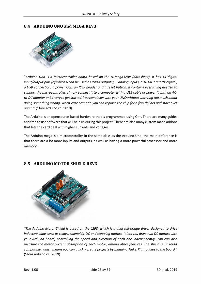
8.4 ARDUINO UNO and MEGA REV3
“Arduino Uno is a microcontroller board based on the ATmega328P (datasheet). It has 14 digital
input/output pins (of which 6 can be used as PWM outputs), 6 analog inputs, a 16 MHz quartz crystal,
a USB connection, a power jack, an ICSP header and a reset button. It contains everything needed to
support the microcontroller; simply connect it to a computer with a USB cable or power it with an AC-
to-DC adapter or battery to get started. You can tinker with your UNO without worrying too much about
doing something wrong, worst case scenario you can replace the chip for a few dollars and start over
again.” (Store.arduino.cc, 2019)
The Arduino is an opensource-based hardware that is programmed using C++. There are many guides
and free to use software that will help us during this project. There are also many custom made addons
that lets the card deal with higher currents and voltages.
The Arduino mega is a microcontroller in the same class as the Arduino Uno, the main difference is
that there are a lot more inputs and outputs, as well as having a more powerful processor and more
memory.
8.5 ARDUINO MOTOR SHIELD REV3
“The Arduino Motor Shield is based on the L298, which is a dual full-bridge driver designed to drive
inductive loads such as relays, solenoids, DC and stepping motors. It lets you drive two DC motors with
your Arduino board, controlling the speed and direction of each one independently. You can also
measure the motor current absorption of each motor, among other features. The shield is TinkerKit
compatible, which means you can quickly create projects by plugging TinkerKit modules to the board.”
(Store.arduino.cc, 2019)

BO19E-01 Railway Safety
Rev: 1.00 side 24 av 57 30. mai. 2019
9 Software
9.1 ABB 800xA
The industrial automation system 800xA is a very comprehensive process platform. The ABB 800xA
consists of several operating and configuration applications. The system has been developed with
experience from decades of successful deliveries and installations.
ABB 800xA offers more than one traditional distribution control system. This is an application that
organizes and gives you access to all plant information if desired.
Features such as graphs, faceplate, alarm handling and trends are available. There are also
opportunities to integrate live video, documents, quality analysis and maintenance information (from
SAP for example) right into the program. This makes it easy and efficient to extract all information from
the relevant equipment.
The system provides a safe, reliable and control-friendly environment with built-in security features
such as Access Control, User Authentication and Audit Trail Capability.
The system is set up from a Workplace called Engineering Workplace. Engineering Workplace has
access to all subfolders and structures the system is built of. One can delete, add or modify objects and
aspects from here.

BO19E-01 Railway Safety
Rev: 1.00 side 25 av 57 30. mai. 2019
9.1.1 The structures
Here are the primary structures used. Structures can be considered as different views on the same
data in the system.
9.1.2 Control Structure
Under Control Structure you find everything related to the controller. Here are the objects used in the
system, hardware setup, controller setup, etc. This is synchronized with the Control Builder M and will
always contain the same information.
9.1.3 Functional Structure
Under Functional Structure, the functionality of the plant is described and structured in systems and
subsystems. It is also used to create screens, alarm lists and other functions related to the structure of
the facility.
9.1.4 Library Structure
Under Library Structures, all libraries are located for reusable objects and functions.
9.1.5 Workplace Structure
In Workplace Structure, it is defined how the layout of the different users should be and which screen
to display for that user. Here, the accesses to the various control stations are administered to the
system. For example, an operator station control station cannot access the system setup, just monitor
and run the system.
9.1.6 Service Structure
Service Structure contains all the services, groups and suppliers as well as their conditions defined in
the system. A service is a global feature of the network. The objects and aspects of Service Structure
control the definition and distribution of the services.
9.2 ABB Control Builder M
Control Builder can be used to configure AC800M control- and safety applications. In addition to
editing that follows IEC 61131, the Control Module Diagram Editor provides the possibility of object-
oriented design and programming of control applications.
Control Builder is a powerful tool for creating control solutions and reusable control libraries for
AC800M controllers. Everything is done in a Windows-based environment, which offers a wide range
of control capabilities for the ABB industrial controls AC800M. It supports all five programming
languages according to IEC 61131-3.
The supported programming languages are:
• Instruction list
• Structured text
• Function block diagram
• Sequence diagram
• Ladder diagram

BO19E-01 Railway Safety
Rev: 1.00 side 26 av 57 30. mai. 2019
9.3 DCC++ This is an open source code that allows the user to control model trains with serial commands. The
program requires an Arduino and a motorshield.
The DCC signal is a bipolar digital pulse signal. The Arduino itself can only make positive pulse signals,
and the voltage on the Arduino is 5V. The DCC signal needs to be transformed from a positive 5V pulse-
train to a bipolar 12V signal. We use the Motorshield for this task. It is originally designed to control
the speed and direction of a dc motor, but it works perfectly for our task. By making a pulse signal for
the polarity output of the motor shield and connecting a 12V power supply to the shield, we are
transforming the 5V PWM signal to a 12V DCC signal.
The DCC++ code has separate addresses for different trains, and commands are given by addressing
the different trains. All commands that can be given to a train are easy to find online. The commands
we are interested in are the throttle command. This decides the speed and direction of the train.
In our system the Arduino Mega reads digital and analog signals from the ABB system, this is then
translated into serial commands that are sent to the Arduino Uno and motorshield.
Example: If the Arduino Mega reads forward direction and 2.5V speed for train 1 from the ABB system,
it would generate this command: <t 1 1 60 1>, this means memory slot 1, train 1, speed 60, direction
forward. A command will be sent every time there is a change in the inputs.

BO19E-01 Railway Safety
Rev: 1.00 side 27 av 57 30. mai. 2019
10 OSI-model As we refer to a number of network protocols in the next chapter, and where they are in the OSI model,
we will give a brief introduction to the model in this chapter.
“The Open Systems Interconnection model (OSI model) is a conceptual model that characterizes and
standardizes the communication functions of a telecommunication or computing system without
regard to its underlying internal structure and technology. Its goal is the interoperability of diverse
communication systems with standard protocols. The model partitions a communication system
into abstraction layers. The original version of the model defined seven layers.
A layer serves the layer above it and is served by the layer below it. For example, a layer that provides error-free communications across a network provides the path needed by applications above it, while it calls the next lower layer to send and receive packets that comprise the contents of that path. Two instances at the same layer are visualized as connected by a horizontal connection in that layer.” (En.wikipedia.org, 2019)
The model includes these seven layers, each of which can be built with different protocols:
1. Physical layer
2. Data link layer
3. Network layer
4. The transport layer controls the transmission in the
network layer, and ensures that the layers above do not have
to take into account any errors in the network layer:
Everything must be corrected in the transport layer. On the
Internet, the transport layer is called TCP (Transport Control
Protocol). Often you combine the transport and network layer
by using TCP/IP as a common term for the Internet protocols.
5. Session layer
6. Presentation layer
7. The application layer allows the software on each side of
the connection to relate directly to each other through
protocols such as HTTP (hypertext), SMTP (email) and FTP (file
transfer).
In our thesis we mainly work in layers 3, 4 and 7.

BO19E-01 Railway Safety
Rev: 1.00 side 28 av 57 30. mai. 2019
11 Protocols and standards This chapter describes the different protocols and standards referred to in our report.
11.1 OPC-standard “OPC is the interoperability standard for the secure and reliable exchange of data in the industrial automation space and in other industries. It is platform independent and ensures the seamless flow of information among devices from multiple vendors. The OPC Foundation is responsible for the development and maintenance of this standard. The OPC standard is a series of specifications developed by industry vendors, end-users and software developers. These specifications define the interface between Clients and Servers, as well as Servers and Servers, including access to real-time data, monitoring of alarms and events, access to historical data and other applications. When the standard was first released in 1996, its purpose was to abstract PLC specific protocols (such as Modbus, Profibus, etc.) into a standardized interface allowing HMI/SCADA systems to interface with a “middle-man” who would convert generic-OPC read/write requests into device-specific requests and vice-versa. As a result, an entire cottage industry of products emerged allowing end-users to implement systems using best-of-breed products all seamlessly interacting via OPC.” (OPC Foundation, 2019)
11.2 MMS-protocol
“Manufacturing Message Specification (MMS) is an international standard (ISO 9506) dealing with messaging systems for transferring real time process data and supervisory control information between networked devices or computer applications. The standard is developed and maintained by the ISO Technical Committee 184 (TC184). MMS defines the following:
• A set of standard objects which must exist in every device, on which operations like read, write, event signaling etc. can be executed. Virtual manufacturing device(VMD) is the main object and all other objects like variables, domains, journals, files etc. comes under VMD.
• A set of standard messages exchanged between a client and a server stations for the purpose of monitoring or controlling these objects.
• A set of encoding rules for mapping these messages to bits and bytes when transmitted.”
(En.wikipedia.org, 2019)
The protocol defines communication transferred between controllers as well as between the
eningeering station (such as Control Builder) and the controller (e.g. downloading an application or
reading/writing variables).
MMS has been developed especially for industrial application. The protocol can be used on many
different networks, but preferably on the TCP/IP network, which is the most commonly used network
today.

BO19E-01 Railway Safety
Rev: 1.00 side 29 av 57 30. mai. 2019
12 Building model
12.1 S800 I/O modules We are using four I/O modules on our model. There are one analog module that delivers a 0-20mA
signal. There is one digital out module that allows us to send digital commands and two digital in
modules that reads the signal from the reed relays.
12.2 Arduino and motorshield We are using the Arduino mega as the main translator for the ABB controller. This allows us to connect
all the signals from the ABB system to one microcontroller. We can also control all the servos on the
track and the crossing. We are connecting the motorshield to Arduino Uno, this contains the DCC++
software. The Arduino Mega are receiving digital and analog signals from the ABB system that are
translated into commands that are sent to the UNO. The UNO then generated the DCC++ signal that
controls the trains. All the servos are also controlled from the MEGA trough signals from the ABB
system
12.3 Reed relay
To detect the position of the trains we are using reed relays. We have fitted magnets on the side og
the trains. The Two trains have a magnet on opisit sides of echother. There are also two reed relays on
each position to detect the separate trains. This ensures the detection of the correct train on every
position.
The reason we chose reed relays is price. Alternative solutions would cost many times as much.

BO19E-01 Railway Safety
Rev: 1.00 side 30 av 57 30. mai. 2019
12.4 Switch servos
To controll the track switches we have fittet small servos under the model. The servoarm pertrude
small holes in the top of the hardwood and they are connected to the track switches witch a metal
string. They are powered by a separet 5V powersupply to prevent a voltage drop when they draw
power. They are contolled by the Arduino Mega. The program dicides the angle of the arm and sends
a PWM signal to the servo. In the program they are calibrated to respond to a digital signal from the
ABB system. This meens, a digital high given to an input on the Arduino Mega will move the servo arm
so that the track switch closes. If the signal is low the train will go straight.

BO19E-01 Railway Safety
Rev: 1.00 side 31 av 57 30. mai. 2019
12.5 Crossing and Lights
The model has a crossing to simulate cars crossing the tracks. This consists of a servo and three lights
on each side. The servos are controlled by the Arduino Mega through a digital signal from the ABB
system. While the lights are controlled directly from the ABB system.

BO19E-01 Railway Safety
Rev: 1.00 side 32 av 57 30. mai. 2019
12.6 Circuit board The different systems we are using on this model uses different voltages. The Arduino and servos
operate at 5V, the track at 12V and the ABB system runs on 24V. Our problem is the communication
between the Arduino and the ABB system. The Arduino is rated for a maximum input voltage of 20
volts.
We have therefore made a circuit board to limit the voltage and to transform the analog mA signal to
a voltage signal.
This is the result:

BO19E-01 Railway Safety
Rev: 1.00 side 33 av 57 30. mai. 2019
12.7 Track After some modifications on the original plans for the track we have a final draft of how the track
layout is. This includes multiple switches and a crossing.
The track is divided into zones. This indicate the position of the trains.
12.8 Table To make the model more suitable for transportation we decided to build it on a custom table. This is
made in four parts that can be dismantled and stacked on top of each other. The result is a table that
is 245 * 122*5 cm when assembled and 122*61*60 cm whilst compressed.

BO19E-01 Railway Safety
Rev: 1.00 side 34 av 57 30. mai. 2019
13 Application design This chapter describe our solutions and explains the logic and software of the system. As well as
explaining the modules and data types.
13.1 Control Modules Control module types and their instances represent an extension to those code containers described
in IEC 61131-3. You can think of control modules as super function blocks that have the ability to hold
code as well as graphics.
The coding techniques and editors are the same as for function blocks and programs, with very little
difference, so all knowledge of programming with traditional programs can be carried forward with
the control modules.
We created a control module for each sub-safety system we were going to use. We assembled these
control modules in a separate project library that we imported into our application. In this way, we can
easily extend the application for multiple trains just by reconnecting the part-security elements.
13.2 Data types In the project library we created three structured data types. A structured data type is a composite
data type that contains several simple data types or compound data types.
13.2.1 Switch Signals:
This data type contains information about the position of all the switches on the model. The value of
the positions of the switches is of the type bool where 0 or low is straight forward, and 1 or high is
turned.
13.2.2 Train data:
This data type contains all the information we need about the train. The signals in this data type consist
of both bool, real and string. This type of data goes between all the sub safety systems and the
information needed in each control module is extracted.
13.2.3 Train I / O:
This data type contains the information for each train to be sent to the I / O cards. This is speed and
direction.

BO19E-01 Railway Safety
Rev: 1.00 side 35 av 57 30. mai. 2019
13.3 Description of all sub-safety systems: As mentioned above, we divided the entire safety system into smaller subsystems. These were made
as separate control modules. Here is a description of each of the subsystems:
13.3.1 Position monitoring:
This system monitors the train's current position. Information about the train's present position is
given by the position sensor being high. In the logic, the different values are turned into positions with
unique numbers. This position is released on the control module output as Position_train.
13.3.2 Train control module:
Values for Speed and Direction will be set from HMI and will set values for Train I / O. It will also be
added to Train Data.
Current position information comes from the Position Monitoring block and is added to Train Data.
Limit Speed is a Boolean value that comes from the Speed limiting safety system. When this is high,
the Speed on the train I/O will be limited to safe speed.
Stop train comes from the Anti Collision system. If this is high, Train I/O speed is set to 0, and the train
stops immediately. The Train data will also receive a Boolean high signal that indicates that the train
has been stopped.

BO19E-01 Railway Safety
Rev: 1.00 side 36 av 57 30. mai. 2019
13.3.3 Anti-collision system:
If a train has the same next position as the position of a different train the safety system will give a
stop signal to that train. If two trains have the same next position the train with the lowest priority will
be given a stop signal. The train with the higher priority will then continue and when there is no conflict
the lower priority train will be able to continue. If a train has the same next position as the position of
another train the train will stop regardless of priority.
Whenever the system is triggered an alarm will be generated with information of what and where
there was/is a conflict.
Train 1 has the highest priority in our model.
If Train 1 (prioritized) has Position A and Next-Position B, while Train 2 has Position C and Next-Position
B, Train 2 will receive stop signal. As soon as Train 1 has got a new position, Train 2 will continue.
If Train 1 (prioritized) has Position A and Next-Position B, while Train 2 has Position B and next-position
A, both trains will receive stop signal.
Train data provides information on position and next position.
Enabled tells whether the safety system should be on or off.
Train data from other train provides position and next position information for the second train
Stop train gives out a Boolean value that is interpreted in the Train function block.

BO19E-01 Railway Safety
Rev: 1.00 side 37 av 57 30. mai. 2019
13.3.4 Track switch safety system:
If a train knows that there is a switch between the current position and the next position, it must
inspect the status of this switch. The track switch will have a "feedback", which is basically based on a
given signal, which will tell if the switch is in the straight-ahead position or turned position. If the train
is moving against a switch, and the switch is in the turned position, the safety system will automatically
drive the exchanger to the straight forward position to avoid derailment.
This is done using IF statements in the logic. If Position A and next are Position B or Position C, servo X
must be in safe position. Regardless of how the train goes to Position B or Position C.
The system also triggers an alarm that shows which switch was altered by the system.
The Enabled parameter is set from HMI and tells if the safety system is on or off.
If the train has been stopped by the anti-collision system this system will be deactivated to avoid
conflicting signals with passing trains.
13.3.5 Speed limiting safety system:
The purpose of this block is to lower the speed of the train as it enters the station area to increase
safety.
The train's current position and direction are extracted from Train Data. Based on the train's direction,
we determine if the train should slow down. If the train has a forward direction and the position before
the station, the speed will be limited to 20%. When the train reaches the position sensor on the way
out of the station area, the speed will return to the value set by the use.
The Enabled parameter is set from HMI and tells whether the safety system should be active.

BO19E-01 Railway Safety
Rev: 1.00 side 38 av 57 30. mai. 2019
13.3.6 Next Position detection system:
The next position detection system uses the train’s position, speed, direction and the track
switch data to determine the next position of the train.
The system reads the position of the train, if the train is moving it sees the direction and the
switch data to determine the next position of the train. If the train is not moving it will return a
unique “no value”, this if to ensure that the safety systems are not triggered by a stationary
train. The safety system will still react if the train is positioned in the way of another train.

BO19E-01 Railway Safety
Rev: 1.00 side 39 av 57 30. mai. 2019
13.4 Application design in the Control Builder General structure
We programmed all parts of the safety systems into control modules. The then connected all
the sub systems in a new control module called Train. In the Train control module, most of the
logic is ready for the trains. In this way, one can extend the safety system with multiple trains
simply by adding a new Train module to the application.
The way it works is that the Position Monitoring system that gets input from all area sensors.
That way we can know where the trains are at any time. We have two sensors mounted on
each position. These are marked with the position number and A or B. This is to be able to
detect whether it is Train 1 or Train 2 that passes the sensor.
On the trains we have glued on a magnet. On train 1, the magnet is glued to the right side and
will therefore activate sensor A if it passes the area sensor. On train 2 we have glued magnet
on the left side and it will therefore activate sensor B if it passes the same position. In this way
we have control over which train has passed. It is then important that the trains can only stand
in one direction and therefore not physically turn on the track.
The Position Monitoring system converts the input it gets into a REAL value that tells which
position the train has. This value is passed on to the Train Control module.
In the Train Control module you also get speed and direction from HMI. This, along with the
position of the train, forms the Train_Data data type for this train. Train_Data is further used
to provide information and take information from other systems. It is only from the Train
Control module that I / O signals are manipulated. This is done by changing the values in the
Train_I / O data type.
Train Control also receives two direct signals on Limit Speed from the Speed Limiting safety
system, and Stop Train from the Anti Collision safety system.

BO19E-01 Railway Safety
Rev: 1.00 side 40 av 57 30. mai. 2019
In the Anti Collision system, we provide information about the train's position, next position
and direction. At the same time we get information about the second train's position and the
next position. In this way we can monitor that the trains will not get the same position or the
next position.
Track Switch Safety system looks at the train path and the upcoming track switches have the
correct position. If a switch is in the wrong position in relation to the train's direction, the train
can derail. This is handled by the security system.
The Speed Limiting safety system lowers the train speed when it enters the platform area. This
is to increase safety, and that track exchangers and logic should have time to respond. The
module sends out a Limit_Speed signal which is sent directly to Train_Control and sets the
speed to 20%.
Next Position detection system looks at the train's current position and direction, as well as
the direction of the switches. In this way we find out what will be the next position of the train.
The modules manipulate Train_Data.
All sub-safety systems can be switched on and off. In this way we can test each systems
separately.

BO19E-01 Railway Safety
Rev: 1.00 side 41 av 57 30. mai. 2019
13.5 Railway crossing system The crossing system is programmed outside the main safety system.
This system controls the crossing. It monitors the position and direction of the train. When a train is
moving into the crossing a Bit will be set that closes the gate. This Bit will be released when it moves
out of the crossing. There is one Bit for each train and if either Bit is active the gate will be closed.
There are three lights on each side of the crossing. two red and one green. when the gate is opened
the green light will flash. When the gate is closed the red lights will alternate.
The user has the possibility to control the gate manually from the HMI.
example:
when the train is in position 14 moving towards the crossing the gate will close, when it passes
position 15 moving away from the crossing the gate will open.
13.6 OPC Server
To be able to communication between the controller and client / server network, we use a connectivity
server with the OPC protocol. The OPC server must communicate with both the controller and the
client / server network for both data acquisition and alarms.

BO19E-01 Railway Safety
Rev: 1.00 side 42 av 57 30. mai. 2019
13.7 Arduino code There are two Arduinos in this project, an Arduino Uno and an Arduino Mega. The Uno will run an open
source code called DCC++, this code responds to serial commands. Since this is not out product, we
will not describe this code in depth.
The Arduino Mega is used for translation of digital and analog signals to both serial commands and
PWM signals to the track switch servos and crossing servos.
13.7.1 Definitions of variables and library’s
The program starts with inclusion of the servo library and the definition of all variables.
There are also variables for the open and closed angle for every servo, this can be changed
to calibrate the switches and crossing.

BO19E-01 Railway Safety
Rev: 1.00 side 43 av 57 30. mai. 2019
13.7.2 Setup
The next part is the setup code, this only runs once. It is where the servos are connected to its outputs,
the inputs and outputs are defined, initial values are set, and the serial communication is initialized.
13.7.3 Train control
The different controls for the program are separated into different loops.
In the train loop we control the power to the track and the train speed and direction.
It starts by checking if the digital signal for powering the track is active, if it is then there will
be sent a serial command to power the track end it enables the rest of the train control.
There are two trains in our model, the program first looks at the first train;

BO19E-01 Railway Safety
Rev: 1.00 side 44 av 57 30. mai. 2019
It monitors the analog value and writes this to a variable, it also writes the direction value to
a variable. It then maps the speed value to go from 0-126, this is the resolution for the speed
in the DCC++ program. If there is a change in the speed or direction the program generates a
command and sends it to the DCC system over the serial port. There is a safety margin at the
lower level of the speed, to ensure that the train comes to a complete stop. We have
programmed it so that if the speed is under 4 the program will send a -1 as the speed. This is
a stop command.
The program then saves the written values for future comparison.
This is then repeated for train 2
If the power track signal is lost the program generates appropriate commands and sends
them to the DCC system.

BO19E-01 Railway Safety
Rev: 1.00 side 45 av 57 30. mai. 2019
13.7.4 Servo control
The servo contoll uses the servo liberary, this lets us write the angle of the servo.
The program reads the digital input for the spesific servo and write the angle from the calibration.
This is repeated for every servo
13.7.5 Main void
The main void runs the train control and the servo control. There is built in a delay to slow down the
program, this lowers the strain on the processor.
We have also built in a reset for the delay timer for when the millis function in the Arduino software
overclocks.

BO19E-01 Railway Safety
Rev: 1.00 side 46 av 57 30. mai. 2019
13.8 HMI design
In this section we will have a look at the HMI display for our project.
The construction of the HMI takes place in the Graphic Display Editor program, but the
structuring of the layouts is done in Engineering Workplace under Functional Structure.
We drew the layout of the railway, and then added all the positions around the track. If the
rails have power they will be green, if they do not they are red. The train's position is shown
with a green arrow that appears at the train's position. The arrow points in the direction the
train goes.
The track switch position is indicated by green and grey lines. All switches have buttons on
the display where you can set the position to straight or turn.
The track crossing is indicated on the HMI, if the gate closes it is indicated with a symbol. The
user has the possibility to turn off the crossing and to control it in manual mode.
On the right side of the display there are buttons for most of the control. This is where you
can turn the rails power on or off. The user can also deactivate or activate the various safety
systems.
There is a set of control for each train, and here one can choose the train's direction and
speed. You can read the train's current position and the next position of the train. In the
picture, the trains have the next position as 998 and 999. This is because the trains are
stationary.
At the bottom right there is a button for Alarm overview. This leads you to a new window
where one can look at the alarms that have been activated in the system.

BO19E-01 Railway Safety
Rev: 1.00 side 47 av 57 30. mai. 2019
13.8.1 Alarm list
Here, all the alarms generated by the safety system show up. In order to remove the alarm,
the cause of the alarm must disappear, and one must acknowledge / confirm the alarm. The
alarm list indicates that the time the alarm occurred, what equipment, and a description of
what the alarm is about.

BO19E-01 Railway Safety
Rev: 1.00 side 48 av 57 30. mai. 2019
14 Finished model
The finished model meets the system requirements and works according to the design.

BO19E-01 Railway Safety
Rev: 1.00 side 49 av 57 30. mai. 2019
15 Testing The final phase of ABB’s project implementation model is testing. This is done to ensure that all
commands from the HMI works as they should as well as checking that the logic is according to the
description. Also, to check that all alarms are registered from the safety systems in different scenarios.
The testing led to some findings that was not easy to fix.
The position system only gives a position when the train passes a reed relay, and that position will
remain until the next reed relay. The anti-collision system will stop any collisions that can be
predicted with the given position, but we found that if an operator stops the train in the middle of a
track switch, the trains could collide. This is because the safety system does not read the position in
the middle of the track switch but on the position of the reed relay. To fix this we could either rebuild
the hardware of the position system or rethink the software. We discovered this problem too late in
the semester to be able to make the changes needed and finish this thesis. This problem could be an
opportunity for a new thesis where another group could rebuild the model with a new position
system and then modify the safety systems to correct this problem.
We also found that the parking safety needed the speed limiting system to be active to be able to
stop the trains before they ran off the tracks. The parking system is part of the anti-collision system.

BO19E-01 Railway Safety
Rev: 1.00 side 50 av 57 30. mai. 2019
16 Discussion In this section we discuss the different possibilities and problems in our task.
16.1 The project and time consumption
The time spent on the project has been according to plan. All the activities, besides building
the model, have been completed within our deadlines.
Building the model took more time than we first expected. However, this has not been a
problem as we have worked with the model and the programming parallelly.
We also spent some time with a few problems we encountered along the way. We have
previous experience with writing thesis and working in projects, and therefore took this into
account when calculating the project.
We have also delivered a progress report every 14 days.
16.2 Our solution As the final solution, we chose to build a physical model and simulate our safety system with this. We
solved position monitoring using reed relays. The problem with this is that the different resolution of
the train positions becomes very poor. This can cause problems for the logic.
There will also be a problem with the model if you want to expand with several trains, with the
current solution we can only have a position sensor on each side of the rails, and thus only two
trains.
16.3 Other solutions / suggestions for improvement As another solution to position monitoring, one can either use cameras to monitor the trains, or a
system that counts points on the rails, thus providing a more accurate position on the trains. With
this solution it will not be a problem to expand with more trains later. We have forwarded this to
ABB.

BO19E-01 Railway Safety
Rev: 1.00 side 51 av 57 30. mai. 2019
16.4 Problems we have encountered along the way
16.4.1 Motor shield
After receiving our first shipment of parts, we had trouble with the Arduino Motor Shield. This
component is supposed to amplify the DC signal from the Arduino. To use the Shield with the train
system we had to cut a latch on the back of the card to protect the Arduino UNO from the higher
voltage on the track. After doing this the shield instantly shorted out both the Uno and the power
supply. We thought that we had damaged the card when cutting the latch on the back of the card
and ordered two new ones at our own expense. When they arrived, we lowered the voltage on the
system so there was no need to modify the shield. When testing the new cards, we had the same
problem as before. We contacted the store who had supplied the shield and asked for help, they said
they had no knowledge of these cards and referred to some public forums that regarded the Arduino
system. After many hours of searching, we found a thread with people experiencing the same
problem as us. We then concluded that the tree cards we have were defective and the supplier have
offered a refund. This was the only supplier that had the original shield in stock, and we did not want
to risk getting another card from them. We then ordered an unoriginal equivalent part from EBAY
(UK).
16.4.2 Voltage drop from servos
For a long time, we had a problem that we thought was noise from the servo engines. After a lot of
troubleshooting, we finally found out that the voltage source did not supply enough power and that
the pulse-width modulation did not work as it should. We first borrowed an adjustable power supply
from the school that we used during testing. This power supply eliminated our problem. We
concluded that the servos drew too much power from the Arduino board, this resulted in a voltage
drop that changed other signals and made a mess. We then ordered a new permanent power supply
and mounted it to the model. It now works perfectly.

BO19E-01 Railway Safety
Rev: 1.00 side 52 av 57 30. mai. 2019
17 Conclusion At the start of the project, only one person in the group had previous experience with ABB's 800xA.
We therefore started the project with a two-week course held by ABB. The aim of the course was to
gain basic knowledge of the construction of 800xA and the various tools used for programming and
system management. This is knowledge the group needed to carry out the project.
The project group's members have backgrounds as automation technicians, but little experience with
the construction of a safety system for a railway. Through the project, we have developed good
knowledge about sensors technology, as well as planning and building up a safety system. In
addition, we have gained knowledge with ABB's system 800xA and AC800M. Through the project, the
group has received positive feedback from ABB who is very pleased with the execution of the project,
as well as the delivered solution.
The reason for the task is that ABB wants to have a train model that is controlled using their systems
and which can be displayed on stands.
The model we have created simulates a real railway, with track switches, railway crossing and the
possibility of critical situations. The model is also portable.
The report describes the task, and the solution we have created to solve the task. We initially wanted
to create completely autonomous driving, but this would take a lot of extra time. We therefore,
together with our project manager in ABB, decided to exclude this from the assignment. This can be
an opportunity for expansion if someone else wants to continue on the task. Another improvement
potential is finding a better solution for monitoring the trains' position.
Throughout the project , the group members have had good cooperation, both between themselves
and with the supervisor. In addition, everyone has been good at teaching new knowledge to each
other, which means that all members are left with a great learning outcome.
We think the bachelor thesis has been very relevant and interesting. The project has given us a lot of
knowledge we can bring with us into future jobs.

BO19E-01 Railway Safety
Rev: 1.00 side 53 av 57 30. mai. 2019
References New.abb.com. (2019). About. [online] Available at: https://new.abb.com/about [Accessed 24 Jan. 2019].
New.abb.com. (2019). ABB 800xA S800 I/O - ABB 800xA DCS Hardware - Controllers and I/O (ABB 800xA
DCS distributed control system). [online] Available at: https://new.abb.com/control-systems/system-
800xa/800xa-dcs/hardware-controllers-io/s800-i-
o?fbclid=IwAR1q7ldH19ZOp0hBj5J1S5e_D0PCJ04R2KHtYIci8gonLyqvsdWI8jUmi_c [Accessed 30 May
2019].
New.abb.com. (2019). Kort om ABB. [online] Available at: https://new.abb.com/no/om-oss/kort-om-ABB
[Accessed 30 May 2019].
OPC Foundation. (2019). What is OPC? - OPC Foundation. [online] Available at:
https://opcfoundation.org/about/what-is-opc/ [Accessed 30 May 2019].
Store.arduino.cc. (2019). Arduino Motor Shield Rev3. [online] Available at: https://store.arduino.cc/arduino-
motor-shield-rev3 [Accessed 23 Jan. 2019].
Store.arduino.cc. (2019). Arduino Uno Rev3. [online] Available at: https://store.arduino.cc/arduino-uno-rev3
[Accessed 23 Jan. 2019].
En.wikipedia.org. (2019). OSI model. [online] Available at: https://en.wikipedia.org/wiki/OSI_model [Accessed
30 May 2019].
En.wikipedia.org. (2019). Manufacturing Message Specification. [online] Available at:
https://en.wikipedia.org/wiki/Manufacturing_Message_Specification [Accessed 30 May 2019].

BO19E-01 Railway Safety
Rev: 1.00 side 54 av 57 30. mai. 2019
Appendiks A Project management
A.1 Project organization chart
A.2 Project model
In collaboration with ABB, the we have decided to follow ABB's implementation model for project
work. The model has been prepared by ABB to ensure that all necessary phases of the project are
carried out according to the client’s needs.
The model consists of five parts:
• Design Basis
• Basic Design
• Detail design
• Fabrication
• Testing
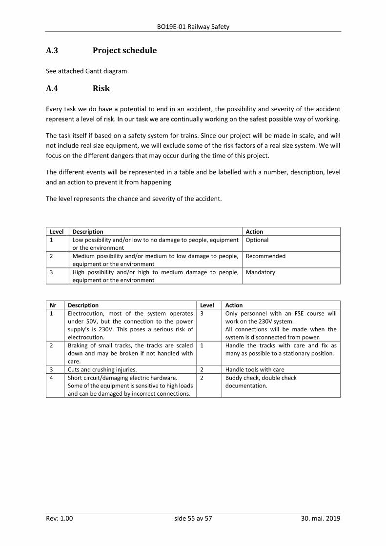
BO19E-01 Railway Safety
Rev: 1.00 side 55 av 57 30. mai. 2019
A.3 Project schedule
See attached Gantt diagram.
A.4 Risk
Every task we do have a potential to end in an accident, the possibility and severity of the accident
represent a level of risk. In our task we are continually working on the safest possible way of working.
The task itself if based on a safety system for trains. Since our project will be made in scale, and will
not include real size equipment, we will exclude some of the risk factors of a real size system. We will
focus on the different dangers that may occur during the time of this project.
The different events will be represented in a table and be labelled with a number, description, level
and an action to prevent it from happening
The level represents the chance and severity of the accident.
Level Description Action
1 Low possibility and/or low to no damage to people, equipment or the environment
Optional
2 Medium possibility and/or medium to low damage to people, equipment or the environment
Recommended
3 High possibility and/or high to medium damage to people, equipment or the environment
Mandatory
Nr Description Level Action
1 Electrocution, most of the system operates under 50V, but the connection to the power supply’s is 230V. This poses a serious risk of electrocution.
3 Only personnel with an FSE course will work on the 230V system. All connections will be made when the system is disconnected from power.
2 Braking of small tracks, the tracks are scaled down and may be broken if not handled with care.
1 Handle the tracks with care and fix as many as possible to a stationary position.
3 Cuts and crushing injuries. 2 Handle tools with care
4 Short circuit/damaging electric hardware. Some of the equipment is sensitive to high loads and can be damaged by incorrect connections.
2 Buddy check, double check documentation.

BO19E-01 Railway Safety
Rev: 1.00 side 56 av 57 30. mai. 2019
Appendiks B User documentation With this report there is attached a zip file called user documentation. This contains:
• Description of:
o Anti collision system
o Crossing system
o Next position system
o Position system
o Track switch safety system
o Speed limiting safety system
o Train block
• Overview of programming logic
• Connection list
• Mounting/dismounting guide for the model (in Norwegian)
• Overview of the track layout
• Power drawing
• Layout of prototype circuit
• Gant diagram

BO19E-01 Railway Safety
Rev: 1.00 side 57 av 57 30. mai. 2019
Appendiks C Code With this report there is attached a zip file called user code. This contains:
• Arduino mega code
• Arduino Uno DCC++ code