
BNA0111404 8
47
ENERGY TECHNOLOGY ENGINEERING CENTER No . 059-01-721 Rev . Page 1_ of 45 OPERATED FOR THE U .S . DE PART ME NT OF E NERGY Orig . Date 08/10/9 0 ROCKETDYNE DIVISION, ROGKYELL INTERNATIONAL Rev . Dat e OPERATING INSTRUCTION ' TITLE : BUILDING 059 SHIELDING CONCRETE REMOVAL EQUIPMENT-- -, - -APPROVALS- - ~ l Originato r ~ W~I r .tS =4pRadiation & Nuclear Safety *♦ / , Nuclear Ops 4'7f9o Health , Safety & Enviro n Project 8-/ .$-94 Facility Manager Z o REV . I REVISION __ . _ APPROVAL/DAT E LTR . - _ _ . - Form 735-A-6 Rev 6-88 BNA0111404 8 HDMSP001821381
-
Upload
khangminh22 -
Category
Documents
-
view
4 -
download
0
Transcript of BNA0111404 8

ENERGY TECHNOLOGY ENGINEERING CENTER No .059-01-721 Rev .Page 1_ of 45
OPERATED FOR THE U .S . DE PARTMENT OF E NERGY Orig . Date 08/10/9 0ROCKETDYNE DIVISION, ROGKYELL INTERNATIONAL Rev . Date
OPERATING INSTRUCTION '
TITLE : BUILDING 059 SHIELDING CONCRETE REMOVAL EQUIPMENT-- -, -
-APPROVALS- - ~
lOriginator ~ W~Ir.tS=4pRadiation & Nuclear Safety *♦/,
Nuclear Ops 4'7f9o Health , Safety & Environ
Project 8-/.$-94 Facility Manager Z o
REV .I
REVISION __ . _ APPROVAL/DAT ELTR.
-
_ _. -
Form 735-A-6 Rev 6-88
BNA0111404 8HDMSP001821381

059-01-721Page i08/10/90
CONTENTS
Paae
1 .0 Scope . . . .. . . . . . . ._ . : . - . . 22 .0 Applicable Documents and References . . . . . . . . . . 3
2 .1 Applicable Documents . . . . . . . . . . . . . . 32 .2 References . . . . . . . . . . . . . . . . 3
3 .0 Equipment and Materials . . . . . . . . . . . . . . . . . 43 .1 Equipment . . . . . . . . . . . . 4
3 .1 .1 Tractor-Backhoe, Ford Model 655A . . . . 43 .1 .2 Backhoe Control Station . . . . . . . . . . . . . 931 .3 Hydraulic Breaker . . . . . . . . . . . . . . . . 93 .1 .4 Hydraulic Shear . . . . . . . . . . . . 163 .1 .5 Hydraulic Bucket and Thumb . . . . . . . . . . . 163 .1 .6 Quick Coupler . . . . . . . . . . . . . . . . . . 163 .1.7 Hand Tools 163 .1 .8 Welding Equipment . . . . . . . . ._ "`. 163 .1 .9 Jerry Cans . . . . . . . . . . . . . . . . . 16
-3 .2 Materials . . . : . . . . . . . . . . . . . . . 204 .0 General Requirements . . -. . . . . . . 21
4 .1 Safety Precautions /Special -Instructions . . . . . . . . . 214 .2 Controlled Work Permit and Confined Space Entries 214 .3 Work Safety . . . . . . . . . . . . . . . . . . . . . . 21-4 .4 Prerequisites . . . . . . . . . . . . . .. . . 21
5 .0 Operating Instructions Overview . . . . . . . . . . 236 .0 Operating Instructions . . . . . . . . . . . . . . . . . . . _ 24
6 .1 Shift Pre-Startup . . . . . . . . . . . . . - . .. . . 246 .1 .1 Log -On Sheet . . . . . . . . . . . . : . . . . 24
6 .2 Normal Operation . . . . . . . . . . . . . . . . . . 256 .2 .1 Tractor - Backhoe . . . . . . . . . . . ..ws. 256 .2 .2 Backhoe Control Station . . . . . . - . . . 266 .2 .3 Hydraulic Breaker . . . . . . . . . . . . . . . . 266 .2 .4 Hydraulic Shear . . . -. . . . ., . . . . _. . . 286 .2 .5 Bucket and Thumb . . . . . . . . . . . . . . . . 28
6 .3 Tool Changeover . . . . . . . . . . . . . . . 336 .4 Shutdown and Log-Off . . . . . . . . . . . . . . . . . . 366 .5 Maintenance . . . . . . . . . . . . . . . . . . . 36
6 .5 .1 Minor Maintenance . . . . . . . . . . . . . . . 366 .5 .2 Maintenance Schedule . . . . . . 37
6 .6 Tractor Refueling in Building 059 Equipment Room . . . . 39
BNA0111404 9HDMSPOOI 821382

059-0I-721Page ii08/10/90
FIGURES
- - - _ - _ Paae
3-1 Artist's Concept of Concrete Removal Equipment 'in Bldg . 0.59. 53-2 Tractor - Backhoe Terminology . . . . . . . . . . . . . . . 63-3 Tractor Gauges and Warning Lights . . . . . . . -.- . 73-4 Tractor Hydraulic System - Schematic . . . . . . . . 83-5 Backhoe Controls . . . . . . . . . . . . 103-6 Functions of the Crowd and Lift Levers on the Backhoe . ~
Control Station . . . . . . . . . . . 11`3-7 Functions of the Actuating and Swing Levers on th e
Backhoe Control Station . . . . . . . . . 123-8 Functions of the Extendible and Dipstick Levers on the
Backhoe Control Station . . . . . . . . . . . . . . . . . . . 133-9 Hydraulic Breaker Schematic Diagram and Nomenclature . . . 143-10 Exploded View of Hydraulic Breaker - . = . - . . -- .- 153-11 Hydraulic Shear Schematic Diagram and Nomenclature -. . . 173-12 Backhoe and Thumb Installed for Mockup Tests . . . . . . 183-13 Quick Coupler Used to Facilitate Rapid . Tool Change i n
the Interest of ALARA . . . . 196-1 Procedure for Bi-Hourly Lubrication of Hydraulic Hammer . . 216-2 Proper Orientation of Hammer to Work Surface , -90 Degrees. 29.6-3 Use the Backhoe Controls to Preload the Hammer . . 306-4 Demolish Concrete by Moving From Near the Edge Toward
the Center of the Structure . . . . . . . . . . . .- . . . 3 16-5 Do Not Use the Hammer to Pry, Push, or Lift Anything . •-: 336-6 Schematic Diagram of Backhoe Control Hydraulic Hose Routing . 356-7 Tractor- Backhoe Lubrication and Maintenance Schedule . . . 38
TABLES -
6-1 Specified Torque Values for Model 225 Hydraulic Hammer ° 406-2 Daily Grease Fitting Lubrication Schedule for
Hydraulic Shear . : . . . . . . . . . . . . . . . . . 406-3 Dry Bolt Torque Chart . . . . . . . . . . . . . . . . . . . . 41
ATTACHMENTS
1 . Instructions for Building 059 Shielding Concrete Remova lEquipment - 059-01-721 . . . . . . . . . . . . . . . . . . 42
2 . Training . . . . . 433 . Signoff Initials, Verification, and Identification Sheet . 444 . Operator Log-On Checklist . . . . .-. 45
BNA0111405 0
HDMSP001821383
059-0I-721Page 208/10/90
1.0 SCOPE
This document provides nomenclature and emphasizes safety,operational , and minor maintenance features of the concrete removalequipment used for the remediation of Building-059: '
This document provides information which will reduce the need forday-to -day reference to supplier ' s operation and==maintenancemanuals .
This document provides instructions and forms for documentation ofworker training and for a log of equipment operating history,including maintenance .
This document is intended to complement document -059-OI-722"Operating Instructions for Building 059 Shielding Concrete RemovalTask Sequence " (AppH cable Document 2 .1 .6) .
IIDI muim i iiuu iimu ii iiim iimuBNA0111405 1
HDMSP001821384

059-0I-721Page 308/10/9 0
2 .0 APPLICABLE DOCUMENTS AND REFERENCES
2 .1 APPLICABLE DOCUMENTS -
2 .1 .1 "Operator's Manual, Ford 655A Tractor-Loader-Backhoe," DT21691
2 .1 .2 "Operator' s Manual, Teledyne Hydraulic Breaker, "_DT21691
2 .1 .3 , "Service Manual, Teledyne Hydraulic Breaker," DT269 1
`2 .1 :4 "Operations and Maintenance Manual , LaBounty Manufacturing, IncShear," DT21691
2 .1 .5 "Backhoe Hydraulic System Technical Information ," DT24906
2 .1 .6 "Building 059 Shielding Concrete -Removal--Task Sequence ," 059-01-722
2 .2 REFERENCES
2 .2 .1 "Facilities Dismantling Plan for Building 059," N704FDP000001
2 .2 .2 "Building 059 Reference Construction Photographs and Drawings,"059-XT -0005, dated 4/18/89
2 .2 .3 "Building 059 Phase II Reactor Test Cell Remediation ProgramManagement Plan," 059-AN -0002 Rev A , dated 10/19189
2 .2 .4 "Instructions for Concrete Removal Equipment Mockup Testing,"059-01 -717 Rev B , dated 7/9/90
2 .2 .5 "BUILDING 059 LLTR and Remediation Emergency Plan," 059-XV-0010 ,dated 11/3/8 9
2 .2 .6 "Locating Concrete D&D Equipment ," IL 90-025 -02-063 , H. H . Neelyto S . L . Pendleberry , dated 4/10/90
BNA0111405 2
HDMSP001821385

059-0I-721Page 408/10/90
3 .0 EQUIPMENT AND MATERIALS
NOTE : See Applicable Document 2 .1 .6 for -a complementary list ofequipment and materials .
This section of these operating instructions includes a briefdescription of the concrete removal equipment . The nomenclatureand terminology used herein are to be used by operators and workerswhen communicating under Controlled Work and /or Confined Entryconditions .
The concrete removal equipment consists of a Tractor-Loader - Backhoe which has been modified for the Building 059Remediation project . The modification consists of removing theloader unit and stabilizer bars and separ-at tng the backhoe controlsfrom the tractor so that the backhoe , with its attachments, can beoperated semi-remotely . The backhoe attachments for concreteremoval are : ( 1) a hydraulic breaker for breaking the concrete, (2)a hydraulic shear for cutting rebar and piping , and (3 ) a hydraulicbucket and thumb to scoop up the rubble and place it in a wastecart . A powered roller conveyor moves the waste cart to a locationwhere it can be lifted and dumped into an appropriate wastecontainer
An artist' s concept of the tractor in its location .in the Building059 Vacuum Equipment Room, and with the three backhoe attachments,is presented in Figure 3-1 .
3 .1 EQUIPMENT
3 .1 .1 Tractor- Backhoe . Ford Model 655 A
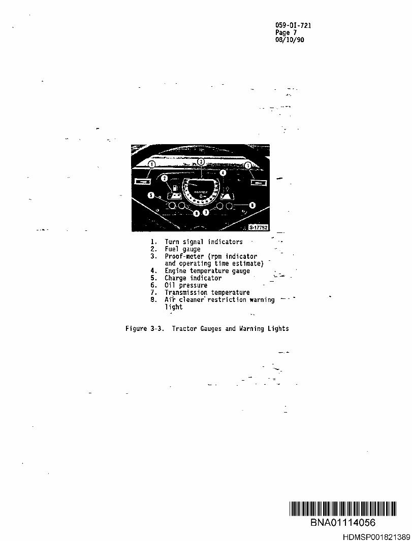
The basic tractor-backhoe unit is shown in Figure 3-2 ; the gaugesand warning lights in front of the steering wheel are shown inFigure 3 -3 . A mirror is mounted in the cab to permit the operatorto monitor the warning lights from the backhoe control stationwhere the operator is working during normal operation .
In order to accommodate the additional hydraulic _fl.uid required forthe remote backhoe control station , the normal hydraulic fluidreservoir has been replaced with a 55 -gallon drum mounted over thehood of the tractor , and an extra cooler placedin the hydrauliccircuit , as shown in Figure 3-4. - _
A detailed description of the Ford tractor -backhoe, along withcomplete operating and maintenance instructions , are presented inReference 2 .1 .1 which, if needed , is available from the Building059 PIC. -
IIDI m u imi i iuuiimuii i iim u i i iiuBNA0111405 3
HDMSP001821386

059-0I-721Page 508/10/90
vu::- R' -
p,p
Figure 3-1 . Artist's Concept of Concrete RemovalEquipment in Building 059
BNA0 1 1 1 4056
HDMSP001821387

- _ BACfIOR TRACTOR
Figure 3 -2 . Tractor-Backhoe Terminology
059-0I-721Page 708/10/90
1 . Turn signal indicator s2. Fuel gauge -3. Proof-meter (rpm indicator
and operating time estimate)4 . Engine temperature gauge5 . Charge indicator6 . Oil pressur e7 . Transmission temperature8. Air cleaner restriction warning
light
Figure 3-3 . Tractor Gauges and Warning Lights
BNA0111405 6
HDMSP001821389

059-0I-721Page 808/10/90
TO LOAOEA
;not sec ;
TO BACKHOE' PUMP OI L
© RETURN TO RESERVOIR OI L
1 . Rese rv oir 4. Unload Valve 7 . Sensing Valve 9. Piper Beyond Tube2. Oil Cooler 5. Filter 8 . Backhoe Main 10 . Loader Main Contro l3. Hydraulic Pump 6 . Expansion Chamber Control Valve - "- - Valve
Figure 3-4 . Tractor Hydraulic System - Schematic
BNA0 1 1 1 405]
HDMSP001821390

059-0I-721Page 908/10/90
3 .1 .2 Backhoe Control Station
The Backhoe control . station is shown in Figure 3-5 .
The functions and terminology associated with the Crowd and Liftlevers are presented in Figure 3-6 . Figure 3-7 shows the sameinformation for the Actuating and Swing Levers, while Figure 3-8describes the Extendible Dipstick foot pedal .
The two remaining controls are the Thumb/Breaker/Shear (TBS) lever,cumbered (6) on Figure 3-5, and the Shear Rotation lever, numbered(1) on Figure 3-5 .
Depending on which backhoe attachment is in place, the right handTBS lever, which is painted white, will actuate : (1) the thumb (seeFigure 3-12) which is used to push rubbl-e into the bucket, (2)trigger the breaker-actuation, and, (3) actuate the-jaw of theshear .
The Shear Rotation lever, which is on the left side and which ispainted red, will cause the hydraulic shear to rotate . Unlimitedrotation in either direction is possible .
The hydraulic backhoe control system is described in detail inReferences 2 .1 .1 and 2 .1 .5 which, if needed, are available from th eBuilding 059 PIC. -
3 .1 .3 Hydraulic Breake r
As shown in Figure 3-9, the Teledyne E-Series _ci'fadel TB225) Breakeris divided into four major sections : (1) Tool holder, (2) Cylinder,(3) Control valve,; (4) Cylinder cover .
The tool holder retains the tool using one retainer pin . Byremoving this pin ; the tool can be quickly changed . Also assembledinto the tool holder are 4 side bolts which hold the cylinder andcylinder cover together with the tool holder .
The cylinder contains the moving piston which strikes the tool .
Assembled onto the cylinder is a control valve which controls themovement of the piston. - -
The cylinder cover contains the cushion chamber which is chargedwith Nitrogen gas-that will act on the piston to recover and reusesome of the impact energy .
An "exploded view " of the hydraulic breaker is presented asFigure 3-10 .
IIDI iiiiuiiuuii iniiuii i iuinmui iBNA0111405 8
HDMSP001821391

1 .2 .3 .4 .5 .6 .7 .
Shear rotation lever (red)Crowd lever (dipstick)Lift lever (boom )Actuating , or curl, lever (tools)Swing leve rThumb/breaker/shear lever (white)Extendible dipstick pedal control
Figure 3 -5 . Backhoe Controls
059-0I-721Page 1008/10/90
I IBNA0111405 9
HDMSP001821392

059-0I-721Page 1108/10/90
Crowd Lever
Pushing the crowd lever forward will move thedipstick and bucket "Out" or away from theoperator . Pulling the crowd lever rearward willmove the dipstick and bucket " In" or toward theoperator.
Lift Lever
Pushing the lift lever forward will "Lower" theboom , dipstick, and bucket . Pulling the li ft leverrearward will "Lift" the boom , dipstick, andbucket .
Figure 3-6 . Functions of the Crowd and Lift Leverson the Backhoe Control Station
BNA0111406 0
HDMSPOOI 821393

059-0I-721Page 1208/10/90
Actuating Lever ( Bucket)
Pushing the actuating lever (bucket) forward-wilt-"Dump " the bucket (move outward). Pulling theactuating fever (bucket) rearward will "Close" ar - -ctrl the bucket (move inward).
Swing Lever
Pushing the swing lever forward will swing theboom , dipper, and bucket to the "Left ." Pullingthe swing lever rearward will swing the boom,dipstick , and bucket to the- "Right ." _
Eigure 3 - 7.- Functions of the Actuating and Swing Levers
on the Backhoe Control Station - -
BNA0111406 1
HDMSP001821394

059-0I-121Page 1308/10/90
Extendible Dipstic k
Pushing the toe "Down " on the foot pedal willextetld the extendible dipstick. Pushing the heel"Down" on the foot pedal will retract the exten-
_ dibi~ dipstick
TOE HEEL
Figure 3-8 . Functions of the Extendible and Dipstick leverson the Backhoe Control Station
S
BNA0111406 2
HDMSP001821395

059-01-721Page 1408/10/90
Cushion Chamber
Control Valve
ffn
Cylinder Cover \ Cylinder
iston Tool
\Tool Holder
Figure 3-9.. ,Hydraulic Breaker Schematic Diagram and Nomenclatur e
BNA0111406 3HDMSPOOI 821396

059-01-721Page 1508/10/90
HIGH STRENGTH, RIDGIDLY EYE BOLTS FOR SERVICEDESIGNED SIPS PLATES MARE PA E PART OF ATHESE BREAKERS,ASTUR'Y LIGHT- COMPLETE TOOL KIT PROVIDED WEARBAR FRONTKEAD.-THESE
UNIT ` WITFS EACH BREAKER _ PROTECTION. BOLT PROTECTIONAND-REINFORCIMG RIBS
a
KEY GROVE TO HOLDSH AR BL K TOTRANSMIT LOADS
SHEAR BLOCKS THA TTRANSMI HE 1 A S FROMRAKThG AND BREAKING INTOTHE SIDE PLATES
STANDARD MOUNTING BRACKETSFIT SEVERAL COMMONLY U BACXHOESEXCAVATORS , I LOADERS
HARDENED STEEL BRACKET PINSDESIGNED TO TNF -BACKKOEMANUFACTURERS SPECIFICATIONS
RUBBER MOUNTS TO ABSORB THE SHOO[ LOAD' "F-SREAXING THE MATERIAL .
NIGH STRENGTH BRACKET BOLTS TO CLAMP THESIDE PLATES THE AK
EASILY REPAIRABLE BRACKET BUSHINGS FOR THE CUSTOMER ORRENTAL FLEET WITH A VARIETY F BACKHOES , ETC. IN THEIRFLEET
Figure 3-10 . Exploded View of Hydraulic Breaker
BNA01114064
HDMSPOO1821397

059-01-721Page 1608/10/90
The hydraulic breaker is described in detail in References 2 .1 .2and 2 . 1 .3 which , if needed , are available from the Building 059PIC. -
3 .1 .4 Hydraulic Shear
The nomenclature for the LaBounty MSD 105R hydraulic shear is shownin Figure-3-11 .
The hydraulic shear is described in detail in Reference 2 .1 .4which , if needed , is available from the Building 059 PIC .
3 .1 .5 Hydraulic Bucket and Thumb
Figure 3-12 shows the 18 - in Gannon Backhoe Bucket and theAttachments International Thumb as installed for mockup testing,part 'of the Building 059 Remediation Program .
3 .1 .6 Quick Coupler
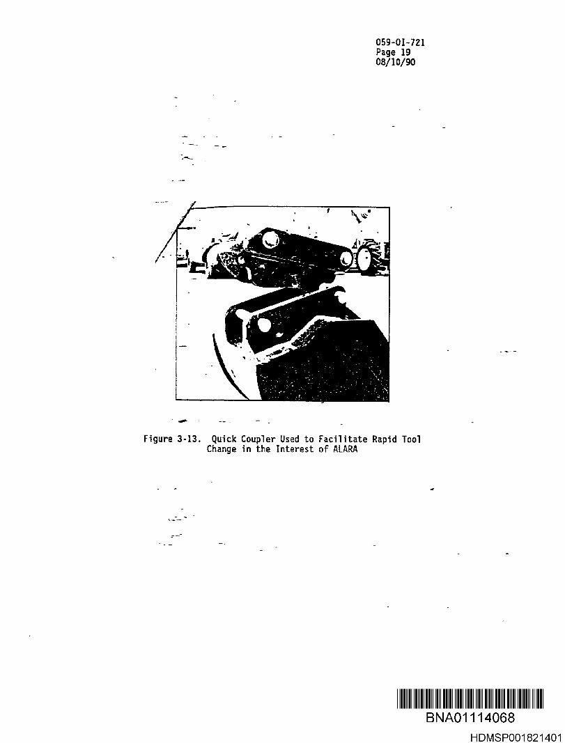
An Attachments International Quick Coupler, shown in Figure 3-13,has been installed on the end of the dipstick and on each tool(breaker, shear , and bucket) to facilitate rapid tool changeoverunder the ALARA working conditions (see paragraph 4 .3) expected inBuilding 059 .
3 .1 .7 Hand Tool s
See Applicable Document 2 .1 .6 :
Al so :
Hydjaulic fitting wrenchTorque wrenches : range 5 - 350 ft-lbShear shim wrenc h
3 .1 .8 Welding Equipmen t
Suitable for hardfacing the hydraulic shear, as required .
3 .1 .9 Jerry Cans
For refueling the tractor.
iimm u imi i imnimuii i iummuuBNA0111406 5
HDMSPOO1821398

059-01-721Page 1708/10/9 0
Hydraulic Motor & Rotator(insi9e ) (if rotator equipped )
Figure 3-11 . Hydraulic Shear Schematic Diagram and Nomenclature
BNA0111406 6
HDMSPOOI 821399

059-01-721Page 1808/10/90
Figure 3-12 . Backhoe and Thumb Installed for Mockup Tests
Note remote backhoe control station and extended dipstick.
BNA0 1 1 1 406]IM
HDMSPOO1821400
059-01-721Page 1908/10/90
Figure 3 - 13 . Quick Coupler Used to Facilitate Rapid ToolChange in the Interest of ALARA
BNA0 1 1 1 x068I I
HDMSPOO1821401

059-01-721Page 2008/10/90
3 .2 MATERIAL S
See Applicable Document 2 .1 .6 .
Also: - - -
A16t'Metalube grease , or equivalent , for breaker .
Caps and plugs for hydraulic system .
Amoco Rykon premium grease No . 2P , or equivalent, for hydraulicshear .
Amalloy 814, Stoody 2110, or Lincoln Abrasoweld weld rod forhardfacing the shear .
'Shear shims` -
Spare-shear blades .
Spare breaker points and chisels .
Ford 34 or 134 , or equivalent , hydraulic fluid .
BNA0111406 9HDMSPOO1821402
059-01-721Page 2108/10/90
4 .0 GENERAL REQUIREMENT S
4 .1 SAFETY PRECAUTIONS/SPECIAL INSTRUCTION S
Each operator of the concrete removal equipment will read theseoperating instructions and sign Attachment 1 of the control copy toindicate'-understanding of the contents .
Each operator is required to have a current Fork Lift and Craneoperator ' s certificate . Additional training requirements may bespecified by Radiation and Nuclear Safety (R&NS) based on theworking environment . See Applicable Document 2 .1 .6 .
Each Candidate operator is required to demonstrate proficiency tothe satisfaction of the PIC before being permitted to operate theconcrete removal equipment .
Each operator will complete Attachment 2 of Applicable Document2 .1 .6 and-sign it to indicate the satisfaction of Trainingrequirements .
The PIC will sign Attachment 2 of Applicable Document 2 .1 .6 toindicate that operator proficiency with the concrete removalequipment is satisfactory .
4 .2 CONTROttED WORK PERMIT AND CONFINED SPACE ENTRIES
Performance of some of the operator ' s and/or worker's duties mayrequire Controlled Work and/or Confined Space Entry Permits .
Requirements relative to these permil ; s are defined in ApplicableDocument 2 .1 .6 "Building 059 Concrete Removal Task Sequence :059-01--U2 .
4 .3 WORK SAFETY
Personnel shall observe safe work practices . A minimum of twopeople shall be in the work area during operations .
Personnel shall work to principles which cause personal radiationexposure to be as-low - as-reasonably - achievable (ALARA) . Somemaintenance operations and tool changeover will require specialattention to ALARA .
4 .4 PREREQUISITES
The PIC will verify prerequisite status on a daily basis .
Prerequisites are :
4 .4 .1 Operators have read and signified understanding of these operatinginstructions by initialing and dating Attachment 1 .
BNA0111407 0HDMSPOO1821403

059-01-721Page 2208/10/90
4 .4 .2 Operators meet the training requirements , including currentForklift_ and-Crane Operator ' s License , as defined in paragraph 4 .1of these operating instructions , and documented on Attachment 2 ofApplicable Document 2 .1 .6 .--
4 .4 .3 Operators•in-itials are traceable to their full names anddepartments , as documented on Attachment 2 .
4 .4 .4 The Log-On (Attachment 3) and Log-Off (Attachment 4) Sheets arecurrent .
4 .4 .5 Required maintenance of equipment and tools has been performed .
4 .5 .6 Special requirements , if any, by Health , Safety , and Environmen tand/or Radiation and Nuclear Safety are met . See ApplicableDocrnie'nt 2 .1 .6.4
BNA0111407 1HDMSP001821404

059-01-721Page 2308/10/90
5 .0 OPERATING INSTRUCTIONS OVERVIEW
A single designated "working copy " of this Operating Instruction(01) will be utilized at the work site . should changes becomenecessary , the-"working copy " of this 01 shall be red -lined andapproved-by at-}east the PIC and the Project Engineer . R&NS mustapprove-and sign any changes affecting radiation and nuclearsafety ; the program manager must approve and sign any changesaffecting cost or schedule . When an approved change to the OI ismade , the work affected by the change will not commence until thechange is documented in the working copy of the 01, and all workershave had an opportunity to read the change . At the completion ofthe tasks covered by this 01 , the working copy of the OI, with allred-lined changes and attachments incorporated and signed , will befiled in the Building 059 Remediation file .
The-designated " working copy' of this-0I will be identified as suchon the cover page . It will be located in an area specificallyassigned for working copies of standard operating procedures(SOP's ) and OI ' s, except for those times when it is being activelyused in the Building 059 work area .
uu ii u iu iBNA0111407 2
HDMSPOO1821405

059-0I-72 1Page 2408/10/90
6 .0 OPERATING INSTRUCTION S
NOTE : These instruction assume that the operators are trained i nthe operation of the equipment . These instructions ire:intended to emphasize items which affect safety o fp'ersonnei and/or equipment .
6 .1 SHIFT PRE=STARTUP
CAUTION : If, at any time, the oxygen ( 0 ) level is less than19 .5`a or the carbon monoxide (S0) level is more than 35ppm, shut off the tractor and immediately clear thevault areas of personnel . Do not enter these areas ifeither of these unsafe conditions exist .
People die from CO poison! Don't mess with this !
6 .1 .1 Log-On Sheet
Each operator will "log on" to the operation of the equipment whenit has been turned off for more than eight hours or when replacinganother operator .
The log-on procedure consists of dating and initialing the Log-OnSheet, Attachment 3, and verifying, on the checklist, that thefollowing were performed: -
NOTE: Advise the PIC before starting, or when operating, theequipment if any discrepancies on the checklist are noted .
Tractor Hours - Record the tractor hours shown on the Proof-Meter(see Fig 3-3)
Fuel Level - Record the fuel level . Advise the PIC when the fuellevel is less than half. Do not start the tractor when the fuellevel indicator is in the red zone without specific permission fromthe PIC .
Tiedowns - Check the chains and turnbuckles that secure the tractorto the. steel plate are tight and that no unusual wear ordeformation of the eyebolts is evident .
Hoses, Visually inspect for damaged hydraulic hoses and for signsof leaks in the hoses or hydraulic fittings .
Engine Lubrication - Check the oil dipstick on-the tractor, itshould be above the "add" mark .
Hydraulic Fluid Level - Check the fluid dipstick in the 55-gallondrum, it should be above the "half tank" mark .
II0IBNA0111407 3
HDMSP001821406

059-0I-721Page 2508/10/90
Radiator Coolant Level - Check that the water level is near thecap. NOTE : Skip this check if the tractor is still hot fromnormal operation .
Exhaust-Connection - Visually check that the exhaust extension isconnected to the` tractor exhaust .
Carbon Monoxide/Oxygen Meter - Check that the meter is functional,within-calibration, "on," and shows a safe breathing atmosphere .
Too - Indicate which tool (breaker, shear, or bucket) is installedat the time of log-on .
6 .2 NORMAL OPERATION
CAUTIONS
During tractor operation , check the exhaust line connection and COmeter frequently to assure that the breathing air is safe. Checkthe warning light mirror on the tractor frequently, also .
Wear ear plugs when the tractor is running .
Do not stand near the hammer or shear during demolition .
Do not lire the hammer unless it is 'loaded, that is, pressedagainst the work surface .
6 .2 .1 Tractor-8ackhoe
NOTE : Do not let the engine run out of fuel . Repriming thediesel is time - consuming .
NOTE : During operation , the tractor should be turned off onlywhen :
a. In the interest of personnel safety .
b . A-tractor warning light is lit .
c. Very low on fuel .
-~ d . Tools are to be changed.
'- e ._ A work delay of more than 15 minutes is expected .
f . Directed by the PIC .
6 .2 .1 .1 Startup
NOTE : " Cold weather ' startup is considered unlikely. If thetemperature of the system is near freezing , or if the-
BNA01114074
HDMSP001821407

059-0I-721Page 2608/10/90
diesel doesn't start after 10 seconds of cranking on a coldmorning, get cold startup directions from the PIC .
Check that Startup Log, Attachment 3, is current .
Check that red trdiesel shutdown" knob is not pulled "out ."
Check that the oil pressure and charge indicator lights are litwhen the start switch is in the "on" position before starting theengine .
When the engine starts, check that the engine oil pressure andcharge indicator lights are out . Check that the Air CleanerRestriction Light is not on .
After a five (5 minute warm-up, set the engine at 1700 revolutionsper-minute (rpm) using the hand throttle .
6 .2 .2 Backhoe Control Statio n
The operational functions of the Backhoe control valves aredescribed in paragraph 3 .1 .2 of these instructions .
Avoid working the backhoe with the dipstick in the extendedposition whenever possible .
6 .2 .3 Hydraulic Breaker
NOTE : In extremely cold weather, a "cold startup" routine may berequired by the PIC .
There are two major concerns regarding the operation of thehydraulic breaker :
1) The hammer must not be "dry-fired," that is, operated withoutbeing pressed (loaded) against the concrete that is to bebroken up. Dry-firing will deform the retainer pins, makingpoint replacement very difficult and damaging the tool holder .
2) The point of the tool must not be driven more than six-(6)inches (about half of the visible tool length) into the work .The- backhoe support system can become over-stressed when tryingto-pull out a stuck tool .
Grease the tool after about every two hours of operating time (seeParagraph 6 .5.2) ; apply down pressure to the tool and apply fromeight to eleven pumps of a grease gun . See Figure 6-1 . Use AlcdMetalube or equivalent MOS2 grease .
Bolt torques on the breaker must be checked DAILY . See paragraph6 .4 .2 .2 and Table 6-1 .
IIDIBNA0111407 5
HDMSP001821408

059-0I-721Page 2708/10/90
Apply down pressure tobreak ., before greasingthe tool
Figure 6 - 1 . Procedure for Bi-Hourly Lubrication of Hydraulic Hammer .Apply 8 to 11` Pumps of the Grease Gun
II0IBNA0111407 6
HDMSP001821409

059-0I-721Page 2808/10/90
For efficient operation :
It is important to position the tool so that it is at about a 90degree angle to the concrete being broken . See Figure 6-2 .
Use the backhoe controls to pre-load the hammer . See Figure 6-3 .
Mockup testing showed the chisel to be more effective than the Moilpoint der fracture line propagation in this type of concretedemolition .
Start near the edge of the object and work toward the center insuccessive passes . See Figure 6-4 .
If the concrete shows no sign of breaking within 20 to 30 secondsof continuous hammering, change the position of the tool . Neverdrive the tool more than six (6) inches into the work .
Do not use the breaker to pry, pick , or lift anything . SeeFigure 6-5 .
Avoid working the breaker with the dipstick in the extendedposition, whenever possible .
6 .2 .4 Hydraulic Shear
The major item of concern for the hydraulic shear is that it belubricated DAILY when being used . See paragraph 6 .4 .2 .3 andTable 6-2 .
Avoid working the shear with the dipstick in the extended position,whenever possible .
6 .2 .5 Bucket and Thum b
The major item of concern in the use of the bucket and thumb isthat the bucket must not be curled against the thumb when the thumbis retracted . The bucket piston is much stronger than the thumband can damage the thumb drive linkage .
Use the thumb to push rubble into the bucket ; DO NOT CURL THEBUCKET AGAINST THE THUMB .
Avoid working with the dipstick in the extended position wheneve rpossible .
uu IftBNA01114077
UHDMSP001821410

059-0I-721Page 2908/10/90
D b do not em e pointmore than 6 inches .
..figure 6-2 . Proper Orientation of Hammerto Work Surface , -90 Degrees
BNA0111407 8HDMSP001821411

059-0I-721Page 3008/10/90
Use the main boom cylinders to apply down pressure to the breaker .
Use the dig cylinder to apply the necessary force to the breaker .
Use a combination of the dig cylinder and the bucket tilt cylinderto provide the necessary force on the breaker when breaking on a
wall or steeply inclined surface.
Figure 6-3 . Use the Backhoe Controls to Preload the Hammer .Do not fire the hammer unless it is preloaded .
Note 90 Degree orientation of Hammer to Work Surface
D I D DBNA01114079
I IHDMSP001821412

059-0I-721Page 3108/10/90
Do not embed point oftool more than 6 inches .
Figure 6-4 . Demolish Concrete b yThe Edge Toward he Center of the Structure
BNA0111408 0HDMSP001821413

059-0I-721Page 3208/10/90
OJX
7TT/ y///lT
Figure 6 - 5 . Do Not Use the Hamer to Pry, Push, or Lift Anything .Do not Change the Angle of Attack While ha mmering .
Do Not Fire the Hamer Before Pressing it Against the Work .
IIDI iiiuiiuui i iniiuii i iuii ui iiiuuBNA0111408 1
HDMSP001821414

059-0I-721Page 3308/10/90
6.3 TOOL CHANGEOVER
CAUTIONS : _
During tool change , use adequate lifting and positioning aids . Donot put hands or fingers where they can get pinched or crushed bythe heavy equipment .
During tool change , do not let hot hydraulic oil get in contactwith skin as it could cause severe burns .
NOTE : Changeover of tools in Building 059 will entail someradiation exposure from the radioactive reactor test cell .Workers will adhere to ALARA working practices .
NOTE : It is very important that hydraulic fluid and other oilleaks and spills be avoided . These fluids, mixed withradioactive waste, become a new , highly-regulated wasteform called "MIXED WASTE° . Disposal of MIXED WASTE will bevery difficult and expensive . Notify PIC of all spillsimmediately .
6 .3 .1 Verify that the holding fixture for the tool currently on thebackhoe is in the tool changeover location .
6 .3 .2 Using backhoe controls, carefully place the existing tool in itsholder in the tool changeover location .
6 .3 .3 Remove the locking ring and retaining pin from the Quick Connectdevice and uncouple the dipstick from the tool .
6 .3 .4 Move the boom/dipstick to a location where the hydraulic fittingsunder the dipstick can be reached .
6 .3 .5 Throttle down the tractor speed and turn off the tractor .
6 .3 .6 Relieve the pressure in the backhoe attachment (tool) hydrauliclines.
Normally, with the tractor turned off, this is accomplished byexcercising the white TBS lever and the red shear rotation lever inboth directions . On occasion , it may be necessary to relieve thepressure in the hydraulic lines per paragraph 6 .3 .6 .1 for Bucketand Breaker removal or per paragraph 6 .3 .6 .2 for Shear removal .
NOTE: Wrap a cloth or paper towel (diaper ) around each hydrauli cfitting while it is being loosened to absorb the smallquantity of fluid that is lost during the pressure reliefoperation .
NOTE: Use the special hydraulic fitting wrench .
IIDI iiiuiiuui i iniiuii iiuii uiiimuBNA0111408 2
HDMSP001821415

059-0I-721Page 3408/10/90
6 .3 .6 .1 For the Bucket and Breaker, loosen each white-marked fitting behindthe backhoe control console until the hydraulic pressure isrelieved, as shown by loss of some fluid . Retighten the fittingimmediately . These fittings are numbered (1) and (8) on Figure6-6 . See the Note in paragraph 6 .3 .6 regarding catching hydraulicfluid .
6 .3 .6 .2 For the Shear, loosen each white-marked fitting and each red-markedfitting behind the backhoe control console until the pressure isrelieved, as shown by loss of some fluid . Retighten the fittingimmediately . These fittings are numbered (7), (8), (9), and (10)on Figure 6-6 . See the Note in paragraph 6 .3 .6 regarding catchinghydraulic fluid .
6 .3 .7 Disconnect the appropriate quick-connect hydraulic fittings on thelines that hang on the dipstick . For the Bucket and Breaker, followparagraph 6 .3 .7 .1 ; for the Shear, follow paragraph 6 .3 .7 .2 .
Caution : The hydraulic fittings and hydraulic fluid can get hot ;exercise caution when disconnecting the hydraulicfittings .
Note : Do not let any fluid drip onto the radioactive waste ; seeNote in paragraph 6 .3 .
6 .3 .7 .1 For the Bucket and Breaker, disconnect the two (2) white-markedhydraulic lines . Immediately cap and plug the lines to the tool tokeep the fittings clean .
6 .3 .7 .2 For the Shear, disconnect the two (2) white-marked hydraulic lines,the two (2) large-diameter red-marked hydraulic lines, and the one(1) small-diameter hydraulic line . Immediately cap and plug alllines to the tool to keep the fittings clean . Cap and plug thethree red hydraulic lines on the dipstick .
6 .3 .8 Move the tool that was disconnected, on its pallet, to the "playpen", stowing the hydraulic lines neatly .
6 .3 .9 Move the tool to be installed, while in its holding fixture on itspallet, to the changeover area . Make an approximate alignment ofthe new tool with the backhoe .
6.3 .10 Unstow the hydraulic lines from the tool and connect each to itscounterpart on the dipstick . Unplug and uncap each hydraulic lineimmediately before being connected in order to keep the fittingclean .
6 .3 .11 Restart the tractor. Throttle up to 1700 rpm as the engine warmsup .
BNA0111408 3
HDMSP001821416

059-0I-721Page 3508/10/90
1 . Crowd Cylinder -Hose Routing - Four Lever Controls
5. Lift Cylinder - 12 . Right Swin g
2 .Rod EndCrowd Cylinder -
Piston End6. Lift Cylinder - Rod
g & : oShear
Cy li nder - Swin gRight
3 .Pistor. En dBucket Cyli nder -R
End
7 ~ 8
Roat i on 13 . Extendible DipstickCylinder - Rod En d
4.od End
Bucket Cylinder -P
Thumb, Breake r& Shear
11 . Left Swing Cylinder- Swing Left
14. Extendible DipstickCylinder - Piston Endiston End
nCtttation
Note : This diagram does not show the shear caseis the 5th hydraulic line to the backhoe tools .
drain line whic h
Figure 6 -6 . Schematic Diagram of Backhoe Control Hydraulic Hose Routin g
BNA01114084
HDMSP001821417

059-0I-721Page 3608/10/90
6 .3 .12 Move the dipstick to the new tool, align the two, Quick Connect thetool to the dipstick, insert the Quick Connect retainer pin, andfasten the locking ring .
6 .3 .13 Using the backhoe controls, carefully lift the new tool from itsholding fixture and move the tool to the work area .
6 .4 SHUTDOWN AND LOG-OFF
When changing operators and at shutdown, rest the tool in a safeplace.
Pull the red knob under the instrument panel to turn off the dieselengine on the tractor . Push the red knob back after the engine isoff .
Check for hydraulic system leaks . Wipe down and place diapers orcatch pans, as appropriate, where fluid may leak overnight . Seenote in Paragraph 6 .3 regarding "mixed waste . "
Each operator will complete the Log-Off Sheet at shutdown or whenturning the equipment over to another operator .
Record the tractor hours on the Proof meter .
Estimate the "working hours" (see paragrpah 6 .5 .2 .b) on tools thatwere used during the period of work. Enter these on the Log-offRecord . Initial and date the Log-off Record .
The PIC will cumulate these and use them as a basis for schedulingmaintenance .
6 .5 MAINTENANCE
6 .5 .1 Minor Maintenanc e
In general , maintenance will be performed by the RocketdyneMaintenance Department , however, the following minor maintenancemay be performed by operators at the direction of the PIC :
Add engine lubrication oil to the engine oil fill tube . Use SAE1OW-30, 15W - 40, or SAE 30 oil of API CD or SF/CD quality .
Add radiator coolant water to the engine radiator .
Add hydraulic fluid to the 55 -gallon drum . Use Ford 48 or 134 orequivalent . _
Lubricate tractor, backhoe, and tool grease fittings as directed bythe PLC . Use lubricants specified in Paragraph 6 .5 .2-1 , -2, and -3
Clean air cleaner as directed by the PIC . CAUTION : Check for
BNA0111408 5HDMSP001821418

059-0I-721Page 3708/10/90
radioactive contamination first .
Rotate the blades on the power shear as directed by the PIC .
Replace tools in the hydraulic breaker as directed by the PIC .
NOTE : Document all maintenance on the Operator Log-off Record(Attachment 4) . Date and initial each entry . PIC initial eachmaintenance entry .
6 .5 .2 Maintenance Schedule
Definition of operating time :
a . Tractor--Operating time is defined as the number shown on thetractor proof -meter . The proof -meter estimates operating hoursby counting engine revolutions and assumes an average o f1666 rpm .
b . Tools ( breaker , shear , and bucket )--Operating time is definedas the sum of clock times when the tool is actively workingunder hydraulic control . It does not include time when thetractor is not running or is idling . It does not include timespent for tool change - over , lunch break , or any otherinterruptions or delays .
The PIC will arrange to have maintenance performed in accordancewith suppliers' 0&M manuals . The following paragraphs present themaintenance schedules for the tractor - backhoe and its tools :
6 .5 .2 .1 Tractor - Backhoe - See Applicable Documents 2 .1 .1 and 2.1 .5 . Therecommended maintenance schedule for the Ford Tractor - Backhoe ispresented on Figure 6-7 . Note that the interval for hydraulicsystem oil and hydraulic system oil filter change is based on themore conservative requirements of the hydraulic breaker .
6 .5 .2 .2 Hydraulic Breaker - See Applicable Documents 2 .1 .2 and 2 .1 .3 .
Every 2 hours of operating time :
Grease the impact tool . See Paragraph 6 .2 .3 and Figure 6-1 .Use Alco Metalube or equivalent MOSZ grease .
Every 8 to 16 hours of operating time :
Check the tool clearance ; change the tool when the clearanceexceeds 0.12-in .
Check retainer pins to be sure they are rotating and are notdeformed .
Check torque on nuts and bolts per Table 6-1._ _
I IBNA0111408 6
HDMSP001821419

059-0I-721Page 3808/10/90
NOTE: For loader-backhoe lobe fittings use molybdenum disulfide grease, Ford Part No . ES4-M1C75B.
JcY Z O N
a
2 V
LUBRICATION AND m w a zWNO. MAINTENANCE ITEMS o w o a d rO =
1 Loader X 7617 Hydraulic System 011 X 70 1 010 Engine Air Restrictio n
Indicator X 12 Hours or20 Engine Oil Level X 6 4
2 Engine Coolant Level X 76 Dally23 Batte ry-water Level X 838 Fuei Flter X 656 Front Wheel Spindles X 87 Every4 Ti re Pressure X 8 5
28 Transmission 011 Lava X 6 827 Rear Axle Oil Level X 6925 FWD Nubs 3
Differential X 7319 Power Steering Oi l
Level X 72 Hours15
_Seat Raba X X 89
12 Hydraulic ReservoirBreather Fi lteu X 70
16 Backhoe X l?5 Engine Oil and Filter X 84 Every
Fuel Injection Pump 08 XHou rs
W r O W QYU W
Z C3< Z
dl~
Zw
U >> s
LUBRICATION AND W mWNO. MAINTENANCE ITEMS c. o v a a ai ?
16 Fan Belt Tension X 7926 Transmission Oil and
Filter X 68 Eve ry13 71 fl12 Hydraulic Reservoir
Breather Filter X 70 Hours
22 Air Cleaner Element X 678 Fuel Fi lter X 85 Every
21 Fuel Injectors X 8 119 Power Steering Oil 3
Filter X 727 Front Wheel Bearings X 87
26 Transmission Oil Filter X 69 Hour s27 Rear Axle 00 X 69 Eve24 Hyd. Pump Drlveshaft ' X 75 120025 FWD Hubs 3
Difterentiai • X 73 Hours •17 70
17A Hydraulic ReservoirScreen X
2 Engine Coolant • X 76 Seasonal
'0r annually- whichever occurs firs t
echange hydraulic system filter every 100 hr per breaker manual .bchange hydraulic system fluid every 1000 hr per breaker manual .
Figure 5 -7 . Tractor- Backhoe Lubrication and Maintenance Schedule
d
IIOI iiiuiiuui i iniiuii i iuii u uBNA0111408 7
HDMSP001821420

059-0I-721Page 3908/10/90
Every 1000 hours of operating time :
Check the pressure relief and flow settings for the breakerhydraulic circuit .
Overhaul the breaker , replacing all seals and inspecting allwear parts .
6 .5 .2 .3 Hydraulic Shear - See Applicable Document 2 .1 .4 .
Every 8 to 16 hours of operating time :
Grease all zerk fittings per Table 6-2 . Use Amoco RyhonPremium Grease No. 2P or equivalent .
Visually check bolt s
Check the torques of the blade bolts per Table 6-3 .
Visua l-ly check attachment pins and retaining bolts
Every 40 hours of operating time :
Rotate the blades , shim if required .
Check main pivot for wear .
As required by tolerance checks :
Hard surface blade wear points .
6 .6 TRACTOR REFUELING IN BUILDING 059 EQUIPMENT ROO M
NOTE : Do not overfill the tractor fuel tank . While in theBuilding 059 vacuum equipment room, the tractor will berefueled using "jerry cans . "
Rocketdyne Maintenance will supply diesel fuel .
Jerry cans will be kept in a Flammable Storage Cabinet .
Use a large funnel in the fuel tank to avoid spilling diesel fuel .
IIDI iiiuiiuui i iniiuii i iuii un iiBNA01114088
I IHDMSP001821421

059-0I-721Page 4008/10/90
Table 6- 1 . Specified Torque Values forModel 225 Hydraulic Hammer
Description Ft-lb Kg-M
Control Valve Cover Bolts 159 22
Control Valve Body Bolts 159 22
Side Rod 87 12
Side Rod Nuts 325 45
Side Plate Bracket Nuts 289 40
Gas Valve Body 61 8.5
Gas Valve Plug 8.7 1.2
Hose Adapter 325 45
Choke Plug in Hose Adapter 36 5
Table 6-2 . Daily Grease Fitting LubricationSchedule for Hydraulic Shear
No . ofLocation Shots
On Shear:
One on side of main shear pivot 6
One on top end of upper 6
One in cylinder rod trunnion 6
One in cylinder butt and trunnion 6
On Bracket :
Main boom attachment pivot (if needed) 12
Arm cylinder connection pin (if needed) 6
Rotation bearing . (If needed) 6
Optional : : Rotation bearing 6
UBNA0111408 9
HDMSP001821422

059-01-721Page 4108/10/90
LaBounty Manufacturing , Inc ., uses dry torque values .Please use the DRY BOLT TORQUE CHART listed below fortorquing all bolts on this attachment .
Please read the following instructions carefully beforetorquing bolts :
Make sure bolts, nuts , and bolt holes are freeof dirt , oil, grease , and other contaminants .You are now ready to use the DRY BOLT TORQUECHART listed below to reassemble yourattachment .
Table 6-3. Dry Bolt Torque Chart forLaBounty Shear
Size Ft-lb
- 20 83/8" - 16 451/2" - 13 1065/8" - 11 212
BNA0111409 0HDMSP001821423

059-0I-721Page 4208/10/90
ATTACHMENT 1
Instructions for : Building 059 Shielding Concrete Removal Equipment -059-0I-721
I HAVE READ AND UNDERSTAND THE ABOVE INSTRUCTION S
Name SS No . Date Dept/Group
BNA0111409 1
HDMSP001821424

059-01-721Page 4308/10/90
ATTACHMENT 2
SIGNOFF INITIALS, VERIFICATION, AND IDENTIFICATION SHEE T
Print Name Sign Name Dept . Initial s
IIDI m Ii l u i I i Iu i II DII u II i 1 mm 1 muuBNA0111409 2
HDMSP001821425

ATTACHMENT 3
OPERATOR LOG-ON CHECKLIST
DateOperator ' sInitials Time
TractorHours
Fue lLevel
Tie-downs Hoses
EngineOil
Hydral cFluid
RadatrWater
ExhaustConnect
COMeter
ToolInstal
PIC Initials ,Comments, & Date
059-721 . OI/bib
1~
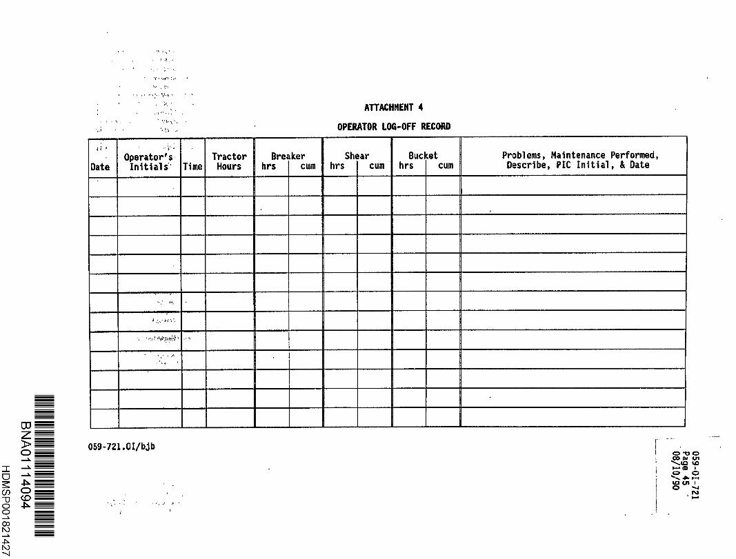
ATTACHMENT 4
OPERATOR LOG-OFF RECORD
DateOperator 's •Initials' Time
TractorHours
Breakerhrs cum
Shearhrs cum
Buckethrs cum
Problems, Maintenance Performed ,Describe, PIC Initial, & Date
!. ~ti?:aAit4 t . w
059-721 .0I/bib