Binocular mobile augmented reality based on stereo camera ...
10
SPECIAL ISSUE PAPER Binocular mobile augmented reality based on stereo camera tracking Jungsik Park 1 • Byung-Kuk Seo 2 • Jong-Il Park 1 Received: 6 January 2016 / Accepted: 19 September 2016 Ó The Author(s) 2016. This article is published with open access at Springerlink.com Abstract Mobile augmented reality (AR) applications have become feasible with the evolution of mobile hard- ware. For example, the advent of the smartphone allowed implementing real-time mobile AR, which triggered the release of various applications. Recently, rapid develop- ment of display technology, especially for stereoscopic displays, has encouraged researches to implement more immersive and realistic AR. In this paper, we present a framework of binocular augmented reality based on stereo camera tracking. Our framework was implemented on a smartphone and supports autostereoscopic display and video see-through display in which a smartphone can be docked. We modified edge-based 3-D object tracking in order to estimate poses of left and right cameras jointly; this guarantees consistent registration across left and right views. Then, virtual contents were overlaid onto camera images using estimated poses, and the augmented stereo images were distorted to be shown through a video see- through display. The feasibility of the proposed framework is shown by experiments and demonstrations. Keywords Mobile augmented reality Stereoscopic display Video see-through display Stereo camera tracking Model-based tracking 1 Introduction Augmented reality (AR) provides immersive experiences for users by overlaying a camera preview with virtual contents. In order to make AR realistic, the real world and virtual world should be aligned precisely; this alignment can be achieved by using physical sensors or camera images. Recently, the use of smartphones equipped with cameras and sensors such as global positioning system (GPS), digital compass, and gyroscope has boosted various mobile AR applications in fields such as education, tourism, and advertising. There is also a growing sense of anticipation of the possibility that mobile AR can be more immersive and realistic with the help of advanced display technology. There are several types of stereo displays that allow people to feel the cubic effect, for example, stereoscopic display and head-mounted display (HMD). With the development of these displays, realistic 3-D contents in contexts such as games, movies, virtual reality (VR), and AR have also been extensively explored. Technologies concerned with these contents on a stereoscopic display have usually been studied in order to create and provide 3-D movies and broadcasts; people have usually watched them in static environments such as theaters and living rooms. However, the stereoscopic displays have become available on portable game consoles and smartphones as they have been miniaturized, and this has allowed people to enjoy realistic 3-D content anywhere. Stereo cameras being placed on those devices have also enabled interactive applications on stereoscopic displays, including mobile AR. Meanwhile, the recent evolution of HMD technology has brought with it an increasing interest in virtual and augmented reality technologies. Video see-through HMDs, & Jong-Il Park [email protected] 1 Hanyang University, Seoul, Korea 2 Fraunhofer IGD, Darmstadt, Germany 123 J Real-Time Image Proc DOI 10.1007/s11554-016-0640-9
-
Upload
khangminh22 -
Category
Documents
-
view
3 -
download
0
Transcript of Binocular mobile augmented reality based on stereo camera ...

SPECIAL ISSUE PAPER
Binocular mobile augmented reality based on stereo cameratracking
Jungsik Park1 • Byung-Kuk Seo2 • Jong-Il Park1
Received: 6 January 2016 / Accepted: 19 September 2016
� The Author(s) 2016. This article is published with open access at Springerlink.com
Abstract Mobile augmented reality (AR) applications
have become feasible with the evolution of mobile hard-
ware. For example, the advent of the smartphone allowed
implementing real-time mobile AR, which triggered the
release of various applications. Recently, rapid develop-
ment of display technology, especially for stereoscopic
displays, has encouraged researches to implement more
immersive and realistic AR. In this paper, we present a
framework of binocular augmented reality based on stereo
camera tracking. Our framework was implemented on a
smartphone and supports autostereoscopic display and
video see-through display in which a smartphone can be
docked. We modified edge-based 3-D object tracking in
order to estimate poses of left and right cameras jointly;
this guarantees consistent registration across left and right
views. Then, virtual contents were overlaid onto camera
images using estimated poses, and the augmented stereo
images were distorted to be shown through a video see-
through display. The feasibility of the proposed framework
is shown by experiments and demonstrations.
Keywords Mobile augmented reality � Stereoscopicdisplay � Video see-through display � Stereo camera
tracking � Model-based tracking
1 Introduction
Augmented reality (AR) provides immersive experiences
for users by overlaying a camera preview with virtual
contents. In order to make AR realistic, the real world and
virtual world should be aligned precisely; this alignment
can be achieved by using physical sensors or camera
images.
Recently, the use of smartphones equipped with cameras
and sensors such as global positioning system (GPS),
digital compass, and gyroscope has boosted various mobile
AR applications in fields such as education, tourism, and
advertising. There is also a growing sense of anticipation of
the possibility that mobile AR can be more immersive and
realistic with the help of advanced display technology.
There are several types of stereo displays that allow
people to feel the cubic effect, for example, stereoscopic
display and head-mounted display (HMD). With the
development of these displays, realistic 3-D contents in
contexts such as games, movies, virtual reality (VR), and
AR have also been extensively explored. Technologies
concerned with these contents on a stereoscopic display
have usually been studied in order to create and provide
3-D movies and broadcasts; people have usually watched
them in static environments such as theaters and living
rooms. However, the stereoscopic displays have become
available on portable game consoles and smartphones as
they have been miniaturized, and this has allowed people to
enjoy realistic 3-D content anywhere. Stereo cameras being
placed on those devices have also enabled interactive
applications on stereoscopic displays, including mobile
AR.
Meanwhile, the recent evolution of HMD technology
has brought with it an increasing interest in virtual and
augmented reality technologies. Video see-through HMDs,
& Jong-Il Park
1 Hanyang University, Seoul, Korea
2 Fraunhofer IGD, Darmstadt, Germany
123
J Real-Time Image Proc
DOI 10.1007/s11554-016-0640-9

especially their high-end versions, provide immersive VR
experiences based on their capacity to render quality,
wearability, a wide field of view, sensors, and so on.
However, as AR devices, they have some problems, for
example, the need for additional computing devices, the
absence of a camera, limited mobility, and a high price. On
the other hand, there are HMDs in which smartphones can
be docked. Some of them, for example Google Cardboard,1
have quite a simple composition, because they use the
smartphone’s display and sensors; this can make their price
quite low. By using them, we can get a VR system for only
a few dollars; immersive mobile AR applications can also
be available if they have a stereo camera.
Some things should be considered for the implementa-
tion of mobile AR using a stereo display; these include a
precise registration between the real and virtual worlds,
real-time processing, and a handling of the intrinsic hard-
ware problems. In early stages, physical sensors were used
for registration in AR [1]. However, sensors are sensitive to
noise, and their accuracy is not enough for robust and
precise registration; for precise registration, a vision-based
tracking technique is necessary. Vision-based tracking is
one of the computer vision techniques that have been
actively researched, with many methods that can be run in
real time even on mobile devices. A marker-based
approach provides precise and robust registration despite
the simplicity of the algorithm [2]. Furthermore, it is fast
enough to perform stereo camera tracking in real time.
Therefore, a marker-based approach was widely used rel-
atively earlier than other vision-based tracking approaches
for stereo AR.
However, stereo camera tracking in natural scenes
exacts a computation cost; it often makes the implemen-
tation of a real-time application difficult. For example,
there was a mobile AR using stereo camera tracking based
on depth sensing algorithms that recovered geometric
structure captured in stereoscopic images [3]. Although this
approach was well implemented on a smartphone with 3-D
display, it was still not suitable for processing in real time,
because of its expensive computational costs. Recently, it
has become possible to run natural feature-based planar
object tracking [4] as well as 3-D object tracking in real
time even on a mobile platform [5, 6] with the development
of hardware and software. Nevertheless, expansion of those
methods to stereo camera tracking requires the careful
design of an algorithm and optimization, because of the
additional computation required for consistent registration
across cameras.
On the other hand, stereo displays still have problems as
AR devices, due to their hardware and operating principles.
In the case of autostereoscopic display, doubt has been
raised about the effectiveness of depth perception in AR.
Recent studies of this problem discovered that the effect of
stereo display on depth perception can be significantly
superior to mono display, depending on whether the scene
provides other depth cues more dominant than stereopsis
[7, 8]. A video see-through display has the problem of
image distortion and chromatic aberration due to the lenses
inside the display. Although geometric distortion can be
handled by a predistortion of images [9], it is still being
studied in order to learn more effective and efficient ways
to generate fine-quality images. For example, Pohl et al.
[10] proposed an improved predistortion method that cor-
rects chromatic aberration. The method distorts each color
channel separately by considering a different index of
refraction according to the wavelength.
In this paper, we present a mobile binocular AR
framework based on stereo camera tracking. Our approach
aims to provide AR on mobile stereoscopic displays; the
proposed framework supports autostereoscopic display and
a Google cardboard-like video see-through HMD. We
implemented the proposed framework on a stereo camera-
equipped smartphone. Stereo images were converted from
YUV to RGB color space and were warped for stereo
image rectification. Camera poses for registration between
the real and virtual worlds were estimated by stereo camera
tracking; at this point, camera poses were jointly estimated
using the geometric relationship between cameras in order
to guarantee consistent registration across the left and right
views. Then, the virtual contents were augmented onto
rectified images. If the user were to use a video see-through
display, the augmented image would be predistorted in
order to correct lens distortion. For real-time performance,
we separated the tracking and rendering processes into
different threads, and color space conversion and stereo
image rectification, which were run in the rendering thread,
were implemented on GPU. The feasibility of the proposed
framework was shown by experiments and demonstrations.
2 The framework
Figure 1 shows the proposed mobile binocular AR frame-
work based on stereo camera tracking. The framework
consists of two threads. One of them performs stereo
camera tracking, and the other performs the rendering of
images from the stereo camera and virtual contents. They
are here called the tracking thread and the rendering thread,
respectively.
In the tracking thread, camera poses are estimated using
edge-based 3-D object tracking. Correspondences between
the edges of the mesh model of a target object and the
edges detected from the Y channel image are established
for each view of the stereo pair. Then, camera poses are1 https://www.google.com/get/cardboard/.
J Real-Time Image Proc
123

jointly estimated using the correspondences from both
sides and are sent to the rendering thread. In the rendering
thread, the YUV images captured by the stereo camera are
converted into an RGB color space and are rectified. At this
time, these color space conversion and stereo image rec-
tifications are performed on a GPU for real-time perfor-
mance. The rectified images are rendered, and the virtual
contents are augmented onto them using camera poses.
Geometric transformations between the cameras, the
intrinsic camera parameters, and the mapping information
for stereo image rectification are computed at the offline
stage. In addition, the predistortion map for video see-
through HMD is also computed at the offline stage.
2.1 Stereo camera tracking
We extended the edge-based 3-D object tracking method
proposed by Seo et al. [5] to stereo camera tracking and
applied it to our framework. Edge-based 3-D object
tracking uses the silhouette of a 3-D mesh model of the
target object and the image edges as visual cues. Figure 2
shows the process of correspondence searching in edge-
based 3-D object tracking. In order to extract the silhouette
of the 3-D model, back-faces invisible at the camera pose
in the previous frame are removed by back-face culling,
and edges that are not shared by two faces among the
remaining faces are removed. However, edges inside the
silhouette cannot be removed completely, and they can
interfere with robust tracking. Therefore, another round of
filtering is performed in order to remove the remaining
edges inside the silhouette. An object region mask is cre-
ated by rendering all faces of the 3-D model onto the image
plane, and a silhouette is extracted from the object mask by
contour detection. Then, the remaining edges are projected,
and the edge whose distance from silhouette is over a
certain threshold is filtered.
Edges belonging to the extracted silhouette are regularly
sampled and projected onto the image plane. Then, the
closest image edge that lies on the normal direction of each
model edge sample is set into correspondence with the
edge sample. The image edge can be detected by a Canny
operator [11]; however, it is inefficient to detect edges from
the whole image, since the searching ranges of the model
edge samples may not cover the entire image plane.
Therefore, local edge components are detected by applying
a Sobel filter only to the pixels within the searching ranges
of the model edge samples, for computational efficiency
(Fig. 3). These processes, from silhouette extraction to
correspondence searching, are performed independently on
each view.
We can estimate the camera pose using the established
correspondences. The camera pose of a monocular camera
Et is updated from previous pose Et�1 by camera motion
DE.
Et ¼ Et�1 � DE ð1Þ
The camera motion DE consists of the rotation transfor-
mation R and the translation transformation t between the
Fig. 1 Flowchart of the proposed framework
Fig. 2 Correspondence searching of the edge-based 3-D object
tracking
J Real-Time Image Proc
123

previous and current frames. It can be parameterized by an
exponential map as follows,
DE ¼R t
01�3 1
� �¼
X5i¼0
eaiGi � IþX5i¼0
aiGi; ð2Þ
where Gi are the basis matrices of rotation and translation
transformation along the x, y, z axes in homogeneous
coordinates, ai are infinitesimal changes in their respective
bases. The distance between the projected edge samples
from a 3-D model and their correspondences should be
similar to the displacement at the projected point m ¼u v w½ �> from 3-D Point M by the basis G. The
a ¼ a0 a1 a2 a3 a4 a5½ �>
satisfying this condition can be estimated by
a ¼ argmina
Xj
dj �X5i¼0
ai nj � li;j� ������
�����2
8<:
9=;; ð3Þ
where nj is the normal vector of the jth sample, and li;j is its
motion vector. The motion vector li;j can be computed by
using camera intrinsic matrix K and partial derivatives of
mi;j:
Dmi;j ¼ u0j v0j w0j
� �>¼ KEt�1GiMj ð4Þ
li;j ¼u
w
0 v
w
0� �
ð5Þ
After the motion parameter a is estimated by least square,
the camera pose Et can be updated using camera motion
DE.In the case of a stereo camera, the individually estimated
camera pose of each view can cause inconsistent
registration. Therefore, camera poses are jointly estimated
by using the geometric relationship between cameras. From
Eq. 1, the camera pose of each view can be represented as
EL;t ¼ EL;t�1DEL
ER;t ¼ ER;t�1DER;ð6Þ
and the camera motions of each can be estimated as
DE�L;t ¼argmin
DEL
Xi
KLELDELXi � xik k2( )
DE�R;t ¼argmin
DER
Xj
KRERDERXj � xj�� ��2
( ):
ð7Þ
Here, the subscripts L and R indicate the left and right
cameras, respectively, and m is the correspondence of the
edge sample of the 3-D model. In order to estimate the
motion of both cameras jointly, the error functions (Eq. 7)
should be combined:
DE�L;t;DE
�R;t ¼ argmin
DEL;DER
Xi
KLELDELXi � xik k2(
þXj
KRERDERXj � xj�� ��2
):
ð8Þ
By assuming that the motions of both cameras are the same
and that the stereo camera has already been calibrated,
Eq. 8 can be rewritten as
DE�L;t ¼ argmin
DEL
Xi
KLELDELXi � xik k2(
þXj
KREL!RELDELXj � xj�� ��2
):
ð9Þ
Now, we can estimate DEL by using correspondences
obtained from both views without regard to DER. After the
estimation of DEL, the right camera pose ER can be com-
puted by multiplying the left camera pose ER and the
relationship between cameras EL!R. The camera poses are
further optimized by performing these processes
iteratively.
2.2 Rendering stereo images
In the proposed framework, three kinds of image process-
ing are performed to render augmented images: color space
conversion, stereo image rectification, and predistortion.
These processes are suitable for performing parallel pro-
cessing, because the same operation is performed inde-
pendently for each pixel. Therefore, we implemented these
processes on the GPU using a programmable shader in
order to enhance performance. Fortunately, no bottlenecks
Fig. 3 Correspondence searching using local edge component
detection
J Real-Time Image Proc
123
due to data transfer from the GPU to CPU existed, because
the processing results were displayed immediately and
asynchronously.
Although Android smartphones usually support YUV
camera input, the OpenGL ES API for image rendering
does not support YUV textures. Thus, camera images
should be converted from YUV format to RGB format for
camera preview rendering. This conversion can be com-
puted simply by a matrix multiplication for each pixel
value and can be faster on a GPU.
The converted RGB image needs to be rectified because
a misalignment of cameras and lens distortions can be
caused by the manufacturing process, which can result in
an interference in the 3-D effect. Stereo image rectification
allows the alignment of cameras to be coplanar and
resolves the problem. Since stereo image rectification
including the undistortion of the image is a nonlinear
transformation, each pixel is warped inversely using the
transformation map. The transformation map contains the
coordinates to which each pixel moves and can be com-
puted in the offline stage. Although this process is quite
simple, the use of the transformation map and bilinear
interpolation requires much memory access and floating
point instructions; these requirements can be a burden on a
mobile phone with low computing power and a small cache
when those operations are sequentially performed.
After stereo image rectification, virtual contents are
rendered onto the rectified stereo image using camera
poses, and the augmented image can be displayed.
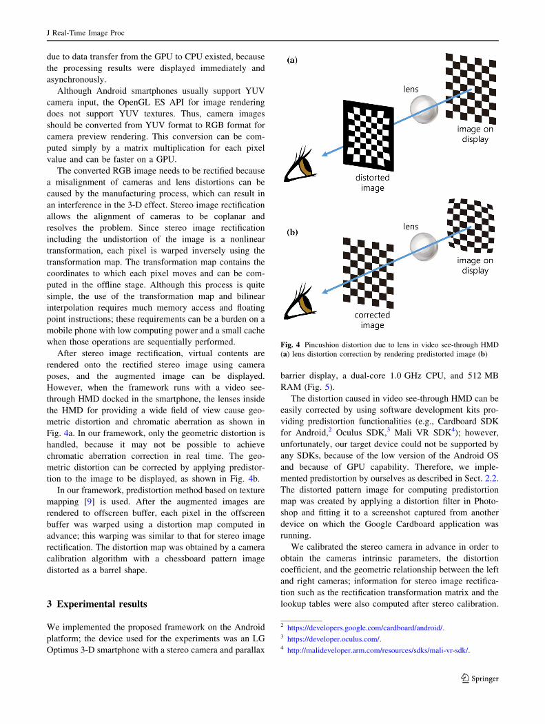
However, when the framework runs with a video see-
through HMD docked in the smartphone, the lenses inside
the HMD for providing a wide field of view cause geo-
metric distortion and chromatic aberration as shown in
Fig. 4a. In our framework, only the geometric distortion is
handled, because it may not be possible to achieve
chromatic aberration correction in real time. The geo-
metric distortion can be corrected by applying predistor-
tion to the image to be displayed, as shown in Fig. 4b.
In our framework, predistortion method based on texture
mapping [9] is used. After the augmented images are
rendered to offscreen buffer, each pixel in the offscreen
buffer was warped using a distortion map computed in
advance; this warping was similar to that for stereo image
rectification. The distortion map was obtained by a camera
calibration algorithm with a chessboard pattern image
distorted as a barrel shape.
3 Experimental results
We implemented the proposed framework on the Android
platform; the device used for the experiments was an LG
Optimus 3-D smartphone with a stereo camera and parallax
barrier display, a dual-core 1.0 GHz CPU, and 512 MB
RAM (Fig. 5).
The distortion caused in video see-through HMD can be
easily corrected by using software development kits pro-
viding predistortion functionalities (e.g., Cardboard SDK
for Android,2 Oculus SDK,3 Mali VR SDK4); however,
unfortunately, our target device could not be supported by
any SDKs, because of the low version of the Android OS
and because of GPU capability. Therefore, we imple-
mented predistortion by ourselves as described in Sect. 2.2.
The distorted pattern image for computing predistortion
map was created by applying a distortion filter in Photo-
shop and fitting it to a screenshot captured from another
device on which the Google Cardboard application was
running.
We calibrated the stereo camera in advance in order to
obtain the cameras intrinsic parameters, the distortion
coefficient, and the geometric relationship between the left
and right cameras; information for stereo image rectifica-
tion such as the rectification transformation matrix and the
lookup tables were also computed after stereo calibration.
Fig. 4 Pincushion distortion due to lens in video see-through HMD
(a) lens distortion correction by rendering predistorted image (b)
2 https://developers.google.com/cardboard/android/.3 https://developer.oculus.com/.4 http://malideveloper.arm.com/resources/sdks/mali-vr-sdk/.
J Real-Time Image Proc
123

At this point, we fixed the focal length of the cameras and
disabled the auto-convergence mode, which adjusts dis-
parity according to the depth of a subject by a disparity
remapping-like algorithm [12], since this would invalidate
the stereo camera calibration. Figure 6 illustrates the
cameras and the calibration patterns with respect to the left
camera. The distance along the x-axis between the cameras
was estimated at 23.29 mm, which means that the cameras
were correctly calibrated, because this was close to the
distance in the specifications of the device (24 mm).
Figures 7 and 8 show the target objects to be tracked
and their 3-D models. We used three objects and their
models: a cube whose model had 8 vertices and 18 edges; a
piece of pottery whose model had 673 vertices and 2000
edges; and a cat figure whose model had 1252 vertices and
3750 edges. We chose objects whose models had different
complexities in shape from each other in order to explore
how the performance of our framework varied with the
complexity of the model.
Figure 9 shows the resulting images from tracking the
pottery object and the augmentation using the proposed
framework. In order to visualize 3-D images via paper, the
3-D images were rendered in anaglyph form instead of
using the parallax barrier display. The 3-D model of the
target object with the green color was successfully and
correctly overlaid on the object. Figure 10 demonstrates
the augmentation on autostereoscopic display and the
predistortion image for the video see-through HMD;
tracking can be performed even with a complex model.
Table 1 shows the average processing time of each
thread over 500 frames. We measured the elapsed time
only for color space conversion and stereo image rectifi-
cation in the rendering thread. The processing time in the
rendering thread was stable, because it did not rely on the
complexity of the model but on the image resolution. The
processing time in the tracking thread was longer than that
for the rendering thread even when the simplest model was
used. Since the device had a dual-core CPU, each thread
could run in parallel. Therefore, the overall speed was
bounded by the tracking process. In this experiment, the
minimum speed of the framework was about 14 fps, which
meant that the framework could run at an interactive rate.
On the other hand, the use of the GPU allowed faster
processing than with the CPU. Table 2 shows the average
processing time of color conversion and stereo image
rectification on CPU and GPU. We achieved about an
eightfold speed-up by implementing these processes on the
GPU.
In order to verify that joint camera pose estimation is
superior to independent estimation of each camera pose in
Fig. 6 Stereo camera calibration result of Optimus 3-D smartphone
Fig. 5 Optimus 3-D smartphone
Fig. 7 a Cube and pottery and b their 3-D mesh models for tracking
Fig. 8 a Cat figure and b its 3-D mesh model for tracking
J Real-Time Image Proc
123

Fig. 9 Tracking and augmentation results (pottery). Top side-by-side images. Bottom anaglyph images
Fig. 10 Tracking and augmentation results: a augmented side-by-side image, b the side-by-side image (a) is displayed via autostereoscopic
display, and c the side-by-side image (a) is rendered as predistorted image for video see-through HMD
J Real-Time Image Proc
123

terms of accuracy and robustness, we compared jointly
estimated poses and independently estimated poses with
the ARToolkit [2] which was regarded as a ground truth
due to its sufficient robustness and accuracy. We used a
marker-attached box (Fig. 11); this allowed both edge-
based 3-D object tracking and marker-based tracking to be
applied same image sequence. The image sequence has 500
frames and was captured from the stereo camera on the
Optimus 3-D smartphone. Figure 12 shows the trajectories
of the cameras, which were estimated jointly and inde-
pendently using box model, and from ARToolKit. Their
differences were mostly not so significant; however, the
error of independently estimated position of the left camera
(orange line) increased in the interval from frame 418 to
449. This error results in inconsistent augmentation on
stereo display, which can disrupt immersion and cause
visual discomfort; this problem can be avoided by adopting
joint camera pose estimation. On the other hand, joint
camera pose estimation worked well maintaining geomet-
ric relationship between the left and right cameras at every
frames.
However, stereo camera tracking we used can fail if
camera motion between adjacent frames is too large
because correspondence searching range cannot cover
the motion and edges cannot be detected due to motion
blur. Because this is the intrinsic problem of the edge-
based tracking, it is difficult to evade tracking failure
Fig. 11 Target object for comparison of jointly estimated and
independently estimated poses: a a box with marker and b its 3-D
model
Table 1 Average processing time in each thread
Tracking thread (ms) Rendering thread (ms)
Cube model 27 14
Pottery model 61 14
Cat model 71 14
Table 2 Processing times for color space conversion and stereo
image rectification in rendering thread on CPU and GPU
CPU implementation
(ms)
GPU implementation
(ms)
Processing time 117 14
Fig. 12 Comparison of estimated trajectory using ARToolKit (blue line) and edge-based 3-D object tracking with independent pose estimation
(orange line) and with joint pose estimation (gray line) from stereo image sequence. Top left camera. Bottom right camera
J Real-Time Image Proc
123

due to large motion. In order to handle tracking failure, a
recovery method such as [13] should be adopted.
Unfortunately, the device we used does not have suffi-
cient computing power to performing such recovery
method; if new devices which have newest hardware and
stereo camera are released, recovery methods can be
adopted.
4 Conclusion
This paper presented an augmented reality framework
for mobile stereo display. Our framework supports
autostereoscopic display as well as a video see-through
display like Google cardboard. Joint camera pose esti-
mation in stereo camera tracking allows the precise
registration of the real and the virtual worlds and con-
sistent augmentation across both views. Utilizing the
GPU and multi-threading enabled the framework to
perform at an interactive rate, despite many computa-
tions for stereo camera tracking and image warping. The
experiments and demonstration showed the feasibility of
the framework.
Nevertheless, there is considerable room for the
improvement of our framework. One issue is that the dis-
tortion mapping function for predistortion was not esti-
mated to completely adjust the features of the display but
was just approximated. Another is that the use of the old-
fashioned device restricted the potential speed-up of the
tracking by optimization. For example, recent devices have
many possibilities for optimization by supporting OpenCL
and memory mapping between the CPU and GPU. We are
currently conducting more optimizations of tracking for
further speed-up and robustness.
Acknowledgments This research is supported by Ministry of Cul-
ture, Sports and Tourism (MCST) and Korea Creative Content
Agency (KOCCA) in the Culture Technology (CT) Research and
Development Program 2015.
Open Access This article is distributed under the terms of the
Creative Commons Attribution 4.0 International License (http://crea
tivecommons.org/licenses/by/4.0/), which permits unrestricted use,
distribution, and reproduction in any medium, provided you give
appropriate credit to the original author(s) and the source, provide a
link to the Creative Commons license, and indicate if changes were
made.
References
1. Feiner, S., MacIntyre, B., Hollerer, T., Webster, A.: A touring
machine: prototyping 3D mobile augmented reality systems for
exploring the urban environment. In: 1997. Digest of Papers, First
International Symposium on Wearable Computers, pp. 74–81
(Oct 1997)
2. Kato, H., Billinghurst, M.: Marker tracking and HMD calibration
for a video-based augmented reality conferencing system. In:
1999 (IWAR’99) Proceedings. 2nd IEEE and ACM International
Workshop on Augmented Reality, pp. 85–94. IEEE (1999)
3. Yuan, C., Liao, M., Hu, X., Mordohai, P.: 18.2: Depth sensing
and augmented reality technologies for mobile 3D platforms. SID
Symp. Dig. Tech. Pap. 43(1), 233–236 (2012). doi:10.1002/j.
2168-0159.2012.tb05756.x
4. Wagner, D., Reitmayr, G., Mulloni, A., Drummond, T., Sch-
malstieg, D.: Real-time detection and tracking for augmented
reality on mobile phones. IEEE Trans. Vis. Comput. Graph.
16(3), 355–368 (2010)
5. Seo, B.-K., Park, J., Park, H., Park, J.-I.: Real-time visual
tracking of less textured three-dimensional objects on mobile
platforms. Opt. Eng. 51(12), 127202–127202 (2013)
6. Ondruska, P., Kohli, P., Izadi, S.: MobileFusion: real-time vol-
umetric surface reconstruction and dense tracking on mobile
phones. IEEE Trans. Vis. Comput. Graph. 21(11), 1251–1258(2015)
7. Berning, M., Kleinert, D., Riedel, T., Beigl, M.: A study of depth
perception in hand-held augmented reality using autostereoscopic
displays. In: 2014 IEEE International Symposium on Mixed and
Augmented Reality (ISMAR), pp. 93–98 (Sept 2014)
8. Kerber, F., Lessel, P., Mauderer, M., Daiber, F., Oulasvirta, A.,
Kruger, A.: Is autostereoscopy useful for handheld AR? In:
Proceedings of the 12th International Conference on Mobile and
Ubiquitous Multimedia, pp. 4:1–4:4. ACM MUM ’13, New York
(2013)
9. Watson, B., Hodges, L.: Using texture maps to correct for optical
distortion in head-mounted displays. In: 1995. Proceedings Vir-
tual Reality Annual International Symposium, pp. 172–178 (Mar
1995)
10. Pohl, D., Johnson, G.S., Bolkart, T.: Improved pre-warping for
wide angle, head mounted displays. In: Proceedings of the 19th
ACM Symposium on Virtual Reality Software and Technology,
pp. 259–262. ACM (2013)
11. Canny, J.: A computational approach to edge detection. IEEE
Trans. Pattern Anal. Mach. Intell. PAMI–8(6), 679–698 (1986)
12. Mangiat, S., Gibson, J.: Disparity remapping for handheld 3D
video communications. In: 2012 IEEE International Conference
on Emerging Signal Processing Applications (ESPA),
pp. 147–150 (Jan 2012)
13. Hinterstoisser, S., Lepetit, V., Ilic, S., Fua, P., Navab, N.:
Dominant orientation templates for real-time detection of texture-
less objects. In: IEEE Computer Society Conference on Com-
puter Vision and Pattern Recognition (2010)
Jungsik Park received B.S. and
M.S. degrees in electronics and
computer engineering in 2010
and 2012, respectively, from
Hanyang University, Seoul,
Korea, where he is currently
pursuing his Ph.D. degree. His
research interests include 3-D
computer vision, mobile aug-
mented reality, and general-
purpose computing on graphics
processing units.
J Real-Time Image Proc
123

Byung-Kuk Seo received the
B.S., M.S., and Ph.D. degrees in
electronics and computer engi-
neering from Hanyang Univer-
sity, Seoul, Korea, in 2006,
2008, and 2014, respectively.
He is currently a postdoctoral
fellow at Fraunhofer Institute
for Computer Graphics, Darm-
stadt, Germany. His research
interests include 3-D computer
vision, augmented reality,
human–computer interaction.
Jong-Il Park received the B.S.,
M.S., and Ph.D. degrees in
electronics engineering from
Seoul National University,
Seoul, Korea, in 1987, 1989,
and 1995, respectively. From
1996 to 1999, he was with ATR
Media Integration and Commu-
nication Research Laboratories,
Japan. He joined the department
of Electrical and Computer
Engineering, Hanyang Univer-
sity, Seoul, Korea, in 1999,
where he is currently a Profes-
sor. His research interests
include computational imaging, augmented reality, 3-D computer
vision, and HCI.
J Real-Time Image Proc
123