Energy Conversion - Electric Machinery book Fitzgerald solution
Upload
khangminh22Category
view
2download
0
& Bi-EnergyAB46 Electric
Service &
Parts Manual

Call Toll Free in U.S.A.
1-800-926-LIFTUpRight, Inc.
1775 Park StreetSelma, California 93662
TEL: 209/891-5200FAX: 209/896-9012
PARTS: 1-888-UR-PARTSPARTSFAX: 209/896-9244
SERVICE & PARTSMANUAL
AB46Electric and Bi Energy Models
Serial Numbers 1000 to current
When contacting UpRight for service or partsinformation, be sure to include the MODELand SERIAL NUMBERS from the equipmentnameplate. Should the nameplate be missingthe SERIAL NUMBER is also stamped on top ofthe chassis above the front axle pivot.
68343-0003/98
StampedSerial Number

Foreword
AB46 Work Platform i
i
1.0
2.0
3.0
4.0
5.0
6.0
Introduction &Specifications
General description and machine specifications.
OperationOperating instructions and safety rules.
MaintenancePreventative maintenance and service information.
TroubleshootingCauses and solutions to typical problems.
SchematicsSchematics and valve block diagram withdescription and location of components.
Illustrated PartsBreakdown
Complete parts lists with illustrations.
Introduction
HOW TO USE THIS MANUALThis manual is divided into 6 sections. The right handpages of each section is marked with a black tab that linesup with one of the thumb index tabs on the right side ofthis page. You can quickly find each section withoutlooking through the table of contents which follows thispage. The section number printed at the top corner of eachpage can also be used as a quick reference guide.
SPECIAL INFORMATION
Indicates the hazard or unsafe practice willresult in severe injury or death.
Indicates the hazard or unsafe practicecould result in severe injury or death.
Indicates the hazard or unsafe practice couldresult in minor injury or property damage.
NOTES: Give helpful information.
WORKSHOP PROCEDURESCAUTION: Detailed descriptions of standard workshopprocedures, safety principles and service operations are notincluded. Please note that this manual does contain warn-ings and cautions against some specific service methodswhich could cause personal injury, or could damage amachine or make it unsafe. Please understand that thesewarnings cannot cover all conceivable ways in which service,whether or not recommended by UpRight, Inc., might bedone, or of the possible hazardous consequences of eachconceivable way, nor could UpRight Inc. investigate all suchways. Anyone using service procedures or tools, whether ornot recommended by UpRight Inc., must satisfy themselvesthoroughly that neither personal safety nor machine safetywill be jeopardized.
All information contained in this manual is based on the latestproduct information available at the time of printing. Wereserve the right to make changes at any time without notice.No part of this publication may be reproduced, stored inretrieval system, or transmitted, in any form by any means,electronic, mechanical, photocopying, recording, or otherwise,without the prior written permission of the publisher. Thisincludes text, figures and tables.

AB46 Work Platformii
Foreword
NOTES

Section
iContents
AB46 Work Platform I
Preventative Maintenance Table Key ........... 3-23.2 Blocking Elevating Assembly ................................. 3-3
Installation ................................................... 3-3Removal ....................................................... 3-3
3.3 Battery Maintenance ............................................. 3-4Battery Inspection and Cleaning ..................... 3-4Battery Charging ............................................. 3-4
3.4 Lubrication ............................................................ 3-5Grease Fittings ................................................ 3-5Hydraulic Oil and Filter .................................. 3-5
Fluid Level ................................................... 3-5Oil and Filter Replacement .......................... 3-5
Torque Hubs .................................................. 3-63.5 Setting Hydraulic Pressures ................................... 3-7
High Relief Valve ............................................ 3-7Low Relief Valve ............................................. 3-7Counterbalance Valves ................................... 3-7
3.6 Proportional Controller ......................................... 3-8Joystick Handle ............................................... 3-8Proportional Control Adjustment ................... 3-8
Rotary Control for Boom Functions ............. 3-9Drive Control ............................................... 3-9
Platform Down Limit Switch .......................... 3-9Tilt Sensor ....................................................... 3-9
3.7 Hydraulic Manifold ............................................... 3-10Removal ......................................................... 3-10Disassembly .................................................... 3-10Cleaning and Inspection ................................. 3-10Assembly ........................................................ 3-10Installation ...................................................... 3-10
3.8 Hydraulic Power Unit ........................................... 3-12Removal ......................................................... 3-12Installation ...................................................... 3-12
3.9 Hydraulic Brakes, Drive Motors, And Hubs ......... 3-12Removal ....................................................... 3-12Seal Replacement ........................................ 3-13Installation ................................................... 3-13
3.10 Electric Motors .................................................... 3-14Drive Motors .................................................. 3-12
Removal ....................................................... 3-14Installation ................................................... 3-14
Pump Motor ................................................... 3-14Removal ....................................................... 3-14Installation ................................................... 3-14
Drive Motor Brushes ...................................... 3-143.11 Front Wheel Bearings ......................................... 3-15
Removal ......................................................... 3-15Installation ...................................................... 3-15
3.12 Torque Hub ........................................................ 3-16Removal ......................................................... 3-16Installation ...................................................... 3-16Seal Replacement ........................................... 3-17Roll and Leak Testing ..................................... 3-17
Roll Test ....................................................... 3-17Leak Test ...................................................... 3-17Pressing Tools .............................................. 3-17
Disassembly .................................................... 3-17
Table of ContentsSection Page
No. No.Section Page
No. No.
1.0 Introduction & Specifications1.0 Introduction .......................................................... 1-1
Purpose .......................................................... 1-1Scope .............................................................. 1-1
1.1 General Description .............................................. 1-1Platform ....................................................... 1-1Controller .................................................... 1-1Elevating Assembly ....................................... 1-1Chassis ......................................................... 1-1
Purpose of Equipment .................................... 1-1Special Limitations .......................................... 1-1
1.2 Specifications ........................................................ 1-2
2.0 OperationSafety Rules ................................................................. 2-12.1 Introduction ........................................................ 2-2
Pre-Operation and Safety Inspection .................. 2-2System Function Inspection ............................ 2-2
Controls and Indicators ....................................... 2-3Operation ........................................................... 2-4
Emergency Stop .............................................. 2-4Service Horn ................................................... 2-4Driving ............................................................ 2-5
With Boom Lowered................................. 2-5With Boom Elevated ................................. 2-5Steering ..................................................... 2-5
Positioning The Platform ..................................... 2-5Multifunction Controls .............................. 2-5Lower Controls Operation ........................ 2-5
Leveling the Platform...................................... 2-6Rotating the Turret ......................................... 2-6Elevating the Riser .......................................... 2-6Elevating the Upper Boom ............................. 2-6Extending the Upper Boom ............................ 2-6Elevating the Jib .............................................. 2-6Rotating the Platform...................................... 2-6
Emergency Operation ......................................... 2-7Lowering Elevating Assembly .......................... 2-7Rotating Turret ............................................... 2-7
Emergency Towing.............................................. 2-7After Use Each Day............................................. 2-7Battery Charging ................................................. 2-7
Transportation .......................................................... 2-8By Crane ............................................................. 2-8By Truck or Trailer .............................................. 2-8
Maintenance ............................................................ 2-9Tires .................................................................... 2-9Battery Charging ................................................. 2-9Battery Maintenance ........................................... 2-9Hydraulic Oil ...................................................... 2-9Lubrication .......................................................... 2-9
3.0 Maintenance3.0 Introduction .......................................................... 3-1
Terminology ................................................... 3-1Lower Control Box ......................................... 3-1Special Tools .................................................. 3-1
3.1 Preventative Maintenance..................................... 3-1

ContentsiSection
II AB46 Work Platform
Table of Contents (cont.)Section Page
No. No.Section Page
No. No.
Assembly ........................................................ 3-17Main Assembly ............................................... 3-18
3.13 Master Cylinder .................................................. 3-23Removal ......................................................... 3-23Disassembly .................................................... 3-23Assembly ........................................................ 3-23Installation ...................................................... 3-23
3.14 Slave Cylinder ..................................................... 3-24Removal ......................................................... 3-24Disassembly .................................................... 3-24Assembly ........................................................ 3-24Installation ...................................................... 3-24
3.15 Cage Rotate Cylinder .......................................... 3-25Removal ......................................................... 3-25Disassembly .................................................... 3-25Assembly ........................................................ 3-25Installation ...................................................... 3-25
3.16 Steering Cylinder ................................................ 3-26Removal ......................................................... 3-26Disassembly .................................................... 3-26Assembly ........................................................ 3-26Installation ...................................................... 3-26
3-17 Jib Cylinder ......................................................... 3-27Removal ......................................................... 3-27Disassembly .................................................... 3-27Assembly ........................................................ 3-27Installation ...................................................... 3-27
3-18 Boom Raise and Boom Riser Cylinders .............. 3-28Removal ......................................................... 3-28Disassembly .................................................... 3-28Assembly ........................................................ 3-28Installation ...................................................... 3-28
3-19 Boom Extend Cylinder ....................................... 3-29Removal ......................................................... 3-29Disassembly .................................................... 3-29Assembly ........................................................ 3-29Installation ...................................................... 3-30
3.20 Long Term Storage .............................................. 3-31Preservation .................................................... 3-31
3.21 Torque Specifications .......................................... 4-31Fasteners ......................................................... 4-31Hydraulic Components .................................. 4-31
4.0 Troubleshooting4.0 Introduction .......................................................... 4-1
General Procedure ......................................... 4-14.1 Operational Theory .............................................. 4-24.2 Troubleshooting Guide ......................................... 4-44.3 Troubleshooting the MOS90 ................................ 4-84.4 Using the Calibrator .............................................. 4.84.5 Calibrator Settings ................................................. 4.94.6 MOS90 Fault Finding Flow Charts ........................ 4-10
5.0 Schematics5.0 Introduction .......................................................... 5-15.1 Electrical Schematics ............................................. 5-25.2 Hydraulic Schematics ........................................... 5-95.3 Upper Control Box Component Location............. 5-155.4 Lower Control Box Component Location ............. 5-175.5 Relay Panel Component Location ........................ 5-21
6.0 Illustrated Parts Breakdown6.0 Introduction .......................................................... 6-16.1 Index..................................................................... 6-16.2 Illustrated Parts Breakdown .................................. 6-2
Final Assembly, AB46 Electric068300-000 ................................................................ 6-2
Final Assembly, AB46 ElectricDrawing 1 of 4 ......................................................... 6-3
Final Assembly, AB46 ElectricDrawing 2 of 4 ......................................................... 6-4
Final Assembly, AB46 ElectricDrawing 3 of 4 ......................................................... 6-5
Final Assembly, AB46 ElectricDrawing 4 of 4 ......................................................... 6-6
Final Assembly, AB46 Bi-Energy068310-000 ................................................................ 6-8
Final Assembly, AB46 Bi-EnergyDrawing 1 of 4 ......................................................... 6-9
Final Assembly, AB46 Bi-EnergyDrawing 2 of 4 ......................................................... 6-10
Final Assembly, AB46 Bi-EnergyDrawing 3 of 4 ......................................................... 6-11
Final Assembly, AB46 Bi-EnergyDrawing 4 of 4 ......................................................... 6-12
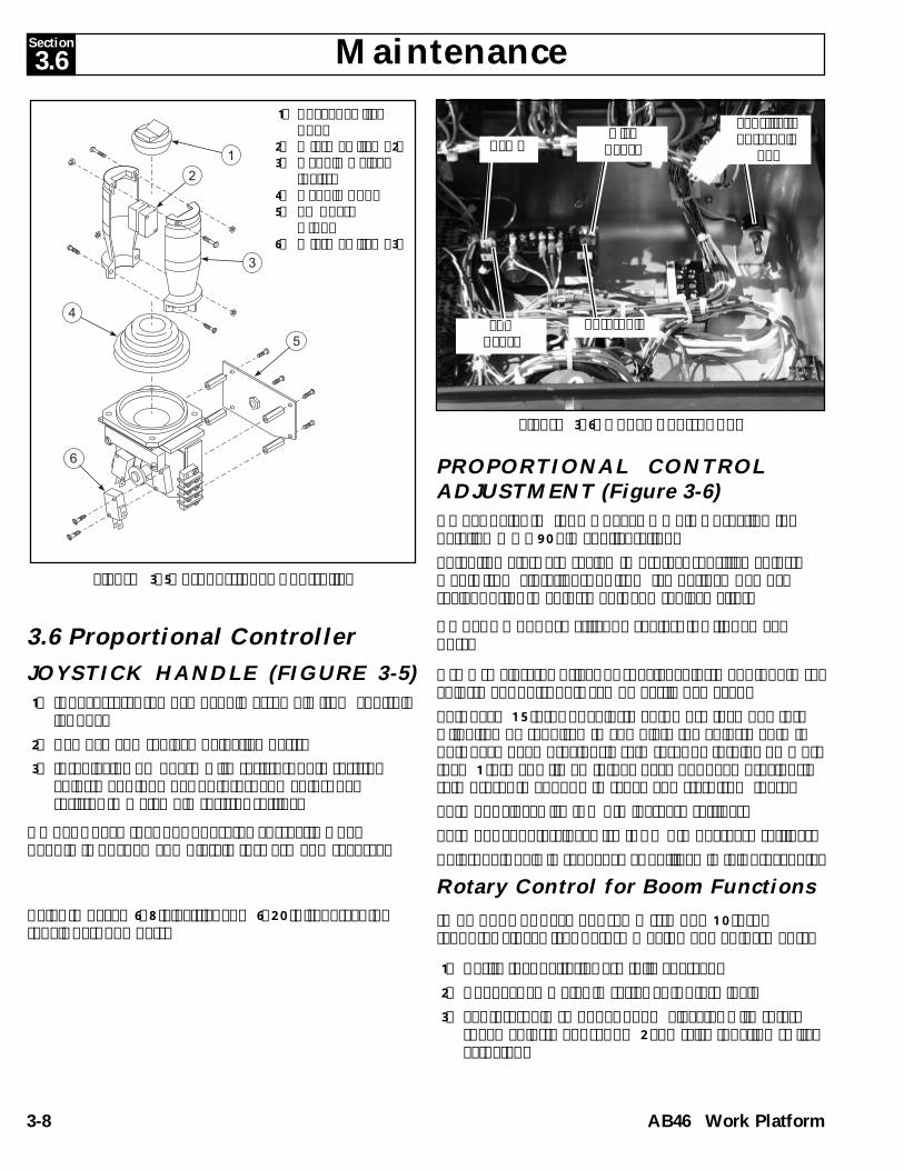
Basic Assembly, AB46 Electric068303-000 ................................................................ 6-14
Basic Assembly, AB46 Bi-Energy068313-000 ................................................................ 6-16
Basic Assembly, AB46 Electric068313-000 ................................................................ 6-17
Chassis Assembly, AB46 Electric068320-000 ................................................................ 6-18
Chassis Assembly, AB46 ElectricDrawing 1 of 2 ......................................................... 6-20
Chassis Assembly, AB46 ElectricDrawing 2 of 2 ......................................................... 6-21
Chassis Assembly, AB46 Bi-Energy068317-000 ................................................................ 6-22
Chassis Assembly, AB46 Bi-EnergyDrawing 1 of 3 ......................................................... 6-24
Chassis Assembly, AB46 Bi-EnergyDrawing 2 of 3 ......................................................... 6-25
Chassis Assembly, AB46 Bi-EnergyDrawing 3 of 3 ......................................................... 6-26
Lower Boom Linkage Assembly, AB46068323-000 ................................................................ 6-28
Lower Boom Linkage Assembly, AB46068323-000 ................................................................ 6-29

Section
iContents
AB46 Work Platform III
Upper Boom Linkage Assembly, AB46068322-000 ................................................................ 6-30
Upper Boom Linkage Assembly, AB46068322-000 ................................................................ 6-31
Turret Assembly, AB46 Electric & Bi-Energy068330-000 & 068330-003 ....................................... 6-32
Turret Assembly, AB46 Electric & Bi-Energy068330-000 & 068330-003 ....................................... 6-33
Power Unit Assembly, AB46 Electric068326-000 ................................................................ 6-34
Brake Valve Block Assembly068324-000 ................................................................ 6-35
Engine Assembly, AB46 Bi-Energy068951-000 ................................................................ 6-36
Engine Assembly, AB46 Bi-EnergyDrawing 1 of 2 ......................................................... 6-37
Engine Assembly, AB46 Bi-EnergyDrawing 2 of 2 ......................................................... 6-38
Power Unit Assembly, AB46 Bi-Energy068326-001 ................................................................ 6-39
Brake Valve Block Assembly, AB46 Bi-Energy068326-001 ................................................................ 6-40
Valve Block Assembly068348-000 ................................................................ 6-42
Valve Block Assembly068348-000 ................................................................ 6-43
Ground Control Box Asembly, AB46 Electric068328-000 ................................................................ 6-44
Ground Control Box Asembly, AB46 ElectricDrawing 1 of 3 ......................................................... 6-45
Ground Control Box Asembly, AB46 ElectricDrawing 2 of 3 ......................................................... 6-46
Ground Control Box Asembly, AB46 ElectricDrawing 3 of 3 ......................................................... 6-47
Ground Control Box Asembly, AB46 Bi-Energy068328-003 ................................................................ 6-48
Ground Control Box Asembly, AB46 Bi-EnergyDrawing 1 of 3 ......................................................... 6-49
Ground Control Box Asembly, AB46 Bi-EnergyDrawing 2 of 3 ......................................................... 6-50
Ground Control Box Asembly, AB46 Bi-EnergyDrawing 3 of 3 ......................................................... 6-51
Relay Panel Assembly, AB46 Electric068346-000 ................................................................ 6-52
Relay Panel Assembly, AB46 ElectricDrawing 1 of 2 ......................................................... 6-53
Relay Panel Assembly, AB46 ElectricDrawing 2 of 2 ......................................................... 6-54
Relay Panel Assembly, AB46 Bi-Energy068346-001 ................................................................ 6-56
Relay Panel Assembly, AB46 Bi-EnergyDrawing 1 of 2 ......................................................... 6-57
Relay Panel Assembly, AB46 Bi-EnergyDrawing 2 of 2 ......................................................... 6-58
Speed Control Panel Assembly, AB46 Bi-Energy068321-000 ................................................................ 6-59
AB46 Electric Controller Inststallation068339-001 ................................................................ 6-60
Section PageNo. No.
Table of Contents (cont.)Figure Page
No. Title No.AB46 Bi-Energy Controller Inststallation
068339-011 ................................................................ 6-61AB46 Electric Controller, Platform
068329-000 ................................................................ 6-62AB46 Electric Controller, Platform
Drawing 1 of 2 ......................................................... 6-63AB46 Electric Controller, Platform
Drawing 2 of 2 ......................................................... 6-64AB46 Bi-Energy Controller, Platform
068329-010 ................................................................ 6-66AB46 Bi-Energy Controller, Platform
Drawing 1 of 2 ......................................................... 6-67AB46 Bi-Energy Controller, Platform
Drawing 2 of 2 ......................................................... 6-68Hose Kit, AB46 Electric
068336-000 ................................................................ 6-70Hose Kit, AB46 Electric
068336-000 ................................................................ 6-71Hose Kit, AB46 Bi-Energy
068336-002 ................................................................ 6-72Hose Kit, AB46 Bi-Energy
068336-002 ................................................................ 6-73Battery Module Assembly, AB46
068321-001,002 ......................................................... 6-74Tire & Wheel Assembly, AB46
068327-000 ................................................................ 6-75Cable Assembly, AB46
068333-000 ................................................................ 6-76Cage "B" Assembly
068325-001 ................................................................ 6-78Cage "B" Assembly
068325-001 ................................................................ 6-79Cage "A"
068500-000 ................................................................ 6-804 FT. Cage
068500-003 ................................................................ 6-81Label Kit, AB46 Electric
068335-000 ................................................................ 6-82Label Kit, AB46 Bi-Energy
068335-003 ................................................................ 6-82Label Kit, AB46 Electric
068335-000 ................................................................ 6-83Label Kit, AB46 Bi-Energy
068335-003 ................................................................ 6-83Motion Alarm/Flashing Beacon - Option
068294-000 ................................................................ 6-84Motion Alarm/Flashing Beacon - Option
068294-000 ................................................................ 6-85Battery Charge Indicator - Option
068297-000 ................................................................ 6-86

ContentsiSection
IV AB46 Work Platform
List of Tables
Figure PageNo. Title No.
1-1 Specifications ............................................................ 1-23-1 Preventative Maintenance Checklist .................... 3-23-3 Bolt Torque ............................................................... 3-313-4 Hydraulic Component Torque .............................. 3-314-1 Troubleshooting Guide-Hydraulics ..................... 4-44-2 Troubleshooting Guide-Electrical ......................... 4-54-3 Calibrator Settings ................................................... 4-94-4 Test Display .............................................................. 4-94-5 Calibrator Diagnostics ............................................ 4-155-1 Electrical Schematic Legend, Electric Model ...... 5-25-2 Electrical Schematic Legend, Bi-Energy Model .. 5-45-3 Engine Assembly - Kubota ZB600C
S/N 1000-1331 .......................................................... 5-75-4 Engine Assembly - Kubota ZB600C
S/N 1331- .................................................................. 5-85-5 Hydraulic Schematic Legend................................. 5-125-6 Upper Controller Components ............................. 5-155-7 Lower Controller Components ............................. 5-17
1-1: AB46 Work Platform ............................................... 1-12-1A: Chassis Controls, Bi-Energy .................................. 2-32-2B: Platform Controls, Bi-Energy ................................ 2-32-1B: Chassis Controls, Electric ....................................... 2-32-2B: Platform Controls, Electric ..................................... 2-32-2: Transporting Work Platform ................................. 2-12-3: Fall Restraint Ancorage Point ................................ 2-42-4: Emergency Control Operation .............................. 2-72-5: Manual Turret Rotation .......................................... 2-72-6: Securing the Machine for Transportation ............ 2-82-7: Battery Charger ........................................................ 2-92-8: Batteries ..................................................................... 2-92-9: Hydraulic Oil Filler ................................................. 2-93-1: Blocking Elevating Assembly ................................ 3-33-2: Lubrication Chart .................................................... 3-53-3: Torque Hub .............................................................. 3-63-4: Valve Manifold ........................................................ 3-73-5: Proportional Controller .......................................... 3-83-6: Upper Control Box .................................................. 3-83-7: Platform Down Limit Switch ................................. 3-93-8: Tilt Sensor ................................................................. 3-93-9: Hydraulic Manifold, Exploded View ................... 3-113-10: Hydraulic Power Unit ............................................ 3-123-11: Rear Axle Assembly ................................................ 3-123-12: Brake Assembly ....................................................... 3-133-13: Replacing Drive Motor Brushes ............................ 3-143-14: Front Axle Assembly .............................................. 3-153-15: Torque Hub Assembly ............................................ 3-163-16: Measuring Hub End Play ....................................... 3-183-17: Torque Hub .............................................................. 3-193-18: Seal Pressing Tool .................................................... 3-203-19: Bearing Cone Pressing Tool ................................... 3-213-20: Bearing Cup Pressing Tool ..................................... 3-223-21: Master Cylinder ....................................................... 2-233-22: Slave Cylinder .......................................................... 3-243-23: Cage Rotate Cylinder .............................................. 3-253-24: Steering Cylinder ..................................................... 3-263-25: Jib Cylinder ............................................................... 3-273-26: Boom Raise Cylinder .............................................. 3-283-27: Removing Boom Extend Cylinder ........................ 3-293-28: Boom extend Cylinder ............................................ 3-304-1: MOS90 Pin Out Designation .................................. 4-164-2: Tachometer Board ................................................... 4-17
List of Illustrations
Table PageNo. Title No.
5-1: Electrical Schematic, Electric Model .................... 5-35-2: Electrical Schematic, Bi-Energy Model
S/N 1000-1331 ......................................................... 5-55-3: Electrical Schematic, Bi-Energy Model
S/N 1331- ................................................................. 5-65-4: Kubota Engine Diagram S/N 1000-1331 ............. 5-75-5: Kubota Engine Diagram S/N 1331- ...................... 5-85-6: Hydraulic Valve Ports ............................................ 5-95-7: Check Ports ............................................................... 5-105-8: Hydraulic Schematic ............................................... 5-135-9: Valve Block Assembly ............................................ 5-145-10: Upper Controller ..................................................... 5-155-11: Electrical Diagram, Upper Control Box, Elec. .... 5-165-12: Electrical Diagram, Upper Control Box, Bi-E. .... 5-165-13: Lower Control Box Cover ...................................... 5-175-14: Terminal Strip, Relay Identification ..................... 5-175-15: Electrical Diagram - Lower Control Box, Elec .... 5-185-16: Electrical Diagram - Bi-Energy Model
S/N 1000-1331 ......................................................... 5-195-17: Electrical Diagram - Bi-Energy Model
S/N 1331- ................................................................. 5-205-18: Relay Panel ............................................................... 5-215-19: Relay Panel Schematic ............................................ 5-22
Figure PageNo. Title No.
List of Illustrations (continued)

Introduction & Specifications Section
AB46 Work Platform 1-1
1.0 IntroductionPURPOSEThe purpose of this service and parts manual is toprovide instructions and illustrations for the operationand maintenance of the AB 46 Work Platform manufac-tured by UpRight, Inc. of Selma, California.
SCOPEThe manual includes procedures for proper operation,maintenance, adjustment, and repair of this product as well asrecommended maintenance schedules and troubleshooting.
1.1 General DescriptionThe AB46 Work Platform consists of the platform,controller, elevating assembly, power module, controlmodule, and chassis.
PlatformThe platform has a reinforced steel floor, 43.5 inch (1.11 m)high guardrails with midrail, 6 inch (152 mm) toeboardsand an entrance gate at the side of the platform.
DO NOT use the maintenance platformwithout guardrails properly assembled andin place.
Platform ControllerThe platform controller contains the controls to operatethe machine. It is located at the front of the platformcage. The foot switch must be depressed to operate anyfunction from the platform. A complete explanation ofcontrol functions can be found in Section 2.
Elevating AssemblyThe platform is raised and lowered by the elevatingassembly; an articulated boom powered by two singlestage lift cylinders. The hydraulic pump, driven by thebatteries, powers the cylinders. Solenoid operated valvescontrol raising and lowering.
ChassisThe chassis is a structural frame that supports all thecomponents of the AB46 Work Platform. It contains theengine (BiEnergy models), batteries, hydraulic powerunit, and electric drive motors.
PURPOSE OF EQUIPMENTThe objective of the AB46 Work Platform is to provide aquickly deployable, self propelled, variable height workplatform to elevate personnel and materials to overheadwork areas.
SPECIAL LIMITATIONSTravel with the platform raised is limited to a creepspeed range.Elevating of the Work Platform is limited to firm, levelsurfaces only. Any degree of slope greater than 5o willsound a warning alarm when machine is elevated. Ifmachine is lowered, a light will illuminate on platformcontrol box.
The elevating function shall ONLY be usedwhen the work platform is level and on afirm surface. The work platform is NOTintended to be driven over uneven, roughor soft terrain when elevated.
Figure 1-1: AB46 Work Platform
1.0
2
1
4
3
6
5
4. Boom5. Chassis Control Module6. Chassis
1. Platform2. Platform Controller Assembly3. Elevating Assembly

Introduction & Specifications
1-2
Section
AB46 Work Platform
1.2
1.2 SpecificationsTable 1-1: Specifications
REACH ENVELOPE DIAGRAMITEM SPECIFICATIONHeight
Working height maximum 52 ft. [15.8 m]Platform height maximum 46 ft. [13.98 m]Platform step in height 9 in. [22.86 cm]Up and over height 25 ft. [7.6 m]Drivable height 46 ft. [13.98 m]
Horizontal outreach 24 ft. 6 in. [7.44 m]Turret rotation 360 deg. non-continuousPlatform rotation 160 deg.Tail swing NoneJib length 5 ft. [1.52 m]Jib arc 140 deg.Inside turning radius 2 ft. [.61 m]Outside turning radius 9 ft. 10 in. [2.98 m]Drive speed (lowered) 3.5 mph [5.63 kph]Drive speed (elevated) .34 mph [.55 kph]Gradeability 30%Dimensions (boom stowed)
Platform Size 69 in. x 39 in. [1.75 m x .99 m]Guardrail height 43
1/2 in. [1.10 m]Toeboards 6 in. [15.24 cm]Maximum platform capacity 500 lbs. [226.8 kg]Maximum no. of occupants 2Weight 14,300 lbs. [6486.4 kg]Overall height 6 ft 6 in. [1.97 m]Overall length 17 ft. 10 in. [5.41 m]Overall width 5 ft. 9 in. [1.75 m]Wheel base 73 in. [1.85 m]Wheel track 59 in. [1.5 m]Ground Clearance 6 in. [15.24 cm]
Power source Eight 6V, 350 AH BatteriesOne Kubota12 HP Diesel(BiEnergy models)
System voltage 48VDCMaximum Hyd. Pressure 2500 psi [172.4 bar]Controls Electric ProportionalTires 9.5x16.5 10 ply highway treadFuel tank - BiEnergy model 8 gal. [30 l]Generator output 85 ampsCharger output 40 ampsHydraulic tank 6 gal [22.7 l]
DIMENSIONS IN FEET
* Specifications subject to change without notice.Meets or exceeds all applicable requirements of OSHA and ANSI A92.5-1992

AB46 Work Platform 2-1
NEVER operate themachine within ten (10)feet of power lines. THISMACHINE IS NOTINSULATED.
NEVER operate theboom or drive withplatform elevatedunless on firm levelsurface.
NEVER position theplatform without firstchecking for overheadobstructions or otherhazards.
NEVER climb, stand orsit on platform guardrailsor midrail.
Electrocution Hazard Tip Over Hazard Collision Hazard Fall Hazard
AB-46 Electric & Bi-EnergyWARNING
All personnel shall carefully read, understand and follow all safety rules, operatinginstructions, and the Scaffold Industry Association’s MANUAL OF RESPONSIBILITIES
(ANSI A92.5) before operating or performing maintenance on any UpRight boom supportedaerial work platform.
ALL occupants must wear an approved fall restraint properly attached to designated platform anchoragepoint. Attach only one fall restraint to each anchorage point.NEVER exceed maximum platform load of 500 lbs. (225 kg) and two (2) occupants.NEVER exceed 45 lbs. (200 N) of side force per occupant.DISTRIBUTE all platform loads evenly on the platform.NEVER operate the machine without first surveying the work area for surface hazards such as holes, drop-offs, bumps, curbs, or debris; and avoiding them.OPERATE machine only on surfaces capable of supporting wheel loads.NEVER elevate the machine when wind speeds exceed 28 mph (12.5 m/sec.).IN CASE OF EMERGENCY push emergency stop button to cut power to all machine functions.ALWAYS close and secure gate after entering platform.NEVER exit or enter platform while elevated.NEVER use ladders, scaffolding, or other items to gain height; work only from the platform floor.NEVER climb down elevating assembly while platform is elevated.INSPECT the machine thoroughly for cracked welds, loose or missing hardware, hydraulic leaks, loosewire connections, and damaged cables or hoses before using.VERIFY that all labels are in place and legible before using. Refer to page 10 & 11 for label identification.NEVER use a machine that is damaged, not functioning properly, or has damaged or missing labels.IF ALARM SOUNDS while boom is elevated, STOP, carefully retract boom and lower platform withoutrotating. Move machine to a firm, level surface.NEVER attach overhanging loads or use boom as a crane.NEVER alter operating or safety systems without manufacturers written consent.NEVER charge battery near sparks or open flame. Charging batteries emit explosive hydrogen gas.NEVER replace any component or part with anything other than original UpRight replacement partswithout the manufacturer's written consent.NEVER tow the machine. Transport by truck or trailer only.AFTER USE, secure the work platform from unauthorized use by turning both keyswitches off and removing all keys.
SAFETY RULES
Section2.1
Safety R
ules an
d O
peratin
g In
structio
nsS
afet
y R
ule
s an
d O
per
atin
g I
nst
ruct
ion
sOperation

2-2 AB46 Work Platform
IntroductionThis section covers the operation of Electric andBi-Energy powered models of the AB-46.
Pre-Operation and SafetyInspection
Carefully read, understand and follow all safetyrules, labels, and operating instructions, thenperform the following steps each day before use.
Perform a complete visual inspection of the entireunit prior to operating. Check the following areasfor discrepancies:
1. Open panels and check hydraulic components /hoses for damage or leaks. Check electricalcomponents / wiring for damage or loose connec-tions.
2. Inspect chassis, axles, hubs, and steering linkagefor damage, deformation, buckled paint, loose ormissing hardware, and cracked welds.
3. Check tires for damage, punctures, and inflation;tire pressure must be 75 psi.
4. Check all hoses / cables for wear.
5. Inspect elevating assembly for damage, deforma-tion, buckled paint, loose or missing hardware,and cracked welds.
6. Inspect platform and guardrails for damage,deformation, buckled paint, loose or missinghardware, and cracked welds. Insure that gateoperates freely and latches securely.
7. Check Hydraulic fluid level with platform fullylowered.
8. Check battery fluid level (see battery mainte-nance, page 2-8).
9. Check fuel level, add fuel if necessary.
10.Ensure that radiator is cold, check coolant level.Add if necessary.
NEVER remove the cap from a hot radiator.Hot coolant can cause severe burns.
DO NOT use a machine that is damaged ormalfunctioning. Tag and remove the unitfrom service until it is repaired.
SYSTEM FUNCTION INSPECTIONNote: Refer to figures 1 and 2 for chassis and plat-form control locations.
1. Before performing the following tests, check areaaround machine and overhead for obstructions, holes,drop-offs, and debris.
2. Turn chassis key switch to chassis, and turn on(rotate clockwise) emergency stop switches at thechassis control panel and at the platform controlpanel.
Note: Bi-Energy machines may be powered bybatteries or by engine. To power the machine byengine, press engine start button to crank engine;release when engine starts. If engine is cold: pressthe preheat button and hold for six seconds prior tostarting diesel models.
3. Push in the chassis emergency stop button andoperate any function switch at the chassis controlpanel, function should NOT activate. Repeat forplatform emergency stop button, operating chassiscontrols. Return both emergency stop switches tothe on position.
4. Operate each function switch to raise / lower, extend/ retract, rotate left / right, each section of theelevating assembly and observe the operation of themachine. All functions should operate through fullcycle smoothly.
5. Turn chassis key switch to platform.
6. Mount the platform, close and latch the gate, andattach approved fall restraint to designated platformanchorage point. Attach only one fall restraint toeach point.
7. Without depressing the foot switch, move the drivecontrol handle, machine should not function.
8. Depress the foot switch and move the drive controlhandle forward and reverse. Observe that propor-tional functions operate smoothly, and that brakesapply quickly after control is released.
9. While depressing foot switch, operate steer switch toleft and right. Observe that steering wheels turnproperly.
10. While depressing foot switch, turn function speedcontrol knob to desired setting, and operate boomcontrols. Observe that boom operates smoothly, andthat upper boom, jib, turret rotation, platform level,and platform rotation controls operate proportionally inconjunction with function speed control knob. Ob-serve that platform maintains level when boom iselevated.
11. With the upper boom elevated one foot, operate drivecontrol handle. Observe that drive speed is limited tocreep (1/2 foot [.15m] per second). Lower upperboom to stowed position.
12. Press the service horn button. Observe that horn isaudible.
OperationSection2.1

AB46 Work Platform 2-3
Figure 2-1A: Chassis ControlsNote: The following list corresponds to thenumbered items in figures 1A and 2A.
1. Emergency stop.2. Diesel Engine start.3. Glow Plug button.4. Keyswitch5. Control fuses.6. Riser control.7. Upper boom control.8. Boom extension control.9. Jib control.10.Turret rotation control.11.Platform rotation control.12.Platform level control.13.Battery condition indicator & Hourmeter.14.Service horn button.15.Drive control handle.16.Function speed control.17.Foot switch (located on platform floor).18.Out of level indicator.19.Low Voltage indicator.
Bi-Energy Model Controlsand Indicators
Figure 2-2A: Platform Controls
3
11
1
8
Figure 2-1B: Chassis ControlsNote: The following list corresponds to thenumbered items in figures 1A and 2A.
1. Emergency stop.2. Electric motor start.3. Low Voltage Indicator.4. Keyswitch5. Control fuses.6. Riser control.7. Upper boom control.8. Boom extension control.9. Jib control.10.Turret rotation control.11.Platform rotation control.12.Platform level control.13.Hourmeter.14.Service horn button.15.Drive control handle.16.Function speed control.17.Foot switch (located on platform floor).18.Out of level indicator.
Electric Model Controlsand Indicators
Figure 2-2B: Platform Controls
2
1
45
8
9
12
111310
7
6
2
6
7
10 13 11
12
9
4 5
15
129876
3
18
10
114
11
5 164
2 16
4
5314
1
10
18
19
6 7 8 9 12
15

2-4 AB46 Work Platform
Figure 2-3: Typical Fall Restraint AnchoragePoint
OperationBefore operating work platform insure that:
Pre-operation and safety inspection has beencompleted, and any discrepancies have beencorrected.
The operator has been thoroughly trained onthe operation of the machine.
The work area is clear of all obstructions,holes, drop-offs, or persons in the route oftravel.
The surface is capable of supporting wheel loads.
Refer to figures one and two for control locations.
Emergency Stop
At any time during operation, press the emergencystop button to stop all functions in an emergency.
Service Horn
At any time during operation, press service hornbutton to sound an audible warning if necessary.
Always wear an approved fall restraintproperly attached to designated platformanchorage point when driving or elevatingthe machine (see Figure 2-3).
Attach only one fall restraint to each anchor-age point.

AB46 Work Platform 2-5
Driving
With Boom Lowered1. Turn chassis key switch to platform, and turn on
(turn clockwise) the chassis emergency stopswitch.
2. Mount the platform, close and latch the gate.
3. Attach approved fall restraint to designatedplatform anchorage point. Attach only one fallrestraint to each point.
4. Check that the area around and above the workplatform is clear of obstructions, holes, drop-offs,persons in the route of travel, and the surface iscapable of supporting wheel loads.
5. Depress the foot switch and move the drivecontrol handle forward to travel forward andreverse to travel in the reverse direction.
Note: When the boom is rotated to the front ofthe chassis (steering wheels aft) directions oftravel and steering will be reversed. Observe thecolor coded arrows on the control panel near thedrive control handle, and on the chassis. Theywill indicate the direction of travel when the drivecontrol handle is moved.
With Boom ElevatedTravel with boom elevated is restricted to firmlevel surfaces only.When driving elevated, the machine will travel atcreep speed (1/2 foot [.15 m] per second).
Steering1. While depressing the foot switch, push the steering
switch (located on top of the control handle) to theleft to turn left, and right to turn right.
Note: Steering is not self centering. Wheelsmust be returned to the straight ahead positionby operating the steering switch.
POSITIONING THE PLATFORMPositioning the platform as close as possible to thework area requires some planning. First, you mustsurvey the work site to find a suitable place to parkthe machine. This must be a firm level area as closeas possible to the work area. Take into consider-ation all obstructions on the ground and overheadand avoid them.
Once you have moved the machine to a firm levelsurface as near as possible to the work area, followthe instructions on page 5 to position the platform.
Always, before operating any function, check thearea around and overhead for any obstructions orelectrical conductors.
Multifunction ControlsThe UpRight AB-46 employs the use of multifunctioncontrols. This means that riser or boom extensionwill function at full speed while simultaneouslyoperating upper boom, jib, turret, or rotating theplatform.
The turret may be rotated while driving if necessaryto make turns in tight areas. All other boom func-tions will not operate while driving.
Lower Control OperationAll boom functions will operate at fixed speed.
1. Turn chassis keyswitch to chassis controls.
2. Operate boom control switches to position theplatform.

2-6 AB46 Work Platform
Elevating the UpperBoom
1. Set the function speed control dial to the desiredsetting. Rotate the dial clockwise to increasespeed, counterclockwise to decrease. If you arenot sure what speed to use, start out slow; thespeed can be varied while operating the function.
2. While depressing the foot switch, push the upperboom control lever forward to elevate the upperboom, rearward to lower the upper boom. Releasethe control lever to stop elevating / lowering.
Extending the UpperBoom
1. While depressing the foot switch, push the boomextension control lever rearward to extend theboom, forward to retract the boom. Release thecontrol lever to stop extending / retracting. Theboom extension will function at a constant speed,function speed control setting is not necessary.
Elevating the Jib
1. Set the function speed control dial to the desiredsetting. Rotate the dial clockwise to increasespeed, counterclockwise to decrease. If you arenot sure what speed to use, start out slow; thespeed can be varied while operating the function.
2. While depressing the foot switch, push the jibcontrol lever forward to elevate the jib, rearwardto lower the jib. Release the control lever to stopelevating / lowering.
Rotating the Platform
1. Set the function speed control dial to the desiredsetting. Rotate the dial clockwise to increasespeed, counterclockwise to decrease. If you arenot sure what speed to use, start out slow; thespeed can be varied while operating the function.
2. While depressing the foot switch, turn theplatform rotation control switch counterclock-wise to rotate left, clockwise to rotate right.Release the switch to stop rotation.
Leveling the Platform
DO NOT operate the machine if theplatform does not maintain level whenelevated.
Note: Platform leveling can be performed onlywith the boom stowed and should be done onlyto calibrate the automatic leveling system.
1. Set the function speed control dial to the desiredsetting. Rotate the dial clockwise to increasespeed, counterclockwise to decrease. If you arenot sure what speed to use, start out slow; thespeed can be varied while operating the function.
2. While depressing the foot switch, push theplatform level control switch forward to swing theplatform upward, rearward to swing the platformdownward. Release the switch to stop leveling.
Rotating the Turret
1. Set the function speed control dial to the desiredsetting. Rotate the dial clockwise to increasespeed, counterclockwise to decrease. If you arenot sure what speed to use, start out slow; thespeed can be varied while operating the function.
2. While depressing the foot switch, turn the turretrotation control switch counterclockwise to rotateleft, clockwise to rotate right. Release the switchto stop rotation. Observe the area around theboom when rotating the turret to avoid anyobstructions.
Elevating the Riser
1. While depressing the foot switch, push the risercontrol lever forward to elevate the riser, rear-ward to lower the riser. Release the controllever to stop elevating / lowering. The riser willfunction at a constant speed, function speedcontrol setting is not necessary.

AB46 Work Platform 2-7
EMERGENCY OPERATIONIn the event of powered function failure, the elevat-ing assembly may be lowered manually by thefollowing procedure.
NEVER climb down the elevating assembly.If controls do not respond, ask someone onthe ground to lower the boom manually.
Lowering Elevating Assembly1. Open the cover on the hydraulic module (opposite
side of the turret from the chassis control panel).
2. Remove the wire loop retainer from the handpump lever, and extend the handle upward togain leverage.
3. Operate the manual override (knurled knob) on theappropriate valve (see figure 4). Push in to lower /extend, pull out to raise / retract as required.
4. While holding the appropriate valve in position,pump the handle in and out until that section ofthe elevating assembly is lowered / retracted.
5. Repeat as necessary operating each valve untilthe elevating assembly is fully lowered.
Rotating Turret1. Obtain a 7/8 inch ratcheting wrench.
2. Place the socket of the wrench onto the hex shaftstub of the turret rotation gearbox.
3. Turn the wrench clockwise to rotate the turretcounterclockwise, turn counterclockwise torotate the turret clockwise.
Figure 2-4: Emergency Control Operation
Figure 2-5: Manual Turret Rotation
Emergency control pump
Riser Valve
Boom Valve
Extend Valve
Jib Valve
7/8 in. RatchetingWrench
Turret RotationGear Box
EMERGENCY TOWINGPerform the following only when the machine willnot operate under its own power and it is neces-sary to move the machine or when winching onto atrailer for transportation.
1. Insure that the platform is fully lowered, and thatthe turret is rotated so the platform is to the rearof the machine.
2. Attach chain / cable of sufficient strength fortowing the machine to front or rear tie down lugs.
3. Turn the keyswitch to the parking brake releaseposition. Alarm will sound.
4. Operate the emergency control pump four fullstrokes to release brakes.
5. After moving the machine, return the keyswitch tothe off position and remove the key to preventunauthorized operation. Brakes are now reset.Alarm will stop.
DO NOT move the machine faster than 3mph. Faster speeds will damage drivecomponents and void warranty.
AFTER USE EACH DAY1. Ensure that the platform is fully lowered.
2. Park the machine on level ground, preferablyunder cover, secure against vandals, children orunauthorized operation.
3. Turn the key switch to OFF and remove all keysto prevent unauthorized operation.
BATTERY CHARGINGSee Maintenance, page 2-9.

2-8 AB46 Work Platform
Figure 2-6: Securing the Machine for Transportation
Transportation
BY CRANE
Stand clear of machine when lifting.
Check specifications on back page, insurethat crane and slings are of correct capacityto lift weight of unit.
1. Insure that boom is fully lowered and retracted.
2. Attach straps to chassis lifting lugs only. Insurethat straps are adjusted properly to keep unitlevel when lifting.
BY TRUCK OR TRAILER1. Insure that boom is fully lowered and retracted.
2. Maneuver the machine onto bed of truck / trailer.
3. When winching, follow instructions for emergencytowing on page 2-7. Attach winch cable to fronttie down lugs.
Do not winch machine faster than 3 mph.
4. After winching, insure that brakes are set.
5. Secure the machine to the transport vehicleusing chains / straps of adequate load capacity(refer to specifications, back page) attached tochassis tie down lugs (see Figure 2-6).
6. Place a wooden block (7.5" x 4" x 28") underplatform support braces as shown (see Figure2-6).
7. Attach ratchet strap; under platform floor grating,over support braces (see Figure 2-6). Tightensecurely, do not overtighten.
NEVER elevate the machine while on atruck or trailer.
Wooden Block7.5" x 4" x 28"
Chassis Tie Down /Lifting Lug (typ.)

AB46 Work Platform 2-9
Maintenance
TIRESTire selection can affect the stability of the ma-chine. Use only tires supplied by UpRight unlessapproved by the manufacturer in writing.
BATTERY CHARGING
Charge batteries only in a well ventilated area.
Hazard of explosive gas mixture. Keepsparks, flame and smoking materials awayfrom batteries.
Always wear safety glasses when workingwith batteries.
Battery fluid is highly corrosive. Rinse awayany spilled fluid thoroughly with clean water.
Always replace batteries with UpRight batter-ies or manufacturer approved replacementsweighing 120 lbs. each.
Charge batteries as follows:1. Check the batteries fluid level. If the electrolyte
level is lower than 3/8 in. (10 mm) above theplates, add clean, distilled water only.
2. Verify charger voltage switch is set to the correctvoltage.
3. Connect extension cord (minimum 12 gauge (1.5 mm) conductor and maximum 50 ft. (15 m)in length) to charger plug located through theopening in front of the chassis (Figure 2-7).Connect extension cord to properly groundedoutlet of proper voltage and frequency.
3. The charger will turn on automatically.4. When the batteries are fully charged, the
charger will turn off automatically .
BATTERY MAINTENANCECheck battery fluid level daily, especially if workplatform is being used in a warm, dry climate.
If electrolyte level is lower than 3/8 in. (10 mm)above plates add distilled water only. DO NOT usetap water it will shorten battery life.
Keep terminals and top of battery clean.
HYDRAULIC OIL1. Check oil level at dipstick and/or sight gauge
inside engine compartment left hand side with theplatform fully lowered.
2. Lift flap located on top of chassis left side(see Figure 2-9).
3. Open filler / breather cap.
4. If necessary, fill to capacity with clean ISO 46compatible hydraulic oil.
5. Replace cap.
LUBRICATIONRefer to service manual for lubrication chart andguidelines.
Figure 2-7: Battery ChargerFigure 2-9: Hydraulic Oil Filler / Breather Cap,Fuel Filler / Breather Cap, and Oil Level Sight
Gauge
Figure 2-8: Batteries (Typical Both Sides)
Hydraulic Oil Filler /Breather Cap
Battery Disconnect
Oil LevelSight Gauge
Fuel Filler /Breather Cap
Ammeter
AC Cord

2-10 AB46 Work Platform
NOTES:

Section
3-1AB46 Work Platform
Maintenance
3.0 Introduction
Be sure to read, understand and follow allinformation in the Operation Section ofthis manual before attempting to operateor perform service on any AB46 WorkPlatform.
NOTE: Bi-Energy models - For service Information onthe engine, refer to your engine manual.
This section contains procedures for the operationinspection, adjustment, scheduled maintenance, andrepair/removal of the AB46.Section 2.0 will aid in understanding the operation andfunction of the various components and systems of theAB46 and help in diagnosing and repair of the machine.Refer to Table 3-1, Preventative Maintenance Checklist,for recommended maintenance intervals.
NOTE: Torque all hardware to torques listed on page3-31 unless otherwise specified.
TERMINOLOGYTERMINAL BLOCKS: Located in upper and lowercontrol boxes. Designated by TB##. (##) designatesthe number of the block which is written on the termi-nal block. "R" right or "L" may follow the number.WIRE COLOR: Indicated by color/color. First colorrefers to insulation color and second color indicatesstripe. If second color is not given there is no stripe.FORWARD: Front of machine indicated by yellowarrows on chassis.AFT: Rear of machine indicated by orange arrows onmachine.GENERAL PROCEDURESCONTACT BLOCKS: Removed by inserting a flatscrewdriver into the slot at either end of block andprying outward. Installed by pressing into an empty slot.SWITCH MOUNT BASE: Assembled to back of switchactuator. Removed by rotating the small black levercounterclockwise and lifting off base.TERMINAL BLOCKS: Remove wires by inserting a smallflat bladed screwdriver into square beside wire. Installwires by stripping 1/2" of insulation, inserting screw-driver in square and inserting wire. Be sure no strandsare bend backwards. Replace wires with same ratingand type.
3.0
LOWER CONTROL BOXDisconnect battery connectors at front of each batterybox. Bi-Energy machines, disconnect negative lead fromstarter battery in chassis. With left battery cover in placeto prevent shorting, remove hardware which securescontrol box cover and rest on battery cover.
SPECIAL TOOLSThe following is a list of special tools which may berequired to perform certain maintenance procedures onthe AB46 work platform.
0-1000 PSI Hydraulic Pressure Gaugewith Adapter Fittings (UpRight P/N 014124-010)
0-3000 PSI Hydraulic Pressure Gaugewith Adapter Fittings (UpRight P/N 014124-030)
0-30 Gallon Hydraulic Flow MeterWith 0-3000 P.S.I. Simulated Load and AdapterFittings (UpRight P/N 67040-000)
Adapter Fitting (UpRight P/N 063965-002)Inclinometer (UpRight P/N 010119-000)MOS90 Calibrator (UpRight P/N 057128-000)Crimping Tool (UpRight P/N 028800-009Terminal Removal Tool (P/N 028800-006)
3.1 Preventative Maintenance(Table 3-1)The complete inspection consists of periodic visual andoperational checks, together with all necessary minoradjustments to assure proper performance. Dailyinspection will prevent abnormal wear and prolong thelife of all systems. The inspection and maintenanceschedule is to be performed at regular intervals. Inspec-tion and maintenance shall be performed by personnelwho are trained and familiar with mechanical andelectrical procedures.
Before performing preventative mainte-nance, familiarize yourself with the opera-tion of the machine.Always block the elevating assembly when-ever it is necessary to perform mainte-nance while the platform is elevated.

Section
3-2 AB46 Work Platform
Maintenance3.1
Preventative Maintenance ReportDate: _______________________________________Owner: ______________________________________Model No: ___________________________________Serial No: ____________________________________Serviced By: __________________________________Service Interval: ______________________________
Table 3-1: Preventative Maintenance Checklist
COMPONENT INSPECTION OR SERVICES INTERVAL Y N RBattery Check electrolyte level 6M
Check specific gravity 6M
Clean exterior 6M
Check battery cable condition DailyClean terminals 6M
Engine Oil Check level and condition Dailyand Check for leaks DailyFilter Change oil and filter 100H
Engine Fuel Check fuel level DailySystem Check for leaks Daily
Replace fuel filter 6M
Check air cleaner DailyEngine Check coolant level (with engine cold) DailyCoolant Replace coolant 400H
Hydraulic Check oil level DailyOil Change filter 6M
Drain and replace oil 2Y
Hydraulic Check for leaks DailySystem Check hose connections 30D
Check hoses for exterior wear 30D
Emergency Operate the emergency lowering DailyHydraulic valve and check for serviceabilitySystemController Check switch operation DailyControl Check the exterior of the cable DailyCable for pinching, binding or wearPlatform Check fasteners for proper torque DailyDeck and Check welds for cracks DailyRails Check condition of deck DailyTires Check for damage Daily
Check air pressure (75 psi [5.2 bar]) Daily
Check lug nuts (torque to 80 ft. lbs. [109 Nm]) 30D
COMPONENT INSPECTION OR SERVICES INTERVAL Y N RHydraulic Check for leaks at mating surfaces 30D
Pump Check for hose fitting leaks DailyCheck mounting bolts for proper torque 30D
Drive Motors Check for operation DailyTorque Check for leaks DailyHubs Check Oil level 250H/6M
Change Oil after break-in 50H/30D
Change Oil 1000h/2ySteering Check hardware & fittings for proper torque 6M
System Grease pivot pins 30D
Oil king pins 30D
Check steering cylinder for leaks 30D
Elevating Inspect for structural cracks DailyAssembly Check pivot points for wear 30D
Check mounting pin pivot bolts 30D
for proper torqueCheck elevating arms for bending 6M
Grease linkage pins 30D
Chassis Check hoses for pinch or rubbing points DailyCheck component mounting 6M
for proper torqueCheck welds for cracks Daily
Lift Check the cylinder rod for wear 30D
Cylinder Check mounting pin pivot bolts 30D
for proper torqueCheck seals for leaks 30D
Inspect pivot points for wear 30D
Check fittings for proper torque 30D
Steering Check the cylinder rod for wear 30D
Cylinder Check mounting pin pivot bolts 30D
for proper torqueCheck seals for leaks 30D
Inspect pivot points for wear 30D
Check fittings for proper torque 30D
Entire Check for and repair collision damage DailyUnit Check fasteners for proper torque 3M
Check for corrosion-remove and repaint 6M
Lubricate 30D
Labels Check for peeling, missing, or Dailyunreadable labels & replace
Turret Lubricate teeth 30D
CHECK BOLTS FOR TORQUE 150HR
GREASE GEARBOX 150HR
Table 3-1: Preventative Maintenance Checklist (cont'd.)
Preventative Maintenance Table Key
IntervalDaily=each shift or every day50h/30d=every 50 hours or 30 days250h/6m=every 250 hours or 6 months1000h/2y=every 1000 hours or 2 years
Y=Yes/AcceptableN=No/Not AcceptableR=Repaired/Acceptable
The preventative maintenance table has been designed to beused primarily for machine service and maintenance repair.Please photocopy this page and use the table as a checklistwhen inspecting the machine for service.

Section
3-3AB46 Work Platform
Maintenance 3.2
3.2 Blocking ElevatingAssembly (Figure 3-1)
Never perform service on the work plat-form in the elevating assembly area whileplatform is elevated without first blockingthe elevating assembly.DO NOT stand in elevating assembly areawhile deploying or storing brace.
Installation1. Park the work platform on firm level ground.2. Fully retract upper boom.3. Verify platform emergency stop switch is ON.4. Turn platform/chassis switch to CHASSIS.5. Using the raise button, elevate platform 8-12 inches.6. Connect a crane or overhead hoist capable of
supporting elevating assembly to front of elevatingassembly.
7. Install brace capable of supporting elevating assem-bly under upper boom as shown.
8. Push lower button and gradually lower platformuntil brace is supporting the platform.
9. Push electric motor start button to stop electricmotor.
Removal1. Using chassis controls, gradually raise platform until
upper boom is off brace.2. Remove brace and unhook chain from front of
upper boom.3. Push lower button to completely lower platform.
Figure 3-1: Blocking Elevating Assembly

Section
3-4 AB46 Work Platform
Maintenance
3.3 Battery Maintenance
Hazard of explosive gas mixture. Keepsparks, flame, and smoking material awayfrom battery.Always wear safety glasses when workingwith batteries.Battery fluid is highly corrosive. Thoroughlyrinse away any spilled fluid with cleanwater.
BATTERY INSPECTION ANDCLEANINGCheck battery fluid level daily, especially if work plat-form is being used in a warm, dry climate. If required,add distilled water ONLY. Use of tap water will shortenbattery life.The batteries should be inspected regularly for signs ofcracks in the case, electrolyte leakage and corrosion ofthe terminals. Inspect cables for worn spots or breaks inthe insulation and for broken cable terminals.Clean the batteries when they show signs of corrosion atthe terminals or when electrolyte has overflowed duringcharging. Use a baking soda solution to clean thebatteries, taking care not to get the solution inside thecells. Rinse thoroughly with clean water. Clean batteryand cable contact surfaces to a bright metal finishwhenever a cable is removed.
Hazard of explosive gas mixture. Keepsparks, flame, and smoking material awayfrom battery.Always wear safety glasses when workingwith batteries.Battery fluid is highly corrosive. Thoroughlyrinse away any spilled fluid with cleanwater.
3.4
BATTERY CHARGINGCharge batteries at the end of each work shift or soonerif the batteries have been discharged.
Charge the batteries only in a well venti-lated area.Do not charge the batteries when the workplatform is in an area containing sparks orflames.Permanent damage will result if the batter-ies are not immediately recharged afterdischarging.Never leave the charger unattended formore than two days.Never disconnect the cables from thebatteries when the charger is operating.Keep the charger dry.
Charge batteries as follows:1. Check the fluid level. If the electrolyte level is lower
than 3/8 in. (10mm) above the plates, add clean,distilled water only.
2. Connect the charger plug to a properly groundedoutlet of the proper voltage and frequency.
3. The charger turns on automatically after a shortdelay.
4. The charger turns off automatically when the batter-ies are fully charged.

Section
3-5AB46 Work Platform
Maintenance
The hydraulic oil may be hot enough tocause burns. Wear safety gloves and safetyglasses when handling hot oil.
2. Provide a suitable container to catch the drained oil.The hydraulic tank has a capacity of 5.0 gallons(19 l).
3. Remove the drain plug and allow all oil to drain intothe container. Be sure to dispose of oil properly.
4. Reinstall the drain plug.5. Remove filter element from filter head (located
beside valve block).6. Apply a thin film of clean hydraulic oil (ISO No. 46)
to the gasket of the replacement filter.7. Thread replacement filter onto the filter head until
the gasket makes contact then rotate 3/4 of a turnfurther.
8. Fill the hydraulic oil tank to operating level ondipstick (sight gauge -Electric model) with ISO #46hydraulic oil.
NOTE: Bi-Energy models - For service Information onthe engine refer to your engine manual.
3.4
3.4 LubricationRefer to Table 3-1 for the lubrication intervals andFigure 3-2 for location of items that require lubricationservice. Refer to the appropriate sections for lubricationinformation on the Steering Linkage, Torque hubs,Hydraulic Oil, Filter, and Engine Oil and Filter.
GREASE FITTINGSWipe each grease fitting before and after greasing.Using multipurpose grease in a grease gun, pump thegrease into the fitting until grease just begins to appearat the edges of the pivot, wipe off any excess grease.
HYDRAULIC OIL AND FILTER
Fluid LevelWith the platform fully lowered, check oil level ondipstick (sight gauge - Electric models). If the oil is NOTin operating range, add hydraulic fluid until oil is visiblein operating range on dipstick or visible in sight gauge.DO NOT fill above operating range or when the plat-form is elevated.
Oil and Filter Replacement1. Operate the platform for 10-15 minutes to bring the
hydraulic oil up to normal operating temperature.
Grease
Oil (open gear lube)
Figure 3-2: Lubrication Chart
Section
3-6 AB46 Work Platform
Maintenance3.5
TORQUE HUBS
Note: Change oil in torque hubs after the first 50hours of operation. Change every 2000 hours there-after.
1. Remove torque hub from drive assembly (refer tosection 3-12).
2. Remove drain plug from underside of torque huband drain oil from unit.
3. Replace drain plug.4. Remove fill plug from top side of torque hub.5. Remove fill level plug from side of hub.6. Fill unit with 90 wt. gear oil until oil comes out fill
level plug opening(1/2 full).7. Replace fill level plug. Replace fill plug.
Figure 3-3: Torque Hub

Section
3-7AB46 Work Platform
Maintenance 3.5
Figure 3-4: Valve Manifold
3.5 Setting Hydraulic Pressures
Figure (3-9) shows complete hydraulic manifoldassembly.
Note: Check hydraulic pressures whenever thepump, manifold or any relief valve has been servicedor replaced.
HIGH RELIEF VALVE (Figure 3-4)1. Operate the hydraulic system 10-15 minutes to
warm the oil.2. Remove the high relief port plug and install a 0-
3000 PSI pressure gauge assembly.3. Remove the plug in the end of the high relief valve
to expose the adjusting screw.4. Operate Jib raise function until jib is completely
raised.5. While activating the jib raise switch, set the pressure
to 2500 PSI (173 bar) maximum by slowly turningthe adjusting screw. Turning the adjusting screwclockwise increases pressure and counterclockwisedecreases pressure.
6. Remove the pressure gauge and reinstall all plugs.
LOW RELIEF VALVE1. Operate the hydraulic system 10 - 15 minutes to
warm the oil.2. Remove the low relief port plug and install a 0-3000
PSI pressure gauge assembly.3. Remove the plug in the end of the low relief valve
to expose the adjusting screw.4. Turn the low relief valve adjustment screw counter-
clockwise two full turns.5. Operate jib lower function until jib is completely
lowered.6. While activating the jib lower switch, set the pres-
sure to 1500 PSI (104 bar) maximum by slowlyturning the adjusting screw. Turning the adjustingscrew clockwise increases pressure and counter-clockwise decreases pressure.
7. Remove the pressure gauge and reinstall all plugs.
1. Motor Spool 4 way Valve, 3 position2. Closed Center 4 way Valve, 3 position3. Tandem Center 4 way, 3 position Valve4. Low Flow Valve5. High Flow Valve6. Counterbalance Valve7. Low Relief Gage Port Plug8. Low Relief 1500 PSI9. High Relief 2500 PSI10. High Relief Gage Port Plug
COUNTERBALANCE RELIEFVALVES1. If any counterbalance relief valve is faulty, com-
pletely lower the jib, boom and elevating assemblyand remove the remove counterbalance valve.
2. Replace or recalibrate (bench set) the counterbal-ance valve.
3. Slowly cycle function related to replaced counter-balance valve several times to remove air fromsystem.
9
10
5
3
2
4
2
1
8
7
6
Section
3-8 AB46 Work Platform
Maintenance3.6
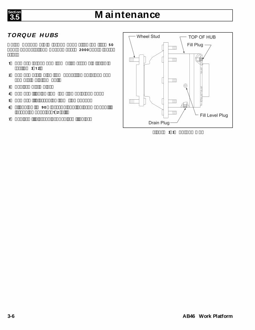
PROPORTIONAL CONTROLADJUSTMENT (Figure 3-6)NOTE: Refer to "TROUBLESHOOTING" section fordetailed MOS90 pin configuration.Potentiometers are sealed to protect sensitive adjust-ments from vibrations, or from tampering. Removesealant prior to adjustment, and replace after.
NOTE: Do not use silicone sealer; it will damagepots.
Use a small screwdriver or special adjustment tool to setadjustment pots. Pots can be easily damaged.Pots have 15 turns of adjustment, more than one turnwill often be required to complete the adjustment. Ifpots have been previously set, reset by turning no morethan 1 turn at a time. If they have not been previouslyset, preset to about mid range and start from there.Turn pot clockwise (CW) to increase settings.Turn pot counterclockwise (CCW) to decrease settings.Adjust pots only in sequence as outlined in this procedure.
Rotary Control for Boom Functions
IMPORTANT: Back out ramp trimpot 10 turns(counter clockwise) before making any adjustments.
1. Verify that batteries are fully charged.2. Connect ammeter in series at "A" terminal.3. Set threshold so upper boom elevates with rotary
speed adjustment set on 2 and raise function switchactuated.
Figure 3-6: Upper Control Box
Figure 3-5: Proportional Controller
1. Rocker SwitchBoot
2. Micro Switch (2)3. Handle Halves
(pairs)4. Handle Boot5. PC Board
w/Pot6. Micro Switch (3)
3.6 Proportional ControllerJOYSTICK HANDLE (FIGURE 3-5)1. If necessary, remove handle assembly from control-
ler box.2. Remove and replace defective parts.3. If replacing PC board with resistor, note resistor
adjustment (number of turns) and adjust newresistor to match old resistor setting.
NOTE: Check that pot operates correctly whenhandle is pushed completely forward and reverse.
Refer to pages 6-8 (Electric) and 6-20 (Bi-Energy) forrepair part numbers.
SensitivityThreshold
PotRamp
HighRange
LowRange
Threshold

Section
3-9AB46 Work Platform
Maintenance 3.7
Figure 3-8: Tilt Sensor
TILT SENSOR (FIGURE 3-8)The Tilt Sensor has four wires; red-power (12V in),black-ground, white-output (12v out) and green (tocontroller). To verify the sensor is working properlythere are two LED's under the sensor; green indicatesthe sensor is on (has power), red indicates the sensor islevel and the white wire is 'hot' (12v out).1. Check tires for proper pressure.2. Place machine on firm level surface ± ¼°.3. Use Inclinometer to ensure that the front and rear of
the chassis are level within± ¼°.4. Adjust the three leveling locknuts until the bubble is
centered in the circle on the attached bubble level.5. Elevate the platform until down limit switch opens
and push the tilt sensor base to test the alarmcircuit. Alarm should sound.
Figure 3-7: Platform Down Limit Switch
4. Set high range at .44 amps or so upper boomfunctions operate with speed adjustment on 9 orhighest speed position. Check for proportional valvevibration. Valve is fully closed when it does notvibrate when energized. Do not over adjust.
5. Set low range so machine slews 180 degrees in 45seconds with speed control set at position 9 or fullspeed.
6. Turn ramp trimpot back in 10 turns. Set ramptrimpot until machine has a smooth start or upperboom delays 2 seconds with raiseswitch actuvatedand speed control set at position 9 or full speed.
Drive Control1. Adjust sensitivity threshold pot (located in upper
control box) to obtain an equal threshold betweenforward and reverse directions (Figure 3-6).
2. Set Servcon motor values. Drive adjustments aremade through the motor control calibrator.
PLATFORM DOWN LIMIT SWITCH(Figure 3-7)The Platform Down Switch bypasses the Tilt Sensorwhen the platform is fully lowered and closes the circuitto the Platform Down Relay, which allows high speedtravel, cage trim function and turret rotation.
Adjustment Nuts
Bubble Level
DO NOT attempt to adjust Limit Switcheswithout first blocking the elevating assem-bly (see section 3.1).
1. Lower the Platform completely.2. With the Platform / Chassis switch on Chassis, push
the Tilt Sensor base to test the alarm circuit.3. If the alarm sounds, elevate the platform and adjust
the position of the switch arm by loosening theadjustment screw and repositioning the arm. Lowerthe platform and retest. If down limit switch isproperly adjusted, the tilt alarm will not sound.
4. With platform elevated, repeat step 2. When switchis properly adjusted, alarm will sound.
Down LimitSwitch
AdjustmentScrew

Section
3-10 AB46 Work Platform
Maintenance
3.7 Hydraulic Manifold(Figure 3-9)It is not necessary to remove the manifold to perform allmaintenance procedures. Prior to performing mainte-nance, determination if the manifold needs to beremoved.
REMOVAL1. Unplug the batteries.2. Tag and disconnect the solenoid valve leads from
the terminal strip.3. Tag, disconnect and plug hydraulic hoses.4. Remove the bolts that hold the manifold to the
mounting bracket.5. Remove manifold block.
DISASSEMBLY
NOTE: Mark all components as they are removed soas not to confuse their location during assembly.Refer to Figure 3-9 often to aid in disassembly andassembly.
1. Remove coils from solenoid valves.2. Remove spool valve cover and spool valve.3. Remove solenoid valves, lift relief valve, counter-
balance valves and divider combiner valve.4. Remove fittings, plugs, springs, balls and orifices.
CLEANING AND INSPECTION1. Wash the manifold in cleaning solvent to remove
built up contaminants and then blow out all pas-sages with clean compressed air.
2. Inspect the manifold for cracks, thread damage andscoring where O-rings seal against internal andexternal surfaces.
3. Wash and dry each component and check forthread damage, torn or cracked O-rings and properoperation.
4. Replace parts and O-rings found unserviceable.
ASSEMBLY
NOTE: Lubricate all O-rings before installation toprevent damage to O-rings. Seat all balls in manifoldblock by lightly tapping on the ball with a brass driftpunch.
1. Install fittings, plugs, springs, balls and orifices. Useone drop of Locktite #242 on each screw-in orifice.
2. Install solenoid valves, lift relief valve, counterbalance valves, divider combiner valve, and spoolvalve.
3. Install coils on solenoid valves.
INSTALLATION1. Attach manifold assembly to mounting plate with
bolts.2. Connect Solenoid leads to terminal strip (as previ-
ously tagged).3. Connect hydraulic hoses. Be certain to tighten
hoses to manifold.4. Plug in batteries.5. Operate each hydraulic function and check for
proper operation and leaks.6. Adjust lift relief and counterbalance valve pressures
according to instructions in Section 3-5.
3.9

Section
3-11AB46 Work Platform
Maintenance
Figure 3-9: Hydraulic Manifold, Exploded View
3.9
1. Valve Block2. Fitting3. Washer, 5/16 Flat4. Fitting, Elbow5. Low Flow Valve6. Steering Valve7. 4-Way Closed Center8. 4-Way Motor Spool9. Relief Valve10. Relief Valve11. Plug
23. Fitting24. Filter Assembly25. Nipple26. Fitting Elbow27. Fitting, Elbow28. Fitting, Elbow29. Fitting Elbow30. Grip31. Fitting Elbow32. Screw, 10-2033. Screw, 5/16-18
12. Diverter Valve13. Counterbalance14. Piston15. Lever16. Extension17. Detent18. Pivot Link19. Mounting Plate20. Seal21. Screw, 5/16-1822. Screw, 3/8 x 5/8
34. Lanyard35. Fitting Adapter36. Orifice37. High Flow Valve38. Steel Ball, 7/1639. Bracket40. Connector Ring41. Connector Female42. Wire43. Fitting, Elbow
NOTE: Refer to Section 5 "SCHEMATICS" Figure 5-4 for a listingof hydraulic valve ports.

Section
3-12 AB46 Work Platform
Maintenance3.8
3.9 Hydraulic Brakes
Removal1. Park the work platform on firm level ground and block
the wheels to prevent the work platform from rolling.2. Disconnect the hydraulic brake lines.3. Tag and disconnect electric cables from drive
motors.
Clean all fittings before disconnecting thehose assemblies.Plug all port holes and hose assembliesIMMEDIATELY to prevent contaminationfrom dust and debris.
4. Remove capscrews and washers holding the motorand brake to torque hub.
5. Remove the motor.5. Remove the brake.
3.8 Hydraulic Power Unit(Figure 3-10)
NOTE: Brushes on the electric motor can be replacedwithout removing the hydraulic power unit from thechassis by raising and securely blocking the chassisand work from underneath the chassis.
NOTE: Power unit may be removed through the frontof the chassis by moving the relay panel out of theway or through the bottom of the chassis by raisingand securely blocking the chassis. Drain the hydrau-lic tank before removing power unit.
REMOVAL1. Mark, disconnect and plug the hose assemblies.2. Mark and disconnect the electric cables.3. Remove hardware which secures power unit and
remove from chassis.
INSTALLATION1. Install power unit using hardware previously re-
moved.2. Unplug and reconnect the hydraulic hoses.3. Reconnect the electric cables.4. Fill the tank with clean hydraulic fluid.5. Check the oil level in the hydraulic tank before
operating the work platform.6. Operate the pump and check for leaks and proper
operation.7. Replenish hydraulic fluid if necessary.
Figure 3-10: Hydraulic Power Unit
(Electric Model Shown)
Figure 3-11: Rear Axle Assembly
Drive Motor Brake
Cap Screw
Pump Motor Brake ValveBlock
NOTE: Torque all hardware to torques listed onpage 3-32 unless otherwise specified.

Section
3-13AB46 Work Platform
Maintenance 3.9
Figure 3-12: Brake Assembly
1. Housing2. Gasket3. Ball Bearing4. Retaining Ring5. Oil Seal6. Spring Retainer7. Spring, Compression8. Shaft9. Pin, Torque10. Primary Disk11. Spring, Compression12. Rotating Disk.13. Stationary Disk14. Piston15. Backup Ring16. O-ring17. Backup Ring18. O-ring19. Power Plate20. Washer21. Capscrew22. Gaskets
Brake Seal Replacement(Figure 3-12)1. With shaft protrusion downward remove capscrews
(21) and washers (20) from brake assembly.2. Remove power plate (19) from housing (1). Remove
the gasket (2).3. Remove piston (14) from power plate (19) by intro-
ducing low pressure air (15 psi) into the hydraulicinlet. Make sure piston is not pointed at anyone.
4. Remove o-rings (16 & 18) and backup rings (15 & 17)from inner and outer diameter grooves of piston.
5. Clean piston (14) and power plate (19) assemblieswith solvent. Inspect the sealing surfaces of thepiston (14) and power plate (19). Inspect sealgrooves in the piston. Replace brake assembly ifthey are damaged or scratched deeply. Lubricatepiston (14), power plate (19), and seals (15, 16, 17,& 18) with clean hydraulic oil prior to assembly.
6. Install the backup rings (15 & 17) and o-rings (16 & 18)into the seal grooves in the piston.
7. Install piston into power plate using a shop press. Becareful not to damage the seals during assembly.Center cutouts in piston with torque pin holes in thepower plate. Press piston to a depth no less than
flush, but not exceeding 0.120 in. below the surfaceof the power plate at cutouts in piston. This depth iscritical. The brake will not hold if it is exceeded.
8. Install gasket (2).9. Install power plate/piston assembly (14 & 19) to
housing (1) using capscrews (21) and washers (20).Tighten sequentially, one turn at a time, to press thetwo assemblies together. Torque capscrews 50 - 60ft.-lbs.
Installation1. Coat output shafts of brake and drive motor with
high pressure molybdenum grease and install gasket(22) and brake onto torque hub.
2. Install gasket (22) and drive motor. Align holes andinstall the two cap screws and lock washers.
3. Reinstall cables to drive motor and hoses to thebrake.
4. Install the wheel. Torque the wheel nuts to 90 ft.lbs. (122 N-m).
5. Remove the jack stands and lower chassis to theground.
6. Position chassis switch to parking brake releaseposition. Alarm will sound.
7. Depress the electric motor start switch to energizebrake hydraulic system.
Seal Kit (068569-000) Includes:2. Gasket (Qty 1)15 & 16. Backup Ring& O-Ring17 & 18. Backup Ring& O-Ring22. Gaskets (Qty. 2)

Section
3-14 AB46 Work Platform
Maintenance8. Check for leaks and bleed air out of brake hydraulic
system using bleed valve located on brake housing.
3.10 Drive Motors
Removal1. Disconnect battery negative terminals or Anderson
connectors (both sides on electric model).2. Tag and disconnect electric cables from motor.3. Remove and save hardware which secures drive
motor to torque hub.
Installation
NOTE: Torque all hardware to torques listed on page3-31 unless otherwise specified.
1. Install drive motor to torque hub using originalhardware.
2. Connect electric cables to motor.3. Connect Anderson connectors or negative terminals
on batteries.
PUMP MOTOR
Removal1. Disconnect battery negative terminals or Anderson
connectors (both sides on electric model).2. Tag and disconnect electric cables from motor.3. Remove and save hardware which secures pump
motor to pump assembly.
Installation
NOTE: Torque all hardware to torques listed on page3-32 unless otherwise specified.
1. Install motor using original hardware.
2. Connect electric cables to motor.3. Connect Anderson connectors or negative terminals
on batteries.
DRIVE MOTOR BRUSHES(Figure 3-13)1. If necessary, remove electric motor (Refer to previ-
ous section).2. Release latch and remove headband.3. Pull back brush spring and latch on hook.4. Remove screw and set aside.
IMPORTANT: Be sure screw does not fall insidemotor.
5. Remove old brush and replace with new brush.
3.10
Figure 3-13: Replacing Drive Motor Brushes
(P/N 068573-010)
Hook
Screw
Hook
Brush

Section
3-15AB46 Work Platform
Maintenance 3.11
3.11 FRONT WHEEL BEARINGS
Removal1. Disconnect battery negative terminals and/or
Anderson connectors (both sides on electric model).2. Loosen wheel lug nuts.3. Raise front axle using 2-ton jack. Support front axle
using two 2-ton jack stands.4. Remove wheel lug nuts and remove wheel.5. Remove axle dust cap.6. Remove cotter pin, hub nut, and washer.7. Remove hub assembly.8. Clean all parts using a suitable solvent.9. Inspect bearings, cones and cups for wear and
replace if necessary.
NOTE: Cups do not need to be replaced if they arenot damaged.
Installation
NOTE: Torque all hardware to torques listed on page3-31 unless otherwise specified.
1. Apply a liberal coating of grease to each cup.2. Pack the inside bearing with a liberal amount of
multi purpose grease and position it in the hub.Install new grease seal.
3. Apply a thin coating of grease to the spindle andslide the hub onto the spindle.
4. Pack the outside bearing cone with multi purposegrease and slide it onto the spindle until it seats inthe outer bearing cup.
5. Install the washer and hub nut. While rotating thehub, tighten the hub nut until the hub drags. Thenback the nut off until a slot lines up with the hole inthe spindle.
6. Install a new cotter pin and bend the end up overthe nut.
7. Install the dust cap and wheel. Torque the lug nutsto 90 ft. lbs. (123 N-m).
8. Remove jack stands and lower the axle to theground.
9. Connect battery negative terminals and/or Andersonconnectors.
Figure 3-14: Front Axle Assembly
1. Stud2. Rear Bearing Cone3. Rear Cup
4. Front Bearing Cone5. Front Cup6. Grease Seal
Repair kit (068577-010) includes:

Section
3-16 AB46 Work Platform
Maintenance
6. Replace screw, unhook brush spring and return tooriginal position.
7. Install and relatch headband.
3.12 TORQUE HUB
Removal1. Park the work platform on firm level ground and
block the wheels to prevent the work platform fromrolling.
2. Disconnect battery negative terminals or Andersonconnectors (both sides on electric model).
3. Loosen the wheel lug nuts on the torque hub to beremoved.
4. Raise the rear of the work platform using a 2-ton jack.5. Position two 2-ton jack stands under the rear axle to
prevent the work platform from falling if the jack fails.6. Remove the wheel nuts and wheel.7. Disconnect hydraulic brake line from brake.
Clean all fittings before disconnecting thehose assemblies.Plug all port holes and hose assembliesIMMEDIATELY to prevent contaminationfrom dust and debris.
8. Remove 90° fitting from side of torque hub.9. Tag and remove electric cables from drive motors.10. Remove mounting bolts from electric motor.11. Separate electric motor from brake. Discard gasket.12. Separate brake from torque hub. Discard gasket.13. Remove 1/2-20 nuts and washers from torque hub.14. Remove torque hub.
1. Motor2. Gasket
Figure 3-15: Torque Hub Assembly
3.12
3. Brake4. Torque Hub5. 90° Fitting
IMPORTANT: Note position of 90° fitting on torquehub body. Hub must be installed with fitting in sameposition.
Installation
IMPORTANT: Hub must be installed with 90° fittingin same position as when it was removed.
NOTE: Torque all hardware to torques listed on page3-31 unless otherwise specified.
1. Install torque hub using 1/2-20 nuts and 1/2 wash-ers.
2. Remove plug from 90° fitting and install fitting inside of torque hub. Point fitting towards rear of hub.
3. Using 90 weight gear lube with EP additive, filltorque hub through top plug hole in rear cover untiloil comes out of 90° fitting in side. Plug 90° fittingand top of rear cover.
4. Install new gasket and brake.5. Install new gasket and electric motor.6. Secure assembly using washers and bolts.7. Connect hydraulic brake lines.8. Connect electric cables.9. Install wheels. Torque lug nuts to 90ft. lbs. (123
Nm).10. Bleed brake lines if necessary.11. Remove jack stands and lower rear end.12. Connect battery terminals or Anderson connectors.

Section
3-17AB46 Work Platform
Maintenance 3.12
3.12 Seal Replacement TorqueHubs
ROLL AND LEAK TESTING
IMPORTANT: Torque hubs should always be roll andleak tested before disassembly and after assembly tomake sure gears and sealants are working properly.
ROLL TESTGears should be able to rotate by applying a constantforce to the axle. Some gear packages roll with moredifficulty than others. Do not be concerned if gearsseem to roll hard as long as they roll with consistency. Ifyou feel more drag only at certain points the gears arenot rolling freely and should be checked for improperinstallation or defects.
LEAK TESTThe purpose of a leak test is to make sure the unit is airtight. Pressurize hub to 5 PSI. Torque hub has a leak ifthe air pressure starts to fall after hub has been pressur-ized. Use soap and water on hub to detect location ofleaks. If a leak is detected, seal or "O" ring must bereplaced.
PRESSING TOOLSThe seal, cup and cone pressing tools are illustrated onpages 20, 21 and 23. Use pressing tools identical in sizeor fabricate them using the dimensions shown.
DISASSEMBLY (Figure 3-16)
CAUTION: Safety glasses should be used duringdisassembly of hub.
1. Remove two pipe plugs in cover and drain the oilfrom the unit.
2. Loosen and remove shoulder bolts and cap screwsfrom cover. Remove cover from hub.
3. Remove "O" ring. Remove thrust washer fromcounterbore in cover.
4. Remove input gear from planet gears.5. Using a punch, remove retaining ring from groove
around inside of input gear.6. Lift carrier sub-assembly from hub. Lift ring gear
from hub. Remove "O" ring from counterbore inhub.
7. Remove pipe plugs from side of hub body.8. Apply a preload to output shaft to remove retaining
ring. Follow steps a & b.
a. Place bearing cone pressing tool on retainingring.
b. Apply pressure to fixture using a hydraulic ramor by striking the fixture with a soft face hammer. Pressure should be applied until hubrotates with difficulty.
9. Using retaining ring pliers remove retaining ring.Remove spacer from output shaft.
10. Place spacer under hub so output shaft will fallthrough bottom when pressed out.
11. Press output shaft out of hub. Output shaft maycome out with bearing cone and seal attached.Remove seal and discard. Use a punch and hammerto remove bearing cone. Be careful not to strikeshaft with punch.
12. If seal and cone remain in hub, press them out usinga pressing tool.
13. Lift bearing cone out of hub.14. Stand hub on its small end. Using a punch and
hammer, remove bearing cup from counterbore ofhub. Be careful not to strike counterbore withpunch.
15. Turn hub over on larger end. Using a punch andhammer, remove bearing cup from counterbore ofhub. Be careful not to strike counterbore.
NOTE: Carrier sub-assembly does not need to bedisassembled to replace seals.
ASSMEBLY
NOTE: Torque all hardware to torques listed on page3-31 unless otherwise specified.
1. Oil output shaft and bearing cone. Using cone press,press bearing cone onto end of output shaft withretaining ring groove.
3. Stand hub on its small end. Using bearing cuppressing tool press bearing cup down into hub.
NOTE: Make sure cup sits square with counterbore.
4. Turn hub over so it sit on large end. Using bearingcup pressing tool press bearing cup into small end ofhub.
NOTE: Make sure cup sits square with counterbore.
5. Place output shaft into hub so end of shaft withretaining ring groove points down.
6. Oil output shaft. Using seal pressing tool press sealinto counterbore in small end of hub. The closedface of the seal should be up.

Section
3-18 AB46 Work Platform
Maintenance
7. Turn hub over so small end points down. Usingbearing cone pressing tool, press bearing cone ontooutput shaft. Rotate hub while pressing bearing.Stop pressing when hub starts to resist rotating.
8. Place spacer onto output shaft so it rests on top ofbearing cone. Using retaining ring pliers, placeretaining ring to make sure it is seated.
9. Hit the end of output shaft once or twice with a softface hammer. Turn the shaft in both clockwise andcounter clockwise directions while hitting. This willseat the bearing cone against the spacer and retain-ing ring allowing necessary endplay in the hub-shaftsub-assembly.
10. Turn hub over so it rests on large end. Measureendplay in hub-shaft sub-assembly. Follow steps a-c.a. Mount a dial indicator on hub . Locate the dial
rod on top of output shaft.b. Lift up on output shaft until the needle on the
dial stops moving.
c. Read the dial. Reading should be no greaterthan .008 in.
- If dial reads less than .008 in. continue on to step11.
- If dial reads more than .008 in. repeat step 8-15 of"DISASSEMBLY" section.d. Remove spacer and replace it with thicker
spacer (SK91 068570-011).e. Repeat steps 7-10 and remeasure end play.
11. Apply a light coat of "Never Seize" to the pipe plugsand install into pipe plug holes in hub.
NOTE: Leave hole for 90° fitting open.
3.12 Seal Replacement TorqueHubs (Continued)
3.12
MAIN ASSEMBLY1. Position hub on its output shaft so that hubs small
diameter end points down.2. Using a marker, mark the four shoulder bolt holes in
hub.3. Grease "O" ring and place in counterbore in hub.
NOTE: "O" rings may be stretched or squeezedtogether in order to fit exactly in counterbore.
4. Oil all exposed surfaces inside hub. Oil carrier sub-assembly.
5. Place carrier sub-assembly, with spline connectionsdown, into mesh with output shaft.
6. Place ring gear, with squared shoulder down, intomesh with the planet gears of the carrier sub-assembly. Make sure that marked shoulder bolt holeon ring gear aligns with any of the marked shoulderbolt holes on the hub. "X" mark should be on thecover side of ring gear.
7. Start one half of retaining ring into groove insideinput gear. Use a soft punch to press the remaininghalf of the retaining ring into the groove.
8. Insert input gear, with large diameter end down,into mesh with planet gears.
9. Place large thrust washer over input gear so it restson carrier housing. Oil all exposed surfaces insidehub.
10. Grease "O" ring and place into counterbore of cover.
NOTE: "O" rings may be stretched or squeezedtogether in order to fit exactly in counterbore.
11. Place cover on top of ring gear so the fill hole will beat top of hub when it is installed.
12. Install four shoulder bolts into shoulder bolt holesand tighten.
13. Install eight cap screws in remaining holes andtighten.
14. Apply 23-27 ft. lbs. of torque to all bolts.15. Apply a light coat of "Never Seize" to both pipe
plugs and install into the two holes in cover.16. Roll test the unit in both clockwise and counter-
clockwise directions. Turn hub nine full revolutionsin each direction.
17. Leak test the hub at Five PSI for two to three min-utes.
Figure 3-16: Measuring Hub End Play

Section
3-19AB46 Work Platform
Maintenance
F. Sun GearG. Gear, InternalH. CoverI. Shoulder BoltJ. Bolt
1. Lip Seal2. Bearing, Cone3. Bearing, Cup4. Thrust Washer5. Retaining Ring
A. SpindleB. HousingC. Carrier AssyD. Gear RingE. Spacer, Input
Figure 3-17: Torque Hub
K. StudL. StudM. Pipe PlugN. Pipe Plug
6. O-Ring (2)7. Thrust Washer (2)9. Bearing, Cup10. Bearing, Cone
Repair Kit (068570-010) contains:
3.12
8. Thrust Washer - SK91 (068570-011)

Section
3-20 AB46 Work Platform
Maintenance3.12
Figure 3-18: Seal Pressing Tool

Section
3-21AB46 Work Platform
Maintenance 3.12
Figure 3-19: Bearing Cone Pressing Tool

Section
3-22 AB46 Work Platform
Maintenance3.12
Figure 3-20: Bearing Cup Pressing Tool

Section
3-23AB46 Work Platform
Maintenance
3.13 Master Cylinder
REMOVAL1. Raise elevating assembly until master cylinder pins
are accessible.2. Support the cage assembly (refer to Figure 3-1).3. Remove rod end retaining bolt and rod end pin.4. Mark and disconnect hoses and immediately cap
the openings to prevent contamination.5. Using a metal drift, remove rod end pin.6. Remove base end pin retaining bolt and pin.7. Carefully remove master cylinder.
DISASSEMBLY
Note: Provide a clean work area for this operation,and observe clean assembly practices. Seals andhydraulic cylinder components are highly sensitive tocontamination that may not be visible to the nakedeye.
1. Remove set screw from cylinder tube and unscrewhead from cylinder.
2. Carefully pull rod assembly from cylinder.3. Clamp rod end in vise and turn piston off of rod.
NOTE: Piston is loctited (Loctite #277) onto rod.
4. Slide the head off of the rod.5. Remove seal kit components (wipers, rod seals, o-
rings and backup rings) from head and piston.6. Thoroughly clean all parts with solvent. Rinse the
inside of the tube and allow to drain. A high pres-sure rinse and wipe with a lint free rag is preferable.
7. Inspect the rod, head, piston, and tube forscratches, pits, or polishing. Check seal groves andsealing surfaces. Scratches or pits deep enough tocatch the fingernail are unacceptable, replace thecylinder. Polishing is a sign of uneven loading.When this occurs, the surface should be checked forroundness. Cylinders not round within .007" shouldbe replaced.
ASSEMBLY
NOTE: Torque all hardware to torques listed on page3-31 unless otherwise specified.
1. Lubricate all components and seals with cleanhydraulic oil prior to assembly.
Note: To avoid cutting the seals, do not use sharpedged tools during seal replacement. After installingseals allow at least one hour for the seals to elasti-cally restore to their original shape before assemblingcylinder.
2. Install new seal kit to piston and head.3. Lubricate rod wiper and seal with hydraulic oil and
slide head onto rod.4. Clean threaded end of rod using loctite primer.5. Using loctite #277, install piston onto rod.6. Lubricate seals on piston and head with hydraulic
oil.7. Carefully slide rod assembly into cylinder.8. Thread head into cylinder. Be sure hole for set
screw aligns with hole in cylinder tube.9. Clean set screw in loctite primer. Install set screw
using loctite #242.
INSTALLATION1. Follow steps from "REMOVAL" section in reverse
order to install cylinder.2. Remove boom support.3. Slowly raise and lower boom several times. Check
hydraulic connections for leaks. Check for properslave cylinder operation.
Figure 3-21: Master Cylinder
1. Rod Wiper2. Rod Seal
3. Backup4. Static Seal5. Piston Seal
A. RodB. HeadC. PistonD. CylinderE. Set Screw
3.13
Seal kit (068454-010) includes:

Section
3-24 AB46 Work Platform
Maintenance
3.14 Slave Cylinder
REMOVAL1. Extend boom until slave cylinder trunion pins are
accessible. Support the cage assembly.2. Remove rod end pin retaining bolt.3. Mark and disconnect hoses and immediately cap
the openings to prevent contamination.4. Using a metal drift, remove rod end pin.5. Remove trunion pin retaining bolts and using a pin
puller, remove trunion pins.6. Carefully remove slave cylinder.
DISASSEMBLY
Note: Provide a clean work area for this operation,and observe clean assembly practices. Seals andhydraulic cylinder components are highly sensitive tocontamination that may not be visible to the nakedeye.
1. Remove set screw from cylinder tube and unscrewhead from cylinder.
2. Carefully pull rod assembly from cylinder.3. Clamp rod end in vise and turn off rod extension.
Slide piston off of rod.
NOTE: Rod extension is loctited (Loctite #262) ontorod.
4. Slide the head off of the rod.5. Remove 1/4 inch socket head cap screws from rod
end of cylinder and remove internal seal block fromcylinder.
6. Remove seal kit components (wipers, rod seals, o-rings and backup rings) from head, piston and sealblock.
7. Thoroughly clean all parts with solvent. Rinse theinside of the tube and allow to drain. A high pres-sure rinse and wipe with a lint free rag is preferable.
8. Inspect parts for scratches, pits, or polishing. Checkseal groves and sealing surfaces. Scratches or pitsdeep enough to catch the fingernail are unaccept-able; replace the cylinder. Polishing is a sign ofuneven loading. When this occurs, the surfaceshould be checked for roundness. Cylinders notround within .007" should be replaced.
ASSEMBLY
NOTE: Torque all hardware to torques listed on page3-31 unless otherwise specified.
1. Lubricate all components and seals with cleanhydraulic oil prior to assembly.
Note: To avoid cutting the seals, do not use sharpedged tools during seal replacement. After installingseals allow at least one hour for the seals to elasti-cally restore to their original shape before assemblingcylinder.
2. Install new seal kit items to piston, head and internalblock.
3. Lubricate rod wiper and seal with hydraulic oil andslide head onto rod.
4. Clean threaded end of rod and rod extension usingloctite primer.
5. Using loctite #262, install rod extension onto rod.6. lubricate seal block static seal and carefully push
seal block into cylinder. Secure seal block using 1/4socket head cap screws.
7. Lubricate seals on piston, head and seal block withhydraulic oil.
8. Carefully slide rod assembly into cylinder.9. Thread head into cylinder. Be sure hole for set
screw aligns with hole in cylinder tube.10. Clean set screw in loctite primer. Install set screw
using loctite #242.
INSTALLATION1. Follow steps from "REMOVAL" section in reverse
order to install cylinder.2. Remove boom support.3. Slowly raise and lower boom several times. Check
hydraulic connections for leaks. Check for properslave cylinder operation.
Figure 3-22: Slave Cylinder
E. Set ScrewF. Cap ScrewG. Rod Extension
1. Rod Wiper2. Rod Seal3. Static Seal4. Static Seal5. Piston Seal6. Rod Seal
A. RodB. HeadC. PistonD. Cylinder
3.14
Seal kit (068455-010) includes:

Section
3-25AB46 Work Platform
Maintenance
3.15 Cage Rotate Cylinder
REMOVAL1. Support the cage assembly at a convenient working
height.2. Mark and disconnect hoses and immediately cap
the openings to prevent contamination.3. Remove hardware which secures cage rotate cylin-
der. Remove cage rotate cylinder.
DISASSEMBLY
Note: Provide a clean work area for this operation,and observe clean assembly practices. Seals andhydraulic cylinder components are highly sensitive tocontamination that may not be visible to the nakedeye.
1. Unscrew head from cylinder2. Carefully pull shaft assembly from cylinder.3. Secure rod end and turn piston off of rod.
NOTE: Piston is loctited (Loctite #262) onto rod.
4. Slide the head off of the rod.5. Remove seal kit components (wipers, rod seals, o-
rings and backup rings) from head and piston.6. Thoroughly clean all parts with solvent. Rinse the
inside of the tube and allow to drain. A high pres-sure rinse and wipe with a lint free rag is preferable.
7. Inspect cylinder parts for scratches, pits, or polish-ing. Check seal groves and sealing surfaces.Scratches or pits deep enough to catch the fingernailare unacceptable, replace the cylinder. Polishing isa sign of uneven loading. When this occurs, thesurface should be checked for roundness. Cylindersnot round within .007" should be replaced.
ASSEMBLY
NOTE: Torque all hardware to torques listed on page3-31 unless otherwise specified.
1. Lubricate all components and seals with cleanhydraulic oil prior to assembly.
Note: To avoid cutting the seals, do not use sharpedged tools during seal replacement. After installingseals allow at least one hour for the seals to elasti-cally restore to their original shape before assemblingcylinder.
2. Install new seal kit items to piston and head.
3. Lubricate rod wiper and seal with hydraulic oil andslide head onto rod.
4. Clean threaded end of rod using loctite primer.5. Using loctite #262, install piston onto rod.6. Lubricate seals on piston and head with hydraulic
oil.7. Carefully slide rod assembly into cylinder.8. Thread head into cylinder.
INSTALLATION1. Follow steps from "REMOVAL" section in reverse
order to install cylinder.2. Slowly cycle cage rotate cylinder several times.
Check hydraulic connections for leaks. Check forproper cylinder operation.
Figure 3-23: Cage Rotate Cylinder
1. Rod Wiper2. Rod Seal
3. Static Seal4. Piston Seal
A. RodB. HeadC. PistonD. Cylinder
3.15
Seal kit (068457-010) includes:

Section
3-26 AB46 Work Platform
Maintenance
3.16 Steering Cylinder
REMOVAL1. Mark and disconnect hoses and immediately cap
the openings to prevent contamination.2. Remove hardware which secures the steering arms
to the spindles.3. Remove hardware which secures steering cylinder
to the chassis. Remove steering cylinder.4. Mark steering arms for position on cylinder. Remove
hardware which secures steering arms to rod ends.Using a hammer and drift, remove the roll pinswhich secure the steering arms to the rod ends.
DISASSEMBLY
Note: Provide a clean work area for this operation,and observe clean assembly practices. Seals andhydraulic cylinder components are highly sensitive tocontamination that may not be visible to the nakedeye.
1. Mark heads for position on cylinder. Unscrew headsfrom cylinder.
IMPORTANT: Heads must be installed onto sameend of cylinder as they were removed from.
2. Carefully pull rod assembly from cylinder.3. Remove one snap ring and piston lock.4. Slide the piston off of the rod.5. Remove seal kit components (wipers, rod seals, o-
rings and backup rings) from heads and piston.6. Thoroughly clean all parts with solvent. Rinse the
inside of the tube and allow to drain. A high pres-sure rinse and wipe with a lint free rag is preferable.
7. Inspect cylinder parts for scratches, pits, or polish-ing. Check seal groves and sealing surfaces.Scratches or pits deep enough to catch the fingernailare unacceptable, replace the cylinder. Polishing isa sign of uneven loading. When this occurs, thesurface should be checked for roundness. Cylindersnot round within .007" should be replaced.
ASSEMBLY
NOTE: Torque all hardware to torques listed on page3-31 unless otherwise specified.
1. Lubricate all components and seals with cleanhydraulic oil prior to assembly.
Note: To avoid cutting the seals, do not use sharpedged tools during seal replacement. After installingseals allow at least one hour for the seals to elasti-cally restore to their original shape before assemblingcylinder.
2. Install new seal kit items to piston and heads.3. Lubricate seals on piston. Slide piston on rod and
secure using piston lock and snap ring.4. Carefully slide rod assembly into cylinder.5. Thread heads into cylinder.
IMPORTANT: Heads must be installed onto sameend of cylinder as they were removed from.
INSTALLATION1. Follow steps from "REMOVAL" section in reverse
order to install cylinder.2. Slowly steering cylinder several times. Check hy-
draulic connections for leaks. Check for propercylinder operation.
Figure 3-24: Steering Cylinder
1. Journal Bearing (2)2. Rod Wiper (2)3. Rod Seal (2)
4. Static Seal (2)5. Static Seal6. Piston Seal
A. RodB. Head (2)C. PistonD. CylinderE. PistonLockF. Snap Ring
3.16
Seal kit (068456-010) includes:

Section
3-27AB46 Work Platform
Maintenance
3.17 Jib Cylinder
REMOVAL1. Using an overhead hoist or crane, support the cage
assembly at a convenient working height.2. Mark and disconnect hoses and immediately cap
the openings to prevent contamination.3. Remove hardware which secures jib cylinder pins.
NOTE: Jib cylinder is heavy. Take appropriate mea-sures to support cylinder.
4. Remove jib cylinder pins. Remove jib cylinder.
DISASSEMBLY
Note: Provide a clean work area for this operation,and observe clean assembly practices. Seals andhydraulic cylinder components are highly sensitive tocontamination that may not even be visible to thenaked eye.
1. Remove counterbalance valve from cylinder.2. Unscrew head from cylinder.3. Carefully pull shaft assembly from cylinder.4. Secure rod end and turn piston off of rod.
NOTE: Piston is loctited (Loctite #277) onto rod.
4. Slide the head off of the rod.5. Remove seal kit components (wipers, rod seals, o-
rings and backup rings) from head and piston.6. Thoroughly clean all parts with solvent. Rinse the
inside of the tube and allow to drain. A high pres-sure rinse and wipe with a lint free rag is preferable.
7. Inspect cylinder parts for scratches, pits, or polish-ing. Check seal groves and sealing surfaces.Scratches or pits deep enough to catch the fingernailare unacceptable, replace the cylinder. Polishing isa sign of uneven loading. When this occurs, thesurface should be checked for roundness. Cylindersnot round within .007" should be replaced.
ASSEMBLY
NOTE: Torque all hardware to torques listed on page3-31 unless otherwise specified.
1. Lubricate all components and seals with cleanhydraulic oil prior to assembly.
Note: To avoid cutting the seals, do not use sharpedged tools during seal replacement. After installingseals allow at least one hour for the seals to elasti-cally restore to their original shape before assemblingcylinder.
2. Install new seal kit items to piston and head.3. Lubricate rod wiper and seal with hydraulic oil and
slide head onto rod.4. Clean threaded end of rod using loctite primer.5. Using loctite #277, install piston onto rod.6. Lubricate seals on piston and head with hydraulic
oil.7. Carefully slide rod assembly into cylinder.8. Thread head into cylinder.
INSTALLATION1. Follow steps from "REMOVAL" section in reverse
order to install cylinder.2. Slowly cycle jib cylinder several times. Check
hydraulic connections for leaks. Check for propercylinder operation.
Figure 3-25: Jib Cylinder
1. Piston Seal2. Wear Ring
3. Rod Wiper4. Rod Seal5. Static Seal
A. RodB. HeadC. PistonD. CylinderE. Set Screw
3.17
Seal kit (068453-010) includes:

Section
3-28 AB46 Work Platform
Maintenance
3.18 Boom Raise & Boom RiserCylinders
REMOVAL1. Raise elevating assembly until cylinder pins are
accessible.1. Support the elevating assembly(refer to Figure 3-1).2. Mark and disconnect hoses and immediately cap
the openings to prevent contamination.3. Remove hardware which secures cylinder. Remove
cylinder.
DISASSEMBLY
Note: Provide a clean work area for this operation,and observe clean assembly practices. Seals andhydraulic cylinder components are highly sensitive tocontamination that may not be visible to the nakedeye.
1. Remove set screw from cylinder tube and unscrewhead from cylinder.
2. Unscrew head from cylinder3. Carefully pull shaft assembly from cylinder.4. Remove 3/16 set screw which secures piston to rod.
NOTE: Set screw is loctited (Loctite #242) intopiston.
2. Secure end of rod and turn piston off of rod.4. Slide stop tube and head off of the rod.5. Remove seal kit components (wipers, rod seals, o-
rings and backup rings) from head and piston.6. Thoroughly clean all parts with solvent. Rinse the
inside of the tube and allow to drain. A high pres-sure rinse and wipe with a lint free rag is preferable.
7. Inspect cylinder parts for scratches, pits, or polish-ing. Check seal groves and sealing surfaces.Scratches or pits deep enough to catch the fingernailare unacceptable, replace the cylinder. Polishing isa sign of uneven loading. When this occurs, thesurface should be checked for roundness. Cylindersnot round within .007" should be replaced.
ASSEMBLY
NOTE: Torque all hardware to torques listed on page3-31 unless otherwise specified.
1. Lubricate all components and seals with cleanhydraulic oil prior to assembly.
Note: To avoid cutting the seals, do not use sharpedged tools during seal replacement. After install-ing seals allow at least one hour for the seals toelastically restore to their original shape beforeassembling cylinder.
2. Install new seal kit items to piston and head.3. Lubricate rod wiper and seal with hydraulic oil and
slide head onto rod.4. Slide stop tube onto rod.5. Thread piston onto rod. Be sure set screw hole lines
up with hole on end of rod.6. Using loctite #242, secure piston to rod with 3/16
set screw.7. Lubricate seals on piston and head with hydraulic
oil.8. Carefully slide rod assembly into cylinder.9. Thread head into cylinder. Be sure hole for setscrew
aligns with hole in cylinder tube.10. Clean set screw in loctite primer. Install set screw
using loctite #242.
INSTALLATION1. Follow steps from "REMOVAL" section in reverse
order to install cylinder.2. Slowly cycle cylinder several times. Check hydraulic
connections for leaks. Check for proper cylinderoperation.
Figure 3-26: Boom Riser Cylinder (shown)
E. Set ScrewF Set ScrewG. Stop Tube
1. Piston Seal2. Wear Ring3. Rod Wiper4. Rod Seal5. Static Seal
A. RodB. HeadC. PistonD. Cylinder
3.18
Boom Raise Seal kit (068451-010) includes:Boom Riser Seal kit (068450-010) includes:

Section
3-29AB46 Work Platform
Maintenance
3.19 Boom Extend Cylinder
REMOVAL1. Lower boom completely. Extend boom until front
boom extend cylinder pin is accessable.1. Use an overhead hoist or crane to support the rear
of the boom (Figure 3-27).2. Remove rear boom pivot pin.3. Remove clips which secure front boom extend
cylinder pin. Remove pin.4. Mark and disconnect boom extend cylinder hoses
and immediately cap the openings to preventcontamination.
5. Using overhead hoist, slightly raise rear of boom.
NOTE: This will extend master cylinder and allowroom to remove boom extend cylinder. It may benecessary to remove a counterbalance valve to allowmaster cylinder to expand.
6. Remove rear boom extend cylinder pin. Carefullyremove boom extend cylinder. Measure length ofexpanded boom cylinder.
IMPORTANT: Boom extend cylinder must be ex-panded to the same length when it is reinstalled.
DISASSEMBLY
Note: Provide a clean work area for this operation,and observe clean assembly practices. Seals andhydraulic cylinder components are highly sensitive tocontamination that may not be visible to the nakedeye.
1. Remove set screw and unscrew head from cylinder.3. Carefully pull shaft assembly from cylinder.4. Secure rod end and turn piston off of shaft.
NOTE: Piston is loctited (Loctite #277) onto rod.
4. Slide the head off of the rod.5. Remove seal kit components (wipers, rod seals, o-
rings and backup rings) from head and piston.6. Thoroughly clean all parts with solvent. Rinse the
inside of the tube and allow to drain. A high pres-sure rinse and wipe with a lint free rag is preferable.
7. Inspect cylinder parts for scratches, pits, or polish-ing. Check seal groves and sealing surfaces.Scratches or pits deep enough to catch the fingernailare unacceptable, replace the cylinder. Polishing isa sign of uneven loading. When this occurs, thesurface should be checked for roundness. Cylindersnot round within .007" should be replaced.
ASSEMBLY
NOTE: Torque all hardware to torques listed on page3-31 unless otherwise specified.
1. Lubricate all components and seals with cleanhydraulic oil prior to assembly.
Note: To avoid cutting the seals, do not use sharpedged tools during seal replacement. After installingseals allow at least one hour for the seals to elasti-cally restore to their original shape before assemblingcylinder.
2. Install new seal kit items to piston and head.3. Lubricate rod wiper and seal with hydraulic oil and
slide head onto rod.4. Clean threaded end of rod using loctite primer.5. Using loctite #277, install piston onto rod.6. Lubricate seals on piston and head with hydraulic
oil.7. Carefully slide rod assembly into cylinder.
Figure 3-27: Removing Boom Extend Cylinder
3.19

Section
3-30 AB46 Work Platform
Maintenance
Figure 3-28: Boom Extend Cylinder
8. Thread head into cylinder.Using loctite #242, installset screw.
INSTALLATION1. Follow steps from "REMOVAL" section in reverse
order to install cylinder.
IMPORTANT: Boom extend cylinder must be ex-panded to the same length it was when it was re-moved.
2. Slowly cycle cylinder several times. Check hydraulicconnections for leaks. Check for proper cylinderoperation.
1. Piston Seal2. Wear Ring3. Static Seal
4. Rod Wiper5. Rod Seal6. Static Seal
A. RodB. HeadC. PistonD. CylinderE. Set ScrewF. Bushing
3.19
Seal kit (068452-010) includes:

Section
3-31AB46 Work Platform
Maintenance 3.20
3.20 LONG TERM STORAGEIf the work platform is to be placed in long termstorage (dead storage) follow these recommendedpreservation procedures.
PRESERVATION1. Clean painted surfaces. If paint is damaged,
repaint.2. Fill the hydraulic tank to operating level. Fluid
will be visible at the sight gauge (BiEnergymodels) or on dipstick (Electric models).
IMPORTANT: Do not fill the hydraulic tank whilethe platform is elevated.
NOTE: Do not drain the hydraulic system prior tolong term storage.
3. Coat exposed portions of cylinder rods with apreservative such as multipurpose grease andwrap with a barrier material.
4. Coat all exposed unpainted metal surfaces withpreservative.
5. Service the engine according to the manufactur-ers recommendations.
6. Remove the batteries and place in alternativeservice.
12 N.m22 N.m41 N.m68 N.m102 N.m203 N.m339 N.m542 N.m813 N.m
TORQUEVALUE
THREADSIZE
1/45/163/87/161/25/83/47/81
ENGLISH METRICAmerican NationalStd.-UNC (course)
Grade 5
Table 3-3: Bolt Torque
110 In/Lbs190 In/Lbs30 Ft/Lbs50 Ft/Lbs75 Ft/Lbs150 Ft/Lbs250 Ft/Lbs400 Ft/Lbs600 Ft/Lbs
3.21 Torque Specifications(Tables 3-3 & 3-4)
FASTENERSUse the following values to torque fasteners used onUpRight Work Platforms unless a specific torque value iscalled out for the part being installed.
WIDTHACROSSFLATS
7/161/29/165/83/4
1 5/16
1 1/8
1 15/16
1 1/2
HYDRAULIC COMPONENTSUse the following values to torque hydraulic compo-nents used on UpRight Work Platforms.
Note: Always lubricate threads with clean hydraulicoil prior to installation.
Table 3-4: Hydraulic Component Torque
FITTINGS
(Ft/Lbs Nm)
N/A N/A10-20 14-2725-30 34-4135-40 47-5485-90 115-122
130-140 176-190
HOSES
(In/Lbs Nm)
135-145 15-16215-245 24-28430-470 49-53680-750 77-85950-1050 107-1311300-1368 147-155
CARTRIDGEPOPPET
(Ft/Lbs Nm)
N/A N/AN/A N/A
25-30 34-4135-40 47-5485-90 115-122
130-140 176-190
TYPE:SAE PARTSERIES
#4#6#8#10#12#16
Coil nuts: 30 IN/Lbs (3 Nm)

Section
3-32 AB46 Work Platform
Maintenance
NOTES:

Troubleshooting Section
4-1AB46 Work Platform
4.0 IntroductionThe following section on troubleshooting providesguidelines on the types of problems users may encoun-ter in the field, helps determine the cause of problems,and suggests proper corrective action.Careful inspection and accurate analysis of the symp-toms listed in the Troubleshooting Guide will localizethe trouble more quickly than any other method. Thismanual cannot cover all possible problems that mayoccur. If a specific problem is not covered in thismanual, call our toll free number for service assistance.Referring to Section 2.0 and 5.0 will aid in understand-ing the operation and function of the various compo-nents and systems of the AB46 and help in diagnosingand repair of the machine.
GENERAL PROCEDUREUse the charts on the following pages to help determinethe cause of a fault in your UpRight AB46.1. Verify your problem.
Do a full function test from both platform controlsand chassis controls and note all functions thatare not operating correctly.
2. Narrow the possible causes of the malfunction.Use the troubleshooting guide to determine whichcomponents are common to all circuits that are notfunctioning correctly.
3. Identify the problem component.Test components that are common to all circuits thatare not functioning correctly. Remember to checkwires and terminals between suspect components.Be sure to check connections to battery negative.
4. Repair or replace component found to be faulty.5. Verify that repair is complete.
Do a full function test from both platform andchassis controls to verify that all functions are operat-ing correctly and machine is performing to specifiedvalues.
4.0
FOR SERVICE ASSISTANCE, IN THE U.S.A., CALL:
1-800-926-5438FROM OUTSIDE THE USA, CALL 1-209-896-5150
Follow the fault finding charts to diagnose problemswith the MOS90 drive system.
NOTE: Spike protection diodes at components havebeen left out of the charts to eliminate confusion.
When troubleshooting, ensure that the workplatform is resting on a firm, level surface.When performing any service which requiresthe platform to be raised, the ElevatingAssembly must be blocked.Disconnect the battery ground cable whenreplacing or testing the continuity of anyelectrical component.

Section Troubleshooting
4-2 AB46 Work Platform
4.1
4.1 OPERATIONAL THEORYThe DC motor controller has four connections: Positive(B+), Battery Negative (B-), Motor Field Negative andField Negative (S).
The electric motor has continuous battery positive (B+)over the main fuse. Inside the controller are high currentMOSFET transistors and capacitors and the controlcircuitry.The controller acts as a switch. The amount of timeBattery Negative (B-) and Motor Field Negative (A) are"connected" controls the RPM of the electric motor.
• If (B-) and (A) are connected all the time themotor will turn at 100%.
• If (B-) and (A) are not connected the motor willturn at 0%.
• The percentage of connection controls the speedof the motor.
The controller acts as a switch which has the abilityto open and close (pulse) very rapidly.
The number of pulses determines the voltage to themotor.
The motor is equipped with a "freewheel diode". Duringopen cycle of MOS90 a current is produced by themotor. The freewheel diode collects this current andsends it back through the motor.
Equal pulses of open and closed drive the motor at halfspeed.
At low speed the MOSFET is mostly open and most ofthe current is from freewheel. At high speed the mosfetis mostly closed and most of the current is from thebattery.

Troubleshooting Section
4-3AB46 Work Platform
4.1
The motor armatures and fields are in series.Forward and reverse are achieved by using directionalcontactors to control the direction of current in the drivemotors.Terminal (S) connects the "Drive Motor Armatures" to adiode inside the MOS90. When the machine stops, asignal is given to apply the brakes.
The illustration below shows a block diagram of themachines electrical system.Refer to section 5 "SCHEMATICS" for a detailed electri-cal schematic.

Section Troubleshooting
4-4 AB46 Work Platform
4.2
Com
pone
nt
.
.
F
unct
ion
Ste
er
Ris
er
Boo
m E
xten
d
Boo
m R
aise
Jib
Cag
e Le
vel
Cag
e R
otat
e
Sle
w
Driv
e
Bra
ke R
elea
se
Par
king
Bra
ke
Rel
ease
Pump X X X X X X X XSteer Valve XSteer Cylinder XHigh Relief X X X X X X X XRelief Check Valves X X X X X X X XHigh Dump 1 X XDiverter Valve 2 2 2 2 2 2 2 2Riser Valve XRiser Cylinder XRiser C/B Valve XRiser CK Valve XBoom Extend Valve XBoom Extend Cylinder XBoom Extend C/B Valve XBoom Extend CK Valve XBoom Raise Valve XBoom Raise Cylinder XBoom Raise C/B Valve XBoom Raise CK Valve XProportional Valve X X X X XJib Valve XJib Orifice XJib Cylinder XJib C/B Valve XJib CK Valve XMaster Cylinder XMaster Cylinder C/B Valves XMaster Cylinder CK Valves XSlave Cylinder XSlave Cylinder CB Valves XTrim Level Valve XLow Relief Valve X X X X X X XCage Rotate Cylinder XCage Rotate Valve XCage Rotate C/B Valve XCage Rotate CK Valve XSlew Motor XTurret Rotate Valve XTurret Rotate CK Valve X1000 PSI Relief XBrake Valve X X XBrake Orifices X X XBrakes X X X1. High dump is not activated by steering. It will close for other functions while steering.2. Diverter valve is not activated during normal operation. Only for hand pump operation.3. Bypass valve is not energized during normal operation.
Table 4-1 Troubleshooting Guide - Hydraulic Schematic

Troubleshooting Section
4-5AB46 Work Platform
4.2
Com
pone
nt
.
.
.
.
F
unct
ion
Upp
er C
ontr
ol
Fun
ctio
ns
Low
er C
ontr
ol
Fun
ctio
ns
Ste
er R
ight
Ste
er L
eft
Ris
er E
leva
te
Ris
er D
esce
nd
Boo
m E
xten
d
Boo
m R
etra
ct
Boo
m R
aise
Boo
m L
ower
Jib
Up
Jib
Dow
n
Cag
e Le
vel U
p
Cag
e Le
vel D
own
Cag
e R
otat
e C
CW
Cag
e R
otat
e C
W
Sle
w C
CW
Sle
w C
W
Driv
e F
orw
ard
Driv
e R
ever
se
Par
king
Bra
ke
Rel
ease
Tilt
Ala
rm
Tilt
Lig
ht
Bat
tery
Cha
rger
Battery X X XBattery Disconnect X X X
Battery Charger XMain Power Relay Coil X X
Main Power Relay Contacts NC XMain Power Relay Contacts NO X X
25 A Fuse X XChassis EM Stop Switch X X
Chassis Key Switch X X X10 Amp Circuit Breaker CB1 X X10 Amp Circuit Breaker CB3 X X
10 Amp Circuit Breaker CB2 X XPlatform EM Stop Switch X X
10 Amp Control Box Fuse X
Control Box Key Switch XDiode DB20 X X X X X X X X X X X X X X X X XDiode DB19 X X X X XDiode DB18 X X X X X X X X X X X X X X X XDiode DB14 XDiode DB13 XDiode DB25 X
Diode DB9 X X X X X X XDiode DB10 X X X X X X XDiode DB11 X X X
Diode DB3 XDiode DB2 XDiode DB5 X X X X XDiode DB6 X X X X X
Diode 1 X XDiode 2 X XDiode 3 X XDiode 4 X XDiode 5 X XDiode 6 X XDiode 7 X XDiode 8 X XDiode 9 X X
Diode 10 X XDiode 11 X XDiode 12 X XDiode 13 X XDiode 14 X X
Diode 1 X XDiode 2 X XDiode 3 X XDiode 4 X XDiode 5 X XDiode 6 X XDiode 7 X XDiode 8 X XDiode 9 X X
Diode 10 X XDiode 11 X XDiode 12 X XDiode 13 X XDiode 14 X X
Diode DB16 X X XDiode DB17 X X X X X X X X XDiode DB18 X X X X X
Diode DB18B X X X X XDiode DB9 X X X
Diode DB10 X X X X X X X X XDiode DB11 X X XDiode DB12 X X X X X X X X X X X X X X X
Diode DB12B X X X X X X X X X X X X X X XDiode DB14 X X X X X X X X X
Low Tilt Relay Coil X X X XLow Tilt Relay Contacts X X X X
Table 4-2 Troubleshooting Guide - Electrical Schematics

Section Troubleshooting
4-6 AB46 Work Platform
4.2Table 4-2 Troubleshooting Guide - Electrical Schematics (continued)
Tilt Light off for normal functions X X
Tilt Alarm off for normal operation X XBrake Relay contacts X X
Tilt Sensor (red wire) X XTilt Sensor (white wire) X X X X
Tilt Sensor (green wire) X X X XHorn Relay contacts X X
Down Limit Switch X XDown Relay coil X X
Chassis Control Power Relay coil X XChassis Control Power Relay contacts X X
Lower Turret Rotate Switch X XLower Cage Rotate Switch X X
Lower Trim Switch X XLower Jib Switch X X
Lower Boom Elevate Switch X XLower Boom Extend Switch X X
Lower Riser Switch X XDiode DB16 X X X X X X X X
Diode DB8 X X X X X X X XDiode DB8.1 X X X X X X X X
Boom Speed Relay coil X X X X X X X XBoom Speed Relay contacts X X X X X X X X
Turtle / Rabbit Knob X X X X X X X XDiode DB17 X X X X
Diode DB18 X XFoot Switch X X X X X X X X X X X X X X X X X X
Upper Turret Rotate Switch X XUpper Cage rotate Switch X X
Upper Trim Switch X XUpper Jib Switch X X
Lower Boom Elevate Switch X XUpper Boom Extend Switch X X
Upper Riser Switch X XTurret Drive Relay contacts X X X X
Boom Disconnect Relay contacts X X X X X X X XDiode DB7 X X X X X X X X
Diode DB6 X XDiode DB11 X X X X X X
Diode DB3 X X X XDiode DB2 X X X X
Diode DB9 X XDiode DB23L X X X X X X X X X X X X X X X X X X
Diode DB23R XDiode DB24 X
Speed Control Knob X X X X X X X X X XBoom Speed Relay contacts X X X X X X X X X X
Boom Speed Relay coil X X X XDrive Enable Relay coil X
Drive Enable Relay contacts XSteer Right Switch X
Steer Left Switch XDown Relay contacts X X
Down Relay contacts XDown Relay contacts X X
Boom Extend Drive Interlock Switch X XBoom Disconnect Relay coil X X
Turret Drive Relay coil X XDrive Joystick X X
Right Drive motor X XLeft Drive Motor X X
Mos 90 Motor Controller X XForward Contactor X
Reverse Contactor XPower Unit X X X X X X X X X X X X X X X X
Boom Pump Relay coil X X X X X X X X X X X X X X X XBoom Pump Relay contacts X X X X X X X X X X X X X X X X
Brake Pressure Switch X X
Com
pone
nt
.
.
.
.
F
unct
ion
Upp
er C
ontr
ol
Fun
ctio
ns
Low
er C
ontr
ol
Fun
ctio
ns
Ste
er R
ight
Ste
er L
eft
Ris
er E
leva
te
Ris
er D
esce
nd
Boo
m E
xten
d
Boo
m R
etra
ct
Boo
m R
aise
Boo
m L
ower
Jib
Up
Jib
Dow
n
Cag
e Le
vel U
p
Cag
e Le
vel D
own
Cag
e R
otat
e C
CW
Cag
e R
otat
e C
W
Sle
w C
CW
Sle
w C
W
Driv
e F
orw
ard
Driv
e R
ever
se
Par
king
Bra
ke
Rel
ease
Tilt
Ala
rm
Tilt
Lig
ht
Bat
tery
Cha
rger

Troubleshooting Section
4-7AB46 Work Platform
Table 4.2 Troubleshooting Guide - Electrical Schematics (continued)
Com
pone
nt
.
.
.
.
F
unct
ion
Upp
er C
ontr
ol
Fun
ctio
ns
Low
er C
ontr
ol
Fun
ctio
ns
Ste
er R
ight
Ste
er L
eft
Ris
er E
leva
te
Ris
er D
esce
nd
Boo
m E
xten
d
Boo
m R
etra
ct
Boo
m R
aise
Boo
m L
ower
Jib
Up
Jib
Dow
n
Cag
e Le
vel U
p
Cag
e Le
vel D
own
Cag
e R
otat
e C
CW
Cag
e R
otat
e C
W
Sle
w C
CW
Sle
w C
W
Driv
e F
orw
ard
Driv
e R
ever
se
Par
king
Bra
ke
Rel
ease
Tilt
Ala
rm
Tilt
Lig
ht
Bat
tery
Cha
rger
4.2
Brake Release Pressure Switch XTach Card X X
Resistor Pack X XTach-Gen (2) X X
Brake Valve NO X X XBrake Valve NC X X
Controller Off Switch X X
Forward Switch X XReverse Switch X X
5K Resistor X X
Trim Up Solenoid Valve XTrim Down Solenoid Valve X
Trim Up Upper Control Diode XTrim Up Relay Lower Control Diode X
Trim Down Upper Control Diode XTrim Down Lower Control Diode X
Jib Up Solenoid Valve XJib Down Solenoid Valve X
Jib Up Upper Control Diode XJib Up Relay Lower Control Diode X
Jib Down Upper Control Diode XJib Down Relay Lower Control Diode X
Boom Up Solenoid Valve XBoom Down Solenoid Valve X
Boom Up Upper Control Diode XBoom Up Lower Control Diode X
Boom Down Upper Control Diode X
Boom Down Lower Control Diode XBoom Extend Solenoid Valve XBoom Retract Solenoid Valve X
Boom Extend Upper Control Diode XBoom Extend Lower Control Diode XBoom Retract Upper Control Diode XBoom Retract Lower Control Diode X
Riser Up Solenoid Valve XRiser Down Solenoid Valve X
Riser Up Upper Control Diode XRiser Up Lower Control Diode X
Riser Down Upper Control Diode XRiser Down Lower Control Diode X
Cage Right Solenoid Valve XCage Left Solenoid Valve X
Cage Right Upper Control Diode XCage Right Lower Control Diode X
Cage Left Upper Control Diode XCage Left Lower Control Diode X
Turret Right Solenoid Valve XTurret Left Solenoid Valve X
Turret Right Upper Control Diode XTurret Right Lower Control Diode X
Turret Left Upper Control Diode XTurret Left Lower Control Diode X
Steer Right Solenoid Valve XSteer Right Diode X
Steer Left Solenoid Valve XSteer Left Diode X
Proportional Valve X X X X X X X X X X
High Flow Valve X X X XDiode DB21 X
Bypass Solenoid Valve XDiode DB25 X X

Section Troubleshooting
4-8 AB46 Work Platform
4.3
4.3 Troubleshooting the MOS90Important basics applicable to the motor control unit.
• The MOS90 has a green diagnostics L.E.D. in thefront panel.
• The green L.E.D. will turn on and shine continu-ously when the MOS90 is powered up andworking correctly.
• The green L.E.D. will be off if no power is sup-plied to the MOS90.
• The green L.E.D. will flash a sequence of flashes ifthe MOS90 is damaged or is receiving an im-proper signal. An explanation of the flash se-quences "flash faults" is shown on the followingpages.
• The MOS90 is high temperature protected by"thermal cutback". The cutback operates between80°C (176°F) and 90°C (194°F). Powered func-tions will gradually operate slower and slower until90°C (194°F). The MOS90 will shut down at 90°C(160°F). Continued operation at high temperaturewill damage the MOS90.
• The MOS90 is low voltage protected by "lowvoltage cutout". The MOS90 shuts down at 14.0VDC. Powered functions suddenly stop. Wheninput voltage goes above 14.0 VDC turns back on.
WHEN A FLASH ERROR OCCURSStep 1.Disconnect the 17 pin connector from the MOS90.Wait Five (5) seconds and plug it back in again. If theflash error repeats go to step Two (2). If the green L.E.D.lights up and stays on continuously - operate machine.Note which functions are being used when problemrepeats itself.Step 2.Disconnect the 17 pin connector from the MOS90.Connect pin Six (6) to a fused battery supply (14.0 VDCminimum) and observe the green L.E.D. If flash errorstays, replace MOS90. If green L.E.D. lights up andremains on continuously, check wiring.
NOTE: Troubleshoot the possible cause of the flasherror before replacing the MOS90, for example anEight (8) flash error will cure itself when the MOS90cools down.
4.4 Using the CalibratorThe calibrator has 20 L.E.D. segments marked as shown.
The values which should be expected when checkingthe machine are shown on the following page.
There are three buttons on the calibrator:increment, marked +decrement, marked -select
When select is pressed, each L.E.D. will light in se-quence until the select button is released. Each person-ality can be incremented or decremented using the + or- buttons when the adjacent L.E.D. is lit.
When "Test" L.E.D. is lit, the state of the MOS90 inputsis displayed. The first input displayed is the acceleratorwhich can vary from 0-100%. When the + button ispressed once the switch Input 1 is displayed. This willbe seen as "10P" until the switch Input voltage changes."1CL" will then be displayed. This is repeated for all theswitch inputs.

Troubleshooting Section
4-9AB46 Work Platform
4.5
When BATTV, MOTORV, MOTORA and TEMPC areselected, the controller shows their values. When BATTVis selected and the "+" button is held in, the highestvoltage that the MOS90 has recorded will be displayed.When TEMPC is selected and the "+" button is held in,the highest temperature that the MOS90 has recordedwill be displayed. The "-" button will display the lowestvalues.
When the MOS90 is first powered up, the recordedminutes of run time is displayed. The "+" button displaysthousands of hours and the "-" button displays hundredsof hours. When the MOS90 is pulsing (being used) runtime is being incremented and stored.
4.5 Calibrator Settings
LED Function Unit Setting CommentsIMAX MOS90 Maximum Amp. Capacity Amps 600PLUG Acceleration Delay Seconds 2.0ACCEL Deceleration Delay Seconds 0.1CREEP Not Used % 0BYPASS Stowed Max. Drive Soeed, Level % 100SPEED Elevated Drive Speed, Level 5 20 Elevated Drive Speed, Off-Level => Alarm On. No DriveSPEED1 Stowed Max. Drive Speed, Off-Level % 75 Drive Speed is reduced
First Tilt Setting when Off-Level in Stowed PositionSPEED2 Stowed Max. Drive Speed, Off-Level % 25 Drive Speed is reduced when Off-Level in Stowed PositionF.WEAK Max. Plugging Current Amps 750TIMER Not UsedSEAT Not UsedX3 Not UsedX4 Not UsedX5 Not UsedBATT Battery Voltage at pin #6 on MOS90 Volts Real TimeMOTOR Voltage across Motor Contacts Volt Real TimeMOTOR Amperage Across Motor Contacts Amp Real TimeTEMP Internal Temp of Controller Celsius Real TimeTEST Switch Activation and Status OP/CL % Open=Unactivated Closed=Activated %=Percentage
Table 4-3 Calibrator Settings

Section Troubleshooting
4-10 AB46 Work Platform
4.6 MOS90 Fault Finding FlowChartsAt battery connection, the LED should not illuminate. Atkey ON, the LED should illuminate steadily. If the LEDilluminates and remains steady, but no drive can beselected, the calibrator can be used to test the wiringharness.
1 Flash- Power up /Fa i l - s a f e Fau l t
- EEPROM data corrupted on k e y
Fault appears at key switch on.
Replace MOS90 Controller
2 Flashes- Procedure Fault
- I l l egal Startup Sequence .
Two d i r ec t i ons s e l e c t ed toge ther ,d i rec t ion and l i f t s e l ec t ed toge theror l i f t and ground se l ec t ed toge ther
- Drive inhib i ted
- Flashes unti l fault is c l e a r ed
Check for correct startup sequence. Was directionor lift selected at power up?
Retry
Check that both directions are not selected.Check direction switches and wiring. Use calibra-
tor test mode and check Fwd/Rev/Lift switchinputs and wiring.
Rectify
Replace MOS90 Controller
3 Flashes- Point "A" less than 7V in neutral,or less than 7V for 15mS in drive , orcontactor coi l short c ircuit .
- Drive inhib i ted .
- Recycle to neutral to c lear .
NOTE: If recycling to neutral does not clear the fault,then the fail-safe is due to a S/C contactor coil andthe keyswitch must be recycled (and the coil re-placed).
Check power and control wiring for shorts
Rectify
Replace Controller
4.6

Troubleshooting Section
4-11AB46 Work Platform
4 Flashes- Direct ion contactor welded . Point"A" within 6V of B+ve in neutral)
- L e a k a g e b e t w e e n m o t o r armature and f i e ld .
- Drive inhib i ted .
- Flashes in neutral unti l faul t i s c l eared
Check direction contactor tips
Free/change tips
Check power wiring for shorts
Rectify
Check motor for armature to field shorts or leakage
Rectify
Check for shorts to frame and battery leakage
Rectify
Replace MOS90 Controller
5 Flashes- Direct ion contactors (or l ine contactor) d id not c lose .
- Motor armature or f i e ld open c ircuit .
- Point "A" not within 6V of B+ve wi th in one second o f s e l ec t ing d irect ion.
- Drive inhib i ted .
- Flashes unti l fault is c l e a r e d , when contactor c loses .
Check contactor tips
Repair/replace
Check contactor for mechanical operation and coilO.K.
Repair/replace
Check power and control wiring
Rectify
Check for open circuit motor
Rectify
Replace controller
4.6

Section Troubleshooting
4-12 AB46 Work Platform
4.26 Flashes- Acce lerator faults
- 3.5 Volts to 0 Volts = Min. to Max.Speed on acce lerator input (p in 14) .Greater than 4.5 volts can mean anopen acce l erator pot . Less than 2 .5Vol t s on power up , ind ica t e s morethan 30% demand
- Contro l l er pulses at creep se t t ing
- Flashes unti l fault c l e a r ed
Check operation of accelerator with test sequence
Rectify/replace
Check pot operation with voltmeter for voltage atminimum setting
Adjust as necessary or replace
Replace MOS90 Controller
7 Flashes- Bat t e ry vo l tage d ipped be low 13 vol ts
- Drive inhib i ted
- Recycle to neutral to c l ear f lash
Check battery voltage (under load) with a voltmeteror calibrator
Change/charge battery
Check power connections, fuses, etc.
Repair/replace
Check for battery leakage to frame
Rectify
Replace MOS90 Controller
Figure 4-1: Blocking Elevating Assembly
4.6

Troubleshooting Section
4-13AB46 Work Platform
8 Flashes- Thermal cutback
- Heats ink t emperature l e ss than 80ºC (176ºF) (Current l imit will be zero at 90ºC (194ºF)
- Al low unit to coo l down, to c l ear f l ash ing
Check current limit setting
Re-set
Check mounting and heatsink of controller
Rectify
Check application is correct
Use larger controller
Replace MOS90 Controller
10 Flashes- Tachometer f au l t
- Drive inhib i ted
- Recyc le key to c l ear faul t
Check tachometer wires for opens or shorts
Rectify
Check output voltage from tachometer using volt-meter
Replace
Check output voltage from tachometer board,using voltmeter
Replace
Replace MOS90 Controller
4.6

Section Troubleshooting
4-14 AB46 Work Platform
4.411 Flashes- Tachometer s ignal out o f range
- Drive inhib i ted
- Flashes unti l fault c l e a r ed
Check tachometer wires for shorts to frame or avoltage source
Rectify
Check output voltage from tachometer using volt-meter
Replace
Replace MOS90 Controller
12 Flashes- Boom up and veh ic l e in severe t i l t condit ion
- "Boom up" and "severe ti lt" swi tches bo th opened (N.C. swi tches
- Veh ic l e goes in to emergency s top ( forced neutra l s tate ) and p lug brakes to a s top
- Lower boom and r e cyc l e k ey t o c lear fault
Use calabrator test mode and check Boom upswitch and severe tilt switch inputs and wiring
Rectify
Replace MOS90 Controller
4.6

Troubleshooting Section
4-15AB46 Work Platform
LED off- Unit not powered up or contro l l erfaulty, or LED faulty
Check battery is connected and keyswitch is on
Rectify
Check all fuses are intact
Rectify
Check supply wiring. Does calibrator unit stillfunction
Rectify
Controller is faulty:
a) Auto fail-safe check failed. LED turns off when adirection is first selected after power up. Recyclekeyswitch.
b) Contactor drive S/C. LED resets itself if shortcircuit clears.
c) Mosfets did not turn on. Recycle direction toneutral to clear fault indication.
Replace controller
Table 4-4 Upright Traction ControllerCalibratior Diagnostics
NOTE: CL = Switch ClosedOP = Switch Open
** If both tilt and boom-up condition, then FWD.and REV. is cleared
4.6
ACTIVATING "TEST"Position red LED at TEST. Press "+" or "-" to select theswitch to be viewed.The zero position input "-" should read zero and is set byadjusting the trim pot in the upper control box. Step onthe foot switch and keeping the joystick centered, adjustthe pot to give a readout of 1 or 2. Slowly back the potdown until the reading has just dropped to zero.If set at an extremely high value MOS90 will read asfault and shut down.Properly set the AB46 should start to move slowly with asmall movement of the joystick after a very small"deadband" zone.
Sequence No. Test Display Input #- Acc. Input 0-100% 141 Reverse CL/OP 82 Forward CL/OP 113 Tach Input 0-100% 124 Hvy Tlt Input CL=Level 7
Speed3 Sw OP=Tilt5 Minor Tlt Input CL=Level 16
Speed2 Sw OP=Tilt6 Brake Applied CL= Brk On 167 Act. Direction OP=FWD 2
Tacho Output CL=REV 28 Boom Up Sw CL=Lowered 13
Speed1 Sw OP=Raised

Section Troubleshooting
4-16 AB46 Work Platform
4.6
MO
S90
1
2
3
4
5
6
7
8
9
10
11
12
13
14
15
16
17
Brake relay driver (48 Volts = brake on & 0 Volts = brake off
Tachometer direction input from tach board (18 Volts = rev. & 0 Volts = FWD.
No connection
Tilt switch input (48 Volts = no tilt & 0 Volts = tilt)
Battery + side of direction & brake contactors for coil suppression (48 Volts)
+ 48 Volt supply to power up controller
Over speed relay (48 Volts = no over speed & 0 Volts = over speed condition)
48 Volts when forward is selected & 0 Volts in neutral
No connection
No connection
48 Volts when reverse is selected & 0 Volts in neutral
Tach signal from tach board (7.5 Volts to 15 Volts = FWD. 0-100% and7.5 Volts to 0 Volts = REV. 0-100%
Boom up switch (48 Volts = boom down & 0 Volts = boom up)
Traction accelerator signal (3.5 Volts to 0 Volts = min. to max. speed)
Forward contactor driver - goes to battery negative to energize contactor
Brake applied input (48 Volts = brake on & 0 Volts = brake off)
Reverse contactor driver - goes to battery negative to energise contactor
Figure 4-1 MOS90 17 WAY CONNECTOR PIN OUT DESIGNATION
Black
Brown
Red (spare)
Orange
Yellow
Green
Blue
Purple
Grey (spare)
White (spare)
Pink
White/Purple
White/Red
White/Black
White/Yellow
White/Blue
White/Green

Troubleshooting Section
4-17AB46 Work Platform
4.6
Figure 4-2 UPRIGHT TACHOMETER BOARD
Battery Positive supply(48 Volts)
A
No connectionB
No connectionC
Output over speed relayconnects to pin 7 of MOS90
D
Battery positive to over speedrelay (48 Volts)
E
D
FuseF1
TachCircuit
Overspeedrelay
1
2
3
4
5
6
7
8
9
10
11
12
13
14
15
16
Battery Negative Supply
Tach speed signal to pin 12 of MOS90
Input from tach generator
Tach direction signal to pin 2 of MOS90
Input from tach generator
Tach generator
No connection
48 Volts = no over speed condition0 Volts = over speed condition
2 Tach speed signal from tach board7.5 Volts to 15 volts = 0-100% speed in FWD.7.5 Volts to 0 volts = 0-100% speed in REV.
4 Tach direction signal18 Volts = REV.0 Volts = FWD.
3
5 Output of tach generator0 to +50 Volts = 0-100% speed in FWD.0 to -50 Volts = 0-100% speed in REV.

Section Troubleshooting
4-18 AB46 Work Platform
NOTES:
4.6

Schematics Section
5-1AB46 Work Platform
5.0 IntroductionThis section contains electrical and hydraulic powerschematics, and associated information for maintenancepurposes.The diagrams are to be used in conjunction with Sec-tion 4 "Troubleshooting". They allow understanding ofthe makeup and functions of the systems for checking,tracing, and faultfinding during trouble analysis.The components that comprise the electrical andhydraulic systems are given a reference designation andare explained as to function and location in the follow-ing tables.
5.0
Section 5.1 Electrical SchematicsFigure 5-1: Electrical Schematic, Electric ModelFigure 5-2: Electrical Schematic, BiEnergy ModelSerial Number 1000-1331Figure 5-3: Electrical Schematic, BiEnergy ModelSerial Number 1331-CurrentFigure 5-4: Engine Assembly - Kubota ZB600CSerial Number 1000-1331Figure 5-5: Engine Assembly - Kubota ZB600CSerial Number 1331-Current
Section 5.2 Hydraulic SchematicsFigure 5-6: Hydraulic Valve PortsFigure 5-7: Check PortsFigure 5-8: Hydraulic Schematic, Electric/Bi-EnergyModelsFigure 5-9: Valve Block Assembly
Section 5.3 Upper ControllerFigure 5-10: Upper ControllerFigure 5-10: Electrical Diagram - Upper Controller,Electric ModelFigure 5-12: Electrical Diagram - Upper Controller,Bi-Energy Model
Section 5.4 Lower ControllerFigure 5-13: Lower Control Box CoverFigure 5-14: Terminal Strip, Relay IdentificationFigure 5-15: Electrical Diagram - Lower Control Box,Electric ModelFigure 5-16: Electrical Diagram - Lower Control Box,Bi-Energy Model S/N 1000-1331Figure 5-17: Electrical Diagram - Lower Control Box,Bi-Energy Model S/N 1331-current
Section 5.5 Relay PanelFigure 5-18: Relay Panel (Electric Model Shown)Figure 5-19: Relay Panel Schematic

SchematicsSection
5-2 AB46 Work Platform
5.1 Electrical Schematic Electrical Model
REFERENCEDESIGNATION NAME FUNCTION LOCATION
MOT1 Motor, Electric Left Drive Motor Rear of Chassis
MOT2 Motor, Electric Right Drive Motor Rear of Chassis
MOT3 Motor, Electric Powers Hydraulic Pump Hydraulic Power UnitMTR1 Meter, Hour Displays number of hours Chassis Control Panel,
Machine is turned on. BottomR1 Main Power Relay Isolates Batteries for Relay Panel
Charging
R2 Boom Pump Relay Power to Hydraulic Lower Control boxPump
R3 Brake Relay Power to Brake controls Lower Control box
R4 Horn Relay Power to Horn Lower Control box
R5 Low Tilt Relay Disenables Drive Lower Control boxFunctions
R6 Power Relay Power to Controller Lower Control box
R7 Brake Release Relay Releases Brake for Lower Control boxtowing
R8 Down Relay Power to Hydraulic Lower Control boxPump
R9 Boom Disconnect Power to Upper Upper Control boxRelay Controller
R10 Boom Elevate Speed Power to Speed Upper Control boxRelay Controller
R11 Turret Drive Relay Power to Turret Upper Control boxRotate Solenoid
R12 Drive Enable Relay Power to Upper Upper Control boxControl box
R13 Forward Relay Powers Drive Motors Relay PanelForward
R14 Reverse Relay Powers Drive Motors Relay PanelBackward
RES1 Resistor Trim resistor Upper control box.
RES2 Resistor Speed control Joystick controlS1 Trim Switch, Power to Trim Lower Control box
(two) Solenoid Upper Control boxS2 Jib Switch, Power to Jib Lower Control box
(two) Solenoid Upper Control box
S3 Boom Switch Power to Boom Lower Control box(two) Lift Solenoid Upper Control box
S4 Boom Extend Switch Power to Boom Lower Control box(two) Extend Solenoid Upper Control box
S5 Riser Switch Power to Riser Lower Control box(two) Solenoid Upper Control box
S6 Cage Switch Power to Cage Lower Control box(two) Rotate Solenoid Upper Control box
S7 Turret Switch Power to Turret Lower Conrtol box(two) Rotate Solenoid Upper Control box
S8 Control Switch Control Handle Control Handle
Table 5-1: (cont.)REFERENCEDESIGNATION NAME FUNCTION LOCATION
S9 Forward-Reverse FWD-Reverse Upper control boxSwitch
S10 Steer Switch Power to left steer Upper control box,and right steer relays top of joystick.
S11 Brake Switch Power to MOS90, Relay Panelbrakes released.
S12 Pressure Stop Switch Cuts power to hydraulic Relay Panelpump if low pressure
S13 Platform/Chassis Supplies power to Lower control boxSwitch Platform/Chassis
S14 Down Limit Switch Controls travel speed Turret at boomSlow/Fast attachment
S15 Chassis Emergency Emergency Stop Lower control box,Stop Switch
S16 Brake Release Release Brakes for Lower ControllerSwitch Towing
S17 Foot Switch Enables operation from Floor of platformplatform
S18 Platform Emergency Emergency Stop Platform control boxStop Switch
S19 Platform Key Switch Enables operation from Platform control boxplatform
S20 Horn Switch Sounds horn Platform control Box
S21 Boom Extend Drive Controls travel speed On BoomInterlock Slow/Fast
SNSR Level Sensor Provides power to cutout Control module.relay when machine islevel.
SOL1 Trim UP Solenoid. Controls lift valve. Right side of manifold,port marked 'J'.
SOL2 Trim Down Solenoid. Controls lift valve. Right side of manifold,port marked 'J'.
SOL3 Jib Up Solenoid. Controls lift valve. Right side of manifold,port marked 'J'.
SOL4 Jib Down Solenoid. Controls lift valve. Right side of manifold,port marked 'J'.
SOL5 Boom Up Solenoid. Controls lift valve. Right side of manifold,port marked 'J'.
SOL6 Boom Down Solenoid. Controls lift valve. Right side of manifold,port marked 'J'.
SOL7 Boom Extend Solenoid Controls reverse valve. Right sSOL8 Boom Retract Solenoid. Controls lift valve. Right side of manifold,
port marked 'J'.SOL9 Riser Up Solenoid. Controls lift valve. Right side of manifold,
port marked 'J'.SOL10 Riser Down Solenoid Controls series / parallel Front side of manifold,
valves. ports marked 'Q' & 'R'.SOL11 Cage Right Solenoid. Controls lift valve. Right side of manifold,
port marked 'J'.SOL12 Cage LeftSolenoid Controls down valve. Lift cylinder, lower end.SOL13 TurretRight Solenoid Controls steer valve when Top of manifold, on
steering right. steer valve.SOL14 TurretLeft Solenoid Controls steer valve when Top of manifold, on
steering left. steer valve.SOL15 Steer Right Solenoid Controls engine throttle. Power module, engine,
right side.SOL16 Steer LeftSolenoid Controls engine choke. Power module, engine,
right side.SOL17 Low Flow Controls lift valve. Right side of manifold,
port marked 'J'.SOL18 High Flow Controls lift valve. Right side of manifold,
port marked 'J'.SOL19 Brake N.O. Controls Brakes Relay Panel
SOL20 Brake N.C. Controls Brakes Relay Panel
TG1 Tach generator Generates speed signal Left drive motor- left
TG2 Tach generator Generates speed signal Right drive motor- right
Table 5-1: Electrical Schematic Legend, Electric Model
REFERENCEDESIGNATION NAME FUNCTION LOCATION
ALM 1 Horn Warning sound Front of chassisALM 2 Alarm, Tilt Provides warning sound Upper control box,
when slope of machine exterior upper left side.excedes 3o side to side,or fore and aft.
CONT1 Controller Controls operating speed Upper control boxof various functions
CRD1 Tach Card Supplies speed Relay Panelinformation to controller
D1 Diode (Block) Supplies power to up Lower Controllertrim solenoid.
D2 Diode (Block) Supplies power to down Lower Controllertrim solenoid.
D3 Diode (Block) Supplies power to up Lower Controllerjib solenoid.
D4 Diode (Block) Supplies power to down Lower Controllerjib solenoid.
D5 Diode (Block) Supplies power to up Lower Controllerboom solenoid.
D6 Diode (Block) Supplies power to down Lower Controllerboom solenoid.
D7 Diode (Block) Supplies power to extend Lower Controllerboom solenoid.
D8 Diode (Block) Supplies Power to retract Lower Controllerboom solenoid.
D9 Diode (Block) Supplies power to up Lower Controllerriser solenoid.
D10 Diode (Block) Supplies power to down Lower Controllerriser solenoid.
D11 Diode (Block) Supplies power to cage Lower Controllerright solenoid.
D12 Diode (Block) Supplies power to cage Lower Controllerleft solenoid.
D13 Diode (Block) Provides power to turret Lower Controllerright solenoid.
D14 Diode (Block) Provides power to turret Lower Controllerleft solenoid.
D15 Diode Provides power to steer Lower Controllerright solenoid
D16 Diode Provides power to steer Lower Controllerleft solenoid
D17 Diode Power to high flow Lower Controllersolenoid from platform
D18 Diode Power to high flow Lower Controllersolenoid from chassis
D19 Diode Power to brake release Lower Controllerrelay R7
D20 Diode Power to power relay Lower ControllerR6 from foot switch
D21 Diode Power to Lower Controller
D22 Doide Power to tilt alarm Lower ControllerALM1
D23 Diode Power to brake Lower Controllersolenoids
REFERENCEDESIGNATION NAME FUNCTION LOCATION
D24 Diode Power to tilt alarm Lower ControllerALM1
D25 Diode Power to boom Lower Controllerpump
D26 Diode Power to boom Lower Controllerpump
D27 Diode Power to high flow Lower Controllersolenoid
D28 Diode Power to brake Lower Controllerrelay
D29 Diode Power to hour Lower Controllermeter
D30 Diode Power to hour Lower Controllermeter
D31 Diode Power to boom Upper Controllerelevate speed relay R10
D32 Diode Power to speed Upper Controllercontroller CONT1
D33 Diode Power to speed Upper Controllercontroller CONT1
D34 Diode Power to speed Upper Controllercontroller CONT1
D35 Diode Power to speed Upper Controllercontroller CONT1
D36 Diode Power to high flow Upper Controllersolenoid SOL18
D37 Diode Power to hour Upper Controllermeter MTR
D38 Diode Power to hour Upper Controllermeter MTR
D39 Diode Power to hour Upper Controllermeter MTR
D40 Diode Power to boom Upper Controllerelevate relay R10
D41 Diode Power to high Lower Controllerflow solenoid
D42 Diode Power to high Lower Controllerflow solenoid
D43 Diode Power to high Lower Controllerflow solenoid
FU1 Fuse Lift Circuit Relay Panel125 AMP
FU2 Fuse Main Fuse Relay Panel350 AMP
FU3 Fuse Brake Ciruit Lower Controller10 AMP
FU4 Fuse Platform Controls Upper Controller10 AMP
FU5 Fuse Power Relay Lower Controller10 AMP
FU6 Fuse Emergency Stop Lower Controller25 AMP
FU7 Fuse Chassis Controls Lower Controller10 AMP
5.1

Schematics Section
AB46 Work Platform 5-3Figure 5-1: Electrical Schematic, Electrical Model

SchematicsSection
5-4 AB46 Work Platform
REFERENCEDESIGNATION NAME FUNCTION LOCATION
D24 Diode Power to tilt alarm Lower Control boxALM1
D25 Diode Power to boom Lower Control boxpump
D26 Diode Power to boom Lower Control boxpump
D27 Diode Power to high flow Lower Control boxsolenoid
D28 Diode Power to brake Lower Control boxrelay
D29 Diode Power to hour Lower Control boxmeter
D30 Diode Power to hour Lower Control boxmeter
D31 Diode Power to boom Upper Control boxelevate relay R10
D32 Diode Power to speed Upper Control boxcontroller CONT1
D33 Diode Power to speed Upper Control boxcontroller CONT1
D34 Diode Power to speed Upper Control boxcontroller CONT1
D35 Diode Power to speed Upper Control boxcontroller CONT1
D36 Diode Power to high flow Upper Control boxsolenoid SOL18
D37 Diode Power to hour Upper Control boxmeter MTR
D38 Diode Power to hour Upper Control boxmeter MTR
D39 Diode Power to hour Upper Control boxmeter MTR
D40 Diode Power to boom Upper Control boxelevate relay R10
D41 Diode Power to high Lower Control boxflow solenoid
D42 Diode Power to high Lower Control boxflow solenoid
D43 Diode Power to high Lower Control boxflow solenoid
FU1 Fuse Lift Circuit Relay Panel
FU2 Fuse Main Fuse Relay Panel
FU3 Fuse Brake Ciruit Lower Control box
FU4 Fuse Platform Controls Upper Control box
FU5 Fuse Power Relay Lower Control box
FU6 Fuse Emergency Stop Lower Control Box
FU7 Fuse Chassis Controls Lower Control Box
MOT1 Motor, Electric Left Drive Motor Rear of Chassis
MOT2 Motor, Electric Right Drive Motor Rear of Chassis
MOT3 Motor, Electric Powers Hydraulic Pump Hydraulic Power Unit
5.1
First page on foldout5.1 Electrical Schematics
REFERENCEDESIGNATION NAME FUNCTION LOCATION
ALM 1 Alarm, Tilt Provides warning sound Upper control box,when slope of machine exterior upper left side.excedes 3o side to side,or fore and aft.
CONT1 Controller Controls operating speed Upper control boxof various functions
D1 Diode (Block) Supplies power to up Lower Control boxtrim solenoid.
D2 Diode (Block) Supplies power to down Lower Control boxtrim solenoid.
D3 Diode (Block) Supplies power to up Lower Control boxjib solenoid.
D4 Diode (Block) Supplies power to down Lower Control boxjib solenoid.
D5 Diode (Block) Supplies power to up Lower Control boxboom solenoid.
D6 Diode (Block) Supplies power to down Lower Control boxboom solenoid.
D7 Diode (Block) Supplies power to extend Lower Control boxboom solenoid.
D8 Diode (Block) Supplies Power to retract Lower Control boxboom solenoid.
D9 Diode (Block) Supplies power to up Lower Control boxriser solenoid.
D10 Diode (Block) Supplies power to down Lower Control boxriser solenoid.
D11 Diode (Block) Supplies power to cage Lower Control boxright solenoid.
D12 Diode (Block) Supplies power to cage Lower Control boxleft solenoid.
D13 Diode (Block) Provides power to turret Lower Control boxright solenoid.
D14 Diode (Block) Provides power to turret Lower Control boxleft solenoid.
D15 Diode Provides power to steer Lower Control boxright solenoid
D16 Diode Provides power to steer Lower Control boxleft solenoid
D17 Diode Power to high flow Lower Control boxsolenoid from platform
D18 Diode Power to high flow Lower Control boxsolenoid from chassis
D19 Diode Power to brake release Lower Control boxrelay R7
D20 Diode Power to power relay Lower Control boxR6 from foot switch
D21 Diode Power to Lower Control box
D22 Doide Power to tilt alarm Lower Control boxALM1
D23 Diode Power to brake Lower Control boxsolenoids
REFERENCEDESIGNATION NAME FUNCTION LOCATION
MTR Meter, Hour Displays number of hours Chassis Control Panel,Machine is turned on. Bottom
R1 Main Power Relay Isolates Batteries for Relay PanelCharging
R2 Boom Pump Relay Power to Hydraulic Lower Control BoxPump
R3 Brake Relay Power to Brake controls Lower Control Box
R4 Horn Relay Power to Horn Lower Control Box
R5 Low Tilt Relay Disenables Drive Lower Control BoxFunctions
R6 Power Relay Power to Controller Lower Control Box
R7 Brake Release Relay Releases Brake for Lower Control Boxtowing
R8 Down Relay Power to Hydraulic Lower Control BoxPump
R9 Boom Disconnect Power to Upper Upper Control BoxRelay Control Box
R10 Boom Elevate Speed Power to Speed Upper Control BoxRelay Controller
R11 Turret Drive Relay Power to Turret Rotate Upper Control BoxSolenoid
R12 Drive Enable Relay Power to Upper Upper Control BoxControl Box
R13 Forward Relay Powers Drive Motors Relay PanelForward
R14 Reverse Relay Powers Drive Motors Relay PanelBackward
R15 Start Engine Relay Power to Start Engine Relay Panel *not used after S/N 1331RES1 Resistor Trim Resistor Upper Control BoxRES2 Resistor Speed Control Joystick ControllerS1 Trim Switch, Power to Trim Lower Control Box
(two) Solenoid Upper Control BoxS2 Jib Switch, Power to Jib Lower Control Box
(two) Solenoid Upper Control Box
S3 Boom Switch Power to Boom Lower Control Box(two) Lift Solenoid Upper Control Box
S4 Boom Extend Switch Power to Boom Lower Control Box(two) Extend Solenoid Upper Control Box
S5 Riser Switch Power to Riser Lower Control Box(two) Solenoid Upper Control Box
S6 Cage Switch Power to Cage Lower Control Box(two) Rotate Solenoid Upper Control Box
S7 Turret Switch Power to Turret Lower Control Box(two) Rotate Solenoid Upper Control Box
S8 Control Switch Enables Joystick Joystick HandleFunctions
S9 FWD/REV Switch FWD/REV Switch Upper Control Box
S10 Steer Switch Power to left steer Upper control box,and right steer relays top of joystick.
Table 5-2: (cont.)REFERENCEDESIGNATION NAME FUNCTION LOCATION
S11 Brake Switch Power to MOS90, Relay Panelbrakes released.
S12 Pressure Stop Switch Cuts power to hydraulic Relay Panelpump if low pressure
S13 Platform/Chassis Supplies power to Lower control box,Switch Platform/Chassis
S14 Down Limit Switch Controls travel speed Turret at boomSwitch Slow/Fast attachment
S15 Chassis Emergency Emergency Stop Lower control box,Stop Switch
S16 Brake Release Release Brakes for Lower ControllerSwitch Towing
S17 Foot Switch Enables operation from Floor of platformplatform
S18 Platform Emergency Emergency Stop Platform control box,Stop Switch
S19 Throttle Switch Supplies power to throttle Lower control box, inrelay. panel, top, first from
right.S20 Platform Key Switch Enables Operation from Platform Control Box
PlatformS21 Boom Extend Drive Controls travel speed On Boom
Interlock Slow/FastSEN1 Level Sensor Provides power to cutout Control module.
relay when machine islevel.
SOL1 Trim UP Solenoid. Controls lift valve. Right side of manifold,port marked 'J'.
SOL2 Trim Down Solenoid. Controls lift valve. Right side of manifold,port marked 'J'.
SOL3 Jib Up Solenoid. Controls lift valve. Right side of manifold,port marked 'J'.
SOL4 Jib Down Solenoid. Controls lift valve. Right side of manifold,port marked 'J'.
SOL5 Boom Up Solenoid. Controls lift valve. Right side of manifold,port marked 'J'.
SOL6 Boom Down Solenoid. Controls lift valve. Right side of manifold,port marked 'J'.
SOL7 Boom Extend Solenoid Controls reverse valve. Right sSOL8 Boom Retract Solenoid. Controls lift valve. Right side of manifold,
port marked 'J'.SOL9 Riser Up Solenoid. Controls lift valve. Right side of manifold,
port marked 'J'.SOL10 Riser Down Solenoid Controls series / parallel Front side of manifold,
valves. ports marked 'Q' & 'R'.SOL11 Cage Right Solenoid. Controls lift valve. Right side of manifold,
port marked 'J'.SOL12 Cage LeftSolenoid Controls down valve. Lift cylinder, lower end.SOL13 TurretRight Solenoid Controls steer valve when Top of manifold, on
steering right. steer valve.SOL14 TurretLeft Solenoid Controls steer valve when Top of manifold, on
steering left. steer valve.SOL15 Steer Right Solenoid Controls engine throttle. Power module, engine,
right side.SOL16 Steer LeftSolenoid Controls engine choke. Power module, engine,
right side.SOL17 Low Flow Controls lift valve. Right side of manifold,
port marked 'J'.SOL18 High Flow Controls lift valve. Right side of manifold,
port marked 'J'.SOL19 Brake N.O. Controls Brakes Relay Panel
SOL20 Brake N.C. Controls Brakes Relay Panel
TG1 Tach Generator Generates speed signal Left drive motor- left
TG2 Tach generator Generates speed signal Right drive motor- right
Table 5-2: Electrical Schematic Legend, BiEnergy Model

Schematics Section
AB46 Work Platform 5-5
6.1
Figure 5-2: (068341-005) Electrical Schematic, BiEnergy Model [S/N 1000 -1331]

SchematicsSection
5-6 AB46 Work Platform
5.1
Figure 5-3: (068341-005) Electrical Schematic, BiEnergy Model [After S/N -1331]

Schematics Section
5-7AB46 Work Platform
Table 5-3: Engine Assembly - Kubota ZB600C - S/N 1000-1331REFERENCEDESIGNATION NAME FUNCTION LOCATION
ALT1 Alternator Power to charge Side of enginebattery BAT1
BAT1 Battery Powers starter motor Side of engineCONN Connector Connects engine assembly On wire harness between
to machine engine and machineFP1 Fuel Pump Provides fuel to the Side of engine
EngineFU1 Fuse Overload protection Wiring harness
for starter solenoid between connectorand engine
GP1 Glow Plug Provide heat for Top of engineengine startup
5.1
GP2 Glow Plug Provide heat for Top of engineengine startup
MOT1 Starter Motor Starts Engine Side of enginePIN Pin Connection between Inside connector
engine and machinePLUG Plug Seals connector Inside connectorRCT1 Rectifier Controls charging of Side of engine
batteryR1 Relay Glow plug relay Side of engine
R2 Relay Starter Relay On starter motor
WDG Wedge Secures connector pins Inside connector
Figure 5-4: Kubota Engine Diagram - S/N 1000-1331
5.1

Section
5-8 AB46 Work Platform
Schematics 5.15.1
Table 5-4: Engine Assembly - Kubota ZB600C- S/N 1331-current
REFERENCEDESIGNATION NAME FUNCTION LOCATION
ALT1 Alternator Power to charge Side of enginebattery BAT1
BAT1 Battery Powers starter motor Side of engineCONN Connector Connects engine assembly On wire harness between
to machine engine and machineFP1 Fuel Pump Provides fuel to the Side of engine
EngineFU1 Fuse Overload protection Wiring harness
for starter solenoid between connectorand engine
GP1 Glow Plug Provide heat for Top of engineengine startup
GP2 Glow Plug Provide heat for Top of engineengine startup
MOT1 Starter Motor Starts Engine Side of enginePIN Pin Connection between Inside connector
engine and machinePLUG Plug Seals connector Inside connectorRCT1 Rectifier Controls charging of Side of engine
batteryR1 Relay Glow plug relay Side of engine
R2 Relay Starter Relay On starter motor
R3 Relay Starter Rrelay Side of engine
WDG Wedge Secures connector pins Inside connector
Figure 5-5: Kubota Engine Diagram - S/N 1331-current

Schematics Section
5-9AB46 Work PlatformFigure 5-6: Hydraulic Valve Ports
5.2 5.2

Section
5-10 AB46 Work Platform
Schematics5.2
Figure 5-7: Check Ports
5.2

Schematics Section
5-11AB46 Work Platform
NOTES:
5.2

Section
5-12 AB46 Work Platform
Schematics
REFERENCEDESIGNATION NAME FUNCTION LOCATION
BA1 Brake Accumulator Stores pressure to keep(Electric Model only) brakes releasedCV1 & CV2 Check Valve, Brake Allows free flow from Rear of Chassis
brakes aroundpressure reducing valve
CV3 Check Valve, Flow Check Hydraulic ManifoldTurret Rotate
CV4 Check Valve, Trim Flow Check Hydraulic ManifoldCV5 Check Valve, Jib Flow Check Hydraulic ManifoldCV6 Check Valve, Flow Check Hydraulic Manifold
Boom RaiseCV7 Check Valve, Flow Check Hydraulic Manifold
Boom ExtendCV8 Check Valve, Riser Flow Check Hydraulic ManifoldCV9 Check Valve, Flow Check Hydraulic Manifold
High ReliefCV10 Check Valve, Flow Check Hydraulic Manifold
High ReliefCV11 Check Valve, Flow Check Hydraulic Manifold
Brake ReleaseCV12 Check Valve, Pump 1 Flow Check Hydraulic ManifoldCV13 Check Valve, Pump 2 Flow Check Hydraulic ManifoldCV14 (2) Check Valve, Stops flow from hand pump Hydraulic Manifold
Hand Pump through diverter valveCV15 (2) Check Valve, Reduces pressure Hydraulic Manifold
for smoothcage rotate operation
CV16 Check Valve, Jib Lower Sends oil through OR2 to Hydraulic Manifoldslow jib lowering
CYL1 Steering Cylinder Actuates steering linkage Front axle assemblyto steer front wheels.
CYL2 Riser Cylinder Raise Elevating Assembly Elevating Assembly
CYL3 Boom Extend Cylinder Extend Boom Inside Boom
CYL4 Boom Raise Cylinder Raise Elevating Assembly Elevating AssemblyCYL5 Jib Cylinder Raise Jib JibCYL6 Master Cylinder Maintain cage level Rear of BoomCYL7 Slave Cylinder Maintain cage level Front of BoomCYL8 Cage Rotate Cylinder Rotate cage Between cage and JibCYL9 Left Brake Cylinder Release left brake Left brakeCYL10 Right Brake Cylinder Release right brake Right brakeFL1 Filter, Return Keep oil clean Hydraulic tankFl2 Filter, Suction Strainer Keep oil clean PumpMOT1 Motor, Slew Turns Turret Bottom of turretORF1 Brake Orifice Allows brakes to release Left side top of manifold
quickly and apply slowly. under fitting in port 12.ORF2 Jib Down Orifice Limits the descent speed
of the jib.PMP1 Hydraulic Pump Provides fluid power for Power module
High Flow hydraulic system.PMP2 Hydraulic Pump Provides fluid power for Power module
Low Flow hydraulic system.PMP3 Hand Pump Pump up brakes for towing Hydraulic manifoldPS1 Pressure Switch Measure brake hydraulic Right brake
pressurePS2 Pressure Switch Provides overpressure Front of manifold, port
protection for steering marked 'A'.components.
REFERENCEDESIGNATION NAME FUNCTION LOCATION
RV1 High Pressure Limits maximum pressure Hydraulic manifoldRelief Valve
RV2 Low Pressure Limits minimum pressure Hydraulic manifoldRelief Valve
RV3 Turret Rotate Limit pressure to turret Hydraulic manifoldRelief Valve rotate motor
RV4 Riser Relief Limit pressure to riser Riser cylinderValve cylinder
RV5 Boom Extend Limit pressure to boom Boom extend cylinderRelief Valve extend cylinder
RV6 Boom Raise Limit pressure to boom Boom raise cylinderRelief Valve raise cylinder
RV7 Jib Relief Limit pressure to jib Jib cylinderValve cylinder
RV8 (2) Master Relief Limit pressure to master Master cylinderValve cylinder
RV9 (2) Slave Relief Limit pressure to slave Slave cylinderValve cylinder
RV10 (2) Cage Rotate Limit pressure to cage rotate Cage rotate cylinderRelief Valve cylinder
V1 Steering Valve Controls oil flow to Top of manifold, portssteering cylinder marked 'D'.
V2 Riser Valve Controls oil flow to Front of manifold, portRiser Cylinder
V3 Boom Extend Valve Controls oil flow to Hydraulic manifoldBoom Extend Cylinder
V4 Boom Raise Valve Controls oil flow to Hydraulic manifoldBoom Raise Cylinder
V5 Jib Valve Controls oil flow to Hydraulic manifoldJib Cylinder
V6 Trim/Level Valve Controls oil flow to Hydraulic manifoldMaster Cylinder
V7 Cage Rotate Valve Controls loi flow to Hydraulic manifoldCage Rotate Cylinder
V8 Turret Rotate Valve Controls oil flow to Hydraulic manifoldSlew Motor (MOT1)
V9 Brake Apply Valve Apply brakes Brake valve block
V10 Brake Release Valve Release brakes Brake valve block
V11 Low Rate Valve Flow control Hydraulic manifold
V12 High Dump Rate Power to riser and Hydraulic manifoldboom extend cylinders
V13 Diverter Valve Allows hand pump to Hydraulic manifoldfunction
Note: See figure 5-6 for hydraulic valve locations.
Table 5-5: Hydraulic Schematic Legend
5.2 5.2

Schematics Section
AB46 Work Platform 5-13
5.2
Figure 5-8: Hydraulic Schematic AB46

Section
5-14 AB46 Work Platform
Schematics 6.25.2
VALVE BLOCK ASSEMBLYITEM DESCRIPTION
ITEM DESCRIPTION
Figure 5-9: Valve Block
Assembly
1. VALVE BLOCK SUB-ASSY.2. FITTING, 2062-4-4S3. WASHER, 5/16 FLAT4. 90° ELBOW 3/4 NPT X 3/4 JIC5. FLOW CNTRL, WATERMAN6. 3 POS, 4 WAY, TANDEM CENTER7. 4 WAY, CLOSED CENTER8. 4 WAY, MOTOR SPOOL9. RELIEF VALVE, 2540 PSI
10. RELIEF VALVE, 1450 PSI11. PLUG, GAUGE PORT12. DIVERTER VALVE13. COUNTERBALANCE VALVE, TURRET ROTATE14. PISTON, HAND PUMP15. LEVER WELDMENT, HAND PUMP16. LEVER EXTENSION, HAND PUMP17. DETENT BALL / SPRING18. PIVOT LINK19. MOUNTING PLATE, VALVE BLOCK20. SEAL, POLY PACK #1250062521. SCREW, SOC.HD. 5/16-18 UNC X 1/222. SCREW, SHOULDER, 3/8 X 5/823. FITTING 202702-4-6S
24. FILTER ASSEMBLY25. PIPE NIPPLE, 3/4 SCHD 40 X 426. FITTING, 45° 6MB-4MJ27. FITTING, 45° SWIVEL EL. 4MB-4MJ28. FITTING, 90° 4MB-6MJ29. FITTING, 90° EL. 6MB-6MJ30. HAND GRIP, VINYL31. FITTING, 2062-6-4S32. SCREW BUTT HEAD 1/4-20 UNC X 1/233. SCREW BUTT HEAD, 5/16-18 UNC X 3/434. LANYARD ASSEMBLY35. FITTING 202702-6-6S36. ORFICE37. VALVE38. STEEL BALL 7/16 DIA39. BRACKET40. CONNECTOR RING, 18-14 GA. #841. CONNECTOR, FEMALE, PUSH, .2542. WIRE, 16 GA. BLACK

Schematics Section
5-15AB46 Work Platform
5.35.3 Upper Control Box Component Location
1. Emergency Stop Button 2. Lamp 3. Horn 4. Lamp 5. Switch, Glow Plug
Switch, Motor Start 6. Switch, Jib Control 7. Switch, Boom Extend 8. Switch, Upper Boom 9. Switch, Riser Control 10. Rheostat, Controller 11. Joystick 12. Key Switch 13. Terminal Strip 14. Cable Connector, 3/4
Electric ModelXX
X
XXXXXXXXXX
BiEnergy ModelXXXXX
XXXXXXXXX
15. Switch, Platform Level 16. Switch, Platform Rotate 17. Switch, Turret Rotate 18. Cable Connector, 1/2 19. Switch, Engine Start 20. Terminal End 21. Terminal Block, Tan 22. Terminal Block, Blue 23. Relay, SPDT, 48 Volt 24. Circuit Breaker, 10 amp 25. Potentiometer, 10 turn 26. End Cap, Contact Block 27. Cable Connector, 1/2
Electric ModelXX
X
XXXXXXXX
BiEnergy ModelXXXXXXXXXXXXX
Figure 5-10: Upper Controller
Bi-Energy Model Shown
Table 5-6: Upper Controller Components
Bi-Energy Model Shown
5.3

SchematicsSection
5-16 AB46 Work Platform
Figure 5-11: Electrical Diagram - Upper Control Box - Electric Model
5.3
Figure 5-12: Electrical Diagram - Upper Control Box - BiEnergy Model

Schematics Section
5-17AB46 Work Platform
5.4 Lower Control Box Component Location
Figure 5-13: Lower Control Box Cover
Figure 5-14: Terminal Strip, Relay Identification
1. Emergency Stop Button 2. Operator Switch 3. Glow Plug Button
Motor Start Button 4. Engine Start Switch 5. Circuit Breakers 6. Jib Extend Switch 7. Cage Level Switch 8. Cage Rotate Switch 9. Hour Meter 10. Fuse 11. Boom Extend Switch 12. Boom Raise Switch 13. Riser Switch
Electric ModelXX
X
XXXXXXXXX
BiEnergy ModelXXXXXXXXXXXXXX
1. Relay Socket2. Relay Socket3. Relay Socket4. Terminal Block (tan)5. Diode Block6. Terminal Block (blue)7. Jumper8. Section End9. Relay, 4 Pole10. Relay, 2 Pole11. Relay, 1 Pole(*)12. Terminal Block (120V)13. Cable Connector14. End Block15. Section End* NOTE: Relay 11 not usedafter serial number (1331).
Table 5-7: Upper Controller Components
5.4

SchematicsSection
5-18 AB46 Work Platform
5.4
Figure 5-15: Electrical Diagram - Lower Control Box - Electric Model

Schematics Section
AB46 Work Platform 5-19
5.4
Figure 5-16: Electrical Diagram - Lower Control Box - BiEnergy Model - Serial Numbers 1000-1331

SchematicsSection
5-20 AB46 Work Platform
6.15.4
Figure 5-17: Electrical Diagram - Lower Control Box - Bi-Energy Model - After Serial Number - 1331

Schematics Section
5-21AB46 Work Platform
Figure 5-18: Relay Panel (Electric model shown)
1. Terminal Block2. Terminal Block3. Resistor Bracket Assembly4. Fuse (Buss ANN-125)
5. Fuse (Buss ANN-350)6. Relay, 48 VDC (Single Contact)7. Relay, 48 VDC (Double Contact)8. Relay, 48 VDC9. Tach Board Assembly
5.5

Section
5-22 AB46 Work Platform
Schematics5.5
Figu
re 5
-19:
Re
lay
Pane
l Sc
hem
atic

Illustrated Parts Breakdown 6.2Section
AB46 Work Platform 6-1
6.0
6.0 IntroductionThis section lists and illustrates the replaceable assem-blies and parts of the AB46 Work Platform, as manufac-tured by UpRight, Inc.Each parts list contains the component parts for thatassembly indented to show relationship where applicable.
6.1 IndexAssembly PageFinal Assembly, AB46 Electric
68300-000 ........................................................................ 6-2Final Assembly, AB46 Bi-Energy
68310-000 ........................................................................ 6-8Basic Assembly, AB46 Electric
68303-000 ....................................................................... 6-14Basic Assembly, AB46 Bi-Energy
68313-000 ....................................................................... 6-16Chassis Assembly, AB46 Electric
68320-000 ....................................................................... 6-18Chassis Assembly, AB46 Bi-Energy
68317-000 ....................................................................... 6-22Lower Boom Linkage Assembly, AB46 Electric & Bi-Energy
68323-000 ....................................................................... 6-28Upper Boom Linkage Assembly, AB46 Electric & Bi-Energy
68322-000 ....................................................................... 6-30Turret Assembly, AB46 Electric
68330-000 ....................................................................... 6-32Turret Assembly, AB46 Bi-Energy
68330-003 ....................................................................... 6-32Power Unit Assembly, AB46 Electric
68326-000 ....................................................................... 6-34Brake Valve Block Assembly, AB46 Electric
68324-000 ....................................................................... 6-35Engine Assembly, Kubota, AB46 Bi-Energy
68951-000 ....................................................................... 6-36Power Unit Assembly, AB46 Bi-Energy
68326-001 ....................................................................... 6-39Brake Valve Block Assembly, AB46 Bi-Energy
68324-001 ....................................................................... 6-40Valve Block Assembly, AB46 Electric & Bi-Energy
68348-000 ....................................................................... 6-42Ground Control Box Assembly, AB46 Electric
68328-000 ....................................................................... 6-44Ground Control Box Assembly, AB46 Bi-Energy
68328-003 ....................................................................... 6-48Relay Panel Assembly, AB46 Electric
68346-000 ....................................................................... 6-52Relay Panel Assembly, AB46 Bi-Energy
68346-001 ....................................................................... 6-56Speed Control Panel Assembly, AB46 Bi-Energy
68321-000 ....................................................................... 6-59Controller Installation, AB46 Electric
68339-001 ....................................................................... 6-60Controller Installation, AB46 Bi-Energy
68339-011 ....................................................................... 6-61Controller Assembly - Platform, AB46 Electric
68329-000 ....................................................................... 6-62Controller Assembly - Platform, AB46 Bi-Energy
68329-010 ....................................................................... 6-66
Hose Kit, AB46 Electric68336-000 ....................................................................... 6-70
Hose Kit, AB46 Bi-Energy68336-002 ....................................................................... 6-72
Battery Module Assembly, AB46 Electric & Bi-Energy68331-001,002 ............................................................... 6-74
Tire and Wheel Assembly, AB46 Electric & Bi-Energy68327-000 ....................................................................... 6-75
Cable Assembly, AB46 Electric & Bi-Energy68333-000 ....................................................................... 6-76
Cage "B" Assembly, AB46 Electric & Bi-Energy68325-001 ....................................................................... 6-78
Cage "A" Assembly, AB46 Electric & Bi-Energy68500-000 ....................................................................... 6-80
4 FT. Cage Assembly, AB46 Electric & Bi-Energy68500-003 ....................................................................... 6-81
Label Kit, AB46 Electric68335-000 ....................................................................... 6-82
Label Kit, AB46 Bi-Energy68335-003 ....................................................................... 6-82
Motion Alarm/Flashing Beacon Option,AB46 Electric & Bi-Energy
68294-000 ....................................................................... 6-84Battery Charge Indicator (Electric Only)
68297-000 ....................................................................... 6-86
Assembly Page

Illustrated Parts Breakdown6.2Section
AB46 Work Platform6-2
FINAL ASSEMBLY, AB46ELECTRIC68300-000
ITEM PART DESCRIPTION QTY. 1 68303-000 BASIC ASSY. AB46-E 1 2 68339-001 CONTROLLER INSTL-ELEC. DOM. 1 3 68335-000 LABEL KIT/INSTL-ELEC. DOM. 1 4 68336-000 HOSE KIT/INSTL-ELEC NOT SHOWN 1 5 68338-000 CHARGER-DOM. NOT SHOWN 1 6 29945-015 LEVEL SENS P-Q DOM.EL NOT SHOWN 1201 29433-099 CABLE, 24 COND. 18 GA. 11 FT202 29434-099 CABLE, 3-10 GA. / 9-14 GA. 63 FT203 29433-099 CABLE, 24 COND. 18 GA. 63 FT204 29433-099 CABLE, 24 COND. 18 GA. 63 FT205 29434-099 CABLE, 3-10 GA. / 9-14 GA. 11 FT206 60214-099 CABLE, 15 COND. 16 GA. 11 FT207 29496-099 WIRE, 2 COND. 16 GA. 5 FT208 29496-099 WIRE, 2 COND. 16 GA. 26 FT209 29496-099 WIRE, 2 COND. 16 GA. 37 FT211 68814-000 TERMINAL, PIN 18212 29610-006 TERMINAL, FORK 18-16 GA. #6 38301 29601-005 TERMINAL, RING 18-22 GA. #10 23302 29931-003 TERMINAL, FEM. PUSH 16-14 GA. 9303 29495-099 WIRE, 3 COND. 14 GA. 6 FT401 29495-099 WIRE, 3 COND. 14 GA. 2 FT402 29496-099 WIRE, 2 COND. 16 GA. 8 FT403 29496-099 WIRE, 2 COND. 16 GA. 2 FT

Illustrated Parts Breakdown 6.2Section
AB46 Work Platform 6-3
FINAL ASSEMBLY,AB46ELECTRICDRAWING 1 OF 4

Section
6-4 AB46 Electric & Bi-Energy Work Platform
6.26.2
FINAL ASSEMBLY,AB46ELECTRICDRAWING 2 OF 4

Illustrated Parts Breakdown 6.2Section
AB46 Work Platform 6-5
FINAL ASSEMBLY,AB46ELECTRICDRAWING 3 OF 4

Section
6-6 AB46 Electric & Bi-Energy Work Platform
6.26.2
FINAL ASSEMBLY,AB46ELECTRICDRAWING 4 OF 4

Illustrated Parts Breakdown 6.2Section
AB46 Work Platform 6-7
NOTES:

Illustrated Parts Breakdown6.2Section
AB46 Work Platform6-8
FINAL ASSEMBLY, AB46BI-ENERGY68310-000
ITEM PART DESCRIPTION QTY. 1 68313-000 BASIC ASSY. AB46 BI-ENERGY 1 2 68339-011 CONTROLLER INSTL, BI-ENERGY DOM. 1 3 68335-003 LABEL KIT/INSTL BI-ENG DOM. 1 4 68336-002 HOSE KIT/INSTL-ELEC NOT SHOWN 1 5 68338-000 CHARGER-DOM. NOT SHOWN 1 6 29945-015 LEVEL SENS P-Q DOM.EL NOT SHOWN 1201 29433-099 CABLE, 24 COND. 18 GA. 11 FT202 29434-099 CABLE, 3-10 GA. / 9-14 GA. 63 FT203 29433-099 CABLE, 24 COND. 18 GA. 63 FT204 29433-099 CABLE, 24 COND. 18 GA. 63 FT205 29434-099 CABLE, 3-10 GA. / 9-14 GA. 11 FT206 60214-099 CABLE, 15 COND. 16 GA. 11 FT207 29496-099 WIRE, 2 COND. 16 GA. 5 FT208 29496-099 WIRE, 2 COND. 16 GA. 26 FT209 29496-099 WIRE, 2 COND. 16 GA. 37 FT211 68814-000 TERMINAL, PIN 18212 29610-006 TERMINAL, FORK 18-16 GA. #6 38301 29601-005 TERMINAL, RING 18-22 GA. #10 23302 29931-003 TERMINAL, FEM. PUSH 16-14 9303 29495-099 WIRE, 3 COND. 14 GA. 6 FT401 29495-099 WIRE, 3 COND. 14 GA. 2 FT402 29496-099 WIRE, 2 COND. 16 GA. 8 FT403 29496-099 WIRE, 2 COND. 16 GA. 2 FT

Illustrated Parts Breakdown 6.2Section
AB46 Work Platform 6-9
FINAL ASSEMBLY,AB46BI-ENERGYDRAWING 1 OF 4

Section
6-10 AB46 Electric & Bi-Energy Work Platform
6.26.2
FINAL ASSEMBLY,AB46BI-ENERGYDRAWING 2 OF 4

Illustrated Parts Breakdown 6.2Section
AB46 Work Platform 6-11
FINAL ASSEMBLY,AB46BI-ENERGYDRAWING 3 OF 4

Section
6-12 AB46 Electric & Bi-Energy Work Platform
6.2
FINAL ASSEMBLY,AB46BI-ENERGYDRAWING 4 OF 4

Illustrated Parts Breakdown 6.2Section
AB46 Work Platform 6-13
NOTES:
Illustrated Parts Breakdown6.2Section
AB46 Work Platform6-14
BASIC ASSEMBLY, AB46ELECTRIC68303-000
ITEM PART DESCRIPTION QTY. 1 68320-000 CHASSIS ASSY. AB46-ELEC 1 2 68330-000 TURRET ASSY-ELEC 1 3 68323-000 LOWER LINKAGE ASSY 1 4 68322-000 UPPER LINKAGE ASSY 1 5 68325-001 CAGE “B” ASSY 1 6 68703-000 HOSE GUARD 1 7 68704-000 HOSE GUARD (58") 2 8 68705-000 HOSE GUARD (68") 2 9 68706-000 HOSE CLAMP 14 10 68731-000 HOSE GUARD-JIB 1 11 68732-000 HOSE CLAMP-JIB 3 12 11248-004 NUT HEX ESNA 1/4-20 UNC 17 13 11240-004 WASHER 1/4 STD FLAT 17

Illustrated Parts Breakdown 6.2Section
AB46 Work Platform 6-15

Illustrated Parts Breakdown6.2Section
AB46 Work Platform6-16
1 68317-000 CHASSIS ASSY. AB46 BI-ENERGY 1 2 68330-003 TURRET ASSY BI-ENERGY 1 3 68323-000 LOWER LINKAGE ASSY 1 4 68322-000 UPPER LINKAGE ASSY 1 5 68325-001 CAGE “B” ASSY 1 6 68703-000 HOSE GUARD 1 7 68704-000 HOSE GUARD (58") 2 8 68705-000 HOSE GUARD (68") 2 9 68706-000 HOSE CLAMP 14 10 68731-000 HOSE GUARD-JIB 1 11 68732-000 HOSE CLAMP-JIB 3 12 11248-004 NUT HEX ESNA 1/4-20 UNC 17 13 11240-004 WASHER 1/4 STD FLAT 17 13 11240-004 WASHER 1/4 STD FLAT 17
BASIC ASSEMBLY, AB46BI-ENERGY68313-000
ITEM PART DESCRIPTION QTY.

Illustrated Parts Breakdown 6.2Section
AB46 Work Platform 6-17

Illustrated Parts Breakdown6.2Section
AB46 Work Platform6-18
CHASSIS ASSEMBLY, AB46ELECTRIC68320-000
ITEM PART DESCRIPTION QTY. 1 68381-001 CHASSIS WELDMENT (ELECTRIC) 1 2 11256-012 SCR, HHC 1/2-13 UNC X 1 1/2 2 3 11238-008 LOCKWASHER, SPLIT RING 1/2" 2 4 11240-008 WASHER, FLAT 1/2" 2 5 68370-000 SPINDLE WELDMENT (L.H.) 1 6 68370-001 SPINDLE WELDMENT (R.H.) 1 7 68368-000 STEERING PIVOT SHAFT 2 8 11257-040 SCR, HHC. 5/8-11 UNC X 5 2 9 11248-010 LOCKNUT, 5/8-11 UNC. (ESNA) 210 68456-000 STEERING CYLINDER 111 68702-000 BOLT, “SPECIAL LENGTH” 5/16-18 212 11239-005 WASHER, 5/16" ASTM A-325 413 11740-014 ROLL PIN Ø 1/2 X 1 3/4 LG. 214 11248-005 LOCKNUT, 5/16-18 UNC. (ESNA) 215 68372-000 STEERING ARM 216 11239-008 WASHER, 1/2" ASTM A-325 2417 62642-033 BUSHING, Ø 1.25 X 1.00 (20DU16) 418 68380-000 STEERING PIN (SHORT) 219 68378-000 STEERING PIN (LONG) 220 14996-008 WASHER, FLAT 1/2" S.A.E. 821 11256-030 SCR, HHC. 1/2-13 UNC X 3 3/4 222 68338-000 BATTERY CHARGER, 123 10092-014 THRUST WASHER, GARLOCK G 28 DU 224 68576-001 BUSHING, GARLOCK #GF4852-40 425 11788-001 SEAL, GARLOCK #71 X 6308 226 13888-224 O-RING, 1.75 I.D. X .125 SECT 227 68373-000 CAP, STEERING PIN 228 11253-006 SCR, HHC. 5/16-18 UNC X 3/4 429 68577-000 FRONT HUB ASSY. 2* 68577-010 FRONT HUB REPAIR KIT 1* 68577-008 STUD BOLTS 1* 68577-007 WHEEL NUTS 1
30 11979-008 O-RING 131 11297-010 BELLEVILLE WASHER, 5/8 DIA. 1832 11469-005 LUG NUT 90° 9/16-18 UNF 2433 68570-000 PLANETARY DRIVE 2* 68570-010 TORQUE HUB REPAIR KIT 1* 68570-011 THRUST WASHER 1
34 68569-000 BRAKE, “OSCO” 2* 68569-010 SEAL KIT 1
35 68573-000 MOTOR, ELECTRIC 24 VOLT D.C. 236 68757-001 LATCH, DRAW 237 ** GASKET 438 10150-005 FITTING, BULKHEAD 8MJ-8MJ 140 68565-000 ACCUMULATOR 141 29945-VAR LEVEL SENSOR, (SEE FINAL ASSY) 142 13969-002 FITTING, 4MJ-8FJ 144 68388-000 COVER PLATE 145 68575-000 MOTOR, HYDRAULIC 146 68571-000 DRIVE, WORM GEAR 147 14576-026 SCR, HHC. GR8 5/8-18UNF X 3 1/4 1848 11941-038 FITTING, STR 10MB-4MJ 249 68326-000 HYDRAULIC POWER UNIT ASSY. 150 68346-000 RELAY PANEL ASSY. 151 68333-000 CABLE ASSY. 1
63 ** NUT, HEX CASTLE 7/8-14 UNF. 2 64 ** COTTER PIN 1/8" DIA. X 2 LG. 2 65 11934-026 FITTING, 90° ELBOW 4MB-6MJ 1 67 11715-004 SCREW, #6-32 X 1/2 4 68 11240-001 WASHER, FLAT #6 4 69 11248-047 LOCKNUT, #6-32 ESNA 6 70 11252-006 SCREW HHC 1/4-20 X 3/4 12 71 11240-004 WASHER 1/4 FLAT STD 10 72 11248-004 LOCKNUT, 1/4-20 ESNA 14 73 14252-004 NUT-SERT 1/4 - 20 UNC 6 74 11256-014 SCR, HHC 1/2-13 UNC X 1 3/4 4 75 11252-016 SCRW HHC GR5 1/4-20 X 2 4 76 11238-004 WASHER SPLIT LOCK 1/4 6 77 11249-008 LOCKNUT, 1/2-20 UNF. ESNA 18 78 68658-001 COVER, ENGINE COMPARTMENT 1 79 68327-000 TIRE & WHEEL ASSY. 4 81 68321-000 SPEED CONTROL PANEL ASSY. 1 82 68551-001 TACH ASSY. KIT (ITEMS 82-87) 2 84 ** MOUNTING PLATE 2 85 ** SCREW R.H. #2-56 X 1/4 6 86 ** WASHER 6 87 ** COUPLING 2 88 68680-007 FITTING, 90° ELBOW 2 94 11254-006 SCREW HHC 3/8-16 X 3/4 1 95 11238-006 WASHER, SPLIT LOCK 3/8 5 96 11240-006 WASHER, FLAT STD 3/8 1 97 03495-000 90° ELBOW STREET 6MB - 6FJ 2 98 29961-000 INLET FLANGE, MALE 1 99 68386-000 COVER PLATE (L.H.) 1100 68386-001 COVER PLATE (R.H.) 1101 68788-000 COVER, ELECTRICAL 1102 11936-001 FITTING, TEE 4MJ-4MJ-4MB 1103 14048-010 FITTING, ADAPT 4FP-4FJ 1104 63921-007 PRESSURE SWITCH 1105 68783-000 PRESSURE SNUBBER 1106 29961-001 SEAL, HUBBELL #6017 1
52 68727-000 ANGLE, BATTERY TRAY MOUNT 453 68331-001 BATTERY MODULE ASSY 154 68331-002 BATTERY MODULE ASSY 155 61692-099 GROMET MATERIAL 7 FT56 11252-014 SCR. HHC 1/4-20 UNC X 1 3/4 457 11254-010 SCR. HHC 3/8-16 UNC X 1 1/4 1058 11248-008 LOCKNUT, HEX 1/2-13 UNC ESNA 1059 11240-006 WASHER, FLAT 3/8" 860 11248-006 LOCKNUT, HEX. 3/8-16 UNC ESNA 9 61 11256-036 SCR, HHC. 1/2-13 UNC X 4 1/4 4 62 ** WASHER, FLAT 7/8" 2
ITEM PART DESCRIPTION QTY.

Illustrated Parts Breakdown 6.2Section
AB46 Work Platform 6-19
Items 84 - 87 included with item 82.Item 37 included with item 34.
**Items 62 - 64, included with item 6.*Not Shown
See page 3-15 for detail ofFront Hub Repair Kit
201 68776-001 CABLE ASSY. X 20" (3/8 X 3/8 LUG) 1202 68776-002 CABLE ASSY. X 35" (3/8 X 3/8 LUG) 1203 68776-003 CABLE ASSY. X 24" (3/8 X 3/8 LUG) 1204 68776-004 CABLE ASSY. X 30" (3/8 X 3/8 LUG) 1205 68777-001 CABLE ASSY. X 41" (5/16 X 3/8 LUG) 1206 68777-002 CABLE ASSY. X 47" (5/16 X 3/8 LUG) 1207 68777-003 CABLE ASSY. X 25" (5/16 X 3/8 LUG) 1208 68777-004 CABLE ASSY. X 20" (5/16 X 3/8 LUG) 1209 68334-003 CABLE ASSY. X 27" (5/16 X 5/16 LUG) 1210 68334-004 CABLE ASSY. X 24" (5/16 X 5/16 LUG) 1211 29452-099 WIRE, 16 GA. BLACK 5 FT212 29451-099 WIRE, 16 GA. WHITE 5 FT213 29454-099 WIRE, 16 GA. RED 5 FT214 29457-099 WIRE, 16 GA. GREEN 5 FT215 29453-099 WIRE, 16 GA. ORANGE 5 FT216 29355-099 WIRE, 16 GA. BLACK / RED 5 FT217 29356-099 WIRE, 16 GA. WHITE / RED 5 FT218 14914-001 CONN. MALE PUSH, 14-16 .25 1219 29931-003 CONN. FEM. PUSH, 14-16 .25 2220 29601-012 CONN. RING, 14-16 #8 8221 29601-015 CONN. RING, 14-16 Ø 3/8 1222 29825-002 DIODE, 3 AMP, 400 VOLT 2223 29440-099 CABLE, 12 GA. 3 COND. S.O 6 FT224 68814-00 TERMINAL, PIN 3225 29361-099 WIRE 16GA WHT/BLK 5 FT
CHASSIS ASSEMBLY, AB46ELECTRIC (CONT.)68320-000
ITEM PART DESCRIPTION QTY.

Illustrated Parts Breakdown6.2Section
AB46 Work Platform6-20
CHASSIS ASSEMBLY,AB46ELECTRICDRAWING 1 OF 2

Illustrated Parts Breakdown 6.2Section
AB46 Work Platform 6-21
CHASSIS ASSEMBLY,AB46ELECTRICDRAWING 2 OF 2

Illustrated Parts Breakdown6.2Section
AB46 Work Platform6-22
CHASSIS ASSEMBLY, AB46BI-ENERGY68317-000
ITEM PART DESCRIPTION QTY. 1 68929-000 CHASSIS WELDMENT BI-ENERGY 1 2 11256-012 SCR, HHC 1/2-13 UNC X 1 1/2 2 3 11238-008 LOCKWASHER, SPLIT RING 1/2" 2 4 11240-008 WASHER, FLAT 1/2" 2 5 68370-000 SPINDLE WELDMENT (L.H.) 1 6 68370-001 SPINDLE WELDMENT (R.H.) 1 7 68368-000 STEERING PIVOT SHAFT 2 8 11257-040 SCR, HHC. 5/8-11 UNC X 5 2 9 11248-010 LOCKNUT, 5/8-11 UNC. (ESNA) 2 10 68456-000 STEERING CYLINDER 1 11 68702-000 BOLT, “SPECIAL LENGTH” 5/16-18 2 12 11239-005 WASHER, 5/16" ASTM A-325 4 13 11740-014 ROLL PIN Ø 1/2 X 1 3/4 LG. 2 14 11248-005 LOCKNUT, 5/16-18 UNC. (ESNA) 2 15 68372-000 STEERING ARM 2 16 11239-008 WASHER, 1/2" ASTM A-325 24 17 62642-033 BUSHING, Ø 1.25 X 1.00 (20DU16) 4 18 68380-000 STEERING PIN (SHORT) 2 19 68378-000 STEERING PIN (LONG) 2 20 14996-008 WASHER, FLAT 1/2" S.A.E. 8 21 11256-030 SCR, HHC. 1/2-13 UNC X 3 3/4 2 22 68338-000 BATTERY CHARGER, 1 23 10092-014 THRUST WASHER, GARLOCK G 28 DU 2 24 68576-001 BUSHING, GARLOCK #GF4852-40 4 25 11788-001 SEAL, GARLOCK #71 X 6308 2 26 13888-224 O-RING, 1.75 I.D. X .125 SECT 2 27 68373-000 CAP, STEERING PIN 2 28 11253-006 SCR, HHC. 5/16-18 UNC X 3/4 4 29 68577-000 FRONT HUB ASSY. 2* 68577-010 FRONT HUB REPAIR KIT 1* 68577-008 STUD BOLTS 1* 68577-007 WHEEL NUTS 1
31 11297-010 BELLEVILLE WASHER, 5/8 DIA. 1832 11469-005 LUG NUT 90° 9/16-18 UNF 2434 68575-000 MOTOR, HYDRAULIC 135 68571-000 DRIVE, WORM GEAR 136 14576-026 SCR, HHC. GR8 5/8-18UNF X 3 1/4 1837 11941-038 FITTING, STR 10MB-4MJ 238 68333-000 CABLE ASSY. 139 68727-000 ANGLE, BATTERY TRAY MOUNT 440 68331-001 BATTERY MODULE ASSY 141 68331-002 BATTERY MODULE ASSY 142 61692-099 GROMMET MATERIAL 7 FT43 11252-014 SCR. HHC 1/4-20 UNC X 1 3/4 444 11248-008 LOCKNUT, HEX 1/2-13 UNC ESNA 1045 ** WASHER, FLAT 7/8" 246 ** NUT, HEX CASTLE 7/8-14 UNF. 247 ** COTTER PIN 1/8" DIA. X 2 LG. 253 11248-004 NUT HEX ESNA 1/4-20 1255 11256-014 SCR, HHC 1/2-13 UNC X 1 3/4 456 11252-016 SCRW HHC GR5 1/4-20 X 2 258 68327-000 TIRE & WHEEL ASSY 459 68680-007 FITTING 90° ELBOW 260 68386-000 COVER PLATE (L.H.) 162 68788-000 COVER ELECTRICAL 1
** Item 45,46,47 included with item 6.
See page 3-15 for detail of Front Hub Repair Kit
* Not Shown
201 68929-000 CHASSIS WELDMENT BI-ENERGY 1202 68951-000 ENGINE ASSY KUBOTA 2 CYL 1203 68326-001 HYD. POWER UNIT ASSY, BI-ENERGY 1204 68346-001 RELAY PANEL ASSY BI-ENERGY 1205 68321-000 SPEED CONTROL PANEL ASSY 1206 68658-002 COVER, ENGINE COMPART. 1208 68570-000 PLANETARY DRIVE 2* 68570-010 TORQUE HUB REPAIR KIT 1* 68570-011 THRUST WASHER 1
209 68569-000 BRAKE, AUSCO 2* 68569-010 SEAL KIT 1
210 68573-000 MOTOR, ELECTRIC 24 VOLT D.C. 2* 68573-010 BRUSHES, (PAIR) 1
211 ** COUPLING 2212 ** MOUNTING PLATE 2213 ** SCREW R.H. #2-56 X 1/4 6214 ** WASHER 6215 68551-001 TACH ASSY KIT (ITEMS 211 - 214) 2216 ** GASKET 4217 10070-099 SEAL STRIP, GASKET 2.13 FT218 03495-000 90° ELBOW, STREET 6MB-6FJ 2219 11936-001 FITTING, TEE 4MJ-4MJ-4MB 1220 14048-010 FITTING ADAPT 4FP-4FJ 1221 68783-000 PRESSURE SNUBBER 1222 63921-007 PRESSURE SWITCH 1223 11715-004 SCREW RD HD #6-32 X 1/2 2224 11248-047 NUT #6-32 HEX 2225 29961-000 INLET 1226 29961-001 SEAL 1227 29945-VAR LEVEL SENSOR (SEE FINAL ASSY) REF229 68982-000 FUEL CAP, DIESEL 1230 68969-000 FUEL TANK, BI-ENERGY PLASTIC 1232 68940-000 AIR INLET DUCT WELDMENT 1233 63674-012 SCREW HHC M6 X 1.0 X 12 MM 6234 20541-013 HOSE CLAMP, GEAR TYPE #28 2235 20331-000 FUEL FILTER 1236 68946-000 OIL FILL TUBE 1237 11238-006 WASHER, SPLIT LOCK 3/8 5238 11254-010 SCREW, HHC 3/8-16 UNC X 1 1/4 14239 68757-001 LATCH, DRAW 2240 11715-004 SCREW, #6-32 X 1/2 4241 11240-001 WASHER, FLAT #6 4242 11248-047 LOCK NUT, #6-32 ESNA 6243 11240-005 WASHER, 5/16 FLAT 6244 11250-005 NUT, HEX 5/16-18 UNC 2245 68549-000 BATTERY HOLD-DOWN BAR 1246 12039-000 ROD, BATTERY HOLD-DOWN 2247 64275-048 BATTERY CABLE 2248 62299-002 BATTERY 12V DC 1249 11240-004 WASHER, 1/4 FLAT STD 29
**Item 211 - 214 included with item 215.Item 216 included with item 210.Item 274 - 277 included with item 254.
*Not Shown
ITEM PART DESCRIPTION QTY.

Illustrated Parts Breakdown 6.2Section
AB46 Work Platform 6-23
250 11248-004 LOCKNUT, 1/4-20 ESNA 17251 11252-006 SCREW, HHC 1/4-20 X 3/4 4252 68933-001 GENERATOR BRACKET 1253 68933-002 GENERATOR ADJUSTING STRAP 1254 68933-000 GENERATOR 1255 68967-001 MUFFLER 1256 68971-000 AIR FILTER INLET HOSE 1257 68974-000 WELDMENT, EXHAUST PIPE BI-ENER. 1258 68973-000 EXHAUST TAIL PIPE 1259 13259-006 1-1/2 MUFFLER CLAMP 2260 68947-001 SPROCKET - 38 TOOTH 1261 14806-008 BUSHING 7/8" “SH” 1262 68947-000 SPROCKET - 64 TOOTH 1263 14806-009 BUSHING 1-7/16" “SK” 1264 68948-000 BELT, HTD DRIVE 1265 68968-000 FUEL TANK BRACKET 2266 11240-007 WASHER, FLAT STD 7/16 4267 11255-020 SCREW HHC 7/16-14 X 2 1/2 LG 2268 11248-007 NUT, 7/16-14 HEX 2269 11923-001 REDUCER, PIPE 1/4 - 1/8 1270 10178-001 FITTING, BARB 1/8NPT X 3/16 HOSE 1271 10178-003 FITTING, BARB 1/4NPT X 1/4 HOSE 1272 11253-006 SCREW HHC 5/16-18 X 3/4 4273 11252-006 SCREW HHC 1/4-20 X 3/4 2274 ** WASHER, FLAT STD 1/2 1275 ** SCREW HHC 1/2-13 X 1 1/2 1276 ** SCREW HHC 1/2-13 X 5 1/2 1277 ** NUT, HEX 1/2-13 1278 11252-008 SCREW HHC 1/4-20 X 1 7279 11240-006 WASHER, FLAT STD 3/8 8280 11248-006 LOCKNUT 3/8-16 ESNA 1281 11238-006 LOCKWASHER 3/8" 1282 11254-006 SCREW 3/8-16 X 3/4 1283 14252-004 NUT SERT, 1/4-20UNC 10284 11252-004 SCREW, 1/4-20 X 1/2 8285 68981-000 COVER PLATE (BOTTOM) 1286 11238-004 WASHER, 1/4 SPLIT LOCK 4287 11250-004 NUT, HEX 1/4-20 UNC 4288 68788-000 COVER, ELECTRICAL 1289 12739-099 HOSE, 1/4" I.D. FUEL 2.13 FT290 20541-001 HOSE CLAMP #1 6291 12736-099 HOSE, 3/16" I.D. 3 FT292 11934-026 FITTING, 4MJ-4MJ 90° 1293 11937-001 FITTING, 4MJ-4FJ 90° 1294 11256-010 SCREW HHC 1/2-13 X 1 1/4 4295 11240-008 WASHER, FLAT STD 1/2 8296 11248-008 NUT, HEX 1/2-13 ESNA 4297 69206-000 HEAT SHIELD (BI-ENERGY) 1
CHASSIS ASSEMBLY, AB46BI-ENERGY (CONT.)68317-000
ITEM PART DESCRIPTION QTY.301 068776-001 CABLE ASSY. X 20" 3/8 1302 068776-002 CABLE ASSY. X 35" 3/8 1303 068776-003 CABLE ASSY. X 24" 3/8 1304 068776-004 CABLE ASSY. X 30" 3/8 1305 068777-001 CABLE ASSY. X 41" 5/16 X 3/8 1306 068777-002 CABLE ASSY. X 47" 5/16 X 3/8 1307 068777-003 CABLE ASSY. X 25" 5/16 X 3/8 1308 068777-004 CABLE ASSY. X 20" 5/16 X 3/8 1309 068334-005 CABLE ASSY. X 60" 5/16 1310 068334-006 CABLE ASSY. X 48" 5/16 1311 029452-099 WIRE, 16 GA. BLACK 5 FT312 029451-099 WIRE, 16 GA. WHITE 5 FT213 029454-099 WIRE, 16 GA. RED 5 FT314 029457-099 WIRE, 16 GA. GREEN 5 FT315 029453-099 WIRE, 16 GA. ORANGE 5 FT316 029355-099 WIRE, 16 GA. BLACK / RED 5 FT317 029356-099 WIRE, 16 GA. WHITE / RED 5 FT318 014914-001 CONN. MALE PUSH, 14-16 .25 1319 029931-003 CONN. FEM. PUSH, 14-16 .25 2320 029601-012 CONN. RING, 14-16 #8 8321 029601-015 CONN. RING, 14-16 Ø 3/8 1322 029825-002 DIODE, 3 AMP, 400 VOLT 2323 029440-099 CABLE, 12 GA. 3 COND. S.O 6 FT324 068814-000 TERMINAL, PIN 3325 029361-099 WIRE 16GA WHT/BLK 5 FT326 068334-007 CABLE ASSY X 35" 5/16 2
ITEM PART DESCRIPTION QTY.

Illustrated Parts Breakdown6.2Section
AB46 Work Platform6-24
CHASSIS ASSEMBLY,AB46BI-ENERGYDRAWING 1 OF 3

Illustrated Parts Breakdown 6.2Section
AB46 Work Platform 6-25
CHASSIS ASSEMBLY,AB46BI-ENERGYDRAWING 2 OF 3

Illustrated Parts Breakdown6.2Section
AB46 Work Platform6-26
CHASSIS ASSEMBLY,AB46BI-ENERGYDRAWING 3 OF 3

Illustrated Parts Breakdown 6.2Section
AB46 Work Platform 6-27
NOTES:

Illustrated Parts Breakdown6.2Section
AB46 Work Platform6-28
LOWER BOOM LINKAGE ASSEMBLYAB4668323-000
ITEM PART DESCRIPTION QTY. 1 68330-000 TURRET ASSEMBLY REF 2 68397-000 RISER POST WELDMENT 1 3 68399-000 TENSION LINK WELDMENT 1 4 68400-000 1ST. TENSION RAIL WELDMENT 2 5 68543-000 2ND. TENSION RAIL WELDMENT 1 6 68412-000 FRONT RISER WELDMENT 1 7 68415-000 2ND. RISER BOOM WELDMENT 1 8 68417-000 1ST. RISER BOOM WELDMENT 1 9 68475-000 PIN, 1.75 DIA. X 12.25 LG. 4 10 68477-001 PIN, 1.75 DIA. X 3.75 LG. 4 11 68451-000 CYLINDER, BOOM RAISE 1* 68451-010 SEAL KIT, BOOM 1
12 68450-000 CYLINDER, BOOM RISER 1* 68450-010 SEAL KIT, RISER 1
13 68477-007 PIN, 1.75 DIA. X 5.00 LG. 2 14 68796-002 PIN, 1.50 DIA. X 8.50 LG. 1 15 68796-001 PIN, 1.50 DIA. X 12.25 LG. 1 16 68477-005 PIN, 1.75 DIA. X 13.75 LG. 1 17 68477-003 PIN, 1.75 DIA. X 19.50 LG. 1 18 68477-002 PIN, 1.75 DIA. X 16.50 LG. 1 19 68477-006 PIN, 1.75 DIA. X 8.63 LG. 1 20 68794-000 PIN, 1.75 DIA. X 5.88 LG. 2 21 62642-034 BUSHING, Ø 1.75 X 2 (28DU32) 14 22 62642-028 BUSHING, Ø 1.75 X 1 (28DU16) 4 23 62642-031 BUSHING, Ø 1.75 X 1.50 (28DU24) 16 24 62642-036 BUSHING, Ø 1.50 X 1.25 (24DU20) 4 25 65214-000 ROD END (PIN RETAINER) 3/8" 4 26 11254-006 SCR, HHC 3/8-16UNC X 3/4 14 27 11238-006 LOCKWASHER, SPLIT RING 3/8 14 28 11254-012 SCR, HHC 3/8-16UNC X 1 1/2 2 29 11254-028 SCR, HHC 3/8-16UNC X 3 1/2 3 30 11248-006 LOCKNUT, HEX 3/8-16UNC (ESNA) 6 31 11254-024 SCR, HHC 3/8-16UNC X 3 1 32 68454-000 MASTER CYLINDER 1* 68454-010 SEAL KIT, MASTER 1
33 68477-008 PIN, 1.75 DIA X 4.75 LG. 2 34 68660-000 REST PAD 1 35 66516-004 CAP, 4" 1 36 11941-004 FITTING, STR 6MB-4MJ 6 37 11932-001 FITTING, 45° 4FJX-4MJ 2 40 65214-001 ROD END (PIN RETAINER) 1/2" 12 41 11254-010 SCREW HHC 3/8-16UNC X 1-1/4" 12 42 11254-014 SCREW HHC 3/8-16UNC X 1-3/4" 1 43 11709-014 SCREW RD HD 10-24 X 1-3/4" 2 44 11248-003 NUT, 10-24 ESNA 2 45 68556-000 SWITCH 1 46 29925-000 STRAIN RELIEF 1 47 68556-001 LEVER 1 48 11739-020 ROLL PIN 3/8 X 2-1/2 2 49 11253-010 SCREW HHC 5/16-18 UNC X 1 1/4 4 50 11248-005 LOCKNUT HEX 5/16-18 UNC ESNA 4 51 14996-005 WASHER 5/16 SAE FLAT 8 52 68778-000 VALVE, COUNTERBALANCE 4
* Not Shown

Illustrated Parts Breakdown 6.2Section
AB46 Work Platform 6-29

Illustrated Parts Breakdown6.2Section
AB46 Work Platform6-30
UPPER BOOM LINKAGE ASSEMBLYAB4668322-000
ITEM PART DESCRIPTION QTY. 1 68497-000 TOP (OUTER) BOOM WELDMENT 1 2 68496-000 TOP (INNER) BOOM WELDMENT 1 3 68452-000 BOOM EXTEND CYLINDER 1 * 68452-010 SEAL KIT, EXTEND 1 4 68479-000 EXTENSION TUBE WELDMENT 1 5 68447-000 LEVELING TUBE WELDMENT 1 6 68453-000 JIB CYLINDER 1 * 68453-010 SEAL KIT, JIB CY. 1 7 68439-000 JIB BOOM WELDMENT 1 8 68438-000 SWINGING FRAME WELDMENT 1 9 68455-000 SLAVE CYLINDER 1 * 68455-010 SEAL KIT, SLAVE 1 10 68436-000 UPPER BEARING PAD CASSETTE 1 11 68435-000 LOWER BEARING PAD CASSETTE 1 12 68423-000 WEAR PAD 12 13 68492-000 EXT. TUBE MTG. BRACKET 1 14 68477-006 PIN, JIB ASSY. PIVOT 1 15 68473-000 PIN, SLAVE CYL. TRUNNION 2 16 68476-005 PIN, SLAVE CYL. ROD END 1 17 68476-006 PIN, JIB CYL. BASE 1 18 68476-003 PIN, BOOM PIVOT 2 19 68476-002 PIN, TELESCOPIC CYL. BASE 1 20 68476-004 PIN, JIB CYL. ROD END 1 21 68474-000 PIN, TELESCOPIC CYL. ROD END 1 22 62642-024 BUSHING, Ø 1.25 X.75 (20DU12) 2 24 62642-025 BUSHING, Ø 1.25 X 1.75 (20DU28) 8 25 62642-027 BUSHING, Ø 1.75 X .75 (28DU12) 2 26 62642-031 BUSHING, Ø 1.75 X 1.50 (28DU24) 2 27 62642-029 BUSHING, Ø 1.75 X 1.75 (28DU28) 2 28 11764-120 RETAINING RING, TRUARC #5100-125 2 29 65214-000 ROD END (PIN RETAINER) 4 31 11248-006 LOCKNUT, HEX. 3/8-16 UNC (ESNA) 2 32 11254-020 SCR, HHC 3/8-16 UNC X 2 1/2 2 33 12553-014 SCR, SOC HD. 1/4-20 UNC X 1 3/4 4 34 11822-006 SCR, BUTT. HD. 5/16-18 UNC X 3/4 8 35 14996-005 WASHER, FLAT 5/16 S.A.E. 30 36 11248-005 LOCKNUT, HEX. 5/16-18 UNC (ESNA) 12 37 11253-010 SCR, HHC. 5/16-18 X 1 1/4 6 38 62881-000 SWITCH, BALL DETENT 1 39 68508-000 PIN, LOWER 1 40 62642-040 BUSHING, Ø 2.50 X 1.00 (40DU16) 2 41 68470-000 PIVOT BRACKET WELDMENT 1 42 68691-022 CAT TRACK (22 LINKS) 1 43 REF. MOUNTING BRACKET (SET) 1 44 68701-099 WEAR STRIP, POLYETHYLENE 1.33 FT 45 11934-003 FITTING 6-4 4 46 11941-001 FITTING 6-4 2 47 65214-001 ROD END 1 48 11254-010 SCREW HHC 3/8-16UNC X 1 1/4 4 49 11238-006 WASHER, 3/8 SPLIT LOCK 5 50 11254-008 SCREW, HHC 3/8-16UNC X 1 1 51 11246-005 NUT, HEX ESNA 5/16-18UNC 2 52 61692-099 GROMMET (EDGE COVER) 1.5 FT 53 68778-000 VALVE, COUNTER BALANCE 4 54 11253-020 SCREW HHC 5/16-18 X 2 1/2 1 55 11248-005 NUT HEX ESNA 5/16-18UNC 1

Illustrated Parts Breakdown 6.2Section
AB46 Work Platform 6-31

Illustrated Parts Breakdown6.2Section
AB46 Work Platform6-32
TURRET ASSEMBLY, AB46ELECTRIC68330-000
ITEM PART DESCRIPTION QTY. ITEM PART DESCRIPTION QTY. 1 68392-000 TURRET POST WELDMENT 1 2 68485-000 STOP WELDMENT 1 5 68660-000 REST PAD 2 6 11291-032 SCREW, HHC 5/8-11 X 4 GR 8 24 8 68478-000 TUBE, STL 1"O.D. X .120W X 3.10" LG 1 9 11248-012 NUT, HEX ESNA 3/4-10 ESNA 1 10 11240-012 WASHER 3/4 STL 2 11 68720-002 NEOPRENE SPRING CYLINDER POLY. 1 12 14099-036 SCREW, HHC 3/4-10 X 4-1/2 1 14 68472-000 SHIM RING 1 15 11248-004 NUT, HEX ESNA 1/4-20 16 18 68656-000 COVER TRIM, GROUND CONTROL 1 19 68653-000 COUNTER WEIGHT, LEFT SIDE 1 20 68652-000 COUNTER WEIGHT, REAR 1 21 68654-000 COUNTER WEIGHT, RIGHT SIDE 1 22 68657-000 COVER TRIM, VALVE BLOCK 1 23 14099-012 SCREW HHC, 3/4-10UNC X 1-1/2 2 24 14918-020 SCREW HHC, 1-8UNC X 2-1/2 6 25 11239-012 WASHER FLAT ASTM 3/4" A325 2 26 11240-016 WASHER FLAT 1" STD 6 27 68328-000 LOWER CONTROL BOX-ELEC 1 28 11297-010 BELLEVILLE WASHER 5/8 DIA 24 29 11240-004 WASHER, 1/4 FLAT STD 30 30 29958-000 HORN, 24 VOLT 1 31 68678-024 TUBING, POLYURETHANE 24" 2 32 13336-001 FITTING, GREASE 2 33 68679-003 FITTING, BULKHEAD 2 34 11252-006 SCREW, HHC 1/4-20 X 3/4 14 36 68348-000 VALVE BLOCK ASSY-ELEC 1 38 68571-000 DRIVE WORM GEAR REF 39 68660-001 REST PAD 1 40 68759-000 HINGE,TURRET COVER 2 41 11253-018 SCRW HHC GR5 5/16-18 X 1-1/2 1 42 11253-022 SCRW HHC GR5 5/16-18 X 2-3/4 2 43 68757-002 LATCH, SOUTHCO 2 44 61692-099 GROMMET MATERIAL 10FT 45 11253-012 SCRW HHC GR5 5/16-18 X 1-1/2 8 46 11248-005 NUT HEX 5/16-18 ESNA 13 47 14996-005 WASHER 5/16 FLAT SAE 22 48 11253-006 SCRW HHC GR5 5/16-18 X 3/4 5 49 11238-005 WASHER, SPLIT LOCK 5/16 4 50 11254-006 SCRW HHC GR5 3/8-16 UNC X 3/4 6 51 11238-006 WASHER, SPLIT LOCK 3/8 6 52 14996-006 WASHER, 3/8 FLAT SAE 6 54 68792-000 BRACKET 1 55 68793-000 BRACKET 1
TURRET ASSEMBLY, AB46BI-ENERGY68330-003
1 68392-000 TURRET POST WELDMENT 1 2 68485-000 STOP WELDMENT 1 5 68660-000 REST PAD 2 6 11291-032 SCREW, HHC 5/8-11 X 4 GR 8 24 8 68478-000 TUBE, STL 1"O.D. X .120W X 3.10" LG 1 9 11248-012 NUT, HEX ESNA 3/4-10 ESNA 1 10 11240-012 WASHER 3/4 STL 2 11 68720-002 NEOPRENE SPRING CYLINDER-POLY. 1 12 14099-036 SCREW, HHC 3/4-10 X 4-1/2 1 14 68472-000 SHIM RING 1 15 11248-004 NUT, HEX ESNA 1/4-20 16 18 68656-000 COVER TRIM, GROUND CONTROL 1 19 68653-000 COUNTER WEIGHT, LEFT SIDE 1 20 68652-000 COUNTER WEIGHT, REAR 1 21 68654-000 COUNTER WEIGHT, RIGHT SIDE 1 22 68657-000 COVER TRIM, VALVE BLOCK 1 23 14099-012 SCREW HHC, 3/4-10UNC X 1-1/2 2 24 14918-020 SCREW HHC, 1-8UNC X 2-1/2 6 25 11239-012 WASHER FLAT ASTM 3/4" A325 2 26 11240-016 WASHER FLAT 1" STD 6 27 68328-003 LOWER CONTROL BOX BI-ENERGY 1 28 11297-010 BELLEVILLE WASHER 5/8 DIA 24 29 11240-004 WASHER, 1/4 FLAT STD 30 30 29958-000 HORN, 24 VOLT 1 31 68678-024 TUBING, POLYURETHANE 24" 2 32 13336-001 FITTING, GREASE 2 33 68679-003 FITTING, BULKHEAD 2 34 11252-006 SCREW, HHC 1/4-20 X 3/4 14 36 68348-000 VALVE BLOCK ASSY-ELEC 1 38 68571-000 DRIVE WORM GEAR REF 39 68660-001 REST PAD 1 40 68759-000 HINGE,TURRET COVER 2 41 11253-018 SCRW HHC GR5 5/16-18 X 1-1/2 1 42 11253-022 SCRW HHC GR5 5/16-18 X 2-3/4 2 43 68757-002 LATCH, SOUTHCO 2 44 61692-099 GROMMET MATERIAL 10FT 45 11253-012 SCRW HHC GR5 5/16-18 X 1-1/2 8 46 11248-005 NUT HEX 5/16-18 ESNA 13 47 14996-005 WASHER 5/16 FLAT SAE 22 48 11253-006 SCRW HHC GR5 5/16-18 X 3/4 5 49 11238-005 WASHER, SPLIT LOCK 5/16 4 50 11254-006 SCRW HHC GR5 3/8-16 UNC X 3/4 6 51 11238-006 WASHER, SPLIT LOCK 3/8 6 52 14996-006 WASHER, 3/8 FLAT SAE 6 54 68792-000 BRACKET 1 55 68793-000 BRACKET 1

Illustrated Parts Breakdown 6.2Section
AB46 Work Platform 6-33

Illustrated Parts Breakdown6.2Section
AB46 Work Platform6-34
POWER UNIT ASSEMBLY, AB46ELECTRIC68326-000
ITEM PART DESCRIPTION QTY. 1 68554-000 POWER UNIT & TANK 1 * 68554-012 PUMP 1 2 63979-006 GAGE, LUBE SIGHT 1 3 11934-003 FITTING 90° 6MB - 4MJ 14 11934-004 FITTING 90° 6MB - 6MJ 15 11940-010 FITTING 90° 6MP - 6MJ 16 11940-019 FITTING 90° 12MP - 10MJ 17 68324-000 BRAKE VALVE BLOCK ASSY 1
8 68554-019 BREATHER 1 9 68554-018 DIPSTICK 110 68554-010 ELECTRIC MOTOR 1 * 68554-011 BRUSHES 1
* Not Shown

Illustrated Parts Breakdown 6.2Section
AB46 Work Platform 6-35
1 68481-000 VALVE BLOCK, BRAKE 1 2 68553-000 VALVE, POPPET N.C. 48VDC 1 3 68674-000 VALVE, POPPET N.O. 48VDC 1 4 63965-001 PLUG, GUAGE PORT 1 5 15919-002 ORIFICE, CESSNA 815 1 6 63921-010 PRESSURE SWITCH, 1 7 11941-005 STR. ADAPTER #6 SAE - #6 JIC 2 8 11934-001 ELBOW 90° #4 SAE - #4 JIC 1 9 11934-004 ELBOW 90° #6 SAE - #6 JIC 1 10 05135-000 STEEL BALL, 5/16" DIA. 1 11 13987-009 SPRING, 1/4 DIA. X 19/32 LG. 1 12 12004-004 PLUG, #4 SAE 1 13 14021-005 PIPE NIPPLE 1/2" SCH 40 X 2 1/2" LG. 1 14 11920-002 PLUG,PIPE SOC HD 1/4-18 NPTF 1 15 68798-001 SPRING 3/8 OD .035WIRE X 1 1/4 LG 1
BRAKE VALVE BLOCK ASSEMBLYAB46, ELECTRIC68324-000
ITEM PART DESCRIPTION QTY.

Illustrated Parts Breakdown6.2Section
AB46 Work Platform6-36
ENGINE ASSEMBLY, KUBOTAAB46, BI-ENERGY68951-000ITEM PART DESCRIPTION QTY.
1 068932-000 ENGINE 1* 68951-006 AIR CLEANER ELEMENT 1* 68951-007 FUEL FILTER 1* 68951-008 OIL FILTER ELEMENT 1* 68951-009 FAN BELT 12 063941-011 SOLENOID WITH INTERNAL THREADS 13 068936-000 SOLENOID BRACKET 14 064423-000 INLINE SWIVEL 15 011760-004 ROD END BEARING 16 011248-004 NUT HEX ESNA 1/4-20UNC 97 020495-004 NUT HEX JAM 1/4-28UNF 38 011252-006 SCREW HHC 1/4-20UNC X 3/4 79 011240-004 WASHER 1/4 STD FLAT 1710 016776-003 ROD,THREADED 1/4-24UNF X 3-3/4"LG 111 027972-000 STARTER SOLENOID 212 068978-000 STARTER SOLENOID BRACKET 113 011252-012 SCREW HHC 1/4-20UNC X 1-1/2 1101 029602-026 CONN RING #2 3/8 DIA 6102 029601-039 CONN RING 12-10 GA. 5/16 2103 029601-013 CONN RING 16-14 GA. # 10 7104 029702-000 FUSE HOLDER 1105 029704-010 FUSE 10 AMP 1107 029477-099 WIRE 16 AWG ORG/BLK 6 FT109 029480-099 WIRE 10 AWG RED 2 FT110 029601-008 CONN RING 18-22 GA 5/16 6111 029620-002 CONN BUTT 16-14 GA 6112 029620-003 CONN BUTT 12-10 GA 1113 029351-099 WIRE 16 AWG BLK/WHT 6 FT114 029450-099 WIRE 16 AWG BLU 6 FT115 029452-099 WIRE 16 AWG BLK 5 FT116 005491-099 WIRE 16 AWG GRN/BLK 6 FT117 029479-099 WIRE 16 AWG WHT/BLK 6 FT118 029454-099 WIRE 16 AWG RED 5 FT119 68762-000 PIN - CONTACT 5121 68764-000 PLUG - SEALING 12-14 GA. 7122 068760-001 CONNECTOR 1123 68761-000 LOCK WEDGE - RECEPTACLE 1

Illustrated Parts Breakdown 6.2Section
AB46 Work Platform 6-37
ENGINE ASSEMBLY,AB46KUBOTA, BI-ENERGYDRAWING 1 OF 2

Illustrated Parts Breakdown6.2Section
AB46 Work Platform6-38
ENGINE ASSEMBLY,AB46KUBOTA, BI-ENERGYDRAWING 2 OF 2

Illustrated Parts Breakdown 6.2Section
AB46 Work Platform 6-39
POWER UNIT ASSEMBLY, AB46BI-ENERGY68326-001
ITEM PART DESCRIPTION QTY.1 68931-000 POWER UNIT & TANK BI-ENERGY 1
* 68554-012 PUMP 12 63979-006 GAGE, LUBE SIGHT 13 11934-003 FITTING 90° 6MB - 4MJ 14 11934-004 FITTING 90° 6MB - 6MJ 1
5 11940-010 FITTING 90° 6MP - 6MJ 16 11940-019 FITTING 90° 12MP - 10MJ 17 68324-001 BRAKE VALVE BLOCK ASSY BI-ENERGY 1
8 68554-019 BREATHER 1 9 68554-018 DIPSTICK 110 68554-010 ELECTRIC MOTOR 1 * 68554-011 BRUSHES 1
* Not Shown

Illustrated Parts Breakdown6.2Section
AB46 Work Platform6-40
BRAKE VALVE BLOCK ASSEMBLYAB46 BI-ENERGY68324-001
ITEM PART DESCRIPTION QTY. 1 68481-000 VALVE BLOCK, BRAKE 1 2 68553-000 VALVE, POPPET N.C. 48VDC 1 3 68674-000 VALVE, POPPET N.O. 48VDC 1 4 63965-001 PLUG, GUAGE PORT 1 6 63921-010 PRESSURE SWITCH, 1 7 11941-005 STR. ADAPTER #6 SAE - #6 JIC 2 8 11934-001 ELBOW 90° #4 SAE-#4 JIC 1 9 12004-006 PLUG #6 SAE 1 10 05135-000 STEEL BALL, 5/16" DIA. 1 11 13987-009 SPRING, 1/4 DIA. X 19/32 LG. 1 12 12004-004 PLUG, #4 SAE 1 13 14021-005 PIPE NIPPLE 1/2" SCH 40 X 2 1/2" LG. 1 14 11920-002 PLUG,PIPE SOC HD 1/4-18 NPTF 1

Illustrated Parts Breakdown 6.2Section
AB46 Work Platform 6-41
NOTES:
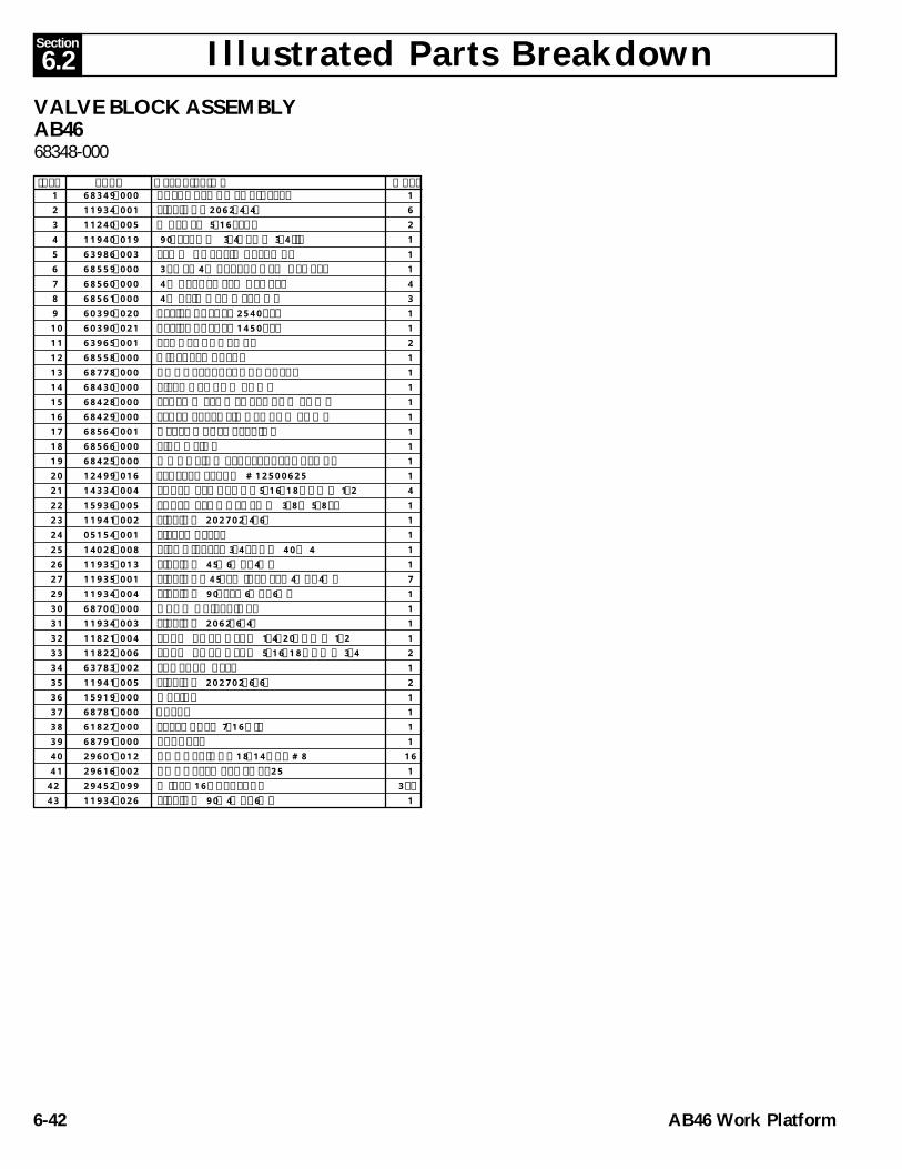
Illustrated Parts Breakdown6.2Section
AB46 Work Platform6-42
VALVE BLOCK ASSEMBLYAB4668348-000
ITEM PART DESCRIPTION QTY. 1 68349-000 VALVE BLOCK SUB-ASSY. 1 2 11934-001 FITTING, 2062-4-4S 6 3 11240-005 WASHER 5/16 FLAT 2 4 11940-019 90° ELBOW 3/4NPT X 3/4 JIC 1 5 63986-003 FLOW CNTRL,WATERMAN 1 6 68559-000 3 POS, 4 WAY, TANDEM CENTER 1 7 68560-000 4 WAY, CLOSED CENTER 4 8 68561-000 4 WAY,MOTOR SPOOL 3 9 60390-020 RELIEF VALVE, 2540 PSI 1 10 60390-021 RELIEF VALVE, 1450 PSI 1 11 63965-001 PLUG, GAGE PORT 2 12 68558-000 DIVERTER VALVE 1 13 68778-000 COUNTERBALANCE VALVE 1 14 68430-000 PISTON, HAND PUMP 1 15 68428-000 LEVER WELDMENT, HAND PUMP 1 16 68429-000 LEVER EXTENSION, HAND PUMP 1 17 68564-001 DETENT BALL / SPRING 1 18 68566-000 PIVOT LINK 1 19 68425-000 MOUNTING PLATE, VALVE BLOCK 1 20 12499-016 SEAL, POLYPAK #12500625 1 21 14334-004 SCREW. SOC. HD. 5/16-18 UNC X 1/2 4 22 15936-005 SCREW, SHOULDER Ø 3/8 X 5/8 LG 1 23 11941-002 FITTING 202702-4-6S 1 24 05154-001 FILTER ASSY. 1 25 14028-008 PIPE NIPPLE, 3/4 SCHD 40 X 4 1 26 11935-013 FITTING 45° 6MB-4MJ 1 27 11935-001 FITTING, 45° SWIVEL EL. 4MB-4MJ 7 29 11934-004 FITTING 90° EL. 6MB-6MJ 1 30 68700-000 HAND GRIP, VINYL 1 31 11934-003 FITTING 2062-6-4S 1 32 11821-004 SCRW BUTT HEAD 1/4-20UNC X 1/2 1 33 11822-006 SCRW BUTT HEAD 5/16-18 UNC X 3/4 2 34 63783-002 LANYARD ASSY 1 35 11941-005 FITTING 202702-6-6S 2 36 15919-000 ORFICE 1 37 68781-000 VALVE 1 38 61827-000 STEEL BALL 7/16 DIA 1 39 68791-000 BRACKET 1 40 29601-012 CONN. RING, 18-14 GA. #8 16 41 29616-002 CONN. FEM. PUSH, .25 142 29452-099 WIRE, 16 GA. BLACK 3 FT43 11934-026 FITTING 90° 4MB-6MJ 1

Illustrated Parts Breakdown 6.2Section
AB46 Work Platform 6-43

Illustrated Parts Breakdown6.2Section
AB46 Work Platform6-44
GROUND CONTROL BOX ASSEMBLYAB46 ELECTRIC68328-000
ITEM PART DESCRIPTION QTY. ITEM PART DESCRIPTION QTY.1 68717-000 BOX, GROUND CONTROL 12 67893-002 DIN RAIL, 14" LONG 23 67662-004 SOCKET, RELAY 14 67662-002 SOCKET, RELAY 15 67662-001 SOCKET, RELAY 46 67662-007 RETAINER CLIP, 17 67662-006 RETAINER CLIP, 18 67662-005 RETAINER CLIP, 49 68698-001 TERMINAL BLOCK (TAN) 2710 68733-000 DIODE BLOCK 1411 68698-002 TERMINAL BLOCK (BLUE) 2212 68773-002 JUMPER 2 PIN 313 68698-004 END SECTION 214 68756-004 RELAY, 4 POLE (48V DC) 115 68756-002 RELAY, 2 POLE (48V DC) 116 68756-001 RELAY, 1 POLE (48V DC) 419 68734-004 TERMINAL BLOCK (120 V) 120 29925-001 CONNECTOR, CABLE 721 29939-003 LOCKNUT, 3/4 NPT 722 11715-003 SCR, RD. HD. 6-32 X 3/8 423 11248-047 LOCKNUT, 6-32 ESNA 424 68889-099 WEATHERSTRIP 1/2" X 3/16" FOAM 4.5 FT25 11248-003 LOCKNUT, 10-24 ESNA 226 11709-010 SCR, RD. HD. 10-24 X 1 1/4 227 67660-006 END BLOCK, TERMINAL 428 11240-001 WASHER, FLAT #6 429 68733-001 END SECTION 130 14252-004 NUT SERT 1/4-20UNC 231 68648-000 TERMINAL BLOCK (ORANGE) 2201 68719-000 CONTROL BOX LID 1202 64446-003 EMERGENCY STOP BUTTON 1204 15752-000 HOUR METER, 1206 12798-004 SWITCH, TOGGLE DPDT MOM. 7207 68582-010 CIRCUIT BREAKER, 10 AMP 3208 64443-001 CONTACT BLOCK, N.O. 1209 64443-002 CONTACT BLOCK, N.C. 1210 64417-001 FLANGE, 3 CONTACT 2212 68588-001 SWITCH, KEY OPERATED 1
213 67652-000 PUSH BUTTON ORERATOR, GREEN 1214 66516-006 HOLE PLUG 7/8" DIA. 1215 08721-001 GUARD, TOGGLE SWITCH 7218 29701-000 FUSE HOLDER 1219 29704-025 FUSE, 25AMP 1221 66805-012 CONTACT BLOCK, N.O./N.C. 2222 11709-004 SCRW MACH RD HD 10-24UNC X 1/2 4223 11248-003 NUT HEX ESNA 10-24 UNC 4224 11821-005 SCRW,BUTT.HD SOC.1/4-20 X 5/8 LG 2301 29452-099 WIRE, 16 GA. BLACK 23 FT302 29451-099 WIRE, 16 GA. WHITE 14 FT303 29454-099 WIRE, 16 GA. RED 22 FT304 29457-099 WIRE, 16 GA. GREEN 33 FT305 29453-099 WIRE, 16 GA. ORANGE 27 FT306 29450-099 WIRE, 16 GA. BLUE 13 FT307 29479-099 WIRE, 16 GA. WHITE/BLACK 17 FT308 29478-099 WIRE, 16 GA. RED/BLACK 5 FT309 05491-099 WIRE, 16 GA. GREEN/BLACK 8 FT310 29477-099 WIRE, 16 GA. ORANGE/BLACK 8 FT311 29475-099 WIRE, 16 GA. BLUE/BLACK 4 FT312 29362-099 WIRE, 16 GA. RED/BLK/WHT 1 FT313 29483-099 WIRE, 16 GA. RED/WHITE 7 FT314 29482-099 WIRE, 16 GA. GREEN/WHITE 5 FT315 29459-099 WIRE, 16 GA. BLUE/WHITE 5 FT316 29355-099 WIRE, 16 GA. BLACK/RED 6 FT317 29356-099 WIRE, 16 GA. WHITE/RED 4 FT318 29357-099 WIRE, 16 GA. ORANGE/RED 8 FT319 29358-099 WIRE, 16 GA. BLUE/RED 5 FT321 29360-099 WIRE, 16 GA. ORANGE/GREEN 4 FT322 29361-099 WIRE, 16 GA. BLACK/WHITE/RED 5 FT323 29825-002 DIODE, 3 AMP. 400 VOLT 29324 13283-002 CABLE MOUNT 9325 29610-002 CONN FORK TERM 16-14
(#8 STUD) LOCKING 10326 29931-003 CONN FEM PUSH TERM 16-14 (1/4") 50327 29616-001 CONN FEM PUSH TERM 16-14 (3/16) 4328 29610-006 CONN FORK TERM 16-14
(#6 STUD) LOCKING 57
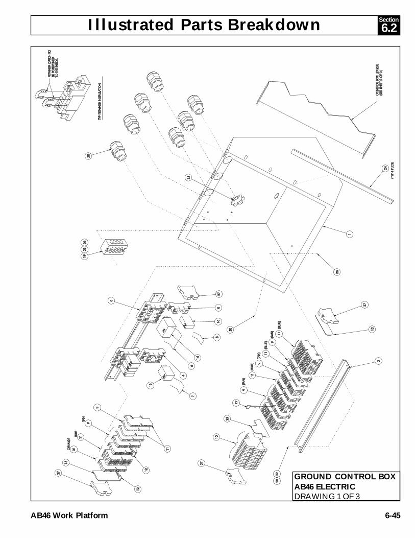
Illustrated Parts Breakdown 6.2Section
AB46 Work Platform 6-45
GROUND CONTROL BOXAB46 ELECTRICDRAWING 1 OF 3

Illustrated Parts Breakdown6.2Section
AB46 Work Platform6-46
GROUND CONTROL BOXAB46 ELECTRICDRAWING 2 OF 3

Section
AB46 Electric & Bi-Energy Work Platform 6-47
6.2
GROUND CONTROL BOXAB46 ELECTRICDRAWING 3 OF 3

Illustrated Parts Breakdown6.2Section
AB46 Work Platform6-48
GROUND CONTROL BOX ASSEMBLYAB46 BI-ENERGY68328-003
ITEM PART DESCRIPTION QTY. ITEM PART DESCRIPTION QTY.1 68717-000 BOX, GROUND CONTROL 12 67893-002 DIN RAIL, 14" LONG 23 67662-004 SOCKET, RELAY 14 67662-002 SOCKET, RELAY 15 67662-001 SOCKET, RELAY 36 67662-007 RETAINER CLIP, 17 67662-006 RETAINER CLIP, 18 67662-005 RETAINER CLIP, 39 68698-001 TERMINAL BLOCK (TAN) 3210 68733-000 DIODE BLOCK 1411 68698-002 TERMINAL BLOCK (BLUE) 2012 68773-002 JUMPER 2 PIN 313 68698-004 END SECTION 214 68756-004 RELAY, 4 POLE 48VDC 115 68756-002 RELAY, 2 POLE 48VDC 116 68756-001 RELAY, 1 POLE 48VDC 318 68698-000 TERMINAL BLOCK (ORANGE) 219 68734-004 TERMINAL BLOCK (120 V) 120 29925-001 CONNECTOR, CABLE 721 29939-003 LOCKNUT, 3/4 NPT 722 11715-003 SCR, RD. HD. 6-32 X 3/8 423 11248-047 LOCKNUT, 6-32 ESNA 424 68889-099 WEATHERSTRIP 1/2" X 3/16" FOAM 4.5 FT25 11248-003 LOCKNUT, 10-24 ESNA 226 11709-010 SCR, RD. HD. 10-24 X 1 1/4 227 67660-006 END BLOCK, TERMINAL 428 11240-001 WASHER, FLAT #6 429 68733-001 END SECTION 130 14252-004 NUT-SERT 1/4-20 UNC 2201 68719-000 CONTROL BOX LID 1202 64446-003 EMERGENCY STOP BUTTON 1204 68581-001 HOUR METER/BATTERY LEVEL IND. 1206 12798-004 SWITCH, TOGGLE DPDT MOM. 7207 68582-010 CIRCUIT BREAKER, 10 AMP 3208 64443-001 CONTACT BLOCK, N.O. 1209 64443-002 CONTACT BLOCK, N.C. 2210 64417-001 FLANGE, 3 CONTACT 1211 68819-000 SWITCH KEY OPERATOR 1212 68588-001 SWITCH, KEY OPERATED 1
213 68585-000 FLANGE, 5 CONTACT 1214 67654-000 PUSH BUTTON, BLACK 1215 08271-001 GUARD, TOGGLE SWITCH 7218 29701-000 FUSE HOLDER 1219 29704-025 FUSE, 25AMP 1220 66805-010 CONTACT BLOCK, N.O. 3221 66805-012 CONTACT BLOCK, N.O./N.C. 2222 11709-004 SCRW MACH RD HD 10-24UNC X 1/2 4223 11248-003 NUT HEX ESNA 10-24 UNC 4224 66805-011 CONTACT BLOCK 1 N.C. 1301 29452-099 WIRE, 16 GA. BLACK 23 FT302 29451-099 WIRE, 16 GA. WHITE 14 FT303 29454-099 WIRE, 16 GA. RED 22 FT304 29457-099 WIRE, 16 GA. GREEN 33 FT305 29453-099 WIRE, 16 GA. ORANGE 27 FT306 29450-099 WIRE, 16 GA. BLUE 13 FT307 29479-099 WIRE, 16 GA. WHITE/BLACK 17 FT308 29478-099 WIRE, 16 GA. RED/BLACK 5 FT309 05491-099 WIRE, 16 GA. GREEN/BLACK 8 FT310 29477-099 WIRE, 16 GA. ORANGE/BLACK 8 FT311 29475-099 WIRE, 16 GA. BLUE/BLACK 4 FT312 29362-099 WIRE, 16 GA. RED/BLK/WHT 1 FT313 29483-099 WIRE, 16 GA. RED/WHITE 7 FT314 29482-099 WIRE, 16 GA. GREEN/WHITE 5 FT315 29459-099 WIRE, 16 GA. BLUE/WHITE 5 FT316 29355-099 WIRE, 16 GA. BLACK/RED 6 FT317 29356-099 WIRE, 16 GA. WHITE/RED 4 FT318 29357-099 WIRE, 16 GA. ORANGE/RED 8 FT319 29358-099 WIRE, 16 GA. BLUE/RED 5 FT321 29360-099 WIRE, 16 GA. ORANGE/GREEN 4 FT322 29361-099 WIRE, 16 GA. BLACK/WHITE/RED 5 FT323 29825-002 DIODE, 3 AMP. 400 VOLT 27 FT324 13283-002 CABLE MOUNT 9325 29610-002 CONN FORK TERM 16-14
(#8 STUD) LOCKING 10326 29931-003 CONN FEM PUSH TERM 16-14 (1/4") 50327 29616-001 CONN FEM PUSH TERM 16-14 (3/16) 4328 29610-006 CONN FORK TERM 16-14
(#6 STUD) LOCKING 57

Illustrated Parts Breakdown 6.2Section
AB46 Work Platform 6-49
GROUND CONTROL BOXAB46 BI-ENERGYDRAWING 1 OF 3

Illustrated Parts Breakdown6.2Section
AB46 Work Platform6-50
GROUND CONTROL BOXAB46 BI-ENERGYDRAWING 2 OF 3

Section
AB46 Electric & Bi-Energy Work Platform 6-51
6.2
GROUND CONTROL BOXAB46 BI-ENERGYDRAWING 3 OF 3

Illustrated Parts Breakdown6.2Section
AB46 Work Platform6-52
RELAY PANEL ASSEMBLY, AB46ELECTRIC68346-000
ITEM PART DESCRIPTION QTY. 1 68490-000 RELAY MOUNT 1 2 68550-016 TACH BOARD ASSY. 1 3 68550-017 INSULATION SHEET 1 4 10122-002 RELAY, 48 VDC 1 5 68552-001 RELAY, 48 VDC DOUBLE CONTACT 1 6 68552-000 RELAY, 48 VDC SINGLE CONTACT 1 7 10149-000 FUSE BLOCK 2 8 68626-003 BUSS BAR 1 9 68626-004 BUSS BAR 1 10 68626-005 BUSS BAR 1 11 11252-006 SCREW, HHC 1/4-20 UNC X 3/4 6 12 11240-004 WASHER, FLAT STD. 1/4" 12 13 11248-004 LOCKNUT, HEX 1/4-20 UNC ESNA 6 14 11248-047 LOCKNUT, HEX #6-32 UNC ESNA 4 15 11715-008 SCREW, RD HD #6-32 UNC X 1 4 16 10148-003 FUSE,BUSS ANN-350 1 17 10148-002 FUSE,BUSS 125 AMP 1 18 11709-004 SCREW FLT HD #10-24 UNC X 1/2 4 19 11248-003 LOCKNUT, HEX #10-24 UNC ESNA 10 20 68550-018 RESISTOR BRACKET ASSY. 1 21 12956-002 GROMMET 8 22 11709-006 SCRW RD HD MACH 10-24 UNC X 3/4 4 23 11240-005 WASHER, FLAT STD 5/16 4 24 68550-015 BRACKET, SIDE MOUNT 1 25 68550-014 BRACKET, VERT. MOUNT 1 27 68550-013 TERMINAL LINK 1 28 68734-004 TERMINAL BLOCK 1 29 68818-000 TERMINAL BLOCK 2 30 68626-002 BUSS BAR 3 31 11709-010 SCR. RD. HD. #10 - 24 UNC X 1 1/4 2 32 20328-001 WASHER, NYLON 2201 68550-021 CONNECTOR, RESISTOR PACK 1202 68550-019 CONNECTOR, SEVCON CONTROL 1203 68550-020 CONNECTOR, TACH CARD 1204 29825-002 DIODE 1205 68758-000 5K RESISTOR 1206 29601-015 CONN. RING, 16-14 Ø 3/8 1207 29601-013 CONN. RING, 16-14 #10 3208 29931-003 CONN. FEM. PUSH, 16-14 .25 8209 29601-040 CONN. RING, 16-14 Ø 5/16 1210 29452-099 WIRE, 16 GA. BLK. 6 FT211 29454-099 WIRE, 16 GA. RED 2 FT212 29457-099 WIRE, 16 GA. GRN. 1 FT213 29453-099 WIRE, 16 GA. ORG. 3 FT214 29352-099 WIRE, 16 GA. RED/WHT 1.5 FT215 29454-099 WIRE, 16 GA. BLU/WHT 2.2 FT

Illustrated Parts Breakdown 6.2Section
AB46 Work Platform 6-53
RELAY PANEL ASSEMBLYAB46 ELECTRICDRAWING 1 OF 2

Illustrated Parts Breakdown6.2Section
AB46 Work Platform6-54
RELAY PANEL ASSEMBLYAB46 ELECTRICDRAWING 2 OF 2

Illustrated Parts Breakdown 6.2Section
AB46 Work Platform 6-55
NOTES:

Illustrated Parts Breakdown6.2Section
AB46 Work Platform6-56
1 68921-000 RELAY MOUNT, BI-ENERGY 1 2 68550-016 TACH BOARD ASSY. 1 3 68550-017 INSULATION SHEET 1 4 10122-002 RELAY, 48 VDC 1 5 68552-001 RELAY, 48 VDC DOUBLE CONTACT 1 6 68552-000 RELAY, 48 VDC SINGLE CONTACT 1 7 10149-000 FUSE BLOCK 2 8 68626-003 BUSS BAR 1 9 68626-004 BUSS BAR 110 68626-005 BUSS BAR 111 11252-006 SCREW, HHC 1/4-20 UNC X 3/4 612 11240-004 WASHER, FLAT STD. 1/4" 1213 11248-004 LOCKNUT, HEX 1/4-20 UNC ESNA 614 11248-047 LOCKNUT, HEX #6-32 UNC ESNA 415 11715-008 SCREW, RD HD #6-32 UNC X 1 416 10148-003 FUSE,BUSS ANN-350 117 10148-004 FUSE,BUSS 125 AMP 118 11709-004 SCREW FLT HD #10-24 UNC X 1/2 419 11248-003 LOCKNUT, HEX #10-24 UNC ESNA 1020 68550-018 RESISTOR BRACKET ASSY. 121 12956-002 GROMMET 822 11709-006 SCRW RD HD MACH 10-24 UNC X 3/4 423 11240-005 WASHER, FLAT STD 5/16 424 68550-015 BRACKET, SIDE MOUNT 125 68550-014 BRACKET, VERT. MOUNT 127 68550-013 TERMINAL LINK 128 68734-004 TERMINAL BLOCK 129 68818-000 TERMINAL BLOCK 230 68626-002 BUSS BAR 331 11709-010 SCR. RD. HD. #10 - 24 UNC X 1 1/4 232 20328-001 WASHER, NYLON 2201 68550-021 CONNECTOR, RESISTOR PACK 1202 68550-019 CONNECTOR, SEVCON CONTROL 1203 68550-020 CONNECTOR, TACH CARD 1204 29825-002 DIODE 1205 68758-000 5K RESISTOR 1206 29601-015 CONN. RING, 16-14 Ø 3/8 1207 29601-013 CONN. RING, 16-14 #10 3208 29931-003 CONN. FEM. PUSH, 16-14 .25 8209 29601-040 CONN. RING, 16-14 Ø 5/16 1210 29452-099 WIRE, 16 GA. BLK. 6 FT211 29454-099 WIRE, 16 GA. RED 2 FT212 29457-099 WIRE, 16 GA. GRN. 1 FT213 29453-099 WIRE, 16 GA. ORG. 3 FT214 29352-099 WIRE, 16 GA. RED/WHT 1.5 FT215 29459-099 WIRE, 16 GA. BLU/WHT 2.2 FT
RELAY PANEL ASSEMBLY, AB46BI-ENERGY68346-001
ITEM PART DESCRIPTION QTY.

Illustrated Parts Breakdown 6.2Section
AB46 Work Platform 6-57
RELAY PANEL ASSEMBLYAB46, BI-ENERGYDRAWING 1 OF 2

Illustrated Parts Breakdown6.2Section
AB46 Work Platform6-58
RELAY PANEL ASSEMBLYAB46, BI-ENERGYDRAWING 2 OF 2

Illustrated Parts Breakdown 6.2Section
AB46 Work Platform 6-59
1 68489-001 CONTROL MOUNT 12 68550-000 MOTION CONTROL, SEVCON 13 68626-002 BUSS BAR 24 63947-008 NUT, HEX. REG. M8 X 1.25 45 11821-004 SCREW, BTN HD. 1/4-20 UNC X 1/2 4
SPEED CONTROL PANEL ASSEMBLYAB46, BI-ENERGY68321-000
ITEM PART DESCRIPTION QTY.

Illustrated Parts Breakdown6.2Section
AB46 Work Platform6-60
1 68329-000 CONTROLLER ASSY - DOM. (ELEC) 1 7 68750-000 DECAL MOUNT 1 8 63778-001 ALARM 1 9 08942-001 FEMALE RECEPTACLE 1 10 29961-001 SEAL 1 11 11252-008 SCREW HHC 1/4-20 UNC X 1 4 12 11248-004 NUT HEX 1/4-20 UNC ESNA 8 13 11715-006 SCREW RD HD 6-32 UNC X 3/4 4 14 11248-047 NUT HEX 6-32 UNC ESNA 4 15 11709-006 SCREW RD HD 10-24 UNC X 3/4 3
CONTROLLER INSTALLATIONAB46 ELECTRIC68339-001
ITEM PART DESCRIPTION QTY. 16 11248-003 NUT HEX 10-24 UNC ESNA 3 17 68820-000 RETAINING STRAP-FOOTSWITCH 2 18 63906-000 FOOT SWITCH CLPR 1 19 64479-000 SWITCH GUARD, FOOT 1 20 11252-012 SCREW HHC 1/4-20 UNC X 1 1/2 4 21 66695-006 SCREW FLAT HD 10-24 UNC X 3/4 2 22 13949-003 WASHER, #10 STAR, EXTERNAL TOOTH 2 23 11250-003 HEX NUT 10-24 UNC 2
ITEM PART DESCRIPTION QTY.

Illustrated Parts Breakdown 6.2Section
AB46 Work Platform 6-61
1 68329-010 CONTROLLER ASSY - DOM. (BI-ENERGY) 1 7 68750-000 DECAL MOUNT 1 8 63778-001 ALARM 1 9 08942-001 FEMALE RECEPTACLE 1 10 29961-001 SEAL 1 11 11252-008 SCREW HHC 1/4-20 UNC X 1 4 13 11715-006 SCREW RD HD 6-32 UNC X 3/4 4 12 11248-004 NUT HEX 1/4-20 UNC ESNA 8 14 11248-047 NUT HEX 6-32 UNC ESNA 4 15 11709-006 SCREW RD HD 10-24 UNC X 3/4 3
CONTROLLER INSTALLATIONAB46 BI-ENERGY68339-011
ITEM PART DESCRIPTION QTY. 16 11248-003 NUT HEX 10-24 UNC ESNA 3 17 68820-000 RETAINING STRAP-FOOTSWITCH 2 18 63906-000 FOOT SWITCH CLPR 1 19 64479-000 SWITCH GUARD, FOOT 1 20 11252-012 SCREW HHC 1/4-20 UNC X 1 1/2 4 21 66695-006 SCREW FLAT HD 10-24 UNC X 3/4 2 22 13949-003 WASHER, #10 STAR, EXTERNAL TOOTH 2 23 11250-003 HEX NUT 10-24 UNC 2
ITEM PART DESCRIPTION QTY.

Illustrated Parts Breakdown6.2Section
AB46 Work Platform6-62
1 68589-001 BOX, ENCLOSURE 1 2 29939-003 LOCKNUT 3/4" NPT 4 3 29939-002 LOCKNUT 1/2" NPT 1 4 29925-000 CONNECTOR CABLE 1/2" NPT 1 5 29925-001 CONNECTOR CABLE 3/4" NPT 4 6 64446-003 EMERGENCY STOP BUTTON 1 7 67654-000 PUSH BUTTON FLUSH (BLACK) 1 8 68595-001 LENS, RED 1 9 11249-003 NUT, HEX 10-32 ESNA 2 10 66516-005 HOLE PLUG ›11/16 1 11 68800-001 LID WELDMENT, CONTROLLER-ELEC. 1 13 68594-000 JOYSTICK - OPERATOR 4 14 68593-000 RHEOSTAT - CONTROLLER (48VOLT) 1 15 68592-000 JOYSTICK OEM/SEVCON (48V) 1* 68592-005 ROCKER SWITCH BOOT 1* 68592-006 MICRO SWITCH 2* 63913-005 HANDLE HALVES (PAIR) 1* 63913-001 HANDLE BOOT 1* 68592-007 PC BOARD W/POT 1* 68592-008 MICRO SWITCH 3
16 68807-000 KEYSWITCH & KEY 1* 68807-010 KEY 1
17 68734-004 TERMINAL STRIP, 120V AC 1 18 68590-000 BASE INDICATOR (LAMP) 1 19 11826-012 SCREW RD HD 10-32 X 1-1/2 2 20 12798-004 TOGGLE SWITCH, MOMENTARY 3 21 64417-001 FLANGE MOUNT 2 22 64443-001 CONTACT BLOCK, N.O. 1 23 68591-000 LAMP T-2-1/2 1 24 66805-012 CONTACT BLOCK, N.O./N.C. 8 25 11715-003 SCREW RD HD 6-32 X 3/8 4 28 64443-002 CONTACT BLOCK N.C. 2 29 67660-006 TERMINAL END 2 30 68698-001 TERMINAL BLOCK (TAN) 18 31 68698-002 TERMINAL BLOCK (BLUE) 4 32 68799-000 ANGLE, CONTROLLER 1 33 67662-001 RELAY SOCKET 4 34 68756-001 RELAY, SPDT 48 VOLT 4 35 67662-005 RETAINING CLIP & WIRE 4 36 11250-001 NUT HEX 6-32 4
CONTROLLER ASSEMBLY-PLATFORMAB46 ELECTRIC68329-000
ITEM PART DESCRIPTION QTY. ITEM PART DESCRIPTION QTY. 37 67893-003 MOUNTING RAIL, DIN 8-1/4" 1 40 68897-099 GASKET,BLACK RUBBER 3.25 FT 41 68582-010 CIRCUIT BREAKER 10 AMP 1 42 68767-000 BRACKET, UPPER CONTROLLER 2 43 11708-004 SCREW 8-32 X 1/2 2 44 11248-002 NUT, HEX ESNA 8-32 UNC 2 45 68769-000 POTENTIOMETER 10 TURN 1 46 11252-005 SCREW HHC GR5 1/4-20UNC X 5/8 6 47 11246-004 NUT HEX ESNA 1/4-20UNC 6 48 14252-004 NUT SERT 1/4-20 1 49 68804-000 BRACKET, POT MOUNT 1 50 068860-001 DOUBLE CONTACT BLOCK GE 2 N.C. 1 51 68698-004 END CAP, CONTACT BLOCK 1 202 29454-099 WIRE 16GA RED 21 FT 203 29482-099 WIRE 16GA GREEN/WHT 3 FT 204 68735-099 WIRE 16GA BLACK/RED 5 FT 205 29452-099 WIRE 16GA BLACK 9.3 FT 206 29610-006 TERM FORK 18-14GA #6 60 207 29620-002 BUTT CONNECTOR 18-14GA 6 210 29451-099 WIRE 16GA WHITE 5.8 FT 211 29931-003 CONN FEMALE PUSH .25 (16-14GA) 12 212 29450-099 WIRE 16GA BLFT4.1 213 29825-002 DIODE 3 AMP 400V 15 214 29478-099 WIRE 16GA RED/BLACK 3.5 FT 215 29457-099 WIRE 16GA GREEN 1.5 FT 216 29616-001 CONN FEMALE PUSH .187 (16-14GA) 3 217 29360-099 WIRE 16GA ORANGE/GREEN 2 FT 218 29453-099 WIRE 16GA ORANGE 1.2 FT 219 29458-099 WIRE 16GA PURPLE 1.2 FT 220 29479-099 WIRE 16GA WHITE/BLACK 4 FT 221 68758-000 RESISTOR 5000 OHM 1 222 29483-099 WIRE 16GA RED/WHITE 2.5 FT 223 29601-039 RING TERM 1 225 68773-000 JUMPER 2 226 68814-000 PIN TERMINAL 6 227 REF RECEPTACLE 1 228 29464-099 WIRE 14GA GREEN .5 FT
* Not Shown
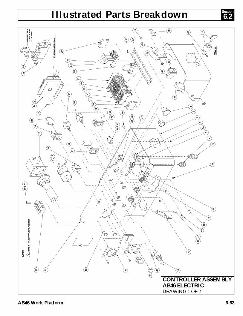
Illustrated Parts Breakdown 6.2Section
AB46 Work Platform 6-63
CONTROLLER ASSEMBLYAB46 ELECTRICDRAWING 1 OF 2

Illustrated Parts Breakdown6.2Section
AB46 Work Platform6-64
CONTROLLER ASSEMBLYAB46 ELECTRICDRAWING 2 OF 2

Illustrated Parts Breakdown 6.2Section
AB46 Work Platform 6-65
NOTES:

Illustrated Parts Breakdown6.2Section
AB46 Work Platform6-66
CONTROLLER ASSEMBLY - PLATFORMAB46 BI-ENERGY68329-010
ITEM PART DESCRIPTION QTY. 1 68589-001 BOX, ENCLOSURE 1 2 29939-003 LOCKNUT 3/4" NPT 4 3 29939-002 LOCKNUT 1/2" NPT 1 4 29925-000 CONNECTOR CABLE 1/2" NPT 1 5 29925-001 CONNECTOR CABLE 3/4" NPT 4 6 64446-003 EMERGENCY STOP BUTTON 1 7 67654-000 PUSH BUTTON FLUSH (BLACK) 1 8 68595-001 LENS, RED 1 9 11249-003 NUT, HEX 10-32 ESNA 2 10 68595-002 LENS, AMBER 1 11 68800-000 LID ASSY, CONTROLLER 1 12 12798-003 TOGGLE SWITCH, 2 POS, MOM 1 13 68594-000 JOYSTICK - OPERATOR 4 14 68593-000 RHEOSTAT - CONTROLLER (48VOLT) 1 15 68592-000 JOYSTICK OEM/SEVCON (48V) 1* 68592-005 ROCKER SWITCH BOOT 1* 68592-006 MICRO SWITCH 2* 63913-005 HANDLE HALVES (PAIR) 1* 63913-001 HANDLE BOOT 1* 68592-007 PC BOARD W/POT 1
16 68807-000 KEYSWITCH & KEY 1* 68807-010 KEY 1
17 68734-004 TERMINAL STRIP, 120V AC 1 18 68590-000 BASE INDICATOR (LAMP) 2 19 11826-012 SCREW RD HD 10-32 X 1-1/2 2 20 12798-004 TOGGLE SWITCH, MOMENTARY 3 21 64417-001 FLANGE MOUNT 2 22 64443-001 CONTACT BLOCK, N.O. 1 23 68591-000 LAMP T-2-1/2 2 24 66805-012 CONTACT BLOCK, N.O./N.C. 8 25 11715-003 SCREW RD HD 6-32 X 3/8 4 26 68986-000 TOGLE SWCH, 3 POS (HOLD, HOLD, MOM) 1 28 64443-002 CONTACT BLOCK N.C. 2 29 67660-006 TERMINAL END 2 30 68698-001 TERMINAL BLOCK (TAN) 18 31 68698-002 TERMINAL BLOCK (BLUE) 4 32 68799-000 ANGLE, CONTROLLER 1 33 67662-001 RELAY SOCKET 4 34 68756-001 RELAY, SPDT 48 VOLT 4 35 67662-005 RETAINING CLIP & WIRE 4 36 11250-001 NUT HEX 6-32 4
37 67893-003 MOUNTING RAIL, DIN 8-1/4" 1 40 68897-099 GASKET,BLACK RUBBER 3.25 FT 41 68582-010 CIRCUIT BREAKER 10 AMP 1 42 68767-000 BRACKET, UPPER CONTROLLER 2 43 11708-004 SCREW 8-32 X 1/2 2 44 11248-002 NUT, HEX ESNA 8-32 UNC 2 45 68769-000 POTENTIOMETER 10 TURN 1 46 11825-006 SCREW RD HD 1/4-20UNC X 3/4 6 47 11246-004 NUT HEX ESNA 1/4-20UNC 6 48 14252-004 NUT SERT 1/4-20 1 49 68804-000 BRACKET, POT MOUNT 1 50 068860-001 DOUBLE CONTACT BLOCK GE 2 N.C. 1 51 68698-004 END CAP, CONTACT BLOCK 1 52 10080-006 CLIP, TREE 2202 29454-099 WIRE 16GA RED | FT 21203 29482-099 WIRE 16GA GREEN/WHT 3 FT204 68735-099 WIRE 16GA BLACK/RED 5 FT205 29452-099 WIRE 16GA BLACK 9.3 FT206 29610-006 TERM FORK 18-14GA #6 63207 29620-002 BUTT CONNECTOR 18-14GA 6210 29451-099 WIRE 16GA WHITE 5.8 FT211 29931-003 CONN FEMALE PUSH .25 (16-14GA) 13212 29450-099 WIRE 16GA BLUE 4.1 FT213 29825-002 DIODE 3 AMP 400V 15214 29478-099 WIRE 16GA RED/BLACK 3.5 FT215 29457-099 WIRE 16GA GREEN 1.5 FT216 29616-001 CONN FEMALE PUSH .187 (16-14GA) 3217 29360-099 WIRE 16GA ORANGE/GREEN 2 FT218 29453-099 WIRE 16GA ORANGE 1.2 FT219 29458-099 WIRE 16GA PURPLE 1.2 FT220 29479-099 WIRE 16GA WHITE/BLACK 4 FT221 68758-000 RESISTOR 5000 OHM 1222 29483-099 WIRE 16GA RED/WHITE 2.5 FT223 29601-039 RING TERM 1225 68773-000 JUMPER 2226 68814-000 PIN TERMINAL 6228 29464-099 WIRE 14GA GREEN .5 FT
ITEM PART DESCRIPTION QTY.
* Not Shown

Illustrated Parts Breakdown 6.2Section
AB46 Work Platform 6-67
CONTROLLER ASSEMBLYAB46 BI-ENERGYDRAWING 1 OF 2

Illustrated Parts Breakdown6.2Section
AB46 Work Platform6-68
CONTROLLER ASSEMBLYAB46 BI-ENERGYDRAWING 2 OF 2

Illustrated Parts Breakdown 6.2Section
AB46 Work Platform 6-69
NOTES:

Illustrated Parts Breakdown6.2Section
AB46 Work Platform6-70
HOSE KITAB46 ELECTRIC68336-000
ITEM PART DESCRIPTION QTY. 1 68737-324 1/4 HOSE ASSY X 324" 4FJX-4FJX 2 2 68736-019 3/16 HOSE ASSY X 19" 4FJX-4FJX 1 3 68737-720 1/4 HOSE ASSY X 720" 4FJX-4FJX 2 4 68809-264 1/4 HOSE ASSY X 264" 4FJX-4FJX 2 5 68736-021 3/16 HOSE ASSY X 21" 4FJX-4FJX 1 6 68736-604 3/16 HOSE ASSY X 604" 4FJX-4FJX 2 7 68736-350 3/16 HOSE ASSY X 350" 4FJX-4FJX 2 8 68763-036 1/4 HOSE ASSY X 36" 6FJX-4FJX 1 9 68737-312 1/4 HOSE ASSY X 312" 4FJX-4FJX 2 10 68737-177 1/4 HOSE ASSY X 177" 4FJX-4FJX 2 11 68753-089 1/4 HOSE ASSY X 89" 4FJX-6FJX 90° 2 12 68741-036 1/4 HOSE ASSY X 36" 6FJX-6FJX 1 13 68741-079 1/4 HOSE ASSY X 79" 6FJX-6FJX 1 14 68737-075 1/4 HOSE ASSY X 75" 4FJX-4FJX 1 15 68740-090 1/2 HOSE ASSY X 90" 10FJX-10FJX 1 16 68753-084 1/4 HOSE ASSY X 84" 4FJX-6FJX 90° 1 17 68763-016 1/4 HOSE ASSY X 16" 6FJX-4FJX 1 18 68741-085 1/4 HOSE ASSY X 85" 6FJX-6FJX 1

Illustrated Parts Breakdown 6.2Section
AB46 Work Platform 6-71

Illustrated Parts Breakdown6.2Section
AB46 Work Platform6-72
HOSE KITAB46 BI-ENERGY68336-002
ITEM PART DESCRIPTION QTY. 1 68737-324 1/4 HOSE ASSY X 324" 4FJX-4FJX 2 2 68736-019 3/16 HOSE ASSY X 19" 4FJX-4FJX 1 3 68737-720 1/4 HOSE ASSY X 720" 4FJX-4FJX 2 4 68809-264 1/4 HOSE ASSY X 264" 4FJX-4FJX 2 5 68736-021 3/16 HOSE ASSY X 21" 4FJX-4FJX 1 6 68736-604 3/16 HOSE ASSY X 604" 4FJX-4FJX 2 7 68736-350 3/16 HOSE ASSY X 350" 4FJX-4FJX 2 8 68763-036 1/4 HOSE ASSY X 36" 6FJX-4FJX 1 9 68737-312 1/4 HOSE ASSY X 312" 4FJX-4FJX 2 10 68737-177 1/4 HOSE ASSY X 177" 4FJX-4FJX 2 11 68753-089 1/4 HOSE ASSY X 89" 4FJX-6FJX 90° 2 12 68741-036 1/4 HOSE ASSY X 36" 6FJX-6FJX 1 13 68741-079 1/4 HOSE ASSY X 79" 6FJX-6FJX 1 14 68737-075 1/4 HOSE ASSY X 75" 4FJX-4FJX 1 15 68740-090 1/2 HOSE ASSY X 90" 10FJX-10FJX 1 16 68753-084 1/4 HOSE ASSY X 84" 4FJX-6FJX 90° 1 18 68741-085 1/4 HOSE ASSY X 85" 6FJX-6FJX 1

Illustrated Parts Breakdown 6.2Section
AB46 Work Platform 6-73

Illustrated Parts Breakdown6.2Section
AB46 Work Platform6-74
BATTERY MODULE ASSEMBLYAB4668331-001,002
ITEM PART DESCRIPTION QTY. 1 68726-000 BATTERY TRAY WELDMENT 1 2 68568-000 BATTERY, 6 VOLT 350 AMP HR. 4 3 68334-001 CABLE ASSEMBLY 3 4 68332-002 CABLE ASSEMBLY 1 5 68659-000 COVER, BATTERY TRAY 1 6 11253-007 SCREW, HHC 5/16-18 UNC X 7/8 8 7 14996-005 WASHER, 5/16 DIA. S.A.E. 8 8 11250-005 NUT,HEX 5/16-18 UNC 8 9 68757-000 LATCH, SOUTHCO 2 10 26552-005 POP RIVET, 8 11 11238-005 WASHER, SPLIT LOCK 5/16 8

Illustrated Parts Breakdown 6.2Section
AB46 Work Platform 6-75
TIRE & WHEEL ASSEMBLYAB4668327-000
ITEM PART DESCRIPTION QTY. 1 68555-000 TIRE 16.5 X 9.50 10 PLY 1 2 67609-000 WHEEL 16.5 X 8.25, 6 HOLE ON 6" B.C. 1 3 12282-001 VALVE STEM 1
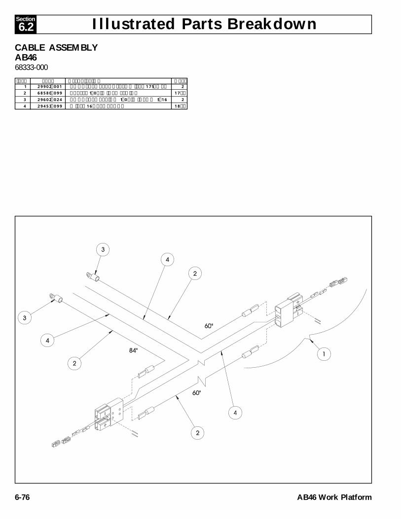
Illustrated Parts Breakdown6.2Section
AB46 Work Platform6-76
CABLE ASSEMBLYAB4668333-000
ITEM PART DESCRIPTION QTY. 1 29902-001 CONNECTOR, ANDERSON (SBX175AMP) 2 2 68580-099 CABLE, 1/0 A.W.G. WELDING 17 FT 3 29602-024 CONNECTOR, RING 1/0 A.W.G. X Ø 5/16 2 4 29453-099 WIRE, 16 GA. ORANGE 18 FT

Illustrated Parts Breakdown 6.2Section
AB46 Work Platform 6-77
NOTES:

Illustrated Parts Breakdown6.2Section
AB46 Work Platform6-78
CAGE "B" ASSEMBLYAB4668325-001
ITEM PART DESCRIPTION QTY. 1 68500-001 CAGE “B” WELDMENT 1 2 68532-000 LIFT-UP GATE WELDMENT 1 3 68775-000 BASKET PIN WELDMENT 1 4 68457-000 CYLINDER, CAGE ROTATION 1 * 68457-010 SEAL KIT, CAGE ROTATE 1 5 68651-000 THRUST WASHER G32DU (MODIFIED) 1 6 65214-000 PIN RETAINER 1 7 63650-012 GAS SPRING 1 8 15936-010 SHOULDER BOLT 2 9 11248-005 LOCKNUT 2 10 11939-004 FITTING, 4MP-4MJ 2 11 11737-012 ROLLPIN 1/4" X 1-1/2" 1 12 11703-008 SCREW, HHC 1/4-20 X 1-1/2 1 13 11248-004 NUT HEX 1/4-20 3 14 11254-008 SCREW HHC 3/8-16 X 1 1 16 11821-005 SCREW BUTTON HD 1/4-20 UNC X 5/8 2 17 68277-000 LATCH ROTARY 1 18 68806-000 STRIKER WELDMENT 1 19 11709-004 SCREW RND HD 10-24 UNC X 1/2 2 20 68778-000 VALVE COUNTERBALANCE (550 PSI) 2 21 11238-006 LOCKWASHER 3/8 SPLIT 1 22 15936-005 SHOULDER BOLT 3/8 X 5/8 LG 2 23 11248-005 NUT, ESNA 5/16-18 2

Illustrated Parts Breakdown 6.2Section
AB46 Work Platform 6-79

Illustrated Parts Breakdown6.2Section
AB46 Work Platform6-80
CAGE "A"AB4668500-000
ITEM PART DESCRIPTION QTY. 1 68500-000 CAGE “A” WELDMENT 1

Illustrated Parts Breakdown 6.2Section
AB46 Work Platform 6-81
4 FT. CAGEAB4668500-003
ITEM PART DESCRIPTION QTY. 1 68500-003 CAGE WELDMENT 4 FT 1
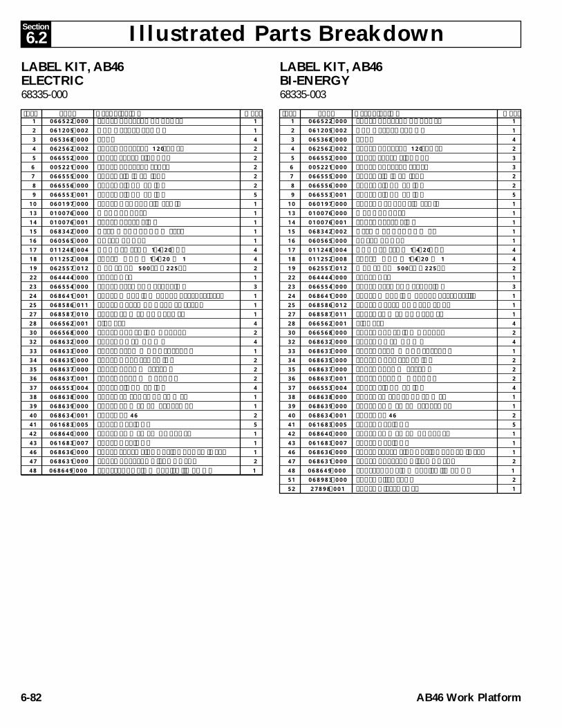
Illustrated Parts Breakdown6.2Section
AB46 Work Platform6-82
1 066522-000 LABEL BATTERY CHARGER 1 2 061205-002 NAME PLATE / BOOM 1 3 065368-000 TACK 4 4 062562-002 LABEL BATTERY 120LBS EA 2 5 066552-000 LABEL EXPLOSIVE GAS 2 6 005221-000 LABEL BATTERY LEVEL 2 7 066555-000 LABEL LIMIT SWITCH 2 8 066556-000 LABEL PINCH POINT 2 9 066553-001 LABEL PINCH POINT 510 060197-000 LABEL HYDRAULIC FLUID 113 010076-000 MANUAL CASE 114 010076-001 LABEL ATTENTION 115 068342-000 USER MANUAL DOM ELEC 116 060565-000 ANSI MANUAL 117 011248-004 NUT HEX ESNA 1/4-20UNC 418 011252-008 SCREW HHC X 1/4-20 X 1 419 062557-012 MAX LOAD 500 Lb / 225 Kg 222 064444-000 LABEL USA 123 066554-000 LABEL BEFORE OPERATION 324 068641-001 LABEL WARNING BRAKE RELEASE-ELEC 125 068586-011 LABEL UPPER CONTROLS ELEC. 127 068587-010 LABEL LOWER CONTROLS 128 066562-001 TIRE PSI 430 066568-000 LABEL CRUSHING HAZARD 232 068632-000 LABEL HOLD DOWN 433 068633-000 LABEL READ & UNDERSTAND 134 068635-000 LABEL HARNESS POINT 235 068637-000 LABEL ARROW YELLOW 236 068637-001 LABEL ARROW ORANGE 237 066553-004 LABEL PINCH POINT 438 068638-000 LABEL EMERGENCY LOWER 139 068639-000 LABEL POWER TO PLATFORM 140 068634-001 LABEL AB46 241 061683-005 LABEL UPRIGHT 542 068640-000 LABEL POWER TO CHARGER 143 061683-007 LABEL UPRIGHT 146 068636-000 LABEL EXPLOSIVE GAS/CHARGER INSTL 147 068631-000 LABEL BATTERY DISCONNECT 248 068649-000 LABEL, CAUTION - RAISE JIB BOOM 1
LABEL KIT, AB46ELECTRIC68335-000
ITEM PART DESCRIPTION QTY. 1 066522-000 LABEL BATTERY CHARGER 1 2 061205-002 NAME PLATE / BOOM 1 3 065368-000 TACK 4 4 062562-002 LABEL BATTERY 120LBS EA 2 5 066552-000 LABEL EXPLOSIVE GAS 3 6 005221-000 LABEL BATTERY LEVEL 3 7 066555-000 LABEL LIMIT SWITCH 2 8 066556-000 LABEL PINCH POINT 2 9 066553-001 LABEL PINCH POINT 510 060197-000 LABEL HYDRAULIC FLUID 113 010076-000 MANUAL CASE 114 010076-001 LABEL ATTENTION 115 068342-002 USER MANUAL DOM BI 116 060565-000 ANSI MANUAL 117 011248-004 NUT HEX ESNA 1/4-20UNC 418 011252-008 SCREW HHC X 1/4-20 X 1 419 062557-012 MAX LOAD 500 Lb / 225 Kg 222 064444-000 LABEL USA 123 066554-000 LABEL BEFORE OPERATION 324 068641-000 LABEL WARNING BRAKE RELEASE-I/C 125 068586-012 LABEL UPPER CONTROLS BI 127 068587-011 LABEL LOWER CONTROLS 128 066562-001 TIRE PSI 430 066568-000 LABEL CRUSHING HAZARD 232 068632-000 LABEL HOLD DOWN 433 068633-000 LABEL READ & UNDERSTAND 134 068635-000 LABEL HARNESS POINT 235 068637-000 LABEL ARROW YELLOW 236 068637-001 LABEL ARROW ORANGE 237 066553-004 LABEL PINCH POINT 438 068638-000 LABEL EMERGENCY LOWER 139 068639-000 LABEL POWER TO PLATFORM 140 068634-001 LABEL AB46 241 061683-005 LABEL UPRIGHT 542 068640-000 LABEL POWER TO CHARGER 143 061683-007 LABEL UPRIGHT 146 068636-000 LABEL EXPLOSIVE GAS/CHARGER INSTL 147 068631-000 LABEL BATTERY DISCONNECT 248 068649-000 LABEL, CAUTION - RAISE JIB BOOM 151 068983-000 LABEL BI-ENERGY 252 27898-001 LABEL DIESEL FUEL 1
LABEL KIT, AB46BI-ENERGY68335-003
ITEM PART DESCRIPTION QTY.

Illustrated Parts Breakdown 6.2Section
AB46 Work Platform 6-83

Illustrated Parts Breakdown6.2Section
AB46 Work Platform6-84
1 66817-000 STROBE MOUNT WELDMENT 22 12848-004 FLASHING STROBE LIGHT 23 66807-000 HORN 14 11258-008 SCR. HHC 3/4-10 UNC X 1 15 11238-016 WASHER, SPLIT LOCK 16 29496-099 WIRE, C COND. 16 GA. 8 FT7 11709-004 SCREW # 10-24 UNC X 1/2" LG 48 11248-003 LOCKNUT # 10-24 UNC ESNA 49 11252-006 SCREW, HHC 1/4-20UNC X 3/4" LG. 110 11239-004 LOCKWASHER, 1/4" SPLIT RING 111 11240-012 FLATWASHER STD 3/4" 2
MOTION ALARM/FLASHING BEACONOPTION - AB4668294-000
ITEM PART DESCRIPTION QTY.

Illustrated Parts Breakdown 6.2Section
AB46 Work Platform 6-85

Illustrated Parts Breakdown6.2Section
AB46 Work Platform6-86
BATTERY CHARGE INDICATOROPTION - AB46 (ELECTRIC ONLY)68297-000
ITEM PART DESCRIPTION QTY.1 68581-001 BATTERY FUEL / HOUR METER 12 29453-099 WIRE, 16 GA. ORANGE (2 PCS. @ 3') 6 FT3 29454-099 WIRE, 16 GA. RED 3 FT4 29361-099 WIRE, 16 GA. BLACK/WHITE/RED 3 FT5 29452-099 WIRE, 16 GA. BLACK 3 FT6 29450-099 WIRE, 16 GA. BLUE 3 FT7 68590-000 BASE, INDICATOR LIGHT 18 68591-000 LAMP, 48 VOLT 19 68595-002 LENS, AMBER 1

Call Toll Free in U.S.A.
1-800-926-LIFTUpRight, Inc.
1775 Park StreetSelma, California 93662
TEL: 209/891-5200FAX: 209/896-9012
PARTS: 1-888-UR-PARTSPARTSFAX: 209/896-9244 68343-000
3/98
Copyright © 2022 FDOKUMEN