An Electric Scooter with Super-Capacitor Drive and Regenerative Braking
Upload
khangminh22Category
view
1download
0
Engineering Science and Technology, an International Journal 21 (2018) 704–713
Contents lists available at ScienceDirect
Engineering Science and Technology,an International Journal
journal homepage: www.elsevier .com/locate / jestch
Full Length Article
A new electric braking system with energy regeneration for a BLDCmotor driven electric vehicle
https://doi.org/10.1016/j.jestch.2018.05.0032215-0986/� 2018 Karabuk University. Publishing services by Elsevier B.V.This is an open access article under the CC BY-NC-ND license (http://creativecommons.org/licenses/by-nc-nd/4.0/).
⇑ Corresponding author.E-mail address: [email protected] (A. Joseph Godfrey).
Peer review under responsibility of Karabuk University.
A. Joseph Godfrey ⇑, V. SankaranarayananControl Systems Research Laboratory, Department of Electrical and Electronics Engineering, National Institute of Technology-Tiruchirappalli, Tiruchirappalli 620015, Tamilnadu, India
a r t i c l e i n f o a b s t r a c t
Article history:Received 15 December 2017Revised 1 April 2018Accepted 5 May 2018Available online 24 May 2018
Keywords:BLDC motorElectric vehicleElectric brakingRegenerative brakingBraking strategy
A new electric braking system is proposed for a brushless DC (BLDC) motor driven electric vehicle (EV) inthis paper based on stopping time and energy regeneration. This new braking system is developed bycombining various regenerative methods and plugging. Other than the existing performance measuressuch as boost ratio, braking torque, and maximum conversion ratio; stopping time and energy recoveryfor various methods are studied for different running conditions. It is observed that the stopping time isless for plugging and increases in the order of two, three and single switch method. In addition, energyrecovery is better for single and three switch method. Based on these performances, a new braking strat-egy is proposed which combine all the regenerative braking methods including plugging and switchamong themselves based on the brake pedal depression. The effectiveness of the proposed method isshown using both simulation and experiment results.� 2018 Karabuk University. Publishing services by Elsevier B.V. This is an open access article under the CC
BY-NC-ND license (http://creativecommons.org/licenses/by-nc-nd/4.0/).
1. Introduction
Electric vehicle (EV) is one of the alternatives to internal com-bustion engine powered vehicle due to pollution concern, costand availability of the oil. These vehicles are propelled by electricmotors of either AC or DC. DC motors are mainly used for propul-sion since batteries are used as the main power source. In recentdays, due to the advancement in power electronic converters,motors such as brushless DC (BLDC) motors, permanent magnetsynchronous motors (PMSM) and switched reluctance motors areused [1,2]. Among these, BLDC motors are often used due to highefficiency, high power density, large starting torque, noiselessoperation, low weight and smaller in size [3]. Recent vehicles arepowered by hub type BLDC motors, motors in-build in the wheel,to avoid complex power train mechanism [4].
Range (driving range) of the EV, the distance traveled by thevehicle per charge, is an important parameter. Improving the rangeis the main objective for most of the EV manufacturer. The rangecan be improved by increasing the efficiency of the overall compo-nents including the motor, power converter, and battery. Regener-ative braking is one of the methods to increase the range bycharging the battery from the energy available during braking.During regenerative braking, the vehicle inertia together with
power electronic converters makes the motor to act as thegenerator to send the energy back to the battery [5,6]. Studiesare ensuring that the driving range can be improved by 8–25%using regenerative braking [7].
Regenerative braking is achieved through various methods inEVs. In [8–11], regenerative braking is achieved using additionalDC-DC converter which boosts the back electromotive force(back-EMF) to the appropriate level to charge the battery. Thismethod requires extra converter which increases the cost andweight of the system. In [12–15], regenerative braking is achievedusing ultracapacitor connected either in series or parallel with bat-teries. The ultracapacitor stores the regenerative energy surge andsends it back to the battery with the help of additional converters.This method also increases the cost and weight of the overallsystem.
Regenerative braking is achieved using electronic gear shifttechnology [16,17] in which the electronic gear forms differentserial and parallel connections of batteries, motor winding, andultracapacitor based on vehicle speed to recover regenerativeenergy. This method requires specially designed motors with mul-tiple windings, various battery connections, and multiple switches.Moreover, a complex switching topology has to be developed forimplementation.
To overcome the disadvantages of various regenerative schemediscussed [8–17], an alternative method is proposed using the sin-gle stage converter which drives the BLDC motor. The single stageconverter is able to perform regenerative braking by applying
A. Joseph Godfrey, V. Sankaranarayanan / Engineering Science and Technology, an International Journal 21 (2018) 704–713 705
switching pulses in a proper sequence without any additionalpower converter. In this single stage converter, different types ofbraking methods based on different switching topology namelysingle switch, two switch and three switch are studied [18,19].Based on the study, it is concluded that single switch and threeswitch are capable of producing required braking torque and betterenergy recovery in mid to high-speed range. Moreover, two switchis recommended for low speed or emergency braking case since itproduces high braking torque. Regenerative braking using the sin-gle switch and two switch are also studied in [15,20–22]. Recentlya fully electrical regenerative braking is proposed for very fast andprecise braking torque control [23]. However, use of regenerativebraking alone is not effective at low speeds and for emergency case[24,25].
In order to ensure effective braking at all speeds, this paper pro-poses a new electrical braking system for a BLDC driven EV basedon various electric braking methods such as single, two, threeswitching topologies and plugging. The performance indices suchas boost ratio, braking torque, and maximum voltage conversionratio are studied for each braking method. In addition, stoppingtime and energy recovery are studied through simulation andexperiment for different running conditions. Based on stoppingtime and energy recovery, a new braking strategy is developed tocombine different regenerative method and plugging using brakepedal depression.
The paper is organized as follows. Section 2 describes the con-ventional electric braking methods and stopping time. In Section 3,the performance of the braking methods is studied by simulationand experimentation. Section 4 explains the implementation of aproposed braking system based on brake pedal depression and fol-lowed by the conclusion in Section 5.
2. Conventional electric braking methods and stopping time
2.1. Single stage electric braking methods
In single stage electric braking method, the braking and energyregeneration are achieved by the use of single stage bidirectionalDC/AC converter which is used to drive the BLDC motor. The BLDCmotor driven by a single stage bidirectional converter is shown inFig. 1. R and L are the phase resistance and phase inductancerespectively. Ea; Eb; Ec and Ia; Ib; Ic are back-EMF and armaturecurrents respectively. S1 to S6 are switches and D1 to D6 are the
Fig. 1. Equivalent circu
freewheeling diodes and C is the DC link capacitor. A dedicatedcontroller is used to switch the inverter in a particular fashionbased on the rotor position received from hall sensors Ha; Hb andHc . The switching sequences and the switches incorporated inachieving various braking methods such as single switch, twoswitch, three switch, and plugging are shown in Fig. 2. Theperformance parameters are given in Table 1.
In single switch braking method, only one switch out ofswitches S2, S4, S6 is operated in pulse width modulation (PWM)switching mode at each commutation state [15,20]. In two switchmethod, two switches out of switches S1-S6 are operated in PWMswitching mode at each commutation state [21,22]. In three switchmethod, three switches S2, S4, S6 are operated in PWM switchingmode at the same time in each commutation state [18,19]. Theswitching sequence of plugging is similar to that of two switchmethod, where a continuous signal is applied instead of PWMpulses [26]. The performance indices of these braking methodssuch as boost ratio, braking torque and maximum voltage conver-sion ratio [18,19] are presented in Table 2.
2.2. Stopping time calculation
In addition to the performance indices [18,19], the stoppingtime of each braking method is obtained in this paper.
The motor dynamics can be expressed as
Jdxdt
þ Bxþ Tl ¼ Te ð1Þ
On neglecting the friction coefficient and load torque, Eq. (1) can besimplified as
Jdxdt
¼ Te ð2Þ
While braking, the motor torque Te becomes negative and is writtenas Te ¼ �Ktia. Therefore
Jdxdt
¼ �Ktia ð3Þ
The equation of braking current for the single switch method atsteady state is [27],
ia ¼ Dð2Vemf ÞRb þ 2R
ð4Þ
it of BLDC motor.

Fig. 2. Switching sequence of conventional electric braking methods.
Table 1List of symbols.
Symbol Description
Vbatt Battery voltage2Vemf Line back-EMFR Armature resistance per phaseRb Equivalent load resistance of battery comprising of internal
resistance and the resistance due to chemical reactionK Ratio of R to Rb
D Duty cycleD0 1� Dia Armature currentTmax Maximum voltage conversion ratioJ Moment of inertiaB Friction coefficientx Angular velocityTl Load torqueTe Motor torqueKt Motor torque constant
Table 2Performance indices of conventional electric braking methods.
Singleswitch
Two switch Threeswitch
Plugging
Boost ratio 2D0 þ 2K
D0
2ð2D0 � 1Þ þ 2K
ð2D0�1Þ
2D0 þ ð74ÞðKD0 Þ
–
Brakingtorque
Ktð2Vemf ÞD02Rb þ 2R
Ktð2Vemf Þð2D0 � 1Þ2Rb þ 2R
Ktð2Vemf ÞD02Rb þ ð74ÞR
Ktð2Vemf ÞRb þ 2R
TmaxðD0Þ 1ffiffiffiffiffi
2Kp � 1
ffiffiffiffiffi
2Kp 1
ffiffiffiffi
74K
p –
Deceleration �KtDð2Vemf ÞJðRb þ 2RÞ �Ktð2Vemf þ DVbattÞ
JðRb þ 2RÞ �KtDð2Vemf ÞJðRb þ 7
4RÞ�Ktð2Vemf þ VbattÞ
JðRb þ 2RÞ
Fig. 3. Block diagram for performance evaluation of various electric brakingmethods.
Table 4Specification of BLDC motor.
Parameters Value
Number of phases 3Stator phase resistance (ohm) 0.17Stator phase inductance (H) 256e�6
Flux linkage established by magnets (V.s) 0.023354Voltage Constant (Vpeak L-L/krpm) 112.5Torque constant (N.m/Apeak) 1.0743
Inertia J(kg.m2) 0.1344Viscous damping F(N.m.s) 0.084Pole pairs 23Static friction Tf(N.m) 0
Table 3Deceleration values of braking methods.
Braking Method Deceleration ðrad=sec2ÞSingle �38.43Three �39.14Two �158.84Plugging �240.82
706 A. Joseph Godfrey, V. Sankaranarayanan / Engineering Science and Technology, an International Journal 21 (2018) 704–713
By substituting (4) in (3) and rearranging, the deceleration of singleswitch is
dxdt
¼ �KtDð2Vemf ÞJðRb þ 2RÞ ð5Þ
Similarly the expression for two switch, three switch and pluggingare derived and are tabulated in the Table 2. To highlight the dis-tinction of deceleration among the braking methods, the amountof deceleration is calculated for motor running at a specific speed,fixed battery voltage and at a particular duty cycle. The motorparameters are as in Table 4, Rb ¼ 2X; 2Vemf ¼ 22:5 V (correspondsto 200 rpm), Vbatt ¼ 48 V and D ¼ 0:5. The deceleration for singleswitch is

A. Joseph Godfrey, V. Sankaranarayanan / Engineering Science and Technology, an International Journal 21 (2018) 704–713 707
dxdt
¼ � 1:0743� 0:5� 22:50:1344� ð2þ 2� 0:17Þ ¼ �38:43
radsec2
ð6Þ
Similarly, calculations are carried out for two switch, three switchand plugging and are presented in Table 3. It is noted that the decel-eration of single switch is less and increases in the order of three,two and plugging. So the stopping time of the single switch is highand decreases in the order of three, two and plugging.
3. Performance evaluation
The performance of various braking methods is carried outusing both simulation and experiments. Stopping time and averageenergy recovery are studied from the simulation results for variousspeed and state of charge (SOC) of the battery. The block diagramof the performance evaluation study is depicted in Fig. 3. The sim-ulation model constitutes a battery, three phase inverter, BLDCmotor and a control module. The control module is programmedwith various braking methods such as plugging, single switch,two switch and three switch. The acceleration and brake com-mands are given to the control module that drives the motor forvarious driving conditions. When acceleration command is applied,the brake command is made inactive and vice versa. The parameterused for simulation is given in Table 4.
0.1 0.2 0.3 0.4 0.5 0.6 0.7 0.8 0.9 10
1
2
3
4
5
6
7
8
9
Duty cycle
Stop
ping
tim
e (s
)
SingleThreeTwoPlugging
0.1 0.2 0.3 0.4 0.5 0.6 0.7 0.8 0.9 10
1
2
3
4
5
6
7
8
9
Duty cycle
Stop
ping
tim
e (s
)
SingleThreeTwoPlugging
Fig. 4. Simulation results for stopping time versus duty cycle for various SOC and speed. (= 400 rpm. (d) SOC = 50%, speed = 200 rpm.
3.1. Simulation results
For the performance evaluation, first the BLDC motor is sub-jected to run at a constant speed to apply brake signal. Each brak-ing methods are studied for various duty cycle while maintainingbattery SOC constant.
3.1.1. Stopping timeFig. 4 shows the comparison of stopping time among the brak-
ing methods at various speed and SOC level. For a particular motorspeed and SOC level as shown in Fig. 4(a), the stopping time is lessfor plugging and increasing from two, three and single switchrespectively. With the duty cycle increase, the stopping time ofall the braking methods again decreases with a higher rate. Thestopping time for plugging is constant since the duty cycle is con-stant. In Fig. 4(a) and (b), the stopping time is compared with a SOClevel of 80% for the speed of 400 rpm and 200 rpm. In general, thestopping time of a motor depends upon the speed at which it isrunning. In Fig. 4a and (b), the stopping time of motor running at200 rpm take less time to stop compared to the motor running atthe speed at 400 rpm for all the methods and the same pattern isfollowed. Similarly in Fig. 4(c) and (d), the stopping time is com-pared with a SOC level of 50% for the speed of 400 rpm and 200rpm and the same scenario can be observed.
0.1 0.2 0.3 0.4 0.5 0.6 0.7 0.8 0.9 10
1
2
3
4
5
6
7
8
9
Duty cycle
Stop
ping
tim
e (s
)
SingleThreeTwoPlugging
0.1 0.2 0.3 0.4 0.5 0.6 0.7 0.8 0.9 10
1
2
3
4
5
6
7
8
9
Duty cycle
Stop
ping
tim
e (s
)
SingleThreeTwoPlugging
a) SOC = 80%, speed = 400 rpm. (b) SOC = 80%, speed = 200 rpm. (c) SOC = 50%, speed
0.1 0.2 0.3 0.4 0.5 0.6 0.7 0.8 0.9 1−100
−50
0
50
100
150
200
Duty cycle
Ener
gy (W
.s)
SingleThreeTwoPlugging
0.1 0.2 0.3 0.4 0.5 0.6 0.7 0.8 0.9 1−100
−50
0
50
100
150
200
Duty cycle
Ener
gy (W
.s)
SingleThreeTwoPlugging
0.1 0.2 0.3 0.4 0.5 0.6 0.7 0.8 0.9 1−100
−50
0
50
100
150
200
Duty cycle
Ener
gy (W
.s)
SingleThreeTwoPlugging
0.1 0.2 0.3 0.4 0.5 0.6 0.7 0.8 0.9 1−100
−50
0
50
100
150
200
Duty cycle
Ener
gy (W
.s)
SingleThreeTwoPlugging
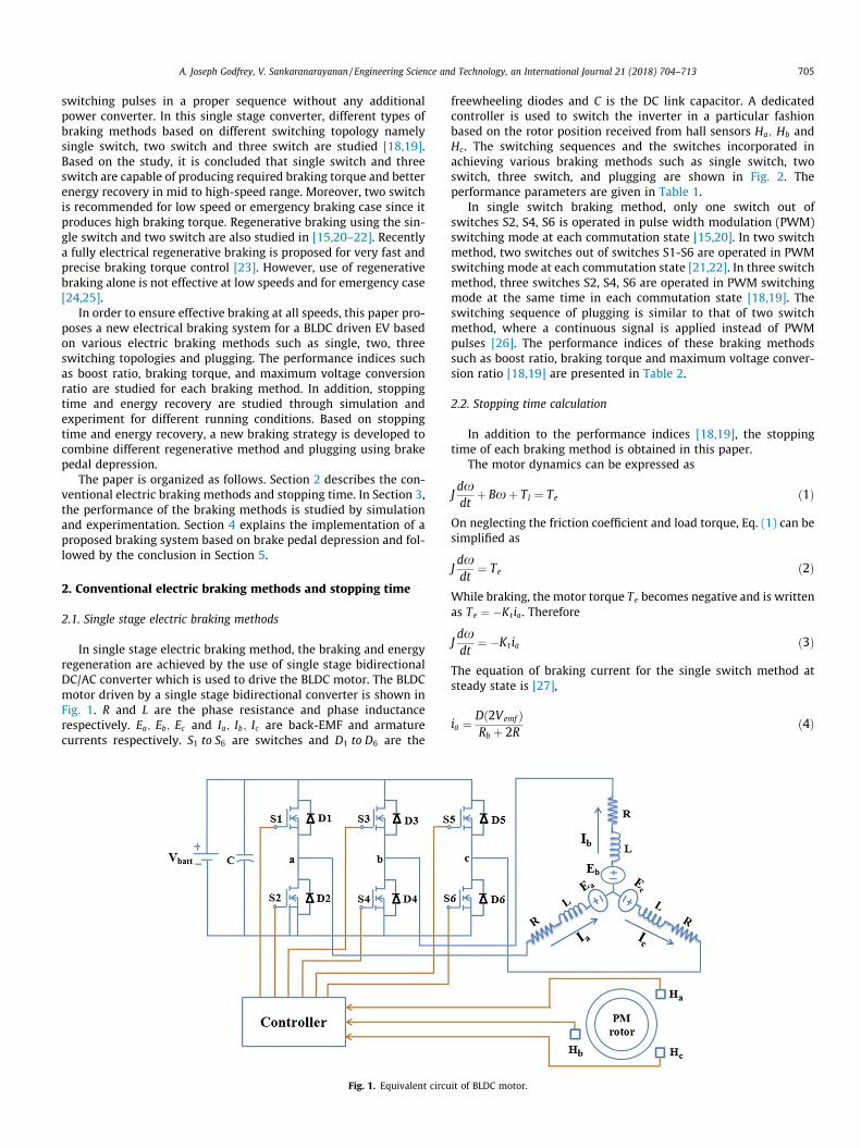
Fig. 5. Simulation results for average energy recovered versus duty cycle for various SOC and speed. (a) SOC = 80%, speed = 400 rpm. (b) SOC = 80%, speed = 200 rpm. (c) SOC= 50%, speed = 400 rpm. (d) SOC = 50%, speed = 200 rpm.
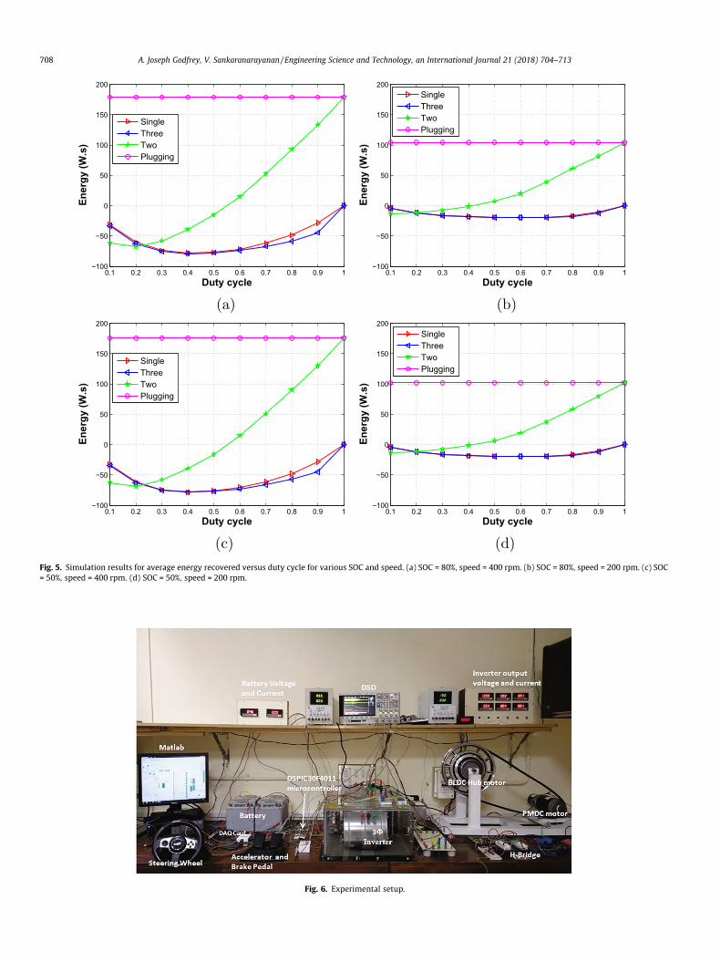
Fig. 6. Experimental setup.
708 A. Joseph Godfrey, V. Sankaranarayanan / Engineering Science and Technology, an International Journal 21 (2018) 704–713
A. Joseph Godfrey, V. Sankaranarayanan / Engineering Science and Technology, an International Journal 21 (2018) 704–713 709
3.1.2. Average energy recoveredThe average energy recovered during the braking period is
compared for various speed and SOC level in Fig. 5. The averageenergy is the area under the power versus time curve over thebraking period. During a particular speed with a SOC level asshown in Fig. 5(a), the energy recovered by three switch is higheramong all the braking methods. The energy recovered in the singleswitch is lesser than the three switch. As the duty cycle increases,the average energy recovered first increase to a peak value andthen decreases and finally reaches zero when duty cycle attainsone. In plugging, the energy is consumed rather than recovery dur-ing braking and it is positive. In two switch, as seen in Fig. 5(a), theaverage energy is negative during the duty cycle ranging from 0 to0.5 and positive during 0.5 to 1. This is because that, during theduty cycle from 0 to 0.5, the amount of energy recovered is morecompared to the amount of energy consumed from the battery
Table 5Stopping time and average current for various duty cycle.
Duty cycle Stop time (s)
Single Three Two Plugging
0.2 2.2 2.15 1.09 0.230.4 1.49 1.39 0.5 0.230.6 1.01 0.99 0.26 0.230.8 0.75 0.7 0.24 0.23
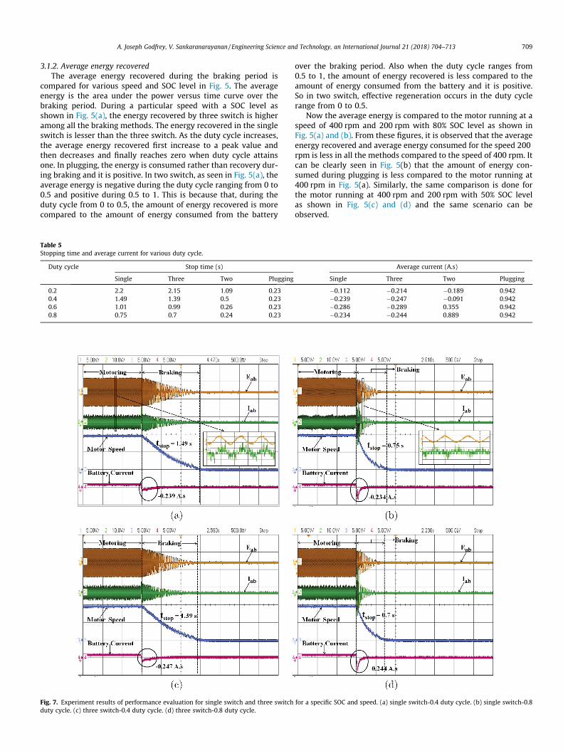
Fig. 7. Experiment results of performance evaluation for single switch and three switchduty cycle. (c) three switch-0.4 duty cycle. (d) three switch-0.8 duty cycle.
over the braking period. Also when the duty cycle ranges from0.5 to 1, the amount of energy recovered is less compared to theamount of energy consumed from the battery and it is positive.So in two switch, effective regeneration occurs in the duty cyclerange from 0 to 0.5.
Now the average energy is compared to the motor running at aspeed of 400 rpm and 200 rpm with 80% SOC level as shown inFig. 5(a) and (b). From these figures, it is observed that the averageenergy recovered and average energy consumed for the speed 200rpm is less in all the methods compared to the speed of 400 rpm. Itcan be clearly seen in Fig. 5(b) that the amount of energy con-sumed during plugging is less compared to the motor running at400 rpm in Fig. 5(a). Similarly, the same comparison is done forthe motor running at 400 rpm and 200 rpm with 50% SOC levelas shown in Fig. 5(c) and (d) and the same scenario can beobserved.
Average current (A.s)
Single Three Two Plugging
�0.112 �0.214 �0.189 0.942�0.239 �0.247 �0.091 0.942�0.286 �0.289 0.355 0.942�0.234 �0.244 0.889 0.942
for a specific SOC and speed. (a) single switch-0.4 duty cycle. (b) single switch-0.8
710 A. Joseph Godfrey, V. Sankaranarayanan / Engineering Science and Technology, an International Journal 21 (2018) 704–713
3.2. Experimental procedure
In order to study the performance of different braking methodsin real time, an experimental setup is built in the laboratory whichemulates an EV. The experimental setup consists of a 48 V, 26 Ahbattery, a three-phase inverter to drive the BLDC motor, digitalcontroller, BLDC hub motor and permanent magnet DC (PMDC)motor for loading purpose. The specification of the BLDC motor issame as used for simulation, which is given in Table 4.
The digital controller dspic30f4011 is used as a PWM generatorfor the three-phase inverter to drive the BLDC motor. A PMDCmotor is connected to the BLDC motor through a belt which actsas a load that mimics the effect of uphill and downhill drivingconditions.
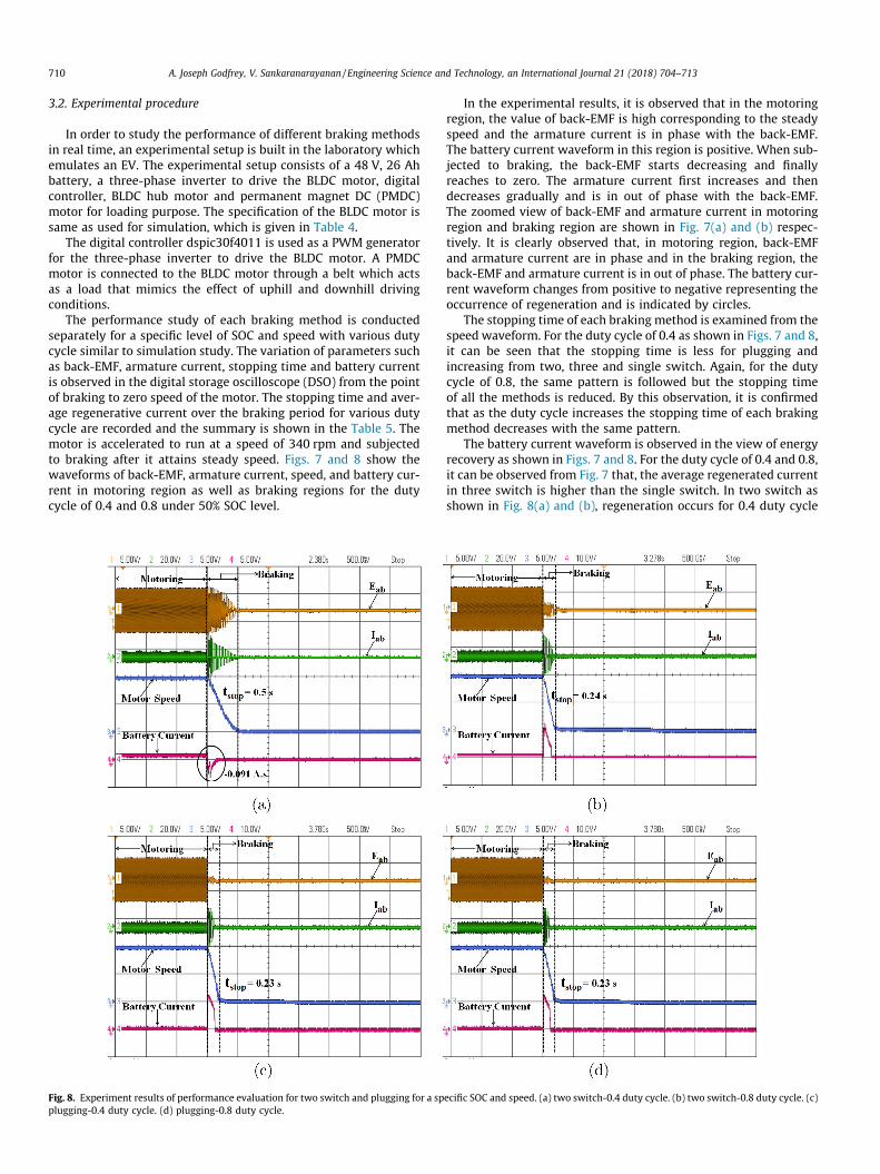
The performance study of each braking method is conductedseparately for a specific level of SOC and speed with various dutycycle similar to simulation study. The variation of parameters suchas back-EMF, armature current, stopping time and battery currentis observed in the digital storage oscilloscope (DSO) from the pointof braking to zero speed of the motor. The stopping time and aver-age regenerative current over the braking period for various dutycycle are recorded and the summary is shown in the Table 5. Themotor is accelerated to run at a speed of 340 rpm and subjectedto braking after it attains steady speed. Figs. 7 and 8 show thewaveforms of back-EMF, armature current, speed, and battery cur-rent in motoring region as well as braking regions for the dutycycle of 0.4 and 0.8 under 50% SOC level.
Fig. 8. Experiment results of performance evaluation for two switch and plugging for a spplugging-0.4 duty cycle. (d) plugging-0.8 duty cycle.
In the experimental results, it is observed that in the motoringregion, the value of back-EMF is high corresponding to the steadyspeed and the armature current is in phase with the back-EMF.The battery current waveform in this region is positive. When sub-jected to braking, the back-EMF starts decreasing and finallyreaches to zero. The armature current first increases and thendecreases gradually and is in out of phase with the back-EMF.The zoomed view of back-EMF and armature current in motoringregion and braking region are shown in Fig. 7(a) and (b) respec-tively. It is clearly observed that, in motoring region, back-EMFand armature current are in phase and in the braking region, theback-EMF and armature current is in out of phase. The battery cur-rent waveform changes from positive to negative representing theoccurrence of regeneration and is indicated by circles.
The stopping time of each braking method is examined from thespeed waveform. For the duty cycle of 0.4 as shown in Figs. 7 and 8,it can be seen that the stopping time is less for plugging andincreasing from two, three and single switch. Again, for the dutycycle of 0.8, the same pattern is followed but the stopping timeof all the methods is reduced. By this observation, it is confirmedthat as the duty cycle increases the stopping time of each brakingmethod decreases with the same pattern.
The battery current waveform is observed in the view of energyrecovery as shown in Figs. 7 and 8. For the duty cycle of 0.4 and 0.8,it can be observed from Fig. 7 that, the average regenerated currentin three switch is higher than the single switch. In two switch asshown in Fig. 8(a) and (b), regeneration occurs for 0.4 duty cycle
ecific SOC and speed. (a) two switch-0.4 duty cycle. (b) two switch-0.8 duty cycle. (c)
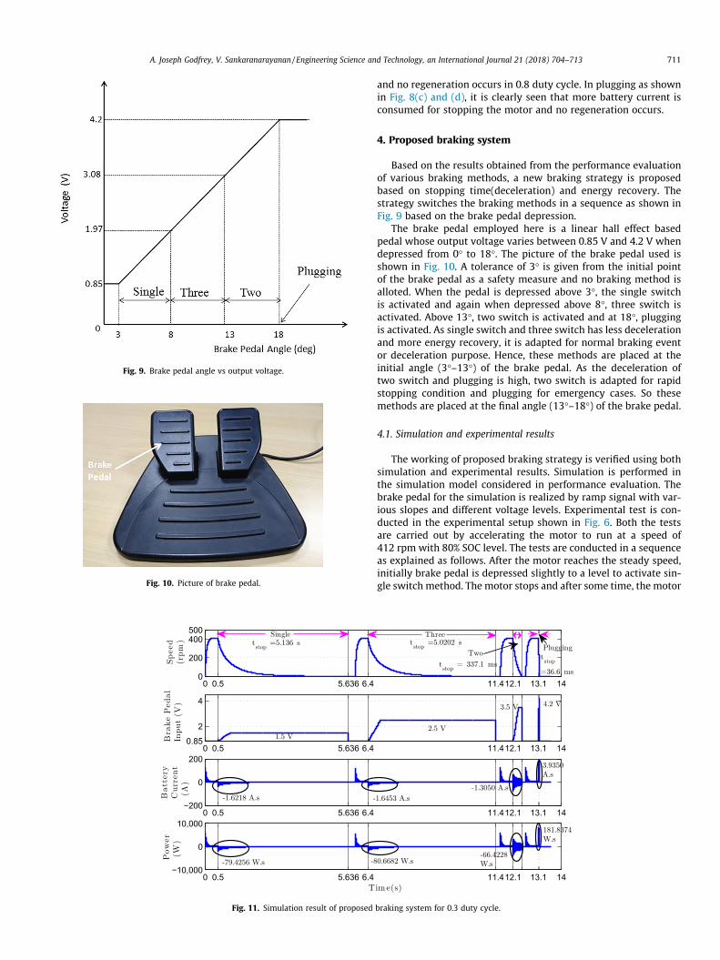
Fig. 9. Brake pedal angle vs output voltage.
Fig. 11. Simulation result of proposed
Fig. 10. Picture of brake pedal.
A. Joseph Godfrey, V. Sankaranarayanan / Engineering Science and Technology, an International Journal 21 (2018) 704–713 711
and no regeneration occurs in 0.8 duty cycle. In plugging as shownin Fig. 8(c) and (d), it is clearly seen that more battery current isconsumed for stopping the motor and no regeneration occurs.
4. Proposed braking system
Based on the results obtained from the performance evaluationof various braking methods, a new braking strategy is proposedbased on stopping time(deceleration) and energy recovery. Thestrategy switches the braking methods in a sequence as shown inFig. 9 based on the brake pedal depression.
The brake pedal employed here is a linear hall effect basedpedal whose output voltage varies between 0.85 V and 4.2 V whendepressed from 0� to 18�. The picture of the brake pedal used isshown in Fig. 10. A tolerance of 3� is given from the initial pointof the brake pedal as a safety measure and no braking method isalloted. When the pedal is depressed above 3�, the single switchis activated and again when depressed above 8�, three switch isactivated. Above 13�, two switch is activated and at 18�, pluggingis activated. As single switch and three switch has less decelerationand more energy recovery, it is adapted for normal braking eventor deceleration purpose. Hence, these methods are placed at theinitial angle (3�–13�) of the brake pedal. As the deceleration oftwo switch and plugging is high, two switch is adapted for rapidstopping condition and plugging for emergency cases. So thesemethods are placed at the final angle (13�–18�) of the brake pedal.
4.1. Simulation and experimental results
The working of proposed braking strategy is verified using bothsimulation and experimental results. Simulation is performed inthe simulation model considered in performance evaluation. Thebrake pedal for the simulation is realized by ramp signal with var-ious slopes and different voltage levels. Experimental test is con-ducted in the experimental setup shown in Fig. 6. Both the testsare carried out by accelerating the motor to run at a speed of412 rpm with 80% SOC level. The tests are conducted in a sequenceas explained as follows. After the motor reaches the steady speed,initially brake pedal is depressed slightly to a level to activate sin-gle switch method. The motor stops and after some time, the motor
braking system for 0.3 duty cycle.
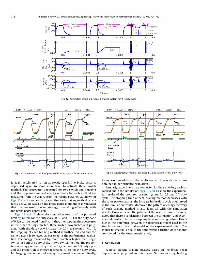
Fig. 12. Simulation result of proposed braking system for 0.7 duty cycle.
Fig. 13. Experimental result of proposed braking system for 0.3 duty cycle. Fig. 14. Experimental result of proposed braking system for 0.7 duty cycle.
712 A. Joseph Godfrey, V. Sankaranarayanan / Engineering Science and Technology, an International Journal 21 (2018) 704–713
is again accelerated to run at steady speed. The brake pedal isdepressed again to some more level to activate three switchmethod. The procedure is repeated for two switch and pluggingand the stopping time and energy recovery for each method aremeasured from the graph. From the results obtained as shown inFigs. 11–14, it can be clearly seen that each braking method is per-fectly activated based on the brake pedal input and it is validatedthat the proposed braking strategy is working effectively withthe brake pedal depression.
Figs. 11 and 12 show the simulation results of the proposedbraking system for the duty cycle of 0.3 and 0.7. For the duty cycleof 0.3, it can be noted from Fig. 11 that, the stopping time decreasesin the order of single switch, three switch, two switch and plug-ging. With the duty cycle increase (i.e 0.7), as shown in Fig. 12,the stopping of each braking method is further reduced and thesame pattern is followed as observed in the performance evalua-tion. The energy recovered by three switch is higher than singleswitch in both the duty cycle. In two switch method, the propor-tion of energy recovered by the battery is more for 0.3 duty cycleand the proportion of energy recovered is less for 0.7 duty cycle.In plugging, the amount of energy consumed is same and finally,
it can be observed that all the results are matching with the patternobtained in performance evaluation.
Similarly, experiments are conducted for the same duty cycle ascarried out in the simulation. Figs. 13 and 14 show the experimen-tal results of the proposed braking system for 0.3 and 0.7 dutycycle. The stopping time of each braking method decreases withthe same pattern against the increase in the duty cycle as observedin the simulation results. Moreover, the pattern of energy recoveryof each braking method is also identical with the simulationresults. However, even the pattern of the result is same, it can benoted that there is a mismatch between the simulation and exper-imental results in terms of stopping time and energy values. This isdue to the difference between the theoretical model used in thesimulation and the actual model of the experimental setup. Themodel mismatch is due to the time-varying friction of the motorconsidered for the experimental study.
5. Conclusion
A novel electric braking strategy based on the brake pedaldepression is proposed in this paper. Various existing braking
A. Joseph Godfrey, V. Sankaranarayanan / Engineering Science and Technology, an International Journal 21 (2018) 704–713 713
methods such as single, two, three switch topologies and pluggingare combined to achieve this new braking strategy. Two importantparameters namely stopping time and energy regeneration areconsidered to arrive at this proposed scheme. As a first step, theirperformances are studied using both numerical simulation andexperiments. It is concluded that the regeneration is better for sin-gle, three switch method and stopping time is better for two switchand plugging. Based on these results, the new braking strategy isdesigned to switch among single, two, three switch topologiesand plugging using brake pedal depression. The proposed strategyis able to stop the vehicle at any speed with possible energy regen-eration. Simulation and experimental results are presented toshow the effectiveness of the proposed method.
References
[1] M. Ehsani, Y. Gao, A. Emadi, Modern Electric, Hybrid Electric, and Fuel CellVehicles: Fundamentals, Theory, and Design, CRC Press, 2009.
[2] M.S. Kumar, S.T. Revankar, Development scheme and key technology of anelectric vehicle: an overview, Renew. Sustain. Energy Rev. 70 (2017) 1266–1285.
[3] C.-L. Jeong, J. Hur, A novel proposal to improve reliability of spoke-type BLDCmotor using ferrite permanent magnet, IEEE Trans. Ind. Appl. 52 (5) (2016)3814–3821.
[4] Y.-H. Hung, C.-H. Wu, A combined optimal sizing and energy managementapproach for hybrid in-wheel motors of evs, Appl. Energy 139 (2015) 260–271.
[5] L. Li, X. Li, X. Wang, J. Song, K. He, C. Li, Analysis of downshift’s improvement toenergy efficiency of an electric vehicle during regenerative braking, Appl.Energy 176 (2016) 125–137.
[6] L. Zhe, Z. Ling, R. Yue, Y. Wei, L. Yinong, G. Feng, L. Yusheng, X. Zhoubin, Acontrol strategy of regenerative braking system for intelligent vehicle, IETInternational Conference on Intelligent and Connected Vehicles (ICV 2016),IET, 2016.
[7] C. Pan, L. Chen, L. Chen, H. Jiang, Z. Li, S. Wang, Research on motor rotationalspeed measurement in regenerative braking system of electric vehicle, Mech.Syst. Signal Process. 66–67 (2016) 829–839.
[8] T. Kim, Regenerative braking control of a light fuel cell hybrid electric vehicle,Electr. Power Components Syst. 39 (5) (2011) 446–460.
[9] O.C. Onar, A. Khaligh, A novel integrated magnetic structure based dc/dcconverter for hybrid battery/ultracapacitor energy storage systems, IEEE Trans.Smart Grid 3 (1) (2012) 296–307.
[10] O. Hegazy, J. Van Mierlo, P. Lataire, Analysis, modeling, and implementation ofa multidevice interleaved dc/dc converter for fuel cell hybrid electric vehicles,IEEE Trans. Power Electron. 27 (11) (2012) 4445–4458.
[11] X. Zhang, Sensorless induction motor drive using indirect vector controller andsliding-mode observer for electric vehicles, IEEE Trans. Veh. Technol. 62 (7)(2013) 3010–3018.
[12] A. Khaligh, Z. Li, Battery, ultracapacitor, fuel cell, and hybrid energy storagesystems for electric, hybrid electric, fuel cell, and plug-in hybrid electricvehicles: State of the art, IEEE Trans. Vehicular Technol. 59 (6) (2010) 2806–2814.
[13] Z. Song, J. Li, X. Han, L. Xu, L. Lu, M. Ouyang, H. Hofmann, Multi-objectiveoptimization of a semi-active battery/supercapacitor energy storage systemfor electric vehicles, Appl. Energy 135 (2014) 212–224.
[14] J. Armenta, C. Núñez, N. Visairo, I. Lázaro, An advanced energy managementsystem for controlling the ultracapacitor discharge and improving the electricvehicle range, J. Power Sources 284 (2015) 452–458.
[15] F. Naseri, E. Farjah, T. Ghanbari, An efficient regenerative braking system basedon battery/supercapacitor for electric, hybrid, and plug-in hybrid electricvehicles with BLDC motor, IEEE Trans. Veh. Technol. 66 (5) (2017) 3724–3738.
[16] Y.-P. Yang, J.-J. Liu, T.-J. Wang, K.-C. Kuo, P.-E. Hsu, An electric gearshift withultracapacitors for the power train of an electric vehicle with a directly drivenwheel motor, IEEE Trans. Veh. Technol. 56 (5) (2007) 2421–2431.
[17] Y.-P. Yang, J.-J. Liu, T.-H. Hu, An energy management system for a directly-driven electric scooter, Energy Conversion Manage. 52 (1) (2011) 621–629.
[18] C.-H. Chen, W.-C. Chi, M.-Y. Cheng, Regenerative braking control for lightelectric vehicles, 2011 IEEE Ninth International Conference on PowerElectronics and Drive Systems (PEDS), IEEE, 2011, pp. 631–636.
[19] W.-C. Chi, M.-Y. Cheng, C.-H. Chen, Position-sensorless method for electricbraking commutation of brushless dc machines, IET Electr. Power Appl. 7 (9)(2013) 701–713.
[20] X. Nian, F. Peng, H. Zhang, Regenerative braking system of electric vehicledriven by brushless dc motor, IEEE Trans. Ind. Electron. 61 (10) (2014) 5798–5808.
[21] M.-J. Yang, H.-L. Jhou, B.-Y. Ma, K.-K. Shyu, A cost-effective method of electricbrake with energy regeneration for electric vehicles, IEEE Trans. Ind. Electron.56 (6) (2009) 2203–2212.
[22] Y. Wang, X. Zhang, X. Yuan, G. Liu, Position-sensorless hybrid sliding-modecontrol of electric vehicles with brushless dc motor, IEEE Trans. VehicularTechnol. 60 (2) (2011) 421–432.
[23] G. Xu, K. Xu, C. Zheng, X. Zhang, T. Zahid, Fully electrified regenerative brakingcontrol for deep energy recovery and maintaining safety of electric vehicles,IEEE Trans. Veh. Technol. 65 (3) (2016) 1186–1198.
[24] M. Paredes, J.A. Pomilio, A.A. Santos, Combined regenerative and mechanicalbraking in electric vehicle, 2013 Brazilian Power Electronics Conference, IEEE,2013, pp. 935–941.
[25] J. Ko, S. Ko, H. Son, B. Yoo, J. Cheon, H. Kim, Development of brake system andregenerative braking cooperative control algorithm for automatic-transmission-based hybrid electric vehicles, IEEE Trans. Veh. Technol. 64 (2)(2015) 431–440.
[26] M. Rakesh, P. Narasimham, Different braking techniques employed to abrushless dc motor drive used in locomotives, Int. Electr. Eng. J 3 (2) (2012)784–790.
[27] Ormec, Dynamic braking using external resistors, [Accessed: 10 Sep 2017](1997). http://www.ormec.com/LinkClick.aspx?fileticket=r4D8nVsbJbY=.
Copyright © 2022 FDOKUMEN