Best Practices in integrating complex robotic systems - ATLAS
55
Best Practices in integrating complex robotic systems Introduction Gianni Borghesan KU Leuven Febraury 2019
-
Upload
khangminh22 -
Category
Documents
-
view
0 -
download
0
Transcript of Best Practices in integrating complex robotic systems - ATLAS
Best Practices in integrating complex robotic systems
Introduction
Gianni BorghesanKU LeuvenFebraury 2019
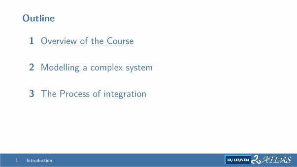
Outline
1 Overview of the Course
2 Modelling a complex system
3 The Process of integration
1 Introduction
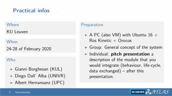
Practical infos
WhereKU Leuven
When24-28 of February 2020
Who
I Gianni Borghesan (KUL)I Diego Dall’ Alba (UNIVR)I Albert Hernansanz (UPC)
Preparation
I A PC (also VM) with Ubuntu 16 +Ros Kinetic + Orocos
I Group: General concept of the systemI Individual: pitch presentation a
description of the module that youwould integrate (behaviour, life-cycle,data exchanged) – after thispresentation.
2 Introduction

Schedule
Monday to Thursday
I Two morning sessions of 1.5 hours (9:30-11:00, 11:15 - 12:45)I Afternoon: practical sessions & Integration (2PM - 5:30PM or later)
Friday
I Morning - IntegrationI Afternoon - Evaluation (close around 4PM)I Happy Hour
3 Introduction
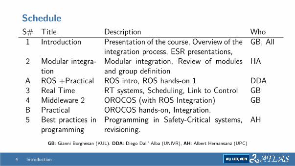
ScheduleS# Title Description Who1 Introduction Presentation of the course, Overview of the
integration process, ESR presentations,GB, All
2 Modular integra-tion
Modular integration, Review of modulesand group definition
HA
A ROS +Practical ROS intro, ROS hands-on 1 DDA3 Real Time RT systems, Scheduling, Link to Control GB4 Middleware 2 OROCOS (with ROS Integration) GBB Practical OROCOS hands-on, Integration.5 Best practices in
programmingProgramming in Safety-Critical systems,revisioning.
AH
GB: Gianni Borghesan (KUL). DDA: Diego Dall’ Alba (UNIVR), AH: Albert Hernansanz (UPC)
4 Introduction
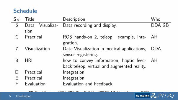
ScheduleS# Title Description Who6 Data Visualiza-
tionData recording and display. DDA GB
C Practical ROS hands-on 2, teleop. example, inte-gration.
AH
7 Visualization Data Visualization in medical applications,sensor registering.
DDA
8 HRI how to convey information, haptic feed-back teleop, virtual and augmented reality.
AH
D Practical IntegrationE Practical IntegrationF Evaluation Evaluation and Feedback
GB: Gianni Borghesan (KUL). DDA: Diego Dall’ Alba (UNIVR), AH: Albert Hernansanz (UPC)5 Introduction
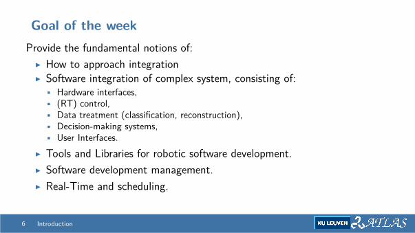
Goal of the weekProvide the fundamental notions of:
I How to approach integrationI Software integration of complex system, consisting of:
• Hardware interfaces,• (RT) control,• Data treatment (classification, reconstruction),• Decision-making systems,• User Interfaces.
I Tools and Libraries for robotic software development.I Software development management.I Real-Time and scheduling.
6 Introduction
Outline
1 Overview of the Course
2 Modelling a complex system
3 The Process of integration
7 Introduction
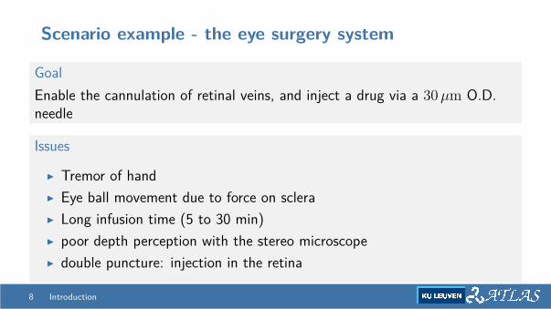
Scenario example - the eye surgery system
GoalEnable the cannulation of retinal veins, and inject a drug via a 30 µm O.D.needle
Issues
I Tremor of handI Eye ball movement due to force on scleraI Long infusion time (5 to 30 min)I poor depth perception with the stereo microscopeI double puncture: injection in the retina
8 Introduction
Eye surgery Robotic System
9 Introduction
Scenario example - the eye surgery system
Desired features - Mechanical
I Comanipulation systemI Tremor filtering - variable dampingI (Adjustable) Remote Center of MotionI Locking system
10 Introduction
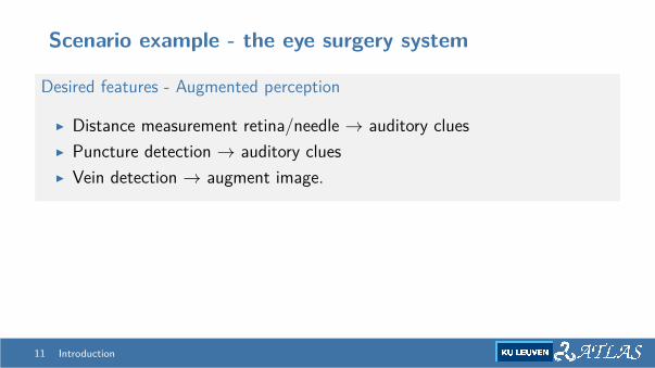
Scenario example - the eye surgery system
Desired features - Augmented perception
I Distance measurement retina/needle → auditory cluesI Puncture detection → auditory cluesI Vein detection → augment image.
11 Introduction
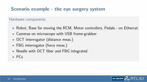
Scenario example - the eye surgery system
Hardware components
I Robot, Base for moving the RCM, Motor controllers, Pedals - on EthercatI Cameras on microscope with USB frame-grabberI OCT interrogator (distance meas.)I FBG interrogator (force meas.)I Needle with OCT fiber and FBG integratedI PCs
12 Introduction
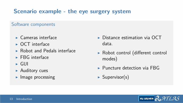
Scenario example - the eye surgery system
Software components
I Cameras interfaceI OCT interfaceI Robot and Pedals interfaceI FBG interfaceI GUII Auditory cuesI Image processing
I Distance estimation via OCTdata.
I Robot control (different controlmodes)
I Puncture detection via FBGI Supervisor(s)
13 Introduction
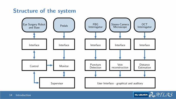
Structure of the system
Stereo-CameraMicroscope
OCTInterrogator
Control
FBGInterrogator
Interface
PedalsEye Surgery Robotand Base
Interface Interface Interface Interface
Monitor PunctureDetection
Veinreconstruction
DistanceEstimation
User Interface - graphical and auditorySupervisor
14 Introduction
Identify the characteristics
I Which are the requirements of each part?I Which data are required/provided, and how?I Which are the steps to bring the system up?I Is there a specific schedule?I Is each system reliable? is it possible to measure?
15 Introduction
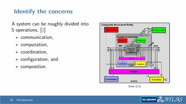
Identify the concerns
A system can be roughly divided into5 operations, [2]
I communication,I computation,I coordination,I configuration, andI composition.
from [10]
16 Introduction

Outline
1 Overview of the Course
2 Modelling a complex system
3 The Process of integration
17 Introduction
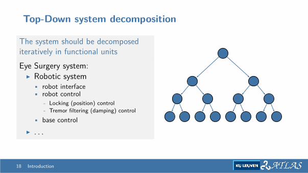
Top-Down system decomposition
The system should be decomposediteratively in functional unitsEye Surgery system:
I Robotic system• robot interface• robot control
- Locking (position) control- Tremor filtering (damping) control
• base controlI . . .
18 Introduction
Top-Down system decomposition
Each system has one or more functionalitiesAlgorithms that compute:
I KinematicsI Control actionsI Estimate of states of the environmentI . . .
19 Introduction
Top-Down system decomposition
Each system/functionality has a context that
I Define the data that are “hidden” in the component• Configuration Parameters• States• . . .
I Define the data that are exposedI Define the data that are needed
20 Introduction
Top-Down system decomposition
Each system/functionality needs to be triggered:
I Periodically?I When new data arrives?I Whenever there is time?
21 Introduction
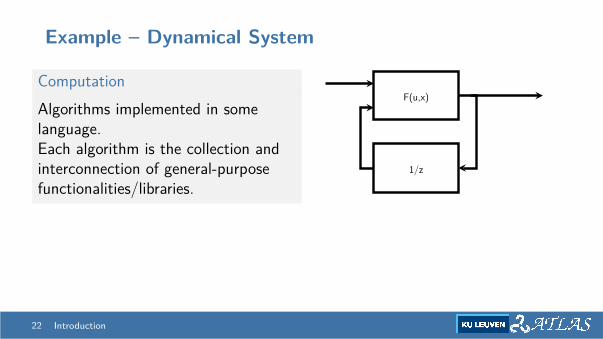
Example – Dynamical System
ComputationAlgorithms implemented in somelanguage.Each algorithm is the collection andinterconnection of general-purposefunctionalities/libraries.
F(u,x)
1/z
22 Introduction
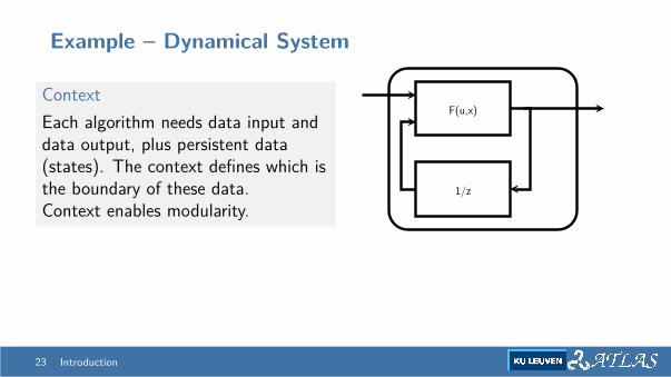
Example – Dynamical System
ContextEach algorithm needs data input anddata output, plus persistent data(states). The context defines which isthe boundary of these data.Context enables modularity.
F(u,x)
1/z
23 Introduction
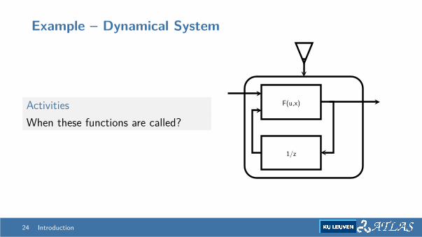
Example – Dynamical System
ActivitiesWhen these functions are called?
F(u,x)
1/z
24 Introduction
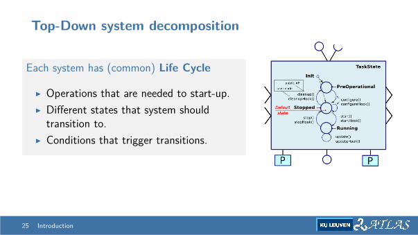
Top-Down system decomposition
Each system has (common) Life Cycle
I Operations that are needed to start-up.I Different states that system should
transition to.I Conditions that trigger transitions.
25 Introduction
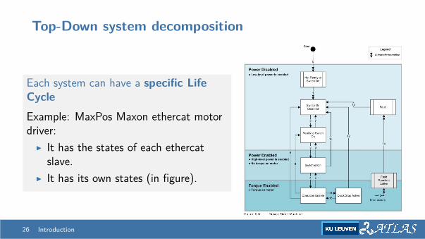
Top-Down system decomposition
Each system can have a specific LifeCycleExample: MaxPos Maxon ethercat motordriver:
I It has the states of each ethercatslave.
I It has its own states (in figure).
26 Introduction
Constraints of the subsystem
Each subsystem has specific requirements
I Input of dataI Timing of inputsI State of the other componentsI . . .
27 Introduction
Plan the work
Provide documentation
Rule out ambiguities
Iterate until consensus
28 Introduction
Plan the work
Provide documentation
I interfacesI offered capabilitiesI required capabilitiesI (risks)
Rule out ambiguities
Iterate until consensus
28 Introduction
Plan the work
Provide documentation
Rule out ambiguities
I units,I order,I definitions,I . . .
→ agree on a model.
Iterate until consensus
28 Introduction
Plan the work
Provide documentation
Rule out ambiguities
Iterate until consensusVerification that all the pieces works (in line of principle)
28 Introduction
Recap - system decomposition
So far:We agreed and documented
I functional decomposition in sub-systems, recursivelyI breakdown of life cyclesI breakdown of requirements and capabilities
29 Introduction
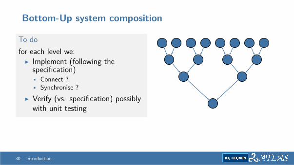
Bottom-Up system composition
To dofor each level we:
I Implement (following thespecification)• Connect ?• Synchronise ?
I Verify (vs. specification) possiblywith unit testing
30 Introduction

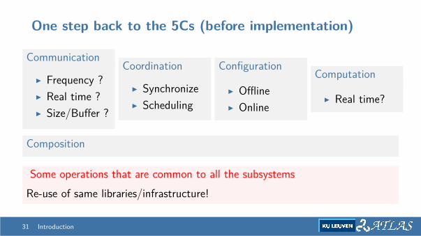
One step back to the 5Cs (before implementation)
Communication
I Frequency ?I Real time ?I Size/Buffer ?
Coordination
I SynchronizeI Scheduling
Configuration
I OfflineI Online
Computation
I Real time?
Composition
Some operations that are common to all the subsystemsRe-use of same libraries/infrastructure!
31 Introduction
Introspection
Introspection is the ability of a (sub-)system to make explicit its state.I the life cycle is the first approximationI Systems may have more complex/nested state → Explicit ModellingI Systems should make aware other systems of their state for
• logging and• feedback on coordination, fault recovery.
32 Introduction
Monitoring
Monitors can evaluate:I The state of world - from continuous domain to symbolic informationI The state of systems
• watch-dog• compare output with expected output
33 Introduction
Choice of tool(s)
Depending by the characteristics of each of the 5C, each part of thesubsystem can rely on different tools, mainly offered by:
I LanguageI Library
34 Introduction
Choice of tool(s)
Language
I Low-level, strongly-typed languages offers deterministic performances.I Scripting languages are normally good for deployment (e.g. Lua) or
non-realtime tasks (e.g. Python).I Some languages are better supported by libraries (e.g. Python) or for
specific tasks.
35 Introduction
Choice of tool(s)
Libraries - computationStand-alone libraries (that depends also by language) Some examples:
I Kinematics: KDL, expressionGraph, . . .I Math/Albegra: Eigen, LAPACK, numpy, . . .I Visualization: Qt, pyside, pyqtgraph, . . .I Optmization: qpOASES, Casadi, . . .
Important!Choose wisely, because these are strong dependencies. . .
36 Introduction
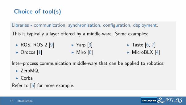
Choice of tool(s)
Libraries - communication, synchronisation, configuration, deployment.This is typically a layer offered by a middle-ware. Some examples:
I ROS, ROS 2 [9]I Orocos [1]
I Yarp [3]I Miro [8]
I Taste [6, 7]I MicroBLX [4]
Inter-process communication middle-ware that can be applied to robotics:I ZeroMQ,I Corba
Refer to [5] for more example.
37 Introduction
Implementation
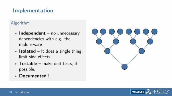
Algorithm
I Independent – no unnecessarydependencies with e.g. themiddle-ware
I Isolated – It does a single thing,limit side effects
I Testable – make unit tests, ifpossible.
I Documented !
38 Introduction
Implementation
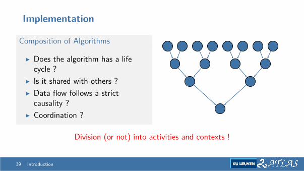
Composition of Algorithms
I Does the algorithm has a lifecycle ?
I Is it shared with others ?I Data flow follows a strict
causality ?I Coordination ?
Division (or not) into activities and contexts !
39 Introduction

Implementation
Composition of Algorithms – Example
1 HW interface of robot – data in2 Forward kinematics3 Control action in user (Cartesian) space4 Inverse/Transpose Differential kinematics5 Control action in joint space6 Safety control7 HW interface of robot – data out
40 Introduction
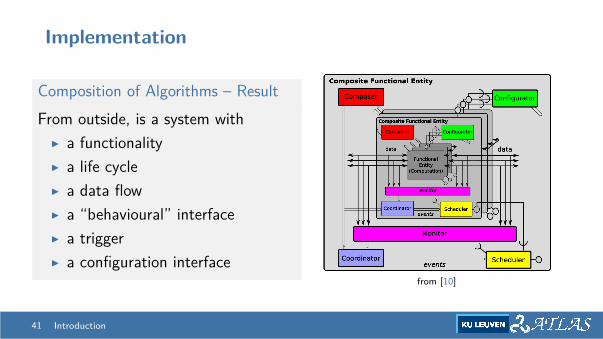
Implementation
Composition of Algorithms – ResultFrom outside, is a system with
I a functionalityI a life cycleI a data flowI a “behavioural” interfaceI a triggerI a configuration interface
from [10]
41 Introduction
Composition of systems
Systems can be deployed
I in the same processI in the same machine (IPC will be needed)I in different machines
Issues of composition: communication and coordination
I Data sharing mechanism: latency, bandwidth, jitter, RTI Explicit schedulingI Additional coordination
42 Introduction
Composition of systems
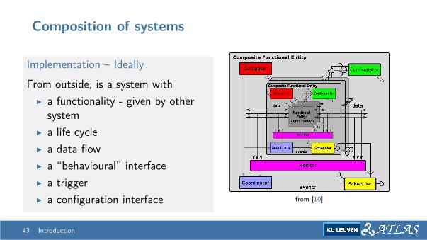
Implementation – IdeallyFrom outside, is a system with
I a functionality - given by othersystem
I a life cycleI a data flowI a “behavioural” interfaceI a triggerI a configuration interface from [10]
43 Introduction
Composition of systems
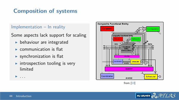
Implementation – In realitySome aspects lack support for scaling
I behaviour are integratedI communication is flatI synchronization is flatI introspection tooling is very
limitedI . . .
from [10]
44 Introduction
Verification
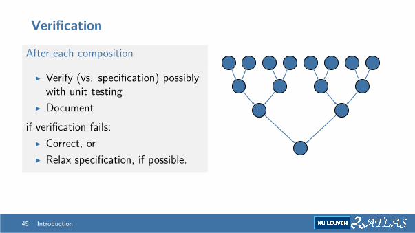
After each composition
I Verify (vs. specification) possiblywith unit testing
I Documentif verification fails:
I Correct, orI Relax specification, if possible.
45 Introduction

Questions ?
Groups
Bibliography I
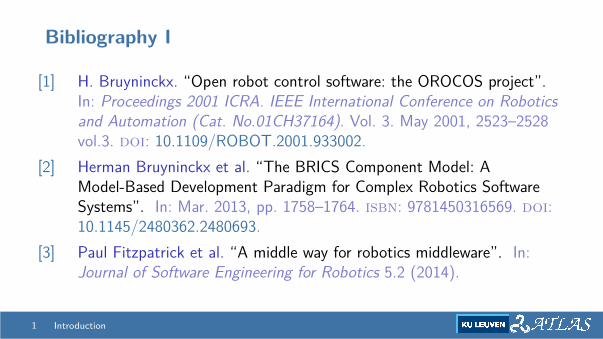
[1] H. Bruyninckx. “Open robot control software: the OROCOS project”.In: Proceedings 2001 ICRA. IEEE International Conference on Roboticsand Automation (Cat. No.01CH37164). Vol. 3. May 2001, 2523–2528vol.3. doi: 10.1109/ROBOT.2001.933002.
[2] Herman Bruyninckx et al. “The BRICS Component Model: AModel-Based Development Paradigm for Complex Robotics SoftwareSystems”. In: Mar. 2013, pp. 1758–1764. isbn: 9781450316569. doi:10.1145/2480362.2480693.
[3] Paul Fitzpatrick et al. “A middle way for robotics middleware”. In:Journal of Software Engineering for Robotics 5.2 (2014).
1 Introduction
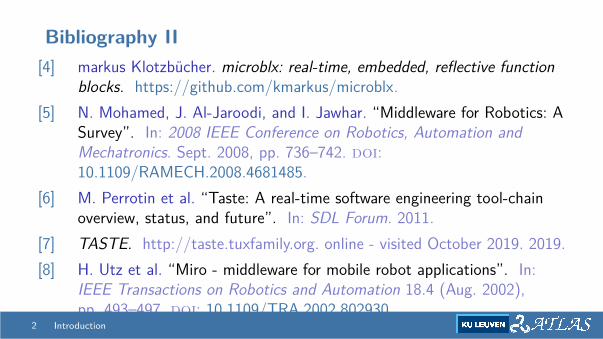
Bibliography II[4] markus Klotzbucher. microblx: real-time, embedded, reflective function
blocks. https://github.com/kmarkus/microblx.[5] N. Mohamed, J. Al-Jaroodi, and I. Jawhar. “Middleware for Robotics: A
Survey”. In: 2008 IEEE Conference on Robotics, Automation andMechatronics. Sept. 2008, pp. 736–742. doi:10.1109/RAMECH.2008.4681485.
[6] M. Perrotin et al. “Taste: A real-time software engineering tool-chainoverview, status, and future”. In: SDL Forum. 2011.
[7] TASTE. http://taste.tuxfamily.org. online - visited October 2019. 2019.[8] H. Utz et al. “Miro - middleware for mobile robot applications”. In:
IEEE Transactions on Robotics and Automation 18.4 (Aug. 2002),pp. 493–497. doi: 10.1109/TRA.2002.802930.
2 Introduction
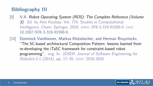
Bibliography III[9] V.A. Robot Operating System (ROS): The Complete Reference (Volume
3). Ed. by Anis Koubaa. Vol. 778. Studies in ComputationalIntelligence. Cham: Springer, 2018. isbn: 978-3-319-91589-0. doi:10.1007/978-3-319-91590-6.
[10] Dominick Vanthienen, Markus Klotzbucher, and Herman Bruyninckx.“The 5C-based architectural Composition Pattern: lessons learned fromre-developing the iTaSC framework for constraint-based robotprogramming”. eng. In: JOSER: Journal of Software Engineering forRobotics 5.1 (2014), pp. 17–35. issn: 2035-3928.
3 Introduction