BEST PRACTICE BOOKLET
126
BEST PRACTICE BOOKLET M. Fischer, Dr. C. Gemmer, Dr. E. Rach
-
Upload
khangminh22 -
Category
Documents
-
view
5 -
download
0
Transcript of BEST PRACTICE BOOKLET

BEST PRACTICEBOOKLET
M. Fischer, Dr. C. Gemmer, Dr. E. Rach


3
Bosch quality stands for impressive reliability and tangible top performance. It also means functionally excellent, high-quality, error-free products. Premium quality is the key to satisfied customers.
As a consequence of observed errors, we at Bosch de-rived, formulated, and introduced 14 Quality Basics for the value stream. Their purpose is to provide a set of measures and rules of conduct to help us prevent fun-damental errors in the value stream that could ultima-tely lead to customer complaints and dissatisfaction.
The value stream encompasses all business processes associated with the manufacture of a product – from the procurement of raw materials and compo-nents, through processing and assembly, right up to delivery to the customer. Given the fact that a significant proportion of the added value in our products is provided by external suppliers, we demand our suppliers of components, machinery, and equipment must also comply with these quality standards.
This booklet is mainly aimed at associates and managers in production plan-ning and manufacture, as well as cross-divisional areas such as logistics, qua-lity management, and technical functions.
Consistent implementation of and adherence to these 14 Quality Basics along with ongoing personal dedication in pursuit of perfection will help you and us to achieve our target of zero errors.
Yours sincerelyDr. Rolf BulanderMember of the Board of Management of Robert Bosch GmbHChairman of the Mobility Solutions Business Sector

Contents
4Best Practice BookletBosch 14 Q-Basics
5
Introduction . . . . . . . . . . . . . . . . . . . . . . . . . . . . . . . . . . . . . . . . . . . . . . . . . . . . . . . 6
1. Stop Sign . . . . . . . . . . . . . . . . . . . . . . . . . . . . . . . . . . . . . . . . . . . . . . . . . . . . . 10
2. Andon Cord . . . . . . . . . . . . . . . . . . . . . . . . . . . . . . . . . . . . . . . . . . . . . . . . . . . 18
3. Instructions . . . . . . . . . . . . . . . . . . . . . . . . . . . . . . . . . . . . . . . . . . . . . . . . . . . 22
4. Process Parameters . . . . . . . . . . . . . . . . . . . . . . . . . . . . . . . . . . . . . . . . . . . . 30
5. Measurement/Test Equipment . . . . . . . . . . . . . . . . . . . . . . . . . . . . . . . . . . 36
6. Check the Checker . . . . . . . . . . . . . . . . . . . . . . . . . . . . . . . . . . . . . . . . . . . . . 42
7. Total Productive Maintenance (TPM) . . . . . . . . . . . . . . . . . . . . . . . . . . . . . 50
8. Tools . . . . . . . . . . . . . . . . . . . . . . . . . . . . . . . . . . . . . . . . . . . . . . . . . . . . . . . . . 56
9. Restart . . . . . . . . . . . . . . . . . . . . . . . . . . . . . . . . . . . . . . . . . . . . . . . . . . . . . . . 64
10. Labeling . . . . . . . . . . . . . . . . . . . . . . . . . . . . . . . . . . . . . . . . . . . . . . . . . . . . . . 70
11. Rework/Scrap . . . . . . . . . . . . . . . . . . . . . . . . . . . . . . . . . . . . . . . . . . . . . . . . . 78
12. Dropped Parts . . . . . . . . . . . . . . . . . . . . . . . . . . . . . . . . . . . . . . . . . . . . . . . . . 84
13. Correct Product . . . . . . . . . . . . . . . . . . . . . . . . . . . . . . . . . . . . . . . . . . . . . . . 90
14. Remaining Items . . . . . . . . . . . . . . . . . . . . . . . . . . . . . . . . . . . . . . . . . . . . . . . 96
Assessment . . . . . . . . . . . . . . . . . . . . . . . . . . . . . . . . . . . . . . . . . . . . . . . . . . . . . 102
Glossary . . . . . . . . . . . . . . . . . . . . . . . . . . . . . . . . . . . . . . . . . . . . . . . . . . . . . . . . 104
List of References . . . . . . . . . . . . . . . . . . . . . . . . . . . . . . . . . . . . . . . . . . . . . . . . 112
Appendix . . . . . . . . . . . . . . . . . . . . . . . . . . . . . . . . . . . . . . . . . . . . . . . . . . . . . . . 114
Index . . . . . . . . . . . . . . . . . . . . . . . . . . . . . . . . . . . . . . . . . . . . . . . . . . . . . . . . . . . 122
CONTENTS

Introduction | Value Stream Q-Basics
6Best Practice BookletBosch 14 Q-Basics
7
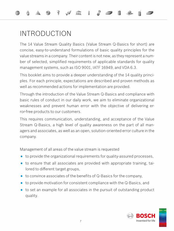
The 14 Value Stream Quality Basics (Value Stream Q-Basics for short) are concise, easy-to-understand formulations of basic quality principles for the value streams in a company. Their content is not new, as they represent a num-ber of selected, simplified requirements of applicable standards for quality management systems, such as ISO 9001, IATF 16949, and VDA 6.3.
This booklet aims to provide a deeper understanding of the 14 quality princi-ples. For each principle, expectations are described and proven methods as well as recommended actions for implementation are provided.
Through the introduction of the Value Stream Q-Basics and compliance with basic rules of conduct in our daily work, we aim to eliminate organizational weaknesses and prevent human error with the objective of delivering er-ror-free products to our customers.
This requires communication, understanding, and acceptance of the Value Stream Q-Basics, a high level of quality awareness on the part of all man- agers and associates, as well as an open, solution-oriented error culture in the company.
Management of all areas of the value stream is requested
to provide the organizational requirements for quality-assured processes,
to ensure that all associates are provided with appropriate training, tai-lored to different target groups,
to convince associates of the benefits of Q-Basics for the company,
to provide motivation for consistent compliance with the Q-Basics, and
to set an example for all associates in the pursuit of outstanding product quality.
INTRODUCTION

8Best Practice BookletBosch 14 Q-Basics
By making regular inspections (line walks), evaluations (assessments), or lay-ered process confirmations (see Glossary) the implementation of the Q-Ba-sics from a content and organizational perspective can be reviewed in order to identify potential areas of improvement as well as best practice solutions. These approaches should always be solution-oriented and advisory in nature, and their results should be viewed as an opportunity and motivation for con-tinuous improvement.
In the following chapters we consciously avoid repeated references to the ze-ro-errors target and emphasis on the question of “why” with respect to the Q-Basics. However, it should be clear that their effectiveness depends strong-ly on sustainable quality awareness (i.e. the mindset) on the part of all man-agers and associates. The introduction of Q-Basics therefore must not be a short-term campaign that loses momentum after initial enthusiasm and even-tually dies out.
Implementation of the Q-Basics essentially involves consistent compliance with rules of conduct. This produces tangible benefits such as:
Increased product quality.
Avoidance of sorting, rework, scrap (internal defect costs).
Increased process output (process efficiency).
Improved delivery capability and reliability (avoidance of logistics errors).
Reduced complaints costs (external defect costs).
Introduction | Value Stream Q-Basics
9
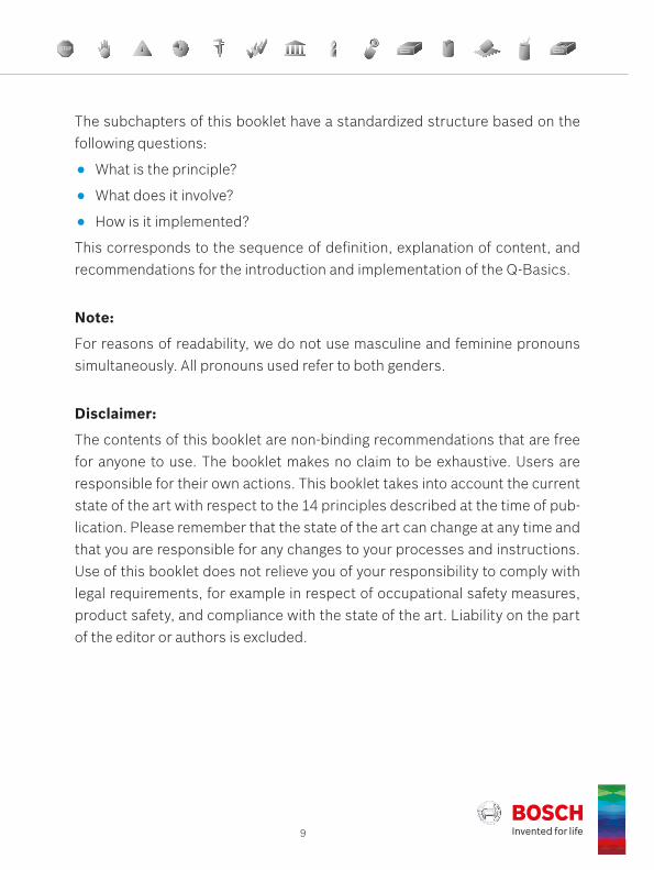
The subchapters of this booklet have a standardized structure based on the following questions:
What is the principle?
What does it involve?
How is it implemented?
This corresponds to the sequence of definition, explanation of content, and recommendations for the introduction and implementation of the Q-Basics.
Note:
For reasons of readability, we do not use masculine and feminine pronouns simultaneously. All pronouns used refer to both genders.
Disclaimer:
The contents of this booklet are non-binding recommendations that are free for anyone to use. The booklet makes no claim to be exhaustive. Users are responsible for their own actions. This booklet takes into account the current state of the art with respect to the 14 principles described at the time of pub-lication. Please remember that the state of the art can change at any time and that you are responsible for any changes to your processes and instructions. Use of this booklet does not relieve you of your responsibility to comply with legal requirements, for example in respect of occupational safety measures, product safety, and compliance with the state of the art. Liability on the part of the editor or authors is excluded.

10Best Practice BookletBosch 14 Q-Basics
Principle 1 | Stop Sign Principle 1 | Stop Sign
Best Practice BookletBosch 14 Q-Basics
1The Stop SignWhat is it about?What is my task?Answers with examples of best-practice

11
Customer complaints are communicated within the production site and, if possible, displayed directly at the station in question. Using problem- solving techniques, they are processed in a fast and systematic manner. The supply chain is promptly informed.
WHAT IS THE PRINCIPLE?
WHAT DOES IT INVOLVE?When complaints occur, it is important that associates and managers from every shift be quickly notified of variations at the location of the potential cause of the issue, that attention be drawn to the issue, and that everyone involved be made aware of the issue. A standardized procedure for the com-munication and visualization of customer complaints in the line is useful in this case. The stop sign is a suitable method. The associated systematic proce-dure includes the use of problem solving techniques (e.g. 8D). It is expected that the commitment of management and active involvement of production will lead to a significant reduction in the time required to resolve the prob-lems. Repeat errors should be effectively prevented.
1. S
top
Sign

12Best Practice BookletBosch 14 Q-Basics
Principle 1 | Stop Sign
HOW IS THE PRINCIPLE IMPLEMENTED?
Gathering of required information and visualization:
Description of variation
Specification of customer(s) and product
Illustration of “good” and “bad”
Process potentially causing the issue
Measures to protect the customer(s)
8D status
8D team members
Communication media (e.g. information board, pin board, monitor)
Location:
A stop sign is placed at a workplace, a station, a line, or in a workshop area where the product/part in question is processed/produced and that is related to the cause. It can also be attached, e.g. to a pin board in the vicinity of the process (e.g. area for team meetings, morning rounds) for the purposes of displaying further information on the status during the course of the problem- solving process. The stop sign is posted up after management decision and with the introduction of immediate measures in step D3 of the 8D process. The ending of the stop sign process is decided on by production/logistics management after the assessment of the evidence of the effectiveness of the remedial actions, e.g. in a meeting involving all participants.

13
Important aspects: Visualization of each customer complaint, if possible near the process po-
tentially causing the issue; placement of the stop sign, if possible at the affected station
Timely (immediate) communication of customer complaints to all poten-tially affected production plants
Provision of information to associates concerning the status of 8D pro-cessing and the associated immediate measures
Removal of the stop sign after closure of the complaint by production/logistics management in a meeting involving all local participants
Decision regarding additional quality assurance measures
Until completion of the 8D process, additional marking of the goods, e.g. with tags, see figure 3, page 16.
Delivery after consultation with the customer or after approval by the customer.
1. S
top
Sign
Figure 1 (left): Example of a stop sign in production, Figure 2 (right): Discussion of measures

14Best Practice BookletBosch 14 Q-Basics
Principle 1 | Stop Sign
Notes on problem solving according to the 8D method:The formulation of the basic problem and the systematic problem analysis as well as the Technical Root Cause (TRC) and Managerial Root Cause (MRC) of a complaint is supported by the work of the team [9]. For this purpose, it is necessary to involve the relevant experts, clearly define corresponding tasks, and use a structured approach. In this context it is also important to note the following:
Fact-based, methodically supported procedure with application of appro-priate tools, e.g. time series graph, Ishikawa diagram, 5 Whys questioning technique.
Containment actions (e.g. blocking/selecting suspicious parts) remain valid until the effectiveness of the corrective actions introduced/planned has been proven.
TOOLS
Figure 3: Example of a tag
Additional Quality Safeguarding Measures
Basic Information
Problem type To be performed
Part number:
Specific requirement:
Actual non conformity: 100 % check
Signature, date:
x
additional sampling inspection
cpk study
Part name:Order number:
Claim number:valid until: closure of 8D

15
WHO IS RESPONSIBLE FOR WHAT TASKS?The production associate …
is informed about a variation by means of a stop sign.
informs himself about the cur-rent status and corresponding measures at a quality informa-tion board.
complies with additional mea-sures during 8D processing and is sensitized to report va-riations.
1. S
top
Sign

16Best Practice BookletBosch 14 Q-Basics
Principle 1 | Stop Sign
The Production / Logistics / Quality Management …
initiates placement of the stop sign.
informs all associates about the complaint and the pro-gress of the problem-solving process.
ensures the regularly updat-ed illustration of the findings from 8D processing.
decides on the termination of the stop sign process.
WHO IS RESPONSIBLE FOR WHAT TASKS?

17
The plant manager …
discusses the conclusion and result of 8D processing with the local participants.
ensures that the effectiveness of the corrective actions is ex-ecuted objectively.
confirms successful conclu-sion of the 8D process.
For additional documents, please visit the purchasing.bosch.com website, section “Value Stream Q-Basics”.
1. S
top
Sign

Best Practice BookletBosch 14 Q-Basics
2The Andon CordWhat is it about?What is my task?Answers with examples of best-practice
Principle 2 | Andon Cord

19
In the event of deviations in quality or if control limits are exceeded in the value stream (source, make, deliver), the associate needs to stop the process or escalate.
WHAT IS THE PRINCIPLE?
WHAT DOES IT INVOLVE?As soon as deviations from the target state (variations in quality, non- conformance) or violations of control limits (e.g. statistical process control, machine parameters) occur in the value stream, the associate must stop the process or initiate escalation in order to prevent further processing/assem-bly, distribution or delivery of potentially defective parts. This requires a suita-ble systematics (e.g. Andon cord, blocking/escalation process, reaction plan), which allows and enables the associate to react like this. Each associate is trained and authorized to stop his activity or the process if he notices varia-tions. The supervisor must be informed immediately. Application of principle 10 “Labeling” must be ensured.
2. A
ndon
Cor
d
20Best Practice BookletBosch 14 Q-Basics
Principle 2 | Andon Cord
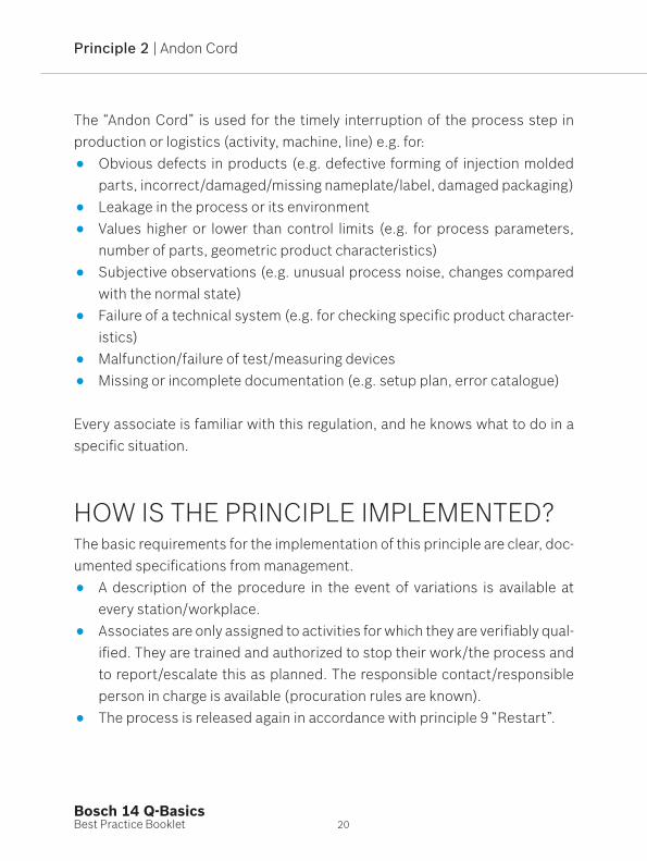
The “Andon Cord” is used for the timely interruption of the process step in production or logistics (activity, machine, line) e.g. for: Obvious defects in products (e.g. defective forming of injection molded
parts, incorrect/damaged/missing nameplate/label, damaged packaging) Leakage in the process or its environment Values higher or lower than control limits (e.g. for process parameters,
number of parts, geometric product characteristics) Subjective observations (e.g. unusual process noise, changes compared
with the normal state) Failure of a technical system (e.g. for checking specific product character-
istics) Malfunction/failure of test/measuring devices Missing or incomplete documentation (e.g. setup plan, error catalogue)
Every associate is familiar with this regulation, and he knows what to do in a specific situation.
HOW IS THE PRINCIPLE IMPLEMENTED?The basic requirements for the implementation of this principle are clear, doc-umented specifications from management. A description of the procedure in the event of variations is available at
every station/workplace. Associates are only assigned to activities for which they are verifiably qual-
ified. They are trained and authorized to stop their work/the process and to report/escalate this as planned. The responsible contact/responsible person in charge is available (procuration rules are known).
The process is released again in accordance with principle 9 “Restart”.

21
Additional requirements:
Production documents (e.g. drawings) and records (e.g. SPC control charts) are up-to-date. Target states and control limits, e.g. with respect to a product or process, are defined.
Every associate can explain the term “deviation”. The associate has been instructed with regard to his obligation to adhere
to specifications; this instruction is documented in the qualification matrix. The quality capability of all processes is established. All processes that ensure compliance with requirements for product-
specific characteristics are capable or assured by means of a capable 100% inspection [7, 8].
For additional documents, please visit the purchasing.bosch.com website, section “Value Stream Q-Basics”.
2. A
ndon
Cor
d
Figure 4: Implementation examples of the “Andon Cord” principle with a stop button

Best Practice BookletBosch 14 Q-Basics
3The InstructionsWhat is it about?What is my task?Answers with examples of best-practice
Principle 3 | Instructions

23
Safety, health, production, and inspection instructions are complied with.5S standards are put in place and observed.
WHAT IS THE PRINCIPLE?
WHAT DOES IT INVOLVE?Safety, health, work, production, and inspection instructions and their obser-vance are essential for a standardized production process and the physical safety of the associates involved. They describe in an appropriate and com-prehensible manner the work and test steps to be carried out and the work, safety, and environmental standards to be adhered to. They also form the ba-sis for associate training and support the job-training process (e.g. new asso-ciates, deployment of reserve associates, change of job, and production of a different product at the same workplace/station).
3. In
stru
ctio
ns

24Best Practice BookletBosch 14 Q-Basics
Principle 3 | Instructions
A procedure based on the 5S approach supports the standardized production process and increases efficiency in the performance of work:
Keyword Measures/rules of conduct
Sort Sort out/remove anything unnecessary at the workplace
Set in order Tidy up; organize work equipment ergonomically
Shine Keep workplace clean
Standardize Maintain organization of objects (e.g. using shadow boards)
Sustain Adhere to rules consistently and improve standards if required
The instructions include information for associates on the following:
Work tasks (what is to be done)
Work sequences (how the work is to be carried out)
Quality (what is important, what is to be checked and how)
Performance (what is expected)
Occupational safety (which safety regulations must be adhered to)
Process/procedure (what is to be monitored)
They must be created in a standardized way for every workplace, made avail- able there, communicated, and adhered to.
25
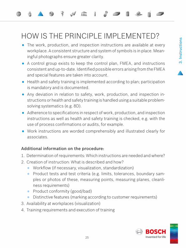
Additional information on the procedure:
1. Determination of requirements: Which instructions are needed and where?2. Creation of instruction: What is described and how? Workflow (if necessary, visualization, standardization) Product tests and test criteria (e.g. limits, tolerances, boundary sam-
ples or photos of these, measuring points, measuring planes, cleanli-ness requirements)
Product conformity (good/bad) Distinctive features (marking according to customer requirements)3. Availability at workplaces (visualization)4. Training requirements and execution of training
HOW IS THE PRINCIPLE IMPLEMENTED? The work, production, and inspection instructions are available at every
workplace. A consistent structure and system of symbols is in place. Mean-ingful photographs ensure greater clarity.
A control group exists to keep the control plan, FMEA, and instructions consistent and up-to-date. Identified possible errors arising from the FMEA and special features are taken into account.
Health and safety training is implemented according to plan; participation is mandatory and is documented.
Any deviation in relation to safety, work, production, and inspection in-structions or health and safety training is handled using a suitable problem- solving systematics (e.g. 8D).
Adherence to specifications in respect of work, production, and inspection instructions as well as health and safety training is checked, e.g. with the use of process confirmations or audits, for example.
Work instructions are worded comprehensibly and illustrated clearly for associates.
3. In
stru
ctio
ns

26Best Practice BookletBosch 14 Q-Basics
Principle 3 | Instructions
Figure 5: Register with inspection instructions at the production line
Figure 6: Clear identification of health instruc-tions at the workplace (no access for people with pacemakers)
Figure 7: Associate wearing ear protection as per the illustration on the right

27
Figure 8: Operating instructions concerning dangers and first aid
Figure 9: Standardized workplace with imple-mentation of 5S
Figure 10: Workshop wagon in accordance with 5S
3. In
stru
ctio
ns

28Best Practice BookletBosch 14 Q-Basics
Principle 3 | Instructions
The Production / Logistics / Quality Management …
creates required documents in standardized form.
carries out regular, document-ed workshop inspections / pro-cess confirmations.
systematically analyzes and eliminates deviations.
ensures provision at defined locations in production.
ensures training of the associ-ates on handling the standard (good/bad, OK/NOK).
NEW
ensures regular updates and checking for consistency.
For additional documents, please visit the purchasing.bosch.com website, section “Value Stream Q-Basics”.
WHO IS RESPONSIBLE FOR WHAT TASKS?

3. In
stru
ctio
ns

Best Practice BookletBosch 14 Q-Basics
4The Process ParametersWhat is it about?What is my task?Answers with examples of best-practice
Principle 4 | Process Parameters
31
The target values/tolerances for all stated process parameters are ob-served.
WHAT IS THE PRINCIPLE?
WHAT DOES IT INVOLVE?The concepts of quality capability and stability of a process are according to standards applied to process results. Stable statistical properties of product characteristics generally require process parameters which are constant (or regulated according to a defined timescale). Process parameters (process characteristics in accordance with [2]), which have an influence on product characteristics/quality, must therefore be specified in full and assigned nomi-nal values and tolerances. These specifications are made by the responsible area (e.g. process development, production planning).
4. P
roce
ss P
aram
eter
s

32Best Practice BookletBosch 14 Q-Basics
Principle 4 | Process Parameters
Parameter values are documented, monitored, and recorded according to suitable standards. Continuous monitoring or regular inspections are used to determine whether the actual values comply with the specifications (see prin-ciple 3 “Instructions”).
The real (measured) values of the process parameters (e.g. speed, force, pressure, temperature, concentration, time) should match the specified tar-get value as closely as possible, i.e. be monitored and, if necessary, readjus-ted. The actual values must lie within predefined limits and are corrected, if necessary, in order to ensure the conformity of the products.
If process parameters can only be set at specified intervals (e.g. number of strokes/min, integer multiples of a unit, discrete switch settings including on/off), the settings must not deviate from the specifications in the process data sheet. It should be noted in particular here that the nominal values and toler- ances of the process parameters may change during the course of modifications to the product and must be taken into consideration in change management.
HOW IS THE PRINCIPLE IMPLEMENTED?During the development of a process, the respective process parameters must be defined and listed along with corresponding tolerances in the con-trol plan. The control plan contains all quality-related parameters and refers to the necessary instructions (e.g. process data sheet, setup plan). The spec-ification of how the process parameters are to be checked is part of process planning.

33
Additional information on implementation:
Determination of the relevant parameters for process management; this also includes parameters for central media supply (e.g. compressed air/cooling lubricant/test oil supply).
Determination of the key parameters for process stability and product quality.
Specification of limits and tolerances
Entry in the control plan
Creation of setup plan (e.g. for machine, tool) and inspection plan
Creation of e.g. process data sheets with all relevant parameters for pro-cess management
The compliance of the target states is continuously monitored using suit-able sensors and corresponding software, for example, which trigger a display with acoustic/optical signals in the event of variations.
Figure 11: Color coding of tolerance range; left: tolerance adhered to, right: process parameter outside tolerance range
4. P
roce
ss P
aram
eter
s

34Best Practice BookletBosch 14 Q-Basics
Principle 4 | Process Parameters
Figure 12: Digital display of a defined process parameter. The process parameter may only be adapted by an author-ized associate with a key.
Analog instruments are given markings (red/green), for example. In this case, monitoring is performed on the basis of regular visual inspections by associates.
Compliance with parameters is checked regularly and, if necessary, re-peated in the event of a process start, restart after a fault, shift change, maintenance/repair, or tool change. Documentation is ensured (e.g. through entry in a release list).
If the repeated occurrence of error messages casts doubt on the correct or appropriate specification or parameter values, these should be checked by process development.
All deviations must be dealt with systematically and resolved permanently (e.g. open point list (OPL), problem-solving sheet).
Changes to parameter specifications are documented and implemented by authorized personnel only after approval (e.g. after risk assessment, initial part test). Associates are given appropriate training. Process param-eters are protected against unauthorized access (e.g. password, lock). An overview of the persons authorized is available and accessible at all times.
35
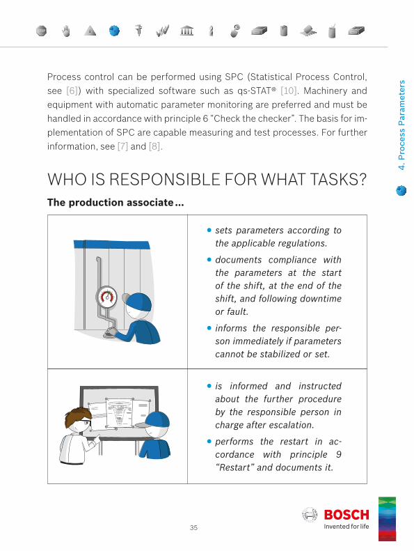
Process control can be performed using SPC (Statistical Process Control, see [6]) with specialized software such as qs-STAT® [10]. Machinery and equipment with automatic parameter monitoring are preferred and must be handled in accordance with principle 6 “Check the checker”. The basis for im-plementation of SPC are capable measuring and test processes. For further information, see [7] and [8].
The production associate …
sets parameters according to the applicable regulations.
documents compliance with the parameters at the start of the shift, at the end of the shift, and following downtime or fault.
informs the responsible per-son immediately if parameters cannot be stabilized or set.
is informed and instructed about the further procedure by the responsible person in charge after escalation.
performs the restart in ac-cordance with principle 9 “Restart” and documents it.
4. P
roce
ss P
aram
eter
s
WHO IS RESPONSIBLE FOR WHAT TASKS?

The Measurement/Test EquipmentWhat is it about?What is my task?Answers with examples of best-practice
Best Practice BookletBosch 14 Q-Basics
5Principle 5 | Measurement/Test Equipment

37
Measuring and test equipment is defined, and monitoring intervals are observed.
WHAT IS THE PRINCIPLE?
WHAT DOES IT INVOLVE? Measurement/test equipment is generally a capable measuring device (see note in Glossary), which is used for “quality inspections” (conformity assess-ments on products). They are used/applied to determine whether the require-ment for a product characteristic is fulfilled, i.e. whether the measured value lies within the tolerance range. The range of measurement/test equipment extends from basic gages through manual handheld measuring devices (e.g. caliper gages) and semiautomatic measuring devices at workplaces to fully automatic measurement systems integrated in machinery (e.g. sensors). Product char-acteristics can include geometric information (e.g. length, shape, orientation, position, layer thickness) as well as mechanical (e.g. force), electrical (current, voltage, frequency), or hydraulic functional characteristics (e.g. volume flow).
5. M
easu
rem
ent/
Test
Equ
ipm
ent

38Best Practice BookletBosch 14 Q-Basics
Principle 5 | Measurement/Test Equipment
The decision as to whether the specification for a characteristic value is ad-hered to is made by comparing the measured actual value with the specified nominal value. The maximum permissible deviation between the actual value and nominal value is specified by the tolerance. This decision requires a reli-able measurement result. Measurement/test equipment that is not capable can lead to wrong decisions. For example, a “good part” whose correct char-acteristic value lies within the tolerance range may be mistakenly assessed as “nonconforming” and scrapped (possibly resulting in financial loss). Similar-ly, a “bad part” whose correct characteristic value lies outside the tolerance range may be mistakenly assessed as “conforming” and delivered to a custom-er (possibly resulting in a customer complaint, financial loss, or loss of trust). The measurement accuracy, measurement stability, and capability of the measurement/test equipment are ensured through measurement/test equip-ment monitoring. This includes all activities relating to the calibration, adjust-ment, and maintenance of measurement/test equipment.
HOW IS THE PRINCIPLE IMPLEMENTED?The measurement/test equipment to be used is selected and specified ac-cording to the characteristics.
The measurement/test equipment and its use are listed in the control plan and in the production and inspection instructions, see also principle 3 “In-structions”.
Each item of measurement/test equipment is clearly identifiable (e.g. en-graved number, sticker).
Capability must be verified for all tests, see [8]. All devices, aids (e.g. standards, mounts, cables), software, and persons involved (e.g. opera-tors) in the measurement process as well as the ambient conditions can

39
influence measurement results. To carry out capability tests, repeatedly measurable and verifiable standards or serial or reference parts must be available as measurement or test objects. If a measuring or testing pro-cess proves to be only conditionally capable or not capable, the causes must be examined and improvement measures must be defined.
Visual inspection workplaces are assessed with respect to their technical conditions (e.g. ergonomics, lighting) and human resource requirements (e.g. qualification, eye test) and with respect to the capability of the test process in a preliminary analysis (see [Issue 10]). With the help of the preceding on-site analysis, one can detect defects at an early stage. This could lead to a negative capability assessment. However, it cannot/must not replace the capability test in accordance with [8].
The functionality and accuracy of all measurement/test equipment in the value stream are regularly checked by authorized and trained personnel, see also principle 6 “Check the checker”. The results are available upon request. The due date of the next inspection (calibration of the measure-ment/test equipment) is clearly visible at the work location, e.g. with a sticker. In general, only capable, calibrated measurement and test equip-ment is used.
Measurement and test equipment that is not capable, out of date, or dam-aged can lead to incorrect measurement/test results. A good part that is identified as “bad” because of an incorrect measurement would be scrapped/reworked unnecessarily. Similarly, a bad part that is incorrectly identified as good would be delivered to the customer and result in a qual-ity incident.
Measurement and test equipment which is not capable, out of date, or dam-aged must be reported immediately and further use must be prevented.
5. M
easu
rem
ent/
Test
Equ
ipm
ent

40Best Practice BookletBosch 14 Q-Basics
Principle 5 | Measurement/Test Equipment
Figure 13: Caliper gage with inspection sticker (blue sticker)
For additional documents, please vis-it the purchasing.bosch.com website, section “Value Stream Q-Basics”.
Figure 14: Measurement/test equipment cabinets with labeling and description of measurement/test equipment
41
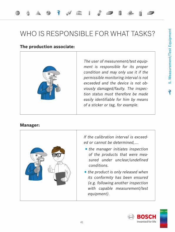
Manager:
If the calibration interval is exceed-ed or cannot be determined, …
the manager initiates inspection of the products that were mea-sured under unclear/undefined conditions.
the product is only released when its conformity has been ensured (e.g. following another inspection with capable measurement/test equipment).
The production associate:
The user of measurement/test equip-ment is responsible for its proper condition and may only use it if the permissible monitoring interval is not exceeded and the device is not ob-viously damaged/faulty. The inspec-tion status must therefore be made easily identifiable for him by means of a sticker or tag, for example.
5. M
easu
rem
ent/
Test
Equ
ipm
ent
WHO IS RESPONSIBLE FOR WHAT TASKS?

The Check the CheckerWhat is it about?What is my task?Answers with examples of best-practice
Best Practice BookletBosch 14 Q-Basics
6Principle 6 | Check the Checker
43
The “check the checker” principle is applied, and the “checker’s” suit-ability is ensured.
WHAT IS THE PRINCIPLE?
WHAT DOES IT INVOLVE? The term “checker” generally refers to an automatic testing system (e.g. laser sensor, load cell, camera system, probe, temperature sensor), the purpose of which is to ensure or at least support compliance with process parameters (process characteristics), and which is used to prevent or detect errors in the process flow. The checker should in particular prevent potential (usually al-ready occurred, random) process errors from remaining undetected and result-ing faulty (non-conforming) parts from being further processed or forwarded.
6. C
heck
the
Che
cker

44Best Practice BookletBosch 14 Q-Basics
Principle 6 | Check the Checker
Note:
The term “checker” is not defined in any of the relevant quality management standards. However, from the above description it is clear that in the context of Q-Basics, the term “checker” refers primarily to installations pertaining to process characteristics, while “measurement/test equipment” is associated with the checking of product characteristics. The visual inspection of a prod-uct by a human “checker” requires capability certification (e.g. in accordance with [8] Process 7) and must therefore be assigned to principle 5 “Measure-ment/Test Equipment”. The “checker” generally involves one or more sensors (e.g. camera), data transfer (e.g. wiring), data processing (e.g. evaluation soft-ware) with trigger function and signaling/control function (see also Glossary), and peripherals (e.g. lighting).
A “checker” can be altered as a result of intentional or unintentional interven- tion, environmental influences, or by changing the ambient and working conditions and therefore be rendered ineffective.
Examples include:
Malfunction or misalignment of the “checker” or its system components
Loading of incorrect/defective/updated software
Loading of an incorrect/modified test program or entry of incorrect/modi-fied test parameters
Replacement of lighting systems
Replacement/modification of checker system components
Modification of the environment (e.g. extensions in the vicinity of sensors)
45
Application examples:
The position of a reflected laser beam on an optical sensor is used to de-termine whether just one disc or – incorrectly – no or two discs have been inserted in a component.
A counting scale is used to check whether the quantity of small parts (e.g. screws) counted by an associate matches the number ordered by the customer.
An image recognition and analysis system compares a camera image with a reference object to determine whether
the assembly/soldering of electronic components on a PCB (printed circuit board) has been carried out correctly.
a component has a defect or not.
6. C
heck
the
Che
cker
The effects of changes, whether intentional or unintentional, are not necessar-ily identified immediately by people or in follow-up processes, which is why a regular inspection (“check”) of the “checker” is required, hence the expres-sion “check the checker”.
“Check the checker” verifies the proper function and effectiveness of the “checker” available in the value stream. The inspection (the “check”) of the testing systems (“checkers”) in use must be carried out regularly in accor- dance with the defined standard and has to be documented. Remedial action must be taken in the event of variations.
46Best Practice BookletBosch 14 Q-Basics
Principle 6 | Check the Checker
All testing systems (“checkers”) in the value stream must be taken into con-sideration. These test processes are evaluated with respect to possible risks using appropriate methods, such as FMEA. This involves an analysis of possible faults/malfunctions of the “checker” before it is used.
The execution of the testing process and the “check the checker” intervals must be defined for each “checker” and regulated by means of an inspec-tion instruction in accordance with principle 3 “Instructions”.
The “checker” must be tested following modifications and at regular inter-vals (e.g. at every production start or shift change). This inspection shows whether the checker correctly detects and displays specially prepared de-fective parts (“check the checker” parts). The results of this inspection are clearly documented (when? who? where? what? how?).
Generally speaking, “check the checker” parts and “checkers” are subject to monitoring of the measurement/test equipment and have defined prop-erties, such as:
Missing/incomplete component/assembly
Geometric variation
Scratches of a defined size
Surface roughness
Color variation
Leakage rate
Electrical contact resistance
HOW IS THE PRINCIPLE IMPLEMENTED?

47
If the result of the “checker” inspection is negative, it must be ensured that the goods produced since the last OK inspection are checked. The further processing and delivery of defective goods must be prevented.
Inspections of camera systems are performed using “check the checker” parts. These are used to assess the system with respect to function and correct detection of product characteristics.
6. C
heck
the
Che
cker
Figure 15: Function test of an automatic camera system using a “check the checker” part

48Best Practice BookletBosch 14 Q-Basics
Principle 6 | Check the Checker
Figure 16 (left) and Figure 17 (right): Application of “check the checker” through inspection of the insertion force sensor using a spring force dummy
Figure 18: “Check the checker” parts (test dummies)
49
For additional documents, please visit the purchasing.bosch.com website, section “Value Stream Q-Basics”.
6. C
heck
the
Che
cker
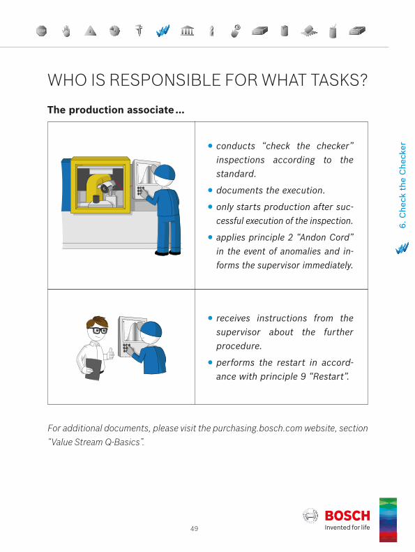
The production associate …
conducts “check the checker” inspections according to the standard.
documents the execution.
only starts production after suc-cessful execution of the inspection.
applies principle 2 “Andon Cord” in the event of anomalies and in-forms the supervisor immediately.
receives instructions from the supervisor about the further procedure.
performs the restart in accord-ance with principle 9 “Restart”.
WHO IS RESPONSIBLE FOR WHAT TASKS?

Best Practice BookletBosch 14 Q-Basics
7The TPMWhat is it about?What is my task?Answers with examples of best-practice
Principle 7 | Total Productive Maintenance (TPM)

51
A maintenance standard is installed and observed at every station.
WHAT IS THE PRINCIPLE?
WHAT DOES IT INVOLVE? Total Productive Maintenance (TPM) stands for the autonomous, planned, and preventive maintenance of machinery and equipment. Its objective is to ensure product quality and delivery capability as well as the availability of machinery and systems. A comprehensive system for service/cleaning, inspection, and maintenance guarantees trouble-free, high-quality, and safe operation. These are preventive measures, which are carried out by trained personnel in accordance with specified standards (e.g. location, interval, ac-tivities). Special attention must be taken to avoid contamination through e.g. a cleaning schedule. Unusual contamination or repeated damage in machinery and setup elements must be consistently analyzed, understood, and resolved.
7. T
otal
Pro
duct
ive
Mai
nten
ance
(TP
M)

52Best Practice BookletBosch 14 Q-Basics
Principle 7 | Total Productive Maintenance (TPM)
HOW IS THE PRINCIPLE IMPLEMENTED?
Trai
ning
and
Coac
hing
5 Success control and documentation
Continuous improve-ment of installations and
process quality
Continuous improvement of the
maintenance system
Continuous improvement of MAE
planning and procurement process
4 Derive and agree upon standards
Carry out independent repair work and
improving standardsApply diagnostic
systemsInstall MAE and put it
into operation
3 Define and implement measures
Carry out independent service jobs and
improving standards
Establish and use maintenance information,
planning and control system
Design and create MAE according to
specifications
2 Analyze causesAgree upon standards
for service incl. cleaning and inspection
Recognize weak points at machines, equipments
and processes, and eliminate their causes
Create MAE concept, including maintenance
specifications and agree upon it with the
manufacturer
1 Determine loss and main problem
Basic inspection of ma-chines and equipments
Develop, set, and implement further
maintenance activities
Consider MAE concept as early as the product and process develop-
ment stage
Elimination of core problems
Autonomous maintenance
Planned maintenance
TPM-compliant design of MAE
TPM Basic training of all team members (initialization, simulation)
Definition of the TPM team and selection of MAE*
TPM
* MAE means Machinery and EquipmentFigure 19: The four-pillar model for Total Productive Maintenance (TPM)
TPM follows a logically structured system based on four pillars. The four-pillar TPM model consists of: Pillar 1 “Elimination of core problems” Pillar 2 “Autonomous maintenance” Pillar 3 “Planned maintenance” Pillar 4 “TPM-compliant design of MAE” (machinery and equipment)

53
This involves the roles and areas of responsibility in production and in the sup-porting areas. These four pillars of TPM include the following activities:
1. Elimination of core problems
Recording sources of losses and identifying core problems
Analyzing causes
Defining and implementing measures
Deriving and defining standards
Carrying out success monitoring and documentation
2. Autonomous maintenance Autonomous maintenance means that routine activities for system mainte-nance are carried out independently by operating personnel during teamwork. This requires appropriate qualification with consideration of the requirements in terms of health, safety, and the environment that apply to these workplaces or systems.
Carrying out a basic inspection of machinery and equipment
Defining standards for maintenance, including cleaning and inspection
Carrying out maintenance, inspection, cleaning work
Carrying out repair work and improving standards
Continuously improving equipment and process quality
7. T
otal
Pro
duct
ive
Mai
nten
ance
(TP
M)
In particular, the implementation of autonomous and planned maintenance for all MAE is an essential requirement for maintaining trouble-free, quality- capable production.
54Best Practice BookletBosch 14 Q-Basics
Principle 7 | Total Productive Maintenance (TPM)
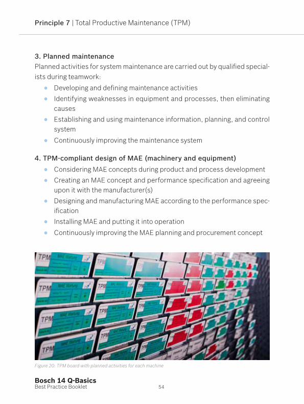
3. Planned maintenance Planned activities for system maintenance are carried out by qualified special-ists during teamwork:
Developing and defining maintenance activities Identifying weaknesses in equipment and processes, then eliminating
causes Establishing and using maintenance information, planning, and control
system
Continuously improving the maintenance system
4. TPM-compliant design of MAE (machinery and equipment) Considering MAE concepts during product and process development Creating an MAE concept and performance specification and agreeing
upon it with the manufacturer(s) Designing and manufacturing MAE according to the performance spec-
ification Installing MAE and putting it into operation
Continuously improving the MAE planning and procurement concept
Figure 20: TPM board with planned activities for each machine
55
Examples of TPM activities include: Cleaning equipment Lubricating mechanical components Stocking up on consumables and materials Checking damage, wear, and function Replacing and repairing
Benefits of the TPM approach: Involvement of all associates, independent processing of tasks, increased
identification of associates with their equipment Teamwork and interdisciplinary cooperation is intensified Improvement in process and product quality Increase in OEE (Overall Equipment Efficiency) Reduction in unplanned downtimes, high level of system availability Planned maintenance instead of unplanned “fire-fighting”
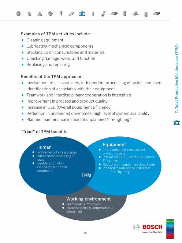
“Triad” of TPM benefits:
TPM
Involvement of all associates Independent processing of
tasks Identification of all
associates with their equipment
Human Improvement in process and
product quality Increase in OEE (Overall Equipment
Efficiency) Reduction in unplanned downtimes Planned maintenance instead of
“fire fighting”
Equipment
Teamwork is improved Interdisciplinary cooperation is
intensified
Working environment
7. T
otal
Pro
duct
ive
Mai
nten
ance
(TP
M)

Principle 8 | Tools
Best Practice BookletBosch 14 Q-Basics
8The ToolsWhat is it about?What is my task?Answers with examples of best-practice

57
Each tool has a defined service life; the current status must be reco-gnizable. A quality evaluation must be carried out during installation, removal or disassembly.
WHAT IS THE PRINCIPLE?
WHAT DOES IT INVOLVE?In the context of production processes one normally thinks of classic tools for material processing, e.g. for turning, drilling, milling, sawing, cutting, grinding, honing. Depending on the product area and production process, the expert might think of other special tools for separating, forming, or shaping, as well as tools associated with assembly processes (gripping, joining, connecting). All the way up to special “tools” for semiconductor technology or complex tools for metal and plastics processing.
8. T
ools

58Best Practice BookletBosch 14 Q-Basics
Principle 8 | Tools
Figure 21: Checking of a complex tool for damage and wear by an expert
Principle 8 therefore in general refers to the monitoring of “wear-prone tools which impact product quality”, therefore work piece carriers and holders are also named in the list of examples. Depending on the production process in question, clear definition of the relevant tools is therefore necessary.
59
Only approved tools may be used in the value stream. Their approval is part of the production process approval. All relevant wear-prone tools with an impact on product quality (e.g. machining/assembly tools, work piece holders) are recorded and subject to monitoring.
HOW IS THE PRINCIPLE IMPLEMENTED?
Their service life is analyzed and specified (e.g. in overview tables, production and inspection instructions). Examples of suitable “service life measurements”:
Number of parts produced with this tool
Number of strokes, shots, rotations, bore holes, welds
Number of shifts
Operating time (in hours, days, weeks)
Cutting length (in meters, kilometers)Compliance with the service life can easily be verified by comparing the cur-rent actual value of this service life measurement with the defined maximum value (service life).
Determination of service life
As a rule, one must follow the tool manufacturer‘s specifications (e.g. obtained through service life tests). Frequently, however, personal empirical values, observations, and records can also serve as a basis, e.g. results of 100% in- process inspections or SPC long-term evaluations (e.g. tool-related reasons for intervention and corresponding measures, see [6]).
8. T
ools

60Best Practice BookletBosch 14 Q-Basics
Principle 8 | Tools
Involvement of associates and procedure
There is a standard that describes the handling of tools in the context of prin-ciple 8. An important aspect of this partly preventive, partly reactive approach is the active involvement and participation of associates.
Tools are checked for wear and damage during installation/removal. A fre-quently asked question in this case is: “Why also during installation?” The an-swer is obvious: the installation and use of, for example, an incorrect, already worn, damaged tool in the machine should be avoided/prevented. Inspection during installation aims to detect premature/unusual wear or damage.
If deviations from the target state are identified during these inspections or in the ongoing process, measures (e.g. adjustment, replacement) must be im-plemented in accordance with the reaction plan. For information on releasing the machine again, see principle 9 “Restart”. A decision must also be made concerning the products processed/manufactured with this tool (e.g. select-ing parts, reworking, scrapping).
In the event of frequent premature tool failure, the causes are analyzed and re-medial actions taken (e.g. revision of service life, elimination of non-systemic technical causes).
61
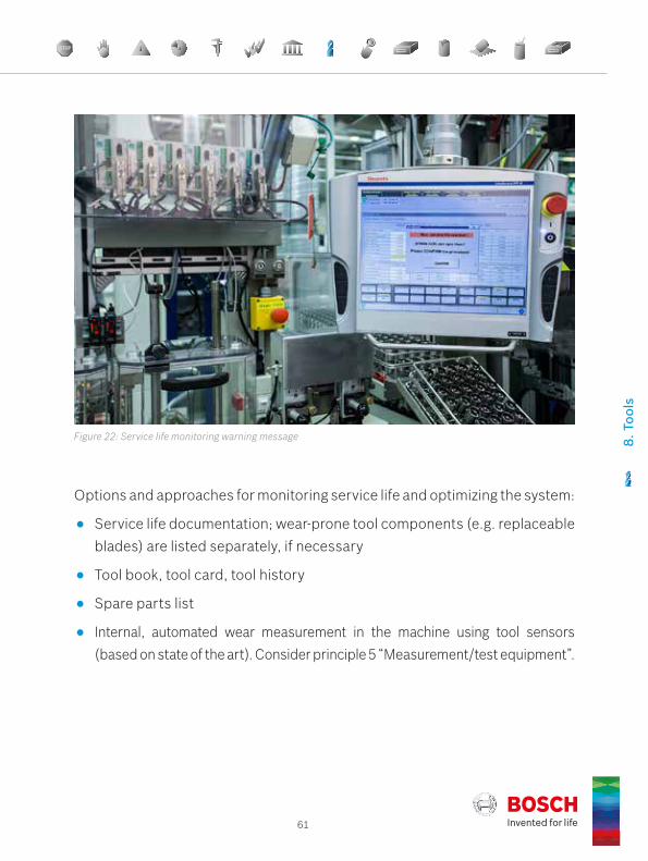
Figure 22: Service life monitoring warning message
Options and approaches for monitoring service life and optimizing the system:
Service life documentation; wear-prone tool components (e.g. replaceable blades) are listed separately, if necessary
Tool book, tool card, tool history
Spare parts list
Internal, automated wear measurement in the machine using tool sensors (based on state of the art). Consider principle 5 “Measurement/test equipment”.
8. T
ools

62Best Practice BookletBosch 14 Q-Basics
Principle 8 | Tools
Labeling and storage
Tools must be labeled. This means in particular that the tool state must be clear and visible at all times. Worn tools (expired service life) are stored sepa-rately from tools that are OK and secured against accidental use.
Tools must be stored in a way that excludes any reduction in quality, e.g. due to contamination, damage, environmental influences.
“Tool maintenance” is responsible for the availability, capability, and quality of tools. Production must be able to depend on tool maintenance.
Evaluation of the tool state at the end of every shift as well as during setup processes (setup/dismantling)
Inspection in accordance with maintenance plan, i.e. linking of principle 8 “Tools” with principle 7 “Total Preventive Maintenance (TPM)”
Indirect monitoring through observation/recording of product characteris-tics (e.g. as part of SPC)
Recorded data for messages of other “warning systems” of machinery and equipment (e.g. spindle status check) or other relevant records for the pro-cess (e.g. results of 100% in-process inspections, SPC long-term evaluations) are analyzed and lead to improvements (e.g. revision of service life).

63
Figure 24: Storage of wear-prone tools including state description and service life specification
Figure 23: Example of a completed tool card
Sheet no.:
Date: 01.10.2015
Product: Product No.: Produced: Contact:
Date: Code: Date: Code: Date: Code:
14.04.2015 1 279 H02 005
DateName
pcs. produced Cld. Set-up Date
Name03.12.2015 3054
S 305406.12.2015 4146
S 720007.12.2015 6957
S 1415722.12.2015 5999 22.12.2015
S 20159 Meier11.01.2016 0
S 017.01.2016 7826
S 782620.01.2016 4542 20.01.2016
S 12368 Müller21.01.2016 0
S 026.01.2016 21450 01.02.2016
S 21450 Schulze02.02.2016 0
S 0
Tool Card
Tool No.: SZ0617 AN/A double Nest: A1, A2 Machine: Arburg
W 5496 W 5851
Maintenance after:
20.000 pcs. + 10%
ABS housing 1 275 100 158 09.2012 resp. planner / MFE-B5
Release: 7.6.07 / MSO, MFE-B6, QMM Prod. change: Product change: Prod. change:
Findings / Measures Maintenance, Repair
x Guide bar cleaned
x Pin nest 2 cleaned
x Pin nest 2 cleaned
x Form disassembled Form compl. cleaned; chips removed from bore holes for temp. sensor
Form assembled
x Set-up to 203
Motor connector & ejector on nest 1 defective Motor connector eroded and 2 new ejectors built in
Form assembled
Form assembled
x Form assembled Form completely cleaned
8. T
ools

Best Practice BookletBosch 14 Q-Basics
9The RestartWhat is it about?What is my task?Answers with examples of best-practice
Principle 9 | Restart

65
Restart after disruptions is clearly regulated for all machinery and equipment.
WHAT IS THE PRINCIPLE?
WHAT DOES IT INVOLVE? Every disruption to the continuous production process presents a potential risk to quality and can impact on product quality. For this reason, a defined standard is required for restarts. The standard regulates the procedures in the event of planned (e.g. tool change, setup, breaks, public holidays, shift cancelations, shift change, maintenance, conversion, software updates or pa-rameter changes on machinery/systems) and unplanned (e.g. power failure, tool failure, missing material) disruptions.
9. R
esta
rt
66Best Practice BookletBosch 14 Q-Basics
Principle 9 | Restart
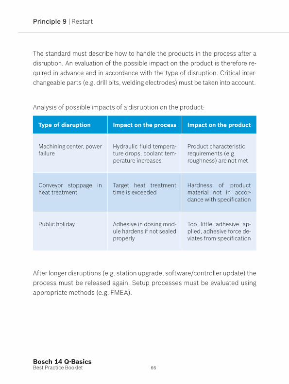
Analysis of possible impacts of a disruption on the product:
Type of disruption Impact on the process Impact on the product
Machining center, power failure
Hydraulic fluid tempera-ture drops, coolant tem-perature increases
Product characteristicrequirements (e.g. roughness) are not met
Conveyor stoppage in heat treatment
Target heat treatment time is exceeded
Hardness of product material not in accor- dance with specification
Public holiday Adhesive in dosing mod-ule hardens if not sealed properly
Too little adhesive ap-plied, adhesive force de-viates from specification
After longer disruptions (e.g. station upgrade, software/controller update) the process must be released again. Setup processes must be evaluated using appropriate methods (e.g. FMEA).
The standard must describe how to handle the products in the process after a disruption. An evaluation of the possible impact on the product is therefore re-quired in advance and in accordance with the type of disruption. Critical inter-changeable parts (e.g. drill bits, welding electrodes) must be taken into account.
67
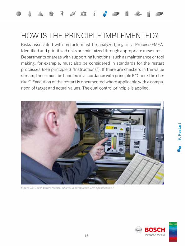
Figure 25: Check before restart; oil level in compliance with specification?
Risks associated with restarts must be analyzed, e.g. in a Process-FMEA. Identified and prioritized risks are minimized through appropriate measures.Departments or areas with supporting functions, such as maintenance or tool making, for example, must also be considered in standards for the restart processes (see principle 3 “Instructions”). If there are checkers in the value stream, these must be handled in accordance with principle 6 “Check the che-cker”. Execution of the restart is documented where applicable with a compa-rison of target and actual values. The dual control principle is applied.
HOW IS THE PRINCIPLE IMPLEMENTED?
9. R
esta
rt

68Best Practice BookletBosch 14 Q-Basics
Principle 9 | Restart
The definition of restart standards must be machine-specific/process-specific and at least regulate the following aspects:
Influences Implementation examples
What happens to products/compo-nents that are still being processed/engaged?
Deciding on discharge, scrapping, or further use
How must parts and materials that are upstream/downstream in the process flow be handled?
Deciding on separation, blocking, scrapping, or further use; ensuring traceability
What must be considered in relation to any transport facilities and utilities affected?
Conveyors, dosing equipment, cool-ant, compressed air
Which tests/approvals are required for the respective product/process/machine?
Creating measurement log for initial parts; approving initial parts, observ-ing dual control principle for machine/process approval
Which individual steps/activities must be performed to restart the process?
Detailed description of work steps/ activities for the restart (checklists)
How and where is the disruption clear-ly documented?
Machine book, production planning system

69
The production associate …
can explain the principle.
performs the restart in accor- dance with specifications.
documents execution of the restart.
The manager …
creates the release rules and trains associates.
monitors the restart according to the dual control principle (together with the associate).
For additional documents, please visit the purchasing.bosch.com website, section “Value Stream Q-Basics”.
9. R
esta
rt
WHO IS RESPONSIBLE FOR WHAT TASKS?

Best Practice BookletBosch 14 Q-Basics
10The LabelingWhat is it about?What is my task?Answers with examples of best-practice
Principle 10 | Labeling

71
Products and containers are labeled according to the set standard.
WHAT IS THE PRINCIPLE?
WHAT DOES IT INVOLVE? Missing, illegible, unclear, or completely incorrect labels are possible sources of faults. Raw materials, components, parts, products, containers, and pack-aging units, for example, must therefore always have a clear status throughout the entire value stream. The status must be visible or determinable at all times using defined, clear labels, and it may only be determined on this basis – not on the basis of appearance or other characteristics. In this case it is neces-sary to define and implement a standard, which describes in particular the labeling used within and outside the production flow. Furthermore, the stan- dard should cover the aspects of control of defective products (blocking) and traceability. The risk of errors can thus be minimized or even eliminated.
10. L
abel
ing

72Best Practice BookletBosch 14 Q-Basics
Principle 10 | Labeling
Implementation of the standard requires consistent adherence to the follow-ing rules:
Filled boxes must be labeled.
Only parts with the same status should be placed in the same container.
No good products in reject containers.
Reject containers must be secured to prevent unauthorized access (e.g. locks, covers, separate rooms, covering during transport). They are emp-tied according to the standard and the parts are analyzed.
Parts at the analysis point are kept separate from the production flow and are clearly marked.
Products are protected from environmental influences (e.g. contamination).
The labeling of blocked goods must be regulated in a blocking process for production and logistics. This regulation includes responsibilities, the flow of information, and specific requirements for the labeling/separation of goods.
Figure 26: Labeling of checked goods at the storage location

73
The clear labeling of goods in the value stream is an essential requirement. This means that the status of every part (e.g. raw materials, components, products, containers, and packaging units) in the value stream, from goods re-ceipt to delivery to the customer, must be visible or determinable at all times. A standard is defined for the labeling of goods in the value stream (e.g. con-tainer marking, labels). It is recommended that associates be involved in the definition of area-specific rules of conduct and that practicable, logical, and simple rules be agreed.Parts with a different status must not be stored in the same container. Cards, stickers, MAT labels, RFID tags, and standardized color coding also support the identification of products, floor space, storage areas, and goods tags, for example. In this particular case, the “5S approach” must be adhered to (see principle 3 “Instructions”).
HOW IS THE PRINCIPLE IMPLEMENTED?
The following classification is recommended for the labeling concept:
Product in good condition
Product blocked
Product for rework/in recursion/to be sorted
Product after additional test back in production flow following an additional check, the goods have been returned to the production flow and are in order
Product is scrap
Sample parts
10. L
abel
ing

74Best Practice BookletBosch 14 Q-Basics
Principle 10 | Labeling
Important aspects for the control of defective products or products with an unclear status:
Precautionary blocking/selection/sorting of potentially defective products
Separation and clear marking of defective products
Recording and analysis of errors detected
Declaration of the revision status
Cause analysis and implementation/verification of the effectiveness of measure(s)
Decision on whether products
are declared as scrap,
are reworked,
can continue to be used with a conclusion.
The labeling of the products must be adapted in line with the current status.
Incorrectly marked products or products whose status is unclear must not undergo further processing or be delivered to customers.
With respect to storage, see principle 11 “Rework/Scrap”, the following points must be considered:
Maximum storage times of parts and products
Storage conditions (e.g. temperature, humidity, purity, ESD protection)
Suitable measures ensure that products declared as scrap can no longer be used or marketed (e.g. mechanical destruction of parts, scrapping), see prin-ciple 11 “Rework/Scrap”.
75
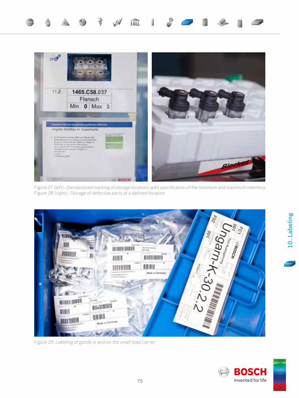
Figure 27 (left): Standardized marking of storage locations with specification of the minimum and maximum inventory Figure 28 (right): Storage of defective parts at a defined location
Figure 29: Labeling of goods in and on the small load carrier
10. L
abel
ing
76Best Practice BookletBosch 14 Q-Basics
Principle 10 | Labeling
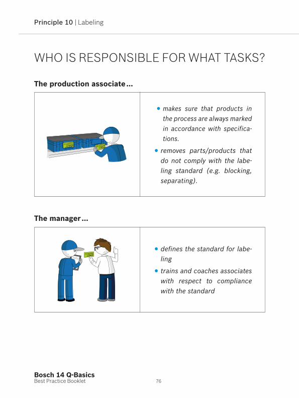
The production associate …
makes sure that products in the process are always marked in accordance with specifica-tions.
removes parts/products that do not comply with the labe-ling standard (e.g. blocking, separating).
The manager …
defines the standard for labe-ling
trains and coaches associates with respect to compliance with the standard
WHO IS RESPONSIBLE FOR WHAT TASKS?

10. L
abel
ing

Best Practice BookletBosch 14 Q-Basics
11The Rework/ScrapWhat is it about?What is my task?Answers with examples of best-practice
Principle 11 | Rework/Scrap

79
The handling of rejected parts and those to be reworked is clearly regulated.
WHAT IS THE PRINCIPLE?
WHAT DOES IT INVOLVE?The focus is on protecting the customer against the supply of defective parts. Scrap is referred to as non-conforming products. Rework is a measure carried out for a non-conforming product in order to ensure that it meets requirements.
In general, the checking or processing of a part that is removed from the standard process which is contrary to the Control Plan is referred to as rework process.
11. R
ewor
k/Sc
rap

80Best Practice BookletBosch 14 Q-Basics
Principle 11 | Rework/Scrap
Rework processes are only permitted if they are economically viable or are required, safeguarded, and approved for the purposes of maintaining delivery capability.
Rework and repair processes involve additional risks to quality, for example due to:
Confusion between products and/or parts (including mixing up of variants)
Damage to parts as a result of dismantling, repair, handling
Causing of additional errors (e.g. flashing with incorrect software)
Logistics errors (quantity difference, incorrect packaging)
Violation of the “First In, First Out” (FIFO) principle
Rework should be avoided. However, if rework is unavoidable, this should be carried out on approved equipment and restricted in terms of time and vol-ume. A concession is required when carrying out rework. Scrap can also be created.
If the rework process is required on a lasting basis, it is to be transferred to a standard process.
Scrap must be disposed of in accordance with the standard; further unauthor-ized use of these products must be prevented (e.g. through destruction).
81
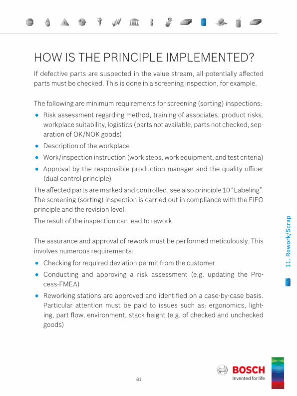
HOW IS THE PRINCIPLE IMPLEMENTED?
The assurance and approval of rework must be performed meticulously. This involves numerous requirements:
Checking for required deviation permit from the customer
Conducting and approving a risk assessment (e.g. updating the Pro-cess-FMEA)
Reworking stations are approved and identified on a case-by-case basis. Particular attention must be paid to issues such as: ergonomics, light-ing, part flow, environment, stack height (e.g. of checked and unchecked goods)
If defective parts are suspected in the value stream, all potentially affected parts must be checked. This is done in a screening inspection, for example.
The following are minimum requirements for screening (sorting) inspections:
Risk assessment regarding method, training of associates, product risks, workplace suitability, logistics (parts not available, parts not checked, sep-aration of OK/NOK goods)
Description of the workplace
Work/inspection instruction (work steps, work equipment, and test criteria)
Approval by the responsible production manager and the quality officer (dual control principle)
The affected parts are marked and controlled, see also principle 10 “Labeling”. The screening (sorting) inspection is carried out in compliance with the FIFO principle and the revision level.
The result of the inspection can lead to rework.
11. R
ewor
k/Sc
rap

82Best Practice BookletBosch 14 Q-Basics
Principle 11 | Rework/Scrap
The risk assessment and reworking stations are generally approved by the production responsible and the quality responsible (dual control principle) Note: Visual inspection processes must be capable (in accordance with procedure 7 according to [8]).
Affected parts are marked and controlled.
The FIFO principle is adhered to.
The revision level is identifiable at all times.
A work instruction with the individual work steps, work equipment, and test criteria is available.
Deployed personnel must be trained in the planned rework process.
Reworked parts undergo all serial testing corresponding to the respective state of construction.
The traceability concept includes rework.
Responsibilities and authorizations with respect to the storage and remov-al of products must be clearly regulated.

83
Figure 31: Checked goods after sorting
Figure 30: Red shelf with scrap and blocked goods
11. R
ewor
k/Sc
rap

Best Practice BookletBosch 14 Q-Basics
12The dropped PartsWhat is it about?What is my task?Answers with examples of best-practice
Principle 12 | Dropped Parts

85
Any products that fall on the floor, into the machine or cannot be clas-sified must be scrapped.
WHAT IS THE PRINCIPLE?
WHAT DOES IT INVOLVE?The quality of “dropped parts” can be affected by contamination or damage, for example. Primarily, this concerns dropped parts, but it also includes e.g.
Parts on the floor
Objects that have fallen down/over during transport or handling
Unmarked parts
Adjustment parts
Parts on/in the machine or in the line, as well as parts on tool wagons or at measuring stations, which do not belong there
12. D
ropp
ed P
arts

86Best Practice BookletBosch 14 Q-Basics
Principle 12 | Dropped Parts
The “Dropped Parts” principle includes dealing with unplanned events during the manual or mechanical handling (movement, transport) of parts (products, components, goods).
It is also about a tolerant error culture aimed at the objective analysis/review of such events. Recriminations are unacceptable and counterproductive. If the issue recurs, the associate informs the responsible manager. Recurrences are analyzed in terms of their systematic causes and improvement measures are implemented. This continuous improvement aims to largely prevent acci-dental errors or systemic “handling” problems.
Defective or unclassifiable products are scrapped. Each individual associate must comply with this standard, irrespective of organizational classification or hierarchy level. Problems are identified and risks minimized through in-creased attention and independent action by associates, as well as through the open handling of such events.
HOW IS THE PRINCIPLE IMPLEMENTED?Each part (product, component) that is not clearly marked or is located out-side the defined value stream represents a deviation from the planned serial process and must be handled according to a defined standard. This standard can include the following, for example:
Placing the part in the scrap container
Blocking
Analyzing (e.g. recurrences)
Applying principle 2 “Andon Cord”

87
Figure 32: Immediate reaction of an associate to a dropped part
Notes on implementation:
There are enough clearly marked containers (see principle 10 “Labeling”) and restricted areas available.
Every associate is familiar with the standard (e.g. from documented train-ing) and must comply with it.
Management and supervisors must act as role models in this regard. They demand compliance with the standard and monitor it regularly, e.g. in the context of process confirmations (e.g. layered process confirmation/au-dit). Variations are documented and remedial actions taken.
12. D
ropp
ed P
arts

88Best Practice BookletBosch 14 Q-Basics
Principle 12 | Dropped Parts
Technical means of avoiding dropped parts:
Manual “handling”
Ergonomic workplace design
Standardized storage system(s)
Inclined work surfaces to prevent parts from accidentally being left be-hind. Parts that are put/placed down on such surfaces slide to the floor automatically and are therefore to be scrapped.
Prevention of oil film on components
Use of handling aids (e.g. grippers, gloves)
Ergonomic orientation of parts
Mechanical “handling”
Collection grilles/trays
Vacuum monitoring in pneumatic systems
Monitoring of setting or gripping force

89
Figure 33: Ergonomic design of a part feeding system
12. D
ropp
ed P
arts

90Best Practice BookletBosch 14 Q-Basics
Principle 13 | Correct Product
Best Practice BookletBosch 14 Q-Basics
13The correct ProductWhat is it about?What is my task?Answers with examples of best-practice
Principle 13 | Correct Product
91
Only the correct product may be provided for removal and assembly.
WHAT IS THE PRINCIPLE?
WHAT DOES IT INVOLVE?To prevent customer complaints, the accidental processing or fitting of e.g. a similar-looking part instead of a correct part should be avoided. In general, it should be assumed that associates cannot or find it difficult to distinguish between parts that have only minor differences. Electronic components may even look completely identical and differ only with respect to the software stored on them.
13. C
orre
ct P
rodu
ct
92Best Practice BookletBosch 14 Q-Basics
Principle 13 | Correct Product
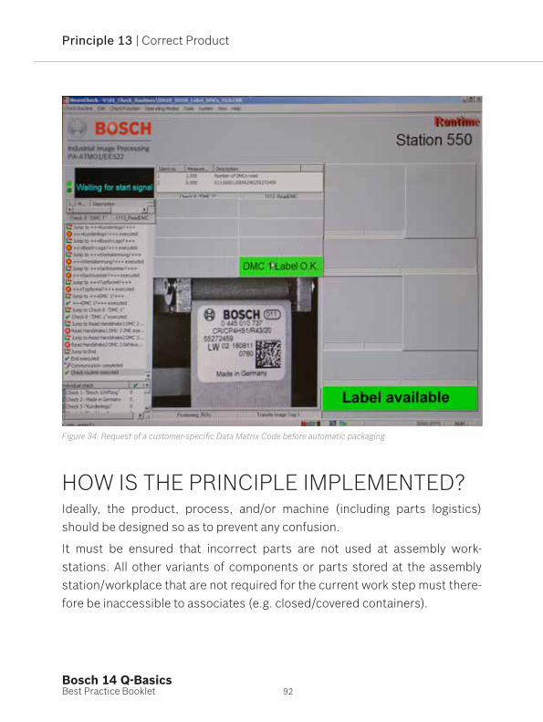
Figure 34: Request of a customer-specific Data Matrix Code before automatic packaging
HOW IS THE PRINCIPLE IMPLEMENTED?Ideally, the product, process, and/or machine (including parts logistics) should be designed so as to prevent any confusion.
It must be ensured that incorrect parts are not used at assembly work- stations. All other variants of components or parts stored at the assembly station/workplace that are not required for the current work step must there-fore be inaccessible to associates (e.g. closed/covered containers).

93
Examples of situations and activities that present an obvious risk of errors include:
Variants with only minor differences at the same location (similar types are produced on the same machine; only one assembly station for different variants)
Variant change in automatic/manual production facilities
“Matching” of coordinated parts (e.g. pistons and cylinders)
Lack of quantity control (assembly situation: 1 part with 4 bore holes requires 4 screws)
Lack of a Poka Yoke for minimizing/preventing human error (e.g. height restriction via screen)
Too many storage areas at the assembly station
Inadequate labeling of storage locations
Insertion of incorrect goods in the correct packaging
Combination of individual units in the end packaging requested by the customer
Logistics chain badly designed
Figure 35 (left): Poka Yoke solution for retaining the correct housing variants Figure 36 (right): Customer-specific color coding of a connector
13. C
orre
ct P
rodu
ct

94Best Practice BookletBosch 14 Q-Basics
Principle 13 | Correct Product
By implementing appropriate (and, where applicable, constructive) measures and regulations, the risks listed can be minimized, e.g.:
Compliance with the FIFO principle
Ensuring the distinguishability of type variants
Carrying out of a check after the “handling operation” if several variants have to be available (e.g. when parts are matched)
Secure change process: changes to products, corresponding production processes and documents (e.g. drawings, parts lists, requirements) within the overall manufacturing and logistics chain.
Integration of additional “checkers” in the system, e.g.:
Measurement system for checking a part diameter before installation
Sensor for scanning the height of an inserted disc
Camera system for 100% inspection of customer connection dimen-sions for variants
Laser scanner for barcode or Data Matrix Code
Figure 37: Determination of the component to be paired and correct selection using a pick-to-light-solution
95
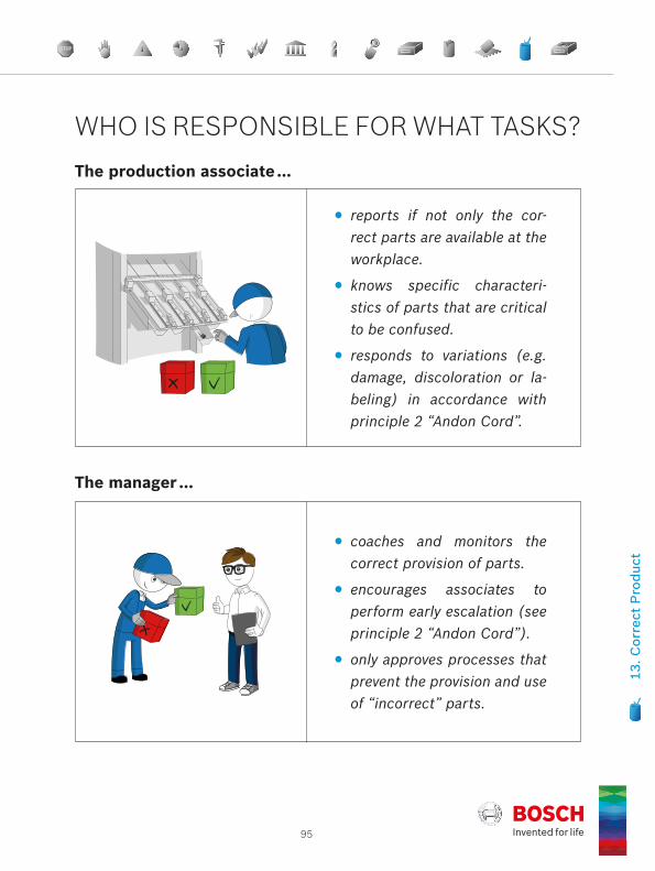
The production associate …
reports if not only the cor-rect parts are available at the workplace.
knows specific characteri-stics of parts that are critical to be confused.
responds to variations (e.g. damage, discoloration or la-beling) in accordance with principle 2 “Andon Cord”.
The manager …
coaches and monitors the correct provision of parts.
encourages associates to perform early escalation (see principle 2 “Andon Cord”).
only approves processes that prevent the provision and use of “incorrect” parts.
13. C
orre
ct P
rodu
ct
WHO IS RESPONSIBLE FOR WHAT TASKS?

Best Practice BookletBosch 14 Q-Basics
14The remaining ItemsWhat is it about?What is my task?Answers with examples of best-practice
Principle 14 | Remaining Items

97
The handling of remaining items/quantities is clearly regulated.
WHAT IS THE PRINCIPLE?
WHAT DOES IT INVOLVE?Generally, remaining items refer to remaining individual parts or units, partial quantities, or incomplete containers.
The term “Remaining Items” can refer generally to materials, raw materials, parts, components, products, semi-finished products, and packaged units in the value stream.
14. R
emai
ning
Item
s

98Best Practice BookletBosch 14 Q-Basics
Principle 14 | Remaining Items
Remaining items can occur because, e.g.: only parts/sections of a raw material or semi-finished product (e.g. rod
material) are required for small quantities a new variant is to be produced on a line the packaging unit can only be partially filled for a planned batch change the customer only ordered a partial quantity of a packaging unit
Figure 38: Labeling and standardized storage of remaining items
It should be concluded that remaining items (remaining quantities): can be confused with other similar or different units are no longer labeled or uniquely identifiable due to removal of the (outer)
packaging can be damaged in an alternative packaging that may be required are inadequately protected against environmental influences (contamina-
tion, corrosion) suffer from deterioration in quality as maximum storage times are exceeded are no longer up-to-date after a change
Remaining items must therefore be clearly marked (e.g. card carrying the part number, identifier, date, volume, name, “remaining item” in the remarks field) and safely stored (e.g. remaining items shelf).
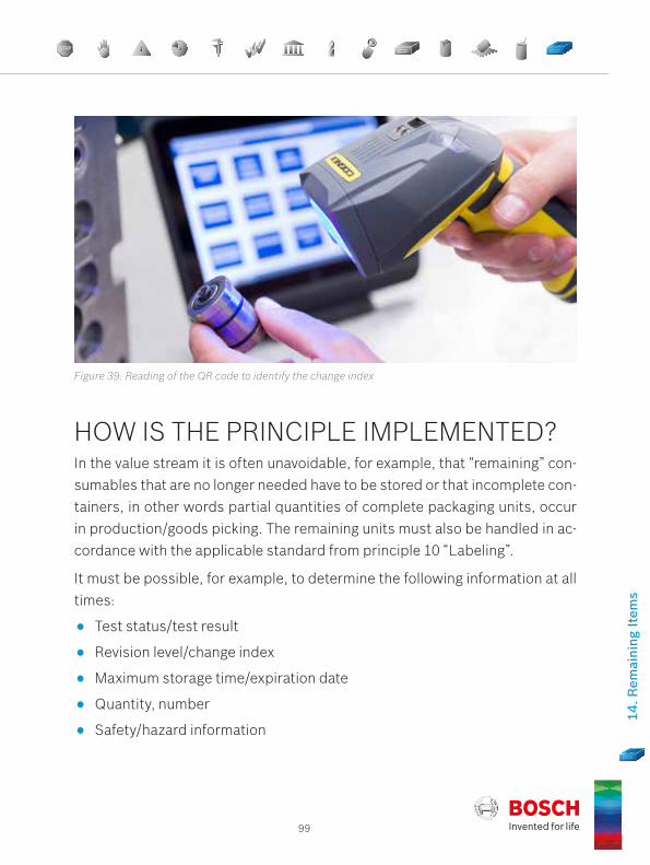
99
Figure 39: Reading of the QR code to identify the change index
In the value stream it is often unavoidable, for example, that “remaining” con-sumables that are no longer needed have to be stored or that incomplete con-tainers, in other words partial quantities of complete packaging units, occur in production/goods picking. The remaining units must also be handled in ac-cordance with the applicable standard from principle 10 “Labeling”.
It must be possible, for example, to determine the following information at all times:
Test status/test result
Revision level/change index
Maximum storage time/expiration date
Quantity, number
Safety/hazard information
HOW IS THE PRINCIPLE IMPLEMENTED?
14. R
emai
ning
Item
s

100Best Practice BookletBosch 14 Q-Basics
Principle 14 | Remaining Items
Consistent implementation of and compliance with the following rules and specifications is necessary:
Remaining quantities are placed on the shelves provided or on marked floor areas in accordance with specifications (setup instructions where applicable) and labeled with a remaining item card/part card.
It is clearly documented what happens with the remaining items in the line when a new variant is to be produced on the same line.
If the remaining items are manufactured products, it is checked whether their revision level matches that of the current series before they are used. Maximum storage times and the “FIFO” principle are also adhered to.
Requirements in relation to storage (e.g. anti-corrosion protection, parts in blister packs) and technical cleanliness are fulfilled, e.g. doors of remain-ing item shelves are closed, small load carriers are fitted with covers.
Managers request compliance with the rules for labeling and for handling remaining units, e.g. by paying particular attention to shelves and floor spaces for remaining items during 5S assessments.
Variations are documented and corresponding remedial action is defined and taken.
Avoidance of remaining items should be taken into account during process design, e.g. with coordinated container and batch sizes.
There is a systematic for monitoring storage times and revision levels, in which remaining items are considered.
The “First In, First Out” (FIFO) principle is always considered when storing or removing remaining items. Maximum storage times must not be exceeded.If the products are not yet in their final packaging, particular care should be taken with orderliness and cleanliness.

14. R
emai
ning
Item
s

102Best Practice BookletBosch 14 Q-Basics
Assessment
A

103
The maturity level of the Q-Basics’ implementation is determined with the help of an assessment. You can find the assessment questionnaire on the website purchasing.bosch.com. Basis for the assessment is the list of criteria and sub-criteria in the chapters 1 – 14.
Assessment criteria: 3 – 5 sub-criteria are allocated to each principle. A sub-criterion is rated by one of the levels 0, 1, 2 or 3.
Legend:
red: 0 ≤ rating < 1yellow: 1 ≤ rating < 2green: 2 ≤ rating ≤ 3
ASSESSMENT
Meaning:
If there are any topical (period under review is 6 months) complaints (inci-dents at the customer’s site) which are verifiably caused by violation of a principle, and still no demonstrably effective corrective actions taken, this principle is assessed by 0.
The overall assessment result is shown by the radar chart (screenshot radar chart)
Optionally, an overall numeric result can be indicated using the arithmetic mean (sum of the principles’ ratings divided by 14), as a value between 0 and 3.
0 = not or merely rudimentary (no) | 1 = largely | 2 = completely (yes) | 3 = Good Practice

Glossary
104Best Practice BookletBosch 14 Q-Basics

105
5S 5S is a method for the gradual improvement of order and cleanliness in the workplace. 5S supports the continuous improvement process and contributes to the reduction of re-source requirements (e.g. raw materials, energy, space) and costs. The workplace becomes clearer.
The 5 “S” stand for: Sort, Set in order, Shine, Standardize, Sustain
8D The 8D method is a procedure for problem-solving in 8 steps (8 disciplines).
D1: Establishing problem-solving team/projectD2: Problem descriptionD3: Containment actions D4: Cause and effect analysis D5: Defining corrective actions and proving effectiveness D6: Implementing corrective actions and tracking effectivenessD7: Establishing preventive actions D8: Final meeting
All 8 steps must be performed during problem-solving.
Adjustment Parts
Parts that are created during a setup procedure on a ma-chine, but are not intended for delivery to customers.
AIAG Automotive Industry Action Group
GLOSSARY

106Best Practice BookletBosch 14 Q-Basics
Glossary
Andon Cord Term derived from Japanese for a system (e.g. rip cord, switch, systematic) enabling an associate to stop installa-tion device.
Assessment Approach to assess the maturity level of the Q-Basics imple-mentation.
Audit (Lat. hearing): Systematic and independent investigation of the actual state e.g. of a quality management system, produc-tion process, or product in comparison to the requirements
Checker Not a normative term. Generally refers to an automatic test-ing system, the purpose of which is to ensure or support compliance with process parameters (process characteris-tics), and which is used to prevent or detect errors in the process flow. Examples of technical implementations are:
Variations e.g. from dimensions, shape, or orientation are detected by sensors and switches.
The process only continues when a specified counter reading (number of parts or individual steps) is reached.
The process can only be executed in a predefined se-quence.
EDP Electronic Data Processing
ESD Electrostatic Discharge
FIFO First In, First Out. Principle according to which goods that were stored first are also removed first.
FMEA The Failure Mode and Effects Analysis is an analytical meth-od for preventive quality assurance. It helps in determining

107
and evaluating risks in good time and in defining and initiat-ing suitable measures for minimizing risk. The FMEA is im-plemented in 5 steps: structural analysis, functional analy-sis, error analysis, measure analysis, and optimization.
GB/QM Division/Head of Quality Management (in German: Ge-schäftsbereich/Leitung Qualitäts-Management)
HSE Health, Safety, Environment
IATF 16949 Quality management standard developed by the Internati-onal Automotive Task Force; IATF is a group of automotive manufacturers and their respective trade associations.
IPN International Production Network
ISO International Organization for Standardization. Worldwide union of national standardization institutes for the develop-ment of international standards.
LPC Layered Process Confirmation. Planned and systematic target/actual comparison of work standards at specific workplaces in the value stream. The aim of process confirmation is to:
Identify deviations from work standards Analyze causes of deviations Derive measures Examine the effectiveness of the measures
LPC is performed at all management levels – from team leader to plant manager – and represents a control group that leads to the continuous improvement of work stand-ards and therefore indirectly to the improvement of results.

108Best Practice BookletBosch 14 Q-Basics
Glossary
MAE Machinery And Equipment
MAT-Label Labeling standard developed jointly by a number of compa-nies (including Bosch) for ensuring traceability in automo-tive industry supply chains.
Measure- ment/Test Equipment
See DIN 1319-2. Note: Due to inadequate standard specifica-tions, the term “measurement/test equipment” is applied here in a broader sense and includes test equipment that does not nec-essarily determine results from the measurement of variables, but through other means such as quantification, classification, or verification of the presence or absence of a characteristic
MRC Managerial Root Cause. Reasons for the interaction of caus-ing conditions in the management system and business pro-cess (systemic root cause) as well as in personnel and in the organization (cause in management).
OEE Overall Equipment Effectiveness. Overall effectiveness (with respect to availability, performance, quality) of an installation
OK/NOK OK/Not OK. In normative language: “conform”/“non-conform” (see ISO 9000)
PDCA-Cycle Sequence of activities for improving concepts, processes, methods, or procedures.Plan: begins with the planning of a project, procedure, prob-lem solving Do: followed by implementation of the planned measure(s),Check: verification of the results, Act: and ending with successful optimization with standard-ization.
109
Poka Yoke (From Japanese). Method to avoid human mistakes, result-ing defects and passing on of non-conforming parts
Process Data Sheet
Document with all relevant parameters for process manage-ment
Process Parameters
Option(s) for influencing a process
QCC Quality Control Chart. Form for the compilation and graph-ical representation of measured values and statistical pa-rameters and for comparing them with predefined control limits (see SPC).
RFID Radio Frequency Identification. Transmitter-receiver sys-tem for the contact-free identification of objects using elec-tromagnetic waves
Service Life Maximum value of a service life measurement which, until reached, means you can work with a tool without the occur-rence of significant signs of wear.
Service Life Measure
Quantity for the quantitative description of a service life, e.g.:
Number of parts produced with a tool Number of strokes, shots, rotations, bore holes, welds Number of shifts Operating time (in hours, days, weeks) Cutting length (in meters, kilometers)
Setup Plan Instructions for the setup of a machine or tool (e.g. for a set-up procedure), with concrete specification of required pro-cess characteristics, such as temperature, pressure, flow rate, joining force

110Best Practice BookletBosch 14 Q-Basics
Glossary
Screening Inspection
A screening inspection is a 100% inspection in which ob-jects/units are checked (visually or using technical aids) with respect to defined characteristics and separated ac-cording to the test result (e.g. conforming/non-conforming).
Source, Make, Deliver
Short descriptions for the main sections of the value stream (source/purchase, production, delivery)
SPC Statistical Process Control: Procedure for the regulation or control of a production process on the basis of statis-tical methods. SPC requires the management of a quality control chart in conjunction with a control group. Process or product data are recorded and analyzed. In the event of unwanted process results, appropriate measures are taken to achieve the desired result.
SQE Supplier Quality Engineer
Standard The term “standard” can have a number of meanings, including:1. National or international norm (e.g. DIN, ISO)2. Standard or measure for measurement processes3. Written specification, e.g. central directive, process in-struction, work instruction4. Written or verbally agreed rules of conduct or procedureIn this booklet the term is mainly used in the context of meanings 3 and 4.

111
TPM Total Productive Maintenance. Autonomous, planned, and preventive maintenance of machinery and equipment. We aim to guarantee optimum utilization of production facili-ties through preventive measures for maintenance, service, and inspection.
TRC Technical Root Cause. Reasons for admitting the interac-tion of the conditions causing the problem/basic problem, which is proven by logical (why?) and functional (how?) re-lationships.

List of References
112Best Practice BookletBosch 14 Q-Basics

113
[1] ISO 9001 Quality Management Systems — Requirements
[2] ISO 22514-1 Statistical methods in process management – Capability and performance – Part 1: General principles and concepts (ISO 22514-1:2014)
[3] IATF 16949 Quality management system requirements for automotive production and relevant service parts organizations
[4] VDA 6.3 Quality Management in the Automotive Industry – Product Audit
[5] Value Stream Q-Basics (see Internet)
Link to Q-Basics download:
http://purchasing.bosch.com/en/de/quality_innovation/quality_manage-ment/requirements/29_wertstrom_q_basics/wertstrom_q_basics.html
Assessment questionnaire and further documents:
Please see website purchasing.bosch.com under “Value Stream Q-Basics”
Booklet Series “Quality Management in the Bosch Group”
[6] Booklet 7: Statistical Process Control
[7] Booklet 9: Machine and Process Capability
[8] Booklet 10: Capability of Measurement and Test Processes
[9] Booklet 16: Problem Solving
Software:
[10] qs-STAT: http://www.q-das.de/en/software/qs-stat/
LIST OF REFERENCES

Appendix
114Best Practice BookletBosch 14 Q-Basics

115
APPENDIX: THE 14 QUALITY PRINCIPLESCustomer complaints are communicated within the production site and, if possible, displayed directly at the station in question. Using problem-solving techniques, they are processed in a fast and sys-tematic manner. The supply chain is promptly informed.
A STOP sign process with all of the 8D elements is displayed on the shop floor. A standard review process involving the pro-duction/logistics management and quality management takes place. The decision to end the STOP sign process is taken by production/logistics management after a review of the meas-ures’ effectiveness. It is necessary to ensure that customer com-plaints are communicated quickly over the entire supply chain from supplier to customer.
1. Stop Sign
In the event of deviations in quality or if control limits are exceeded in the value stream (source, make, deliver), the employee needs to stop the process or escalate.
There is a systematics (e.g. Andon cord, blocking/escalation process, reaction plan) in place that allows the operator, if he notices deviations, to choose to prevent the passing-on / further processing of parts (by stopping/blocking) and to escalate im-mediately. Deviations can occur if control limits are exceeded, and also based on subjective observations (for example, the power screwdriver is not running smoothly, material has been funneled into the incorrect chute, or the associate is not working to the standards set, label badly readable or incomplete). After stopping the system there needs to be a well-defined process governing the restarting and release of the system by shop floor management.
2. Andon Cord

116Best Practice BookletBosch 14 Q-Basics
Appendix
Safety, health, production, and inspection instructions are com-plied with. 5S standards are put in place and observed.
The work, production and inspection instructions are clearly vis-ible at every work place. A consistent set of symbols is available. If appropriate, the right/left hand movement becomes evident from the instruction. The failure modes from the FMEA and spe-cial characteristics from the control plan are taken into account. Detailed photos support the process. There is a feedback loop in place that ensures the consistency of the control plan, FMEA, and directions. Health and safety instructions are carried out according to the plan. Participation is compulsory and will be documented. All deviations regarding safety, work, production and inspection instructions or safety and health briefings shall be resolved using the 8D method.
3. Instructions
The target values/tolerances for all stated process parameters are observed.
All process parameters (e.g. press-in force, maximum storage time) that affect product quality are clearly defined and system-atically checked on basis of the control plan. All required inspec-tion criteria are implemented according to specification. Process validations are performed to determine whether target values/tolerances of the defined parameters have been observed. Devi-ations are systematically recorded and eliminated permanently.
4. ProcessParameters
Measuring and test equipment is defined, and monitoring intervals are observed.
The type of measuring and test equipment (e.g. gages, scanners) incl. auxiliary means and its uses is defined for all processes in the control plans. All measuring and test equipment is calibrat-ed and only utilized within the permissible inspection interval.
5. Measurement/Test Equipment

117
The “Check the checker” principle is applied, and the “checker’s” suitability is ensured.
The suitability of processes used to prevent or detect errors (e.g. camera-monitored processes, sensor-based measure-ments, inspection processes, scanning of labels) needs to be checked according to a predefined standard. Possible errors, such as loading the incorrect camera software/testing program or incorrect MAE software versions/updates, entry of wrong in-spection parameters, or improper sensor calibration, need to be prevented by carrying out the inspection. These inspection processes need to be evaluated using appropriate methods (e.g. FMEA). “Check the checker” parts are included in the con-trol of inspection measurement and test equipment. Generally speaking, mistake-proofing is always preferable to error detec-tion (e.g. Poka Yoke).
6. Check the Checker
The inspection status of the measuring and test equipment is recognizable at its place of usage (e.g. marked by inspection certificate sticker, tag). In case of suspected malfunctions/dam-ages this has to be notified.
A maintenance standard is installed and observed at every station.
The four-pillar TPM model, particularly the autonomous and pre-ventative maintenance, is instituted at every machine, device, facility. This contains both the roles and responsibilities for pro-duction and the supporting areas. Systematic damage and dirt build-up on machinery and device components (e.g. workpiece carriers, storage facilities, stackers) need to be consistently analyzed, recognized, and remedied. The restart after mainte-nance (see principle 9) has to consider potential influences on product quality.
7. Total Pro- ductive Main-
tenance (TPM)
118Best Practice BookletBosch 14 Q-Basics
Appendix
Restart after disruptions is clearly regulated for all machinery and equipment.
Each disruption to the continuous production process (tool change, setup, break, shift change, maintenance, power failure, upgrade, MAE software update, parameter changes) presents a potential risk to quality. A predefined standard for post-re-start is therefore necessary. This should detail how to deal with products in the process after a disruption. All devices have been inspected according to a defined standard for quality risks in connection with disruptions (for example, an unplanned dis-ruption to the welding process, the injection molding process stops unexpectedly, a product remains in thermal treatment for too long, the silicone bead is exposed to the air for too long). The standard also includes the analysis of critical wear parts (for example, drill bits or welding electrodes). Following longer disruptions (e.g. station upgrade, control software update), it is necessary to newly release the process. Setup processes need to be evaluated using appropriate methods (e.g. FMEA).
9. Restart
Each tool has a defined service life; the current status must be recognizable. A quality evaluation must be carried out during in-stallation, removal or disassembly.
Wear-prone tools with influence on product quality (e.g. pro-cessing, assembly, molding tools, workpiece fixtures/carriers) have been recorded and are controlled (e.g. defined service lives, control on basis of product characteristics, inspection during maintenance). A warning system promptly displays when tools need to be replaced or serviced. Each tool needs to be inspected when installed, removed or disassembled to check for recognizable abnormalities (e.g. damage/wear and tear). In case of deviations, it is necessary to follow measures to ensure product quality is maintained.
8. Tools

119
Products and containers are labeled according to the set standard.
In the entire value stream products must always have a clear status. Therefore, a consistent identification/labeling concept at the production site and adherence to the following rules are necessary.
Within the production flow:Filled boxes must always be labeled (e.g. card, sticker, RFID).
Outside the production flow:White card with a red diagonal stripe: Product blockedGreen card: Product after additional test back in production
flow and in good conditionYellow card: Product for reworkRed card: Product is scrapWhite card: Product in good condition Rejected parts in the red box (scrap container).Red boxes must be secured against unintended access (e.g. by locking them, covering, spatial separation, covering during transport).Containers for rejects must be emptied in the line with stand-ards and the parts must be analyzed. Parts at the analysis station are spatially separated from the production flow and clearly identified. Only parts with the same status in the same container. No good parts in the red box. A blocking process for production and logistics is defined. Products are protected against environmental influences (e.g. contamination) in line with regulations.
Note: The aforementioned color codes are binding in the Bosch Group. Cards, stickers, tags, RFID tags, containers, etc. can be used to mark products. The status “Blocked” is signaled by the color “Red”.
10. Labeling

120Best Practice BookletBosch 14 Q-Basics
Appendix
The handling of rejected parts and those to be reworked is clearly regulated.
Basic rule: Inspection or processing of a part that, contrary to the control plan, is removed from the standard process, is re-work.
If rework is unavoidable it takes place on an approved device and is limited in time or quantity. A concession is necessary. A rework process that is permanently required must be trans-ferred to a standard process.
Sorting inspections require a
risk assessment,
description of the workplace,
work/inspection instruction.
They are approved by the responsible for production and the re-sponsible for quality. Scrap must be disposed of in line with the standard and unauthorized further use of these products must be prevented (for example, by destroying them).
11. Rework/ Scrap
Any products that fall on the floor, into the machine or cannot be classified must be scrapped.
Each individual employee must adhere to this standard regard-less of what part of the organization he/she belongs to or his/her position within the company. In case of repeated occurrence the shop floor management must be notified by the employee. Repeat events are analyzed regarding systematic causes and im-provement measures are implemented. Non-conforming prod-ucts or products that cannot be classified must be scrapped according to procedure.
12. Dropped Parts

121
Only the correct product may be provided for removal and assembly.
Only the correct product may be available to the associate at the time of assembly. All other variants or versions that are stored at the assembly station/workplace must not be accessible to the employee (e.g. closed/covered containers). If several variants need to be available (e.g. mating of parts), an inspection takes place after the handling operation.
13. Correct Product
The handling of remaining items/quantities is clearly regulated.
Remaining quantities must be clearly labeled (e.g. white card with part number, number of units, date, name, remaining quan-tity in the comments field) and stored securely (e.g. shelf for remaining items). The “First In, First Out” principle must be ob-served. Maximum storage times must not be exceeded. Close attention must be paid to ensure tidiness and cleanliness as the goods have yet to be placed in the final packaging. The quantity of remaining items must be taken into consideration with regard to engineering change requests.
14. Remaining Items

Index
122Best Practice BookletBosch 14 Q-Basics
123
5S . . . . . . . . . . . . . . . . . . . . . . . 23, 27, 738D . . . . . . . . . . . . . . . . . . . . . . . . . . 12, 14Adjustment Parts . . . . . . . . . . . . . . . . 85Andon Cord . . . . . . . . . . . . . . . . . . . . . 19Barcode . . . . . . . . . . . . . . . . . . . . . . . . 94Blocking . . . . . . . . . . . . . . . . . . . . . . . 86Blocking Process . . . . . . . . . . . . . . . . 72Calibration . . . . . . . . . . . . . . . . . . . . . 39Capability . . . . . . . . . . . . . . . . . . . . . . 39Checker . . . . . . . . . . . . . . . . . . 43, 67, 94Color Code . . . . . . . . . . . . . . . . . . . . . 73Conformity Evaluation . . . . . . . . . . . 38Containment Actions . . . . . . . . . . . . 14Control Limits . . . . . . . . . . . . . . . . 19, 21Control Plan . . . . . . . . . . . . . . . . . 25, 33Correct Product . . . . . . . . . . . . . . . . 91Data Matrix Code . . . . . . . . . . . . . . . . 94Disruption . . . . . . . . . . . . . . . . . . . . . . 94Dropped Parts . . . . . . . . . . . . . . . . . . 85ESD . . . . . . . . . . . . . . . . . . . . . . . . . . . 74FIFO . . . . . . . . . . . . . . . . 80, 82, 94, 100Handling . . . . . . . . . . . . . . . . . . . . 86, 88Inspection Instruction . . . . . . . . . . . . 25Instructions . . . . . . . . . . . . . . . . . . . . 23Labeling . . . . . . . . . . . . . . . . . . . . . . . 71LPC . . . . . . . . . . . . . . . . . . . . . . . . . 8, 87MAE . . . . . . . . . . . . . . . . . . . . . . . . . . . 54Maintenance . . . . . . . . . . . . 52, 53, 54Matching . . . . . . . . . . . . . . . . . . . . . . . 93MAT-Label . . . . . . . . . . . . . . . . . . . . . . 73Measurement/Test Equipment . . . . 37MRC . . . . . . . . . . . . . . . . . . . . . . . . . . . 14OEE . . . . . . . . . . . . . . . . . . . . . . . . . . . 55
OPL . . . . . . . . . . . . . . . . . . . . . . . . . . . 34Poka Yoke . . . . . . . . . . . . . . . . . . . . . . 93Process Characteristics . . . . . . . . . 32Process Data Sheet . . . . . . . . . . . . . . 33Process Parameters . . . . . . . . . . . . . 31Product Characteristic . . . . . . . . . . 38Production Process Approval . . . . . 59Qualification Matrix . . . . . . . . . . . . . 21Quality Assessment . . . . . . . . . . . . . 58Reaction Plan . . . . . . . . . . . . . . . . . . . 19Remaining Items . . . . . . . . . . . . . . . . 97Restart . . . . . . . . . . . . . . . . . . . . . 65, 67Rework . . . . . . . . . . . . . . . . . . . . . . . . 79RFID . . . . . . . . . . . . . . . . . . . . . . . . . . . 73Risk Assessment . . . . . . . . . . . . . 34, 81Sample Parts . . . . . . . . . . . . . . . . . . . 73Scrap . . . . . . . . . . . . . . . . . . . . . . . . . . 79Service Life . . . . . . . . . . . . . . . . . . 57, 59Setup Plan . . . . . . . . . . . . . . . . . . . . . 33Setup Processes . . . . . . . . . . . . . . . . 66SPC . . . . . . . . . . . . . . . . . . . . . . . . 35, 62Stop Button . . . . . . . . . . . . . . . . . . . . 21Stop Sign . . . . . . . . . . . . . . . . . . . . . . 11Supply Chain . . . . . . . . . . . . . . . . . . . 11Tag . . . . . . . . . . . . . . . . . . . . . . . . . . . . 14Testing System . . . . . . . . . . . . . . . . . . 46Tools . . . . . . . . . . . . . . . . . . . . . . . 57, 62TPM . . . . . . . . . . . . . . . . . . . . . . . . . . . 51Traceability . . . . . . . . . . . . . . . . . . . . . 82TRC . . . . . . . . . . . . . . . . . . . . . . . . . . . 14Visual Inspection . . . . . . . . . . . . . . . . 39Warning System . . . . . . . . . . . . . . . . 62Wrong Decision . . . . . . . . . . . . . . . . . 38
INDEX


Robert Bosch GmbH | CP/TSC-EU | PO Box 30 02 20 | 70442 Stuttgart | GERMANY
Version 2.0