Visual control of a robotic hand
6
Visual Control of a Robotic Hand Ignazio Infantino 1 Antonio Chella 1,2 Haris Džindo 1 Irene Macaluso 1 1 ICAR-CNR sez. di Palermo Viale delle Scienze, edif. 11, 90128, Palermo, Italy (infantino, dzindo, macaluso)@pa.icar.cnr.it 2 DINFO Università di Palermo Viale delle Scienze, 90128, Palermo, Italy [email protected] Abstract -- The paper deals with the design and implementation of a visual control of a robotic system composed of a dexterous hand and stereo cameras. The aim of the proposed system is to reproduce the movements of a human hand in order to learn complex manipulation tasks. A novelty algorithm for a robust and fast fingertips localization and tracking is presented. Moreover, a simulator is integrated in the system to give useful feedbacks to the users during operations, and provide robust testing framework for real experiments (see video). I. INTRODUCTION The control of robotic systems has reached a high level of precision and accuracy, but often the high complexity and task specificity are limiting factors for large scale uses. Today, robots are requested to be both “intelligent” and “easy to use”, allowing a natural and useful interaction with human operators and users. In this paper, we deal with the (remote) control of an anthropomorphic robotic hand: our approach is to provide a Human-Computer-Interface [10][17][15] based on natural hand gesture imitation of the operator showing his hand [8]. Different methods have been proposed to capture human hand motion. Rehg and Kanade [11][12] introduced the use of a highly articulated 3D hand model for the tracking of a human hand [13][14]. For tracking, the axes of the truncated cylinders that are used to model phalanges, are projected onto the image, and local edges are found. Fingertip positions are measured through a similar procedure. A nonlinear least squares method is used to minimize the error between the measured joint and tip locations and the locations predicted by the model. The system runs in real-time, however, dealing with occlusions and handling background clutter remains a problem. Heap and Hogg [6] used a deformable 3D hand shape model. The hand is modeled as a surface mesh which is constructed via PCA from training examples. Real-time tracking is achieved by finding the closest possibly deformed model matching the image. In [16], Cipolla and Mendoca presented a stereo hand tracking system using a 2D model deformable by affine transformations. Wu and Huang [19] proposed a two- step algorithm to estimate the hand pose, first estimating the global pose and subsequently finding the configuration of the joints. Their algorithm relies on the assumption that all fingertips are visible. Our method uses fingertips as features, considering each finger except the thumb as planar manipulator, and starting from this hypothesis we compute inverse kinematics to control the robotic hand. This paper is structured as follows: section II describes the whole system and the experimentation setup; section III deals with the fingertip localization and the tracking on image sequence; section IV concerns the control of robotic hand by inverse kinematics computation; section V reports the details about various experimentations done; finally, some conclusions and future work are drawn in section VI. II. THE IMPLEMENTED SYSTEM DESCRIPTION Our proposal deals with the design and implementation of a visual control of a robotic system composed by a dexterous anthropomorphic hand (the DIST-Hand [1]) and calibrated stereo cameras. The aim of the present work is to reproduce real-time movements of a human hand in order to learn complex manipulation tasks. The human hand is placed in front of the stereo couple. A black panel is used as background and illumination is controlled. Fingertips and wrist are extracted at each frame and their 3D coordinates are computed by a standard triangulation algorithm. Given a hand model, inverse kinematics is used to compute the joint angles which are translated to suitable commands sent to the DIST-Hand controller. The system (see figure 1) is composed by some common modules that work in parallel on the two flows of images sourcing from the stereo rig: 1) image pre-processing operation (noise filtering, tresholding, edge detecting); 2) the fingertip tracking following the first estimation; 3) fingertip localization on image based on previous position. The coordinates of the fingertips are the input of the other software modules responsible of: 1) 3D coordinate computation; 2) inverse kinematics; 3) actuator commands computation. III. FINGERTIP LOCALIZATION AND TRACKING This section deals with the localization of the fingertips in long image sequences. In order to achieve real-time
Transcript of Visual control of a robotic hand

Visual Control of a Robotic Hand
Ignazio Infantino1 Antonio Chella1,2 Haris Džindo1 Irene Macaluso1
1ICAR-CNR sez. di Palermo Viale delle Scienze, edif. 11,
90128, Palermo, Italy (infantino, dzindo, macaluso)@pa.icar.cnr.it
2DINFO Università di Palermo
Viale delle Scienze, 90128, Palermo, Italy
Abstract -- The paper deals with the design and implementation of a visual control of a robotic system composed of a dexterous hand and stereo cameras. The aim of the proposed system is to reproduce the movements of a human hand in order to learn complex manipulation tasks. A novelty algorithm for a robust and fast fingertips localization and tracking is presented. Moreover, a simulator is integrated in the system to give useful feedbacks to the users during operations, and provide robust testing framework for real experiments (see video).
I. INTRODUCTION
The control of robotic systems has reached a high level of precision and accuracy, but often the high complexity and task specificity are limiting factors for large scale uses. Today, robots are requested to be both “intelligent” and “easy to use”, allowing a natural and useful interaction with human operators and users. In this paper, we deal with the (remote) control of an anthropomorphic robotic hand: our approach is to provide a Human-Computer-Interface [10][17][15] based on natural hand gesture imitation of the operator showing his hand [8]. Different methods have been proposed to capture human hand motion. Rehg and Kanade [11][12] introduced the use of a highly articulated 3D hand model for the tracking of a human hand [13][14]. For tracking, the axes of the truncated cylinders that are used to model phalanges, are projected onto the image, and local edges are found. Fingertip positions are measured through a similar procedure. A nonlinear least squares method is used to minimize the error between the measured joint and tip locations and the locations predicted by the model. The system runs in real-time, however, dealing with occlusions and handling background clutter remains a problem. Heap and Hogg [6] used a deformable 3D hand shape model. The hand is modeled as a surface mesh which is constructed via PCA from training examples. Real-time tracking is achieved by finding the closest possibly deformed model matching the image. In [16], Cipolla and Mendoca presented a stereo hand tracking system using a 2D model deformable by affine transformations. Wu and Huang [19] proposed a two-step algorithm to estimate the hand pose, first estimating the global pose and subsequently finding the configuration of the joints. Their algorithm relies on the assumption that all fingertips are visible.
Our method uses fingertips as features, considering each finger except the thumb as planar manipulator, and starting from this hypothesis we compute inverse kinematics to
control the robotic hand. This paper is structured as follows: section II describes the whole system and the experimentation setup; section III deals with the fingertip localization and the tracking on image sequence; section IV concerns the control of robotic hand by inverse kinematics computation; section V reports the details about various experimentations done; finally, some conclusions and future work are drawn in section VI.
II. THE IMPLEMENTED SYSTEM DESCRIPTION
Our proposal deals with the design and implementation of a visual control of a robotic system composed by a dexterous anthropomorphic hand (the DIST-Hand [1]) and calibrated stereo cameras. The aim of the present work is to reproduce real-time movements of a human hand in order to learn complex manipulation tasks. The human hand is placed in front of the stereo couple. A black panel is used as background and illumination is controlled. Fingertips and wrist are extracted at each frame and their 3D coordinates are computed by a standard triangulation algorithm. Given a hand model, inverse kinematics is used to compute the joint angles which are translated to suitable commands sent to the DIST-Hand controller. The system (see figure 1) is composed by some common modules that work in parallel on the two flows of images sourcing from the stereo rig:
1) image pre-processing operation (noise filtering, tresholding, edge detecting); 2) the fingertip tracking following the first estimation; 3) fingertip localization on image based on previous position.
The coordinates of the fingertips are the input of the other software modules responsible of:
1) 3D coordinate computation; 2) inverse kinematics; 3) actuator commands computation.
III. FINGERTIP LOCALIZATION AND TRACKING
This section deals with the localization of the fingertips
in long image sequences. In order to achieve real-time

performances state-space estimation techniques are used to reduce the search space from the full camera view to a smaller search window centered on the prediction of the future position of the fingertips. In the following, a novel algorithm is proposed to detect the fingertip position inside the search window.
Image Preprocessing
Module
Left Image
Right Image
xreal
xpred
Kalman Filter Module
Fingertip Extraction Module
3D Coordinate Computation
Module
I*
X
Inverse Kinematics
Module
Human-To-Robot Mapping
Module
Qhuman
To the communication units
Qrobot
Initial estimates
Fig.1 The system architecture: two parallel set of procedures perform separately the estimation of the fingertips on right and left images; the
coordinates extracted are the input of the procedures responsible for the control of the robotic hand.
The visual servoing procedure starts with a preliminary setup phase, based on various image processing operations. The procedure individuates the hand/arm on image, compares it with robotic one and calculates exact size ratios. Relevant features are tracked on image sequences, and reconstructed in a three-dimensional space, using standard computer vision algorithms [3]. These features are used as a guide to perform 3D reconstruction of the simulated arm/hand, and real system positioning. The reconstructed movements are reproduced both by the simulator and the robotic system in real time. A. Fingertip Tracking
In this section we are involved with prediction of feature points in long image sequences. If the motion of the observed scene is continuous, as it is, we should be able to make predictions on the motion of the image points, at any time, on the basis on their previous trajectories. Kalman filter [1] [16] is the ideal tool in such tracking problems.
The motion of a fingertip at each time instance (frame) can be characterized by its position and velocity. For a feature point, define the state vector at time tk as
x(k)= [ r(k) c(k) vr(k) vc(k)]T
where (r(k), c(k)) represent the fingertip pixel position at kth frame, and (vr(k) , vc(k)) be its velocity in r and c directions.
a
b
c
Fig.2 (a) Initial hand configuration used to calculate the first estimation of
the fingertip positions; (b) three points (yellow squares) with high correlation response individuate a group and provide a fingertip candidate computed as centroid of such a group (red arrow); (c) circular templates
used to search fingertips.
Under the assumption that a fingertip moves with constant translation over the long sequence and a sufficiently small sampling interval (T), the plant equation for the recursive tracking algorithm can be written as
X(k+1)=Ax(k)+w(k) Where
1 0 T 0 0 1 0 T A = 0 0 1 0
0 0 0 1
and the plant noise w(k) is assumed to be zero mean with covariance matrix Q(k).
For each fingertip, the measurement used for the corresponding recursive tracking filter at time tk is the image plane coordinates of the corresponding point in the kth image. Thus the measurement is related to the state vector as:
Z(k) = Hx(k) + v(k) where
0 1 0 0 H = 0 0 1 0
and the measurement noise v(k) is assumed to be zero mean with covariance matrix R(k).
After the plant and measurement equations have been formulated, the Kalman filter can be applied to recursively estimate the motion between two consecutive frames and track the feature point.
Assuming that the trajectory of a feature point has been established up to the kth frame of a sequence, we describe procedures for estimating the in-frame motion between the kth and (k+1)th frames. First, for a fingertip, the predicted location of its corresponding point z(k+1|k) is computed by the KF. Subsequently, a window centering at z(k+1|k) is extracted from the (k+1)th image and the fingertip extraction algorithm is applied to the window to identify salient feature points as described in the next section. The same process is repeated for each fingertip. The initial fingertips and wrist coordinates are computed by assuming the hand is placed as in figure 2.a. Under such hypothesis it is straightforward to compute the fingertip coordinates. B. Fingertip Extraction
This subsection describes a novelty algorithm to perform robust and fast localization of the fingertips. Once a search window is determined for each fingertip, the feature point is searched for within that window. The overall shape of a human fingertip can be approximated by a semicircle. Based on this observation, fingertips are searched for by template matching with a set of circular templates as shown in figure 2.c. Ideally, the size of the templates should differ for different fingers and different users. However, our experiments showed that fixed window size works well for various users. This result has been proven by other authors [9]. We choose a square of 20x20 pixels with a circle whose radius is 10 pixels as a template for normalized correlation in our implementation.
In order to find meaningful data we first perform an adaptive threshold on the response images to obtain distinct regions. For each correlation we select the points with the highest matching scores (usually 2-3) which lies in unconnected regions of the thresholded image.
Subsequently, near responses of different correlations are grouped. We select the groups characterized by the highest number of points associated and the centroid of such groups are used to compute the fingertip candidates. In order to calculate those candidates, we must combine the information provided by each point in the group. However, only the points corresponding to semi-circle correlation responses are used in this stage.
Each point is associated with a vector whose direction depends on the orientation of the corresponding semi-circle (i.e. right - 0°, up - 90°, and so on). Its module is given by the correlation matching score. The direction in which the fingertip candidate should be searched is computed as the angle formed by the vector sum of such vectors (see figure 2.b). Therefore, the fingertip candidate coordinate for each group lies on the line through the previously computed centroid and whose direction is given by the above procedure. We use techniques of data association based on the previous measurements and predicted state to choose the correct fingertip among the selected candidates.
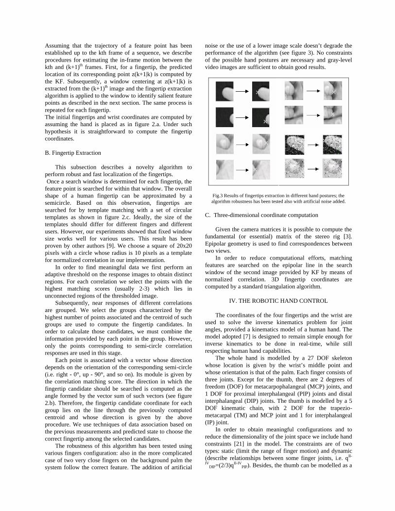
The robustness of this algorithm has been tested using various fingers configuration: also in the more complicated case of two very close fingers on the background palm the system follow the correct feature. The addition of artificial
noise or the use of a lower image scale doesn’t degrade the performance of the algorithm (see figure 3). No constraints of the possible hand postures are necessary and gray-level video images are sufficient to obtain good results.
Fig.3 Results of fingertips extraction in different hand postures; the algorithm robustness has been tested also with artificial noise added.
C. Three-dimensional coordinate computation
Given the camera matrices it is possible to compute the fundamental (or essential) matrix of the stereo rig [3]. Epipolar geometry is used to find correspondences between two views.
In order to reduce computational efforts, matching features are searched on the epipolar line in the search window of the second image provided by KF by means of normalized correlation. 3D fingertip coordinates are computed by a standard triangulation algorithm.
IV. THE ROBOTIC HAND CONTROL
The coordinates of the four fingertips and the wrist are used to solve the inverse kinematics problem for joint angles, provided a kinematics model of a human hand. The model adopted [7] is designed to remain simple enough for inverse kinematics to be done in real-time, while still respecting human hand capabilities.
The whole hand is modelled by a 27 DOF skeleton whose location is given by the wrist’s middle point and whose orientation is that of the palm. Each finger consists of three joints. Except for the thumb, there are 2 degrees of freedom (DOF) for metacarpophalangeal (MCP) joints, and 1 DOF for proximal interphalangeal (PIP) joints and distal interphalangeal (DIP) joints. The thumb is modelled by a 5 DOF kinematic chain, with 2 DOF for the trapezio-metacarpal (TM) and MCP joint and 1 for interphalangeal (IP) joint.
In order to obtain meaningful configurations and to reduce the dimensionality of the joint space we include hand constraints [21] in the model. The constraints are of two types: static (limit the range of finger motion) and dynamic (describe relationships between some finger joints, i.e. qII-
IVDIP=(2/3)qII-IV
PIP). Besides, the thumb can be modelled as a

4 DOF manipulator. Since the robotic hand has four fingers and it is not placed on an arm, we are not interested neither in the posture of the pinky, nor in the position/orientation of the hand. Then, given the hand constraints, it is possible to reduce the number of DOF to 13. A. Inverse Kinematics
In order to solve the inverse kinematics problem, calibration of the human hand has to be performed to adapt to various users. This process is must be done off-line using an interactive procedure. We use 6 frames to represent finger kinematics: Oc (the camera frame), Oh (the hand frame whose origin is the wrist’s middle point and whose axes are that of the camera frame) and Ofr(I-IV) (the finger-root frame whose origin is at first flexion/extension joint of each finger and whose axes are defined by the palm orientation with z axes perpendicular to the palm plane and x axis pointing towards the respective fingertip in the initial configuration).
Fig.4 A simulator is part of the system architecture, allowing to visualize the reconstructed movements on the virtual robotic hand. The 3D model used is very similar to real robotic hand and receive the same commands. The simulator also includes the model of a PUMA-arm that in future will
complete our system architecture.
Under the assumption that the hand orientation doesn’t change in time, we can compute the fixed transformation matrixes Th
fr(I-IV) during the initialization phase. In such a way it is possible to express the coordinates of each fingertip in the finger-root frame and solve for the joint state vector. For each finger except for the thumb we compute the joint variable qMCP-AA
II-IV as the angle between the projection of the fingertip on the palm plane and the x axes. By rotating the finger-root frame around z axis by angle qMCP-
AAII-IV, each finger II-IV can be represented as a 3-link
planar manipulator. The joint angles qMCP-FE, qPIP and qDIP for the fingers II-IV are then found by solving the inverse kinematics problem for such a manipulator. The thumb joint angles are found directly by solving the inverse kinematics problem for the kinematics model associated with it.
Given the fingertip coordinates xi(k) and the forward kinematics equation xi(k)=k[qi(k)], i=I...IV, and denoting with D(x,y) the distance between two points, each state
vector qi(k) may be computed by minimizing the following function:
F (qi(k)) = D ( xi(k), k(qi(k)) ), i=I...IV
subject to the human hand constraints. The initial guess is set to the previously computed joint vector qi(k-1) since under the slow motions assumption we can state that the joint angles vary little from time k-1 to time k.
The computed positions of the hand are sent to the human-to-robot mapping unit which computes the corresponding robot joint angles. These angles are communicated by local network to the real hand, or by the DDE mechanism to the simulator (see fig. 4).
Fig.5 . Hand tracking and control of robotic hand movements using web-
cameras.

Sample images Hand movement Success rate (%)
Opened hand (initial position)
100%
Thumb (T)
89%
Index (I)
92%
Middle (M)
91%
Ring (R)
90%
Two fingers (TI, TM,TR, IM, IR, MR)
85%
Three fingers (TIM, TIR, IMR, TMR)
80%
Four fingers (TIMR)
74%
Closed hand (TIMR+P)
73%
Fig.6 .We have tested the system performing 17 standard movements
starting from the initial position. For each final posture, it ha been calculated the percentage of success in reaching correct final position by qualitative observation of the robotic hand. The results shown are related
to 20 acquired sequences for each class of movements. Note: letters T,I,M,R,P indicate the fingers.
V. EXPERIMENTAL RESULTS
We have tested our proposed method by using two
different stereo rigs: the first one was composed by two Sony cameras, and the second one by two usb web-cams.
The software (the described system and the simulator) runs on a personal computer (Pentium III, 450 MHz), equipped with two video grabber cards and an ethernet card. The movements command are send to robotic DIST-hand using a TCP-IP link to it.
The various procedures implemented to perform the visual control allow a frame rate of 10 images per second, permitting a qualitative correct reproduction of the movements of the real hand presented (see video).
If the system find inconsistencies of fingertip positions or fails to follow them (mainly due a too rapid movements), the user can establish a new visual control showing the hand in the position of initialization. A more reactive behavior of the system is obtained if it is used only the images of a single camera: avoiding the 3-d reconstruction of the fingertips, it is possible to perform the control of the robotic hand using the variations of the length ratios from the initial position.
Naturally, the precision is lower but it is enough to execute manipulation or grasping tasks (see example shown in figure 5). We have tested the system performing 17 standard movements starting from the initial position: opened hand (no movement), movements involving only one finger (4 cases), movements involving two fingers (6 cases), three fingers (4 cases), four fingers, closed hands (see figure 6). For each final posture, it has been calculated the percentage of success in reaching correct final position by qualitative observation of the robotic hand posture. The results shown in figure 6 are related to 20 acquired sequences for each class of movements.
VI. CONCLUSIONS
The research demonstrates how to control in “natural
way” a robotic hand using only visual information. The proposed system is able to reproduce the movements of a human hand in order to perform telepresence tasks or to learn complex manipulation tasks.
Moreover, a novelty algorithm for a robust and fast fingertips localization and tracking is been presented and results shown the goodness of the proposed solution. Future work will extend the visual control to a complete robotic arm-hand system.
VII. ACKNOWLEDGMENTS
This research is partially supported by MIUR (Italian
Ministry of Education, University and Research) under project RoboCare (A Multi-Agent System with Intelligent Fixed and Mobile Robotic Components).
VIII. REFERENCES
[1] S. Bernieri, A. Caffaz, G. Casalino, “The DIST-Hand”
Robot IROS '97, Conference Video Proceedings, Grenoble (France), September 1997.
[2] C. K. Chui, G. Chen, Kalman Filtering: With Real-Time Applications, Springer Series in Information Sciences, 1999.

[3] O. Faugeras, Three-Dimensional Computer Vision, MIT Press, Cambridge, MA, 1993.
[4] B.P.K. Horn, Robot Vision, MIT Press, Cambridge, MA, 1986.
[5] F. Lathuilière, J.Y. Hervé, “Visual Hand Posture Tracking in a Gripper Guiding Application”, in Proc. Of IEEE Int’l Conference on Robotics and Automation, San Francisco, April 2002.
[6] A. J. Heap, D. C. Hogg, “Towards 3-D hand tracking using a deformable model”, in 2nd International Face and Gesture Recognition Conference, pp. 140-145, Killington, Vermont, USA, October 1996.
[7] J. Lee, T.L. Kunii, “Model-based analysis of Hand Posture”, in IEEE Computer Graphics and Applications, pp. 77-86, 1995.
[8] C. Nolker, H. Ritter, “Visual Recognition of Continuous Hand Postures”, IEEE Transaction on Neural Network, Vol. 13, no. 4, July 2002.
[9] K. Oka, Y. Sato, H. Koike, ”Real-time tracking of multiple fingertips and gesture recognition for augmented desk interface systems”, in Proc. 2002 IEEE Int'l Conf. Automatic Face and Gesture Recognition 2002 , pp. 429-434, May 2002.
[10] V. Pavlovic, R. Sharma, T.S. Huang., “Visual interpretation of hand gestures for human-computer interaction: a review”, IEEE PAMI, 19(7), 1997.
[11] J.M. Rehg, T. Kanade, “DigitEyes: Vision-Based Hand Tracking for Human-Computer Interaction”, in Proc. of the IEEE Workshop on Motion of Non-Rigid and Articulated Objects, Austin, Texas, Nov. 1994, pp.16-22.
[12] J.M. Regh, T. Kanade, “Visual tracking of high dof articulated structures: an application to human hand tracking”, in Proc. of Third European Conf. on Computer Vision, Stockholm, Sweden, 1994, pp. 35-46.
[13] R. Rosales, V. Athitsos, L. Sigal, S. Sclaroff, “3D Hand Pose Reconstruction Using Specialized Mappings”, in Proc. IEEE Intl. Conf. on Computer Vision (ICCV’01), Canada, Jul. 2001.
[14] Y. Sato, M. Saito, H. Koike, “Real-Time Input of 3D Pose and Gestures of a User’s Hand and Its Applications for HCI”, in Proc. of Virtual Reality 2001 Conference, pp. 13-17, March 2001, Yokohama, Japan.
[15] T. Starner, J. Weaver, A. Pentland, “Real-time American sign language recognition using desk- and wearable computer-based video”, IEEE PAMI, 20(12): 1371–1375, 1998.
[16] B.D.R. Stenger, P.R.S. Mendonca, R. Cipolla, “Model-Based Hand Tracking Using an Unscented Kalman Filter”, in Proc. British Machine Vision Conference, Manchester, UK, September 2001.
[17] B.D.R. Stenger, P.R.S. Mendonca, R. Cipolla, “Model based 3D tracking of an articulated hand”, in Proc. CVPR‘01, pages 310–315, 2001.
[18] S. Waldherr S., Thrun S., Romero R, “A gesture-based interface for human-robot interaction”, Autonomous Robots, 9, (2), 2000, 151-173.
[19] Y.Wu, T. S. Huang, “View-independent Recognition of Hand Postures”, in Proc. of IEEE CVPR'2000, Vol. II, pp.88-94, Hilton Head Island, SC, 2000
[20] Y. Wu, J.Y. Lin, T. S. Huang, “Capturing Natural Hand Articulation”, in Proc. of IEEE Int'l Conf. on Computer Vision, Vancouver, Canada, 2001.
[21] Y. Wu, J. Y. Lin, T. S. Huang, "Modeling Human Hand Constraints", in Proc. Of Workshop on Human Motion (Humo2000), Austin, TX, Dec., 2000.