3D Visual Sensing of the Human Hand for the Remote Operation of a Robotic Hand
13
3D Visual Sensing of the Human Hand for the Remote Operation of a Robotic Hand Regular Paper Pablo Gil 1,* , Carlos Mateo 1 and Fernando Torres 1 1 Physics, Systems Engineering and Signal Theory Department, University of Alicante, Spain * Corresponding author E-mail: [email protected] Received 02 May 2013; Accepted 11 Dec 2013 DOI: 10.5772/57525 © 2014 The Author(s). Licensee InTech. This is an open access article distributed under the terms of the Creative Commons Attribution License (http://creativecommons.org/licenses/by/3.0), which permits unrestricted use, distribution, and reproduction in any medium, provided the original work is properly cited. Abstract New low cost sensors and open free libraries for 3D image processing are making important advances in robot vision applications possible, such as three- dimensional object recognition, semantic mapping, navigation and localization of robots, human detection and/or gesture recognition for human-machine interaction. In this paper, a novel method for recognizing and tracking the fingers of a human hand is presented. This method is based on point clouds from range images captured by a RGBD sensor. It works in real time and it does not require visual marks, camera calibration or previous knowledge of the environment. Moreover, it works successfully even when multiple objects appear in the scene or when the ambient light is changed. Furthermore, this method was designed to develop a human interface to control domestic or industrial devices, remotely. In this paper, the method was tested by operating a robotic hand. Firstly, the human hand was recognized and the fingers were detected. Secondly, the movement of the fingers was analysed and mapped to be imitated by a robotic hand. Keywords RGB-D, Kinect, Hand Recognition, Interaction Human-Robot 1. Introduction The recognition and tracking processes of non-rigid 3D objects have been widely studied. They have been used in different fields: human body recognition [1][2], human tracking [3], activity identification [4], imitation of human movements and gesture control [5], etc. In recent years, the emergence of low cost 3D sensors such as Microsoft’s Kinect has introduced a new mechanism of interaction between users and digital characters in the video game industry. Furthermore, the development of open-source and free libraries [6] have provided new developments and advances in the recognition of articulated structures such as human limbs [7], facial gestures [8] or hands [9] as well as human-robot interactions [10][11]. Low cost 3D sensors allow for the development of a strong emotional connection between the player and the character inside the video game but also they will help in the control of industrial and domestic devices, such as robots or consumer and home appliances, in the near future. Until recently, the most common methods [4] of hand detection and gesture recognition involved skin segmentation techniques, edges, silhouettes, moments, etc., from 2d colour or greyscale images. In these cases, 1 Pablo Gil, Carlos Mateo and Fernando Torres: 3D Visual Sensing of the Human Hand for the Remote Operation of a Robotic Hand ARTICLE Int J Adv Robot Syst, 2014, 11:26 | doi: 10.5772/57525 International Journal of Advanced Robotic Systems
-
Upload
independent -
Category
Documents
-
view
6 -
download
0
Transcript of 3D Visual Sensing of the Human Hand for the Remote Operation of a Robotic Hand
3D Visual Sensing of the Human Hand for the Remote Operation of a Robotic Hand Regular Paper
Pablo Gil1,*, Carlos Mateo1 and Fernando Torres1
1 Physics, Systems Engineering and Signal Theory Department, University of Alicante, Spain * Corresponding author E-mail: [email protected]
Received 02 May 2013; Accepted 11 Dec 2013 DOI: 10.5772/57525 © 2014 The Author(s). Licensee InTech. This is an open access article distributed under the terms of the Creative Commons Attribution License (http://creativecommons.org/licenses/by/3.0), which permits unrestricted use, distribution, and reproduction in any medium, provided the original work is properly cited.
Abstract New low cost sensors and open free libraries for 3D image processing are making important advances in robot vision applications possible, such as three-dimensional object recognition, semantic mapping, navigation and localization of robots, human detection and/or gesture recognition for human-machine interaction. In this paper, a novel method for recognizing and tracking the fingers of a human hand is presented. This method is based on point clouds from range images captured by a RGBD sensor. It works in real time and it does not require visual marks, camera calibration or previous knowledge of the environment. Moreover, it works successfully even when multiple objects appear in the scene or when the ambient light is changed. Furthermore, this method was designed to develop a human interface to control domestic or industrial devices, remotely. In this paper, the method was tested by operating a robotic hand. Firstly, the human hand was recognized and the fingers were detected. Secondly, the movement of the fingers was analysed and mapped to be imitated by a robotic hand.
Keywords RGB-D, Kinect, Hand Recognition, Interaction Human-Robot
1. Introduction
The recognition and tracking processes of non-rigid 3D objects have been widely studied. They have been used in different fields: human body recognition [1][2], human tracking [3], activity identification [4], imitation of human movements and gesture control [5], etc. In recent years, the emergence of low cost 3D sensors such as Microsoft’s Kinect has introduced a new mechanism of interaction between users and digital characters in the video game industry. Furthermore, the development of open-source and free libraries [6] have provided new developments and advances in the recognition of articulated structures such as human limbs [7], facial gestures [8] or hands [9] as well as human-robot interactions [10][11]. Low cost 3D sensors allow for the development of a strong emotional connection between the player and the character inside the video game but also they will help in the control of industrial and domestic devices, such as robots or consumer and home appliances, in the near future.
Until recently, the most common methods [4] of hand detection and gesture recognition involved skin segmentation techniques, edges, silhouettes, moments, etc., from 2d colour or greyscale images. In these cases,
1Pablo Gil, Carlos Mateo and Fernando Torres: 3D Visual Sensing of the Human Hand for the Remote Operation of a Robotic Hand
ARTICLE
Int J Adv Robot Syst, 2014, 11:26 | doi: 10.5772/57525
International Journal of Advanced Robotic Systems
the main problem was the lighting conditions. They limited the extent to which features could be extracted from images. In this method, the detection of the intensity value of each colour can be affected by race, skin tone and how the light rays reflect on the surface of each human body part. Moreover, another problem of using colour images acquired from RGB cameras is the presence of occlusions. These can be caused by shadows or the presence of multiple objects at different planes of depth in the scene. The depth information can be useful for dividing the planes of the scene and for removing unwanted objects even though they have similar features such as colour, silhouette or shape.
In the last few years, some approaches have been developed which use RGBD or ToF cameras supplying real time depth information per pixel. For instance, in [12] the authors reviewed computer vision techniques using Kinect. Han et al. summarized some interesting works on hand detection. Rayi Yanu Tara et al. [13] considered hand segmentation as a depth clustering problem. The critical aspect of this was to determine a threshold, indicating the depth of the level at which the hand was located. Liang et al. [14] detected hands in depth images using a clustering algorithm followed by morphological constraints. Afterwards, a distance transform to the segmented hand contour was performed to estimate the palm and its centre. Caputo et al. [15] used the human-body skeleton generated by Kinect. On this skeleton map, the positions of both hands can be easily extracted using the given hypothesis. Given the 3D position of a hand, the algorithm found the corresponding hand size in a look-up table, which stored the sizes of a standard human hand at different depth levels. In other works, as in [16][17], the authors approached the hand detection process as a pixels labelling problem. The skin colour detector on the RGB image and the clustering on the depth image determined two conditions with which to qualify a hand pixel. The hand region was the intersection of a skin region and a uniform region that was closer to the camera.
The method presented in this paper uses the depth information obtained from Kinect to identify the gestural movement of human fingers. Afterwards, the recognition method is tested by a robotic hand which mimics the movements of the detected human hand. Along similar lines, Zhang et al. [18] combined 3d vision techniques to extract hand movements and these techniques were applied to teleoperate a robotic arm and its effector. That method had several undesirable assumptions, as the user should be in a specific pose and also should be in the foreground of the image range. Also, there could be no objects between the sensor and the human operator. Those assumptions are very restrictive to controlling robotic devices or agents (i.e., the hand should be joined
to a skeleton body or the hand should be the first object in the image or it should to be in a pose in a location within the range image). The presented approach overcomes these problems and disadvantages. As such, the proposed method provides several advantages in relation to other similar methods, like [11]. First, the method does not need to search the human skeleton to find the human hand, nor does it require the human operator to adopt a specific position. Second, it works in unknown environments without any prior knowledge of the objects being operated. In addition, unlike the method presented in [16][17], the proposed approach does not require a 3D hand model to be built in order to search for discrepancies between visual observations of a human hand and model. Moreover, it does not take a set initial reference position to find the human hand in the range image. Our approach only assumes the initial pose of the human hand, the neutral pose, but not a specific location in the scene. Its weakness is that only a Caucasian person’s hand can be detected correctly. Another advantage is that the proposed method uses a very simple model of the hand whereby the hand is considered a single object as opposed to in the method presented in [16] which used a complex hand model. It considered the hand as having different volumes and they were based on a set of 27 assembled geometric primitives.
The visual sensing of human hands to control robotic agents has limitations, such as delays between detection and real time teleoperation and feedback information loss during the recognition process, but there also considerable benefits, such as cost reduction if compared with a teleoperation bilateral system where a joystick gives master commands to a slave which performs tasks. Moreover, the purpose of using human gestures to control robotic agents or consumer appliances is that it is more intuitive and accessible for the human operator. The human operator does not require specific training to control the devices. However, force feedback from the slave (i.e., the robotic agent) to the master (i.e., the human hand) representing tactile information cannot be managed from a vision system. The advances in human gesture recognition for controlling robotic devices may provide simple ways to control domestic devices and home appliances such as robotic vacuum cleaners, toy robots, domotic systems, smart TVs, etc.
The paper is organized as follows: Section 2 explains the sensors and the software architecture of the proposed human-robot interaction method. Section 3 describes the steps implemented to detect the hand using the RGBD data. Section 4 explains the human and robot models and the implementation in ROS of the communication between the robotic hand and the gesture recognition method. Some experimental results are also discussed and shown in section 5. These experimental results
2 Int J Adv Robot Syst, 2014, 11:26 | doi: 10.5772/57525

shown in a real-world scenario demonstrate the robustness of the approach. Section 6 presents the conclusions of the work described in this paper.
2. Implemented Architecture
The proposed method uses Kinect to acquire range images like point clouds. Kinect consists of two sensors: an IR CMOS and a RGB to acquire colour images at 640x480 pixels. Its frame rate is 30 fps which is enough to sense motion. The IR sensor provides a depth map of up to 2048 levels of sensitivity. The commercial software of Kinect limits the workspace to between 1.2 to 3.5 meters, approximately. However, the sensor can work between 0.7-6 meters.
In the last three years, some drivers and libraries have been developed for image acquisition with Kinect using a PC, such as KinectSDK, OpenKinect and OpenNI. In this work, the proposed method has been implemented in C/C++ using open-free libraries: PCL (Point Cloud Library) [6], ROS (Robot Operating System) [20], both running on a Linux platform installed on a standard PC. For this work, we have used neither commercial software nor other free-open software which provides full-body 3D motion capture or gesture recognition.
First frames
Fixed threshold Adaptive threshold
Skin regions
4 Segmentation
4a 4b
Yes No
6
Kinect (OpenNI)
Filtered/Sampled
Split up/clustering
Descriptor/Classifing
Tracking
2-3
RGB-Image XYZ-Point Cloud Image
XiYiZi-Point SubClouds
1
5
7
Desired SubCloud
Figure 1. Flow-chart of the human hand recognition method
2.1 The recognition and detection process
The entire procedure for an input range image is performed at three different levels of processing. At the first level, the detection is performed at the pixel and point level (steps 1-3). At the second, the detection is carried out by analysing the local and neighbouring points (steps 4-5). Finally, global information is considered (step 6). Thus, the recognition and detection processes of the human hand and its fingers, respectively, are carried out in the following steps, shown in Figure 1:
1. Range images are acquired. Each image defines a point cloud (see Table 1).
2. A band-pass filtering is performed on the point cloud, according to the workspace. As such, the region of interest is limited according to the working distance, i.e., the distance between the human hand and the sensor. In this case, the points outside the confined region (too close or too far) are considered noise and they are removed.
3. A sampled process is performed to minimize the computational cost and improve the processing speed. A suitable dense set of the point cloud guarantees that the system can work in real time because it requires less time to process and visualize the captured information. Thus, the distance sampling can be adjusted to prioritize the speed (point cloud less dense) or precision (point cloud more dense) of the algorithm.
4. A segmentation process is applied. In this step, the point cloud is segmented to extract interest points for each frame. The interest points define pixels the colour of which corresponds with the Caucasian skin tone. This module is composed of two blocks: The first block, (see Figure 1, block 4.a), uses global thresholds determined from prior knowledge, to label candidate colour regions. The second block, (see Figure 1, block 4.b), estimates the adaptive thresholds in HSV colour space based on the entropy and statistics average of the hue and saturation from a frame sequence, dynamically.
5. A clustering process is used to divide an unorganized point cloud into smaller parts. The clustering process is carried out using concurrent programming techniques. In this way, the points which relate the 3D-candidate region to human body parts are grouped into subsets. Each subset is a cluster of points which defines a 3D-region with human skin colour. This is done for each frame of the image sequence.
6. The combination of steps 4 and 5 defines the set of 3D-regions (subsets of points) that represents the human body parts, S (see Table 1.) Consequently, in this step, a descriptor is computed for each subset, iP . The descriptor classifies the kind of object according to its shape. Thus, it is possible to recognize and locate the human hand in each frame, as a point cloud. The hand is modelled like a voxel. A voxel is a 3D mesh which contains all the points inside its coordinates. This voxel is used to define a representation of the pseudo-skeleton of the hand. Thus, instead of managing thousands of points per frame, the algorithm manages a few voxels.
7. Finally, a tracking process is carried out during the estimation of the finger positions and it provides the search and detection process of the fingers in each frame of the video sequence when the movements occur. Thus, the computation time is reduced for the initial detection process of the human hand.
3Pablo Gil, Carlos Mateo and Fernando Torres: 3D Visual Sensing of the Human Hand for the Remote Operation of a Robotic Hand
2.2 The interaction process
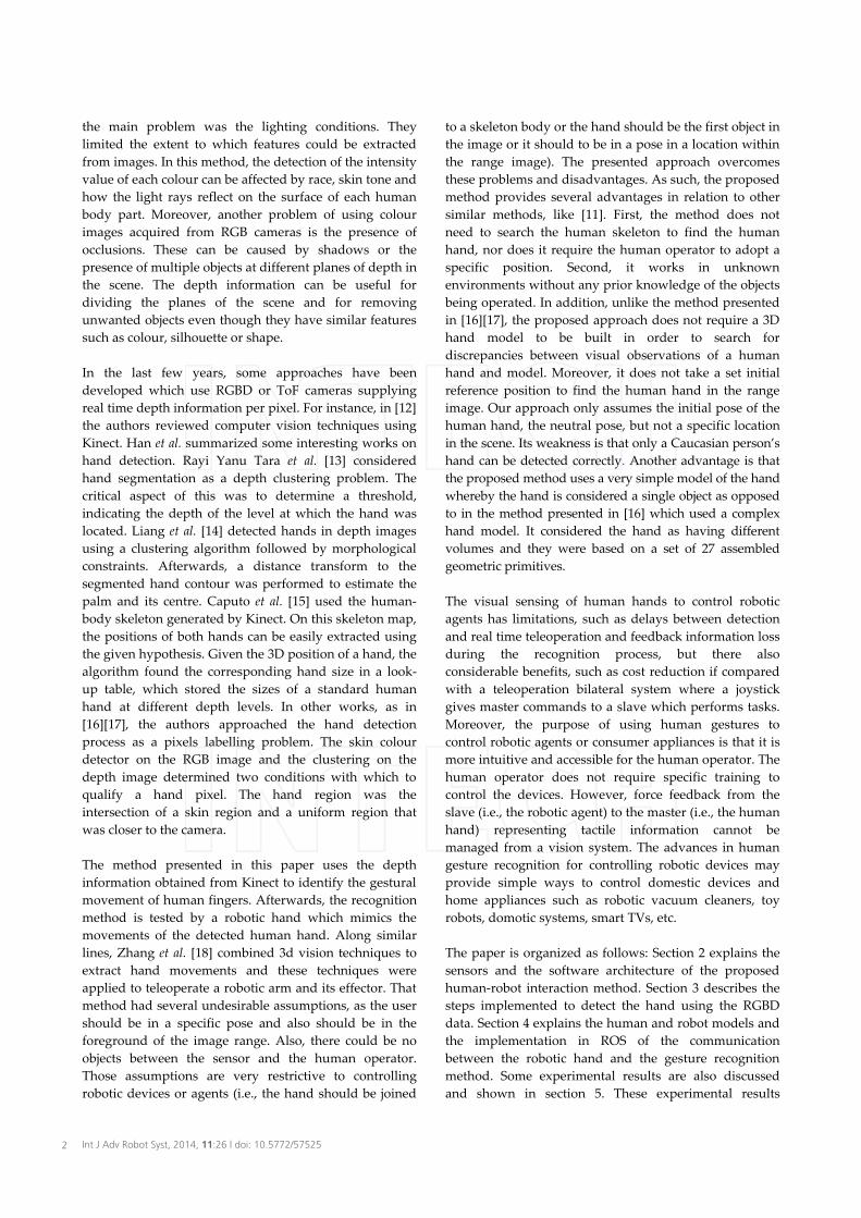
The procedure for the remote operation of the robotic hand is carried out by calculating the pose of the human hand for each frame of the video sequence. The ROS platform [20] is used as the communication system to send to the robotic hand the desired position for each finger. Thus, the distributed architecture of the ROS system is used to combine the kinematic control of the robotic hand with the human hand recognition. ROS provides similar services to operating systems such as hardware abstraction, inter-process communication and library integration, similar to the code for the recognition process. In our case, two ROS nodes were implemented: one for the robotic hand control and another for the visual acquisition and processing of the hand recognition as shown in Figure 2.
Figure 2. Architecture of the system and communication between devices in the ROS platform
1. The human hand, palm and fingertips are recognized and tracked in a video sequence, in advance. Then, in this step, the pose of the hand and the positions of the fingers are computed using a simple model based on Euclidean distances and angles between the palm and fingertips to determine the movement between consecutive frames of the sequence.
2. Later, these movements of the fingertips are mapped to the fingers of the robotic hand. To do this, a human-to-robot grasp mapping scheme is defined depending on the type of robotic hand used. In this work, we have used a Barrett [21] hand with three fingers as shown in Figure 2. The type of robotic hand determines the kind of movements that can be replicated, the configuration of the fingers when they set a pose to imitate the movements of the human hand correctly, and the position and orientation of the fingertips. Unlike in the work studied in [22], the movements are not evaluated based on the simulation of movements in a virtual environment for the fingers and robotic hand. In this paper, the robot directly imitates human behaviour in real time. These functionalities have been implemented using ROS. Moreover, the kinematic structure of the human hand is computed from the image and we have not used position mappings from the exoskeleton as in [23].
3. Finally, the method establishes communication between the robotic hand and the recognition process based on the standard message structure of ROS which sends information to ROS processes implemented as nodes. The first ROS node acts as the server of the kinematic control of the robotic hand and it is executed in a computer which is directly connected to the robotic hand through the serial port. This node performs a service which receives the joint angle of the robotic hand and it sends the corresponding command through the serial port in order to execute it. This node also publishes the joint angles of the hand into a topic so that the current joint state of the hand can be monitored in real-time. The second ROS node is a client of this service which implements the human hand recognition algorithm and it can be executed on a different computer. Specifically, this second ROS node is connected to the Kinect camera by a USB port. It communicates with the camera through the OpenNI drivers and it uses the PCL library [6] to implement the recognition process previously mentioned. It is described in the next section.
P = (p1,p2,...,pn) Point cloud: 3d points set pi=(xi,yi,zi,ri,gi,bi) A 3d point
(x,y,z) The position of a 3d point (r,g,b) The colour of a 3d point
'fP Point cloud filtered by depth to
eliminate the background fP Point cloud sampled in order to
reduce the density of the points. S = {P1,P2,.., Pn} A set of n point clouds
fsP Point cloud of a skin region
fnsP Point cloud of a non-skin region ),...,,( 1 ki vvV = Vertices of a 2d convex-hull
iP~ Centroid of a 3d convex-hull
{ }iiih PVP ~,)( =Η Human hand descriptor
Table 1. Symbols list and notations
3. Human hand Recognition Process
In the literature [24] appear some works that combine the use of a RGB camera and depth information from a ToF camera to obtain range images, but they require two off-line calibration processes to obtain the internal camera parameters and external camera parameters: rotation and translation between the coordinate systems of each sensor. In our case, the acquisition of range images, using Kinect, provides uncalibrated data (colour and depth) from two different sensors RGB and IR, too. However, these sensors are not aligned and for further processing steps the synchronization of signals and a rectified process are required; using OpenNI together with PCL, this problem is solved and a point cloud is created. The point cloud defines a RGB-D image. Sometimes, the
4 Int J Adv Robot Syst, 2014, 11:26 | doi: 10.5772/57525
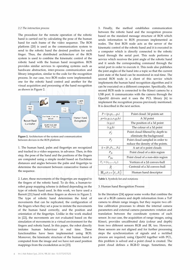
(a) (b) (c) (d) (e) Figure 3. (a) Original RGB-D image. (b) Filtered and Sampled Image. (c) Skin detection. (d) Computing the hand descriptor. (e) Detection of fingertips and palm.
processing of point clouds results in both a high computational cost (processing time) and a high space cost (storage). Therefore, the implemented algorithms and methods must be as fast as possible.
3.1 Filtered and sampled
At this stage, we filter the input data using the depth information, z, of each point, p, of the point cloud, P.Thus, let P be the scan data set for the image. It consists of 3D points represented as follows:
),...,,( 21 npppP = (1)
Thus, a distance band pass filter is applied to an initial point cloud as shown in (1) and (2).
'),( fi PtPHPp =→∈∀ (2)
where 'fP is the filtered data set. It consists of 3D points
where z is the depth between 1.2 and 3.5 meters, this parameter is imposed by the working distance between the human operator and the sensor. H is the function of filtering P and obtaining the output ),...,,( 21
'mf pppP =
where m<n. Thus, this process removes information from the background that could be considered noise. To improve the accuracy and efficiency of the method, one step more has been considered. '
fP is filtered again, as
follows ffs PtPH =),( ' . Now, sH is a function by which
to sample the point cloud. To do this, for any point, ip ,assuming they are the surviving points after applying the depth filter from (2), we remove all the neighbouring points, fp , into the open ball of the radius, sd >0 around
ip as follows:
<∈= = s
nji jifjsi dppPpdpB 1,
2' ),(:),( (3)
where the sampling ratio, sd , is the radius of the ball and it is computed as the minimum allowable Euclidean distance between any point that belongs to '
fP and its
nearest neighbours. In our experiments, a value of 3mm provided good results in the detection process and improved the detection speed in indoor environments.
The purpose of these two processes is to reduce the density of points to be processed in the next stages while maintaining an acceptable resolution to distinguish the hand palm and the fingers (Figure 3a-b) without causing significant discontinuity in the surface of these human body parts.
3.2 Skin detection
The workspace can contain surrounding objects (i.e., other body parts, other persons, walls, doors, furniture, etc.). The objective of this step is to implement a colour segmentation to identify the set of points in fP which has a texture
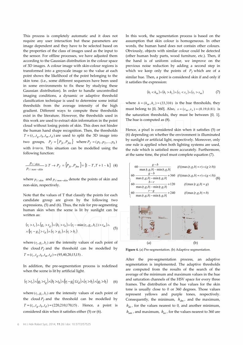
similar to Caucasian human skin. However, this process means that other human body parts (such as hands, arms, legs, etc.) are unwittingly detected. In this method, a combination of two strategies has been implemented to resolve the problem of colour skin detection in a video sequence. First, a pre-segmentation process is carried out (Figure 4a). This is based on a rule set in which fixed global thresholds of two space colour, RGB and HSV are used. Second, an adaptive segmentation process based on HSV is implemented to find the values of the optimal threshold for hue, saturation and value (Figure 4b). Then, the segmentation is dynamically adapted to light conditions while new images are acquired.
In the studies [19][25], two rules based on thresholds are used to detect human skin in the pre-segmentation process. The first rule is used when the indoor environment is illuminated with natural light (sunlight). The second rule is used when the indoor environment is illuminated with artificial light. These rules are defined below in equations (5) and (6). These values are well suited to discriminating skin pixels from non-skin pixels in 3D images captured of white-skinned people. Sometimes the environment is illuminated with both kinds of light, sunlight and artificial, then the more restrictive rule is applied in those cases, (5) or (6). The colour temperature, hot or cold, and the lumens determine which equation is suitable.
5Pablo Gil, Carlos Mateo and Fernando Torres: 3D Visual Sensing of the Human Hand for the Remote Operation of a Robotic Hand
This process is completely automatic and it does not require any user interaction but these parameters are image dependent and they have to be selected based on the properties of the class of images used as the input to the sensor. For offline processes, we have adjusted them according to the Gaussian distribution in the colour space of 3D images. A colour image with skin-colour regions is transformed into a greyscale image so the value at each point shows the likelihood of the point belonging to the skin tone. (i.e., some different sequences have been used in some environments to fix these by studying these Gaussian distribution). In order to handle uncontrolled imaging conditions, a dynamic or adaptive threshold classification technique is used to determine some initial thresholds from the average intensity of the high gradient. Different ways to compute these thresholds exist in the literature. However, the thresholds used in this work are used to extract skin information in the point cloud without losing points of skin. This does not hinder the human hand shape recognition. Then, the thresholds
),,,,( dmbgr tttttT = are used to split the 3D image into
two groups, { }fnsfsf PPP ,= where ),...,,( 21 kf pppP =
with k<m<n. This situation can be modelled using the following function:
{ } { }k~1,~1,/
/ +==→≥−
TTPPPTp
pfnsfsf
skinnoni
skini (4)
where skinip / and skinnonip −/ denote the points of skin and non-skin, respectively.
Note that the values of T that classify the points for each candidate group are given by the following two expressions, (5) and (6). Thus, the rule for pre-segmenting human skin when the scene is lit by sunlight can be written as:
( ) ( ) ( ) ( )( ) ( ) ( )iiiidii
miiiibigiri
brgrtgr
tbgrrtbtgtr
>∧>∧>−∧
∧>−∧>∧>∧> }),,min{ (5)
where ),,( iii bgr are the intensity values of each point of the cloud fP and the threshold can be modelled by
)15,15,20,40,95(),,,,( == dmbgr tttttT .
In addition, the pre-segmentation process is redefined when the scene is lit by artificial light.
( ) ( ) ( ) ( ) ( ) ( )iiiidiibigiri bgbrtgrtbtgtr >∧>∧≤−∧>∧>∧> (6)
where ),,( iii bgr are the intensity values of each point of the cloud fP and the threshold can be modelled by
)15,170,210,220(),,,( == dbgr ttttT . Hence, a point is
considered skin when it satisfies either (5) or (6).
In this work, the segmentation process is based on the assumption that skin colour is homogeneous. In other words, the human hand does not contain other colours. Obviously, objects with similar colour could be detected (other human body parts, wood furniture, etc.). Then, if the hand is of uniform colour, we improve on the previous noise reduction by adding a second step in which we keep only the points of fP which are of a
similar hue. Then, a point is considered skin if and only if it satisfies the expression:
( ) ( ) ( ) ( )misisimi sssshhhh >∧<∧>∨< (7)
where )310,33(),( == sm hhh is the hue thresholds, they must belong to [0, 360]. Also, )81.0,19.0(),( == sm sss is the saturation thresholds, they must be between [0, 1]. The hue is computed as (8).
Hence, a pixel is considered skin when it satisfies (5) or (6) depending on whether the environment is illuminated by sunlight or artificial light, respectively. Moreover, only one rule is applied when both lighting systems are used, the rule which is satisfied more accurately. Furthermore, at the same time, the pixel must complete equation (7).
=+−−⋅
=+−−⋅
<∧=+−−⋅
≥∧=−−⋅
)},,(max{240},,min{},,max{
60
)},,(max{120},,min{},,max{
60
))()},,((max{360},,min{},,max{
60
))()},,((max{},,min{},,max{
60
bbgrifbgrbgr
gr
gbgrifbgrbgr
rb
bgrbgrifbgrbgr
bg
bgrbgrifbgrbgr
bg
(8)
(a) (b)
Figure 4. (a) Pre-segmentation. (b) Adaptive segmentation.
After the pre-segmentation process, an adaptive segmentation is implemented. The adaptive thresholds are computed from the results of the search of the average of the minimum and maximum values in the hue and saturation channels of the HSV space for every three frames. The distribution of the hue values for the skin tone is usually close to 0 or 360 degrees. Those values represent yellows and purple tones, respectively. Consequently, the minimum, dmh , and the maximum,
dsh , for the values nearest to 0, and another minimum,
umh , and maximum, ush , for the values nearest to 360 are
6 Int J Adv Robot Syst, 2014, 11:26 | doi: 10.5772/57525

estimated for every three frames in the video sequence. The rules for this step can be written as (9) and (10):
( ) ( )( ) ( ) ( )( )usiumidsidmi hhhhhhhh <∧>∨<∧> (9)
( ) ( )simi ssss <∧> (10)
where sS is the minimum value of saturation and mS is the maximum value of saturation.
3.3 Hand descriptor and tracker
Once the regions with skin colour are obtained, the goal is to estimate the regions which represent the human hands. However, sometimes, the workspace can contain surrounding objects that are not skin (i.e., doors, furniture, etc.). In order to accurately detect and track the human hand, this information must be filtered and eliminated.
The main idea of our approach is to search the nearest neighbour to cluster the point cloud fsP . Then, given a set
of points, ),...,,( 21 mppp in the metric space of P and belonging to fsP , new points ip in the same metric space
are sought and added to the set if they are the closest toip . Thus, in this step, we have used Kd-tree structures to
search for the k-nearest neighbour and to find the closest K neighbours within a certain radius, the used search distance is 1mm. The Kd-tree structures recursively divide the data points fsP using binary trees. The space
partitioning data are organized in k-dimensional space, which is very efficient for low dimensionality data. This algorithm allows us to organize fsP (skin candidate
points) as point subclouds.
{ }kfs PPPP ,...,, 21= (11)
where each point subcloud, iP , represents a candidate object. Every point subcloud has to fulfil a quality factor in order to be considered a candidate for a body human part.
Afterwards, a classifier to discriminate between the different regions using standard descriptors is added, to detect the human hand in the set fsP . This classifier
consists of a global descriptor of the human hand and a multi-part description based on spatial relations between parts of the human hand, such as the fingers and the palm.On the one hand, the shape is used as a global descriptor to identify the type of object in the scene. Therefore, for each
iP of fsP , the shape is calculated and it is compared with a
human hand model. The number of samples for the human hand model limits the poses that can be used to detect the hand in the initial position (in our case, neutral pose). Then, from the candidate objects, according to (11), the
algorithm determines the number of hands in the scene and their locations. Afterwards, the convex-hull of iP ,
)(3 id PcH is computed. The convex-hull is defined as the smallest convex set containing iP . In addition, a point in iP
is a vertex, iv , of the convex hull of iP , if it is an extreme point in relation to P (i.e., it is part of the boundary). In the presented method, the depth has been discarded, then a 3D convex-hull is calculated as a 2D convex-hull, and it represents the minimal polygonal containing the set of points of the iP . Geometrically, ),...,,( 21 ki vvvV = are the vertices which define the polygonal contour in the 2D-convex-hull, )(2 id PcH , and they are used as a descriptor in order to identify the shape of iP together with the 3D-centroid as follows (see Figure 3d):
{ } Η ⋅=∈=i
ip
iiiiiih mipPPcHVPVP /~),(:~,)( (12)
where iP~ is the 3D-centroid and iV are the vertices of 2D-convex-hull, )(2 id PcH .
On the other hand, the structure of the human hand is modelled using the relations between the parts of the human hand, in this case between the vertices, iV and iP~
between each other, iV , according to the error function shown in (13). The first part accumulates the distance between the vertices and the second part accumulates the distances of the centroid for the vertices of the convex-hull.
( ) ΗΗ∈Η∈
−+−=)()(
~)(, ihiihji PV
iiPV
jiih PVVVPE (13)
Moreover, other compositional rules are added to represent the human hand as a combination of these descriptors, )( ih PΗ . In other words, a candidate subcloud is considered as a human hand, if the set of points, iP , satisfies the next constraints:
The number of vertices iV must be greater than seven and smaller than 15. At best, the hand shape model is represented by k=7 vertices: Five are at the end of the fingers (fingertips) and two are in the wrist (joining the hand and the forearm).
The maximum limit of the vertices is k=15 because the joint position of the hand and the background in the range image with a similar texture can generate a polygonal shape for the convex-hull with a large number of vertices. These false vertices can cause confusion in the shape descriptor. For this reason, the proposed method tests the structure of iV and the vertices which do not keep a Euclidean distance in the 3D space of iP , in
7Pablo Gil, Carlos Mateo and Fernando Torres: 3D Visual Sensing of the Human Hand for the Remote Operation of a Robotic Hand
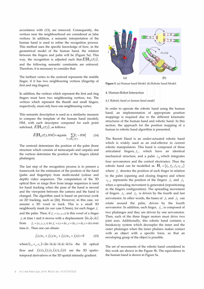
accordance with (13), are removed. Consequently, the vertices near the neighbourhood are considered as false vertices. In addition, a semantic interpretation of the human hand is used to refine the recognition process.This method uses the specific knowledge of how, in the geometrical model of the human hand, the relation between the fingers and palm will be (Figure 5a). This way, the recognition is adjusted such that ( ))( ih PE Η ,and the following semantic constraints are enforced. Therefore, it is necessary to consider that:
The farthest vertex to the centroid represents the middle finger, if it has two neighbouring vertices (fingertip of first and ring fingers).
In addition, the vertices which represent the first and ring fingers must have two neighbouring vertices, too. The vertices which represent the thumb and small fingers, respectively, must only have one neighbouring vertex.
This semantic description is used as a similarity measure to compare the template of the human hand (model), HM, with each descriptor computed for each point subcloud, ( ))( ih PE Η , as follows:
( ) ΗΗ∈
−=)(
minarg),(ihi PViih HMVHMPE (14)
The centroid determines the position of the palm (bone structure which consists of metacarpals and carpals) and the vertices determine the position of the fingers (distal phalanges).
The last step of the recognition process is to present a framework for the estimation of the position of the hand (palm and fingertips) from multi-modal (colour and depth) video sequences. The computation of the 3D optical flow or range flow from image sequences is used for hand tracking when the pose of the hand is moved and the viewpoint between the camera and the hand is changed. The algorithm used is based on previous work on 2D tracking, such as [26]. However, in this case, we assume a 3D voxel to track. This is a small 3D neighbourly mask (in our case 0.3mm), for each finger if
and the palm. Then, if ),,( zyxfi = is this voxel of a finger
if at time t and it moves with a displacement ( )zyx ∂∂∂ ,,from ),,,( tzyxfi = to ),,,( ttzzyyxxfi ∂+∂+∂+∂+= overtime t∂ . Then one can obtain:
0)()()()( =+++ tfvzfvyfvxf iziyixi (15)
where ( ) ( )tztytxvvv zyx ∂∂∂∂∂∂= /,/,/,, is the 3d optical
flow and )(),(),(),( tfzfyfxf iiii are the 3D spatio-
temporal derivatives or the 3D spatial intensity gradient.
(a) (b)
Figure 5. (a) Human hand Model. (b) Robotic hand Model.
4. Human-Robot Interaction
4.1 Robotic hand vs human hand model
In order to operate the robotic hand using the human hand, an implementation of appropriate position mappings is required due to the different kinematic structures of the human hand and robotic hand. In this section, the approach for the position mapping of a human to robotic hand algorithm is presented.
The Barrett Hand is an under-actuated robotic hand which is widely used as an end-effector in current robotic manipulators. This hand is composed of three articulated fingers, if , which have an identical mechanical structure, and a palm pc which integrates
four servomotors and the control electronics. Thus the robotic hand can be modelled as { }21321 ,,, −=Η rfffr
where if denotes the position of each finger in relation to the palm (opening and closing fingers) and where
21−r represents the position of the fingers 1f and 2f
when a spreading movement is generated (repositioning in the fingers configuration). The spreading movement of fingers 1f , and 2f is driven by the fourth and last servomotor. In other words, the bases of 1f and 2f can rotate around the palm, driven by the fourth servomotor. In addition, each finger, if , is composed of two phalanges and they are driven by one servomotor. Then, each of the three finger motors must drive two joint axes. Additionally, this robotic hand contains a breakaway system which decouples the inner and the outer phalanges when the inner phalanx makes contact with an object with a specific force, so that an enveloping grasp of the object is possible.
The set of movements of the robotic hand considered in this work are shown in the Figure 5b. The equivalence in the human hand is shown in Figure 5a.
f1
f2f3
f1
f2
f3
i1
i2, i3
8 Int J Adv Robot Syst, 2014, 11:26 | doi: 10.5772/57525

The human hand model { }pcfffffHM ,,,,, 54321= has
been limited to achieve a proper imitation of hand movements. In particular, only three fingers of the human hand are considered although the five fingers were detected in the recognition process, discussed in the previous section, then the model is defined as
{ }iPvvvHM ~,,,' 321= , where 1v , 2v and 3v are the xyz-
coordinates of the fingertips in relation to the palm, iP~ ,for the fingers: thumb, middle and first, respectively. The index, middle and thumb human fingers are chosen because they can be easily moved without moving other fingers involuntarily. In addition, they allow the user to simulate the grasp pose, open pose, close pose, etc. In our method the full kinematic configuration of the human hand with 19 links and 24 DoF is not considered [27], only a simplified model. In addition, in order to map the human hand configuration to the robotic hand, the relative Cartesian position of 'HM is mapped to the robotic hand rΗ . This method uses the kinematics equations of the Barrett Hand and then, the corresponding joint angles of the three fingers are obtained and applied to the robotic hand.
On the one hand, according to the direct kinematics, the encoder counts for the servomotors of the Barrett hand are related to the joint angles as:
{ }
∈∈+±=
==
]31500,0[],17500,0[:375
,125
,35
2',','
44
321
qqqqq
f
iii
iiii θθθ(16)
where 'ikθ is the k-joint angle for the robot finger if andwhere iq are the values that can be adopted by the servomotors. They can adopt values of between 0 and 31500 for the servomotor which controls the spreading movement of fingers 1f and 2f . They can also adopt values of between 0 and 17500 for the other three servomotors which control the movements of opening and closing of all the fingers.
Furthermore, the maximum values for '2iθ is 140º, '3iθare 47º and '1iθ is ±180º. Since the robotic hand fingers cannot be stretched completely, the joint angles '2iθand '3iθ are constantly 2.46º and 50º, respectively. Then, the angle position for each finger is computed from (16) as:
{ } { }50',46.2',',, 321321 ++== iiiiiiif θθθθθθ (17)
On the other hand, according to the fingertip Cartesian 3D-position ),,( iii zyx for each if (see Figure 6), it is computed as in equation (18).
⋅⋅
−−+
−+
⋅+
⋅−
−+
=
−
−−
−
32
23
22
22
122
1
332
331
122
1
1
3
2
1
2cos
cossintantan
tan
ll
llzlyx
lll
lyx
z
xy
iii
i
i
ii
i
i
i
i
i
i
θθ
θθθ
(18)
where { } { }56,70,50,, 321 == iiii llll mm are the length of the limbs for each of the robot’s fingers, i=1,..,3.
The forward kinematics of the robotic hand describes the Cartesian 3d-position for each fingertip as:
( )( )( )( )
( )
+⋅+⋅⋅++⋅+⋅⋅++⋅+⋅
=
23322
1123322
1123322
3
2
1
sinsinsincoscoscoscoscos
iii
iiii
iiii
i
i
i
llllllll
zyx
θθθθθθθθθθθ
(19)
where ( )( ) 0coscos 123322 ≥++⋅+⋅ lll iii θθθ
( )( )( )( )
( )
+⋅−⋅−⋅+⋅−⋅−⋅+⋅−⋅−
=
23322
1233221
1233221
3
2
1
sinsinsincoscoscoscoscos
iii
iiii
iiii
i
i
i
llllllll
zyx
θθθθθθθθθθθ
(20)
where ( )( ) 0coscos 123322 <++⋅+⋅ lll iii θθθ
4.2 Communication with the robotic hand
The communication, between the recognition process and the robotic hand via the serial link, produces latencies when short data (command frames) are sent. The Barrett hand supports 21 commands of these different types: opening fingers, moving any combination of the four axes to an array of positions, incrementally opening and closing by default or user-defined distances. The firmware of the robotic hand allows us to read the strain gauges, but not the position of the fingers to monitor if the remote operation process is correctly realized. The commands of the Barrett to achieve the robot finger poses from the servomotor steps are:
- GHOME: Initialization - SM 3100: The robotic hand, { }21321 ,,, −=Η rfffr
imitates the initial position of the human hand detected. 1f , 2f are extended and positioned in line with 3f . Similar to the position shown in Figure 10a
- xIO value: An extending movement (open) with decreasing values of servomotor steps (value) for finger x where x can be { }321 ,, fff
- xIC value: A flexing movement (close) with increasing values of servomotor steps (value) for finger x where x can be { }321 ,, fff . Similar to the position shown in Figure 10b-c
9Pablo Gil, Carlos Mateo and Fernando Torres: 3D Visual Sensing of the Human Hand for the Remote Operation of a Robotic Hand
For the finger tracking process, the robot commands are sent when a specific human finger is opening or closing.
(a) (b) Figure 6. Geometric relationships of the finger phalanges
5. Experimental Results
5.1 Recognition
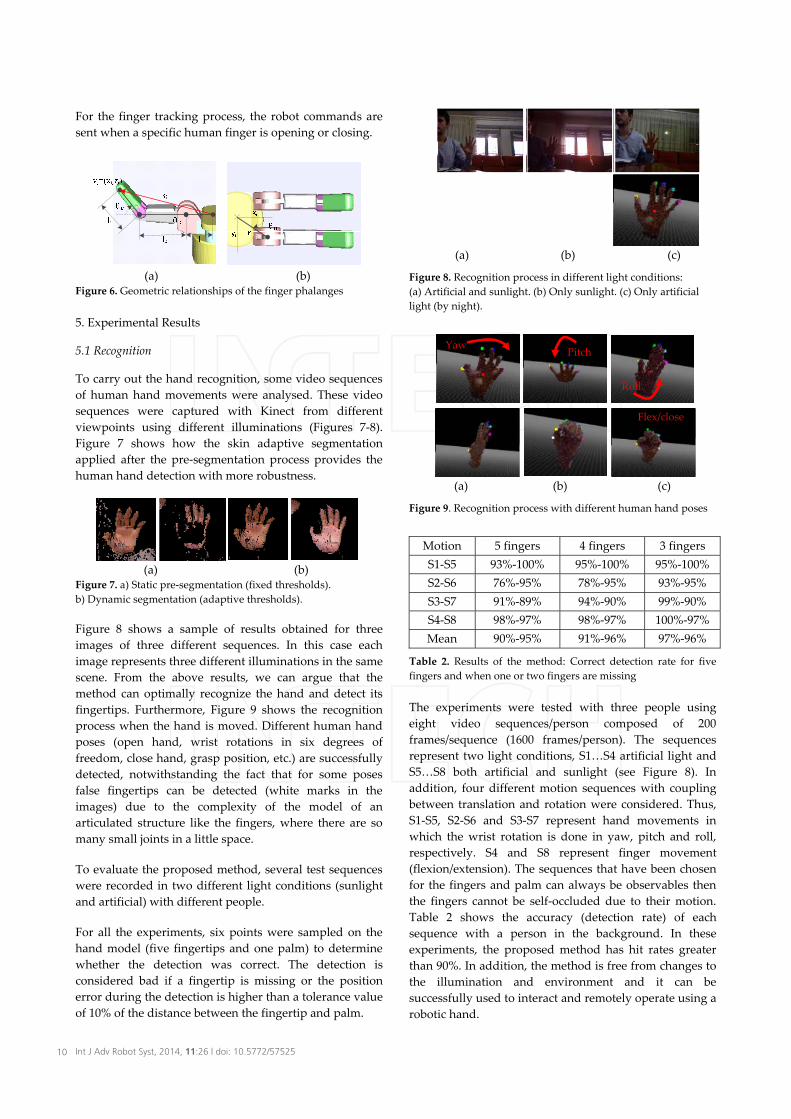
To carry out the hand recognition, some video sequences of human hand movements were analysed. These video sequences were captured with Kinect from different viewpoints using different illuminations (Figures 7-8). Figure 7 shows how the skin adaptive segmentation applied after the pre-segmentation process provides the human hand detection with more robustness.
(a) (b) Figure 7. a) Static pre-segmentation (fixed thresholds). b) Dynamic segmentation (adaptive thresholds).
Figure 8 shows a sample of results obtained for three images of three different sequences. In this case each image represents three different illuminations in the same scene. From the above results, we can argue that the method can optimally recognize the hand and detect its fingertips. Furthermore, Figure 9 shows the recognition process when the hand is moved. Different human hand poses (open hand, wrist rotations in six degrees of freedom, close hand, grasp position, etc.) are successfully detected, notwithstanding the fact that for some poses false fingertips can be detected (white marks in the images) due to the complexity of the model of an articulated structure like the fingers, where there are so many small joints in a little space.
To evaluate the proposed method, several test sequences were recorded in two different light conditions (sunlight and artificial) with different people.
For all the experiments, six points were sampled on the hand model (five fingertips and one palm) to determine whether the detection was correct. The detection is considered bad if a fingertip is missing or the position error during the detection is higher than a tolerance value of 10% of the distance between the fingertip and palm.
(a) (b) (c)
Figure 8. Recognition process in different light conditions: (a) Artificial and sunlight. (b) Only sunlight. (c) Only artificial light (by night).
(a) (b) (c)
Figure 9. Recognition process with different human hand poses
Motion 5 fingers 4 fingers 3 fingers S1-S5 93%-100% 95%-100% 95%-100% S2-S6 76%-95% 78%-95% 93%-95% S3-S7 91%-89% 94%-90% 99%-90% S4-S8 98%-97% 98%-97% 100%-97% Mean 90%-95% 91%-96% 97%-96%
Table 2. Results of the method: Correct detection rate for five fingers and when one or two fingers are missing
The experiments were tested with three people using eight video sequences/person composed of 200 frames/sequence (1600 frames/person). The sequences represent two light conditions, S1…S4 artificial light and S5…S8 both artificial and sunlight (see Figure 8). In addition, four different motion sequences with coupling between translation and rotation were considered. Thus, S1-S5, S2-S6 and S3-S7 represent hand movements in which the wrist rotation is done in yaw, pitch and roll, respectively. S4 and S8 represent finger movement (flexion/extension). The sequences that have been chosen for the fingers and palm can always be observables then the fingers cannot be self-occluded due to their motion. Table 2 shows the accuracy (detection rate) of each sequence with a person in the background. In these experiments, the proposed method has hit rates greater than 90%. In addition, the method is free from changes to the illumination and environment and it can be successfully used to interact and remotely operate using a robotic hand.
YawPitch
Roll
Flex/close
10 Int J Adv Robot Syst, 2014, 11:26 | doi: 10.5772/57525
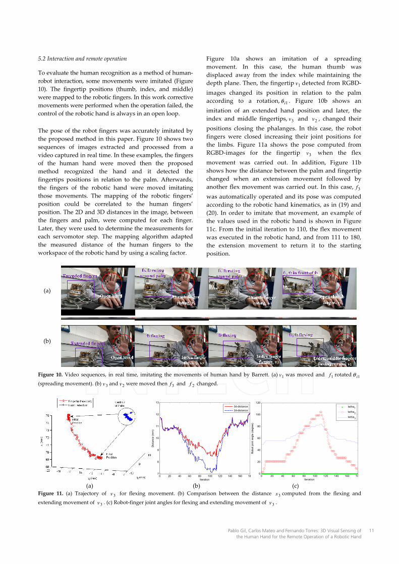
5.2 Interaction and remote operation
To evaluate the human recognition as a method of human-robot interaction, some movements were imitated (Figure 10). The fingertip positions (thumb, index, and middle) were mapped to the robotic fingers. In this work corrective movements were performed when the operation failed, the control of the robotic hand is always in an open loop.
The pose of the robot fingers was accurately imitated by the proposed method in this paper. Figure 10 shows two sequences of images extracted and processed from a video captured in real time. In these examples, the fingers of the human hand were moved then the proposed method recognized the hand and it detected the fingertips positions in relation to the palm. Afterwards, the fingers of the robotic hand were moved imitating those movements. The mapping of the robotic fingers’ position could be correlated to the human fingers’ position. The 2D and 3D distances in the image, between the fingers and palm, were computed for each finger. Later, they were used to determine the measurements for each servomotor step. The mapping algorithm adapted the measured distance of the human fingers to the workspace of the robotic hand by using a scaling factor.
Figure 10a shows an imitation of a spreading movement. In this case, the human thumb was displaced away from the index while maintaining the depth plane. Then, the fingertip 1v detected from RGBD-images changed its position in relation to the palm according to a rotation, 1iθ . Figure 10b shows an imitation of an extended hand position and later, the index and middle fingertips, 3v and 2v , changed their positions closing the phalanges. In this case, the robot fingers were closed increasing their joint positions for the limbs. Figure 11a shows the pose computed from RGBD-images for the fingertip 3v when the flex movement was carried out. In addition, Figure 11b shows how the distance between the palm and fingertip changed when an extension movement followed by another flex movement was carried out. In this case, 3f
was automatically operated and its pose was computed according to the robotic hand kinematics, as in (19) and (20). In order to imitate that movement, an example of the values used in the robotic hand is shown in Figure 11c. From the initial iteration to 110, the flex movement was executed in the robotic hand, and from 111 to 180, the extension movement to return it to the starting position.
(a)
(b)
Figure 10. Video sequences, in real time, imitating the movements of human hand by Barrett. (a) 1v was moved and 1f rotated 1iθ(spreading movement). (b) 3v and 2v were moved then 3f and 2f changed.
(a) (b) (c) Figure 11. (a) Trajectory of 3v for flexing movement. (b) Comparison between the distance 3s computed from the flexing and
extending movement of 3v . (c) Robot-finger joint angles for flexing and extending movement of 3v .
0 20 40 60 80 100 120 140 160 187
8
9
10
11
12
13
Dis
tanc
e (m
m)
Iteration
3d-distance2d-distance
0 20 40 60 80 100 120 140 160 180
20
40
60
80
100
120
Rob
ot jo
int a
ngle
(deg
ree)
Iteration
tetha1
tetha2
tetha3
11Pablo Gil, Carlos Mateo and Fernando Torres: 3D Visual Sensing of the Human Hand for the Remote Operation of a Robotic Hand

Mean Std. Dev. Kurtosis Asymmetry21ms. ±18.9ms 0.46 1.15
Table 3. Running time of the method
In this case, the method took a computation time of 21ms, at each iteration, and the statistical analysis of its distribution is shown in Table 3. These computation times allow the robotic hand to operate in real time from the 3d visual sensing of a human hand.
6. Conclusions
This paper presents a method for detecting and tracking hands, by using a Kinect camera and acquiring and processing images in real time. The implemented method has been tested for different configurations of hands, with different people. Furthermore, some tests were done for several different indoor environments where the working distance was changed, the number, type and features of the objects were different and where the ambient light was also different. Moreover, this method did not require any previous calibration process. Initially, the system detects the human hand independently from the environment in spite of the fact that there are several body parts which are visible. However, to detect a human hand, the method requires that the hand initially be open. This method does not use the human skeleton recognition to limit the search space in order to detect the hands. In this work, to test the validity of our method, simple gestures of the human hand were analysed and measured to imitate human movements with a Barrett robotic hand considering its inverse kinematics. Only three fingers of the detected human hand’s anatomy were used in this task due to the restrictions of the anthropomorphic structure of the Barrett hand. The advantage of our multi-fingered manipulation system is its low cost and that it does not require a pose control using an exoskeleton.
7. Acknowledgments
The research leading to these results received funding from the Spanish Government and European FEDER funds (DPI2012-32390) and the Valencia Regional Government (GV2012/102 and PROMETEO/2013/085).
8. References
[1] Malassiotis S, Strintzis M (2008) Real-Time hand posture recognition using range data. Image and Vision Computing. 26(7) : 1027-1037.
[2] Southwell B.J, Fang G, (2013) Human object recognition using colour and depth information and RGB-D Kinect sensor. Int. J. of Advanced Robotic Systems. DOI: 10.5772/55717
[3] Park S, Yu S, Kim J, Kim S, Lee S (2012) 3D hand tracking using Kalman filter in depth space. EURASIP J. on Advances in Signal Processing. 36: 1-18.
[4] Erol A, Bebis, M Nicolescu R, Boyle R.D, Twombly X (2007) Vision based hand pose estimation: a review. Computer Vision and Image Understanding. 108: 52-73.
[5] Zabulis X, Baltzakis H, Argyros A.A (2009) Vision-based hand gesture recognition for human-computer interaction. In The Universal Access Handbook-Series on Human Factors and Ergonomics. 24 : 1-30.
[6] Rusu R.B, Cousins S (2011) 3D is here: Point Cloud Library. In: Proc. of IEEE Int. Conf. on Robotics and Automation, Shanghai, China.
[7] Shotton J, Fitzgibbon A, Cook M, Sharp T, Finocchio M, Moore R, Kipman A, Blake A (2011) Real-Time Human Pose Recognition in Parts from Single Depth Images. In: Proc. of IEEE Conf. on Computer Vision and Pattern Recognition, Colorado Springs, USA.
[8] Bellmore C, Ptucha R, Savakis A (2011) Interactive Display Using Depth and RGB Sensors for Face and Gesture Control. In: Proc. of IEEE Western New York Image Processing Workshop. Rochester, USA.
[9] Ren Z, Yuan J, Zhang Z (2011) Robust hand gesture recognition based on finger-earth mover’s distance with a commodity depth camera. In: Proc. of the 19th ACM Int. Conf. on Multimedia, Scottsdale-Arizona, USA.
[10] Ryden F, Chizeck H.J, Kosari S.N, King H, Hannaford B (2011). Using Kinect and a Haptic Interface for Implementation of Real-Time Virtual Fixtures. In: Proc. of Robotics Science and Systems Workshop on RGBD Cameras, Los Angeles, USA.
[11] Van den Berg M, Carton D, De Nijs R, Mitsou N, Landsiedel C, Kuehlenz K, Wollherr D, Van Gool L, Buss M (2011) Real-time 3D hand gesture interaction with a robot for understanding directions from humans. In: Proc. of 20th IEEE Int. Symp. on Robot and Human Interactive Communication, Atlanta, USA.
[12] Han J, Shao L, Xu D, Shotton J (2013) Enhanced Computer Vision with Microsoft Kinect Sensor: A Review, IEEE Transactions on Systems, Man and Cybernetics, Part B, vol. 43(5), pp.1318-1334.
[13] Tara R, Santosa P, Adji T (2012) Hand Segmentation from Depth Image using Anthropometric Approach in Natural Interface Development, Int. J. of Scientificand Engineering Research, 3, pp. 1-4.
[14] Liang H, Yuan J, Thalmann D (2012) 3D Fingertip and Palm Tracking in Depth Image Sequences. In: Proc. ACM Int. Conf. on Multimedia.
[15] Caputo M, Denker K, Dums B, Umlauf G (2012) 3D Hand Gesture Recognition Based on Sensor Fusion of Commodity Hardware. Mensch & Computer: interktiv informier, pp. 292-302.
[16] Oikonomidis I, Kyriazis N, Argyros A (2011) Efficient Model-based 3D tracking of hand articulations using Kinect. In: Proc. of the 22nd British Machine Vision Conference, Dundee, UK, pp. 101.1-101.11.
12 Int J Adv Robot Syst, 2014, 11:26 | doi: 10.5772/57525
[17] Oikonomidis I, Kyriazis N, Argyros A (2012) Tracking the Articulated Motion of Two Strongly Interacting Hands. In: Proc. IEEE Conf. on Computer Vision and Pattern Recognition, Providence, USA.
[18] Du G, Zhang P, Mai J, Li Z (2012) Markerless Kinect-Based Hand Tracking for Robot Teleoperation. International Journal of Advanced Robotic Systems, Aiguo Song (Ed.), ISBN: 1729-8806, InTech, DOI: 10.5772/50093.
[19] Mateo C.M, Gil P, Corrales J.A, Puente S.T, Torres F (2012) RGBD Human hand recognition for the Interaction with Robot. In: Proc. of IEEE/RSJ Int. Conf. on Intelligent Robots and Systems Workshops, Vila-Moura, Portugal.
[20] Quigley M, Gerkey B, Conley K, Faust J, Foote T.B, Leibs J, Wheeler R, Ng A.Y (2009) Ros: an open-source robot operating system. In: Proc. of IEEE Int. Conf. on Robotics and Automation-Workshop on Open Source Software, Anchourage, USA.
[21] Townsend W (2000) The BarrettHand grasper – programmably flexible part handling and assembly. Industrial Robot: An Int. J. 27(3): 181-188.
[22] Kjellstrom H, Romero J, Kragic D (2008) Visual recognition of grasps for human-to-robot mapping. In: Proc. of IEEE/RSJ Int. Conf. on Intelligent Robots and Systems, Nice, France.
[23] Peer A, Einenkel S, Bus M (2008) Multi-fingered telemanipulation-mapping of a human hand to a three finger gripper. In: Proc. of 17th IEEE Int. Symp. on Robot and Human Interactive Communication, Munich, Germany. 24: 465-470.
[24] Van den Bergh M, Van Gool L (2011) Combining RGB and ToF cameras for real-time 3D hand gesture interaction. In: Proc. of IEEE Workshop on Applications of Computer Vision, Kona, USA.
[25] Peer P, Kovac J, Solina F (2003) Human Skin Colour Clustering for Face Detection. In: Proc. of Int. Conf. on Computer as a Tool, Ljubljana, Slovenia.
[26] Corrales J.A, Gil P, Candelas F.A, Torres F (2009) Tracking based on Hue-Saturation Features with a Miniaturized Active Vision System. In: Proc. of 40th Int. Symp. on Robotics, Barcelona, Spain.
[27] Cobos S, Ferre M, Aracil R, Ortego J, Sanchez-Urán, M.A (2010) Simplified human hand models for manipulation tasks. Int. J. of Advanced Robotic Systems- Cutting Edge Robotics. 10: 155-174.
13Pablo Gil, Carlos Mateo and Fernando Torres: 3D Visual Sensing of the Human Hand for the Remote Operation of a Robotic Hand