
BEAD BATH™ - Kentron Microbiology
20
® BEAD BATH MODELS: 74300-706, 74300-714, & 74300-720 74200-706, 74200-714, & 74200-720 100-120V/220-240V Models MICROPROCESSOR CONTROLLED INSTALLATION AND OPERATION MANUAL 4861685 03/12
-
Upload
khangminh22 -
Category
Documents
-
view
1 -
download
0
Transcript of BEAD BATH™ - Kentron Microbiology

®
BEAD BATH MODELS: 74300-706, 74300-714, & 74300-720
74200-706, 74200-714, & 74200-720 100-120V/220-240V Models
MICROPROCESSOR CONTROLLED
INSTALLATION AND OPERATION MANUAL
4861685 03/12

2 Microprocessor Control Bead Bath
These units are TUV CUE listed as general purpose air incubators for professional, industrial or educational use where the preparation or testing of materials is done at approximately atmospheric pressure and no flammable, volatile or combustible materials are being heated. These units have been tested to the requirements of CAN/CSA-C22.2 No. 61010-1, second edition, including Amendment 1, or a later version of the same standard incorporating the same level of testing requirements. These units are not intended for hazardous or household locations or use.
Lab Armor, LLC. P.O. Box 627 Cornelius, Oregon 97113 EMAIL: [email protected]
INTERNET: http://www.labarmor.com
PHONE: 1-800-210-8612
FAX: (210) 568-6441

Microprocessor Control Bead Bath 3
TABLE OF CONTENTS INTRODUCTION ........................................................................................................................................... 4
General Safety Considerations ........................................................................................................ 4 RECEIVING YOUR UNIT .............................................................................................................................. 5
Inspection Guidelines ....................................................................................................................... 5 Returning Shipment.......................................................................................................................... 5 Recording Data Plate Information .................................................................................................... 5
GRAPHIC SYMBOLS .................................................................................................................................... 6
INSTALLATION ............................................................................................................................................. 7 Environmental Conditions ................................................................ Error! Bookmark not defined. Power Source ................................................................................................................................... 7 Location ............................................................................................................................................ 7 Lifting and Handling .......................................................................................................................... 7 Cleaning and Decontamination ........................................................................................................ 7
CONTROLS OVERVIEW .............................................................................................................................. 8 Power Switch .................................................................................................................................... 8 Main Temperature Controller ........................................................................................................... 8 Fuses................................................................................................................................................ 8 Over Temperature Thermostat (OTL) .............................................................................................. 8 Heating Activated ............................................................................................................................. 8 Over Temperature Activated Light ................................................................................................... 8
OPERATION ................................................................................................................................................. 9 Filling with Lab Armor Beads and Turning on the Unit ..................................................................... 9 Setting Main Temperature Control ................................................................................................... 9 Calibrating the Main Temperature Control ....................................................................................... 9 Setting the Over Temperature Thermostat ...................................................................................... 9 Thaw Zone ....................................................................................................................................... 9
MAINTENANCE .......................................................................................................................................... 10 Cleaning ......................................................................................................................................... 10
TROUBLESHOOTING ................................................................................................................................ 11 Service ........................................................................................................................................... 12
PARTS LIST ................................................................................................................................................ 13
UNIT SPECIFICATIONS ............................................................................................................................. 14

Microprocessor Control Bead Bath 4
INTRODUCTION Thank you for choosing a general purpose Bead Bath . These units are not intended for use at hazardous or household locations. Before you use the unit, read this entire manual carefully to understand how to install, operate, and maintain the unit in a safe manner. Your satisfaction with the unit will be maximized as you read about its safety and operational features. Keep this manual on-hand so it can be used by all operators of the unit. Be sure all operators of the unit are given appropriate training before you put the unit in service.
Note: Use the unit only in the way described in this manual. Failure to follow the guidelines and instructions in this manual may be dangerous and illegal.
Warning: Use bead media only. Do not fill with liquid.
Avertissement: Utiliser un milieu de perles exclusivement. Ne pas remplir avec du liquid.
General Safety Considerations Your Bead Bath and its recommended accessories have been designed and tested to meet strict safety requirements. For continued safe operation of your bead bath, always follow basic safety precautions including: Read this entire manual before using the Bead Bath . Be sure you follow any city, county, or other ordinances in your area regarding the use of this unit. Use only approved accessories. Do not modify system components. Any alterations or modifications
to your bead bath may be dangerous and will void your warranty. The Bead Bath is designed for use with Lab Armor® Beads only. Do not use liquids in Bead Bath
tank.
electrical codes. If the unit is not grounded, parts such as knobs and controls may conduct electricity and cause serious injury.
Do not connect the unit to a power source of any other voltage or frequency beyond the range stated on the power rating overlay at the rear of the unit.
Do not modify the power cord provided with the unit. If the plug does not fit an outlet, have a proper outlet installed by a qualified electrician.
Avoid damaging the power cord. Do not bend it excessively, step on it, place heavy objects on it. A damaged cord can easily become a shock or fire hazard. Never use a power cord after it has become damaged.
Do not position equipment in a manner that prohibits access to power cord. Do not attempt to move the unit during operation or before the unit has been allowed to cool.
Section
1

Microprocessor Control Bead Bath 5
RECEIVING YOUR UNIT Before leaving our factory, all units are packaged in high quality shipping materials designed to provide protection from transportation related damage.
Once a unit leaves our factory, safe delivery becomes the responsibility of the carrier who is liable for loss or damage to your unit. Damage sustained during transit is not covered under your unit warranty.
When you receive your unit, inspect it for concealed loss or damage to its interior and exterior. Should you
Inspection Guidelines Carefully inspect the shipping carton for damage. If the carton is damaged, report the damage to the carrier service that delivered the unit.
If the carton is not damaged, open the carton and remove its contents. Verify that all of the following equipment is included in the carton:
One (1) Bead Bath One (1) bath cover One (1) power cord
Carefully check all packaging before discarding. Save the shipping carton until you are sure everything is in order.
Returning Shipment If you must return the unit for any reason, first contact your service representative for authorization. You will be asked to provide the data plate information. See Recording Data Plate Information.
Recording Data Plate Information Once you have determined the unit is free from damage, locate the data plate at the back of the unit. The
reference.
Table 1. Data Plate Information Model Number
Serial Number
Part Number
Voltage
Section
2

Microprocessor Control Bead Baths 6
GRAPHIC SYMBOLS Your unit is provided with a display of graphic symbols that should help in identifying user adjustable components.
SYMBOL IDENTIFICATION Indicates that you sh
Indique que l'opérateur doit consulter le manuel d'utilisation pour y trouver les instructions complémentaires.
Repère "température"
Signale un "dépassement de température"
Repère "secteur AC"
I Repère de la position "MARCHE" de l'interrupteur d'alimentation
O Repère de la position "ARRÊT" de l'interrupteur d'alimentation
Repère de la "terre de protection"
Touches de déplacements respectifs vers le "HAUT" et le "BAS"
Signale un élément "réglable manuellement"
Signale un "risque potentiel d'électrocution" au-delà de la cloison.
(Not disposed of in land-fill). Indique (Ne pas jeter dans une décharge)
Section
3

7 Microprocessor Control Bead Baths
INSTALLATION Your satisfaction and safety require a complete understanding of this unit. Read the instructions thoroughly and be sure all operators are given adequate training before attempting to put the unit in service. This equipment must be used only for its intended application; any alterations or modifications will void your warranty. Local city, county, or other ordinances may govern the use of this equipment. If you have any questions about local requirements, please contact the appropriate local agency. The end user may perform installation.
Power Source Check the data plate for voltage, cycle, and ampere requirements. If matched to your power source, plug the power cord into a grounded outlet. Voltage should not vary more than ± 10% from the data plate rating. These units are intended for 50/60-HZ application. A separate circuit is recommended to prevent damage to the unit due to overloading or circuit failure.
Location In selecting a location, consider all conditions that might affect performance, such as heat from radiators, ovens, autoclaves, etc. Avoid direct sun, fast-moving air currents, heating and cooling ducts, and high traffic areas. Allow a minimum of 10 cm between the unit and any walls or partitions that might obstruct free airflow.
Lifting and Handling These units are heavy and care should be taken to use appropriate lifting devices that are sufficiently rated for these loads. The unit should be completely restrained from tipping during lifting or transport. All moving parts such as trays or covers should be removed during transfer to prevent shifting and damage. The bottom of the unit is hot during operation as is the bead in the tank. Always allow the unit to cool before attempting to move it.
Cleaning and Decontamination In the event hazardous material is spilled onto or into the equipment appropriate decontamination must be carried out. If there is any doubt about the compatibility of decontamination or cleaning agents with parts of the equipment or with material contained, please contact the manufacturer. Units are cleaned at the factory, but not sterilized. Remove any beads if assembled and clean the bath with a disinfectant that is suitable for your application. Separately wash beads. CAUTION: Avoid using strong acids, bases, including bleach solutions, and detergents, which can tarnish the beads. For additional information, see MAINTENANCE for cleaning instructions and precautions.
Section
4

Microprocessor Control Bead Baths 8
CONTROLS OVERVIEW This section provides an overview of the panel controls. See Figure 1 for an illustration of the panel controls.
Figure 1. Control Panel
Power Switch The Green I/O (On/Off) power switch controls all power to the unit. It must be in the I position to be ON and the green power on light illuminated before any systems are operational. The on/off switch must remain easily accessible at all times.
Main Temperature Controller This control consists of the digital display and UP and DOWN arrow pads for inputting set point temperatures and calibration.
Fuses The fuses are located at the back of the unit within the power inlet plug and 220v units also have a fuse holder located next to the inlet. The fuses act as a circuit breaker and will cut off power to the unit if there is an electrical surge or malfunction. The fuses must be in place for the unit to operate. Please contact customer service for more information.
Over Temperature Thermostat (OTL) This controller is marked afety and is completely independent of the Temperature Controller. The OTL guards against any failure of the Temperature Controller that would allow the temperature to rise past set point. If the temperature rises to the OTL set point, the OTL takes control of the heating element and allows continued use of the bead bath until the problem can be resolved or service can be arranged. The OTL is manually adjusted with a screwdriver or coin so accidental adjustment cannot occur.
Heating Activated This light is ON when the Temperature Controller has activated the heating element to reach and maintain set point.
Over Temperature Activated Light This light is ON when the Over Temperature Thermostat has been activated. Under normal operating conditions this light should never be on.
Section
5

Microprocessor Control Bead Baths 9
OPERATION Filling with Lab Armor Beads and Turning on the Unit To turn on the unit, perform the following steps: 1. Check power supply against unit serial plate; they must match. 2. Plug service cord into the electrical outlet. If supplied with a detachable cordset, plug the female end
into the unit inlet and the male plug into the power supply. Verify that units requiring a fuse have the fuse installed in the power inlet.
3. Fill the bath with a minimum of three-fourths (3/4) volume with Lab Armor Beads. Do not use liquids in Bead Bath tank.
4. Push the Main power switch to the ON position and turn the Over Temperature Safety Thermostat to its maximum position, clockwise.
Setting Main Temperature Control To enter set point mode on the control, push and release either the Up or Down arrow pad one time and the digital display will start to blink from bright to dim. While blinking, the digital display shows the set point that can be changed using the UP or DOWN arrow pads. If the arrow pads are not pressed for five (5) seconds, the display will stop blinking and will revert to reading the actual temperature in the bath. Allow at least twelve (12) hours for the temperature to stabilize.
Calibrating the Main Temperature Control We recommend that you calibrate your unit once it has been installed in its working environment and the chamber temperature has been stable at the set point for several hours. 1. Place a calibrated reference thermometer into a vessel filled with 25 ml or more of water. Place the
vessel and thermometer into the center of the bath. Allow the thermometer to reach temperature and remain stable for one (1) hour.
2. Compare the reading on the reference thermometer with the temperature control display. If there is a difference, put the display into calibrate mode by pressing both the Up and Down arrow pads at the same time until the .
3. When the decimal points are blinking, press the Up or Down arrow pad to adjust the display to match the reference thermometer. If the arrow pads are not pressed within five (5) seconds the display will revert to showing the temperature within the bath.
4. Allow the unit to stabilize for one (1) hour and repeat calibration if necessary.
Setting the Over Temperature Thermostat To set the Over Temperature Thermostat, perform the following steps: 1. Verify that the Thermostat was set to its maximum position to allow the Bead Bath to stabilize. 2. Turn the Thermostat counterclockwise until the Safety indicator light turns on. 3. Turn the Thermostat clockwise until the Safety indicator light turns off. 4. Turn the thermostat clockwise again, past the point where the indicator light went out. This will
set the Thermostat at approximately 1 C above the Main Temperature set point.
Thaw Zone -hand corner when viewing
the unit from the front Control Panel.
Section
6

10 Microprocessor Control Bead Baths
MAINTENANCE Warning: Prior to any maintenance or service on this unit, disconnect the power cord from the power supply and
remove the beads from the tank. Before reattaching the unit to its power supply, be sure all volatile and flammable cleaners are evaporated and dry.
Avertissement: Avant d'effectuer toute maintenance ou entretien de cet appareil, débrancher le cordon secteur de la source d'alimentation. Avant de reconnecter l'appareil sur le secteur, s'assurer que tous les produits de nettoyage volatiles et inflammables sont complètement évaporés.
Cleaning The unit chamber should be cleaned and disinfected prior to use.
To clean the bead bath, perform the following steps: 1. Clean the Bead Bath with mild soap and water solution. DO NOT USE chlorine-based bleaches, as
they will damage the tank interior. DO NOT USE spray cleaners that may contain solvents, which could leak through openings and cracks and harm electrical part coatings. Failure to do this may permanently damage the unit.
2. Clean Bead Bath with a damp cloth with cleaning solution. Wipe the bath bank clean. Do not pour cleaning solution directly into the tank. Bead Bath was not designed to hold any liquid.
3. Separately wash beads clean of any spills with soap and water; completely dry beads before returning to the bath. If necessary, disinfect beads with a 70% ethanol solution. Avoid using strong acids, bases, including bleach solutions, and detergents, which can tarnish the beads.
Disinfecting Disinfect the bath on a regular basis. To disinfect the incubator, perform the following steps. 1. Disinfect the bath, including all corners, using a suitable disinfectant. DO NOT USE spray
disinfectants that might leak through openings and cracks and get on electrical components, or that may contain solvents, corrosives, or abrasives that will harm the stainless steel coatings. Special care should be taken when cleaning around sensing heads to prevent damage and around the door gasket so as not to impair the positive seal.
2. Hazardous Material Spill Containment protocol. Contact your local Site Safety Officer and follow instructions per the policy and procedures established for your site.
3. There are many commercially available disinfectants available that are non-corrosive and non-abrasive and suitable for use on stainless steel surfaces. Contact your local Site Safety Officer for detailed information for the proper disinfectants suitable for your operation.
Warning: Never clean the unit with alcohol or flammable cleaners and assure all volatile or flammable cleaners are evaporated and dry before reattaching the unit to the power supply.
Avertissement: Ne jamais nettoyer l'appareil à l'alcool ou avec des nettoyants inflammables et veiller à ce que les produits volatils ou inflammables soient entièrement évaporés avant de rebrancher le content d'alimentation de l'appareil.
No maintenance is required on electrical components. If the incubator fails to operate as specified, please review the Troubleshooting section prior to calling for service.
Section
7

11 Microprocessor Control Bead Baths
TROUBLESHOOTING Should the unit malfunction, use this section to determine the problem and resolution. Troubleshooting topics include: Temperature Mechanical Miscellaneous
Warning: Troubleshooting procedures involve working with high voltages that can cause injury or death. Troubleshooting should be performed only by trained personnel.
Temperature Troubleshooting
Problem Possible Cause Solution
Temperature too high Insufficient quantity of beads. Fill bath a minimum of three-fourths (3/4) full with beads.
Main controller set too high See Setting Main Temperature Control
Main controller failed on Call customer service.
Display reads "HI" or "400"+ Probe is unplugged Call customer service.
Probe is broken or wire to the sensor is broken.
Call customer service.
Temperature spikes over set point and then settles to set point.
Calibration issue Recalibrate.
Temperature is too low
Over Temperature Safety is set too low.
See Setting Main Temperature Control.
Bath temperature not recovered from bead being added.
Wait for display to stop changing.
Unit not recovered from power failure or being turned off.
Bath will need a minimum of 8 hours to warm up and stabilize.
Main controller failure Confirm with front panel lights that controller is calling for heat.
Display reads "LO" but heating all the time Control failure Call customer service.
Section
8

8
12 Microprocessor Control Bead Baths
Problem Possible Cause Solution
Unit will not heat over a temperature that is below set point
OTL has activated. Confirm that set point is set high enough and that the Over Temperature Safety is not activated.
Temperature calibration is not correct.
Check calibration. Using independent thermometer, follow instructions in Calibration.
Unit will not heat up at all Controller Fault. Do all controller functions work? Controller failure-call
Customer Service.
OTL has activated. Set the Over Temperature Thermostat higher.
Indicated bath temperature unstable
Insufficient quantity of beads. Fill bath a minimum of three-fourths (3/4) full with beads.
Fluctuating by ± 0.1? May be normal, especially without the use of bath cover.
Ambient room temperature is radically changing
Temperature fluctuation due to door opening or room airflow from heaters or air conditioning. Stabilize ambient conditions.
Electrical noise Remove nearby sources of RFI including motors, arcing relays or radio transmitters
Bad connection on temperature sensor or faulty sensor
Call customer service.
Will not maintain set point
Insufficient quantity of beads. Fill bath a minimum of three-fourths (3/4) full with beads.
Temperature set too low.
Assure that set point is at least 5 degrees over ambient room temperature.
Ambient temperature too high.
See if ambient is fluctuating.
Cannot adjust set points or calibration
Controller hangs up.
Turn entire unit off and on to reset. If repeatedly happens, call Customer Service.
Calibrated at one temperature, but not at another
Set point too far from calibration point.
This can be a normal condition when operating temperature varies widely. For maximum accuracy, calibration should be done as close to the set point temperature as possible.
Miscellaneous Troubleshooting
Problem Possible Cause Solution
Unit will not turn on No power. Check wall power source.
Fuse blown. Check fuse/circuit breaker on unit or in wall.
Service If this product should require service, contact your customer service representative.

13 Microprocessor Control Bead Baths
PARTS LIST Description 100-120V 220-240V
Fuse, 6.3 AMP 3300515 3300515
Microprocessor Main Temp Control 1750849 1750928
Over Temperature Control 1750747 1750747
Pilot Lamp, Green 4650554 4650554
Pilot Lamp, Red 4650553 4650553
Power Cord 1800510 1800500
Power Switch 7850559 7850559
Rubber Feet w/ Screws 2700513 2700513
Tank 6L 9550899 9550899
Tank 14L 9550901 9550901
Tank 20L 9550902 9550902
Lab Armor® Beads 2 Liter* 42370-002 42370-002
Lab Armor® Beads 4 Liter* 42370-004 42370-004
Lab Armor® Beads 8 Liter* 42370-008 42370-008
*Ordered Separately
Section
9

14 Microprocessor Control Bead Baths
UNIT SPECIFICATIONS Weight
Model Shipping Net 74300-706 74200-706
20 (lbs) 9.1 (kg)
13 (lbs) 5.9 (kg)
74300-714 74200-714
26.5 (lbs) 12.0 (kg)
18 (lbs) 8.2 (kg)
74300-720 74200-720
36 (lbs) 16.3 (kg)
22 (lbs) 10.0 (kg)
Dimensions Model Exterior WxDxH Interior WxDxH
74300-706 74200-706
15.9 x12.3 x 8.5 (in) 40.4 x 31.2 x 21.6 (cm)
12.0 x 6.1 x 6.0 (in) 30.5 x 15.5 x 15.2 (cm)
74300-714 74200-714
15.9 x18.5 x 8.5 (in) 40.4 x 47.0 x 21.6 (cm)
12.0 x 12.1 x 6.0 (in) 30.5 x 30.7 x 15.2 (cm)
74300-720 74200-720
15.9 x 23.35 x 8.5 (in) 40.4 x 59.3 x 21.6 (cm)
12.0 x 17.1 x 6.0 (in) 30.5 x 43.4 x 15.2 (cm)
Capacity Model Beads/Fill Line
74300-706 74200-706 4 Liters
74300-714 74200-714 12 Liters
74300-720 74200-720 16 Liters
Temperature
Power Requirements
Section
10
Model Range Uniformity Sensitivity 74300-706 74200-706 Amb. +5 C to 80 C +1.0 C @ 37 C + .1 C
74300-714 74200-714 Amb. +5 C to 80 C +1.0 C @ 37 C + .1 C
74300-720 74200-720 Amb. +5 C to 80 C +1.0 C @ 37 C + .1 C
Model Voltage 74300-706 74200-706
Volts 100-120 V~ 3.0 A 50/60 Hz Volts 220-240 V~ 2.0 A 50/60 Hz
74300-714 74200-714
Volts 100-120 V~ 4.5 A 50/60 Hz Volts 220-240 V~ 2.5 A 50/60 Hz
74300-720 74200-720
Volts 100-120 V~ 6.0 A 50/60 Hz Volts 220-240 V~ 3.0 A 50/60 Hz

Microprocessor Control Bead Baths 15
SCHEMATICS WIRE DIAGRAM
74300-706
HOT
NEUTRAL
GROUND
LOAD
1750849MICRO CONTROLLER
LOGORED
BLACK
1 2
4
BLACK H
T
BLACK HT
BLACK HT
BLACK BLACK
RED HT
RED HT
RED HT
BLACK BLACK
BLACK BLACK
WH
ITE HT
WHITE HT
WHITE HT
WHITE HT
INLET 4200505
POWER LIGHT4650554
LED LIGHTBOARD1750742
OTL LIGHT4650553
HEAT LIGHT4650554
OTL1750747
BOTTOM HEATER 200W 2350545
RIGHT SIDE 10W 2350574
LEFT SIDE 10W 2350574
BACK SIDE 50W 2350570
FRONT SIDE 50W 2350570
BLACK CHERRY SWITCH 7850559
TERM
INAL BLO
CK #1
TERM
INAL BLO
CK # 2
TERM
INAL BLO
CK # 3
Section
11

16 Microprocessor Control Bead Baths
WIRE DIAGRAM 74200-706
HOT
NEUTRAL
GROUND
LOAD
LOGORED
BLACK
1 2
4B
LAC
K H
T
BLACK HT
BLACK HT
BLACK BLACK
RED HT
RED HT
RED HT
BLACK BLACK
BLACK BLACK
WH
ITE H
T
WHITE HT
WHITE HT
WHITE HT
INLET 4200505
POWER LIGHT4650554
LED LIGHTBOARD1750742
OTL LIGHT4650553
HEAT LIGHT4650554
OTL1750747
BOTTOM HEATER 200W 2350549
RIGHT SIDE 10W 2350575
LEFT SIDE 10W 2350575
BACK SIDE 50W 2350571
FRONT SIDE 50W 2350571
BLACK CHERRY SWITCH 7850559
TER
MIN
AL B
LOC
K #1
TER
MIN
AL B
LOC
K # 2
TER
MIN
AL B
LOC
K # 3
2800502EMI FILTER
WHITE HT
WHITE HT
WHITE HT
BLA
CK
HT
TEMPERATURECONTROL1750928

Microprocessor Control Bead Baths 17
WIRE DIAGRAM 74300-714
HOT
NEUTRAL
GROUND
LOAD
1750849MICRO CONTROLLER
LOGORED
BLACK
1 2
4
BLA
CK
HT
BLACK HT
BLACK HT
BLACK BLACK
RED HT
RED HT
RED HT
BLACK BLACK
BLACK BLACK
WH
ITE H
T
WHITE HT
WHITE HT
WHITE HT
INLET 4200505
POWER LIGHT4650554
LED LIGHTBOARD1750742
OTL LIGHT4650553
HEAT LIGHT4650554
OTL1750747
BOTTOM HEATER 250W 54
RIGHT SIDE 50W 2350570
LEFT SIDE 50W 2350570
BACK SIDE 50W 2350570
FRONT SIDE 50W 2350570
BLACK CHERRY SWITCH 7850559
TER
MIN
AL B
LOC
K #1
TER
MIN
AL B
LOC
K # 2
TER
MIN
AL B
LOC
K # 3

18 Microprocessor Control Bead Baths
WIRE DIAGRAM 74200-714
HOT
NEUTRAL
GROUND
LOAD
LOGORED
BLACK
1 2
4B
LAC
K H
T
BLACK HT
BLACK HT
BLACK BLACK
RED HT
RED HT
RED HT
BLACK BLACK
BLACK BLACK
WH
ITE H
T
WHITE HT
WHITE HT
WHITE HT
INLET 4200505
POWER LIGHT4650554
LED LIGHTBOARD1750742
OTL LIGHT4650553
HEAT LIGHT4650554
OTL1750747
BOTTOM HEATER 216 250W
RIGHT SIDE 50W 2350571
LEFT SIDE 50W 2350571
BACK SIDE 50W 2350571
FRONT SIDE 50W 2350571
BLACK CHERRY SWITCH 7850559
TER
MIN
AL B
LOC
K #1
TER
MIN
AL B
LOC
K # 2
TER
MIN
AL B
LOC
K # 3
2800502EMI FILTER
WHITE HT
WHITE HT
WHITE HT
BLA
CK
HT
TEMPERATURECONTROL1750928

Microprocessor Control Bead Baths 19
WIRE DIAGRAM 74300-720
HOT
NEUTRAL
GROUND
LOAD
1750849MICRO CONTROLLER
LOGORED
BLACK
1 2
4
BLA
CK
HT
BLACK HT
BLACK HT
BLACK BLACK
RED HT
RED HT
RED HT
BLACK BLACK
BLACK BLACK
WH
ITE H
T
WHITE HT
WHITE HT
WHITE HT
INLET 4200505
POWER LIGHT4650554
LED LIGHTBOARD1750742
OTL LIGHT4650553
HEAT LIGHT4650554
OTL1750747
BOTTOM HEATER 400W 33.5
BACK SIDE 50W 2350570
FRONT SIDE 50W 2350570
BLACK CHERRY SWITCH 7850559
TER
MIN
AL B
LOC
K #1
TER
MIN
AL B
LOC
K # 2
TER
MIN
AL B
LOC
K # 3
RIGHT SIDE 50W 2350572
LEFT SIDE 50W 2350572
20 Microprocessor Control Bead Baths
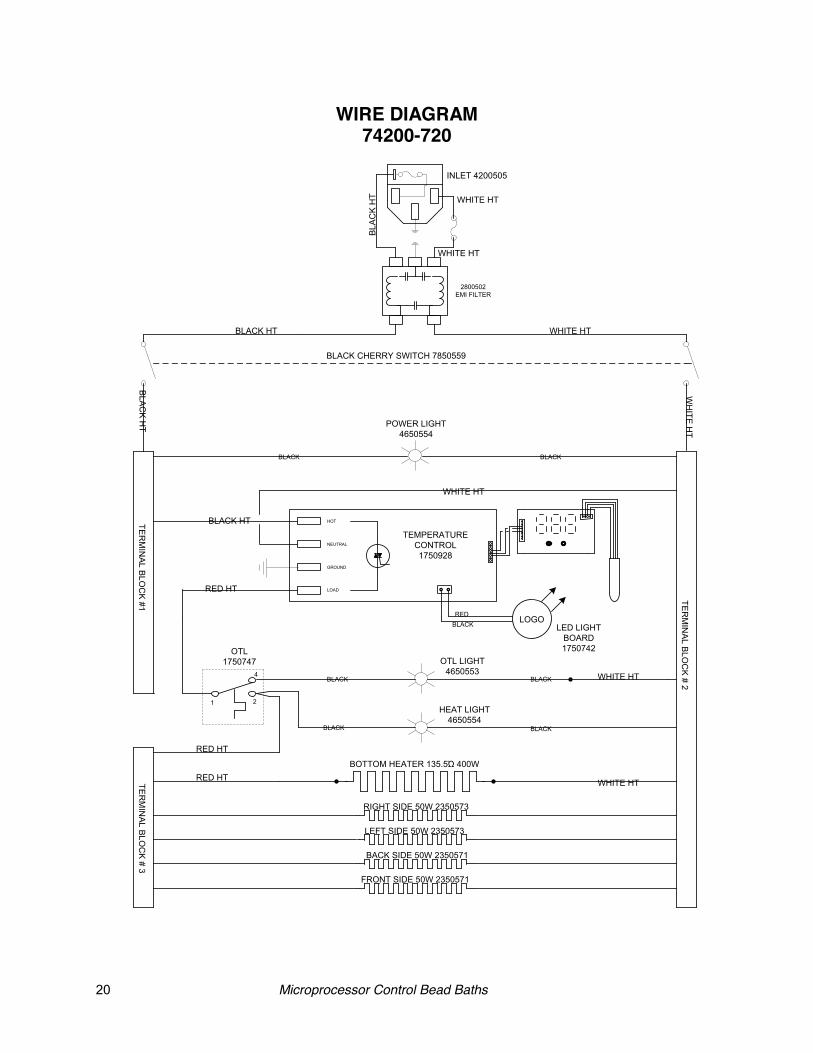
WIRE DIAGRAM 74200-720
HOT
NEUTRAL
GROUND
LOAD
LOGORED
BLACK
1 2
4B
LAC
K H
T
BLACK HT
BLACK HT
BLACK BLACK
RED HT
RED HT
RED HT
BLACK BLACK
BLACK BLACK
WH
ITE H
T
WHITE HT
WHITE HT
WHITE HT
INLET 4200505
POWER LIGHT4650554
LED LIGHTBOARD1750742
OTL LIGHT4650553
HEAT LIGHT4650554
OTL1750747
BOTTOM HEATER 135.5 400W
RIGHT SIDE 50W 2350573
LEFT SIDE 50W 2350573
BACK SIDE 50W 2350571
FRONT SIDE 50W 2350571
BLACK CHERRY SWITCH 7850559
TER
MIN
AL B
LOC
K #1
TER
MIN
AL B
LOC
K # 2
TER
MIN
AL B
LOC
K # 3
2800502EMI FILTER
WHITE HT
WHITE HT
WHITE HT
BLA
CK
HT
TEMPERATURECONTROL1750928