Basic e DART Setup and Use 2010 4 1
105
1 - Basic eDART™ eDART System™ Application Training Rev. 4.0
-
Upload
independent -
Category
Documents
-
view
7 -
download
0
Transcript of Basic e DART Setup and Use 2010 4 1

1 - Basic eDART™
eDART System™ Application Training
Rev. 4.0
2 - Basic eDART™
Table of Contents
Introduction………………………………………………………………………………..3Interfacing the eDART™ with your Machine….……………….….…………………9Machine Sensors…………………………………………………………....…………...20Mold Pressure Sensors…………………………………...……………….…………...25Flush Mount Sensors…………………………………………………….……………...33Sensor Placement Strategy……………………………...……….…………………….40Starting up the eDART™……………………………………….……………………….44
Navigating the eDART™ Software…………………………………………………….55Alarm Settings and Part Diverter………………………………………………………73Troubleshooting…………………………………………...…….……………………….84Security……………………………………………………………………………………..94Using Saved eDART™ Data……………………………………...……………………..99

3 - Basic eDART™
RJG Insight System®
eDART™ Cavity Pressure
Sensors Machine Sensors Machine Timing
Inputs Machine Transfer
and Sorting Outputs

4 - Basic eDART™
Benefits
Process Monitoring – Complete process history for each part
Part Containment – Quality to the Customer
Cavity Pressure Control – Process Consistency
Process Setup Match – Verify the right process setup is running
Can you tell which are the good parts?
With RJG Insight System®, you can.
5 - Basic eDART™
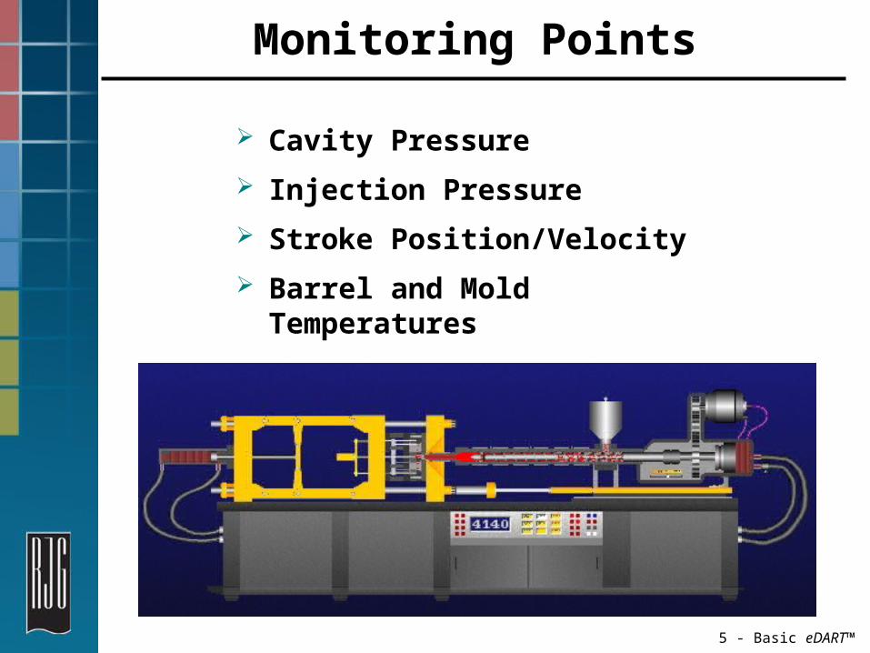
Monitoring Points
Cavity Pressure Injection Pressure Stroke Position/Velocity Barrel and Mold Temperatures

6 - Basic eDART™
Insight System® Layout

7 - Basic eDART™
eDART™ Components
Essentially a Computer
Data Storage/Memory
Keyboard/Mouse ports
Video output Ethernet / Modem Insight Software

8 - Basic eDART™
eDART™ Connections Power: 120VAC Lynx Ports: Sensors and Machine Interface
Modules Serial (COM) Port: Remote Access, Touch
Screens Phone Line: Dial-In Support Ethernet (NIC): Network

9 - Basic eDART™
Interfacing the eDART™ with Your Machine

10 - Basic eDART™
Mounting Guidelines for eDART™
Mount eDART™ to Non-Vibrating Surface – (Temperature not to exceed 122°F/50° C)
Position eDART™ with connectors facing down (Reduce the chance of fluids getting in the ports)
Keep eDART™ and associated cables away from high voltage and static (e.g. Material feed lines, high voltages, motors, solenoids, etc.)

11 - Basic eDART™
Machine Interface Modules
Module FunctionID7-D-SEQ Seven sequence digital input module (universal voltages).
Gets machine StateIA1-D-VI 0-10V or 4-20mA isolated analog input module for signals
from machineOA1-D-V 0-10V isolated analog output, feeds signals to machine
controller for transferOR2-D Dual relay output, Contact rating – 2A at 24V or 0.5A at
120VAC for control, sorting, or lights.

12 - Basic eDART™
Sequence ModuleID7-D-SEQ
35mm DIN rail mountable input module
Machine signals connect to terminal 1 through 7, Common to 8
Operates at 24VDC

13 - Basic eDART™
Sequence ModuleID7-D-SEQ (24VDC or 120VAC)
Terminal - Importance
Comes On Goes Off Purpose
1. INJ Forward (2) Injection Starts
End of hold Search for peaks, hold pressure. (Required for control)
2. 1st Stage (5) Inj. Starts Inj. goes to hold
Creates internal inj. Forward, pack, & in 2-Stage “Fill”
3. Screw Run (1) Screw motor Starts
Stops Stroke direction, Zero, Material variation information (Required for control)
4. Mold Clamped (3)
Mold clamped to pressure
Mold cracks Accurate cycle time, integration limit (Reset Piezo Adapter & UMPI)
5. Mold Opening (4)
Mold opening
Mold fully open
Pinched part detection (Resets Piezo Adapter & UMPI)
6. Manual (6) Machine in manual
In Full/Semi Automatic mode
Prevents parts counts and data storage while in this mode
7. Shuttle Position (7)
Start of cyclePosition 2
Start of cyclePosition 1
Detects mold position in 2-position shuttle molding
8. Input CommonMold Closing (8) Mold begins
to closeMold clamps up
Cycle time with mold opening (Resets Piezo Adapter and UMPI)
Mold Open (9) Mold fully open
Mold begins to close
Cycle time and integration limit (Resets Piezo Adapter and UMPI)
Second Stage (10) Start of hold
End of hold Creates internal injection forward and pack
Fill (11) Inj. Moves forward after decompress point
Inj. speed changes from fast fill (V1) to slow pack (V2).
Measuring of material viscosity (Rare machine signal)

14 - Basic eDART™
Analog InputIA1-D-VI (0-10v)
Connection Function Wire Color
Terminal 1 N/A -Terminal 2 N/A -Terminal 3 Jumper 1 -Terminal 4 Jumper 1 -Terminal 5 Jumper 2 -Terminal 6 Jumper 2 -Terminal 7 0V BlackTerminal 8 0-10V RedJ1, J2 Communi-
cations-
DIN rail mountable 0-10V/4-20mA signal Input Module
Monitors signals i.e. Electric Machine Injection Pressure
Requires user input at initial setup

15 - Basic eDART™
Dual Relay Output Module OR2-D (Relay Module with 2 Dry Contact)
Terminal
Function Wire Color
1 N/A -2 N.C. CR2 -3 COM CR2 Black4 N.O. CR2 Brown5 N/A -6 N.C. CR1 -7 COM CR1 Black8 N.O. CR1 Green
J1, J2 Communications
-
35 mm DIN rail mountable module
Has 2 independently configurable dry contact outputs
Each set of relay contacts has spare fuse at bottom

16 - Basic eDART™
Relay Output Module OR2-D (Dry Contact Relay)
Part Containment Configure one or both of OR2-D contacts to be setup for part containment
Define contacts as a 'Good Control' output or a 'Reject Control’ output depending on the application
Robot Interface

17 - Basic eDART™
Relay Output Module OR2-D (Dry Contact Relay)
Machine Transfer Implement RJG, Inc. DECOUPLED MOLDINGSM by
transferring from velocity to pack At setup page define one side of the
module contact as Velocity to Pressure

18 - Basic eDART™
Indicator Light TreeLT3-1/2-(24VDC or 120VAC)
Machine mountable 3 colors (red, yellow, green) light-tree that visually indicates if process is running within limits.
The lights are controlled based on process limits set in Alarm Settings

19 - Basic eDART™
Analog OutputOA1-D-VI (0-10V/0-20mV)
Terminal
Function Wire Color
1 N/A -2 N/A -3 0-10V COM Black4 0-10V +SIG Red5 N/A -6 N/A -7 0-20mV COM Black
8 0-20mV +SIG
Red
J1, J2 Communi-cations
-
DIN rail mountable module that outputs 0-10V/4-20mA signals
Outputs an analog signal i.e. Machine Transfer Option
Requires user input for initial setup

20 - Basic eDART™
Machine Sensors

21 - Basic eDART™
Screw Position/VelocityLE-R-30
Monitors Stroke/Position, Volume
Standard Travel 30”

22 - Basic eDART™
Mounting the LE-R-30

23 - Basic eDART™
Plastic Pressure for Injection
The eDART™ uses the intensification Ratio (Ri) of the machine and a direct hydraulic measurement to display the Injection Pressure in actual plastic pressure at the nozzle.
This allows the data to be machine independent.
This Module gives us: Fill Pressure Viscosity Back Pressure Hold Pressure
Electric machines are always in plastic pressure

24 - Basic eDART™
Water based coolant differential pressure sensor between two NPT fittings.
Delta Pressure SensorLS-DP-100

25 - Basic eDART™
Mold Pressure Sensors

26 - Basic eDART™
Behind the Ejector Pin SensorsButton Style (Strain Gauge and Piezoelectric)
Installed behind an ejector pin Pin transfers force to sensor Sensor transfers pressure readings to
eDART™

27 - Basic eDART™
Indirect Mold Pressure
Sensors that sit behind a pin read pressure indirectly. To get the correct cavity pressure the force exerted on the pin is divided by the area of the pin
The pin size must be input in the eDART™
Pressure = Force / Area
28 - Basic eDART™
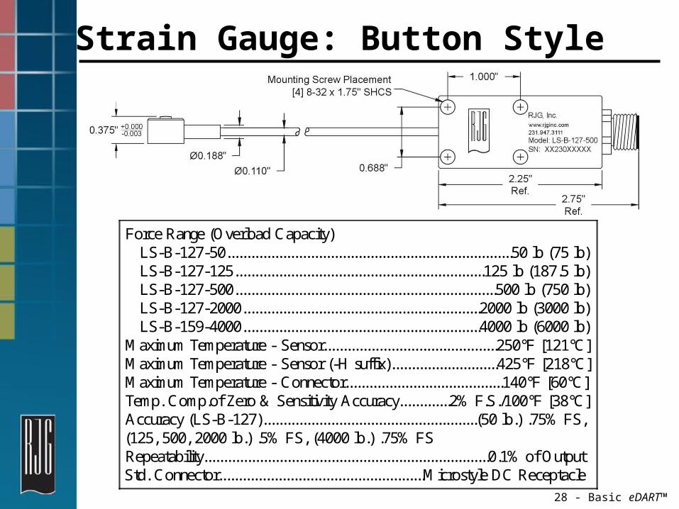
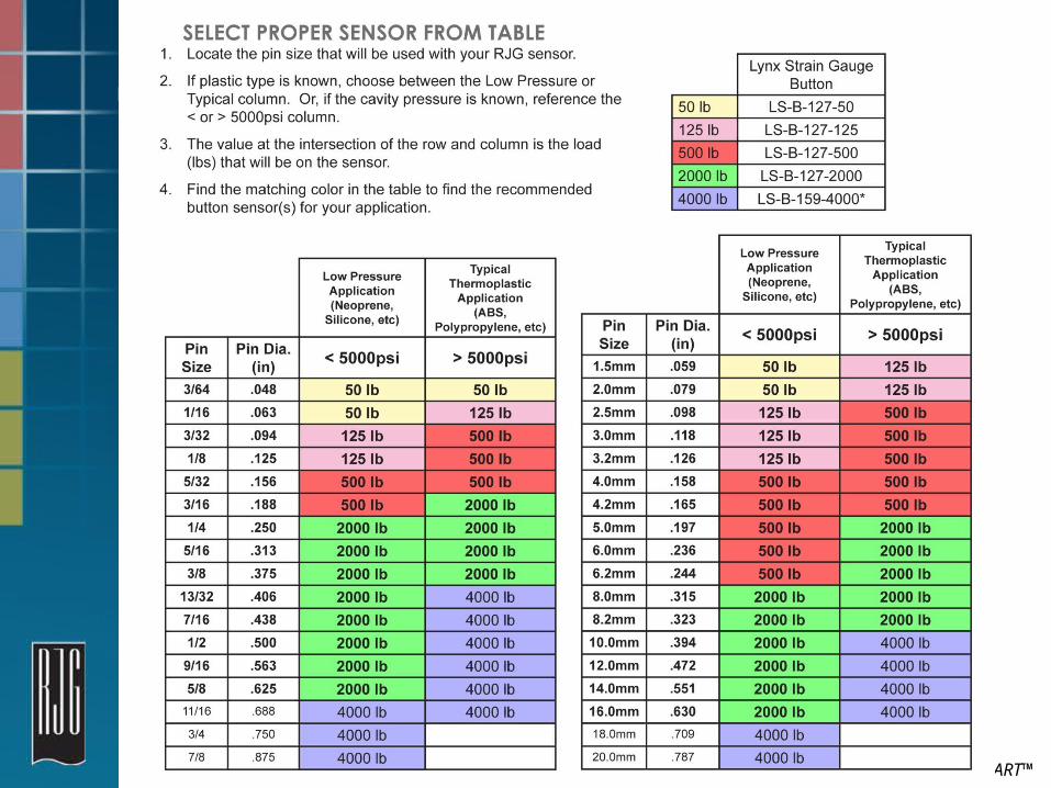
Strain Gauge: Button Style
Force Range (Overload Capacity) LS-B-127-50........................................................................50 lb (75 lb) LS-B-127-125...............................................................125 lb (187.5 lb) LS-B-127-500..................................................................500 lb (750 lb) LS-B-127-2000............................................................2000 lb (3000 lb) LS-B-159-4000............................................................4000 lb (6000 lb)M aximum Temperature - Sensor............................................250°F [121°C]M aximum Temperature - Sensor (-H suffix)...........................425°F [218°C]M aximum Temperature - Connector........................................140°F [60°C]Temp. Comp.of Zero & Sensitivity Accuracy.............2% F.S./100°F [38°C]Accuracy (LS-B-127)......................................................(50 lb.) .75% FS,(125, 500, 2000 lb.) .5% FS, (4000 lb.) .75% FSRepeatability........................................................................0.1% of OutputStd. Connector....................................................M icrostyle DC Receptacle

29 - Basic eDART™
Choosing the Correct Model
Key element – expected pressure vs. pin area
Pin size references the surface that contacts plastic part
How to select a sensor:1. RJG recommends using more than 10% of the usable
range for an individual sensor: i.e. Expected plastic psi should generate more than 50# for a 500# sensor.
2. RJG will base most recommendations on the 10,000 psi column: i.e. 10,000 psi on a 6.0mm pin generates 438#'s of force. Use a 2000# sensor.
Note: RJG also has a selection of flush mount sensors for applications
where an under-the-pin sensor is not practical.
Refer to chart on next page
30 - Basic eDART™

31 - Basic eDART™
Installation Issues Upside down Shallow pocket
(Pre-Load) Narrow pocket Pinched cables Uneven pocket
bottom Rounded corners
in pocket Web Resource:http://www.rjginc.com/resources/choosin
g_the_right_sensor

32 - Basic eDART™
Piezoelectric: Button Style
Uses Quartz Element Outputs Charge When Pressed 9211, 9204

33 - Basic eDART™
Flush Mount SensorsLynx Flush MountPiezoelectric

34 - Basic eDART™
Flush Mount SensorDirect Mold Pressure
Sensor becomes part of cavity
Plastic applies pressure to sensor
The sensor transfers the pressure readings to eDART™
All RJG flush Direct sensors 30K PSI Maximum Rating

35 - Basic eDART™
Flush Mount Sensor Installation
RJG, Inc.
www.rjginc.com
231.947.3111
Model: LS-F-40-20K
SN: XX284XXXXX
L4M in. Cable Bend 17,5 m m
25,4 m m
5,6 m m
8,7 m m
L1L2
L3
T132
Drill & Tap for8-32 x 1.75" Screws
4 Holes
D3
D2
D1 H7
0,3 m m M in. 0,4 m m M ax.60° Angle Relief

36 - Basic eDART™
Choosing the Correct ModelFlush Mount Sensor Installation
Consideration How large a witness mark allowed Good to 30,000psi in cavity
Sensor Sensor Diameter LengthLP-F-25-30K 2.5mm (0.0984”) 12”, 24”,
36”, 48”LP-F-40-30K 4.0mm (0.1574”) 12”, 24”,
36”, 48”6157, 6159 2.5 mm/ 4.0 mm (cables sold
separately)

37 - Basic eDART™
Installation IssuesFlush Mount Sensor Installation
Don’t over-tighten nut
Ensure bores are centered
Avoid pinching cables
Keep connectors clean

38 - Basic eDART™
Sensor AdaptorSG/LX1-S
Medium between Analogsensors and eDART™
Needs setup

39 - Basic eDART™
Mold IdentifierID/LX1-S
Identifies un-instrumented molds
Does not measure mold pressure

40 - Basic eDART™
Sensor Placement Strategy
Conventional Runner Hot Runner/Hot Drop

41 - Basic eDART™
Area of Influence
Incorrect
Correct
Control sensors should be located in the “Area of Influence”.
Correct
42 - Basic eDART™
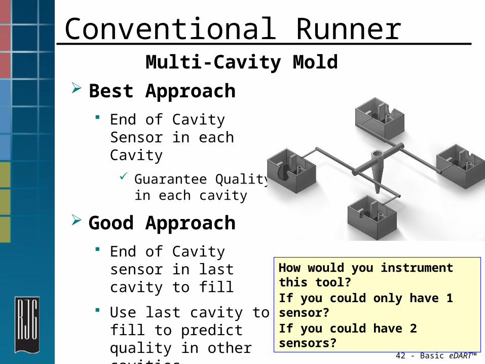
Conventional Runner Multi-Cavity Mold
Best Approach End of Cavity Sensor in each Cavity
Guarantee Quality in each cavity
Good Approach End of Cavity sensor in last cavity to fill
Use last cavity to fill to predict quality in other cavities
How would you instrument this tool?If you could only have 1 sensor?If you could have 2 sensors?

43 - Basic eDART™
Hot Runner/Hot Drop Multi-Cavity Mold
Choose a location at the end of fill in every cavity due to “Multi-Process Disease”
Example
Click on Picture to run animation

44 - Basic eDART™
Starting Up the eDART™
45 - Basic eDART™
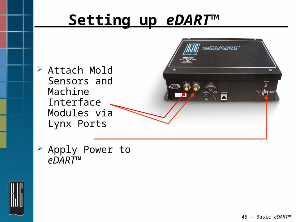
Setting up eDART™
Attach Mold Sensors and Machine Interface Modules via Lynx Ports
Apply Power to eDART™

46 - Basic eDART™
Job Setup Screen First Screen to Appear
Top of the window indicates sensors were found
Enter Mold Number (Material and Cavities are Optional)
Enter Plant, Cell and Machine name Choose Accept when finished

47 - Basic eDART™
Job Setup Screen Key Concepts
Descriptive name with Standardized naming system
If the material and cavities never change, enter the Mold Level only. This will allow the use of automatic job start tools.

48 - Basic eDART™
Sensor LocationsDisplays all Sensors Attached
Serial#: SignalUnique serial number with available contacts
Senor Type:Kind of sensor
Sensor Location:Where it goes
Identifier:Uniquely Identifies
SetupAnalog input/output, sensor adapter
Click Accept when finished
No Duplicate Entries
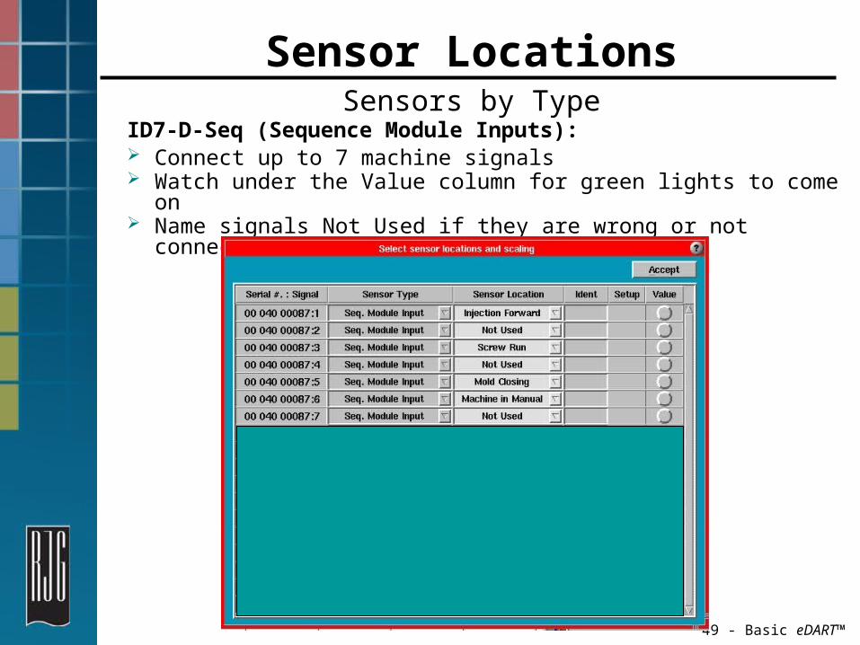
49 - Basic eDART™
Sensor LocationsSensors by Type
ID7-D-Seq (Sequence Module Inputs): Connect up to 7 machine signals Watch under the Value column for green lights to come
on Name signals Not Used if they are wrong or not
connected.

50 - Basic eDART™
Sensor LocationsSensors by Type
OR2-D: Two sets of dry contacts per unit Each set can be setup for different functions

51 - Basic eDART™
Ejector Pin Sizes
Choose/Enter Ejector Pin(s) Size Click Match Pins (if all pin sizes are equal)
Choose Accept when finished
52 - Basic eDART™
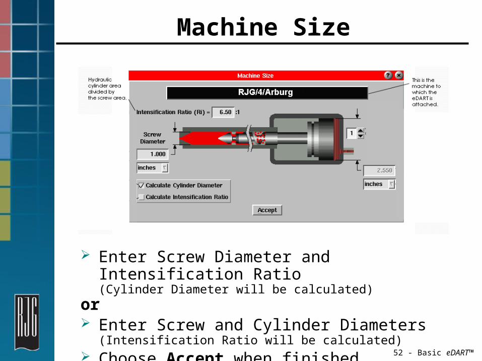
Machine Size
Enter Screw Diameter and Intensification Ratio (Cylinder Diameter will be calculated)
or Enter Screw and Cylinder Diameters
(Intensification Ratio will be calculated) Choose Accept when finished
53 - Basic eDART™
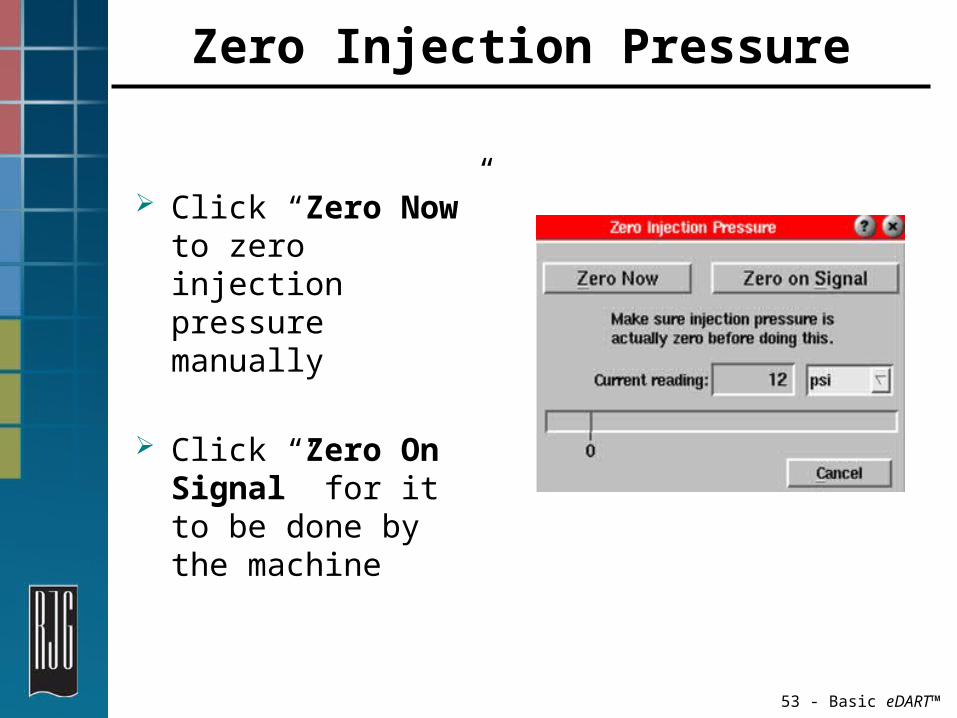
Zero Injection Pressure
Click “Zero Now” to zero injection pressure manually
Click “Zero On Signal” for it to be done by the machine

54 - Basic eDART™
Viewing Your Process“Standard” View Screens
Cycle Graph Summary Graph Cycle Values Statistics

55 - Basic eDART™
Navigating the eDART™ Software
Standard Software Views Cycle Graph Use Summary Graph Use Using Summary Statistics Setting Alarms Configuring the Part Diverter Shutting the System Down

56 - Basic eDART™
Saved ViewsChoose or Save a Standard View
Arrange how tools are displayed on the monitor
Views can be stored or deleted

57 - Basic eDART™
Cycle GraphShows Real Time Cycle
DataInjection Pressure
Shot VolumeCavity PressureCurves
Machine Sequences
58 - Basic eDART™
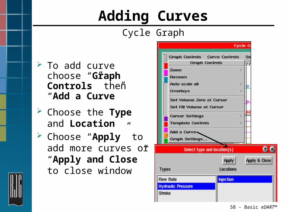
Adding CurvesCycle Graph
To add curve choose “Graph Controls” then “Add a Curve”
Choose the Type and Location
Choose “Apply” to add more curves or “Apply and Close” to close window

59 - Basic eDART™
Sequence SettingsSetting the Machine Fill Value
Make a “Fill Only” shot and click this button.
Click this button to set the zero volume point before decompress (if screw run unavailable)

60 - Basic eDART™
Set Screw BottomAllows the system to display and set
alarms on a cushion value
Drive the screw all the way to the bottom and click the Bottom the screw button

61 - Basic eDART™
Zoom/UnzoomCycle Graph
Choose “Graph Controls”; “Zoom”
Choose a Portion of the Cycle Graph to Zoom in on
May also change times on Cycle Graph
62 - Basic eDART™
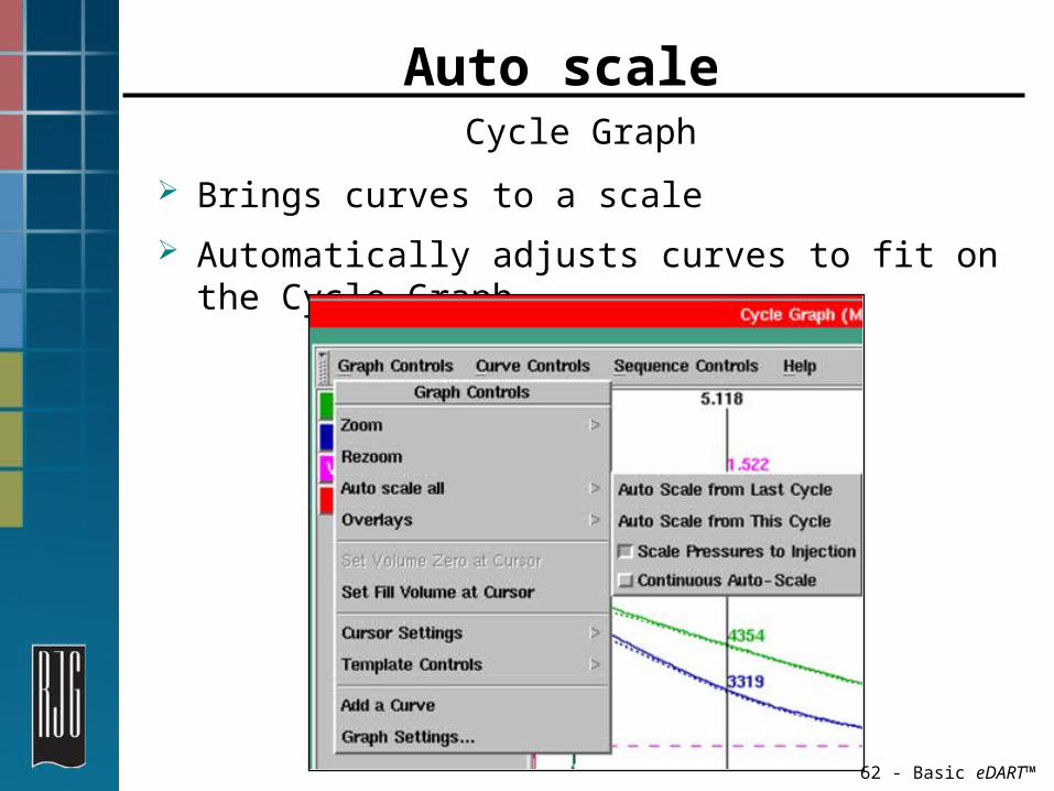
Auto scale Cycle Graph
Brings curves to a scale Automatically adjusts curves to fit on the Cycle Graph

63 - Basic eDART™
Template ControlsCycle Graph
Matching Template equals the same plastic part Match Process from machine to machine Match Process from tool makers/sister companies
Select Template to apply existing template
Save TemplateTo create a template from the current process
Manage TemplateTo move, copy, delete existing template

64 - Basic eDART™
Cycle Values Shows Actual Values of the Cycle Peaks Integrals Sequence Times
Comparative Template Values
65 - Basic eDART™
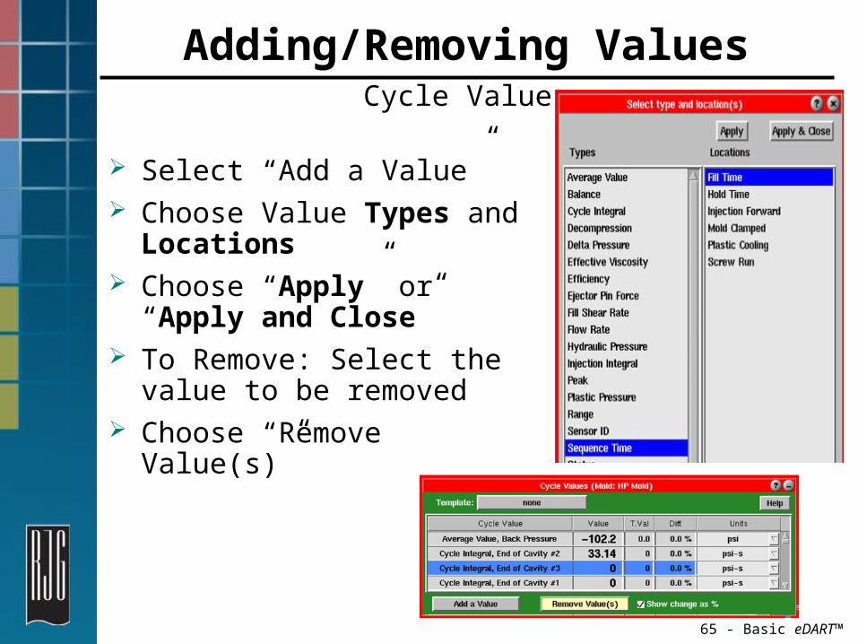
Adding/Removing ValuesCycle Values
Select “Add a Value” Choose Value Types and Locations
Choose “Apply” or “Apply and Close”
To Remove: Select the value to be removed
Choose “Remove Value(s)”

66 - Basic eDART™
Summary GraphShows Data Over Time
Collects historical data of a process
Good for detecting variations over time
Add Alarm/Warning limitsAlarm Limits

67 - Basic eDART™
Statistics
Average Maximum Minimum Std. Deviation Expected Variation CPK PPK, etc.
Gives Statistics of Process

68 - Basic eDART™
Adding/Removing a ValueStatisticsTo add
Choose “Add A Value”
Select Type of stats
Choose Type and Locations
To Remove Highlight thevalue(s)
Choose Remove Value (s)

69 - Basic eDART™
Documentation of Process Changes Hold Pressure Fill Speed Screw RPM Material Change
Put cursor overthe note to view
Adding NotesSummary Graph
70 - Basic eDART™
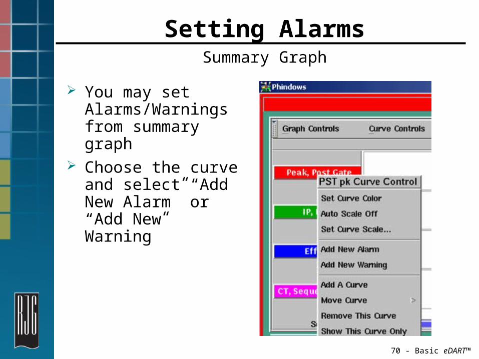
Setting AlarmsSummary Graph
You may set Alarms/Warnings from summary graph
Choose the curve and select “Add New Alarm” or “Add New Warning”

71 - Basic eDART™
Alarm Setting Entry and Part Diverter Settings
Using the Alarm Settings Tool Configuring the Part Diverter

72 - Basic eDART™
Alarm Wizard sets the Upper/Lower limits to 6σ for Alarms and 3σ for Warnings over last 20 shots
Setting AlarmsSummary Graph

73 - Basic eDART™
Go to Alarms Settings page to view values
Alarm levels can be manually entered
Setting AlarmsAlarm Level Entry

74 - Basic eDART™
Activating Alarm Outputs
eDART™ is set to calculate the integral at the end of screw Run by default Good if NO Cavity
Pressure is present at the end of Screw Run
If Cavity Pressure IS present at the end of Screw Run the integral area will vary with screw run time variations Noisy Summary
Data Hard to set good
alarm

75 - Basic eDART™
Part Diverter ControlsSorting good parts from the bad
SortDiverter control is
enabled Don't Sort
Diverter control is disabled
GoodValue is within alarm
limits Susp
Both Good andReject output are OFF
Rej.The value crossed alarm
limit Diverter Settings
Configuring diverter functionalities

76 - Basic eDART™
Part Diverter ControlsTesting the Diverter Output
Manual Diverter Test Manually test
diverter/flipper direction
Press the “Good” button, did the robot or diverter go to the right position.
Press the “Reject” button, did the robot or diverter go to the right position.

77 - Basic eDART™
Part Diverter ControlsSet diverter operating times
Hold Diverter Position Until Alarm Changes
Change direction only if the alarm is different
Hold Diverter Position for a timeAdd needed time for thepart to reach proper box

78 - Basic eDART™
Part Diverter ControlsSet diverter disabled operation
Set Part Diverter Operation when the Part Diverter has been disabled (Don’t Sort Pressed).
Consider the parts reject if the Part Diverter is disabled.
79 - Basic eDART™
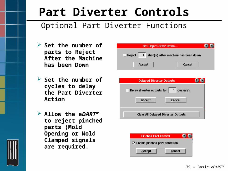
Part Diverter ControlsOptional Part Diverter Functions
Set the number of parts to Reject After the Machine has been Down
Set the number of cycles to delay the Part Diverter Action
Allow the eDART™ to reject pinched parts (Mold Opening or Mold Clamped signals are required.

80 - Basic eDART™
Stop Job Always stop job when mold is removed
Go to “Main Menu” - “Stop Job”
You will receive a warning screen, confirm job stop
Always stop job when mold is removed!!

81 - Basic eDART™
System ShutdownPowering Off System
Click on “QNX” menu and choose “Shutdown System”
At warning screen, confirm shutdown
Message appears saying you may power down system
Pull power cord or fuse

82 - Basic eDART™
Troubleshooting

83 - Basic eDART™
TroubleshootingRaw Data Viewer
Select from the Main Menu View status of ports and sensors Diagnose when failures occur

84 - Basic eDART™
TroubleshootingRaw Data Viewer, Data Details
Check details on sensor calibration The current offset can indicate installation issues. The initial offset is ideal.
85 - Basic eDART™
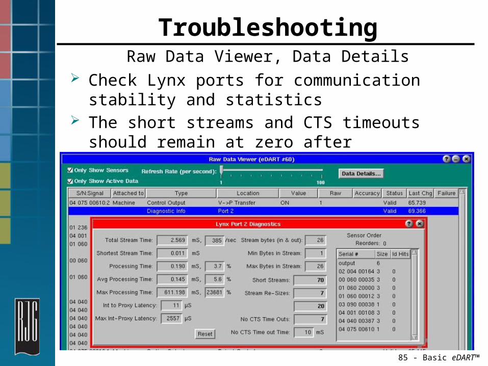
TroubleshootingRaw Data Viewer, Data Details
Check Lynx ports for communication stability and statistics
The short streams and CTS timeouts should remain at zero after selecting Reset.

86 - Basic eDART™
Sequence SettingsInjection Forward Tab
ON: Indicates how accurately the eDART™ is able to do the OFF to ON switch of Injection Forward sequence signal
OFF: Indicates how accurately the eDART™ is able to do the ON to OFF switch of Injection Forward sequence signal
Each bar block is one level. A blank bar is 0 and a full bar 5.

87 - Basic eDART™
Sequence Lights
Shows the actual hard
wired sequence signals
Shows the sequence signals as
calculated by eDART™

88 - Basic eDART™
Sequence SettingsWorking with inaccurate machine sequence
inputs
When one or more machine sequences are lost or are reset.
Enter a time after injection forward goes off to wait before looking for a rising edge again.
Check this box if your system has inaccurate sequence signals coming from the Sequence Module (ID7-D-SEQ).

89 - Basic eDART™
TroubleshootingLynx Cables
Bad cables will give communication problems between eDART™ and sensors
Swap out cable(s) to see if problem persists
Keep connectors clean Keep away from high traffic areas Keep away from material lines, pumps, and motors
Avoid pinch points

90 - Basic eDART™
TroubleshootingMouse
If mouse is not working, check to make sure it is connected to the proper input
Verify that the a good connection is being made
Choose QNX Menu, Reset Keyboard and Mouse - (you must use keyboard)
Swap out the mouse
91 - Basic eDART™
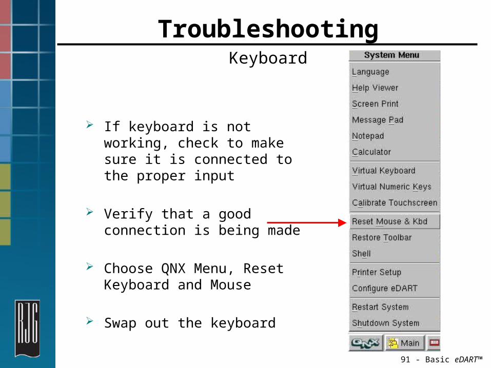
TroubleshootingKeyboard
If keyboard is not working, check to make sure it is connected to the proper input
Verify that a good connection is being made
Choose QNX Menu, Reset Keyboard and Mouse
Swap out the keyboard

92 - Basic eDART™
Security SettingsSecuring Your System
Apply authorization requirements
Track changes made in the tools you have secured

93 - Basic eDART™
Security SettingsAdministrative Log In
Select Log In from the Main Menu
Type the administrative password

94 - Basic eDART™
Security SettingsSecurity Maintenance
Choose Security from the Main Menu Create/Rename/Delete User and Group Accounts
Assign User(s) to Group Set general security settings

95 - Basic eDART™
Security SettingsGeneral Security Settings
Enable/Disable security Set security parameters Select Functions for securing

96 - Basic eDART™
Secured Functions Setting Permission
Lists all tools that can be secured
Check the tool and its sub-feature to secure

97 - Basic eDART™
Using Saved eDART™ Data

98 - Basic eDART™
Extracting eDART™ Data
Connect your PC or Laptop to the eDART™ with a Cross Over Ethernet cable
Choose eDART™ Data Extractor from the RJG Insight Folder
Select the Mold, Desired Dates and choose Get Data

99 - Basic eDART™
Extracting eDART™ Data
Select the Mold, Desired Dates Choose Get Data

100 - Basic eDART™
Review Data in Analyzer
Select the Mold, Desired Dates Double Click the Summary Graph Icon

101 - Basic eDART™
Review Data in Analyzer
Select the desired date and time with the mouse
Click the Get Cycle button on the Summary Graph

102 - Basic eDART™
Review Data in Analyzer
Move one cycle forward or backward using the black arrows.
Replay data automatically by using the green button.
Overlay cycles using the OV button.

103 - Basic eDART™
Exporting Data into Excel ®
Select the desired date and time span with the mouse
Click the Export button on the Summary Graph
104 - Basic eDART™
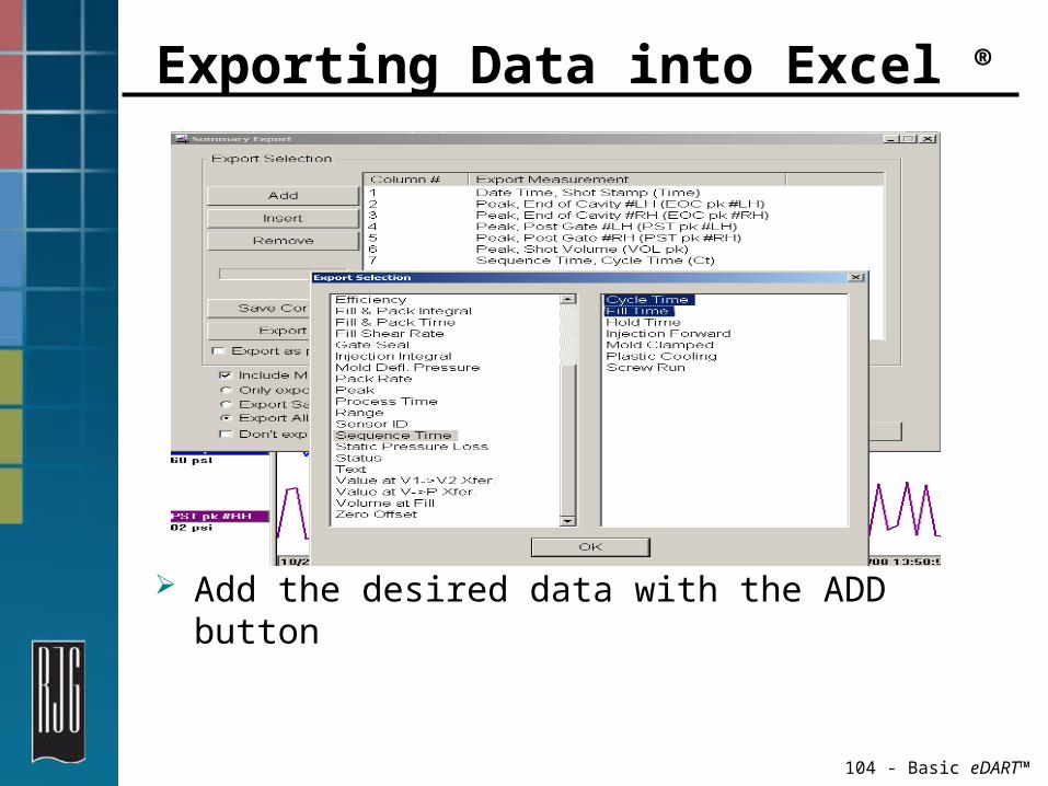
Exporting Data into Excel ®
Add the desired data with the ADD button

105 - Basic eDART™
Exporting Data into Excel ®
Select Export on the Summary Export Tool
Manipulate the data in Excel