A Flexible Metamaterial Based Printed Antenna for Wearable ...

22 IEEE A&E SYSTEMS MAGAZINE MARCH 2015
Band Pass Filter Bank Design (250–500 MHz) for Radio Astronomy Application Based on Metamaterial ZOR TechniquesSougata Chatterjee, Anil Raut, Suresh KumarFront End Group, Giant Metrewave Radio Telescope Pune, India
INTRODUCTION
M
MTM-ZOR BPF DESIGN FOR 420–520 MHZ
CL LL
Authors’ current address: S. Chatterjee, A. Raut, S. Kumar, Front End Group, Giant Metrewave Radio Telescope (GMRT), NCRA-TIFR, Pune-410504, India, E-mail: ([email protected]). Manuscript received October 24, 2014, and ready for publica-tion December 16, 2014. DOI No. 10.1109/MAES.2015.140072. Review handled by M. De Santos. 0885/8985/15/$26.00© 2015 IEEE
Figure 1.
Figure 2.

MARCH 2015 IEEE A&E SYSTEMS MAGAZINE 23
fse fsh fL fR fO
fse is equal fsh
where n LK K
where W S
where
kg
h t
Figure 3. Figure 4.

24 IEEE A&E SYSTEMS MAGAZINE MARCH 2015
Band Pass F i l ter Bank Design for Radio Astronomy Appl icat ion Based on Metamater ia l ZOR Techniques
W L S
n Wg LgCL
LR LLCR
/
BPF BANDWIDTH AND ROLL-OFF CONTROL
(L L L
Table 1.
Specifications for Five-Pole Filter for 420–520 MHz
Item Specification
Central frequency(f0) 470 MHz
Bandwidth (6dB) 100 MHz
Insertion loss < 3 dB
Return loss in the pass band 10 dB
Sharp skirt (Attenuation at fue+30 MHz)
20 dB
Figure 5.
Figure 6.

MARCH 2015 IEEE A&E SYSTEMS MAGAZINE 25
Chatter jee, Raut , and Kumar
MTM-ZOR-BASED FILTER BANK DESIGN
SIZE REDUCTION OF FILTER
USING MTM-ZOR
Figure 7.
Figure 9.
Figure 8.

26 IEEE A&E SYSTEMS MAGAZINE MARCH 2015
Band Pass F i l ter Bank Design for Radio Astronomy Appl icat ion Based on Metamater ia l ZOR Techniques
Table 2.
Design Dimensions of the Filter After Modification to the Frequency Range of
420–520 MHz (All Dimensions Are in Millimeters)
Design Parameter 420-520 MHz
ZOR-1 W, S, Wp, L 0.527, 0.11, 0.125, 8.7595
WF , LF 0.8, 5.6
Ls1, Ls2, ls3, ls4
,Ws8.01, 4.005, 2.0025, 2.0035, 0.555
LIRC, WIRC 3.1, 0.3
ZOR-2 W, S, Wp, L 0.562, 0.11, 1.35, 6.52
Ls1, Ls2, Ls3, ls4, Ws 8.9957, 4.49785, 2.248925, 2.248925, 0.69
LIRC, WIRC 2.5, 0.7
ZOR-3 W, S, Wp, L 0.585, 0.11, 1.21, 6
Ls1, Ls2, Ls3, Ws 9.9546, 4.9773, 4.9773, 0.69
LIRC, WIRC 2.5, 0.7
Table 3.
Fabricated Design of the Modified Filter and Its Experimental Results
Design Parameter Expected Achieved
Band width (6 dB) 420–520 MHz 411–517 MHz
Insertion loss 2.0–3.0 dB (470 MHz) 2 dB (470 MHz)
Return loss 10 dB over the band 10 dB over the band
Higher frequency cutoff +30MHz 30 dB (550 MHz) 32 dB (547MHz)
Table 4.
Design Dimensions for the Four Subband Filters That Were Fabricated (All Dimensions Are in Millimeters)
420–520 MHz 360–460 MHz 300–400 MHz 240–340 MHz
ZOR-1 W, S, Wp, L 0.527, 0.11, 0.125, 8.7595
0.54, 0.11, 0.16, 10.5 0.587, 0.1, 0.165, 11.9 5.45, 0.1, 0.267, 18.364
WF , LF0.8, 5.6 4.5, 0.8 0.9, 5 0.8, 5
Ls1, Ls2, ls3, ls4
, Ws8.01, 4.005, 2.0025, 2.0035, 0.555
8.854, 4.4595, 2.22745, 2.22745, 0.555
9.85, 4.925, 2.4625, 2.4625, 0.555
10.85, 5.425, 2.7125, 2.7125, 0.555
LIRC, WIRC 3.1, 0.3 4.1, 0.3 4.2, 0.2 4.2, 0.2
ZOR-2 W, S, Wp, L 0.562, 0.11, 1.35, 6.52 0.555, 0.11, 1, 8.67 0.571, 0.1, 0.9, 9.5 0.55, 0.1, 1.1, 14.6
Ls1, Ls2, Ls3, ls4, Ws 8.9957, 4.49785, 2.248925, 2.248925, 0.69
9.8341, 4.9701, 2.4585, 2.4583, 0.69
11.35, 5.675, 2.8375, 2.8375, 0.69
12.35, 6.175, 3.0875, 3.0875, 0.69
LIRC, WIRC 2.5, 0.7 2.5, 1 2.5, 0.9 2.5, 1.2
ZOR-3 W, S, Wp, L 0.585, 0.11, 1.21 0.54, 0.11, 0.95, 7.763 0.565, 0.1, 0.8, 9 0.56, 0.1, 1.1, 13.9
Ls1, Ls2, Ls3, Ws 9.9546, 4.9773, 4.9773, 0.69
10.82, 5.14, 2.57, 0.69 12.35, 6.175, 6.175, 0.69
13.35, 6.675, 6.675, 0.69
LIRC, WIRC 2.5, 07 2.5, 1 2.5, 0.9 2.5, 1.2

MARCH 2015 IEEE A&E SYSTEMS MAGAZINE 27
Chatter jee, Raut , and Kumar
Figure 10.
28 IEEE A&E SYSTEMS MAGAZINE MARCH 2015
Band Pass F i l ter Bank Design for Radio Astronomy Appl icat ion Based on Metamater ia l ZOR Techniques
CONCLUSION
ACKNOWLEDGMENTS
Figure 11.
Figure 12.
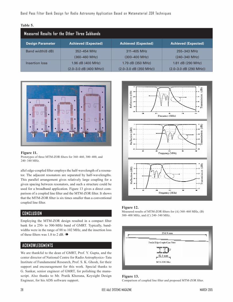
Figure 13.
Table 5.
Measured Results for the Other Three Subbands
Design Parameter Achieved (Expected) Achieved (Expected) Achieved (Expected)
Band width(6 dB) 352–454 MHz
(360–460 MHz)
311–405 MHz
(300–400 MHz)
255–343 MHz
(240–340 MHz)
Insertion loss 1.96 dB (400 MHz)
(2.0–3.0 dB (400 MHz))
1.79 dB (350 MHz)
(2.0–3.0 dB (350 MHz))
1.81 dB (290 MHz)
(2.0–3.0 dB (290 MHz))

MARCH 2015 IEEE A&E SYSTEMS MAGAZINE 29
Chatter jee, Raut , and Kumar
REFERENCES
Uspekhi Fizicheskikh Nauk,
IET Microwaves, Antennas & Propagation,
Proceedings of the 39th European Microwave Conference,
Progress in Electromagnetics Re-search C,
IEEE Microwave and Wireless Components Letters,
Electromagnetics Metamaterial: Transmission Line Theory and Microwave Application.
Current Science,
IOP Conference Series: Material Science and En-gineering.
Copyright © 2022 FDOKUMEN