
Marketing Planning Workbook MBA in a DAY® STRATEGIC MARKETING PLANNING TEMPLATE
Upload
khangminh22Category
view
4download
0
Avaya CallPilot® Planning andEngineering Guide
5.1NN44200-200
02.01October 2012
© 2012 Avaya Inc.
All Rights Reserved.
Notice
While reasonable efforts have been made to ensure that theinformation in this document is complete and accurate at the time ofprinting, Avaya assumes no liability for any errors. Avaya reserves theright to make changes and corrections to the information in thisdocument without the obligation to notify any person or organization ofsuch changes.
Documentation disclaimer
“Documentation” means information published by Avaya in varyingmediums which may include product information, operating instructionsand performance specifications that Avaya generally makes availableto users of its products. Documentation does not include marketingmaterials. Avaya shall not be responsible for any modifications,additions, or deletions to the original published version ofdocumentation unless such modifications, additions, or deletions wereperformed by Avaya. End User agrees to indemnify and hold harmlessAvaya, Avaya's agents, servants and employees against all claims,lawsuits, demands and judgments arising out of, or in connection with,subsequent modifications, additions or deletions to this documentation,to the extent made by End User.
Link disclaimer
Avaya is not responsible for the contents or reliability of any linked Websites referenced within this site or documentation provided by Avaya.Avaya is not responsible for the accuracy of any information, statementor content provided on these sites and does not necessarily endorsethe products, services, or information described or offered within them.Avaya does not guarantee that these links will work all the time and hasno control over the availability of the linked pages.
Warranty
Avaya provides a limited warranty on its Hardware and Software(“Product(s)”). Refer to your sales agreement to establish the terms ofthe limited warranty. In addition, Avaya’s standard warranty language,as well as information regarding support for this Product while underwarranty is available to Avaya customers and other parties through theAvaya Support Web site: http://support.avaya.com. Please note that ifyou acquired the Product(s) from an authorized Avaya reseller outsideof the United States and Canada, the warranty is provided to you bysaid Avaya reseller and not by Avaya.
Licenses
THE SOFTWARE LICENSE TERMS AVAILABLE ON THE AVAYAWEBSITE, HTTP://SUPPORT.AVAYA.COM/LICENSEINFO/ AREAPPLICABLE TO ANYONE WHO DOWNLOADS, USES AND/ORINSTALLS AVAYA SOFTWARE, PURCHASED FROM AVAYA INC.,ANY AVAYA AFFILIATE, OR AN AUTHORIZED AVAYA RESELLER(AS APPLICABLE) UNDER A COMMERCIAL AGREEMENT WITHAVAYA OR AN AUTHORIZED AVAYA RESELLER. UNLESSOTHERWISE AGREED TO BY AVAYA IN WRITING, AVAYA DOESNOT EXTEND THIS LICENSE IF THE SOFTWARE WAS OBTAINEDFROM ANYONE OTHER THAN AVAYA, AN AVAYA AFFILIATE OR ANAVAYA AUTHORIZED RESELLER; AVAYA RESERVES THE RIGHTTO TAKE LEGAL ACTION AGAINST YOU AND ANYONE ELSEUSING OR SELLING THE SOFTWARE WITHOUT A LICENSE. BYINSTALLING, DOWNLOADING OR USING THE SOFTWARE, ORAUTHORIZING OTHERS TO DO SO, YOU, ON BEHALF OFYOURSELF AND THE ENTITY FOR WHOM YOU ARE INSTALLING,DOWNLOADING OR USING THE SOFTWARE (HEREINAFTERREFERRED TO INTERCHANGEABLY AS “YOU” AND “END USER”),AGREE TO THESE TERMS AND CONDITIONS AND CREATE ABINDING CONTRACT BETWEEN YOU AND AVAYA INC. OR THEAPPLICABLE AVAYA AFFILIATE (“AVAYA”).
Copyright
Except where expressly stated otherwise, no use should be made ofmaterials on this site, the Documentation, Software, or Hardwareprovided by Avaya. All content on this site, the documentation and theProduct provided by Avaya including the selection, arrangement anddesign of the content is owned either by Avaya or its licensors and isprotected by copyright and other intellectual property laws including thesui generis rights relating to the protection of databases. You may notmodify, copy, reproduce, republish, upload, post, transmit or distributein any way any content, in whole or in part, including any code andsoftware unless expressly authorized by Avaya. Unauthorizedreproduction, transmission, dissemination, storage, and or use withoutthe express written consent of Avaya can be a criminal, as well as acivil offense under the applicable law.
Third-party components
Certain software programs or portions thereof included in the Productmay contain software distributed under third party agreements (“ThirdParty Components”), which may contain terms that expand or limitrights to use certain portions of the Product (“Third Party Terms”).Information regarding distributed Linux OS source code (for thoseProducts that have distributed the Linux OS source code), andidentifying the copyright holders of the Third Party Components and theThird Party Terms that apply to them is available on the Avaya SupportWeb site: http://support.avaya.com/Copyright.
Trademarks
The trademarks, logos and service marks (“Marks”) displayed in thissite, the Documentation and Product(s) provided by Avaya are theregistered or unregistered Marks of Avaya, its affiliates, or other thirdparties. Users are not permitted to use such Marks without prior writtenconsent from Avaya or such third party which may own the Mark.Nothing contained in this site, the Documentation and Product(s)should be construed as granting, by implication, estoppel, or otherwise,any license or right in and to the Marks without the express writtenpermission of Avaya or the applicable third party.
Avaya is a registered trademark of Avaya Inc.
All non-Avaya trademarks are the property of their respective owners,and “Linux” is a registered trademark of Linus Torvalds.
Downloading Documentation
For the most current versions of Documentation, see the AvayaSupport Web site: http://support.avaya.com.
Contact Avaya Support
See the Avaya Support Web site: http://support.avaya.com for productnotices and articles, or to report a problem with your Avaya product.For a list of support telephone numbers and contact addresses, go tothe Avaya Support Web site: http://support.avaya.com, scroll to thebottom of the page, and select Contact Avaya Support.
2 Avaya CallPilot® Planning and Engineering Guide October 2012Comments? [email protected]
Contents
Chapter 1: Customer service............................................................................................. 9Getting technical documentation............................................................................................................... 9Getting product training............................................................................................................................. 9Getting help from a distributor or reseller.................................................................................................. 9Getting technical support from the Avaya Web site.................................................................................. 10
Chapter 2: Getting started.................................................................................................. 11In this chapter............................................................................................................................................ 11Scope and purpose................................................................................................................................... 11Issues to consider..................................................................................................................................... 11Reference documents............................................................................................................................... 12Components of a CallPilot system............................................................................................................ 15Servers and switches................................................................................................................................ 15Desktop PCs and wireless devices........................................................................................................... 15System configuration and ordering........................................................................................................... 16
Chapter 3: Grounding and power requirements.............................................................. 17In this chapter............................................................................................................................................ 17Overview................................................................................................................................................... 17Power and grounding guidelines............................................................................................................... 18General..................................................................................................................................................... 18Power........................................................................................................................................................ 18Single-point ground................................................................................................................................... 19Auxiliary power.......................................................................................................................................... 21Terminal devices....................................................................................................................................... 21Auxiliary equipment................................................................................................................................... 21Existing power and grounding................................................................................................................... 21
Chapter 4: System configurations..................................................................................... 23In this chapter............................................................................................................................................ 23CallPilot® architecture............................................................................................................................... 23Compatibility of switches and servers....................................................................................................... 26Web server for CallPilot administration..................................................................................................... 27Desktop messaging clients....................................................................................................................... 27Section A: Hardware and software configurations.................................................................................... 27In this section............................................................................................................................................ 27CallPilot server.......................................................................................................................................... 28Hardware................................................................................................................................................... 28Software.................................................................................................................................................... 28Compatibility with other products and environments................................................................................ 29Meridian Mail............................................................................................................................................. 29Multi-tenant Meridian 1 switch................................................................................................................... 29Internet Telephony Gateway..................................................................................................................... 29Antivirus software...................................................................................................................................... 30Third-party software.................................................................................................................................. 30Avaya Contact Center Server................................................................................................................... 30Voice services........................................................................................................................................... 31
Avaya CallPilot® Planning and Engineering Guide October 2012 3

CallPilot Application Builder...................................................................................................................... 32Supported switches................................................................................................................................... 32Meridian 1................................................................................................................................................. 32Avaya Communication Server 1000.......................................................................................................... 33T1/SMDI switches..................................................................................................................................... 33Web server for CallPilot............................................................................................................................ 34Introduction............................................................................................................................................... 34Configurations of CallPilot Web services.................................................................................................. 34External Web server configuration............................................................................................................ 35Hardware................................................................................................................................................... 35Software.................................................................................................................................................... 35Free disk space......................................................................................................................................... 36Other Web server considerations.............................................................................................................. 36Monitoring performance............................................................................................................................ 36CallPilot desktop messaging..................................................................................................................... 37Voice messages........................................................................................................................................ 37Fax pages................................................................................................................................................. 38Desktop messaging clients....................................................................................................................... 38Section B: Connectivity requirements....................................................................................................... 38In this section............................................................................................................................................ 38Avaya server subnet connections............................................................................................................. 39Introduction............................................................................................................................................... 39Hardware requirements............................................................................................................................. 39Data transmission rates............................................................................................................................ 39Network protocols..................................................................................................................................... 40Avaya server subnet traffic considerations............................................................................................... 40Data transfer rates.................................................................................................................................... 40ELAN subnet connections......................................................................................................................... 41Introduction............................................................................................................................................... 41ELAN subnet description........................................................................................................................... 42ELAN subnet power requirements............................................................................................................ 42System administration and the ELAN subnet........................................................................................... 43Desktop client PCs and the ELAN subnet................................................................................................ 43ELAN subnet hardware requirements....................................................................................................... 43Hardware requirements for Option 11C.................................................................................................... 44Hardware requirements for Options 51C, 61C, and 81C.......................................................................... 44Cabling between the Meridian 1 switch and the ELAN Ethernet switch (layer 2) or hub.......................... 44ELAN subnet connectivity requirements on the switch............................................................................. 45Meridian 1 connectivity.............................................................................................................................. 45Introduction............................................................................................................................................... 45IPE (202i) platform connectivity................................................................................................................ 46Tower and rack-mount connectivity........................................................................................................... 46MPB16 board............................................................................................................................................ 46MPB96 board-DS30X................................................................................................................................ 46MPB96-board CAT5.................................................................................................................................. 46MGate-DS30X card................................................................................................................................... 47MGate-CAT5 card..................................................................................................................................... 47
4 Avaya CallPilot® Planning and Engineering Guide October 2012
Number of MGate cards and MPB96 boards supported by server type................................................... 48Meridian 1 IPE resource requirements...................................................................................................... 48Meridian 1 software requirements............................................................................................................. 48Meridian 1 memory and real-time engineering......................................................................................... 49CallPilot usage of Meridian 1 software resources..................................................................................... 50ACD DN overflow...................................................................................................................................... 50CS 1000 connectivity................................................................................................................................ 51Introduction............................................................................................................................................... 51IPE (202i) platform connectivity................................................................................................................ 51Tower and rack-mount server connectivity................................................................................................ 51MPB16 board............................................................................................................................................ 51MPB96 board-DS30X................................................................................................................................ 52MPB96-board CAT5.................................................................................................................................. 52MGate-DS30X card................................................................................................................................... 52MGate-CAT5 card..................................................................................................................................... 53Number of MGate cards and MPB96 boards supported by server type................................................... 53CS 1000 software...................................................................................................................................... 53Real-time engineering............................................................................................................................... 54CallPilot usage of CS 1000 software resources........................................................................................ 54T1/SMDI connectivity................................................................................................................................ 55Introduction............................................................................................................................................... 55MPB96 board............................................................................................................................................ 55Intel Dialogic D/480JCT-2T1 board........................................................................................................... 55SL-100 and DMS-100 connectivity........................................................................................................... 56SMDI link................................................................................................................................................... 56Line side T1 cards..................................................................................................................................... 56Channel bank for DMS-100....................................................................................................................... 57Software requirements.............................................................................................................................. 57Programming considerations.................................................................................................................... 57Section C: System requirements............................................................................................................... 58In this section............................................................................................................................................ 58Compatibility.............................................................................................................................................. 58Products and environments...................................................................................................................... 58Application Builder clients and operating systems.................................................................................... 59Desktop Messaging clients: operating systems........................................................................................ 60Customer e-mail clients............................................................................................................................. 60My CallPilot Web messaging.................................................................................................................... 60Operating system and Internet browser support with My CallPilot, CallPilot Manager, and CallPilotReporter.................................................................................................................................................... 62Software feature key adapter.................................................................................................................... 63Migration from Meridian Mail..................................................................................................................... 63
Chapter 5: Determining system size................................................................................. 65In this chapter............................................................................................................................................ 65Overview................................................................................................................................................... 65Introduction............................................................................................................................................... 65System sizing............................................................................................................................................ 66Sales engineering tools............................................................................................................................. 66Avaya Enterprise Configurator.................................................................................................................. 66
Avaya CallPilot® Planning and Engineering Guide October 2012 5
CallPilot Capacity Engineering Spreadsheet............................................................................................ 66System requirements................................................................................................................................ 67Channel requirements............................................................................................................................... 67DSP MPU requirements............................................................................................................................ 67Storage requirements................................................................................................................................ 68CPU real-time requirements...................................................................................................................... 68CallPilot platform capacity......................................................................................................................... 68Switch channel connectivity hardware...................................................................................................... 68DSP hardware........................................................................................................................................... 69Customer requirements............................................................................................................................. 69Principal input............................................................................................................................................ 69Voice Users maximums............................................................................................................................. 72Channel requirements............................................................................................................................... 72Channel types........................................................................................................................................... 72Busy hour.................................................................................................................................................. 73Usage assumptions................................................................................................................................... 73Basic user................................................................................................................................................. 73Mobile user................................................................................................................................................ 74Fax user.................................................................................................................................................... 74Desktop user............................................................................................................................................. 74Sizing the number and type of channels................................................................................................... 74Default assumptions in the system sizing tools........................................................................................ 75Daily calls and faxes................................................................................................................................. 77Voice traffic services................................................................................................................................. 77Principal services...................................................................................................................................... 77Provisioning voice channels on CallPilot.................................................................................................. 78Modeling busy hour voice traffic................................................................................................................ 78Fax traffic services.................................................................................................................................... 81Principal services...................................................................................................................................... 81Estimating fax channels............................................................................................................................ 81Modeling busy hour fax traffic................................................................................................................... 81Speech recognition traffic services........................................................................................................... 83Principal services...................................................................................................................................... 83Modeling busy hour speech recognition traffic.......................................................................................... 83Storage estimation.................................................................................................................................... 84Storage calculation assumptions.............................................................................................................. 84
Chapter 6: Engineering the server.................................................................................... 85In this chapter............................................................................................................................................ 85Avaya CallPilot® server capacities............................................................................................................ 85CallPilot product capacities....................................................................................................................... 86Overview................................................................................................................................................... 86202i server features.................................................................................................................................. 88600r server features.................................................................................................................................. 891005r server features................................................................................................................................ 891006r server features................................................................................................................................ 901002rp (T1/SMDI) server features............................................................................................................ 91Remote access service connectivity......................................................................................................... 91
6 Avaya CallPilot® Planning and Engineering Guide October 2012
Chapter 7: Selecting a site................................................................................................. 93In this chapter............................................................................................................................................ 93Space requirements for the AvayaCallPilot® server................................................................................. 93General requirements............................................................................................................................... 93Space requirements.................................................................................................................................. 94Switch room space planning..................................................................................................................... 94Ethernet switch or hub, and cables........................................................................................................... 94Peripheral devices..................................................................................................................................... 94202i server................................................................................................................................................ 95600r server................................................................................................................................................ 951005r server.............................................................................................................................................. 961006r Server............................................................................................................................................. 961002rp server............................................................................................................................................ 97CallPilot power supply requirements......................................................................................................... 97Introduction............................................................................................................................................... 97Single-point grounding.............................................................................................................................. 98UPS recommendation............................................................................................................................... 98Power requirements.................................................................................................................................. 98Environmental specifications..................................................................................................................... 99General..................................................................................................................................................... 99202i server................................................................................................................................................ 100600r server................................................................................................................................................ 1001005r server.............................................................................................................................................. 1011006r server.............................................................................................................................................. 1011002rp server............................................................................................................................................ 102
Traffic capacity tables......................................................................................................... 103In this chapter............................................................................................................................................ 103Types of traffic capacity tables.................................................................................................................. 103Introduction............................................................................................................................................... 103Types of tables to use............................................................................................................................... 103CCS values and channel requirements table............................................................................................ 104Introduction............................................................................................................................................... 104Before using the table............................................................................................................................... 104
Regulatory information....................................................................................................... 109In this chapter............................................................................................................................................ 109Grounding................................................................................................................................................. 109General compliance and safety information for specific countries............................................................ 110Information for European countries........................................................................................................... 110Safety specifications................................................................................................................................. 110RoHS compliance..................................................................................................................................... 110Information for North America................................................................................................................... 111Information for Japan................................................................................................................................ 111Japan Denan statement............................................................................................................................ 111Electromagnetic compatibility.................................................................................................................... 112Radio and TV interference........................................................................................................................ 113Information for the United States.............................................................................................................. 114Information for Canada............................................................................................................................. 114
Avaya CallPilot® Planning and Engineering Guide October 2012 7
Information for Japan................................................................................................................................ 114Index..................................................................................................................................... 117
8 Avaya CallPilot® Planning and Engineering Guide October 2012
Chapter 1: Customer service
Visit the Avaya Web site to access the complete range of services and support that Avaya provides. Goto www.avaya.com or go to one of the pages listed in the following sections.
Navigation
• Getting technical documentation on page 9• Getting product training on page 9• Getting help from a distributor or reseller on page 9• Getting technical support from the Avaya Web site on page 10
Getting technical documentationTo download and print selected technical publications and release notes directly from theInternet, go to www.avaya.com/support.
Getting product trainingOngoing product training is available. For more information or to register, you can access theWeb site at www.avaya.com/support. From this Web site, you can locate the Training contactslink on the left-hand navigation pane.
Getting help from a distributor or resellerIf you purchased a service contract for your Avaya product from a distributor or authorizedreseller, contact the technical support staff for that distributor or reseller for assistance.
Avaya CallPilot® Planning and Engineering Guide October 2012 9
Getting technical support from the Avaya Web siteThe easiest and most effective way to get technical support for Avaya products is from theAvaya Technical Support Web site at www.avaya.com/support.
Customer service
10 Avaya CallPilot® Planning and Engineering Guide October 2012Comments? [email protected]

Chapter 2: Getting started
In this chapterScope and purpose on page 11
Reference documents on page 12
Components of a CallPilot system on page 15
Scope and purposeThe CallPilot Planning and Engineering Guide provides information and instructions forselecting the best Avaya CallPilot® system for the specific needs of your organization.
The purpose of planning and engineering is to determine the best size, platform, and locationfor your Avaya CallPilot system. This guide provides information designed to help you planand engineer your CallPilot system.
If you are installing a High Availability system, see the High Availability: Installation andConfiguration Guide (NN44200-311) for planning and engineering information specific to aHigh Availability configuration.
If you plan to configure Geographic Redundancy between two CallPilot servers after theservers have been installed, see the Geographic Redundancy Application Guide(NN44200-322).
Issues to considerAt the beginning of the process of planning and engineering a CallPilot system, you mustconsider the following issues:
• the CallPilot platform that you intend to use
• the CallPilot server location
Avaya CallPilot® Planning and Engineering Guide October 2012 11
• the CallPilot server connection to the switch
• the connectivity of the PCs in your network
Note:If you are installing a High Availability system, see the High Availability Installation andConfiguration Guide (NN44200-311) for planning and engineering information.
Note:If you plan to configure Geographic Redundancy (GR) between two CallPilot servers, keepin mind that engineering rules will change due to increased users and mailbox messageson each server in the GR pair. For more information, see the Geographic RedundancyApplication Guide (NN44200-322).
Note:To comply with the Restriction of Hazardous Substances (RoHS) Directive 2002/95/ECsome of the part numbers now contain an E5 or E6 suffix. For example, part numberNTRH2014 is now NTRH2014E6. The part numbers in this guide do not contain the suffix.
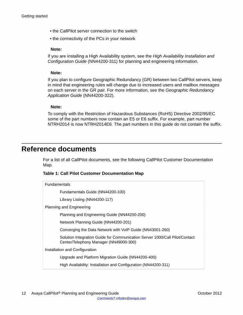
Reference documentsFor a list of all CallPilot documents, see the following CallPilot Customer DocumentationMap.
Table 1: Call Pilot Customer Documentation Map
Fundamentals
Fundamentals Guide (NN44200-100)
Library Listing (NN44200-117)
Planning and Engineering
Planning and Engineering Guide (NN44200-200)
Network Planning Guide (NN44200-201)
Converging the Data Network with VoIP Guide (NN43001-260)
Solution Integration Guide for Communication Server 1000/Call Pilot/ContactCenter/Telephony Manager (NN49000-300)
Installation and Configuration
Upgrade and Platform Migration Guide (NN44200-400)
High Availability: Installation and Configuration (NN44200-311)
Getting started
12 Avaya CallPilot® Planning and Engineering Guide October 2012Comments? [email protected]
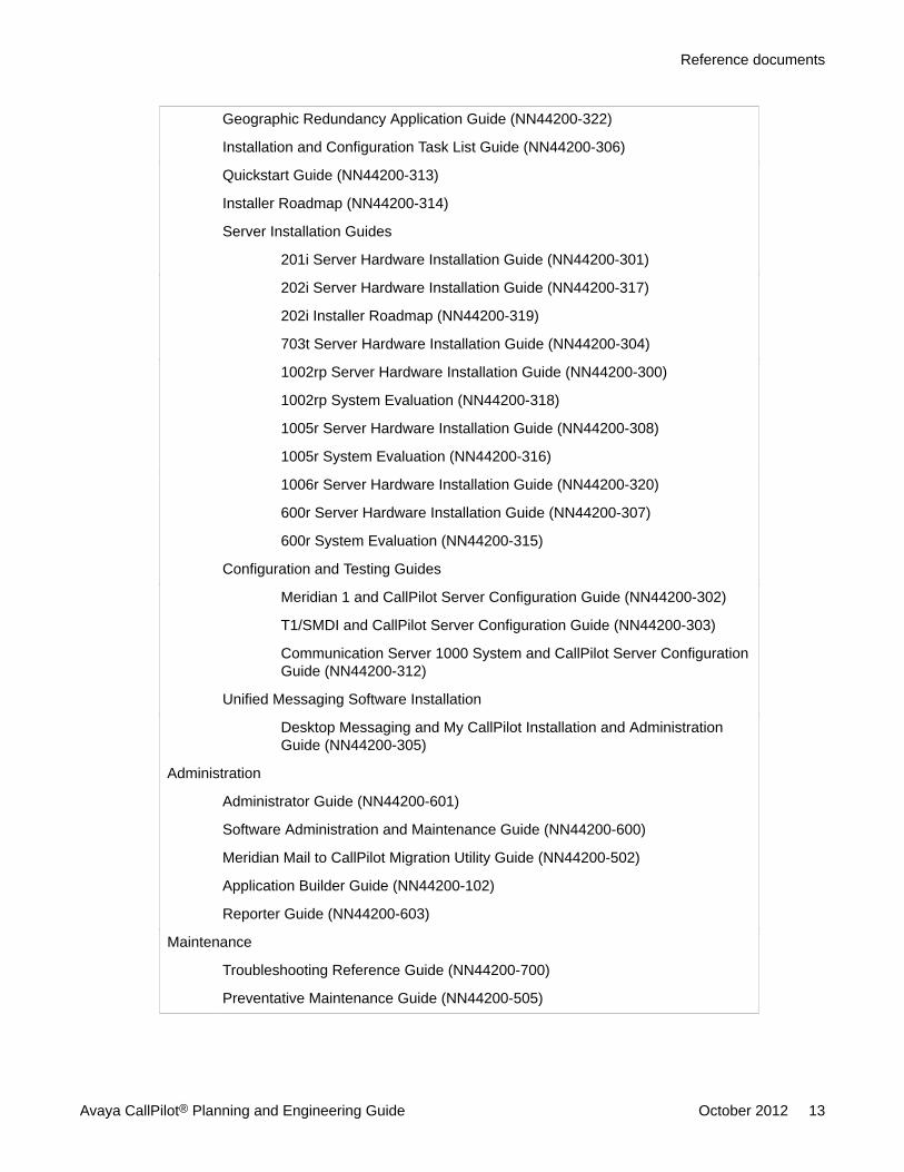
Geographic Redundancy Application Guide (NN44200-322)
Installation and Configuration Task List Guide (NN44200-306)
Quickstart Guide (NN44200-313)
Installer Roadmap (NN44200-314)
Server Installation Guides
201i Server Hardware Installation Guide (NN44200-301)
202i Server Hardware Installation Guide (NN44200-317)
202i Installer Roadmap (NN44200-319)
703t Server Hardware Installation Guide (NN44200-304)
1002rp Server Hardware Installation Guide (NN44200-300)
1002rp System Evaluation (NN44200-318)
1005r Server Hardware Installation Guide (NN44200-308)
1005r System Evaluation (NN44200-316)
1006r Server Hardware Installation Guide (NN44200-320)
600r Server Hardware Installation Guide (NN44200-307)
600r System Evaluation (NN44200-315)
Configuration and Testing Guides
Meridian 1 and CallPilot Server Configuration Guide (NN44200-302)
T1/SMDI and CallPilot Server Configuration Guide (NN44200-303)
Communication Server 1000 System and CallPilot Server ConfigurationGuide (NN44200-312)
Unified Messaging Software Installation
Desktop Messaging and My CallPilot Installation and AdministrationGuide (NN44200-305)
Administration
Administrator Guide (NN44200-601)
Software Administration and Maintenance Guide (NN44200-600)
Meridian Mail to CallPilot Migration Utility Guide (NN44200-502)
Application Builder Guide (NN44200-102)
Reporter Guide (NN44200-603)
Maintenance
Troubleshooting Reference Guide (NN44200-700)
Preventative Maintenance Guide (NN44200-505)
Reference documents
Avaya CallPilot® Planning and Engineering Guide October 2012 13
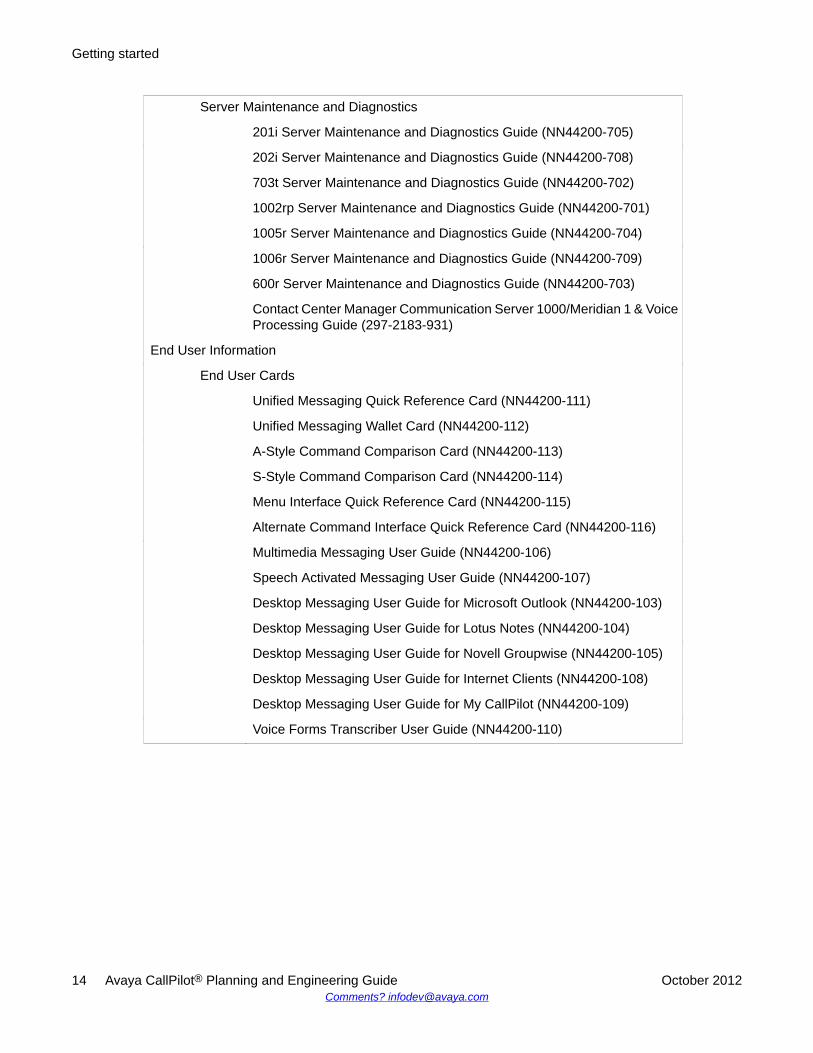
Server Maintenance and Diagnostics
201i Server Maintenance and Diagnostics Guide (NN44200-705)
202i Server Maintenance and Diagnostics Guide (NN44200-708)
703t Server Maintenance and Diagnostics Guide (NN44200-702)
1002rp Server Maintenance and Diagnostics Guide (NN44200-701)
1005r Server Maintenance and Diagnostics Guide (NN44200-704)
1006r Server Maintenance and Diagnostics Guide (NN44200-709)
600r Server Maintenance and Diagnostics Guide (NN44200-703)
Contact Center Manager Communication Server 1000/Meridian 1 & VoiceProcessing Guide (297-2183-931)
End User Information
End User Cards
Unified Messaging Quick Reference Card (NN44200-111)
Unified Messaging Wallet Card (NN44200-112)
A-Style Command Comparison Card (NN44200-113)
S-Style Command Comparison Card (NN44200-114)
Menu Interface Quick Reference Card (NN44200-115)
Alternate Command Interface Quick Reference Card (NN44200-116)
Multimedia Messaging User Guide (NN44200-106)
Speech Activated Messaging User Guide (NN44200-107)
Desktop Messaging User Guide for Microsoft Outlook (NN44200-103)
Desktop Messaging User Guide for Lotus Notes (NN44200-104)
Desktop Messaging User Guide for Novell Groupwise (NN44200-105)
Desktop Messaging User Guide for Internet Clients (NN44200-108)
Desktop Messaging User Guide for My CallPilot (NN44200-109)
Voice Forms Transcriber User Guide (NN44200-110)
Getting started
14 Avaya CallPilot® Planning and Engineering Guide October 2012Comments? [email protected]
Components of a CallPilot systemA CallPilot system comprises three key components:
• the CallPilot server
• the switch resources related to CallPilot
• the desktop client PCs (if the Unified Messaging feature is installed)
The CallPilot system can also include optional features:
• Unified Messaging—installed on the PCs in the CallPilot network
• customer-provided Web server—necessary for the installation of CallPilot Reporter if itwill be used for management reporting purposes
CallPilot Web services, including the CallPilot Manager administrator component, usuallyresides on the CallPilot server, although it can optionally run on the Web server. The MyCallPilot end-user Web services can reside on the CallPilot server, or on a separate Webserver, or on both.
Servers and switchesThe following switches are compatible with CallPilot 5.1:
• Meridian 1*
• Communication Server 1000 (CS 1000), formerly known as Succession 1000
• DMS-100
• SL-100
More information about the compatibility of CallPilot with various types of switches is providedlater in this guide.
Desktop PCs and wireless devicesSystem administrators can use the Web browser on a PC to access CallPilot Manager to
• maintain and administer the CallPilot software
• view CallPilot Reporter reports
Components of a CallPilot system
Avaya CallPilot® Planning and Engineering Guide October 2012 15
If the desktop messaging client is installed, users can download messages from the serverusing a PC or a wireless device.
System configuration and orderingThe Models & Ordering Procedures document that applies to CallPilot 5.1 lists features andordering information for each CallPilot server platform. To obtain the Models & OrderingProcedures document, contact your Avaya* channel partner.
Getting started
16 Avaya CallPilot® Planning and Engineering Guide October 2012Comments? [email protected]
Chapter 3: Grounding and powerrequirements
In this chapterOverview on page 17
Power and grounding guidelines on page 18
Auxiliary power on page 21
OverviewThis chapter outlines the guidelines for providing power and grounding to switch and AvayaCallPilot® equipment, and describes the auxiliary power requirements. However, if theinformation in this chapter conflicts with the local or national code, then follow the code.
Before the Avaya CallPilot server installation, a qualified electrician must implement the single-point ground reference, as required, between the power outlets of the CallPilot server and thepower outlets of the switch.
Voltage:DANGER OF ELECTRIC SHOCK
If you fail to ground the switch and the CallPilot equipment correctly, the installation can be
• unsafe for personnel
• unprotected from lightning or power transients
• subject to service interruptions, degraded performance, and loss of information.
Avaya CallPilot® Planning and Engineering Guide October 2012 17
Power and grounding guidelines
GeneralThe power and ground for the switch and the CallPilot equipment must originate from the samesupply service (equipment room service panel or transformer), where the ground conductorand the neutral conductor are connected and referenced to the main building ground. All powerfeeds must contain a separate safety conductor (green wire).
Note:Do not use the main building ground directly as the ground reference for the system.
Important:The 600r, 1005r, and 1006r rack-mount servers are only offered in the ac environment. Ifyou use a dc environment, you must procure a dc to ac inverter.
To ensure a complete power and grounding installation:
• In rack-mount server installations, ensure that the CallPilot server chassis and equipmentracks are isolated from other foreign sources of ground. Acceptable isolation methodsinclude: isolation pads, grommets, chassis side rail strips, non-conducting washers, andso on.
• In rack-mount server installations where other equipment is installed in the same 19 inchrack, ensure that all equipment derives ground from the same service panel as CallPilotand the switch, whether or not the equipment is ac or dc powered.
• In rack-mount dc-powered server installations, ensure that the PDU (Power DistributionUnit for dc applications) is installed on the same rack as the CallPilot server. This type ofinstallation is required because the main ground wire for the PDU is not insulated fromthe metal enclosure.
PowerThe service panel, which must be in the equipment room, must not service lighting, airconditioning, heating, generators, or motors. Avaya strongly recommends that supplyconductors be dedicated and uninterrupted from a building primary source to the dedicatedequipment room service panel.
Grounding and power requirements
18 Avaya CallPilot® Planning and Engineering Guide October 2012Comments? [email protected]
Power is supplied to the service panel by a power transformer. The transformer typicallyprovides secondary voltages of 208/120 V three-phase four-wire "wye" service, 240/120 Vsingle-phase four-wire "delta" service, or 240/120 V single-phase three-wire service.Collectively, these secondary voltages are referred to as "nominal 208/240 V ac".
A dedicated power transformer for the switch, CallPilot server, and associated auxiliary andtelephone operating company interface equipment is preferred. However, a shared transformeror distribution is acceptable.
Do not use ground fault circuit interrupt (GFCI) devices on the switch and CallPilot powerfeeds.
Single-point groundThe switch and the CallPilot system require a single-point ground (SPG) topology for all switchequipment and all CallPilot associated auxiliary equipment respectively.
The switch and the CallPilot system have several types of grounds and several types of signalreturns that are generally referred to as "grounds":
• In ac systems, a logic return (LR or LRTN) and a green wire frame ground, called the acequipment ground (ACEG), are typically part of the input power cord.
• In dc systems, a logic return (LR or LRTN) and a battery return (RTN), as well as an acequipment ground (ACEG) green wire, are on the input to the rectifiers.
• All systems must have an external hardwired frame ground connection (also called thepersonal hazard safety ground). The frame ground is connected internally to the ACEGgreen wire. As the frame ground is hardwired, it ensures that the equipment has a groundconnection even if the system is "unplugged."
• External Communications wiring that meets the requirements as stipulated in NEC Article800-30 FPN 4 requires the use of lightning protection. The cable sheaths, and protectiongrounds must be installed as indicated in NEC Article 800 - 33, and Article 800 - 40 (b).
For an SPG topology, each of the preceding grounds, from each of the columns, must terminateat a single connection point before attaching to the actual ground reference at the service panelor transformer. Physically, the SPG is usually a copper bar or plate (referred to as a "bus"). Inits simplest form, the SPG (the single connection point) can be an isolated ground bus or anACEG bus in the service panel or transformer.
Refer to the documentation associated with the PBX switch configured with CallPilot for furtherinformation on grounding requirements.
Document title NTP numberMeridian 1 Installation Planning 553-3001-120
Meridian 1 Power Engineering 553-3001-152
Single-point ground
Avaya CallPilot® Planning and Engineering Guide October 2012 19
Document title NTP numberMeridian 1 System Installation Procedures 553-3001-210
Planning and Installation Guide for Option 11C Mini 553-3021-209
Planning and Installation Guide for Option 11C 553-3021-210
Planning and Engineering Guidelines - Succession 1000 553-3023-102
Also refer to the ANSI-J-STD-607-A-2002 standard Commercial Building Grounding (Earthing)and Bonding Requirements for Telecommunications.
Follow these requirements when implementing the SPG:
• All ground conductors must be identified according to local codes and terminatedpermanently.
• Terminations must be accessible for inspection and maintenance during the life of theinstallation.
• All grounding conductors must be
- continuous, with no splices or junctions
- tagged "Do not remove or disconnect"
- insulated against contact with foreign grounds
• Grounding conductors must be no load, non-current carrying cables, under normaloperating conditions.
• The ground interface in a steel-framed building must have a single connecting referencelocated at the service panel, to the building steel on the same floor as the switch and theCallPilot system (or within one floor from the switch and the CallPilot system).
Note:Avaya does not recommend the use of building steel as an integral part of the switchand CallPilot ground system. The building steel is a reference point only.
The dc resistance of the system ground conductor, which runs from the switch to the mainbuilding ground, must be as close to zero as possible. The maximum total resistance on allruns within the building must not exceed 0.5 ohms.
Grounding and power requirements
20 Avaya CallPilot® Planning and Engineering Guide October 2012Comments? [email protected]
Auxiliary power
Terminal devicesTerminal devices in the equipment room require local power. Power for these devices must bewired and fused independently from all other receptacles, labeled at the service panel (toprevent unauthorized power interruption), and referenced to the same interface point on thebuilding system ground as the service panel ground.
Auxiliary power in the equipment room can be supplied by isolated or non-isolated servicereceptacles, which must match the grounding for the system. In other words, if the switch andthe CallPilot server have an isolated ground topology, the receptacles must also be isolated.
Auxiliary equipmentIf auxiliary equipment using an RS-232 interface is too remote to be powered from the servicepanel, a modem or fiber link is required for ground isolation. Failure to provide this isolationdefeats the SPG required by the system.
Existing power and groundingExisting powering and grounding on some sites can make it difficult to ensure that the localpower grounding is referenced to the same potential as the system ground. In addition, localpower grounding can form part of a common grounding network that is subject to noise fromexternal sources. Under these conditions, where locally powered terminals and equipmentconnect directly to the system through dc coupled links sharing a common ground, incidentalground loops can form and inject noise onto the system.
Auxiliary power
Avaya CallPilot® Planning and Engineering Guide October 2012 21

Grounding and power requirements
22 Avaya CallPilot® Planning and Engineering Guide October 2012Comments? [email protected]
Chapter 4: System configurations
In this chapterCallPilot® architecture on page 23
Compatibility of switches and servers on page 26
Section A: Hardware and software configurations on page 27
CallPilot server on page 28
Avaya Contact Center Server on page 30
Supported switches on page 32
Web server for CallPilot on page 34
CallPilot desktop messaging on page 37
Section B: Connectivity requirements on page 38
Avaya server subnet connections on page 39
ELAN subnet connections on page 41
Meridian 1 connectivity on page 45
CS 1000 connectivity on page 51
T1/SMDI connectivity on page 55
Section C: System requirements on page 58
Compatibility on page 58
Migration from Meridian Mail on page 63
CallPilot® architectureThe following figure shows an example of a network in which an Avaya CallPilot server isconnected to a Meridian 1 switch (AML connectivity).
Avaya CallPilot® Planning and Engineering Guide October 2012 23
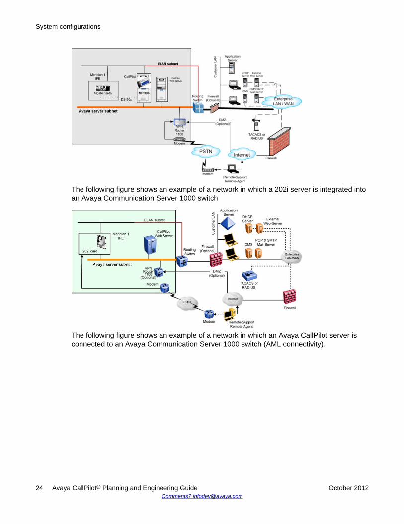
The following figure shows an example of a network in which a 202i server is integrated intoan Avaya Communication Server 1000 switch
The following figure shows an example of a network in which an Avaya CallPilot server isconnected to an Avaya Communication Server 1000 switch (AML connectivity).
System configurations
24 Avaya CallPilot® Planning and Engineering Guide October 2012Comments? [email protected]
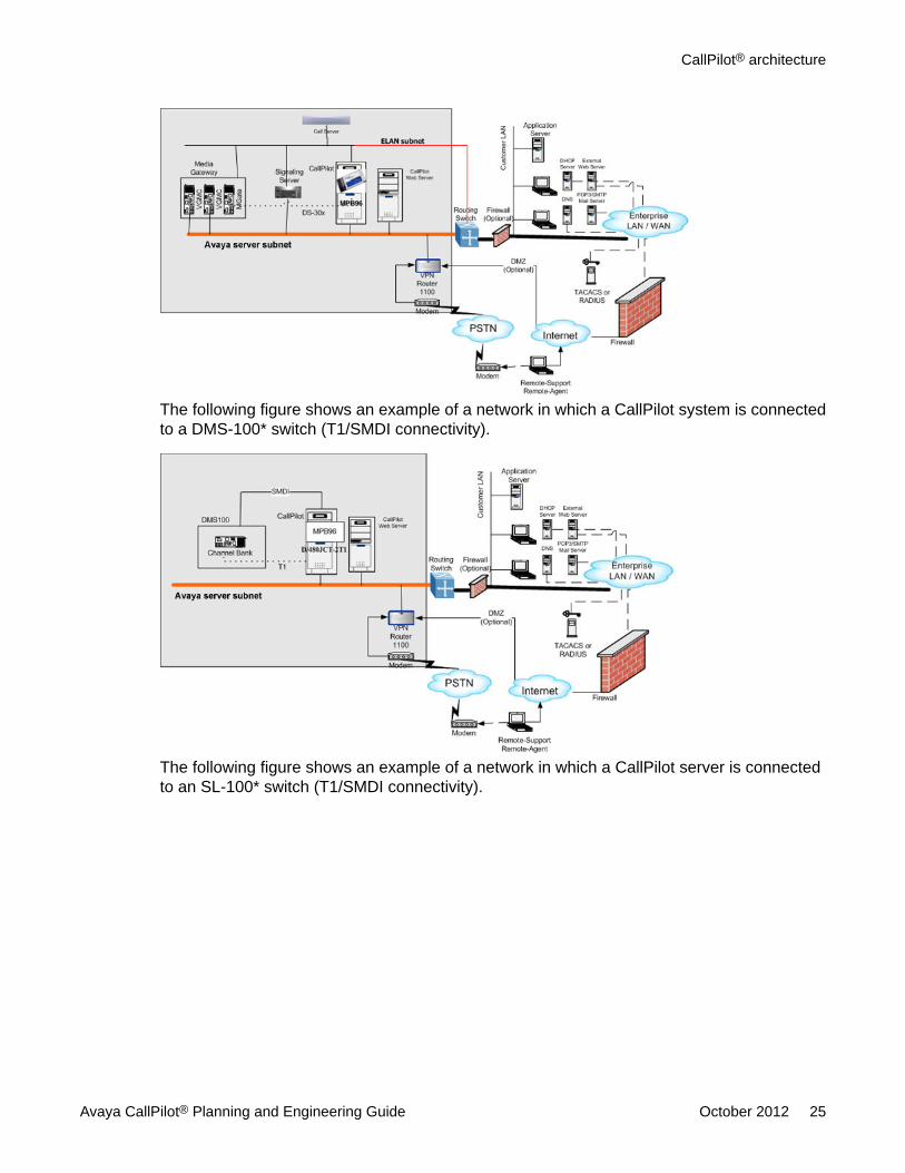
The following figure shows an example of a network in which a CallPilot system is connectedto a DMS-100* switch (T1/SMDI connectivity).
The following figure shows an example of a network in which a CallPilot server is connectedto an SL-100* switch (T1/SMDI connectivity).
CallPilot® architecture
Avaya CallPilot® Planning and Engineering Guide October 2012 25
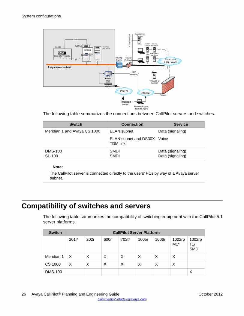
The following table summarizes the connections between CallPilot servers and switches.
Switch Connection ServiceMeridian 1 and Avaya CS 1000 ELAN subnet Data (signaling)
ELAN subnet and DS30XTDM link
Voice
DMS-100SL-100
SMDISMDI
Data (signaling)Data (signaling)
Note:The CallPilot server is connected directly to the users' PCs by way of a Avaya serversubnet.
Compatibility of switches and serversThe following table summarizes the compatibility of switching equipment with the CallPilot 5.1server platforms.
Switch CallPilot Server Platform201i* 202i 600r 703t* 1005r 1006r 1002rp
M1*1002rpT1/SMDI
Meridian 1 X X X X X X X
CS 1000 X X X X X X X
DMS-100 X
System configurations
26 Avaya CallPilot® Planning and Engineering Guide October 2012Comments? [email protected]
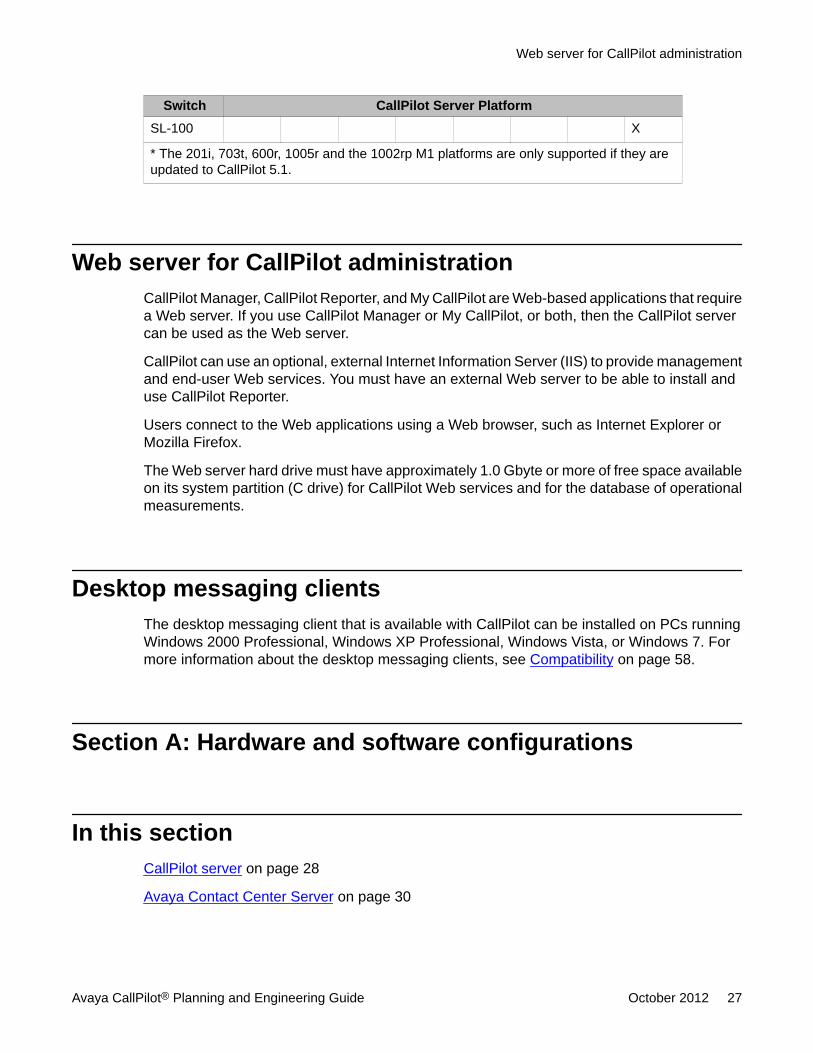
Switch CallPilot Server PlatformSL-100 X
* The 201i, 703t, 600r, 1005r and the 1002rp M1 platforms are only supported if they areupdated to CallPilot 5.1.
Web server for CallPilot administrationCallPilot Manager, CallPilot Reporter, and My CallPilot are Web-based applications that requirea Web server. If you use CallPilot Manager or My CallPilot, or both, then the CallPilot servercan be used as the Web server.
CallPilot can use an optional, external Internet Information Server (IIS) to provide managementand end-user Web services. You must have an external Web server to be able to install anduse CallPilot Reporter.
Users connect to the Web applications using a Web browser, such as Internet Explorer orMozilla Firefox.
The Web server hard drive must have approximately 1.0 Gbyte or more of free space availableon its system partition (C drive) for CallPilot Web services and for the database of operationalmeasurements.
Desktop messaging clientsThe desktop messaging client that is available with CallPilot can be installed on PCs runningWindows 2000 Professional, Windows XP Professional, Windows Vista, or Windows 7. Formore information about the desktop messaging clients, see Compatibility on page 58.
Section A: Hardware and software configurations
In this sectionCallPilot server on page 28
Avaya Contact Center Server on page 30
Web server for CallPilot administration
Avaya CallPilot® Planning and Engineering Guide October 2012 27
Supported switches on page 32
Web server for CallPilot on page 34
CallPilot desktop messaging on page 37
CallPilot server
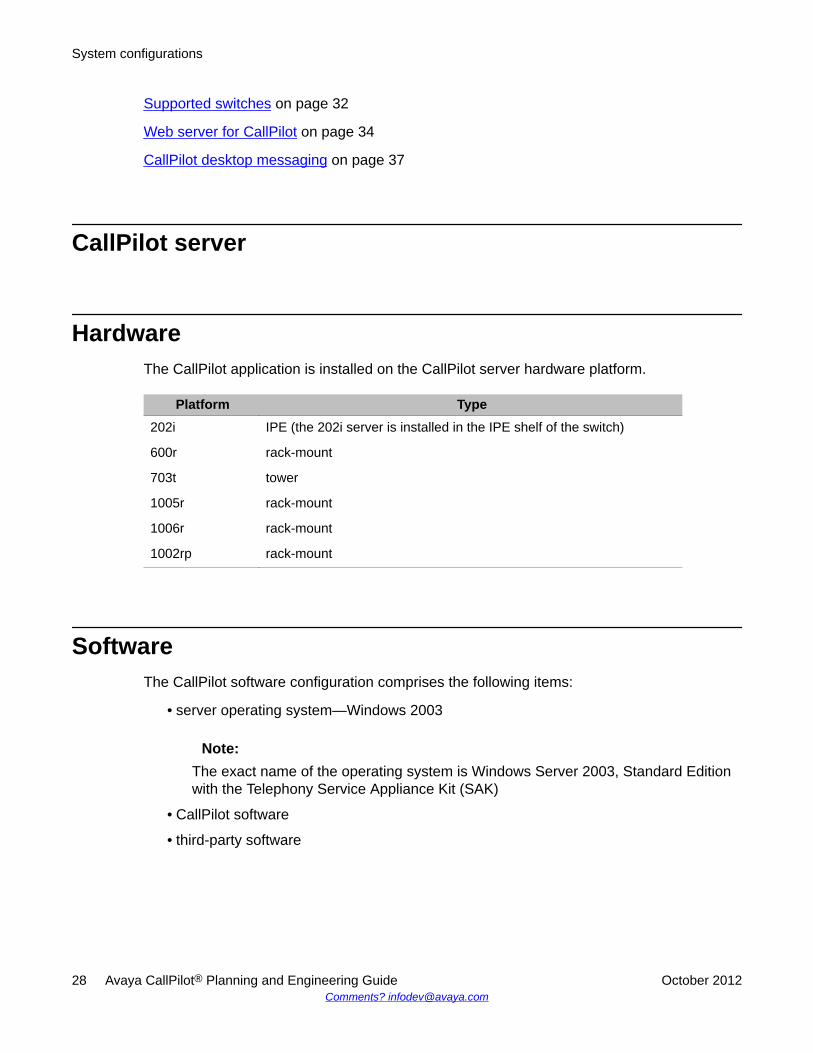
HardwareThe CallPilot application is installed on the CallPilot server hardware platform.
Platform Type202i IPE (the 202i server is installed in the IPE shelf of the switch)
600r rack-mount
703t tower
1005r rack-mount
1006r rack-mount
1002rp rack-mount
SoftwareThe CallPilot software configuration comprises the following items:
• server operating system—Windows 2003
Note:The exact name of the operating system is Windows Server 2003, Standard Editionwith the Telephony Service Appliance Kit (SAK)
• CallPilot software
• third-party software
System configurations
28 Avaya CallPilot® Planning and Engineering Guide October 2012Comments? [email protected]
Compatibility with other products and environments
Meridian MailCallPilot can coexist with Meridian Mail* on the Meridian 1 switch. You can connect CallPilotwith Meridian Mail systems on networks that use one or both of the following networkingprotocols:
• Audio Messaging Interchange Specification-Analog (AMIS-A)
• Enterprise
For more information about the coexistence of CallPilot and Meridian Mail on the same switch,see the Meridian Mail to CallPilot Migration Guide (NN44200-502).
Multi-tenant Meridian 1 switchCallPilot supports users on a multi-tenant Meridian 1 switch as if the users were on a single-tenant system. However, CallPilot does not
• support more than a single customer of a multi-customer Meridian 1 switch
• know to which Meridian 1 tenant a user belongs
• provide administration or billing features by tenant
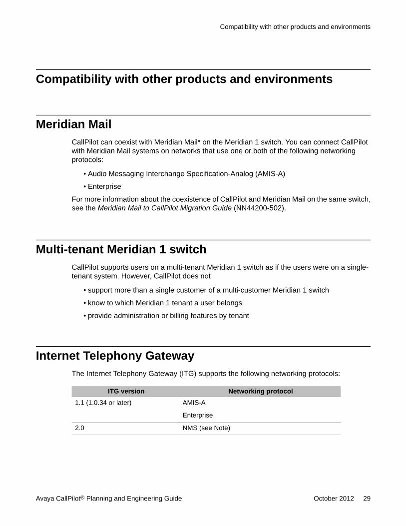
Internet Telephony GatewayThe Internet Telephony Gateway (ITG) supports the following networking protocols:
ITG version Networking protocol1.1 (1.0.34 or later) AMIS-A
Enterprise
2.0 NMS (see Note)
Compatibility with other products and environments
Avaya CallPilot® Planning and Engineering Guide October 2012 29
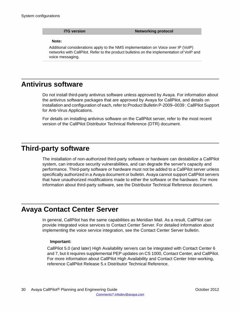
ITG version Networking protocol
Note:Additional considerations apply to the NMS implementation on Voice over IP (VoIP)networks with CallPilot. Refer to the product bulletins on the implementation of VoIP andvoice messaging.
Antivirus softwareDo not install third-party antivirus software unless approved by Avaya. For information aboutthe antivirus software packages that are approved by Avaya for CallPilot, and details oninstallation and configuration of each, refer to:Product Bulletin P-2009–0039 : CallPilot Supportfor Anti-Virus Applications.
For details on installing antivirus software on the CallPilot server, refer to the most recentversion of the CallPilot Distributor Technical Reference (DTR) document.
Third-party softwareThe installation of non-authorized third-party software or hardware can destabilize a CallPilotsystem, can introduce security vulnerabilities, and can degrade the server's capacity andperformance. Third-party software or hardware must not be added to a CallPilot server unlessspecifically authorized in a Avaya document or bulletin. Avaya cannot support CallPilot serversthat have unauthorized modifications made to either the software or the hardware. For moreinformation about third-party software, see the Distributor Technical Reference document.
Avaya Contact Center ServerIn general, CallPilot has the same capabilities as Meridian Mail. As a result, CallPilot canprovide integrated voice services to Contact Center Server. For detailed information aboutimplementing the voice service integration, see the Contact Center Server bulletin.
Important:CallPilot 5.0 (and later) High Availability servers can be integrated with Contact Center 6and 7, but it requires supplemental PEP updates on CS 1000, Contact Center, and CallPilot.For more information about CallPilot High Availability and Contact Center Inter-working,reference CallPilot Release 5.x Distributor Technical Reference.
System configurations
30 Avaya CallPilot® Planning and Engineering Guide October 2012Comments? [email protected]
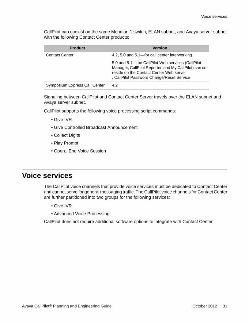
CallPilot can coexist on the same Meridian 1 switch, ELAN subnet, and Avaya server subnetwith the following Contact Center products:
Product VersionContact Center 4.2, 5.0 and 5.1—for call center interworking
5.0 and 5.1—the CallPilot Web services (CallPilotManager, CallPilot Reporter, and My CallPilot) can co-reside on the Contact Center Web server, CallPilot Password Change/Reset Service
Symposium Express Call Center 4.2
Signaling between CallPilot and Contact Center Server travels over the ELAN subnet andAvaya server subnet.
CallPilot supports the following voice processing script commands:
• Give IVR
• Give Controlled Broadcast Announcement
• Collect Digits
• Play Prompt
• Open...End Voice Session
Voice servicesThe CallPilot voice channels that provide voice services must be dedicated to Contact Centerand cannot serve for general messaging traffic. The CallPilot voice channels for Contact Centerare further partitioned into two groups for the following services:
• Give IVR
• Advanced Voice Processing
CallPilot does not require additional software options to integrate with Contact Center.
Voice services
Avaya CallPilot® Planning and Engineering Guide October 2012 31
CallPilot Application BuilderUse the Application Builder program to create CallPilot applications that callers can access asdialable services. With Application Builder, you can perform the following tasks:
• specify the call functions that you want to include in applications, such as menus andannouncements
• design the call flow (the path that calls follow) in an application
• import system prompts, voice items, and customized prompts
• record system prompts, voice items, and customized prompts
• archive and restore applications
In Application Builder, a series of blocks connected by lines represents an application. Thegraphical display lets you follow the call flow.
Application Builder requires the installation of a client on the administrator's PC. You candownload the client, on demand, from the CallPilot Manager Web service to the PC.
For more information about Application Builder, see the CallPilot Application Builder Guide(NN44200-102).
Supported switches
Meridian 1CallPilot supports the following Meridian 1 platforms:
• Option 11C
• Option 11C Mini
• Option 51C
• Option 61C
• Option 81C
New CallPilot installations requires X21 Release 3.0 or later on the Meridian 1 switch.
System configurations
32 Avaya CallPilot® Planning and Engineering Guide October 2012Comments? [email protected]
Avaya Communication Server 1000The CS 1000 VoIP system includes the following features:
• fully installed and configured CS 1000 server
• Media Gateway card
• Voice Gateway card
• Media Gateway Expansion card (optional)
• connection to a TCP/IP network (ELAN subnet)
CallPilot requires X21 Release 3.0 or later on the CS 1000 system.
For information about X21 patches (if any), refer to the CallPilot Distributor Technical Reference(DTR) Bulletin. You can find this document on the Avaya support site at http://support.avaya.com.
T1/SMDI switchesCallPilot 5.1 supports the DMS-100 and SL-100 T1/SMDI switches:
Two hardware components must be installed and configured on the CallPilot server to ensurethe connection to the T1/SMDI switches:
• the simplified message desk interface (SMDI) link
• the T1 links
The SL-100 and DMS-100 switches support the SMDI link using either an input-outputcontroller (IOC) shelf with an NT1X89 card or an NTFX30 input-output module (IOM).
The T1 connection is integrated with the SL-100 switch by way of line side T1 interface cardsinstalled in the intelligent peripheral equipment (IPE) module of the switch. You must have asufficient number of line side T1 cards for the number of channels purchased. Refer to the LineSide T-1 Interface (LT1) for IPE Services Guide (555-4001-022) for instructions on installingthe line side T1 cards.
The line side T1 cards must be configured for ground start. CallPilot does not support loopstart. The DMS-100 switch does not use line side T1 cards for the T1 connection. However,the DMS-100 switch requires an external channel bank to support Centrex service.
Note:The SL-100 switch can also use an external channel bank for call lines.
Avaya Communication Server 1000
Avaya CallPilot® Planning and Engineering Guide October 2012 33
The T1 links from the SL-100 or DMS-100 switches are terminated on Intel Dialogic boards(D/480JCT-2T1) installed in the CallPilot server.
For programming purposes, the SL-100 switch requires MSL-10 software or higher, and theDMS-100 switch requires NA08 software or higher.
For information on connectivity requirements, see T1/SMDI connectivity on page 55.
Web server for CallPilot
IntroductionYou can install three CallPilot applications on the Web server.
Application FunctionCallPilot Manager System configuration and management
CallPilot Reporter Report generation
My CallPilot End-user mailbox configuration, messaging, anddocumentation
CallPilot Password Change/ResetService
Provides immediate mailbox password resetcapabilities to mailbox owners.
The Microsoft Internet Information Server (IIS) established on the CallPilot server ispreconfigured according to the best security practices available.
You can have multiple external Web servers for a single CallPilot server.
You can use one external Web server for up to 20 CallPilot servers.
Configurations of CallPilot Web servicesCallPilot Manager, CallPilot Reporter, and My CallPilot can all reside on an external IIS server.In this situation, you have the option to disable the IIS server on the CallPilot server to reducesecurity risks.
In a hybrid configuration, My CallPilot can reside on the CallPilot server, while CallPilotManager and CallPilot Reporter reside on the IIS server
CallPilot is supplied pre-engineered to support My CallPilot or CallPilot Manager IIS Webservices, or both, and still be capable of providing high performance levels to all other services
System configurations
34 Avaya CallPilot® Planning and Engineering Guide October 2012Comments? [email protected]

running on CallPilot. CallPilot end users and administrators can access the IIS server on theAvaya server subnet using Web browsers.
External Web server configuration
HardwareThe My CallPilot and CallPilot Reporter Web services can generate high CPU loads. Theminimum hardware configuration for the external Web server must include
• a 600 MHz PIII processor
• 128 Mbytes of RAM
• 1 Gbyte of free disk space on the system drive (C drive)
SoftwareThe external Web server requires one of the following software configurations:
• Windows 2000 Server with Service Pack 1 or later (Standard version only) runningInternet Information Server (IIS) 5.0 (Service Pack 1 or later)
• Windows Server 2003 with Service Pack 1 or later (Standard version only) running IIS6.0
• Windows Server 2008 with Service Pack 2 running IIS 7.0
• Windows Vista (Standard and Enterprise Editions) running IIS 7.0
Note:For Windows 2000, the Advanced Server and DataCenter Server versions are notsupported. Future support for the DataCenter version is planned.
If the Secure Socket Layer (SSL) technology is to be used, you must purchase and install anadditional SSL certificate for use with the IIS. Avaya recommends the following SSL certificatevendors:
• Entrust (http://www.entrust.net/index.htm)
• Verisign (http://www.verisign.com/)
External Web server configuration
Avaya CallPilot® Planning and Engineering Guide October 2012 35
Free disk spaceGenerally, the Web server must have approximately 1 Gbyte of free disk space available forthe installation of CallPilot Web services. If CallPilot Reporter is used for a large CallPilotsystem or a network of CallPilot systems, Avaya recommends that you estimate the necessaryfree disk space using the following formula:
Free disk space = 300 Mbytes + [total number of channels * (days in DB + 1) * 0.2 Mbytes]
• total number of channels = the total number of channels on all CallPilot systems whosedata is in the CallPilot Reporter database
• days in DB = the number of days that data are stored in the CallPilot Reporter database
Other Web server considerationsThe following factors determine the Web server load generated by CallPilot services:
• the number of active My CallPilot users
• the number of users simultaneously accessing messages using My CallPilot versus thenumber of users using desktop messaging clients such as Microsoft Outlook
• the number of reports generated during the busy hour
The Web server does not have to be dedicated to CallPilot Web services. The same servercan host Web pages or provide standard network services, such as printing and file sharing.However, running other applications and services on the server can slow down CallPilotservices and significantly reduce user productivity and satisfaction with the services.Therefore, Avaya recommends dedicating the Web server to CallPilot services.
Monitoring performanceYou must monitor the Web server performance after an installation or a major change, suchas the addition of users, to detect a possible system overload. If the response time is slowduring the busy hour, then use the Windows Performance Monitor (Start > Programs >Administrative Tools > Performance) to determine if the server is overloaded.
System configurations
36 Avaya CallPilot® Planning and Engineering Guide October 2012Comments? [email protected]
The main indicators to monitor are the CPU usage, the available memory, and the physicaldisk space. The user response time can be degraded if one or all of the following conditionsare encountered:
• the CPU usage (shown as Processor Time) is constantly above 90 percent for a significantnumber of minutes during the busy hour
• the available memory (shown as Available Bytes) is below 4 Mbytes
• the disk space (shown as Physical Disk Space) is insufficient
CallPilot desktop messagingTo calculate the disk space used for voice and fax messages, see the following conversionfactors.
Voice messagesCallPilot uses a proprietary sub-band voice encoding at 18 kbit/s for messaging. To calculatethe disk space used for voice in the CallPilot message store of desktop messaging, use thefollowing conversion factors.
CallPilot 5.1 offers users the ability to configure the desired WAV encoding format.
Message duration Format Storage space1 minute WAV-GSM 6.10 * 110 kbytes
1 minute SBC or VBK 141 kbytes
1 minute WAV 945 kbytes
* For CallPilot 5.0 running on the 1005r or 600r, all outgoing WAV files are converted toMicrosoft WAV-GSM 6.10. This feature helps reduce the storage space required on e-mailservers.
Note:Messages are kept in the message store on the PC only if they are played on the PC.
CallPilot desktop messaging
Avaya CallPilot® Planning and Engineering Guide October 2012 37
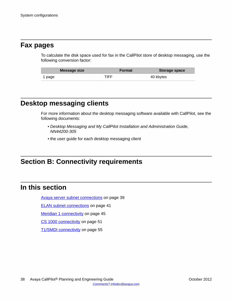
Fax pagesTo calculate the disk space used for fax in the CallPilot store of desktop messaging, use thefollowing conversion factor:
Message size Format Storage space1 page TIFF 40 kbytes
Desktop messaging clientsFor more information about the desktop messaging software available with CallPilot, see thefollowing documents:
• Desktop Messaging and My CallPilot Installation and Administration Guide,NN44200-305
• the user guide for each desktop messaging client
Section B: Connectivity requirements
In this sectionAvaya server subnet connections on page 39
ELAN subnet connections on page 41
Meridian 1 connectivity on page 45
CS 1000 connectivity on page 51
T1/SMDI connectivity on page 55
System configurations
38 Avaya CallPilot® Planning and Engineering Guide October 2012Comments? [email protected]
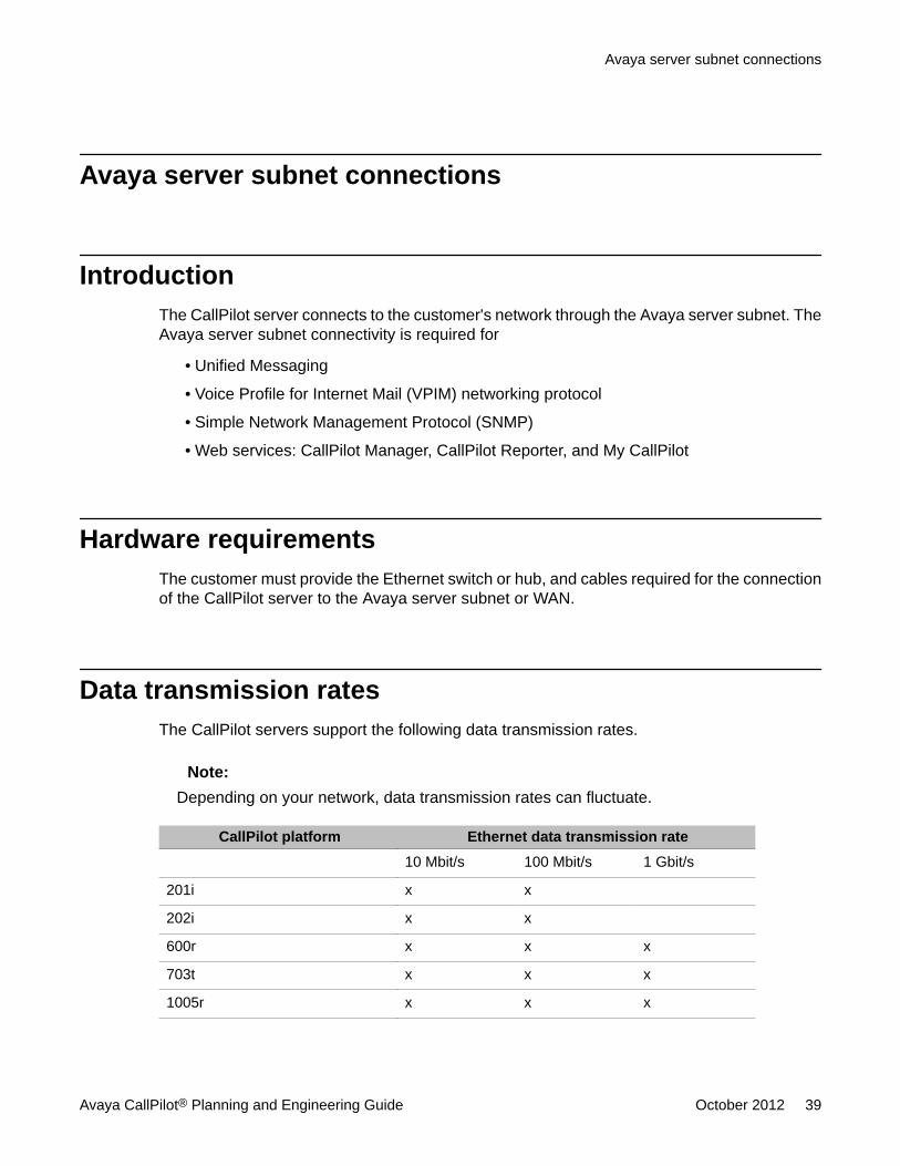
Avaya server subnet connections
IntroductionThe CallPilot server connects to the customer's network through the Avaya server subnet. TheAvaya server subnet connectivity is required for
• Unified Messaging
• Voice Profile for Internet Mail (VPIM) networking protocol
• Simple Network Management Protocol (SNMP)
• Web services: CallPilot Manager, CallPilot Reporter, and My CallPilot
Hardware requirementsThe customer must provide the Ethernet switch or hub, and cables required for the connectionof the CallPilot server to the Avaya server subnet or WAN.
Data transmission ratesThe CallPilot servers support the following data transmission rates.
Note:Depending on your network, data transmission rates can fluctuate.
CallPilot platform Ethernet data transmission rate10 Mbit/s 100 Mbit/s 1 Gbit/s
201i x x
202i x x
600r x x x
703t x x x
1005r x x x
Avaya server subnet connections
Avaya CallPilot® Planning and Engineering Guide October 2012 39
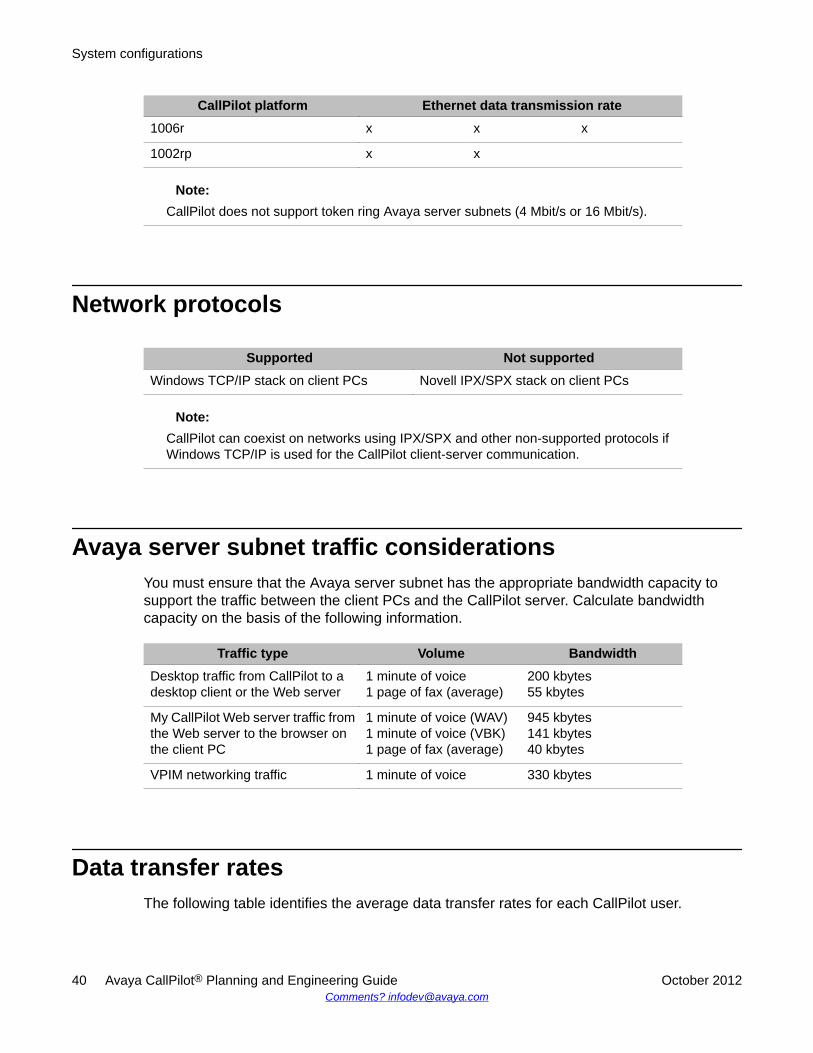
CallPilot platform Ethernet data transmission rate1006r x x x
1002rp x x
Note:CallPilot does not support token ring Avaya server subnets (4 Mbit/s or 16 Mbit/s).
Network protocols
Supported Not supportedWindows TCP/IP stack on client PCs Novell IPX/SPX stack on client PCs
Note:CallPilot can coexist on networks using IPX/SPX and other non-supported protocols ifWindows TCP/IP is used for the CallPilot client-server communication.
Avaya server subnet traffic considerationsYou must ensure that the Avaya server subnet has the appropriate bandwidth capacity tosupport the traffic between the client PCs and the CallPilot server. Calculate bandwidthcapacity on the basis of the following information.
Traffic type Volume BandwidthDesktop traffic from CallPilot to adesktop client or the Web server
1 minute of voice1 page of fax (average)
200 kbytes55 kbytes
My CallPilot Web server traffic fromthe Web server to the browser onthe client PC
1 minute of voice (WAV)1 minute of voice (VBK)1 page of fax (average)
945 kbytes141 kbytes40 kbytes
VPIM networking traffic 1 minute of voice 330 kbytes
Data transfer ratesThe following table identifies the average data transfer rates for each CallPilot user.
System configurations
40 Avaya CallPilot® Planning and Engineering Guide October 2012Comments? [email protected]
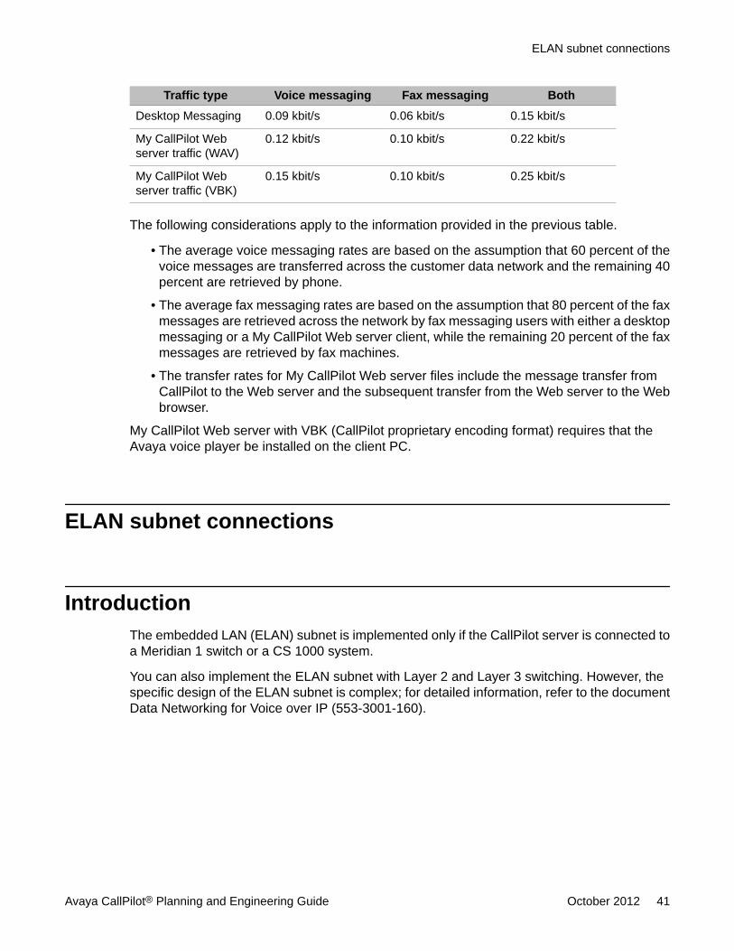
Traffic type Voice messaging Fax messaging BothDesktop Messaging 0.09 kbit/s 0.06 kbit/s 0.15 kbit/s
My CallPilot Webserver traffic (WAV)
0.12 kbit/s 0.10 kbit/s 0.22 kbit/s
My CallPilot Webserver traffic (VBK)
0.15 kbit/s 0.10 kbit/s 0.25 kbit/s
The following considerations apply to the information provided in the previous table.
• The average voice messaging rates are based on the assumption that 60 percent of thevoice messages are transferred across the customer data network and the remaining 40percent are retrieved by phone.
• The average fax messaging rates are based on the assumption that 80 percent of the faxmessages are retrieved across the network by fax messaging users with either a desktopmessaging or a My CallPilot Web server client, while the remaining 20 percent of the faxmessages are retrieved by fax machines.
• The transfer rates for My CallPilot Web server files include the message transfer fromCallPilot to the Web server and the subsequent transfer from the Web server to the Webbrowser.
My CallPilot Web server with VBK (CallPilot proprietary encoding format) requires that theAvaya voice player be installed on the client PC.
ELAN subnet connections
IntroductionThe embedded LAN (ELAN) subnet is implemented only if the CallPilot server is connected toa Meridian 1 switch or a CS 1000 system.
You can also implement the ELAN subnet with Layer 2 and Layer 3 switching. However, thespecific design of the ELAN subnet is complex; for detailed information, refer to the documentData Networking for Voice over IP (553-3001-160).
ELAN subnet connections
Avaya CallPilot® Planning and Engineering Guide October 2012 41
ELAN subnet descriptionThe CallPilot server connects to the switch or system by way of an ELAN subnet and one ormore proprietary time division multiplexing (TDM) connections (DS30X).
The CallPilot ELAN subnet is a segregated network that carries IP traffic between the followingequipment:
• the CallPilot server
• the Meridian 1 switch or CS 1000 system
• a limited number of connected administration PCs
The ELAN subnet is used for real-time, low-delay, and mission-critical signaling betweenCallPilot and the switch using the proprietary Application Module Link (AML) protocol. The AMLprotocol is also used by Meridian Mail. All customer data traffic must be kept off the ELANsubnet.
Caution:Risk of severe performance degradation
Only Avaya equipment must be connected to the ELAN Ethernet switch (layer 2) or hub. Toprevent severe performance degradation, the customer's network must not be connectedto the ELAN subnet.
The direct connection of the ELAN subnet to external networks (such as the Avaya serversubnet), as well as the improper router, bridge, or switch device selection or configuration,can degrade the call processing abilities of the ELAN switches and CallPilot server. A directconnection can also increase the risk of hacker traffic into the network.
Avaya does not recommend the implementation of router and switching technologies thatare applied to the ELAN subnet. If you require such connections, contact your Avayatechnical support representative.
ELAN subnet power requirementsCustomers expect telephone and messaging services to continue through power disruptions.The CallPilot server and the Meridian 1 switch or CS 1000 system must be protected frompower failures by uninterruptible power supply (UPS) devices. The ELAN Ethernet switch (layer2) or hub must also be connected to a UPS.
If power to the ELAN Ethernet switch (layer 2) or hub is disrupted, CallPilot service stopsbecause the AML signaling link to the Meridian 1 switch or CS 1000 system is interrupted.
System configurations
42 Avaya CallPilot® Planning and Engineering Guide October 2012Comments? [email protected]
System administration and the ELAN subnetYou can connect administration PCs to the ELAN subnet to administer CallPilot and theMeridian 1 switch or CS 1000 system.
CallPilot administration PCs are typically located on the Avaya server subnet, if a Avaya serversubnet is available.
Caution:Risk of reduced system performance
Because the ELAN subnet carries critical real-time traffic between the CallPilot server andMeridian 1 switch or CS 1000 system, do not perform high-traffic OA&M activities on theELAN subnet while CallPilot call processing is in progress. The traffic-intensive tasksinclude, for example, remote control, large file transfers, backup and restore operations, andprinting.
Desktop client PCs and the ELAN subnetThe ELAN subnet is dedicated to the connectivity between CallPilot and the Meridian 1 switchor CS 1000 system, and their associated applications only.
The ELAN subnet does not support high volumes of IP traffic originating within the local ELANsubnet or from external interconnected networks. As a result, the ELAN subnet does notsupport desktop client PCs.
ELAN subnet hardware requirementsThe ELAN subnet runs between CallPilot, Contact Center, Optivity Telephony Manager (OTM),and the Meridian 1 switch or the Avaya CS 1000 system; see the diagram in CallPilot®architecture on page 23. The 10Base-T ELAN subnet is implemented using the followingequipment:
• a Medium Attachment Unit (MAU) to one or more 10Base-T transceivers for theconnection to the call processor
• category 5 cables
• a dedicated Ethernet switch or hub from either Avaya or a third-party
System administration and the ELAN subnet
Avaya CallPilot® Planning and Engineering Guide October 2012 43
Hardware requirements for Option 11CCallPilot does not support the copper-connected Option 11C switch. If you are using a copper-connected Option 11C switch, then you must upgrade it to a Fiber Cabinet Option 11C switchto support the ELAN subnet connection.
Hardware requirements for Options 51C, 61C, and 81COptions 51C, 61C, and 81C must be equipped with the appropriate Ethernet IODU/C card tosupport the connection to the ELAN subnet.
Switch IODU/C cardOption 51C NT5D61AA/BA (1)
Option 61C NT5D61AA/BA (1)
Option 81C NT5D61AA/BA (2)
A Meridian 1 switch that runs X21 release 3.0 can be upgraded with IODU/C cards. The IODU/C cards provide
• Ethernet connectivity to the ELAN subnet (comparable to the capability provided by theIOP/CMDU cards)
• drive unit functions
• input/output processing functions
Cabling between the Meridian 1 switch and the ELANEthernet switch (layer 2) or hub
The following table presents the cables required to connect the Meridian 1 switch to the ELANEthernet switch (layer 2) or hub.
Switch Cable PEC Cable CPC ConnectionOption 11C NTDK27AA A0630723 backplane—position P1
Option 51COption 61COption 81C
NT7D90CA A0406481 CORE backplane—slot 16,position F
System configurations
44 Avaya CallPilot® Planning and Engineering Guide October 2012Comments? [email protected]
A DB-15 to 10Base-T transceiver is necessary to convert the DB-15 end of the Ethernet cableto a 10Base-T end. The RJ-45 connector of the transceiver can then be connected to the ELANEthernet switch (layer 2) or hub.
Each site must have one or two DB-15 to 10Base-T transceivers, depending on the numberof CORE backplanes. You can purchase the DB-15 to 10Base-T transceiver (DB-15 to RJ-45)in any computer supply store, or you can order it from Avaya.
Description PEC CPCTransceiver (MAU to 10Base-T) NTRH9069 A0795886
ELAN subnet connectivity requirements on the switchThe CallPilot server connects to the Meridian 1 switch or CS 1000 system by way of aproprietary TDM DS30X connection for voice services, and through the ELAN subnet for data(signaling) services.
Separate ELAN subnet connections are required as follows:
• Meridian 1 Option 81 switch: one connection for each call processor
• CS 1000 system: one connection for the call server and one connection for the MediaGateway or Media Gateway Expansion card
Meridian 1 connectivity
IntroductionThe CallPilot server connects to the Meridian 1 switch by way of an ELAN subnet, using theTCP/IP protocol at a rate of 10 Mbit/s.
CallPilot requires X21 Release 3.0 or later on the Meridian 1 switch.
Important:CallPilot does not support Meridian 1 switch, release X11.
ELAN subnet connectivity requirements on the switch
Avaya CallPilot® Planning and Engineering Guide October 2012 45

IPE (202i) platform connectivityEach 202i CallPilot server occupies two consecutive slots in the Meridian 1 IntelligentPeripheral Equipment (IPE) shelf, and interfaces with the network loop through one connectionon the IPE backplane. From the Meridian 1 switch perspective, the 202i server appearslogically equivalent to one regular card.
The 202i CallPilot server can support up to 32 DSO channels. It provides 32 MPUs of DSPprocessing power.
Tower and rack-mount connectivityThe following boards and cards provide connectivity between servers and switches.
MPB16 boardThe MPB16 board is used only for legacy 1002rp systems.
MPB96 board-DS30XThe MPB96 board was shipped with 600r and 1005r servers and is required for the 1002rpserver (including SL-100/DMS integration).
MPB96-board CAT5The MPB96 board-CAT5 is also available on the 600r and 1005r servers and is required on1006r servers.
System configurations
46 Avaya CallPilot® Planning and Engineering Guide October 2012Comments? [email protected]
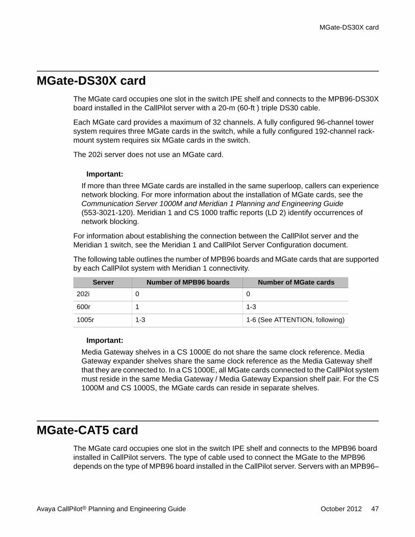
MGate-DS30X cardThe MGate card occupies one slot in the switch IPE shelf and connects to the MPB96-DS30Xboard installed in the CallPilot server with a 20-m (60-ft ) triple DS30 cable.
Each MGate card provides a maximum of 32 channels. A fully configured 96-channel towersystem requires three MGate cards in the switch, while a fully configured 192-channel rack-mount system requires six MGate cards in the switch.
The 202i server does not use an MGate card.
Important:If more than three MGate cards are installed in the same superloop, callers can experiencenetwork blocking. For more information about the installation of MGate cards, see theCommunication Server 1000M and Meridian 1 Planning and Engineering Guide(553-3021-120). Meridian 1 and CS 1000 traffic reports (LD 2) identify occurrences ofnetwork blocking.
For information about establishing the connection between the CallPilot server and theMeridian 1 switch, see the Meridian 1 and CallPilot Server Configuration document.
The following table outlines the number of MPB96 boards and MGate cards that are supportedby each CallPilot system with Meridian 1 connectivity.
Server Number of MPB96 boards Number of MGate cards202i 0 0
600r 1 1-3
1005r 1-3 1-6 (See ATTENTION, following)
Important:Media Gateway shelves in a CS 1000E do not share the same clock reference. MediaGateway expander shelves share the same clock reference as the Media Gateway shelfthat they are connected to. In a CS 1000E, all MGate cards connected to the CallPilot systemmust reside in the same Media Gateway / Media Gateway Expansion shelf pair. For the CS1000M and CS 1000S, the MGate cards can reside in separate shelves.
MGate-CAT5 cardThe MGate card occupies one slot in the switch IPE shelf and connects to the MPB96 boardinstalled in CallPilot servers. The type of cable used to connect the MGate to the MPB96depends on the type of MPB96 board installed in the CallPilot server. Servers with an MPB96–
MGate-DS30X card
Avaya CallPilot® Planning and Engineering Guide October 2012 47
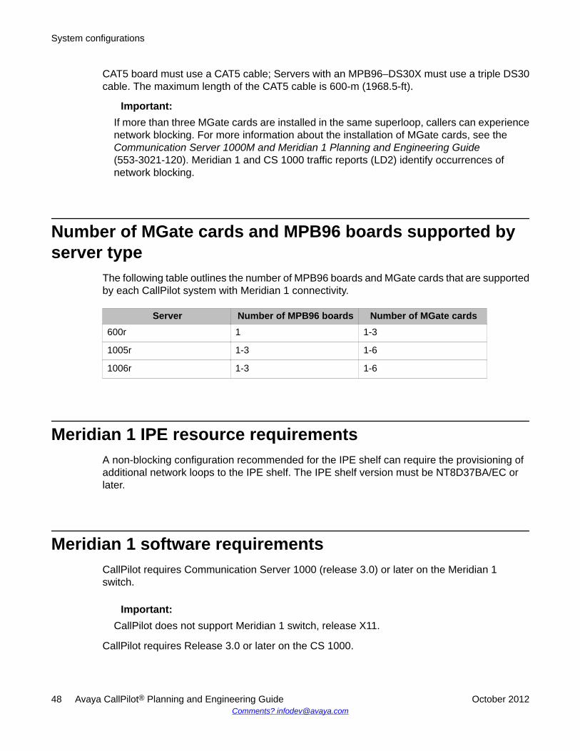
CAT5 board must use a CAT5 cable; Servers with an MPB96–DS30X must use a triple DS30cable. The maximum length of the CAT5 cable is 600-m (1968.5-ft).
Important:If more than three MGate cards are installed in the same superloop, callers can experiencenetwork blocking. For more information about the installation of MGate cards, see theCommunication Server 1000M and Meridian 1 Planning and Engineering Guide(553-3021-120). Meridian 1 and CS 1000 traffic reports (LD2) identify occurrences ofnetwork blocking.
Number of MGate cards and MPB96 boards supported byserver type
The following table outlines the number of MPB96 boards and MGate cards that are supportedby each CallPilot system with Meridian 1 connectivity.
Server Number of MPB96 boards Number of MGate cards600r 1 1-3
1005r 1-3 1-6
1006r 1-3 1-6
Meridian 1 IPE resource requirementsA non-blocking configuration recommended for the IPE shelf can require the provisioning ofadditional network loops to the IPE shelf. The IPE shelf version must be NT8D37BA/EC orlater.
Meridian 1 software requirementsCallPilot requires Communication Server 1000 (release 3.0) or later on the Meridian 1switch.
Important:CallPilot does not support Meridian 1 switch, release X11.
CallPilot requires Release 3.0 or later on the CS 1000.
System configurations
48 Avaya CallPilot® Planning and Engineering Guide October 2012Comments? [email protected]
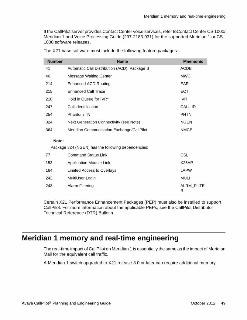
If the CallPilot server provides Contact Center voice services, refer toContact Center CS 1000/Meridian 1 and Voice Processing Guide (297-2183-931) for the supported Meridian 1 or CS1000 software releases.
The X21 base software must include the following feature packages:
Number Name Mnemonic41 Automatic Call Distribution (ACD), Package B ACDB
46 Message Waiting Center MWC
214 Enhanced ACD Routing EAR
215 Enhanced Call Trace ECT
218 Hold in Queue for IVR* IVR
247 Call identification CALL ID
254 Phantom TN PHTN
324 Next Generation Connectivity (see Note) NGEN
364 Meridian Communication Exchange/CallPilot NMCE
Note:Package 324 (NGEN) has the following dependencies:
77 Command Status Link CSL
153 Application Module Link X25AP
164 Limited Access to Overlays LAPW
242 MultiUser Login MULI
243 Alarm Filtering ALRM_FILTER
Certain X21 Performance Enhancement Packages (PEP) must also be installed to supportCallPilot. For more information about the applicable PEPs, see the CallPilot DistributorTechnical Reference (DTR) Bulletin.
Meridian 1 memory and real-time engineeringThe real-time impact of CallPilot on Meridian 1 is essentially the same as the impact of MeridianMail for the equivalent call traffic.
A Meridian 1 switch upgraded to X21 release 3.0 or later can require additional memory.
Meridian 1 memory and real-time engineering
Avaya CallPilot® Planning and Engineering Guide October 2012 49
CallPilot usage of Meridian 1 software resourcesEnsure that sufficient software resources are provisioned on the Meridian 1 switch to supportCallPilot. The software resources are, for example, terminal number (TN) levels, automatic calldistribution (ACD) agents, control directory numbers (CDN) and voice ports. CallPilot does notshare Meridian 1 resources with other applications.
The following considerations apply to the provisioning of software resources on the Meridian1 switch to support CallPilot:
• A primary CDN is required for most traffic. A secondary CDN is required for fax callanswering.
• One phantom TN/DN or dummy ACD queue is required for each service that has an entryin the Service DN table, which is equivalent to the voice service directory number (VSDN)table on Meridian Mail. CallPilot uses the phantom TN/DN in the same way as MeridianMail.
• CallPilot uses one ACD queue to manage its hardware channels. A second ACD DN isrequired for the default DN.
• CallPilot uses one ACD agent for each channel.
• Each fax user with a virtual fax machine DN requires one phantom DN and one optionaldirect inward dial (DID) line.
• Each service accessed from outside the Meridian 1 switch requires one DID line.
ACD DN overflowThe Meridian 1 switch does not permit the ACD DN to overflow to a CDN. Therefore, the ACDDN overflow is not possible with CallPilot, which uses a CDN model for call management andcontrol. If ACD DN overflow is required, then use either Symposium Express or Contact Centerintegrated with CallPilot as a viable alternative that provides enhanced call routingcapabilities.
System configurations
50 Avaya CallPilot® Planning and Engineering Guide October 2012Comments? [email protected]
CS 1000 connectivity
IntroductionThe CallPilot server connects to the CS 1000 system on the ELAN subnet through the MediaGateway or Media Gateway Expansion card. Voice services are routed through the MediaGateway card and data (signaling) services are routed through the ELAN subnet.
IPE (202i) platform connectivityEach 202i CallPilot server occupies two consecutive slots in the Media Gateway or MediaGateway Expansion cabinet, and interfaces with the network loop through one connection onthe IPE backplane. From the CS 1000 switch perspective, the 202i server appears logicallyequivalent to one regular card. Refer to the 202i Server Hardware Installation document fordetails on the 202i server installation.
The 202i CallPilot server can support up to 32 DSO channels. It provides 32 MPUs of DSPprocessing power.
Tower and rack-mount server connectivityFor detailed information about tower and rack-mount server connectivity, see theCommunication Server 1000 and CallPilot Server Configuration document.
MPB16 boardThe MPB16 board is only for legacy 1002rp systems and is replaced by the MPB96 board.
CS 1000 connectivity
Avaya CallPilot® Planning and Engineering Guide October 2012 51
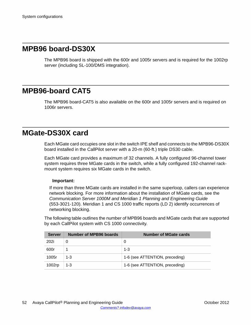
MPB96 board-DS30XThe MPB96 board is shipped with the 600r and 1005r servers and is required for the 1002rpserver (including SL-100/DMS integration).
MPB96-board CAT5The MPB96 board-CAT5 is also available on the 600r and 1005r servers and is required on1006r servers.
MGate-DS30X cardEach MGate card occupies one slot in the switch IPE shelf and connects to the MPB96-DS30Xboard installed in the CallPilot server with a 20-m (60-ft.) triple DS30 cable.
Each MGate card provides a maximum of 32 channels. A fully configured 96-channel towersystem requires three MGate cards in the switch, while a fully configured 192-channel rack-mount system requires six MGate cards in the switch.
Important:If more than three MGate cards are installed in the same superloop, callers can experiencenetwork blocking. For more information about the installation of MGate cards, see theCommunication Server 1000M and Meridian 1 Planning and Engineering Guide(553-3021-120). Meridian 1 and CS 1000 traffic reports (LD 2) identify occurrences ofnetworking blocking.
The following table outlines the number of MPB96 boards and MGate cards that are supportedby each CallPilot system with CS 1000 connectivity.
Server Number of MPB96 boards Number of MGate cards202i 0 0
600r 1 1-3
1005r 1-3 1-6 (see ATTENTION, preceding)
1002rp 1-3 1-6 (see ATTENTION, preceding)
System configurations
52 Avaya CallPilot® Planning and Engineering Guide October 2012Comments? [email protected]
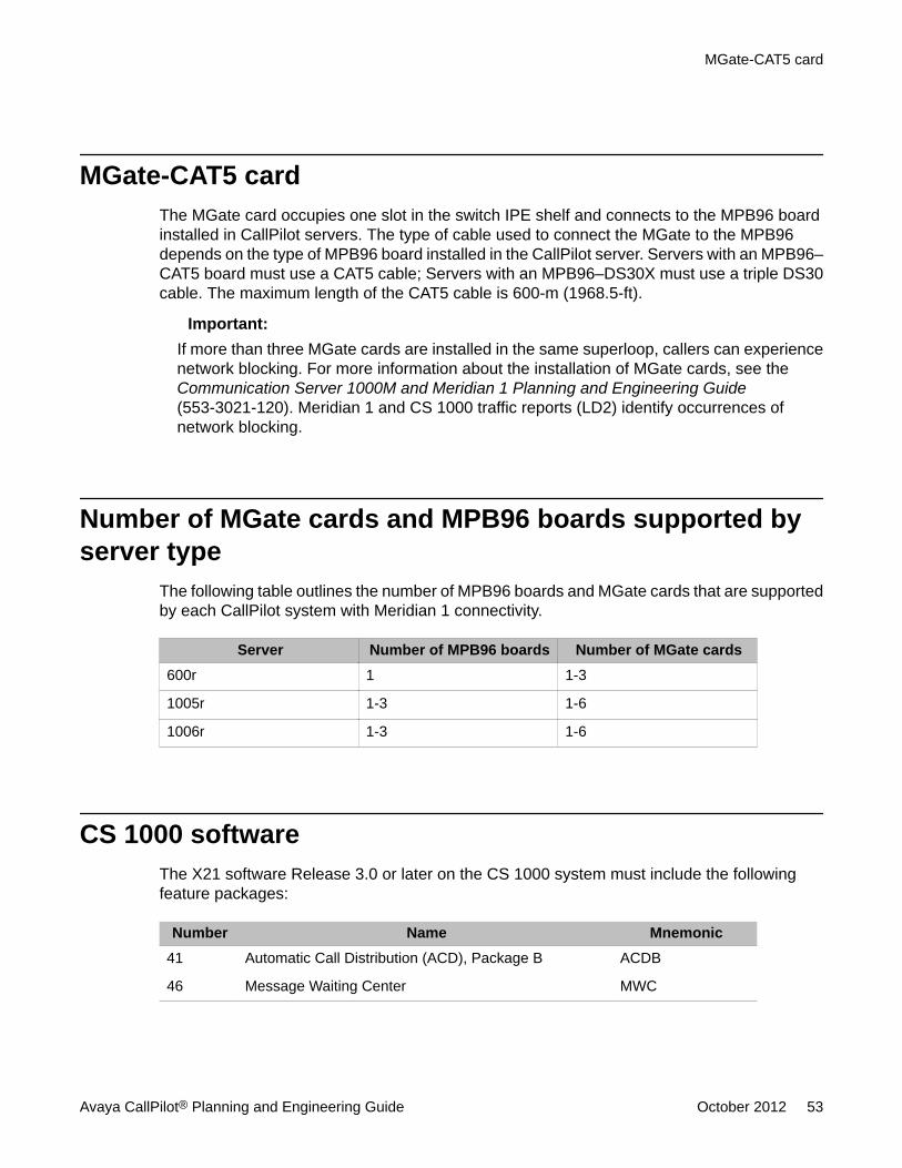
MGate-CAT5 cardThe MGate card occupies one slot in the switch IPE shelf and connects to the MPB96 boardinstalled in CallPilot servers. The type of cable used to connect the MGate to the MPB96depends on the type of MPB96 board installed in the CallPilot server. Servers with an MPB96–CAT5 board must use a CAT5 cable; Servers with an MPB96–DS30X must use a triple DS30cable. The maximum length of the CAT5 cable is 600-m (1968.5-ft).
Important:If more than three MGate cards are installed in the same superloop, callers can experiencenetwork blocking. For more information about the installation of MGate cards, see theCommunication Server 1000M and Meridian 1 Planning and Engineering Guide(553-3021-120). Meridian 1 and CS 1000 traffic reports (LD2) identify occurrences ofnetwork blocking.
Number of MGate cards and MPB96 boards supported byserver type
The following table outlines the number of MPB96 boards and MGate cards that are supportedby each CallPilot system with Meridian 1 connectivity.
Server Number of MPB96 boards Number of MGate cards600r 1 1-3
1005r 1-3 1-6
1006r 1-3 1-6
CS 1000 softwareThe X21 software Release 3.0 or later on the CS 1000 system must include the followingfeature packages:
Number Name Mnemonic41 Automatic Call Distribution (ACD), Package B ACDB
46 Message Waiting Center MWC
MGate-CAT5 card
Avaya CallPilot® Planning and Engineering Guide October 2012 53
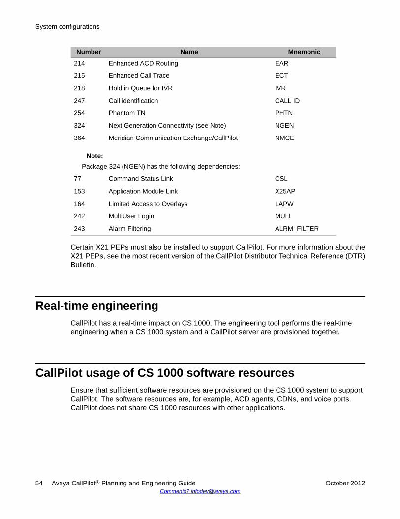
Number Name Mnemonic214 Enhanced ACD Routing EAR
215 Enhanced Call Trace ECT
218 Hold in Queue for IVR IVR
247 Call identification CALL ID
254 Phantom TN PHTN
324 Next Generation Connectivity (see Note) NGEN
364 Meridian Communication Exchange/CallPilot NMCE
Note:Package 324 (NGEN) has the following dependencies:
77 Command Status Link CSL
153 Application Module Link X25AP
164 Limited Access to Overlays LAPW
242 MultiUser Login MULI
243 Alarm Filtering ALRM_FILTER
Certain X21 PEPs must also be installed to support CallPilot. For more information about theX21 PEPs, see the most recent version of the CallPilot Distributor Technical Reference (DTR)Bulletin.
Real-time engineeringCallPilot has a real-time impact on CS 1000. The engineering tool performs the real-timeengineering when a CS 1000 system and a CallPilot server are provisioned together.
CallPilot usage of CS 1000 software resourcesEnsure that sufficient software resources are provisioned on the CS 1000 system to supportCallPilot. The software resources are, for example, ACD agents, CDNs, and voice ports.CallPilot does not share CS 1000 resources with other applications.
System configurations
54 Avaya CallPilot® Planning and Engineering Guide October 2012Comments? [email protected]
The following considerations apply to the provisioning of software resources on the CS 1000system to support CallPilot:
• A primary CDN is required for most traffic. A secondary CDN is required for fax callanswering.
• Each service that has an entry in the CallPilot Service DN table requires one phantomTN/DN.
• CallPilot uses one ACD queue to manage hardware channels. The default DN requiresa second ACD queue.
• CallPilot uses an ACD agent for each channel.
• Each fax user with a virtual fax machine DN requires one phantom DN and one optionalDID line for each fax user.
• Each service accessed from outside the CS 1000 system requires one DID line.
T1/SMDI connectivity
IntroductionThe 1002rp server is the only CallPilot platform that can be connected to T1/SMDI switches.The SL-100 and DMS-100 switches exchange information with the CallPilot server using
• a simplified message desk interface (SMDI) link
• T1 links
MPB96 boardThe MPB96 board provides 96 MPUs.
Intel Dialogic D/480JCT-2T1 boardOne or more D/480JCT-2T1 boards reside in the CallPilot server. Each D/480JCT-2T1 boardsupports up to two T1 links and a maximum of 48 channels per board.
The D/480JCT-2T1 board receives the media stream and call control signals from the switchand passes them to the MPB96 carrier boards for processing. A CTBus cable connects the D/
T1/SMDI connectivity
Avaya CallPilot® Planning and Engineering Guide October 2012 55
480JCT-2T1 board to the MPB96 board. The CTBus cable must have 1024 timeslots to supportthe D/480JCT-2T1 boards.
SL-100 and DMS-100 connectivity
SMDI linkThe SMDI link is a data link between the serial port COM2 on the CallPilot server and themultimedia processing card (MPC) port on the switch. The SMDI link transports incoming callinformation and message waiting indicator (MWI) control messages. If the CallPilot server isphysically close enough to the switch, then the SMDI link can be a direct cable connectionbetween the server and the switch.
The criteria for direct cable connection depend on whether the switch has an input-outputcontroller (IOC) shelf or an input-output module (IOM):
• With an IOC shelf in the switch, the CallPilot server must be within 15.25 m (50 ft.) of theswitch.
• With an IOM in the switch, the CallPilot server must be within 230 m (750 ft.) of theswitch.
Use a modem connection for distances that are greater than those specified in the precedinglist. The General DataComm 060A010-001 (North American ac version) modem and theTelenetics V3600 33.6K SMDI modem (NTRH9098) are approved for ensuring the connectionbetween the CallPilot server and the switch.
Line side T1 cardsThe line side T1 cards in the SL-100 switch send the voice and data signals to the CallPilotserver.
Note:The SL-100 switch can also use an external channel bank for the call lines.
System configurations
56 Avaya CallPilot® Planning and Engineering Guide October 2012Comments? [email protected]
Channel bank for DMS-100The DMS-100 switch does not use line side T1 cards, and requires an external channel bankfor the call lines. The channel bank multiplexes up to 48 universal call distribution (UCD) linesconfigured on the DMS-100 switch onto two T1 links that are attached to the D/480JCT-2T1boards in the CallPilot server.
Software requirementsCallPilot requires the following software on the SL-100 and DMS-100 switches:
• SL-100 switch—MSL10 software or later
• DMS-100 switch—NA08 software or later
Programming considerationsThe following considerations apply to the programming of the SL-100 and DMS-100 switches:
• A UCD group is defined for each required media type on the switch. Each UCD group hasunique directory numbers (DN) and supporting UCD agents.
• Line DNs are created for each directly dialable service. The DNs must be set up so thatthey can be forwarded to the UCD groups defined for each media type.
• The switch subscriber forwards the calls to the primary voice messaging DN if thecondition Busy or No Answer is encountered.
• The MWI feature must be configured for each subscriber set.
The forwarding DN can be configured as either the originally called DN (the first forwardingDN in a call forward chain is the default option) or the redirecting DN (the last forwarding DNin a call forward chain) if the LASTFWDN option is assigned to the SMDI link.
Channel bank for DMS-100
Avaya CallPilot® Planning and Engineering Guide October 2012 57
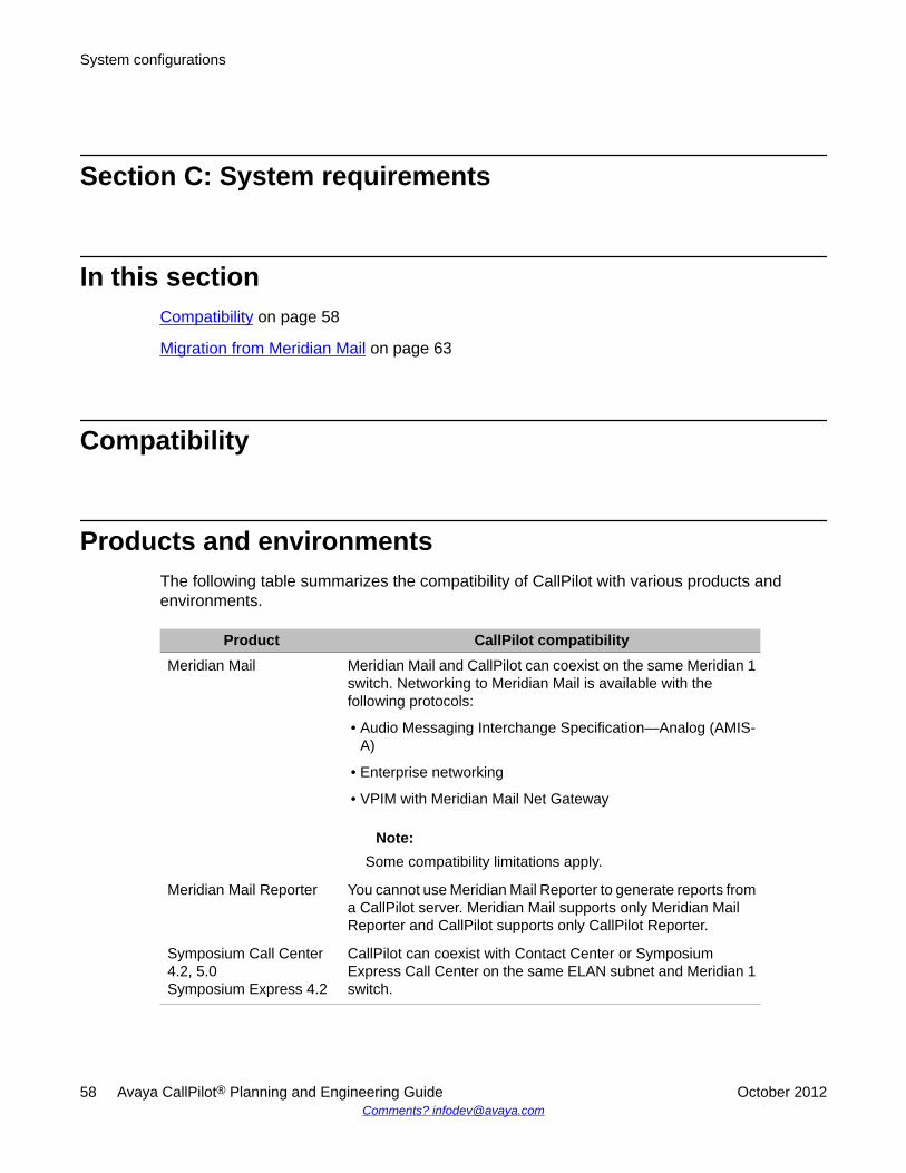
Section C: System requirements
In this sectionCompatibility on page 58
Migration from Meridian Mail on page 63
Compatibility
Products and environmentsThe following table summarizes the compatibility of CallPilot with various products andenvironments.
Product CallPilot compatibilityMeridian Mail Meridian Mail and CallPilot can coexist on the same Meridian 1
switch. Networking to Meridian Mail is available with thefollowing protocols:
• Audio Messaging Interchange Specification—Analog (AMIS-A)
• Enterprise networking
• VPIM with Meridian Mail Net Gateway
Note:Some compatibility limitations apply.
Meridian Mail Reporter You cannot use Meridian Mail Reporter to generate reports froma CallPilot server. Meridian Mail supports only Meridian MailReporter and CallPilot supports only CallPilot Reporter.
Symposium Call Center4.2, 5.0Symposium Express 4.2
CallPilot can coexist with Contact Center or SymposiumExpress Call Center on the same ELAN subnet and Meridian 1switch.
System configurations
58 Avaya CallPilot® Planning and Engineering Guide October 2012Comments? [email protected]
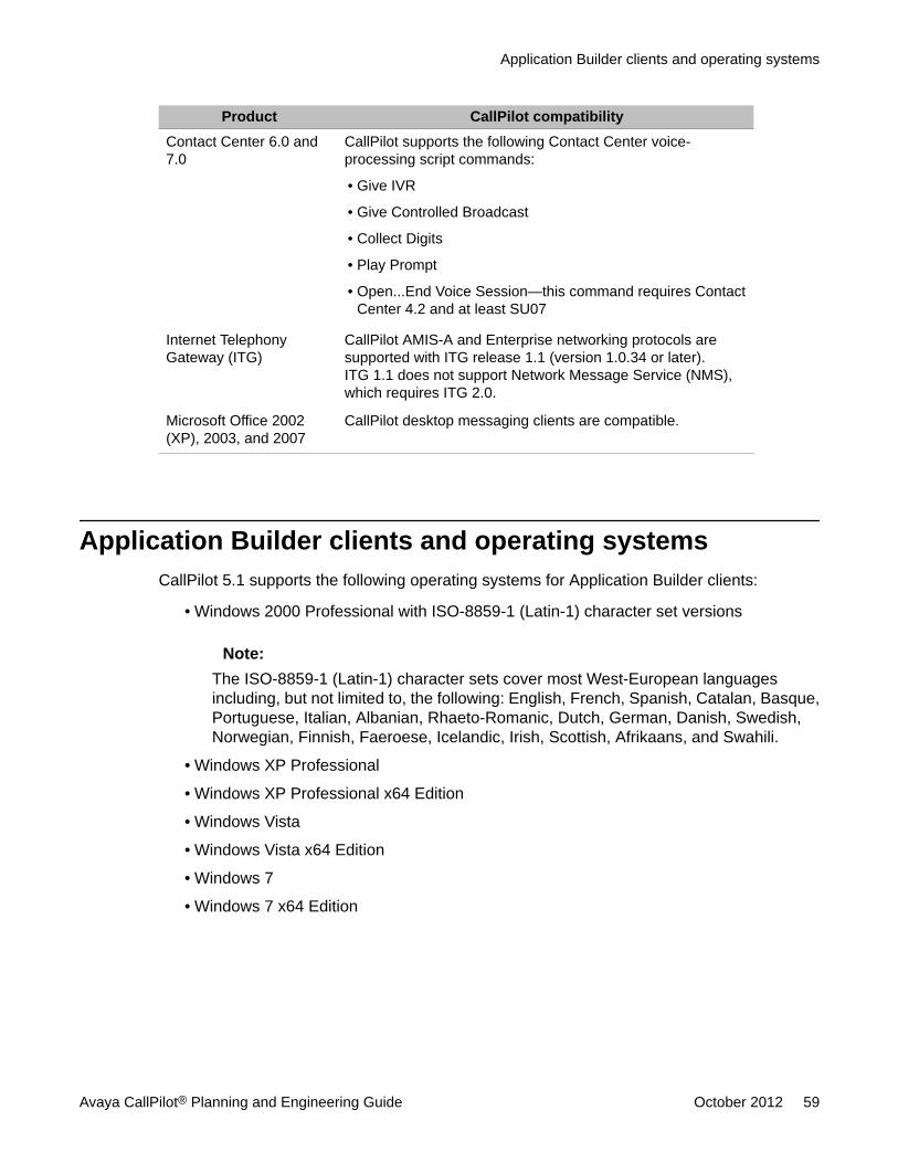
Product CallPilot compatibilityContact Center 6.0 and7.0
CallPilot supports the following Contact Center voice-processing script commands:
• Give IVR
• Give Controlled Broadcast
• Collect Digits
• Play Prompt
• Open...End Voice Session—this command requires ContactCenter 4.2 and at least SU07
Internet TelephonyGateway (ITG)
CallPilot AMIS-A and Enterprise networking protocols aresupported with ITG release 1.1 (version 1.0.34 or later).ITG 1.1 does not support Network Message Service (NMS),which requires ITG 2.0.
Microsoft Office 2002(XP), 2003, and 2007
CallPilot desktop messaging clients are compatible.
Application Builder clients and operating systemsCallPilot 5.1 supports the following operating systems for Application Builder clients:
• Windows 2000 Professional with ISO-8859-1 (Latin-1) character set versions
Note:The ISO-8859-1 (Latin-1) character sets cover most West-European languagesincluding, but not limited to, the following: English, French, Spanish, Catalan, Basque,Portuguese, Italian, Albanian, Rhaeto-Romanic, Dutch, German, Danish, Swedish,Norwegian, Finnish, Faeroese, Icelandic, Irish, Scottish, Afrikaans, and Swahili.
• Windows XP Professional
• Windows XP Professional x64 Edition
• Windows Vista
• Windows Vista x64 Edition
• Windows 7
• Windows 7 x64 Edition
Application Builder clients and operating systems
Avaya CallPilot® Planning and Engineering Guide October 2012 59
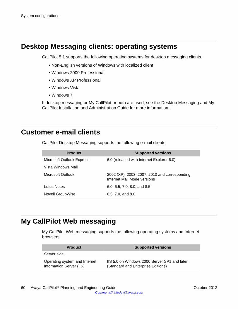
Desktop Messaging clients: operating systemsCallPilot 5.1 supports the following operating systems for desktop messaging clients.
• Non-English versions of Windows with localized client
• Windows 2000 Professional
• Windows XP Professional
• Windows Vista
• Windows 7
If desktop messaging or My CallPilot or both are used, see the Desktop Messaging and MyCallPilot Installation and Administration Guide for more information.
Customer e-mail clientsCallPilot Desktop Messaging supports the following e-mail clients.
Product Supported versionsMicrosoft Outlook Express 6.0 (released with Internet Explorer 6.0)
Vista Windows Mail
Microsoft Outlook 2002 (XP), 2003, 2007, 2010 and correspondingInternet Mail Mode versions
Lotus Notes 6.0, 6.5, 7.0, 8.0, and 8.5
Novell GroupWise 6.5, 7.0, and 8.0
My CallPilot Web messagingMy CallPilot Web messaging supports the following operating systems and Internetbrowsers.
Product Supported versionsServer side
Operating system and InternetInformation Server (IIS)
IIS 5.0 on Windows 2000 Server SP1 and later.(Standard and Enterprise Editions)
System configurations
60 Avaya CallPilot® Planning and Engineering Guide October 2012Comments? [email protected]
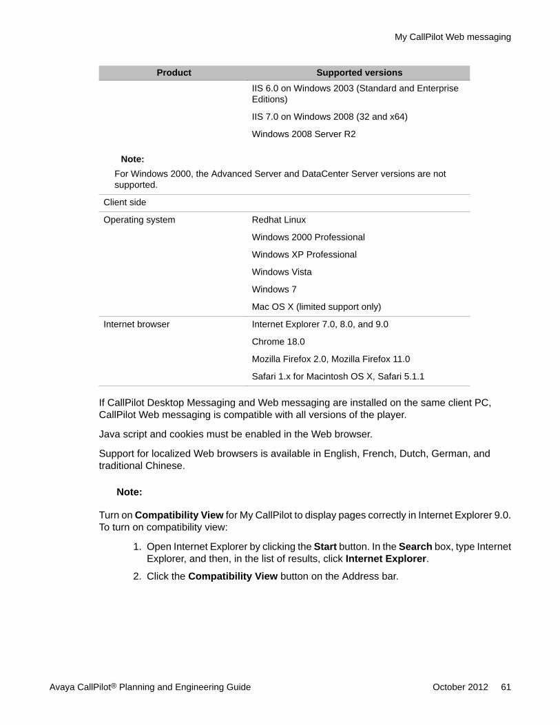
Product Supported versionsIIS 6.0 on Windows 2003 (Standard and EnterpriseEditions)
IIS 7.0 on Windows 2008 (32 and x64)
Windows 2008 Server R2
Note:For Windows 2000, the Advanced Server and DataCenter Server versions are notsupported.
Client side
Operating system Redhat Linux
Windows 2000 Professional
Windows XP Professional
Windows Vista
Windows 7
Mac OS X (limited support only)
Internet browser Internet Explorer 7.0, 8.0, and 9.0
Chrome 18.0
Mozilla Firefox 2.0, Mozilla Firefox 11.0
Safari 1.x for Macintosh OS X, Safari 5.1.1
If CallPilot Desktop Messaging and Web messaging are installed on the same client PC,CallPilot Web messaging is compatible with all versions of the player.
Java script and cookies must be enabled in the Web browser.
Support for localized Web browsers is available in English, French, Dutch, German, andtraditional Chinese.
Note:
Turn on Compatibility View for My CallPilot to display pages correctly in Internet Explorer 9.0.To turn on compatibility view:
1. Open Internet Explorer by clicking the Start button. In the Search box, type InternetExplorer, and then, in the list of results, click Internet Explorer.
2. Click the Compatibility View button on the Address bar.
My CallPilot Web messaging
Avaya CallPilot® Planning and Engineering Guide October 2012 61
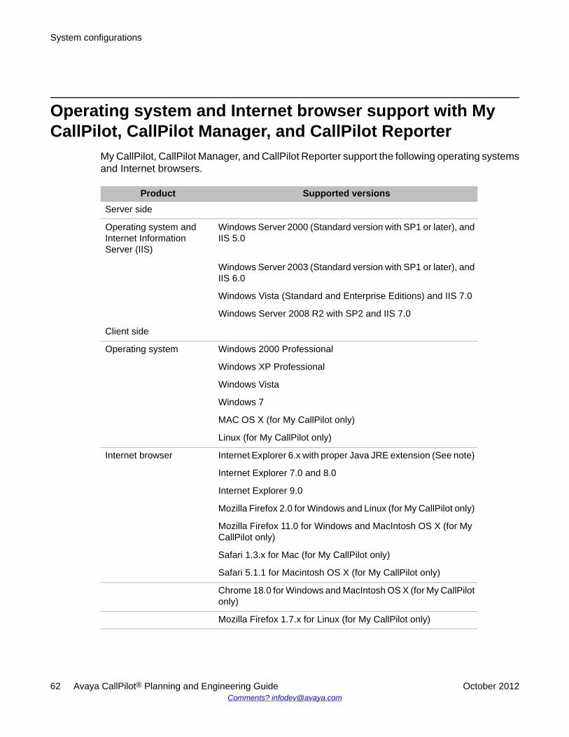
Operating system and Internet browser support with MyCallPilot, CallPilot Manager, and CallPilot Reporter
My CallPilot, CallPilot Manager, and CallPilot Reporter support the following operating systemsand Internet browsers.
Product Supported versionsServer side
Operating system andInternet InformationServer (IIS)
Windows Server 2000 (Standard version with SP1 or later), andIIS 5.0
Windows Server 2003 (Standard version with SP1 or later), andIIS 6.0
Windows Vista (Standard and Enterprise Editions) and IIS 7.0
Windows Server 2008 R2 with SP2 and IIS 7.0
Client side
Operating system Windows 2000 Professional
Windows XP Professional
Windows Vista
Windows 7
MAC OS X (for My CallPilot only)
Linux (for My CallPilot only)
Internet browser Internet Explorer 6.x with proper Java JRE extension (See note)
Internet Explorer 7.0 and 8.0
Internet Explorer 9.0
Mozilla Firefox 2.0 for Windows and Linux (for My CallPilot only)
Mozilla Firefox 11.0 for Windows and MacIntosh OS X (for MyCallPilot only)
Safari 1.3.x for Mac (for My CallPilot only)
Safari 5.1.1 for Macintosh OS X (for My CallPilot only)
Chrome 18.0 for Windows and MacIntosh OS X (for My CallPilotonly)
Mozilla Firefox 1.7.x for Linux (for My CallPilot only)
System configurations
62 Avaya CallPilot® Planning and Engineering Guide October 2012Comments? [email protected]
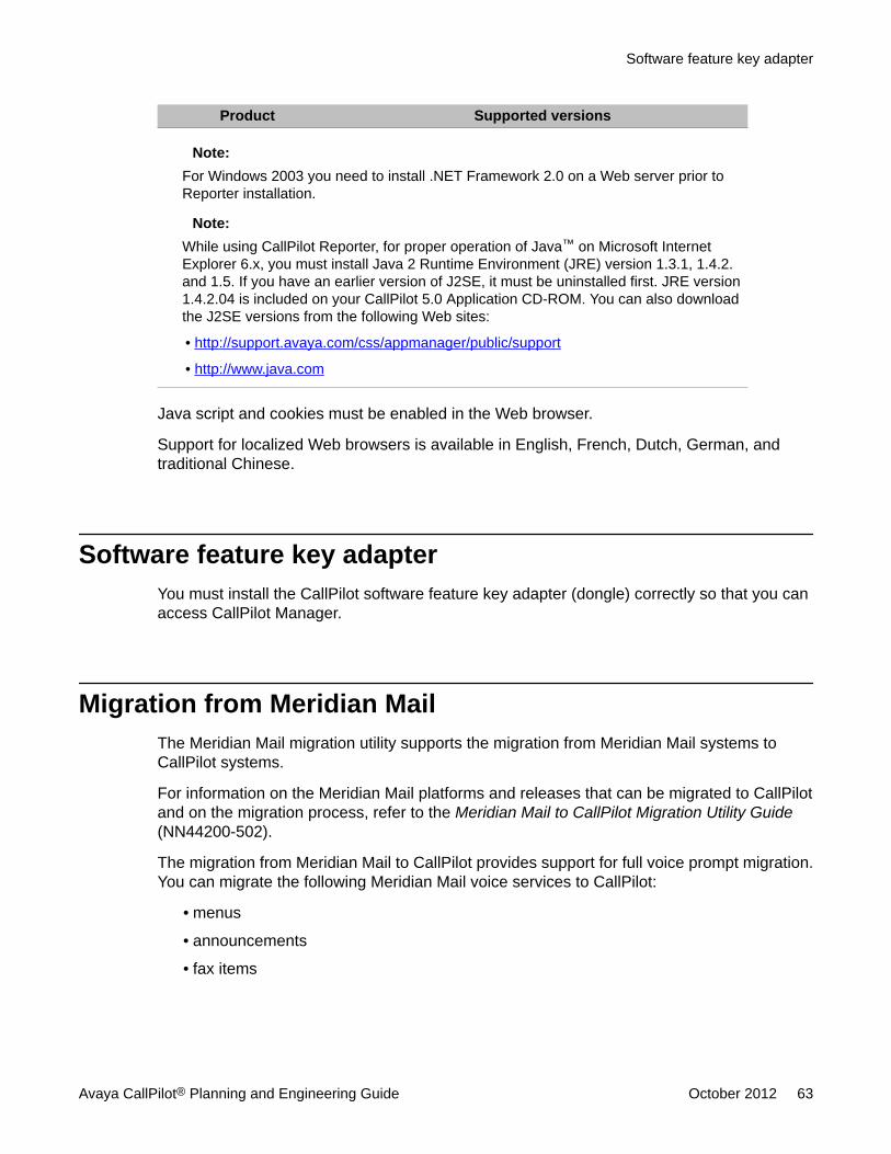
Product Supported versions
Note:For Windows 2003 you need to install .NET Framework 2.0 on a Web server prior toReporter installation.
Note:While using CallPilot Reporter, for proper operation of Java™ on Microsoft InternetExplorer 6.x, you must install Java 2 Runtime Environment (JRE) version 1.3.1, 1.4.2.and 1.5. If you have an earlier version of J2SE, it must be uninstalled first. JRE version1.4.2.04 is included on your CallPilot 5.0 Application CD-ROM. You can also downloadthe J2SE versions from the following Web sites:
• http://support.avaya.com/css/appmanager/public/support
• http://www.java.com
Java script and cookies must be enabled in the Web browser.
Support for localized Web browsers is available in English, French, Dutch, German, andtraditional Chinese.
Software feature key adapterYou must install the CallPilot software feature key adapter (dongle) correctly so that you canaccess CallPilot Manager.
Migration from Meridian MailThe Meridian Mail migration utility supports the migration from Meridian Mail systems toCallPilot systems.
For information on the Meridian Mail platforms and releases that can be migrated to CallPilotand on the migration process, refer to the Meridian Mail to CallPilot Migration Utility Guide(NN44200-502).
The migration from Meridian Mail to CallPilot provides support for full voice prompt migration.You can migrate the following Meridian Mail voice services to CallPilot:
• menus
• announcements
• fax items
Software feature key adapter
Avaya CallPilot® Planning and Engineering Guide October 2012 63
• voice items
• Contact Center voice prompts
Each voice service (for example, a menu) migrated from Meridian Mail is represented as anApplication Builder application on CallPilot. This application contains voice or fax items, orboth, that were associated with the migrated voice service on Meridian Mail.
The logic of the voice services is not migrated to CallPilot. Only a default application is createdin Application Builder. You must complete the application manually so that you can put it intoservice in CallPilot.
System configurations
64 Avaya CallPilot® Planning and Engineering Guide October 2012Comments? [email protected]
Chapter 5: Determining system size
In this chapterOverview on page 65
System sizing on page 66
Customer requirements on page 69
Channel requirements on page 72
Voice traffic services on page 77
Fax traffic services on page 81
Speech recognition traffic services on page 83
Storage estimation on page 84
Overview
IntroductionThis chapter provides an overview of the enterprise capacity issues that you must considerbefore installing an Avaya CallPilot® system. Avaya provides engineering tools that determineautomatically the type of Avaya CallPilot system that you need on the basis of the informationthat you provide:
• the number of users
• the application usage
• the busy hour activity
Avaya CallPilot® Planning and Engineering Guide October 2012 65
System sizing
Sales engineering tools
Avaya Enterprise ConfiguratorAfter completing the gathering of solution planning requirements, you can obtain a customerquotation by way of the Avaya Enterprise Configurator (NNEC) tool. The NNEC is the globalenterprise configurator and quotation tool for Avaya voice and Voice over IP (VoIP)portfolios.
Use the NNEC tool to determine the following system requirements:
• Channel media type and resources driven by the number and type of seats and featureusage required.
• Server platform determined by the total number of channels, resiliency requirements, andstorage requirements.
• The integration type and amount of interworking connectivity required depending on theselected solution host.
The NNEC replaces Meridian Configurator in North and South America.
The NNEC provides the following quotation methods:
• Engineered Offer Quote (North and South America)
• Functional Offer Quote (Europe, the Middle East, Africa, and Asia)
CallPilot Capacity Engineering SpreadsheetThe CallPilot Capacity Engineering Spreadsheet in Microsoft Excel format is available forprequotation planning. This spreadsheet is available in the CallPilot area established on thesupport web site at http://support.avaya.com/css/appmanager/public/support. Click Products> Products by category > Alphabetically > CallPilot 5.1 > P.13 CallPilot Sales Engineering.
Determining system size
66 Avaya CallPilot® Planning and Engineering Guide October 2012Comments? [email protected]
System requirementsUse the engineering tools to determine the requirements for the following system factors:
• channels
• digital signal processors (DSP) media processing units (MPU)
• storage
• CPU real-time resources
The engineering tools also help you determine
• the CallPilot platform having sufficient channel, DSP, and CPU real-time capacity to meetthe requirements of your specific situation
• the hardware for the switch channel connectivity
• the DSP hardware
Channel requirementsDetermine the number of voice, fax, and speech-recognition channels required to meet yourneeds as follows:
1. Estimate the busy-hour traffic using a parameter-driven traffic model.
2. Look up the corresponding channel capacity in the P05 Erlang C traffic table.
The parameters available for modeling traffic are described later in this chapter. Also refer to Traffic capacity tables on page 103, on page Traffic capacity tables on page 103.
DSP MPU requirementsThe DSP capacity is calculated in MPUs. The engineering tool determines the required DSPprocessing power on the basis of the following ratios:
• 1 MPU for each voice channel
• 2 MPUs for each fax channel
• 4 MPUs for each speech-recognition channel
System requirements
Avaya CallPilot® Planning and Engineering Guide October 2012 67
Storage requirementsThe storage capacity is calculated in hours of voice messages. The engineering tool multipliesthe number of mailboxes by the minutes of voice messages for each mailbox to estimate thevoice message storage requirements.
The storage capacity for fax services is determined by multiplying the estimated number ofstored fax pages by a mix of the normal and fine densities:
• 212 pages of normal density fax = 1 hour of voice messages
• 106 pages of fine density fax = 1 hour of voice messages
CPU real-time requirementsWith the introduction of CPU-intensive services (such as E-Mail by Phone, which uses host-based text-to-speech algorithms), it is necessary to calculate the CPU load of a given set ofapplications. The engineering tool calculates the CPU load by
1. estimating the total traffic in centum call seconds (CCS) for applications, messaging,and E-mail by Phone services
2. multiplying each service type by load factors
3. adding up the results of the estimations and calculations
CallPilot platform capacityThe engineering tool performs the following tasks for the selected CallPilot platform:
• checks the platform capacity for channels, DSP MPUs, and CPU real-time load againstthe calculated requirements
• flags instances in which the platform capacity is exceeded
Switch channel connectivity hardwareThe engineering tool provisions the switch channel connectivity hardware that is necessary tomeet the channel requirements.
Determining system size
68 Avaya CallPilot® Planning and Engineering Guide October 2012Comments? [email protected]
DSP hardwareThe engineering tool provisions the DSP hardware that is necessary to meet the DSP MPUrequirements.
Customer requirements
Principal inputCustomer requirements are the principal input into the engineering tools and the major driverof the system capacity. The following parameters must be determined as part of the customerrequirements:
Note:If the IPE option is selected as the System Type parameter, then only Meridian 1 or CS 1000can be selected as the Switch parameter.
Note:If CallPilot is ordered in conjunction with a Meridian 1 switch, then only the Meridian 1parameter can be selected.
Note:If CallPilot is ordered in conjunction with a CS 1000 system, then only the CS 1000 parametercan be selected.
Parameter Initialvalue
Minimum Maximum Comments
System Type (IPE,tower, rack-mount)
None Not applicable Not applicable The selection ofany option enablesall the CallPilotinputs.
Voice Users Blank 0 8000 (202i)20 000 (600r)50 000 (1002rp,1005r, and 1006r)
Enter the numberof voicemailboxes.
DSP hardware
Avaya CallPilot® Planning and Engineering Guide October 2012 69
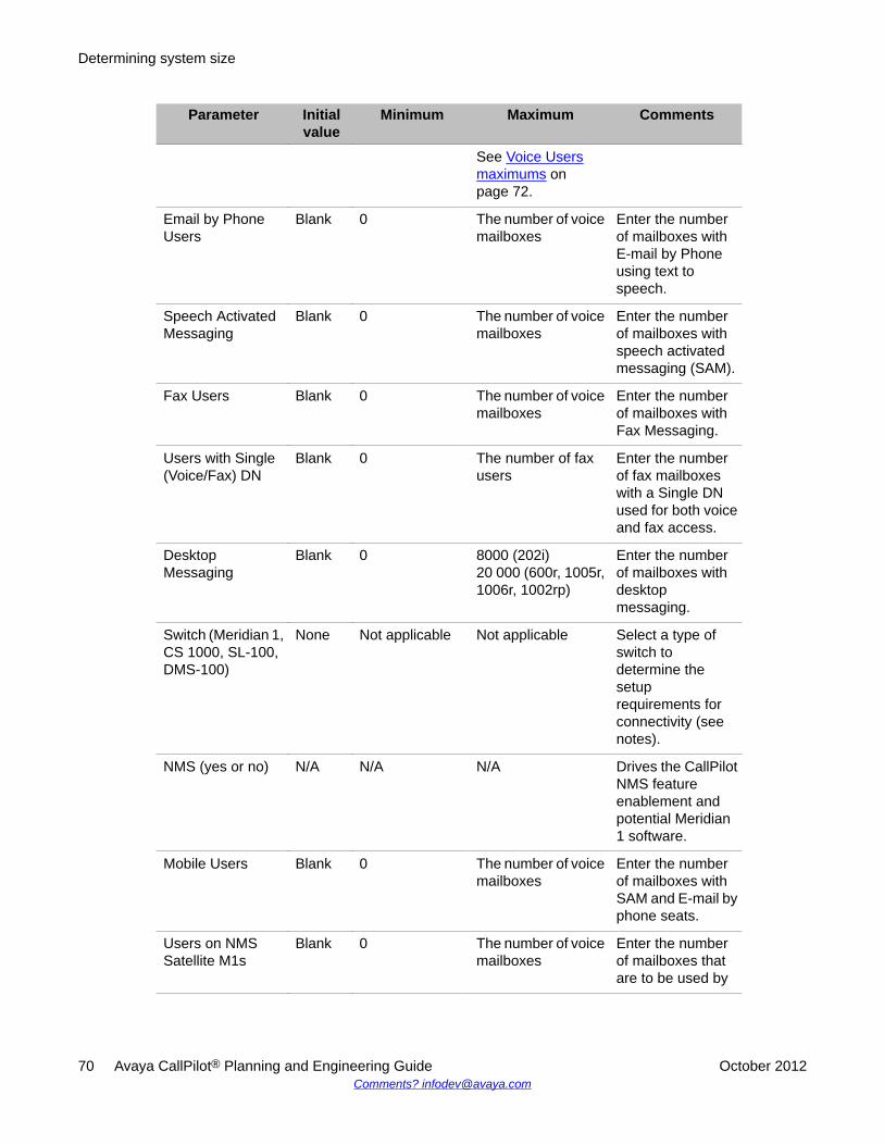
Parameter Initialvalue
Minimum Maximum Comments
See Voice Usersmaximums onpage 72.
Email by PhoneUsers
Blank 0 The number of voicemailboxes
Enter the numberof mailboxes withE-mail by Phoneusing text tospeech.
Speech ActivatedMessaging
Blank 0 The number of voicemailboxes
Enter the numberof mailboxes withspeech activatedmessaging (SAM).
Fax Users Blank 0 The number of voicemailboxes
Enter the numberof mailboxes withFax Messaging.
Users with Single(Voice/Fax) DN
Blank 0 The number of faxusers
Enter the numberof fax mailboxeswith a Single DNused for both voiceand fax access.
DesktopMessaging
Blank 0 8000 (202i)20 000 (600r, 1005r,1006r, 1002rp)
Enter the numberof mailboxes withdesktopmessaging.
Switch (Meridian 1,CS 1000, SL-100,DMS-100)
None Not applicable Not applicable Select a type ofswitch todetermine thesetuprequirements forconnectivity (seenotes).
NMS (yes or no) N/A N/A N/A Drives the CallPilotNMS featureenablement andpotential Meridian1 software.
Mobile Users Blank 0 The number of voicemailboxes
Enter the numberof mailboxes withSAM and E-mail byphone seats.
Users on NMSSatellite M1s
Blank 0 The number of voicemailboxes
Enter the numberof mailboxes thatare to be used by
Determining system size
70 Avaya CallPilot® Planning and Engineering Guide October 2012Comments? [email protected]
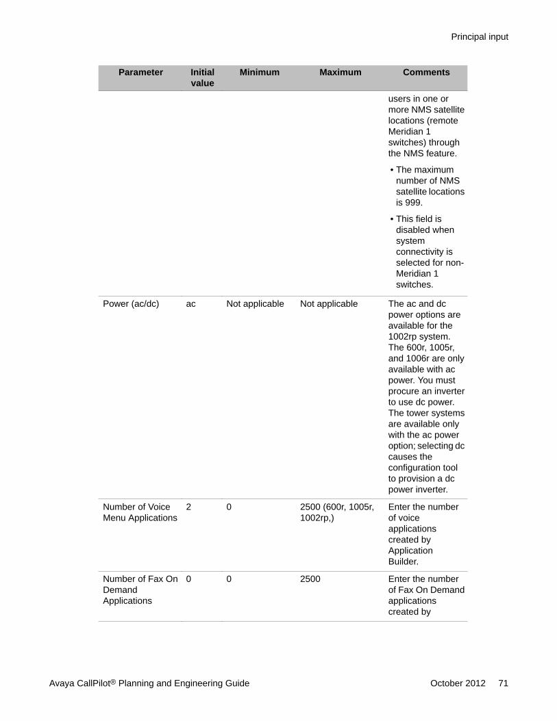
Parameter Initialvalue
Minimum Maximum Comments
users in one ormore NMS satellitelocations (remoteMeridian 1switches) throughthe NMS feature.
• The maximumnumber of NMSsatellite locationsis 999.
• This field isdisabled whensystemconnectivity isselected for non-Meridian 1switches.
Power (ac/dc) ac Not applicable Not applicable The ac and dcpower options areavailable for the1002rp system.The 600r, 1005r,and 1006r are onlyavailable with acpower. You mustprocure an inverterto use dc power.The tower systemsare available onlywith the ac poweroption; selecting dccauses theconfiguration toolto provision a dcpower inverter.
Number of VoiceMenu Applications
2 0 2500 (600r, 1005r,1002rp,)
Enter the numberof voiceapplicationscreated byApplicationBuilder.
Number of Fax OnDemandApplications
0 0 2500 Enter the numberof Fax On Demandapplicationscreated by
Principal input
Avaya CallPilot® Planning and Engineering Guide October 2012 71
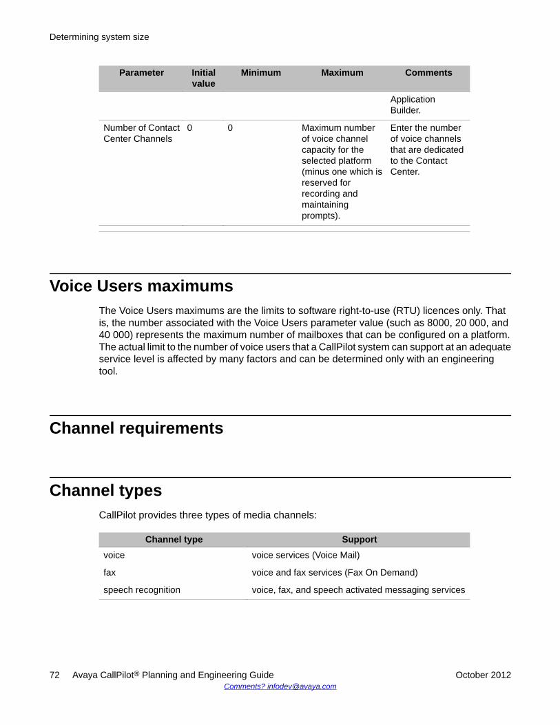
Parameter Initialvalue
Minimum Maximum Comments
ApplicationBuilder.
Number of ContactCenter Channels
0 0 Maximum numberof voice channelcapacity for theselected platform(minus one which isreserved forrecording andmaintainingprompts).
Enter the numberof voice channelsthat are dedicatedto the ContactCenter.
Voice Users maximumsThe Voice Users maximums are the limits to software right-to-use (RTU) licences only. Thatis, the number associated with the Voice Users parameter value (such as 8000, 20 000, and40 000) represents the maximum number of mailboxes that can be configured on a platform.The actual limit to the number of voice users that a CallPilot system can support at an adequateservice level is affected by many factors and can be determined only with an engineeringtool.
Channel requirements
Channel typesCallPilot provides three types of media channels:
Channel type Supportvoice voice services (Voice Mail)
fax voice and fax services (Fax On Demand)
speech recognition voice, fax, and speech activated messaging services
Determining system size
72 Avaya CallPilot® Planning and Engineering Guide October 2012Comments? [email protected]
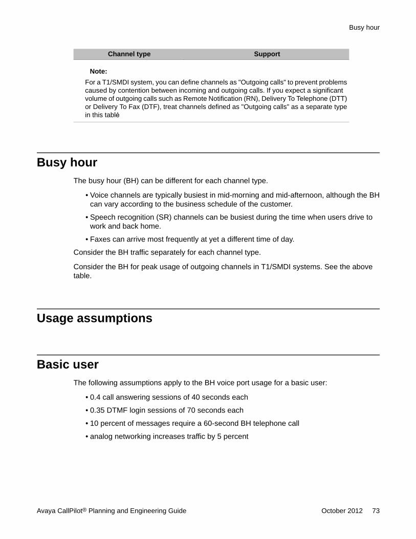
Channel type Support
Note:For a T1/SMDI system, you can define channels as "Outgoing calls" to prevent problemscaused by contention between incoming and outgoing calls. If you expect a significantvolume of outgoing calls such as Remote Notification (RN), Delivery To Telephone (DTT)or Delivery To Fax (DTF), treat channels defined as "Outgoing calls" as a separate typein this tablė
Busy hourThe busy hour (BH) can be different for each channel type.
• Voice channels are typically busiest in mid-morning and mid-afternoon, although the BHcan vary according to the business schedule of the customer.
• Speech recognition (SR) channels can be busiest during the time when users drive towork and back home.
• Faxes can arrive most frequently at yet a different time of day.
Consider the BH traffic separately for each channel type.
Consider the BH for peak usage of outgoing channels in T1/SMDI systems. See the abovetable.
Usage assumptions
Basic userThe following assumptions apply to the BH voice port usage for a basic user:
• 0.4 call answering sessions of 40 seconds each
• 0.35 DTMF login sessions of 70 seconds each
• 10 percent of messages require a 60-second BH telephone call
• analog networking increases traffic by 5 percent
Busy hour
Avaya CallPilot® Planning and Engineering Guide October 2012 73
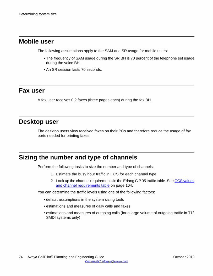
Mobile userThe following assumptions apply to the SAM and SR usage for mobile users:
• The frequency of SAM usage during the SR BH is 70 percent of the telephone set usageduring the voice BH.
• An SR session lasts 70 seconds.
Fax userA fax user receives 0.2 faxes (three pages each) during the fax BH.
Desktop userThe desktop users view received faxes on their PCs and therefore reduce the usage of faxports needed for printing faxes.
Sizing the number and type of channelsPerform the following tasks to size the number and type of channels:
1. Estimate the busy hour traffic in CCS for each channel type.
2. Look up the channel requirements in the Erlang C P.05 traffic table. See CCS valuesand channel requirements table on page 104.
You can determine the traffic levels using one of the following factors:
• default assumptions in the system sizing tools
• estimations and measures of daily calls and faxes
• estimations and measures of outgoing calls (for a large volume of outgoing traffic in T1/SMDI systems only)
Determining system size
74 Avaya CallPilot® Planning and Engineering Guide October 2012Comments? [email protected]
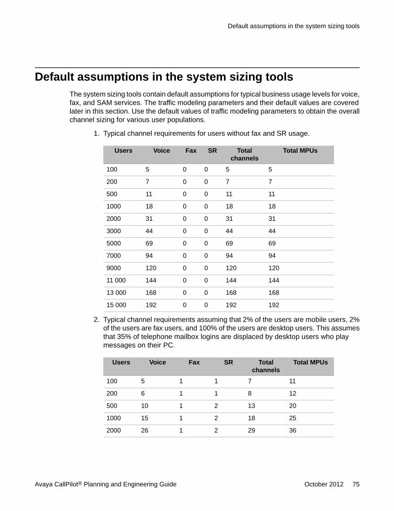
Default assumptions in the system sizing toolsThe system sizing tools contain default assumptions for typical business usage levels for voice,fax, and SAM services. The traffic modeling parameters and their default values are coveredlater in this section. Use the default values of traffic modeling parameters to obtain the overallchannel sizing for various user populations.
1. Typical channel requirements for users without fax and SR usage.
Users Voice Fax SR Totalchannels
Total MPUs
100 5 0 0 5 5
200 7 0 0 7 7
500 11 0 0 11 11
1000 18 0 0 18 18
2000 31 0 0 31 31
3000 44 0 0 44 44
5000 69 0 0 69 69
7000 94 0 0 94 94
9000 120 0 0 120 120
11 000 144 0 0 144 144
13 000 168 0 0 168 168
15 000 192 0 0 192 192
2. Typical channel requirements assuming that 2% of the users are mobile users, 2%of the users are fax users, and 100% of the users are desktop users. This assumesthat 35% of telephone mailbox logins are displaced by desktop users who playmessages on their PC.
Users Voice Fax SR Totalchannels
Total MPUs
100 5 1 1 7 11
200 6 1 1 8 12
500 10 1 2 13 20
1000 15 1 2 18 25
2000 26 1 2 29 36
Default assumptions in the system sizing tools
Avaya CallPilot® Planning and Engineering Guide October 2012 75
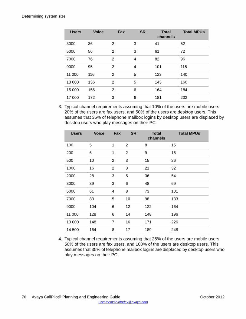
Users Voice Fax SR Totalchannels
Total MPUs
3000 36 2 3 41 52
5000 56 2 3 61 72
7000 76 2 4 82 96
9000 95 2 4 101 115
11 000 116 2 5 123 140
13 000 136 2 5 143 160
15 000 156 2 6 164 184
17 000 172 3 6 181 202
3. Typical channel requirements assuming that 10% of the users are mobile users,20% of the users are fax users, and 50% of the users are desktop users. Thisassumes that 35% of telephone mailbox logins by desktop users are displaced bydesktop users who play messages on their PC.
Users Voice Fax SR Totalchannels
Total MPUs
100 5 1 2 8 15
200 6 1 2 9 16
500 10 2 3 15 26
1000 16 2 3 21 32
2000 28 3 5 36 54
3000 39 3 6 48 69
5000 61 4 8 73 101
7000 83 5 10 98 133
9000 104 6 12 122 164
11 000 128 6 14 148 196
13 000 148 7 16 171 226
14 500 164 8 17 189 248
4. Typical channel requirements assuming that 25% of the users are mobile users,50% of the users are fax users, and 100% of the users are desktop users. Thisassumes that 35% of telephone mailbox logins are displaced by desktop users whoplay messages on their PC.
Determining system size
76 Avaya CallPilot® Planning and Engineering Guide October 2012Comments? [email protected]
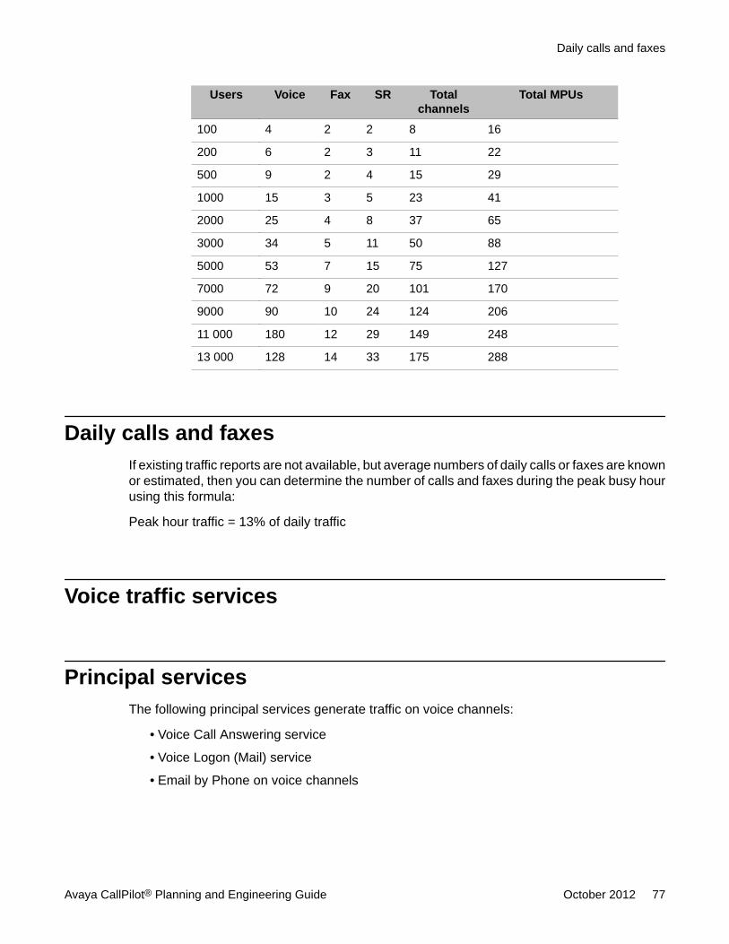
Users Voice Fax SR Totalchannels
Total MPUs
100 4 2 2 8 16
200 6 2 3 11 22
500 9 2 4 15 29
1000 15 3 5 23 41
2000 25 4 8 37 65
3000 34 5 11 50 88
5000 53 7 15 75 127
7000 72 9 20 101 170
9000 90 10 24 124 206
11 000 180 12 29 149 248
13 000 128 14 33 175 288
Daily calls and faxesIf existing traffic reports are not available, but average numbers of daily calls or faxes are knownor estimated, then you can determine the number of calls and faxes during the peak busy hourusing this formula:
Peak hour traffic = 13% of daily traffic
Voice traffic services
Principal servicesThe following principal services generate traffic on voice channels:
• Voice Call Answering service
• Voice Logon (Mail) service
• Email by Phone on voice channels
Daily calls and faxes
Avaya CallPilot® Planning and Engineering Guide October 2012 77
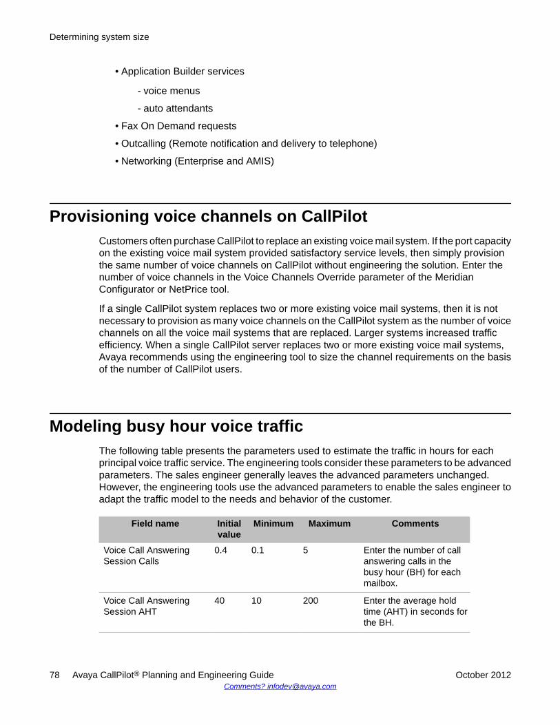
• Application Builder services
- voice menus
- auto attendants
• Fax On Demand requests
• Outcalling (Remote notification and delivery to telephone)
• Networking (Enterprise and AMIS)
Provisioning voice channels on CallPilotCustomers often purchase CallPilot to replace an existing voice mail system. If the port capacityon the existing voice mail system provided satisfactory service levels, then simply provisionthe same number of voice channels on CallPilot without engineering the solution. Enter thenumber of voice channels in the Voice Channels Override parameter of the MeridianConfigurator or NetPrice tool.
If a single CallPilot system replaces two or more existing voice mail systems, then it is notnecessary to provision as many voice channels on the CallPilot system as the number of voicechannels on all the voice mail systems that are replaced. Larger systems increased trafficefficiency. When a single CallPilot server replaces two or more existing voice mail systems,Avaya recommends using the engineering tool to size the channel requirements on the basisof the number of CallPilot users.
Modeling busy hour voice trafficThe following table presents the parameters used to estimate the traffic in hours for eachprincipal voice traffic service. The engineering tools consider these parameters to be advancedparameters. The sales engineer generally leaves the advanced parameters unchanged.However, the engineering tools use the advanced parameters to enable the sales engineer toadapt the traffic model to the needs and behavior of the customer.
Field name Initialvalue
Minimum Maximum Comments
Voice Call AnsweringSession Calls
0.4 0.1 5 Enter the number of callanswering calls in thebusy hour (BH) for eachmailbox.
Voice Call AnsweringSession AHT
40 10 200 Enter the average holdtime (AHT) in seconds forthe BH.
Determining system size
78 Avaya CallPilot® Planning and Engineering Guide October 2012Comments? [email protected]
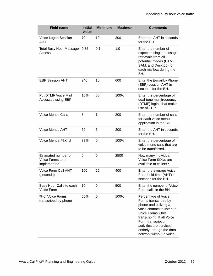
Field name Initialvalue
Minimum Maximum Comments
Voice Logon SessionAHT
70 10 300 Enter the AHT in secondsfor the BH.
Total Busy Hour MessageAccess
0.35 0.1 1.0 Enter the number ofexpected single messageretrievals from allpotential modes (DTMF,SAM, and Desktop) foreach mailbox during theBH.
EBP Session AHT 240 10 600 Enter the E-mail by Phone(EBP) session AHT inseconds for the BH.
Pct DTMF Voice MailAccesses using EBP
10% 00 100% Enter the percentage ofdual-tone multifrequency(DTMF) logins that makeuse of EBP.
Voice Menus Calls 5 1 200 Enter the number of callsfor each voice menuapplication in the BH.
Voice Menus AHT 60 5 200 Enter the AHT in secondsfor the BH.
Voice Menus: %Xfrd 33% 0 100% Enter the percentage ofvoice menu calls that areto be transferred.
Estimated number ofVoice Forms to beimplemented
0 0 2500 How many individualVoice Form SDNs areavailable to callers?
Voice Form Call AHT(seconds)
100 20 400 Enter the average VoiceForm hold time (AHT) inseconds for the BH.
Busy Hour Calls to eachVoice Form
10 0 500 Enter the number of VoiceForm calls in the BH.
% of Voice Formstranscribed by phone
50% 0 100% Percentage of VoiceForms transcribed byphone and utilizing avoice channel to listen toVoice Forms whiletranscribing. If all VoiceForm transcriptionactivities are servicedentirely through the datanetwork without a voice
Modeling busy hour voice traffic
Avaya CallPilot® Planning and Engineering Guide October 2012 79
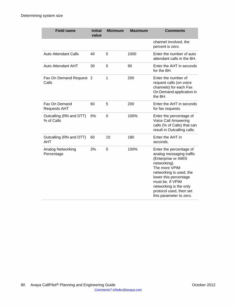
Field name Initialvalue
Minimum Maximum Comments
channel involved, thepercent is zero.
Auto Attendant Calls 40 5 1000 Enter the number of autoattendant calls in the BH.
Auto Attendant AHT 30 5 90 Enter the AHT in secondsfor the BH.
Fax On Demand RequestCalls
2 1 200 Enter the number ofrequest calls (on voicechannels) for each FaxOn Demand application inthe BH.
Fax On DemandRequests AHT
60 5 200 Enter the AHT in secondsfor fax requests.
Outcalling (RN and DTT)% of Calls
5% 0 100% Enter the percentage ofVoice Call Answeringcalls (% of Calls) that canresult in Outcalling calls.
Outcalling (RN and DTT)AHT
60 10 180 Enter the AHT inseconds.
Analog NetworkingPercentage
3% 0 100% Enter the percentage ofanalog messaging traffic(Enterprise or AMISnetworking).The more VPIMnetworking is used, thelower this percentagemust be. If VPIMnetworking is the onlyprotocol used, then setthis parameter to zero.
Determining system size
80 Avaya CallPilot® Planning and Engineering Guide October 2012Comments? [email protected]
Fax traffic services
Principal servicesThese are the principal services that generate traffic on fax channels:
• Fax On Demand applications with same call fax access
• Fax On Demand callback delivery
• Fax auto attendant (fax express messaging)
• Fax call answering
• Delivery to fax services
• Fax broadcasting (multicast to fax service)
• Fax printing to fax machines
Estimating fax channelsIn some situations, the CallPilot fax channels replace a small number of fax machines thathave high inbound traffic. Avaya does not recommend that you replace the fax machines withfax channels on a one-for-one basis. Instead, Avaya recommends that you estimate theaverage number of
• fax messages per fax user
• pages per fax message
Enter the estimated average numbers into the Advanced parameters box of the engineeringtool.
Modeling busy hour fax trafficThe following table presents the parameters used to estimate the traffic for each principal faxservice. The engineering tools consider these parameters to be advanced parameters. Thesales engineer generally leaves the advanced parameters unchanged. However, the
Fax traffic services
Avaya CallPilot® Planning and Engineering Guide October 2012 81
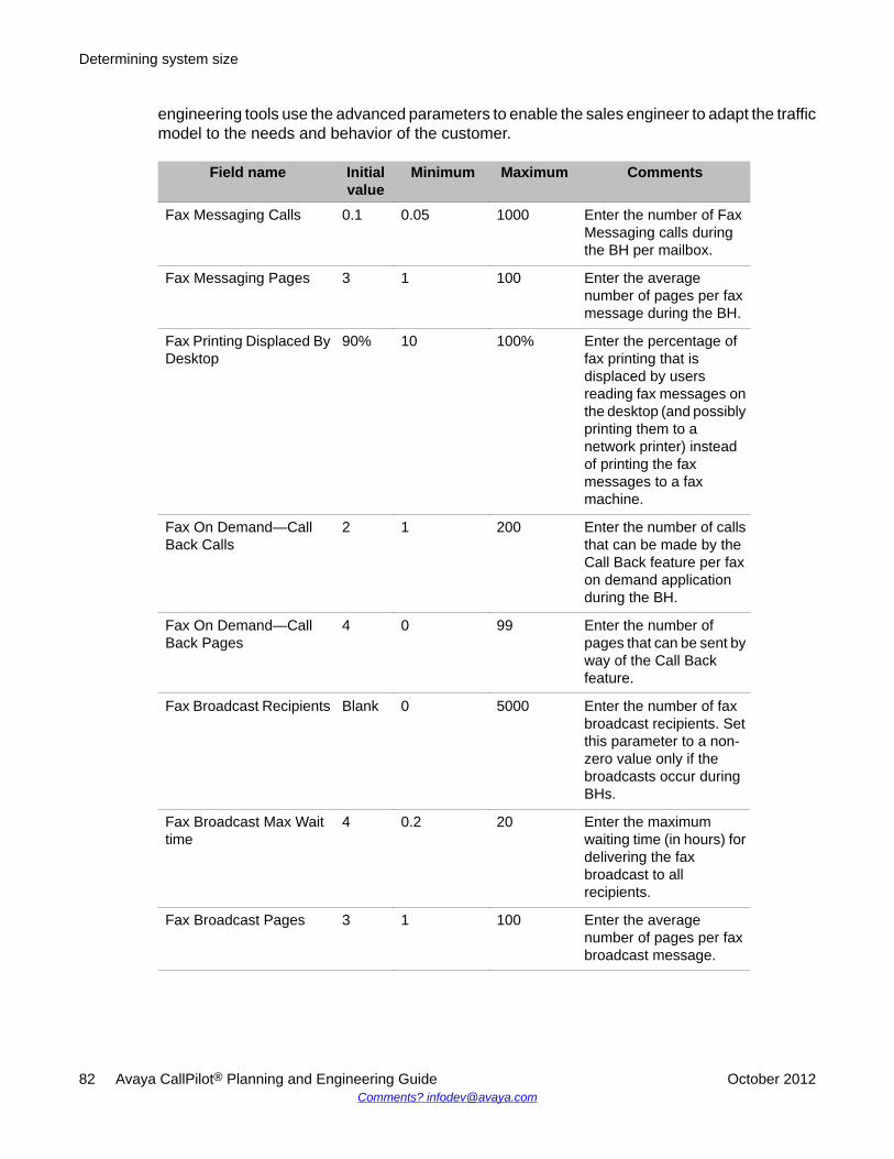
engineering tools use the advanced parameters to enable the sales engineer to adapt the trafficmodel to the needs and behavior of the customer.
Field name Initialvalue
Minimum Maximum Comments
Fax Messaging Calls 0.1 0.05 1000 Enter the number of FaxMessaging calls duringthe BH per mailbox.
Fax Messaging Pages 3 1 100 Enter the averagenumber of pages per faxmessage during the BH.
Fax Printing Displaced ByDesktop
90% 10 100% Enter the percentage offax printing that isdisplaced by usersreading fax messages onthe desktop (and possiblyprinting them to anetwork printer) insteadof printing the faxmessages to a faxmachine.
Fax On Demand—CallBack Calls
2 1 200 Enter the number of callsthat can be made by theCall Back feature per faxon demand applicationduring the BH.
Fax On Demand—CallBack Pages
4 0 99 Enter the number ofpages that can be sent byway of the Call Backfeature.
Fax Broadcast Recipients Blank 0 5000 Enter the number of faxbroadcast recipients. Setthis parameter to a non-zero value only if thebroadcasts occur duringBHs.
Fax Broadcast Max Waittime
4 0.2 20 Enter the maximumwaiting time (in hours) fordelivering the faxbroadcast to allrecipients.
Fax Broadcast Pages 3 1 100 Enter the averagenumber of pages per faxbroadcast message.
Determining system size
82 Avaya CallPilot® Planning and Engineering Guide October 2012Comments? [email protected]
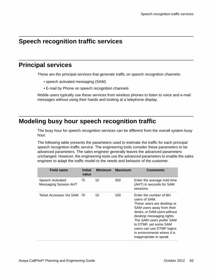
Speech recognition traffic services
Principal servicesThese are the principal services that generate traffic on speech recognition channels:
• speech activated messaging (SAM)
• E-mail by Phone on speech recognition channels
Mobile users typically use these services from wireless phones to listen to voice and e-mailmessages without using their hands and looking at a telephone display.
Modeling busy hour speech recognition trafficThe busy hour for speech recognition services can be different from the overall system busyhour.
The following table presents the parameters used to estimate the traffic for each principalspeech recognition traffic service. The engineering tools consider these parameters to beadvanced parameters. The sales engineer generally leaves the advanced parametersunchanged. However, the engineering tools use the advanced parameters to enable the salesengineer to adapt the traffic model to the needs and behavior of the customer.
Field name Initialvalue
Minimum Maximum Comments
Speech ActivatedMessaging Session AHT
75 10 300 Enter the average hold time(AHT) in seconds for SAMsessions.
Telset Accesses Via SAM 70 10 100 Enter the number of BHusers of SAM.These users are desktop orSAM users away from theirdesks, or SAM users withoutdesktop messaging rights.The SAM users prefer SAMto DTMF, yet some SAMusers can use DTMF loginsin environments where it isinappropriate to speak
Speech recognition traffic services
Avaya CallPilot® Planning and Engineering Guide October 2012 83
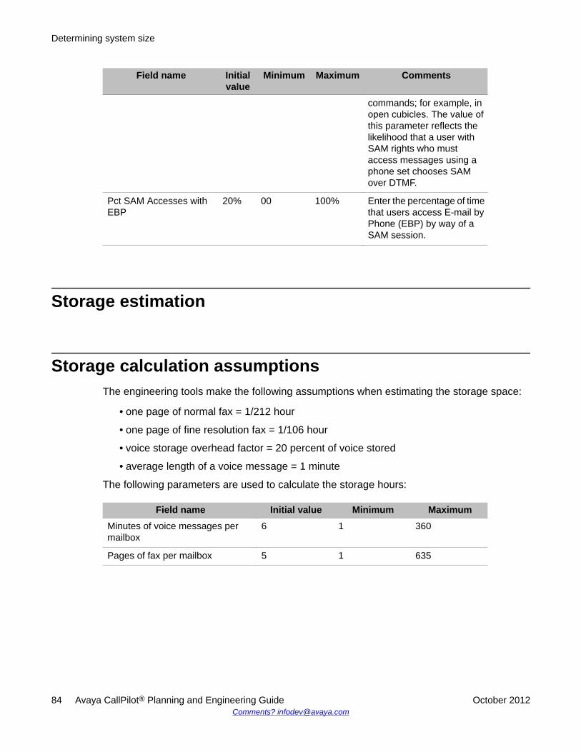
Field name Initialvalue
Minimum Maximum Comments
commands; for example, inopen cubicles. The value ofthis parameter reflects thelikelihood that a user withSAM rights who mustaccess messages using aphone set chooses SAMover DTMF.
Pct SAM Accesses withEBP
20% 00 100% Enter the percentage of timethat users access E-mail byPhone (EBP) by way of aSAM session.
Storage estimation
Storage calculation assumptionsThe engineering tools make the following assumptions when estimating the storage space:
• one page of normal fax = 1/212 hour
• one page of fine resolution fax = 1/106 hour
• voice storage overhead factor = 20 percent of voice stored
• average length of a voice message = 1 minute
The following parameters are used to calculate the storage hours:
Field name Initial value Minimum MaximumMinutes of voice messages permailbox
6 1 360
Pages of fax per mailbox 5 1 635
Determining system size
84 Avaya CallPilot® Planning and Engineering Guide October 2012Comments? [email protected]
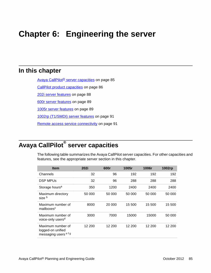
Chapter 6: Engineering the server
In this chapterAvaya CallPilot® server capacities on page 85
CallPilot product capacities on page 86
202i server features on page 88
600r server features on page 89
1005r server features on page 89
1002rp (T1/SMDI) server features on page 91
Remote access service connectivity on page 91
Avaya CallPilot® server capacitiesThe following table summarizes the Avaya CallPilot server capacities. For other capacities andfeatures, see the appropriate server section in this chapter.
Item 202i 600r 1005r 1006r 1002rpChannels 32 96 192 192 192
DSP MPUs 32 96 288 288 288
Storage hoursa 350 1200 2400 2400 2400
Maximum directorysize b
50 000 50 000 50 000 50 000 50 000
Maximum number ofmailboxesc
8000 20 000 15 500 15 500 15 500
Maximum number ofvoice-only usersd
3000 7000 15000 15000 50 000
Maximum number oflogged-on unifiedmessaging users e f g
12 200 12 200 12 200 12 200 12 200
Avaya CallPilot® Planning and Engineering Guide October 2012 85
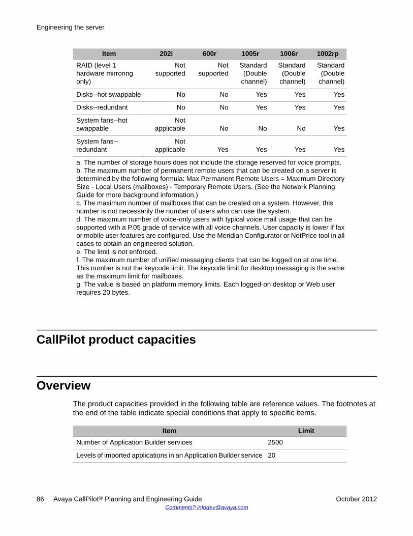
Item 202i 600r 1005r 1006r 1002rpRAID (level 1hardware mirroringonly)
Notsupported
Notsupported
Standard(Double
channel)
Standard(Double
channel)
Standard(Double
channel)
Disks--hot swappable No No Yes Yes Yes
Disks--redundant No No Yes Yes Yes
System fans--hotswappable
Notapplicable No No No Yes
System fans--redundant
Notapplicable Yes Yes Yes Yes
a. The number of storage hours does not include the storage reserved for voice prompts.b. The maximum number of permanent remote users that can be created on a server isdetermined by the following formula: Max Permanent Remote Users = Maximum DirectorySize - Local Users (mailboxes) - Temporary Remote Users. (See the Network PlanningGuide for more background information.)c. The maximum number of mailboxes that can be created on a system. However, thisnumber is not necessarily the number of users who can use the system.d. The maximum number of voice-only users with typical voice mail usage that can besupported with a P.05 grade of service with all voice channels. User capacity is lower if faxor mobile user features are configured. Use the Meridian Configurator or NetPrice tool in allcases to obtain an engineered solution.e. The limit is not enforced.f. The maximum number of unified messaging clients that can be logged on at one time.This number is not the keycode limit. The keycode limit for desktop messaging is the sameas the maximum limit for mailboxes.g. The value is based on platform memory limits. Each logged-on desktop or Web userrequires 20 bytes.
CallPilot product capacities
OverviewThe product capacities provided in the following table are reference values. The footnotes atthe end of the table indicate special conditions that apply to specific items.
Item LimitNumber of Application Builder services 2500
Levels of imported applications in an Application Builder service 20
Engineering the server
86 Avaya CallPilot® Planning and Engineering Guide October 2012Comments? [email protected]
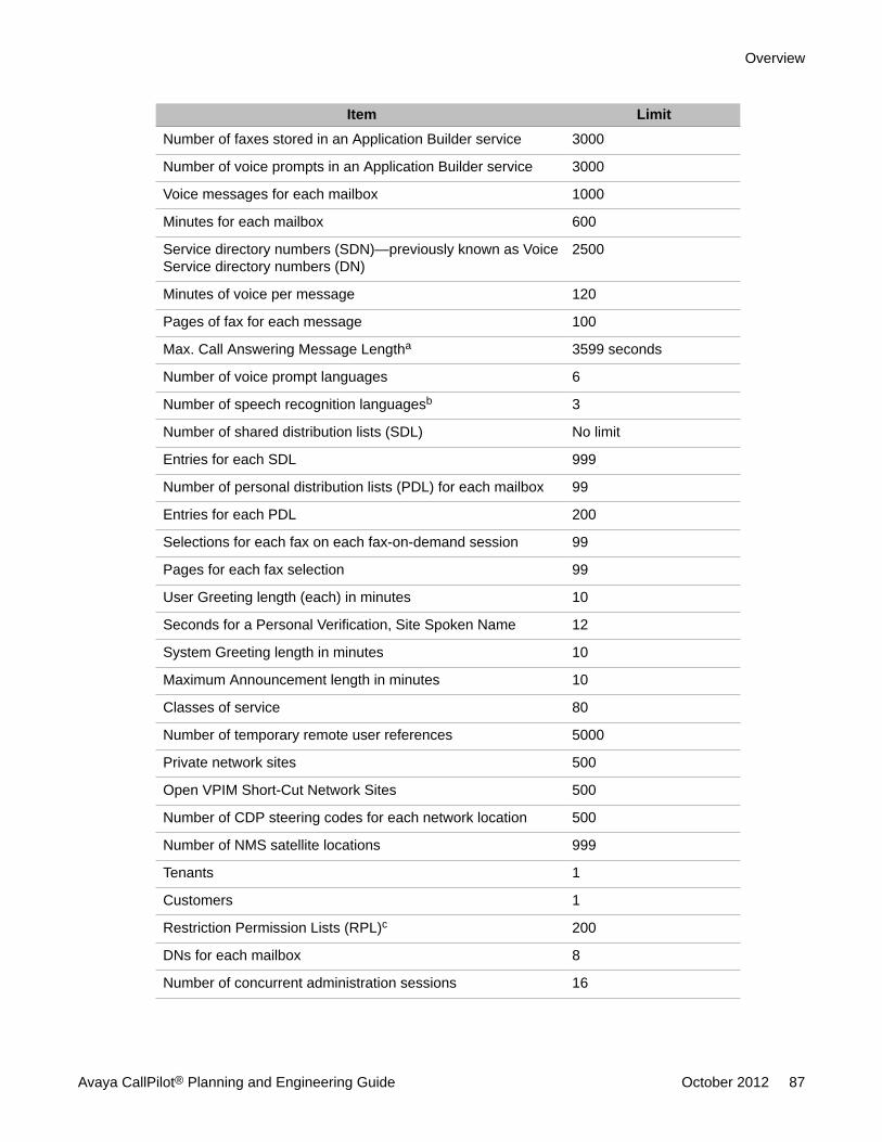
Item LimitNumber of faxes stored in an Application Builder service 3000
Number of voice prompts in an Application Builder service 3000
Voice messages for each mailbox 1000
Minutes for each mailbox 600
Service directory numbers (SDN)—previously known as VoiceService directory numbers (DN)
2500
Minutes of voice per message 120
Pages of fax for each message 100
Max. Call Answering Message Lengtha 3599 seconds
Number of voice prompt languages 6
Number of speech recognition languagesb 3
Number of shared distribution lists (SDL) No limit
Entries for each SDL 999
Number of personal distribution lists (PDL) for each mailbox 99
Entries for each PDL 200
Selections for each fax on each fax-on-demand session 99
Pages for each fax selection 99
User Greeting length (each) in minutes 10
Seconds for a Personal Verification, Site Spoken Name 12
System Greeting length in minutes 10
Maximum Announcement length in minutes 10
Classes of service 80
Number of temporary remote user references 5000
Private network sites 500
Open VPIM Short-Cut Network Sites 500
Number of CDP steering codes for each network location 500
Number of NMS satellite locations 999
Tenants 1
Customers 1
Restriction Permission Lists (RPL)c 200
DNs for each mailbox 8
Number of concurrent administration sessions 16
Overview
Avaya CallPilot® Planning and Engineering Guide October 2012 87
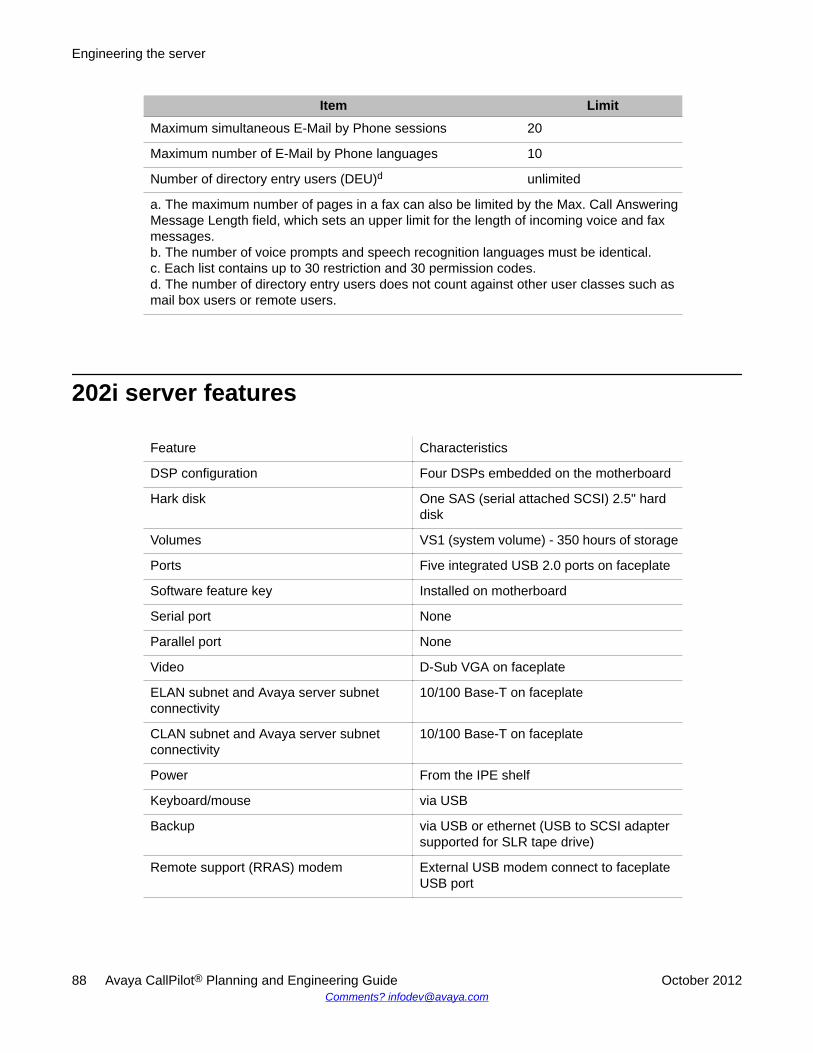
Item LimitMaximum simultaneous E-Mail by Phone sessions 20
Maximum number of E-Mail by Phone languages 10
Number of directory entry users (DEU)d unlimited
a. The maximum number of pages in a fax can also be limited by the Max. Call AnsweringMessage Length field, which sets an upper limit for the length of incoming voice and faxmessages.b. The number of voice prompts and speech recognition languages must be identical.c. Each list contains up to 30 restriction and 30 permission codes.d. The number of directory entry users does not count against other user classes such asmail box users or remote users.
202i server features
Feature Characteristics
DSP configuration Four DSPs embedded on the motherboard
Hark disk One SAS (serial attached SCSI) 2.5" harddisk
Volumes VS1 (system volume) - 350 hours of storage
Ports Five integrated USB 2.0 ports on faceplate
Software feature key Installed on motherboard
Serial port None
Parallel port None
Video D-Sub VGA on faceplate
ELAN subnet and Avaya server subnetconnectivity
10/100 Base-T on faceplate
CLAN subnet and Avaya server subnetconnectivity
10/100 Base-T on faceplate
Power From the IPE shelf
Keyboard/mouse via USB
Backup via USB or ethernet (USB to SCSI adaptersupported for SLR tape drive)
Remote support (RRAS) modem External USB modem connect to faceplateUSB port
Engineering the server
88 Avaya CallPilot® Planning and Engineering Guide October 2012Comments? [email protected]
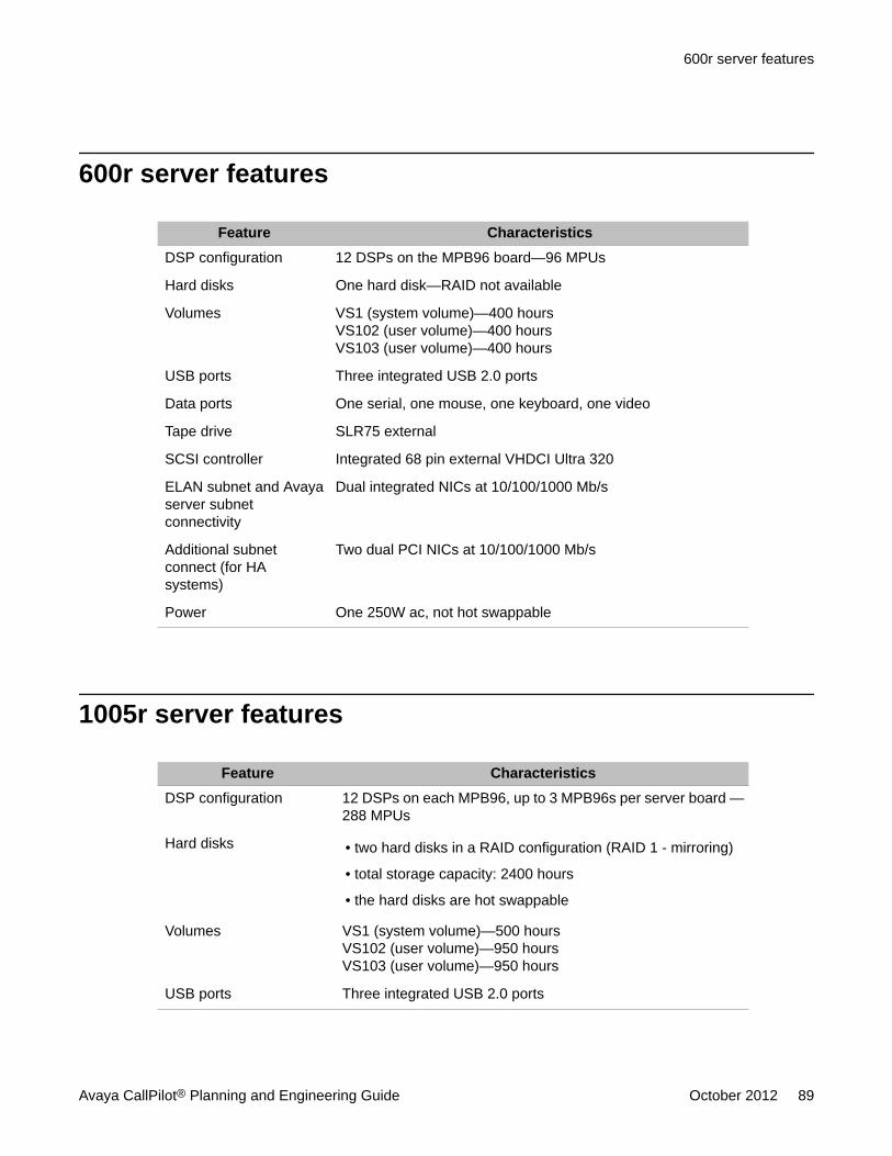
600r server features
Feature CharacteristicsDSP configuration 12 DSPs on the MPB96 board—96 MPUs
Hard disks One hard disk—RAID not available
Volumes VS1 (system volume)—400 hoursVS102 (user volume)—400 hoursVS103 (user volume)—400 hours
USB ports Three integrated USB 2.0 ports
Data ports One serial, one mouse, one keyboard, one video
Tape drive SLR75 external
SCSI controller Integrated 68 pin external VHDCI Ultra 320
ELAN subnet and Avayaserver subnetconnectivity
Dual integrated NICs at 10/100/1000 Mb/s
Additional subnetconnect (for HAsystems)
Two dual PCI NICs at 10/100/1000 Mb/s
Power One 250W ac, not hot swappable
1005r server features
Feature CharacteristicsDSP configuration 12 DSPs on each MPB96, up to 3 MPB96s per server board —
288 MPUs
Hard disks • two hard disks in a RAID configuration (RAID 1 - mirroring)
• total storage capacity: 2400 hours
• the hard disks are hot swappable
Volumes VS1 (system volume)—500 hoursVS102 (user volume)—950 hoursVS103 (user volume)—950 hours
USB ports Three integrated USB 2.0 ports
600r server features
Avaya CallPilot® Planning and Engineering Guide October 2012 89
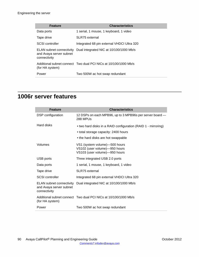
Feature CharacteristicsData ports 1 serial, 1 mouse, 1 keyboard, 1 video
Tape drive SLR75 external
SCSI controller Integrated 68 pin external VHDCI Ultra 320
ELAN subnet connectivityand Avaya server subnetconnectivity
Dual integrated NIC at 10/100/1000 Mb/s
Additional subnet connect(for HA system)
Two dual PCI NICs at 10/100/1000 Mb/s
Power Two 500W ac hot swap redundant
1006r server features
Feature CharacteristicsDSP configuration 12 DSPs on each MPB96, up to 3 MPB96s per server board —
288 MPUs
Hard disks • two hard disks in a RAID configuration (RAID 1 - mirroring)
• total storage capacity: 2400 hours
• the hard disks are hot swappable
Volumes VS1 (system volume)—500 hoursVS102 (user volume)—950 hoursVS103 (user volume)—950 hours
USB ports Three integrated USB 2.0 ports
Data ports 1 serial, 1 mouse, 1 keyboard, 1 video
Tape drive SLR75 external
SCSI controller Integrated 68 pin external VHDCI Ultra 320
ELAN subnet connectivityand Avaya server subnetconnectivity
Dual integrated NIC at 10/100/1000 Mb/s
Additional subnet connect(for HA system)
Two dual PCI NICs at 10/100/1000 Mb/s
Power Two 500W ac hot swap redundant
Engineering the server
90 Avaya CallPilot® Planning and Engineering Guide October 2012Comments? [email protected]
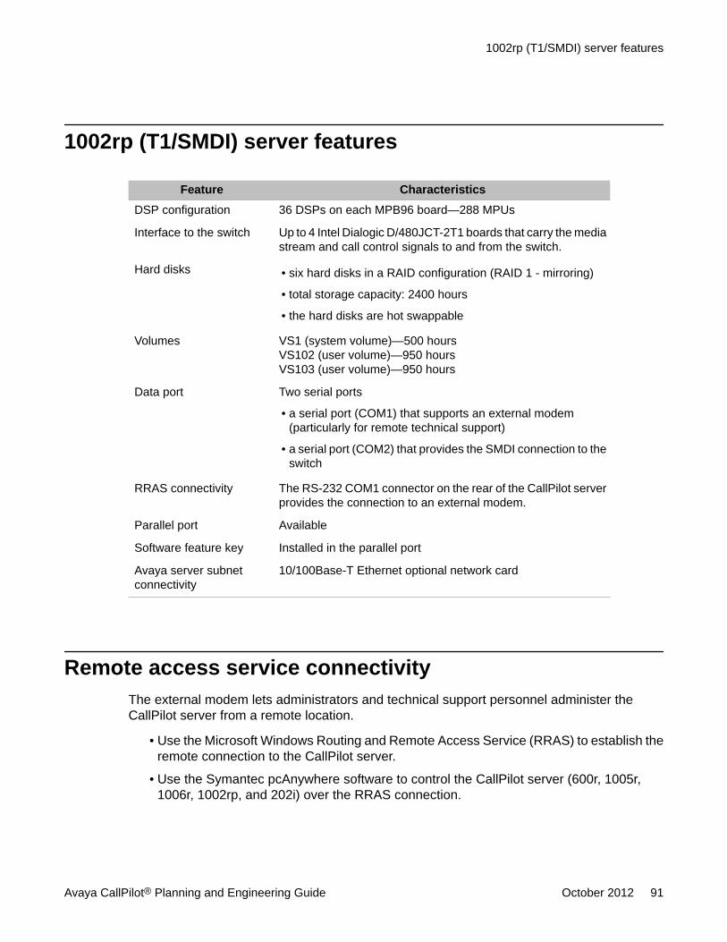
1002rp (T1/SMDI) server features
Feature CharacteristicsDSP configuration 36 DSPs on each MPB96 board—288 MPUs
Interface to the switch Up to 4 Intel Dialogic D/480JCT-2T1 boards that carry the mediastream and call control signals to and from the switch.
Hard disks • six hard disks in a RAID configuration (RAID 1 - mirroring)
• total storage capacity: 2400 hours
• the hard disks are hot swappable
Volumes VS1 (system volume)—500 hoursVS102 (user volume)—950 hoursVS103 (user volume)—950 hours
Data port Two serial ports
• a serial port (COM1) that supports an external modem(particularly for remote technical support)
• a serial port (COM2) that provides the SMDI connection to theswitch
RRAS connectivity The RS-232 COM1 connector on the rear of the CallPilot serverprovides the connection to an external modem.
Parallel port Available
Software feature key Installed in the parallel port
Avaya server subnetconnectivity
10/100Base-T Ethernet optional network card
Remote access service connectivityThe external modem lets administrators and technical support personnel administer theCallPilot server from a remote location.
• Use the Microsoft Windows Routing and Remote Access Service (RRAS) to establish theremote connection to the CallPilot server.
• Use the Symantec pcAnywhere software to control the CallPilot server (600r, 1005r,1006r, 1002rp, and 202i) over the RRAS connection.
1002rp (T1/SMDI) server features
Avaya CallPilot® Planning and Engineering Guide October 2012 91
or
• Use the Windows Remote Desktop Connection software to control the CallPilot server overthe RRAS connection.
Engineering the server
92 Avaya CallPilot® Planning and Engineering Guide October 2012Comments? [email protected]
Chapter 7: Selecting a site
In this chapterSpace requirements for the AvayaCallPilot® server on page 93
CallPilot power supply requirements on page 97
Environmental specifications on page 99
Space requirements for the AvayaCallPilot® serverYou must consider the physical space occupied by the Avaya CallPilot server as part of yourplanning activities. This section provides guidelines for determining the adequate space thatyou must provide for the server.
General requirementsInstall the CallPilot server in an area that is
• free of static electricity
• exempt from vibrations
• away from a sprinkler system, as well as from water, steam, and any liquid-carrying pipes
• safe for personnel and equipment
• protected against electromagnetic interference (EMI) from the following sources:
- broadcast stations
- radar
- mobile communications
- high-voltage power lines
- power tools
Avaya CallPilot® Planning and Engineering Guide October 2012 93
- office equipment such as photocopiers
Space requirementsInstall the server in an area that provides enough space for
• the front and rear cabinet doors to open and close
• the servicing or removal of components
Switch room space planningWhen you plan for the space needed for the CallPilot server and peripherals, you must alsoconsider the space required in the switch room.
Ethernet switch or hub, and cablesEnsure that sufficient space is available for the Ethernet switch or hub, and cables.
Important:Always use shielded Ethernet cables to connect the CallPilot servers to the Ethernet switchor hub.
Peripheral devicesYou must ensure that sufficient space is available for the following peripheral devices:
• modem
• monitor
• keyboard (with integrated track-ball)
• mouse
Selecting a site
94 Avaya CallPilot® Planning and Engineering Guide October 2012Comments? [email protected]
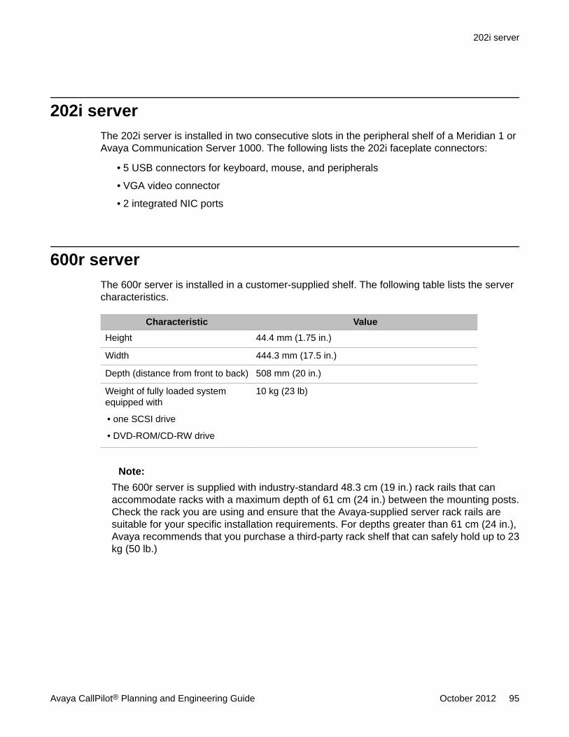
202i serverThe 202i server is installed in two consecutive slots in the peripheral shelf of a Meridian 1 orAvaya Communication Server 1000. The following lists the 202i faceplate connectors:
• 5 USB connectors for keyboard, mouse, and peripherals
• VGA video connector
• 2 integrated NIC ports
600r serverThe 600r server is installed in a customer-supplied shelf. The following table lists the servercharacteristics.
Characteristic ValueHeight 44.4 mm (1.75 in.)
Width 444.3 mm (17.5 in.)
Depth (distance from front to back) 508 mm (20 in.)
Weight of fully loaded systemequipped with
• one SCSI drive
• DVD-ROM/CD-RW drive
10 kg (23 lb)
Note:The 600r server is supplied with industry-standard 48.3 cm (19 in.) rack rails that canaccommodate racks with a maximum depth of 61 cm (24 in.) between the mounting posts.Check the rack you are using and ensure that the Avaya-supplied server rack rails aresuitable for your specific installation requirements. For depths greater than 61 cm (24 in.),Avaya recommends that you purchase a third-party rack shelf that can safely hold up to 23kg (50 lb.)
202i server
Avaya CallPilot® Planning and Engineering Guide October 2012 95
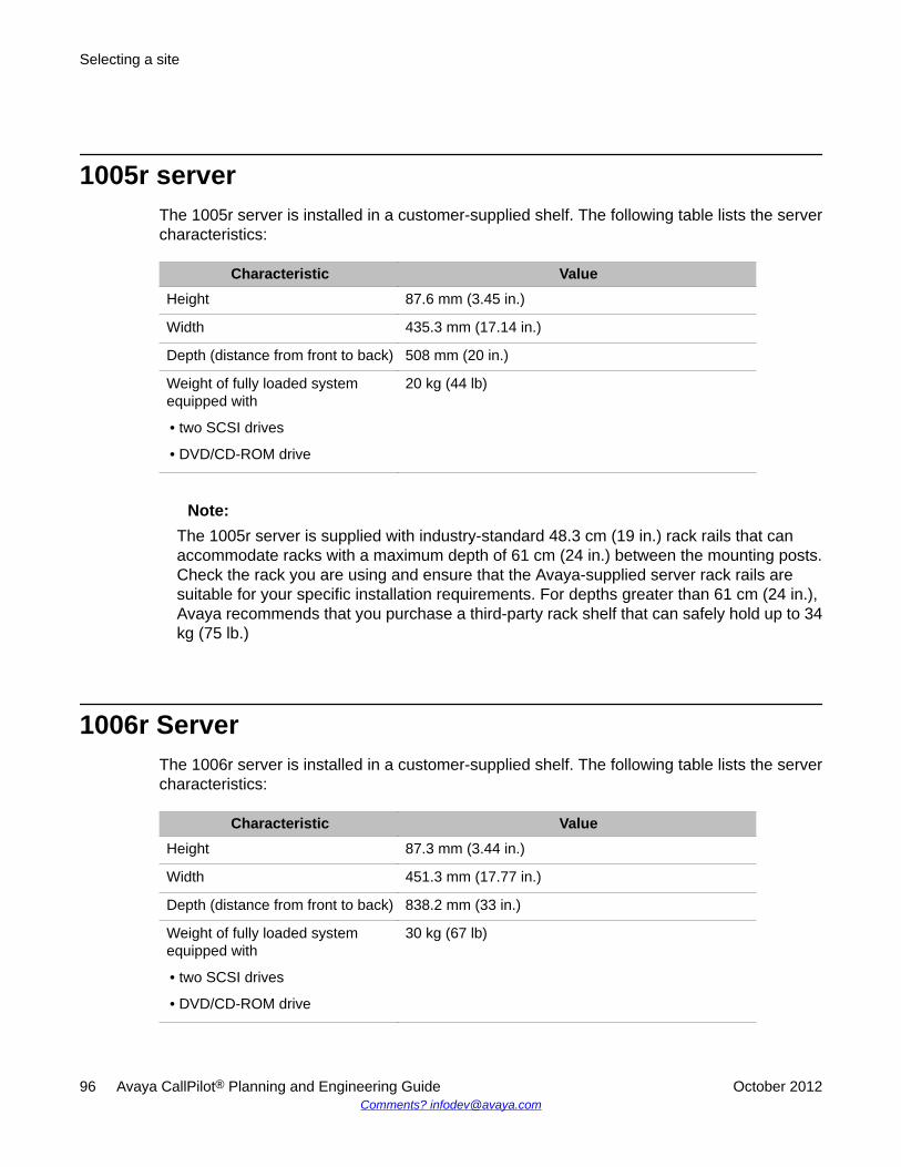
1005r serverThe 1005r server is installed in a customer-supplied shelf. The following table lists the servercharacteristics:
Characteristic ValueHeight 87.6 mm (3.45 in.)
Width 435.3 mm (17.14 in.)
Depth (distance from front to back) 508 mm (20 in.)
Weight of fully loaded systemequipped with
• two SCSI drives
• DVD/CD-ROM drive
20 kg (44 lb)
Note:The 1005r server is supplied with industry-standard 48.3 cm (19 in.) rack rails that canaccommodate racks with a maximum depth of 61 cm (24 in.) between the mounting posts.Check the rack you are using and ensure that the Avaya-supplied server rack rails aresuitable for your specific installation requirements. For depths greater than 61 cm (24 in.),Avaya recommends that you purchase a third-party rack shelf that can safely hold up to 34kg (75 lb.)
1006r ServerThe 1006r server is installed in a customer-supplied shelf. The following table lists the servercharacteristics:
Characteristic ValueHeight 87.3 mm (3.44 in.)
Width 451.3 mm (17.77 in.)
Depth (distance from front to back) 838.2 mm (33 in.)
Weight of fully loaded systemequipped with
• two SCSI drives
• DVD/CD-ROM drive
30 kg (67 lb)
Selecting a site
96 Avaya CallPilot® Planning and Engineering Guide October 2012Comments? [email protected]
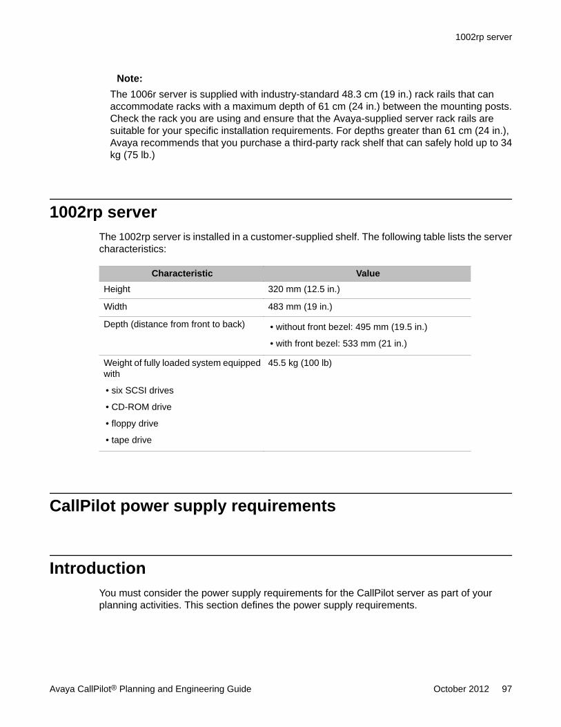
Note:The 1006r server is supplied with industry-standard 48.3 cm (19 in.) rack rails that canaccommodate racks with a maximum depth of 61 cm (24 in.) between the mounting posts.Check the rack you are using and ensure that the Avaya-supplied server rack rails aresuitable for your specific installation requirements. For depths greater than 61 cm (24 in.),Avaya recommends that you purchase a third-party rack shelf that can safely hold up to 34kg (75 lb.)
1002rp serverThe 1002rp server is installed in a customer-supplied shelf. The following table lists the servercharacteristics:
Characteristic ValueHeight 320 mm (12.5 in.)
Width 483 mm (19 in.)
Depth (distance from front to back) • without front bezel: 495 mm (19.5 in.)
• with front bezel: 533 mm (21 in.)
Weight of fully loaded system equippedwith
• six SCSI drives
• CD-ROM drive
• floppy drive
• tape drive
45.5 kg (100 lb)
CallPilot power supply requirements
IntroductionYou must consider the power supply requirements for the CallPilot server as part of yourplanning activities. This section defines the power supply requirements.
1002rp server
Avaya CallPilot® Planning and Engineering Guide October 2012 97
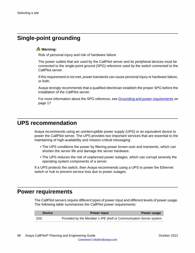
Single-point grounding
Warning:Risk of personal injury and risk of hardware failure
The power outlets that are used by the CallPilot server and its peripheral devices must beconnected to the single-point ground (SPG) reference used by the switch connected to theCallPilot server.
If this requirement is not met, power transients can cause personal injury or hardware failure,or both.
Avaya strongly recommends that a qualified electrician establish the proper SPG before theinstallation of the CallPilot server.
For more information about the SPG reference, see Grounding and power requirements onpage 17
UPS recommendationAvaya recommends using an uninterruptible power supply (UPS) or an equivalent device topower the CallPilot server. The UPS provides two important services that are essential to themaintaining of high-availability and mission-critical messaging:
• The UPS conditions the power by filtering power brown-outs and transients, which canshorten the server life and damage the server hardware.
• The UPS reduces the risk of unplanned power outages, which can corrupt severely theoperating system components of a server.
If a UPS protects the switch, then Avaya recommends using a UPS to power the Ethernetswitch or hub to prevent service loss due to power outages.
Power requirementsThe CallPilot servers require different types of power input and different levels of power usage.The following table summarizes the CallPilot power requirements:
Device Power input Power usage202i Provided by the Meridian 1 IPE shelf or Communication Server system.
Selecting a site
98 Avaya CallPilot® Planning and Engineering Guide October 2012Comments? [email protected]
Device Power input Power usage600r 120 V ac
240 V ac250 W
1005r 120 V ac240 V ac
500 W
1006r 120 V ac240 V ac
750 W
1002rp 120 V ac240 V ac
400 W
1002rp dc 48 V, 20 A dc (see Note) 500 W
External tapedrive
110 V 7.2 W
Modem 110 V with a power adapter that provides 9 V ac to 15V ac at 10 W
10 W
Monitor 110 V ac 90 W
Note:The NTRH9032 dc to ac power converter is no longer available. Avaya recommends thatyou supply a third-party dc to ac power converter that provides at least 1000 W of capacityfor the 600r, 1005r, 1006r, and 1002rp servers and their peripherals. Ensure that thepower converter is properly installed, according to the manufacturer's instructions.
If you use the Avaya MFA150 rectifier (which is supplied with 30 A breakers and two 20 Abreakers in the Spare Circuit Breaker Kit, 20 A [P0729846]), then you must configure therectifier to supply the two 20-A dc circuits for the rack-mount server.
Environmental specifications
GeneralAlways consider the environmental specifications when planning an adequate location for theCallPilot servers.
Before considering the server environmental specifications, you must take into account theswitch environmental specifications.
Environmental specifications
Avaya CallPilot® Planning and Engineering Guide October 2012 99
The proper operating temperature and humidity are important for the longevity of the servers.The tables provided in this section summarize the key environmental specifications of theCallPilot servers.
The "non-operating" term used in the tables refers to the environmental conditions that haveto be maintained during shipping and storage.
202i server
Environmental condition SpecificationRecommended temperature 15°C to 30°C (59°F to 86°F)
Absolute temperature 10°C to 45°C (50 °F to 113°F)
Long-term storage temperature –20°C to 60°C ( –4°F to 140°F)
Short-term storage temperature –40°C to 70°C (–40 °F to 158°F)
Change rate temperature less than 1°C (1.8°F) per 3 minutes
Recommended relative humidity (RH) 20% to 55% RH (non-condensing)
Absolute RH 20% to 80% RH (non-condensing)
Long-term storage RH °5% to 95% RH at –40°C to 70°C (–40 °F to158°F) respectively (non-condensing)
600r server
Parameter Condition SpecificationTemperature Operating 5°C to 35°C (41°F to 95°F)
Non-operating –40°C to 70°C (–40°F to 158°F)
Heat load Operating 600 BTUs/hr
Humidity Non-operating 95% at 23 to 40°C (104°F)
Shock Operating 2 G, 1 millisecond duration
Electrostaticdischarge
Operating 15 kV or more
Altitude Operating 1829 m (6000 ft)
Selecting a site
100 Avaya CallPilot® Planning and Engineering Guide October 2012Comments? [email protected]
Parameter Condition SpecificationHandling drop Operating Operational after a free fall from 458 mm (18
in.)
1005r server
Parameter Condition SpecificationTemperature Operating 5°C to 35°C (41°F to 95°F)
Non-operating –40°C to 70°C (–40°F to 158°F)
Heat load Operating 1200 BTUs/hr
Humidity Non-operating 95% at 23 to 40ºC (104ºF)
Shock Operating 2 G, 11 ms
Electrostaticdischarge
Operating 15 kV or more
Altitude Operating 1 829 m (6000 ft)
Handling drop Operating Operational after a free fall from 18 in.
1006r server
Parameter Condition SpecificationTemperature Operating 10°C to 35°C (50°F to 95°F)
Non-operating –40°C to 70°C (–40°F to 158°F)
Heat load Operating 1200 BTUs/hr
Humidity Non-operating 90% at 23 to 40ºC (104ºF)
Shock Operating 2 G, 11 ms
Electrostaticdischarge
Operating 15 kV or more
Altitude Operating 1 829 m (6000 ft)
Handling drop Operating Operational after a free fall from 18 in.
1005r server
Avaya CallPilot® Planning and Engineering Guide October 2012 101
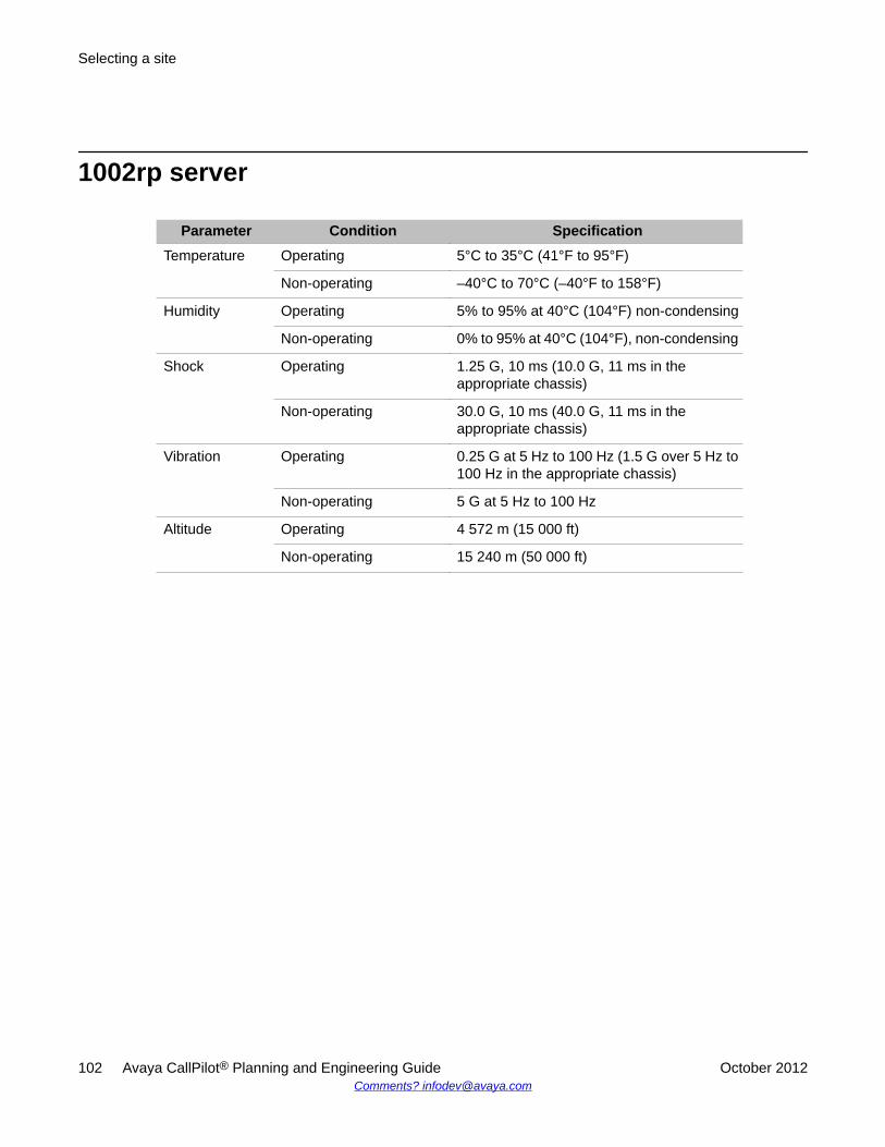
1002rp server
Parameter Condition SpecificationTemperature Operating 5°C to 35°C (41°F to 95°F)
Non-operating –40°C to 70°C (–40°F to 158°F)
Humidity Operating 5% to 95% at 40°C (104°F) non-condensing
Non-operating 0% to 95% at 40°C (104°F), non-condensing
Shock Operating 1.25 G, 10 ms (10.0 G, 11 ms in theappropriate chassis)
Non-operating 30.0 G, 10 ms (40.0 G, 11 ms in theappropriate chassis)
Vibration Operating 0.25 G at 5 Hz to 100 Hz (1.5 G over 5 Hz to100 Hz in the appropriate chassis)
Non-operating 5 G at 5 Hz to 100 Hz
Altitude Operating 4 572 m (15 000 ft)
Non-operating 15 240 m (50 000 ft)
Selecting a site
102 Avaya CallPilot® Planning and Engineering Guide October 2012Comments? [email protected]
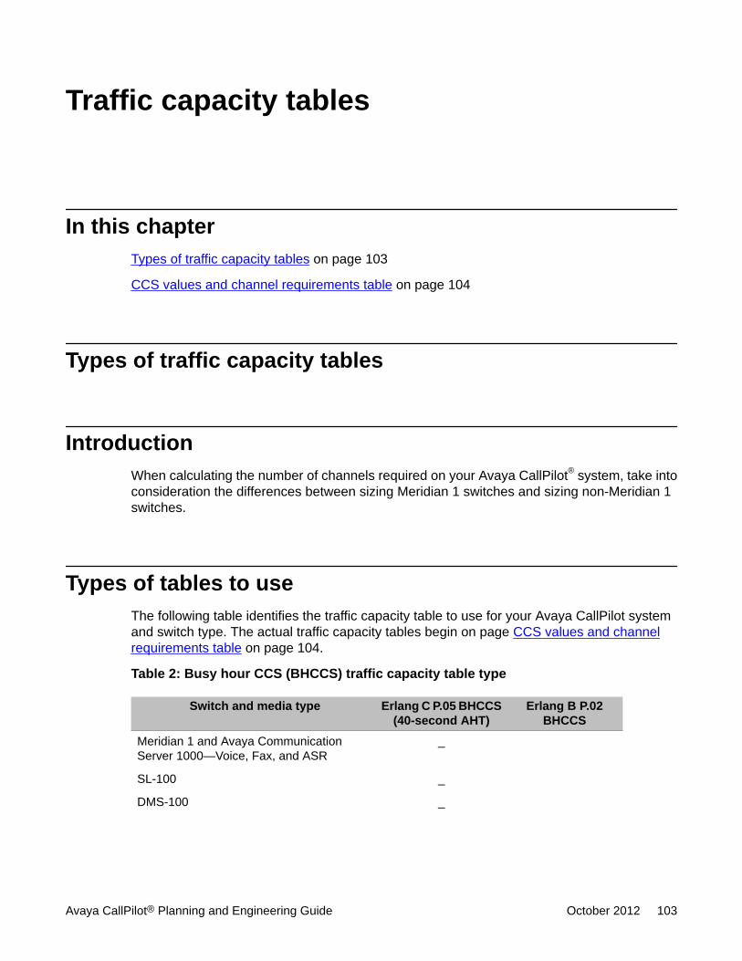
Traffic capacity tables
In this chapterTypes of traffic capacity tables on page 103
CCS values and channel requirements table on page 104
Types of traffic capacity tables
IntroductionWhen calculating the number of channels required on your Avaya CallPilot® system, take intoconsideration the differences between sizing Meridian 1 switches and sizing non-Meridian 1switches.
Types of tables to useThe following table identifies the traffic capacity table to use for your Avaya CallPilot systemand switch type. The actual traffic capacity tables begin on page CCS values and channelrequirements table on page 104.
Table 2: Busy hour CCS (BHCCS) traffic capacity table type
Switch and media type Erlang C P.05 BHCCS(40-second AHT)
Erlang B P.02BHCCS
Meridian 1 and Avaya CommunicationServer 1000—Voice, Fax, and ASR
_
SL-100 _
DMS-100 _
Avaya CallPilot® Planning and Engineering Guide October 2012 103
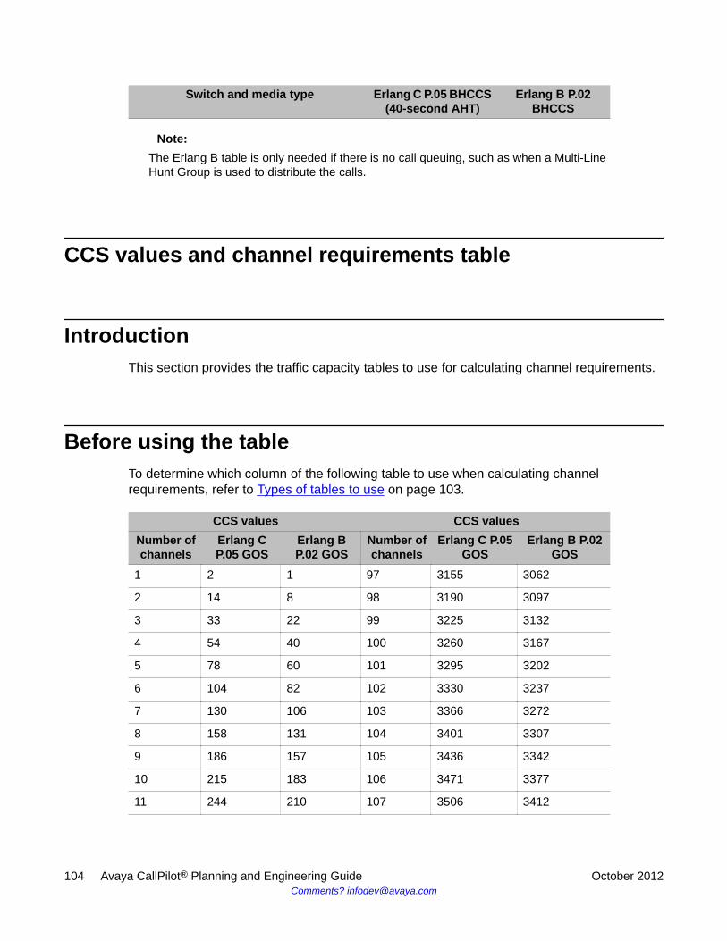
Switch and media type Erlang C P.05 BHCCS(40-second AHT)
Erlang B P.02BHCCS
Note:The Erlang B table is only needed if there is no call queuing, such as when a Multi-LineHunt Group is used to distribute the calls.
CCS values and channel requirements table
IntroductionThis section provides the traffic capacity tables to use for calculating channel requirements.
Before using the tableTo determine which column of the following table to use when calculating channelrequirements, refer to Types of tables to use on page 103.
CCS values CCS valuesNumber ofchannels
Erlang CP.05 GOS
Erlang BP.02 GOS
Number ofchannels
Erlang C P.05GOS
Erlang B P.02GOS
1 2 1 97 3155 3062
2 14 8 98 3190 3097
3 33 22 99 3225 3132
4 54 40 100 3260 3167
5 78 60 101 3295 3202
6 104 82 102 3330 3237
7 130 106 103 3366 3272
8 158 131 104 3401 3307
9 186 157 105 3436 3342
10 215 183 106 3471 3377
11 244 210 107 3506 3412
104 Avaya CallPilot® Planning and Engineering Guide October 2012Comments? [email protected]
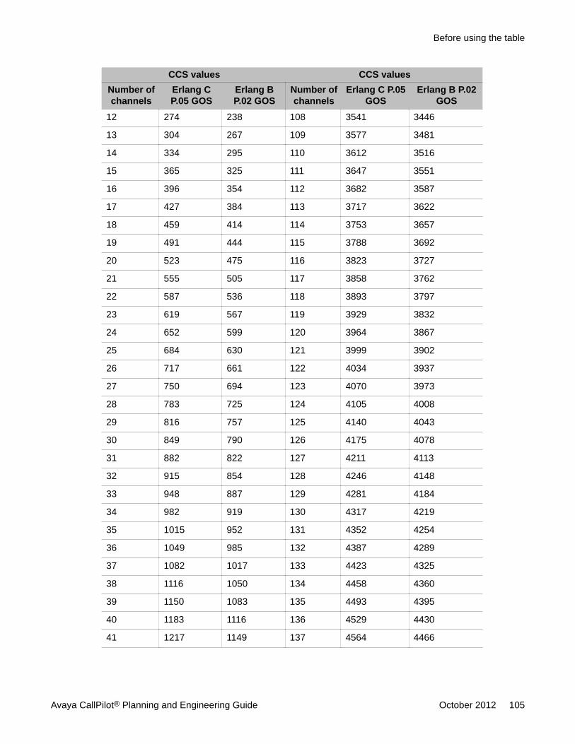
CCS values CCS valuesNumber ofchannels
Erlang CP.05 GOS
Erlang BP.02 GOS
Number ofchannels
Erlang C P.05GOS
Erlang B P.02GOS
12 274 238 108 3541 3446
13 304 267 109 3577 3481
14 334 295 110 3612 3516
15 365 325 111 3647 3551
16 396 354 112 3682 3587
17 427 384 113 3717 3622
18 459 414 114 3753 3657
19 491 444 115 3788 3692
20 523 475 116 3823 3727
21 555 505 117 3858 3762
22 587 536 118 3893 3797
23 619 567 119 3929 3832
24 652 599 120 3964 3867
25 684 630 121 3999 3902
26 717 661 122 4034 3937
27 750 694 123 4070 3973
28 783 725 124 4105 4008
29 816 757 125 4140 4043
30 849 790 126 4175 4078
31 882 822 127 4211 4113
32 915 854 128 4246 4148
33 948 887 129 4281 4184
34 982 919 130 4317 4219
35 1015 952 131 4352 4254
36 1049 985 132 4387 4289
37 1082 1017 133 4423 4325
38 1116 1050 134 4458 4360
39 1150 1083 135 4493 4395
40 1183 1116 136 4529 4430
41 1217 1149 137 4564 4466
Before using the table
Avaya CallPilot® Planning and Engineering Guide October 2012 105
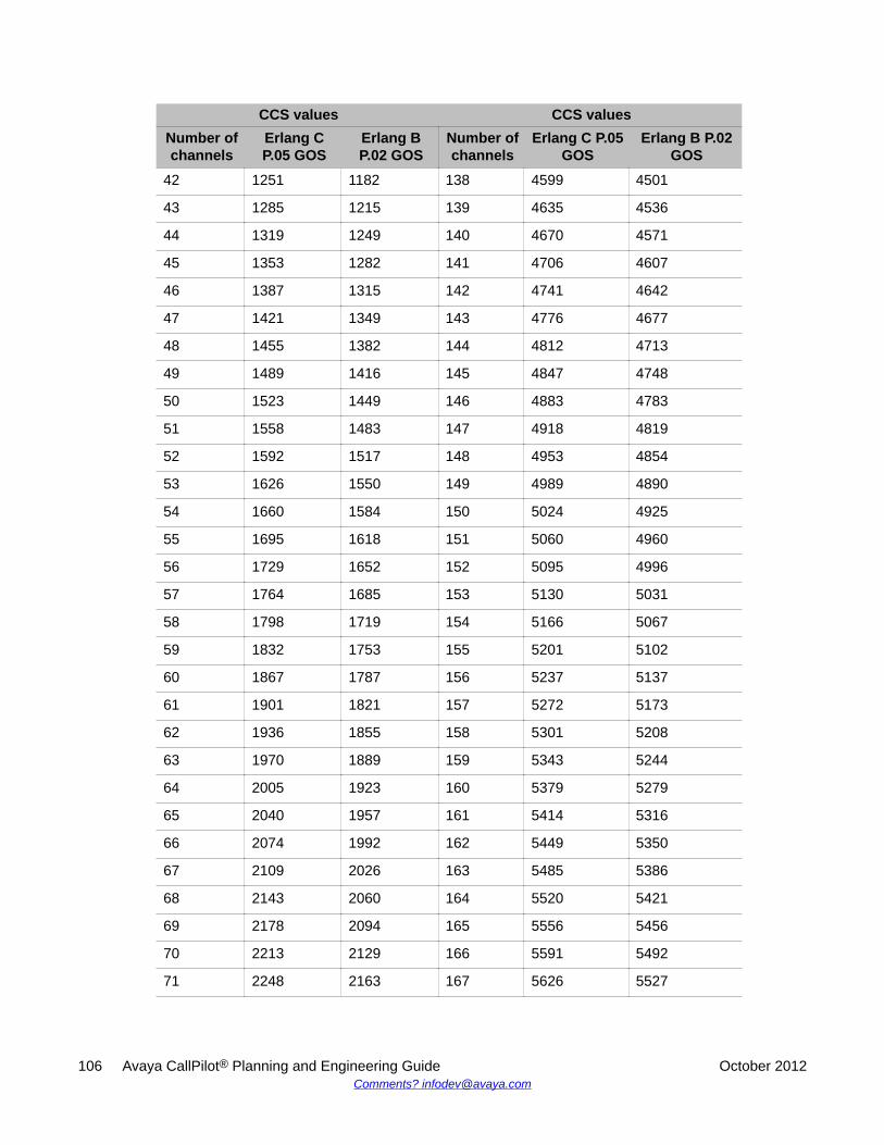
CCS values CCS valuesNumber ofchannels
Erlang CP.05 GOS
Erlang BP.02 GOS
Number ofchannels
Erlang C P.05GOS
Erlang B P.02GOS
42 1251 1182 138 4599 4501
43 1285 1215 139 4635 4536
44 1319 1249 140 4670 4571
45 1353 1282 141 4706 4607
46 1387 1315 142 4741 4642
47 1421 1349 143 4776 4677
48 1455 1382 144 4812 4713
49 1489 1416 145 4847 4748
50 1523 1449 146 4883 4783
51 1558 1483 147 4918 4819
52 1592 1517 148 4953 4854
53 1626 1550 149 4989 4890
54 1660 1584 150 5024 4925
55 1695 1618 151 5060 4960
56 1729 1652 152 5095 4996
57 1764 1685 153 5130 5031
58 1798 1719 154 5166 5067
59 1832 1753 155 5201 5102
60 1867 1787 156 5237 5137
61 1901 1821 157 5272 5173
62 1936 1855 158 5301 5208
63 1970 1889 159 5343 5244
64 2005 1923 160 5379 5279
65 2040 1957 161 5414 5316
66 2074 1992 162 5449 5350
67 2109 2026 163 5485 5386
68 2143 2060 164 5520 5421
69 2178 2094 165 5556 5456
70 2213 2129 166 5591 5492
71 2248 2163 167 5626 5527
106 Avaya CallPilot® Planning and Engineering Guide October 2012Comments? [email protected]
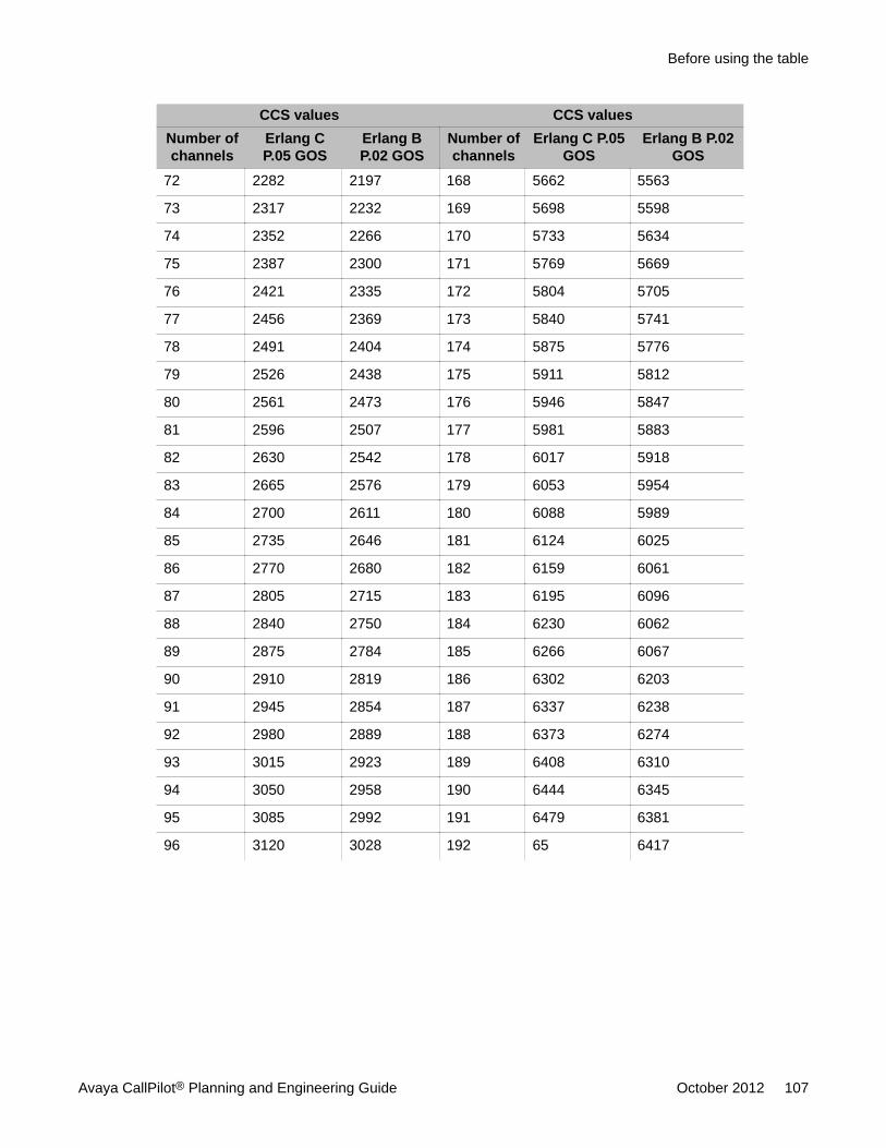
CCS values CCS valuesNumber ofchannels
Erlang CP.05 GOS
Erlang BP.02 GOS
Number ofchannels
Erlang C P.05GOS
Erlang B P.02GOS
72 2282 2197 168 5662 5563
73 2317 2232 169 5698 5598
74 2352 2266 170 5733 5634
75 2387 2300 171 5769 5669
76 2421 2335 172 5804 5705
77 2456 2369 173 5840 5741
78 2491 2404 174 5875 5776
79 2526 2438 175 5911 5812
80 2561 2473 176 5946 5847
81 2596 2507 177 5981 5883
82 2630 2542 178 6017 5918
83 2665 2576 179 6053 5954
84 2700 2611 180 6088 5989
85 2735 2646 181 6124 6025
86 2770 2680 182 6159 6061
87 2805 2715 183 6195 6096
88 2840 2750 184 6230 6062
89 2875 2784 185 6266 6067
90 2910 2819 186 6302 6203
91 2945 2854 187 6337 6238
92 2980 2889 188 6373 6274
93 3015 2923 189 6408 6310
94 3050 2958 190 6444 6345
95 3085 2992 191 6479 6381
96 3120 3028 192 65 6417
Before using the table
Avaya CallPilot® Planning and Engineering Guide October 2012 107

108 Avaya CallPilot® Planning and Engineering Guide October 2012Comments? [email protected]
Regulatory information
In this chapterGrounding on page 109
General compliance and safety information for specific countries on page 110
Electromagnetic compatibility on page 112
Radio and TV interference on page 113
GroundingMake sure that the electrical ground connections of the power utility, telephone lines, andinternal metallic water pipe system, if present, connect together. This precaution is for theusers' protection, and is particularly important in rural areas.
Caution:Risk of equipment damage
The Avaya CallPilot® system frame ground of each system cabinet or chassis must be tiedto a reliable building ground reference.
Warning:Risk of electrocution
Do not attempt to make electrical ground connections yourself. Contact your local electricalinspection authority or electrician to make electrical ground connections.
For more information about the preceding issues, see Grounding and power requirements onpage 17
Avaya CallPilot® Planning and Engineering Guide October 2012 109
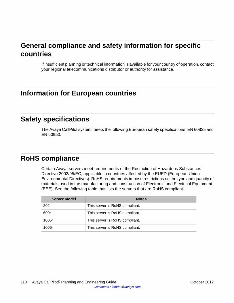
General compliance and safety information for specificcountries
If insufficient planning or technical information is available for your country of operation, contactyour regional telecommunications distributor or authority for assistance.
Information for European countries
Safety specificationsThe Avaya CallPilot system meets the following European safety specifications: EN 60825 andEN 60950.
RoHS complianceCertain Avaya servers meet requirements of the Restriction of Hazardous SubstancesDirective 2002/95/EC, applicable in countries affected by the EUED (European UnionEnvironmental Directives). RoHS requirements impose restrictions on the type and quantity ofmaterials used in the manufacturing and construction of Electronic and Electrical Equipment(EEE). See the following table that lists the servers that are RoHS compliant.
Server model Notes202i This server is RoHS compliant.
600r This server is RoHS compliant.
1005r This server is RoHS compliant.
1006r This server is RoHS compliant.
110 Avaya CallPilot® Planning and Engineering Guide October 2012Comments? [email protected]
Information for North AmericaCallPilot server models 600r, 1005r, 1006r, 1002rp, and 202i comply with the followingstandards:
• UL 60950-1 Information Technology Equipment Safety Part 1- General Requirements(U.S.A.)
• CSA-C22.2 No. 60950-1-03 Safety Telecom Information Technology Equipment Safety,Part 1- General Requirements (Canada)
Information for Japan
Japan Denan statementThe following applies to server models 600r, 1005r, 1006r, and 1002rp:
Information for North America
Avaya CallPilot® Planning and Engineering Guide October 2012 111
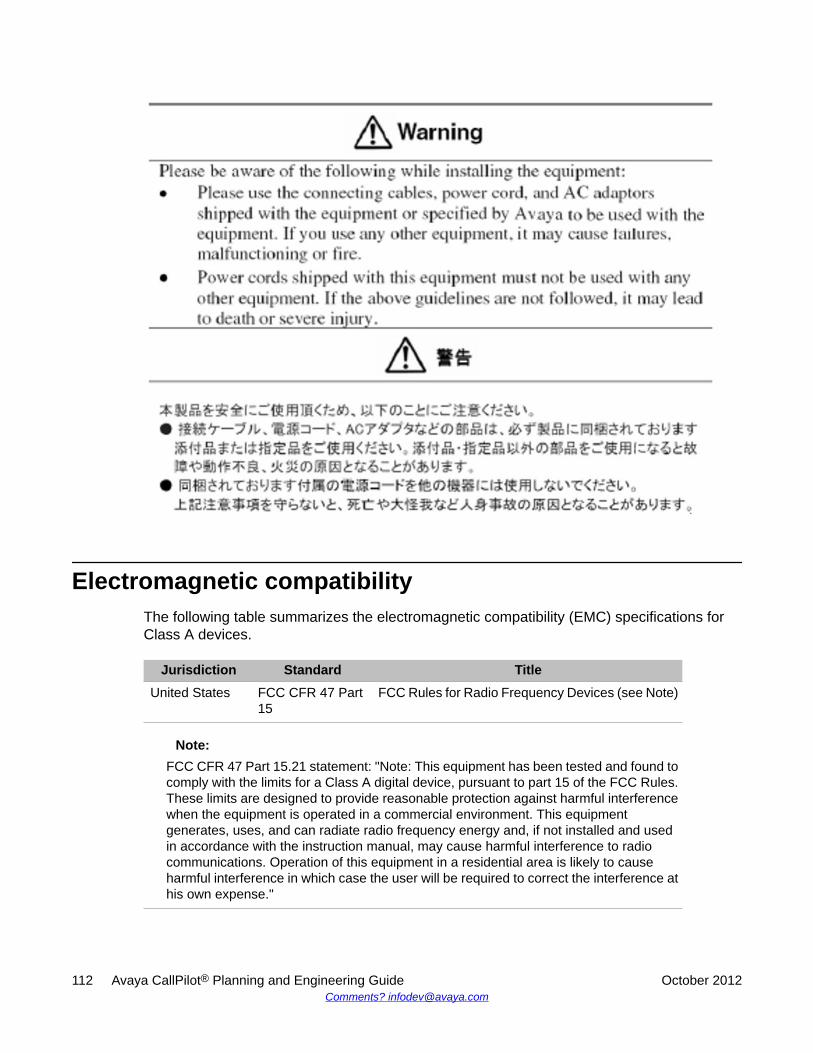
Electromagnetic compatibilityThe following table summarizes the electromagnetic compatibility (EMC) specifications forClass A devices.
Jurisdiction Standard TitleUnited States FCC CFR 47 Part
15FCC Rules for Radio Frequency Devices (see Note)
Note:FCC CFR 47 Part 15.21 statement: "Note: This equipment has been tested and found tocomply with the limits for a Class A digital device, pursuant to part 15 of the FCC Rules.These limits are designed to provide reasonable protection against harmful interferencewhen the equipment is operated in a commercial environment. This equipmentgenerates, uses, and can radiate radio frequency energy and, if not installed and usedin accordance with the instruction manual, may cause harmful interference to radiocommunications. Operation of this equipment in a residential area is likely to causeharmful interference in which case the user will be required to correct the interference athis own expense."
112 Avaya CallPilot® Planning and Engineering Guide October 2012Comments? [email protected]
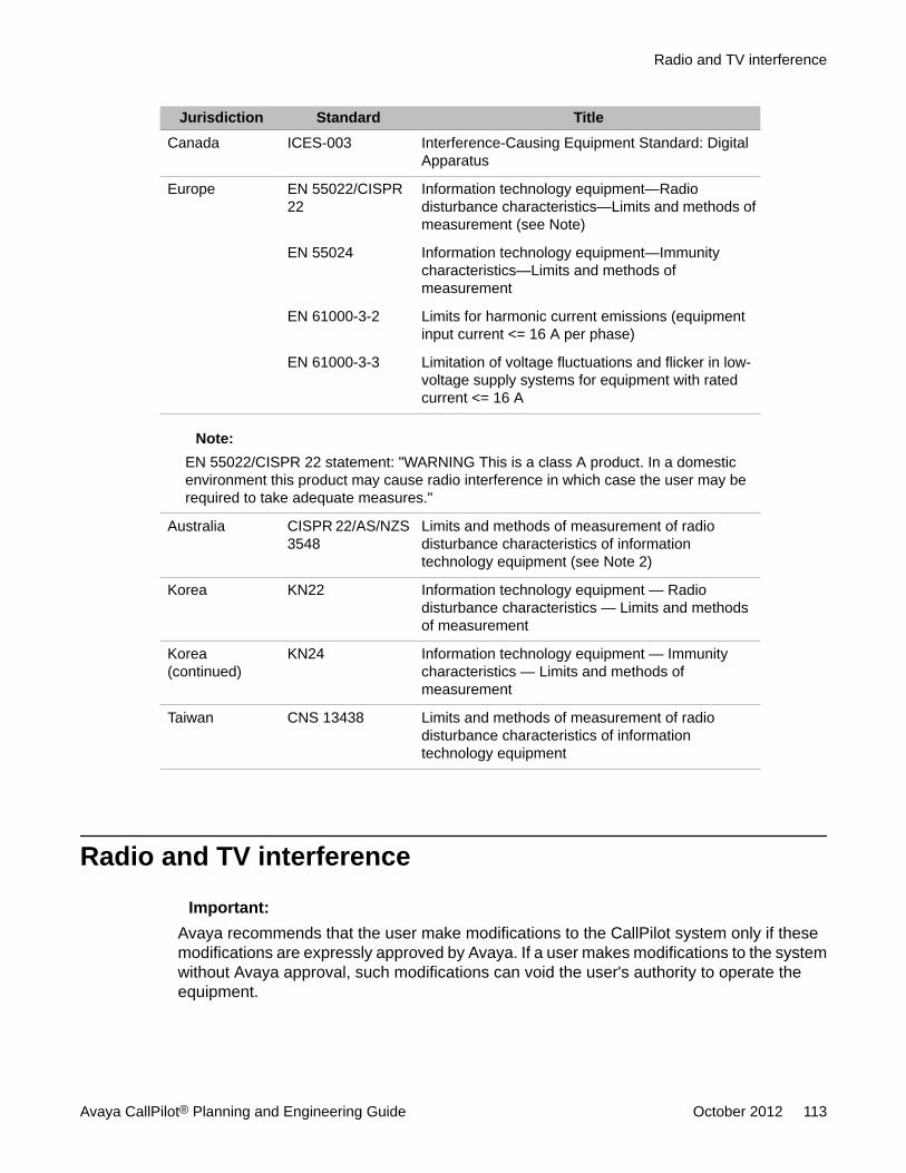
Jurisdiction Standard TitleCanada ICES-003 Interference-Causing Equipment Standard: Digital
Apparatus
Europe EN 55022/CISPR22
Information technology equipment—Radiodisturbance characteristics—Limits and methods ofmeasurement (see Note)
EN 55024 Information technology equipment—Immunitycharacteristics—Limits and methods ofmeasurement
EN 61000-3-2 Limits for harmonic current emissions (equipmentinput current <= 16 A per phase)
EN 61000-3-3 Limitation of voltage fluctuations and flicker in low-voltage supply systems for equipment with ratedcurrent <= 16 A
Note:EN 55022/CISPR 22 statement: "WARNING This is a class A product. In a domesticenvironment this product may cause radio interference in which case the user may berequired to take adequate measures."
Australia CISPR 22/AS/NZS3548
Limits and methods of measurement of radiodisturbance characteristics of informationtechnology equipment (see Note 2)
Korea KN22 Information technology equipment — Radiodisturbance characteristics — Limits and methodsof measurement
Korea(continued)
KN24 Information technology equipment — Immunitycharacteristics — Limits and methods ofmeasurement
Taiwan CNS 13438 Limits and methods of measurement of radiodisturbance characteristics of informationtechnology equipment
Radio and TV interference
Important:Avaya recommends that the user make modifications to the CallPilot system only if thesemodifications are expressly approved by Avaya. If a user makes modifications to the systemwithout Avaya approval, such modifications can void the user's authority to operate theequipment.
Radio and TV interference
Avaya CallPilot® Planning and Engineering Guide October 2012 113
Information for the United StatesThe CallPilot system complies with Part 15 of the FCC rules in the United States. Operation issubject to the following two conditions:
• The system must not cause harmful interference.
• The system must accept any interference received, including interference that can causeundesirable operation.
If the CallPilot system causes interference to radio or television reception, which can bedetermined by placing a telephone call while monitoring, the user is encouraged to try to correctthe interference by the following measures:
• Reorient the receiving TV or radio antenna where this can be done safely.
• Move the TV or radio in relation to the telephone equipment.
If necessary, ask a qualified radio or television technician or supplier for additional information.Also, you can refer to the document "How to Identify and Resolve Radio-TV Interference",prepared by the Federal Communications Commission. This document is available from:
U.S. Government Printing Office Washington dc 20402
Information for CanadaThe CallPilot system does not exceed Class A limits for radio noise emissions from digitalapparatus, as set out in the radio interference regulations of Industry Canada.
This equipment complies with the CE Marking requirements.
Information for JapanThe following applies to server models 600r, 1005r, 1006r, and 1002rp:
This is a Class A product based on the standard of the Voluntary Control Council forInterference by Information Technology Equipment (VCCI). If this equipment is used in a
114 Avaya CallPilot® Planning and Engineering Guide October 2012Comments? [email protected]

domestic environment, radio disturbance may occur, in which case, the user may be requiredto take corrective action.
Information for Japan
Avaya CallPilot® Planning and Engineering Guide October 2012 115

116 Avaya CallPilot® Planning and Engineering Guide October 2012Comments? [email protected]

Index
Numerics
1002rp server ............................................................. 98power supply requirements ..................................98
1005r server ............................................................... 98power supply requirements ..................................98
1006r server ............................................................... 98power supply requirements ..................................98
202i server power supply requirements ..................... 98600r server ................................................................. 98
power supply requirements ..................................98
A
ACD agent ............................................................ 50, 54ACD queue ........................................................... 50, 54administrative PC, configuration .................................34announcements ..........................................................63
migrating from Meridian Mail Voice Services .......63Avaya Networks server subnet ...................................39
B
busy hour fax traffic .................................................... 81modeling .............................................................. 81
busy hour Speech Recognition traffic .........................83modeling .............................................................. 83
busy hour voice traffic ................................................ 78modeling .............................................................. 78
C
cable, multi I/O ........................................................... 91connections ..........................................................91
RS-232 .......................................................... 91cables, ELAN Ethernet switch (layer 2) or hub ...........44calculation, channel requirements ..............................67calculation, CPU real-time requirements ....................68calculation, DSP MPU requirements .......................... 67calculation, storage requirements .............................. 68CallPilot administration ...............................................27
Web server ...........................................................27CallPilot Engineering Spreadsheet .............................66CallPilot Manager ................................................. 27, 62
Internet browser support ......................................62CallPilot Reporter ....................................................... 62
Internet browser support ......................................62cautions ...................................................................... 43
ELAN subnet ........................................................43and OA and M activities ................................ 43
CCS values and channel requirements .................... 104table of ............................................................... 104
channel bank .............................................................. 57channel requirements .................................................67COM1 connection, description ................................... 91compatibility .................................................... 15, 26, 58
products and environments ..................................58servers and switches ......................................15, 26
configuration ...............................................................34administrative PC .................................................34
connections ................................................................ 91COM1, description ............................................... 91
connectity ................................................................... 46M1 switch .............................................................46
connectivity ..................................................... 46, 51, 55CS 1000 ...............................................................51M1 switch .............................................................46T1/SMDI, SL-100 and DMS-100 ..........................55
connectivity requirements ...........................................45ELAN subnet ........................................................45
Contact Center Server ................................................30CPU real-time requirements .......................................68customer requirement parameters ............................. 69
table of ................................................................. 69customer service .......................................................... 9
D
data transfer rates ...................................................... 40data transmission rates .............................................. 39desktop clients and ELAN subnet .............................. 43Desktop Messaging client OS .................................... 27Dialogic D/480JCT-2T1 .............................................. 55DID line ................................................................. 50, 54distributor ..................................................................... 9DMS-100 ......................................................... 23, 33, 55documentation ..............................................................9DSP hardware ............................................................ 69DSP MPU requirements ............................................. 67dummy ACD Queue ................................................... 50
Avaya CallPilot® Planning and Engineering Guide October 2012 117
E
E-Mail by Phone ......................................................... 68e-mail environments ................................................... 60ELAN subnet .........................................................42, 43
and desktop client PCs, attention ........................ 43and switch performance, risk ............................... 43power requirements ............................................. 42system administration .......................................... 43
ELAN subnet connections .................................... 41, 43hardware ..............................................................43
engineering tools, system requirements .....................67determining size and capacity ..............................67
engineering tools, system sizing ................................ 66Meridian Configurator .......................................... 66NetPrice ............................................................... 66
environmental specifications ...................................... 99
F
fax channels ............................................................... 81estimating .............................................................81
fax items ..................................................................... 63migrating from Meridian Mail Voice Services .......63
fax traffic parameters ..................................................81feature key adapter .................................................... 63free space ...................................................................27
Web server hard drive ..........................................27
G
ground, single point .............................................. 19, 98grounding and power requirements ............................17
H
High Availability .......................................................... 11
I
IIS Web server ............................................................27input-output controller (IOC) .......................................33input-output module (IOM) ......................................... 33ISO-8859-1 character set ........................................... 59
L
line side T1 card ......................................................... 33
M
MAU to 10BaseT transceiver ..................................... 43
menus .........................................................................63migrating from Meridian Mail Voice Services .......63
Meridian 1 ...................................................................48IPE resource requirements .................................. 48
Meridian 1 switch .................................................. 29, 32multi-tenant .......................................................... 29
Meridian 1, software resources .................................. 50provisioning ..........................................................50
Meridian Configurator .................................................66Meridian Mail .............................................................. 29Meridian Mail Voice Services ..................................... 63
migrating announcements ....................................63migrating fax items ...............................................63migrating menus .................................................. 63
Meridian Mail, migration from ..................................... 63migrated announcements ...........................................63
from Meridian Mail Voice Services .......................63migrated fax items ...................................................... 63
from Meridian Mail Voice Services .......................63migrated menus ..........................................................63
from Meridian Mail Voice Services .......................63migration from Meridian Mail ...................................... 63mission-critical signaling .............................................42multi I/O cable ............................................................ 91
description ............................................................91RS-232 connection ........................................91
multi-tenant .................................................................29Meridian 1 ............................................................ 29
My CallPilot ..................................................... 27, 60, 62Internet browser support ................................ 60, 62Web messaging ................................................... 60
N
NetPrice ......................................................................66NNS subnet ................................................................ 39NNS subnet connectivity ............................................ 39
O
OA and M and ELAN subnet, caution ........................ 43
P
performance ............................................................... 43risk, ELAN subnet and switch .............................. 43
phantom DN ............................................................... 54phantom TN ................................................................54phantom TN/DN ......................................................... 50power and grounding ..................................................18power supply requirements ........................................ 97
118 Avaya CallPilot® Planning and Engineering Guide October 2012
primary CDN ......................................................... 50, 54principal services .............................................77, 81, 83
fax traffic .............................................................. 81Speech Recognition traffic ................................... 83voice traffic ...........................................................77
product capacities ...................................................... 86table of ................................................................. 86
R
regulatory information ...............................................109Reporter ..................................................................... 27reseller ......................................................................... 9resource requirements, Meridian 1 IPE ......................48risk, ELAN subnet and switch performance ............... 43RS-232 connection .....................................................91
S
SCbus cable ............................................................... 55secondary CDN .................................................... 50, 54server capacities ........................................................ 85
table of ................................................................. 85server features ......................................................88–91
1002rp (T1/SMDI) ................................................ 911005r ....................................................................891006r ....................................................................90202i ...................................................................... 88600r ......................................................................89
server operating system ............................................. 28server space requirements .........................................94Simple Network Management Protocol ...................... 39simplified message desk interface (SMDI) ........... 33, 55single-point ground ............................................... 19, 98SL-100 .............................................................23, 33, 55SMDI .......................................................................... 55SNMP Network Managers ..........................................39software resources, CS, CSE 1000 ............................54
CallPilot usage and ..............................................54Speech Recognition parameters ................................ 83
table of ................................................................. 83
SPG. See single-point ground ....................................19storage calculation assumptions ................................ 84storage hour parameters ............................................ 84
table of ................................................................. 84storage requirements ................................................. 68Switch channel connectivity hardware ....................... 68switch software requirements .....................................48
Meridian 1 ............................................................ 48system sizing ..............................................................69
customer requirements ........................................ 69
T
T1 links ................................................................. 33, 55T1/SMDI ..................................................................... 33traffic capacity tables ................................................ 103training ......................................................................... 9
U
Unified Messaging ......................................................39UPS power ................................................................. 42
V
voice channels and voice mail system ....................... 78provisioning ..........................................................78
voice mail system and voice channels ....................... 78provisioning ..........................................................78
Voice Profile for Internet Mail ..................................... 39voice traffic parameters .............................................. 78
table of ................................................................. 78VPIM networking ........................................................ 39
W
warnings ..................................................................... 17field maintenance .................................................17
Web messaging ..........................................................60Web server hard drive ................................................ 27
space requirement ............................................... 27Web server, My CallPilot with VBK .............................40Web-based applications ............................................. 27
X
X21 software features ................................................ 48
Avaya CallPilot® Planning and Engineering Guide October 2012 119

Copyright © 2022 FDOKUMEN