Installation and Configuration Task List - Avaya Support
104
Nortel CallPilot Installation and Configuration Task List NN44200-306 .
-
Upload
khangminh22 -
Category
Documents
-
view
0 -
download
0
Transcript of Installation and Configuration Task List - Avaya Support
Nortel CallPilot
Installation and ConfigurationTask List
NN44200-306.
Document status: StandardDocument version: 01.06Document date: 11 August 2009
Copyright © 2007-2009, Nortel NetworksAll Rights Reserved.
Sourced in Canada
While the information in this document is believed to be accurate and reliable, except as otherwise expressly agreedto in writing NORTEL PROVIDES THIS DOCUMENT "AS IS" WITHOUT WARRANTY OR CONDITION OF ANYKIND, EITHER EXPRESS OR IMPLIED. The information and/or products described in this document are subjectto change without notice.
Nortel, Nortel Networks, the Nortel logo, and the Globemark are trademarks of Nortel Networks.
All other trademarks are the property of their respective owners.
3COM is a trademark of 3Com Corporation.
ADOBE is a trademark of Adobe Systems Incorporated.
ATLAS is a trademark of Quantum Corporation.
BLACKBERRY is a trademark of Research in Motion Limited.
CRYSTAL REPORTS is a trademark of Seagate Software Inc.
EUDORA and QUALCOMM are trademarks of Qualcomm, Inc.
ETRUST and INOCULATEIT are trademarks of Computer Associates Think Inc.
DIRECTX, EXCHANGE.NET, FRONTPAGE, INTERNET EXPLORER, LINKEXCHANGE, MICROSOFT,MICROSOFT EXCHANGE SERVER, MS-DOS, NETMEETING, OUTLOOK, POWERPOINT, VISUAL STUDIO,WINDOWS, WINDOWS MEDIA, WINDOWS NT, and WINDOWS SERVER are trademarks of Microsoft Corporation.
GROUPWISE and NOVELL are trademarks of Novell Inc.
INTEL is a trademark of Intel Corporation.
LOGITECH is a trademark of Logitech, Inc.
MCAFEE and NETSHIELD are trademarks of McAfee Associates, Inc.
MYLEX is a trademark of Mylex Corporation.
NETSCAPE COMMUNICATOR is a trademark of Netscape Communications Corporation.
NOTES is a trademark of Lotus Development Corporation.
NORTON ANTIVIRUS and PCANYWHERE are trademarks of Symantec Corporation.
QUICKTIME is a trademark of Apple Computer, Inc.
RADISYS is a trademark of Radisys Corporation.
ROLM is a trademark of Siemens ROLM Communications Inc.
SLR4, SLR5, and TANDBERG are trademarks of Tandberg Data ASA.
SONY is a trademark of Sony Corporation.

SYBASE is a trademark of Sybase, Inc.
TEAC is a trademark of TEAC Corporation.
US ROBOTICS, the US ROBOTICS logo, and SPORTSTER are trademarks of US Robotics.
WINZIP is a trademark of Nico Mark Computing, Inc.
XEON is a trademark of Intel, Inc.
All other trademarks and registered trademarks are the property of their respective owners.


5
Publication History
August 2009CallPilot 5.0, Standard 01.06 of the Installation and Configuration TaskList is up-issued to include information on password change serviceconfiguration tasks.
March 2009CallPilot 5.0, Standard 01.05 of the Installation and Configuration TaskList is up-issued to update information the section Preparing to install theCallPilot server.
January 2009CallPilot 5.0, Standard 01.04 of the Installation and Configuration Task Listis issued for general release.
May 2008CallPilot 5.0, Standard 01.03 of the Installation and Configuration Task Listis issued for general release.
April 2007CallPilot 5.0, Standard 01.02 of the Installation and Configuration Task Listis issued for general release.
March 2007CallPilot 5.0, Standard 01.01 of the Installation and Configuration Task Listis issued for general release.
Nortel CallPilotInstallation and Configuration Task List
NN44200-306 01.06 Standard5.0 11 August 2009
Copyright © 2007-2009, Nortel Networks
.

6 Publication History
Nortel CallPilotInstallation and Configuration Task List
NN44200-306 01.06 Standard5.0 11 August 2009
Copyright © 2007-2009, Nortel Networks
.

7
Contents
New in this release 9Features 9Other changes 9
Chapter 1 How to get help 11
Chapter 2 CallPilot installation and configuration 15Where to start 15Related information 16
Chapter 3 Installing a new CallPilot server 19Overview of installation tasks 19Preparing to install the CallPilot server 21Installing the CallPilot server 23Connecting the switch to the CallPilot server 24Configuring the switch and CallPilot server 24Testing CallPilot connectivity, services, and channels 25Other administrative tasks 26Desktop Messaging and My CallPilot installation tasks 28
Chapter 4 Upgrading CallPilot 29
Chapter 5 Expanding CallPilot features and capacity 31
Chapter 6 CallPilot server platform migration 35
Chapter 7 High Availability 37Installing a new High Availability system 37Feature Expansion 38
Chapter 8 Configuring and administering the CallPilot system41Logging on to the CallPilot server with CallPilot Manager 41On-site configuration and administration tasks 45Desktop Messaging and My CallPilot configuration tasks 47Fax services configuration tasks 48Speech activated messaging service configuration tasks 48E-mail By Phone configuration tasks 49Password change service configuration tasks 49
Nortel CallPilotInstallation and Configuration Task List
NN44200-306 01.06 Standard5.0 11 August 2009
Copyright © 2007-2009, Nortel Networks
.
8 Contents
Chapter 9 Testing the CallPilot system and applications 51
Chapter 10 Starting up and shutting down the CallPilot server53Stopping and starting channels 53Restarting the server 56Powering down the server 59To Power up the server 62
Chapter 11 Troubleshooting system problems 67Overview 67Using the Installation and Configuration guides 68Using the CallPilot Administrator Guide 71
Appendix A Installation preparation checklists 77Site inspection checklist 77Required tools and materials 80Customer-supplied items checklist 81CallPilot server hardware checklist 83CallPilot hardware and documentation spares checklist 87CallPilot software media and documentation checklist 88Preinstalled software 90
Appendix B Configuration worksheets 93Overview 93Switch or system configuration worksheet 94Configuration Wizard worksheet 96
Nortel CallPilotInstallation and Configuration Task List
NN44200-306 01.06 Standard5.0 11 August 2009
Copyright © 2007-2009, Nortel Networks
.
9
New in this release
The following section details what is new in Nortel CallPilot Installation andConfiguration Task List (NN44200-306) for release 5.0.
Navigation• "Features" (page 9)
• "Other changes" (page 9)
FeaturesSee the following sections for information about changes that arefeature-related
• "Password change service configuration tasks" (page 49)
Other changesNo non-feature-related changes have been made.
Nortel CallPilotInstallation and Configuration Task List
NN44200-306 01.06 Standard5.0 11 August 2009
Copyright © 2007-2009, Nortel Networks
.

10 New in this release
Nortel CallPilotInstallation and Configuration Task List
NN44200-306 01.06 Standard5.0 11 August 2009
Copyright © 2007-2009, Nortel Networks
.

11
Chapter 1How to get help
This section explains how to get help for Nortel products and services.
Getting Help from the Nortel Web siteThe best way to get technical support for Nortel products is from the NortelTechnical Support Web site:
http://www.nortel.com/support
This site provides quick access to software, documentation, bulletins, andtools to address issues with Nortel products. More specifically, you can:
• download software, documentation, and product bulletins
• search the Technical Support Web site and the Nortel Knowledge Basefor answers to technical issues
• sign up for automatic notification of new software and documentationfor Nortel equipment
• open and manage technical support cases
Getting Help over the phone from a Nortel Solutions CenterIf you do not find the information you require on the Nortel Technical SupportWeb site, and have a Nortel support contract, you can also get help over thephone from a Nortel Solutions Center.
In North America, call 1-800-4NORTEL (1-800-466-7835).
Outside North America, go to the following Web site to obtain the phonenumber for your region:
http://www.nortel.com/callus
Nortel CallPilotInstallation and Configuration Task List
NN44200-306 01.06 Standard5.0 11 August 2009
Copyright © 2007-2009, Nortel Networks
.

12 Chapter 1 How to get help
Getting Help from a specialist by using an Express Routing CodeTo access some Nortel Technical Solutions Centers, you can use an ExpressRouting Code (ERC) to quickly route your call to a specialist in your Nortelproduct or service. To locate the ERC for your product or service, go to:
http://www.nortel.com/erc
Getting Help through a Nortel distributor or resellerIf you purchased a service contract for your Nortel product from a distributoror authorized reseller, contact the technical support staff for that distributoror reseller.
Nortel CallPilotInstallation and Configuration Task List
NN44200-306 01.06 Standard5.0 11 August 2009
Copyright © 2007-2009, Nortel Networks
.

Getting Help through a Nortel distributor or reseller 13
Nortel CallPilotInstallation and Configuration Task List
NN44200-306 01.06 Standard5.0 11 August 2009
Copyright © 2007-2009, Nortel Networks
.

14 Chapter 1 How to get help
Nortel CallPilotInstallation and Configuration Task List
NN44200-306 01.06 Standard5.0 11 August 2009
Copyright © 2007-2009, Nortel Networks
.

15
Chapter 2CallPilot installation and configuration
This chapter contains information on the following topics:
"Where to start" (page 15)
"Related information" (page 16)
Where to startThe CallPilot Installation and Configuration Task List provides an overviewof the installation of the CallPilot* system hardware and software:
• The primary purpose of the task list guide is to provide a road mapfor installing a new system.
• The task list guide describes additional system tasks that can beperformed during the initial installation of the system or after a systemis installed.
Note: General references to hardware installation, configuration, andmaintenance guides that use a model number or name in the title usethe following convention:
• <server_model> Hardware Installation(for example, 1002rp Hardware Installation)
• <server_model> Server Maintenance and Diagnostics(for example, 1002rp Server Maintenance and Diagnostics)
• <switch_model> and CallPilot Server Configuration(for example, Meridian 1* and CallPilot Server Configuration)
Note: To comply with the EU (European Union) RoHS directive, someof the part numbers now contain an E5 or E6 suffix. For example, part
Nortel CallPilotInstallation and Configuration Task List
NN44200-306 01.06 Standard5.0 11 August 2009
Copyright © 2007-2009, Nortel Networks
.

16 Chapter 2 CallPilot installation and configuration
number NTRH2014 is now NTRH2014E6. The part numbers in thisguide do not contain the suffix.
Installing a new systemFor a new CallPilot installation, see Chapter 3 "Installing a new CallPilotserver" (page 19).
The checklists and worksheets required for the installation are in Appendix"Installation preparation checklists" (page 77) and Appendix "Configurationworksheets" (page 93).
Additional system tasks during or after installationAdditional system tasks include migrating data, expanding CallPilot features,and installing additional software components, such as the ApplicationBuilder and Desktop Messaging software.
Note 1: System upgrade tasks are not described in the Installation andConfiguration Task List. For a general description of upgrades and whereto find the procedures, see Chapter 4 "Upgrading CallPilot" (page 29).
Note 2: Chapter 10 "Starting up and shutting down the CallPilot server"(page 53)appears in the guide for reference during the initial installation.These tasks are also used in maintenance operations where the servermust be shut down, restarted, or powered up.
Related informationThe following information can be useful for CallPilot installation andconfiguration.
CallPilot Fundamentals GuideFor more information about the following topics, see the CallPilotFundamentals Guide (NN44200-100):
• safety guidelines
• skills required
• symbols and conventions
• obtaining CallPilot technical documents
• accessing CallPilot online Help
CallPilot guidesCallPilot installation, configuration, administration, and maintenance guidesare stored on the CD-ROM supplied with your system.
Online Help for CallPilot Manager and My CallPilot is available afterinstallation and provides online access to the guides.
Nortel CallPilotInstallation and Configuration Task List
NN44200-306 01.06 Standard5.0 11 August 2009
Copyright © 2007-2009, Nortel Networks
.

Related information 17
Contacting technical supportContact your channel partners to get help with troubleshooting your system.
Nortel CallPilotInstallation and Configuration Task List
NN44200-306 01.06 Standard5.0 11 August 2009
Copyright © 2007-2009, Nortel Networks
.

18 Chapter 2 CallPilot installation and configuration
Nortel CallPilotInstallation and Configuration Task List
NN44200-306 01.06 Standard5.0 11 August 2009
Copyright © 2007-2009, Nortel Networks
.

19
Chapter 3Installing a new CallPilot server
This chapter contains information on the following topics:
"Overview of installation tasks" (page 19)
"Preparing to install the CallPilot server" (page 21)
"Installing the CallPilot server" (page 23)
"Connecting the switch to the CallPilot server" (page 24)
"Configuring the switch and CallPilot server" (page 24)
"Testing CallPilot connectivity, services, and channels" (page 25)
"Other administrative tasks" (page 26)
"Desktop Messaging and My CallPilot installation tasks" (page 28)
Overview of installation tasksThe installation checklists in this chapter describe how to install a newCallPilot server. The tasks are presented in the order that can be completed.
Note: This document does not cover the installation and configurationof a High Availability system. See the High Availability Installation andConfiguration Guide (NN44200-311) for the High Availability installationand configuration task list.
Nortel CallPilotInstallation and Configuration Task List
NN44200-306 01.06 Standard5.0 11 August 2009
Copyright © 2007-2009, Nortel Networks
.

20 Chapter 3 Installing a new CallPilot server
CAUTIONRisk of software malfunctionDo not install software that is not provided with CallPilot. Softwarethat is not approved by Nortel is not supported and can causeCallPilot to malfunction.
For information about non-CallPilot software supported by Nortel,see the CallPilot Distributor Technical Reference (DTR).
ATTENTIONMeridian 1 and CS 1000:For important considerations about using the ELAN subnet in your network, seethe section about the ELAN subnet for Meridian 1 and CS 1000, in the CallPilotPlanning and Engineering Guide (NN44200-200).
ATTENTIONThis is not a system recovery procedure. To perform a system recovery, see thesection about recovering a system in the CallPilot Software Administration andMaintenance Guide (NN44200-600).
Before you beginBefore installing CallPilot hardware and software, become familiar with thefollowing information:
• Appendix "Installation preparation checklists" (page 77)
• Appendix "Configuration worksheets" (page 93)
• CallPilot system information, such as safety guidelines described in theCallPilot Fundamentals Guide (NN44200-100)
• installation background information described in the CallPilot Planningand Engineering Guide (NN44200-200) such as requirements for usingthe Embedded LAN (Meridian 1 and CS 1000)
• a high-level diagram of how CallPilot fits into your network in the serverdescription section in the CallPilot <server_model> Server HardwareInstallation guide for your server (for example, the CallPilot 202i ServerHardware Installation Guide
• an overview of switch programming and call routing in the<switch_model> and CallPilot Server Configuration guide for yourswitch and server (for example, the Meridian 1 and CallPilot ServerConfiguration Guide NN44200-302)
Nortel CallPilotInstallation and Configuration Task List
NN44200-306 01.06 Standard5.0 11 August 2009
Copyright © 2007-2009, Nortel Networks
.

Preparing to install the CallPilot server 21
Note: For information and procedures about installing DesktopMessaging and My CallPilot software, see the Desktop Messaging andMy CallPilot Installation and Administration Guide (NN44200-305).
Preparing to install the CallPilot server
Step Description Time required Check
1 Verify that the customer site is clean,properly laid out, and equipped.
Complete the "Site inspection checklist"(page 77).
5 minutes, if thesite meets all of therequirements
2 Ensure that you have the information andtools required to install the hardware:
• Obtain the necessary networkconfiguration information from thecustomer’s network administrator.
For the CallPilot server
— unique computer names
— IP addresses
— subnet masks (NNS subnet andELAN subnet)
— default gateway (NNS Subnet)
— static DNS record for the NNS(CLAN) interface must be createdon the DNS server (if DNS serveris used in the customer’s networksolution)
— Direct inward dial (DID) numbers onthe switch. Record this informationon the following worksheets, asrequired:
– "Switch or system configurationworksheet" (page 94)
– "Configuration Wizardworksheet" (page 96)
• Gather the necessary equipment,tools, and materials and complete thechecklists:
— "Required tools and materials"(page 80)
10 minutes, if you haveall of the items youneed
Nortel CallPilotInstallation and Configuration Task List
NN44200-306 01.06 Standard5.0 11 August 2009
Copyright © 2007-2009, Nortel Networks
.

22 Chapter 3 Installing a new CallPilot server
Step Description Time required Check
— "Customer-supplied items checklist"(page 81)
3 Unpack the server and supplied equipment,software, and documentation.
Verify the items received against the Nortelpacking list to ensure that you received thecorrect equipment. Ensure also that theserial number and keycode match, and thatall hardware is in good condition.
Complete the following checklists to ensurethat you have all the components that youordered:
• "CallPilot server hardware checklist"(page 83)
• "CallPilot software media anddocumentation checklist" (page 88)
30 minutes
4 Inspect the server. Report any damage ormissing components to Nortel.
10–30 minutes (basedon your server model)
5 For tower or rackmount servers, reviewthe slot and IRQ assignment informationprovided in the CallPilot <server_model>Server Hardware Installation guide for yourserver.
You need the slot assignment informationlater in the installation. If you experienceproblems with the server, you may need theIRQ information for troubleshooting .
10 minutes
6 Review the "Network connectivity" sectionin the CallPilot <server_model> ServerHardware Installation guide for your server.
This section provides an overview of howthe CallPilot server is connected to thecustomer network.
5 minutes
7 If not already completed, fill out theconfiguration worksheets in Appendix"Configuration worksheets" (page 93):
• the "Switch or system configurationworksheet" (page 94)
• the CallPilot server "ConfigurationWizard worksheet" (page 96)
20 minutes, if you haveall of the informationyou need
Nortel CallPilotInstallation and Configuration Task List
NN44200-306 01.06 Standard5.0 11 August 2009
Copyright © 2007-2009, Nortel Networks
.

Installing the CallPilot server 23
Installing the CallPilot serverFor instructions about installing the CallPilot server, see the CallPilot<server_model> Server Hardware Installation guide for your server.
Step Description Time required Check
1 If your server is a 1002rp, install the powersupply modules.
2 minutes
2If the 19-inch rack is not already installed,install it now. For instructions, see the rackdocumentation.
ATTENTIONIf applicable, ensure that the rack meetsseismic bracing requirements. For moreinformation, see the documentation for yourswitch or system.
Based on rack,location, andconnections: 1 to4.5 hours
3 Place the server hardware and peripheraldevices in the location chosen for the server.
5 minutes, if youunpacked the items inthe chosen location
4 Connect peripheral devices to the server.
Peripheral devices include the following items,based on your server platform:
• external modem for remote access
• ELAN switch (layer 2) or Ethernet switch orhub (Meridian 1 or CS 1000 only)
• Nortel Server Subnet (also known as CLAN)Ethernet switch or hub (optional)
Note: To reduce the risk of infection from thisnetwork, do not connect CallPilot to the optionalNortel server subnet or CLAN before antivirusprograms and Nortel security updates areinstalled.
• external tape and CD-ROM/DVD drives (201iand 202i server only)
• external SLR75 tape drive for the 202i, 600rand 1005r servers (external SLR75 tapedrive connected to the 202i server with aUSB to SCSI adapter)
• external Tandberg RDX drive (USB) for the202i, 600r and 1005r servers
• monitor, keyboard, and mouse
30 minutes
Nortel CallPilotInstallation and Configuration Task List
NN44200-306 01.06 Standard5.0 11 August 2009
Copyright © 2007-2009, Nortel Networks
.

24 Chapter 3 Installing a new CallPilot server
Step Description Time required Check
• software feature key adapter (tower andrackmount platforms only) or USB adaptor(600r and 1005r)
5 Power up the server. Based on your servermodel
Connecting the switch to the CallPilot serverFor instructions about connecting and configuring the server and switch,see the <switch_model> and CallPilot Server Configuration guide for yourswitch and server.
Step Description Time required Check
1 For tower and rackmount platforms only: installthe connectivity hardware for connecting theCallPilot server to the switch.
• For Meridian 1 and CS 1000, install theMGate card in the switch.
• For T1/SMDI switches, install T1 and SMDIdevices (such as T1 line side cards and anSMDI IOC shelf).
15 minutes
2 Connect the CallPilot server to the switch asdescribed in the <switch_model> and CallPilotServer Configuration guide for your switch andserver.
15 minutes
Configuring the switch and CallPilot server
Step Description Time required Check
1 Configure the switch.
For switch configuration information, see the"Switch or system configuration worksheet" (page94) provided in the Appendix "Configurationworksheets" (page 93).
For instructions, see configuring the switch orsystem in the <switch_model> and CallPilotServer Configuration guide for your switch andserver.
30 minutes
Nortel CallPilotInstallation and Configuration Task List
NN44200-306 01.06 Standard5.0 11 August 2009
Copyright © 2007-2009, Nortel Networks
.

Testing CallPilot connectivity, services, and channels 25
Step Description Time required Check
2 Log on to the CallPilot server. The setup wizardautomatically launches and guides you througha number of setup steps prior to configuringyour system. Use CallPilot Manager to log onto the server. Run the Configuration Wizard toconfigure the CallPilot server and change theoperating system passwords.
For server configuration information, seethe "Configuration Wizard worksheet" (page96) provided in the Appendix "Configurationworksheets" (page 93).
For log on and configuration instructions, see:
• configuring CallPilot server software inthe <switch_model> and CallPilot ServerConfiguration guide for your switch andserver
• online Help for the Configuration Wizard
20 minutes, plus upto 1 hour to apply thechanges
3 Restart the server and ensure that it can startCallPilot.
For instructions, see "Restarting the server"(page 56).
Based on your servermodel, at least 10minutes
4 Change the CallPilotDist password forpcAnywhere .
Note: Record the new passwords on the"Configuration Wizard worksheet" (page 96) and"pcAnywhere password" (page 97).
For information about changing the pcAnywherepassword, see the <switch_model> and CallPilotServer Configuration guide for your switch andserver.
5 minutes
Testing CallPilot connectivity, services, and channelsFor instructions, see "Testing the CallPilot installation" in the <switch_model>and CallPilot Server Configuration guide for your switch and server.
Step DescriptionApproximatetime required Check
1 Check CallPilot system ready indicators to see ifCallPilot is ready to accept calls.
10 minutes
2 Test the connection to the ELAN subnet, ifapplicable.
1 minute, if the ping issuccessful
Nortel CallPilotInstallation and Configuration Task List
NN44200-306 01.06 Standard5.0 11 August 2009
Copyright © 2007-2009, Nortel Networks
.

26 Chapter 3 Installing a new CallPilot server
Step DescriptionApproximatetime required Check
3 Test the connection to the Nortel Server Subnet(NS, also known as CLAN) Ethernet switch orhub.
1 minute, if the ping issuccessful
4 Verify that CallPilot answers when you dial theVoice Messaging DN.
5–10 minutes, if thetest is successful
5 Verify network connectivity to the CallPilot serverby using a Web browser to log on to the CallPilotserver.
5 minutes
6 Verify that you can leave a message.
Note: This task includes the first-timeconfiguration of a Voice Messaging DN and testmailbox.
25 minutes
7 Verify that you can retrieve a message. 2 minutes
8 Verify that each call channel and multimediachannel is functioning correctly.
2 hours
Other administrative tasks
Step Description Time required Check
1For tower or rackmount servers: Create orupdate the emergency repair disk.
The emergency repair disk contains a backupof registry files so that you can restoredamaged Windows system files or performdisaster recovery.
For instructions, see "Creating or updatingthe emergency repair disk" in Part 4 of theCallPilot Installation and Configuration guides.
ATTENTIONNortel recommends that you create andmaintain more than one copy of theemergency repair disk. The disks can bestored in a safe location off-site.
10 minutes
Nortel CallPilotInstallation and Configuration Task List
NN44200-306 01.06 Standard5.0 11 August 2009
Copyright © 2007-2009, Nortel Networks
.

Other administrative tasks 27
Step Description Time required Check
2Perform a full system backup of the CallPilotsystem.
For instructions about performing the backup,see the CallPilot Administrator’s Guide(NN44200-601) and CallPilot online Help.
ATTENTIONNortel recommends that the backup also bestored in a safe location off-site.
Based on server model,up to 3 hours
3 For most CallPilot customers: Verify Websecurity and install CallPilot Manager andReporter on a stand-alone Web server.
When you install CallPilot Manager on astand-alone Web server, you can choose theoption of installing CallPilot Reporter.
Note: Ensure that the Web server meetsrequirements. Nortel recommends an externalsecurity audit.
For instructions, see the CallPilot SoftwareAdministration and Maintenance guide(NN44200-600).
10 minutes, if theWeb server meetsthe requirements forCallPilot Manager
4 Install pcAnywhere on the stand-alone Webserver and a remote PC, and configure remoteadministrations.
Note: Nortel requires pcAnywhere (supplied bythe customer) for remote support.
5 If purchased by the customer, install either orboth:
• Desktop Messaging on a user’s personalcomputer
• My CallPilot on the CallPilot server orstand-alone Web server
For instructions, see "Desktop Messaging andMy CallPilot installation tasks" (page 28).
Nortel CallPilotInstallation and Configuration Task List
NN44200-306 01.06 Standard5.0 11 August 2009
Copyright © 2007-2009, Nortel Networks
.

28 Chapter 3 Installing a new CallPilot server
Desktop Messaging and My CallPilot installation tasks
Task Reference
1 Review and understand:
• the installation process
• Desktop Messaging requirements
• My CallPilot requirements
Desktop Messaging and My CallPilot Installationand Administration Guide (NN44200-305)
2 Complete the Preinstallation checklist. Desktop Messaging and My CallPilot Installationand Administration Guide (NN44200-305),"Desktop Messaging and My CallPilotpreinstallation checklist"
3 Configure the CallPilot server to supportDesktop Messaging and My CallPilot.
Desktop Messaging and My CallPilot Installationand Administration Guide (NN44200-305),"Configuring the CallPilot Server"
4 Install or upgrade the Desktop Messagingsoftware.
Desktop Messaging and My CallPilot Installationand Administration Guide (NN44200-305),"Installing Desktop Messaging"
5 Configure Desktop Messaging. Desktop Messaging and My CallPilot Installationand Administration Guide(NN44200-305),"Configuring Desktop Messaging"
6 Install My CallPilot. Desktop Messaging and My CallPilot Installationand Administration Guide (NN44200-305),"Installing My CallPilot on a Web server"
Nortel CallPilotInstallation and Configuration Task List
NN44200-306 01.06 Standard5.0 11 August 2009
Copyright © 2007-2009, Nortel Networks
.

29
Chapter 4Upgrading CallPilot
Upgrading CallPilot software involves replacing the software with a highernumbered release. The upgrade can also require a hardware change.
You can upgrade your CallPilot system by using one of the followingscenarios:
• upgrade from a previous release
• upgrade from a previous release after performing a feature expansion
• upgrade from a previous release at the same time as performing afeature expansion
You cannot downgrade to a previous version of CallPilot software.
Upgrade documentationFor instructions about upgrading your CallPilot server, see the CallPilotUpgrade and Platform Migration Guide (NN44200-400).
ATTENTIONIf you are upgrading to include High Availability, see the High AvailabilityInstallation and Configuration guide (NN44200-311).
Nortel CallPilotInstallation and Configuration Task List
NN44200-306 01.06 Standard5.0 11 August 2009
Copyright © 2007-2009, Nortel Networks
.

30 Chapter 4 Upgrading CallPilot
Nortel CallPilotInstallation and Configuration Task List
NN44200-306 01.06 Standard5.0 11 August 2009
Copyright © 2007-2009, Nortel Networks
.

31
Chapter 5Expanding CallPilot features andcapacity
Perform a CallPilot software expansion when you want to:
• add one or more keycoded features, such as AppBuilderFax orNetworking
• increase the number of channels
• install additional languages
ATTENTIONBefore you can perform a software expansion, you must acquire a new keycodefrom Nortel.
ATTENTIONIf you are expanding CallPilot features to include the High Availability feature, seethe High Availability Installation and Configuration guide (NN44200-311).
Feature expansion checklist
Step Description Time required Check
1 Compare the current CallPilot systemconfiguration with the expansion keycodelabel, and ensure that:
• the serial number matches
• the feature limits on the keycode label areequal to or greater than the limits on theCallPilot server
If the information on the keycode does notmatch the system configuration, the expansionmay not succeed.
5 minutes
Nortel CallPilotInstallation and Configuration Task List
NN44200-306 01.06 Standard5.0 11 August 2009
Copyright © 2007-2009, Nortel Networks
.
32 Chapter 5 Expanding CallPilot features and capacity
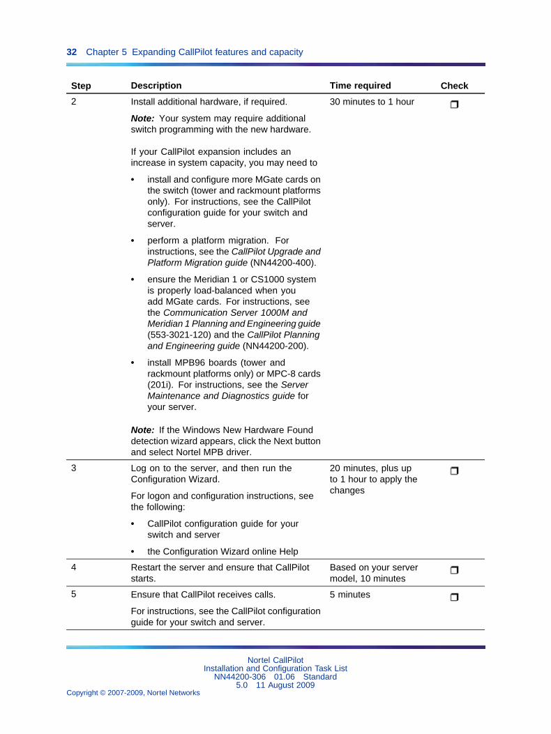
Step Description Time required Check
2 Install additional hardware, if required.
Note: Your system may require additionalswitch programming with the new hardware.
If your CallPilot expansion includes anincrease in system capacity, you may need to
• install and configure more MGate cards onthe switch (tower and rackmount platformsonly). For instructions, see the CallPilotconfiguration guide for your switch andserver.
• perform a platform migration. Forinstructions, see the CallPilot Upgrade andPlatform Migration guide (NN44200-400).
• ensure the Meridian 1 or CS1000 systemis properly load-balanced when youadd MGate cards. For instructions, seethe Communication Server 1000M andMeridian 1 Planning and Engineering guide(553-3021-120) and the CallPilot Planningand Engineering guide (NN44200-200).
• install MPB96 boards (tower andrackmount platforms only) or MPC-8 cards(201i). For instructions, see the ServerMaintenance and Diagnostics guide foryour server.
Note: If the Windows New Hardware Founddetection wizard appears, click the Next buttonand select Nortel MPB driver.
30 minutes to 1 hour
3 Log on to the server, and then run theConfiguration Wizard.
For logon and configuration instructions, seethe following:
• CallPilot configuration guide for yourswitch and server
• the Configuration Wizard online Help
20 minutes, plus upto 1 hour to apply thechanges
4 Restart the server and ensure that CallPilotstarts.
Based on your servermodel, 10 minutes
5 Ensure that CallPilot receives calls.
For instructions, see the CallPilot configurationguide for your switch and server.
5 minutes
Nortel CallPilotInstallation and Configuration Task List
NN44200-306 01.06 Standard5.0 11 August 2009
Copyright © 2007-2009, Nortel Networks
.
Feature expansion checklist 33
Step Description Time required Check
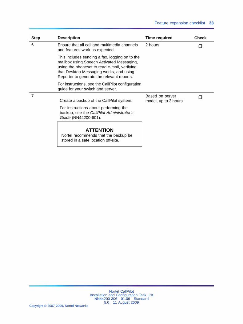
6 Ensure that all call and multimedia channelsand features work as expected.
This includes sending a fax, logging on to themailbox using Speech Activated Messaging,using the phoneset to read e-mail, verifyingthat Desktop Messaging works, and usingReporter to generate the relevant reports.
For instructions, see the CallPilot configurationguide for your switch and server.
2 hours
7Create a backup of the CallPilot system.
For instructions about performing thebackup, see the CallPilot Administrator’sGuide (NN44200-601).
ATTENTIONNortel recommends that the backup bestored in a safe location off-site.
Based on servermodel, up to 3 hours
Nortel CallPilotInstallation and Configuration Task List
NN44200-306 01.06 Standard5.0 11 August 2009
Copyright © 2007-2009, Nortel Networks
.

34 Chapter 5 Expanding CallPilot features and capacity
Nortel CallPilotInstallation and Configuration Task List
NN44200-306 01.06 Standard5.0 11 August 2009
Copyright © 2007-2009, Nortel Networks
.

35
Chapter 6CallPilot server platform migration
Perform a platform migration to migrate data from one CallPilot serverto another CallPilot server without losing existing CallPilot information.The migration path must be from an existing CallPilot platform to anotherequivalent or larger CallPilot platform. If your current server platform is notsupported, you must perform a platform migration.
The unsupported platforms are:
• 200i
• 702t
• 1001rp
Platform Migration documentationFor instructions about migrating your CallPilot server, see the CallPilotUpgrade and Platform Migration Guide (NN44200-400).
Nortel CallPilotInstallation and Configuration Task List
NN44200-306 01.06 Standard5.0 11 August 2009
Copyright © 2007-2009, Nortel Networks
.

36 Chapter 6 CallPilot server platform migration
Nortel CallPilotInstallation and Configuration Task List
NN44200-306 01.06 Standard5.0 11 August 2009
Copyright © 2007-2009, Nortel Networks
.

37
Chapter 7High Availability
A CallPilot High Availability system consists of two 1005r servers that workas peers. At any time, one server is active while the other server is instandby mode. The servers are referred to as CallPilot server 1 (CP1) andCallPilot server 2 (CP2).
For detailed information, see High Availability: Installation and Configuration(NN44200-311).
Installing a new High Availability systemThe following table outlines the tasks required to install, configure, and testthe High Availability feature. The tasks (and procedures within each task)must be completed in the order presented in the following table.
Task Procedures required to complete the task
Prepare the switch. High Availability: Installation and Configuration(NN44200-311), "Preparing the switch and the servers"
Install the two 1005r servers. High Availability: Installation and Configuration(NN44200-311), "Installing the two 1005r servers"
Prepare both 1005r servers. High Availability: Installation and Configuration (NN44200-311)
• "Changing the server name (optional)"
• "Installing the antivirus software (optional)"
• "Running the CallPilot Setup Wizard"
Configure CP1 and CP2 using theCallPilot Configuration Wizard.
High Availability: Installation and Configuration (NN44200-311)
• "Configuring CP1 using the CallPilot Configuration Wizard"
• "Configuring CP2 using the CallPilot Configuration Wizard"
Nortel CallPilotInstallation and Configuration Task List
NN44200-306 01.06 Standard5.0 11 August 2009
Copyright © 2007-2009, Nortel Networks
.

38 Chapter 7 High Availability
Connect and verify the LANconnections.
High Availability: Installation and Configuration (NN44200-311)
• "Connecting and verifying LAN connections"
• "Modifying the hosts file (optional)"
• "Testing the host name resolution"
Run Stage 1 of the High AvailabilityConfiguration Wizard to check theconfiguration of CP1 and CP2.
High Availability: Installation and Configuration(NN44200-311), "Running Stage 1 of the High AvailabilityConfiguration Wizard to check CP1 and CP2 configuration"
Install the AutoStart 5.2.2 softwareon CP1.
High Availability: Installation and Configuration(NN44200-311), "Installing the AutoStart Agent and Consolesoftware on CP1"
Configure licensing and security onCP1.
High Availability: Installation and Configuration(NN44200-311), "Configuring licensing and security by addingthe CP2 Administrator Account to the AutoStart Console"
Install the AutoStart 5.2.2 softwareon CP2.
High Availability: Installation and Configuration(NN44200-311), "Installing the AutoStart Agent software onCP2"
Configure the AutoStart softwareon CP1.
High Availability: Installation and Configuration (NN44200-311)
• "Modifying the AutoStart Domain and Verification links"
• "Adding the Remote Mirroring Host on CP2"
• "Generating the AutoStart Definition File"
• "Importing the AutoStart Definition file"
• "Adding the Windows administrator account password forthe AutoStart Utility Processes"
Bring the Resource Groups online. High Availability: Installation and Configuration (NN44200-311)
• Bringing the CallPilot Resource Group online on CP1
• Bringing the Resource Groups CallPilot_[CP1] andCallPilot_[CP2] online
Test your configuration. High Availability: Installation and Configuration(NN44200-311), "Testing the configuration of CP1 and CP2"
Create the CallPilot Reporterconnections.
High Availability: Installation and Configuration(NN44200-311), "Creating the Reporter connection"
Add server to a Windows domain(if required).
High Availability: Installation and Configuration(NN44200-311), "Joining a Windows domain"
Feature ExpansionIf you are upgrading or migrating to a CallPilot 5.0 1005r server and areadding the High Availability feature, do the following:
Nortel CallPilotInstallation and Configuration Task List
NN44200-306 01.06 Standard5.0 11 August 2009
Copyright © 2007-2009, Nortel Networks
.

Feature Expansion 39
Step Action
1 Follow the instructions in the CallPilot Upgrade and PlatformMigration Guide (NN44200-400) to upgrade or migrate your server toa CallPilot 1005r server running CallPilot 5.0. (Note: Do not enablethe High Availability feature when running the Configuration Wizard.)
2 Follow the instructions outlined in High Availability: Installation andConfiguration (NN44200-311) to perform a feature expansion to addthe High Availability feature to an existing CallPilot 5.0 1005r server.This procedure introduces a second 1005r server and configures thetwo 1005r servers as a High Availability pair.
—End—
If you have a CallPilot 5.0 1005r server and are adding the High Availabilityfeature, then follow the instructions outlined in High Availability: Installationand Configuration (NN44200-311) to perform a feature expansion. Thisprocedure adds the High Availability feature to an existing CallPilot 5.01005r server by introducing a second 1005r server and configuring the two1005r servers as a High Availability pair.
Nortel CallPilotInstallation and Configuration Task List
NN44200-306 01.06 Standard5.0 11 August 2009
Copyright © 2007-2009, Nortel Networks
.

40 Chapter 7 High Availability
Nortel CallPilotInstallation and Configuration Task List
NN44200-306 01.06 Standard5.0 11 August 2009
Copyright © 2007-2009, Nortel Networks
.

41
Chapter 8Configuring and administering theCallPilot system
A CallPilot administrator can:
• configure mailbox security
• add or customize restriction permission lists (RPLs)
• configure addressing information
• configure messaging service defaults
• configure CallPilot services (service DNs) and customize systemprompts
• configure CallPilot networking
• customize and add mailbox classes to provide group access to installedCallPilot services
• add, delete, and customize mailboxes
• create and maintain shared distribution lists (SDL)
Logging on to the CallPilot server with CallPilot ManagerYou must use a Web browser to log on to and administer the CallPilot server.
The logon process is completed in two stages:
Step Action
1 Launch the Web browser (on the CallPilot server or on any PC thathas network access to the CallPilot server).
The Web browser on the CallPilot server is configured toautomatically connect to the CallPilot Manager Web server. If youlaunch the Web browser on a PC, you must specify the URL for theCallPilot Manager Web server.
Nortel CallPilotInstallation and Configuration Task List
NN44200-306 01.06 Standard5.0 11 August 2009
Copyright © 2007-2009, Nortel Networks
.

42 Chapter 8 Configuring and administering the CallPilot system
The URL syntax is http://<Web server host name or IPaddress>/cpmgr/.
2 Log on to the CallPilot server with an administrator mailbox numberand password.
—End—
Relationship of the CallPilot Manager Web server to the CallPilot serverThe CallPilot Manager Web server software can be installed on the CallPilotserver or on a stand-alone server. If the CallPilot Manager Web serversoftware is installed on a stand-alone server, you must know the CallPilotManager server host name or IP address as well as the CallPilot server hostname or IP address.
See the following diagrams:
Nortel CallPilotInstallation and Configuration Task List
NN44200-306 01.06 Standard5.0 11 August 2009
Copyright © 2007-2009, Nortel Networks
.

Logging on to the CallPilot server with CallPilot Manager 43
To log on to the CallPilot server
Step Action
1 Launch the Web browser on your PC or on the CallPilot server.
IF you are launchingthe Web browser on THEN
the CallPilot server the CallPilot Manager - Login windowappears automatically. Continue with step2.
your PC type the CallPilot Manager Web serverURL in the Address or Location box of yourWeb browser, and then press Enter.
Example: http://sunbird/cpmgr/
When the connection is established, theCallPilot Manager - Login window appears.Continue with step 2.
Nortel CallPilotInstallation and Configuration Task List
NN44200-306 01.06 Standard5.0 11 August 2009
Copyright © 2007-2009, Nortel Networks
.

44 Chapter 8 Configuring and administering the CallPilot system
Note: The URL automatically appears as http://<host name orIP address>/cpmgr/login.asp. On the CallPilot server, the URL ishttp://localhost/cpmgr/login.asp.
2 In the CallPilot Manager Login page, type the administrator mailboxnumber and password:
• administrator mailbox number (default): 000000
• administrator mailbox password (default): 124578
3 Do one of the following:
• From the list of preconfigured servers or locations in the Presetserver list box, choose a server or location or choose the Lastserver accessed.
• In the Server box, type the CallPilot server host name or IPaddress.
• Type the CallPilot server host name or IP address in the Serverbox, and then type the name of the switch location on whichthe administration mailbox resides in the Location box if theCallPilot server that you connect to has Network MessageService (NMS) installed.
Nortel CallPilotInstallation and Configuration Task List
NN44200-306 01.06 Standard5.0 11 August 2009
Copyright © 2007-2009, Nortel Networks
.

On-site configuration and administration tasks 45
4 Click Login.
The main CallPilot Manager window appears.
Note: If you log on to new system, the Configuration Wizard isthe only option available.
—End—
On-site configuration and administration tasks
Task Reference
1 For customers with more than 1000mailboxes: Add specialized administrators.
From the Contents tab of the CallPilot ManagerHelp, navigate to Delegating administrativetasks.
2 Set up mailbox security. From the Contents tab of the CallPilot ManagerHelp, navigate to Securing the CallPilot system> Configuring mailbox security.
3 Customize restriction permission lists(RPLs).
From the Contents tab of the CallPilot ManagerHelp, navigate to Securing the CallPilot system> Maintaining restriction permission lists(RPLs) > Customizing RPLs.
Nortel CallPilotInstallation and Configuration Task List
NN44200-306 01.06 Standard5.0 11 August 2009
Copyright © 2007-2009, Nortel Networks
.

46 Chapter 8 Configuring and administering the CallPilot system
Task Reference
4 Verify basic messaging defaults. From the Contents tab of the CallPilot ManagerHelp, navigate to Configuring CallPilot services> Configuring CallPilot messaging servicedefaults > Changing messaging defaults.
5 If purchased by the customer: ConfigureCallPilot networking.
From the Contents tab of the CallPilot ManagerHelp, navigate to Administering a messagingnetwork.
6 Use the Configuration Worksheet as areference to add service DNs (SDNs) forcustom applications (including voice menus).
From the Contents tab of the CallPilot ManagerHelp, navigate to Configuring CallPilot services> Adding and deleting inbound SDNs.
7 Configure user creation templates. From the Contents tab of the CallPilot ManagerHelp, navigate to Managing mailbox creationand privileges > Using templates to createmailboxes.
8 Customize system prompts. From the Contents tab of the CallPilot ManagerHelp, navigate to Configuring CallPilot services> Configuring CallPilot messaging servicedefaults > Customizing system prompts.
9 If purchased by the customer: Configure faxservices.
"Fax services configuration tasks" (page 48) ofthis document.
10 If purchased by the customer: Configurespeech activated messaging services.
"Speech activated messaging serviceconfiguration tasks" (page 48) of thisdocument.
11 If purchased by the customer: ConfigureE-mail by Phone options.
"E-mail By Phone configuration tasks" (page49) of this document.
12 Test CallPilot operation:
1. Add test mailboxes.
2. Verify CallPilot Manager searchfunctionality.
3. Verify operation of new unifiedmessaging components.
4. Verify mailbox access controls.
• From the Contents tab of the CallPilotManager Help, navigate to Administeringmailboxes > Adding and removingmailboxes.
• From the Contents tab of the CallPilotManager Help, navigate to Securing theCallPilot system > Configuring mailboxsecurity.
13 Add custom applications (including voicemenus).
• From the Contents tab of the CallPilotManager Help, navigate to ConfiguringCallPilot services.
• CallPilot Application Builder Guide(NN44200-102).
• CallPilot Application Builder online Helptopics.
Nortel CallPilotInstallation and Configuration Task List
NN44200-306 01.06 Standard5.0 11 August 2009
Copyright © 2007-2009, Nortel Networks
.

Desktop Messaging and My CallPilot configuration tasks 47
Task Reference
14 Set up basic reports to monitor the system.
Note: This requires that CallPilot Managerand Reporter are installed on a stand-aloneWeb server.
• From the Contents tab of the CallPilotManager Help, navigate to Monitoring theCallPilot system > Running reports.
• CallPilot Reporter Guide (NN44200-603).
15 For upgrades: Use CallPilot archives tomigrate mailbox, custom prompt, andApplication Builder information.
Note: Using mailbox (user) archives tomigrate mailbox information gives mailboxowners with remote notification capabilityautomatic remote text notification capability.
From the Contents tab of the CallPilot ManagerHelp, navigate to Securing the CallPilotsystem > Backing up and restoring CallPilotinformation > Using CallPilot archives.
16 Add remaining mailbox owners and shareddistribution lists (SDLs).
From the Contents tab of the CallPilot ManagerHelp, navigate to Administering mailboxes >Adding and removing mailboxes > Adding agroup of mailboxes in a single operation.
Desktop Messaging and My CallPilot configuration tasks
Task Reference
1 Configure mailbox classes to enable mailboxowners to access Desktop Messaging and MyCallPilot.
From the Contents tab of the CallPilotManager Help, navigate to Managing mailboxcreation and privileges > Using mailboxclasses to manage mailbox privileges >Permitting use of optional unified messagingcomponents.
2 Configure and apply the Desktop Messagingrestriction permission list (RPL) to controlaccess to Desktop Messaging and MyCallPilot.
From the Contents tab of the CallPilotManager Help, navigate to Securing theCallPilot system > Maintaining restrictionpermission lists (RPLs) > Applying RPLs.
3 Define support information for My CallPilotusers.
CallPilot Desktop Messaging and MyCallPilot Installation and Administration Guide(NN44200-305), CallPilot server configurationfor My CallPilot services.
4 If mailbox owners have e-mail by phonecapability: Configure E-mail by Phone.
"E-mail By Phone configuration tasks" (page49) of this document.
5 If mailbox owners have remote text notificationcapability: Configure the appropriate usercreation templates with remote text notificationoptions.
From the Contents tab of the CallPilotManager Help, navigate to Managing mailboxcreation and privileges > Using templates tocreate new mailboxes.
Nortel CallPilotInstallation and Configuration Task List
NN44200-306 01.06 Standard5.0 11 August 2009
Copyright © 2007-2009, Nortel Networks
.

48 Chapter 8 Configuring and administering the CallPilot system
Fax services configuration tasks
Task Reference
1 Apply RPLs to fax callbacks and fax printing. From the Contents tab of the CallPilotManager Help, navigate to Securing theCallPilot system > Maintaining restrictionpermission lists (RPLs) > Applying RPLs.
2 Verify the express fax messaging sessionprofile.
From the Contents tab of the CallPilot ManagerHelp, navigate to Configuring a session profilefor a voice menu or service.
3 Configure fax callback handling and other faxoptions.
From the Contents tab of the CallPilotManager Help, navigate to Configuringcallback handling for an Application Builderfax service.
4 Update or add mailbox classes to enable faxcapability for groups.
From the Contents tab of the CallPilot ManagerHelp, navigate to Managing mailbox creationand privileges > Using mailbox classes tomanage mailbox privileges > Permitting useof optional unified messaging components >Permitting mailbox class members to sendand receive faxes.
5 Configure fax general delivery and faxoverflow mailboxes.
From the Contents tab of the CallPilot ManagerHelp, navigate to Administering mailboxes >Customizing mailboxes for special purposes >Setting up mailboxes to handle fax deliveriesand fax machine overflows.
Speech activated messaging service configuration tasks
Task Reference
1 Update or add mailbox classes to enablespeech activated messaging for mailbox classmembers.
From the Contents tab of the CallPilot ManagerHelp, navigate to Managing mailbox creationand privileges > Using mailbox classes tomanage mailbox privileges > Permitting useof optional unified messaging components> Speech activated messaging > Permittingmailbox class members to speak CallPilotphoneset commands.
Nortel CallPilotInstallation and Configuration Task List
NN44200-306 01.06 Standard5.0 11 August 2009
Copyright © 2007-2009, Nortel Networks
.

Password change service configuration tasks 49
E-mail By Phone configuration tasks
Task Reference
1 Define external e-mail servers. From the Contents tab of the CallPilot ManagerHelp, navigate to Desktop Messaging andMy CallPilot > Adding and removing externale-mail servers.
2 Define E-mail by Phone options. From the Contents tab of the CallPilotManager Help, navigate to ConfiguringCallPilot services > Configuring E-mail byphone > Defining E-mail by Phone options.
3 Update or add mailbox classes to enablespeech activated messaging for mailbox classmembers.
From the Contents tab of the CallPilotManager Help, navigate to Managing mailboxcreation and privileges > Using mailboxclasses to manage mailbox privileges >Permitting use of optional unified messagingcomponents > Permitting mailbox classmembers to listen to e-mail messages overa phoneset.
Password change service configuration tasks
Task Reference
1 Define Server FQDN. From the Message Network Configuration,Server Properties page, define the ServerFQDN
2 Ensure VPIM prefix is on the local primelocation.
From the Message Network Configuration,Prime Location Properties page, ensure theVPIM prefix is on the local prime location
3 Define Message Delivery Configuration. From the Message Delivery Configurationpage, define the Outgoing SMTP Mail/Proxyserver and enable Outgoing and IncomingSMTP/VPIM
Nortel CallPilotInstallation and Configuration Task List
NN44200-306 01.06 Standard5.0 11 August 2009
Copyright © 2007-2009, Nortel Networks
.

50 Chapter 8 Configuring and administering the CallPilot system
Nortel CallPilotInstallation and Configuration Task List
NN44200-306 01.06 Standard5.0 11 August 2009
Copyright © 2007-2009, Nortel Networks
.

51
Chapter 9Testing the CallPilot system andapplications
When a CallPilot system is installed, upgraded, or migrated to a differentplatform, perform the "Onsite testing tasks" (page 51).
Onsite testing tasks
Task Reference
1 Test the CallPilot connectivity, services, andchannels.
<switch_model> and CallPilot ServerConfiguration guide for your switch and server.
Also, refer back to "Testing CallPilotconnectivity, services, and channels" (page25) in this task list guide for an overview of theconfiguration testing that is performed duringinstallation.
2 Add test mailboxes. From the Contents tab of the CallPilotManager Help, navigate to Administeringmailboxes > Adding and removing mailboxes> Adding mailboxes, one at a time.
3 Verify that you can log on to the mailbox. <switch_model> and CallPilot ServerConfiguration guide for your switch and server.
4 Test mailbox search functions. From the Contents tab of the CallPilotManager Help, navigate to Administeringmailboxes > Finding mailboxes, administratorsor directory entries.
5 If pcAnywhere is installed on a remotecomputer: Test remote administration of theCallPilot server.
CallPilot Administrator’s Guide(NN44200-601), "Configuring remoteadministration of the CallPilot server".
Nortel CallPilotInstallation and Configuration Task List
NN44200-306 01.06 Standard5.0 11 August 2009
Copyright © 2007-2009, Nortel Networks
.

52 Chapter 9 Testing the CallPilot system and applications
Task Reference
6 If Reporter is installed: Test the Reporter linkand set up monitoring and reports.
• CallPilot Administrator’s Guide(NN44200-601), "Learning aboutCallPilot features".
• CallPilot Reporter Guide (NN44200-603).
7 If Application Builder is installed: Test theApplication Builder link and ensure theavailability of existing custom applications.
• CallPilot Administrator’s Guide(NN44200-601), "UnderstandingCallPilot features and services".
• CallPilot Application Builder Guide(NN44200-102).
Nortel CallPilotInstallation and Configuration Task List
NN44200-306 01.06 Standard5.0 11 August 2009
Copyright © 2007-2009, Nortel Networks
.

53
Chapter 10Starting up and shutting down theCallPilot server
This chapter contains information on the following topics:
"Stopping and starting channels" (page 53)
"Restarting the server" (page 56)
"Powering down the server" (page 59)
"To Power up the server" (page 62)
Stopping and starting channelsThis section describes how to stop and start channels.
IntroductionIf you take the CallPilot system out of service to perform software orhardware maintenance, first take all channels off duty.
If you take channels off duty, you must manually start them to put them backon duty. Channels that are manually taken off duty do not automatically startwhen the CallPilot server is restarted or powered up.
Methods for taking channels off dutyTwo options exist to take channels off duty:
• Courtesy stop channels (preferred method)
When you courtesy stop channels, CallPilot waits until the channelsare no longer active before taking them off duty, instead of suddenlyterminating active calls.
• Stop channels
Nortel CallPilotInstallation and Configuration Task List
NN44200-306 01.06 Standard5.0 11 August 2009
Copyright © 2007-2009, Nortel Networks
.

54 Chapter 10 Starting up and shutting down the CallPilot server
When you stop channels, you suddenly take them off duty and terminateall active calls.
ATTENTIONNortel recommends that, if possible, you courtesy stop channels. Courtesy stopis available only at the individual channel level.
To courtesy stop CallPilot, use the following:
• Multimedia Monitor: to courtesy stop a range of multimedia (DSP)channels
• Channel Monitor: to courtesy stop a range of call (DS30X, also knownas DS0) channels
Stopping or starting channels
Step Action
1 Log on to the CallPilot server with CallPilot Manager.
For instructions, see "Logging on to the CallPilot server with CallPilotManager" (page 41).
2 In CallPilot Manager, click Maintenance > Multimedia Monitor.
The Multimedia Monitor screen appears, showing the channelsassociated with each DSP.
ATTENTIONCourtesy stop is available only at the individual channel level. Therefore,to take the CallPilot system out of service, you must select each channelbefore clicking Courtesy Stop.
3 Select the check box for each DSP channel.
4 Do one of the following:
IF you want to THEN
take the selected channels offduty
do the following:
1. Click Courtesy Stop.
Note: If the Courtesy Stop button is notavailable, wait a few seconds for thescreen to refresh.
You are asked to confirm theCourtesy Stop.
Nortel CallPilotInstallation and Configuration Task List
NN44200-306 01.06 Standard5.0 11 August 2009
Copyright © 2007-2009, Nortel Networks
.

Stopping and starting channels 55
IF you want to THEN
2. Click OK.
The selected DSP channels changeto off-duty status.
put the selected channels onduty
Click Start.
The selected DSP channels change toon-duty status.
5 Click Maintenance > Channel Monitor.
The Channel Monitor screen appears, showing the DS0 channelsassociated with each DS30X link.
ATTENTIONCourtesy stop is available only at the individual channel level. Therefore,to take the CallPilot system out of service, you must select each channelbefore clicking Courtesy Stop.
6 Select the check box for each DS0 channel.
7 Do one of the following:
IF you want to THEN
take the selected channels offduty
do the following:
1. Click Courtesy Stop.
Note: If the Courtesy Stop button is notavailable, wait a few seconds for thescreen to refresh.
You are asked to confirm theCourtesy Stop.
2. Click OK.
The selected DS0 channels changeto off-duty status.
3. After all channels are off duty, dialthe CallPilot messaging DN to verifythat all DSP and DS0 channels areoff duty.
Nortel CallPilotInstallation and Configuration Task List
NN44200-306 01.06 Standard5.0 11 August 2009
Copyright © 2007-2009, Nortel Networks
.

56 Chapter 10 Starting up and shutting down the CallPilot server
IF you want to THEN
If all channels are off duty, you mayreceive a busy signal.
put the selected channels onduty
Click Start.
The selected DS0 channels change toon-duty status.
—End—
Restarting the serverThis section describes how to restart the server.
When to restart the serverYou must restart the server as described in this section when you:
• are putting software changes into effect
• are attempting to resolve operational problems
• are instructed to do so
ATTENTIONNortel recommends that, if the CallPilot server is in service, you courtesy stop allchannels before you restart the server. When you courtesy stop the channels,CallPilot waits until the channels are no longer active before disabling them,instead of suddenly disconnecting active calls.
For instructions, see "Stopping and starting channels" (page 53).
ATTENTIONTo minimize the amount of time required to wait for channels to become inactive,consider one or both of the following options:
• Perform the server restart during off-hours.
• Inform mailbox users and other administrators in advance when youplan to restart the server. This ensures that their Desktop Messaging,Web messaging, and administration sessions are logged off.
Before you beginIf your server is a 201i or 202i server, and you are working at the server,connect a keyboard, monitor, and mouse to the server.
Nortel CallPilotInstallation and Configuration Task List
NN44200-306 01.06 Standard5.0 11 August 2009
Copyright © 2007-2009, Nortel Networks
.

Restarting the server 57
Restarting the serverTo restart the server, you must be working at the CallPilot server or beconnected to the server through pcAnywhere.
Step Action
1 Log on to the server with CallPilot Manager.
For instructions, see "Logging on to the CallPilot server with CallPilotManager" (page 41).
2 Courtesy stop all call channels.
For instructions, see "Stopping and starting channels" (page 53).
3 Do one of the following:
IF you are THEN
at the server continue to next step.
at a PC connected remotely to theserver
do the following:
1. Use pcAnywhere to connectto and log on to the CallPilotserver.
2. Continue to next step.
4 Close all applications on the server.
Note: Applications that you are unable to close are automaticallyclosed when you perform the operating system shutdown.
5 Press Ctrl+Alt+Delete.
Note: Shutting down the server software by pressing theCtrl+Alt+Delete keys closes database files properly and reducesthe time to restart the server.
The Windows Security dialog box appears.
6 Set the following options in the Windows Security dialog box:
Nortel CallPilotInstallation and Configuration Task List
NN44200-306 01.06 Standard5.0 11 August 2009
Copyright © 2007-2009, Nortel Networks
.

58 Chapter 10 Starting up and shutting down the CallPilot server
What do you want to do? Choose Restart from the drop-downmenu.
Select the option that bestdescribes why you want to shutdown the computer.
Choose one of the following:
• Other (Planned)
• Hardware: Maintenance(Planned)
• Hardware: Installation(Planned)
• Operating System:Reconfiguration (Planned)
• Application: Maintenance(Planned)
• Application: Installation(Planned)
• Security Issue
Comment If you selected Other (Planned)above, the OK button is unavailable.You must add a comment to enablethe button.
7 Click OK.
The server shuts down and then restarts.
Note: To interpret the diagnostic results that appear during therestart, see the CallPilot <server_model> Server Maintenanceand Diagnostics guide for your server.
8 When the operating system logon prompt appears, pressCtrl+Alt+Delete to log on.
You are prompted for an operating system user name and password.
9 Enter Administrator as the user name.
Note: You can choose to log on with a different user ID that haslocal administrative privileges.
10 Enter the password, and then click OK.
The CallPilot server software starts.
ATTENTIONWait 10 minutes before proceeding with step 11.
Nortel CallPilotInstallation and Configuration Task List
NN44200-306 01.06 Standard5.0 11 August 2009
Copyright © 2007-2009, Nortel Networks
.
Powering down the server 59
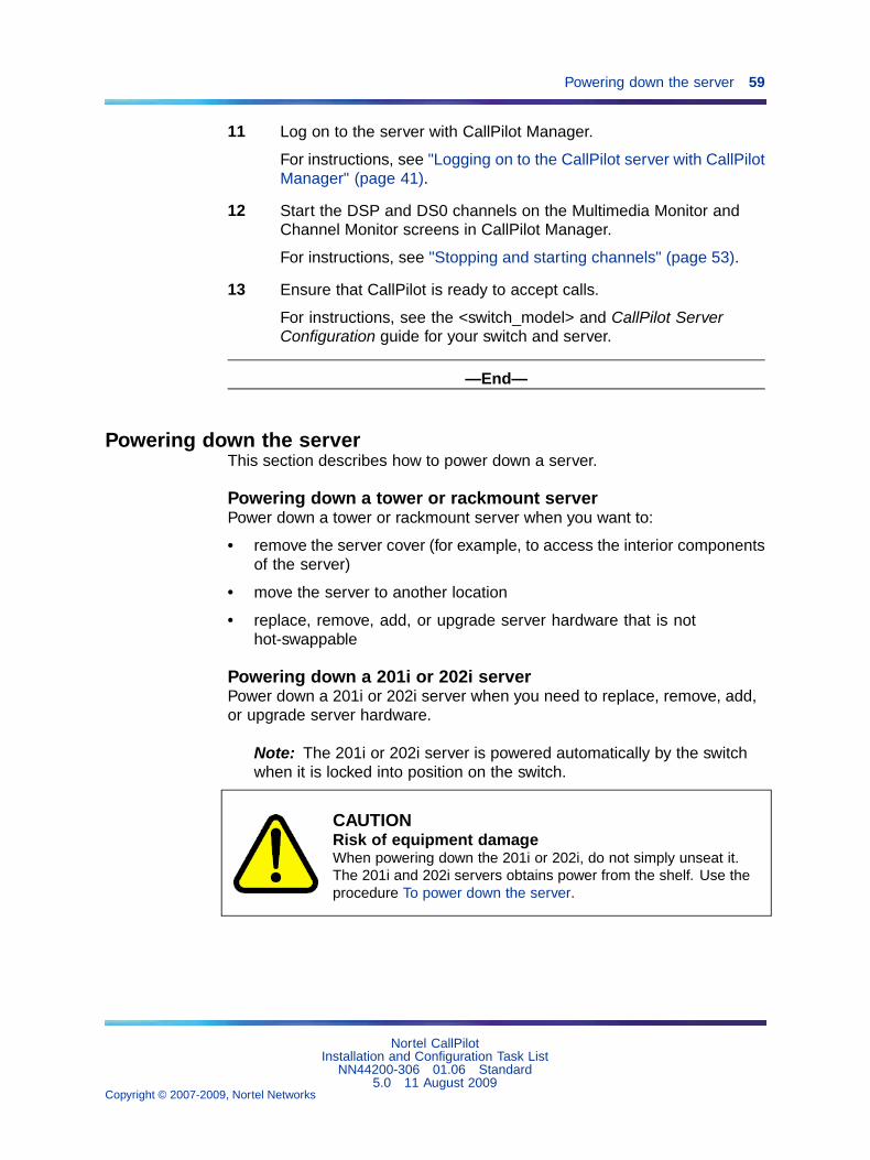
11 Log on to the server with CallPilot Manager.
For instructions, see "Logging on to the CallPilot server with CallPilotManager" (page 41).
12 Start the DSP and DS0 channels on the Multimedia Monitor andChannel Monitor screens in CallPilot Manager.
For instructions, see "Stopping and starting channels" (page 53).
13 Ensure that CallPilot is ready to accept calls.
For instructions, see the <switch_model> and CallPilot ServerConfiguration guide for your switch and server.
—End—
Powering down the serverThis section describes how to power down a server.
Powering down a tower or rackmount serverPower down a tower or rackmount server when you want to:
• remove the server cover (for example, to access the interior componentsof the server)
• move the server to another location
• replace, remove, add, or upgrade server hardware that is nothot-swappable
Powering down a 201i or 202i serverPower down a 201i or 202i server when you need to replace, remove, add,or upgrade server hardware.
Note: The 201i or 202i server is powered automatically by the switchwhen it is locked into position on the switch.
CAUTIONRisk of equipment damageWhen powering down the 201i or 202i, do not simply unseat it.The 201i and 202i servers obtains power from the shelf. Use theprocedure To power down the server.
Nortel CallPilotInstallation and Configuration Task List
NN44200-306 01.06 Standard5.0 11 August 2009
Copyright © 2007-2009, Nortel Networks
.

60 Chapter 10 Starting up and shutting down the CallPilot server
ATTENTIONWhen power is lost at the SL-100, the CallPilot server must be shut downgracefully. After power is restored to the SL-100 and the T1 trunks are operational,restart the CallPilot server.
ATTENTIONIf CallPilot is in service, Nortel recommends that you courtesy stop all channelsbefore you power down the server. When you courtesy stop the channels,CallPilot waits until the channels are no longer active before disabling theminstead of suddenly disconnecting active calls.
For instructions, see "Stopping and starting channels" (page 53).
ATTENTIONTo minimize the amount of time that you may be required to wait for channels tobecome inactive, consider one or both of the following options:
• Power down the server during off-hours.
• Inform mailbox users and other administrators in advance when youplan to power down the server. This ensures that their DesktopMessaging, Web messaging, and administration sessions are loggedoff.
Before you beginIf your server is a 201i or 202i server, and you are working at the server,connect a keyboard, monitor, and mouse to the server.
Powering down the serverTo power down the server, you must be working at the CallPilot server orbe connected to the server through pcAnywhere.
Step Action
1 Log on to the server with CallPilot Manager.
For instructions, see "Logging on to the CallPilot server with CallPilotManager" (page 41).
2 Courtesy stop all call channels.
For instructions, see "Stopping and starting channels" (page 53).
3 Do one of the following:
Nortel CallPilotInstallation and Configuration Task List
NN44200-306 01.06 Standard5.0 11 August 2009
Copyright © 2007-2009, Nortel Networks
.
Powering down the server 61
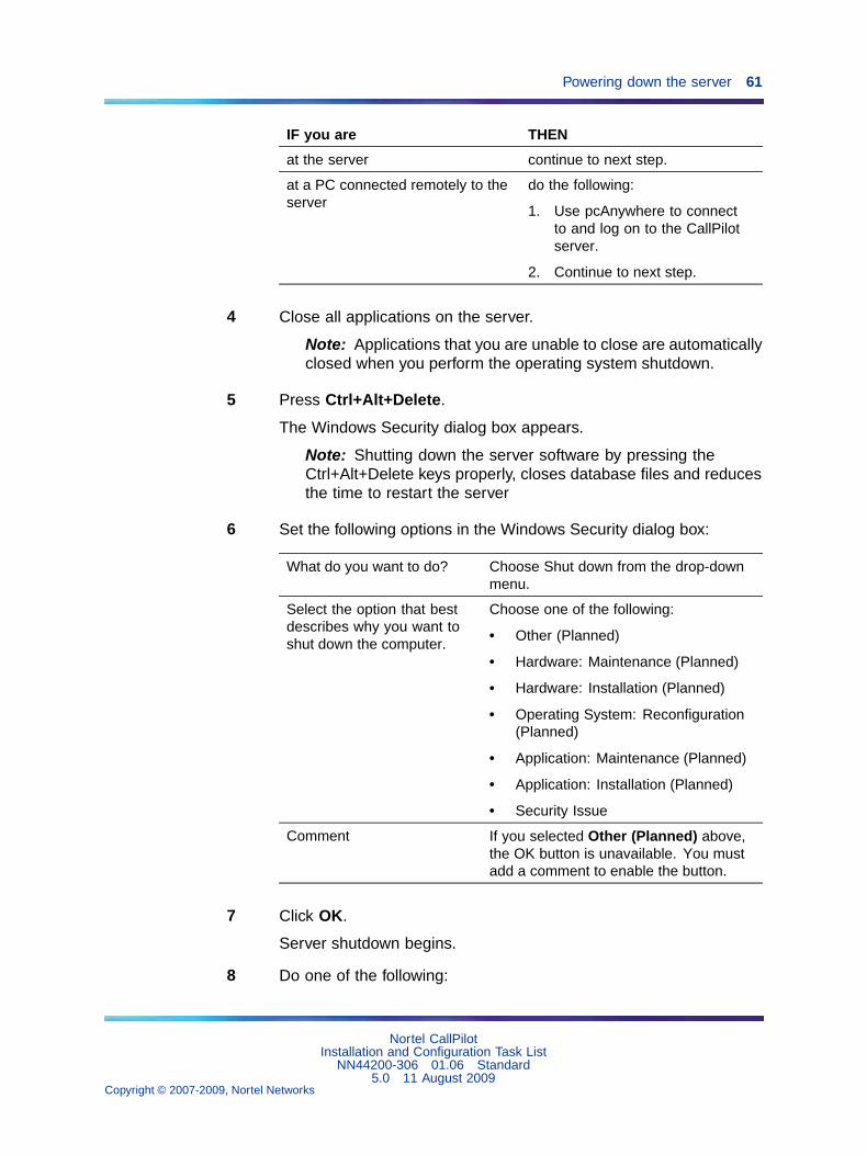
IF you are THEN
at the server continue to next step.
at a PC connected remotely to theserver
do the following:
1. Use pcAnywhere to connectto and log on to the CallPilotserver.
2. Continue to next step.
4 Close all applications on the server.
Note: Applications that you are unable to close are automaticallyclosed when you perform the operating system shutdown.
5 Press Ctrl+Alt+Delete.
The Windows Security dialog box appears.
Note: Shutting down the server software by pressing theCtrl+Alt+Delete keys properly, closes database files and reducesthe time to restart the server
6 Set the following options in the Windows Security dialog box:
What do you want to do? Choose Shut down from the drop-downmenu.
Select the option that bestdescribes why you want toshut down the computer.
Choose one of the following:
• Other (Planned)
• Hardware: Maintenance (Planned)
• Hardware: Installation (Planned)
• Operating System: Reconfiguration(Planned)
• Application: Maintenance (Planned)
• Application: Installation (Planned)
• Security Issue
Comment If you selected Other (Planned) above,the OK button is unavailable. You mustadd a comment to enable the button.
7 Click OK.
Server shutdown begins.
8 Do one of the following:
Nortel CallPilotInstallation and Configuration Task List
NN44200-306 01.06 Standard5.0 11 August 2009
Copyright © 2007-2009, Nortel Networks
.

62 Chapter 10 Starting up and shutting down the CallPilot server
IF your server is THEN
a tower or rackmount server press the server power switch.
a 202i or 202i server do the following:
1. Ensure that DOWN appears onthe server HEX display.
Note: The red LED power statusindicator remains lit during theshutdown until the system isrestarted.
CAUTIONRisk ofequipmentdamageWait at least 2minutes beforeremoving the201i or 202i toallow the drive topark the head.
2. Remove the server from theswitch.
—End—
To Power up the serverIf you power down the server to perform hardware maintenance, use theprocedure described in this section to restart the server.
Powering up the server
Step Action
1 Ensure that all peripheral devices are powered up.
Note: If your server is a 201i or 202i server:
• Ensure that the switch shelf is also powered up.
• Ensure that a monitor is connected during the power-upsequence.
Nortel CallPilotInstallation and Configuration Task List
NN44200-306 01.06 Standard5.0 11 August 2009
Copyright © 2007-2009, Nortel Networks
.

To Power up the server 63
Note: The monitor is connected only when you need it.The 201 or 202i server is not intended to operate with apermanent monitor connection.
2 Do the following:
IF your server is THEN
a tower or rackmount server press the server power switch to start theserver.
a 201i or 202i server do the following:
1. Push the server gently but firmly until itis flush with the switch backplane.
The power LED illuminates to indicatethat power is received.
2. Close the lock latches to secure theserver to the backplane.
3. Ensure that the power status LED is lit.
3 Watch the start-up sequence as follows:
IF your server is THEN
a tower or rackmount server Observe the Power-On Self-Test (POST)and initialization messages on the monitor.Ensure that all alarm LEDs are green (600rand 1005r)
a 201i or 202i server Watch the HEX display on the server.
The HEX display shows T:01 through T:08,and then HOST.
4 The server boots into the operating system automatically, displayinga series of start-up screens and finally the operating system logo.
IF your server is THEN
a tower or rackmount server The operating system start sequencebegins.
When the start sequence is completed, theoperating system logon prompt appearson the monitor.
Nortel CallPilotInstallation and Configuration Task List
NN44200-306 01.06 Standard5.0 11 August 2009
Copyright © 2007-2009, Nortel Networks
.

64 Chapter 10 Starting up and shutting down the CallPilot server
IF your server is THEN
If the logon prompt does not appear,see the CallPilot <server_model> ServerMaintenance and Diagnostics guide foryour server.
201i or 202i server The operating system start sequencebegins, and communication with the switchoccurs. The HEX display shows NT (forabout 30 seconds), followed by OK. Theoperating system logon prompt appearson the monitor.
Note: Before OK appears, one of thefollowing messages may appear, but notfor more than 1 second: CDLN, C:01, orC:02. This is normal operation.
If OK, or the logon prompt, or both do notappear, see the CallPilot <server_model>Server Maintenance and Diagnostics guidefor your server.
You are prompted for an operating system user name and password.If the system needs to be configured, a pop-up box for MaintenanceConfiguration Detection Information may appear to remind you.
5 If the Maintenance Configuration Detection Information boxappears, click OK unless you want a reminder to configure theserver.
Note: On the 201i server, the HEX display changes from OK, toCRI, On the 202i server, the HEX display may change from OK.
6 Enter the user name (Administrator) and the password.
Note: You can choose to log on with a different user ID that haslocal administrative privileges.
7 Click OK.
The CallPilot server software starts.
ATTENTIONWait 10 minutes before proceeding with the next step.
8 Log on to the server with CallPilot Manager.
Nortel CallPilotInstallation and Configuration Task List
NN44200-306 01.06 Standard5.0 11 August 2009
Copyright © 2007-2009, Nortel Networks
.

To Power up the server 65
For instructions, see "Logging on to the CallPilot server with CallPilotManager" (page 41).
9 Start the DSP and DS0 channels on the Multimedia Monitor andChannel Monitor windows in CallPilot Manager.
For instructions, see "Stopping and starting channels" (page 53).
10 Ensure that CallPilot is ready to accept calls.
For instructions, see the CallPilot configuration guide for your switchand server.
—End—
Nortel CallPilotInstallation and Configuration Task List
NN44200-306 01.06 Standard5.0 11 August 2009
Copyright © 2007-2009, Nortel Networks
.

66 Chapter 10 Starting up and shutting down the CallPilot server
Nortel CallPilotInstallation and Configuration Task List
NN44200-306 01.06 Standard5.0 11 August 2009
Copyright © 2007-2009, Nortel Networks
.

67
Chapter 11Troubleshooting system problems
This chapter contains information on the following topics:"Overview" (page 67)
"Using the Installation and Configuration guides" (page 68)
"Using the CallPilot Administrator Guide" (page 71)
If the monitor suddenly shows a blue screen with only white text, a systemerror has occurred. Record all of the events that took place prior to theappearance of the blue screen. Record any text that appears on the bluescreen, and contact customer support for assistance.
OverviewThis section provides an overview of the resources and tools that you canuse to determine the cause of system problems, and then resolve them.
ResourcesDocumentation available for resolving system problems are:
• CallPilot <server_model> Server Maintenance and Diagnostics guidefor your server
• CallPilot Administrator’s Guide (NN44200-601)
• CallPilot Troubleshooting Reference Guide (NN44200-700)
ToolsThe following tools are provided with your CallPilot system and are brieflydescribed in this chapter:
Type Tools
Generic tools • TCP/IP diagnostics
Nortel CallPilotInstallation and Configuration Task List
NN44200-306 01.06 Standard5.0 11 August 2009
Copyright © 2007-2009, Nortel Networks
.
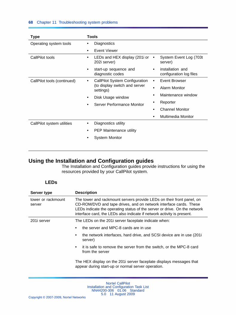
68 Chapter 11 Troubleshooting system problems
Type Tools
Operating system tools • Diagnostics
• Event Viewer
CallPilot tools • LEDs and HEX display (201i or202i server)
• start-up sequence anddiagnostic codes
• System Event Log (703tserver)
• installation andconfiguration log files
CallPilot tools (continued) • CallPilot System Configuration(to display switch and serversettings)
• Disk Usage window
• Server Performance Monitor
• Event Browser
• Alarm Monitor
• Maintenance window
• Reporter
• Channel Monitor
• Multimedia Monitor
CallPilot system utilities • Diagnostics utility
• PEP Maintenance utility
• System Monitor
Using the Installation and Configuration guidesThe Installation and Configuration guides provide instructions for using theresources provided by your CallPilot system.
LEDs
Server type Description
tower or rackmountserver
The tower and rackmount servers provide LEDs on their front panel, onCD-ROM/DVD and tape drives, and on network interface cards. TheseLEDs indicate the operating status of the server or drive. On the networkinterface card, the LEDs also indicate if network activity is present.
201i server The LEDs on the 201i server faceplate indicate when:
• the server and MPC-8 cards are in use
• the network interfaces, hard drive, and SCSI device are in use (201iserver)
• it is safe to remove the server from the switch, or the MPC-8 cardfrom the server
The HEX display on the 201i server faceplate displays messages thatappear during start-up or normal server operation.
Nortel CallPilotInstallation and Configuration Task List
NN44200-306 01.06 Standard5.0 11 August 2009
Copyright © 2007-2009, Nortel Networks
.

Using the Installation and Configuration guides 69
Server type Description
For more information, see the CallPilot <server_model> ServerMaintenance and Diagnostics guide for your server.
202i server The LEDs on the 202i server faceplate indicate when:
• the server is in use
• the network interfaces and hard drive are in use (202i server)
• it is safe to remove the server from the switch
The HEX display on the 202i server faceplate displays messages thatappear during start-up or normal server operation.
For more information, see the CallPilot <server_model> ServerMaintenance and Diagnostics guide for your server.
Start-up sequence and diagnostic codesTo help you determine if the server started successfully (or if it failed), watchthe start-up sequence and the diagnostic codes that appear on the monitor.If your server is a 201i or 202i server, also observe the HEX display onthe server faceplate.
If a hardware problem on the 703t server prevents the operating systemfrom starting or a hardware problem is indicated by the status LED on thefront panel, you can use the server System Event Log to investigate theproblem. The System Event Log is a utility on the 703t server that reportshardware-related errors. You can access the System Event Log by usingthe System Setup Utility.
For more information, see the CallPilot <server_model> Server Maintenanceand Diagnostics guide for your server.
Log filesThe installation event log tracks events associated with any installation,reinstallation, upgrade, or uninstallation operation. The log also tracks anyfatal errors that interrupt these operations.
The Configuration Wizard log file is a record of the information enteredthrough the CallPilot Configuration Wizard.
For more information, see the CallPilot Software Administration Guide(NN44200-600).
Operating system Diagnostics and Event ViewerYou can use the operating system Diagnostics window to view detailsconcerning the system and network components.
Nortel CallPilotInstallation and Configuration Task List
NN44200-306 01.06 Standard5.0 11 August 2009
Copyright © 2007-2009, Nortel Networks
.

70 Chapter 11 Troubleshooting system problems
The Event Viewer provides access to three logs (system, security, andapplication) that you can use to diagnose and debug system problems.
For more information, see the CallPilot <server_model> Server Maintenanceand Diagnostics guide for your server.
TCP/IP diagnosticsThe following diagnostic tools help you to verify network connectivity androuting:
• ipconfig
• ping
• tracert
• arp
• nbtstat
• netstat
For more information, see the CallPilot <server_model> Server Maintenanceand Diagnostics guide for your server.
CallPilot ManagerUse the following screens in CallPilot Manager to monitor hardware status:
• Event Browser
You can use the Event Browser to view events that have been recordedin the server log. The event description can help you determine theroot cause of an event or problem.
• Alarm Monitor
An alarm is a warning that is generated by an event. The alarm notifiesyou of a potential or real problem. Use the Alarm Monitor in CallPilotManager to investigate one or more raised alarms.
• Maintenance
Use the Maintenance screen to get status information for serverhardware components, or to run diagnostics for a particular component.
• Channel and Multimedia Monitors
The Channel Monitor shows the status of DS0 channels, which are theconnections that carry the call signals from the switch to CallPilot.
The Multimedia Monitor shows the status of multimedia channels, whichare the DSP ports that process the calls. They are the voice, fax, andspeech recognition channels.
Nortel CallPilotInstallation and Configuration Task List
NN44200-306 01.06 Standard5.0 11 August 2009
Copyright © 2007-2009, Nortel Networks
.
Using the CallPilot Administrator Guide 71
For more information about using CallPilot Manager, see the following:
• CallPilot Software Administration Guide (NN44200-600)
• CallPilot Manager online Help
• CallPilot <server_model> Server Maintenance and Diagnostics guidefor your server
CallPilot system utilitiesYou can use the Diagnostics utility to enable and disable CallPilot start-updiagnostics that run when the system starts. When diagnostics are disabled,this saves time during system maintenance operations where restarts orCall Processing services restarts are required.
The PEP Maintenance utility displays a list of all installed PEPs on theserver and lets you uninstall PEPs.
The Services Monitor can help you determine whether the CallPilot serveris fully operational. It displays true states of the CallPilot services accordingto the operating system definition, including the states that are not availablethrough the control panel.
The Session Trace tool provides detailed information about the activity in auser’s mailbox and the state of the message waiting indicator (MWI).
The System Monitor provides the following information:
• the status of all CallPilot services, multimedia channels, and callchannels
• details about the CallPilot system, such as the features purchased,keycode, serial number, and IP addresses
For more information about these utilities, see the CallPilot <server_model>Server Maintenance and Diagnostics guide for your server.
Using the CallPilot Administrator GuideThe CallPilot Manager online Help and the CallPilot Administrator’sGuide (NN44200-601) provide valuable information for monitoring systemperformance.
The CallPilot Manager online Help and the CallPilot Administrator’s Guide(NN44200-601) both describe how to:
• view and filter server events
• monitor the CallPilot server
• manage CallPilot channels
• troubleshoot CallPilot call service and system operation problems
Nortel CallPilotInstallation and Configuration Task List
NN44200-306 01.06 Standard5.0 11 August 2009
Copyright © 2007-2009, Nortel Networks
.

72 Chapter 11 Troubleshooting system problems
Accessing the CallPilot Administrator GuideThe CallPilot Administrator’s Guide (NN44200-601) is provided in thefollowing locations:
• on the CallPilot Documentation CD-ROM
• in the Installation and Administration area of CallPilot Manager
To access the Installation and Administration area, click the Help link inthe top-right corner.
Viewing and filtering server eventsIf you want to reduce the number of events shown in the Event Browser atone time, you can screen the event log to view a specific number of themost recently filtered events. By default, the Event Browser displays thelatest 100 critical events.
You can set the filter to display:
• a specific number of latest events, or all events that are retrieved fromthe server
• events of a certain severity (critical, major, minor, information)
• a specific event code range or all event codes
• a specific type of alarm status (alarm set, alarm cleared, or message)
• events that occur during a specific date and time interval
Note: The filter combines the filter settings from each category.
Monitoring the CallPilot serverMonitoring activities include the following:
• viewing switch configuration and server settings
You may need this information when you communicate with productsupport personnel.
• monitoring disk space
The performance of your CallPilot system depends, to some degree, onthe amount of available disk space. Without enough disk space, theserver cannot perform adequately. In some circumstances, the servercan stop functioning.
Nortel systems are engineered to provide adequate space to meet yourdata storage and system operation requirements. You must, however,monitor disk space occasionally to ensure that space does not becometoo limited.
• monitoring the database
Nortel CallPilotInstallation and Configuration Task List
NN44200-306 01.06 Standard5.0 11 August 2009
Copyright © 2007-2009, Nortel Networks
.

Using the CallPilot Administrator Guide 73
The database stores user information, system configuration information,and various statistics that are collected by the system. You cannotmonitor the database disk space directly. However, an informationalalarm is generated if the database reaches 95 percent capacity. A majoralarm is generated if the database reaches 98 percent or 100 percentcapacity.
Possible reasons for database problems include the following:
— Operational measurement statistics are too detailed or stored fortoo long.
— The system is under-engineered.
If your estimated usage patterns change or if your number of usersgrow, you may need to purchase additional disk space. Contact yourNortel channel partner for details.
• monitoring server performance
You can use the Performance Monitor to keep track of the day-to-dayhardware and software operations of your system. The window includesinformation about processor usage, available memory, and availablestorage space. You may want to view server performance daily to ensurethat the server is working properly. You may also want to view data if theperformance of your server has deteriorated.
Managing CallPilot channelsCall channels carry digital voice, fax, and speech recognition data from theswitch to the server. When the data reaches the server, the multimediachannels process the data according to the type of transmission.
You can monitor individual call channels through the Channel Monitorscreen, and multimedia channels or MPC-8 cards through the MultimediaMonitor screen in CallPilot Manager.
As required, you can also remove the call and multimedia channels fromservice so that you can perform diagnostics, upgrades, or installations.When the maintenance or diagnostics are complete, restart the call andmultimedia channels and put them back into service.
Troubleshooting call service problemsCall service problems may occur in the Remote Notification, Delivery toTelephone (DTT), and Delivery to Fax (DTF) services, if they have beenput into service.
Nortel CallPilotInstallation and Configuration Task List
NN44200-306 01.06 Standard5.0 11 August 2009
Copyright © 2007-2009, Nortel Networks
.

74 Chapter 11 Troubleshooting system problems
The types of problems that can occur when using Outcalling servicesinclude:
• being unable to use the Outcalling service because channels are notavailable
This situation can occur if the channel allocation is not spread evenly, orif channels are out of service or faulty.
• experiencing a high rate of failures because of incorrect configuration orbecause the retry limits are exceeded
DTT or DTF failures can occur because of the following conditions:
— busy
— no answer
— answered, but no DTMF confirmation was provided, or the call wasterminated before delivery could occur
Remote Notification failures can occur because of the following:
— The users’ Remote Notification target DNs are restricted.
— Pager setups may not be correctly configured for users.
— Retry limits are exceeded.
You can monitor these types of problems by using the Event Browser orReporter.
Troubleshooting system operation problemsThe following types of system operation problems can occur:
• Alarms are generated despite no apparent system problem.
If the system shows no apparent system problem but alarms occur,check if someone has recently run diagnostics on the system. Adiagnostic test can generate an alarm as part of its test, even if thesystem is fine.
• Calls are not answered.
Possible causes include the following:
— CallPilot is improperly configured.
— The Service DN table is not configured correctly.
• Call flow from the switch is impaired due to an incorrect switchconfiguration.
• Calls are answered, but no prompts are heard.
Nortel CallPilotInstallation and Configuration Task List
NN44200-306 01.06 Standard5.0 11 August 2009
Copyright © 2007-2009, Nortel Networks
.

Using the CallPilot Troubleshooting Reference 75
Possible causes include the following:
— An error in the application that supports the requested service.
— A problem with the DS0 channel or the DS30X link.
• The system is not working after an IP address change.
If the IP address of a CallPilot server is changed while the system is upand running, the system does not work until you restart the switch.
• The monitor shows a blue screen.
If the monitor suddenly shows a blue screen with only white text, a systemerror has occurred. Record all of the events that took place prior to theappearance of the blue screen. Record any text that appears on the bluescreen, and contact customer support for assistance.
Using the CallPilot Troubleshooting ReferenceThe CallPilot Troubleshooting Reference describes symptoms that canappear on all CallPilot server platforms, and describes ways to resolve them.
Obtaining the CallPilot Troubleshooting ReferenceThe CallPilot Troubleshooting Reference is written for Nortel distributorsand technical support representatives and is, therefore, not included in thecustomer documentation package.
Nortel continually updates the CallPilot Troubleshooting Referenceand posts it on the Nortel Partner Information Center (PIC) at:http://my.nortelnetworks.com
You require a user ID and password to access the PIC. If you do not havea PIC account, click Register to request an account. It can take up to 72hours to process your account request.
Note: If you are not a Nortel distributor, contact your Nortel technicalsupport representative for assistance.
Types of problems that are coveredUse this document to resolve the following types of problems:
• server boot cycle failures
• peripheral device problems
• monitor display problems
• server to network connection problems
• remote access connection problems
Nortel CallPilotInstallation and Configuration Task List
NN44200-306 01.06 Standard5.0 11 August 2009
Copyright © 2007-2009, Nortel Networks
.

76 Chapter 11 Troubleshooting system problems
• CallPilot application problems
Nortel CallPilotInstallation and Configuration Task List
NN44200-306 01.06 Standard5.0 11 August 2009
Copyright © 2007-2009, Nortel Networks
.

77
Appendix AInstallation preparation checklists
This chapter contains information on the following topics:
"Site inspection checklist" (page 77)
"Required tools and materials" (page 80)
"Customer-supplied items checklist" (page 81)
"CallPilot server hardware checklist" (page 83)
"CallPilot hardware and documentation spares checklist" (page 87)
"CallPilot software media and documentation checklist" (page 88)
"Preinstalled software" (page 90)
Site inspection checklistBefore you perform the hardware installation, complete the following siteinspection checklist:
Check Description
Ensure that a water fire retardant system is not present in thechosen location.
An activation of this system could severely impact the ability of theCallPilot system to operate.
Ensure that heat sources are not near the peripheral equipment.
The CallPilot server environment must be properly cooled.
Nortel CallPilotInstallation and Configuration Task List
NN44200-306 01.06 Standard5.0 11 August 2009
Copyright © 2007-2009, Nortel Networks
.

78 Appendix A Installation preparation checklists
Check Description
Ensure that the area is isolated from strong electromagnetic fieldsand electrical noise sources such as air conditioners, large fans,motors, radio or TV transmitters, or high-frequency security devices.
Ensure that the area is clean and clear of any debris.
If the CallPilot server is a rackmount server, install the 19-inchrack.
For instructions, see the rack documentation.
ATTENTIONIf applicable, ensure that the rack meets seismic bracingrequirements. For more information, see the documentation foryour switch or system.
Ensure that there is adequate space for all equipment.
• If your server is a tower or rackmount server, ensure that thereis adequate space for access to the front, side, and rear panelsof the server.
• For ventilation, ensure that there is adequate space for air flowaround the peripheral equipment.
Ensure that there is a desk, shelf, or table available for the monitor,keyboard, mouse, and modem.
Ensure that an external analog phone line is available for the modem.
Note: The line should not be connected to the customer’s switch.If the switch goes down, the CallPilot server cannot be supportedfrom a remote location.
Ensure that a single-point ground reference is available for all thepower outlets serving the CallPilot server and its peripherals.
Before the CallPilot server installation, a qualified electricianmust implement the single-point ground reference requirementbetween the power outlets of the CallPilot server and the poweroutlets of the switch. For more information, see the section aboutsingle-point grounding requirements in the CallPilot Fundamentals(NN44200-100).
Provide a sufficient number of properly grounded power outlets orpower bars for all equipment. You need one outlet for each of thefollowing items:
• server (if your server is a tower or rackmount platform)
Nortel CallPilotInstallation and Configuration Task List
NN44200-306 01.06 Standard5.0 11 August 2009
Copyright © 2007-2009, Nortel Networks
.

Site inspection checklist 79
Check Description
• Web-enabled administration PC that has network connectivity toCallPilot, or monitor, or both
• modem (remote maintenance modem)
• monitor
• external CD-ROM drive (if your server is a 201i server)
• external DVD-ROM drive (if your server is a 202i server)
• external tape drive (optional for a 201i, 1005r or 600r server)
• external SLR75 tape drive if your server is a 1005r or 600rserver)
• external Tandberg RDX drive (optional for 2021, 600r, or 1005rserver)
• ELAN and NNS subnet Ethernet switch or hubs
ATTENTIONA Class A Ethernet switch or hub must be located 10 m (33 ft)away from the 703t server to comply with EMC requirements.
• Contact Center (if installed)
• customer-supplied network equipment (if required)
• uninterruptible power supply (UPS) (if installed)
Note: Nortel strongly recommends that you use a UPS to maintainpower to the server and ELAN/NNS subnet Ethernet switch or hubsif you experience a power outage.
Ensure that jacks and cables are ready for all required connections.
Ensure that any changes that are necessary on the switch to makeroom for the 201i or 202i server or the MGate card (NTRB18CA orNTRH40DA) are performed before the installation date.
This includes:
• ensuring that two consecutive IPE card slots are available (forthe 201i or 202i server)
• ensuring that there are enough card slots for the MGate cards
• moving lines and trunks
• consolidating TNs
Nortel CallPilotInstallation and Configuration Task List
NN44200-306 01.06 Standard5.0 11 August 2009
Copyright © 2007-2009, Nortel Networks
.

80 Appendix A Installation preparation checklists
Required tools and materialsEnsure that the tools and materials identified in the following checklist areavailable. You may need to use them to perform installation, upgrade, ormaintenance tasks:
Check Item
Antistatic ESD wrist strap (recommended)
Various sizes of Phillips cross-head and standard screwdrivers
Note: If your server is a tower or rackmount server, magneticscrewdrivers are recommended to prevent you from losing thescrews inside the server chassis.
ATTENTIONTo prevent data loss, keep magnetic screwdrivers away frombackup tapes, floppy disks, and hard drives.
A set of hex nut drivers
Side cutters
Jumper removal tool or needle-nosed pliers
Tweezers
Tape measure for determining cable lengths
A flashlight for examining the interior of a tower or rackmount serverchassis
Pen for writing notes, cable lengths, and cable identifications
Cable tie wraps
Cable identification labels
Equipment log
The equipment log is used to record the model and serial number ofthe system, all installed options, and other information.
Null modem serial cable (it can be useful for troubleshooting)
If the CallPilot server is a 201i server, an external tape drive forthe 201i server
The tape drive is required when performing backups or restoringdata from backups
If the CallPilot server is a 202i server, an external tape drive
Nortel CallPilotInstallation and Configuration Task List
NN44200-306 01.06 Standard5.0 11 August 2009
Copyright © 2007-2009, Nortel Networks
.

Customer-supplied items checklist 81
Check Item
If the CallPilot server is a 201i, an external CD-ROM drive
The external CD-ROM drive is required when installing CallPilot oroperating system software
If the CallPilot server is a 202i server, an external DVD-ROM drive
The external DVD-ROM drive is required when installing CallPilot oroperating system software.
If the CallPilot server is a 202i, a USB to SCSI adapter and SCSItape drive (if you are performing a migration, or to backup to tapeon a 202i)
If the CallPilot server is a 202i, an external Tandberg RDX drive
The Tandberg RDX drive is recommended for performing backups.
If the CallPilot server is a 1005r or 600r, an SLR75 external tapedrive is needed. The tape drive is required when performingbackups or restoring data from backups if you are not backing upto a network drive.
For any server model, a monitor peripheral kit to access the CallPilotsystem for maintenance purposes
A computer with a CD-ROM drive that is separate from the CallPilotserver (such as a laptop computer)
This separate computer is required for reading documentation onCD-ROM and for connecting to the CallPilot server network fortroubleshooting.
Customer-supplied items checklistEnsure that the customer has supplied the items identified in the followingchecklist:
Check Item
Secure location for the CallPilot server and peripheral equipment
Windows and doors should be kept locked and provide access onlyto authorized personnel.
External analog phone line for the modem
The line should not be connected to the switch. If the switch goesdown, the CallPilot server cannot be supported from a remotelocation.
Nortel CallPilotInstallation and Configuration Task List
NN44200-306 01.06 Standard5.0 11 August 2009
Copyright © 2007-2009, Nortel Networks
.

82 Appendix A Installation preparation checklists
Check Item
Web-enabled administrative PC
The Web-enabled administrative PC should be in close proximity tothe CallPilot server, and must have:
• network connectivity to the CallPilot server (it can be on theNNS subnet or ELAN subnet)
• one of the following Web browsers installed (for softwareversions, see the CallPilot Planning and Engineering GuideNN44200-200):
— Internet Explorer
— Netscape Communicator
• a CD-ROM drive so that CallPilot documentation can beaccessed from a CD-ROM
• access to the Internet so that the installation technician candownload software updates from Nortel, if required
TCP/IP-based ELAN subnet that connects the switch and the server(Meridian 1 or CS 1000 only)
A layer 2 Ethernet switch or hub for the ELAN subnet (or anappropriate alternative), power cord, and, if required, back-uppower supply
The ELAN Ethernet switch or hub is optional. You can usea cross-over network cable to make a direct point-to-pointconnection from the CallPilot server to the switch. If you wantother devices to have connectivity to the ELAN subnet, use anEthernet switch or hub.
ATTENTIONA Class A Ethernet switch or hub must be located 10 m (33 ft)away from the 703t server to comply with EMC requirements.
Ethernet connections ready at the Meridian 1 or CS 1000 system(cables and Ethernet transceivers or MAUs).
Cable for connecting the ELAN subnet to the customer WAN(optional).
You can connect to the ELAN subnet from a remote location.
TCP/IP-based NNS subnet that connects desktop or Webmessaging users to the server, if the Desktop Messaging featurehas been purchased.
This includes any hardware or software to facilitate NNS Subnetsegmentation or multiple-LAN protocols.
Nortel CallPilotInstallation and Configuration Task List
NN44200-306 01.06 Standard5.0 11 August 2009
Copyright © 2007-2009, Nortel Networks
.

CallPilot server hardware checklist 83
Check Item
An Ethernet switch or hub for the NNS Subnet or an appropriatealternative.
ATTENTIONA Class A Ethernet switch or hub must be located 10 m (33 ft)away from the 703t server to comply with EMC requirements.
Jacks and a cable for connecting the CallPilot server to the NNSSubnet (optional)
Web server PC, if:
• CallPilot Manager and CallPilot Reporter are installed on astand-alone server
CallPilot Manager is the Web-based software that you useto administer the CallPilot server. CallPilot Manager mustbe installed on a stand-alone Web server if you want to useCallPilot Reporter. You cannot install CallPilot Reporter on theCallPilot server.
• My CallPilot is used by mailbox owners
My CallPilot is a Web-based portal that provides access toCallPilot messages and mailbox configuration over the Internet.
My CallPilot can be installed on the same Web server asCallPilot Manager.
For information about the Web server PC requirements for CallPilotManager and My CallPilot, see the CallPilot Software Administration(NN44200-600) guide.
•
CallPilot server hardware checklistThe following checklist identifies the hardware that you need to put theCallPilot server into operation in your network. Use this checklist (as wellas the packing list provided with the customer order) to ensure that youhave all the components you need.
Check Item
Tower or rackmount server and peripheral devices
Keycode printed on a label that lists the purchased features
Nortel CallPilotInstallation and Configuration Task List
NN44200-306 01.06 Standard5.0 11 August 2009
Copyright © 2007-2009, Nortel Networks
.

84 Appendix A Installation preparation checklists
Check Item
Tower or rackmount CallPilot server
The server contains the following items, which are already installed:
• CD-ROM/DVD drive
• hard drives
• network interface cards
• One or more MPB boards
• SCbus cable (NTRH2011) (702t and 1002rp servers)
Keyboard and mouse
SVGA 14-in. monitor
External Tape Drive SLR75
SCSI terminator (for 600r)
Modem with cable and power cord (for remote access). Note: USBmodems do not require power cords.
Ethernet switches or hubs, if purchased from Nortel
201i server and peripheral devices
Keycode printed on a label that lists the purchased features
201i server
Multi I/O cable (NTRH0912)
EMC kit (NTRH3503)
Note: The EMC kit is required for Option 11C Mini and CS 1000systems only.
Backplane (tip and ring) cable (NTRH3501)
Note: This cable is required for Meridian 1 Option 51C–Option 81Csystems only.
One of the following groups of SCSI cables:
• For Meridian 1 Option 51C–Option 81C:
— NTRH1408
— NTRH1410
— NTRH3502
• For Option 11C:
— NTRH1407
— NTRH3502
Nortel CallPilotInstallation and Configuration Task List
NN44200-306 01.06 Standard5.0 11 August 2009
Copyright © 2007-2009, Nortel Networks
.

CallPilot server hardware checklist 85
Check Item
• For Option 11C Mini or CS 1000: NTRH3502 (two cables arerequired)
Note: An NTRH3502 cable is supplied with each external SCSICD-ROM or tape drive.
MPC-8 cards to provide the number of channels purchased forCallPilot
SVGA 14-in. monitor
Keyboard and mouse
Note: If you are using a USB mouse, ensure that you also have aUSB-to-PS/2 converter and a PS/2 extension cable (A0855616).
Modem with cables and power cord (for remote access)
Ethernet switches or hubs, if purchased from Nortel
External CD-ROM drive with NTRH3502 SCSI and power cables
External tape drive with SCSI and power cables
202i server and peripheral devices
Keycode printed on a label that lists the purchased features
202i server
Multi I/O cable (NTRH0912)
EMC kit (NTRH3503)
Note: The EMC kit is required for Option 11C Mini and CS 1000systems only.
Backplane (tip and ring) cable (NTRH3501)
Note: This cable is required for Meridian 1 Option 51C–Option 81Csystems only.
One of the following groups of SCSI cables:
• For Meridian 1 Option 51C–Option 81C:
— NTRH1408
— NTRH1410
— NTRH3502
• For Option 11C:
— NTRH1407
— NTRH3502
Nortel CallPilotInstallation and Configuration Task List
NN44200-306 01.06 Standard5.0 11 August 2009
Copyright © 2007-2009, Nortel Networks
.

86 Appendix A Installation preparation checklists
Check Item
• For Option 11C Mini or CS 1000: NTRH3502 (two cables arerequired)
Note: An NTRH3502 cable is supplied with each external SCSICD-ROM or tape drive.
SVGA 14-in. monitor
Keyboard and mouse
Note: If you are using a USB mouse, ensure that you also have aUSB-to-PS/2 converter and a PS/2 extension cable (A0855616).
Modem with cables and power cord (for remote access)
Ethernet switches or hubs, if purchased from Nortel
External CD-ROM drive with NTRH3502 SCSI and power cables
External tape drive with SCSI and power cables
SCSI to USB adaptor
Meridian 1 or CS 1000 connectivity items—rackmount server only
MGate cards (NTRB18CA or NTRB18DA)
The following MGate cables, as required:
• Single DS30XV interconnect cable (NTRH2012) (for connectionto MPB16-4 boards only)
• Dual DS30XV connect cable (NTRH2013) (for connection toMPB16-4 boards only)
• Triple DS30XV connect cable (NTRH2014) (for connection toNTRH40AA MPB96 boards only)
• Standard CAT5e (or better) RJ-45 connectorized "Ethernet"cables (for connection to NTRH40CA MPB96 cards only)
Note: The NTRH40CA MPB96 connects to an NTRB18DA (or later)MGate card only. The NTRH40AA MPB96 card and the MPB16-4cards can connect to either an NTRB18CA or NTRB18DA MGatecard.
Note: For more details about the MGate card cabling requirements,see the <switch_model> and CallPilot Server Configuration guide foryour switch and server.
SL-100, DMS-100 connectivity items—rackmount platforms only
Dialogic D/480JCT-2T1 board(s)
Nortel CallPilotInstallation and Configuration Task List
NN44200-306 01.06 Standard5.0 11 August 2009
Copyright © 2007-2009, Nortel Networks
.
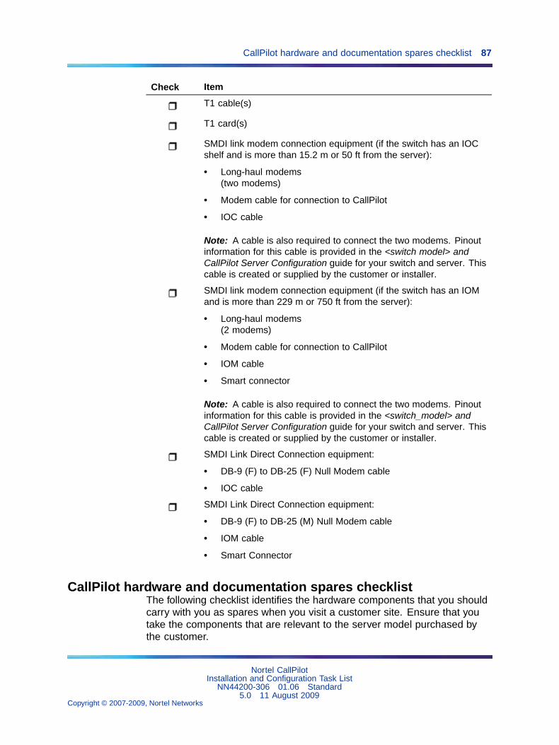
CallPilot hardware and documentation spares checklist 87
Check Item
T1 cable(s)
T1 card(s)
SMDI link modem connection equipment (if the switch has an IOCshelf and is more than 15.2 m or 50 ft from the server):
• Long-haul modems(two modems)
• Modem cable for connection to CallPilot
• IOC cable
Note: A cable is also required to connect the two modems. Pinoutinformation for this cable is provided in the <switch model> andCallPilot Server Configuration guide for your switch and server. Thiscable is created or supplied by the customer or installer.
SMDI link modem connection equipment (if the switch has an IOMand is more than 229 m or 750 ft from the server):
• Long-haul modems(2 modems)
• Modem cable for connection to CallPilot
• IOM cable
• Smart connector
Note: A cable is also required to connect the two modems. Pinoutinformation for this cable is provided in the <switch_model> andCallPilot Server Configuration guide for your switch and server. Thiscable is created or supplied by the customer or installer.
SMDI Link Direct Connection equipment:
• DB-9 (F) to DB-25 (F) Null Modem cable
• IOC cable
SMDI Link Direct Connection equipment:
• DB-9 (F) to DB-25 (M) Null Modem cable
• IOM cable
• Smart Connector
CallPilot hardware and documentation spares checklistThe following checklist identifies the hardware components that you shouldcarry with you as spares when you visit a customer site. Ensure that youtake the components that are relevant to the server model purchased bythe customer.
Nortel CallPilotInstallation and Configuration Task List
NN44200-306 01.06 Standard5.0 11 August 2009
Copyright © 2007-2009, Nortel Networks
.

88 Appendix A Installation preparation checklists
Check Item Quantity
MPB96 board 1
MPC-8 cards (for the 201i server) 4
201i or 202i server hard drive 1
1005r server hard drive 1
600r server hard drive 1
703t server hard drive 1
1002rp server hard drive 1
Network hub 1
Network cable 1
CallPilot image DVD (1005r and 600r) 1
All CallPilot 201i server software CD-ROMs (for acomplete list, see "CallPilot software media anddocumentation checklist" (page 88)).
1 of eachCD-ROM
All CallPilot 202iserver software media ( DVD-ROM)(for a complete list, see "CallPilot software media anddocumentation checklist" (page 88)).
1 DVD
CallPilot software media and documentation checklistThe software media and documentation checklist identifies the softwaremedia and documentation needed to put the CallPilot server into operationin your network. Use the checklist (and the packing list provided with yourorder) to ensure that you have all of the components you need.
Note: Store software media in a safe place. Use the software wheninstructed in the documentation. CallPilot server software is preinstalledat the factory, so you may not be asked to use some of theseCD/DVD-ROMs unless you are performing a recovery, reinstallation,expansion or upgrade.
Check Item
CallPilot Documentation (download from Nortel Technical SupportWeb site)
Nortel CallPilotInstallation and Configuration Task List
NN44200-306 01.06 Standard5.0 11 August 2009
Copyright © 2007-2009, Nortel Networks
.

CallPilot software media and documentation checklist 89
Check Item
The following CallPilot documentation (download from NortelTechnical Support Web site):
• NTPs
• CallPilot Distributor Technical Reference (DTR)
Note: You can obtain other CallPilot documentation from theInstallation and Administration Help area in CallPilot Manager.For more details about the available documents, see "Relatedinformation" (page 16).
CallPilot Image CDs or DVD — contain an image of the CallPilotsoftware.
• 201i server — three CDs
• 202i server — one DVD
• 600r — one DVD
• 703t — three CDs
• 1002rp ELAN — three CDs
• 1002rp T1 — four CDs
• 1005r — one DVD
CallPilot Service Update/PEP (download from Nortel TechnicalSupport Web site http://www.nortel.com/support or EnterpriseSolutions PEP Library http://www.nortel.com/espl).
• Service Updates and PEPs
• Upgrade tools (system sanity, upgrade platform validity, upgradedata validity)
CallPilot Application CD-ROM (contains applications that can bere-installed):
• CallPilot server software
• CallPilot Manager and Reporter on a stand-alone Web server(installed or re-installed)
• CallPilot Application Builder (installed or re-installed)
• pcAnywhere
• Adobe Acrobat Reader
• CallPilot Directory Synchronization (installed or re-installed)
• JavaRunTimeEnv (installed or re-installed)
Nortel CallPilotInstallation and Configuration Task List
NN44200-306 01.06 Standard5.0 11 August 2009
Copyright © 2007-2009, Nortel Networks
.

90 Appendix A Installation preparation checklists
Check Item
CallPilot Unified Messaging CD-ROM
• Desktop Messaging client
• My CallPilot client
CallPilot language prompts CD-ROM set (two CD-ROMs):
• Americas and Asia-Pacific region language prompts
• EMEA ( Europe, Middle East, Africa) region language prompts
Preinstalled softwareThe factory installs the operating system and CallPilot server software andthird-party applications such as pcAnywhere prior to shipping the server.A disk image of this software is also shipped with the system (see thetable in the section "CallPilot software media and documentation checklist"(page 88)).
For version numbers of the software applicable to your installation, see theCallPilot Planning and Engineering Guide (NN44200-200).
The following software is installed at the factory before the server ships:
• the operating system and the components required by CallPilot
• Web browser
• software for the switch-connectivity hardware
• CallPilot server software
• CallPilot Manager (Web-based administration server software)
• RAID software, if RAID is included with the tower or rackmount server
• SQL Anywhere database
• pcAnywhere
• Adobe Acrobat Reader (for online viewing of the CallPilot documentation)
• other equipment manufacturers (OEM) right-to-use (RTU) softwarecertificates
Nortel utilizes OEM software license RTUs, and each RTU is licensedfor each CallPilot application. The manufacturer provides a certificateand serial number with the RTU.
Nortel CallPilotInstallation and Configuration Task List
NN44200-306 01.06 Standard5.0 11 August 2009
Copyright © 2007-2009, Nortel Networks
.

Preinstalled software 91
The OEM license and serial number must be kept with the CallPilotapplication for its entire service life. These RTU serial numbers are requiredfor complete software reinstallation if the disk fails. If the server is replacedor decommissioned, you must return all OEM RTUs to Nortel with theserver hardware.
Nortel recommends that you store all RTU certificates on-site in a secure,dry, accessible place for future access. You can store the RTU certificates inan envelope that is taped to the CallPilot server.
Cautions
CAUTIONRisk of system interruption or malfunctionDo not download and install any security patches from theMicrosoft Web site or antivirus software unless they are approvedfor CallPilot by Nortel. Installation of unapproved security patchesor antivirus software can result in the incorrect operation of yourCallPilot system.
To determine which patches and antivirus software are approvedby Nortel for CallPilot, see the latest issue of the CallPilotDistributor Technical Reference (DTR).
CAUTIONRisk of reduced system performanceDo not activate screen savers on the CallPilot server. Screensavers consume significant CPU resources and, therefore, impactCallPilot response time.
Note: CallPilot operation is not affected when you poweroff the monitor.
Nortel CallPilotInstallation and Configuration Task List
NN44200-306 01.06 Standard5.0 11 August 2009
Copyright © 2007-2009, Nortel Networks
.

92 Appendix A Installation preparation checklists
Nortel CallPilotInstallation and Configuration Task List
NN44200-306 01.06 Standard5.0 11 August 2009
Copyright © 2007-2009, Nortel Networks
.
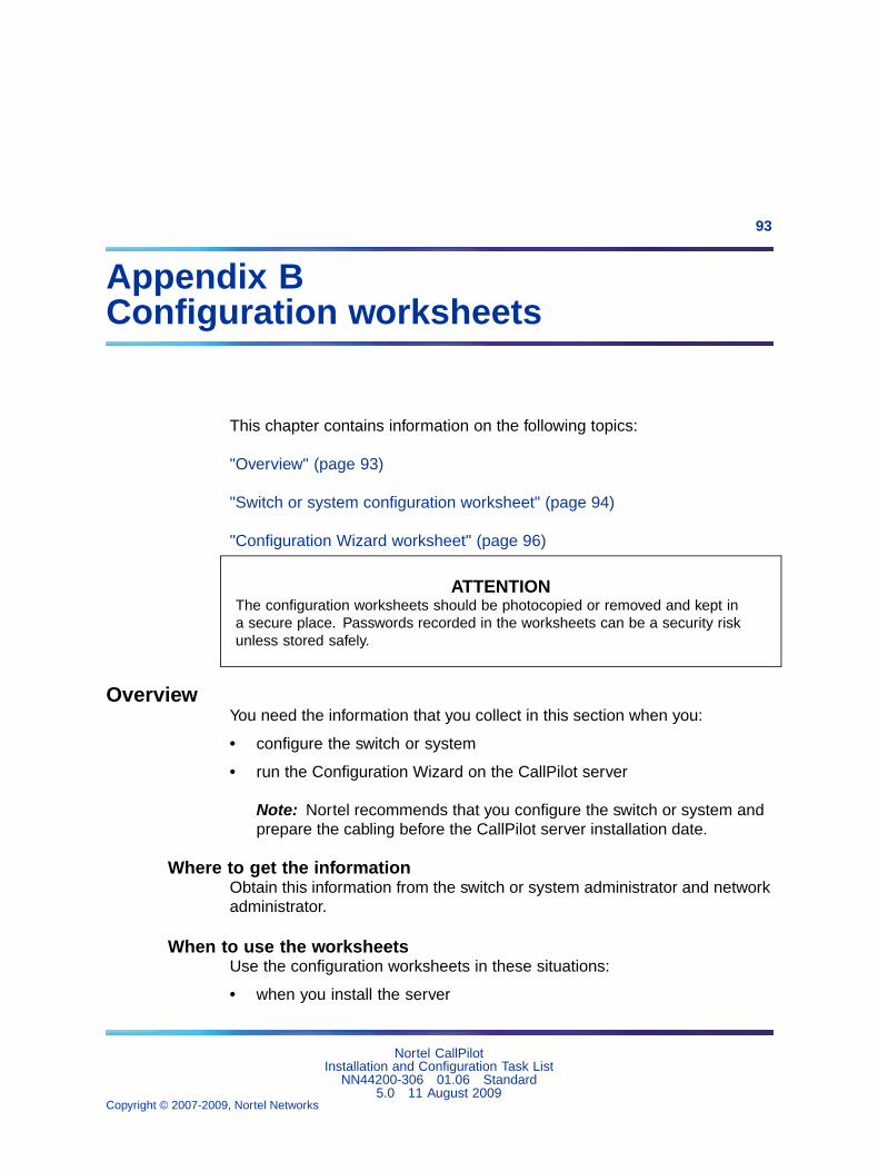
93
Appendix BConfiguration worksheets
This chapter contains information on the following topics:
"Overview" (page 93)
"Switch or system configuration worksheet" (page 94)
"Configuration Wizard worksheet" (page 96)
ATTENTIONThe configuration worksheets should be photocopied or removed and kept ina secure place. Passwords recorded in the worksheets can be a security riskunless stored safely.
OverviewYou need the information that you collect in this section when you:
• configure the switch or system
• run the Configuration Wizard on the CallPilot server
Note: Nortel recommends that you configure the switch or system andprepare the cabling before the CallPilot server installation date.
Where to get the informationObtain this information from the switch or system administrator and networkadministrator.
When to use the worksheetsUse the configuration worksheets in these situations:
• when you install the server
Nortel CallPilotInstallation and Configuration Task List
NN44200-306 01.06 Standard5.0 11 August 2009
Copyright © 2007-2009, Nortel Networks
.

94 Appendix B Configuration worksheets
• each time configuration changes are required as part of an upgrade,migration, or reinstallation
Switch or system configuration worksheetComplete this worksheet as preparation for configuring the switch orsystem. For instructions about how to configure the switch or system, seethe <switch_model> and CallPilot Server Configuration guide for your switchand server.
switch or system type
• Meridian 1
— Option 51C, 61C, 81, 81C
— Option 11 or Option 11C Mini
• CS 1000
See "Meridian 1 or CS 1000 information" (page94).
• SL-100, DMS-100 See "SL-100/DMS-100 switch information" (page95).
Meridian 1 or CS 1000 informationComplete this section if your CallPilot server is connected to a Meridian 1or CS 1000 system.
Customer number: _______________________________
Ethernet information (Overlay 117)
Primary IP address (ELAN): ______ . ______ . ______ . ______
Secondary IP address (ELAN): ______ . ______ . ______ . ______
Note: A secondary IP address for the ELAN subnet is required for large Meridian 1 systems (suchas Option 51C).
Subnet mask (ELAN): ______ . ______ . ______ . ______
Default IP gateway: ______ . ______ . ______ . ______
Note: The default IP gateway is required only if the Meridian 1 or CS 1000 system is also connectedto the NNS Subnet (CLAN).
ACD queue and agents (Overlays 11 and 23)
ACD DN of CallPilot agents (Overlay 23): _______________________________
Agent TNs (Overlay 11): _______________________________
Position ID on Key0: _______________________________
SCN on Key1: _______________________________
Default ACD DN for CDN (Overlay 23): _______________________________
Nortel CallPilotInstallation and Configuration Task List
NN44200-306 01.06 Standard5.0 11 August 2009
Copyright © 2007-2009, Nortel Networks
.

Switch or system configuration worksheet 95
CDN queues (Overlay 23)
Primary CDN (Voice Messaging): _______________________________
Secondary CDN (Multimedia Messaging): _______________________________
Phantom DNs, if used instead of dummy ACD DNs (Overlays 10 and 97)
CallPilot application name: _______________________________
Superloop (Overlay 97): _______________________________
Phantom DN (Overlay 10): _______________________________
DCFW CDN: _______________________________
CallPilot application name: _______________________________
Superloop (Overlay 97): _______________________________
Phantom DN (Overlay 10): _______________________________
Phantom DNs, if used instead of dummy ACD DNs (Overlays 10 and 97) (continued)
DCFW CDN: _______________________________
CallPilot application name: _______________________________
Superloop (Overlay 97): _______________________________
Phantom DN (Overlay 10): _______________________________
DCFW CDN: _______________________________
Dummy ACD DNs, if used instead of phantom DNs (Overlay 23)
CallPilot application name: _______________________________
ACD DN: _______________________________
NCFW CDN: _______________________________
CallPilot application name: _______________________________
ACD DN: _______________________________
NCFW CDN: _______________________________
CallPilot application name: _______________________________
ACD DN: _______________________________
NCFW CDN: _______________________________
SL-100/DMS-100 switch informationComplete this section only if your CallPilot server is connected to an SL-100or DMS-100 switch.
Nortel CallPilotInstallation and Configuration Task List
NN44200-306 01.06 Standard5.0 11 August 2009
Copyright © 2007-2009, Nortel Networks
.

96 Appendix B Configuration worksheets
UCD DN for voice messaging: _______________________________
UCD DN for multimedia messaging (ifpurchased):
_______________________________
UCD DN for speech recognition (if purchased): _______________________________
Channel configuration
UCD DN: _______________________________
DN of agent: _______________________________
Message Desk Number: _______________________________
Terminal Number: _______________________________
Login Code: _______________________________
Logout Code: _______________________________
Service DN: _______________________________
Associated application: _______________________________
SMDI Link
Port Name (Default: COM 2): _______________________________
Port Use type (Default: MM Access): _______________________________
Baud Rate (Recommended default: 9600): _______________________________
Parity: _______________________________
Number of Data Bits (Default: 7): _______________________________
Number of Stop Bits (Default: 1): _______________________________
Flow Control (Default: None): _______________________________
Configuration Wizard worksheetComplete the following worksheet as preparation for configuring the CallPilotserver. For more information about the information on this worksheet,and the instructions about how to configure the CallPilot server, see the<switch_model> and CallPilot Server Configuration guide for your switchand server.
Worksheet sectionsThe Configuration Wizard worksheet contains the following sections:
• "CallPilot information" (page 97)
• "Operating system password" (page 97)
• "pcAnywhere password" (page 97)
• "Multimedia allocation" (page 98)
Nortel CallPilotInstallation and Configuration Task List
NN44200-306 01.06 Standard5.0 11 August 2009
Copyright © 2007-2009, Nortel Networks
.

Configuration Wizard worksheet 97
• "Application DN information" (page 98)
• "Languages" (page 98)
• "CallPilot network information" (page 99)
• "Customer LAN access information" (page 99)
• "Meridian 1 or CS 1000 information" (page 100)
• "T1/SMDI information" (page 101)
CallPilot information
Company name: _______________________________
Customer name: _______________________________
Serial number:Obtain the serial number from the CallPilotkeycode label.
Keycode:Obtain the keycode from the CallPilot keycodelabel.
Computer name: _______________________________
Time zone: _______________________________
Country code (for the server location): _______________________________
Area code (for the server location): _______________________________
Operating system passwordCallPilot uses strong passwords to increase security on the operatingsystem accounts. Strong passwords are enabled by default. When loggingon to an account or running the Configuration Wizard for the first time, youmust change the password. For more information about strong passwords,see the CallPilot Fundamentals Guide (NN44200-100).
ATTENTIONFor security reasons, do not write the passwords in this guide. Photocopy thepage to record the new passwords. Store the page in a secure place.
Password type Current Password New Password
Account Name default: Bvw250
pcAnywhere password
Password type New Password
Account Name
Nortel CallPilotInstallation and Configuration Task List
NN44200-306 01.06 Standard5.0 11 August 2009
Copyright © 2007-2009, Nortel Networks
.

98 Appendix B Configuration worksheets
For more information about changing the pcAnywhere password see:
• Step 4, Change the CallPilotDist password for pcAnywhere
• The <switch_model> and CallPilot Server Configuration guide for yourswitch and server
Multimedia allocation
DSP Encoding: • A-law (Europe or Caribbean)
• Mu-law (North America)
Application DN information
Voice Messaging (Primary CDN): _______________________________
Multimedia Messaging (Secondary CDN): _______________________________
Speech Activated Messaging: _______________________________
Express Voice Messaging: _______________________________
Voice Item Maintenance: _______________________________
Enterprise Networking: _______________________________
AMIS Networking: _______________________________
Fax Item Maintenance: _______________________________
Express Fax Messaging: _______________________________
Paced Speech Activated Messaging: _______________________________
Custom Commands: _______________________________
Interactive Voice Response: _______________________________
AUI CallPilot Menu Interface: _______________________________
AUI CallPilot Alternative Command Interface: _______________________________
Languages
Record the languages you need:
Primary prompt language: _______________________________
Secondary prompt language: _______________________________
Nortel CallPilotInstallation and Configuration Task List
NN44200-306 01.06 Standard5.0 11 August 2009
Copyright © 2007-2009, Nortel Networks
.

Configuration Wizard worksheet 99
Other languages: _______________________________
_______________________________
_______________________________
_______________________________
Automated Speech Recognition languages: _______________________________
_______________________________
_______________________________
CallPilot network information
Embedded LAN TCP/IP Information (Meridian1 and CS 1000 only)
MAC address of ELAN network card on theCallPilot server (tower or rackmount serversonly):
_______________________________
CallPilot server ELAN IP address: ______ . ______ . ______ . ______
Subnet mask: ______ . ______ . ______ . ______
Customer LAN TCP/IP information
MAC address of NNS Subnet (CLAN) networkcard on the CallPilot server (tower or rackmountservers):
_______________________________
CallPilot server CLAN IP address: ______ . ______ . ______ . ______
Subnet mask: ______ . ______ . ______ . ______
Gateway: ______ . ______ . ______ . ______
Customer LAN access informationThe following information is not requested by the Configuration Wizard.However, you may need it if you connect to the CallPilot server with a PCon the Nortel Server Subnet (NS Subnet), also known as the customerLAN (CLAN).
Obtain the following from the network administrator:
Network user name: _______________________________
Nortel CallPilotInstallation and Configuration Task List
NN44200-306 01.06 Standard5.0 11 August 2009
Copyright © 2007-2009, Nortel Networks
.

100 Appendix B Configuration worksheets
Domain name: _______________________________
Password: _______________________________
Meridian 1 or CS 1000 informationComplete this section if your CallPilot server is connected to a Meridian 1or CS 1000 system.
Switch information
Switch IP address: ______ . ______ . ______ . ______
Switch type:
• Meridian 1
• Option 11 or Option 11C Mini
• CS 1000
Switch customer number: _______________________________
Contact Center CLAN IP Address: ______ . ______ . ______ . ______
Contact Center voice application Class ID: _______________________________
Note: The Contact Center CLAN IP address and voice application class ID are required if you usethe Contact Center Voice Services Support feature.
TN information
Note: Copy the relevant information from the "Switch or system configuration worksheet" (page 94).
Number of TNs: _______________________________
Dedicated to: • ACCESS ACD queue
• IVR* ACD queue
Note: Check one of these options if this group of TNs is dedicated to the Contact Center VoiceServices Support feature.
Start TN: _______________________________
Start TN Key 0 (Position ID): _______________________________
Start TN Key 1 (SCN): _______________________________
TN information (complete this section if another TN group is required)
Note: Copy the relevant information from the "Switch or system configuration worksheet" (page 94).
Number of TNs: _______________________________
Dedicated to:• ACCESS ACD queue
• IVR ACD queue
Note: Check one of these options if this group of TNs is dedicated to the Contact Center VoiceServices Support feature.
Start TN: _______________________________
Nortel CallPilotInstallation and Configuration Task List
NN44200-306 01.06 Standard5.0 11 August 2009
Copyright © 2007-2009, Nortel Networks
.

Configuration Wizard worksheet 101
Start TN Key 0 (Position ID): _______________________________
Start TN Key 1 (SCN): _______________________________
TN information (complete this section if another TN group is required)
Note: Copy the relevant information from the "Switch or system configuration worksheet" (page 94).
Number of TNs: _______________________________
Dedicated to:• ACCESS ACD queue
• IVR ACD queue
Note: Check one of these options if this group of TNs is dedicated to the Contact Center VoiceServices Support feature.
Start TN: _______________________________
Start TN Key 0 (Position ID): _______________________________
Start TN Key 1 (SCN): _______________________________
T1/SMDI informationComplete this section if your CallPilot server is connected to a T1/SMDIswitch or system (for example, DMS-100/SL-100).
Switch information
SMDI Transport Data Settings
Poll Timeout (Default: 10 000 ms): _______________________________
Poll Timeout Threshold (Default: 5): _______________________________
Poll DN (Default: 0): _______________________________
MWI Padding (Default: blank): _______________________________
COM Port Settings
Port Name COM 2
Port Use type (Default: MM Access): _______________________________
Baud Rate (Default: 9600): _______________________________
Parity (Default: Even): _______________________________
Number of Data Bits (Default: 7): _______________________________
Number of Stop Bits (Default: 1): _______________________________
Flow Control (Default: None): _______________________________
T1 Board Properties
Line Interface Type (Default: Ground Start): _______________________________
Frame Format: Only D4 is supported.
Note: Debounce value and Hook Flash Time units indicate 10x ms. Example: 13 indicates 130 ms.
Nortel CallPilotInstallation and Configuration Task List
NN44200-306 01.06 Standard5.0 11 August 2009
Copyright © 2007-2009, Nortel Networks
.

102 Appendix B Configuration worksheets
Coding Format: Only B8ZS is supported.
(T1) Cable Length (Default: None): _______________________________
Debounce Value (Default: 13): _______________________________
Hook Flash Time (Default: 50): _______________________________
Note: Debounce value and Hook Flash Time units indicate 10x ms. Example: 13 indicates 130 ms.
Channel Detail Information
UCD group for Voice channels, if Voice channels are purchased
Number of Channels (in this UCD group): _______________________________
Agent DN (starting): _______________________________
Hunt Group DN (UCD DN): _______________________________
Message Desk Number: _______________________________
Message Terminal Number (starting): _______________________________
Login Code: _______________________________
Logout Code: _______________________________
UCD group for Fax channels, if Fax channels are purchased
Number of Channels (in this UCD group): _______________________________
Agent DN (starting): _______________________________
Hunt Group DN (UCD DN): _______________________________
Message Desk Number: _______________________________
Message Terminal Number (starting): _______________________________
Login Code: _______________________________
Logout Code: _______________________________
UCD group for Speech Recognition channels, if Speech Recognition channels are purchased
Number of Channels (in this UCD group): _______________________________
Agent DN (starting): _______________________________
Hunt Group DN (UCD DN): _______________________________
Message Desk Number: _______________________________
Message Terminal Number (starting): _______________________________
Login Code: _______________________________
Logout Code: _______________________________
Nortel CallPilotInstallation and Configuration Task List
NN44200-306 01.06 Standard5.0 11 August 2009
Copyright © 2007-2009, Nortel Networks
.


Nortel CallPilot
Installation and Configuration Task ListCopyright © 2007-2009, Nortel NetworksAll Rights Reserved.
Publication: NN44200-306Document status: StandardDocument version: 01.06Document date: 11 August 2009
To provide feedback or to report a problem in this document, go to http://www.nortel.com/documentfeedback.
Sourced in Canada
While the information in this document is believed to be accurate and reliable, except as otherwise expressly agreed to in writingNORTEL PROVIDES THIS DOCUMENT "AS IS" WITHOUT WARRANTY OR CONDITION OF ANY KIND, EITHER EXPRESS ORIMPLIED. The information and/or products described in this document are subject to change without notice.
Nortel, Nortel Networks, the Nortel logo, and the Globemark are trademarks of Nortel Networks.
All other trademarks are the property of their respective owners.