Autonomous Control of a Quadcopter via Fuzzy Gain Scheduled PD Control
6
Autonomous Control of a Quadcopter via Fuzzy Gain Scheduled PD Control Saad Sardar Electrical and Power Engineering Department Pakistan Navy Engineering College, NUST, Karachi, Pakistan [email protected] Muhammad Bilal Kadri Electrical and Power Engineering Department Pakistan Navy Engineering College, NUST, Karachi, Pakistan [email protected] Abstract— This paper discusses the Intelligent Gain Scheduled PD technique to autonomously control the attitude of the Quad Copter. This paper would focus on two aspects of the autonomous quad-copter i.e. Attitude Control and Trajectory Following. The autonomous control of a quad-copter is a challenge due to its non-linear dynamics and environmental perturbations. The aim of the investigation is to study a Fuzzy Takagi-Sugeno method used to control the position and the yaw angle of the quad-copter and to compare the simulated results with the conventional PD Controller. Index Terms—Quadcopter, PD, fuzzy, gain-scheduling, Takagi-Sugeno I. INTRODUCTION The autonomous control of a quad-copter is a challenge due to its non-linear dynamics and environmental perturbations. The environmental perturbations can easily tip off the stability of the quad-copter since it has coupled EOM (Equations of Motion) which makes it easier for a disturbance to mitigate the effects of one of the rotors to other three. The non-linear dynamics of the quad-copter aggressively diminishes the performance of PD furthermore the spontaneous switching of the rotors can burn their motors. The aim of the investigation is to study about the different methods used to control the position and the yaw angle of the quad-copter. This investigation will be carried out using a complete Non-Linear Simulink model. We will discuss two control techniques i.e. (i) Gain Scheduled PD, (ii) Fuzzy Supervisory Gain Offset Mechanism/Capability to re-tune its parameters with the changing surroundings. Adaptive Gain-Scheduled control is a combination of classical and modern control approaches. This technique keeps the onboard computational requirements very low while the adaptation process regularly update the gains to counter perturbations thus increasing the robustness of the overall system. A. Literature Review • Adaptive Hybrid Control Algorithm Design for Attitude Stabilization of Quadrotor (UAV) This paper presents a new adaptive hybrid Fuzzy Logic based PID (FPID) Control algorithm for attitude stabilization of Quadrotor Unmanned Aerial Vehicle (UAV). Usually UAV systems are unstable and attitude stabilization control plays a very important role in it. The proposed algorithm for attitude controlling of UAV uses Fuzzy controller to online update the parameters of PID controller i.e. Kp, Ki and Kd that being used to control the attitude stabilization of quadrotor UAV. This approach acclimatizes the conventional PID Controller to a dynamic PID Controller. This new adaptive hybrid algorithm was simulated on MATLAB and compared with convention PID controller. Simulation results proves that proposed adaptive hybrid Fuzzy Logic based PID (FPID) controller give better results in the term of response time and settling time in quardroto UAV application as compare to convention PID controller. [1] • Control of a quadcopter using Self-Tuning Fuzzy PID Controller In this paper the modelling, simulation-based controller design and path planning of a quadrotor is discussed. An EKF based self-tuning Fuzzy PID control is proposed for the attitude control.to reduce the computational time a Dijkstra’s algorithm is used for path planning in a closed and known environment lled with obstacles and/or boundaries. The Dijkstra algorithm helps avoid obstacle and nd the shortest route from a given initial position to the nal position. [2] 12th International Conference on Frontiers of Information Technology 978-1-4799-7505-1/14 $31.00 © 2014 IEEE DOI 10.1109/FIT.2014.23 73 12th International Conference on Frontiers of Information Technology 978-1-4799-7505-1/14 $31.00 © 2014 IEEE DOI 10.1109/FIT.2014.23 73
Transcript of Autonomous Control of a Quadcopter via Fuzzy Gain Scheduled PD Control
Autonomous Control of a Quadcopter via Fuzzy Gain Scheduled PD Control
Saad Sardar Electrical and Power Engineering Department Pakistan Navy Engineering College, NUST,
Karachi, Pakistan [email protected]
Muhammad Bilal Kadri Electrical and Power Engineering Department Pakistan Navy Engineering College, NUST,
Karachi, Pakistan [email protected]
Abstract— This paper discusses the Intelligent Gain
Scheduled PD technique to autonomously control the attitude of the Quad Copter. This paper would focus on two aspects of the autonomous quad-copter i.e. Attitude Control and Trajectory Following. The autonomous control of a quad-copter is a challenge due to its non-linear dynamics and environmental perturbations. The aim of the investigation is to study a Fuzzy Takagi-Sugeno method used to control the position and the yaw angle of the quad-copter and to compare the simulated results with the conventional PD Controller.
Index Terms—Quadcopter, PD, fuzzy, gain-scheduling, Takagi-Sugeno
I. INTRODUCTION The autonomous control of a quad-copter is a challenge due to its non-linear dynamics and environmental perturbations. The environmental perturbations can easily tip off the stability of the quad-copter since it has coupled EOM (Equations of Motion) which makes it easier for a disturbance to mitigate the effects of one of the rotors to other three. The non-linear dynamics of the quad-copter aggressively diminishes the performance of PD furthermore the spontaneous switching of the rotors can burn their motors. The aim of the investigation is to study about the different methods used to control the position and the yaw angle of the quad-copter. This investigation will be carried out using a complete Non-Linear Simulink model. We will discuss two control techniques i.e. (i) Gain Scheduled PD, (ii) Fuzzy Supervisory Gain Offset Mechanism/Capability
to re-tune its parameters with the changing surroundings.
Adaptive Gain-Scheduled control is a combination of classical and modern control approaches. This technique keeps the onboard computational requirements very low while the
adaptation process regularly update the gains to counter perturbations thus increasing the robustness of the overall system.
A. Literature Review • Adaptive Hybrid Control Algorithm Design for Attitude
Stabilization of Quadrotor (UAV) This paper presents a new adaptive hybrid Fuzzy Logic based PID (FPID) Control algorithm for attitude stabilization of Quadrotor Unmanned Aerial Vehicle (UAV). Usually UAV systems are unstable and attitude stabilization control plays a very important role in it. The proposed algorithm for attitude controlling of UAV uses Fuzzy controller to online update the parameters of PID controller i.e. Kp, Ki and Kd that being used to control the attitude stabilization of quadrotor UAV. This approach acclimatizes the conventional PID Controller to a dynamic PID Controller. This new adaptive hybrid algorithm was simulated on MATLAB and compared with convention PID controller. Simulation results proves that proposed adaptive hybrid Fuzzy Logic based PID (FPID) controller give better results in the term of response time and settling time in quardroto UAV application as compare to convention PID controller. [1] • Control of a quadcopter using Self-Tuning Fuzzy PID
Controller
In this paper the modelling, simulation-based controller design and path planning of a quadrotor is discussed. An EKF based self-tuning Fuzzy PID control is proposed for the attitude control.to reduce the computational time a Dijkstra’s algorithm is used for path planning in a closed and known environment �lled with obstacles and/or boundaries. The Dijkstra algorithm helps avoid obstacle and �nd the shortest route from a given initial position to the �nal position. [2]
12th International Conference on Frontiers of Information Technology
978-1-4799-7505-1/14 $31.00 © 2014 IEEE
DOI 10.1109/FIT.2014.23
73
12th International Conference on Frontiers of Information Technology
978-1-4799-7505-1/14 $31.00 © 2014 IEEE
DOI 10.1109/FIT.2014.23
73
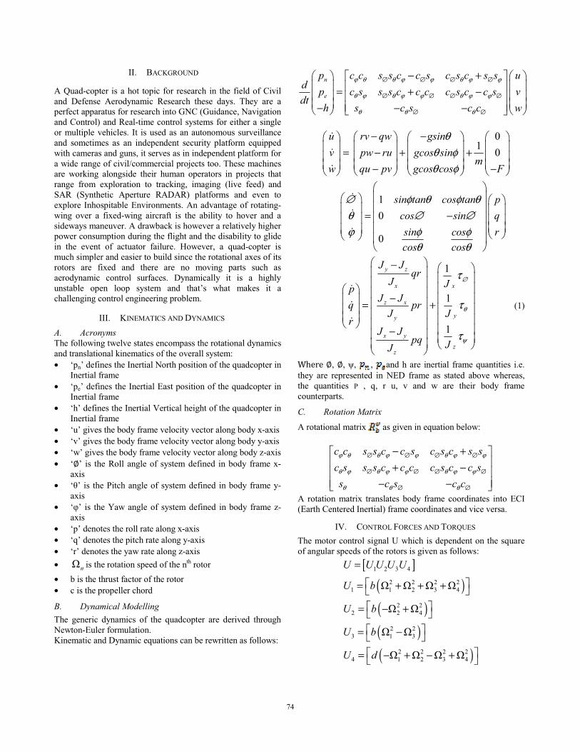
II. BACKGROUND
A Quad-copter is a hot topic for research in the field of Civil and Defense Aerodynamic Research these days. They are a perfect apparatus for research into GNC (Guidance, Navigation and Control) and Real-time control systems for either a single or multiple vehicles. It is used as an autonomous surveillance and sometimes as an independent security platform equipped with cameras and guns, it serves as in independent platform for a wide range of civil/commercial projects too. These machines are working alongside their human operators in projects that range from exploration to tracking, imaging (live feed) and SAR (Synthetic Aperture RADAR) platforms and even to explore Inhospitable Environments. An advantage of rotating-wing over a fixed-wing aircraft is the ability to hover and a sideways maneuver. A drawback is however a relatively higher power consumption during the flight and the disability to glide in the event of actuator failure. However, a quad-copter is much simpler and easier to build since the rotational axes of its rotors are fixed and there are no moving parts such as aerodynamic control surfaces. Dynamically it is a highly unstable open loop system and that’s what makes it a challenging control engineering problem.
III. KINEMATICS AND DYNAMICS
A. Acronyms The following twelve states encompass the rotational dynamics and translational kinematics of the overall system: • ‘pn’ defines the Inertial North position of the quadcopter in
Inertial frame • ‘pe’ defines the Inertial East position of the quadcopter in
Inertial frame • ‘h’ defines the Inertial Vertical height of the quadcopter in
Inertial frame • ‘u’ gives the body frame velocity vector along body x-axis • ‘v’ gives the body frame velocity vector along body y-axis • ‘w’ gives the body frame velocity vector along body z-axis • ‘�’ is the Roll angle of system defined in body frame x-
axis • ‘�’ is the Pitch angle of system defined in body frame y-
axis • ‘�’ is the Yaw angle of system defined in body frame z-
axis • ‘p’ denotes the roll rate along x-axis • ‘q’ denotes the pitch rate along y-axis • ‘r’ denotes the yaw rate along z-axis • �n is the rotation speed of the nth rotor • b is the thrust factor of the rotor • c is the propeller chord
B. Dynamical Modelling The generic dynamics of the quadcopter are derived through Newton-Euler formulation. Kinematic and Dynamic equations can be rewritten as follows:
n
e
p c c s s c c s c s c s s ud p c s s s c c c c s c c s vdt
h s c s c c w
ϕ θ θ ϕ ϕ θ ϕ ϕ
θ ϕ θ ϕ ϕ θ ϕ ϕ
θ θ θ
∅ ∅ ∅ ∅
∅ ∅ ∅ ∅
∅ ∅
− +� � � �� � � �= + −� � � �� � � �− − −
� �� � � � � �
01 0
u rv qw gsinv pw ru gcos sin
mw qu pv gcos cos F
θθ φθ φ
− −� � � � � � � �� � � � � � � �= − + +� � � � � � � �� � � � � � � �− − � � � �
���
10
0
sin tan cos tan pcos sin qsin cos rcos cos
∅ φ θ φ θθ ∅ ∅ϕ φ φ
θ θ
� �� �� � � �� �� � � �= −� �� � � �
� �� �� � � � � � �
��
�
1
1
1
y z
x x
z x
yy
x y
zz
J Jqr
J JpJ Jq pr
J Jr
J Jpq JJ
∅
θ
ψ
τ
τ
τ
� �− � �� � � �� � � �� � � �− � �� � � �= + � �� � � �� � � � � � � � �−� � � �� � � �
���
(1)
�������, �, �, , and h are inertial frame quantities i.e. they are represented in NED frame as stated above whereas, the quantities P , q, r u, v and w are their body frame counterparts.
C. Rotation Matrix
A rotational matrix as given in equation below:
c c s s c c s c s c s sc s s s c c c c s c c ss c s c c
ϕ θ θ ϕ ϕ θ ϕ ϕ
θ ϕ θ ϕ ϕ θ ϕ ϕ
θ θ θ
∅ ∅ ∅ ∅
∅ ∅ ∅ ∅
∅ ∅
− +� �� + −� � − − �
A rotation matrix translates body frame coordinates into ECI (Earth Centered Inertial) frame coordinates and vice versa.
IV. CONTROL FORCES AND TORQUES The motor control signal U which is dependent on the square of angular speeds of the rotors is given as follows:
[ ]( )( )( )( )
1 2 3 4
2 2 2 21 1 2 3 4
2 22 2 4
2 23 1 3
2 2 2 24 1 2 3 4
� � � �
� �
� �
� � � �
U U U U U
U b
U b
U b
U d
=
� �= + + + �� �= − + �� �= − �� �= − + − + �
7474

Where U1 is the Altitude Control command, U2 is the Rolling command, U3 is Pitching command and U4 is the Yawing command.
A. Rotor Dynamics Actuators are four fixed-pitch rotors; each one includes a Brush-Less Direct Current (BLDC) motor, a one-stage gearbox and a propeller. A first-order transfer function is sufficient to reproduce the dynamics between the propeller’s speed set-point and its true speed.
( ) 0.936 0.178 1
G ss
=+
(2)
The dynamic model (1) presented above contains two gyroscopic effects. The influence of these effects in our case is less important than the motor’s action;
Figure 1 Block Diagram of PD Quadrotor Control
¨
2
¨
3
¨
4
xx
yy
xx
I lU
I lU
I U
θ
ψ
∅ =
=
=
(3)
especially if we consider a near-hover situation. In order to make it possible to design multiple PD controllers for this system, one can neglect these gyroscopic effects and thus remove the cross coupling. If we include in (2), the rotor dynamics and rewrite the model in Laplace domain we obtain:
( ) ( ) ( ) ( )( )
( ) ( ) ( ) ( )( )
( ) ( ) ( ) ( )
22 24 22 2
22 23 12 2
2 41 2
22 21
( 1
xx
yy
i
izz
B bls u s u ss s A I
B bls u s u ss s A I
B ds u ss s A I
θ
ψ +
=
∅ = −+
= −+
= −+ �
(4)
where A and B are the coefficients of the linearized rotor dynamics, while C, too small comparing to B, is neglected. By using the control inputs Ui instead of the motor inputs ui, above equation becomes:
( ) ( )2
22 2 (
xx
A ls Us s A I
∅ =+
( ) ( ) ( )
( ) ( ) ( )
2
32 2
2
42 2
y y
z z
A ls Us s A I
As Us s A I
θ
ψ
=+
=+
(5)
The numerical application gives:
( ) ( )
( ) ( )
( ) ( )
24 3 2
34 3 2
44 3 2
0.522 0.004 0.039 0.009
0.522 0.004 0.039 0.009
21.78 0.008 0.077 0.18
s Us s s
s Us s s
s Us s s
θ
ψ
∅ =+ +
=+ +
=+ +
(6)
B. PD control A PD controller is introduced for each orientation angle:
( ) ( )2,3,4 , , , ,, , , ,U k dθ ψ θ ψθ ψ θ ψ∅ ∅= ∅ + ∅ (7) Several simulations were performed on Simulink using the complete model in order to tune the six control parameters. The controller’s task was to stabilize the orientation angles. For these simulations, the Dynamic model (1) was used, obtaining the results shown in Fig 1. The simulated performance was satisfactory regarding the simple control synthesis approach.
V. FUZZY ADAPTIVE CONTROL
A. Generalized Fuzzy Control Scheme Fuzzy control technique is comparatively new in which input variables are mapped onto membership function this process is called fuzzification and the membership values quantify the implication degree of a rule from rule base. On the basis of rule base a conclusion is made using inference mechanism in the end defuzzification converts membership values into crisp output. Generalized fuzzy control system is given as follows:
Figure 2 Generic Fuzzy Control Scheme
B. Fuzzy Gain Scheduled PD Control The transfer function of a conventional PD controller is:
( ) dp
KG s Ks
= + (8)
7575
where Kp and Kd are the proportional and derivative gains, respectively. A Takagi-Sugeno (TS) type Fuzzy Logic Controller (FLC) tunes the PD gains online where the tracking error ‘e’ and the change of the tracking error ‘edot’ are used to determine control parameters. Linear transformation gives the modified controller gains as follows [5]:
( )( )
', , ,
, , ,
d d max d min d minK K K K K= − +
= − +'p p max p min p p minK K K K K
(9)
with [ ; ] and [ ; ] are pre-determined ranges of Kp, and Kd respectively.[4]
C. Takagi-Sugeno Type Fuzzy Inference The type of Fuzzy Controllers used in this research is are based on Takagi-Sugeno (TS) type fuzzy inference mechanism. A typical rule in a Sugeno fuzzy model has the form:
If Input 1 = x and Input 2 = y, then Output is z = ax + by + c Instead of a membership function at the output (as in Mamdani) there is a linear equation or a singleton. [12] This gives an edge over a resource hungry Mamdani fuzzy inference mechanism since there are no output membership function so there is a less memory requirement and thus the control activity is much limited yet very precise. A set of linguistic rules used in the FLC structure determine
and The If-Else set of linguistic rules are derived from expert knowledge essentially on the basis of Open loop manual control. Rule statements comprise of an Antecedent and Consequence as following example demonstrates: [5]
Figure 2 Block Diagram of Fuzzy PD Controller
i. IF IS NEGATIVE BIG (N.B)AND IS NEGATIVE BIG (N.B) THAN
conμ IS POSITIVE BIG (N.B).
ii. IF IS NEGATIVE SMALL (N.S) AND IS NEGATIVE BIG (N.B)
THAN conμ IS POSITIVE BIG (N.B); AND SO ON.
\ NB NM NS Z PS PM PL
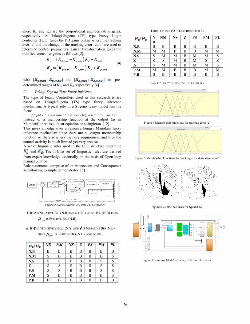
N.B B B B B B B B N.M S B B B B B S N.S S S B B B S S Z S S S B S S S P.S S S B B B S S P.M S B B B B B S P.B B B B B B B B
TABLE 1 FUZZY PD IF-ELSE RULES FOR KP
\ NB
NM NS Z PS PM PL
N.B B B B B B B B N.M M M B B B M M N.S S M M B M M S Z Z S M B M S Z .S S M M B M M S P.M M M B B B M M P.B B B B B B B B
TABLE 2 FUZZY PD IF-ELSE RULES FOR KD
Figure 4 Membership Functions for tracking error ‘e’
Figure 5 Membership Functions for tracking error derivative ‘edot’
Figure 6 Control Surfaces for Kp and Kd
Figure 7 Simulink Model of Fuzzy PD Control Scheme
7676

Figure 8 Fuzzy Adaptive Control Strategy
VI. SIMULATIONS
In Simulink Matlab, a complete Non-Linear 6-DoF Coupled model of Quadcopter was implemented and subjected to the tests with both PD and Fuzzy GS PD Controllers. Real-Time simulation was performed using Matlab Simulink. During the design of PD control scheme it was made sure that all the stated were observable since PD would only work if all states are available at the Output. Following quadcopter constants were assumed for the simulations. The trajectory generation block simulates vertical takeoff/landing, hover and moving to a desired 3 dimensional space. At the end of each maneuver a quadcopter’s attitude angles should settle to zero i.e. hover at a point as seen in the figures 10 and 13. It is seen in the Simulink model [figure 8] the model that converts control constants [Uroll,Upitch,Uyaw] to motor control signals [U1,U2,U3,U4] also known as ESC (Electronic Speed Converter) that generates a corresponding PWM signal for Motor speed control [3].
S.no Parameter Value Unit 1 Gravitational acceleration (g) 9.8 m/s2 2 Mass of Quadcopter (m) 1 Kg 3 Length of wings ( ) 0.24 M
4 Rotational Inertia along x-axis
8.1 x 10⁻³ Kg.m2
5 Rotational Inertia along y-axis
8.1 x 10⁻³ Kg.m2
6 Rotational Inertia along z-axis
14.2 x 10⁻³ Kg.m2
7 Residual Rotational Inertia
104 x 106 Kg.m2
8 Initial Roll, Pitch and Yaw Angles
[0.8;0.8;0.8] degrees
9 Motor constant 6.2 x 10⁻³ -
10 Motor constant 6.2 x 10⁻³ -
11 Drag Factor 1.1 x 10⁻⁶ -
TABLE 3 QUADCOPTER PHYSICAL/SIMULATED CONSTANT
A. Simulation with Simple PD control strategy Initial conditions for all state variables are set to zero. Measurement Noise block is inducing sensor noise in the system to make simulations more realistic. PD control parameters are presented in below table. [4]
Simulation results are obtained for period of 100 sec. It is clearly observed in figure 9 there is a considerable steady state error and the quadcopter is constantly trying to adjust its attitude to make adjustments for the wind flowing over its propellers which due to fixed PD gains can’t change or vary according to changing speed of wind and the quadcopter could smoothly fly even in simulated gusty environment.
Variable Parameter Value
Ki,p Ki,d Ki,i
x 5 10 -
y 5 10 -
z 5 10 -
10 20 -
10 20 -
10 20 -
Motor 1 - 10
TABLE 4 PD GAINS
B. Simulation with Self Tuning Fuzzy PD control strategy Almost everything is similar except Fuzzy GS PD controller block. Furthermore, same scaling is ensured for the same type of results with different control scheme where possible. Simulation results are obtained for period of 100 sec.
VII. SIMULATIONS
In Simulink Matlab, a complete Non-Linear 6-DoF Coupled model of Quadcopter was implemented and subjected to the tests with both PD and Fuzzy GS PD Controllers. Real-Time simulation was performed using Matlab Simulink. During the design of PD control scheme it was made sure that all the stated were observable since PD would only work if all states are available at the Output. Following quadcopter constants were assumed for the simulations. The trajectory generation block simulates vertical takeoff/landing, hover and moving to a desired 3 dimensional space. At the end of each maneuver a quadcopter’s attitude angles should settle to zero i.e. hover at a point as seen in the figures 10 and 13. It is seen in the Simulink model [figure 8] the model that converts control constants [Uroll,Upitch,Uyaw] to motor control signals [U1,U2,U3,U4] also known as ESC (Electronic Speed Converter) that generates a corresponding PWM signal for Motor speed control [3]. It is clear from figures 10-11 that steady state error has been reduced to negligible/bearable threshold.
0 20 40 60 80 100−0.3
−0.2
−0.1
0
0.1
0.2
0.3
0.4
0.5
0.6Attitude Angles
Time [sec]
RPY [
degre
es]
RollPitchYaw
Figure 8a Attitude Angles PD Controller
7777

0 10 20 30 40 50 60 70 80 90 100−0.8
−0.6
−0.4
−0.2
0
0.2
0.4
0.6
Time [sec]
Attitud
e Ang
le Erro
r [deg
rees]
Attitude Angle Error
Figure 8b Attitude Angles’ error with PD Controller
0 0.5 1 1.5 2 2.55
0
5
10
15
20
25
Figure 9 Trajectory Following with PD Controller
0 10 20 30 40 50 60 70 80 90 100−0.8
−0.6
−0.4
−0.2
0
0.2
0.4
0.6
Time [sec]
Attitud
e Ang
le Erro
r [deg
rees]
Attitude Angle Error
0 10 20 30 40 50 60 70 80 90 100−0.3
−0.2
−0.1
0
0.1
0.2
0.3
0.4
0.5
0.6
Time [sec]
Angle
s [deg
rees]
Attitude Angles
Roll PitchYaw
Figure 10 Attitude Angles and Angle Error with Fuzzy PD
0 0.5 1 1.5 2 2.5
x 105
0
5
10
15
20
25
Figure 11 Trajectory Results with Fuzzy PD
0.2637 0.2876
1.4888
0.2447 0.2125
1.4241
0
0.5
1
1.5
X Y Z
RMSE
RMSE values for Fuzzy PD and PD Controllers for Position.
PD Fuzzy PD
Figure 12 RMSE Results
VIII. CONCLUSION
The obtained simulation results revealed the effectiveness of the proposed method and its ability to adapt in the presence of uncertainties and external disturbances. As it is clear from the results above that the fixed gain PD controller can’t cope with the Real environmental disturbances like wind gusts or Ground Effect and since it can’t make necessary adjustments to counter such effects there would be a significant loss in its battery consumption as the quad would make very frequent attitude adjustments with constant rotor speeds whereas the Fuzzy GS PD controller can effectively increase or decrease its gains hence the rotor speeds to counter changing disturbance effects and save the battery life without compromising the quality of work for which it has been deployed.
IX. REFERENCES 1. Hazry Desa, S.Faiz Ahmed, A. Zul Azfar, “Adaptive Hybrid
Control Algorithm Design for Attitude Stabilization of Quadrotor (UAV),” Archives Des Sciences Vol 66, No. 2, Feb 2013, University Malaysia Perlis, Malaysia.
2. S. Bouabdallah, A. Noth, R. Siegwart, “PID vs LQ control techniques applied to an indoor micro quadrotor”, Autonomous Syst. Lab., Swiss Fed. Inst. of Technol., Lausanne, Switzerland In proceeding of: Intelligent Robots and Systems, 2004. (IROS 2004). Proceedings. 2004 IEEE/RSJ International Conference on PID, Volume: 3 Source: IEEE Xplore
3. Samir BOUABDALLAH , “Design and control of quadrotors with application to autonomous flying”, PhD Thesis, THÈSE NO 3727 (2007) ÉCOLE POLYTECHNIQUE FÉDÉRALE DE LAUSAN
4. Zulfatman and Rahmat, M.F. (2009), “Application of self-tuning fuzzy PID controller on industrial hydraulic actuator using system identification approach”, Int. J. on Smart Sensing and Intelligent Systems, 2, 246-261.
5. Ziegler, J.G. and Nichols, N.B. (1942), “Optimum settings for automatic controllers”. ASME Trans., (64), 759-768.
6. Zhao, Z., Tomizuka, M., and Isaka, S. (1993), “Fuzzy gain scheduling of PID controllers”. IEEE Transactions on Systems, Man, and Cybernetics, 23(5), 1392-1398.
7878