A Mouse to Human Search for Plasma Proteome Changes Associated with Pancreatic Tumor Development
Upload
khangminh22Category
view
0download
0
1
DEVELOPMENT OF QUADCOPTER FOR
SEARCH AND RESCUE IN NATURAL DISASTERS
A project report submitted in the partial fulfillment of the
requirement for the award of the degree of
BACHELOR OF TECHNOLOGY
in
ELECTRONICS & INSTRUMENTATION ENGINEERING
by
E.GOPI KRISHNA (09016T0616)
S.NAGARAJU (09016T0655)
A.VAMSI KRISHNA (09016T0619)
B.MAHESH BABU (09016T0645)
Under the guidance of
Sri K.SRINIVAS
Assistant Professor, Dept. of E&I Engg.
DEPARTMENT OF ELECTRONICS & INSTRUMENTATION ENGINEERING
KAKATIYA INSTITUTE OF TECHNOLOGY & SCIENCE
(Affiliated to Kakatiya University)
WARANGAL-506015
March 2013
2
dedicated to our department (E&I Engg.)

3
Acknowledgement
No creation in this world is solo effort. Neither is this project. Well, to say, this
is our project would be totally untrue. Albeit this was our dream, there are some
people in this world, some of them so wonderful, that made this dream become true.
From the person who inspired us to do the project to the person who guided us to
complete the project, everyone has a role.
We wish to thank Dr. K.Ashoka Reddy, Principal, Kakatiya Institute of
Technology and Science, for providing all the required facilities and encouraging us to
do the project by providing fund from college.
Our sincere thanks to Smt M.Sreelatha, Professor & Head of the
Department, E&I Engineering for providing all the facilities to carry out the project
work and her constant encouragement throughout this work.
We express our deep sense of gratitude to our project guide Sri K.Srinivas,
Assistant Professor, Dept of E&I Engg. under whose guidance and supervision this
work has been accomplished. His keen interest, constant support has been of great
help to us throughout the course of this project work.
We also owe a great deal of thanks to Sri. B. Shashikanth, Asst. Professor,
Dept of E&I Engg for his valuable advice and guidance as project co-ordinator
We thank all the faculty members of Dept. of E&I Engg for their kind
cooperation and valuable help in the completion of the project
God, who continues to look after us despite our flaws.
Our friends who constantly encouraged us to do the project.
And last but not least, our parents for their constant support and
encouragement.
4
ABSTRACT
In many circumstances it is desirable to have a versatile, inexpensive robot
available to complete a task. This is most often advantageous when a circumstance
presents a danger to human life or when a human is not possible due to size or
maneuverability issues and also when disasters and crises arise visual information
needs to be rapidly gathered and assessed in order to assist rescue workers and
emergency personnel. Often such situations are life-threatening and people cannot
safely obtain such information. Our goal will be to create an aerial platform that will
be the core for mission specific uses. These uses range from surveillance, mapping,
search and rescue, security and more. Military applications are also possible and
advantageous due to the low cost of the platform and the life saving possibilities of
robotic warfare.
In the above context we developed an aerial vehicle capable of flight to
maneuver down a hallway and send video wirelessly.
To achieve our specified goal and to overcome the above said danger to human
life we designed an aerial vehicle (Quad copter). In short terms a Quad Copter is what
the name says a copter-like device with four rotors (quad).
Here to achieve the control, the microcontroller is programmed with a main
algorithm (Multiwii) that will control the vehicle using inputs from various sensors.
Accordingly the control will be given to four motors which control the flight
orientation (pitch, roll and yaw) through Electronic speed controllers (ESC).Here to
provide the visual aid of the surroundings of our vehicle we have mounted a camera
on it and it will be transmitting the video signal wirelessly to the base station where
from our vehicle will be controlled. Here, sensors used by us will automatically
change the motor speeds for proper orientation and the movement of our vehicle is
controlled at base station using RF communication.
5
CONTENTS
1. Introduction 12
1.1 Introduction 12
1.2 Problem Statement 14
1.3 Project scopes/Constraints 14
2. Unmanned Aerial Vehicle (UAV Background and Project
motivation 15
2.1 UAV Background 15
2.2 Project motivation 17
3. Methodology 19
3.1 Introduction 19
3.2 Flowchart 19
3.3 Quadcopter Design Constraints 20
3.4 Quadcopter Movement Mechanism 22
3.5 Quadcopter mathematical modeling 25
4. Technical Specifications 29
4.1 Brushless DC motors 29
4.2 Propellers 31
4.3 Electronic Speed controllers 32
4.4 Battery 33
6
4.5 Battery Charger 35
4.6 Voltage Detector 35
4.7 Transmitter & Receiver 36
4.8 CCD camera & Tx-Rx 38
4.9 Flight Control Board 39
4.10 Calculations basing on Selected Components 47
5. Software Used 48
5.1 Arduino 48
5.2 MULTIWII CONFIG 2_1 51
6. Electrical Connections 55
6.1 Introduction 55
6.2 Schematic Diagram 56
6.3 Building Quadcopter 56
7. Programming and Configuration 63
7.1 Introduction 63
7.2 Programming 63
7.3 Configuration of Quadcopter 67
8. FPV 71
8.1 Introduction 71
8.2 Equipment 72
7
8.3 Radio Frequencies 72
8.4 Ready to Fly 72
9. Achievements 73
9.1 Achievements 73
9.2 Pictures of flight 73
9.3 Videos of Flight 75
10. Further Developments and Advancements 76
10.1 Further Developments 76
10.2 Advancements 77
Appendix 80
References 81
8
List of figures
2.1 Global Hawk 15
2.2 Micro Air vehicles 16
3.1 Flow chart of Quadcopter design 20
3.2 Quadcopter X configuration 21
3.3 Quadcopter + configuration 21
3.4 Pitch direction of Quadcopter 22
3.5 Roll direction of Quadcopter 22
3.6 Yaw direction of Quadcopter 23
3.7 Take-off motion 23
3.8 Landing motion 23
3.9 Forward motion 24
3.10 Backward motion 24
3.11 Right motion 24
3.12 Left motion 24
3.13 Roll right 25
3.14 Roll left 25
3.15 Schematic of Quadcopter 26
3.16 Angle Movement of Quadcopter 27
4.1 Brushless DC motor 29
4.2 Brushless and brushed motor internal 30
4.3 Propellers 31
4.4 ESC 32
4.5 Battery 33
9
4.6 Battery charger 35
4.7 Voltage detector 35
4.8 Tx and Rx 36
4.9 How to control? 37
4.10 Camera and Tx-Rx 38
4.11 Crius Multiwii SE QuadX Flight Control Board 39
4.12 Pinout of ATMEGA328P 40
4.13 Block diagram of ATMEGA328P 40
4.14 Digital Gyroscope 41
4.15 Digital accelerometer 43
4.16 Accelerometer example 44
4.17 Accelerometer force vector 44
4.18 Magneto resistive sensor 45
4.19 FTDI basic programmer 46
4.20 Schematic of FTDI 47
4.21 Calculations 47
5.1 Arduino logo 48
5.2 Arduino environment 49
5.3 Selecting an Arduino Uno/microcontroller 50
5.4 Multiwii configuration screen 51
6.1 Schematic diagram 56
6.2 Quadcopter frame 57
6.3 Motors mounted onto the frame 58
6.4 Proper tilted Propellers connected to proper motors 58
6.5 ESC to motor wiring 59
6.6 ESC to motor 59
10
6.7 Wiring to connect battery to four ESCs 59
6.8 Wiring for calibration 60
6.9 Receiver and flight control board connection 61
6.10 Motors and flight control board connection 62
7.1 Arduino environment 66
7.2 Com port selection 67
7.3 Upload click 67
7.4 Multiwiiconfig screen 68
9.1 - 9.6 Snapshots of our Flight 73-74
9.7-9.10 Some snapshots of our video from camera 74-75
10.1 To increase payload 77
10.2 8 formation 78
10.3 Swarm of quadcopters 79
11
Challenges are what make life interesting and overcoming them is what makes life
meaningful
-Joshua J Marine
CHAPTER 1
INTRODUCTION
1.1 Introduction
Research and development of unmanned aerial vehicle (UAV) and micro aerial
vehicle (MAV) are getting high encouragement nowadays, since the application of
UAV and MAV can apply to variety of area such as rescue mission, military, film
making, agriculture and others.
Aerial robotics is an emerging field which is very exciting. The first robots
were for use in industrial manufacturing, and mostly consisted of stationary variants
on robotic arms. The next generation of robots was land-based and years of robotics
research went into increasing their agility and purposeful movement on the 2D plane.
Now it is becoming possible to make robots with the freedom to roam about all three
dimensions. A popular platform for small unmanned aerial vehicles (UAVs) is the
quad copter.
Multi-rotor aerial vehicles have become increasingly popular robotic platforms
because of their mechanical simplicity, dynamic capabilities, and suitability for both
indoors and out-door environments. In particular, there have been many recent
advances in the design, control and planning for quad rotors, rotorcrafts with four
rotors.
The last decade has seen rapid progress in micro aerial robots, autonomous
aerial vehicles that are smaller than 1 meter in scale and 1 kg or less in mass. Winged
aircrafts can range from fixed-wing vehicles to flapping-wing vehicles, the latter
mostly inspired by insect flight. Rotorcrafts, including helicopters, coaxial rotor crafts
, ducted fans, quad rotors and hex rotors, have proved to be more mature with quad
rotors being the most commonly used aerial platform in robotics research labs.

12
Of course micro aerial robots have a fundamental payload limitation that is
difficult to overcome in many practical applications. However larger payloads can be
manipulated and transported by multiple UAVs either using grippers or cables.
Applications such as surveillance or search and rescue that require coverage of
large areas or imagery from multiple sensors can be addressed by coordinating
multiple UAVs, each with different sensors. The most important and obvious benefit
of scaling down in size is the ability of the quad rotor to operate in tightly constrained
environments in tight formations. While the payload capacity of the quad rotor falls
dramatically, it is possible to deploy multiple quadrotors that cooperate to overcome
this limitation. Again, the small size benefits us because smaller vehicles can operate
in closer proximity than large vehicles. Another interesting benefit of scaling down is
agility.
The military and search and rescue use of unmanned aerial vehicles (UAVs)
has grown because of their ability to operate in dangerous locations while keeping
their human operators at a safe distance. The larger UAVs also provide a reliable long
duration, cost effective, platform for reconnaissance as well as weapons. They have
grown to become an indispensable tool for the military.
UAVs for military use were reduced to practice in the mid-1990s when the
Global Hawk and the Predator were developed. These were very large fixed wing
aircraft with wingspans in the 50 – 100 foot range. Payloads for these large UAVs
included radar, laser designators, cameras, and missile systems. The introduction of
these aircraft removed the pilots from harm’s way plus added the ability to remain in
the target area for many hours at a time. However, these UAVs are large and very
expensive and they beg the question of whether smaller UAVs could also play a role
in military applications. Likewise, on the other extreme, there is considerable work in
micro UAVs some of which are bio-inspired designs. There are designs modeled after
insects and birds, but just as the large military UAVs are too expensive, we felt that
these micro-UAVs were too small to be practical and required technology that was not
readily available. It was therefore a vehicle in the one foot to one meter class size that
caught our team’s interest and is the basis for our project. Specifically, our team is
13
very interested in whether these smaller UAVs can be used not only for military
applications but also for search and rescue operations. Although most of the large
military UAVs are fixed wing aircraft, we felt that a small UAV should have greater
maneuverability and versatility since it was likely to be useful for a broader range of
applications than the larger or smaller versions. We were also motivated by the
DARPA UAVforge challenge which required a vertical takeoff UAV design. We
selected the Quadcopter design because of its maneuverability, stability, and large
payload capacity. The UAV that we are building is a prototype unit that could be used
for rescue operations use but is not rugged or robust enough for military use. Although
we met the goal of producing a small UAV that could perform useful missions in both
military and rescue operations, time and funding constraints forced us to design a
UAV to meet our functional requirements but not to meet harsh environmental
conditions such as those encountered during military missions. However, our UAV
design certainly could be re-implemented with newer and more robust technology
which would allow it to be used for military functions.
1.2 Problem Statement
To develop an aerial vehicle capable of flight to maneuver and send video
wirelessly.
1.3 Project scopes/constraints
The scope includes weather, distance and space:
(a) Quadcopter only can operate in sunny day or dry condition.
(b) Quadcopter operates distance not more than 300m in eye sight from the
Wireless receiver.
(c) Quadcopter is control by Arduino base microcontroller.
(d) Quadcopter is operated by brushless motor control by electronic speed
controller.
14
‘Necessity is the mother of Invention’
CHAPTER 2
UNMANNED AERIAL VEHICLES (UAV)
BACKGROUND AND PROJECT MOTIVATION
2.1 UAV Background
UAVs for military use were reduced to practice in the mid-1990s with the
High-Altitude Endurance Unmanned Aerial Vehicle Advanced Concept Technology
Demonstrator (HAE UAV ACTD) program managed by the Defense Advanced
Research Projects Agency (DARPA) and Defense Airborne Reconnaissance Office
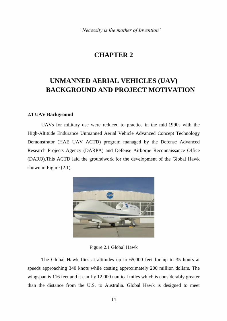
(DARO).This ACTD laid the groundwork for the development of the Global Hawk
shown in Figure (2.1).
Figure 2.1 Global Hawk
The Global Hawk flies at altitudes up to 65,000 feet for up to 35 hours at
speeds approaching 340 knots while costing approximately 200 million dollars. The
wingspan is 116 feet and it can fly 12,000 nautical miles which is considerably greater
than the distance from the U.S. to Australia. Global Hawk is designed to meet
15
domestic needs including homeland security and has been demonstrated in drug
interdiction. Global Hawks are also approved by the FAA to fly in U.S. airspace.
Another very successful UAV is the Predator which was also created in the
mid-1990s but has since been enhanced with Hellfire missiles. “Named by
Smithsonian’s Air & Space magazine as one of the top ten aircraft that changed the
world, Predator is the most combat-proven Unmanned Aircraft System (UAS) in the
world”. The original version of the Predator, built by General Atomics, can fly at
25,000 feet for 40 hours at a maximum airspeed of 120 knots. In addition to missiles,
the Predator can carry cameras, high resolution all weather radar and laser designators.
The Predator is a little smaller than the Global Hawk but still has a wingspan of 55
feet.
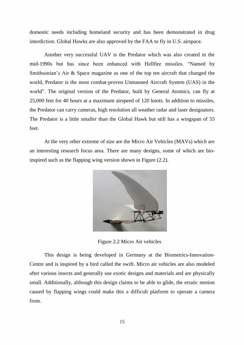
At the very other extreme of size are the Micro Air Vehicles (MAVs) which are
an interesting research focus area. There are many designs, some of which are bio-
inspired such as the flapping wing version shown in Figure (2.2).
Figure 2.2 Micro Air vehicles
This design is being developed in Germany at the Biometrics-Innovation-
Centre and is inspired by a bird called the swift. Micro air vehicles are also modeled
after various insects and generally use exotic designs and materials and are physically
small. Additionally, although this design claims to be able to glide, the erratic motion
caused by flapping wings could make this a difficult platform to operate a camera
from.
16
Although the designs in this class of UAV are fascinating, our interest was in
attempting to produce a small UAV which could support a broad mission capability
and these MAVs were dismissed as being too small. In addition to reviewing very
large and very small UAVs, we were also intrigued by the requirements of DARPA’s
UAV forge competition which was posted. The UAV forge challenge uses crowd
sourcing techniques to design and build a micro-UAV that can take off vertically, go
to a designated distant location, monitor the location for up to three hours, identify
specific objects and then return home. We found this challenge interesting because,
since it was a DARPA research project, it represented pushing beyond the limits of
what a small UAV had ever achieved.
The requirement for vertical liftoff also aligned with our thinking about the
optimum form factor for a small UAV. Many of the deployed UAVs are fixed wing
aircraft; however, we were looking for something more versatile that we believed
could be built in small scale. The Quadcopter, like other helicopter designs, is able to
take off without a runway, take video from a fixed hovering position, and finally
maneuver through tight spaces as required. The Quadcopter also provides a superior
payload capacity when compared to the helicopter and is a more stable platform. Since
the Quadcopter was a vertical liftoff design, it aligned well with our team goals and
therefore it became our baseline form factor.
2.2 Project motivation
We had a story to tell which explains, why we were motivated to take up this
project. Once when one of our project members was watching television in which a
news channel was broadcasting an accident in a factory which led to release of
hazardous gases in the factory. The rescue personnel acting there cannot enter the
factory due to hazardous gases and the management did not know whether some
workers working in factory got stuck inside the factory. So, in the stated situation the
rescue personnel cannot act for a rescue so ‘when a man can’t do the job then that man
thinks of a machine to do it for him’. Therefore to solve the above situation we
thought of an UAV to do the job for us in detecting the workers inside the factory

17
using some heat detectors. The UAV which we planned to develop is Quadcopter
because of some advantages said in above paragraphs.
In addition to the military uses and rescue operation uses of the small UAV, we
were interested in evaluating applications in the commercial and industrial sector. Our
premise was that if smaller and cheaper UAVs become readily available, new markets
and uses will emerge. Potential new markets in commercial and industrial applications
include inspecting pipelines or even inspecting dangerous areas like a meltdown site at
a nuclear power plant. Disaster relief or crop assessment seems also to be likely areas
where small UAVs could be useful. We were also motivated by on-campus uses such
as monitoring parking or quick-look video of an incident, or monitoring hard to reach
locations, or exploration of a collapsed building or other dangerous location.

18
‘Those who wish to succeed must ask the right preliminary questions’
-Aristotle
CHAPTER 3
METHODOLOGY
3.1 Introduction
This chapter will divide into two phases. The first phase understands the design
process of quad copter and second is to understand its structure and its basic
mathematical modeling.
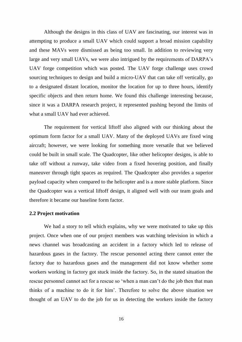
3.2 Flowchart
Designs of Quadcopter are divided into two stages that is part design in first
stage and full interface at second stage. Flow chart of Quadcopter design is described
below:
19
Figure 3.1: Flow chart of Quadcopter design
3.3 Quadcopter Design constraints
Quadcopter is an aerial vehicle consisting of four rotors connected in ‘+’ or ‘X’
design. Out of four rotors two should rotate in clockwise direction and the other two in
20
anti-clockwise rotation. The four propellers are not identical. One set of propellers
(Clockwise rotation) are tilted towards right and the other set (Anti-clockwise
rotation) are tilted towards left.
The reason for this is that the motor torque and the law of physics will make
the Quadcopter spin around itself if all the propellers were rotating the same way,
without any chance of stabilizing it. By making the propeller pairs spin in each
direction, but also having opposite tilting, all of them will provide lifting thrust
without spinning in the same direction. This makes it possible for the Quadcopter to
stabilize the yaw rotation, which is the rotation around itself.
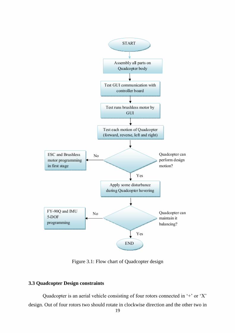
3.3.1 Frame constraints
We have two types of frame configurations the ‘X’ and the ‘+’.
The X and + configurations are as follows:
Figure 3.2 Quadcopter X configuration Figure 3.3 Quadcopter + configuration
The difference is how the motors have to be controlled. For the + configuration
the motor controlling is fairly simple as you just have one motor assigned to each
direction. The negative aspect of the + configuration though is that you only have a
single motor to provide extra thrust (speed up) when you want to move to another
21
direction. In the X configuration you will always have two motors working together
on changing direction.
On basing of above advantage we are moving forward with the X
configuration.
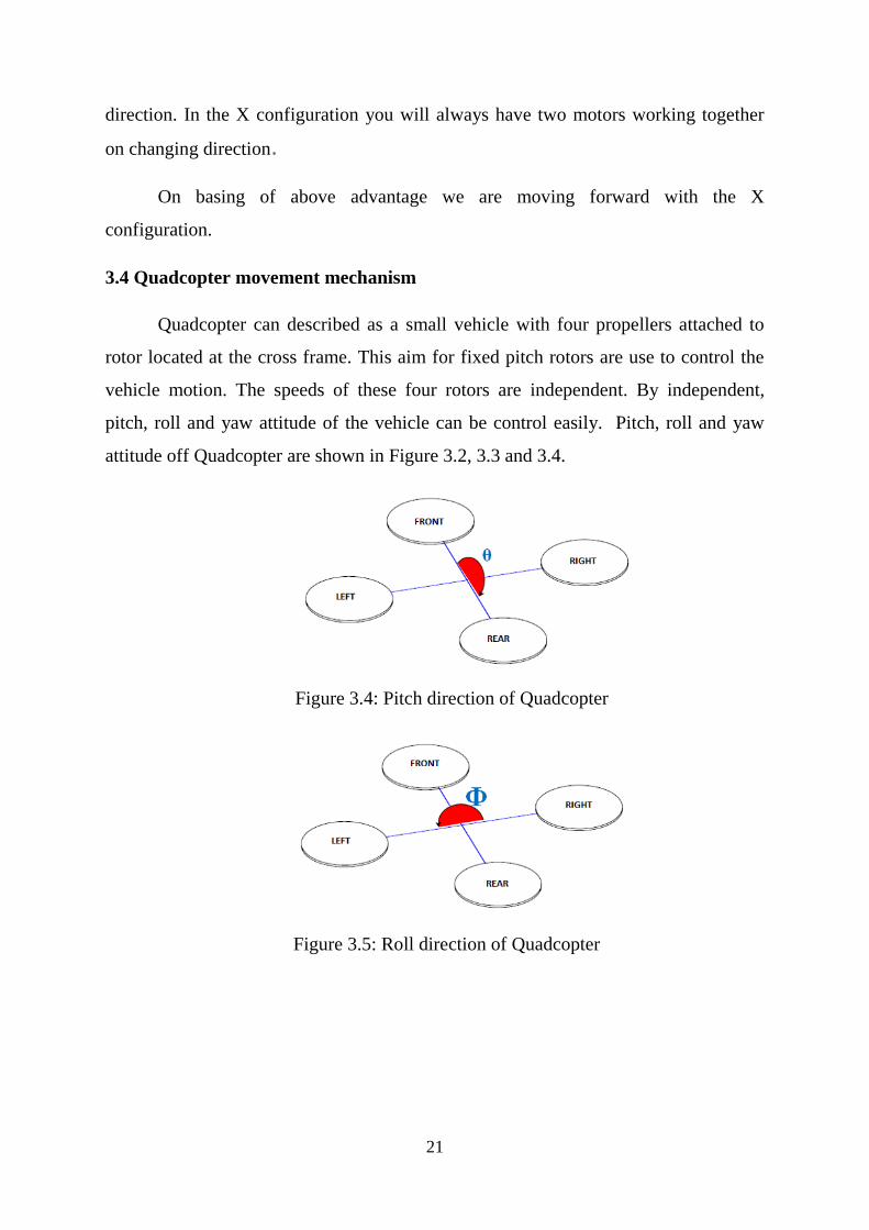
3.4 Quadcopter movement mechanism
Quadcopter can described as a small vehicle with four propellers attached to
rotor located at the cross frame. This aim for fixed pitch rotors are use to control the
vehicle motion. The speeds of these four rotors are independent. By independent,
pitch, roll and yaw attitude of the vehicle can be control easily. Pitch, roll and yaw
attitude off Quadcopter are shown in Figure 3.2, 3.3 and 3.4.
Figure 3.4: Pitch direction of Quadcopter
Figure 3.5: Roll direction of Quadcopter
22
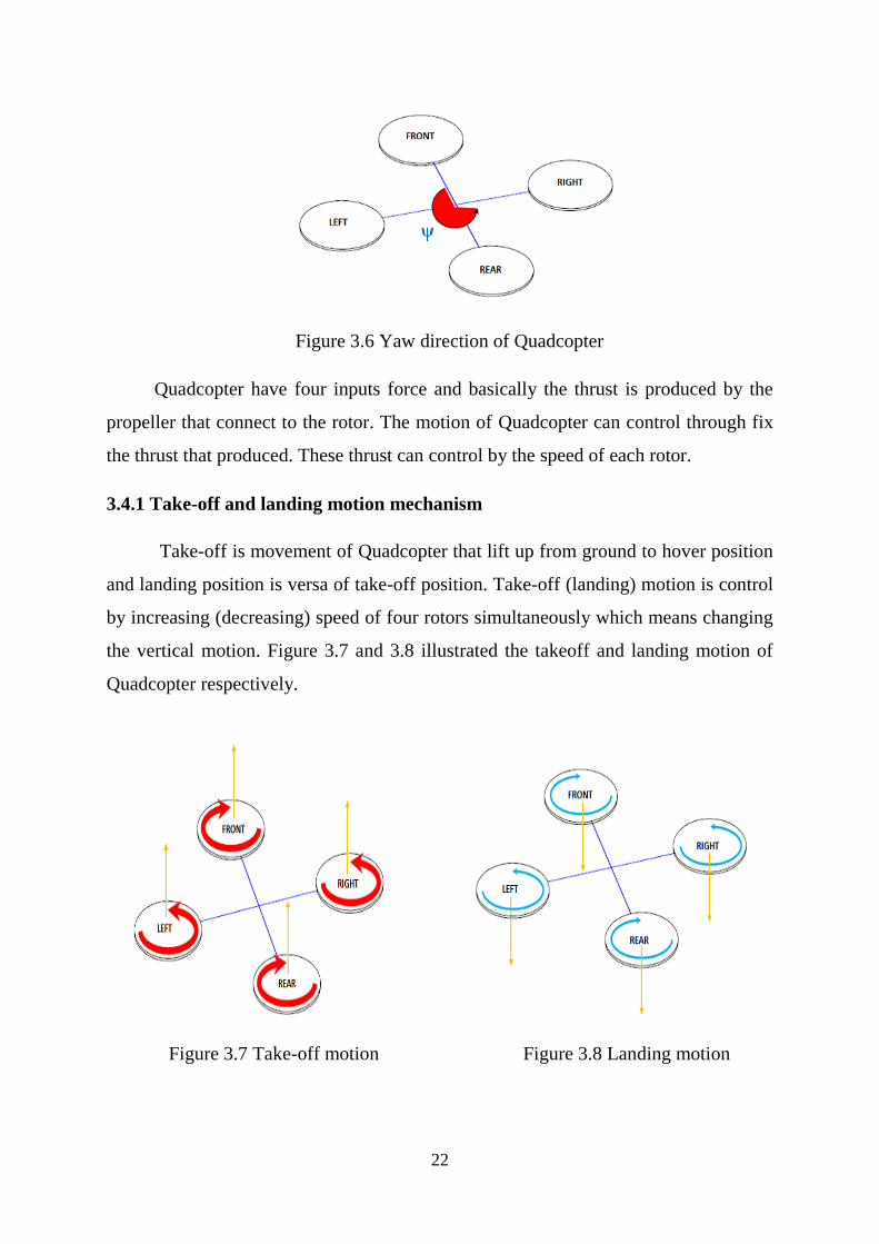
Figure 3.6 Yaw direction of Quadcopter
Quadcopter have four inputs force and basically the thrust is produced by the
propeller that connect to the rotor. The motion of Quadcopter can control through fix
the thrust that produced. These thrust can control by the speed of each rotor.
3.4.1 Take-off and landing motion mechanism
Take-off is movement of Quadcopter that lift up from ground to hover position
and landing position is versa of take-off position. Take-off (landing) motion is control
by increasing (decreasing) speed of four rotors simultaneously which means changing
the vertical motion. Figure 3.7 and 3.8 illustrated the takeoff and landing motion of
Quadcopter respectively.
Figure 3.7 Take-off motion Figure 3.8 Landing motion
23
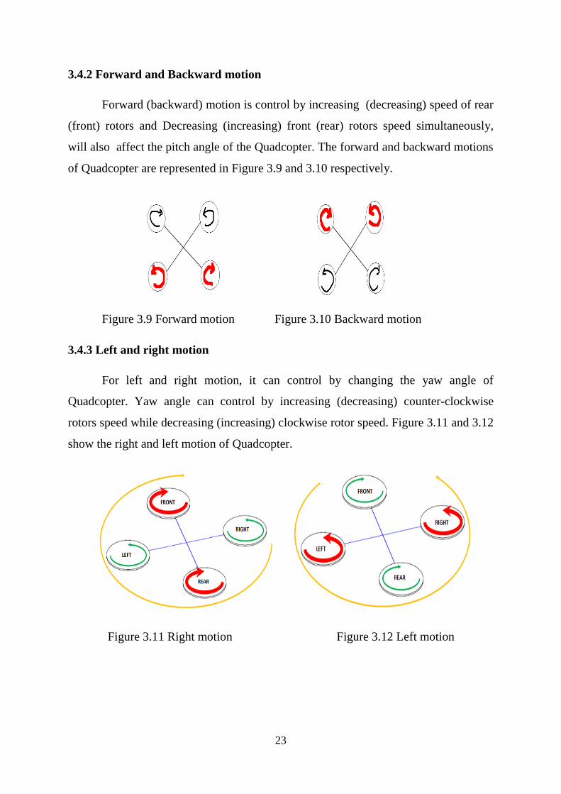
3.4.2 Forward and Backward motion
Forward (backward) motion is control by increasing (decreasing) speed of rear
(front) rotors and Decreasing (increasing) front (rear) rotors speed simultaneously,
will also affect the pitch angle of the Quadcopter. The forward and backward motions
of Quadcopter are represented in Figure 3.9 and 3.10 respectively.
Figure 3.9 Forward motion Figure 3.10 Backward motion
3.4.3 Left and right motion
For left and right motion, it can control by changing the yaw angle of
Quadcopter. Yaw angle can control by increasing (decreasing) counter-clockwise
rotors speed while decreasing (increasing) clockwise rotor speed. Figure 3.11 and 3.12
show the right and left motion of Quadcopter.
Figure 3.11 Right motion Figure 3.12 Left motion
24
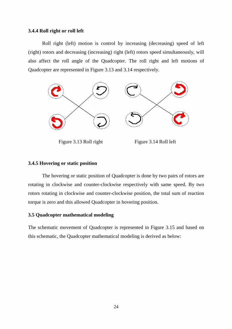
3.4.4 Roll right or roll left
Roll right (left) motion is control by increasing (decreasing) speed of left
(right) rotors and decreasing (increasing) right (left) rotors speed simultaneously, will
also affect the roll angle of the Quadcopter. The roll right and left motions of
Quadcopter are represented in Figure 3.13 and 3.14 respectively.
Figure 3.13 Roll right Figure 3.14 Roll left
3.4.5 Hovering or static position
The hovering or static position of Quadcopter is done by two pairs of rotors are
rotating in clockwise and counter-clockwise respectively with same speed. By two
rotors rotating in clockwise and counter-clockwise position, the total sum of reaction
torque is zero and this allowed Quadcopter in hovering position.
3.5 Quadcopter mathematical modeling
The schematic movement of Quadcopter is represented in Figure 3.15 and based on
this schematic, the Quadcopter mathematical modeling is derived as below:

25
Figure 3.15 Schematic of Quadcopter
Where,
U1 = sum of the thrust of each motor
Th1= thrust generated by front motor
Th2= thrust generated by rear motor
Th3= thrust generated by right motor
Th4= thrust generated by left motor
m = mass of Quadcopter
g = the acceleration of gravity
l = the half length of the Quadcopter
x, y, z = three position
θ, ɸ, ψ = three Euler angles representing pitch, roll, and yaw
The dynamics formulation of Quadcopter moving from landing position to a fixed
point in the space is given as:

26
By applying the force and moment balance laws, the Quadcopter motion equation are
given in Equation (3.2) till (3.4) and Pythagoras theorem is computed as Figure 3.16.
Where,
Ki = drag coefficient (Assume zero since drag is negligible at low speed)
Figure 3.16 Angle Movement of Quadcopter
The angle ɸd and ψd in Figure 3.16 are determined using Equation (3.5) and
(3.6) respectively.
27
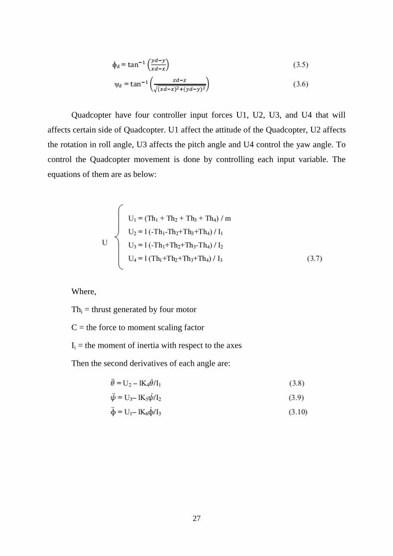
Quadcopter have four controller input forces U1, U2, U3, and U4 that will
affects certain side of Quadcopter. U1 affect the attitude of the Quadcopter, U2 affects
the rotation in roll angle, U3 affects the pitch angle and U4 control the yaw angle. To
control the Quadcopter movement is done by controlling each input variable. The
equations of them are as below:
Where,
Thi = thrust generated by four motor
C = the force to moment scaling factor
Ii = the moment of inertia with respect to the axes
Then the second derivatives of each angle are:
28
‘Strength is life, weakness is death’
-Swami Vivekananda
CHAPTER 4
TECHNICAL SPECIFICATIONS
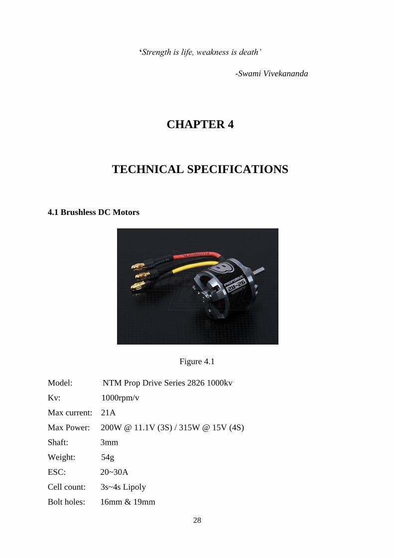
4.1 Brushless DC Motors
Figure 4.1
Model: NTM Prop Drive Series 2826 1000kv
Kv: 1000rpm/v
Max current: 21A
Max Power: 200W @ 11.1V (3S) / 315W @ 15V (4S)
Shaft: 3mm
Weight: 54g
ESC: 20~30A
Cell count: 3s~4s Lipoly
Bolt holes: 16mm & 19mm
29
Bolt thread: M3
Connection: 3.5mm Bullet-connector
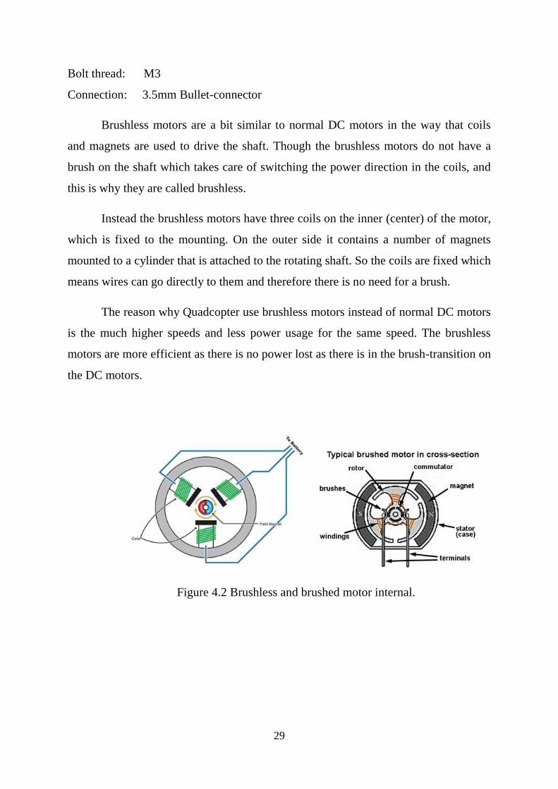
Brushless motors are a bit similar to normal DC motors in the way that coils
and magnets are used to drive the shaft. Though the brushless motors do not have a
brush on the shaft which takes care of switching the power direction in the coils, and
this is why they are called brushless.
Instead the brushless motors have three coils on the inner (center) of the motor,
which is fixed to the mounting. On the outer side it contains a number of magnets
mounted to a cylinder that is attached to the rotating shaft. So the coils are fixed which
means wires can go directly to them and therefore there is no need for a brush.
The reason why Quadcopter use brushless motors instead of normal DC motors
is the much higher speeds and less power usage for the same speed. The brushless
motors are more efficient as there is no power lost as there is in the brush-transition on
the DC motors.
Figure 4.2 Brushless and brushed motor internal.
30
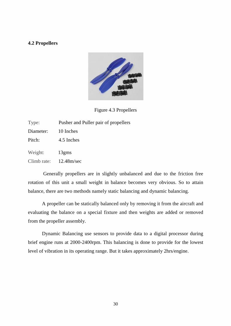
4.2 Propellers
Figure 4.3 Propellers
Type: Pusher and Puller pair of propellers
Diameter: 10 Inches
Pitch: 4.5 Inches
Weight: 13gms
Climb rate: 12.48m/sec
Generally propellers are in slightly unbalanced and due to the friction free
rotation of this unit a small weight in balance becomes very obvious. So to attain
balance, there are two methods namely static balancing and dynamic balancing.
A propeller can be statically balanced only by removing it from the aircraft and
evaluating the balance on a special fixture and then weights are added or removed
from the propeller assembly.
Dynamic Balancing use sensors to provide data to a digital processor during
brief engine runs at 2000-2400rpm. This balancing is done to provide for the lowest
level of vibration in its operating range. But it takes approximately 2hrs/engine.

31
4.3 Electronic speed Controllers (ESC)
Figure 4.4 ESC
Model: 30A Blue Series Brushless Speed Controller
Continuous Current: 30A
Burst Current: 40A
Battery: 2-4 Cell Lipo / 5-12 Cell Ni-XX
SBEC: 5V/ 3A Output
Size: 23*43*6mm
Weight: 28g
As the brushless motors are multi-phased, normally 3 phases, you can’t just
apply power to it to make it spin. The motors requires some special phase-control
electronics that is capable of generating three high frequency signals with different but
controllable phases, but the electronics should also be able to source a lot of current as
the motors can be very power-hungry.
In this case we got the Electronic Speed Controllers, known as ESCs. The
ESCs is simply a brushless motor controller board with battery input and a three phase
output for the motors. For the control it is usually just a simple PPM signal (similar to
PWM) that ranges from 1ms (min speed=turn off) to 2ms (max speed) in pulse width.
The frequency of the signals does also vary a lot from controller to controller, but for
a Quadcopter it is recommended to get a controller that supports at least 200Hz or
even better 300Hz PPM signal, as it should be possible to change the motor speeds
32
very quickly to adjust the Quadcopter to the stable position. It is also possible to get
ESCs that is controlled through One Wire of I2C. These tends to be much more
expensive though, but sometimes it is also possible to mod other ESCs to add the I2C
feature.
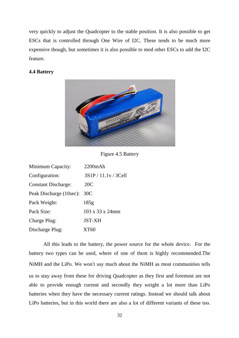
4.4 Battery
Figure 4.5 Battery
Minimum Capacity: 2200mAh
Configuration: 3S1P / 11.1v / 3Cell
Constant Discharge: 20C
Peak Discharge (10sec): 30C
Pack Weight: 185g
Pack Size: 103 x 33 x 24mm
Charge Plug: JST-XH
Discharge Plug: XT60
All this leads to the battery, the power source for the whole device. For the
battery two types can be used, where of one of them is highly recommended.The
NiMH and the LiPo. We won’t say much about the NiMH as most communities tells
us to stay away from these for driving Quadcopter as they first and foremost are not
able to provide enough current and secondly they weight a lot more than LiPo
batteries when they have the necessary current ratings. Instead we should talk about
LiPo batteries, but in this world there are also a lot of different variants of these too.
33
LiPo batteries can be found in packs of everything from a single cell (3.7V) to over 10
cells (37V). The cells are usually connected in series, making the voltage higher but
giving the same amount of amp-hours.
For a Quadcopter you should go after the 3SP1 batteries which means 3 cells
connected in series as 1 parallel (just forget the parallel, as it has no sense because we
just use 3 cells in series). This should give us 11.1V but at fully charged it actually
gives us around 12V instead.
For a brushless motor with a Kv-rating of 1000, this gives us a maximum of
12000 rounds per minute. This number is totally fictive as the battery voltage will
drop immediately to around 11.1V (at fully charged state) when current is being
drained. Anyways, this gives us a good idea about how fast the propellers will be
spinning!
As for the battery capacity regards you should make some calculations on how
much power your motors will draw and then decide how long flight time you want
and how much influence the battery weight should have on the total weight. A good
rule of thumb is that you with four EPP1045 propellers and four Kv=1000 rated motor
will get the number of minutes of full throttle flight time as the same number of amp-
hours in your battery capacity. This means that if you have a 4000mAh battery, you
will get around 4 minutes of full throttle flight time though with a 1KG total weight
you will get around 16 minutes of hover.
Another thing to be-aware of when selecting the right battery is the discharge
rate, formerly known as the C-value. The C-value together with the battery capacity
indicates how much current you are able to source from the battery. The calculations
follow this simple rule: MaxSource = DischargeRate x Capacity
34
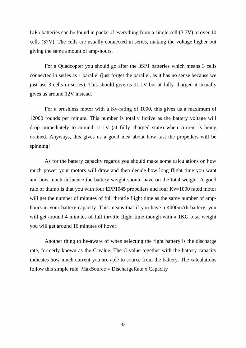
4.5 Battery Charger
Figure 4.6 Battery charger
Input: 12-15v DC
- Turnigy balancer & Charger 2S-3S
- charges at a rate of around 800mAh.
- There are two LED status lights. The red light indicates that power is connected to
the charger. The green light means that charging is in progress. The green light goes
out when charging is complete.
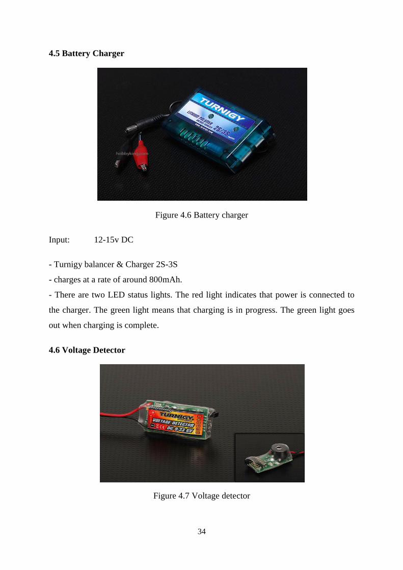
4.6 Voltage Detector
Figure 4.7 Voltage detector
35
Operating Voltage: 9~33.6V
Weight: 6g
The 3~8S voltage detector will give a warning buzzer as well as LED
indication for High, Average, below average, and Low voltages on your Lipoly
battery.
The buzzer is also quiet loud. Its varied warning range is great for those with
gliders that need time to bring the plane down from a high altitude.
Turnigy voltage detector has polarity protection.
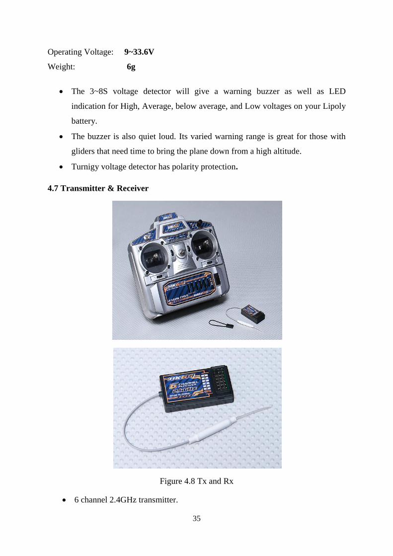
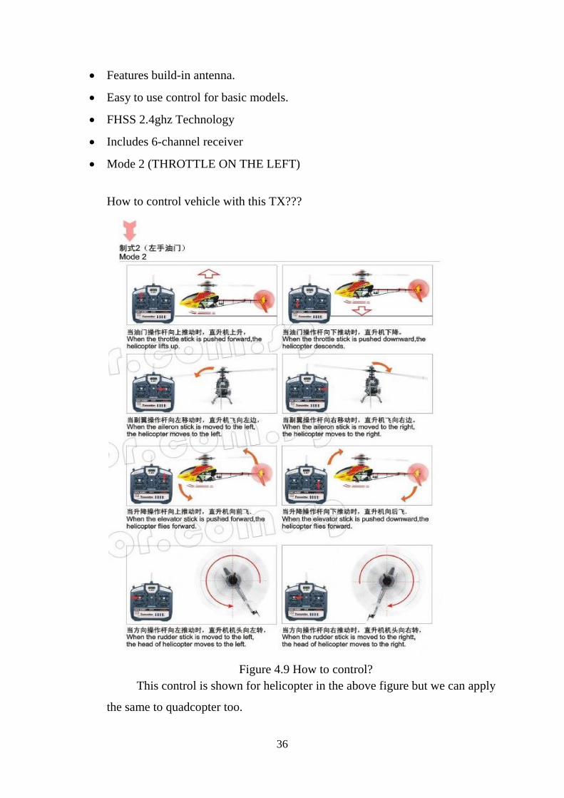
4.7 Transmitter & Receiver
Figure 4.8 Tx and Rx
6 channel 2.4GHz transmitter.
36
Features build-in antenna.
Easy to use control for basic models.
FHSS 2.4ghz Technology
Includes 6-channel receiver
Mode 2 (THROTTLE ON THE LEFT)
How to control vehicle with this TX???
Figure 4.9 How to control?
This control is shown for helicopter in the above figure but we can apply
the same to quadcopter too.
37
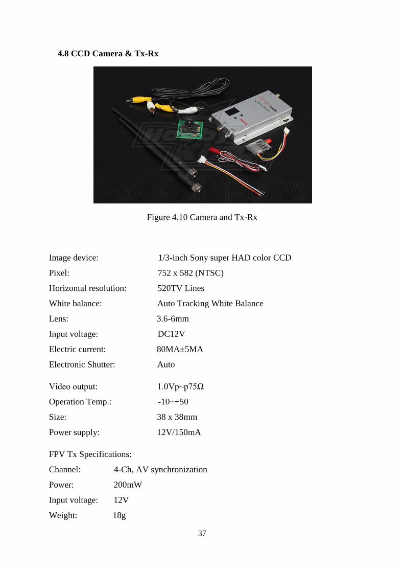
4.8 CCD Camera & Tx-Rx
Figure 4.10 Camera and Tx-Rx
Image device: 1/3-inch Sony super HAD color CCD
Pixel: 752 x 582 (NTSC)
Horizontal resolution: 520TV Lines
White balance: Auto Tracking White Balance
Lens: 3.6-6mm
Input voltage: DC12V
Electric current: 80MA±5MA
Electronic Shutter: Auto
Video output: 1.0Vp~p75Ω
Operation Temp.: -10~+50
Size: 38 x 38mm
Power supply: 12V/150mA
FPV Tx Specifications:
Channel: 4-Ch, AV synchronization
Power: 200mW
Input voltage: 12V
Weight: 18g
38
Size: 31 x 88 x 8mm
Frequency: 0.9G, 0.910G,0.980G,1.010G,1.040G
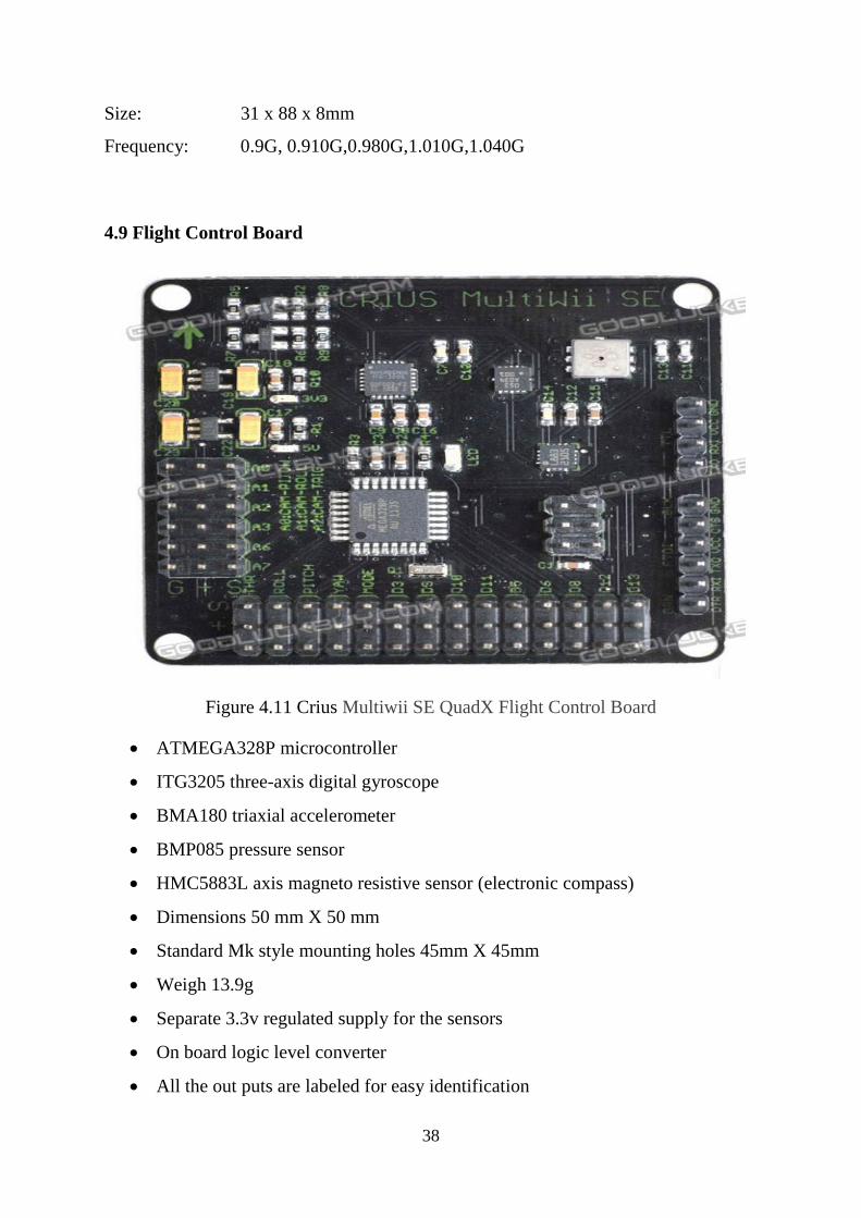
4.9 Flight Control Board
Figure 4.11 Crius Multiwii SE QuadX Flight Control Board
ATMEGA328P microcontroller
ITG3205 three-axis digital gyroscope
BMA180 triaxial accelerometer
BMP085 pressure sensor
HMC5883L axis magneto resistive sensor (electronic compass)
Dimensions 50 mm X 50 mm
Standard Mk style mounting holes 45mm X 45mm
Weigh 13.9g
Separate 3.3v regulated supply for the sensors
On board logic level converter
All the out puts are labeled for easy identification
39
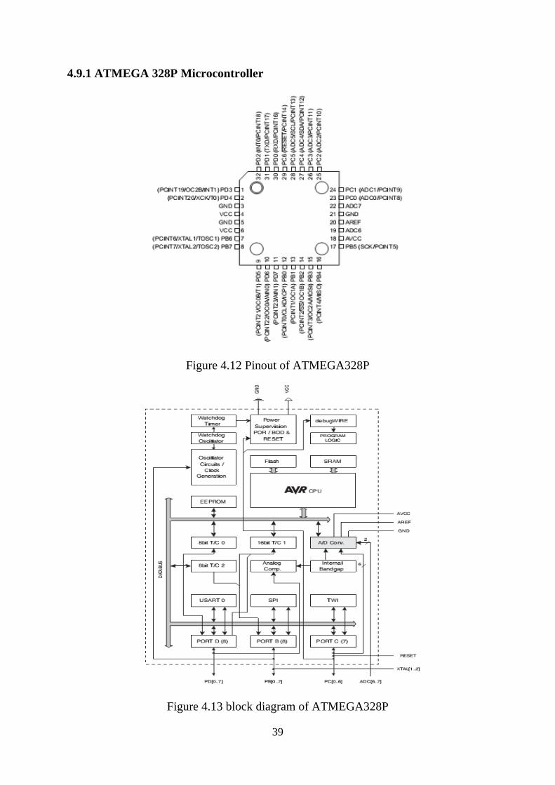
4.9.1 ATMEGA 328P Microcontroller
Figure 4.12 Pinout of ATMEGA328P
Figure 4.13 block diagram of ATMEGA328P

40
Low Power AVR 8-Bit Microcontroller
Advanced RISC Architecture
131 Powerful Instructions – Most Single Clock Cycle Execution
32 x 8 General Purpose Working Registers
Fully Static Operation
Up to 20 MIPS Throughput at 20 MHz
On-chip 2-cycle Multiplier.
32K Bytes of In-System Self-Programmable Flash program memory
1K Bytes EEPROM
2K Bytes Internal SRAM
Two 8-bit Timer/Counters
One 16-bit Timer/Counter
8-channel 10-bit ADC
Programmable Serial USART
Master/Slave SPI Serial Interface
On-chip Analog Comparator
Operating voltage : 1.8 - 5.5V
Speed grade : 0 - 20 MHz @ 1.8 - 5.5V
4.9.2 ITG 3205 Digital gyroscope
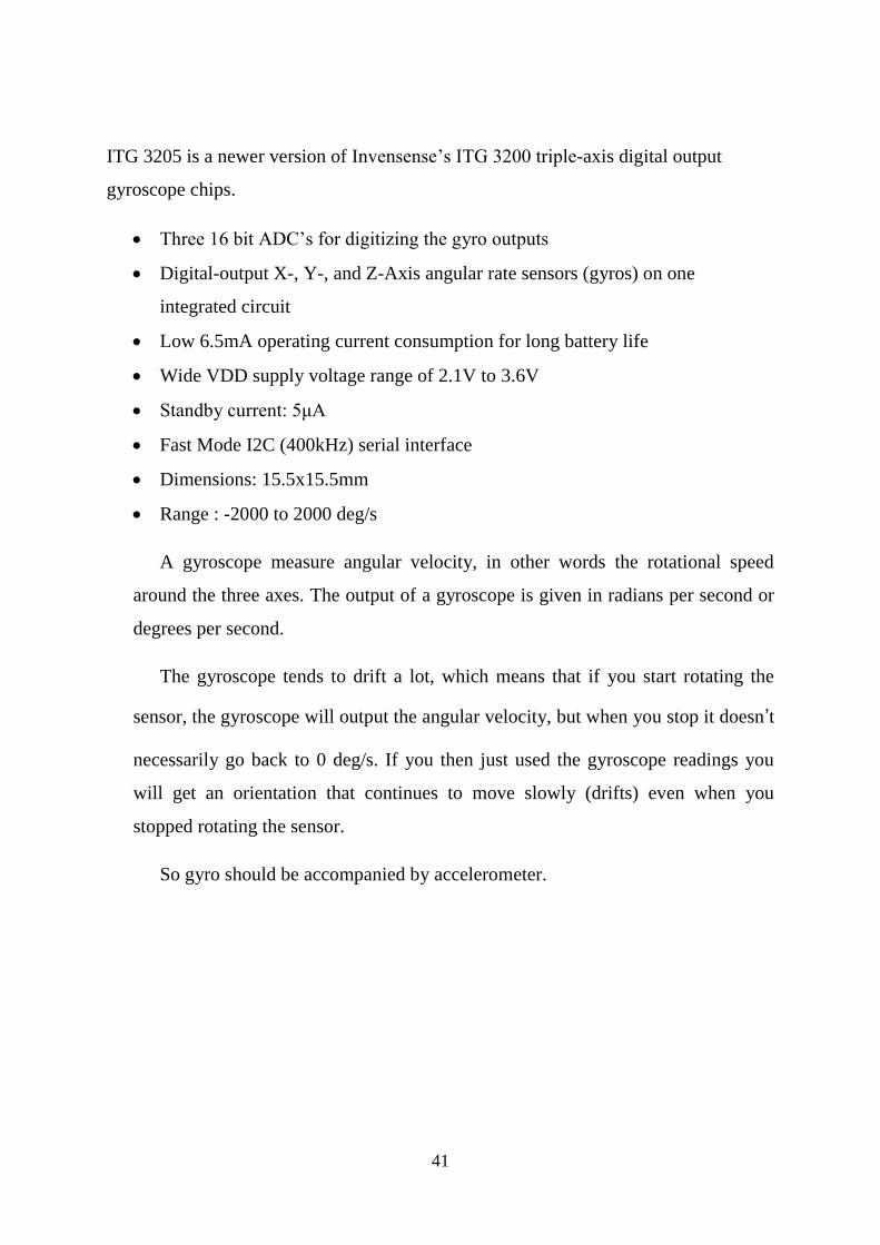
Figure 4.14 Digital Gyroscope
41
ITG 3205 is a newer version of Invensense’s ITG 3200 triple-axis digital output
gyroscope chips.
Three 16 bit ADC’s for digitizing the gyro outputs
Digital-output X-, Y-, and Z-Axis angular rate sensors (gyros) on one
integrated circuit
Low 6.5mA operating current consumption for long battery life
Wide VDD supply voltage range of 2.1V to 3.6V
Standby current: 5μA
Fast Mode I2C (400kHz) serial interface
Dimensions: 15.5x15.5mm
Range : -2000 to 2000 deg/s
A gyroscope measure angular velocity, in other words the rotational speed
around the three axes. The output of a gyroscope is given in radians per second or
degrees per second.
The gyroscope tends to drift a lot, which means that if you start rotating the
sensor, the gyroscope will output the angular velocity, but when you stop it doesn’t
necessarily go back to 0 deg/s. If you then just used the gyroscope readings you
will get an orientation that continues to move slowly (drifts) even when you
stopped rotating the sensor.
So gyro should be accompanied by accelerometer.

42
4.9.3 BMA 180 Digital Triple Axis Accelerometer
Figure 4.15 Digital accelerometer
This is a breakout board for Bosch's BMA180 three-axis, ultra-high
performance digital accelerometer
Wide variety of measurement ranges (±1g, 1.5g, 2g, 3g, 4g, 8g and 16g
14 or 12-bit ADC conversion
2 selectable I2C addresses
2 main standard modes: low-noise and low-power
Dimensions: 0.80 x 0.40"
43
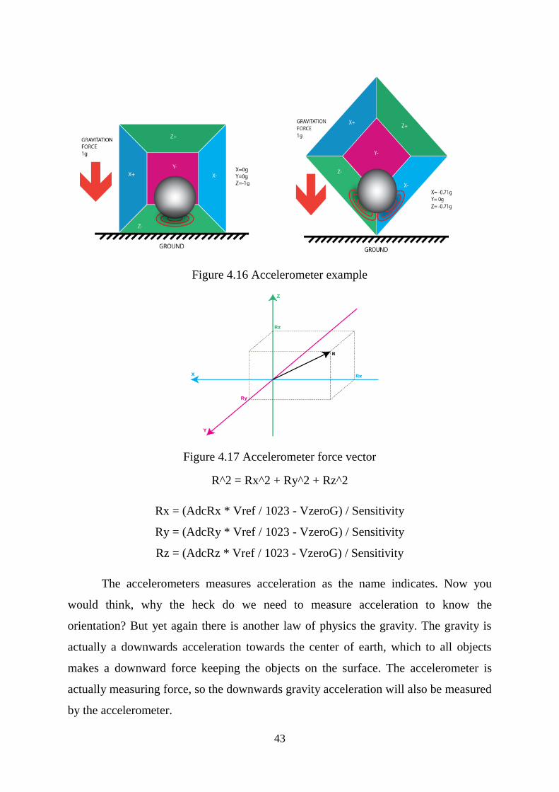
Figure 4.16 Accelerometer example
Figure 4.17 Accelerometer force vector
R^2 = Rx^2 + Ry^2 + Rz^2
Rx = (AdcRx * Vref / 1023 - VzeroG) / Sensitivity
Ry = (AdcRy * Vref / 1023 - VzeroG) / Sensitivity
Rz = (AdcRz * Vref / 1023 - VzeroG) / Sensitivity
The accelerometers measures acceleration as the name indicates. Now you
would think, why the heck do we need to measure acceleration to know the
orientation? But yet again there is another law of physics the gravity. The gravity is
actually a downwards acceleration towards the center of earth, which to all objects
makes a downward force keeping the objects on the surface. The accelerometer is
actually measuring force, so the downwards gravity acceleration will also be measured
by the accelerometer.

44
As the accelerometer sensor can measure the acceleration in three directions we
can actually calculate how the accelerometer is oriented against the surface.
The accelerometer, then enough to measure the orientation? The problem lies
in the way the accelerometer works, because it isn’t very stable. If only the
accelerometer were used to calculate the orientation even the smallest movements of
the accelerometer will mess up the orientation. So if mounted on a Quadcopter with
vibrating motors it will be no good.
So accelerometer is used in parallel with gyro.
4.9.4 HMC5883L Magneto Resistive Sensor
Figure 4.18 magneto resistive sensor
3 Axis Magneto resistive Sensors. m
12 Bit ADC
Low Voltage Operations (2.16 to 3.6V)
Low Power Consumption (100 μA)
I2C Digital Interface.
For the Yaw rotational movement the accelerometer can’t be used as the
reference sensor as it could with the Roll and Pitch movement. Instead a
magnetometer is sometimes used. A 3-axis magnetometer measures the magnetic field
that affects the sensor in all three directions. As the earth contains a magnetic field on
the North- and South Pole, the magnetic sensor can be used to determine where north
and south is located. The locations of these poles can then be used as a reference
45
together with the angular velocity around Yaw from the gyroscope, to calculate a
stable Yaw angle.
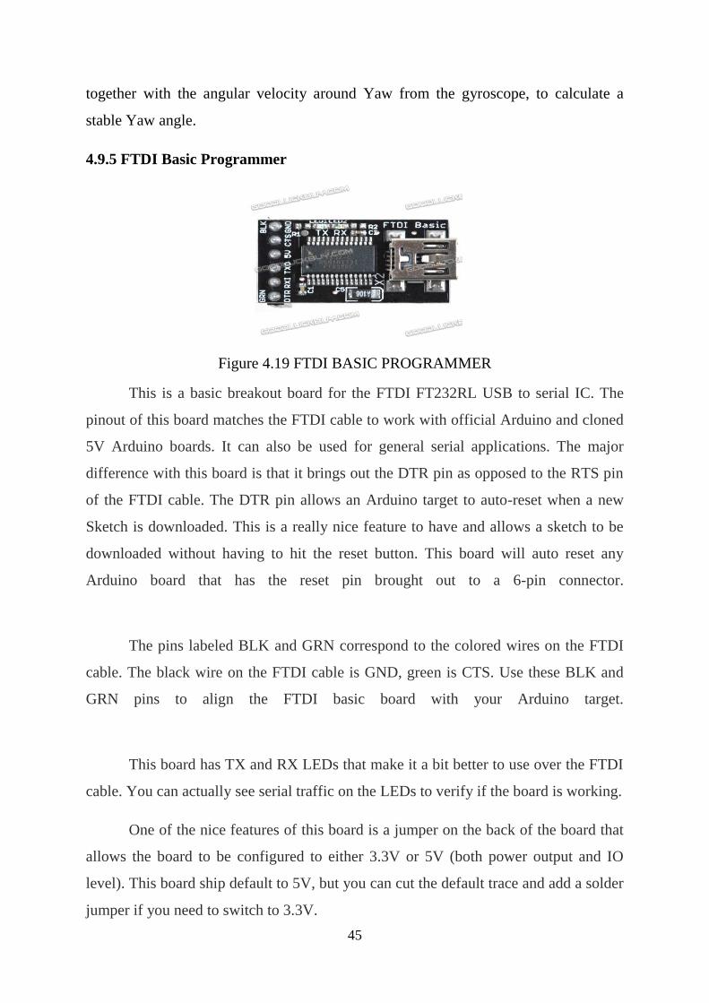
4.9.5 FTDI Basic Programmer
Figure 4.19 FTDI BASIC PROGRAMMER
This is a basic breakout board for the FTDI FT232RL USB to serial IC. The
pinout of this board matches the FTDI cable to work with official Arduino and cloned
5V Arduino boards. It can also be used for general serial applications. The major
difference with this board is that it brings out the DTR pin as opposed to the RTS pin
of the FTDI cable. The DTR pin allows an Arduino target to auto-reset when a new
Sketch is downloaded. This is a really nice feature to have and allows a sketch to be
downloaded without having to hit the reset button. This board will auto reset any
Arduino board that has the reset pin brought out to a 6-pin connector.
The pins labeled BLK and GRN correspond to the colored wires on the FTDI
cable. The black wire on the FTDI cable is GND, green is CTS. Use these BLK and
GRN pins to align the FTDI basic board with your Arduino target.
This board has TX and RX LEDs that make it a bit better to use over the FTDI
cable. You can actually see serial traffic on the LEDs to verify if the board is working.
One of the nice features of this board is a jumper on the back of the board that
allows the board to be configured to either 3.3V or 5V (both power output and IO
level). This board ship default to 5V, but you can cut the default trace and add a solder
jumper if you need to switch to 3.3V.
46
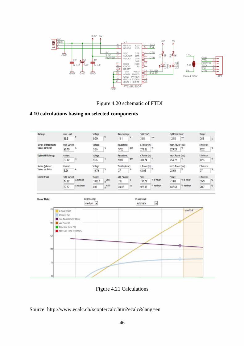
Figure 4.20 schematic of FTDI
4.10 calculations basing on selected components
Figure 4.21 Calculations
Source: http://www.ecalc.ch/xcoptercalc.htm?ecalc&lang=en
47
‘To accomplish great things, we must not only act, but also dream, not only plan, but
also believe.’
-Anatole France
CHAPTER 5
SOFTWARES USED
5.1 ARDUINO
Figure 5.1 Arduino logo
The open-source Arduino environment makes it easy to write code and upload
it to the I/O board. It runs on Windows, Mac OS X, and Linux. The environment is
written in Java and based on Processing, avr-gcc, and other open source software.
We can download the Arduino environment from the internet with url
www.arduino.cc
48
5.1.1 How to use Arduino
1. Launch the Arduino applicat ion
Double-click the Arduino application. (Note: if the Arduino software loads in
the wrong language, you can change it in the preferences dialog.)
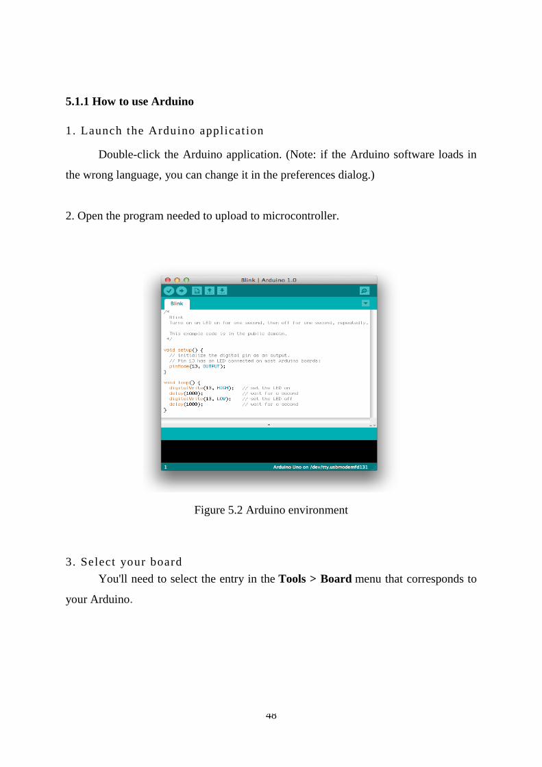
2. Open the program needed to upload to microcontroller.
Figure 5.2 Arduino environment
3. Select your board
You'll need to select the entry in the Tools > Board menu that corresponds to
your Arduino.
49
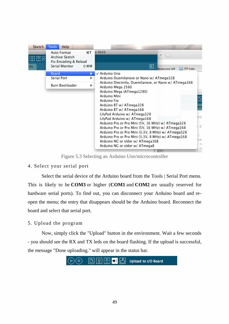
Figure 5.3 Selecting an Arduino Uno/microcontroller
4. Select your serial port
Select the serial device of the Arduino board from the Tools | Serial Port menu.
This is likely to be COM3 or higher (COM1 and COM2 are usually reserved for
hardware serial ports). To find out, you can disconnect your Arduino board and re-
open the menu; the entry that disappears should be the Arduino board. Reconnect the
board and select that serial port.
5. Upload the program
Now, simply click the "Upload" button in the environment. Wait a few seconds
- you should see the RX and TX leds on the board flashing. If the upload is successful,
the message "Done uploading." will appear in the status bar.
50
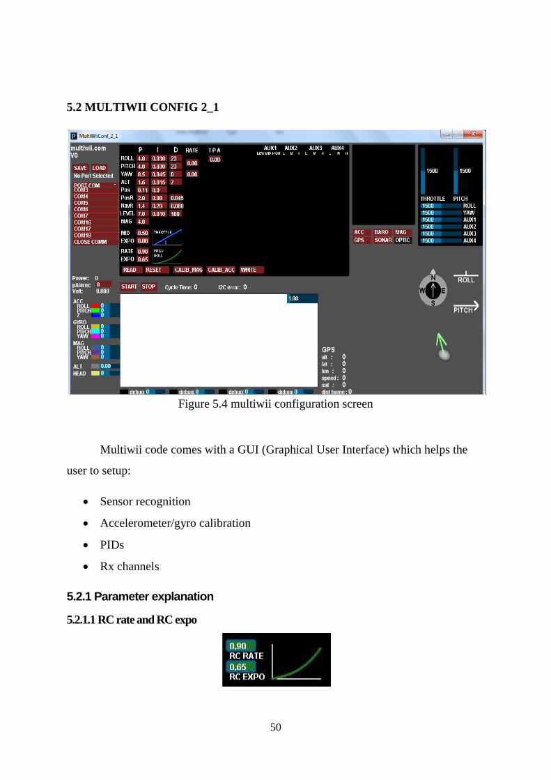
5.2 MULTIWII CONFIG 2_1
Figure 5.4 multiwii configuration screen
Multiwii code comes with a GUI (Graphical User Interface) which helps the
user to setup:
Sensor recognition
Accelerometer/gyro calibration
PIDs
Rx channels
5.2.1 Parameter explanation
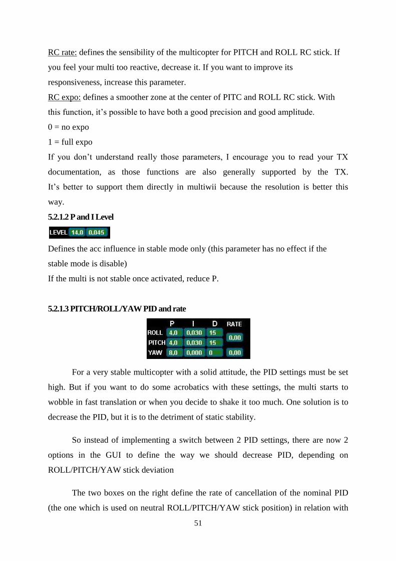
5.2.1.1 RC rate and RC expo
51
RC rate: defines the sensibility of the multicopter for PITCH and ROLL RC stick. If
you feel your multi too reactive, decrease it. If you want to improve its
responsiveness, increase this parameter.
RC expo: defines a smoother zone at the center of PITC and ROLL RC stick. With
this function, it’s possible to have both a good precision and good amplitude.
0 = no expo
1 = full expo
If you don’t understand really those parameters, I encourage you to read your TX
documentation, as those functions are also generally supported by the TX.
It’s better to support them directly in multiwii because the resolution is better this
way.
5.2.1.2 P and I Level
Defines the acc influence in stable mode only (this parameter has no effect if the
stable mode is disable)
If the multi is not stable once activated, reduce P.
5.2.1.3 PITCH/ROLL/YAW PID and rate
For a very stable multicopter with a solid attitude, the PID settings must be set
high. But if you want to do some acrobatics with these settings, the multi starts to
wobble in fast translation or when you decide to shake it too much. One solution is to
decrease the PID, but it is to the detriment of static stability.
So instead of implementing a switch between 2 PID settings, there are now 2
options in the GUI to define the way we should decrease PID, depending on
ROLL/PITCH/YAW stick deviation
The two boxes on the right define the rate of cancellation of the nominal PID
(the one which is used on neutral ROLL/PITCH/YAW stick position) in relation with

52
ROLL/STICK/YAW deviation. In fact only P and D parameters are impacted in the
transformation. The purpose of this setting is not really to gain more stability, but to
gain more maneuverability. 0 = soft rate (for FPV or beginners); 0.4 = soft acro ; 0.7 =
fast acro ; 1 = insane rate. If you are not familiar with this, just keep the default values
(0).
5.2.1.4 THROTTLE rate
This box defines the rate of cancellation of the nominal PID (the one which is used on
neutral ROLL/PITCH stick position) in relation with Throttle stick.
The purpose of this curve is to gain more stability when you are in a situation to use
more throttle than needed to just maintain a lift. This is typically the case in fast
translation.
If you are not familiar with this, just keep the default values (0)
5.2.1.5 How to activate options
Depending on your configuration, you can easily activate/deactivate options via 2
switches on your RC TX.
The 2 switches correspond to channel 5 (AUX1) and channel 6 (AUX2).
LEVEL is the auto level feature (require an ACC)
BARO allows to keep a constant altitude once activated (require a barometer)
MAG allows to keep a perfect heading direction once activated (require a
magnetometer)
CAMSTAB: if activated, the PITCH&ROLL servo output will follow the inclination
of the multi (require an ACC + the code activation via #define statement)
CAMSTRIG: if activated, a servo output will trigger repetitively a sequence where we
can define the duration on the HIGH/LOW position.
53
To activate a function, you must check the white box at the intersection of the required
option (row) and at the switch state you want to enable (column).
It’s possible to make a complex mix.
If you want to force an option permanently, it’s possible to check all the white boxes,
even without a RC channel connected.
(=> This way, you don’t need a 5 or 6 channels RC receiver).
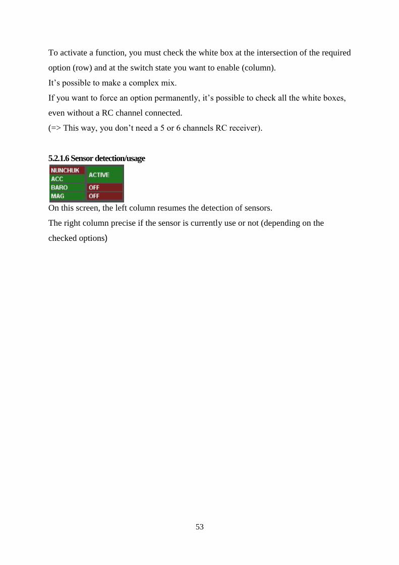
5.2.1.6 Sensor detection/usage
On this screen, the left column resumes the detection of sensors.
The right column precise if the sensor is currently use or not (depending on the
checked options)
54
‘Sometimes things become possible if we want those bad enough’
-T.S.Eliot
CHAPTER 6
ELECTRICAL CONNECTIONS
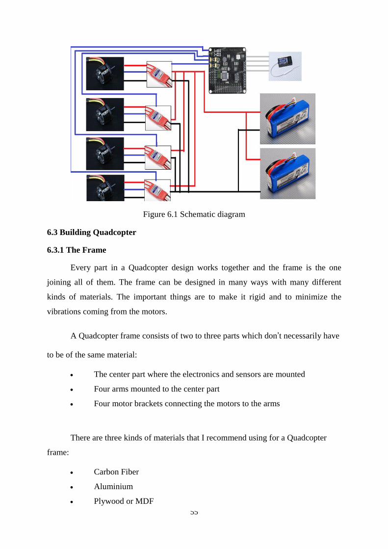
6.1 Introduction
When we have all the components required to build Quadcopter then the next
step to move forward is to connect all the components according to their
specifications, pin outs. This chapter is divided into two phases.
In the first phase the schematic diagram of the overall connections is given and
in latter phase each component connection with the other is given in detail.
6.2 Schematic diagram:
55
Figure 6.1 Schematic diagram
6.3 Building Quadcopter
6.3.1 The Frame
Every part in a Quadcopter design works together and the frame is the one
joining all of them. The frame can be designed in many ways with many different
kinds of materials. The important things are to make it rigid and to minimize the
vibrations coming from the motors.
A Quadcopter frame consists of two to three parts which don’t necessarily have
to be of the same material:
The center part where the electronics and sensors are mounted
Four arms mounted to the center part
Four motor brackets connecting the motors to the arms
There are three kinds of materials that I recommend using for a Quadcopter
frame:
Carbon Fiber
Aluminium
Plywood or MDF
56
Carbon fiber is the most rigid and vibration absorbent of the three materials but
is also by far the most expensive.
Most of the times the arms used in Quadcopter are made of hollow aluminium
square rails which make the Quadcopter relatively light weight but still make it rigid.
The problem with these hollow aluminum rails are the vibrations, as they aren’t
damped and will therefore vibrate to the center part and maybe mess up the sensor
readings.
Instead solid MDF plates could be cut out for the arms as they will absorb the
vibrations much better than the aluminium. Unfortunately we have another problem
then, as the MDF plates are not very rigid and will break if the Quadcopter falls to the
ground.
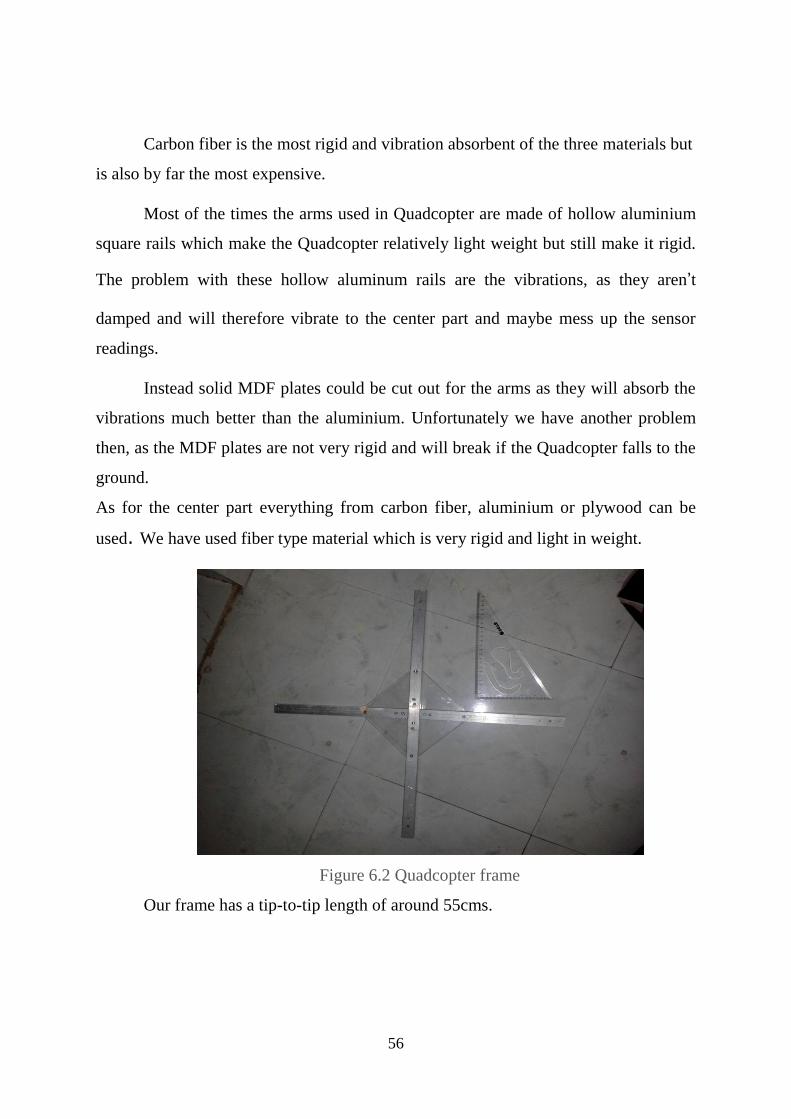
As for the center part everything from carbon fiber, aluminium or plywood can be
used. We have used fiber type material which is very rigid and light in weight.
Figure 6.2 Quadcopter frame
Our frame has a tip-to-tip length of around 55cms.
57
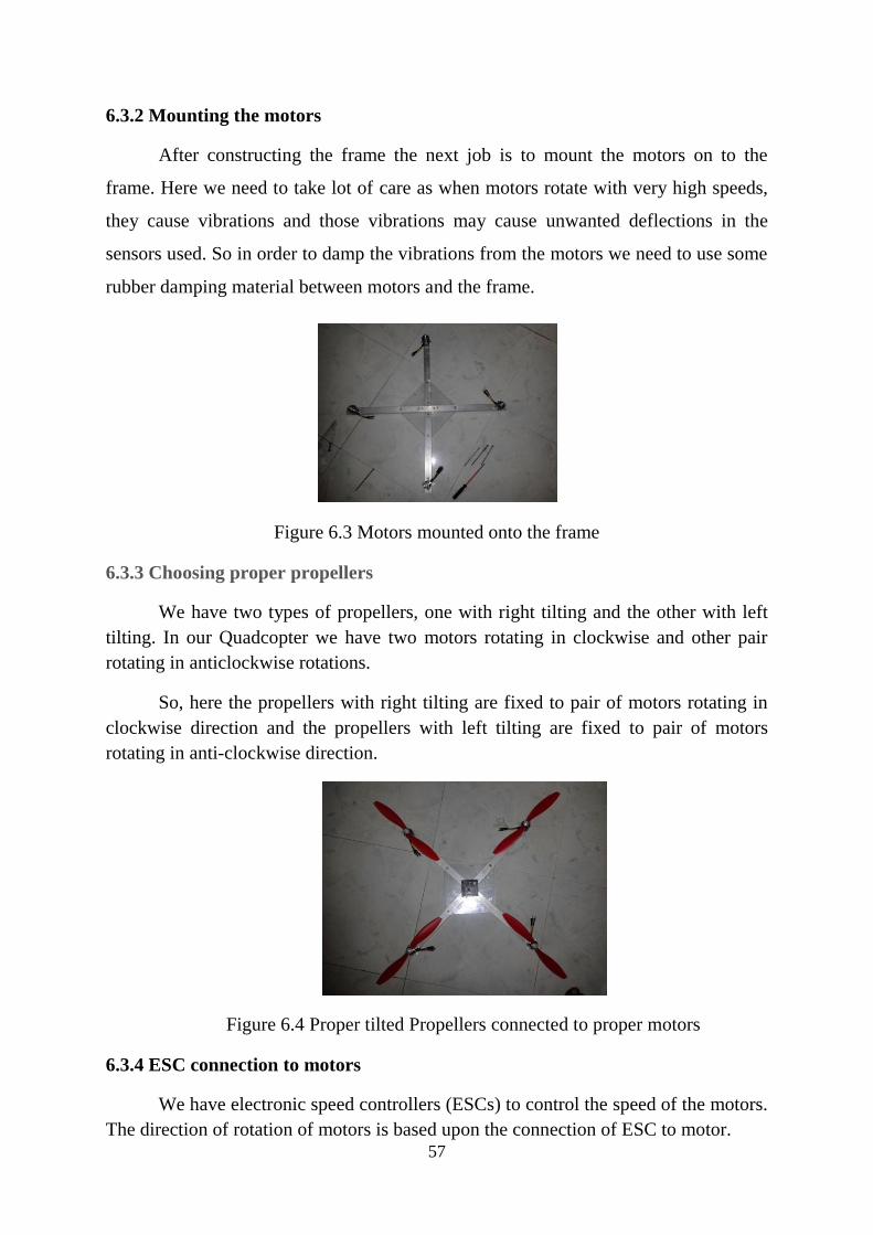
6.3.2 Mounting the motors
After constructing the frame the next job is to mount the motors on to the
frame. Here we need to take lot of care as when motors rotate with very high speeds,
they cause vibrations and those vibrations may cause unwanted deflections in the
sensors used. So in order to damp the vibrations from the motors we need to use some
rubber damping material between motors and the frame.
Figure 6.3 Motors mounted onto the frame
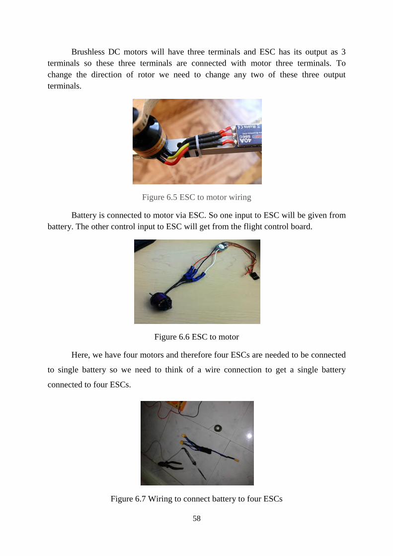
6.3.3 Choosing proper propellers
We have two types of propellers, one with right tilting and the other with left
tilting. In our Quadcopter we have two motors rotating in clockwise and other pair
rotating in anticlockwise rotations.
So, here the propellers with right tilting are fixed to pair of motors rotating in
clockwise direction and the propellers with left tilting are fixed to pair of motors
rotating in anti-clockwise direction.
Figure 6.4 Proper tilted Propellers connected to proper motors
6.3.4 ESC connection to motors
We have electronic speed controllers (ESCs) to control the speed of the motors.
The direction of rotation of motors is based upon the connection of ESC to motor.
58
Brushless DC motors will have three terminals and ESC has its output as 3
terminals so these three terminals are connected with motor three terminals. To
change the direction of rotor we need to change any two of these three output
terminals.
Figure 6.5 ESC to motor wiring
Battery is connected to motor via ESC. So one input to ESC will be given from
battery. The other control input to ESC will get from the flight control board.
Figure 6.6 ESC to motor
Here, we have four motors and therefore four ESCs are needed to be connected
to single battery so we need to think of a wire connection to get a single battery
connected to four ESCs.
Figure 6.7 Wiring to connect battery to four ESCs
59
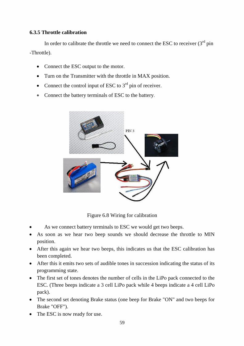
6.3.5 Throttle calibration
In order to calibrate the throttle we need to connect the ESC to receiver (3rd
pin
-Throttle).
Connect the ESC output to the motor.
Turn on the Transmitter with the throttle in MAX position.
Connect the control input of ESC to 3rd
pin of receiver.
Connect the battery terminals of ESC to the battery.
Figure 6.8 Wiring for calibration
As we connect battery terminals to ESC we would get two beeps.
As soon as we hear two beep sounds we should decrease the throttle to MIN
position.
After this again we hear two beeps, this indicates us that the ESC calibration has
been completed.
After this it emits two sets of audible tones in succession indicating the status of its
programming state.
The first set of tones denotes the number of cells in the LiPo pack connected to the
ESC. (Three beeps indicate a 3 cell LiPo pack while 4 beeps indicate a 4 cell LiPo
pack).
The second set denoting Brake status (one beep for Brake "ON" and two beeps for
Brake "OFF").
The ESC is now ready for use.

60
6.3.6 Connecting receiver to flight control board
The receiver has 6 channels out of which we use 5 channels to connect the
receiver and flight control board. For each connection there are three terminals (VCC,
GND, SGNL).The flight control board should be mounted on the Quad copter so that
the arrow direction marked ‘front’ on board should be directed to front of Quadcopter.
Receiver Flight control board
Pin 1 Aileron Roll
Pin 2 Elevator Pitch
Pin 3 Throttle THR
Pin 4 Rudder Yaw
Pin 5 Gear digital Aux pin
Figure 6.9 receiver and flight control board connection

61
6.3.7 Connecting motors to flight control board
Motors are connected to flight control board via ESC. Each ESC has three
terminals to be connected to flight control board (VCC, GND, and SGNL).
Motor Flight control board
Top left motor (3) D3 pin
Bottom Right motor (9) D9pin
Top right motor (10) D10 pin
Bottom right motor (11) D11 pin
Figure 6.10 motors and flight control board connection
62
‘The world is the great gymnasium where we come to make ourselves strong’
-Swami Vivekananda
CHAPTER 7
PROGRAMMING AND CONFIGURATION
7.1 Introduction
In this chapter we have two parts, the first part deals with the interfacing of
flight control board to a computer and uploading code into the microcontroller and the
second part deals with the configuration of Quadcopter.
7.2 Programming
7.2.1 Connecting flight control board to computer
The flight control board is connected to the computer with the help of FTDI
basic programmer. We have 6pins on flight control board to connect the board to
computer. They are DTR, RXI, TX0, VCC.CTS, and GND.
We should install the driver of FTDI programmer in the system to get the
device connected to the system.
The drivers of FTDI basic programmer are available online at
http://www.ftdichip.com/FTDrivers.htm
63
7.2.2 Code (MULTIWII) and uploading
We have used open source code to upload into the microcontroller. The code
we have used is MILTIWII.
MultiWii is general purpose software to control a multirotor RC model. We
have used ARDUINO platform to compile and upload the code into the
microcontroller.
We used 2.1 which was released in July 2012.
We can find this code at: https://code.google.com/p/multiwii/downloads/list
7.2.2.1 Configuring code
Multiwii has config.h file which is used to configure the open source code
according tour specifications.
In the config.h we have updated the code according to our requirements.
The changes we have done include:
The type of multicopter: uncomment #define QUADX
Motor min throttle: #define MINTHROTTLE 1000
Motor Max throttle: #define MAXTHROTTLE 1850
Min Command: #define MINCOMMAND 900
Boards and sensor definitions: #define CRIUS_SE
Independent Sensors
Gyro: #define ITG3200
Accelerometer: #define BMA180
Magnetometer: #define HMC5883
64
7.2.2.2 Failsafe configuration
In the code we have an option of failsafe feature; this option is very useful
when the quadrotor loses the signal from the transmitter.
The failsafe routine of multiwii determines what is happening if the connection
between RX and TX is lost.
If a loss of TX Signal is detected the copter enters stable mode after a guard
time if an ACC is present and applies a configured throttle for a given time before it
shuts down the motors.
There are different options that control the behavior of the multirotor after loss
of TX signal:
#define FAILSAFE
Failsafe function activated if TX signal loss found.
#define FAILSAFE_PIN
On which pin should the FC check for a signal loss
#define FAILSAVE_DELAY
How long does the copter need to notice a loss of TX signal?
#define FAILSAVE_OFF_DELAY
How long does the copter try to land before switching off the motors? If you
set this value to 0 the copter will shut down immediately - sometimes the safest
solution. Be aware, that the copter may drift and crash into anything while trying to
land.
#define FAILSAVE_THROTTLE
65
How much throttle is applied while trying to land? This value is dependent on
the weight of your copter, the strength of your motors and on the size of your
propellers. You need to test, which value is right to enter a descending movement.
7.2.2.3 Uploading code:
After configuring the code, the code should be uploaded into the
microcontroller using Arduino platform.
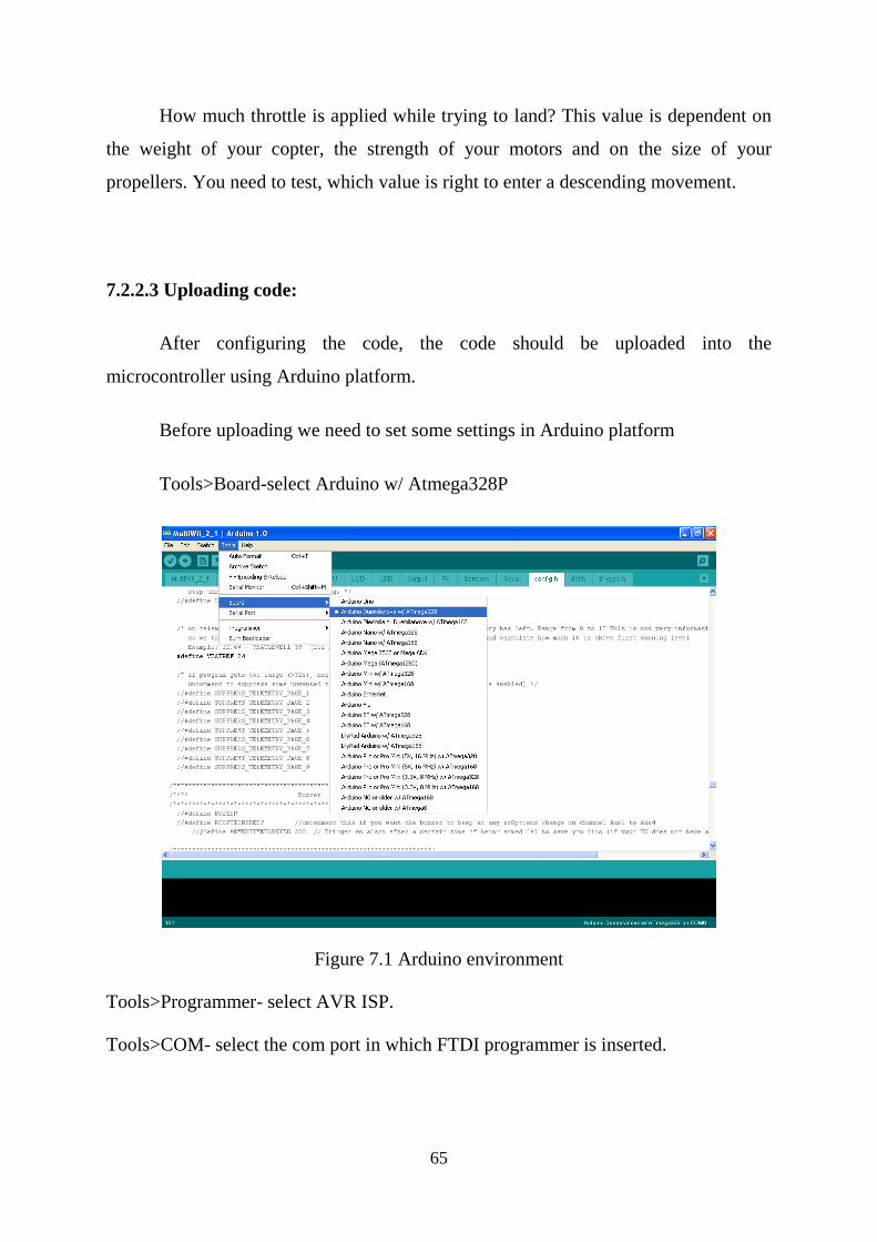
Before uploading we need to set some settings in Arduino platform
Tools>Board-select Arduino w/ Atmega328P
Figure 7.1 Arduino environment
Tools>Programmer- select AVR ISP.
Tools>COM- select the com port in which FTDI programmer is inserted.
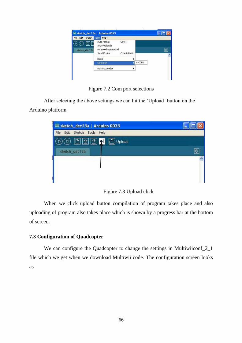
66
Figure 7.2 Com port selections
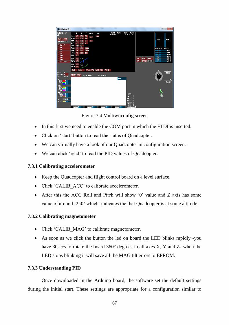
After selecting the above settings we can hit the ‘Upload’ button on the
Arduino platform.
Figure 7.3 Upload click
When we click upload button compilation of program takes place and also
uploading of program also takes place which is shown by a progress bar at the bottom
of screen.
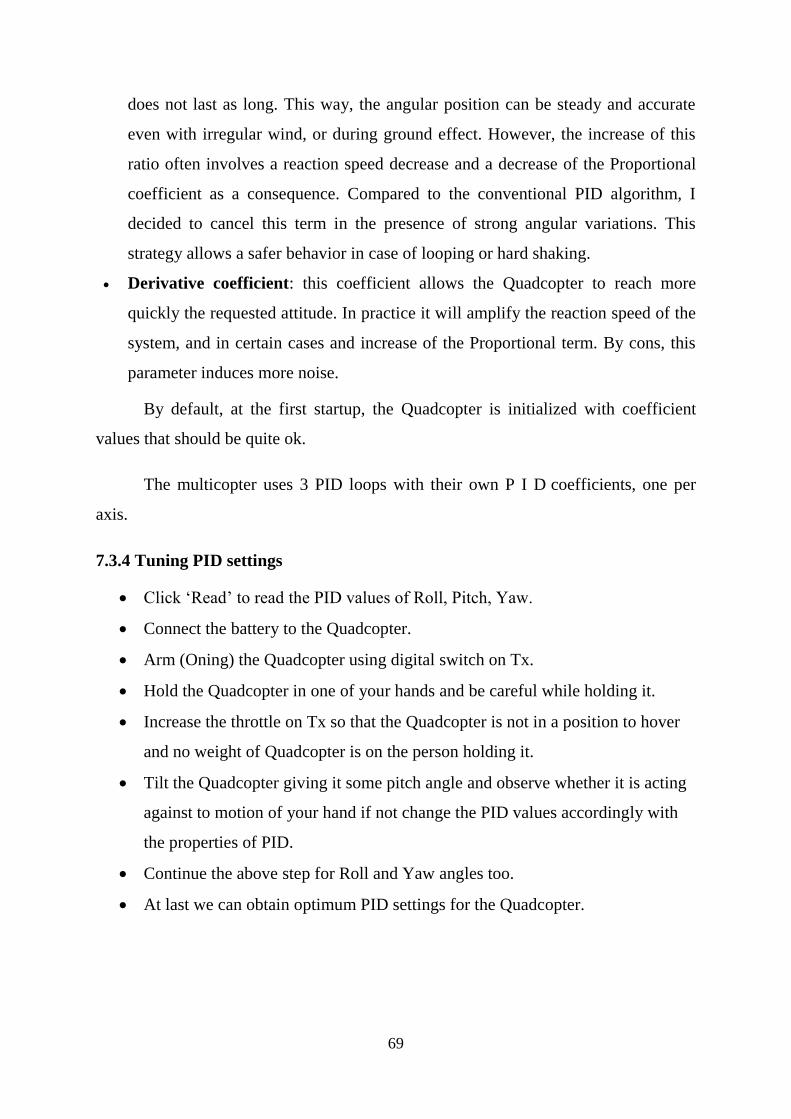
7.3 Configuration of Quadcopter
We can configure the Quadcopter to change the settings in Multiwiiconf_2_1
file which we get when we download Multiwii code. The configuration screen looks
as
67
Figure 7.4 Multiwiiconfig screen
In this first we need to enable the COM port in which the FTDI is inserted.
Click on ‘start’ button to read the status of Quadcopter.
We can virtually have a look of our Quadcopter in configuration screen.
We can click ‘read’ to read the PID values of Quadcopter.
7.3.1 Calibrating accelerometer
Keep the Quadcopter and flight control board on a level surface.
Click ‘CALIB_ACC’ to calibrate accelerometer.
After this the ACC Roll and Pitch will show ‘0’ value and Z axis has some
value of around ‘250’ which indicates the that Quadcopter is at some altitude.
7.3.2 Calibrating magnetometer
Click ‘CALIB_MAG’ to calibrate magnetometer.
As soon as we click the button the led on board the LED blinks rapidly -you
have 30secs to rotate the board 360° degrees in all axes X, Y and Z- when the
LED stops blinking it will save all the MAG tilt errors to EPROM.
7.3.3 Understanding PID
Once downloaded in the Arduino board, the software set the default settings
during the initial start. These settings are appropriate for a configuration similar to

68
mine (motors / ESCs / propellers / weight).However, another configuration will
probably require other parameters to be optimal.
For instance, if you want to use a larger multicopter for FPV. The multicopter
uses a closed controlled loop to ensure its stability and maneuverability.
Like most multirotor, it is a Proportional-Integral-Derivative (PID) regulator.
This controller is translated into software code lines in the Arduino and tries to correct
the error calculated between a measurement at the controller output (measured by the
gyros) and an input set point (position of the stick), using appropriate action to adjust
the output of the process (command to motors).
PID controller involves three separate parameters: the term Proportional, the
term Integral and the term Derivative. The variation of each of these parameters alters
the effectiveness of the stabilization.
Applied to a multirotor, the coefficients of these parameters can be translated
by their behavior:
Proportional coefficient: alone, it may achieve stabilization. This coefficient
determines the importance of action on the engines in relation with the values
measured by the gyroscopes. The higher the coefficient, the higher the
Quadcopter seems more “rigid” versus angular deviation. If it is too low, the
multicopter will appear soft and will be harder to keep steady. One can “feel” this
setting by handling the Quadcopter and trying to change its orientation: the higher
the parameter, the higher the opposition is important. In practice, this parameter
must be set alone and increased up to be the limit for obtaining small oscillations.
If too high, the system becomes unstable by amplifying the oscillations.
Integral coefficient: this coefficient can increase the precision of the angular
position. In practice, when the Quadcopter is disturbed and its angle changes, the
term Integral remembers the disruption and applies a correction to the engines to
get the right angle. We can see this term as a heading hold factor. Typically if you
take handfuls the multicopter and try to force it into a position, the engines will
continue for some time to counteract the action. Without this term, the opposition
69
does not last as long. This way, the angular position can be steady and accurate
even with irregular wind, or during ground effect. However, the increase of this
ratio often involves a reaction speed decrease and a decrease of the Proportional
coefficient as a consequence. Compared to the conventional PID algorithm, I
decided to cancel this term in the presence of strong angular variations. This
strategy allows a safer behavior in case of looping or hard shaking.
Derivative coefficient: this coefficient allows the Quadcopter to reach more
quickly the requested attitude. In practice it will amplify the reaction speed of the
system, and in certain cases and increase of the Proportional term. By cons, this
parameter induces more noise.
By default, at the first startup, the Quadcopter is initialized with coefficient
values that should be quite ok.
The multicopter uses 3 PID loops with their own P I D coefficients, one per
axis.
7.3.4 Tuning PID settings
Click ‘Read’ to read the PID values of Roll, Pitch, Yaw.
Connect the battery to the Quadcopter.
Arm (Oning) the Quadcopter using digital switch on Tx.
Hold the Quadcopter in one of your hands and be careful while holding it.
Increase the throttle on Tx so that the Quadcopter is not in a position to hover
and no weight of Quadcopter is on the person holding it.
Tilt the Quadcopter giving it some pitch angle and observe whether it is acting
against to motion of your hand if not change the PID values accordingly with
the properties of PID.
Continue the above step for Roll and Yaw angles too.
At last we can obtain optimum PID settings for the Quadcopter.
70
‘One picture is worth more than ten thousand words’
-Anonymous
‘
CHAPTER 8
FPV
8.1 Introduction
First-person view (FPV), also known as remote-person view (RPV), or simply
video piloting, is a method used to control a radio controlled model vehicle from the
driver or pilot's view point. Most commonly it is used to pilot an unmanned aerial
vehicle (UAV) or a radio-controlled aircraft. The vehicle is either driven or piloted
remotely from a first person perspective via an onboard camera, fed wirelessly to
virtual reality goggles or a video monitor.
First-person view (FPV) flight is a type of remote-control (RC) flying that has
grown in popularity in recent years. It involves mounting a small video camera and
analog television transmitter on an RC aircraft and flying by means of a live video
down-link, commonly displayed on video goggles or a portable LCD screen. When
flying FPV, the pilot sees from the aircraft's perspective, and does not even have to
look at the model. As a result, FPV aircraft can be flown well beyond visual range,
limited only by the range of the remote control and video transmitter. FPV became
increasingly common throughout the 2000s and early 2010s. It is currently one of the
fastest growing activities involving RC aircraft, and has given rise to a small but
growing industry providing products specifically designed for FPV use.
71
8.2 Equipment
There are two primary components of an FPV setup—the airborne component
and the ground component (typically called a ground station). A basic FPV system
consists of a camera and video transmitter on the aircraft and a video receiver and a
display on the ground. More advanced setups commonly add in specialized hardware,
including on-screen displays with GPS navigation and flight data, stabilization
systems, and autopilot devices with "return to home" capability—allowing the aircraft
to fly back to its starting point on its own in the event of a signal loss. On-board
cameras can be equipped with a pan and tilt mount, which when coupled with video
goggles and "head tracking" devices creates a truly immersive, first-person
experience, as if the pilot was actually sitting in the cockpit of the RC aircraft.
Ground stations can be equipped with high gain antennas and automatic
antenna tracking systems to provide for maximum range on the video link.
8.3 Radio frequencies
Video transmitters typically operate at a power level between 200 mW and
1500 mW. The most common frequencies used for video transmission are 900 MHz,
1.2 GHz, 2.4 GHz, and 5.8 GHz.
We have equipped our Quadcopter with a CCD camera as specified in
specifications in chapter 4. To the camera we have connected 0.9GHz four channels
Tx to transmit the video.
At the ground station we have a 12 channel Rx with antenna to receive the
video signal and from the Rx we have a RCA cable and that RCA cable can be
connected to Television or any display device to view the video.
8.4 Ready to fly
After equipped with all components as specified in chapter 4 and configuring it
as in chapters 6, 7 we are ready to fly the quadcopter!
72
‘Success in the end erases all the mistakes along the way’
CHAPTER 9
ACHIEVEMENTS
9.1 Achievements
After flying our Quadcopter we achieved some goals of our task
Our quad can hover and maneuver for a time of 6minutes with the battery
(chapter 4) we used.
Our quad can stably fly and we have achieved height of over 30feet (we can
also get more height but we did not go beyond this due to some air restrictions).
We have also got the first person view from the camera we equipped on quad
over the distance of 200m.
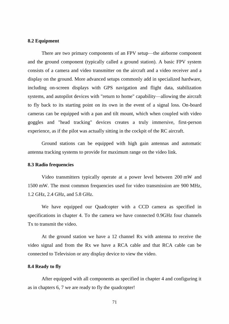
9.2 Pictures of flight
We had taken some snapshots of our flight.
Figure 9.1 Figure 9.2
73
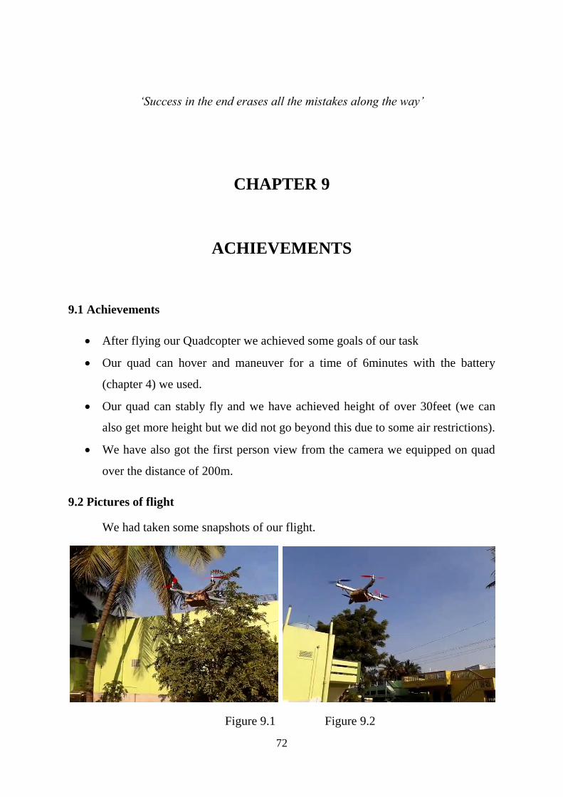
Figure 9.3 Figure 9.4
Figure 9.5 Figure 9.6
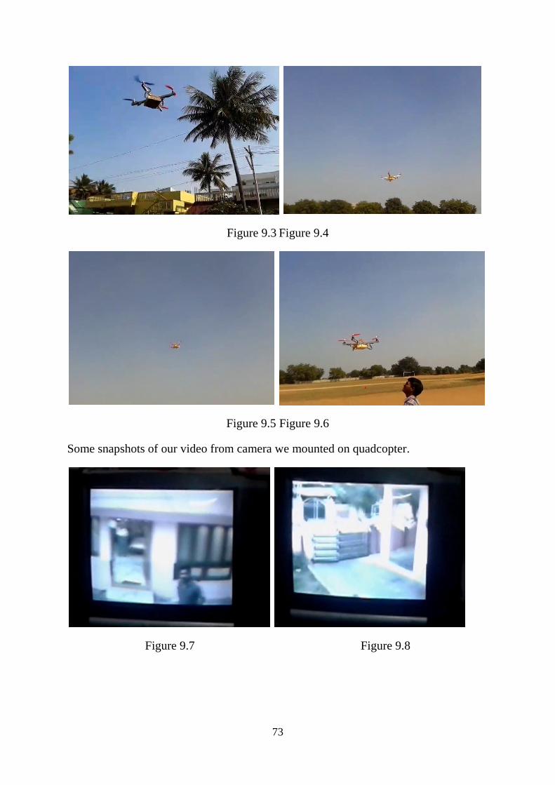
Some snapshots of our video from camera we mounted on quadcopter.
Figure 9.7 Figure 9.8
74
Figure 9.9 Figure 9.10
9.3 Videos of flight
You can view videos of our flight on YouTube
www.youtube.com (channel: Gopi Krishna)
75
‘Experience is simply the name we give our mistakes.’
-Oscar Wilde
CHAPTER 10
FURTHER DEVELOPMENT AND ADVANCEMENTS
10.1 Further developments
Albeit we worked hard to develop our quadcopter without flaws, we found
some problems during our flight.
So we present some further developments to our vehicle for smooth running
and for perfect execution of task.
We have used aluminium frame to build our vehicle. Although it is very less in
weight it is not damping the vibrations caused by the motors and these vibrations are
tending their effect on the sensors (accelerometers, gyros) we used on the flight
control board.
So due to the effect of vibrations on sensors, the sensors are giving wrong
orientation (may be very minute, but in aerial vehicles it is significant) to the
microcontroller and indeed there is some fluctuations in stability of vehicle which we
did not want to prevail.
So to decrease the effect of vibrations we should use ‘carbon fibre’ instead of
aluminium to damp the maximum vibrations.
76
In extension with carbon fiber frame we should take necessary steps to damp
the vibrations of motors by using some rubber like material down the motor and
mount the motor tightly and perfectly.
10.2 Advancements
With the motors we have used, our quadcopter cannot make a 180degree turn
and hover , so it make it work like that we have to use motors and propellers in such a
way that when it turn 180 degrees the propellers should also change their pitch so we
have to have a mechanism at the motor to make this.
Our quadcopter can handle the natural disasters like earthquakes, liminic
eruptions, heat waves and other disasters may be natural or manmade.
In order to sustain hydro disasters we have to make some necessary
advancement to the quadcopter by providing some water resistant material to protect
the electrical connections, we can use materials like polyester fleece, plastic etc.
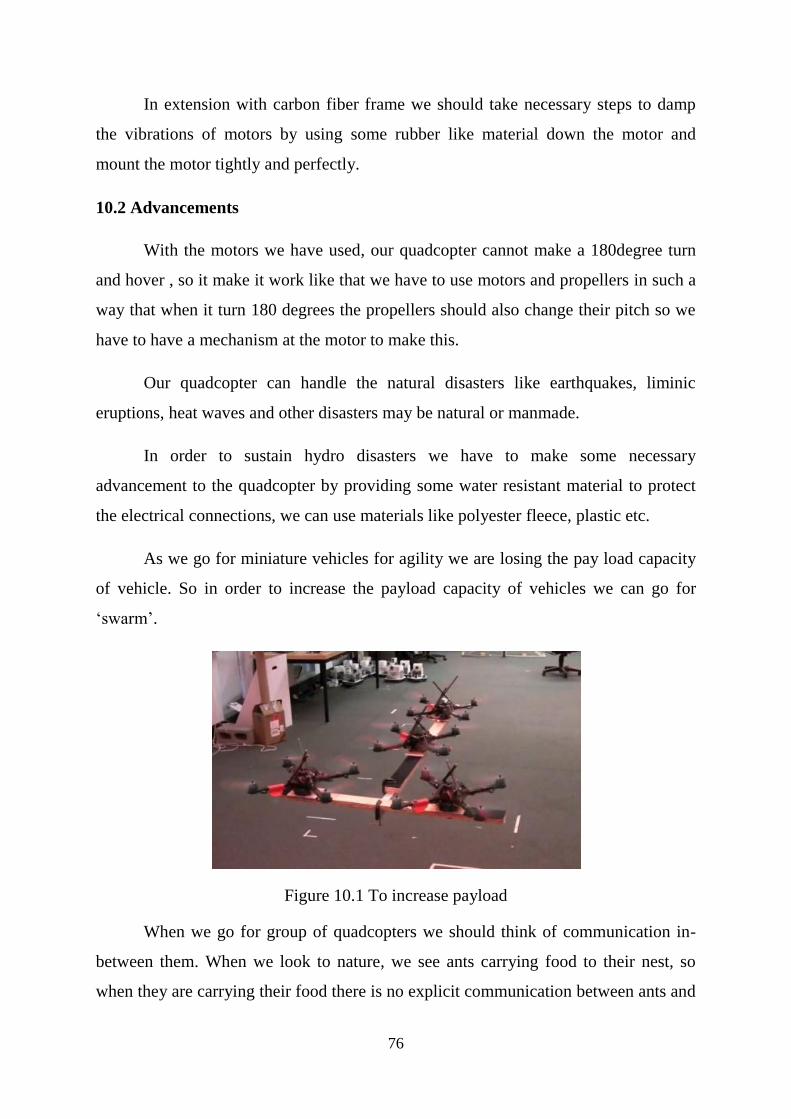
As we go for miniature vehicles for agility we are losing the pay load capacity
of vehicle. So in order to increase the payload capacity of vehicles we can go for
‘swarm’.
Figure 10.1 To increase payload
When we go for group of quadcopters we should think of communication in-
between them. When we look to nature, we see ants carrying food to their nest, so
when they are carrying their food there is no explicit communication between ants and

77
there is no centralized communication too. But they communicate implicitly in a
decentralized way.
So, learning from nature we have to make the swarm of quads to communicate
with each other and develop a formation to carry the payload required.
We have different algorithms for these swarm vehicles as proposed by Vijay
Kumar and his team in his paper ‘Towards A Swarm of Agile Micro Quadrotors’.
The algorithms include:
Formation flight:
Flying in formation reduces the complexity of generating trajectories for
a large team of vehicles to generating a trajectory for a single entity. If the
controllers are well-designed, there is no need to explicitly incorporate
collision avoidance between vehicles.
Time-Separated Trajectory Following
Another way to reduce the complexity of the trajectory generation
problem is to require all vehicles to follow the same team trajectory but be
separated by some time increment.
Figure 10.2 8 formation
Some images for swarm of quadcopters:
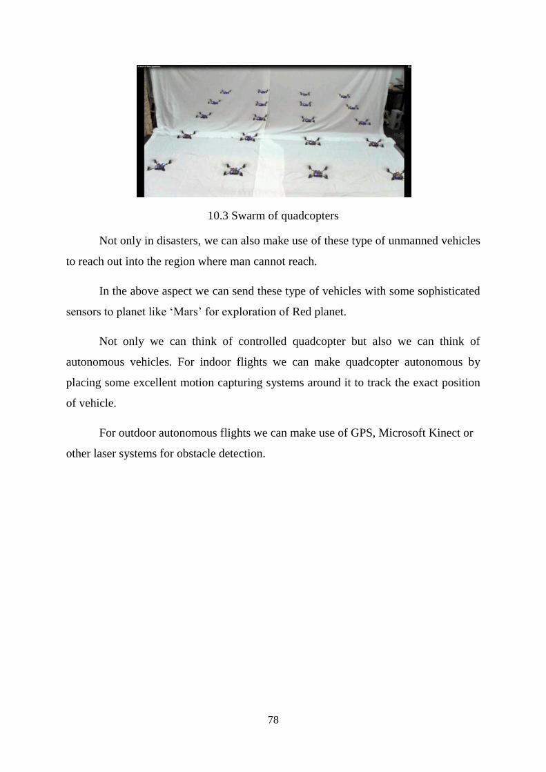
78
10.3 Swarm of quadcopters
Not only in disasters, we can also make use of these type of unmanned vehicles
to reach out into the region where man cannot reach.
In the above aspect we can send these type of vehicles with some sophisticated
sensors to planet like ‘Mars’ for exploration of Red planet.
Not only we can think of controlled quadcopter but also we can think of
autonomous vehicles. For indoor flights we can make quadcopter autonomous by
placing some excellent motion capturing systems around it to track the exact position
of vehicle.
For outdoor autonomous flights we can make use of GPS, Microsoft Kinect or
other laser systems for obstacle detection.

79
APPENDIX
The details of cost of components we used (from www.hobbyking.com)
(From www.goodluckbuy.com)
Total: $ 398.85 USD
80
References
‘Towards A Swarm of Agile Micro Quadrotors’ by Alex Kushleyev, Daniel
Mellinger, Vijay Kumar, GRASP Lab, University of Pennsylvania
Datasheets: ATMEGA328P, ITG3205, BMA180, HMC5883L
www.multiwii.com – the site for open source code on multirotors
www.wikipedia.com – for enormous data related to concepts of aerodynamic lift
www.hobbyking.com – the site to buy different Radio Controlled (RC) components
www.goodluckbuy.com – the site to buy flight control board
www.arduino.cc – the site for Arduino software
www.ecalc.ch – the site for calculations of multirotors
www.rcgroups.com- the forum for various discussions on multirotors
www.blog.tkjelectronics.dk – the blog to know basics of multirotors
www.ted.com- for video of Vijaykumar on autonomous quadrotors
Copyright © 2022 FDOKUMEN