Quadcopter Docking on a Moving Platform Critical Design ...
41
Quadcopter Docking on a Moving Platform Critical Design Review Report Team E – Dock-in-Piece 05/05/2016 Paul M. Calhoun Rushat Gupta Chadha Keerthana Subramanian Manivannan Aishanou Osha Rait Bishwamoy Sinha Roy
-
Upload
khangminh22 -
Category
Documents
-
view
2 -
download
0
Transcript of Quadcopter Docking on a Moving Platform Critical Design ...

Quadcopter Docking on a Moving Platform
Critical Design Review Report Team E – Dock-in-Piece
05/05/2016
Paul M. Calhoun
Rushat Gupta Chadha Keerthana Subramanian Manivannan
Aishanou Osha Rait Bishwamoy Sinha Roy

MRSD Project – Dock-in-Piece December 17, 2015
1
Abstract
Our problem statement is inspired by the challenges faced by FMC Technologies Schilling
Robotics personnel, while docking their Remote Operated Vehicle (ROV) to the Tether
Management System (TMS). The ROV detaches and deploys from the bottom of the TMS when
the system is at depth. The TMS is negatively buoyant and is suspended from a ship. As the ship
heaves on the surface of the water, the TMS heaves up and down with a slight lateral motion. ROV
Operators must dock and latch the ROV to the underside of the moving TMS before resurfacing.
This can be very challenging for even experienced operators. Autonomous docking is the core
problem we aim to solve. Through this project we will demonstrate the autonomous docking of a
quadcopter to the underside of a suspended moving platform. The underwater environment will be
simulated by functioning in a GPS degraded environment. At the end of the project, we were
docking autonomously to a moving overhead platform, with the quadcopter acting completely
autonomously until docking occurred, including landing if the dock was moving faster than was
considered safe. The details of our design and implementation are outlined in this report.

MRSD Project – Dock-in-Piece December 17, 2015
2
Table of Contents
1 Introduction ........................................................................................................................................ 4
2 Project Description .............................................................................................................................. 4
3 Use Case .............................................................................................................................................. 4
4 System level requirements .................................................................................................................. 6
4.1 Mandatory Requirements ........................................................................................................... 6
4.1.1 Functional Requirements .................................................................................................... 6
4.1.2 Non-Functional Requirements ............................................................................................ 6
4.2 Desirable Requirements .............................................................................................................. 6
4.2.1 Functional Requirements .................................................................................................... 6
4.2.2 Non Functional Requirements............................................................................................. 7
5 Functional Architecture ....................................................................................................................... 7
5.1 Initiation Phase............................................................................................................................ 7
5.2 Decision Phase ............................................................................................................................ 7
5.3 Docking Phase ............................................................................................................................. 8
6 System Level Trade Studies ................................................................................................................. 8
6.1 Overall System Design ................................................................................................................. 8
6.2 Docking Mechanism .................................................................................................................... 9
6.3 Quadcopter ............................................................................................................................... 10
7 Cyber-physical Architecture .............................................................................................................. 11
7.1 Docking Platform ....................................................................................................................... 11
7.2 Quadcopter ............................................................................................................................... 11
8 System Description and Evaluation ................................................................................................... 14
8.1 System/subsystem descriptions/depictions.............................................................................. 14
8.1.1 Docking Platform ............................................................................................................... 14
8.1.2 Quadcopter ....................................................................................................................... 16
8.1.3 Palantir .............................................................................................................................. 16
8.2 Modelling, Analysis and Testing ................................................................................................ 19

MRSD Project – Dock-in-Piece December 17, 2015
3
8.2.1 Docking Platform ............................................................................................................... 19
8.2.2 Quadcopter ....................................................................................................................... 21
8.2.3 Palantir .............................................................................................................................. 23
8.3 Performance evaluation against the Spring Validation Experiment (SVE) ................................ 24
8.4 Strong/Weak Points .................................................................................................................. 26
9 Project Management......................................................................................................................... 27
9.1 Schedule .................................................................................................................................... 27
9.2 Budget ....................................................................................................................................... 28
9.3 Risk Management...................................................................................................................... 29
10 Conclusions ....................................................................................................................................... 30
10.1 Lessons Learned ........................................................................................................................ 30
10.2 Future Work .............................................................................................................................. 31
11 References ......................................................................................................................................... 31
Appendix A ................................................................................................................................................ 32
MRSD Project – Dock-in-Piece December 17, 2015
4
1 Introduction
Our problem statement is inspired by the challenges faced by FMC Technologies Schilling
Robotics personnel while docking their Remotely Operated Vehicle (ROV) to the Tether
Management System (TMS). The ROV detaches and deploys from the bottom of the TMS when
the system is at depth. The TMS is negatively buoyant and is suspended from a ship. As the ship
heaves on the surface of the water, the TMS heaves up and down with a slight lateral motion.
ROV Operators must dock and latch the ROV to the underside of the moving TMS before
resurfacing. This can be very challenging for even experienced operators. Collisions frequently
damage the ROV and TMS. The tether is sometimes compressed between the ROV and the TMS,
which degrades the communication and power supply between the TMS and the ROV. At times,
the tether breaks and the ROV falls to the bottom of the seabed, resulting in the need for another
ROV to be deployed to bring it back.
2 Project Description
Through this project, we demonstrated the autonomous docking of a quadcopter to the
underside of a suspended moving platform. This model approximated the subsea system of ROV
and TMS, complete with determining the safe conditions to dock and providing mechanical
latching system that minimizes the forces between the quadcopter and the platform. The platform
moves up and down in a sinusoidal motion which is analogous to the TMS which bobs up and
down under the sea, and the quadcopter is analogous to the ROV. The project focuses on more
on the prediction system which predicts an optimal moment to dock rather than the locking or
mechanical aspects of the ROV-TMS system. The underwater environment is simulated by
functioning in a GPS degraded environment.
3 Use Case
A developer at Schilling Robotics visits a trade fair and sees a retrofit kit that adds a minimal
payload and the capability of autonomous docking to a platform moving in a single axis. Having
several customers of his unmanned undersea vehicle branch who want a method of navigating to
a tether management system with their underwater remotely operated vehicle, he purchases the
retrofit. He reasons that it will be fun and possibly get him a pay point on his next performance
cycle if he can demonstrate its usefulness to his supervisor. He purchases the retrofit and declines
to fill out a customer survey asking him what further features he wants to see in the next version,
since this one has all the features he wants already.
He receives the kit and spends a weekend setting up a dock as shown in figure 1. The addition
of the software changes to his Phantom 2 takes a few minutes and the hardware install is almost
as swift. It’s a windy day and the tree he’d tied his platform to was swaying quite a bit, and after
his initial disappointment at the app telling him it was impossible to dock in those conditions,
repeatedly mashing the ‘dock’ button finally proved effective and the drone successfully attaches
itself to the dock without running into the tree. It even weaves around his bird feeder and succeeds
in avoiding a starling that appeared intent on driving the drone out of the air. He is pleased that
the retrofit is light and not very cumbersome.

MRSD Project – Dock-in-Piece December 17, 2015
30
Figure 1 Quadcopter and Platform in adverse environment
The developer secures funding from his supervisor and contacts the student team who
launched the retrofit into a full product. Though hesitant at first, they engage an attorney and draw
up a limited use contract for the TDP of the docking kit. The developer is happy, his boss less so
when he sees what kind of royalties the developer had agreed to, and the developer realizes he’s
going to have to work very hard for that pay point. He gets going and succeeds in adapting the
code for his customers’ ROV and TMS. On its first test, the ROV collides with an undersea vent.
However, the entire test is invalidated when they discover an octopus had attached itself to the
ROV camera and that a warning had been displayed by the adapted software, but not where the
ROV operator is used to viewing warnings and cautions.
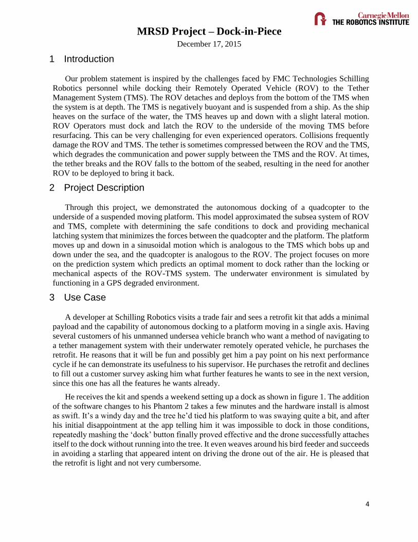
Finally, launch day arrives and the customer is pleased at the results. The ROV docks without
needing the use of a heave-compensated winch. The ROV smoothly detaches from the TMS, goes
about its mission, and returns to be hauled up on the TMS without incident (figure 2). The
customer is also very happy with the user interface, which is a single toggle button, removing the
need for lengthy training and decreasing the costs of using the ROV, since the operators don’t
have to be as skilled at docking any more. The developer gets a bonus from his supervisor, an
angry letter from the sailors’ union, and a bill from the UAV kit developers after an independent
audit.
Figure 2 Successful Retrieval of the ROV
Future deployments of ROV systems aboard ships include the changes and a program to make
sure the necessary changes is implemented on legacy ROV carriers as they are brought in for
routine maintenance.

MRSD Project – Dock-in-Piece December 17, 2015
30
4 System level requirements
4.1 Mandatory Requirements
4.1.1 Functional Requirements
The system shall
MF1. Have two major components: a quadcopter and a moving platform
MF2. Detect and communicate when docking is not possible
The docking platform shall
MF1.1 Be moving in a single axis (z-direction) until the quadcopter has been docked
MF1.2. Oscillate in harmonic motion with dominant frequency < 0.3Hz
MF1.3. Have oscillations’ span ±200mm
The quadcopter shall
MF2.1. Localize w.r.t. platform within 50mm accuracy
MF2.2 Plan a path to the docking platform
MF2.2 Generate a trajectory from the starting position to the platform
MF2.3 Navigate to the platform
MF2.4. Dock to the platform autonomously and without colliding (collision defined as
relative velocity of the quadcopter with respect to the dock of 50 cm/s) within 10 minutes
4.1.2 Non-Functional Requirements
The system shall
MNF1. Function in a GPS degraded environment
MNF2. Be easy to operate, maintain, and repair
MNF3. Provide a user interface status of docking
MNF4. Cost less than $3,000 to own over its life cycle
The quadcopter shall
MNF2.1 Have a payload capacity of > 500g
The platform shall
MNF3.1 Have a locking mechanism which supports weight of 5kg
4.2 Desirable Requirements
4.2.1 Functional Requirements
The docking platform will
DF1.1. Have 3 degrees of freedom along X, Y and Z-direction

MRSD Project – Dock-in-Piece December 17, 2015
30
DF1.2. Oscillate in harmonic motion with dominant frequency of greater range
4.2.2 Non Functional Requirements
The docking platform will
DNF1.2. Have random movements in 3D space
The quadcopter will
DNF2.1. Dock to the platform within 5 minutes
5 Functional Architecture
Figure 3 Functional Architecture of the Docking process
The system’s input is the user’s decision to dock and the output is the successful dock. The
architecture is divided into three parts - the quadcopter, the platform, and the Palantir. The
subsystems work together to plan the approach to the docking platform and dock at an opportune
moment. The moment to dock is determined by the Palantir. There are three phases in the whole
docking process. (Figure 3)
5.1 Initiation Phase
During this phase the user initiates the docking sequence by beginning the program, which
allows the quadcopter to take off and stabilize at a safe distance below the moving platform. The
safe distance is determined by hovering in place for 8-10s and watching the heave of the platform.
The quadcopter, then, autonomously maintains the safe distance for the next phase.
5.2 Decision Phase
Once the quadcopter reaches the safe distance, the Palantir starts analyzing the IR data from
the platform. Once enough data is received (10s), the Palantir runs its analysis to come up with
the mating moment and communicates this instant with a approach velocity to the quadcopter. If
docking isn’t possible (frequency of the platform is higher than a modifiable threshold), the
quadcopter lands. If docking is possible, the system moves to the docking phase.

MRSD Project – Dock-in-Piece December 17, 2015
30
5.3 Docking Phase
When the quadcopter receives the time to mate and the velocity approach, it waits for the
prescribed amount of time and begins its approach. It latches on using the locking mechanism
(Velcro) and the final output is sent to the user that the quadcopter has been docked successfully
and what the relative velocity between the quadcopter and dock was.
6 System Level Trade Studies
6.1 Overall System Design
Table 1 Overall System Trade Study
Category Weightage
(100%)
Tethered
Non-Tethered
Heave Compensating Mechanism
Ease of Quadcopter
Maneuverability
20 7 10 10
Customer
Requirements
15 9 9 5
Mechanical
Complexity
15 8 8 4
Scalability 15 8 8 3
Control Complexity 15 7 8 7
Cost 10 7 9 4
Chance of Failure 10 7 9 5
Total 10 7.6 8.75 5.75
An important thing which was kept in mind while deciding various system level designs was
the fact that this project is a simulation of a real life problem. To deliver what our client needs, it
is very important that this project is in line with their expectations, problems faced with the existing
hardware. After brainstorming, the team has come up three system level solutions that are being
judged by the 7 criteria shown in Table 1.
Of the three potential solutions, two were purely Quadcopter control based, while the other
was a mechanical solution to be installed on the moving platform. While the sponsor gave the team
a lot of flexibility on the range of possible solutions, a mechanical solution was strongly
discouraged, primarily because of the scalability issue and the fact that mechanical appendages
has lots of on-site maintenance problems. Since the team shared common interest in making the
final product as implementable as possible, the heave compensating mechanical appendage was
ruled out. A major decision that the team had to make was whether to use a tether on the
Quadcopter or not. While using a tethered Quadcopter would be the closest simulation of the actual
MRSD Project – Dock-in-Piece December 17, 2015
30
system, the low score in ease of Quadcopter maneuverability, which had the maximum weight,
automatically ruled the tethered solution out. With a score of 8.75 on a scale of 10, a Non-Tethered
Quadcopter using a purely control based approach which was also the most scalable and desired
solution to the problem was chosen.
6.2 Docking Mechanism
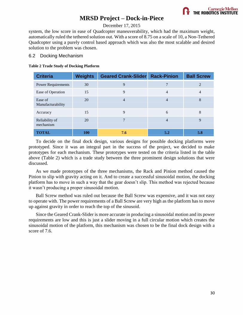
Table 2 Trade Study of Docking Platform
Criteria Weights Geared Crank-Slider Rack-Pinion Ball Screw
Power Requirements 30 9 7 2
Ease of Operation 15 9 4 4
Ease of
Manufacturability
20 4 4 8
Accuracy 15 9 6 8
Reliability of
mechanism
20 7 4 9
TOTAL 100 7.6 5.2 5.8
To decide on the final dock design, various designs for possible docking platforms were
prototyped. Since it was an integral part in the success of the project, we decided to make
prototypes for each mechanism. These prototypes were tested on the criteria listed in the table
above (Table 2) which is a trade study between the three prominent design solutions that were
discussed.
As we made prototypes of the three mechanisms, the Rack and Pinion method caused the
Pinion to slip with gravity acting on it. And to create a successful sinusoidal motion, the docking
platform has to move in such a way that the gear doesn’t slip. This method was rejected because
it wasn’t producing a proper sinusoidal motion.
Ball Screw method was ruled out because the Ball Screw was expensive, and it was not easy
to operate with. The power requirements of a Ball Screw are very high as the platform has to move
up against gravity in order to reach the top of the sinusoid.
Since the Geared Crank-Slider is more accurate in producing a sinusoidal motion and its power
requirements are low and this is just a slider moving in a full circular motion which creates the
sinusoidal motion of the platform, this mechanism was chosen to be the final dock design with a
score of 7.6.

MRSD Project – Dock-in-Piece December 17, 2015
30
6.3 Quadcopter
Table 3 Quadcopter Trade Study
Category Weightage
(100%)
DJI Matrice
100 [4]
TurboAce
Matrix
3DR
solo
3DR
X8+
Payload Capacity 20 8 9 4 7
Customizability
of processor
15 8 1 7 7
Availability of an
SDK
20 9 0 8 8
Documentation of
SDK
20 9 0 8 8
Position of on
Board Camera
10 8 9 4 4
Battery Life 5 8 8 6 4
Spares /
availability
5 8 8 8 8
Cost 5 3 6 7 8
Total 10 8.35 4.35 6.9 7.45
The Quadcopter is the most important subsystem of this project, and the success of the project
revolves around the Quadcopter’s control. A carefully discussed set of criteria for the selection of
a Quadcopter with their respective weights are illustrated in Table 3 .Three of these criteria played
a significant role in the decision process: Payload capacity, availability of an SDK (Software
Development Kit), and its Documentation. After filtering out hobby Quadcopters, the team
narrowed down to 4 Quadcopters, suppliers of which are famous among the aerial vehicle
community for various reasons like payload capacity and the SDK. However, 2 of these (TurboAce
Matrix and 3DR solo), got ruled out because of lack of an SDK and low payload capacity.
A lengthy analysis based on reviews from users and developers led to the conclusion that even
though the DJI Matrice 100 was more expensive, its add-ons, like preloaded flight algorithms,
filtered sensor outputs, battery life, and excellent reviews would overall be a very big advantage
for the team while troubleshooting sensor and hardware related problems. Since this was the most
important part of our project, cost wasn’t given a high weight and hence the DJI Matrice 100 won
the trade study with a score of 8.35 on a scale of 10.
MRSD Project – Dock-in-Piece December 17, 2015
30
7 Cyber-physical Architecture
7.1 Docking Platform
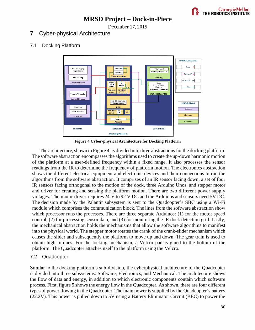
Figure 4 Cyber-physical Architecture for Docking Platform
The architecture, shown in Figure 4, is divided into three abstractions for the docking platform.
The software abstraction encompasses the algorithms used to create the up-down harmonic motion
of the platform at a user-defined frequency within a fixed range. It also processes the sensor
readings from the IR to determine the frequency of platform motion. The electronics abstraction
shows the different electrical equipment and electronic devices and their connections to run the
algorithms from the software abstraction. It comprises of an IR sensor facing down, a set of four
IR sensors facing orthogonal to the motion of the dock, three Arduino Unos, and stepper motor
and driver for creating and sensing the platform motion. There are two different power supply
voltages. The motor driver requires 24 V to 92 V DC and the Arduinos and sensors need 5V DC.
The decision made by the Palantir subsystem is sent to the Quadcopter’s SBC using a Wi-Fi
module which comprises the communication block. The lines from the software abstraction show
which processor runs the processes. There are three separate Arduinos: (1) for the motor speed
control, (2) for processing sensor data, and (3) for monitoring the IR dock detection grid. Lastly,
the mechanical abstraction holds the mechanisms that allow the software algorithms to manifest
into the physical world. The stepper motor rotates the crank of the crank-slider mechanism which
causes the slider and subsequently the platform to move up and down. The gear train is used to
obtain high torques. For the locking mechanism, a Velcro pad is glued to the bottom of the
platform. The Quadcopter attaches itself to the platform using the Velcro.
7.2 Quadcopter
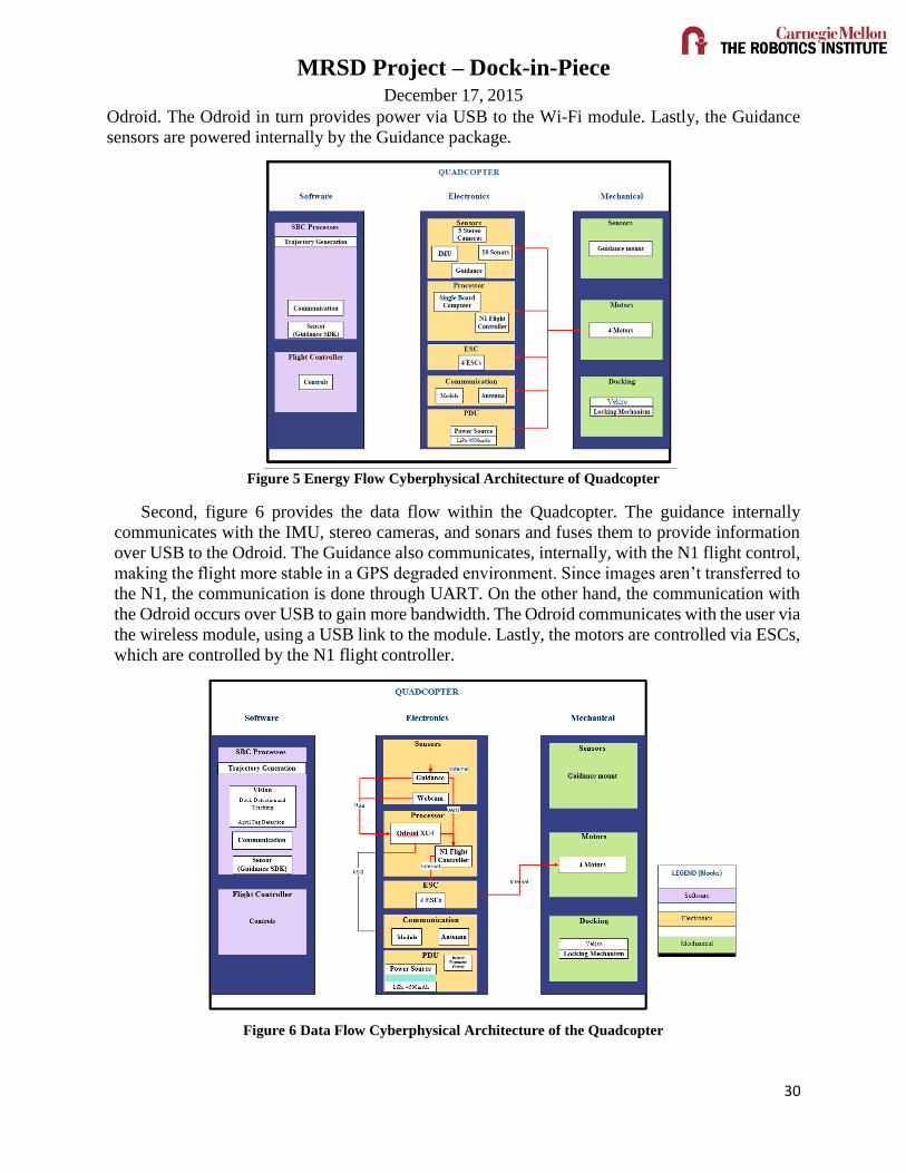
Similar to the docking platform’s sub-division, the cyberphysical architecture of the Quadcopter
is divided into three subsystems: Software, Electronics, and Mechanical. The architecture shows
the flow of data and energy, in addition to which electronic components contain which software
process. First, figure 5 shows the energy flow in the Quadcopter. As shown, there are four different
types of power flowing in the Quadcopter. The main power is supplied by the Quadcopter’s battery
(22.2V). This power is pulled down to 5V using a Battery Eliminator Circuit (BEC) to power the
MRSD Project – Dock-in-Piece December 17, 2015
30
Odroid. The Odroid in turn provides power via USB to the Wi-Fi module. Lastly, the Guidance
sensors are powered internally by the Guidance package.
Figure 5 Energy Flow Cyberphysical Architecture of Quadcopter
Second, figure 6 provides the data flow within the Quadcopter. The guidance internally
communicates with the IMU, stereo cameras, and sonars and fuses them to provide information
over USB to the Odroid. The Guidance also communicates, internally, with the N1 flight control,
making the flight more stable in a GPS degraded environment. Since images aren’t transferred to
the N1, the communication is done through UART. On the other hand, the communication with
the Odroid occurs over USB to gain more bandwidth. The Odroid communicates with the user via
the wireless module, using a USB link to the module. Lastly, the motors are controlled via ESCs,
which are controlled by the N1 flight controller.
Figure 6 Data Flow Cyberphysical Architecture of the Quadcopter
MRSD Project – Dock-in-Piece December 17, 2015
30
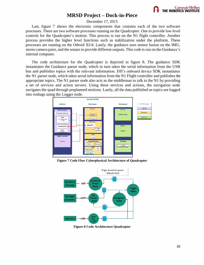
Last, figure 7 shows the electronic components that contains each of the two software
processes. There are two software processes running on the Quadcopter. One to provide low level
controls for the Quadcopter’s motion. This process is run on the N1 flight controller. Another
process provides the higher level functions such as stabilization under the platform. These
processes are running on the Odroid XU4. Lastly, the guidance uses sensor fusion on the IMU,
stereo camera pairs, and the sonars to provide different outputs. This code is run on the Guidance’s
internal computer.
The code architecture for the Quadcopter is depicted in figure 8. The guidance SDK
instantiates the Guidance parser node, which in turn takes the serial information from the USB
bus and publishes topics with the relevant information. DJI’s onboard device SDK instantiates
the N1 parser node, which takes serial information from the N1 Flight controller and publishes the
appropriate topics. The N1 parser node also acts as the middleman to talk to the N1 by providing
a set of services and action servers. Using these services and actions, the navigation node
navigates the quad through preplanned motions. Lastly, all the data published as topics are logged
into rosbags using the Logger node.
Figure 7 Code Flow Cyberphysical Architecture of Quadcopter
Figure 8 Code Architecture Quadcopter

MRSD Project – Dock-in-Piece December 17, 2015
30
8 System Description and Evaluation
8.1 System/subsystem descriptions/depictions
The overall system consists of three major subsystems as shown in Figure 9 below.
8.1.1 Docking Platform
The docking platform can be divided into three major sub-systems as shown in figure 10.
Figure 11 Overall component layout of Docking Platform
Quadcopter Docking on a
moving platform
Docking platform Quadcopter Palantir
Figure 9 Major Subsystems of the overall system
Figure 10 Sub-system components of docking platform

MRSD Project – Dock-in-Piece December 17, 2015
30
The mechanical design is a slider crank mechanism and the
platform is connected to the slider. As the crank rotates the slider
moves up and down, causing the desired harmonic motion of the
platform. A stepper motor is coupled with the crank and can create
rotation at different speeds. Based on our performance
requirements, the frequency of up-down motion of the platform can
vary between 0.15 to 0.23 Hz (Scaled down due motor torque
issues). This variation is obtained by changing the control input to
the stepper motor controller using an Arduino Uno. The various
parts of the system are shown in figure 11. The actual platform is
shown in figure 12 and the gear train and the stepper motor is
shown in figure 13.
The motion of the platform is sensed using an Infrared Sensor
(IR). The waveform obtained from the motion (shown in figure 14)
is used to find the frequency of the platform motion. This
information is subsequently provided to the quadcopter to
determine the right instant to dock.
The IR values are read in real time through
a serial port using a serial read node written in
Python. The waveform obtained are shown in
the figure below along with the prediction
times which will be explained in detail in the
Palantir subsystem. The dock is suspended on
a superstructure hung from the ceiling of the
laboratory space in NSH (Newell-Simon Hall)
level B. The platform’s locking mechanism is
a pad of Velcro glued to the bottom of the
platform (Figure 15) and its counterpart glued
on top of the quadcopter. Four IR sensors
monitor the space just below the platform to
see when the quadcopter docks and to generate a trigger to record the time at which docking
Figure 12 Docking Platform
Figure 13 Real time plot of IR data used to
estimate the motion of the platform
Figure 14 Gear train and stepper motor [7] of
docking platform
Figure 15 Dock hanging from ceiling with IR sensors,
camera, and locking mechanism

MRSD Project – Dock-in-Piece December 17, 2015
30
occurs, making it possible to calculate the dock’s and quadcopter’s velocity. These values are
used to find the relative velocity between the platform and the quadcopter at the docking instant
which is required to confirm our functional requirement of docking without collision. If the
relative velocity at the docking instant is less than 0.5 m/s then it classified as a successful dock
without collision. A camera (also visible in figure 15), looks down at an April Tag on the
quadcopter which forms the vision system and is used for X-Y stabilization of the quadcopter
below the platform. It is also used to maintain a safe distance between the quadcopter and the
minimum point in platform motion by using the Z values from the April Tag detections.
8.1.2 Quadcopter
The quadcopter sub-system includes the DJI Matrice 100 [4] with the Guidance and a locking
mechanism as shown in figure 10(a). The Guidance[5] as shown in figure 10(b) provides the N1
flight controller more stable velocities using optical flow. The N1 Flight controller runs low level
control algorithms, while the single board computer (Odroid XU4) runs higher level processes to
control the quadcopter as per our requirement. Power supply to the Odroid is provided through a
Castle 5V, 10 A Battery Eliminator Circuit (BEC) as shown in the figure 10(c).
Figure 16 (a) DJI Matrice with Velcro and AprilTag, (b) Guidance Sensor Package (c) Battery Eliminator
Circuit (BEC)
8.1.3 Palantir
Palantir subsystem is used to fine the optimum moment to dock on the moving platform by
using data from the IR sensors which track the motion of the platform. To do so the IR data is
collected for 1000 data points (for 20 seconds at 50 Hz) through a serial read in Python. The mean
of this data is calculated and the values are normalized using it. Thereafter, Fast Fourier Transform
(FFT) is performed on the data to determine the dominant frequency of the data. As seen in the
figure 17 below the FFT response has many other frequencies due to noise. Thus the dominant
frequency obtained is not always accurate. To account for these differences we took frequencies
in the range of +/-10% of the dominant frequency, at steps of 1% of Dominant frequency and tried
to fit a curve using non-linear regression using the following equation.
𝑦 = 𝐵0 + 𝐵1 sinω𝑡 + 𝐵2 cosω𝑡
To find the best values of B0, B1, B2 and ω we minimize the S.S.E (Sum of Squared Errors) between
the y (predicted) and y (actual).
(a) (b) (c)

MRSD Project – Dock-in-Piece December 17, 2015
30
Once the function is determined we extrapolate and
find the crest of the waveform after one cycle. One cycle
is skipped to ensure that the quadcopter gets sufficient
time to move and approach the platform. The time to
move is calculated by subtracting the processing time
taken for the above computations and 1/8th of the cycle
to ensure that the quadcopter begins to move at the
lowest point and docks at of before the platform reaches
the mean point in its motion.
The final code distribution is shown in figure 18
below. The vision node is run on the laptop to obtain
faster processing rates. Only the required nodes are run
on the ORDROID to avoid latency issues. The Palantir
Node and the Decision node form the communication
system between the laptop and the ODROID. The time to move and the velocity to move is given
by the Palantir which is received by the Decision node. The Decision node estimates the time left
and then counts down till the time to move and publishes the velocity to move at that instant. This
value is read by the Navigation node which commands the quadcopter to move up.
Figure 18 Code structure
Figure 19 shows the state machine implementation and the flow of control from one state to
another during complete process of docking on a moving platform.
Figure 17 FFT plot of 0.2 Hz

MRSD Project – Dock-in-Piece December 17, 2015
30
Figure 19 States showing change between different states of the state machine
Our physical system is an approximation of the actual motion of the TMS. In reality the
motion is much more random. To show the strength and portability of our prediction system we
implemented the logic in MATLAB and tested it on the actual data of TMS motion provided by
M/s FMC Technologies Schilling Robotics. The only modification made was that instead of
storing 1000 data points, values were stored from the peak of the waveform to 6 points beyond
the mean. This is done because unlike our sinusoidal system each cycle was independent of each
other. The figure 20 below shows the prediction made by this system. There was a confidence
measure incorporated to give an estimate of how sure the system is about its prediction. This
confidence depends on the number of data points collected. The error metric was determined
based on the difference in the time and velocity at the mean value between the prediction and the
ground truth.

MRSD Project – Dock-in-Piece December 17, 2015
30
Figure 20 Example of good prediction on Schilling Data
8.2 Modelling, Analysis and Testing
8.2.1 Docking Platform
The docking subsystem is the testing apparatus in our project that emulates the Tether
Management System’s up and down motion (heave) which is caused due to the waves and the
spring like nature of the tether resulting in a harmonic motion. To accomplish this project’s
mandatory requirement, we will be docking on a moving platform with a single harmonic.
Overall the docking platform consisted of 3 major areas of work –
Mechanical
Motor
Sensors
The mechanical section consisted of the design, modeling and fabrication of the dock. Once
the trade studies between various possible dock designs were done, component selection and final
design went hand in hand towards the final dock design. To reach to the final dock design various
designs for possible docking platforms were prototyped.
The three designs that were considered were
Rack and Pinion
This design included a platform connected to a rack and a pinion gear
attached to a direct current motor. (Figure 21) This was rejected due
to its complexity, both in design and its control as it reduced the
reliability of the mechanism.
Figure 21 Rack and
Pinion

MRSD Project – Dock-in-Piece December 17, 2015
30
Ball Screw
In this design we attached a ball screw to a cantilevered platform.
(Figure 22) Even though the design handled the load well without
many deflections, it was rejected due to the high power required by
the motor to drive it. It was around this time that we realized that our
quadcopter drifted quite a bit and that having anything closer to it
would be too dangerous. All future designs, therefore, had nothing
under the platform.
Geared crank slider -
This design was rejected initially since it couldn’t take a mixture of
frequencies or variation in amplitude. However, revisiting our mandatory
requirements we saw the need of only one frequency at a time to fulfil it
and a 3D printed prototype was built to test its feasibility. The sinusoidal
motion was mechanically present because of the design and hence the
control was easy with just velocity inputs being given.
Between a DC motor, Servo motor, and stepper motor we rejected the
dc motor because of its complexity in control and the chose the stepper
motor over servo motor because it had better holding torque. Servo
motors were more expensive for the same amount of torque they
provided, and a stepper motor was chosen.
For the final design, the CAD model was made on SolidWorks, considering every
manufacturing aspect and parts from McMaster-Carr were selected. (Figure 23) While performing
the calculations, to keep a safety margin the whole mechanical and electrical system was
oversized by a factor of 2. So instead of 5kg, all calculations were done for 10kg.
This was done in 3 stages:
Testing the motor without any mechanical appendages.
o This was to get the basic motor control logic working right.
Testing with the gear train (but no load)
o This was to ensure that the gear reduction and other tweaks due to an added gear
train were right.
Testing with the entire platform setup.
o This was to fine tune the motor control to account for slip because of the weight
of the platform
To make the project as analogous to the real problem as possible, we chose an IR sensor to
find the frequency of oscillation. While the manufacturing of the actual platform was in progress,
the 3D printed prototype was used to get the sensor readings right and were verified using a
stopwatch.
Figure 22 Ball screw
Figure 23 Geared Crank
Slider
MRSD Project – Dock-in-Piece December 17, 2015
30
Once these 3 components were integrated we found out that there was an error of ± 0.1Hz in
every reading that we got. We also performed a load test on the platform and the platform could
withstand loads up to 11.40 lbs and broke down at 13.2lbs. Both these numbers were more than
our quadcopter’s maximum possible weight (7.5 lbs). An important thing to note is that oversizing
by a factor of 2 worked perfectly for us as the system was design for 22lbs and could withstand
11.4lbs only, just like we had anticipated.
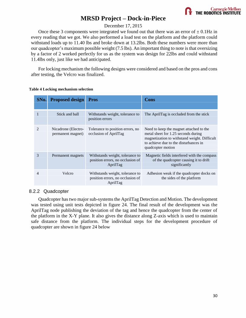
For locking mechanism the following designs were considered and based on the pros and cons
after testing, the Velcro was finalized.
Table 4 Locking mechanism selection
SNo. Proposed design Pros Cons
1 Stick and ball Withstands weight, tolerance to
position errors
The AprilTag is occluded from the stick
2 Nicadrone (Electro-
permanent magnet)
Tolerance to position errors, no
occlusion of AprilTag
Need to keep the magnet attached to the
metal sheet for 1.25 seconds during
magnetization to withstand weight. Difficult
to achieve due to the disturbances in
quadcopter motion
3 Permanent magnets Withstands weight, tolerance to
position errors, no occlusion of
AprilTag
Magnetic fields interfered with the compass
of the quadcopter causing it to drift
significantly
4 Velcro Withstands weight, tolerance to
position errors, no occlusion of
AprilTag
Adhesion weak if the quadcopter docks on
the sides of the platform
8.2.2 Quadcopter
Quadcopter has two major sub-systems the AprilTag Detection and Motion. The development
was tested using unit tests depicted in figure 24. The final result of the development was the
AprilTag node publishing the deviation of the tag and hence the quadcopter from the center of
the platform in the X-Y plane. It also gives the distance along Z-axis which is used to maintain
safe distance from the platform. The individual steps for the development procedure of
quadcopter are shown in figure 24 below

MRSD Project – Dock-in-Piece December 17, 2015
30
Figure 24 Development Procedure for the Quadcopter
Quadcopter motion was tested using the set-up detailed in figure 25. When the quadcopter is
run on the simulation the drone is connected via a USB cable to the laptop running the simulation.
Whatever commands are provided to N1 are sent to the simulation internally and used to run the
drone in the simulation. Additionally, the Remote Controller is present for emergency takeover.
However, the mode is set to ‘F’ when Odroid needs to be in control. The mode needs to be changed
to ‘A’ when manual override needs to be activated. The code is run by opening a secure shell from
a laptop. Data from all the topics are logged using rosbag.
Figure 25 Test Set-up for Quadcopter Testing
Pose detection of
AprilTag using Odroid
Robustness to
lighting variation
on Odroid
Computer Vision
Increasing tag
detection rate on
Odroid
Hover and manual
control using Laptop as
the onboard device and
quadcopter flying in
simulation
Hover and manual control
using Odroid as the
onboard device and
quadcopter flying in
simulation
Hover and manual
control using Odroid as
the onboard device and
quadcopter flying in
reality
Autonomous Hover and
landing using Laptop as
the onboard device and
quadcopter flying in
simulation
Autonomous Hover and
landing using Odroid as
the onboard device and
quadcopter flying in
simulation
Autonomous Hover and
landing using Odroid as
the onboard device and
quadcopter flying in
reality
Autonomous motion
using Laptop as the
onboard device and
quadcopter flying in
simulation
Autonomous motion
using Odroid as the
onboard device and
quadcopter flying in
simulation
Quadcopter Motion
Autonomous motion
using Odroid as the
onboard device and
quadcopter flying in
reality
Pose detection of
AprilTag using Laptop
Quadcopter move
to points detected
by AprilTag node
Remote Controller
N1 Flight Controller (Motion)
Webcam
(AprilTag
Wi-Fi/ Wi-
Fly
Laptop

MRSD Project – Dock-in-Piece December 17, 2015
30
Analysis was performed on the logged data. For example, the velocity controller on the
quadcopter needed to be validated before implementing a position controller. To do this, the
quadcopter was flown using the velocity controller in simulator, and figure 26 depicts the logged
velocity data. Note, positive Z is pointing down, making the initial negative velocity the liftoff and
the final positive z-velocity the landing. A sequence of velocity commands in the x and y axes
were provided with a magnitude of 2 m/s. This graph validated our use of the velocity control
service exposed by the N1 parser node.
Figure 26 Velocity Test Data from Simulation flight
A more interesting show of our analysis is provided by the figure 27. This figure is taken
when the quadcopter was in flight, not in simulation. The graph shows the huge spike in the z-
axis velocity in the positive direction, which is consistent with a fall. This graph is the result of
giving a position offset of 1m in both x and y direction. The main take-away from this graph is
that changing the local navigation action exposed by the N1 parser node is troublesome as there
are dependencies that aren’t clear. The local navigation action is the actionlib instance that takes
the quadcopter to a requested destination.
Figure 27 Velocity Data from the Crash
8.2.3 Palantir
While developing the Palantir subsystem testing and evaluation was done using a range of
frequencies before implementing it on the quadcopter. Figure 28 below shows the various times
which were analyzed to ensure that the quadcopter docks at the desired time instant. Starting from

MRSD Project – Dock-in-Piece December 17, 2015
30
left the first line indicates the time at which the data collection begins, the second line indicates
the end of data collection, the third line indicates when the palantir makes the decision, the fourth
line indicates the time at which the docking should take place and the last line is the actual
prediction made by the palantir. This offset in the desired and predicted is due the processing time
taken by the palantir. Using this analysis method we were able to account for this latency and
provide the correct time to move to the quadcopter.
Figure 28 Plot of IR data with prediction
8.3 Performance evaluation against the Spring Validation Experiment (SVE)
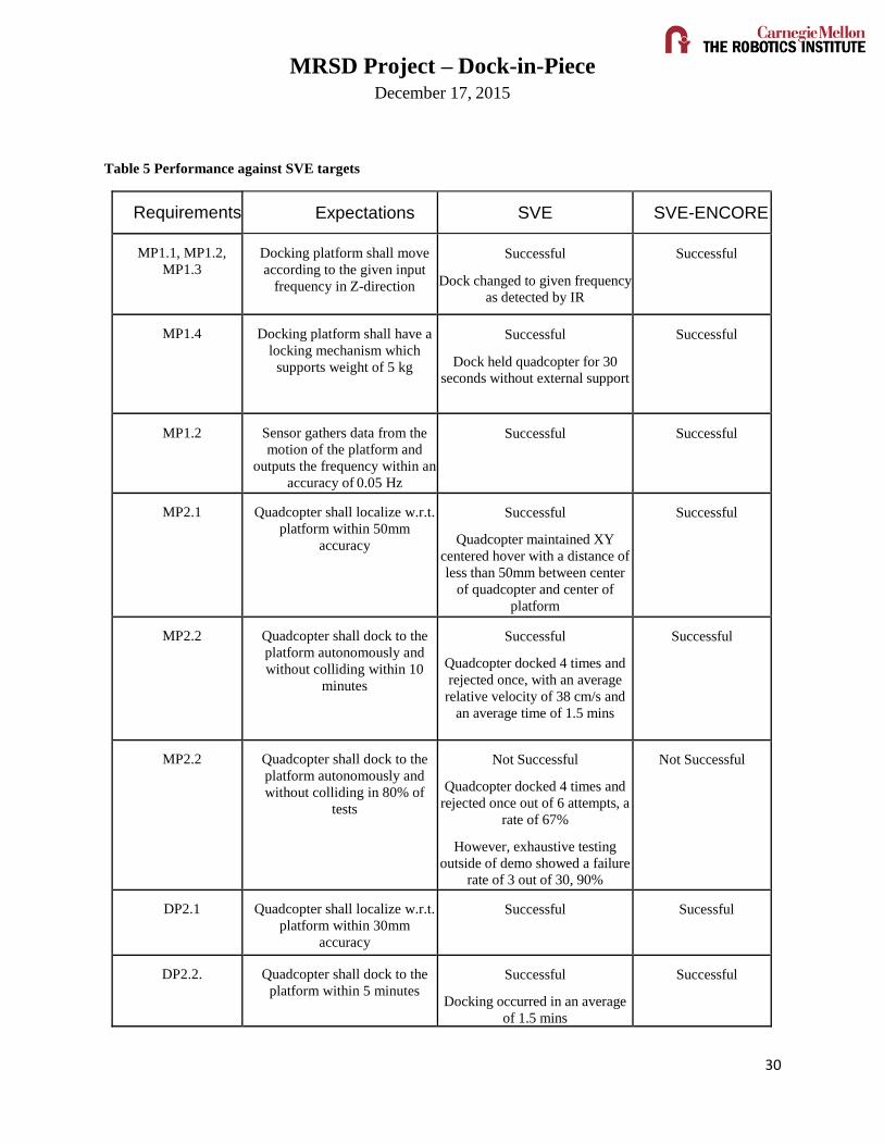
Table 5 highlights the key objectives of the SVE and our performance. As it can be seen we
were able to achieve all of our goals, however reliability of the system docking on the first attempt
was only achieved outside of the experimental time period, with testing showing a much higher
reliability than was demonstrated. The cause of this is believed to be linked to the Guidance
subsystem, which is highly sensitive to motion in the testing area. During validation testing, our
success rate was 90%, during the lab tours it was 85%, and in SVE it was 67%. This indicates
that the system degradation is linked both to quantity of noise in any given direction and how
many directions the noise was coming from. The highest reliability came when only one quadrant
had moderate noise (operators in operation space), followed by high noise in one quadrant and
moderate in a second (tour group in tour space and operators in operator space), and finally lowest
values were found with high noise in one quadrant and moderate noise in two others (evaluators
in tour space, operators in operator space, evaluators near the lab exit door). This makes sense,
as the Matrice’s expected operating space is well above most objects, meaning that the majority
of what it perceives is expected to be static obstacles like poles and buildings. Operating low to
the ground with many people moving in its view, the Guidance was put in a state of uncertainty
about objects in its environment. As a result the system shifted to IMUs estimates which have
significant error causing the quadcopter to drift.
MRSD Project – Dock-in-Piece December 17, 2015
30
Table 5 Performance against SVE targets
Requirements Expectations SVE SVE-ENCORE
MP1.1, MP1.2,
MP1.3
Docking platform shall move
according to the given input
frequency in Z-direction
Successful
Dock changed to given frequency
as detected by IR
Successful
MP1.4 Docking platform shall have a
locking mechanism which
supports weight of 5 kg
Successful
Dock held quadcopter for 30
seconds without external support
Successful
MP1.2 Sensor gathers data from the
motion of the platform and
outputs the frequency within an
accuracy of 0.05 Hz
Successful
Successful
MP2.1 Quadcopter shall localize w.r.t.
platform within 50mm
accuracy
Successful
Quadcopter maintained XY
centered hover with a distance of
less than 50mm between center
of quadcopter and center of
platform
Successful
MP2.2 Quadcopter shall dock to the
platform autonomously and
without colliding within 10
minutes
Successful
Quadcopter docked 4 times and
rejected once, with an average
relative velocity of 38 cm/s and
an average time of 1.5 mins
Successful
MP2.2 Quadcopter shall dock to the
platform autonomously and
without colliding in 80% of
tests
Not Successful
Quadcopter docked 4 times and
rejected once out of 6 attempts, a
rate of 67%
However, exhaustive testing
outside of demo showed a failure
rate of 3 out of 30, 90%
Not Successful
DP2.1 Quadcopter shall localize w.r.t.
platform within 30mm
accuracy
Successful Sucessful
DP2.2. Quadcopter shall dock to the
platform within 5 minutes Successful
Docking occurred in an average
of 1.5 mins
Successful
MRSD Project – Dock-in-Piece December 17, 2015
30
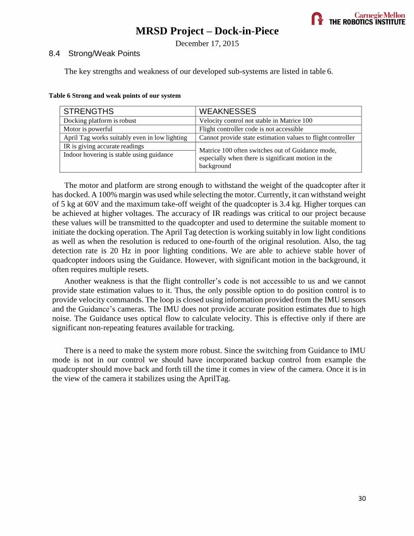
8.4 Strong/Weak Points
The key strengths and weakness of our developed sub-systems are listed in table 6.
Table 6 Strong and weak points of our system
STRENGTHS WEAKNESSES Docking platform is robust Velocity control not stable in Matrice 100
Motor is powerful Flight controller code is not accessible
April Tag works suitably even in low lighting Cannot provide state estimation values to flight controller
IR is giving accurate readings Matrice 100 often switches out of Guidance mode,
especially when there is significant motion in the
background
Indoor hovering is stable using guidance
The motor and platform are strong enough to withstand the weight of the quadcopter after it
has docked. A 100% margin was used while selecting the motor. Currently, it can withstand weight
of 5 kg at 60V and the maximum take-off weight of the quadcopter is 3.4 kg. Higher torques can
be achieved at higher voltages. The accuracy of IR readings was critical to our project because
these values will be transmitted to the quadcopter and used to determine the suitable moment to
initiate the docking operation. The April Tag detection is working suitably in low light conditions
as well as when the resolution is reduced to one-fourth of the original resolution. Also, the tag
detection rate is 20 Hz in poor lighting conditions. We are able to achieve stable hover of
quadcopter indoors using the Guidance. However, with significant motion in the background, it
often requires multiple resets.
Another weakness is that the flight controller’s code is not accessible to us and we cannot
provide state estimation values to it. Thus, the only possible option to do position control is to
provide velocity commands. The loop is closed using information provided from the IMU sensors
and the Guidance’s cameras. The IMU does not provide accurate position estimates due to high
noise. The Guidance uses optical flow to calculate velocity. This is effective only if there are
significant non-repeating features available for tracking.
There is a need to make the system more robust. Since the switching from Guidance to IMU
mode is not in our control we should have incorporated backup control from example the
quadcopter should move back and forth till the time it comes in view of the camera. Once it is in
the view of the camera it stabilizes using the AprilTag.
MRSD Project – Dock-in-Piece December 17, 2015
30
9 Project Management
9.1 Schedule
Our schedule was integrated with our progress review (PR) goals, each subsystem we
implemented or unit we intend to test being a demonstration at the PR (Table 7).
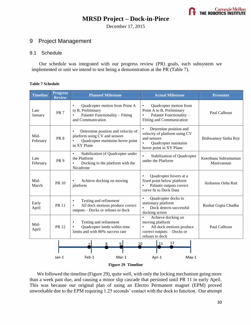
Table 7 Schedule
Timeline Progress
Review Planned Milestone Actual Milestone Presenter
Late
January PR 7
• Quadcopter motion from Point A
to B, Preliminary
• Palantir Functionality – Fitting
and Communication
• Quadcopter motion from
Point A to B, Preliminary
• Palantir Functionality –
Fitting and Communication
Paul Calhoun
Mid-
February PR 8
• Determine position and velocity of
platform using CV and sensors
• Quadcopter maintains hover point
in XY Plane
• Determine position and
velocity of platform using CV
and sensors
• Quadcopter maintains
hover point in XY Plane
Bishwamoy Sinha Roy
Late
February PR 9
• Stabilization of Quadcopter under
the Platform
• Docking to the platform with the
Nicadrone
• Stabilization of Quadcopter
under the Platform
Keerthana Subramanian
Manivannan
Mid-
March PR 10
• Achieve docking on moving
platform
• Quadcopter hovers at a
fixed point below platform
• Palantir outputs correct
curve fit to Dock Data
Aishanou Osha Rait
Early
April PR 11
• Testing and refinement
• All dock motions produce correct
outputs – Docks or refuses to dock
• Quadcopter docks to
stationary platform
• Dock detects successful
docking action
Rushat Gupta Chadha
Mid-
April PR 12
• Testing and refinement
• Quadcopter lands within time
limits and with 80% success rate
• Achieve docking on
moving platform
• All dock motions produce
correct outputs: – Docks or
refuses to dock
Paul Calhoun
Figure 29 Timeline
We followed the timeline (Figure 29), quite well, with only the locking mechanism going more
than a week past due, and causing a minor slip cascade that persisted until PR 11 in early April.
This was because our original plan of using an Electro Permanent magnet (EPM) proved
unworkable due to the EPM requiring 1.25 seconds’ contact with the dock to function. Our attempt
MRSD Project – Dock-in-Piece December 17, 2015
30
to use permanent magnets also failed when it interfered with the navigation of the Quadcopter,
making the compass cease functioning. The locking mechanism was a key item to several other
developments, which had to be put on hold until the team found an acceptable replacement for the
EPM.
9.2 Budget
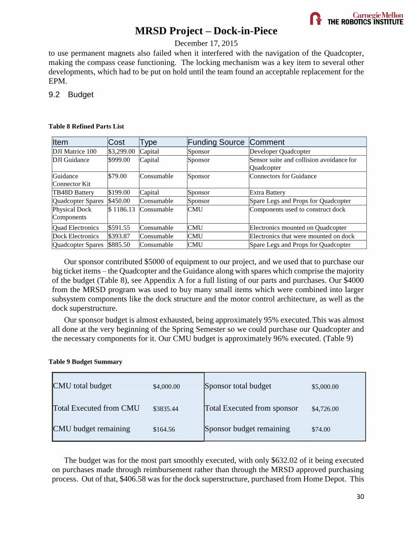
Table 8 Refined Parts List
Item Cost Type Funding Source Comment DJI Matrice 100 $3,299.00 Capital Sponsor Developer Quadcopter
DJI Guidance $999.00 Capital Sponsor Sensor suite and collision avoidance for
Quadcopter
Guidance
Connector Kit
$79.00 Consumable Sponsor Connectors for Guidance
TB48D Battery $199.00 Capital Sponsor Extra Battery
Quadcopter Spares $450.00 Consumable Sponsor Spare Legs and Props for Quadcopter
Physical Dock
Components
$ 1186.13 Consumable CMU Components used to construct dock
Quad Electronics $591.55 Consumable CMU Electronics mounted on Quadcopter
Dock Electronics $393.87 Consumable CMU Electronics that were mounted on dock
Quadcopter Spares $885.50 Consumable CMU Spare Legs and Props for Quadcopter
Our sponsor contributed $5000 of equipment to our project, and we used that to purchase our
big ticket items – the Quadcopter and the Guidance along with spares which comprise the majority
of the budget (Table 8), see Appendix A for a full listing of our parts and purchases. Our $4000
from the MRSD program was used to buy many small items which were combined into larger
subsystem components like the dock structure and the motor control architecture, as well as the
dock superstructure.
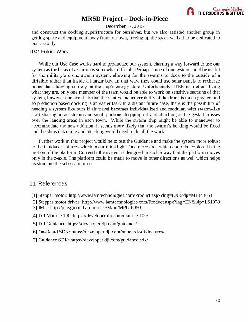
Our sponsor budget is almost exhausted, being approximately 95% executed. This was almost
all done at the very beginning of the Spring Semester so we could purchase our Quadcopter and
the necessary components for it. Our CMU budget is approximately 96% executed. (Table 9)
Table 9 Budget Summary
CMU total budget
$4,000.00
Sponsor total budget
$5,000.00
Total Executed from CMU
$3835.44 Total Executed from sponsor
$4,726.00
CMU budget remaining
$164.56 Sponsor budget remaining
$74.00
The budget was for the most part smoothly executed, with only $632.02 of it being executed
on purchases made through reimbursement rather than through the MRSD approved purchasing
process. Out of that, $406.58 was for the dock superstructure, purchased from Home Depot. This

MRSD Project – Dock-in-Piece December 17, 2015
30
was an unavoidable situation. The rest were for electronic components that needed to be replaced
quickly, and $187.95 for a PCB mistakenly purchased because the team member in charge of that
subsystem had a mistaken belief about how PCB purchases were made. In the first semester one
team member took care of purchases and budget, and in the second semester it was consolidated
into the overall PM tasking. This was done as PM tasking also included coordination, which
helped in keeping track of who needed what and why.
9.3 Risk Management
Table 10 Risk Summary
Probability
Severity A
B
C
D
E
Negligible Low Moderate Severe Catastrophic
5 Nearly Certain 0 0 0 0 0
4 Likely 0 0 1 0 0
3 Possible 0 0 0 0 1
2 Unlikely 0 0 2 2 1
1 Rare 0 1 0 1 0
Immediate Action Urgent Action Action Monitor No Action
Team Dock-In-Piece has had a successful risk mitigation strategy. (Table 10)
By the end, we had mitigated all the highest level risks and most of the middle risks. The
remaining risks are distributed evenly from the physical (dock motor not working right) to the
supply chain (spares strategy insufficient) to the human resource (a developer becomes
unavailable). See Appendix A for a full listing of our risks. Risk ID 5, 6 7, 19, 23, 24, and 25 involve
direct physical risks to the Quadcopter. Each failure mode is captured as a separate risk, as most
of them require different methods of being mitigated and prevented – all but one of which was
fully mitigated by the end either by scope changes or our risk strategy.
During the former part of the academic year, we had faced a lot of delays in shipping, which led the
team on a late start of the project. But, the team had successfully completed the FVE nonetheless. The
team decided to work on the Quadcopter’s software during the winter break, which gave us time to test
and refine the process early.
In the Spring semester, we had faced significant delays as well. Some of them are: finalizing the
locking mechanism, finding a place for testing, Guidance failing mid-flight.
The locking mechanism had an unexpected delay as we brainstormed for and tried on different
methods. This was mitigated by using a simple solution to a problem – using Velcro as the locking
mechanism.
The team faced shortage of spare propellers before one of our PRs. It was then mitigated by

MRSD Project – Dock-in-Piece December 17, 2015
30
ordering a large number of spare propellers and spare arms for the next PR. During one of our
testing, the Quadcopter fell and a part on the arm was broken, and it is one which cannot be
bought off the internet. So we borrowed the part from another team who were working with M100
on their project to show the goals to be achieved in PR.
The risk chart was constantly updated by the Project Manager and the items were moved to
lower portions as they were mitigated.
The team, however, failed to mitigate the problem of motor giving out bad outputs. The motor
wouldn’t perform as it was expected since it didn’t output the input frequency. The problem of
Guidance failing mid-flight is also not resolved. The final system sometimes fails because the
Quadcopter drifts off since the Guidance doesn’t work.
One method of mitigating this problem from arising would have been to more thoroughly
research the Guidance and motor choices. Seeking help from peers and experts in the respective
fields would have helped us mitigate this problem.
Overall our risk mitigation served its purpose and enabled us to deliver a fully autonomous
Quadcopter docking onto a moving platform. However, with a few key changes – such as adding
more risk mitigation to our schedule and seeking more advice from experts – our risk management
system can be even more robust in the future project scopes.
10 Conclusions
10.1 Lessons Learned
As with many teams, our largest lesson learned is requirement generation and tracking. We
originally had many requirements that our customer thought would be useful but they didn’t need.
By reducing our scope to what our customer absolutely needs, we’ve streamlined our process and
expectations so we can produce a working system. The de-scoping continued through both
semesters as we got an even better idea of our customer’s intended use, including removing
undocking from the requirements and no longer requiring a dedicated user interface.
Our trade studies also did not have logistics and maintenance as columns. While this would
have been difficult in many cases, further research may have helped us realize that our main
suppliers for vehicle and motor had very long lead times for delivery. In both cases we had to
wait over a month for key components during which development in non-key areas. In the Spring,
this was mitigated by ordering further in advance, ordering from suppliers that delivered faster,
and by not needing as many key components.
Communication was a big problem during sprints. Spring semester’s schedule permitted a
more structured teaming process so that we don’t lose sight of the full system as we implemented
subsystems. Our documentation was also not kept up to date during the Fall, producing lengthy
catchup periods as we entered large volumes of information into our databases. In the Spring, we
at first attempted to have more structure with regular meetings and a single dedicated model in
which everything was kept up to date. This eventually gave way to not requiring documentation
at all, which streamlined the process significantly as we no longer had the internal customer
requirement (course presentations) to keep such records.
We have done very well in the Spring with finding test facilities. Not only did we arrange for
MRSD Project – Dock-in-Piece December 17, 2015
30
and construct the docking superstructure for ourselves, but we also assisted another group in
getting space and equipment away from our own, freeing up the space we had to be dedicated to
our use only
10.2 Future Work
While our Use Case works hard to productize our system, charting a way forward to use our
system as the basis of a startup is somewhat difficult. Perhaps some of our system could be useful
for the military’s drone swarm system, allowing for the swarms to dock to the outside of a
dirigible rather than inside a hangar bay. In that way, they could use solar panels to recharge
rather than drawing entirely on the ship’s energy store. Unfortunately, ITER restrictions being
what they are, only one member of the team would be able to work on sensitive sections of that
system, however one benefit is that the relative maneuverability of the drone is much greater, and
so prediction based docking is an easier task. In a distant future case, there is the possibility of
needing a system like ours if air travel becomes individualized and modular, with swarm-like
craft sharing an air stream and small portions dropping off and attaching as the gestalt crosses
over the landing areas in each town. While the swarm ship might be able to maneuver to
accommodate the new addition, it seems more likely that the swarm’s heading would be fixed
and the ships detaching and attaching would need to do all the work.
Further work in this project would be to test the Guidance and make the system more robust
to the Guidance failures which occur mid-flight. One more area which could be explored is the
motion of the platform. Currently the system is designed in such a way that the platform moves
only in the z-axis. The platform could be made to move in other directions as well which helps
us simulate the sub-sea motion.
11 References
[1] Stepper motor: http://www.lamtechnologies.com/Product.aspx?lng=EN&idp=M1343051
[2] Stepper motor driver: http://www.lamtechnologies.com/Product.aspx?lng=EN&idp=LS1078
[3] IMU: http://playground.arduino.cc/Main/MPU-6050
[4] DJI Matrice 100: https://developer.dji.com/matrice-100/
[5] DJI Guidance: https://developer.dji.com/guidance/
[6] On-Board SDK: https://developer.dji.com/onboard-sdk/features/
[7] Guidance SDK: https://developer.dji.com/guidance-sdk/
MRSD Project – Dock-in-Piece December 17, 2015
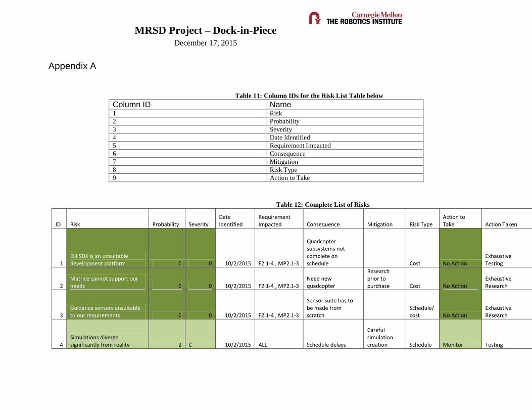
Appendix A
Table 11: Column IDs for the Risk List Table below
Column ID Name 1 Risk
2 Probability
3 Severity
4 Date Identified
5 Requirement Impacted
6 Consequence
7 Mitigation
8 Risk Type
9 Action to Take
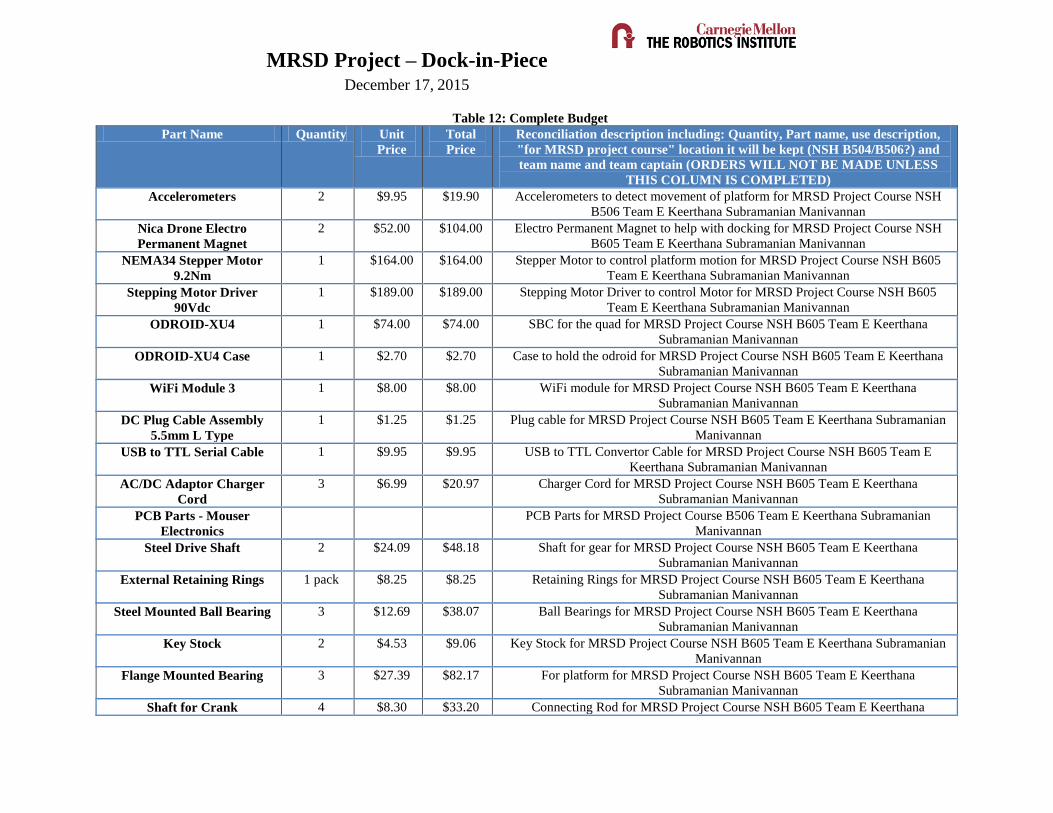
Table 12: Complete List of Risks
ID Risk Probability Severity Date Identified
Requirement Impacted Consequence Mitigation Risk Type
Action to Take Action Taken
1 DJI SDK is an unsuitable development platform 0 0 10/2/2015 F2.1-4 , MP2.1-3
Quadcopter subsystems not complete on schedule Cost No Action
Exhaustive Testing
2 Matrice cannot support our needs 0 0 10/2/2015 F2.1-4 , MP2.1-3
Need new quadcopter
Research prior to purchase Cost No Action
Exhaustive Research
3 Guidance sensors unsuitable to our requirements 0 0 10/2/2015 F2.1-4 , MP2.1-3
Sensor suite has to be made from scratch
Schedule/cost No Action
Exhaustive Research
4 Simulations diverge significantly from reality 2 C 10/2/2015 ALL Schedule delays
Careful simulation creation Schedule Monitor Testing
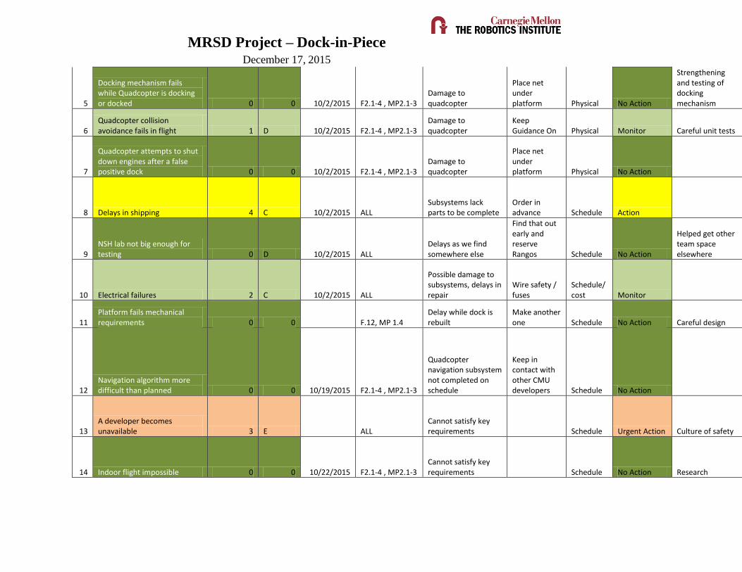
MRSD Project – Dock-in-Piece December 17, 2015
5
Docking mechanism fails while Quadcopter is docking or docked 0 0 10/2/2015 F2.1-4 , MP2.1-3
Damage to quadcopter
Place net under platform Physical No Action
Strengthening and testing of docking mechanism
6 Quadcopter collision avoidance fails in flight 1 D 10/2/2015 F2.1-4 , MP2.1-3
Damage to quadcopter
Keep Guidance On Physical Monitor Careful unit tests
7
Quadcopter attempts to shut down engines after a false positive dock 0 0 10/2/2015 F2.1-4 , MP2.1-3
Damage to quadcopter
Place net under platform Physical No Action
8 Delays in shipping 4 C 10/2/2015 ALL Subsystems lack parts to be complete
Order in advance Schedule Action
9 NSH lab not big enough for testing 0 D 10/2/2015 ALL
Delays as we find somewhere else
Find that out early and reserve Rangos Schedule No Action
Helped get other team space elsewhere
10 Electrical failures 2 C 10/2/2015 ALL
Possible damage to subsystems, delays in repair
Wire safety / fuses
Schedule/cost Monitor
11 Platform fails mechanical requirements 0 0 F.12, MP 1.4
Delay while dock is rebuilt
Make another one Schedule No Action Careful design
12 Navigation algorithm more difficult than planned 0 0 10/19/2015 F2.1-4 , MP2.1-3
Quadcopter navigation subsystem not completed on schedule
Keep in contact with other CMU developers Schedule No Action
13 A developer becomes unavailable 3 E ALL
Cannot satisfy key requirements Schedule Urgent Action Culture of safety
14 Indoor flight impossible 0 0 10/22/2015 F2.1-4 , MP2.1-3 Cannot satisfy key requirements Schedule No Action Research

MRSD Project – Dock-in-Piece December 17, 2015
15 SDK Legal Issues Continue for significant time 0 0 10/22/2015 F2.1-4 , MP2.1-3
Quadcopter subsystems not complete on schedule
Get a personal license Schedule No Action Research
16 Motor has insufficient torque 0 0 10/22/2015 F1.1-2, MP1.1-4 Delay while new motor is found
Learn more about motors
Cost/Schedule No Action Research
17 Quadcopter Fails to Arrive in time for FVE 0 0 10/29/2015 F2.1-4 , MP2.1-3
Demo cannot be completed
Lower expectations
Schedule, Programmatic No Action
18
Hover/manual control dependent on netgear wifi module 0 0 11/16/2015 F2.1-4 , MP2.1-3
Quadcopter testing delayed
Scope down into laying April tags in descending order to mitigate drift
Schedule, Programmatic No Action
19 Quadcopter Spares Strategy Insufficient 2 D 12/13/2015 F2.1-4 , MP2.1-3
Quadcopter testing delayed
Failure Mode Effects and Criticality Analysis Schedule Action
Spares strategy re-evaluated periodically
20 Motor burns out 2 E 12/13/2015 F1.1-2, MP1.1-4 Delay while new motor is found
Overcurrent Fuse
Cost, Schedule Action
21 Dock Strikes Pantrybot Frame 0 B 12/13/2015 F1.1-2, MP1.1-4
Delay while dock is rebuilt, loss of goodwill if we damage the Pantrybot
Temporarily Remove Letters from Pantrybot
Cost, Schedule No Action
Move to a separate location
22 Arduino Not Fast Enough to Control Motor 1 B 12/13/2015 MP 1.2
Dock subsystem will require redesign
User Datagram Protocol Edits to the Driver Setting Schedule No Action
Update motor driver settings
23 Quadcopter Lands Upside Down (operator influence) 2 D 12/13/2015 F2.1-4 , MP2.1-3
Damage to quadcopter
Soft Landing Platform
Cost, Schedule Action Careful testing

MRSD Project – Dock-in-Piece December 17, 2015
24 Guidance Fails Midflight 0 0 12/13/2015 F2.1-4 , MP2.1-3 Damage to quadcopter
Switch to Manual Control Faster
Cost, Schedule No Action Careful testing
25 Quadcopter propulsion does not disengage after docking 0 0 12/14/2015 F2.1-4 , MP2.1-3
Damage to quadcopter
Limit switch on quadcopter Physical No Action
26 No place to hang dock 0 E 12/15/2015 ALL System cannot be tested
Find somewhere to put the dock
Programmatic No Action
Worked with facilities to build dock superstructure
27 Locking Mechanism Delayed 0 0 2/15/2016 ALL System cannot be tested
Do not show locked situation
Programmatic No Action
Analysis of alternatives
MRSD Project – Dock-in-Piece December 17, 2015
Table 12: Complete Budget
Part Name Quantity Unit
Price
Total
Price
Reconciliation description including: Quantity, Part name, use description,
"for MRSD project course" location it will be kept (NSH B504/B506?) and
team name and team captain (ORDERS WILL NOT BE MADE UNLESS
THIS COLUMN IS COMPLETED)
Accelerometers 2 $9.95 $19.90 Accelerometers to detect movement of platform for MRSD Project Course NSH
B506 Team E Keerthana Subramanian Manivannan
Nica Drone Electro
Permanent Magnet
2 $52.00 $104.00 Electro Permanent Magnet to help with docking for MRSD Project Course NSH
B605 Team E Keerthana Subramanian Manivannan
NEMA34 Stepper Motor
9.2Nm
1 $164.00 $164.00 Stepper Motor to control platform motion for MRSD Project Course NSH B605
Team E Keerthana Subramanian Manivannan
Stepping Motor Driver
90Vdc
1 $189.00 $189.00 Stepping Motor Driver to control Motor for MRSD Project Course NSH B605
Team E Keerthana Subramanian Manivannan
ODROID-XU4 1 $74.00 $74.00 SBC for the quad for MRSD Project Course NSH B605 Team E Keerthana
Subramanian Manivannan
ODROID-XU4 Case 1 $2.70 $2.70 Case to hold the odroid for MRSD Project Course NSH B605 Team E Keerthana
Subramanian Manivannan
WiFi Module 3 1 $8.00 $8.00 WiFi module for MRSD Project Course NSH B605 Team E Keerthana
Subramanian Manivannan
DC Plug Cable Assembly
5.5mm L Type
1 $1.25 $1.25 Plug cable for MRSD Project Course NSH B605 Team E Keerthana Subramanian
Manivannan
USB to TTL Serial Cable 1 $9.95 $9.95 USB to TTL Convertor Cable for MRSD Project Course NSH B605 Team E
Keerthana Subramanian Manivannan
AC/DC Adaptor Charger
Cord
3 $6.99 $20.97 Charger Cord for MRSD Project Course NSH B605 Team E Keerthana
Subramanian Manivannan
PCB Parts - Mouser
Electronics
PCB Parts for MRSD Project Course B506 Team E Keerthana Subramanian
Manivannan
Steel Drive Shaft 2 $24.09 $48.18 Shaft for gear for MRSD Project Course NSH B605 Team E Keerthana
Subramanian Manivannan
External Retaining Rings 1 pack $8.25 $8.25 Retaining Rings for MRSD Project Course NSH B605 Team E Keerthana
Subramanian Manivannan
Steel Mounted Ball Bearing 3 $12.69 $38.07 Ball Bearings for MRSD Project Course NSH B605 Team E Keerthana
Subramanian Manivannan
Key Stock 2 $4.53 $9.06 Key Stock for MRSD Project Course NSH B605 Team E Keerthana Subramanian
Manivannan
Flange Mounted Bearing 3 $27.39 $82.17 For platform for MRSD Project Course NSH B605 Team E Keerthana
Subramanian Manivannan
Shaft for Crank 4 $8.30 $33.20 Connecting Rod for MRSD Project Course NSH B605 Team E Keerthana

MRSD Project – Dock-in-Piece December 17, 2015
Subramanian Manivannan
Brass Standard Key Stock 1 $1.78 $1.78 Key for end schaft for MRSD Project Course NSH B605 Team E Keerthana
Subramanian Manivannan
Black-Finish Steel External
Retaining Ring
1 $10.13 $10.13 Ring for Schaft for MRSD Project Course NSH B605 Team E Keerthana
Subramanian Manivannan
Frelon-Lined Sleeve-Bearing
Carriage
1 $41.44 $41.44 Slider Carriage for MRSD Project Course NSH B605 Team E Keerthana
Subramanian Manivannan
Guide Rail, 15mm Wide, for
Frelon-Lined Sleeve-Bearing
Carriage
1 $93.80 $93.80 Slider Rail for MRSD Project Course NSH B605 Team E Keerthana Subramanian
Manivannan
McMaster Order 6 $321.71 $321.71 Parts for fabrication of platform for MRSD Project Course NSH B605 Team E
Keerthana Subramanian Manivannan
Matrice Landing Gear Kit 1 $19.00 $19.00 Landing gear for the quadcopter for MRSD Project Course B506 Team E
Keerthana Subramanian Manivannan
Mouser Electronics PCB Parts for MRSD Project Course B506 Team E Keerthana Subramanian
Manivannan
LiPo Battery 1 $55.61 $55.61 Battery for PCB for MRSD Project Course B506 Team E Keerthana Subramanian
Manivannan
Battery Charger 1 $34.99 $34.99 Battery Charger for PCB for MRSD Project Course B506 Team E Keerthana
Subramanian Manivannan
Linear Regulator 3 $8.04 $24.12 Linear Regulator for PCB for MRSD Project Course B506 Team E Keerthana
Subramanian Manivannan
Wire Harness 3 $10.60 $31.80 Wire Harness for Battery for MRSD Project Course B506 Team E Keerthana
Subramanian Manivannan
Battery 1 $49.73 $49.73 Battery for PCB for MRSD Project Course B506 Team E Keerthana Subramanian
Manivannan
Battery 1 $33.42 $33.42 Battery for PCB for MRSD Project Course B506 Team E Keerthana Subramanian
Manivannan
Matrice Arm M1 1 $99.00 $99.00 Spare Arm for the quadcopter for MRSD Project Course B506 Team E Keerthana
Subramanian Manivannan
Matrice Arm M2 1 $99.00 $99.00 Spare Arm for the quadcopter for MRSD Project Course B506 Team E Keerthana
Subramanian Manivannan
Matrice Arm M3 1 $99.00 $99.00 Spare Arm for the quadcopter for MRSD Project Course B506 Team E Keerthana
Subramanian Manivannan
Matrice Arm M4 1 $99.00 $99.00 Spare Arm for the quadcopter for MRSD Project Course B506 Team E Keerthana
Subramanian Manivannan
WiFi Module 3 1 $8.00 $8.00 WiFi module for MRSD Project Course NSH B605 Team E Keerthana
Subramanian Manivannan

MRSD Project – Dock-in-Piece December 17, 2015
FTDI Breakout 1 $14.95 $14.95 FTDI Breakout board for MRSD Project NSH B605 Team E Keerthana
Subramanian Manivannan
PlayStation Eye 1 $6.49 $6.49 Monocluar Camera for quadcoper for MRSD Project Course NSH B605 Team E
Paul Calhoun
12V Rechargeable Li-ion
Battery Pack
2 $9.04 $18.08 Battery Packs for Controllers for MRSD Project Course NSH B605 Team E Paul
Calhoun
Arduino Stackable Header
Kit
4 $1.50 $6.00 Headers to attach IMU to Arduino for MRSD Project Course NSH B605 Team E
Paul Calhoun
DJI 1345s 5 $7.45 $37.25 Spare Propellors for quadcopter for MRSD Project Course B506 Team E Paul
Calhoun
Kootek GY-521 MPU-6050 2 $5.99 $11.98 Spare IMU for Dock for MRSD Project Course B506 Team E Paul Calhoun
Linear Regulator 3 $8.04 $24.12 Linear Regulator for PCB for MRSD Project Course B506 Team E Paul Calhoun
Odroid xu4 1 $74.00 $74.00 Odroid to go on quadcopter for MRSD Project Course B506 Team E Paul Calhoun
0.100" (2.54 mm)
Breakaway Male Header:
1×40-Pin
5 $0.75 $0.75 Headers to attach boards to Arduino for MRSD Project Course NSH B605 Team E
Paul Calhoun
Arduino Nano v3.0 2 $28.99 $57.98 Arduino controller for MRSD Project Course NSH B605 Team E Paul Calhoun
USB 2.0 Extension Cable -
A-Male to A-Female - 9.8
Feet (3 Meters)
4 $5.79 $23.16 USB Extension Cables for Data flow MRSD Project Course NSH B605 Team E
Paul Calhoun
SW MINI SNAP ACTION
.3A VERT 6V
5 $0.78 $3.90 Limit switch for MRSD Project Course NSH B605 Team E Paul Calhoun
SWITCH DETECT
SNAPACT SPDT 30V
3 $1.86 $5.58 Limit switch for MRSD Project Course NSH B605 Team E Paul Calhoun
WiFi Module 3 1 $8.00 $8.00 New Wifi Adapter for Odroid for MRSD Project Course NSH B605 Team E Paul
Calhoun
Camera Tripod and
Universal Smartphone
Moun
1 $11.95 $11.95 Tripod for MRSD Project Course NSH B605 Team E Paul Calhoun
Castle Creations CC Bec
10A 6S Switching Regulator
1 20,40 20,40 BEC for quadcopter for MRSD Project Course NSHB605 Team E Paul Calhoun
SparkFun FTDI Basic
Breakout - 3.3V
2 $14.95 $29.90 Breakout board for quadcopter for MRSD Project Course NSHB605 Team E Paul
Calhoun
USB 2.0 Cable - A-Male to
Mini-B - 6 Feet
3 $4.34 $13.02 Cable for Arduino Nanos for MRSD Project Course NSHB605 Team E Paul
Calhoun
Logitech Pro 9000 1 $139.96 $139.96 Camera for docking system for MRSD Project Course NSHB605 Team E Paul
Calhoun
ARDUINO UNO REV3 2 $24.95 $49.90 Arduino controller for MRSD Project Course NSH B605 Team E Paul Calhoun
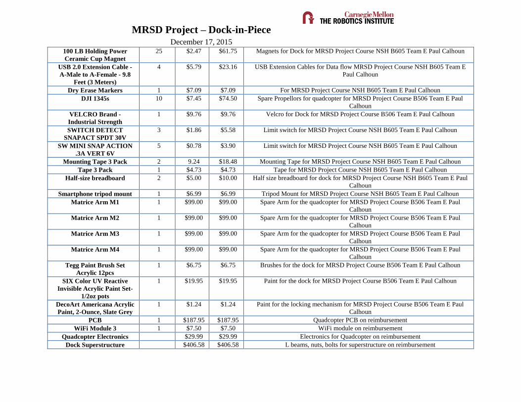
MRSD Project – Dock-in-Piece December 17, 2015
100 LB Holding Power
Ceramic Cup Magnet
25 $2.47 $61.75 Magnets for Dock for MRSD Project Course NSH B605 Team E Paul Calhoun
USB 2.0 Extension Cable -
A-Male to A-Female - 9.8
Feet (3 Meters)
4 $5.79 $23.16 USB Extension Cables for Data flow MRSD Project Course NSH B605 Team E
Paul Calhoun
Dry Erase Markers 1 $7.09 $7.09 For MRSD Project Course NSH B605 Team E Paul Calhoun
DJI 1345s 10 $7.45 $74.50 Spare Propellors for quadcopter for MRSD Project Course B506 Team E Paul
Calhoun
VELCRO Brand -
Industrial Strength
1 $9.76 $9.76 Velcro for Dock for MRSD Project Course B506 Team E Paul Calhoun
SWITCH DETECT
SNAPACT SPDT 30V
3 $1.86 $5.58 Limit switch for MRSD Project Course NSH B605 Team E Paul Calhoun
SW MINI SNAP ACTION
.3A VERT 6V
5 $0.78 $3.90 Limit switch for MRSD Project Course NSH B605 Team E Paul Calhoun
Mounting Tape 3 Pack 2 9.24 $18.48 Mounting Tape for MRSD Project Course NSH B605 Team E Paul Calhoun
Tape 3 Pack 1 $4.73 $4.73 Tape for MRSD Project Course NSH B605 Team E Paul Calhoun
Half-size breadboard 2 $5.00 $10.00 Half size breadboard for dock for MRSD Project Course NSH B605 Team E Paul
Calhoun
Smartphone tripod mount 1 $6.99 $6.99 Tripod Mount for MRSD Project Course NSH B605 Team E Paul Calhoun
Matrice Arm M1 1 $99.00 $99.00 Spare Arm for the quadcopter for MRSD Project Course B506 Team E Paul
Calhoun
Matrice Arm M2 1 $99.00 $99.00 Spare Arm for the quadcopter for MRSD Project Course B506 Team E Paul
Calhoun
Matrice Arm M3 1 $99.00 $99.00 Spare Arm for the quadcopter for MRSD Project Course B506 Team E Paul
Calhoun
Matrice Arm M4 1 $99.00 $99.00 Spare Arm for the quadcopter for MRSD Project Course B506 Team E Paul
Calhoun
Tegg Paint Brush Set
Acrylic 12pcs
1 $6.75 $6.75 Brushes for the dock for MRSD Project Course B506 Team E Paul Calhoun
SIX Color UV Reactive
Invisible Acrylic Paint Set-
1/2oz pots
1 $19.95 $19.95 Paint for the dock for MRSD Project Course B506 Team E Paul Calhoun
DecoArt Americana Acrylic
Paint, 2-Ounce, Slate Grey
1 $1.24 $1.24 Paint for the locking mechanism for MRSD Project Course B506 Team E Paul
Calhoun
PCB 1 $187.95 $187.95 Quadcopter PCB on reimbursement
WiFi Module 3 1 $7.50 $7.50 WiFi module on reimbursement
Quadcopter Electronics $29.99 $29.99 Electronics for Quadcopter on reimbursement
Dock Superstructure $406.58 $406.58 L beams, nuts, bolts for superstructure on reimbursement

MRSD Project – Dock-in-Piece December 17, 2015
Components
TOTAL $3835.44