NASA Docking System (NDS) Interface Definitions Document ...
294
NASA Docking System (NDS) Interface Definitions Document (IDD) Development Projects Office International Space Station Program JSC 65795 Date: November 16, 2013 Revision H National Aeronautics and Space Administration Houston, Texas 77058
-
Upload
khangminh22 -
Category
Documents
-
view
0 -
download
0
Transcript of NASA Docking System (NDS) Interface Definitions Document ...

NASA Docking System (NDS) Interface
Definitions Document (IDD)
Development Projects Office
International Space Station Program
JSC 65795
Date: November 16, 2013
Revision H
National Aeronautics and Space Administration
Houston, Texas 77058
JSC 65795 16 November 2013 Revision H
ii
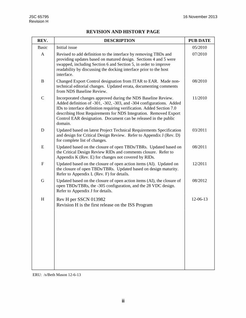
REVISION AND HISTORY PAGE
REV. DESCRIPTION PUB DATE
Basic Initial issue 05/2010
A Revised to add definition to the interface by removing TBDs and
providing updates based on matured design. Sections 4 and 5 were
swapped, including Section 6 and Section 5, in order to improve
readability by discussing the docking interface prior to the host
interface.
07/2010
B Changed Export Control designation from ITAR to EAR. Made non-
technical editorial changes. Updated errata, documenting comments
from NDS Baseline Review.
08/2010
C Incorporated changes approved during the NDS Baseline Review.
Added definition of -301, -302, -303, and -304 configurations. Added
IDs to interface definition requiring verification. Added Section 7.0
describing Host Requirements for NDS Integration. Removed Export
Control EAR designation. Document can be released in the public
domain.
11/2010
D Updated based on latest Project Technical Requirements Specification
and design for Critical Design Review. Refer to Appendix J (Rev. D)
for complete list of changes.
03/2011
E Updated based on the closure of open TBDs/TBRs. Updated based on
the Critical Design Review RIDs and comments closure. Refer to
Appendix K (Rev. E) for changes not covered by RIDs.
08/2011
F Updated based on the closure of open action items (AI). Updated on
the closure of open TBDs/TBRs. Updated based on design maturity.
Refer to Appendix L (Rev. F) for details.
12/2011
G Updated based on the closure of open action items (AI), the closure of
open TBDs/TBRs, the -305 configuration, and the 28 VDC design.
Refer to Appendix J for details.
08/2012
H Rev H per SSCN 013982
Revision H is the first release on the ISS Program
12-06-13
ERU: /s/Beth Mason 12-6-13
JSC 65795 16 November 2013 Revision H
iii
PREFACE
The contents of this document define the integrated performance and interface design for NASA
Docking System (NDS) Block 1 and the International Docking Adapter. The intent of this IDD is
to provide the interface design for using, installing, and interfacing to the NDS Block 1 that will
enable successful docking to the IDA. This document is under the control of the ISS
Development Projects Office (OG).
JSC 65795 16 November 2013 Revision H
iv
NASA Docking System (NDS)
Interface Definitions Document (IDD)
Approved By:
JSC 65795 16 November 2013 Revision H
v
NASA Docking System (NDS)
Interface Definitions Document (IDD)
Boeing Concurrence

JSC 65795 16 November 2013 Revision H
vi
NASA Docking System (NDS)
Interface Definitions Document (IDD)
LIST OF CHANGES
All changes to paragraphs, tables and figures in this document are shown below:
DATE PARAGRAPH CHANGE SUMMARY
11/16/13 ALL Total re-write to accommodate NDSB1 design

JSC 65795 16 November 2013 Revision H
vii
Table of Contents
Section Page 1.0 INTRODUCTION ........................................................................................... 1 1.1 PURPOSE AND SCOPE ............................................................................... 1 1.2 RESPONSIBILITY AND CHANGE AUTHORITY ........................................... 2 2.0 APPLICABLE AND REFERENCE DOCUMENTS ......................................... 3 2.1 APPLICABLE DOCUMENTS ........................................................................ 3 2.2 REFERENCE DOCUMENTS ......................................................................... 4 2.3 ORDER OF PRECEDENCE .......................................................................... 5 3.0 GENERAL SYSTEM OVERVIEW .................................................................. 6 3.1 SYSTEM DESCRIPTION ............................................................................... 8 3.1.1 NDS BLOCK 1 ............................................................................................... 8 3.1.2 INTERNATIONAL DOCKING ADAPTER ...................................................... 9 3.2 MASS PROPERTIES ................................................................................... 11 3.3 VOLUME PROPERTIES .............................................................................. 11 3.4 MATING PLANE DEFINITION ..................................................................... 12 3.5 UNITS OF MEASURE, DIMENSIONS, AND TOLERANCES ...................... 12 3.6 NDSB1 COORDINATE SYSTEM ................................................................ 12 3.6.1 NDSB1 STRUCTURAL COORDINATE SYSTEM ....................................... 13 3.6.2 NDSB1 DOCKING COORDINATE SYSTEMS ............................................ 14 3.6.2.1 NDSB1 ACTIVE DOCKING COORDINATE SYSTEM ................................. 16 3.6.2.2 IDA COORDINATE SYSTEM ...................................................................... 17 3.7 NDSB1 COMPONENT NUMBERING AND LABELING .............................. 17 3.7.1 NDSB1 COMPONENT NUMBERING .......................................................... 17 3.7.2 NDSB1 COMPONENT LABELING .............................................................. 17 3.8 SYSTEM PERFORMANCE PARAMETERS ................................................ 17 3.8.1 NDSB1 DOCKING ....................................................................................... 17 3.8.1.1 NDSB1 DOCKING CAPTURE PERFORMANCE ........................................ 17 3.8.1.2 VEHICLE RELATIVE DYNAMIC MOTION LIMITS DURING DOCKING ..... 19 3.8.1.3 NDSB1 ENVELOPES .................................................................................. 21 3.8.1.3.1 STATIC ENVELOPE .................................................................................... 21 3.8.1.3.2 KINEMATIC ENVELOPE ............................................................................. 22 3.8.1.4 IDA ENVELOPE .......................................................................................... 23 3.8.2 NDSB1 BERTHING ..................................................................................... 24 3.8.3 NDSB1 SEPARATION LIMITATIONS ......................................................... 24 4.0 NDSB1 DOCKING INTERFACE .................................................................. 25 4.1 NDSB1 INTERFACES ................................................................................. 25 4.1.1 STRUCTURAL/MECHANICAL .................................................................... 25 4.1.1.1 THERMAL INTERFACE .............................................................................. 29 4.1.1.1.1 NON-OPERATIONAL SURVIVAL ............................................................... 34 4.1.1.1.2 OPERATIONAL ........................................................................................... 34 4.1.1.1.2.1 TUNNEL AND SEAL MATING INTERFACE ............................................... 34 4.1.1.1.2.2 SOFT CAPTURE MATING INTERFACES ................................................... 35 4.1.1.1.3 MATED AND PRESSURIZED ..................................................................... 35 4.1.1.1.3.1 MATED AND PRESSURIZED STEADY-STATE TEMPERATURE RANGE 35 4.1.1.1.3.2 MATED AND PRESSURIZED TRANSIENT TEMPERATURES .................. 36
JSC 65795 16 November 2013 Revision H
viii
4.1.1.1.4 MATED AND UNPRESSURIZED ................................................................ 36 4.1.1.2 SOFT CAPTURE SYSTEM .......................................................................... 37 4.1.1.2.1 GUIDE PETAL SYSTEM ............................................................................. 37 4.1.1.2.2 SOFT CAPTURE RING ............................................................................... 39 4.1.1.2.3 MAGNET AND STRIKER ............................................................................ 42 4.1.1.2.4 SOFT CAPTURE SENSORS AND STRIKERS ........................................... 42 4.1.1.2.5 PRE-CAPTURE SCS COMPRESSIVE FORCE RESISTANCE ................... 42 4.1.1.2.6 SCS MECHANICAL LATCH STRIKER ....................................................... 42 4.1.1.3 HARD CAPTURE SYSTEM ......................................................................... 42 4.1.1.3.1 TUNNEL ...................................................................................................... 44 4.1.1.3.2 SEAL ........................................................................................................... 46 4.1.1.3.3 GUIDE PINS AND RECEPTACLES ............................................................ 47 4.1.1.3.4 HARD CAPTURE HOOKS .......................................................................... 49 4.1.1.3.5 UNDOCKING COMPLETE SENSORS AND STRIKERS............................. 56 4.1.1.3.6 HCS COMPRESSIVE FORCE RESISTANCE DURING SCS RETRACTION57 4.1.1.3.7 SEPARATION SYSTEM SPRINGS AND STRIKERS .................................. 57 4.1.1.4 NDSB1 INTERFACE COMPONENT MATERIALS ...................................... 58 4.1.1.5 LOADS ........................................................................................................ 59 4.1.1.5.1 SOFT CAPTURE DOCKING LOADS .......................................................... 59 4.1.1.5.2 HARD CAPTURE MATED LOADS ............................................................. 60 4.1.1.6 LEAK RATE ................................................................................................ 61 4.1.2 ELECTRICAL INTERFACES ....................................................................... 62 4.1.2.1 ELECTRICAL BONDING............................................................................. 62 4.1.2.1.1 ELECTRICAL BONDING AT HARD CAPTURE (CLASS-R – PROTECTION
AGAINST RADIO FREQUENCY EMISSION) .............................................. 62 4.1.2.1.1.1 ELECTRICAL BONDING AT HARD CAPTURE (CLASS-H PROTECTION
AGAINST ELECTRICAL FAULTS) ............................................................. 62 4.1.2.1.2 ELECTRICAL BONDING AT SOFT CAPTURE (CLASS-S – PROTECTION
AGAINST ELECTROSTATIC DISCHARGE) ............................................... 63 4.1.3 RESOURCE TRANSFER ............................................................................ 63 4.1.3.1 POWER TRANSFER AND COMMAND AND DATA HANDLING TRANSFER
UMBILICAL ................................................................................................. 64 4.1.3.1.1 POWER TRANSFER ................................................................................... 64 4.1.3.1.2 DATA TRANSFER....................................................................................... 65 4.1.3.1.2.1 ETHERNET CABLE SPECIFICATION ........................................................ 65 4.1.3.1.2.2 MIL-STD-1553 CABLE SPECIFICATION .................................................... 65 4.1.3.1.2.3 PERFORMANCE DATA .............................................................................. 65 4.1.3.2 WATER TRANSFER ................................................................................... 65 4.1.3.3 FUEL TRANSFER ....................................................................................... 65 4.1.3.4 PRESSURANT TRANSFER ........................................................................ 65 4.1.3.5 OXIDIZER TRANSFER ................................................................................ 65 4.1.4 SURFACE CLEANLINESS .......................................................................... 65 4.2 IDA INTERFACES ....................................................................................... 66 4.2.1 STRUCTURAL/MECHANICAL .................................................................... 66 4.2.1.1 THERMAL INTERFACE .............................................................................. 68 4.2.1.1.1 NON-OPERATIONAL SURVIVAL ............................................................... 68 4.2.1.1.2 OPERATIONAL ........................................................................................... 68 4.2.1.1.2.1 TUNNEL AND SEAL MATING INTERFACE ............................................... 68 4.2.1.1.2.2 SOFT CAPTURE MATING INTERFACES ................................................... 68 4.2.1.1.3 MATED AND PRESSURIZED ..................................................................... 68 4.2.1.1.3.1 MATED AND PRESSURIZED STEADY-STATE TEMPERATURE RANGE 68
JSC 65795 16 November 2013 Revision H
ix
4.2.1.1.3.2 MATED AND PRESSURIZED TRANSIENT TEMPERATURES .................. 69 4.2.1.1.4 MATED AND UNPRESSURIZED ................................................................ 69 4.2.1.2 SOFT CAPTURE SYSTEM .......................................................................... 69 4.2.1.2.1 GUIDE PETAL SYSTEM ............................................................................. 70 4.2.1.2.2 SOFT CAPTURE RING ............................................................................... 76 4.2.1.2.3 MAGNET AND STRIKER ............................................................................ 78 4.2.1.2.4 PRE-CAPTURE SCS COMPRESSIVE FORCE RESISTANCE ................... 78 4.2.1.2.5 SCS MECHANICAL LATCH STRIKER ....................................................... 78 4.2.1.3 HARD CAPTURE SYSTEM ......................................................................... 80 4.2.1.3.1 TUNNEL ...................................................................................................... 84 4.2.1.3.2 RESERVED ................................................................................................. 85 4.2.1.3.3 GUIDE PINS AND RECEPTACLES ............................................................ 85 4.2.1.3.4 HARD CAPTURE HOOKS .......................................................................... 88 4.2.1.3.5 UNDOCKING COMPLETE SENSORS AND STRIKERS............................. 95 4.2.1.3.6 HCS COMPRESSIVE FORCE RESISTANCE DURING SCS RETRACTION95 4.2.1.3.7 SEPARATION SYSTEM SPRINGS AND STRIKERS .................................. 95 4.2.1.4 IDA INTERFACE COMPONENT MATERIALS .......................................... 102 4.2.1.5 LOADS ...................................................................................................... 103 4.2.1.5.1 SOFT CAPTURE DOCKING LOADS ........................................................ 103 4.2.1.5.2 HARD CAPTURE MATED LOADS ........................................................... 105 4.2.1.6 LEAK RATE .............................................................................................. 105 4.2.1.7 GN&C AIDS ............................................................................................... 106 4.2.2 ELECTRICAL INTERFACES ..................................................................... 108 4.2.2.1 ELECTRICAL BONDING........................................................................... 108 4.2.2.1.1 ELECTRICAL BONDING AT HARD CAPTURE (CLASS-R – PROTECTION
AGAINST RADIO FREQUENCY EMISSION) ............................................ 108 4.2.2.1.1.1 ELECTRICAL BONDING AT HARD CAPTURE (CLASS-H PROTECTION
AGAINST ELECTRICAL FAULTS) ........................................................... 109 4.2.2.1.2 ELECTRICAL BONDING AT SOFT CAPTURE (CLASS-S – PROTECTION
AGAINST ELECTROSTATIC DISCHARGE) ............................................. 110 4.2.3 RESOURCE TRANSFER .......................................................................... 110 4.2.3.1 POWER TRANSFER AND COMMAND AND DATA HANDLING TRANSFER
UMBILICAL ............................................................................................... 110 4.2.3.1.1 POWER TRANSFER ................................................................................. 116 4.2.3.1.2 POWER QUALITY ..................................................................................... 117 4.2.3.1.3 DATA TRANSFER..................................................................................... 119 4.2.3.1.3.1 ETHERNET CABLE SPECIFICATION ...................................................... 119 4.2.3.1.3.2 MIL-STD-1553 CABLE SPECIFICATION .................................................. 119 4.2.3.1.4 EME EFFECTS .......................................................................................... 119 4.2.3.2 WATER TRANSFER ................................................................................. 120 4.2.3.3 FUEL TRANSFER ..................................................................................... 120 4.2.3.4 PRESSURANT TRANSFER ...................................................................... 120 4.2.3.5 OXIDIZER TRANSFER .............................................................................. 120 4.2.3.6 INTERMODULE VENTILATION ................................................................ 120 4.2.3.6.1 TEMPERATURE ........................................................................................ 124 4.2.3.6.2 DEW POINT............................................................................................... 124 4.2.3.6.3 FLOWRATE............................................................................................... 124 4.2.3.6.4 PRESSURE LOSS IN IMV DUCTING ........................................................ 124 4.2.4 SURFACE CLEANLINESS ........................................................................ 124 4.2.5 ENVIRONMENTS ...................................................................................... 124 4.2.5.1 LOADS ...................................................................................................... 124

JSC 65795 16 November 2013 Revision H
x
4.2.5.1.1 TRANSIENT LIMIT LOADS ....................................................................... 124 4.2.5.1.2 THERMAL STRUCTURAL LOADS ........................................................... 126 5.0 NDSB1-TO-HOST VEHICLE INTERFACE ................................................ 128 5.1 INTERFACE DESCRIPTION ..................................................................... 128 5.2 STRUCTURAL/MECHANICAL/SEAL/THERMAL INTERFACES .............. 128 5.2.1 STRUCTURAL/MECHANICAL INTERFACES .......................................... 129 5.2.1.1 MECHANICAL MOUNTING AND SEAL INTERFACE .............................. 137 5.2.1.2 NDSB1 INSTALLATION AND MMOD SHIELD MOUNTING INTERFACES137 5.2.1.3 SCS MECHANISM KEEP OUT ZONE (KOZ) ............................................ 141 5.2.1.4 NDSB1 VESTIBULE CLOSEOUT COVER ................................................ 141 5.2.1.5 NDSB1 ELECTRICAL BOXES .................................................................. 141 5.2.1.5.1 DSC RANDOM VIBRATION ENVIRONMENT ........................................... 149 5.2.1.5.2 DSC SHOCK ENVIRONMENT .................................................................. 150 5.2.1.5.3 DSC JETTISON SHOCK ENVIRONMENT ................................................ 152 5.2.1.5.4 LAC RANDOM VIBRATION ENVIRONMENT ........................................... 153 5.2.1.5.5 LAC SHOCK ENVIRONMENT .................................................................. 154 5.2.1.5.6 LAC JETTISON SHOCK ENVIRONMENT ................................................ 155 5.2.1.6 SURFACE CLEANLINESS ........................................................................ 156 5.2.1.7 SEAL SURFACE CLEANLINESS ............................................................. 156 5.2.1.8 LEAK CHECK PORT ................................................................................. 156 5.2.2 THERMAL INTERFACE ............................................................................ 156 5.2.2.1 NDSB1-TO-HOST VEHICLE ..................................................................... 161 5.2.2.1.1 NON-OPERATIONAL SURVIVAL ............................................................. 161 5.2.2.1.1.1 STRUCTURAL .......................................................................................... 161 5.2.2.1.1.2 NDSB1 ELECTRICAL BOXES .................................................................. 161 5.2.2.1.1.3 DELETED .................................................................................................. 162 5.2.2.1.1.4 NDSB1 COMPONENT LEVEL NON-OPERATING TEMPERATURE LIMITS
.................................................................................................................. 162 5.2.2.1.2 OPERATIONAL ......................................................................................... 165 5.2.2.1.2.1 STRUCTURAL .......................................................................................... 165 5.2.2.1.2.2 NDSB1 ELECTRICAL BOXES .................................................................. 165 5.2.2.1.3 MATED AND PRESSURIZED ................................................................... 166 5.2.2.1.3.1 MATED AND PRESSURIZED STEADY-STATE TEMPERATURE RANGE166 5.2.2.1.3.2 MATED AND PRESSURIZED STEADY-STATE TIME PERIOD ............... 167 5.2.2.1.4 MATED AND UNPRESSURIZED .............................................................. 167 5.2.2.1.5 THERMAL CONDUCTANCE ..................................................................... 168 5.2.2.1.5.1 UMBILICAL POWER TRANSFER INTERFACE-TO-HOST VEHICLE ...... 168 5.2.2.1.6 NDSB1 REMOTE-MOUNTED ELECTRICAL BOXES AND HEATER POWER
DISSIPATION ............................................................................................ 168 5.2.2.2 HOST VEHICLE PROVIDED MMOD ......................................................... 170 5.3 NDSB1-TO-HOST VEHICLE ELECTRICAL AND SIGNAL INTERFACE
UMBILICAL ............................................................................................... 170 5.3.1 UMBILICAL DATA TRANSFER INTERFACE-TO-THE-HOST VEHICLE . 171 5.3.1.1 UMBILICAL CONNECTOR MATED INDICATION .................................... 171 5.3.2 UMBILICAL CONNECTOR DATA BUS TERMINATION WIRES INTERFACE-
TO-THE-HOST VEHICLE .......................................................................... 171 5.3.3 PYROTECHNIC INTERFACE NDSB1 ....................................................... 171 5.3.4 ELECTRICAL POWER FROM HOST VEHICLE-TO-NDSB1 .................... 174 5.3.5 COMMUNICATIONS BETWEEN THE HOST VEHICLE AND THE NDSB1175 5.3.5.1 C&DH TIA-422-B INTERFACE .................................................................. 176 5.3.5.2 C&DH MIL-STD-1553B INTERFACE ........................................................ 178

JSC 65795 16 November 2013 Revision H
xi
5.3.5.2.1 MIL-STD-1553 REMOTE TERMINALS ...................................................... 179 5.3.5.2.2 MIL-STD-1553 RT ADDRESSING ............................................................. 179 5.3.5.2.3 HOST VEHICLE MIL-STD-1553B BUS CONTROLLER ............................ 180 5.3.5.2.4 HOST VEHICLE MIL-STD-1553B PARITY ................................................ 181 5.3.5.2.5 HOST VEHICLE MIL-STD-1553 MODE COMMANDS .............................. 181 5.3.5.2.6 HOST VEHICLE RESPONSE TO NDSB1 H&S DATA .............................. 181 5.3.5.2.6.1 HOST VEHICLE ISOLATION OF NDSB1 FAULTS ................................... 181 5.3.5.2.6.2 HOST VEHICLE RESPONSE TO NDSB1 FAULTS .................................. 181 5.3.5.3 JUMPERS ................................................................................................. 181 5.3.6 HEATER POWER AND CONTROL ........................................................... 181 5.3.7 GROUND SUPPORT EQUIPMENT SOFTWARE INTERFACE-TO-NDSB1181 5.3.8 ELECTRICAL BONDING BETWEEN THE HOST VEHICLE AND THE NDSB1
.................................................................................................................. 182 5.3.9 ELECTROMAGNETIC ENVIRONMENTAL EFFECTS .............................. 182 5.4 NDSB1-TO-HOST VEHICLE COMMAND AND HEALTH & STATUS
INTERFACE .............................................................................................. 183 5.4.1 NDSB1-TO-HOST VEHICLE APPLICATION COMMAND AND HEALTH &
STATUS INTERFACE ............................................................................... 183 5.4.1.1 NDSB1-TO-HOST COMMAND HANDLING .............................................. 183 5.4.1.1.1 HOST VEHICLE COMMANDS TO NDSB1 ............................................... 184 5.4.1.1.2 HOST VEHICLE COMMAND RATES ........................................................ 184 5.4.1.2 NDSB1-TO-HOST VEHICLE H&S DATA HANDLING .............................. 184 5.4.1.3 NDSB1 FDIR ............................................................................................. 184 5.4.1.4 NDSB1 I-LOADS PARAMETERS FOR DOCKING OR BERTHING
OPERATIONS ........................................................................................... 185 5.4.2 NDSB1 PACKET STRUCTURES .............................................................. 185 5.4.3 NDSB1 DATA TRANSFER ........................................................................ 187 5.4.3.1 TIA-422-B SERIAL .................................................................................... 187 5.4.3.2 MIL-STD-1553B ......................................................................................... 188 5.5 NDSB1-TO-HOST VEHICLE CONNECTORS LOCATIONS AND PIN
ASSIGNMENTS ......................................................................................... 188 5.5.1 NDSB1 POWER TRANSFER INTERFACE TO HOST VEHICLE
CONNECTOR LOCATION ........................................................................ 193 5.5.1.1 NDSB1 POWER TRANSFER INTERFACE TO HOST .............................. 193 5.5.2 NDSB1 DATA TRANSFER INTERFACE TO HOST .................................. 193 5.5.2.1 NDSB1 DATA TRANSFER INTERFACE TO HOST .................................. 193 5.5.3 WATER TRANSFER ................................................................................. 193 5.5.4 FUEL TRANSFER ..................................................................................... 193 5.5.5 PRESSURANT TRANSFER ...................................................................... 194 5.5.6 OXIDIZER TRANSFER .............................................................................. 194 6.0 NDSB1-TO- SUPPORT EQUIPMENT INTERFACE TBR13 ...................... 195 6.1 STRUCTURAL/MECHANICAL .................................................................. 195 6.1.1 LIFTING INTERFACE TBR13 ................................................................... 195 6.1.2 SEAL COVER INTERFACE TBR13 .......................................................... 195 6.1.3 PRESSURE DOME INTERFACES TBR13 ................................................ 195 6.1.4 PRESSURE SEAL INTERFACE, PASS-THROUGH CONNECTORS TBR13
.................................................................................................................. 195 6.1.5 PRESSURE SEAL INTERFACE, TEST PORTS TBR13 ........................... 195 6.1.6 HANDLING FIXTURE INTERFACE TBR13 .............................................. 197 6.1.7 TEST SUPPORT EQUIPMENT – DOCKING SYSTEM EMULATOR......... 198 7.0 HOST REQUIREMENTS FOR NASA DOCKING SYSTEM INTEGRATION199
JSC 65795 16 November 2013 Revision H
xii
7.1 INTERFACE CHARACTERISTICS (HOST VEHICLE) .............................. 199 7.1.1 PHYSICAL INTERFACE ........................................................................... 199 7.1.1.1 MECHANICAL ........................................................................................... 199 7.1.1.1.1 NDSB1 KEEP OUT ZONES ...................................................................... 199 7.1.1.2 STRUCTURAL ATTACHMENT ................................................................. 199 7.1.1.2.1 SEALS ....................................................................................................... 199 7.1.1.2.1.1 HOST VEHICLE SEAL INTERFACE ......................................................... 199 7.1.1.2.2 MOUNTING ............................................................................................... 199 7.1.1.2.2.1 HOST VEHICLE MOUNTING INSERTS .................................................... 199 7.1.1.2.2.2 HOST VEHICLE THROUGH BOLT MOUNTING ....................................... 199 7.1.1.2.2.3 HOST VEHICLE MOUNTING FLANGE ..................................................... 200 7.1.1.2.2.3.1 FLANGE THICKNESS ............................................................................... 200 7.1.1.2.2.3.2 FLANGE STIFFNESS AT MAXIMUM GAP ............................................... 200 7.1.1.2.2.3.3 UNIFORM FLANGE STIFFNESS .............................................................. 200 7.1.1.2.3 HOST VEHICLE PROVIDED MMOD SHIELD ........................................... 200 7.1.1.2.3.1 HOST VEHICLE MMOD ............................................................................ 200 7.1.1.2.3.2 MINIMUM PROBABILITY OF NO PENETRATION ................................... 201 7.1.1.2.3.3 HOST VEHICLE EXTERNAL THERMAL INTERFACE ............................. 201 7.1.1.2.3.4 HOST VEHICLE MMOD TEMPERATURE ................................................ 201 7.1.2 ELECTRONIC INTERFACE ...................................................................... 201 7.1.2.1 FUNCTIONAL ELECTRICAL AND SIGNAL INTERFACES ...................... 201 7.1.2.1.1 HOST VEHICLE ELECTRICAL AND SIGNAL INTERFACES ................... 201 7.1.2.1.2 HOST VEHICLE SEPARATION OF POWER AND COMMAND ................ 205 7.1.2.2 REDUNDANT WIRING .............................................................................. 205 7.1.2.2.1 HOST VEHICLE WIRING .......................................................................... 205 7.1.2.3 UMBILICAL INTERFACE .......................................................................... 205 7.1.2.3.1 HOST VEHICLE UMBILICAL DATA TRANSFER ISS TO HOST VEHICLE206 7.1.2.3.1.1 HOST VEHICLE RECEIVE IEEE 802.3U ETHERNET DATA .................... 206 7.1.2.3.1.2 HOST VEHICLE RECEIVE MIL-STD-1553 DATA BUS ............................ 206 7.1.2.3.1.3 HOST VEHICLE TERMINATE MIL-STD-1553 DATA BUS ....................... 206 7.1.2.3.2 HOST VEHICLE UMBILICAL POWER TRANSFER FROM ISS................ 206 7.1.2.4 DATA INTERFACE.................................................................................... 206 7.1.2.4.1 TWO’S COMPLEMENT NOTATION......................................................... 206 7.1.2.4.2 ZERO FILL UNUSED BITS AND WORDS ................................................ 206 7.1.2.4.3 SERIAL DATA COMMUNICATIONS ......................................................... 206 7.1.2.4.3.1 HOST VEHICLE MIL-STD-1553/TIA-422 COMMUNICATION JUMPER ... 206 7.1.2.4.3.2 HOST VEHICLE TRANSFORMER-COUPLED REMOTE TERMINAL ...... 207 7.1.2.4.3.3 HOST VEHICLE COMMANDING .............................................................. 207 7.1.2.4.3.3.1 HOST VEHICLE COMMANDS TO NDSB1 ............................................... 207 7.1.2.4.3.3.2 HOST VEHICLE COMMAND RATES ........................................................ 207 7.1.2.4.3.3.3 HOST VEHICLE TIA-422 COMMANDING ................................................. 207 7.1.2.4.3.4 HOST VEHICLE RECEPTION OF NDSB1 DATA ..................................... 207 7.1.2.4.3.5 HOST VEHICLE RESPONSE TO NDSB1 DATA ...................................... 207 7.1.2.4.3.5.1 RESPONSE TO INITIAL DOCKING CONTACT ........................................ 207 7.1.2.4.4 C&DH TIA-422-B NETWORK TOPOLOGY ............................................... 207 7.1.2.4.5 C&DH MIL-STD-1553B INTERFACE ........................................................ 208 7.1.2.4.5.1 HOST VEHICLE MIL-STD-1553B BUS CONTROLLER ............................ 208 7.1.2.4.5.2 HOST VEHICLE MIL-STD-1553B PARITY ................................................ 208 7.1.2.4.5.3 HOST VEHICLE MIL-STD-1553 MODE COMMANDS .............................. 208 7.1.2.4.5.4 HOST VEHICLE RESPONSE TO NDSB1 H&S DATA .............................. 208 7.1.2.4.5.4.1 HOST VEHICLE ISOLATION OF NDSB1 FAULTS ................................... 208

JSC 65795 16 November 2013 Revision H
xiii
7.1.2.5 PYROTECHNIC INTERFACE .................................................................... 208 7.1.2.5.1 HOST VEHICLE PYROTECHNIC FIRING ................................................. 209 7.1.2.5.1.1 SOURCES ................................................................................................. 209 7.1.2.5.1.2 ENERGY LEVEL ....................................................................................... 209 7.1.2.5.1.3 SIMULTANEOUS FIRING ......................................................................... 209 7.1.2.5.1.3.1 HV HOOK FIRING LIMIT ........................................................................... 209 7.1.2.5.1.3.2 HV PASSIVE OR ACTIVE HOOK FIRING ................................................. 209 7.1.3 ELECTRICAL INTERFACE ....................................................................... 209 7.1.3.1 ELECTRICAL BONDING........................................................................... 209 7.1.3.1.1 HOST VEHICLE METAL TO METAL BONDING ....................................... 209 7.1.3.1.2 HOST VEHICLE CABLE/UMBILICAL BONDING ..................................... 210 7.1.3.1.3 DSC GROUNDING .................................................................................... 210 7.1.3.1.4 LAC GROUNDING .................................................................................... 210 7.1.3.2 HOST VEHICLE TO NDSB1 POWER ....................................................... 210 7.1.3.2.1 HOST VEHICLE POWER SUPPLY ........................................................... 210 7.1.3.2.2 HOST VEHICLE POWER APPLICATION ................................................. 211 7.1.3.2.2.1 LAC SYSTEM A POWER APPLICATION ................................................. 211 7.1.3.2.2.2 LAC SYSTEM B POWER APPLICATION ................................................. 211 7.1.3.2.3 HOST VEHICLE POWER TO NDSB1 CONSUMPTION ............................ 212 7.1.3.2.3.1 PRIMARY SYSTEM DOCKING POWER ................................................... 212 7.1.3.2.3.2 STANDBY SYSTEM DOCKING POWER .................................................. 212 7.1.3.2.3.3 PRIMARY SYSTEM UNDOCKING POWER .............................................. 213 7.1.3.2.3.4 RESERVED ............................................................................................... 214 7.1.3.2.3.5 MONITOR MODE POWER ........................................................................ 214 7.1.3.2.4 HOST VEHICLE POWER CHARACTERISTICS ....................................... 214 7.1.4 INDUCED ENVIRONMENTAL INTERFACES ........................................... 214 7.1.4.1 STRUCTURAL LOADS ............................................................................. 214 7.1.4.1.1 HOST VEHICLE INDUCED OPERATIONAL LOAD .................................. 214 7.1.4.1.1.1 ON-ORBIT MATED LOADS ...................................................................... 214 7.1.4.1.1.2 ACOUSTIC VIBRATION ............................................................................ 215 7.1.4.1.1.3 ASCENT RANDOM VIBRATION ............................................................... 217 7.1.4.1.1.4 SHOCK (FUNCTIONAL)............................................................................ 218 7.1.4.1.1.5 ASCENT LOAD FACTORS ....................................................................... 219 7.1.4.1.1.6 ON-ORBIT LOAD FACTORS .................................................................... 220 7.1.4.1.1.7 INITIAL CONTACT CONDITIONS ............................................................. 220 7.1.4.1.2 HOST VEHICLE INDUCED NON-OPERATIONAL LOAD ......................... 220 7.1.4.1.2.1 ABORT ACOUSTIC VIBRATION .............................................................. 220 7.1.4.1.2.2 ABORT RANDOM VIBRATION ................................................................. 222 7.1.4.1.2.3 JETTISON SHOCK (NON-FUNCTIONAL) ................................................ 223 7.1.4.1.2.4 LOAD FACTORS (NON-FUNCTIONAL) ................................................... 224 7.1.4.2 THERMAL ................................................................................................. 225 7.1.4.2.1 HOST VEHICLE THERMAL CONDUCTANCE .......................................... 225 7.1.4.2.2 HOST VEHICLE TO NDSB1 INTERFACE TEMPERATURE ..................... 225 7.1.4.2.2.1 SOLO FLIGHT ........................................................................................... 225 7.1.4.2.2.2 CHECKOUT AND DOCKING OPERATIONS ............................................ 225 7.1.4.2.2.3 MATED OPERATIONS .............................................................................. 225 7.1.4.2.3 SOLAR RAY PROTECTION ...................................................................... 225 7.1.4.2.4 HOST VEHICLE HEAT TRANSFER ACROSS THE INTERFACE ............ 226 7.1.4.2.4.1 SOLO FLIGHT, CHECKOUT, AND DOCKING OPERATIONS ................. 226 7.1.4.2.4.2 MATED OPERATIONS .............................................................................. 226 7.1.4.3 SALT FOG ................................................................................................. 226

JSC 65795 16 November 2013 Revision H
xiv
7.1.4.4 LIGHTNING ............................................................................................... 226 7.1.4.5 DEBRIS PROTECTION ............................................................................. 226 7.1.4.6 ULTRAVIOLET RADIATION PROTECTION ............................................. 226 7.1.4.7 SURFACE CLEANLINESS ........................................................................ 227 7.1.4.7.1 NDSB1 SURFACE CLEANLINESS ........................................................... 227 7.1.4.7.2 SEAL SURFACE CLEANLINESS ............................................................. 227 7.1.4.8 RADIANT ENERGY INTERACTION .......................................................... 227 7.1.4.9 ON-ORBIT EXTERNAL CONTAMINATION .............................................. 227 7.1.4.10 FLOATING POTENTIAL ENVIRONMENT ................................................ 227 7.1.4.11 PLASMA ENVIRONMENT ......................................................................... 227 7.1.4.12 REENTRY LOADS ENVIRONMENTAL PROTECTION ............................ 227 7.1.4.12.1 THERMAL RE-ENTRY ENVIRONMENTAL PROTECTION ...................... 227 7.1.4.12.2 DESCENT WIND PRESSURE TBD ........................................................... 228 7.1.4.13 INTERFACE UNDOCKING SEPARATION CONDITIONS ........................ 228 7.1.4.14 HV FUNDAMENTAL FREQUENCY .......................................................... 228 7.1.4.15 ELECTRICAL POWER CONSUMING EQUIPMENT ................................. 228 7.1.4.16 BUS COUPLER TYPE ............................................................................... 230 7.1.4.16.1 HV BUS COUPLER SPECIFICATION ....................................................... 230 7.1.4.16.2 HV BUS COUPLER STUBS ...................................................................... 230 7.1.4.16.3 BUS STUB LENGTH ................................................................................. 230 7.1.4.17 RECEIVE INTERMODULE VENTILATION ................................................ 231 7.1.4.17.1 IMV DUCT ................................................................................................. 231 7.1.4.18 RETURN INTERMODULE VENTILATION ................................................ 232 7.1.4.18.1 RECEIVE INTERMODULE VENTILATION FROM VV ............................... 232 7.1.4.18.2 RETURN INTERMODULE VENTILATION FROM VV ............................... 232 7.1.4.19 DELETED .................................................................................................. 232 7.1.4.20 DELETED .................................................................................................. 232 7.1.4.21 PLUME IMPINGEMENT HEATING ........................................................... 232 7.1.5 SAFETY ..................................................................................................... 232 7.1.5.1 DOCKING OPERATIONS SAFETY ........................................................... 232 7.1.5.1.1 AUTOMATED RESPONSE TO NDSB1 FAILURE INDICATIONS ............ 232 7.1.5.1.2 AUTOMATED RESPONSE TO NDSB1 SYSTEM A AND SYSTEM B
FAILURES ................................................................................................. 232 7.1.5.1.3 HOST VEHICLE RESPONSE TO READY TO CAPTURE INDICATION ... 232 7.1.5.1.4 AUTOMATED HOST VEHICLE RESPONSE TO NDSB1 FAULTS ........... 233 7.1.5.1.5 HV RESPONSE TO FAILURE TO ENSURE INITIAL CONTACT CONDITIONS
.................................................................................................................. 233 7.1.5.1.6 HOST VEHICLE PROVISIONS TO PRECLUDE INADVERTENT JET FIRING
.................................................................................................................. 233 7.1.5.1.7 HOST VEHICLE RESPONSE TO FAILURE TO CAPTURE ...................... 233 7.1.5.1.8 CONTINGENCY CAPTURE LATCH RELEASE – INDEPENDENT
OPERATION.............................................................................................. 233 7.1.5.1.9 INADVERTENT CAPTURE LATCH RELEASE PREVENTION – INHIBITS233 7.1.5.1.10 RESERVED ............................................................................................... 234 7.1.5.1.11 HV DOCKING ABORT PERFORMANCE .................................................. 234 7.1.5.2 MATED OPERATIONS SAFETY ............................................................... 234 7.1.5.2.1 INHIBIT POWER TO NDSB1 FOR MATED OPERATIONS ...................... 234 7.1.5.2.2 PREPAREDNESS FOR UNDOCKING ...................................................... 234 7.1.5.2.3 INDIVIDUAL CREW ACTIONS FOR UNDOCKING ................................... 234 7.1.5.2.4 MONITORING OF INHIBIT TO NDSB1 MOTOR POWER ......................... 234 7.1.5.2.5 SEPARATION OF NDSB1 CONTROLLER AND MOTOR COMMANDS .. 234

JSC 65795 16 November 2013 Revision H
xv
7.1.5.2.6 HOST VEHICLE PYROTECHNIC INADVERTENT FIRING ....................... 234 7.1.5.2.7 HOST VEHICLE PYROTECHNIC INHIBITS MONITORING ...................... 235 7.1.5.2.8 HOST VEHICLE PYROTECHNIC FIRING CIRCUIT ELECTRICAL HARNESS
DESIGN ..................................................................................................... 235 7.1.5.2.9 PYROTECHNIC FIRING CIRCUIT WIRING CHECKOUT .......................... 235 7.1.5.2.10 PYROTECHNIC FIRING CIRCUIT EMC .................................................... 235 7.1.5.2.11 HOST VEHICLE IVA INTERFACE SAFETY.............................................. 235 7.1.5.3 UNDOCKING OPERATIONS SAFETY ...................................................... 235 7.1.5.3.1 HV RESPONSE TO UNDOCKING COMPLETE INDICATION .................. 235 7.1.5.3.2 INDEPENDENT PYROTECHNIC CONTROLLER OPERATION ............... 235 7.1.5.3.3 VESTIBULE DEPRESSURIZATION AND REPRESSURIZATION
REDUNDANCY OR INDEPENDENCE ...................................................... 236 7.1.5.4 RETURN OPERATIONS SAFETY ............................................................. 236 7.1.5.4.1 HOST VEHICLE RESPONSE TO FAILURE TO SECURE SCS ................ 236 7.1.5.4.2 NDSB1 JETTISON RESPONSIBILITIES ................................................... 236 APPENDIX A – ACRONYMS AND ABBREVIATIONS ........................................................ 237 APPENDIX B – DEFINITION OF TERMS ............................................................................ 243 APPENDIX C – NASA DOCKING SYSTEM (NDSB1) COMMAND AND H&S DEFINITIONS244 APPENDIX D – NASA DOCKING SYSTEM (NDSB1) HEATER MASTER MEASUREMENT
LIST (MML) ............................................................................................... 245 APPENDIX E – NASA DOCKING SYSTEM (NDSB1) CONFIGURATION DIFFERENCES 246 APPENDIX F – HOST INTERFACE CONNECTOR PINOUTS ............................................ 247 APPENDIX G – FAILURE RESPONSE TABLES ................................................................ 248 APPENDIX H – NDSB1 REMOTE ELECTRICAL BOX MOUNTING IMPEDANCE LIMITS 254 APPENDIX I – ERRATA AND TO BE DETERMINED/TO BE REVIEWED LIST ................. 255 APPENDIX J - INTERFACE DEFINITION DOCUMENT (IDD) CHANGE RECORD FOR
REVISION G .............................................................................................. 264 APPENDIX K - ELECTRICAL POWER QUALITY REQUIREMENTS ................................. 265
JSC 65795 16 November 2013 Revision H
xvi
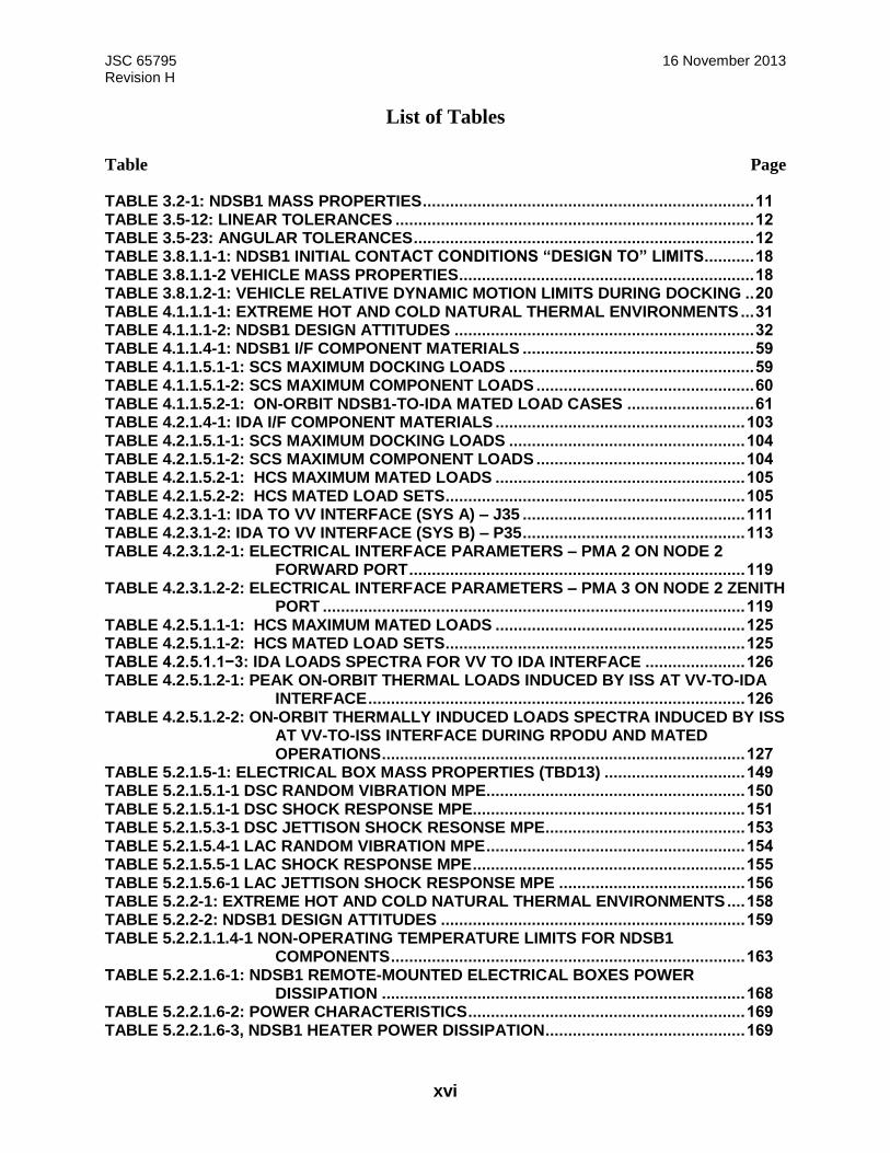
List of Tables
Table Page
TABLE 3.2-1: NDSB1 MASS PROPERTIES ......................................................................... 11 TABLE 3.5-12: LINEAR TOLERANCES ............................................................................... 12 TABLE 3.5-23: ANGULAR TOLERANCES ........................................................................... 12 TABLE 3.8.1.1-1: NDSB1 INITIAL CONTACT CONDITIONS “DESIGN TO” LIMITS ........... 18 TABLE 3.8.1.1-2 VEHICLE MASS PROPERTIES ................................................................. 18 TABLE 3.8.1.2-1: VEHICLE RELATIVE DYNAMIC MOTION LIMITS DURING DOCKING .. 20 TABLE 4.1.1.1-1: EXTREME HOT AND COLD NATURAL THERMAL ENVIRONMENTS ... 31 TABLE 4.1.1.1-2: NDSB1 DESIGN ATTITUDES .................................................................. 32 TABLE 4.1.1.4-1: NDSB1 I/F COMPONENT MATERIALS ................................................... 59 TABLE 4.1.1.5.1-1: SCS MAXIMUM DOCKING LOADS ...................................................... 59 TABLE 4.1.1.5.1-2: SCS MAXIMUM COMPONENT LOADS ................................................ 60 TABLE 4.1.1.5.2-1: ON-ORBIT NDSB1-TO-IDA MATED LOAD CASES ............................ 61 TABLE 4.2.1.4-1: IDA I/F COMPONENT MATERIALS ....................................................... 103 TABLE 4.2.1.5.1-1: SCS MAXIMUM DOCKING LOADS .................................................... 104 TABLE 4.2.1.5.1-2: SCS MAXIMUM COMPONENT LOADS .............................................. 104 TABLE 4.2.1.5.2-1: HCS MAXIMUM MATED LOADS ....................................................... 105 TABLE 4.2.1.5.2-2: HCS MATED LOAD SETS .................................................................. 105 TABLE 4.2.3.1-1: IDA TO VV INTERFACE (SYS A) – J35 ................................................. 111 TABLE 4.2.3.1-2: IDA TO VV INTERFACE (SYS B) – P35 ................................................. 113 TABLE 4.2.3.1.2-1: ELECTRICAL INTERFACE PARAMETERS – PMA 2 ON NODE 2
FORWARD PORT .......................................................................... 119 TABLE 4.2.3.1.2-2: ELECTRICAL INTERFACE PARAMETERS – PMA 3 ON NODE 2 ZENITH
PORT ............................................................................................. 119 TABLE 4.2.5.1.1-1: HCS MAXIMUM MATED LOADS ....................................................... 125 TABLE 4.2.5.1.1-2: HCS MATED LOAD SETS .................................................................. 125 TABLE 4.2.5.1.1−3: IDA LOADS SPECTRA FOR VV TO IDA INTERFACE ...................... 126 TABLE 4.2.5.1.2-1: PEAK ON-ORBIT THERMAL LOADS INDUCED BY ISS AT VV-TO-IDA
INTERFACE ................................................................................... 126 TABLE 4.2.5.1.2-2: ON-ORBIT THERMALLY INDUCED LOADS SPECTRA INDUCED BY ISS
AT VV-TO-ISS INTERFACE DURING RPODU AND MATED OPERATIONS ................................................................................ 127
TABLE 5.2.1.5-1: ELECTRICAL BOX MASS PROPERTIES (TBD13) ............................... 149 TABLE 5.2.1.5.1-1 DSC RANDOM VIBRATION MPE ......................................................... 150 TABLE 5.2.1.5.1-1 DSC SHOCK RESPONSE MPE............................................................ 151 TABLE 5.2.1.5.3-1 DSC JETTISON SHOCK RESONSE MPE ............................................ 153 TABLE 5.2.1.5.4-1 LAC RANDOM VIBRATION MPE ......................................................... 154 TABLE 5.2.1.5.5-1 LAC SHOCK RESPONSE MPE ............................................................ 155 TABLE 5.2.1.5.6-1 LAC JETTISON SHOCK RESPONSE MPE ......................................... 156 TABLE 5.2.2-1: EXTREME HOT AND COLD NATURAL THERMAL ENVIRONMENTS .... 158 TABLE 5.2.2-2: NDSB1 DESIGN ATTITUDES ................................................................... 159 TABLE 5.2.2.1.1.4-1 NON-OPERATING TEMPERATURE LIMITS FOR NDSB1
COMPONENTS .............................................................................. 163 TABLE 5.2.2.1.6-1: NDSB1 REMOTE-MOUNTED ELECTRICAL BOXES POWER
DISSIPATION ................................................................................ 168 TABLE 5.2.2.1.6-2: POWER CHARACTERISTICS ............................................................. 169 TABLE 5.2.2.1.6-3, NDSB1 HEATER POWER DISSIPATION ............................................ 169

JSC 65795 16 November 2013 Revision H
xvii
TABLE 5.3.3-1, MAXIMUM PYROSHOCK LEVELS AT NDSB1/IDA AND NDSB1/HOST I/F FOR CONTINGENCY PYROTECHNIC NDSB1 SEPARATION ..... 173
TABLE 5.3.3-2: PIN ASSIGNMENTS .................................................................................. 173 TABLE 5.3.4-1: HV TO NDSB1 POWER PIN ASSIGNMENTS ........................................... 174 TABLE 5.3.5.1-1: TIA-422B PIN ASSIGNMENTS ............................................................... 177 TABLE 5.3.5.2-1: NDSB1 IMPLEMENTATION OF MIL-STD-1553B MODE CODES ......... 179 TABLE 5.3.5.2.2-1: 1553 RT JUMPER SELECTION DEFINITION ..................................... 180 TABLE 5.3.9-1, CONDUCTED & RADIATED EMI AND INDIRECT LIGHTNING
REQUIREMENTS TBR .................................................................. 182 TABLE 5.4.2-1: HOST VEHICLE-TO-NDSB1 COMMAND PACKET .................................. 185 TABLE 5.4.2-2: HOST VEHICLE-TO-NDSB1 COMMAND PACKET PARAMETERS ........ 186 TABLE 5.4.2-3: NDSB1-TO-HOST VEHICLE H&S PACKET ............................................. 186 TABLE 5.4.2-4: NDSB1-TO-HOST VEHICLE H&S PACKET PARAMETERS .................... 187 TABLE 5.4.2-5: CRC-CCITT PARAMETERS ...................................................................... 187 TABLE 5.4.3.1-1: HV TO DSC RS-422 INTERFACE PROTOCOL ..................................... 188 TABLE 5.4.3.2-1: NDSB1-TO-HOST VEHICLE C&DH INTERFACE LAYERS ................... 188 TABLE 5.5-1: NDSB1 CONNECTIONS-TO-HOST VEHICLE ............................................. 190 TABLE 5.5-2, NDSB1 TO HOST VEHICLE PIN ASSIGNMENTS ....................................... 191 TABLE 7.1.2.1.1-1: NDSB1-TO-HOST VEHICLE ELECTRICAL INTERFACE ................... 202 TABLE 7.1.2.5.1.1-1: GANG/HOOK RELATIONSHIP ........................................................ 209 TABLE 7.1.3.2.3.1-1: PRIMARY POWER UTILIZATION FOR DOCKING .......................... 212 TABLE 7.1.3.2.3.2-1: STANDBY UTILIZATION FOR DOCKING ........................................ 212 TABLE 7.1.3.2.3.3-1: ACTIVE UTILIZATION FOR UNDOCKING ....................................... 214 TABLE 7.1.4.1.1.1-1: ON-ORBIT NDSB1-TO-HV MAXIMUM MATED LOAD CASES ...... 215 TABLE 7.1.4.1.1.2-1: ACOUSTIC ENVELOPE MAXIMUM PREDICTED ENVIRONMENT . 216 TABLE 7.1.4.1.1.3.3-1: RANDOM VIBRATION ENVELOPE MPE FOR THE HOST-NDSB1
INTERFACE ................................................................................... 218 TABLE 7.1.4.1.1.4-1: SHOCK RESPONSE SPECTRUM FROM HOST .............................. 219 TABLE 7.1.4.1.1.5-1: ASCENT LOAD FACTORS .............................................................. 220 TABLE 7.1.4.1.2.1-1: ABORT ACOUSTIC MAXIMUM PREDICTED ENVIRONMENT ....... 222 TABLE 7.1.4.1.2.2-1: ABORT RANDOM VIBRATION MPE FOR THE HOST-NDSB1
INTERFACE ................................................................................... 223 TABLE 7.1.4.1.2.3-1: NDSB1 SHOCK RESPONSE AT THE HV TO NDSB1 INTERFACE 224 TABLE 7.1.4.1.2.4-1: LOAD FACTORS (NON-FUNCTION) ............................................... 225 TABLE I-1: TBD IDENTIFICATION ..................................................................................... 256 TABLE I-2: TBR IDENTIFICATION ..................................................................................... 261 TABLE I-3: TBC IDENTIFICATION ..................................................................................... 263 TABLE K1.0-1 NDSB1 POWER INPUT FEEDS .................................................................. 267
JSC 65795 16 November 2013 Revision H
xviii
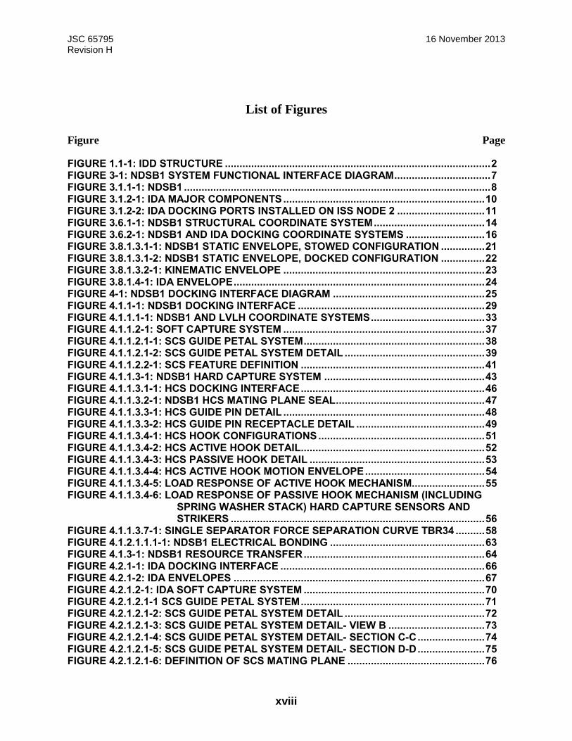
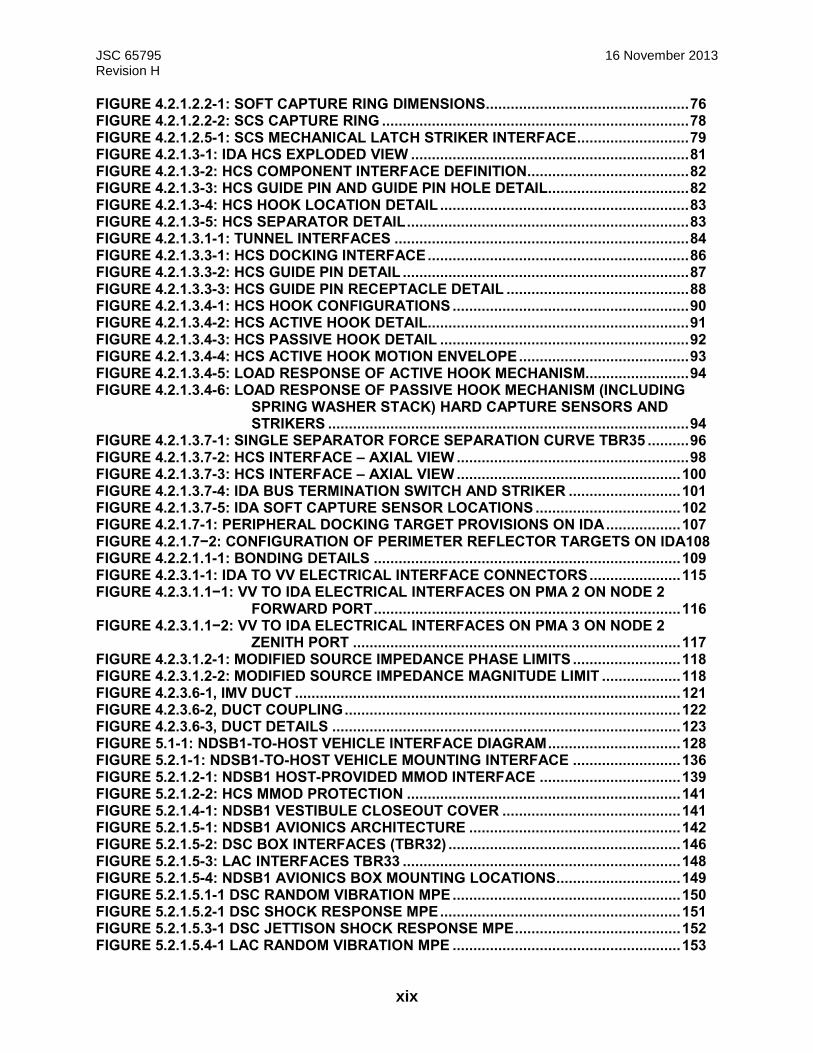
List of Figures
Figure Page
FIGURE 1.1-1: IDD STRUCTURE ........................................................................................... 2 FIGURE 3-1: NDSB1 SYSTEM FUNCTIONAL INTERFACE DIAGRAM ................................. 7 FIGURE 3.1.1-1: NDSB1 ......................................................................................................... 8 FIGURE 3.1.2-1: IDA MAJOR COMPONENTS ..................................................................... 10 FIGURE 3.1.2-2: IDA DOCKING PORTS INSTALLED ON ISS NODE 2 .............................. 11 FIGURE 3.6.1-1: NDSB1 STRUCTURAL COORDINATE SYSTEM ...................................... 14 FIGURE 3.6.2-1: NDSB1 AND IDA DOCKING COORDINATE SYSTEMS ........................... 16 FIGURE 3.8.1.3.1-1: NDSB1 STATIC ENVELOPE, STOWED CONFIGURATION ............... 21 FIGURE 3.8.1.3.1-2: NDSB1 STATIC ENVELOPE, DOCKED CONFIGURATION ............... 22 FIGURE 3.8.1.3.2-1: KINEMATIC ENVELOPE ..................................................................... 23 FIGURE 3.8.1.4-1: IDA ENVELOPE ...................................................................................... 24 FIGURE 4-1: NDSB1 DOCKING INTERFACE DIAGRAM .................................................... 25 FIGURE 4.1.1-1: NDSB1 DOCKING INTERFACE ................................................................ 29 FIGURE 4.1.1.1-1: NDSB1 AND LVLH COORDINATE SYSTEMS ....................................... 33 FIGURE 4.1.1.2-1: SOFT CAPTURE SYSTEM ..................................................................... 37 FIGURE 4.1.1.2.1-1: SCS GUIDE PETAL SYSTEM .............................................................. 38 FIGURE 4.1.1.2.1-2: SCS GUIDE PETAL SYSTEM DETAIL ................................................ 39 FIGURE 4.1.1.2.2-1: SCS FEATURE DEFINITION ............................................................... 41 FIGURE 4.1.1.3-1: NDSB1 HARD CAPTURE SYSTEM ....................................................... 43 FIGURE 4.1.1.3.1-1: HCS DOCKING INTERFACE ............................................................... 46 FIGURE 4.1.1.3.2-1: NDSB1 HCS MATING PLANE SEAL ................................................... 47 FIGURE 4.1.1.3.3-1: HCS GUIDE PIN DETAIL ..................................................................... 48 FIGURE 4.1.1.3.3-2: HCS GUIDE PIN RECEPTACLE DETAIL ............................................ 49 FIGURE 4.1.1.3.4-1: HCS HOOK CONFIGURATIONS ......................................................... 51 FIGURE 4.1.1.3.4-2: HCS ACTIVE HOOK DETAIL ............................................................... 52 FIGURE 4.1.1.3.4-3: HCS PASSIVE HOOK DETAIL ............................................................ 53 FIGURE 4.1.1.3.4-4: HCS ACTIVE HOOK MOTION ENVELOPE ......................................... 54 FIGURE 4.1.1.3.4-5: LOAD RESPONSE OF ACTIVE HOOK MECHANISM......................... 55 FIGURE 4.1.1.3.4-6: LOAD RESPONSE OF PASSIVE HOOK MECHANISM (INCLUDING
SPRING WASHER STACK) HARD CAPTURE SENSORS AND STRIKERS ....................................................................................... 56
FIGURE 4.1.1.3.7-1: SINGLE SEPARATOR FORCE SEPARATION CURVE TBR34 .......... 58 FIGURE 4.1.2.1.1.1-1: NDSB1 ELECTRICAL BONDING ..................................................... 63 FIGURE 4.1.3-1: NDSB1 RESOURCE TRANSFER .............................................................. 64 FIGURE 4.2.1-1: IDA DOCKING INTERFACE ...................................................................... 66 FIGURE 4.2.1-2: IDA ENVELOPES ...................................................................................... 67 FIGURE 4.2.1.2-1: IDA SOFT CAPTURE SYSTEM .............................................................. 70 FIGURE 4.2.1.2.1-1 SCS GUIDE PETAL SYSTEM ............................................................... 71 FIGURE 4.2.1.2.1-2: SCS GUIDE PETAL SYSTEM DETAIL ................................................ 72 FIGURE 4.2.1.2.1-3: SCS GUIDE PETAL SYSTEM DETAIL- VIEW B ................................. 73 FIGURE 4.2.1.2.1-4: SCS GUIDE PETAL SYSTEM DETAIL- SECTION C-C ....................... 74 FIGURE 4.2.1.2.1-5: SCS GUIDE PETAL SYSTEM DETAIL- SECTION D-D ....................... 75 FIGURE 4.2.1.2.1-6: DEFINITION OF SCS MATING PLANE ............................................... 76
JSC 65795 16 November 2013 Revision H
xix
FIGURE 4.2.1.2.2-1: SOFT CAPTURE RING DIMENSIONS ................................................. 76 FIGURE 4.2.1.2.2-2: SCS CAPTURE RING .......................................................................... 78 FIGURE 4.2.1.2.5-1: SCS MECHANICAL LATCH STRIKER INTERFACE ........................... 79 FIGURE 4.2.1.3-1: IDA HCS EXPLODED VIEW ................................................................... 81 FIGURE 4.2.1.3-2: HCS COMPONENT INTERFACE DEFINITION ....................................... 82 FIGURE 4.2.1.3-3: HCS GUIDE PIN AND GUIDE PIN HOLE DETAIL.................................. 82 FIGURE 4.2.1.3-4: HCS HOOK LOCATION DETAIL ............................................................ 83 FIGURE 4.2.1.3-5: HCS SEPARATOR DETAIL .................................................................... 83 FIGURE 4.2.1.3.1-1: TUNNEL INTERFACES ....................................................................... 84 FIGURE 4.2.1.3.3-1: HCS DOCKING INTERFACE ............................................................... 86 FIGURE 4.2.1.3.3-2: HCS GUIDE PIN DETAIL ..................................................................... 87 FIGURE 4.2.1.3.3-3: HCS GUIDE PIN RECEPTACLE DETAIL ............................................ 88 FIGURE 4.2.1.3.4-1: HCS HOOK CONFIGURATIONS ......................................................... 90 FIGURE 4.2.1.3.4-2: HCS ACTIVE HOOK DETAIL ............................................................... 91 FIGURE 4.2.1.3.4-3: HCS PASSIVE HOOK DETAIL ............................................................ 92 FIGURE 4.2.1.3.4-4: HCS ACTIVE HOOK MOTION ENVELOPE ......................................... 93 FIGURE 4.2.1.3.4-5: LOAD RESPONSE OF ACTIVE HOOK MECHANISM......................... 94 FIGURE 4.2.1.3.4-6: LOAD RESPONSE OF PASSIVE HOOK MECHANISM (INCLUDING
SPRING WASHER STACK) HARD CAPTURE SENSORS AND STRIKERS ....................................................................................... 94
FIGURE 4.2.1.3.7-1: SINGLE SEPARATOR FORCE SEPARATION CURVE TBR35 .......... 96 FIGURE 4.2.1.3.7-2: HCS INTERFACE – AXIAL VIEW ........................................................ 98 FIGURE 4.2.1.3.7-3: HCS INTERFACE – AXIAL VIEW ...................................................... 100 FIGURE 4.2.1.3.7-4: IDA BUS TERMINATION SWITCH AND STRIKER ........................... 101 FIGURE 4.2.1.3.7-5: IDA SOFT CAPTURE SENSOR LOCATIONS ................................... 102 FIGURE 4.2.1.7-1: PERIPHERAL DOCKING TARGET PROVISIONS ON IDA .................. 107 FIGURE 4.2.1.7−2: CONFIGURATION OF PERIMETER REFLECTOR TARGETS ON IDA108 FIGURE 4.2.2.1.1-1: BONDING DETAILS .......................................................................... 109 FIGURE 4.2.3.1-1: IDA TO VV ELECTRICAL INTERFACE CONNECTORS ...................... 115 FIGURE 4.2.3.1.1−1: VV TO IDA ELECTRICAL INTERFACES ON PMA 2 ON NODE 2
FORWARD PORT .......................................................................... 116 FIGURE 4.2.3.1.1−2: VV TO IDA ELECTRICAL INTERFACES ON PMA 3 ON NODE 2
ZENITH PORT ............................................................................... 117 FIGURE 4.2.3.1.2-1: MODIFIED SOURCE IMPEDANCE PHASE LIMITS .......................... 118 FIGURE 4.2.3.1.2-2: MODIFIED SOURCE IMPEDANCE MAGNITUDE LIMIT ................... 118 FIGURE 4.2.3.6-1, IMV DUCT ............................................................................................. 121 FIGURE 4.2.3.6-2, DUCT COUPLING ................................................................................. 122 FIGURE 4.2.3.6-3, DUCT DETAILS .................................................................................... 123 FIGURE 5.1-1: NDSB1-TO-HOST VEHICLE INTERFACE DIAGRAM ................................ 128 FIGURE 5.2.1-1: NDSB1-TO-HOST VEHICLE MOUNTING INTERFACE .......................... 136 FIGURE 5.2.1.2-1: NDSB1 HOST-PROVIDED MMOD INTERFACE .................................. 139 FIGURE 5.2.1.2-2: HCS MMOD PROTECTION .................................................................. 141 FIGURE 5.2.1.4-1: NDSB1 VESTIBULE CLOSEOUT COVER ........................................... 141 FIGURE 5.2.1.5-1: NDSB1 AVIONICS ARCHITECTURE ................................................... 142 FIGURE 5.2.1.5-2: DSC BOX INTERFACES (TBR32) ........................................................ 146 FIGURE 5.2.1.5-3: LAC INTERFACES TBR33 ................................................................... 148 FIGURE 5.2.1.5-4: NDSB1 AVIONICS BOX MOUNTING LOCATIONS .............................. 149 FIGURE 5.2.1.5.1-1 DSC RANDOM VIBRATION MPE ....................................................... 150 FIGURE 5.2.1.5.2-1 DSC SHOCK RESPONSE MPE .......................................................... 151 FIGURE 5.2.1.5.3-1 DSC JETTISON SHOCK RESPONSE MPE ........................................ 152 FIGURE 5.2.1.5.4-1 LAC RANDOM VIBRATION MPE ....................................................... 153

JSC 65795 16 November 2013 Revision H
xx
FIGURE 5.2.1.5.5-1 LAC SHOCK REPONSE MPE............................................................. 154 FIGURE 5.2.1.5.6-1 LAC JETTISON SHOCK RESPONSE MPE ........................................ 155 FIGURE 5.2.2-1, NDSB1 AND LVLH COORDINATE SYSTEMS ........................................ 160 FIGURE 5.3.3-1: MAXIMUM PYROSHOCK LEVELS AT NDSB1/IDA AND NDSB1/HOST I/F
FOR CONTINGENCY PYROTECHNIC NDSB1 SEPARATION ..... 173 FIGURE 5.5-1: NDSB1 TO-HOST VEHICLE ELECTRICAL INTERFACE .......................... 189 FIGURE 6.5.1-1: LEAK TEST PORT LOCATIONS ............................................................. 196 FIGURE 6.5.1-2: LEAK TEST PORT CROSS SECTION .................................................... 196 FIGURE 6.5.1-3: LEAK TEST PORT DETAIL ..................................................................... 197 FIGURE 6.1.6-1: HANDLING FIXTURE INTERFACE TO NDSB1 BOLT PATTERN .......... 197 FIGURE 6.1.7–4: DSE OVERIEW ....................................................................................... 198 FIGURE 7.1.1.2.2.3.3-1 DEFINITION OF LOAD DEFLECTION AT FLANGE ..................... 200 FIGURE 7.1.2.5-1: NDSB1 PYROTECHNIC SYSTEM ARCHITECTURE ........................... 209 FIGURE 7.1.3.2.1-1: NDSB1 POWER SYSTEM ................................................................. 211 FIGURE 7.1.4.1.1.2-1: ACOUSTIC ENVELOPE MAXIMUM PREDICTED ENVIRONMENT216 FIGURE 7.1.4.1.1.3-1: RANDOM VIBRATION ENVELOPE MPE FOR THE HOST-NDSB1
INTERFACE ................................................................................... 218 FIGURE 7.1.4.1.1.4-1: SHOCK RESPONSE SPECTRUM FROM HOST ............................ 219 FIGURE 7.1.4.1.2.1-1: ABORT ACOUSTIC MAXIMUM PREDICTED ENVIRONMENT ...... 221 FIGURE 7.1.4.1.2.2-1: ABORT RANDOM VIBRATION MPE FOR THE HOST-NDSB1
INTERFACE ................................................................................... 223 FIGURE 7.1.4.1.2.3-1: NDSB1 SHOCK RESPONSE AT THE HV TO NDSB1 INTERFACE224 FIGURE 7.1.4.15-1: MODIFIED LOAD IMPEDANCE MAGNITUDE LIMIT ......................... 229 FIGURE 7.1.4.15-2: MODIFIED LOAD IMPEDANCE PHASE LIMIT .................................. 229 FIGURE 7.1.4.16.3-1: BUS STUB LENGTH ........................................................................ 231 FIGURE K1.0-1:NDS-TO-HOST VEHICLE ELECTRICAL INTERFACE ............................. 265 FIGURE K2.1-1 SOURCE IMPEDANCE MAGNITUDE LIMITS – 2 AMPS ......................... 267 FIGURE K2.1-2 SOURCE IMPEDANCE PHASE LIMITS – 2 AMPS ................................... 268 FIGURE K2.1-3 SOURCE IMPEDANCE MAGNITUDE LIMITS – 20 & 30 AMPS ............... 268 FIGURE K2.1-4 SOURCE IMPEDANCE PHASE LIMITS – 20 & 30 AMPS ........................ 269 FIGURE K2.3.2-1-1 RIPPLE VOLTAGE SPECTRUM ......................................................... 270 FIGURE K2.4-1 NORMAL TRANSIENT VOLTAGE ............................................................ 271 FIGURE K.2.5.1-1 ABNORMAL TRANSIENT LIMITS ........................................................ 272 FIGURE K.2.5.1-2 ABNORMAL TRANSIENT LIMITS DETAILS ........................................ 273 FIGURE K.2.8-1, REGENERATION CURRENT LIMIT ........................................................ 274
JSC 65795 16 November 2013 Revision H
1
1.0 Introduction
The National Aeronautics and Space Administration (NASA) Docking System Block 1 (NDSB1)
and the International Docking Adapter (IDA) are a mating system that supports both crewed and
un-crewed docking at USOS docking ports.
The NDSB1 is NASA’s implementation of an International Docking System Standard (IDSS)
compatible system. NDSB1 and IDA can mate based on the requirements of IDSS Interface
Definition Document, Revision B, released April, 2013 with Soft Capture System parameters
modified in accordance with DCB-DP-10R1.
1.1 Purpose and Scope
This NDSB1 IDD defines the interface characteristics and performance capability of the NDSB1,
and supports both crewed and un-crewed space vehicles for Low Earth Orbit (LEO).
The responsibility for developing space vehicles and for making them technically and
operationally compatible with the NDSB1\IDA rests with the vehicle providers. This document
defines the NDSB1-to-IDA interfaces, the NDSB1-to-host vehicle interfaces, and the performance
capabilities. It is up to implementers to examine the IDD to determine if there are any issues
regarding the implementation of the NDS on their vehicle. Section 1 of this document is an
introduction. Section 2 is the Applicable and Reference Document section. Section 3 provides a
general system overview. Section 4 describes the NDSB1 to IDA interface implementation details.
Section 5 describes the NDSB1 to Host Vehicle (HV) interface implementation details. Section 6
describes the NDSB1 to Test Equipment interfaces. Section 7 describes the Host Vehicle interface
requirements for using the NDSB1. Refer to Figure 1.1-1: the NDS IDD structure and scope.
Revision H of this document is specific to the NDSB1 and IDA designs. Refer to revision G for
the previous NDS Block 0 designs. Future NDS block upgrade design(s) will be documented in
future revisions of this IDD.

JSC 65795 16 November 2013 Revision H
2
FIGURE 1.1-1: IDD STRUCTURE
1.2 Responsibility and Change Authority
The responsibility for this document, including change authority, rests with the International Space
Station (ISS) Development Projects Office
NDSB1-to-IDA IDD
JSC 65795 Rev H
Sections 1-3
Host
Vehicle
NDS IDD Sections
5 & 7 ND
SB1
IDA
NDS IDD Sections
4
IDA-ISS ICD SSP 50951
Section 3
Test & Support
Equipment
NDS IDD Sections
6
JSC 65795 16 November 2013 Revision H
3
2.0 Applicable and Reference Documents
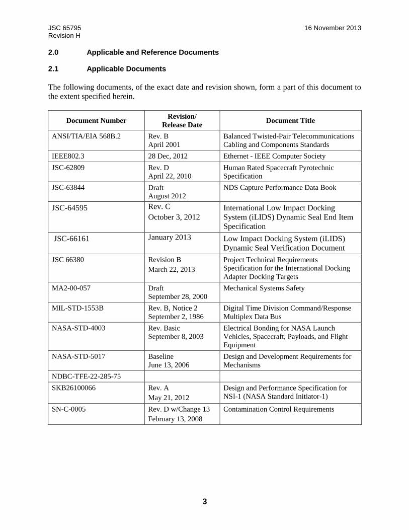
2.1 Applicable Documents
The following documents, of the exact date and revision shown, form a part of this document to
the extent specified herein.
Document Number Revision/
Release Date Document Title
ANSI/TIA/EIA 568B.2 Rev. B
April 2001
Balanced Twisted-Pair Telecommunications
Cabling and Components Standards
IEEE802.3 28 Dec, 2012 Ethernet - IEEE Computer Society
JSC-62809 Rev. D
April 22, 2010
Human Rated Spacecraft Pyrotechnic
Specification
JSC-63844 Draft
August 2012
NDS Capture Performance Data Book
JSC-64595 Rev. C
October 3, 2012
International Low Impact Docking
System (iLIDS) Dynamic Seal End Item
Specification
JSC-66161 January 2013 Low Impact Docking System (iLIDS)
Dynamic Seal Verification Document
JSC 66380 Revision B
March 22, 2013
Project Technical Requirements
Specification for the International Docking
Adapter Docking Targets
MA2-00-057 Draft
September 28, 2000
Mechanical Systems Safety
MIL-STD-1553B Rev. B, Notice 2
September 2, 1986
Digital Time Division Command/Response
Multiplex Data Bus
NASA-STD-4003 Rev. Basic
September 8, 2003
Electrical Bonding for NASA Launch
Vehicles, Spacecraft, Payloads, and Flight
Equipment
NASA-STD-5017 Baseline
June 13, 2006
Design and Development Requirements for
Mechanisms
NDBC-TFE-22-285-75
SKB26100066 Rev. A
May 21, 2012
Design and Performance Specification for
NSI-1 (NASA Standard Initiator-1)
SN-C-0005 Rev. D w/Change 13
February 13, 2008
Contamination Control Requirements

JSC 65795 16 November 2013 Revision H
4
2.2 Reference Documents
The following documents are reference documents used in the development of this document.
These documents do not form a part of this document, and are not controlled by their reference
herein.
Document Number Revision/
Release Date Document Title
684-018763 May 2013 Electro-Mechanical Actuator Assembly,
Umbilical
AMS4078 Latest 7075-T7351 Aluminum Alloy Plate 5.62n
Specification
AMS 4144 Latest 2219 Aluminum Alloy Specification
AMS 4965 Latest Titanium Alloy Specification
AMS 5659 Latest Stainless Steel Consumable Electrode Melted
Specification
AMS 6930 Latest Titanium Alloy Bars, Forgings and Forging
Stock
AMS-QQ-A-250/12 Latest 7075-T7351 Aluminum Alloy Plate
Specification
ARP 5412 Rev. A
February 2005
Aircraft Lightning Environment and Related
Test Waveforms
AS9390
Pin, Straight, Headless, UNS66286 standard
D684-15386
NDSB1 Concept of Operations
DRPSDZ29101974-5003 Draft pending Drill Template, NDS – Host Interface
EID684-15524
NDSB1 Thermal Analysis Report
IDSS IDD Rev. B
November 15 2012 International Docking System Standard
(IDSS) Interface Definition Document (IDD)
JSC-28596 Rev. A
February 29, 2000
NASA Standard Initiator User’s Guide
JSC-63686 Rev. H
August 2012
International Low Impact Docking System
(iLIDS) Project Technical Requirements
Specification
JSC-63688 Phase II Draft
November 17, 2011
Risk Assessment Executive Summary Report
(RAESR) for the International Low Impact
Docking System (iLIDS)
JSC-65842 Basic
November 16, 2011
iLIDS Electromagnetic Environmental
Effects (E3) Requirements Document
JSC-66188 Draft pending NASA Docking System (NDS) Operations
Manual
JSC-66189 Draft pending NASA Docking System (NDS) to Host
Vehicle Integration and Checkout
JSC 65795 16 November 2013 Revision H
5
Document Number Revision/
Release Date Document Title
MIL-DTL-5541 Rev. F
July 11, 2006
Chemical Conversion Coatings on
Aluminum and Aluminum Alloys
NCR-ISS-iLIDS-002
Non-conformance Compliance Report
PRC-2001 Rev. G
August 10, 2009 Heat Treatment of Steel Alloys
PRC-5002 Rev. E
September 2006
Process Specification for Passivation and
Pickling of Metallic Materials
PRC-5006 Rev. C
May 2003
Process Specification for the Anodizing of
Aluminum Alloy
683-100100-0001
NDSB1 Top Assembly
SDZ29101861 Rev. 7
August 28, 2011
Guide Petal Drawing – SCS, iLIDS
SLZ29101649 Rev. 4
September 9, 2011
Umbilical EMA Specification Control
Drawing
SSP 30309 Rev. F
November 2005
Safety Analysis and Risk Assessment
Requirements Document
SSP 30559 Rev. D
July 27, 2007
Structural Design and Verification
Requirements
SSP 50021 Baseline, DCN 004
July 8, 2009
Safety Requirements Document
SSP 50038 Rev. B
November 17, 1995
Computer-Based Control System Safety
Requirements
SSP 50920 Rev. A
November 2010
NASA Docking System (NDS) Users Guide
SSQ 22680 Rev J
May 2011 Connectors, Rectangular, (ORU), Space
Quality, General Specification For
TIA-422-B Rev. B
May 1994 Electrical Characteristics of Balanced
Voltage Digital Interface Circuits
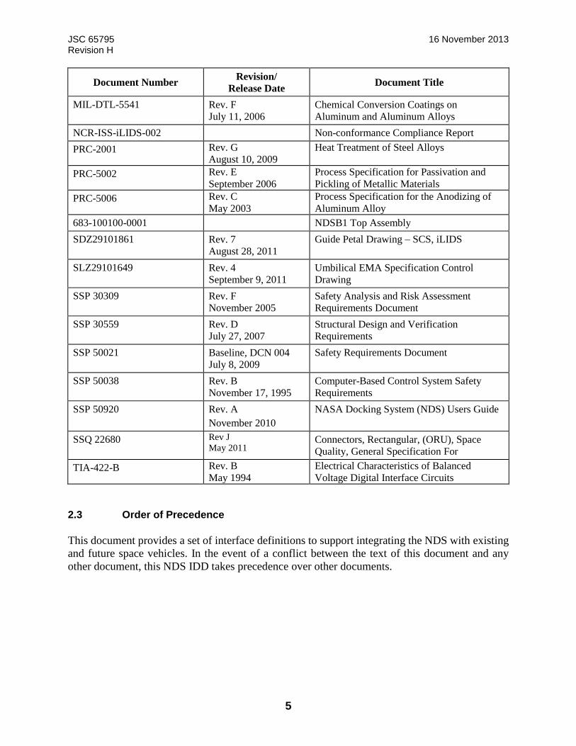
2.3 Order of Precedence
This document provides a set of interface definitions to support integrating the NDS with existing
and future space vehicles. In the event of a conflict between the text of this document and any
other document, this NDS IDD takes precedence over other documents.

JSC 65795 16 November 2013 Revision H
6
3.0 General System Overview
The NDSB1 system will establish the initial connection of a visiting vehicle to ISS USOS docking
port through the soft capture mechanisms for NDSB1 and IDA. The soft capture subsystems will
consist of guide petals on both systems, Soft Capture System (SCS) latch striker interfaces on IDA
and mechanical latches on NDSB1 for SCS mate, and 6 electromechanical actuators independently
controlling six legs of the SCS platform using a feed forward control law on NDSB1. During
docking soft capture, the guide petals are the first element to make contact providing course
alignment and a transmitted first contact signal that will indicate to the NDSB1 host vehicle to go
in to free drift. Upon initial contact the SCS actuators will lunge to perform initial capture with
SCS latches to IDA passive latch strikers. The SCS will then perform attenuation, align SCS
parallel to Hard Capture System (HCS) mating plane and then retract to the ready to hook position
using pins on the HCS for fine alignment.
The NDSB1 HCS will utilize powered hooks to engage with the IDA passive hooks, providing a
structural connection ready for pressurization between the mated vehicles that allows for cargo
and crew transfer. The HCS consists of a tunnel, electro-mechanical mating mechanism with 12
active/passive hook pairs, seals, fine alignment features, mechanized umbilicals, contingency pyro
release, and undocking separation system and multiple sensors elements.
The docking will be completed when 12 active hooks are closed, separators are energized and
resource transfer umbilicals are engaged. The umbilical system will provide pass through for
power and data communications between the two vehicles. The control of both the HCS and SCS
is performed by a remotely located Docking System Controller that receives 28 V power from the
Commercial Crew Program (CCP) HV and communicates with the HV via either RS-422 or 1553
data bus.
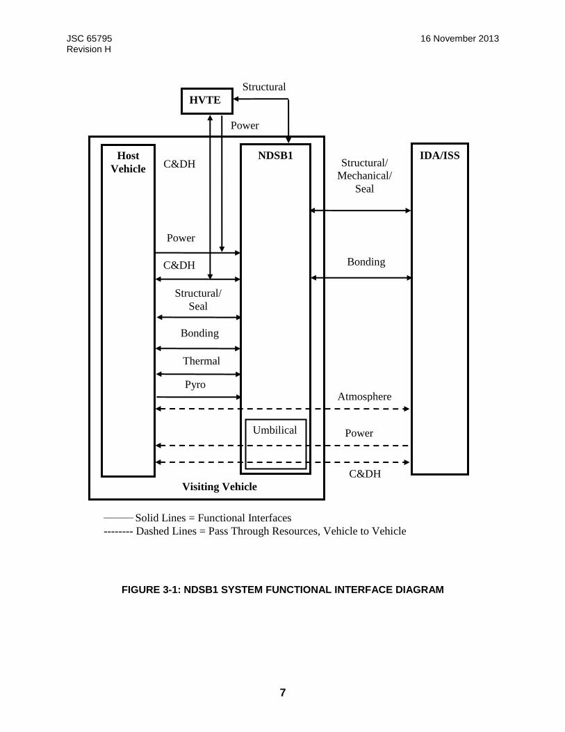
The following subsections describe the system interfaces for the NDSB1. Interface responsibilities
are defined with respect to the interface boundaries presented in Figure 3-1: NDSB1 System
Functional Interface Diagram.
JSC 65795 16 November 2013 Revision H
7
FIGURE 3-1: NDSB1 SYSTEM FUNCTIONAL INTERFACE DIAGRAM
Host
Vehicle
IDA/ISS NDSB1
HVTE
Umbilical
C&DH
Power
Atmosphere Pyro
Thermal
Bonding
Structural/
Seal
C&DH
Power
Visiting Vehicle
Power
C&DH
Structural
Bonding
Structural/
Mechanical/
Seal
________ Solid Lines = Functional Interfaces
-------- Dashed Lines = Pass Through Resources, Vehicle to Vehicle
JSC 65795 16 November 2013 Revision H
8
3.1 System Description
3.1.1 NDS Block 1
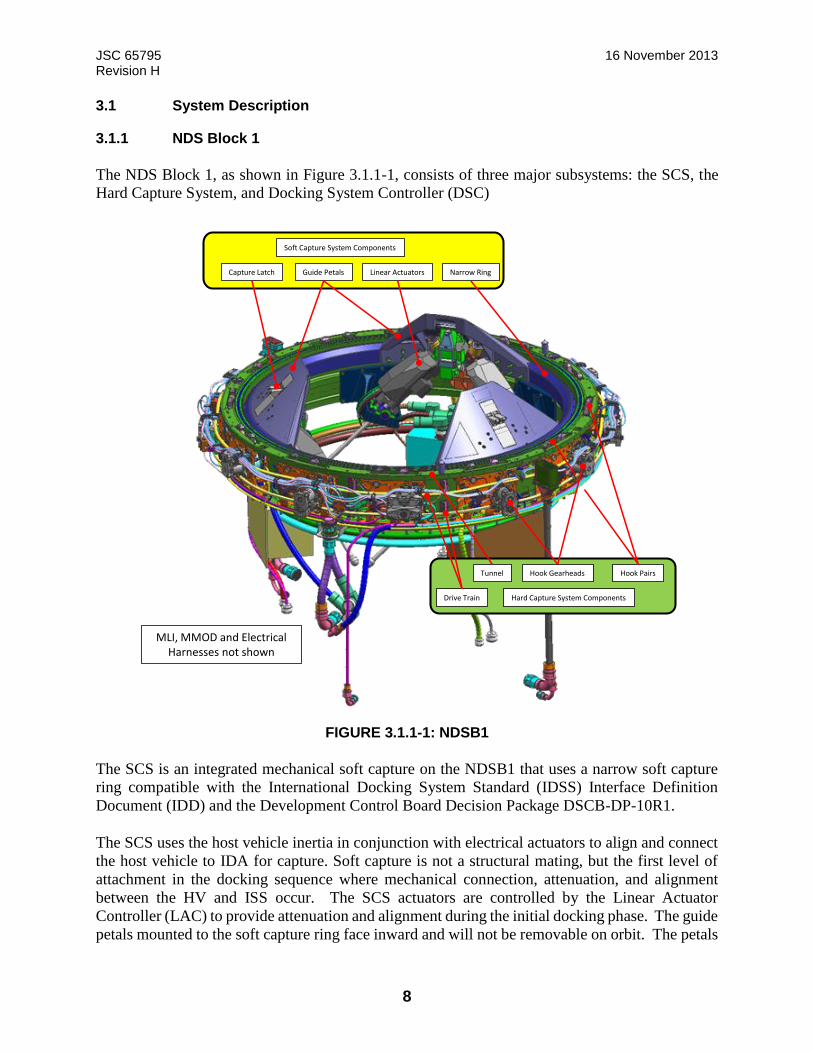
The NDS Block 1, as shown in Figure 3.1.1-1, consists of three major subsystems: the SCS, the
Hard Capture System, and Docking System Controller (DSC)
FIGURE 3.1.1-1: NDSB1
The SCS is an integrated mechanical soft capture on the NDSB1 that uses a narrow soft capture
ring compatible with the International Docking System Standard (IDSS) Interface Definition
Document (IDD) and the Development Control Board Decision Package DSCB-DP-10R1.
The SCS uses the host vehicle inertia in conjunction with electrical actuators to align and connect
the host vehicle to IDA for capture. Soft capture is not a structural mating, but the first level of
attachment in the docking sequence where mechanical connection, attenuation, and alignment
between the HV and ISS occur. The SCS actuators are controlled by the Linear Actuator
Controller (LAC) to provide attenuation and alignment during the initial docking phase. The guide
petals mounted to the soft capture ring face inward and will not be removable on orbit. The petals
Figure 3.1-1
Capture Latch Guide Petals Linear Actuators Narrow Ring
Soft Capture System Components
Drive Train
Tunnel Hook PairsHook Gearheads
Hard Capture System Components
MLI, MMOD and Electrical Harnesses not shown
JSC 65795 16 November 2013 Revision H
9
are equally spaced around the circumference of the soft capture docking ring. The SCS guide
petals mounts an active latch for soft capture and are extended from its stowed position by
electrically driven linear actuators.
The NDSB1 provides an electrical interface to allow the HV to re-mode the soft capture system
latches for contingency/emergency situations. The functionality provided is independent of the
normal (redundant) NDSB1 avionics. Operation of the contingency release is intended only for
situations when standard NDSB1 electronics interfaces are non-functioning or
unavailable. Activation of the contingency release configures all 3 soft capture system latches to
an Open/Releasing mode. Contingency release is a one-time operation meaning the latches cannot
be reset to Closed/Capturing mode after activation. Soft Capture after contingency release
operation will not be possible.
The LAC controls the SCS linear actuators to provide sensing of initial contact between the HV
and IDA, soft capture of the IDA, attenuation of initial contact forces, and alignment for hard
capture. The LAC receives operational commands from, and returns status data to the DSC.
The HCS uses powered hooks to engage with the passive system, providing a structural connection
ready for pressurization between the mated vehicles that allows for cargo and crew transfer. The
HCS consists of a tunnel, 12 active/passive hook pairs, seals, fine alignment guide pins,
mechanized separation springs, and mechanized umbilicals.
Docking is complete when mechanized resource transfer umbilicals are engaged and the spring-
loaded separation system is energized for undocking. The NDSB1 commanded via an NDS
electronics interface from the HV.
The DSC provides control of the NDSB1. The DSC is the interface between the system operation
and status of the NDSB1 and the resultant docking system operation. The DSC receives
commands from a HV Flight Computer (FC) on a 1553B bus or a RS-422 interface to perform
active docking/undocking, HSC or SCS checkout, manual control operations or monitoring system
performance. The DSC is packaged in two flight boxes with redundant A and B systems. Along
with the LAC the DSC boxes are remotely mounted and powered by 28 volt DC power supply
from the host vehicle.
3.1.2 International Docking Adapter
The ISS IDA provides a docking port on the ISS for Visiting Vehicles (VV). The IDA’s purpose
is to convert the ISS APAS docking ports into IDSS-compatible docking ports. The CCP vehicle
will have an active docking mechanism to dock with the IDA. The IDA has a fixed capture ring
with guide petals, capture sensors, and mechanical SCS body latches (mechanical latch strikers).
The IDA HCS consists of a tunnel with a metallic sealing surface, electro-mechanical mating
mechanism with 12 active/passive hook pairs, and mechanized separation system and fixed
umbilicals. The IDA will provide power and data utility connections to the VV after docking. It
will allow cargo and crew to be exchanged between the VV and ISS through a pressurized tunnel.
The IDA will also provide passive navigation aids to assist the VV during proximity operations.
IDA provides contingency active hooks that can be driven by the IDA Control Panel (ICP) on ISS

JSC 65795 16 November 2013 Revision H
10
if there is a hook gang failure on NDSB1. At the end of VV attached operations, in case of NDS
Block1 separators contingency, the IDA may provide a nominal separation impulse to undock the
HV. Note – The need for the use of the IDA separator would be identified in docking operations
when the NDSB1 separators are energized.
Figure 3.1.2-1, IDA Major Components, shows the IDA major components which include the
Energia IDA Primary Structure (EIPS) (consisting of a Modified Androgynous Peripheral
Attachment System (MAPAS), the EIPS Adapter Ring (EAR), and the Passive Hard Mate
Assembly (PHMA)), and the Passive Soft Capture System.
FIGURE 3.1.2-1: IDA MAJOR COMPONENTS
The current operational concept specifies that two IDAs will be installed on the ISS to support
docking of VVs. One IDA will be installed on Pressurized Mating Adapter 2 (PMA2) at Node 2
Forward. The second IDA will be installed on Pressurized Mating Adapter 3 (PMA3) at Node 2
Zenith. Figure 3.1.2-2 shows the IDA installed on PMA2 at the Node 2 Forward location. Figure
3.1.2-2 also shows the ISS outfitted with IDA forward and zenith docking ports on Node 2.

JSC 65795 16 November 2013 Revision H
11
FIGURE 3.1.2-2: IDA DOCKING PORTS INSTALLED ON ISS NODE 2
3.2 Mass Properties
The mass properties for NDSB1 are described in Table 3.2-1: Mass Properties. Mass properties
reference the NDSB1 center of gravity relative to the coordinate system defined in Figure 3.6-1:
NDSB1 STRUCTURAL COORDINATE SYSTEM . These mass properties are for the integrated
mechanism, including the electrical boxes. See Table 5.2.1.5-1: Electrical Box Mass Properties for
electrical boxes that are integrated by the host separately from the mechanism.
TABLE 3.2-1: NDSB1 MASS PROPERTIES
Mass lb (kg)
[Not to exceed]
Center of Mass (1)
In
(mm)
[Not to exceed]
Moments of Inertia (2)
lb-in2
(kg-mm2)
[Not to exceed]
715
(324)
X Y Z IXX IYY IZZ Pxy Pxz Pyz
0.014
(-0.356)
0.178
(4.5)
-6.505
(-165.0)
1.706E+06
(4.992E+08
1.722E+06
(5.039E+08)
2.28E+06
(6.67E+08)
7.006E+02
(2.05E+05)
-1.095E+02
(-3.206E+04)
-1.92E=02
(-5.643E04)
Notes:
(1) Center of gravity tolerances : ± 0.5 in ( 12.7mm)
(2) Moments of inertia are based on the nominal center of gravity location.
3.3 Volume Properties
For host Environmental Control and Life Support System (ECLSS) analysis, the following worst-
case volumes may be used. The NDSB1 internal vestibule volume is not to exceed 10.3 ft3 (0.286
m3). This volume is defined from the NDSB1 mounting plane to the NDSB1 HCS mating plane.
The calculated volume assumes no hardware inside the pressure wall of the NDSB1 tunnel.
Therefore, the actual volume will be slightly less. The IDA internal volume is not to exceed 27.26
ft3 (0.772 m3).
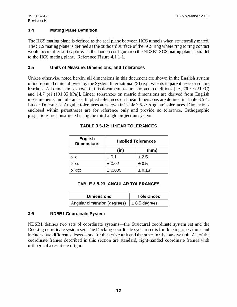
JSC 65795 16 November 2013 Revision H
12
3.4 Mating Plane Definition
The HCS mating plane is defined as the seal plane between HCS tunnels when structurally mated.
The SCS mating plane is defined as the outboard surface of the SCS ring where ring to ring contact
would occur after soft capture. In the launch configuration the NDSB1 SCS mating plan is parallel
to the HCS mating plane. Reference Figure 4.1.1-1.
3.5 Units of Measure, Dimensions, and Tolerances
Unless otherwise noted herein, all dimensions in this document are shown in the English system
of inch-pound units followed by the System International (SI) equivalents in parentheses or square
brackets. All dimensions shown in this document assume ambient conditions [i.e., 70 °F (21 °C)
and 14.7 psi (101.35 kPa)]. Linear tolerances on metric dimensions are derived from English
measurements and tolerances. Implied tolerances on linear dimensions are defined in Table 3.5-1:
Linear Tolerances. Angular tolerances are shown in Table 3.5-2: Angular Tolerances. Dimensions
enclosed within parentheses are for reference only and provide no tolerance. Orthographic
projections are constructed using the third angle projection system.
TABLE 3.5-12: LINEAR TOLERANCES
English Dimensions
Implied Tolerances
(in) (mm)
x.x ± 0.1 ± 2.5
x.xx ± 0.02 ± 0.5
x.xxx ± 0.005 ± 0.13
TABLE 3.5-23: ANGULAR TOLERANCES
Dimensions Tolerances
Angular dimension (degrees) ± 0.5 degrees
3.6 NDSB1 Coordinate System
NDSB1 defines two sets of coordinate systems—the Structural coordinate system set and the
Docking coordinate system set. The Docking coordinate system set is for docking operations and
includes two different subsets—one for the active unit and the other for the passive unit. All of the
coordinate frames described in this section are standard, right-handed coordinate frames with
orthogonal axes at the origin.
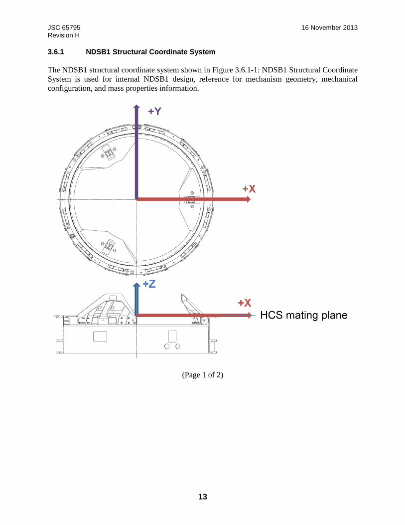
JSC 65795 16 November 2013 Revision H
13
3.6.1 NDSB1 Structural Coordinate System
The NDSB1 structural coordinate system shown in Figure 3.6.1-1: NDSB1 Structural Coordinate
System is used for internal NDSB1 design, reference for mechanism geometry, mechanical
configuration, and mass properties information.
(Page 1 of 2)

JSC 65795 16 November 2013 Revision H
14
Origin: The origin of the NDSB1 Structural Docking Coordinate System is defined as the
intersection of the NDSB1 cylindrical axis and the hard capture mating plane and is coincident
with the NDSB1 Active Docking Coordinate System Origin.
X-axis: The X-axis lies in the hard capture mating plane and is positive from the origin toward
the NDSB1 Guide Petal 1. The X-axis coincides with the NDSB1 line of symmetry.
Y-axis: The Y-axis lies in the hard capture mating plane and is positive from the origin toward
the HCS guide pin-receptacle combo. The Y-axis coincides with the NDSB1 line of androgyny.
Z-axis: The Z-axis coincides with the NDSB1 cylindrical axis and is positive in the direction
pointing away from the hard capture mating plane (forward flight direction) and completes the
right-handed system.
(Page 2 of 2) FIGURE 3.6.1-1: NDSB1 STRUCTURAL COORDINATE SYSTEM
3.6.2 NDSB1 Docking Coordinate Systems
The NDSB1B1 Docking coordinate system set is used for docking operations and analysis. It uses
the same coordinate center or origin as does the NDSB1 Structural Coordinate System. Its
orientation follows an approach common in flight dynamics, where the X-axis is positive in the
forward flight direction. The NDSB1 Docking coordinate system set contains the NDSB1 Docking
coordinate system and the IDA Docking coordinate system (see Figure 3.6.2-1: NDSB1 AND IDA
+Y-axis NDS Structural Docking
+X-axis NDS Structural Docking
+Z-axis NDS Structural Docking
Guide Petal 1
Guide Petal 2
Guide Petal 3 Internal MLI omitted for clarity
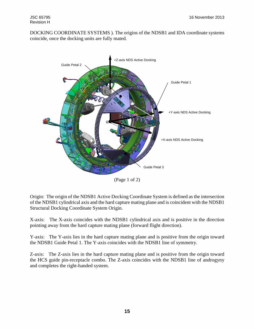
JSC 65795 16 November 2013 Revision H
15
DOCKING COORDINATE SYSTEMS ). The origins of the NDSB1 and IDA coordinate systems
coincide, once the docking units are fully mated.
(Page 1 of 2)
Origin: The origin of the NDSB1 Active Docking Coordinate System is defined as the intersection
of the NDSB1 cylindrical axis and the hard capture mating plane and is coincident with the NDSB1
Structural Docking Coordinate System Origin.
X-axis: The X-axis coincides with the NDSB1 cylindrical axis and is positive in the direction
pointing away from the hard capture mating plane (forward flight direction).
Y-axis: The Y-axis lies in the hard capture mating plane and is positive from the origin toward
the NDSB1 Guide Petal 1. The Y-axis coincides with the NDSB1 line of symmetry.
Z-axis: The Z-axis lies in the hard capture mating plane and is positive from the origin toward
the HCS guide pin-receptacle combo. The Z-axis coincides with the NDSB1 line of androgyny
and completes the right-handed system.
+Z-axis NDS Active Docking
+Y-axis NDS Active Docking
+X-axis NDS Active Docking
Guide Petal 1
Guide Petal 2
Guide Petal 3

JSC 65795 16 November 2013 Revision H
16
(Page 2 of 2)
FIGURE 3.6.2-1: NDSB1 AND IDA DOCKING COORDINATE SYSTEMS
3.6.2.1 NDSB1 Active Docking Coordinate System
The NDSB1 active docking coordinate system shown in Figure 3.6.2-1 is used for docking
performance analysis and is associated with the NDSB1 unit in the active mode.
Origin: The origin of the NDSB1 Active Docking Coordinate System is defined as the intersection
of the NDSB1 cylindrical axis and the HCS mating plane (see Figure 3.6.1-1), coincident with the
NDSB1 Docking Coordinate System origin.
X-axis: The X-axis coincides with the NDSB1 cylindrical axis and is positive in the direction
pointing away from the vehicle mounting plane.
Z-axis: The Z-axis lies in the HCS mating plane and is positive from the origin toward the HCS
guide pin-receptacle combo. The Z-axis coincides with the NDSB1 line of androgyny.

JSC 65795 16 November 2013 Revision H
17
Y-axis: The Y-axis lies in the HCS mating plane and is positive from the origin toward the NDSB1
guide petal 1. The Y-axis coincides with the NDSB1 line of symmetry.
3.6.2.2 IDA Coordinate System
The IDA docking coordinate system shown in Figure 3.6.2-1 is used for docking performance
analysis and is associated with the IDA as the passive mode.
Origin: The origin of the IDA Coordinate System is defined as the intersection of the IDA
cylindrical axis and the HCS mating plane (see Figure 3.6.1-1), coincident with the NDSB1
Docking Coordinate System origin.
X-axis: The X-axis coincides with the IDA cylindrical axis and is positive in the direction pointing
toward the vehicle mounting plane.
Z-axis: The Z-axis lies in the HCS mating plane and is positive from the origin toward the HCS
guide pin-receptacle combo. The Z-axis coincides with the IDA line of symmetry.
Y-axis: The Y-axis lies in the HCS mating plane and is positive from the origin pointing away
from the NDSB1 guide petal 1. The Y-axis coincides with the IDA line of symmetry.
3.7 NDSB1 Component Numbering and Labeling
3.7.1 NDSB1 Component Numbering
The docking system components are numbered. The numbering method is based on the following
convention. Starting from the positive X-axis (structural coordinate system), the first component
of a subsystem is labeled “1” with the next component being “2” in a counterclockwise fashion.
Reference Figure 3.6.1-1.
3.7.2 NDSB1 Component Labeling
To aid operations, NDSB1 includes some visible labels. For subsystems with the same quantity of
components, a single zone label (e.g., “2”) represents all components in that zone, as shown in
Figure 4.3-1: NDSB1 Resource Transfer.
3.8 System Performance Parameters
The NDSB1 is designed to support docking without hardware reconfiguration.
3.8.1 NDSB1 Docking
3.8.1.1 NDSB1 Docking Capture Performance
The baseline capture envelope is defined in Table 3.8.1.1-1, NDSB1 Initial Contact Conditions.

JSC 65795 16 November 2013 Revision H
18
TABLE 3.8.1.1-1: NDSB1 INITIAL CONTACT CONDITIONS “DESIGN TO” LIMITS
Initial Conditions Limiting Value
Closing (axial) rate 0.1 to 0.2 ft/sec (0.03 to 0.06 m/s)
Lateral (radial) rate 0.13 ft/sec (0.04 m/s)
Angular rate 0.40 deg/sec about NDSB1 X axis;
0.15 deg/sec about any axis within the NDSB1 Y-
Z plane
Lateral (radial) misalignment 4.33 in. (110 mm)
Angular misalignment 5.0 degrees about NDSB1 X axis;
5.0 degrees about any axis within the NDSB1 Y-Z
plane
Notes:
1. Initial conditions are 3σ maxima and are to be applied simultaneously in a statistically appropriate manner. 2. Mean closing rate may be adjusted depending on vehicle mass combinations. Refer to Table 3.8.1.1-2 Vehicle Mass Properties. 3. Lateral (radial) rate limit includes combined lateral and rotational rates of both vehicles. 4. Lateral misalignment is defined as the minimum distance between the center of the active soft capture ring and the longitudinal axis of the passive soft capture ring at the moment of first contact between the guide petals. 5. The NDSB1 will use a right-hand orthogonal body coordinate system, the origin of which lies in the intersection of the NDSB1 cylindrical center line X-axis and HCS mating plane (refer to Figure 3.6.2-1, NDSB1 Active Docking Coordinate System). 6. The NDSB1 will control the accuracy of the position of the SCS ring at the Ready-To-Capture height within 0.14 inch per lateral axis and 0.28 degrees per axis with respect to the NDSB1 docking coordinate frame
TABLE 3.8.1.1-2 VEHICLE MASS PROPERTIES
Vehicle Mass (lb)
Moment of Inertia (ft*lbf*sec2) Coordinates of the Hard Capture System Mating Plane
Center (ft)
Ixx Iyy Izz Ixy Ixz Iyz X Y Z
ISS – N2F
docking
9.71E05
9.82E07
6.25E07
1.39E08
-2.42E06
-3.56E06
-1.21E06
52.65 0.0 18.25
ISS – N2Z docking
9.71E05
9.82E07
6.25E07
1.39E08
-2.42E06
-3.56E06
-1.21E06
33.52 0.0 -0.55
IDSS-10T
HV
22000 12500 31000 31000 0 0 0 11.5 0 0
18T HV 40000 37100 81700 81700 0 0 0 13.9 0 0
ISS C.G. (ft) X = -13.95 , Y = -1.34, Z = 13.74
Notes: 1. Moments of inertia (MOI) are about C.G. and products of inertia (POI) are positive integral.
2. HV mass properties and mating plane coordinates defined in coordinate system located at C.G. with X-axis along vehicle longitudinal axis and
positive toward the docking interface. 3. ISS mass properties and mating plane coordinates defined in ISS coordinate system. (ISS L&D Model xd94ih, EID684-15328, dated 12-14-
2012).
JSC 65795 16 November 2013 Revision H
19
3.8.1.2 Vehicle Relative Dynamic Motion Limits During Docking
The maximum relative motion between two docking vehicles occurs during the soft capture and
attenuation phases of docking. During soft capture, the SCS is contending with vehicle
misalignment and trying to achieve capture. During attenuation, the SCS is contending with
limiting the relative motion between the two docking vehicles. After soft capture and attenuation,
the SCS aligns then retracts the two docking interfaces. For NDSB1, the maximum relative motion
between two docking vehicles has been defined at select SCS extension heights in Table 3.8.1.2-
1: Vehicle Relative Dynamic Motion Limits During Docking. This data provides host vehicles
with the necessary information to assess vehicle-to-vehicle clearances during docking. It is the
responsibility of the applicable mission or program to determine the vehicle clearance pass-fail
requirements and approve any exceptions.
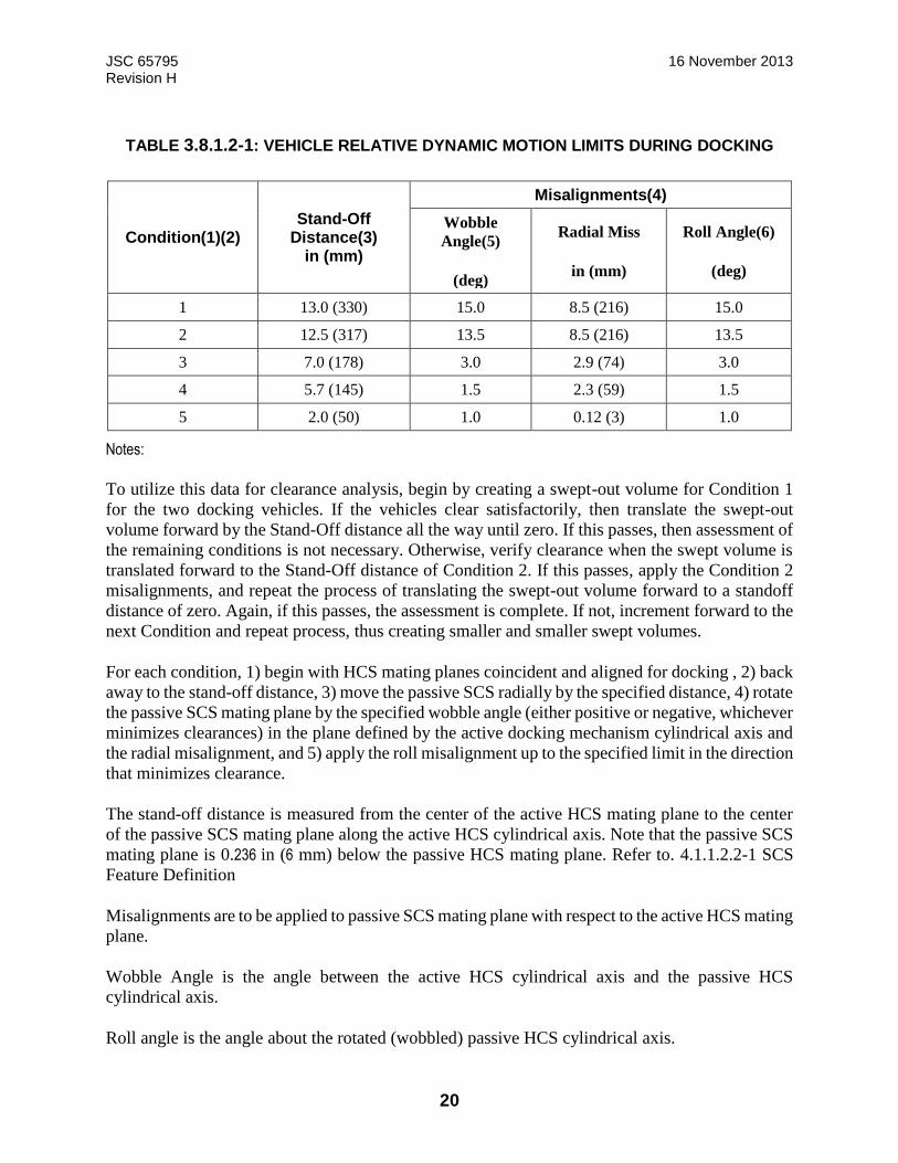
JSC 65795 16 November 2013 Revision H
20
TABLE 3.8.1.2-1: VEHICLE RELATIVE DYNAMIC MOTION LIMITS DURING DOCKING
Condition(1)(2) Stand-Off
Distance(3) in (mm)
Misalignments(4)
Wobble
Angle(5)
(deg)
Radial Miss
in (mm)
Roll Angle(6)
(deg)
1 13.0 (330) 15.0 8.5 (216) 15.0
2 12.5 (317) 13.5 8.5 (216) 13.5
3 7.0 (178) 3.0 2.9 (74) 3.0
4 5.7 (145) 1.5 2.3 (59) 1.5
5 2.0 (50) 1.0 0.12 (3) 1.0
Notes:
To utilize this data for clearance analysis, begin by creating a swept-out volume for Condition 1
for the two docking vehicles. If the vehicles clear satisfactorily, then translate the swept-out
volume forward by the Stand-Off distance all the way until zero. If this passes, then assessment of
the remaining conditions is not necessary. Otherwise, verify clearance when the swept volume is
translated forward to the Stand-Off distance of Condition 2. If this passes, apply the Condition 2
misalignments, and repeat the process of translating the swept-out volume forward to a standoff
distance of zero. Again, if this passes, the assessment is complete. If not, increment forward to the
next Condition and repeat process, thus creating smaller and smaller swept volumes.
For each condition, 1) begin with HCS mating planes coincident and aligned for docking , 2) back
away to the stand-off distance, 3) move the passive SCS radially by the specified distance, 4) rotate
the passive SCS mating plane by the specified wobble angle (either positive or negative, whichever
minimizes clearances) in the plane defined by the active docking mechanism cylindrical axis and
the radial misalignment, and 5) apply the roll misalignment up to the specified limit in the direction
that minimizes clearance.
The stand-off distance is measured from the center of the active HCS mating plane to the center
of the passive SCS mating plane along the active HCS cylindrical axis. Note that the passive SCS
mating plane is 0.236 in (6 mm) below the passive HCS mating plane. Refer to. 4.1.1.2.2-1 SCS
Feature Definition
Misalignments are to be applied to passive SCS mating plane with respect to the active HCS mating
plane.
Wobble Angle is the angle between the active HCS cylindrical axis and the passive HCS
cylindrical axis.
Roll angle is the angle about the rotated (wobbled) passive HCS cylindrical axis.
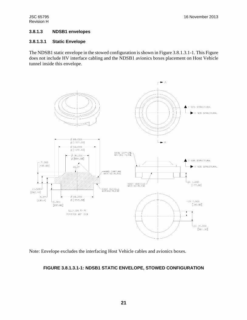
JSC 65795 16 November 2013 Revision H
21
3.8.1.3 NDSB1 envelopes
3.8.1.3.1 Static Envelope
The NDSB1 static envelope in the stowed configuration is shown in Figure 3.8.1.3.1-1. This Figure
does not include HV interface cabling and the NDSB1 avionics boxes placement on Host Vehicle
tunnel inside this envelope.
Note: Envelope excludes the interfacing Host Vehicle cables and avionics boxes.
FIGURE 3.8.1.3.1-1: NDSB1 STATIC ENVELOPE, STOWED CONFIGURATION

JSC 65795 16 November 2013 Revision H
22
The NDSB1 static envelope in the docked configuration is shown in Figure 3.8.1.3.1-2. This Figure
does not include HV interface cabling and the NDSB1 avionics boxes placement on Host Vehicle
tunnel inside this envelope.
Note: Envelope excludes the interfacing Host Vehicle cables and avionics boxes.
FIGURE 3.8.1.3.1-2: NDSB1 STATIC ENVELOPE, DOCKED CONFIGURATION
3.8.1.3.2 Kinematic Envelope
The NDSB1 kinematic envelope is shown in Figure 3.8.1.3.2-1. This Figure includes the NDSB1
avionics boxes placement on Host Vehicle tunnel inside this envelope.
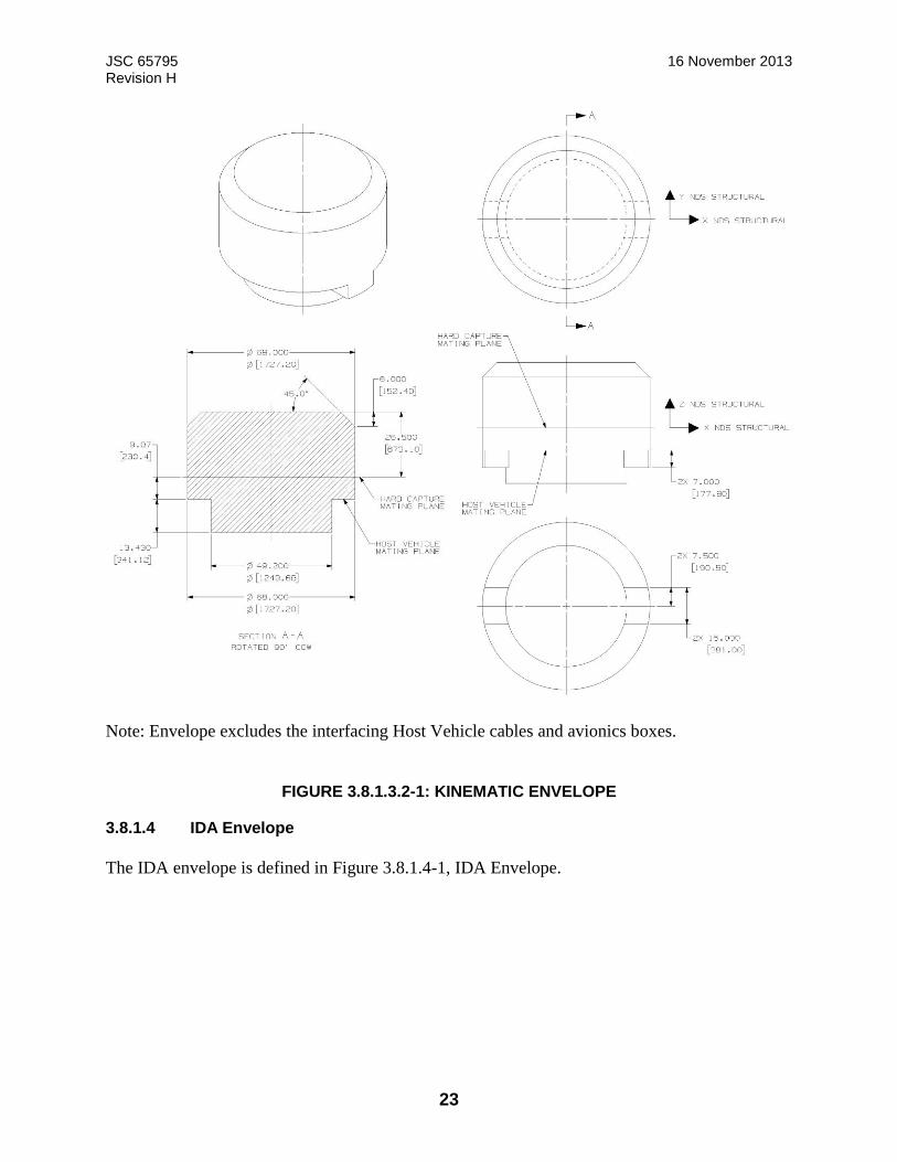
JSC 65795 16 November 2013 Revision H
23
Note: Envelope excludes the interfacing Host Vehicle cables and avionics boxes.
FIGURE 3.8.1.3.2-1: KINEMATIC ENVELOPE
3.8.1.4 IDA Envelope
The IDA envelope is defined in Figure 3.8.1.4-1, IDA Envelope.
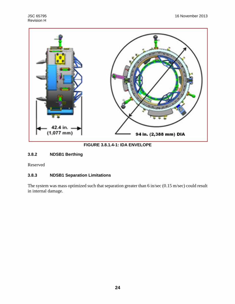
JSC 65795 16 November 2013 Revision H
24
FIGURE 3.8.1.4-1: IDA ENVELOPE
3.8.2 NDSB1 Berthing
Reserved
3.8.3 NDSB1 Separation Limitations
The system was mass optimized such that separation greater than 6 in/sec (0.15 m/sec) could result
in internal damage.

JSC 65795 16 November 2013 Revision H
25
4.0 NDSB1 DOCKING INTERFACE
This section describes the interfaces for mating with the active NDSB1 and a passive IDA. The
figures and text show/describe interfaces between the active NDSB1 and passive IDA assemblies.
__________ Solid lines = functional interfaces _ _ _ _ _ _ _ Dashed lines = pass-through resources vehicle-to-vehicle
FIGURE 4-1: NDSB1 DOCKING INTERFACE DIAGRAM
4.1 NDSB1 Interfaces
4.1.1 Structural/Mechanical
When the NDSB1 unit docks to an IDA, the initial connection occurs in the SCS between the
capture latch on the NDSB1 and the striker plates on the IDA. Once the soft capture phase is
finished, the HCS on the NDSB1 completes the docking structural connection via the hook
assembly system. The NDSB1 unit can only mate with an IDA with a unique relative clocking
orientation, which is determined by the pair of adjacent guide pins and guide pin receptacles on
the HCS, as shown in Figure 4.1.1-1: NDSB1 Docking Interface. The volume for the NDSB1 is
defined in Figure 3.8.1.3.1-2: NDSB1 Static Envelope, Docked Configuration.
The NDSB1 will satisfy the VV Keep Out Zones (KOZs) as defined in Figure 4.2.1-2: IDA
Envelopes.
B
Structural/Mechanical/Seal
Bonding
Thermal
NDSB1 IDA
Power C&DH
Power C&DH
Umbilicals
Atmosphere

JSC 65795 16 November 2013 Revision H
26
(page 1 of 4)
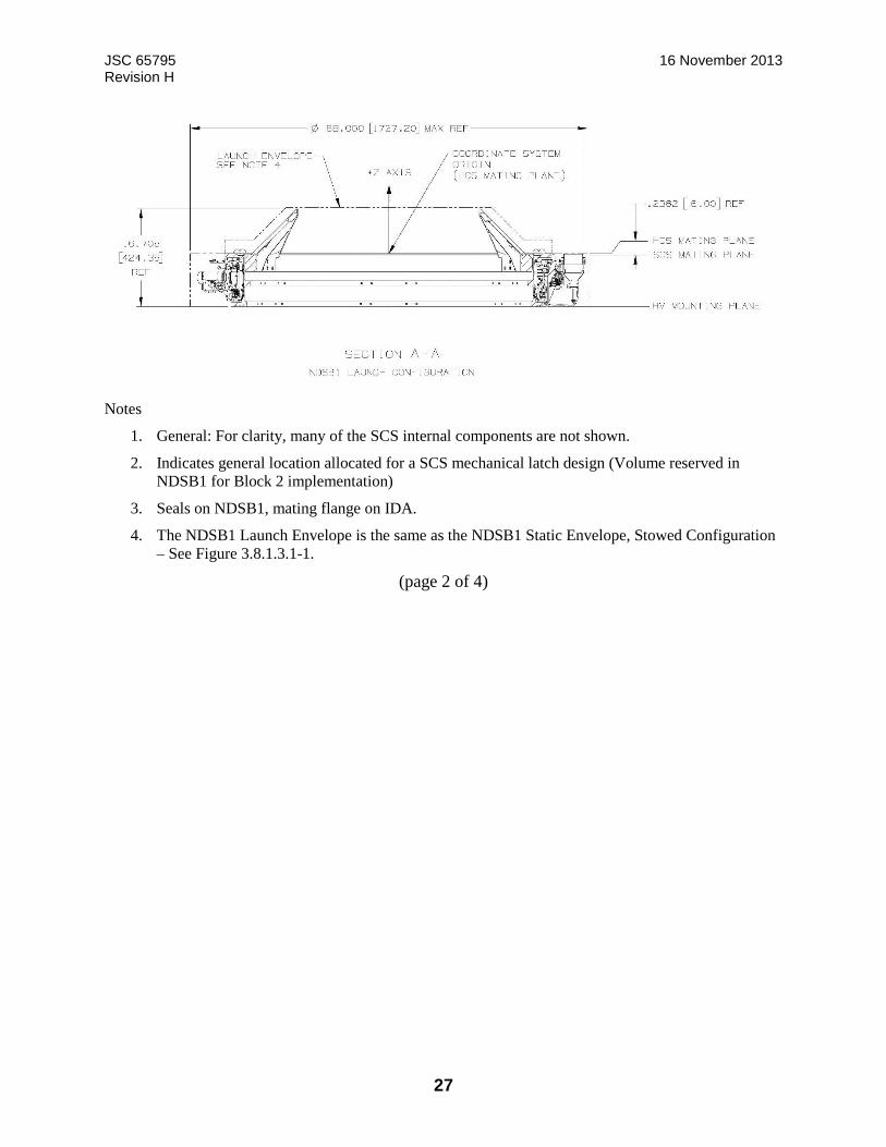
JSC 65795 16 November 2013 Revision H
27
Notes
1. General: For clarity, many of the SCS internal components are not shown.
2. Indicates general location allocated for a SCS mechanical latch design (Volume reserved in
NDSB1 for Block 2 implementation)
3. Seals on NDSB1, mating flange on IDA.
4. The NDSB1 Launch Envelope is the same as the NDSB1 Static Envelope, Stowed Configuration
– See Figure 3.8.1.3.1-1.
(page 2 of 4)
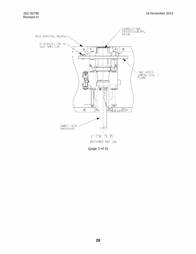
JSC 65795 16 November 2013 Revision H
28
(page 3 of 4)
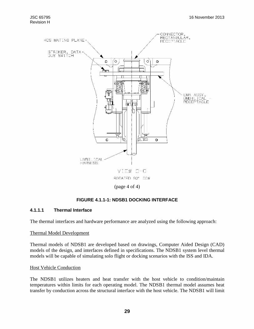
JSC 65795 16 November 2013 Revision H
29
(page 4 of 4)
FIGURE 4.1.1-1: NDSB1 DOCKING INTERFACE
4.1.1.1 Thermal Interface
The thermal interfaces and hardware performance are analyzed using the following approach:
Thermal Model Development
Thermal models of NDSB1 are developed based on drawings, Computer Aided Design (CAD)
models of the design, and interfaces defined in specifications. The NDSB1 system level thermal
models will be capable of simulating solo flight or docking scenarios with the ISS and IDA.
Host Vehicle Conduction
The NDSB1 utilizes heaters and heat transfer with the host vehicle to condition/maintain
temperatures within limits for each operating model. The NDSB1 thermal model assumes heat
transfer by conduction across the structural interface with the host vehicle. The NDSB1 will limit

JSC 65795 16 November 2013 Revision H
30
heat transfer across the interface. The host vehicle will provide the required boundary temperatures
based on the heat transfer.
Host Vehicle Radiation
A disc representing the NDSB1 view to host vehicle is included in the NDSB1 system level thermal
model to represent radiation to the host vehicle. The disc representing the host vehicle will have
a radius 1.43 times larger than the NDSB1. The disc is modeled with arithmetic nodes and optical
properties of α = 0.3 and = 0.9. This disc will be flush with the NDSB1 base/vehicle interface
point.
Host Vehicle Micro Meteoroid/ Orbital Debris (MMOD)/External Hardware Thermal Interface
NDSB1 system level thermal analysis will be performed with the NDSB1 external Multi-Layer
Insulation (MLI) exposed and no additional heat leak applied at the external flange interfaces.
Environment and Attitudes
The NDSB1 system level thermal model simulates the LEO environments and attitudes to predict
temperature ranges for comparison to hardware limits. Table 4.1.1.1-1 shows the LEO
environmental parameters for thermal: Solar flux, albedo, and Earth Outgoing Long-wave
Radiation (OLR) environments. Table 4.1.1.1-2 gives the flight attitudes used for design. Figure
4.1.1.1-1 shows the NDSB1 coordinate system and the Local Vertical, Local Horizontal (LVLH)
coordinate system for docking to the ISS.
Unmated solar inertial attitudes with the NDSB1 facing the sun are known to cause violations of
operational and survival limits. These attitudes will be assessed for capability only. Time
constraints to protect the NDSB1 will be documented in EID684-15524, NDSB1 Thermal Analysis
Report.

JSC 65795 16 November 2013 Revision H
31
TABLE 4.1.1.1-1: EXTREME HOT AND COLD NATURAL THERMAL ENVIRONMENTS
Condition (1,2) ALBEDO* OLR** (Btu/hr-ft2)
Cold A 0.27 65.3
B 0.20 76.4
Hot A 0.30 90.6
B 0.40 76.4
Solar Constants (Btu/hr-ft2) Cold 418.8 Hot 451.2 Notes: (1) Values in this table represent a 3 sigma probability. Albedo and OLR are adjusted to the top of the atmosphere (18.6 nm altitude). (2) Both Set A and Set B are design requirements. Set A represents worst case OLR values with corresponding albedo values. Set B represents worst case albedo values with corresponding OLR values.
*Albedo is the fraction of solar energy (shortwave radiation) reflected from the Earth back into space. It is a measure of the reflectivity of the earth's surface. **Outgoing Longwave Radiation (OLR) is the energy leaving the earth as infrared radiation. The OLR is dependent on the temperature of the radiating body.
Source: NASA Technical Memorandum 4527 “Natural Orbital Environment Guidelines for use in Aerospace Vehicle Development”, dated June 1994 by Jeffrey Anderson.
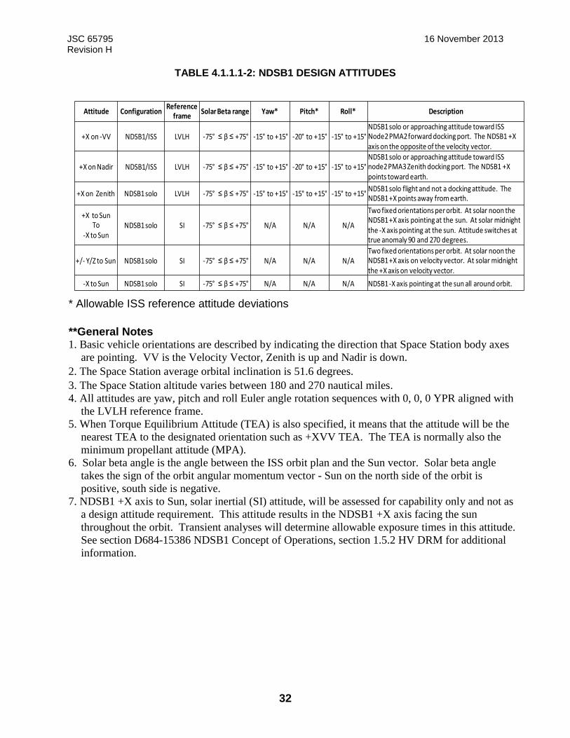
JSC 65795 16 November 2013 Revision H
32
TABLE 4.1.1.1-2: NDSB1 DESIGN ATTITUDES
* Allowable ISS reference attitude deviations
**General Notes 1. Basic vehicle orientations are described by indicating the direction that Space Station body axes
are pointing. VV is the Velocity Vector, Zenith is up and Nadir is down.
2. The Space Station average orbital inclination is 51.6 degrees.
3. The Space Station altitude varies between 180 and 270 nautical miles.
4. All attitudes are yaw, pitch and roll Euler angle rotation sequences with 0, 0, 0 YPR aligned with
the LVLH reference frame.
5. When Torque Equilibrium Attitude (TEA) is also specified, it means that the attitude will be the
nearest TEA to the designated orientation such as +XVV TEA. The TEA is normally also the
minimum propellant attitude (MPA).
6. Solar beta angle is the angle between the ISS orbit plan and the Sun vector. Solar beta angle
takes the sign of the orbit angular momentum vector - Sun on the north side of the orbit is
positive, south side is negative.
7. NDSB1 +X axis to Sun, solar inertial (SI) attitude, will be assessed for capability only and not as
a design attitude requirement. This attitude results in the NDSB1 +X axis facing the sun
throughout the orbit. Transient analyses will determine allowable exposure times in this attitude.
See section D684-15386 NDSB1 Concept of Operations, section 1.5.2 HV DRM for additional
information.
Attitude ConfigurationReference
frameSolar Beta range Yaw* Pitch* Roll* Description
+X on -VV NDSB1/ISS LVLH -75° ≤ β ≤ +75° -15° to +15° -20° to +15° -15° to +15°NDSB1 solo or approaching attitude toward ISS Node2 PMA2 forward docking port. The NDSB1 +X axis on the opposite of the velocity vector.
+X on Nadir NDSB1/ISS LVLH -75° ≤ β ≤ +75° -15° to +15° -20° to +15° -15° to +15°NDSB1 solo or approaching attitude toward ISS node2 PMA3 Zenith docking port. The NDSB1 +X points toward earth.
+X on Zenith NDSB1 solo LVLH -75° ≤ β ≤ +75° -15° to +15° -15° to +15° -15° to +15°NDSB1 solo flight and not a docking attitude. The NDSB1 +X points away from earth.
+X to SunTo
-X to SunNDSB1 solo SI -75° ≤ β ≤ +75° N/A N/A N/A
Two fixed orientations per orbit. At solar noon the NDSB1 +X axis pointing at the sun. At solar midnight the -X axis pointing at the sun. Attitude switches at true anomaly 90 and 270 degrees.
+/- Y/Z to Sun NDSB1 solo SI -75° ≤ β ≤ +75° N/A N/A N/ATwo fixed orientations per orbit. At solar noon the NDSB1 +X axis on velocity vector. At solar midnight the +X axis on velocity vector.
-X to Sun NDSB1 solo SI -75° ≤ β ≤ +75° N/A N/A N/A NDSB1 -X axis pointing at the sun all around orbit.
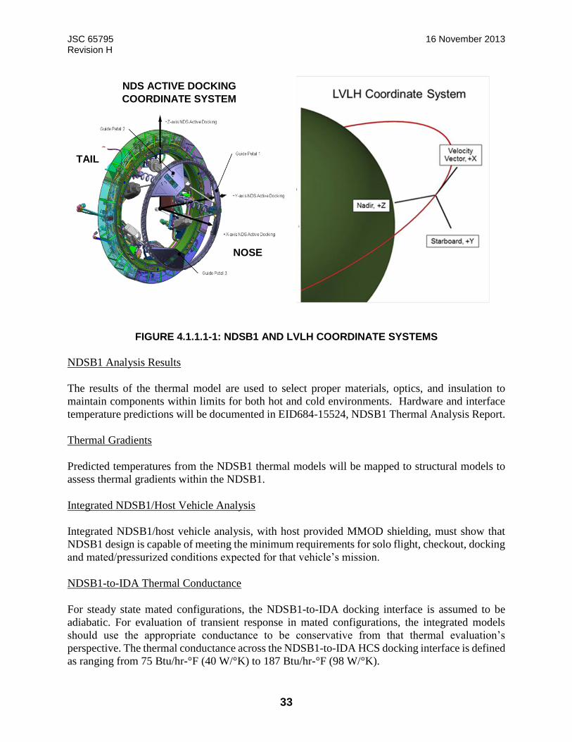
JSC 65795 16 November 2013 Revision H
33
FIGURE 4.1.1.1-1: NDSB1 AND LVLH COORDINATE SYSTEMS
NDSB1 Analysis Results
The results of the thermal model are used to select proper materials, optics, and insulation to
maintain components within limits for both hot and cold environments. Hardware and interface
temperature predictions will be documented in EID684-15524, NDSB1 Thermal Analysis Report.
Thermal Gradients
Predicted temperatures from the NDSB1 thermal models will be mapped to structural models to
assess thermal gradients within the NDSB1.
Integrated NDSB1/Host Vehicle Analysis
Integrated NDSB1/host vehicle analysis, with host provided MMOD shielding, must show that
NDSB1 design is capable of meeting the minimum requirements for solo flight, checkout, docking
and mated/pressurized conditions expected for that vehicle’s mission.
NDSB1-to-IDA Thermal Conductance
For steady state mated configurations, the NDSB1-to-IDA docking interface is assumed to be
adiabatic. For evaluation of transient response in mated configurations, the integrated models
should use the appropriate conductance to be conservative from that thermal evaluation’s
perspective. The thermal conductance across the NDSB1-to-IDA HCS docking interface is defined
as ranging from 75 Btu/hr-°F (40 W/°K) to 187 Btu/hr-°F (98 W/°K).
NDS ACTIVE DOCKING
COORDINATE SYSTEM
TAIL
NOSE
JSC 65795 16 November 2013 Revision H
34
Dynamic Seal Temperature Range
The dynamic seal is the limiting component of the HCS-to-IDA thermal interface. The dynamic
seal operational and non-operational temperature limits are documented in JSC-64595C,
International Low Impact Docking System (iLIDS) Dynamic Seal End Item Specification and
JSC-66161, International Low Impact Docking System (iLIDS) Dynamic Seal Verification
Document. The temperature ranges were derived from analyses of NDSB0 thermal performance
and seal material properties.
The operational range is -38 °F to 122 °F.
The non-operational (survival) range is -65 °F to 192 °F.
The allowable NDSB1-to-IDA interface temperature ranges for each mission phase are defined in
the following subsections.
4.1.1.1.1 Non-Operational Survival
Non-operational survival conditions apply to solo flight prior to check-out and docking operations.
The following NDSB1 temperature range applies to HCS and SCS interface hardware prior to
docking of NDSB1 and IDA (Only heaters and electrical boxes will be active at this point):
-65 °F to +192 °F (-54 °C to +89 °C)
Minimum – The minimum temperature of -65 °F (-54 °C) is defined by the minimum dynamic
seal survival temperature limit.
Maximum – The maximum temperature of +192 °F (+89 °C) is the limiting maximum temperature
survival limit for the NDSB1 hardware.
4.1.1.1.2 Operational
This subsection defines operational temperature limits for the NDSB1-to-IDA interface during
check-out and docking operations. Individual components have capabilities outside these ranges.
Specific component allowable limits will be described and evaluated in EID684-15524, NDSB1
Thermal Analysis Report.
4.1.1.1.2.1 Tunnel and Seal Mating Interface
The following applies to the HCS tunnel and seal mating interfaces when the system is preparing
to dock, up through hard mate, but prior to pressurization:
-38 °F to +122 °F (-39 °C to +50 °C)
JSC 65795 16 November 2013 Revision H
35
Minimum – The minimum interface temperature of -38 °F (-39 °C) is defined by the minimum
seal operational temperature limit. The predicted temperature is expected to be significantly
warmer due to conduction from the HV.
Maximum – The maximum interface temperature of +122 °F (+50 °C) is defined by the maximum
seal operational temperature limit.
The allowable temperature differential between the sealing interfaces during docking hard capture
is also restricted. The maximum allowable difference between the average temperatures of the hard
capture mating interface from initial contact through hard mate complete is 100 °F (56 °C).
The hard mate differential was determined by analyses of the maximum differential temperature
allowed for soft capture guide petal engagement and seal mating interface temperatures. This
differential can be evaluated via mission profile analysis prior to docking.
4.1.1.1.2.2 Soft Capture Mating Interfaces
The following applies to soft capture components when the system is preparing to dock, up through
hard mate, but prior to pressurization:
-65 °F to +165 °F (-54 °C to +74 °C)
Minimum – The minimum interface temperature of -65 °F (-54 °C) is defined by the minimum
hardware operational temperature limit.
Maximum – The maximum interface temperature of +165 °F (+74 °C) is defined by the maximum
hardware operational temperature limit.
The allowable temperature difference between the top rings is also restricted. The maximum
allowable difference between the average temperatures of the soft capture mating surfaces is 100
°F (56 °C) from initial contact through hard mate complete. This restriction is based on thermal
expansion limits for the engagement of the mating guide petals in the mating NDSB1. This
differential can be evaluated via mission profile analysis prior to docking.
4.1.1.1.3 Mated and Pressurized
This subsection defines mated and pressurized limits for the NDSB1 after hard mate and
pressurization.
4.1.1.1.3.1 Mated and Pressurized Steady-State Temperature Range
The following is the steady-state temperature range after hard mate and pressurization:
+60 °F to +113 °F (+15.6 °C to +45 °C)
JSC 65795 16 November 2013 Revision H
36
Minimum –The NDSB1 internal volume temperatures will be above +60 F to preclude
condensation. The typical dew point temperature range for crewed vehicles is +40 °F to +60 °F
(+4.4 °C to +15.6 °C). The host vehicle will provide thermal conditioning for steady state mated
operations.
Maximum – The temperature of +113 °F (+45 °C) is the maximum bare-handed touch temperature
for continuous contact.
These temperatures apply to all mated and pressurized conditions, except for the transient
temperature response period of 10 hours after docking and pressurization.
4.1.1.1.3.2 Mated and Pressurized Transient Temperatures
Hardware temperatures at the time of docking may be below the dew point and minimum IVA
touch temperature for cold cases environments and attitudes, or above the maximum IVA touch
temperature for hot case environments and attitudes. The NDSB1 temperature conditions will
approach the steady state temperatures described in Paragraph 4.1.1.1.3.1 as a function of time.
The time-to-limit for worst case hot and cold case conditions will be assessed and documented in
EID684-15524, Thermal Analysis Report.
Pressurization or hatch opening is not restricted by the transient temperature profile. However, if
hatch opening is required prior to the system achieving safe touch temperatures, the crew may be
required to use Personal Protective Equipment (PPE). If the temperature of the vestibule is not
above the dew point, condensation would result within the vestibule during this transition period.
4.1.1.1.4 Mated and Unpressurized
For scenarios in which the NDSB1 is hard mated and the vestibule is unpressurized, the following
temperature ranges apply:
-38 °F to +122 °F (-39 °C to +50 °C) at docking
Minimum – The minimum interface temperature of -38 °F (-39 °C) is defined by the minimum
seal operational temperature limit at docking.
Maximum – The maximum interface temperature of +122 °F (+50 °C) is defined by the maximum
seal operational temperature limit at docking.
+60 °F to +120 °F (+15.6 °C to +49 °C) at undocking
Minimum – The minimum interface temperature is limited to +60 °F (+15.6 °C) to prevent
excessive heat transfer with the IDA. Temperatures colder than +60 °F (+15.6 °C) will affect the
IDA’s ability to maintain interface requirements with the PMA. Maximum – The maximum
interface temperature is limited to +120°F (+49 °C) to prevent excessive heat transfer with the
IDA. Temperatures warmer than +120°F (+49 °C) will affect the IDA’s ability to maintain
interface requirements with the PMA.

JSC 65795 16 November 2013 Revision H
37
4.1.1.2 Soft Capture System
The soft capture is not final structural mating but the first level of attachment in the docking
sequence where attenuation and alignment between the HV and ISS occurs following initial
impact. The NDSB1 SCS utilizes an open loop control feed-forward control system for the
attenuation and alignment sequences during the initial docking phase. The guide petals are
mounted to the soft capture ring, face inward and they will not be removed on orbit. The petals
are equally spaced around the circumference of the soft capture docking ring. The SCS guide
petals mounts an active latch for soft capture. An overview is shown in Figure 4.1.1.2-1.
FIGURE 4.1.1.2-1: SOFT CAPTURE SYSTEM
4.1.1.2.1 Guide Petal System
Three guide petals mount to the soft capture ring and face inward. The petals are equally spaced
around the circumference of the soft capture docking ring. A representative depiction of the guide
petal layout can be seen in Figure 4.1.1.2.1-1: SCS GUIDE PETAL SYSTEM, Figure 4.1.1.2.1-2:
SCS Guide Petal System Detail, and Figure 4.1.1.2.2-1: SCS Feature Definition. The stiffness and
hardness characteristics of the guide petals also impact capture performance. Hosts with other
docking systems must either match the NDSB1 petal design or prove that their design has
equivalent hardness and stiffness characteristics.

JSC 65795 16 November 2013 Revision H
38
FIGURE 4.1.1.2.1-1: SCS GUIDE PETAL SYSTEM
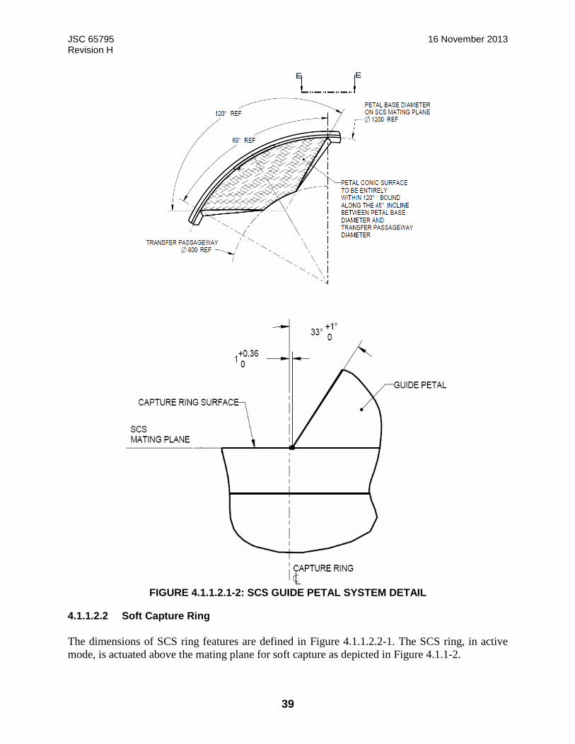
JSC 65795 16 November 2013 Revision H
39
FIGURE 4.1.1.2.1-2: SCS GUIDE PETAL SYSTEM DETAIL
4.1.1.2.2 Soft Capture Ring
The dimensions of SCS ring features are defined in Figure 4.1.1.2.2-1. The SCS ring, in active
mode, is actuated above the mating plane for soft capture as depicted in Figure 4.1.1-2.

JSC 65795 16 November 2013 Revision H
40
Definition of SCS Mating Plane
Cross Section
Radial View (Page 1 of 2)

JSC 65795 16 November 2013 Revision H
41
Top View, Mechanical Latch
Active Mechanical Soft Capture Latch Interface
(Page 2 of 2)
FIGURE 4.1.1.2.2-1: SCS FEATURE DEFINITION

JSC 65795 16 November 2013 Revision H
42
4.1.1.2.3 Magnet and Striker
Reserved.
4.1.1.2.4 Soft Capture Sensors and Strikers
The SCS of the docking system provides an indication when the two SCS mating planes become
coplanar through the use of position sensors. The NDSB1 has three soft capture indication
positions, located at an offset from the centerline as defined in Figure 4.1.1.1-1.
4.1.1.2.5 Pre-Capture SCS Compressive Force Resistance
The NDSB1 SCS will not exceed a maximum compressive resistance force of 22.48 lbf (100 N).
This resistance includes the soft capture latch resistance, guide petals, SCS capture sensors, and
actuators.
4.1.1.2.6 SCS Mechanical Latch Striker
The NDSB1 configuration has reserved volume for potential implementation of SCS mechanical
latch strikers, which would allow other IDSS-compatible docking systems that use SCS
mechanical latches to dock to an NDSB1. This is not structural mating, but the first level of
attachment. The NDSB1 configuration has reserved volume, as defined in Figure 4.1.1.2.2-1
located as depicted in Figure 4.1.1-1.
4.1.1.3 Hard Capture System
The NDSB1 HCS conceptual design includes the following components: active/passive hook
assemblies, a motor to drive the hook assemblies, a hook assembly release mechanism, a hook
assembly drive mechanism, a hook assembly power resource, a hook assembly electrical interface,
a tunnel with a HV mounting interface, an IDA interface, seals, retractable pushers, contingency
pyro hook release, and mechanized separation umbilicals. The HCS Subsystem uses powered
hooks to engage with the IDA, providing a structural connection ready for pressurization between
the mated vehicles that allows for cargo and crew transfer. The HCS completes the docking
sequence when resource transfer umbilicals are engaged. See Figure 4.1.1.3-1.

JSC 65795 16 November 2013 Revision H
43
FIGURE 4.1.1.3-1: NDSB1 HARD CAPTURE SYSTEM
Figure 3.1.2-1
Tunnel Assembly
NDSB1 to HV Mounting Interface
Spacers and HV Mounting Hardware
Launch Locks
Separators and Sensors
Hook Assemblies
Shims
Drive Train
Pyrotechnic System
Receptacle Umbilical EMA
Plug Umbilical EMA
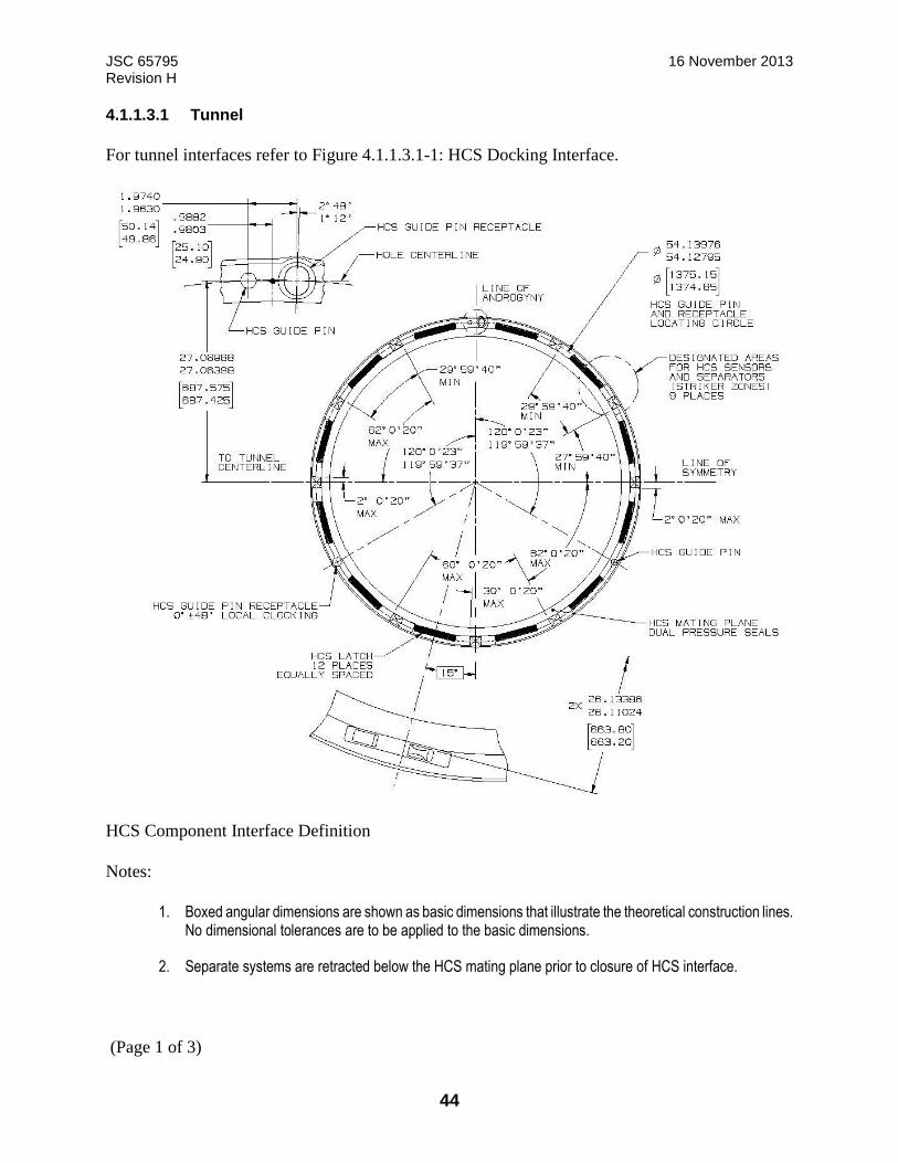
JSC 65795 16 November 2013 Revision H
44
4.1.1.3.1 Tunnel
For tunnel interfaces refer to Figure 4.1.1.3.1-1: HCS Docking Interface.
HCS Component Interface Definition
Notes:
1. Boxed angular dimensions are shown as basic dimensions that illustrate the theoretical construction lines. No dimensional tolerances are to be applied to the basic dimensions.
2. Separate systems are retracted below the HCS mating plane prior to closure of HCS interface.
(Page 1 of 3)
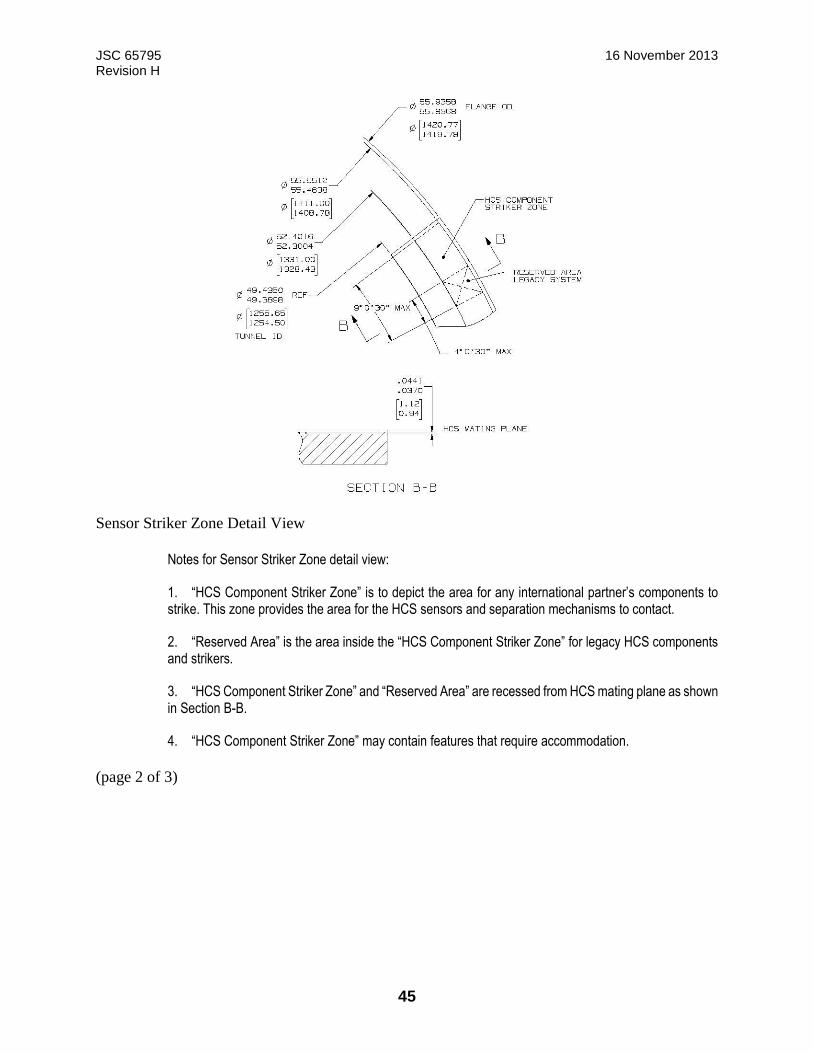
JSC 65795 16 November 2013 Revision H
45
Sensor Striker Zone Detail View
Notes for Sensor Striker Zone detail view:
1. “HCS Component Striker Zone” is to depict the area for any international partner’s components to strike. This zone provides the area for the HCS sensors and separation mechanisms to contact.
2. “Reserved Area” is the area inside the “HCS Component Striker Zone” for legacy HCS components and strikers.
3. “HCS Component Striker Zone” and “Reserved Area” are recessed from HCS mating plane as shown in Section B-B.
4. “HCS Component Striker Zone” may contain features that require accommodation.
(page 2 of 3)
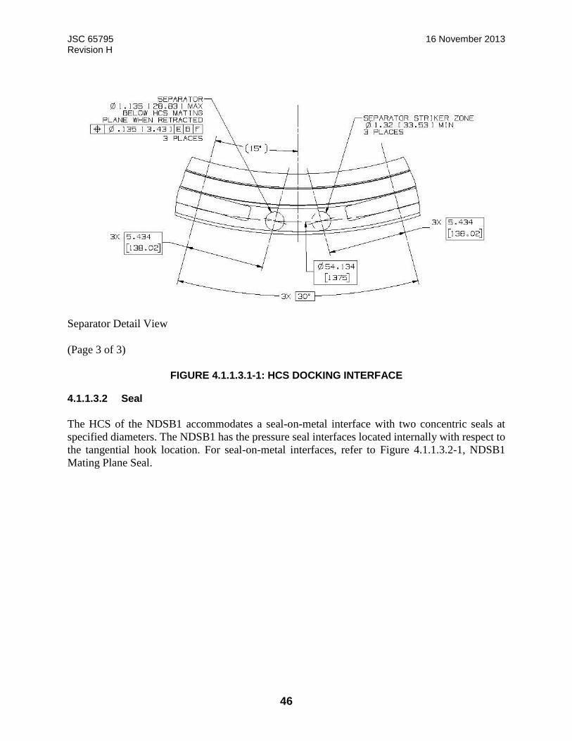
JSC 65795 16 November 2013 Revision H
46
Separator Detail View
(Page 3 of 3)
FIGURE 4.1.1.3.1-1: HCS DOCKING INTERFACE
4.1.1.3.2 Seal
The HCS of the NDSB1 accommodates a seal-on-metal interface with two concentric seals at
specified diameters. The NDSB1 has the pressure seal interfaces located internally with respect to
the tangential hook location. For seal-on-metal interfaces, refer to Figure 4.1.1.3.2-1, NDSB1
Mating Plane Seal.
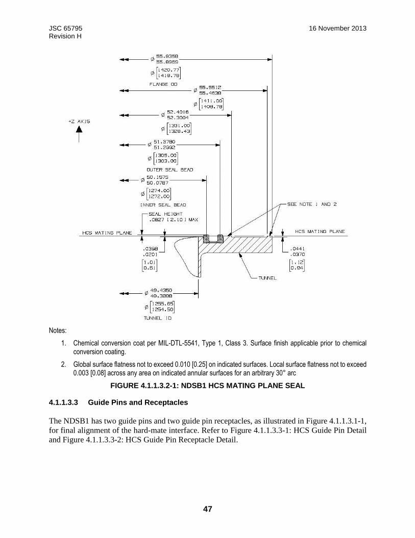
JSC 65795 16 November 2013 Revision H
47
Notes:
1. Chemical conversion coat per MIL-DTL-5541, Type 1, Class 3. Surface finish applicable prior to chemical conversion coating.
2. Global surface flatness not to exceed 0.010 [0.25] on indicated surfaces. Local surface flatness not to exceed 0.003 [0.08] across any area on indicated annular surfaces for an arbitrary 30° arc
FIGURE 4.1.1.3.2-1: NDSB1 HCS MATING PLANE SEAL
4.1.1.3.3 Guide Pins and Receptacles
The NDSB1 has two guide pins and two guide pin receptacles, as illustrated in Figure 4.1.1.3.1-1,
for final alignment of the hard-mate interface. Refer to Figure 4.1.1.3.3-1: HCS Guide Pin Detail
and Figure 4.1.1.3.3-2: HCS Guide Pin Receptacle Detail.
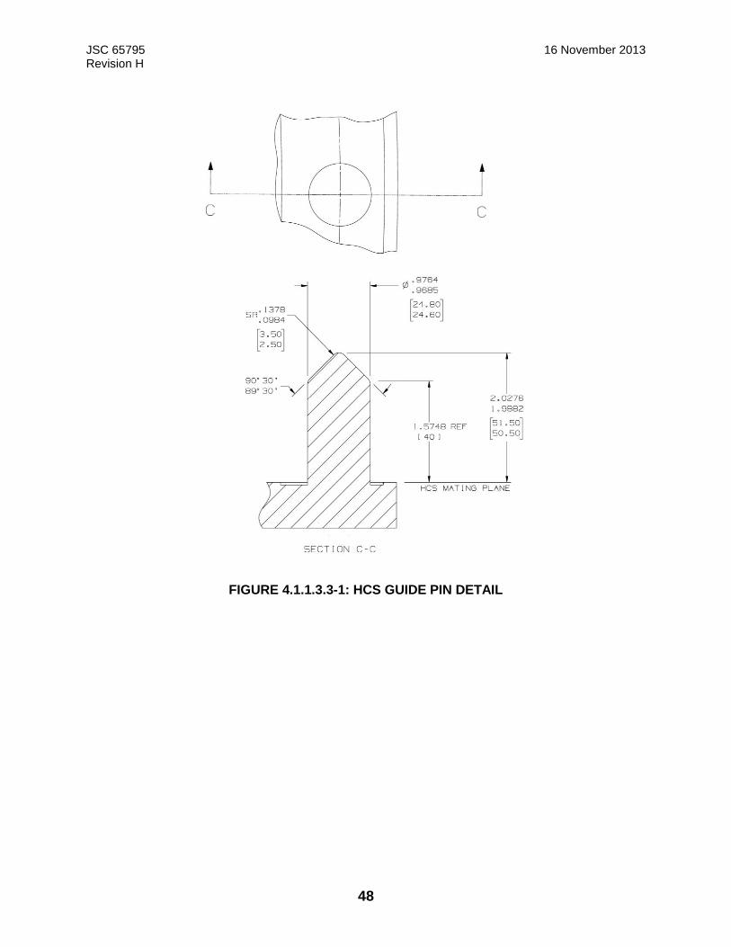
JSC 65795 16 November 2013 Revision H
48
FIGURE 4.1.1.3.3-1: HCS GUIDE PIN DETAIL
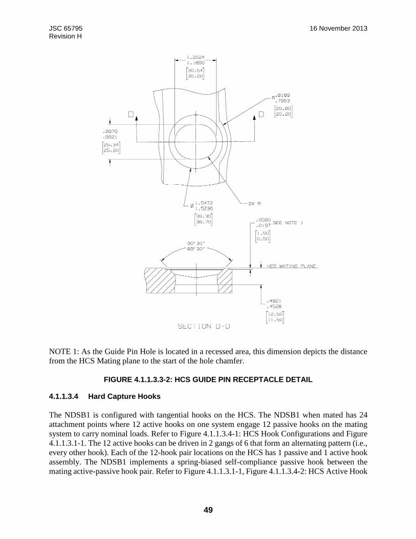
JSC 65795 16 November 2013 Revision H
49
NOTE 1: As the Guide Pin Hole is located in a recessed area, this dimension depicts the distance
from the HCS Mating plane to the start of the hole chamfer.
FIGURE 4.1.1.3.3-2: HCS GUIDE PIN RECEPTACLE DETAIL
4.1.1.3.4 Hard Capture Hooks
The NDSB1 is configured with tangential hooks on the HCS. The NDSB1 when mated has 24
attachment points where 12 active hooks on one system engage 12 passive hooks on the mating
system to carry nominal loads. Refer to Figure 4.1.1.3.4-1: HCS Hook Configurations and Figure
4.1.1.3.1-1. The 12 active hooks can be driven in 2 gangs of 6 that form an alternating pattern (i.e.,
every other hook). Each of the 12-hook pair locations on the HCS has 1 passive and 1 active hook
assembly. The NDSB1 implements a spring-biased self-compliance passive hook between the
mating active-passive hook pair. Refer to Figure 4.1.1.3.1-1, Figure 4.1.1.3.4-2: HCS Active Hook
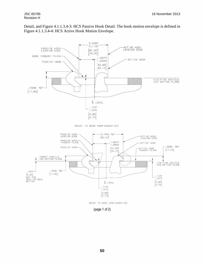
JSC 65795 16 November 2013 Revision H
50
Detail, and Figure 4.1.1.3.4-3: HCS Passive Hook Detail. The hook motion envelope is defined in
Figure 4.1.1.3.4-4: HCS Active Hook Motion Envelope.
(page 1 of 2)
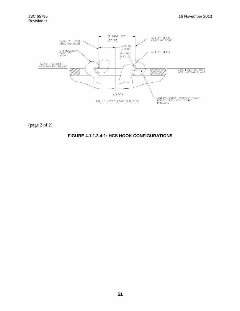
JSC 65795 16 November 2013 Revision H
51
(page 2 of 2)
FIGURE 4.1.1.3.4-1: HCS HOOK CONFIGURATIONS
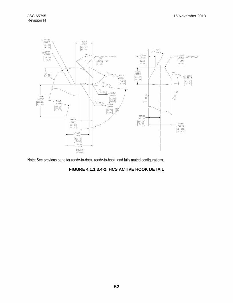
JSC 65795 16 November 2013 Revision H
52
Note: See previous page for ready-to-dock, ready-to-hook, and fully mated configurations.
FIGURE 4.1.1.3.4-2: HCS ACTIVE HOOK DETAIL
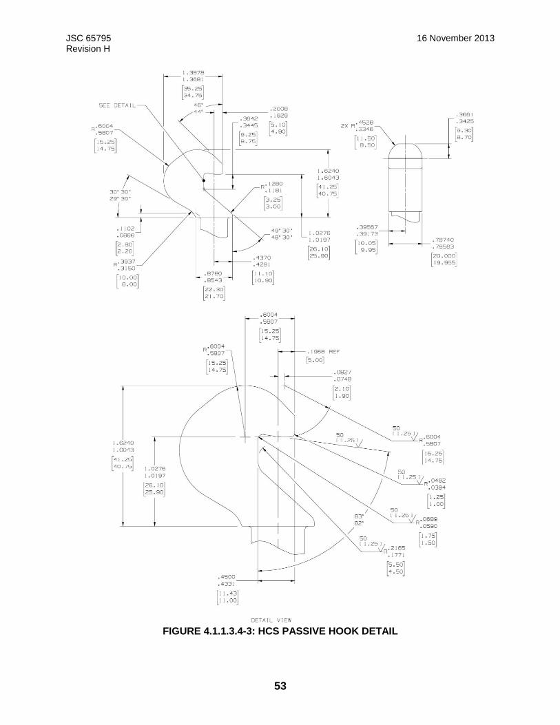
JSC 65795 16 November 2013 Revision H
53
FIGURE 4.1.1.3.4-3: HCS PASSIVE HOOK DETAIL
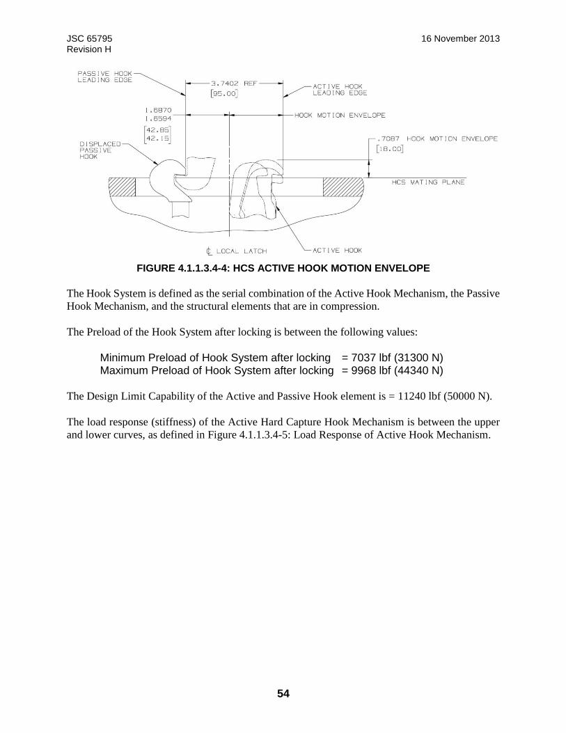
JSC 65795 16 November 2013 Revision H
54
FIGURE 4.1.1.3.4-4: HCS ACTIVE HOOK MOTION ENVELOPE
The Hook System is defined as the serial combination of the Active Hook Mechanism, the Passive
Hook Mechanism, and the structural elements that are in compression.
The Preload of the Hook System after locking is between the following values:
Minimum Preload of Hook System after locking = 7037 lbf (31300 N) Maximum Preload of Hook System after locking = 9968 lbf (44340 N)
The Design Limit Capability of the Active and Passive Hook element is = 11240 lbf (50000 N).
The load response (stiffness) of the Active Hard Capture Hook Mechanism is between the upper
and lower curves, as defined in Figure 4.1.1.3.4-5: Load Response of Active Hook Mechanism.

JSC 65795 16 November 2013 Revision H
55
FIGURE 4.1.1.3.4-5: LOAD RESPONSE OF ACTIVE HOOK MECHANISM
The load response (stiffness) of the Passive Hard Capture Hook Mechanism is between the upper
and lower curves, as defined in Figure 4.1.1.3.4-6: Load Response of Passive Hook Mechanism
(Including Spring Washer Stack) Hard Capture Sensors and Strikers.
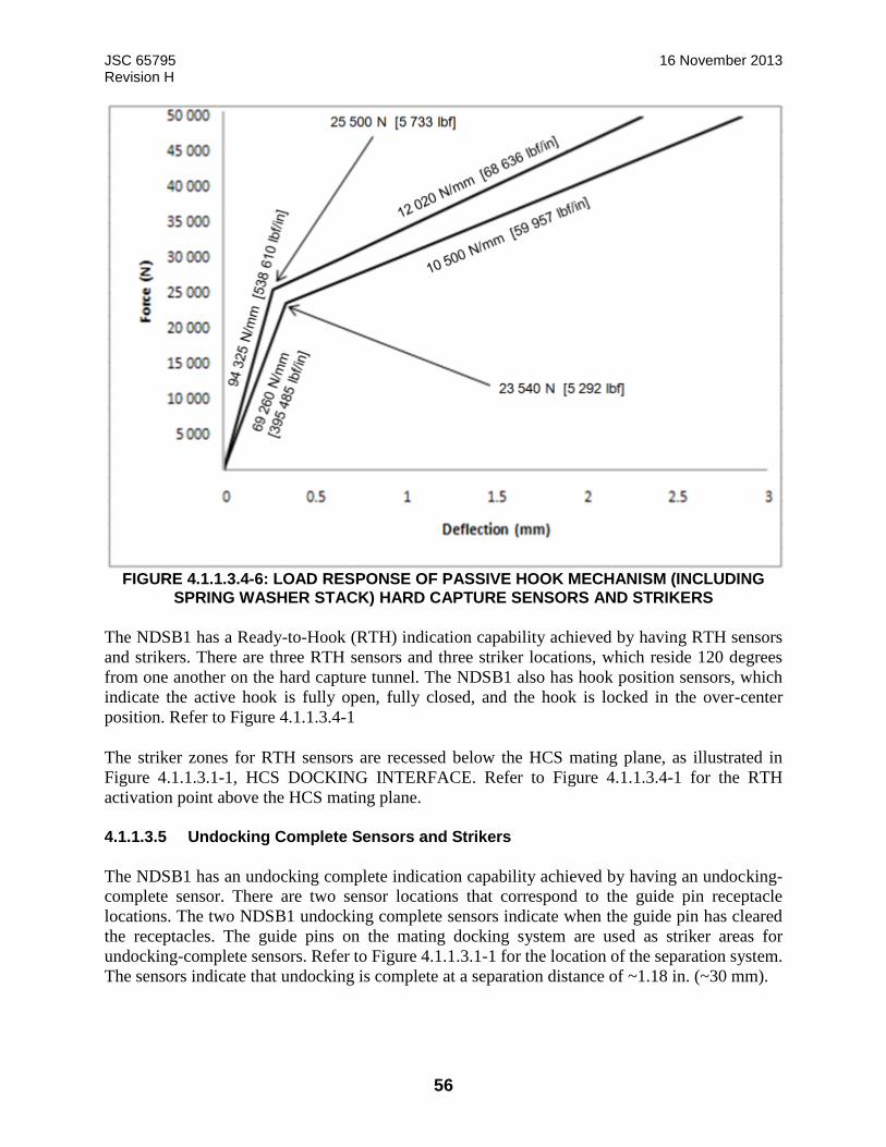
JSC 65795 16 November 2013 Revision H
56
FIGURE 4.1.1.3.4-6: LOAD RESPONSE OF PASSIVE HOOK MECHANISM (INCLUDING
SPRING WASHER STACK) HARD CAPTURE SENSORS AND STRIKERS
The NDSB1 has a Ready-to-Hook (RTH) indication capability achieved by having RTH sensors
and strikers. There are three RTH sensors and three striker locations, which reside 120 degrees
from one another on the hard capture tunnel. The NDSB1 also has hook position sensors, which
indicate the active hook is fully open, fully closed, and the hook is locked in the over-center
position. Refer to Figure 4.1.1.3.4-1
The striker zones for RTH sensors are recessed below the HCS mating plane, as illustrated in
Figure 4.1.1.3.1-1, HCS DOCKING INTERFACE. Refer to Figure 4.1.1.3.4-1 for the RTH
activation point above the HCS mating plane.
4.1.1.3.5 Undocking Complete Sensors and Strikers
The NDSB1 has an undocking complete indication capability achieved by having an undocking-
complete sensor. There are two sensor locations that correspond to the guide pin receptacle
locations. The two NDSB1 undocking complete sensors indicate when the guide pin has cleared
the receptacles. The guide pins on the mating docking system are used as striker areas for
undocking-complete sensors. Refer to Figure 4.1.1.3.1-1 for the location of the separation system.
The sensors indicate that undocking is complete at a separation distance of ~1.18 in. (~30 mm).
JSC 65795 16 November 2013 Revision H
57
4.1.1.3.6 HCS Compressive Force Resistance During SCS Retraction
The SCS requires minimal compressive force resistance. As the SCS retracts, it encounters the
RTH and undocking complete sensors while in a kinematic configuration that has limited axial
pulling force capability. To ensure the ability to engage the hooks, a maximum of 37.8 lbf (168 N)
compressive force resistance is allowed across the interface. This means each side is allowed to
have a maximum of 18.9 lbf (84 N) resistance.
4.1.1.3.7 Separation System Springs and Strikers
The NDSB1 includes three separation springs recessed below the docking sealing surface, which
can be remotely engaged for separation and reset to a recessed position for docking. This system
provides force to overcome the seal stiction and energy to accelerate the vehicle away when the
structural mate mechanism is released.
The umbilical resource connectors are nominally retracted prior to undocking. However, in the
event of failure to retract the umbilicals, the separation system is capable of providing enough
force to de-mate the umbilical resource connectors during separation.
The separation system and associated striker zones are shown in Figure 4.1.1.3.1-1. The striker
zones are recessed below the HCS mating plane, as illustrated in Figure 4.1.1.3.1-1, HCS
DOCKING INTERFACE.
Once charged against the striker on the mating docking interface, the separator has a minimum
total extension stroke of 1.295 in. (32.9 mm) to be used for separation. The first part of the stroke
is used for loosening the pressure seals and disengaging umbilical connectors, if any. The second
part is used for vehicle separation dynamics. The three NDSB1 separators together provide a total
initial stored energy between 28.9 ft-lb (4.0 kgf-m) and 35 ft-lb (4.8 kgf-m) at zero interface
separation. The nominal force applied by a single charged separator to the striker surface is 155 to
160 lbf (689 to 712 N). However, during contingency cases, such as a limit switch failure, the
maximum force can reach 200 lbf (890 N).
Figure 4.1.1.3.7-1: Single Separator Force Separation Curve shows the linear force separation
curves of a single separator where the undocking separation distance indicates the separation
between the two HCS mating planes. Multiply the force values by three to get the total system
force acting on the vehicles at a given separation point. At a separation of 0.165 in. (4.2 mm), the
separation system provides a minimum of 133.3 lbf (593 N) for each separator.
Nominally, it can be assumed that the vehicles have zero relative axial velocity as the hooks
disengage. This occurs at a separation of approximately 0.22 in. (5.6 mm). Hence, a total energy
between 21.2 ft-lb (2.9 kgf-m) and 26.1 ft-lb (3.6 kgf-m) is applied to vehicle separation under
nominal conditions.
Note: In a contingency situation where the NDSB1 umbilicals are not retracted first, the umbilical
connectors resist separation until a separation of approximately 0.512 in. (13 mm) is achieved.
Therefore, the energy available for vehicle separation is reduced in this scenario.
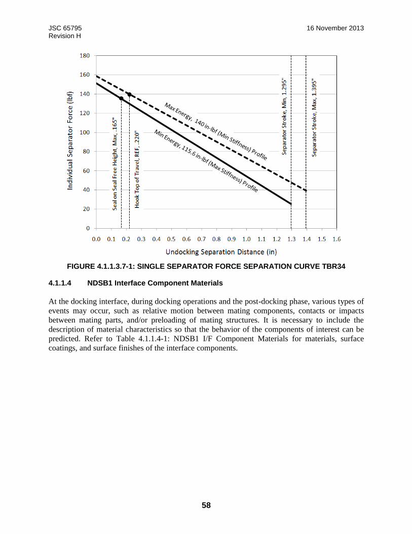
JSC 65795 16 November 2013 Revision H
58
FIGURE 4.1.1.3.7-1: SINGLE SEPARATOR FORCE SEPARATION CURVE TBR34
4.1.1.4 NDSB1 Interface Component Materials
At the docking interface, during docking operations and the post-docking phase, various types of
events may occur, such as relative motion between mating components, contacts or impacts
between mating parts, and/or preloading of mating structures. It is necessary to include the
description of material characteristics so that the behavior of the components of interest can be
predicted. Refer to Table 4.1.1.4-1: NDSB1 I/F Component Materials for materials, surface
coatings, and surface finishes of the interface components.
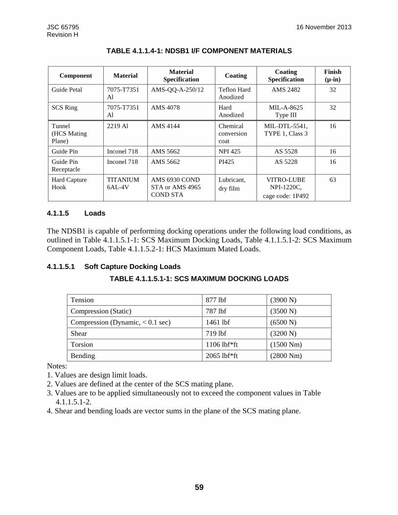
JSC 65795 16 November 2013 Revision H
59
TABLE 4.1.1.4-1: NDSB1 I/F COMPONENT MATERIALS
Component Material Material
Specification Coating
Coating
Specification
Finish
(µ-in)
Guide Petal 7075-T7351
Al
AMS-QQ-A-250/12 Teflon Hard
Anodized
AMS 2482 32
SCS Ring 7075-T7351
Al
AMS 4078 Hard
Anodized
MIL-A-8625
Type III
32
Tunnel
(HCS Mating
Plane)
2219 Al AMS 4144 Chemical
conversion
coat
MIL-DTL-5541,
TYPE 1, Class 3
16
Guide Pin Inconel 718 AMS 5662 NPI 425 AS 5528 16
Guide Pin
Receptacle
Inconel 718 AMS 5662 PI425 AS 5228 16
Hard Capture
Hook
TITANIUM
6AL-4V
AMS 6930 COND
STA or AMS 4965
COND STA
Lubricant,
dry film
VITRO-LUBE
NPI-1220C,
cage code: 1P492
63
4.1.1.5 Loads
The NDSB1 is capable of performing docking operations under the following load conditions, as
outlined in Table 4.1.1.5.1-1: SCS Maximum Docking Loads, Table 4.1.1.5.1-2: SCS Maximum
Component Loads, Table 4.1.1.5.2-1: HCS Maximum Mated Loads.
4.1.1.5.1 Soft Capture Docking Loads
TABLE 4.1.1.5.1-1: SCS MAXIMUM DOCKING LOADS
Tension 877 lbf (3900 N)
Compression (Static) 787 lbf (3500 N)
Compression (Dynamic, < 0.1 sec) 1461 lbf (6500 N)
Shear 719 lbf (3200 N)
Torsion 1106 lbf*ft (1500 Nm)
Bending 2065 lbf*ft (2800 Nm)
Notes:
1. Values are design limit loads.
2. Values are defined at the center of the SCS mating plane.
3. Values are to be applied simultaneously not to exceed the component values in Table
4.1.1.5.1-2.
4. Shear and bending loads are vector sums in the plane of the SCS mating plane.
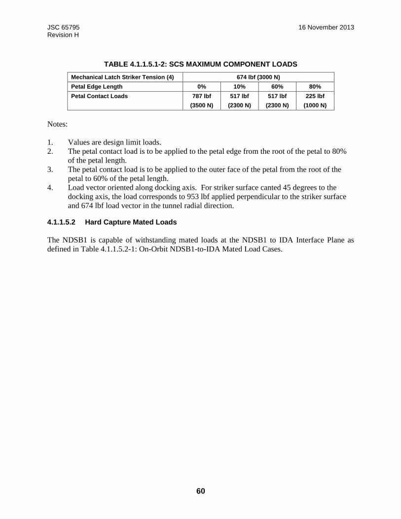
JSC 65795 16 November 2013 Revision H
60
TABLE 4.1.1.5.1-2: SCS MAXIMUM COMPONENT LOADS
Mechanical Latch Striker Tension (4) 674 lbf (3000 N)
Petal Edge Length 0% 10% 60% 80%
Petal Contact Loads 787 lbf 517 lbf 517 lbf 225 lbf
(3500 N) (2300 N) (2300 N) (1000 N)
Notes:
1. Values are design limit loads.
2. The petal contact load is to be applied to the petal edge from the root of the petal to 80%
of the petal length.
3. The petal contact load is to be applied to the outer face of the petal from the root of the
petal to 60% of the petal length.
4. Load vector oriented along docking axis. For striker surface canted 45 degrees to the
docking axis, the load corresponds to 953 lbf applied perpendicular to the striker surface
and 674 lbf load vector in the tunnel radial direction.
4.1.1.5.2 Hard Capture Mated Loads
The NDSB1 is capable of withstanding mated loads at the NDSB1 to IDA Interface Plane as
defined in Table 4.1.1.5.2-1: On-Orbit NDSB1-to-IDA Mated Load Cases.

JSC 65795 16 November 2013 Revision H
61
TABLE 4.1.1.5.2-1: ON-ORBIT NDSB1-TO-IDA MATED LOAD CASES
Load Set Case 1 Case 2 Case 3 Case 4
Compressive Axial 1,124 lbf
(5,000 N)
3,979 lbf
(17,700 N)
3,080 lbf
(13,700 N)
67,443 lbf
(300,000 N)
Tensile Axial 1,124 lbf
(5,000 N)
3,979 lbf
(17,700 N)
3,080 lbf
(13,700 N)
22,481 lbf
(100,000 N)
Shear [2] 1,124 lbf
(5,000 N)
3,327 lbf
(14,800 N)
3,754 lbf
(16,700 N)
2,248 lbf
(10,000 N)
Torsion 11,063 ft-lbf
(15,000 N-m)
11,063 ft -lbf
(15,000 N-m)
11,063 ft-lbf
(15,000 N-m)
11,063 ft-lbf
(15,000 N-m)
Bending [2] 48,163 ft-lbf
(65,300 N-m)
28,912 ft-lbf
(39,200 N-m)
50,671 ft-lbf
(68,700 N-m)
29,502 ft-lbf
(40,000 N-m)
Notes:
1. Loads are defined at the HCS mating plane in the NDSB1 structural coordinate
system.
2. Shear and bending loads may act in any direction in the HCS mating plane.
3. The load components are to be applied concurrently in all possible combinations of
positive and negative values.
4. These values are design limit loads.
5. Does not include internal pressure, seal force or pusher/separator loads.
6. Cases 1 through 3 are pressurized mated cases. Case 4 is an unpressurized mated
case.
7. Case descriptions:
Case 1 – Attitude control by Orbiter-like, combined with crew activity.
Case 2 – Berthing of ISS segment while mated.
Case 3 – Orbiter-like translation with payload attached to Orbiter Docking System
(ODS).
Case 4 – Trans-Lunar Insertion (TLI)-like, modified from Constellation analysis.
8. These loads are for the nominal 12-hook case.
4.1.1.6 Leak Rate
The leak rates defined in this subsection assume a pressure internal to the NDSB1 vestibule of 14.7
psia and an external pressure of 7.5E-14 Torr (1.0E-11 Pascal). The total leak rate for the mated
NDSB1 is less than 0.015 lbm dry air/day. This includes the host vehicle interface leakage rate.
When calculating the mated leak rate for a combined mated NDSB1 stack, the NDSB1-to-IDA
leak rate should only be accounted for once.

JSC 65795 16 November 2013 Revision H
62
4.1.2 Electrical Interfaces
4.1.2.1 Electrical Bonding
The NDSB1 establishes bond paths to mitigate electrical hazards on the integrated subsystem
interfaces. The electrical bond meets the requirements established in NASA-STD-4003, Electrical
Bonding for NASA Launch Vehicles, Spacecraft, Payloads, and Flight Equipment.
4.1.2.1.1 Electrical Bonding at Hard Capture (Class-R – Protection Against Radio Frequency Emission)
The NDSB1 is protected against Radio Frequency (RF) emissions by maintaining a NASA-STD-
4003 Class R bond at the hard capture NDSB1-to-IDA interface. There are three Class R bond
paths between the mated systems. The first bond path is through the metal-to-metal contact on the
seal interface between the two NDSB1 mated systems. Refer to Figure 4.1.1.3.1-1, HCS
DOCKING INTERFACE. The second bond path is through the electrical umbilical connector
backshell for the plug connector. The third bond path is through the electrical umbilical connector
backshell for the receptacle connector. Refer to Figure 4.1.2.1.1.1-1 Electrical Bonding for the 2nd
and 3rd bond paths.
4.1.2.1.1.1 Electrical Bonding at Hard Capture (Class-H Protection Against Electrical Faults)
The NDSB1 will provide a class-H bond at the cable and Umbilical NDSB1 to HV interfaces in
accordance with NASA-STD-4003, Electrical Bonding for NASA Launch Vehicles, Spacecraft,
Payloads, and Flight Equipment, paragraph 4.2. Refer to Figure 4.1.2.1.1.1-1 for an example of
bonding between host vehicles.
The NDSB1 will provide a class-H bond through the metal-to-metal contact on the seal interface
between the two NDS mated systems interfaces in accordance with NASA-STD-4003, Electrical
Bonding for NASA Launch Vehicles, Spacecraft, Payloads, and Flight Equipment, paragraph 4.
2.

JSC 65795 16 November 2013 Revision H
63
FIGURE 4.1.2.1.1.1-1: NDSB1 ELECTRICAL BONDING
4.1.2.1.2 Electrical Bonding at Soft Capture (Class-S – Protection Against Electrostatic Discharge)
Reserved
4.1.3 Resource Transfer
The NDSB1 umbilical connector interfaces transfer resources between the docked vehicles. These
resources are power, data, and ground safety wire for the NDSB1 configurations defined in this
IDD. All umbilical connections are recessed below the docking mating plane during docking. The
umbilical connectors are mechanized such that they can be driven to mate after docking hard
capture occurs. Upon undocking, these connectors are nominally driven to the unmated state prior
to unlatching the hooks. However, they can be separated passively by the energized separation
system in the event of a failure to retract the umbilicals. For the NDSB1-to-IDA umbilical interface
location, refer to Figure 4.1.3-1. For a detailed description of NDSB1 umbilical implementation,
refer to 684-018763, Umbilical EMA Specification Control Drawing.
NDSB1 IDA

JSC 65795 16 November 2013 Revision H
64
FIGURE 4.1.3-1: NDSB1 RESOURCE TRANSFER
4.1.3.1 Power Transfer and Command and Data Handling Transfer Umbilical
As shown in Figure 4.1.3-1, there are two umbilical connectors for power/data transfer. Each
connector is a SSQ22680 Flight Releasable Attachment Mechanism (FRAM)-type connector that
contains both power and data in the same connector shell. Separate power and data cable bundles
are routed to the connector, and then combined in the connector backshell. The connector body is
the only shared volume where these two different Electromagnetic Compatibility (EMC) classes
are combined. Refer to JSC-65842, Electromagnetic Environmental Effects (EEE) Requirements
Document, for the exception allowing two different EMC classes to reside in the same connector.
Table 4.2.3.1-1: FRAM-Type Connector Pinouts shows the pinouts of the FRAM-type umbilical
connector.
4.1.3.1.1 Power Transfer
The NDSB1, after hard-mate is complete, transfers redundant 25 amps at a maximum of 126 VDC
power from the IDA to the Host Vehicle in accordance with SSP 50933. The Pin Assignments are
shown in Table 4.2.3.1-1, IDA to HV Interface (SYS A) –J35 and Table 4.2.3.1-2, IDA to HV
Interface (SYS B) – P35.
JSC 65795 16 November 2013 Revision H
65
4.1.3.1.2 Data Transfer
The NDSB1 to Host Vehicle umbilical interfaces will provide the utilities to transfer two hard-line
MIL-STD-1553 and two IEEE 802.3 Ethernet data and communication between the mated vehicles
when the Host Vehicle is hard mated to the ISS.
4.1.3.1.2.1 Ethernet Cable Specification
The Ethernet Cables utilize American National Standards Institute (ANSI)/Telecommunications
Industry Association (TIA)/Electronic Industry Alliance (EIA) 568B.2, 100 Ohm Twisted Pair
Cabling Standards, Category 5e 100 ohm two-pair twisted cable for each Ethernet link.
4.1.3.1.2.2 MIL-STD-1553 Cable Specification
The NDSB1 umbilical cabling for MIL-STD-1553 communication is constructed in accordance
with SSQ 21655, Cable, Electrical, MIL-STD-1553 Databus, Space Quality, General
Specification.
4.1.3.1.2.3 Performance Data
Performance test data (e.g., voltage drop, frequency response) for power and data transfer is
described in D684-14211-01, iLIDS FRAM Connector Test Evaluation.
4.1.3.2 Water Transfer
Reserved
4.1.3.3 Fuel Transfer
Reserved
4.1.3.4 Pressurant Transfer
Reserved
4.1.3.5 Oxidizer Transfer
Reserved
4.1.4 Surface Cleanliness
Exterior surfaces shall be Visibly Clean Level Sensitive in accordance with SN-C-0005. Sealing
surfaces shall be Visibly Clean Level Highly Sensitive in accordance with SN-C-0005.

JSC 65795 16 November 2013 Revision H
66
4.2 IDA Interfaces
4.2.1 Structural/Mechanical
When the NDSB1 unit docks to an IDA, the initial connection occurs in the SCS between the
capture latch on the NDSB1 and the striker plates on the IDA. Once the soft capture phase is
finished, the HCS on the NDSB1 completes the docking structural connection via the hook
assembly system. The NDSB1 unit can only mate with an IDA with a unique relative clocking
orientation, which is determined by the pair of adjacent guide pins and guide pin receptacles on
the HCS, as shown in Figure 4.2-1: IDA Docking Interface. The volume for the IDA is defined in
Figure 4.2.1-2: IDA Envelopes.
The NDSB1 KOZs for the IDA are defined in Figure 3.8.1.3.1-1: NDSB1 Static Envelope, Stowed
Configuration, Figure 3.8.1.3.1-2: NDSB1 Static Envelope, Docked configuration, and Figure
3.8.1.3.2-1: Kinematic Envelope.
FIGURE 4.2.1-1: IDA DOCKING INTERFACE
PRESSURE SEAL AREA
HCS TUNNEL
3X SCS BODY LATCH
HCS GUIDE PIN HOLE
12X HCS LATCH
HCS GUIDE PIN
LINE OF SYMMETRY
SCS SENSOR
SCS GUIDE PETAL
SCS RING
HCS GUIDE PIN HOLE
LINE OF
ANDROGNY
3X HCS SEPARATOR
HCS GUIDE PIN

JSC 65795 16 November 2013 Revision H
67
FIGURE 4.2.1-2: IDA ENVELOPES
CL
R 5.835 f t
(1.78 m)
25.276 in.
(642.0 mm)
VV to IDA Interface
Plane
ISS PMA 2 to IDA
Interface Plane
VV Keep Out Zone
Visiting
Vehicle
(Notional)
IDAISS PMA 2
Existing 2 f t
Keep Out Zone
Existing 2 f t
Keep Out Zone
JSC 65795 16 November 2013 Revision H
68
4.2.1.1 Thermal Interface
For steady state mated configurations, the NDSB1-to-IDA docking interface is assumed to be
adiabatic. For evaluation of transient response in mated configurations, the integrated models
should use the appropriate conductance to be conservative from that thermal evaluation’s
perspective. The thermal conductance across the NDSB1-to-IDA HCS docking interface is defined
as ranging from 75 Btu/hr-°F (40 W/°K) to 187 Btu/hr-°F (98 W/°K).
4.2.1.1.1 Non-Operational Survival
Not required
4.2.1.1.2 Operational
4.2.1.1.2.1 Tunnel and Seal Mating Interface
Before capture the temperature of the IDA docking ring at the docked VV to IDA interface is
maintained in the temperature range of -38°F (-38.9°C) to +122 °F (50°C).
Note: The minimum temperature of -38°F (-38.9°C) is based on the minimum capability of the
NDSB1 dynamic seals. However, the expected nominal minimum temperature is approximately
+60°F (+15.56°C) provided that required PMA and IDA electrical power for heaters to maintain
this temperature level is provided. After VV docking, the IDA ensures that the docking mechanism
and vestibule surfaces between the PMA Hatch and the docking interface plane are between +60°F
(+15.5°C) and +113°F (+45°C), except for a period of 10 hours after docking is complete, without
relying on heat transfer with the ISS or visiting vehicle via conduction or radiation.
4.2.1.1.2.2 Soft Capture Mating Interfaces
The following applies to soft capture assembly when the system is preparing to dock, up through
hard mate, but prior to pressurization:
-65 °F to +165 °F (-54 °C to +74 °C)
4.2.1.1.3 Mated and Pressurized
4.2.1.1.3.1 Mated and Pressurized Steady-State Temperature Range
When the IDA is pressurized, the IDA maintains the temperatures of vestibule surfaces between
the PMA Hatch and the docking interface plane between +60°F (+15.5°C) and +113°F (+45°C).
These conditions are accomplished without relying on conduction or radiation heat transfer
between IDA and VV.
During depressurization, the IDA maintains the temperatures of the vestibule surfaces between the
PMA Hatch and the docking interface plane between +60°F (+15.6°C) and +113°F (+45°C),
without relying on heat transfer with the ISS or VV via conduction or radiation.
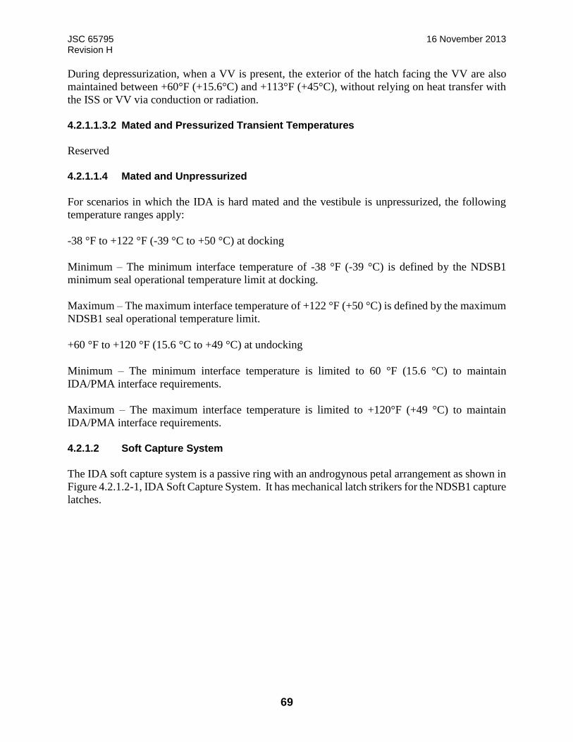
JSC 65795 16 November 2013 Revision H
69
During depressurization, when a VV is present, the exterior of the hatch facing the VV are also
maintained between +60°F (+15.6°C) and +113°F (+45°C), without relying on heat transfer with
the ISS or VV via conduction or radiation.
4.2.1.1.3.2 Mated and Pressurized Transient Temperatures
Reserved
4.2.1.1.4 Mated and Unpressurized
For scenarios in which the IDA is hard mated and the vestibule is unpressurized, the following
temperature ranges apply:
-38 °F to +122 °F (-39 °C to +50 °C) at docking
Minimum – The minimum interface temperature of -38 °F (-39 °C) is defined by the NDSB1
minimum seal operational temperature limit at docking.
Maximum – The maximum interface temperature of +122 °F (+50 °C) is defined by the maximum
NDSB1 seal operational temperature limit.
+60 °F to +120 °F (15.6 °C to +49 °C) at undocking
Minimum – The minimum interface temperature is limited to 60 °F (15.6 °C) to maintain
IDA/PMA interface requirements.
Maximum – The maximum interface temperature is limited to +120°F (+49 °C) to maintain
IDA/PMA interface requirements.
4.2.1.2 Soft Capture System
The IDA soft capture system is a passive ring with an androgynous petal arrangement as shown in
Figure 4.2.1.2-1, IDA Soft Capture System. It has mechanical latch strikers for the NDSB1 capture
latches.
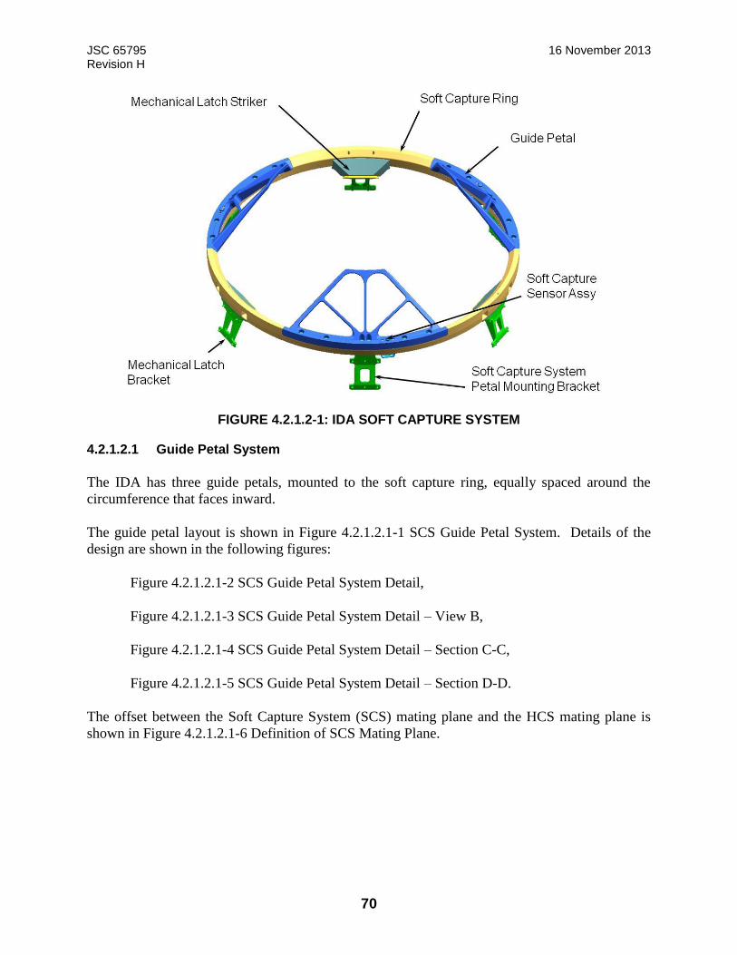
JSC 65795 16 November 2013 Revision H
70
FIGURE 4.2.1.2-1: IDA SOFT CAPTURE SYSTEM
4.2.1.2.1 Guide Petal System
The IDA has three guide petals, mounted to the soft capture ring, equally spaced around the
circumference that faces inward.
The guide petal layout is shown in Figure 4.2.1.2.1-1 SCS Guide Petal System. Details of the
design are shown in the following figures:
Figure 4.2.1.2.1-2 SCS Guide Petal System Detail,
Figure 4.2.1.2.1-3 SCS Guide Petal System Detail – View B,
Figure 4.2.1.2.1-4 SCS Guide Petal System Detail – Section C-C,
Figure 4.2.1.2.1-5 SCS Guide Petal System Detail – Section D-D.
The offset between the Soft Capture System (SCS) mating plane and the HCS mating plane is
shown in Figure 4.2.1.2.1-6 Definition of SCS Mating Plane.

JSC 65795 16 November 2013 Revision H
71
FIGURE 4.2.1.2.1-1 SCS GUIDE PETAL SYSTEM
LINE OF SYMMETRY
LINE OF
ANDROGNY

JSC 65795 16 November 2013 Revision H
72
FIGURE 4.2.1.2.1-2: SCS GUIDE PETAL SYSTEM DETAIL
LINE OF SYMMETRY
LINE OF
ANDROGNY

JSC 65795 16 November 2013 Revision H
73
FIGURE 4.2.1.2.1-3: SCS GUIDE PETAL SYSTEM DETAIL- VIEW B
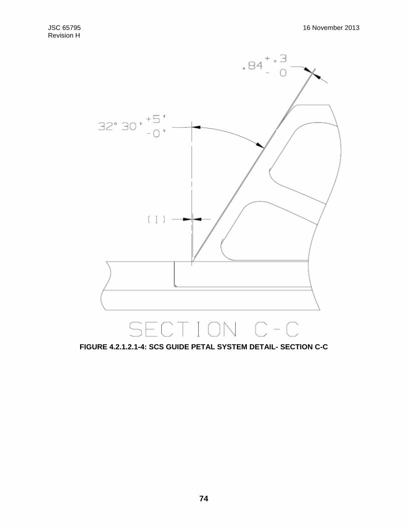
JSC 65795 16 November 2013 Revision H
74
FIGURE 4.2.1.2.1-4: SCS GUIDE PETAL SYSTEM DETAIL- SECTION C-C

JSC 65795 16 November 2013 Revision H
75
FIGURE 4.2.1.2.1-5: SCS GUIDE PETAL SYSTEM DETAIL- SECTION D-D
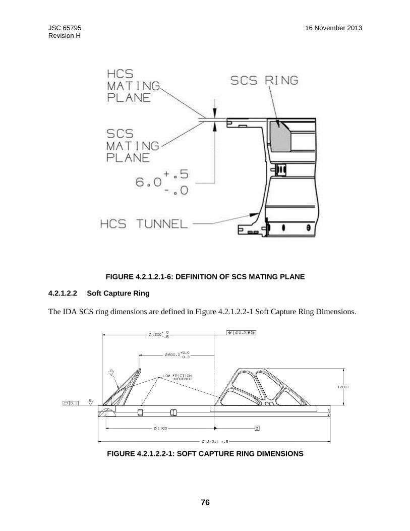
JSC 65795 16 November 2013 Revision H
76
FIGURE 4.2.1.2.1-6: DEFINITION OF SCS MATING PLANE
4.2.1.2.2 Soft Capture Ring
The IDA SCS ring dimensions are defined in Figure 4.2.1.2.2-1 Soft Capture Ring Dimensions.
FIGURE 4.2.1.2.2-1: SOFT CAPTURE RING DIMENSIONS
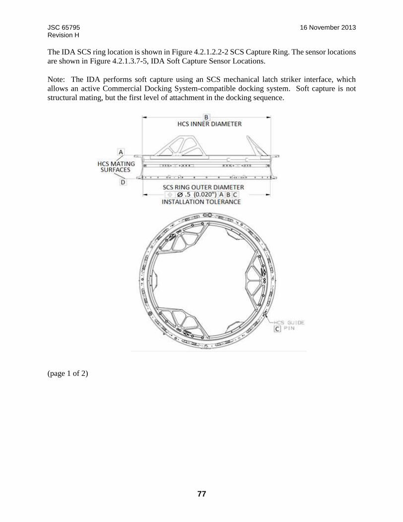
JSC 65795 16 November 2013 Revision H
77
The IDA SCS ring location is shown in Figure 4.2.1.2.2-2 SCS Capture Ring. The sensor locations
are shown in Figure 4.2.1.3.7-5, IDA Soft Capture Sensor Locations.
Note: The IDA performs soft capture using an SCS mechanical latch striker interface, which
allows an active Commercial Docking System-compatible docking system. Soft capture is not
structural mating, but the first level of attachment in the docking sequence.
(page 1 of 2)

JSC 65795 16 November 2013 Revision H
78
(page 2 of 2)
FIGURE 4.2.1.2.2-2: SCS CAPTURE RING
4.2.1.2.3 Magnet and Striker
Not applicable
4.2.1.2.4 Pre-Capture SCS Compressive Force Resistance
The IDA can withstand a total compressive resistance force of 22.48 lbf (100 N), plus margin,
during capture for the IDA soft capture interface.
Note: This resistance includes the SCS capture sensors and any other sources of compressive force
resistance prior to soft capture latch engagement.
4.2.1.2.5 SCS Mechanical Latch Striker
The IDA SCS interface includes three mechanical latch strikers that are sized as defined in Figure
4.2.1.2.5-1 SCS Mechanical Latch Striker Interface and Figure 4.2.1.2.5-2 SCS Mechanical Latch
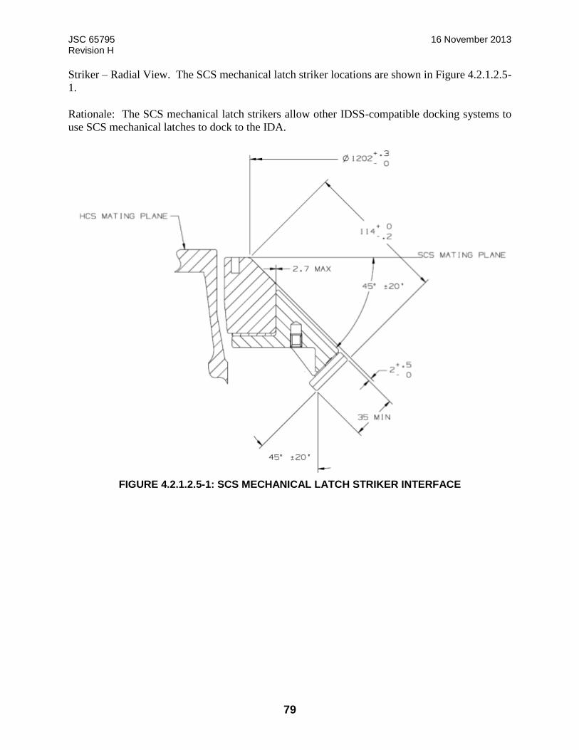
JSC 65795 16 November 2013 Revision H
79
Striker – Radial View. The SCS mechanical latch striker locations are shown in Figure 4.2.1.2.5-
1.
Rationale: The SCS mechanical latch strikers allow other IDSS-compatible docking systems to
use SCS mechanical latches to dock to the IDA.
FIGURE 4.2.1.2.5-1: SCS MECHANICAL LATCH STRIKER INTERFACE
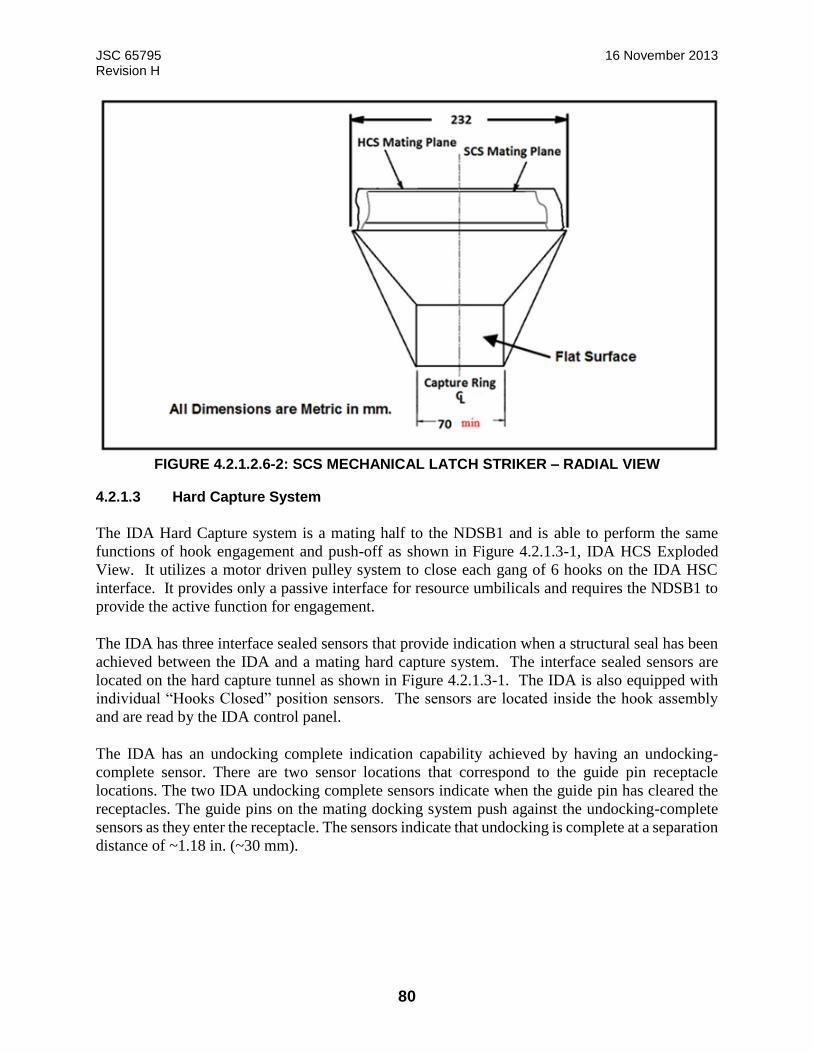
JSC 65795 16 November 2013 Revision H
80
FIGURE 4.2.1.2.6-2: SCS MECHANICAL LATCH STRIKER – RADIAL VIEW
4.2.1.3 Hard Capture System
The IDA Hard Capture system is a mating half to the NDSB1 and is able to perform the same
functions of hook engagement and push-off as shown in Figure 4.2.1.3-1, IDA HCS Exploded
View. It utilizes a motor driven pulley system to close each gang of 6 hooks on the IDA HSC
interface. It provides only a passive interface for resource umbilicals and requires the NDSB1 to
provide the active function for engagement.
The IDA has three interface sealed sensors that provide indication when a structural seal has been
achieved between the IDA and a mating hard capture system. The interface sealed sensors are
located on the hard capture tunnel as shown in Figure 4.2.1.3-1. The IDA is also equipped with
individual “Hooks Closed” position sensors. The sensors are located inside the hook assembly
and are read by the IDA control panel.
The IDA has an undocking complete indication capability achieved by having an undocking-
complete sensor. There are two sensor locations that correspond to the guide pin receptacle
locations. The two IDA undocking complete sensors indicate when the guide pin has cleared the
receptacles. The guide pins on the mating docking system push against the undocking-complete
sensors as they enter the receptacle. The sensors indicate that undocking is complete at a separation
distance of ~1.18 in. (~30 mm).
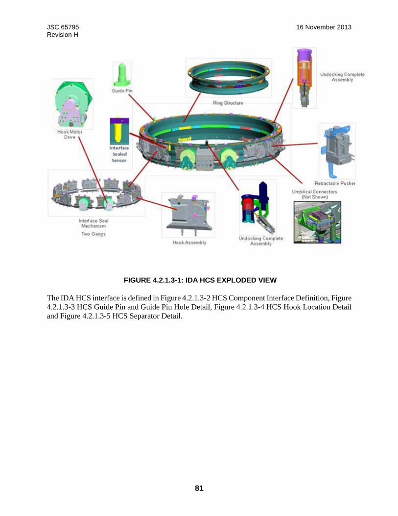
JSC 65795 16 November 2013 Revision H
81
FIGURE 4.2.1.3-1: IDA HCS EXPLODED VIEW
The IDA HCS interface is defined in Figure 4.2.1.3-2 HCS Component Interface Definition, Figure
4.2.1.3-3 HCS Guide Pin and Guide Pin Hole Detail, Figure 4.2.1.3-4 HCS Hook Location Detail
and Figure 4.2.1.3-5 HCS Separator Detail.

JSC 65795 16 November 2013 Revision H
82
FIGURE 4.2.1.3-2: HCS COMPONENT INTERFACE DEFINITION
FIGURE 4.2.1.3-3: HCS GUIDE PIN AND GUIDE PIN HOLE DETAIL
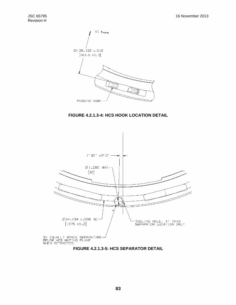
JSC 65795 16 November 2013 Revision H
83
FIGURE 4.2.1.3-4: HCS HOOK LOCATION DETAIL
FIGURE 4.2.1.3-5: HCS SEPARATOR DETAIL
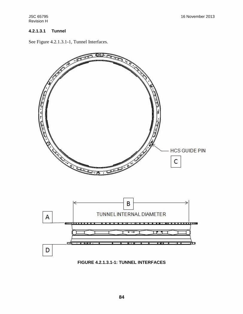
JSC 65795 16 November 2013 Revision H
84
4.2.1.3.1 Tunnel
See Figure 4.2.1.3.1-1, Tunnel Interfaces.
FIGURE 4.2.1.3.1-1: TUNNEL INTERFACES
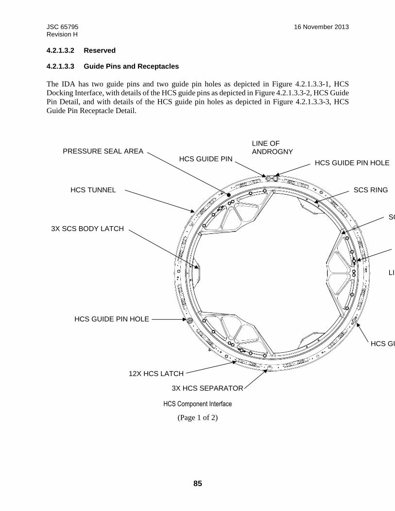
JSC 65795 16 November 2013 Revision H
85
4.2.1.3.2 Reserved
4.2.1.3.3 Guide Pins and Receptacles
The IDA has two guide pins and two guide pin holes as depicted in Figure 4.2.1.3.3-1, HCS
Docking Interface, with details of the HCS guide pins as depicted in Figure 4.2.1.3.3-2, HCS Guide
Pin Detail, and with details of the HCS guide pin holes as depicted in Figure 4.2.1.3.3-3, HCS
Guide Pin Receptacle Detail.
HCS Component Interface
(Page 1 of 2)
PRESSURE SEAL AREA
HCS TUNNEL
3X SCS BODY LATCH
HCS GUIDE PIN HOLE
12X HCS LATCH
HCS GUIDE PIN
LINE OF SYMMETRY
SCS SENSOR
SCS GUIDE PETAL
SCS RING
HCS GUIDE PIN HOLE
LINE OF ANDROGNY
3X HCS SEPARATOR
HCS GUIDE PIN
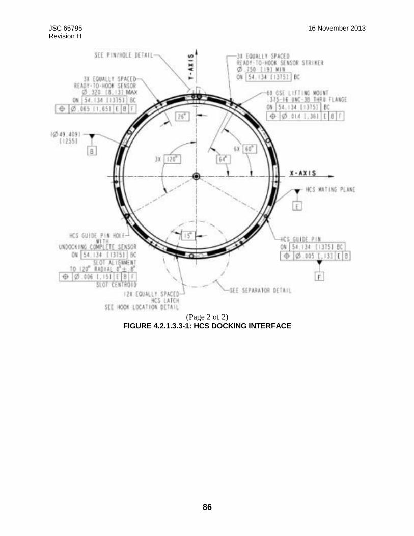
JSC 65795 16 November 2013 Revision H
86
(Page 2 of 2)
FIGURE 4.2.1.3.3-1: HCS DOCKING INTERFACE
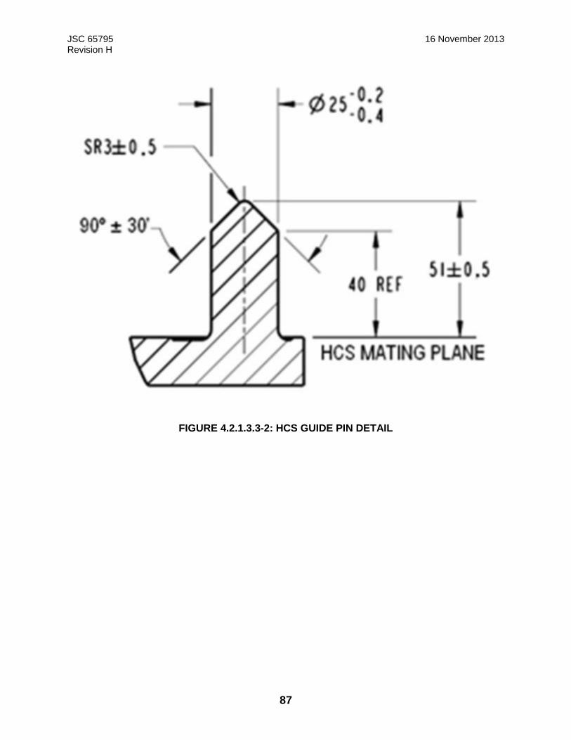
JSC 65795 16 November 2013 Revision H
87
FIGURE 4.2.1.3.3-2: HCS GUIDE PIN DETAIL
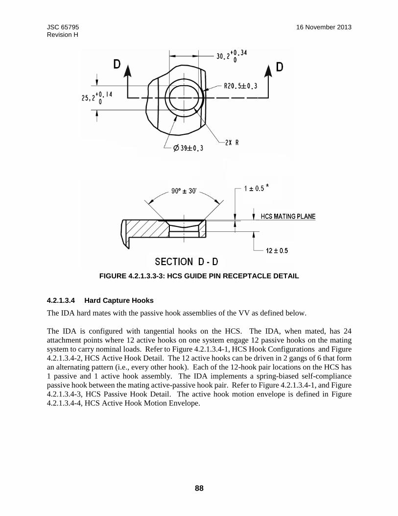
JSC 65795 16 November 2013 Revision H
88
FIGURE 4.2.1.3.3-3: HCS GUIDE PIN RECEPTACLE DETAIL
4.2.1.3.4 Hard Capture Hooks
The IDA hard mates with the passive hook assemblies of the VV as defined below.
The IDA is configured with tangential hooks on the HCS. The IDA, when mated, has 24
attachment points where 12 active hooks on one system engage 12 passive hooks on the mating
system to carry nominal loads. Refer to Figure 4.2.1.3.4-1, HCS Hook Configurations and Figure
4.2.1.3.4-2, HCS Active Hook Detail. The 12 active hooks can be driven in 2 gangs of 6 that form
an alternating pattern (i.e., every other hook). Each of the 12-hook pair locations on the HCS has
1 passive and 1 active hook assembly. The IDA implements a spring-biased self-compliance
passive hook between the mating active-passive hook pair. Refer to Figure 4.2.1.3.4-1, and Figure
4.2.1.3.4-3, HCS Passive Hook Detail. The active hook motion envelope is defined in Figure
4.2.1.3.4-4, HCS Active Hook Motion Envelope.

JSC 65795 16 November 2013 Revision H
89
Ready-To-Dock Configuration
Ready-To-Hook Configuration
(page 1 of 2)
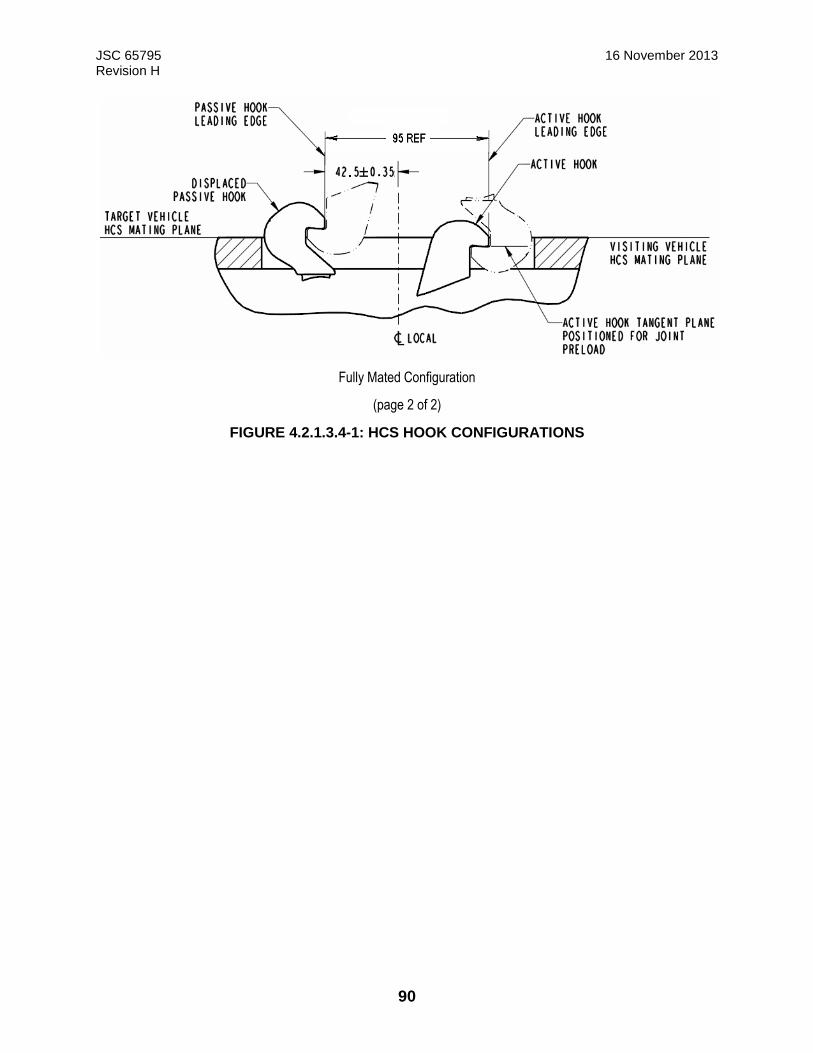
JSC 65795 16 November 2013 Revision H
90
Fully Mated Configuration
(page 2 of 2)
FIGURE 4.2.1.3.4-1: HCS HOOK CONFIGURATIONS
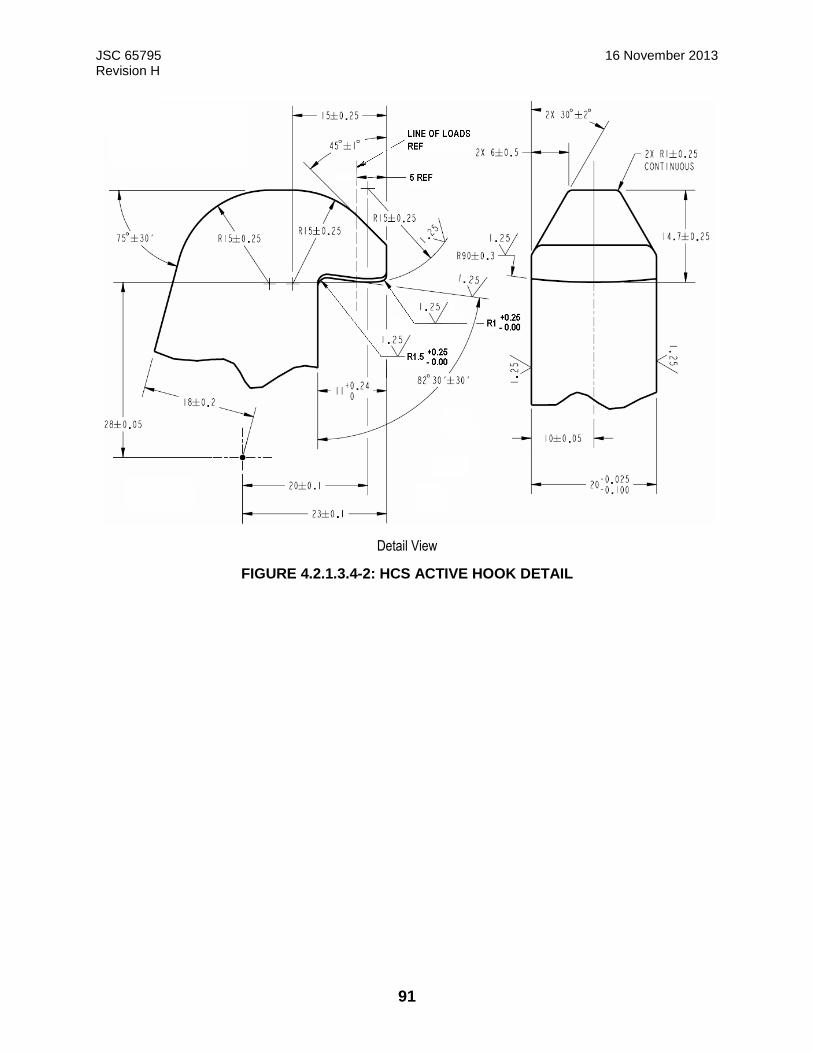
JSC 65795 16 November 2013 Revision H
91
Detail View
FIGURE 4.2.1.3.4-2: HCS ACTIVE HOOK DETAIL

JSC 65795 16 November 2013 Revision H
92
FIGURE 4.2.1.3.4-3: HCS PASSIVE HOOK DETAIL

JSC 65795 16 November 2013 Revision H
93
FIGURE 4.2.1.3.4-4: HCS ACTIVE HOOK MOTION ENVELOPE
The Hook System is defined as the serial combination of the Active Hook Mechanism, the Passive
Hook Mechanism, and the structural elements that are in compression.
The Preload of the Hook System after locking is between the following values:
Minimum Preload of Hook System after locking = 7037 lbf (31300 N)
Maximum Preload of Hook System after locking = 9968 lbf (44340 N)
The Design Limit Capability of the Active and Passive Hook element is =
11240 lbf (50000 N).
The load response (stiffness) of the Active Hard Capture Hook Mechanism is between the upper
and lower curves, as defined in Figure 4.2.1.3.4-5, Load Response of Active Hook Mechanism.
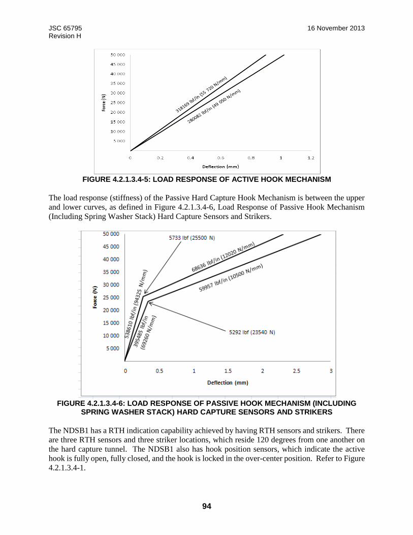
JSC 65795 16 November 2013 Revision H
94
FIGURE 4.2.1.3.4-5: LOAD RESPONSE OF ACTIVE HOOK MECHANISM
The load response (stiffness) of the Passive Hard Capture Hook Mechanism is between the upper
and lower curves, as defined in Figure 4.2.1.3.4-6, Load Response of Passive Hook Mechanism
(Including Spring Washer Stack) Hard Capture Sensors and Strikers.
FIGURE 4.2.1.3.4-6: LOAD RESPONSE OF PASSIVE HOOK MECHANISM (INCLUDING
SPRING WASHER STACK) HARD CAPTURE SENSORS AND STRIKERS
The NDSB1 has a RTH indication capability achieved by having RTH sensors and strikers. There
are three RTH sensors and three striker locations, which reside 120 degrees from one another on
the hard capture tunnel. The NDSB1 also has hook position sensors, which indicate the active
hook is fully open, fully closed, and the hook is locked in the over-center position. Refer to Figure
4.2.1.3.4-1.
JSC 65795 16 November 2013 Revision H
95
The striker zones for RTH sensors are recessed below the HCS mating plane, as illustrated in
Figure 4.2.1.3.7-3, HCS Interface – Axial View. Refer to Figure 4.2.1.3.4-1 for the RTH activation
point above the HCS mating plane.
4.2.1.3.5 Undocking Complete Sensors and Strikers
The IDA has two undocking complete sensors at the VV to IDA interface at the guide pin
receptacle locations as defined in Figure 4.2.1.3.3-1 and Figure 4.2.1.3.3-2. Note: The sensors
indicate that undocking is complete at a separation distance of ~1.18 in. (~30 mm).
4.2.1.3.6 HCS Compressive Force Resistance During SCS Retraction
The IDA hard capture interface is 18.9 lbf (84 N) compressive force resistance during SCS
retraction.
Note: As the SCS retracts, it encounters the RTH and undocking complete sensors while in a
kinematic configuration that has limited axial pulling force capability. To ensure the ability to
engage the hooks, a maximum of 37.8 lbf (168 N) compressive force resistance is allowed across
the interface. This means each side is allowed to have a maximum of 18.9 lbf (84 N) resistance.
4.2.1.3.7 Separation System Springs and Strikers
The IDA provides three retractable separation mechanisms capable of providing a force sufficient
to push the VV away from the ISS in accordance with the IDA as defined below.
The IDA includes three separation springs recessed below the docking sealing surface, which can
be remotely engaged for separation and reset to a recessed position for docking. This system
provides force to overcome the seal stiction and energy to accelerate the vehicle away when the
structural mate mechanism is released.
The umbilical resource connectors are nominally retracted prior to undocking. However, in the
event of failure to retract the umbilicals, the separation system is capable of providing enough
force to de-mate the umbilical resource connectors during separation.
The separation system and associated striker zones are shown in Figure 4.2.1.3.3-1. The striker
zones are recessed below the HCS mating plane, as illustrated in Figure 4.2.1.3.7-3, HCS Interface
– Axial View.
Once charged against the striker on the mating docking interface, the separator has a minimum
total extension stroke of 1.295 in. (32.9 mm) to be used for separation. The first part of the stroke
is used for loosening the pressure seals and disengaging umbilical connectors, if any. The second
part is used for vehicle separation dynamics. The three IDA separators together provide a total
initial stored energy between 28.9 ft-lb (4.0 kgf-m) and 35 ft-lb (4.8 kgf-m) at zero interface
separation. The nominal force applied by a single charged separator to the striker surface is 155
to 160 lbf (689 to 712 N). However, during contingency cases, such as a limit switch failure, the
maximum force can reach 200 lbf ( 890 N).

JSC 65795 16 November 2013 Revision H
96
Figure 4.2.1.3.7-1, Single Separator Force Separation Curve shows the linear force separation
curves of a single separator where the undocking separation distance indicates the separation
between the two HCS mating planes. Multiply the force values by three to get the total system
force acting on the vehicles at a given separation point. At a separation of 0.165 in. (4.2 mm), the
separation system provides a minimum of 133.3 lbf (593 N) for each separator.
Nominally, it can be assumed that the vehicles have zero relative axial velocity as the hooks
disengage. This occurs at a separation of approximately 0.22 in. (5.6 mm). Hence, a total energy
between 21.2 ft-lb (2.9 kgf-m) and 26.1 ft-lb (3.6 kgf-m) is applied to vehicle separation under
nominal conditions.
Note: In a contingency situation where the NDSB1 umbilicals are not retracted first, the umbilical
connectors resist separation until a separation of approximately 0.512 in. (13 mm) is achieved.
Therefore, the energy available for vehicle separation is reduced in this scenario.
FIGURE 4.2.1.3.7-1: SINGLE SEPARATOR FORCE SEPARATION CURVE TBR35
The IDA accommodates a visiting vehicle equipped with an undocking separation system, which
utilizes separation pushers located in accordance with any of the 9 potential striker locations as
defined below.

JSC 65795 16 November 2013 Revision H
97
The HCS has designated areas for striker zones used by the opposing docking system. These
striker areas can be used for various HCS sensory components or other subsystems such as
separation system push-off devices. IDSS compliant systems abide by the designated striker zones
defined in Figure 4.2.1.3.7-2: HCS Interface – Axial View and Figure 4.2.1.3.7-3: HCS Interface
– Axial View.
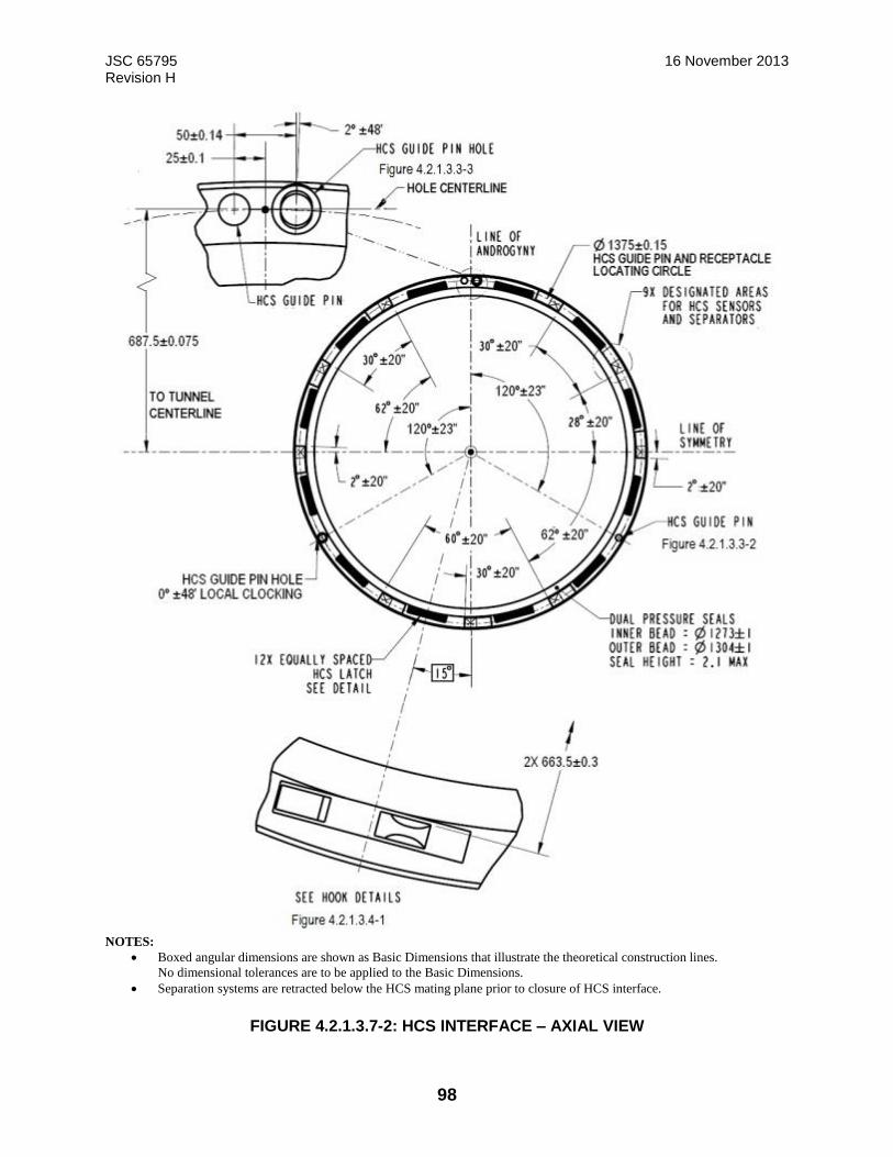
JSC 65795 16 November 2013 Revision H
98
NOTES:
Boxed angular dimensions are shown as Basic Dimensions that illustrate the theoretical construction lines.
No dimensional tolerances are to be applied to the Basic Dimensions.
Separation systems are retracted below the HCS mating plane prior to closure of HCS interface.
FIGURE 4.2.1.3.7-2: HCS INTERFACE – AXIAL VIEW

JSC 65795 16 November 2013 Revision H
99
(Page 1 of 2)

JSC 65795 16 November 2013 Revision H
100
(Page 2 of 2)
NOTES:
1. Hard capture System features in striker zones as noted in detail view shown above
2. Reference Figure 4.2.1.3-2 HCS Component Interface Definition for PHMA/IDA GSE lifting
points and Interface Sealed locations.
3. PHMA Hook shear Pin feature only in 2 locations 2 and 8 (view not shown for simplicity)
FIGURE 4.2.1.3.7-3: HCS INTERFACE – AXIAL VIEW
The IDA has a 1553 bus termination switch and striker on the Flight Releasable Attachment
Mechanism (FRAM) Plug connector that corresponds to a matching bus termination striker and
switch on the VV FRAM Receptacle connector, as specified in SLZ29101649, Specification
Control Drawing, Umbilical EMA, Figure 3-9 and Figure 3-12 and as shown in Figure 4.2.1.3.7-
4 IDA Bus Termination Switch and Striker.
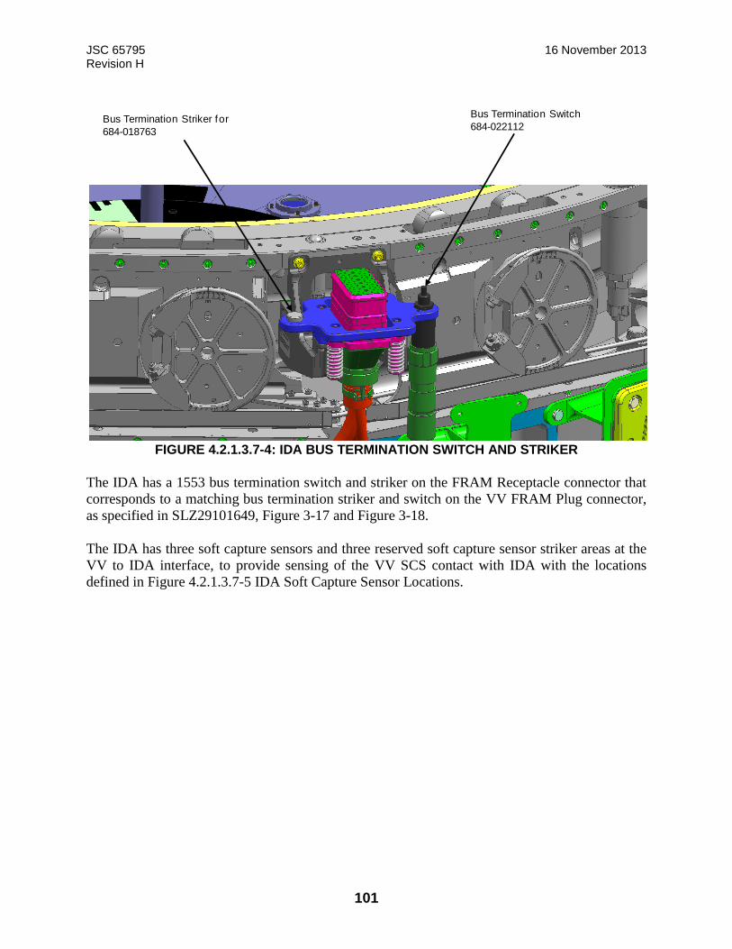
JSC 65795 16 November 2013 Revision H
101
FIGURE 4.2.1.3.7-4: IDA BUS TERMINATION SWITCH AND STRIKER
The IDA has a 1553 bus termination switch and striker on the FRAM Receptacle connector that
corresponds to a matching bus termination striker and switch on the VV FRAM Plug connector,
as specified in SLZ29101649, Figure 3-17 and Figure 3-18.
The IDA has three soft capture sensors and three reserved soft capture sensor striker areas at the
VV to IDA interface, to provide sensing of the VV SCS contact with IDA with the locations
defined in Figure 4.2.1.3.7-5 IDA Soft Capture Sensor Locations.
Bus Termination Striker for
684-018763
Bus Termination Switch
684-022112
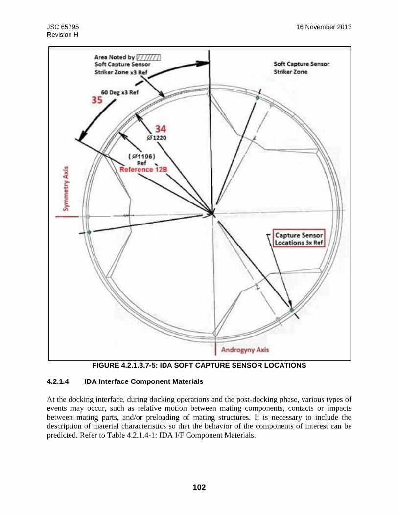
JSC 65795 16 November 2013 Revision H
102
FIGURE 4.2.1.3.7-5: IDA SOFT CAPTURE SENSOR LOCATIONS
4.2.1.4 IDA Interface Component Materials
At the docking interface, during docking operations and the post-docking phase, various types of
events may occur, such as relative motion between mating components, contacts or impacts
between mating parts, and/or preloading of mating structures. It is necessary to include the
description of material characteristics so that the behavior of the components of interest can be
predicted. Refer to Table 4.2.1.4-1: IDA I/F Component Materials.
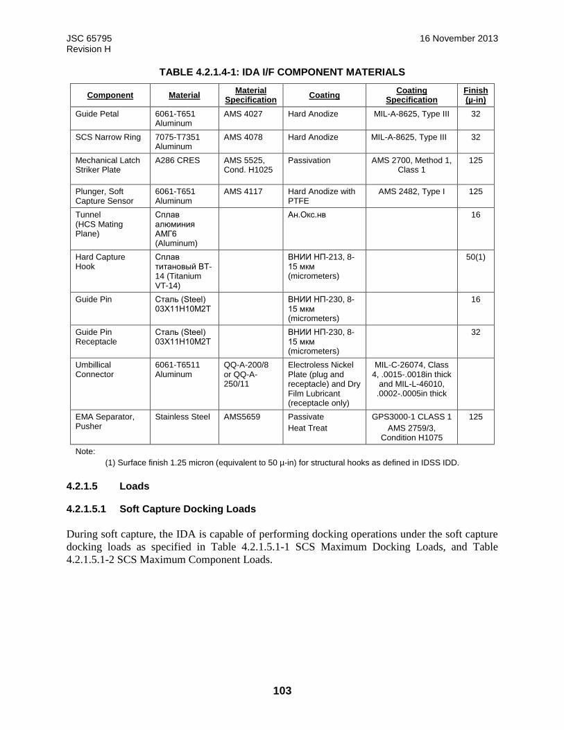
JSC 65795 16 November 2013 Revision H
103
TABLE 4.2.1.4-1: IDA I/F COMPONENT MATERIALS
Component Material Material
Specification Coating
Coating Specification
Finish (µ-in)
Guide Petal 6061-T651 Aluminum
AMS 4027 Hard Anodize MIL-A-8625, Type III 32
SCS Narrow Ring 7075-T7351 Aluminum
AMS 4078 Hard Anodize MIL-A-8625, Type III 32
Mechanical Latch Striker Plate
A286 CRES AMS 5525, Cond. H1025
Passivation AMS 2700, Method 1, Class 1
125
Plunger, Soft Capture Sensor
6061-T651 Aluminum
AMS 4117 Hard Anodize with PTFE
AMS 2482, Type I 125
Tunnel (HCS Mating Plane)
Сплав алюминия АМГ6 (Aluminum)
Ан.Окс.нв 16
Hard Capture Hook
Сплав титановый ВТ-14 (Titanium VT-14)
ВНИИ НП-213, 8-15 мкм (micrometers)
50(1)
Guide Pin Сталь (Steel) 03Х11Н10М2Т
ВНИИ НП-230, 8-15 мкм (micrometers)
16
Guide Pin Receptacle
Сталь (Steel) 03Х11Н10М2Т
ВНИИ НП-230, 8-15 мкм (micrometers)
32
Umbillical Connector
6061-T6511 Aluminum
QQ-A-200/8 or QQ-A-250/11
Electroless Nickel Plate (plug and receptacle) and Dry Film Lubricant (receptacle only)
MIL-C-26074, Class 4, .0015-.0018in thick
and MIL-L-46010, .0002-.0005in thick
EMA Separator, Pusher
Stainless Steel AMS5659 Passivate
Heat Treat
GPS3000-1 CLASS 1
AMS 2759/3, Condition H1075
125
Note:
(1) Surface finish 1.25 micron (equivalent to 50 µ-in) for structural hooks as defined in IDSS IDD.
4.2.1.5 Loads
4.2.1.5.1 Soft Capture Docking Loads
During soft capture, the IDA is capable of performing docking operations under the soft capture
docking loads as specified in Table 4.2.1.5.1-1 SCS Maximum Docking Loads, and Table
4.2.1.5.1-2 SCS Maximum Component Loads.
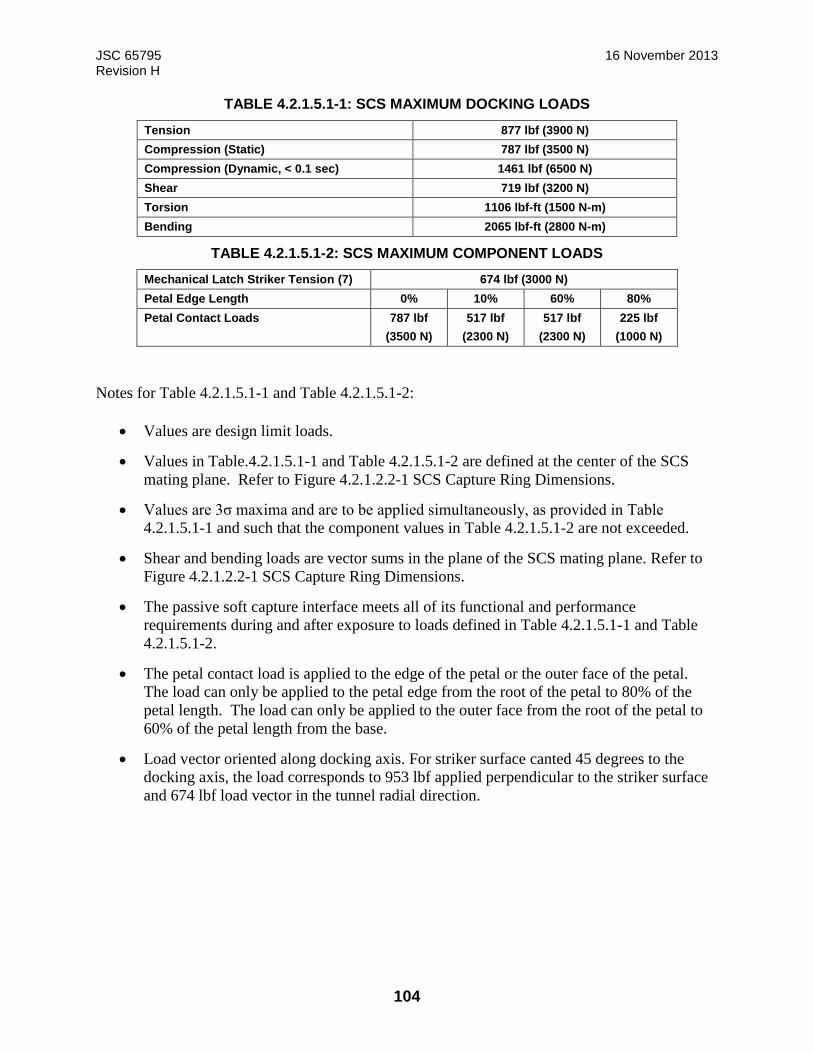
JSC 65795 16 November 2013 Revision H
104
TABLE 4.2.1.5.1-1: SCS MAXIMUM DOCKING LOADS
Tension 877 lbf (3900 N)
Compression (Static) 787 lbf (3500 N)
Compression (Dynamic, < 0.1 sec) 1461 lbf (6500 N)
Shear 719 lbf (3200 N)
Torsion 1106 lbf-ft (1500 N-m)
Bending 2065 lbf-ft (2800 N-m)
TABLE 4.2.1.5.1-2: SCS MAXIMUM COMPONENT LOADS
Mechanical Latch Striker Tension (7) 674 lbf (3000 N)
Petal Edge Length 0% 10% 60% 80%
Petal Contact Loads 787 lbf 517 lbf 517 lbf 225 lbf
(3500 N) (2300 N) (2300 N) (1000 N)
Notes for Table 4.2.1.5.1-1 and Table 4.2.1.5.1-2:
Values are design limit loads.
Values in Table.4.2.1.5.1-1 and Table 4.2.1.5.1-2 are defined at the center of the SCS
mating plane. Refer to Figure 4.2.1.2.2-1 SCS Capture Ring Dimensions.
Values are 3σ maxima and are to be applied simultaneously, as provided in Table
4.2.1.5.1-1 and such that the component values in Table 4.2.1.5.1-2 are not exceeded.
Shear and bending loads are vector sums in the plane of the SCS mating plane. Refer to
Figure 4.2.1.2.2-1 SCS Capture Ring Dimensions.
The passive soft capture interface meets all of its functional and performance
requirements during and after exposure to loads defined in Table 4.2.1.5.1-1 and Table
4.2.1.5.1-2.
The petal contact load is applied to the edge of the petal or the outer face of the petal.
The load can only be applied to the petal edge from the root of the petal to 80% of the
petal length. The load can only be applied to the outer face from the root of the petal to
60% of the petal length from the base.
Load vector oriented along docking axis. For striker surface canted 45 degrees to the
docking axis, the load corresponds to 953 lbf applied perpendicular to the striker surface
and 674 lbf load vector in the tunnel radial direction.
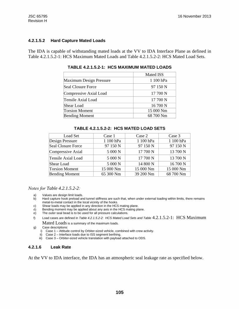
JSC 65795 16 November 2013 Revision H
105
4.2.1.5.2 Hard Capture Mated Loads
The IDA is capable of withstanding mated loads at the VV to IDA Interface Plane as defined in
Table 4.2.1.5.2-1: HCS Maximum Mated Loads and Table 4.2.1.5.2-2: HCS Mated Load Sets.
TABLE 4.2.1.5.2-1: HCS MAXIMUM MATED LOADS
Mated ISS
Maximum Design Pressure 1 100 hPa
Seal Closure Force 97 150 N
Compressive Axial Load 17 700 N
Tensile Axial Load 17 700 N
Shear Load 16 700 N
Torsion Moment 15 000 Nm
Bending Moment 68 700 Nm
TABLE 4.2.1.5.2-2: HCS MATED LOAD SETS
Load Set Case 1 Case 2 Case 3
Design Pressure 1 100 hPa 1 100 hPa 1 100 hPa
Seal Closure Force 97 150 N 97 150 N 97 150 N
Compressive Axial 5 000 N 17 700 N 13 700 N
Tensile Axial Load 5 000 N 17 700 N 13 700 N
Shear Load 5 000 N 14 800 N 16 700 N
Torsion Moment 15 000 Nm 15 000 Nm 15 000 Nm
Bending Moment 65 300 Nm 39 200 Nm 68 700 Nm
Notes for Table 4.2.1.5.2-2:
a) Values are design limit loads. b) Hard capture hook preload and tunnel stiffness are such that, when under external loading within limits, there remains
metal-to-metal contact in the local vicinity of the hooks. c) Shear loads may be applied in any direction in the HCS mating plane. d) Bending moment may be applied about any axis in the HCS mating plane. e) The outer seal bead is to be used for all pressure calculations.
f) Load cases are defined in Table 4.2.1.5.2-2: HCS Mated Load Sets and Table 4.2.1.5.2-1: HCS Maximum
Mated Loads is a summary of the maximum loads.
g) Case descriptions: i) Case 1 – Attitude control by Orbiter-sized vehicle, combined with crew activity. ii) Case 2 – Interface loads due to ISS segment berthing. iii) Case 3 – Orbiter-sized vehicle translation with payload attached to ODS.
4.2.1.6 Leak Rate
At the VV to IDA interface, the IDA has an atmospheric seal leakage rate as specified below.
JSC 65795 16 November 2013 Revision H
106
The leak rates assume a pressure internal to the NDSB1 vestibule of 14.7 psia and an external
pressure of 7.5E-14 Torr (1.0E-11 Pascal). The leak rate at the host interface is less than 0.0008
lbm dry air/day. The leak rate at the NDS-to-IDA interface is less than 0.0025 lbm dry air/day.
When calculating the mated leak rate for a combined mated NDS stack, the NDSB1-to-IDA leak
rate should only be accounted for once.
The following assumption is made:
The leak rate at the NDSB1-to-IDA interface assumes 12 hooks fully closed.
4.2.1.7 GN&C Aids
The IDA has Perimeter Reflector Target (PRT) interfaces, consisting of one Planar Retro Reflector
and two Hemispherical Retro Reflectors, for laser ranging from equipment on an approaching VV
as shown in Figure 4.2.1.7-2 Configuration of Perimeter Reflector Targets on IDA.
The IDA has Perimeter Reflector Targets with the coverage angles as defined in JSC 66380,
section 3.2.3.1.5.
The IDA has no structural obstructions within +90 degrees to -90 degrees of the bore sight of the
reflective elements of the PRTs as shown in Figure 4.2.1.7-2.
The IDA provides four provisional locations for ground-installed Peripheral Docking Targets that
are visible to a VV as it approaches for final guidance and navigation within 30 m of the docking
interface to ISS at Node 2 Forward port, as shown in Figure 4.2.1.7-1 Peripheral Docking Target
Provisions on IDA.

JSC 65795 16 November 2013 Revision H
107
Note: The origin (0o) of the angular position of the Peripheral Docking Target Provisions is on
the
–ZIDA-axis.
FIGURE 4.2.1.7-1: PERIPHERAL DOCKING TARGET PROVISIONS ON IDA
Peripheral
Docking
Target
Provisions
4 Places
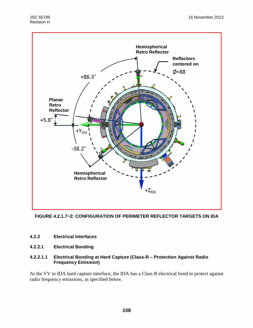
JSC 65795 16 November 2013 Revision H
108
Hemispherical Retro Reflector
Reflectors
centered on
Hemispherical Retro Reflector
Planar Retro Reflector
FIGURE 4.2.1.7−2: CONFIGURATION OF PERIMETER REFLECTOR TARGETS ON IDA
4.2.2 Electrical Interfaces
4.2.2.1 Electrical Bonding
4.2.2.1.1 Electrical Bonding at Hard Capture (Class-R – Protection Against Radio Frequency Emission)
At the VV to IDA hard capture interface, the IDA has a Class R electrical bond to protect against
radio frequency emissions, as specified below.
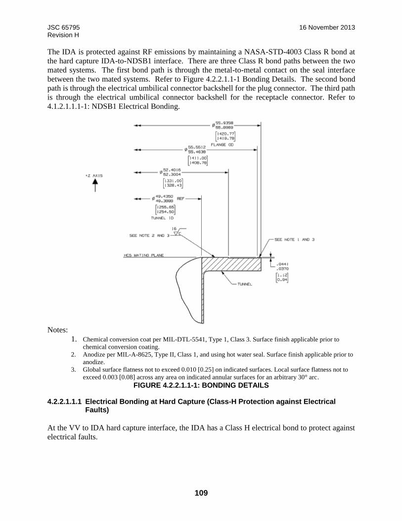
JSC 65795 16 November 2013 Revision H
109
The IDA is protected against RF emissions by maintaining a NASA-STD-4003 Class R bond at
the hard capture IDA-to-NDSB1 interface. There are three Class R bond paths between the two
mated systems. The first bond path is through the metal-to-metal contact on the seal interface
between the two mated systems. Refer to Figure 4.2.2.1.1-1 Bonding Details. The second bond
path is through the electrical umbilical connector backshell for the plug connector. The third path
is through the electrical umbilical connector backshell for the receptacle connector. Refer to
4.1.2.1.1.1-1: NDSB1 Electrical Bonding.
Notes:
1. Chemical conversion coat per MIL-DTL-5541, Type 1, Class 3. Surface finish applicable prior to
chemical conversion coating. 2. Anodize per MIL-A-8625, Type II, Class 1, and using hot water seal. Surface finish applicable prior to
anodize.
3. Global surface flatness not to exceed 0.010 [0.25] on indicated surfaces. Local surface flatness not to
exceed 0.003 [0.08] across any area on indicated annular surfaces for an arbitrary 30° arc.
FIGURE 4.2.2.1.1-1: BONDING DETAILS
4.2.2.1.1.1 Electrical Bonding at Hard Capture (Class-H Protection against Electrical Faults)
At the VV to IDA hard capture interface, the IDA has a Class H electrical bond to protect against
electrical faults.

JSC 65795 16 November 2013 Revision H
110
4.2.2.1.2 Electrical Bonding at Soft Capture (Class-S – Protection against Electrostatic Discharge)
At the VV to IDA soft capture interface, the IDA has a Class S electrical bond to protect against
static charge buildup.
4.2.3 Resource Transfer
The IDA provides automated blind electrical mating to the electrical connectors (power,
commands and data) at the VV to IDA interface during the Hard Mate phase of the HV docking
operation.
4.2.3.1 Power Transfer and Command and Data Handling Transfer Umbilical
The IDA has an Umbilical Mated Loopback feature in each FRAM connector at the VV to IDA
interface to provide a return electrical path for a mated VV to ensure electrical connections are
engaged.
The IDA has SSQ 22680 FRAM-type electrical connectors (power and data) that are external to
the pressure seals at the VV to IDA interface as defined below.
As shown in Figure 4.2.1.3-1, there are two umbilical connectors for power/data transfer. Each
connector is a SSQ22680 FRAM-type connector that contains both power and data in the same
connector shell. Separate power and data cable bundles are routed to the connector, and then
combined in the connector backshell. Maximum possible separation is maintained inside the
connector. The connector body is the only shared volume where these two different EMC classes
are combined. Refer to JSC-65842, EEE Requirements Document, for the exception allowing two
different EMC classes to reside in the same connector. Table 4.2.3.1-1, IDA TO HV INTERFACE
(SYS A) – J35 and Table 4.2.3.1-2, IDA TO VV INTERFACE (SYS B) – P35 shows the pinouts
of the FRAM-type umbilical connector.
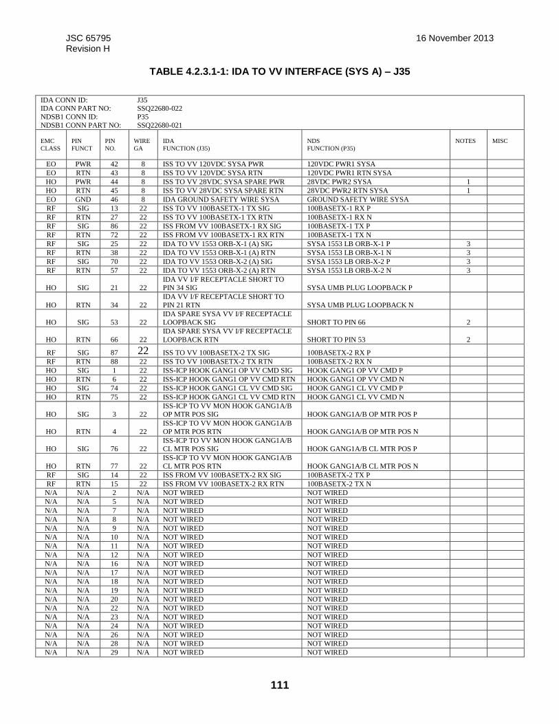
JSC 65795 16 November 2013 Revision H
111
TABLE 4.2.3.1-1: IDA TO VV INTERFACE (SYS A) – J35
IDA CONN ID: J35 IDA CONN PART NO: SSQ22680-022
NDSB1 CONN ID: P35
NDSB1 CONN PART NO: SSQ22680-021
EMC
CLASS
PIN
FUNCT
PIN
NO.
WIRE
GA
IDA
FUNCTION (J35)
NDS
FUNCTION (P35)
NOTES
MISC
EO PWR 42 8 ISS TO VV 120VDC SYSA PWR 120VDC PWR1 SYSA
EO RTN 43 8 ISS TO VV 120VDC SYSA RTN 120VDC PWR1 RTN SYSA
HO PWR 44 8 ISS TO VV 28VDC SYSA SPARE PWR 28VDC PWR2 SYSA 1
HO RTN 45 8 ISS TO VV 28VDC SYSA SPARE RTN 28VDC PWR2 RTN SYSA 1
EO GND 46 8 IDA GROUND SAFETY WIRE SYSA GROUND SAFETY WIRE SYSA
RF SIG 13 22 ISS TO VV 100BASETX-1 TX SIG 100BASETX-1 RX P
RF RTN 27 22 ISS TO VV 100BASETX-1 TX RTN 100BASETX-1 RX N
RF SIG 86 22 ISS FROM VV 100BASETX-1 RX SIG 100BASETX-1 TX P
RF RTN 72 22 ISS FROM VV 100BASETX-1 RX RTN 100BASETX-1 TX N
RF SIG 25 22 IDA TO VV 1553 ORB-X-1 (A) SIG SYSA 1553 LB ORB-X-1 P 3
RF RTN 38 22 IDA TO VV 1553 ORB-X-1 (A) RTN SYSA 1553 LB ORB-X-1 N 3
RF SIG 70 22 IDA TO VV 1553 ORB-X-2 (A) SIG SYSA 1553 LB ORB-X-2 P 3
RF RTN 57 22 IDA TO VV 1553 ORB-X-2 (A) RTN SYSA 1553 LB ORB-X-2 N 3
HO SIG 21 22 IDA VV I/F RECEPTACLE SHORT TO PIN 34 SIG SYSA UMB PLUG LOOPBACK P
HO RTN 34 22
IDA VV I/F RECEPTACLE SHORT TO
PIN 21 RTN SYSA UMB PLUG LOOPBACK N
HO SIG 53 22 IDA SPARE SYSA VV I/F RECEPTACLE LOOPBACK SIG SHORT TO PIN 66 2
HO RTN 66 22
IDA SPARE SYSA VV I/F RECEPTACLE
LOOPBACK RTN SHORT TO PIN 53 2
RF SIG 87 22 ISS TO VV 100BASETX-2 TX SIG 100BASETX-2 RX P
RF RTN 88 22 ISS TO VV 100BASETX-2 TX RTN 100BASETX-2 RX N
HO SIG 1 22 ISS-ICP HOOK GANG1 OP VV CMD SIG HOOK GANG1 OP VV CMD P
HO RTN 6 22 ISS-ICP HOOK GANG1 OP VV CMD RTN HOOK GANG1 OP VV CMD N
HO SIG 74 22 ISS-ICP HOOK GANG1 CL VV CMD SIG HOOK GANG1 CL VV CMD P
HO RTN 75 22 ISS-ICP HOOK GANG1 CL VV CMD RTN HOOK GANG1 CL VV CMD N
HO SIG 3 22 ISS-ICP TO VV MON HOOK GANG1A/B OP MTR POS SIG HOOK GANG1A/B OP MTR POS P
HO RTN 4 22
ISS-ICP TO VV MON HOOK GANG1A/B
OP MTR POS RTN HOOK GANG1A/B OP MTR POS N
HO SIG 76 22 ISS-ICP TO VV MON HOOK GANG1A/B CL MTR POS SIG HOOK GANG1A/B CL MTR POS P
HO RTN 77 22
ISS-ICP TO VV MON HOOK GANG1A/B
CL MTR POS RTN HOOK GANG1A/B CL MTR POS N
RF SIG 14 22 ISS FROM VV 100BASETX-2 RX SIG 100BASETX-2 TX P
RF RTN 15 22 ISS FROM VV 100BASETX-2 RX RTN 100BASETX-2 TX N
N/A N/A 2 N/A NOT WIRED NOT WIRED
N/A N/A 5 N/A NOT WIRED NOT WIRED
N/A N/A 7 N/A NOT WIRED NOT WIRED
N/A N/A 8 N/A NOT WIRED NOT WIRED
N/A N/A 9 N/A NOT WIRED NOT WIRED
N/A N/A 10 N/A NOT WIRED NOT WIRED
N/A N/A 11 N/A NOT WIRED NOT WIRED
N/A N/A 12 N/A NOT WIRED NOT WIRED
N/A N/A 16 N/A NOT WIRED NOT WIRED
N/A N/A 17 N/A NOT WIRED NOT WIRED
N/A N/A 18 N/A NOT WIRED NOT WIRED
N/A N/A 19 N/A NOT WIRED NOT WIRED
N/A N/A 20 N/A NOT WIRED NOT WIRED
N/A N/A 22 N/A NOT WIRED NOT WIRED
N/A N/A 23 N/A NOT WIRED NOT WIRED
N/A N/A 24 N/A NOT WIRED NOT WIRED
N/A N/A 26 N/A NOT WIRED NOT WIRED
N/A N/A 28 N/A NOT WIRED NOT WIRED
N/A N/A 29 N/A NOT WIRED NOT WIRED
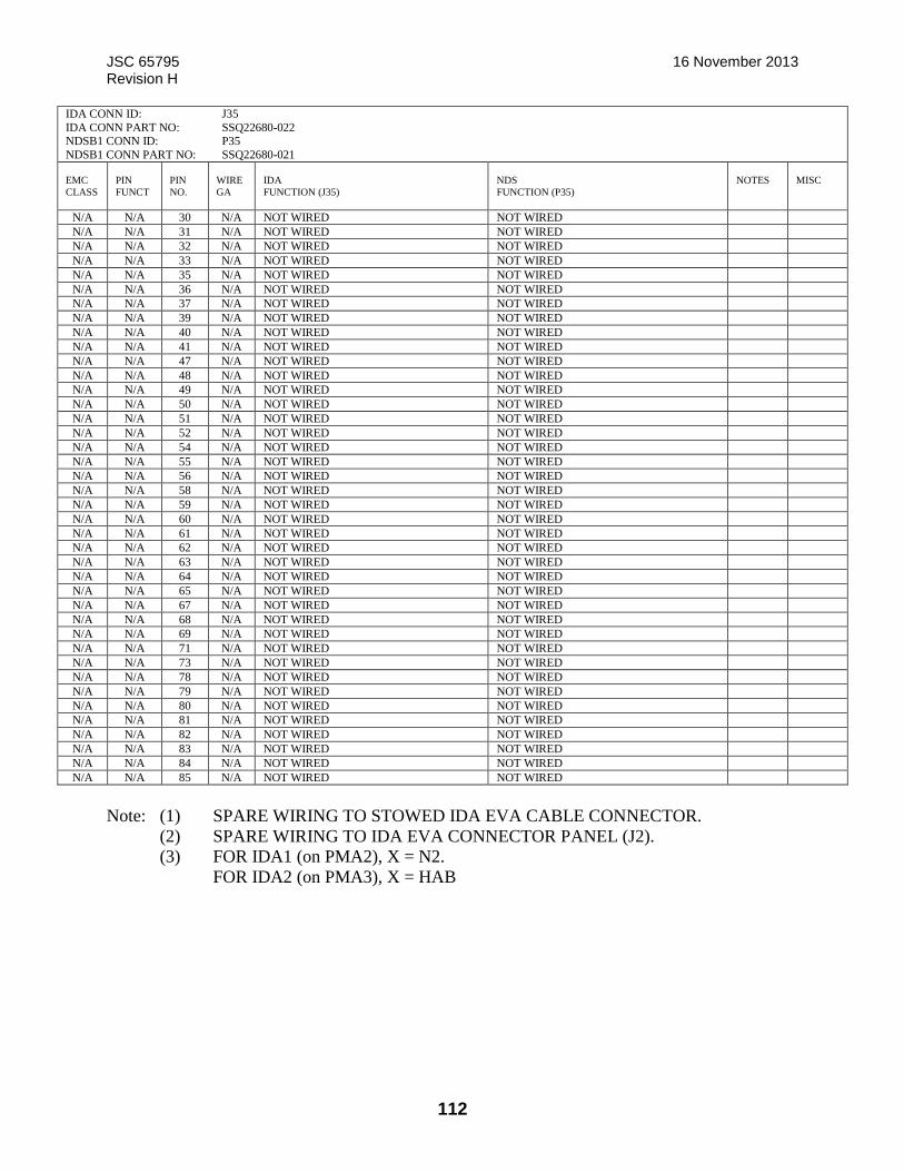
JSC 65795 16 November 2013 Revision H
112
IDA CONN ID: J35
IDA CONN PART NO: SSQ22680-022 NDSB1 CONN ID: P35
NDSB1 CONN PART NO: SSQ22680-021
EMC
CLASS
PIN
FUNCT
PIN
NO.
WIRE
GA
IDA
FUNCTION (J35)
NDS
FUNCTION (P35)
NOTES
MISC
N/A N/A 30 N/A NOT WIRED NOT WIRED
N/A N/A 31 N/A NOT WIRED NOT WIRED
N/A N/A 32 N/A NOT WIRED NOT WIRED
N/A N/A 33 N/A NOT WIRED NOT WIRED
N/A N/A 35 N/A NOT WIRED NOT WIRED
N/A N/A 36 N/A NOT WIRED NOT WIRED
N/A N/A 37 N/A NOT WIRED NOT WIRED
N/A N/A 39 N/A NOT WIRED NOT WIRED
N/A N/A 40 N/A NOT WIRED NOT WIRED
N/A N/A 41 N/A NOT WIRED NOT WIRED
N/A N/A 47 N/A NOT WIRED NOT WIRED
N/A N/A 48 N/A NOT WIRED NOT WIRED
N/A N/A 49 N/A NOT WIRED NOT WIRED
N/A N/A 50 N/A NOT WIRED NOT WIRED
N/A N/A 51 N/A NOT WIRED NOT WIRED
N/A N/A 52 N/A NOT WIRED NOT WIRED
N/A N/A 54 N/A NOT WIRED NOT WIRED
N/A N/A 55 N/A NOT WIRED NOT WIRED
N/A N/A 56 N/A NOT WIRED NOT WIRED
N/A N/A 58 N/A NOT WIRED NOT WIRED
N/A N/A 59 N/A NOT WIRED NOT WIRED
N/A N/A 60 N/A NOT WIRED NOT WIRED
N/A N/A 61 N/A NOT WIRED NOT WIRED
N/A N/A 62 N/A NOT WIRED NOT WIRED
N/A N/A 63 N/A NOT WIRED NOT WIRED
N/A N/A 64 N/A NOT WIRED NOT WIRED
N/A N/A 65 N/A NOT WIRED NOT WIRED
N/A N/A 67 N/A NOT WIRED NOT WIRED
N/A N/A 68 N/A NOT WIRED NOT WIRED
N/A N/A 69 N/A NOT WIRED NOT WIRED
N/A N/A 71 N/A NOT WIRED NOT WIRED
N/A N/A 73 N/A NOT WIRED NOT WIRED
N/A N/A 78 N/A NOT WIRED NOT WIRED
N/A N/A 79 N/A NOT WIRED NOT WIRED
N/A N/A 80 N/A NOT WIRED NOT WIRED
N/A N/A 81 N/A NOT WIRED NOT WIRED
N/A N/A 82 N/A NOT WIRED NOT WIRED
N/A N/A 83 N/A NOT WIRED NOT WIRED
N/A N/A 84 N/A NOT WIRED NOT WIRED
N/A N/A 85 N/A NOT WIRED NOT WIRED
Note: (1) SPARE WIRING TO STOWED IDA EVA CABLE CONNECTOR.
(2) SPARE WIRING TO IDA EVA CONNECTOR PANEL (J2).
(3) FOR IDA1 (on PMA2), X = N2.
FOR IDA2 (on PMA3), X = HAB
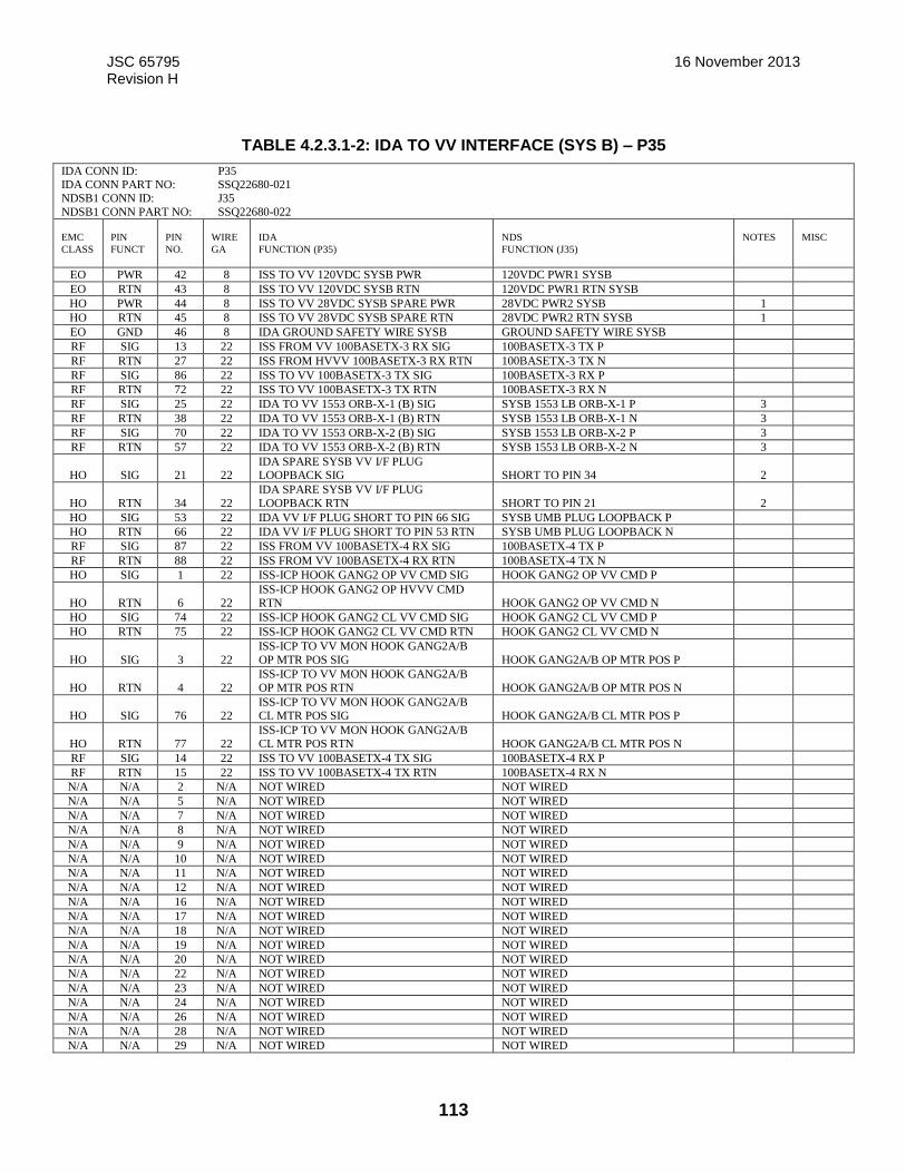
JSC 65795 16 November 2013 Revision H
113
TABLE 4.2.3.1-2: IDA TO VV INTERFACE (SYS B) – P35
IDA CONN ID: P35 IDA CONN PART NO: SSQ22680-021
NDSB1 CONN ID: J35
NDSB1 CONN PART NO: SSQ22680-022
EMC
CLASS
PIN
FUNCT
PIN
NO.
WIRE
GA
IDA
FUNCTION (P35)
NDS
FUNCTION (J35)
NOTES
MISC
EO PWR 42 8 ISS TO VV 120VDC SYSB PWR 120VDC PWR1 SYSB
EO RTN 43 8 ISS TO VV 120VDC SYSB RTN 120VDC PWR1 RTN SYSB
HO PWR 44 8 ISS TO VV 28VDC SYSB SPARE PWR 28VDC PWR2 SYSB 1
HO RTN 45 8 ISS TO VV 28VDC SYSB SPARE RTN 28VDC PWR2 RTN SYSB 1
EO GND 46 8 IDA GROUND SAFETY WIRE SYSB GROUND SAFETY WIRE SYSB
RF SIG 13 22 ISS FROM VV 100BASETX-3 RX SIG 100BASETX-3 TX P
RF RTN 27 22 ISS FROM HVVV 100BASETX-3 RX RTN 100BASETX-3 TX N
RF SIG 86 22 ISS TO VV 100BASETX-3 TX SIG 100BASETX-3 RX P
RF RTN 72 22 ISS TO VV 100BASETX-3 TX RTN 100BASETX-3 RX N
RF SIG 25 22 IDA TO VV 1553 ORB-X-1 (B) SIG SYSB 1553 LB ORB-X-1 P 3
RF RTN 38 22 IDA TO VV 1553 ORB-X-1 (B) RTN SYSB 1553 LB ORB-X-1 N 3
RF SIG 70 22 IDA TO VV 1553 ORB-X-2 (B) SIG SYSB 1553 LB ORB-X-2 P 3
RF RTN 57 22 IDA TO VV 1553 ORB-X-2 (B) RTN SYSB 1553 LB ORB-X-2 N 3
HO SIG 21 22 IDA SPARE SYSB VV I/F PLUG LOOPBACK SIG SHORT TO PIN 34 2
HO RTN 34 22
IDA SPARE SYSB VV I/F PLUG
LOOPBACK RTN SHORT TO PIN 21 2
HO SIG 53 22 IDA VV I/F PLUG SHORT TO PIN 66 SIG SYSB UMB PLUG LOOPBACK P
HO RTN 66 22 IDA VV I/F PLUG SHORT TO PIN 53 RTN SYSB UMB PLUG LOOPBACK N
RF SIG 87 22 ISS FROM VV 100BASETX-4 RX SIG 100BASETX-4 TX P
RF RTN 88 22 ISS FROM VV 100BASETX-4 RX RTN 100BASETX-4 TX N
HO SIG 1 22 ISS-ICP HOOK GANG2 OP VV CMD SIG HOOK GANG2 OP VV CMD P
HO RTN 6 22 ISS-ICP HOOK GANG2 OP HVVV CMD RTN HOOK GANG2 OP VV CMD N
HO SIG 74 22 ISS-ICP HOOK GANG2 CL VV CMD SIG HOOK GANG2 CL VV CMD P
HO RTN 75 22 ISS-ICP HOOK GANG2 CL VV CMD RTN HOOK GANG2 CL VV CMD N
HO SIG 3 22
ISS-ICP TO VV MON HOOK GANG2A/B
OP MTR POS SIG HOOK GANG2A/B OP MTR POS P
HO RTN 4 22
ISS-ICP TO VV MON HOOK GANG2A/B
OP MTR POS RTN HOOK GANG2A/B OP MTR POS N
HO SIG 76 22 ISS-ICP TO VV MON HOOK GANG2A/B CL MTR POS SIG HOOK GANG2A/B CL MTR POS P
HO RTN 77 22
ISS-ICP TO VV MON HOOK GANG2A/B
CL MTR POS RTN HOOK GANG2A/B CL MTR POS N
RF SIG 14 22 ISS TO VV 100BASETX-4 TX SIG 100BASETX-4 RX P
RF RTN 15 22 ISS TO VV 100BASETX-4 TX RTN 100BASETX-4 RX N
N/A N/A 2 N/A NOT WIRED NOT WIRED
N/A N/A 5 N/A NOT WIRED NOT WIRED
N/A N/A 7 N/A NOT WIRED NOT WIRED
N/A N/A 8 N/A NOT WIRED NOT WIRED
N/A N/A 9 N/A NOT WIRED NOT WIRED
N/A N/A 10 N/A NOT WIRED NOT WIRED
N/A N/A 11 N/A NOT WIRED NOT WIRED
N/A N/A 12 N/A NOT WIRED NOT WIRED
N/A N/A 16 N/A NOT WIRED NOT WIRED
N/A N/A 17 N/A NOT WIRED NOT WIRED
N/A N/A 18 N/A NOT WIRED NOT WIRED
N/A N/A 19 N/A NOT WIRED NOT WIRED
N/A N/A 20 N/A NOT WIRED NOT WIRED
N/A N/A 22 N/A NOT WIRED NOT WIRED
N/A N/A 23 N/A NOT WIRED NOT WIRED
N/A N/A 24 N/A NOT WIRED NOT WIRED
N/A N/A 26 N/A NOT WIRED NOT WIRED
N/A N/A 28 N/A NOT WIRED NOT WIRED
N/A N/A 29 N/A NOT WIRED NOT WIRED
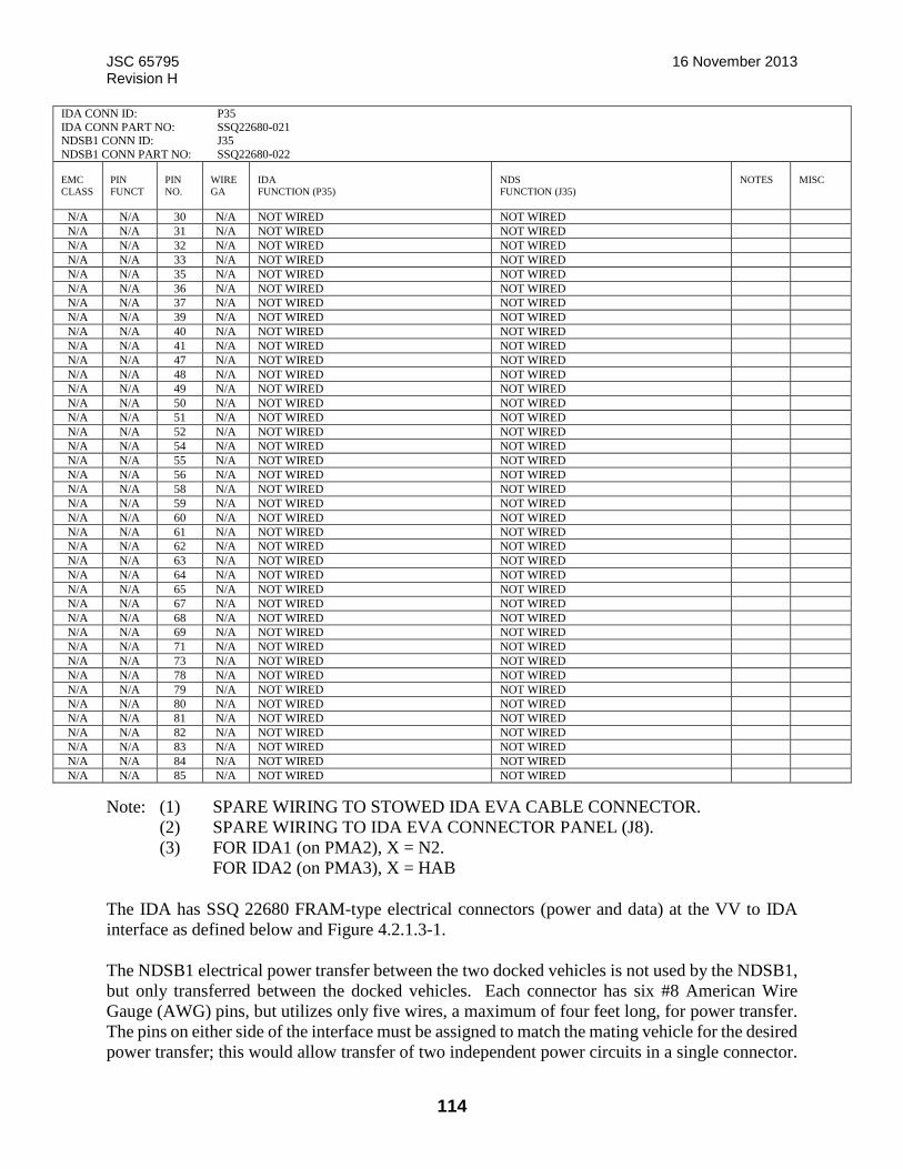
JSC 65795 16 November 2013 Revision H
114
IDA CONN ID: P35
IDA CONN PART NO: SSQ22680-021 NDSB1 CONN ID: J35
NDSB1 CONN PART NO: SSQ22680-022
EMC
CLASS
PIN
FUNCT
PIN
NO.
WIRE
GA
IDA
FUNCTION (P35)
NDS
FUNCTION (J35)
NOTES
MISC
N/A N/A 30 N/A NOT WIRED NOT WIRED
N/A N/A 31 N/A NOT WIRED NOT WIRED
N/A N/A 32 N/A NOT WIRED NOT WIRED
N/A N/A 33 N/A NOT WIRED NOT WIRED
N/A N/A 35 N/A NOT WIRED NOT WIRED
N/A N/A 36 N/A NOT WIRED NOT WIRED
N/A N/A 37 N/A NOT WIRED NOT WIRED
N/A N/A 39 N/A NOT WIRED NOT WIRED
N/A N/A 40 N/A NOT WIRED NOT WIRED
N/A N/A 41 N/A NOT WIRED NOT WIRED
N/A N/A 47 N/A NOT WIRED NOT WIRED
N/A N/A 48 N/A NOT WIRED NOT WIRED
N/A N/A 49 N/A NOT WIRED NOT WIRED
N/A N/A 50 N/A NOT WIRED NOT WIRED
N/A N/A 51 N/A NOT WIRED NOT WIRED
N/A N/A 52 N/A NOT WIRED NOT WIRED
N/A N/A 54 N/A NOT WIRED NOT WIRED
N/A N/A 55 N/A NOT WIRED NOT WIRED
N/A N/A 56 N/A NOT WIRED NOT WIRED
N/A N/A 58 N/A NOT WIRED NOT WIRED
N/A N/A 59 N/A NOT WIRED NOT WIRED
N/A N/A 60 N/A NOT WIRED NOT WIRED
N/A N/A 61 N/A NOT WIRED NOT WIRED
N/A N/A 62 N/A NOT WIRED NOT WIRED
N/A N/A 63 N/A NOT WIRED NOT WIRED
N/A N/A 64 N/A NOT WIRED NOT WIRED
N/A N/A 65 N/A NOT WIRED NOT WIRED
N/A N/A 67 N/A NOT WIRED NOT WIRED
N/A N/A 68 N/A NOT WIRED NOT WIRED
N/A N/A 69 N/A NOT WIRED NOT WIRED
N/A N/A 71 N/A NOT WIRED NOT WIRED
N/A N/A 73 N/A NOT WIRED NOT WIRED
N/A N/A 78 N/A NOT WIRED NOT WIRED
N/A N/A 79 N/A NOT WIRED NOT WIRED
N/A N/A 80 N/A NOT WIRED NOT WIRED
N/A N/A 81 N/A NOT WIRED NOT WIRED
N/A N/A 82 N/A NOT WIRED NOT WIRED
N/A N/A 83 N/A NOT WIRED NOT WIRED
N/A N/A 84 N/A NOT WIRED NOT WIRED
N/A N/A 85 N/A NOT WIRED NOT WIRED
Note: (1) SPARE WIRING TO STOWED IDA EVA CABLE CONNECTOR.
(2) SPARE WIRING TO IDA EVA CONNECTOR PANEL (J8).
(3) FOR IDA1 (on PMA2), X = N2.
FOR IDA2 (on PMA3), X = HAB
The IDA has SSQ 22680 FRAM-type electrical connectors (power and data) at the VV to IDA
interface as defined below and Figure 4.2.1.3-1.
The NDSB1 electrical power transfer between the two docked vehicles is not used by the NDSB1,
but only transferred between the docked vehicles. Each connector has six #8 American Wire
Gauge (AWG) pins, but utilizes only five wires, a maximum of four feet long, for power transfer.
The pins on either side of the interface must be assigned to match the mating vehicle for the desired
power transfer; this would allow transfer of two independent power circuits in a single connector.

JSC 65795 16 November 2013 Revision H
115
The IDA has electrical connector pin assignments as specified in Tables 4.2.3.1-1 and 4.2.3.1-2.
The VV electrical connectors (power and data) are external to the pressure seals at the VV to IDA
interface.
The VV to IDA interface design incorporates provisions for the mechanical connection of power
and C&DH utilities during on-orbit installation. Location of IDA to VV electrical interface
connectors are depicted in Figure 4.2.3.1-1, HV to IDA Electrical Interface Connectors.
Associated interconnect utilities are shown in Figures 4.2.3.1.1-1 VV to IDA Electrical Interfaces
on PMA 2 on NODE 2 Forward Port and 4.2.3.1.1-2, VV to IDA Electrical Interfaces on PMA 3
on NODE 2 Zenith Port
FIGURE 4.2.3.1-1: IDA TO VV ELECTRICAL INTERFACE CONNECTORS
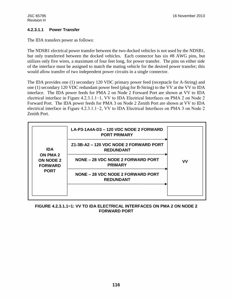
JSC 65795 16 November 2013 Revision H
116
4.2.3.1.1 Power Transfer
The IDA transfers power as follows:
The NDSB1 electrical power transfer between the two docked vehicles is not used by the NDSB1,
but only transferred between the docked vehicles. Each connector has six #8 AWG pins, but
utilizes only five wires, a maximum of four feet long, for power transfer. The pins on either side
of the interface must be assigned to match the mating vehicle for the desired power transfer; this
would allow transfer of two independent power circuits in a single connector.
The IDA provides one (1) secondary 120 VDC primary power feed (receptacle for A-String) and
one (1) secondary 120 VDC redundant power feed (plug for B-String) to the VV at the VV to IDA
interface. The IDA power feeds for PMA 2 on Node 2 Forward Port are shown at VV to IDA
electrical interface in Figure 4.2.3.1.1−1, VV to IDA Electrical Interfaces on PMA 2 on Node 2
Forward Port. The IDA power feeds for PMA 3 on Node 2 Zenith Port are shown at VV to IDA
electrical interface in Figure 4.2.3.1.1−2, VV to IDA Electrical Interfaces on PMA 3 on Node 2
Zenith Port.
FIGURE 4.2.3.1.1−1: VV TO IDA ELECTRICAL INTERFACES ON PMA 2 ON NODE 2 FORWARD PORT
IDA
ON PMA 2
ON NODE 2
FORWARD
PORT
VV
LA-P3-1A4A-D3 – 120 VDC NODE 2 FORWARD
PORT PRIMARY
Z1-3B-A2 – 120 VDC NODE 2 FORWARD PORT
REDUNDANT
NONE – 28 VDC NODE 2 FORWARD PORT
PRIMARY
NONE – 28 VDC NODE 2 FORWARD PORT
REDUNDANT
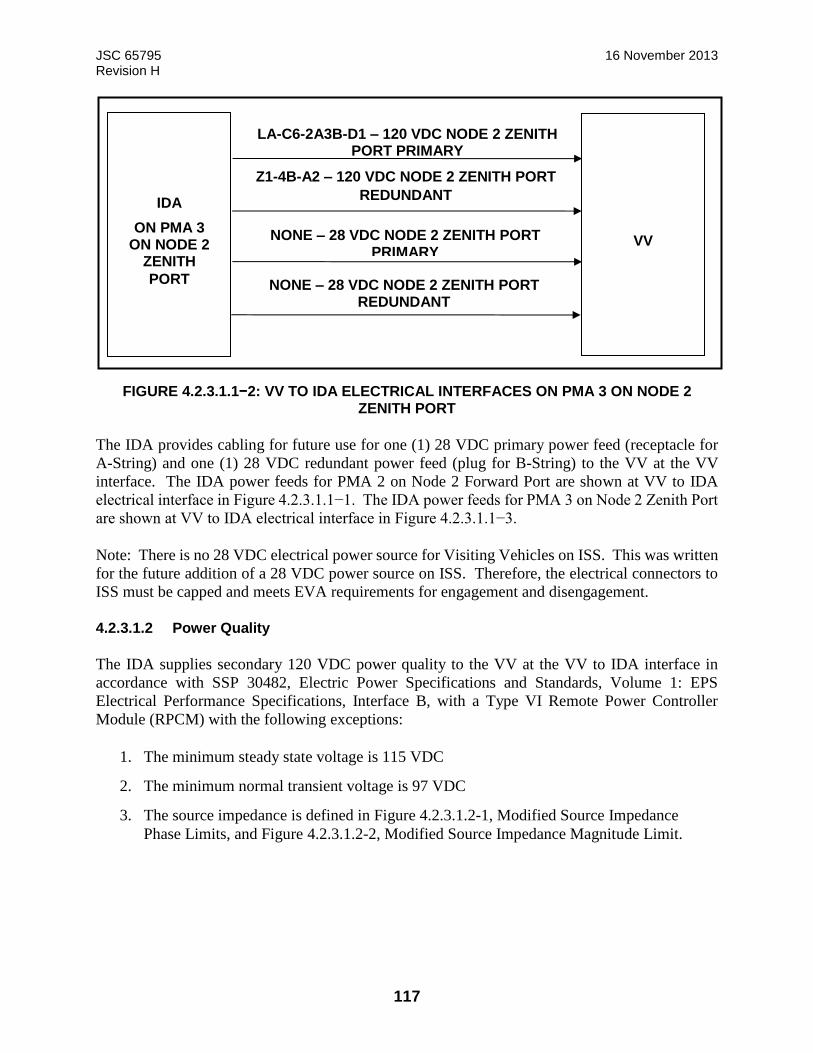
JSC 65795 16 November 2013 Revision H
117
FIGURE 4.2.3.1.1−2: VV TO IDA ELECTRICAL INTERFACES ON PMA 3 ON NODE 2 ZENITH PORT
The IDA provides cabling for future use for one (1) 28 VDC primary power feed (receptacle for
A-String) and one (1) 28 VDC redundant power feed (plug for B-String) to the VV at the VV
interface. The IDA power feeds for PMA 2 on Node 2 Forward Port are shown at VV to IDA
electrical interface in Figure 4.2.3.1.1−1. The IDA power feeds for PMA 3 on Node 2 Zenith Port
are shown at VV to IDA electrical interface in Figure 4.2.3.1.1−3.
Note: There is no 28 VDC electrical power source for Visiting Vehicles on ISS. This was written
for the future addition of a 28 VDC power source on ISS. Therefore, the electrical connectors to
ISS must be capped and meets EVA requirements for engagement and disengagement.
4.2.3.1.2 Power Quality
The IDA supplies secondary 120 VDC power quality to the VV at the VV to IDA interface in
accordance with SSP 30482, Electric Power Specifications and Standards, Volume 1: EPS
Electrical Performance Specifications, Interface B, with a Type VI Remote Power Controller
Module (RPCM) with the following exceptions:
1. The minimum steady state voltage is 115 VDC
2. The minimum normal transient voltage is 97 VDC
3. The source impedance is defined in Figure 4.2.3.1.2-1, Modified Source Impedance
Phase Limits, and Figure 4.2.3.1.2-2, Modified Source Impedance Magnitude Limit.
IDA
ON PMA 3 ON NODE 2
ZENITH
PORT
VV
LA-C6-2A3B-D1 – 120 VDC NODE 2 ZENITH PORT PRIMARY
Z1-4B-A2 – 120 VDC NODE 2 ZENITH PORT
REDUNDANT
NONE – 28 VDC NODE 2 ZENITH PORT PRIMARY
NONE – 28 VDC NODE 2 ZENITH PORT REDUNDANT
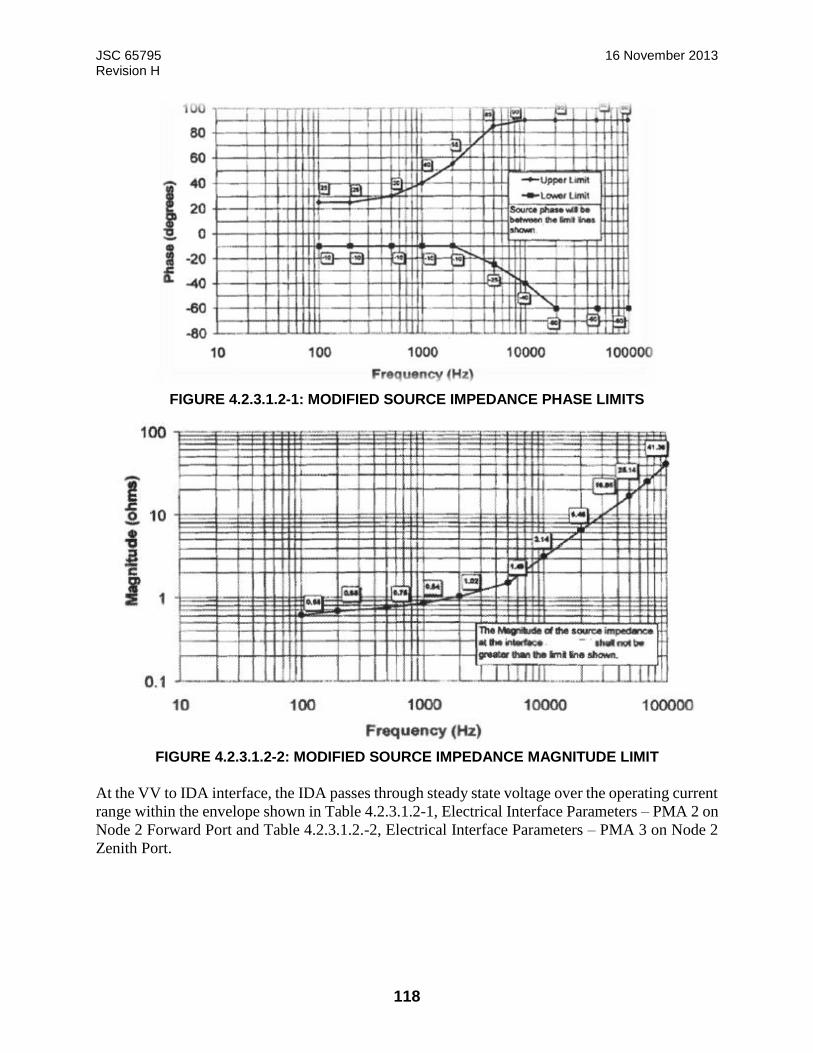
JSC 65795 16 November 2013 Revision H
118
FIGURE 4.2.3.1.2-1: MODIFIED SOURCE IMPEDANCE PHASE LIMITS
FIGURE 4.2.3.1.2-2: MODIFIED SOURCE IMPEDANCE MAGNITUDE LIMIT
At the VV to IDA interface, the IDA passes through steady state voltage over the operating current
range within the envelope shown in Table 4.2.3.1.2-1, Electrical Interface Parameters – PMA 2 on
Node 2 Forward Port and Table 4.2.3.1.2.-2, Electrical Interface Parameters – PMA 3 on Node 2
Zenith Port.
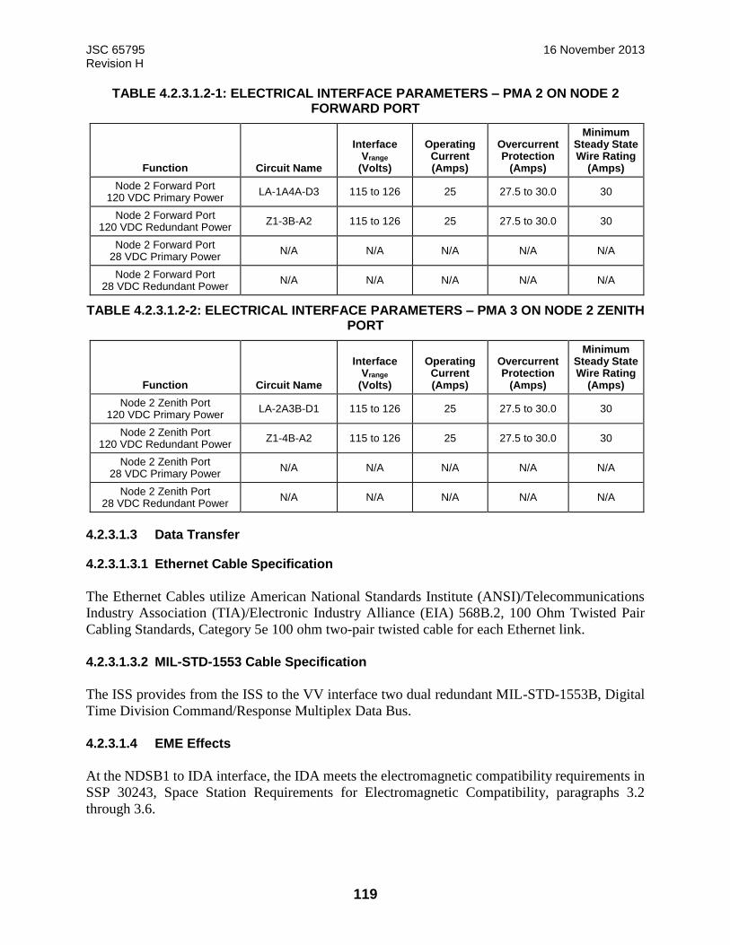
JSC 65795 16 November 2013 Revision H
119
TABLE 4.2.3.1.2-1: ELECTRICAL INTERFACE PARAMETERS – PMA 2 ON NODE 2 FORWARD PORT
Function
Circuit Name
Interface Vrange
(Volts)
Operating
Current (Amps)
Overcurrent Protection
(Amps)
Minimum Steady State Wire Rating
(Amps)
Node 2 Forward Port 120 VDC Primary Power
LA-1A4A-D3 115 to 126 25 27.5 to 30.0 30
Node 2 Forward Port 120 VDC Redundant Power
Z1-3B-A2 115 to 126 25 27.5 to 30.0 30
Node 2 Forward Port 28 VDC Primary Power
N/A N/A N/A N/A N/A
Node 2 Forward Port 28 VDC Redundant Power
N/A N/A N/A N/A N/A
TABLE 4.2.3.1.2-2: ELECTRICAL INTERFACE PARAMETERS – PMA 3 ON NODE 2 ZENITH PORT
Function
Circuit Name
Interface Vrange
(Volts)
Operating
Current (Amps)
Overcurrent Protection
(Amps)
Minimum Steady State Wire Rating
(Amps)
Node 2 Zenith Port 120 VDC Primary Power
LA-2A3B-D1 115 to 126 25 27.5 to 30.0 30
Node 2 Zenith Port 120 VDC Redundant Power
Z1-4B-A2 115 to 126 25 27.5 to 30.0 30
Node 2 Zenith Port 28 VDC Primary Power
N/A N/A N/A N/A N/A
Node 2 Zenith Port 28 VDC Redundant Power
N/A N/A N/A N/A N/A
4.2.3.1.3 Data Transfer
4.2.3.1.3.1 Ethernet Cable Specification
The Ethernet Cables utilize American National Standards Institute (ANSI)/Telecommunications
Industry Association (TIA)/Electronic Industry Alliance (EIA) 568B.2, 100 Ohm Twisted Pair
Cabling Standards, Category 5e 100 ohm two-pair twisted cable for each Ethernet link.
4.2.3.1.3.2 MIL-STD-1553 Cable Specification
The ISS provides from the ISS to the VV interface two dual redundant MIL-STD-1553B, Digital
Time Division Command/Response Multiplex Data Bus.
4.2.3.1.4 EME Effects
At the NDSB1 to IDA interface, the IDA meets the electromagnetic compatibility requirements in
SSP 30243, Space Station Requirements for Electromagnetic Compatibility, paragraphs 3.2
through 3.6.
JSC 65795 16 November 2013 Revision H
120
At the NDSB1 to IDA interface, the IDA meets the electromagnetic interference requirements in
SSP 30237, paragraphs 3.2 and 3.3.
At the NDSB1 to IDA interface, the IDA meets the grounding requirements in SSP 30240, Space
Station Grounding Requirements, section 3.0.
4.2.3.2 Water Transfer
Reserved
4.2.3.3 Fuel Transfer
Reserved
4.2.3.4 Pressurant Transfer
Reserved
4.2.3.5 Oxidizer Transfer
Reserved
4.2.3.6 Intermodule Ventilation
Internal volume in the IDA is reserved at the ISS to IDA interface for the IDA Intermodule
Ventilation (IMV) Duct. A representation of the duct is shown in Figures 4.2.3.6-1, IMV Duct,
4.2.3.6-2, Duct Coupling, and 4.2.3.6-3, Duct Details.
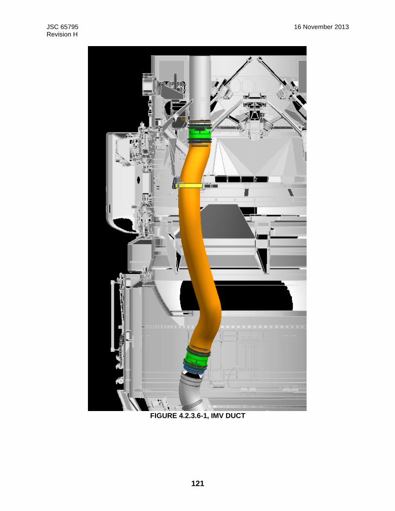
JSC 65795 16 November 2013 Revision H
121
FIGURE 4.2.3.6-1, IMV DUCT
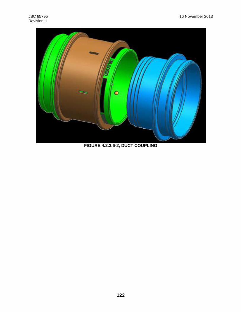
JSC 65795 16 November 2013 Revision H
122
FIGURE 4.2.3.6-2, DUCT COUPLING
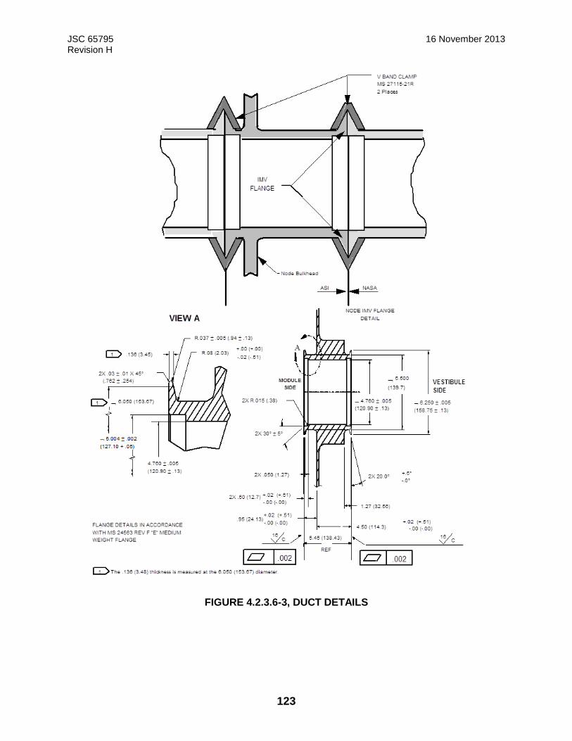
JSC 65795 16 November 2013 Revision H
123
FIGURE 4.2.3.6-3, DUCT DETAILS
JSC 65795 16 November 2013 Revision H
124
4.2.3.6.1 Temperature
The IDA transfers inter-module ventilation from the ISS to the VV at the VV to IDA interface
through the IDA IMV Duct at a temperature range of +65°F (+18.3°C) to +80°F (+26.7°C).
4.2.3.6.2 Dew Point
The IDA transfers inter-module ventilation from the ISS to the VV at the VV to IDA interface at
dew point range of +40°F (+4.4°C) to +60°F (+15.6°C) except during the first 10 hours after
pressurization. During this period, the dew point will range from 40 °F (4.4 °C) and 45 °F (7.2
°C).
4.2.3.6.3 Flowrate
When the IDA is in its Operational Configuration (See Appendix B), the IDA transfers inter-
module ventilation from the ISS to the VV at the VV to IDA interface through the IMV duct with
a volumetric flow rate in the range of 125 cfm (3.5 m3/min) to 210 cfm (5.95 m3/min).
4.2.3.6.4 Pressure Loss in IMV Ducting
When the IDA is in its Operational Configuration (See Appendix B), the maximum pressure loss
of the ISS inter-module ventilation supply in the IMV duct will have a pressure loss no greater
than 1.5 inches of water (373 Pa) at a minimum flow rate of 125 cfm (3.5 m3/min) between the
IMV fan and the end of the IDA IMV duct at the VV to IDA interface plane.
4.2.4 Surface Cleanliness
Exterior surfaces will be Visibly Clean Level Sensitive in accordance with SN-C-0005. Sealing
surfaces will be Visibly Clean Level Highly Sensitive in accordance with SN-C-0005.
4.2.5 Environments
4.2.5.1 Loads
4.2.5.1.1 Transient Limit Loads
The IDA performs as designed after withstanding the loads specified in Table 4.2.5.1.1-1, HCS
Maximum Mated Loads, Table 4.2.5.1.1-2: HCS Mated Load Sets, and using the load spectra
defined in Table 4.2.5.1.1-3, IDA Loads Spectra for VV to IDA Interface.

JSC 65795 16 November 2013 Revision H
125
TABLE 4.2.5.1.1-1: HCS MAXIMUM MATED LOADS
Mated ISS
Maximum Design Pressure 1 100 hPa
Seal Closure Force 97 150 N
Compressive Axial Load 17 700 N
Tensile Axial Load 17 700 N
Shear Load 16 700 N
Torsion Moment 15 000 Nm
Bending Moment 68 700 Nm
TABLE 4.2.5.1.1-2: HCS MATED LOAD SETS
Load Set Case 1 Case 2 Case 3
Design Pressure 1 100 hPa 1 100 hPa 1 100 hPa
Seal Closure Force 97 150 N 97 150 N 97 150 N
Compressive Axial 5 000 N 17 700 N 13 700 N
Tensile Axial Load 5 000 N 17 700 N 13 700 N
Shear Load 5 000 N 14 800 N 16 700 N
Torsion Moment 15 000 Nm 15 000 Nm 15 000 Nm
Bending Moment 65 300 Nm 39 200 Nm 68 700 Nm
Notes for Table Table 4.2.5.1.1-2:
h) Values are design limit loads. i) Hard capture hook preload and tunnel stiffness are such that, when under external loading within limits, there remains
metal-to-metal contact in the local vicinity of the hooks. j) Shear loads may be applied in any direction in the HCS mating plane. k) Bending moment may be applied about any axis in the HCS mating plane. l) The outer seal bead is to be used for all pressure calculations.
m) Load cases are defined in Table 4.2.1.5.2-2: HCS Mated Load Sets and Table 4.2.1.5.2-1: HCS Maximum
Mated Loads is a summary of the maximum loads.
n) Case descriptions: iv) Case 1 – Attitude control by Orbiter-sized vehicle, combined with crew activity. v) Case 2 – Interface loads due to ISS segment berthing. vi) Case 3 – Orbiter-sized vehicle translation with payload attached to ODS.
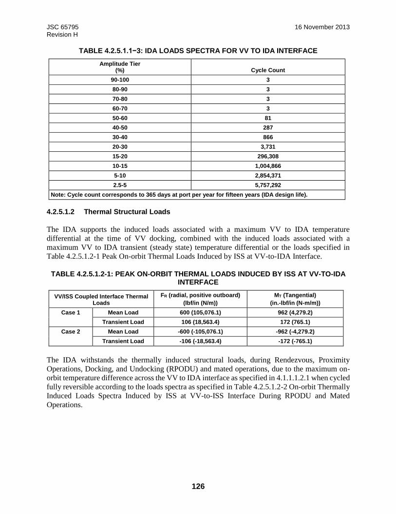
JSC 65795 16 November 2013 Revision H
126
TABLE 4.2.5.1.1−3: IDA LOADS SPECTRA FOR VV TO IDA INTERFACE
Amplitude Tier (%) Cycle Count
90-100 3
80-90 3
70-80 3
60-70 3
50-60 81
40-50 287
30-40 866
20-30 3,731
15-20 296,308
10-15 1,004,866
5-10 2,854,371
2.5-5 5,757,292
Note: Cycle count corresponds to 365 days at port per year for fifteen years (IDA design life).
4.2.5.1.2 Thermal Structural Loads
The IDA supports the induced loads associated with a maximum VV to IDA temperature
differential at the time of VV docking, combined with the induced loads associated with a
maximum VV to IDA transient (steady state) temperature differential or the loads specified in
Table 4.2.5.1.2-1 Peak On-orbit Thermal Loads Induced by ISS at VV-to-IDA Interface.
TABLE 4.2.5.1.2-1: PEAK ON-ORBIT THERMAL LOADS INDUCED BY ISS AT VV-TO-IDA INTERFACE
VV/ISS Coupled Interface Thermal Loads
FR (radial, positive outboard)
(lbf/in (N/m))
MT (Tangential)
(in.-lbf/in (N-m/m))
Case 1 Mean Load 600 (105,076.1) 962 (4,279.2)
Transient Load 106 (18,563.4) 172 (765.1)
Case 2 Mean Load -600 (-105,076.1) -962 (-4,279.2)
Transient Load -106 (-18,563.4) -172 (-765.1)
The IDA withstands the thermally induced structural loads, during Rendezvous, Proximity
Operations, Docking, and Undocking (RPODU) and mated operations, due to the maximum on-
orbit temperature difference across the VV to IDA interface as specified in 4.1.1.1.2.1 when cycled
fully reversible according to the loads spectra as specified in Table 4.2.5.1.2-2 On-orbit Thermally
Induced Loads Spectra Induced by ISS at VV-to-ISS Interface During RPODU and Mated
Operations.
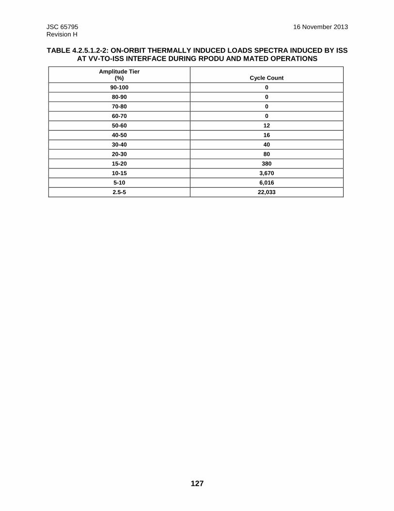
JSC 65795 16 November 2013 Revision H
127
TABLE 4.2.5.1.2-2: ON-ORBIT THERMALLY INDUCED LOADS SPECTRA INDUCED BY ISS AT VV-TO-ISS INTERFACE DURING RPODU AND MATED OPERATIONS
Amplitude Tier (%) Cycle Count
90-100 0
80-90 0
70-80 0
60-70 0
50-60 12
40-50 16
30-40 40
20-30 80
15-20 380
10-15 3,670
5-10 6,016
2.5-5 22,033
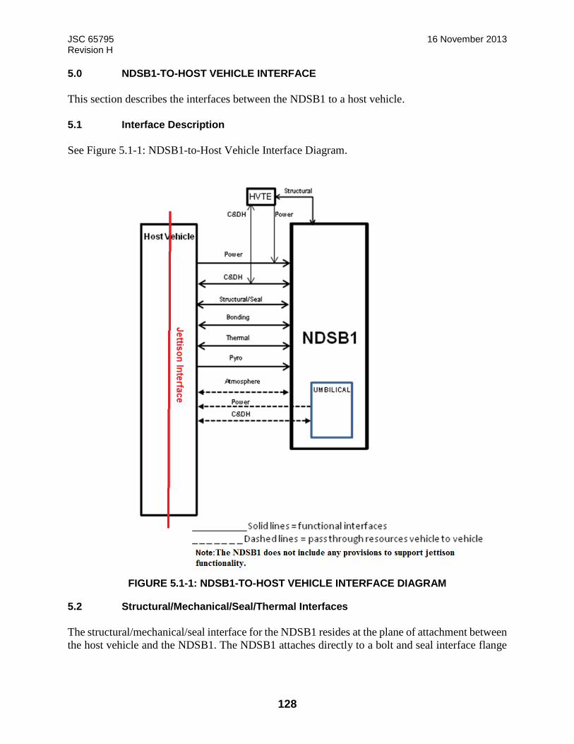
JSC 65795 16 November 2013 Revision H
128
5.0 NDSB1-TO-HOST VEHICLE INTERFACE
This section describes the interfaces between the NDSB1 to a host vehicle.
5.1 Interface Description
See Figure 5.1-1: NDSB1-to-Host Vehicle Interface Diagram.
FIGURE 5.1-1: NDSB1-TO-HOST VEHICLE INTERFACE DIAGRAM
5.2 Structural/Mechanical/Seal/Thermal Interfaces
The structural/mechanical/seal interface for the NDSB1 resides at the plane of attachment between
the host vehicle and the NDSB1. The NDSB1 attaches directly to a bolt and seal interface flange

JSC 65795 16 November 2013 Revision H
129
on the host vehicle. The NDSB1 attaches to the host vehicle with a circular arrangement of
fasteners.
5.2.1 Structural/Mechanical Interfaces
Refer to Figure 5.2.1-1: NDSB1-to-Host Vehicle Mounting Interface for an overview of the
NDSB1-to-host vehicle mounting interface.
View Looking at NDSB1 Mounting Flange from the Host Vehicle.
O-Ring Grooves Omitted for Clarity
(Page 1 of 8)
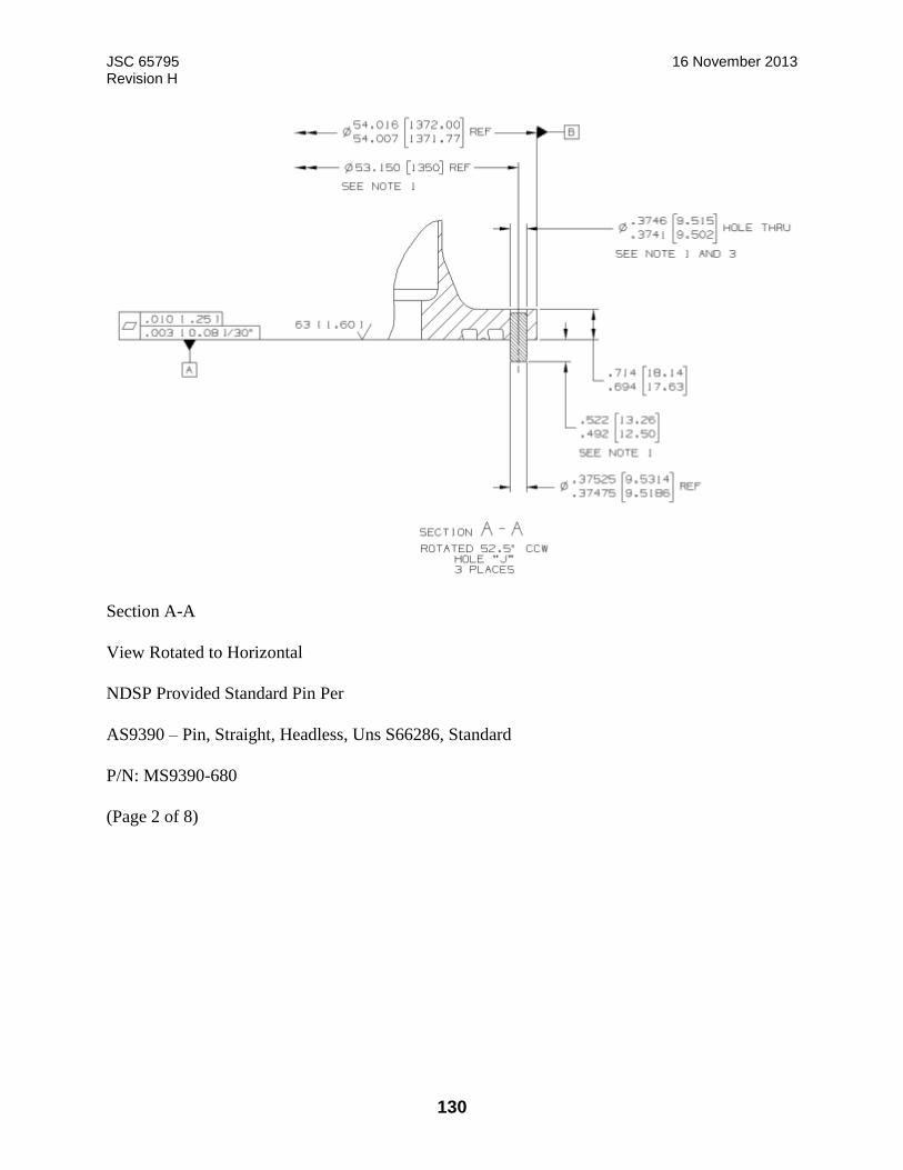
JSC 65795 16 November 2013 Revision H
130
Section A-A
View Rotated to Horizontal
NDSP Provided Standard Pin Per
AS9390 – Pin, Straight, Headless, Uns S66286, Standard
P/N: MS9390-680
(Page 2 of 8)

JSC 65795 16 November 2013 Revision H
131
Section B-B
Rotated 3.75º CCW
(Page 3 of 8)
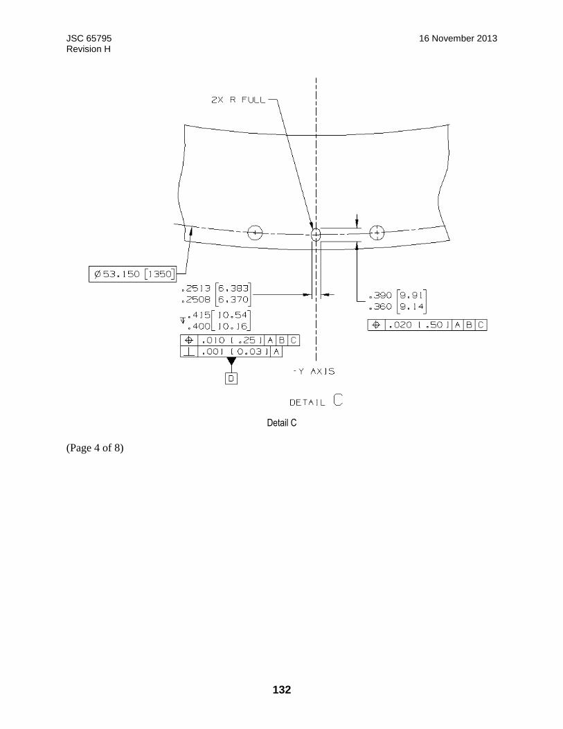
JSC 65795 16 November 2013 Revision H
132
Detail C
(Page 4 of 8)
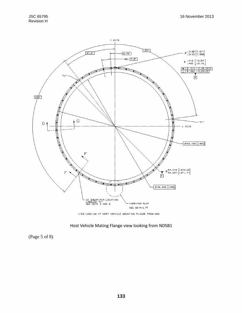
JSC 65795 16 November 2013 Revision H
133
Host Vehicle Mating Flange view looking from NDSB1
(Page 5 of 8)
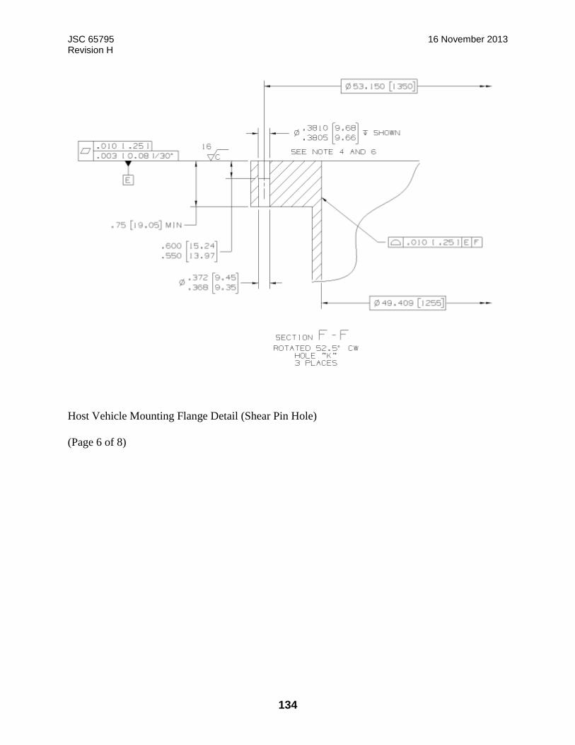
JSC 65795 16 November 2013 Revision H
134
Host Vehicle Mounting Flange Detail (Shear Pin Hole)
(Page 6 of 8)
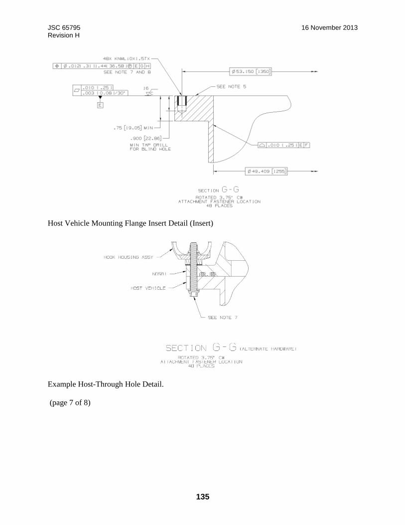
JSC 65795 16 November 2013 Revision H
135
Host Vehicle Mounting Flange Insert Detail (Insert)
Example Host-Through Hole Detail.
(page 7 of 8)

JSC 65795 16 November 2013 Revision H
136
Host Vehicle Mating Flange Attachment Tooling Slot Definition Detail H
(page 8 of 8) Notes:
1. Shear pin holes located using DRPSDZ29101974-5003 Drill Template. Hole specified in Section A-A IS for NDS flange only. Install MS9390-710 Pin in flange to dimensions shown. Wet install shear pin using approved zinc-chromate primer.
2. Chemical conversion coat datum surface in area indicated per MIL-DTL-5541, Type 1, Class 3. 3. Tooling design must control positional location within true position diameter of 0.020 [0.508] with respect
to Datums A, C and D. 4. Shear pin holes located using DRPSDZ29101974-5003 Drill Template. Hole specified in Section D-D is for
host vehicle flange only. Chemical conversion coat tool drilled hole per MIL-DTL-5541, Type 1, Class 3. 5. Chemical conversion coat entire datum surface per MIL-DTL-5541, Type 1, Class 3. 6. Tooling design must control positional location within true position diameter of 0.020 [0.508] with respect
to Datums E, G and H. 7. The NDS provides through holes and associated fasteners for host vehicle mounting. Host Vehicle
provides mating insert P/N KNML10 X 1.5TX KEENSERT (CAGE CODE: 29372). Blind installation shown; however, host vehicle may implement either through hole or bottom tap for KEENSERT installation as desired. Additionally, a through-bolt and nut mounting installation option is feasible, but requires additional certification prior to implementation. See Section G-G (alternate hardware).
8. Install insert per NA0145, except tap drill depth as indicated. Wet install insert using approved zinc-chromate primer.
FIGURE 5.2.1-1: NDSB1-TO-HOST VEHICLE MOUNTING INTERFACE

JSC 65795 16 November 2013 Revision H
137
5.2.1.1 Mechanical Mounting and Seal Interface
The NDSB1 will limit seal leakage at the NDSB1 to HV mounting interface to less than 0.0008
lbm dry air/day when the internal pressure is 14.7 psia and external pressure is a 7.5E-14 Torr
(1.0E-11 Pascal).
5.2.1.2 NDSB1 Installation and MMOD Shield Mounting Interfaces
The NDSB1 provides an exterior MMOD shield mounting interface defined in Figure 5.2.1.2-1:
NDSB1 Host-Provided MMOD Interface. The NDSB1 is installed on the host vehicle by metric
fasteners provided by NDSP. In order to maintain NDSB1 certification, the host must follow 683-
100000-0001, Docking Adapter Kit. The NDSB1 provides MMOD protection inside the HCS
tunnel, if required. Refer to Figure 5.2.1.2-2, HCS MMOD Protection.

JSC 65795 16 November 2013 Revision H
138
NOTE: Applicable for both Umbilical locations
Section Through Mounting Hole
MMOD Shield Interface on Tunnel HSC Mating Plane
(Page 1 of 2)
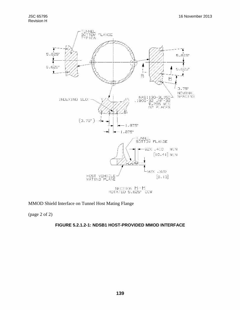
JSC 65795 16 November 2013 Revision H
139
MMOD Shield Interface on Tunnel Host Mating Flange
(page 2 of 2)
FIGURE 5.2.1.2-1: NDSB1 HOST-PROVIDED MMOD INTERFACE
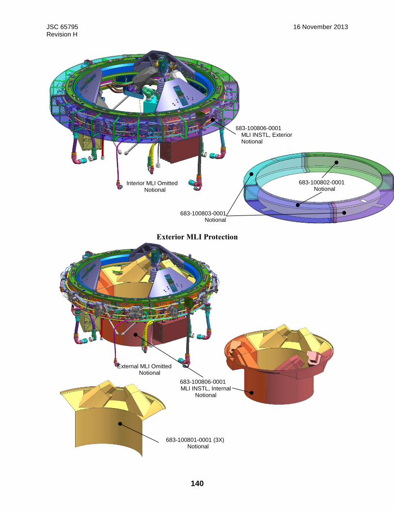
JSC 65795 16 November 2013 Revision H
140
Exterior MLI Protection
683-100806-0001 MLI INSTL, Exterior Notional
Interior MLI Omitted Notional
683-100803-0001 Notional
683-100802-0001 Notional
683-100806-0001 MLI INSTL, Internal
Notional
External MLI Omitted Notional
683-100801-0001 (3X) Notional

JSC 65795 16 November 2013 Revision H
141
Interior MLI/MMOD Protection FIGURE 5.2.1.2-2: HCS MMOD PROTECTION
5.2.1.3 SCS Mechanism Keep Out Zone (KOZ)
During soft capture, attenuation, and retraction, the SCS mechanism requires a clear operational
motion envelope. The SCS Mechanism KOZ is defined in Figure 3.8.1.3.2-1, Kinematic Envelope.
5.2.1.4 NDSB1 Vestibule Closeout Cover
The NDSB1 provides a closeout cover designed to close out the NDSB1 vestibule crew
passageway during docked operations. The cover protects the crew from exposure to sharp edges
in the SCS mechanism, as well as to protect the mechanism from Foreign Object Debris (FOD)
which could be floating in the passageway. The cover for NDSB1 is shown in Figure 5.1.4-1:
NDSB1 Vestibule Closeout Cover.
FIGURE 5.2.1.4-1: NDSB1 VESTIBULE CLOSEOUT COVER
5.2.1.5 NDSB1 Electrical Boxes
The NDSB1 Avionics subsystem conceptual design (See Figure 5.2.1.5-1, Avionics Architecture)
includes the following components: DSC and LAC.
683-100806-0001 MLI INSTL, Internal
Notional
External MLI Omitted Notional
683-100801-0001 (3X) Notional
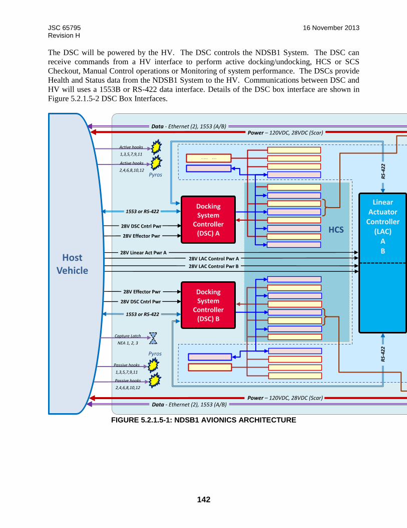
JSC 65795 16 November 2013 Revision H
142
The DSC will be powered by the HV. The DSC controls the NDSB1 System. The DSC can
receive commands from a HV interface to perform active docking/undocking, HCS or SCS
Checkout, Manual Control operations or Monitoring of system performance. The DSCs provide
Health and Status data from the NDSB1 System to the HV. Communications between DSC and
HV will uses a 1553B or RS-422 data interface. Details of the DSC box interface are shown in
Figure 5.2.1.5-2 DSC Box Interfaces.
FIGURE 5.2.1.5-1: NDSB1 AVIONICS ARCHITECTURE
Linear Actuator
Controller (LAC)
A
B
R
S-4
22
28V Linear Act Pwr A 28V LAC Control Pwr A 28V LAC Control Pwr B
1553 or RS-422
28V DSC Cntrl Pwr
28V DSC Cntrl Pwr
28V Effector Pwr
28V Effector Pwr
Docking System
Controller (DSC) A
Heaters (3)
RTDs (3)
Umbilical Position (4) Launch Restraint (3) Launch Rstnt Position (6)
Capture Latch (3) Capture Ltch Position (6) Capture Sensor (6) RTH (3) and Undock (2)
Hook Motor (2) Hook Position (12) Umbilical Motor (2)
Separator Motor (3) Separator Position (6)
Heaters (3)
RTDs (3)
Umbilical Position (4) Launch Restraint (3) Launch Rstnt Position (6)
Capture Latch (3) Capture Ltch Position (6) Capture Sensors (6) RTH (3) and Undock (2)
Hook Motor (2) Hook Position (12) Umbilical Motor (2)
Separator Motor (3) Separator Position (6)
Data - Ethernet (2), 1553 (A/B) Power – 120VDC, 28VDC (Scar)
Data - Ethernet (2), 1553 (A/B) Power – 120VDC, 28VDC (Scar)
Pyros
Active hooks 1,3,5,7,9,11 Active hooks 2,4,6,8,10,12
Pyros
Passive hooks 1,3,5,7,9,11 Passive hooks 2,4,6,8,10,12
Host
Vehicle
1553 or RS-422
R
S-4
22
Docking System
Controller (DSC) B
HCS
Capture Latch NEA 1, 2, 3
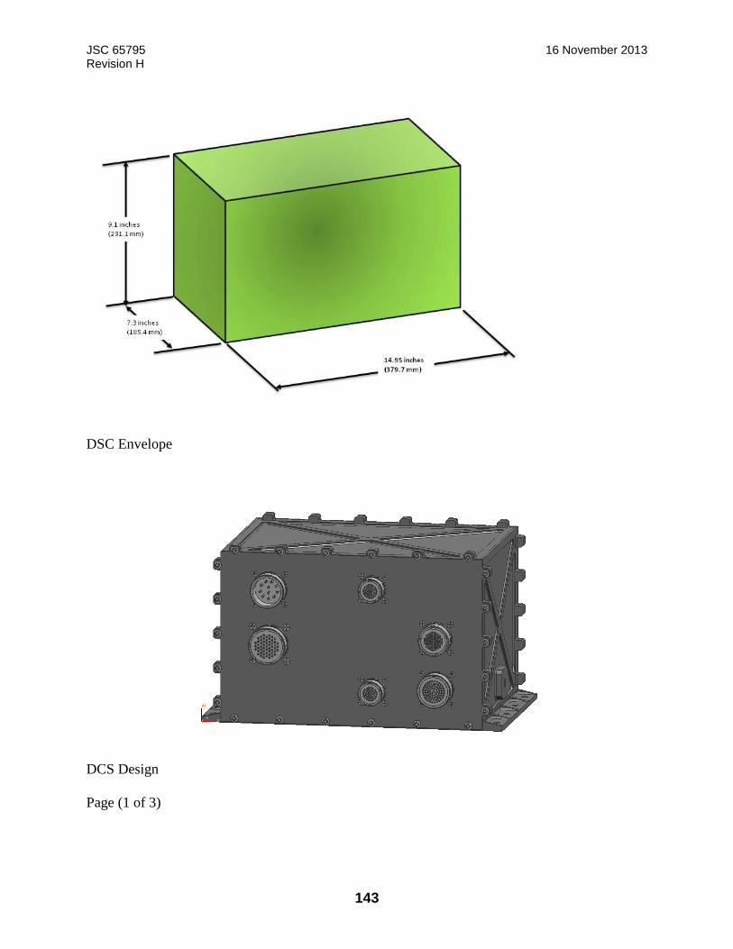
JSC 65795 16 November 2013 Revision H
143
DSC Envelope
DCS Design
Page (1 of 3)

JSC 65795 16 November 2013 Revision H
144
Page (2 of 3)

JSC 65795 16 November 2013 Revision H
145
DSC Mounting Hole Locations
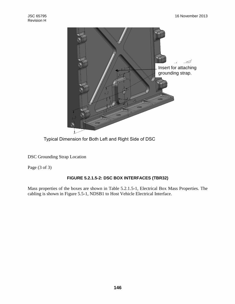
JSC 65795 16 November 2013 Revision H
146
DSC Grounding Strap Location
Page (3 of 3)
FIGURE 5.2.1.5-2: DSC BOX INTERFACES (TBR32)
Mass properties of the boxes are shown in Table 5.2.1.5-1, Electrical Box Mass Properties. The
cabling is shown in Figure 5.5-1, NDSB1 to Host Vehicle Electrical Interface.
Typical Dimension for Both Left and Right Side of DSC
Insert for attaching grounding strap.
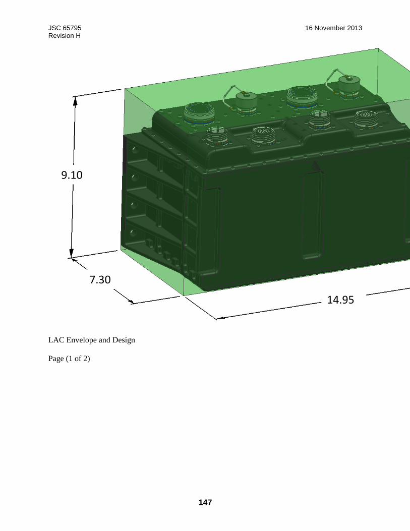
JSC 65795 16 November 2013 Revision H
147
LAC Envelope and Design
Page (1 of 2)
9.10
7.30
14.95
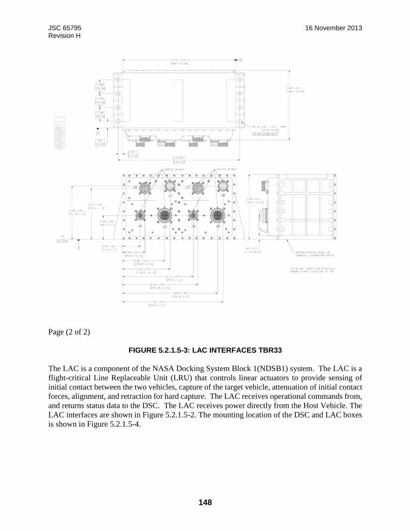
JSC 65795 16 November 2013 Revision H
148
Page (2 of 2)
FIGURE 5.2.1.5-3: LAC INTERFACES TBR33
The LAC is a component of the NASA Docking System Block 1(NDSB1) system. The LAC is a
flight-critical Line Replaceable Unit (LRU) that controls linear actuators to provide sensing of
initial contact between the two vehicles, capture of the target vehicle, attenuation of initial contact
forces, alignment, and retraction for hard capture. The LAC receives operational commands from,
and returns status data to the DSC. The LAC receives power directly from the Host Vehicle. The
LAC interfaces are shown in Figure 5.2.1.5-2. The mounting location of the DSC and LAC boxes
is shown in Figure 5.2.1.5-4.
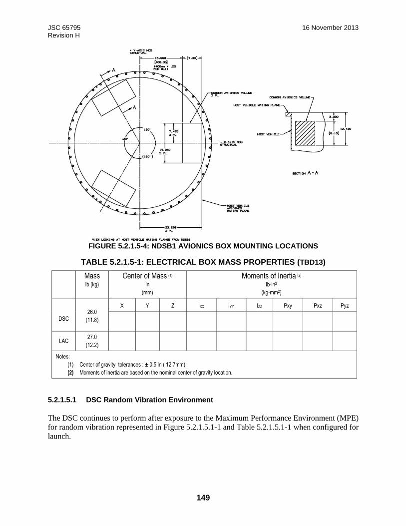
JSC 65795 16 November 2013 Revision H
149
FIGURE 5.2.1.5-4: NDSB1 AVIONICS BOX MOUNTING LOCATIONS
TABLE 5.2.1.5-1: ELECTRICAL BOX MASS PROPERTIES (TBD13)
Mass lb (kg)
Center of Mass (1)
In
(mm)
Moments of Inertia (2)
lb-in2
(kg-mm2)
DSC
26.0
(11.8)
X Y Z IXX IYY IZZ Pxy Pxz Pyz
LAC 27.0
(12.2)
Notes:
(1) Center of gravity tolerances : ± 0.5 in ( 12.7mm)
(2) Moments of inertia are based on the nominal center of gravity location.
5.2.1.5.1 DSC Random Vibration Environment
The DSC continues to perform after exposure to the Maximum Performance Environment (MPE)
for random vibration represented in Figure 5.2.1.5.1-1 and Table 5.2.1.5.1-1 when configured for
launch.
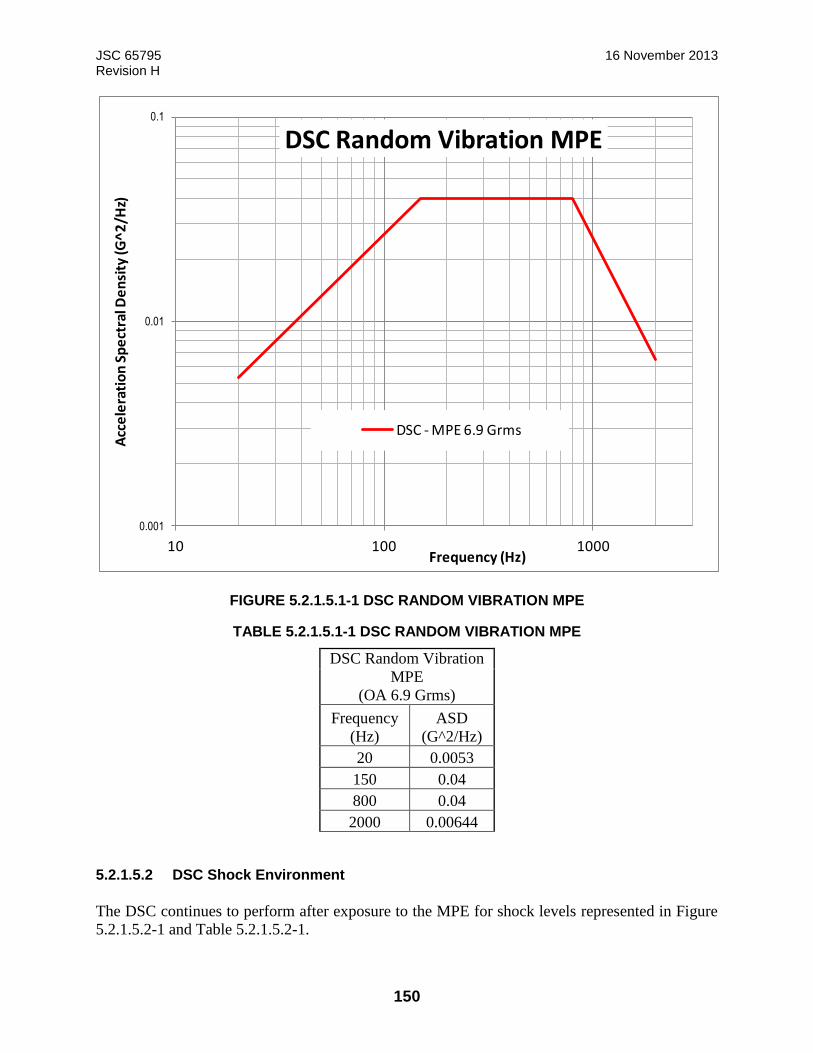
JSC 65795 16 November 2013 Revision H
150
FIGURE 5.2.1.5.1-1 DSC RANDOM VIBRATION MPE
TABLE 5.2.1.5.1-1 DSC RANDOM VIBRATION MPE
DSC Random Vibration
MPE
(OA 6.9 Grms)
Frequency
(Hz)
ASD
(G^2/Hz)
20 0.0053
150 0.04
800 0.04
2000 0.00644
5.2.1.5.2 DSC Shock Environment
The DSC continues to perform after exposure to the MPE for shock levels represented in Figure
5.2.1.5.2-1 and Table 5.2.1.5.2-1.
0.001
0.01
0.1
10 100 1000
Acc
ele
rati
on
Sp
ect
ral D
en
sity
(G^
2/H
z)
Frequency (Hz)
DSC Random Vibration MPE
DSC - MPE 6.9 Grms
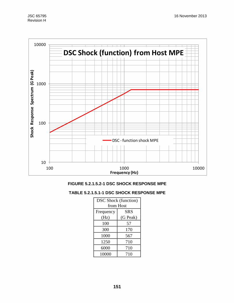
JSC 65795 16 November 2013 Revision H
151
FIGURE 5.2.1.5.2-1 DSC SHOCK RESPONSE MPE
TABLE 5.2.1.5.1-1 DSC SHOCK RESPONSE MPE
DSC Shock (function)
from Host
Frequency SRS
(Hz) (G Peak)
100 57
300 170
1000 567
1250 710
6000 710
10000 710
10
100
1000
10000
100 1000 10000
Sho
ck R
esp
on
se S
pe
ctru
m (
G P
eak
)
Frequency (Hz)
DSC Shock (function) from Host MPE
DSC - function shock MPE
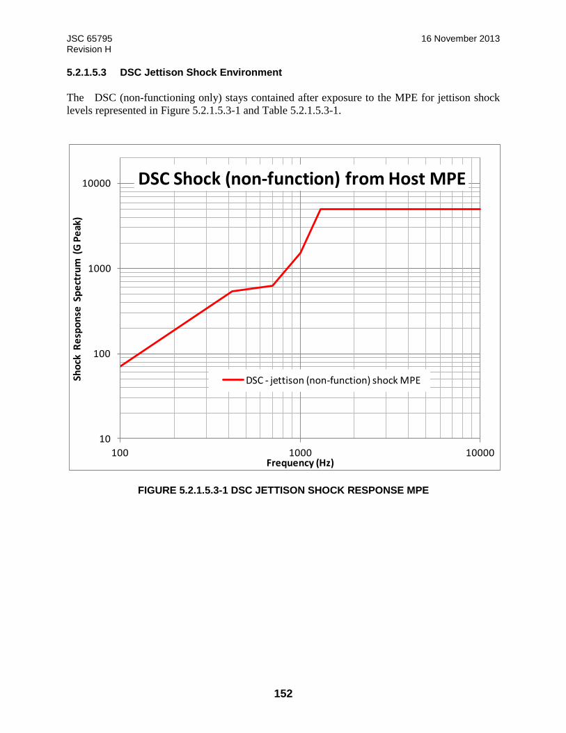
JSC 65795 16 November 2013 Revision H
152
5.2.1.5.3 DSC Jettison Shock Environment
The DSC (non-functioning only) stays contained after exposure to the MPE for jettison shock
levels represented in Figure 5.2.1.5.3-1 and Table 5.2.1.5.3-1.
FIGURE 5.2.1.5.3-1 DSC JETTISON SHOCK RESPONSE MPE
10
100
1000
10000
100 1000 10000
Sho
ck R
esp
on
se S
pe
ctru
m (
G P
eak
)
Frequency (Hz)
DSC Shock (non-function) from Host MPE
DSC - jettison (non-function) shock MPE
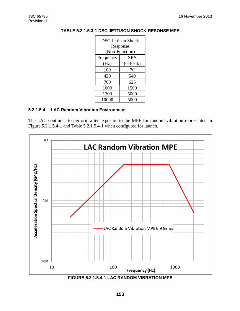
JSC 65795 16 November 2013 Revision H
153
TABLE 5.2.1.5.3-1 DSC JETTISON SHOCK RESONSE MPE
DSC Jettison Shock
Response
(Non-Function)
Frequency SRS
(Hz) (G Peak)
100 70
420 540
700 625
1000 1500
1300 5000
10000 5000
5.2.1.5.4 LAC Random Vibration Environment
The LAC continues to perform after exposure to the MPE for random vibration represented in
Figure 5.2.1.5.4-1 and Table 5.2.1.5.4-1 when configured for launch.
FIGURE 5.2.1.5.4-1 LAC RANDOM VIBRATION MPE
0.001
0.01
0.1
10 100 1000
Acc
ele
rati
on
Sp
ect
ral D
en
sity
(G^
2/H
z)
Frequency (Hz)
LAC Random Vibration MPE
LAC Random Vibration MPE 6.9 Grms

JSC 65795 16 November 2013 Revision H
154
TABLE 5.2.1.5.4-1 LAC RANDOM VIBRATION MPE
LAC Random
Vibration MPE
(OA 6.9 Grms)
Frequency
(Hz)
ASD
(G^2/Hz)
20 0.0053
150 0.04
800 0.04
2000 0.00644
OA 6.9 Grms
5.2.1.5.5 LAC Shock Environment
The LAC continues to perform after exposure to the MPE for shock levels represented in Figure
5.2.1.5.5-1 and Table 5.2.1.5.5-1.
FIGURE 5.2.1.5.5-1 LAC SHOCK REPONSE MPE
10
100
1000
10000
100 1000 10000
Sho
ck R
esp
on
se S
pe
ctru
m (
G P
eak
)
Frequency (Hz)
LAC Shock (function) from Host MPE
LAC - function shock MPE
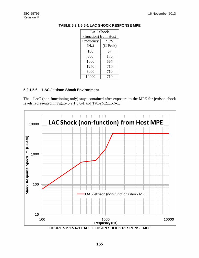
JSC 65795 16 November 2013 Revision H
155
TABLE 5.2.1.5.5-1 LAC SHOCK RESPONSE MPE
LAC Shock
(function) from Host
Frequency
(Hz)
SRS
(G Peak)
100 57
300 170
1000 567
1250 710
6000 710
10000 710
5.2.1.5.6 LAC Jettison Shock Environment
The LAC (non-functioning only) stays contained after exposure to the MPE for jettison shock
levels represented in Figure 5.2.1.5.6-1 and Table 5.2.1.5.6-1.
FIGURE 5.2.1.5.6-1 LAC JETTISON SHOCK RESPONSE MPE
10
100
1000
10000
100 1000 10000
Sho
ck R
esp
on
se S
pe
ctru
m (
G P
eak
)
Frequency (Hz)
LAC Shock (non-function) from Host MPE
LAC - jettison (non-function) shock MPE
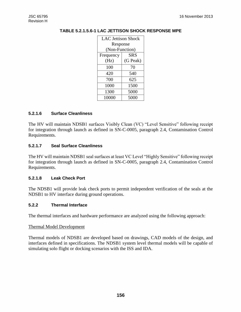
JSC 65795 16 November 2013 Revision H
156
TABLE 5.2.1.5.6-1 LAC JETTISON SHOCK RESPONSE MPE
LAC Jettison Shock
Response
(Non-Function)
Frequency
(Hz)
SRS
(G Peak)
100 70
420 540
700 625
1000 1500
1300 5000
10000 5000
5.2.1.6 Surface Cleanliness
The HV will maintain NDSB1 surfaces Visibly Clean (VC) “Level Sensitive” following receipt
for integration through launch as defined in SN-C-0005, paragraph 2.4, Contamination Control
Requirements.
5.2.1.7 Seal Surface Cleanliness
The HV will maintain NDSB1 seal surfaces at least VC Level “Highly Sensitive” following receipt
for integration through launch as defined in SN-C-0005, paragraph 2.4, Contamination Control
Requirements.
5.2.1.8 Leak Check Port
The NDSB1 will provide leak check ports to permit independent verification of the seals at the
NDSB1 to HV interface during ground operations.
5.2.2 Thermal Interface
The thermal interfaces and hardware performance are analyzed using the following approach:
Thermal Model Development
Thermal models of NDSB1 are developed based on drawings, CAD models of the design, and
interfaces defined in specifications. The NDSB1 system level thermal models will be capable of
simulating solo flight or docking scenarios with the ISS and IDA.
JSC 65795 16 November 2013 Revision H
157
Host Vehicle Conduction
The NDSB1 utilizes heaters and heat transfer with the host vehicle to condition/maintain
temperatures within limits for each operating model. The NDSB1 thermal model assumes heat
transfer by conduction across the structural interface with the host vehicle. The NDSB1 will limit
heat transfer across the interface. The host vehicle will provide the required boundary temperatures
based on the heat transfer.
Host Vehicle Radiation
A disc representing the NDSB1 view to host vehicle is included in the NDSB1 system level thermal
model to represent radiation to the host vehicle. The disc representing the host vehicle will have
a radius 1.43 times larger than the NDSB1. The disc is modeled with arithmetic nodes and optical
properties of α = 0.3 and e = 0.9. This disc will be flush with the NDSB1 base/vehicle interface
point.
Host Vehicle MMOD/External Hardware Thermal Interface
NDSB1 system level thermal analysis will be performed with the NDSB1 external MLI exposed
and no additional heat leak applied at the external flange interfaces.
Environment and Attitudes
The NDSB1 system level thermal model simulates the LEO environments and attitudes to predict
temperature ranges for comparison to hardware limits. Table 5.2.2-1 shows the LEO
environmental parameters for thermal: Solar flux, albedo, and Earth Outgoing Long-wave
Radiation (OLR) environments. Table 5.2.2-2 gives the flight attitudes used for design. Figure
5.2.2-1 shows the NDSB1 coordinate system and the LVLH coordinate system for docking to the
ISS.
Unmated solar inertial attitudes with the NDSB1 facing the sun are known to cause violations of
operational and survival limits. These attitudes will be assessed for capability only. Time
constraints to protect the NDSB1 will be documented in EID684-15524, NDSB1 Thermal Analysis
Report.
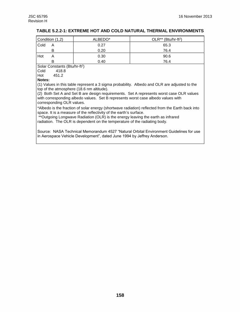
JSC 65795 16 November 2013 Revision H
158
TABLE 5.2.2-1: EXTREME HOT AND COLD NATURAL THERMAL ENVIRONMENTS
Condition (1,2) ALBEDO* OLR** (Btu/hr-ft2)
Cold A 0.27 65.3 B 0.20 76.4
Hot A 0.30 90.6 B 0.40 76.4 Solar Constants (Btu/hr-ft2) Cold 418.8 Hot 451.2 Notes: (1) Values in this table represent a 3 sigma probability. Albedo and OLR are adjusted to the top of the atmosphere (18.6 nm altitude). (2) Both Set A and Set B are design requirements. Set A represents worst case OLR values with corresponding albedo values. Set B represents worst case albedo values with corresponding OLR values.
*Albedo is the fraction of solar energy (shortwave radiation) reflected from the Earth back into space. It is a measure of the reflectivity of the earth’s surface. **Outgoing Longwave Radiation (OLR) is the energy leaving the earth as infrared radiation. The OLR is dependent on the temperature of the radiating body.
Source: NASA Technical Memorandum 4527 “Natural Orbital Environment Guidelines for use in Aerospace Vehicle Development”, dated June 1994 by Jeffrey Anderson.
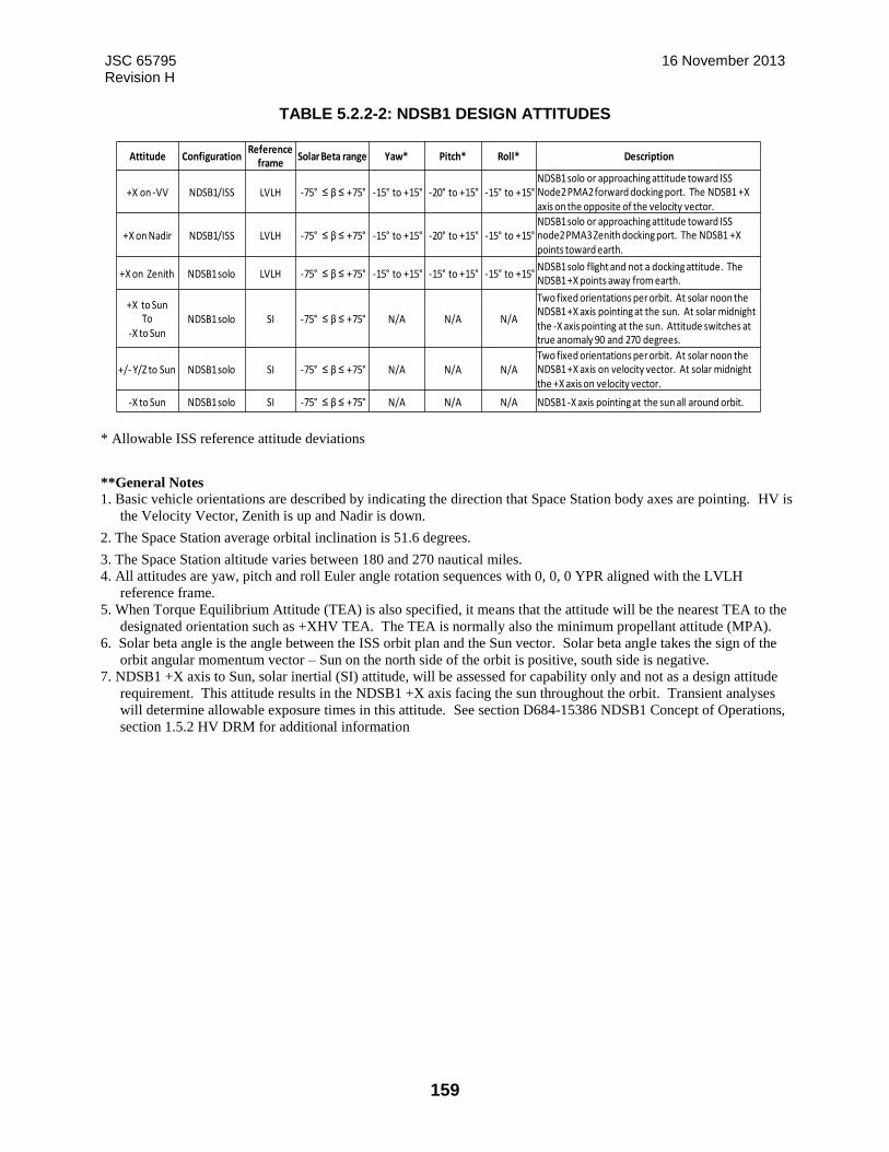
JSC 65795 16 November 2013 Revision H
159
TABLE 5.2.2-2: NDSB1 DESIGN ATTITUDES
* Allowable ISS reference attitude deviations
**General Notes 1. Basic vehicle orientations are described by indicating the direction that Space Station body axes are pointing. HV is
the Velocity Vector, Zenith is up and Nadir is down.
2. The Space Station average orbital inclination is 51.6 degrees.
3. The Space Station altitude varies between 180 and 270 nautical miles. 4. All attitudes are yaw, pitch and roll Euler angle rotation sequences with 0, 0, 0 YPR aligned with the LVLH
reference frame. 5. When Torque Equilibrium Attitude (TEA) is also specified, it means that the attitude will be the nearest TEA to the
designated orientation such as +XHV TEA. The TEA is normally also the minimum propellant attitude (MPA). 6. Solar beta angle is the angle between the ISS orbit plan and the Sun vector. Solar beta angle takes the sign of the
orbit angular momentum vector – Sun on the north side of the orbit is positive, south side is negative.
7. NDSB1 +X axis to Sun, solar inertial (SI) attitude, will be assessed for capability only and not as a design attitude
requirement. This attitude results in the NDSB1 +X axis facing the sun throughout the orbit. Transient analyses
will determine allowable exposure times in this attitude. See section D684-15386 NDSB1 Concept of Operations,
section 1.5.2 HV DRM for additional information
Attitude ConfigurationReference
frameSolar Beta range Yaw* Pitch* Roll* Description
+X on -VV NDSB1/ISS LVLH -75° ≤ β ≤ +75° -15° to +15° -20° to +15° -15° to +15°NDSB1 solo or approaching attitude toward ISS Node2 PMA2 forward docking port. The NDSB1 +X axis on the opposite of the velocity vector.
+X on Nadir NDSB1/ISS LVLH -75° ≤ β ≤ +75° -15° to +15° -20° to +15° -15° to +15°NDSB1 solo or approaching attitude toward ISS node2 PMA3 Zenith docking port. The NDSB1 +X points toward earth.
+X on Zenith NDSB1 solo LVLH -75° ≤ β ≤ +75° -15° to +15° -15° to +15° -15° to +15°NDSB1 solo flight and not a docking attitude. The NDSB1 +X points away from earth.
+X to SunTo
-X to SunNDSB1 solo SI -75° ≤ β ≤ +75° N/A N/A N/A
Two fixed orientations per orbit. At solar noon the NDSB1 +X axis pointing at the sun. At solar midnight the -X axis pointing at the sun. Attitude switches at true anomaly 90 and 270 degrees.
+/- Y/Z to Sun NDSB1 solo SI -75° ≤ β ≤ +75° N/A N/A N/ATwo fixed orientations per orbit. At solar noon the NDSB1 +X axis on velocity vector. At solar midnight the +X axis on velocity vector.
-X to Sun NDSB1 solo SI -75° ≤ β ≤ +75° N/A N/A N/A NDSB1 -X axis pointing at the sun all around orbit.
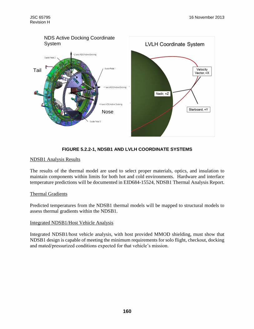
JSC 65795 16 November 2013 Revision H
160
FIGURE 5.2.2-1, NDSB1 AND LVLH COORDINATE SYSTEMS
NDSB1 Analysis Results
The results of the thermal model are used to select proper materials, optics, and insulation to
maintain components within limits for both hot and cold environments. Hardware and interface
temperature predictions will be documented in EID684-15524, NDSB1 Thermal Analysis Report.
Thermal Gradients
Predicted temperatures from the NDSB1 thermal models will be mapped to structural models to
assess thermal gradients within the NDSB1.
Integrated NDSB1/Host Vehicle Analysis
Integrated NDSB1/host vehicle analysis, with host provided MMOD shielding, must show that
NDSB1 design is capable of meeting the minimum requirements for solo flight, checkout, docking
and mated/pressurized conditions expected for that vehicle’s mission.
NDS Active Docking Coordinate System
Tail
Nose

JSC 65795 16 November 2013 Revision H
161
NDSB1-to-IDA Thermal Conductance
For steady state mated configurations, the NDSB1-to-IDA docking interface is assumed to be
adiabatic. For evaluation of transient response in mated configurations, the integrated models
should use the appropriate conductance to be conservative from that thermal evaluation’s
perspective. The thermal conductance across the NDSB1-to-IDA HCS docking interface is defined
as ranging from 75 Btu/hr-°F (40 W/°K) to 187 Btu/hr-°F (98 W/°K).
5.2.2.1 NDSB1-to-Host Vehicle
The NDSB1 utilizes heaters and conduction to the HV to maintain temperatures within the
temperature limits for each operating mode. .
The allowable NDSB1-to-host vehicle interface temperature ranges, the heat transfer rate for each
operating condition, the thermal conductance across the interface flange, the electrical box heat
dissipation, and the HV MMOD thermal interface are defined in the following subsections.
5.2.2.1.1 Non-Operational Survival
Non-operational survival conditions apply to NDSB1 to host vehicle structural interfaces during
solo flight.
5.2.2.1.1.1 Structural
The following applies when the docking system is unmated and the system is not in checkout or
docking mode. Heaters may be required depending on mission profile.
NDSB1 to HV Heat Transfer
Maximum heat loss from HV-to-NDSB1: 360 W
Maximum heat gain to HV from NDSB1: 370 W
The NDSB1 will be designed to limit the orbital average heat transfer across the NDSB1-to-HV
structural interface.
HV-to-NDSB1 Interface temperatures
60°F (-15.6°C) to 103°F (+39.4°C)
The HV controls the temperature of the structural interface between the HV and the NDSB1 to
this range during Host Vehicle Solo Flight.
5.2.2.1.1.2 NDSB1 Electrical boxes
The following applies when the docking system is unmated and the system is not in checkout or
docking mode.

JSC 65795 16 November 2013 Revision H
162
Unpowered
The non-operational temperature range for the NDSB1 electrical boxes is:
-11 °F to +142 °F (-24 °C to +61 °C)
The HV thermal design should maintain the temperature of the electrical boxes (Docking System
Controller and Linear Actuator Controller) within this range prior to activation of the system.
Powered
The operational temperature range for the NDSB1 electrical boxes is:
-11 °F to +142 °F (-24 °C to +61 °C)
Figure 5.2.1.5-1 shows the mounting interface for the DSC. Figure 5.2.1.5-2 shows the mounting
interface for the LAC.
The HV is responsible for the design of the mounting provisions for the electrical boxes. The
thermal design of the host vehicle mounting must provide the combination of conduction and
mounting interface temperatures necessary to maintain DSC and LAC baseplate temperatures
within limits during powered operations. Integrated host vehicle analysis must be performed to
assess this interface. The mounting interface temperature during operation will vary depending on
box power dissipation and environment parameters. To minimize the temperature difference
between the box and the mounting surface, the HV design should provide a thermal contact
conductance greater than 25 Btu/hr-ft2-°F (142 W/m2-°K) across the full area of the box baseplate.
A higher contact conductance may be required depending on the vehicle design and temperature
conditions. A thermal conductive elastomer or gap filler will be needed between the mounting
surface and the box baseplate if the components are mounted in the unpressurized environment.
The thermal optical properties of the electrical boxes analysis are required for HV thermal analysis.
The LAC and DSC have an emissivity greater than 0.75 and a solar absorptivity-to-emissivity ratio
less than 1.2 on non-baseplate surfaces.
Section 5.2.2.1.6 provides the component heat dissipation for different phases of operation. The
LAC contains a set of redundant cards and will dissipate heat on one half of the baseplate contact
area during operation. Note: If electrical boxes are remotely mounted inside the host vehicle, they
may reach temperatures during operation that exceed the bare handed touch temperature limit of
+113 °F (45 °C). If integrated host vehicle analysis indicates this condition can occur, the host
may need to apply warning labels or guards.
5.2.2.1.1.3 Deleted
5.2.2.1.1.4 NDSB1 Component Level Non-Operating Temperature Limits
Non-operating temperature limits for individual NDSB1 components are shown in Table
5.2.2.1.1.4-1.

JSC 65795 16 November 2013 Revision H
163
TABLE 5.2.2.1.1.4-1 NON-OPERATING TEMPERATURE LIMITS FOR NDSB1 COMPONENTS

JSC 65795 16 November 2013 Revision H
164
Assembly Component SCD/ED doc. Non-Operating Temperature
Limits (°F)
Lower Upper
Tunnel Tunnel D683-93052-85 -65 192
Pyro Pyrobolt ED684-016650-C -100 225
ETL ED684-016643-D -100 225
Seals Dynamic Seals JSC-64595C -65 192
Static Seals JSC-65978 -65 192
Hook Assembly Structure S684-14475 -65 192
Hooks S684-14475 -100 225
Hook Drive System Flex Shafts SSW FABOE25AZ
-85 212
Gear heads SLZ29101646 -65 192
EMA SLZ29101646 -65 192
Separation System Structure ED684-018764 -65 192
Plunger ED684-018764 -65 192
EMA ED684-018764 -65 192
Limit Switches ED684-016231 -85 500
Umbilical Assembly Connector SSQ 22680-J -135 372
Structure ED684-018763 -65 192
EMA ED684-018763 -65 192
Limit Switches ED684-016231 -85 500
Ready to Hook Sensor
Structure D683-93052-85 -65 192
Limit Switches ED684-016231 -85 500
Lockdown Assembly
Structure D683-93052-85 -65 192
Motor/Solenoid TBD TBD TBD
Limit Switches ED684-016231 -85 500
Guide Ring Ring D683-93052-85 -65 192
Guide Petals Petals D683-93052-85 -65 192
Capture Latch
Assembly
Structure D683-93052-85 -65 192
Motor/Solenoid TBD TBD TBD
Limit Switches ED684-016231 -85 500
Soft Capture
Sensor
Structure IDA CDR -65 204
Limit Switches ED684-016231 -85 500
Linear Actuators Housing ED683-101103-A -65 160
Motor ED683-101103-A -65 160
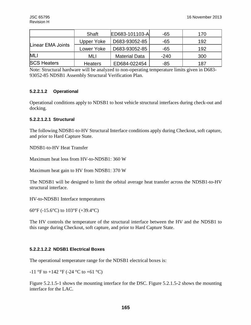
JSC 65795 16 November 2013 Revision H
165
Shaft ED683-101103-A -65 170
Linear EMA Joints Upper Yoke D683-93052-85 -65 192
Lower Yoke D683-93052-85 -65 192
MLI MLI Material Data -240 300
SCS Heaters Heaters ED684-022454 -85 187
Note: Structural hardware will be analyzed to non-operating temperature limits given in D683-
93052-85 NDSB1 Assembly Structural Verification Plan.
5.2.2.1.2 Operational
Operational conditions apply to NDSB1 to host vehicle structural interfaces during check-out and
docking.
5.2.2.1.2.1 Structural
The following NDSB1-to-HV Structural Interface conditions apply during Checkout, soft capture,
and prior to Hard Capture State.
NDSB1-to-HV Heat Transfer
Maximum heat loss from HV-to-NDSB1: 360 W
Maximum heat gain to HV from NDSB1: 370 W
The NDSB1 will be designed to limit the orbital average heat transfer across the NDSB1-to-HV
structural interface.
HV-to-NDSB1 Interface temperatures
60°F (-15.6°C) to 103°F (+39.4°C)
The HV controls the temperature of the structural interface between the HV and the NDSB1 to
this range during Checkout, soft capture, and prior to Hard Capture State.
5.2.2.1.2.2 NDSB1 Electrical Boxes
The operational temperature range for the NDSB1 electrical boxes is:
-11 °F to +142 °F (-24 °C to +61 °C)
Figure 5.2.1.5-1 shows the mounting interface for the DSC. Figure 5.2.1.5-2 shows the mounting
interface for the LAC.
JSC 65795 16 November 2013 Revision H
166
The HV is responsible for the design of the mounting provisions for the electrical boxes. The
thermal design of the host vehicle mounting must provide the combination of conduction and
mounting interface temperatures necessary to maintain DSC and LAC baseplate temperatures
within limits during powered operations. Integrated host vehicle analysis must be performed to
assess this interface. The mounting interface temperature during operation will vary depending on
box power dissipation and environment parameters. To minimize the temperature difference
between the box and the mounting surface, the HV design should provide a thermal contact
conductance greater than 25 Btu/hr-ft2-°F (142 W/m2-°K) across the full area of the box baseplate.
A higher contact conductance may be required depending on the vehicle design and temperature
conditions. A thermal conductive elastomer or gap filler may be needed between the mounting
surface and the box baseplate if the components are mounted in the unpressurized environment.
The thermal optical properties of the electrical boxes analysis are required for HV thermal analysis.
The LAC and DSC have an emissivity greater than 0.75 and a solar absorptivity-to-emissivity ratio
less than 1.2 on non-baseplate surfaces.
Section 5.2.2.1.6 provides the component heat dissipation for different phases of operation. The
LAC contains a set of redundant cards and will dissipate heat on one half of the baseplate contact
area during operation. Note: If electrical boxes are remotely mounted inside the host vehicle, they
may reach temperatures during operation that exceed the bare handed touch temperature limit of
+113 °F (45 °C). If integrated host vehicle analysis indicates this condition can occur, the host
may need to apply warning labels or guards.
5.2.2.1.3 Mated and Pressurized
This subsection defines steady-state mated and pressurized limits for the NDSB1 after hard mate
and pressurization.
5.2.2.1.3.1 Mated and Pressurized Steady-State Temperature Range
The following applies during mated pressurized operation:
NDSB1-to-HV Heat Transfer
Maximum heat loss from HV to NDSB1: 100 W when the HV side of the structural interface is at
+65°F (+18.3°C)
Maximum heat gain to HV from NDSB1: No heat gain at maximum temperature
The NDSB1 is unheated during mated pressurized operations. The design will limit heat loss from
the HV when exposed to cold case conditions
HV-to-NDSB1 Interface temperatures
+65°F (+18.3°C) to +113°F (+45°C)
JSC 65795 16 November 2013 Revision H
167
The HV control the temperature at the structural interface between the HV and the NDSB1 during
mated operations.
NDSB1 Internal Volume
60°F (15.6°C) and 113°F (+45°C)
Temperatures within this range are above the maximum dew point requirement and below the
maximum IVA touch temperature.
5.2.2.1.3.2 Mated and Pressurized Steady-State Time Period
Hardware temperatures at the time of docking may be below the dew point and minimum IVA
touch temperature for cold cases environments and attitudes, or above the maximum IVA touch
temperature for hot case environments and attitudes. The NDSB1 temperature conditions will
approach the steady state temperatures described in Paragraph 5.2.2.1.3.1 as a function of time.
The time-to-limit for worst case hot and cold case conditions will be assessed and documented in
EID684-15524, NDSB1 Thermal Analysis Report.
Pressurization or hatch opening is not restricted by the transient temperature profile. (Refer to
Nonconformance Compliance Report NCR-ISS-iLIDS-002 allowing early hatch opening.)
However, if hatch opening is required prior to the system achieving safe touch temperatures, the
crew may be required to use PPE. If the temperature of the vestibule is not above the dew point,
condensation will occur within the vestibule during this transition period.
5.2.2.1.4 Mated and Unpressurized
For scenarios in which the NDSB1 is hard mated and the vestibule remains unpressurized, the
steady state temperatures and heat transfer will be similar to mated pressurized conditions.
However, the touch temperature and condensation limits are not in effect, so the transient
temperature response is not an issue.
The following applies during mated unpressurized operation:
NDSB1-to-HV Heat Transfer
Maximum heat loss from HV to NDSB1: 100 W when the HV side of the structural interface is at
+65°F (+18.3°C)
Maximum heat gain to HV from NDSB1: No heat gain at maximum temperature
The NDSB1 is unheated during mated pressurized operations. The design will limit heat loss from
the HV for the mated configuration.
HV-to-NDSB1 Interface temperatures

JSC 65795 16 November 2013 Revision H
168
+65°F (+18.3°C) to +113°F (+45°C)
The HV provides control of the temperature of the structural interface between the HV and the
NDSB1 during mated operations.
NDSB1 Internal Volume
60°F (15.6°C) and 113°F (+45°C)
The NDSB1 design does not rely on convection to maintain thermal conditioning for steady-state
mated conditions. The NDSB1 design will be able to maintain the temperatures within the same
range for both pressurized and unpressurized conditions.
5.2.2.1.5 Thermal Conductance
The HV design is responsible for the providing the thermal conductance across the NDSB1-to-HV
interface. The thermal contact conductance across the structural interface is defined as being
greater than or equal to 50 Btu/hr-ft2-°F (284 W/m2-°K). Integrated models should use the
appropriate contact conductance to be conservative from that thermal evaluation’s perspective.
5.2.2.1.5.1 Umbilical Power Transfer Interface-to-Host Vehicle
The NDSB1, after hard-mate is complete, will transfer redundant 25 amps at a maximum of 126
VDC power from the IDA to the Host Vehicle in accordance with SSP 50933. The pinouts are
shown in Table 4.2.2.3.1-1, IDA to HV Interface (SYS A) –J35 and Table 4.2.2.3.1-2, IDA to HV
Interface (SYS B) – P35.
5.2.2.1.6 NDSB1 Remote-Mounted Electrical Boxes and Heater Power Dissipation
The NDSB1 design consists of three remotely mounted boxes, a LAC and two DSC. The heat
dissipation of these components depends on the mode of operation. The power dissipation for the
Linear Actuator Controller is provided in Table 5.2.2.1.6-1. The power dissipation for the Docking
System Controller is provided in Table 5.2.2.1.6-2. The DSC controls the NDSB1heater system.
Table 5.2.2.1.6-3, NDSB1 HEATER POWER DISSIPATION, documents the heaters and DSC
power dissipation due to driving the heaters. The heater power dissipation is calculated as follows:
Energy = ((Total Heater Power x 24 hrs) + (DSC dissipation x 1hr(1))) x Duty Cycle
(1) Docking = 1hr, Undocking=0.5hr
The power dissipation on each box is provided to allow host vehicles to size environmental systems
for remote mounted boxes.
TABLE 5.2.2.1.6-1: NDSB1 REMOTE-MOUNTED ELECTRICAL BOXES POWER DISSIPATION
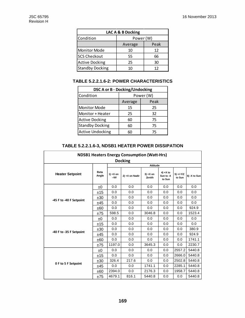
JSC 65795 16 November 2013 Revision H
169
TABLE 5.2.2.1.6-2: POWER CHARACTERISTICS
TABLE 5.2.2.1.6-3, NDSB1 HEATER POWER DISSIPATION
Condition
Average Peak
Monitor Mode 10 12
SCS Checkout 55 66
Active Docking 25 30
Standby Docking 10 12
Power (W)
LAC A & B Docking
Condition
Average Peak
Monitor Mode 15 25
Monitor + Heater 25 32
Active Docking 60 75
Standby Docking 60 75
Active Undocking 60 75
DSC A or B - Docking/Undocking
Power (W)
1) +X on
–VV2) +X on Nadir
3) +X on
Zenith
4) +X to
Sun to -X
to Sun
5) +/-Y/Z
to Sun 6) -X to Sun
±0 0.0 0.0 0.0 0.0 0.0 0.0
±15 0.0 0.0 0.0 0.0 0.0 0.0
±30 0.0 0.0 0.0 0.0 0.0 0.0
±45 0.0 0.0 0.0 0.0 0.0 0.0
±60 0.0 0.0 0.0 0.0 0.0 924.9
±75 598.5 0.0 3046.8 0.0 0.0 1523.4
±0 0.0 0.0 0.0 0.0 0.0 0.0
±15 0.0 0.0 0.0 0.0 0.0 0.0
±30 0.0 0.0 0.0 0.0 0.0 380.9
±45 0.0 0.0 0.0 0.0 0.0 924.9
±60 0.0 0.0 0.0 0.0 0.0 1741.1
±75 1197.0 0.0 3645.3 0.0 0.0 2230.7
±0 0.0 0.0 0.0 0.0 2557.2 5440.8
±15 0.0 0.0 0.0 0.0 2666.0 5440.8
±30 326.4 217.6 0.0 0.0 2502.8 5440.8
±45 0.0 0.0 1741.1 0.0 2285.1 5440.8
±60 2394.0 0.0 2176.3 0.0 1958.7 5440.8
±75 4679.1 816.1 5440.8 0.0 0.0 5440.8
NDSB1 Heaters Energy Consumption (Watt-Hrs)
Docking Attitude
-40 F to -35 F Setpoint
-45 F to -40 F Setpoint
0 F to 5 F Setpoint
Beta
AngleHeater Setpoint
JSC 65795 16 November 2013 Revision H
170
Note: The tables above represent NDSB1 heater power consumption in solo flight. Power consumption is
dependent on attitude and heater setpoint. The HV can reset heater setpoints during operation based on
mission attitude profile and power availability.
-45°F to -40°F Setpoint: Minimum setpoint to protect hardware limits.
• -40°F to -35°F Setpoint: Minimum setpoint with additional 5°F margin.
• 0°F to 5°F Setpoint: Maximum recommended setpoint for solo flight and docking at worst
case attitude.
Heater power is assumed worst case at 73.5W and 36VDC
DSC power dissipation due to driving heaters is incorporated in the Watt-Hr calculations
Watt-Hrs are calculated for a 24 hour cycle
5.2.2.2 Host Vehicle provided MMOD
The MMOD protection for the NDSB1 is provided by the HV. Figure 5.2.1.2-1: NDSB1 Host-
Provided MMOD Interface shows the mounting points on the tunnel flange for MMOD shielding
or other external hardware.
Integrated NDSB1/host vehicle analysis, with host vehicle hardware mounted at this interface,
must show that the NDSB1 is capable of meeting requirements for non-operational, operational
and mated/pressurized conditions expected for that vehicle’s mission (see paragraph 7.1.1.2.3.2).
General design guidelines for HV MMOD to meet thermal requirements are listed below.
• HV MMOD shields or other tunnel flange mounted hardware can only contact the NDSB1
at the upper and lower tunnel flanges.
• HV external hardware should incorporate isolators, optical properties, or other design
features to prevent excessive heat transfer at the flange mounts.
• The temperature of external HV MMOD and hardware should be limited to avoid excessive
thermal radiation to umbilicals and hooks not covered by the NDSB1 provided MLI.
• An MLI Thermal cover over the external tunnel hardware is provided by the NDSB1. The
NDSB1 MLI thermal blankets are located internal to the HV provided MMOD shields.
• The HV will prevent the components external to the NDSB1 tunnel from receiving any
incident solar rays except for the docking flange hook assembly openings.
5.3 NDSB1-to-Host Vehicle Electrical and Signal Interface Umbilical
This subsection describes the electrical and signal interfaces between the NDS and the host vehicle.
As indicated in Figure 5.2.1.5-3 NDSB1 Cabling there are two NDSB1-to-IDA electrical umbilical
connectors allowing redundant electrical signals. Both power and Command and Data Handling
(C&DH) are routed through a single connector. However, after exiting the backshell of the
NDSB1-to-IDA umbilical connector, the power and C&DH are separated and run to individual
connectors at the host side. The NDSB1 electrical connections are located as shown in Figure 5.5-

JSC 65795 16 November 2013 Revision H
171
1: NDSB1 -to-Host Vehicle Electrical Interface. The electrical interface between the NDSB1 and
the host vehicle has the functions indicated in Figure 5.2.1.5-3, NDSB1 Cabling .
5.3.1 Umbilical Data Transfer Interface-to-the-Host Vehicle
The NDSB1 to Host Vehicle umbilical interfaces will provide the utilities to transfer two MIL-
STD-1553 and two IEEE 802.3u Ethernet connections between the mated vehicles when the Host
Vehicle is hard mated to the ISS. The pinouts are shown in Table 4.2.3.1-1: IDA to HV Interface
(SYS A) – J35 and Table 4.2.3.1-2: IDA to HV Interface (SYS B) – P35.
5.3.1.1 Umbilical Connector Mated Indication
The data connector interface to the host provides indication that pins have engaged between the
NDSB1-to-IDA umbilical connectors. Each connector has pins that are electrically shorted
together; when the connectors mate, this short can be sensed by the docking vehicles. This is an
indication that the connectors are seated and the pins have engaged, which signifies that power
and data can be exchanged. For the umbilical connector to host vehicle interface locations, see
Figure 4.1.1-1.
5.3.2 Umbilical Connector Data Bus Termination Wires Interface-to-the-Host Vehicle
The MIL-STD-1553 data bus passing through the umbilical resource is not terminated by the
NDSB1. The NDSB1 implements a striker plate that switches the MIL-STD-1553 data bus from
the IDA bus terminator to the Host Vehicle MIL-STD-1553 interface when the mating umbilicals
are in contact. The MIL-STD-1553 wires are routed to a connector at the interface to the host
vehicle as shown in Table 4.2.3.1-1: IDA to HV Interface (SYS A) – J35 and Table 4.2.3.1-2: IDA
to HV Interface (SYS B) – P35. It is the host vehicle’s responsibility to terminate the MIL STD-
1553 data bus as required by the integrated MIL-STD-1553 design when the umbilical is
connected. See Figure 4.1.1-1 for the mechanical implementation of the striker plate and the bus
termination switch on the NDSB1 umbilical.
5.3.3 Pyrotechnic Interface NDSB1
The NDSB1 contains pyrotechnics in both the active and passive hooks at the hard mate interface.
Therefore, if the NDSB1 active hooks fail to unlatch, the host may fire the pyrotechnics releasing
either or both active and passive gangs of hooks. The 24 hooks will be fired in gangs, six at a time.
A single gang of six is every other hook. The total time required for hook release within one gang
of six hooks is less than 150 ms. The control and inhibits for this firing are provided by the host
vehicle. The host provides three inhibits to inadvertent firing. There are four NASA Standard
Initiators (NSIs) in the NDSB1 (one per gang of six hooks, active and passive). For each NSI, the
HV provides an all-fire bridgewire control signal compliant to JSC-28596A from the HV and
NDSB1 introduces a resistance of no more than 1.5 ohms, which provides the necessary firing
energy and duration for each NSI.
Pyrotechnics would be used as contingency measures in the event of two failures to undock.
Therefore, no redundancy is required in the NSIs or pyrotechnic controller channel. All
pyrotechnics used in this system follow the requirements of JSC-62809, Human Rated Spacecraft
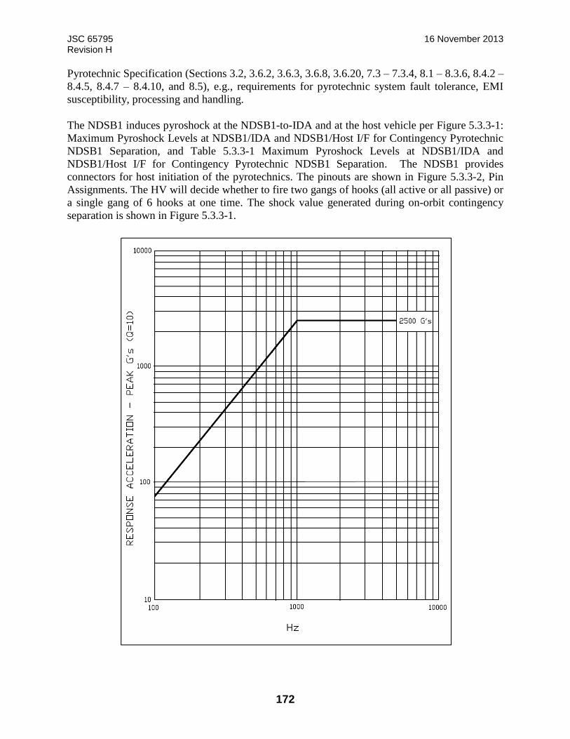
JSC 65795 16 November 2013 Revision H
172
Pyrotechnic Specification (Sections 3.2, 3.6.2, 3.6.3, 3.6.8, 3.6.20, 7.3 – 7.3.4, 8.1 – 8.3.6, 8.4.2 –
8.4.5, 8.4.7 – 8.4.10, and 8.5), e.g., requirements for pyrotechnic system fault tolerance, EMI
susceptibility, processing and handling.
The NDSB1 induces pyroshock at the NDSB1-to-IDA and at the host vehicle per Figure 5.3.3-1:
Maximum Pyroshock Levels at NDSB1/IDA and NDSB1/Host I/F for Contingency Pyrotechnic
NDSB1 Separation, and Table 5.3.3-1 Maximum Pyroshock Levels at NDSB1/IDA and
NDSB1/Host I/F for Contingency Pyrotechnic NDSB1 Separation. The NDSB1 provides
connectors for host initiation of the pyrotechnics. The pinouts are shown in Figure 5.3.3-2, Pin
Assignments. The HV will decide whether to fire two gangs of hooks (all active or all passive) or
a single gang of 6 hooks at one time. The shock value generated during on-orbit contingency
separation is shown in Figure 5.3.3-1.
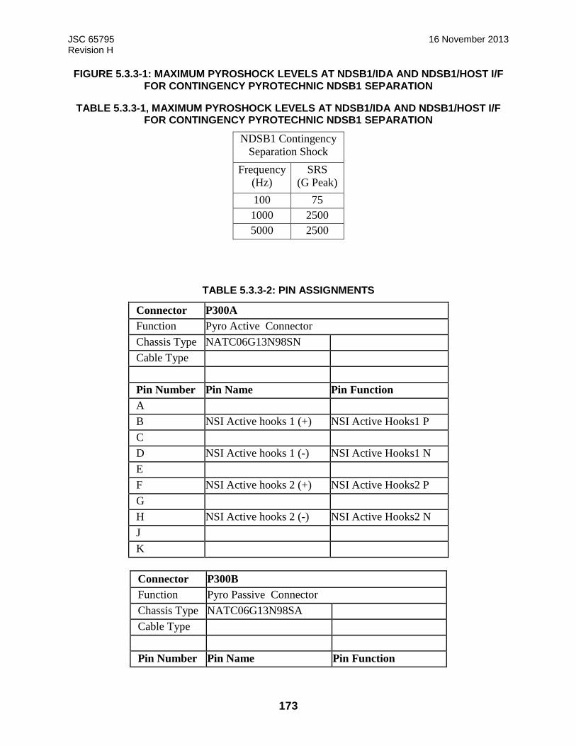
JSC 65795 16 November 2013 Revision H
173
FIGURE 5.3.3-1: MAXIMUM PYROSHOCK LEVELS AT NDSB1/IDA AND NDSB1/HOST I/F FOR CONTINGENCY PYROTECHNIC NDSB1 SEPARATION
TABLE 5.3.3-1, MAXIMUM PYROSHOCK LEVELS AT NDSB1/IDA AND NDSB1/HOST I/F FOR CONTINGENCY PYROTECHNIC NDSB1 SEPARATION
NDSB1 Contingency
Separation Shock
Frequency
(Hz)
SRS
(G Peak)
100 75
1000 2500
5000 2500
TABLE 5.3.3-2: PIN ASSIGNMENTS
Connector P300A
Function Pyro Active Connector
Chassis Type NATC06G13N98SN Cable Type
Pin Number Pin Name Pin Function
A B NSI Active hooks 1 (+) NSI Active Hooks1 P
C D NSI Active hooks 1 (-) NSI Active Hooks1 N
E F NSI Active hooks 2 (+) NSI Active Hooks2 P
G H NSI Active hooks 2 (-) NSI Active Hooks2 N
J K
Connector P300B
Function Pyro Passive Connector
Chassis Type NATC06G13N98SA Cable Type
Pin Number Pin Name Pin Function
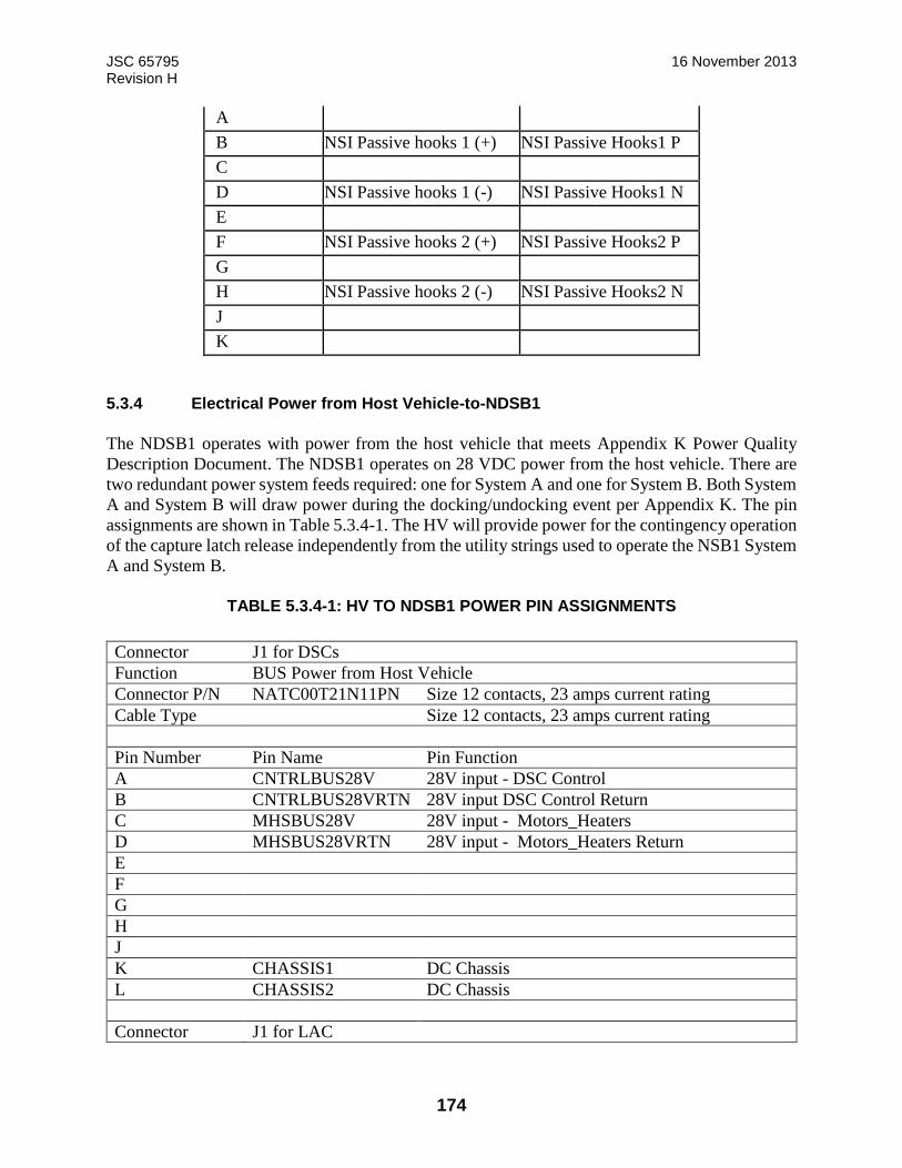
JSC 65795 16 November 2013 Revision H
174
A B NSI Passive hooks 1 (+) NSI Passive Hooks1 P
C D NSI Passive hooks 1 (-) NSI Passive Hooks1 N
E F NSI Passive hooks 2 (+) NSI Passive Hooks2 P
G H NSI Passive hooks 2 (-) NSI Passive Hooks2 N
J K
5.3.4 Electrical Power from Host Vehicle-to-NDSB1
The NDSB1 operates with power from the host vehicle that meets Appendix K Power Quality
Description Document. The NDSB1 operates on 28 VDC power from the host vehicle. There are
two redundant power system feeds required: one for System A and one for System B. Both System
A and System B will draw power during the docking/undocking event per Appendix K. The pin
assignments are shown in Table 5.3.4-1. The HV will provide power for the contingency operation
of the capture latch release independently from the utility strings used to operate the NSB1 System
A and System B.
TABLE 5.3.4-1: HV TO NDSB1 POWER PIN ASSIGNMENTS
Connector J1 for DSCs
Function BUS Power from Host Vehicle
Connector P/N NATC00T21N11PN Size 12 contacts, 23 amps current rating
Cable Type Size 12 contacts, 23 amps current rating
Pin Number Pin Name Pin Function
A CNTRLBUS28V 28V input - DSC Control
B CNTRLBUS28VRTN 28V input DSC Control Return
C MHSBUS28V 28V input - Motors_Heaters
D MHSBUS28VRTN 28V input - Motors_Heaters Return
E
F
G
H
J
K CHASSIS1 DC Chassis
L CHASSIS2 DC Chassis
Connector J1 for LAC
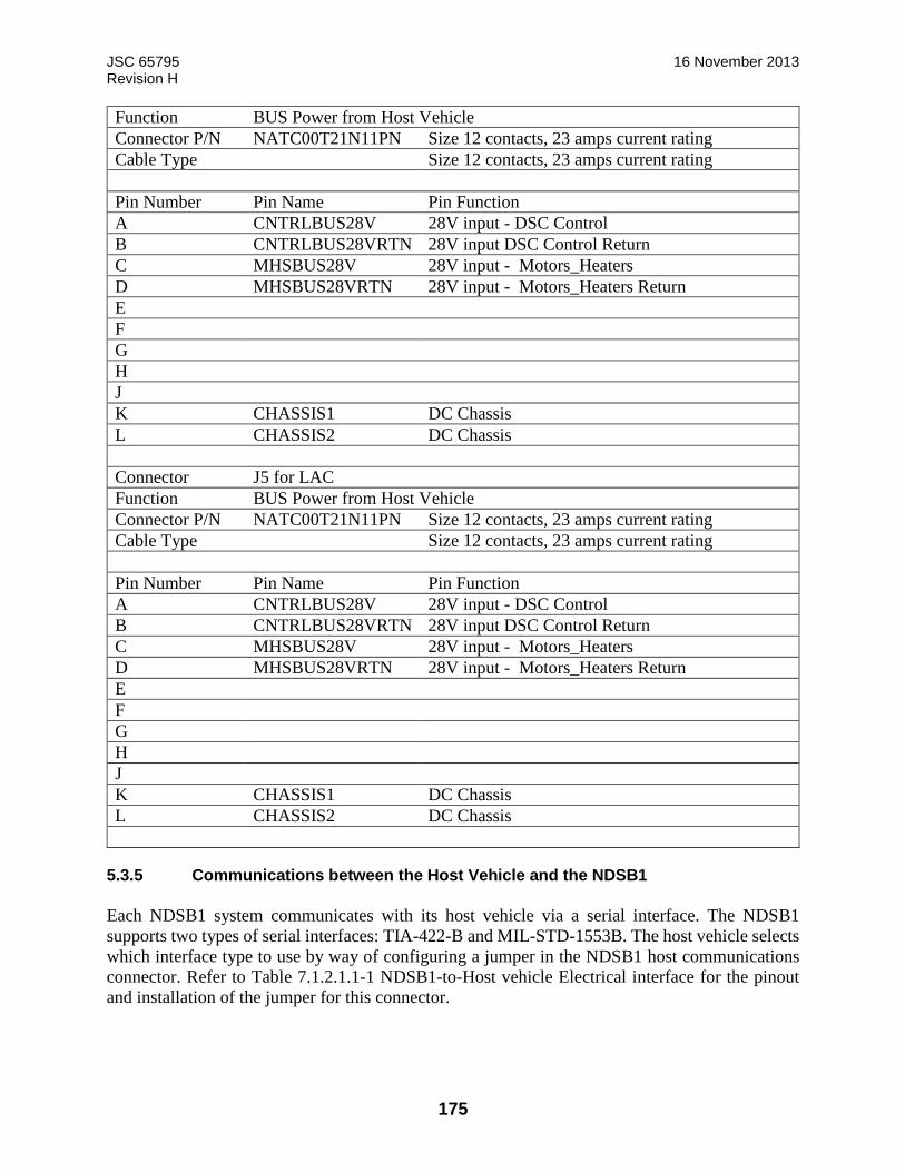
JSC 65795 16 November 2013 Revision H
175
Function BUS Power from Host Vehicle
Connector P/N NATC00T21N11PN Size 12 contacts, 23 amps current rating
Cable Type Size 12 contacts, 23 amps current rating
Pin Number Pin Name Pin Function
A CNTRLBUS28V 28V input - DSC Control
B CNTRLBUS28VRTN 28V input DSC Control Return
C MHSBUS28V 28V input - Motors_Heaters
D MHSBUS28VRTN 28V input - Motors_Heaters Return
E
F
G
H
J
K CHASSIS1 DC Chassis
L CHASSIS2 DC Chassis
Connector J5 for LAC
Function BUS Power from Host Vehicle
Connector P/N NATC00T21N11PN Size 12 contacts, 23 amps current rating
Cable Type Size 12 contacts, 23 amps current rating
Pin Number Pin Name Pin Function
A CNTRLBUS28V 28V input - DSC Control
B CNTRLBUS28VRTN 28V input DSC Control Return
C MHSBUS28V 28V input - Motors_Heaters
D MHSBUS28VRTN 28V input - Motors_Heaters Return
E
F
G
H
J
K CHASSIS1 DC Chassis
L CHASSIS2 DC Chassis
5.3.5 Communications between the Host Vehicle and the NDSB1
Each NDSB1 system communicates with its host vehicle via a serial interface. The NDSB1
supports two types of serial interfaces: TIA-422-B and MIL-STD-1553B. The host vehicle selects
which interface type to use by way of configuring a jumper in the NDSB1 host communications
connector. Refer to Table 7.1.2.1.1-1 NDSB1-to-Host vehicle Electrical interface for the pinout
and installation of the jumper for this connector.
JSC 65795 16 November 2013 Revision H
176
The NDSB1 requires two redundant communication interfaces: one for System A and one for
System B. Both System A and System B will communicate with the host vehicle simultaneously.
All communication (e.g., commands, data, status) for operating the NDSB1 are sent through the
selected serial interfaces.
5.3.5.1 C&DH TIA-422-B Interface
As described in Table 5.3.5.1-1 the TIA-422-B interface is selected by shorting the COMMID1+
and COMMID1- pins on both systems and not shorting the COMMID2+ and COMMID2- pins.
The TIA-422-B interface is a point-to-point, full duplex, serial interface utilizing 8 data bits with
no parity. The systems are connected so that each transmitter connects to a dedicated receiver.

JSC 65795 16 November 2013 Revision H
177
TABLE 5.3.5.1-1: TIA-422B PIN ASSIGNMENTS
Connector ID
Function
Connector P/N NATC00T15N35SN Size 22D contacts, 5 amps current rating
Pin Number Pin Name Pin Function
1 N/C
2 N/C
3 RTJMPRJ0+ R T Address Jumper 0 + HV
4 RTJMPRJ0- R T Address Jumper 0 - HV
5 RTJMPRJ1+ R T Address Jumper 1 + HV
6 RTJMPRJ1- R T Address Jumper 1 - HV
7 RTJMPRJ2+ R T Address Jumper 2 + HV
8 RTJMPRJ2- R T Address Jumper 2 - HV
9 RTJMPRJ3+ R T Address Jumper 3 + HV
10 RTJMPRJ3- R T Address Jumper 3 - HV
11 RTJMPRJ4+ R T Address Jumper 4 + HV
12 RTJMPRJ4- R T Address Jumper 4 - HV
13 RTJMPRJP+ R T Address Jumper P + HV
14 RTJMPRJP- R T Address Jumper P - HV
15 N/C
16 N/C
17 UNITID1+ Unit A Select + HV
18 UNITID1- Unit A Select - HV
19 UNITID2+ Unit B Select + HV
20 UNITID2- Unit B Select - HV
21 RS422TXHI DSC to HV RS422 Transmit Hi HV
22 RS422TXLO DSC to HV RS422 Transmit Lo HV
23 RS422RXHI DSC to HV RS422 Receive Hi HV
24 RS422RXLO DSC to HV RS422 Receive Lo HV
25 N/C
26 N/C
27 COMMID1+ Select RS422 Comm + HV
28 COMMID1- Select RS422 Comm - HV
29 COMMID2+ Select 1553 Comm + HV
30 COMMID2- Select 1553 Comm - HV
31 N/C
32 MIL1553HIA 1553 Stub A Hi HV
33 MIL1553LOA 1553 Stub A Lo HV
34 MIL1553HIB 1553 Stub B Hi HV
35 MIL1553LOB 1553 Stub B Lo HV
36 N/C
37 N/C
J3
DSC to HV Communication

JSC 65795 16 November 2013 Revision H
178
5.3.5.2 C&DH MIL-STD-1553B Interface
Each NDSB1 DSC is a (separate) Remote Terminal (RT). The host vehicle is the Bus Controller
(BC).
As described in Table 5.3.5.1-1 the MIL-STD-1553 interface is selected by not shorting the
COMMID1+ and COMMID1- pins on both systems and shorting the COMMID2+ and
COMMID2- pins. If both pairs of Communications ID pins are shorted jumpers together or neither
pair is shorted together, this indicates a failure, and the controller will transition to a non-
operational state with no communication provided to the HV. The MIL-STD-1553B RT address
for the NDSB1 System is set in the host communications connector by shorting the appropriate
RT address pins. Refer to Appendix C for the pin locations for signals RT_ADDR0, RT_ADDR1,
RT_ADDR2, RT_ADDR3, RT_ADDR4, and RT_ADDR_PARITY. Odd Parity must be used
when setting the RT address parity bit. Shorting each signal to its associated signal return will set
it to a zero. Leaving the signal open will set it to a one.
The NDSB1 provides the ability to receive a subset of the Mode Codes defined in MIL-STD-1553.
The Mode Codes supported by NDSB1 are listed in Table 5.3.5.2-1: NDSB1 Implementation of
MIL-STD-1553B Mode Codes. The message formats and behavior associated with Mode Code
transactions are defined in MIL-STD-1553B Notice 2.
When the host vehicle Bus Controller (BC) requests data from the NDSB1, it will receive NDSB1
Health and Status (H&S) telemetry as described in Appendix C. Described in detail in Appendix
C, these packets comprise multiple sub-addresses. For example, the H&S packet is divided across
multiple sub-addresses.
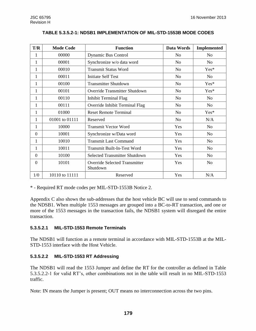
JSC 65795 16 November 2013 Revision H
179
TABLE 5.3.5.2-1: NDSB1 IMPLEMENTATION OF MIL-STD-1553B MODE CODES
T/R Mode Code Function Data Words Implemented
1 00000 Dynamic Bus Control No No
1 00001 Synchronize w/o data word No No
1 00010 Transmit Status Word No Yes*
1 00011 Initiate Self Test No No
1 00100 Transmitter Shutdown No Yes*
1 00101 Override Transmitter Shutdown No Yes*
1 00110 Inhibit Terminal Flag No No
1 00111 Override Inhibit Terminal Flag No No
1 01000 Reset Remote Terminal No Yes*
1 01001 to 01111 Reserved No N/A
1 10000 Transmit Vector Word Yes No
0 10001 Synchronize w/Data word Yes No
1 10010 Transmit Last Command Yes No
1 10011 Transmit Built-In-Test Word Yes No
0 10100 Selected Transmitter Shutdown Yes No
0 10101 Override Selected Transmitter
Shutdown
Yes No
1/0 10110 to 11111 Reserved Yes N/A
* - Required RT mode codes per MIL-STD-1553B Notice 2.
Appendix C also shows the sub-addresses that the host vehicle BC will use to send commands to
the NDSB1. When multiple 1553 messages are grouped into a BC-to-RT transaction, and one or
more of the 1553 messages in the transaction fails, the NDSB1 system will disregard the entire
transaction.
5.3.5.2.1 MIL-STD-1553 Remote Terminals
The NDSB1 will function as a remote terminal in accordance with MIL-STD-1553B at the MIL-
STD-1553 interface with the Host Vehicle.
5.3.5.2.2 MIL-STD-1553 RT Addressing
The NDSB1 will read the 1553 Jumper and define the RT for the controller as defined in Table
5.3.5.2.2-1 for valid RT’s, other combinations not in the table will result in no MIL-STD-1553
traffic.
Note: IN means the Jumper is present; OUT means no interconnection across the two pins.
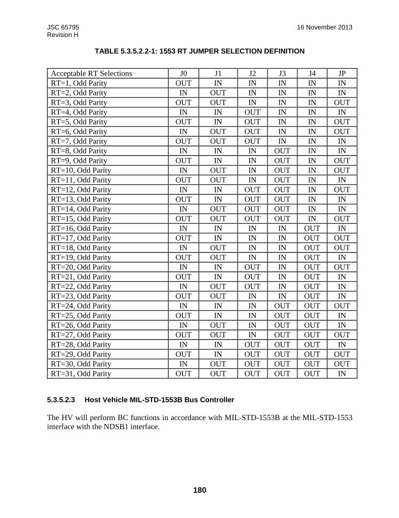
JSC 65795 16 November 2013 Revision H
180
TABLE 5.3.5.2.2-1: 1553 RT JUMPER SELECTION DEFINITION
5.3.5.2.3 Host Vehicle MIL-STD-1553B Bus Controller
The HV will perform BC functions in accordance with MIL-STD-1553B at the MIL-STD-1553
interface with the NDSB1 interface.
Acceptable RT Selections J0 J1 J2 J3 J4 JP
RT=1, Odd Parity OUT IN IN IN IN IN
RT=2, Odd Parity IN OUT IN IN IN IN
RT=3, Odd Parity OUT OUT IN IN IN OUT
RT=4, Odd Parity IN IN OUT IN IN IN
RT=5, Odd Parity OUT IN OUT IN IN OUT
RT=6, Odd Parity IN OUT OUT IN IN OUT
RT=7, Odd Parity OUT OUT OUT IN IN IN
RT=8, Odd Parity IN IN IN OUT IN IN
RT=9, Odd Parity OUT IN IN OUT IN OUT
RT=10, Odd Parity IN OUT IN OUT IN OUT
RT=11, Odd Parity OUT OUT IN OUT IN IN
RT=12, Odd Parity IN IN OUT OUT IN OUT
RT=13, Odd Parity OUT IN OUT OUT IN IN
RT=14, Odd Parity IN OUT OUT OUT IN IN
RT=15, Odd Parity OUT OUT OUT OUT IN OUT
RT=16, Odd Parity IN IN IN IN OUT IN
RT=17, Odd Parity OUT IN IN IN OUT OUT
RT=18, Odd Parity IN OUT IN IN OUT OUT
RT=19, Odd Parity OUT OUT IN IN OUT IN
RT=20, Odd Parity IN IN OUT IN OUT OUT
RT=21, Odd Parity OUT IN OUT IN OUT IN
RT=22, Odd Parity IN OUT OUT IN OUT IN
RT=23, Odd Parity OUT OUT IN IN OUT IN
RT=24, Odd Parity IN IN IN OUT OUT OUT
RT=25, Odd Parity OUT IN IN OUT OUT IN
RT=26, Odd Parity IN OUT IN OUT OUT IN
RT=27, Odd Parity OUT OUT IN OUT OUT OUT
RT=28, Odd Parity IN IN OUT OUT OUT IN
RT=29, Odd Parity OUT IN OUT OUT OUT OUT
RT=30, Odd Parity IN OUT OUT OUT OUT OUT
RT=31, Odd Parity OUT OUT OUT OUT OUT IN

JSC 65795 16 November 2013 Revision H
181
5.3.5.2.4 Host Vehicle MIL-STD-1553B Parity
The HV will use odd parity when setting the RT address parity bit in accordance with MIL_STD-
1553.
5.3.5.2.5 Host Vehicle MIL-STD-1553 Mode Commands
The HV will transmit the mode code commands as defined in MIL-STD-1553B Notice 2.
5.3.5.2.6 Host Vehicle Response to NDSB1 H&S Data
5.3.5.2.6.1 Host Vehicle Isolation of NDSB1 Faults
The HV will isolate NDSB1 faults to the recovery level.
5.3.5.2.6.2 Host Vehicle Response to NDSB1 Faults
Refer to Appendix G
5.3.5.3 Jumpers
The DSC will read the two AB SEL Jumpers, designated A and B. If jumper A is present and B is
not present, then the DSC is System A, if jumper A is absent and jumper B is present, then the
DSC is System B. If both jumpers are present or absent, this indicates a failure, and the DSC will
transition the system into the monitor mode and disable further mode transitions.
5.3.6 Heater Power and Control
NDSB1 heaters receive power from the Host Vehicle. Default heater set points and Resistive
Temperature Device (RTD) error set points will be defined for each heater zone. The DSC will
energize enabled zone heaters when the corresponding zone RTD temperature sensor values are
less than the minimum set point value for the zone. The DSC will de-energize enabled zone heaters
when the corresponding zone RTD temperature sensor values are greater than the maximum set
point for the zone. If RTD temperature sensor values are outside of the RTD Error Guard Range,
the DSC will disable the corresponding zone heaters and report an RTD Range Error. The zone
heaters will remain disabled until the system is reset or until the error is explicitly reset by a
command.
Heater control is allowed in the following modes: Monitor Mode, Active Docking Mode, SCS
Checkout Mode, Standby Docking Mode, and Manual Mode. Heater set point values and RTD
error set point values can be changed via commands from the Host Vehicle.
Heaters are temporarily disabled any time the DSC is driving an effector.
5.3.7 Ground Support Equipment Software Interface-to-NDSB1
Reserved (Not Provided)
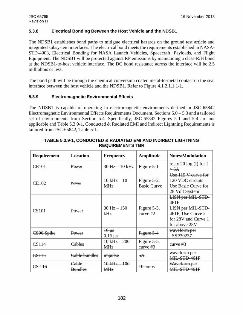
JSC 65795 16 November 2013 Revision H
182
5.3.8 Electrical Bonding Between the Host Vehicle and the NDSB1
The NDSB1 establishes bond paths to mitigate electrical hazards on the ground test article and
integrated subsystem interfaces. The electrical bond meets the requirements established in NASA-
STD-4003, Electrical Bonding for NASA Launch Vehicles, Spacecraft, Payloads, and Flight
Equipment. The NDSB1 will be protected against RF emissions by maintaining a class-R/H bond
at the NDSB1-to-host vehicle interface. The DC bond resistance across the interface will be 2.5
milliohms or less.
The bond path will be through the chemical conversion coated metal-to-metal contact on the seal
interface between the host vehicle and the NDSB1. Refer to Figure 4.1.2.1.1.1-1.
5.3.9 Electromagnetic Environmental Effects
The NDSB1 is capable of operating in electromagnetic environments defined in JSC-65842
Electromagnetic Environmental Effects Requirements Document, Sections 5.0 – 5.3 and a tailored
set of environments from Section 5.4. Specifically, JSC-65842 Figures 5-1 and 5-4 are not
applicable and Table 5.3.9-1, Conducted & Radiated EMI and Indirect Lightning Requirements is
tailored from JSC-65842, Table 5-1.
TABLE 5.3.9-1, CONDUCTED & RADIATED EMI AND INDIRECT LIGHTNING REQUIREMENTS TBR
Requirement Location Frequency Amplitude Notes/Modulation
CE101 Power 30 Hz – 10 kHz Figure 5-1 relax 20 log (I) for I
> 5A
CE102 Power 10 kHz – 10
MHz
Figure 5-2,
Basic Curve
Use 115 V curve for
120 VDC circuits
Use Basic Curve for
28 Volt System
CS101 Power 30 Hz – 150
kHz
Figure 5-3,
curve #2
LISN per MIL-STD-
461F
LISN per MIL-STD-
461F, Use Curve 2
for 28V and Curve 1
for above 28V
CS06 Spike Power 10 μs
0.15 μs Figure 5-4
waveform per
SSP30237
CS114 Cables 10 kHz – 200
MHz
Figure 5-5,
curve #3 curve #3
CS115 Cable bundles impulse 5A waveform per
MIL-STD-461F
CS 116 Cable
Bundles
10 kHz – 100
MHz 10 amps
Waveform per
MIL-STD-461F
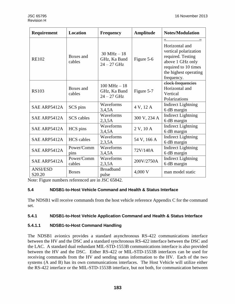
JSC 65795 16 November 2013 Revision H
183
Requirement Location Frequency Amplitude Notes/Modulation
RE102 Boxes and
cables
30 MHz – 18
GHz, Ka Band
24 – 27 GHz
Figure 5-6
“ “
Horizontal and
vertical polarization
required. Testing
above 1 GHz only
required to 10 times
the highest operating
frequency.
RS103 Boxes and
cables
100 MHz – 18
GHz, Ka Band
24 – 27 GHz
Figure 5-7
clock frequencies
Horizontal and
Vertical
Polarizations
SAE ARP5412A SCS pins Waveforms
3,4,5A 4 V, 12 A
Indirect Lightning
6 dB margin
SAE ARP5412A SCS cables Waveforms
2,3,5A 300 V, 234 A
Indirect Lightning
6 dB margin
SAE ARP5412A HCS pins Waveforms
3,4,5A 2 V, 10 A
Indirect Lightning
6 dB margin
SAE ARP5412A HCS cables Waveforms
2,3,5A 54 V, 166 A
Indirect Lightning
6 dB margin
SAE ARP5412A Power/Comm
pins
Waveforms
3,4,5A 72V/140A
Indirect Lightning
6 dB margin
SAE ARP5412A Power/Comm
cables
Waveforms
2,3,5A 200V/2750A
Indirect Lightning
6 dB margin
ANSI/ESD
S20.20 Boxes
Broadband
pulse 4,000 V man model static
Note: Figure numbers referenced are in JSC 65842.
5.4 NDSB1-to-Host Vehicle Command and Health & Status Interface
The NDSB1 will receive commands from the host vehicle reference Appendix C for the command
set.
5.4.1 NDSB1-to-Host Vehicle Application Command and Health & Status Interface
5.4.1.1 NDSB1-to-Host Command Handling
The NDSB1 avionics provides a standard asynchronous RS-422 communications interface
between the HV and the DSC and a standard synchronous RS-422 interface between the DSC and
the LAC. A standard dual redundant MIL-STD-1553B communications interface is also provided
between the HV and the DSC. Either RS-422 or MIL-STD-1553B interfaces can be used for
receiving commands from the HV and sending status information to the HV. Each of the two
systems (A and B) has its own communications interfaces. The Host Vehicle will utilize either
the RS-422 interface or the MIL-STD-1553B interface, but not both, for communication between
JSC 65795 16 November 2013 Revision H
184
the HV and the DSC. Selection of which interface is active in the avionics is determined by the
two Communications Jumpers. See Appendix C for Host Vehicle to NDSB1 commands.
5.4.1.1.1 Host Vehicle Commands to NDSB1
The HV will control the NDSB1 using the commands listed in Appendix C Command Definitions
Tab.
5.4.1.1.2 Host Vehicle Command Rates
The maximum HV to NDSB1 command rate is specified in paragraph 7.1.2.4.3.3.2, Host Vehicle
Command Rates.
5.4.1.2 NDSB1-to-Host Vehicle H&S Data Handling
The NDSB1 will make health and status data available for collection on the MIL-STD-1553B data
bus as defined in Appendix C.
5.4.1.3 NDSB1 FDIR
The NDSB1 has two controllers: System A and System B. Systems A and B do not communicate
directly with each other in any way, but both receive commands from, and provide health and
status data to, the host vehicle. During NDSB1 docking operation, systems A and B are both turned
on, one in an active mode and the other in a standby mode. In general, during soft capture
operations, if there is a fault in a system that results in loss of that system’s functionality, the host
vehicle can command the healthy system to continue performing the desired function. In several
cases (hook motors, for example), both systems drive the effector and thus the desired function
will continue with no intervention, but the operation will take twice as much time.
The tables in Appendix G, Failure Response Table, define the host vehicle’s automated response
to detected faults that occur during docking. The first table identifies the action to take on the first
detected fault. The second table defines the action to take on a subsequent fault. Note that the
tables identify different actions depending on the current operational state of the docking (which
is determined from the telemetry returned from the NDS).
If a fault requiring a switch to the redundant string is identified, a minimum amount of time is
needed to switch between controllers in order to maintain safe control of the linear actuators,
depending on the phase of operation. This switch time is most critical during docking capture and
attenuation phases.
The maximum total time required for a switch to take place from A to B is 580 ms. This time is
from fault detection, output of the fault indicator in the NDSB1 H&S data to the host vehicle,
passage of the H&S message through the host vehicle’s subsystem interfaces and buses/networks
into the flight computer/software that monitors the fault indicator to the time it takes for the host
vehicle’s switching commands to traverse back to the NDSB1 and for NDSB1 to effect the switch.
The total time has to be allocated between the NDSB1 and the host vehicle. The host vehicle will
be required to send the commands to switch primary control from System A to System B within
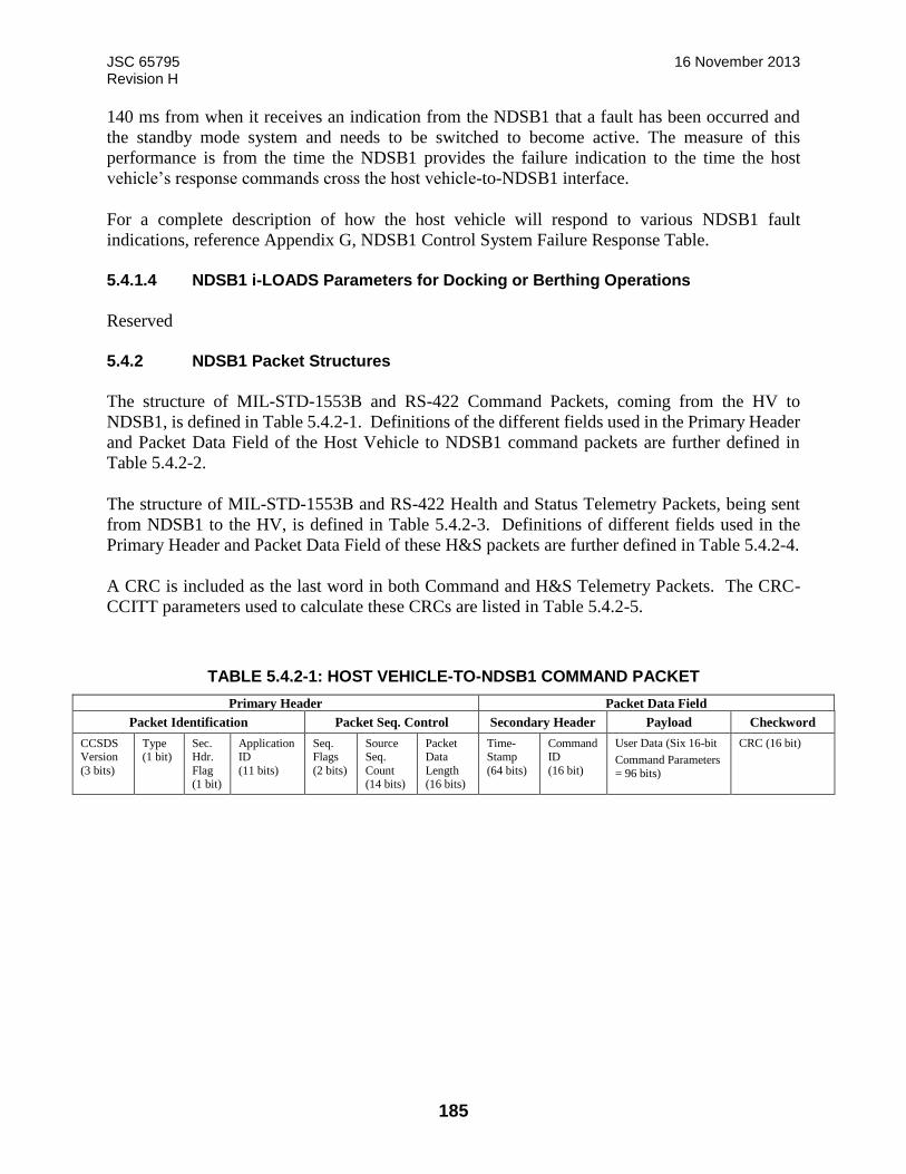
JSC 65795 16 November 2013 Revision H
185
140 ms from when it receives an indication from the NDSB1 that a fault has been occurred and
the standby mode system and needs to be switched to become active. The measure of this
performance is from the time the NDSB1 provides the failure indication to the time the host
vehicle’s response commands cross the host vehicle-to-NDSB1 interface.
For a complete description of how the host vehicle will respond to various NDSB1 fault
indications, reference Appendix G, NDSB1 Control System Failure Response Table.
5.4.1.4 NDSB1 i-LOADS Parameters for Docking or Berthing Operations
Reserved
5.4.2 NDSB1 Packet Structures
The structure of MIL-STD-1553B and RS-422 Command Packets, coming from the HV to
NDSB1, is defined in Table 5.4.2-1. Definitions of the different fields used in the Primary Header
and Packet Data Field of the Host Vehicle to NDSB1 command packets are further defined in
Table 5.4.2-2.
The structure of MIL-STD-1553B and RS-422 Health and Status Telemetry Packets, being sent
from NDSB1 to the HV, is defined in Table 5.4.2-3. Definitions of different fields used in the
Primary Header and Packet Data Field of these H&S packets are further defined in Table 5.4.2-4.
A CRC is included as the last word in both Command and H&S Telemetry Packets. The CRC-
CCITT parameters used to calculate these CRCs are listed in Table 5.4.2-5.
TABLE 5.4.2-1: HOST VEHICLE-TO-NDSB1 COMMAND PACKET
Primary Header Packet Data Field
Packet Identification Packet Seq. Control Secondary Header Payload Checkword
CCSDS Version
(3 bits)
Type (1 bit)
Sec. Hdr.
Flag (1 bit)
Application ID
(11 bits)
Seq. Flags
(2 bits)
Source Seq.
Count (14 bits)
Packet Data
Length (16 bits)
Time-Stamp
(64 bits)
Command ID
(16 bit)
User Data (Six 16-bit
Command Parameters = 96 bits)
CRC (16 bit)
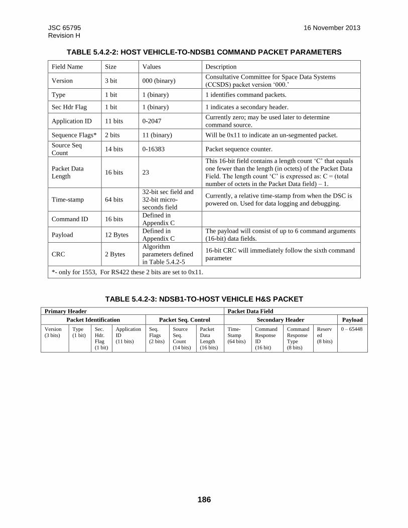
JSC 65795 16 November 2013 Revision H
186
TABLE 5.4.2-2: HOST VEHICLE-TO-NDSB1 COMMAND PACKET PARAMETERS
Field Name Size Values Description
Version 3 bit 000 (binary) Consultative Committee for Space Data Systems
(CCSDS) packet version ‘000.’
Type 1 bit 1 (binary) 1 identifies command packets.
Sec Hdr Flag 1 bit 1 (binary) 1 indicates a secondary header.
Application ID 11 bits 0-2047 Currently zero; may be used later to determine
command source.
Sequence Flags* 2 bits 11 (binary) Will be 0x11 to indicate an un-segmented packet.
Source Seq
Count 14 bits 0-16383 Packet sequence counter.
Packet Data
Length 16 bits 23
This 16-bit field contains a length count ‘C’ that equals
one fewer than the length (in octets) of the Packet Data
Field. The length count ‘C’ is expressed as: C = (total
number of octets in the Packet Data field) – 1.
Time-stamp 64 bits 32-bit sec field and
32-bit micro-
seconds field
Currently, a relative time-stamp from when the DSC is
powered on. Used for data logging and debugging.
Command ID 16 bits Defined in
Appendix C
Payload 12 Bytes Defined in
Appendix C The payload will consist of up to 6 command arguments
(16-bit) data fields.
CRC 2 Bytes Algorithm
parameters defined
in Table 5.4.2-5
16-bit CRC will immediately follow the sixth command
parameter
*- only for 1553, For RS422 these 2 bits are set to 0x11.
TABLE 5.4.2-3: NDSB1-TO-HOST VEHICLE H&S PACKET
Primary Header Packet Data Field
Packet Identification Packet Seq. Control Secondary Header Payload
Version
(3 bits)
Type
(1 bit)
Sec.
Hdr. Flag
(1 bit)
Application
ID (11 bits)
Seq.
Flags (2 bits)
Source
Seq. Count
(14 bits)
Packet
Data Length
(16 bits)
Time-
Stamp (64 bits)
Command
Response ID
(16 bit)
Command
Response Type
(8 bits)
Reserv
ed (8 bits)
0 – 65448

JSC 65795 16 November 2013 Revision H
187
TABLE 5.4.2-4: NDSB1-TO-HOST VEHICLE H&S PACKET PARAMETERS
Field Name Size Values Description
Version 3 bit 0 CCSDS packet version ‘000.’
Type 1 bit 0 0 identifies telemetry packets.
Sec Hdr Flag 1 bit 1 1 Indicates a secondary header.
Application ID 11 bits 0
Always zero
Sequence Flags* 2 bits 0x11 Will be 0x11 to indicate an unsegmented packet.
Source Seq
Count 14 bits 0-16383 Packet sequence counter.
Packet Length 16 bits 0 – 65535
This 16-bit field contains a length count ‘C’ that equals
one fewer than the length (in octets) of the Packet Data
Field. The length count ‘C’ is expressed as: C = (total
number of octets in the Packet Data field) – 1.
Time-stamp 64 bits
32-bit sec field and
32-bit micro-
seconds field
Currently, a relative time-stamp from when the DSC is
powered on. Used for data logging and debugging.
Command
Response ID 16 bits
Defined in
Appendix C Command ID of the command being reported on.
Command
Response Type 8 bits
Defined in
Appendix C
Command response such as Valid, Invalid, Received, and
Executed.
Reserved 8 bits 0 Reserved field (currently used to keep 32-bit alignment
between secondary header and payload).
Payload Defined in
Appendix C
Defined in
Appendix C H&S payload packet defined in Appendix C.
*- only for 1553, For RS422 these 2 bits are set to 0x11.
The DSC will implement a CRC for the H&S Transmit Packet and Verify on the Command
Interface. The CRC is calculated for the entire length of the transfer frame payload data field,
excluding the CRC.
TABLE 5.4.2-5: CRC-CCITT PARAMETERS
Algorithm CRC-CCITT
Width: 16 bits
(Truncated) Polynomial: 0x1021
Initial Remainder: 0xFFFF
Final XOR Value: 0x0000
Reflect Data: No
Reflect Remainder: No
5.4.3 NDSB1 Data Transfer
5.4.3.1 TIA-422-B Serial
The NDSB1 will transmit packets using two independent serial data (TIA-422-B)
command/control paths from the host vehicle as System A and System B. See Table 5.4.3.1-1:
NDSB1-to-Host Vehicle C&DH Interface Layers for details. The data will be transferred in
network byte order (big-endian).
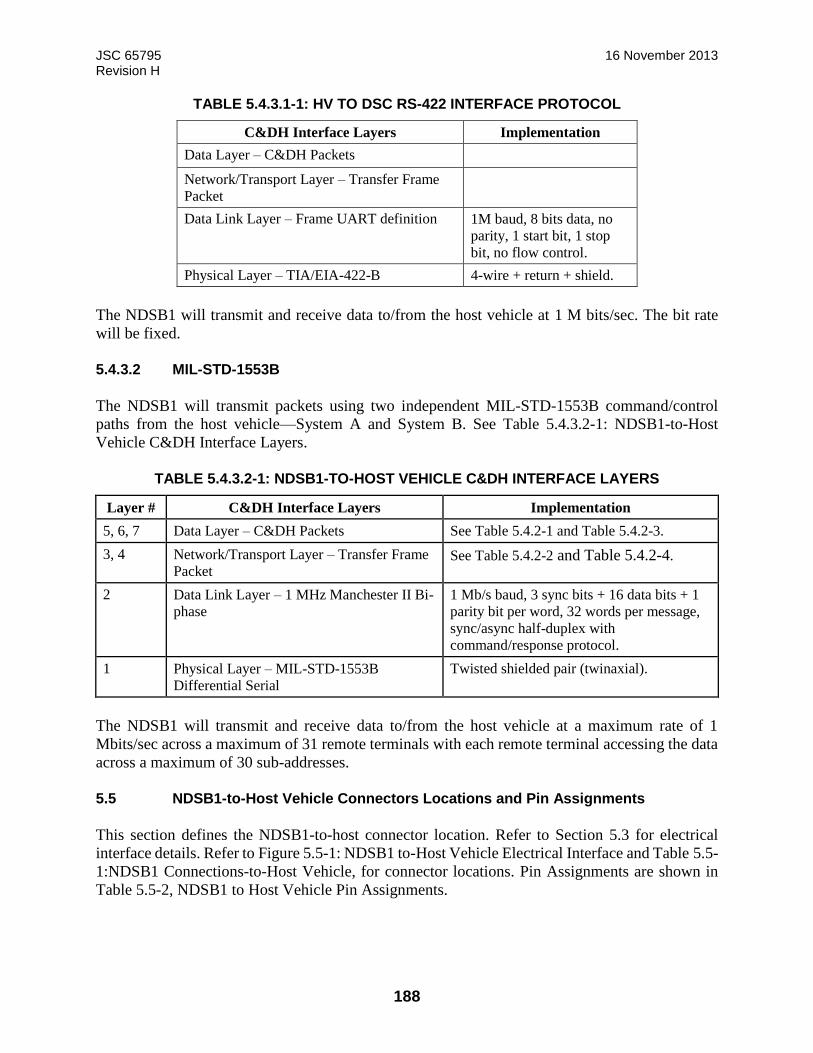
JSC 65795 16 November 2013 Revision H
188
TABLE 5.4.3.1-1: HV TO DSC RS-422 INTERFACE PROTOCOL
C&DH Interface Layers Implementation
Data Layer – C&DH Packets
Network/Transport Layer – Transfer Frame
Packet
Data Link Layer – Frame UART definition 1M baud, 8 bits data, no
parity, 1 start bit, 1 stop
bit, no flow control.
Physical Layer – TIA/EIA-422-B 4-wire + return + shield.
The NDSB1 will transmit and receive data to/from the host vehicle at 1 M bits/sec. The bit rate
will be fixed.
5.4.3.2 MIL-STD-1553B
The NDSB1 will transmit packets using two independent MIL-STD-1553B command/control
paths from the host vehicle—System A and System B. See Table 5.4.3.2-1: NDSB1-to-Host
Vehicle C&DH Interface Layers.
TABLE 5.4.3.2-1: NDSB1-TO-HOST VEHICLE C&DH INTERFACE LAYERS
Layer # C&DH Interface Layers Implementation
5, 6, 7 Data Layer – C&DH Packets See Table 5.4.2-1 and Table 5.4.2-3.
3, 4 Network/Transport Layer – Transfer Frame
Packet See Table 5.4.2-2 and Table 5.4.2-4.
2 Data Link Layer – 1 MHz Manchester II Bi-
phase
1 Mb/s baud, 3 sync bits + 16 data bits + 1
parity bit per word, 32 words per message,
sync/async half-duplex with
command/response protocol.
1 Physical Layer – MIL-STD-1553B
Differential Serial
Twisted shielded pair (twinaxial).
The NDSB1 will transmit and receive data to/from the host vehicle at a maximum rate of 1
Mbits/sec across a maximum of 31 remote terminals with each remote terminal accessing the data
across a maximum of 30 sub-addresses.
5.5 NDSB1-to-Host Vehicle Connectors Locations and Pin Assignments
This section defines the NDSB1-to-host connector location. Refer to Section 5.3 for electrical
interface details. Refer to Figure 5.5-1: NDSB1 to-Host Vehicle Electrical Interface and Table 5.5-
1:NDSB1 Connections-to-Host Vehicle, for connector locations. Pin Assignments are shown in
Table 5.5-2, NDSB1 to Host Vehicle Pin Assignments.
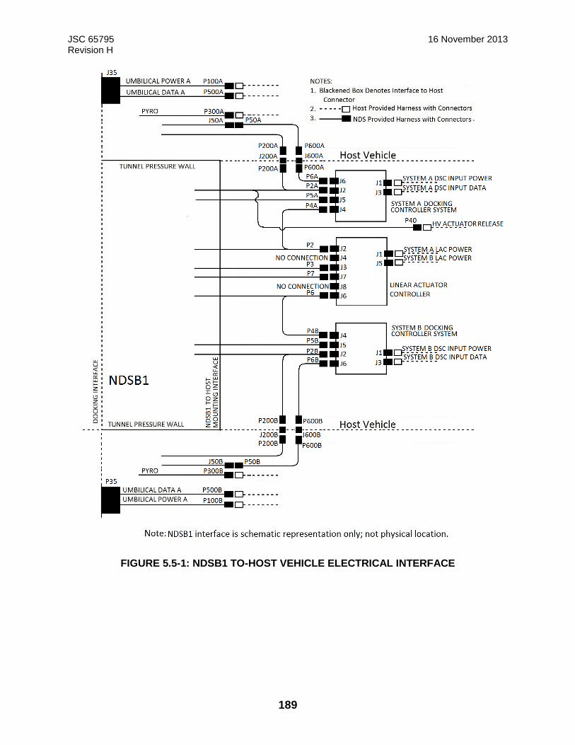
JSC 65795 16 November 2013 Revision H
189
FIGURE 5.5-1: NDSB1 TO-HOST VEHICLE ELECTRICAL INTERFACE
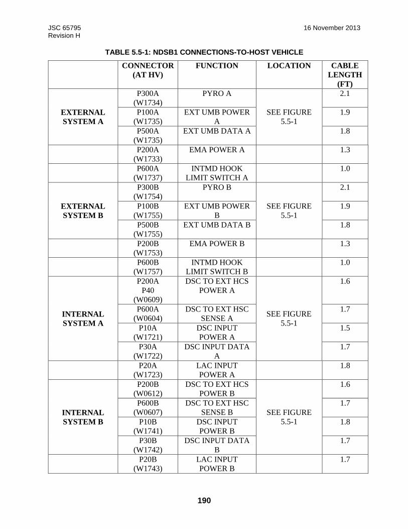
JSC 65795 16 November 2013 Revision H
190
TABLE 5.5-1: NDSB1 CONNECTIONS-TO-HOST VEHICLE
CONNECTOR
(AT HV)
FUNCTION LOCATION CABLE
LENGTH
(FT)
EXTERNAL
SYSTEM A
P300A
(W1734)
PYRO A
SEE FIGURE
5.5-1
2.1
P100A
(W1735)
EXT UMB POWER
A
1.9
P500A
(W1735)
EXT UMB DATA A 1.8
P200A
(W1733)
EMA POWER A 1.3
P600A
(W1737)
INTMD HOOK
LIMIT SWITCH A
1.0
EXTERNAL
SYSTEM B
P300B
(W1754)
PYRO B
SEE FIGURE
5.5-1
2.1
P100B
(W1755)
EXT UMB POWER
B
1.9
P500B
(W1755)
EXT UMB DATA B 1.8
P200B
(W1753)
EMA POWER B 1.3
P600B
(W1757)
INTMD HOOK
LIMIT SWITCH B
1.0
INTERNAL
SYSTEM A
P200A
P40
(W0609)
DSC TO EXT HCS
POWER A
SEE FIGURE
5.5-1
1.6
P600A
(W0604)
DSC TO EXT HSC
SENSE A
1.7
P10A
(W1721)
DSC INPUT
POWER A
1.5
P30A
(W1722)
DSC INPUT DATA
A
1.7
P20A
(W1723)
LAC INPUT
POWER A
1.8
INTERNAL
SYSTEM B
P200B
(W0612)
DSC TO EXT HCS
POWER B
SEE FIGURE
5.5-1
1.6
P600B
(W0607)
DSC TO EXT HSC
SENSE B
1.7
P10B
(W1741)
DSC INPUT
POWER B
1.8
P30B
(W1742)
DSC INPUT DATA
B
1.7
P20B
(W1743)
LAC INPUT
POWER B
1.7
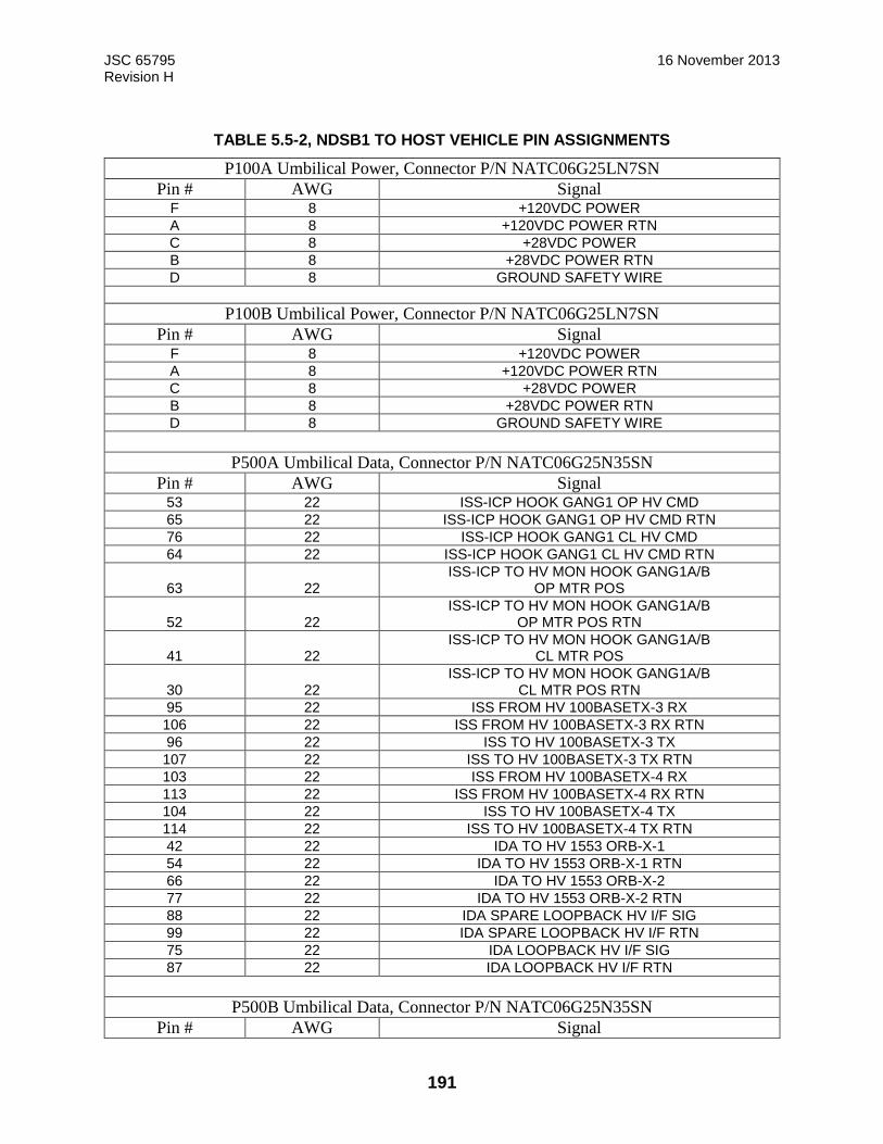
JSC 65795 16 November 2013 Revision H
191
TABLE 5.5-2, NDSB1 TO HOST VEHICLE PIN ASSIGNMENTS
P100A Umbilical Power, Connector P/N NATC06G25LN7SN
Pin # AWG Signal F 8 +120VDC POWER A 8 +120VDC POWER RTN C 8 +28VDC POWER B 8 +28VDC POWER RTN D 8 GROUND SAFETY WIRE
P100B Umbilical Power, Connector P/N NATC06G25LN7SN
Pin # AWG Signal F 8 +120VDC POWER A 8 +120VDC POWER RTN C 8 +28VDC POWER B 8 +28VDC POWER RTN D 8 GROUND SAFETY WIRE
P500A Umbilical Data, Connector P/N NATC06G25N35SN
Pin # AWG Signal 53 22 ISS-ICP HOOK GANG1 OP HV CMD 65 22 ISS-ICP HOOK GANG1 OP HV CMD RTN 76 22 ISS-ICP HOOK GANG1 CL HV CMD 64 22 ISS-ICP HOOK GANG1 CL HV CMD RTN
63 22 ISS-ICP TO HV MON HOOK GANG1A/B
OP MTR POS
52 22 ISS-ICP TO HV MON HOOK GANG1A/B
OP MTR POS RTN
41 22 ISS-ICP TO HV MON HOOK GANG1A/B
CL MTR POS
30 22 ISS-ICP TO HV MON HOOK GANG1A/B
CL MTR POS RTN 95 22 ISS FROM HV 100BASETX-3 RX 106 22 ISS FROM HV 100BASETX-3 RX RTN 96 22 ISS TO HV 100BASETX-3 TX 107 22 ISS TO HV 100BASETX-3 TX RTN 103 22 ISS FROM HV 100BASETX-4 RX 113 22 ISS FROM HV 100BASETX-4 RX RTN 104 22 ISS TO HV 100BASETX-4 TX 114 22 ISS TO HV 100BASETX-4 TX RTN 42 22 IDA TO HV 1553 ORB-X-1 54 22 IDA TO HV 1553 ORB-X-1 RTN 66 22 IDA TO HV 1553 ORB-X-2 77 22 IDA TO HV 1553 ORB-X-2 RTN 88 22 IDA SPARE LOOPBACK HV I/F SIG 99 22 IDA SPARE LOOPBACK HV I/F RTN 75 22 IDA LOOPBACK HV I/F SIG 87 22 IDA LOOPBACK HV I/F RTN
P500B Umbilical Data, Connector P/N NATC06G25N35SN
Pin # AWG Signal

JSC 65795 16 November 2013 Revision H
192
53 22 ISS-ICP HOOK GANG2 OP HV CMD 65 22 ISS-ICP HOOK GANG2 OP HV CMD RTN 76 22 ISS-ICP HOOK GANG2 CL HV CMD 64 22 ISS-ICP HOOK GANG2 CL HV CMD RTN
63 22 ISS-ICP TO HV MON HOOK GANG2A/B
OP MTR POS
52 22 ISS-ICP TO HV MON HOOK GANG2A/B
OP MTR POS RTN
41 22 ISS-ICP TO HV MON HOOK GANG2A/B
CL MTR POS
30 22 ISS-ICP TO HV MON HOOK GANG2A/B
CL MTR POS RTN 95 22 ISS FROM HV 100BASETX RX 106 22 ISS FROM HV 100BASETX RX RTN 96 22 ISS TO HV 100BASETX TX 107 22 ISS TO HV 100BASETX TX RTN 103 22 ISS FROM HV 100BASETX RX 113 22 ISS FROM HV 100BASETX RX RTN 104 22 ISS TO HV 100BASETX TX 114 22 ISS TO HV 100BASETX TX RTN 42 22 IDA TO HV 1553 -1 54 22 IDA TO HV 1553 -1 RTN 66 22 IDA TO HV 1553 -2 77 22 IDA TO HV 1553 -2 RTN 88 22 IDA SPARE LOOPBACK HV I/F SIG 99 22 IDA SPARE LOOPBACK HV I/F RTN 75 22 IDA LOOPBACK HV I/F SIG 87 22 IDA LOOPBACK HV I/F RTN
P300A Active Pyro, Connector P/N NATC06G13N98SN
Pin # AWG Signal B 20 NSI ACTIVE HOOKS1 (+) D 20 NSI ACTIVE HOOKS1 (-) F 20 NSI ACTIVE HOOKS2 (+) H 20 NSI ACTIVE HOOKS2 (-)
P300B Passive Pyro, Connector P/N NATC06G13N98SN
Pin # AWG Signal B 20 NSI PASSIVE HOOKS1 (+) D 20 NSI PASSIVE HOOKS1 (-) F 20 NSI PASSIVE HOOKS2 (+) H 20 NSI PASSIVE HOOKS2 (-)
J200A EXTERNAL EMA POWER, Connector P/N NATC77H25N29PPN
Pin # AWG Signal
TBD65
J200B EXTERNAL EMA POWER, Connector P/N NATC77H25N29PPN
Pin # Pin # Pin #
TBD65

JSC 65795 16 November 2013 Revision H
193
J600A EXTERNAL LIMIT SWITCHES, Connector P/N NATC77H25N35PPN
Pin # AWG Signal
TBD 66
J600B EXTERNAL LIMIT SWITCHES, Connector P/N NATC77H25N35PPN
Pin # AWG Signal
TBD66
P40 HOST VEHICLE ACTUATOR RELEASE, Connector P/N NATC06G13N35SN
Pin # AWG Signal 21 22 HV ACTUATION PETAL1 + 15 22 HV ACTUATION PETAL1 - 20 22 HV ACTUATION PETAL2 + 19 22 HV ACTUATION PETAL2 - 22 22 HV ACTUATION PETAL3 + 18 22 HV ACTUATION PETAL3 -
5.5.1 NDSB1 Power Transfer Interface to Host Vehicle Connector Location
Deleted
5.5.1.1 NDSB1 Power Transfer Interface to Host
Deleted
5.5.2 NDSB1 Data Transfer Interface to Host
Deleted
5.5.2.1 NDSB1 Data Transfer Interface to Host
Deleted
5.5.3 Water Transfer
Reserved
5.5.4 Fuel Transfer
Reserved

JSC 65795 16 November 2013 Revision H
194
5.5.5 Pressurant Transfer
Reserved
5.5.6 Oxidizer Transfer
Reserved
JSC 65795 16 November 2013 Revision H
195
6.0 NDSB1-TO- SUPPORT EQUIPMENT INTERFACE TBR13
The NDSB1 contains features built in to accommodate Test Support Equipment interfaces for
attaching lifting hardware, seal protective covers, bell jars, and electrical connectors.
6.1 Structural/Mechanical
6.1.1 Lifting Interface TBR13
Refer to Figure 4.1.2.3-1 for details showing lift points. The lift points are designed for a vertical
lift only and require the use of an NASA Docking System Project (NDSP) provided spreader bar.
For alternate installation orientations, contact the NDSP Office.
6.1.2 Seal Cover Interface TBR13
NDSP-provided upper and lower seal covers will provide protection for the seals during handling
and shipping of the NDSB1 hardware (TBR).
The lower seal cover attaches to the NDSB1 lower surface through the NDSB1-Host Vehicle
mounting interface holes (TBR) per Figure 5.2.1.2-2.
6.1.3 Pressure Dome Interfaces TBR13
NDSP-provided upper and lower pressure domes will be used for seal leak tests during ground
testing. In addition to ground testing of seal leaks, the upper pressure dome will be used for leak
testing of the upper seal while mounted to a vehicle.
The upper dome will attach to the NDSB1 by engaging the NDSB1 passive hook with a manually
activated hook on the pressure dome side. The upper pressure dome includes pins and sockets to
align with the NDSB1 alignment pins. Figure 4.1.3.1-1 shows the specific alignment pin and hook
locations.
The lower pressure dome that will be used in ground testing of the NDSB1 will attach to the
NDSB1 through the 48 NDSB1-to-vehicle bolt pattern. Refer to Figure 5.2.1.2-2.
6.1.4 Pressure Seal Interface, Pass-Through Connectors TBR13
TBR13
6.1.5 Pressure Seal Interface, Test Ports TBR13
Two pressure test ports are located on the NDSB1 host seal interface to provide the capability to
perform individual seal leak tests of the host seal interface on the ground prior to host integration
and while integrated to the host vehicle.
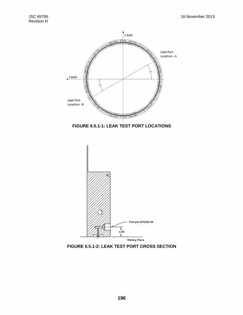
JSC 65795 16 November 2013 Revision H
196
FIGURE 6.5.1-1: LEAK TEST PORT LOCATIONS
FIGURE 6.5.1-2: LEAK TEST PORT CROSS SECTION
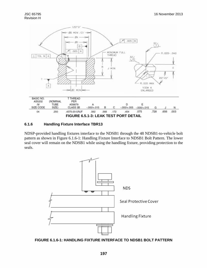
JSC 65795 16 November 2013 Revision H
197
FIGURE 6.5.1-3: LEAK TEST PORT DETAIL
6.1.6 Handling Fixture Interface TBR13
NDSP-provided handling fixtures interface to the NDSB1 through the 48 NDSB1-to-vehicle bolt
pattern as shown in Figure 6.1.6-1: Handling Fixture Interface to NDSB1 Bolt Pattern. The lower
seal cover will remain on the NDSB1 while using the handling fixture, providing protection to the
seals.
FIGURE 6.1.6-1: HANDLING FIXTURE INTERFACE TO NDSB1 BOLT PATTERN
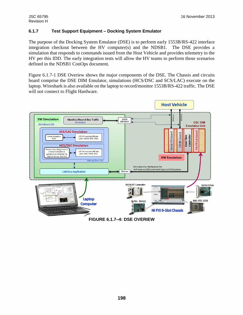
JSC 65795 16 November 2013 Revision H
198
6.1.7 Test Support Equipment – Docking System Emulator
The purpose of the Docking System Emulator (DSE) is to perform early 1553B/RS-422 interface
integration checkout between the HV computer(s) and the NDSB1. The DSE provides a
simulation that responds to commands issued from the Host Vehicle and provides telemetry to the
HV per this IDD. The early integration tests will allow the HV teams to perform those scenarios
defined in the NDSB1 ConOps document.
Figure 6.1.7-1 DSE Overiew shows the major components of the DSE. The Chassis and circuits
board comprise the DSE DIM Emulator, simulations (HCS/DSC and SCS/LAC) execute on the
laptop. Wireshark is also available on the laptop to record/monitor 1553B/RS-422 traffic. The DSE
will not connect to Flight Hardware.
FIGURE 6.1.7–4: DSE OVERIEW

JSC 65795 16 November 2013 Revision H
199
7.0 Host Requirements for NASA Docking System Integration
This section defines the requirements that the host Vehicle must meet in order to control integrated
host/NDSB1 hazards and/or specific host requirements to integrate the NDSB1. It is incumbent on
the host to perform any analysis or test necessary to meet these requirements. The host vehicle is
responsible for both developing the verification methods and verifying these requirements.
7.1 Interface Characteristics (Host Vehicle)
7.1.1 Physical Interface
7.1.1.1 Mechanical
7.1.1.1.1 NDSB1 Keep Out Zones
The HV shall remain outside the KOZs as defined in Figure 3.8.1.3.1-2, NDSB1 Static Envelope,
Docked Configuration.
Note: The entire envelope is a keep out zone for the Host Vehicle prior to start of docking and
after dock
7.1.1.2 Structural Attachment
The Host Vehicle shall be physically attached to the NDSB1 as shown in Figure 5.2.1.2-2.
7.1.1.2.1 Seals
7.1.1.2.1.1 Host Vehicle Seal Interface
The HV shall provide a chemical conversion coated aluminum seal land which corresponds to the
NDSB1 seal locations defined in Figure 5.2.1.2- NDSB1-to-Host Vehicle Mounting Interface.
7.1.1.2.2 Mounting
7.1.1.2.2.1 Host Vehicle Mounting Inserts
The HV shall use the locking insert KNML10 x 1.5TX, as shown in Figure 5.2.1-1, NSB1-To-
Host Vehicle Mounting Interface (Host Vehicle Mounting Flange Insert Detail (Insert)) for the
structural interface to NDSB1 to prevent fastener back-out if Host Vehicle Through Bolt Mounting
in accordance with 7.1.1.2.2.2 is not used.
7.1.1.2.2.2 Host Vehicle Through Bolt Mounting
The HV shall use the use bolt with nut fastener as shown in Figure 5.2.1-1, NSB1-To-Host Vehicle
Mounting Interface (Example Host-Through Hole Detail) if Host Vehicle Mounting Inserts in
accordance with 7.1.1.2.2.1 are not used.

JSC 65795 16 November 2013 Revision H
200
7.1.1.2.2.3 Host Vehicle Mounting Flange
7.1.1.2.2.3.1 Flange Thickness
The HV shall provide a mounting flange no less than 0.75 in. (19.05 mm) thick.
7.1.1.2.2.3.2 Flange Stiffness at maximum gap
The HV flange stiffness shall be such that the maximum gap at the HV to NDSB1 seal interface is
less than .002 inches under worse case loading.
Note: Gap values are the amount of flange separation at the inner seal midline. Stiffness is
measured as a force applied at the bolt circle.
7.1.1.2.2.3.3 Uniform Flange Stiffness
The HV shall provide a uniform interface flange stiffness ≥ 1,000 kip/in (TBR30). Flange stiffness
is defined as the ratio of load to deflection when an axial force is applied at the interface bolt hole
centerline and the maximum displacement is measured along the radius of the inner seal midline
(R=25.46”). Reference configuration is shown in Figure 7.1.1.2.2.3.3-1 Definition of Load
Deflection at Flange.
FIGURE 7.1.1.2.2.3.3-1 DEFINITION OF LOAD DEFLECTION AT FLANGE
7.1.1.2.3 Host Vehicle Provided MMOD Shield
7.1.1.2.3.1 Host Vehicle MMOD
The HV shall be responsible for MMOD protection for external components of theNDSB1 for the
area defined in Figure 5.2.1.2-1: NDSB1 Host-Provided MMOD Interface.
7.5 ° of NDS IDD HV Flange Segment Shown
Tangential Symmetry constraints
Fixed at lower edge
No pressure
Measured Deflection
At Inner Seal MidlineApplied
Load
(R25.46”)
NDS Static Seal Centerlines

JSC 65795 16 November 2013 Revision H
201
7.1.1.2.3.2 Minimum Probability of No Penetration
The HV integrating NDSB1 shall provide MMOD shielding for NDSB1 to meet HV Probability
of No Penetration (PNP) requirements for 214 days.
7.1.1.2.3.3 Host Vehicle External Thermal Interface
The HV hardware shall limit heat transfer at the external mounting interface defined in Figure
5.2.1.2-1: NDSB1 Host-Provided MMOD Interface to comply with thermal interface requirements
in Sections 5.2.2 and 7.1.4.2.
7.1.1.2.3.4 Host Vehicle MMOD Temperature
Deleted
7.1.2 Electronic Interface
7.1.2.1 Functional Electrical and Signal Interfaces
7.1.2.1.1 Host Vehicle Electrical and Signal Interfaces
The Host Vehicle shall provide the functional electrical and signal interfaces as shown in Table
7.1.2.1.1-1 NDSB1-to-Host Vehicle Electrical Interface at the interface between NDSB1 and the
Host Vehicle.
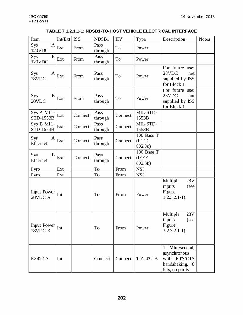
JSC 65795 16 November 2013 Revision H
202
TABLE 7.1.2.1.1-1: NDSB1-TO-HOST VEHICLE ELECTRICAL INTERFACE
Item Int/Ext ISS NDSB1 HV Type Description Notes Sys A
120VDC Ext From Pass
through To Power
Sys B
120VDC Ext From
Pass
through To Power
Sys A
28VDC Ext From
Pass
through To Power
For future use;
28VDC not
supplied by ISS
for Block 1
Sys B
28VDC Ext From
Pass
through To Power
For future use;
28VDC not
supplied by ISS
for Block 1
Sys A MIL-
STD-1553B Ext Connect
Pass
through Connect
MIL-STD-
1553B
Sys B MIL-
STD-1553B Ext Connect
Pass
through Connect
MIL-STD-
1553B
Sys A
Ethernet Ext Connect
Pass
through Connect
100 Base T
(IEEE
802.3u)
Sys B
Ethernet Ext Connect
Pass
through Connect
100 Base T
(IEEE
802.3u)
Pyro Ext To From NSI
Pyro Ext To From NSI
Input Power
28VDC A Int To From Power
Multiple 28V
inputs (see
Figure
3.2.3.2.1-1).
Input Power
28VDC B Int To From Power
Multiple 28V
inputs (see
Figure
3.2.3.2.1-1).
RS422 A Int Connect Connect TIA-422-B
1 Mbit/second,
asynchronous
with RTS/CTS
handshaking, 8
bits, no parity
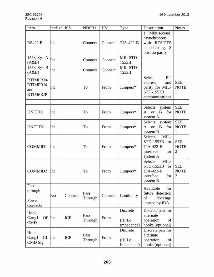
JSC 65795 16 November 2013 Revision H
203
Item Int/Ext ISS NDSB1 HV Type Description Notes
RS422 B Int Connect Connect TIA-422-B
1 Mbit/second,
asynchronous
with RTS/CTS
handshaking, 8
bits, no parity
1553 Sys A
(A&B) Int Connect Connect
MIL-STD-
1553B
1553 Sys B
(A&B) Int Connect Connect
MIL-STD-
1553B
RTJMPRJ0-
RTJMPRJ4
and
RTJMPRJP
Int To From Jumpers*
Select RT
address and
parity for MIL-
STD-1553B
communications
SEE
NOTE
1
UNITID1 Int To From Jumpers*
Selects system
A or B for
system A
SEE
NOTE
1
UNITID2 Int To From Jumpers*
Selects system
A or B for
system B
SEE
NOTE
1
COMMID1 Int To From Jumpers*
Selects MIL-
STD-1553B or
TIA-422-B
interface for
system A
SEE
NOTE
2
COMMID2 Int To From Jumpers*
Selects MIL-
STD-1553B or
TIA-422-B
interface for
system B
SEE
NOTE
2
Feed
through
Power
Contacts
Ext Connect Pass
Through Connect Continuity
Available for
future detection
of docking;
unused by IDA
Hook
Gang1 OP
CMD
Int ICP Pass
Through From
Discrete
(Hi/Lo
Impedance)
Discrete pair for
alternate
operation of
hooks (optional)
Hook
Gang1 CL
CMD Sig
Int ICP Pass
Through From
Discrete
(Hi/Lo
Impedance)
Discrete pair for
alternate
operation of
hooks (optional)

JSC 65795 16 November 2013 Revision H
204
Item Int/Ext ISS NDSB1 HV Type Description Notes Hook
Gang1 OP
POS Sig
Int From Pass
Through To
Discrete
(Hi/Lo
Impedance)
Discrete pair for
alternate
operation of
hooks (optional)
Hook
Gang1 CL
POS Sig
Int From Pass
through To
Discrete
(Hi/Lo
Impedance)
Discrete pair for
alternate
operation of
hooks (optional)
Hook
Gang2 OP
CMD
Int ICP Pass
Through From
Discrete
(Hi/Lo
Impedance)
Discrete pair for
alternate
operation of
hooks (optional)
Hook
Gang2 CL
CMD Sig
Int ICP Pass
Through From
Discrete
(Hi/Lo
Impedance)
Discrete pair for
alternate
operation of
hooks (optional)
Hook
Gang2 OP
POS Sig
Int From Pass
Through To
Discrete
(Hi/Lo
Impedance)
Discrete pair for
alternate
operation of
hooks (optional)
Hook
Gang2 CL
POS Sig
Int From Pass
through To
Discrete
(Hi/Lo
Impedance)
Discrete pair for
alternate
operation of
hooks (optional)
Int – Internal to tunnel
Ext – External to tunnel
* Jumpers are used for three types of identifying, configuring or mapping/addressing of hardware.
• Communication ID
• Unit ID
• 1553 RT Selection
The DSC provides ten (10) jumper interfaces;
• six (6) 1553 RT
• two (2) Unit ID
• two (2) Communication ID
JSC 65795 16 November 2013 Revision H
205
Jumpers are only read on system startup. The DSC uses pull-up resistors connected to at least 3
VDC and supplying at least 490 μA of current for each of the three types of Jumpers. This type of
hardware design determines whether or not any particular pin within a connector has an electrical
characteristic of being “high” or “low”. It is the electrical state of these individual pins or
combination of pins that allows the FPGA to read, map, or assign hardware configurations within
the NDSB1 assembly.
NOTE 1: There are two DSC avionics boxes per each NDSB1 assembly. Both of these DSCs are
identified with the same part number; however a Unit Identification (ID) jumper will be installed
on each of the DSCs that will address or specifically map which individual DSC belongs to System
A and which DSC belongs to System B.
NOTE 2: A standard dual redundant MIL-STD-1553B communications interface is provided
between the HV and the DSC. Either RS-422 or MIL-STD-1553B interfaces can be used for
receiving commands from the HV and sending status information to the HV. Each of the two
systems (A and B) has its own communications interfaces. The Host Vehicle will utilize either
the RS-422 interface or the MIL-STD-1553B interface, but not both for communication between
the HV and the DSC. Selection of which interface is active in the avionics is determined by the
two Communication ID Jumpers, one jumper for each DSC. The Communication ID Jumper is
installed between either the COMMID1+ and COMMID1- pins or the COMMID2+ and
COMMID2- pins. Each of the two DSCs within the NDSB1 assembly shall check the
Communication ID pins. If the COMMID1+ and COMMID- pins are shorted, and the
COMMID2+ and COMMID2- pins are not shorted, the data shall be communicated over the RS-
422 interface. If the COMMID1+ and COMMID- pins are not shorted, and the COMMID2+ and
COMMID2- pins are shorted, data shall be communicated over the MIL-STD-1553 interface. If
both sets of Communication ID pins are shorted together or neither pair is shorted together, this
indicates a failure, and the controller will transition to a non-operational state with no
communication provided to the HV.
7.1.2.1.2 Host Vehicle Separation of Power and Command
The HV shall physically separate redundant avionics power and command functions.
7.1.2.2 Redundant Wiring
7.1.2.2.1 Host Vehicle Wiring
The HV shall physically separate or protect redundant interconnecting wiring.
Note: To ensure that an event which damages one wire is not likely to prevent the other redundant
wire from performing its function.
7.1.2.3 Umbilical Interface
The NDSB1 provides the utilities necessary for pass-through transfer of power and data from/to
the ISS and the Host Vehicle.
JSC 65795 16 November 2013 Revision H
206
7.1.2.3.1 Host Vehicle Umbilical Data Transfer ISS to Host Vehicle
The NDSB1 to HV umbilical interfaces shall provide the utilities to transfer two hard-line MIL-
STD-1553 and two IEEE 802.3u Ethernet data and communication between the mated vehicles
when the Host Vehicle is hard mated to the ISS.
7.1.2.3.1.1 Host Vehicle Receive IEEE 802.3u Ethernet Data
The HV shall receive data via two redundant IEEE 802.3u Ethernet data buses from the ISS via
the NDSB1 to HV interface.
7.1.2.3.1.2 Host Vehicle Receive MIL-STD-1553 Data Bus
After umbilical mate to ISS, the HV shall receive data via two redundant MIL-STD-1553B data
buses from the ISS via the NDSB1 to HV interface.
7.1.2.3.1.3 Host Vehicle Terminate MIL-STD-1553 Data Bus
The HV shall terminate MIL-STD-1553 buses on the HV side of the NDSB1 to HV interface in
accordance with MIL-STD-1553B Notice 2.
7.1.2.3.2 Host Vehicle Umbilical Power Transfer from ISS
The Host Vehicle shall receive redundant 120 VDC power from the ISS via the NDSB1 to HV
interface as shown in Table 7.1.2.1.1-1 NDSB1-to-Host Vehicle Electrical Interface to the NDSB1.
7.1.2.4 Data Interface
Each NDSB1 system communicates with its HV via either a TIA-422B serial interface or MIL-
STD-1553 interface.
7.1.2.4.1 Two’s Complement Notation
The HV shall employ two’s complement notation to represent all signed integers.
7.1.2.4.2 Zero Fill Unused Bits and Words
The HV shall zero fill all unused (or spare) bits and words in HV to DSC messages.
7.1.2.4.3 Serial Data Communications
7.1.2.4.3.1 Host Vehicle MIL-STD-1553/TIA-422 Communication Jumper
The HV shall provide one Communication ID Jumper for each DSC to define whether a MIL-
STD-1553 or a TIA-422 communication interface will be used between the HV and the DSCs.
JSC 65795 16 November 2013 Revision H
207
Note: If the Communication ID Jumper is installed between the COMMID1+ and COMMID1-
pins then data will be communicated over the RS-422 interface. If the Communication ID Jumper
is installed between the COMMID2+ and COMMID2- pins then data will be communicated over
the MIL-STD-1553 interface. If both sets of Communication ID pins are shorted together or
neither pair is shorted together, this indicates a failure, and the controller will transition to a non-
operational state.
7.1.2.4.3.2 Host Vehicle Transformer-coupled Remote Terminal
The HV shall provide transformer-coupled stubs to connect the NDSB1 to the MIL-STD-1553B
buses.
7.1.2.4.3.3 Host Vehicle Commanding
7.1.2.4.3.3.1 Host Vehicle Commands to NDSB1
The HV shall control the NSDB1 using the commands listed in Appendix C.
7.1.2.4.3.3.2 Host Vehicle Command Rates
The HV shall provide commands to the NDSB1 at a maximum rate of 50 Hz.
7.1.2.4.3.3.3 Host Vehicle TIA-422 Commanding
When RS-422 communications is selected, the HV shall send commands to the Primary DSC at a
minimum rate of one command per second.
Note: The Primary DSC will monitor the serial input to detect the Host Vehicle. If the HV has no
commands to send, an “RS_422_Keep_Alive” command is available for the sole purpose of
meeting this requirement. If the DSC does not detect a command within 3 seconds, it will assume
the HV is not present or has failed and will revert to Monitor Mode.
7.1.2.4.3.4 Host Vehicle Reception of NDSB1 Data
The HV shall receive serial data from the NDSB1 as defined in Appendix C
7.1.2.4.3.5 Host vehicle Response to NDSB1 Data
7.1.2.4.3.5.1 Response to Initial Docking Contact
The HV Guidance, Navigation, and Control (GN&C) shall transition into free drift within 500 ms
of receipt of the Initial Contact indication in the NDSB1 H&S message from the NDSB1.
7.1.2.4.4 C&DH TIA-422-B Network Topology
The HV shall implement a point-to-point network topology.

JSC 65795 16 November 2013 Revision H
208
7.1.2.4.5 C&DH MIL-STD-1553B Interface
7.1.2.4.5.1 Host Vehicle MIL-STD-1553B Bus Controller
The HV shall perform Bus Controller (BC) functions in accordance with MIL-STD-1553B.
7.1.2.4.5.2 Host Vehicle MIL-STD-1553B Parity
The HV shall use odd parity when setting the RT address parity bit in accordance with MIL_STD-
1553.
7.1.2.4.5.3 Host Vehicle MIL-STD-1553 Mode Commands
The HV shall transmit the mode code commands as defined in MIL-STD-1553B Notice 2.
7.1.2.4.5.4 Host Vehicle Response to NDSB1 H&S Data
7.1.2.4.5.4.1 Host Vehicle Isolation of NDSB1 Faults
The HV shall isolate NDSB1 faults to the recovery level.
7.1.2.5 Pyrotechnic Interface
The HV shall provide the pyrotechnical interfaces shown in Figure 7.1.2.5-1, NDSB1 Pyrotechnic
System Architecture.
Note: The Pyrotechnic System is used in a contingency scenario in the event demating a HV is
prevented because of a malfunction of the Hook Assembly.
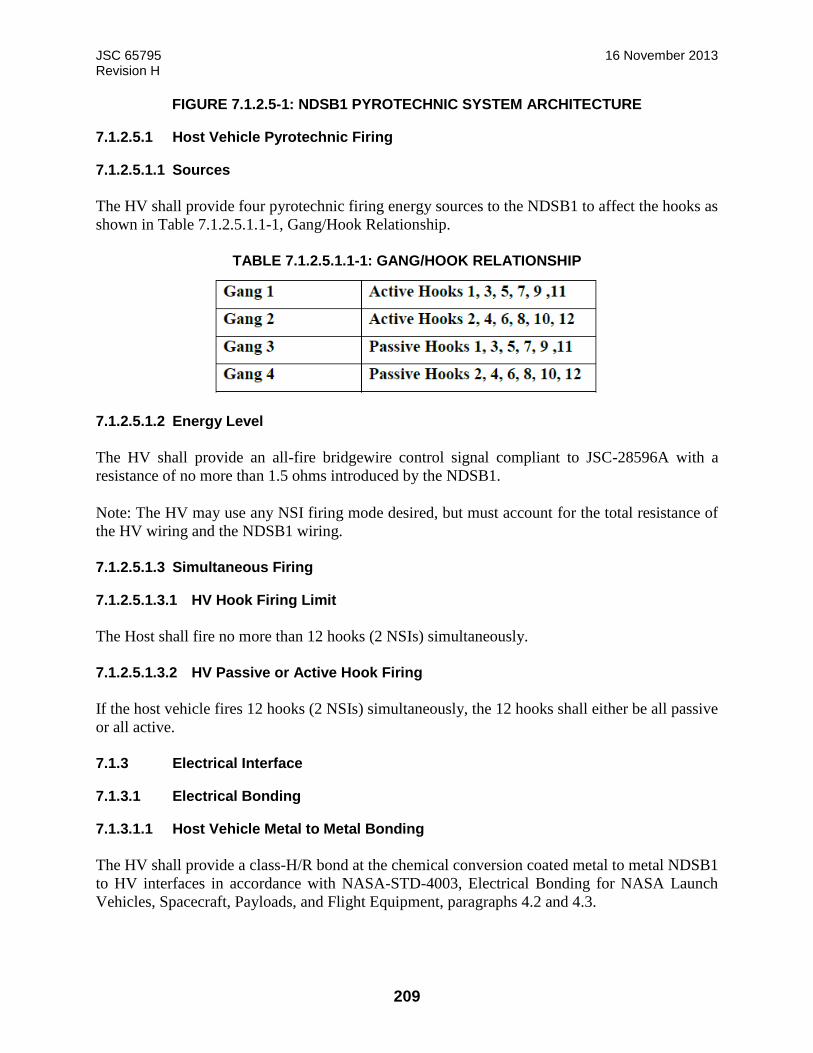
JSC 65795 16 November 2013 Revision H
209
FIGURE 7.1.2.5-1: NDSB1 PYROTECHNIC SYSTEM ARCHITECTURE
7.1.2.5.1 Host Vehicle Pyrotechnic Firing
7.1.2.5.1.1 Sources
The HV shall provide four pyrotechnic firing energy sources to the NDSB1 to affect the hooks as
shown in Table 7.1.2.5.1.1-1, Gang/Hook Relationship.
TABLE 7.1.2.5.1.1-1: GANG/HOOK RELATIONSHIP
7.1.2.5.1.2 Energy Level
The HV shall provide an all-fire bridgewire control signal compliant to JSC-28596A with a
resistance of no more than 1.5 ohms introduced by the NDSB1.
Note: The HV may use any NSI firing mode desired, but must account for the total resistance of
the HV wiring and the NDSB1 wiring.
7.1.2.5.1.3 Simultaneous Firing
7.1.2.5.1.3.1 HV Hook Firing Limit
The Host shall fire no more than 12 hooks (2 NSIs) simultaneously.
7.1.2.5.1.3.2 HV Passive or Active Hook Firing
If the host vehicle fires 12 hooks (2 NSIs) simultaneously, the 12 hooks shall either be all passive
or all active.
7.1.3 Electrical Interface
7.1.3.1 Electrical Bonding
7.1.3.1.1 Host Vehicle Metal to Metal Bonding
The HV shall provide a class-H/R bond at the chemical conversion coated metal to metal NDSB1
to HV interfaces in accordance with NASA-STD-4003, Electrical Bonding for NASA Launch
Vehicles, Spacecraft, Payloads, and Flight Equipment, paragraphs 4.2 and 4.3.
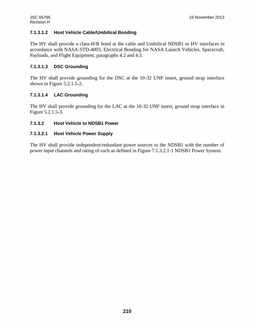
JSC 65795 16 November 2013 Revision H
210
7.1.3.1.2 Host Vehicle Cable/Umbilical Bonding
The HV shall provide a class-H/R bond at the cable and Umbilical NDSB1 to HV interfaces in
accordance with NASA-STD-4003, Electrical Bonding for NASA Launch Vehicles, Spacecraft,
Payloads, and Flight Equipment, paragraphs 4.2 and 4.3.
7.1.3.1.3 DSC Grounding
The HV shall provide grounding for the DSC at the 10-32 UNF insert, ground strap interface
shown in Figure 5.2.1.5-2.
7.1.3.1.4 LAC Grounding
The HV shall provide grounding for the LAC at the 10-32 UNF insert, ground strap interface in
Figure 5.2.1.5-3.
7.1.3.2 Host Vehicle to NDSB1 Power
7.1.3.2.1 Host Vehicle Power Supply
The HV shall provide independent/redundant power sources to the NDSB1 with the number of
power input channels and rating of each as defined in Figure 7.1.3.2.1-1 NDSB1 Power System.

JSC 65795 16 November 2013 Revision H
211
*- This is three 5 amp power feeds
FIGURE 7.1.3.2.1-1: NDSB1 POWER SYSTEM
7.1.3.2.2 Host Vehicle Power Application
It is expected that the HV will apply power to the NDSB1 DSC A1 and A3 power feeds, or the
DSC B1 and B3 power feeds, immediately after exposing the NDSB1 structure to space. Note:
Power is needed to enable monitoring and SCS heaters.
7.1.3.2.2.1 LAC System A Power Application
The HV shall only apply power to the System A LAC power feeds (A2 and A4) after the successful
power up of the System A DSC, indicated by nominal H&S packets from the DSC.
7.1.3.2.2.2 LAC System B Power Application
The HV shall only apply power to the System B LAC power feeds (B2 and B4) after the successful
power up of the System B DSC, indicated by nominal H&S packets from the DSC.
LAC A
LAC B
Linear Actuators (6)
Host Vehicle
NDSB1
Tunnel
DSC A
DSC Control Power Sys A (2 Amp)
Heater/Motor Pwr Sys A (20 Amp)
LAC Control Power Sys A (2 Amp)
Linear Act Power Sys A (30 Amp)
DSC Control Power Sys B (2 Amp)
Heater/Motor Pwr Sys B (20 Amp)
Linear Act Power Sys B (30 Amp)
LAC Control Power Sys B (2 Amp)
Linear Actuators (6)
Heaters (3)
Heaters (3)
DSC B
HCS
Motors (10)
Motors (3)
Motors (3)
Motors (10)
Capture Latch Non-Explosive Actuation (15 Amp)
Capture Latch Mechanisms (3)*
A1
A3
A2
A4
B4
B2
B3
B1
(A) Effectors
(B) Effectors

JSC 65795 16 November 2013 Revision H
212
Note: The DSC must be powered on prior to the applying power to the corresponding LAC to
prevent loss of communications detection and safing by the LAC. Power is only applied to the
LAC in the Monitor, Manual, Active Docking, Standby Docking, and SCS Checkout modes.
Power is not applied to the LAC in the Undocking or HCS Checkout modes.
7.1.3.2.3 Host Vehicle Power to NDSB1 Consumption
7.1.3.2.3.1 Primary System Docking Power
The HV shall provide power to the primary NDSB1 system as shown in Table 7.1.3.2.3.1-1 during
docking.
TABLE 7.1.3.2.3.1-1: PRIMARY POWER UTILIZATION FOR DOCKING
Checkout & Active Docking Mode
Power Feed Max Peak Power (W)
2A DSC Control Power 25
20A HCM Power 490
2A LAC Control Power 15
30A Linear Actuator 460
7.1.3.2.3.2 Standby System Docking Power
The HV shall provide power to the standby NDSB1 system during docking as shown in Table
7.1.3.2.3.2-1.
TABLE 7.1.3.2.3.2-1: STANDBY UTILIZATION FOR DOCKING
Standby Docking Mode
Power Feed Max Peak Power (W)
2A DSC Control Power 25
20A HCMPower 490
2A LAC Control Power 15
30A Linear Actuator 5

JSC 65795 16 November 2013 Revision H
213
7.1.3.2.3.3 Primary System Undocking Power
The HV shall provide power to the primary NDSB1 System as shown in Table 7.1.3.2.3.3-1, during
undocking.
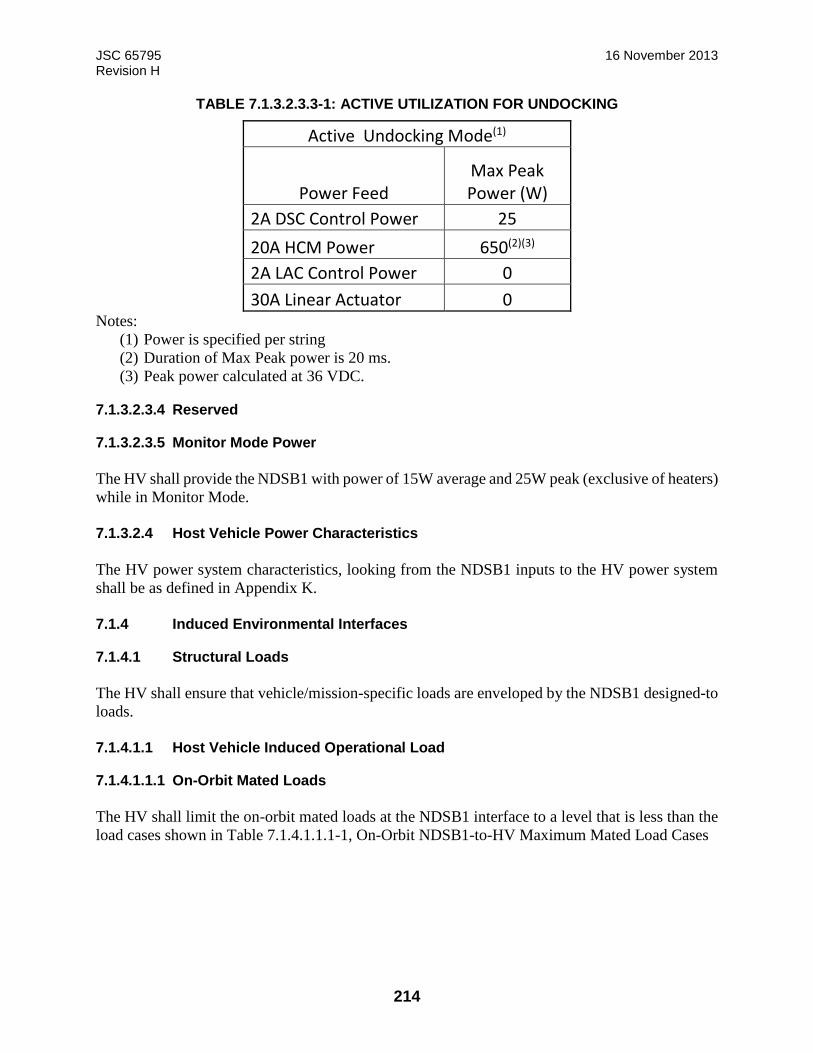
JSC 65795 16 November 2013 Revision H
214
TABLE 7.1.3.2.3.3-1: ACTIVE UTILIZATION FOR UNDOCKING
Active Undocking Mode(1)
Power Feed Max Peak Power (W)
2A DSC Control Power 25
20A HCM Power 650(2)(3)
2A LAC Control Power 0
30A Linear Actuator 0 Notes:
(1) Power is specified per string
(2) Duration of Max Peak power is 20 ms.
(3) Peak power calculated at 36 VDC.
7.1.3.2.3.4 Reserved
7.1.3.2.3.5 Monitor Mode Power
The HV shall provide the NDSB1 with power of 15W average and 25W peak (exclusive of heaters)
while in Monitor Mode.
7.1.3.2.4 Host Vehicle Power Characteristics
The HV power system characteristics, looking from the NDSB1 inputs to the HV power system
shall be as defined in Appendix K.
7.1.4 Induced Environmental Interfaces
7.1.4.1 Structural Loads
The HV shall ensure that vehicle/mission-specific loads are enveloped by the NDSB1 designed-to
loads.
7.1.4.1.1 Host Vehicle Induced Operational Load
7.1.4.1.1.1 On-Orbit Mated Loads
The HV shall limit the on-orbit mated loads at the NDSB1 interface to a level that is less than the
load cases shown in Table 7.1.4.1.1.1-1, On-Orbit NDSB1-to-HV Maximum Mated Load Cases
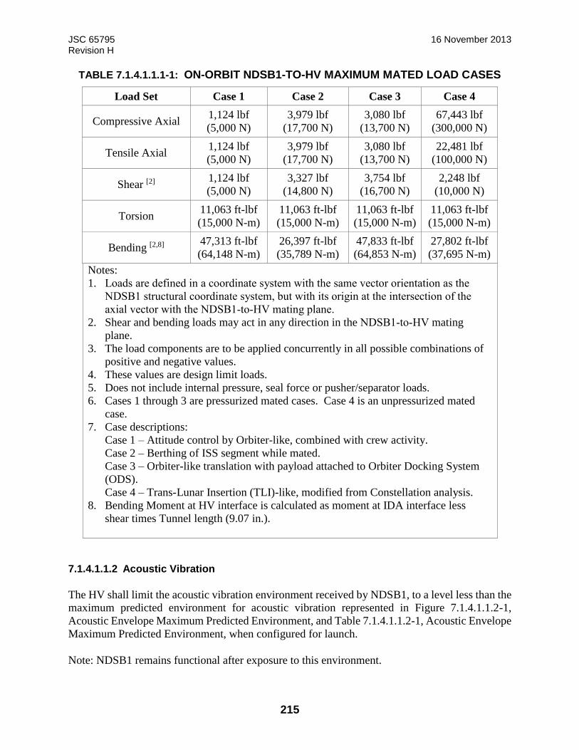
JSC 65795 16 November 2013 Revision H
215
TABLE 7.1.4.1.1.1-1: ON-ORBIT NDSB1-TO-HV MAXIMUM MATED LOAD CASES
Load Set Case 1 Case 2 Case 3 Case 4
Compressive Axial 1,124 lbf
(5,000 N)
3,979 lbf
(17,700 N)
3,080 lbf
(13,700 N)
67,443 lbf
(300,000 N)
Tensile Axial 1,124 lbf
(5,000 N)
3,979 lbf
(17,700 N)
3,080 lbf
(13,700 N)
22,481 lbf
(100,000 N)
Shear [2] 1,124 lbf
(5,000 N)
3,327 lbf
(14,800 N)
3,754 lbf
(16,700 N)
2,248 lbf
(10,000 N)
Torsion 11,063 ft-lbf
(15,000 N-m)
11,063 ft-lbf
(15,000 N-m)
11,063 ft-lbf
(15,000 N-m)
11,063 ft-lbf
(15,000 N-m)
Bending [2,8] 47,313 ft-lbf
(64,148 N-m)
26,397 ft-lbf
(35,789 N-m)
47,833 ft-lbf
(64,853 N-m)
27,802 ft-lbf
(37,695 N-m)
Notes:
1. Loads are defined in a coordinate system with the same vector orientation as the
NDSB1 structural coordinate system, but with its origin at the intersection of the
axial vector with the NDSB1-to-HV mating plane.
2. Shear and bending loads may act in any direction in the NDSB1-to-HV mating
plane.
3. The load components are to be applied concurrently in all possible combinations of
positive and negative values.
4. These values are design limit loads.
5. Does not include internal pressure, seal force or pusher/separator loads.
6. Cases 1 through 3 are pressurized mated cases. Case 4 is an unpressurized mated
case.
7. Case descriptions:
Case 1 – Attitude control by Orbiter-like, combined with crew activity.
Case 2 – Berthing of ISS segment while mated.
Case 3 – Orbiter-like translation with payload attached to Orbiter Docking System
(ODS).
Case 4 – Trans-Lunar Insertion (TLI)-like, modified from Constellation analysis.
8. Bending Moment at HV interface is calculated as moment at IDA interface less
shear times Tunnel length (9.07 in.).
7.1.4.1.1.2 Acoustic Vibration
The HV shall limit the acoustic vibration environment received by NDSB1, to a level less than the
maximum predicted environment for acoustic vibration represented in Figure 7.1.4.1.1.2-1,
Acoustic Envelope Maximum Predicted Environment, and Table 7.1.4.1.1.2-1, Acoustic Envelope
Maximum Predicted Environment, when configured for launch.
Note: NDSB1 remains functional after exposure to this environment.
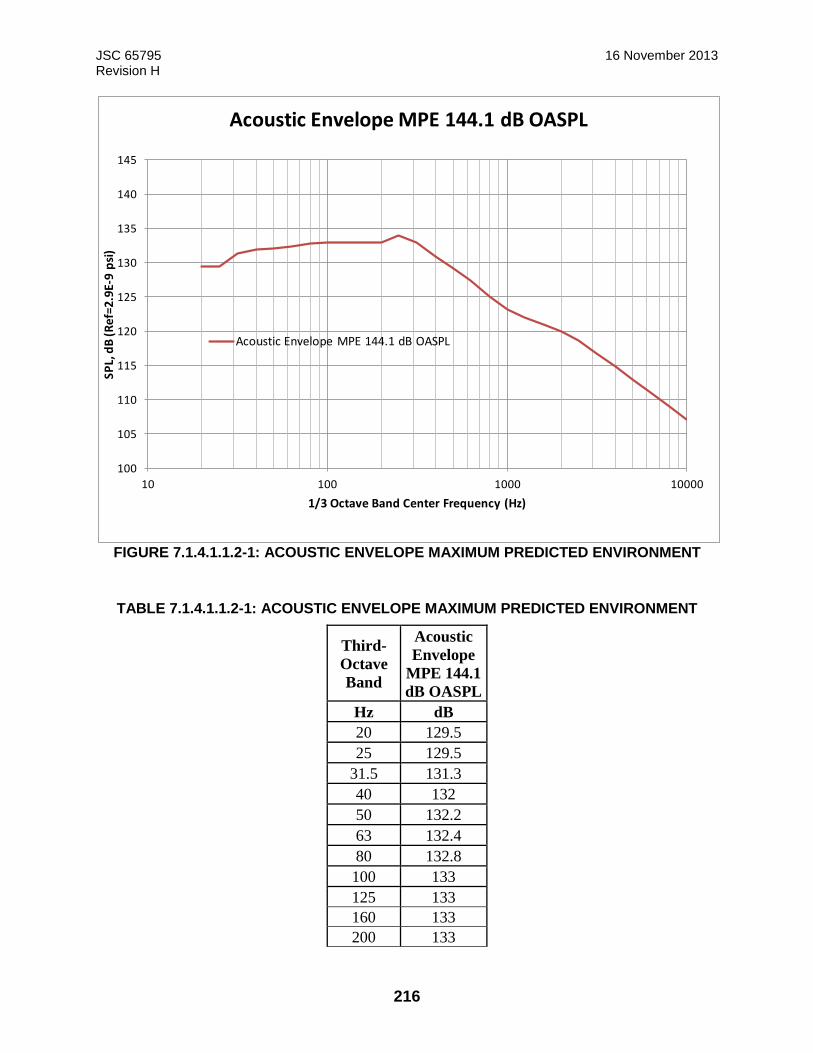
JSC 65795 16 November 2013 Revision H
216
FIGURE 7.1.4.1.1.2-1: ACOUSTIC ENVELOPE MAXIMUM PREDICTED ENVIRONMENT
TABLE 7.1.4.1.1.2-1: ACOUSTIC ENVELOPE MAXIMUM PREDICTED ENVIRONMENT
Third-
Octave
Band
Acoustic
Envelope
MPE 144.1
dB OASPL
Hz dB
20 129.5
25 129.5
31.5 131.3
40 132
50 132.2
63 132.4
80 132.8
100 133
125 133
160 133
200 133
100
105
110
115
120
125
130
135
140
145
10 100 1000 10000
SPL,
dB
(R
ef=
2.9
E-9
psi
)
1/3 Octave Band Center Frequency (Hz)
Acoustic Envelope MPE 144.1 dB OASPL
Acoustic Envelope MPE 144.1 dB OASPL
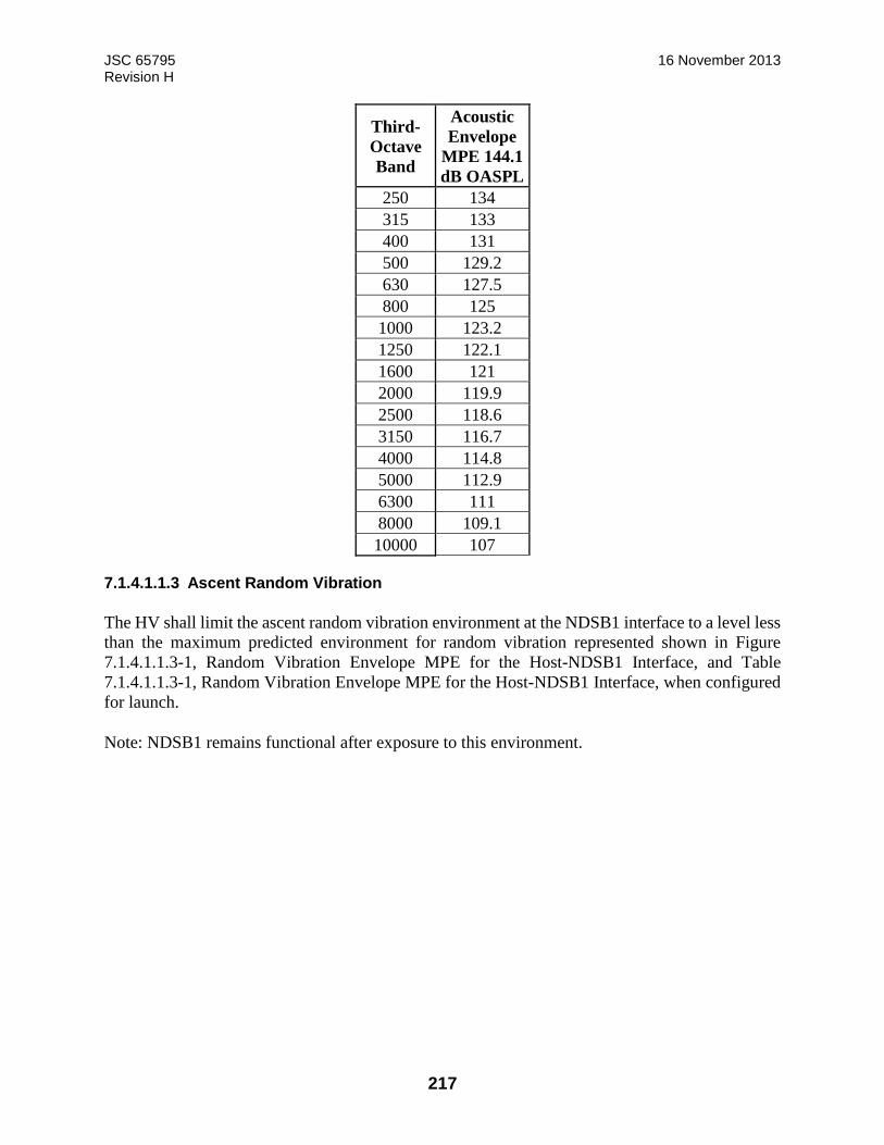
JSC 65795 16 November 2013 Revision H
217
Third-
Octave
Band
Acoustic
Envelope
MPE 144.1
dB OASPL
250 134
315 133
400 131
500 129.2
630 127.5
800 125
1000 123.2
1250 122.1
1600 121
2000 119.9
2500 118.6
3150 116.7
4000 114.8
5000 112.9
6300 111
8000 109.1
10000 107
7.1.4.1.1.3 Ascent Random Vibration
The HV shall limit the ascent random vibration environment at the NDSB1 interface to a level less
than the maximum predicted environment for random vibration represented shown in Figure
7.1.4.1.1.3-1, Random Vibration Envelope MPE for the Host-NDSB1 Interface, and Table
7.1.4.1.1.3-1, Random Vibration Envelope MPE for the Host-NDSB1 Interface, when configured
for launch.
Note: NDSB1 remains functional after exposure to this environment.

JSC 65795 16 November 2013 Revision H
218
FIGURE 7.1.4.1.1.3-1: RANDOM VIBRATION ENVELOPE MPE FOR THE HOST-NDSB1 INTERFACE
TABLE 7.1.4.1.1.3.3-1: RANDOM VIBRATION ENVELOPE MPE FOR THE HOST-NDSB1 INTERFACE
Random Vibration
Envelope 4.53 Grms
FREQ
(Hz)
ASD
(G^2/Hz)
20 0.001
40 0.01
50 0.04
80 0.04
100 0.02
600 0.02
2000 0.002
7.1.4.1.1.4 Shock (Functional)
The HV shall limit the shock environment at the interface with NDSB1 to a level that is less than
the shock shown in Figure 7.1.4.1.1.4-1, Shock Response Spectrum from Host, with spectrum as
represented in Table 7.1.4.1.1.4-1 Shock Response Spectrum from Host.
Note: NDSB1 remains functional after exposure to this shock level.
0.001
0.010
0.100
10 100 1000
Acc
ele
rati
on
Sp
ect
ral D
en
sity
(G^
2/H
z)
Frequency (Hz)
Random Vibration Envelope MPE 4.53 Grms
Random Vibration Envelope 4.53 Grms
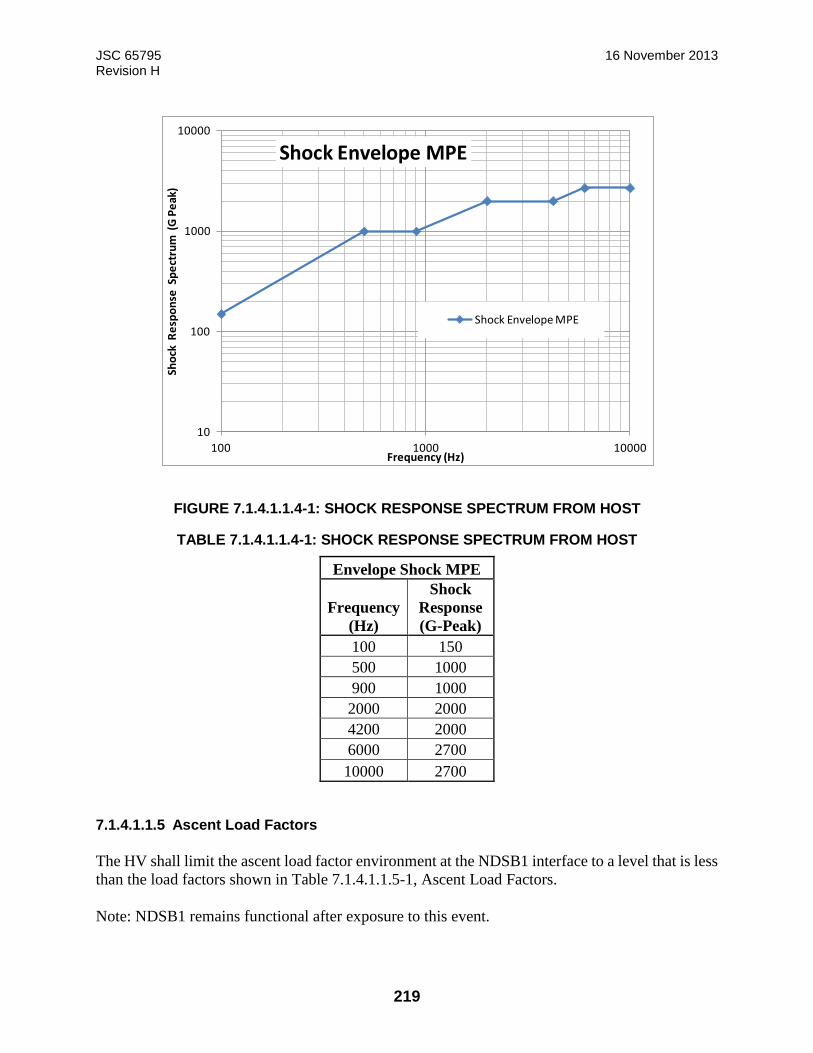
JSC 65795 16 November 2013 Revision H
219
FIGURE 7.1.4.1.1.4-1: SHOCK RESPONSE SPECTRUM FROM HOST
TABLE 7.1.4.1.1.4-1: SHOCK RESPONSE SPECTRUM FROM HOST
Envelope Shock MPE
Frequency
(Hz)
Shock
Response
(G-Peak)
100 150
500 1000
900 1000
2000 2000
4200 2000
6000 2700
10000 2700
7.1.4.1.1.5 Ascent Load Factors
The HV shall limit the ascent load factor environment at the NDSB1 interface to a level that is less
than the load factors shown in Table 7.1.4.1.1.5-1, Ascent Load Factors.
Note: NDSB1 remains functional after exposure to this event.
10
100
1000
10000
100 1000 10000
Sho
ck R
esp
on
se S
pe
ctru
m (
G P
eak
)
Frequency (Hz)
Shock Envelope MPE
Shock Envelope MPE
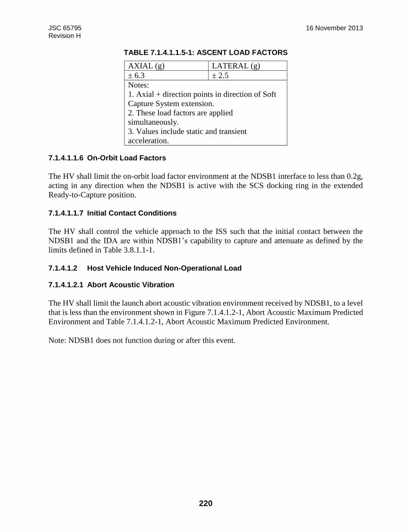
JSC 65795 16 November 2013 Revision H
220
TABLE 7.1.4.1.1.5-1: ASCENT LOAD FACTORS
AXIAL (g) LATERAL (g)
± 6.3 ± 2.5
Notes:
1. Axial + direction points in direction of Soft
Capture System extension.
2. These load factors are applied
simultaneously.
3. Values include static and transient
acceleration.
7.1.4.1.1.6 On-Orbit Load Factors
The HV shall limit the on-orbit load factor environment at the NDSB1 interface to less than 0.2g,
acting in any direction when the NDSB1 is active with the SCS docking ring in the extended
Ready-to-Capture position.
7.1.4.1.1.7 Initial Contact Conditions
The HV shall control the vehicle approach to the ISS such that the initial contact between the
NDSB1 and the IDA are within NDSB1’s capability to capture and attenuate as defined by the
limits defined in Table 3.8.1.1-1.
7.1.4.1.2 Host Vehicle Induced Non-Operational Load
7.1.4.1.2.1 Abort Acoustic Vibration
The HV shall limit the launch abort acoustic vibration environment received by NDSB1, to a level
that is less than the environment shown in Figure 7.1.4.1.2-1, Abort Acoustic Maximum Predicted
Environment and Table 7.1.4.1.2-1, Abort Acoustic Maximum Predicted Environment.
Note: NDSB1 does not function during or after this event.
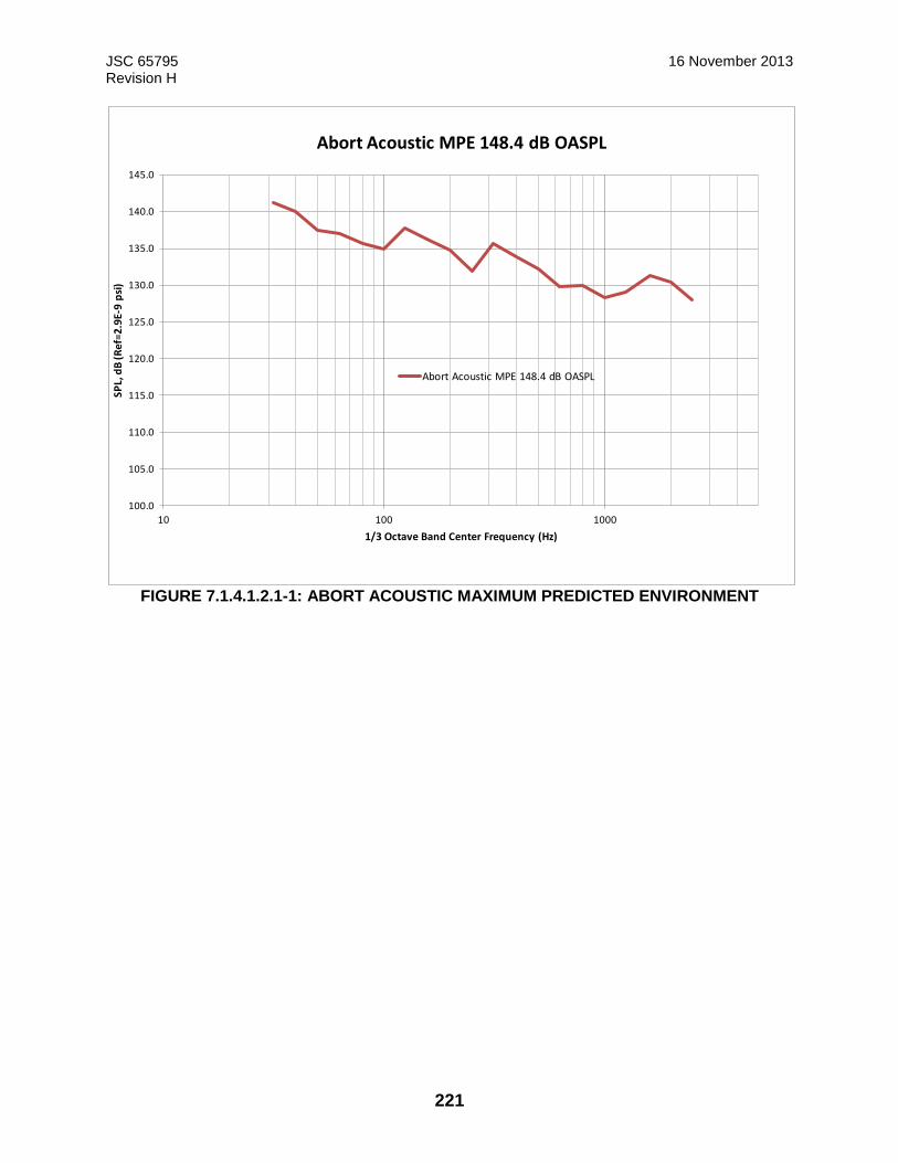
JSC 65795 16 November 2013 Revision H
221
FIGURE 7.1.4.1.2.1-1: ABORT ACOUSTIC MAXIMUM PREDICTED ENVIRONMENT
100.0
105.0
110.0
115.0
120.0
125.0
130.0
135.0
140.0
145.0
10 100 1000
SPL,
dB
(R
ef=
2.9
E-9
psi
)
1/3 Octave Band Center Frequency (Hz)
Abort Acoustic MPE 148.4 dB OASPL
Abort Acoustic MPE 148.4 dB OASPL
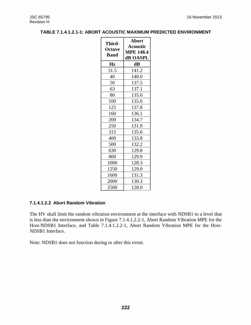
JSC 65795 16 November 2013 Revision H
222
TABLE 7.1.4.1.2.1-1: ABORT ACOUSTIC MAXIMUM PREDICTED ENVIRONMENT
Third-
Octave
Band
Abort
Acoustic
MPE 148.4
dB OASPL
Hz dB
31.5 141.2
40 140.0
50 137.5
63 137.1
80 135.6
100 135.0
125 137.8
160 136.1
200 134.7
250 131.9
315 135.6
400 133.8
500 132.2
630 129.8
800 129.9
1000 128.3
1250 129.0
1600 131.3
2000 130.3
2500 128.0
7.1.4.1.2.2 Abort Random Vibration
The HV shall limit the random vibration environment at the interface with NDSB1 to a level that
is less than the environment shown in Figure 7.1.4.1.2.2-1, Abort Random Vibration MPE for the
Host-NDSB1 Interface, and Table 7.1.4.1.2.2-1, Abort Random Vibration MPE for the Host-
NDSB1 Interface.
Note: NDSB1 does not function during or after this event.
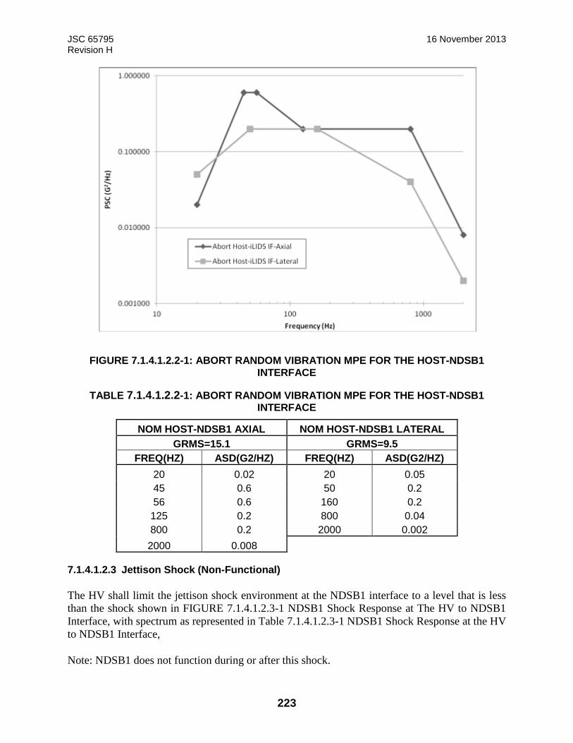
JSC 65795 16 November 2013 Revision H
223
FIGURE 7.1.4.1.2.2-1: ABORT RANDOM VIBRATION MPE FOR THE HOST-NDSB1
INTERFACE
TABLE 7.1.4.1.2.2-1: ABORT RANDOM VIBRATION MPE FOR THE HOST-NDSB1 INTERFACE
NOM HOST-NDSB1 AXIAL NOM HOST-NDSB1 LATERAL
GRMS=15.1 GRMS=9.5
FREQ(HZ) ASD(G2/HZ) FREQ(HZ) ASD(G2/HZ)
20 0.02 20 0.05
45 0.6 50 0.2
56 0.6 160 0.2
125 0.2 800 0.04
800 0.2 2000 0.002
2000 0.008
7.1.4.1.2.3 Jettison Shock (Non-Functional)
The HV shall limit the jettison shock environment at the NDSB1 interface to a level that is less
than the shock shown in FIGURE 7.1.4.1.2.3-1 NDSB1 Shock Response at The HV to NDSB1
Interface, with spectrum as represented in Table 7.1.4.1.2.3-1 NDSB1 Shock Response at the HV
to NDSB1 Interface,
Note: NDSB1 does not function during or after this shock.
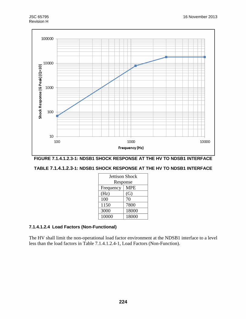
JSC 65795 16 November 2013 Revision H
224
FIGURE 7.1.4.1.2.3-1: NDSB1 SHOCK RESPONSE AT THE HV TO NDSB1 INTERFACE
TABLE 7.1.4.1.2.3-1: NDSB1 SHOCK RESPONSE AT THE HV TO NDSB1 INTERFACE
Jettison Shock
Response
Frequency MPE
(Hz) (G)
100 70
1150 7800
3000 18000
10000 18000
7.1.4.1.2.4 Load Factors (Non-Functional)
The HV shall limit the non-operational load factor environment at the NDSB1 interface to a level
less than the load factors in Table 7.1.4.1.2.4-1, Load Factors (Non-Function).
JSC 65795 16 November 2013 Revision H
225
TABLE 7.1.4.1.2.4-1: LOAD FACTORS (NON-FUNCTION)
AXIAL (g) LATERAL1 (g) LATERAL2 (g)
± 20.6 ± 4.5 ± 5.3
Notes: 1. Axial + direction points in direction of Soft Capture System
extension.
2. These load factors are applied simultaneously.
3. Values envelope ascent abort, NDSB1 does not function during or
after this flight event
4. Lateral 1 and Lateral 2 directions are perpendicular to each other in
the lateral plane, and act in any direction.
7.1.4.2 Thermal
7.1.4.2.1 Host Vehicle Thermal Conductance
The HV design shall provide a thermal contact conductance across the NDSB1-to-HV structural
interface greater than or equal to 50 Btu/hr-ft2-°F (284 W/m2-°K).
Note: The area assumed for contact conductance is the NDSB1’s total flange area including the
voids due to the seals, air groove, and other mechanical features.
7.1.4.2.2 Host Vehicle to NDSB1 Interface Temperature
7.1.4.2.2.1 Solo Flight
The HV shall control the temperature of the structural interface between the HV and the NDSB1
to a range of 60°F 15.6°C) to 103°F (+39.4°C) during Host Vehicle Solo Flight.
7.1.4.2.2.2 Checkout and Docking Operations
The HV shall control the temperature of the structural interface between the HV and the NDSB1
to a range of 60°F (15.6°C) to 103°F (+39.4°C) during Checkout, soft capture, and prior to Hard
Capture State.
7.1.4.2.2.3 Mated Operations
The HV shall control the temperature of the structural interface between the HV and the NDSB1
within +65°F (+18.3°C) to +113°F (+45°C) during mated operations.
Note: Docking is from initial contact until hard mate.
7.1.4.2.3 Solar Ray Protection
The HV shall prevent the components external to the NDSB1 tunnel, excluding open mating flange
components, from receiving any incident solar rays during on-orbit operations.

JSC 65795 16 November 2013 Revision H
226
7.1.4.2.4 Host Vehicle Heat Transfer Across The Interface
7.1.4.2.4.1 Solo Flight, Checkout, and Docking Operations
The HV shall accommodate orbital average heat transfer across the NDSB1-to-HV structural
interface ranging from a maximum heat leak of 360W to a maximum heat gain of 370W during
Host Vehicle Solo Flight, Checkout, soft capture, and prior to Hard Capture State.
7.1.4.2.4.2 Mated Operations
The HV shall accommodate a maximum heat loss across the NDSB1-to-HV structural interface of
100 W when the HV side of the structural interface is at +65°F (+18.3°C) during mated operations.
7.1.4.3 Salt Fog
The HV shall protect the NDSB1 from exposure to salt particles (i.e., salt fog) by maintaining at
least a Class 100,000 conditioned air cleanliness level (as defined in FED-STD-209D) around the
NDSB1 during ground integration and launch pad operations.
Note: The NDSB1 will provide non-flight covers. However, when these covers are removed, the
HV must provide protection. For example, on the pad, the host might provide a purged
environment around the docking system. The NDSB1 will tolerate an incidental short term
exposure to salt particles (for example, potential exposure between purge termination and liftoff)
by using corrosion resistant materials and parts and by design that protects parts and assemblies
from potential impacts.
7.1.4.4 Lightning
The HV shall protect the NDSB1 from primary lightning effects (i.e., lightning direct current path)
and limit the indirect lightning effects to 6 dB below the indirect lightning effect levels specified
in JSC-65842 Table 5-1 and Section 7.0 for power, communications, control and pyrotechnic
interfaces.
7.1.4.5 Debris Protection
The HV shall prevent debris generated or released during vehicle launch and/or ascent from
contaminating NDSB1 mechanisms, seal surfaces, mating surfaces and umbilicals.
7.1.4.6 Ultraviolet Radiation Protection
The HV shall limit the NDSB1 dynamic seals’ cumulative exposure to ultraviolet radiation to
below 58 equivalent sun hours (ESH) during solo flight operations.
JSC 65795 16 November 2013 Revision H
227
7.1.4.7 Surface Cleanliness
7.1.4.7.1 NDSB1 Surface Cleanliness
The HV shall maintain NDSB1 surfaces VC Level “Sensitive” following receipt for integration
through launch as defined in SN-C-0005, paragraph 2.4, Contamination Control Requirements.
7.1.4.7.2 Seal Surface Cleanliness
The HV shall maintain NDSB1 seal surfaces at least VC Level “Highly Sensitive” following
receipt for integration through launch as defined in SN-C-0005, paragraph 2.4, Contamination
Control Requirements.
7.1.4.8 Radiant Energy Interaction
The HV shall limit radiant energy interaction upon other Space Station elements in accordance
with D684-10058-03-04 Integrated ISS Math Models, Volume 3, Book 4.
7.1.4.9 On-Orbit External Contamination
The HV shall comply with ISS system level external contamination release control requirements
as defined in SSP 30426, Sections 3.4 through 3.6.
7.1.4.10 Floating Potential Environment
The HV shall limit the NDSB1 exposure to the ISS floating potential environment to between
+20V to -80 V.
7.1.4.11 Plasma Environment
The HV shall limit NDSB1 exposure to the natural plasma environment to below those defined in
SSP 30425, Space Station Program Natural Environment Definition for Design, section 5.
7.1.4.12 Reentry Loads Environmental Protection
If the NDSB1 is returned from orbit, the Host Vehicle shall protect the NDSB1 against reentry,
descent, and landing load environments as defined in paragraphs 5.2.1.5.3, 5.2.1.5.6, 7.1.4.1.2.2,
7.1.4.1.2.3, and 7.1.4.1.2.4.
7.1.4.12.1 Thermal Re-entry Environmental Protection
If the NDSB1 is returned from orbit, the HV shall maintain the NDSB1 within -65 °F and 160 °F
during re-entry, descent, and landing.
Note: The thermal capability of individual components is documented in paragraph 5.2.2.1.1.3.
JSC 65795 16 November 2013 Revision H
228
7.1.4.12.2 Descent Wind Pressure TBD
7.1.4.13 Interface Undocking Separation Conditions
The HV shall withstand the total potential undocking separation load of up to 600 lbf (2,669 N),
per contingency case defined in 4.1.1.3.7. Note: This load is applied when the docking interfaces
are fully mated (i.e. at zero separation distance).
7.1.4.14 HV Fundamental Frequency
The HV shall have a fundamental frequency of 1.5 Hz or greater when rigidly fixed at the IDA
hard dock interface degrees of freedom. This frequency applies to overall-structure vibration
modes and not to local appendage or antenna modes.
7.1.4.15 Electrical Power Consuming Equipment
When the HV is equipped with secondary 120 VDC electrical interfaces, the HV Electrical Power
Consuming Equipment (EPCE) shall comply with SSP 52051, User Electric Power Specifications
and Standards, Volume 1: 120 Volt DC Loads, Interface B, with the following exceptions:
1. The minimum steady voltage is 115 VDC
2. The minimum normal transient voltage is 97 VDC
3. The source impedance is defined in Figure 7.1.4.15-1, Modified Load Impedance
Magnitude Limit, and Figure 7.1.4.15-2, Modified Load Impedance Phase Limit.
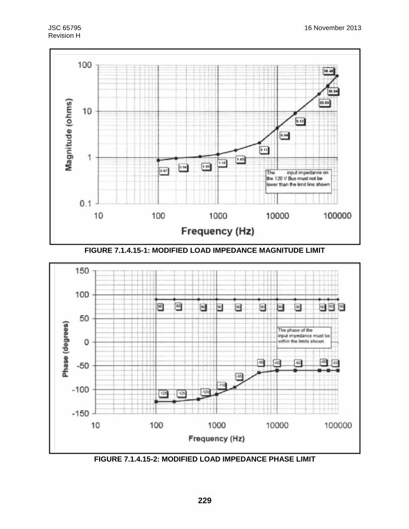
JSC 65795 16 November 2013 Revision H
229
FIGURE 7.1.4.15-1: MODIFIED LOAD IMPEDANCE MAGNITUDE LIMIT
FIGURE 7.1.4.15-2: MODIFIED LOAD IMPEDANCE PHASE LIMIT

JSC 65795 16 November 2013 Revision H
230
7.1.4.16 BUS Coupler Type
7.1.4.16.1 HV BUS Coupler Specification
The MIL-STD-1553 bus crossing the ISS interface shall have bus couplers that are in accordance
with SSQ 21676, Coupler, Data Bus, MIL-STD-1553B, Space Quality, General Specification For.
7.1.4.16.2 HV BUS Coupler Stubs
The MIL-STD-1553 bus crossing the ISS interface shall have bus couplers that contain a maximum
of two stubs per coupler.
7.1.4.16.3 BUS Stub Length
The MIL-STD-1553 bus crossing the ISS interface shall have a maximum bus stub length of 20
feet (6.1 m) as measured from the Coupling Transformer to the Isolation Transformer as defined
in Figure 7.1.4.16.3-1, Bus Stub Length, Measurement A.
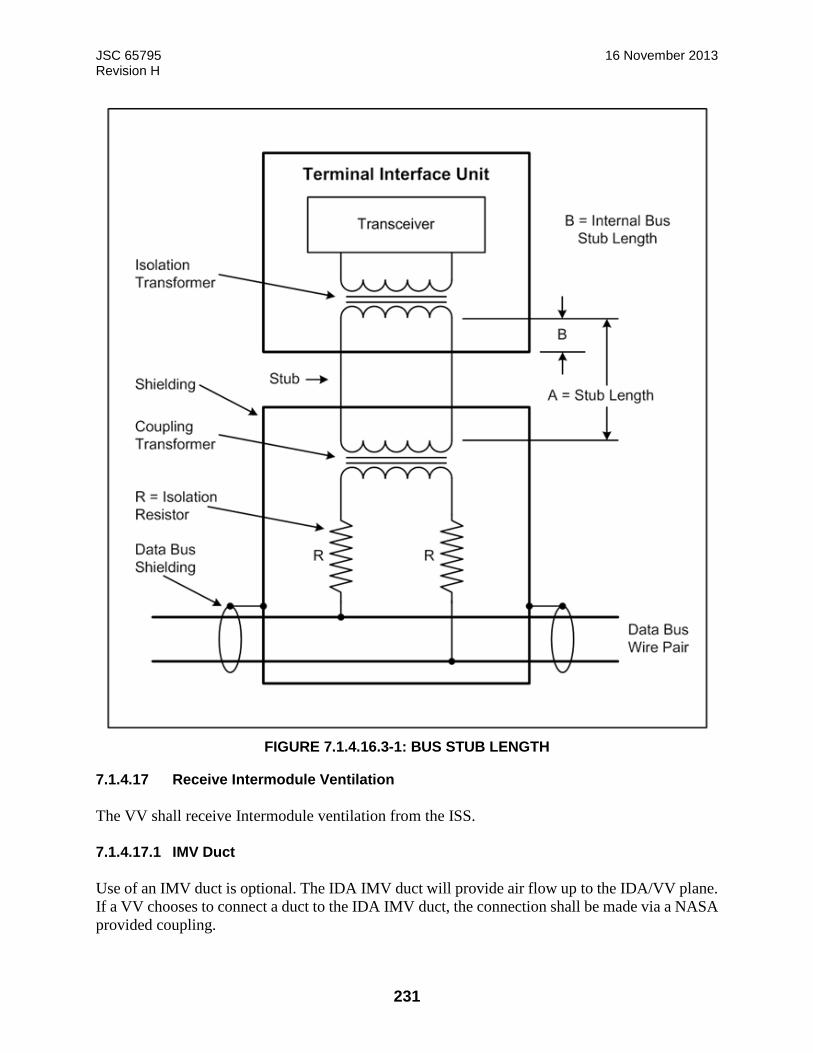
JSC 65795 16 November 2013 Revision H
231
FIGURE 7.1.4.16.3-1: BUS STUB LENGTH
7.1.4.17 Receive Intermodule Ventilation
The VV shall receive Intermodule ventilation from the ISS.
7.1.4.17.1 IMV Duct
Use of an IMV duct is optional. The IDA IMV duct will provide air flow up to the IDA/VV plane.
If a VV chooses to connect a duct to the IDA IMV duct, the connection shall be made via a NASA
provided coupling.
JSC 65795 16 November 2013 Revision H
232
Rationale: ISS program office is not requiring the VV to provide a duct if they can meet their
airflow requirements without one.
7.1.4.18 Return Intermodule Ventilation
7.1.4.18.1 Receive Intermodule Ventilation from VV
When the VV is Hard Mated and the hatches of the VV and ISS are open, the IDA receives return
intermodule ventilation from the VV at the VV to IDA interface through the VV to IDA
passageway.
7.1.4.18.2 Return Intermodule Ventilation FROM VV
When the VV is Hard Mated and the hatches of the VV and ISS are open, the VV shall return
intermodule ventilation to the IDA at the HVVV to IDA interface through the VV to IDA
passageway.
7.1.4.19 Deleted
7.1.4.20 Deleted
7.1.4.21 Plume Impingement Heating
During approach/separation from ISS, the VV thruster plume impingement heating on the IDA
hardware does not exceed a maximum heat flux rate of 133 kW/m2 over a continuous period of
.07 seconds and maximum heat flux integral of 119.6 kJ/m2 imposed as a heat flux of 0.2235
kW/m2 over a period of 535 seconds.
7.1.5 Safety
7.1.5.1 Docking Operations Safety
7.1.5.1.1 Automated Response to NDSB1 Failure Indications
Deleted
7.1.5.1.2 Automated Response to NDSB1 System A and System B Failures
Deleted
7.1.5.1.3 Host Vehicle Response to Ready to Capture Indication
The HV shall only proceed for final docking approach after receiving positive confirmation from
the NDSB1 health and status message that the NDSB1 has reached the ready to capture
configuration.

JSC 65795 16 November 2013 Revision H
233
7.1.5.1.4 Automated Host Vehicle Response to NDSB1 Faults
The HV shall execute a failure response to an NDSB1 failure as specified in Appendix G Failure
Response Tables within 140 ms of a failure indication. Note: A failure indication may include
both a distinct failure notification in the NDSB1 H&S message or any other abnormal H&S
message as described in Appendix G.
7.1.5.1.5 HV response to Failure to Ensure Initial Contact Conditions
The HV shall either ensure after any two faults that the initial contact between the NDSB1 and the
IDA is within NDSB1’s capability to capture and attenuate as defined by Table 3.8.1.1-1, or
terminate the docking attempt and avoid a potential collision.
7.1.5.1.6 Host Vehicle Provisions to Preclude Inadvertent Jet Firing
The HV shall enter free drift per paragraph 7.1.2.4.1.5.1 after any two faults or terminate the
docking attempt and avoid a potential collision.
7.1.5.1.7 Host Vehicle Response to Failure to Capture
Deleted
7.1.5.1.8 Contingency Capture Latch Release – Independent Operation
The HV shall provide for the contingency operation of the capture latch release independently
from the utility strings used to operate the NSB1 System A and System B.
Note: This requirement ensures that the contingency capture latch release function is operable
following either two power bus failures within the HV or following two avionics failures within
NDSB1.
7.1.5.1.9 Inadvertent Capture Latch Release Prevention – Inhibits
The HV shall provide at least one inhibit against an inadvertent release of the contingency capture
latch when NDS is not in a docking mode of operation.
Note 1: This inhibit will protect for a loss of mission due to inadvertent capture latch release.
Note 2: It is assumed that the status of the contingency capture latch release is checked either
electrically or visually on the ground following NDS installation on the vehicle.
Note 3: It is recommended that the vehicle implement two-step commanding for manual activation
(by the crew or ground) of the contingency capture latch release after the inhibit has been removed.
However, the automated abort sequence may script these two commands together to ensure a safe
abort.
JSC 65795 16 November 2013 Revision H
234
7.1.5.1.10 Reserved
7.1.5.1.11 HV Docking Abort Performance
The HV shall have the capability to null vehicle motion within 600 milliseconds TBR31 with no
assistance from NDS from docking initial contact through soft capture retraction complete. Note:
The NDS soft capture system active control is only single fault tolerant. After two faults (e.g.
avionics, power, commanding, electromechanical), NDS is no longer capable of preventing an
uncontrolled collision between the HV and the ISS. The HV GN&C must, therefore, be capable
of preventing collision by using thrusters in order to achieve two fault tolerance to that catastrophic
hazard. NDS dynamics and avionics timing analyses indicate that the allowable time for the vehicle
to prevent the collision may be as short as 600 milliseconds TBR31, presuming the HV operates
within allowable initial contact condition limits.
7.1.5.2 Mated Operations Safety
7.1.5.2.1 Inhibit power to NDSB1 for mated operations
The HV shall remove power from both NDSB1 Systems A and B prior to unlocking the docking
hatch for mated operations until the hatch is closed and locked for undocking operations.
7.1.5.2.2 Preparedness for Undocking
The HV shall be configured for undocking at times when the power is supplied to either System
A or System B.
7.1.5.2.3 Individual Crew Actions for Undocking
The HV shall separate crew actions required for NDSB1 to undock such that Motor Power Enable,
Control Power Enable, and Enable Undock command, and Execute Undock commands each
require a separate crew action.
7.1.5.2.4 Monitoring of Inhibit to NDSB1 Motor Power
While power is removed from NDSB1 for mated operations, the HV shall monitor, in near real
time or more frequently, the inhibit that prevents supplying NDSB1 with motor power.
7.1.5.2.5 Separation of NDSB1 Controller and Motor Commands
Deleted
7.1.5.2.6 Host Vehicle Pyrotechnic Inadvertent Firing
The HV shall provide three inhibits (safe, arm, fire) to preclude inadvertent firing of the NDSB1
pyrotechnics in accordance with JSC 62809 Section 8.2 and 8.3.
JSC 65795 16 November 2013 Revision H
235
7.1.5.2.7 Host Vehicle Pyrotechnic Inhibits Monitoring
The HV shall monitor in near real time at least two of the three inhibits used to prevent inadvertent
firing of each NDSB1 NSI.
Note: Monitoring of inhibits is required per ISS program safety requirements to prevent the
inadvertent operation of a function that could result in a catastrophic hazard (ref. SSP 50021
sections 3.3.6.1.5.1c and 3.3.6.2.3). This requirement is in addition to the fault tolerance
requirements levied as part of JSC 62809 sections 8.2 and 8.3.
7.1.5.2.8 Host Vehicle Pyrotechnic Firing Circuit Electrical Harness Design
The HV shall design electrical harnesses connected to the NDSB1 pyrotechnic system in
accordance with JSC 62809 sections 8.4.7 through 8.4.10.
7.1.5.2.9 Pyrotechnic Firing Circuit Wiring Checkout
The HV shall install and checkout pyrotechnic wiring harnesses connected to NDSB1 in
accordance with JSC 62809 sections 7.3 through 7.3.4 and section 8.5.
7.1.5.2.10 Pyrotechnic Firing Circuit EMC
The HV shall ensure the electromagnetic compatibility of the NDSB1 pyrotechnic system when
integrated with the HV’s firing circuitry in accordance with JSC 62809 sections 8.4.2 through
8.4.5.
7.1.5.2.11 Host Vehicle IVA Interface Safety
The HV shall ensure that NDSB1 IVA-accessible surfaces are within the safe temperature range
(+113°F to +39°F) for crew translation through the docking tunnel or provide the crew with
appropriate personal protective equipment to protect them from hot or cold surfaces.
7.1.5.3 Undocking Operations Safety
7.1.5.3.1 HV Response to Undocking Complete Indication
The HV shall not initiate vehicle thrusters until at least two “Undocking Complete” indications are
provided.
Note: The two means may include either indications from NDSB1 or one indication from NDSB1
and another from a separate means (e.g. crew visual, GN&C sensor etc.).
7.1.5.3.2 Independent Pyrotechnic Controller Operation
The HV shall provide command / power to the NDSB1 pyrotechnic system that are independent
from those used to command / power NDSB1 System A and System B avionics.
JSC 65795 16 November 2013 Revision H
236
Note: This requirement ensures that the pyrotechnic hook release function is operable following
two power bus or avionics failures within the HV
7.1.5.3.3 Vestibule Depressurization and Repressurization Redundancy or Independence
The HV shall provide redundant vestibule depressurization capability or provide independent
vestibule depressurization and repressurization capability.
7.1.5.4 Return Operations Safety
7.1.5.4.1 Host Vehicle Response to Failure to Secure SCS
The HV shall provide a safe reentry configuration if the NDSB1 fails to stow and secure the
NDSB1 soft capture system.
7.1.5.4.2 NDSB1 Jettison Responsibilities
The HV shall provide for a partial or complete jettisoning of the NDSB1 from the HV.
Note: Complete (HCS, SCS and avionics) or partial (HCS and SCS) jettisoning may be
implemented at the HV discretion.

JSC 65795 16 November 2013 Revision H
237
APPENDIX A – ACRONYMS AND ABBREVIATIONS
# Number
% Percent
AI Action Item
AMP Ampere(s)
ANSI American National Standards Institute
ASI Agenzia Spaziale Italiana
AWG American Wire Gauge
BC Bus Controller
Btu British Thermal Units
°C Degrees Centigrade
CAD Computer Aided Design
C&DH Command and Data Handling
CCP Commercial Crew Program
CCW Counterclockwise
CDR Critical Design Review
CFM Cubic Feet per Minute
C.G. Center of Gravity
CRC Cyclic Redundancy Check
CW Clockwise
dB decibel(s)
Deg Degrees
deg/sec Degrees per Second
DIA Diameter
DSC Docking System Controller
DSE Docking System Emulator
JSC 65795 16 November 2013 Revision H
238
EAR Export Administration Regulations or EIPS Adapter Ring
ECLSS Environmental Control and Life Support System
ED Engineering Drawing
EEE Electromagnetic Environmental Effects
e.g. for example
EIA Electronic Industry Association
EIPS Energia IDA Primary Structure
EMA Electromechanical Actuator
EMC Electromagnetic Compatibility
EPCE Electrical Power Consuming Equipment
ESH Equivalent Sun Hours
°F Degrees Fahrenheit
FC Flight Computer
FDIR Fault Detection, Isolation, and Recovery
FOD Foreign Object Debris
FRAM Flight Releasable Attachment Mechanism
ft/sec Feet per Second
ft2 Square Feet
ft3 Cubic Feet
G Acceleration due to Gravity
GHz Gigahertz
GN&C Guidance, Navigation, and Control
Grms Gravity, Root Mean Square
H&S Health and Status
HCS Hard Capture System
hPa hectoPascal(s)
hr hour(s)
HV Host Vehicle
HVTE Host Vehicle Test Equipment
Hz Hertz
JSC 65795 16 November 2013 Revision H
239
I/F Interface
ICD Interface Control Document
ICP IDA Control Panel
ID Internal Diameter or Identification
IDA International Docking Adapter
IDD Interface Definition Document
IDSS International Docking System Standard
I/F Interface
iLIDS International Low Impact Docking System
in. Inch(es)
ISS International Space Station
ITAR International Traffic in Arms Regulations
IVA Intravehicular Activity
JSC Johnson Space Center
°K Degrees Kelvin
kg Kilogram(s)
kg-mm2 Kilograms per square millimeter
kgf Kilograms Force
kHz Kilohertz
kJ Kilojoules
KOZ Keep Out Zone
kPa Kilo Pascal(s)
kW Kilowatts
L&D Loads and dynamics
lb Pound(s)
lb-in2 pounds per square inch
lbf Pound Force
lbm Pound Mass
LAC Linear Actuator Controller
JSC 65795 16 November 2013 Revision H
240
LEO Low Earth Orbit
LRU Line Replaceable Unit
LVLH Local Vertical/Local Horizontal
M Meter(s)
M2 square meters
m3 cubic millimeters
MAPAS Modified Androgynous Peripheral Attachment System
Max Maximum
Mbits Megabits
MHz MegaHertz
Min minimum or minute
m/s Meters per Second
MLI Multi-Layer Insulation
mm Millimeter(s)
MMOD Micro Meteoroid Orbital Debris
MOI Moments of Inertia
MPA Minimum Propellant Altitude
MPE Maximum Performance Environment
ms Millisecond(s)
N Newton(s)
N/A Not Applicable
NASA National Aeronautics and Space Administration
NCR Non-compliance Conformance Report
NDS NASA Docking System
NDSB1 NASA Docking System Block One
NDSP NASA Docking System Project
nm Nautical Miles
NSI NASA Standard Initiator
OD Outer Diameter
ODS Orbiter Docking System
JSC 65795 16 November 2013 Revision H
241
OLR Outgoing Longwave Radiation
Pa Pascal(s)
P/N Part Number
PDR Preliminary Design Review
PHMA Passive Hard Mate Assembly
PMA Pressurized Mating Adapter
PNP Probability of No Penetration
POI Products of Inertia
PPE Personal Protective Equipment
PRT Perimeter Reflector Target
psi Pounds per Square Inch
psia Pounds per Square Inch, Absolute
RAESR Risk Assessment Executive Summary Report
REF Reference
Rev. Revision
RF Radio Frequency
RID Review Item Discrepancy
RPODU Rendezvous, Proximity Operations, Docking, and Undocking
RT Remote Terminal
RTD Resistive Temperature Device
RTH Ready to Hook
RX Receive
SCD Specification Control Drawing
SCS Soft Capture System
sec Second
SI System International or Solar Inertial
SRR System Requirements Review
SRS Shock Response Spectrum
TBC To Be Confirmed
JSC 65795 16 November 2013 Revision H
242
TBD To Be Determined
TBR To Be Resolved
TEA Torque Equilibrium Attitude
TIA Telecommunication Industry Association
TLI Trans-Lunar Insertion
TX Transmit
UART Universal Asynchronous Receiver/Transmitter
U.S. United States
USOS United States On-orbit Segment
VC Visibly Clean
VDC Volts Direct Current
VRT Vestibule Reflector Target
VV Visiting Vehicle
VVT Vestibule Visual Target
W Watt(s)
YPR Yaw, Pitch, Roll
JSC 65795 16 November 2013 Revision H
243
APPENDIX B – DEFINITION OF TERMS
Reserved
JSC 65795 16 November 2013 Revision H
244
APPENDIX C – NASA DOCKING SYSTEM (NDSB1) COMMAND AND H&S DEFINITIONS
NDSB1_Command_and_H&S_Definitions_11_15_13.xlsx
JSC 65795 16 November 2013 Revision H
245
APPENDIX D – NASA DOCKING SYSTEM (NDSB1) HEATER MASTER MEASUREMENT LIST (MML)
Reserved
JSC 65795 16 November 2013 Revision H
246
APPENDIX E – NASA DOCKING SYSTEM (NDSB1) CONFIGURATION DIFFERENCES
Reserved

JSC 65795 16 November 2013 Revision H
247
APPENDIX F – HOST INTERFACE CONNECTOR PINOUTS
Reserved
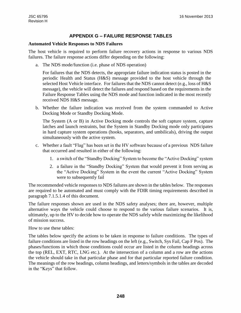
JSC 65795 16 November 2013 Revision H
248
APPENDIX G – FAILURE RESPONSE TABLES
Automated Vehicle Responses to NDS Failures
The host vehicle is required to perform failure recovery actions in response to various NDS
failures. The failure response actions differ depending on the following:
a. The NDS mode/function (i.e. phase of NDS operation)
For failures that the NDS detects, the appropriate failure indication status is posted in the
periodic Health and Status (H&S) message provided to the host vehicle through the
selected Host Vehicle interface. For failures that the NDS cannot detect (e.g., loss of H&S
message), the vehicle will detect the failures and respond based on the requirements in the
Failure Response Tables using the NDS mode and function indicated in the most recently
received NDS H&S message.
b. Whether the failure indication was received from the system commanded to Active
Docking Mode or Standby Docking Mode.
The System (A or B) in Active Docking mode controls the soft capture system, capture
latches and launch restraints, but the System in Standby Docking mode only participates
in hard capture system operations (hooks, separators, and umbilicals), driving the output
simultaneously with the active system.
c. Whether a fault “Flag” has been set in the HV software because of a previous NDS failure
that occurred and resulted in either of the following:
1. a switch of the “Standby Docking” System to become the “Active Docking” system
2. a failure in the “Standby Docking” System that would prevent it from serving as
the “Active Docking” System in the event the current “Active Docking” System
were to subsequently fail
The recommended vehicle responses to NDS failures are shown in the tables below. The responses
are required to be automated and must comply with the FDIR timing requirements described in
paragraph 7.1.5.1.4 of this document.
The failure responses shown are used in the NDS safety analyses; there are, however, multiple
alternative ways the vehicle could choose to respond to the various failure scenarios. It is,
ultimately, up to the HV to decide how to operate the NDS safely while maximizing the likelihood
of mission success.
How to use these tables:
The tables below specify the actions to be taken in response to failure conditions. The types of
failure conditions are listed in the row headings on the left (e.g., Switch, Sys Fail, Cap F Pos). The
phases/functions in which those conditions could occur are listed in the column headings across
the top (REL, EXT, RTC, LNG etc.). At the intersection of a column and a row are the actions
the vehicle should take in that particular phase and for that particular reported failure condition.
The meanings of the row headings, column headings, and letters/symbols in the tables are decoded
in the “Keys” that follow.

JSC 65795 16 November 2013 Revision H
249
Failure Response Tables:
First Failure (i.e., no fault “Flags” set yet):
Functions: REL EXT RTC LNG HOL[7] ATT ALI RET G1 STO LCK G2 CHA MAT
Act
ive
Switch F HXF HXF HXF HF ATF ALF RF RF - - - - -
Sys Fail ↓F ↓HXF ↓HXF ↓HXF ↓HF ↓ATF ↓ALF ↓RF ↓RF ↓ ↓ ↓ ↓ ↓
Cap Miss [6] - - - X - - - - - - - - - -
Sta
nd
by Functions: WG1 G1 WG2 G2 CHA MAT
Switch F F - - - -
Sys Fail ↓F ↓F ↓ ↓ ↓ ↓
Co
mb
o Cap F Pos - - TX TX - - - - - - - - - -
Cap Loss - - - - - TX TX TX - - - - - -
Cap F Neg - - - G - - - - - - - - - -
Subsequent Failures (i.e., a fault “Flag” was set from a previous failure):
Functions: REL EXT RTC LNG HOL[7] ATT ALI RET G1 STO LCK G2 CHA MAT
Act
ive
Switch - X OX OX O OX OX OX - - - - - -
Sys Fail ↓ ↓X ↓OX ↓OX ↓O ↓OX ↓OX ↓OX ↓ ↓ ↓ ↓ ↓ ↓
Cap Miss [6] - - - X - - - - - - - - - -
Sta
nd
by Functions: WG1 G1 WG2 G2 CHA MAT
Switch - - - - - -
Sys Fail ↓ ↓ ↓ ↓ ↓ ↓
Co
mb
o Cap F Pos - - TX TX - - - - - - - - - -
Cap Loss - - - - - TX TX TX - - - - - -
Cap F Neg - - - G - - - - - - - - - -
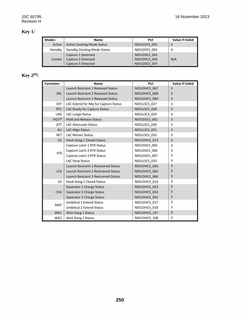
JSC 65795 16 November 2013 Revision H
250
Key 1:
Modes: Name PUI Value if Failed
Active Active Docking Mode Status NDS1DSYS_001 4
Standby Standby Docking Mode Status NDS1DSYS_003 4
Combo Capture 1 Detected Capture 2 Detected Capture 3 Detected
NDS1DSCS_045 NDS1DSCS_046 NDS1DSCS_047
N/A
Key 2[9]:
Functions: Name PUI Value if Failed
REL
Launch Restraint 1 Released Status NDS1DHCS_067 3
Launch Restraint 2 Released Status NDS1DHCS_068 3
Launch Restraint 3 Released Status NDS1DHCS_069 3
EXT LAC Extend for Rdy for Capture Status NDS1LSCS_027 3
RTC LAC Ready for Capture Status NDS1LSCS_028 3
LNG LAC Lunge Status NDS1LSCS_029 3
HOL[7] Hold and Release Status NDS1DSCS_042 3
ATT LAC Attenuate Status NDS1LSCS_030 3
ALI LAC Align Status NDS1LSCS_031 3
RET LAC Retract Status NDS1LSCS_032 3
G1 Hook Gang 1 Closed Status NDS1DHCS_013 3
ST0
Capture Latch 1 RTR Status NDS1DSCS_005 3
Capture Latch 2 RTR Status NDS1DSCS_006 3
Capture Latch 3 RTR Status NDS1DSCS_007 3
LAC Stow Status NDS1LSCS_033 3
LCK
Launch Restraint 1 Restrained Status NDS1DHCS_064 3
Launch Restraint 2 Restrained Status NDS1DHCS_065 3
Launch Restraint 3 Restrained Status NDS1DHCS_066 3
G2 Hook Gang 2 Closed Status NDS1DHCS_014 3
CHA
Separator 1 Charge Status NDS1DHCS_053 3
Separator 2 Charge Status NDS1DHCS_054 3
Separator 3 Charge Status NDS1DHCS_055 3
MAT Umbilical 1 Extend Status NDS1DHCS_017 3
Umbilical 2 Extend Status NDS1DHCS_018 3
WG1 Wait Gang 1 Status NDS1DHCS_107 3
WG2 Wait Gang 2 Status NDS1DHCS_108 3

JSC 65795 16 November 2013 Revision H
251
Key 3:
Vehicle Command Response to NDS Active
System (if powered on)
Vehicle Command Response to
NDS Standby System
Additional Required Vehicle
Response
F none none
Set “Flag” in vehicle software
indicating which NDS System (A or
B) experienced the failure such that
the appropriate failure response will
be taken on a subsequent relevant
failure.[4]
↓ none none
Remove all power (all control
system power and all motor power)
from BOTH the DSC & LAC on the
failed NDS System (either A or B).
AT
1. DSC_MONITOR_MODE (NDS1DCMD_0014)
3. DSC_STANDBY_DOCKING_MODE
(NDS1DCMD_0038) Parameter 1 = 1 (Enable)
4. DSC_STANDBY_DOCKING_MODE
(NDS1DCMD_0038) Parameter 1 = 2 (Execute)
2. DSC_ACTIVE_DOCKING_M
ODE (NDS1DCMD_0002)
Parameter 1 = 4
(Execute_at_Attenuate)
none
AL
1. DSC_MONITOR_MODE (NDS1DCMD_0014)
3. DSC_STANDBY_DOCKING_MODE
(NDS1DCMD_0038) Parameter 1 = 1 (Enable)
4. DSC_STANDBY_DOCKING_MODE
(NDS1DCMD_0038) Parameter 1 = 2 (Execute)
2. DSC_ACTIVE_DOCKING_M
ODE (NDS1DCMD_0002)
Parameter 1 = 5
(Execute_at_Align)
none
R
1. DSC_MONITOR_MODE (NDS1DCMD_0014)
3. DSC_STANDBY_DOCKING_MODE
(NDS1DCMD_0038) Parameter 1 = 1 (Enable)
4. DSC_STANDBY_DOCKING_MODE
(NDS1DCMD_0038) Parameter 1 = 2 (Execute)
2. DSC_ACTIVE_DOCKING_M
ODE (NDS1DCMD_0002)
Parameter 1 = 6
(Execute_at_Retract)
none
H 1. DSC_MONITOR_MODE (NDS1DCMD_0014)
2. DSC_ACTIVE_DOCKING_M
ODE (NDS1DCMD_0002)
Parameter 1 = 8
(Hold_and_Release) [7]
none
O 1. DSC_MONITOR_MODE (NDS1DCMD_0014) 1. DSC_MONITOR_MODE
(NDS1DCMD_0014)
Command contingency capture latch
release power to operate all three of
the NDS contingency capture latch
release mechanisms.
T 1. DSC_TERMINATE_DOCKING
(NDS1DCMD_0040) [10] none none
G
1. DSC_ACTIVE_DOCKING_MODE
(NDS1DCMD_0002) Parameter 1 = 4
(Execute_at_Attenuate)
none none
X none none
HV GN&C to perform hold, retreat,
or abort maneuvers as appropriate to
avoid vehicle-to-vehicle collision
- none none none
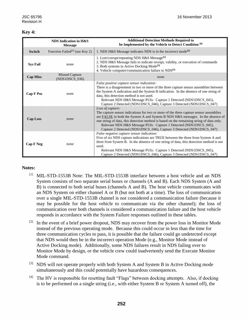
JSC 65795 16 November 2013 Revision H
252
Key 4:
NDS Indication in H&S
Message
Additional Detection Methods Required to
be Implemented by the Vehicle to Detect Condition [8]
Switch Function Failed[9] (see Key 2) 1. NDS H&S Message indicates NDS is in the incorrect mode[2]
Sys Fail none
1. Lost/corrupt/repeating NDS H&S Message[1]
2. NDS H&S Message fails to indicate receipt, validity, or execution of commands
3. Both systems in Active Docking Mode[3]
4. Vehicle computer/communication failure to NDS[5]
Cap Miss Missed Capture
(NDS1DSCS_036) none
Cap F Pos none
False positive capture sensor indication:
There is a disagreement in two or more of the three capture sensor assemblies between
the System A indication and the System B indication. In the absence of one string of
data, this detection method is not used.
Relevant NDS H&S Message PUIs: Capture 1 Detected (NDS1DSCS_045),
Capture 2 Detected (NDS1DSCS_046), Capture 3 Detected (NDS1DSCS_047)
Cap Loss none
Loss of capture:
The capture sensor indications for two or more of the three capture sensor assemblies
are FALSE in both the System A and System B NDS H&S messages. In the absence of
one string of data, this detection method is based on the remaining string of data only.
Relevant NDS H&S Message PUIs: Capture 1 Detected (NDS1DSCS_045),
Capture 2 Detected (NDS1DSCS_046), Capture 3 Detected (NDS1DSCS_047)
Cap F Neg none
False negative capture sensor indication:
Five of six NDS capture indications are TRUE between the three from System A and
three from System B. In the absence of one string of data, this detection method is not
used.
Relevant NDS H&S Message PUIs: Capture 1 Detected (NDS1DSCS_045),
Capture 2 Detected (NDS1DSCS_046), Capture 3 Detected (NDS1DSCS_047)
Notes:
[1] MIL-STD-1553B Note: The MIL-STD-1553B interface between a host vehicle and an NDS
System consists of two separate serial buses or channels (A and B). Each NDS System (A and
B) is connected to both serial buses (channels A and B). The host vehicle communicates with
an NDS System on either channel A or B (but not both at a time). The loss of communication
over a single MIL-STD-1553B channel is not considered a communication failure (because it
may be possible for the host vehicle to communicate via the other channel); the loss of
communication over both channels is considered a communication failure and the host vehicle
responds in accordance with the System Failure responses outlined in these tables.
[2] In the event of a brief power dropout, NDS may recover from the power loss in Monitor Mode
instead of the previous operating mode. Because this could occur in less than the time for
three communication cycles to pass, it is possible that the failure could go undetected except
that NDS would then be in the incorrect operation Mode (e.g., Monitor Mode instead of
Active Docking mode). Additionally, some NDS failures result in NDS failing over to
Monitor Mode by design, or the vehicle crew could inadvertently send the Execute Monitor
Mode command.
[3] NDS will not operate properly with both System A and System B in Active Docking mode
simultaneously and this could potentially have hazardous consequences.
[4] The HV is responsible for resetting fault “Flags” between docking attempts. Also, if docking
is to be performed on a single string (i.e., with either System B or System A turned off), the
JSC 65795 16 November 2013 Revision H
253
vehicle failure responses should modified to exclude string switching (i.e. the fault flag should
be pre-set before the docking attempt). These tables do not specifically address docking with
one string failed.
[5] In the event that NDS senses a loss of communication from the HV (e.g., the HV computer
responsible for controlling NDS fails off), NDS transitions to Monitor Mode in which all NDS
effectors are disabled. In this scenario, the HV’s redundant computer must sense the failure of
the primary computer and send the appropriate commands to continue NDS operations on the
redundant NDS string (A or B).
[6] If NDS experiences a missed capture during Lunge (i.e., time from initial contact until capture
expires or an actuator exceeds a maximum length threshold), NDS automatically enters the
“Hold and Release” function described in note [7] below, allowing the vehicle to safely retreat
from the failed docking attempt.
[7] The “Hold and Release” function is an off-nominal function that NDS enters when safing the
system after a fault has been experienced and a docking termination is required. In this
function, the NDS soft capture system holds position (with a pre-determined linear actuator
slip force limit) and NDS releases the soft capture latches to allow a HV to safely retreat from
a terminated docking attempt.
[8] For failure detection methods that occur in the vehicle’s computers, the vehicle should
consider the appropriate inclusion of persistence counters in the fault detection algorithms
employed. For example, for a “Cap F Pos” fault detection algorithm, a persistence count of at
least two should be used to protect for a case where the NDS System A and System B Health
& Status messages are slightly out of synch with one another. Additionally, it is expected that
for a “Sys Fail” detection algorithm (e.g. detecting a lost/corrupt/repeating NDS H&S
message), the vehicle will implement a persistence count of three to allow for intermittent
communication errors. Conversely, for distinct failures reported by NDS in the H&S message
(e.g. “Switch”), the vehicle is expected to perform the failure response actions after the first
instance.
[9] Each NDS function has a unique status in the NDS H&S message. The possible status for a
function may be one of the following: “NOT_ACTIVE”, “ACTIVE”, “COMPLETED”, or
“FAILED”. Through this status, the HV can determine the NDS phase of operation as well as
whether a failure has occurred in that function. Key 2, above, lists the applicable NDS
functions for both Active Docking and Standby Docking modes. Key 2 also includes the
unique identifier for each function’s status in the NDS H&S message as well as what the
value of that status will be if the function has failed. Note that for a function that has more
than one associated Program Unique Identifier (PUI) (e.g. the “REL” function), the vehicle
response action is to be taken when any one of the listed PUI’s status is “FAILED”.
[10] The “Terminate Docking” command is used by the HV to stop the docking process. During
the soft capture phases of docking, the HV can send this command to the system in Active
Docking Mode to cause NDS to transition to the “Hold and Release” function described in
note [7] above. During the hard capture phases of docking (any time after gang 1 hooks begin
to close), if the HV sends the command to an NDS system, NDS will transition to Monitor
Mode where effectors are disabled.
JSC 65795 16 November 2013 Revision H
254
APPENDIX H – NDSB1 REMOTE ELECTRICAL BOX MOUNTING IMPEDANCE LIMITS
Reserved
JSC 65795 16 November 2013 Revision H
255
APPENDIX I – ERRATA AND TO BE DETERMINED/TO BE REVIEWED LIST
This document is intended to define all functional interfaces and their locations. However, the
document is being released in parallel with the maturing interface definition. As such, there are
several To Be Determined (TBD) and To Be Reviewed (TBR) values. These have been uniquely
identified in Table I-1: TBD Identification and Table I-2, TBR Identification for closure tracking
and update in future releases. Several NDSB1 SRR Review Item Discrepancies (RID)’s from
NDSB1 System Requirements Review (SRR) are still open that could affect the NDSB1 host
requirements in Section 7.0 and the design of the NDSB1 host vehicle (Section 5) and IDA
docking interface (Section 4). The IDA design interface will be fully documented and presented
at the IDA Critical Design Review (CDR) on August 28th. The NDSB1 design interfaces will be
documented and presented at the NDSB1 Preliminary Design Review (PDR) on Sept 19th.
Following IDA CDR/NDSB1 PDR and on-going work for TBX closeout, this document will be
finalized and released by 10/31/2013.

JSC 65795 16 November 2013 Revision H
256
TABLE I-1: TBD IDENTIFICATION

JSC 65795 16 November 2013 Revision H
257
TBD
#
Section,
Figure, or
Table #
Section, Figure, or Table
Title
Issue Status
1 P1.1 Purpose and Scope Need PTRS JSC doc # Closed
2 F4.1.1-1 NDSB1 Envelope Note 4 is unknown Closed
3 T4.1.3.1.1-1 NDSB1 to IDA Power Pin
Assignments
Need assignments Closed
4 T4.1.3.1.1-1 NDSB1 to IDA Power Pin
Assignments
Need Connector P/N for J23A Closed
5 T4.1.3.1.1-1 NDSB1 to IDA Power Pin
Assignments
Need Connector P/N J23B Closed
6 F4.2.1.3-5 HCS SEPARATOR
DETAIL
Need update per Tomas Closed
7 P4.2.1.7 GN&C Aids Need Appendix for
approach/targets
Closed
8 P4.2.1.7 GN&C Aids Need Appendix for
approach/targets
Closed
9 P4.2.3.6 Duct Details Need interface details Closed
10 P5.2.1.2 NDS Installation and
MMOD Shield Mounting
Interfaces
Need installation drawing # Closed
11 F5.2.1.5-1 DSC Box Interfaces Need hole info, bonding,
fastener, etc
Closed
12 F5.2.1.5-2 LAC Interfaces Need hole info, bonding,
fastener, etc
Closed
13 T5.2.1.5-1 Electrical Box Mass
Properties
Need Mass Properties Open
14 T5.2.1.5-2 Impedance Requirements Need values Closed
15 T5.3.1-1 NDSB1 to Host Vehicle
Electrical Power Pin
Assignments
Need values Closed
16 T5.3.1-1 NDSB1 to Host Vehicle
Electrical Power Pin
Assignments
Need connector P/N Closed
17 T5.3.1-1 NDSB1 to Host Vehicle
Electrical Power Pin
Assignments
Need connector P/N Closed
18 T5.2.2.1.6-2 Power Characteristics Need values Closed
19 T5.3.2-1 Umbilical Data Pin
Assignments
Need values Closed
20 T5.3.2-1 Umbilical Data Pin
Assignments
Need Connector P/N Closed
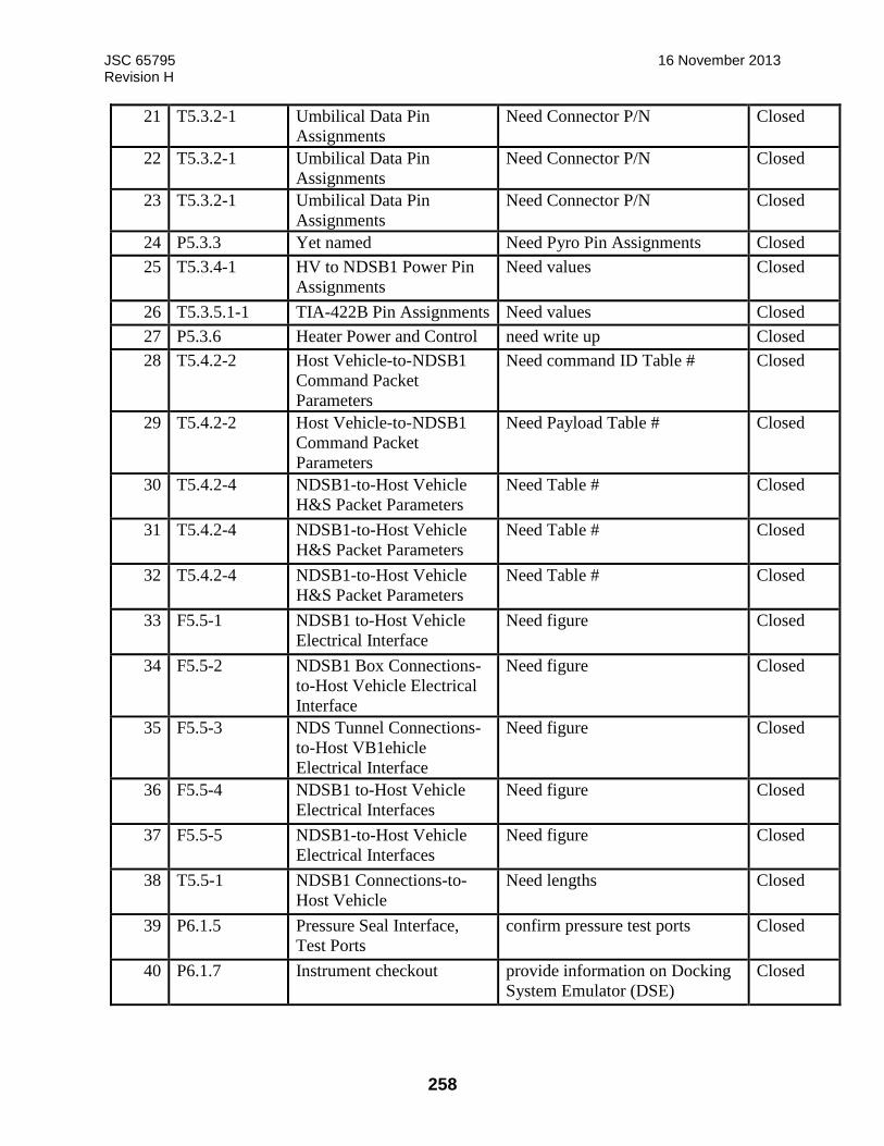
JSC 65795 16 November 2013 Revision H
258
21 T5.3.2-1 Umbilical Data Pin
Assignments
Need Connector P/N Closed
22 T5.3.2-1 Umbilical Data Pin
Assignments
Need Connector P/N Closed
23 T5.3.2-1 Umbilical Data Pin
Assignments
Need Connector P/N Closed
24 P5.3.3 Yet named Need Pyro Pin Assignments Closed
25 T5.3.4-1 HV to NDSB1 Power Pin
Assignments
Need values Closed
26 T5.3.5.1-1 TIA-422B Pin Assignments Need values Closed
27 P5.3.6 Heater Power and Control need write up Closed
28 T5.4.2-2 Host Vehicle-to-NDSB1
Command Packet
Parameters
Need command ID Table # Closed
29 T5.4.2-2 Host Vehicle-to-NDSB1
Command Packet
Parameters
Need Payload Table # Closed
30 T5.4.2-4 NDSB1-to-Host Vehicle
H&S Packet Parameters
Need Table # Closed
31 T5.4.2-4 NDSB1-to-Host Vehicle
H&S Packet Parameters
Need Table # Closed
32 T5.4.2-4 NDSB1-to-Host Vehicle
H&S Packet Parameters
Need Table # Closed
33 F5.5-1 NDSB1 to-Host Vehicle
Electrical Interface
Need figure Closed
34 F5.5-2 NDSB1 Box Connections-
to-Host Vehicle Electrical
Interface
Need figure Closed
35 F5.5-3 NDS Tunnel Connections-
to-Host VB1ehicle
Electrical Interface
Need figure Closed
36 F5.5-4 NDSB1 to-Host Vehicle
Electrical Interfaces
Need figure Closed
37 F5.5-5 NDSB1-to-Host Vehicle
Electrical Interfaces
Need figure Closed
38 T5.5-1 NDSB1 Connections-to-
Host Vehicle
Need lengths Closed
39 P6.1.5 Pressure Seal Interface,
Test Ports
confirm pressure test ports Closed
40 P6.1.7 Instrument checkout provide information on Docking
System Emulator (DSE)
Closed
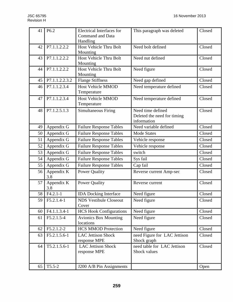
JSC 65795 16 November 2013 Revision H
259
41 P6.2 Electrical Interfaces for
Command and Data
Handling
This paragraph was deleted Closed
42 P7.1.1.2.2.2 Host Vehicle Thru Bolt
Mounting
Need bolt defined Closed
43 P7.1.1.2.2.2 Host Vehicle Thru Bolt
Mounting
Need nut defined Closed
44 P7.1.1.2.2.2 Host Vehicle Thru Bolt
Mounting
Need figure Closed
45 P7.1.1.2.2.3.2 Flange Stiffness Need gap defined Closed
46 P7.1.1.2.3.4 Host Vehicle MMOD
Temperature
Need temperature defined Closed
47 P7.1.1.2.3.4 Host Vehicle MMOD
Temperature
Need temperature defined Closed
48 P7.1.2.5.1.3 Simultaneous Firing Need time defined
Deleted the need for timing
information
Closed
49 Appendix G Failure Response Tables Need variable defined Closed
50 Appendix G Failure Response Tables Mode States Closed
51 Appendix G Failure Response Tables Vehicle response Closed
52 Appendix G Failure Response Tables Vehicle response Closed
53 Appendix G Failure Response Tables switch Closed
54 Appendix G Failure Response Tables Sys fail Closed
55 Appendix G Failure Response Tables Cap fail Closed
56 Appendix K
3.8
Power Quality Reverse current Amp-sec Closed
57 Appendix K
3.8
Power Quality Reverse current Closed
58 F4.2.1-1 IDA Docking Interface Need figure Closed
59 F5.2.1.4-1 NDS Vestibule Closeout
Cover
Need figure Closed
60 F4.1.1.3.4-1 HCS Hook Configurations Need figure Closed
61 F5.2.1.5-4 Avionics Box Mounting
locations
Need figure Closed
62 F5.2.1.2-2 HCS MMOD Protection Need figure Closed
63 F5.2.1.5.6-1 LAC Jettison Shock
response MPE
need Figure for LAC Jettison
Shock graph
Closed
64 T5.2.1.5.6-1 LAC Jettison Shock
response MPE
need table for LAC Jettison
Shock values
Closed
65 T5.5-2 J200 A/B Pin Assignments Open

JSC 65795 16 November 2013 Revision H
260
66 T5.5-2 J600 A/B Pin Assignments Open
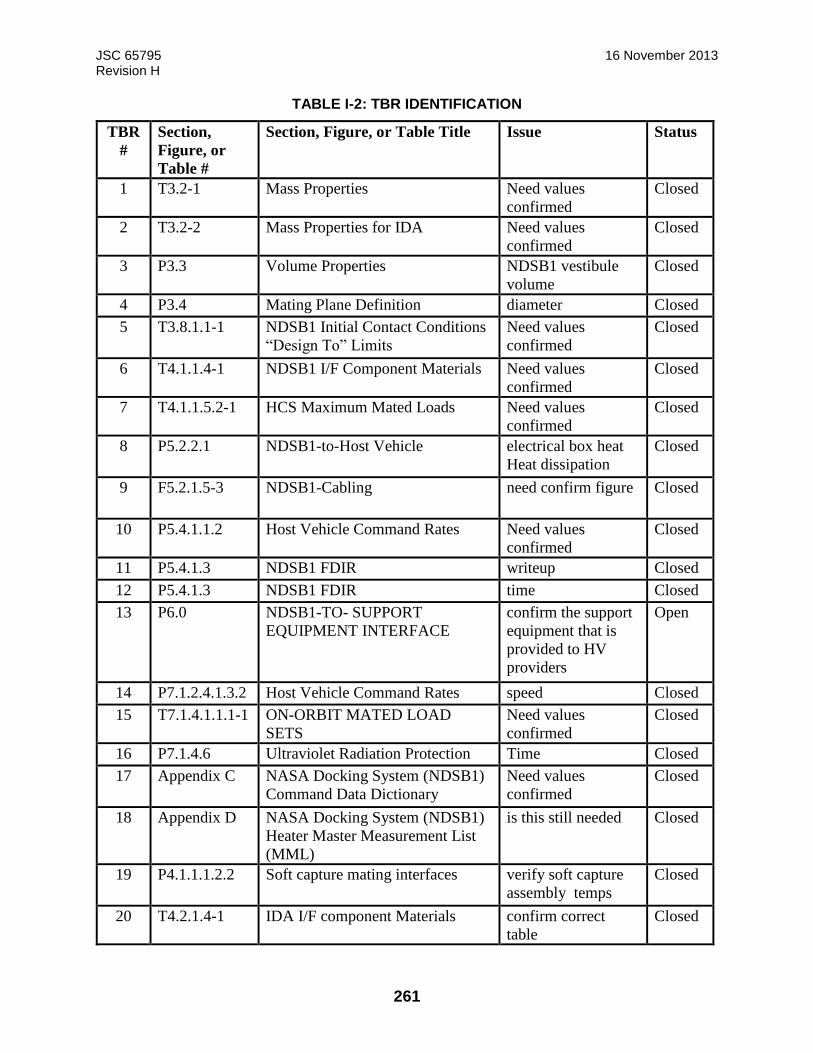
JSC 65795 16 November 2013 Revision H
261
TABLE I-2: TBR IDENTIFICATION
TBR
#
Section,
Figure, or
Table #
Section, Figure, or Table Title Issue Status
1 T3.2-1 Mass Properties Need values
confirmed
Closed
2 T3.2-2 Mass Properties for IDA Need values
confirmed
Closed
3 P3.3 Volume Properties NDSB1 vestibule
volume
Closed
4 P3.4 Mating Plane Definition diameter Closed
5 T3.8.1.1-1 NDSB1 Initial Contact Conditions
“Design To” Limits
Need values
confirmed
Closed
6 T4.1.1.4-1 NDSB1 I/F Component Materials Need values
confirmed
Closed
7 T4.1.1.5.2-1 HCS Maximum Mated Loads Need values
confirmed
Closed
8 P5.2.2.1 NDSB1-to-Host Vehicle electrical box heat
Heat dissipation
Closed
9 F5.2.1.5-3 NDSB1-Cabling need confirm figure Closed
10 P5.4.1.1.2 Host Vehicle Command Rates Need values
confirmed
Closed
11 P5.4.1.3 NDSB1 FDIR writeup Closed
12 P5.4.1.3 NDSB1 FDIR time Closed
13 P6.0 NDSB1-TO- SUPPORT
EQUIPMENT INTERFACE
confirm the support
equipment that is
provided to HV
providers
Open
14 P7.1.2.4.1.3.2 Host Vehicle Command Rates speed Closed
15 T7.1.4.1.1.1-1 ON-ORBIT MATED LOAD
SETS
Need values
confirmed
Closed
16 P7.1.4.6 Ultraviolet Radiation Protection Time Closed
17 Appendix C NASA Docking System (NDSB1)
Command Data Dictionary
Need values
confirmed
Closed
18 Appendix D NASA Docking System (NDSB1)
Heater Master Measurement List
(MML)
is this still needed Closed
19 P4.1.1.1.2.2 Soft capture mating interfaces verify soft capture
assembly temps
Closed
20 T4.2.1.4-1 IDA I/F component Materials confirm correct
table
Closed
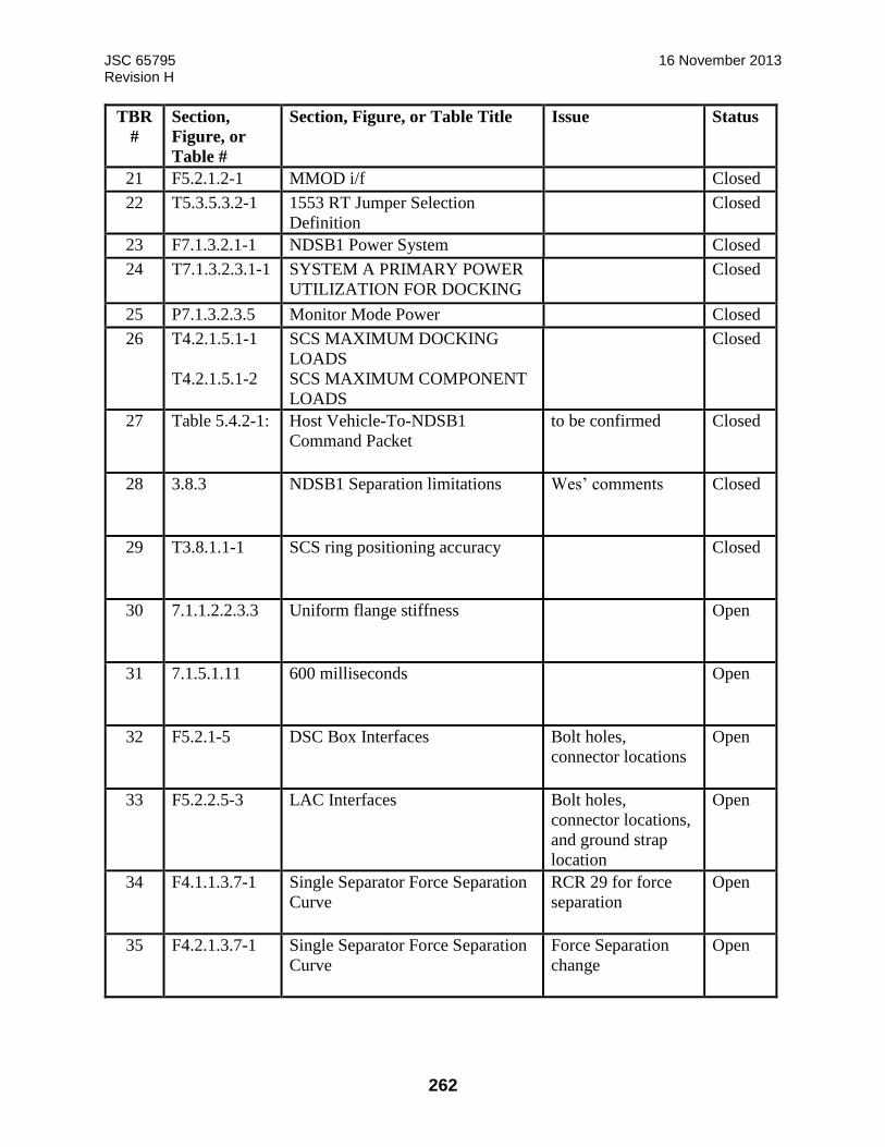
JSC 65795 16 November 2013 Revision H
262
TBR
#
Section,
Figure, or
Table #
Section, Figure, or Table Title Issue Status
21 F5.2.1.2-1 MMOD i/f Closed
22 T5.3.5.3.2-1 1553 RT Jumper Selection
Definition
Closed
23 F7.1.3.2.1-1 NDSB1 Power System Closed
24 T7.1.3.2.3.1-1 SYSTEM A PRIMARY POWER
UTILIZATION FOR DOCKING
Closed
25 P7.1.3.2.3.5 Monitor Mode Power Closed
26 T4.2.1.5.1-1
T4.2.1.5.1-2
SCS MAXIMUM DOCKING
LOADS
SCS MAXIMUM COMPONENT
LOADS
Closed
27 Table 5.4.2-1: Host Vehicle-To-NDSB1
Command Packet
to be confirmed Closed
28 3.8.3 NDSB1 Separation limitations Wes’ comments Closed
29 T3.8.1.1-1 SCS ring positioning accuracy Closed
30 7.1.1.2.2.3.3 Uniform flange stiffness Open
31 7.1.5.1.11 600 milliseconds Open
32 F5.2.1-5 DSC Box Interfaces Bolt holes,
connector locations
Open
33 F5.2.2.5-3 LAC Interfaces Bolt holes,
connector locations,
and ground strap
location
Open
34 F4.1.1.3.7-1 Single Separator Force Separation
Curve
RCR 29 for force
separation
Open
35 F4.2.1.3.7-1 Single Separator Force Separation
Curve
Force Separation
change
Open
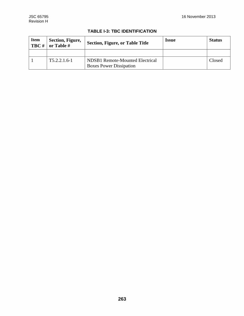
JSC 65795 16 November 2013 Revision H
263
TABLE I-3: TBC IDENTIFICATION
Item
TBC #
Section, Figure,
or Table # Section, Figure, or Table Title
Issue Status
1 T5.2.2.1.6-1 NDSB1 Remote-Mounted Electrical
Boxes Power Dissipation
Closed

JSC 65795 16 November 2013 Revision H
264
APPENDIX J - INTERFACE DEFINITION DOCUMENT (IDD) CHANGE RECORD FOR REVISION G
Reserved.

JSC 65795 16 November 2013 Revision H
265
APPENDIX K - ELECTRICAL POWER QUALITY REQUIREMENTS
K.1.0 Electrical Power
The following sections are the power quality and compatibility requirements for the host
vehicle/NDSB1 interfaces, which is defined at the input of the DSC and LAC hardware. The
requirements are based on the NDSB1 architecture as defined in Figure K.1.0-1
FIGURE K1.0-1:NDS-TO-HOST VEHICLE ELECTRICAL INTERFACE
Linear Actuator
Controller (LAC)
A
B
R
S-4
22
28V Linear Act Pwr A 28V LAC Control Pwr A 28V LAC Control Pwr B
1553 or RS-422
28V DSC Cntrl Pwr
28V DSC Cntrl Pwr
28V Effector Pwr
28V Effector Pwr
Docking System
Controller (DSC) A
Heaters (3)
RTDs (3)
Umbilical Position (4) Launch Restraint (3) Launch Rstnt Position (6)
Capture Latch (3) Capture Ltch Position (6) Capture Sensor (6) RTH (3) and Undock (2)
Hook Motor (2) Hook Position (12) Umbilical Motor (2)
Separator Motor (3) Separator Position (6)
Heaters (3)
RTDs (3)
Umbilical Position (4) Launch Restraint (3) Launch Rstnt Position (6)
Capture Latch (3) Capture Ltch Position (6) Capture Sensors (6) RTH (3) and Undock (2)
Hook Motor (2) Hook Position (12) Umbilical Motor (2)
Separator Motor (3) Separator Position (6)
Data - Ethernet (2), 1553 (A/B) Power – 120VDC, 28VDC (Scar)
Data - Ethernet (2), 1553 (A/B) Power – 120VDC, 28VDC (Scar)
Pyros
Active hooks 1,3,5,7,9,11 Active hooks 2,4,6,8,10,12
Pyros
Passive hooks 1,3,5,7,9,11 Passive hooks 2,4,6,8,10,12
Host
Vehicle
1553 or RS-422
R
S-4
22
Docking System
Controller (DSC) B
HCS
Capture Latch NEA 1, 2, 3

JSC 65795 16 November 2013 Revision H
266
The host vehicles shall provide eleven power feeds to the NDSB1 avionics, four per system A and
B, and three for NEAs, as defined in Table K1.0-1 NDSB1 POWER INPUT FEEDS. System A
and B power feeds are redundant and will meet the same requirements therefore only one set of
feeds will be defined in the following sections.
Note: System A and B should be fed by different power feeds originating from different/ redundant
power sources.
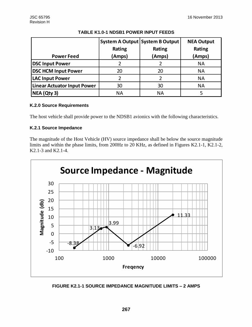
JSC 65795 16 November 2013 Revision H
267
TABLE K1.0-1 NDSB1 POWER INPUT FEEDS
K.2.0 Source Requirements
The host vehicle shall provide power to the NDSB1 avionics with the following characteristics.
K.2.1 Source Impedance
The magnitude of the Host Vehicle (HV) source impedance shall be below the source magnitude
limits and within the phase limits, from 200Hz to 20 KHz, as defined in Figures K2.1-1, K2.1-2,
K2.1-3 and K2.1-4.
FIGURE K2.1-1 SOURCE IMPEDANCE MAGNITUDE LIMITS – 2 AMPS
Power Feed
System A Output
Rating
(Amps)
System B Output
Rating
(Amps)
NEA Output
Rating
(Amps)
DSC Input Power 2 2 NA
DSC HCM Input Power 20 20 NA
LAC Input Power 2 2 NA
Linear Actuator Input Power 30 30 NA
NEA (Qty 3) NA NA 5
-8.38
3.133.99
-6.92
11.33
-10
-5
0
5
10
15
20
25
30
100 1000 10000 100000
Mag
nit
ud
e (
db
)
Freqency
Source Impedance - Magnitude

JSC 65795 16 November 2013 Revision H
268
FIGURE K2.1-2 SOURCE IMPEDANCE PHASE LIMITS – 2 AMPS
FIGURE K2.1-3 SOURCE IMPEDANCE MAGNITUDE LIMITS – 20 & 30 AMPS
60.073.0
73.0
73.0
73.0 80.0
90.0
-60.0 -60.0
-60.0
-63.0 -63.0-52.0
-30.0-30.0
-130.0
-80.0
-30.0
20.0
70.0
120.0
100 1000 10000 100000
Ph
ase
(D
eg)
Freqency
Source Impedance - Phase
-12.20
-12.02
-10.58
-10.01
-6.92
11.33
-20
-10
0
10
20
30
100 1000 10000 100000
Mag
nit
ud
e (
db
)
Freqency
Source Impedance - Magnitude
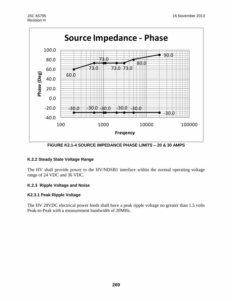
JSC 65795 16 November 2013 Revision H
269
FIGURE K2.1-4 SOURCE IMPEDANCE PHASE LIMITS – 20 & 30 AMPS
K.2.2 Steady State Voltage Range
The HV shall provide power to the HV/NDSB1 interface within the normal operating voltage
range of 24 VDC and 36 VDC.
K.2.3 Ripple Voltage and Noise K2.3.1 Peak Ripple Voltage
The HV 28VDC electrical power feeds shall have a peak ripple voltage no greater than 1.5 volts
Peak-to-Peak with a measurement bandwidth of 20MHz.
60.0
73.0 73.0
73.0
73.080.0
90.0
-30.0 -30.0 -30.0-30.0 -30.0-30.0
-40.0
-20.0
0.0
20.0
40.0
60.0
80.0
100.0
100 1000 10000 100000
Ph
ase
(D
eg)
Freqency
Source Impedance - Phase
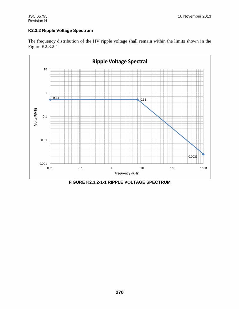
JSC 65795 16 November 2013 Revision H
270
K2.3.2 Ripple Voltage Spectrum
The frequency distribution of the HV ripple voltage shall remain within the limits shown in the
Figure K2.3.2-1
FIGURE K2.3.2-1-1 RIPPLE VOLTAGE SPECTRUM
0.530.53
0.0025
0.001
0.01
0.1
1
10
0.01 0.1 1 10 100 1000
Vo
lts(R
MS
)
Frequency (KHz)
Ripple Voltage Spectral

JSC 65795 16 November 2013 Revision H
271
K.2.4 Normal Transient Voltage Range
The host vehicle transient voltage range shall be within the voltage envelope shown in Figure
K2.4-1 Normal Transient Voltage.
FIGURE K2.4-1 NORMAL TRANSIENT VOLTAGE
Note: The NDSB1 hardware will provide nominal performance with input voltage excursions as
defined in Figure K.2.4-1.
K.2.5 Abnormal Transient Voltage Range
The abnormal transient voltages are generated during faults in bus lines or loads or due to system
overload conditions.
36V
43V43V
36V 36V
24V
18V 18V
24V 24V
10
15
20
25
30
35
40
45
50
-1 0 1 2 3 4
Vo
lts
(DC
)
Time (ms)
Normal Transient Limits
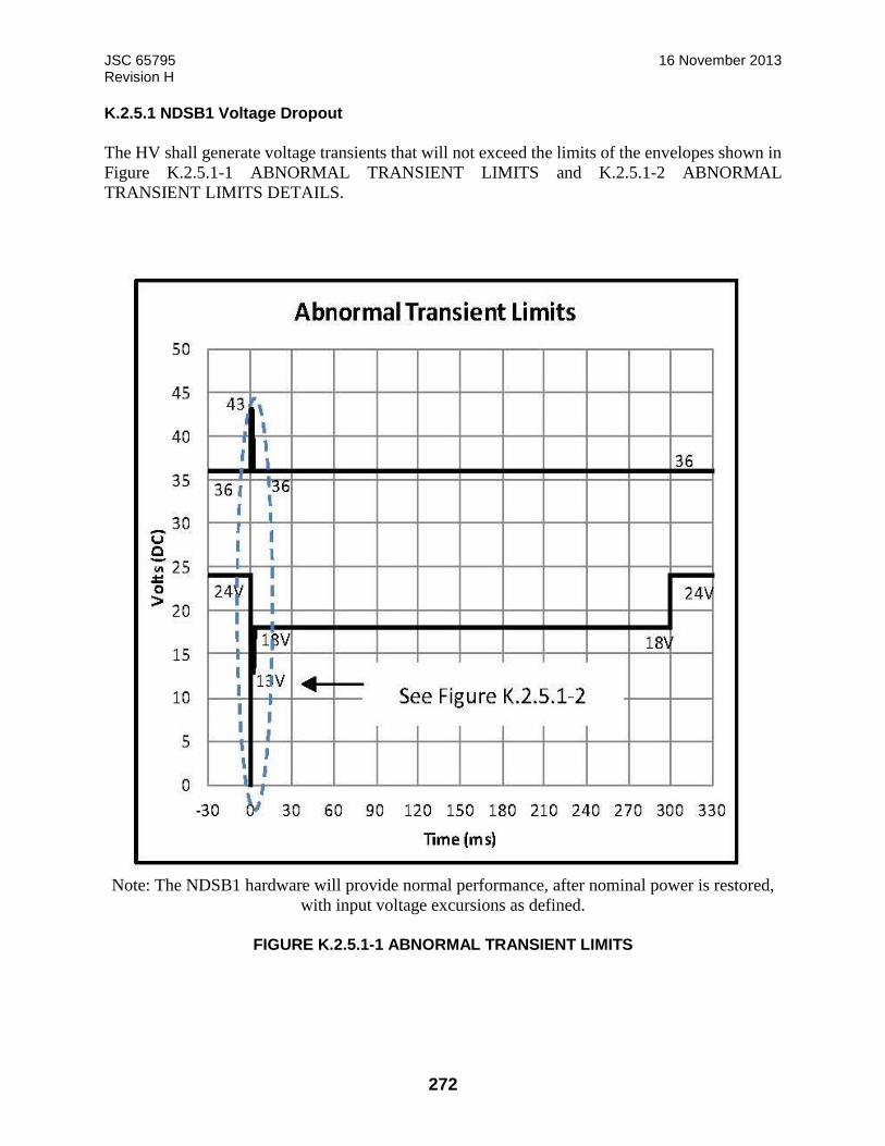
JSC 65795 16 November 2013 Revision H
272
K.2.5.1 NDSB1 Voltage Dropout
The HV shall generate voltage transients that will not exceed the limits of the envelopes shown in
Figure K.2.5.1-1 ABNORMAL TRANSIENT LIMITS and K.2.5.1-2 ABNORMAL
TRANSIENT LIMITS DETAILS.
Note: The NDSB1 hardware will provide normal performance, after nominal power is restored,
with input voltage excursions as defined.
FIGURE K.2.5.1-1 ABNORMAL TRANSIENT LIMITS
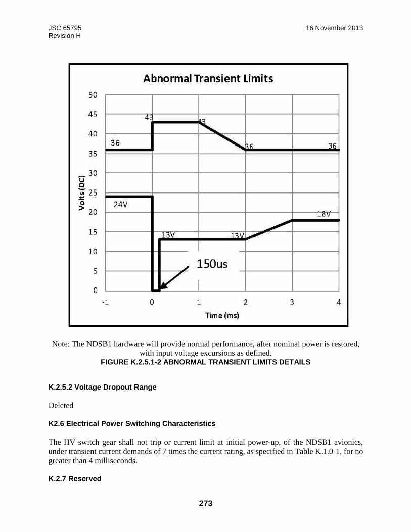
JSC 65795 16 November 2013 Revision H
273
Note: The NDSB1 hardware will provide normal performance, after nominal power is restored,
with input voltage excursions as defined. FIGURE K.2.5.1-2 ABNORMAL TRANSIENT LIMITS DETAILS
K.2.5.2 Voltage Dropout Range
Deleted
K2.6 Electrical Power Switching Characteristics
The HV switch gear shall not trip or current limit at initial power-up, of the NDSB1 avionics,
under transient current demands of 7 times the current rating, as specified in Table K.1.0-1, for no
greater than 4 milliseconds.
K.2.7 Reserved
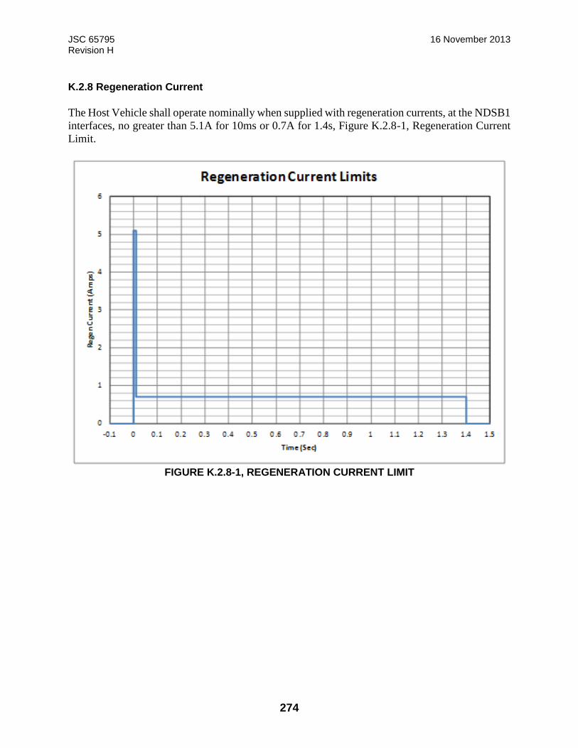
JSC 65795 16 November 2013 Revision H
274
K.2.8 Regeneration Current
The Host Vehicle shall operate nominally when supplied with regeneration currents, at the NDSB1
interfaces, no greater than 5.1A for 10ms or 0.7A for 1.4s, Figure K.2.8-1, Regeneration Current
Limit.
FIGURE K.2.8-1, REGENERATION CURRENT LIMIT