Visual tracking and control of a quadcopter using a stereo camera system and inertial sensors
7
Visual Tracking and Control of a Quadcopter Using a Stereo Camera System and Inertial Sensors * Markus Achtelik, Tianguang Zhang, Kolja K¨ uhnlenz and Martin Buss Institute of Automatic Control Engineering (LSR) Technische Universit¨ at M¨ unchen D-80290 Munich, Germany [email protected], {tg.zhang, kolja.kuehnlenz, m.buss}@ieee.org Abstract— In this paper a complete system is designed and implemented, in which the motion of a quadcopter is sta- bly controlled based on visual feedback and measurements of inertial sensors. We focus on developing a cost effective and easy-to-setup vision system. Active markers were finely designed to improve visibility under various perspectives as well as robustness towards disturbances in the image-based pose estimation. Moreover, position- and heading controllers for the quadcopter were implemented to show the system’s capabilities. The performance of the controllers was further improved by the use of inertial sensors of the quadcopter. A closed-loop control system is successfully conducted. Index Terms— Vision system, motion estimation, multiple sensing system, UAV/MAV control. I. I NTRODUCTION In recent years, unmanned aerial vehicle (UAV) and micro aerial vehicle (MAV) are major focuses of active researches, since they can extend our capability in a variety of areas, especially for applications like search-and-rescue and inspec- tion. A significant challenge in developing UAVs is to extract and fuse the useful information in a robust manner and to provide stable flight and an accurate navigation. To exploit various flight behaviors and control strategies of UAVs, we use a quadcopter [1] [2] as testbed. The control of quadcopter during autonomous flights re- lies on knowledge of variables like position, velocity and orientation, which can be partly calculated using information provided by on-board inertial sensors. However, the drift of inertial sensors leads to errors during time-discrete integra- tion, making a steadily accurate estimation of the absolute pose nearly impossible. Therefore, an absolute reference is needed, e.g. a GPS system for outdoor applications. Indoors, where no GPS is available, a visual tracking system could be applied. In [3], an efficient iterative algorithm is proposed in order to achieve a globally convergent pose estimation of an object with known 3D geometry. Another accurate pose estimation of moving rigid object using a calibrated stereoscopic vision setup is described in [4], in which a * This work is partially supported by the DFG excellence initiative research cluster Cognition for Technical Systems – CoTeSys and the Bernstein Center for Computational Neuroscience Munich. Fig. 1: The quadcopter with illuminated markers novel correction scheme compensating accumulated errors was integrated. However, the real time capability of them is not sufficient for quadcopter motion control. In [2] a position controller for a quadcopter was implemented using an optical tracking system by VICON in the “Holodeck” lab at MIT. This intelligent space is nevertheless very expensive and not transportable. 3D-pose estimation and control of a quadcopter using only visual feedback had been done in [5] based on one camera fixed on the ground an additional second camera mounted on the quadcopter facing downwards. The flight volume in this work is very limited and the feature detection applied is sensitive to the light condition and therefore not re- liable enough. We see our system not competing with systems developed in [6] [7] where on-board sensors such as IMU, camera and sonars or laser rangefinders are used for pose estimation and obstacle avoidance for an autonomous flight. In contrast, it could be an extremely helpful addition during the development of onboard pose estimation systems men- tioned above by providing absolute position information and ground truth. These algorithms usually need a well structured environment that might be totally different from laboratories where tracking systems like VICON are installed, for which reason we like to emphasize the transportability and easy setup of our system. To deal the aforementioned problems, a complete system is designed and implemented, in which the motion of a quadcopter is stably controlled based on visual feedback and measurements of inertial sensors. We focus on developing a cost effective and easy-to-setup vision system. We use an off-
Transcript of Visual tracking and control of a quadcopter using a stereo camera system and inertial sensors

Visual Tracking and Control of a QuadcopterUsing a Stereo Camera System and Inertial Sensors∗
Markus Achtelik, Tianguang Zhang, Kolja Kuhnlenz and Martin BussInstitute of Automatic Control Engineering (LSR)
Technische Universitat MunchenD-80290 Munich, Germany
[email protected], {tg.zhang, kolja.kuehnlenz, m.buss}@ieee.org
Abstract— In this paper a complete system is designed andimplemented, in which the motion of a quadcopter is sta-bly controlled based on visual feedback and measurementsof inertial sensors. We focus on developing a cost effectiveand easy-to-setup vision system. Active markers were finelydesigned to improve visibility under various perspectives aswell as robustness towards disturbances in the image-based poseestimation. Moreover, position- and heading controllers for thequadcopter were implemented to show the system’s capabilities.The performance of the controllers was further improved by theuse of inertial sensors of the quadcopter. A closed-loop controlsystem is successfully conducted.
Index Terms— Vision system, motion estimation, multiplesensing system, UAV/MAV control.
I. INTRODUCTION
In recent years, unmanned aerial vehicle (UAV) and microaerial vehicle (MAV) are major focuses of active researches,since they can extend our capability in a variety of areas,especially for applications like search-and-rescue and inspec-tion. A significant challenge in developing UAVs is to extractand fuse the useful information in a robust manner and toprovide stable flight and an accurate navigation. To exploitvarious flight behaviors and control strategies of UAVs, weuse a quadcopter [1] [2] as testbed.
The control of quadcopter during autonomous flights re-lies on knowledge of variables like position, velocity andorientation, which can be partly calculated using informationprovided by on-board inertial sensors. However, the drift ofinertial sensors leads to errors during time-discrete integra-tion, making a steadily accurate estimation of the absolutepose nearly impossible. Therefore, an absolute reference isneeded, e.g. a GPS system for outdoor applications. Indoors,where no GPS is available, a visual tracking system couldbe applied. In [3], an efficient iterative algorithm is proposedin order to achieve a globally convergent pose estimationof an object with known 3D geometry. Another accuratepose estimation of moving rigid object using a calibratedstereoscopic vision setup is described in [4], in which a
∗ This work is partially supported by the DFG excellence initiativeresearch cluster Cognition for Technical Systems – CoTeSys and the BernsteinCenter for Computational Neuroscience Munich.
Fig. 1: The quadcopter with illuminated markers
novel correction scheme compensating accumulated errorswas integrated. However, the real time capability of them isnot sufficient for quadcopter motion control. In [2] a positioncontroller for a quadcopter was implemented using an opticaltracking system by VICON in the “Holodeck” lab at MIT.This intelligent space is nevertheless very expensive and nottransportable. 3D-pose estimation and control of a quadcopterusing only visual feedback had been done in [5] based onone camera fixed on the ground an additional second cameramounted on the quadcopter facing downwards. The flightvolume in this work is very limited and the feature detectionapplied is sensitive to the light condition and therefore not re-liable enough. We see our system not competing with systemsdeveloped in [6] [7] where on-board sensors such as IMU,camera and sonars or laser rangefinders are used for poseestimation and obstacle avoidance for an autonomous flight.In contrast, it could be an extremely helpful addition duringthe development of onboard pose estimation systems men-tioned above by providing absolute position information andground truth. These algorithms usually need a well structuredenvironment that might be totally different from laboratorieswhere tracking systems like VICON are installed, for whichreason we like to emphasize the transportability and easysetup of our system.
To deal the aforementioned problems, a complete systemis designed and implemented, in which the motion of aquadcopter is stably controlled based on visual feedback andmeasurements of inertial sensors. We focus on developing acost effective and easy-to-setup vision system. We use an off-
board stereo camera setup consisting of two web cameras toprovide accurate position information. Active markers werefinely designed with high-power LEDs of different colors.This design allows visibility under various perspectives andimproves robustness towards disturbances. Finally, the image-based pose estimation was experimentally evaluated usinga positioning table. We also show the implementation ofa position- and heading controller as well as an approachon how to incorporate IMU data. Hovering and autonomousflight are excellently implemented as shown in video.
This paper is organized as follows: firstly, in Section II, wedescribe the hardware configuration in our application as wellas their functional principle. In Section III, marker detectionand pose estimation of the quadcopter are introduced. Pro-cessing times and accuracy are evaluated in Section IV. Theimplementation of the controllers and experimental resultsare shown in Section V. Conclusions are given in SectionVI.
II. HARDWARE CONFIGURATION
A. Quadcopter
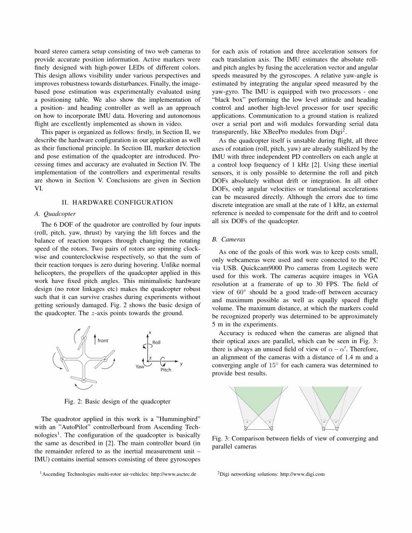
The 6 DOF of the quadrotor are controlled by four inputs(roll, pitch, yaw, thrust) by varying the lift forces and thebalance of reaction torques through changing the rotatingspeed of the rotors. Two pairs of rotors are spinning clock-wise and counterclockwise respectively, so that the sum oftheir reaction torques is zero during hovering. Unlike normalhelicopters, the propellers of the quadcopter applied in thiswork have fixed pitch angles. This minimalistic hardwaredesign (no rotor linkages etc) makes the quadcopter robustsuch that it can survive crashes during experiments withoutgetting seriously damaged. Fig. 2 shows the basic design ofthe quadcopter. The z-axis points towards the ground.
Fig. 2: Basic design of the quadcopter
The quadrotor applied in this work is a ”Hummingbird”with an ”AutoPilot” controllerboard from Ascending Tech-nologies1. The configuration of the quadcopter is basicallythe same as described in [2]. The main controller board (inthe remainder refered to as the inertial measurement unit –IMU) contains inertial sensors consisting of three gyroscopes
1Ascending Technologies multi-rotor air-vehicles: http://www.asctec.de
for each axis of rotation and three acceleration sensors foreach translation axis. The IMU estimates the absolute roll-and pitch angles by fusing the acceleration vector and angularspeeds measured by the gyroscopes. A relative yaw-angle isestimated by integrating the angular speed measured by theyaw-gyro. The IMU is equipped with two processors - one“black box” performing the low level attitude and headingcontrol and another high-level processor for user specificapplications. Communication to a ground station is realizedover a serial port and wifi modules forwarding serial datatransparently, like XBeePro modules from Digi2.
As the quadcopter itself is unstable during flight, all threeaxes of rotation (roll, pitch, yaw) are already stabilized by theIMU with three independent PD controllers on each angle ata control loop frequency of 1 kHz [2]. Using these inertialsensors, it is only possible to determine the roll and pitchDOFs absolutely without drift or integration. In all otherDOFs, only angular velocities or translational accelerationscan be measured directly. Although the errors due to timediscrete integration are small at the rate of 1 kHz, an externalreference is needed to compensate for the drift and to controlall six DOFs of the quadcopter.
B. Cameras
As one of the goals of this work was to keep costs small,only webcameras were used and were connected to the PCvia USB. Quickcam9000 Pro cameras from Logitech wereused for this work. The cameras acquire images in VGAresolution at a framerate of up to 30 FPS. The field ofview of 60◦ should be a good trade-off between accuracyand maximum possible as well as equally spaced flightvolume. The maximum distance, at which the markers couldbe recognized properly was determined to be approximately5 m in the experiments.
Accuracy is reduced when the cameras are aligned thattheir optical axes are parallel, which can be seen in Fig. 3:there is always an unused field of view of α−α′. Therefore,an alignment of the cameras with a distance of 1.4 m and aconverging angle of 15◦ for each camera was determined toprovide best results.
Fig. 3: Comparison between fields of view of converging andparallel cameras
2Digi networking solutions: http://www.digi.com

C. Markers
To be more independent from light conditions, activemarkers were mounted at the end of each boom of thequadcopter. The basic idea was to illuminate the markersas bright as possible and to reduce the exposure time of thecameras then. This method reduces motion blur as well asthe influence of ambient light.
To compute all six DOFs of the quadcopter from thetracked marker-positions, three markers would be sufficient.For redundancy reasons and to avoid potential failure due toself-occlusion, four markers were applied. Two high powerLEDs each were aligend inside a table-tennis ball dispersingthe light of the LEDs diffusely. As a result, a homogeneouslylit sphere could be recognized by the cameras as a circle fromall directions of view. Fig. 4a and 4b shows the design anda lightened view of a marker.
(a) (b)
Fig. 4: Design of the markers
III. TRACKING AND POSE RECONSTRUCTION
A. Recognition of the markers
For each marker, the area and a center of gravity (COG)is calculated which is then used for computing the stereocorrespondences needed for the 3-D reconstruction after-wards. The following steps are performed for each of thefour markers in the image of each camera.
First of all, the image is transformed from RGB intothe YUV-colorspace so that the search for colors can beperformed independently from lighting conditions. Each pixelthat falls within predifined ranges is called hit. Before com-puting the COG, a robust filter is applied: only hits whosecoordinates in both x and y are close to the median of thecoordinates will be considered in the calculation of the centerof gravity. Compared to a median filter on the intensityvalues of a neighborhood of each pixel, the procedure ofsorting the coordinates in order to calculate the median is notexpensive: due to the line-by-line search, the y-coordinatesare already sorted and the x-coordinates are presorted. Oncea valid center of gravity is found, a region of interest (ROI)is determined around this position and search in the nexttimestep only takes place in this region.
In case a marker was partially occluded by parts of thequadcopter, the COG of a marker shifts although the marker
itself did not. The markers are bullets, so a circle in thebinary image gained from the thresholds above is expected.To reconstruct the real center of the marker, the foregroundof the binary image is corrected by morphological closingto fill gaps in the foreground but keep the basic structureapproximately and edge filtering is done afterwards. Now,a circle can be fitted into the edges found in the stepbefore. The deviations of the center of the markers couldbe reduced significantly using this method, especially onpartially occluded markers. Fig. 5 shows step-by-step theprocedure of recovering the circle.
Fig. 5: Step-by-step fitting of the circle
B. 3-D reconstruction of the marker’s positions
After the 2-D coordinates of the center of the markershave been successfully determined in each image, their 3-Dcoordinates can be recovered. The coordinates from markersof the same color now serve as a corresponding pair ofcoordinates for the reconstruction. A 3-D point in spaceis projected into the camera’s image planes up to a scalarfactor λ by the following equations [8]. All coordinates arerepresented as homogeneous coordinates.
λx1 =[K1 0
]·X0 = Π1 ·X0 (1)
λx2 =[K2R K2T
]·X0 = Π2 ·X0 (2)
xi ∈ R3×1 denotes the projection of X0 ∈ R4×1 intothe image plane of the left and right cameras through theprojection matrices Πi ∈ R3×4 which consist of the intrinsicparameter matrices Ki as well as of the extrinsic parametersR and T . The frame of the left camera is taken as referenceframe. Rewriting of (1, 2) leads to four constraints for thepoint X0 we wish to recover from both views:(
x1π3T1 − π1T
1
)X0 = 0
(y1π
3T1 − π2T
1
)X0 = 0 (3)(
x2π3T2 − π1T
2
)X0 = 0
(y2π
3T2 − π2T
2
)X0 = 0 (4)
Where xi =[xi yi 1
]T. πjT
i are the jth row vectors of theprojection matrices Πi =
[π1
i π2i π3
i
]T. (3) and (4) now
form a 4 × 4 homogeneous system of equations that has tobe solved: MX0 = 0. In practice, this system does not havea solution due to small errors in the correspondences or inthe camera calibration. The best solution in the sense of leastsquares for X0 is the eigenvector of MTM corresponding toits smallest eigenvalue. To complete the reconstruction, X0
has to be normalized so that its last coordinate is equal to 1.

C. Reconstruction of the quadcopter’s pose
Having reconstructed the 3-D positions of the markers, theposition and orientation of the quadcopter can be determined.In [9], Umeyama proposes an approach to determine therotation R and the translation T from two given sets ofpoints Xi and Y i where the mean squared errors e(R, T )are minimized.Y i were chosen as initial positions of the quadcopter’s
markers. As the positions of the markers were reconstructedw.r.t. the left camera’s frame, this frame was also takenas reference frame for the initial positions. These initialpositions have the coordinates of the markers mounted at theend of the quadcopter’s booms and lie in the x-y plane. Thetransformation between the initial positions and the currentpositions of the markers can be described as follows:
Xi = R · Yi + T (5)
To gain R and T uniquely in 3-D space, at least threecorrespondences are necessary. Firstly, the rotation will becalculated. The sets of points are translated by their centroidsµx and µy to the origin and the covariance matrix Σxy of thetranslated sets of points is computed. n denotes the numberof corresponding pairs of points.
µx =1n
n∑i=1
Xi µy =1n
n∑i=1
Y i (6)
Σxy =1n
n∑i=1
(Y i − µy)(Xi − µx)T (7)
The best solution for R in the sense of minimizing thesquared errors is now achieved by computing the singularvalue decomposition Σxy = USV T and setting the singularvalues equal to 1. If rank (Σxy) = 2, which is always thecase for only three corresponding pairs of points or morethan three points that are coplanar, the transformation matrixitself is exactly determined, but not uniquely if it is a rotationor a reflection. This can be checked by calculating det (R).Then, if necessary, S has to be corrected:
R = USV T (8)
with S =
{diag (1, 1, 1) for det (R) = 1diag (1, 1,−1) for det (R) = −1
(9)
Having calculated the rotation matrix, the translation vectorcan now be gained by simply rewriting (5) and using themean vectors µx and µy of the two sets of points:
T = µy −Rµx (10)
Although the distinction between rotation and reflection wasmade through calculating the determinant of R, this decisioncaused problems in practice. For example, the roll anglecalculated from the rotation matrix (see below) jumpedbetween 0◦ and −180◦ in certain cases. To avoid this effect,
a “helper point” normal to the plane spanned by the markers,was constructed for each the initial (Y i) and current (Xi)sets of points, which is shown in Fig. 6. To ensure that thishelper point is always located on the same side of the plane,the crossproduct of the vectors connecting the markers isalways calculated in the same sense of rotation. This is doneby the following steps, before computing R and T :
1) Span the vectors l1 and l2 between the markers(Xfront, Xright, Xback, X left):If all four markers were recognized:
l1 = Xfront −Xback; l2 = Xright −X left (11)
If only three markers were recognized: sort the markersin the order front-right-back-left⇒ X1, X2, X3
l1 = X1 −X2; l2 = X1 −X3 (12)
2) Calculate the vector normal to the plane:
n = l1 × l2 (13)
3) Calculate the mean vector µ as in (6)4) Calculate the helper point:
Xhelper = µ+ n (14)
Fig. 6: Construction of the helper points
The covariance matrix Σxy calculated from Xi, Xhelper,Y i and Y helper by (6), (7) has full rank and R will alwaysbe a valid rotation matrix. T can still be computed similar to(10).
Thus far, the rotation and translation of the quadcopter arestill computed w.r.t. the left camera’s frame. In most cases,the camera rig will be placed “somewhere” in a room, sothe pose of the camera would not be a desirable referenceframe for further applications such as position control. Thus,another transformation from the camera to world coordinatesis required. The idea is to determine a new reference frameby the frame spanned by the quadcopter lying e.g. at its startposition. The desired rotation/translation of the quadcopterw.r.t. its start position is given by:
R0 = RTQC,start ·RQC,camera (15)
T0 = RTQC,start · TQC,camera −RT
QC,start · TQC,start (16)
RQC,camera denotes the rotation w.r.t. the camera frame,RQC,start the start position (i.e. the new reference frame) and
R0 the desired rotation w.r.t. the startposition, T respectively.When the camera rig’s position changes, simply R0 and T0
need to be stored at the quadcopter’s start position which arederived by the algorithms above.
IV. PERFORMANCE OF THE SYSTEMAfter the implementation of the tracking of the quadcopter,
its performance was evaluated before attempting positioncontrol.
A. Processing times and delays
To measure the total delay between a change of thequadcopter and a control reaction, processing times of certainalgorithms were logged. In addition, the time between achange and the moment that the image is delivered by thecamera driver was measured with a digital oscilloscope. Asit can be seen in Table I, the largest part of the delay wascaused by the cameras. This delay included an interframedelay of 33 ms on average or 66 ms at maximum, assuming15 FPS. Compared to the communication- and camera delays,the other processing times were negligible. In the worst case,it takes 121 ms + 96/2 ms = 169 ms and in the mean 71 msfrom a change in position to a response at the quadcopter.
TABLE I: Processing times and delays
t [ms] std(t)[ms] tmax [ms]
load image from driver 0.5 0.4 1.9LED-recogn., all LEDs 0.7 0.2 2.1LED-recogn., three LEDs 5.8 0.6 7.3LED-recogn., no LED 20.1 1.2 28.43D-reconstruction < 0.1 - -position- and orientation < 0.1 - -communication, roundtrip 55.1 18.8 96camera delay 86.9 20.6 121
The Software was executed on a laptop with a 2.4 GHzCore2Duo processor and 3 GB RAM. CPU load with only3 recognized LEDs at 15 FPS was about 25-30 % includ-ing 15 % needed by the cameradrivers to capture images.Memory usage was about 50 MB.
B. Pose accuracy
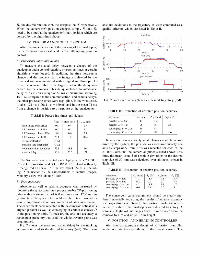
Absolute as well as relative accuracy was measured bymounting the quadcopter on a programmable 2D-positioningtable with a traverse path of 600 mm in x- and 1200 mm iny- direction.The quadcopter could also be rotated around itsz-axis. Trajectories were programmed and taken as reference.The experiments were repeated with the cameras’ optical axisaligned parallel as well as converging at certain distances Dto the positioning table. To measure the absolute accuracy, arectangular trajectory that used the whole traverse paths wasprogrammed.
Fig. 7 shows the measured values (blue) by the trackingsystem compared to the desired trajectory (red). The mean
absolute deviations to the trajectory ∆ were computed as aquality criterion which are listed in Table II.
Fig. 7: measured values (blue) vs. desired trajectory (red)
TABLE II: Evaluation of absolute position accuracy
alignment ∆x [mm] ∆y [mm] ∆yaw [◦]
parallel, D = 2 m 43 102 1.1parallel, D = 4 m 98 137 2.8converging, D = 2 m 18 87 1.1converging, D = 4 m 42 120 2.0
To measure how accurately small changes could be recog-nized by the system, the position was increased in only oneaxis by steps of 50 mm. This was repeated for each of thex- and y-axis and the camera alignments listed above. Thistime, the mean value δ of absolute deviations to the desiredstep size of 50 mm was calculated over all steps, shown inTable III.
TABLE III: Evaluation of relative position accuracy
alignment δx [mm] δx [%] δy [mm] δy [%]parallel, D = 2 m 4.3 8.7 1.8 3.5parallel, D = 4 m 26.0 52.1 3.7 7.3converging, D = 2 m 4.2 8.3 0.9 1.7converging, D = 4 m 6.6 13.1 1.5 3.1
The convergent camera-alignment should be clearly pre-ferred especially regarding the results of relative accuracyfor larger distances. Overall, the position resolution is suf-ficient to stabilize the quadcopter on a desired trajectory. Aresonable flight volume ranges from 1.5 m distance from thecameras to 4 m and up to 1.5 in height.
V. POSITION- AND HEADINGCONTROLLERWe show an exemplary design of a position controller
to demonstrate the capabilities of the overall system. The

controllers are implemented on the high-level processor ofthe IMU (II-A) using a Matlab/Simulink SDK available forit.
A. Basic controller design and settings
Four DOF (x, y, z, yaw) must be controlled with the help ofan absolute reference to achieve stable hovering. The IMU’shigh-level processor receives filtered and fused sensor datafrom the low level processor and can send control commandsboth at a rate of 1 kHz. All four controllers are implementedindependently as PID (x, y, z) or PI (yaw) controllers. Theinterface of the low-level processor offers the following inputsignals:
Roll: roll-angle ⇒ acceleration in y-directionPitch: pitch-angle ⇒ acceleration in x-directionThrust:momentum of motors⇒ acceleration in z-directionYaw: angular velocity around z-axisAs no dynamic or aerobatic maneuvers should be per-
formed, the control inputs were assumed to be linear tothe resulting accelerations when the quadcopter is hovering(small angle approximation). The controller’s differentialcomponents are computed from vision- data since we haveno sensors to directly measure the speed. The integral com-ponent is non-linear, i.e. errors are not summed up whenthe quadcopter already moves towards its setpoint, so thatovershooting is reduced.
For the yaw controller, only a P-term is needed to com-pensate for drift because the angular velocity was alreadycontrolled by the IMU. A small I-term was added to avoidconstant errors. The P-terms of the x-, y- and z- controllershad to be chosen small until oscillations occurred due to thereduced bandwidth of the controller caused by delays inducedby the cameras and data transmission. For the height or z-controller, an I-term is needed to keep the height constant atchanging battery voltages or different payloads.
B. Improvements by using onboard inertial sensors
We were able to achieve stable hovering with the quad-copter with the controllers described above. Inertial measure-ments are provided by the IMU’s low level processor at arate of 1 kHz (section II-A). We show a simple approach toimprove the controller’s performance by incorporating thisadditional information. In order to achieve better dampingof the fast dynamics of the vehicle and fast responses todisturbances, especially the speed-signal has to be improved.Therefore, we used the acceleration measurements as wellas the differential terms from vision data as inputs for acomplementary filter. The filter and controller is implementedon the onboard high-level processor running at a rate of 1kHz. This avoids delays induced by wireless transmission toa ground station and back. Just pose information and setpointcommands have to be transmitted to the quadcopter at muchslower rates from the ground station evaluating vision data.
Fig. 8: system structure
The system is now able to respond quickly based on thefast onboard velocity estimates whereas drift resulting fromintegrating noisy signals is compensated by the much slower,but absolute vision signal. Other filtering techniques like thefamily of Kalman filters to combine vision and inertial datawould also be suitable and could further improve results, butare not implemented yet.
Important is the choice of the reference frame in whichthe quadcopter is controlled. We use the world frame asreference but omitting yaw, denoted by a subscript 0. Thisis possible, since yaw is already controlled by the low-level processor on the IMU that uses an estimated headingfrom the yaw gyroscope. With this approach, control outputsgained from faster IMU data can be mapped directly intoappropriate motor commands. In contrast, control in the“pure” world reference frame (subscript 0) would requireIMU data available at much higher rates to be transformedw.r.t. the heading (yaw) determined by the vision system.Control outputs in the x- and y- axis would then rely onthe heading provided from vision that might be up to 50-100 IMU-timesteps old. Our controllers can now damp thevehicle’s dynamics and can quickly respond to disturbances.In the slower vision loop, the absolute position errors gainedfrom slower vision and setpoint commands are then rotatedinto the quadcopter frame to compensate for the remainingdrift.
The final resulting controller structure can be seen inFig. 8. The acceleration vector xB is measured w.r.t thequadcopter’s current attitude. Before integrating accelera-tions, this vector has first to be rotated from body to 0 -coordinates by R0B . This rotation matrix is determined fromthe pitch- and roll-angles estimated by the IMU. R00 rotatesthe quadcopter’s pose w.r.t. the world reference frame bythe yaw-angle to 0. The “inversion” block transforms theacceleration commands into appropriate control commandsfor the quadcopter. In the current implementation, it is a linearblock for small angle approximation.

C. Results
In the following graphs, the behavior of the system incertain situations is shown. Fig. 9 shows stationary hovering.Only slow oscillation with an amplitude of ≈ 15 cm occur.Fig. 10 shows how disturbances at t = 12.5 s and t = 3.5 s inthe x- and y-axis were handled. The large disturbance of they-axis for example could be compensated within 5 s. Fig. 11shows the behavior when following a trajectory. The graphof the yaw-angle is a lot more smother because the anglewas controlled by the IMU at 1 kHz, so that our controlleronly needs to compensate for drifts (see also II-A). A videoof the results can be seen at the author’s website3.
0 5 10 15 20 25 30
-0.20
0.20.40.6
x, y, z vs . time
time [s ]
po
sitio
n [
m]
x y z
Fig. 9: stationary hovering
Fig. 10: disturbances of x- and y-position
VI. CONCLUSIONS
We presented an effective and reliable method for trackinga quadcopter or general objects with active markers. Thetracking system is highly transportable, easy to set up andthe can be executed on a laptop. We also showed thatnegative influence of the time delays on the performanceof the controllers could be compensated by evaluating theonboard acceleration sensors of the quadcopter. In future,we plan to apply more than two cameras to gain a largerflight volume. Position control and sensor data fusion couldbe further enhanced by using techniques like the family ofKalman filters.
3http://www.lsr.ei.tum.de/research/videos/robotics/qc-tracking-high
Fig. 11: following trajectories for x and yaw
ACKNOWLEDGMENT
This work was supported in part within the DFG excellenceinitiative research cluster Cognition for Technical Systems –CoTeSys, see also www.cotesys.org and the BernsteinCenter for Computational Neuroscience Munich, see alsowww.bccn-munich.de. The authors also gratefully ac-knowledge Daniel Gurdan, Jan Stumpf, Michael Achtelik andKlaus-Michael Doth from Ascending Technologies GmbHfor their technical support with the quadcopter.
REFERENCES
[1] P. Pounds, R. Mahony, J. Gresham, P. Corke, and J. Roberts, “To-wards dynamically-favourable quad-rotor aerial robots,” in AustralianConference on Robotics and Automation,, 2004.
[2] D. Gurdan, J. Stumpf, M. Achtelik, K.-M. Doth, G. Hirzinger, andD. Rus, “Energy-efficient autonomous four-rotor flying robot controlledat 1 khz,” in IEEE International Conference on Robotics and Automa-tion, Roma, Italy, Apr. 2007, pp. 361 – 366.
[3] C. Lu, G. D. Hager, and E. Mjolsness, “Fast and globally convergentpose estimation from video images,” IEEE Transactions on PatternAnalysis and Machine Intelligence, vol. 22, pp. 610–622, 2000.
[4] R. Laganiere, S. Gilbert, and G. Roth, “Robust object pose estimationfrom feature-based stereo,” IEEE Transactions on Instrumentation andMeasurement. Volume 55, Number 4. August 2006., vol. 55, pp. 1270–1280, 2006.
[5] E. Altug, J. P. Ostrowski, and C. J. Taylor, “Control of a quadrotor he-licopter using dual cameravisual feedback,” The International Journalof Robotics Research, vol. 24, pp. 329–341, 2005.
[6] S. Bouabdallah, “Design and control of quadrotors with application toautonomous flying,” Ph.D. dissertation, Ecole polytechnique fdrale deLausanne (EPFL), 2007.
[7] R. He, S. Prentice, and N. Roy, “Planning in information space fora quadrotor helicopter in a gps-denied environments,” in Proc. ICRA,Los Angeles, CA, 2008, pp. 1814–1820.
[8] Y. Ma, S. Soatto, J. Kosecka, and S. S. Sastry, An Invitation to 3-DVision. Springer Verlag New York, 2005.
[9] S. Umeyama, “Least-squares estimation of transformation parametersbetween two point patterns,” in IEEE Transactions on Pattern Analysisand Machine Intelligence, vol. 13, Apr. 1991, pp. 376–380.
[10] G. Hoffmann, H. Huang, S. L. Waslander, and C. J. Tomlin, “Quadrotorhelicopter flight dynamics and control: Theory and experiment,” in Pro-ceedings of the AIAA Guidance, Navigation, and Control Conference,2007.