AUTOMATIC TRANSAXLE SECTION AT - DIY Guides
293
AUTOMATIC TRANSAXLE SECTION AT When you read wiring diagrams: I Read GI section, “HOW TO READ WIRING DIAGRAMS”. I See EL section, “POWER SUPPLY ROUTING” for power distribution circuit. When you perform trouble diagnoses, read GI section, “HOW TO FOLLOW FLOW CHART IN TROUBLE DIAGNOSES” and “HOW TO PERFORM EFFICIENT DIAGNOSIS FOR AN ELECTRICAL INCIDENT”. Go to Table of Contents Go to Quick Reference Index
-
Upload
khangminh22 -
Category
Documents
-
view
2 -
download
0
Transcript of AUTOMATIC TRANSAXLE SECTION AT - DIY Guides
AUTOMATIC TRANSAXLE
SECTIONAT
When you read wiring diagrams:I Read GI section, “HOW TO READ WIRING DIAGRAMS”.I See EL section, “POWER SUPPLY ROUTING” for power distribution circuit.When you perform trouble diagnoses, read GI section, “HOW TO FOLLOW FLOWCHART IN TROUBLE DIAGNOSES” and “HOW TO PERFORM EFFICIENT DIAGNOSISFOR AN ELECTRICAL INCIDENT”.
Go to Table of Contents
Go to Quick Reference Index
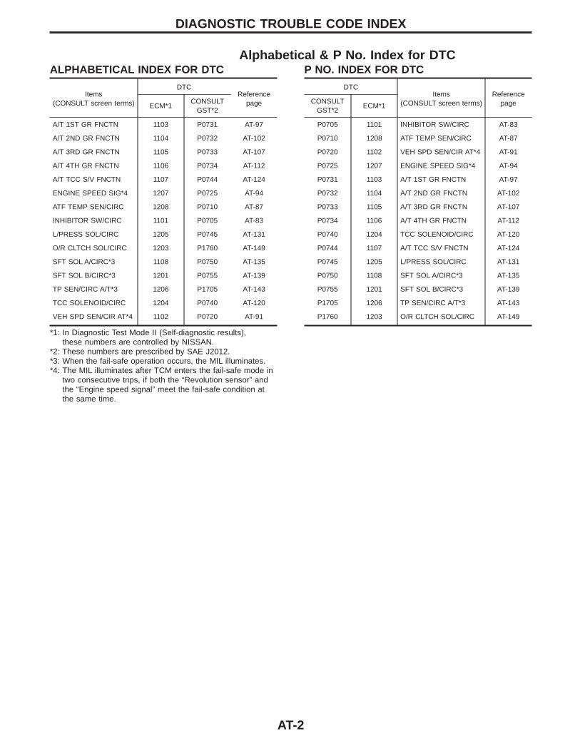
Alphabetical & P No. Index for DTCALPHABETICAL INDEX FOR DTC
Items(CONSULT screen terms)
DTCReference
pageECM*1CONSULT
GST*2
A/T 1ST GR FNCTN 1103 P0731 AT-97
A/T 2ND GR FNCTN 1104 P0732 AT-102
A/T 3RD GR FNCTN 1105 P0733 AT-107
A/T 4TH GR FNCTN 1106 P0734 AT-112
A/T TCC S/V FNCTN 1107 P0744 AT-124
ENGINE SPEED SIG*4 1207 P0725 AT-94
ATF TEMP SEN/CIRC 1208 P0710 AT-87
INHIBITOR SW/CIRC 1101 P0705 AT-83
L/PRESS SOL/CIRC 1205 P0745 AT-131
O/R CLTCH SOL/CIRC 1203 P1760 AT-149
SFT SOL A/CIRC*3 1108 P0750 AT-135
SFT SOL B/CIRC*3 1201 P0755 AT-139
TP SEN/CIRC A/T*3 1206 P1705 AT-143
TCC SOLENOID/CIRC 1204 P0740 AT-120
VEH SPD SEN/CIR AT*4 1102 P0720 AT-91
*1: In Diagnostic Test Mode II (Self-diagnostic results),these numbers are controlled by NISSAN.
*2: These numbers are prescribed by SAE J2012.*3: When the fail-safe operation occurs, the MIL illuminates.*4: The MIL illuminates after TCM enters the fail-safe mode in
two consecutive trips, if both the “Revolution sensor” andthe “Engine speed signal” meet the fail-safe condition atthe same time.
P NO. INDEX FOR DTC
DTCItems
(CONSULT screen terms)Reference
pageCONSULTGST*2
ECM*1
P0705 1101 INHIBITOR SW/CIRC AT-83
P0710 1208 ATF TEMP SEN/CIRC AT-87
P0720 1102 VEH SPD SEN/CIR AT*4 AT-91
P0725 1207 ENGINE SPEED SIG*4 AT-94
P0731 1103 A/T 1ST GR FNCTN AT-97
P0732 1104 A/T 2ND GR FNCTN AT-102
P0733 1105 A/T 3RD GR FNCTN AT-107
P0734 1106 A/T 4TH GR FNCTN AT-112
P0740 1204 TCC SOLENOID/CIRC AT-120
P0744 1107 A/T TCC S/V FNCTN AT-124
P0745 1205 L/PRESS SOL/CIRC AT-131
P0750 1108 SFT SOL A/CIRC*3 AT-135
P0755 1201 SFT SOL B/CIRC*3 AT-139
P1705 1206 TP SEN/CIRC A/T*3 AT-143
P1760 1203 O/R CLTCH SOL/CIRC AT-149
DIAGNOSTIC TROUBLE CODE INDEX
AT-2
Supplemental Restraint System (SRS) “AIRBAG”
The Supplemental Restraint System “AIR BAG”, used along with a seat belt, helps to reduce the risk or severityof injury to the driver and front passenger in a frontal collision. The Supplemental Restraint System consistsof air bag modules (located in the center of the steering wheel and on the instrument panel on the passen-ger side), a diagnosis sensor unit, warning lamp, wiring harness and spiral cable. In addition to the supple-mental air bags for a frontal collision, the supplemental side air bag used along with the seat belt helps toreduce the risk or severity of injury to the driver and front passenger in a side collision. The supplemental sideair bag consists of air bag modules (located in the outer side of front seats), satellite sensor, diagnosis sen-sor unit (which is one of components of supplemental air bags for a frontal collision), wiring harness, warninglamp (which is one of components of supplemental air bags for a frontal collision). Information necessary toservice the system safely is included in the RS section in this Service Manual.WARNING:I To avoid rendering the SRS inoperative, which could increase the risk of personal injury or death
in the event of a collision which would result in air bag inflation, all maintenance must be performedby an authorized NISSAN dealer.
I Improper maintenance, including incorrect removal and installation of the SRS, can lead to per-sonal injury caused by unintentional activation of the system.
I Do not use electrical test equipment on any circuit related to the SRS unless instructed to in thisService Manual. SRS wiring harnesses can be identified with yellow harness protector or yellowinsulation tape before the harness connectors.
Precautions for On Board Diagnostic (OBD)System of A/T and Engine
The ECM (ECCS control module) has an on board diagnostic system. It will light up the malfunction indica-tor lamp (MIL) to warn the driver of a malfunction causing emission deterioration.CAUTION:I Be sure to turn the ignition switch OFF and disconnect the negative battery terminal before any
repair or inspection work. The open/short circuit of related switches, sensors, solenoid valves, etc.will cause the MIL to light up.
I Be sure to connect and lock the connectors securely after work. A loose (unlocked) connector willcause the MIL to light up due to an open circuit. (Be sure the connector is free from water, grease,dirt, bent terminals, etc.)
I Be sure to route and secure the harnesses properly after work. Interference of the harness with abracket, etc. may cause the MIL to light up due to a short circuit.
I Be sure to connect rubber tubes properly after work. A misconnected or disconnected rubber tubemay cause the MIL to light up due to a malfunction of the EGR system or fuel injection system,etc.
I Be sure to erase the unnecessary malfunction information (repairs completed) from the TCM andECM before returning the vehicle to the customer.
PRECAUTIONS AND PREPARATION
AT-3
SEF289H
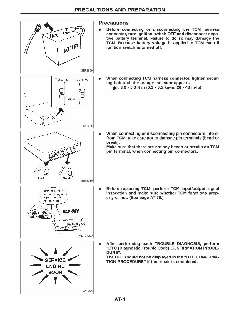
PrecautionsI Before connecting or disconnecting the TCM harness
connector, turn ignition switch OFF and disconnect nega-tive battery terminal. Failure to do so may damage theTCM. Because battery voltage is applied to TCM even ifignition switch is turned off.
SAT973I
I When connecting TCM harness connector, tighten secur-ing bolt until the orange indicator appears.
: 3.0 - 5.0 N⋅m (0.3 - 0.5 kg-m, 26 - 43 in-lb)
SEF291H
I When connecting or disconnecting pin connectors into orfrom TCM, take care not to damage pin terminals (bend orbreak).Make sure that there are not any bends or breaks on TCMpin terminal, when connecting pin connectors.
MEF040DA
I Before replacing TCM, perform TCM input/output signalinspection and make sure whether TCM functions prop-erly or not. (See page AT-78.)
SAT964I
I After performing each TROUBLE DIAGNOSIS, perform“DTC (Diagnostic Trouble Code) CONFIRMATION PROCE-DURE”.The DTC should not be displayed in the “DTC CONFIRMA-TION PROCEDURE” if the repair is completed.
PRECAUTIONS AND PREPARATION
AT-4
I Before proceeding with disassembly, thoroughly clean the outside of the transaxle. It is important to pre-vent the internal parts from becoming contaminated by dirt or other foreign matter.
I Disassembly should be done in a clean work area.I Use lint-free cloth or towels for wiping parts clean. Common shop rags can leave fibers that could inter-
fere with the operation of the transaxle.I Place disassembled parts in order for easier and proper assembly.I All parts should be carefully cleaned with a general purpose, non-flammable solvent before inspection or
reassembly.I Gaskets, seals and O-rings should be replaced any time the transaxle is disassembled.I It is very important to perform functional tests whenever they are indicated.I The valve body contains precision parts and requires extreme care when parts are removed and serviced.
Place disassembled valve body parts in order for easier and proper assembly. Care will also preventsprings and small parts from becoming scattered or lost.
I Properly installed valves, sleeves, plugs, etc. will slide along bores in valve body under their own weight.I Before assembly, apply a coat of recommended ATF to all parts. Apply petroleum jelly to protect O-rings
and seals, or hold bearings and washers in place during assembly. Do not use grease.I Extreme care should be taken to avoid damage to O-rings, seals and gaskets when assembling.I Replace ATF cooler if excessive foreign material is found in oil pan or clogging strainer. Refer to “ATF
COOLER SERVICE” (Refer to AT-6).I After overhaul, refill the transmission with new ATF.I When the A/T drain plug is removed, only some of the fluid is drained. Old A/T fluid will remain in torque
converter and ATF cooling system.Always follow the procedures under “Changing A/T Fluid” in the MA section when changing A/T fluid.
Service Notice or PrecautionsFAIL-SAFEThe TCM has an electronic Fail-Safe (limp home mode). This allows the vehicle to be driven even if a majorelectrical input/output device circuit is damaged.Under Fail-Safe, the vehicle always runs in third gear, even with a shift lever position of “1”, “2” or “D”. Thecustomer may complain of sluggish or poor acceleration.When the ignition key is turned “ON” following Fail-Safe operation, O/D OFF indicator lamp blinks for about8 seconds. (For “TCM SELF-DIAGNOSTIC PROCEDURE (No Tools)”, refer to AT-50.)Fail-Safe may occur without electrical circuit damage if the vehicle is driven under extreme conditions (suchas excessive wheel spin followed by sudden braking). To recover normal shift pattern, turn the ignition key“OFF” for 5 seconds, then “ON”.The blinking of the O/D OFF indicator lamp for about 8 seconds will appear only once and be cleared. Thecustomer may resume normal driving conditions.Always follow the “WORK FLOW” (Refer to AT-59).The SELF-DIAGNOSIS results will be as follows:
The first SELF-DIAGNOSIS will indicate damage to the vehicle speed sensor or the revolution sensor.During the next SELF-DIAGNOSIS, performed after checking the sensor, no damages will be indicated.
TORQUE CONVERTER SERVICEThe torque converter should be replaced under any of the following conditions:I External leaks in the hub weld area.I Converter hub is scored or damaged.I Converter pilot is broken, damaged or fits poorly into crankshaft.I Steel particles are found after flushing the cooler and cooler lines.I Pump is damaged or steel particles are found in the converter.I Vehicle has TCC shudder and/or no TCC apply. Replace only after all hydraulic and electrical diagnoses
have been made. (Converter clutch material may be glazed.)I Converter is contaminated with engine coolant containing antifreeze.I Internal failure of stator roller clutch.I Heavy clutch debris due to overheating (blue converter).I Steel particles or clutch lining material found in fluid filter or on magnet when no internal parts in unit are
worn or damaged — indicates that lining material came from converter.The torque converter should not be replaced if:I The oil has an odor, is discolored, and there is no evidence of metal or clutch facing particles.I The threads in one or more of the converter bolt holes are damaged.
PRECAUTIONS AND PREPARATIONPrecautions (Cont’d)
AT-5
I Transaxle failure did not display evidence of damaged or worn internal parts, steel particles or clutch platelining material in unit and inside the fluid filter.
I Vehicle has been exposed to high mileage (only). The exception may be where the torque converter clutchdampener plate lining has seen excess wear by vehicles operated in heavy and/or constant traffic, suchas taxi, delivery or police use.
ATF COOLER SERVICEReplace ATF cooler if excessive foreign material is found in oil pan or clogging strainer.VQ30DE engine (with RE4F04A/V) ... fin type cooler
Replace radiator lower tank (which includes ATF cooler) with a new one and flush cooler line using clean-ing solvent and compressed air.
OBD-II SELF-DIAGNOSISI A/T self-diagnosis is performed by the TCM in combination with the ECM. The results can be read through
the blinking pattern of the O/D OFF indicator or the malfunction indicator lamp (MIL). Refer to the table onAT-44 for the indicator used to display each self-diagnostic result.
I The self-diagnostic results indicated by the MIL are automatically stored in both the ECM and TCMmemories.Always perform the procedure “HOW TO ERASE DTC” on AT-41 to complete the repair and avoidunnecessary blinking of the MIL.
I The following self-diagnostic items can be detected using ECM self-diagnostic results mode* only whenthe O/D OFF indicator lamp does not indicate any malfunctions.−Inhibitor switch−A/T 1st, 2nd, 3rd, or 4th gear function−A/T TCC S/V function (lock-up)
*: For details of OBD-II, refer to EC section (“ON BOARD DIAGNOSTIC SYSTEM DESCRIPTION”).
PRECAUTIONS AND PREPARATIONService Notice or Precautions (Cont’d)
AT-6

Special Service ToolsThe actual shapes of Kent-Moore tools may differ from those of special service tools illustrated here.
Tool number(Kent-Moore No.)Tool name
Description
KV381054S0(J34286)Puller
NT414
I Removing differential side oil sealsI Removing differential side bearing outer
raceI Removing idler gear bearing outer race
a: 250 mm (9.84 in)b: 160 mm (6.30 in)
ST33400001(J26082)Drift
NT086
Installing differential side oil seal (RH side)Installing oil seal on oil pump housing
a: 60 mm (2.36 in) dia.b: 47 mm (1.85 in) dia.
ST2505S001(J34301-C)Oil pressure gauge setq1 ST25051001
( — )Oil pressure gauge
q2 ST25052000( — )Hose
q3 ST25053000( — )Joint pipe
q4 ST25054000( — )Adapter
q5 ST25055000( — )Adapter
NT097
Measuring line pressure.
ST27180001(J25726-A)Puller
NT424
Removing idler gear
a: 100 mm (3.94 in)b: 110 mm (4.33 in)c: M8 x 1.25P
ST23540000(J25689-A)Pin punch
NT442
Removing and installing parking rod plate andmanual plate pins.
a: 2.3 mm (0.091 in) dia.b: 4 mm (0.16 in) dia.
ST25710000(J25689-A)Pin punch
NT410
Aligning groove of manual shaft and hole oftransmission case.
a: 2 mm (0.08 in) dia.
PRECAUTIONS AND PREPARATION
AT-7
Tool number(Kent-Moore No.)Tool name
Description
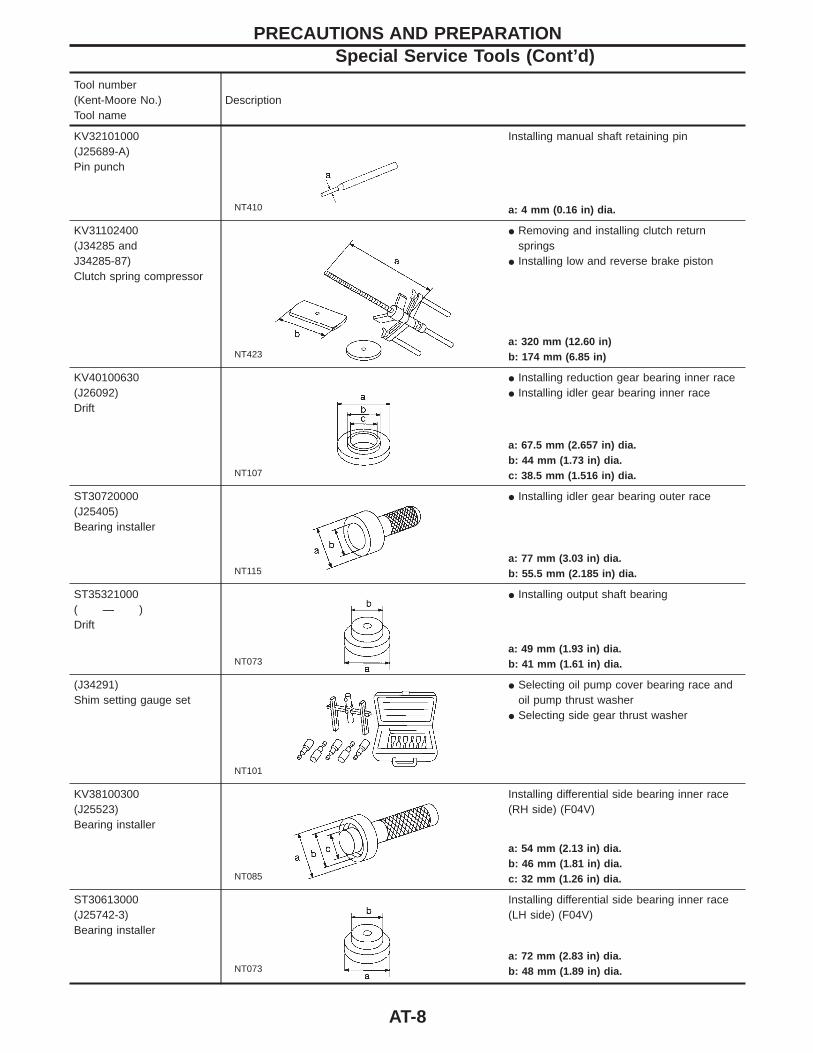
KV32101000(J25689-A)Pin punch
NT410
Installing manual shaft retaining pin
a: 4 mm (0.16 in) dia.
KV31102400(J34285 andJ34285-87)Clutch spring compressor
NT423
I Removing and installing clutch returnsprings
I Installing low and reverse brake piston
a: 320 mm (12.60 in)b: 174 mm (6.85 in)
KV40100630(J26092)Drift
NT107
I Installing reduction gear bearing inner raceI Installing idler gear bearing inner race
a: 67.5 mm (2.657 in) dia.b: 44 mm (1.73 in) dia.c: 38.5 mm (1.516 in) dia.
ST30720000(J25405)Bearing installer
NT115
I Installing idler gear bearing outer race
a: 77 mm (3.03 in) dia.b: 55.5 mm (2.185 in) dia.
ST35321000( — )Drift
NT073
I Installing output shaft bearing
a: 49 mm (1.93 in) dia.b: 41 mm (1.61 in) dia.
(J34291)Shim setting gauge set
NT101
I Selecting oil pump cover bearing race andoil pump thrust washer
I Selecting side gear thrust washer
KV38100300(J25523)Bearing installer
NT085
Installing differential side bearing inner race(RH side) (F04V)
a: 54 mm (2.13 in) dia.b: 46 mm (1.81 in) dia.c: 32 mm (1.26 in) dia.
ST30613000(J25742-3)Bearing installer
NT073
Installing differential side bearing inner race(LH side) (F04V)
a: 72 mm (2.83 in) dia.b: 48 mm (1.89 in) dia.
PRECAUTIONS AND PREPARATIONSpecial Service Tools (Cont’d)
AT-8
Tool number(Kent-Moore No.)Tool name
Description
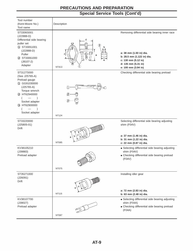
ST3306S001(J22888-D)Differential side bearingpuller setq1 ST33051001
(J22888-D)Puller
q2 ST33061000(J8107-2)Adapter
NT413
Removing differential side bearing inner race
a: 38 mm (1.50 in) dia.b: 28.5 mm (1.122 in) dia.c: 130 mm (5.12 in)d: 135 mm (5.31 in)e: 100 mm (3.94 in)
ST3127S000(See J25765-A)Preload gaugeq1 GG91030000
(J25765-A)Torque wrench
q2 HT62940000( — )Socket adapter
q3 HT62900000( — )Socket adapter
NT124
Checking differential side bearing preload
ST33220000(J25805-01)Drift
NT085
Selecting differential side bearing adjustingshim (F04V)
a: 37 mm (1.46 in) dia.b: 31 mm (1.22 in) dia.c: 22 mm (0.87 in) dia.
KV38105210(J39883)Preload adapter
NT075
I Selecting differential side bearing adjustingshim (F04V)
I Checking differential side bearing preload(F04V)
ST35271000(J26091)Drift
NT115
Installing idler gear
a: 72 mm (2.83 in) dia.b: 63 mm (2.48 in) dia.
KV38107700(J39027)Preload adapter
NT087
I Selecting differential side bearing adjustingshim (F04A)
I Checking differential side bearing preload(F04A)
PRECAUTIONS AND PREPARATIONSpecial Service Tools (Cont’d)
AT-9
Tool number(Kent-Moore No.)Tool name
Description
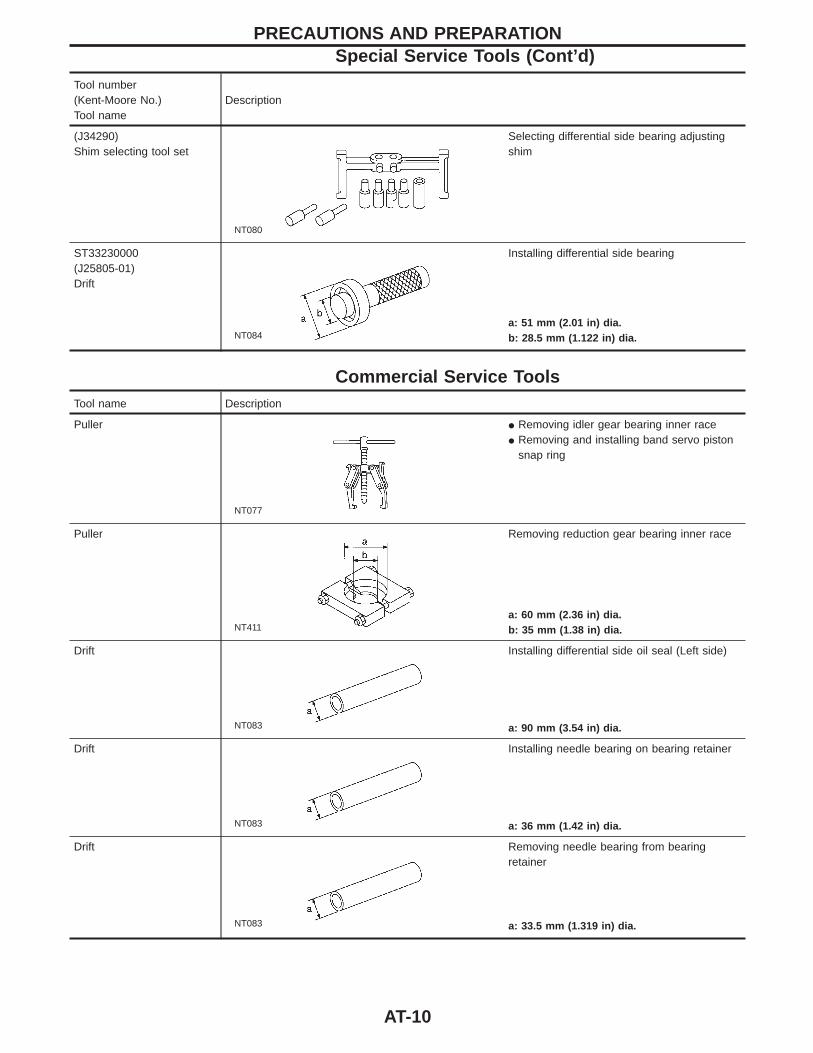
(J34290)Shim selecting tool set
NT080
Selecting differential side bearing adjustingshim
ST33230000(J25805-01)Drift
NT084
Installing differential side bearing
a: 51 mm (2.01 in) dia.b: 28.5 mm (1.122 in) dia.
Commercial Service ToolsTool name Description
Puller
NT077
I Removing idler gear bearing inner raceI Removing and installing band servo piston
snap ring
Puller
NT411
Removing reduction gear bearing inner race
a: 60 mm (2.36 in) dia.b: 35 mm (1.38 in) dia.
Drift
NT083
Installing differential side oil seal (Left side)
a: 90 mm (3.54 in) dia.
Drift
NT083
Installing needle bearing on bearing retainer
a: 36 mm (1.42 in) dia.
Drift
NT083
Removing needle bearing from bearingretainer
a: 33.5 mm (1.319 in) dia.
PRECAUTIONS AND PREPARATIONSpecial Service Tools (Cont’d)
AT-10
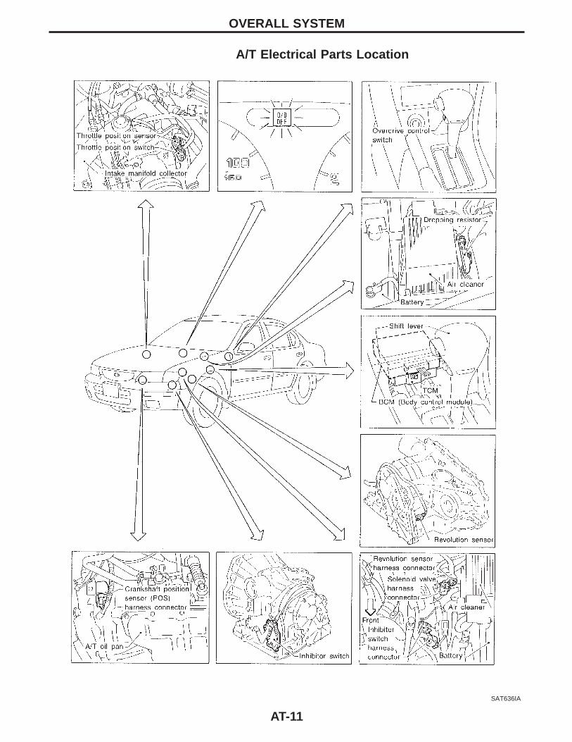
A/T Electrical Parts Location
SAT636IA
OVERALL SYSTEM
AT-11
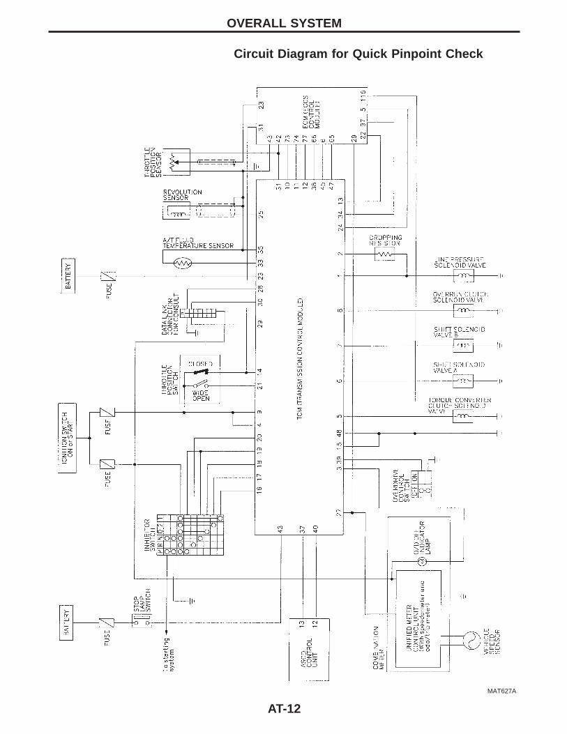
Circuit Diagram for Quick Pinpoint Check
MAT627A
OVERALL SYSTEM
AT-12
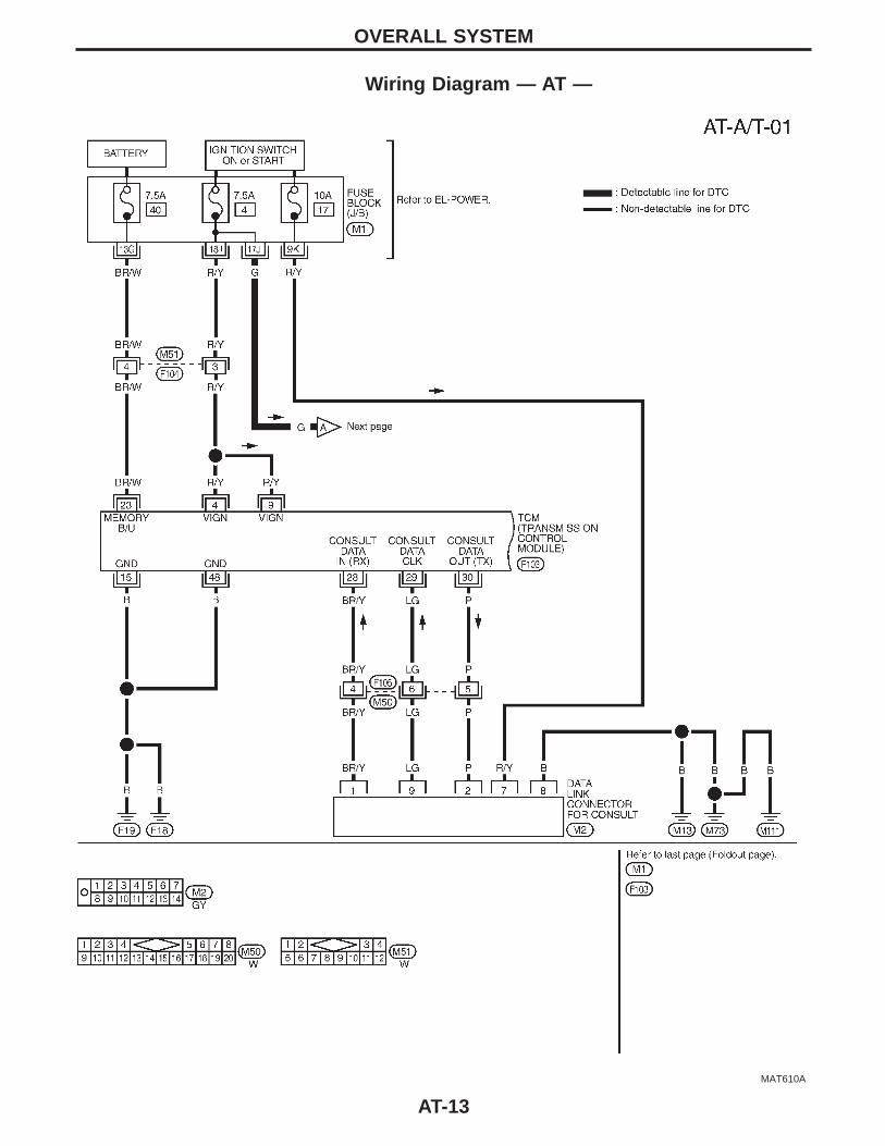
Wiring Diagram — AT —
MAT610A
OVERALL SYSTEM
AT-13
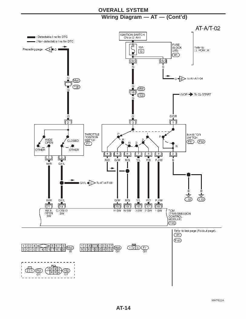
MAT611A
OVERALL SYSTEMWiring Diagram — AT — (Cont’d)
AT-14

MAT604A
OVERALL SYSTEMWiring Diagram — AT — (Cont’d)
AT-15
MAT612A
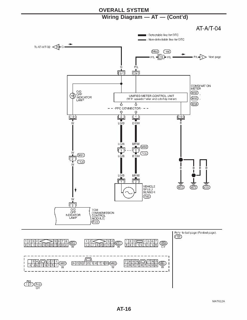
OVERALL SYSTEMWiring Diagram — AT — (Cont’d)
AT-16
MAT605A
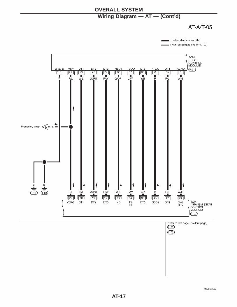
OVERALL SYSTEMWiring Diagram — AT — (Cont’d)
AT-17
MAT613A
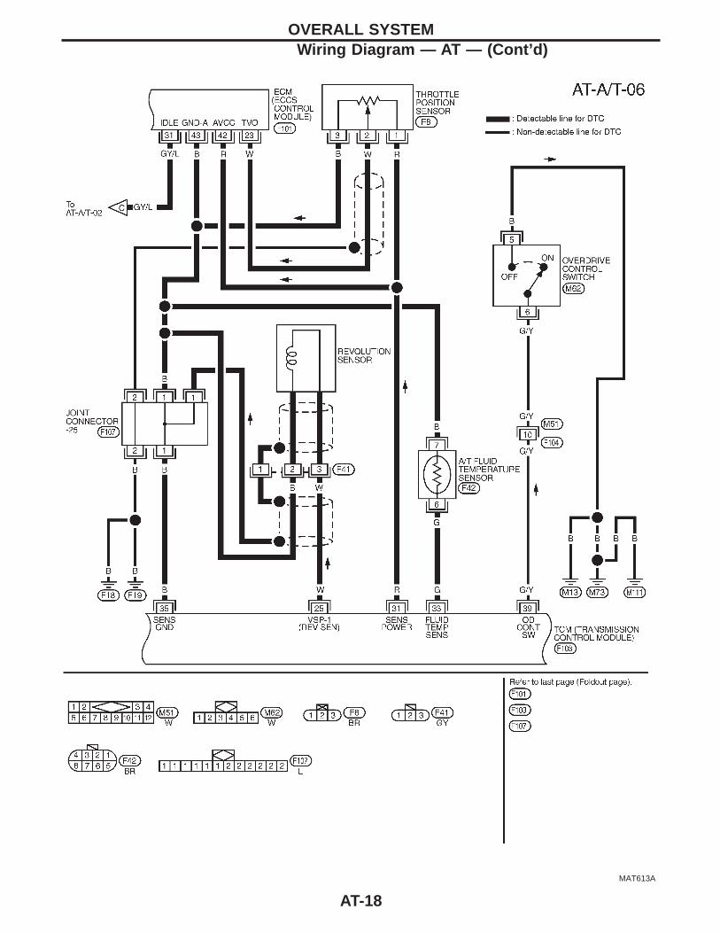
OVERALL SYSTEMWiring Diagram — AT — (Cont’d)
AT-18
MAT614A
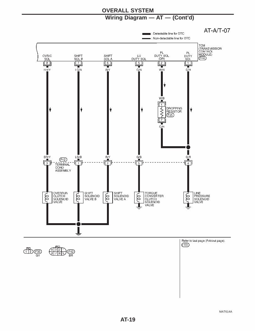
OVERALL SYSTEMWiring Diagram — AT — (Cont’d)
AT-19
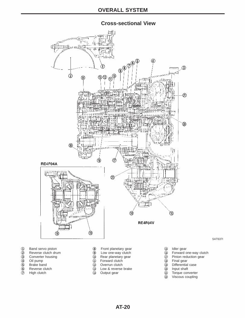
Cross-sectional View
SAT637I
q1 Band servo pistonq2 Reverse clutch drumq3 Converter housingq4 Oil pumpq5 Brake bandq6 Reverse clutchq7 High clutch
q8 Front planetary gearq9 Low one-way clutchq10 Rear planetary gearq11 Forward clutchq12 Overrun clutchq13 Low & reverse brakeq14 Output gear
q15 Idler gearq16 Forward one-way clutchq17 Pinion reduction gearq18 Final gearq19 Differential caseq20 Input shaftq21 Torque converterq22 Viscous coupling
OVERALL SYSTEM
AT-20
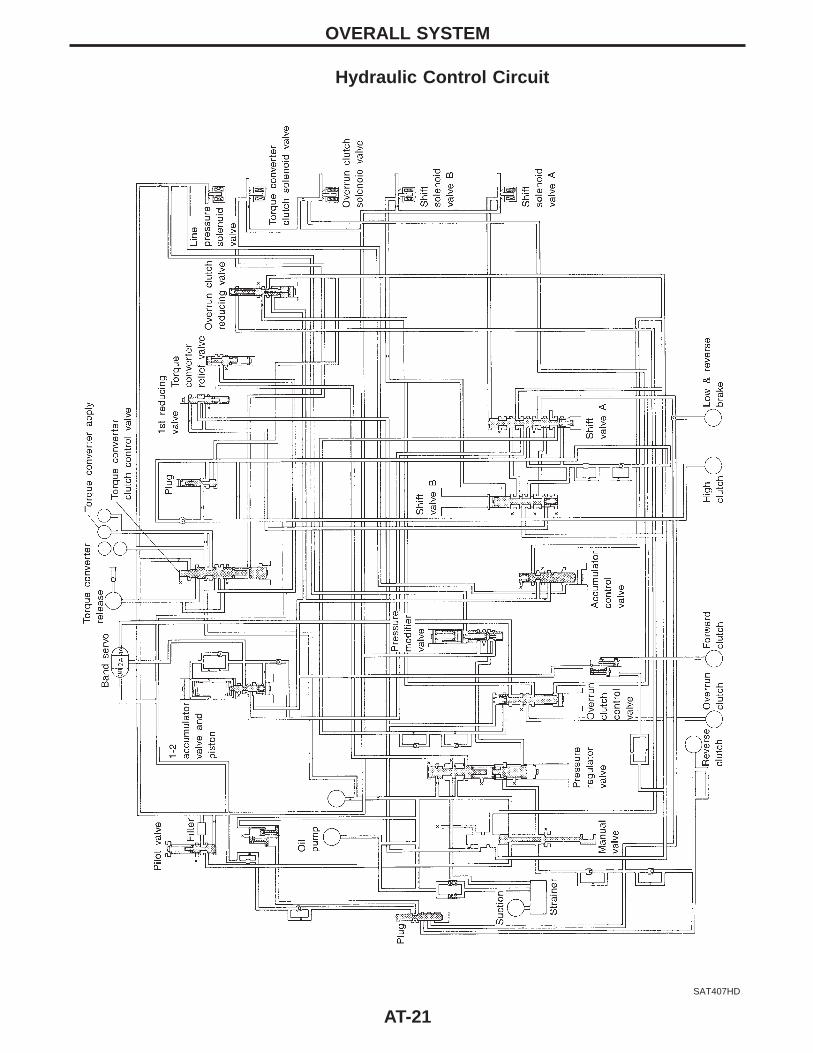
Hydraulic Control Circuit
SAT407HD
OVERALL SYSTEM
AT-21
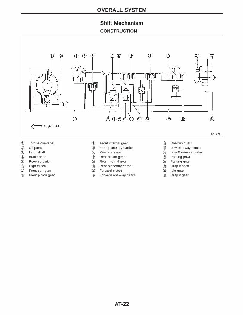
Shift MechanismCONSTRUCTION
SAT998I
q1 Torque converterq2 Oil pumpq3 Input shaftq4 Brake bandq5 Reverse clutchq6 High clutchq7 Front sun gearq8 Front pinion gear
q9 Front internal gearq10 Front planetary carrierq11 Rear sun gearq12 Rear pinion gearq13 Rear internal gearq14 Rear planetary carrierq15 Forward clutchq16 Forward one-way clutch
q17 Overrun clutchq18 Low one-way clutchq19 Low & reverse brakeq20 Parking pawlq21 Parking gearq22 Output shaftq23 Idle gearq24 Output gear
OVERALL SYSTEM
AT-22
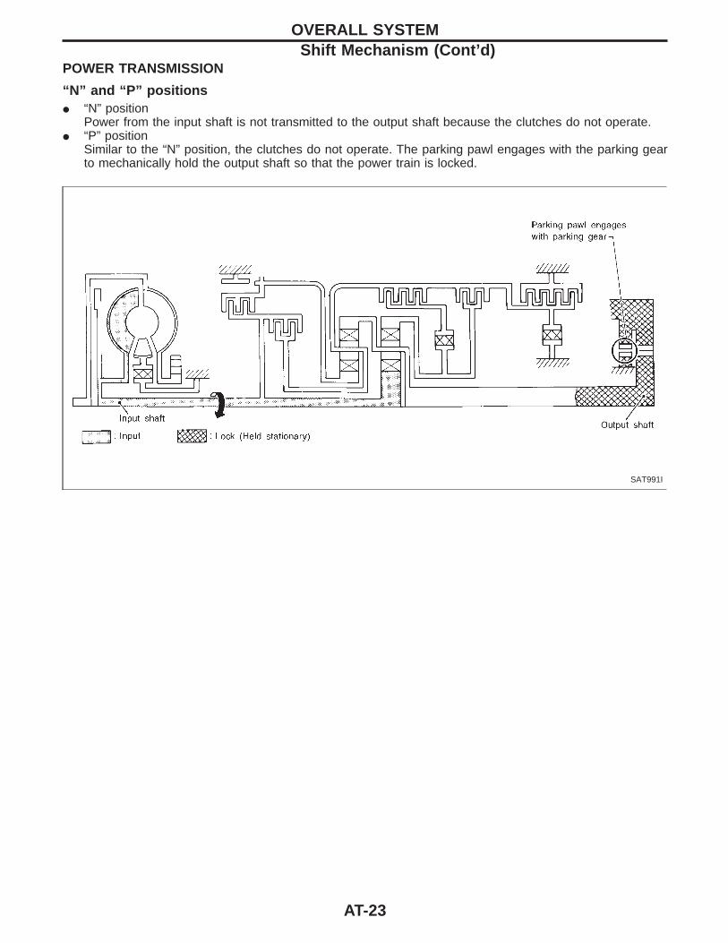
POWER TRANSMISSION
“N” and “P” positionsI “N” position
Power from the input shaft is not transmitted to the output shaft because the clutches do not operate.I “P” position
Similar to the “N” position, the clutches do not operate. The parking pawl engages with the parking gearto mechanically hold the output shaft so that the power train is locked.
SAT991I
OVERALL SYSTEMShift Mechanism (Cont’d)
AT-23
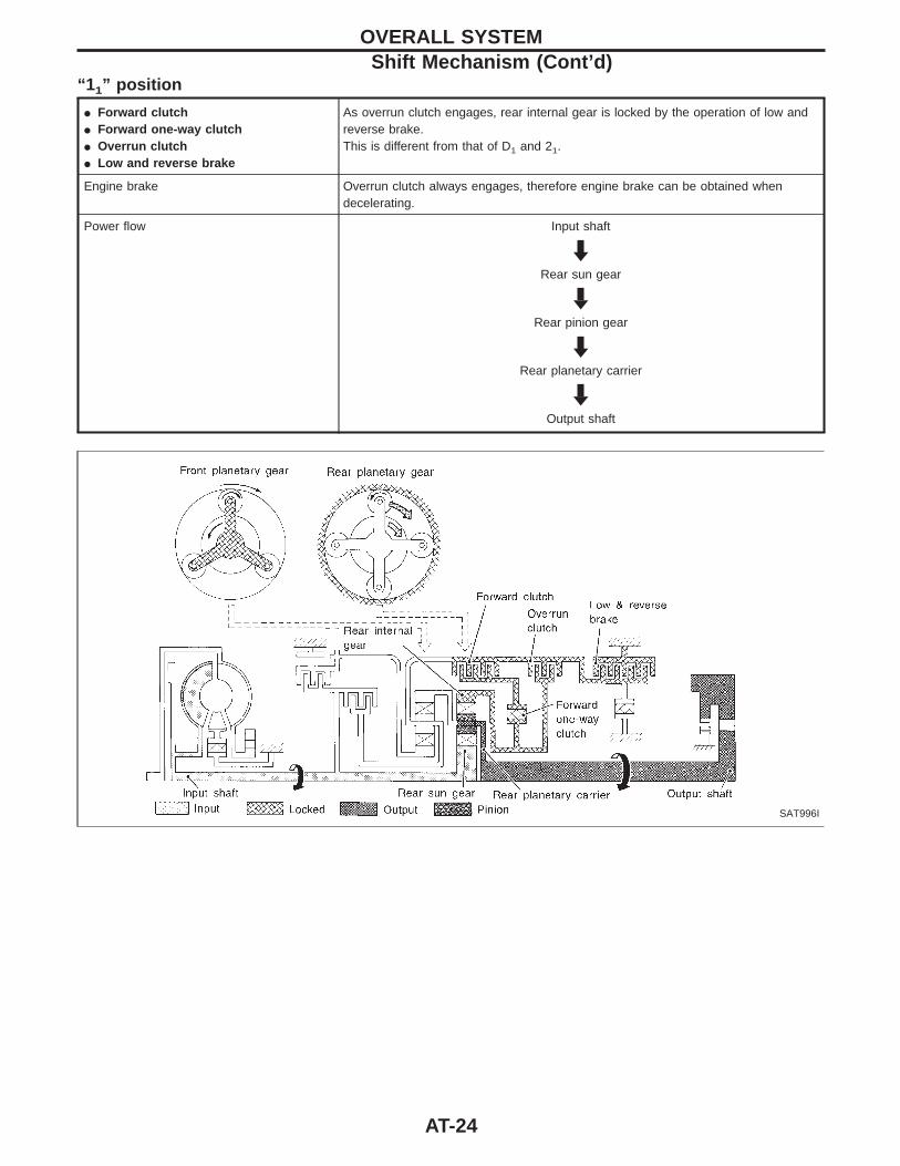
“1 1” position
I Forward clutchI Forward one-way clutchI Overrun clutchI Low and reverse brake
As overrun clutch engages, rear internal gear is locked by the operation of low andreverse brake.This is different from that of D1 and 21.
Engine brake Overrun clutch always engages, therefore engine brake can be obtained whendecelerating.
Power flow Input shaft
HRear sun gear
HRear pinion gear
HRear planetary carrier
HOutput shaft
SAT996I
OVERALL SYSTEMShift Mechanism (Cont’d)
AT-24
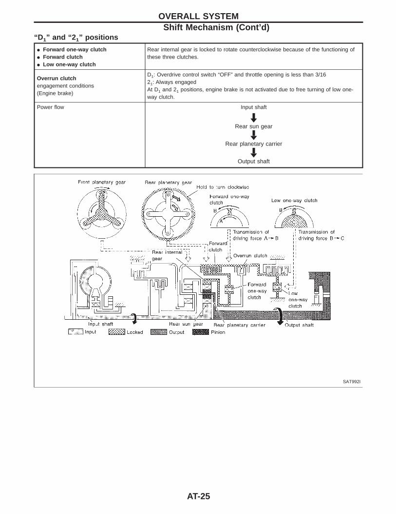
“D 1” and “2 1” positions
I Forward one-way clutchI Forward clutchI Low one-way clutch
Rear internal gear is locked to rotate counterclockwise because of the functioning ofthese three clutches.
Overrun clutchengagement conditions(Engine brake)
D1: Overdrive control switch “OFF” and throttle opening is less than 3/1621: Always engagedAt D1 and 21 positions, engine brake is not activated due to free turning of low one-way clutch.
Power flow Input shaft
HRear sun gear
HRear planetary carrier
HOutput shaft
SAT992I
OVERALL SYSTEMShift Mechanism (Cont’d)
AT-25
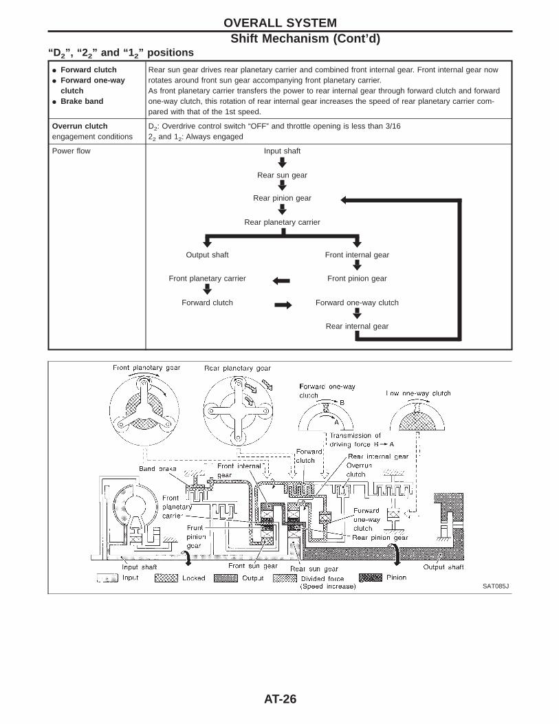
“D 2”, “2 2” and “1 2” positions
I Forward clutchI Forward one-way
clutchI Brake band
Rear sun gear drives rear planetary carrier and combined front internal gear. Front internal gear nowrotates around front sun gear accompanying front planetary carrier.As front planetary carrier transfers the power to rear internal gear through forward clutch and forwardone-way clutch, this rotation of rear internal gear increases the speed of rear planetary carrier com-pared with that of the 1st speed.
Overrun clutchengagement conditions
D2: Overdrive control switch “OFF” and throttle opening is less than 3/1622 and 12: Always engaged
Power flow Input shaft
HRear sun gear
HRear pinion gear
HF
Rear planetary carrier
H HOutput shaft Front internal gear
HFront planetary carrier F Front pinion gear
HForward clutch E Forward one-way clutch
HRear internal gear
SAT085J
OVERALL SYSTEMShift Mechanism (Cont’d)
AT-26
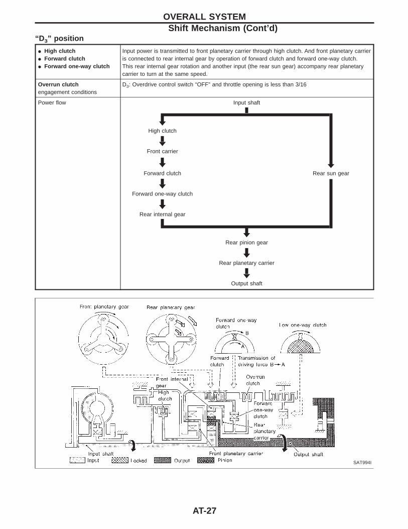
“D 3” position
I High clutchI Forward clutchI Forward one-way clutch
Input power is transmitted to front planetary carrier through high clutch. And front planetary carrieris connected to rear internal gear by operation of forward clutch and forward one-way clutch.This rear internal gear rotation and another input (the rear sun gear) accompany rear planetarycarrier to turn at the same speed.
Overrun clutchengagement conditions
D3: Overdrive control switch “OFF” and throttle opening is less than 3/16
Power flow Input shaft
HHigh clutch
HFront carrier
H HForward clutch Rear sun gear
HForward one-way clutch
HRear internal gear
HRear pinion gear
HRear planetary carrier
HOutput shaft
SAT994I
OVERALL SYSTEMShift Mechanism (Cont’d)
AT-27
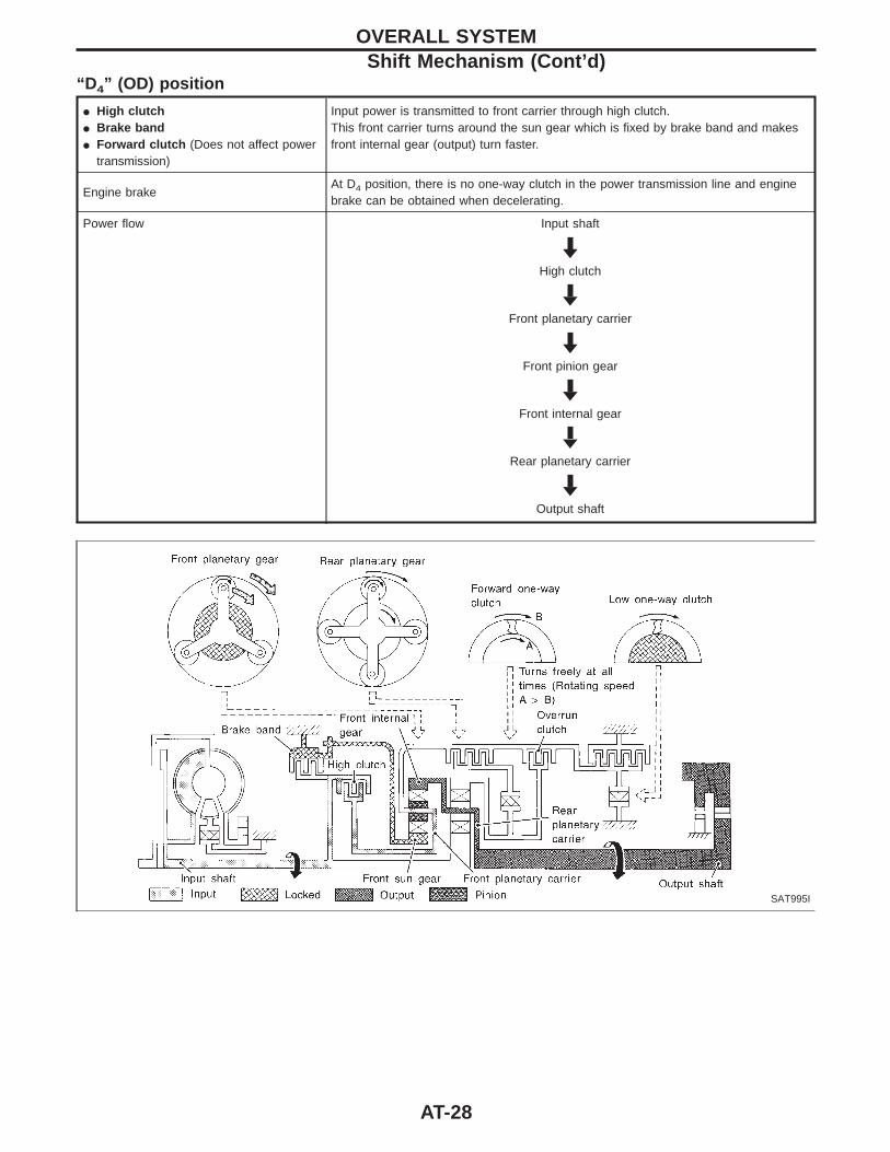
“D 4” (OD) position
I High clutchI Brake bandI Forward clutch (Does not affect power
transmission)
Input power is transmitted to front carrier through high clutch.This front carrier turns around the sun gear which is fixed by brake band and makesfront internal gear (output) turn faster.
Engine brakeAt D4 position, there is no one-way clutch in the power transmission line and enginebrake can be obtained when decelerating.
Power flow Input shaft
HHigh clutch
HFront planetary carrier
HFront pinion gear
HFront internal gear
HRear planetary carrier
HOutput shaft
SAT995I
OVERALL SYSTEMShift Mechanism (Cont’d)
AT-28
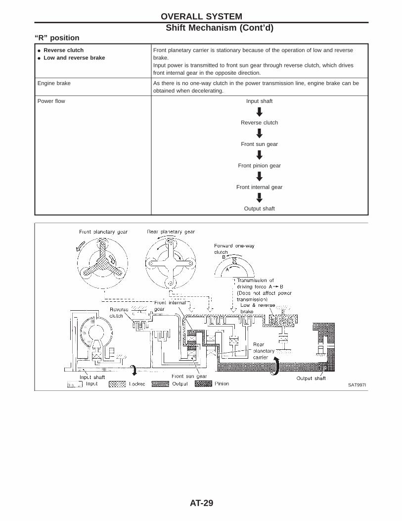
“R” position
I Reverse clutchI Low and reverse brake
Front planetary carrier is stationary because of the operation of low and reversebrake.Input power is transmitted to front sun gear through reverse clutch, which drivesfront internal gear in the opposite direction.
Engine brake As there is no one-way clutch in the power transmission line, engine brake can beobtained when decelerating.
Power flow Input shaft
HReverse clutch
HFront sun gear
HFront pinion gear
HFront internal gear
HOutput shaft
SAT997I
OVERALL SYSTEMShift Mechanism (Cont’d)
AT-29
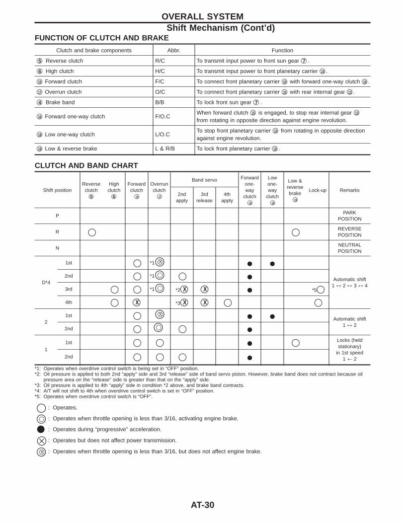
FUNCTION OF CLUTCH AND BRAKE
Clutch and brake components Abbr. Function
q5 Reverse clutch R/C To transmit input power to front sun gear q7 .
q6 High clutch H/C To transmit input power to front planetary carrier q10 .
q15 Forward clutch F/C To connect front planetary carrier q10 with forward one-way clutch q16 .
q17 Overrun clutch O/C To connect front planetary carrier q10 with rear internal gear q13 .
q4 Brake band B/B To lock front sun gear q7 .
q16 Forward one-way clutch F/O.CWhen forward clutch q15 is engaged, to stop rear internal gear q13
from rotating in opposite direction against engine revolution.
q18 Low one-way clutch L/O.CTo stop front planetary carrier q10 from rotating in opposite directionagainst engine revolution.
q19 Low & reverse brake L & R/B To lock front planetary carrier q10 .
CLUTCH AND BAND CHART
Shift positionReverseclutch
q5
Highclutch
q6
Forwardclutch
q15
Overrunclutch
q17
Band servo Forwardone-way
clutchq16
Lowone-way
clutchq18
Low &reversebrake
q19
Lock-up Remarks2nd
apply3rd
release4th
apply
PPARK
POSITION
R q q REVERSEPOSITION
NNEUTRALPOSITION
D*4
1st q *1qXq I IAutomatic shift
1 ) 2 ) 3 ) 4
2nd q *1qq q I3rd q q *1qq *2qX qX I *5q4th q qX *3qX qX q q
21st q qXq I I Automatic shift
1 ) 22nd q qq q I
1
1st q q I q Locks (heldstationary)
in 1st speed1 + 22nd q q q I
*1: Operates when overdrive control switch is being set in “OFF” position.*2: Oil pressure is applied to both 2nd “apply” side and 3rd “release” side of band servo piston. However, brake band does not contract because oil
pressure area on the “release” side is greater than that on the “apply” side.*3: Oil pressure is applied to 4th “apply” side in condition *2 above, and brake band contracts.*4: A/T will not shift to 4th when overdrive control switch is set in “OFF” position.*5: Operates when overdrive control switch is “OFF”.
q : Operates.
qq : Operates when throttle opening is less than 3/16, activating engine brake.
v : Operates during “progressive” acceleration.
J : Operates but does not affect power transmission.
qXq : Operates when throttle opening is less than 3/16, but does not affect engine brake.
OVERALL SYSTEMShift Mechanism (Cont’d)
AT-30
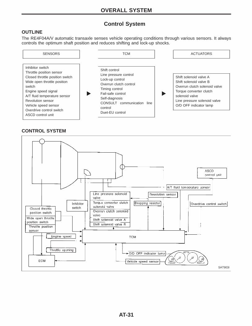
Control SystemOUTLINEThe RE4F04A/V automatic transaxle senses vehicle operating conditions through various sensors. It alwayscontrols the optimum shaft position and reduces shifting and lock-up shocks.
SENSORS TCM ACTUATORS
Inhibitor switchThrottle position sensorClosed throttle position switchWide open throttle positionswitchEngine speed signalA/T fluid temperature sensorRevolution sensorVehicle speed sensorOverdrive control switchASCD control unit
E
Shift controlLine pressure controlLock-up controlOverrun clutch controlTiming controlFail-safe controlSelf-diagnosisCONSULT communication linecontrolDuet-EU control
E
Shift solenoid valve AShift solenoid valve BOverrun clutch solenoid valveTorque converter clutchsolenoid valveLine pressure solenoid valveO/D OFF indicator lamp
CONTROL SYSTEM
SAT903I
OVERALL SYSTEM
AT-31
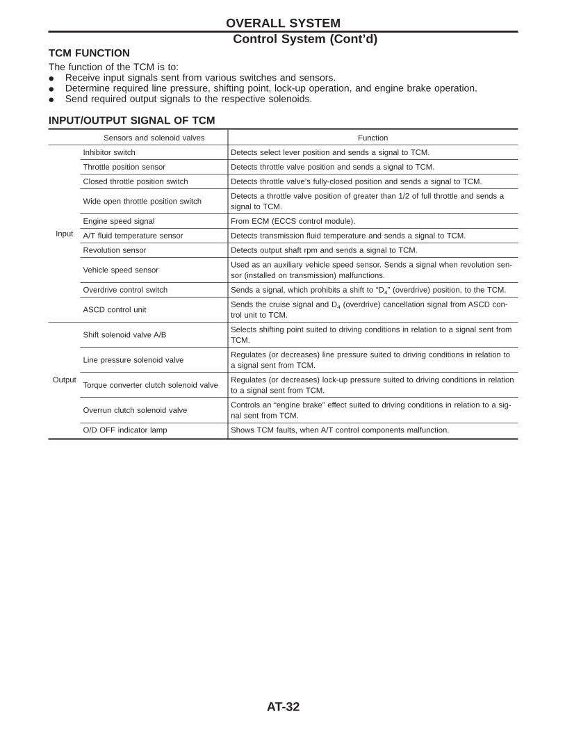
TCM FUNCTIONThe function of the TCM is to:I Receive input signals sent from various switches and sensors.I Determine required line pressure, shifting point, lock-up operation, and engine brake operation.I Send required output signals to the respective solenoids.
INPUT/OUTPUT SIGNAL OF TCM
Sensors and solenoid valves Function
Input
Inhibitor switch Detects select lever position and sends a signal to TCM.
Throttle position sensor Detects throttle valve position and sends a signal to TCM.
Closed throttle position switch Detects throttle valve’s fully-closed position and sends a signal to TCM.
Wide open throttle position switchDetects a throttle valve position of greater than 1/2 of full throttle and sends asignal to TCM.
Engine speed signal From ECM (ECCS control module).
A/T fluid temperature sensor Detects transmission fluid temperature and sends a signal to TCM.
Revolution sensor Detects output shaft rpm and sends a signal to TCM.
Vehicle speed sensorUsed as an auxiliary vehicle speed sensor. Sends a signal when revolution sen-sor (installed on transmission) malfunctions.
Overdrive control switch Sends a signal, which prohibits a shift to “D4” (overdrive) position, to the TCM.
ASCD control unitSends the cruise signal and D4 (overdrive) cancellation signal from ASCD con-trol unit to TCM.
Output
Shift solenoid valve A/BSelects shifting point suited to driving conditions in relation to a signal sent fromTCM.
Line pressure solenoid valveRegulates (or decreases) line pressure suited to driving conditions in relation toa signal sent from TCM.
Torque converter clutch solenoid valveRegulates (or decreases) lock-up pressure suited to driving conditions in relationto a signal sent from TCM.
Overrun clutch solenoid valveControls an “engine brake” effect suited to driving conditions in relation to a sig-nal sent from TCM.
O/D OFF indicator lamp Shows TCM faults, when A/T control components malfunction.
OVERALL SYSTEMControl System (Cont’d)
AT-32
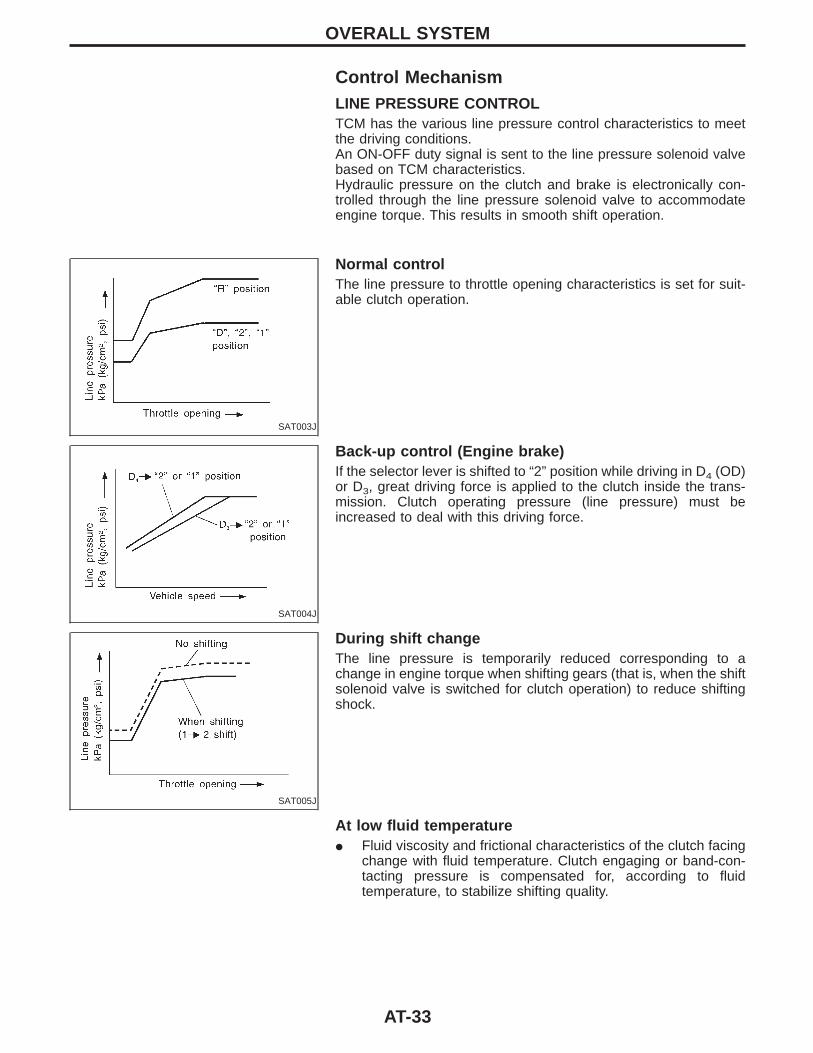
Control MechanismLINE PRESSURE CONTROLTCM has the various line pressure control characteristics to meetthe driving conditions.An ON-OFF duty signal is sent to the line pressure solenoid valvebased on TCM characteristics.Hydraulic pressure on the clutch and brake is electronically con-trolled through the line pressure solenoid valve to accommodateengine torque. This results in smooth shift operation.
SAT003J
Normal controlThe line pressure to throttle opening characteristics is set for suit-able clutch operation.
SAT004J
Back-up control (Engine brake)If the selector lever is shifted to “2” position while driving in D4 (OD)or D3, great driving force is applied to the clutch inside the trans-mission. Clutch operating pressure (line pressure) must beincreased to deal with this driving force.
SAT005J
During shift changeThe line pressure is temporarily reduced corresponding to achange in engine torque when shifting gears (that is, when the shiftsolenoid valve is switched for clutch operation) to reduce shiftingshock.
At low fluid temperatureI Fluid viscosity and frictional characteristics of the clutch facing
change with fluid temperature. Clutch engaging or band-con-tacting pressure is compensated for, according to fluidtemperature, to stabilize shifting quality.
OVERALL SYSTEM
AT-33
SAT006J
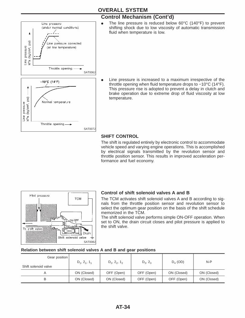
I The line pressure is reduced below 60°C (140°F) to preventshifting shock due to low viscosity of automatic transmissionfluid when temperature is low.
SAT007J
I Line pressure is increased to a maximum irrespective of thethrottle opening when fluid temperature drops to −10°C (14°F).This pressure rise is adopted to prevent a delay in clutch andbrake operation due to extreme drop of fluid viscosity at lowtemperature.
SHIFT CONTROLThe shift is regulated entirely by electronic control to accommodatevehicle speed and varying engine operations. This is accomplishedby electrical signals transmitted by the revolution sensor andthrottle position sensor. This results in improved acceleration per-formance and fuel economy.
SAT008J
Control of shift solenoid valves A and BThe TCM activates shift solenoid valves A and B according to sig-nals from the throttle position sensor and revolution sensor toselect the optimum gear position on the basis of the shift schedulememorized in the TCM.The shift solenoid valve performs simple ON-OFF operation. Whenset to ON, the drain circuit closes and pilot pressure is applied tothe shift valve.
Relation between shift solenoid valves A and B and gear positions
Gear position
Shift solenoid valveD1, 21, 11 D2, 22, 12 D3, 23 D4 (OD) N-P
A ON (Closed) OFF (Open) OFF (Open) ON (Closed) ON (Closed)
B ON (Closed) ON (Closed) OFF (Open) OFF (Open) ON (Closed)
OVERALL SYSTEMControl Mechanism (Cont’d)
AT-34
Control of shift valves A and B
SAT009J
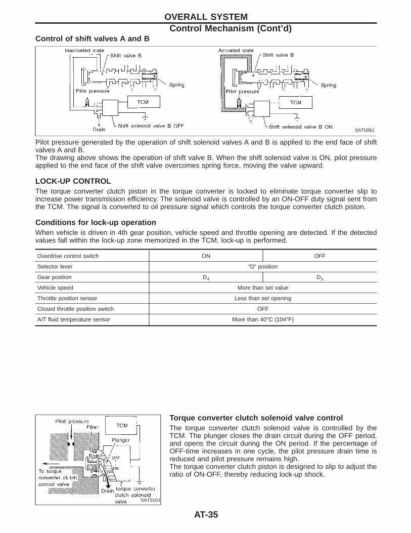
Pilot pressure generated by the operation of shift solenoid valves A and B is applied to the end face of shiftvalves A and B.The drawing above shows the operation of shift valve B. When the shift solenoid valve is ON, pilot pressureapplied to the end face of the shift valve overcomes spring force, moving the valve upward.
LOCK-UP CONTROLThe torque converter clutch piston in the torque converter is locked to eliminate torque converter slip toincrease power transmission efficiency. The solenoid valve is controlled by an ON-OFF duty signal sent fromthe TCM. The signal is converted to oil pressure signal which controls the torque converter clutch piston.
Conditions for lock-up operationWhen vehicle is driven in 4th gear position, vehicle speed and throttle opening are detected. If the detectedvalues fall within the lock-up zone memorized in the TCM, lock-up is performed.
Overdrive control switch ON OFF
Selector lever “D” position
Gear position D4 D3
Vehicle speed More than set value
Throttle position sensor Less than set opening
Closed throttle position switch OFF
A/T fluid temperature sensor More than 40°C (104°F)
SAT010J
Torque converter clutch solenoid valve controlThe torque converter clutch solenoid valve is controlled by theTCM. The plunger closes the drain circuit during the OFF period,and opens the circuit during the ON period. If the percentage ofOFF-time increases in one cycle, the pilot pressure drain time isreduced and pilot pressure remains high.The torque converter clutch piston is designed to slip to adjust theratio of ON-OFF, thereby reducing lock-up shock.
OVERALL SYSTEMControl Mechanism (Cont’d)
AT-35
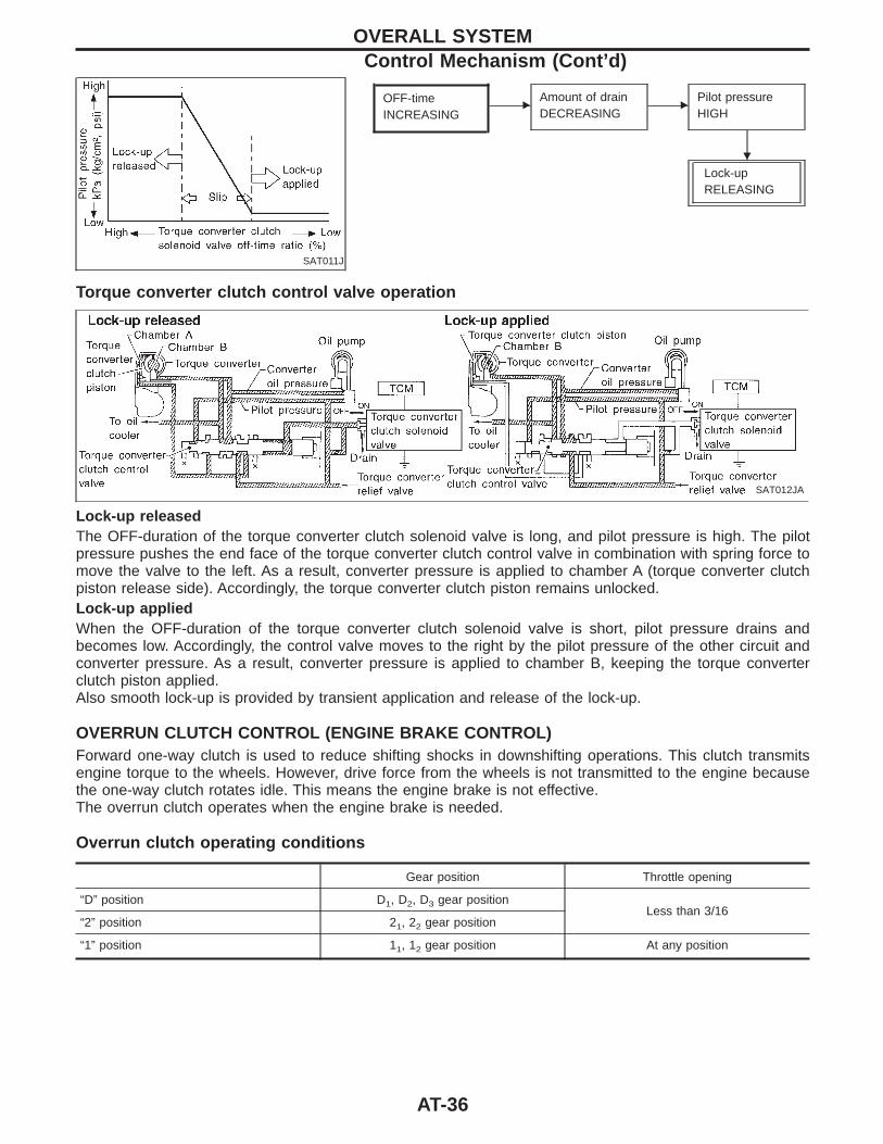
SAT011J
OFF-timeINCREASING
EAmount of drainDECREASING
EPilot pressureHIGH
Lock-upRELEASING
Torque converter clutch control valve operation
SAT012JA
Lock-up releasedThe OFF-duration of the torque converter clutch solenoid valve is long, and pilot pressure is high. The pilotpressure pushes the end face of the torque converter clutch control valve in combination with spring force tomove the valve to the left. As a result, converter pressure is applied to chamber A (torque converter clutchpiston release side). Accordingly, the torque converter clutch piston remains unlocked.Lock-up appliedWhen the OFF-duration of the torque converter clutch solenoid valve is short, pilot pressure drains andbecomes low. Accordingly, the control valve moves to the right by the pilot pressure of the other circuit andconverter pressure. As a result, converter pressure is applied to chamber B, keeping the torque converterclutch piston applied.Also smooth lock-up is provided by transient application and release of the lock-up.
OVERRUN CLUTCH CONTROL (ENGINE BRAKE CONTROL)Forward one-way clutch is used to reduce shifting shocks in downshifting operations. This clutch transmitsengine torque to the wheels. However, drive force from the wheels is not transmitted to the engine becausethe one-way clutch rotates idle. This means the engine brake is not effective.The overrun clutch operates when the engine brake is needed.
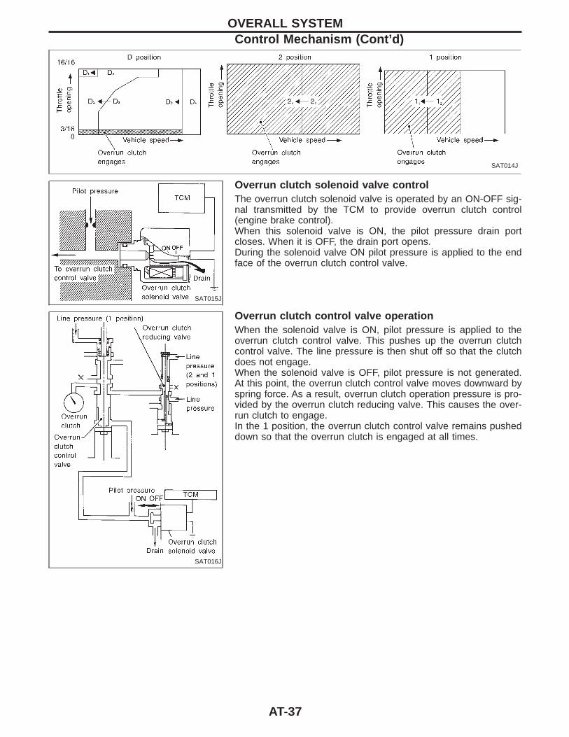
Overrun clutch operating conditions
Gear position Throttle opening
“D” position D1, D2, D3 gear positionLess than 3/16
“2” position 21, 22 gear position
“1” position 11, 12 gear position At any position
OVERALL SYSTEMControl Mechanism (Cont’d)
H
AT-36
SAT014J
SAT015J
Overrun clutch solenoid valve controlThe overrun clutch solenoid valve is operated by an ON-OFF sig-nal transmitted by the TCM to provide overrun clutch control(engine brake control).When this solenoid valve is ON, the pilot pressure drain portcloses. When it is OFF, the drain port opens.During the solenoid valve ON pilot pressure is applied to the endface of the overrun clutch control valve.
SAT016J
Overrun clutch control valve operationWhen the solenoid valve is ON, pilot pressure is applied to theoverrun clutch control valve. This pushes up the overrun clutchcontrol valve. The line pressure is then shut off so that the clutchdoes not engage.When the solenoid valve is OFF, pilot pressure is not generated.At this point, the overrun clutch control valve moves downward byspring force. As a result, overrun clutch operation pressure is pro-vided by the overrun clutch reducing valve. This causes the over-run clutch to engage.In the 1 position, the overrun clutch control valve remains pusheddown so that the overrun clutch is engaged at all times.
OVERALL SYSTEMControl Mechanism (Cont’d)
AT-37
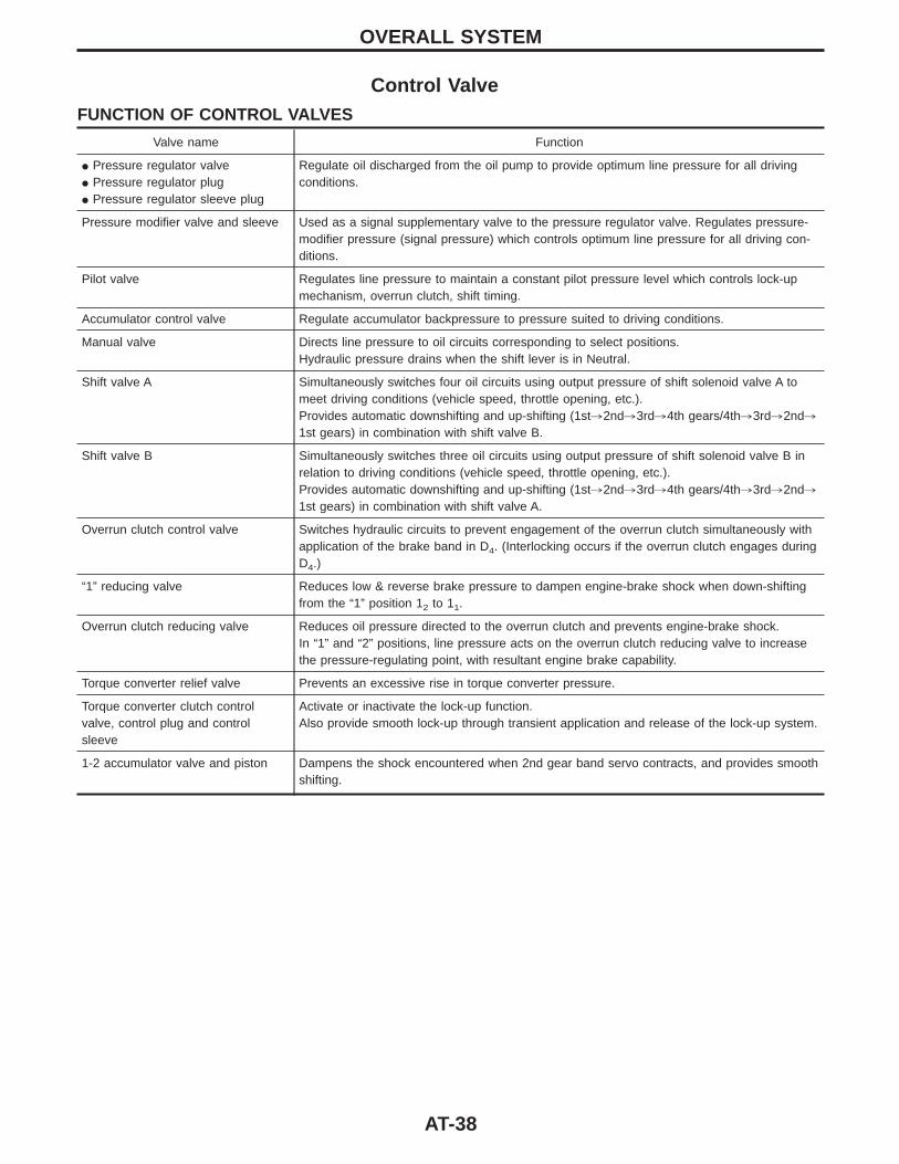
Control ValveFUNCTION OF CONTROL VALVES
Valve name Function
I Pressure regulator valveI Pressure regulator plugI Pressure regulator sleeve plug
Regulate oil discharged from the oil pump to provide optimum line pressure for all drivingconditions.
Pressure modifier valve and sleeve Used as a signal supplementary valve to the pressure regulator valve. Regulates pressure-modifier pressure (signal pressure) which controls optimum line pressure for all driving con-ditions.
Pilot valve Regulates line pressure to maintain a constant pilot pressure level which controls lock-upmechanism, overrun clutch, shift timing.
Accumulator control valve Regulate accumulator backpressure to pressure suited to driving conditions.
Manual valve Directs line pressure to oil circuits corresponding to select positions.Hydraulic pressure drains when the shift lever is in Neutral.
Shift valve A Simultaneously switches four oil circuits using output pressure of shift solenoid valve A tomeet driving conditions (vehicle speed, throttle opening, etc.).Provides automatic downshifting and up-shifting (1st,2nd,3rd,4th gears/4th,3rd,2nd,1st gears) in combination with shift valve B.
Shift valve B Simultaneously switches three oil circuits using output pressure of shift solenoid valve B inrelation to driving conditions (vehicle speed, throttle opening, etc.).Provides automatic downshifting and up-shifting (1st,2nd,3rd,4th gears/4th,3rd,2nd,1st gears) in combination with shift valve A.
Overrun clutch control valve Switches hydraulic circuits to prevent engagement of the overrun clutch simultaneously withapplication of the brake band in D4. (Interlocking occurs if the overrun clutch engages duringD4.)
“1” reducing valve Reduces low & reverse brake pressure to dampen engine-brake shock when down-shiftingfrom the “1” position 12 to 11.
Overrun clutch reducing valve Reduces oil pressure directed to the overrun clutch and prevents engine-brake shock.In “1” and “2” positions, line pressure acts on the overrun clutch reducing valve to increasethe pressure-regulating point, with resultant engine brake capability.
Torque converter relief valve Prevents an excessive rise in torque converter pressure.
Torque converter clutch controlvalve, control plug and controlsleeve
Activate or inactivate the lock-up function.Also provide smooth lock-up through transient application and release of the lock-up system.
1-2 accumulator valve and piston Dampens the shock encountered when 2nd gear band servo contracts, and provides smoothshifting.
OVERALL SYSTEM
AT-38

IntroductionThe A/T system has two self-diagnostic systems.The first is the emission-related on board diagnostic system (OBD-II) performed by the TCM (transmissioncontrol module) in combination with the ECM (ECCS control module). The malfunction is indicated by the MIL(malfunction indicator lamp) and is stored as a DTC in the ECM memory but not the TCM memory.The second is the TCM original self-diagnosis indicated by the O/D OFF indicator lamp. The malfunction isstored in the TCM memory. The detected items are overlapped with OBD-II self-diagnostic items. For detail,refer to AT-52.
OBD-II Function for A/T SystemThe ECM (ECCS control module) provides emission-related on board diagnostic (OBD-II) functions for the A/Tsystem. One function is to receive a signal from the TCM used with OBD-related parts of the A/T system. Thesignal is sent to the ECM when a malfunction occurs in the corresponding OBD-related part. The other func-tion is to indicate a diagnostic result by means of the MIL (malfunction indicator lamp) on the instrument panel.Sensors, switches and solenoid valves are used as sensing elements.The MIL automatically illuminates in One or Two Trip Detection Logic when a malfunction is sensed in rela-tion to A/T system parts.
One or Two Trip Detection Logic of OBD-IIONE TRIP DETECTION LOGICIf a malfunction is sensed during the first test drive, the MIL will illuminate and the malfunction will be storedin the ECM memory as a DTC. The TCM is not provided with such a memory function.
TWO TRIP DETECTION LOGICWhen a malfunction is sensed during the first test drive, it is stored in the ECM memory as a 1st trip DTC(diagnostic trouble code) or 1st trip freeze frame data. At this point, the MIL will not illuminate. — First TripIf the same malfunction as that experienced during the first test drive is sensed during the second test drive,the MIL will illuminate. — Second TripA/T-related parts for which the MIL illuminates during the first or second test drive are listed below.
ItemsMIL
One trip detection Two trip detectionShift solenoid valve A — DTC: P0750 (1108) XShift solenoid valve B — DTC: P0755 (1201) XThrottle position sensor or switch — DTC: P1705 (1206) XExcept above X
The “trip” in the “One or Two Trip Detection Logic” means a driving mode in which self-diagnosis is performedduring vehicle operation.
OBD-II Diagnostic Trouble Code (DTC)How to read DTC and 1st trip DTCDTC and 1st trip DTC can be read by the following methods.
1. The number of blinks of the malfunction indicator lamp in the Diagnostic Test Mode II (Self-Diagnos-tic Results) Examples: 1101, 1102, 1103, 1104, etc. For details, refer to EC section [“Malfunction Indi-cator Lamp (MIL)”, “ON BOARD DIAGNOSTIC SYSTEM DESCRIPTION”].These DTCs are controlled by NISSAN.
2. CONSULT or GST (Generic Scan Tool) Examples: P0705, P0710, P0720, P0725, etc.These DTCs are prescribed by SAE J2012.
(CONSULT also displays the malfunctioning component or system.)
ON BOARD DIAGNOSTIC SYSTEM DESCRIPTION
AT-39
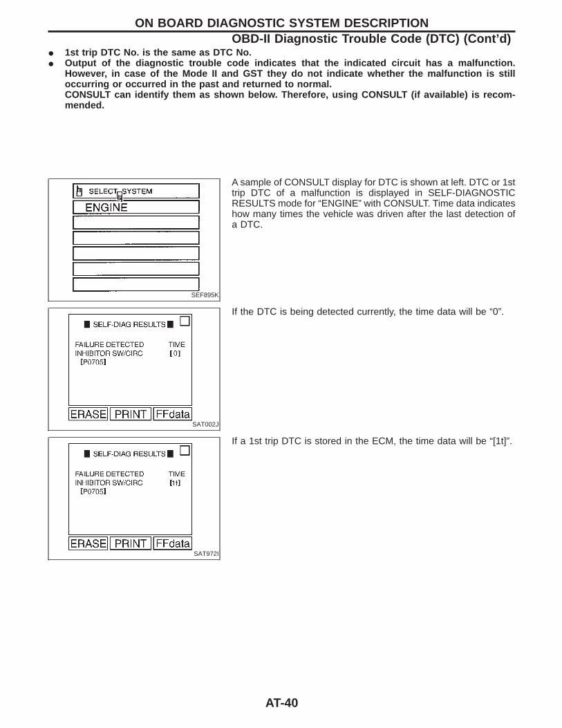
I 1st trip DTC No. is the same as DTC No.I Output of the diagnostic trouble code indicates that the indicated circuit has a malfunction.
However, in case of the Mode II and GST they do not indicate whether the malfunction is stilloccurring or occurred in the past and returned to normal.CONSULT can identify them as shown below. Therefore, using CONSULT (if available) is recom-mended.
SEF895K
A sample of CONSULT display for DTC is shown at left. DTC or 1sttrip DTC of a malfunction is displayed in SELF-DIAGNOSTICRESULTS mode for “ENGINE” with CONSULT. Time data indicateshow many times the vehicle was driven after the last detection ofa DTC.
SAT002J
If the DTC is being detected currently, the time data will be “0”.
SAT972I
If a 1st trip DTC is stored in the ECM, the time data will be “[1t]”.
ON BOARD DIAGNOSTIC SYSTEM DESCRIPTIONOBD-II Diagnostic Trouble Code (DTC) (Cont’d)
AT-40
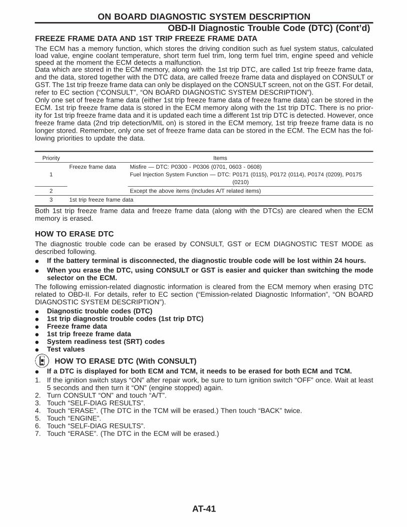
FREEZE FRAME DATA AND 1ST TRIP FREEZE FRAME DATAThe ECM has a memory function, which stores the driving condition such as fuel system status, calculatedload value, engine coolant temperature, short term fuel trim, long term fuel trim, engine speed and vehiclespeed at the moment the ECM detects a malfunction.Data which are stored in the ECM memory, along with the 1st trip DTC, are called 1st trip freeze frame data,and the data, stored together with the DTC data, are called freeze frame data and displayed on CONSULT orGST. The 1st trip freeze frame data can only be displayed on the CONSULT screen, not on the GST. For detail,refer to EC section (“CONSULT”, “ON BOARD DIAGNOSTIC SYSTEM DESCRIPTION”).Only one set of freeze frame data (either 1st trip freeze frame data of freeze frame data) can be stored in theECM. 1st trip freeze frame data is stored in the ECM memory along with the 1st trip DTC. There is no prior-ity for 1st trip freeze frame data and it is updated each time a different 1st trip DTC is detected. However, oncefreeze frame data (2nd trip detection/MIL on) is stored in the ECM memory, 1st trip freeze frame data is nolonger stored. Remember, only one set of freeze frame data can be stored in the ECM. The ECM has the fol-lowing priorities to update the data.
Priority Items
1Freeze frame data Misfire — DTC: P0300 - P0306 (0701, 0603 - 0608)
Fuel Injection System Function — DTC: P0171 (0115), P0172 (0114), P0174 (0209), P0175(0210)
2 Except the above items (Includes A/T related items)
3 1st trip freeze frame data
Both 1st trip freeze frame data and freeze frame data (along with the DTCs) are cleared when the ECMmemory is erased.
HOW TO ERASE DTCThe diagnostic trouble code can be erased by CONSULT, GST or ECM DIAGNOSTIC TEST MODE asdescribed following.I If the battery terminal is disconnected, the diagnostic trouble code will be lost within 24 hours.I When you erase the DTC, using CONSULT or GST is easier and quicker than switching the mode
selector on the ECM.The following emission-related diagnostic information is cleared from the ECM memory when erasing DTCrelated to OBD-II. For details, refer to EC section (“Emission-related Diagnostic Information”, “ON BOARDDIAGNOSTIC SYSTEM DESCRIPTION”).I Diagnostic trouble codes (DTC)I 1st trip diagnostic trouble codes (1st trip DTC)I Freeze frame dataI 1st trip freeze frame dataI System readiness test (SRT) codesI Test values
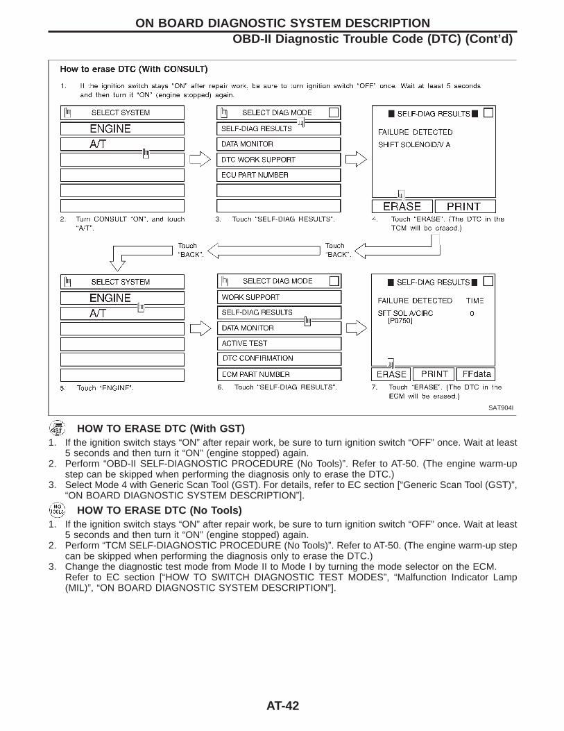
HOW TO ERASE DTC (With CONSULT)I If a DTC is displayed for both ECM and TCM, it needs to be erased for both ECM and TCM.1. If the ignition switch stays “ON” after repair work, be sure to turn ignition switch “OFF” once. Wait at least
5 seconds and then turn it “ON” (engine stopped) again.2. Turn CONSULT “ON” and touch “A/T”.3. Touch “SELF-DIAG RESULTS”.4. Touch “ERASE”. (The DTC in the TCM will be erased.) Then touch “BACK” twice.5. Touch “ENGINE”.6. Touch “SELF-DIAG RESULTS”.7. Touch “ERASE”. (The DTC in the ECM will be erased.)
ON BOARD DIAGNOSTIC SYSTEM DESCRIPTIONOBD-II Diagnostic Trouble Code (DTC) (Cont’d)
AT-41
SAT904I
HOW TO ERASE DTC (With GST)1. If the ignition switch stays “ON” after repair work, be sure to turn ignition switch “OFF” once. Wait at least
5 seconds and then turn it “ON” (engine stopped) again.2. Perform “OBD-II SELF-DIAGNOSTIC PROCEDURE (No Tools)”. Refer to AT-50. (The engine warm-up
step can be skipped when performing the diagnosis only to erase the DTC.)3. Select Mode 4 with Generic Scan Tool (GST). For details, refer to EC section [“Generic Scan Tool (GST)”,
“ON BOARD DIAGNOSTIC SYSTEM DESCRIPTION”].
HOW TO ERASE DTC (No Tools)1. If the ignition switch stays “ON” after repair work, be sure to turn ignition switch “OFF” once. Wait at least
5 seconds and then turn it “ON” (engine stopped) again.2. Perform “TCM SELF-DIAGNOSTIC PROCEDURE (No Tools)”. Refer to AT-50. (The engine warm-up step
can be skipped when performing the diagnosis only to erase the DTC.)3. Change the diagnostic test mode from Mode II to Mode I by turning the mode selector on the ECM.
Refer to EC section [“HOW TO SWITCH DIAGNOSTIC TEST MODES”, “Malfunction Indicator Lamp(MIL)”, “ON BOARD DIAGNOSTIC SYSTEM DESCRIPTION”].
ON BOARD DIAGNOSTIC SYSTEM DESCRIPTIONOBD-II Diagnostic Trouble Code (DTC) (Cont’d)
AT-42
SAT964I
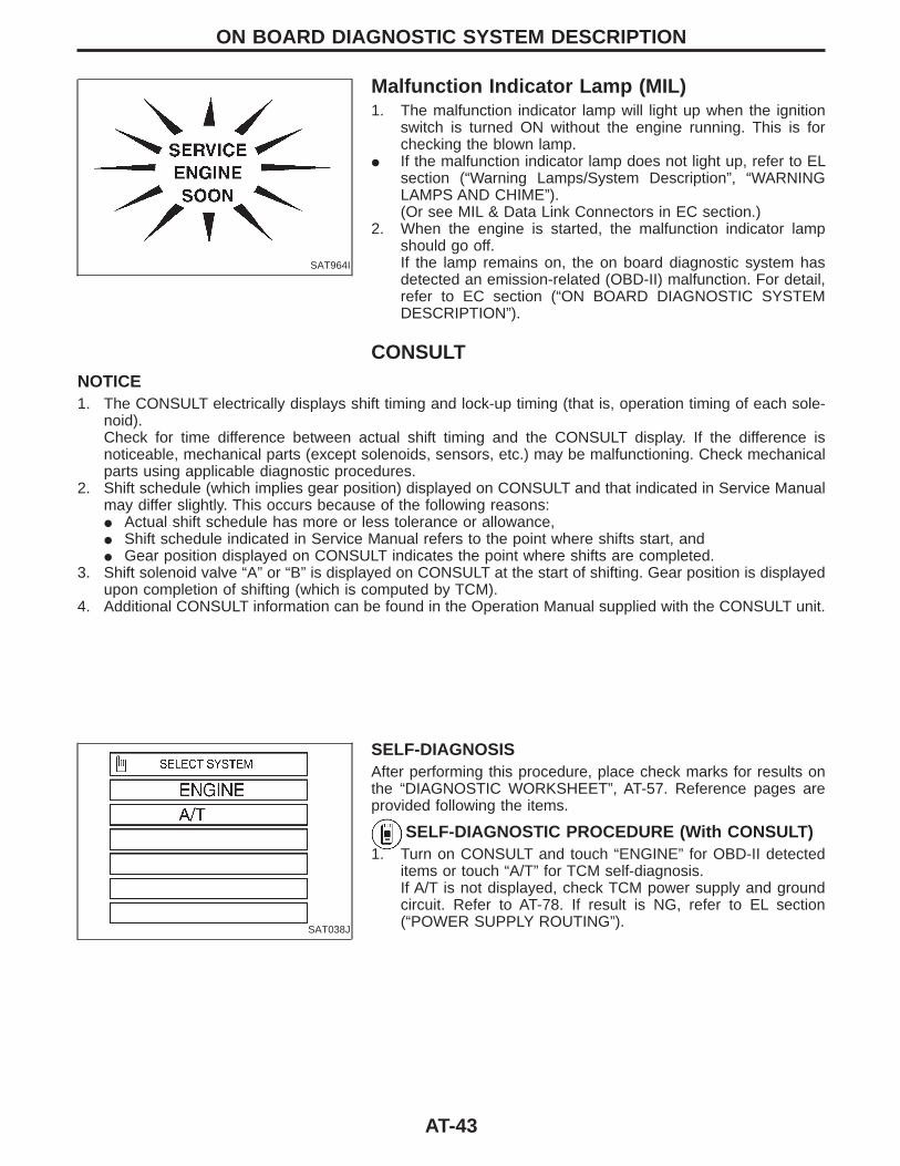
Malfunction Indicator Lamp (MIL)1. The malfunction indicator lamp will light up when the ignition
switch is turned ON without the engine running. This is forchecking the blown lamp.
I If the malfunction indicator lamp does not light up, refer to ELsection (“Warning Lamps/System Description”, “WARNINGLAMPS AND CHIME”).(Or see MIL & Data Link Connectors in EC section.)
2. When the engine is started, the malfunction indicator lampshould go off.If the lamp remains on, the on board diagnostic system hasdetected an emission-related (OBD-II) malfunction. For detail,refer to EC section (“ON BOARD DIAGNOSTIC SYSTEMDESCRIPTION”).
CONSULTNOTICE1. The CONSULT electrically displays shift timing and lock-up timing (that is, operation timing of each sole-
noid).Check for time difference between actual shift timing and the CONSULT display. If the difference isnoticeable, mechanical parts (except solenoids, sensors, etc.) may be malfunctioning. Check mechanicalparts using applicable diagnostic procedures.
2. Shift schedule (which implies gear position) displayed on CONSULT and that indicated in Service Manualmay differ slightly. This occurs because of the following reasons:I Actual shift schedule has more or less tolerance or allowance,I Shift schedule indicated in Service Manual refers to the point where shifts start, andI Gear position displayed on CONSULT indicates the point where shifts are completed.
3. Shift solenoid valve “A” or “B” is displayed on CONSULT at the start of shifting. Gear position is displayedupon completion of shifting (which is computed by TCM).
4. Additional CONSULT information can be found in the Operation Manual supplied with the CONSULT unit.
SAT038J
SELF-DIAGNOSISAfter performing this procedure, place check marks for results onthe “DIAGNOSTIC WORKSHEET”, AT-57. Reference pages areprovided following the items.
SELF-DIAGNOSTIC PROCEDURE (With CONSULT)1. Turn on CONSULT and touch “ENGINE” for OBD-II detected
items or touch “A/T” for TCM self-diagnosis.If A/T is not displayed, check TCM power supply and groundcircuit. Refer to AT-78. If result is NG, refer to EL section(“POWER SUPPLY ROUTING”).
ON BOARD DIAGNOSTIC SYSTEM DESCRIPTION
AT-43
SAT708G
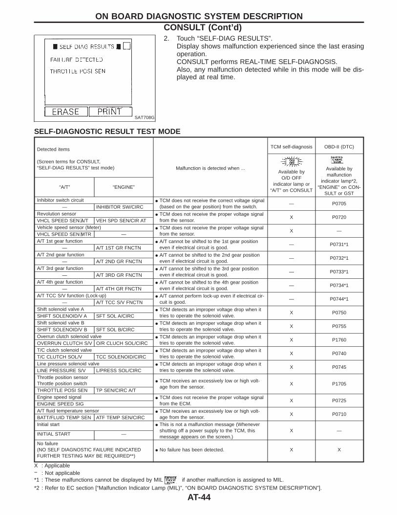
2. Touch “SELF-DIAG RESULTS”.Display shows malfunction experienced since the last erasingoperation.CONSULT performs REAL-TIME SELF-DIAGNOSIS.Also, any malfunction detected while in this mode will be dis-played at real time.
SELF-DIAGNOSTIC RESULT TEST MODE
Detected items
(Screen terms for CONSULT,“SELF-DIAG RESULTS” test mode) Malfunction is detected when ...
TCM self-diagnosis OBD-II (DTC)
Available byO/D OFF
indicator lamp or“A/T” on CONSULT
Available bymalfunction
indicator lamp*2,“ENGINE” on CON-
SULT or GST“A/T” “ENGINE”
Inhibitor switch circuit I TCM does not receive the correct voltage signal(based on the gear position) from the switch.
— P0705— INHIBITOR SW/CIRC
Revolution sensor I TCM does not receive the proper voltage signalfrom the sensor.
X P0720VHCL SPEED SEN⋅A/T VEH SPD SEN/CIR ATVehicle speed sensor (Meter) I TCM does not receive the proper voltage signal
from the sensor.X —
VHCL SPEED SEN⋅MTR —A/T 1st gear function I A/T cannot be shifted to the 1st gear position
even if electrical circuit is good.— P0731*1
— A/T 1ST GR FNCTNA/T 2nd gear function I A/T cannot be shifted to the 2nd gear position
even if electrical circuit is good.— P0732*1
— A/T 2ND GR FNCTNA/T 3rd gear function I A/T cannot be shifted to the 3rd gear position
even if electrical circuit is good.— P0733*1
— A/T 3RD GR FNCTNA/T 4th gear function I A/T cannot be shifted to the 4th gear position
even if electrical circuit is good.— P0734*1
— A/T 4TH GR FNCTNA/T TCC S/V function (Lock-up) I A/T cannot perform lock-up even if electrical cir-
cuit is good.— P0744*1
— A/T TCC S/V FNCTNShift solenoid valve A I TCM detects an improper voltage drop when it
tries to operate the solenoid valve.X P0750
SHIFT SOLENOID/V A SFT SOL A/CIRCShift solenoid valve B I TCM detects an improper voltage drop when it
tries to operate the solenoid valve.X P0755
SHIFT SOLENOID/V B SFT SOL B/CIRCOverrun clutch solenoid valve I TCM detects an improper voltage drop when it
tries to operate the solenoid valve.X P1760
OVERRUN CLUTCH S/V O/R CLUCH SOL/CIRCT/C clutch solenoid valve I TCM detects an improper voltage drop when it
tries to operate the solenoid valve.X P0740
T/C CLUTCH SOL/V TCC SOLENOID/CIRCLine pressure solenoid valve I TCM detects an improper voltage drop when it
tries to operate the solenoid valve.X P0745
LINE PRESSURE S/V L/PRESS SOL/CIRCThrottle position sensorThrottle position switch I TCM receives an excessively low or high volt-
age from the sensor.X P1705
THROTTLE POSI SEN TP SEN/CIRC A/TEngine speed signal I TCM does not receive the proper voltage signal
from the ECM.X P0725
ENGINE SPEED SIGA/T fluid temperature sensor I TCM receives an excessively low or high volt-
age from the sensor.X P0710
BATT/FLUID TEMP SEN ATF TEMP SEN/CIRCInitial start I This is not a malfunction message (Whenever
shutting off a power supply to the TCM, thismessage appears on the screen.)
X —INITIAL START —
No failure(NO SELF DIAGNOSTIC FAILURE INDICATEDFURTHER TESTING MAY BE REQUIRED**)
I No failure has been detected. X X
X : Applicable− : Not applicable*1 : These malfunctions cannot be displayed by MIL if another malfunction is assigned to MIL.
*2 : Refer to EC section [“Malfunction Indicator Lamp (MIL)”, “ON BOARD DIAGNOSTIC SYSTEM DESCRIPTION”].
ON BOARD DIAGNOSTIC SYSTEM DESCRIPTIONCONSULT (Cont’d)
AT-44
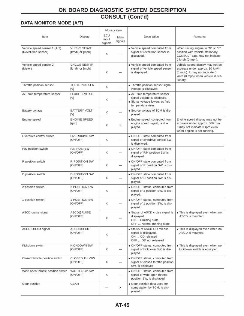
DATA MONITOR MODE (A/T)
Item Display
Monitor item
Description RemarksECUinput
signals
Mainsignals
Vehicle speed sensor 1 (A/T)(Revolution sensor)
VHCL/S SE⋅A/T[km/h] or [mph]
X —
I Vehicle speed computed fromsignal of revolution sensor isdisplayed.
When racing engine in “N” or “P”position with vehicle stationary,CONSULT data may not indicate0 km/h (0 mph).
Vehicle speed sensor 2(Meter)
VHCL/S SE⋅MTR[km/h] or [mph]
X —
I Vehicle speed computed fromsignal of vehicle speed sensoris displayed.
Vehicle speed display may not beaccurate under approx. 10 km/h(6 mph). It may not indicate 0km/h (0 mph) when vehicle is sta-tionary.
Throttle position sensor THRTL POS SEN[V]
X —I Throttle position sensor signal
voltage is displayed.
A/T fluid temperature sensor FLUID TEMP SE[V]
X —
I A/T fluid temperature sensorsignal voltage is displayed.
I Signal voltage lowers as fluidtemperature rises.
Battery voltage BATTERY VOLT[V]
X —I Source voltage of TCM is dis-
played.
Engine speed ENGINE SPEED[rpm]
X X
I Engine speed, computed fromengine speed signal, is dis-played.
Engine speed display may not beaccurate under approx. 800 rpm.It may not indicate 0 rpm evenwhen engine is not running.
Overdrive control switch OVERDRIVE SW[ON/OFF] X —
I ON/OFF state computed fromsignal of overdrive control SWis displayed.
P/N position switch P/N POSI SW[ON/OFF] X —
I ON/OFF state computed fromsignal of P/N position SW isdisplayed.
R position switch R POSITION SW[ON/OFF] X —
I ON/OFF state computed fromsignal of R position SW is dis-played.
D position switch D POSITION SW[ON/OFF] X —
I ON/OFF state computed fromsignal of D position SW is dis-played.
2 position switch 2 POSITION SW[ON/OFF] X —
I ON/OFF status, computed fromsignal of 2 position SW, is dis-played.
1 position switch 1 POSITION SW[ON/OFF] X —
I ON/OFF status, computed fromsignal of 1 position SW, is dis-played.
ASCD cruise signal ASCD⋅CRUISE[ON/OFF]
X —
I Status of ASCD cruise signal isdisplayed.ON ... Cruising stateOFF ... Normal running state
I This is displayed even when noASCD is mounted.
ASCD OD cut signal ASCD⋅OD CUT[ON/OFF]
X —
I Status of ASCD OD releasesignal is displayed.ON ... OD releasedOFF ... OD not released
I This is displayed even when noASCD is mounted.
Kickdown switch KICKDOWN SW[ON/OFF] X —
I ON/OFF status, computed fromsignal of kickdown SW, is dis-played.
I This is displayed even when nokickdown switch is equipped.
Closed throttle position switch CLOSED THL/SW[ON/OFF] X —
I ON/OFF status, computed fromsignal of closed throttle positionSW, is displayed.
Wide open throttle position switch W/O THRL/P-SW[ON/OFF] X —
I ON/OFF status, computed fromsignal of wide open throttleposition SW, is displayed.
Gear position GEAR— X
I Gear position data used forcomputation by TCM, is dis-played.
ON BOARD DIAGNOSTIC SYSTEM DESCRIPTIONCONSULT (Cont’d)
AT-45
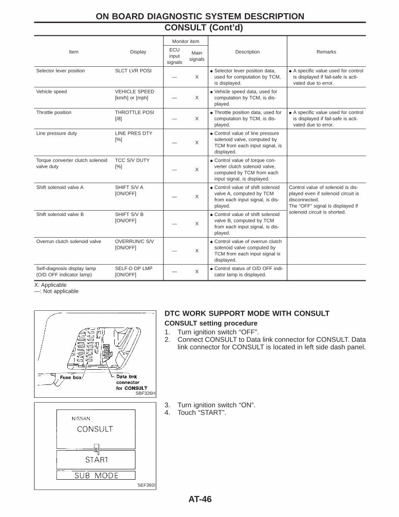
Item Display
Monitor item
Description RemarksECUinput
signals
Mainsignals
Selector lever position SLCT LVR POSI— X
I Selector lever position data,used for computation by TCM,is displayed.
I A specific value used for controlis displayed if fail-safe is acti-vated due to error.
Vehicle speed VEHICLE SPEED[km/h] or [mph] — X
I Vehicle speed data, used forcomputation by TCM, is dis-played.
Throttle position THROTTLE POSI[/8] — X
I Throttle position data, used forcomputation by TCM, is dis-played.
I A specific value used for controlis displayed if fail-safe is acti-vated due to error.
Line pressure duty LINE PRES DTY[%]
— X
I Control value of line pressuresolenoid valve, computed byTCM from each input signal, isdisplayed.
Torque converter clutch solenoidvalve duty
TCC S/V DUTY[%]
— X
I Control value of torque con-verter clutch solenoid valve,computed by TCM from eachinput signal, is displayed.
Shift solenoid valve A SHIFT S/V A[ON/OFF]
— X
I Control value of shift solenoidvalve A, computed by TCMfrom each input signal, is dis-played.
Control value of solenoid is dis-played even if solenoid circuit isdisconnected.The “OFF” signal is displayed ifsolenoid circuit is shorted.Shift solenoid valve B SHIFT S/V B
[ON/OFF]— X
I Control value of shift solenoidvalve B, computed by TCMfrom each input signal, is dis-played.
Overrun clutch solenoid valve OVERRUN/C S/V[ON/OFF]
— X
I Control value of overrun clutchsolenoid valve computed byTCM from each input signal isdisplayed.
Self-diagnosis display lamp(O/D OFF indicator lamp)
SELF-D DP LMP[ON/OFF]
— XI Control status of O/D OFF indi-
cator lamp is displayed.
X: Applicable—: Not applicable
SBF326H
DTC WORK SUPPORT MODE WITH CONSULTCONSULT setting procedure1. Turn ignition switch “OFF”.2. Connect CONSULT to Data link connector for CONSULT. Data
link connector for CONSULT is located in left side dash panel.
SEF392I
3. Turn ignition switch “ON”.4. Touch “START”.
ON BOARD DIAGNOSTIC SYSTEM DESCRIPTIONCONSULT (Cont’d)
AT-46
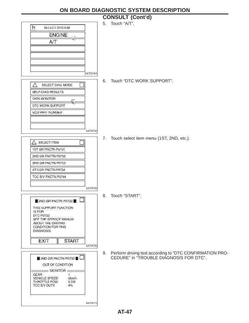
SAT974H
5. Touch “A/T”.
SAT974I
6. Touch “DTC WORK SUPPORT”.
SAT975I
7. Touch select item menu (1ST, 2ND, etc.).
SAT976I
8. Touch “START”.
SAT977I
9. Perform driving test according to “DTC CONFIRMATION PRO-CEDURE” in “TROUBLE DIAGNOSIS FOR DTC”.
ON BOARD DIAGNOSTIC SYSTEM DESCRIPTIONCONSULT (Cont’d)
AT-47
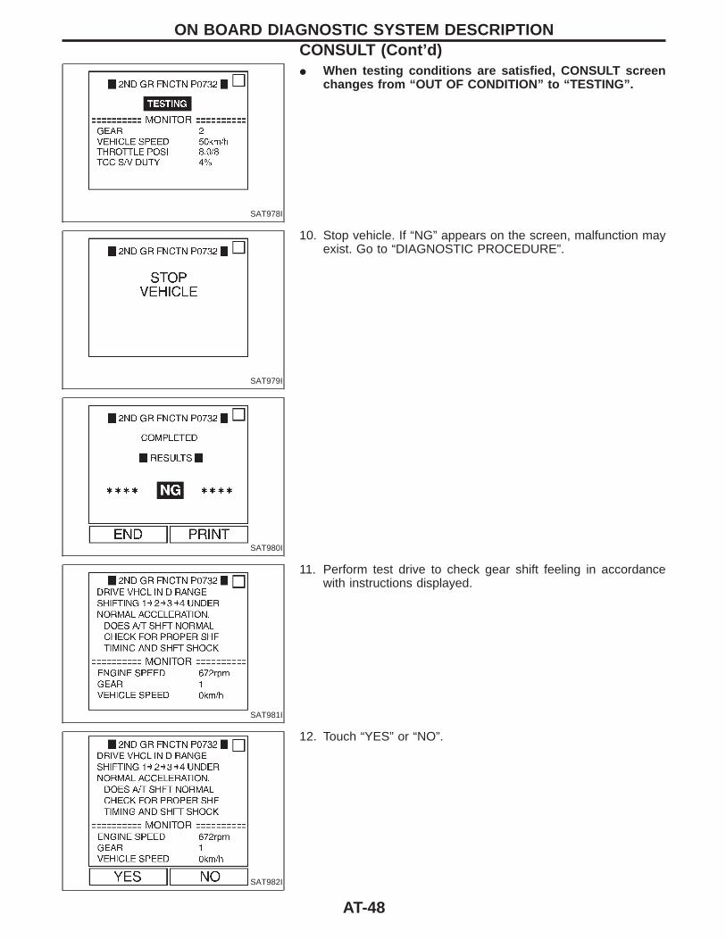
SAT978I
I When testing conditions are satisfied, CONSULT screenchanges from “OUT OF CONDITION” to “TESTING”.
SAT979I
10. Stop vehicle. If “NG” appears on the screen, malfunction mayexist. Go to “DIAGNOSTIC PROCEDURE”.
SAT980I
SAT981I
11. Perform test drive to check gear shift feeling in accordancewith instructions displayed.
SAT982I
12. Touch “YES” or “NO”.
ON BOARD DIAGNOSTIC SYSTEM DESCRIPTIONCONSULT (Cont’d)
AT-48
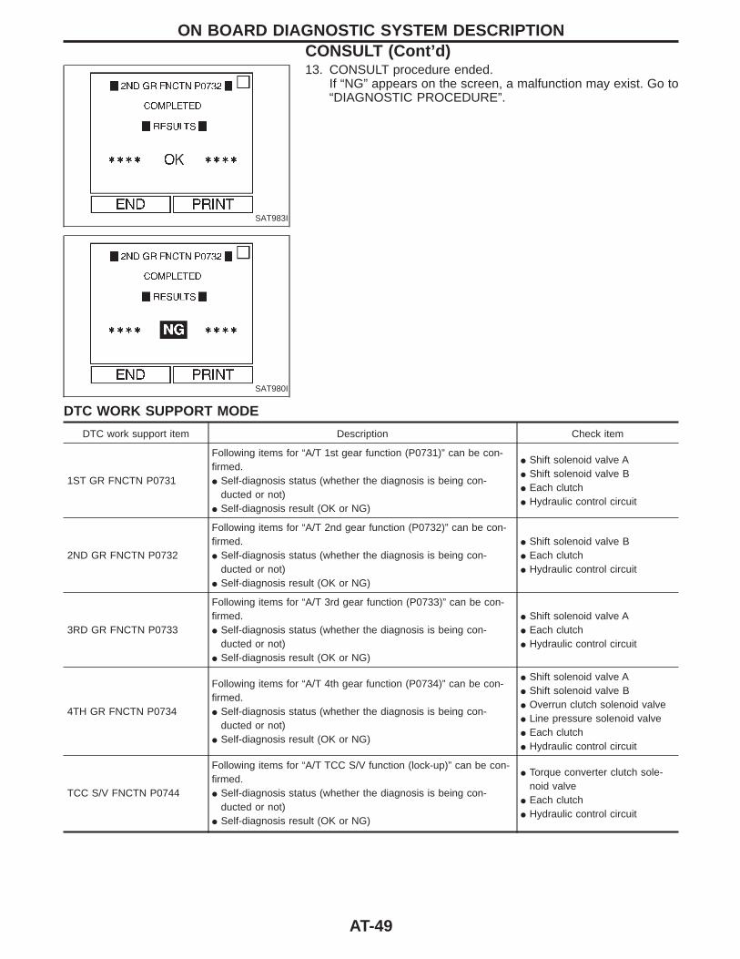
SAT983I
13. CONSULT procedure ended.If “NG” appears on the screen, a malfunction may exist. Go to“DIAGNOSTIC PROCEDURE”.
SAT980I
DTC WORK SUPPORT MODE
DTC work support item Description Check item
1ST GR FNCTN P0731
Following items for “A/T 1st gear function (P0731)” can be con-firmed.I Self-diagnosis status (whether the diagnosis is being con-
ducted or not)I Self-diagnosis result (OK or NG)
I Shift solenoid valve AI Shift solenoid valve BI Each clutchI Hydraulic control circuit
2ND GR FNCTN P0732
Following items for “A/T 2nd gear function (P0732)” can be con-firmed.I Self-diagnosis status (whether the diagnosis is being con-
ducted or not)I Self-diagnosis result (OK or NG)
I Shift solenoid valve BI Each clutchI Hydraulic control circuit
3RD GR FNCTN P0733
Following items for “A/T 3rd gear function (P0733)” can be con-firmed.I Self-diagnosis status (whether the diagnosis is being con-
ducted or not)I Self-diagnosis result (OK or NG)
I Shift solenoid valve AI Each clutchI Hydraulic control circuit
4TH GR FNCTN P0734
Following items for “A/T 4th gear function (P0734)” can be con-firmed.I Self-diagnosis status (whether the diagnosis is being con-
ducted or not)I Self-diagnosis result (OK or NG)
I Shift solenoid valve AI Shift solenoid valve BI Overrun clutch solenoid valveI Line pressure solenoid valveI Each clutchI Hydraulic control circuit
TCC S/V FNCTN P0744
Following items for “A/T TCC S/V function (lock-up)” can be con-firmed.I Self-diagnosis status (whether the diagnosis is being con-
ducted or not)I Self-diagnosis result (OK or NG)
I Torque converter clutch sole-noid valve
I Each clutchI Hydraulic control circuit
ON BOARD DIAGNOSTIC SYSTEM DESCRIPTIONCONSULT (Cont’d)
AT-49
SAT383I
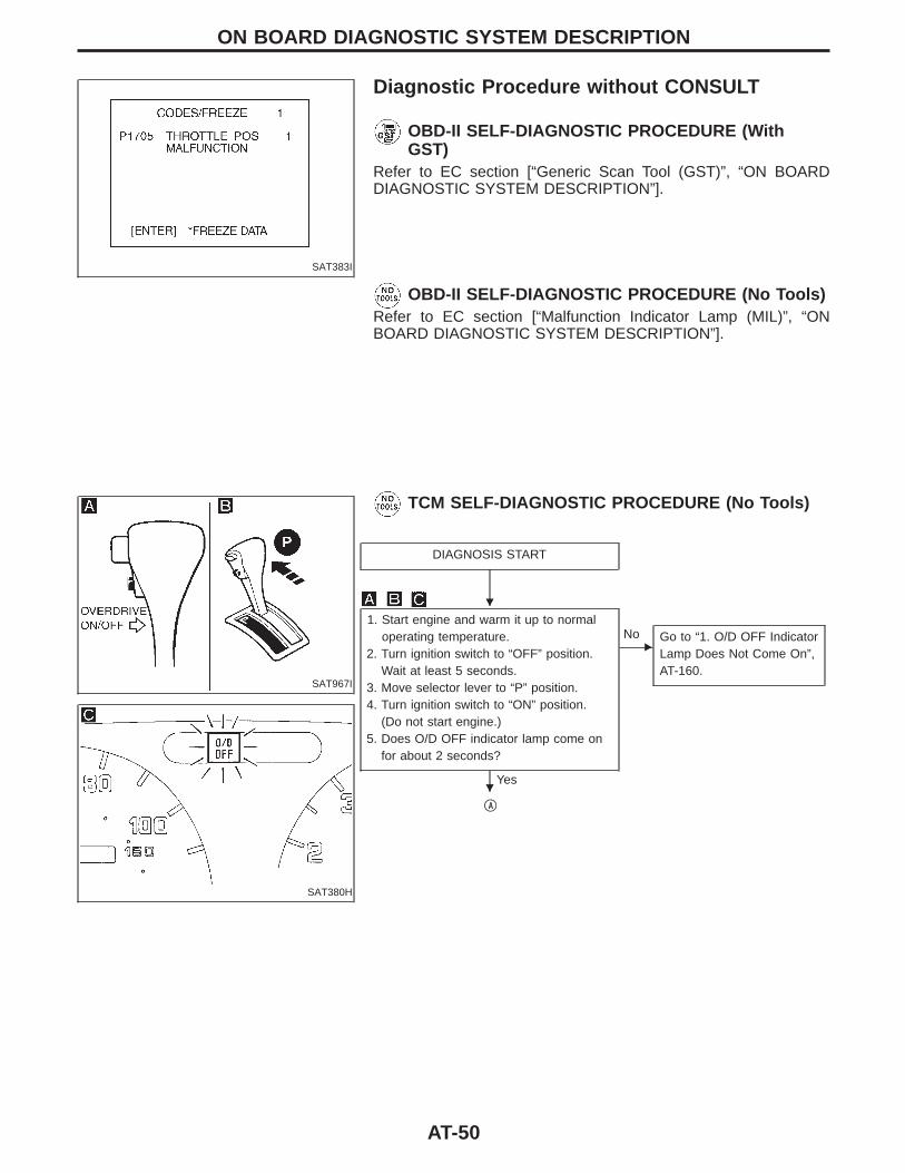
Diagnostic Procedure without CONSULT
OBD-II SELF-DIAGNOSTIC PROCEDURE (WithGST)
Refer to EC section [“Generic Scan Tool (GST)”, “ON BOARDDIAGNOSTIC SYSTEM DESCRIPTION”].
OBD-II SELF-DIAGNOSTIC PROCEDURE (No Tools)Refer to EC section [“Malfunction Indicator Lamp (MIL)”, “ONBOARD DIAGNOSTIC SYSTEM DESCRIPTION”].
SAT967I
TCM SELF-DIAGNOSTIC PROCEDURE (No Tools)
SAT380H
DIAGNOSIS START
1. Start engine and warm it up to normaloperating temperature.
2. Turn ignition switch to “OFF” position.Wait at least 5 seconds.
3. Move selector lever to “P” position.4. Turn ignition switch to “ON” position.
(Do not start engine.)5. Does O/D OFF indicator lamp come on
for about 2 seconds?
Yes
ENo Go to “1. O/D OFF Indicator
Lamp Does Not Come On”,AT-160.
qA
ON BOARD DIAGNOSTIC SYSTEM DESCRIPTION
H
H
AT-50
SAT968I
SAT969I
SAT970I
SAT981F
SAT380H
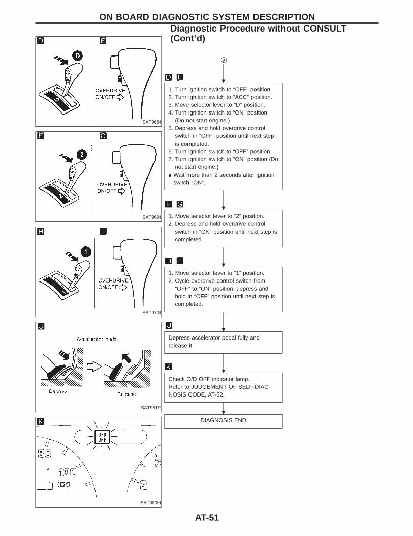
qA
1. Turn ignition switch to “OFF” position.2. Turn ignition switch to “ACC” position.3. Move selector lever to “D” position.4. Turn ignition switch to “ON” position.
(Do not start engine.)5. Depress and hold overdrive control
switch in “OFF” position until next stepis completed.
6. Turn ignition switch to “OFF” position.7. Turn ignition switch to “ON” position (Do
not start engine.)I Wait more than 2 seconds after ignition
switch “ON”.
1. Move selector lever to “2” position.2. Depress and hold overdrive control
switch in “ON” position until next step iscompleted.
1. Move selector lever to “1” position.2. Cycle overdrive control switch from
“OFF” to “ON” position, depress andhold in “OFF” position until next step iscompleted.
Depress accelerator pedal fully andrelease it.
Check O/D OFF indicator lamp.Refer to JUDGEMENT OF SELF-DIAG-NOSIS CODE, AT-52.
DIAGNOSIS END
ON BOARD DIAGNOSTIC SYSTEM DESCRIPTIONDiagnostic Procedure without CONSULT(Cont’d)
H
H
H
H
H
H
AT-51
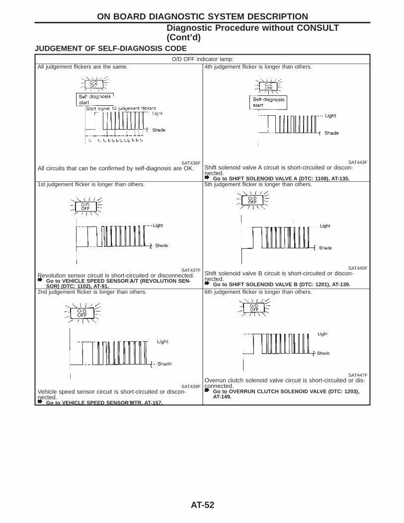
JUDGEMENT OF SELF-DIAGNOSIS CODEO/D OFF indicator lamp:
All judgement flickers are the same.
SAT436FAll circuits that can be confirmed by self-diagnosis are OK.
4th judgement flicker is longer than others.
SAT443FShift solenoid valve A circuit is short-circuited or discon-nected.
Go to SHIFT SOLENOID VALVE A (DTC: 1108), AT-135.1st judgement flicker is longer than others.
SAT437FRevolution sensor circuit is short-circuited or disconnected.
Go to VEHICLE SPEED SENSOR ⋅A/T (REVOLUTION SEN-SOR) (DTC: 1102), AT-91.
5th judgement flicker is longer than others.
SAT445FShift solenoid valve B circuit is short-circuited or discon-nected.
Go to SHIFT SOLENOID VALVE B (DTC: 1201), AT-139.2nd judgement flicker is longer than others.
SAT439FVehicle speed sensor circuit is short-circuited or discon-nected.
Go to VEHICLE SPEED SENSOR ⋅MTR, AT-157.
6th judgement flicker is longer than others.
SAT447FOverrun clutch solenoid valve circuit is short-circuited or dis-connected.
Go to OVERRUN CLUTCH SOLENOID VALVE (DTC: 1203),AT-149.
ON BOARD DIAGNOSTIC SYSTEM DESCRIPTIONDiagnostic Procedure without CONSULT(Cont’d)
AT-52
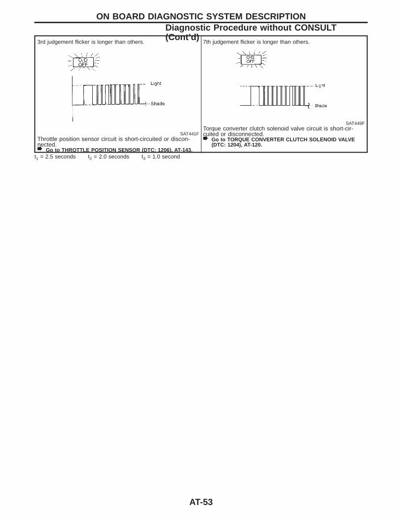
3rd judgement flicker is longer than others.
SAT441FThrottle position sensor circuit is short-circuited or discon-nected.
Go to THROTTLE POSITION SENSOR (DTC: 1206), AT-143.
7th judgement flicker is longer than others.
SAT449FTorque converter clutch solenoid valve circuit is short-cir-cuited or disconnected.
Go to TORQUE CONVERTER CLUTCH SOLENOID VALVE(DTC: 1204), AT-120.
t1 = 2.5 seconds t2 = 2.0 seconds t3 = 1.0 second
ON BOARD DIAGNOSTIC SYSTEM DESCRIPTIONDiagnostic Procedure without CONSULT(Cont’d)
AT-53
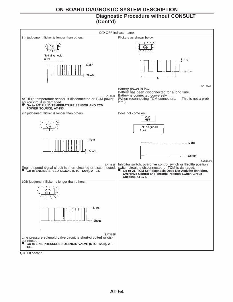
O/D OFF indicator lamp:
8th judgement flicker is longer than others.
SAT451FA/T fluid temperature sensor is disconnected or TCM powersource circuit is damaged.
Go to A/T FLUID TEMPERATURE SENSOR AND TCMPOWER SOURCE, AT-153.
Flickers as shown below.
SAT457FBattery power is low.Battery has been disconnected for a long time.Battery is connected conversely.(When reconnecting TCM connectors. — This is not a prob-lem.)
9th judgement flicker is longer than others.
SAT453FEngine speed signal circuit is short-circuited or disconnected.
Go to ENGINE SPEED SIGNAL (DTC: 1207), AT-94.
Does not come on.
SAT414GInhibitor switch, overdrive control switch or throttle positionswitch circuit is disconnected or TCM is damaged.
Go to 21. TCM Self-diagnosis Does Not Activate (Inhibitor,Overdrive Control and Throttle Position Switch CircuitChecks), AT-175.
10th judgement flicker is longer than others.
SAT455FLine pressure solenoid valve circuit is short-circuited or dis-connected.
Go to LINE PRESSURE SOLENOID VALVE (DTC: 1205), AT-131.
t4 = 1.0 second
ON BOARD DIAGNOSTIC SYSTEM DESCRIPTIONDiagnostic Procedure without CONSULT(Cont’d)
AT-54
SAT631IA
SAT632I
SEF234G
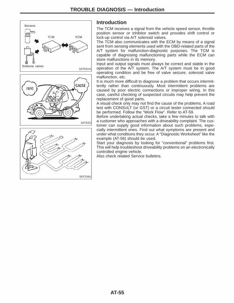
IntroductionThe TCM receives a signal from the vehicle speed sensor, throttleposition sensor or inhibitor switch and provides shift control orlock-up control via A/T solenoid valves.The TCM also communicates with the ECM by means of a signalsent from sensing elements used with the OBD-related parts of theA/T system for malfunction-diagnostic purposes. The TCM iscapable of diagnosing malfunctioning parts while the ECM canstore malfunctions in its memory.Input and output signals must always be correct and stable in theoperation of the A/T system. The A/T system must be in goodoperating condition and be free of valve seizure, solenoid valvemalfunction, etc.It is much more difficult to diagnose a problem that occurs intermit-tently rather than continuously. Most intermittent problems arecaused by poor electric connections or improper wiring. In thiscase, careful checking of suspected circuits may help prevent thereplacement of good parts.A visual check only may not find the cause of the problems. A roadtest with CONSULT (or GST) or a circuit tester connected shouldbe performed. Follow the “Work Flow”. Refer to AT-59.Before undertaking actual checks, take a few minutes to talk witha customer who approaches with a driveability complaint. The cus-tomer can supply good information about such problems, espe-cially intermittent ones. Find out what symptoms are present andunder what conditions they occur. A “Diagnostic Worksheet” like theexample (AT-56) should be used.Start your diagnosis by looking for “conventional” problems first.This will help troubleshoot driveability problems on an electronicallycontrolled engine vehicle.Also check related Service bulletins.
TROUBLE DIAGNOSIS — Introduction
AT-55

Diagnostic WorksheetINFORMATION FROM CUSTOMER
KEY POINTSWHAT ........ Vehicle & A/T modelWHEN ........ Date, FrequenciesWHERE ..... Road conditionsHOW .......... Operating conditions, Symptoms
Customer name MR/MS Model & Year VIN
Trans. model Engine Mileage
Incident Date Manuf. Date In Service Date
Frequency l Continuous l Intermittent ( times a day)
Symptoms l Vehicle does not move. (l Any position l Particular position)
l No up-shift (l 1st , 2nd l 2nd , 3rd l 3rd , O/D)
l No down-shift (l O/D , 3rd l 3rd , 2nd l 2nd , 1st)
l Lockup malfunction
l Shift point too high or too low.
l Shift shock or slip (l N , D l Lockup l Any drive position)
l Noise or vibration
l No kickdown
l No pattern select
l Others( )
O/D OFF indicator lamp Blinks for about 8 seconds.
l Continuously lit l Not lit
Malfunction indicator lamp (MIL) l Continuously lit l Not lit
TROUBLE DIAGNOSIS — Introduction
AT-56
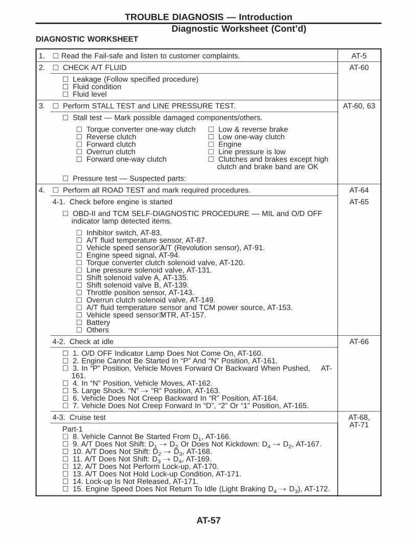
DIAGNOSTIC WORKSHEET
1. l Read the Fail-safe and listen to customer complaints. AT-5
2. l CHECK A/T FLUID AT-60
l Leakage (Follow specified procedure)l Fluid conditionl Fluid level
3. l Perform STALL TEST and LINE PRESSURE TEST. AT-60, 63
l Stall test — Mark possible damaged components/others.
l Torque converter one-way clutchl Reverse clutchl Forward clutchl Overrun clutchl Forward one-way clutch
l Low & reverse brakel Low one-way clutchl Enginel Line pressure is lowl Clutches and brakes except high
clutch and brake band are OK
l Pressure test — Suspected parts:
4. l Perform all ROAD TEST and mark required procedures. AT-64
4-1. Check before engine is started AT-65
l OBD-II and TCM SELF-DIAGNOSTIC PROCEDURE — MIL and O/D OFFindicator lamp detected items.
l Inhibitor switch, AT-83.l A/T fluid temperature sensor, AT-87.l Vehicle speed sensor⋅A/T (Revolution sensor), AT-91.l Engine speed signal, AT-94.l Torque converter clutch solenoid valve, AT-120.l Line pressure solenoid valve, AT-131.l Shift solenoid valve A, AT-135.l Shift solenoid valve B, AT-139.l Throttle position sensor, AT-143.l Overrun clutch solenoid valve, AT-149.l A/T fluid temperature sensor and TCM power source, AT-153.l Vehicle speed sensor⋅MTR, AT-157.l Batteryl Others
4-2. Check at idle AT-66
l 1. O/D OFF Indicator Lamp Does Not Come On, AT-160.l 2. Engine Cannot Be Started In “P” And “N” Position, AT-161.l 3. In “P” Position, Vehicle Moves Forward Or Backward When Pushed, AT-
161.l 4. In “N” Position, Vehicle Moves, AT-162.l 5. Large Shock. “N” , “R” Position, AT-163.l 6. Vehicle Does Not Creep Backward In “R” Position, AT-164.l 7. Vehicle Does Not Creep Forward In “D”, “2” Or “1” Position, AT-165.
4-3. Cruise test AT-68,AT-71Part-1
l 8. Vehicle Cannot Be Started From D1, AT-166.l 9. A/T Does Not Shift: D1 , D2 Or Does Not Kickdown: D4 , D2, AT-167.l 10. A/T Does Not Shift: D2 , D3, AT-168.l 11. A/T Does Not Shift: D3 , D4, AT-169.l 12. A/T Does Not Perform Lock-up, AT-170.l 13. A/T Does Not Hold Lock-up Condition, AT-171.l 14. Lock-up Is Not Released, AT-171.l 15. Engine Speed Does Not Return To Idle (Light Braking D4 , D3), AT-172.
TROUBLE DIAGNOSIS — IntroductionDiagnostic Worksheet (Cont’d)
AT-57
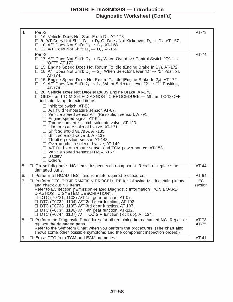
4. Part-2l 16. Vehicle Does Not Start From D1, AT-173.l 9. A/T Does Not Shift: D1 , D2 Or Does Not Kickdown: D4 , D2, AT-167.l 10. A/T Does Not Shift: D2 , D3, AT-168.l 11. A/T Does Not Shift: D3 , D4, AT-169.
AT-73
Part-3l 17. A/T Does Not Shift: D4 , D3 When Overdrive Control Switch “ON” ,
“OFF”, AT-173l 15. Engine Speed Does Not Return To Idle (Engine Brake In D3), AT-172.l 18. A/T Does Not Shift: D3 , 22, When Selector Lever “D” , “2” Position,
AT-174.l 15. Engine Speed Does Not Return To Idle (Engine Brake In 22), AT-172.l 19. A/T Does Not Shift: 22 , 11, When Selector Lever “2” , “1” Position,
AT-174.l 20. Vehicle Does Not Decelerate By Engine Brake, AT-175.l OBD-II and TCM SELF-DIAGNOSTIC PROCEDURE — MIL and O/D OFF
indicator lamp detected items.
AT-74
l Inhibitor switch, AT-83.l A/T fluid temperature sensor, AT-87.l Vehicle speed sensor⋅A/T (Revolution sensor), AT-91.l Engine speed signal, AT-94.l Torque converter clutch solenoid valve, AT-120.l Line pressure solenoid valve, AT-131.l Shift solenoid valve A, AT-135.l Shift solenoid valve B, AT-139.l Throttle position sensor, AT-143.l Overrun clutch solenoid valve, AT-149.l A/T fluid temperature sensor and TCM power source, AT-153.l Vehicle speed sensor⋅MTR, AT-157.l Batteryl Others
5. l For self-diagnosis NG items, inspect each component. Repair or replace thedamaged parts.
AT-44
6. l Perform all ROAD TEST and re-mark required procedures. AT-647. l Perform DTC CONFIRMATION PROCEDURE for following MIL indicating items
and check out NG items.Refer to EC section [“Emission-related Diagnostic Information”, “ON BOARDDIAGNOSTIC SYSTEM DESCRIPTION”].l DTC (P0731, 1103) A/T 1st gear function, AT-97.l DTC (P0732, 1104) A/T 2nd gear function, AT-102.l DTC (P0733, 1105) A/T 3rd gear function, AT-107.l DTC (P0734, 1106) A/T 4th gear function, AT-112.l DTC (P0744, 1107) A/T TCC S/V function (lock-up), AT-124.
ECsection
8. l Perform the Diagnostic Procedures for all remaining items marked NG. Repair orreplace the damaged parts.Refer to the Symptom Chart when you perform the procedures. (The chart alsoshows some other possible symptoms and the component inspection orders.)
AT-78AT-75
9. l Erase DTC from TCM and ECM memories. AT-41
TROUBLE DIAGNOSIS — IntroductionDiagnostic Worksheet (Cont’d)
AT-58
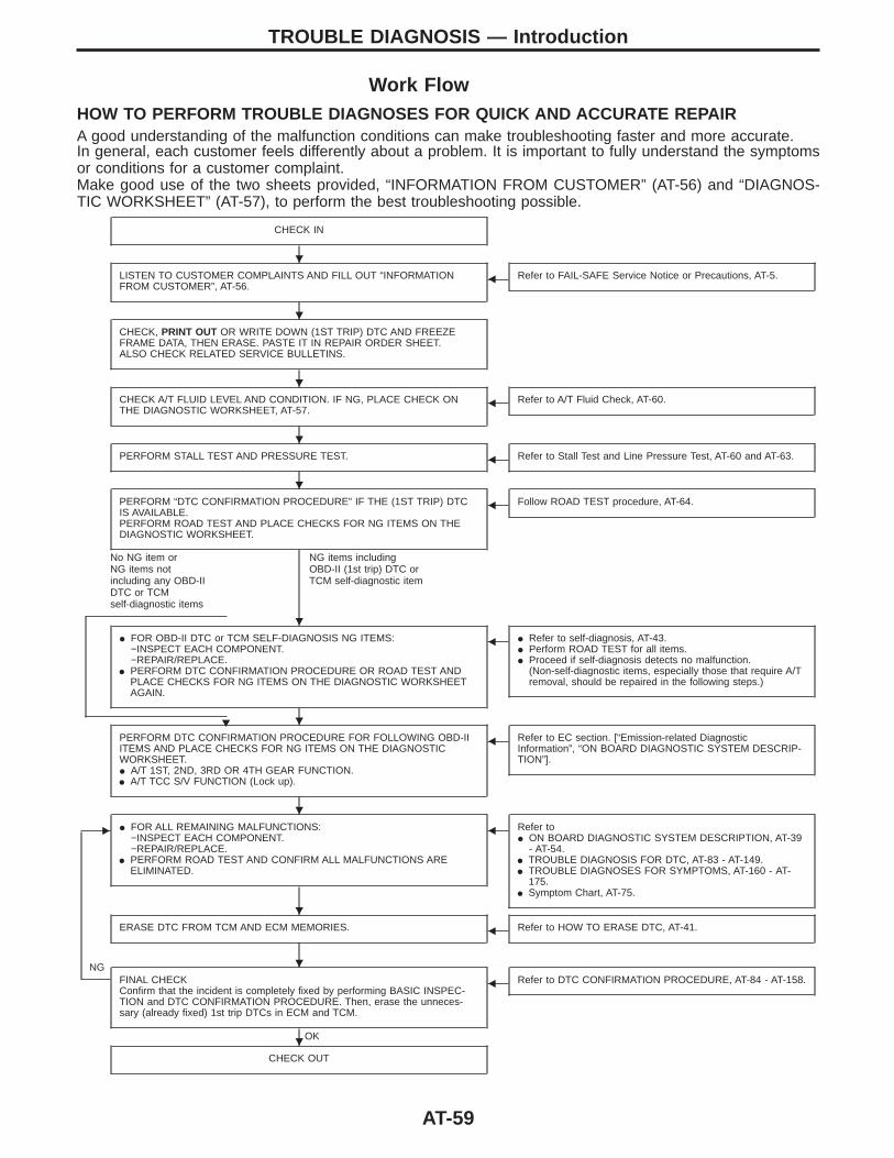
Work FlowHOW TO PERFORM TROUBLE DIAGNOSES FOR QUICK AND ACCURATE REPAIRA good understanding of the malfunction conditions can make troubleshooting faster and more accurate.In general, each customer feels differently about a problem. It is important to fully understand the symptomsor conditions for a customer complaint.Make good use of the two sheets provided, “INFORMATION FROM CUSTOMER” (AT-56) and “DIAGNOS-TIC WORKSHEET” (AT-57), to perform the best troubleshooting possible.
CHECK IN
LISTEN TO CUSTOMER COMPLAINTS AND FILL OUT “INFORMATIONFROM CUSTOMER”, AT-56.
F Refer to FAIL-SAFE Service Notice or Precautions, AT-5.
CHECK, PRINT OUT OR WRITE DOWN (1ST TRIP) DTC AND FREEZEFRAME DATA, THEN ERASE. PASTE IT IN REPAIR ORDER SHEET.ALSO CHECK RELATED SERVICE BULLETINS.
CHECK A/T FLUID LEVEL AND CONDITION. IF NG, PLACE CHECK ONTHE DIAGNOSTIC WORKSHEET, AT-57.
F Refer to A/T Fluid Check, AT-60.
PERFORM STALL TEST AND PRESSURE TEST. F Refer to Stall Test and Line Pressure Test, AT-60 and AT-63.
PERFORM “DTC CONFIRMATION PROCEDURE” IF THE (1ST TRIP) DTCIS AVAILABLE.PERFORM ROAD TEST AND PLACE CHECKS FOR NG ITEMS ON THEDIAGNOSTIC WORKSHEET.
No NG item orNG items notincluding any OBD-IIDTC or TCMself-diagnostic items
NG items includingOBD-II (1st trip) DTC orTCM self-diagnostic item
F Follow ROAD TEST procedure, AT-64.
I FOR OBD-II DTC or TCM SELF-DIAGNOSIS NG ITEMS:−INSPECT EACH COMPONENT.−REPAIR/REPLACE.
I PERFORM DTC CONFIRMATION PROCEDURE OR ROAD TEST ANDPLACE CHECKS FOR NG ITEMS ON THE DIAGNOSTIC WORKSHEETAGAIN.
H
F I Refer to self-diagnosis, AT-43.I Perform ROAD TEST for all items.I Proceed if self-diagnosis detects no malfunction.
(Non-self-diagnostic items, especially those that require A/Tremoval, should be repaired in the following steps.)
PERFORM DTC CONFIRMATION PROCEDURE FOR FOLLOWING OBD-IIITEMS AND PLACE CHECKS FOR NG ITEMS ON THE DIAGNOSTICWORKSHEET.I A/T 1ST, 2ND, 3RD OR 4TH GEAR FUNCTION.I A/T TCC S/V FUNCTION (Lock up).
F Refer to EC section. [“Emission-related DiagnosticInformation”, “ON BOARD DIAGNOSTIC SYSTEM DESCRIP-TION”].
E I FOR ALL REMAINING MALFUNCTIONS:−INSPECT EACH COMPONENT.−REPAIR/REPLACE.
I PERFORM ROAD TEST AND CONFIRM ALL MALFUNCTIONS AREELIMINATED.
F Refer toI ON BOARD DIAGNOSTIC SYSTEM DESCRIPTION, AT-39
- AT-54.I TROUBLE DIAGNOSIS FOR DTC, AT-83 - AT-149.I TROUBLE DIAGNOSES FOR SYMPTOMS, AT-160 - AT-
175.I Symptom Chart, AT-75.
ERASE DTC FROM TCM AND ECM MEMORIES. F Refer to HOW TO ERASE DTC, AT-41.
NGFINAL CHECKConfirm that the incident is completely fixed by performing BASIC INSPEC-TION and DTC CONFIRMATION PROCEDURE. Then, erase the unneces-sary (already fixed) 1st trip DTCs in ECM and TCM.
OK
F Refer to DTC CONFIRMATION PROCEDURE, AT-84 - AT-158.
CHECK OUT
TROUBLE DIAGNOSIS — Introduction
H
H
H
H
H
H
H
H
H
H
H
AT-59
SAT767B
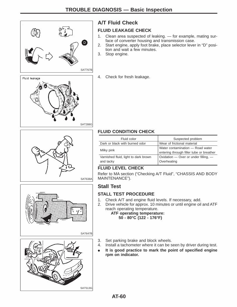
A/T Fluid CheckFLUID LEAKAGE CHECK1. Clean area suspected of leaking. — for example, mating sur-
face of converter housing and transmission case.2. Start engine, apply foot brake, place selector lever in “D” posi-
tion and wait a few minutes.3. Stop engine.
SAT288G
4. Check for fresh leakage.
SAT638A
FLUID CONDITION CHECK
Fluid color Suspected problemDark or black with burned odor Wear of frictional material
Milky pinkWater contamination — Road waterentering through filler tube or breather
Varnished fluid, light to dark brownand tacky
Oxidation — Over or under filling, —Overheating
FLUID LEVEL CHECKRefer to MA section (“Checking A/T Fluid”, “CHASSIS AND BODYMAINTENANCE”).
SAT647B
Stall TestSTALL TEST PROCEDURE1. Check A/T and engine fluid levels. If necessary, add.2. Drive vehicle for approx. 10 minutes or until engine oil and ATF
reach operating temperature.ATF operating temperature:
50 - 80°C (122 - 176°F)
SAT513G
3. Set parking brake and block wheels.4. Install a tachometer where it can be seen by driver during test.I It is good practice to mark the point of specified engine
rpm on indicator.
TROUBLE DIAGNOSIS — Basic Inspection
AT-60
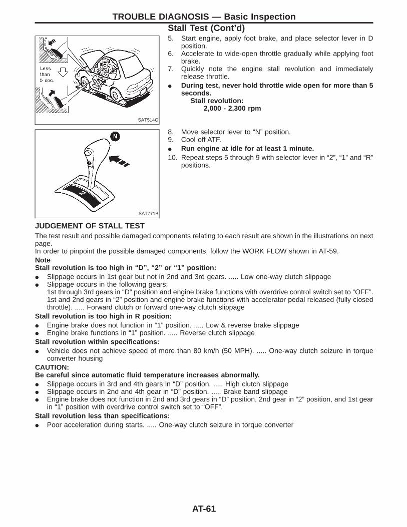
SAT514G
5. Start engine, apply foot brake, and place selector lever in Dposition.
6. Accelerate to wide-open throttle gradually while applying footbrake.
7. Quickly note the engine stall revolution and immediatelyrelease throttle.
I During test, never hold throttle wide open for more than 5seconds.
Stall revolution:2,000 - 2,300 rpm
SAT771B
8. Move selector lever to “N” position.9. Cool off ATF.I Run engine at idle for at least 1 minute.10. Repeat steps 5 through 9 with selector lever in “2”, “1” and “R”
positions.
JUDGEMENT OF STALL TESTThe test result and possible damaged components relating to each result are shown in the illustrations on nextpage.In order to pinpoint the possible damaged components, follow the WORK FLOW shown in AT-59.NoteStall revolution is too high in “D”, “2” or “1” position:I Slippage occurs in 1st gear but not in 2nd and 3rd gears. ..... Low one-way clutch slippageI Slippage occurs in the following gears:
1st through 3rd gears in “D” position and engine brake functions with overdrive control switch set to “OFF”.1st and 2nd gears in “2” position and engine brake functions with accelerator pedal released (fully closedthrottle). ..... Forward clutch or forward one-way clutch slippage
Stall revolution is too high in R position:I Engine brake does not function in “1” position. ..... Low & reverse brake slippageI Engine brake functions in “1” position. ..... Reverse clutch slippageStall revolution within specifications:I Vehicle does not achieve speed of more than 80 km/h (50 MPH). ..... One-way clutch seizure in torque
converter housingCAUTION:Be careful since automatic fluid temperature increases abnormally.I Slippage occurs in 3rd and 4th gears in “D” position. ..... High clutch slippageI Slippage occurs in 2nd and 4th gear in “D” position. ..... Brake band slippageI Engine brake does not function in 2nd and 3rd gears in “D” position, 2nd gear in “2” position, and 1st gear
in “1” position with overdrive control switch set to “OFF”.Stall revolution less than specifications:I Poor acceleration during starts. ..... One-way clutch seizure in torque converter
TROUBLE DIAGNOSIS — Basic InspectionStall Test (Cont’d)
AT-61
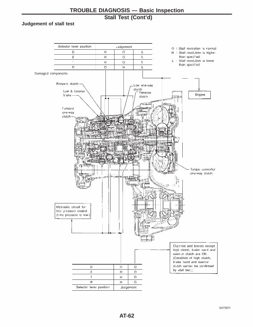
Judgement of stall test
SAT907I
TROUBLE DIAGNOSIS — Basic InspectionStall Test (Cont’d)
AT-62
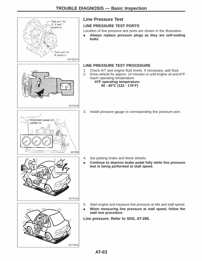
SAT301FA
Line Pressure TestLINE PRESSURE TEST PORTSLocation of line pressure test ports are shown in the illustration.I Always replace pressure plugs as they are self-sealing
bolts.
SAT647B
LINE PRESSURE TEST PROCEDURE1. Check A/T and engine fluid levels. If necessary, add fluid.2. Drive vehicle for approx. 10 minutes or until engine oil and ATF
reach operating temperature.ATF operating temperature:
50 - 80°C (122 - 176°F)
AAT898
3. Install pressure gauge to corresponding line pressure port.
SAT513G
4. Set parking brake and block wheels.I Continue to depress brake pedal fully while line pressure
test is being performed at stall speed.
SAT493G
5. Start engine and measure line pressure at idle and stall speed.I When measuring line pressure at stall speed, follow the
stall test procedure.
Line pressure: Refer to SDS, AT-285.
TROUBLE DIAGNOSIS — Basic Inspection
AT-63
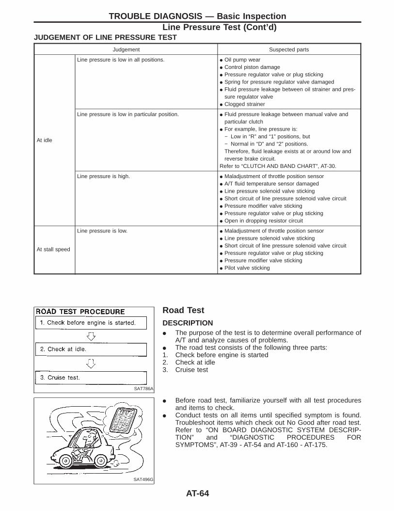
JUDGEMENT OF LINE PRESSURE TEST
Judgement Suspected parts
At idle
Line pressure is low in all positions. I Oil pump wearI Control piston damageI Pressure regulator valve or plug stickingI Spring for pressure regulator valve damagedI Fluid pressure leakage between oil strainer and pres-
sure regulator valveI Clogged strainer
Line pressure is low in particular position. I Fluid pressure leakage between manual valve andparticular clutch
I For example, line pressure is:− Low in “R” and “1” positions, but− Normal in “D” and “2” positions.Therefore, fluid leakage exists at or around low andreverse brake circuit.
Refer to “CLUTCH AND BAND CHART”, AT-30.
Line pressure is high. I Maladjustment of throttle position sensorI A/T fluid temperature sensor damagedI Line pressure solenoid valve stickingI Short circuit of line pressure solenoid valve circuitI Pressure modifier valve stickingI Pressure regulator valve or plug stickingI Open in dropping resistor circuit
At stall speed
Line pressure is low. I Maladjustment of throttle position sensorI Line pressure solenoid valve stickingI Short circuit of line pressure solenoid valve circuitI Pressure regulator valve or plug stickingI Pressure modifier valve stickingI Pilot valve sticking
SAT786A
Road TestDESCRIPTIONI The purpose of the test is to determine overall performance of
A/T and analyze causes of problems.I The road test consists of the following three parts:1. Check before engine is started2. Check at idle3. Cruise test
SAT496G
I Before road test, familiarize yourself with all test proceduresand items to check.
I Conduct tests on all items until specified symptom is found.Troubleshoot items which check out No Good after road test.Refer to “ON BOARD DIAGNOSTIC SYSTEM DESCRIP-TION” and “DIAGNOSTIC PROCEDURES FORSYMPTOMS”, AT-39 - AT-54 and AT-160 - AT-175.
TROUBLE DIAGNOSIS — Basic InspectionLine Pressure Test (Cont’d)
AT-64
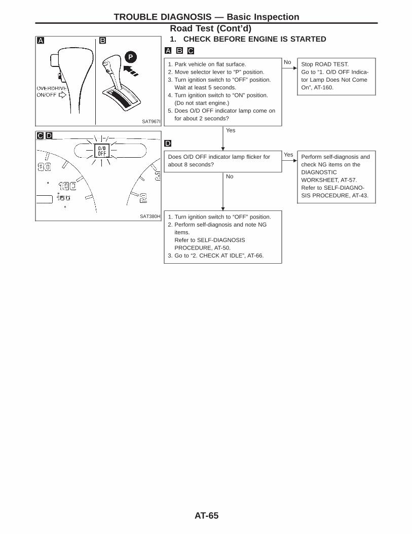
SAT967I
1. CHECK BEFORE ENGINE IS STARTED
SAT380H
1. Park vehicle on flat surface.2. Move selector lever to “P” position.3. Turn ignition switch to “OFF” position.
Wait at least 5 seconds.4. Turn ignition switch to “ON” position.
(Do not start engine.)5. Does O/D OFF indicator lamp come on
for about 2 seconds?
Yes
ENo Stop ROAD TEST.
Go to “1. O/D OFF Indica-tor Lamp Does Not ComeOn”, AT-160.
Does O/D OFF indicator lamp flicker forabout 8 seconds?
No
EYes Perform self-diagnosis and
check NG items on theDIAGNOSTICWORKSHEET, AT-57.Refer to SELF-DIAGNO-SIS PROCEDURE, AT-43.
1. Turn ignition switch to “OFF” position.2. Perform self-diagnosis and note NG
items.Refer to SELF-DIAGNOSISPROCEDURE, AT-50.
3. Go to “2. CHECK AT IDLE”, AT-66.
TROUBLE DIAGNOSIS — Basic InspectionRoad Test (Cont’d)
H
H
AT-65
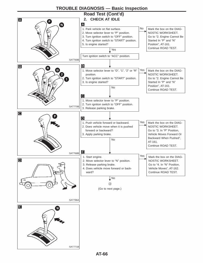
SAT769B
2. CHECK AT IDLE
SAT770B
SAT768B
SAT796A
SAT771B
1. Park vehicle on flat surface.2. Move selector lever to “P” position.3. Turn ignition switch to “OFF” position.4. Turn ignition switch to “START” position.5. Is engine started?
Yes
ENo Mark the box on the DIAG-
NOSTIC WORKSHEET.Go to “2. Engine Cannot BeStarted In “P” and “N”Position”, AT-161.Continue ROAD TEST.
Turn ignition switch to “ACC” position.
1. Move selector lever to “D”, “1”, “2” or “R”position.
2. Turn ignition switch to “START” position.3. Is engine started?
No
EYes Mark the box on the DIAG-
NOSTIC WORKSHEET.Go to “2. Engine Cannot BeStarted In “P” and “N”Position”, AT-161.Continue ROAD TEST.
1. Move selector lever to “P” position.2. Turn ignition switch to “OFF” position.3. Release parking brake.
1. Push vehicle forward or backward.2. Does vehicle move when it is pushed
forward or backward?3. Apply parking brake.
No
EYes Mark the box on the DIAG-
NOSTIC WORKSHEET.Go to “3. In “P” Position,Vehicle Moves Forward OrBackward When Pushed”,AT-161.Continue ROAD TEST.
1. Start engine.2. Move selector lever to “N” position.3. Release parking brake.4. Does vehicle move forward or back-
ward?
No
EYes Mark the box on the DIAG-
NOSTIC WORKSHEET.Go to “4. In “N” Position,Vehicle Moves”, AT-162.Continue ROAD TEST.
qA
(Go to next page.)
TROUBLE DIAGNOSIS — Basic InspectionRoad Test (Cont’d)
H
H
H
H
H
H
AT-66
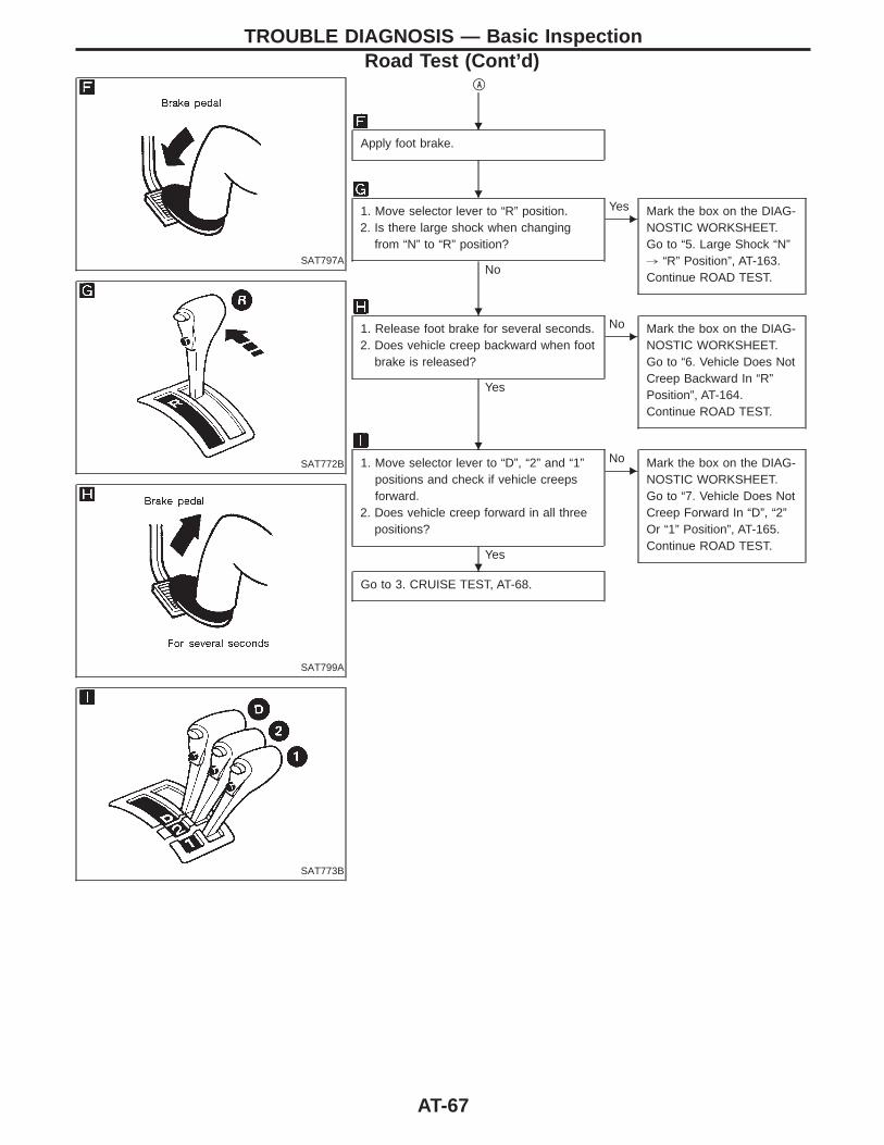
SAT797A
SAT772B
SAT799A
SAT773B
qA
Apply foot brake.
1. Move selector lever to “R” position.2. Is there large shock when changing
from “N” to “R” position?
No
EYes Mark the box on the DIAG-
NOSTIC WORKSHEET.Go to “5. Large Shock “N”, “R” Position”, AT-163.Continue ROAD TEST.
1. Release foot brake for several seconds.2. Does vehicle creep backward when foot
brake is released?
Yes
ENo Mark the box on the DIAG-
NOSTIC WORKSHEET.Go to “6. Vehicle Does NotCreep Backward In “R”Position”, AT-164.Continue ROAD TEST.
1. Move selector lever to “D”, “2” and “1”positions and check if vehicle creepsforward.
2. Does vehicle creep forward in all threepositions?
Yes
ENo Mark the box on the DIAG-
NOSTIC WORKSHEET.Go to “7. Vehicle Does NotCreep Forward In “D”, “2”Or “1” Position”, AT-165.Continue ROAD TEST.
Go to 3. CRUISE TEST, AT-68.
TROUBLE DIAGNOSIS — Basic InspectionRoad Test (Cont’d)
H
H
H
H
H
AT-67
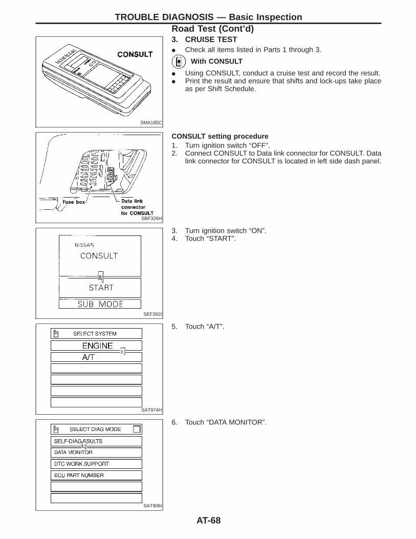
SMA185C
3. CRUISE TESTI Check all items listed in Parts 1 through 3.
With CONSULT
I Using CONSULT, conduct a cruise test and record the result.I Print the result and ensure that shifts and lock-ups take place
as per Shift Schedule.
SBF326H
CONSULT setting procedure1. Turn ignition switch “OFF”.2. Connect CONSULT to Data link connector for CONSULT. Data
link connector for CONSULT is located in left side dash panel.
SEF392I
3. Turn ignition switch “ON”.4. Touch “START”.
SAT974H
5. Touch “A/T”.
SAT906I
6. Touch “DATA MONITOR”.
TROUBLE DIAGNOSIS — Basic InspectionRoad Test (Cont’d)
AT-68

SAT902H
7. Touch “SETTING” to set recording condition.
SAT297C
8. Touch “LONG TIME” and “ENTER” key.
SAT903H
9. Go back to SELECT MONITOR ITEM and touch “MAIN SIG-NALS”.
10. Touch “START”.
SAT071H
11. When performing cruise test, touch “RECORD”.
SAT072H
12. After finishing cruise test part 1, touch “STOP”.
TROUBLE DIAGNOSIS — Basic InspectionRoad Test (Cont’d)
AT-69
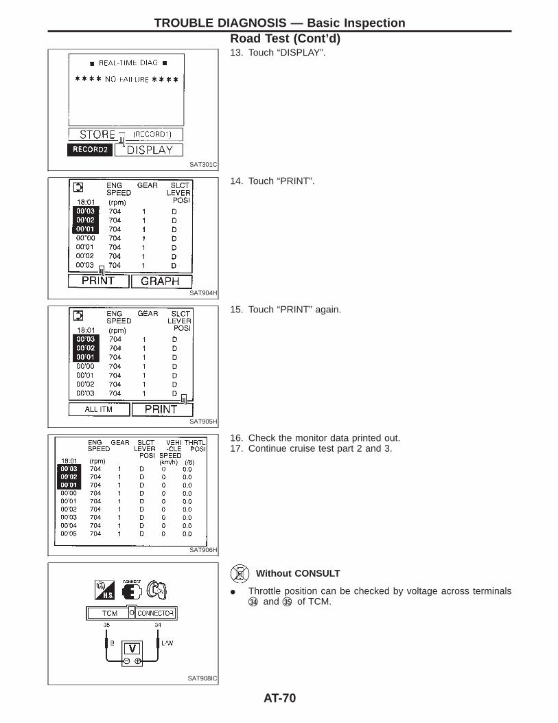
SAT301C
13. Touch “DISPLAY”.
SAT904H
14. Touch “PRINT”.
SAT905H
15. Touch “PRINT” again.
SAT906H
16. Check the monitor data printed out.17. Continue cruise test part 2 and 3.
SAT908IC
Without CONSULT
I Throttle position can be checked by voltage across terminalsq34 and q35 of TCM.
TROUBLE DIAGNOSIS — Basic InspectionRoad Test (Cont’d)
AT-70
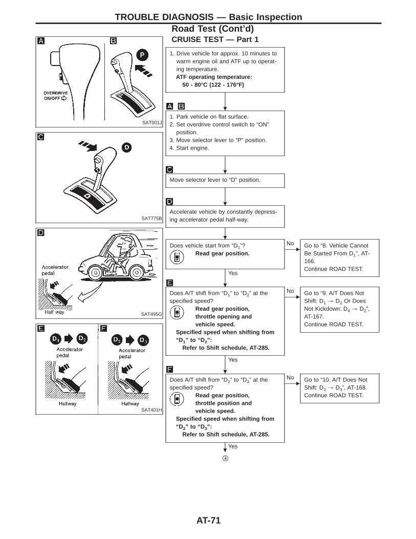
SAT001J
CRUISE TEST — Part 1
SAT775B
SAT495G
SAT401H
1. Drive vehicle for approx. 10 minutes towarm engine oil and ATF up to operat-ing temperature.ATF operating temperature:
50 - 80°C (122 - 176°F)
1. Park vehicle on flat surface.2. Set overdrive control switch to “ON”
position.3. Move selector lever to “P” position.4. Start engine.
Move selector lever to “D” position.
Accelerate vehicle by constantly depress-ing accelerator pedal half-way.
Does vehicle start from “D1”?Read gear position.
Yes
ENo Go to “8. Vehicle Cannot
Be Started From D1”, AT-166.Continue ROAD TEST.
Does A/T shift from “D1” to “D2” at thespecified speed?
Read gear position,throttle opening andvehicle speed.
Specified speed when shifting from“D 1” to “D 2”:
Refer to Shift schedule, AT-285.
Yes
ENo Go to “9. A/T Does Not
Shift: D1 , D2 Or DoesNot Kickdown: D4 , D2”,AT-167.Continue ROAD TEST.
Does A/T shift from “D2” to “D3” at thespecified speed?
Read gear position,throttle position andvehicle speed.
Specified speed when shifting from“D 2” to “D 3”:
Refer to Shift schedule, AT-285.
Yes
ENo Go to “10. A/T Does Not
Shift: D2 , D3”, AT-168.Continue ROAD TEST.
qA
TROUBLE DIAGNOSIS — Basic InspectionRoad Test (Cont’d)
H
H
H
H
H
H
H
AT-71
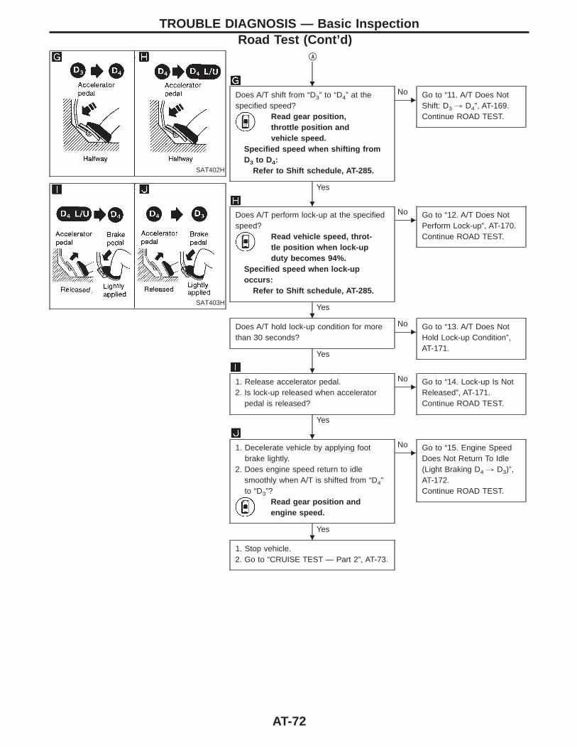
SAT402H
SAT403H
qA
Does A/T shift from “D3” to “D4” at thespecified speed?
Read gear position,throttle position andvehicle speed.
Specified speed when shifting fromD3 to D4:
Refer to Shift schedule, AT-285.
Yes
ENo Go to “11. A/T Does Not
Shift: D3 , D4”, AT-169.Continue ROAD TEST.
Does A/T perform lock-up at the specifiedspeed?
Read vehicle speed, throt-tle position when lock-upduty becomes 94%.
Specified speed when lock-upoccurs:
Refer to Shift schedule, AT-285.
Yes
ENo Go to “12. A/T Does Not
Perform Lock-up”, AT-170.Continue ROAD TEST.
Does A/T hold lock-up condition for morethan 30 seconds?
Yes
ENo Go to “13. A/T Does Not
Hold Lock-up Condition”,AT-171.
1. Release accelerator pedal.2. Is lock-up released when accelerator
pedal is released?
Yes
ENo Go to “14. Lock-up Is Not
Released”, AT-171.Continue ROAD TEST.
1. Decelerate vehicle by applying footbrake lightly.
2. Does engine speed return to idlesmoothly when A/T is shifted from “D4”to “D3”?
Read gear position andengine speed.
Yes
ENo Go to “15. Engine Speed
Does Not Return To Idle(Light Braking D4 , D3)”,AT-172.Continue ROAD TEST.
1. Stop vehicle.2. Go to “CRUISE TEST — Part 2”, AT-73.
TROUBLE DIAGNOSIS — Basic InspectionRoad Test (Cont’d)
H
H
H
H
H
H
AT-72
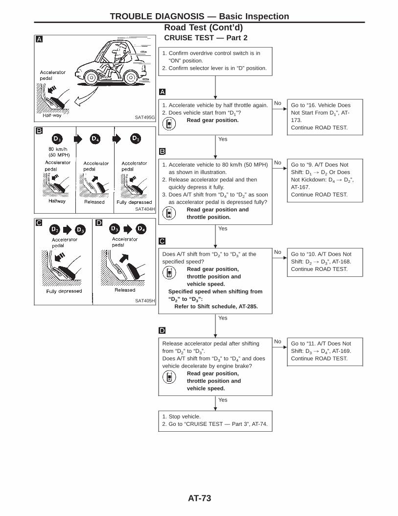
SAT495G
CRUISE TEST — Part 2
SAT404H
SAT405H
1. Confirm overdrive control switch is in“ON” position.
2. Confirm selector lever is in “D” position.
1. Accelerate vehicle by half throttle again.2. Does vehicle start from “D1”?
Read gear position.
Yes
ENo Go to “16. Vehicle Does
Not Start From D1”, AT-173.Continue ROAD TEST.
1. Accelerate vehicle to 80 km/h (50 MPH)as shown in illustration.
2. Release accelerator pedal and thenquickly depress it fully.
3. Does A/T shift from “D4” to “D2” as soonas accelerator pedal is depressed fully?
Read gear position andthrottle position.
Yes
ENo Go to “9. A/T Does Not
Shift: D1 , D2 Or DoesNot Kickdown: D4 , D2”,AT-167.Continue ROAD TEST.
Does A/T shift from “D2” to “D3” at thespecified speed?
Read gear position,throttle position andvehicle speed.
Specified speed when shifting from“D 2” to “D 3”:
Refer to Shift schedule, AT-285.
Yes
ENo Go to “10. A/T Does Not
Shift: D2 , D3”, AT-168.Continue ROAD TEST.
Release accelerator pedal after shiftingfrom “D2” to “D3”.Does A/T shift from “D3” to “D4” and doesvehicle decelerate by engine brake?
Read gear position,throttle position andvehicle speed.
Yes
ENo Go to “11. A/T Does Not
Shift: D3 , D4”, AT-169.Continue ROAD TEST.
1. Stop vehicle.2. Go to “CRUISE TEST — Part 3”, AT-74.
TROUBLE DIAGNOSIS — Basic InspectionRoad Test (Cont’d)
H
H
H
H
H
AT-73
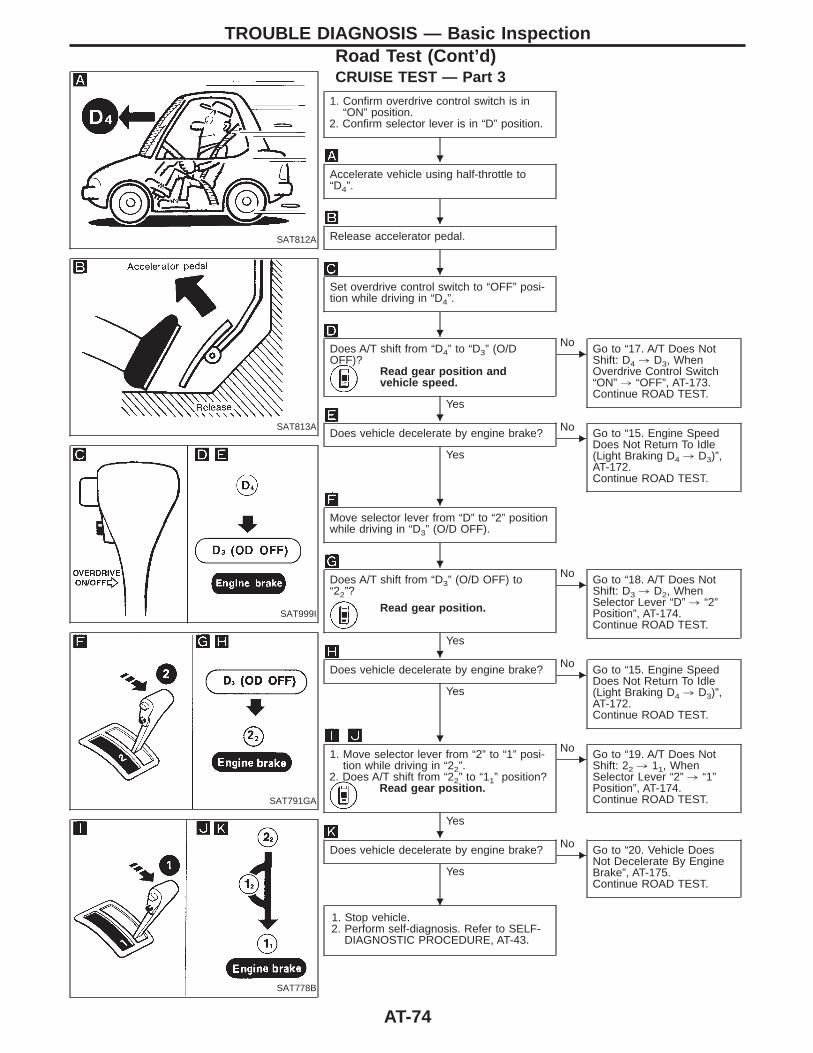
SAT812A
CRUISE TEST — Part 3
SAT813A
SAT999I
SAT791GA
SAT778B
1. Confirm overdrive control switch is in“ON” position.
2. Confirm selector lever is in “D” position.
Accelerate vehicle using half-throttle to“D4”.
Release accelerator pedal.
Set overdrive control switch to “OFF” posi-tion while driving in “D4”.
Does A/T shift from “D4” to “D3” (O/DOFF)?
Read gear position andvehicle speed.
Yes
ENo Go to “17. A/T Does Not
Shift: D4 , D3, WhenOverdrive Control Switch“ON” , “OFF”, AT-173.Continue ROAD TEST.
Does vehicle decelerate by engine brake?
Yes
ENo Go to “15. Engine Speed
Does Not Return To Idle(Light Braking D4 , D3)”,AT-172.Continue ROAD TEST.
Move selector lever from “D” to “2” positionwhile driving in “D3” (O/D OFF).
Does A/T shift from “D3” (O/D OFF) to“22”?
Read gear position.
Yes
ENo Go to “18. A/T Does Not
Shift: D3 , D2, WhenSelector Lever “D” , “2”Position”, AT-174.Continue ROAD TEST.
Does vehicle decelerate by engine brake?
Yes
ENo Go to “15. Engine Speed
Does Not Return To Idle(Light Braking D4 , D3)”,AT-172.Continue ROAD TEST.
1. Move selector lever from “2” to “1” posi-tion while driving in “22”.
2. Does A/T shift from “22” to “11” position?Read gear position.
Yes
ENo Go to “19. A/T Does Not
Shift: 22 , 11, WhenSelector Lever “2” , “1”Position”, AT-174.Continue ROAD TEST.
Does vehicle decelerate by engine brake?
Yes
ENo Go to “20. Vehicle Does
Not Decelerate By EngineBrake”, AT-175.Continue ROAD TEST.
1. Stop vehicle.2. Perform self-diagnosis. Refer to SELF-
DIAGNOSTIC PROCEDURE, AT-43.
TROUBLE DIAGNOSIS — Basic InspectionRoad Test (Cont’d)
H
H
H
H
H
H
H
H
H
H
H
AT-74
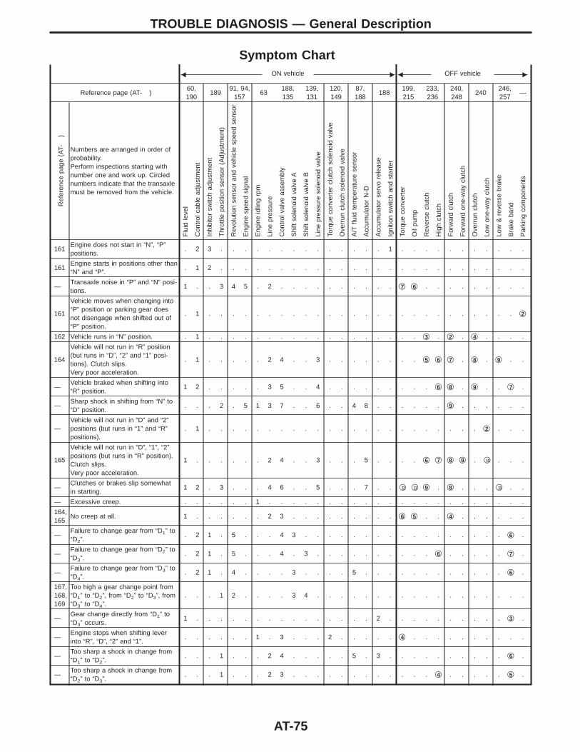
Symptom ChartF ON vehicle E F OFF vehicle E
Reference page (AT- )60,190
18991, 94,
15763
188,135
139,131
120,149
87,188
188199,215
233,236
240,248
240246,257
—
Ref
eren
cepa
ge(A
T-)
Numbers are arranged in order ofprobability.Perform inspections starting withnumber one and work up. Circlednumbers indicate that the transaxlemust be removed from the vehicle.
Flu
idle
vel
Con
trol
cabl
ead
just
men
t
Inhi
bito
rsw
itch
adju
stm
ent
Thr
ottle
posi
tion
sens
or(A
djus
tmen
t)
Rev
olut
ion
sens
oran
dve
hicl
esp
eed
sens
or
Eng
ine
spee
dsi
gnal
Eng
ine
idlin
grp
m
Line
pres
sure
Con
trol
valv
eas
sem
bly
Shi
ftso
leno
idva
lve
A
Shi
ftso
leno
idva
lve
B
Line
pres
sure
sole
noid
valv
e
Torq
ueco
nver
ter
clut
chso
leno
idva
lve
Ove
rrun
clut
chso
leno
idva
lve
A/T
fluid
tem
pera
ture
sens
or
Acc
umul
ator
N-D
Acc
umul
ator
serv
ore
leas
e
Igni
tion
switc
han
dst
arte
r
Torq
ueco
nver
ter
Oil
pum
p
Rev
erse
clut
ch
Hig
hcl
utch
For
war
dcl
utch
For
war
don
e-w
aycl
utch
Ove
rrun
clut
ch
Low
one-
way
clut
ch
Low
&re
vers
ebr
ake
Bra
keba
nd
Par
king
com
pone
nts
161Engine does not start in “N”, “P”positions.
. 2 3 . . . . . . . . . . . . . . 1 . . . . . . . . . . .
161Engine starts in positions other than“N” and “P”.
. 1 2 . . . . . . . . . . . . . . . . . . . . . . . . . .
—Transaxle noise in “P” and “N” posi-tions.
1 . . 3 4 5 . 2 . . . . . . . . . . q7 q6 . . . . . . . . .
161
Vehicle moves when changing into“P” position or parking gear doesnot disengage when shifted out of“P” position.
. 1 . . . . . . . . . . . . . . . . . . . . . . . . . . q2
162 Vehicle runs in “N” position. . 1 . . . . . . . . . . . . . . . . . . q3 . q2 . q4 . . . .
164
Vehicle will not run in “R” position(but runs in “D”, “2” and “1” posi-tions). Clutch slips.Very poor acceleration.
. 1 . . . . . 2 4 . . 3 . . . . . . . . q5 q6 q7 . q8 . q9 . .
—Vehicle braked when shifting into“R” position.
1 2 . . . . . 3 5 . . 4 . . . . . . . . . q6 q8 . q9 . . q7 .
—Sharp shock in shifting from “N” to“D” position.
. . . 2 . 5 1 3 7 . . 6 . . 4 8 . . . . . . q9 . . . . . .
—Vehicle will not run in “D” and “2”positions (but runs in “1” and “R”positions).
. 1 . . . . . . . . . . . . . . . . . . . . . . . q2 . . .
165
Vehicle will not run in “D”, “1”, “2”positions (but runs in “R” position).Clutch slips.Very poor acceleration.
1 . . . . . . 2 4 . . 3 . . . 5 . . . . q6 q7 q8 q9 . q10 . . .
—Clutches or brakes slip somewhatin starting.
1 2 . 3 . . . 4 6 . . 5 . . . 7 . . q12 q11 q9 . q8 . . . q10 . .
— Excessive creep. . . . . . . 1 . . . . . . . . . . . . . . . . . . . . . .
164,165
No creep at all. 1 . . . . . . 2 3 . . . . . . . . . q6 q5 . . q4 . . . . . .
—Failure to change gear from “D1” to“D2”.
. 2 1 . 5 . . . 4 3 . . . . . . . . . . . . . . . . . q6 .
—Failure to change gear from “D2” to“D3”.
. 2 1 . 5 . . . 4 . 3 . . . . . . . . . . q6 . . . . . q7 .
—Failure to change gear from “D3” to“D4”.
. 2 1 . 4 . . . . 3 . . . . 5 . . . . . . . . . . . . q6 .
167,168,169
Too high a gear change point from“D1” to “D2”, from “D2” to “D3”, from“D3” to “D4”.
. . . 1 2 . . . . 3 4 . . . . . . . . . . . . . . . . . .
—Gear change directly from “D1” to“D3” occurs.
1 . . . . . . . . . . . . . . . 2 . . . . . . . . . . q3 .
—Engine stops when shifting leverinto “R”, “D”, “2” and “1”.
. . . . . . 1 . 3 . . . 2 . . . . . q4 . . . . . . . . . .
—Too sharp a shock in change from“D1” to “D2”.
. . . 1 . . . 2 4 . . . . . 5 . 3 . . . . . . . . . . q6 .
—Too sharp a shock in change from“D2” to “D3”.
. . . 1 . . . 2 3 . . . . . . . . . . . . q4 . . . . . q5 .
TROUBLE DIAGNOSIS — General Description
AT-75
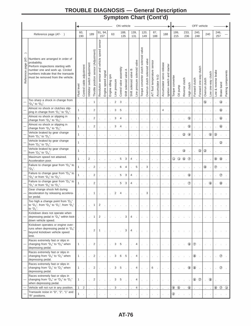
F ON vehicle E F OFF vehicle E
Reference page (AT- )60,190
18991, 94,
15763
188,135
139,131
120,149
87,188
188199,215
233,236
240,248
240246,257
—
Ref
eren
cepa
ge(A
T-)
Numbers are arranged in order ofprobability.Perform inspections starting withnumber one and work up. Circlednumbers indicate that the transaxlemust be removed from the vehicle.
Flu
idle
vel
Con
trol
cabl
ead
just
men
t
Inhi
bito
rsw
itch
adju
stm
ent
Thr
ottle
posi
tion
sens
or(A
djus
tmen
t)
Rev
olut
ion
sens
oran
dve
hicl
esp
eed
sens
or
Eng
ine
spee
dsi
gnal
Eng
ine
idlin
grp
m
Line
pres
sure
Con
trol
valv
eas
sem
bly
Shi
ftso
leno
idva
lve
A
Shi
ftso
leno
idva
lve
B
Line
pres
sure
sole
noid
valv
e
Torq
ueco
nver
ter
clut
chso
leno
idva
lve
Ove
rrun
clut
chso
leno
idva
lve
A/T
fluid
tem
pera
ture
sens
or
Acc
umul
ator
N-D
Acc
umul
ator
serv
ore
leas
e
Igni
tion
switc
han
dst
arte
r
Torq
ueco
nver
ter
Oil
pum
p
Rev
erse
clut
ch
Hig
hcl
utch
For
war
dcl
utch
For
war
don
e-w
aycl
utch
Ove
rrun
clut
ch
Low
one-
way
clut
ch
Low
&re
vers
ebr
ake
Bra
keba
nd
Par
king
com
pone
nts
—Too sharp a shock in change from“D3” to “D4”.
. . . 1 . . . 2 3 . . . . . . . . . . . . . . . q5 . . q4 .
—Almost no shock or clutches slip-ping in change from “D1” to “D2”.
1 . . 2 . . . 3 5 . . . . . . . 4 . . . . . . . . . . q6 .
—Almost no shock or slipping inchange from “D2” to “D3”.
1 . . 2 . . . 3 4 . . . . . . . . . . . . q5 . . . . . q6 .
—Almost no shock or slipping inchange from “D3” to “D4”.
1 . . 2 . . . 3 4 . . . . . . . . . . . . q5 . . . . . q6 .
—Vehicle braked by gear changefrom “D1” to “D2”.
1 . . . . . . . . . . . . . . . . . . . q2 q4 . . . q5 q3 . .
—Vehicle braked by gear changefrom “D2” to “D3”.
1 . . . . . . . . . . . . . . . . . . . . . . . . . . q2 .
—Vehicle braked by gear changefrom “D3” to “D4”.
1 . . . . . . . . . . . . . . . . . . . q4 . . q3 q2 . . . .
—Maximum speed not attained.Acceleration poor.
1 . 2 . . . . . 5 3 4 . . . . . . . q11 q10 q6 q7 . . . . q9 q8 .
—Failure to change gear from “D4” to“D3”.
1 . . 2 . . . . 6 4 . 5 . 3 . . . . . . . . . . q8 . q7 . .
—Failure to change gear from “D3” to“D2” or from “D4” to “D2”.
1 . . 2 . . . . 5 3 4 . . . . . . . . . . q6 . . . . . q7 .
—Failure to change gear from “D2” to“D1” or from “D3” to “D1”.
1 . . 2 . . . . 5 3 4 . . . . . . . . . . q7 . . . q6 . q8 .
—Gear change shock felt duringdeceleration by releasing accelera-tor pedal.
. . . 1 . . . 2 4 . . . . 3 . . . . . . . . . . . . . . .
—Too high a change point from “D4”to “D3”, from “D3” to “D2”, from “D2”to “D1”.
. . . 1 2 . . . . . . . . . . . . . . . . . . . . . . . .
—Kickdown does not operate whendepressing pedal in “D4” within kick-down vehicle speed.
. . . 1 2 . . . . 3 4 . . . . . . . . . . . . . . . . . .
—
Kickdown operates or engine over-runs when depressing pedal in “D4”beyond kickdown vehicle speedlimit.
. . . 2 1 . . . . 3 4 . . . . . . . . . . . . . . . . . .
—Races extremely fast or slips inchanging from “D4” to “D3” whendepressing pedal.
1 . . 2 . . . 3 5 . . 4 . . . . . . . . . q6 q7 . . . . . .
—Races extremely fast or slips inchanging from “D4” to “D2” whendepressing pedal.
1 . . 2 . . . 3 6 5 . 4 . . . . . . . . . . q8 . . . . q7 .
—Races extremely fast or slips inchanging from “D3” to “D2” whendepressing pedal.
1 . . 2 . . . 3 5 . . 4 . . 6 . . . . . . q9 q8 . . . . q7 .
—Races extremely fast or slips inchanging from “D4” or “D3” to “D1”when depressing pedal.
1 . . 2 . . . 3 5 . . 4 . . . . . . . . . . q6 q7 . q8 . . .
— Vehicle will not run in any position. 1 2 . . . . . 3 . . . 4 . . . . . . q9 q5 . q6 . . . . q8 q7 q10
—Transaxle noise in “D”, “2”, “1” and“R” positions.
1 . . . . . . . . . . . . . . . . . q2 . . . . . . . . . .
TROUBLE DIAGNOSIS — General DescriptionSymptom Chart (Cont’d)
AT-76
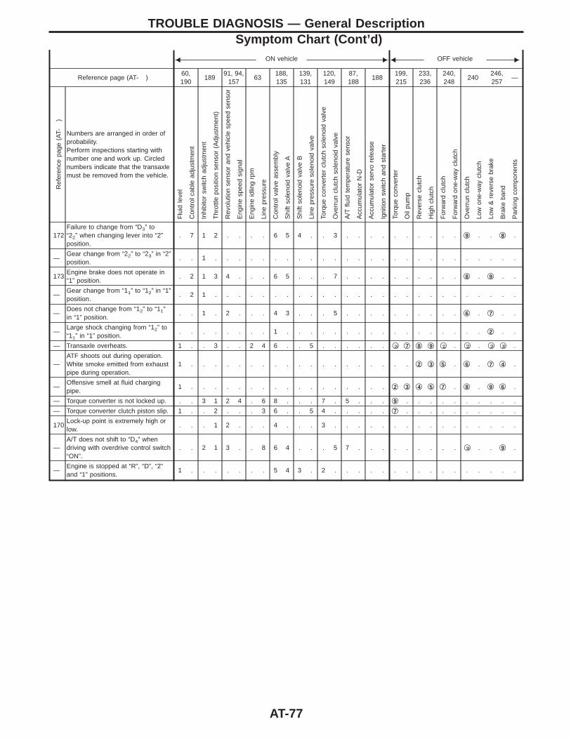
F ON vehicle E F OFF vehicle E
Reference page (AT- )60,190
18991, 94,
15763
188,135
139,131
120,149
87,188
188199,215
233,236
240,248
240246,257
—
Ref
eren
cepa
ge(A
T-)
Numbers are arranged in order ofprobability.Perform inspections starting withnumber one and work up. Circlednumbers indicate that the transaxlemust be removed from the vehicle.
Flu
idle
vel
Con
trol
cabl
ead
just
men
t
Inhi
bito
rsw
itch
adju
stm
ent
Thr
ottle
posi
tion
sens
or(A
djus
tmen
t)
Rev
olut
ion
sens
oran
dve
hicl
esp
eed
sens
or
Eng
ine
spee
dsi
gnal
Eng
ine
idlin
grp
m
Line
pres
sure
Con
trol
valv
eas
sem
bly
Shi
ftso
leno
idva
lve
A
Shi
ftso
leno
idva
lve
B
Line
pres
sure
sole
noid
valv
e
Torq
ueco
nver
ter
clut
chso
leno
idva
lve
Ove
rrun
clut
chso
leno
idva
lve
A/T
fluid
tem
pera
ture
sens
or
Acc
umul
ator
N-D
Acc
umul
ator
serv
ore
leas
e
Igni
tion
switc
han
dst
arte
r
Torq
ueco
nver
ter
Oil
pum
p
Rev
erse
clut
ch
Hig
hcl
utch
For
war
dcl
utch
For
war
don
e-w
aycl
utch
Ove
rrun
clut
ch
Low
one-
way
clut
ch
Low
&re
vers
ebr
ake
Bra
keba
nd
Par
king
com
pone
nts
172Failure to change from “D3” to“22” when changing lever into “2”position.
. 7 1 2 . . . . 6 5 4 . . 3 . . . . . . . . . . q9 . . q8 .
—Gear change from “22” to “23” in “2”position.
. . 1 . . . . . . . . . . . . . . . . . . . . . . . . . .
173Engine brake does not operate in“1” position.
. 2 1 3 4 . . . 6 5 . . . 7 . . . . . . . . . . q8 . q9 . .
—Gear change from “11” to “12” in “1”position.
. 2 1 . . . . . . . . . . . . . . . . . . . . . . . . . .
—Does not change from “12” to “11”in “1” position.
. . 1 . 2 . . . 4 3 . . . 5 . . . . . . . . . . q6 . q7 . .
—Large shock changing from “12” to“11” in “1” position.
. . . . . . . . 1 . . . . . . . . . . . . . . . . . q2 . .
— Transaxle overheats. 1 . . 3 . . 2 4 6 . . 5 . . . . . . q14 q7 q8 q9 q11 . q12 . q13 q10 .
—ATF shoots out during operation.White smoke emitted from exhaustpipe during operation.
1 . . . . . . . . . . . . . . . . . . . q2 q3 q5 . q6 . q7 q4 .
—Offensive smell at fluid chargingpipe.
1 . . . . . . . . . . . . . . . . . q2 q3 q4 q5 q7 . q8 . q9 q6 .
— Torque converter is not locked up. . . 3 1 2 4 . 6 8 . . . 7 . 5 . . . q9 . . . . . . . . . .
— Torque converter clutch piston slip. 1 . . 2 . . . 3 6 . . 5 4 . . . . . q7 . . . . . . . . . .
170Lock-up point is extremely high orlow.
. . . 1 2 . . . 4 . . . 3 . . . . . . . . . . . . . . . .
—A/T does not shift to “D4” whendriving with overdrive control switch“ON”.
. . 2 1 3 . . 8 6 4 . . . 5 7 . . . . . . . . . q10 . . q9 .
—Engine is stopped at “R”, “D”, “2”and “1” positions.
1 . . . . . . . 5 4 3 . 2 . . . . . . . . . . . . . . . .
TROUBLE DIAGNOSIS — General DescriptionSymptom Chart (Cont’d)
AT-77
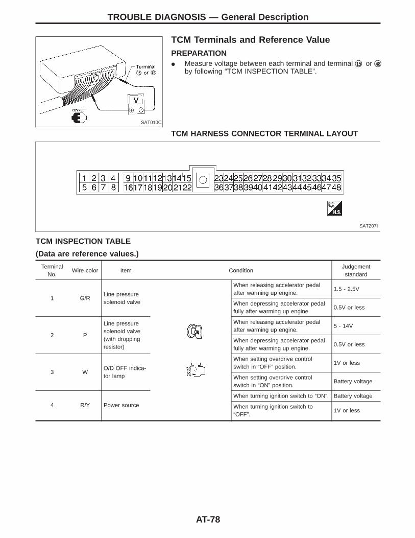
SAT010C
TCM Terminals and Reference ValuePREPARATIONI Measure voltage between each terminal and terminal q15 or q48
by following “TCM INSPECTION TABLE”.
TCM HARNESS CONNECTOR TERMINAL LAYOUT
SAT207I
TCM INSPECTION TABLE
(Data are reference values.)
TerminalNo.
Wire color Item ConditionJudgementstandard
1 G/RLine pressuresolenoid valve
When releasing accelerator pedalafter warming up engine.
1.5 - 2.5V
When depressing accelerator pedalfully after warming up engine.
0.5V or less
2 P
Line pressuresolenoid valve(with droppingresistor)
When releasing accelerator pedalafter warming up engine.
5 - 14V
When depressing accelerator pedalfully after warming up engine.
0.5V or less
3 WO/D OFF indica-tor lamp
When setting overdrive controlswitch in “OFF” position.
1V or less
When setting overdrive controlswitch in “ON” position.
Battery voltage
4 R/Y Power source
When turning ignition switch to “ON”. Battery voltage
When turning ignition switch to“OFF”.
1V or less
TROUBLE DIAGNOSIS — General Description
AT-78
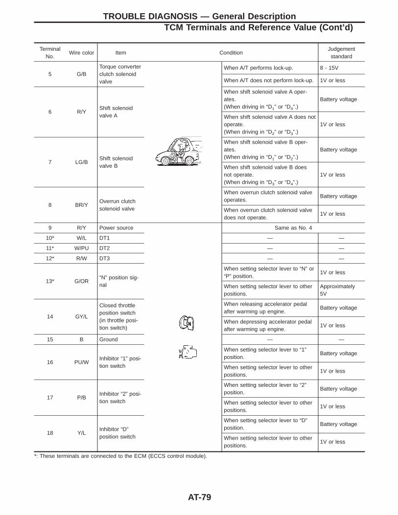
TerminalNo.
Wire color Item ConditionJudgementstandard
5 G/BTorque converterclutch solenoidvalve
When A/T performs lock-up. 8 - 15V
When A/T does not perform lock-up. 1V or less
6 R/YShift solenoidvalve A
When shift solenoid valve A oper-ates.(When driving in “D1” or “D4”.)
Battery voltage
When shift solenoid valve A does notoperate.(When driving in “D2” or “D3”.)
1V or less
7 LG/BShift solenoidvalve B
When shift solenoid valve B oper-ates.(When driving in “D1” or “D2”.)
Battery voltage
When shift solenoid valve B doesnot operate.(When driving in “D3” or “D4”.)
1V or less
8 BR/YOverrun clutchsolenoid valve
When overrun clutch solenoid valveoperates.
Battery voltage
When overrun clutch solenoid valvedoes not operate.
1V or less
9 R/Y Power source Same as No. 4
10* W/L DT1 — —
11* W/PU DT2 — —
12* R/W DT3 — —
13* G/OR“N” position sig-nal
When setting selector lever to “N” or“P” position.
1V or less
When setting selector lever to otherpositions.
Approximately5V
14 GY/L
Closed throttleposition switch(in throttle posi-tion switch)
When releasing accelerator pedalafter warming up engine.
Battery voltage
When depressing accelerator pedalafter warming up engine.
1V or less
15 B Ground — —
16 PU/WInhibitor “1” posi-tion switch
When setting selector lever to “1”position.
Battery voltage
When setting selector lever to otherpositions.
1V or less
17 P/BInhibitor “2” posi-tion switch
When setting selector lever to “2”position.
Battery voltage
When setting selector lever to otherpositions.
1V or less
18 Y/LInhibitor “D”position switch
When setting selector lever to “D”position.
Battery voltage
When setting selector lever to otherpositions.
1V or less
*: These terminals are connected to the ECM (ECCS control module).
TROUBLE DIAGNOSIS — General DescriptionTCM Terminals and Reference Value (Cont’d)
AT-79
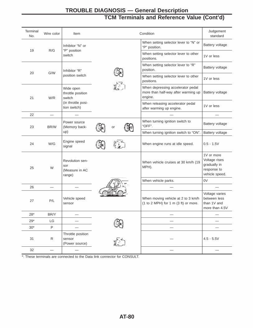
TerminalNo.
Wire color Item ConditionJudgementstandard
19 R/GInhibitor “N” or“P” positionswitch
When setting selector lever to “N” or“P” position.
Battery voltage
When setting selector lever to otherpositions.
1V or less
20 G/WInhibitor “R”position switch
When setting selector lever to “R”position.
Battery voltage
When setting selector lever to otherpositions.
1V or less
21 W/R
Wide openthrottle positionswitch(in throttle posi-tion switch)
When depressing accelerator pedalmore than half-way after warming upengine.
Battery voltage
When releasing accelerator pedalafter warming up engine.
1V or less
22 — — — —
23 BR/WPower source(Memory back-up)
or
When turning ignition switch to“OFF”.
Battery voltage
When turning ignition switch to “ON”. Battery voltage
24 W/GEngine speedsignal
When engine runs at idle speed. 0.5 - 1.5V
25 W
Revolution sen-sor(Measure in ACrange)
When vehicle cruises at 30 km/h (19MPH).
1V or moreVoltage risesgradually inresponse tovehicle speed.
When vehicle parks. 0V
26 — — — —
27 P/LVehicle speedsensor
When moving vehicle at 2 to 3 km/h(1 to 2 MPH) for 1 m (3 ft) or more.
Voltage variesbetween lessthan 1V andmore than 4.5V
28* BR/Y — — —
29* LG — — —
30* P — — —
31 RThrottle positionsensor(Power source)
— 4.5 - 5.5V
32 — — — —
*: These terminals are connected to the Data link connector for CONSULT.
TROUBLE DIAGNOSIS — General DescriptionTCM Terminals and Reference Value (Cont’d)
AT-80
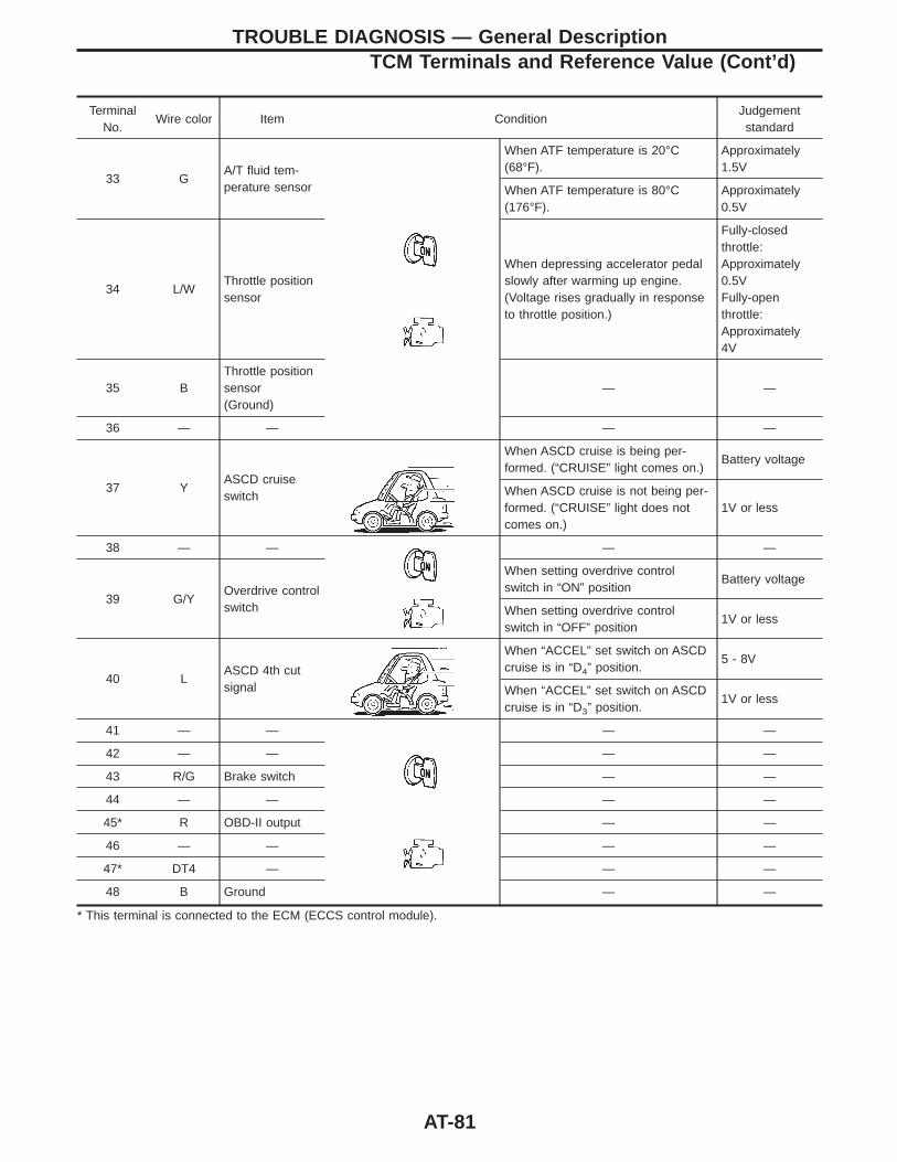
TerminalNo.
Wire color Item ConditionJudgementstandard
33 GA/T fluid tem-perature sensor
When ATF temperature is 20°C(68°F).
Approximately1.5V
When ATF temperature is 80°C(176°F).
Approximately0.5V
34 L/WThrottle positionsensor
When depressing accelerator pedalslowly after warming up engine.(Voltage rises gradually in responseto throttle position.)
Fully-closedthrottle:Approximately0.5VFully-openthrottle:Approximately4V
35 BThrottle positionsensor(Ground)
— —
36 — — — —
37 YASCD cruiseswitch
When ASCD cruise is being per-formed. (“CRUISE” light comes on.)
Battery voltage
When ASCD cruise is not being per-formed. (“CRUISE” light does notcomes on.)
1V or less
38 — — — —
39 G/YOverdrive controlswitch
When setting overdrive controlswitch in “ON” position
Battery voltage
When setting overdrive controlswitch in “OFF” position
1V or less
40 LASCD 4th cutsignal
When “ACCEL” set switch on ASCDcruise is in “D4” position.
5 - 8V
When “ACCEL” set switch on ASCDcruise is in “D3” position.
1V or less
41 — — — —
42 — — — —
43 R/G Brake switch — —
44 — — — —
45* R OBD-II output — —
46 — — — —
47* DT4 — — —
48 B Ground — —
* This terminal is connected to the ECM (ECCS control module).
TROUBLE DIAGNOSIS — General DescriptionTCM Terminals and Reference Value (Cont’d)
AT-81
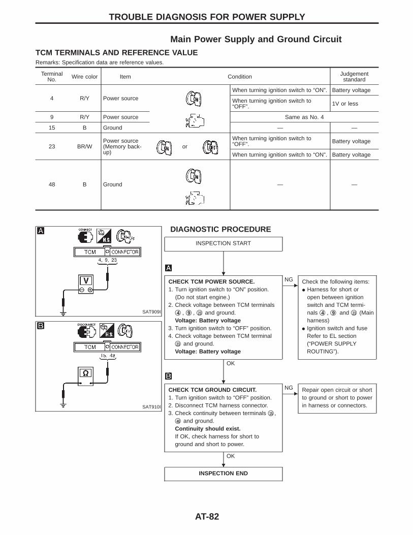
Main Power Supply and Ground CircuitTCM TERMINALS AND REFERENCE VALUERemarks: Specification data are reference values.
TerminalNo. Wire color Item Condition Judgement
standard
4 R/Y Power sourceWhen turning ignition switch to “ON”. Battery voltage
When turning ignition switch to“OFF”. 1V or less
9 R/Y Power source Same as No. 4
15 B Ground — —
23 BR/WPower source(Memory back-up)
orWhen turning ignition switch to“OFF”. Battery voltage
When turning ignition switch to “ON”. Battery voltage
48 B Ground — —
SAT909I
SAT910I
DIAGNOSTIC PROCEDURE
INSPECTION START
CHECK TCM POWER SOURCE.1. Turn ignition switch to “ON” position.
(Do not start engine.)2. Check voltage between TCM terminals
q4 , q9 , q23 and ground.Voltage: Battery voltage
3. Turn ignition switch to “OFF” position.4. Check voltage between TCM terminal
q23 and ground.Voltage: Battery voltage
OK
ENG Check the following items:
I Harness for short oropen between ignitionswitch and TCM termi-nals q4 , q9 and q23 (Mainharness)
I Ignition switch and fuseRefer to EL section(“POWER SUPPLYROUTING”).
CHECK TCM GROUND CIRCUIT.1. Turn ignition switch to “OFF” position.2. Disconnect TCM harness connector.3. Check continuity between terminals q15 ,
q48 and ground.Continuity should exist.If OK, check harness for short toground and short to power.
OK
ENG Repair open circuit or short
to ground or short to powerin harness or connectors.
INSPECTION END
TROUBLE DIAGNOSIS FOR POWER SUPPLY
H
H
H
AT-82
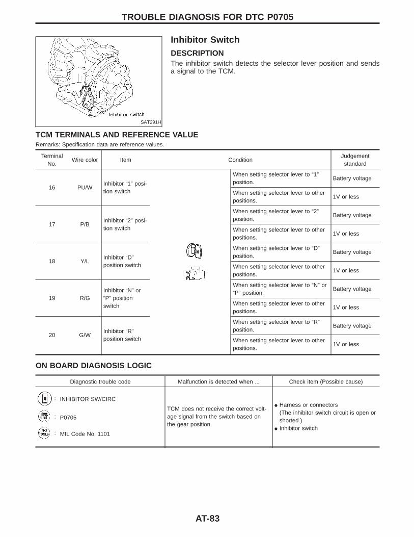
SAT291H
Inhibitor SwitchDESCRIPTIONThe inhibitor switch detects the selector lever position and sendsa signal to the TCM.
TCM TERMINALS AND REFERENCE VALUERemarks: Specification data are reference values.
TerminalNo.
Wire color Item ConditionJudgementstandard
16 PU/WInhibitor “1” posi-tion switch
When setting selector lever to “1”position.
Battery voltage
When setting selector lever to otherpositions.
1V or less
17 P/BInhibitor “2” posi-tion switch
When setting selector lever to “2”position.
Battery voltage
When setting selector lever to otherpositions.
1V or less
18 Y/LInhibitor “D”position switch
When setting selector lever to “D”position.
Battery voltage
When setting selector lever to otherpositions.
1V or less
19 R/GInhibitor “N” or“P” positionswitch
When setting selector lever to “N” or“P” position.
Battery voltage
When setting selector lever to otherpositions.
1V or less
20 G/WInhibitor “R”position switch
When setting selector lever to “R”position.
Battery voltage
When setting selector lever to otherpositions.
1V or less
ON BOARD DIAGNOSIS LOGIC
Diagnostic trouble code Malfunction is detected when ... Check item (Possible cause)
: INHIBITOR SW/CIRC
TCM does not receive the correct volt-age signal from the switch based onthe gear position.
I Harness or connectors(The inhibitor switch circuit is open orshorted.)
I Inhibitor switch
: P0705
: MIL Code No. 1101
TROUBLE DIAGNOSIS FOR DTC P0705
AT-83
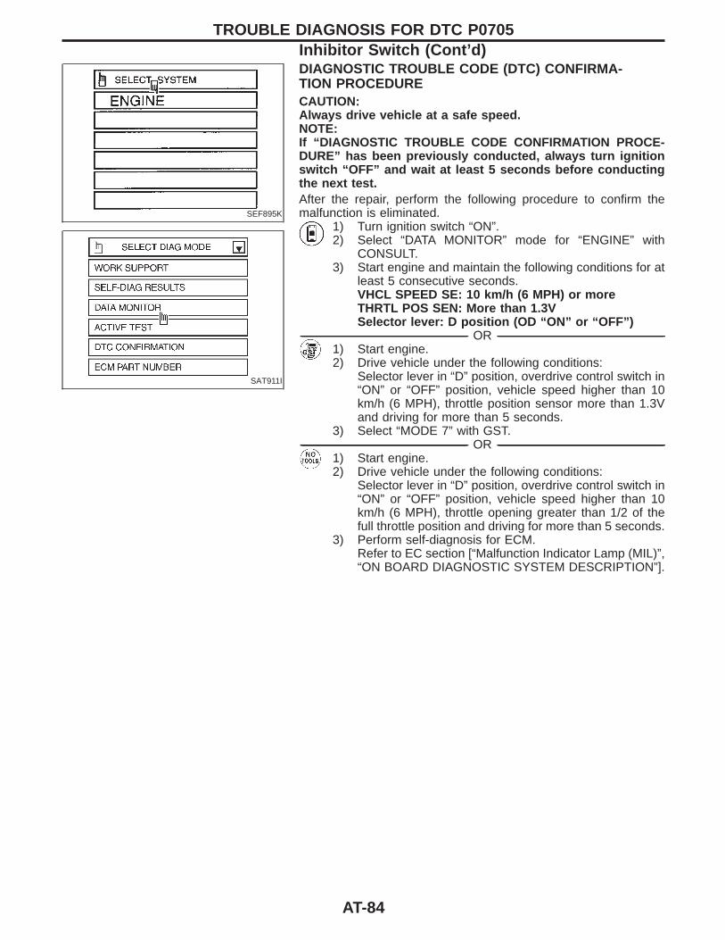
SEF895K
SAT911I
DIAGNOSTIC TROUBLE CODE (DTC) CONFIRMA-TION PROCEDURECAUTION:Always drive vehicle at a safe speed.NOTE:If “DIAGNOSTIC TROUBLE CODE CONFIRMATION PROCE-DURE” has been previously conducted, always turn ignitionswitch “OFF” and wait at least 5 seconds before conductingthe next test.After the repair, perform the following procedure to confirm themalfunction is eliminated.
1) Turn ignition switch “ON”.2) Select “DATA MONITOR” mode for “ENGINE” with
CONSULT.3) Start engine and maintain the following conditions for at
least 5 consecutive seconds.VHCL SPEED SE: 10 km/h (6 MPH) or moreTHRTL POS SEN: More than 1.3VSelector lever: D position (OD “ON” or “OFF”)
------------------------------------------------------------------------------------------------------------------------------------------------------------------------------------------------------------------------------------------------------ OR ------------------------------------------------------------------------------------------------------------------------------------------------------------------------------------------------------------------------------------------------------1) Start engine.2) Drive vehicle under the following conditions:
Selector lever in “D” position, overdrive control switch in“ON” or “OFF” position, vehicle speed higher than 10km/h (6 MPH), throttle position sensor more than 1.3Vand driving for more than 5 seconds.
3) Select “MODE 7” with GST.------------------------------------------------------------------------------------------------------------------------------------------------------------------------------------------------------------------------------------------------------ OR ------------------------------------------------------------------------------------------------------------------------------------------------------------------------------------------------------------------------------------------------------
1) Start engine.2) Drive vehicle under the following conditions:
Selector lever in “D” position, overdrive control switch in“ON” or “OFF” position, vehicle speed higher than 10km/h (6 MPH), throttle opening greater than 1/2 of thefull throttle position and driving for more than 5 seconds.
3) Perform self-diagnosis for ECM.Refer to EC section [“Malfunction Indicator Lamp (MIL)”,“ON BOARD DIAGNOSTIC SYSTEM DESCRIPTION”].
TROUBLE DIAGNOSIS FOR DTC P0705Inhibitor Switch (Cont’d)
AT-84
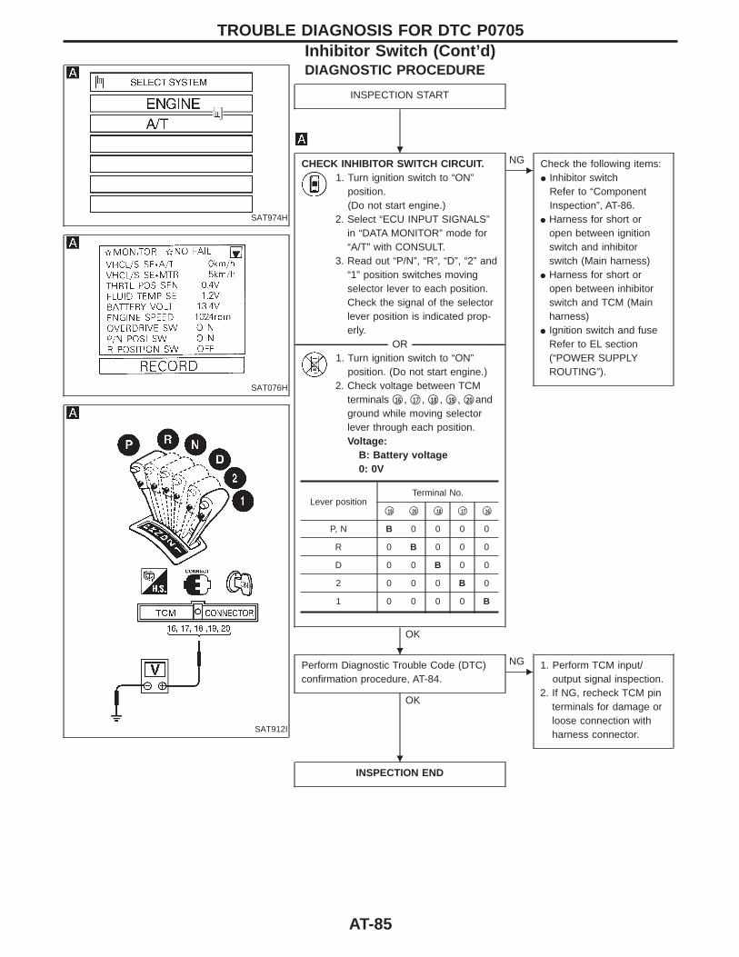
SAT974H
SAT076H
SAT912I
DIAGNOSTIC PROCEDURE
INSPECTION START
CHECK INHIBITOR SWITCH CIRCUIT.1. Turn ignition switch to “ON”
position.(Do not start engine.)
2. Select “ECU INPUT SIGNALS”in “DATA MONITOR” mode for“A/T” with CONSULT.
3. Read out “P/N”, “R”, “D”, “2” and“1” position switches movingselector lever to each position.Check the signal of the selectorlever position is indicated prop-erly.
-------------------------------------------------------------------------------------------------------------------------------------- OR --------------------------------------------------------------------------------------------------------------------------------------1. Turn ignition switch to “ON”
position. (Do not start engine.)2. Check voltage between TCM
terminals q16 , q17 , q18 , q19 , q20 andground while moving selectorlever through each position.Voltage:
B: Battery voltage0: 0V
OK
ENG Check the following items:
I Inhibitor switchRefer to “ComponentInspection”, AT-86.
I Harness for short oropen between ignitionswitch and inhibitorswitch (Main harness)
I Harness for short oropen between inhibitorswitch and TCM (Mainharness)
I Ignition switch and fuseRefer to EL section(“POWER SUPPLYROUTING”).
Perform Diagnostic Trouble Code (DTC)confirmation procedure, AT-84.
OK
ENG 1. Perform TCM input/
output signal inspection.2. If NG, recheck TCM pin
terminals for damage orloose connection withharness connector.
INSPECTION END
Lever positionTerminal No.
q19 q20 q18 q17 q16
P, N B 0 0 0 0
R 0 B 0 0 0
D 0 0 B 0 0
2 0 0 0 B 0
1 0 0 0 0 B
TROUBLE DIAGNOSIS FOR DTC P0705Inhibitor Switch (Cont’d)
H
H
H
AT-85
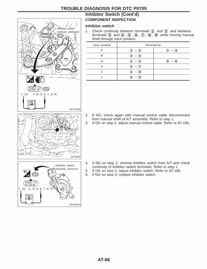
SAT019JA
COMPONENT INSPECTION
Inhibitor switch1. Check continuity between terminals q1 and q2 and between
terminals q3 and q4 , q5 , q6 , q7 , q8 , q9 while moving manualshaft through each position.
Lever position Terminal No.
P q1 — q2 q3 — q4
R q3 — q5
N q1 — q2 q3 — q6
D q3 — q7
2 q3 — q8
1 q3 — q9
SAT530F
2. If NG, check again with manual control cable disconnectedfrom manual shaft of A/T assembly. Refer to step 1.
3. If OK on step 2, adjust manual control cable. Refer to AT-190.
SAT020JA
4. If NG on step 2, remove inhibitor switch from A/T and checkcontinuity of inhibitor switch terminals. Refer to step 1.
5. If OK on step 4, adjust inhibitor switch. Refer to AT-189.6. If NG on step 4, replace inhibitor switch.
TROUBLE DIAGNOSIS FOR DTC P0705Inhibitor Switch (Cont’d)
AT-86
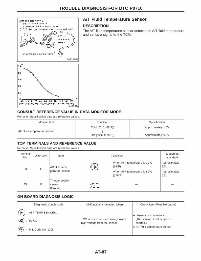
SAT283HA
A/T Fluid Temperature SensorDESCRIPTIONThe A/T fluid temperature sensor detects the A/T fluid temperatureand sends a signal to the TCM.
SAT021J
CONSULT REFERENCE VALUE IN DATA MONITOR MODERemarks: Specification data are reference values.
Monitor item Condition Specification
A/T fluid temperature sensorCold [20°C (68°F)]
"
Hot [80°C (176°F)]
Approximately 1.5V"
Approximately 0.5V
TCM TERMINALS AND REFERENCE VALUERemarks: Specification data are reference values.
TerminalNo.
Wire color Item ConditionJudgementstandard
33 GA/T fluid tem-perature sensor
When ATF temperature is 20°C(68°F).
Approximately1.5V
When ATF temperature is 80°C(176°F).
Approximately0.5V
35 BThrottle positionsensor(Ground)
— —
ON BOARD DIAGNOSIS LOGIC
Diagnostic trouble code Malfunction is detected when ... Check item (Possible cause)
: ATF TEMP SEN/CIRC
TCM receives an excessively low orhigh voltage from the sensor.
I Harness or connectors(The sensor circuit is open orshorted.)
I A/T fluid temperature sensor
: P0710
: MIL Code No. 1208
TROUBLE DIAGNOSIS FOR DTC P0710
AT-87
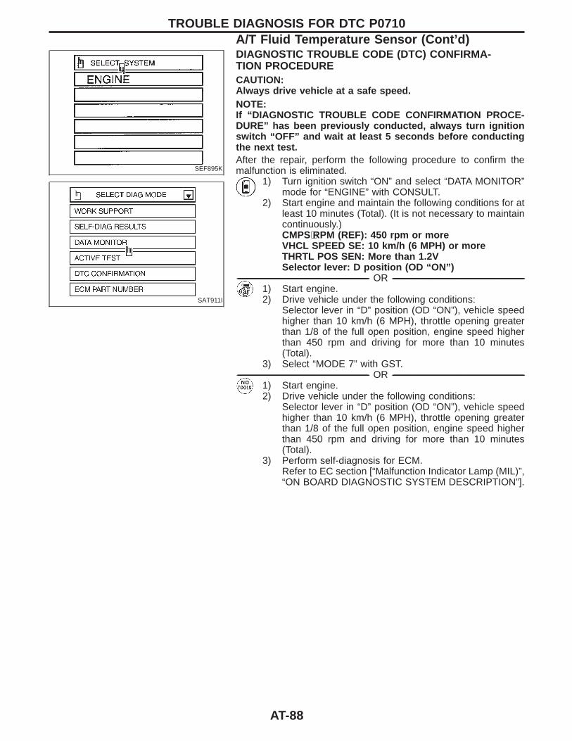
SEF895K
SAT911I
DIAGNOSTIC TROUBLE CODE (DTC) CONFIRMA-TION PROCEDURECAUTION:Always drive vehicle at a safe speed.NOTE:If “DIAGNOSTIC TROUBLE CODE CONFIRMATION PROCE-DURE” has been previously conducted, always turn ignitionswitch “OFF” and wait at least 5 seconds before conductingthe next test.After the repair, perform the following procedure to confirm themalfunction is eliminated.
1) Turn ignition switch “ON” and select “DATA MONITOR”mode for “ENGINE” with CONSULT.
2) Start engine and maintain the following conditions for atleast 10 minutes (Total). (It is not necessary to maintaincontinuously.)CMPS⋅RPM (REF): 450 rpm or moreVHCL SPEED SE: 10 km/h (6 MPH) or moreTHRTL POS SEN: More than 1.2VSelector lever: D position (OD “ON”)
------------------------------------------------------------------------------------------------------------------------------------------------------------------------------------------------------------------------------------------------------ OR ------------------------------------------------------------------------------------------------------------------------------------------------------------------------------------------------------------------------------------------------------1) Start engine.2) Drive vehicle under the following conditions:
Selector lever in “D” position (OD “ON”), vehicle speedhigher than 10 km/h (6 MPH), throttle opening greaterthan 1/8 of the full open position, engine speed higherthan 450 rpm and driving for more than 10 minutes(Total).
3) Select “MODE 7” with GST.------------------------------------------------------------------------------------------------------------------------------------------------------------------------------------------------------------------------------------------------------ OR ------------------------------------------------------------------------------------------------------------------------------------------------------------------------------------------------------------------------------------------------------
1) Start engine.2) Drive vehicle under the following conditions:
Selector lever in “D” position (OD “ON”), vehicle speedhigher than 10 km/h (6 MPH), throttle opening greaterthan 1/8 of the full open position, engine speed higherthan 450 rpm and driving for more than 10 minutes(Total).
3) Perform self-diagnosis for ECM.Refer to EC section [“Malfunction Indicator Lamp (MIL)”,“ON BOARD DIAGNOSTIC SYSTEM DESCRIPTION”].
TROUBLE DIAGNOSIS FOR DTC P0710A/T Fluid Temperature Sensor (Cont’d)
AT-88
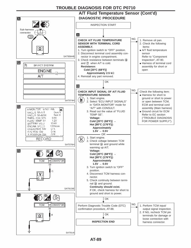
SAT956HB
SAT974H
SAT076H
SAT913IE
SAT914I
DIAGNOSTIC PROCEDURE
INSPECTION START
CHECK A/T FLUID TEMPERATURESENSOR WITH TERMINAL CORDASSEMBLY.1. Turn ignition switch to “OFF” position.2. Disconnect terminal cord assembly con-
nector in engine compartment.3. Check resistance between terminals q6
and q7 when A/T is cold.Resistance:
Cold [20°C (68°F)]Approximately 2.5 k Ω
4. Reinstall any part removed.
OK
ENG 1. Remove oil pan.
2. Check the followingitems:
I A/T fluid temperaturesensorRefer to “ComponentInspection”, AT-90.
I Harness of terminal cordassembly for short oropen
CHECK INPUT SIGNAL OF A/T FLUIDTEMPERATURE SENSOR.
1. Start engine.2. Select “ECU INPUT SIGNALS”
in “DATA MONITOR” mode for“A/T” with CONSULT.
3. Read out the value of “FLUIDTEMP SE”.Voltage:Cold [20°C (68°F)] →Hot [80°C (176°F)]:
Approximately1.5V → 0.5V
-------------------------------------------------------------------------------------------------------------------------------------- OR --------------------------------------------------------------------------------------------------------------------------------------1. Start engine.2. Check voltage between TCM
terminal q33 and ground whilewarming up A/T.Voltage:Cold [20°C (68°F)] →Hot [80°C (176°F)]:
Approximately1.5V → 0.5V
3. Turn ignition switch to “OFF”position.
4. Disconnect TCM harness con-nector.
5. Check continuity between termi-nal q35 and ground.Continuity should exist.If OK, check harness for short toground and short to power.
OK
ENG Check the following item:
I Harness for short toground or short to poweror open between TCM,ECM and terminal cordassembly (Main harness)
I Ground circuit for ECMRefer to EC section(“TROUBLE DIAGNOSISFOR POWER SUPPLY”).
Perform Diagnostic Trouble Code (DTC)confirmation procedure, AT-88.
OK
ENG 1. Perform TCM input/
output signal inspection.2. If NG, recheck TCM pin
terminals for damage orloose connection withharness connector.INSPECTION END
TROUBLE DIAGNOSIS FOR DTC P0710A/T Fluid Temperature Sensor (Cont’d)
H
H
H
H
AT-89
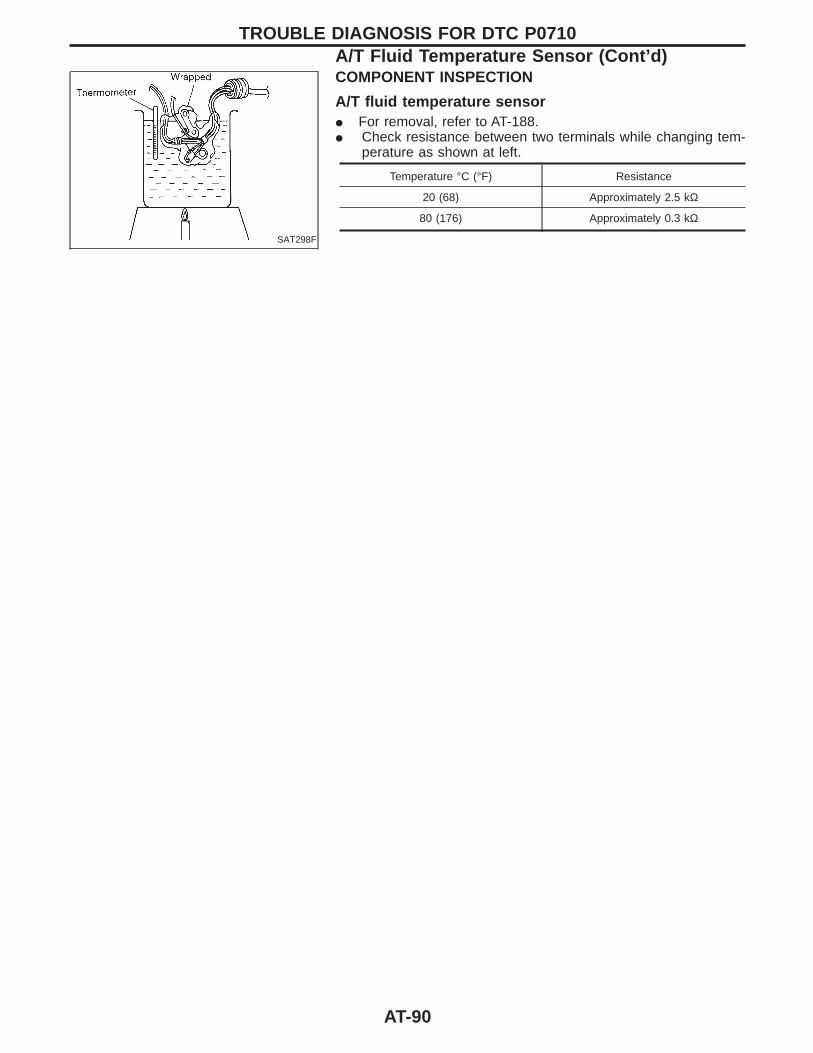
SAT298F
COMPONENT INSPECTION
A/T fluid temperature sensorI For removal, refer to AT-188.I Check resistance between two terminals while changing tem-
perature as shown at left.
Temperature °C (°F) Resistance
20 (68) Approximately 2.5 kΩ
80 (176) Approximately 0.3 kΩ
TROUBLE DIAGNOSIS FOR DTC P0710A/T Fluid Temperature Sensor (Cont’d)
AT-90
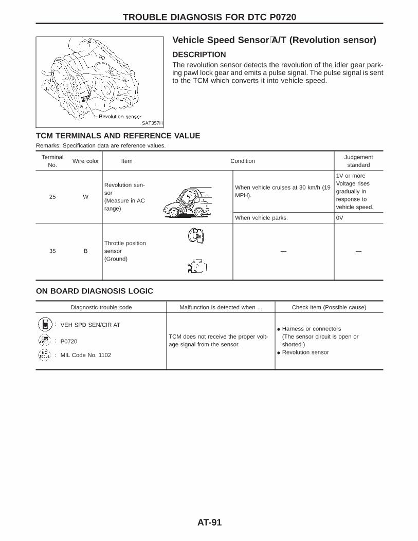
SAT357H
Vehicle Speed Sensor ⋅A/T (Revolution sensor)
DESCRIPTIONThe revolution sensor detects the revolution of the idler gear park-ing pawl lock gear and emits a pulse signal. The pulse signal is sentto the TCM which converts it into vehicle speed.
TCM TERMINALS AND REFERENCE VALUERemarks: Specification data are reference values.
TerminalNo.
Wire color Item ConditionJudgementstandard
25 W
Revolution sen-sor(Measure in ACrange)
When vehicle cruises at 30 km/h (19MPH).
1V or moreVoltage risesgradually inresponse tovehicle speed.
When vehicle parks. 0V
35 BThrottle positionsensor(Ground)
— —
ON BOARD DIAGNOSIS LOGIC
Diagnostic trouble code Malfunction is detected when ... Check item (Possible cause)
: VEH SPD SEN/CIR AT
TCM does not receive the proper volt-age signal from the sensor.
I Harness or connectors(The sensor circuit is open orshorted.)
I Revolution sensor
: P0720
: MIL Code No. 1102
TROUBLE DIAGNOSIS FOR DTC P0720
AT-91
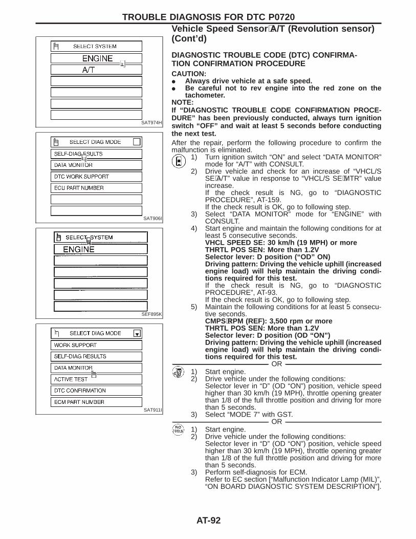
SAT974H
SAT906I
SEF895K
SAT911I
DIAGNOSTIC TROUBLE CODE (DTC) CONFIRMA-TION CONFIRMATION PROCEDURECAUTION:I Always drive vehicle at a safe speed.I Be careful not to rev engine into the red zone on the
tachometer.NOTE:If “DIAGNOSTIC TROUBLE CODE CONFIRMATION PROCE-DURE” has been previously conducted, always turn ignitionswitch “OFF” and wait at least 5 seconds before conductingthe next test.After the repair, perform the following procedure to confirm themalfunction is eliminated.
1) Turn ignition switch “ON” and select “DATA MONITOR”mode for “A/T” with CONSULT.
2) Drive vehicle and check for an increase of “VHCL/SSE⋅A/T” value in response to “VHCL/S SE⋅MTR” valueincrease.If the check result is NG, go to “DIAGNOSTICPROCEDURE”, AT-159.If the check result is OK, go to following step.
3) Select “DATA MONITOR” mode for “ENGINE” withCONSULT.
4) Start engine and maintain the following conditions for atleast 5 consecutive seconds.VHCL SPEED SE: 30 km/h (19 MPH) or moreTHRTL POS SEN: More than 1.2VSelector lever: D position (“OD” ON)Driving pattern: Driving the vehicle uphill (increasedengine load) will help maintain the driving condi-tions required for this test.If the check result is NG, go to “DIAGNOSTICPROCEDURE”, AT-93.If the check result is OK, go to following step.
5) Maintain the following conditions for at least 5 consecu-tive seconds.CMPS⋅RPM (REF): 3,500 rpm or moreTHRTL POS SEN: More than 1.2VSelector lever: D position (OD “ON”)Driving pattern: Driving the vehicle uphill (increasedengine load) will help maintain the driving condi-tions required for this test.
------------------------------------------------------------------------------------------------------------------------------------------------------------------------------------------------------------------------------------------------------ OR ------------------------------------------------------------------------------------------------------------------------------------------------------------------------------------------------------------------------------------------------------1) Start engine.2) Drive vehicle under the following conditions:
Selector lever in “D” (OD “ON”) position, vehicle speedhigher than 30 km/h (19 MPH), throttle opening greaterthan 1/8 of the full throttle position and driving for morethan 5 seconds.
3) Select “MODE 7” with GST.------------------------------------------------------------------------------------------------------------------------------------------------------------------------------------------------------------------------------------------------------ OR ------------------------------------------------------------------------------------------------------------------------------------------------------------------------------------------------------------------------------------------------------
1) Start engine.2) Drive vehicle under the following conditions:
Selector lever in “D” (OD “ON”) position, vehicle speedhigher than 30 km/h (19 MPH), throttle opening greaterthan 1/8 of the full throttle position and driving for morethan 5 seconds.
3) Perform self-diagnosis for ECM.Refer to EC section [“Malfunction Indicator Lamp (MIL)”,“ON BOARD DIAGNOSTIC SYSTEM DESCRIPTION”].
TROUBLE DIAGNOSIS FOR DTC P0720Vehicle Speed Sensor ⋅A/T (Revolution sensor)(Cont’d)
AT-92
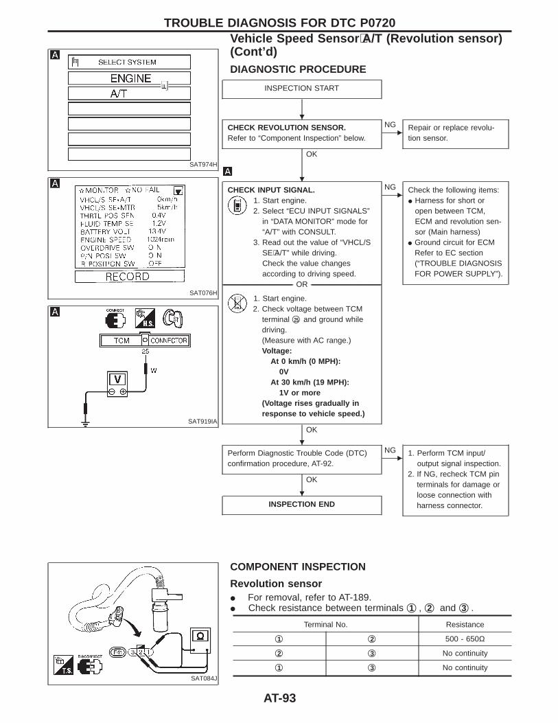
SAT974H
SAT076H
SAT919IA
DIAGNOSTIC PROCEDURE
INSPECTION START
CHECK REVOLUTION SENSOR.Refer to “Component Inspection” below.
OK
ENG Repair or replace revolu-
tion sensor.
CHECK INPUT SIGNAL.1. Start engine.2. Select “ECU INPUT SIGNALS”
in “DATA MONITOR” mode for“A/T” with CONSULT.
3. Read out the value of “VHCL/SSE⋅A/T” while driving.Check the value changesaccording to driving speed.
-------------------------------------------------------------------------------------------------------------------------------------- OR --------------------------------------------------------------------------------------------------------------------------------------
1. Start engine.2. Check voltage between TCM
terminal q25 and ground whiledriving.(Measure with AC range.)Voltage:
At 0 km/h (0 MPH):0V
At 30 km/h (19 MPH):1V or more
(Voltage rises gradually inresponse to vehicle speed.)
OK
ENG Check the following items:
I Harness for short oropen between TCM,ECM and revolution sen-sor (Main harness)
I Ground circuit for ECMRefer to EC section(“TROUBLE DIAGNOSISFOR POWER SUPPLY”).
Perform Diagnostic Trouble Code (DTC)confirmation procedure, AT-92.
OK
ENG 1. Perform TCM input/
output signal inspection.2. If NG, recheck TCM pin
terminals for damage orloose connection withharness connector.INSPECTION END
SAT084J
COMPONENT INSPECTION
Revolution sensorI For removal, refer to AT-189.I Check resistance between terminals q1 , q2 and q3 .
Terminal No. Resistance
q1 q2 500 - 650Ω
q2 q3 No continuity
q1 q3 No continuity
TROUBLE DIAGNOSIS FOR DTC P0720Vehicle Speed Sensor ⋅A/T (Revolution sensor)(Cont’d)
H
H
H
H
AT-93
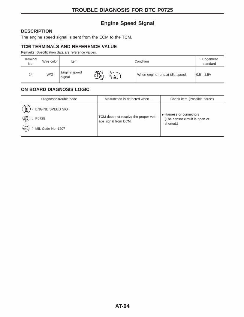
Engine Speed SignalDESCRIPTIONThe engine speed signal is sent from the ECM to the TCM.
TCM TERMINALS AND REFERENCE VALUERemarks: Specification data are reference values.
TerminalNo.
Wire color Item ConditionJudgementstandard
24 W/GEngine speedsignal
When engine runs at idle speed. 0.5 - 1.5V
ON BOARD DIAGNOSIS LOGIC
Diagnostic trouble code Malfunction is detected when ... Check item (Possible cause)
: ENGINE SPEED SIG
TCM does not receive the proper volt-age signal from ECM.
I Harness or connectors(The sensor circuit is open orshorted.)
: P0725
: MIL Code No. 1207
TROUBLE DIAGNOSIS FOR DTC P0725
AT-94
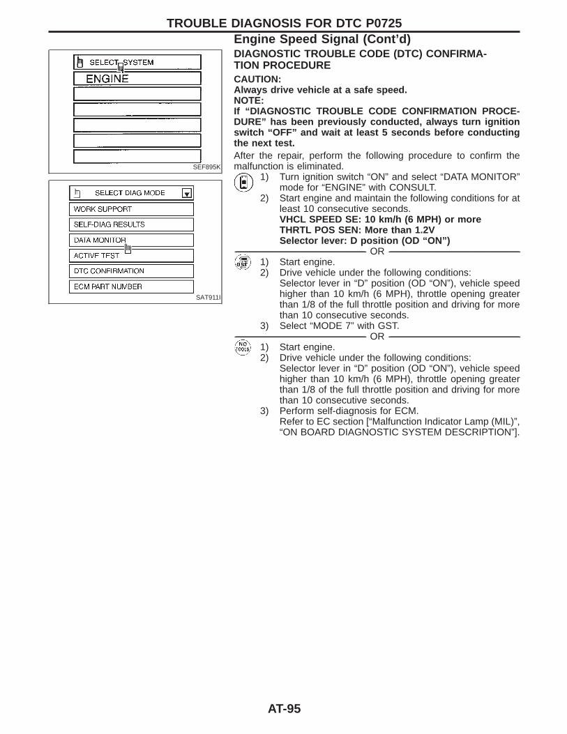
SEF895K
SAT911I
DIAGNOSTIC TROUBLE CODE (DTC) CONFIRMA-TION PROCEDURECAUTION:Always drive vehicle at a safe speed.NOTE:If “DIAGNOSTIC TROUBLE CODE CONFIRMATION PROCE-DURE” has been previously conducted, always turn ignitionswitch “OFF” and wait at least 5 seconds before conductingthe next test.After the repair, perform the following procedure to confirm themalfunction is eliminated.
1) Turn ignition switch “ON” and select “DATA MONITOR”mode for “ENGINE” with CONSULT.
2) Start engine and maintain the following conditions for atleast 10 consecutive seconds.VHCL SPEED SE: 10 km/h (6 MPH) or moreTHRTL POS SEN: More than 1.2VSelector lever: D position (OD “ON”)
------------------------------------------------------------------------------------------------------------------------------------------------------------------------------------------------------------------------------------------------------ OR ------------------------------------------------------------------------------------------------------------------------------------------------------------------------------------------------------------------------------------------------------1) Start engine.2) Drive vehicle under the following conditions:
Selector lever in “D” position (OD “ON”), vehicle speedhigher than 10 km/h (6 MPH), throttle opening greaterthan 1/8 of the full throttle position and driving for morethan 10 consecutive seconds.
3) Select “MODE 7” with GST.------------------------------------------------------------------------------------------------------------------------------------------------------------------------------------------------------------------------------------------------------ OR ------------------------------------------------------------------------------------------------------------------------------------------------------------------------------------------------------------------------------------------------------
1) Start engine.2) Drive vehicle under the following conditions:
Selector lever in “D” position (OD “ON”), vehicle speedhigher than 10 km/h (6 MPH), throttle opening greaterthan 1/8 of the full throttle position and driving for morethan 10 consecutive seconds.
3) Perform self-diagnosis for ECM.Refer to EC section [“Malfunction Indicator Lamp (MIL)”,“ON BOARD DIAGNOSTIC SYSTEM DESCRIPTION”].
TROUBLE DIAGNOSIS FOR DTC P0725Engine Speed Signal (Cont’d)
AT-95
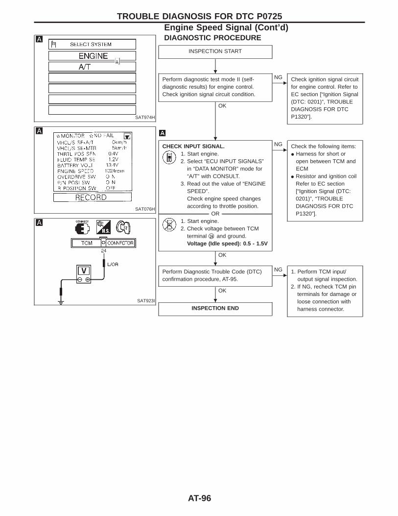
SAT974H
SAT076H
SAT923I
DIAGNOSTIC PROCEDURE
INSPECTION START
Perform diagnostic test mode II (self-diagnostic results) for engine control.Check ignition signal circuit condition.
OK
ENG Check ignition signal circuit
for engine control. Refer toEC section [“Ignition Signal(DTC: 0201)”, TROUBLEDIAGNOSIS FOR DTCP1320”].
CHECK INPUT SIGNAL.1. Start engine.2. Select “ECU INPUT SIGNALS”
in “DATA MONITOR” mode for“A/T” with CONSULT.
3. Read out the value of “ENGINESPEED”.Check engine speed changesaccording to throttle position.
-------------------------------------------------------------------------------------------------------------------------------------- OR --------------------------------------------------------------------------------------------------------------------------------------1. Start engine.2. Check voltage between TCM
terminal q24 and ground.Voltage (Idle speed): 0.5 - 1.5V
OK
ENG Check the following items:
I Harness for short oropen between TCM andECM
I Resistor and ignition coilRefer to EC section[“Ignition Signal (DTC:0201)”, “TROUBLEDIAGNOSIS FOR DTCP1320”].
Perform Diagnostic Trouble Code (DTC)confirmation procedure, AT-95.
OK
ENG 1. Perform TCM input/
output signal inspection.2. If NG, recheck TCM pin
terminals for damage orloose connection withharness connector.INSPECTION END
TROUBLE DIAGNOSIS FOR DTC P0725Engine Speed Signal (Cont’d)
H
H
H
H
AT-96
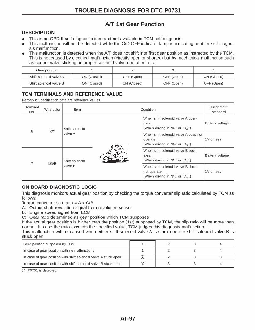
A/T 1st Gear FunctionDESCRIPTIONI This is an OBD-II self-diagnostic item and not available in TCM self-diagnosis.I This malfunction will not be detected while the O/D OFF indicator lamp is indicating another self-diagno-
sis malfunction.I This malfunction is detected when the A/T does not shift into first gear position as instructed by the TCM.
This is not caused by electrical malfunction (circuits open or shorted) but by mechanical malfunction suchas control valve sticking, improper solenoid valve operation, etc.
Gear position 1 2 3 4
Shift solenoid valve A ON (Closed) OFF (Open) OFF (Open) ON (Closed)
Shift solenoid valve B ON (Closed) ON (Closed) OFF (Open) OFF (Open)
TCM TERMINALS AND REFERENCE VALUERemarks: Specification data are reference values.
TerminalNo.
Wire color Item ConditionJudgementstandard
6 R/YShift solenoidvalve A
When shift solenoid valve A oper-ates.(When driving in “D1” or “D4”.)
Battery voltage
When shift solenoid valve A does notoperate.(When driving in “D2” or “D3”.)
1V or less
7 LG/BShift solenoidvalve B
When shift solenoid valve B oper-ates.(When driving in “D1” or “D2”.)
Battery voltage
When shift solenoid valve B doesnot operate.(When driving in “D3” or “D4”.)
1V or less
ON BOARD DIAGNOSTIC LOGICThis diagnosis monitors actual gear position by checking the torque converter slip ratio calculated by TCM asfollows:Torque converter slip ratio = A x C/BA: Output shaft revolution signal from revolution sensorB: Engine speed signal from ECMC: Gear ratio determined as gear position which TCM supposesIf the actual gear position is higher than the position (1st) supposed by TCM, the slip ratio will be more thannormal. In case the ratio exceeds the specified value, TCM judges this diagnosis malfunction.This malfunction will be caused when either shift solenoid valve A is stuck open or shift solenoid valve B isstuck open.
Gear position supposed by TCM 1 2 3 4
In case of gear position with no malfunctions 1 2 3 4
In case of gear position with shift solenoid valve A stuck open q2 2 3 3
In case of gear position with shift solenoid valve B stuck open q4 3 3 4
q: P0731 is detected.
TROUBLE DIAGNOSIS FOR DTC P0731
AT-97
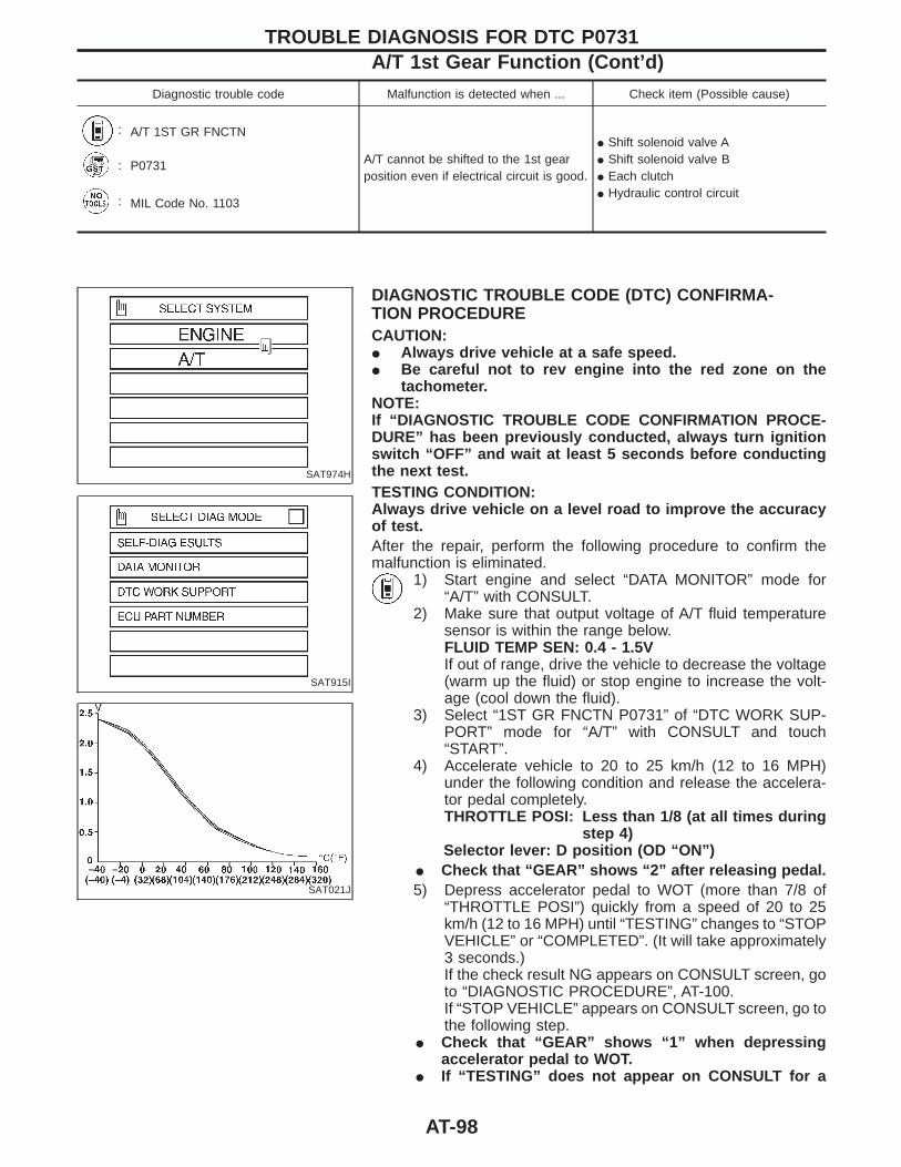
Diagnostic trouble code Malfunction is detected when ... Check item (Possible cause)
: A/T 1ST GR FNCTN
A/T cannot be shifted to the 1st gearposition even if electrical circuit is good.
I Shift solenoid valve AI Shift solenoid valve BI Each clutchI Hydraulic control circuit
: P0731
: MIL Code No. 1103
SAT974H
SAT915I
SAT021J
DIAGNOSTIC TROUBLE CODE (DTC) CONFIRMA-TION PROCEDURECAUTION:I Always drive vehicle at a safe speed.I Be careful not to rev engine into the red zone on the
tachometer.NOTE:If “DIAGNOSTIC TROUBLE CODE CONFIRMATION PROCE-DURE” has been previously conducted, always turn ignitionswitch “OFF” and wait at least 5 seconds before conductingthe next test.TESTING CONDITION:Always drive vehicle on a level road to improve the accuracyof test.After the repair, perform the following procedure to confirm themalfunction is eliminated.
1) Start engine and select “DATA MONITOR” mode for“A/T” with CONSULT.
2) Make sure that output voltage of A/T fluid temperaturesensor is within the range below.FLUID TEMP SEN: 0.4 - 1.5VIf out of range, drive the vehicle to decrease the voltage(warm up the fluid) or stop engine to increase the volt-age (cool down the fluid).
3) Select “1ST GR FNCTN P0731” of “DTC WORK SUP-PORT” mode for “A/T” with CONSULT and touch“START”.
4) Accelerate vehicle to 20 to 25 km/h (12 to 16 MPH)under the following condition and release the accelera-tor pedal completely.THROTTLE POSI: Less than 1/8 (at all times during
step 4)Selector lever: D position (OD “ON”)
I Check that “GEAR” shows “2” after releasing pedal.5) Depress accelerator pedal to WOT (more than 7/8 of
“THROTTLE POSI”) quickly from a speed of 20 to 25km/h (12 to 16 MPH) until “TESTING” changes to “STOPVEHICLE” or “COMPLETED”. (It will take approximately3 seconds.)If the check result NG appears on CONSULT screen, goto “DIAGNOSTIC PROCEDURE”, AT-100.If “STOP VEHICLE” appears on CONSULT screen, go tothe following step.
I Check that “GEAR” shows “1” when depressingaccelerator pedal to WOT.
I If “TESTING” does not appear on CONSULT for a
TROUBLE DIAGNOSIS FOR DTC P0731A/T 1st Gear Function (Cont’d)
AT-98
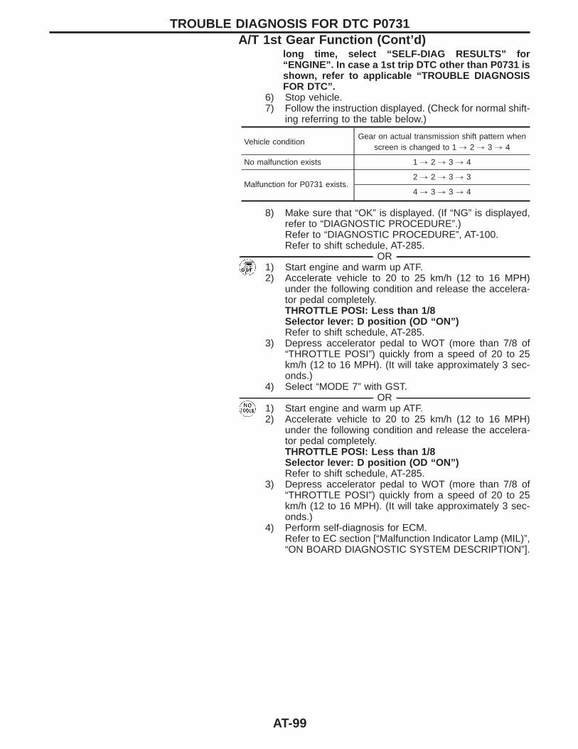
long time, select “SELF-DIAG RESULTS” for“ENGINE”. In case a 1st trip DTC other than P0731 isshown, refer to applicable “TROUBLE DIAGNOSISFOR DTC”.
6) Stop vehicle.7) Follow the instruction displayed. (Check for normal shift-
ing referring to the table below.)
Vehicle conditionGear on actual transmission shift pattern when
screen is changed to 1 , 2 , 3 , 4
No malfunction exists 1 , 2 , 3 , 4
Malfunction for P0731 exists.2 , 2 , 3 , 3
4 , 3 , 3 , 4
8) Make sure that “OK” is displayed. (If “NG” is displayed,refer to “DIAGNOSTIC PROCEDURE”.)Refer to “DIAGNOSTIC PROCEDURE”, AT-100.Refer to shift schedule, AT-285.
------------------------------------------------------------------------------------------------------------------------------------------------------------------------------------------------------------------------------------------------------ OR ------------------------------------------------------------------------------------------------------------------------------------------------------------------------------------------------------------------------------------------------------1) Start engine and warm up ATF.2) Accelerate vehicle to 20 to 25 km/h (12 to 16 MPH)
under the following condition and release the accelera-tor pedal completely.THROTTLE POSI: Less than 1/8Selector lever: D position (OD “ON”)Refer to shift schedule, AT-285.
3) Depress accelerator pedal to WOT (more than 7/8 of“THROTTLE POSI”) quickly from a speed of 20 to 25km/h (12 to 16 MPH). (It will take approximately 3 sec-onds.)
4) Select “MODE 7” with GST.------------------------------------------------------------------------------------------------------------------------------------------------------------------------------------------------------------------------------------------------------ OR ------------------------------------------------------------------------------------------------------------------------------------------------------------------------------------------------------------------------------------------------------
1) Start engine and warm up ATF.2) Accelerate vehicle to 20 to 25 km/h (12 to 16 MPH)
under the following condition and release the accelera-tor pedal completely.THROTTLE POSI: Less than 1/8Selector lever: D position (OD “ON”)Refer to shift schedule, AT-285.
3) Depress accelerator pedal to WOT (more than 7/8 of“THROTTLE POSI”) quickly from a speed of 20 to 25km/h (12 to 16 MPH). (It will take approximately 3 sec-onds.)
4) Perform self-diagnosis for ECM.Refer to EC section [“Malfunction Indicator Lamp (MIL)”,“ON BOARD DIAGNOSTIC SYSTEM DESCRIPTION”].
TROUBLE DIAGNOSIS FOR DTC P0731A/T 1st Gear Function (Cont’d)
AT-99
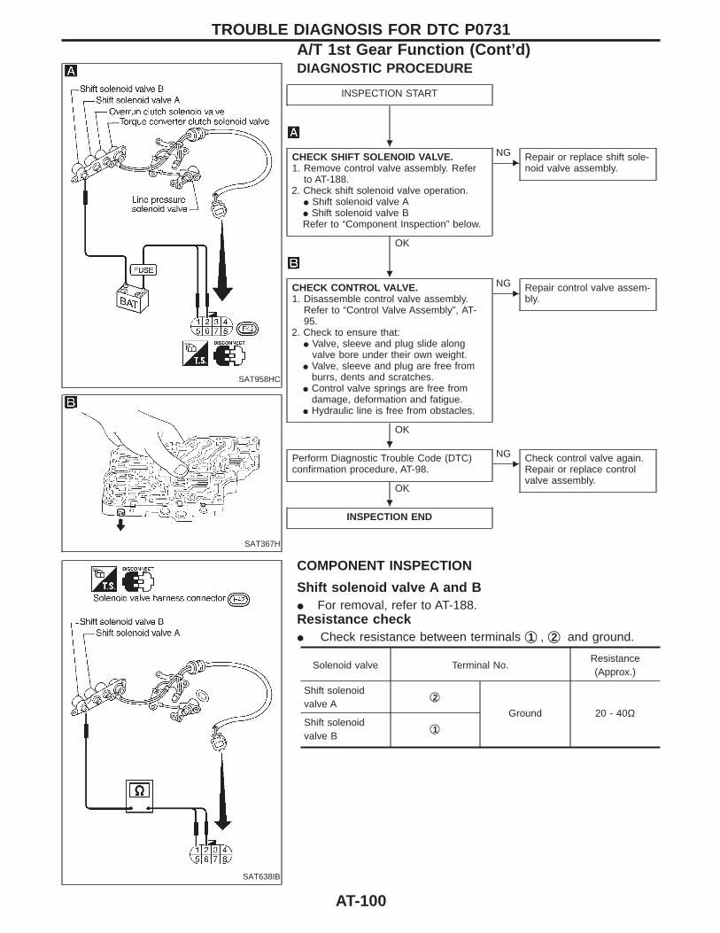
SAT958HC
SAT367H
DIAGNOSTIC PROCEDURE
INSPECTION START
CHECK SHIFT SOLENOID VALVE.1. Remove control valve assembly. Refer
to AT-188.2. Check shift solenoid valve operation.
I Shift solenoid valve AI Shift solenoid valve BRefer to “Component Inspection” below.
OK
ENG Repair or replace shift sole-
noid valve assembly.
CHECK CONTROL VALVE.1. Disassemble control valve assembly.
Refer to “Control Valve Assembly”, AT-95.
2. Check to ensure that:I Valve, sleeve and plug slide along
valve bore under their own weight.I Valve, sleeve and plug are free from
burrs, dents and scratches.I Control valve springs are free from
damage, deformation and fatigue.I Hydraulic line is free from obstacles.
OK
ENG Repair control valve assem-
bly.
Perform Diagnostic Trouble Code (DTC)confirmation procedure, AT-98.
OK
ENG Check control valve again.
Repair or replace controlvalve assembly.
INSPECTION END
SAT638IB
COMPONENT INSPECTION
Shift solenoid valve A and BI For removal, refer to AT-188.Resistance checkI Check resistance between terminals q1 , q2 and ground.
Solenoid valve Terminal No.Resistance(Approx.)
Shift solenoidvalve A
q2Ground 20 - 40Ω
Shift solenoidvalve B
q1
TROUBLE DIAGNOSIS FOR DTC P0731A/T 1st Gear Function (Cont’d)
H
H
H
H
AT-100
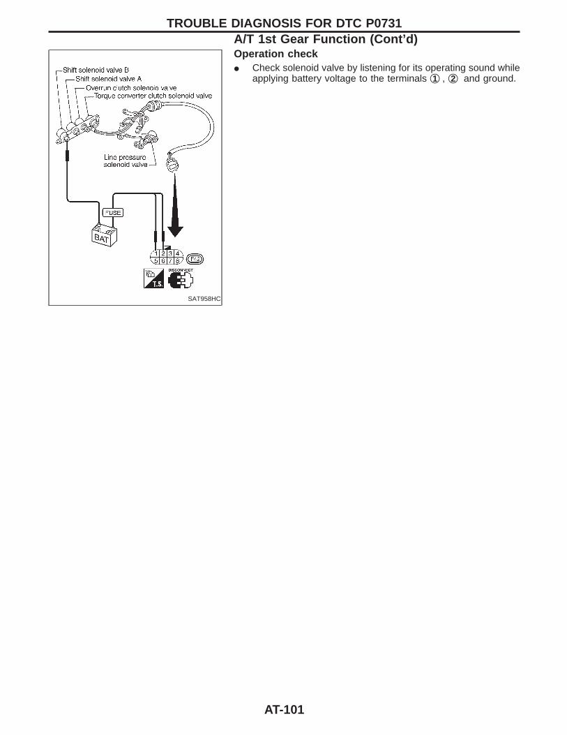
SAT958HC
Operation checkI Check solenoid valve by listening for its operating sound while
applying battery voltage to the terminals q1 , q2 and ground.
TROUBLE DIAGNOSIS FOR DTC P0731A/T 1st Gear Function (Cont’d)
AT-101
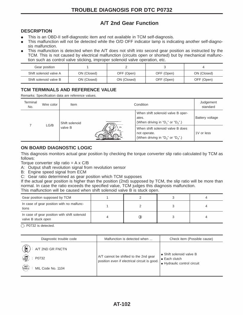
A/T 2nd Gear FunctionDESCRIPTIONI This is an OBD-II self-diagnostic item and not available in TCM self-diagnosis.I This malfunction will not be detected while the O/D OFF indicator lamp is indicating another self-diagno-
sis malfunction.I This malfunction is detected when the A/T does not shift into second gear position as instructed by the
TCM. This is not caused by electrical malfunction (circuits open or shorted) but by mechanical malfunc-tion such as control valve sticking, improper solenoid valve operation, etc.
Gear position 1 2 3 4
Shift solenoid valve A ON (Closed) OFF (Open) OFF (Open) ON (Closed)
Shift solenoid valve B ON (Closed) ON (Closed) OFF (Open) OFF (Open)
TCM TERMINALS AND REFERENCE VALUERemarks: Specification data are reference values.
TerminalNo.
Wire color Item ConditionJudgementstandard
7 LG/BShift solenoidvalve B
When shift solenoid valve B oper-ates.(When driving in “D1” or “D2”.)
Battery voltage
When shift solenoid valve B doesnot operate.(When driving in “D3” or “D4”.)
1V or less
ON BOARD DIAGNOSTIC LOGICThis diagnosis monitors actual gear position by checking the torque converter slip ratio calculated by TCM asfollows:Torque converter slip ratio = A x C/BA: Output shaft revolution signal from revolution sensorB: Engine speed signal from ECMC: Gear ratio determined as gear position which TCM supposesIf the actual gear position is higher than the position (2nd) supposed by TCM, the slip ratio will be more thannormal. In case the ratio exceeds the specified value, TCM judges this diagnosis malfunction.This malfunction will be caused when shift solenoid valve B is stuck open.
Gear position supposed by TCM 1 2 3 4
In case of gear position with no malfunc-tions
1 2 3 4
In case of gear position with shift solenoidvalve B stuck open
4 q3 3 4
q: P0732 is detected.
Diagnostic trouble code Malfunction is detected when ... Check item (Possible cause)
: A/T 2ND GR FNCTN
A/T cannot be shifted to the 2nd gearposition even if electrical circuit is good.
I Shift solenoid valve BI Each clutchI Hydraulic control circuit
: P0732
: MIL Code No. 1104
TROUBLE DIAGNOSIS FOR DTC P0732
AT-102
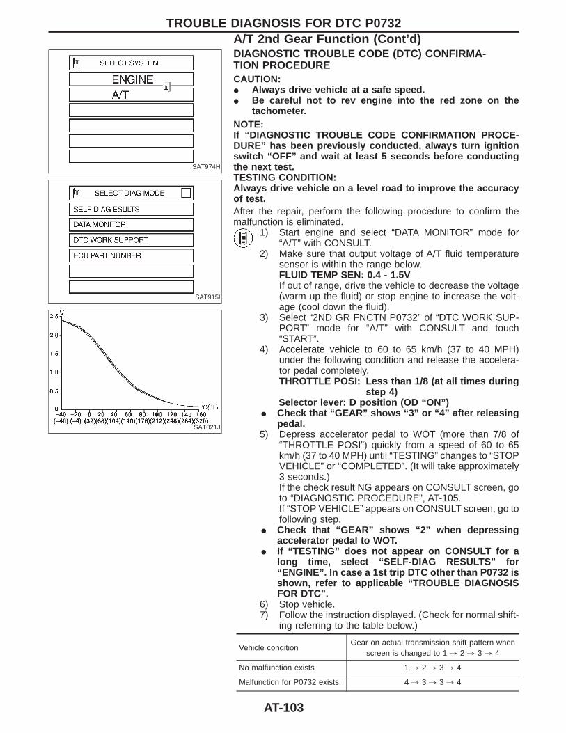
SAT974H
SAT915I
SAT021J
DIAGNOSTIC TROUBLE CODE (DTC) CONFIRMA-TION PROCEDURECAUTION:I Always drive vehicle at a safe speed.I Be careful not to rev engine into the red zone on the
tachometer.NOTE:If “DIAGNOSTIC TROUBLE CODE CONFIRMATION PROCE-DURE” has been previously conducted, always turn ignitionswitch “OFF” and wait at least 5 seconds before conductingthe next test.TESTING CONDITION:Always drive vehicle on a level road to improve the accuracyof test.After the repair, perform the following procedure to confirm themalfunction is eliminated.
1) Start engine and select “DATA MONITOR” mode for“A/T” with CONSULT.
2) Make sure that output voltage of A/T fluid temperaturesensor is within the range below.FLUID TEMP SEN: 0.4 - 1.5VIf out of range, drive the vehicle to decrease the voltage(warm up the fluid) or stop engine to increase the volt-age (cool down the fluid).
3) Select “2ND GR FNCTN P0732” of “DTC WORK SUP-PORT” mode for “A/T” with CONSULT and touch“START”.
4) Accelerate vehicle to 60 to 65 km/h (37 to 40 MPH)under the following condition and release the accelera-tor pedal completely.THROTTLE POSI: Less than 1/8 (at all times during
step 4)Selector lever: D position (OD “ON”)
I Check that “GEAR” shows “3” or “4” after releasingpedal.
5) Depress accelerator pedal to WOT (more than 7/8 of“THROTTLE POSI”) quickly from a speed of 60 to 65km/h (37 to 40 MPH) until “TESTING” changes to “STOPVEHICLE” or “COMPLETED”. (It will take approximately3 seconds.)If the check result NG appears on CONSULT screen, goto “DIAGNOSTIC PROCEDURE”, AT-105.If “STOP VEHICLE” appears on CONSULT screen, go tofollowing step.
I Check that “GEAR” shows “2” when depressingaccelerator pedal to WOT.
I If “TESTING” does not appear on CONSULT for along time, select “SELF-DIAG RESULTS” for“ENGINE”. In case a 1st trip DTC other than P0732 isshown, refer to applicable “TROUBLE DIAGNOSISFOR DTC”.
6) Stop vehicle.7) Follow the instruction displayed. (Check for normal shift-
ing referring to the table below.)
Vehicle conditionGear on actual transmission shift pattern when
screen is changed to 1 , 2 , 3 , 4
No malfunction exists 1 , 2 , 3 , 4
Malfunction for P0732 exists. 4 , 3 , 3 , 4
TROUBLE DIAGNOSIS FOR DTC P0732A/T 2nd Gear Function (Cont’d)
AT-103
8) Make sure that “OK” is displayed. (If “NG” is displayed,refer to “DIAGNOSTIC PROCEDURE”.)Refer to “DIAGNOSTIC PROCEDURE”, AT-105.Refer to shift schedule, AT-285.
------------------------------------------------------------------------------------------------------------------------------------------------------------------------------------------------------------------------------------------------------ OR ------------------------------------------------------------------------------------------------------------------------------------------------------------------------------------------------------------------------------------------------------1) Start engine and warm up ATF.2) Accelerate vehicle to 63 to 68 km/h (39 to 42 MPH)
under the following condition and release the accelera-tor pedal completely.THROTTLE POSI: Less than 1/8Selector lever: D position (OD “ON”)Refer to shift schedule, AT-285.
3) Depress accelerator pedal to WOT (more than 7/8 of“THROTTLE POSI”) quickly from a speed of 63 to 68km/h (39 to 42 MPH). (It will take approximately 3 sec-onds.)
4) Select “MODE 7” with GST.------------------------------------------------------------------------------------------------------------------------------------------------------------------------------------------------------------------------------------------------------ OR ------------------------------------------------------------------------------------------------------------------------------------------------------------------------------------------------------------------------------------------------------
1) Start engine and warm up ATF.2) Accelerate vehicle to 63 to 68 km/h (39 to 42 MPH)
under the following condition and release the accelera-tor pedal completely.THROTTLE POSI: Less than 1/8Selector lever: D position (OD “ON”)Refer to shift schedule, AT-285.
3) Depress accelerator pedal to WOT (more than 7/8 of“THROTTLE POSI”) quickly from a speed of 63 to 68km/h (39 to 42 MPH). (It will take approximately 3 sec-onds.)
4) Perform self-diagnosis for ECM.Refer to EC section [“Malfunction Indicator Lamp (MIL)”,“ON BOARD DIAGNOSTIC SYSTEM DESCRIPTION”].
TROUBLE DIAGNOSIS FOR DTC P0732A/T 2nd Gear Function (Cont’d)
AT-104
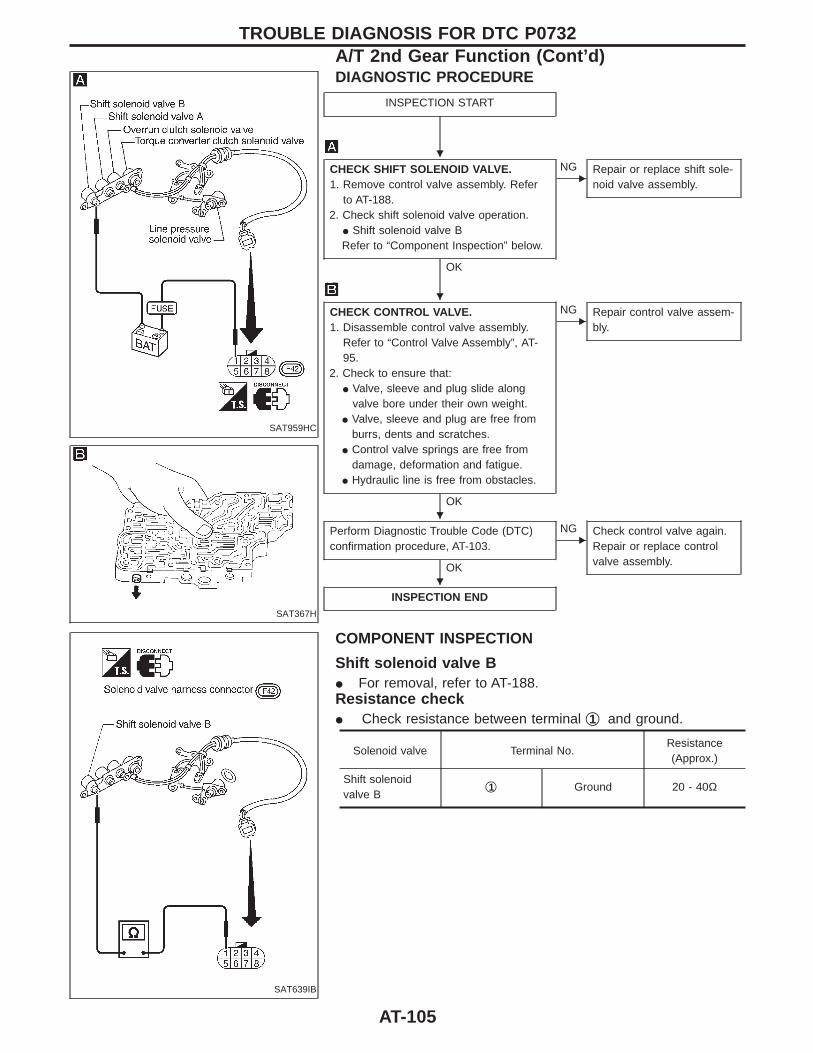
SAT959HC
SAT367H
DIAGNOSTIC PROCEDURE
INSPECTION START
CHECK SHIFT SOLENOID VALVE.1. Remove control valve assembly. Refer
to AT-188.2. Check shift solenoid valve operation.
I Shift solenoid valve BRefer to “Component Inspection” below.
OK
ENG Repair or replace shift sole-
noid valve assembly.
CHECK CONTROL VALVE.1. Disassemble control valve assembly.
Refer to “Control Valve Assembly”, AT-95.
2. Check to ensure that:I Valve, sleeve and plug slide along
valve bore under their own weight.I Valve, sleeve and plug are free from
burrs, dents and scratches.I Control valve springs are free from
damage, deformation and fatigue.I Hydraulic line is free from obstacles.
OK
ENG Repair control valve assem-
bly.
Perform Diagnostic Trouble Code (DTC)confirmation procedure, AT-103.
OK
ENG Check control valve again.
Repair or replace controlvalve assembly.
INSPECTION END
SAT639IB
COMPONENT INSPECTION
Shift solenoid valve BI For removal, refer to AT-188.Resistance checkI Check resistance between terminal q1 and ground.
Solenoid valve Terminal No.Resistance(Approx.)
Shift solenoidvalve B
q1 Ground 20 - 40Ω
TROUBLE DIAGNOSIS FOR DTC P0732A/T 2nd Gear Function (Cont’d)
H
H
H
H
AT-105

SAT959HC
Operation checkI Check solenoid valve by listening for its operating sound while
applying battery voltage to the terminal q1 and ground.
TROUBLE DIAGNOSIS FOR DTC P0732A/T 2nd Gear Function (Cont’d)
AT-106
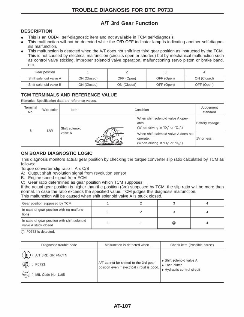
A/T 3rd Gear FunctionDESCRIPTIONI This is an OBD-II self-diagnostic item and not available in TCM self-diagnosis.I This malfunction will not be detected while the O/D OFF indicator lamp is indicating another self-diagno-
sis malfunction.I This malfunction is detected when the A/T does not shift into third gear position as instructed by the TCM.
This is not caused by electrical malfunction (circuits open or shorted) but by mechanical malfunction suchas control valve sticking, improper solenoid valve operation, malfunctioning servo piston or brake band,etc.
Gear position 1 2 3 4
Shift solenoid valve A ON (Closed) OFF (Open) OFF (Open) ON (Closed)
Shift solenoid valve B ON (Closed) ON (Closed) OFF (Open) OFF (Open)
TCM TERMINALS AND REFERENCE VALUERemarks: Specification data are reference values.
TerminalNo.
Wire color Item ConditionJudgementstandard
6 L/WShift solenoidvalve A
When shift solenoid valve A oper-ates.(When driving in “D1” or “D4”.)
Battery voltage
When shift solenoid valve A does notoperate.(When driving in “D2” or “D3”.)
1V or less
ON BOARD DIAGNOSTIC LOGICThis diagnosis monitors actual gear position by checking the torque converter slip ratio calculated by TCM asfollows:Torque converter slip ratio = A x C/BA: Output shaft revolution signal from revolution sensorB: Engine speed signal from ECMC: Gear ratio determined as gear position which TCM supposesIf the actual gear position is higher than the position (3rd) supposed by TCM, the slip ratio will be more thannormal. In case the ratio exceeds the specified value, TCM judges this diagnosis malfunction.This malfunction will be caused when shift solenoid valve A is stuck closed.
Gear position supposed by TCM 1 2 3 4
In case of gear position with no malfunc-tions
1 2 3 4
In case of gear position with shift solenoidvalve A stuck closed
1 1 q4 4
q: P0733 is detected.
Diagnostic trouble code Malfunction is detected when ... Check item (Possible cause)
: A/T 3RD GR FNCTN
A/T cannot be shifted to the 3rd gearposition even if electrical circuit is good.
I Shift solenoid valve AI Each clutchI Hydraulic control circuit
: P0733
: MIL Code No. 1105
TROUBLE DIAGNOSIS FOR DTC P0733
AT-107
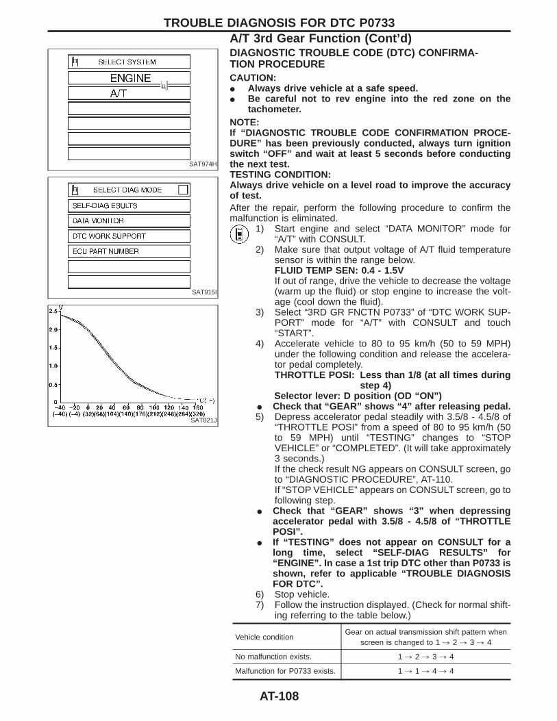
SAT974H
SAT915I
SAT021J
DIAGNOSTIC TROUBLE CODE (DTC) CONFIRMA-TION PROCEDURECAUTION:I Always drive vehicle at a safe speed.I Be careful not to rev engine into the red zone on the
tachometer.NOTE:If “DIAGNOSTIC TROUBLE CODE CONFIRMATION PROCE-DURE” has been previously conducted, always turn ignitionswitch “OFF” and wait at least 5 seconds before conductingthe next test.TESTING CONDITION:Always drive vehicle on a level road to improve the accuracyof test.After the repair, perform the following procedure to confirm themalfunction is eliminated.
1) Start engine and select “DATA MONITOR” mode for“A/T” with CONSULT.
2) Make sure that output voltage of A/T fluid temperaturesensor is within the range below.FLUID TEMP SEN: 0.4 - 1.5VIf out of range, drive the vehicle to decrease the voltage(warm up the fluid) or stop engine to increase the volt-age (cool down the fluid).
3) Select “3RD GR FNCTN P0733” of “DTC WORK SUP-PORT” mode for “A/T” with CONSULT and touch“START”.
4) Accelerate vehicle to 80 to 95 km/h (50 to 59 MPH)under the following condition and release the accelera-tor pedal completely.THROTTLE POSI: Less than 1/8 (at all times during
step 4)Selector lever: D position (OD “ON”)
I Check that “GEAR” shows “4” after releasing pedal.5) Depress accelerator pedal steadily with 3.5/8 - 4.5/8 of
“THROTTLE POSI” from a speed of 80 to 95 km/h (50to 59 MPH) until “TESTING” changes to “STOPVEHICLE” or “COMPLETED”. (It will take approximately3 seconds.)If the check result NG appears on CONSULT screen, goto “DIAGNOSTIC PROCEDURE”, AT-110.If “STOP VEHICLE” appears on CONSULT screen, go tofollowing step.
I Check that “GEAR” shows “3” when depressingaccelerator pedal with 3.5/8 - 4.5/8 of “THROTTLEPOSI”.
I If “TESTING” does not appear on CONSULT for along time, select “SELF-DIAG RESULTS” for“ENGINE”. In case a 1st trip DTC other than P0733 isshown, refer to applicable “TROUBLE DIAGNOSISFOR DTC”.
6) Stop vehicle.7) Follow the instruction displayed. (Check for normal shift-
ing referring to the table below.)
Vehicle conditionGear on actual transmission shift pattern when
screen is changed to 1 , 2 , 3 , 4
No malfunction exists. 1 , 2 , 3 , 4
Malfunction for P0733 exists. 1 , 1 , 4 , 4
TROUBLE DIAGNOSIS FOR DTC P0733A/T 3rd Gear Function (Cont’d)
AT-108
8) Make sure that “OK” is displayed. (If “NG” is displayed,refer to “DIAGNOSTIC PROCEDURE”.)Refer to “DIAGNOSTIC PROCEDURE”, AT-110.Refer to shift schedule, AT-285.
------------------------------------------------------------------------------------------------------------------------------------------------------------------------------------------------------------------------------------------------------ OR ------------------------------------------------------------------------------------------------------------------------------------------------------------------------------------------------------------------------------------------------------1) Start engine and warm up ATF.2) Accelerate vehicle to 80 to 95 km/h (50 to 59 MPH)
under the following condition and release the accelera-tor pedal completely.THROTTLE POSI: Less than 1/8Selector lever: D position (OD “ON”)Refer to shift schedule, AT-285.
3) Depress accelerator pedal with 3.5/8 - 4.5/8 of“THROTTLE POSI” from a speed of 80 to 95 km/h (50to 59 MPH). (It will take approximately 3 seconds.)
4) Select “MODE 7” with GST.------------------------------------------------------------------------------------------------------------------------------------------------------------------------------------------------------------------------------------------------------ OR ------------------------------------------------------------------------------------------------------------------------------------------------------------------------------------------------------------------------------------------------------
1) Start engine and warm up ATF.2) Accelerate vehicle to 80 to 95 km/h (50 to 59 MPH)
under the following condition and release the accelera-tor pedal completely.THROTTLE POSI: Less than 1/8Selector lever: D position (OD “ON”)Refer to shift schedule, AT-285.
3) Depress accelerator pedal with 3.5/8 - 4.5/8 of“THROTTLE POSI” from a speed of 80 to 95 km/h (50to 59 MPH). (It will take approximately 3 seconds.)
4) Perform self-diagnosis for ECM.Refer to EC section [“Malfunction Indicator Lamp (MIL)”,“ON BOARD DIAGNOSTIC SYSTEM DESCRIPTION”].
TROUBLE DIAGNOSIS FOR DTC P0733A/T 3rd Gear Function (Cont’d)
AT-109
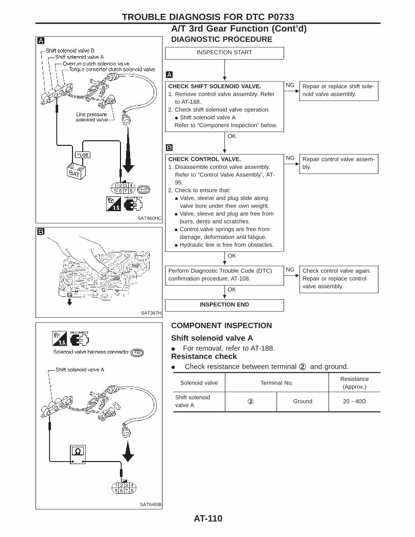
SAT960HC
SAT367H
DIAGNOSTIC PROCEDURE
INSPECTION START
CHECK SHIFT SOLENOID VALVE.1. Remove control valve assembly. Refer
to AT-188.2. Check shift solenoid valve operation.
I Shift solenoid valve ARefer to “Component Inspection” below.
OK
ENG Repair or replace shift sole-
noid valve assembly.
CHECK CONTROL VALVE.1. Disassemble control valve assembly.
Refer to “Control Valve Assembly”, AT-95.
2. Check to ensure that:I Valve, sleeve and plug slide along
valve bore under their own weight.I Valve, sleeve and plug are free from
burrs, dents and scratches.I Control valve springs are free from
damage, deformation and fatigue.I Hydraulic line is free from obstacles.
OK
ENG Repair control valve assem-
bly.
Perform Diagnostic Trouble Code (DTC)confirmation procedure, AT-108.
OK
ENG Check control valve again.
Repair or replace controlvalve assembly.
INSPECTION END
SAT640IB
COMPONENT INSPECTION
Shift solenoid valve AI For removal, refer to AT-188.Resistance checkI Check resistance between terminal q2 and ground.
Solenoid valve Terminal No.Resistance(Approx.)
Shift solenoidvalve A
q2 Ground 20 - 40Ω
TROUBLE DIAGNOSIS FOR DTC P0733A/T 3rd Gear Function (Cont’d)
H
H
H
H
AT-110

SAT960HC
Operation checkI Check solenoid valve by listening for its operating sound while
applying battery voltage to the terminal q2 and ground.
TROUBLE DIAGNOSIS FOR DTC P0733A/T 3rd Gear Function (Cont’d)
AT-111
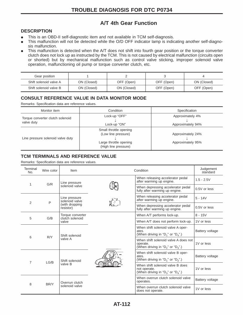
A/T 4th Gear FunctionDESCRIPTIONI This is an OBD-II self-diagnostic item and not available in TCM self-diagnosis.I This malfunction will not be detected while the O/D OFF indicator lamp is indicating another self-diagno-
sis malfunction.I This malfunction is detected when the A/T does not shift into fourth gear position or the torque converter
clutch does not lock up as instructed by the TCM. This is not caused by electrical malfunction (circuits openor shorted) but by mechanical malfunction such as control valve sticking, improper solenoid valveoperation, malfunctioning oil pump or torque converter clutch, etc.
Gear position 1 2 3 4
Shift solenoid valve A ON (Closed) OFF (Open) OFF (Open) ON (Closed)
Shift solenoid valve B ON (Closed) ON (Closed) OFF (Open) OFF (Open)
CONSULT REFERENCE VALUE IN DATA MONITOR MODERemarks: Specification data are reference values.
Monitor item Condition Specification
Torque converter clutch solenoidvalve duty
Lock-up “OFF”"
Lock-up “ON”
Approximately 4%"
Approximately 94%
Line pressure solenoid valve duty
Small throttle opening(Low line pressure)
"
Large throttle opening(High line pressure)
Approximately 24%"
Approximately 95%
TCM TERMINALS AND REFERENCE VALUERemarks: Specification data are reference values.
TerminalNo. Wire color Item Condition Judgement
standard
1 G/R Line pressuresolenoid valve
When releasing accelerator pedalafter warming up engine. 1.5 - 2.5V
When depressing accelerator pedalfully after warming up engine. 0.5V or less
2 P
Line pressuresolenoid valve(with droppingresistor)
When releasing accelerator pedalafter warming up engine. 5 - 14V
When depressing accelerator pedalfully after warming up engine. 0.5V or less
5 G/BTorque converterclutch solenoidvalve
When A/T performs lock-up. 8 - 15V
When A/T does not perform lock-up. 1V or less
6 R/Y Shift solenoidvalve A
When shift solenoid valve A oper-ates.(When driving in “D1” or “D4”.)
Battery voltage
When shift solenoid valve A does notoperate.(When driving in “D2” or “D3”.)
1V or less
7 LG/B Shift solenoidvalve B
When shift solenoid valve B oper-ates.(When driving in “D1” or “D2”.)
Battery voltage
When shift solenoid valve B doesnot operate.(When driving in “D3” or “D4”.)
1V or less
8 BR/Y Overrun clutchsolenoid valve
When overrun clutch solenoid valveoperates. Battery voltage
When overrun clutch solenoid valvedoes not operate. 1V or less
TROUBLE DIAGNOSIS FOR DTC P0734
AT-112
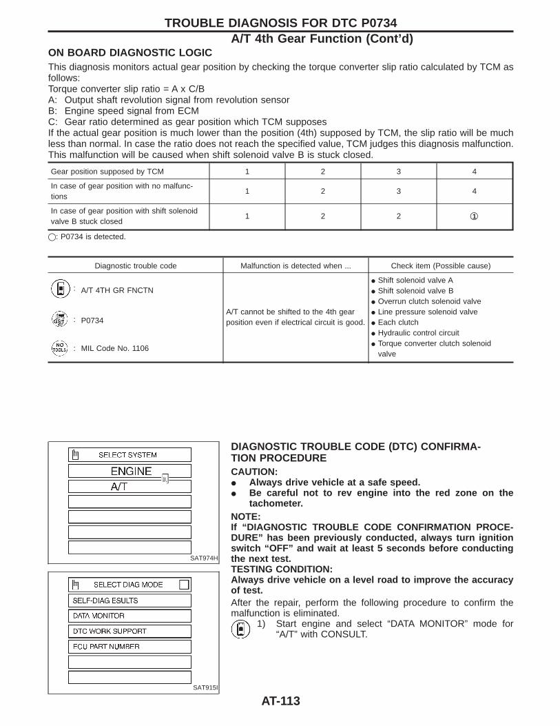
ON BOARD DIAGNOSTIC LOGICThis diagnosis monitors actual gear position by checking the torque converter slip ratio calculated by TCM asfollows:Torque converter slip ratio = A x C/BA: Output shaft revolution signal from revolution sensorB: Engine speed signal from ECMC: Gear ratio determined as gear position which TCM supposesIf the actual gear position is much lower than the position (4th) supposed by TCM, the slip ratio will be muchless than normal. In case the ratio does not reach the specified value, TCM judges this diagnosis malfunction.This malfunction will be caused when shift solenoid valve B is stuck closed.
Gear position supposed by TCM 1 2 3 4
In case of gear position with no malfunc-tions
1 2 3 4
In case of gear position with shift solenoidvalve B stuck closed
1 2 2 q1
q: P0734 is detected.
Diagnostic trouble code Malfunction is detected when ... Check item (Possible cause)
: A/T 4TH GR FNCTN
A/T cannot be shifted to the 4th gearposition even if electrical circuit is good.
I Shift solenoid valve AI Shift solenoid valve BI Overrun clutch solenoid valveI Line pressure solenoid valveI Each clutchI Hydraulic control circuitI Torque converter clutch solenoid
valve
: P0734
: MIL Code No. 1106
SAT974H
SAT915I
DIAGNOSTIC TROUBLE CODE (DTC) CONFIRMA-TION PROCEDURECAUTION:I Always drive vehicle at a safe speed.I Be careful not to rev engine into the red zone on the
tachometer.NOTE:If “DIAGNOSTIC TROUBLE CODE CONFIRMATION PROCE-DURE” has been previously conducted, always turn ignitionswitch “OFF” and wait at least 5 seconds before conductingthe next test.TESTING CONDITION:Always drive vehicle on a level road to improve the accuracyof test.After the repair, perform the following procedure to confirm themalfunction is eliminated.
1) Start engine and select “DATA MONITOR” mode for“A/T” with CONSULT.
TROUBLE DIAGNOSIS FOR DTC P0734A/T 4th Gear Function (Cont’d)
AT-113
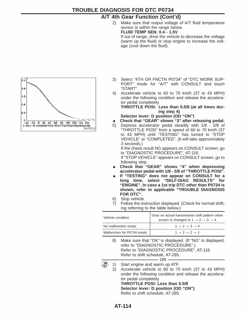
2) Make sure that output voltage of A/T fluid temperaturesensor is within the range below.FLUID TEMP SEN: 0.4 - 1.5VIf out of range, drive the vehicle to decrease the voltage(warm up the fluid) or stop engine to increase the volt-age (cool down the fluid).
SAT021J
3) Select “4TH GR FNCTN P0734” of “DTC WORK SUP-PORT” mode for “A/T” with CONSULT and touch“START”.
4) Accelerate vehicle to 60 to 70 km/h (37 to 43 MPH)under the following condition and release the accelera-tor pedal completely.THROTTLE POSI: Less than 5.5/8 (at all times dur-
ing step 4)Selector lever: D position (OD “ON”)
I Check that “GEAR” shows “3” after releasing pedal.5) Depress accelerator pedal steadily with 1/8 - 2/8 of
“THROTTLE POSI” from a speed of 60 to 70 km/h (37to 43 MPH) until “TESTING” has turned to “STOPVEHICLE” or “COMPLETED”. (It will take approximately3 seconds.)If the check result NG appears on CONSULT screen, goto “DIAGNOSTIC PROCEDURE”, AT-116.If “STOP VEHICLE” appears on CONSULT screen, go tofollowing step.
I Check that “GEAR” shows “4” when depressingaccelerator pedal with 1/8 - 2/8 of “THROTTLE POSI”.
I If “TESTING” does not appear on CONSULT for along time, select “SELF-DIAG RESULTS” for“ENGINE”. In case a 1st trip DTC other than P0734 isshown, refer to applicable “TROUBLE DIAGNOSISFOR DTC”.
6) Stop vehicle.7) Follow the instruction displayed. (Check for normal shift-
ing referring to the table below.)
Vehicle conditionGear on actual transmission shift pattern when
screen is changed to 1 , 2 , 3 , 4
No malfunction exists 1 , 2 , 3 , 4
Malfunction for P0734 exists. 1 , 2 , 2 , 1
8) Make sure that “OK” is displayed. (If “NG” is displayed,refer to “DIAGNOSTIC PROCEDURE”.)Refer to “DIAGNOSTIC PROCEDURE”, AT-116.Refer to shift schedule, AT-285.
------------------------------------------------------------------------------------------------------------------------------------------------------------------------------------------------------------------------------------------------------ OR ------------------------------------------------------------------------------------------------------------------------------------------------------------------------------------------------------------------------------------------------------1) Start engine and warm up ATF.2) Accelerate vehicle to 60 to 70 km/h (37 to 43 MPH)
under the following condition and release the accelera-tor pedal completely.THROTTLE POSI: Less than 5.5/8Selector lever: D position (OD “ON”)Refer to shift schedule, AT-285.
TROUBLE DIAGNOSIS FOR DTC P0734A/T 4th Gear Function (Cont’d)
AT-114
3) Depress accelerator pedal with 1/8 - 2/8 of “THROTTLEPOSI” from a speed of 60 to 70 km/h (37 to 43 MPH) (Itwill take approximately 3 seconds.)
4) Select “MODE 7” with GST.------------------------------------------------------------------------------------------------------------------------------------------------------------------------------------------------------------------------------------------------------ OR ------------------------------------------------------------------------------------------------------------------------------------------------------------------------------------------------------------------------------------------------------
1) Start engine and warm up ATF.2) Accelerate vehicle to 60 to 70 km/h (37 to 43 MPH)
under the following condition and release the accelera-tor pedal completely.THROTTLE POSI: Less than 5.5/8Selector lever: D position (OD “ON”)Refer to shift schedule, AT-285.
3) Depress accelerator pedal with 1/8 - 2/8 of “THROTTLEPOSI” from a speed of 60 to 70 km/h (37 to 43 MPH).(It will take approximately 3 seconds.)
4) Perform self-diagnosis for ECM.Refer to EC section [“Malfunction Indicator Lamp (MIL)”,“ON BOARD DIAGNOSTIC SYSTEM DESCRIPTION”].
TROUBLE DIAGNOSIS FOR DTC P0734A/T 4th Gear Function (Cont’d)
AT-115
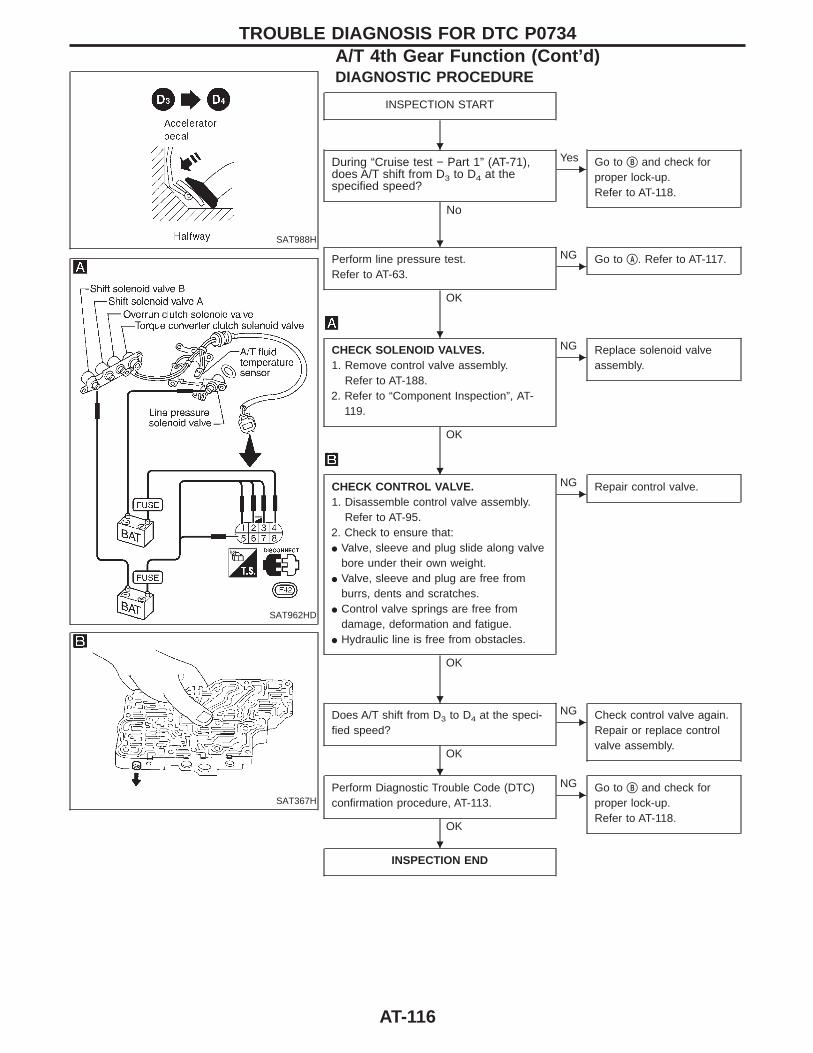
SAT988H
SAT962HD
SAT367H
DIAGNOSTIC PROCEDURE
INSPECTION START
During “Cruise test − Part 1” (AT-71),does A/T shift from D3 to D4 at thespecified speed?
No
EYes Go to qB and check for
proper lock-up.Refer to AT-118.
Perform line pressure test.Refer to AT-63.
OK
ENG Go to qA . Refer to AT-117.
CHECK SOLENOID VALVES.1. Remove control valve assembly.
Refer to AT-188.2. Refer to “Component Inspection”, AT-
119.
OK
ENG Replace solenoid valve
assembly.
CHECK CONTROL VALVE.1. Disassemble control valve assembly.
Refer to AT-95.2. Check to ensure that:I Valve, sleeve and plug slide along valve
bore under their own weight.I Valve, sleeve and plug are free from
burrs, dents and scratches.I Control valve springs are free from
damage, deformation and fatigue.I Hydraulic line is free from obstacles.
OK
ENG Repair control valve.
Does A/T shift from D3 to D4 at the speci-fied speed?
OK
ENG Check control valve again.
Repair or replace controlvalve assembly.
Perform Diagnostic Trouble Code (DTC)confirmation procedure, AT-113.
OK
ENG Go to qB and check for
proper lock-up.Refer to AT-118.
INSPECTION END
TROUBLE DIAGNOSIS FOR DTC P0734A/T 4th Gear Function (Cont’d)
H
H
H
H
H
H
H
AT-116
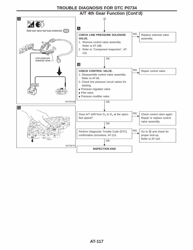
SAT641IB
SAT367H
qA
CHECK LINE PRESSURE SOLENOIDVALVE.1. Remove control valve assembly.
Refer to AT-188.2. Refer to “Component Inspection”, AT-
119.
OK
ENG Replace solenoid valve
assembly.
CHECK CONTROL VALVE.1. Disassemble control valve assembly.
Refer to AT-95.2. Check line pressure circuit valves for
sticking.I Pressure regulator valveI Pilot valveI Pressure modifier valve
OK
ENG Repair control valve.
Does A/T shift from D3 to D4 at the speci-fied speed?
OK
ENG Check control valve again.
Repair or replace controlvalve assembly.
Perform Diagnostic Trouble Code (DTC)confirmation procedure, AT-113.
OK
ENG Go to qB and check for
proper lock-up.Refer to AT-118.
INSPECTION END
TROUBLE DIAGNOSIS FOR DTC P0734A/T 4th Gear Function (Cont’d)
H
H
H
H
H
AT-117
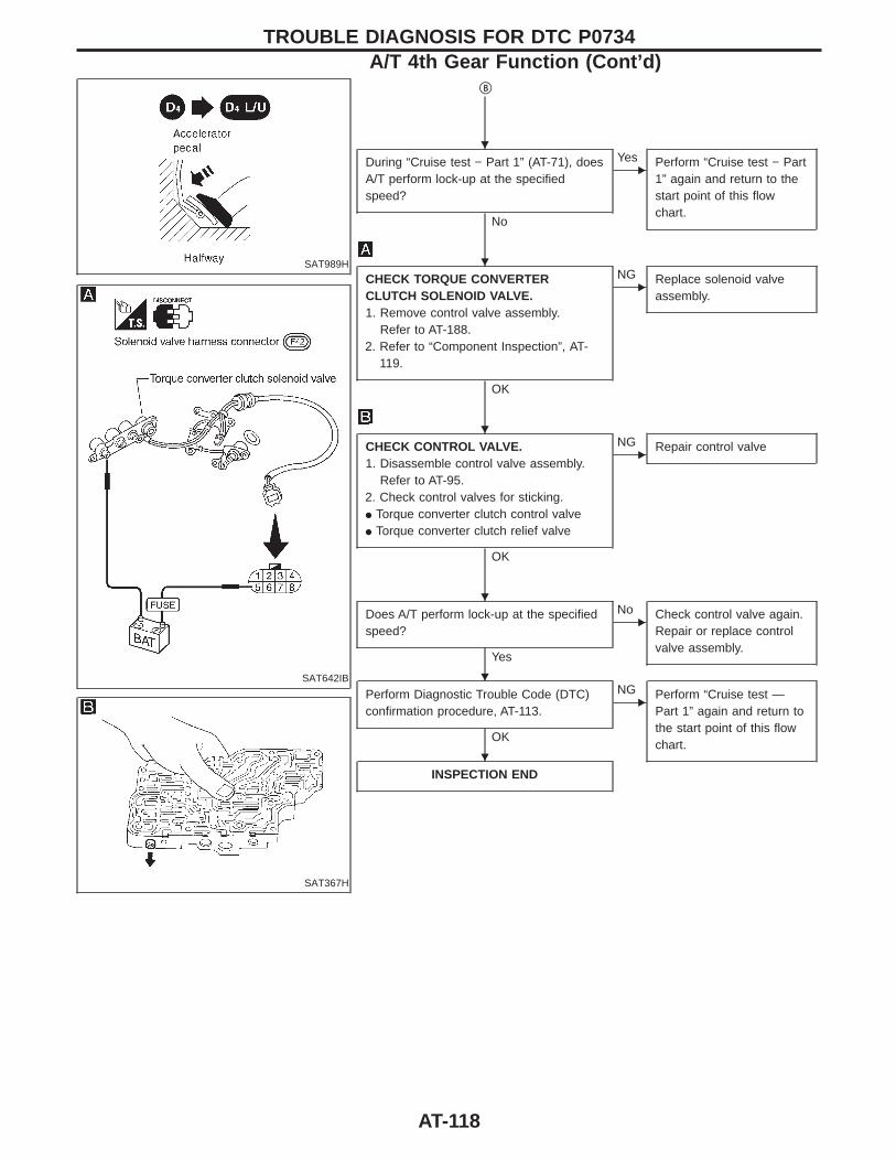
SAT989H
SAT642IB
SAT367H
qB
During “Cruise test − Part 1” (AT-71), doesA/T perform lock-up at the specifiedspeed?
No
EYes Perform “Cruise test − Part
1” again and return to thestart point of this flowchart.
CHECK TORQUE CONVERTERCLUTCH SOLENOID VALVE.1. Remove control valve assembly.
Refer to AT-188.2. Refer to “Component Inspection”, AT-
119.
OK
ENG Replace solenoid valve
assembly.
CHECK CONTROL VALVE.1. Disassemble control valve assembly.
Refer to AT-95.2. Check control valves for sticking.I Torque converter clutch control valveI Torque converter clutch relief valve
OK
ENG Repair control valve
Does A/T perform lock-up at the specifiedspeed?
Yes
ENo Check control valve again.
Repair or replace controlvalve assembly.
Perform Diagnostic Trouble Code (DTC)confirmation procedure, AT-113.
OK
ENG Perform “Cruise test —
Part 1” again and return tothe start point of this flowchart.
INSPECTION END
TROUBLE DIAGNOSIS FOR DTC P0734A/T 4th Gear Function (Cont’d)
H
H
H
H
H
H
AT-118
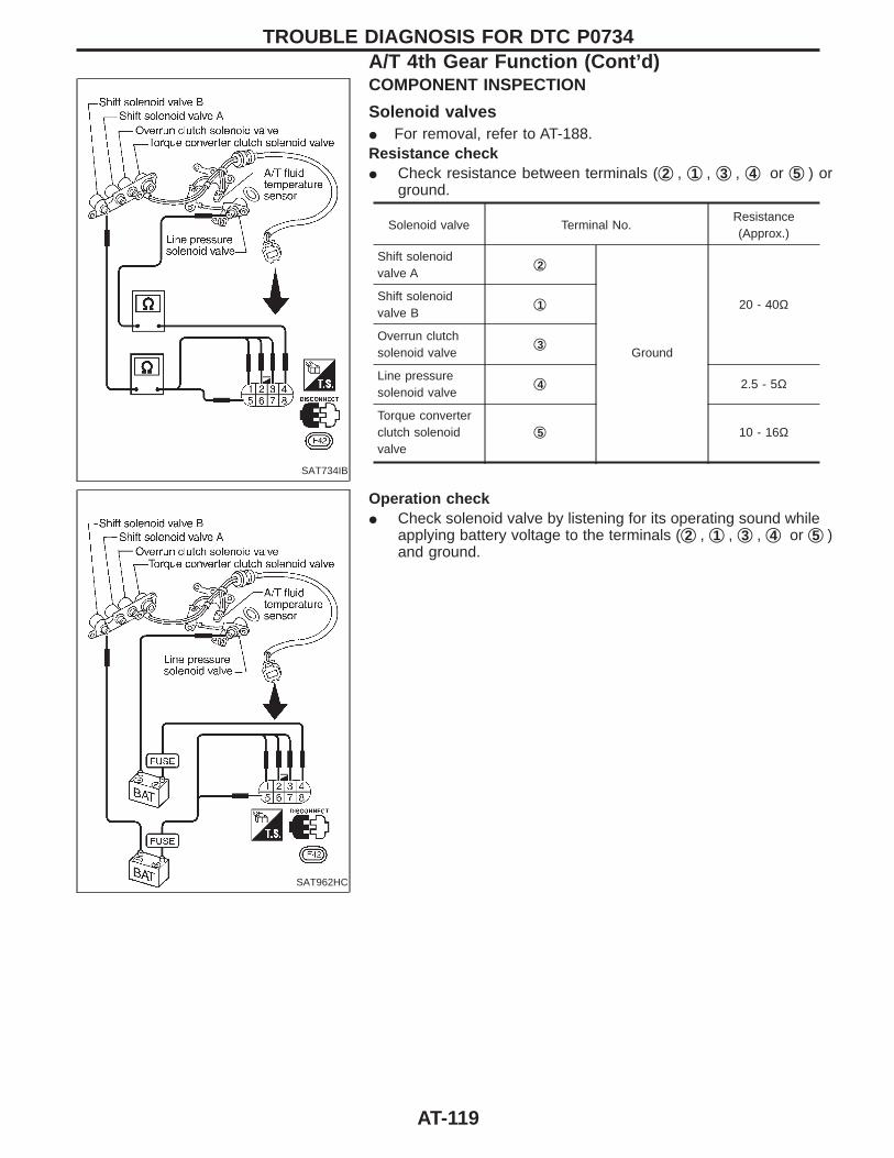
SAT734IB
COMPONENT INSPECTION
Solenoid valvesI For removal, refer to AT-188.Resistance checkI Check resistance between terminals (q2 , q1 , q3 , q4 or q5 ) or
ground.
Solenoid valve Terminal No.Resistance(Approx.)
Shift solenoidvalve A
q2
Ground
20 - 40ΩShift solenoidvalve B
q1
Overrun clutchsolenoid valve
q3
Line pressuresolenoid valve
q4 2.5 - 5Ω
Torque converterclutch solenoidvalve
q5 10 - 16Ω
SAT962HC
Operation checkI Check solenoid valve by listening for its operating sound while
applying battery voltage to the terminals (q2 , q1 , q3 , q4 or q5 )and ground.
TROUBLE DIAGNOSIS FOR DTC P0734A/T 4th Gear Function (Cont’d)
AT-119
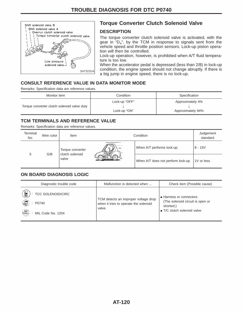
SAT322GA
Torque Converter Clutch Solenoid Valve
DESCRIPTIONThe torque converter clutch solenoid valve is activated, with thegear in “D4”, by the TCM in response to signals sent from thevehicle speed and throttle position sensors. Lock-up piston opera-tion will then be controlled.Lock-up operation, however, is prohibited when A/T fluid tempera-ture is too low.When the accelerator pedal is depressed (less than 2/8) in lock-upcondition, the engine speed should not change abruptly. If there isa big jump in engine speed, there is no lock-up.
CONSULT REFERENCE VALUE IN DATA MONITOR MODERemarks: Specification data are reference values.
Monitor item Condition Specification
Torque converter clutch solenoid valve dutyLock-up “OFF”
"
Lock-up “ON”
Approximately 4%"
Approximately 94%
TCM TERMINALS AND REFERENCE VALUERemarks: Specification data are reference values.
TerminalNo.
Wire color Item ConditionJudgementstandard
5 G/BTorque converterclutch solenoidvalve
When A/T performs lock-up. 8 - 15V
When A/T does not perform lock-up. 1V or less
ON BOARD DIAGNOSIS LOGIC
Diagnostic trouble code Malfunction is detected when ... Check item (Possible cause)
: TCC SOLENOID/CIRC
TCM detects an improper voltage dropwhen it tries to operate the solenoidvalve.
I Harness or connectors(The solenoid circuit is open orshorted.)
I T/C clutch solenoid valve
: P0740
: MIL Code No. 1204
TROUBLE DIAGNOSIS FOR DTC P0740
AT-120
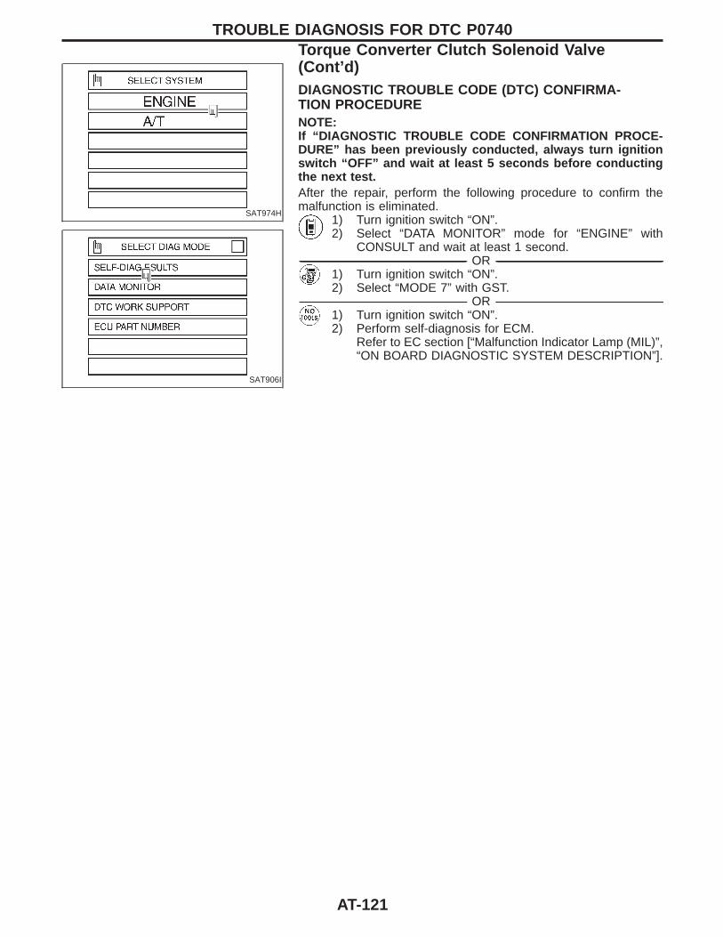
SAT974H
SAT906I
DIAGNOSTIC TROUBLE CODE (DTC) CONFIRMA-TION PROCEDURENOTE:If “DIAGNOSTIC TROUBLE CODE CONFIRMATION PROCE-DURE” has been previously conducted, always turn ignitionswitch “OFF” and wait at least 5 seconds before conductingthe next test.After the repair, perform the following procedure to confirm themalfunction is eliminated.
1) Turn ignition switch “ON”.2) Select “DATA MONITOR” mode for “ENGINE” with
CONSULT and wait at least 1 second.------------------------------------------------------------------------------------------------------------------------------------------------------------------------------------------------------------------------------------------------------ OR ------------------------------------------------------------------------------------------------------------------------------------------------------------------------------------------------------------------------------------------------------
1) Turn ignition switch “ON”.2) Select “MODE 7” with GST.
------------------------------------------------------------------------------------------------------------------------------------------------------------------------------------------------------------------------------------------------------ OR ------------------------------------------------------------------------------------------------------------------------------------------------------------------------------------------------------------------------------------------------------1) Turn ignition switch “ON”.2) Perform self-diagnosis for ECM.
Refer to EC section [“Malfunction Indicator Lamp (MIL)”,“ON BOARD DIAGNOSTIC SYSTEM DESCRIPTION”].
TROUBLE DIAGNOSIS FOR DTC P0740Torque Converter Clutch Solenoid Valve(Cont’d)
AT-121
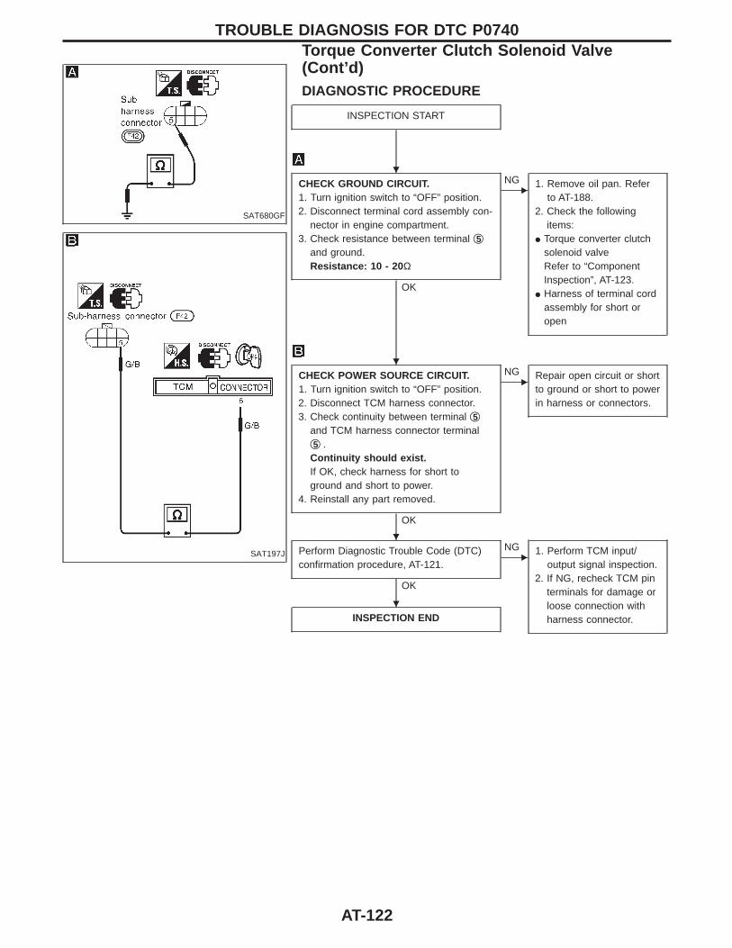
SAT680GF
SAT197J
DIAGNOSTIC PROCEDURE
INSPECTION START
CHECK GROUND CIRCUIT.1. Turn ignition switch to “OFF” position.2. Disconnect terminal cord assembly con-
nector in engine compartment.3. Check resistance between terminal q5
and ground.Resistance: 10 - 20 Ω
OK
ENG 1. Remove oil pan. Refer
to AT-188.2. Check the following
items:I Torque converter clutch
solenoid valveRefer to “ComponentInspection”, AT-123.
I Harness of terminal cordassembly for short oropen
CHECK POWER SOURCE CIRCUIT.1. Turn ignition switch to “OFF” position.2. Disconnect TCM harness connector.3. Check continuity between terminal q5
and TCM harness connector terminalq5 .Continuity should exist.If OK, check harness for short toground and short to power.
4. Reinstall any part removed.
OK
ENG Repair open circuit or short
to ground or short to powerin harness or connectors.
Perform Diagnostic Trouble Code (DTC)confirmation procedure, AT-121.
OK
ENG 1. Perform TCM input/
output signal inspection.2. If NG, recheck TCM pin
terminals for damage orloose connection withharness connector.INSPECTION END
TROUBLE DIAGNOSIS FOR DTC P0740Torque Converter Clutch Solenoid Valve(Cont’d)
H
H
H
H
AT-122

SAT643IB
COMPONENT INSPECTION
Torque converter clutch solenoid valveI For removal, refer to AT-188.Resistance checkI Check resistance between terminal q5 and ground.
Solenoid valve Terminal No.Resistance(Approx.)
Torque converterclutch solenoidvalve
q5 Ground 10 - 16Ω
SAT642IC
Operation checkI Check solenoid valve by listening for its operating sound while
applying battery voltage to the terminal q5 and ground.
TROUBLE DIAGNOSIS FOR DTC P0740Torque Converter Clutch Solenoid Valve(Cont’d)
AT-123
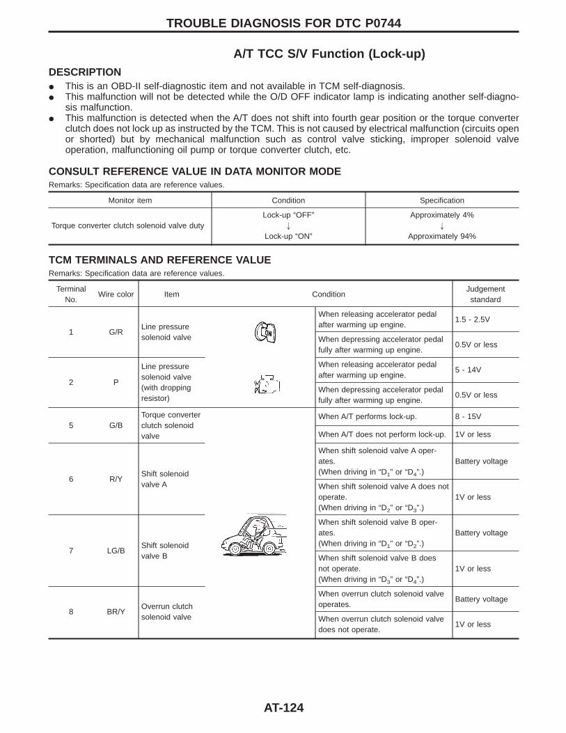
A/T TCC S/V Function (Lock-up)DESCRIPTIONI This is an OBD-II self-diagnostic item and not available in TCM self-diagnosis.I This malfunction will not be detected while the O/D OFF indicator lamp is indicating another self-diagno-
sis malfunction.I This malfunction is detected when the A/T does not shift into fourth gear position or the torque converter
clutch does not lock up as instructed by the TCM. This is not caused by electrical malfunction (circuits openor shorted) but by mechanical malfunction such as control valve sticking, improper solenoid valveoperation, malfunctioning oil pump or torque converter clutch, etc.
CONSULT REFERENCE VALUE IN DATA MONITOR MODERemarks: Specification data are reference values.
Monitor item Condition Specification
Torque converter clutch solenoid valve dutyLock-up “OFF”
"
Lock-up “ON”
Approximately 4%"
Approximately 94%
TCM TERMINALS AND REFERENCE VALUERemarks: Specification data are reference values.
TerminalNo.
Wire color Item ConditionJudgementstandard
1 G/RLine pressuresolenoid valve
When releasing accelerator pedalafter warming up engine.
1.5 - 2.5V
When depressing accelerator pedalfully after warming up engine.
0.5V or less
2 P
Line pressuresolenoid valve(with droppingresistor)
When releasing accelerator pedalafter warming up engine.
5 - 14V
When depressing accelerator pedalfully after warming up engine.
0.5V or less
5 G/BTorque converterclutch solenoidvalve
When A/T performs lock-up. 8 - 15V
When A/T does not perform lock-up. 1V or less
6 R/YShift solenoidvalve A
When shift solenoid valve A oper-ates.(When driving in “D1” or “D4”.)
Battery voltage
When shift solenoid valve A does notoperate.(When driving in “D2” or “D3”.)
1V or less
7 LG/BShift solenoidvalve B
When shift solenoid valve B oper-ates.(When driving in “D1” or “D2”.)
Battery voltage
When shift solenoid valve B doesnot operate.(When driving in “D3” or “D4”.)
1V or less
8 BR/YOverrun clutchsolenoid valve
When overrun clutch solenoid valveoperates.
Battery voltage
When overrun clutch solenoid valvedoes not operate.
1V or less
TROUBLE DIAGNOSIS FOR DTC P0744
AT-124
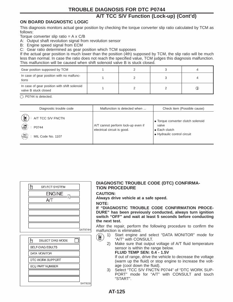
ON BOARD DIAGNOSTIC LOGICThis diagnosis monitors actual gear position by checking the torque converter slip ratio calculated by TCM asfollows:Torque converter slip ratio = A x C/BA: Output shaft revolution signal from revolution sensorB: Engine speed signal from ECMC: Gear ratio determined as gear position which TCM supposesIf the actual gear position is much lower than the position (4th) supposed by TCM, the slip ratio will be muchless than normal. In case the ratio does not reach the specified value, TCM judges this diagnosis malfunction.This malfunction will be caused when shift solenoid valve B is stuck closed.
Gear position supposed by TCM 1 2 3 4
In case of gear position with no malfunc-tions
1 2 3 4
In case of gear position with shift solenoidvalve B stuck closed
1 2 2 q1
q: P0744 is detected.
Diagnostic trouble code Malfunction is detected when ... Check item (Possible cause)
: A/T TCC S/V FNCTN
A/T cannot perform lock-up even ifelectrical circuit is good.
I Torque converter clutch solenoidvalve
I Each clutchI Hydraulic control circuit
: P0744
: MIL Code No. 1107
SAT974H
SAT915I
DIAGNOSTIC TROUBLE CODE (DTC) CONFIRMA-TION PROCEDURECAUTION:Always drive vehicle at a safe speed.NOTE:If “DIAGNOSTIC TROUBLE CODE CONFIRMATION PROCE-DURE” has been previously conducted, always turn ignitionswitch “OFF” and wait at least 5 seconds before conductingthe next test.After the repair, perform the following procedure to confirm themalfunction is eliminated.
1) Start engine and select “DATA MONITOR” mode for“A/T” with CONSULT.
2) Make sure that output voltage of A/T fluid temperaturesensor is within the range below.FLUID TEMP SEN: 0.4 - 1.5VIf out of range, drive the vehicle to decrease the voltage(warm up the fluid) or stop engine to increase the volt-age (cool down the fluid).
3) Select “TCC S/V FNCTN P0744” of “DTC WORK SUP-PORT” mode for “A/T” with CONSULT and touch“START”.
TROUBLE DIAGNOSIS FOR DTC P0744A/T TCC S/V Function (Lock-up) (Cont’d)
AT-125
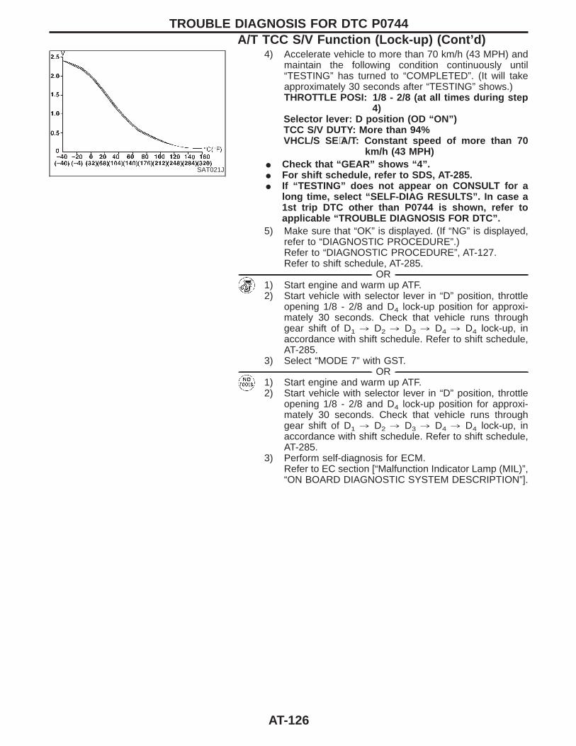
SAT021J
4) Accelerate vehicle to more than 70 km/h (43 MPH) andmaintain the following condition continuously until“TESTING” has turned to “COMPLETED”. (It will takeapproximately 30 seconds after “TESTING” shows.)THROTTLE POSI: 1/8 - 2/8 (at all times during step
4)Selector lever: D position (OD “ON”)TCC S/V DUTY: More than 94%VHCL/S SE⋅A/T: Constant speed of more than 70
km/h (43 MPH)I Check that “GEAR” shows “4”.I For shift schedule, refer to SDS, AT-285.I If “TESTING” does not appear on CONSULT for a
long time, select “SELF-DIAG RESULTS”. In case a1st trip DTC other than P0744 is shown, refer toapplicable “TROUBLE DIAGNOSIS FOR DTC”.
5) Make sure that “OK” is displayed. (If “NG” is displayed,refer to “DIAGNOSTIC PROCEDURE”.)Refer to “DIAGNOSTIC PROCEDURE”, AT-127.Refer to shift schedule, AT-285.
------------------------------------------------------------------------------------------------------------------------------------------------------------------------------------------------------------------------------------------------------ OR ------------------------------------------------------------------------------------------------------------------------------------------------------------------------------------------------------------------------------------------------------1) Start engine and warm up ATF.2) Start vehicle with selector lever in “D” position, throttle
opening 1/8 - 2/8 and D4 lock-up position for approxi-mately 30 seconds. Check that vehicle runs throughgear shift of D1 , D2 , D3 , D4 , D4 lock-up, inaccordance with shift schedule. Refer to shift schedule,AT-285.
3) Select “MODE 7” with GST.------------------------------------------------------------------------------------------------------------------------------------------------------------------------------------------------------------------------------------------------------ OR ------------------------------------------------------------------------------------------------------------------------------------------------------------------------------------------------------------------------------------------------------
1) Start engine and warm up ATF.2) Start vehicle with selector lever in “D” position, throttle
opening 1/8 - 2/8 and D4 lock-up position for approxi-mately 30 seconds. Check that vehicle runs throughgear shift of D1 , D2 , D3 , D4 , D4 lock-up, inaccordance with shift schedule. Refer to shift schedule,AT-285.
3) Perform self-diagnosis for ECM.Refer to EC section [“Malfunction Indicator Lamp (MIL)”,“ON BOARD DIAGNOSTIC SYSTEM DESCRIPTION”].
TROUBLE DIAGNOSIS FOR DTC P0744A/T TCC S/V Function (Lock-up) (Cont’d)
AT-126
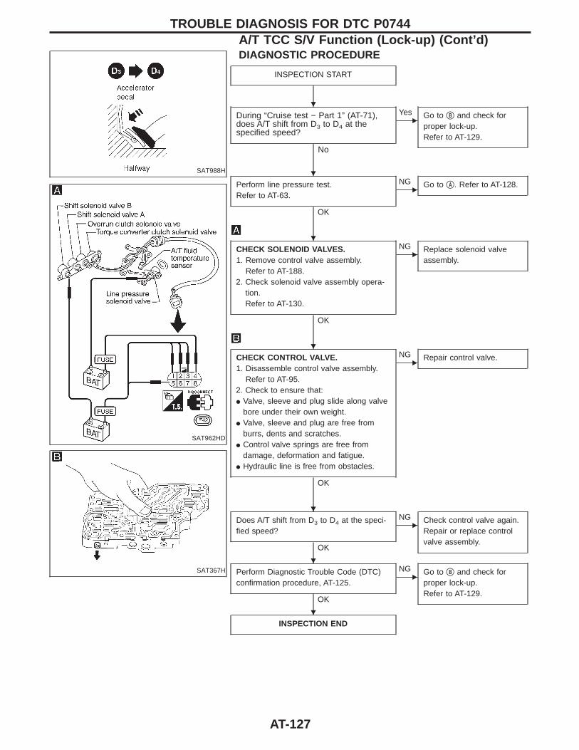
SAT988H
SAT962HD
SAT367H
DIAGNOSTIC PROCEDURE
INSPECTION START
During “Cruise test − Part 1” (AT-71),does A/T shift from D3 to D4 at thespecified speed?
No
EYes Go to qB and check for
proper lock-up.Refer to AT-129.
Perform line pressure test.Refer to AT-63.
OK
ENG Go to qA . Refer to AT-128.
CHECK SOLENOID VALVES.1. Remove control valve assembly.
Refer to AT-188.2. Check solenoid valve assembly opera-
tion.Refer to AT-130.
OK
ENG Replace solenoid valve
assembly.
CHECK CONTROL VALVE.1. Disassemble control valve assembly.
Refer to AT-95.2. Check to ensure that:I Valve, sleeve and plug slide along valve
bore under their own weight.I Valve, sleeve and plug are free from
burrs, dents and scratches.I Control valve springs are free from
damage, deformation and fatigue.I Hydraulic line is free from obstacles.
OK
ENG Repair control valve.
Does A/T shift from D3 to D4 at the speci-fied speed?
OK
ENG Check control valve again.
Repair or replace controlvalve assembly.
Perform Diagnostic Trouble Code (DTC)confirmation procedure, AT-125.
OK
ENG Go to qB and check for
proper lock-up.Refer to AT-129.
INSPECTION END
TROUBLE DIAGNOSIS FOR DTC P0744A/T TCC S/V Function (Lock-up) (Cont’d)
H
H
H
H
H
H
H
AT-127
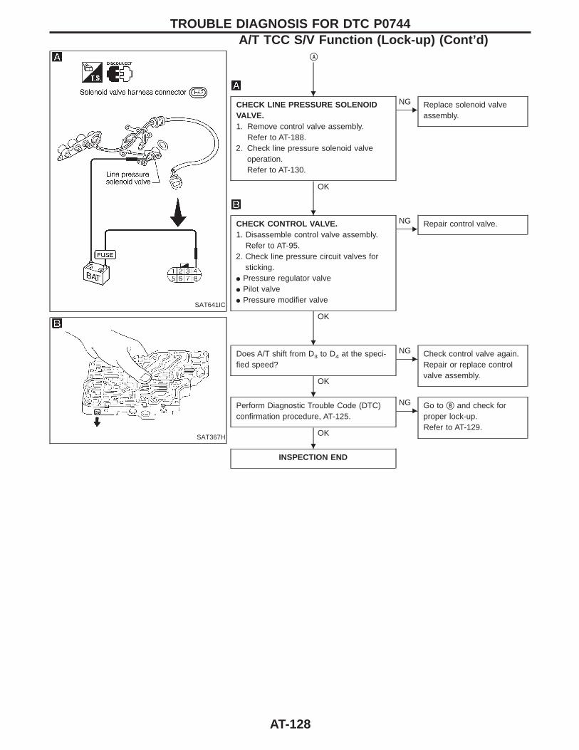
SAT641IC
SAT367H
qA
CHECK LINE PRESSURE SOLENOIDVALVE.1. Remove control valve assembly.
Refer to AT-188.2. Check line pressure solenoid valve
operation.Refer to AT-130.
OK
ENG Replace solenoid valve
assembly.
CHECK CONTROL VALVE.1. Disassemble control valve assembly.
Refer to AT-95.2. Check line pressure circuit valves for
sticking.I Pressure regulator valveI Pilot valveI Pressure modifier valve
OK
ENG Repair control valve.
Does A/T shift from D3 to D4 at the speci-fied speed?
OK
ENG Check control valve again.
Repair or replace controlvalve assembly.
Perform Diagnostic Trouble Code (DTC)confirmation procedure, AT-125.
OK
ENG Go to qB and check for
proper lock-up.Refer to AT-129.
INSPECTION END
TROUBLE DIAGNOSIS FOR DTC P0744A/T TCC S/V Function (Lock-up) (Cont’d)
H
H
H
H
H
AT-128
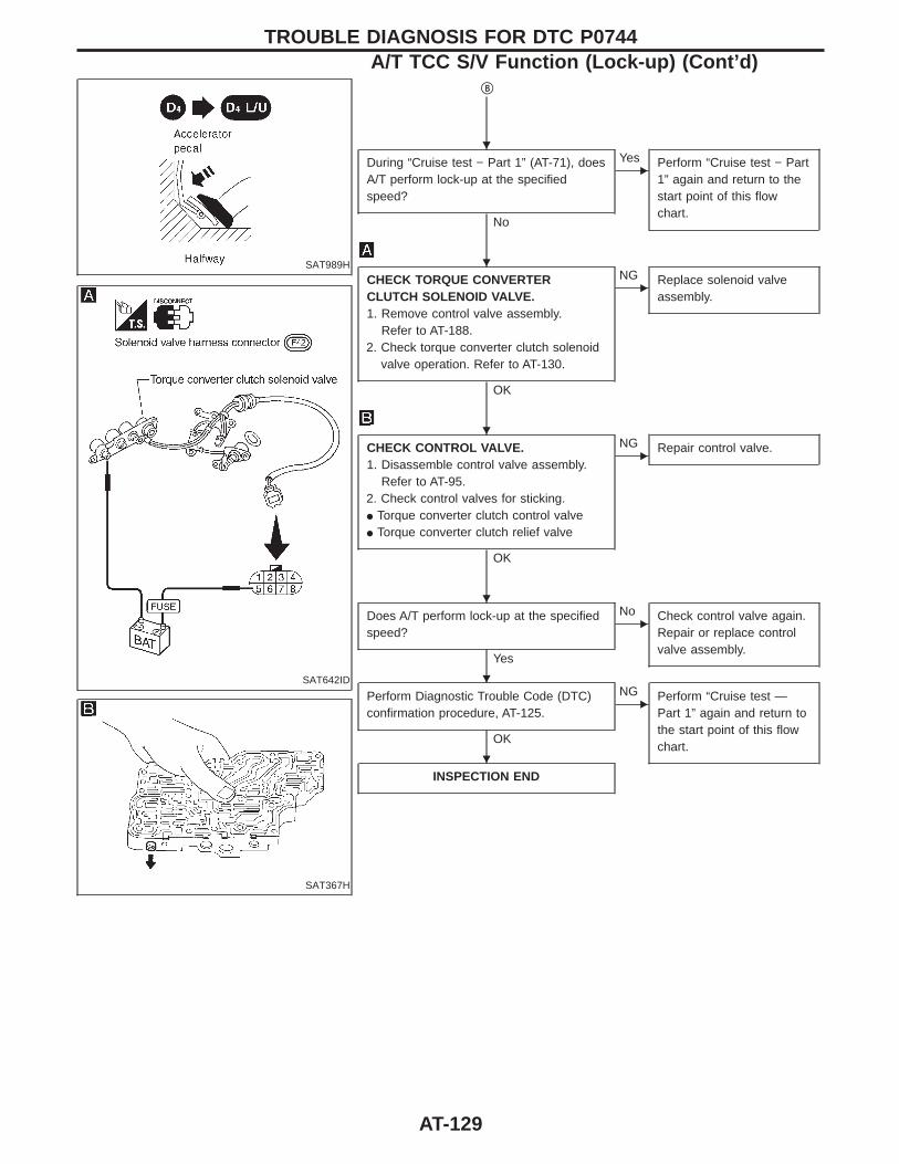
SAT989H
SAT642ID
SAT367H
qB
During “Cruise test − Part 1” (AT-71), doesA/T perform lock-up at the specifiedspeed?
No
EYes Perform “Cruise test − Part
1” again and return to thestart point of this flowchart.
CHECK TORQUE CONVERTERCLUTCH SOLENOID VALVE.1. Remove control valve assembly.
Refer to AT-188.2. Check torque converter clutch solenoid
valve operation. Refer to AT-130.
OK
ENG Replace solenoid valve
assembly.
CHECK CONTROL VALVE.1. Disassemble control valve assembly.
Refer to AT-95.2. Check control valves for sticking.I Torque converter clutch control valveI Torque converter clutch relief valve
OK
ENG Repair control valve.
Does A/T perform lock-up at the specifiedspeed?
Yes
ENo Check control valve again.
Repair or replace controlvalve assembly.
Perform Diagnostic Trouble Code (DTC)confirmation procedure, AT-125.
OK
ENG Perform “Cruise test —
Part 1” again and return tothe start point of this flowchart.
INSPECTION END
TROUBLE DIAGNOSIS FOR DTC P0744A/T TCC S/V Function (Lock-up) (Cont’d)
H
H
H
H
H
H
AT-129
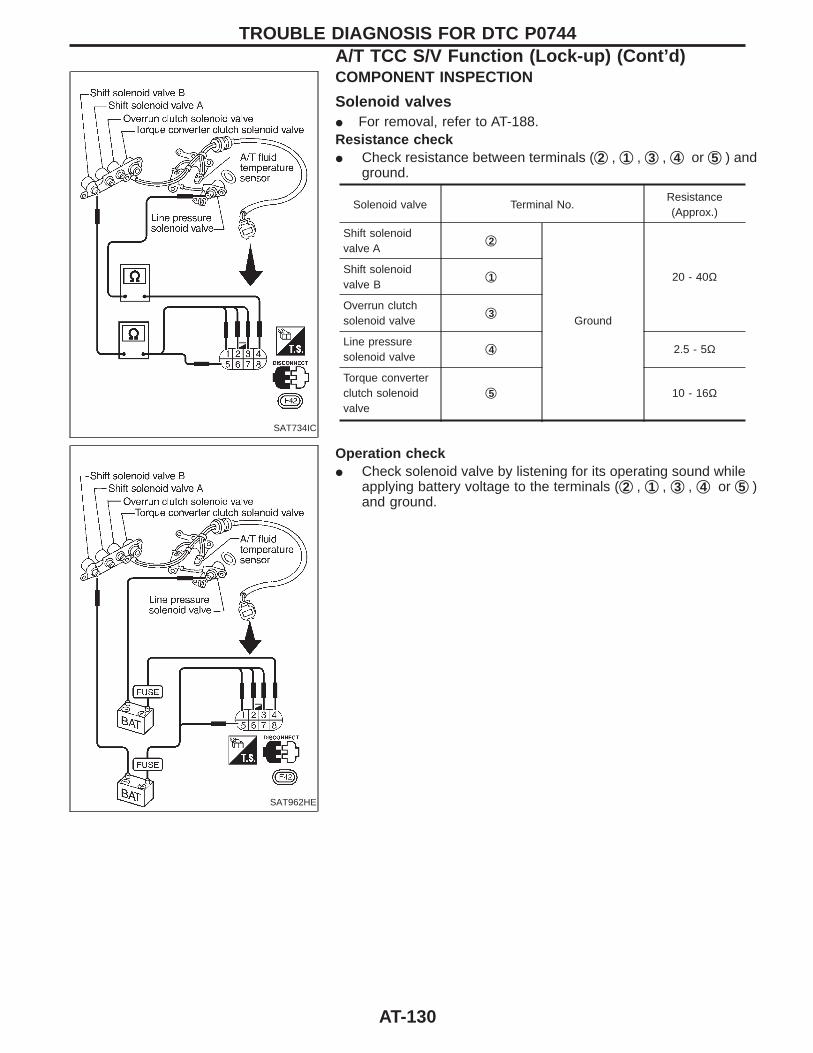
SAT734IC
COMPONENT INSPECTION
Solenoid valvesI For removal, refer to AT-188.Resistance checkI Check resistance between terminals (q2 , q1 , q3 , q4 or q5 ) and
ground.
Solenoid valve Terminal No.Resistance(Approx.)
Shift solenoidvalve A
q2
Ground
20 - 40ΩShift solenoidvalve B
q1
Overrun clutchsolenoid valve
q3
Line pressuresolenoid valve
q4 2.5 - 5Ω
Torque converterclutch solenoidvalve
q5 10 - 16Ω
SAT962HE
Operation checkI Check solenoid valve by listening for its operating sound while
applying battery voltage to the terminals (q2 , q1 , q3 , q4 or q5 )and ground.
TROUBLE DIAGNOSIS FOR DTC P0744A/T TCC S/V Function (Lock-up) (Cont’d)
AT-130
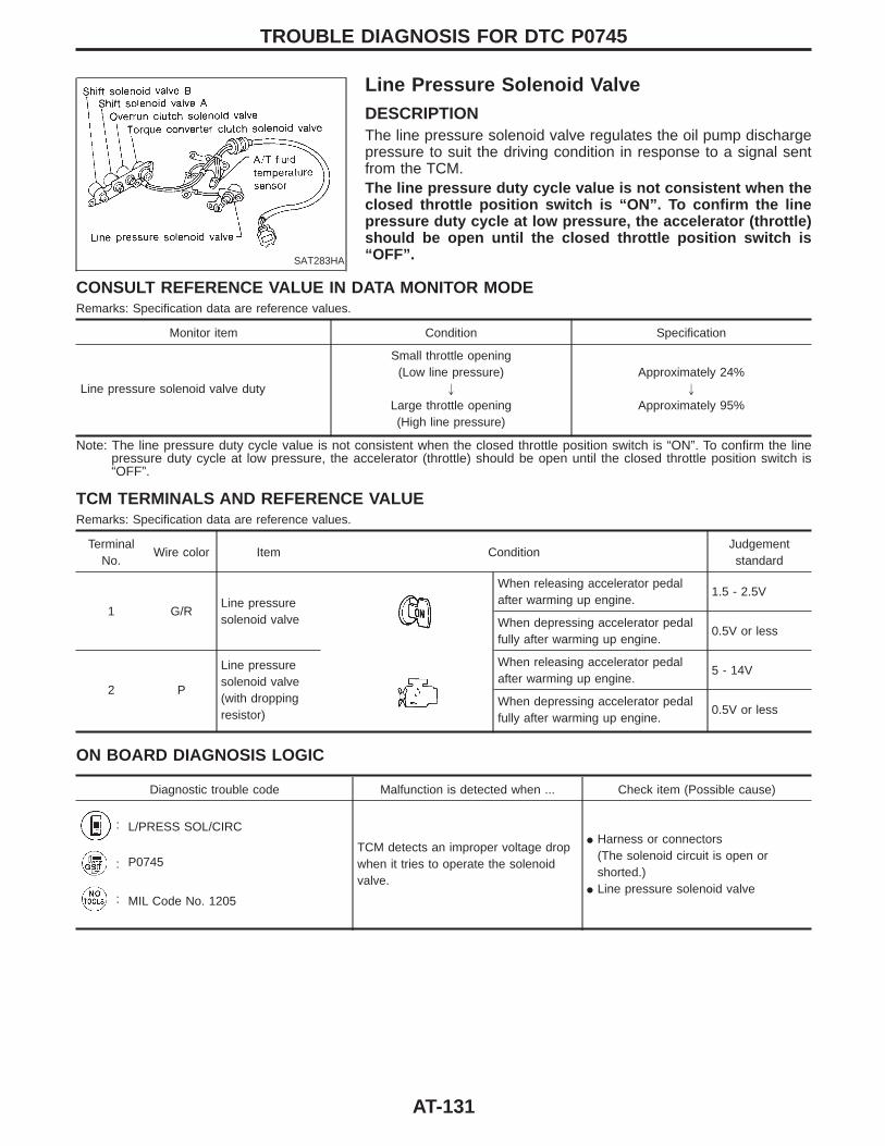
SAT283HA
Line Pressure Solenoid ValveDESCRIPTIONThe line pressure solenoid valve regulates the oil pump dischargepressure to suit the driving condition in response to a signal sentfrom the TCM.The line pressure duty cycle value is not consistent when theclosed throttle position switch is “ON”. To confirm the linepressure duty cycle at low pressure, the accelerator (throttle)should be open until the closed throttle position switch is“OFF”.
CONSULT REFERENCE VALUE IN DATA MONITOR MODERemarks: Specification data are reference values.
Monitor item Condition Specification
Line pressure solenoid valve duty
Small throttle opening(Low line pressure)
"
Large throttle opening(High line pressure)
Approximately 24%"
Approximately 95%
Note: The line pressure duty cycle value is not consistent when the closed throttle position switch is “ON”. To confirm the linepressure duty cycle at low pressure, the accelerator (throttle) should be open until the closed throttle position switch is“OFF”.
TCM TERMINALS AND REFERENCE VALUERemarks: Specification data are reference values.
TerminalNo.
Wire color Item ConditionJudgementstandard
1 G/RLine pressuresolenoid valve
When releasing accelerator pedalafter warming up engine.
1.5 - 2.5V
When depressing accelerator pedalfully after warming up engine.
0.5V or less
2 P
Line pressuresolenoid valve(with droppingresistor)
When releasing accelerator pedalafter warming up engine.
5 - 14V
When depressing accelerator pedalfully after warming up engine.
0.5V or less
ON BOARD DIAGNOSIS LOGIC
Diagnostic trouble code Malfunction is detected when ... Check item (Possible cause)
: L/PRESS SOL/CIRC
TCM detects an improper voltage dropwhen it tries to operate the solenoidvalve.
I Harness or connectors(The solenoid circuit is open orshorted.)
I Line pressure solenoid valve
: P0745
: MIL Code No. 1205
TROUBLE DIAGNOSIS FOR DTC P0745
AT-131
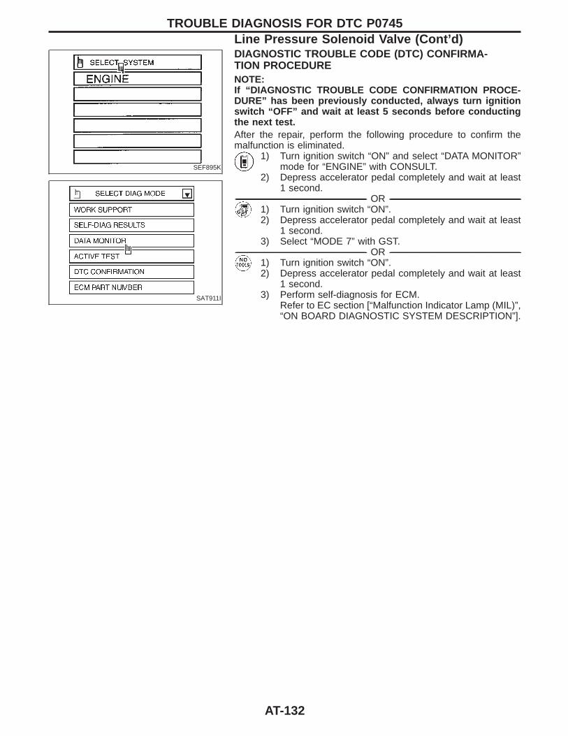
SEF895K
SAT911I
DIAGNOSTIC TROUBLE CODE (DTC) CONFIRMA-TION PROCEDURENOTE:If “DIAGNOSTIC TROUBLE CODE CONFIRMATION PROCE-DURE” has been previously conducted, always turn ignitionswitch “OFF” and wait at least 5 seconds before conductingthe next test.After the repair, perform the following procedure to confirm themalfunction is eliminated.
1) Turn ignition switch “ON” and select “DATA MONITOR”mode for “ENGINE” with CONSULT.
2) Depress accelerator pedal completely and wait at least1 second.
------------------------------------------------------------------------------------------------------------------------------------------------------------------------------------------------------------------------------------------------------ OR ------------------------------------------------------------------------------------------------------------------------------------------------------------------------------------------------------------------------------------------------------1) Turn ignition switch “ON”.2) Depress accelerator pedal completely and wait at least
1 second.3) Select “MODE 7” with GST.
------------------------------------------------------------------------------------------------------------------------------------------------------------------------------------------------------------------------------------------------------ OR ------------------------------------------------------------------------------------------------------------------------------------------------------------------------------------------------------------------------------------------------------1) Turn ignition switch “ON”.2) Depress accelerator pedal completely and wait at least
1 second.3) Perform self-diagnosis for ECM.
Refer to EC section [“Malfunction Indicator Lamp (MIL)”,“ON BOARD DIAGNOSTIC SYSTEM DESCRIPTION”].
TROUBLE DIAGNOSIS FOR DTC P0745Line Pressure Solenoid Valve (Cont’d)
AT-132
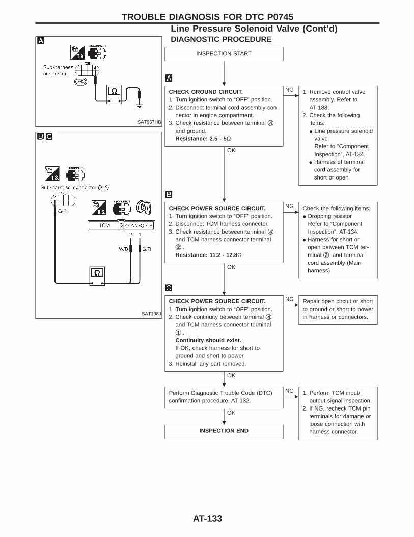
SAT957HB
SAT198J
DIAGNOSTIC PROCEDURE
INSPECTION START
CHECK GROUND CIRCUIT.1. Turn ignition switch to “OFF” position.2. Disconnect terminal cord assembly con-
nector in engine compartment.3. Check resistance between terminal q4
and ground.Resistance: 2.5 - 5 Ω
OK
ENG 1. Remove control valve
assembly. Refer toAT-188.
2. Check the followingitems:I Line pressure solenoid
valveRefer to “ComponentInspection”, AT-134.
I Harness of terminalcord assembly forshort or open
CHECK POWER SOURCE CIRCUIT.1. Turn ignition switch to “OFF” position.2. Disconnect TCM harness connector.3. Check resistance between terminal q4
and TCM harness connector terminalq2 .Resistance: 11.2 - 12.8 Ω
OK
ENG Check the following items:
I Dropping resistorRefer to “ComponentInspection”, AT-134.
I Harness for short oropen between TCM ter-minal q2 and terminalcord assembly (Mainharness)
CHECK POWER SOURCE CIRCUIT.1. Turn ignition switch to “OFF” position.2. Check continuity between terminal q4
and TCM harness connector terminalq1 .Continuity should exist.If OK, check harness for short toground and short to power.
3. Reinstall any part removed.
OK
ENG Repair open circuit or short
to ground or short to powerin harness or connectors.
Perform Diagnostic Trouble Code (DTC)confirmation procedure, AT-132.
OK
ENG 1. Perform TCM input/
output signal inspection.2. If NG, recheck TCM pin
terminals for damage orloose connection withharness connector.INSPECTION END
TROUBLE DIAGNOSIS FOR DTC P0745Line Pressure Solenoid Valve (Cont’d)
H
H
H
H
H
AT-133
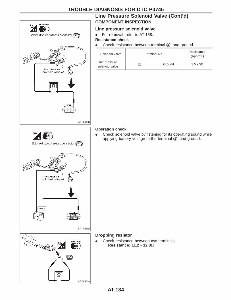
SAT644IB
COMPONENT INSPECTION
Line pressure solenoid valveI For removal, refer to AT-188.Resistance checkI Check resistance between terminal q4 and ground.
Solenoid valve Terminal No.Resistance(Approx.)
Line pressuresolenoid valve
q4 Ground 2.5 - 5Ω
SAT641ID
Operation checkI Check solenoid valve by listening for its operating sound while
applying battery voltage to the terminal q4 and ground.
SAT933IA
Dropping resistorI Check resistance between two terminals.
Resistance: 11.2 - 12.8 Ω
TROUBLE DIAGNOSIS FOR DTC P0745Line Pressure Solenoid Valve (Cont’d)
AT-134

SAT322GA
Shift Solenoid Valve ADESCRIPTIONShift solenoid valves A and B are turned “ON” or “OFF” by the TCMin response to signals sent from the inhibitor switch, vehicle speedand throttle position sensors. Gears will then be shifted to the opti-mum position.
Gear position 1 2 3 4
Shift solenoid valve A ON (Closed) OFF (Open) OFF (Open) ON (Closed)
Shift solenoid valve B ON (Closed) ON (Closed) OFF (Open) OFF (Open)
TCM TERMINALS AND REFERENCE VALUERemarks: Specification data are reference values.
TerminalNo.
Wire color Item ConditionJudgementstandard
6 R/YShift solenoidvalve A
When shift solenoid valve A oper-ates.(When driving in “D1” or “D4”.)
Battery voltage
When shift solenoid valve A does notoperate.(When driving in “D2” or “D3”.)
1V or less
ON BOARD DIAGNOSIS LOGIC
Diagnostic trouble code Malfunction is detected when ... Check item (Possible cause)
: SFT SOL A/CIRC
TCM detects an improper voltage dropwhen it tries to operate the solenoidvalve.
I Harness or connectors(The solenoid circuit is open orshorted.)
I Shift solenoid valve A
: P0750
: MIL Code No. 1108
TROUBLE DIAGNOSIS FOR DTC P0750
AT-135

SEF895K
SAT911I
DIAGNOSTIC TROUBLE CODE (DTC) CONFIRMA-TION PROCEDURECAUTION:Always drive vehicle at a safe speed.NOTE:If “DIAGNOSTIC TROUBLE CODE CONFIRMATION PROCE-DURE” has been previously conducted, always turn ignitionswitch “OFF” and wait at least 5 seconds before conductingthe next test.After the repair, perform the following procedure to confirm themalfunction is eliminated.
1) Turn ignition switch “ON” and select “DATA MONITOR”mode for “ENGINE” with CONSULT.
2) Start engine.3) Drive vehicle in D position and allow the transmission to
shift “1” , “2” (“GEAR”).------------------------------------------------------------------------------------------------------------------------------------------------------------------------------------------------------------------------------------------------------ OR ------------------------------------------------------------------------------------------------------------------------------------------------------------------------------------------------------------------------------------------------------
1) Start engine.2) Drive vehicle in D1 , D2 position.3) Select “MODE 7” with GST.
------------------------------------------------------------------------------------------------------------------------------------------------------------------------------------------------------------------------------------------------------ OR ------------------------------------------------------------------------------------------------------------------------------------------------------------------------------------------------------------------------------------------------------1) Start engine.2) Drive vehicle in D1 , D2 position.3) Perform self-diagnosis for ECM.
Refer to EC section [“Malfunction Indicator Lamp (MIL)”,“ON BOARD DIAGNOSTIC SYSTEM DESCRIPTION”].
TROUBLE DIAGNOSIS FOR DTC P0750Shift Solenoid Valve A (Cont’d)
AT-136

SAT953HB
SAT199J
DIAGNOSTIC PROCEDURE
INSPECTION START
CHECK GROUND CIRCUIT.1. Turn ignition switch to “OFF” position.2. Disconnect terminal cord assembly con-
nector in engine compartment.3. Check resistance between terminal q2
and ground.Resistance: 20 - 40 Ω
OK
ENG 1. Remove control valve
assembly. Refer toAT-188.
2. Check the followingitems:
I Shift solenoid valve ARefer to “ComponentInspection”, AT-138.
I Harness of terminal cordassembly for short oropen
CHECK POWER SOURCE CIRCUIT.1. Turn ignition switch to “OFF” position.2. Disconnect TCM harness connector.3. Check continuity between terminal q2
and TCM harness connector terminalq6 .Continuity should exist.If OK, check harness for short toground and short to power.
4. Reinstall any part removed.
OK
ENG Repair open circuit or short
to ground or short to powerin harness or connectors.
Perform Diagnostic Trouble Code (DTC)confirmation procedure, AT-136.
OK
ENG 1. Perform TCM input/
output signal inspection.2. If NG, recheck TCM pin
terminals for damage orloose connection withharness connector.INSPECTION END
TROUBLE DIAGNOSIS FOR DTC P0750Shift Solenoid Valve A (Cont’d)
H
H
H
H
AT-137
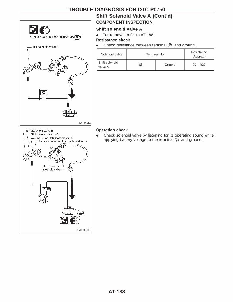
SAT640IC
COMPONENT INSPECTION
Shift solenoid valve AI For removal, refer to AT-188.Resistance checkI Check resistance between terminal q2 and ground.
Solenoid valve Terminal No.Resistance(Approx.)
Shift solenoidvalve A
q2 Ground 20 - 40Ω
SAT960HE
Operation checkI Check solenoid valve by listening for its operating sound while
applying battery voltage to the terminal q2 and ground.
TROUBLE DIAGNOSIS FOR DTC P0750Shift Solenoid Valve A (Cont’d)
AT-138
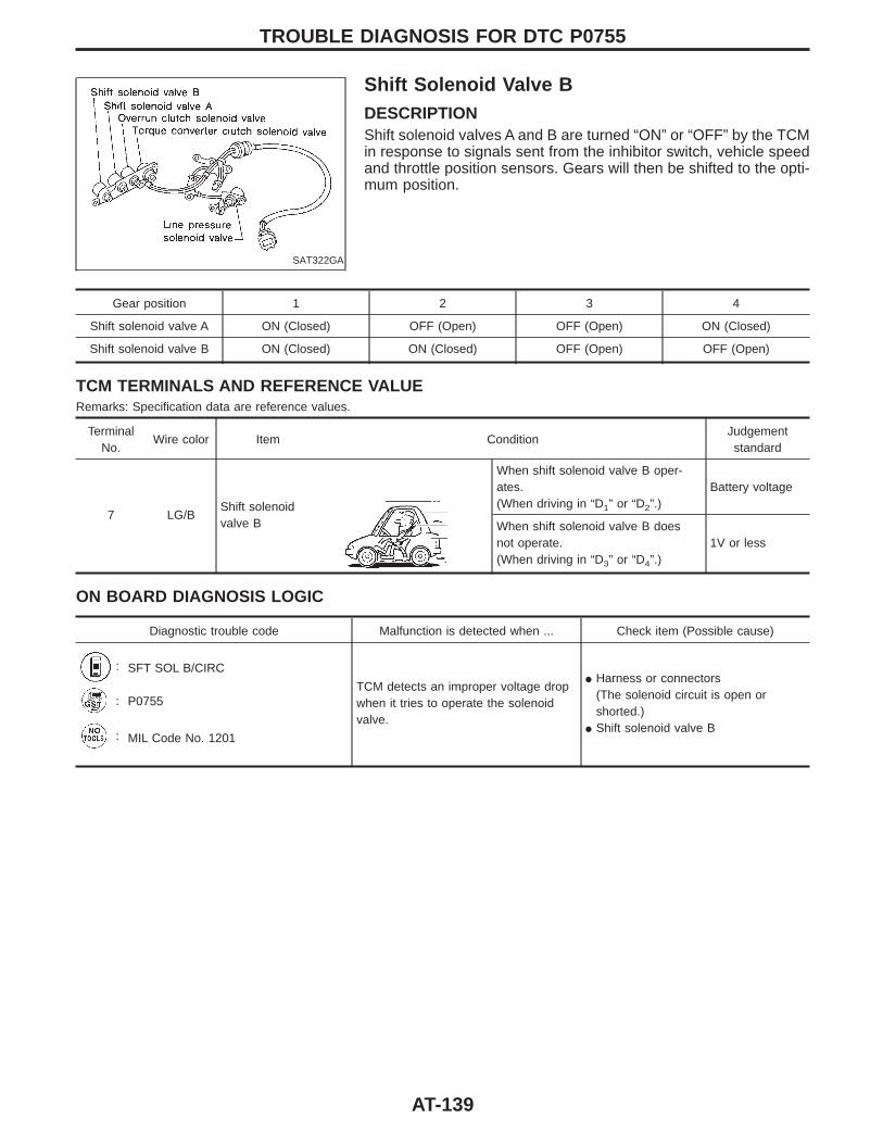
SAT322GA
Shift Solenoid Valve BDESCRIPTIONShift solenoid valves A and B are turned “ON” or “OFF” by the TCMin response to signals sent from the inhibitor switch, vehicle speedand throttle position sensors. Gears will then be shifted to the opti-mum position.
Gear position 1 2 3 4
Shift solenoid valve A ON (Closed) OFF (Open) OFF (Open) ON (Closed)
Shift solenoid valve B ON (Closed) ON (Closed) OFF (Open) OFF (Open)
TCM TERMINALS AND REFERENCE VALUERemarks: Specification data are reference values.
TerminalNo.
Wire color Item ConditionJudgementstandard
7 LG/BShift solenoidvalve B
When shift solenoid valve B oper-ates.(When driving in “D1” or “D2”.)
Battery voltage
When shift solenoid valve B doesnot operate.(When driving in “D3” or “D4”.)
1V or less
ON BOARD DIAGNOSIS LOGIC
Diagnostic trouble code Malfunction is detected when ... Check item (Possible cause)
: SFT SOL B/CIRC
TCM detects an improper voltage dropwhen it tries to operate the solenoidvalve.
I Harness or connectors(The solenoid circuit is open orshorted.)
I Shift solenoid valve B
: P0755
: MIL Code No. 1201
TROUBLE DIAGNOSIS FOR DTC P0755
AT-139
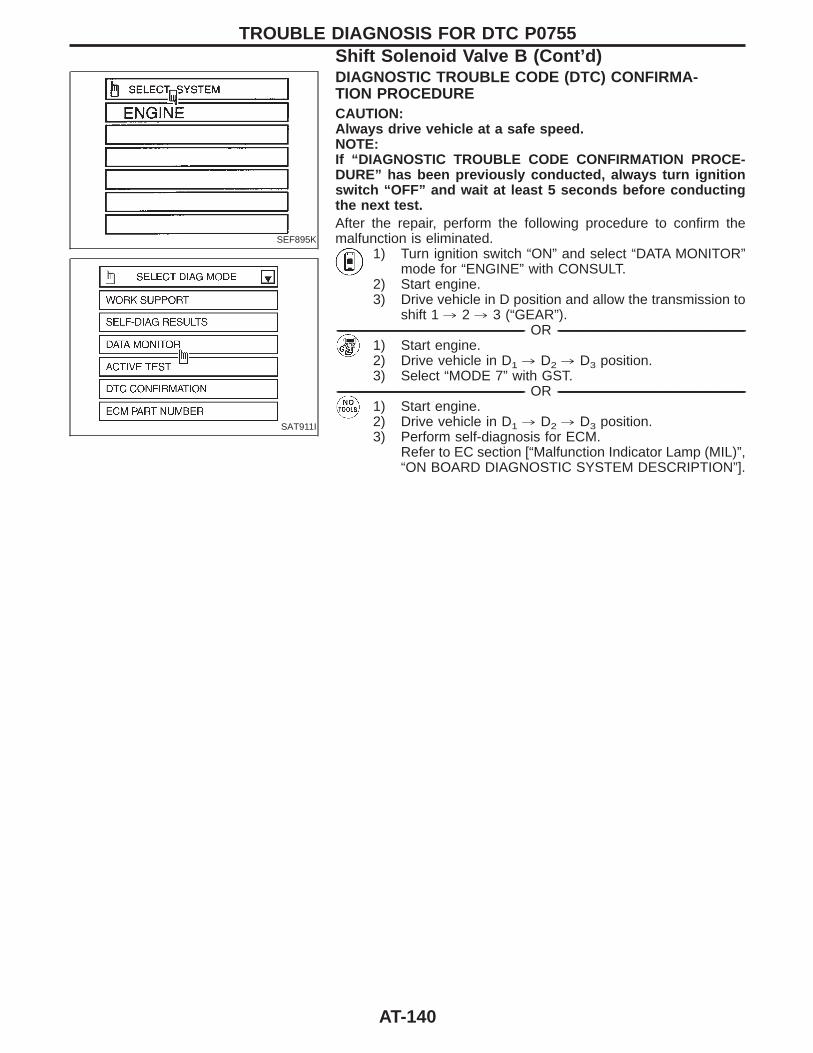
SEF895K
SAT911I
DIAGNOSTIC TROUBLE CODE (DTC) CONFIRMA-TION PROCEDURECAUTION:Always drive vehicle at a safe speed.NOTE:If “DIAGNOSTIC TROUBLE CODE CONFIRMATION PROCE-DURE” has been previously conducted, always turn ignitionswitch “OFF” and wait at least 5 seconds before conductingthe next test.After the repair, perform the following procedure to confirm themalfunction is eliminated.
1) Turn ignition switch “ON” and select “DATA MONITOR”mode for “ENGINE” with CONSULT.
2) Start engine.3) Drive vehicle in D position and allow the transmission to
shift 1 , 2 , 3 (“GEAR”).------------------------------------------------------------------------------------------------------------------------------------------------------------------------------------------------------------------------------------------------------ OR ------------------------------------------------------------------------------------------------------------------------------------------------------------------------------------------------------------------------------------------------------
1) Start engine.2) Drive vehicle in D1 , D2 , D3 position.3) Select “MODE 7” with GST.
------------------------------------------------------------------------------------------------------------------------------------------------------------------------------------------------------------------------------------------------------ OR ------------------------------------------------------------------------------------------------------------------------------------------------------------------------------------------------------------------------------------------------------1) Start engine.2) Drive vehicle in D1 , D2 , D3 position.3) Perform self-diagnosis for ECM.
Refer to EC section [“Malfunction Indicator Lamp (MIL)”,“ON BOARD DIAGNOSTIC SYSTEM DESCRIPTION”].
TROUBLE DIAGNOSIS FOR DTC P0755Shift Solenoid Valve B (Cont’d)
AT-140
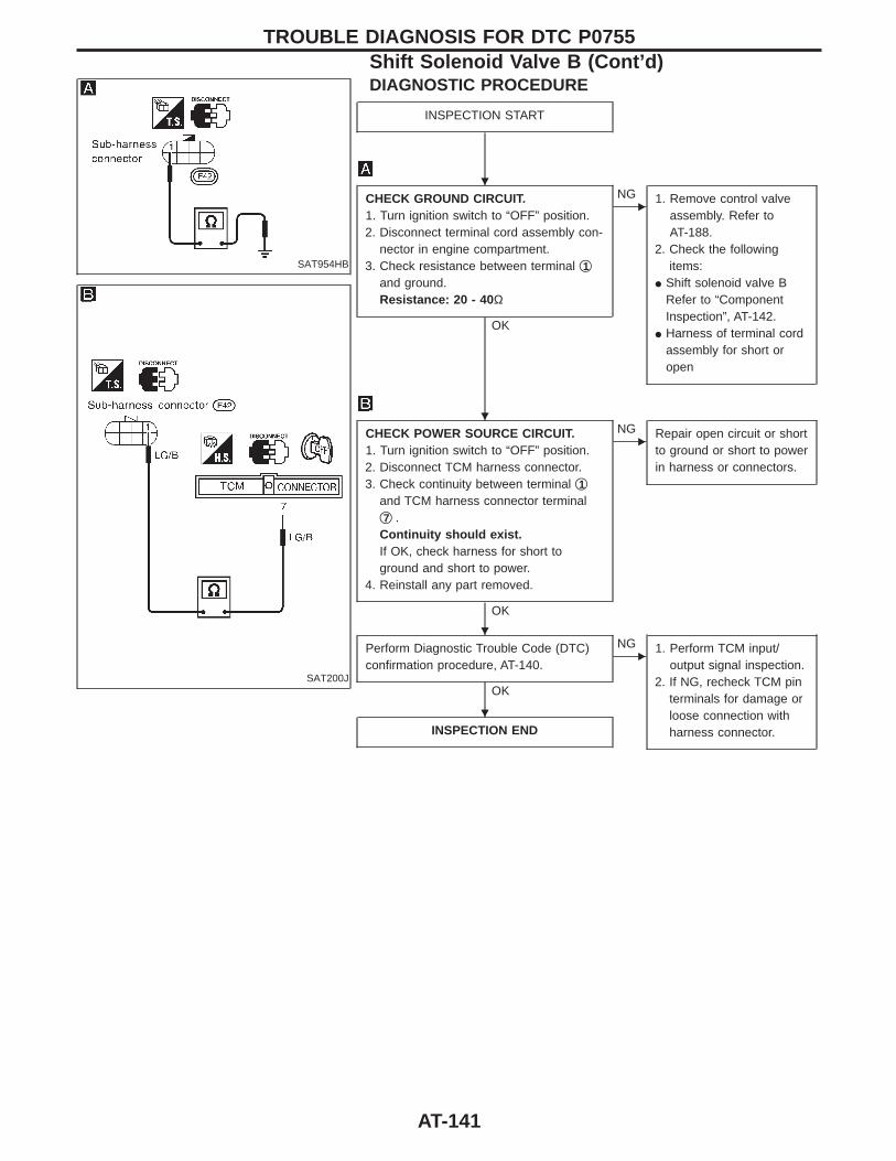
SAT954HB
SAT200J
DIAGNOSTIC PROCEDURE
INSPECTION START
CHECK GROUND CIRCUIT.1. Turn ignition switch to “OFF” position.2. Disconnect terminal cord assembly con-
nector in engine compartment.3. Check resistance between terminal q1
and ground.Resistance: 20 - 40 Ω
OK
ENG 1. Remove control valve
assembly. Refer toAT-188.
2. Check the followingitems:
I Shift solenoid valve BRefer to “ComponentInspection”, AT-142.
I Harness of terminal cordassembly for short oropen
CHECK POWER SOURCE CIRCUIT.1. Turn ignition switch to “OFF” position.2. Disconnect TCM harness connector.3. Check continuity between terminal q1
and TCM harness connector terminalq7 .Continuity should exist.If OK, check harness for short toground and short to power.
4. Reinstall any part removed.
OK
ENG Repair open circuit or short
to ground or short to powerin harness or connectors.
Perform Diagnostic Trouble Code (DTC)confirmation procedure, AT-140.
OK
ENG 1. Perform TCM input/
output signal inspection.2. If NG, recheck TCM pin
terminals for damage orloose connection withharness connector.INSPECTION END
TROUBLE DIAGNOSIS FOR DTC P0755Shift Solenoid Valve B (Cont’d)
H
H
H
H
AT-141
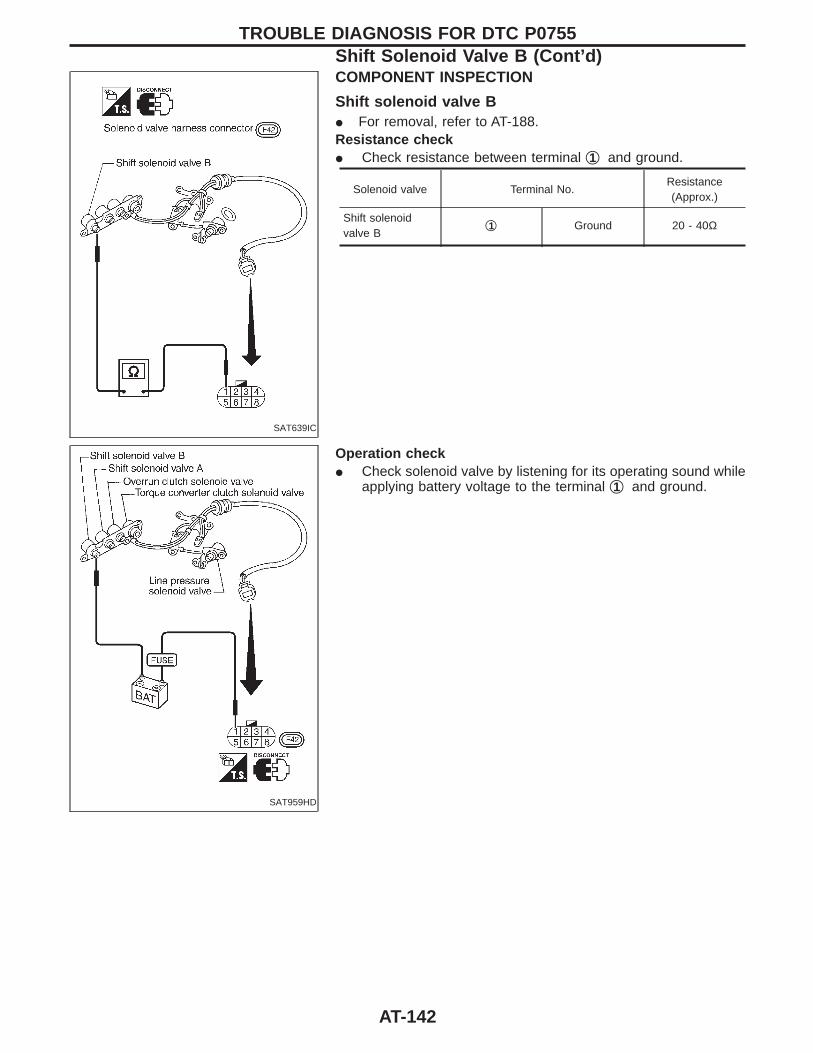
SAT639IC
COMPONENT INSPECTION
Shift solenoid valve BI For removal, refer to AT-188.Resistance checkI Check resistance between terminal q1 and ground.
Solenoid valve Terminal No.Resistance(Approx.)
Shift solenoidvalve B
q1 Ground 20 - 40Ω
SAT959HD
Operation checkI Check solenoid valve by listening for its operating sound while
applying battery voltage to the terminal q1 and ground.
TROUBLE DIAGNOSIS FOR DTC P0755Shift Solenoid Valve B (Cont’d)
AT-142
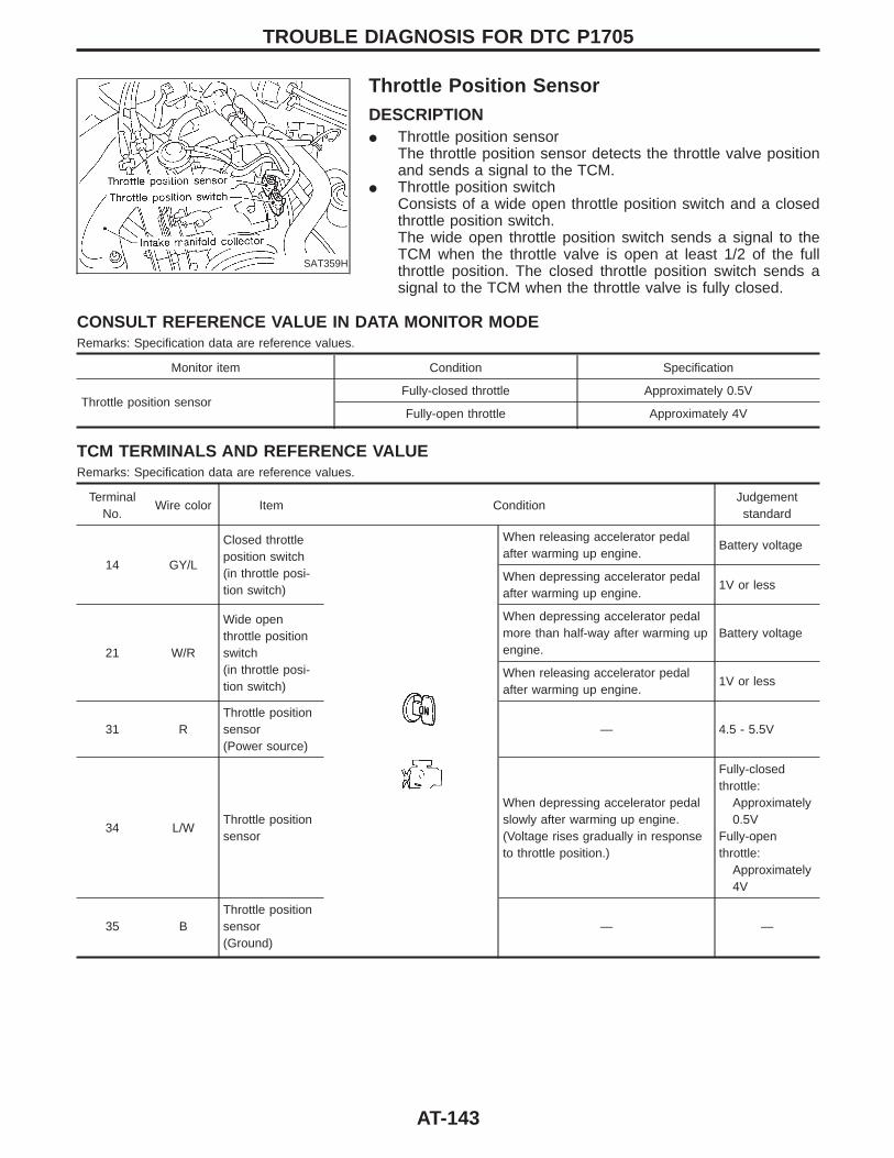
SAT359H
Throttle Position SensorDESCRIPTIONI Throttle position sensor
The throttle position sensor detects the throttle valve positionand sends a signal to the TCM.
I Throttle position switchConsists of a wide open throttle position switch and a closedthrottle position switch.The wide open throttle position switch sends a signal to theTCM when the throttle valve is open at least 1/2 of the fullthrottle position. The closed throttle position switch sends asignal to the TCM when the throttle valve is fully closed.
CONSULT REFERENCE VALUE IN DATA MONITOR MODERemarks: Specification data are reference values.
Monitor item Condition Specification
Throttle position sensorFully-closed throttle Approximately 0.5V
Fully-open throttle Approximately 4V
TCM TERMINALS AND REFERENCE VALUERemarks: Specification data are reference values.
TerminalNo.
Wire color Item ConditionJudgementstandard
14 GY/L
Closed throttleposition switch(in throttle posi-tion switch)
When releasing accelerator pedalafter warming up engine.
Battery voltage
When depressing accelerator pedalafter warming up engine.
1V or less
21 W/R
Wide openthrottle positionswitch(in throttle posi-tion switch)
When depressing accelerator pedalmore than half-way after warming upengine.
Battery voltage
When releasing accelerator pedalafter warming up engine.
1V or less
31 RThrottle positionsensor(Power source)
— 4.5 - 5.5V
34 L/WThrottle positionsensor
When depressing accelerator pedalslowly after warming up engine.(Voltage rises gradually in responseto throttle position.)
Fully-closedthrottle:
Approximately0.5V
Fully-openthrottle:
Approximately4V
35 BThrottle positionsensor(Ground)
— —
TROUBLE DIAGNOSIS FOR DTC P1705
AT-143
ON BOARD DIAGNOSIS LOGIC
Diagnostic trouble code Malfunction is detected when ... Check item (Possible cause)
: TP SEN/CIRC A/T
TCM receives an excessively low orhigh voltage from the sensor.
I Harness or connectors(The sensor circuit is open orshorted.)
I Throttle position sensorI Throttle position switch
: P1705
: MIL Code No. 1206
TROUBLE DIAGNOSIS FOR DTC P1705Throttle Position Sensor (Cont’d)
AT-144
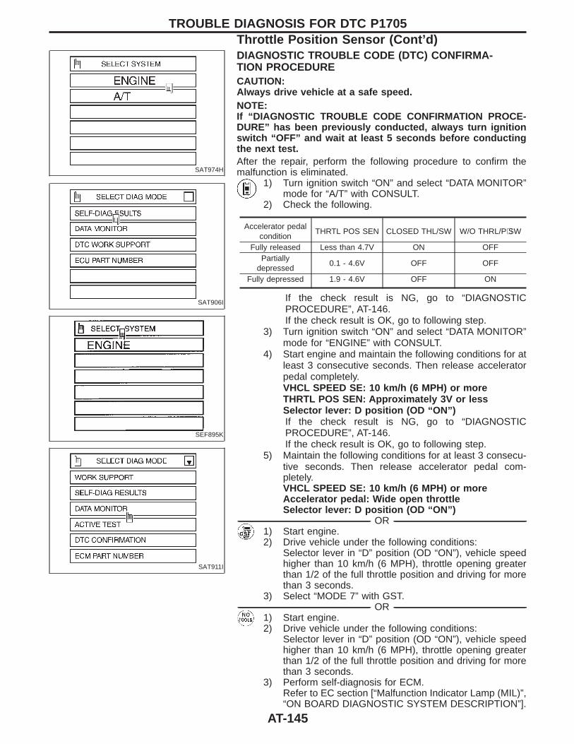
SAT974H
SAT906I
SEF895K
SAT911I
DIAGNOSTIC TROUBLE CODE (DTC) CONFIRMA-TION PROCEDURECAUTION:Always drive vehicle at a safe speed.NOTE:If “DIAGNOSTIC TROUBLE CODE CONFIRMATION PROCE-DURE” has been previously conducted, always turn ignitionswitch “OFF” and wait at least 5 seconds before conductingthe next test.After the repair, perform the following procedure to confirm themalfunction is eliminated.
1) Turn ignition switch “ON” and select “DATA MONITOR”mode for “A/T” with CONSULT.
2) Check the following.
Accelerator pedalcondition
THRTL POS SEN CLOSED THL/SW W/O THRL/P⋅SW
Fully released Less than 4.7V ON OFFPartially
depressed0.1 - 4.6V OFF OFF
Fully depressed 1.9 - 4.6V OFF ON
If the check result is NG, go to “DIAGNOSTICPROCEDURE”, AT-146.If the check result is OK, go to following step.
3) Turn ignition switch “ON” and select “DATA MONITOR”mode for “ENGINE” with CONSULT.
4) Start engine and maintain the following conditions for atleast 3 consecutive seconds. Then release acceleratorpedal completely.VHCL SPEED SE: 10 km/h (6 MPH) or moreTHRTL POS SEN: Approximately 3V or lessSelector lever: D position (OD “ON”)If the check result is NG, go to “DIAGNOSTICPROCEDURE”, AT-146.If the check result is OK, go to following step.
5) Maintain the following conditions for at least 3 consecu-tive seconds. Then release accelerator pedal com-pletely.VHCL SPEED SE: 10 km/h (6 MPH) or moreAccelerator pedal: Wide open throttleSelector lever: D position (OD “ON”)
------------------------------------------------------------------------------------------------------------------------------------------------------------------------------------------------------------------------------------------------------ OR ------------------------------------------------------------------------------------------------------------------------------------------------------------------------------------------------------------------------------------------------------1) Start engine.2) Drive vehicle under the following conditions:
Selector lever in “D” position (OD “ON”), vehicle speedhigher than 10 km/h (6 MPH), throttle opening greaterthan 1/2 of the full throttle position and driving for morethan 3 seconds.
3) Select “MODE 7” with GST.------------------------------------------------------------------------------------------------------------------------------------------------------------------------------------------------------------------------------------------------------ OR ------------------------------------------------------------------------------------------------------------------------------------------------------------------------------------------------------------------------------------------------------
1) Start engine.2) Drive vehicle under the following conditions:
Selector lever in “D” position (OD “ON”), vehicle speedhigher than 10 km/h (6 MPH), throttle opening greaterthan 1/2 of the full throttle position and driving for morethan 3 seconds.
3) Perform self-diagnosis for ECM.Refer to EC section [“Malfunction Indicator Lamp (MIL)”,“ON BOARD DIAGNOSTIC SYSTEM DESCRIPTION”].
TROUBLE DIAGNOSIS FOR DTC P1705Throttle Position Sensor (Cont’d)
AT-145
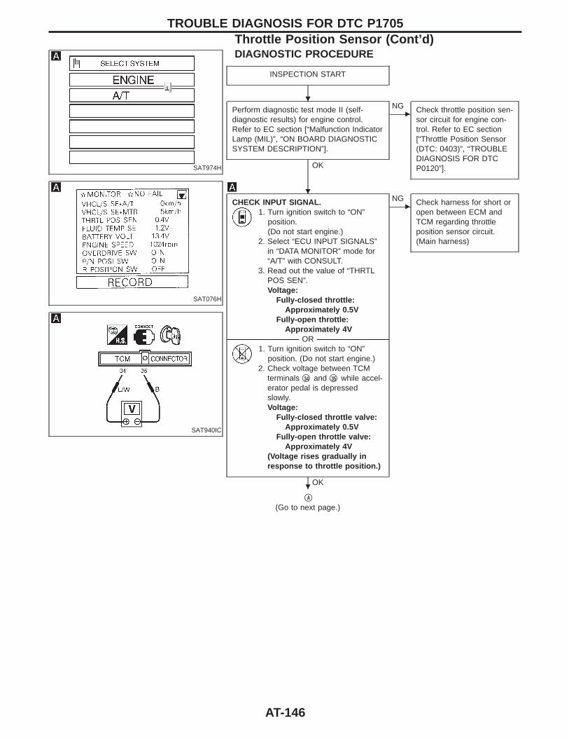
SAT974H
SAT076H
SAT940IC
DIAGNOSTIC PROCEDURE
INSPECTION START
Perform diagnostic test mode II (self-diagnostic results) for engine control.Refer to EC section [“Malfunction IndicatorLamp (MIL)”, “ON BOARD DIAGNOSTICSYSTEM DESCRIPTION”].
OK
ENG Check throttle position sen-
sor circuit for engine con-trol. Refer to EC section[“Throttle Position Sensor(DTC: 0403)”, “TROUBLEDIAGNOSIS FOR DTCP0120”].
CHECK INPUT SIGNAL.1. Turn ignition switch to “ON”
position.(Do not start engine.)
2. Select “ECU INPUT SIGNALS”in “DATA MONITOR” mode for“A/T” with CONSULT.
3. Read out the value of “THRTLPOS SEN”.Voltage:
Fully-closed throttle:Approximately 0.5V
Fully-open throttle:Approximately 4V
-------------------------------------------------------------------------------------------------------------------------------------- OR --------------------------------------------------------------------------------------------------------------------------------------1. Turn ignition switch to “ON”
position. (Do not start engine.)2. Check voltage between TCM
terminals q34 and q35 while accel-erator pedal is depressedslowly.Voltage:
Fully-closed throttle valve:Approximately 0.5V
Fully-open throttle valve:Approximately 4V
(Voltage rises gradually inresponse to throttle position.)
OK
ENG Check harness for short or
open between ECM andTCM regarding throttleposition sensor circuit.(Main harness)
qA
(Go to next page.)
TROUBLE DIAGNOSIS FOR DTC P1705Throttle Position Sensor (Cont’d)
H
H
H
AT-146
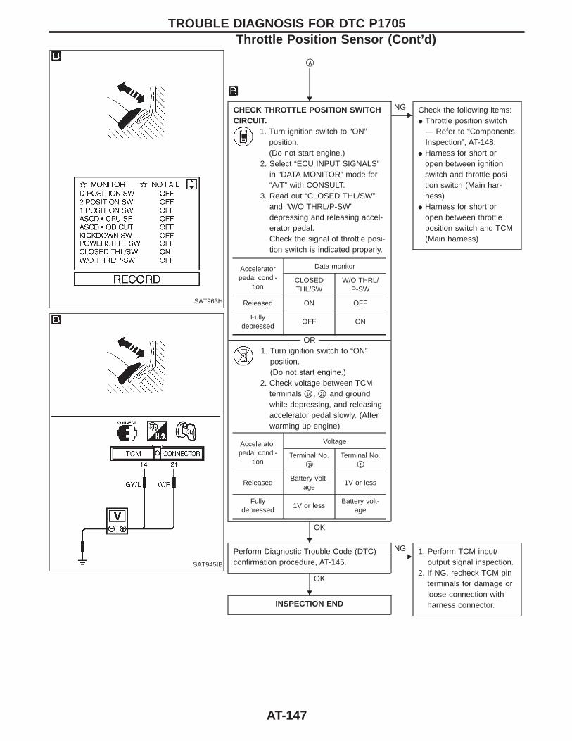
SAT963H
SAT945IB
qA
CHECK THROTTLE POSITION SWITCHCIRCUIT.
1. Turn ignition switch to “ON”position.(Do not start engine.)
2. Select “ECU INPUT SIGNALS”in “DATA MONITOR” mode for“A/T” with CONSULT.
3. Read out “CLOSED THL/SW”and “W/O THRL/P-SW”depressing and releasing accel-erator pedal.Check the signal of throttle posi-tion switch is indicated properly.
-------------------------------------------------------------------------------------------------------------------------------------- OR --------------------------------------------------------------------------------------------------------------------------------------1. Turn ignition switch to “ON”
position.(Do not start engine.)
2. Check voltage between TCMterminals q14 , q21 and groundwhile depressing, and releasingaccelerator pedal slowly. (Afterwarming up engine)
OK
ENG Check the following items:
I Throttle position switch— Refer to “ComponentsInspection”, AT-148.
I Harness for short oropen between ignitionswitch and throttle posi-tion switch (Main har-ness)
I Harness for short oropen between throttleposition switch and TCM(Main harness)
Perform Diagnostic Trouble Code (DTC)confirmation procedure, AT-145.
OK
ENG 1. Perform TCM input/
output signal inspection.2. If NG, recheck TCM pin
terminals for damage orloose connection withharness connector.INSPECTION END
Acceleratorpedal condi-
tion
Data monitor
CLOSEDTHL/SW
W/O THRL/P-SW
Released ON OFF
Fullydepressed
OFF ON
Acceleratorpedal condi-
tion
Voltage
Terminal No.q14
Terminal No.q21
ReleasedBattery volt-
age1V or less
Fullydepressed
1V or lessBattery volt-
age
TROUBLE DIAGNOSIS FOR DTC P1705Throttle Position Sensor (Cont’d)
H
H
H
AT-147
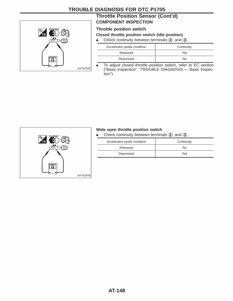
SAT915HE
COMPONENT INSPECTION
Throttle position switchClosed throttle position switch (idle position)I Check continuity between terminals q2 and q3 .
Accelerator pedal condition Continuity
Released Yes
Depressed No
I To adjust closed throttle position switch, refer to EC section(“Basic Inspection”, “TROUBLE DIAGNOSIS — Basic Inspec-tion”).
SAT915HE
Wide open throttle position switchI Check continuity between terminals q2 and q3 .
Accelerator pedal condition Continuity
Released No
Depressed Yes
TROUBLE DIAGNOSIS FOR DTC P1705Throttle Position Sensor (Cont’d)
AT-148
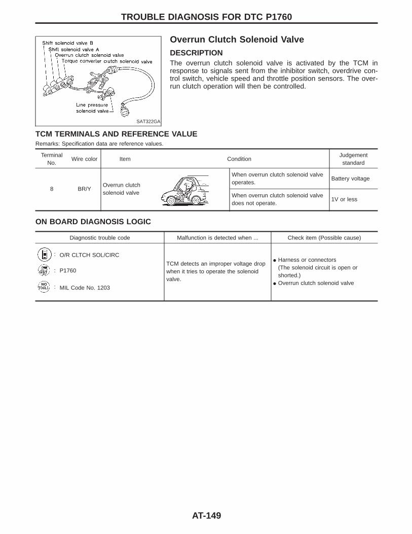
SAT322GA
Overrun Clutch Solenoid ValveDESCRIPTIONThe overrun clutch solenoid valve is activated by the TCM inresponse to signals sent from the inhibitor switch, overdrive con-trol switch, vehicle speed and throttle position sensors. The over-run clutch operation will then be controlled.
TCM TERMINALS AND REFERENCE VALUERemarks: Specification data are reference values.
TerminalNo.
Wire color Item ConditionJudgementstandard
8 BR/YOverrun clutchsolenoid valve
When overrun clutch solenoid valveoperates.
Battery voltage
When overrun clutch solenoid valvedoes not operate.
1V or less
ON BOARD DIAGNOSIS LOGIC
Diagnostic trouble code Malfunction is detected when ... Check item (Possible cause)
: O/R CLTCH SOL/CIRC
TCM detects an improper voltage dropwhen it tries to operate the solenoidvalve.
I Harness or connectors(The solenoid circuit is open orshorted.)
I Overrun clutch solenoid valve
: P1760
: MIL Code No. 1203
TROUBLE DIAGNOSIS FOR DTC P1760
AT-149
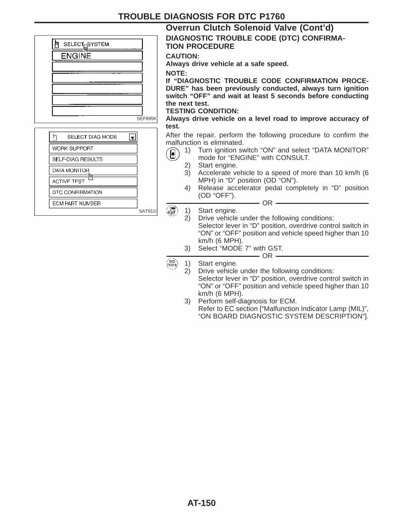
SEF895K
SAT911I
DIAGNOSTIC TROUBLE CODE (DTC) CONFIRMA-TION PROCEDURECAUTION:Always drive vehicle at a safe speed.NOTE:If “DIAGNOSTIC TROUBLE CODE CONFIRMATION PROCE-DURE” has been previously conducted, always turn ignitionswitch “OFF” and wait at least 5 seconds before conductingthe next test.TESTING CONDITION:Always drive vehicle on a level road to improve accuracy oftest.After the repair, perform the following procedure to confirm themalfunction is eliminated.
1) Turn ignition switch “ON” and select “DATA MONITOR”mode for “ENGINE” with CONSULT.
2) Start engine.3) Accelerate vehicle to a speed of more than 10 km/h (6
MPH) in “D” position (OD “ON”).4) Release accelerator pedal completely in “D” position
(OD “OFF”).------------------------------------------------------------------------------------------------------------------------------------------------------------------------------------------------------------------------------------------------------ OR ------------------------------------------------------------------------------------------------------------------------------------------------------------------------------------------------------------------------------------------------------
1) Start engine.2) Drive vehicle under the following conditions:
Selector lever in “D” position, overdrive control switch in“ON” or “OFF” position and vehicle speed higher than 10km/h (6 MPH).
3) Select “MODE 7” with GST.------------------------------------------------------------------------------------------------------------------------------------------------------------------------------------------------------------------------------------------------------ OR ------------------------------------------------------------------------------------------------------------------------------------------------------------------------------------------------------------------------------------------------------
1) Start engine.2) Drive vehicle under the following conditions:
Selector lever in “D” position, overdrive control switch in“ON” or “OFF” position and vehicle speed higher than 10km/h (6 MPH).
3) Perform self-diagnosis for ECM.Refer to EC section [“Malfunction Indicator Lamp (MIL)”,“ON BOARD DIAGNOSTIC SYSTEM DESCRIPTION”].
TROUBLE DIAGNOSIS FOR DTC P1760Overrun Clutch Solenoid Valve (Cont’d)
AT-150
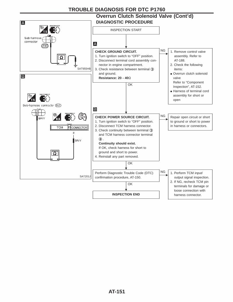
SAT955HB
SAT201J
DIAGNOSTIC PROCEDURE
INSPECTION START
CHECK GROUND CIRCUIT.1. Turn ignition switch to “OFF” position.2. Disconnect terminal cord assembly con-
nector in engine compartment.3. Check resistance between terminal q3
and ground.Resistance: 20 - 40 Ω
OK
ENG 1. Remove control valve
assembly. Refer toAT-188.
2. Check the followingitems:
I Overrun clutch solenoidvalveRefer to “ComponentInspection”, AT-152.
I Harness of terminal cordassembly for short oropen
CHECK POWER SOURCE CIRCUIT.1. Turn ignition switch to “OFF” position.2. Disconnect TCM harness connector.3. Check continuity between terminal q3
and TCM harness connector terminalq8 .Continuity should exist.If OK, check harness for short toground and short to power.
4. Reinstall any part removed.
OK
ENG Repair open circuit or short
to ground or short to powerin harness or connectors.
Perform Diagnostic Trouble Code (DTC)confirmation procedure, AT-150.
OK
ENG 1. Perform TCM input/
output signal inspection.2. If NG, recheck TCM pin
terminals for damage orloose connection withharness connector.INSPECTION END
TROUBLE DIAGNOSIS FOR DTC P1760Overrun Clutch Solenoid Valve (Cont’d)
H
H
H
H
AT-151
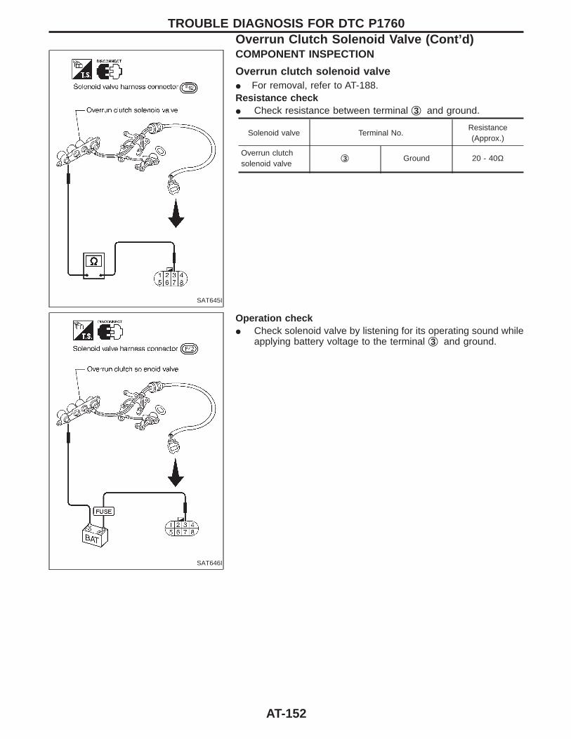
SAT645I
COMPONENT INSPECTION
Overrun clutch solenoid valveI For removal, refer to AT-188.Resistance checkI Check resistance between terminal q3 and ground.
Solenoid valve Terminal No.Resistance(Approx.)
Overrun clutchsolenoid valve
q3 Ground 20 - 40Ω
SAT646I
Operation checkI Check solenoid valve by listening for its operating sound while
applying battery voltage to the terminal q3 and ground.
TROUBLE DIAGNOSIS FOR DTC P1760Overrun Clutch Solenoid Valve (Cont’d)
AT-152
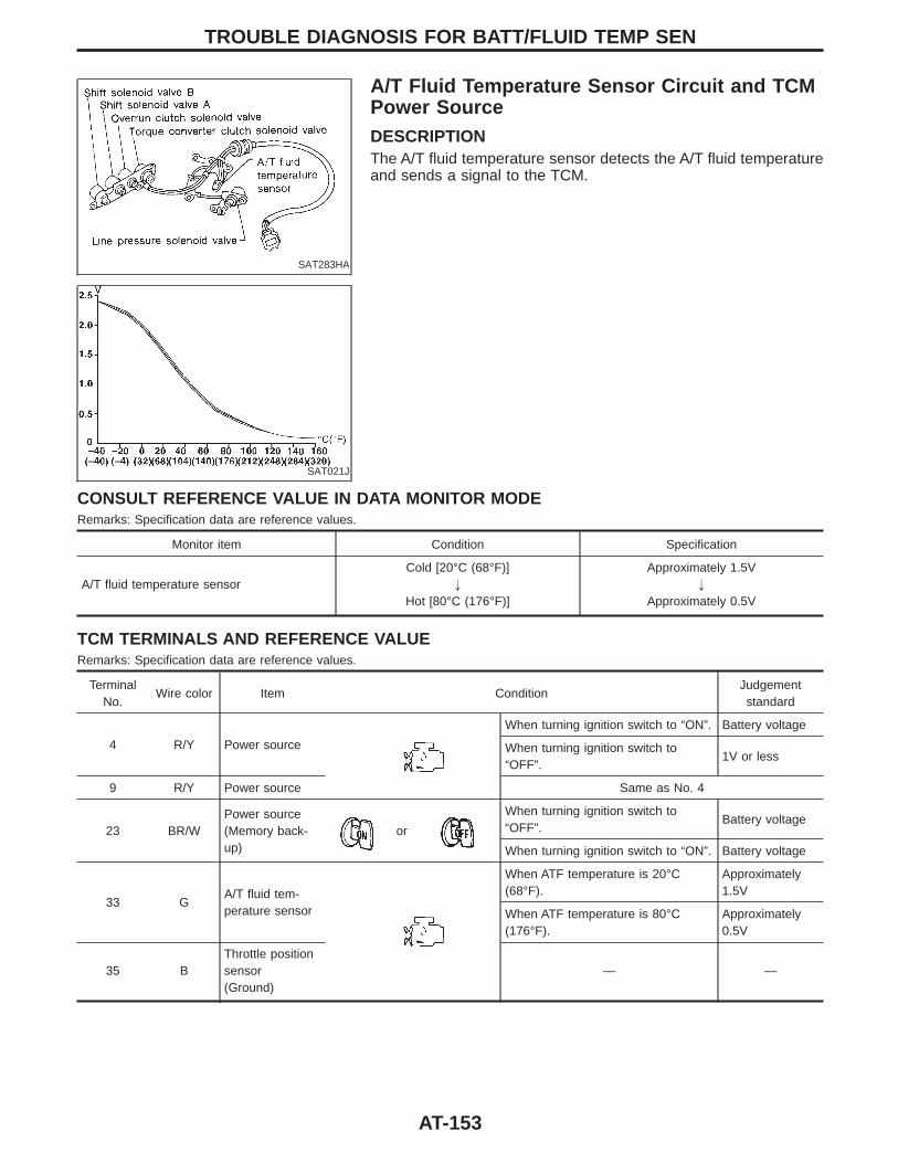
SAT283HA
A/T Fluid Temperature Sensor Circuit and TCMPower SourceDESCRIPTIONThe A/T fluid temperature sensor detects the A/T fluid temperatureand sends a signal to the TCM.
SAT021J
CONSULT REFERENCE VALUE IN DATA MONITOR MODERemarks: Specification data are reference values.
Monitor item Condition Specification
A/T fluid temperature sensorCold [20°C (68°F)]
"
Hot [80°C (176°F)]
Approximately 1.5V"
Approximately 0.5V
TCM TERMINALS AND REFERENCE VALUERemarks: Specification data are reference values.
TerminalNo.
Wire color Item ConditionJudgementstandard
4 R/Y Power source
When turning ignition switch to “ON”. Battery voltage
When turning ignition switch to“OFF”.
1V or less
9 R/Y Power source Same as No. 4
23 BR/WPower source(Memory back-up)
or
When turning ignition switch to“OFF”.
Battery voltage
When turning ignition switch to “ON”. Battery voltage
33 GA/T fluid tem-perature sensor
When ATF temperature is 20°C(68°F).
Approximately1.5V
When ATF temperature is 80°C(176°F).
Approximately0.5V
35 BThrottle positionsensor(Ground)
— —
TROUBLE DIAGNOSIS FOR BATT/FLUID TEMP SEN
AT-153
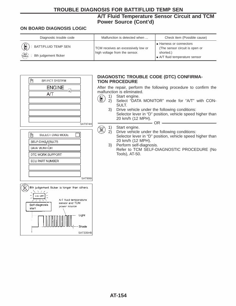
ON BOARD DIAGNOSIS LOGIC
Diagnostic trouble code Malfunction is detected when ... Check item (Possible cause)
: BATT/FLUID TEMP SEN TCM receives an excessively low orhigh voltage from the sensor.
I Harness or connectors(The sensor circuit is open orshorted.)
I A/T fluid temperature sensor: 8th judgement flicker
SAT974H
SAT906I
SAT335HB
DIAGNOSTIC TROUBLE CODE (DTC) CONFIRMA-TION PROCEDUREAfter the repair, perform the following procedure to confirm themalfunction is eliminated.
1) Start engine.2) Select “DATA MONITOR” mode for “A/T” with CON-
SULT.3) Drive vehicle under the following conditions:
Selector lever in “D” position, vehicle speed higher than20 km/h (12 MPH).
------------------------------------------------------------------------------------------------------------------------------------------------------------------------------------------------------------------------------------------------------ OR ------------------------------------------------------------------------------------------------------------------------------------------------------------------------------------------------------------------------------------------------------1) Start engine.2) Drive vehicle under the following conditions:
Selector lever in “D” position, vehicle speed higher than20 km/h (12 MPH).
3) Perform self-diagnosis.Refer to TCM SELF-DIAGNOSTIC PROCEDURE (NoTools), AT-50.
TROUBLE DIAGNOSIS FOR BATT/FLUID TEMP SENA/T Fluid Temperature Sensor Circuit and TCMPower Source (Cont’d)
AT-154
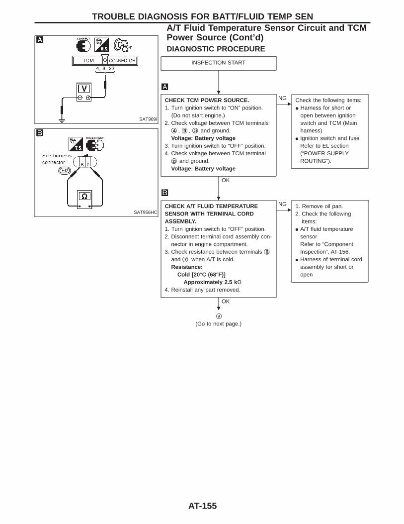
SAT909I
SAT956HC
DIAGNOSTIC PROCEDURE
INSPECTION START
CHECK TCM POWER SOURCE.1. Turn ignition switch to “ON” position.
(Do not start engine.)2. Check voltage between TCM terminals
q4 , q9 , q23 and ground.Voltage: Battery voltage
3. Turn ignition switch to “OFF” position.4. Check voltage between TCM terminal
q23 and ground.Voltage: Battery voltage
OK
ENG Check the following items:
I Harness for short oropen between ignitionswitch and TCM (Mainharness)
I Ignition switch and fuseRefer to EL section(“POWER SUPPLYROUTING”).
CHECK A/T FLUID TEMPERATURESENSOR WITH TERMINAL CORDASSEMBLY.1. Turn ignition switch to “OFF” position.2. Disconnect terminal cord assembly con-
nector in engine compartment.3. Check resistance between terminals q6
and q7 when A/T is cold.Resistance:
Cold [20°C (68°F)]Approximately 2.5 k Ω
4. Reinstall any part removed.
OK
ENG 1. Remove oil pan.
2. Check the followingitems:
I A/T fluid temperaturesensorRefer to “ComponentInspection”, AT-156.
I Harness of terminal cordassembly for short oropen
qA
(Go to next page.)
TROUBLE DIAGNOSIS FOR BATT/FLUID TEMP SENA/T Fluid Temperature Sensor Circuit and TCMPower Source (Cont’d)
H
H
H
AT-155
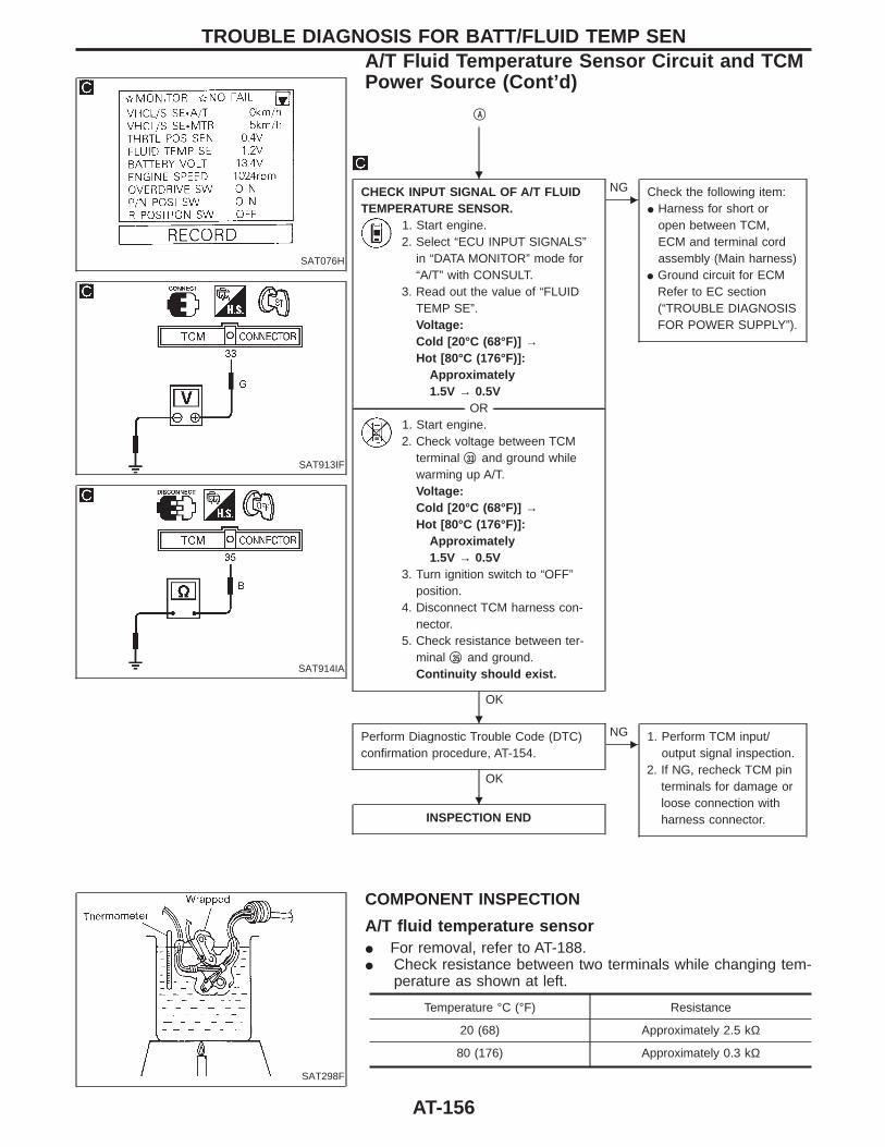
SAT076H
SAT913IF
SAT914IA
qA
CHECK INPUT SIGNAL OF A/T FLUIDTEMPERATURE SENSOR.
1. Start engine.2. Select “ECU INPUT SIGNALS”
in “DATA MONITOR” mode for“A/T” with CONSULT.
3. Read out the value of “FLUIDTEMP SE”.Voltage:Cold [20°C (68°F)] →Hot [80°C (176°F)]:
Approximately1.5V → 0.5V
-------------------------------------------------------------------------------------------------------------------------------------- OR --------------------------------------------------------------------------------------------------------------------------------------1. Start engine.2. Check voltage between TCM
terminal q33 and ground whilewarming up A/T.Voltage:Cold [20°C (68°F)] →Hot [80°C (176°F)]:
Approximately1.5V → 0.5V
3. Turn ignition switch to “OFF”position.
4. Disconnect TCM harness con-nector.
5. Check resistance between ter-minal q35 and ground.Continuity should exist.
OK
ENG Check the following item:
I Harness for short oropen between TCM,ECM and terminal cordassembly (Main harness)
I Ground circuit for ECMRefer to EC section(“TROUBLE DIAGNOSISFOR POWER SUPPLY”).
Perform Diagnostic Trouble Code (DTC)confirmation procedure, AT-154.
OK
ENG 1. Perform TCM input/
output signal inspection.2. If NG, recheck TCM pin
terminals for damage orloose connection withharness connector.INSPECTION END
SAT298F
COMPONENT INSPECTION
A/T fluid temperature sensorI For removal, refer to AT-188.I Check resistance between two terminals while changing tem-
perature as shown at left.
Temperature °C (°F) Resistance
20 (68) Approximately 2.5 kΩ
80 (176) Approximately 0.3 kΩ
TROUBLE DIAGNOSIS FOR BATT/FLUID TEMP SENA/T Fluid Temperature Sensor Circuit and TCMPower Source (Cont’d)
H
H
H
AT-156

SAT358H
Vehicle Speed Sensor ⋅MTRDESCRIPTIONThe vehicle speed sensor⋅MTR is built into the speedometerassembly. The sensor functions as an auxiliary device to the revo-lution sensor when it is malfunctioning. The TCM will then use asignal sent from the vehicle speed sensor⋅MTR.
TCM TERMINALS AND REFERENCE VALUERemarks: Specification data are reference values.
TerminalNo.
Wire color Item ConditionJudgementstandard
27 P/LVehicle speedsensor
When moving vehicle at 2 to 3 km/h(1 to 2 MPH) for 1 m (3 ft) or more.
Voltage variesbetween lessthan 1V andmore than 4.5V
ON BOARD DIAGNOSIS LOGIC
Diagnostic trouble code Malfunction is detected when ... Check item (Possible cause)
: VHCL SPEED SEN⋅MTRTCM does not receive the proper volt-age signal from the sensor.
I Harness or connectors(The sensor circuit is open orshorted.)
I Vehicle speed sensor: 2nd judgement flicker
TROUBLE DIAGNOSIS FOR VHCL SPEED SEN ⋅MTR
AT-157
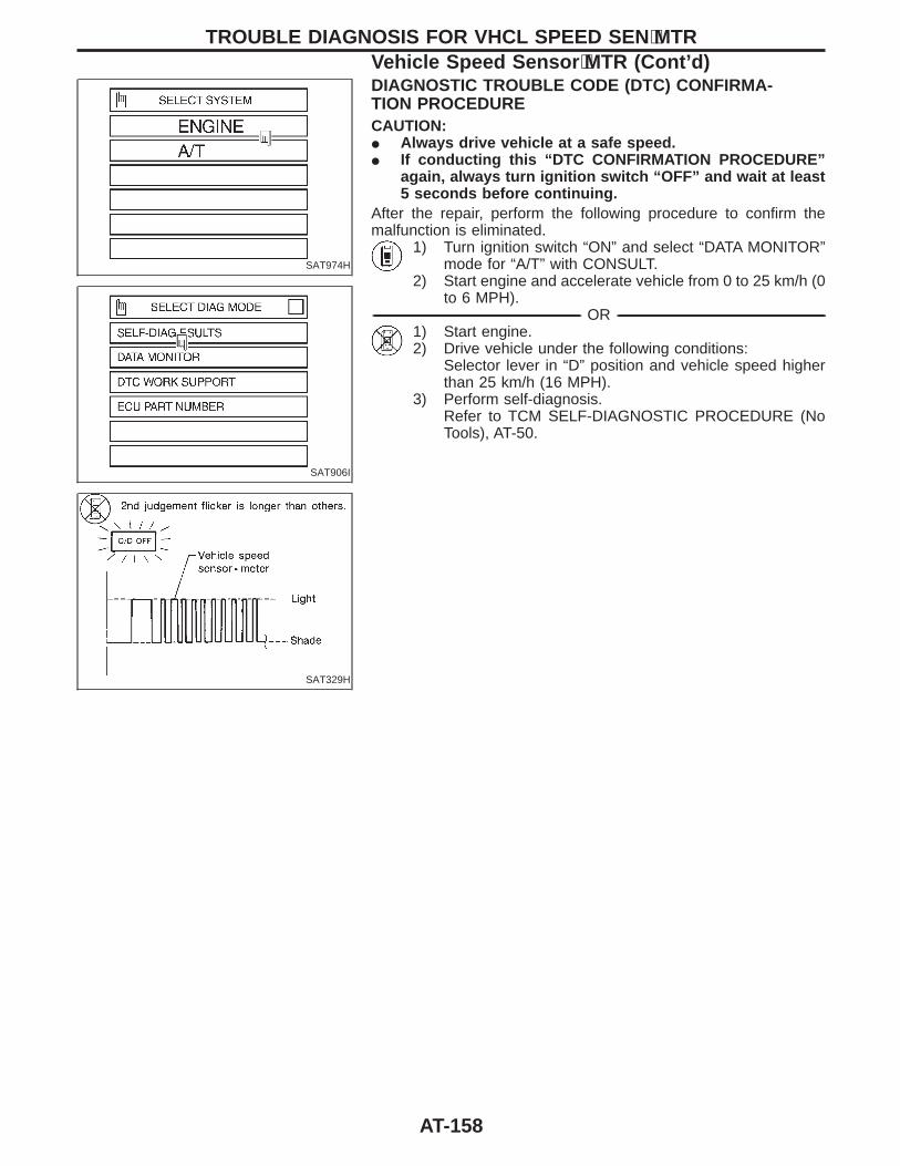
SAT974H
SAT906I
SAT329H
DIAGNOSTIC TROUBLE CODE (DTC) CONFIRMA-TION PROCEDURECAUTION:I Always drive vehicle at a safe speed.I If conducting this “DTC CONFIRMATION PROCEDURE”
again, always turn ignition switch “OFF” and wait at least5 seconds before continuing.
After the repair, perform the following procedure to confirm themalfunction is eliminated.
1) Turn ignition switch “ON” and select “DATA MONITOR”mode for “A/T” with CONSULT.
2) Start engine and accelerate vehicle from 0 to 25 km/h (0to 6 MPH).
------------------------------------------------------------------------------------------------------------------------------------------------------------------------------------------------------------------------------------------------------ OR ------------------------------------------------------------------------------------------------------------------------------------------------------------------------------------------------------------------------------------------------------1) Start engine.2) Drive vehicle under the following conditions:
Selector lever in “D” position and vehicle speed higherthan 25 km/h (16 MPH).
3) Perform self-diagnosis.Refer to TCM SELF-DIAGNOSTIC PROCEDURE (NoTools), AT-50.
TROUBLE DIAGNOSIS FOR VHCL SPEED SEN ⋅MTRVehicle Speed Sensor ⋅MTR (Cont’d)
AT-158

SAT076H
SAT943IB
DIAGNOSTIC PROCEDURE
INSPECTION START
CHECK INPUT SIGNAL.1. Start engine.2. Select “ECU INPUT SIGNALS”
in “DATA MONITOR” mode for“A/T” with CONSULT.
3. Read out the value of “VHCL/SSE⋅MTR” while driving.Check the value changesaccording to driving speed.
-------------------------------------------------------------------------------------------------------------------------------------- OR --------------------------------------------------------------------------------------------------------------------------------------1. Start engine.2. Check voltage between TCM
terminal q27 and ground whiledriving at 2 to 3 km/h (1 to 2MPH) for 1 m (3 ft) or more.Voltage:
Voltage varies between lessthan 1V and more than4.5V.
OK
ENG Check the following items:
I Vehicle speed sensorand ground circuit forvehicle speed sensorRefer to EL section(“METERS ANDGAUGES”).
I Harness for short oropen between TCM andvehicle speed sensor(Main harness)
Perform Diagnostic Trouble Code (DTC)confirmation procedure, AT-158.
OK
ENG 1. Perform TCM input/
output signal inspection.2. If NG, recheck TCM pin
terminals for damage orloose connection withharness connector.INSPECTION END
TROUBLE DIAGNOSIS FOR VHCL SPEED SEN ⋅MTRVehicle Speed Sensor ⋅MTR (Cont’d)
H
H
H
AT-159
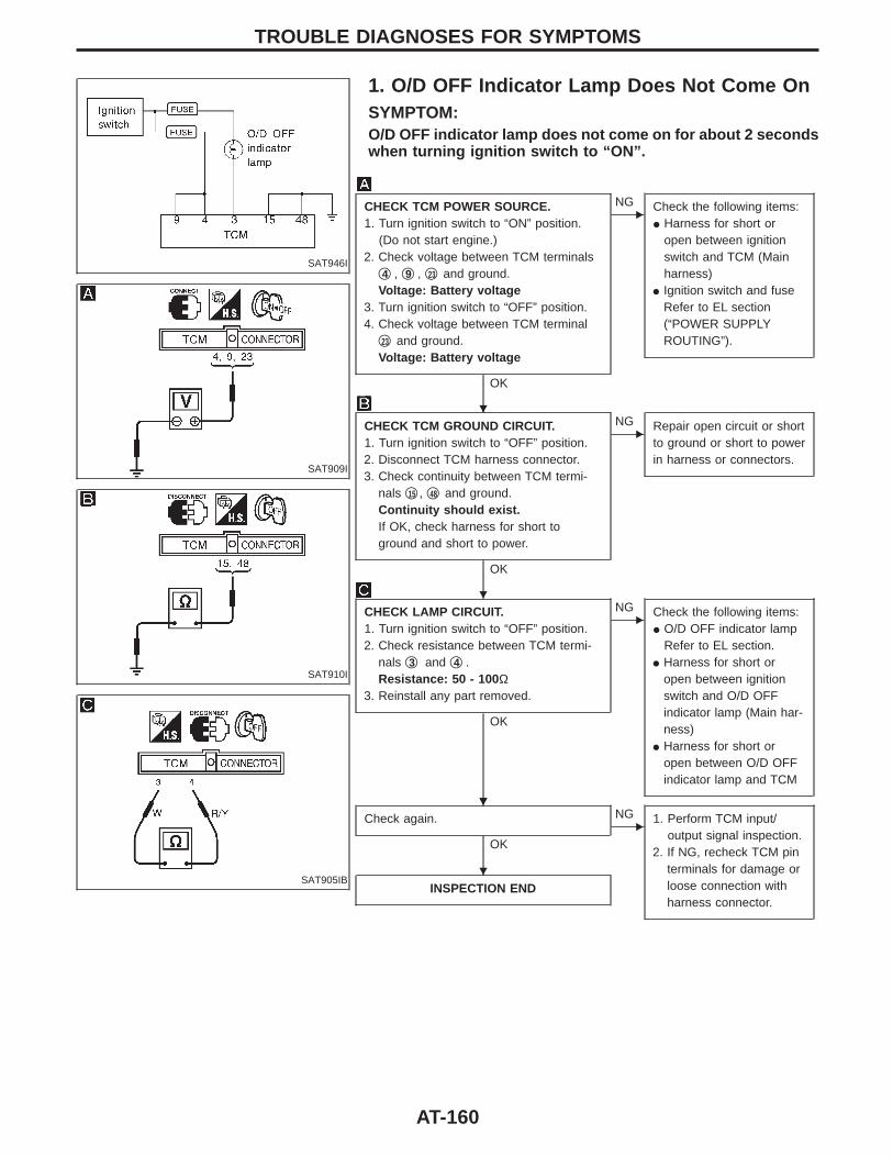
SAT946I
1. O/D OFF Indicator Lamp Does Not Come OnSYMPTOM:O/D OFF indicator lamp does not come on for about 2 secondswhen turning ignition switch to “ON”.
SAT909I
SAT910I
SAT905IB
CHECK TCM POWER SOURCE.1. Turn ignition switch to “ON” position.
(Do not start engine.)2. Check voltage between TCM terminals
q4 , q9 , q23 and ground.Voltage: Battery voltage
3. Turn ignition switch to “OFF” position.4. Check voltage between TCM terminal
q23 and ground.Voltage: Battery voltage
OK
ENG Check the following items:
I Harness for short oropen between ignitionswitch and TCM (Mainharness)
I Ignition switch and fuseRefer to EL section(“POWER SUPPLYROUTING”).
CHECK TCM GROUND CIRCUIT.1. Turn ignition switch to “OFF” position.2. Disconnect TCM harness connector.3. Check continuity between TCM termi-
nals q15 , q48 and ground.Continuity should exist.If OK, check harness for short toground and short to power.
OK
ENG Repair open circuit or short
to ground or short to powerin harness or connectors.
CHECK LAMP CIRCUIT.1. Turn ignition switch to “OFF” position.2. Check resistance between TCM termi-
nals q3 and q4 .Resistance: 50 - 100 Ω
3. Reinstall any part removed.
OK
ENG Check the following items:
I O/D OFF indicator lampRefer to EL section.
I Harness for short oropen between ignitionswitch and O/D OFFindicator lamp (Main har-ness)
I Harness for short oropen between O/D OFFindicator lamp and TCM
Check again.
OK
ENG 1. Perform TCM input/
output signal inspection.2. If NG, recheck TCM pin
terminals for damage orloose connection withharness connector.
INSPECTION END
TROUBLE DIAGNOSES FOR SYMPTOMS
H
H
HH
H
AT-160
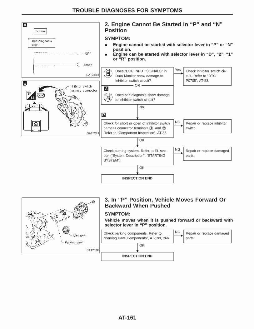
SAT344H
2. Engine Cannot Be Started In “P” and “N”PositionSYMPTOM:I Engine cannot be started with selector lever in “P” or “N”
position.I Engine can be started with selector lever in “D”, “2”, “1”
or “R” position.
SAT022J
Does “ECU INPUT SIGNALS” inData Monitor show damage toinhibitor switch circuit?
-------------------------------------------------------------------------------------------------------------------------------------- OR --------------------------------------------------------------------------------------------------------------------------------------
Does self-diagnosis show damageto inhibitor switch circuit?
No
EYes Check inhibitor switch cir-
cuit. Refer to “DTCP0705”, AT-83.
Check for short or open of inhibitor switchharness connector terminals q1 and q2 .Refer to “Component Inspection”, AT-86.
OK
ENG Repair or replace inhibitor
switch.
Check starting system. Refer to EL sec-tion (“System Description”, “STARTINGSYSTEM”).
OK
ENG Repair or replace damaged
parts.
INSPECTION END
SAT282F
3. In “P” Position, Vehicle Moves Forward OrBackward When PushedSYMPTOM:Vehicle moves when it is pushed forward or backward withselector lever in “P” position.
Check parking components. Refer to“Parking Pawl Components”, AT-199, 266.
OK
ENG Repair or replace damaged
parts.
INSPECTION END
TROUBLE DIAGNOSES FOR SYMPTOMS
H
H
H
H
AT-161
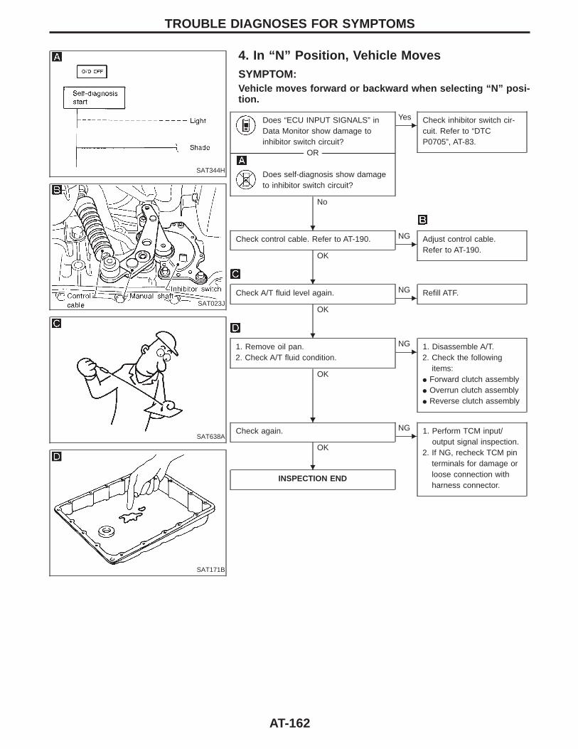
SAT344H
4. In “N” Position, Vehicle MovesSYMPTOM:Vehicle moves forward or backward when selecting “N” posi-tion.
SAT023J
SAT638A
SAT171B
Does “ECU INPUT SIGNALS” inData Monitor show damage toinhibitor switch circuit?
-------------------------------------------------------------------------------------------------------------------------------------- OR --------------------------------------------------------------------------------------------------------------------------------------
Does self-diagnosis show damageto inhibitor switch circuit?
No
EYes Check inhibitor switch cir-
cuit. Refer to “DTCP0705”, AT-83.
Check control cable. Refer to AT-190.
OK
ENG Adjust control cable.
Refer to AT-190.
Check A/T fluid level again.
OK
ENG Refill ATF.
1. Remove oil pan.2. Check A/T fluid condition.
OK
ENG 1. Disassemble A/T.
2. Check the followingitems:
I Forward clutch assemblyI Overrun clutch assemblyI Reverse clutch assembly
Check again.
OK
ENG 1. Perform TCM input/
output signal inspection.2. If NG, recheck TCM pin
terminals for damage orloose connection withharness connector.
INSPECTION END
TROUBLE DIAGNOSES FOR SYMPTOMS
H
H
H
HH
H
AT-162
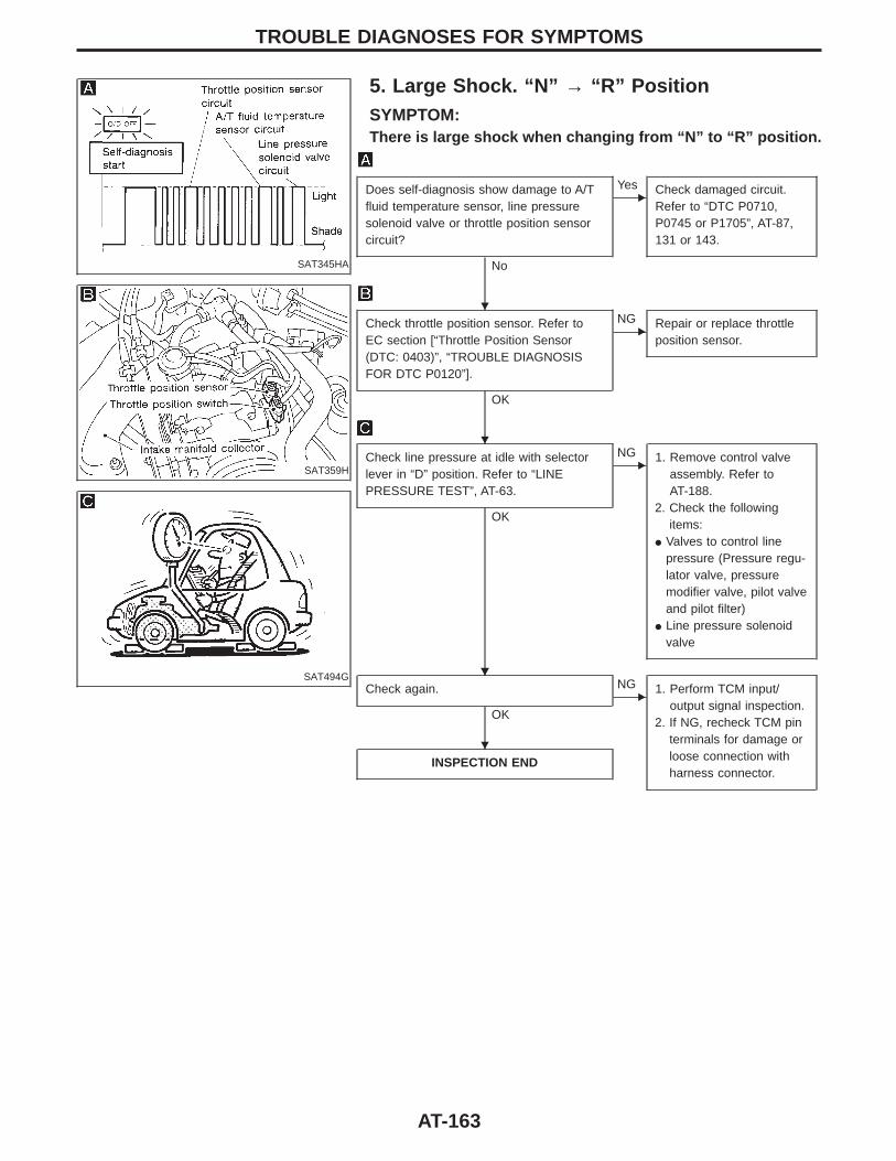
SAT345HA
5. Large Shock. “N” → “R” PositionSYMPTOM:There is large shock when changing from “N” to “R” position.
SAT359H
SAT494G
Does self-diagnosis show damage to A/Tfluid temperature sensor, line pressuresolenoid valve or throttle position sensorcircuit?
No
EYes Check damaged circuit.
Refer to “DTC P0710,P0745 or P1705”, AT-87,131 or 143.
Check throttle position sensor. Refer toEC section [“Throttle Position Sensor(DTC: 0403)”, “TROUBLE DIAGNOSISFOR DTC P0120”].
OK
ENG Repair or replace throttle
position sensor.
Check line pressure at idle with selectorlever in “D” position. Refer to “LINEPRESSURE TEST”, AT-63.
OK
ENG 1. Remove control valve
assembly. Refer toAT-188.
2. Check the followingitems:
I Valves to control linepressure (Pressure regu-lator valve, pressuremodifier valve, pilot valveand pilot filter)
I Line pressure solenoidvalve
Check again.
OK
ENG 1. Perform TCM input/
output signal inspection.2. If NG, recheck TCM pin
terminals for damage orloose connection withharness connector.
INSPECTION END
TROUBLE DIAGNOSES FOR SYMPTOMS
H
H
HH
H
AT-163
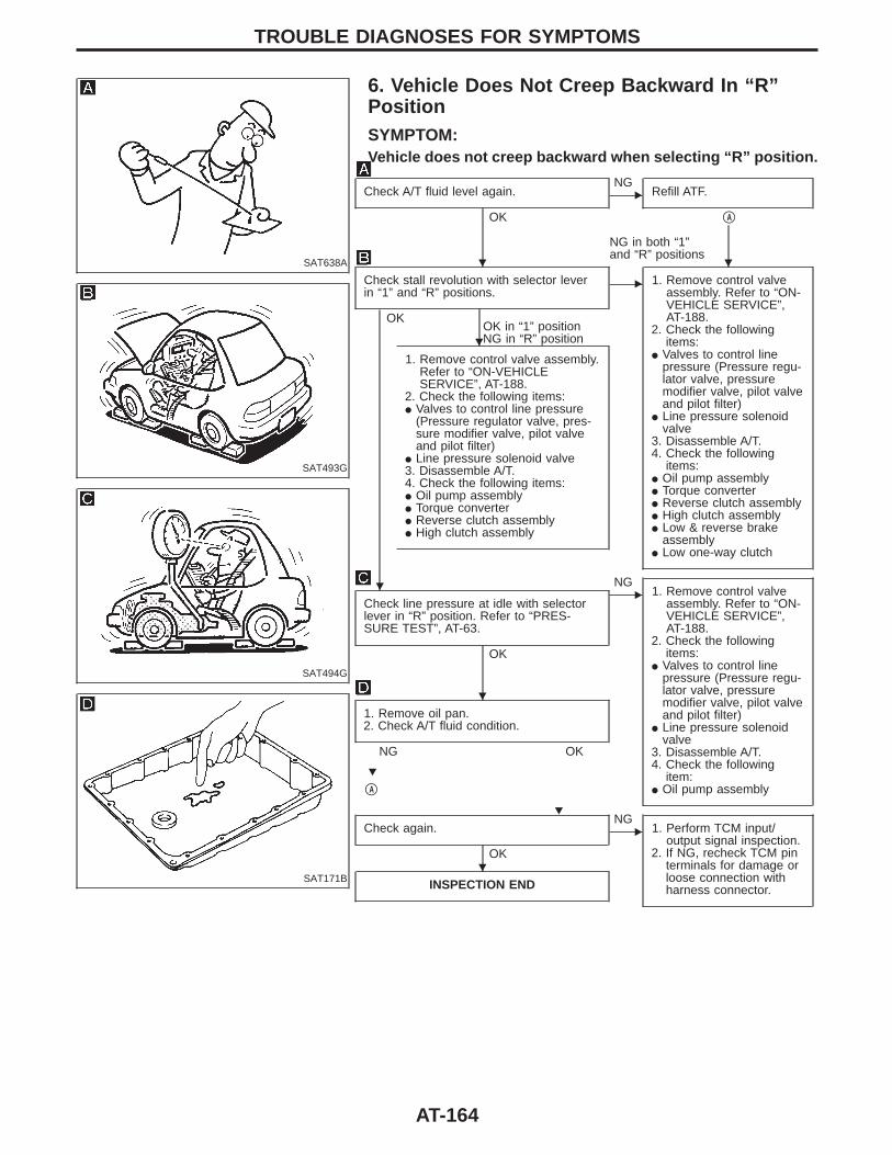
SAT638A
6. Vehicle Does Not Creep Backward In “R”PositionSYMPTOM:Vehicle does not creep backward when selecting “R” position.
SAT493G
SAT494G
SAT171B
Check A/T fluid level again.
OK
ENG
Refill ATF.
qA
NG in both “1”and “R” positions
Check stall revolution with selector leverin “1” and “R” positions.
OKOK in “1” positionNG in “R” position
E 1. Remove control valveassembly. Refer to “ON-VEHICLE SERVICE”,AT-188.
2. Check the followingitems:
I Valves to control linepressure (Pressure regu-lator valve, pressuremodifier valve, pilot valveand pilot filter)
I Line pressure solenoidvalve
3. Disassemble A/T.4. Check the following
items:I Oil pump assemblyI Torque converterI Reverse clutch assemblyI High clutch assemblyI Low & reverse brake
assemblyI Low one-way clutch
1. Remove control valve assembly.Refer to “ON-VEHICLESERVICE”, AT-188.
2. Check the following items:I Valves to control line pressure
(Pressure regulator valve, pres-sure modifier valve, pilot valveand pilot filter)
I Line pressure solenoid valve3. Disassemble A/T.4. Check the following items:I Oil pump assemblyI Torque converterI Reverse clutch assemblyI High clutch assembly
Check line pressure at idle with selectorlever in “R” position. Refer to “PRES-SURE TEST”, AT-63.
OK
ENG
1. Remove control valveassembly. Refer to “ON-VEHICLE SERVICE”,AT-188.
2. Check the followingitems:
I Valves to control linepressure (Pressure regu-lator valve, pressuremodifier valve, pilot valveand pilot filter)
I Line pressure solenoidvalve
3. Disassemble A/T.4. Check the following
item:I Oil pump assembly
1. Remove oil pan.2. Check A/T fluid condition.
NG OK
qA
Check again.
OK
ENG
1. Perform TCM input/output signal inspection.
2. If NG, recheck TCM pinterminals for damage orloose connection withharness connector.INSPECTION END
TROUBLE DIAGNOSES FOR SYMPTOMS
H H
H
H
H
H
H
H
AT-164

SAT638A
7. Vehicle Does Not Creep Forward In “D”, “2”Or “1” PositionSYMPTOM:Vehicle does not creep forward when selecting “D”, “2” or “1”position.
SAT493G
SAT494G
SAT171B
Check A/T fluid level again.
OK
ENG
Refill ATF.
qA
Check stall revolution with selector lever in“D” position. Refer to “STALL TEST”, AT-60.
OK
ENG
1. Remove control valveassembly. Refer toAT-188.
2. Check the followingitems:
I Valves to control linepressure (Pressureregulator valve, pres-sure modifier valve,pilot valve and pilotfilter)
I Line pressure sole-noid valve
3. Disassemble A/T.4. Check the following
items:I Oil pump assemblyI Forward clutch
assemblyI Forward one-way
clutchI Low one-way clutchI Low & reverse brake
assemblyI Torque converter
Check line pressure at idle with selector leverin “D” position. Refer to “LINE PRESSURETEST”, AT-63.
OK NG
1. Remove control valve assembly.Refer to AT-188.
2. Check the following items:I Valves to control line pressure
(Pressure regulator valve, pressuremodifier valve, pilot valve and pilotfilter)
I Line pressure solenoid valve3. Disassemble A/T.4. Check the following item:I Oil pump assembly
1. Remove oil pan.2. Check A/T fluid condition.
OK
ENG
qA
Check again.
OK
ENG
1. Perform TCM input/output signal inspec-tion.
2. If NG, recheck TCMpin terminals fordamage or looseconnection with har-ness connector.
INSPECTION END
TROUBLE DIAGNOSES FOR SYMPTOMS
H H
H
H
H
HH
H
AT-165
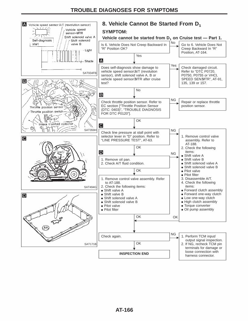
SAT934FB
8. Vehicle Cannot Be Started From D 1
SYMPTOM:Vehicle cannot be started from D 1 on Cruise test — Part 1.
SAT359H
SAT494G
SAT171B
Is 6. Vehicle Does Not Creep Backward In“R” Position OK?
Yes
ENo
Go to 6. Vehicle Does NotCreep Backward In “R”Position, AT-164.
Does self-diagnosis show damage tovehicle speed sensor⋅A/T (revolutionsensor), shift solenoid valve A, B orvehicle speed sensor⋅MTR after cruisetest?
No
EYes
Check damaged circuit.Refer to “DTC P0720,P0750, P0755 or VHCLSPEED SEN⋅MTR”, AT-91,135, 139 or 157.
Check throttle position sensor. Refer toEC section [“Throttle Position Sensor(DTC: 0403)”, “TROUBLE DIAGNOSISFOR DTC P0120”].
OK
ENG
Repair or replace throttleposition sensor.
Check line pressure at stall point withselector lever in “D” position. Refer to“LINE PRESSURE TEST”, AT-63.
OK
ENG
1. Remove control valveassembly. Refer toAT-188.
2. Check the followingitems:
I Shift valve AI Shift valve BI Shift solenoid valve AI Shift solenoid valve BI Pilot valveI Pilot filter3. Disassemble A/T.4. Check the following
items:I Forward clutch assemblyI Forward one-way clutchI Low one-way clutchI High clutch assemblyI Torque converterI Oil pump assembly
1. Remove oil pan.2. Check A/T fluid condition.
OK
ENG
1. Remove control valve assembly. Referto AT-188.
2. Check the following items:I Shift valve AI Shift valve BI Shift solenoid valve AI Shift solenoid valve BI Pilot valveI Pilot filter
OK OKF
Check again.
OK
ENG
1. Perform TCM input/output signal inspection.
2. If NG, recheck TCM pinterminals for damage orloose connection withharness connector.INSPECTION END
TROUBLE DIAGNOSES FOR SYMPTOMS
H
H
H
H
H
HH
H
AT-166
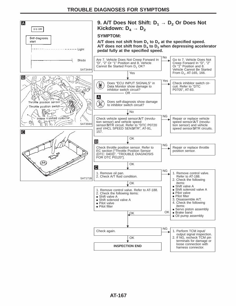
SAT344H
9. A/T Does Not Shift: D 1 → D2 Or Does NotKickdown: D 4 → D2
SYMPTOM:A/T does not shift from D 1 to D2 at the specified speed.A/T does not shift from D 4 to D2 when depressing acceleratorpedal fully at the specified speed.
SAT359H
SAT171B
Are 7. Vehicle Does Not Creep Forward In“D”, “2” Or “1” Position and 8. VehicleCannot Be Started From D1 OK?
Yes
ENo
Go to 7. Vehicle Does NotCreep Forward In “D”, “2”Or “1” Position and 8.Vehicle Cannot Be StartedFrom D1, AT-165, 166.
Does “ECU INPUT SIGNALS” inData Monitor show damage toinhibitor switch circuit?
-------------------------------------------------------------------------------------------------------------------------------------- OR --------------------------------------------------------------------------------------------------------------------------------------
Does self-diagnosis show damageto inhibitor switch circuit?
No
EYes
Check inhibitor switch cir-cuit. Refer to “DTCP0705”, AT-83.
Check vehicle speed sensor⋅A/T (revolu-tion sensor) and vehicle speedsensor⋅MTR circuit. Refer to “DTC P0720and VHCL SPEED SEN⋅MTR”, AT-91,157.
OK
ENG
Repair or replace vehiclespeed sensor⋅A/T (revolu-tion sensor) and vehiclespeed sensor⋅MTR circuits.
Check throttle position sensor. Refer toEC section [“Throttle Position Sensor(DTC: 0403)”, “TROUBLE DIAGNOSISFOR DTC P0120”].
OK
ENG
Repair or replace throttleposition sensor.
1. Remove oil pan.2. Check A/T fluid condition.
OK
ENG
1. Remove control valve.Refer to AT-188.
2. Check the followingitems:
I Shift valve AI Shift solenoid valve AI Pilot valveI Pilot filter3. Disassemble A/T.4. Check the following
items:I Servo piston assemblyI Brake bandI Oil pump assembly
1. Remove control valve. Refer to AT-188.2. Check the following items:I Shift valve AI Shift solenoid valve AI Pilot valveI Pilot filter
OK OKF
Check again.
OK
ENG
1. Perform TCM input/output signal inspection.
2. If NG, recheck TCM pinterminals for damage orloose connection withharness connector.INSPECTION END
TROUBLE DIAGNOSES FOR SYMPTOMS
H
H
H
H
H
HH
H
AT-167
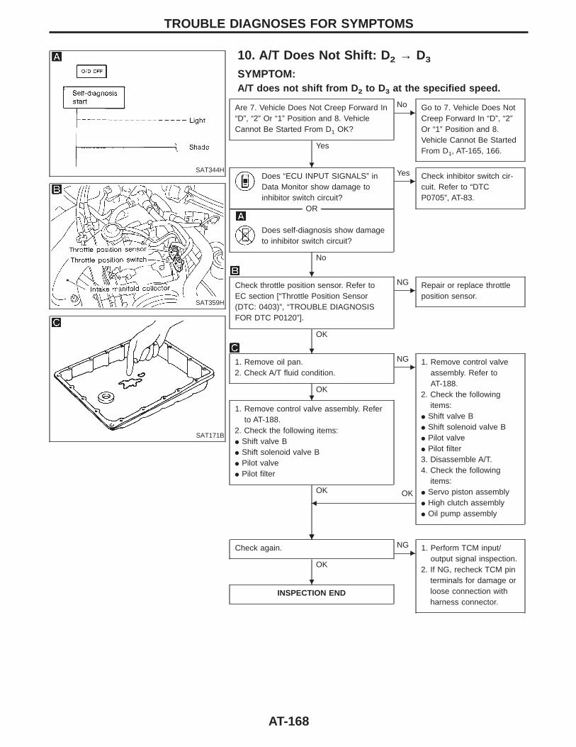
SAT344H
10. A/T Does Not Shift: D 2 → D3
SYMPTOM:A/T does not shift from D 2 to D3 at the specified speed.
SAT359H
SAT171B
Are 7. Vehicle Does Not Creep Forward In“D”, “2” Or “1” Position and 8. VehicleCannot Be Started From D1 OK?
Yes
ENo Go to 7. Vehicle Does Not
Creep Forward In “D”, “2”Or “1” Position and 8.Vehicle Cannot Be StartedFrom D1, AT-165, 166.
Does “ECU INPUT SIGNALS” inData Monitor show damage toinhibitor switch circuit?
-------------------------------------------------------------------------------------------------------------------------------------- OR --------------------------------------------------------------------------------------------------------------------------------------
Does self-diagnosis show damageto inhibitor switch circuit?
No
EYes Check inhibitor switch cir-
cuit. Refer to “DTCP0705”, AT-83.
Check throttle position sensor. Refer toEC section [“Throttle Position Sensor(DTC: 0403)”, “TROUBLE DIAGNOSISFOR DTC P0120”].
OK
ENG Repair or replace throttle
position sensor.
1. Remove oil pan.2. Check A/T fluid condition.
OK
ENG 1. Remove control valve
assembly. Refer toAT-188.
2. Check the followingitems:
I Shift valve BI Shift solenoid valve BI Pilot valveI Pilot filter3. Disassemble A/T.4. Check the following
items:I Servo piston assemblyI High clutch assemblyI Oil pump assembly
1. Remove control valve assembly. Referto AT-188.
2. Check the following items:I Shift valve BI Shift solenoid valve BI Pilot valveI Pilot filter
OK OKF
Check again.
OK
ENG 1. Perform TCM input/
output signal inspection.2. If NG, recheck TCM pin
terminals for damage orloose connection withharness connector.
INSPECTION END
TROUBLE DIAGNOSES FOR SYMPTOMS
H
H
H
H
HH
H
AT-168
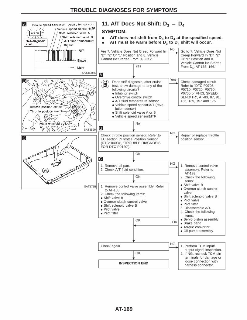
SAT363HC
11. A/T Does Not Shift: D 3 → D4
SYMPTOM:I A/T does not shift from D 3 to D4 at the specified speed.I A/T must be warm before D 3 to D4 shift will occur.
SAT359H
SAT171B
Are 7. Vehicle Does Not Creep Forward In“D”, “2” Or “1” Position and 8. VehicleCannot Be Started From D1 OK?
Yes
ENo
Go to 7. Vehicle Does NotCreep Forward In “D”, “2”Or “1” Position and 8.Vehicle Cannot Be StartedFrom D1, AT-165, 166.
Does self-diagnosis, after cruisetest, show damage to any of thefollowing circuits?I Inhibitor switchI Overdrive control switchI A/T fluid temperature sensorI Vehicle speed sensor⋅A/T (revo-
lution sensor)I Shift solenoid valve A or BI Vehicle speed sensor⋅MTR
No
EYes
Check damaged circuit.Refer to “DTC P0705,P0710, P0720, P0750,P0755 or VHCL SPEEDSEN⋅MTR”, AT-83, 87, 91,135, 139, 157 and 175.
Check throttle position sensor. Refer toEC section [“Throttle Position Sensor(DTC: 0403)”, “TROUBLE DIAGNOSISFOR DTC P0120”].
OK
ENG
Repair or replace throttleposition sensor.
1. Remove oil pan.2. Check A/T fluid condition.
OK
ENG
1. Remove control valveassembly. Refer toAT-188.
2. Check the followingitems:
I Shift valve BI Overrun clutch control
valveI Shift solenoid valve BI Pilot valveI Pilot filter3. Disassemble A/T.4. Check the following
items:I Servo piston assemblyI Brake bandI Torque converterI Oil pump assembly
1. Remove control valve assembly. Referto AT-188.
2. Check the following items:I Shift valve BI Overrun clutch control valveI Shift solenoid valve BI Pilot valveI Pilot filter
OK OKF
Check again.
OK
ENG
1. Perform TCM input/output signal inspection.
2. If NG, recheck TCM pinterminals for damage orloose connection withharness connector.INSPECTION END
TROUBLE DIAGNOSES FOR SYMPTOMS
H
H
H
H
HH
H
AT-169
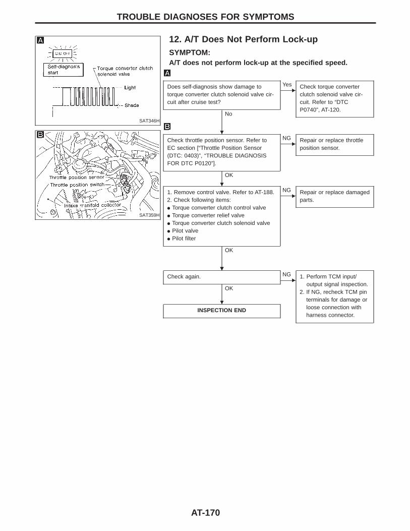
SAT346H
12. A/T Does Not Perform Lock-upSYMPTOM:A/T does not perform lock-up at the specified speed.
SAT359H
Does self-diagnosis show damage totorque converter clutch solenoid valve cir-cuit after cruise test?
No
EYes Check torque converter
clutch solenoid valve cir-cuit. Refer to “DTCP0740”, AT-120.
Check throttle position sensor. Refer toEC section [“Throttle Position Sensor(DTC: 0403)”, “TROUBLE DIAGNOSISFOR DTC P0120”].
OK
ENG Repair or replace throttle
position sensor.
1. Remove control valve. Refer to AT-188.2. Check following items:I Torque converter clutch control valveI Torque converter relief valveI Torque converter clutch solenoid valveI Pilot valveI Pilot filter
OK
ENG Repair or replace damaged
parts.
Check again.
OK
ENG 1. Perform TCM input/
output signal inspection.2. If NG, recheck TCM pin
terminals for damage orloose connection withharness connector.
INSPECTION END
TROUBLE DIAGNOSES FOR SYMPTOMS
H
H
HH
H
AT-170
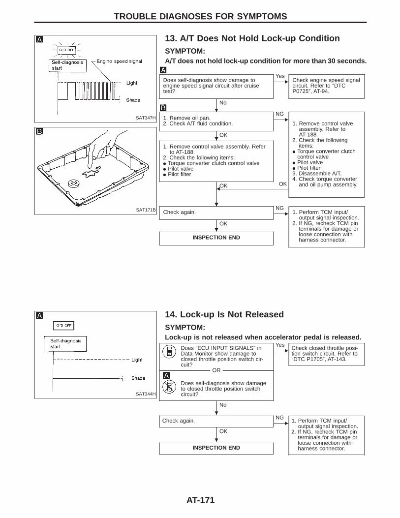
SAT347H
13. A/T Does Not Hold Lock-up ConditionSYMPTOM:A/T does not hold lock-up condition for more than 30 seconds.
SAT171B
Does self-diagnosis show damage toengine speed signal circuit after cruisetest?
No
EYes
Check engine speed signalcircuit. Refer to “DTCP0725”, AT-94.
1. Remove oil pan.2. Check A/T fluid condition.
OK
ENG
1. Remove control valveassembly. Refer toAT-188.
2. Check the followingitems:
I Torque converter clutchcontrol valve
I Pilot valveI Pilot filter3. Disassemble A/T.4. Check torque converter
and oil pump assembly.
1. Remove control valve assembly. Referto AT-188.
2. Check the following items:I Torque converter clutch control valveI Pilot valveI Pilot filter
OK OKF
Check again.
OK
ENG
1. Perform TCM input/output signal inspection.
2. If NG, recheck TCM pinterminals for damage orloose connection withharness connector.INSPECTION END
SAT344H
14. Lock-up Is Not ReleasedSYMPTOM:Lock-up is not released when accelerator pedal is released.
Does “ECU INPUT SIGNALS” inData Monitor show damage toclosed throttle position switch cir-cuit?
-------------------------------------------------------------------------------------------------------------------------------------- OR --------------------------------------------------------------------------------------------------------------------------------------
Does self-diagnosis show damageto closed throttle position switchcircuit?
No
EYes Check closed throttle posi-
tion switch circuit. Refer to“DTC P1705”, AT-143.
Check again.
OK
ENG 1. Perform TCM input/
output signal inspection.2. If NG, recheck TCM pin
terminals for damage orloose connection withharness connector.INSPECTION END
TROUBLE DIAGNOSES FOR SYMPTOMS
H
H
HH
H
H
H
AT-171
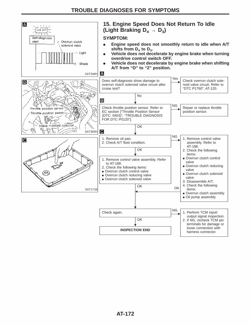
SAT348H
15. Engine Speed Does Not Return To Idle(Light Braking D 4 → D3)SYMPTOM:I Engine speed does not smoothly return to idle when A/T
shifts from D 4 to D3.I Vehicle does not decelerate by engine brake when turning
overdrive control switch OFF.I Vehicle does not decelerate by engine brake when shifting
A/T from “D” to “2” position.
SAT359H
SAT171B
Does self-diagnosis show damage tooverrun clutch solenoid valve circuit aftercruise test?
No
EYes
Check overrun clutch sole-noid valve circuit. Refer to“DTC P1760”, AT-120.
Check throttle position sensor. Refer toEC section [“Throttle Position Sensor(DTC: 0403)”, “TROUBLE DIAGNOSISFOR DTC P0120”].
OK
ENG
Repair or replace throttleposition sensor.
1. Remove oil pan.2. Check A/T fluid condition.
OK
ENG
1. Remove control valveassembly. Refer toAT-188.
2. Check the followingitems:
I Overrun clutch controlvalve
I Overrun clutch reducingvalve
I Overrun clutch solenoidvalve
3. Disassemble A/T.4. Check the following
items:I Overrun clutch assemblyI Oil pump assembly
1. Remove control valve assembly. Referto AT-188.
2. Check the following items:I Overrun clutch control valveI Overrun clutch reducing valveI Overrun clutch solenoid valve
OK OKF
Check again.
OK
ENG
1. Perform TCM input/output signal inspection.
2. If NG, recheck TCM pinterminals for damage orloose connection withharness connector.INSPECTION END
TROUBLE DIAGNOSES FOR SYMPTOMS
H
H
H
HH
H
AT-172
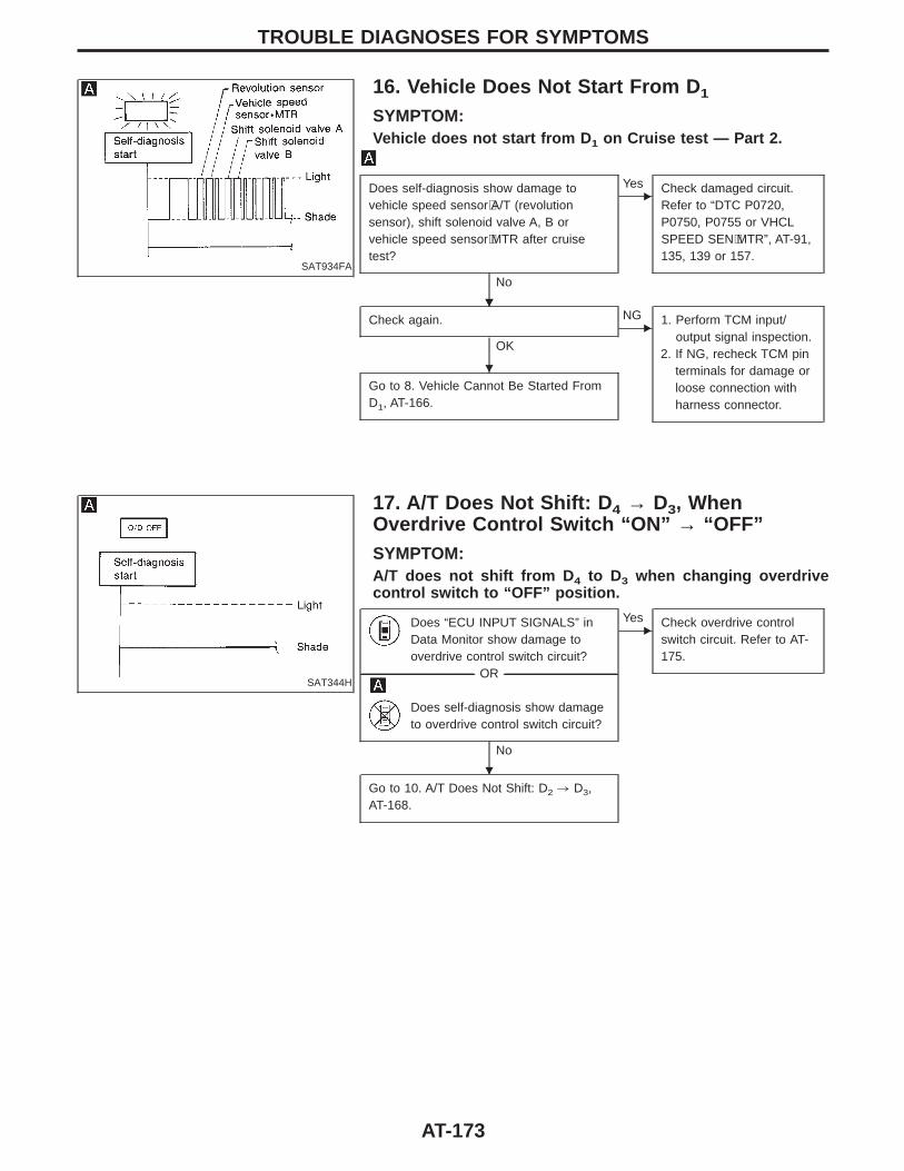
SAT934FA
16. Vehicle Does Not Start From D 1
SYMPTOM:Vehicle does not start from D 1 on Cruise test — Part 2.
Does self-diagnosis show damage tovehicle speed sensor⋅A/T (revolutionsensor), shift solenoid valve A, B orvehicle speed sensor⋅MTR after cruisetest?
No
EYes Check damaged circuit.
Refer to “DTC P0720,P0750, P0755 or VHCLSPEED SEN⋅MTR”, AT-91,135, 139 or 157.
Check again.
OK
ENG 1. Perform TCM input/
output signal inspection.2. If NG, recheck TCM pin
terminals for damage orloose connection withharness connector.
Go to 8. Vehicle Cannot Be Started FromD1, AT-166.
SAT344H
17. A/T Does Not Shift: D 4 → D3, WhenOverdrive Control Switch “ON” → “OFF”SYMPTOM:A/T does not shift from D 4 to D3 when changing overdrivecontrol switch to “OFF” position.
Does “ECU INPUT SIGNALS” inData Monitor show damage tooverdrive control switch circuit?
-------------------------------------------------------------------------------------------------------------------------------------- OR --------------------------------------------------------------------------------------------------------------------------------------
Does self-diagnosis show damageto overdrive control switch circuit?
No
EYes Check overdrive control
switch circuit. Refer to AT-175.
Go to 10. A/T Does Not Shift: D2 , D3,AT-168.
TROUBLE DIAGNOSES FOR SYMPTOMS
HH
H
H
AT-173
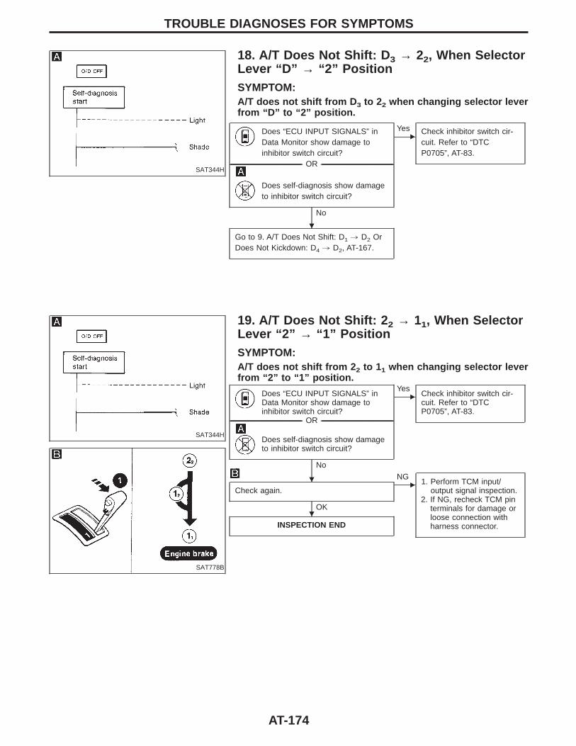
SAT344H
18. A/T Does Not Shift: D 3 → 22, When SelectorLever “D” → “2” PositionSYMPTOM:A/T does not shift from D 3 to 22 when changing selector leverfrom “D” to “2” position.
Does “ECU INPUT SIGNALS” inData Monitor show damage toinhibitor switch circuit?
-------------------------------------------------------------------------------------------------------------------------------------- OR --------------------------------------------------------------------------------------------------------------------------------------
Does self-diagnosis show damageto inhibitor switch circuit?
No
EYes Check inhibitor switch cir-
cuit. Refer to “DTCP0705”, AT-83.
Go to 9. A/T Does Not Shift: D1 , D2 OrDoes Not Kickdown: D4 , D2, AT-167.
SAT344H
19. A/T Does Not Shift: 2 2 → 11, When SelectorLever “2” → “1” PositionSYMPTOM:A/T does not shift from 2 2 to 11 when changing selector leverfrom “2” to “1” position.
SAT778B
Does “ECU INPUT SIGNALS” inData Monitor show damage toinhibitor switch circuit?
-------------------------------------------------------------------------------------------------------------------------------------- OR --------------------------------------------------------------------------------------------------------------------------------------
Does self-diagnosis show damageto inhibitor switch circuit?
No
EYes
Check inhibitor switch cir-cuit. Refer to “DTCP0705”, AT-83.
Check again.
OK
ENG
1. Perform TCM input/output signal inspection.
2. If NG, recheck TCM pinterminals for damage orloose connection withharness connector.INSPECTION END
TROUBLE DIAGNOSES FOR SYMPTOMS
H
H
H
AT-174
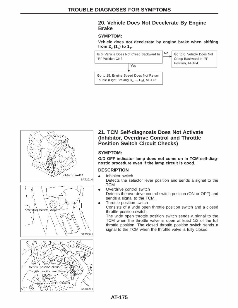
20. Vehicle Does Not Decelerate By EngineBrakeSYMPTOM:Vehicle does not decelerate by engine brake when shiftingfrom 2 2 (12) to 11.
Is 6. Vehicle Does Not Creep Backward In“R” Position OK?
Yes
ENo Go to 6. Vehicle Does Not
Creep Backward In “R”Position, AT-164.
Go to 15. Engine Speed Does Not ReturnTo Idle (Light Braking D4 , D3), AT-172.
SAT291H
21. TCM Self-diagnosis Does Not Activate(Inhibitor, Overdrive Control and ThrottlePosition Switch Circuit Checks)
SAT360H
SAT359H
SYMPTOM:O/D OFF indicator lamp does not come on in TCM self-diag-nostic procedure even if the lamp circuit is good.
DESCRIPTIONI Inhibitor switch
Detects the selector lever position and sends a signal to theTCM.
I Overdrive control switchDetects the overdrive control switch position (ON or OFF) andsends a signal to the TCM.
I Throttle position switchConsists of a wide open throttle position switch and a closedthrottle position switch.The wide open throttle position switch sends a signal to theTCM when the throttle valve is open at least 1/2 of the fullthrottle position. The closed throttle position switch sends asignal to the TCM when the throttle valve is fully closed.
TROUBLE DIAGNOSES FOR SYMPTOMS
H
AT-175
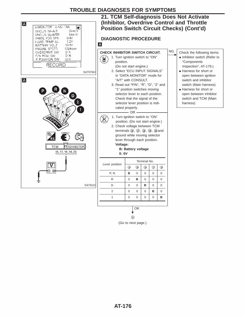
SAT076H
SAT912I
DIAGNOSTIC PROCEDURE
CHECK INHIBITOR SWITCH CIRCUIT.1. Turn ignition switch to “ON”
position.(Do not start engine.)
2. Select “ECU INPUT SIGNALS”in “DATA MONITOR” mode for“A/T” with CONSULT.
3. Read out “P/N”, “R”, “D”, “2” and“1” position switches movingselector lever to each position.Check that the signal of theselector lever position is indi-cated properly.
-------------------------------------------------------------------------------------------------------------------------------------- OR --------------------------------------------------------------------------------------------------------------------------------------1. Turn ignition switch to “ON”
position. (Do not start engine.)2. Check voltage between TCM
terminals q16 , q17 , q18 , q19 , q20 andground while moving selectorlever through each position.Voltage:
B: Battery voltage0: 0V
OK
ENG Check the following items:
I Inhibitor switch (Refer to“ComponentsInspection”, AT-179.)
I Harness for short oropen between ignitionswitch and inhibitorswitch (Main harness)
I Harness for short oropen between inhibitorswitch and TCM (Mainharness)
qA
(Go to next page.)
Lever positionTerminal No.
q19 q20 q18 q17 q16
P, N B 0 0 0 0
R 0 B 0 0 0
D 0 0 B 0 0
2 0 0 0 B 0
1 0 0 0 0 B
TROUBLE DIAGNOSES FOR SYMPTOMS21. TCM Self-diagnosis Does Not Activate(Inhibitor, Overdrive Control and ThrottlePosition Switch Circuit Checks) (Cont’d)
H
AT-176
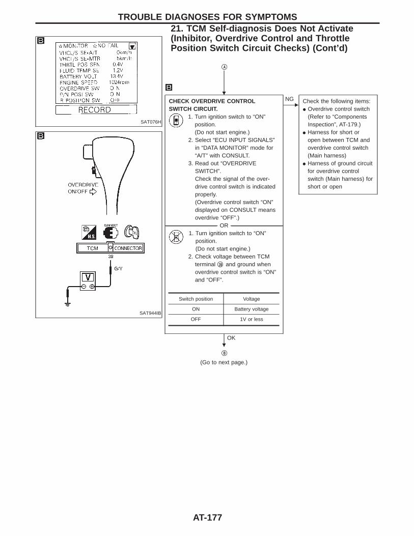
SAT076H
SAT944IB
qA
CHECK OVERDRIVE CONTROLSWITCH CIRCUIT.
1. Turn ignition switch to “ON”position.(Do not start engine.)
2. Select “ECU INPUT SIGNALS”in “DATA MONITOR” mode for“A/T” with CONSULT.
3. Read out “OVERDRIVESWITCH”.Check the signal of the over-drive control switch is indicatedproperly.(Overdrive control switch “ON”displayed on CONSULT meansoverdrive “OFF”.)
-------------------------------------------------------------------------------------------------------------------------------------- OR --------------------------------------------------------------------------------------------------------------------------------------1. Turn ignition switch to “ON”
position.(Do not start engine.)
2. Check voltage between TCMterminal q39 and ground whenoverdrive control switch is “ON”and “OFF”.
OK
ENG Check the following items:
I Overdrive control switch(Refer to “ComponentsInspection”, AT-179.)
I Harness for short oropen between TCM andoverdrive control switch(Main harness)
I Harness of ground circuitfor overdrive controlswitch (Main harness) forshort or open
qB
(Go to next page.)
Switch position Voltage
ON Battery voltage
OFF 1V or less
TROUBLE DIAGNOSES FOR SYMPTOMS21. TCM Self-diagnosis Does Not Activate(Inhibitor, Overdrive Control and ThrottlePosition Switch Circuit Checks) (Cont’d)
H
H
AT-177
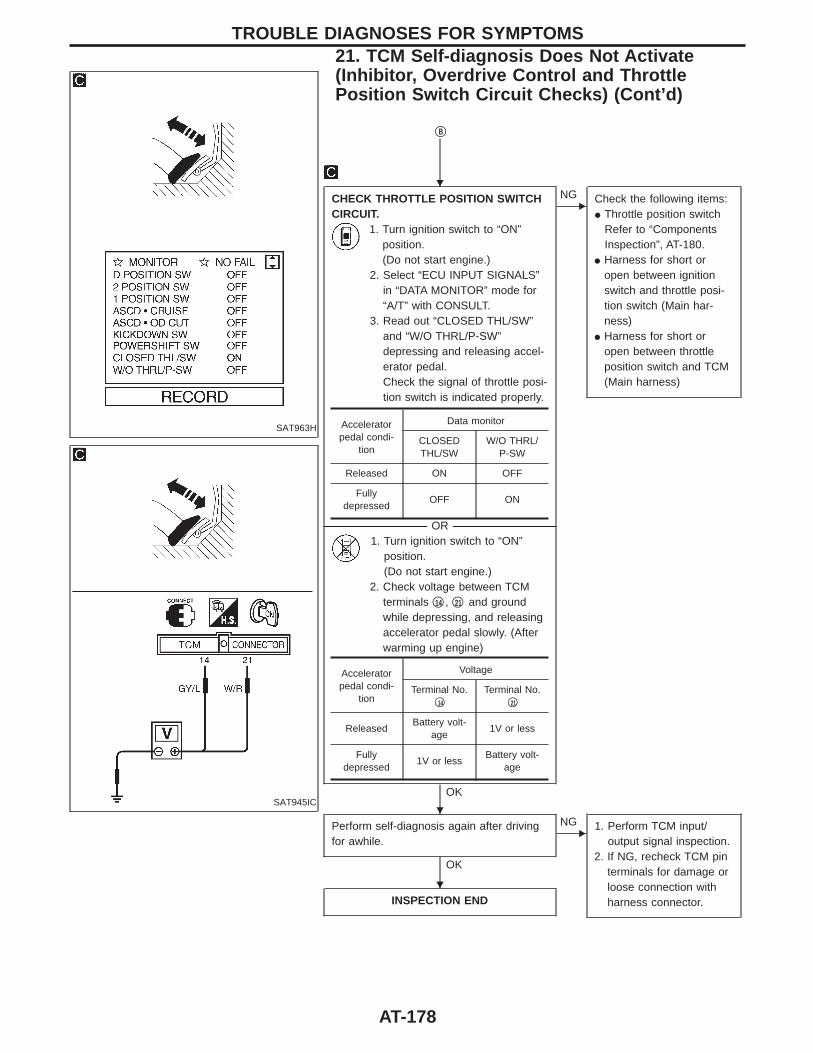
SAT963H
SAT945IC
qB
CHECK THROTTLE POSITION SWITCHCIRCUIT.
1. Turn ignition switch to “ON”position.(Do not start engine.)
2. Select “ECU INPUT SIGNALS”in “DATA MONITOR” mode for“A/T” with CONSULT.
3. Read out “CLOSED THL/SW”and “W/O THRL/P-SW”depressing and releasing accel-erator pedal.Check the signal of throttle posi-tion switch is indicated properly.
-------------------------------------------------------------------------------------------------------------------------------------- OR --------------------------------------------------------------------------------------------------------------------------------------1. Turn ignition switch to “ON”
position.(Do not start engine.)
2. Check voltage between TCMterminals q14 , q21 and groundwhile depressing, and releasingaccelerator pedal slowly. (Afterwarming up engine)
OK
ENG Check the following items:
I Throttle position switchRefer to “ComponentsInspection”, AT-180.
I Harness for short oropen between ignitionswitch and throttle posi-tion switch (Main har-ness)
I Harness for short oropen between throttleposition switch and TCM(Main harness)
Perform self-diagnosis again after drivingfor awhile.
OK
ENG 1. Perform TCM input/
output signal inspection.2. If NG, recheck TCM pin
terminals for damage orloose connection withharness connector.INSPECTION END
Acceleratorpedal condi-
tion
Data monitor
CLOSEDTHL/SW
W/O THRL/P-SW
Released ON OFF
Fullydepressed
OFF ON
Acceleratorpedal condi-
tion
Voltage
Terminal No.q14
Terminal No.q21
ReleasedBattery volt-
age1V or less
Fullydepressed
1V or lessBattery volt-
age
TROUBLE DIAGNOSES FOR SYMPTOMS21. TCM Self-diagnosis Does Not Activate(Inhibitor, Overdrive Control and ThrottlePosition Switch Circuit Checks) (Cont’d)
H
H
H
AT-178
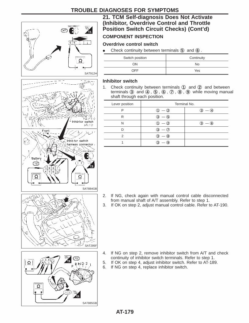
SAT912H
COMPONENT INSPECTION
Overdrive control switchI Check continuity between terminals q5 and q6 .
Switch position Continuity
ON No
OFF Yes
SAT884GB
Inhibitor switch1. Check continuity between terminals q1 and q2 and between
terminals q3 and q4 , q5 , q6 , q7 , q8 , q9 while moving manualshaft through each position.
Lever position Terminal No.
P q1 — q2 q3 — q4
R q3 — q5
N q1 — q2 q3 — q6
D q3 — q7
2 q3 — q8
1 q3 — q9
SAT295F
2. If NG, check again with manual control cable disconnectedfrom manual shaft of A/T assembly. Refer to step 1.
3. If OK on step 2, adjust manual control cable. Refer to AT-190.
SAT885GB
4. If NG on step 2, remove inhibitor switch from A/T and checkcontinuity of inhibitor switch terminals. Refer to step 1.
5. If OK on step 4, adjust inhibitor switch. Refer to AT-189.6. If NG on step 4, replace inhibitor switch.
TROUBLE DIAGNOSES FOR SYMPTOMS21. TCM Self-diagnosis Does Not Activate(Inhibitor, Overdrive Control and ThrottlePosition Switch Circuit Checks) (Cont’d)
AT-179
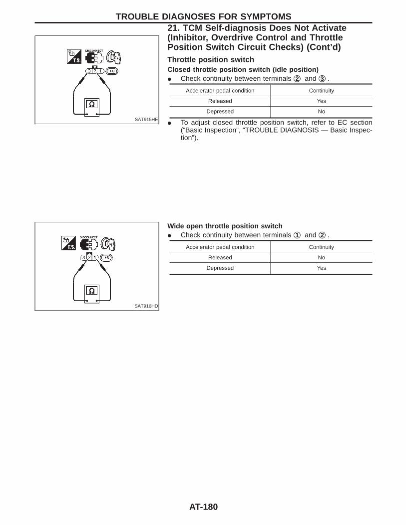
SAT915HE
Throttle position switchClosed throttle position switch (idle position)I Check continuity between terminals q2 and q3 .
Accelerator pedal condition Continuity
Released Yes
Depressed No
I To adjust closed throttle position switch, refer to EC section(“Basic Inspection”, “TROUBLE DIAGNOSIS — Basic Inspec-tion”).
SAT916HD
Wide open throttle position switchI Check continuity between terminals q1 and q2 .
Accelerator pedal condition Continuity
Released No
Depressed Yes
TROUBLE DIAGNOSES FOR SYMPTOMS21. TCM Self-diagnosis Does Not Activate(Inhibitor, Overdrive Control and ThrottlePosition Switch Circuit Checks) (Cont’d)
AT-180
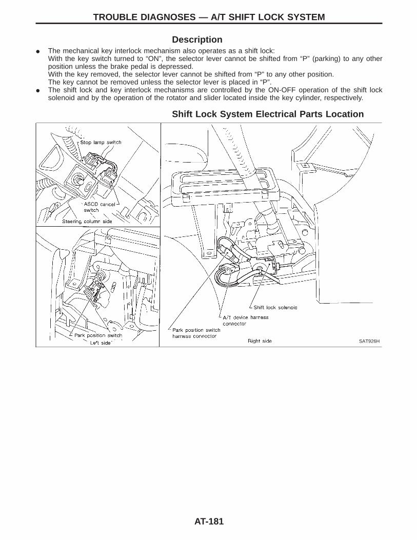
DescriptionI The mechanical key interlock mechanism also operates as a shift lock:
With the key switch turned to “ON”, the selector lever cannot be shifted from “P” (parking) to any otherposition unless the brake pedal is depressed.With the key removed, the selector lever cannot be shifted from “P” to any other position.The key cannot be removed unless the selector lever is placed in “P”.
I The shift lock and key interlock mechanisms are controlled by the ON-OFF operation of the shift locksolenoid and by the operation of the rotator and slider located inside the key cylinder, respectively.
Shift Lock System Electrical Parts Location
SAT926H
TROUBLE DIAGNOSES — A/T SHIFT LOCK SYSTEM
AT-181
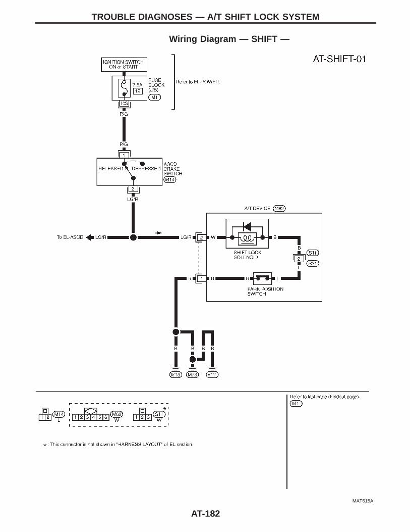
Wiring Diagram — SHIFT —
MAT615A
TROUBLE DIAGNOSES — A/T SHIFT LOCK SYSTEM
AT-182
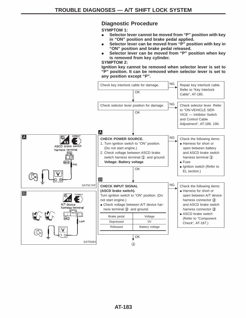
Diagnostic ProcedureSYMPTOM 1:I Selector lever cannot be moved from “P” position with key
in “ON” position and brake pedal applied.I Selector lever can be moved from “P” position with key in
“ON” position and brake pedal released.I Selector lever can be moved from “P” position when key
is removed from key cylinder.SYMPTOM 2:Ignition key cannot be removed when selector lever is set to“P” position. It can be removed when selector lever is set toany position except “P”.
SAT917HF
SAT918H
Check key interlock cable for damage.
OK
ENG Repair key interlock cable.
Refer to “Key InterlockCable”, AT-185.
Check selector lever position for damage.
OK
ENG Check selector lever. Refer
to “ON-VEHICLE SER-VICE — Inhibitor Switchand Control CableAdjustment”, AT-189, 190.
CHECK POWER SOURCE.1. Turn ignition switch to “ON” position.
(Do not start engine.)2. Check voltage between ASCD brake
switch harness terminal q1 and ground.Voltage: Battery voltage
OK
ENG Check the following items:
I Harness for short oropen between batteryand ASCD brake switchharness terminal q1
I FuseI Ignition switch (Refer to
EL section.)
CHECK INPUT SIGNAL(ASCD brake switch).Turn ignition switch to “ON” position. (Donot start engine.)I Check voltage between A/T device har-
ness terminal q2 and ground.
OK
ENG Check the following items:
I Harness for short oropen between A/T deviceharness connector q2and ASCD brake switchharness connector q2
I ASCD brake switch(Refer to “ComponentCheck”, AT-187.)
qA
Brake pedal Voltage
Depressed 0V
Released Battery voltage
TROUBLE DIAGNOSES — A/T SHIFT LOCK SYSTEM
H
H
H
H
AT-183
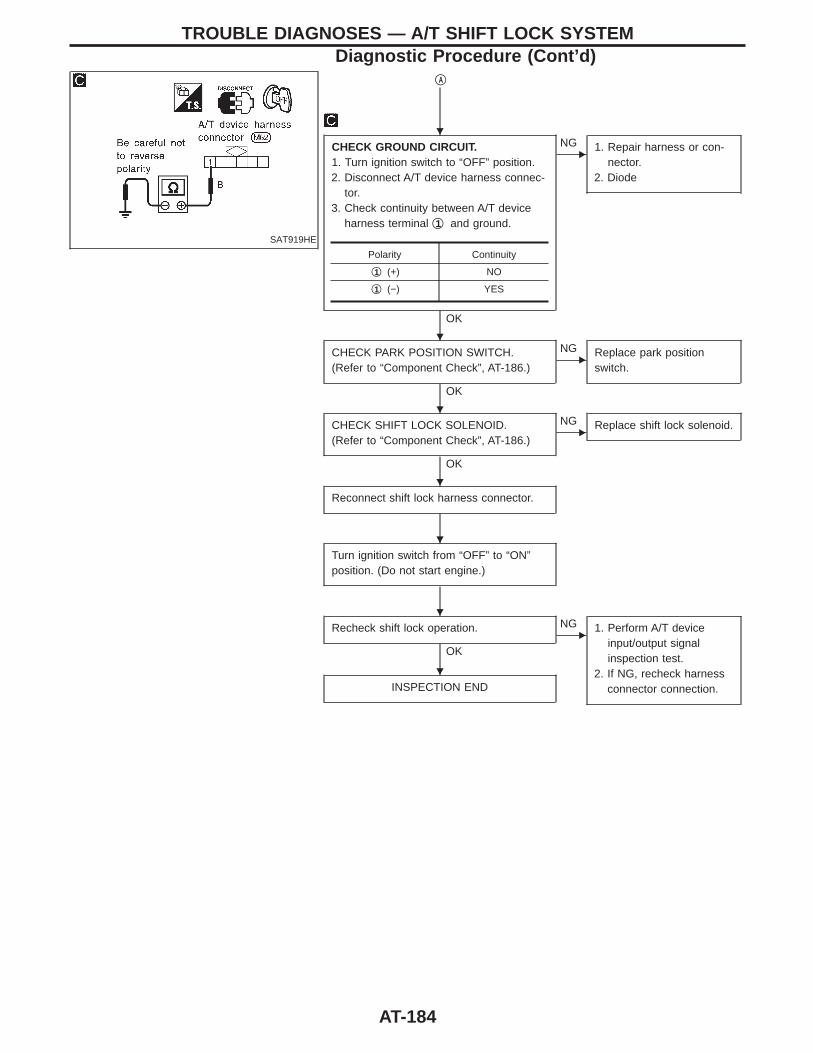
SAT919HE
qA
CHECK GROUND CIRCUIT.1. Turn ignition switch to “OFF” position.2. Disconnect A/T device harness connec-
tor.3. Check continuity between A/T device
harness terminal q1 and ground.
OK
ENG 1. Repair harness or con-
nector.2. Diode
CHECK PARK POSITION SWITCH.(Refer to “Component Check”, AT-186.)
OK
ENG Replace park position
switch.
CHECK SHIFT LOCK SOLENOID.(Refer to “Component Check”, AT-186.)
OK
ENG Replace shift lock solenoid.
Reconnect shift lock harness connector.
Turn ignition switch from “OFF” to “ON”position. (Do not start engine.)
Recheck shift lock operation.
OK
ENG 1. Perform A/T device
input/output signalinspection test.
2. If NG, recheck harnessconnector connection.INSPECTION END
Polarity Continuity
q1 (+) NO
q1 (−) YES
TROUBLE DIAGNOSES — A/T SHIFT LOCK SYSTEMDiagnostic Procedure (Cont’d)
H
H
H
H
H
H
H
AT-184
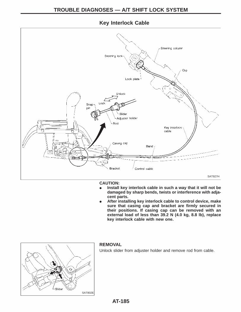
Key Interlock Cable
SAT927H
CAUTION:I Install key interlock cable in such a way that it will not be
damaged by sharp bends, twists or interference with adja-cent parts.
I After installing key interlock cable to control device, makesure that casing cap and bracket are firmly secured intheir positions. If casing cap can be removed with anexternal load of less than 39.2 N (4.0 kg, 8.8 lb), replacekey interlock cable with new one.
SAT802E
REMOVALUnlock slider from adjuster holder and remove rod from cable.
TROUBLE DIAGNOSES — A/T SHIFT LOCK SYSTEM
AT-185
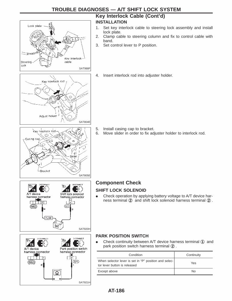
SAT988F
INSTALLATION1. Set key interlock cable to steering lock assembly and install
lock plate.2. Clamp cable to steering column and fix to control cable with
band.3. Set control lever to P position.
SAT804E
4. Insert interlock rod into adjuster holder.
SAT805E
5. Install casing cap to bracket.6. Move slider in order to fix adjuster holder to interlock rod.
SAT920H
Component CheckSHIFT LOCK SOLENOIDI Check operation by applying battery voltage to A/T device har-
ness terminal q2 and shift lock solenoid harness terminal q2 .
SAT921H
PARK POSITION SWITCHI Check continuity between A/T device harness terminal q1 and
park position switch harness terminal q2 .
Condition Continuity
When selector lever is set in “P” position and selec-tor lever button is released
Yes
Except above No
TROUBLE DIAGNOSES — A/T SHIFT LOCK SYSTEMKey Interlock Cable (Cont’d)
AT-186
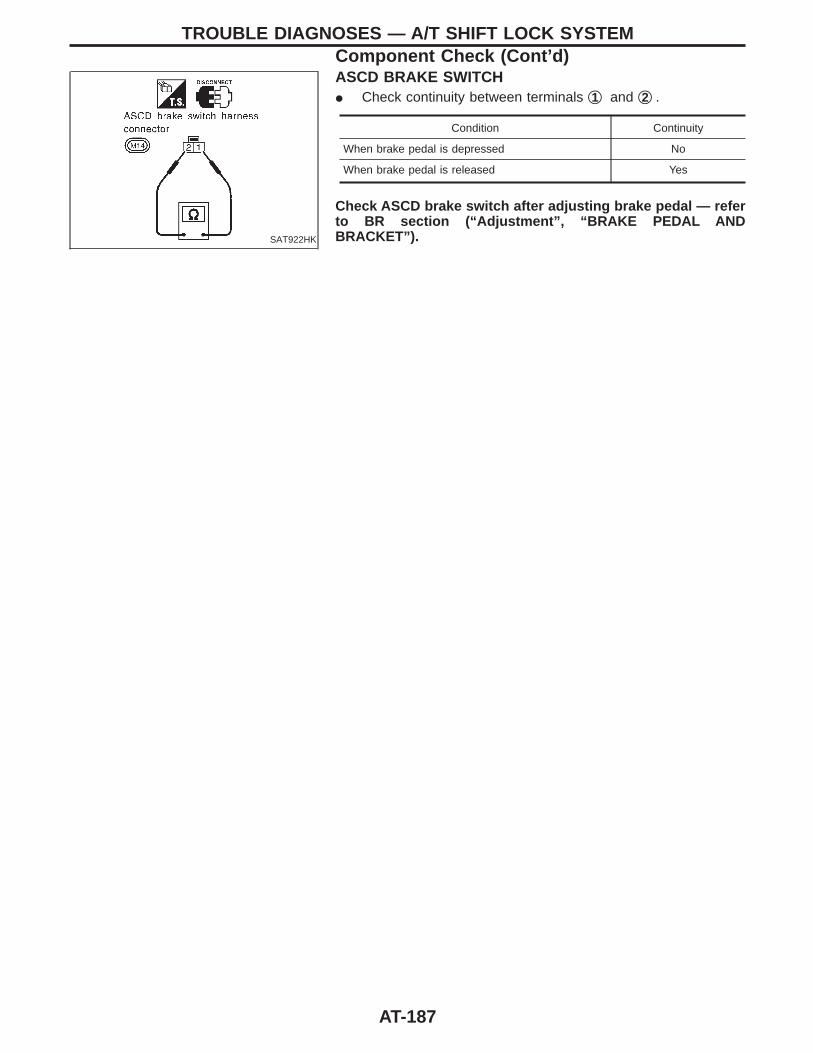
SAT922HK
ASCD BRAKE SWITCHI Check continuity between terminals q1 and q2 .
Condition Continuity
When brake pedal is depressed No
When brake pedal is released Yes
Check ASCD brake switch after adjusting brake pedal — referto BR section (“Adjustment”, “BRAKE PEDAL ANDBRACKET”).
TROUBLE DIAGNOSES — A/T SHIFT LOCK SYSTEMComponent Check (Cont’d)
AT-187
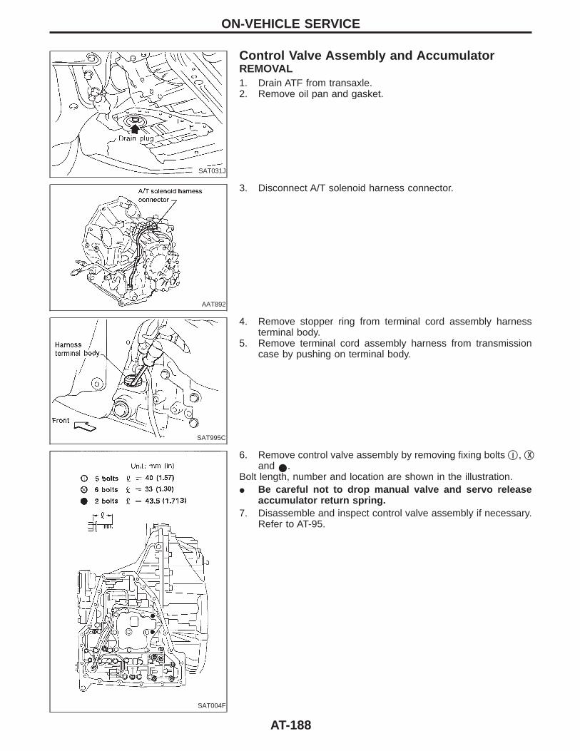
SAT031J
Control Valve Assembly and AccumulatorREMOVAL1. Drain ATF from transaxle.2. Remove oil pan and gasket.
AAT892
3. Disconnect A/T solenoid harness connector.
SAT995C
4. Remove stopper ring from terminal cord assembly harnessterminal body.
5. Remove terminal cord assembly harness from transmissioncase by pushing on terminal body.
SAT004F
6. Remove control valve assembly by removing fixing bolts qI , qXand I.
Bolt length, number and location are shown in the illustration.I Be careful not to drop manual valve and servo release
accumulator return spring.7. Disassemble and inspect control valve assembly if necessary.
Refer to AT-95.
ON-VEHICLE SERVICE
AT-188
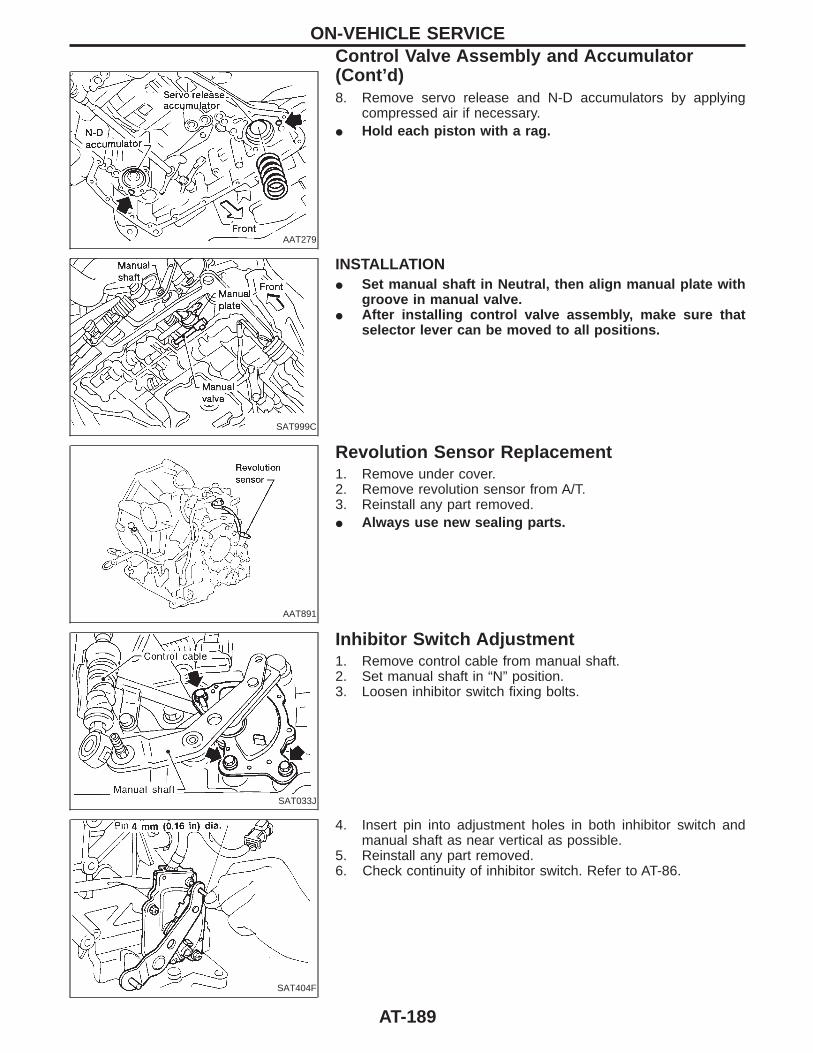
AAT279
8. Remove servo release and N-D accumulators by applyingcompressed air if necessary.
I Hold each piston with a rag.
SAT999C
INSTALLATIONI Set manual shaft in Neutral, then align manual plate with
groove in manual valve.I After installing control valve assembly, make sure that
selector lever can be moved to all positions.
AAT891
Revolution Sensor Replacement1. Remove under cover.2. Remove revolution sensor from A/T.3. Reinstall any part removed.I Always use new sealing parts.
SAT033J
Inhibitor Switch Adjustment1. Remove control cable from manual shaft.2. Set manual shaft in “N” position.3. Loosen inhibitor switch fixing bolts.
SAT404F
4. Insert pin into adjustment holes in both inhibitor switch andmanual shaft as near vertical as possible.
5. Reinstall any part removed.6. Check continuity of inhibitor switch. Refer to AT-86.
ON-VEHICLE SERVICEControl Valve Assembly and Accumulator(Cont’d)
AT-189
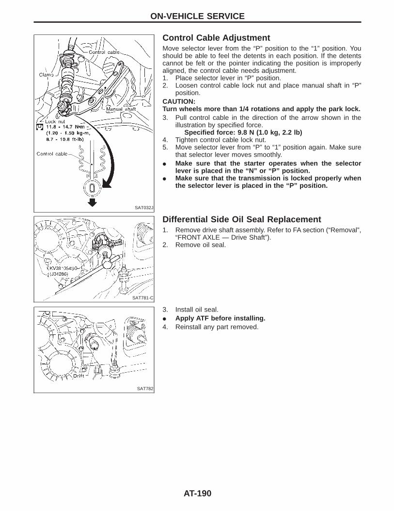
SAT032J
Control Cable AdjustmentMove selector lever from the “P” position to the “1” position. Youshould be able to feel the detents in each position. If the detentscannot be felt or the pointer indicating the position is improperlyaligned, the control cable needs adjustment.1. Place selector lever in “P” position.2. Loosen control cable lock nut and place manual shaft in “P”
position.CAUTION:Turn wheels more than 1/4 rotations and apply the park lock.3. Pull control cable in the direction of the arrow shown in the
illustration by specified force.Specified force: 9.8 N (1.0 kg, 2.2 lb)
4. Tighten control cable lock nut.5. Move selector lever from “P” to “1” position again. Make sure
that selector lever moves smoothly.I Make sure that the starter operates when the selector
lever is placed in the “N” or “P” position.I Make sure that the transmission is locked properly when
the selector lever is placed in the “P” position.
SAT781-C
Differential Side Oil Seal Replacement1. Remove drive shaft assembly. Refer to FA section (“Removal”,
“FRONT AXLE — Drive Shaft”).2. Remove oil seal.
SAT782
3. Install oil seal.I Apply ATF before installing.4. Reinstall any part removed.
ON-VEHICLE SERVICE
AT-190
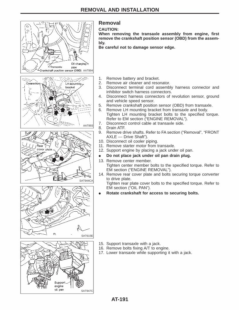
AAT894
RemovalCAUTION:When removing the transaxle assembly from engine, firstremove the crankshaft position sensor (OBD) from the assem-bly.Be careful not to damage sensor edge.
AAT893
SAT944CA
SAT615E
1. Remove battery and bracket.2. Remove air cleaner and resonator.3. Disconnect terminal cord assembly harness connector and
inhibitor switch harness connectors.4. Disconnect harness connectors of revolution sensor, ground
and vehicle speed sensor.5. Remove crankshaft position sensor (OBD) from transaxle.6. Remove LH mounting bracket from transaxle and body.
Tighten LH mounting bracket bolts to the specified torque.Refer to EM section (“ENGINE REMOVAL”).
7. Disconnect control cable at transaxle side.8. Drain ATF.9. Remove drive shafts. Refer to FA section (“Removal”, “FRONT
AXLE — Drive Shaft”).10. Disconnect oil cooler piping.11. Remove starter motor from transaxle.12. Support engine by placing a jack under oil pan.I Do not place jack under oil pan drain plug.13. Remove center member.
Tighten center member bolts to the specified torque. Refer toEM section (“ENGINE REMOVAL”).
14. Remove rear cover plate and bolts securing torque converterto drive plate.Tighten rear plate cover bolts to the specified torque. Refer toEM section (“OIL PAN”).
I Rotate crankshaft for access to securing bolts.
SAT947C
15. Support transaxle with a jack.16. Remove bolts fixing A/T to engine.17. Lower transaxle while supporting it with a jack.
REMOVAL AND INSTALLATION
AT-191

SAT977H
InstallationI Drive plate runoutCAUTION:Do not allow any magnetic materials to contact the ring gearteeth.
Maximum allowable runout:Refer to EM section (“Inspection”, “CYLINDERBLOCK”).
If this runout is out of allowance, replace drive plate and ringgear.
SAT044A
I When connecting torque converter to transaxle, measure dis-tance “A” to be certain that they are correctly assembled.
Distance “A”:19 mm (0.75 in) or more
SAT946C
I Install bolts fixing converter to drive plate.I With converter installed, rotate crankshaft several turns to
check that transaxle rotates freely without binding.
AAT895
I Tighten bolts securing transaxle.I Tighten LH mounting bracket bolts to the specified torque.
Refer to EM section (“ENGINE REMOVAL”).I Tighten center member bolts to the specified torque. Refer to
EM section (“ENGINE REMOVAL”).I Tighten rear plate cover bolts to the specified torque. Refer to
EM section (“OIL PAN”).
Bolt No.Tightening torqueN⋅m (kg-m, ft-lb)
mm (in)
q1 39 - 49 (4.0 - 5.0, 29 - 36) 45 (1.77)
q2 30 - 36 (3.1 - 3.7, 22 - 27) 30 (1.18)
q3 30 - 36 (3.1 - 3.7, 22 - 27) 40 (1.57)
q4 74 - 83 (7.5 - 8.5, 54 - 61) 45 (1.77)
q5 30 - 36 (3.1 - 3.7, 22 - 27) 80 (3.15)
q6 30 - 36 (3.1 - 3.7, 22 - 27) 65 (2.56)
I Reinstall any part removed.
REMOVAL AND INSTALLATION
AT-192

SAT638A
I Check fluid level in transaxle.I Move selector lever through all positions to be sure that tran-
saxle operates correctly.With parking brake applied, rotate engine at idling. Move selec-tor lever through “N” to “D”, to “2”, to “1” and to “R” position. Aslight shock should be felt by hand gripping selector each timetransaxle is shifted.
I Perform road test. Refer to AT-64.
REMOVAL AND INSTALLATIONInstallation (Cont’d)
AT-193
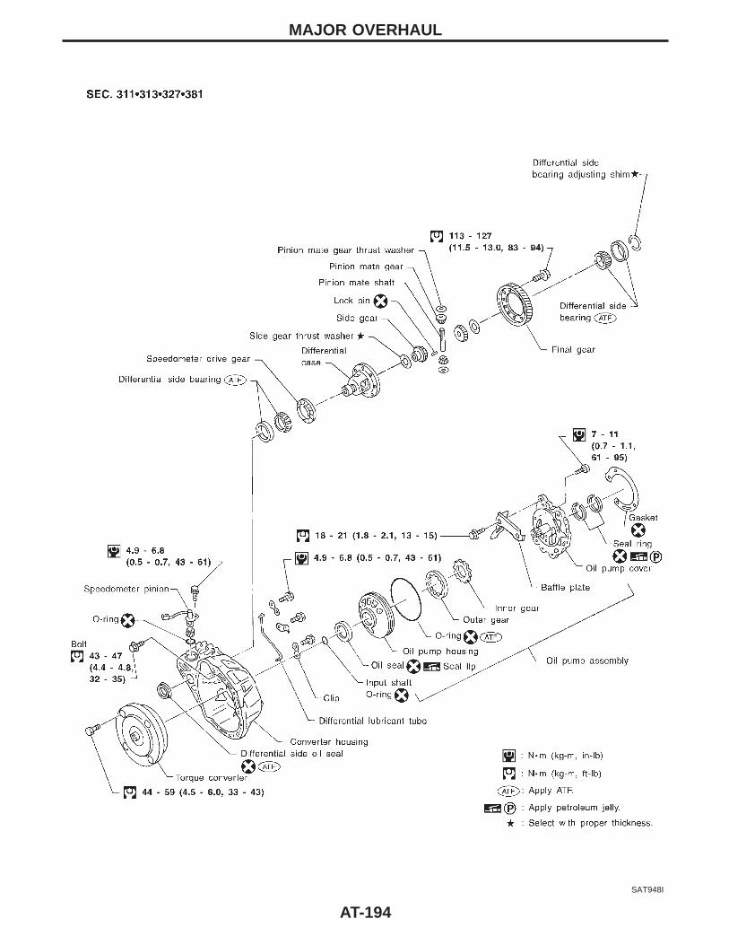
SAT948I
MAJOR OVERHAUL
AT-194
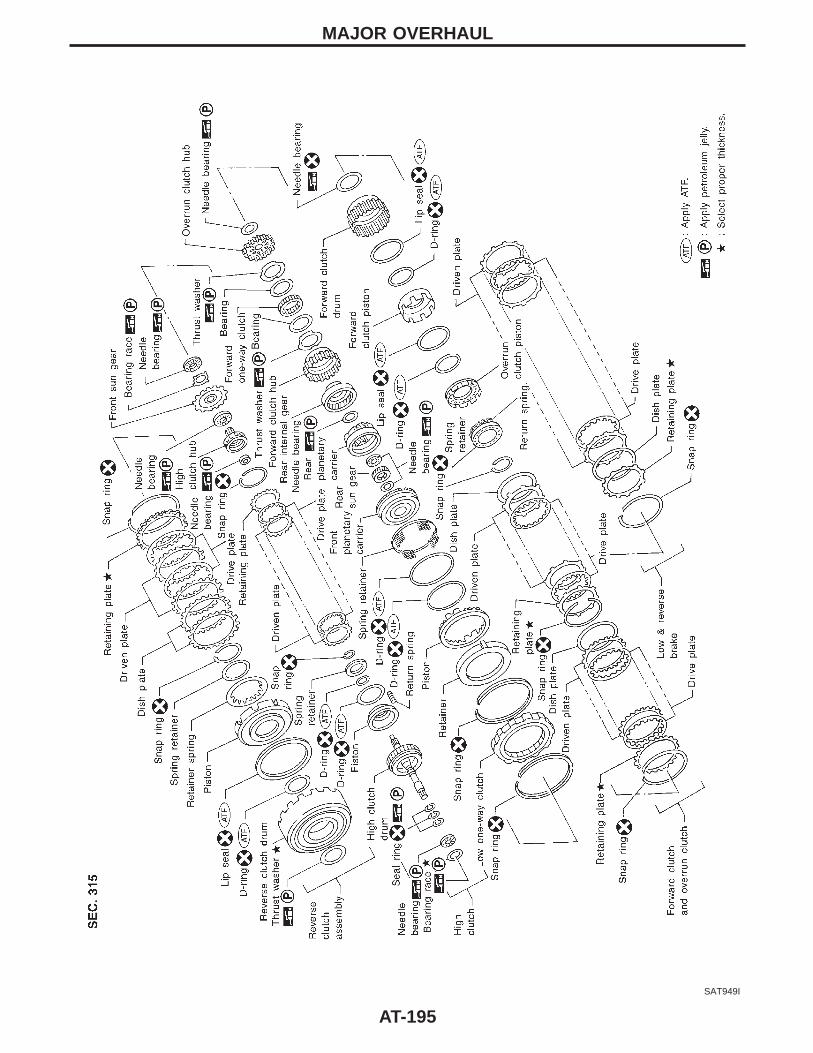
SAT949I
MAJOR OVERHAUL
AT-195

SAT971I
MAJOR OVERHAUL
AT-196
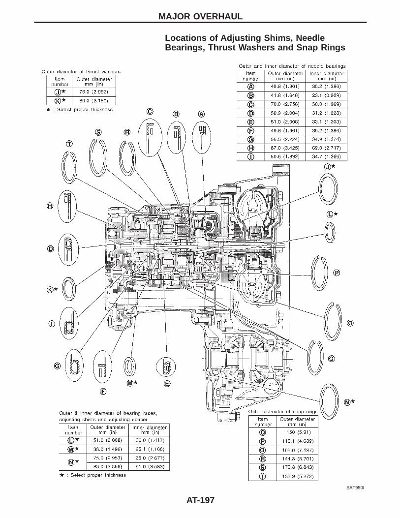
Locations of Adjusting Shims, NeedleBearings, Thrust Washers and Snap Rings
SAT950I
MAJOR OVERHAUL
AT-197
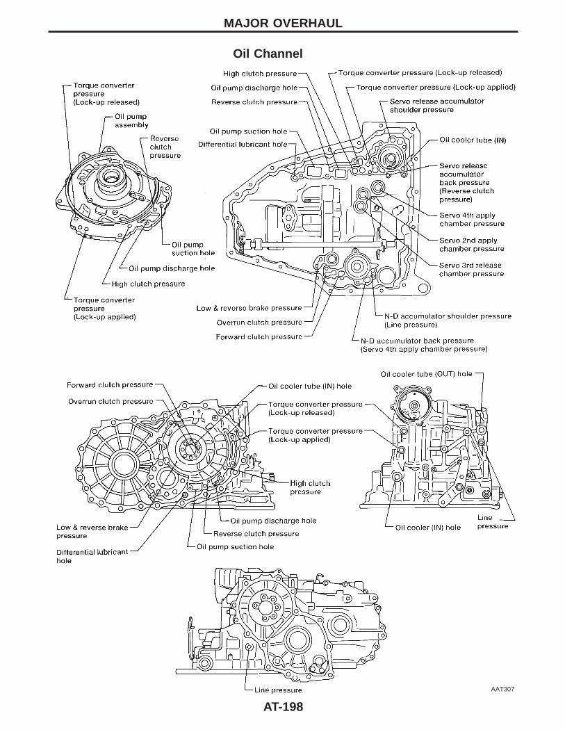
Oil Channel
AAT307
MAJOR OVERHAUL
AT-198
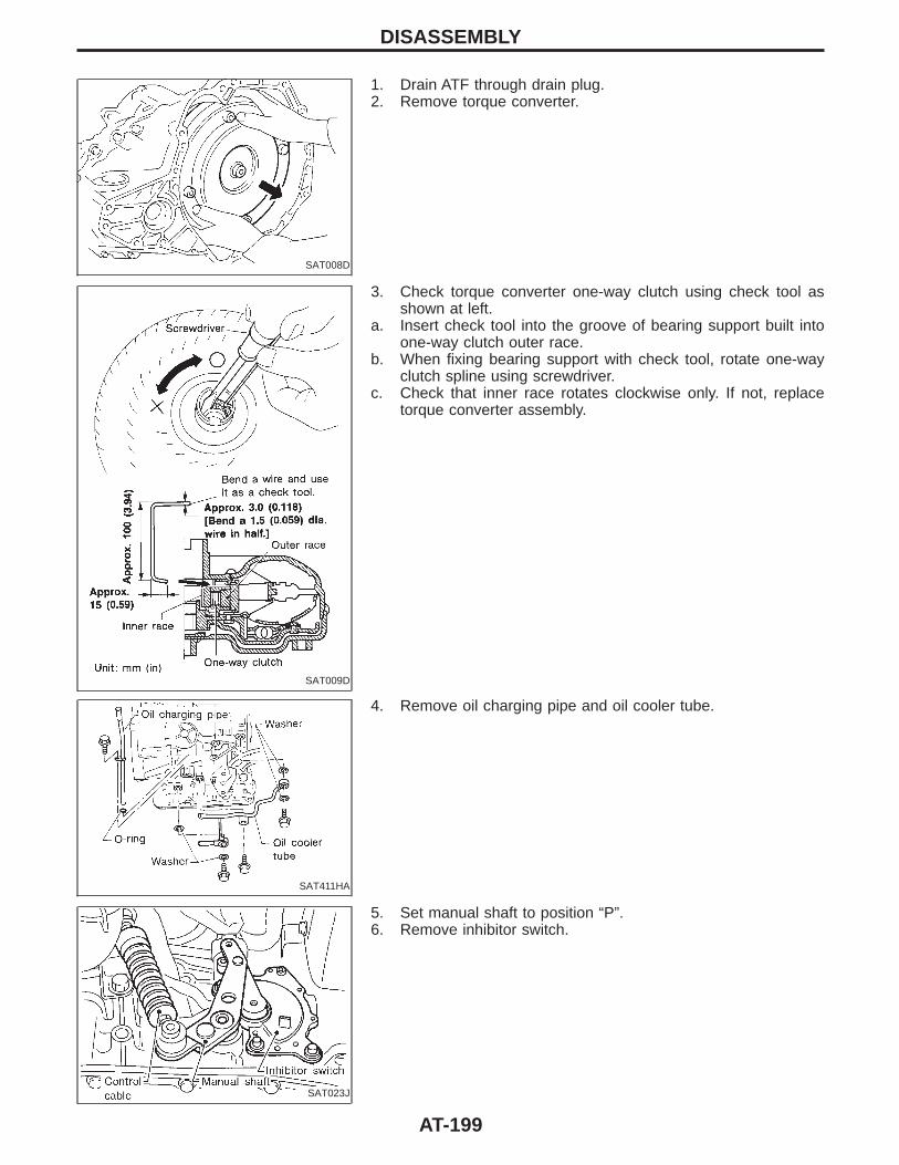
SAT008D
1. Drain ATF through drain plug.2. Remove torque converter.
SAT009D
3. Check torque converter one-way clutch using check tool asshown at left.
a. Insert check tool into the groove of bearing support built intoone-way clutch outer race.
b. When fixing bearing support with check tool, rotate one-wayclutch spline using screwdriver.
c. Check that inner race rotates clockwise only. If not, replacetorque converter assembly.
SAT411HA
4. Remove oil charging pipe and oil cooler tube.
SAT023J
5. Set manual shaft to position “P”.6. Remove inhibitor switch.
DISASSEMBLY
AT-199
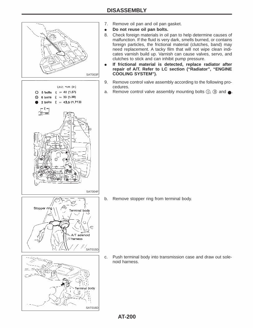
SAT003F
7. Remove oil pan and oil pan gasket.I Do not reuse oil pan bolts.8. Check foreign materials in oil pan to help determine causes of
malfunction. If the fluid is very dark, smells burned, or containsforeign particles, the frictional material (clutches, band) mayneed replacement. A tacky film that will not wipe clean indi-cates varnish build up. Varnish can cause valves, servo, andclutches to stick and can inhibit pump pressure.
I If frictional material is detected, replace radiator afterrepair of A/T. Refer to LC section (“Radiator”, “ENGINECOOLING SYSTEM”).
SAT004F
9. Remove control valve assembly according to the following pro-cedures.
a. Remove control valve assembly mounting bolts qI , qX and I.
SAT015D
b. Remove stopper ring from terminal body.
SAT016D
c. Push terminal body into transmission case and draw out sole-noid harness.
DISASSEMBLY
AT-200
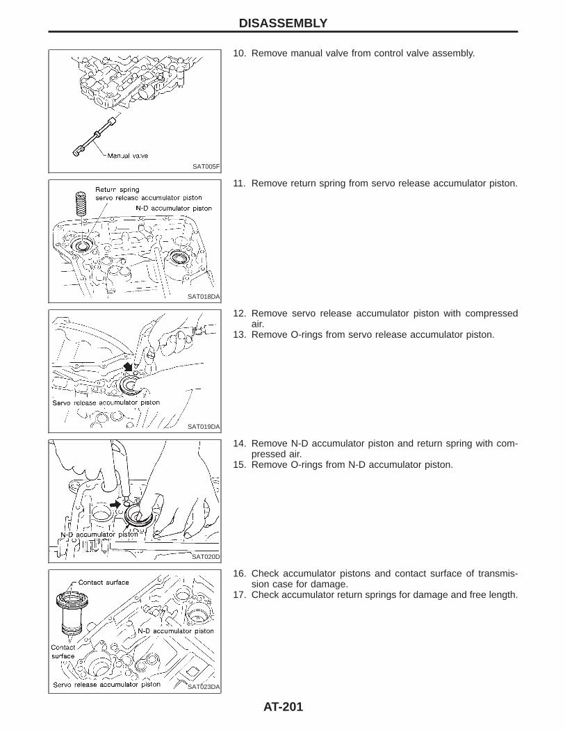
SAT005F
10. Remove manual valve from control valve assembly.
SAT018DA
11. Remove return spring from servo release accumulator piston.
SAT019DA
12. Remove servo release accumulator piston with compressedair.
13. Remove O-rings from servo release accumulator piston.
SAT020D
14. Remove N-D accumulator piston and return spring with com-pressed air.
15. Remove O-rings from N-D accumulator piston.
SAT023DA
16. Check accumulator pistons and contact surface of transmis-sion case for damage.
17. Check accumulator return springs for damage and free length.
DISASSEMBLY
AT-201

SAT006F
18. Remove lip seals.
SAT862HA
19. Remove L & R oil tube and oil sleeve.
SAT008F
20. Remove converter housing according to the following proce-dures.
a. Remove converter housing mounting bolts.b. Remove converter housing by tapping it lightly.
SAT235F
c. Remove O-ring from differential oil port.
SAT228F
21. Remove final drive assembly from transmission case.
DISASSEMBLY
AT-202

SAT010FB
22. Remove differential side bearing outer race from transmissioncase.
SAT031D
23. Remove differential side bearing adjusting shim from transmis-sion case.
SAT011FB
24. Remove differential side bearing outer race from converterhousing.
SAT032D
25. Remove oil seal with screwdriver from converter housing.I Be careful not to damage case.
SAT230FA
26. Remove oil tube from converter housing.
DISASSEMBLY
AT-203
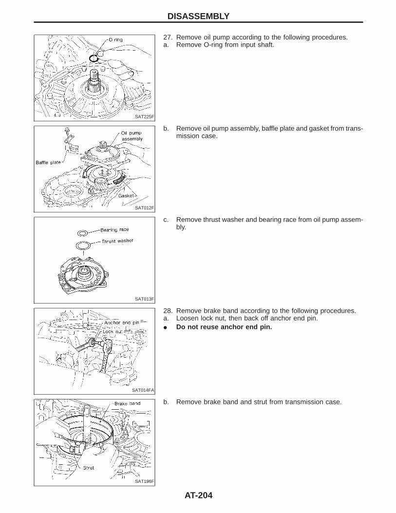
SAT225F
27. Remove oil pump according to the following procedures.a. Remove O-ring from input shaft.
SAT012F
b. Remove oil pump assembly, baffle plate and gasket from trans-mission case.
SAT013F
c. Remove thrust washer and bearing race from oil pump assem-bly.
SAT014FA
28. Remove brake band according to the following procedures.a. Loosen lock nut, then back off anchor end pin.I Do not reuse anchor end pin.
SAT196F
b. Remove brake band and strut from transmission case.
DISASSEMBLY
AT-204

SAT039D
I To prevent brake linings from cracking or peeling, do notstretch the flexible band unnecessarily. When removingthe brake band, always secure it with a clip as shown inthe figure at left.Leave the clip in position after removing the brake band.
SAT040D
c. Check brake band facing for damage, cracks, wear or burns.
SAT549F
29. Remove input shaft assembly (high clutch) and reverse clutchaccording to the following procedures.
a. Remove input shaft assembly (high clutch) with reverse clutch.
SAT566F
b. Remove input shaft assembly (high clutch) from reverseclutch.
SAT567F
c. Remove needle bearings from high clutch drum and check fordamage or wear.
DISASSEMBLY
AT-205

SAT568F
d. Remove high clutch hub and front sun gear from transmissioncase.
SAT019F
e. Remove front sun gear and needle bearing from high clutchhub and check for damage or wear.
f. Remove bearing race from front sun gear and check for dam-age or wear.
SAT020F
30. Remove needle bearing from transmission case and check fordamage or wear.
SAT138F
31. Apply compressed air and check to see that low and reversebrake operates.
SAT046D
32. Remove low one-way clutch and front planetary carrier assem-bly according to the following procedures.
a. Remove snap ring with flat-bladed screwdriver.
DISASSEMBLY
AT-206
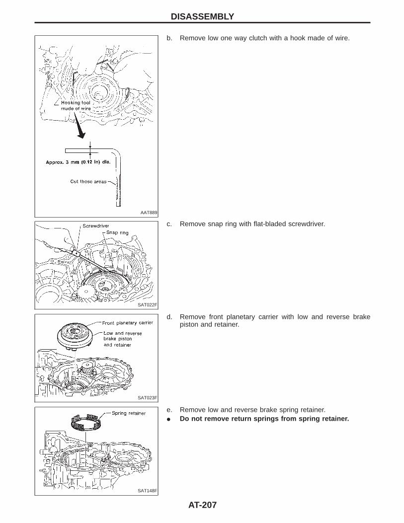
AAT889
b. Remove low one way clutch with a hook made of wire.
SAT022F
c. Remove snap ring with flat-bladed screwdriver.
SAT023F
d. Remove front planetary carrier with low and reverse brakepiston and retainer.
SAT148F
e. Remove low and reverse brake spring retainer.I Do not remove return springs from spring retainer.
DISASSEMBLY
AT-207

SAT048D
f. Check that low one-way clutch rotates in the direction of thearrow and locks in the opposite direction.
SAT024F
g. Remove needle bearing, low and reverse brake piston andretainer from front planetary carrier.
SAT025F
h. Check front planetary carrier, low one-way clutch and needlebearing for damage or wear.
i. Check clearance between planetary gears and planetary car-rier with feeler gauge.
Standard clearance:0.20 - 0.70 mm (0.0079 - 0.0276 in)
Allowable limit:0.80 mm (0.0315 in)
Replace front planetary carrier if the clearance exceeds allow-able limit.
SAT026F
33. Remove rear planetary carrier assembly and rear sun gearaccording to the following procedures.
a. Remove rear planetary carrier assembly from transmissioncase.
SAT027F
b. Remove rear sun gear from rear planetary carrier.
DISASSEMBLY
AT-208
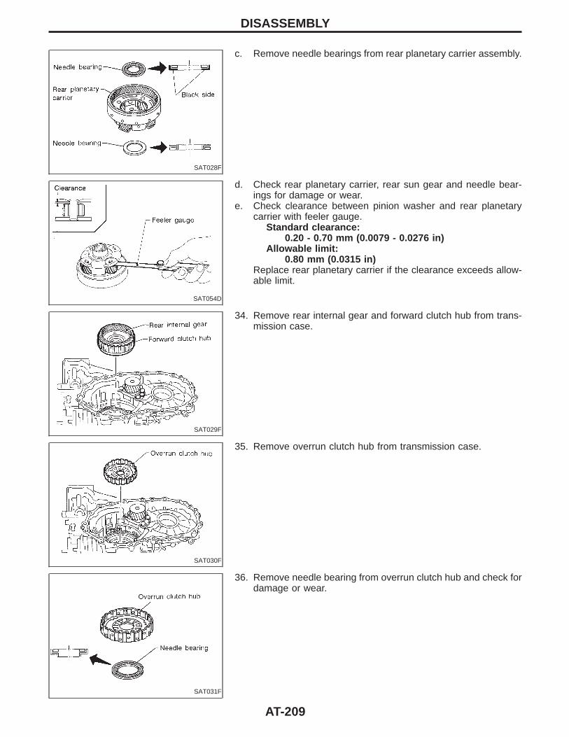
SAT028F
c. Remove needle bearings from rear planetary carrier assembly.
SAT054D
d. Check rear planetary carrier, rear sun gear and needle bear-ings for damage or wear.
e. Check clearance between pinion washer and rear planetarycarrier with feeler gauge.
Standard clearance:0.20 - 0.70 mm (0.0079 - 0.0276 in)
Allowable limit:0.80 mm (0.0315 in)
Replace rear planetary carrier if the clearance exceeds allow-able limit.
SAT029F
34. Remove rear internal gear and forward clutch hub from trans-mission case.
SAT030F
35. Remove overrun clutch hub from transmission case.
SAT031F
36. Remove needle bearing from overrun clutch hub and check fordamage or wear.
DISASSEMBLY
AT-209
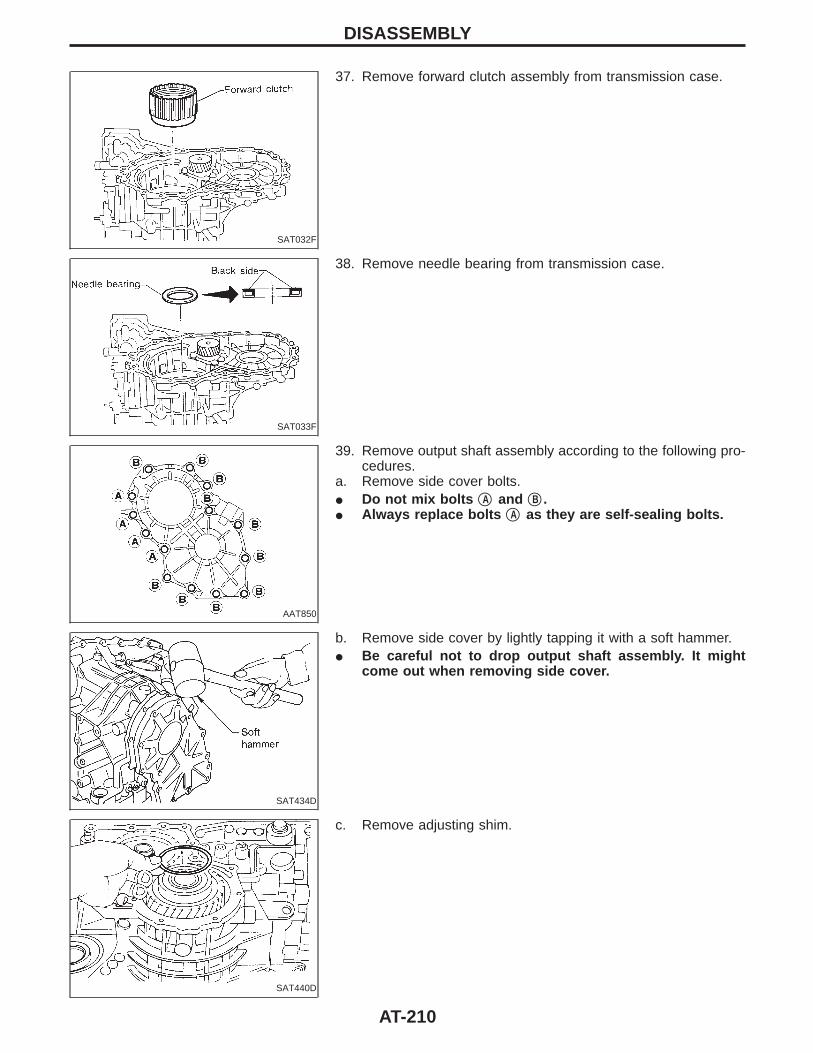
SAT032F
37. Remove forward clutch assembly from transmission case.
SAT033F
38. Remove needle bearing from transmission case.
AAT850
39. Remove output shaft assembly according to the following pro-cedures.
a. Remove side cover bolts.I Do not mix bolts qA and qB .I Always replace bolts qA as they are self-sealing bolts.
SAT434D
b. Remove side cover by lightly tapping it with a soft hammer.I Be careful not to drop output shaft assembly. It might
come out when removing side cover.
SAT440D
c. Remove adjusting shim.
DISASSEMBLY
AT-210
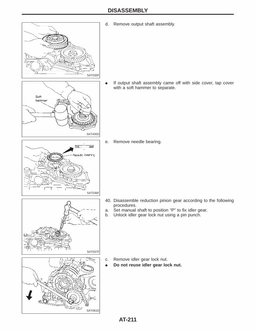
SAT035F
d. Remove output shaft assembly.
SAT435D
I If output shaft assembly came off with side cover, tap coverwith a soft hammer to separate.
SAT036F
e. Remove needle bearing.
SAT037F
40. Disassemble reduction pinion gear according to the followingprocedures.
a. Set manual shaft to position “P” to fix idler gear.b. Unlock idler gear lock nut using a pin punch.
SAT061D
c. Remove idler gear lock nut.I Do not reuse idler gear lock nut.
DISASSEMBLY
AT-211
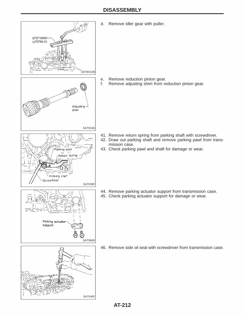
SAT841DB
d. Remove idler gear with puller.
SAT916D
e. Remove reduction pinion gear.f. Remove adjusting shim from reduction pinion gear.
SAT039F
41. Remove return spring from parking shaft with screwdriver.42. Draw out parking shaft and remove parking pawl from trans-
mission case.43. Check parking pawl and shaft for damage or wear.
SAT066D
44. Remove parking actuator support from transmission case.45. Check parking actuator support for damage or wear.
SAT040F
46. Remove side oil seal with screwdriver from transmission case.
DISASSEMBLY
AT-212
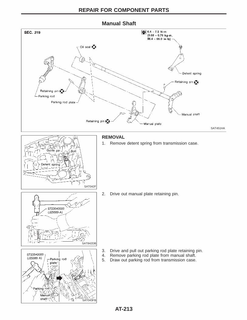
Manual Shaft
SAT451HA
SAT042F
REMOVAL1. Remove detent spring from transmission case.
SAT842DB
2. Drive out manual plate retaining pin.
SAT043FB
3. Drive and pull out parking rod plate retaining pin.4. Remove parking rod plate from manual shaft.5. Draw out parking rod from transmission case.
REPAIR FOR COMPONENT PARTS
AT-213
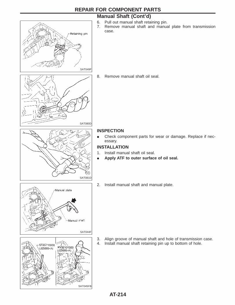
SAT049F
6. Pull out manual shaft retaining pin.7. Remove manual shaft and manual plate from transmission
case.
SAT080D
8. Remove manual shaft oil seal.
SAT081D
INSPECTIONI Check component parts for wear or damage. Replace if nec-
essary.
INSTALLATION1. Install manual shaft oil seal.I Apply ATF to outer surface of oil seal.
SAT044F
2. Install manual shaft and manual plate.
SAT045FB
3. Align groove of manual shaft and hole of transmission case.4. Install manual shaft retaining pin up to bottom of hole.
REPAIR FOR COMPONENT PARTSManual Shaft (Cont’d)
AT-214
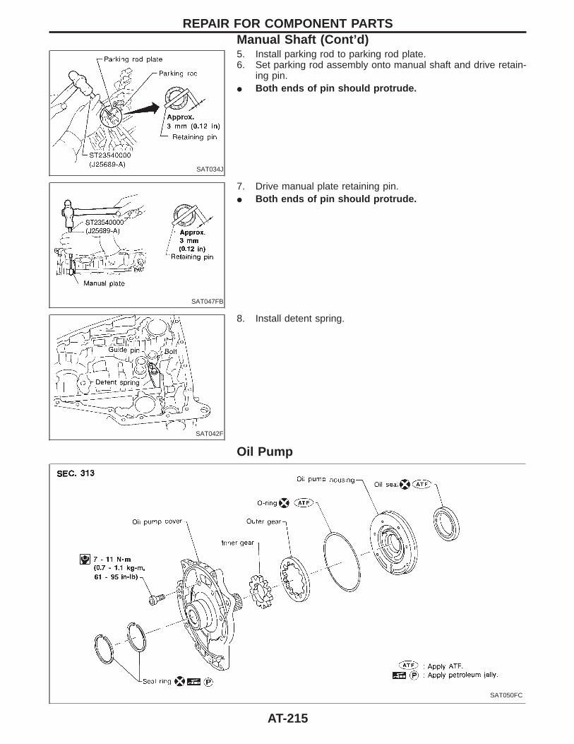
SAT034J
5. Install parking rod to parking rod plate.6. Set parking rod assembly onto manual shaft and drive retain-
ing pin.I Both ends of pin should protrude.
SAT047FB
7. Drive manual plate retaining pin.I Both ends of pin should protrude.
SAT042F
8. Install detent spring.
Oil Pump
SAT050FC
REPAIR FOR COMPONENT PARTSManual Shaft (Cont’d)
AT-215
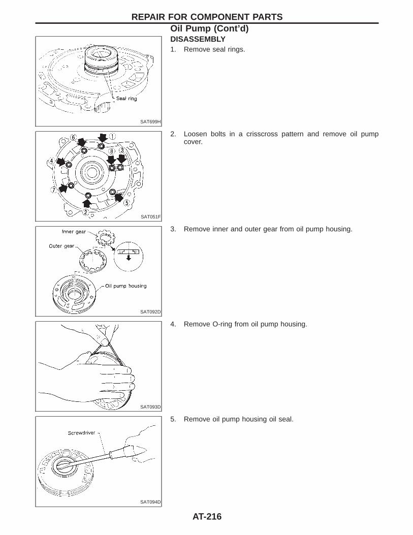
SAT699H
DISASSEMBLY1. Remove seal rings.
SAT051F
2. Loosen bolts in a crisscross pattern and remove oil pumpcover.
SAT092D
3. Remove inner and outer gear from oil pump housing.
SAT093D
4. Remove O-ring from oil pump housing.
SAT094D
5. Remove oil pump housing oil seal.
REPAIR FOR COMPONENT PARTSOil Pump (Cont’d)
AT-216
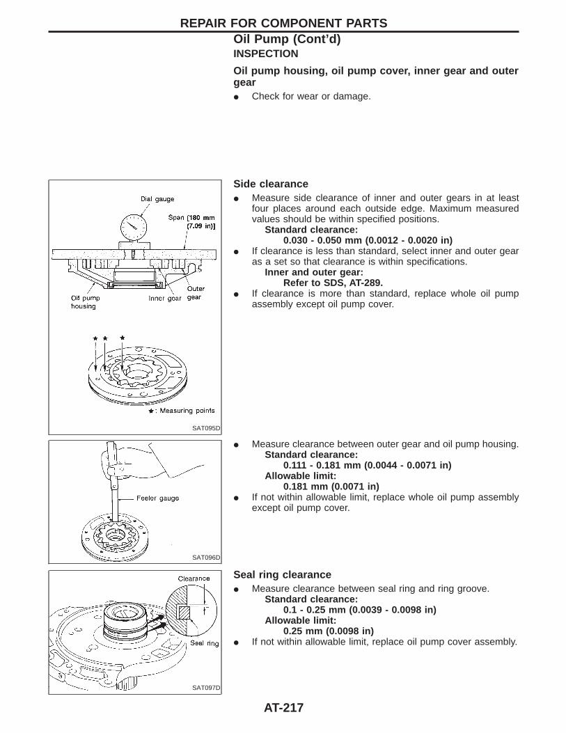
INSPECTION
Oil pump housing, oil pump cover, inner gear and outergearI Check for wear or damage.
SAT095D
Side clearanceI Measure side clearance of inner and outer gears in at least
four places around each outside edge. Maximum measuredvalues should be within specified positions.
Standard clearance:0.030 - 0.050 mm (0.0012 - 0.0020 in)
I If clearance is less than standard, select inner and outer gearas a set so that clearance is within specifications.
Inner and outer gear:Refer to SDS, AT-289.
I If clearance is more than standard, replace whole oil pumpassembly except oil pump cover.
SAT096D
I Measure clearance between outer gear and oil pump housing.Standard clearance:
0.111 - 0.181 mm (0.0044 - 0.0071 in)Allowable limit:
0.181 mm (0.0071 in)I If not within allowable limit, replace whole oil pump assembly
except oil pump cover.
SAT097D
Seal ring clearanceI Measure clearance between seal ring and ring groove.
Standard clearance:0.1 - 0.25 mm (0.0039 - 0.0098 in)
Allowable limit:0.25 mm (0.0098 in)
I If not within allowable limit, replace oil pump cover assembly.
REPAIR FOR COMPONENT PARTSOil Pump (Cont’d)
AT-217
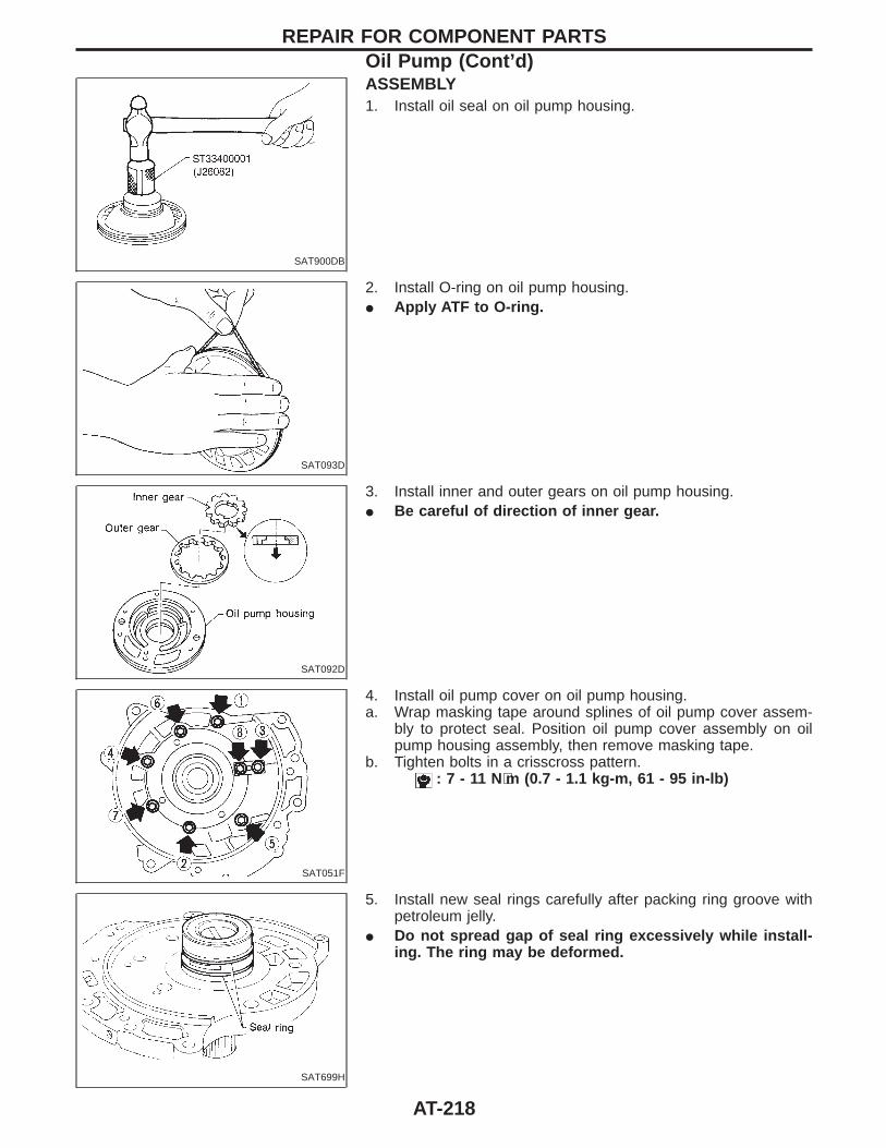
SAT900DB
ASSEMBLY1. Install oil seal on oil pump housing.
SAT093D
2. Install O-ring on oil pump housing.I Apply ATF to O-ring.
SAT092D
3. Install inner and outer gears on oil pump housing.I Be careful of direction of inner gear.
SAT051F
4. Install oil pump cover on oil pump housing.a. Wrap masking tape around splines of oil pump cover assem-
bly to protect seal. Position oil pump cover assembly on oilpump housing assembly, then remove masking tape.
b. Tighten bolts in a crisscross pattern.: 7 - 11 N⋅m (0.7 - 1.1 kg-m, 61 - 95 in-lb)
SAT699H
5. Install new seal rings carefully after packing ring groove withpetroleum jelly.
I Do not spread gap of seal ring excessively while install-ing. The ring may be deformed.
REPAIR FOR COMPONENT PARTSOil Pump (Cont’d)
AT-218
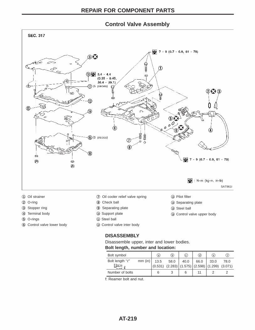
Control Valve Assembly
SAT961I
q1 Oil strainer
q2 O-ring
q3 Stopper ring
q4 Terminal body
q5 O-rings
q6 Control valve lower body
q7 Oil cooler relief valve spring
q8 Check ball
q9 Separating plate
q10 Support plate
q11 Steel ball
q12 Control valve inter body
q13 Pilot filter
q14 Separating plate
q15 Steel ball
q16 Control valve upper body
DISASSEMBLYDisassemble upper, inter and lower bodies.Bolt length, number and location:
Bolt symbol qa qb qc qd qe qf
Bolt length “” mm (in) 13.5(0.531)
58.0(2.283)
40.0(1.575)
66.0(2.598)
33.0(1.299)
78.0(3.071)
Number of bolts 6 3 6 11 2 2
f: Reamer bolt and nut.
REPAIR FOR COMPONENT PARTS
AT-219
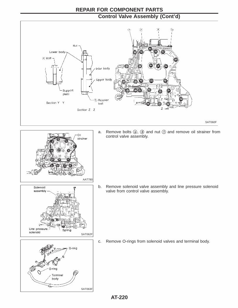
SAT060F
AAT780
a. Remove bolts qa , qd and nut qf and remove oil strainer fromcontrol valve assembly.
SAT062F
b. Remove solenoid valve assembly and line pressure solenoidvalve from control valve assembly.
SAT063F
c. Remove O-rings from solenoid valves and terminal body.
REPAIR FOR COMPONENT PARTSControl Valve Assembly (Cont’d)
AT-220
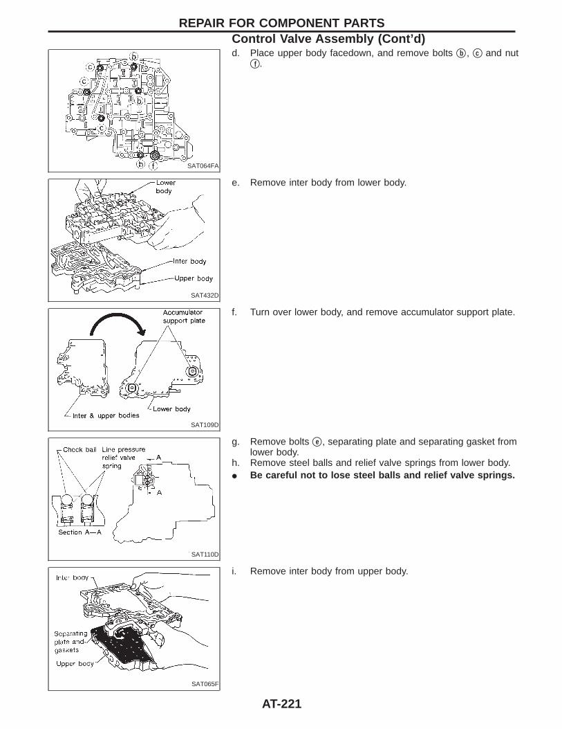
SAT064FA
d. Place upper body facedown, and remove bolts qb , qc and nutqf .
SAT432D
e. Remove inter body from lower body.
SAT109D
f. Turn over lower body, and remove accumulator support plate.
SAT110D
g. Remove bolts qe , separating plate and separating gasket fromlower body.
h. Remove steel balls and relief valve springs from lower body.I Be careful not to lose steel balls and relief valve springs.
SAT065F
i. Remove inter body from upper body.
REPAIR FOR COMPONENT PARTSControl Valve Assembly (Cont’d)
AT-221

SAT412H
j. Check to see that steel balls are properly positioned in interbody and then remove them.
I Be careful not to lose steel balls.
SAT067F
k. Check to see that steel balls are properly positioned in upperbody and then remove them.
I Be careful not to lose steel balls.
SAT550G
INSPECTION
Lower and upper bodiesI Check to see that retainer plates are properly positioned in
lower body.
SAT551G
I Check to see that retainer plates are properly positioned inupper body.
I Be careful not to lose these parts.
Oil strainerI Check wire netting of oil strainer for damage.
AAT890
Shift solenoid valves “A” and “B”, line pressuresolenoid valve, torque converter clutch solenoid valveand overrun clutch solenoid valveI Measure resistance. Refer to “Components Inspection”, AT-
119.
REPAIR FOR COMPONENT PARTSControl Valve Assembly (Cont’d)
AT-222
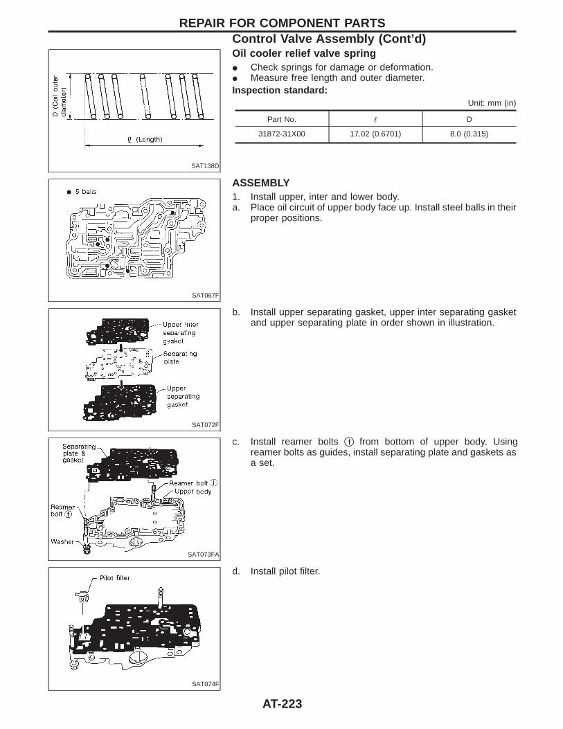
SAT138D
Oil cooler relief valve springI Check springs for damage or deformation.I Measure free length and outer diameter.Inspection standard:
Unit: mm (in)
Part No. D
31872-31X00 17.02 (0.6701) 8.0 (0.315)
SAT067F
ASSEMBLY1. Install upper, inter and lower body.a. Place oil circuit of upper body face up. Install steel balls in their
proper positions.
SAT072F
b. Install upper separating gasket, upper inter separating gasketand upper separating plate in order shown in illustration.
SAT073FA
c. Install reamer bolts qf from bottom of upper body. Usingreamer bolts as guides, install separating plate and gaskets asa set.
SAT074F
d. Install pilot filter.
REPAIR FOR COMPONENT PARTSControl Valve Assembly (Cont’d)
AT-223
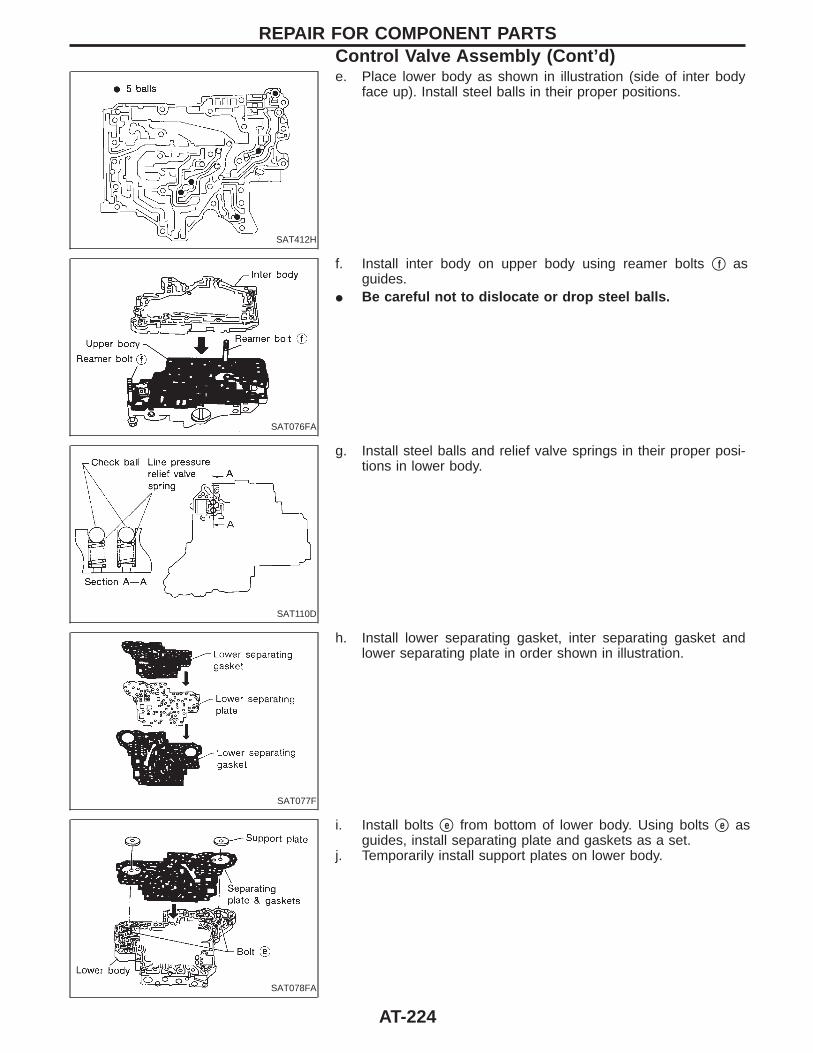
SAT412H
e. Place lower body as shown in illustration (side of inter bodyface up). Install steel balls in their proper positions.
SAT076FA
f. Install inter body on upper body using reamer bolts qf asguides.
I Be careful not to dislocate or drop steel balls.
SAT110D
g. Install steel balls and relief valve springs in their proper posi-tions in lower body.
SAT077F
h. Install lower separating gasket, inter separating gasket andlower separating plate in order shown in illustration.
SAT078FA
i. Install bolts qe from bottom of lower body. Using bolts qe asguides, install separating plate and gaskets as a set.
j. Temporarily install support plates on lower body.
REPAIR FOR COMPONENT PARTSControl Valve Assembly (Cont’d)
AT-224
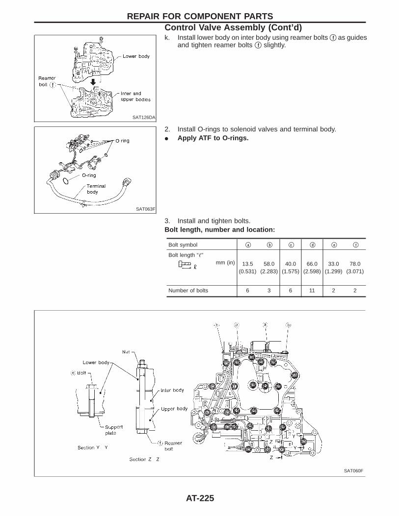
SAT126DA
k. Install lower body on inter body using reamer bolts qf as guidesand tighten reamer bolts qf slightly.
SAT063F
2. Install O-rings to solenoid valves and terminal body.I Apply ATF to O-rings.
3. Install and tighten bolts.Bolt length, number and location:
Bolt symbol qa qb qc qd qe qf
Bolt length “”mm (in) 13.5
(0.531)58.0
(2.283)40.0
(1.575)66.0
(2.598)33.0
(1.299)78.0
(3.071)
Number of bolts 6 3 6 11 2 2
SAT060F
REPAIR FOR COMPONENT PARTSControl Valve Assembly (Cont’d)
AT-225
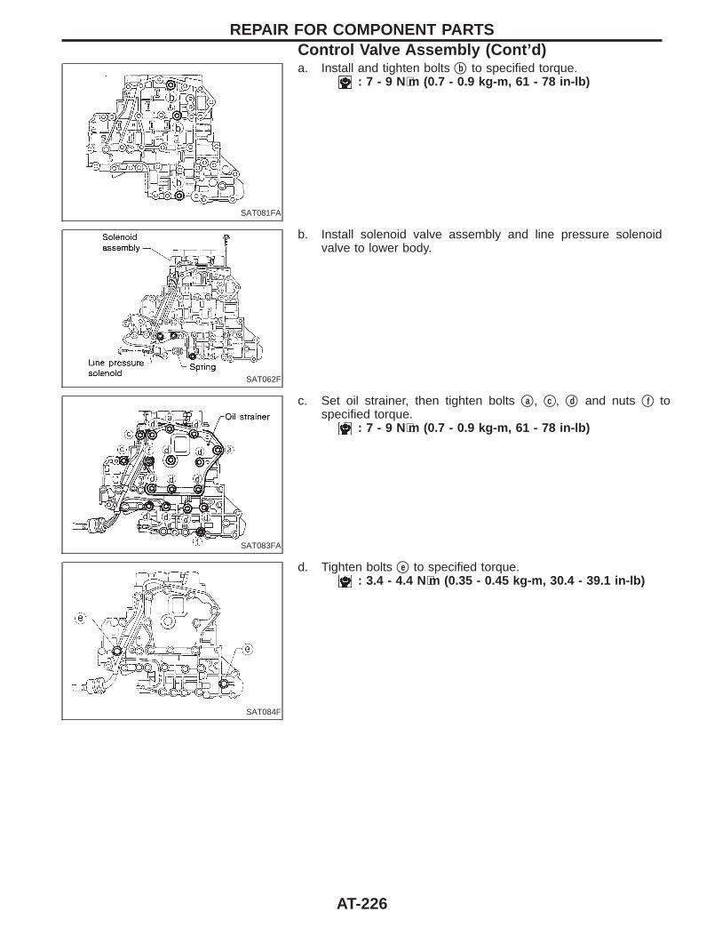
SAT081FA
a. Install and tighten bolts qb to specified torque.: 7 - 9 N⋅m (0.7 - 0.9 kg-m, 61 - 78 in-lb)
SAT062F
b. Install solenoid valve assembly and line pressure solenoidvalve to lower body.
SAT083FA
c. Set oil strainer, then tighten bolts qa , qc , qd and nuts qf tospecified torque.
: 7 - 9 N⋅m (0.7 - 0.9 kg-m, 61 - 78 in-lb)
SAT084F
d. Tighten bolts qe to specified torque.: 3.4 - 4.4 N⋅m (0.35 - 0.45 kg-m, 30.4 - 39.1 in-lb)
REPAIR FOR COMPONENT PARTSControl Valve Assembly (Cont’d)
AT-226
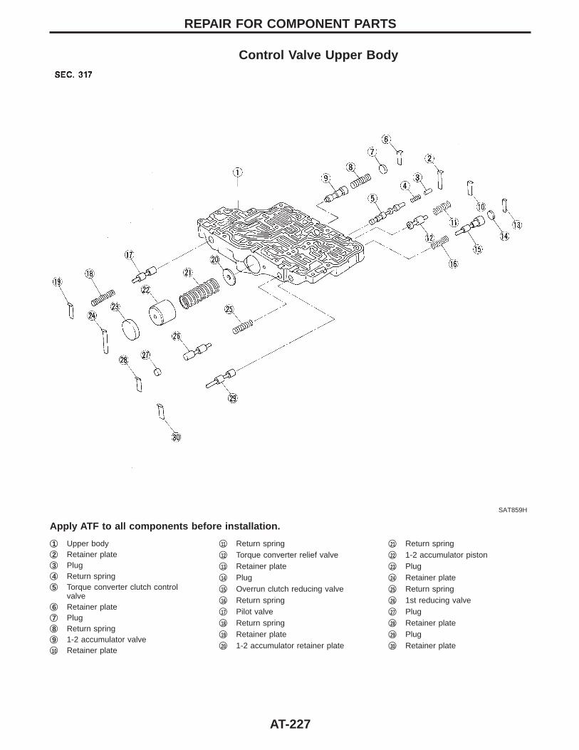
Control Valve Upper Body
SAT859H
Apply ATF to all components before installation.
q1 Upper bodyq2 Retainer plateq3 Plugq4 Return springq5 Torque converter clutch control
valveq6 Retainer plateq7 Plugq8 Return springq9 1-2 accumulator valveq10 Retainer plate
q11 Return springq12 Torque converter relief valveq13 Retainer plateq14 Plugq15 Overrun clutch reducing valveq16 Return springq17 Pilot valveq18 Return springq19 Retainer plateq20 1-2 accumulator retainer plate
q21 Return springq22 1-2 accumulator pistonq23 Plugq24 Retainer plateq25 Return springq26 1st reducing valveq27 Plugq28 Retainer plateq29 Plugq30 Retainer plate
REPAIR FOR COMPONENT PARTS
AT-227
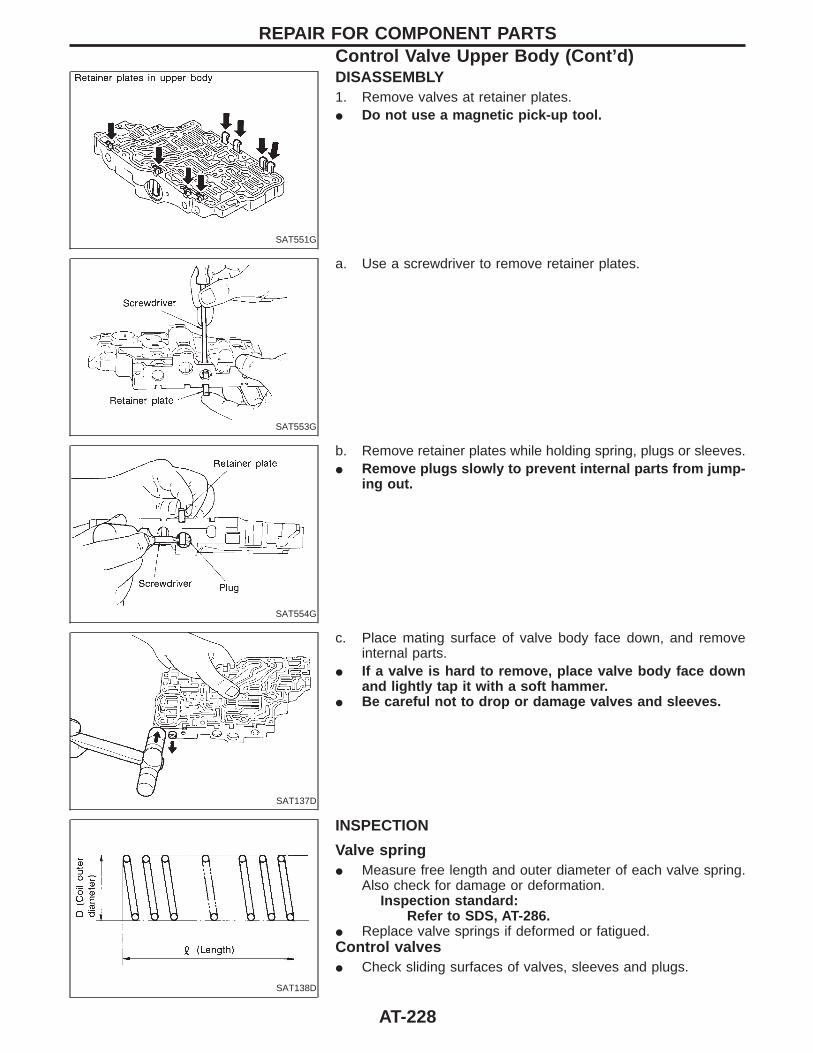
SAT551G
DISASSEMBLY1. Remove valves at retainer plates.I Do not use a magnetic pick-up tool.
SAT553G
a. Use a screwdriver to remove retainer plates.
SAT554G
b. Remove retainer plates while holding spring, plugs or sleeves.I Remove plugs slowly to prevent internal parts from jump-
ing out.
SAT137D
c. Place mating surface of valve body face down, and removeinternal parts.
I If a valve is hard to remove, place valve body face downand lightly tap it with a soft hammer.
I Be careful not to drop or damage valves and sleeves.
SAT138D
INSPECTION
Valve springI Measure free length and outer diameter of each valve spring.
Also check for damage or deformation.Inspection standard:
Refer to SDS, AT-286.I Replace valve springs if deformed or fatigued.Control valvesI Check sliding surfaces of valves, sleeves and plugs.
REPAIR FOR COMPONENT PARTSControl Valve Upper Body (Cont’d)
AT-228
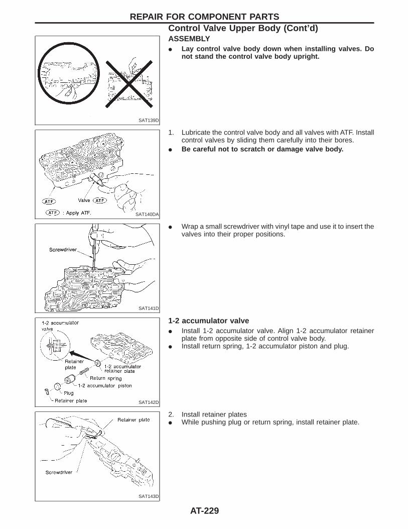
SAT139D
ASSEMBLYI Lay control valve body down when installing valves. Do
not stand the control valve body upright.
SAT140DA
1. Lubricate the control valve body and all valves with ATF. Installcontrol valves by sliding them carefully into their bores.
I Be careful not to scratch or damage valve body.
SAT141D
I Wrap a small screwdriver with vinyl tape and use it to insert thevalves into their proper positions.
SAT142D
1-2 accumulator valveI Install 1-2 accumulator valve. Align 1-2 accumulator retainer
plate from opposite side of control valve body.I Install return spring, 1-2 accumulator piston and plug.
SAT143D
2. Install retainer platesI While pushing plug or return spring, install retainer plate.
REPAIR FOR COMPONENT PARTSControl Valve Upper Body (Cont’d)
AT-229
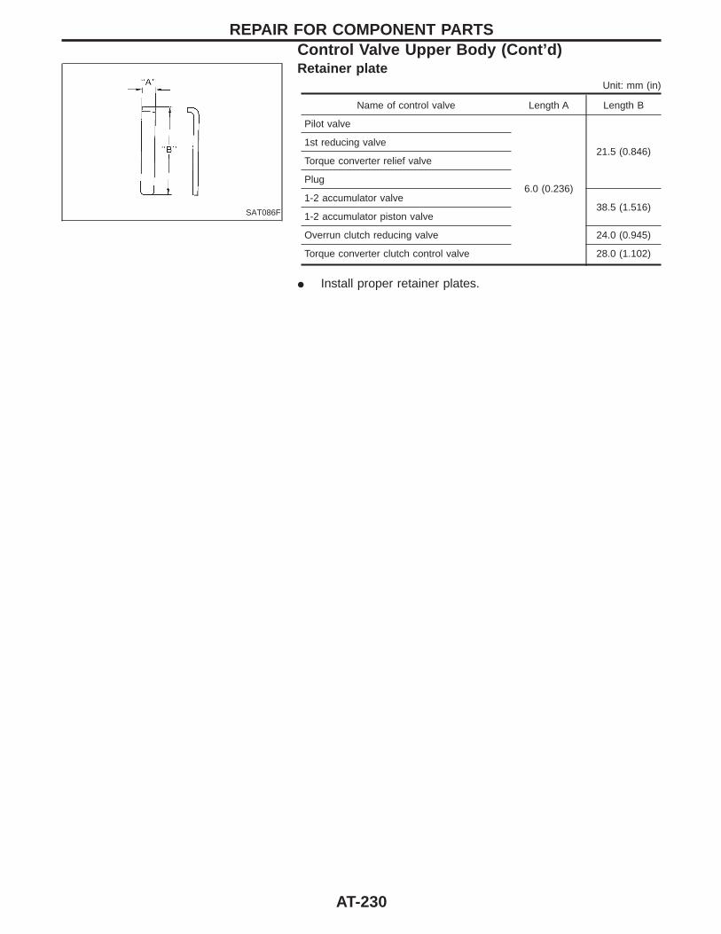
SAT086F
Retainer plateUnit: mm (in)
Name of control valve Length A Length B
Pilot valve
6.0 (0.236)
21.5 (0.846)1st reducing valve
Torque converter relief valve
Plug
1-2 accumulator valve38.5 (1.516)
1-2 accumulator piston valve
Overrun clutch reducing valve 24.0 (0.945)
Torque converter clutch control valve 28.0 (1.102)
I Install proper retainer plates.
REPAIR FOR COMPONENT PARTSControl Valve Upper Body (Cont’d)
AT-230
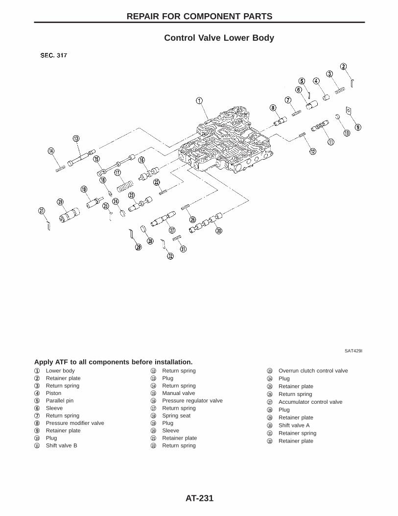
Control Valve Lower Body
SAT429I
Apply ATF to all components before installation.q1 Lower bodyq2 Retainer plateq3 Return springq4 Pistonq5 Parallel pinq6 Sleeveq7 Return springq8 Pressure modifier valveq9 Retainer plateq10 Plugq11 Shift valve B
q12 Return springq13 Plugq14 Return springq15 Manual valveq16 Pressure regulator valveq17 Return springq18 Spring seatq19 Plugq20 Sleeveq21 Retainer plateq22 Return spring
q23 Overrun clutch control valveq24 Plugq25 Retainer plateq26 Return springq27 Accumulator control valveq28 Plugq29 Retainer plateq30 Shift valve Aq31 Retainer springq32 Retainer plate
REPAIR FOR COMPONENT PARTS
AT-231
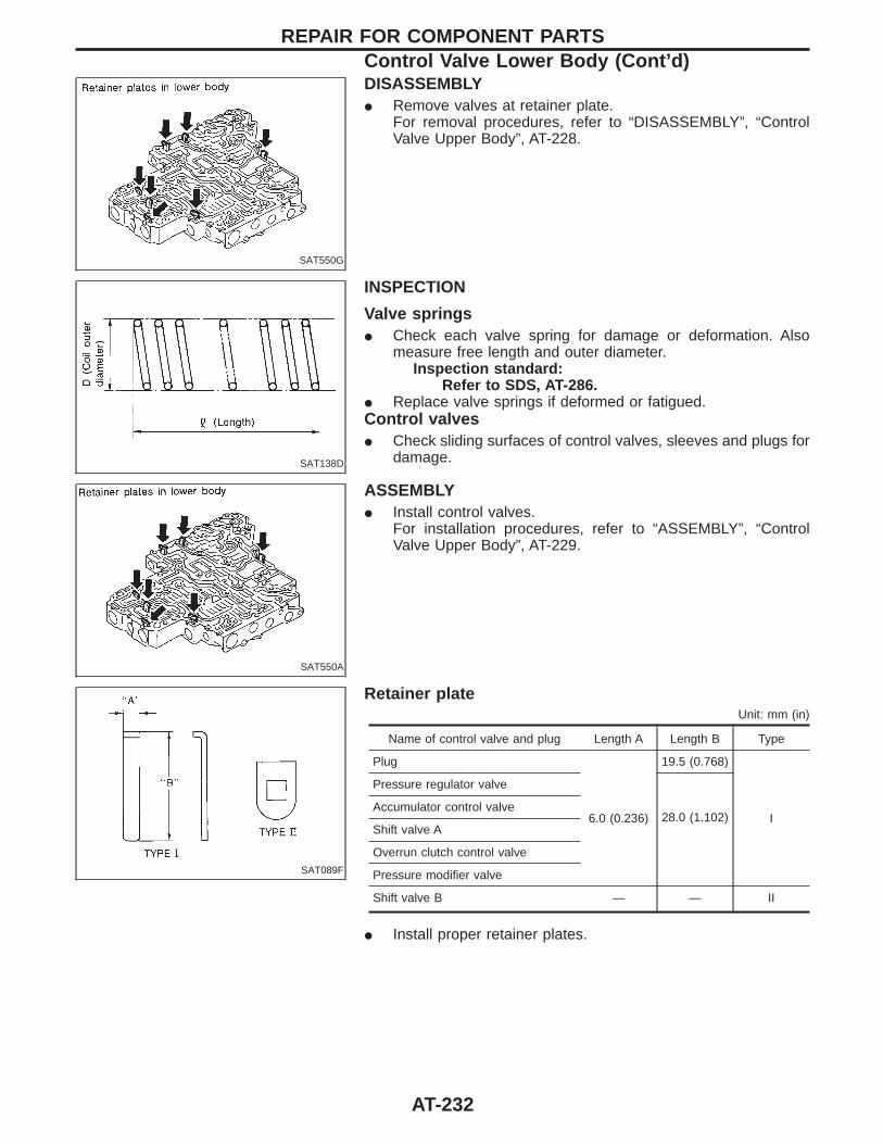
SAT550G
DISASSEMBLYI Remove valves at retainer plate.
For removal procedures, refer to “DISASSEMBLY”, “ControlValve Upper Body”, AT-228.
SAT138D
INSPECTION
Valve springsI Check each valve spring for damage or deformation. Also
measure free length and outer diameter.Inspection standard:
Refer to SDS, AT-286.I Replace valve springs if deformed or fatigued.Control valvesI Check sliding surfaces of control valves, sleeves and plugs for
damage.
SAT550A
ASSEMBLYI Install control valves.
For installation procedures, refer to “ASSEMBLY”, “ControlValve Upper Body”, AT-229.
SAT089F
Retainer plateUnit: mm (in)
Name of control valve and plug Length A Length B Type
Plug
6.0 (0.236)
19.5 (0.768)
I
Pressure regulator valve
28.0 (1.102)Accumulator control valve
Shift valve A
Overrun clutch control valve
Pressure modifier valve
Shift valve B — — II
I Install proper retainer plates.
REPAIR FOR COMPONENT PARTSControl Valve Lower Body (Cont’d)
AT-232
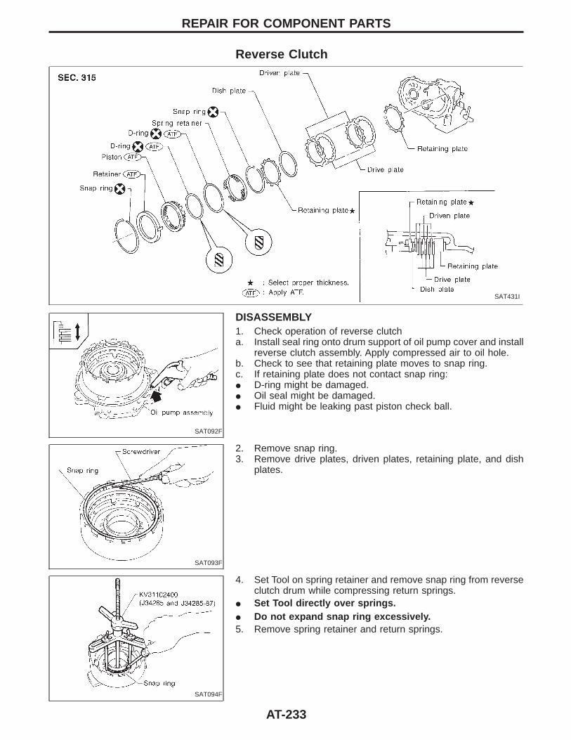
Reverse Clutch
SAT431I
SAT092F
DISASSEMBLY1. Check operation of reverse clutcha. Install seal ring onto drum support of oil pump cover and install
reverse clutch assembly. Apply compressed air to oil hole.b. Check to see that retaining plate moves to snap ring.c. If retaining plate does not contact snap ring:I D-ring might be damaged.I Oil seal might be damaged.I Fluid might be leaking past piston check ball.
SAT093F
2. Remove snap ring.3. Remove drive plates, driven plates, retaining plate, and dish
plates.
SAT094F
4. Set Tool on spring retainer and remove snap ring from reverseclutch drum while compressing return springs.
I Set Tool directly over springs.I Do not expand snap ring excessively.5. Remove spring retainer and return springs.
REPAIR FOR COMPONENT PARTS
AT-233
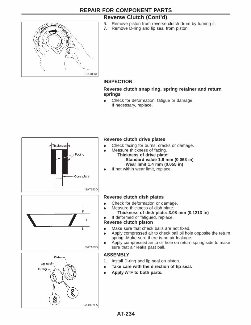
SAT096F
6. Remove piston from reverse clutch drum by turning it.7. Remove D-ring and lip seal from piston.
INSPECTION
Reverse clutch snap ring, spring retainer and returnspringsI Check for deformation, fatigue or damage.
If necessary, replace.
SAT162D
Reverse clutch drive platesI Check facing for burns, cracks or damage.I Measure thickness of facing.
Thickness of drive plate:Standard value 1.6 mm (0.063 in)Wear limit 1.4 mm (0.055 in)
I If not within wear limit, replace.
SAT163D
Reverse clutch dish platesI Check for deformation or damage.I Measure thickness of dish plate.
Thickness of dish plate: 3.08 mm (0.1213 in)I If deformed or fatigued, replace.Reverse clutch pistonI Make sure that check balls are not fixed.I Apply compressed air to check ball oil hole opposite the return
spring. Make sure there is no air leakage.I Apply compressed air to oil hole on return spring side to make
sure that air leaks past ball.
SAT097FA
ASSEMBLY1. Install D-ring and lip seal on piston.I Take care with the direction of lip seal.I Apply ATF to both parts.
REPAIR FOR COMPONENT PARTSReverse Clutch (Cont’d)
AT-234
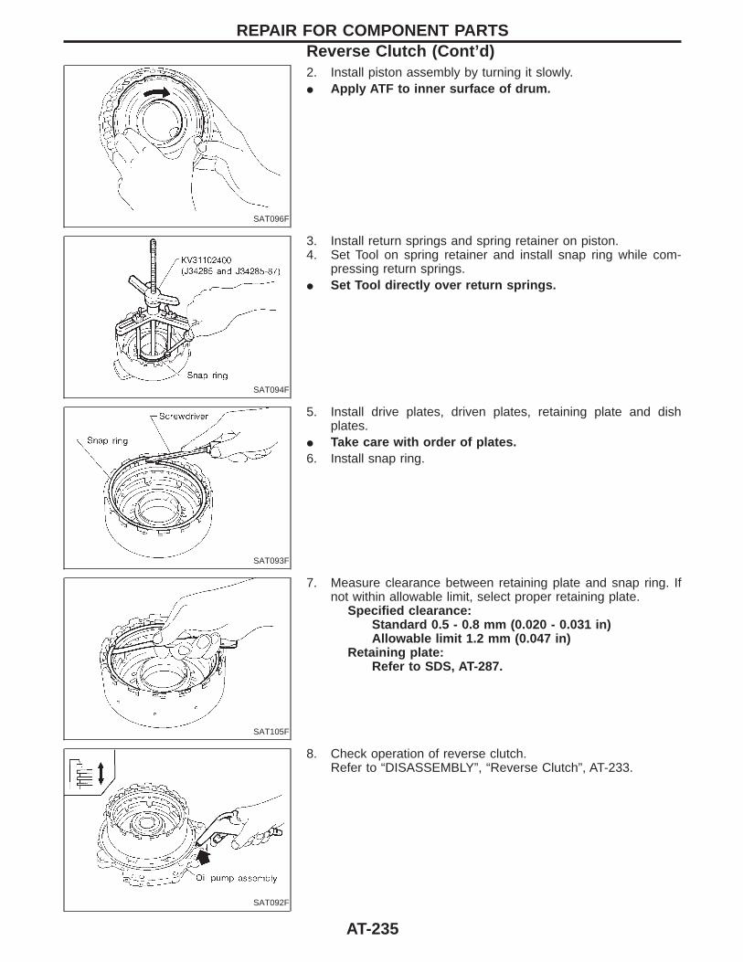
SAT096F
2. Install piston assembly by turning it slowly.I Apply ATF to inner surface of drum.
SAT094F
3. Install return springs and spring retainer on piston.4. Set Tool on spring retainer and install snap ring while com-
pressing return springs.I Set Tool directly over return springs.
SAT093F
5. Install drive plates, driven plates, retaining plate and dishplates.
I Take care with order of plates.6. Install snap ring.
SAT105F
7. Measure clearance between retaining plate and snap ring. Ifnot within allowable limit, select proper retaining plate.
Specified clearance:Standard 0.5 - 0.8 mm (0.020 - 0.031 in)Allowable limit 1.2 mm (0.047 in)
Retaining plate:Refer to SDS, AT-287.
SAT092F
8. Check operation of reverse clutch.Refer to “DISASSEMBLY”, “Reverse Clutch”, AT-233.
REPAIR FOR COMPONENT PARTSReverse Clutch (Cont’d)
AT-235
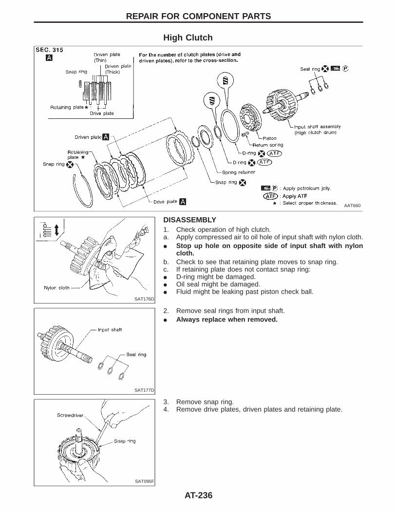
High Clutch
AAT660
SAT176D
DISASSEMBLY1. Check operation of high clutch.a. Apply compressed air to oil hole of input shaft with nylon cloth.I Stop up hole on opposite side of input shaft with nylon
cloth.b. Check to see that retaining plate moves to snap ring.c. If retaining plate does not contact snap ring:I D-ring might be damaged.I Oil seal might be damaged.I Fluid might be leaking past piston check ball.
SAT177D
2. Remove seal rings from input shaft.I Always replace when removed.
SAT095F
3. Remove snap ring.4. Remove drive plates, driven plates and retaining plate.
REPAIR FOR COMPONENT PARTS
AT-236
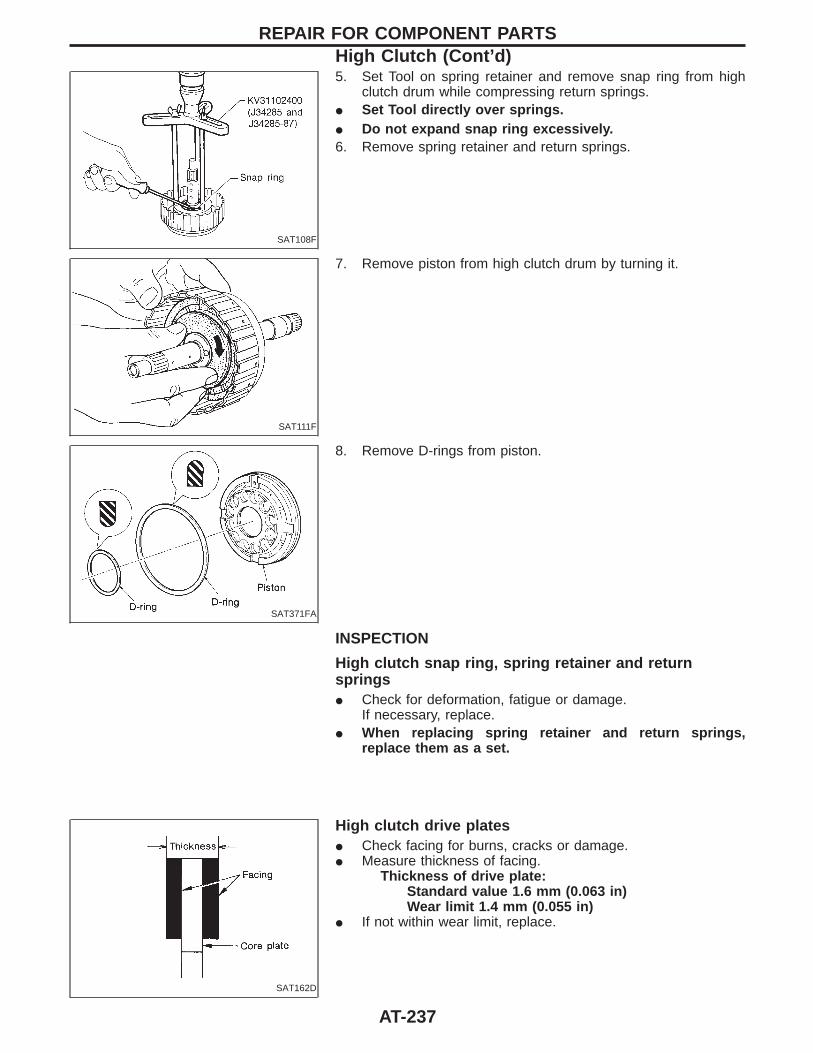
SAT108F
5. Set Tool on spring retainer and remove snap ring from highclutch drum while compressing return springs.
I Set Tool directly over springs.I Do not expand snap ring excessively.6. Remove spring retainer and return springs.
SAT111F
7. Remove piston from high clutch drum by turning it.
SAT371FA
8. Remove D-rings from piston.
INSPECTION
High clutch snap ring, spring retainer and returnspringsI Check for deformation, fatigue or damage.
If necessary, replace.I When replacing spring retainer and return springs,
replace them as a set.
SAT162D
High clutch drive platesI Check facing for burns, cracks or damage.I Measure thickness of facing.
Thickness of drive plate:Standard value 1.6 mm (0.063 in)Wear limit 1.4 mm (0.055 in)
I If not within wear limit, replace.
REPAIR FOR COMPONENT PARTSHigh Clutch (Cont’d)
AT-237
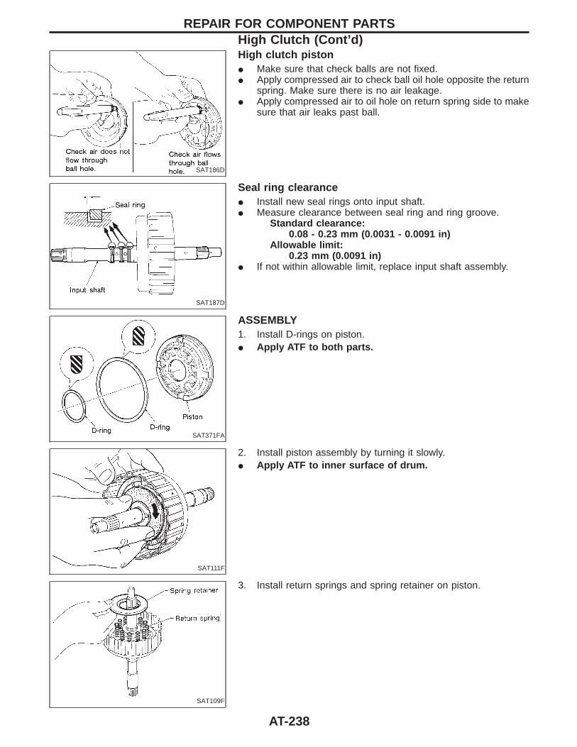
SAT186D
High clutch pistonI Make sure that check balls are not fixed.I Apply compressed air to check ball oil hole opposite the return
spring. Make sure there is no air leakage.I Apply compressed air to oil hole on return spring side to make
sure that air leaks past ball.
SAT187D
Seal ring clearanceI Install new seal rings onto input shaft.I Measure clearance between seal ring and ring groove.
Standard clearance:0.08 - 0.23 mm (0.0031 - 0.0091 in)
Allowable limit:0.23 mm (0.0091 in)
I If not within allowable limit, replace input shaft assembly.
SAT371FA
ASSEMBLY1. Install D-rings on piston.I Apply ATF to both parts.
SAT111F
2. Install piston assembly by turning it slowly.I Apply ATF to inner surface of drum.
SAT109F
3. Install return springs and spring retainer on piston.
REPAIR FOR COMPONENT PARTSHigh Clutch (Cont’d)
AT-238
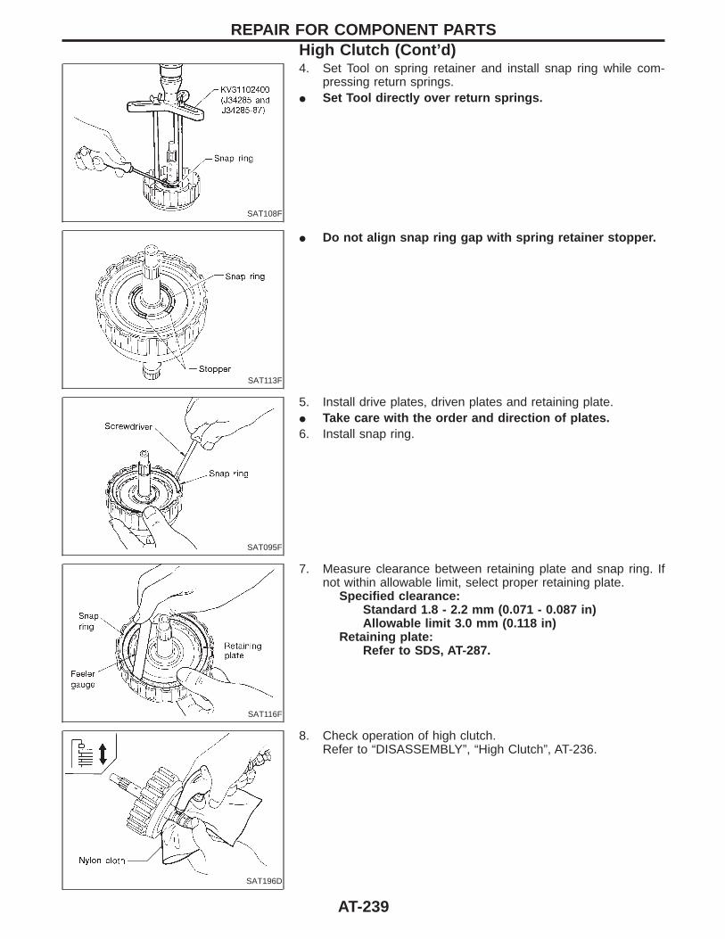
SAT108F
4. Set Tool on spring retainer and install snap ring while com-pressing return springs.
I Set Tool directly over return springs.
SAT113F
I Do not align snap ring gap with spring retainer stopper.
SAT095F
5. Install drive plates, driven plates and retaining plate.I Take care with the order and direction of plates.6. Install snap ring.
SAT116F
7. Measure clearance between retaining plate and snap ring. Ifnot within allowable limit, select proper retaining plate.
Specified clearance:Standard 1.8 - 2.2 mm (0.071 - 0.087 in)Allowable limit 3.0 mm (0.118 in)
Retaining plate:Refer to SDS, AT-287.
SAT196D
8. Check operation of high clutch.Refer to “DISASSEMBLY”, “High Clutch”, AT-236.
REPAIR FOR COMPONENT PARTSHigh Clutch (Cont’d)
AT-239
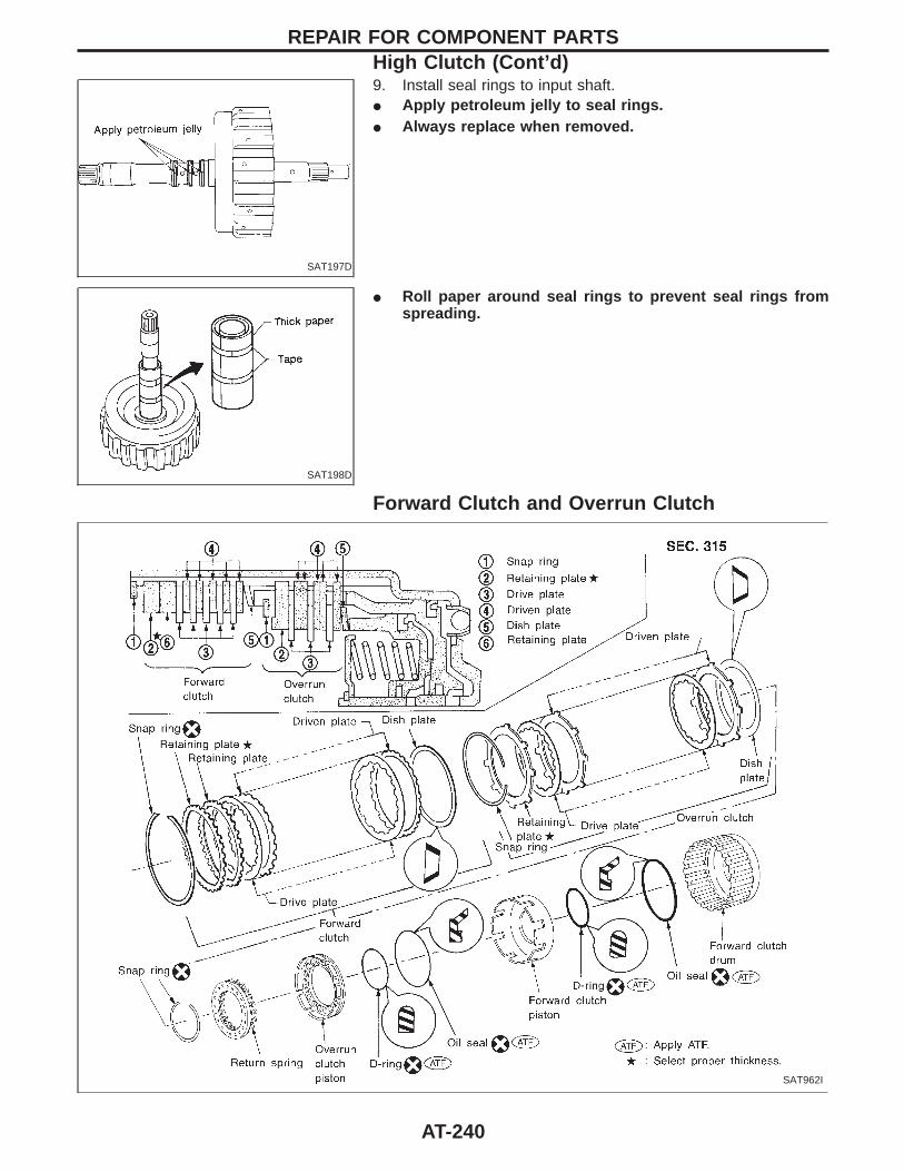
SAT197D
9. Install seal rings to input shaft.I Apply petroleum jelly to seal rings.I Always replace when removed.
SAT198D
I Roll paper around seal rings to prevent seal rings fromspreading.
Forward Clutch and Overrun Clutch
SAT962I
REPAIR FOR COMPONENT PARTSHigh Clutch (Cont’d)
AT-240
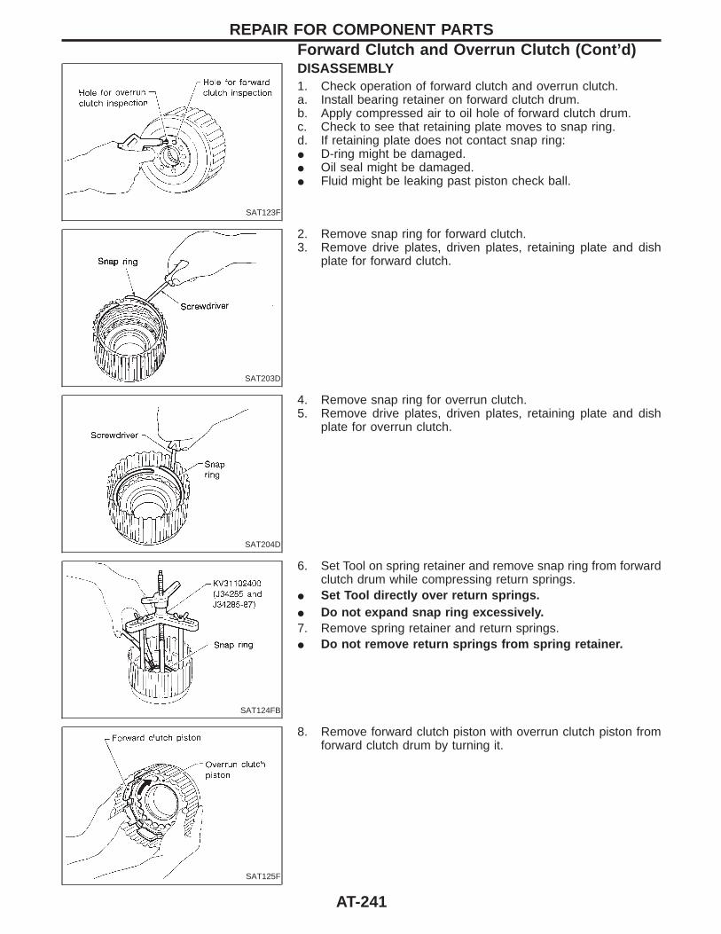
SAT123F
DISASSEMBLY1. Check operation of forward clutch and overrun clutch.a. Install bearing retainer on forward clutch drum.b. Apply compressed air to oil hole of forward clutch drum.c. Check to see that retaining plate moves to snap ring.d. If retaining plate does not contact snap ring:I D-ring might be damaged.I Oil seal might be damaged.I Fluid might be leaking past piston check ball.
SAT203D
2. Remove snap ring for forward clutch.3. Remove drive plates, driven plates, retaining plate and dish
plate for forward clutch.
SAT204D
4. Remove snap ring for overrun clutch.5. Remove drive plates, driven plates, retaining plate and dish
plate for overrun clutch.
SAT124FB
6. Set Tool on spring retainer and remove snap ring from forwardclutch drum while compressing return springs.
I Set Tool directly over return springs.I Do not expand snap ring excessively.7. Remove spring retainer and return springs.I Do not remove return springs from spring retainer.
SAT125F
8. Remove forward clutch piston with overrun clutch piston fromforward clutch drum by turning it.
REPAIR FOR COMPONENT PARTSForward Clutch and Overrun Clutch (Cont’d)
AT-241
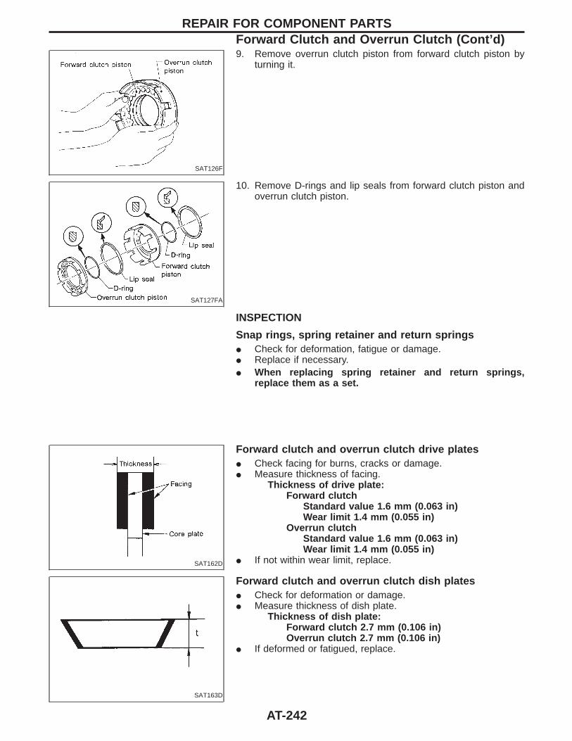
SAT126F
9. Remove overrun clutch piston from forward clutch piston byturning it.
SAT127FA
10. Remove D-rings and lip seals from forward clutch piston andoverrun clutch piston.
INSPECTION
Snap rings, spring retainer and return springsI Check for deformation, fatigue or damage.I Replace if necessary.I When replacing spring retainer and return springs,
replace them as a set.
SAT162D
Forward clutch and overrun clutch drive platesI Check facing for burns, cracks or damage.I Measure thickness of facing.
Thickness of drive plate:Forward clutch
Standard value 1.6 mm (0.063 in)Wear limit 1.4 mm (0.055 in)
Overrun clutchStandard value 1.6 mm (0.063 in)Wear limit 1.4 mm (0.055 in)
I If not within wear limit, replace.
SAT163D
Forward clutch and overrun clutch dish platesI Check for deformation or damage.I Measure thickness of dish plate.
Thickness of dish plate:Forward clutch 2.7 mm (0.106 in)Overrun clutch 2.7 mm (0.106 in)
I If deformed or fatigued, replace.
REPAIR FOR COMPONENT PARTSForward Clutch and Overrun Clutch (Cont’d)
AT-242
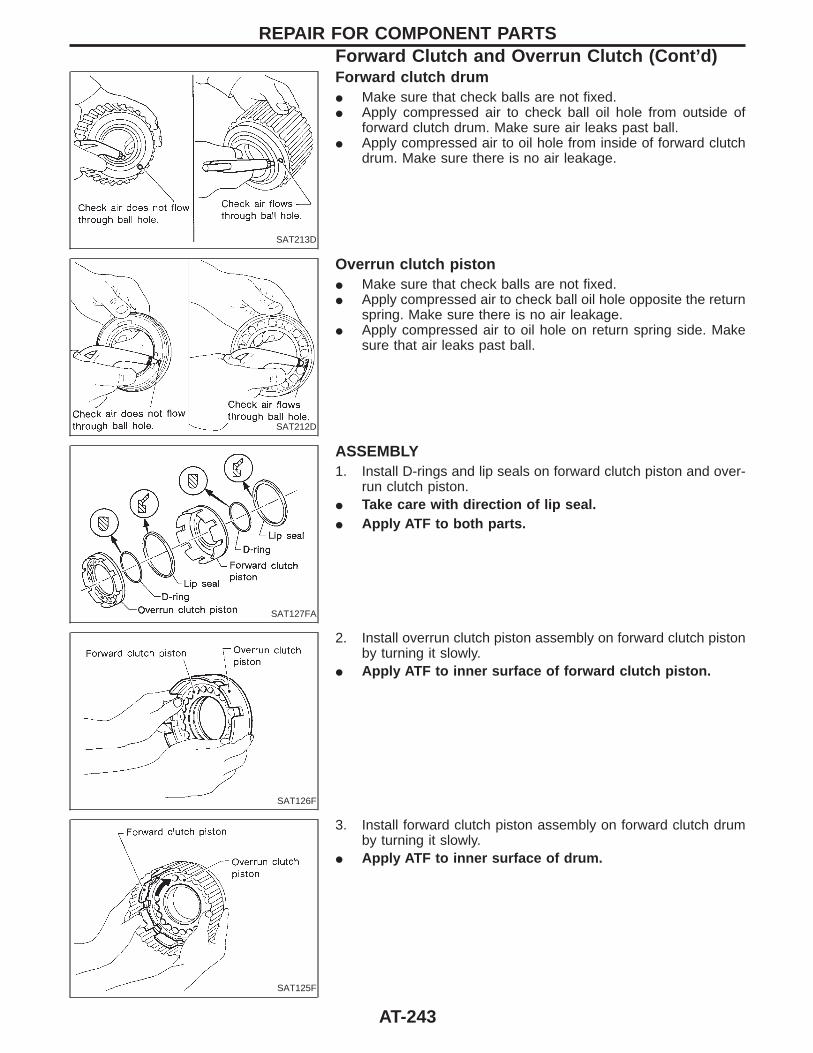
SAT213D
Forward clutch drumI Make sure that check balls are not fixed.I Apply compressed air to check ball oil hole from outside of
forward clutch drum. Make sure air leaks past ball.I Apply compressed air to oil hole from inside of forward clutch
drum. Make sure there is no air leakage.
SAT212D
Overrun clutch pistonI Make sure that check balls are not fixed.I Apply compressed air to check ball oil hole opposite the return
spring. Make sure there is no air leakage.I Apply compressed air to oil hole on return spring side. Make
sure that air leaks past ball.
SAT127FA
ASSEMBLY1. Install D-rings and lip seals on forward clutch piston and over-
run clutch piston.I Take care with direction of lip seal.I Apply ATF to both parts.
SAT126F
2. Install overrun clutch piston assembly on forward clutch pistonby turning it slowly.
I Apply ATF to inner surface of forward clutch piston.
SAT125F
3. Install forward clutch piston assembly on forward clutch drumby turning it slowly.
I Apply ATF to inner surface of drum.
REPAIR FOR COMPONENT PARTSForward Clutch and Overrun Clutch (Cont’d)
AT-243
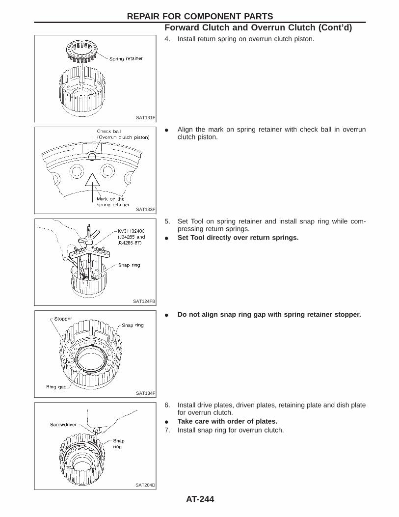
SAT131F
4. Install return spring on overrun clutch piston.
SAT133F
I Align the mark on spring retainer with check ball in overrunclutch piston.
SAT124FB
5. Set Tool on spring retainer and install snap ring while com-pressing return springs.
I Set Tool directly over return springs.
SAT134F
I Do not align snap ring gap with spring retainer stopper.
SAT204D
6. Install drive plates, driven plates, retaining plate and dish platefor overrun clutch.
I Take care with order of plates.7. Install snap ring for overrun clutch.
REPAIR FOR COMPONENT PARTSForward Clutch and Overrun Clutch (Cont’d)
AT-244
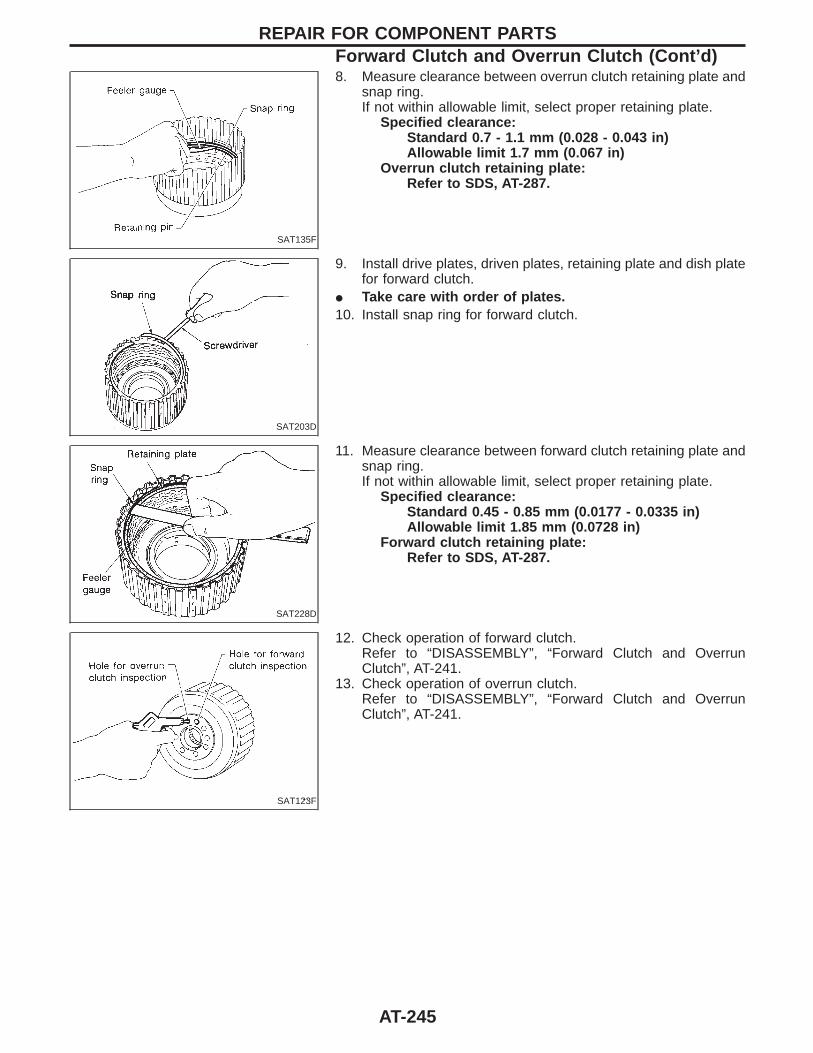
SAT135F
8. Measure clearance between overrun clutch retaining plate andsnap ring.If not within allowable limit, select proper retaining plate.
Specified clearance:Standard 0.7 - 1.1 mm (0.028 - 0.043 in)Allowable limit 1.7 mm (0.067 in)
Overrun clutch retaining plate:Refer to SDS, AT-287.
SAT203D
9. Install drive plates, driven plates, retaining plate and dish platefor forward clutch.
I Take care with order of plates.10. Install snap ring for forward clutch.
SAT228D
11. Measure clearance between forward clutch retaining plate andsnap ring.If not within allowable limit, select proper retaining plate.
Specified clearance:Standard 0.45 - 0.85 mm (0.0177 - 0.0335 in)Allowable limit 1.85 mm (0.0728 in)
Forward clutch retaining plate:Refer to SDS, AT-287.
SAT123F
12. Check operation of forward clutch.Refer to “DISASSEMBLY”, “Forward Clutch and OverrunClutch”, AT-241.
13. Check operation of overrun clutch.Refer to “DISASSEMBLY”, “Forward Clutch and OverrunClutch”, AT-241.
REPAIR FOR COMPONENT PARTSForward Clutch and Overrun Clutch (Cont’d)
AT-245
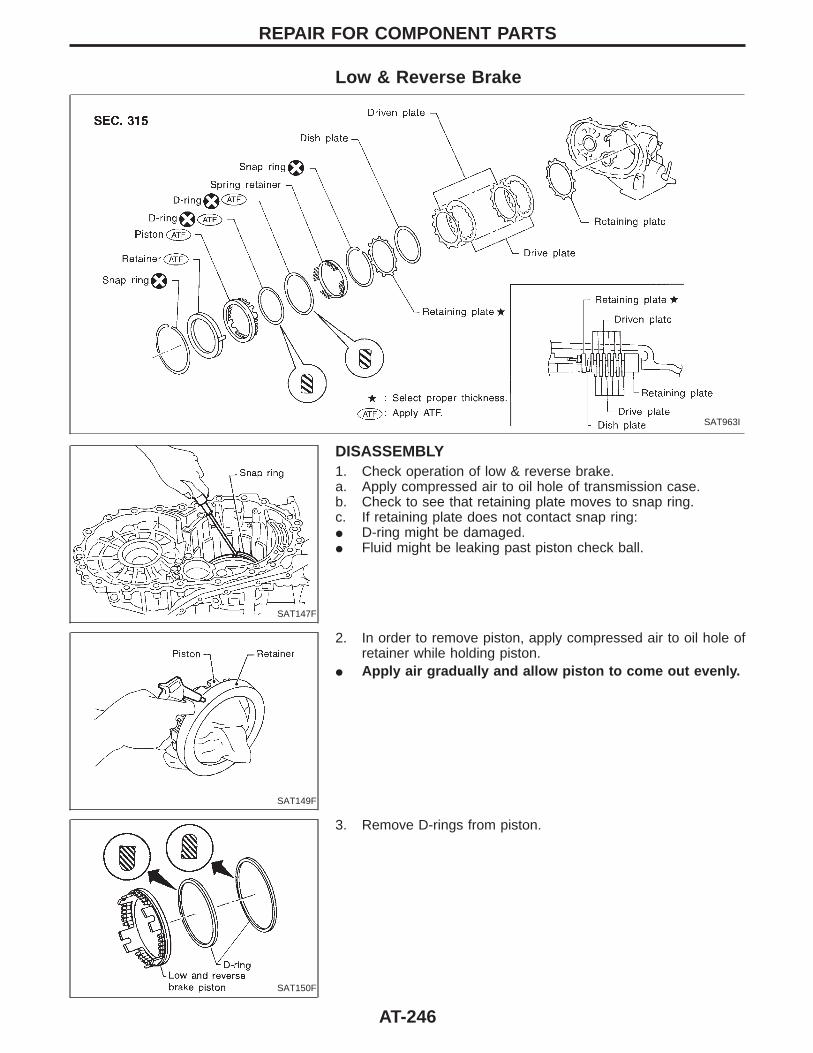
Low & Reverse Brake
SAT963I
SAT147F
DISASSEMBLY1. Check operation of low & reverse brake.a. Apply compressed air to oil hole of transmission case.b. Check to see that retaining plate moves to snap ring.c. If retaining plate does not contact snap ring:I D-ring might be damaged.I Fluid might be leaking past piston check ball.
SAT149F
2. In order to remove piston, apply compressed air to oil hole ofretainer while holding piston.
I Apply air gradually and allow piston to come out evenly.
SAT150F
3. Remove D-rings from piston.
REPAIR FOR COMPONENT PARTS
AT-246
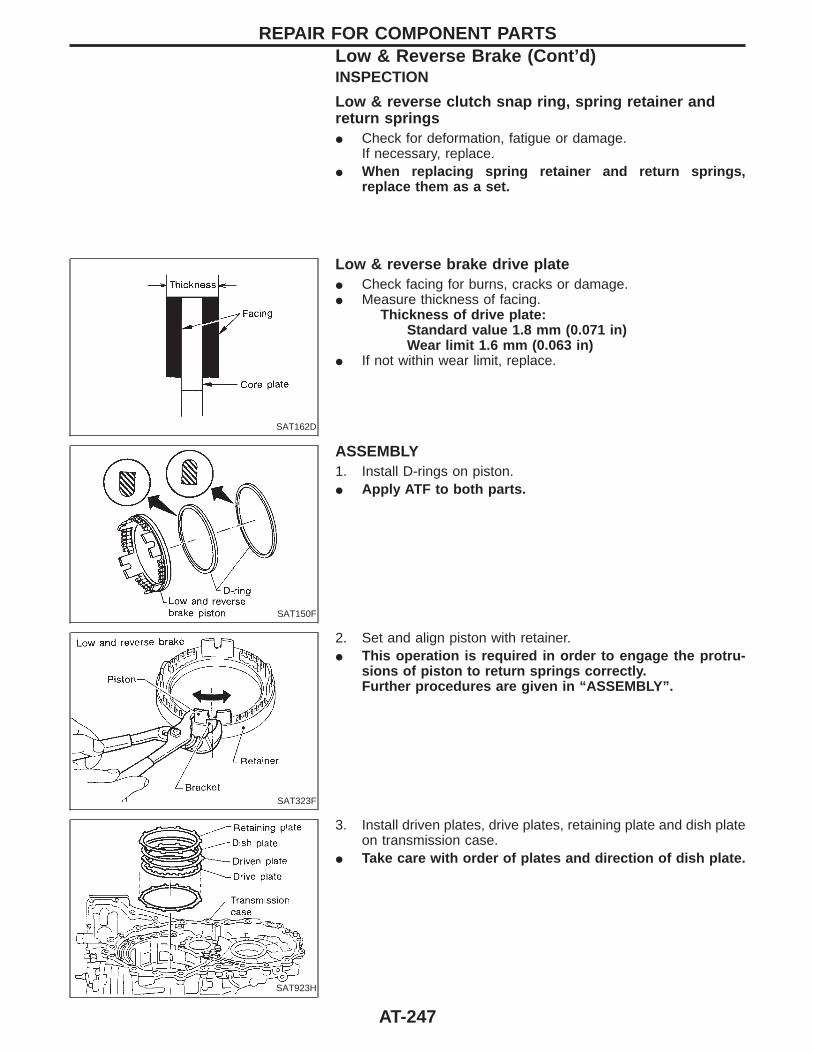
INSPECTION
Low & reverse clutch snap ring, spring retainer andreturn springsI Check for deformation, fatigue or damage.
If necessary, replace.I When replacing spring retainer and return springs,
replace them as a set.
SAT162D
Low & reverse brake drive plateI Check facing for burns, cracks or damage.I Measure thickness of facing.
Thickness of drive plate:Standard value 1.8 mm (0.071 in)Wear limit 1.6 mm (0.063 in)
I If not within wear limit, replace.
SAT150F
ASSEMBLY1. Install D-rings on piston.I Apply ATF to both parts.
SAT323F
2. Set and align piston with retainer.I This operation is required in order to engage the protru-
sions of piston to return springs correctly.Further procedures are given in “ASSEMBLY”.
SAT923H
3. Install driven plates, drive plates, retaining plate and dish plateon transmission case.
I Take care with order of plates and direction of dish plate.
REPAIR FOR COMPONENT PARTSLow & Reverse Brake (Cont’d)
AT-247
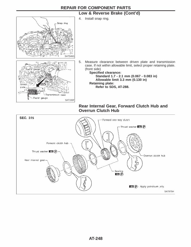
SAT546G
4. Install snap ring.
SAT155F
5. Measure clearance between driven plate and transmissioncase. If not within allowable limit, select proper retaining plate.(front side)
Specified clearance:Standard 1.7 - 2.1 mm (0.067 - 0.083 in)Allowable limit 3.3 mm (0.130 in)
Retaining plate:Refer to SDS, AT-288.
Rear Internal Gear, Forward Clutch Hub andOverrun Clutch Hub
SAT975H
REPAIR FOR COMPONENT PARTSLow & Reverse Brake (Cont’d)
AT-248
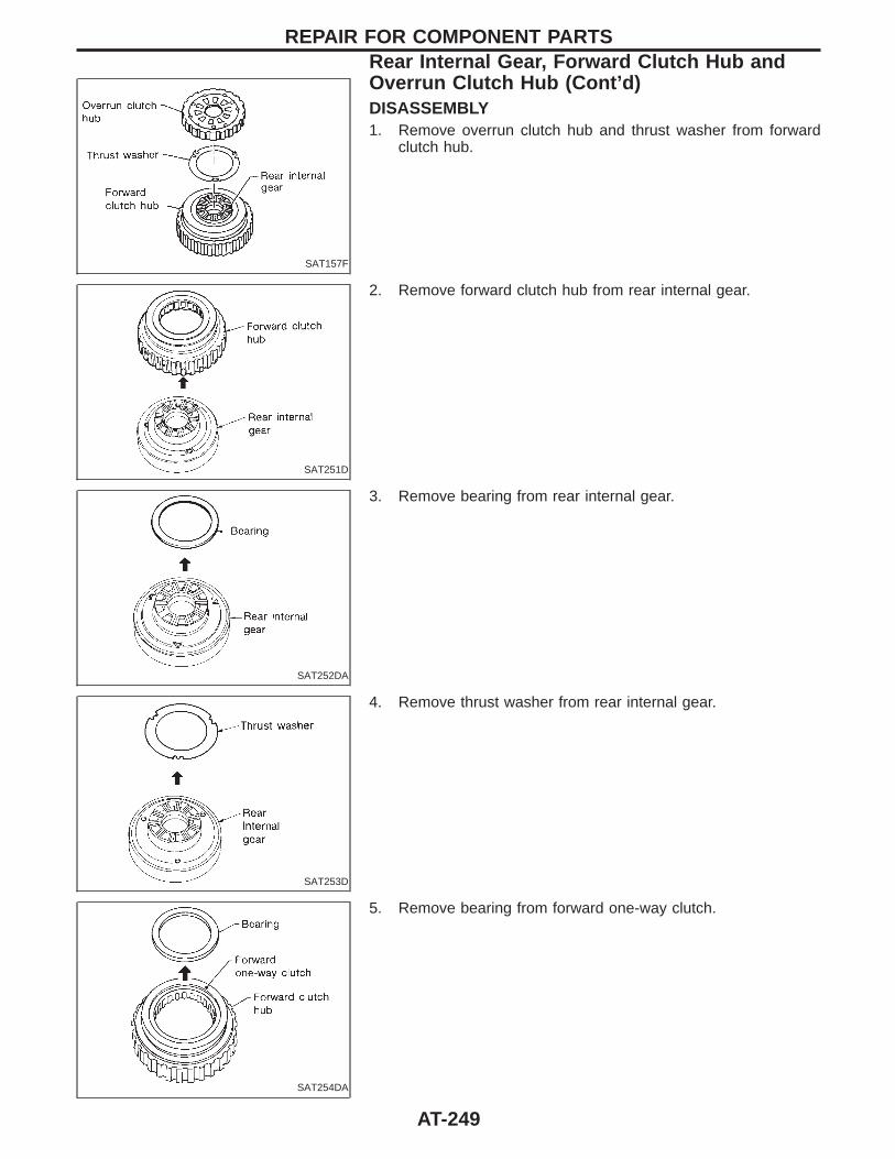
SAT157F
DISASSEMBLY1. Remove overrun clutch hub and thrust washer from forward
clutch hub.
SAT251D
2. Remove forward clutch hub from rear internal gear.
SAT252DA
3. Remove bearing from rear internal gear.
SAT253D
4. Remove thrust washer from rear internal gear.
SAT254DA
5. Remove bearing from forward one-way clutch.
REPAIR FOR COMPONENT PARTSRear Internal Gear, Forward Clutch Hub andOverrun Clutch Hub (Cont’d)
AT-249
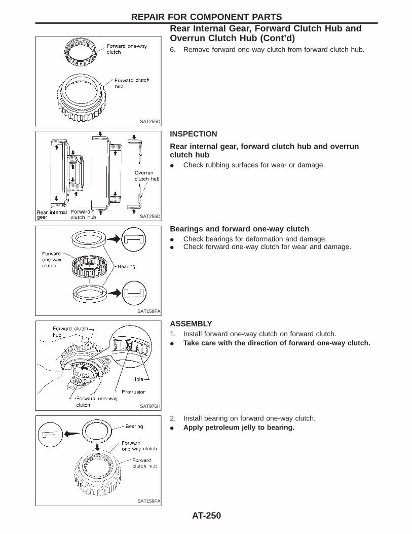
SAT255D
6. Remove forward one-way clutch from forward clutch hub.
SAT256D
INSPECTION
Rear internal gear, forward clutch hub and overrunclutch hubI Check rubbing surfaces for wear or damage.
SAT158FA
Bearings and forward one-way clutchI Check bearings for deformation and damage.I Check forward one-way clutch for wear and damage.
SAT976H
ASSEMBLY1. Install forward one-way clutch on forward clutch.I Take care with the direction of forward one-way clutch.
SAT159FA
2. Install bearing on forward one-way clutch.I Apply petroleum jelly to bearing.
REPAIR FOR COMPONENT PARTSRear Internal Gear, Forward Clutch Hub andOverrun Clutch Hub (Cont’d)
AT-250
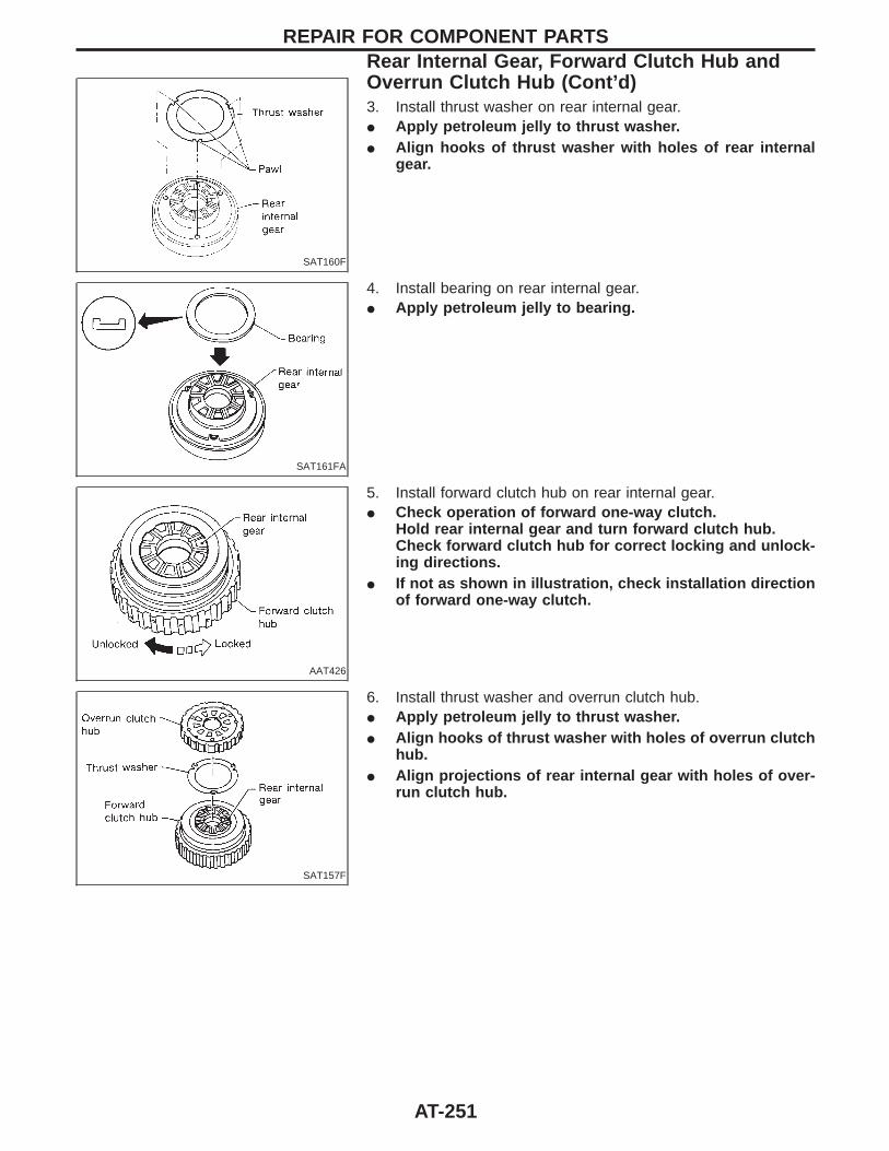
SAT160F
3. Install thrust washer on rear internal gear.I Apply petroleum jelly to thrust washer.I Align hooks of thrust washer with holes of rear internal
gear.
SAT161FA
4. Install bearing on rear internal gear.I Apply petroleum jelly to bearing.
AAT426
5. Install forward clutch hub on rear internal gear.I Check operation of forward one-way clutch.
Hold rear internal gear and turn forward clutch hub.Check forward clutch hub for correct locking and unlock-ing directions.
I If not as shown in illustration, check installation directionof forward one-way clutch.
SAT157F
6. Install thrust washer and overrun clutch hub.I Apply petroleum jelly to thrust washer.I Align hooks of thrust washer with holes of overrun clutch
hub.I Align projections of rear internal gear with holes of over-
run clutch hub.
REPAIR FOR COMPONENT PARTSRear Internal Gear, Forward Clutch Hub andOverrun Clutch Hub (Cont’d)
AT-251
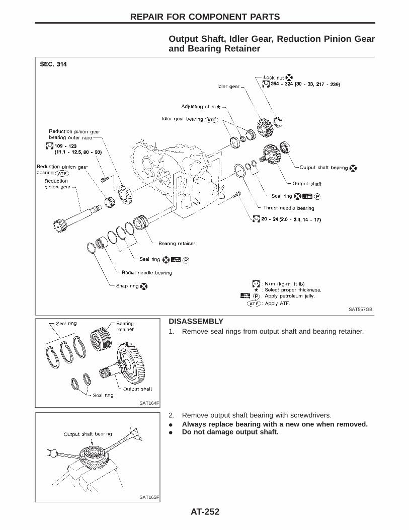
Output Shaft, Idler Gear, Reduction Pinion Gearand Bearing Retainer
SAT557GB
SAT164F
DISASSEMBLY1. Remove seal rings from output shaft and bearing retainer.
SAT165F
2. Remove output shaft bearing with screwdrivers.I Always replace bearing with a new one when removed.I Do not damage output shaft.
REPAIR FOR COMPONENT PARTS
AT-252
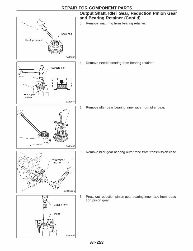
SAT166F
3. Remove snap ring from bearing retainer.
SAT167F
4. Remove needle bearing from bearing retainer.
SAT168F
5. Remove idler gear bearing inner race from idler gear.
SAT859DC
6. Remove idler gear bearing outer race from transmission case.
SAT169F
7. Press out reduction pinion gear bearing inner race from reduc-tion pinion gear.
REPAIR FOR COMPONENT PARTSOutput Shaft, Idler Gear, Reduction Pinion Gearand Bearing Retainer (Cont’d)
AT-253
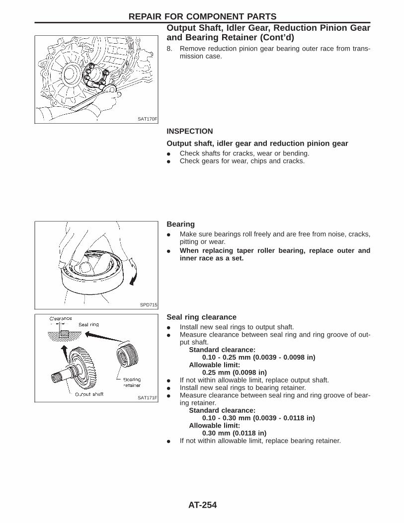
SAT170F
8. Remove reduction pinion gear bearing outer race from trans-mission case.
INSPECTION
Output shaft, idler gear and reduction pinion gearI Check shafts for cracks, wear or bending.I Check gears for wear, chips and cracks.
SPD715
BearingI Make sure bearings roll freely and are free from noise, cracks,
pitting or wear.I When replacing taper roller bearing, replace outer and
inner race as a set.
SAT171F
Seal ring clearanceI Install new seal rings to output shaft.I Measure clearance between seal ring and ring groove of out-
put shaft.Standard clearance:
0.10 - 0.25 mm (0.0039 - 0.0098 in)Allowable limit:
0.25 mm (0.0098 in)I If not within allowable limit, replace output shaft.I Install new seal rings to bearing retainer.I Measure clearance between seal ring and ring groove of bear-
ing retainer.Standard clearance:
0.10 - 0.30 mm (0.0039 - 0.0118 in)Allowable limit:
0.30 mm (0.0118 in)I If not within allowable limit, replace bearing retainer.
REPAIR FOR COMPONENT PARTSOutput Shaft, Idler Gear, Reduction Pinion Gearand Bearing Retainer (Cont’d)
AT-254
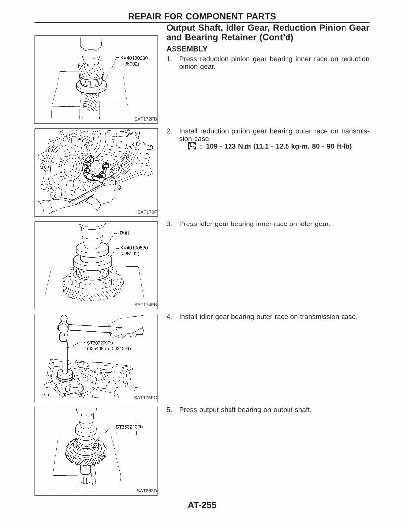
SAT172FB
ASSEMBLY1. Press reduction pinion gear bearing inner race on reduction
pinion gear.
SAT170F
2. Install reduction pinion gear bearing outer race on transmis-sion case.
: 109 - 123 N⋅m (11.1 - 12.5 kg-m, 80 - 90 ft-lb)
SAT174FB
3. Press idler gear bearing inner race on idler gear.
SAT175FC
4. Install idler gear bearing outer race on transmission case.
SAT863D
5. Press output shaft bearing on output shaft.
REPAIR FOR COMPONENT PARTSOutput Shaft, Idler Gear, Reduction Pinion Gearand Bearing Retainer (Cont’d)
AT-255
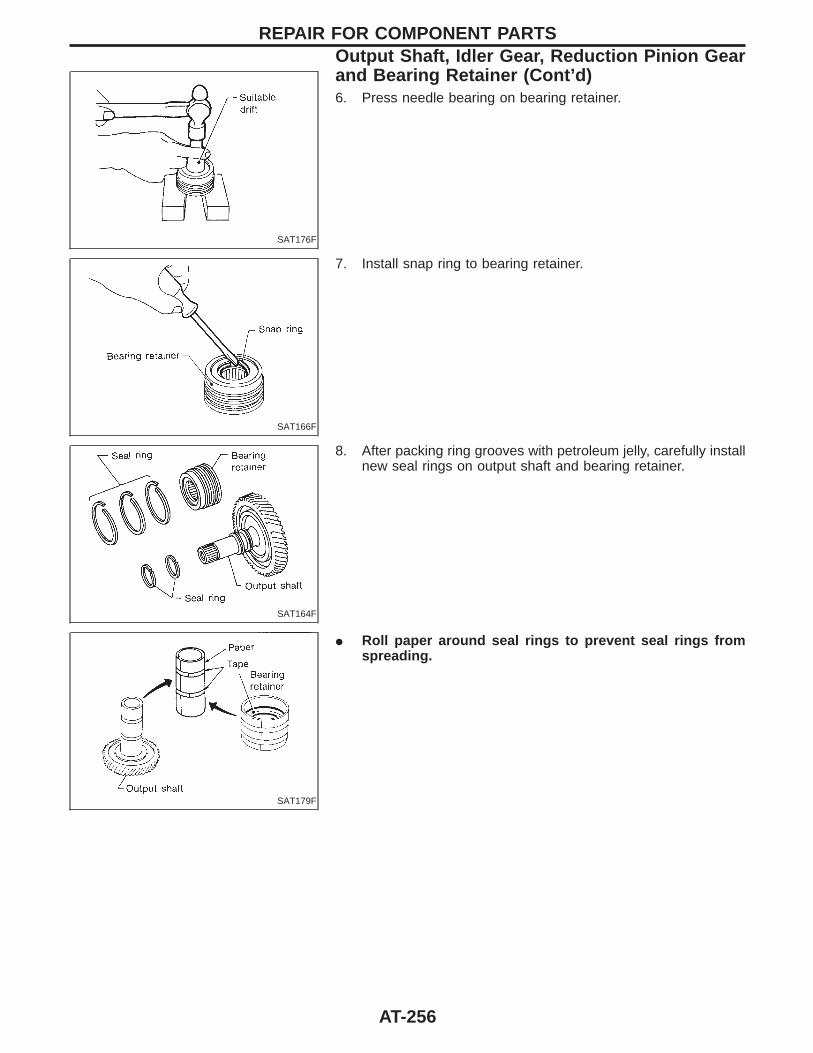
SAT176F
6. Press needle bearing on bearing retainer.
SAT166F
7. Install snap ring to bearing retainer.
SAT164F
8. After packing ring grooves with petroleum jelly, carefully installnew seal rings on output shaft and bearing retainer.
SAT179F
I Roll paper around seal rings to prevent seal rings fromspreading.
REPAIR FOR COMPONENT PARTSOutput Shaft, Idler Gear, Reduction Pinion Gearand Bearing Retainer (Cont’d)
AT-256
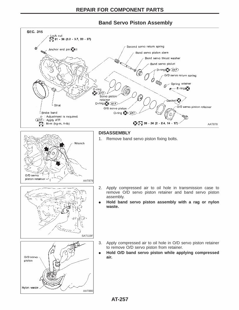
Band Servo Piston Assembly
AAT878
AAT879
DISASSEMBLY1. Remove band servo piston fixing bolts.
SAT119F
2. Apply compressed air to oil hole in transmission case toremove O/D servo piston retainer and band servo pistonassembly.
I Hold band servo piston assembly with a rag or nylonwaste.
AAT880
3. Apply compressed air to oil hole in O/D servo piston retainerto remove O/D servo piston from retainer.
I Hold O/D band servo piston while applying compressedair.
REPAIR FOR COMPONENT PARTS
AT-257
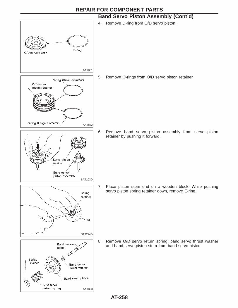
AAT881
4. Remove D-ring from O/D servo piston.
AAT882
5. Remove O-rings from O/D servo piston retainer.
SAT293D
6. Remove band servo piston assembly from servo pistonretainer by pushing it forward.
SAT294D
7. Place piston stem end on a wooden block. While pushingservo piston spring retainer down, remove E-ring.
AAT883
8. Remove O/D servo return spring, band servo thrust washerand band servo piston stem from band servo piston.
REPAIR FOR COMPONENT PARTSBand Servo Piston Assembly (Cont’d)
AT-258
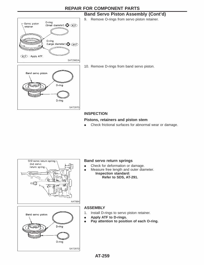
SAT296DA
9. Remove O-rings from servo piston retainer.
SAT297D
10. Remove D-rings from band servo piston.
INSPECTION
Pistons, retainers and piston stemI Check frictional surfaces for abnormal wear or damage.
AAT884
Band servo return springsI Check for deformation or damage.I Measure free length and outer diameter.
Inspection standard:Refer to SDS, AT-291.
SAT297D
ASSEMBLY1. Install D-rings to servo piston retainer.I Apply ATF to D-rings.I Pay attention to position of each O-ring.
REPAIR FOR COMPONENT PARTSBand Servo Piston Assembly (Cont’d)
AT-259
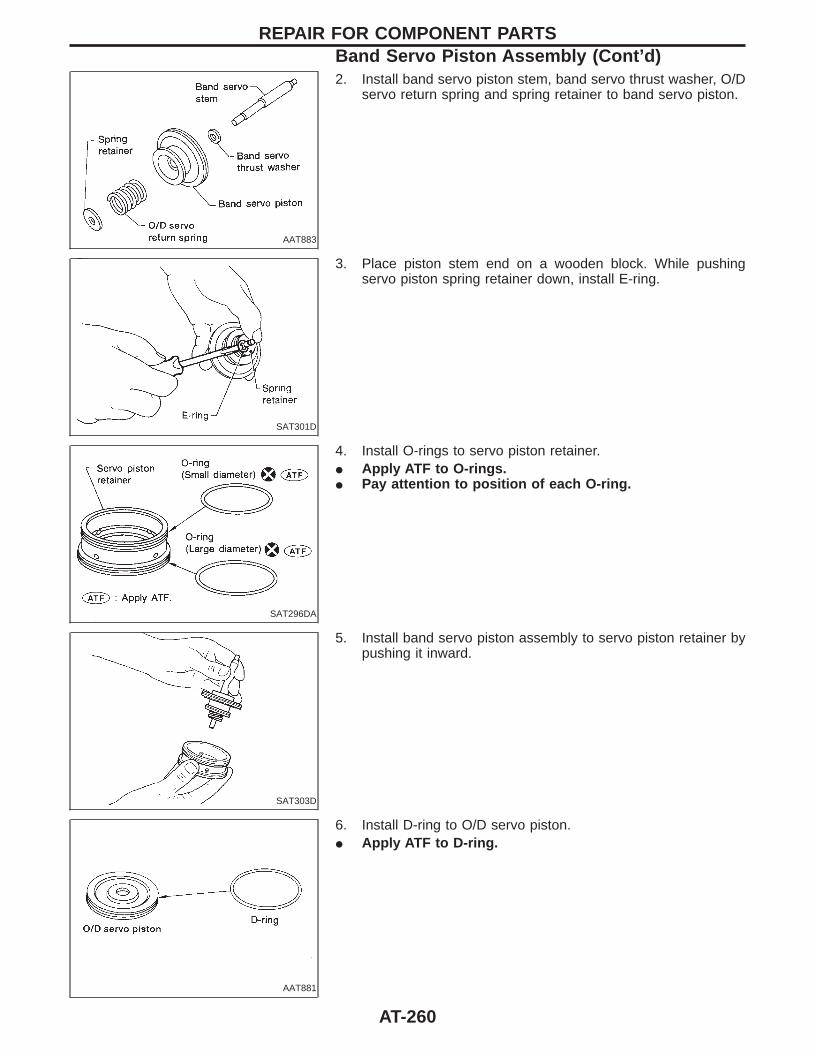
AAT883
2. Install band servo piston stem, band servo thrust washer, O/Dservo return spring and spring retainer to band servo piston.
SAT301D
3. Place piston stem end on a wooden block. While pushingservo piston spring retainer down, install E-ring.
SAT296DA
4. Install O-rings to servo piston retainer.I Apply ATF to O-rings.I Pay attention to position of each O-ring.
SAT303D
5. Install band servo piston assembly to servo piston retainer bypushing it inward.
AAT881
6. Install D-ring to O/D servo piston.I Apply ATF to D-ring.
REPAIR FOR COMPONENT PARTSBand Servo Piston Assembly (Cont’d)
AT-260
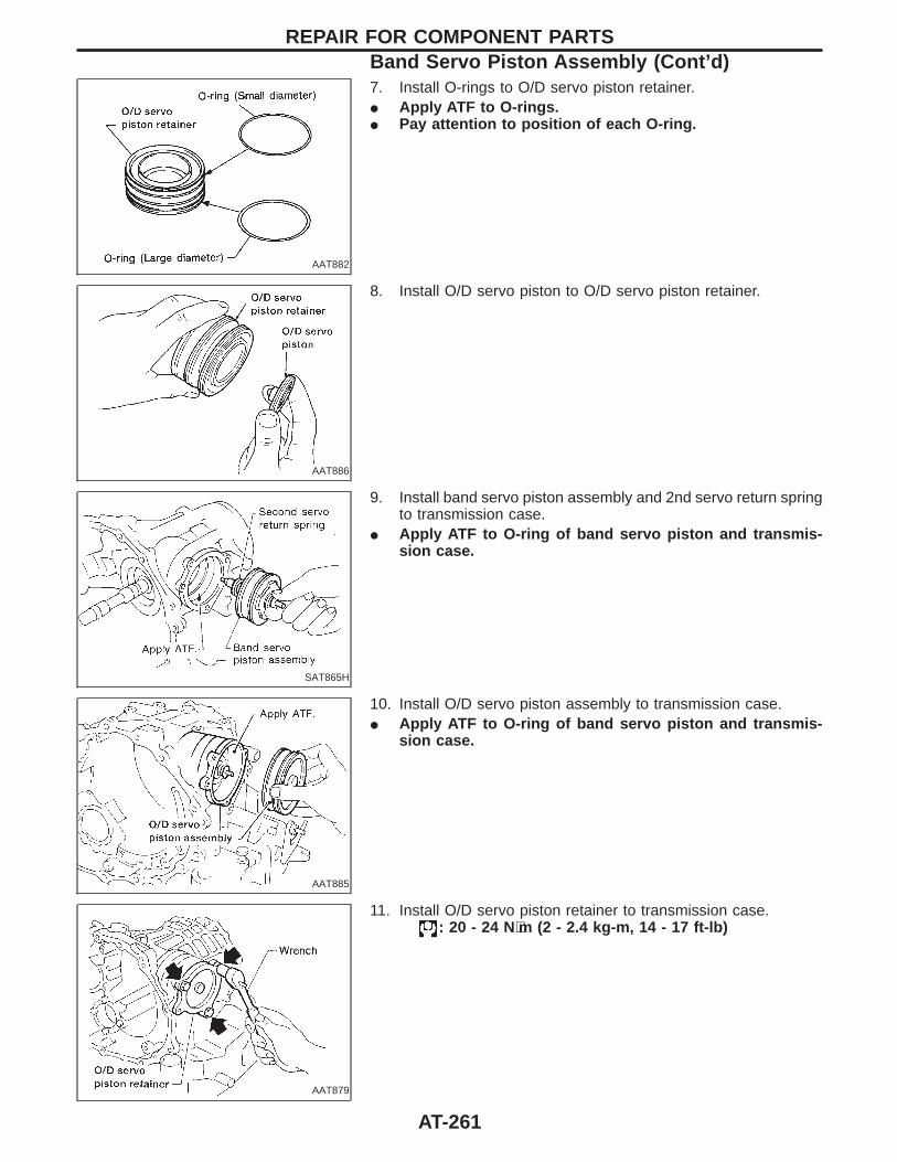
AAT882
7. Install O-rings to O/D servo piston retainer.I Apply ATF to O-rings.I Pay attention to position of each O-ring.
AAT886
8. Install O/D servo piston to O/D servo piston retainer.
SAT865H
9. Install band servo piston assembly and 2nd servo return springto transmission case.
I Apply ATF to O-ring of band servo piston and transmis-sion case.
AAT885
10. Install O/D servo piston assembly to transmission case.I Apply ATF to O-ring of band servo piston and transmis-
sion case.
AAT879
11. Install O/D servo piston retainer to transmission case.: 20 - 24 N⋅m (2 - 2.4 kg-m, 14 - 17 ft-lb)
REPAIR FOR COMPONENT PARTSBand Servo Piston Assembly (Cont’d)
AT-261
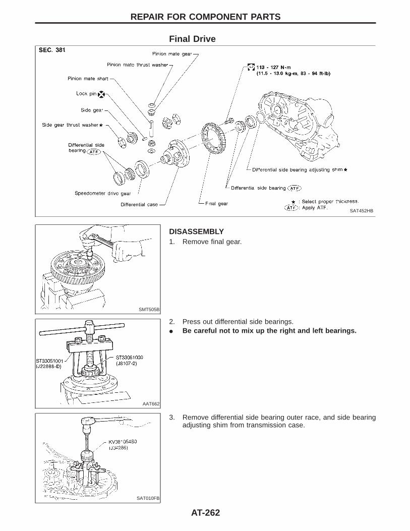
Final Drive
SAT452HB
SMT505B
DISASSEMBLY1. Remove final gear.
AAT662
2. Press out differential side bearings.I Be careful not to mix up the right and left bearings.
SAT010FB
3. Remove differential side bearing outer race, and side bearingadjusting shim from transmission case.
REPAIR FOR COMPONENT PARTS
AT-262

SAT313D
4. Remove speedometer drive gear.
SAT904D
5. Drive out pinion mate shaft lock pin.
SAT316D
6. Draw out pinion mate shaft lock pin.7. Remove pinion mate gears and side gears.
SAT544F
INSPECTION
Gears, washers, shaft and caseI Check mating surfaces of differential case, side gears and
pinion mate gears.I Check washers for wear.
SPD715
BearingsI Make sure bearings roll freely and are free from noise, cracks,
pitting or wear.I When replacing taper roller bearing, replace outer and
inner race as a set.
REPAIR FOR COMPONENT PARTSFinal Drive (Cont’d)
AT-263
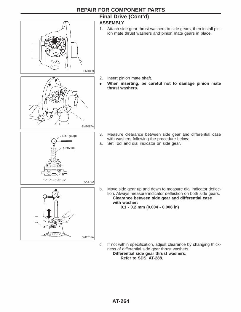
SMT839
ASSEMBLY1. Attach side gear thrust washers to side gears, then install pin-
ion mate thrust washers and pinion mate gears in place.
SMT087A
2. Insert pinion mate shaft.I When inserting, be careful not to damage pinion mate
thrust washers.
AAT782
3. Measure clearance between side gear and differential casewith washers following the procedure below:
a. Set Tool and dial indicator on side gear.
SMT611A
b. Move side gear up and down to measure dial indicator deflec-tion. Always measure indicator deflection on both side gears.
Clearance between side gear and differential casewith washer:
0.1 - 0.2 mm (0.004 - 0.008 in)
c. If not within specification, adjust clearance by changing thick-ness of differential side gear thrust washers.
Differential side gear thrust washers:Refer to SDS, AT-288.
REPAIR FOR COMPONENT PARTSFinal Drive (Cont’d)
AT-264
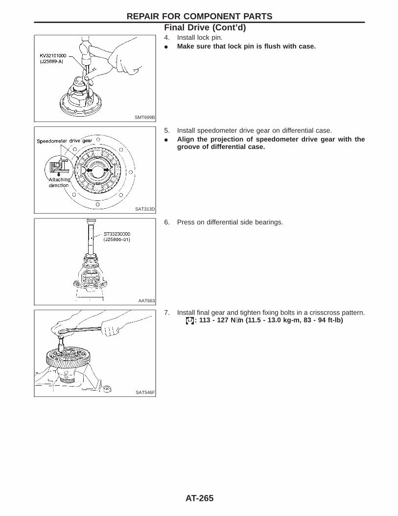
SMT699B
4. Install lock pin.I Make sure that lock pin is flush with case.
SAT313D
5. Install speedometer drive gear on differential case.I Align the projection of speedometer drive gear with the
groove of differential case.
AAT663
6. Press on differential side bearings.
SAT546F
7. Install final gear and tighten fixing bolts in a crisscross pattern.: 113 - 127 N⋅m (11.5 - 13.0 kg-m, 83 - 94 ft-lb)
REPAIR FOR COMPONENT PARTSFinal Drive (Cont’d)
AT-265
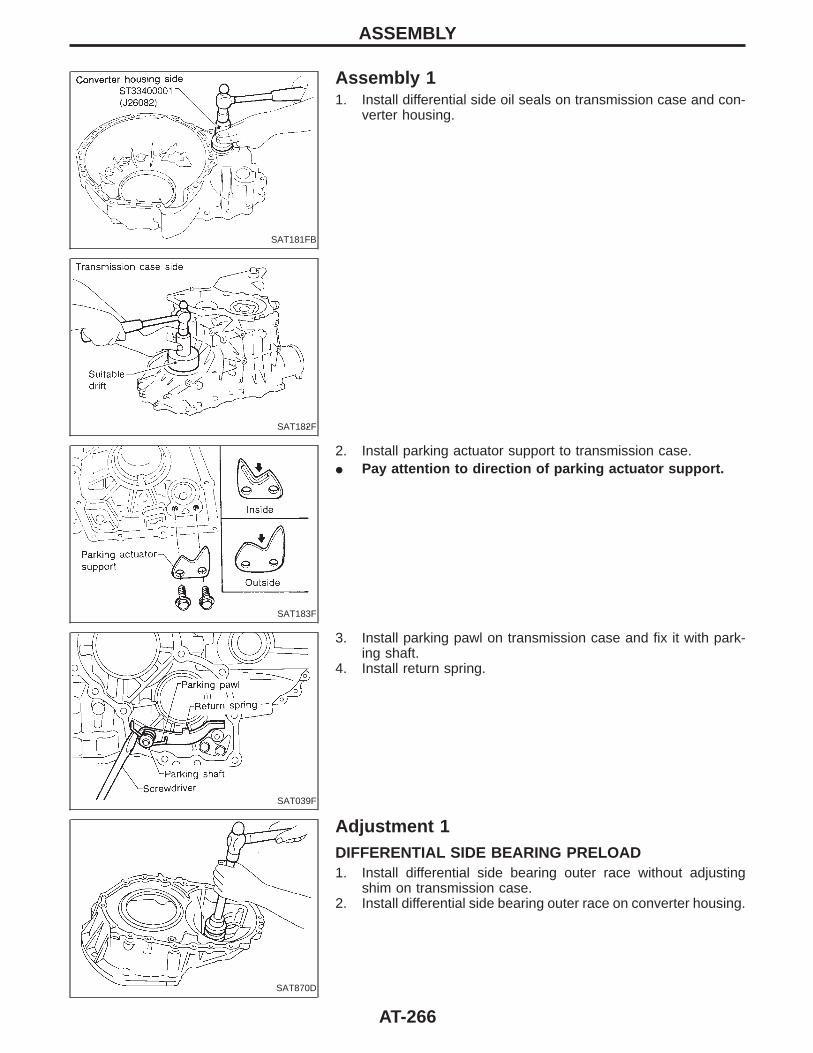
SAT181FB
Assembly 11. Install differential side oil seals on transmission case and con-
verter housing.
SAT182F
SAT183F
2. Install parking actuator support to transmission case.I Pay attention to direction of parking actuator support.
SAT039F
3. Install parking pawl on transmission case and fix it with park-ing shaft.
4. Install return spring.
SAT870D
Adjustment 1DIFFERENTIAL SIDE BEARING PRELOAD1. Install differential side bearing outer race without adjusting
shim on transmission case.2. Install differential side bearing outer race on converter housing.
ASSEMBLY
AT-266
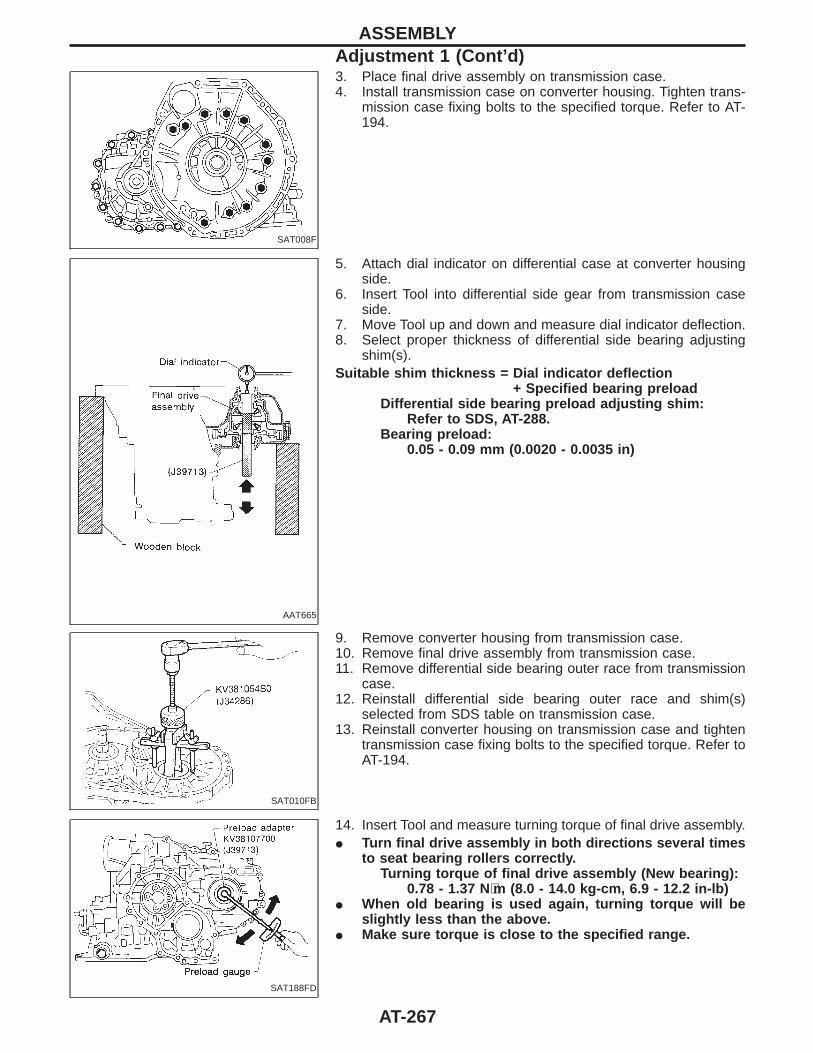
SAT008F
3. Place final drive assembly on transmission case.4. Install transmission case on converter housing. Tighten trans-
mission case fixing bolts to the specified torque. Refer to AT-194.
AAT665
5. Attach dial indicator on differential case at converter housingside.
6. Insert Tool into differential side gear from transmission caseside.
7. Move Tool up and down and measure dial indicator deflection.8. Select proper thickness of differential side bearing adjusting
shim(s).Suitable shim thickness = Dial indicator deflection
+ Specified bearing preloadDifferential side bearing preload adjusting shim:
Refer to SDS, AT-288.Bearing preload:
0.05 - 0.09 mm (0.0020 - 0.0035 in)
SAT010FB
9. Remove converter housing from transmission case.10. Remove final drive assembly from transmission case.11. Remove differential side bearing outer race from transmission
case.12. Reinstall differential side bearing outer race and shim(s)
selected from SDS table on transmission case.13. Reinstall converter housing on transmission case and tighten
transmission case fixing bolts to the specified torque. Refer toAT-194.
SAT188FD
14. Insert Tool and measure turning torque of final drive assembly.I Turn final drive assembly in both directions several times
to seat bearing rollers correctly.Turning torque of final drive assembly (New bearing):
0.78 - 1.37 N⋅m (8.0 - 14.0 kg-cm, 6.9 - 12.2 in-lb)I When old bearing is used again, turning torque will be
slightly less than the above.I Make sure torque is close to the specified range.
ASSEMBLYAdjustment 1 (Cont’d)
AT-267
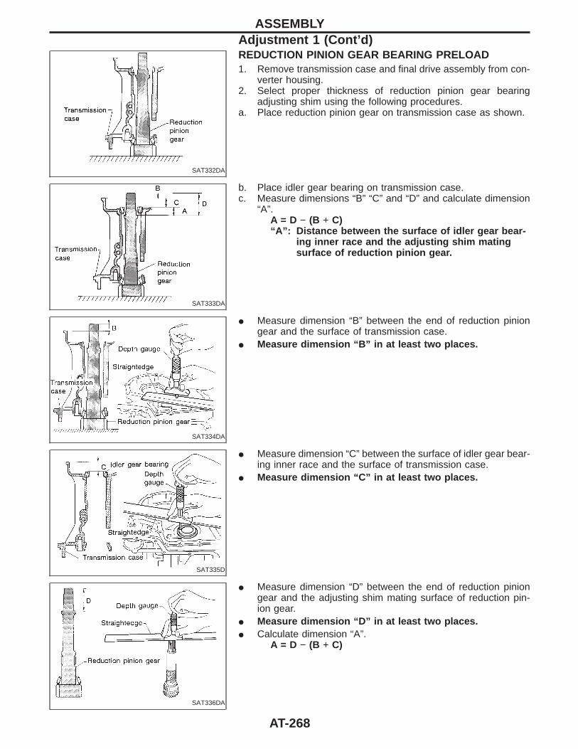
SAT332DA
REDUCTION PINION GEAR BEARING PRELOAD1. Remove transmission case and final drive assembly from con-
verter housing.2. Select proper thickness of reduction pinion gear bearing
adjusting shim using the following procedures.a. Place reduction pinion gear on transmission case as shown.
SAT333DA
b. Place idler gear bearing on transmission case.c. Measure dimensions “B” “C” and “D” and calculate dimension
“A”.A = D − (B + C)“A”: Distance between the surface of idler gear bear-
ing inner race and the adjusting shim matingsurface of reduction pinion gear.
SAT334DA
I Measure dimension “B” between the end of reduction piniongear and the surface of transmission case.
I Measure dimension “B” in at least two places.
SAT335D
I Measure dimension “C” between the surface of idler gear bear-ing inner race and the surface of transmission case.
I Measure dimension “C” in at least two places.
SAT336DA
I Measure dimension “D” between the end of reduction piniongear and the adjusting shim mating surface of reduction pin-ion gear.
I Measure dimension “D” in at least two places.I Calculate dimension “A”.
A = D − (B + C)
ASSEMBLYAdjustment 1 (Cont’d)
AT-268
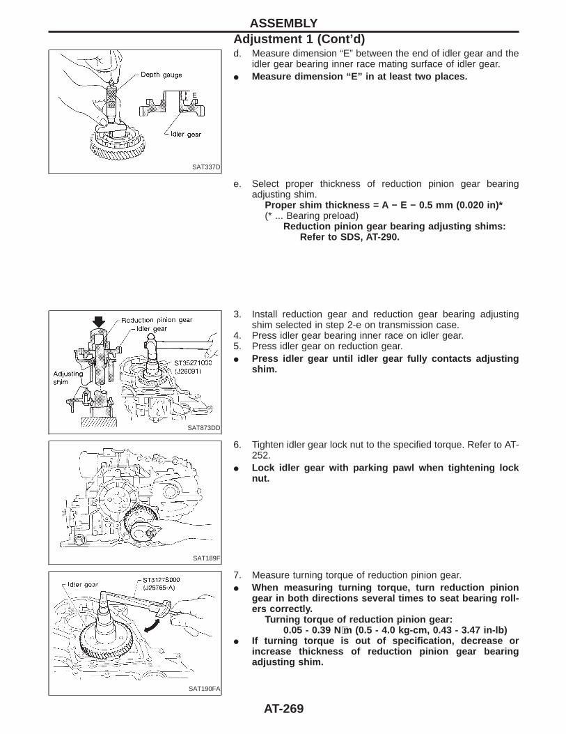
SAT337D
d. Measure dimension “E” between the end of idler gear and theidler gear bearing inner race mating surface of idler gear.
I Measure dimension “E” in at least two places.
e. Select proper thickness of reduction pinion gear bearingadjusting shim.
Proper shim thickness = A − E − 0.5 mm (0.020 in)*(* ... Bearing preload)
Reduction pinion gear bearing adjusting shims:Refer to SDS, AT-290.
SAT873DD
3. Install reduction gear and reduction gear bearing adjustingshim selected in step 2-e on transmission case.
4. Press idler gear bearing inner race on idler gear.5. Press idler gear on reduction gear.I Press idler gear until idler gear fully contacts adjusting
shim.
SAT189F
6. Tighten idler gear lock nut to the specified torque. Refer to AT-252.
I Lock idler gear with parking pawl when tightening locknut.
SAT190FA
7. Measure turning torque of reduction pinion gear.I When measuring turning torque, turn reduction pinion
gear in both directions several times to seat bearing roll-ers correctly.
Turning torque of reduction pinion gear:0.05 - 0.39 N⋅m (0.5 - 4.0 kg-cm, 0.43 - 3.47 in-lb)
I If turning torque is out of specification, decrease orincrease thickness of reduction pinion gear bearingadjusting shim.
ASSEMBLYAdjustment 1 (Cont’d)
AT-269
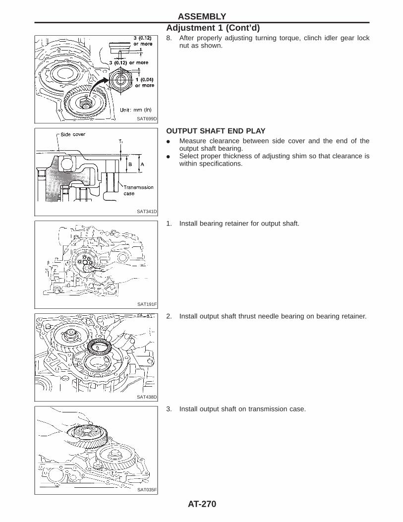
SAT699D
8. After properly adjusting turning torque, clinch idler gear locknut as shown.
SAT341D
OUTPUT SHAFT END PLAYI Measure clearance between side cover and the end of the
output shaft bearing.I Select proper thickness of adjusting shim so that clearance is
within specifications.
SAT191F
1. Install bearing retainer for output shaft.
SAT438D
2. Install output shaft thrust needle bearing on bearing retainer.
SAT035F
3. Install output shaft on transmission case.
ASSEMBLYAdjustment 1 (Cont’d)
AT-270
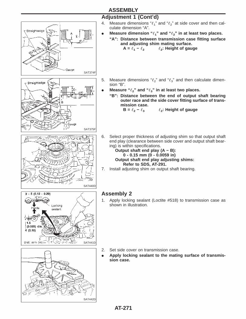
SAT374F
4. Measure dimensions “1” and “2” at side cover and then cal-culate dimension “A”.
I Measure dimension “ 1” and “ 2” in at least two places.“A”: Distance between transmission case fitting surface
and adjusting shim mating surface.A = 1 − 2 2: Height of gauge
SAT375F
5. Measure dimensions “2” and “3” and then calculate dimen-sion “B”.
I Measure “ 2” and “ 3” in at least two places.“B”: Distance between the end of output shaft bearing
outer race and the side cover fitting surface of trans-mission case.
B = 2 − 3 2: Height of gauge
SAT440D
6. Select proper thickness of adjusting shim so that output shaftend play (clearance between side cover and output shaft bear-ing) is within specifications.
Output shaft end play (A − B):0 - 0.15 mm (0 - 0.0059 in)
Output shaft end play adjusting shims:Refer to SDS, AT-291.
7. Install adjusting shim on output shaft bearing.
SAT441D
Assembly 21. Apply locking sealant (Loctite #518) to transmission case as
shown in illustration.
SAT442D
2. Set side cover on transmission case.I Apply locking sealant to the mating surface of transmis-
sion case.
ASSEMBLYAdjustment 1 (Cont’d)
AT-271
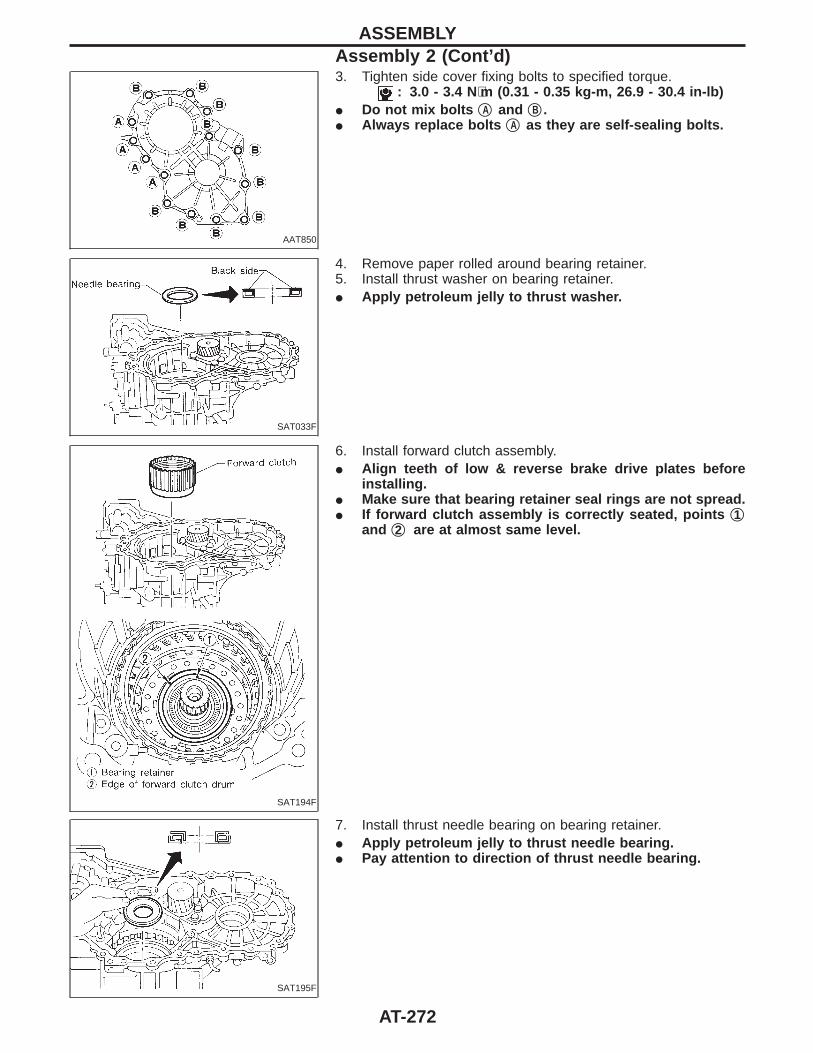
AAT850
3. Tighten side cover fixing bolts to specified torque.: 3.0 - 3.4 N⋅m (0.31 - 0.35 kg-m, 26.9 - 30.4 in-lb)
I Do not mix bolts qA and qB .I Always replace bolts qA as they are self-sealing bolts.
SAT033F
4. Remove paper rolled around bearing retainer.5. Install thrust washer on bearing retainer.I Apply petroleum jelly to thrust washer.
SAT194F
6. Install forward clutch assembly.I Align teeth of low & reverse brake drive plates before
installing.I Make sure that bearing retainer seal rings are not spread.I If forward clutch assembly is correctly seated, points q1
and q2 are at almost same level.
SAT195F
7. Install thrust needle bearing on bearing retainer.I Apply petroleum jelly to thrust needle bearing.I Pay attention to direction of thrust needle bearing.
ASSEMBLYAssembly 2 (Cont’d)
AT-272
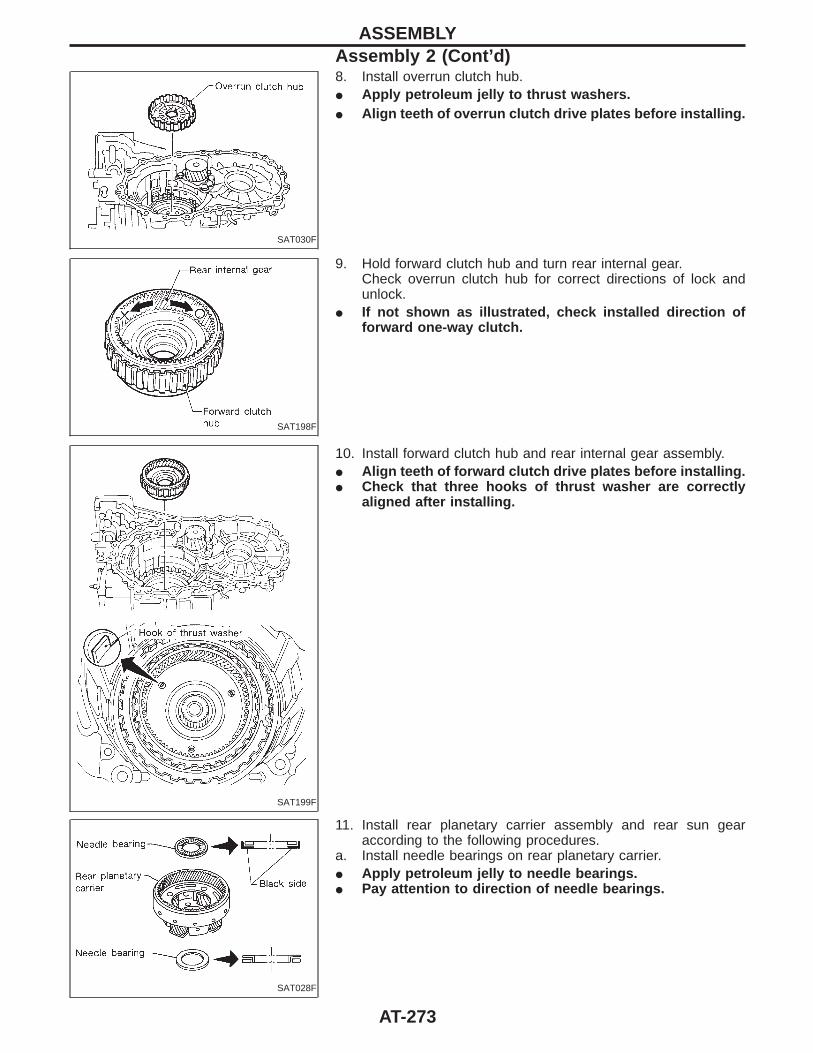
SAT030F
8. Install overrun clutch hub.I Apply petroleum jelly to thrust washers.I Align teeth of overrun clutch drive plates before installing.
SAT198F
9. Hold forward clutch hub and turn rear internal gear.Check overrun clutch hub for correct directions of lock andunlock.
I If not shown as illustrated, check installed direction offorward one-way clutch.
SAT199F
10. Install forward clutch hub and rear internal gear assembly.I Align teeth of forward clutch drive plates before installing.I Check that three hooks of thrust washer are correctly
aligned after installing.
SAT028F
11. Install rear planetary carrier assembly and rear sun gearaccording to the following procedures.
a. Install needle bearings on rear planetary carrier.I Apply petroleum jelly to needle bearings.I Pay attention to direction of needle bearings.
ASSEMBLYAssembly 2 (Cont’d)
AT-273
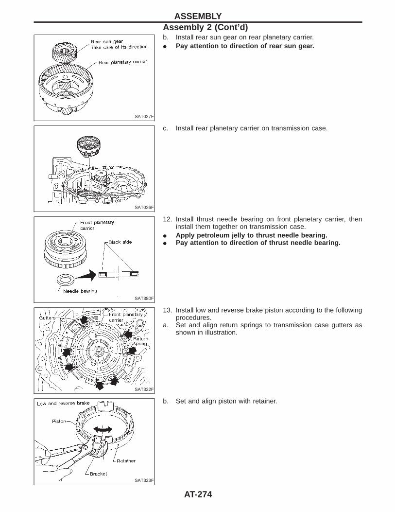
SAT027F
b. Install rear sun gear on rear planetary carrier.I Pay attention to direction of rear sun gear.
SAT026F
c. Install rear planetary carrier on transmission case.
SAT380F
12. Install thrust needle bearing on front planetary carrier, theninstall them together on transmission case.
I Apply petroleum jelly to thrust needle bearing.I Pay attention to direction of thrust needle bearing.
SAT322F
13. Install low and reverse brake piston according to the followingprocedures.
a. Set and align return springs to transmission case gutters asshown in illustration.
SAT323F
b. Set and align piston with retainer.
ASSEMBLYAssembly 2 (Cont’d)
AT-274
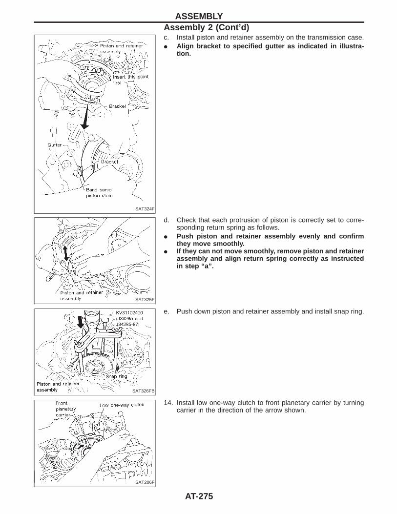
SAT324F
c. Install piston and retainer assembly on the transmission case.I Align bracket to specified gutter as indicated in illustra-
tion.
SAT325F
d. Check that each protrusion of piston is correctly set to corre-sponding return spring as follows.
I Push piston and retainer assembly evenly and confirmthey move smoothly.
I If they can not move smoothly, remove piston and retainerassembly and align return spring correctly as instructedin step “a”.
SAT326FB
e. Push down piston and retainer assembly and install snap ring.
SAT206F
14. Install low one-way clutch to front planetary carrier by turningcarrier in the direction of the arrow shown.
ASSEMBLYAssembly 2 (Cont’d)
AT-275
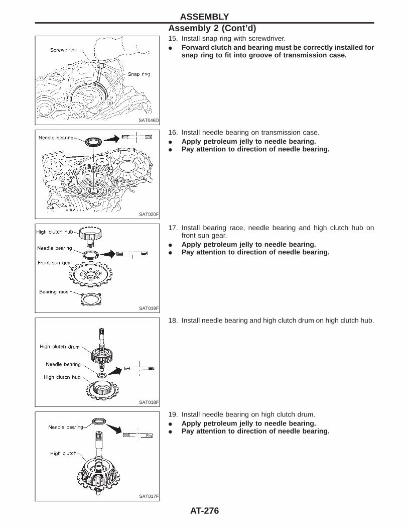
SAT046D
15. Install snap ring with screwdriver.I Forward clutch and bearing must be correctly installed for
snap ring to fit into groove of transmission case.
SAT020F
16. Install needle bearing on transmission case.I Apply petroleum jelly to needle bearing.I Pay attention to direction of needle bearing.
SAT019F
17. Install bearing race, needle bearing and high clutch hub onfront sun gear.
I Apply petroleum jelly to needle bearing.I Pay attention to direction of needle bearing.
SAT018F
18. Install needle bearing and high clutch drum on high clutch hub.
SAT017F
19. Install needle bearing on high clutch drum.I Apply petroleum jelly to needle bearing.I Pay attention to direction of needle bearing.
ASSEMBLYAssembly 2 (Cont’d)
AT-276
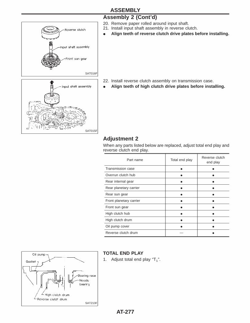
SAT016F
20. Remove paper rolled around input shaft.21. Install input shaft assembly in reverse clutch.I Align teeth of reverse clutch drive plates before installing.
SAT015F
22. Install reverse clutch assembly on transmission case.I Align teeth of high clutch drive plates before installing.
Adjustment 2When any parts listed below are replaced, adjust total end play andreverse clutch end play.
Part name Total end playReverse clutch
end play
Transmission case I I
Overrun clutch hub I I
Rear internal gear I I
Rear planetary carrier I I
Rear sun gear I I
Front planetary carrier I I
Front sun gear I I
High clutch hub I I
High clutch drum I I
Oil pump cover I I
Reverse clutch drum — I
SAT213F
TOTAL END PLAY1. Adjust total end play “T1”.
ASSEMBLYAssembly 2 (Cont’d)
AT-277
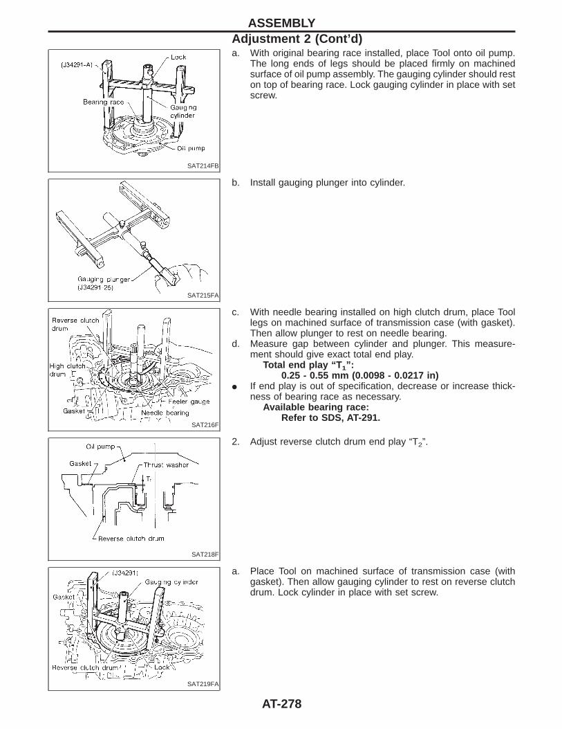
SAT214FB
a. With original bearing race installed, place Tool onto oil pump.The long ends of legs should be placed firmly on machinedsurface of oil pump assembly. The gauging cylinder should reston top of bearing race. Lock gauging cylinder in place with setscrew.
SAT215FA
b. Install gauging plunger into cylinder.
SAT216F
c. With needle bearing installed on high clutch drum, place Toollegs on machined surface of transmission case (with gasket).Then allow plunger to rest on needle bearing.
d. Measure gap between cylinder and plunger. This measure-ment should give exact total end play.
Total end play “T 1”:0.25 - 0.55 mm (0.0098 - 0.0217 in)
I If end play is out of specification, decrease or increase thick-ness of bearing race as necessary.
Available bearing race:Refer to SDS, AT-291.
SAT218F
2. Adjust reverse clutch drum end play “T2”.
SAT219FA
a. Place Tool on machined surface of transmission case (withgasket). Then allow gauging cylinder to rest on reverse clutchdrum. Lock cylinder in place with set screw.
ASSEMBLYAdjustment 2 (Cont’d)
AT-278
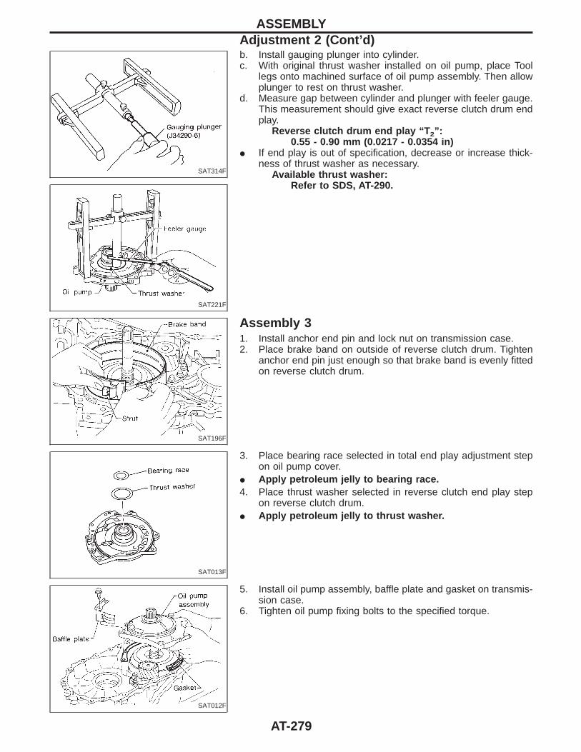
SAT314F
SAT221F
b. Install gauging plunger into cylinder.c. With original thrust washer installed on oil pump, place Tool
legs onto machined surface of oil pump assembly. Then allowplunger to rest on thrust washer.
d. Measure gap between cylinder and plunger with feeler gauge.This measurement should give exact reverse clutch drum endplay.
Reverse clutch drum end play “T 2”:0.55 - 0.90 mm (0.0217 - 0.0354 in)
I If end play is out of specification, decrease or increase thick-ness of thrust washer as necessary.
Available thrust washer:Refer to SDS, AT-290.
SAT196F
Assembly 31. Install anchor end pin and lock nut on transmission case.2. Place brake band on outside of reverse clutch drum. Tighten
anchor end pin just enough so that brake band is evenly fittedon reverse clutch drum.
SAT013F
3. Place bearing race selected in total end play adjustment stepon oil pump cover.
I Apply petroleum jelly to bearing race.4. Place thrust washer selected in reverse clutch end play step
on reverse clutch drum.I Apply petroleum jelly to thrust washer.
SAT012F
5. Install oil pump assembly, baffle plate and gasket on transmis-sion case.
6. Tighten oil pump fixing bolts to the specified torque.
ASSEMBLYAdjustment 2 (Cont’d)
AT-279
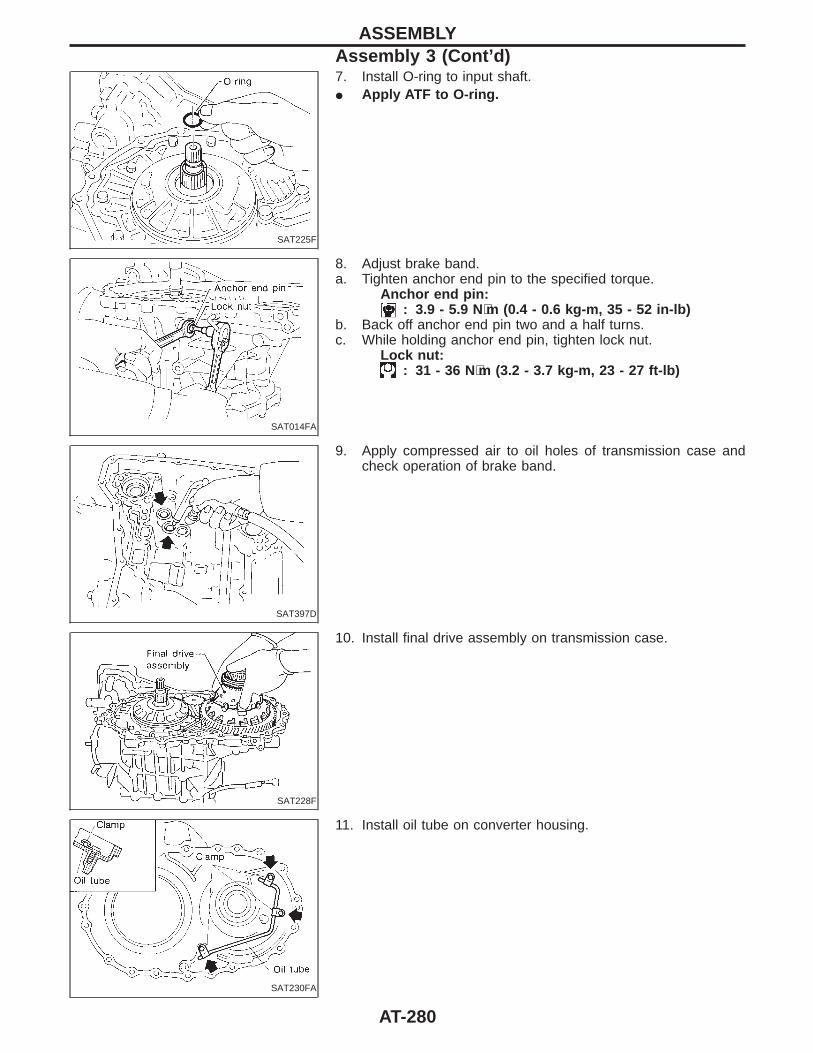
SAT225F
7. Install O-ring to input shaft.I Apply ATF to O-ring.
SAT014FA
8. Adjust brake band.a. Tighten anchor end pin to the specified torque.
Anchor end pin:: 3.9 - 5.9 N⋅m (0.4 - 0.6 kg-m, 35 - 52 in-lb)
b. Back off anchor end pin two and a half turns.c. While holding anchor end pin, tighten lock nut.
Lock nut:: 31 - 36 N⋅m (3.2 - 3.7 kg-m, 23 - 27 ft-lb)
SAT397D
9. Apply compressed air to oil holes of transmission case andcheck operation of brake band.
SAT228F
10. Install final drive assembly on transmission case.
SAT230FA
11. Install oil tube on converter housing.
ASSEMBLYAssembly 3 (Cont’d)
AT-280
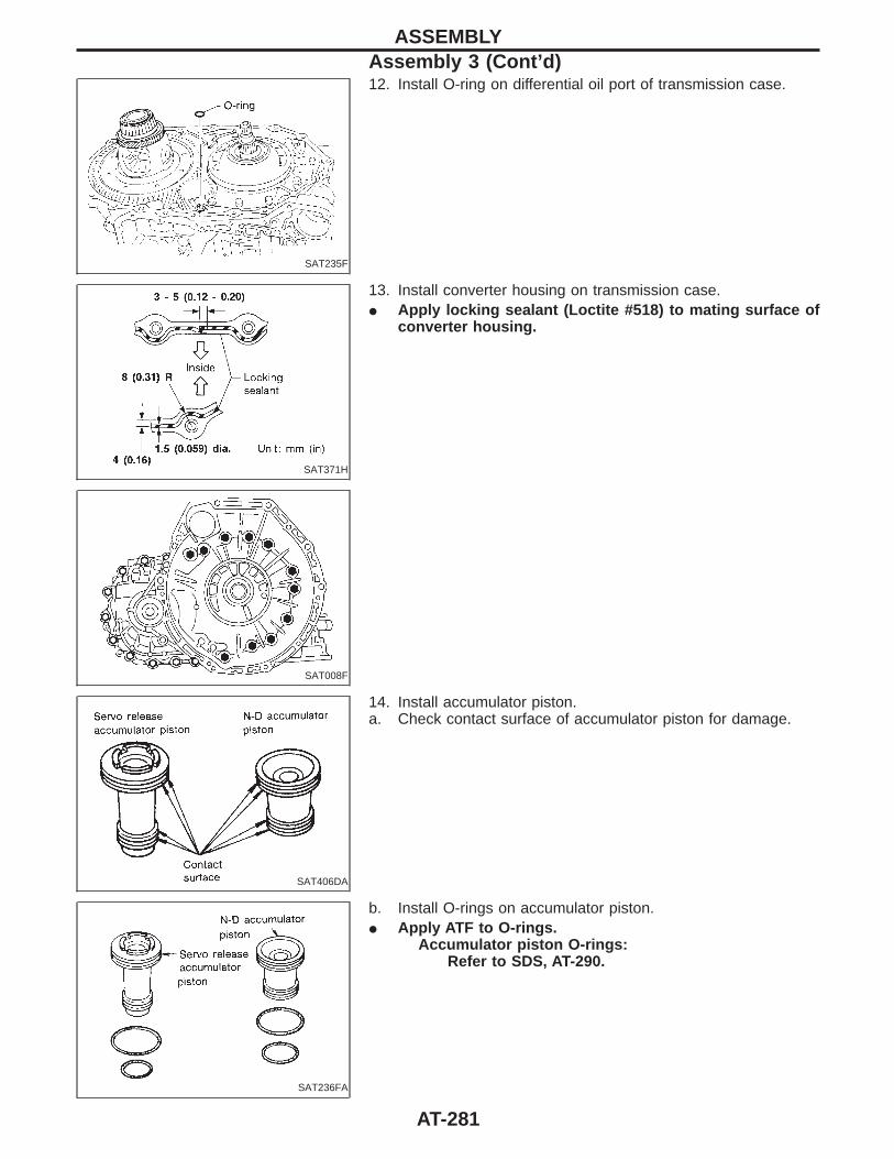
SAT235F
12. Install O-ring on differential oil port of transmission case.
SAT371H
13. Install converter housing on transmission case.I Apply locking sealant (Loctite #518) to mating surface of
converter housing.
SAT008F
SAT406DA
14. Install accumulator piston.a. Check contact surface of accumulator piston for damage.
SAT236FA
b. Install O-rings on accumulator piston.I Apply ATF to O-rings.
Accumulator piston O-rings:Refer to SDS, AT-290.
ASSEMBLYAssembly 3 (Cont’d)
AT-281
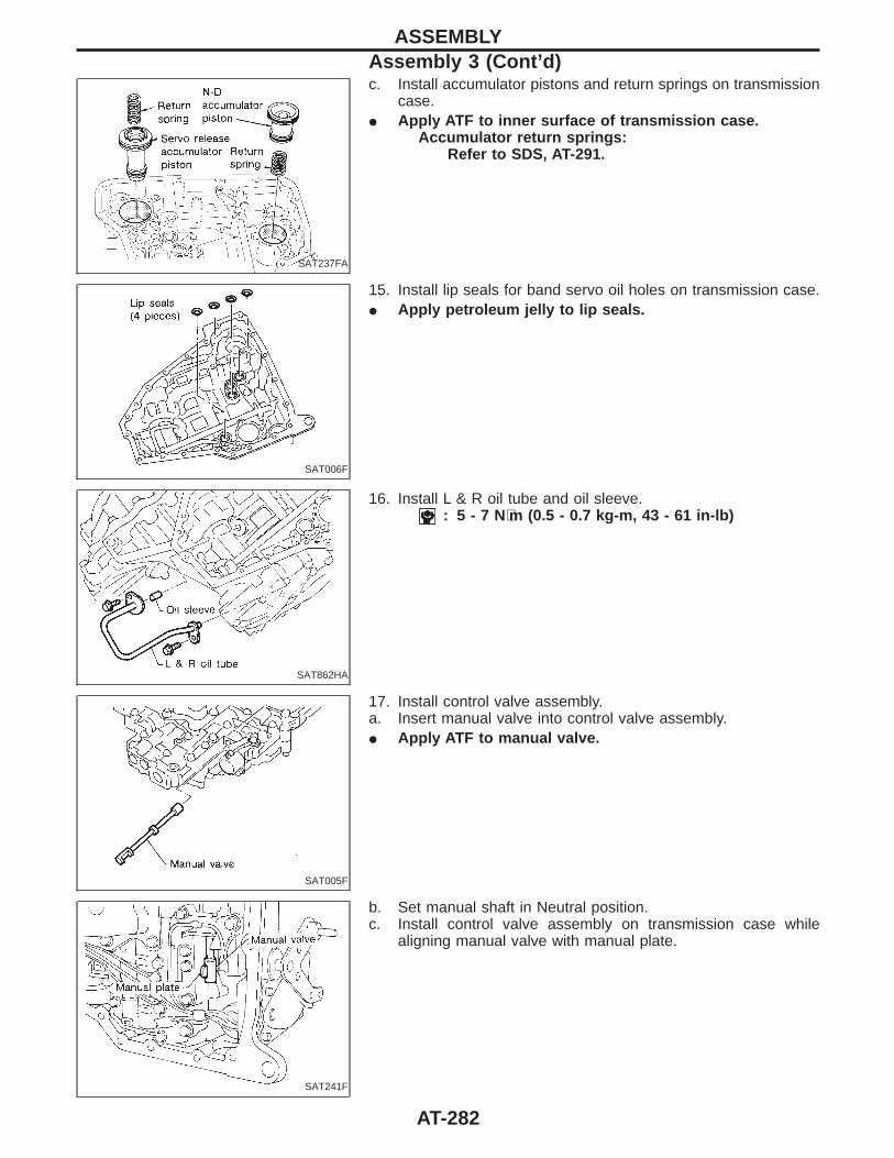
SAT237FA
c. Install accumulator pistons and return springs on transmissioncase.
I Apply ATF to inner surface of transmission case.Accumulator return springs:
Refer to SDS, AT-291.
SAT006F
15. Install lip seals for band servo oil holes on transmission case.I Apply petroleum jelly to lip seals.
SAT862HA
16. Install L & R oil tube and oil sleeve.: 5 - 7 N⋅m (0.5 - 0.7 kg-m, 43 - 61 in-lb)
SAT005F
17. Install control valve assembly.a. Insert manual valve into control valve assembly.I Apply ATF to manual valve.
SAT241F
b. Set manual shaft in Neutral position.c. Install control valve assembly on transmission case while
aligning manual valve with manual plate.
ASSEMBLYAssembly 3 (Cont’d)
AT-282
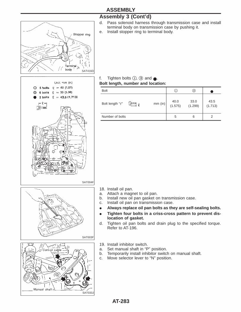
SAT416D
d. Pass solenoid harness through transmission case and installterminal body on transmission case by pushing it.
e. Install stopper ring to terminal body.
SAT004F
f. Tighten bolts qI , qX and I.Bolt length, number and location:
Bolt qI qX I
Bolt length “” mm (in)40.0
(1.575)33.0
(1.299)43.5
(1.713)
Number of bolts 5 6 2
SAT003F
18. Install oil pan.a. Attach a magnet to oil pan.b. Install new oil pan gasket on transmission case.c. Install oil pan on transmission case.I Always replace oil pan bolts as they are self-sealing bolts.I Tighten four bolts in a criss-cross pattern to prevent dis-
location of gasket.d. Tighten oil pan bolts and drain plug to the specified torque.
Refer to AT-196.
SAT033J
19. Install inhibitor switch.a. Set manual shaft in “P” position.b. Temporarily install inhibitor switch on manual shaft.c. Move selector lever to “N” position.
ASSEMBLYAssembly 3 (Cont’d)
AT-283
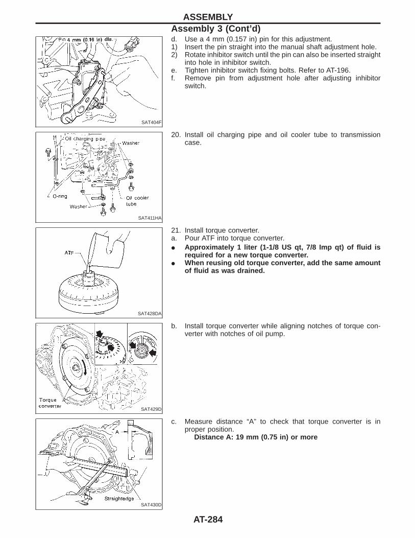
SAT404F
d. Use a 4 mm (0.157 in) pin for this adjustment.1) Insert the pin straight into the manual shaft adjustment hole.2) Rotate inhibitor switch until the pin can also be inserted straight
into hole in inhibitor switch.e. Tighten inhibitor switch fixing bolts. Refer to AT-196.f. Remove pin from adjustment hole after adjusting inhibitor
switch.
SAT411HA
20. Install oil charging pipe and oil cooler tube to transmissioncase.
SAT428DA
21. Install torque converter.a. Pour ATF into torque converter.I Approximately 1 liter (1-1/8 US qt, 7/8 Imp qt) of fluid is
required for a new torque converter.I When reusing old torque converter, add the same amount
of fluid as was drained.
SAT429D
b. Install torque converter while aligning notches of torque con-verter with notches of oil pump.
SAT430D
c. Measure distance “A” to check that torque converter is inproper position.
Distance A: 19 mm (0.75 in) or more
ASSEMBLYAssembly 3 (Cont’d)
AT-284
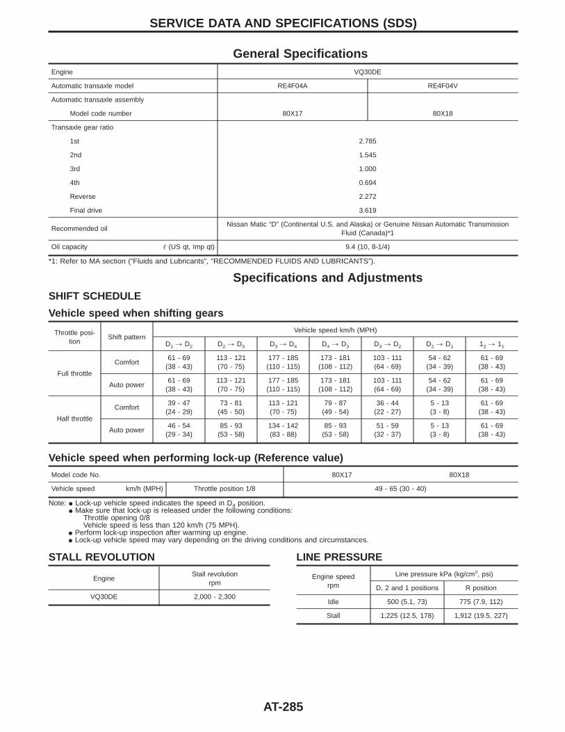
General SpecificationsEngine VQ30DE
Automatic transaxle model RE4F04A RE4F04V
Automatic transaxle assembly
Model code number 80X17 80X18
Transaxle gear ratio
1st 2.785
2nd 1.545
3rd 1.000
4th 0.694
Reverse 2.272
Final drive 3.619
Recommended oilNissan Matic “D” (Continental U.S. and Alaska) or Genuine Nissan Automatic Transmission
Fluid (Canada)*1
Oil capacity (US qt, Imp qt) 9.4 (10, 8-1/4)
*1: Refer to MA section (“Fluids and Lubricants”, “RECOMMENDED FLUIDS AND LUBRICANTS”).
Specifications and AdjustmentsSHIFT SCHEDULE
Vehicle speed when shifting gears
Throttle posi-tion
Shift patternVehicle speed km/h (MPH)
D1 , D2 D2 , D3 D3 , D4 D4 , D3 D3 , D2 D2 , D1 12 , 11
Full throttle
Comfort61 - 69
(38 - 43)113 - 121(70 - 75)
177 - 185(110 - 115)
173 - 181(108 - 112)
103 - 111(64 - 69)
54 - 62(34 - 39)
61 - 69(38 - 43)
Auto power61 - 69
(38 - 43)113 - 121(70 - 75)
177 - 185(110 - 115)
173 - 181(108 - 112)
103 - 111(64 - 69)
54 - 62(34 - 39)
61 - 69(38 - 43)
Half throttle
Comfort39 - 47
(24 - 29)73 - 81
(45 - 50)113 - 121(70 - 75)
79 - 87(49 - 54)
36 - 44(22 - 27)
5 - 13(3 - 8)
61 - 69(38 - 43)
Auto power46 - 54
(29 - 34)85 - 93
(53 - 58)134 - 142(83 - 88)
85 - 93(53 - 58)
51 - 59(32 - 37)
5 - 13(3 - 8)
61 - 69(38 - 43)
Vehicle speed when performing lock-up (Reference value)
Model code No. 80X17 80X18
Vehicle speed km/h (MPH) Throttle position 1/8 49 - 65 (30 - 40)
Note: I Lock-up vehicle speed indicates the speed in D4 position.I Make sure that lock-up is released under the following conditions:
Throttle opening 0/8Vehicle speed is less than 120 km/h (75 MPH).
I Perform lock-up inspection after warming up engine.I Lock-up vehicle speed may vary depending on the driving conditions and circumstances.
STALL REVOLUTION
EngineStall revolution
rpm
VQ30DE 2,000 - 2,300
LINE PRESSURE
Engine speedrpm
Line pressure kPa (kg/cm2, psi)
D, 2 and 1 positions R position
Idle 500 (5.1, 73) 775 (7.9, 112)
Stall 1,225 (12.5, 178) 1,912 (19.5, 227)
SERVICE DATA AND SPECIFICATIONS (SDS)
AT-285
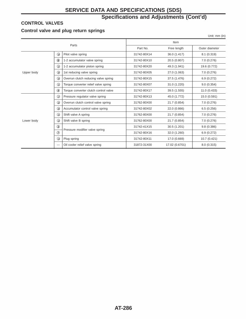
CONTROL VALVES
Control valve and plug return springsUnit: mm (in)
PartsItem
Part No. Free length Outer diameter
Upper body
q18 Pilot valve spring 31742-80X14 36.0 (1.417) 8.1 (0.319)
q8 1-2 accumulator valve spring 31742-80X10 20.5 (0.807) 7.0 (0.276)
q21 1-2 accumulator piston spring 31742-80X20 49.3 (1.941) 19.6 (0.772)
q25 1st reducing valve spring 31742-80X05 27.0 (1.063) 7.0 (0.276)
q16 Overrun clutch reducing valve spring 31742-80X15 37.5 (1.476) 6.9 (0.272)
q11 Torque converter relief valve spring 31742-80X07 31.0 (1.220) 9.0 (0.354)
q4 Torque converter clutch control valve 31742-80X17 39.5 (1.555) 11.0 (0.433)
Lower body
q17 Pressure regulator valve spring 31742-80X13 45.0 (1.772) 15.0 (0.591)
q22 Overrun clutch control valve spring 31762-80X00 21.7 (0.854) 7.0 (0.276)
q26 Accumulator control valve spring 31742-80X02 22.0 (0.866) 6.5 (0.256)
q31 Shift valve A spring 31762-80X00 21.7 (0.854) 7.0 (0.276)
q12 Shift valve B spring 31762-80X00 21.7 (0.854) 7.0 (0.276)
q3Pressure modifier valve spring
31742-41X15 30.5 (1.201) 9.8 (0.386)
q7 31742-80X16 32.0 (1.260) 6.9 (0.272)
q14 Plug spring 31742-80X11 17.0 (0.669) 10.7 (0.421)
— Oil cooler relief valve spring 31872-31X00 17.02 (0.6701) 8.0 (0.315)
SERVICE DATA AND SPECIFICATIONS (SDS)Specifications and Adjustments (Cont’d)
AT-286
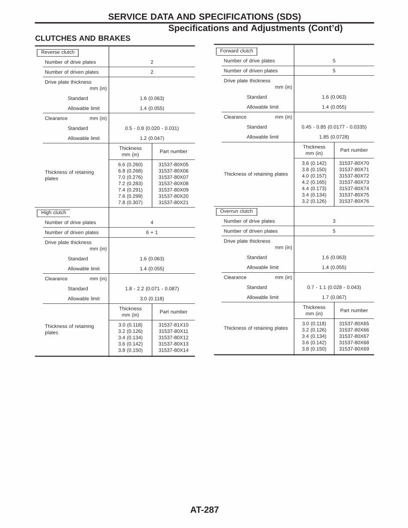
CLUTCHES AND BRAKES
Reverse clutch
Number of drive plates 2
Number of driven plates 2
Drive plate thicknessmm (in)
Standard 1.6 (0.063)
Allowable limit 1.4 (0.055)
Clearance mm (in)
Standard 0.5 - 0.8 (0.020 - 0.031)
Allowable limit 1.2 (0.047)
Thickness of retainingplates
Thicknessmm (in)
Part number
6.6 (0.260)6.8 (0.268)7.0 (0.276)7.2 (0.283)7.4 (0.291)7.6 (0.299)7.8 (0.307)
31537-80X0531537-80X0631537-80X0731537-80X0831537-80X0931537-80X2031537-80X21
High clutch
Number of drive plates 4
Number of driven plates 6 + 1
Drive plate thicknessmm (in)
Standard 1.6 (0.063)
Allowable limit 1.4 (0.055)
Clearance mm (in)
Standard 1.8 - 2.2 (0.071 - 0.087)
Allowable limit 3.0 (0.118)
Thickness of retainingplates
Thicknessmm (in)
Part number
3.0 (0.118)3.2 (0.126)3.4 (0.134)3.6 (0.142)3.8 (0.150)
31537-81X1031537-80X1131537-80X1231537-80X1331537-80X14
Forward clutch
Number of drive plates 5
Number of driven plates 5
Drive plate thicknessmm (in)
Standard 1.6 (0.063)
Allowable limit 1.4 (0.055)
Clearance mm (in)
Standard 0.45 - 0.85 (0.0177 - 0.0335)
Allowable limit 1.85 (0.0728)
Thickness of retaining plates
Thicknessmm (in)
Part number
3.6 (0.142)3.8 (0.150)4.0 (0.157)4.2 (0.165)4.4 (0.173)3.4 (0.134)3.2 (0.126)
31537-80X7031537-80X7131537-80X7231537-80X7331537-80X7431537-80X7531537-80X76
Overrun clutch
Number of drive plates 3
Number of driven plates 5
Drive plate thicknessmm (in)
Standard 1.6 (0.063)
Allowable limit 1.4 (0.055)
Clearance mm (in)
Standard 0.7 - 1.1 (0.028 - 0.043)
Allowable limit 1.7 (0.067)
Thickness of retaining plates
Thicknessmm (in)
Part number
3.0 (0.118)3.2 (0.126)3.4 (0.134)3.6 (0.142)3.8 (0.150)
31537-80X6531537-80X6631537-80X6731537-80X6831537-80X69
SERVICE DATA AND SPECIFICATIONS (SDS)Specifications and Adjustments (Cont’d)
AT-287
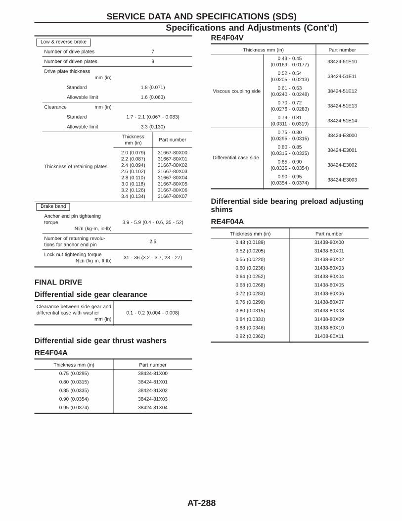
Low & reverse brake
Number of drive plates 7
Number of driven plates 8
Drive plate thicknessmm (in)
Standard 1.8 (0.071)
Allowable limit 1.6 (0.063)
Clearance mm (in)
Standard 1.7 - 2.1 (0.067 - 0.083)
Allowable limit 3.3 (0.130)
Thickness of retaining plates
Thicknessmm (in)
Part number
2.0 (0.079)2.2 (0.087)2.4 (0.094)2.6 (0.102)2.8 (0.110)3.0 (0.118)3.2 (0.126)3.4 (0.134)
31667-80X0031667-80X0131667-80X0231667-80X0331667-80X0431667-80X0531667-80X0631667-80X07
Brake band
Anchor end pin tighteningtorque
N⋅m (kg-m, in-lb)3.9 - 5.9 (0.4 - 0.6, 35 - 52)
Number of returning revolu-tions for anchor end pin
2.5
Lock nut tightening torqueN⋅m (kg-m, ft-lb)
31 - 36 (3.2 - 3.7, 23 - 27)
FINAL DRIVE
Differential side gear clearance
Clearance between side gear anddifferential case with washer
mm (in)0.1 - 0.2 (0.004 - 0.008)
Differential side gear thrust washers
RE4F04A
Thickness mm (in) Part number
0.75 (0.0295) 38424-81X00
0.80 (0.0315) 38424-81X01
0.85 (0.0335) 38424-81X02
0.90 (0.0354) 38424-81X03
0.95 (0.0374) 38424-81X04
RE4F04V
Thickness mm (in) Part number
Viscous coupling side
0.43 - 0.45(0.0169 - 0.0177)
38424-51E10
0.52 - 0.54(0.0205 - 0.0213)
38424-51E11
0.61 - 0.63(0.0240 - 0.0248)
38424-51E12
0.70 - 0.72(0.0276 - 0.0283)
38424-51E13
0.79 - 0.81(0.0311 - 0.0319)
38424-51E14
Differential case side
0.75 - 0.80(0.0295 - 0.0315)
38424-E3000
0.80 - 0.85(0.0315 - 0.0335)
38424-E3001
0.85 - 0.90(0.0335 - 0.0354)
38424-E3002
0.90 - 0.95(0.0354 - 0.0374)
38424-E3003
Differential side bearing preload adjustingshims
RE4F04A
Thickness mm (in) Part number
0.48 (0.0189) 31438-80X00
0.52 (0.0205) 31438-80X01
0.56 (0.0220) 31438-80X02
0.60 (0.0236) 31438-80X03
0.64 (0.0252) 31438-80X04
0.68 (0.0268) 31438-80X05
0.72 (0.0283) 31438-80X06
0.76 (0.0299) 31438-80X07
0.80 (0.0315) 31438-80X08
0.84 (0.0331) 31438-80X09
0.88 (0.0346) 31438-80X10
0.92 (0.0362) 31438-80X11
SERVICE DATA AND SPECIFICATIONS (SDS)Specifications and Adjustments (Cont’d)
AT-288
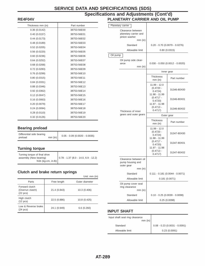
RE4F04V
Thickness mm (in) Part number
0.36 (0.0142) 38753-56E00
0.40 (0.0157) 38753-56E01
0.44 (0.0173) 38753-56E02
0.48 (0.0189) 38753-56E03
0.52 (0.0205) 38753-56E04
0.56 (0.0220) 38753-56E05
0.60 (0.0236) 38753-56E06
0.64 (0.0252) 38753-56E07
0.68 (0.0268) 38753-56E08
0.72 (0.0283) 38753-56E09
0.76 (0.0299) 38753-56E10
0.80 (0.0315) 38753-56E11
0.84 (0.0331) 38753-56E12
0.88 (0.0346) 38753-56E13
0.92 (0.0362) 38753-56E14
0.12 (0.0047) 38753-56E15
0.16 (0.0063) 38753-56E16
0.20 (0.0079) 38753-56E17
0.24 (0.0094) 38753-56E18
0.28 (0.0110) 38753-56E19
0.32 (0.0126) 38753-56E20
Bearing preload
Differential side bearingpreload mm (in)
0.05 - 0.09 (0.0020 - 0.0035)
Turning torque
Turning torque of final driveassembly (New bearing)
N⋅m (kg-cm, in-lb)0.78 - 1.37 (8.0 - 14.0, 6.9 - 12.2)
Clutch and brake return springsUnit: mm (in)
Parts Free length Outer diameter
Forward clutch(Overrun clutch)(22 pcs)
21.4 (0.843) 10.3 (0.406)
High clutch(12 pcs)
22.5 (0.886) 10.8 (0.425)
Low & Reverse brake(24 pcs)
24.1 (0.949) 6.6 (0.260)
PLANETARY CARRIER AND OIL PUMP
Planetary carrier
Clearance betweenplanetary carrier andpinion washer
mm (in)
Standard 0.20 - 0.70 (0.0079 - 0.0276)
Allowable limit 0.80 (0.0315)
Oil pump
Oil pump side clear-ance
mm (in)0.030 - 0.050 (0.0012 - 0.0020)
Thickness of innergears and outer gears
Inner gear
Thicknessmm (in)
Part number
11.99 - 12.0(0.4720 -0.4724)
11.98 - 11.99(0.4717 -0.4720)
11.97 - 11.98(0.4713 -0.4717)
31346-80X00
31346-80X01
31346-80X02
Outer gear
Thicknessmm (in)
Part number
11.99 - 12.0(0.4720 -0.4724)
11.98 - 11.99(0.4717 -0.4720)
11.97 - 11.98(0.4713 -0.4717)
31347-80X00
31347-80X01
31347-80X02
Clearance between oilpump housing andouter gear
mm (in)
Standard 0.111 - 0.181 (0.0044 - 0.0071)
Allowable limit 0.181 (0.0071)
Oil pump cover sealring clearance
mm (in)
Standard 0.10 - 0.25 (0.0039 - 0.0098)
Allowable limit 0.25 (0.0098)
INPUT SHAFT
Input shaft seal ring clearancemm (in)
Standard 0.08 - 0.23 (0.0031 - 0.0091)
Allowable limit 0.23 (0.0091)
SERVICE DATA AND SPECIFICATIONS (SDS)Specifications and Adjustments (Cont’d)
AT-289
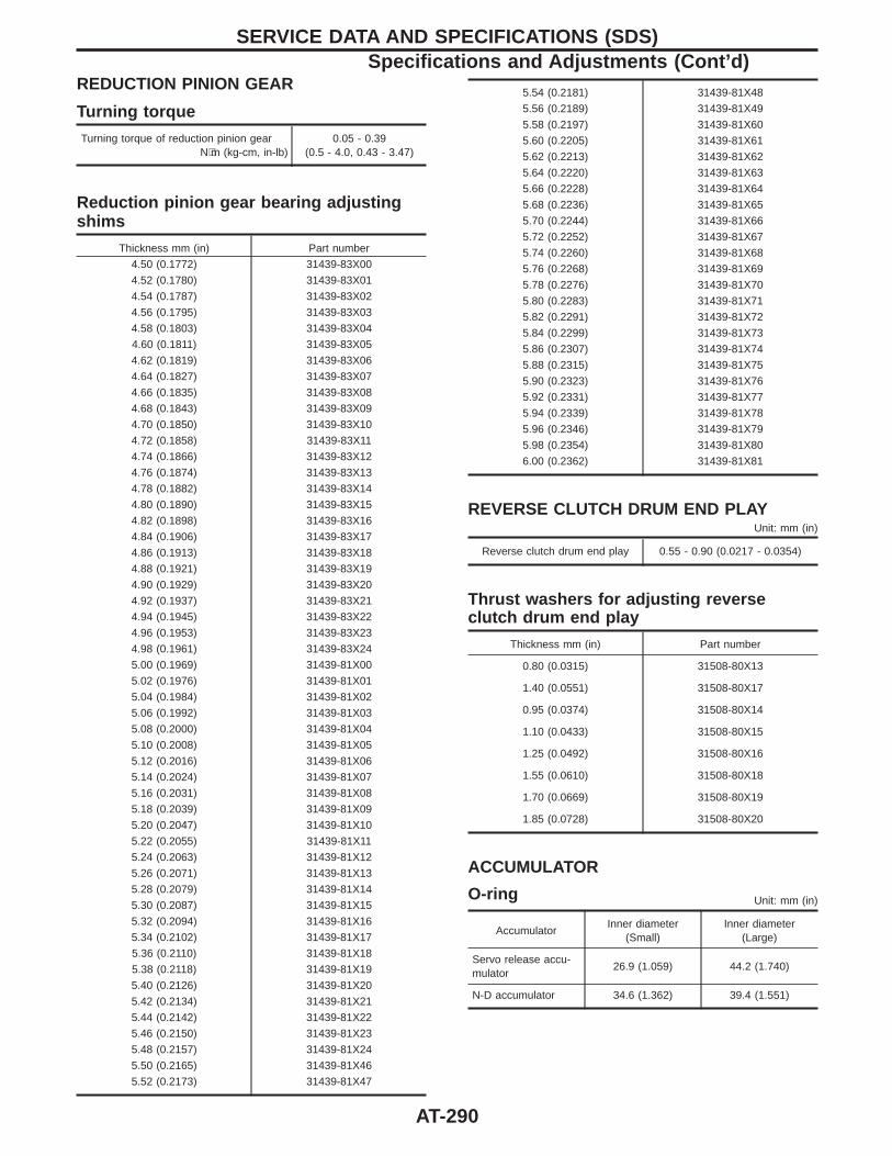
REDUCTION PINION GEAR
Turning torque
Turning torque of reduction pinion gearN⋅m (kg-cm, in-lb)
0.05 - 0.39(0.5 - 4.0, 0.43 - 3.47)
Reduction pinion gear bearing adjustingshims
Thickness mm (in) Part number
4.50 (0.1772) 31439-83X00
4.52 (0.1780) 31439-83X01
4.54 (0.1787) 31439-83X02
4.56 (0.1795) 31439-83X03
4.58 (0.1803) 31439-83X04
4.60 (0.1811) 31439-83X05
4.62 (0.1819) 31439-83X06
4.64 (0.1827) 31439-83X07
4.66 (0.1835) 31439-83X08
4.68 (0.1843) 31439-83X09
4.70 (0.1850) 31439-83X10
4.72 (0.1858) 31439-83X11
4.74 (0.1866) 31439-83X12
4.76 (0.1874) 31439-83X13
4.78 (0.1882) 31439-83X14
4.80 (0.1890) 31439-83X15
4.82 (0.1898) 31439-83X16
4.84 (0.1906) 31439-83X17
4.86 (0.1913) 31439-83X18
4.88 (0.1921) 31439-83X19
4.90 (0.1929) 31439-83X20
4.92 (0.1937) 31439-83X21
4.94 (0.1945) 31439-83X22
4.96 (0.1953) 31439-83X23
4.98 (0.1961) 31439-83X24
5.00 (0.1969) 31439-81X00
5.02 (0.1976) 31439-81X01
5.04 (0.1984) 31439-81X02
5.06 (0.1992) 31439-81X03
5.08 (0.2000) 31439-81X04
5.10 (0.2008) 31439-81X05
5.12 (0.2016) 31439-81X06
5.14 (0.2024) 31439-81X07
5.16 (0.2031) 31439-81X08
5.18 (0.2039) 31439-81X09
5.20 (0.2047) 31439-81X10
5.22 (0.2055) 31439-81X11
5.24 (0.2063) 31439-81X12
5.26 (0.2071) 31439-81X13
5.28 (0.2079) 31439-81X14
5.30 (0.2087) 31439-81X15
5.32 (0.2094) 31439-81X16
5.34 (0.2102) 31439-81X17
5.36 (0.2110) 31439-81X18
5.38 (0.2118) 31439-81X19
5.40 (0.2126) 31439-81X20
5.42 (0.2134) 31439-81X21
5.44 (0.2142) 31439-81X22
5.46 (0.2150) 31439-81X23
5.48 (0.2157) 31439-81X24
5.50 (0.2165) 31439-81X46
5.52 (0.2173) 31439-81X47
5.54 (0.2181) 31439-81X48
5.56 (0.2189) 31439-81X49
5.58 (0.2197) 31439-81X60
5.60 (0.2205) 31439-81X61
5.62 (0.2213) 31439-81X62
5.64 (0.2220) 31439-81X63
5.66 (0.2228) 31439-81X64
5.68 (0.2236) 31439-81X65
5.70 (0.2244) 31439-81X66
5.72 (0.2252) 31439-81X67
5.74 (0.2260) 31439-81X68
5.76 (0.2268) 31439-81X69
5.78 (0.2276) 31439-81X70
5.80 (0.2283) 31439-81X71
5.82 (0.2291) 31439-81X72
5.84 (0.2299) 31439-81X73
5.86 (0.2307) 31439-81X74
5.88 (0.2315) 31439-81X75
5.90 (0.2323) 31439-81X76
5.92 (0.2331) 31439-81X77
5.94 (0.2339) 31439-81X78
5.96 (0.2346) 31439-81X79
5.98 (0.2354) 31439-81X80
6.00 (0.2362) 31439-81X81
REVERSE CLUTCH DRUM END PLAYUnit: mm (in)
Reverse clutch drum end play 0.55 - 0.90 (0.0217 - 0.0354)
Thrust washers for adjusting reverseclutch drum end play
Thickness mm (in) Part number
0.80 (0.0315) 31508-80X13
1.40 (0.0551) 31508-80X17
0.95 (0.0374) 31508-80X14
1.10 (0.0433) 31508-80X15
1.25 (0.0492) 31508-80X16
1.55 (0.0610) 31508-80X18
1.70 (0.0669) 31508-80X19
1.85 (0.0728) 31508-80X20
ACCUMULATOR
O-ring Unit: mm (in)
AccumulatorInner diameter
(Small)Inner diameter
(Large)
Servo release accu-mulator
26.9 (1.059) 44.2 (1.740)
N-D accumulator 34.6 (1.362) 39.4 (1.551)
SERVICE DATA AND SPECIFICATIONS (SDS)Specifications and Adjustments (Cont’d)
AT-290
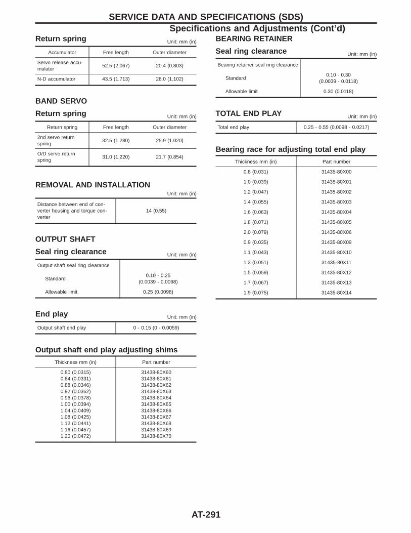
Return spring Unit: mm (in)
Accumulator Free length Outer diameter
Servo release accu-mulator
52.5 (2.067) 20.4 (0.803)
N-D accumulator 43.5 (1.713) 28.0 (1.102)
BAND SERVO
Return spring Unit: mm (in)
Return spring Free length Outer diameter
2nd servo returnspring
32.5 (1.280) 25.9 (1.020)
O/D servo returnspring
31.0 (1.220) 21.7 (0.854)
REMOVAL AND INSTALLATIONUnit: mm (in)
Distance between end of con-verter housing and torque con-verter
14 (0.55)
OUTPUT SHAFT
Seal ring clearance Unit: mm (in)
Output shaft seal ring clearance
Standard0.10 - 0.25
(0.0039 - 0.0098)
Allowable limit 0.25 (0.0098)
End play Unit: mm (in)
Output shaft end play 0 - 0.15 (0 - 0.0059)
Output shaft end play adjusting shims
Thickness mm (in) Part number
0.80 (0.0315)0.84 (0.0331)0.88 (0.0346)0.92 (0.0362)0.96 (0.0378)1.00 (0.0394)1.04 (0.0409)1.08 (0.0425)1.12 (0.0441)1.16 (0.0457)1.20 (0.0472)
31438-80X6031438-80X6131438-80X6231438-80X6331438-80X6431438-80X6531438-80X6631438-80X6731438-80X6831438-80X6931438-80X70
BEARING RETAINER
Seal ring clearance Unit: mm (in)
Bearing retainer seal ring clearance
Standard0.10 - 0.30
(0.0039 - 0.0118)
Allowable limit 0.30 (0.0118)
TOTAL END PLAY Unit: mm (in)
Total end play 0.25 - 0.55 (0.0098 - 0.0217)
Bearing race for adjusting total end play
Thickness mm (in) Part number
0.8 (0.031) 31435-80X00
1.0 (0.039) 31435-80X01
1.2 (0.047) 31435-80X02
1.4 (0.055) 31435-80X03
1.6 (0.063) 31435-80X04
1.8 (0.071) 31435-80X05
2.0 (0.079) 31435-80X06
0.9 (0.035) 31435-80X09
1.1 (0.043) 31435-80X10
1.3 (0.051) 31435-80X11
1.5 (0.059) 31435-80X12
1.7 (0.067) 31435-80X13
1.9 (0.075) 31435-80X14
SERVICE DATA AND SPECIFICATIONS (SDS)Specifications and Adjustments (Cont’d)
AT-291
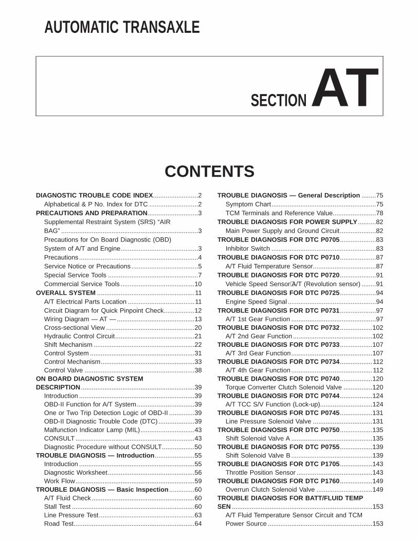
AUTOMATIC TRANSAXLE
SECTIONATCONTENTS
DIAGNOSTIC TROUBLE CODE INDEX .........................2Alphabetical & P No. Index for DTC ...........................2
PRECAUTIONS AND PREPARATION ............................3Supplemental Restraint System (SRS) “AIRBAG” ............................................................................3Precautions for On Board Diagnostic (OBD)System of A/T and Engine...........................................3Precautions ..................................................................4Service Notice or Precautions .....................................5Special Service Tools ..................................................7Commercial Service Tools .........................................10
OVERALL SYSTEM ......................................................11A/T Electrical Parts Location .....................................11Circuit Diagram for Quick Pinpoint Check.................12Wiring Diagram — AT — ...........................................13Cross-sectional View .................................................20Hydraulic Control Circuit............................................21Shift Mechanism ........................................................22Control System ..........................................................31Control Mechanism....................................................33Control Valve .............................................................38
ON BOARD DIAGNOSTIC SYSTEMDESCRIPTION ...............................................................39
Introduction ................................................................39OBD-II Function for A/T System................................39One or Two Trip Detection Logic of OBD-II ..............39OBD-II Diagnostic Trouble Code (DTC) ....................39Malfunction Indicator Lamp (MIL)..............................43CONSULT ..................................................................43Diagnostic Procedure without CONSULT..................50
TROUBLE DIAGNOSIS — Introduction ......................55Introduction ................................................................55Diagnostic Worksheet................................................56Work Flow..................................................................59
TROUBLE DIAGNOSIS — Basic Inspection ..............60A/T Fluid Check .........................................................60Stall Test ....................................................................60Line Pressure Test.....................................................63Road Test...................................................................64
TROUBLE DIAGNOSIS — General Description ........75Symptom Chart..........................................................75TCM Terminals and Reference Value........................78
TROUBLE DIAGNOSIS FOR POWER SUPPLY ..........82Main Power Supply and Ground Circuit....................82
TROUBLE DIAGNOSIS FOR DTC P0705 ....................83Inhibitor Switch ..........................................................83
TROUBLE DIAGNOSIS FOR DTC P0710 ....................87A/T Fluid Temperature Sensor...................................87
TROUBLE DIAGNOSIS FOR DTC P0720 ....................91Vehicle Speed Sensor⋅A/T (Revolution sensor) ........91
TROUBLE DIAGNOSIS FOR DTC P0725 ....................94Engine Speed Signal .................................................94
TROUBLE DIAGNOSIS FOR DTC P0731 ....................97A/T 1st Gear Function ...............................................97
TROUBLE DIAGNOSIS FOR DTC P0732 ..................102A/T 2nd Gear Function ............................................102
TROUBLE DIAGNOSIS FOR DTC P0733 ..................107A/T 3rd Gear Function.............................................107
TROUBLE DIAGNOSIS FOR DTC P0734 ..................112A/T 4th Gear Function .............................................112
TROUBLE DIAGNOSIS FOR DTC P0740 ..................120Torque Converter Clutch Solenoid Valve ................120
TROUBLE DIAGNOSIS FOR DTC P0744 ..................124A/T TCC S/V Function (Lock-up).............................124
TROUBLE DIAGNOSIS FOR DTC P0745 ..................131Line Pressure Solenoid Valve .................................131
TROUBLE DIAGNOSIS FOR DTC P0750 ..................135Shift Solenoid Valve A .............................................135
TROUBLE DIAGNOSIS FOR DTC P0755 ..................139Shift Solenoid Valve B .............................................139
TROUBLE DIAGNOSIS FOR DTC P1705 ..................143Throttle Position Sensor ..........................................143
TROUBLE DIAGNOSIS FOR DTC P1760 ..................149Overrun Clutch Solenoid Valve ...............................149
TROUBLE DIAGNOSIS FOR BATT/FLUID TEMPSEN ..............................................................................153
A/T Fluid Temperature Sensor Circuit and TCMPower Source ..........................................................153
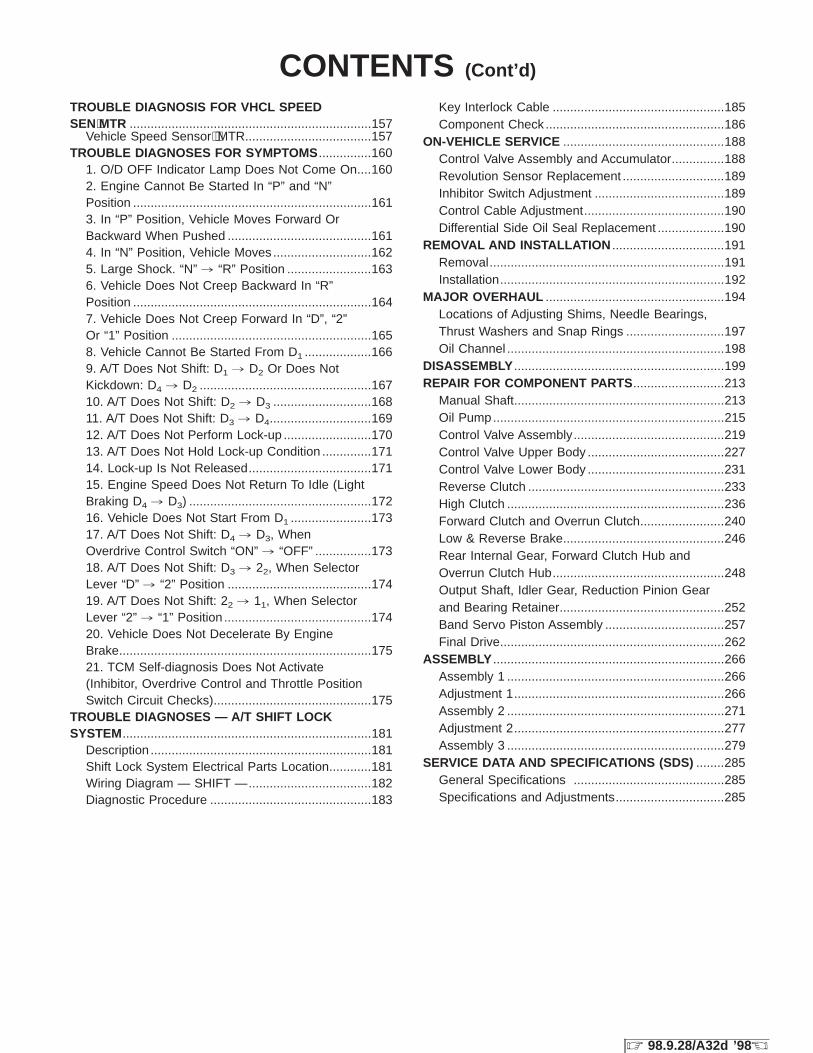
TROUBLE DIAGNOSIS FOR VHCL SPEEDSEN⋅MTR .....................................................................157
Vehicle Speed Sensor⋅⋅MTR....................................157TROUBLE DIAGNOSES FOR SYMPTOMS ...............160
1. O/D OFF Indicator Lamp Does Not Come On....1602. Engine Cannot Be Started In “P” and “N”Position ....................................................................1613. In “P” Position, Vehicle Moves Forward OrBackward When Pushed .........................................1614. In “N” Position, Vehicle Moves ............................1625. Large Shock. “N” , “R” Position ........................1636. Vehicle Does Not Creep Backward In “R”Position ....................................................................1647. Vehicle Does Not Creep Forward In “D”, “2”Or “1” Position .........................................................1658. Vehicle Cannot Be Started From D1 ...................1669. A/T Does Not Shift: D1 , D2 Or Does NotKickdown: D4 , D2 .................................................16710. A/T Does Not Shift: D2 , D3 ............................16811. A/T Does Not Shift: D3 , D4.............................16912. A/T Does Not Perform Lock-up .........................17013. A/T Does Not Hold Lock-up Condition ..............17114. Lock-up Is Not Released...................................17115. Engine Speed Does Not Return To Idle (LightBraking D4 , D3) ....................................................17216. Vehicle Does Not Start From D1 .......................17317. A/T Does Not Shift: D4 , D3, WhenOverdrive Control Switch “ON” , “OFF” ................17318. A/T Does Not Shift: D3 , 22, When SelectorLever “D” , “2” Position .........................................17419. A/T Does Not Shift: 22 , 11, When SelectorLever “2” , “1” Position ..........................................17420. Vehicle Does Not Decelerate By EngineBrake........................................................................17521. TCM Self-diagnosis Does Not Activate(Inhibitor, Overdrive Control and Throttle PositionSwitch Circuit Checks).............................................175
TROUBLE DIAGNOSES — A/T SHIFT LOCKSYSTEM.......................................................................181
Description ...............................................................181Shift Lock System Electrical Parts Location............181Wiring Diagram — SHIFT —...................................182Diagnostic Procedure ..............................................183
Key Interlock Cable .................................................185Component Check ...................................................186
ON-VEHICLE SERVICE ..............................................188Control Valve Assembly and Accumulator...............188Revolution Sensor Replacement .............................189Inhibitor Switch Adjustment .....................................189Control Cable Adjustment........................................190Differential Side Oil Seal Replacement ...................190
REMOVAL AND INSTALLATION ................................191Removal...................................................................191Installation................................................................192
MAJOR OVERHAUL ...................................................194Locations of Adjusting Shims, Needle Bearings,Thrust Washers and Snap Rings ............................197Oil Channel ..............................................................198
DISASSEMBLY ............................................................199REPAIR FOR COMPONENT PARTS ..........................213
Manual Shaft............................................................213Oil Pump..................................................................215Control Valve Assembly...........................................219Control Valve Upper Body .......................................227Control Valve Lower Body .......................................231Reverse Clutch ........................................................233High Clutch ..............................................................236Forward Clutch and Overrun Clutch........................240Low & Reverse Brake..............................................246Rear Internal Gear, Forward Clutch Hub andOverrun Clutch Hub.................................................248Output Shaft, Idler Gear, Reduction Pinion Gearand Bearing Retainer...............................................252Band Servo Piston Assembly ..................................257Final Drive................................................................262
ASSEMBLY ..................................................................266Assembly 1 ..............................................................266Adjustment 1............................................................266Assembly 2 ..............................................................271Adjustment 2............................................................277Assembly 3 ..............................................................279
SERVICE DATA AND SPECIFICATIONS (SDS) ........285General Specifications ...........................................285Specifications and Adjustments...............................285
CONTENTS (Cont’d)
Z 98.9.28/A32d ’98 X