
AUTOMATIC OPTIMISATION OF A TRIMARAN HULL FORM CONFIGURATION
10
International Conference on Fast Sea Transportation FAST’2005, June 2005, St.Petersburg, Russia 1 AUTOMATIC OPTIMISATION OF A TRIMARAN HULL FORM CONFIGURATION Stefano Brizzolara, Dario Bruzzone, Emilio Tincani University of Genova Department of Naval Architecture and Marine technology Via Montallegro,1 Genova, Italy ABSTRACT paper presents the development and main results of a theoretical investigation about the best hull form configu- ration of a fast trimaran ferry, designed with the help of modern CFD tools, coupled with modules for automatic geometry generation and differential evolution algorithms to converge on the best solution. A comprehensive set of experimental tests in systematically varied configurations has been carried out as well and the conclusions drawn from the theoretical study are discussed also comparing with the experimental re- sults.The wave making resistance of each investigated solution is evaluated by means of a free surface potential flow panel method suitable for fast multi-hulls.. At first, the accuracy of the CFD tool is validated against the experimental results over a large speed range. Then the numerical model is used into the frame of a more com- plex optimisation algorithm which systematically drives the choice of the free parameters to convergence to the best multi-hull configuration, in terms of low wave-making resistance. In this regards, the hull forms of the original designed trimaran have been kept, assuming as free parameters the transversal and longitudinal posi- tion of the side hulls. Different deterministic and stochastic type of optimisation algorithms have been used and compared with respect to their performance in finding and reaching the best solution. Interesting considerations are given in the paper about the numerical accuracy on the theoretical prediction of the wave resistance, of the dynamic trim and sinkage and on the interference effects of the side hulls. Finally, some guidelines for the design of new medium sized fast trimarans will be drawn.. INTRODUCTION A cooperative research project dedicated to the study of modern and efficient multi-hull vessels for fast sea transportation, is carried out jointly by the Depart- ments of Naval Architecture of three Italian Universi- ties and is funded by the Italian Ministry of Research. The considered marine vehicles are trimaran, pen- tamarans and unconventional catamarans for passen- gers and cars. This study presented in this paper, is part of the activ- ity of this research project and deals with a trimaran hull. The intention is to further analyse the hydrody- namic behaviour and the interference effects in dif- ferent configurations of one of the two possibilities considered in the research project for the component hull forms [1]. The ship wave-making resistance is evaluated numerically also to complement with the inevitably limited number of experimental investiga- tion considering a higher number of configurations for what the influence of the longitudinal and trans- verse position of the outriggers is concerned. Other motivations of the present study regard: en- hancing the experience in the application of paramet- ric optimisation algorithms to the design of fast ship hulls with improved powering characteristics, that brought already interesting results in another study [2] and extend the application of the free surface potential flow method on a new multi-hull typology and verify the accuracy and stability of the results. Aim of this work is to give useful information on the performance of a realistic high speed trimaran, suit- able for medium routes. TRIMARAN HULL FORMS The hull design of the trimaran has been developed at the University of Naples, on the basis of a realistic general layout for a contemporary fast transportation vessel. The trimaran, was composed by a round bilge main hull and round bilge outriggers, both derived from the series. 64. The body plan is shown in fig. 1 and the principal dimension and dimensional parameters are given in table 1. Resistance tests were conducted on 1/30 scale models in the Naples University towing tank and repeated at
Transcript of AUTOMATIC OPTIMISATION OF A TRIMARAN HULL FORM CONFIGURATION
International Conference on Fast Sea Transportation FAST’2005, June 2005, St.Petersburg, Russia
1
AUTOMATIC OPTIMISATION OF A TRIMARAN HULL FORM
CONFIGURATION Stefano Brizzolara, Dario Bruzzone, Emilio Tincani
University of Genova Department of Naval Architecture and Marine technology
Via Montallegro,1 Genova, Italy
ABSTRACT
paper presents the development and main results of a theoretical investigation about the best hull form configu-ration of a fast trimaran ferry, designed with the help of modern CFD tools, coupled with modules for automatic geometry generation and differential evolution algorithms to converge on the best solution. A comprehensive set of experimental tests in systematically varied configurations has been carried out as well and the conclusions drawn from the theoretical study are discussed also comparing with the experimental re-sults.The wave making resistance of each investigated solution is evaluated by means of a free surface potential flow panel method suitable for fast multi-hulls.. At first, the accuracy of the CFD tool is validated against the experimental results over a large speed range. Then the numerical model is used into the frame of a more com-plex optimisation algorithm which systematically drives the choice of the free parameters to convergence to the best multi-hull configuration, in terms of low wave-making resistance. In this regards, the hull forms of the original designed trimaran have been kept, assuming as free parameters the transversal and longitudinal posi-tion of the side hulls. Different deterministic and stochastic type of optimisation algorithms have been used and compared with respect to their performance in finding and reaching the best solution. Interesting considerations are given in the paper about the numerical accuracy on the theoretical prediction of the wave resistance, of the dynamic trim and sinkage and on the interference effects of the side hulls. Finally, some guidelines for the design of new medium sized fast trimarans will be drawn..
INTRODUCTION
A cooperative research project dedicated to the study of modern and efficient multi-hull vessels for fast sea transportation, is carried out jointly by the Depart-ments of Naval Architecture of three Italian Universi-ties and is funded by the Italian Ministry of Research. The considered marine vehicles are trimaran, pen-tamarans and unconventional catamarans for passen-gers and cars. This study presented in this paper, is part of the activ-ity of this research project and deals with a trimaran hull. The intention is to further analyse the hydrody-namic behaviour and the interference effects in dif-ferent configurations of one of the two possibilities considered in the research project for the component hull forms [1]. The ship wave-making resistance is evaluated numerically also to complement with the inevitably limited number of experimental investiga-tion considering a higher number of configurations for what the influence of the longitudinal and trans-verse position of the outriggers is concerned. Other motivations of the present study regard: en-hancing the experience in the application of paramet-ric optimisation algorithms to the design of fast ship
hulls with improved powering characteristics, that brought already interesting results in another study [2] and extend the application of the free surface potential flow method on a new multi-hull typology and verify the accuracy and stability of the results. Aim of this work is to give useful information on the performance of a realistic high speed trimaran, suit-able for medium routes.
TRIMARAN HULL FORMS
The hull design of the trimaran has been developed at the University of Naples, on the basis of a realistic general layout for a contemporary fast transportation vessel. The trimaran, was composed by a round bilge main hull and round bilge outriggers, both derived from the series. 64. The body plan is shown in fig. 1 and the principal dimension and dimensional parameters are given in table 1. Resistance tests were conducted on 1/30 scale models in the Naples University towing tank and repeated at

2
a scale of 1/50 at the towing tank of the University of Genova.
Tab. 1: Principal characteristics
Hull Model main side main side
LWL (m) 105.6 35.19 2.112 0.697 T (m) 4.416 0.69 0.091 0.014 B (m) 8.83 1.65 0.177 0.032 ∆ (t) 2318.19 14.37 18.124 0.109 Vmax (kn) 36 36 CB 0.55 0.35 0.55 0.35 L/B 11.96 21.5 11.96 21.5 B/T 2.00 2.39 2.00 2.39 Table 2 illustrates the test matrix of the trimaran con-figurations. The stagger (ST) values express the lon-gitudinal position of side hulls and are chosen as the distance of the transom section of the outriggers from the transom section of the main hull; the clearance (CL) values express the transversal position of the side hulls chosen as the distance of the symmetry plane of each side hull from the symmetry plane of the main hull. Both are calculated in percentage of the main hull length.
Tab. 2: Towing Test Matrix at Genova Univ. ST / LWL
CL / LWL 0% 10% (20%) (30%)9.9% P11 P12 P13 P14
11.10% P21 P22 P23 P24 13.40% P31 P32 P33 P34 15.00% P41 P42 P43 P44
In total, twelve different arrangements obtained with four longitudinal positions and three transversal posi-tions of the side hulls were tested, in the whole speed range corresponding to Fn=0.35÷0.60.
2. THE CFD METHOD The solution of the free surface potential flow around the multi-hull is obtained by a linear Rankine sources panel method, initially developed at the University of Genova for conventional ships [3] and continuously extended and validated especially in the case of fast multihull ships [4] [5] [6] [7], also for far field wash problems in case of limited bottom depths [8]. Assuming inviscid and irrotational flow, the problem of the steady fluid motion around a ship advancing at a constant speed can be described by a velocity po-tential from which the velocities and all the other relevant flow quantities can be derived. The Laplace equation, the body boundary condition of no flow penetration into the hull, the kinematic and dynamic boundary conditions on the free surface, combined with the radiation condition of no upstream waves, set up the boundary value problem in terms of the unknown velocity potential. The non linear free sur-face boundary condition may be linearised by ex-pressing the total velocity potential as the sum of a reference potential and of a perturbation potential having a lower order of magnitude. The reference potential is assumed as that describing the deeply immersed double model flow: the so called double model potential. A Rankine source distribution is assumed on the hull and on the free surface so the integral boundary value problem is expressed in terms of the related unknown source density. The discretisation of the hull and of a part of the free sur-face surrounding the hull is realised by means of quadrilateral panels and leads to the numeric formula-tion of the boundary value problem. The method is of the indirect type in which the relevant terms of the boundary equations are expressed recurring to the influence coefficients for the velocities (i.e. the first order partial derivatives of the potential) that are ob-tained according the Hess and Smith procedure. The second order derivatives of the velocity potential are computed by a backward finite difference operator in the longitudinal direction and by an outward finite difference operator in the transverse direction. Collo-
Fig. 1: Transverse sections of main and side hulls of the trimaran (in the reference conf. P11)

3
cating the boundary equations at the centre of each panel, a linear system of equations for the unknown source densities on each panel is obtained and solved after LU factorisation. Then, wave resistance can be determined by integration of the pressure forces on the hull which are derived by the application of the Bernoulli equation. Computations can be performed either in a given fixed position, or using an iterative procedure capable to converge on the dynamic sinkage and trim, which realise the equilibrium of vertical forces and mo-ments. The wave resistance, then, is calculated in the free numerically predicted attitude. It has been al-ready verified in several studies of the authors that to correctly predict wave resistance of high speed hulls the hull must be modelled in its dynamic attitude, and indeed the described numerical method predicts this values quite satisfactory. PRELIMINARY NUMERICAL STUDY AND CORRELATION WITH EXPERIMENTS
In preparation to the optimisation study, the free sur-face panel method has been applied to some of the configurations tested in towing tank (see table 2) to verify the accuracy and reliability of the predicted results.
Fig. 2: Trimaran Conf. P11: comparison of predicted wave resistance coefficient fixed or free running atti-tude and residuary resistance deduced from the tow-ing tank tests. To assess the influence of the dynamic trim and sink-age on the predicted wave resistance, the method was applied with and without numerical iterative search of the equilibrium of forces and moments in the vertical plane. As in the case of other types of fast ships, the importance of including the prediction of the dynamic attitude for the evaluation of wave resistance is fun-damental. Figure 2 represents an example of compari-son between predicted wave resistance and the re-siduary resistance obtained from the experiment. Other comparisons of this kind have been made for the other position of side hulls and showed similar correlations. First, it is evident the considerable effect of the dynamic attitude on the predicted wave resis-
tance, which rises up towards the residuary resistance value with the model in free attitude. Moreover, the Froude number at which the wave resistance coeffi-cient has a maximum is well captured by the method, as well as the decreasing of the curve trend at highest Froude numbers. The magnitude of the predicted wave resistance coefficients is indeed correlated with the corresponding value of residuary resistance de-duced from towing tank tests, although the numerical values result always lower and in general with a less pronounced peak. The experimental CR has been cal-culated from the measured total resistance with a cor-rected CF allowing for the actual wetted surface in the running attitude.
Fig. 3: Trimaran conf. P11: comparison of numeri-cally predicted trim (positive bow-up) and sinkage at midship (positive if draft increase) with measured values.
Fig. 4: Typical convergence history of the trim and sinkage during iterations (trimaran P11, at Fn=0.5). f1 and f2 are the non-dimensional residuals of the equilibrium of vertical forces and trim moments. Figure 3 presents a typical comparison of the pre-dicted dynamic trim angle and sinkage at midship with the values measured in towing tank, for P11 con-figuration. Figure 4, in addition, shows the corre-sponding convergence history of the two variables during the iterative process. Generally the dynamic attitude that verifies the equilibrium of the vertical forces (residual f1 tends to zero) and pitching mo-ment (residual f2) is found after not more than 5 itera-
4
tions. The trim angle predicted by the panel method agrees, in general, very well with experiments, while the sinkage results less satisfactory, although its trend with respect to Froude number follows that found in the experiments. The reason of the poorer prediction of sinkage force is currently investigated by the au-thors. As a general implication, the trim angle and sinkage experienced by the trimaran is quite relevant and for sure an optimisation of the shape of the aft sections (with a different slope or a wedge) could well reduce the resistance of the hull. Wave interactions Effects
A further preparation study was conducted to investi-gate the wave interaction effects generated when cou-pling the side hulls in the different positions with the main hull of the trimaran. For this purpose, the numerical panel method has been applied to the main hull in isolation and to one side hull, in the fixed static attitude, over the whole speed range. Neglecting the wave and viscous-pressure interference effects, one could calculate the total wave resistance by simply adding the contribu-tion of each isolated component. So in terms of resis-tance coefficients:
MAINSIDE
MAINMAINW
SIDESIDEWISOL
W SSSCSC
C++
=2
2. (1)
A sort of pure wave interference coefficient, due to the effect of side hulls, can be calculated comparing the actual wave resistance predicted by the panel method for the full trimaran configuration, with that obtain with (1), i.e.:
ISOLW
TIMARANW
CCCIW =... (2)
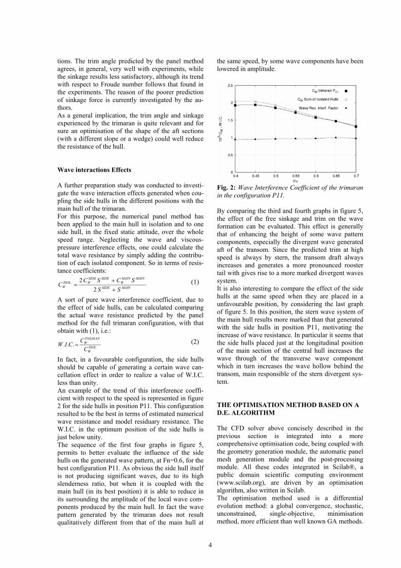
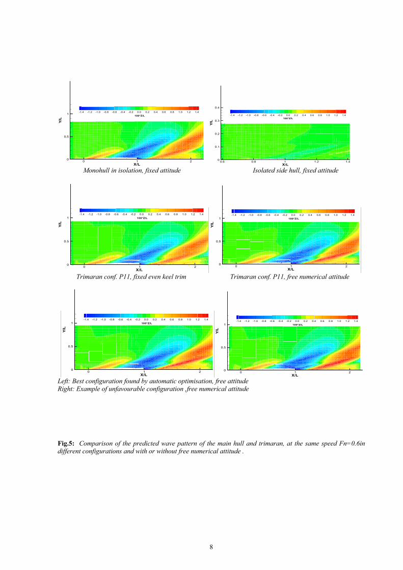
In fact, in a favourable configuration, the side hulls should be capable of generating a certain wave can-cellation effect in order to realize a value of W.I.C. less than unity. An example of the trend of this interference coeffi-cient with respect to the speed is represented in figure 2 for the side hulls in position P11. This configuration resulted to be the best in terms of estimated numerical wave resistance and model residuary resistance. The W.I.C. in the optimum position of the side hulls is just below unity. The sequence of the first four graphs in figure 5, permits to better evaluate the influence of the side hulls on the generated wave pattern, at Fn=0.6, for the best configuration P11. As obvious the side hull itself is not producing significant waves, due to its high slenderness ratio, but when it is coupled with the main hull (in its best position) it is able to reduce in its surrounding the amplitude of the local wave com-ponents produced by the main hull. In fact the wave pattern generated by the trimaran does not result qualitatively different from that of the main hull at
the same speed, by some wave components have been lowered in amplitude.
Fig. 2: Wave Interference Coefficient of the trimaran in the configuration P11. By comparing the third and fourth graphs in figure 5, the effect of the free sinkage and trim on the wave formation can be evaluated. This effect is generally that of enhancing the height of some wave pattern components, especially the divergent wave generated aft of the transom. Since the predicted trim at high speed is always by stern, the transom draft always increases and generates a more pronounced rooster tail with gives rise to a more marked divergent waves system. It is also interesting to compare the effect of the side hulls at the same speed when they are placed in a unfavourable position, by considering the last graph of figure 5. In this position, the stern wave system of the main hull results more marked than that generated with the side hulls in position P11, motivating the increase of wave resistance. In particular it seems that the side hulls placed just at the longitudinal position of the main section of the central hull increases the wave through of the transverse wave component which in turn increases the wave hollow behind the transom, main responsible of the stern divergent sys-tem. THE OPTIMISATION METHOD BASED ON A D.E. ALGORITHM The CFD solver above concisely described in the previous section is integrated into a more comprehensive optimisation code, being coupled with the geometry generation module, the automatic panel mesh generation module and the post-processing module. All these codes integrated in Scilab®, a public domain scientific computing environment (www.scilab.org), are driven by an optimisation algorithm, also written in Scilab. The optimisation method used is a differential evolution method: a global convergence, stochastic, unconstrained, single-objective, minimisation method, more efficient than well known GA methods.
5
The method was developed in a relative recent time by Price and Storn (1995, 1996) and demonstrated a very good efficiency even in very tough minimisation problems. The advantage of stochastic type methods is that they do not require the evaluation of the gradient of the minimizing (objective) function with respected to the free variables of the problem which would take a prohibitive time each convergence step if the objective function is evaluated, as in our case, by the CFD solver. This kind of optimisation algorithm was already used with success in the similar but more complex case of the optimisation of the total resistance of a SWATH ship by variation of the lower hull forms [2] and a new typology of catamaran with a submerged internal bulb [6]. Addressing the reader to the specialised references, the basic idea behind DE method is briefly introduced hereinafter. The objective function ℑ to be minimised is a general function of the N free variables of the problem. In our case of the minimisation of the hull calm water resistance, in the most general sense, we can define the objective function as a weighted sum over the index i (with weights pi) of the resistance reduction ∆Ri evaluated at NV different speeds Vi:
( ) ( )
( ) ( ) ( )( )
[ ] jj
NV
ii
iHullf
iHullfii
NV
iii
LSTzLxp
VRVRVR
VR
VRp
/,/,/,1
,10
1
.Re
.Re2%
1%
∆∆==
−=∆
∆⋅=ℑ
∑
∑
=
=
ψ
ψ
(3)
The free variable values are ordered in a vector ψj which is referenced to as the jth member of the population formed by all the ∞N vectors that belong to the N free variable domain. It is assumed that there is a special member of the population which is capable of realising the minimum of the objective function over the considered domain. The iterative process act on a series of ‘generations’ formed by NP population members. The generation individuals do not change during the minimisation process. The first generation has individuals uniformly (in probabilistic sense) distributed inside a certain guessed initial domain, or around a known approximate solution. Up to this point, like genetic algorithms. The new idea behind DE algorithm is in the scheme used to find the individuals which will belong to the next generation. The new tentative individual is characterised by a trial free variable vector ψnew, found by linear combination of one random individual ψ1 of the current generation with the difference ψ2-ψ3 between two other random individuals (of the current generation) through a linear factor F:
( )321 ψψψψ −⋅+= Fnew (4) F is a constant which regulates the amplification of the differential variation.
If the new (individual) vector realises a lower objective function value with respect to the value obtained with a comparison vector, then the new trial vector replaces the vector with which it was compared. The comparison vector can, but not need to be, a member of the population. Moreover, in order to increase the diversity of the individuals between successive generations, a certain random permutation or exchange of elements in the trial vector just formed as per (3) is performed. As in genetic algorithms, this technique is called direct (because it acts directly on the elements of the vector) cross-over. The parameter which control the number of substituted vectors elements during the cross-over function is the cross-over factor [ ]1;0∈CR . Several variation of the algorithm exist, depending on the way of calculating the trial vector and of choosing the comparison vector, but basically in addition to the one seen before (2), named DE1, there is the DE2, which generates the trial vector in the following way:
( ) ( )3211 ψψψψλψψ −⋅+−⋅+= FBestnew (5) where the additional control variable λ regulates the greediness of the scheme to converge towards a local minimum by adding a vector deviation which depends also by the distance to the best member of the current generation bestxr . Other modifications may be introduced by modifying the crossover function (exponential or binomial) and the base vector 1xr that instead of being randomly selected may be fixed to the best vector of the current generation. For the time being, no attempt of personalizing the algorithm has been done for this study, and the standard DE/rand/1/exp algorithm has been used with the following constant factors: F=0.6, CR=0.8, NP=10⋅size(ψ). Interesting will be in the future to verify the dependence of the convergence speed on the control parameters of the DE algorithm. Our optimisation problem has a bounded domain. Since the DE method is naturally unbounded, the only way to include these boundary constraints is inside the objective function: an additional penalty function will be added to the value of ℑ found as per (3), which returns an higher value if the trial vector is outside the domain of investigation. In general in our case:
Condition: [ ]7.0;0.0 −∉∆L
x [ ]15.0;08.0∉∆L
y
Penalty Value: 100 100
The domain limits, though, have been adapted for the different speeds to be relatively close around the possible minimum, to avoid a dispersion of time in the convergence . Finally a simple check of numerically unstable results is used to avoid unrealistic results which very seldom the CFD code can generate: the cases for which a negative wave resistance is predicted are evaluated with a very high penalty value. Another more consis-
6
tent check, perhaps using a criteria based on the analysis of the wave pattern formation, is necessary to avoid also few other unrealistic results, not so dras-tic in terms of global wave resistance, that at the mo-ment must be excluded ‘a posteriori’ and do some-time prevent the convergence of the optimisation al-gorithm. AUTOMATIC SEARCH OF THE BEST CONFIGURATION AT DIFFERENT SPEEDS The optimisation algorithm was coupled with a in-termediary program able to generate the panel mesh for each different configuration and the CFD solver to form an automatic optimisation tool. The optimisation was run for two different speed, corresponding to Fn=0.5 and Fn=0.6, with and with-out free attitude. A number of 20 individuals for each of the 45 genera-tions was used, for a total of 900 estimated trimaran configurations. The calculation took about 18 hours to complete on a modern PC, for the fixed static atti-tude case, while about 3 times higher in the free atti-tude. Figure 6 and 7 synthesizes the results in terms of con-tour levels of the relative difference in wave resis-tance of a generic configuration with respect to the reference configuration P11, with fixed static attitude, at both speeds of Fn=0.5 and 0.6 respectively. Con-tour level were generated by surface interpolation of the sparse results known from all the calculated indi-viduals by the optimisation algorithm. For the optimi-sation with fixed trim, the allowed range of variation of the side hull stagger (-Dx/L) was limited to 0.l aft and 0.8 forward, while the clearance (Dy/L) was lim-ited to change from 0.08 to 0.3 aside. In general, at these highest speeds, two areas with lowest wave resistance values exist: one with side hulls in the aftmost position and the other with side hulls in the foremost position. The percentage differ-ence in the evaluated wave resistance range in the whole from -4% to +10%, with respect to the position P11. The highest values occur with the side hulls transoms placed around the midship section of the main hull. Similar qualitative results are found in the optimisa-tion case performed with free attitude at the same speeds, resumed in the graphs of figure 8 and 9. In these cases, the maximum allowed relative clearance of the side hulls has been limited to [0.09÷0.15] and the wave resistance has been expressed in percentage difference of the value calculated for trimaran P11 in fixed static attitude. With these assumptions, it can be noted that the wave resistance calculated with free attitude generally increases by 25% to 60% with re-spect to the reference best one in the fixed even keel attitude. This confirms that the running trim by stern experienced by these hulls forms is generally detri-mental for the resistance.
For the free attitude optimisation case, similar loca-tions of the minimum of the wave resistance are found: the best positions are with the side hulls moved at the extreme aft (Dx/L=0.0÷0.1) or forward positions (Dx/L=0.6÷0.7) and the most favourable clearance is in general with the side hull at the inner-most position.
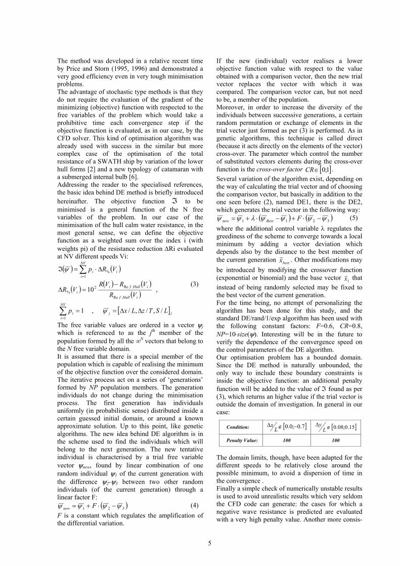
Fig. 3: Scatter plot of the evaluated individuals by optimisation algorithm. Free attitude, Fn=0.6.
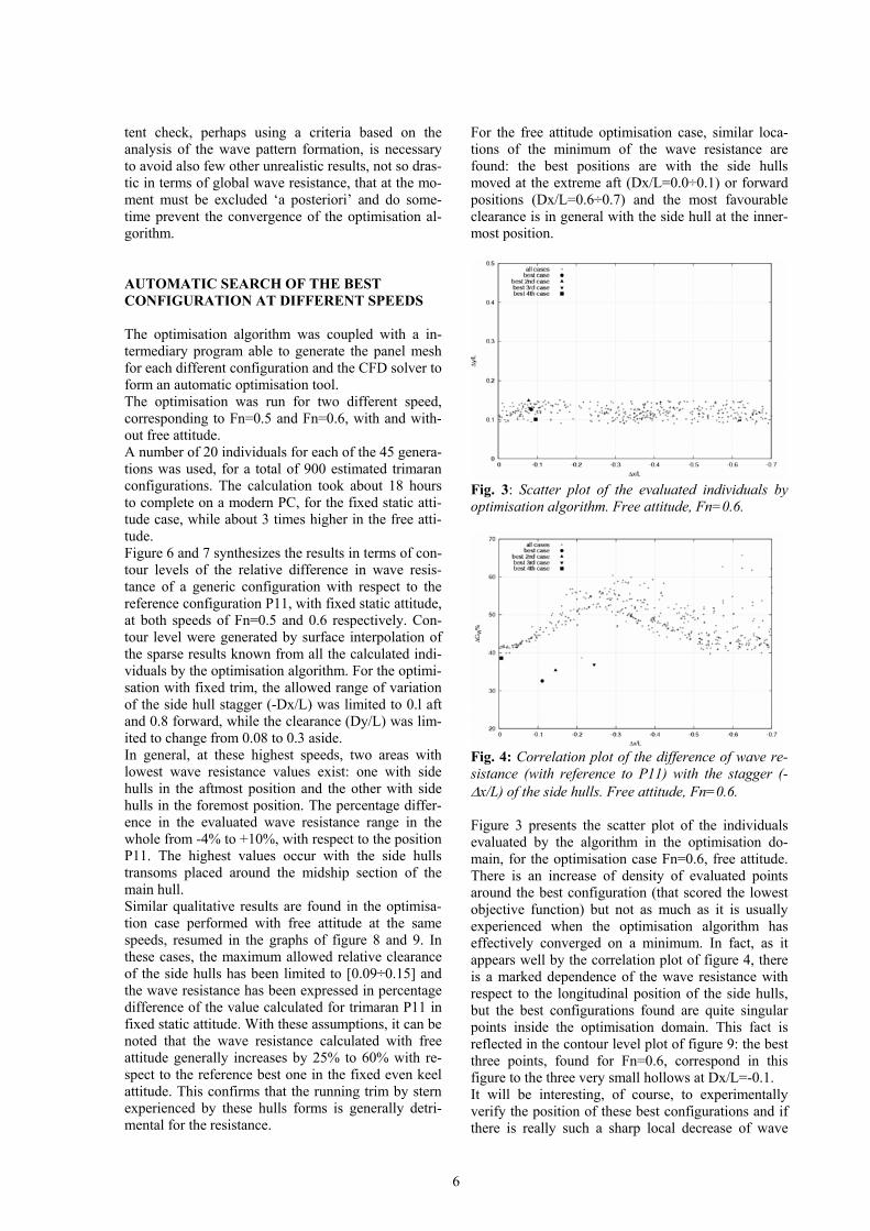
Fig. 4: Correlation plot of the difference of wave re-sistance (with reference to P11) with the stagger (-∆x/L) of the side hulls. Free attitude, Fn=0.6. Figure 3 presents the scatter plot of the individuals evaluated by the algorithm in the optimisation do-main, for the optimisation case Fn=0.6, free attitude. There is an increase of density of evaluated points around the best configuration (that scored the lowest objective function) but not as much as it is usually experienced when the optimisation algorithm has effectively converged on a minimum. In fact, as it appears well by the correlation plot of figure 4, there is a marked dependence of the wave resistance with respect to the longitudinal position of the side hulls, but the best configurations found are quite singular points inside the optimisation domain. This fact is reflected in the contour level plot of figure 9: the best three points, found for Fn=0.6, correspond in this figure to the three very small hollows at Dx/L=-0.1. It will be interesting, of course, to experimentally verify the position of these best configurations and if there is really such a sharp local decrease of wave
7
resistance. The test matrix of the configuration tested in towing tank (table 2) is, for obvious reasons in fact, too coarse to confirm at the moment these findings. The contour plots in figures 10 and 11 represent the experimentally deduced residuary resistance decre-ment, with respect to the reference CR found from the tests at the position P11. These plots confirm the gen-eral trend found for the wave resistance with respect to the longitudinal position of side hulls. The best area, generally being located around Dx/L=0.0÷0.1. CONCLUSIONS AND FUTURE RESEARCH A numerical CFD study on the optimum configura-tion of a trimaran hull design has been presented and discussed in details in the paper. The physical nature of various phenomena influencing the wave resis-tance of trimaran hulls has been examined with the aid of a series of preliminary calculations. The effect of trim (by stern) and sinkage is crucial for a better numerical evaluation of the wave resistance and in general always increases the resistance with respect to the hull running at the even keel (static) attitude. In particular, in the design of similar hull forms, it is worth trying to reduce the running trim and sinkage by means of different shaping of the aft buttocks for instance with a wedge or by means of active lift devices at stern. The results of the optimisation procedure indicate that at the highest speeds, corresponding to Fn=0.5 and Fn=0.6, there are in general two favourable staggers locations for the side hulls: one with the hull in the aftmost position (transom of the main and side hulls aligned) and the other in the foremost position (bow of the three hulls aligned). The most favourable clear-ance being almost always with the side hulls closer to the main hull. This general tendency is repeated also in the case of other fast trimaran designs, as it appears from the referenced literature. With these particular hull forms the optimisation al-gorithm found some singular isolated configurations that are able to score the lowest wave resistance. It will be interesting to verify the performance of these configurations by experimental tests. Some work must be still dedicated to increasing the robustness of the optimisation procedure, in particular defining some criteria to automatically recognize and exclude misleading calculation cases. In this sense, perhaps, some condition on the maximum amplitude of the generated wave pattern or the maximum al-lowed trim and sinkage could be advisable. For the future, it is planned to extend the optimisation procedure to a be able to considering as a free pa-rameter also the local shape of the hulls, the volume
distribution between the three hulls, or the relative volume and dimension of side hulls. REFERENCES 1. Begovic E., Bove A., Bruzzone D., Caldarella S., Cassella P., Ferrando M., Tincani E., Zotti I., 2005, Co-Operative Investigation into Resistance of Differ-ent Trimaran Hull Forms And Configurations, sub-mitted at the 8th Int. Conf. On Fast Marine Transpor-tation, St. Petersburg. 2. Brizzolara S., 2004, Parametric Optimization of SWAT-Hull Forms by a Viscous-Inviscid Free Sur-face Method Driven by a Differential Evolution Al-gorithm, 25th Symposium on Naval Hydrodynamics, St. John’s, Newfoundland and Labrador, CANADA, 3. Bruzzone D., 1994, Numerical Evaluation of the Steady Free Surface Waves, Proc. CFD Workshop Tokyo 1994, Ship Res. Inst. Tokyo, Vol.I, pp. 126-134. 4. Brizzolara S., Bruzzone D., Cassella P., Scamar-della I., Zotti I., 1998, Wave Resistance and Wave Pattern for High Speed Crafts; Validation of Numerical Results by Model Tests, Proc. XXII Sym-posium on Naval Hydrodynamics, Washington D.C., pp. 69-83. 5. Brizzolara S., Bruzzone D. (2000), Numerical Wave Resistance and Dynamic Trim for High Speed Crafts, Proc. NAV 2000 Int. Conference, Venice, Vol.I, pp. 4.2.1-4.2.13. 6. Brizzolara S., Bruzzone D., 2004, Automatic Op-timisation of a New Type of Catamaran with Bulb, HIPER 2004, 4th Int. Conf. On High performance Marine Vehicles, Rome, pp. 27-29. 7. Bruzzone D., Cassella P., Zotti I., 2000, Resistance Components on a Wigley Trimaran: Experimental and Numerical Investigation, Proc. of the Fourth Int. Conf. on Hydrodynamics, Yokohama, Vol I, pp. 115-120. 8. Brizzolara S., Bruzzone D., 2003, Near and Distant Waves of Fast Ships in Limited and Unlimited Depths, 7th International Conference on Fast Sea Transportation FAST 2003, Ischia, Italy, vol. III, pp. H1-H12. 9. Storn R., Price K., 1995, Differential Evolution – A Simple and Efficient Adaptive Scheme for Global Optimization over Continuous Spaces, TR-95-012, March 1995, Int. Computer Science Institute, Berke-ley, California. 10. Storn R., 1996, On the usage of Differential Evo-lution Algorithms for Function Optimization, Pro-ceedings NAFIPS, Berkeley, California, pp. 519-523.
8
X/L
Y/L
0 1 20
0.5
1-1.4 -1.2 -1.0 -0.8 -0.6 -0.4 -0.2 0.0 0.2 0.4 0.6 0.8 1.0 1.2 1.4
100*Z/L
X/L
Y/L
0.6 0.8 1 1.2 1.40
0.1
0.2
0.3
0.4
z: -1.4 -1.2 -1.0 -0.8 -0.6 -0.4 -0.2 0.0 0.2 0.4 0.6 0.8 1.0 1.2 1.4100*Z/L
Monohull in isolation, fixed attitude Isolated side hull, fixed attitude
X/L
Y/L
0 1 20
0.5
1-1.4 -1.2 -1.0 -0.8 -0.6 -0.4 -0.2 0.0 0.2 0.4 0.6 0.8 1.0 1.2 1.4
100*Z/L
X/L
Y/L
0 1 20
0.5
1-1.4 -1.2 -1.0 -0.8 -0.6 -0.4 -0.2 0.0 0.2 0.4 0.6 0.8 1.0 1.2 1.4
100*Z/L
Trimaran conf. P11, fixed even keel trim Trimaran conf. P11, free numerical attitude
X/L
Y/L
0 1 20
0.5
1-1.4 -1.2 -1.0 -0.8 -0.6 -0.4 -0.2 0.0 0.2 0.4 0.6 0.8 1.0 1.2 1.4
100*Z/L
X/L
Y/L
0 1 20
0.5
1-1.4 -1.2 -1.0 -0.8 -0.6 -0.4 -0.2 0.0 0.2 0.4 0.6 0.8 1.0 1.2 1.4
100*Z/L
Left: Best configuration found by automatic optimisation, free attitude Right: Example of unfavourable configuration ,free numerical attitude
Fig.5: Comparison of the predicted wave pattern of the main hull and trimaran, at the same speed Fn=0.6in different configurations and with or without free numerical attitude .

9
-4 -2 0 2 4 6 8 10
-0.8-0.7-0.6-0.5-0.4-0.3-0.2-0.1 0 0.1 0.05
0.1
0.15
0.2
0.25
0.3
Dx/L
Dy/L
Fig. 6: Contour level of the percentage decrease in wave resistance predicted by the numerical method during the optimisation process with fixed trim, when side hulls are shifted forward of Dx/L and aside of Dy/L with re-spect to the reference configuration P11, to find the optimum position, Fn=0.5.
-4 -2 0 2 4 6 8 10
-0.8-0.7-0.6-0.5-0.4-0.3-0.2-0.1 0 0.1 0.05
0.1
0.15
0.2
0.25
0.3
Dx/L
Dy/L
Fig. 7: Same as above, but for Fn=0.6: (the percentage decrease refers to the wave resistance of P11 conf. at Fn=0.6). The dotted rectangular area in-dicates the limit of the domain assumed for the optimisation with free attitude.

10
25 30 35 40 45 50 55 60 65
-0.7-0.6-0.5-0.4-0.3-0.2-0.1 0 0.09
0.1
0.11
0.12
0.13
0.14
0.15
Dx/L
Dy/L
Figure 8: Contour level showing the percentage increase in wave resistance predicted by the numerical method during the optimisation process with free attitude, with respect to the value predicted for P11 with fixed attitude. The stagger of side hulls towards the bow has negative Dx/L values and side shift is indicated with Dy/L with respect to the reference configuration P11, Fn=0.5.
30 35 40 45 50 55 60 65
-0.7-0.6-0.5-0.4-0.3-0.2-0.1 0 0.09
0.1
0.11
0.12
0.13
0.14
0.15
Dx/L
Dy/L
Figure 9: Same as above, but for Fn=0.6.
ST/L
CL/
L
0 0.02 0.04 0.06 0.08 0.1 0.12 0.14 0.16 0.18 0.20.1
0.12
0.14
0.16
0.18
Delta_CR %: 0 2 4 6 8 10 12 14 16
Figure 10: Interpolated contour levels of the percentage increase of residuary resistance for different position of side hulls, due to variation of the relative stagger (ST/L) and clearance (CL/L). Fn=0.5. The reference residu-ary resistance is that deduced from the tests for the position P11
ST/L
CL/
L
0 0.02 0.04 0.06 0.08 0.1 0.12 0.14 0.16 0.18 0.20.1
0.12
0.14
0.16
0.18
Delta_CR %: 0 2 4 6 8 10 12 14 16
Figure 11: Same as previous figure, but for Fn=0.6 (reference CR still that of P11).
Experimental tests area
Experimental tests area