
Strength Analysis of Hull Structures in Container Carriers
69
CLASSIFICATION NOTES DET NORSKE VERITAS AS The content of this service document is the subject of intellectual property rights reserved by Det Norske Veritas AS (DNV). The user accepts that it is prohibited by anyone else but DNV and/or its licensees to offer and/or perform classification, certification and/or verification services, including the issuance of certificates and/or declarations of conformity, wholly or partly, on the basis of and/or pursuant to this document whether free of charge or chargeable, without DNV's prior written consent. DNV is not responsible for the consequences arising from any use of this document by others. The electronic pdf version of this document found through http://www.dnv.com is the officially binding version No. 31.7 Strength Analysis of Hull Structures in Container Carriers JULY 2013
-
Upload
khangminh22 -
Category
Documents
-
view
1 -
download
0
Transcript of Strength Analysis of Hull Structures in Container Carriers
CLASSIFICATION NOTES
DET NORSKE VERITAS AS
The content of this service document is the subject of intellectual property rights reserved by Det Norske Veritas AS (DNV). The useraccepts that it is prohibited by anyone else but DNV and/or its licensees to offer and/or perform classification, certification and/orverification services, including the issuance of certificates and/or declarations of conformity, wholly or partly, on the basis of and/orpursuant to this document whether free of charge or chargeable, without DNV's prior written consent. DNV is not responsible for theconsequences arising from any use of this document by others.
The electronic pdf version of this document found through http://www.dnv.com is the officially binding version
No. 31.7
Strength Analysis of Hull Structures in Container Carriers
JULY 2013
FOREWORD
DNV is a global provider of knowledge for managing risk. Today, safe and responsible business conduct is both a licenseto operate and a competitive advantage. Our core competence is to identify, assess, and advise on risk management. Fromour leading position in certification, classification, verification, and training, we develop and apply standards and bestpractices. This helps our customers safely and responsibly improve their business performance. DNV is an independentorganisation with dedicated risk professionals in more than 100 countries, with the purpose of safeguarding life, propertyand the environment.
Classification Notes
Classification Notes are publications that give practical information on classification of ships and other objects. Examplesof design solutions, calculation methods, specifications of test procedures, as well as acceptable repair methods for somecomponents are given as interpretations of the more general rule requirements.
© Det Norske Veritas AS July 2013
Any comments may be sent by e-mail to [email protected]
If any person suffers loss or damage which is proved to have been caused by any negligent act or omission of Det Norske Veritas, then Det Norske Veritas shall pay compensation tosuch person for his proved direct loss or damage. However, the compensation shall not exceed an amount equal to ten times the fee charged for the service in question, provided thatthe maximum compensation shall never exceed USD 2 million.In this provision "Det Norske Veritas" shall mean the Foundation Det Norske Veritas as well as all its subsidiaries, directors, officers, employees, agents and any other acting on behalfof Det Norske Veritas.
Classification Notes - No. 31.7, July 2013
Changes – Page 3
DET NORSKE VERITAS AS
CHANGES – CURRENT
General
This document supersedes Classification Note No. 31.7, July 2011.
Text affected by the main changes in this edition is highlighted in red colour. However, if the changes involvea whole chapter, section or sub-section, normally only the title will be in red colour.
Main changes
• General
Sign convention for hull girder loads has been included. Application of hull girder loads in level 2 torsionanalyses has been updated accordingly. Methods on how to establish design waves for level 3 analysis havebeen made clear. Calculation procedures for lashing bridge, hatch cover stoppers and fuel oil tank structureshave been updated based on accumulated experience.
The former Appendix C Structural Verification Procedure for Hatch Cover Guide Post has been removed.
• Sec.1 Introduction
— Table 1-1: Clear requirements to when the different analysis level scope applies are introduced.
• Sec.2 Design Loads
— [2.1]: Definitions of coordinate system and sign convention are inserted for clarification.— [2.5.1]: Distribution of Rule defined wave torsional moments and still water torsional moments are made
clearer.
• Sec.4 Cargo Hold Analysis Based on Rule-Defined Load Cases
— [4.4.3]: Distribution of transverse loads when 20' containers are stowed in 40' bay is specified forclarification.
— Table 4-2: Buckling utilisation factors for longitudinal girders and watertight transverse bulkhead arefurther clarified.
• Sec.5 Level 1 Rule Torsional Analysis
— [5.1.3]: Figures showing Rule wave torsional moments distribution, warping stress and horizontal bendingstress distribution are updated.
— [5.5.6]: Figure for stress reading point for warping deformation induced stress is updated.— [5.7.1] Buckling utilisation factors for longitudinal structural members under combined stress are clarified
for level 1 torsion analysis.
• Sec.6 Level 2 Global Analysis
— [6.7]: Application of horizontal wave bending moment and torsional moments are updated based ondefinition of coordinate system and sign convention updated in [2.1]. Sign factors for hull girder loads fromCUTRES are specified, according to the sign convention updated in [2.1].
— [6.11.2]: Buckling utilisation factors for longitudinal structural members under combined stress areclarified for level 2 torsion analysis.
• Sec.7Level 3 Wave Load Analysis
— [7.4.3]: Still water conditions for ULS applied in wave load analysis is updated— [7.4.3]: Design waves for ULS applied in wave load analysis is updated— [7.8.3]: Still water conditions for FLS applied in wave load analysis is updated— [7.8.3]: Time fraction of each still water condition is updated
• App. A Structural Verification Procedure for Lashing Bridge Structure
— It is clarified that MSL of lashing bars should be used as lashing force for lashing bridge design.Alternatively, lashing force based on homogeneous weight distribution may be used as basis.
• App. B Structural Verification Procedure for Hatch Cover Stoppers
— It is clarified that homogeneous weight distribution should be used as design basis for hatch cover stoppers.In addition, it is clarified that 40' container stack weight and 20'+40' container combined stack weight(Russian stowage) should be considered.
Classification Notes - No. 31.7, July 2013
Changes – Page 4
DET NORSKE VERITAS AS
• App. C (Previous App. D) Structural Verification Procedure for Hatch Covers
— It is clarified that homogeneous weight distribution should be used as design basis for hatch covers. Inaddition, it is clarified that 40' container stack weight and 20'+40' container combined stack weight(Russian stowage) should be considered. The acceptance criteria are also aligned with existing practice.
• App. D (Previous App. E) Strength Analysis of Fuel Oil Deep Tank Structure in Container Hold
— Design loading conditions for fuel oil tanks are updated in accordance with experience.
In addition to the above stated main changes, editorial corrections may have been made.
Editorial Corrections
Classification Notes - No. 31.7, July 2013
Contents – Page 5
DET NORSKE VERITAS AS
CONTENTS
CHANGES – CURRENT ....................................................................................................................3
1. Introduction............................................................................................................................................ 71.1 General......................................................................................................................................................71.2 Container carrier characteristics ...............................................................................................................71.3 Objectives .................................................................................................................................................81.4 Application and scope...............................................................................................................................81.5 Mandatory scope of calculation/analysis ..................................................................................................91.6 Detailed scope for Level 1 Rule torsional analysis.................................................................................101.7 Detailed scope for Level 2 global analysis .............................................................................................101.8 Detailed scope for Level 3 wave load analysis .......................................................................................111.9 Definition of symbols and abbreviations ................................................................................................12
2. Design Loads......................................................................................................................................... 132.1 Definition of units, coordinate system and sign conventions .................................................................132.2 Design loads............................................................................................................................................152.3 Container forces .....................................................................................................................................152.4 Sea pressures...........................................................................................................................................162.5 Torsional moments for Level 1 Rule torsional analysis and Level 2 global analysis ............................16
3. Hull Girder Strength Calculation for Vertical Hull Girder Loads, and Local Rule Scantlings .. 183.1 Limits for design still water bending moment ........................................................................................183.2 Limits for still water shear force.............................................................................................................183.3 Scantling check positions........................................................................................................................18
4. Cargo Hold Analysis Based on Rule-Defined Load Cases ............................................................... 194.1 General....................................................................................................................................................194.2 Analysis model........................................................................................................................................194.3 Boundary conditions ...............................................................................................................................214.4 Load cases...............................................................................................................................................224.5 Acceptance criteria..................................................................................................................................22
5. Level 1 Rule Torsional Analysis ......................................................................................................... 255.1 General principles ...................................................................................................................................255.2 Combined nominal stress evaluation ......................................................................................................285.3 Combined hot spot stress evaluation.......................................................................................................295.4 Fatigue assessment..................................................................................................................................295.5 Calculation procedure .............................................................................................................................315.6 Stress concentration factors for hot spot stress evaluation .....................................................................345.7 Acceptance criteria..................................................................................................................................38
6. Level 2 Global Analysis ....................................................................................................................... 396.1 General principles ...................................................................................................................................396.2 Combined nominal stress evaluation ......................................................................................................396.3 Combined hot spot stress evaluation.......................................................................................................406.4 Fatigue assessment .................................................................................................................................416.5 Global coarse FE modelling ...................................................................................................................416.6 Load cases...............................................................................................................................................436.7 Load application......................................................................................................................................436.8 General procedures for obtaining hot spot stress....................................................................................476.9 Hot spot stress evaluation by fine-mesh models ....................................................................................486.10 Stress concentration factors for hot spot stress evaluation .....................................................................496.11 Acceptance criteria..................................................................................................................................51
7. Level 3 Wave Load Analysis ............................................................................................................... 527.1 General principles ...................................................................................................................................527.2 Hydrodynamic analysis...........................................................................................................................527.3 Structural modelling principles...............................................................................................................527.4 Methodology for ultimate limit state (ULS) assessment ........................................................................527.5 Combined nominal stress evaluation (ULS) ...........................................................................................547.6 Transverse strength of the fore and aft body ..........................................................................................547.7 Combined hot spot stress evaluation (ULS) ...........................................................................................557.8 Methodology for fatigue limit state (FLS) assessment ...........................................................................557.9 Fatigue assessment of hatchway corners and stringer corners................................................................567.10 Fatigue assessment of stiffener end connections amidships ...................................................................577.11 Documentation and verification..............................................................................................................577.12 Acceptance criteria..................................................................................................................................57
Classification Notes - No. 31.7, July 2013
Contents – Page 6
DET NORSKE VERITAS AS
8. References............................................................................................................................................. 59
Appendix A.
Structural Verification Procedure for Lashing Bridge Structure ............................................................ 60
Appendix B.
Structural Verification Procedure for Hatch Cover Stoppers................................................................... 62
Appendix C.
Structural Verification Procedure for Hatch Covers ................................................................................. 64
Appendix D.
Strength Analysis of Fuel Oil Deep Tank Structure in Container Hold .................................................. 66
CHANGES – HISTORIC................................................................................................................... 69
Classification Notes - No. 31.7, July 2013
Sec.1 Introduction – Page 7
DET NORSKE VERITAS AS
1 Introduction
1.1 General
This Classification Note describes the scope and methods required for structural analysis of container carriersand the background for how such analyses should be carried out. The description is based on relevant Rules forClassification of Ships, guidance and software.
The DNV Rules for Classification of Ships may require direct structural strength analyses in case of a complexstructural arrangement, or unusual vessel size.
Structural analyses carried out in accordance with the procedure outlined in this Classification Note willnormally be accepted as basis for plan approval.
Where the text refers to the Rules for Classification of Ships, the references refer to the latest edition of theRules for Classification of Ships.
Any recognised calculation method or computer program may be utilised provided that the effects of bending,shear, axial and torsional deformations are considered, when relevant.
If wave loads are calculated from a hydrodynamic analysis, it is required to use recognised software. Asrecognised software is considered all wave load programs that can show results to the satisfaction of theSociety.
1.2 Container carrier characteristics
1.2.1 Container carrier categories
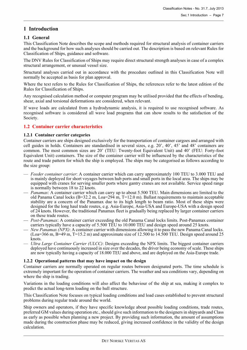
Container carriers are ships designed exclusively for the transportation of container cargoes and arranged withcell guides in holds. Containers are standardised in several sizes, e.g. 20’, 40’, 45’ and 48’ containers arecommon. The most common sizes are 20’ (TEU: Twenty-foot Equivalent Unit) and 40’ (FEU: Forty-footEquivalent Unit) containers. The size of the container carrier will be influenced by the characteristics of theroute and trade pattern for which the ship is employed. The ships may be categorised as follows according tothe size group:
— Feeder container carrier: A container carrier which can carry approximately 100 TEU to 3.000 TEU andis mainly deployed for short voyages between hub ports and small ports in the local area. The ships may beequipped with cranes for serving smaller ports where gantry cranes are not available. Service speed rangeis normally between 18 to 22 knots.
— Panamax: A container carrier which can carry up to about 5.500 TEU. Main dimensions are limited to theold Panama Canal locks (B=32.2 m, Loa=294 m, T=12.0 m). Ballast requirements to maintain acceptablestability are a concern of the Panamax due to its high length to beam ratio. Most of these ships weredesigned for the long haul trade routes, e.g. Asia-Europe, Asia-USA and Europe-USA with a design speedof 24 knots. However, the traditional Panamax fleet is gradually being replaced by larger container carrierson these trade routes.
— Post-Panamax: A container carrier exceeding the old Panama Canal locks limits. Post-Panamax containercarriers typically have a capacity of 5.500 TEU to 10.000 TEU and design speed around 25 knots.
— New Panamax (NPX): A container carrier with dimensions allowing it to pass the new Panama Canal locks.(Loa=366 m, B=49 m, T=15.2 m) and approximate size of 12.500 to 14.500 TEU. Design speed around 25knots.
— Ultra Large Container Carrier (ULCC): Designs exceeding the NPX limits. The biggest container carriersdeployed have continuously increased in size over the decades, the driver being economy of scale. These shipsare now typically having a capacity of 18.000 TEU and above, and are deployed on the Asia-Europe trade.
1.2.2 Operational patterns that may have impact on the design
Container carriers are normally operated on regular routes between designated ports. The time schedule isextremely important for the operation of container carriers. The weather and sea conditions vary, depending onwhere the ship is trading.
Variations in the loading conditions will also affect the behaviour of the ship at sea, making it complex topredict the actual long-term loading on the hull structure.
This Classification Note focuses on typical loading conditions and load cases established to prevent structuralproblems during regular trade around the world.
Ship owners and operators, if they have specific knowledge about possible loading conditions, trade routes,preferred GM values during operation etc., should give such information to the designers in shipyards and Classas early as possible when planning a new project. By providing such information, the amount of assumptionsmade during the construction phase may be reduced, giving increased confidence in the validity of the designcalculation.
Classification Notes - No. 31.7, July 2013
Sec.1 Introduction – Page 8
DET NORSKE VERITAS AS
1.2.3 Torsional response
Container carriers having large hatchway openings are subject to large torsional response compared to shipshaving closed cross-sections. Only considering the vertical hull girder force components is therefore notsufficient to decide the required hull girder strength.
The torsion (still water torsion induced by cargo and unsymmetrical tank arrangement etc., and wave torsioninduced by oblique wave encounter) and the horizontal wave bending moment should therefore also beincluded in the hull girder strength assessments.
The criticality of the torsional response will heavily depend on the ship size. This Classification Note describesthree different levels for longitudinal hull girder strength assessments including torsional analysis, dependingon the ship size, as shown in Table 1-1.
1.3 Objectives
The objective of this Classification Note is:
— To give a guidance for design and assessment of the hull structures of container carriers in accordance withthe Rules for Classification of Ships.
— To give a general description on how to carry out relevant calculations and analyses.— To suggest alternative methods for torsional response calculation.— To achieve a reliable design by adopting rational design and analysis procedures.
1.4 Application and scope
1.4.1 Overview of different analysis levels
In order to achieve the objectives described in [1.3] three different analysis levels are defined. The threedifferent analysis levels are applicable for the design of container carriers according to the vessel characteristicsas described in Table 1-1.
Level 1 analysis should normally be carried out as part of the mandatory procedure for theNAUTICUS(Newbuilding) notation. However, strengthening required by the Level 1 analysis may beoverruled by findings from more comprehensive analyses according to Level 2 and Level 3.
1.4.2 Calculation tools
The following tools may be used, depending upon the characteristics of the vessel and the required analysisscope as shown in Table 1-1:
— NAUTICUS Hull 1) Section Scantlings can be used for typical midship section and other necessary cross-sections in order to calculate:
Table 1-1 Analysis levels versus calculation/analysis scope
LevelRules calculationLevel 1 Analysis
Extended Rule calculationLevel 2 Analysis
ComprehensiveLevel 3 Analysis
Applicable NotationNAUTICUS(Newbuilding)*
NAUTICUS(Newbuilding)
NAUTICUS(Newbuilding)
Mandatory scope of calcula-tion/analysis
— hull girder strength calculation for vertical bending moments and vertical shear forces, and local Rules scantlings
— rule check of hull girder ultimate strength — rule fatigue strength calculation for end connections of longitudinals **— cargo hold analysis based on Rule-defined loading conditions **— rule torsional calculation (ULS) for longitudinal members and hatchway corners— rule torsional calculation (FLS) for hatchway corners.
Supplementary scope of analysis
Global FE analysis for Rule torsional load cases (ULS and FLS)
Global FE analysis with di-rect calculated wave loads (ULS and FLS)
Fine-mesh analysis for selected hatchway corners and stringer corners (ULS and FLS)
Remarks Intended for container carri-ers with B ≤ 40 m
Mandatory for container car-riers with 40 m < B ≤ 52 m
Mandatory for container car-riers with B > 52 m
* NAUTICUS(Newbuilding) notation is mandatory for Container Carriers with length greater than 190 m.** For designs where the NAUTICUS(Newbuilding) notation is mandatory, the structural verification procedures
require the use of FEA in the evaluation of the midship cargo hold region. In addition, extended fatigue evaluations of end connections of longitudinals within the cargo region are required.
Classification Notes - No. 31.7, July 2013
Sec.1 Introduction – Page 9
DET NORSKE VERITAS AS
— local rule scantlings— hull girder strength calculation for vertical bending moments and vertical shear forces— rule check of hull girder ultimate strength— rule fatigue strength calculation for end connections of longitudinals.
— Cargo hold analysis for the assessment of primary structures in the midship area using NAUTICUS Hull1)
Genie FE modelling and analysis tools.— Rule torsion calculation using NAUTICUS Hull1) Section Scantlings, 3D Beam and Simplified Torsion
Calculation Tool.— Global analysis modelling the complete ship length using NAUTICUS Hull1) Genie FE modelling and
analysis tools, and using load cases obtained either by direct wave load analysis or Rule-defined loads.— Verification of applied loads to the global model using NAUTICUS Hull 1) CUTRES.— Wave load analysis2) as part of a global analysis using WASIM 3) or equivalent.— Hatchway corner analysis, Ultimate Limit State (ULS) and Fatigue Limit State (FLS), with fine-mesh
model for selected hatchway corner locations. Evaluation of the remaining hatchway corners based onestablished stress concentration factors and nominal stress.
1) NAUTICUS Hull is a computer program, offered by DNV, that is suitable for the calculations of Rules required scantlings and cargo hold analysis,etc.
2) Direct wave load analysis is not part of the mandatory requirement for NAUTICUS(Newbuilding) class notation, but is mandatory for Ultra LargeContainer Carriers.
3) WASIM is a linear/nonlinear time domain computational tool for sea keeping and load analysis of ships. The complete 3D interaction betweenwaves and hull at forward speed is included. The computer program is not limited to small waves but can simulate also extreme wave conditions.
1.5 Mandatory scope of calculation/analysis
1.5.1 Hull girder strength calculation for vertical hull girder loads, and local Rule scantlings
Longitudinal strength of the vessel for vertical bending moments and vertical shear forces, and local Rulescantlings can be verified by the Rule-defined calculation procedure as further described in Sec.3. NAUTICUSHull Section Scantlings should be utilised for a suitable number of cross-sections along the length of the ship.Special attention should be given to sections where the arrangement of longitudinal material changes. Sectionsclose to the aft and forward quarter-length, and at the transition between the engine room and cargo hold area,need to be specially considered.
1.5.2 Rule check of hull girder ultimate strength
A global ULS hull girder criterion for container carriers is given in the Rules for Classification of Ships Pt.5Ch.2 Sec.6 B200 /2/. This implies that the whole length of the ship is verified to have an ultimate yield andbuckling strength to withstand an extreme vertical wave hogging moment, through an advanced bucklinganalysis method.
All relevant cross-sections shall be considered; also outside 0.4 L. Hull cross-sections with transverselystiffened areas, such as engine rooms, are considered to be especially important to be checked.
Cross-sections modelled in NAUTICUS Hull Section Scantlings in order to comply with requirements inaccordance with [1.5.1] can be utilized for strength verification according to the global ULS hull girdercriterion.
1.5.3 Rule fatigue strength calculation for end connections of longitudinals
For container carriers where the NAUTICUS(Newbuilding) notation is mandatory (see Rules for Classificationof Ships Pt.5 Ch.2 Sec.6 A106), the fatigue characteristics of end connections of longitudinals in bottom, innerbottom, side, inner side/longitudinal bulkheads and decks should be assessed as specified in Rules forClassification of Ships Pt.5 Ch.2 Sec.6 B810.
For other designs where the NAUTICUS(Newbuilding) notation is not mandatory, as a minimum the fatiguecharacteristics of side shell longitudinals as given in Rules for Classification of Ships Pt.3 Ch.1 Sec.7 E400 /1/should be evaluated.
1.5.4 Cargo hold analysis based on Rule-defined load cases
Strength of the typical primary structural members in the midship area shall be assessed through a cargo holdanalysis using NAUTICUS Hull Genie FE modelling and analysis tools or equivalent. The complete analysisincluding modelling, load cases, strength assessment, allowable stresses, and buckling control should becarried out according to the procedures given in Sec.3.
For fuel oil deep tanks arranged in the cargo area, i.e. fuel oil deep tanks located inboard of the inner side, abovethe inner bottom, and between adjacent transverse bulkheads, additional strength analysis should be carried outin order to determine the required scantling of primary structures. Applicable procedures are described inAppendix [D].
Classification Notes - No. 31.7, July 2013
Sec.1 Introduction – Page 10
DET NORSKE VERITAS AS
1.6 Detailed scope for Level 1 Rule torsional analysis
1.6.1 General
The Level 1 Rule torsional analysis is in line with the standard Rule scope and provides a fast and reliablemethod for torsional response assessment. This procedure may also be used at an early design stage for largerand/or novel container carrier designs in order to obtain preliminary torsional response results.
1.6.2 Application
For smaller ships with B ≤ 40 m, a Level 1 Rule torsional analysis is considered sufficient for the strengthassessment.
1.6.3 Objective
The objective of a Level 1 Rule torsional analysis is to examine the hull girder structural response due to stillwater and Rule wave torsional moments combined with Rule vertical bending moments and Rule horizontalwave bending moment.
1.6.4 Scope
In order to assess torsional response for smaller container carriers, a simplified torsional assessment (Level 1Rule torsional analysis) has been proven reliable. The Level 1 Rule torsional analysis is based on prismaticbeam theory, applying Rule-defined loads (vertical bending, horizontal wave bending and torsion). A Level 1Rule torsional analysis shall be carried out within the cargo hold area where the hatchway opening size remainsunchanged.
The scope of the torsional response evaluation is to carry out, within the Level 1 Rule torsional model range:
— yield check of nominal combined stress in way upper deck hatchway corners and hatch coaming top cornersas given in [5.2]
— yield check of combined hot spot stress in way of upper deck hatchway corners and hatch coaming top asgiven in [5.3]
— fatigue assessment of upper deck hatchway corners and hatch coaming top corners as given in [5.4]— yield check and uni-axial buckling assessment of nominal combined stress of the bilge area and lower stool
bench structures, applying nominal combined stress as given in [5.2].
The hot spot stress in way of the hatchway corners for yield check and fatigue assessment shall be establishedbased on nominal combined stress, combined with predefined stress concentration factors defined in [5.6].
The Level 1 Rule torsional response evaluation calculation procedure is further described in [5.5].
1.7 Detailed scope for Level 2 global analysis
1.7.1 General
The Level 2 global analysis includes a more elaborate procedure for obtaining nominal combined stresses. Thescope for establishing hot spot stresses is also more detailed compared with Level 1 Rule torsional analysis (see[1.7.4]). Acceptance criteria are in general the same as for Level 1 Rule torsional analysis.
1.7.2 Application
This procedure applies to container with 40 m ≤ B < 52 m, but may also be applicable for smaller ships havingan unconventional structural arrangement.
1.7.3 Objective
The objective of a Level 2 global analysis is:
— To examine hull structural response to still water and Rule wave torsional moments combined with Rulevertical bending moments and Rule horizontal wave bending moment
— To obtain hull deflections at the hatch coaming top level.
1.7.4 Scope
A Level 2 global analysis includes a global coarse FE model covering the entire ship length, and fine-meshmodels for selected critical locations. The global loads are same loads as for Level 1 Rule torsional analysis(Rule-defined loads). The loads are applied to the global model in a simplified manner by adding point loadsthroughout the ship length. The scope of the global response evaluation is to carry out throughout the entireship length:
— yield check of nominal combined stress in way of upper deck hatchway corners and hatch coaming topcorners as given in [6.2]
Classification Notes - No. 31.7, July 2013
Sec.1 Introduction – Page 11
DET NORSKE VERITAS AS
— yield check of combined hot spot stress in way of hatchway corners, critical stringer corners in the forwardarea, and corners in way of HFO deep tank top structures (if applicable) as given in [6.3]
— fatigue assessment of hatchway corners, critical stringer corners in the forward area, and corners in way ofHFO deep tank top structures (if applicable) as given in [6.4]
— yield check and uni-axial buckling assessment of nominal combined stress of the bilge area and lower stoolbench structures, applying nominal combined stress as given in [6.2]
— assessment of hull deflections at the hatch coaming top and the upper deck levels, as guidance to the hatchcover manufacturer.
The hot spot stress for yield check and fatigue assessment is for certain critical areas as specified in [6.8.2] tobe established based on fine-mesh models. For the remaining locations the simplified procedure as outlined in[6.8.3] should be used.
1.8 Detailed scope for Level 3 wave load analysis
1.8.1 General
The Level 3 wave load analysis involves a comprehensive analysis scope requiring direct calculation of waveload and response. The scope of hydrodynamic analysis and structural modelling principles for the coarseglobal FE model is comparable to that required for the CSA-2 class notation according to the Rules forClassification of Ships Pt.3 Ch.1 Sec.15 E. The scope for Ultimate Limit State (ULS) assessment and FatigueLimit State (FLS) assessment is quite limited compared to the CSA-2 class notation, as shown in [1.8.4.3] and[1.8.4.4].
1.8.2 Application
This analysis is mandatory for container carriers with B > 52 m. This analysis is also recommended for smallercontainer carriers having extraordinary structural arrangement or main dimensions, as well as vessels of noveldesign.
1.8.3 Objective
The aim of the analysis is to ensure that all critical structural details are adequately designed to meet fatigueand strength requirements. The objective of a Level 3 wave load analysis is:
— to calculate the design waves for vertical hull girder loads in upright condition— to calculate, along the hull girder, the maximum combined hull girder stress and stress range induced by
wave torsional moment, wave horizontal bending moment and wave vertical bending moment in obliquewaves
— to examine hull structural response against the chosen maximum conditions as above, with regard tobuckling, yield and fatigue
— to obtain hull deformations at hatch coaming top level— to assess the transverse strength of the fore and aft body.
1.8.4 Scope
1.8.4.1 Hydrodynamic analysis
Typically, two different types of hydrodynamic analyses shall be carried out. These are:
— ULS (Ultimate Limit State) analysis intended to calculate hull girder loads, local sea pressure and motionsin extreme environmental conditions
— FLS (Fatigue Limit State) analysis intended for calculation of dynamic loads used for fatigue assessmentof critical details of the structure.
The objectives of the wave load analysis are:
— to calculate the sea-keeping characteristics of the vessel, including accelerations— to calculate the global hull girder loads distributed over the vessel length— to establish design waves for ULS conditions for further nonlinear wave load calculations— to calculate ULS load cases for global strength, buckling and yield checks— to calculate FLS load cases for hatchway corners, HFO deep tank structure (where applicable), critical
stringer corners in the forward area, and for longitudinal connection in side shell and bilge area in themidship.
The procedures for hydrodynamic analysis are further described in [7.2].
1.8.4.2 Structural modelling principles
A Level 3 wave load analysis includes a global coarse FE structural model covering the entire ship length. Theprocedures for structural modelling are further described in [7.3]. The global coarse FE model is similar to thatfor Level 2 global analysis, with a more detailed load application (pressure loads transferred from the
Classification Notes - No. 31.7, July 2013
Sec.1 Introduction – Page 12
DET NORSKE VERITAS AS
hydrodynamic analysis), and with mass modelling in order to obtain equilibrium.
The scope for establishing hot spot stress is the same as for Level 2 global analysis as shown in [1.6.4].
1.8.4.3 Ultimate Limit State (ULS) assessment
The procedures for obtaining nominal stresses in the coarse FE structural model are similar to the proceduresoutlined in Classification Note No. 34.1, CSA – Direct Analysis of Ship Structures, Sec.5 /4/. The methodologyis further specified in [7.4].
The scope and procedures for result evaluation are somewhat reduced compared to Classification Note No.34.1, and are therefore further described in the following sections:
— combined nominal stress evaluation (ULS) according to [7.5]— transverse strength of the fore and aft body according to [7.6]— combined hot spot stress evaluation (ULS) according to [7.7].
1.8.4.4 Fatigue Limit State (FLS) assessment
The procedures for obtaining nominal stresses in the coarse FE structural model are similar to the proceduresas outlined in Classification Note No. 34.1, CSA – Direct Analysis of Ship Structures, Sec.4. The methodologyis further specified in [7.8].
The scope and procedures for fatigue assessment is somewhat reduced compared to Classification Note No.34.1, and is therefore further described in the following sections:
— fatigue assessment of hatchway corners and stringer corners according to [7.9]— fatigue assessment of stiffener end connections amidship according to [7.10].
1.8.4.5 Deformation
The deformation of the hatch coaming in the maximum torsional load case is important for the hatch coverdesign.
The deformation should also be considered in connection with lashing, e.g. lashing bridge may take additionalforce due to relative movement between hatch cover and hatch coamings.
1.9 Definition of symbols and abbreviationsSymbols not mentioned in the following list are given in connection with relevant formulae. The generalsymbols may be repeated when additional definitions are found necessary in connection with specific formulae.
L = Rule length in m 1)
B = Rule breadth in m 1)
D = Rule depth in m 1)
T = Rule draught in m 1)
TA = draught in m for considered conditionTB = draught in m for ballast conditionCB = Rule block coefficient 1)
CW = wave coefficient 2)
V = maximum service speed in knots on draught TE = modulus of elasticity, 2.1·105 N/mm2 for steelG = shear modulus, 0.7·105 N/mm2 for steelav = combined dynamic vertical acceleration in m/s2 2)
go = standard acceleration of gravity, 9.81 m/s2
hdb = height of double bottom in mφ = rolling angle 2)
θ = pitching angle 2)
ULS = Ultimate Limit State (i.e. stress, yield and buckling check)FLS = Fatigue Limit State.
1) For details, see the Rules for Classification of Ships Pt.3 Ch.1 Sec.1.
2) For details, see the Rules for Classification of Ships Pt.3 Ch.1 Sec.4 B.
Classification Notes - No. 31.7, July 2013
Sec.2 Design Loads – Page 13
DET NORSKE VERITAS AS
2 Design Loads
2.1 Definition of units, coordinate system and sign conventions
2.1.1 Definition of units
The following SI units are used in this Classification Note:
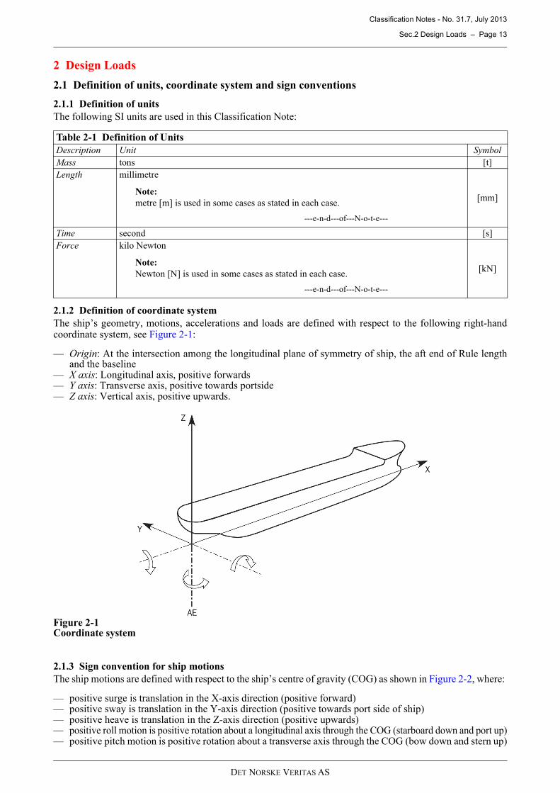
2.1.2 Definition of coordinate system
The ship’s geometry, motions, accelerations and loads are defined with respect to the following right-handcoordinate system, see Figure 2-1:
— Origin: At the intersection among the longitudinal plane of symmetry of ship, the aft end of Rule lengthand the baseline
— X axis: Longitudinal axis, positive forwards— Y axis: Transverse axis, positive towards portside— Z axis: Vertical axis, positive upwards.
Figure 2-1Coordinate system
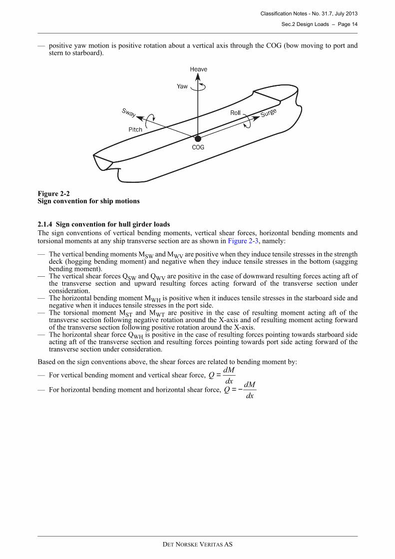
2.1.3 Sign convention for ship motions
The ship motions are defined with respect to the ship’s centre of gravity (COG) as shown in Figure 2-2, where:
— positive surge is translation in the X-axis direction (positive forward)— positive sway is translation in the Y-axis direction (positive towards port side of ship)— positive heave is translation in the Z-axis direction (positive upwards)— positive roll motion is positive rotation about a longitudinal axis through the COG (starboard down and port up)— positive pitch motion is positive rotation about a transverse axis through the COG (bow down and stern up)
Table 2-1 Definition of Units
Description Unit Symbol
Mass tons [t]
Length millimetre
Note:
metre [m] is used in some cases as stated in each case.
---e-n-d---of---N-o-t-e---
[mm]
Time second [s]
Force kilo Newton
Note:
Newton [N] is used in some cases as stated in each case.
---e-n-d---of---N-o-t-e---
[kN]
Classification Notes - No. 31.7, July 2013
Sec.2 Design Loads – Page 14
DET NORSKE VERITAS AS
— positive yaw motion is positive rotation about a vertical axis through the COG (bow moving to port andstern to starboard).
Figure 2-2Sign convention for ship motions
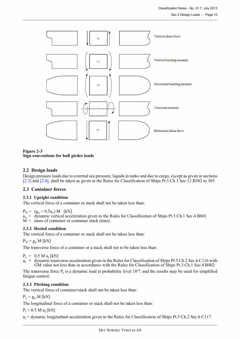
2.1.4 Sign convention for hull girder loads
The sign conventions of vertical bending moments, vertical shear forces, horizontal bending moments andtorsional moments at any ship transverse section are as shown in Figure 2-3, namely:
— The vertical bending moments MSW and MWV are positive when they induce tensile stresses in the strengthdeck (hogging bending moment) and negative when they induce tensile stresses in the bottom (saggingbending moment).
— The vertical shear forces QSW and QWV are positive in the case of downward resulting forces acting aft ofthe transverse section and upward resulting forces acting forward of the transverse section underconsideration.
— The horizontal bending moment MWH is positive when it induces tensile stresses in the starboard side andnegative when it induces tensile stresses in the port side.
— The torsional moment MST and MWT are positive in the case of resulting moment acting aft of thetransverse section following negative rotation around the X-axis and of resulting moment acting forwardof the transverse section following positive rotation around the X-axis.
— The horizontal shear force QWH is positive in the case of resulting forces pointing towards starboard sideacting aft of the transverse section and resulting forces pointing towards port side acting forward of thetransverse section under consideration.
Based on the sign conventions above, the shear forces are related to bending moment by:
— For vertical bending moment and vertical shear force,
— For horizontal bending moment and horizontal shear force,
dx
dMQ =
dx
dMQ −=
Classification Notes - No. 31.7, July 2013
Sec.2 Design Loads – Page 15
DET NORSKE VERITAS AS
Figure 2-3Sign conventions for hull girder loads
2.2 Design loads
Design pressure loads due to external sea pressure, liquids in tanks and due to cargo, except as given in sections[2.3] and [2.4], shall be taken as given in the Rules for Classification of Ships Pt.3 Ch.1 Sec.12 B302 to 305.
2.3 Container forces
2.3.1 Upright condition
The vertical force of a container or stack shall not be taken less than:
PV = (go + 0.5av) M [kN]av = dynamic vertical acceleration given in the Rules for Classification of Ships Pt.3 Ch.1 Sec.4 B601M = mass of container or container stack (tons).
2.3.2 Heeled condition
The vertical force of a container or stack shall not be taken less than:
PV = go M [kN]
The transverse force of a container or a stack shall not to be taken less than:
Pt = 0.5 M at [kN]at = dynamic transverse acceleration given in the Rules for Classification of Ships Pt.5 Ch.2 Sec.6 C116 with
GM value not less than in accordance with the Rules for Classification of Ships Pt.3 Ch.1 Sec.4 B402
The transverse force Pt is a dynamic load at probability level 10-4, and the results may be used for simplifiedfatigue control.
2.3.3 Pitching condition
The vertical force of container/stack shall not be taken less than:
Pv = go M [kN]
The longitudinal force of a container or stack shall not be taken less than:
Pt = 0.5 M al [kN]
al = dynamic longitudinal acceleration given in the Rules for Classification of Ships Pt.5 Ch.2 Sec.6 C117.
Classification Notes - No. 31.7, July 2013
Sec.2 Design Loads – Page 16
DET NORSKE VERITAS AS
2.4 Sea pressures
2.4.1 Upright seagoing conditions
The external sea pressure in upright seagoing conditions shall be taken in accordance with the Rules forClassification of Ships Pt.3 Ch.1 Sec.12 B306.
2.4.2 Heeled conditions
The external sea pressure in heeled conditions shall normally be taken in accordance with the Rules forClassification of Ships Pt.5 Ch.2 Sec.6 C115.
For external sea pressures in heeled conditions to be applied for strength analysis of fuel oil deep tank structurein container hold, please refer to Appendix [D].
2.5 Torsional moments for Level 1 Rule torsional analysis and Level 2 global analysis
2.5.1 ULS
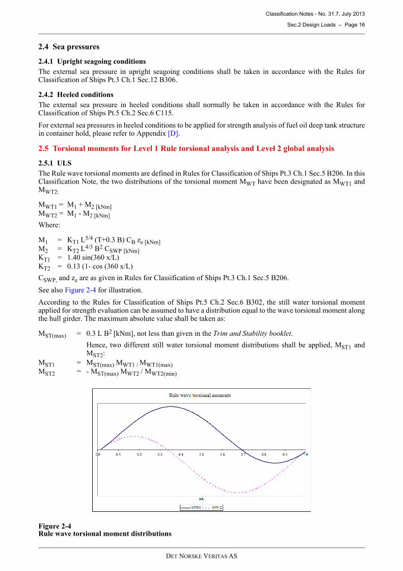
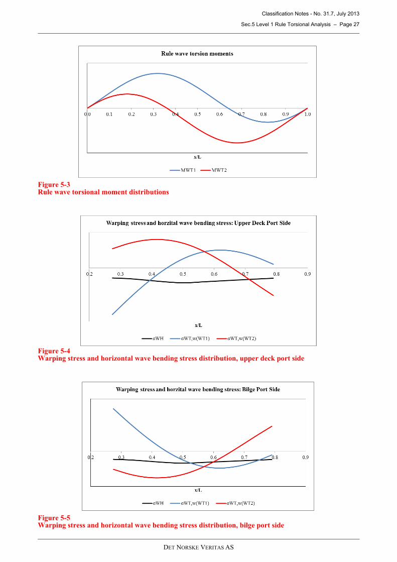
The Rule wave torsional moments are defined in Rules for Classification of Ships Pt.3 Ch.1 Sec.5 B206. In thisClassification Note, the two distributions of the torsional moment MWT have been designated as MWT1 andMWT2:
MWT1 = M1 + M2 [kNm]
MWT2 = M1 - M2 [kNm]
Where:
M1 = KT1 L5/4 (T+0.3 B) CB ze [kNm]
M2 = KT2 L4/3 B2 CSWP [kNm]
KT1 = 1.40 sin(360 x/L)
KT2 = 0.13 (1- cos (360 x/L)
CSWP, and ze are as given in Rules for Classification of Ships Pt.3 Ch.1 Sec.5 B206.
See also Figure 2-4 for illustration.
According to the Rules for Classification of Ships Pt.5 Ch.2 Sec.6 B302, the still water torsional momentapplied for strength evaluation can be assumed to have a distribution equal to the wave torsional moment alongthe hull girder. The maximum absolute value shall be taken as:
MST(max) = 0.3 L B2 [kNm], not less than given in the Trim and Stability booklet.
Hence, two different still water torsional moment distributions shall be applied, MST1 andMST2:
MST1 = MST(max) MWT1 / MWT1(max)
MST2 = - MST(max) MWT2 / MWT2(min)
Figure 2-4Rule wave torsional moment distributions
Classification Notes - No. 31.7, July 2013
Sec.2 Design Loads – Page 17
DET NORSKE VERITAS AS
2.5.2 FLS
For FLS, the Rule-defined wave torsional moments should be reduced to 10-4 probability level by the fr factoras defined in Classification Note No. 30.7 Fatigue Assessment of Ship Structures /3/. Fatigue life shall bechecked for both Rule-defined torsional cases, MWT1 and MWT2:
Mwt1 = fr MWT1
Mwt2 = fr MWT2
Where:
fr = factor to reduce the load from 10-8 to 10-4 probability level = 0.51/h
0h0 = long-term Weibull shape parameter = 2.21 – 0.54 log10(L)
Classification Notes - No. 31.7, July 2013
Sec.3 Hull Girder Strength Calculation for Vertical Hull Girder Loads, and Local Rule Scantlings – Page 18
DET NORSKE VERITAS AS
3 Hull Girder Strength Calculation for Vertical Hull Girder Loads, and Local Rule Scantlings
3.1 Limits for design still water bending momentIn general, the design still water bending moments shall be taken as the greater of:
— maximum values according to the loading conditions in Trim and Stability Booklet— rule values as given in the Rules for Classification of Ships Rules for Classification of Ships Pt.3 Ch.1
Sec.5 B100.
The design still water bending moments may according to the Rules for Classification of Ships Rules Pt.5 Ch.2Sec.6 be based on the envelope curve representing all relevant fully and partly load cargo and ballast conditionsas given in the Rules for Classification of Ships Pt.3 Ch.1 Sec.5 B101.
In general, it is recommended to have a 5% margin over the maximum still water bending moments accordingto the Trim and Stability Booklet. The margin relative to the design bending moments is normally to be decidedbased on the agreement between the builder and the owner.
The longitudinal distributions of the vertical wave bending moments, horizontal wave bending moment andwave torsional moments shall be according to the Rules for Classification of Ships.
3.2 Limits for still water shear forceThe still water shear force limits (positive and negative) along the entire hull length should be established fora seagoing and harbour conditions. The still water shear force limits shall be established by a shear flowanalysis.
The shear flow analysis shall be carried out at several longitudinal positions in order to establish a shear forcelimit curve that reflects the hull girder shear force capacity over the length of the ship.
The calculated hull girder shear stress shall comply with the yield and buckling criteria specified in the Rulesfor Classification of Ships Pt.3 Ch.1 Sec.5 D101.
Shear force correction at the watertight bulkheads need not to be carried out in general.
3.3 Scantling check positionsA local Section Scantlings analysis should normally be carried out for the cross-sections where the structuralarrangement and the scantlings of longitudinal members are changed.
The following cross-sections shall, as a minimum, be analysed:
— midship section— 0.25 L from A.P.— 0.75 L from A.P.— in way of HFO deep tank structure (where relevant)— 3 to 5 frame spaces aft of the forward E.R. bulkhead.
In order to carry out a complete longitudinal strength assessment for vertical hull girder loads, it isrecommended to run cross-sectional analyses in way of every transverse bulkhead location within the cargohold area. In way of stepping of stool bench structures, due consideration should be given when assessing thehull girder bending efficiency.
Classification Notes - No. 31.7, July 2013
Sec.4 Cargo Hold Analysis Based on Rule-Defined Load Cases – Page 19
DET NORSKE VERITAS AS
4 Cargo Hold Analysis Based on Rule-Defined Load Cases
4.1 General
The objective of the cargo hold analysis is to determine the scantlings of typical primary structural membersof the double bottom, transverse bulkhead and side structure of container holds in the midship area.
Normally, a cargo hold model is only carried out for the midship region. However, additional calculations maybe carried out for the fore end and the aft end as the hull shape and structural arrangement is changedsignificantly compared to that of the midship region.
4.2 Analysis model
4.2.1 Model extent
The necessary longitudinal extent of the model will depend on structural arrangement, applied boundaryconditions and loading conditions.
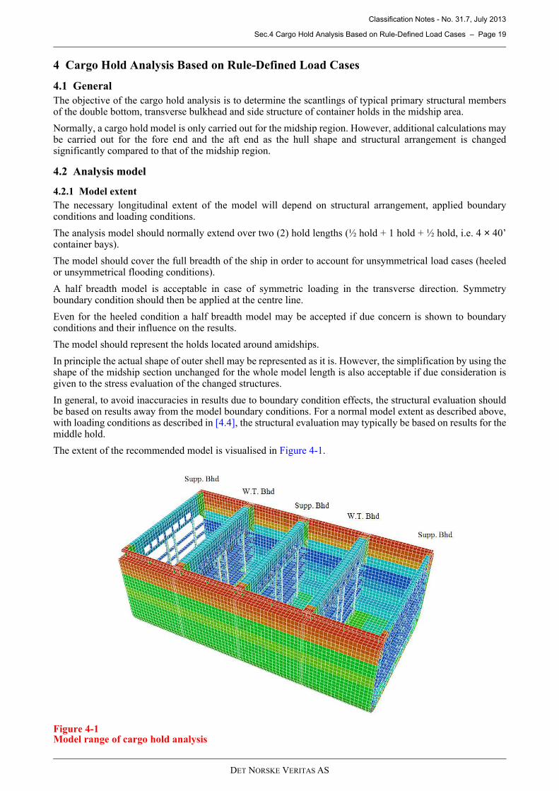
The analysis model should normally extend over two (2) hold lengths (½ hold + 1 hold + ½ hold, i.e. 4 × 40’container bays).
The model should cover the full breadth of the ship in order to account for unsymmetrical load cases (heeledor unsymmetrical flooding conditions).
A half breadth model is acceptable in case of symmetric loading in the transverse direction. Symmetryboundary condition should then be applied at the centre line.
Even for the heeled condition a half breadth model may be accepted if due concern is shown to boundaryconditions and their influence on the results.
The model should represent the holds located around amidships.
In principle the actual shape of outer shell may be represented as it is. However, the simplification by using theshape of the midship section unchanged for the whole model length is also acceptable if due consideration isgiven to the stress evaluation of the changed structures.
In general, to avoid inaccuracies in results due to boundary condition effects, the structural evaluation shouldbe based on results away from the model boundary conditions. For a normal model extent as described above,with loading conditions as described in [4.4], the structural evaluation may typically be based on results for themiddle hold.
The extent of the recommended model is visualised in Figure 4-1.
Figure 4-1Model range of cargo hold analysis
Classification Notes - No. 31.7, July 2013
Sec.4 Cargo Hold Analysis Based on Rule-Defined Load Cases – Page 20
DET NORSKE VERITAS AS
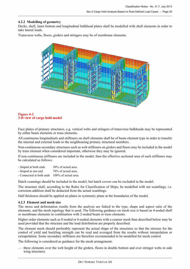
4.2.2 Modelling of geometry
Decks, shell, inner bottom and longitudinal bulkhead plates shall be modelled with shell elements in order totake lateral loads.
Transverse webs, floors, girders and stringers may be of membrane elements.
Figure 4-23-D view of cargo hold model
Face plates of primary structures, e.g. vertical webs and stringers of transverse bulkheads may be representedby either beam elements or truss elements.
All continuous longitudinals and stiffeners on shell elements shall be of beam element type in order to transferthe internal and external loads to the neighbouring primary structural members.
Non-continuous secondary structures such as web stiffeners on girders and floors may be included in the modelby truss element when considered important, otherwise they may be ignored.
If non-continuous stiffeners are included in the model, then the effective sectional area of such stiffeners maybe calculated as follows:
Hatch coamings should be included in the model, but hatch covers can be excluded in the model.
The structure shall, according to the Rules for Classification of Ships, be modelled with net scantlings, i.e.corrosion addition shall be deducted from the actual scantlings.
Half thickness should be applied on plates in symmetry plane at the boundaries of the model.
4.2.3 Element and mesh size
The stress and deformation results from the analysis are linked to the type, shape and aspect ratio of theelements, and the mesh topology that is used. The following guidance on mesh size is based on 4-noded shellor membrane elements in combination with 2-noded beam or truss elements.
Higher order elements such as 8-noded or 6-noded elements with a coarser mesh than described below may beused provided that the structure and the load distribution are properly described.
The element mesh should preferably represent the actual shape of the structures so that the stresses for thecontrol of yield and buckling strength can be read and averaged from the results without interpolation orextrapolation. Some secondary stiffeners are therefore recommended to be modelled for mesh control.
The following is considered as guidance for the mesh arrangement:
— three elements over the web height of the girders, floors in double bottom and over stringer webs in sidewing structures
- Sniped at both ends 30% of actual area.
- Sniped at one end 70% of actual area.
- Connected at both ends 100% of actual area.
Classification Notes - No. 31.7, July 2013
Sec.4 Cargo Hold Analysis Based on Rule-Defined Load Cases – Page 21
DET NORSKE VERITAS AS
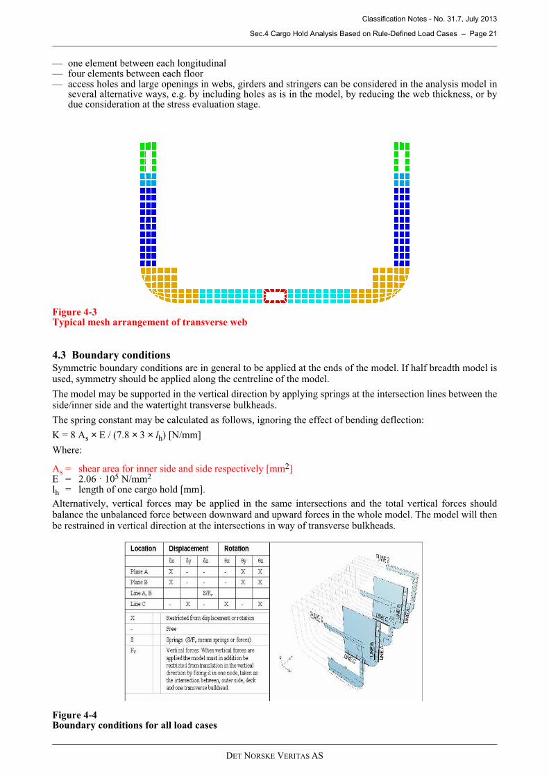
— one element between each longitudinal— four elements between each floor— access holes and large openings in webs, girders and stringers can be considered in the analysis model in
several alternative ways, e.g. by including holes as is in the model, by reducing the web thickness, or bydue consideration at the stress evaluation stage.
Figure 4-3Typical mesh arrangement of transverse web
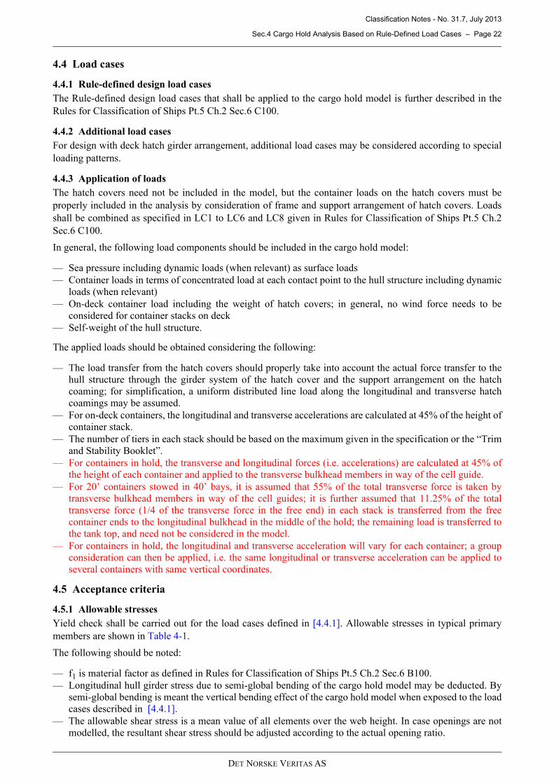
4.3 Boundary conditions
Symmetric boundary conditions are in general to be applied at the ends of the model. If half breadth model isused, symmetry should be applied along the centreline of the model.
The model may be supported in the vertical direction by applying springs at the intersection lines between theside/inner side and the watertight transverse bulkheads.
The spring constant may be calculated as follows, ignoring the effect of bending deflection:
K = 8 As × E / (7.8 × 3 × lh) [N/mm]
Where:
As = shear area for inner side and side respectively [mm2]E = 2.06 · 105 N/mm2
lh = length of one cargo hold [mm].
Alternatively, vertical forces may be applied in the same intersections and the total vertical forces shouldbalance the unbalanced force between downward and upward forces in the whole model. The model will thenbe restrained in vertical direction at the intersections in way of transverse bulkheads.
Figure 4-4Boundary conditions for all load cases
Classification Notes - No. 31.7, July 2013
Sec.4 Cargo Hold Analysis Based on Rule-Defined Load Cases – Page 22
DET NORSKE VERITAS AS
4.4 Load cases
4.4.1 Rule-defined design load cases
The Rule-defined design load cases that shall be applied to the cargo hold model is further described in the
Rules for Classification of Ships Pt.5 Ch.2 Sec.6 C100.
4.4.2 Additional load cases
For design with deck hatch girder arrangement, additional load cases may be considered according to special
loading patterns.
4.4.3 Application of loads
The hatch covers need not be included in the model, but the container loads on the hatch covers must be
properly included in the analysis by consideration of frame and support arrangement of hatch covers. Loads
shall be combined as specified in LC1 to LC6 and LC8 given in Rules for Classification of Ships Pt.5 Ch.2
Sec.6 C100.
In general, the following load components should be included in the cargo hold model:
— Sea pressure including dynamic loads (when relevant) as surface loads
— Container loads in terms of concentrated load at each contact point to the hull structure including dynamic
loads (when relevant)
— On-deck container load including the weight of hatch covers; in general, no wind force needs to be
considered for container stacks on deck
— Self-weight of the hull structure.
The applied loads should be obtained considering the following:
— The load transfer from the hatch covers should properly take into account the actual force transfer to the
hull structure through the girder system of the hatch cover and the support arrangement on the hatch
coaming; for simplification, a uniform distributed line load along the longitudinal and transverse hatch
coamings may be assumed.
— For on-deck containers, the longitudinal and transverse accelerations are calculated at 45% of the height of
container stack.
— The number of tiers in each stack should be based on the maximum given in the specification or the “Trim
and Stability Booklet”.
— For containers in hold, the transverse and longitudinal forces (i.e. accelerations) are calculated at 45% of
the height of each container and applied to the transverse bulkhead members in way of the cell guide.
— For 20’ containers stowed in 40’ bays, it is assumed that 55% of the total transverse force is taken by
transverse bulkhead members in way of the cell guides; it is further assumed that 11.25% of the total
transverse force (1/4 of the transverse force in the free end) in each stack is transferred from the free
container ends to the longitudinal bulkhead in the middle of the hold; the remaining load is transferred to
the tank top, and need not be considered in the model.
— For containers in hold, the longitudinal and transverse acceleration will vary for each container; a group
consideration can then be applied, i.e. the same longitudinal or transverse acceleration can be applied to
several containers with same vertical coordinates.
4.5 Acceptance criteria
4.5.1 Allowable stresses
Yield check shall be carried out for the load cases defined in [4.4.1]. Allowable stresses in typical primary
members are shown in Table 4-1.
The following should be noted:
— f1 is material factor as defined in Rules for Classification of Ships Pt.5 Ch.2 Sec.6 B100.
— Longitudinal hull girder stress due to semi-global bending of the cargo hold model may be deducted. By
semi-global bending is meant the vertical bending effect of the cargo hold model when exposed to the load
cases described in [4.4.1].
— The allowable shear stress is a mean value of all elements over the web height. In case openings are not
modelled, the resultant shear stress should be adjusted according to the actual opening ratio.
Classification Notes - No. 31.7, July 2013
Sec.4 Cargo Hold Analysis Based on Rule-Defined Load Cases – Page 23
DET NORSKE VERITAS AS
4.5.2 Buckling control
Buckling control is to be carried out for the load cases defined in [4.4.1].
Table 4-2 gives examples of areas to be checked for buckling, and the applicable method and acceptancecriteria based on formulae as given in the Rules for Classification of Ships Rules for Classification of ShipsPt.3 Ch.1 Sec.13.
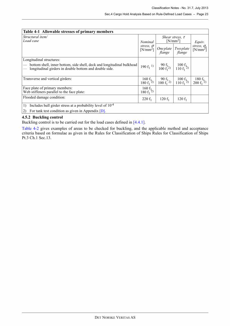
Table 4-1 Allowable stresses of primary members
Structural item/Load case Nominal
stress, σ[N/mm2]
Shear stress, τ[N/mm2] Equiv.
stress, σe [N/mm2] One plate
flangeTwo plate
flange
Longitudinal structures:
— bottom shell, inner bottom, side shell, deck and longitudinal bulkhead— longitudinal girders in double bottom and double side.
190 f1 1) 90 f1100 f1
2)100 f1
110 f1 2)
Transverse and vertical girders: 160 f1180 f1 2)
90 f1100 f1 2)
100 f1110 f1 2)
180 f1200 f1 2)
Face plate of primary members:Web stiffeners parallel to the face plate:
160 f1180 f1 2)
Flooded damage condition: 220 f1 120 f1 120 f1
1) Includes hull girder stress at a probability level of 10-4
2) For tank test condition as given in Appendix [D].
Classification Notes - No. 31.7, July 2013
Sec.4 Cargo Hold Analysis Based on Rule-Defined Load Cases – Page 24
DET NORSKE VERITAS AS
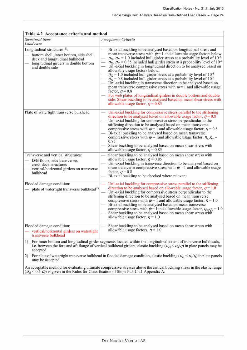
Table 4-2 Acceptance criteria and method
Structural item/Load case
Acceptance Criteria
Longitudinal structures 1):
— bottom shell, inner bottom, side shell, deck and longitudinal bulkhead
— longitudinal girders in double bottom and double side
— Bi-axial buckling to be analysed based on longitudinal stress and mean transverse stress with ψ = 1 and allowable usage factors below:
— ηX, ηY = 1.0 included hull girder stress at a probability level of 10-8
— ηX, ηY = 0.85 included hull girder stress at a probability level of 10-4
— Uni-axial buckling in longitudinal direction to be analysed based on allowable usage factors below:
— ηX = 1.0 included hull girder stress at a probability level of 10-8
— ηX = 0.8 included hull girder stress at a probability level of 10-4
— Uni-axial buckling in transverse direction to be analysed based on mean transverse compressive stress with ψ = 1 and allowable usage factor, η = 0.8
— For web plates of longitudinal girders in double bottom and double side: Shear buckling to be analysed based on mean shear stress with allowable usage factor, η = 0.85
Plate of watertight transverse bulkhead — Uni-axial buckling for compressive stress parallel to the stiffening direction to be analysed based on allowable usage factor, η = 0.8
— Uni-axial buckling for compressive stress perpendicular to the stiffening direction to be analysed based on mean transverse compressive stress with ψ = 1 and allowable usage factor, η = 0.8
— Bi-axial buckling to be analysed based on mean transverse compressive stress with ψ = 1and allowable usage factor, ηx,ηy = 0.85
— Shear buckling to be analysed based on mean shear stress with allowable usage factor, η = 0.85
Transverse and vertical structures:
— D/B floors, side transverses — cross-deck structures — vertical/horizontal girders on transverse
bulkhead
— Shear buckling to be analysed based on mean shear stress with allowable usage factor, η = 0.85
— Uni-axial buckling in transverse direction to be analysed based on mean transverse compressive stress with ψ = 1 and allowable usage factor, η = 0.8
— Bi-axial buckling to be checked where relevant
Flooded damage condition:
— plate of watertight transverse bulkhead2)
— Uni-axial buckling for compressive stress parallel to the stiffening direction to be analysed based on allowable usage factor, η = 1.0
— Uni-axial buckling for compressive stress perpendicular to the stiffening direction to be analysed based on mean transverse compressive stress with ψ = 1 and allowable usage factor, η = 1.0
— Bi-axial buckling to be analysed based on mean transverse compressive stress with ψ = 1and allowable usage factor, ηx,ηy = 1.0
— Shear buckling to be analysed based on mean shear stress with allowable usage factor, η = 1.0
Flooded damage condition:
— vertical/horizontal girders on watertight transverse bulkhead
— Shear buckling to be analysed based on mean shear stress with allowable usage factors, η = 1.0
1) For inner bottom and longitudinal girder segments located within the longitudinal extent of transverse bulkheads, i.e. between the fore and aft flange of vertical bulkhead girders, elastic buckling (σel < σa/η) in plate panels may be accepted.
2) For plate of watertight transverse bulkhead in flooded damage condition, elastic buckling (σel < σa/η) in plate panels may be accepted.
An acceptable method for evaluating ultimate compressive stresses above the critical buckling stress in the elastic range (σel < 0.5 σf) is given in the Rules for Classification of Ships Pt.3 Ch.1 Appendix A.
Classification Notes - No. 31.7, July 2013
Sec.5 Level 1 Rule Torsional Analysis – Page 25
DET NORSKE VERITAS AS
5 Level 1 Rule Torsional Analysis
5.1 General principles
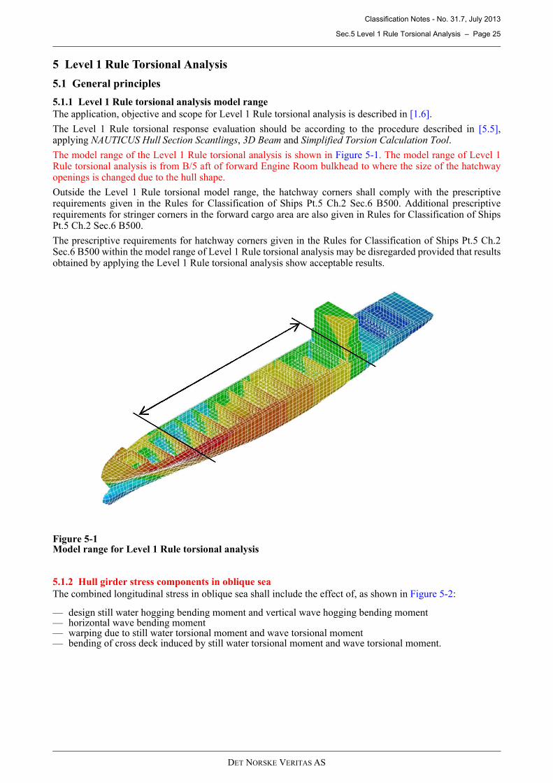
5.1.1 Level 1 Rule torsional analysis model range
The application, objective and scope for Level 1 Rule torsional analysis is described in [1.6].
The Level 1 Rule torsional response evaluation should be according to the procedure described in [5.5],applying NAUTICUS Hull Section Scantlings, 3D Beam and Simplified Torsion Calculation Tool.
The model range of the Level 1 Rule torsional analysis is shown in Figure 5-1. The model range of Level 1Rule torsional analysis is from B/5 aft of forward Engine Room bulkhead to where the size of the hatchwayopenings is changed due to the hull shape.
Outside the Level 1 Rule torsional model range, the hatchway corners shall comply with the prescriptiverequirements given in the Rules for Classification of Ships Pt.5 Ch.2 Sec.6 B500. Additional prescriptiverequirements for stringer corners in the forward cargo area are also given in Rules for Classification of ShipsPt.5 Ch.2 Sec.6 B500.
The prescriptive requirements for hatchway corners given in the Rules for Classification of Ships Pt.5 Ch.2Sec.6 B500 within the model range of Level 1 Rule torsional analysis may be disregarded provided that resultsobtained by applying the Level 1 Rule torsional analysis show acceptable results.
Figure 5-1Model range for Level 1 Rule torsional analysis
5.1.2 Hull girder stress components in oblique sea
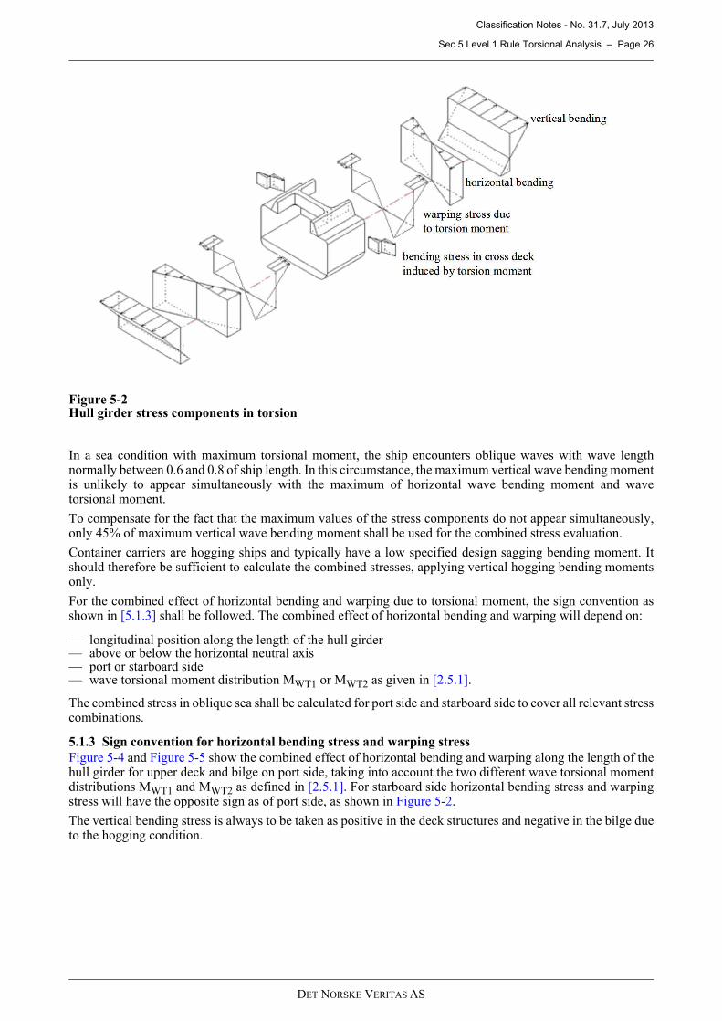
The combined longitudinal stress in oblique sea shall include the effect of, as shown in Figure 5-2:
— design still water hogging bending moment and vertical wave hogging bending moment— horizontal wave bending moment— warping due to still water torsional moment and wave torsional moment— bending of cross deck induced by still water torsional moment and wave torsional moment.
Classification Notes - No. 31.7, July 2013
Sec.5 Level 1 Rule Torsional Analysis – Page 26
DET NORSKE VERITAS AS
Figure 5-2Hull girder stress components in torsion
In a sea condition with maximum torsional moment, the ship encounters oblique waves with wave lengthnormally between 0.6 and 0.8 of ship length. In this circumstance, the maximum vertical wave bending momentis unlikely to appear simultaneously with the maximum of horizontal wave bending moment and wavetorsional moment.
To compensate for the fact that the maximum values of the stress components do not appear simultaneously,only 45% of maximum vertical wave bending moment shall be used for the combined stress evaluation.
Container carriers are hogging ships and typically have a low specified design sagging bending moment. Itshould therefore be sufficient to calculate the combined stresses, applying vertical hogging bending momentsonly.
For the combined effect of horizontal bending and warping due to torsional moment, the sign convention asshown in [5.1.3] shall be followed. The combined effect of horizontal bending and warping will depend on:
— longitudinal position along the length of the hull girder— above or below the horizontal neutral axis— port or starboard side— wave torsional moment distribution MWT1 or MWT2 as given in [2.5.1].
The combined stress in oblique sea shall be calculated for port side and starboard side to cover all relevant stresscombinations.
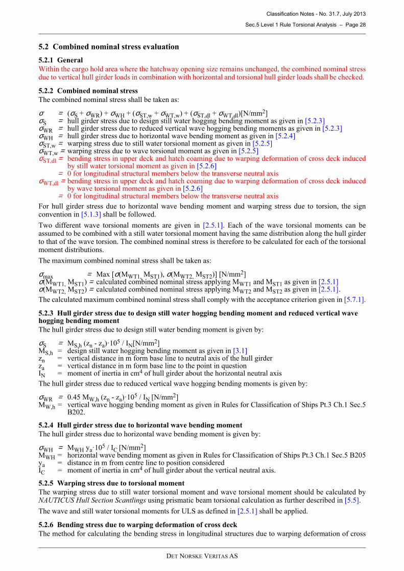
5.1.3 Sign convention for horizontal bending stress and warping stress
Figure 5-4 and Figure 5-5 show the combined effect of horizontal bending and warping along the length of thehull girder for upper deck and bilge on port side, taking into account the two different wave torsional momentdistributions MWT1 and MWT2 as defined in [2.5.1]. For starboard side horizontal bending stress and warpingstress will have the opposite sign as of port side, as shown in Figure 5-2.
The vertical bending stress is always to be taken as positive in the deck structures and negative in the bilge dueto the hogging condition.
Classification Notes - No. 31.7, July 2013
Sec.5 Level 1 Rule Torsional Analysis – Page 27
DET NORSKE VERITAS AS
Figure 5-3Rule wave torsional moment distributions
Figure 5-4Warping stress and horizontal wave bending stress distribution, upper deck port side
Figure 5-5Warping stress and horizontal wave bending stress distribution, bilge port side
Classification Notes - No. 31.7, July 2013
Sec.5 Level 1 Rule Torsional Analysis – Page 28
DET NORSKE VERITAS AS
5.2 Combined nominal stress evaluation
5.2.1 General
Within the cargo hold area where the hatchway opening size remains unchanged, the combined nominal stressdue to vertical hull girder loads in combination with horizontal and torsional hull girder loads shall be checked.
5.2.2 Combined nominal stress
The combined nominal stress shall be taken as:
σ = (σS + σWR) + σWH + (σST,w + σWT,w) + (σST,dl + σWT,dl)[N/mm2]σS = hull girder stress due to design still water hogging bending moment as given in [5.2.3]σWR = hull girder stress due to reduced vertical wave hogging bending moments as given in [5.2.3]σWH = hull girder stress due to horizontal wave bending moment as given in [5.2.4]σST,w = warping stress due to still water torsional moment as given in [5.2.5]σWT,w = warping stress due to wave torsional moment as given in [5.2.5]σST,dl = bending stress in upper deck and hatch coaming due to warping deformation of cross deck induced
by still water torsional moment as given in [5.2.6] = 0 for longitudinal structural members below the transverse neutral axisσWT,dl = bending stress in upper deck and hatch coaming due to warping deformation of cross deck induced
by wave torsional moment as given in [5.2.6] = 0 for longitudinal structural members below the transverse neutral axis
For hull girder stress due to horizontal wave bending moment and warping stress due to torsion, the signconvention in [5.1.3] shall be followed.
Two different wave torsional moments are given in [2.5.1]. Each of the wave torsional moments can beassumed to be combined with a still water torsional moment having the same distribution along the hull girderto that of the wave torsion. The combined nominal stress is therefore to be calculated for each of the torsionalmoment distributions.
The maximum combined nominal stress shall be taken as:
σmax = Max [σ(MWT1, MST1), σ(MWT2, MST2)] [N/mm2]σ(MWT1, MST1) = calculated combined nominal stress applying MWT1 and MST1 as given in [2.5.1]σ(MWT2, MST2) = calculated combined nominal stress applying MWT2 and MST2 as given in [2.5.1].The calculated maximum combined nominal stress shall comply with the acceptance criterion given in [5.7.1].
5.2.3 Hull girder stress due to design still water hogging bending moment and reduced vertical wave hogging bending moment
The hull girder stress due to design still water bending moment is given by:
σS = MS,h (zn - za)·105 / IN[N/mm2]MS,h = design still water hogging bending moment as given in [3.1]zn = vertical distance in m form base line to neutral axis of the hull girder za = vertical distance in m form base line to the point in questionIN = moment of inertia in cm4 of hull girder about the horizontal neutral axis
The hull girder stress due to reduced vertical wave hogging bending moments is given by:
σWR = 0.45 MW,h (zn - za)·105 / IN [N/mm2]MW,h = vertical wave hogging bending moment as given in Rules for Classification of Ships Pt.3 Ch.1 Sec.5
B202.
5.2.4 Hull girder stress due to horizontal wave bending moment
The hull girder stress due to horizontal wave bending moment is given by:
σWH = MWH ya·105 / IC [N/mm2]MWH = horizontal wave bending moment as given in Rules for Classification of Ships Pt.3 Ch.1 Sec.5 B205ya = distance in m from centre line to position consideredIC = moment of inertia in cm4 of hull girder about the vertical neutral axis.
5.2.5 Warping stress due to torsional moment
The warping stress due to still water torsional moment and wave torsional moment should be calculated byNAUTICUS Hull Section Scantlings using prismatic beam torsional calculation as further described in [5.5].
The wave and still water torsional moments for ULS as defined in [2.5.1] shall be applied.
5.2.6 Bending stress due to warping deformation of cross deck
The method for calculating the bending stress in longitudinal structures due to warping deformation of cross
Classification Notes - No. 31.7, July 2013
Sec.5 Level 1 Rule Torsional Analysis – Page 29
DET NORSKE VERITAS AS
deck induced by still water and wave torsion is further described in [5.5], applying the modelling techniquesas given in [5.5.2] and [5.5.3].
The wave and still water torsional moments for ULS as defined in [2.5.1] shall be applied.
The read-out point of stress from the beam calculation should be in accordance with [5.5.5].
5.3 Combined hot spot stress evaluation
5.3.1 General
Within the cargo hold area where the hatchway opening size remains unchanged, the combined hot spot stresslevel in way of hatchway corners on upper deck and hatch coaming top shall be checked.
The hot spot stress shall be calculated applying predefined stress concentration factors to the nominal combinedstress. As the stress concentrations will vary along the edge of the hatch corner, it is recommended to calculatethe combined hot spot stress for 10 positions along the edge of the hatchway corner.
5.3.2 Combined hot spot stress
The combined hot spot stress shall be taken as:
σhs = Kv (σS + σWR) + KhσWH + Ktw(σST,w + σWT,w) + Ktd(σST,dt + σWT,dt) [N/mm2] σS, σWR = as given in [5.2.3]σWH = as given in [5.2.4]σST,w = as given in [5.2.5]σWT,w = as given in [5.2.5]σST,dt = bending stress in cross decks due to warping deformation induced by still water torsional moment
as given in [5.3.3]σWT,dt = bending stress in cross decks due to warping deformation induced by wave torsional moment as
given in [5.3.3]Kv = stress concentration factor in way of hatchway corners from vertical bending as given in [5.6.3]
and [5.6.4]Kh = stress concentration factor in way of hatchway corners from horizontal bending as given in [5.6.3]
and [5.6.4]Ktw = stress concentration factor in way of hatchway corners from warping as given in [5.6.3] and [5.6.4]Ktd = stress concentration factor in way of hatchway corners from bending stress due to warping
deformations of cross decks as given in [5.6.3] and [5.6.4].
For hull girder stress due to horizontal wave bending moment and warping stress due to torsion, the signconvention in [5.1.3] shall be followed.
Two different wave torsional moments are given in [2.5.1]. Each of the wave torsional moments can beassumed to be combined with a still water torsional moment having the same distribution along the hull girderto that of the wave torsion. The combined hot spot stress is therefore to be calculated for each of the torsionalmoment distributions.
The maximum combined hot spot stress shall be taken as:
σhs max = Max [σhs(MWT1, MST1), σhs(MWT2, MST2)] [N/mm2]σhs(MWT1, MST1) = calculated combined hot spot stress applying MWT1 and MST1 as given in [2.5.1]σhs(MWT2, MST2) = calculated combined hot spot stress applying MWT2 and MST2 as given in [2.5.1]
The calculated maximum combined hot spot stress shall comply with the acceptance criterion given in [5.7.1].
5.3.3 Bending stress due to warping deformation of cross deck
The method for calculating the bending stress due to warping deformation of cross deck induced by still waterand wave torsion is further described in [5.5], applying the modelling techniques as given in [5.5.2] and [5.5.3].
The wave and still water torsional moments for ULS as defined in [2.5.1] shall be applied.
The read-out point of stress from the beam calculation should be in accordance with [5.5.6].
5.4 Fatigue assessment
5.4.1 General
Fatigue of hatchway corners in way of upper deck and hatch coaming top within the cargo hold area where thehatchway opening size remains unchanged is to be assessed in accordance with Classification Note No. 30.7,including warping stress obtained from wave torsional moment.
The hot spot stress range shall be calculated applying predefined stress concentration factors to the nominalcombined stress on 10-4 probability level. As the stress concentrations will vary along the edge of the hatchwaycorner, it is recommended to calculate the fatigue life for 10 positions along the edge of the hatchway corner.
Classification Notes - No. 31.7, July 2013
Sec.5 Level 1 Rule Torsional Analysis – Page 30
DET NORSKE VERITAS AS
5.4.2 Damage calculation
Two different wave torsional moments are given in [2.5.2]. The damage for each hatchway corner is thereforeto be taken as:
D = Max [D(Mwt1), D(Mwt2)]D(Mwt1) = calculated fatigue damage applying Mwt1 as given in [2.5.2]D(Mwt2) = calculated fatigue damage applying Mwt2 as given in [2.5.2].
The fatigue damage for each hatchway corner shall be calculated in accordance with Classification Note No.30.7 applying:
— design criteria as given in [5.7.2].— combined local stress range due to lateral pressure loads ∆σl = 0— combined global stress range, ∆σg, as given in [5.4.3].
5.4.3 Combined global stress range
The combined global stress range shall be taken as:
∆σv = stress range due to vertical wave bending moment as given in [5.4.4]∆(σhg + σwt) = stress range due to horizontal wave bending moment and wave torsional momentρvh = correlation coefficient as given in Classification Note No. 30.7, [4.6.5]
The stress range due to horizontal wave bending moment and wave torsional moment can be further bedescribed as:
∆(σhg + σwt) = 2|(σhg + σwt)| [N/mm2]σhg = hull girder stress due to horizontal wave bending moment as given in [5.4.5]σwt = warping stress and bending stress due to warping deformation of cross deck induced by
wave torsional moment.
The warping stress and bending stress due to warping deformation of cross deck induced by wave torsionalmoment can be further described as:
σwt = Ktw σwt,w + Ktd σwt,dt [N/mm2] σwt,w = warping stress due to wave torsional moment as given in [5.4.6]σwt,dt = bending stress in cross decks due to warping deformation induced by wave torsional
moment as given in [5.4.7]Ktw = stress concentration factor in way of hatchway corners due to warping as given in [5.6.3]
and [5.6.4]Ktd = stress concentration factor in way of hatchway corners from bending stress due to warping
deformations of cross decks as given in [5.6.3] and [5.6.4].For hull girder stress due to horizontal wave bending moment and warping stress due to torsion, the signconvention in [5.1.3] shall be followed.
5.4.4 Stress range due to vertical wave bending moment
The stress range due to vertical wave bending moment shall be taken as:
∆σv = 2σv [N/mm2]
The vertical wave hull girder stress shall be taken as:
σv = 0.5 Kv [Mwo,h – Mwo,s]·105| zn-za | / IN [N/mm2]Mwo,s(h) = vertical wave sagging (hogging) bending moment as given in Classification Note No. 30.7, [6.2.1]zn za IN = as given in [5.2.3]Kv = stress concentration factor in way of hatchway corners due to vertical bending as given in [5.6.3]
and [5.6.4].
5.4.5 Stress due to horizontal wave bending moment
The horizontal wave hull girder stress shall be taken as:
σhg = Kh Mh105 y / IC [N/mm2]Mh = horizontal wave bending moment as given in Classification Note No. 30.7, [6.2.2]y IC = as given in [5.2.4]Kh = stress concentration factor in way of hatchway corners due to horizontal bending as given in
[5.6.3] and [5.6.4].
( ) ( )wthgvvhwthgvg σσσρσσσσ +∆∆++∆+∆=∆ 222
[N/mm2]
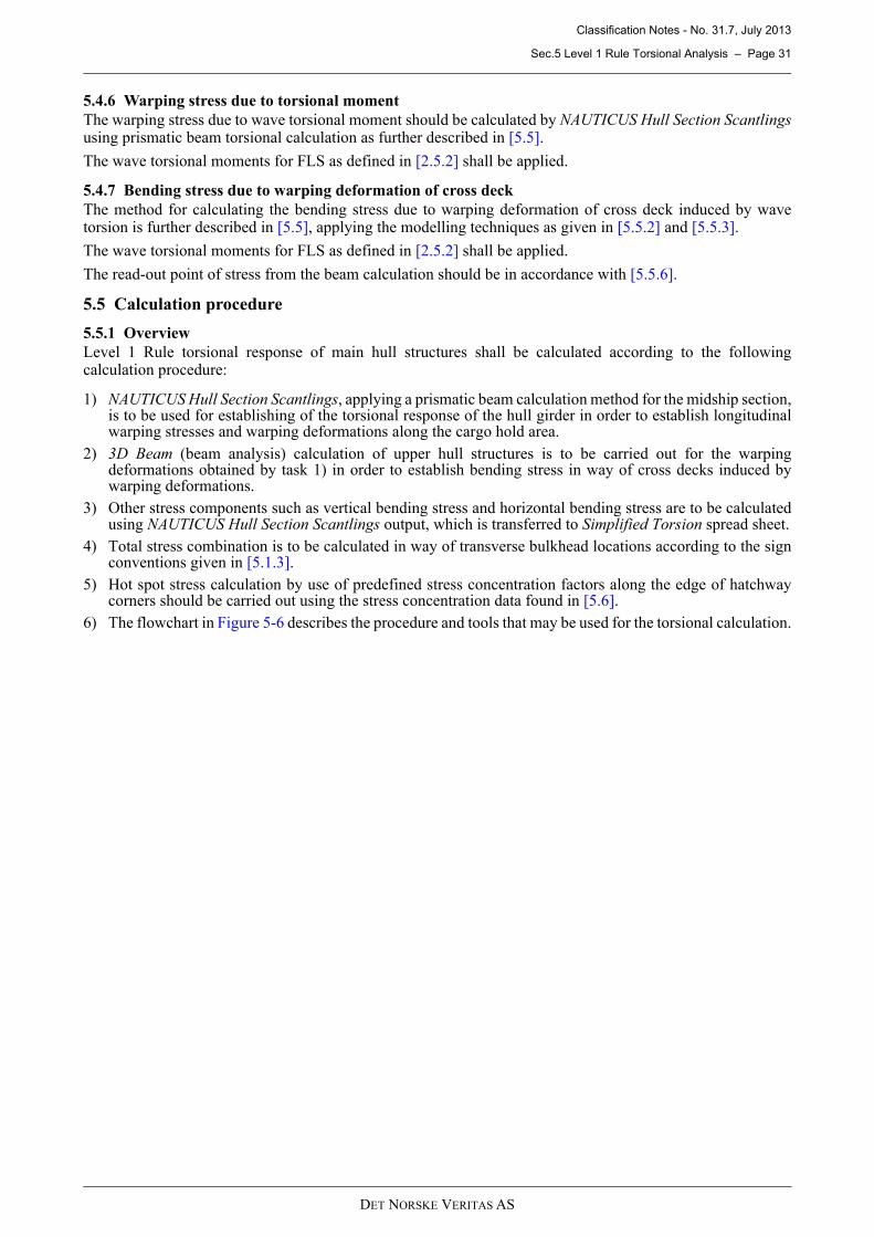
Classification Notes - No. 31.7, July 2013
Sec.5 Level 1 Rule Torsional Analysis – Page 31
DET NORSKE VERITAS AS
5.4.6 Warping stress due to torsional moment
The warping stress due to wave torsional moment should be calculated by NAUTICUS Hull Section Scantlingsusing prismatic beam torsional calculation as further described in [5.5].
The wave torsional moments for FLS as defined in [2.5.2] shall be applied.
5.4.7 Bending stress due to warping deformation of cross deck
The method for calculating the bending stress due to warping deformation of cross deck induced by wavetorsion is further described in [5.5], applying the modelling techniques as given in [5.5.2] and [5.5.3].
The wave torsional moments for FLS as defined in [2.5.2] shall be applied.
The read-out point of stress from the beam calculation should be in accordance with [5.5.6].
5.5 Calculation procedure
5.5.1 Overview
Level 1 Rule torsional response of main hull structures shall be calculated according to the followingcalculation procedure:
1) NAUTICUS Hull Section Scantlings, applying a prismatic beam calculation method for the midship section,is to be used for establishing of the torsional response of the hull girder in order to establish longitudinalwarping stresses and warping deformations along the cargo hold area.
2) 3D Beam (beam analysis) calculation of upper hull structures is to be carried out for the warpingdeformations obtained by task 1) in order to establish bending stress in way of cross decks induced bywarping deformations.
3) Other stress components such as vertical bending stress and horizontal bending stress are to be calculatedusing NAUTICUS Hull Section Scantlings output, which is transferred to Simplified Torsion spread sheet.
4) Total stress combination is to be calculated in way of transverse bulkhead locations according to the signconventions given in [5.1.3].
5) Hot spot stress calculation by use of predefined stress concentration factors along the edge of hatchwaycorners should be carried out using the stress concentration data found in [5.6].
6) The flowchart in Figure 5-6 describes the procedure and tools that may be used for the torsional calculation.
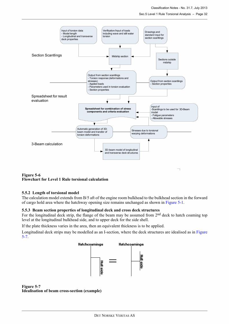
Classification Notes - No. 31.7, July 2013
Sec.5 Level 1 Rule Torsional Analysis – Page 32
DET NORSKE VERITAS AS
Figure 5-6Flowchart for Level 1 Rule torsional calculation
5.5.2 Length of torsional model
The calculation model extends from B/5 aft of the engine room bulkhead to the bulkhead section in the forwardof cargo hold area where the hatchway opening size remains unchanged as shown in Figure 5-1.
5.5.3 Beam section properties of longitudinal deck and cross deck structures
For the longitudinal deck strip, the flange of the beam may be assumed from 2nd deck to hatch coaming toplevel at the longitudinal bulkhead side, and to upper deck for the side shell.
If the plate thickness varies in the area, then an equivalent thickness is to be applied.
Longitudinal deck strips may be modelled as an I-section, where the deck structures are idealised as in Figure5-7.
Figure 5-7Idealisation of beam cross-section (example)
Input of torsion data:- Model length- Longitudinal and transverse deck properties
Output from section scantlings
- Torsion response (deformations and stresses)- Applied loads- Parameters used in torsion evaluation
- Section properties
Drawings and
standard input for
section scanltings
Section Scantlings
Spreadsheet for result
evaluation
3-Beam calculation
Midship section
Sections outside
midship
Verification/Input of loads including wave and still water torsion
Output from section scantlings- Section properties
3D-beam model of longitudinal
and transverse deck structures
Input of -Scantlings to be used for 3D-Beam
model- Fatigue parameters
- Allowable stresses
Automatic generation of 3D-beam model and transfer of
torsion deformations
Spreadsheet for combination of stress components and criteria evaluation
Stresses due to torsional warping deformations
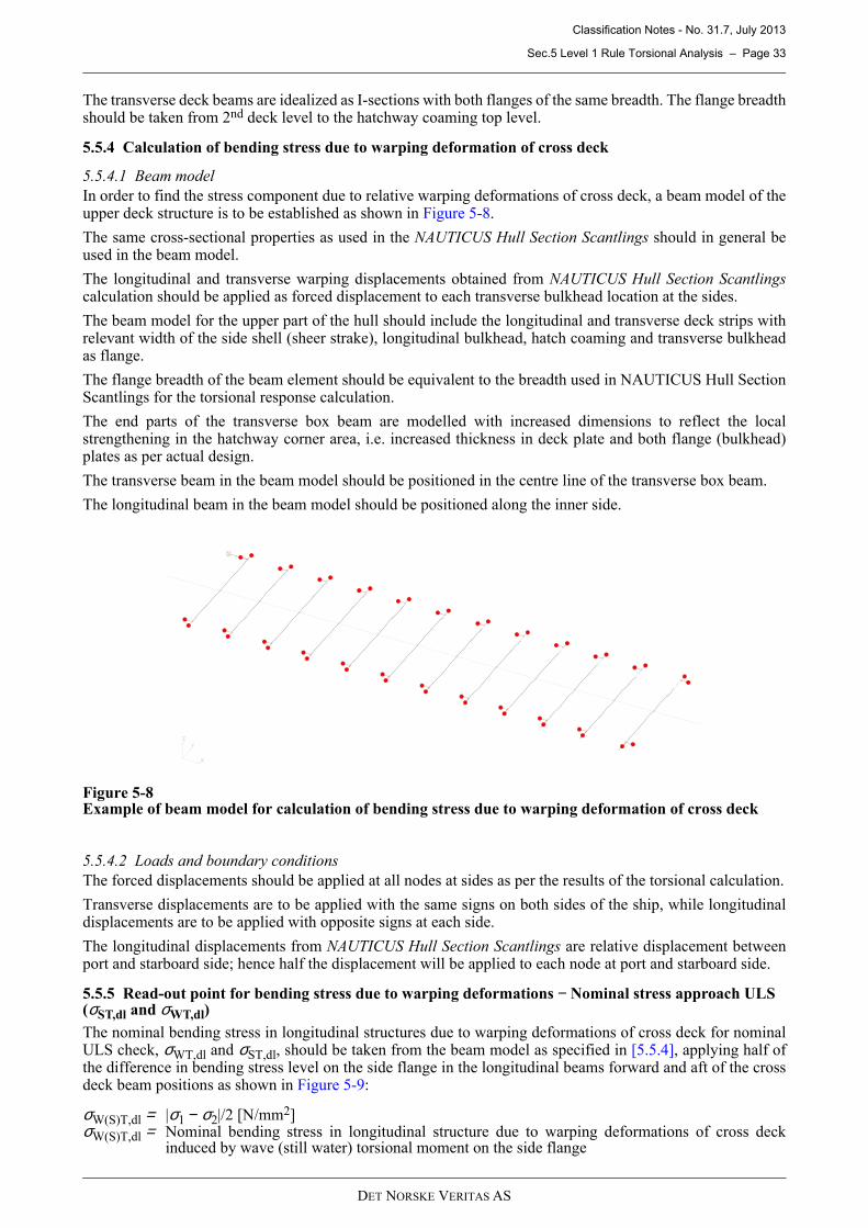
Classification Notes - No. 31.7, July 2013
Sec.5 Level 1 Rule Torsional Analysis – Page 33
DET NORSKE VERITAS AS
The transverse deck beams are idealized as I-sections with both flanges of the same breadth. The flange breadthshould be taken from 2nd deck level to the hatchway coaming top level.
5.5.4 Calculation of bending stress due to warping deformation of cross deck
5.5.4.1 Beam model
In order to find the stress component due to relative warping deformations of cross deck, a beam model of theupper deck structure is to be established as shown in Figure 5-8.
The same cross-sectional properties as used in the NAUTICUS Hull Section Scantlings should in general beused in the beam model.
The longitudinal and transverse warping displacements obtained from NAUTICUS Hull Section Scantlingscalculation should be applied as forced displacement to each transverse bulkhead location at the sides.
The beam model for the upper part of the hull should include the longitudinal and transverse deck strips withrelevant width of the side shell (sheer strake), longitudinal bulkhead, hatch coaming and transverse bulkheadas flange.
The flange breadth of the beam element should be equivalent to the breadth used in NAUTICUS Hull SectionScantlings for the torsional response calculation.
The end parts of the transverse box beam are modelled with increased dimensions to reflect the localstrengthening in the hatchway corner area, i.e. increased thickness in deck plate and both flange (bulkhead)plates as per actual design.
The transverse beam in the beam model should be positioned in the centre line of the transverse box beam.
The longitudinal beam in the beam model should be positioned along the inner side.
Figure 5-8Example of beam model for calculation of bending stress due to warping deformation of cross deck
5.5.4.2 Loads and boundary conditions
The forced displacements should be applied at all nodes at sides as per the results of the torsional calculation.
Transverse displacements are to be applied with the same signs on both sides of the ship, while longitudinaldisplacements are to be applied with opposite signs at each side.
The longitudinal displacements from NAUTICUS Hull Section Scantlings are relative displacement betweenport and starboard side; hence half the displacement will be applied to each node at port and starboard side.
5.5.5 Read-out point for bending stress due to warping deformations − Nominal stress approach ULS (σST,dl and σWT,dl)
The nominal bending stress in longitudinal structures due to warping deformations of cross deck for nominalULS check, σWT,dl and σST,dl, should be taken from the beam model as specified in [5.5.4], applying half ofthe difference in bending stress level on the side flange in the longitudinal beams forward and aft of the crossdeck beam positions as shown in Figure 5-9:
σW(S)T,dl = |σ1 − σ2|/2 [N/mm2] σW(S)T,dl = Nominal bending stress in longitudinal structure due to warping deformations of cross deck
induced by wave (still water) torsional moment on the side flange
X
Y
Z
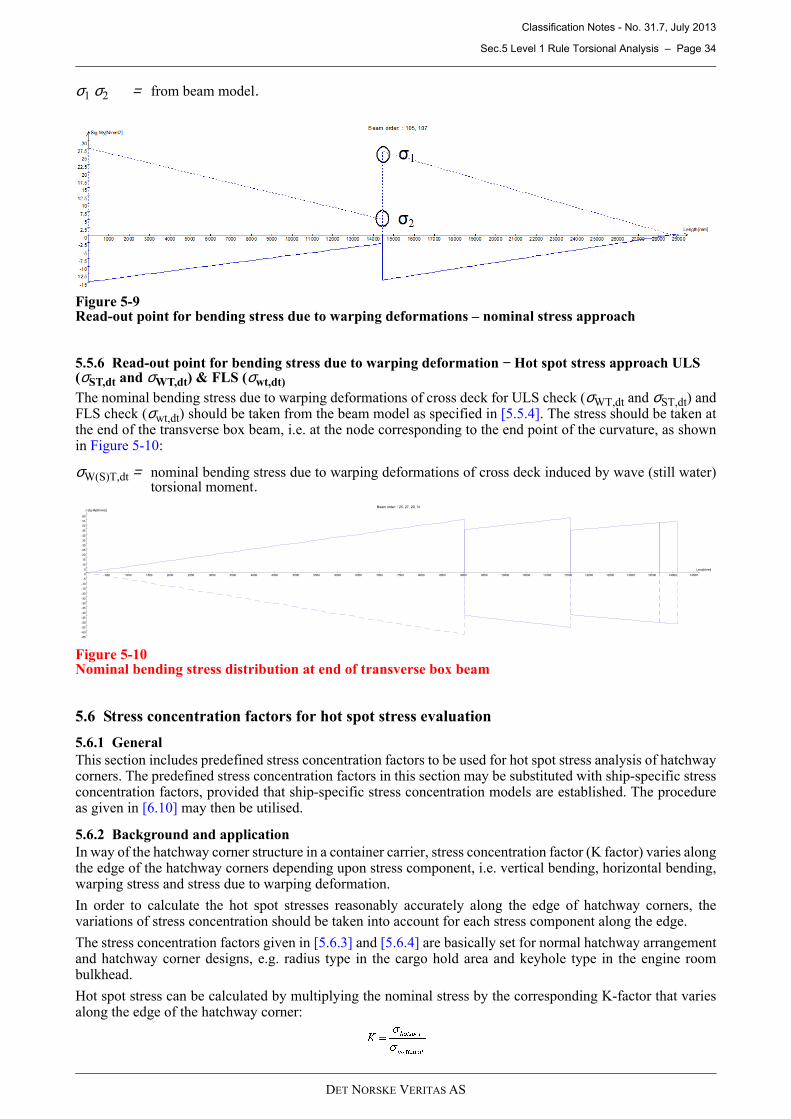
Classification Notes - No. 31.7, July 2013
Sec.5 Level 1 Rule Torsional Analysis – Page 34
DET NORSKE VERITAS AS
σ1 σ2 = from beam model.
Figure 5-9Read-out point for bending stress due to warping deformations – nominal stress approach
5.5.6 Read-out point for bending stress due to warping deformation − Hot spot stress approach ULS (σST,dt and σWT,dt) & FLS (σwt,dt)
The nominal bending stress due to warping deformations of cross deck for ULS check (σWT,dt and σST,dt) andFLS check (σwt,dt) should be taken from the beam model as specified in [5.5.4]. The stress should be taken atthe end of the transverse box beam, i.e. at the node corresponding to the end point of the curvature, as shownin Figure 5-10:
σW(S)T,dt = nominal bending stress due to warping deformations of cross deck induced by wave (still water)torsional moment.
Figure 5-10Nominal bending stress distribution at end of transverse box beam
5.6 Stress concentration factors for hot spot stress evaluation
5.6.1 General
This section includes predefined stress concentration factors to be used for hot spot stress analysis of hatchwaycorners. The predefined stress concentration factors in this section may be substituted with ship-specific stressconcentration factors, provided that ship-specific stress concentration models are established. The procedureas given in [6.10] may then be utilised.
5.6.2 Background and application
In way of the hatchway corner structure in a container carrier, stress concentration factor (K factor) varies alongthe edge of the hatchway corners depending upon stress component, i.e. vertical bending, horizontal bending,warping stress and stress due to warping deformation.
In order to calculate the hot spot stresses reasonably accurately along the edge of hatchway corners, thevariations of stress concentration should be taken into account for each stress component along the edge.
The stress concentration factors given in [5.6.3] and [5.6.4] are basically set for normal hatchway arrangementand hatchway corner designs, e.g. radius type in the cargo hold area and keyhole type in the engine roombulkhead.
Hot spot stress can be calculated by multiplying the nominal stress by the corresponding K-factor that variesalong the edge of the hatchway corner:
Length[mm]
500 1000 1500 2000 2500 3000 3500 4000 4500 5000 5500 6000 6500 7000 7500 8000 8500 9000 9500 10000 10500 11000 11500 12000 12500 13000 13500 14000 14500
Sig-My[N/mm2]
-65
-60
-55
-50
-45
-40
-35
-30
-25
-20
-15
-10
-5
0
5
10
15
20
25
30
35
40
45
50
55
60
Beam order: : 25, 27, 29, 31
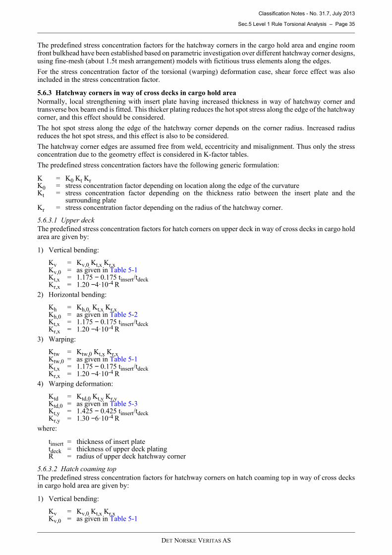
Classification Notes - No. 31.7, July 2013
Sec.5 Level 1 Rule Torsional Analysis – Page 35
DET NORSKE VERITAS AS
The predefined stress concentration factors for the hatchway corners in the cargo hold area and engine roomfront bulkhead have been established based on parametric investigation over different hatchway corner designs,using fine-mesh (about 1.5t mesh arrangement) models with fictitious truss elements along the edges.
For the stress concentration factor of the torsional (warping) deformation case, shear force effect was alsoincluded in the stress concentration factor.
5.6.3 Hatchway corners in way of cross decks in cargo hold area
Normally, local strengthening with insert plate having increased thickness in way of hatchway corner andtransverse box beam end is fitted. This thicker plating reduces the hot spot stress along the edge of the hatchwaycorner, and this effect should be considered.
The hot spot stress along the edge of the hatchway corner depends on the corner radius. Increased radiusreduces the hot spot stress, and this effect is also to be considered.
The hatchway corner edges are assumed free from weld, eccentricity and misalignment. Thus only the stressconcentration due to the geometry effect is considered in K-factor tables.
The predefined stress concentration factors have the following generic formulation:
K = K0 Kt Kr K0 = stress concentration factor depending on location along the edge of the curvatureKt = stress concentration factor depending on the thickness ratio between the insert plate and the
surrounding plateKr = stress concentration factor depending on the radius of the hatchway corner.
5.6.3.1 Upper deck
The predefined stress concentration factors for hatch corners on upper deck in way of cross decks in cargo holdarea are given by:
1) Vertical bending:
Kv = Kv,0 Kt,x Kr,xKv,0 = as given in Table 5-1Kt,x = 1.175 − 0.175 tinsert/tdeckKr,x = 1.20 −4·10-4 R
2) Horizontal bending:
Kh = Kh,0, Kt,x Kr,xKh,0 = as given in Table 5-2Kt,x = 1.175 − 0.175 tinsert/tdeckKr,x = 1.20 −4·10-4 R
3) Warping:
Ktw = Ktw,0 Kt,x Kr,xKtw,0 = as given in Table 5-1Kt,x = 1.175 − 0.175 tinsert/tdeckKr,x = 1.20 −4·10-4 R
4) Warping deformation:
Ktd = Ktd,0 Kt,y Kr,yKtd,0 = as given in Table 5-3Kt,y = 1.425 − 0.425 tinsert/tdeckKr,y = 1.30 −6·10-4 R
where:
tinsert = thickness of insert platetdeck = thickness of upper deck platingR = radius of upper deck hatchway corner
5.6.3.2 Hatch coaming top
The predefined stress concentration factors for hatchway corners on hatch coaming top in way of cross decksin cargo hold area are given by:
1) Vertical bending:
Kv = Kv,0 Kt,x Kr,xKv,0 = as given in Table 5-1
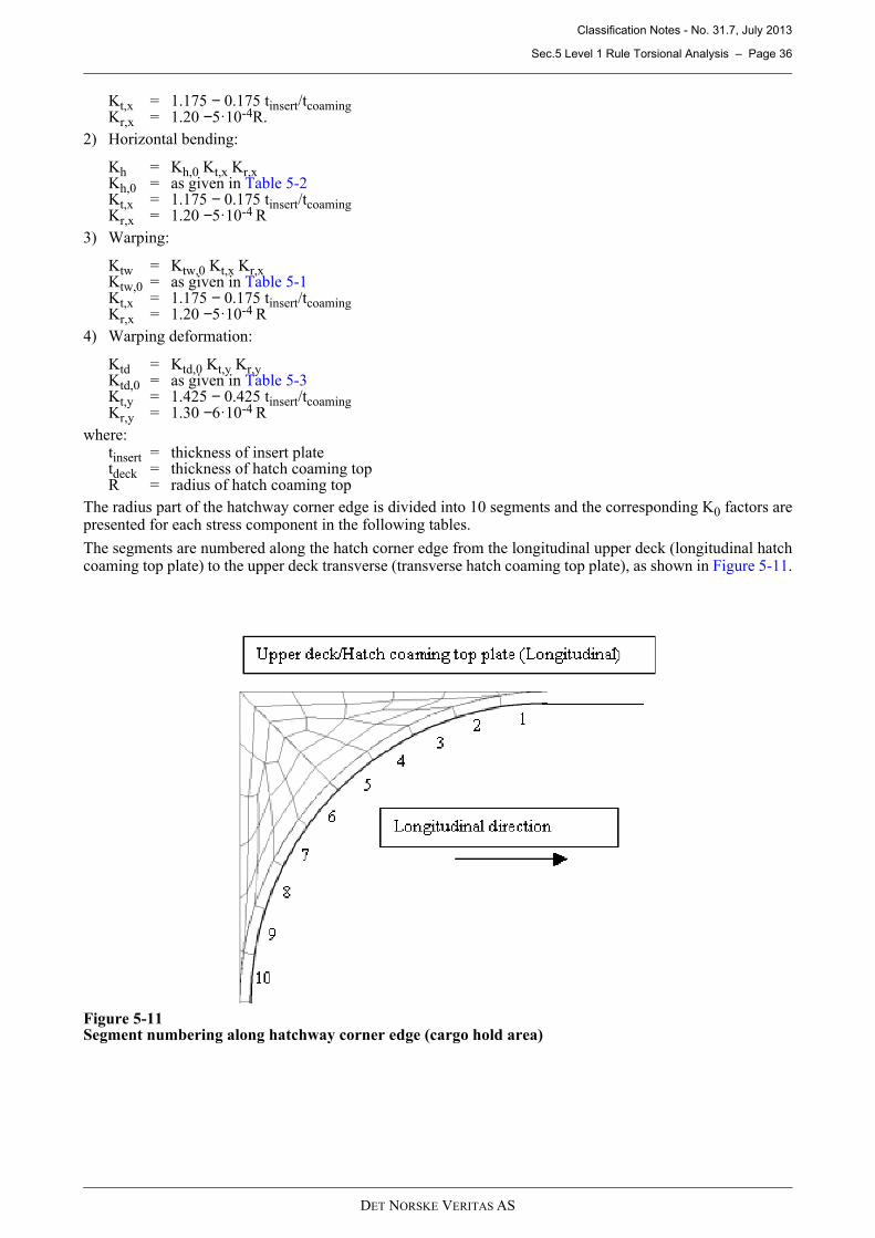
Classification Notes - No. 31.7, July 2013
Sec.5 Level 1 Rule Torsional Analysis – Page 36
DET NORSKE VERITAS AS
Kt,x = 1.175 − 0.175 tinsert/tcoamingKr,x = 1.20 −5·10-4R.
2) Horizontal bending:
Kh = Kh,0 Kt,x Kr,xKh,0 = as given in Table 5-2Kt,x = 1.175 − 0.175 tinsert/tcoamingKr,x = 1.20 −5·10-4 R
3) Warping:
Ktw = Ktw,0 Kt,x Kr,xKtw,0 = as given in Table 5-1Kt,x = 1.175 − 0.175 tinsert/tcoamingKr,x = 1.20 −5·10-4 R
4) Warping deformation:
Ktd = Ktd,0 Kt,y Kr,yKtd,0 = as given in Table 5-3Kt,y = 1.425 − 0.425 tinsert/tcoamingKr,y = 1.30 −6·10-4 R
where:tinsert = thickness of insert platetdeck = thickness of hatch coaming topR = radius of hatch coaming top
The radius part of the hatchway corner edge is divided into 10 segments and the corresponding K0 factors arepresented for each stress component in the following tables.
The segments are numbered along the hatch corner edge from the longitudinal upper deck (longitudinal hatchcoaming top plate) to the upper deck transverse (transverse hatch coaming top plate), as shown in Figure 5-11.
Figure 5-11Segment numbering along hatchway corner edge (cargo hold area)
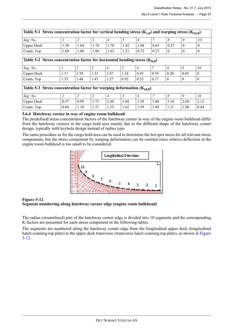
Classification Notes - No. 31.7, July 2013
Sec.5 Level 1 Rule Torsional Analysis – Page 37
DET NORSKE VERITAS AS
5.6.4 Hatchway corner in way of engine room bulkhead
The predefined stress concentration factors of the hatchway corner in way of the engine room bulkhead differfrom the hatchway corners in the cargo hold area mainly due to the different shape of the hatchway cornerdesign, typically with keyhole design instead of radius type.
The same procedure as for the cargo hold area can be used to determine the hot spot stress for all relevant stresscomponents, but the stress component by warping deformation can be omitted since relative deflection at theengine room bulkhead is too small to be considered.
Figure 5-12Segment numbering along hatchway corner edge (engine room bulkhead)
The radius (streamlined) part of the hatchway corner edge is divided into 10 segments and the correspondingK-factors are presented for each stress component in the following tables.
The segments are numbered along the hatchway corner edge from the longitudinal upper deck (longitudinalhatch coaming top plate) to the upper deck transverse (transverse hatch coaming top plate), as shown in Figure5-12.
Table 5-1 Stress concentration factor for vertical bending stress (Kv,0) and warping stress (Ktw,0)
Seg. No. 1 2 3 4 5 6 7 8 9 10
Upper Deck 1.39 1.64 1.78 1.70 1.42 1.04 0.63 0.27 0 0
Coam. Top 1.69 1.88 1.88 1.63 1.21 0.72 0.27 0 0 0
Table 5-2 Stress concentration factor for horizontal bending stress (Kh,0)
Seg. No. 1 2 3 4 5 6 7 8 9 10
Upper Deck 1.17 1.39 1.53 1.47 1.24 0.93 0.59 0.28 0.05 0
Coam. Top 1.33 1.48 1.47 1.27 0.92 0.53 0.17 0 0 0
Table 5-3 Stress concentration factor for warping deformation (Ktd,0)
Seg. No. 1 2 3 4 5 6 7 8 9 10
Upper Deck 0.57 0.99 1.73 2.48 3.04 3.39 3.40 3.18 2.69 2.12
Coam. Top 0.84 1.10 1.37 1.55 1.62 1.59 1.49 1.31 1.08 0.84
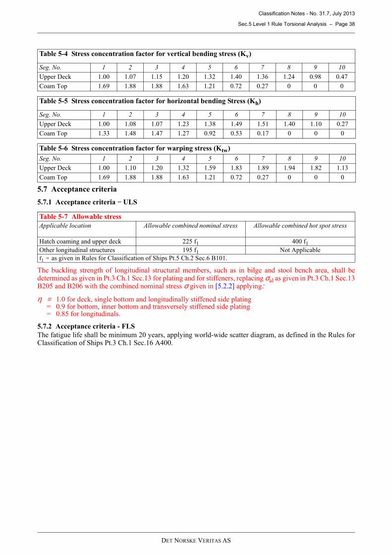
Classification Notes - No. 31.7, July 2013
Sec.5 Level 1 Rule Torsional Analysis – Page 38
DET NORSKE VERITAS AS
5.7 Acceptance criteria
5.7.1 Acceptance criteria − ULS
The buckling strength of longitudinal structural members, such as in bilge and stool bench area, shall bedetermined as given in Pt.3 Ch.1 Sec.13 for plating and for stiffeners, replacing σal as given in Pt.3 Ch.1 Sec.13B205 and B206 with the combined nominal stress σ given in [5.2.2] applying:
η = 1.0 for deck, single bottom and longitudinally stiffened side plating = 0.9 for bottom, inner bottom and transversely stiffened side plating = 0.85 for longitudinals.
5.7.2 Acceptance criteria - FLS
The fatigue life shall be minimum 20 years, applying world-wide scatter diagram, as defined in the Rules forClassification of Ships Pt.3 Ch.1 Sec.16 A400.
Table 5-4 Stress concentration factor for vertical bending stress (Kv)
Seg. No. 1 2 3 4 5 6 7 8 9 10
Upper Deck 1.00 1.07 1.15 1.20 1.32 1.40 1.36 1.24 0.98 0.47
Coam Top 1.69 1.88 1.88 1.63 1.21 0.72 0.27 0 0 0
Table 5-5 Stress concentration factor for horizontal bending Stress (Kh)
Seg. No. 1 2 3 4 5 6 7 8 9 10
Upper Deck 1.00 1.08 1.07 1.23 1.38 1.49 1.51 1.40 1.10 0.27
Coam Top 1.33 1.48 1.47 1.27 0.92 0.53 0.17 0 0 0
Table 5-6 Stress concentration factor for warping stress (Ktw)
Seg. No. 1 2 3 4 5 6 7 8 9 10
Upper Deck 1.00 1.10 1.20 1.32 1.59 1.83 1.89 1.94 1.82 1.13
Coam Top 1.69 1.88 1.88 1.63 1.21 0.72 0.27 0 0 0
Table 5-7 Allowable stress
Applicable location Allowable combined nominal stress Allowable combined hot spot stress
Hatch coaming and upper deck 225 f1 400 f1
Other longitudinal structures 195 f1 Not Applicable
f1 = as given in Rules for Classification of Ships Pt.5 Ch.2 Sec.6 B101.
Classification Notes - No. 31.7, July 2013
Sec.6 Level 2 Global Analysis – Page 39
DET NORSKE VERITAS AS
6 Level 2 Global Analysis
6.1 General principles
The application, objective and scope for Level 2 global analysis is described in [1.7].
A global coarse FE model shall be made in accordance with [6.5].
Similar to Level 1 Rule torsional analysis, Rule-defined loads shall be applied. The Rule-defined loads arefurther described in [6.6].
The Rule-defined loads shall be applied to the global coarse FE model as vertical and horizontal forces coveringthe entire ship length as shown in [6.7].
For ships which are symmetrical about the centre line, the stress resulting from horizontal bending and torsionalmoments will be of equal magnitude but opposite sign at port and starboard side. Therefore, in the global modelit is sufficient to apply loads representing oblique waves from one side only. Furthermore, provided that thehull girder stress components are combined in the manner described in subsequent parts of this section, it issufficient to read out all stress components from one side of the global model only.
In order to obtain hot spot stress for yield check and fatigue assessment, the general procedure as shown in [6.8]shall be applied.
The acceptance criteria for Level 2 global analysis are similar as for Level 1 Rule torsional analysis and aregiven in [6.11].
Results obtained from Level 2 global analysis supersede results from Level 1 Rule torsional analysis and theprescriptive minimum requirements to hatchway corners and stringer corners given in the Rules forClassification of Ships Pt.5 Ch.2 Sec.6 B500.
6.2 Combined nominal stress evaluation
6.2.1 General
Within the cargo hold area the combined nominal stress of vertical and horizontal hull girder bending and oftorsional moment from oblique sea shall be checked.
6.2.2 Combined nominal stress
The combined nominal stress shall be taken as:
σ = σV + σH&T [N/mm2]σV = hull girder stress due to:
— design still water hogging bending moment; and — reduced vertical wave hogging bending moment as given in [6.2.3].
σH&T = hull girder stress due to:
— horizontal wave bending moment;— still water torsional moment; and— wave torsional moment as given in [6.2.4].
Two different wave torsional moments are given in [2.5.1]. Each of the wave torsional moments can beassumed to be combined with a still water torsional moment having the same distribution along the hull girderas the wave torsion. The combined nominal stress is therefore to be calculated for each of the torsional momentdistributions.
The maximum combined nominal stress shall be taken as:
σmax = Max [σ(1), σ(2)] [N/mm2]σ(1) = calculated combined nominal stress with σV and σH&T applying MWT1 and MST1 as given in [2.5.1]σ(2) = calculated combined nominal stress with σV and σH&T applying MWT2 and MST2 as given in [2.5.1]
The calculated maximum combined nominal stress shall comply with the acceptance criteria given in [6.11.1].
6.2.3 Hull girder stress due to design still water hogging bending moment and reduced vertical wave hogging bending moment
The hull girder stress, σV, shall be calculated applying the following procedure:
— Load case LCV,ULS as given in [6.6.1.1] is to be applied to the global coarse FE model following theprocedure defined in [6.7.2].
Classification Notes - No. 31.7, July 2013
Sec.6 Level 2 Global Analysis – Page 40
DET NORSKE VERITAS AS
— σV is to be obtained from the global coarse FE model. In way of corners, σV, is to be calculated in way ofthe intersection between inner side and cross deck. The stress is to be obtained applying an appropriatelinear extrapolation of longitudinal stress along the inner side.
6.2.4 Hull girder stress due to horizontal wave bending moment and torsional moment
The hull girder stress, σH&T, shall be calculated applying the following procedure:
— Load cases LCH&T1,ULS and LCH&T2,ULS as given in [6.6.1.2] are to be applied to the global coarse FEmodel following the procedure defined in [6.7.3].
— σH&T is to be obtained from the global coarse FE model, with the sign determined in the following manner:— Above the horizontal neutral axis of the hull girder, where the vertical hogging moment gives rise to
tension, σH&T shall be added as a tensile stress, i.e. σH&T = |σH&T|— Below the horizontal neutral axis of the hull girder, where the vertical hogging moment gives rise to
compression, σH&T shall be added as a compressive stress, i.e. σH&T = -|σH&T|.— In way of corners, σH&T is to be calculated at the intersection between inner side and cross deck. The stress
is to be obtained applying an appropriate linear extrapolation of longitudinal stress along the inner side.
6.3 Combined hot spot stress evaluation
6.3.1 General
Within the cargo hold area the combined hot spot stress levels in way of hatchway corners shall be checked.
In addition, the combined hot spot stress shall be calculated for the most critical stringer corner (with thegreatest nominal combined stress calculated, following the procedure as given in [6.2]) and corners in way ofHFO deep tanks structure (where applicable).
Stringer corners not complying with the screening criteria given in [6.11.1], if any, shall also be checked forcombined hot spot stress.
6.3.2 Combined hot spot stress
The combined hot spot stress shall be taken as:
σhs = σV,hs + |σH&T,hs| [N/mm2]σV,hs = hull girder hot spot stress due to:
— design still water hogging bending moment; and — reduced vertical wave hogging bending moment as given in [6.3.3].
σH&T,hs = hull girder hot spot stress due to:
— horizontal wave bending moment;— still water torsional moment; and— wave torsional moment as given in [6.3.4].
Two different wave torsional moments are given in [2.5.1]. Each of the wave torsional moments can beassumed to be combined with a still water torsional moment having the same distribution along the hull girderas the wave torsion. The combined nominal stress is therefore to be calculated for each of the torsional momentdistributions.
The maximum combined nominal stress shall be taken as:
σmax,hs = Max [σhs(1), σ hs(2)] [N/mm2]σ hs(1) = calculated combined nominal stress with σV,hs and σH&T,hs applying MWT1 and MST1 as given in
[2.5.1]σ hs(2) = calculated combined nominal stress with σV,hs and σH&T,hs applying MWT2 and MST2 as given in
[2.5.1] The calculated maximum combined nominal stress shall comply with the acceptance criteriongiven in [6.11.1].
6.3.3 Hull girder stress due to vertical still water hogging bending moment and reduced vertical wave hogging bending moment
The hull girder stress, σV,hs, shall be calculated applying the following procedure:
— Load case LCV,ULS as given in [6.6.1.1] is to be applied to the global coarse FE model following theprocedure defined in [6.7.2].
— For locations where fine-mesh models have been established, as required by [6.8.2], σV,hs is to becalculated following the procedures defined in [6.9].
— For locations where fine-mesh models have not been established (see [6.8.2]), σV,hs is to be calculatedfollowing the procedures defined in [6.8.3].
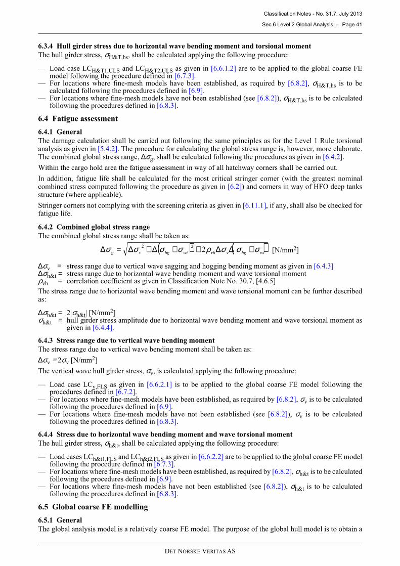
Classification Notes - No. 31.7, July 2013
Sec.6 Level 2 Global Analysis – Page 41
DET NORSKE VERITAS AS
6.3.4 Hull girder stress due to horizontal wave bending moment and torsional moment
The hull girder stress, σH&T,hs, shall be calculated applying the following procedure:
— Load case LCH&T1,ULS and LCH&T2,ULS as given in [6.6.1.2] are to be applied to the global coarse FEmodel following the procedure defined in [6.7.3].
— For locations where fine-mesh models have been established, as required by [6.8.2], σH&T,hs is to becalculated following the procedures defined in [6.9].
— For locations where fine-mesh models have not been established (see [6.8.2]), σH&T,hs is to be calculatedfollowing the procedures defined in [6.8.3].
6.4 Fatigue assessment
6.4.1 General
The damage calculation shall be carried out following the same principles as for the Level 1 Rule torsionalanalysis as given in [5.4.2]. The procedure for calculating the global stress range is, however, more elaborate.The combined global stress range, ∆σg, shall be calculated following the procedures as given in [6.4.2].
Within the cargo hold area the fatigue assessment in way of all hatchway corners shall be carried out.
In addition, fatigue life shall be calculated for the most critical stringer corner (with the greatest nominalcombined stress computed following the procedure as given in [6.2]) and corners in way of HFO deep tanksstructure (where applicable).
Stringer corners not complying with the screening criteria as given in [6.11.1], if any, shall also be checked forfatigue life.
6.4.2 Combined global stress range
The combined global stress range shall be taken as:
∆σv = stress range due to vertical wave sagging and hogging bending moment as given in [6.4.3]∆σh&t = stress range due to horizontal wave bending moment and wave torsional momentρvh = correlation coefficient as given in Classification Note No. 30.7, [4.6.5]
The stress range due to horizontal wave bending moment and wave torsional moment can be further describedas:
∆σh&t = 2|σh&t| [N/mm2]σh&t = hull girder stress amplitude due to horizontal wave bending moment and wave torsional moment as
given in [6.4.4].
6.4.3 Stress range due to vertical wave bending moment
The stress range due to vertical wave bending moment shall be taken as:
∆σv = 2σv [N/mm2]
The vertical wave hull girder stress, σv, is calculated applying the following procedure:
— Load case LCv,FLS as given in [6.6.2.1] is to be applied to the global coarse FE model following theprocedures defined in [6.7.2].
— For locations where fine-mesh models have been established, as required by [6.8.2], σv is to be calculatedfollowing the procedures defined in [6.9].
— For locations where fine-mesh models have not been established (see [6.8.2]), σv is to be calculatedfollowing the procedures defined in [6.8.3].
6.4.4 Stress due to horizontal wave bending moment and wave torsional moment
The hull girder stress, σh&t, shall be calculated applying the following procedure:
— Load cases LCh&t1,FLS and LCh&t2,FLS as given in [6.6.2.2] are to be applied to the global coarse FE modelfollowing the procedure defined in [6.7.3].
— For locations where fine-mesh models have been established, as required by [6.8.2], σh&t is to be calculatedfollowing the procedures defined in [6.9].
— For locations where fine-mesh models have not been established (see [6.8.2]), σh&t is to be calculatedfollowing the procedures defined in [6.8.3].
6.5 Global coarse FE modelling
6.5.1 General
The global analysis model is a relatively coarse FE model. The purpose of the global hull model is to obtain a
( ) ( )wthgvvhwthgvg σσσρσσσσ +∆∆++∆+∆=∆ 222
[N/mm2]
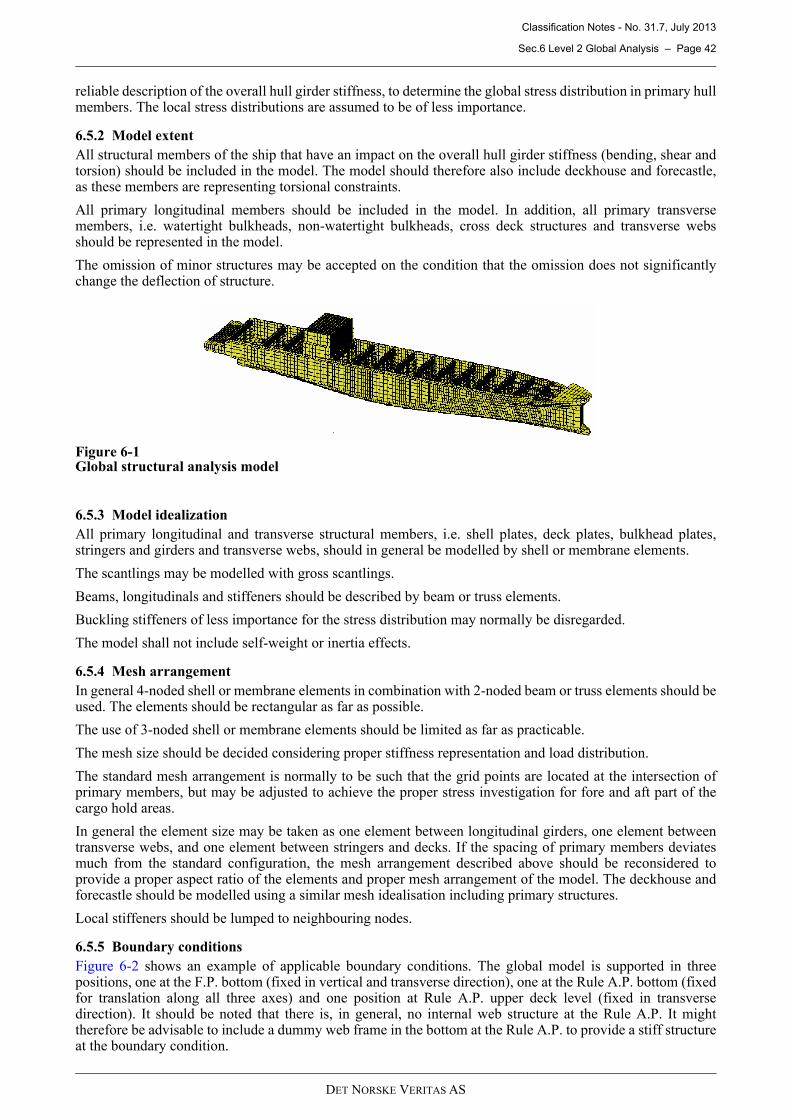
Classification Notes - No. 31.7, July 2013
Sec.6 Level 2 Global Analysis – Page 42
DET NORSKE VERITAS AS
reliable description of the overall hull girder stiffness, to determine the global stress distribution in primary hullmembers. The local stress distributions are assumed to be of less importance.
6.5.2 Model extent
All structural members of the ship that have an impact on the overall hull girder stiffness (bending, shear andtorsion) should be included in the model. The model should therefore also include deckhouse and forecastle,as these members are representing torsional constraints.
All primary longitudinal members should be included in the model. In addition, all primary transversemembers, i.e. watertight bulkheads, non-watertight bulkheads, cross deck structures and transverse websshould be represented in the model.
The omission of minor structures may be accepted on the condition that the omission does not significantlychange the deflection of structure.
Figure 6-1Global structural analysis model
6.5.3 Model idealization
All primary longitudinal and transverse structural members, i.e. shell plates, deck plates, bulkhead plates,stringers and girders and transverse webs, should in general be modelled by shell or membrane elements.
The scantlings may be modelled with gross scantlings.
Beams, longitudinals and stiffeners should be described by beam or truss elements.
Buckling stiffeners of less importance for the stress distribution may normally be disregarded.
The model shall not include self-weight or inertia effects.
6.5.4 Mesh arrangement
In general 4-noded shell or membrane elements in combination with 2-noded beam or truss elements should beused. The elements should be rectangular as far as possible.
The use of 3-noded shell or membrane elements should be limited as far as practicable.
The mesh size should be decided considering proper stiffness representation and load distribution.
The standard mesh arrangement is normally to be such that the grid points are located at the intersection ofprimary members, but may be adjusted to achieve the proper stress investigation for fore and aft part of thecargo hold areas.
In general the element size may be taken as one element between longitudinal girders, one element betweentransverse webs, and one element between stringers and decks. If the spacing of primary members deviatesmuch from the standard configuration, the mesh arrangement described above should be reconsidered toprovide a proper aspect ratio of the elements and proper mesh arrangement of the model. The deckhouse andforecastle should be modelled using a similar mesh idealisation including primary structures.
Local stiffeners should be lumped to neighbouring nodes.
6.5.5 Boundary conditions
Figure 6-2 shows an example of applicable boundary conditions. The global model is supported in threepositions, one at the F.P. bottom (fixed in vertical and transverse direction), one at the Rule A.P. bottom (fixedfor translation along all three axes) and one position at Rule A.P. upper deck level (fixed in transversedirection). It should be noted that there is, in general, no internal web structure at the Rule A.P. It mighttherefore be advisable to include a dummy web frame in the bottom at the Rule A.P. to provide a stiff structureat the boundary condition.
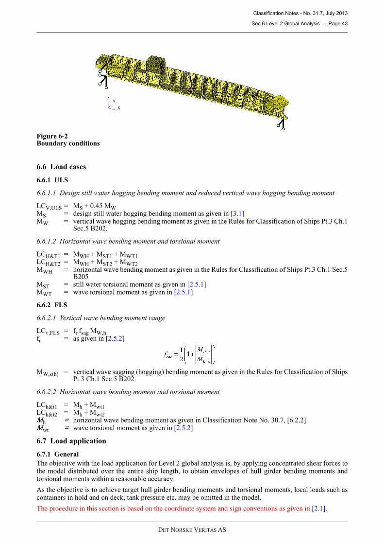
Classification Notes - No. 31.7, July 2013
Sec.6 Level 2 Global Analysis – Page 43
DET NORSKE VERITAS AS
Figure 6-2Boundary conditions
6.6 Load cases
6.6.1 ULS
6.6.1.1 Design still water hogging bending moment and reduced vertical wave hogging bending moment
LCV,ULS = MS + 0.45 MWMS = design still water hogging bending moment as given in [3.1]MW = vertical wave hogging bending moment as given in the Rules for Classification of Ships Pt.3 Ch.1
Sec.5 B202.
6.6.1.2 Horizontal wave bending moment and torsional moment
LCH&T1 = MWH + MST1 + MWT1LCH&T2 = MWH + MST2 + MWT2MWH = horizontal wave bending moment as given in the Rules for Classification of Ships Pt.3 Ch.1 Sec.5
B205MST = still water torsional moment as given in [2.5.1]MWT = wave torsional moment as given in [2.5.1].
6.6.2 FLS
6.6.2.1 Vertical wave bending moment range
LCv,FLS = fr fsag MW,hfr = as given in [2.5.2]
MW,s(h) = vertical wave sagging (hogging) bending moment as given in the Rules for Classification of ShipsPt.3 Ch.1 Sec.5 B202.
6.6.2.2 Horizontal wave bending moment and torsional moment
LCh&t1 = Mh + Mwt1LCh&t2 = Mh + Mwt2Μh = horizontal wave bending moment as given in Classification Note No. 30.7, [6.2.2]Μwt = wave torsional moment as given in [2.5.2].
6.7 Load application
6.7.1 General
The objective with the load application for Level 2 global analysis is, by applying concentrated shear forces tothe model distributed over the entire ship length, to obtain envelopes of hull girder bending moments andtorsional moments within a reasonable accuracy.
As the objective is to achieve target hull girder bending moments and torsional moments, local loads such ascontainers in hold and on deck, tank pressure etc. may be omitted in the model.
The procedure in this section is based on the coordinate system and sign conventions as given in [2.1].
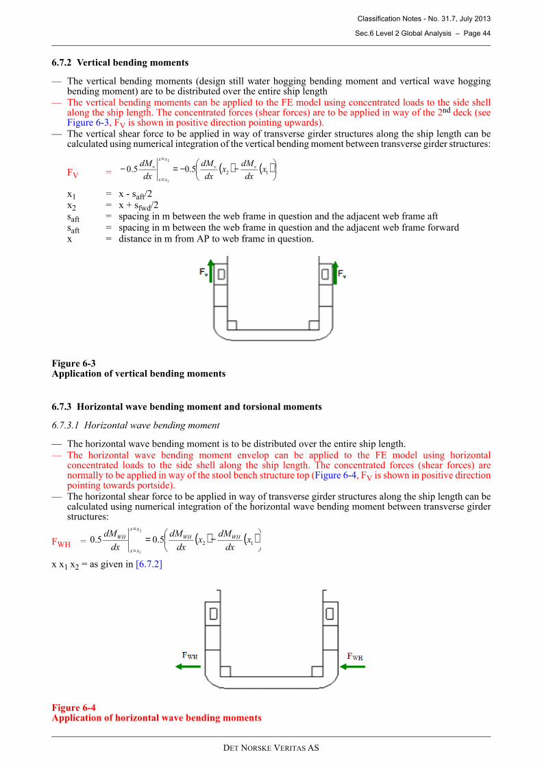
Classification Notes - No. 31.7, July 2013
Sec.6 Level 2 Global Analysis – Page 44
DET NORSKE VERITAS AS
6.7.2 Vertical bending moments
— The vertical bending moments (design still water hogging bending moment and vertical wave hoggingbending moment) are to be distributed over the entire ship length
— The vertical bending moments can be applied to the FE model using concentrated loads to the side shellalong the ship length. The concentrated forces (shear forces) are to be applied in way of the 2nd deck (seeFigure 6-3, FV is shown in positive direction pointing upwards).
— The vertical shear force to be applied in way of transverse girder structures along the ship length can becalculated using numerical integration of the vertical bending moment between transverse girder structures:
FV =
x1 = x - saft/2x2 = x + sfwd/2saft = spacing in m between the web frame in question and the adjacent web frame aftsaft = spacing in m between the web frame in question and the adjacent web frame forwardx = distance in m from AP to web frame in question.
Figure 6-3Application of vertical bending moments
6.7.3 Horizontal wave bending moment and torsional moments
6.7.3.1 Horizontal wave bending moment
— The horizontal wave bending moment is to be distributed over the entire ship length.— The horizontal wave bending moment envelop can be applied to the FE model using horizontal
concentrated loads to the side shell along the ship length. The concentrated forces (shear forces) arenormally to be applied in way of the stool bench structure top (Figure 6-4, FV is shown in positive directionpointing towards portside).
— The horizontal shear force to be applied in way of transverse girder structures along the ship length can becalculated using numerical integration of the horizontal wave bending moment between transverse girderstructures:
FWH =
x x1 x2 = as given in [6.7.2]
Figure 6-4Application of horizontal wave bending moments
( ) ( )
−−=−=
=125.05.0
2
1
xdx
dMx
dx
dM
dx
dM vv
xx
xx
v
( ) ( )
−==
=125.05.0
2
1
xdx
dMx
dx
dM
dx
dM WHWH
xx
xx
WH
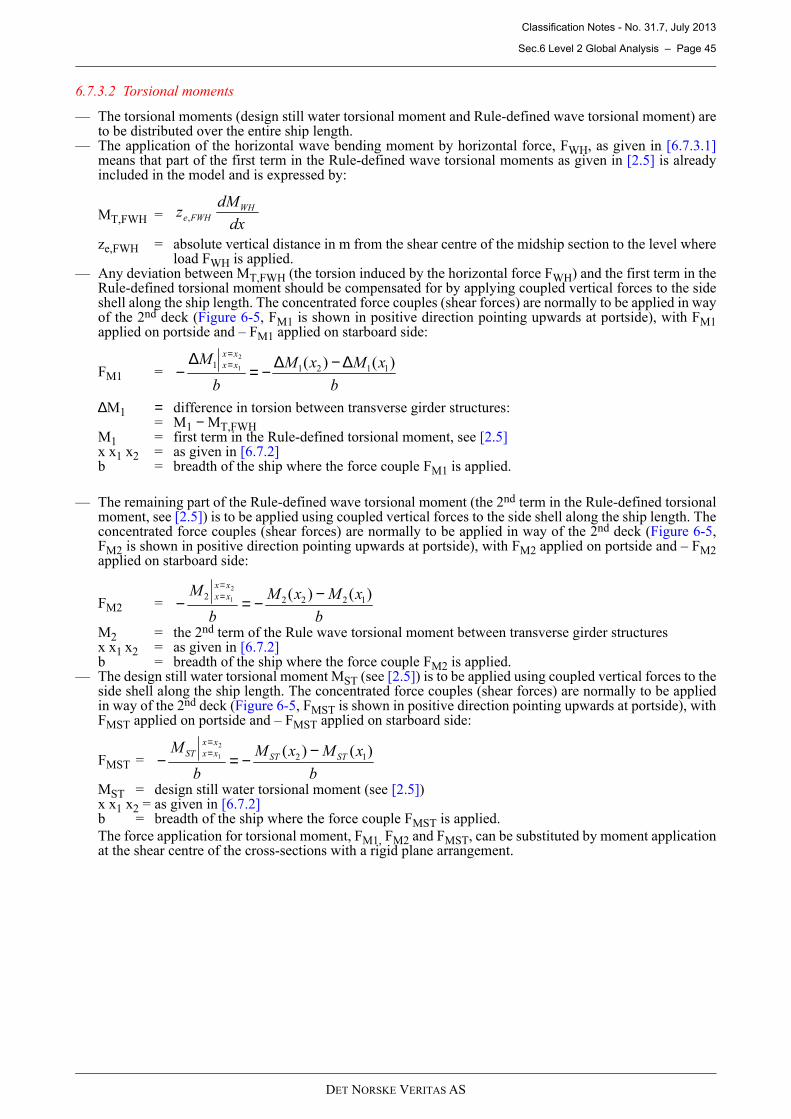
Classification Notes - No. 31.7, July 2013
Sec.6 Level 2 Global Analysis – Page 45
DET NORSKE VERITAS AS
6.7.3.2 Torsional moments
— The torsional moments (design still water torsional moment and Rule-defined wave torsional moment) areto be distributed over the entire ship length.
— The application of the horizontal wave bending moment by horizontal force, FWH, as given in [6.7.3.1]means that part of the first term in the Rule-defined wave torsional moments as given in [2.5] is alreadyincluded in the model and is expressed by:
MT,FWH =
ze,FWH = absolute vertical distance in m from the shear centre of the midship section to the level whereload FWH is applied.
— Any deviation between MT,FWH (the torsion induced by the horizontal force FWH) and the first term in theRule-defined torsional moment should be compensated for by applying coupled vertical forces to the sideshell along the ship length. The concentrated force couples (shear forces) are normally to be applied in wayof the 2nd deck (Figure 6-5, FM1 is shown in positive direction pointing upwards at portside), with FM1applied on portside and – FM1 applied on starboard side:
FM1 =
∆M1 = difference in torsion between transverse girder structures: = M1 − MT,FWHM1 = first term in the Rule-defined torsional moment, see [2.5]x x1 x2 = as given in [6.7.2] b = breadth of the ship where the force couple FM1 is applied.
— The remaining part of the Rule-defined wave torsional moment (the 2nd term in the Rule-defined torsionalmoment, see [2.5]) is to be applied using coupled vertical forces to the side shell along the ship length. Theconcentrated force couples (shear forces) are normally to be applied in way of the 2nd deck (Figure 6-5,FM2 is shown in positive direction pointing upwards at portside), with FM2 applied on portside and – FM2applied on starboard side:
FM2 =
M2 = the 2nd term of the Rule wave torsional moment between transverse girder structuresx x1 x2 = as given in [6.7.2] b = breadth of the ship where the force couple FM2 is applied.
— The design still water torsional moment MST (see [2.5]) is to be applied using coupled vertical forces to theside shell along the ship length. The concentrated force couples (shear forces) are normally to be appliedin way of the 2nd deck (Figure 6-5, FMST is shown in positive direction pointing upwards at portside), withFMST applied on portside and – FMST applied on starboard side:
FMST =
MST = design still water torsional moment (see [2.5]) x x1 x2 = as given in [6.7.2] b = breadth of the ship where the force couple FMST is applied.
The force application for torsional moment, FM1, FM2 and FMST, can be substituted by moment applicationat the shear centre of the cross-sections with a rigid plane arrangement.
dx
dMz WH
FWHe,
b
xMxM
b
Mxx
xx )()( 112112
1 ∆−∆−=∆
−==
b
xMxM
b
Mxx
xx )()( 122222
1 −−=−==
b
xMxM
b
MSTST
xx
xxST )()( 12
2
1 −−=−==
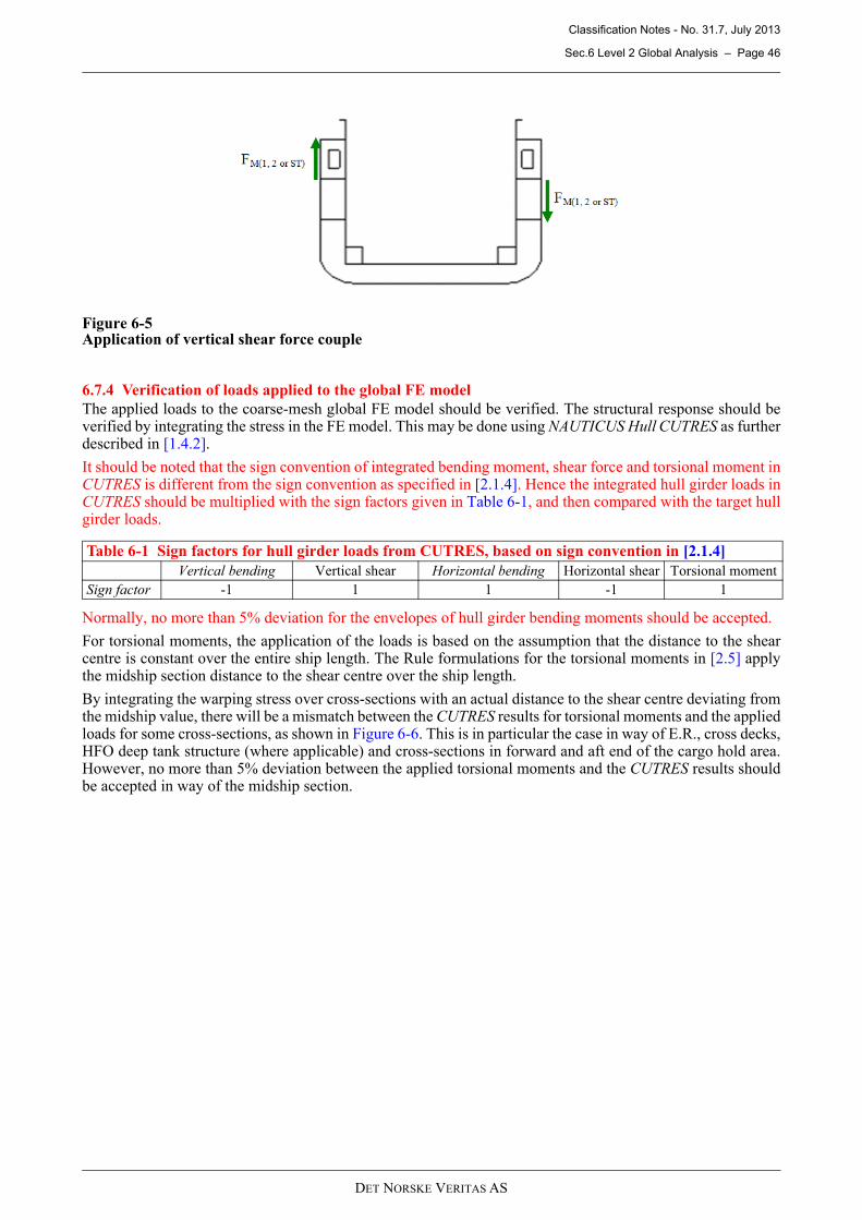
Classification Notes - No. 31.7, July 2013
Sec.6 Level 2 Global Analysis – Page 46
DET NORSKE VERITAS AS
Figure 6-5Application of vertical shear force couple
6.7.4 Verification of loads applied to the global FE model
The applied loads to the coarse-mesh global FE model should be verified. The structural response should beverified by integrating the stress in the FE model. This may be done using NAUTICUS Hull CUTRES as furtherdescribed in [1.4.2].
It should be noted that the sign convention of integrated bending moment, shear force and torsional moment inCUTRES is different from the sign convention as specified in [2.1.4]. Hence the integrated hull girder loads inCUTRES should be multiplied with the sign factors given in Table 6-1, and then compared with the target hullgirder loads.
Normally, no more than 5% deviation for the envelopes of hull girder bending moments should be accepted.
For torsional moments, the application of the loads is based on the assumption that the distance to the shearcentre is constant over the entire ship length. The Rule formulations for the torsional moments in [2.5] applythe midship section distance to the shear centre over the ship length.
By integrating the warping stress over cross-sections with an actual distance to the shear centre deviating fromthe midship value, there will be a mismatch between the CUTRES results for torsional moments and the appliedloads for some cross-sections, as shown in Figure 6-6. This is in particular the case in way of E.R., cross decks,HFO deep tank structure (where applicable) and cross-sections in forward and aft end of the cargo hold area.However, no more than 5% deviation between the applied torsional moments and the CUTRES results shouldbe accepted in way of the midship section.
Table 6-1 Sign factors for hull girder loads from CUTRES, based on sign convention in [2.1.4]
Vertical bending Vertical shear Horizontal bending Horizontal shear Torsional moment
Sign factor -1 1 1 -1 1
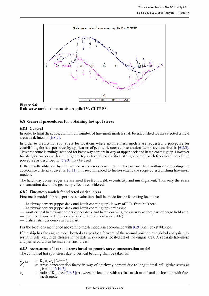
Classification Notes - No. 31.7, July 2013
Sec.6 Level 2 Global Analysis – Page 47
DET NORSKE VERITAS AS
Figure 6-6Rule wave torsional moments - Applied Vs CUTRES
6.8 General procedures for obtaining hot spot stress
6.8.1 General
In order to limit the scope, a minimum number of fine-mesh models shall be established for the selected criticalareas as defined in [6.8.2].
In order to predict hot spot stress for locations where no fine-mesh models are requested, a procedure forestablishing the hot spot stress by application of geometric stress concentration factors are described in [6.8.3].This procedure is mainly intended for hatchway corners in way of upper deck and hatch coaming top. Howeverfor stringer corners with similar geometry as for the most critical stringer corner (with fine-mesh model) theprocedure as described in [6.8.3] may be used.
If the results obtained by the method with stress concentration factors are close within or exceeding theacceptance criteria as given in [6.11], it is recommended to further extend the scope by establishing fine-meshmodels.
The hatchway corner edges are assumed free from weld, eccentricity and misalignment. Thus only the stressconcentration due to the geometry effect is considered.
6.8.2 Fine-mesh models for selected critical areas
Fine-mesh models for hot spot stress evaluation shall be made for the following locations:
— hatchway corners (upper deck and hatch coaming top) in way of E.R. front bulkhead— hatchway corners (upper deck and hatch coaming top) amidships— most critical hatchway corners (upper deck and hatch coaming top) in way of fore part of cargo hold area— corners in way of HFO deep tanks structure (where applicable)— critical stringer corner in fore part.
For the locations mentioned above fine-mesh models in accordance with [6.9] shall be established.
If the ship has the engine room located at a position forward of the normal position, the global analysis mayresult in relatively high stresses in the hatchway corners located aft of the engine area. A separate fine-meshanalysis should then be made for such areas.
6.8.3 Assessment of hot spot stress based on generic stress concentration model
The combined hot spot stress due to vertical bending shall be taken as:
σV,hs = Kx cx σV [N/mm2] Κx = stress concentration factor in way of hatchway corners due to longitudinal hull girder stress as
given in [6.10.2] cx = ratio of Kt,x (see [5.6.3]) between the location with no fine-mesh model and the location with fine-
mesh model
Classification Notes - No. 31.7, July 2013
Sec.6 Level 2 Global Analysis – Page 48
DET NORSKE VERITAS AS
σV = nominal longitudinal hull girder stress from vertical bending in way of the intersection betweeninner side and cross deck. The stress is to be obtained applying an appropriate linear extrapolationof longitudinal stress along the inner side.
The combined hot spot stress due to horizontal wave bending moment and torsional moment shall be taken as:
σH&T,hs = Kx cx σH&T + Ky cy σT [N/mm2]
Κx = stress concentration factor in way of hatchway corners due to longitudinal hull girder stress asgiven in [6.10.2]
cx = ratio of Kt,x (see [5.6.3]) between the location with no fine-mesh model and the location with fine-mesh model
σH&T = nominal longitudinal hull girder stress due to horizontal bending, and longitudinal hull girderwarping stress induced by torsional moment in way of the intersection between inner side andcross deck; the stress is to be obtained applying an appropriate linear extrapolation of longitudinalstress along the inner side
Κy = stress concentration factor in way of hatchway corners from bending stress due to warpingdeformations of cross decks [6.10.2]
cy = ratio of Kt,y (see [5.6.3]) between the location with no fine-mesh model and the location with fine-mesh model
σT = nominal bending stress due to warping deformation of cross deck induced by torsional moment inway of the intersection between inner side and cross deck. The stress is to be obtained applyingan appropriate linear extrapolation of transverse stress along the inner side.
6.9 Hot spot stress evaluation by fine-mesh models
6.9.1 Application
Fine-mesh models shall be defined for selected critical areas as specified in [6.8.2]. The intention with the fine-
mesh models is to examine the stress response including geometric stress concentrations for ULS hot spot stress
evaluation and FLS in way of selected critical corners.
6.9.2 Modelling
It is generally recommended to use sub-modelling techniques for the fine-mesh models where displacements
are transferred from the global model to the smaller fine-mesh models.
The analysis model in the midship region should extend two web spaces aft and forward of transverse bulkhead
location in the longitudinal direction, and from the hatch coaming top to 2nd deck level in vertical direction.
If the scantlings and or structural arrangement differ between the watertight bulkhead and the support bulkhead,
due consideration will be necessary, i.e. separate modelling may be required.
The analysis model of the engine room front bulkhead should extend two web spaces aft and forward of
transverse bulkhead location in the longitudinal direction, and downward to 2nd deck level in vertical direction.
The model should also extend up to the suitable level of deckhouse deck, if applicable.
The analysis model for stringer corners should extend two web spaces aft and forward of transverse bulkhead
in the longitudinal direction. The model should also extend two coarse-size elements above and below the
stringer deck level.
Mesh arrangement in way of hatchway corner area is important. It is recommended that the radius be divided
into 8 to 10 divisions, but with an element size of maximum 2t (i.e. twice the plate thickness).
It is recommended to utilise fictitious 1 × 1 mm beam elements along the edge of hatchway corner radius for
easy read-out of stress. Special attention should be paid where the curvature of the hatchway corner starts and
ends. In order to obtain a correct read-out of stress for the first and the last element in way of the curvature, the
beam elements should be extended to the first element outside the hatchway corner radius.
All the models are to include fine-mesh in way of hatchway corners as well as at the scarping and at the end
terminations of longitudinal hatch coamings, where relevant.
The coaming stays should also be properly represented in the model by shell or membrane elements.
All cut-outs, e.g. ventilation opening, access openings, should be included in the model.
Secondary stiffeners may be represented by truss elements unless their contribution to the stresses, at the area
of concern, is negligible.
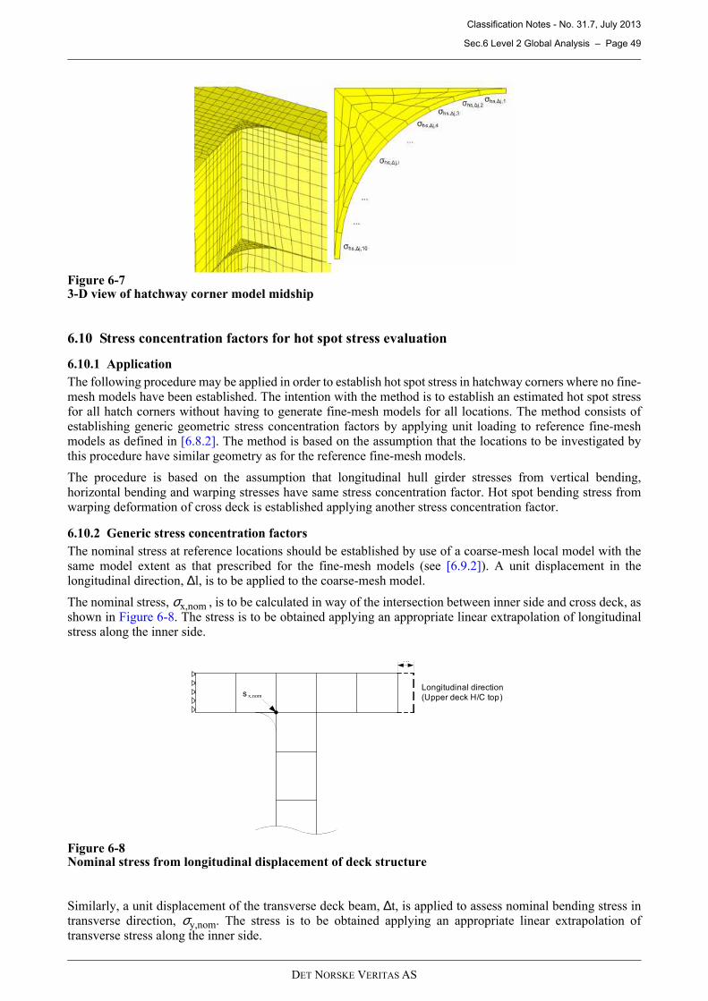
Classification Notes - No. 31.7, July 2013
Sec.6 Level 2 Global Analysis – Page 49
DET NORSKE VERITAS AS
Figure 6-73-D view of hatchway corner model midship
6.10 Stress concentration factors for hot spot stress evaluation
6.10.1 Application
The following procedure may be applied in order to establish hot spot stress in hatchway corners where no fine-
mesh models have been established. The intention with the method is to establish an estimated hot spot stressfor all hatch corners without having to generate fine-mesh models for all locations. The method consists of
establishing generic geometric stress concentration factors by applying unit loading to reference fine-meshmodels as defined in [6.8.2]. The method is based on the assumption that the locations to be investigated by
this procedure have similar geometry as for the reference fine-mesh models.
The procedure is based on the assumption that longitudinal hull girder stresses from vertical bending,
horizontal bending and warping stresses have same stress concentration factor. Hot spot bending stress fromwarping deformation of cross deck is established applying another stress concentration factor.
6.10.2 Generic stress concentration factors
The nominal stress at reference locations should be established by use of a coarse-mesh local model with the
same model extent as that prescribed for the fine-mesh models (see [6.9.2]). A unit displacement in thelongitudinal direction, ∆l, is to be applied to the coarse-mesh model.
The nominal stress, σx,nom , is to be calculated in way of the intersection between inner side and cross deck, as
shown in Figure 6-8. The stress is to be obtained applying an appropriate linear extrapolation of longitudinalstress along the inner side.
Figure 6-8Nominal stress from longitudinal displacement of deck structure
Similarly, a unit displacement of the transverse deck beam, ∆t, is applied to assess nominal bending stress intransverse direction, σy,nom. The stress is to be obtained applying an appropriate linear extrapolation of
transverse stress along the inner side.
s x,nom
Longitudinal direction
(Upper deck H/C top)
?x
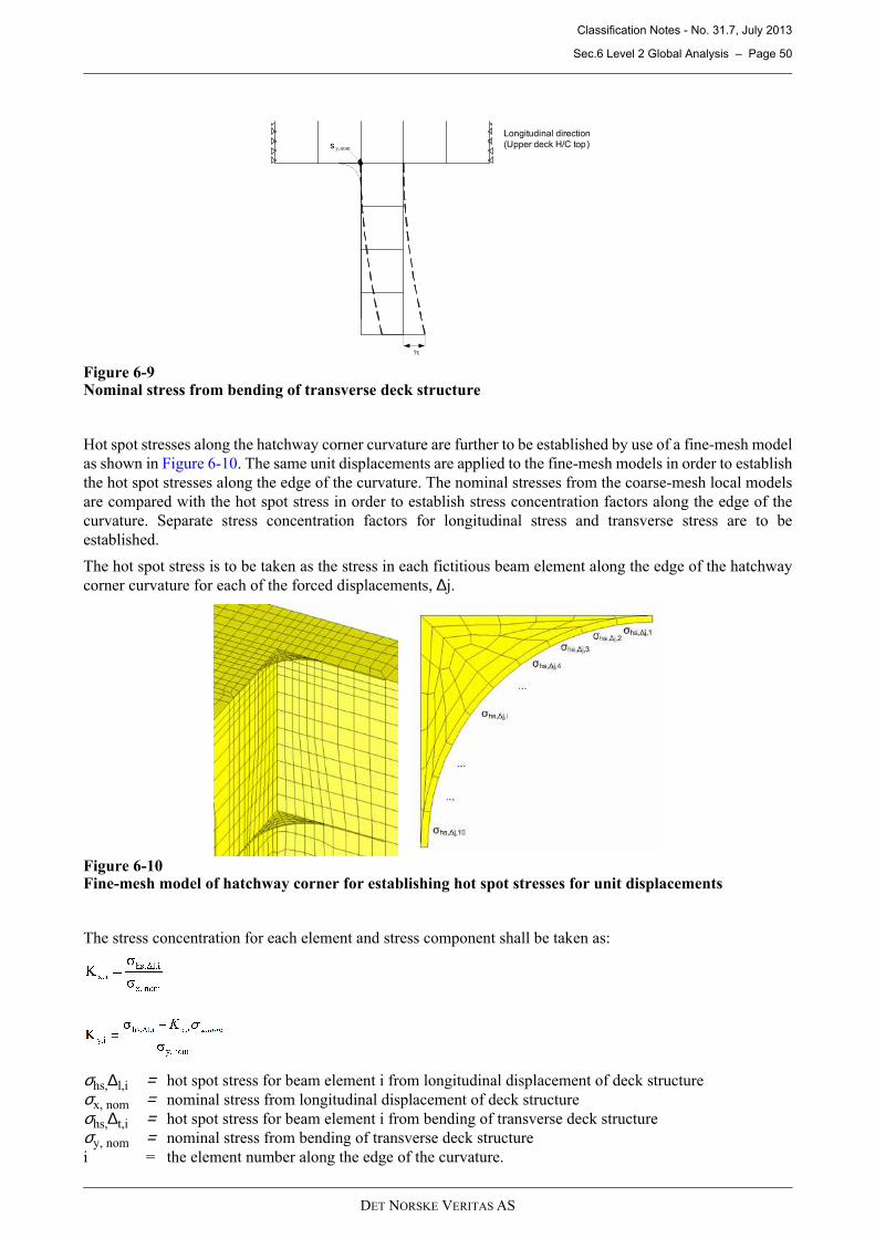
Classification Notes - No. 31.7, July 2013
Sec.6 Level 2 Global Analysis – Page 50
DET NORSKE VERITAS AS
Figure 6-9Nominal stress from bending of transverse deck structure
Hot spot stresses along the hatchway corner curvature are further to be established by use of a fine-mesh model
as shown in Figure 6-10. The same unit displacements are applied to the fine-mesh models in order to establish
the hot spot stresses along the edge of the curvature. The nominal stresses from the coarse-mesh local models
are compared with the hot spot stress in order to establish stress concentration factors along the edge of the
curvature. Separate stress concentration factors for longitudinal stress and transverse stress are to be
established.
The hot spot stress is to be taken as the stress in each fictitious beam element along the edge of the hatchway
corner curvature for each of the forced displacements, ∆j.
Figure 6-10Fine-mesh model of hatchway corner for establishing hot spot stresses for unit displacements
The stress concentration for each element and stress component shall be taken as:
σhs,∆l,i = hot spot stress for beam element i from longitudinal displacement of deck structure
σx, nom = nominal stress from longitudinal displacement of deck structure
σhs,∆t,i = hot spot stress for beam element i from bending of transverse deck structure
σy, nom = nominal stress from bending of transverse deck structure
i = the element number along the edge of the curvature.
s y,nom
Longitudinal direction
(Upper deck H/C top)
?t
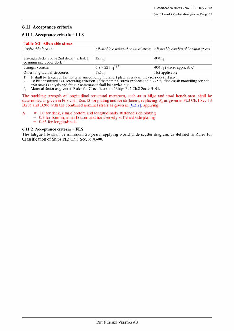
Classification Notes - No. 31.7, July 2013
Sec.6 Level 2 Global Analysis – Page 51
DET NORSKE VERITAS AS
6.11 Acceptance criteria
6.11.1 Acceptance criteria − ULS
The buckling strength of longitudinal structural members, such as in bilge and stool bench area, shall bedetermined as given in Pt.3 Ch.1 Sec.13 for plating and for stiffeners, replacing σal as given in Pt.3 Ch.1 Sec.13B205 and B206 with the combined nominal stress as given in [6.2.2], applying:
η = 1.0 for deck, single bottom and longitudinally stiffened side plating = 0.9 for bottom, inner bottom and transversely stiffened side plating = 0.85 for longitudinals.
6.11.2 Acceptance criteria − FLS
The fatigue life shall be minimum 20 years, applying world wide-scatter diagram, as defined in Rules forClassification of Ships Pt.3 Ch.1 Sec.16 A400.
Table 6-2 Allowable stress
Applicable location Allowable combined nominal stress Allowable combined hot spot stress
Strength decks above 2nd deck, i.e. hatch coaming and upper deck
225 f1 400 f1
Stringer corners 0.8 × 225 f11) 2) 400 f1 (where applicable)
Other longitudinal structures 195 f1 Not applicable
1) f1 shall be taken for the material surrounding the insert plate in way of the cross deck, if any.2) To be considered as a screening criterion. If the nominal stress exceeds 0.8 × 225 f1, fine-mesh modelling for hot
spot stress analysis and fatigue assessment shall be carried out.f1 Material factor as given in Rules for Classification of Ships Pt.5 Ch.2 Sec.6 B101.
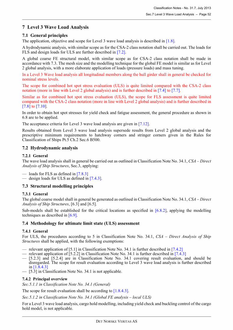
Classification Notes - No. 31.7, July 2013
Sec.7 Level 3 Wave Load Analysis – Page 52
DET NORSKE VERITAS AS
7 Level 3 Wave Load Analysis
7.1 General principles
The application, objective and scope for Level 3 wave load analysis is described in [1.8].
A hydrodynamic analysis, with similar scope as for the CSA-2 class notation shall be carried out. The loads forFLS and design loads for ULS are further described in [7.2].
A global coarse FE structural model, with similar scope as for CSA-2 class notation shall be made inaccordance with 7.3. The mesh size and the modelling technique for the global FE model is similar as for Level2 global analysis, with a more elaborate application of loads (pressure loads) and mass tuning.
In a Level 3 Wave load analysis all longitudinal members along the hull girder shall in general be checked fornominal stress levels.
The scope for combined hot spot stress evaluation (ULS) is quite limited compared with the CSA-2 classnotation (more in line with Level 2 global analysis) and is further described in [7.4] to [7.7].
Similar as for combined hot spot stress evaluation (ULS), the scope for FLS assessment is quite limitedcompared with the CSA-2 class notation (more in line with Level 2 global analysis) and is further described in[7.8] to [7.10].
In order to obtain hot spot stresses for yield check and fatigue assessment, the general procedure as shown in6.8 are to be applied.
The acceptance criteria for Level 3 wave load analysis are given in [7.12].
Results obtained from Level 3 wave load analysis supersede results from Level 2 global analysis and theprescriptive minimum requirements to hatchway corners and stringer corners given in the Rules forClassification of Ships Pt.5 Ch.2 Sec.6 B500.
7.2 Hydrodynamic analysis
7.2.1 General
The wave load analysis shall in general be carried out as outlined in Classification Note No. 34.1, CSA – DirectAnalysis of Ship Structures, Sec.3, applying:
— loads for FLS as defined in [7.8.3]— design loads for ULS as defined in [7.4.3].
7.3 Structural modelling principles
7.3.1 General
The global coarse model shall in general be generated as outlined in Classification Note No. 34.1, CSA – DirectAnalysis of Ship Structures, [6.3] and [6.5].
Sub-models shall be established for the critical locations as specified in [6.8.2], applying the modellingtechniques as described in [6.9].
7.4 Methodology for ultimate limit state (ULS) assessment
7.4.1 General
For ULS, the procedures according to 5 in Classification Note No. 34.1, CSA – Direct Analysis of ShipStructures shall be applied, with the following exemptions:
— relevant application of [5.1] in Classification Note No. 34.1 is further described in [7.4.2]— relevant application of [5.2.2] in Classification Note No. 34.1 is further described in [7.4.3]— [5.2.3] and [5.2.4] are in Classification Note No. 34.1 covering result evaluation, and should be
disregarded. The scope for result evaluation according to Level 3 wave load analysis is further describedin [1.8.4.3]
— [5.3] in Classification Note No. 34.1 is not applicable.
7.4.2 Principal overview
Sec.5.1.1 in Classification Note No. 34.1 (General)
The scope for result evaluation shall be according to [1.8.4.3].
Sec.5.1.2 in Classification Note No. 34.1 (Global FE analysis – local ULS)
For a Level 3 wave load analysis, cargo hold modelling, including yield check and buckling control of the cargohold model, is not applicable.
Classification Notes - No. 31.7, July 2013
Sec.7 Level 3 Wave Load Analysis – Page 53
DET NORSKE VERITAS AS
Sec.5.1.3 in Classification Note No. 34.1 (Hull girder collapse – global ULS)
Hull girder collapse − global ULS is not applicable for Level 3 wave load analysis.
Sec.5.1.4 in Classification Note No. 34.1 (Scantlings/corrosion model)
Corrosion addition as given in the Rules for Classification of Ships Pt.3 Ch.1 Sec.2 D200 shall be deductedfrom the global coarse model and sub-models.
7.4.3 Design loads
Sec.5.2.2.1 in Classification Note No. 34.1 (General)
Level 3 wave load analysis shall comply with the procedures outlined in Classification Note No. 34.1, [5.2.2.1].
Sec.5.2.2.2 in Classification Note No. 34.1 (Design condition and selection of critical loading conditions)
The following loading conditions (mass distribution) should as a minimum be analysed:
— maximum still water hogging moment amidships, normally light homogeneous container loading conditionwith maximum TEU on scantling draught
— maximum still water sagging moment (or minimum still water hogging moment if applicable) amidships,normally ballast condition
— container loading condition with maximum GM, normally heavy homogeneous container loading conditionon scantling draught (large GM gives larger roll motions and therefore higher torsional moment)
The loading conditions specified above may in general be taken from the Trim and Stability Booklet. However,if the extreme values of the longitudinal strength parameters deviates more than 5% from the permissible limitsthe conditions should be adjusted accordingly.
The loading condition giving the maximum still water hogging moment amidships normally also gives thegreatest extreme values of still water shear forces in way of aft and forward quarter-length. If not, additionalloading condition should be analysed.
Sec.5.2.2.3 in Classification Note No. 34.1 (Hydrodynamic analysis)
Level 3 wave load analysis shall in general comply with the procedures outlined in Classification Note No.34.1, [5.2.2.3] meaning that:
— head sea (180° wave heading): 5 knots— wave headings 240° to 120°: 2/3 of design speed— wave headings 150° and 210°: If 2/3 of design speed gives greater long term response of wave induced
vertical hull girder bending moments than for head sea with 5 knots, then 5 knots shall be applied. If not,then 2/3 of design speed shall be applied.
Sec.5.2.2.4 in Classification Note No. 34.1 (Design life and wave environment)
Level 3 wave load analysis shall comply with the procedures outlined in Classification Note No. 34.1, [5.2.2.5].
Sec.5.2.2.5 in Classification Note No. 34.1 (Design waves)
The following design waves given in Table 5-1 of Classification Note No. 34.1 shall be applied:
— 1A: Max hogging wave moment— 1B: Max sagging wave moment— 3A: Max wave shear in way of the position with Max still water shear (in engine room around aft quarter-
length)— 3B: Min wave shear in way of the position with Min still water shear (around fore quarter-length)— 4B: Maximum wave pressure at No.1 hold in head seas— 5: Design wave(s) in quartering/ beam sea condition.
In order to assess the transverse strength of the aft body as requested in [1.8.4.3] the following additional designwave shall be applied:
— 4C: Maximum wave pressure at aft most hold in head seas.
Only the design waves which represent vertical bending moment and vertical shear force (1A, 1B, 3A, and 3Bspecified above) shall be performed with non-linear analysis. The other design waves may be performed withlinear analysis.
In general the design waves should have a wave frequency taken from the response spectrum from the sea statecontributing the most to the long term response from the current heading. The height of the design wave shouldbe found by scaling the response for the design wave up to the long term response.
Instead of applying design wave(s) 5 in quartering/ beam sea condition specified above, a full stochastic
Classification Notes - No. 31.7, July 2013
Sec.7 Level 3 Wave Load Analysis – Page 54
DET NORSKE VERITAS AS
analysis should be carried out. The hull girder response in quartering/ beam sea condition is a combination ofvertical bending, horizontal bending and warping stress induced by torsion. The extreme values of thecombined stress and hatch cover deflections are therefore not necessarily correlated with any extreme value oflongitudinal strength parameters.
Alternatively to a full stochastic analysis a simplified approach with design waves may be applied in order toinvestigate the response in quartering/ beam sea condition. The following simplified approach may be appliedfor establishing design wave(s) 5 in quartering/ beam sea condition:
— Following oblique seas (with 60° and 300° heading) and head oblique seas (with 120° and 240° heading)contributes most to the long term torsional response; design waves with such headings should therefore beestablished.
— Design waves should as a minimum be established with extreme values of torsional moments in way of:
— aft local extreme value of long term torsional response (around aft quarter-length)— fore local extreme value of long term torsional response (around fore quarter-length)— amidships.
— Design waves should have a wave frequency taken from the response spectrum from the sea statecontributing the most to the long term torsional response from the current heading.
— The height of the design wave shall be found by scaling the torsional response for the design wave up tothe long term torsional response.
— If the wave height is greater than seven times the wave length (breaking wave), the next highest responsespectrum column shall be applied.
— The design waves shall not have distributions of hull girder loads (in particular torsional moment, verticalbending moment and horizontal bending moment) greater than the long term responses. If so, then thedesign wave shall not be applied to the structural model.
The method given above is based on the assumption that the maximum combined response is obtained in phasewith the extreme values of torsional moment. The same method should additionally be carried out applyingvertical bending as target instead of torsion, with 150° and 210° heading. The long term response of waveinduced vertical bending moment should in this case be established based on 150° and 210° heading only.
Sec.5.2.2.6 in Classification Note No. 34.1 (Load transfer)
Level 3 wave load analysis shall comply with the procedures outlined in Classification Note No. 34.1, [5.2.2.6].
7.5 Combined nominal stress evaluation (ULS)
7.5.1 General
All longitudinal members along the hull girder shall in general be checked for nominal stress levels. Within thecargo hold area the combined nominal stress level in way of hatch corners, stringer corners, and bilge shall bespecially checked.
7.5.2 Combined nominal stress
As all relevant stress components are included for each design wave, the combined nominal stress can beextracted directly from each load case in the global FE model, and shall comply with the acceptance criteriaaccording to [7.12.2].
For stringer corners not complying with the screening criterion as given in [7.12.3], the nominal stress levelsmay be accepted provided that local fine-mesh modelling is carried out. The results from the fine-mesh modelshould then comply with the requirements according to [7.7] and [7.9].
In way of corners the nominal combined stress is to be calculated in way of the intersection between inner sideand cross deck. The stress is to be obtained applying an appropriate linear extrapolation of longitudinal stressalong the inner side.
The buckling control is limited to reading out compressive nominal membrane stress in way of the bilge areaand stool bench structures form the coarse global FE model, and carry out a uni-axial buckling assessment inaccordance with the requirement given in [7.12.5].
7.6 Transverse strength of the fore and aft body
7.6.1 General
Sea pressures are applied to the global coarse structural FE model. As the FEM cargo hold analysis accordingto Sec.4 does not accurately represent the transverse girder structures in the fore and aft body, the transversestrength of thee members should be checked.
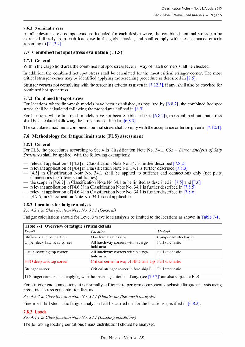
Classification Notes - No. 31.7, July 2013
Sec.7 Level 3 Wave Load Analysis – Page 55
DET NORSKE VERITAS AS
7.6.2 Nominal stress
As all relevant stress components are included for each design wave, the combined nominal stress can beextracted directly from each load case in the global model, and shall comply with the acceptance criteriaaccording to [7.12.2].
7.7 Combined hot spot stress evaluation (ULS)
7.7.1 General
Within the cargo hold area the combined hot spot stress level in way of hatch corners shall be checked.
In addition, the combined hot spot stress shall be calculated for the most critical stringer corner. The mostcritical stringer corner may be identified applying the screening procedure as described in [7.5].
Stringer corners not complying with the screening criteria as given in [7.12.3], if any, shall also be checked forcombined hot spot stress.
7.7.2 Combined hot spot stress
For locations where fine-mesh models have been established, as required by [6.8.2], the combined hot spotstress shall be calculated following the procedures defined in [6.9].
For locations where fine-mesh models have not been established (see [6.8.2]), the combined hot spot stressshall be calculated following the procedures defined in [6.8.3].
The calculated maximum combined nominal stress shall comply with the acceptance criterion given in [7.12.4].
7.8 Methodology for fatigue limit state (FLS) assessment
7.8.1 General
For FLS, the procedures according to Sec.4 in Classification Note No. 34.1, CSA – Direct Analysis of ShipStructures shall be applied, with the following exemptions:
— relevant application of [4.2] in Classification Note No. 34. is further described [7.8.2]— relevant application of [4.4] in Classification Note No. 34.1 is further described [7.8.3]— [4.5] in Classification Note No. 34.1 shall be applied to stiffener end connections only (not plate
connections to stiffeners and frames)— the scope in [4.6.2] in Classification Note No.34.1 to be limited as described in [7.5] and [7.6]— relevant application of [4.6.3] in Classification Note No. 34.1 is further described in [7.8.5]— relevant application of [4.6.4] in Classification Note No. 34.1 is further described in [7.8.6]— [4.7.5] in Classification Note No. 34.1 is not applicable.
7.8.2 Locations for fatigue analysis
Sec.4.2.1 in Classification Note No. 34.1 (General)
Fatigue calculations should for Level 3 wave load analysis be limited to the locations as shown in Table 7-1.
For stiffener end connections, it is normally sufficient to perform component stochastic fatigue analysis usingpredefined stress concentration factors.
Sec.4.2.2 in Classification Note No. 34.1 (Details for fine-mesh analysis)
Fine-mesh full stochastic fatigue analysis shall be carried out for the locations specified in [6.8.2].
7.8.3 Loads
Sec.4.4.1 in Classification Note No. 34.1 (Loading conditions)
The following loading conditions (mass distribution) should be analysed:
Table 7-1 Overview of fatigue critical details
Detail Location Method
Stiffeners end connection One frame amidships Component stochastic
Upper deck hatchway corner All hatchway corners within cargo hold area
Full stochastic
Hatch coaming top corner All hatchway corners within cargo hold area
Full stochastic
HFO deep tank top corner Critical corner in way of HFO tank top Full stochastic
Stringer corner Critical stringer corner in fore ship1) Full stochastic
1) Stringer corners not complying with the screening criterion, if any, (see [7.5.2]) are also subject to FLS
Classification Notes - No. 31.7, July 2013
Sec.7 Level 3 Wave Load Analysis – Page 56
DET NORSKE VERITAS AS
— light homogeneous container loading condition (with high still water hogging moment) on design draught— heavy homogeneous container loading condition (with high GM) on design draught.
Sec.4.4.2 in Classification Note No. 34.1 (Time at sea)
For a Level 3 wave load analysis 85% time fraction at sea should be applied, with same time fraction of eachloading condition.
Sec.4.4.3 in Classification Note No. 34.1 (Wave environment)
Level 3 wave load analysis shall comply with the procedures outlined in Classification Note No. 34.1, [4.4.3].
Sec.4.4.4 in Classification Note No. 34.1 (Hydrodynamic analysis)
Level 3 wave load analysis shall comply with the procedures outlined in Classification Note No. 34.1, [4.4.4].
Sec.4.4.5 in Classification Note No. 34.1 (Load application)
Level 3 wave load analysis shall comply with the procedures outlined in Classification Note No. 34.1, [4.4.5].
7.8.4 Global screening analysis
Sec.4.6.2.1 in Classification Note No. 34.1 (Allowable stress concentration in deck)
As the fatigue scope of Level 3 wave load analysis is limited to hatchway corners and critical stringer corners,the screening procedure for allowable stress concentration in deck as described in [4.6.2.1] in ClassificationNote No. 34.1 is therefore not applicable.
Sec.4.6.2.2 in Classification Note No. 34.1 (Finding the most critical location for a detail)
Fine-mesh models are as a minimum to be carried out for the locations as specified in [6.8.2]. The fine-meshmodels are to be modelled as specified in [6.9]. In order to identify the most critical hatchway corner locationin way of upper deck and the most critical stringer connection in foreship, the screening criteria as specified in[4.6.2.2] in Classification Note No. 43.1 may be applied.
Sec.4.6.2.3 in Classification Note No. 34.1 (Fatigue ratio between different positions)
In order to predict the fatigue ratio between hatchway corners with fine-mesh models, and hatchway cornerswith no fine-mesh models, the procedure described in [6.8.3] should be followed.
7.8.5 Local fatigue analysis
The fine-mesh modelling shall follow the procedures as described in [6.9].
7.8.6 Determination of hot spot stress
Sec.4.6.4.1 in Classification Note No. 34.1 (General)
The fine-mesh modelling of the hatchway corners shall follow the procedures as described in [6.9].
Sec.4.6.4.2 in Classification Note No. 34.1 (Cruciform connections)
Fatigue assessment of cruciform joints is not applicable to container carriers applying Level 3 wave loadanalysis procedure.
Sec.4.6.4.3 in Classification Note No. 34.1 (Stress concentration factor)
In order to establish stress concentration factors for hatchway corners, and to predict fatigue life for locationswith no fine-mesh model, the procedure as specified in [6.8.3] shall be followed.
7.9 Fatigue assessment of hatchway corners and stringer corners
7.9.1 General
Within the cargo hold area full stochastic fatigue assessment in way of all hatchway corners shall be carried out.
For hatchway corners with fine-mesh models (see [6.8.2]), the hot spot stresses shall be extracted directly fromthe fine-mesh model.
For locations with no fine-mesh model, the hot spot stresses shall be predicted applying the procedure describedin [6.8.3].
In addition, fatigue life shall be calculated for the most critical stringer corner. The most critical stringer cornermay be identified applying the screening procedure described in [7.5].
Stringer corners not complying with the screening criteria as given in [7.12.3], if any, shall also to be checkedfor fatigue.
7.9.2 Damage calculation
The damage calculations shall be carried out applying the procedures specified in Classification Note No.34.1, [4.7].
Classification Notes - No. 31.7, July 2013
Sec.7 Level 3 Wave Load Analysis – Page 57
DET NORSKE VERITAS AS
As the stress concentrations will vary along the edge of the hatchway corner and stringer corner, it isrecommended to calculate the fatigue life for 10 positions along the edge of the corner.
7.10 Fatigue assessment of stiffener end connections amidships
7.10.1 General
Component stochastic fatigue assessment for stiffener end connections in way of one frame amidships shall becarried out.
7.10.2 Damage calculation
The damage calculations shall be carried out applying the procedures specified in Classification Note No.34.1,[4.7].
Stress concentration factors according to Classification Note No. 30.7, Appendix A.2 may be applied. Thepredefined stress concentration factors according to A.2 may be overruled by stress concentration models.
7.11 Documentation and verification
7.11.1 General
Documentation and verification should be documented in accordance with Classification Note No. 34.1, Sec.7.
7.11.2 Comparison of hull girder loads with Rules for Classification of Ships
In addition to [7.11.1], the maximum hull girder loads according to the hydrodynamic analysis should becompared with those of the Rules for Classification of Ships.
The simultaneous values for the torsional moment, vertical bending moment and the horizontal bendingmoment should be compared with those of the Rules for Classification of Ships.
Care should be taken in selection of the critical load combinations. To evaluate the strength of deck andcoaming structures the wave torsional cases should be added to the still water hogging moment. To evaluatethe bilge longitudinals the wave torsional cases should be combined with the still water sagging (or minimumhogging) moment.
7.12 Acceptance criteria
7.12.1 General
The allowable nominal stresses as explained in this section should only be used when loads are based onhydrodynamic analysis that is applied as sea pressure and inertial loads on the FE model.
Allowable stress criteria of the global analysis are as outlined below, but the stresses have to be finally assessedconsidering the local structural design, location, element fineness, etc.
7.12.2 Criteria for nominal stress
Allowable von Mises membrane stress in longitudinal members:
σall = 0.9 σf [N/mm2] if interaction between hatchway cover and main hull structure is not included in stresscalculation
σall = 0.95 σf [N/mm2] if interaction between hatch cover and main hull structure is included in stresscalculation.
Allowable von Mises membrane in transverse members:
σall = 0.85 σf [N/mm2]σf = minimum upper yield stress of the material.
7.12.3 Screening criterion for nominal stress in way of stringer corners
Allowable von Mises membrane stress in way of stringer corners:
σall = 0.8 σf [N/mm2]σf = minimum upper yield stress of the material surrounding the insert plate, if any
7.12.4 Hot spot stress in way of hatchway corners and stringer corners
When loads are based on 20-year North Atlantic operation, the allowable local peak stresses (equivalent stress)in the hatchway corners may be taken as:
σall = 400 f1 [N/mm2]f1 = as given in the Rules for Classification of Ships Pt.5 Ch.2 Sec.6 B101
Classification Notes - No. 31.7, July 2013
Sec.7 Level 3 Wave Load Analysis – Page 58
DET NORSKE VERITAS AS
7.12.5 Buckling Control
The ultimate buckling strength shall be checked for compliance with the Rules for Classification of Ships Pt.3Ch.1 Sec.13 irrespective of whether loads based on Rules of direct wave loads analysis.
The buckling strength of longitudinal structural members, such as in bilge and stool bench area, shall bedetermined as given in Pt.3 Ch.1 Sec.13 for plating and for stiffeners, replacing σal as given in Pt.3 Ch.1 Sec.13B205 and B206 with the combined nominal stress s given in [7.5.2], applying:
η = 1.0 for deck, single bottom and longitudinally stiffened side plating = 0.9 for bottom, inner bottom and transversely stiffened side plating = 0.85 for longitudinals.
Classification Notes - No. 31.7, July 2013
Sec.8 References – Page 59
DET NORSKE VERITAS AS
8 References
/1/ DNV: Rules for Classification of Ships, Pt.3 Ch.1 Hull Structural Design, Ships with Length 100 metresand above.
/2/ DNV: Rules for Classification of Ships, Pt.5 Ch.2 Passenger and Dry Cargo Ships.
/3/ DNV: Classification Note No. 30.7 Fatigue Assessment of Ship Structure.
/4/ DNV: Classification Note No. 34.1 CSA Direct Analysis of Ship Structures.
Classification Notes - No. 31.7, July 2013
A Structural Verification Procedure for Lashing Bridge Structure – Page 60
DET NORSKE VERITAS AS
Appendix A
Structural Verification Procedure for Lashing Bridge Structure
A.1 Introduction
A.1.1
Container carriers are normally equipped with lashing bridges in order to simplify the securing of high stacksand allow for a large number of cargo containers on hatch covers/deck space.
A.1.2
Requirements to strength evaluation of container securing arrangements, including requirements to strength ofsupporting structures of fixed container securing devices, are given in the Rules for Classification of Ships Pt.5Ch.2 Sec.6 E.
A.1.3
The lashing bridge strength shall be based on a direct strength analysis applying loads and acceptance criteriagiven in the following.
A.2 Lashing force
A.2.1
Maximum Securing Load (MSL) in container securing devices, such as lashings, shall not exceed half theminimum breaking load. Reference is made to the Rules for Classification of Ships Pt.5 Ch.2 Sec.6 E802.
MSL will therefore represent a theoretical maximum lashing force to be applied in Appendix [A.3] for strengthverification of lashing bridge.
For container stowage with external lashing; applying MSL as lashing force in Appendix [A.3] may be realisticfor the uppermost cross lashing.
For container stowage with internal lashing and for lower external lashing; applying MSL as lashing force inAppendix [A.3] will represent a too conservative approach for strength evaluation of the lashing bridge. Theassumptions and methods for establishing the lashing force given in Appendix [A.2.2] should then be applied.
A.2.2
The lashing force may be calculated in accordance with Classification Note No. 32.2 Container Securingapplying the following container stowage:
— 40’ container stack with lashing arrangement in accordance with container loading plan— maximum container stack height in accordance with container loading plan— VCG of the individual containers taken as 45% of container height— GM as given in Rules for Classification of Ships Pt.3 Ch.1 Sec.4 B— accelerations as given in the Rules for Classification of Ships Pt.5 Ch.2 Sec.6 E301 to E303— maximum allowable homogeneous stack weight obtained applying the calculation procedures and
acceptance criteria given in Classification Note No. 32.2.
Relative displacement between hatch cover and hull structure shall be considered as given in the Rules forClassification of Ships Pt.3 Ch.3 Sec.6 F203. However, this is in normal cases covered by applying load case4 as given in Appendix [A.3.2.4].
A.3 Design loads
A.3.1 Load application
The lashing forces given in Appendix [A.2] shall be applied as point loads in way of the lashing eye positions.
For simple application, the lashing force can be decomposed into force components in longitudinal, transverseand vertical direction.
A.3.2 Load cases
A.3.2.1 Case 1: Simultaneous loading in fore and aft space
Lashing forces established in Appendix [A.2] shall be applied to fore and aft part of the lashing bridge in linewith the connected lashing bars along the same direction.
A.3.2.2 Case 2: Lashing force for container loading in fore space only
Lashing forces established in Appendix [A.2] shall be applied to fore space only of the lashing bridge in linewith the connected lashing bars along the same direction.
Classification Notes - No. 31.7, July 2013
A Structural Verification Procedure for Lashing Bridge Structure – Page 61
DET NORSKE VERITAS AS
A.3.2.3 Case 3: Lashing force for container loading in aft space only
Lashing forces established in Appendix [A.2] shall be applied to aft space only of the lashing bridge in linewith the connected lashing bars along the same direction.
A.3.2.4 Case 4: MSL in fore space only
Lashing force for container loading in fore space only:
— MSL (typically 250 kN) for short lashing bars (one tier height); and — half the MSL (typically 125kN for long lashing bars (two tiers height).
This case will cover the relative displacement between hatch cover and main hull structure, i.e. lashing bridge.
If MSL is applied as lashing force in Appendix [A.3.1] to [A.3.2] LC4 is not applicable.
A.4 Acceptance criteria
A.4.1 Allowable stress
— normal stress σ = 210 f1 [N/mm2]— shear stress τ = 120 f1 [N/mm2]
A.4.2 Buckling control
The lashing bridge primary structural members shall comply with relevant buckling requirements given in theRules for Classification of Ships Pt.3 Ch.1 Sec.13 applying:
η = 1.0 for requirements given in Pt.3 Ch.1 Sec.13 B200, B400, B500 = 0.9 for requirements given in Pt.3 Ch.1 Sec.13 B300 = 0.85 for requirement given in Pt.3 Ch.1 Sec.13 C304κ = 0.85 for requirement given in Pt.3 Ch.1 Sec.13 C203.
Classification Notes - No. 31.7, July 2013
B Structural Verification Procedure for Hatch Cover Stoppers – Page 62
DET NORSKE VERITAS AS
Appendix B
Structural Verification Procedure for Hatch Cover Stoppers
B.1 Introduction
B.1.1
Hatch covers are normally fitted with rolling stoppers which are fixations against transverse movement (oneway fix for longitudinal shifting) and rolling/ pitching stoppers (pin stopper) which are fixations againstmovement in both directions.
B.1.2
To prevent damage to hatch covers and ship structures the location and type of stoppers shall be harmonisedwith the relative movements between the hatch covers and ship structure.
B.1.3
The number of stoppers shall be minimized as far as practical, preferably only one stopper at each end of thehatch cover panel.
B.1.4
A typical arrangement for hatch covers are one rolling stopper at one end and rolling/pitching stopper (pinstopper) at the other end.
B.2 Assumption
B.2.1
If the container stack is secured to other structures than the hatch cover (i.e. lashing bridge) the horizontal forceexposed to the hatch cover will be somewhat reduced. However as a conservative approach, this should not beconsidered in the strength evaluation of the hatch cover stoppers.
B.2.2
Friction force at bearing pads may reduce the horizontal force by about 10% as given the Rules forClassification of Ships Pt.3 Ch.3 Sec.6 F601. However, this should be decided based on bearing pad material.If the bearing pad is of low-friction material the horizontal forces acting on the stoppers should not be reduced.
B.2.3
Hatch coaming and supporting structures shall be adequately stiffened to accommodate the loading from hatchcovers.
B.2.4
Wind forces acting on the containers are neglected.
B.3 Design loads
B.3.1 Accelerations
Accelerations at and al shall be in accordance with the Rules for Classification of Ships Pt.5 Ch.2 Sec.6 E301and E303, applying GM as given in the Rules for Classification of Ships Pt.3 Ch.1 Sec. 4 B402.
A homogeneous stack weight distribution with maximum allowable stack height shall be applied. VCG of theindividual containers shall be taken as 45% of the container height.
B.3.2 Stack weight
The hatch cover stoppers shall be strengthened for the maximum allowable hatch cover loading, based on thegreater of:
— all stacks on hatch cover loaded with 20’ containers, with each stack having maximum allowable stackweight
— all stacks on hatch cover loaded with 40’ containers, with each stack having maximum allowable stackweight
— if the design is intended for 20’ containers topped with 40’ containers (Russian stowage), the combinedstack weight shall also be considered. The combined stack weight shall then be taken as:
— M = 2 M20’ n20’ + M40’ n40’— M20’(40’) = weight of each 20’ (40’) container taken as the maximum allowable 20’ (40’) stack weight
divided by number of tiers, unless otherwise specified— n20’(40’)= number of tiers with 20’ (40’) containers.
Classification Notes - No. 31.7, July 2013
B Structural Verification Procedure for Hatch Cover Stoppers – Page 63
DET NORSKE VERITAS AS
B.3.3 Load application
The horizontal force shall be applied to the level of the highest contact point between the hatch cover and therolling stopper.
For pin stopper the force shall be applied to the middle of the contact area.
B.3.4 Load cases
B.3.4.1 Case 1: Transverse force
Pt (total) = 0.67 at × (maximum allowable hatch cover loading [tons] + hatch cover weight [tons]) [kN]
For a typical arrangement (see Appendix [B.1.4]) the transverse force will be taken by one stopper at each endof the hatch cover and thus half of Pt (total) shall be applied to each stopper.
B.3.4.2 Case 2: Longitudinal force
Pl (total) = 0.67 al × (maximum allowable hatch cover loading [tons] + hatch cover weight [tons]) [kN]
For a typical arrangement (see Appendix [B.1.4]) the pin stopper will take the whole longitudinal force.
B.4 Allowable stress
— Normal stress σ = 120 f1 [N/mm2]— Shear stress τ = 80 f1 [N/mm2]— Equivalent stress σe = 150 f1 [N/mm2].
Classification Notes - No. 31.7, July 2013
C Structural Verification Procedure for Hatch Covers – Page 64
DET NORSKE VERITAS AS
Appendix C
Structural Verification Procedure for Hatch Covers
C.1 Introduction
C.1.1
Hatch covers of container carriers shall comply with the general requirements given in the Rules forClassification of Ships Pt.3 Ch.3 Sec.6 E. Additional calculation procedures for strength evaluation of hatchcovers loaded with container stacks are specified in the following.
C.1.2
The hatch cover strength against container loading shall be based on a direct strength analysis applying loadsand acceptance criteria given in the following.
C.1.3
Hatch covers are typically mounted on bearing pads which take vertical forces, whilst stoppers take horizontalforces.
C.2 Assumption
C.2.1
The hatch cover is fitted with stoppers securing the hatch cover against horizontal movements. The stoppersare strengthened in accordance with the procedures given in Appendix B.
C.2.2
Wind forces acting on the containers are neglected.
C.2.3
If the container stack is secured to a lashing bridge the horizontal force and the overturning moment in heeledcondition exposed to the hatch cover will be somewhat reduced. However as a conservative approach, thisshould not be considered in the strength evaluation of the hatch covers.
C.2.4
Hatch coaming and supporting structures shall be adequately stiffened to accommodate the loading from hatchcovers.
C.2.5
Relative movements between hatch cover and hull structure shall be considered as given in the Rules forClassification of Ships Pt.3 Ch.3 Sec.6 F203.
The transverse hatch cover clearances (gap between the hatch cover Fy stoppers and the hatch cover panel)shall be considered based on maximum torsional deformations. It shall additionally be verified that sufficientvertical contact area is maintained on the bearing pads when exposed to maximum torsional deformations.
C.3 Design loads
C.3.1 Accelerations
Accelerations at and av shall be in accordance with the Rules for Classification of Ships Pt.5 Ch.2 Sec.6 E301and E302, applying GM as given in the Rules for Classification of Ships Pt.3 Ch.1 Sec. 4 B402.
A homogeneous stack weight distribution with maximum allowable stack height shall be applied. VCG of theindividual containers shall be taken as 45% of the container height.
C.3.2 Stack weight
The hatch covers shall be strengthened for the following stacking arrangements:
— 20’ container stacks, with each stack having maximum allowable stack weight— 40’ container stacks, with each stack having maximum allowable stack weight — If the design is intended for 20’ containers topped with 40’ containers (Russian stowage), such stacking
arrangement shall also be considered. The weight of each 20’ (40’) container shall be assumed as themaximum allowable 20’ (40’) stack weight divided by number of tiers, unless otherwise specified
C.3.3 Load application
Vertical forces should be applied as point loads in way of the container sockets.
Horizontal forces will act as shear on the hatch cover top plate and may be neglected. However, if the structural
Classification Notes - No. 31.7, July 2013
C Structural Verification Procedure for Hatch Covers – Page 65
DET NORSKE VERITAS AS
arrangements transferring the horizontal force from the hatch cover top plate to the stoppers are well definedin the model, horizontal forces in way of the container sockets should be applied as point loads.
Hatch cover self-weight should be included in the model.
C.3.4 Load cases
C.3.4.1 Case 1: All stacks full in upright seagoing condition
Pv (stack) = (g0 + 0.5 av) × (container stacks weight [tons]) [kN]
For each container corner:Fv = Pv (stack) / 4 [kN]
C.3.4.2 Case 2: All stacks full in heeled condition
Pv (stack) = g0 × (container stacks weight [tons]) [kN]Pt (stack) = 0.67 at × (container stacks weight [tons]) [kN]Pv (transverse) =Pt H / B.
Where:
H = distance from bottom of container stack to the container stack VCGB = container width, normally 2.438 m
For each container corner:Fv = Pv (stack) / 4 ± Pv (transverse) / 2 [kN]Ft = Pt (stack) / 4 [kN].
C.3.4.3 Case 3: One empty stack in upright seagoing condition
Same as Case 1 except for one empty container stack abreast.
C.3.4.4 Case 4: One empty stack in rolling condition
Same as Case 2 except one empty container stack abreast.
C.4 Acceptance criteria
C.4.1 Allowable stress
— normal stress σ = 0.67σf [N/mm2]— shear stress τ = 0.37 σf [N/mm2].
C.4.2 Buckling control
The hatch cover primary structural members shall comply with the buckling requirements given in the Rulesfor Classification of Ships Pt.3 Ch.1 Sec.13 applying:
η = 0.87 for requirements given in Pt.3 Ch.1 Sec.13 B200, B400, B500 = 0.85 for requirements given in Pt.3 Ch.1 Sec.13 B300.
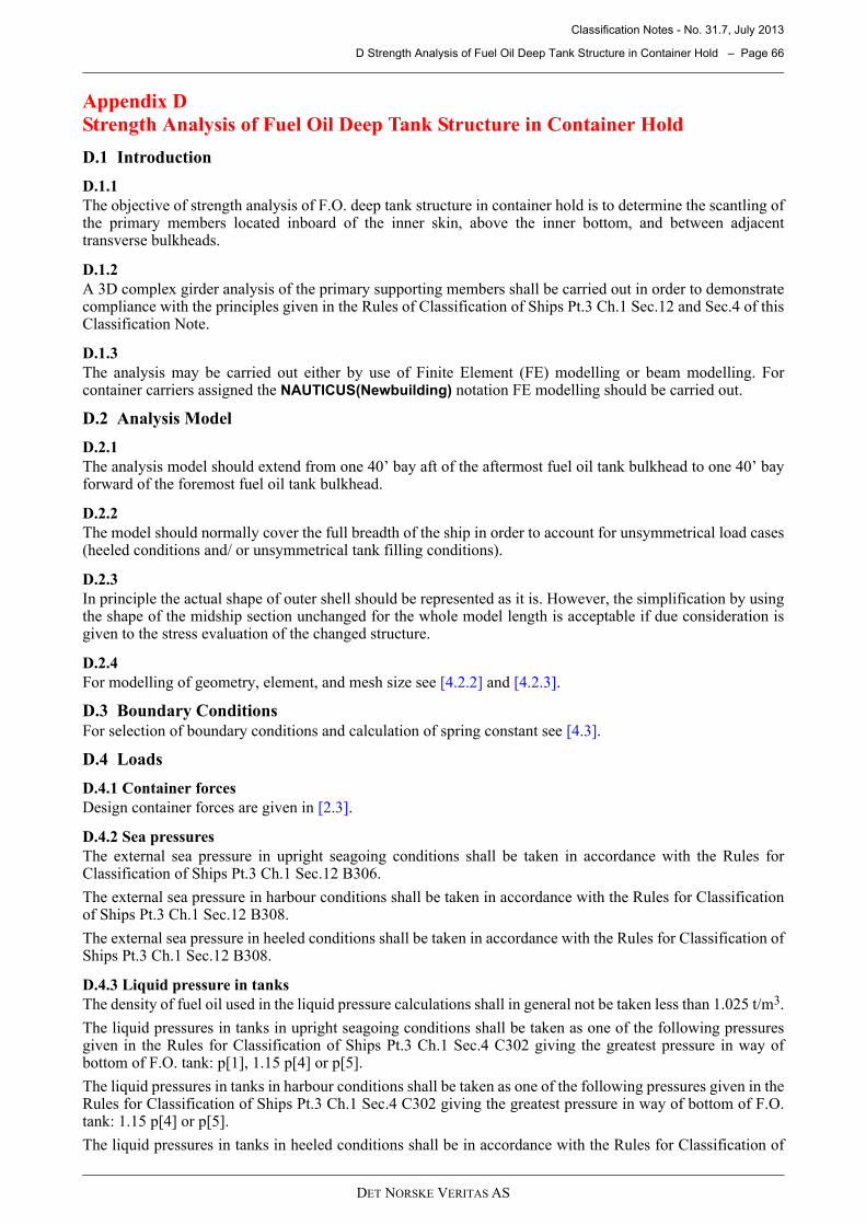
Classification Notes - No. 31.7, July 2013
D Strength Analysis of Fuel Oil Deep Tank Structure in Container Hold – Page 66
DET NORSKE VERITAS AS
Appendix D
Strength Analysis of Fuel Oil Deep Tank Structure in Container Hold
D.1 Introduction
D.1.1
The objective of strength analysis of F.O. deep tank structure in container hold is to determine the scantling ofthe primary members located inboard of the inner skin, above the inner bottom, and between adjacenttransverse bulkheads.
D.1.2
A 3D complex girder analysis of the primary supporting members shall be carried out in order to demonstratecompliance with the principles given in the Rules of Classification of Ships Pt.3 Ch.1 Sec.12 and Sec.4 of thisClassification Note.
D.1.3
The analysis may be carried out either by use of Finite Element (FE) modelling or beam modelling. Forcontainer carriers assigned the NAUTICUS(Newbuilding) notation FE modelling should be carried out.
D.2 Analysis Model
D.2.1
The analysis model should extend from one 40’ bay aft of the aftermost fuel oil tank bulkhead to one 40’ bayforward of the foremost fuel oil tank bulkhead.
D.2.2
The model should normally cover the full breadth of the ship in order to account for unsymmetrical load cases(heeled conditions and/ or unsymmetrical tank filling conditions).
D.2.3
In principle the actual shape of outer shell should be represented as it is. However, the simplification by usingthe shape of the midship section unchanged for the whole model length is acceptable if due consideration isgiven to the stress evaluation of the changed structure.
D.2.4
For modelling of geometry, element, and mesh size see [4.2.2] and [4.2.3].
D.3 Boundary Conditions
For selection of boundary conditions and calculation of spring constant see [4.3].
D.4 Loads
D.4.1 Container forces
Design container forces are given in [2.3].
D.4.2 Sea pressures
The external sea pressure in upright seagoing conditions shall be taken in accordance with the Rules forClassification of Ships Pt.3 Ch.1 Sec.12 B306.
The external sea pressure in harbour conditions shall be taken in accordance with the Rules for Classificationof Ships Pt.3 Ch.1 Sec.12 B308.
The external sea pressure in heeled conditions shall be taken in accordance with the Rules for Classification ofShips Pt.3 Ch.1 Sec.12 B308.
D.4.3 Liquid pressure in tanks
The density of fuel oil used in the liquid pressure calculations shall in general not be taken less than 1.025 t/m3.
The liquid pressures in tanks in upright seagoing conditions shall be taken as one of the following pressuresgiven in the Rules for Classification of Ships Pt.3 Ch.1 Sec.4 C302 giving the greatest pressure in way ofbottom of F.O. tank: p[1], 1.15 p[4] or p[5].
The liquid pressures in tanks in harbour conditions shall be taken as one of the following pressures given in theRules for Classification of Ships Pt.3 Ch.1 Sec.4 C302 giving the greatest pressure in way of bottom of F.O.tank: 1.15 p[4] or p[5].
The liquid pressures in tanks in heeled conditions shall be in accordance with the Rules for Classification of
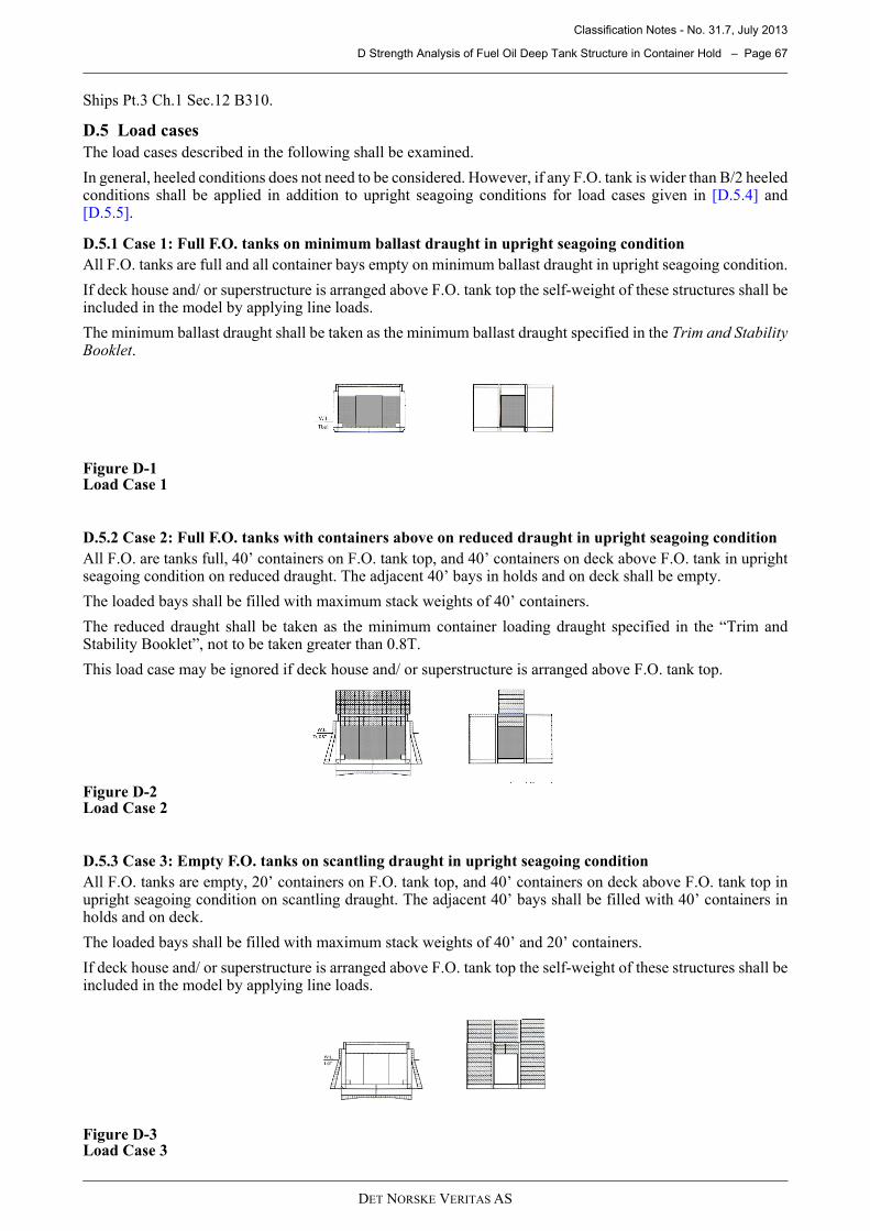
Classification Notes - No. 31.7, July 2013
D Strength Analysis of Fuel Oil Deep Tank Structure in Container Hold – Page 67
DET NORSKE VERITAS AS
Ships Pt.3 Ch.1 Sec.12 B310.
D.5 Load cases
The load cases described in the following shall be examined.
In general, heeled conditions does not need to be considered. However, if any F.O. tank is wider than B/2 heeledconditions shall be applied in addition to upright seagoing conditions for load cases given in [D.5.4] and[D.5.5].
D.5.1 Case 1: Full F.O. tanks on minimum ballast draught in upright seagoing condition
All F.O. tanks are full and all container bays empty on minimum ballast draught in upright seagoing condition.
If deck house and/ or superstructure is arranged above F.O. tank top the self-weight of these structures shall beincluded in the model by applying line loads.
The minimum ballast draught shall be taken as the minimum ballast draught specified in the Trim and StabilityBooklet.
Figure D-1Load Case 1
D.5.2 Case 2: Full F.O. tanks with containers above on reduced draught in upright seagoing condition
All F.O. are tanks full, 40’ containers on F.O. tank top, and 40’ containers on deck above F.O. tank in uprightseagoing condition on reduced draught. The adjacent 40’ bays in holds and on deck shall be empty.
The loaded bays shall be filled with maximum stack weights of 40’ containers.
The reduced draught shall be taken as the minimum container loading draught specified in the “Trim andStability Booklet”, not to be taken greater than 0.8T.
This load case may be ignored if deck house and/ or superstructure is arranged above F.O. tank top.
Figure D-2Load Case 2
D.5.3 Case 3: Empty F.O. tanks on scantling draught in upright seagoing condition
All F.O. tanks are empty, 20’ containers on F.O. tank top, and 40’ containers on deck above F.O. tank top inupright seagoing condition on scantling draught. The adjacent 40’ bays shall be filled with 40’ containers inholds and on deck.
The loaded bays shall be filled with maximum stack weights of 40’ and 20’ containers.
If deck house and/ or superstructure is arranged above F.O. tank top the self-weight of these structures shall beincluded in the model by applying line loads.
Figure D-3Load Case 3
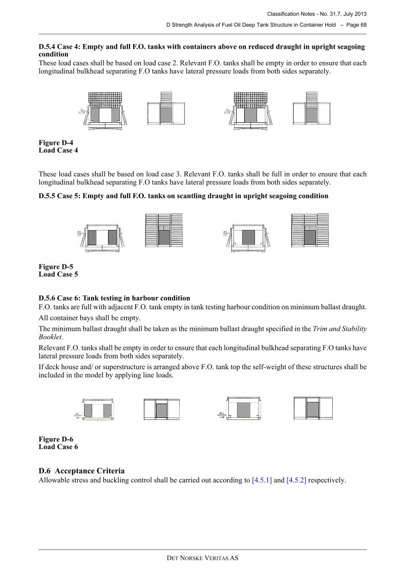
Classification Notes - No. 31.7, July 2013
D Strength Analysis of Fuel Oil Deep Tank Structure in Container Hold – Page 68
DET NORSKE VERITAS AS
D.5.4 Case 4: Empty and full F.O. tanks with containers above on reduced draught in upright seagoing condition
These load cases shall be based on load case 2. Relevant F.O. tanks shall be empty in order to ensure that eachlongitudinal bulkhead separating F.O tanks have lateral pressure loads from both sides separately.
Figure D-4Load Case 4
These load cases shall be based on load case 3. Relevant F.O. tanks shall be full in order to ensure that eachlongitudinal bulkhead separating F.O tanks have lateral pressure loads from both sides separately.
D.5.5 Case 5: Empty and full F.O. tanks on scantling draught in upright seagoing condition
Figure D-5Load Case 5
D.5.6 Case 6: Tank testing in harbour condition
F.O. tanks are full with adjacent F.O. tank empty in tank testing harbour condition on minimum ballast draught.
All container bays shall be empty.
The minimum ballast draught shall be taken as the minimum ballast draught specified in the Trim and StabilityBooklet.
Relevant F.O. tanks shall be empty in order to ensure that each longitudinal bulkhead separating F.O tanks havelateral pressure loads from both sides separately.
If deck house and/ or superstructure is arranged above F.O. tank top the self-weight of these structures shall beincluded in the model by applying line loads.
Figure D-6Load Case 6
D.6 Acceptance CriteriaAllowable stress and buckling control shall be carried out according to [4.5.1] and [4.5.2] respectively.
Classification Notes - No. 31.7, July 2013
CHANGES – HISTORIC – Page 69
DET NORSKE VERITAS AS
CHANGES – HISTORIC
Note that historic changes older than the editions shown below (if any), have not been included.
July 2011 edition
Main changes
— Table 1-1: Analysis Level 3 in existing class note has been removed resulting in reduction from 4 to 3possible analysis level scopes for container ships.
— The calculation scope for the different analyses Levels is now more precisely defined in 1.6 to 1.8.— Rule torsion loads are now more clearly defined in 2.5.— In the current class note, the Rule-defined design load cases for FE cargo hold model is a repeat of Pt.5
Ch.2 Sec.6 C400. The figures for these load cases in this proposal have been removed, with a reference tothe Rules in 4.4.1.
— Buckling requirements to the FE cargo hold model have been updated in Table 4-2:
— Requirements in flooded damage condition.— For inner bottom and longitudinal girders in way of transverse bulkheads, elastic buckling may be accepted.— Longitudinal structures shall also be checked for uni-axial buckling in longitudinal direction.
— The changes in procedures and requirements to Level 1 Rule torsion analysis are mainly editorial with thefollowing exemptions:
— 5.4.3: The procedure for calculating the combined global stress range for fatigue assessment of hatchcovers has been changed.
— 5.6.3: Stress concentration factors for hatch corners have been made dependant of the radius and thickness.
— Scope of ULS hot spot stress and FLS in way of all hatch corners for Level 2 and 3 analyses has beenmodified to include all hatch corners and critical stringer corners.
— The changes in procedures and requirements to Level 2 global analysis are mainly editorial with thefollowing exemptions:
— 6.4.2: The procedure for calculating the combined global stress range for fatigue assessment of hatchcovers has been changed.
— 6.6.2: Fatigue load cases to be applied to the global FE model have been aligned with the proceduresfor calculating the combined global stress range for fatigue assessment of hatch covers.
— 6.8.2: The required locations for fine-mesh models are now clearly defined.— 6.8.3: A general procedure has been established for assessing hot spot stresses for hatch corners with
no fine-mesh models.— 6.10.2: A general procedure has been established for establishing generic stress concentration factors
in way of hatch corners with no fine-mesh models.— 6.11.1: A screening criterion has been introduced for check of nominal stress levels in way of stringer
corners. If not complying with this screening criterion, then ULS hot spot stress and FLS assessmentneed to be carried out.
— The procedures and requirements to Level 3 global analysis (Level 4 in the current class note) have beenchanged as follows:
— 7.2: Hydrodynamic analysis is in general same as for CSA-2 class notation (as defined in Class noteNo. 34-1) with some Level 3 specific items.
— 7.3: Global structural FE model is in general same as for CSA-2 class notation (as defined in Class noteNo. 34-1) with some Level 3 specific items.
— 7.5 to 7.10: Scope for result evaluation (ULS and FLS) is significantly reduced compared to CSA-2class notation, and is same as for Level 2 global analysis with the following additional requirements:
- 7.6: ULS check of transverse strength fore and aft body.- 7.10: Component stochastic FLS of stiffener end connections amidships.
— 7.12.3: A screening criterion has been introduced for check of nominal stress levels in way of stringercorners. If not complying with this screening criterion, then ULS hot spot stress and FLS assessmentneed to be carried out.
Amendments 2011-08-03
In addition to some editorial corrections, superfluous text on page 2 was removed.