aus dem Fachbereich Geowissenschaften der Universität ...
84
aus dem Fachbereich Geowissenschaften der Universität Bremen No. 214 Meggers, H. , L. Babero-Munoz, C. Barrera, M. BergenthaI, J. Betancort, L. Cardona, A. Cianca, B. A. Cire, W. Dimmler, F. Drünert, A. Eberwein, T. Freudenthai, J. Garming, C. Gebhardt, J. Gutt, G Kahl, S. Kasten, S. Klar, E. Kopiske, U. Koy,A. Makaoui, G Meinecke, N. Nowald,A. Pinck, K. Plewa, V. Ratmeyer, O. Romero, U. Rosiak, G Ruhland, W. Schmidt, M. Scholz, T. Truscheit, M. Villagarcia, C. Warnken, A. Wülbers REPORT AND PRELIMINARY RESULTS OF METEOR CRUISE M 53/1, LIMASSOL - LAS PALMAS - MINDELO, 30.03. - 03.05.2002 Berichte, Fachbereich Geowissenschaften, Universität Bremen, No. 214, 81 pages, Bremen 2003 ISSN 0931-0800
-
Upload
khangminh22 -
Category
Documents
-
view
7 -
download
0
Transcript of aus dem Fachbereich Geowissenschaften der Universität ...
aus dem Fachbereich Geowissenschaftender Universität Bremen
No. 214
Meggers, H. , L. Babero-Munoz, C. Barrera, M. BergenthaI, J. Betancort,L. Cardona, A. Cianca, B. A. Cire, W. Dimmler, F. Drünert, A. Eberwein,
T. Freudenthai, J. Garming, C. Gebhardt, J. Gutt, G Kahl, S. Kasten,S. Klar, E. Kopiske, U. Koy,A. Makaoui, G Meinecke, N. Nowald,A. Pinck,
K. Plewa, V. Ratmeyer, O. Romero, U. Rosiak, G Ruhland, W. Schmidt, M. Scholz,T. Truscheit, M. Villagarcia, C. Warnken, A. Wülbers
REPORT AND PRELIMINARY RESULTS OF METEOR CRUISE M 53/1,LIMASSOL - LAS PALMAS - MINDELO, 30.03. - 03.05.2002
Berichte, Fachbereich Geowissenschaften, Universität Bremen, No. 214,81 pages, Bremen 2003
ISSN 0931-0800


RVMETEOR Cruise 53, Leg 1, Limassol- Las Palmas - Las Palmas - Mindelo
Table of Contents
1.
2.
3.
4.
Research Objectives
Participants
Research Program
Narrative of the cruise
02
06
10
11
4.1
4.2
4.3
Leg M 53/1a
LegM53/lb
Leg M53/1c
11
11
13
5. Preliminary Results 15
5.1 M53/1a 15
5.1.1 Sediment Trap and Suspended Particulate Matter 15Investigations in the Eastern Mediterranean
5.2 M53/1b 18
5.2.1 Chemical Oceanography 185.2.2 Carbon dioxide in sea-water 235.2.3 Particle flux studies and deep-sea technology 24
5.2.3.1 Mooring work within the projects DOLAN,ESTOC and ANIMATE 245.2.3.2 ROV Operations 35
5.3 M53/1c 42
5.3.1 Chemical Oceanography 425.3.2 Particle flux measurements with moored particle
traps 485.3.3 Deep-Sea Particle Camera System ParCa 495.3.4 Underway geophysics 535.3.5 Sediment Sampling 55
5.3.5.1 Sediment surface sampling with multicorer 555.3.5.2 Sediment sampling with gravity corer 565.3.5.3 First shipboard results 58
5.3.6 Geochemistry 70
6.
7.
8.
The weather during the cruise M53/1
References
Station list
1
74
76
79
RVMETEOR Cruise 53, Leg 1, Limassol- Las Palmas - Las Palmas - Mindelo
1. Research objectives
During RV METEOR cruise M53/1, research was carried out in connection with the
following projects:
• ANIMATE ("Atlantic Network of Interdisciplinary Moorings and Time series for
Europe")
• DFG-Projects
• "In-situ measurements and sampling ofmarine aggregates"
• "Zooplankton structures and partic1e flux in the Levantine Sea againstthe background of the changes in the thermohaline circulation"
• DOLAN ("Operational Data Transmission in the Ocean and Lateral Acoustic Network in
the Deep-Sea")
• ESTOC ("European Station for Time-Series in the Ocean, Canary Islands")
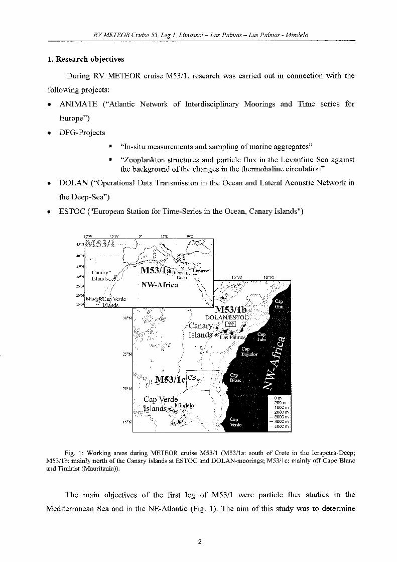
Fig. 1: Working areas during METEOR cruise M53/1 (M53/1a: south of Crete iu the Ierapetra-Deep;M53/1b: maiuly nOlth ofthe Canary Islands at ESTOC and DOLAN-moorings; M53/lc: maiuly off Cape Blaneand Timirist (Mauritania)).
The mam objectives of the first leg of M53/1 were partic1e flux studies in the
Mediterranean Sea and in the NE-Atlantic (Fig. 1). The aim of this study was to determine
2
RVMETEOR erläse 53, Leg 1, Limassol- Las Palmas - Las Palmas - Mindelo
and understand the processes controlling the varying fluxes of carbon on short-term, seasonal,
inter-annual back to glaciallinterglacial time-scales.
For logistical reasons this leg was subdivided into three subparts (Fig. 1). During
M53/la from Limassol to Las Palmas a sediment trap mooring ofthe University ofHamburg
was recovered in the Iapetra-Deep. The aim of this work is to understand the partic1e flux
mechanisms and their relation to the deep-sea biology in the Levantine Sea south of Crete.
M53/1b concentrated on the area north ofthe Canary Islands. One goal ofM53/1b was
the monthly sampling work at ESTOC ("European Station for Time-series in the Ocean,
Canary Islands") for April 2002. ESTOC is located 60 um north (upstream) of Gran Canaria
in the eastern boundary flow of the subtropical North Atlantic gyre (at 29°10'N and
15°30'W). The time-series station was initiated in the year 1994 and is co-operated by two
Spanish (Instituto Canario de Ciencias Marinas in Telde (Gran Canaria) and Instituto Espanol
de Oceanografia in Santa Cmz (Tenerife)) and two German institutes (Department of
Oceanography of the University of Kiel and Department of Earth Sciences at the University
of Bremen). The main purpose of the station is to build a long-term oceanographic data base
to be able to discern seasonal from long-term variability ofhydrographic and biogeochemical
parameters in this environmentally sensitive region of the Eastern Boundary Current of the
North-Atlantic gyre. The region is especially interesting because of episodic dust depositions
from the African continent that likely influence productivity and partic1e formation.
Also on M53/1b the establishment of the operational transmission of datasets at the
DOLAN mooring site was performed. In addition to that, mooring-, maintenance works and
tests of the technical devices were done within the scope of the BMBF project DOLAN
("Operational Data transmission in the Ocean and lateral acoustic Network in the Deep-Sea").
This gauging station is located 30 um west of ESTOC and comprises technology for the
transmission of data by means of acoustics in the water column via satellite and internet.
Closely linked to ESTOC and DOLAN is the EU project ANIMATE ("Atlantic Network of
Interdisciplinary Moorings and Time series for Europe"). In the ANIMATE project, moorings
were deployed at key sites in the northern Atlantic in order to gain data of C02, nutrients and
fluorescence, which will be directly transmitted via satellite to the participating scientific
institutes. A significant element in ANIMATE is the technology used in the DOLAN project
for the transmission of datasets from the deep-sea. Furthennore, ESTOC is the reference site
for the subtropical NE-Atlantic within the ANIMATE project.
The mooring work at ESTOC and DOLAN were accompanied by the deployment of a
"Remotely Operated Vehide" (ROV), which can reach depths up to 1000 m. With aid of this
3
RVMETEOR Cruise 53, Leg 1, Limassol- Las Palmas - Las Palmas - Mindelo
new and innovative technology, high resolution datasets for the quantitative balancing of
partic1e fluxes through the water column will be obtained. The intention is the measurement,
sampling and subsequently analysis of the sinking and suspended material, against the
background of the not sufficiently understood processes of the formation of aggregates and
their vertical and lateral transport processes in the ocean. For this purpose, a remotely from
the ship movements independent and free flying vehic1e was deployed. This vehic1e was
equipped with a new technology for the simultaneous measurement of the in-situ
characteristics and selective sampling of single marine aggregates. The obtained datasets will
be compared and interpreted with datasets of the size distribution of marine aggregates
provided by deep-sea cameras, optical sensors (optical backscatter and fluorescence), CTD
profIles and results from partic1e flux measurements provided by sediment traps. For the
immediate comparison of the aggregate- and partic1e flux data, the grain size distribution of
the lithogenic fraction (wind transported dust) in marine aggregates and settling material, will
be used as an independent transportation proxy.
During M53/lc sedimentological field work of the Research Center Ocean Margins of
the University of Bremen started. The upwelling area off NW-Africa is one of the most
important upwelling systems of the world and is influenced by high amounts of Saharan dust,
which is transporting nutrients into the ocean. Both processes are of fundamental importance
for the partic1e production in the ocean and influence with the processes biological pump and
carbonate pump the global atmospheric CO2-budget. Despite the main driving-force for
climatic variability is situated in the northern North-Atlantic, the upwelling area off NW
Africa is suitable to reconstruct the past c1imatic variability, because of high accumulation
rates in the sediments and thus a good paleoceanographic resolution. The phenomenon of
abrupt climatic change was in the focus of research. Various ice-core studies and
paleoceanographic investigations have shown that c1imatic change in the past often happened
abrupt within a few decades. In high resolution sediments of the North Atlantic numerous
short-termed climatic changes were described from "Bond-cyc1es" and "Heinrich-Events" in
the Glacial to the Little lce Age (1300-1870). These abrupt changes in the climatic system, the
knowledge and the worrying prospect that global change could also occur very spontaneously
within a few decades at present times have brought the paleoceanographic studies more and
more in the focus ofthe public attention. Especially the analyses ofhighly resolved Holocene
marine sediments give the potential to c1assify historical climatic changes of the last 2000
years like the Little lce Age or the Medieval Warm Period in the context of the long-term
climatic variability ofthe last 11,500 years. On the basis ofthe results ofprevious METEOR
4

RV METEOR erzäse 53, Leg 1, Limassol- Las Palmas - Las Palmas - Mindelo
eruises (M37/1, M42/4, M45/5) and the knowledge that the partic1e flux is higher in the Cape
Blane area due to yearly upwelling in relation to seasonal upwelling in the Canary Islands
region, we expeet higher sedimentation rates off Cape Blane and therefore good elimatic
archives for high-resolution paleoeeanographie studies. The POSEIDON eruise POS 272 in
April 2001 gave valuable information by first profiling work of Cape Bojador and Cape Blane
and by first sampling of the sediments with multieorer and gravity eorer. On the basis of this
information work during M53/le eould be done speeifieally after short surveys with
HYDROSWEEP and PARASOUND. Sediments were reeovered using a multieorer and a
gravity eorer with different pipe lengths. These aeoustie board systems were used on site as a
proven tool to find suitable loeations of sampling sites. Suitable loeations were sampled with
eonventional wire1ine eoring teehniques (multieorer and gravity eorer).
Fig. 2: Stations during METEOR cruise M53/1 band c.
Also during M53/le as during M53/lb surveys with a partic1e eamera system and the
ROV were earried out to deseribe and sampIe the marine aggregates off Cape Blane and to
eompare these results with that of the Canary Islands region. SeaWiFS satellite images of the
strueture of the filament will be transmirted from Bremen in real-time to aid in the
investigation ofthe eomplex strueture ofthe filament off Cape Blane.
5

RVMETEOR Cruise 53, Leg 1, Limassol- Las Palmas - Las Palmas - Mindelo
2. Participants
For logistic reasons, the leg M 53/1 was divided in three parts with the following
palticipants and institutions (Tabs. I, 2, 3):
Part 53/1a: Limassol-Las Palmas, 30.03.2002 - 10.04.2002Part 53/1b: Las Palmas-Las Palmas, 12.04.2002 - 18.04.2002Part 53/1c: Las Palmas-Mindelo, 20.04.2002 - 03.05.2002
Tab. 1: Pmticipants ofMETEOR cruise no. 53/1
Leg M 53/1a
Name
Meggers, Helge, Dr.
(Chief Scientist)
Gebhardt, Catalina
Kahl, Gerhard, Dr.
Truschert, Thor~en
Warnken, Carolin
Subject
Sedimentology/Partic1e Flux
Partic1e Flux
Meteorology
Meteorology
Partic1e Flux
6
Institution
GeoB
UniHH
DWD
DWD
UniHH

RVMETEOR erzdse 53, Leg 1, Limassol- Las Palmas - Las Palmas - Mindelo
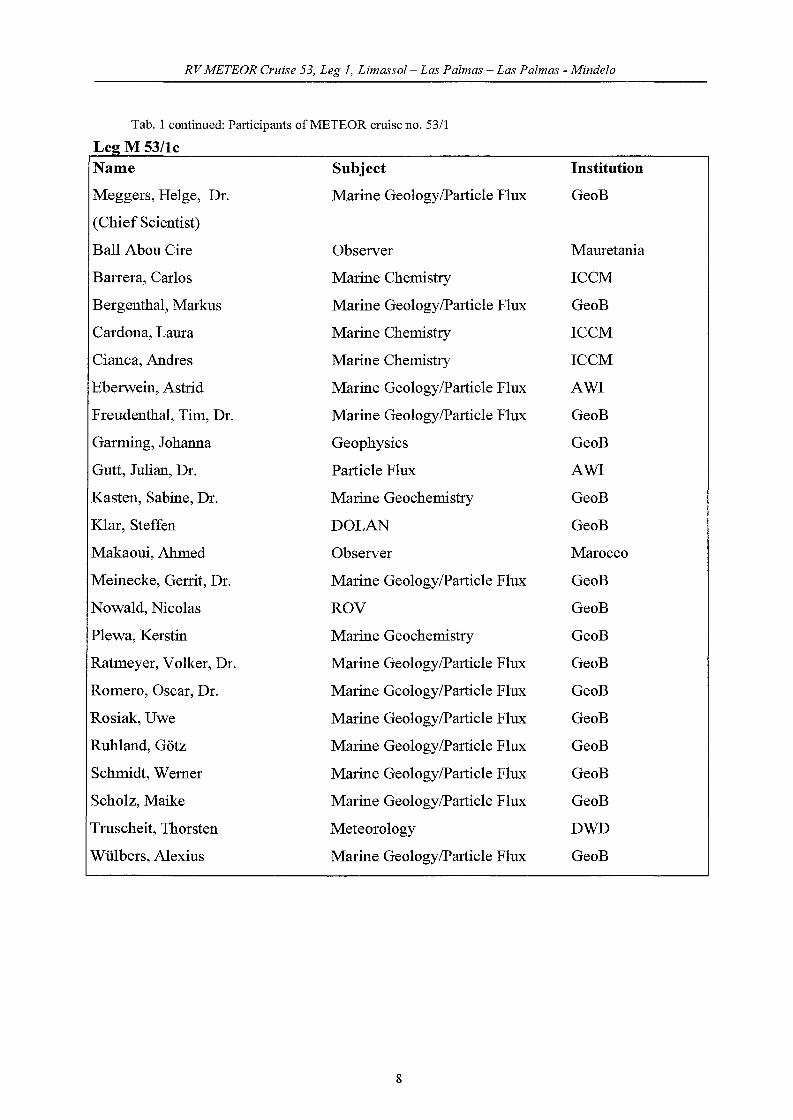
Tab. 1 continued: Participants ofMETEOR cmise no. 53/1
Leg M 53/1bName
Meggers, Helge, Dr.
(Chief Scientist)
Subject
Partic1e Flux
Institution
GeoB
Babero-Munoz, Leticia
Barrera, Carlos
Bergenthal, Markus
Betancort, Juan
Budweg, Harald
Cardona, Laura
DinllIUer, Wemer
DrÜllert, Frank, Dr.
Findeklee, Antje
Giani, Dieter, Dr.
Hübner, Anneliese, Dr.
Kahl, Gerhard, Dr.
Klämer, Dietmut, Dr.
Klar, Steffen
Kopiske, Bberhard
Koy, Uwe
Löwenberg, Ralf
Meinecke, Gerrit, Dr.
Mews, Klaus
Moser, Stefan
Nowald, Nicolas
Pinck, Andreas
Ratmeyer, Volker, Dr.
Rosiak, Uwe
Ruhland, Götz
Schmidt, Wemer
Truschert, Thor&en
Villagarcia, Marimar, Dr.
Marine Chemistry ULPGC
Marine Chemistry ICCM
DOLANlPartic1e Flux GeoB
Marine Chemistry ICCM
Meteorology DWD
Marine Chemistry ICCM
Partic1e Flux AWI
DOLAN OHB
Joumalist Spektrum-online
Joumalist TV
Joumalist Weser-Kurier
Meteorology DWD
Joumalist FAZINZZlRadio
DOLAN GeoB
DOLAN GeoB
ANIMATE IfMK
Ship's logistic Werum
DOLANlPartic1e Flux GeoB
Meteorology DWD
Joumalist Camera-man
ROV GeoB
ANIMATE IfMK
DOLANlPartic1e Flux GeoB
DOLANlPartic1e Flux GeoB
DOLANlPartic1e Flux GeoB
DOLANlPartic1e Flux GeoB
Meteorology DWD
Marine Chemistry ICCM
7
RVMETEOR Cruise 53, Leg I, Limassol- Las Palmas - Las Palmas - Mindelo
Tab. 1 continued: Participants ofMETEOR cmise no. 53/1
Lee: M 53/1cName Subject Institution
Meggers, Helge, Dr. Marine GeologylPartic1e Flux GeoB
(Chief Scientist)
Ball Abou Cire Observer Mauretania
Barrera, Carlos Marine Chemistry ICCM
Bergenthai, Markus Marine GeologylPartic1e Flux GeoB
Cardona, Laura Marine Chemistry ICCM
Cianca, Andres Marine Chemistry ICCM
Eberwein, Astrid Marine GeologylPartic1e Flux AWI
Freudenthai, Tim, Dr. Marine GeologylPartic1e Flux GeoB
Garming, Johanna Geophysics GeoB
Gutt, Julian, Dr. Partic1e Flux AWI
Kasten, Sabine, Dr. Marine Geochemistry GeoB
Klar, Steffen DOLAN GeoB
Makaoui, Ahmed Observer Marocco
Meinecke, Gerrit, Dr. Marine GeologylPartic1e Flux GeoB
Nowald, Nicolas ROV GeoB
Plewa, Kerstin Marine Geochemistry GeoB
Ratmeyer, Volker, Dr. Marine GeologylPartic1e Flux GeoB
Romero, Oscar, Dr. Marine GeologylPartic1e Flux GeoB
Rosiak, Uwe Marine GeologylPartic1e Flux GeoB
Ruhland, Götz Marine GeologylPartic1e Flux GeoB
Schmidt, Wemer Marine GeologylPartic1e Flux GeoB
Scholz, Maike Marine GeologylPartic1e Flux GeoB
Truschert, Thor~en Meteorology DWD
Wülbers, Alexius Marine GeologylPartic1e Flux GeoB
8
RV METEOR erläse 53, Leg 1, Limassol- Las Palmas - Las Palmas - Mindelo
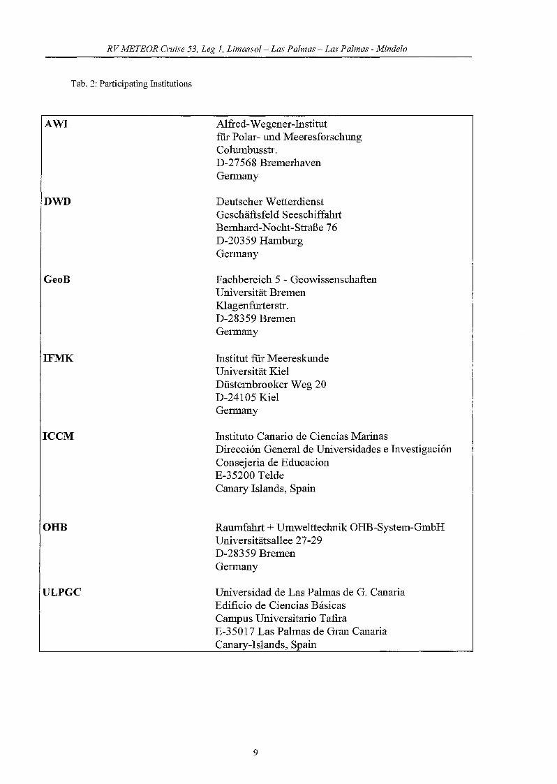
Tab. 2: Participating Institutions
AWI
DWD
GeoB
IFMK
ICCM
OHB
ULPGC
Alfred-Wegener-Institutfür Polar- und MeeresforschungColumbusstr.D-27568 BremerhavenGermany
Deutscher WetterdienstGeschäftsfeld SeeschiffahrtBemhard-Nocht-Straße 76D-20359 HamburgGermany
Fachbereich 5 - GeowissenschaftenUniversität BremenKlagenfurterstr.D-28359 BremenGelmany
Institut für MeereskundeUniversität KielDüstembrooker Weg 20D-24105 KielGermany
Instituto Canario de Ciencias MarinasDirecci6n General de Universidades e Investigaci6nConsejeria de EducacionE-35200 TeldeCanary Islands, Spain
Raumfahrt + Umwelttechnik OHB-System-GmbHUniversitätsallee 27-29D-28359 BremenGermany
Universidad de Las Palmas de G. CanariaEdificio de Ciencias BasicasCampus Universitario TafiraE-35017 Las Palmas de Gran CanariaCanary-Islands, Spain
9

RV METEOR Cruise 53, Leg 1, Limassol- Las Palmas - Las Palmas - Mindelo
3. Research program
The main purpose of the cruise was the investigation of biogeochemical processes and
fluxes on different spatial and temporal scales in relation to water mass circulation. Due to its
unique location, the Canary Islands and Cape Verde Islands region occupies a key position
with respect to the biogeochemical cyc1es in the region and is a prime location to study
environmental parameters sensitive to c1imate change.
The purpose is to obtain an integrated view of oceanographic processes in this region
both in the present and ofthe past.
Within the mentioned projects (see above) the following was done:
1. Studying the partic1e flux by recovering and deploying three sediment trap
moonngs (MID-II, ESTOC and CB ("Cape Blanc-mooring")). The particulate material
collected will be analysed to determine total flux, particulate flux, particulate organie carbon,
particulate nitrogen, biogenie opal, carbonate and carbon isotopes of organie matter, and
lithogenic material. The trapped material will further be investigated for species composition
of the planktonie organisms (pteropods, foraminifera, radiolaria, coccolithophorids, and
diatoms), together with the chemieal and isotopic compositions of these organisms and the
composition of the organie and terrigenous material. Complementary, the ROV and the
partic1e camera system were used to understand processes of the formation of aggregates and
their vertical and lateral transport processes in the ocean.
2. Sampling the surface waters to determine the cWorophyll content
3. Studying the amplitudes and rates of longterm environmental variability
exemplified by the flux variability of environmental tracers and atmospheric dust through the
last glacial-interglacial cyc1e along transects from the high-productivity coastal zone off Cape
Blanc to the oligotrophie central gyre region by taking sediment cores.
Within the framework of the deep-sea device programme DOLAN the following work
was carrled out:
1. Deployment of a permanent open sea mooring SBU ("Surface Buoy Unit")
with surface buoy.
2. Test ofthe satellite telemetry via OrbComm satellites.
3. Deployment of the MSU ("Multi Sensor Unit") mooring, inc1uding the device
platform MSD at 3000m depth.
4. Recovery and redeployment ofthe ESTOC mooring.
10
RVMETEOR erzäse 53, Leg 1, Limassol- Las Palmas - Las Palmas - Mindelo
4. Narrative ofthe Cruise
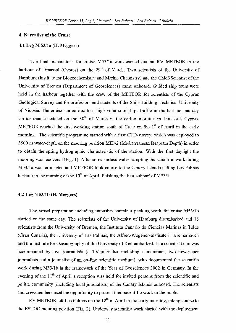
4.1 Leg M 53/1a (H. Meggers)
The final preparations for cruise M53/la were carried out on RV METEOR in the
harbour of Limassol (Cypres) on the 29th of March. Two scientists of the University of
Hamburg (Institute for Biogeochemistry and Marine Chemistry) and the Chief-Scientist ofthe
University of Bremen (Department of Geosciences) came onboard. Guided ship tours were
held in the harbour together with the crew of the METEOR for scientists of the Cyprus
Geological Survey and for professors and students ofthe Ship-Building Technical University
of Nicosia. The cruise started due to a high volume of ships traffic in the harbour one day
earlier than scheduled on the 30th of March in the earlier morning in Limassol, Cypres.
METEOR reached the first working station south of Crete on the 1st of April in the early
morning. The scientific programme started with a first CTD-survey, which was deployed to
3500 m water-depth on the mooring position MID-2 (Mediterranean Ierapetra Depth) in order
to obtain the spring hydrographie characteristic of the station. With the first daylight the
mooring was recovered (Fig. 1). After some surface water sampling the scientific work during
M53/la was tenninated and METEOR took course to the Canary Islands calling Las Palmas
harbour in the morning ofthe 10th ofApril, finishing the first subpart ofM53/1.
4.2 Leg M53/1b (H. Meggers)
The vessel preparation inc1uding intensive container packing work for cruise M53/1b
started on the same day. The scientists of the University of Hamburg disembarked and 18
scientists from the University of Bremen, the Instituto Canario de Ciencias Marinas in TeIde
(Gran Canaria), the University of Las Palmas, the Alfred-Wegener-Institute in Bremerhaven
and the Institute for Oceanography ofthe University ofKiel embarked. The scientist team was
accompanied by five joumalists (a TV-joumalist inc1uding cameraman, two newspaper
joumalists and a joumalist of an on-line scientific medium), who documented the scientific
work during M53/1b in the framework of the Year of Geosciences 2002 in Germany. In the
evening of the 11th of April a reception was held for invited persons from the scientific and
politic community (including local joumalists) ofthe Canary Islands onboard. The scientists
and crewmembers used the opportunity to present their scientific work to the public.
RV METEOR left Las Palmas on the 12th ofApril in the early morning, taking course to
the ESTOC-mooring position (Fig. 2). Underway scientific work started with the deployment
11

RV METEOR erläse 53, Leg 1, Limassol- Las Palmas - Las Palmas - Mindelo
ofXBT's on the way every 10 nautical minutes beginning at 28°10'N. Station work started in
the late afternoon with the monthly work (CTDlRosette casts, deployment of a NOAA-drifter)
for April 2002 at the ESTOC time-series station, located 60 um north of Gran Canaria. The
main purpose of this station is to build a long-term oceanographic data base to be able to
discern seasonal from 10ng-telID variability of hydrographic and biogeochemical parameters.
ESTOC is also used as an important reference station for ANIMATE, a EU-project for
thermoc1ine measurements of CO2- and nutrients at various key-sites in the NE-Atlantic. On
the 13th of April the sediment trap mooring CI14 was recovered successfully. This mooring
contains three sediment traps (20 cup collector), the upper one at least 500 m above the sea
floor, the lower one at least 500 m below surface. Sampling periods are two weeks. The
particulate material collected will be analysed to determine total flux, particulate flux,
particulate organic carbon, particulate nitrogen, biogenic opal, carbonate and carbon isotopes
of organic matter, and lithogenic material. The trapped material will further be investigated
for species composition of the planktonic organisms (pteropods, foraminifera, radiolaria,
coccolithophorids, and diatoms), together with the chemical and isotopic compositions of
these organisms and the composition of the organic and terrigenous material.
In the following days testing of deep-sea technology in the framework of DOLAN and
use of the CTDlRosette-system alternate with each other. The deep-sea technology testing
inc1uded various tests of satellite telemetry via OrbComm- satellite, the programming and
interface tests between the under water and satellite communication and tests of the under
water communication via the top buoy as a master unit. After this successful testing
programme the SBU-mooring (additionally implemented in the mooring chain a nutrient
analyser and a fluorometer) was deployed in the moming of the 12th of April 30 um west of
ESTOC. In the afternoon of the same day a second mooring with a Multi Sensor Device
(MSD) including a sediment trap, a partic1e camera and a CTD at 3000 m water depth was
deployed. After testing the entire data path with SBU and MSD the operational commission of
the platforms with measuring and transmission started. In the moming of the 16th of April a
combined CI15/ANIMATE mooring (including 2 sediment traps, current meters and various
Microcat-CTD's) was deployed near ESTOC. After finishing work north of the Canary
Islands METEOR took course southward in the lee of the Canary Islands to get weather
condition favourable for an intensive testing of the new "Remotely Operating Vehic1e"
(ROV). This device can reach depths up to 1000 m and with aid of this new and innovative
technology high-resolution datasets for the quantitative balancing of partic1e fluxes through
the water column will be obtained. During M53/1b balance testing and pilot testing were
12
RVMETEOR Cruise 53, Leg 1, Limassol- Las Palmas - Las Palmas - Mindelo
carried out intensive1y. The second subpart ofM53/1 ended in the moming ofthe 18th ofApril
in Las Palmas.
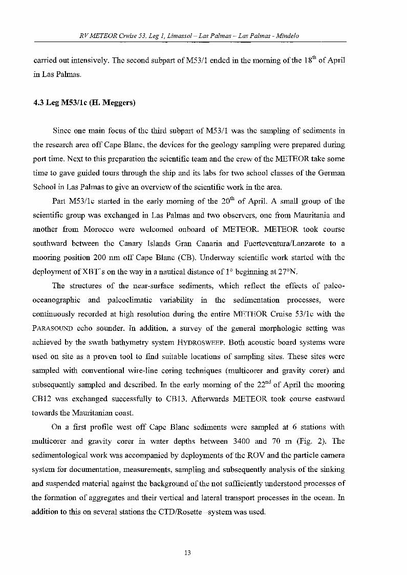
4.3 Leg M53/1c (H. Meggers)
Since one main focus of the third subpart of M53/1 was the samp1ing of sediments in
the research area off Cape B1anc, the devices for the geo10gy samp1ing were prepared during
port time. Next to this preparation the scientific team and the crew ofthe :METEOR take some
time to gave guided tours through the ship and its labs for two schoo1 c1asses of the German
Schoo1 in Las Palmas to give an overview ofthe scientific work in the area.
Part M53/lc started in the early moming of the 20th of April. A small group of the
scientific group was exchanged in Las Palmas and two observers, one from Mauritania and
another from Morocco were we1comed onboard of METEOR. :METEOR took course
southward between the Canary Is1ands Gran Canaria and FuerteventuralLanzarote to a
mooring position 200 nm off Cape B1anc (CB). Undelway scientific work started with the
dep10yment ofXBT's on the way in a nautica1 distance of 1° beginning at 27°N.
The structures of the near-surface sediments, which reflect the effects of pa1eo
oceanographic and pa1eoc1imatic variability in the sedimentation processes, were
continuous1y recorded at high resolution during the entire METEOR Cruise 53/1c with the
PARASOUND echo sounder. In addition, a survey of the general morpho10gic setting was
achieved by the swath bathymetry system HYDROSWEEP. Both acoustic board systems were
used on site as a proven too1 to find suitab1e 10cations of sampling sites. These sites were
samp1ed with conventiona1 wire-1ine coring techniques (multicorer and gravity corer) and
subsequently samp1ed and described. In the early morning of the 22ud of April the mooring
CB12 was exchanged successfully to CB13. Afterwards :METEOR took course eastward
towards the Mauritanian coast.
On a first profile west off Cape B1anc sediments were samp1ed at 6 stations with
multicorer and gravity corer in water depths between 3400 and 70 m (Fig. 2). The
sedimento10gica1 work was accompanied by dep10yments of the ROV and the partic1e camera
system for documentation, measurements, samp1ing and subsequently analysis of the sinking
and suspended material against the background of the not sufficient1y understood processes of
the fOlmation of aggregates and their vertica1 and lateral transport processes in the ocean. In
addition to this on severa1 stations the CTD/Rosette -system was used.
13
RVMETEOR Cruise 53, Leg 1, Limassol- Las Palmas - Las Palmas - Mindelo
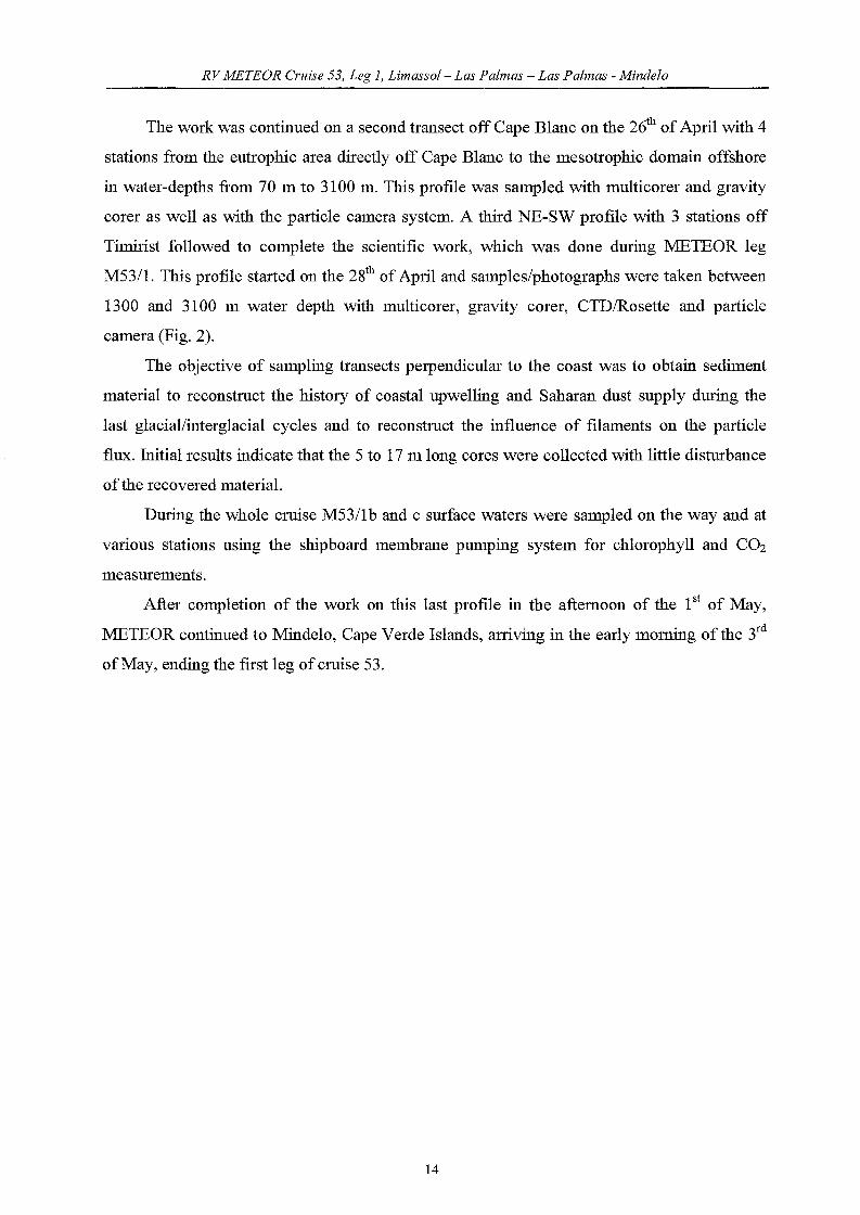
The work was eontinued on a seeond transeet off Cape B1ane on the 26th of April with 4
stations from the eutrophie area direct1y off Cape B1ane to the mesotrophie domain offshore
in water-depths from 70 m to 3100 m. This profile was samp1ed with multieorer and gravity
eorer as weIl as with the partic1e eamera system. A third NE-SW profile with 3 stations off
Timirist followed to eomp1ete the seientifie work, whieh was done during METEOR leg
M53/1. This profile started on the 28th of ApriJ and samp1es/photographs were taken between
1300 and 3100 m water depth with multieorer, gravity eorer, CTD/Rosette and partic1e
eamera (Fig. 2).
The objeetive of samp1ing transeets perpendieu1ar to the eoast was to obtain sediment
material to reeonstruet the history of eoasta1 upwelling and Saharan dust supp1y during the
last glaeiallinterg1acia1 eyc1es and to reeonstruet the influenee of filaments on the partic1e
flux. Initial results indieate that the 5 to 17 m 10ng eores were eolleeted with litt1e disturbanee
of the reeovered material.
During the who1e eruise M53/1b and e surfaee waters were samp1ed on the way and at
various stations using the shipboard membrane pumping system for chlorophyll and COz
measurements.
After eomp1etion of the work on this last profile in the aftemoon of the 1st of May,
METEOR eontinued to Minde10, Cape Verde Is1ands, arriving in the early moming of the 3rd
ofMay, ending the first leg of eruise 53.
14

RVMETEOR erläse 53, Leg 1, Limassol- Las Palmas - Las Palmas - Mindelo
5. Preliminary Results
5.1 M53/1a
5.1.1 Sediment Trap and Suspended Particulate Matter Investigations in the Eastern
Mediterranean
(A. C. Gebhardt, C. Warnken)
Introduction
When studying the global biogeochemical cyc1e of elements such as carbon, silica and
nitrogen, the transfer of particulate matter fi..om the surface layer through the water column to
the sediment-water interface as well as its incorporation into the sediment playamajor role.
Sediment traps provide a reliable means to sampIe sinking particulate matter and to ca1culate
flux rates. Sediment trap investigations carried out in numerous regions of the world ocean
have contributed to the better understanding of processes and factors controlling the
formation, amount and composition of sinking partic1es (e.g. Honjo, 1996; Ittekkot, 1996).
This information is essential for interpretation of the sedimentary record.
40"
38"
36"
34".........
MID·2
40"
38"
36"
34"
32"
30"
28"
~~.30"
26"
14" 16" 18" 20" 22" 24" 26" 28" 30"
Fig. 3: Positions of sediment trap MID-2
In November 2001, the mooring system "MID-2 (Mediterranean Ierapetra Deep) was
deployed in the Eastem Mediterranean off Crete in order to prolong the record from MID-l
15

RVMETEOR Cruise 53, Leg 1, Limassol- Las Palmas - Las Palmas - Mindelo
(deployed in spring 1999, see Pätzold et al. , 2000). The major goal of the sediment trap
investigation is to record the flux of settling partic1es in the deep Eastem Mediterranean.
Detailed analyzes of bulk composition and organie compounds will provide information on
the sourees, alteration, transport paths as well as transport processes of the organie matter.
Moreover, the sediment trap record will allow to quanti:fy the carbon flux to the deep Eastem
Mediterranean.
Methods
Sediment Trap
During the M51/2 cruise in October/November 2001 into the Eastem Mediterranean a
conical sediment trap mooring was deployed off Crete (34°26.50'N, 26°11.40'E; see Fig. 3)
in order to record an semi-annual cyc1e of the vertical partic1e flux and its saisonality. The
system consisted of two eight-year old PARFLUX MARK 7G-21 and one newly built
PARFLUX MARK 78G-21 sediment traps and was deployed at a water depth of3600 m. The
mooring was designed to collect settling partic1es in water depths of 550 m, 1530 m and 2560
m. The cups were initially filled with filtered sea water fixed with 35 g NaCI and 3.3 g HgCh
per litre in order to avoid organie matter decomposition during deployment.
Tab. 3: RecovelY scheme for sediment trap MID-2
Cup No. Start End Period Status1 05.11.01 12.11.01 7 days ok2 12.11.01 19.11.01 7 days ok3 19.11.01 26.11.01 7 days ok4 26.11.01 03.12.01 7 days lost5 03.12.01 10.12.01 7 days ok6 10.12.01 17.12.01 7 days lost7 17.12.01 24.12.01 7 days ok8 24.12.01 31.12.01 7 days ok9 31.12.01 07.01.02 7 days lost10 07.01.02 14.01.02 7 days ok11 14.01.02 21.01.02 7 days ok12 21.01.02 28.01.02 7 days ok13 28.01.02 04.02.02 7 days ok14 04.02.02 11.02.02 7 days ok15 11.02.02 18.02.02 7 days lost16 08.02.02 25.02.02 7 days lost17 25.02.02 04.03.02 7 days lost18 04.03.02 11.03.02 7 days ok19 11.03.02 18.03.02 7 days ok20 18.03.02 25.03.02 7 days ok21 25.03.02 01.04.02 7 days ok
16
RVMETEOR Cruise 53, Leg 1, Limassol- Las Palmas - Las Palmas - Mindelo
For sediment trap parameters refer to the M51/2 report (Meteor-Berichte, Universität
Hamburg, Cruise No. 51, inpreparation).
The sediment trap mooring was easily retrieved at the M51/2 station 529 site.
Unfortunately, the uppermost and the middle sediment trap - the old MARK 7G-21 traps
turned out not to have rotated at a11. Nevertheless, the lowermost new MARK 78G-21 trap
had tumed to bottle 21 and could be recovered on open hole. Regrettably, the lowermost trap
had gotten entangled with the chains and ropes during recovery and 6 of the filigrane cups
were lost. Data from the sediment trap timer board could be read and verified the system had
tumed correctly throughout the investigated time span (see Tab. 3).
The sampies were filtered through polycarbonate (0.45 I-lm) filters and dried at 40°C for
72 hours.
Suspended Particulate Matter
Sampies of suspended particulate matter were taken from surface water from two
stations (one at and one dose to the sediment trap site, see Fig. 3). They were filtered through
polycarbonate (0.45 I-lm) and GFIF (0.7 I-lm) filters, respectively. All sampies were dried at 40
°C for 72 hours.
Ongoing work
The sediment trap sampies as we11 as the suspended matter sampies will be analyzed for
opal, organic carbon and nitrogen, carbon and nitrogen isotopes as we11 as for amino acids.
Fluxes for the settling particles will be calculated.
17

RV METEOR erzäse 53, Leg 1, Limassol- Las Palmas - Las Palmas - Mindelo
5.2 M53/1b
5.2.1 Chemical Oceanography
(C. Barrera, J. Betancort, L. Cardona, M. Villagarcia)
Objectives and scientific questions
The main area of study for the ICCM oceanography group is located north of the Canary
Islands, mainly at 29°N latitude; it is a section that inc1udes the ESTOC station where our
group has undergone montWy sampling continuously from 1994. This zone is influenced by
the North Atlantic subtropical gyre, which is one of the most significant sources of surface
variability ofthe Atlantic Ocean. The recurrent sampling around the ESTOC environment will
help to know what the station represents within the area.
-18 -17 -16 -15 -14 -13 -12
• • .-e2 186190 1~ 29DOLAN
+4.::: • +31:: 1840 +2Z • +1Q) 185"tl::s 2 28.... •:t:lCll 192..J
CANARY ISLANDS27 27
-18 -17 -16 -15 -14 -13 -12
Longitude East
Fig. 4: Position of the CTD stations (dots) and XBT 1aunches (crosses) made by ICCM a10ng PoseidonM53/1b.
The setting of the ANIMATE mooring provides the opportunity to know the physico
chemical parameters of interest, not only montWy but in a daily basis. The smaller scale data
sets will allow on one hand to know processes not found by the montWy visit to the station
and, on the other hand to check the interannual variability by comparing it with the 8-years
data we have from ESTOC. Further, this cruise has permitted to make some stations in the
path between Tenerife and Gran Canaria Islands, to test the presence of intermediate waters
when coming from the south between the Canary Islands.
The distribution of nutrients, oxygen, cWorophyll and gelbstoff together with the
temperature and salinity profiles allow a reasonable approximation to some of the surface
phenomena occurring in the area.
18
RVMETEOR Cruise 53, Leg 1, Limassol- Las Palmas - Las Palmas - Mindelo
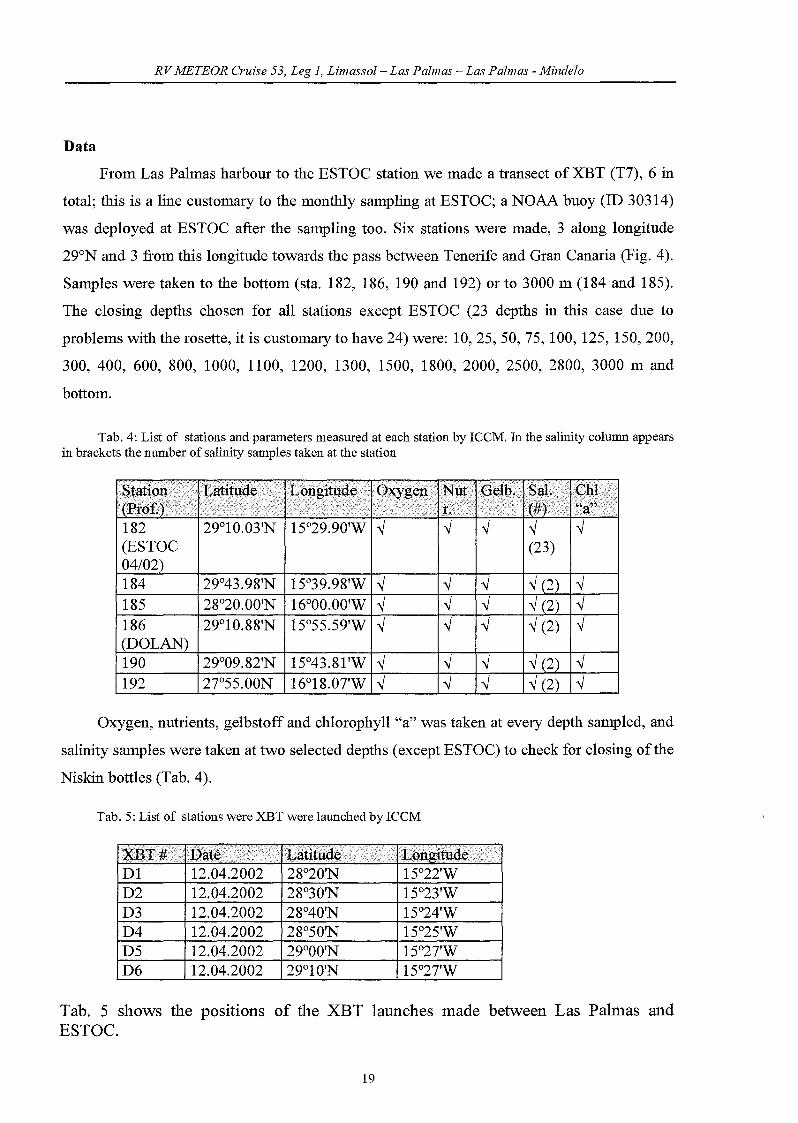
Data
From Las Palmas harbour to the ESTOC station we made a transect ofXBT (T7), 6 in
total; this is a line customary to the monthly samp1ing at ESTOC; a NOAA buoy (ID 30314)
was dep10yed at ESTOC after the samp1ing too. Six stations were made, 3 a10ng 10ngitude
29°N and 3 from this 10ngitude towards the pass between Tenerife and Gran Canaria (Fig. 4).
Sampies were taken to the bottom (sta. 182, 186, 190 and 192) or to 3000 m (184 and 185).
The c10sing depths chosen for all stations except ESTOC (23 depths in this case due to
problems with the rosette, it is customary to have 24) were: 10,25,50, 75, 100, 125, 150,200,
300, 400, 600, 800, 1000, 1100, 1200, 1300, 1500, 1800, 2000, 2500, 2800, 3000 m and
bottom.
Tab. 4: List of stations and parameters measured at each station by ICCM. In the salinity colunm appearsin brackets the number of salinity sampies taken at the station
182 29°10.03'N 15°29.90'W ~(ESTOC04102)184 29°43.98'N 15°39.98'W ~ ~ ~ ~
185 28°20.00'N 16°00.00'W ~ ~ ~ ~
186 29°10.88'N 15°55.59'W ~ ~ ~ ~(DOL190 29°09.82'N 15°43.81'W ~ ~ ~ ~
192 27°55.00N 16°18.0TW ~ ~ ~ ~
Oxygen, nutrients, gelbstoff and chlorophyll "a" was taken at every depth samp1ed, and
salinity sampies were taken at two se1ected depths (except ESTOC) to check for c10sing ofthe
Niskin bott1es (Tab. 4).
Tab. 5: List of stations were XBT were launched by ICCM
Dl 12.04.2002 28°20'N 15°22'WD2 12.04.2002 28°30'N 15°23'WD3 12.04.2002 28°40'N 15°24'WD4 12.04.2002 28°50'N 15°25'WD5 12.04.2002 29°00'N 15°2TWD6 12.04.2002 29°10'N 15°2TW
Tab. 5 shows the positions of the XBT launches made between Las Palmas andESTOC.
19
RVMETEOR Cruise 53, Leg 1, Limassol- Las Palmas - Las Palmas - Mindelo
Methods
Sampling Sampies were collected immediately after the bottles were on board from each
depth. The sampling sequence was as follows:
1.) Oxygen: was taken in glass bottles of about 125 m1 ofvolume which were previously
c1eaned and washed with HCl acid and was fixed at once; then it was kept for at least six hours
according to WOCE regulations and finally it was analysed at the laboratory on board the ship.
2.) Nutrients: were taken in polypropylene bottles which were previously c1eaned and
washed with HCl acid and were completely dry. Sampies were immediately frozen at -20°C,
analysing them as soon as possible after arrival at the laboratory. Freezing the sampies is a
common practice; it does not or only in a non-significant way affects the nitrate + nitrite and
the phosphate values (by a slight decrease) and is not noticeable in the silicate values
(Kremling and Wenck, 1986; McDonald and McLunghlin, 1982).
3.) Gelbstoff: water was taken in dark glass bottles which were previously c1eaned and
washed with HCl acid. The sampies were analysed within 3 hours of having taken them by
spectrofluorometry.
4.) Salinity: sampies were taken in dark glass bottles which were previously c1eaned and
washed with HCl acid. Then, they were kept in boxes to protect them from light till analysis
on land.
5.) Chlorophyll: sampies of one liter ofwater were taken. The chlorophyll sampies were
filtered inmediatelly and the filters were frozen subsequently at -20°C. Their analyses take
place at the ICCM laboratory on land.
All sampies were taken using the procedures established in the WOCE Operations
Manual, WHP Office Report WHPO 91-1/WOCE Report NO.68/91.
Analysis
Dissolved Oxygen: The sampies were analysed using the method described in the WOCE
Operations Manual, WHP Office Report No. 68/91; the final titration point was detected using
a Metrohm 665 Dosimat Oxygen Auto-Titrator Analyser.
Nutrients: The nutrients determination was performed with a segmented continuous-flow
autoanalyser, a Skalar® San Plus System (ICCM).
20
RVMETEOR Cruise 53, Leg 1, Limassol- Las Palmas - Las Palmas - Mindelo
Nitrate+Nitrite: The automated procedure for the determination of nitrate and nitrite is based
on the cadmium reduction method; the sample is passed through a column containing
granulated copper-cadmium to reduce the nitrate to nitrite (Wood et al.,1967), using
ammonium cWoride as pH controller and complexer of the cadmium cations formed
(Strickland and Parsons, 1972). The optimal column preparation conditions are described by
several authors (NydaW, 1976; Garside, 1993).
Phosphate: Orthophosphate concentration is understood as the concentration of reactive
phosphate (Riley and Skirpow, 1975) and according to Koroleff (1983a) is a synonym of
"dissolved inorganic phosphate". The automated procedure for the determination ofphosphate
is based on the following reaction: ammonium molybdate and potassium antimony tartrate
react in an acidic medium with diluted solution of phosphate to form an antimony-phospho
molybdate complex. This complex is reduced to an intensely blue-coloured complex, ascorbic
acid. The complex is measured at 88Onm. The basic methodology for this anion determination
is given by Murphy and Riley (1962); the used methodology is the one adapted by Strickland
and Parsons (1972).
Silicate: The determination of the soluble silicon compounds in natural waters is based on the
formation of the yellow coloured silicomolybdic acid; the sample is acidified and mixed with
an ammonium molybdate solution forming molybdosilicic acid. This acid is reduced with
ascorbic acid to a blue dye, which is measured at 810 um. Oxalic acid is added to avoid
phosphate interference. The used method is described in Koroleff(1983b).
Yellow Substance: The values were obtained using the methodology described by Determann
et al. (1994, 1996). The samples were measured with a spectrofluorometer SHlMADZU RF
1501 at an excitation wavelength of 341 um and the intensities taken at emission wavelength
between 350 and 500 um. Gelbstoff fluorescence is derived from the emission spectra and
obtained in Raman units.
Phytoplankton pigments: Pigments were measured using fluorimetric analysis, following the
methodology described by We1schmeyer (1994). The determination was achieved using a
fluorometer TURNER 10-AU-000.
21
RVMETEOR erldse 53, Leg 1, Limassol- Las Palmas - Las Palmas - Mindelo
Salinity: Samples were measured with a salinometer, model Autosal 8400a, whose
measurement range was between 0.005-42 (psu), with an accuracy of ±0.003, according to the
manufacturer. It was calibrated following the manufacturer's information and standarizing it
with IAPSO Standard Seawater. Salinity values were calculated as practical salinity according
to Unesco (1978, 1984).
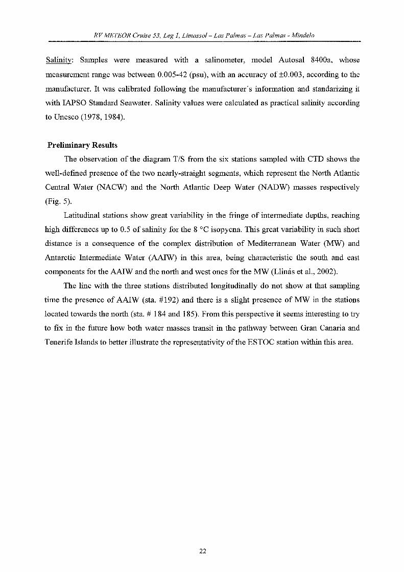
Preliminary Results
The observation of the diagram T/S from the six stations sampled with CTD shows the
well-defined presence ofthe two nearly-straight segments, which represent the NOlfu Atlantic
Central Water (NACW) and the North Atlantic Deep Water (NADW) masses respectively
(Fig.5).
Latitudinal stations show great variability in the fringe of intermediate depths, reaching
high differences up to 0.5 of salinity for the 8 °C isopycna. This great variability in such short
distance is a consequence of the complex distribution of Mediterranean Water (MW) and
Antarctic Intermediate Water (AAIW) in this area, being characteristic the south and east
components for the AAIW and the north and west ones for the MW (Llinas et aL, 2002).
The line with the three stations distributed longitudinally do not show at that sampling
time the presence of AAIW (sta. #192) and there is a slight presence of MW in the stations
located towards the north (sta. # 184 and 185). From this perspective it seems interesting to try
to fix in the future how both water masses transit in the pathway between Gran Canaria and
Tenerife Islands to better illustrate the representativity ofthe ESTOC station within this area.
22

RVMETEOR Cruise 53, Leg 1, Limassol- Las Palmas - Las Palmas - Mindelo
20
18
16
14~-U9-.J
~ 12::::>
~Q)
10""-EQ)
f-8
6
34.0 34.5 35.0 35.5 36.0 36.5
Salinity37.0 37.5 38.0
Fig. 5: T/S ofthe two transects made along the cruise in the ESTOC area
5.2.2 Carbon dioxide in sea-water
(L. Babero-Munoz)
In response to increased interest in global c1imate change and greenhouse warming,
measurements ofthe marine carbon system (i.e. total CO2, TC02, titration total alkalinity TA,
pR and pC02) have been inc1uded in several global research programs such as the World
Ocean Circulation Experiments (WOCE) and the Joint Global Ocean Flux Study (JGOFS).
These programs inc1ude time series stations primarily designed to examine temporal
variability and the mechanism controlling this variability. The Canary Islands Time series
(ESTOC) is visited each month and the surrounding area approximately twice a year. Time
series station data provide excellent opportunities to study the temporal variability of the
carbon system at a single location over several years, while cruises around the ESTOC station
will provide information about spatial variability of the carbon species in the area.
The main objective on this cruise was to study the spatio-temporal variability of the
parameters which define the carbonate system in the water column. The parameters to be
determined are pR and total alkalinity. Underway continuous pC02 were carried out in the
23
RVMETEOR Cruise 53, Leg 1, Limassol- Las Palmas - Las Palmas - Mindelo
ESTOC 10cation and vicinity, together with air pCOz va1ue (each hour). In addition, water
samp1es for pH and titration alkalinity collected from surface to bottom were ana1ysed on
board within four hour of collection with a two-thermostatized (25°C ± 0.1) 200 m1 titration
cells with ROSS glass pH e1ectrode and Orion double junction Ag, AgC1 reference e1ectrodes.
The reliability of the titration systems was tested by determining the TA of Certified
Reference Material for Oceanic COz measurements (batch 35) provided by Dr. Dickson,
Scripps Institution of Oceanography, San Diego. The results of these measurements indicate
that high-precision measurements of TA (± 1.2 /-lmo1 kg-1) can be obtained. Photometrie pH
was determined by a stopped-flow system designed by this group by using a m-creso1 purp1e
sea-water solution as dye for the pH determination following the DOE (1994) SOP 6 for the
analysis of the carbonate system variables of oceanic sea-water samp1es. Reproducibility is
better than 0.003 pH units.
5.2.3 Particle tlux studies and deep-sea technology
5.2.3.1 Mooring work within the projects DOLAN, ESTOC and ANIMATE
(M. Bergentha1, S. Klar, E. Kopiske, U. Koy, G. Meinecke, A. Pinck, V. Ratmeyer, G.
Ruhland, U. Rosiak)
A main goal during the M53/1b cruise was to establish the operationa1 transmission of
datasets at the DOLAN mooring site. In addition to that, mooring-, maintenance work and
severa1 tests of the technica1 devices shou1d be done within the scope of the BMBF project
DOLAN ("Operationa1 Data transmission in the Ocean and lateral acoustic Network in the
Deep-Sea"). The DOLAN station is 10cated 20 um west ofESTOC and comprises techno10gy
for the transmission of data by means of acoustics in the water co1umn via satellite and
internet. C10se1y linked to ESTOC and DOLAN is the EU project ANIMATE ("At1antic
Network of Interdiscip1inary Moorings and Time series for Europe"). In the ANIMATE
project, moorings will be dep10yed at key sites in the northern Atlantic (Porcupine Abyssa1
P1ain, PAP; Centra1 Irminger Sea, CIS and at ESTOC) in order to gain data of COz, nutrients
and fluorescence, which will be directly transmitted via satellite to the participating scientific
institutes. A significant element in ANIMATEis the techno10gy for the transmission of
datasets from the deep-sea used in the DOLAN project. Furthermore, ESTOC is the reference
site for the subtropica1 NE-At1antic within the ANIMATE project.
24
RVMETEOR erzäse 53, Leg 1, Limassol- Las Palmas - Las Palmas - Mindelo
In order to reduce the number of permanent mooring sites, it was p1anned to merge the
ANIMAlE sensors with the existing DOLAN and ESTOC moorings. For this reason, the
MicroCat CTDs and the ADCP shou1d be attached to the ESTOC mooring site. The
ANIMAlE fluorescence sensor and the Nutrient ana1yzer shou1d be integrated into the
mooring chain be10w the DOLAN data buoy. The main tasks during the M53-1b cruise were:
1. Dep10yment of a permanent open sea mooring SBU ("Surface Buoy Unit")
with surface buoy. Measuring of the anchor position of the SBU and integration of the
ANIMAlE sensors (fluorescence and nutrients)
2. Test of the satellite te1emetry via OrbComm satellites. Retrieva1 of the GPS
and weather data. Programming and test of the interface between underwater- and
satellite communication. Test of the underwater communication with the buoy as the
master unit.
3. Dep10yment ofthe MSU ("Multi Sensor Unit") mooring, inc1uding the device
p1atfOlm MSD at 3000 m depth. Measuring of the anchor position of the MSU and its
position in the water above the position of the MSD ("Multi Sensor Device"). Test of
the entire data path with SBU and MSU.
4. Recovery ofthe ESTOC mooring and redep10yment ofthe ESTOC/ANIMAlE
moonng.
Dep10yment of the SBU
DOLAN data buoy
The DOLAN data buoy is part of national funded program DOLAN (Data transmission
m the Ocean and lateral acoustic Network - BMBF, Germany). The buoy is build of
polyurethan foam and has a diameter of 2.4 m by a weight of 1.5 tons (Fig. 6). It is equipped
with solar panels in order to provide power for flasher, e1ectronics and to re-charge the bui1d
in batteries, which are stored in one of the 4 watertight e1ectronic pockets. In one pocket the
comp1ete OrbComm te1emetry is installed together with the controlling PC and the acoustic
underwater modem. In addition, a short distance radio link (SATEL) is also installed in the
buoy in order to communicate with the buoy from the ship nearby. Spare room for additional
e1ectronics is still avai1ab1e. A simple and uncalibrated weather station (temperature, speed,
direction) is installed on the buoy as scientific sensor. For tracking purposes a comp1ete
25

RVMETEOR Cruise 53, Leg 1, Limassol- Las Palmas - Las Palmas - Mindelo
independent and battery powered (D-cells) OrbComm te1emetly unit was attached to the outer
centra1 part ofthe buoy.
Fig. 6: Dolan sUlface buoy SBU prior to deployment
Tests prior to deployment
The OrbComm te1emetly system consists of two basic hardware components, a contro1
PC to interface with the attached sensors and the PANASONIC KX-G7100/7101 OrbComm
communicator. The contro1 PC BC10 (digital controller by OHB-Te1edata, Bremen, Germany)
offers five RS232-Ports, four ofthese are used as sensor-interface. One RS232 port is used for
communication with the PANASONIC and therefore OrbComm. The digital controller is
equipped with hardware watchdog, RTC, alarm functions, powersave-mode (to zero
microampere extema1 power) and the ability ofremote BIOS download. It runs with apower
supp1y from 12 to 24 Volts DC under temperature conditions from -40°C to +80 °C.
26

RV METEOR Cruise 53, Leg 1, Limassol- Las Palmas - Las Palmas - Mindelo
The PANASONIC transceiver is a commercial product and seems to be very robust and
easy to use. It runs with power supply from 12 to 24 V and offers 2 digital 10- and 2 analog
channels. The serial RS 232 port can be used as the standard interface for scientific
application but also for programming of the PANASONIC itself via a terminal program like
hyper terminal. The internal software is subdivided into 4 command sets - transmission,
tracking, setup and special commands. There is no direct need in general to run the
PANASONIC in combination with a control PC - here it is the case due to the demand for
additional serial COM ports.
The PANASONIC OrbComm communicator is available in two specification - with
(KX-G710l) and without build in GPS receiver (KX-G7100). In the DOLAN/ANIMATE
project both types of communicator are still in use - with GPS receiver on the separate
tracking unit on the buoy and without GPS as central communication unit on the buoy.
Integration and Test
In the starting phase of ANIMATE the OrbComm telemetry sole1y was used at the
ESTOC site - more precisely on the DOLAN data buoy. Before installation of the telemetry
hardware an intense lab testing has been done in the institute at GeoB Bremen and onboard
the RV METEOR. Due to the fact of satellite transmission it's no matter whether the buoys
electronic are located in Bremen or at the Canaries. After successful testing the hardware was
prepared for integration into the buoy. The central buoy telemetry - internally integrated with
the controlling PC into aseparate casing - was attached to a steal frame, together with the
acoustic underwater modem. This steal frame fits in one of the electronic pockets of the data
buoy. Afterwards, the battery pocket and the e1ectronic pocket were completely wired through
internal tube-like connections between the 4 pockets. The additional connections from outside
like antennas, transducer cable, solar panels and flasher were plugged into the bulkhead
connectors located in the pocket lids. Finally, the buoy was completely prepared for
deployment.
Deployment ofthe SBU
The deployment of the SBU-mooring needs to be operated in two steps. The mooring
itse1f consists of very robust 20 mm polypropylene rope with 3500 m of totallength. As the
uppermost part, two pieces of 12 mm steel wire (450 m and 50 m) were attached to the
mooring line. In order to position the ANIMATE nutrient analyzer at the target depth of 80 m
below sea surface, the sensor was c1amped between the two steel wires (Fig. 7).
27

RV METEOR Cruise 53, Leg 1, Limassol-Las Palmas -Las Palmas - Mindelo
Fig. 7: Nutrient analyzer prior to deployment
The end of the steel wire was prepared with a 5 tons swivel and than connected to 20 m
of 22 mm chain. The acoustic transducer and the transducer cable were aheady integrated in
the chain. At the end of the chain 25 glass spheres (dummy buoyancy) were connected. The
dummy buoyancy was used in order to prevent the surface buoy of damage during
deployment of the complete mooring. Afterwards, the mooring was deployed with a 2.7 tons
anchor weight without any problems.
In the second step, the surface buoy itselfwas prepared onboard the RV METEOR. The
dummy buoyancy of the mooring line was recovered and the chain was pulled onboard in
order to artach the ANIMATE fluorescence sensor in the target depth of 10m be10w sea
surface. Afterwards the buoy was c1amped to the mooring chain and the transducer cable was
connected to the buoys electronic. Finally, the buoy was Iowered down to the sea surface and
the SBU was completely deployed (Fig. 8).
28

RVMETEOR erläse 53, Leg 1, Limassol- Las Palmas - Las Palmas - Mindelo
Depth (m) Device
8m Ghain(20 mmJ
Flasher, YellowGroup 5, alle 20 sec,
Hobl LabsSpeClrum Analyzer
SOm Steelropll (12 mm)
20 m Chain(20 mm)
1m Chain(20 rmn)
Firdell Radar Refiektor (210/7)
Scientific Data Buoy
Sviwel
NUlfientAnalyzer
10
o
80
30
450m Steelrope (12 mm)
Shackles
2 x 500m PolyProp.-Rope (20 mm)
1050
2060
3060
3560
3585
3600
10 Spheres (yellow)
2 x 500m PolyProp.-Rope (20 mm)
2 Spheres (yellow)
2 x 500m PolyProp.,.Rope (20 mm)
2 Spheres (yellow)
1 x 500m PolyProp.-RQpe (20 mm)
6 Spheres (yeliow)
20 m PolyProp.·Rope (20 mm)
2 x 1m Chain(2·fach Hahnepod)
Releaser AR 661#475,478
10 m Chaln2x 1,5 m Chain(2·fach Hahnepod)
Anchor (ca. 2,7 t)
Mooring: DOLAN SBU (Surface Buoy)Expedition: M53/1 bArea: Canary Istands, 20nm östlich v. ESTOC StationWater depth: ca. 3634 mDeployment date: 15.04.2002
~ ~~leYcr;~c~~l; BREMEN
LatLong
29°11.15 N015"55.35 W
Fig. 8: Mooring design of complete SBU-mooring
29
RVMETEOR Cruise 53, Leg 1, Limassol- Las Palmas - Las Palmas - Mindelo
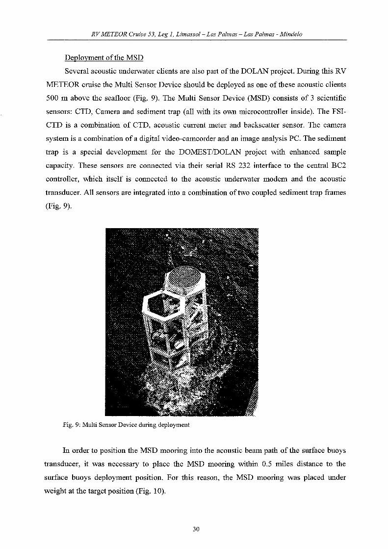
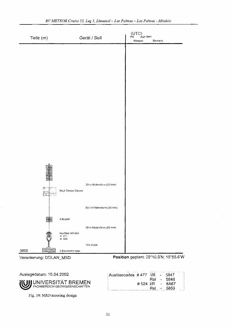
Deployment ofthe MSD
Severa1 acoustic underwater clients are also part ofthe DOLAN project. During this RV
METEOR cruise the Multi Sensor Device shou1d be dep10yed as one of these acoustic c1ients
500 m above the seafloor (Fig. 9). The Multi Sensor Device (MSD) consists of 3 scientific
sensors: CTD, Camera and sediment trap (all with its Own microcontroller inside). The FSI
CTD is a combination of CTD, acoustic current meter and backscatter sensor. The camera
system is a combination of a digital video-camcorder and an image analysis PC. The sediment
trap is a special deve10pment for the DOMESTIDOLAN project with enhanced samp1e
capacity. These sensors are connected via their seria1 RS 232 interface to the centra1 BC2
controller, which itse1f is connected to the acoustic underwater modem and the acoustic
transducer. All sensors are integrated into a combination oftwo coup1ed sediment trap frames
(Fig.9).
Fig. 9: Multi Sensor Device during deployment
In order to position the MSD mooring into the acoustic beam path of the surface buoys
transducer, it was necessary to p1ace the MSD mooring within 0.5 mi1es distance to the
surface buoys dep10yment position. For this reason, the MSD mooring was p1aced under
weight at the target position (Fig. 10).
30
RVMETEOR erzäse 53, Leg 1, Limassol- Las Palmas - Las Palmas - Mindelo
Tiefe (m) Gerät I Seil
20 m Meteorteine (20 mm)
MulÜ Sensor Device
500 m Meteorleine (20 mm)
(UTC)Ins aus dem
Wasser Bemerk,
4 Kugeln
20 m Metoorfeine (20 mm)
Auslöser AR 661#477# 52A
10m Kelte
3600 :3 Eisenoahnräder
Verankerung: DOLAN_MSD Position geplant: 29"10.9'N; 15"55.6'W
Auslegedatum: 15.04.2002
i"iU1I UNIVERSITÄT BREMEN~ FACHBEREICH GEOWISSENSCHAFTEN
Fig. 10: MSD mooring design
Auslösecodes # 477 I/RRel
# 524 I/R
31
584758488A67

RVMETEOR erläse 53, Leg 1, Limassol- Las Palmas - Las Palmas - Mindelo
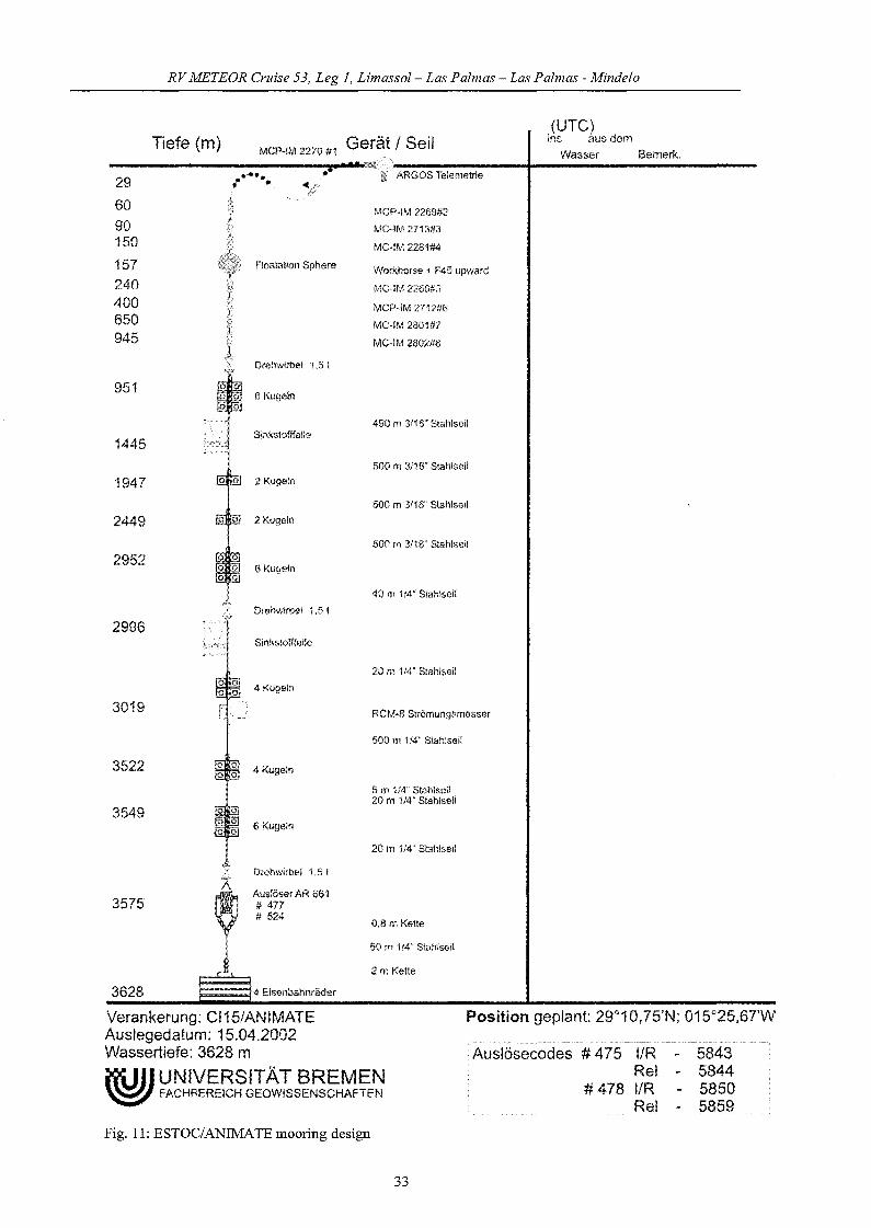
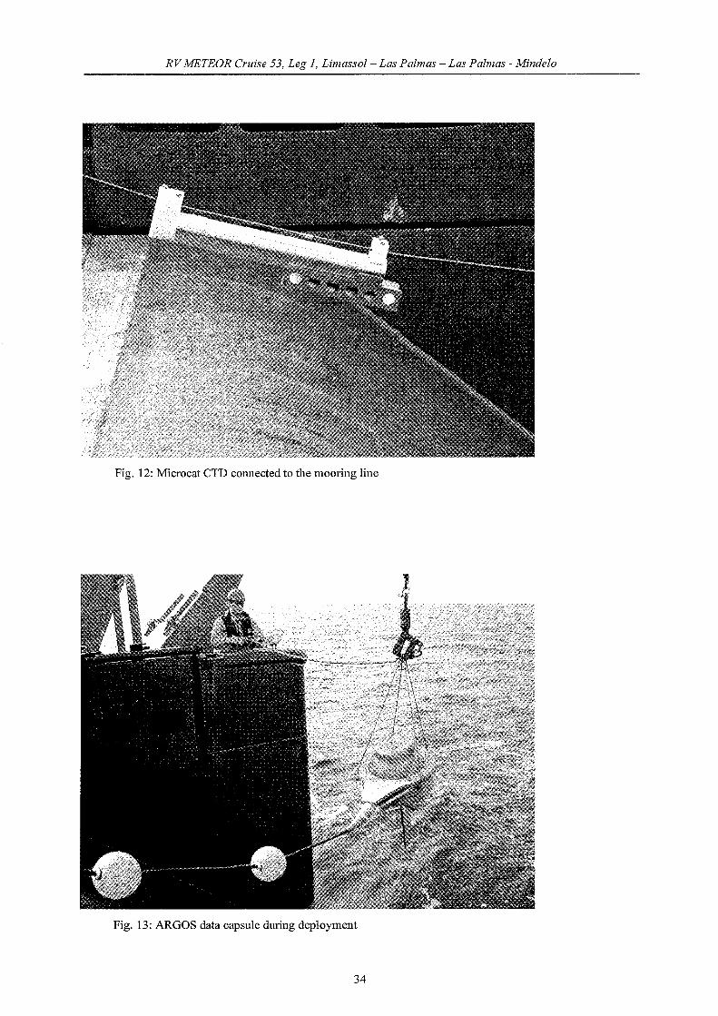
Deployment of the ESTOC/ANIMATE Mooring
Parallel to the dep10yment ofthe nutrient analyzer and the fluorescence sensor inside the
SBU mooring it was necessary to implement inductive Microcat CTD and the ARGOS
telemetry at the ESTOC site. For this reason the long term ESTOC mooring was redesigned
with steel cables instead of polypropylene ropes and the uppermost part of the mooring line
was equipped with several. Microcat CTD, an upward looking RDI ADCP and the ARGOS
te1emetry capsule (Figs. 11, 12, 13). In order to get into contact with the ARGOS satellite it
was necessary that the overall mooring length was greater than water depth to ensure the data
capsule was at sea surface. All sensors do have the capability to store their data inside but also
to transmit their data via the inductive link and the steel cables to the ARGOS data capsule
(Fig. 13). As basic part of the ESTOC mooring two sediment traps were also attached to the
mooring line. After preparation on deck it was no problem to deploy the complex mooring
without any prob1ems.
32
RVMETEOR erzäse 53, Leg 1, Limassol- Las Palmas - Las Palmas - Mindelo
MCP-IM 2270 #1 Gerät I Seil• ' • oe t'*'R
296090150157240400650945
Tiefe (m)
••••~ .
Floatation Sphere
i~ ARGOS Telemetrie
MCP-IM 2269#2
MG·tM 2713#3
MC·tM 2261#4
Workhorse + F45 upward
MC·IM 2260#5
MCP-IM 2712#6
MC.IM 2801#7
MC·IM 2802#8
(urc)ins aus dem
Wasser Bemerk.
951
1445
1947
2449
2952
2996
3019
3522
3549
3575
Drehwirbe! 1,5!
6 Kugeln
Sinkstofffalle
2 Kugeln
2 Kugeln
ß Kugeln
Drehwirbel 1,5 I
Sinksiofffalle
4 Kugeln
4 Kugeln
6 Kugeln
Drehwirbel 1,5!
Auslöser AR 661#477# 524
490 m 3116" Stahlsei!
500 m 3118" SlahlseH
500 m 3116" S!ahlseil
500 m 3116" Stahlseil
40 m 114" Slahlseil
20 m 114" SlahJseil
RCM·g Strömungsmesser
500 m 114" Stahlseil
5 m 1/4" Stahlseil20 m 1!4" Stahlseil
20 m 1/4" StahtseH
O,8m Kette
50 m 1/4" BtahlseH
2m Kette
Position geplant: 29"10,75'N; 015"25,67'W
3628 4 Eisenbahnräder
Verankerung: Cl15/ANIMATEAuslegedatum: 15,04.2002Wassertiefe: 3628 m
itüJl UNIVERSITÄT BREMEN~ FACHBEREICH GEOWISSENSCHAFTEN
Fig. 11: ESTOC/ANIMATE mooring design
33
Auslösecodes # 475 IIRRel
#478 I/RRel
5843584458505859
RVMETEOR Cruise 53, Leg 1, Limassol- Las Palmas - Las Palmas - Mindelo
Fig. 12: Microcat CTn connected to the mooring line
Fig. 13: ARGOS data capsule during dep10yment
34

RV METEOR Cruise 53, Leg 1, Limassol- Las Palmas - Las Palmas - Mindelo
5.2.3.2 ROV Operations
(M. BergenthaI, S. Klar, G. Meinecke, N. Nowald, V. Ratmeyer, G. Ruhland, W. Schmidt)
The MElEOR cruise M53-1b and M53-1c were the :first open ocean tests for the new
Cherokee ROV. In addition to the scientific tasks the ROV should perform the dives were
undertaken in order to proof the reliability of the system itself and to train the ROV crew to
operate the complete system under field trip conditions. Abrief technical overview will be
given in the following section. For explanation the complete system is separated into two
logical parts, the topside equipment (all components used on the ship) and downside
equipment (underwater equipment, the ROV itself).
Topside
The topside equipment consists of three basic parts, the power distribution unit (PDU),
the surface control unit (SCU) and the spooling winch (SW).
PDU
The PDU is a galvanic decoupled power transformer which can use input voltages fi.'om
380 V to 440 V, three phases. The output voltages ofthe PDU are 440 V AC and 220 V AC,
both necessary to run the ROV. The complete power supply is in a range of 10 to 12 kVA.
Due to peak current loads of 30 to 40 A it is necessary to run the PDU on a secure and stable
power outlet othetwise the PDU will collapse during ROV diving missions.
SCU
The SCU is the central controlling device for the ROV, installed in a 19" flight case
rack. It consists of the central controlling PC, operation console, two 9" Panasonic colour
screens, one PC with TFT display for the Sonar system, 1 Panasonic SVHS video recorder
and an internal video overlay system (Fig. 14). The power supply from the PDU is
interconnected with the ROV tether in order to provide the 440 V for the thrusters and the
220 V for the ROV electronics (switched separately). Both voltages are monitored in the SCU
and in conjunction with an earth fault detection system one have the ability to perform
emergency stops, ifnecessary. In addition to the power supply, 4 twisted pair copper lines and
4 mono fibres are interconnected from the SCU to the ROV tether. The downside installed
sensors like vehic1e compass, pressure sensor, altimeter data and also sonar data were
transmitted via the copper lines to one of the screens as part of the video overlay system.
35

RV METEOR Cruise 53, Leg 1, Limassol- Las Palmas - Las Palmas - Mindelo
These data are pelmanently visible ones the ROV is powered up and the sonar is switched on.
The optic fibres of the tether are used to transmit up to 4 separate Video channels and also
four RS 232 (full duplex) and two RS 485 (half duplex) signals between seu and the ROV.
All vehic1e functions can be controlled via the operation console. In addition to the thrusters
controls (forward, backward; lateralleft, lateral right; axialleft, axial right; up, down) one can
limit the thrusters power consumption, dim the lights, control the pan and tilt unit, run the
camera focus and zoom and control auto heading and auto depth. The console itself can be
connected to the seu either directly or via a 30 m remote cable, necessary during deploy and
recovery operation of the ROV. If necessary for operations, the ROV manipulator can be
controlled by aseparate console attached to the main console.
Fig. 14: Surface contro1 unit (SCU, middle) with the additional pilot rack (PR, left) installed onboard theRVMETEOR
Beside this seu rack, two additional 19" racks (pilot rack (PR), stereo cam rack (SR))
are connected to the seu in order to provide better information for the pilot and for the
scientific user ofthe ROV system. The PR consists of one pe with 15" TFT display with dual
head VGA adapter and an attached overlay generator in order to pick up actual ship born data
like ships time, ships heading, water depths, GPS data out of the NMEA data stream provided
by RV METEOR. These data were merged with the seu overlay data like ROV heading on a
separate 12" Sony Monitor, also installed in the PR rack. Now, the ROV pilot has the
36
RVMETEOR Cruise 53, Leg 1, Limassol- Las Palmas - Las Palmas - Mindelo
opportunity to see ships heading in relation to ROV heading on one screen (necessary to keep
the ROV on the right side ofthe ship during deploy and recovelY).
The SR rack basically consists of one PC with 18" TFT display, frame grabber card and
attached overlay generator and has to perform two basic tasks. On one hand, the video signal
transmitted in this rack is stored on the Sony DV recorder and can be picked up as a screen
shot by the PC frame grabber card (still shots stored as bmp-file on the hard disc). On the
other hand, this PC is the control unit for the attached stereo head mounted display (HMD)
and the software utility to run the fast proportional stereo cam pan and tilt unit via a joystick
interface. One line ofthis stereo camera system can be transferred to a separately attached 14"
Panasonic monitor in order to provide additional video data to the scientific user.
All original video sources (1 pilot cam, 2 pencil cams, 1 spare) and the overlay sources
(SCU, Pilot Rack, Stereo Rack) are interconnected via an 8 port Video Cross over Matrix to
the video targets (12" Monitor, 14" Monitor, 2 x 9" Monitor, SVHS-Recorder and DV
Recorder, 1 spare). Nearly all combinations of distinct video signals on specific screens 01'
recorders are possible.
SW
The ROV winch is designed as a simple spooling winch, built of stainless steal with a
complete weight of 1.7 tons (winch and tether). It is electric driven by a 440 V AC Motor,
controlled by a console box mounted on the winch frame. The winch carries 1000 m Kevlar
reinforced fibre-optical cable (9 copper lines power 440 V, 220 V, 2 tirnes Neutral, 4 twisted
pair lines and 4 mono fibres), which is designed as a buoyancy adjusted tether and not as an
armoured Umbilical (Fig. 15). The ROV itself can't be lifted with the tether. In the actual
configuration a electric slip ring (48 connectors) is attached to the winch, means all electric
cables passes through the winch axis and are active throughout all operations of the winch.
Unfortunately, the fibres need to be connected/disconnected while the winch need to be
spooled, means no video data are available from the ROV throughout these operations. The
outlet from the slip ring and the 4 optical fibres are interconnected via 30 m of deck cable
with the SCU.
37
RV METEOR Cruise 53, Leg 1, Limassol- Las Palmas - Las Palmas - Mindelo
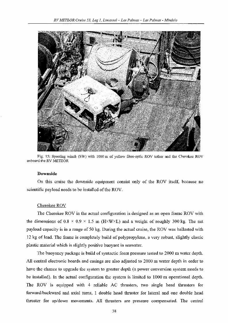
Fig. 15: Spooling winch (SW) with 1000 m of yellow fibre-optic ROV tether and the Cherokee ROVonboard the RV METEOR
Downside
On this cruise the downside equipment consist only of the ROV itself, because no
scientific payload needs to be installed ofthe ROV.
Cherokee ROV
The Cherokee ROV in the actual configuration is designed as an open frame ROV with
the dimensions of 0.8 x 0.9 x 1.5 m (HxWxL) and a weight of roughly 300 kg. The net
payload capacity is in a range of 50 kg. During the actual cruise, the ROV was ballasted with
12 kg of lead. The frame is completely build of polypropylene, a very robust, slightly elastic
p1astic material which is slightly positive buoyant in seawater.
The buoyancy package is build of syntactic foam pressure tested to 2000 m water depth.
All central electronic boards and casings are also adjusted to 2000 m water depth in order to
have the chance to upgrade the system to greater depth (a power conversion system needs to
be installed). In the actual configuration the system is limited to 1000 m operational depth.
The ROV is equipped with 4 reliable AC thrusters, two single head thrusters for
forwardlbackward and axial turns, 1 double head thruster for lateral and one double head
thruster for up/down movements. All thrusters are pressure compensated. The central
38
RVMETEOR Cruise 53, Leg 1, Limassol- Las Palmas - Las Palmas - Mindelo
e1ectronics are p1aced in 2 pressure resistant aluminium housings. In the front of the ROV the
pan and tilt unit (fixed speed) for the pilot camera is installed and the 1ights (3 x 250 W) also.
A TRITECH TYHOON co10ur CCD camera with more than 470 TV-1ines resolution (795 x
596 pixels) and 22 times zoom is attached to the pan and tilt as the mayor pilot cam. At the
top of the buoyancy block, two additional pencil cameras can be attached to the proportional
SCHILLING pan and tilt unit. The 0 17 mm wide angle penci1 cameras are bui1d of JAI
co10ur CCD DSP controlled cameras with aresolution of 450 TV 1ines (752 x 582 pixels),
installed in titanium housings. In addition to the video cameras, a TRITECH dual frequency
scanning sonar head (325/675 Hz) is fitted into the buoyancy package, a TRITECH altimeter
is 10cated in the bottom part of the frame and the pressure sensor and TCM2 compass is
10cated in one ofthe electronic pods. At the right side ofthe ROV a 5 function HYDROLEK
manipulator (wrist up/down; arm up/down; arm 1eft, right; jaw rotate 1ift/right; jaw
open/dose) is mounted to the frame. The manipulator is controlled by a 6 port va1ve pack
(one spare function) installed at the back ofthe ROV. To comp1ete the ROV, a small samp1e
box bui1d of stainless stea1 p1ates was fitted on the 1eft side in front ofthe ROV.
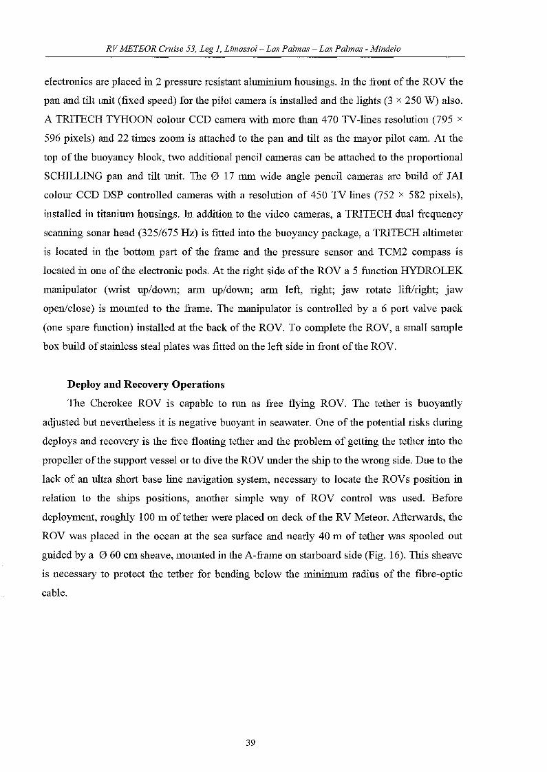
Deploy and Recovery Operations
The Cherokee ROV is capab1e to run as ffee flying ROV. The tether is buoyantly
adjusted but neverfue1ess it is negative buoyant in seawater. One of the potential risks during
dep10ys and recovery is the free floating tether and the problem of getting the tether into the
propeller ofthe support vesse1 or to dive the ROV under the ship to the wrong side. Due to the
lack of an ultra short base line navigation system, necessary to 10cate the ROVs position in
relation to the ships positions, another simple way of ROV contro1 was used. Before
dep10yment, roughly 100 m oftether were p1aced on deck ofthe RV Meteor. Afterwards, the
ROV was p1aced in the ocean at the sea surface and nearly 40 m of tether was spoo1ed out
guided by a 060 cm sheave, mounted in the A-frame on starboard side (Fig. 16). This sheave
is necessary to protect the tether for bending be10w the minimum radius of the fibre-optic
cab1e.
39
RV METEOR erläse 53, Leg 1, Limassol- Las Palmas - Las Palmas - Mindelo
Fig. 16: Cherokee ROV during deployment operation
The 40 m oftether were buoyantly positive balanced due to 4 floatation balls (each with
2.5 kg uplift), c1amped equally spaced to the tether. The ROV was driven away in right angle
direction from the starboard side of the RV METEOR. Afterwards, a ships wire with a
depressor weight was lowered down from the A-frame, 8 m below the ship and than the tether
was c1amped to the ships wire. Now, in parallel, the ROV and the ships wire both were
lowered down farther on and the ROV starts it's descend to the seafloor. The degree of
freedom for the ROV was limited to the length ofthe free floating tether, in this case roughly
40 m around the ships wire. During the ROV operations in the water column, the wire length
was adjusted permanently to actual water depth or 10m less, depending on drag and currents.
For the recovery of the ROV, the pilot has to take care that the ROV ascend in right angle
direction to the starboard side, roughly 40 m away from ofthe RV Meteor. At the sea surface,
first the depressor weight was recovered while the ROV had to keep the right angle position at
starboard side. Afterwards the 40 m of tether, the floatation balls and the ROV itself were
recovered.
ROV dives
During the METEOR cruise the Cherokee ROV was used for several test dives. The
deploy and recovery operation worked very well and it was easy to bring the vehic1e into and
out ofthe water. During these dives a maximum water depth of only 80 m was reached by the
40

RVMETEOR Cruise 53, Leg 1, Limassol- Las Palmas - Las Palmas - Mindelo
ROV. During all dives the very sensible balance between ships speed, currents and wire
length of the depressor weight was c1early visible, due to the lack of a dynatnic positioning
system on RV METEOR. If one of these three factors was in the wrong setting, it was
impossible to go deeper or to stay at a specific position. During the dives the camera signal
was stored on the SVHS (with ROV overlay, GPS and ship bom data) and in parallel on the
DV tape (without any overlay). As standard the pilot camera was recorded.
Only the first test dive south off Gran Canaria was successfu1ly. We were able to locate
the ParCa camera system at the water depth of 60 m, which was used as the depressor weight
for the ships wire. During this dive we checked the manoeuvrability of the ROV and
terminated the test after 1 hour and recovered the vehic1e successfully. During the next tests
dives, several malfunctions occurred on the ROV. The strongest problems were related to the
cable connections in general and specific to the fibre telemetry which obviously is very
sensible to mounting and dismounting in the cable connectors at the SCU. Some times the
serial communication lines malfunctioned without a specific syntax. After complete
dismounting ofthe electronics, it seems to be c1ear that small amounts of smea1' films from the
bulkhead connectors which settled down on the tip of the fibres weaken the optical signal
more 01' less completely. In addition, obviously some fibres were interchanged somewhe1'e in
the complete tether system (SCU, winch, junction box, electronic pod on the ROV). Due to
the lack of an optical fibre checking device, we were unable to locate the conc1'ete problem.
Finally we decided that the system was not in the condition to perform dives. We used the
remaining time to 1'emove additional components from the ROV and run basic test onboard
the RV METEOR.
41

RVMETEOR erläse 53, Leg 1, Limassol- Las Palmas - Las Palmas - Mindelo
5.3 M53/1e
5.3.1 Chemieal Oeeanography
(C. Barrera, A. Cianca, L. Cardona)
The area comprised between the Canary Is1ands and Cape Verde had se1dom been
studied by the ICCM oceanography group in the last years. This cruise was of great interest to
try to e1ucidate the arrival of AAIW from the south towards the Canary Is1ands off the
African coast. Severa1 cruises to the north and south of the is1ands have shown the presence of
AAIW and there are severa1 theories concerning the arrival paths. The intermediate water
masses in the Canary Is1ands environment show great variation of percentage of MW and
AAIW at simi1ar depths, depending on seasona1 and geographica1 parameters.
16 15 ~18 17 + ++ +
~
D
3
2
€oZGl
~ 2
j
CAPE VERT I S.
-25
CANARY ISLANDS
eP\1'
oW <5 ß.. 7
+8+
9+
10+
11+
-20 -15
Longitude West
-10
Fig. 17: Position of the CTD stations (dots) and XBT 1aunches (crosses) made by ICCM along PoseidonM53/1c
The surface waters off the African coast at these 1atitudes are characterised by the
upwelling phenomena (through cWorophyll and temperature satellite imagery) and episodes
42

RVMETEOR erläse 53, Leg 1, Limassol- Las Palmas - Las Palmas - Mindelo
of Saharan dust outbreaks. For this reason the possibility of measuring chlorophyll "in situ"
on a daily basis provided an unva1uab1e too1 to test the primary production models being
deve10ped for the Macarronesic (Azores, Madeira, Canaries and Cape Verde) area.
Due to the lack of time there was not possibility of doing rosette and CTD samp1ing at
all the stations needed, therefore XBT's were dep10yed whi1e the ship kept cruising, which
made possib1e to have a better sampling scheme (Fig. 17). The distribution of nutrients,
oxygen, chlorophyll and gelbstoff together with the temperature and sa1inity profiles allow a
reasonab1e approximation to some ofthe surface phenomena occurring in the area.
Data
Every 4 hours of each cruise day surface chlorop1yll samp1es were taken from pumping
water. Nine CTD stations were also made a10ng the cruise track, all casts were taken to the
bottom. Tab. 6 shows positions and parameters taken.
Tab 6: List of CTD stations and parameters measured by ICCM along M53/lc. The salinity colunmappears in brackets the number of salinity sampies taken at the station
194 21°15.66'N 200 46.93'W ...; ...; ...; ...;
197 200 56.54'N 19°22.98'W ...; ...; ...; ...;198 200 44.96'N 18°34.97'W ...; ...; ...; -V200 200 39.65'N 18°15.60'W ...; ...; ...; ...;
202 200 32.82'N 17°33.56'W ...; ...; ...; ...;206 19°05.92N 17°02.89'W ...; ...; ...; ...;
210 19°00.01'N 17°17.02'W ...; ...; ...; ...;214 18°35.45'N 18°02.35'W ...; ...; ...; ...;
217 18°05.44'N 18°55.02'W ...; ...; -V ...;
The c10sing depths chosen for all stations as a general trend were: 10, 25, 50, 75, 100,
125,150,200,300,400,600,800,1000,1100,1200, 1300, 1500, 2000,2500, 2800 and3000
m and bottom. Oxygen, nutrients, gelbstoff and chlorophyll "a" was taken at every depth
samp1ed, and sa1inity samp1es were taken at 2 or 3 se1ected depths (except ESTOC) to check
for c10sing ofthe Niskin bottles (Tab. 6).
43

RVMETEOR Cruise 53, Leg 1, Limassol- Las Palmas - Las Palmas - Mindelo
Tab. 7: List of XBT stations made by ICCM along M53/lc.
i;ml'l#~ee ,,'iiiT ;'·'f;;ii Ti
D7 20.04.2002 26°59.97'N 16°06.86'WD8 20.04.2002 25°59.98'N 16°50.72'WD9 21.04.2002 25°00.01 'N 17°41.37'WDI0 21.04.2002 24°00.00'N 18°31.70'WDll 21.04.2002 23°00.00'N 19°21.98'WD12 21.04.2002 21°58.77'N 200 12.06'WD13 22.04.2002 21°58.77'N 200 12.06'WD14 01.05.2002 17°54.32'N 19°53.84'WD15 02.05.2002 17°44.38'N 200 45.74'WD16 02.05.2002 17°34.65'N 21°36.79'WD17 02.05.2002 17°34.41'N 21°38.07'WD18 02.05.2002 17°15.05'N 23°19.57'W
From Las Palmas harbour to Cape Verde (in transit) two transects ofXBT (T7) of 7 and
5 probes respectively were also perfonned at the beginning and end ofthe cruise (see Tab. 7).
44

RVMETEOR erläse 53, Leg 1, Limassol- Las Palmas - Las Palmas - Mindelo
Preliminary Results
The ftrst XBT seetion c1early shows the north- south latitudinal gradient in the surfaee
waters, ranging from values of 19°C in the Canary Islands waters to values of 21°C at Cape
Blane latitude (Fig. 18a).
.1·"'.>-+23-'-----'21.",-----.'2l.3-----.2<l.',-----.-+."""""""'(oloß-)
Fig 18 (a ,b): Plots oftemperature from XBT's in both transects ofthe cruise
At the depth range eorresponding to the eentral intermediate waters it c1early appears the
eontaet front between the North Atlantie Central Water (NACW) and the South Atlantic
Central Water (SACW) as a step towards eolder waters in the transit from north to south.
45

RV METEOR erläse 53, Leg 1, Limassol- Las Palmas - Las Palmas - Mindelo
2
4
6
8
1 I I I I I I 1J I I I , I I J__________1 . .I. _, ,- . ..1 .__ ...._l.__ ,.. _ ~ __ ..J- -'__. ... .J. ,.. ._ ...1
I I I I I I I II I I I I , I 1I I I I I 1 I II I I I I 1 I 1
-"",,- -----~------ --t--,.. ---~- -~----- -- -~--,.. -,.. --- -- ~- -- -,.. ...~ -1- ... --,.. -,.. --J- -,..._----1I I I J I I I I
: ; : : M %,: " : : ;---- .. ,.. -~-- ------ ~ --,.. ---~-~- _... -- ---~-- -- -~-'-L- --J---~ ... _--- ---~---,.... ----1
1 11 1 ll..1 1 -I 1I I 1 I +~. J 'I 1
) 1 I~ .~ J" .;~~ I . I -, I
--------J---------l---------L------J--; . ~.: --------l----------.l---------l] ! l i :1~ -1 : 1 11 I 1 ~'J I I I 11 I I I 1 I I-- -4 4- __ ,..- 100 .. - J-_ -~ .. -- -- ..... ... 1
I I I I I I II r I I J I J
~ 1 : { ~ )___ ..__ .;_J_.""' l __ .......__ 1 I I I I:: "-r- ---.-(Cäbö-ä-ahco-siäiiÖI1-i --"---:l! I $ I Cabo Tirhirisstatio'hs I---~ - _._~;..- ---- - -T--- - -- ----.---~-- - - ---- L' --- - __ J- ~ ...._ ..L__ ___ ----~
: l :::::I I I I I I I I
--- -----~-- -..,..-----t .-- ... -~----- ---~-- -- --- --~- -- ------!- ---------1---------JI 1 I I 1 I I I
: : : : : : : :t ' : : : : : :
-..,..".. -- - -."'" ,--.-- --..,.. - -- -,- --r"'" -.- -- -- -, - -- - - -- --r- ---- - - -,- -'"' - - ---..,.,......,. - -- -,.. --,I j I I I I It 1 I I I I I
] 1: l I I l--- -- '"' _._.~----- -..,_....~ - ;..--_.__ ....~,- --- - -- --~- -''';' - -- -- -4- _.- _._._.:. ... -~ - - _._- ---I
I :: l : : :I ::::::I I I I I I I
- -- -- -_.- -1-- - - -_... - -- ... -- -- -I- - -- -- -- -"1- - - - - -- -- t-- .. -- - _ .... -- -t- _._ ... - --- -'1' -_.- - '"' - -·--1I I I l 1 I II I I , I I II I I I , I II I I I I t I Il \ I I I I I I- -- -- - -- ~ ... - _.- -- - -t --- -- ---.-~- _... -_._- -~ - --- _._- --~- - -- ---7-'- _.- - -- -~ ~.- -- -- --:I I I I I 1 I I
I 1 I I I I I Io --+..,.---r....,......,rl-'...--r...--r+'..,.---r-,-,rl-',-,-...,-,+'--,--,-.-r--+--'...--r..,.---r-f'-,-r-r-r--+--'-.--r--r-r-'i'
18
24
16
22
20
(...)'L" 14f!:''"~ 120-E~ 10
34 34.5 35 35.5 36 36.5Salinity
37 37.5 38
Fig. 19: Diagram T/S showing all the CTD stations sampled along the cuise
The T/S diagrams ofthe stations sampled with the CTD in the Cape Blane area rati:fY the
prevalenee of the SACW but with eertain influenee of waters from the north in the seetion
eomprising statins #194 to #202 (Fig. 19). This northem influenee gets refleeted in the sign of
MW eneountered at deeper depths.
The southernmost XBT seetion depiets very weIl the generie eoastal eooling produeed
by the upwelling of the area, and the possibility of the presenee of subsurfaee waters eoming
from the south below the thermoc1ine eentered at XBT station # 15 (Fig. 18b).
The south seetion made with CTD are c1early defined by waters eharaeteristie from the
south, both at intermediate and deep depths. It is worth notieing the diminishement of the
salinity in the surfaee and subsurfaee waters, eonoborating its origin.
The oxygen eoneentrations are eoherent with the appearanee of the oxygen minimum
eore deseribed in the literature (Metealf, 1969; Sarmiento, 1985; Fukumori et al. , 1991;
Kawase and; Speer, 1993) loeated in this area. This is a eonsequenee ofthe high eonsumption
produeed to oxidize the great amounts of organie matter generated at this upwelling eore (Fig.
20). In eoneordanee with this first approximation we found out that the oxygen eoneentration
deereases with the proximity to the eoastal eore, coincident with the deerease in depth.
46

RVMETEOR Cruise 53, Leg 1, Limassol- Las Palmas - Las Palmas - Mindelo
45215
lWO
750
?J5 4<)xYQ8n C. (mI/I)
Fig. 20: Vertical profiles (to 1000m) ofthe oxygen at the CTD stations sampled dming the cmise
The minimum oxygen value that corresponds to the AAIW does not appear weIl
signalIed in the vertical distributions of oxygen (Fig. 21), maybe as a consequence of the
subsurface minimum values being masked. The vertical profile of station #194 shows this
47
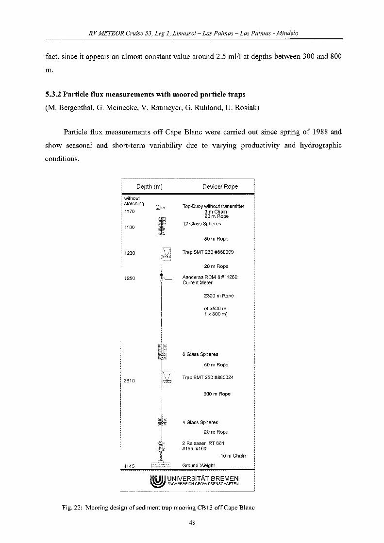
RVMETEOR Cruise 53, Leg 1, Limassol- Las Palmas - Las Palmas - Mindelo
fact, sinee it appears an almost constant va1ue around 2.5 ml/1 at depths between 300 and 800
m.
5.3.2 Particle flux measurements with moored particle traps
(M. Bergentha1, G. Meineeke, V. Ratmeyer, G. Ruhland, U. Rosiak)
Partic1e flux measurements off Cape B1ane were carried out since spring of 1988 and
show seasona1 and shOli-term variability due to varying productivity and hydrographie
conditions.
Depth (m) Devicel Rope
: withouti streching
• 1170
, 1180
~ 1230
• 1250
o 0
o 0
L~(
!i~
I!,~i
Top-Buoy without transmitter3 m Chain20 m Rope
12 Glass Spheres
50 m Rope
Trap SMT 230 #860009
20 m Rope
Aanderaa RCM 8 #11262Current Meter
2300 m Rope
(4 x500 m1 x300 m)
I,[",1[9;11 8 Glass Spheres
I 50 m Rope
! 3610 ~ Trap SMT 230 #860024
500 m Rope
: 4145
rob,~
14 Glass Spheres
20 m Rope
2 Releaser RT 661#155,#160
10 m Chain
Ground W3ight
itUlJ UNIVERSITÄT BREMEN~ FACHBEREICH GEOWSSENSCHAFTEN
Fig. 22: Mooring design of sediment trap mooring CB 13 off Cape Blaue
48

RVMETEOR Cruise 53, Leg 1, Limassol- Las Palmas - Las Palmas - Mindelo
During METEOR cruise M53/1c the mooring CB was exchanged. The CB12 sediment
trap mooring was recovered on April. 22,2002. It carried two traps and 2 current meters. All
instruments functioned properly with the exception of the upper trap that did not tumed. The
mooring was re-deployed on April. 22, with the same devices as the recovered one (CB 13,
see Fig. 22). CB 13 will be exchanged in May 2003 on RV METEOR cruise M 58/2.
5.3.3 Deep-Sea Particle Camera System ParCa
Introduction
Most studies and ca1culations on export rates ofpatiiculate matter in the ocean are based
upon data obtained with sediment traps. Measurements of the in-situ distribution and
characteristics of marine snow, like size 01' shape, are not possible with this technique.
Therefore, estimations about the efficiency and processes influencing the vertical and
frequently discussed lateral transport, are difficult.
Non destructive, optical methods like the deep-sea camera system ParCa (Ratmeyer and
Wefer, 1996) are best suited for the quantification of the in-situ distribution and transport
processes of particulate matter in the ocean. The system was designed and improved in
consideration ofsimilar systems used by Honjo et al. (1984) 01' Asper (1987).
Scientific goalsTo continue studies of previous crulses 1ll different reglOns of the NW African
upwelling system, the aim of the deployment of the ParCa system was to obtain high
resolution datasets of the vertical distribution of particulate matter on short temporal and
spatial scales. This is necessary, because results from previous cruises and satellite data show,
that the upwel1ing region off Cape Blanc is highly dynamic and that the partic1e distribution
changes within hours and differs distinctly even within short distances (i.e. <10 km).
Another focus is laid on studies oftransport processes and transport directions ofmatme
partic1es. Apart from the predominantly vertical sinking direction of particulate matter, the
lateral shift of material from the upper slope towards the open ocean, plays an important role
with respect to mass transportation of particulate matter. ParCa profiles could detect these
lateral advected c10uds directly in the water column, so statements about their origin, intensity
and influence on partic1e transport might be possible.
49

RV METEOR Cruise 53, Leg 1, Limassol- Las Palmas - Las Palmas - Mindelo
Therefore, the foeus of ParCa profiling stations was put on a station matrix south of
Cape Blane, off Timerist. 9 vertical profiles, in 3 profile sequenees were taken within 3 days
(Fig. 23). A detailed ParCa station list is given in Tab. 8.
Non-destruetive, optieal teelmiques provide valuable information about the in-situ shape
of partic1e aggregates. ParCa images will be used, to investigate on partic1e aggregation and
disaggregation proeesses. Espeeially the role of large aggregates and their eontribution to the
vertieal flux, is subjeet of intense studies. The images might be able to tell, in whieh speeifie
depths partic1e aggregation takes plaee and if aggregates are ehanging in shape and size while
sinking through the water eolumn.
19"
17" 500 m1000m
mil! 20m",mil! 3000",!@l 4(0)",
Fig. 23: ParCa station matrix off Timerist
Tab.8: ParCa station list
16"
Station Date Lon. Lat. Profilinadepth (m) Waterdepth (m)
7929 29.04.02 19°04.1N 17°04.0W 1425 1425
7930 29.04.02 19°14.1 N 17°04.0W 1150 1464
7931 29.04.02 19°14.1N 16°54.1W 424 442
7932 29.04.02 19°00.0N 17°17.0W 1925 1953
7933 30.04.02 19°10.5N 17°17.2W 1925 1950
7934 30.04.02 19°10.3N 17°27.25W 1920 1950
7935 30.04.02 19°04.0N 17°27.5W 1943 2117
7937 01.05.02 18°40.1N 18°02.5W 2600 2667
7938 01.05.02 18°50.1N 18°50.5W 2550 2606
50
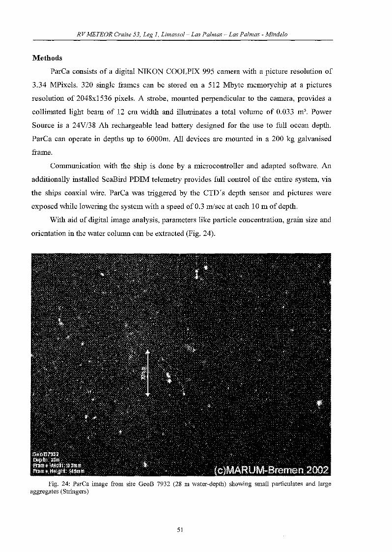
RVMETEOR Cruise 53, Leg 1, Limassol- Las Palmas - Las Palmas - Mindelo
Methods
ParCa consists of a digital NIKON COOLPIX 995 camera with a picture resolution of
3.34 MPixe1s. 320 single frames can be stored on a 512 Mbyte memorychip at a pictures
resolution of 2048x1536 pixels. Astrobe, mounted perpendicu1ar to the camera, provides a
collimated light beam of 12 cm width and illuminates a total volume of 0.033 m3• Power
Source is a 24V/38 Ah rechargeab1e lead battery designed for the use to full ocean depth.
ParCa can operate in depths up to 6000m. All devices are mounted in a 200 kg ga1vanised
frame.
Communication with the ship is done by a microcontroller and adapted software. An
additionally installed SeaBird PDIM: te1emetry provides full contro1 of the entire system, via
the ships coaxia1 wire. ParCa was triggered by the CTD's depth sensor and pictures were
exposed while 10wering the system with a speed ofO.3 m/sec at each 10 m of depth.
With aid of digital image analysis, parameters 1ike partic1e concentration, grain size and
orientation in the water co1umn can be extracted (Fig. 24).
Fig. 24: ParCa image from site GeoB 7932 (28 m water-depth) showing small particulates and largeaggregates (Stringers)
51
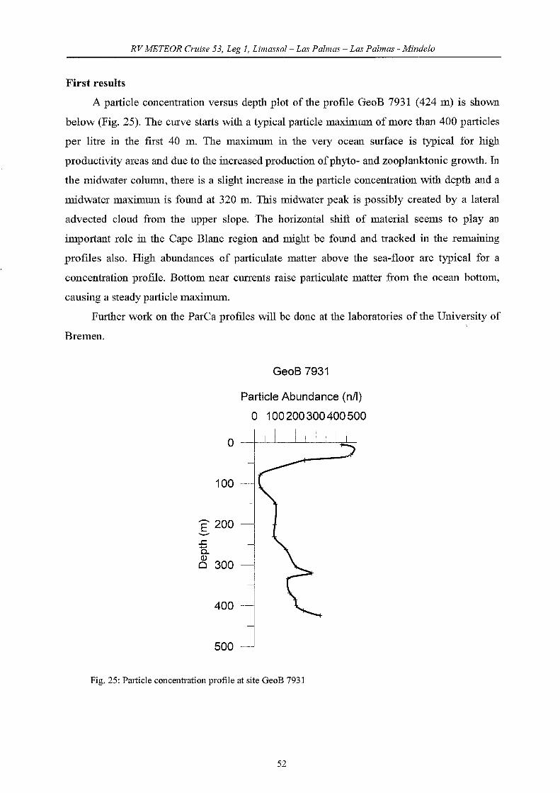
RVMETEOR Cruise 53, Leg 1, Limassol- Las Palmas - Las Palmas - Mindelo
First results
A partic1e eoneentration versus depth plot of the profile GeoB 7931 (424 m) is shown
below (Fig. 25). The eurve starts with a typieal partic1e maximum of more than 400 partic1es
per litre in the first 40 m. The maximum in the very ocean surfaee is typieal for high
produetivity areas and due to the inereased produetion ofphyto- and zooplanktonie growth. In
the midwater eolumn, there is a slight increase in the partic1e concentration with depth and a
midwater maximum is found at 320 m. This midwater peak is possibly ereated by a lateral
advected c10ud from the upper slope. The horizontal shift of material seems to play an
important role in the Cape Blane region and might be found and traeked in the remaining
profIles also. High abundanees of partieulate matter above the sea-floor are typical for a
concentration profile. Bottom near eurrents raise partieulate matter from the oeean bottom,
causing a steady partic1e maximum.
Further work on the ParCa profiles will be done at the laboratories of the University of
Bremen.
GeoB 7931
o
100
E 200'-'"
~
ö..~ 300
400
500
Particle Abundance (nil)
o 100200300400500
I I I I !
Fig. 25: Particle concentration profile at site GeoB 7931
52
RVMETEOR Cruise 53, Leg 1, Limassol- Las Palmas - Las Palmas - Mindelo
5.3.4 Underway geophysics(Shipboard PARASOUND Watchers)
During METEOR Leg M 5311c the shipboard acoustical systems HYDROSWEEP and
PARASOUND were used for site investigation off Cape Blanc in order to record continuous
high resolution bathymetric and sediment echosounding profiles. The data provided valuable
information for choosing suitable coring stations in the investigation areas.
PARASOUND
PARASOUND surveys the uppelmost sedimentary layers of the seafloor. Due to the high
signal frequency of 4 kHz, the short signallength of two sinoid pulses, and the narrow beam
angle of 4.5°, a very high vertical resolution is achieved. Sedimentary layers along the ship
track on ascale of less than one meter can be resolved. The PARASOUND data provided
information about the physical state of the sea bottom as well as about sediment structures up
to a depth of 50 m below sea floor. The penetration ofthe PARASOUND signal depends on the
density of the uppermost sediment layers and the impedance contrasts between these layers
and at the sea floor. Thus, the penetration was used as a first hint for the quality of a potential
coring location. The digitisation and storage of the echosounding seismograms were
conducted with the software package ParaDigMa (Spieß 1993). The pre-processed data are
plotted online with a HP colour printer. These plots provided a first impression of variations
in sea floor morphology, sediment coverage and sediment patterns along the ship's track. In
addition, navigational data are printed and stored on disk simultaneously. Besides using
PARASOUND as a tool for localisation of promising core sites, it is possible to image and
describe the dominating sedimentation processes and to interpret the structural context of the
longer sediment cores.
HYDROSWEEP
The general purpose of HYDROSWEEP is to survey topographie features of the seafloor.
A fan of 59 pre-formed beams covers a sector of 90°. Thus, a stripe with the width oftwice
the water depth is mapped perpendicular to the ship track. Data are stored on magnetic tapes
in a sensor independent format. Since a workstation is direct1y installed beside the ParaDigMa
PC, the PARASOUND operator is able to check the topographie map and profiles on the
HYDROSWEEP screen simultaneously. Thus, in conjunction with PARASOUND, HYDROSWEEP
has shown to be a very efficient aid for the selection of suitable coring stations. The precise
knowledge of the local bathymetry is essential to select suitable sites and coring device, and
53
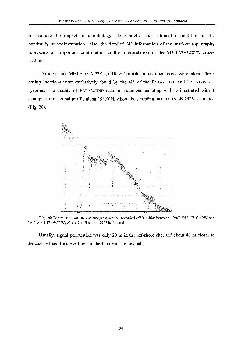
RV METEOR Cruise 53, Leg 1, Limassol- Las Palmas - Las Palmas - Mindelo
to evaluate the impact of morphology, slope angles and sediment instabilities on the
continuity of sedimentation. Also, the detailed 3D information of the seafloor topography
represents an important contribution to the interpretation of the 2D PARASOUND cross
sections.
During cmise METEOR M53/lc, different profiles of sediment cores were taken. These
coring locations were exc1usively found by the aid of the PARASOUND and HYDROSWEEP
systems. The quality of PARASOUND data for sediment sampling will be illustrated with 1
example fi'om a zonal profile along 19°00'N, where the sampling location GeoB 7928 is situated
(Fig.26).
Fig. 26: Digital PARASOUND seismogram section recorded off Timirist between 19°07.29N 17°03.69W and19°04.09N 17°09.71W, where GeoB station 7928 is situated
Usually, signal penetration was only 20 m in the off-shore site, and about 40 m doser to
the coast where the upwelling and the filaments are located.
54

RVMETEOR Cruise 53, Leg 1, Limassol- Las Palmas - Las Palllws - Mindelo
5.3.5 Sediment Sampling
(A. Eberwein, O. Romero, B. Abou Cire, M. Bergenthai, T. Freudenthai, J. Garming, A.
Makaoui, H. Meggers, U. Rosiak, M. Scholz, A. Wülbers)
Sediments were recovered at 12 stations on two profiles west of Cape Blanc and a
proftle west of Timirist. Surface sediments were generally recovered with a multicorer. A
gravity corer with different pipe lengths and a weight of 1.5 tons on top was used at 11
stations to be able to recover deeper sediment sequences (Fig. 2).
5.3.5.1 Sediment surface sampling with multicorer
Multicorer
The tool for the recovery of undisturbed sediment surfaces and the overlying bottom
water was the multicorer equipped with 8 tubes of 10 cm and 4 smaller tubes of 5 cm in
diameter. The multicorer was used at 10 stations (Tab. 9). The core recovery was exc1usively
good, typically 10 to 12 tubes were filled, and cores ofvery good quality reaching 32 cm of
sediment were recovered from station GeoB 7919 to station GeoB 7936.
At each multicorer station, the overlying bottom water of one of the large tubes was
sampled for stable isotope measurements at Bremen. Mostly 4 of the large tubes and 1 of the
smaller tubes were usually sampled in 1 cm slices for analysis of Corg, benthic and planktic
foraminifera, diatoms and geophysics. The Corg sampies were frozen immediately aftero
collection at -27 C. Benthic foraminifera sampies were stained with a solution of Ig of rose
bengal in 1 1 ethanol. A second set of non-stained sampies was also collected for planktic
foraminiferal and diatom analysis. All this sampies were kept at 40
C. Mostly one large and/or
one small core were frozen as archive material. In addition, surface sediment sampies for two
purposes. Firstly, surface sampies were taken for DNA-analyses ofbenthic foraminifera. The
0- 1 cm level of one tube was sampled and wet-sieved over a 63 micron sieve immediately
after recovery. The remaining fraction was frozen. 1 to 2 surface sampies (0-1 cm) were taken
for dinoflagellate analyses. Sampies were stored in bottles and kept at -27°C.
55

RVMETEOR Cruise 53, Leg 1, Limassol- Las Palmas - Las Palmas - Mindelo
Tab. 9: Multicorer sampling, METEOR cmise 53/1c
A. Large tubes
GeoB Depth Recovery Corg Archive Geo- Mar. Benthic DNA Dinofl.No. (m) (cm) chem. Chem. Forams
7919-2 3429 30 1 2 2 2 smf7920-3 2278 30 1 1 2 surf 3smf7922-3 1289 23 1 1 2 smf 2smf7923-1 1516 26 1 1 2 surf 2 surf7924-3 73 24 1 2 2 smf 2smf7926-3 2501 25 1 2 2 smf 2 surf7927-1 3128 29 1 2 2 smf 2smf7928-3 1348 23 1 2+surf 1 2 smf7932-2 1964 32 1 3+surf 2 smf7936-2 2680 32 1 1 2 1 surf.
Tab. 9 continued: Multicorer sampling, METEOR cmise 53/1c
B. Small tubes
GeoB Depth RecovelY Archive PF Geo Diatoms Dinofl.No. (m) (cm) physics.
7919-2 3429 30 1 1 1 17920-3 2278 30 1 1 17922-3 1289 23 1 1 1 17923-1 1516 26 1 1 1 17924-3 73 24 1 1 1 17926-3 2501 25 1 1 1 17927-1 3128 29 1 1 1 17928-3 1348 23 1 1 1 17932-2 1964 32 1 1 1 17936-2 2680 32 1 1 1 1
5.3.5.2 Sediment sampling with gravity corer
14 gravity cores, in a total of 145 m of sediments were recovered from 11 stations with
recoveries which vary between 2.27 m and 16.89 m.
11 cores were opened, described and sampled on board (Tab. 10, Figs. 27-36). After
splitting, the archive section was described following the ODP nomenc1ature and sediment
colour was determined by comparison with the MUNSEL soil coloUl' charts. A colour scanner
was used to record the coloUl' of the fresh sediments at the 5 cm sampling interval (see
spectrophotometry section). All core sections were photographed together with a coloUl'
reference card.
56
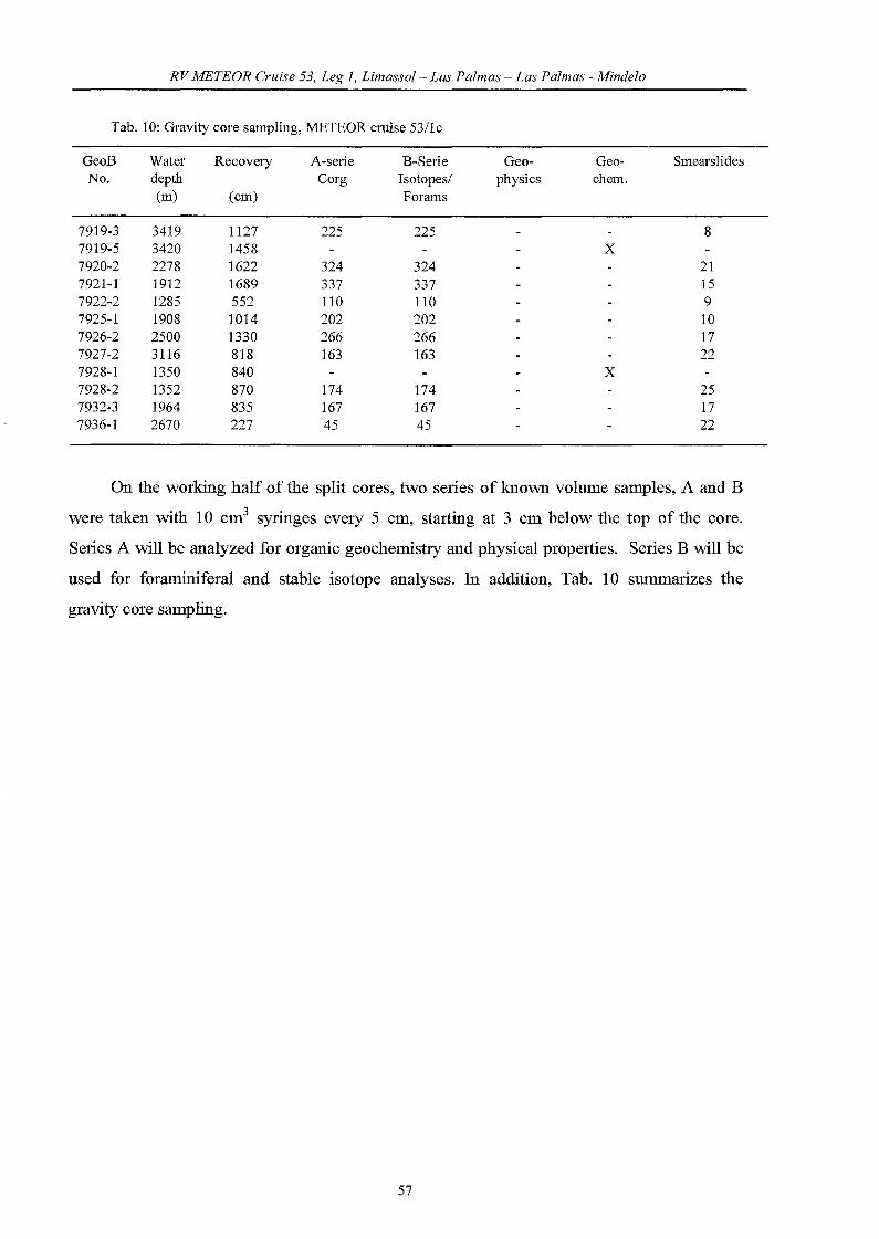
RV METEOR erläse 53, Leg 1, Limassol- Las Palmas - Las Palmas - Mindelo
Tab. 10: G:ravity eore sampling, METEOR cruise 53/le
GeoB Water Recovery A-serie B-Serie Geo- Geo- SmearslidesNo. depth Corg Isotopes/ physics ehem.
(m) (em) Forams
7919-3 3419 1127 225 225 87919-5 3420 1458 X7920-2 2278 1622 324 324 217921-1 1912 1689 337 337 157922-2 1285 552 110 110 97925-1 1908 1014 202 202 107926-2 2500 1330 266 266 177927-2 3116 818 163 163 227928-1 1350 840 X7928-2 1352 870 174 174 257932-3 1964 835 167 167 177936-1 2670 227 45 45 22
On the working half of the split cores, two senes of known volume sampies, A and B
were taken with 10 cm3 syringes evelY 5 cm, starting at 3 cm below the top of the core.
Senes A will be analyzed for organie geochemistry and physical properties. Series B will be
used for foraminiferal and stable isotope analyses. In addition, Tab. 10 summarizes the
gravity core sampling.
57
RVMETEOR erläse 53, Leg 1, Limassol- Las Palmas - Las Palmas - Mindelo
5.3.5.3 First shipboard results
Core description and smear slide analysis
The core description, carried out on the archive half of all gravity core segments, serves
to summarize the most important sediment features. The major objective of macroscopic core
description is the identification of sediment structures, such as unconformities, discontinuities,
turbidites and bioturbation. Core descriptions followed the ODP nomenc1ature (Fig. 27 for
legend). The visible colour classification, determined by comparison with the MUNSEL soil
colour chart are supplemented with more detail by Minolta CM 2002TM hand-held
spectrophotometer measurements, every 2 cm on the work half. Reflectance profiles are also
presented right-hand to the core-description diagrams (Figs. 28-36).
The lithologie observation is supported by smear slide analysis. In each core segment at
least one sample was taken depending on the heterogeneity of the sediment and the
occurrence of conspicuous lithologies. In some cases, the position of smear slides was
determined by changes in colour. For smear slides sediment was taken using a toothpick. The
sample was placed on a clean glass microscope slide and smeared with water. Smear slides
were prepared using NORLAND OPTICAL ADHESIVE as a mounting medium and dried
with UV light for at least one hour. The samples were investigated using an OLYMPUS light
microscope at 400 and 1000 X. The sediment composition was described also according to the
ODP nomenc1ature. A total of 175 smear slides were analyzed.
During the cruise M53/1c, 14 sediment cores were retrieved from water depths ranging
from 1285 to 3421 m (Tab. 10). Core stations are located along 1 transect from almost west to
east, and two transects from northeast to southwest. Core recovery was generally very good,
resulting in core lengths between 2.27 m and 16.89 m. 9 cores were opened and described on
board, while 5 remain to be opened.
Transect 1
In the northernmost part of the working area, seven gravity cores were retrieved along a
transect between ca. 19°-18°W, 200 45'N off Cape Blanc. Water depths range from 1285 to
3419 m. Recovery was very good, resulting in two cores longer than 16 m length. Three cores
were not opened on board. The two shallower cores (GeoB 7923-2 and GeoB 7921-1) are
more homogeneous in colour and lithology than the two deeper cores. GeoB 7923-2 mostly
consists of olive-coloured sediment, while colour in GeoB 7912-1 varies from olive to olive
grey, and is mainly composed by foraminifera and coccolithophores. Both cores contain
58
RVMETEOR erläse 53, Leg 1, Limassol- Las Palmas - Las Palmas - Mindelo
megafossils in the range of 1 to 5 cm diameter and a few intercalated coarser grained sections.
The two deeper, more pe1agic cores are characterized by olive to olive grey and light olive
grey sediments. While GeoB 7919-3 is predominantly composed by coccolithophores, the
microfossil composition of GeoB 7920-2 shows a larger variety.
Transect 2
Gravity cores GeoB 7925-1, GeoB 7926-2 and GeoB 7927-2 were gained at a NE-SW
transect at ca. 20° N, between ca. 18° and 19°W. At a11 cores colour predominantly varies
from olive to olive grey and light olive grey ooze with different lithologie structure, marked
by c1ayey and quartz bearing parts. Turbidites occur in each core, which intelTupt the
continuous sediment sequence, with features such as fining up- and downwards and erosional
contact at their base. The last two cores are characterized by one to three laminated sections
within the centimeter-scale. GeoB 7925-1 sediment is mainly carbonaceous, with foraminifera
as main component, accompanied by coccolithophores. GeoB 7926-1 shows a strong
alternation of a11 biogenie components, with diatoms mostly as main contributors.
Coccolithoporids and foraminifera alternate in GeoB 7927-2.
Transect 3
The second NE-SW transect south off Cape Blanc comprises three gravity cores: GeoB
7928-2, GeoB 7932-3 and GeoB 7936-1. The coring sites are located at approximately 20° N,
between 18° W and 19° W. The last core was considered unworthy to be opened on board,
because the corer's pipe was bended. Except a thin turbidite in core GeoB 7932-3, both cores
show a continuous sedimentation. The topmost centimeter of GeoB 7928-2 shows a ye110wish
brown colour, while sediment, predominantly olive, mostly consist of coccolithophorids and
foraminifera with some diatom oozes intercalated. GeoB 7932-3 is characterized by olive and
olive grey ooze with strongly varying lithology. The dominant microfossil content is ricWy
composed of coccolithophorids, foraminifera and diatoms. Clayey and quartz bearing sections
intercalate.
59
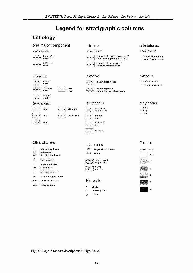
RVMETEOR Cruise 53, Leg 1, Lirnassol- Las Palrnas - Las Palrnas - Mindelo
Legend for stratigraphie eolumns
Lithology
one major component
calcareous
mixtures
calcareous
admixtures
calcareous
~.~
EZj~ '"~ ~
~ ~ ,
foraminiferooze
nannofossilooze
~ nannofossil bearing foram oozelr~-~-I foram bearing nannofossil ooze
r-::;:-:t=< nannofossil foram ooze Ir++++1 foram nannofossil ooze
~ foraminifer-bearing~ nannofossil-bearing
siliceousdiatomooze
diatommud
silie,mud
siliceous
muddy diatom ooze
muddy silieeousforaminifer nannofossil ooze
siliceousdiatom-bearing
~ sponge-spieules b.
terrigenous
L0 (> 0 J silicieeous~ muddysand
terrigenous~~ elay
l-=--...-=---:-1 mudi-=---=- j
sand
~l~-~-I siltymud
~~ 0 ~~I sandy mud fO"l~
~~=~=I
muddysand
diatom-b,elay
terrigenouso sand
elay-..;;.. mud
Structures0 mud elast
Colors weakly bioturbated @ diagenetie coneretion Munsell valueSS bioturbated
~ slumpI ISSS strongly bioturbated 7-8
~ fining upwards Ei '::-001muddy sand
6beddedllaminated ~
w pebbles
J.U. discontinuity i."GJ :1 slump5iO:.(j deposit
Py pyrite precipitation
Mn Manganese precipitation4
Zem Cemented horizon Fossils 3
vole. volcanie glass0 shells •;0 shell fragments
1-2
V eorals
Fig. 27: Legend for core descriptions in Figs. 28-36
60
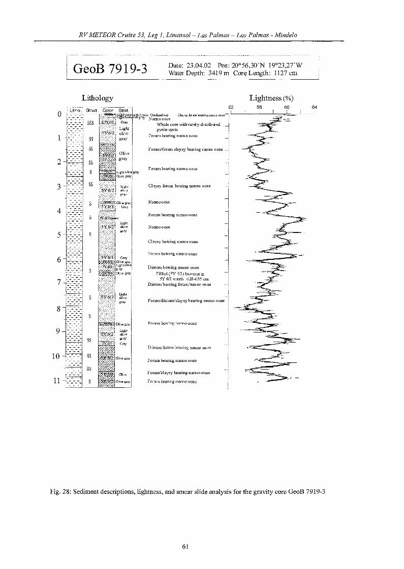
RVMETEOR Cruise 53, Leg 1, Limassol- Las Palmas - Las Palmas - Mindelo
GeoB 7919-3 Date: 23.04.02 Pos: 200 56,30'N 19°23,2TWWater Depth: 3419 m Core Length: 1127 cm
Fig. 28: Sediment descriptions, lightness, and smear slide analysis for the gravity core GeoB 7919-3
61
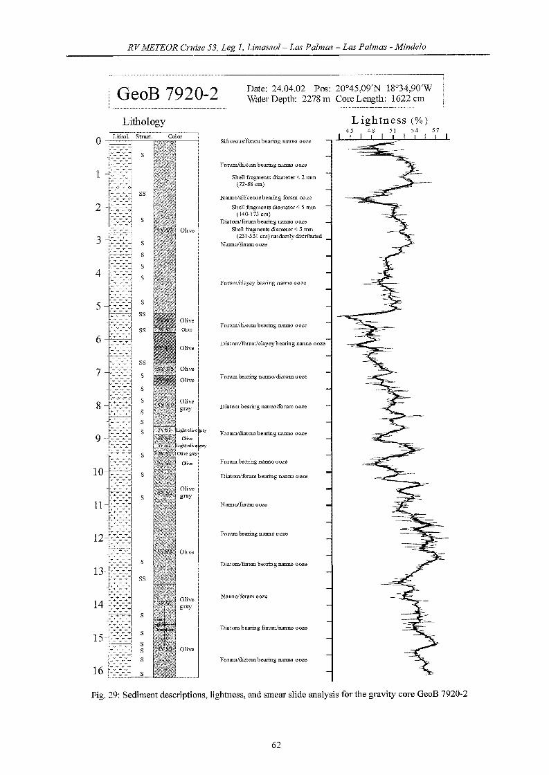
RVMETEOR Cruise 53, Leg 1, Limassol- Las Palmas - Las Palmas - Mindelo
GeoB 7920-2 Date: 24.04.02 Pos: 200 45,09'N 18°34,90WWater Depth: 2278 m Core Length: 1622 cm
Lithology
ILight olil,'e Igray
Oliw I·ghtOliv.~y
OI.hegrayl
ru,e I
Siliceous/foram bearing nanno Gaze
ForamIdiatom bearing nanno oaze
Shell fragments diameter< 2 111111
(72-88 cm)
Nanno/siliceousbearing foram ooze
Shell fragments diameter< 5 mm(140-173 cm)
Diatom/foram bearing uanno Gaze
Shell fragments diameter< 3 mn(231-331 cm) nndomly distnbuted
Nannolforamooze
Foramlc1ayey hearing nmmo aaze
Foram/diatom hearing nanno Gaze
Diatomlforam/clayeybearing nanno ooze
Foram hearing nanno/diatom GQze
Diat01ll bearing nanno/foram DQZe
Foram/diatOll1 hearing nanno Gaze
Foram hearing nanno GQze
Diatomlforam hearing nanno ooze
Nanuofforam ooze
Foram hearing nanno Gaze
Diatomlforam bearing nanno ooze
Nanno/foram ooze
Diatom bearing foramInanno ooze
ForamidiatOll1 hearing nanno Gaze
Lightness (%)45 48 51 54
I I I I57I
Fig. 29: Sediment descriptions, lightness, and smear slide analysis for the gravity core GeoB 7920-2
62

RV METEOR erläse 53, Leg 1, Limassol- Las Palmas - Las Palmas - Mindelo
GeoB 7921-1 Date: 25.04.02 Pos: 20048,33'N 18° 15,55'WWater Depth: 1912 m Core Length: 1689 cm
Lithology Lightness (%)
Musse]112 Clll. 1. 1 cm diameter
SandIenses223-225 Clll. 544-548 cm, 664-677 Clll
Nmmo.ldiatom hearing foram ooze
Diatomiclayeybeariug foram/uanno ooze
NalIDo/diatoID hearing foraulooze
Diatom hearing foraminanno Gaze
Nauno/quartzldiatom bearingforam ooze
Quartz bearing foramluanno ooze
Quartzldiatom(626-697 cm) bearingforarnlnanno QQze
Diatom beariug foramluanno ooze
s
s
ossss
~:-'-:~:~~,... -v .......... :1 ~~~~~~~!
f- -+ -+- -+ I
~>:<~:JI- -+ -+- -+ ,Iv +- v +i+ -+- -+- -+- !
Core continous next page
Fig. 30: Sediment descriptions, lightness, and smear slide analysis for the gravity core GeoB 7921-1
63

RVMETEOR Cruise 53, Leg 1, Limassol- Las Palmas - Las Palmas - Mindelo
GeoB 7923-2 Date: 26.04.02 Pos: 200 44,39'N l8°1O,69'WWaterDepth; l5l6111 CoreLength: 976clll
8
9
Lithology
+ - +~ + +
r:->:. +- + + I
++-+-1-+--; SS
~ + +
+ + +
{+++-+++:.,..+-t-+++......,
~~
WIlo!e core v.Ührandomly distriblllrosmall sIlell fiagment s < 3 nun di atreter
Diat01ll bearing foramInanno ooze
Nanuo/forarn ooze
Musse!3 crn diameter (114 crn)
Diat01ll bearing nanno/foram ooze
Foram hearing nanno ooze
Nanuo bearing forarn ooze
Nanuo/foramooze
Foramlc1ayey hearing na1ll1O ooze
Coarse seCtiOll388 -448 C1l1, co arsesl part403-409 Clll, finingdowuwards
Mussel ?1 cm diameter (407 cm)
ForamJnaUllO ozoe
ForamJclayey nalmo ooze
Foram/natDlO!clayey ooze
N annolsp ollgespi cu!es bearingnamloooze
Coarse seetion712-792 cm, fining dOW11wards
Nanno/foramooze
Coarse secriOlls812·827 cll. 889-994 crn
C!ayey bearing 11anuo/foram ooze
Narmo/foram ooze
45I
Lightness (%)48 51 54
I
Fig. 31: Sediment descriptions, lightness, and Slllear slide analysis for the gravity core GeoB 7923-2
64
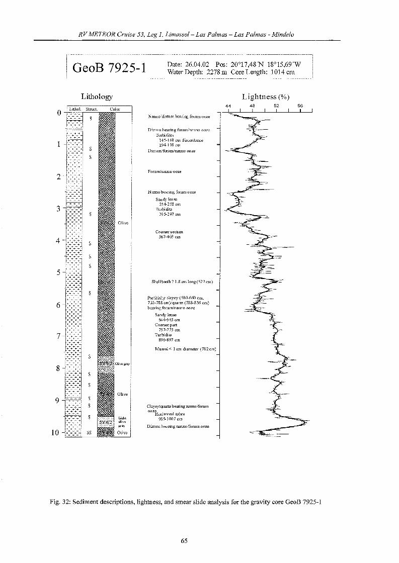
RVMETEOR Cruise 53, Leg 1, Limassol- Las Palmas - Las Palmas - Mindelo
GeoB 7925-1 Date: 26.04.02 Pos: 200 17,48'N 18°15,69'WWater Depth: 2278 m Core Length: 1014 cm
Lithology56
I
Lightness (%)48 52
I I44
L
ShelL1ooth? 1.8 cm 1011g (52 7 cm)
Coarser seetion367-403 cm
Partitia11y cmyey (580-660 CllL
730-788 cm)/quartz (788-836 cm)hearing foram/namlO ooze
Sandy leuse644-645 cm
Co arser part757-775 cm
Turbidite896-897 cm
Nanno/diatom bearing foram ooze
Diatom hearing foramln..'lI1l1o oozeTurbidites
145-168 CU} discordance194-198 cm
DiatomiforamJ11amlO ooze
Musse! < 10111 diameter (782 cm)
N atmO bearing foram ooze
Sandy 1euse254-258 cm
Turbidite295-297 cm
ForamJnanno ooze
Cmyey/quartz be:ring nanno/foramooze
Horizontal tubes985-1007 cm
Diat01ll hearing nanno/foram ooze
s
s
s
ss
Lithol.
+++
.~~~~:~..,
++++ + +
+ + +
+ + ++ + +
+ + ++++
+ + ++ + +
+ + +
+ + ++ + +
+ + ++ + +
+ + ++++
+ + ++ + +
+ + +
+ + +
+ + ++++
+ + +
+ + ++ + +
+ + ++ + +
+ + ++ + +
+ + ++ + +
++++ + +
+ + ++++
+ + ++++
+ + ++ + +
+ + +
+ + +
o
1
7
2
5
3
6
4
8
9
10
Fig. 32: Sediment descriptions, lightness, and smear slide analysis for the gravity core GeoB 7925-1
65
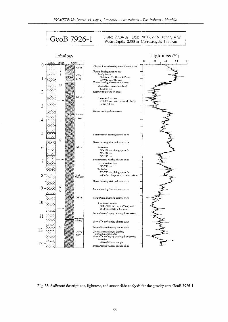
RVMETEOR Cruise 53, Leg 1, Limassol- Las Palmas - Las Palmas - Mindelo
GeoB 7926-1 Date: 27.04.02 Pos: 2OC12,79'N 18°27,14WWater Depth: 2500 m Core Length: 1330 Cll1
Nanno hearing <liatom!foram ooze
Tur1:i<lites543-558 C11l, finiugupwards581·584 cm592·593 cm
Foramlnanno bearing diatom ooze
Laminated section692·748 cm
Turbi<lite762·780 C111, finiugupwardswith shell fragments, erosive hottom
Clayey <li atom bearingnanno/foram ooze
Nanno/foram hearing <li atom ooze
Forum hearing nanno oozeSandy lenses
80·83 cm, 91-93 cm. 407 cn1,809-912 C111, 913 C111,
Foram hearing diatom/nanno ooze
Verlica! burrows (abundant)176-330 cm
Diatom/foramluanno ooze
Lammated section259-339 C111, \\;fu brov.nish. fluffylayers < 1 cm
Laminated section1048·1080 C11l, layer (7 cm) \\ifu!hell fragments at bottom
Forammanno/clayeybearing <liatomooze
Nalmo hearing <liatomlforam ooze
Foram/nanno bearing diatorn ooze
Foram hearing diatom/nanno ooze
ForamInanno hearing <li atom ooze
Natmobearil1g diat011100ze
Lightness (%)
Foram/diatorn bearing nanno ooze
Clayey/nanno/<liatom hearingsponge spicules ooze
Nanno/foram/clayeyhearing <liatom oozeTurbi<lite
1280·1285 C111, !roughNanno/foram bearing <liatom ooze
s
v v v
+ v +v + v
Lithology
0LithoL Stmcl. Color+ + +
S~ ~ ~
Ss
1
ss
2
= ClUv v v
3 v v v
• V V V
~ ~ ~
v v v
4~ ~ ~
v
S- v v v
'v V "V
V V v
5v v v
9
11
10
12
13
Fig. 33: Sediment descriptions, lightness, and smear slide analysis for the gravity core GeoB 7926-1
66

RVMETEOR erzäse 53, Leg 1, Limassol- Las Palmas - Las Palmas - Mindelo
GeoB 7927-2 Date: 27.04.02 Pos: 19°56,19'N 19°09,IO'WWater Depth: 3116 m Core Length: 818 cm
Lithology Lightness (%)52 56 60I I I
Clayey bearing nauuo/foram 00 re
N anno/forum OQze
Foram/diatolU bearing lllUl1l0 ooze
Sandy leuses89,96,130 cm
Diatom bearing foraminanno oaze
Turbidites106-108cm122-125 cm172-188 C1ll, coarsest part
181-183 cmfiuiug upand dov..nwards
Nanno/foramooze
Turbi di te405-406 cm
Diatam bearing uauno/foram oore
Forum/nalma ooze
Turbidite657-658 cm
Laminated section768-793 cm, top and bottomirregularly shape
N atn10 bearing diatom Daze
Fig. 34: Sediment descriptions, lightness, and smear slide analysis for the gravity core GeoB 7927-2
67

RVMETEOR erzdse 53, Leg 1, Limassol- Las Palmas - Las Palmas - Mindelo
GeoB 7928-2 Date: 28.04.02 Pos: 19°05,98'N 17°02,88WWater Depth: 1352 m COl'e Length: 870 cm
Lithology
Foram bearing llamlO ooze
Foram/llatmo bearing diatonl ooze
N amlO/di atom bearing foratu ooze
NatnlO/diatomJquartz hearingforam ooze
DiatOlll bearing foram/nanno ooze
NamlO bearing foram ooze
Shell fi"agments < 2=540 cm
N amlOlquartzlclayay bearingforamooze
Nanno/qllartz bearing foram ooze
Foram/clayey bearing nanno ooze
Clayey bearing nanno/foram ooze
44[
Lightness (%)46 48 50
I52
Fig. 35: Sediment descriptions, lightness, and smear slide analysis fo1' the gravity co1'e GeoB 7928-2
68

RV METEOR erzäse 53, Leg 1, Limassol- Las Palmas - Las Palmas - Mindelo
6
GeoB 7932-3
LithologyColor
I
ai,eg,ayl
IOlive I
aive gray
I
Date: 29.04.02 Pos: 19°00,09'N 17°16,89'W\I\klter Depth: 1964 m Core Length: 835 cm
Lightness (%)
36 40 44 48 52
Clayey hearing nanno!foram ooze
Nam1o/foram Goze
Foram bearing natnlO/diato111 ooze
N anno!eby bearing diatomlforam ooze
Foram bearing diatomInanno ooze
NarIDo/foramJclayeybearing diato111 ooze
Diatomiql.1artz bearing foram/naullo ooze
Tmbidite471-473 em. erosivebottoll1fining Ujlw.trds
Foram/qllartz hearing diatomJnanno ooze
ForamJclayey bearing nanno!diatom ozoe
Diatom/foranvquartz bearing nanll0 OQze
Pteropodeo 1.2em diameter (675 em)
ForamJdiatorn beariog nanno ooze
N anno!diatom!qumtzJel ayey bealingforamooze
Nanno!cbyeybearing diatomJforam ooze
Diatomlnanno/clayey bearing foram ooze
Fig. 36: Sediment descriptions, lightness, and smear slide analysis for the gravity core GeoB 7932-3
69

RVMETEOR Cruise 53, Leg 1, Limassol- Las Palmas - Las Palmas - Mindelo
5.3.6 Geochemistry
(Sabine Kasten, Kerstin Plewa)
Introduction
The main focus of geochemical investigations carried out during this cruise was a
detailed sampling and analysis of the solid phase of se1ected sediment cores from the Canary
Islands/Cape Verde Islands area. The aim was to reveal whether and how the distribution of
various elements and/or minerals in the sedimentmy solid phase can be used to reconstruct
changes in terrigenous input, in productivity and in the extent of diagenetic overprint.
A second emphasis was put on the high-resolution examination along glaciaVinterglacial
transitions as well as across active and fossil iron redox boundaries in sediments of the study
area. Previous studies have demonstrated that the Fe redox boundary is and was often
associated with glacial terminations and is/was frequently fixed within this depth interval for a
considerable length of time (Funk et al. , subrn.). As a consequence of the sustained
localization and/or the downward progression of redox boundaries and reaction fronts, a
distinct diagenetic overprint of the primary composition within these transitional sediment
intervals occurs - inc1uding post-depositional oxidation of organic carbon, dissolution of
minerals as well as formation of distinct secondary element and mineral emichments (e.g.,
Moreno et al., 2002; Freudenthai et al., subrn.; Kasten et al., subrn.). The conditions which
trigger such nonsteady-state diagenetic episodes are assumed to be the pronounced differences
in sedimentation rate, organic carbon input and oxygen content of bortom waters encountered
during the transition from glacials to interglacials. The objective of these high-resolution
studies is to identi:fy which factors control the extent of diagenetic overprint in transitional
sediment intervals. Furthermore, we intend to reveal which of the secondary element
enrichments produced are preserved in the sedimentary record on fmiher burial and can thus
serve as valuable indicators for changes in organic carbon burial.
In addition to sampling and storage ofthe sediments for subsequent solid-phase analyses
at the University of Bremen we extracted and analysed the pore water immediatelyon board
in order to characterize the current geochemical environment of the sediments and to identi:fy
the depth position of the modem Fe(ll)/Fe(III) redox bOundalY. During this cruise 1
multicorer core (GeoB 7919-2) and 2 gravity cores (GeoB 7919-5 and GeoB 7928-1) were
processed.
70

RVMETEOR Cruise 53, Leg 1, Limassol- Las Palmas - Las Palmas - Mindelo
Methods
To prevent a warming of the sediments on board all cores were transferred into a
cooling room immediately after recovery and maintained at a temperature of about 4°C. The
multicorer core was processed directly after recovery. Two sampies ofthe supematant bottom
water were taken and filtered for subsequent analyses. The remaining bottom water was
carefully removed from the multicorer tube by means of a siphon to avoid destruction of the
sediment surface. During subsequent cutting of the core into slices for pressure filtration, pR
and Eh measurements were performed with a minimum resolution depth of 0.5 cm.
Conductivity and temperature were measured on a second, parallel core to calculate sediment
density and porosity.
The gravity cores were cut into I m segments on deck. Within a few days after recovery,
gravity cores were cut lengthwise into two halves and processed. On the working halves pR
and Eh were determined and sediment sampies were taken every 25 cm for pressure filtration.
Conductivity and temperature were measured on the archive halves. Solid phase sampies were
taken at 10 cm intervals and kept in gas-tight glass bottles under argon atmosphere for
sequential extractions and mineralogical investigations. The storage temperature for all
sediments was -20°C to avoid dissimilatory oxidation.
All work done on opened cores was carried out in a glove box under argon atmosphere.
For pressure filtration Teflon-squeezers were used. The squeezers were operated with argon at
apressure gradually increasing up to 5 bar. The pore water was retrieved through 0.2 11m
cellulose acetate membrane filters. Depending on the porosity and compressibility of the
sediments, the amount ofpore water recovered ranged between 5 and 20 ml.
Pore water analyses
Pore water analyses of the following parameters were carried out during this cruise: Eh,
pR, temperature, conductivity (porosity), alkalinity, ammonium, and iron.
Eh, pR, conductivity and temperature were determined with electrodes before the
sediment structure was disturbed by sampling for pressure filtration. Ammonium was
measured photometrically with an autoanalyser using a standard method. Alkalinity was
calculated from a volumetrie analysis by tritration of 1 m1 sampie with 0.01 or 0.05 M RCI,
respectively. For the analysis of dissolved iron (Fe2+) sub-samples of 1 ml were taken within
the glove box and immediately complexed with 50 111 of "Ferrospectral" and afterwards
determined photometrically.
71

RVMETEOR Cruise 53, Leg 1, Limassol- Las Palmas - Las Palmas - Mindelo
For further analyses at the University of Bremen, aliquots of the remailllllg pore water
sampies were either frozen (for analyses ofP04 and N03) or acidified with HN03-Csuprapure) for
the determination of cations (Ca, Mg, Sr, K, Ba, S, Mn, Si, B) by ICP-AES and AAS. Sub
sampies for sulfate and chloride determinations were diluted 1:20 and stored for analysis by
ion chromatography (HPLC).
A complete overview of sampling procedures and analytical techniques used on board
and in the laboratories at the University of Bremen is available on http://www.uni
bremen.geochemie.de.
Shipboard Results
Site GeoB 7919 is located off Cape Blanc at a water depth of 3420 m. At this location a
visible colour change from brown to grey/green was observed a few tenths of centimeters
below the sediment surface. While this colour change was not reached by the penetration
depth ofthe multicorer (c.f., Fig. 37), dissolved iron was detected below a depth of 0.8 m in
the gravity core (Fig. 38).
GeoB 7919-2 MeVlJaler deplh: 3429 m
Eh pH Alkalinity[mV] [mmo~eq)fQ
·200 0 200 400 7.37.'1 7.5 7.6 7.7 7.8 2 2 3 3
0.00 0.00 0.00. . ..~
... · .. ·004.
0.04 · 0.04
NH4 F.lIJmolfl] lIJmoUQ
o 1 2 3 4 5
0.00 0.00 -t----'---'
O.Q.4 0.04
0.06 0.080.08 0.08 0.08
I
0.12 0.12 0.12
0.16 0.16 0.16
020 0.20 020
0.12
0.16
0.20
0.16
0.20
Fig 37: Pore water concentration profiles of Eh, pR, alkalinity, ammonium and iron for multicorer core
GeoB 7919-2
This finding is evidence that the active/modem Fe redox boundary is located in the
sediment section between 0.5 and 0.8 m depth. Elevated amounts of Fe of up to about 3
/-lmo1l1 are found in the depth interval between 0.8 and 8.0 m which could be due to higher
rates of iron reduction occurring within this sediment section or a removal of Fe2+ from pore
water due to the formation of authigenic iron minerals in the sediments below 8.0 m. Except
for the uppermost meter of the sediment, alkalinity and ammonium show a parallel and linear
72
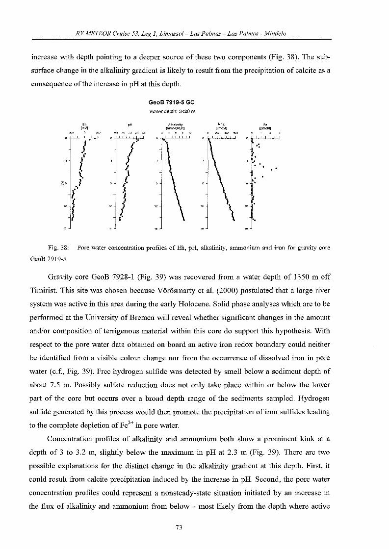
RV METEOR Cruise 53, Leg 1, Limassol- Las Palmas - Las Palmas - Mindelo
increase with depth pointing to a deeper source ofthese two components (Fig. 38). The sub
surface change in the alkalinity gradient is likely to result from the precipitation of calcite as a
consequence ofthe increase in pH at this depth.
Fe[~mol/Il
o 1 2 3
4 ...\
..
"\ 12
\ ..16
NH4[~moUij
o 200 4Xl €CO
GeoB 7919-5 Ge
water depth: 3420 m
Eh pH Alkalintty[mV] [mmol(eq)J1]
.= 0 = 6.8 7.0 7.2 7.4 7.6 2 4 6 8 10
/ Je ••
0\;,. l.J
~ l(
") f
\( "I
I.'
12 ) 12
1.I
16 16
Fig. 38: Pore water concentration profiles of Eh, pH, alkalinity, ammonium and iron for gravity core
GeoB 7919-5
Gravity core GeoB 7928-1 (Fig. 39) was recovered from a water depth of 1350 m off
Timirist. This site was chosen because Vörösmarty et al. (2000) postulated that a large river
system was active in this area during the early Holocene. Solid phase analyses which are to be
performed at the University of Bremen will reveal whether significant changes in the amount
and/or composition of terrigenous material within this core do support this hypothesis. With
respect to the pore water data obtained on board an active iron redox boundary could neither
be identified from a visible colour change nor from the occurrence of dissolved iron in pore
water (c.f., Fig. 39). Free hydrogen sulfide was detected by smell below a sediment depth of
about 7.5 m. Possibly sulfate reduction does not onIy take place within 01' below the lower
part of the core but occurs over a broad depth range of the sediments sampled. Hydrogen
sulfide generated by this process would then promote the precipitation of iron sulfides leading
to the complete depletion ofFe2+ in pore water.
Concentration profiles of alkalinity and ammonium both show a prominent kink at a
depth of 3 to 3.2 m, slightly below the maximum in pH at 2.3 m (Fig. 39). There are two
possible explanations for the distinct change in the alkalinity gradient at this depth. First, it
could result from calcite precipitation induced by the increase in pH. Second, the pore water
concentration profiles could represent a nonsteady-state situation initiated by an increase in
the flux of alkalinity and ammonium from below - most likely from the depth where active
73

RVMETEOR Cruise 53, Leg 1, Limassol- Las Palmas - Las Palmas - Mindelo
methanogenesis takes p1ace. Maximum concentrations of ammonium found in this gravity
core approximate1y double the contents detelmined for core GeoB 7919 10cated off Cape
B1anc indicating that site GeoB 7928 is 1ike1y to be characterized by higher input of organie
carbon and higher minera1ization rates.
GeoB 7928-1 Ge
VVater depth: 1350 m
10
Eh[mV]
..4J:) .;::00 0 a:o
oo
ooooo
ooooo.oo
ooooo
oo
ooo
:oo
oo
oo
10
pH
7.0 7.1 7.2 7.3 7.4 7.5
oo
o00
oooooo
oo
ooo
oo
oooo
oo
oooooo
oo
o
Alkallnlty[mmo~eqVlj
2 4 6 8 10
o
:ooo
2 :ooooo
oo
00ooooo
\oooo...
10
NH4!Jlmolll]
o 4X} 800 1200
ooo
:2 :
ooooooooo
':00
oo00
ooo
00
10 10
Fe!JlmoUlj
,! H,S smell
f
Fig. 39: Pore water concentration profiles of Eh, pR, alkalinity, ammonium and iron for gravity COl'e
GeoB 7928-1
The determination of further pore water constituents - particu1arly of sulfate - as well as
the ana1yses of the solid phase and the computer modelling of the sediment/pore water system
will give evidence which of the above discussed exp1anations hold true for the examined core
sites.
6. The weather during the cruise M53/1(G. Kahl, T. Truscheit)
When METEOR 1eft Limasso1 on March 30th, 2002, high pressure influence was
prevailing over most of Western and Centra1 Europe, extending east via the B1ack Sea to the
Caucasian Mountains. The only 10w worth mentioning was of 1005 hPa over Lybia, moving
east. Consequently, there were only light easterly winds when the research vesse1 put out to
sea.
During the next day, the 10w reached the NILE valley, tuming north and reaching
CYPRUS. Then it turned even west, filling thereby. For the METEOR this meant light to
moderate northerly winds when asounding was recovered at CRBTE's south coast.
74

RVMETEOR Cruise 53, Leg 1, Limassol- Las Palmas - Las Palmas - Mindelo
On April 2lld, winds were light and variable as METEOR was passing through a high north of
the SYRTE. Meanwhile, a low of about 1004 hPa had developed over the TUNESIAN saIt
lakes west of the SYRTE and another one with a central pressure of 1000 hPa near IDIZA.
Still another low was developed near Sicily so that when the ship stopped shortly before LA
VALLETTA, MALTA, southasterly winds of 6 Bft were prevailing. With that the METEOR
left the EASTERN MEDlTERRENEAN, where she had been working since October 2001.
The WESTERN MEDlTERRENEAN welcomed the ship with westerly storms of 10 Bft für
the duration of an hour on April 4th, 11 Bft (60 kn) for a 10 minutes-mean and hurricane force
gusts of 12 Bft. The synoptic situation in the morning comprised of a gale center 996 hPa just
east of the BALEARIC Islands intensifying and moving east into the TYRRHENIAN SEA,
central pressure going down to 993 hPa. This intensification was not responsible for the
storms, however, for within about two hours a storm center developed in the trough, reaching
SARDINIA with a central pressure of 990 hPa. As this low was passed the storms were feIt.
On April 5th, northwesterly gales of 9 Bft subsided to westerly 7 Bft as the METEOR passed
the Straits of SARDINIA.
In the meantime an Atlantic low of 995 hPa had arrived just southwest of Ireland. A
secondary low 1003 was lyingjust west ofPORTO, Portugal. This secondary low was the one
to deve10p to 993 hPa west of Cabo Sao Vicente by April i h as the METEOR was sailing
along the Costa deI Sol under light westerly winds. Then the research vesse1 passed the Straits
of GibraItar, re-entering the Atlantic. From one minute to the next winds backed to the
southwest to become pure headwinds, and force was up to 5 Bft. To achieve this, the synoptic
situation had developed as folIows: the low near Cabo Sao Vicente had moved north and
:filled somewhat, but had retained its character as the centrallow. A secondary low which had
developed near 400 N 18°W had moved southeast to 35°N 12°Wand intensified to 1000 hPa.
In this manner moderate to strong southwesterly winds prevailed until the ship called at Las
Palmas on April 1Oth, even peaking Southwest 7 Bft up to the very last hours.
During the time the research vessel was in port the advection of cold air that had kept the
merry-go-round of lows alive lessened, a low of 997 hPa still lying east of MADEIRA on
April 11th, but then this remnant, too, :filled quickly. When the ship put out to sea again on
April lih, northerly winds 4 to 5 Bft prevailed. The wind even abated to Northeast 3 Bft.
Starting April 16th, however, conditions changed: the northeasterly winds were gradually up 6
Bft because a low over the southern part of Morocco had formed and was intensifiying
slowly.
METEOR called at Las Palmas again on April18th only to leave port on April 20th.
75

RV METEOR Cruise 53, Leg 1, Limassol- Las Palmas - Las Palmas - Mindelo
When METEOR left Las Palmas de Cran Canaria on April 20th, 2002 southwards, light
northeasterly wind was prevailing. From April 22ud, for the present it was partly c10udy and
from April 23rd to April 24th it was completely c10udy with some rain. The synoptic situation
to this was a low 1008 hPa over Senegal and high pressure 1033 hPa easterly of the Azores
Islands.
During the next days and till METEOR called at Port of Sao Vicente, light to moderate,
sometimes fresh breeze, northerly winds, on April 30th up to near gale (Bft 7), prevailed.
7. References
Asper, V.L., 1987. Measuring the flux and sinking speed ofmarine snow aggregates. Deep
Sea Research, 34, 1-17.
Determann, S., R. Reuter, P. Wagner and R. Willkomm, 1994. Fluorescent matter in the
eastern Atlantic Ocean: Part 1, method of measurement and near-surface distribution.
Deep-Sea Research, 41,659-675.
Determann, S., R. Reuter, R. Willkomm, 1996. Fluorescent matter in the eastern Atlantic
Ocean: Part 2, vertical profiles and relation of water masses. Deep-Sea Research, 43,
345-360.
FreudenthaI, T., S. Kasten, and H. Meggers, submitted. Glacial trade wind intensity controlled
by latitudinal sea surface temperature gradients. Submitted to Geology.
Fukumori, 1., F. Martel and C. Wunsch, 1991. The hydrography ofthe North Atlantic in the
early 1980's: an Atlas. Progress in Oceanography, 27 (1-2), 1-110.
Funk, l, T. von Dobeneck, T. Wagner and S. Kasten, submitted. Late Quaternary
sedimentation and early diagenesis in the equatorial Atlantic Ocean: Patterns, trends and
processes deduced from rock magnetic and geochemical records.- In: G. Wefer, S.
Mulitza, V. Ratmeyer (eds.) The South Atlantic in the Late Quaternary: Reconstruction
ofMass Budget and Current Systems. Springer, Berlin Heidelberg New York.
Garside, C., 1993. Nitrate reductor efficiency as an error source in seawater analysis. Marine
Chemistry, 4 (1), 25-30.
Honjo, S., 1996. Fluxes of partic1es to the interior of the open oceans. In: V. Ittekkot, P.
Schäfer, S. Honjo and P.J. Depetris (eds.), Particle Flux in the Ocean. SCOPE, Wiley
and Sons, Chichester, pp. 91-154.
76

RVMETEOR erzäse 53, Leg 1, Limassol- Las Palmas - Las Palmas - Mindelo
Honjo, S., KW. Doherty, Y.C. Agrawal and Y.L. Asper, 1984. Direct optical assessment of
large amorphous aggregates (marine snow) in the deep ocean. Deep-Sea Research, 31,
67-76.
Ittekkot, V., 1996. Partic1e flux in the ocean: Introduction. In: V. Ittekkot, P. Schäfer, S.
Honjo and P.l Depetris (eds.), Particle Flux in the Ocean. SCOPE, Wiley and Sons,
Chichester, pp. 1-6.
Käse, RH., lF. Price, P.L. Richardson and W. Zenk" 1986. A quasi- synoptic survey of the
thermoc1ine circulation and the water mass distribution within the Canary Basin.
Journal ofGeophysical Research, 91, 9739- 9797.
Kasten, S., M. Zabel, V. Heuer, and C. Hensen, submitted. Nonsteady-state diagenesis and its
documentation and preservation in marine sediment/pore water systems. In: The South
Atlantic in the Late Quaternmy: Reconstruction 0/Mass Budget and Current Systems.
G. Wefer, S. Mulitza and V. Ratmeyer (eds.). Springer, Berlin Heidelberg NewYork.
Kawase, M. and J.L. Sarmiento, 1985. Nutrients in the Atlantic thermoc1ine. Journal of
Geophysical Research, 90, 8961- 8979.
Koroleff, F., 1983a. Determination of dissolved inorganic phosphate. In: Methods ofSeawater
Analysis. K Cil'asshoff, A. Ehrhardt and K Kremling (eds), Verlag Chemie, 126-129.
Koroleff, F, 1983b. Determination of dissolved inorganic silicate. In: Methods of Semvater
Analysis. K Crt'asshoff, A. Eluhardt and K Kremling (eds.), Verlag Chemie, 175-180.
Kremling, K and A. Wenck, 1986. On the storage of dissolved inorganic phosphate, nitrate
and reactive silicate in Atlantic Ocean water samples. Meeresforsch, 31, 69-74.
Llinas, 0., A. Rodriguez de Leon, G. Siedler and G. Wefer , 1994. The ESTOC Time Series
Station Stalted Operation. WOCE Newsletter, 17, Nov. 1994.
Llinas, 0., A. Rodriguez de Leon, G. Siedler and G. Wefer, 1997. ESTOC Data Report 1994.
In! Tee Inst. Canario Cienc. Mar., 3, Telde, Crt'an Canaria.
Llinas, 0., M.l Rueda, l Perez-MalTero, E. Perez-Martell, R Santana, M.G. Villagarcia, A.
Cianca, l Godoy and L. Maroto, 2002. Variability of the Antarctic intelmediate waters
in the NOlfuern Canary Box. Deep-Sea Research 11,49,3441- 3453.
McDona1d, RW. and F.A. McLaughlin, 1982. The effect of starege by freeging of dissolute
inorganic phosphate, nitrate and reactive silicate for samples from coastal and internal
water. Water Research, 16,95-104.
Metcalf, W.G., 1969. Dissolved silicate in the deep North Atlantic. Deep-Sea Research, 16,
139- 145.
77
RVMETEOR Cruise 53, Leg 1, Limassol- Las Palmas - Las Palmas - Mindelo
Moreno, A., S. Nave, H. Kuhlmann, M. Canals, l Targarona, T. Freudenthai, and F.
Abrantes, F., 2002. Productivity response in the North Canary Basin to c1imate changes
during the last 250 000 yr: a multi-proxy approach. Earth and Planetary Science Letters.
196, 147-159.
Murphy, J. and J.P. Riley, 1962. A modified single solution method for the determination of
phosphate in natural waters. Anal. Chim. Acta, 27, 31-36.
Neuer, S. and M. Rueda, 1997. European Time-Series Station in Operation North of the
Canary Islands. U.S. JGOFS Newsletter, March 1997.
Nydahl, F., 1976. On the optimum conditions for the reduction of nitrate by cadmiun.
Talanta, 23,349-357.
Pätzold, J., Halbach, P. E., Hempel, G. and Weigert, M., 2000. Östliches Mittelmeer
Nördliches Rotes Meer 1999, Cruise No. 44, 22 January - 16 May 1999. Meteor
Berichte, Universität Hamburg, 00-3, 240 pp.
Ratmeyer, V. and G. Wefer, 1996. A high resolution camera system (ParCa) for imaging
partic1es in the ocean. System design and results from profIles and a three-month
deployment. Journal ofMarine Research, 54, 589-603.
Riley, J.P. & J.P. Skirpow, 1975. The Micronutrient Element. Chemical Oceanography, 2,
245-297.
Spear, K.G., 1993. The deep silica tongue in the North Atlantic. Deep-Sea Research, 40 (5),
925-936.
Strickland, lD.H & Parsons, 1972. A practical handbook of seawater analysis. Fisheries
Research Board ofCanada, 167 pp.
UNESCO, 1978. Technical Papers in Marine Science, 28, 35 pp.
UNESCO, 1984. La escala de salinidades practicas de 1978 y la ecuacion intemacional de
estado deI agua de mar de 1980. Documentos tecnicos de la Unesco sobre Ciencias dei
Mar,no.36.
Vörösmarty, C.J., Fekete, B.M., Meybeck, M. and Lammers, R.B., 2000. Global system of
river: Its role in organizing continentalland mass and defining land-to-ocean linkages.
Global Biogeochemical Cycles 14,599-621.
We1schmeyer, N.A., 1994. Fluorimetric Analysis of Chlorophyll a in presence of Chlorophyll
band Phaeopigments. Limnol. Oceanog. 39 (8), 1985-1992.
Willenbrink, E., 1982. Wassermassenanalyse 1ID tropischen und subtropischen
Nordostatlantik. Berichte aus dem Institut für Meereskunde Kiel, 96, 72 pp.
78

RVMETEOR Cruise 53, Leg 1, Limassol-Las Palmas -Las Palmas - Mindelo
8. Stationlist METEOR 53/1
GeoB# Ships # Date Device Time Latitude Longitude Water Recovery Remarks
2002 seatloorl depth
max. wire [m]
-Iength
[UTC]
7901-1 179 01.04. CTDI 01:57 34°26.5'N 26°12.6'E 3510
PlNGER
7902-1 180 01.04. MID-2 04:49 34°26.8'N 26°11.4·E 3511 recovery ofmooring MID-2,
two upper traps failed
7903-1 181 12.04. CTDIROS 17:07 29°1O.0'N 15°30.0'W 3612 water for CTDIROS test
traps
7903-2 181 12.04. CTDIROS 21:44 29°1O.0'N 15°30.0'W 3613 failed, uuclear sarnpling
depths
7903-3 181 13.04. CTDIROS 01:47 29°1O.0'N 15°30.0'W 3615 23 bottles
7903-4 181 13.04. CTD 05:49 29°1O.0'N 15°30.0'W 3613 Microcats-Calibration
7903-5 181 13.04. NOAA- 06:24 29°1O.0'N 15°30.0'W
Drifter
7904-1 182 13.04. CIl4 07:51 29°13.6'N 15°27.0'W 3603 Recovery of mooring CIl4
Lower trap stopped on bottle 4
7905-1 183 13.04. MSD 15:35 29°13.8'N 15°27.2'W 3610 MSD-testing on wire
7905-2 183 13.04. MSD 19:34 29°13.9'N 15°27.0'W 3610 MSD-testing on wire
7906-1 184 14.04. CTDIROS 01:09 28°44.0'N 15°40,0'W 3595 23 bottles Sarnpling down to 3000 m
7907-1 185 14.04. CTDIROS 07:14 28°18.0'N 16°00.1'W 2859 24 bott1es Sarnpling down to the bottom
7908-1 186 14.04. Test 13:18 29°05.0'N 15°56.0'W 3632 ANIMATE-Telemetry test
7909-1 187 14.04. CTDIROS 16:35 29°1O.9'N 15°55.6'W 3632 24 bottles Sarnpling down to the bottom
7909-2 187 14.04. MSD 29°10.9N 15°55.6W 3632 MSD-testing on wire
7910-1 188 15.04. SBU 08:17 29°10.6N 15°55.2'W 3634 Dep10yment ofDOLAN-
buoy-mooring
7910-2 188 15.04. MSD 16:10 29°1O.9N 15°55.6W 3632 Deployment ofMSD-mooring
7911-1 189 15.04. CTDIROS 22:18 29°09.8'N 15°43.8'W 3625 24 bott1es Sarnpling down to bottom
7912-1 190 16.04. CIl5/ANl 08:55 29°1O.8'N 15°25.7'W 3613 Dep10yment ofthe combined
MATE CIl5 and ANIMATE mooring
7913-1 191 17.04. CTDIROS 03:07 27°55.0'N 16°18.0'W 2521 24 bott1es Sarnpling down to bottom
7914-1 192 17.04. ROV 10:35 27°44.8'N 15°46.7'W 90 Balance, drive- and diving test
7914-2 192 17.04. ROVlPar 12:00 27°44,8'N 15°47.2'W 90 Testing
Ca
7915-1 193 17.04. ROV 17:23 27°40.7'N 15°37.1'W 423 Testing
7916-1 194 22.04. CTDIROS 03:22 21°15.8'N 200 47.1'W 4154 23 bott1es Sarnpling down to bottom
7917-1 195 22.04. CB12 09:23 21°16.0'N 200 47.2'W 4153 Recovery ofCB12 mooring
7918-1 196 22.04. CB13 13:31 21°16.8'N 200 46.7'W 4144 Dep10yment of CB13 mooring
7919-1 197 23.04. CTDIROS 06:16 200 56.5'N 19°23.4'W 3428 22 bottles Sarnpling down to bottom
7919-2 197 23.04. MUC 09:09 200 56.5'N 19°23.2'W 3429 30cm
7919-3 197 23.04. SL12 11:44 200 56.3'N 19°23.4'W 3419 1127 cm Core for Marine Geology
Group
7919-4 197 23.04. SL12 14:11 200 56.4'N 19°23.4'W 3421 1175 cm Overpenetration 1 m
7919-5 197 23.04. SL18 16:45 200 56.4'N 19°23.4'W 3420 1458 cm Core for Marine Geochemistry
Group
7919-6 197 23.04. ParCa 19:11 200 56.8'N 19°24.8'W 3455 System failed
7919-7 197 23.04. ParCa 23:18 200 56.6'N 19°26.6'W 3472
79

RVMETEOR Cruise 53, Leg 1, Limassol- Las Palmas - Las Palmas - Mindelo
GeoB # Ships # Date
2002
Device Time Latitude
seafloor/
max. wire
Longitude Water Recovery Remarks
depth
[m]
-length
[UTC]
SLl2 18:55
07:01
09:10
11:32
13:35
23:10
01:25
02:45
09:14
Testing of device
Sampling down to bottom
Corebended
Sampling down to bottom
Sampling down to bottom
Test and profile
Core for Marine Geochemistry
Group
Core for Marine Geology
Group
26cm
991 cm
19 bottles
1622 cm
30cm
870cm
17 bottles
552 cm
23 cm
840cm
1689 cm
1330 cm
25 cm
29 cm
818 cm
24cm
1014 cm
73
73
1908
1908
2500
2500
2500
3128
3116
3118
1350
1352
1279
1516
1516
73
2278
2278
2278
2285
2266
1914
1948
1265
1285
1289
1279
18°35.0'W
18°34.9'W
18°35.0'W
18°35.1'W
17°33.4'W
17°33.4'W
18°15.7'W
18°15.TW
18°27.1'W
18°27.1'W
18°27.1'W
19°09.1'W
19°09.I'W
19°09.1'W
IT02.9'W
17°02.9'W
18°15.7'W
18°1O.TW
18°1O.7'W
17°33.5'W
18°34.9'W
18°15.6'W
18°14.6'W
18°15.6'W
18°15.7'W
18°15.TW
18°15.7'W
200 45.0'N
200 45.1'N
200 45.0'N
200 45.1'N
200 40.0'N
200 44.4'N
200 44.4'N
200 32.9'N
200 45.2'N
200 48.3'N
200 49.3'N
200 39.7'N
200 40.0'N
200 40.0'N
200 40.0'N
200 32.8'N
200 32.8'N
200 17.5'N
200 17.5'N
20°12.8'N
200 12.8'N
200 12.8'N
19°56.2'N
19°56.2'N
19°56.3'N
19°06.0'N
CTDIROS
SLl8
MUC
ROVlPar
Ca
ParCa 22:48
SLl8 06:30
ParCa 11:43
CTDIROS 14:10
SLl8 15:36
MUC 17:02
ROVlPar 20:20
Ca
ParCa
MUC
SLl2
ROVlPar
Ca
CTDIROS 12: 10
MUC 12:36
SLl8 18:35
ParCa 22:30
ParCa 03:38
SLl8 05:21
MUC 07:15
MUC 16:03
SLl2 18:07
ParCa 00:32
SLl2 17:32
25.04.
26.04.
26.04.
26.04.
24.04.
24.04.
24.04.
24.04.
26.04.
26.04.
26.04.
26.04.
27.04.
27.04.
27.04.
27.04.
27.04.
27.04.
28.04.
24.04.
25.04.
25.04.
25.04.
25.04.
25.04.
25.04.
28.04.
200
201
201
202
198
198
198
198
198
199
199
200
200
200
200
206
202
202
203
203
204
204
204
205
205
205
206
7922-5
7923-1
7923-2
7924-1
7920-1
7920-2
7920-3
7920-4
7920-5
7921-1
7921-2
7922-1
7922-2
7922-3
7922-4
7928-2
7924-2
7924-3
7925-1
7925-2
7926-1
7926-2
7926-3
7927-1
7927-2
7927-3
7928-1
7928-3
7928-4
7929-1
7930-1
7931-1
7932-1
7932-2
7932-3
7932-4
7933-1
7934-1
7935-1
7936-1
7936-2
206
206
207
208
209
210
210
210
210
211
212
213
214
214
28.04.
28.04.
29.04.
29.04.
29.04.
29.04.
29.04.
29.04.
29.04.
30.04.
30.04.
30.04.
30.04.
30.04.
MUC
CTDIROS
ParCa
ParCa
ParCa
CTDIROS
MUC
SLl2
ParCa
ParCa
ParCa
ParCa
SLl2
MUC
20:03
21:16
00:19
03:04
05:06
12:55
14:39
17:21
20:44
00:50
04:27
08:12
14:37
16:29
19°06.0'N
19°05.9'N
19°04.1'N
19°14.1'N
19°14.1'N
19°00.0'N
19°00.1'N
19°00.0'N
19°00.0'N
19°1O.5'N
19°1O.3'N
19°04.0'N
18°35.4'N
18°35.5'N
17°02.8'W
17°02.9'W
17°04.0'W
17°04.0'W
16°54.1'W
17°17.0'W
17°17.0'W
17°17.O'W
17°17.O'W
17°17.2'W
17°27.5'W
17°27.5'W
18°02.3'W
18°02.2'W
1348
1368
1425
1464
442
1956
1964
1964
1953
1950
1950
2117
2690
2663
23cm
18 bottles
18 bottles
32cm
835 cm
227 cm
32cm
Sampling down to bottom
Sampling down to bottom
Corebended
80
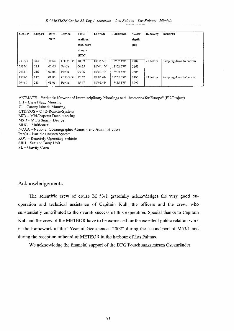
RV METEOR Cruise 53, Leg 1, Limassol- Las Palmas - Las Palmas - Mindelo
GeoB# Ships # Date Device Time Latitude Longitude Water Recovery Remarks
2002 seafloorl depth
max. wire Im]
-length
[UTC]
7936-3 214 30.04. CTDIROS 18:39 18°35.5'N 18°02.4'W 2702 21 bottles Sampling down to bottom
7937-1 215 01.05. ParCa 00:25 18°40.1'N 18°02.5'W 2667
7938-1 216 01.05. ParCa 05:06 18°50.1'N 18°02.5'W 2606
7939-1 217 01.05. CTDIROS 12:57 18°05.4'N 18°55.0'W 3100 23 bott1es Sampling down to bottom
7940-1 218 01.05. ParCa 15:47 18°05.4'N 18°55.1'W 3097
ANIMATE - "Atlantic Network ofInterdisciplinmy Moorings and Timeseries for Europe" (EU-Project)CB - Cape Blanc MooringCI - CanalY Islands MooringCTD/ROS - CTD-Rosette-SystemMID - Mid-Ieapetra Deep mooringMSD - Multi Sensor DeviceMUC - MulticorerNOAA - National Oceanographic Atmospheric AdministrationParCa - Palticle Camera SystemROV - Remotely Operating VehicleSBU - Sm'face Buoy UnitSL - Gl'avity Corer
Acknowledgements
The scientific crew of crUlse M 53/1 gratefuliy acknow1edges the very good co
operation and technical assistance of Capitain Kuli, the officers and the crew, who
substantialiy contributed to the overall success of this expedition. Special thanks to Capitain
KulI and the crew of the :METEOR have to be expressed for the excelient public relation work
in the framework of the "Year of Geosciences 2002" during the second part of M53/1 and
during the reception onboard of:METEOR in the harbour ofLas Palmas.
We acknowledge the fmancial support ofthe DFG Forschungszentrum Ozeanränder.
81