Assessment of Preventative Biofouling Management Measures
125
Project 16214 Assessment of Preventative Biofouling Management Measures MPI Technical Paper No: 2016/69 Prepared for Ministry for Primary Industries By ESLINK Services ISBN No: 978-1-77665-407-9 (online) ISSN No: 2253-3923 (o) September 2016
-
Upload
khangminh22 -
Category
Documents
-
view
3 -
download
0
Transcript of Assessment of Preventative Biofouling Management Measures
Project 16214 Assessment of Preventative Biofouling Management MeasuresMPI Technical Paper No: 2016/69
Prepared for Ministry for Primary Industries By ESLINK Services
ISBN No: 978-1-77665-407-9 (online) ISSN No: 2253-3923 (o)
September 2016
Disclaimer While every effort has been made to ensure the information is accurate, the Ministry for Primary Industries does not accept any responsibility or liability for error of fact, omission, interpretation or opinion that may be present, nor for the consequences of any decisions based on this information. Any view or opinion expressed does not necessarily represent the view of the Ministry for Primary Industries. Requests for further copies should be directed to: Publications Logistics Officer Ministry for Primary Industries PO Box 2526 WELLINGTON 6140 Email: [email protected] Telephone: 0800 00 83 33 Facsimile: 04-894 0300 This publication is also available on the Ministry for Primary Industries website at http://www.mpi.govt.nz/news-and-resources/publications/ © Crown Copyright - Ministry for Primary Industries
PROJECT 16214 ASSESSMENT OF PREVENTATIVE
BIOFOULING MANAGEMENT MEASURES
Prepared for: Biosecurity Science, Food Science and Risk Assessment Directorate Ministry for Primary Industries Wellington NEW ZEALAND
September 2016
ES LINK SERVICES PTY LTD ABN 76 088 414 037
PO Box 10 Castlemaine VIC 3450
E [email protected] W www.eslinkservices.com.au
Linking sustainable economic returns with environmental and social outcomes

Project 16214 Biofouling Management
ii
Project 16214 Biofouling Management
PROJECT 16214 ASSESSMENT OF PREVENTATIVE
BIOFOULING MANAGEMENT MEASURES Prepared for: Biosecurity Science, Food Science and Risk Assessment Directorate Ministry for Primary Industries Wellington NEW ZEALAND
Prepared by:
John A Lewis Principal Marine Consultant
ES Link Services Pty Ltd
September 2016
iii

Project 16214 Biofouling Management
iv
Project 16214 Biofouling Management
ABBREVIATIONS
Abbreviation Description
AGM Asian Green Mussel [Perna viridis]
ASA Australian Shipowners Association (now MIAL)
ASTM American Society for Testing Materials (now ASTM International)
CDP Controlled Depletion Polymer [coating]
CP Cathodic Protection
CRMS [New Zealand] Craft Risk Management Standard
CSLC California State Lands Commission
DSTO [Australian Government] Defence, Science and Technology Organisation (now DSTG)
DSTG [Australian Government] Defence, Science and Technology Group
DTTAS Department of Transport, Tourism and Sport [Ireland]
FRC Foul Release Coating
ICAF Impressed Current Antifouling
ICMCF International Congress on Marine Corrosion and Fouling
IMO International Maritime Organization
IPPIC International Paint and Printing Ink Council
MAF [New Zealand Government] Ministry of Agriculture and Forestry (now MPI)
MEPC [IMO] Marine Environment Protection Committee
MGPS Marine Growth Prevention System
MIAL Maritime Industries Australia Ltd
MLIT Ministry of Land, Infrastructure, Transport and Tourism [Japan]
MPI [New Zealand Government] Ministry for Primary Industries
NIS Non-Indigenous Species
PI Principal Investigator
PPR [MEPC] Sub-Committee on Pollution Prevention and Response
v
Project 16214 Biofouling Management
Abbreviation Description
SD Standard Deviation
SPC Self-Polishing Copolymer [coating]
WHOI Woods Hole Oceanographic Institute
WSC World Shipping Council
vi
Project 16214 Biofouling Management
TABLE OF CONTENTS
Executive Summary .......................................................................................................................... 1
1 Introduction ............................................................................................................................ 3
2 Background ............................................................................................................................. 3
2.1 Invasive Aquatic Species ................................................................................................. 3
2.2 The IMO Guidelines........................................................................................................ 4
2.3 New Zealand’s Craft Risk Management Standard ............................................................ 4
2.4 Antifouling Systems ........................................................................................................ 5
Paints and Coatings .............................................................................................. 5 Marine Growth Prevention Systems ....................................................................... 6
3 Aims & Objectives .................................................................................................................. 7
4 Project Design ......................................................................................................................... 7
5 Data Collection ........................................................................................................................ 9
5.1 Enlistment of Participants ................................................................................................ 9
5.2 Reporting Package Inputs ................................................................................................ 9
5.3 Docking Reports ........................................................................................................... 10
5.4 Vessel Inspections ......................................................................................................... 10
5.5 Image Collections ......................................................................................................... 11
5.6 Information Summary ................................................................................................... 11
6 Observations.......................................................................................................................... 14
6.1 Paint Systems ................................................................................................................ 14
Hulls ................................................................................................................... 14 Intake Grates ....................................................................................................... 21 Sea Chests ........................................................................................................... 25 Other Niches ....................................................................................................... 30
6.2 Marine Growth Prevention Systems............................................................................... 34
Copper Anodic .................................................................................................... 34 Chemical Dosing ................................................................................................. 42 Sound .................................................................................................................. 43
7 Discussion .............................................................................................................................. 44
7.1 The IMO Guidelines...................................................................................................... 44
7.2 Paint Systems ................................................................................................................ 44
Paint Types ......................................................................................................... 44 Hull Surfaces ....................................................................................................... 45 Intake Grates ....................................................................................................... 47 Sea Chests ........................................................................................................... 48
Propulsion and Steering Gear ............................................................................. 49
vii
Project 16214 Biofouling Management
7.3 Marine Growth Prevention Systems............................................................................... 50
MGPS Effectiveness ............................................................................................ 50 Copper Anodic Systems ....................................................................................... 50 Chemical Dosing Systems .................................................................................... 51 Sonic Systems ...................................................................................................... 51
Electrochlorination Systems ................................................................................ 52
8 Conclusions & Recommendations ........................................................................................ 53
8.1 Study Limitations .......................................................................................................... 53
8.2 Coatings ........................................................................................................................ 53
Hull Surfaces ....................................................................................................... 53
Intake Grates ....................................................................................................... 53 Sea Chests ........................................................................................................... 53 Propulsion and Steering Gear ............................................................................. 54
8.3 MGPS ........................................................................................................................... 54
8.4 Further work ................................................................................................................. 54
9 Acknowledgements ................................................................................................................ 55
10 References ............................................................................................................................. 56
Appendix 1 – Reporting Guidance ................................................................................................. 61
Appendix 2 – Dock Guide ............................................................................................................... 48
Appendix 3 – MEPC Information paper ........................................................................................ 52
viii
Project 16214 Biofouling Management
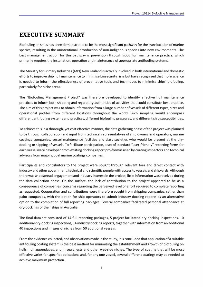
EXECUTIVE SUMMARY
Biofouling on ships has been demonstrated to be the most significant pathway for the translocation of marine species, resulting in the unintentional introduction of non-indigenous species into new environments. The best management action for this pathway is prevention through good hull maintenance practice, which primarily requires the installation, operation and maintenance of appropriate antifouling systems. The Ministry for Primary Industries (MPI) New Zealand is actively involved in both international and domestic efforts to improve ship hull maintenance to minimise biosecurity risks but have recognised that more science is needed to inform the effectiveness of preventative tools and techniques to minimise ships’ biofouling, particularly for niche areas. The “Biofouling Management Project” was therefore developed to identify effective hull maintenance practices to inform both shipping and regulatory authorities of activities that could constitute best practice. The aim of this project was to obtain information from a large number of vessels of different types, sizes and operational profiles from different locations throughout the world. Such sampling would encompass different antifouling systems and practices, different biofouling pressures, and different ship susceptibilities. To achieve this in a thorough, yet cost effective manner, the data gathering phase of the project was planned to be through collaboration and input from technical representatives of ship owners and operators, marine coatings companies, vessel maintenance facilities and class societies who would be present at the dry-docking or slipping of vessels. To facilitate participation, a set of standard “user-friendly” reporting forms for each vessel were developed from existing docking report pro-formas used by coating inspectors and technical advisors from major global marine coatings companies. Participants and contributors to the project were sought through relevant fora and direct contact with industry and other government, technical and scientific people with access to vessels and shipyards. Although there was widespread engagement and industry interest in the project, little information was received during the data collection phase. On the surface, the lack of contribution to the project appeared to be as a consequence of companies’ concerns regarding the perceived level of effort required to complete reporting as requested. Cooperation and contributions were therefore sought from shipping companies, rather than paint companies, with the option for ship operators to submit industry docking reports as an alternative option to the completion of full reporting packages. Several companies facilitated personal attendance at dry-dockings of their ships in Australia. The final data set consisted of 14 full reporting packages, 5 project-facilitated dry-docking inspections, 10 additional dry-docking inspections, 14 industry docking reports, together with information from an additional 40 inspections and images of niches from 50 additional vessels. From the evidence collected, and observations made in the study, it is concluded that application of a suitable antifouling coating system is the best method for minimising the establishment and growth of biofouling on hulls, hull appendages, and in sea chests and other wet-side niches. The type of coating that will be most effective varies for specific applications and, for any one vessel, several different coatings may be needed to achieve maximum protection.
1

Project 16214 Biofouling Management The major conclusions from the project were:
• for hull surfaces, self-polishing copolymer (SPC) and foul-release (FRC) coatings provided longer and more reliable biofouling than controlled depletion polymer (CDP) coatings;
• the application of FRC coatings to intake grates can minimise both paint system breakdown and biofouling growth;
• faster polishing (“soft”) CDP and SPC coatings are more effective in preventing biofouling inside sea chests than slower polishing (“hard”) coatings of the same type;
• the application of FRC coatings to propeller blades minimises biofouling attachment and survival, and would simplify cleaning if biofouling did establish; and
• there was no evidence that anodic copper, chemical dosing, or sonic MGPSs prevented or reduced the attachment and growth of biofouling within sea chests or seawater piping. No conclusion can be made on the effectiveness of electrochlorination systems as no information was received nor observations made on vessels fitted with this type of MGPS.
As the quantity and type of data obtained was not suitable for statistical analysis, the above conclusions are based on the observational information received and collated for this project, and its interpretation by the author. The rigour of the conclusions, and consequent benefits for improved biofouling management, could be enhanced through widespread support from the shipping and paint industries to assess systems and generate additional information for comparison.
2
Project 16214 Biofouling Management
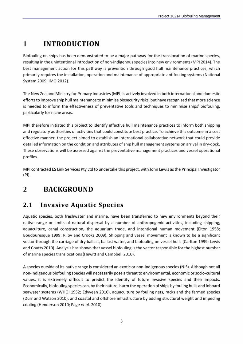
1 INTRODUCTION
Biofouling on ships has been demonstrated to be a major pathway for the translocation of marine species, resulting in the unintentional introduction of non-indigenous species into new environments (MPI 2014). The best management action for this pathway is prevention through good hull maintenance practices, which primarily requires the installation, operation and maintenance of appropriate antifouling systems (National System 2009; IMO 2012). The New Zealand Ministry for Primary Industries (MPI) is actively involved in both international and domestic efforts to improve ship hull maintenance to minimise biosecurity risks, but have recognised that more science is needed to inform the effectiveness of preventative tools and techniques to minimise ships’ biofouling, particularly for niche areas. MPI therefore initiated this project to identify effective hull maintenance practices to inform both shipping and regulatory authorities of activities that could constitute best practice. To achieve this outcome in a cost effective manner, the project aimed to establish an international collaborative network that could provide detailed information on the condition and attributes of ship hull management systems on arrival in dry-dock. These observations will be assessed against the preventative management practices and vessel operational profiles. MPI contracted ES Link Services Pty Ltd to undertake this project, with John Lewis as the Principal Investigator (PI).
2 BACKGROUND
2.1 Invasive Aquatic Species
Aquatic species, both freshwater and marine, have been transferred to new environments beyond their native range or limits of natural dispersal by a number of anthropogenic activities, including shipping, aquaculture, canal construction, the aquarium trade, and intentional human movement (Elton 1958; Boudouresque 1999; Rilov and Crooks 2009). Shipping and vessel movement is known to be a significant vector through the carriage of dry ballast, ballast water, and biofouling on vessel hulls (Carlton 1999; Lewis and Coutts 2010). Analysis has shown that vessel biofouling is the vector responsible for the highest number of marine species translocations (Hewitt and Campbell 2010). A species outside of its native range is considered an exotic or non-indigenous species (NIS). Although not all non-indigenous biofouling species will necessarily pose a threat to environmental, economic or socio-cultural values, it is extremely difficult to predict the identity of future invasive species and their impacts. Economically, biofouling species can, by their nature, harm the operation of ships by fouling hulls and inboard seawater systems (WHOI 1952; Edyvean 2010), aquaculture by fouling nets, racks and the farmed species (Dürr and Watson 2010), and coastal and offshore infrastructure by adding structural weight and impeding cooling (Henderson 2010; Page et al. 2010).
3
Project 16214 Biofouling Management The introduction of harmful aquatic organisms to new environments by ships has been identified as a major threat to the world’s ocean and to the conservation of biodiversity. In 2004, Member States of the International Maritime Organization (IMO) made a clear commitment to minimizing the transfer of invasive aquatic species by shipping in adopting the International Convention for the Control and Management of Ships’ Ballast Water and Sediments and, more recently in 2011, Guidelines for the Control and Management of Ships’ Biofouling (“the Guidelines”) (IMO 2009; 2012).
2.2 The IMO Guidelines
As stated within the IMO Guidelines, the objectives “are to provide practical guidance on measures to minimize the risk of transferring invasive aquatic species from ships’ biofouling” (IMO 2012). Ships are encouraged to implement biofouling management practices, including the use of antifouling systems and other operational management practices to reduce the development of biofouling. The intent of such practices is to keep the ship’s submerged surfaces, and internal seawater cooling systems, as free of biofouling as practical. A ship following this guidance and minimizing macrofouling would therefore have a reduced potential for transferring invasive aquatic species. It is important that biofouling management procedures be effective as well as environmentally safe, practical, designed to minimise costs and delays to the ship, and based on the Guidelines whenever possible.
2.3 New Zealand’s Craft Risk Management Standard
MPI is charged with leadership of the New Zealand biosecurity system. This encompasses facilitating international trade, protecting the health of New Zealanders and ensuring the welfare of New Zealand’s environment, flora and fauna, marine life and Maori resources. The ongoing risks posed by vessel biofouling are of immediate concern to MPI, given that the marine environment is a key part of many of New Zealand’s economic, environmental, and social and cultural values. Accordingly, MPI developed and in 2014 signed-off the Craft Risk Management Standard (CRMS): Biofouling on Vessels Arriving to New Zealand (Bell et al. 2011; Georgiades and Kluza 2014; MPI 2014). Implementation of this standard will commence May 2018 to allow shipping, and other vessel operators, time to make any adjustments needed to their hull maintenance regimes. The CRMS represents a proactive approach to manage the biosecurity risk from biofouling on arriving vessels so that harmful organisms do not arrive, or are intercepted on arrival before they can establish and cause unwanted damage to New Zealand’s natural resources. Continual maintenance following best practice is one of the recognised measures for meeting the requirements of the CRMS. The IMO Guidelines are recognised as an example of best practice.
4
Project 16214 Biofouling Management
2.4 Antifouling Systems
Paints and Coatings
Coatings applied to the underwater hulls of ships to prevent, or minimise, biofouling attachment can be broadly classed as biocidal or non-biocidal. Biocidal coatings contain active substances that are continuously released through the paint surface to provide a toxic or deterrent effect at the paint surface – seawater interface (Lewis 1998). Effective biocide-free coatings, known as foul-release coatings (FRC), have surface properties that deter or minimise the strength of adhesion of attaching biofouling organisms (Lewis 1998). The latter are detached by turbulent water flow across the surface if a vessel is travelling at sufficient speed or has a hull form to generate turbulent flow across the hull surface. The current, best performing FRC coatings are based on silicone or fluoropolymers (Townsin and Anderson 2009). In addition to these FRC coatings, a variety of other biocide-free coatings have been investigated and considered as alternatives to biocidal antifouling paints, including fibre coatings, scrubbable and inert coatings and non-leaching active coatings, but none has yet provided a practical, widely applicable alternative for vessels (Lewis 2009). Biocidal coatings vary in the mechanism to enable the continuous release of biocide which, for copper, is understood to be 10 µg/cm2/day (Morrisey et al. 2013). Copper, in the form of cuprous oxide or cuprous thiocyanate, is the most widely used antifouling biocide, either as the sole active agent or in combination with a secondary, “booster” biocide to broaden efficacy (Dafforn et al. 2011). The three principal types of coating are ablative, contact leaching, and self-polishing. Ablative (also known as soluble matrix) coatings have sparingly soluble paint matrix that slowly dissolves to enable the continued dissolution of biocide mixed through the matrix. Conventional soluble matrix coatings use natural rosin as the matrix, but newer coatings have additional components to improve the rate and control of dissolution. This class of coating are known as controlled depletion polymer (CDP) coatings. Traditional ablative coatings had an effective life rarely exceeding two years, but the modern CDP coatings are commonly specified as an economical “value for money” product for in-service periods of up to 36 months (Anonymous 2010; Lejars et al. 2012). However, they have thick leached layers which limit performance and negatively affect re-coatability. It is claimed that CDP coatings are not as effective as self-polishing copolymer systems, and therefore considered “suitable for use in lower fouling areas or for vessels with short dry-dock intervals” (Fathom 2013). Contact leaching, or hard coatings, have an insoluble matrix and biocide release depends on a high concentration of biocide within the coating that enables biocide dissolution though micro-channels created by the dissolving biocide. These coatings rarely achieve a two year life, so are not generally applied to commercial vessels (Finnie and Williams 2010; Lejars et al. 2012). The first self-polishing copolymer (SPC) systems were organotin-based coatings in which the paint matrix was based on the copolymer tributyltin methacrylate, which hydrolysed in seawater to release the biocide and a consequent dissolution of the residual polymer base (Lewis 1998). This mechanism enabled a formulation of antifouling coatings with effective in-service periods of up to 60 months (Lewis 2002; Lejars et al. 2012). Since the ban on organotin antifouling coatings, copper-based SPC systems have been developed that provide equivalent performance, and some are now specified for in-service periods of up to 90 months (e.g., AkzoNobel 2013; Hempel 2014). However, the price differential between CDP and SPC coatings has become significant, and operators of vessels with more frequent dry-dockings often opt for the cheaper yet less effective CDP coatings. The relative paint costs of different coating types when compared to contact leaching coatings (the cheapest) are: soluble matrix and CDP, 1.5 times; tin-free SPC, 2-3 times; and FRC coatings, 4-6
5
Project 16214 Biofouling Management times (Eliasson 2003, quoted in Lejars et al. 2012). Estimated application costs for tin-free SPC coatings were estimated, in 2003, to be 1.5 times that for CDP coatings, and for FRC coatings 2.3 times that for CDP (Eliasson 2003). More recent figures have not been found, as product pricing is commercially sensitive, but the figures given are considered likely to still apply (Colin Anderson, American Chemet Association, pers. comm.). SPC and CDP coatings are commonly formulated in two grades: a “softer”, faster polishing version for low speed and low activity, generally coastal, vessels, and a “harder”, slower polishing version for high speed and high activity, generally deep sea, vessels (Thompson Clarke Shipping 2007; INTERTANKO 2016).
Marine Growth Prevention Systems
Marine Growth Prevention Systems (MGPS) are installed on vessels to prevent the obstruction of seawater pipes and other equipment by marine growth (Grandison et al. 2011). These systems operate on the principle that a low, continuous or pulsed dose of a biocide will prevent organism survival and growth. In some systems the biocide is introduced into the pipework just inboard of the sea chests, in others within the sea chests to prevent marine growth in both the sea chest and the internal pipework served by the sea chest. The three main types of MGPS are anodic copper (impressed current antifouling (ICAF)), electrochlorination, and direct chemical dosing. Anodic systems have copper anodes, often together with aluminium or iron anodes, located in the sea chest or within the intake pipework, and electrical current is passed through these anodes to electrochemically release copper, aluminium or iron ions into the intake seawater (Grandison et al. 2011). The copper ions are intended to prevent fouling attachment and survival, the aluminium and iron to minimise corrosion of steel and cupro-nickel or aluminium brass pipes respectively. The current settings are calculated from the system flow rates to generate what is considered to be the effective metal ion concentration in the flowing seawater. Chlorination can be achieved using chlorine gas, hypochlorite solutions, and other chlorine compounds in solid or liquid forms. However, although direct chlorine or chlorine compound injection is still used in coastal infrastructure, electrolytic hypochlorite generation is used on ships as it is safer than carrying chlorine gas or liquids. Typical electrochorinators convert some of the chloride in the incoming seawater into sodium hypochlorite solution in an electrolytic cell. This solution is then piped back to the intake and drip fed into the incoming seawater (Grandison et al. 2011). In the third method, a number of chemicals are marketed or promoted for the control of biofouling in seawater pipework by direct injection1, 2, 3. Recommendations on dosage rates vary between products: some recommend a necessary concentration in the seawater of once through systems, others a rate that is a function of the wetted surface of the pipework. Sonic systems have also been promoted for the prevention of marine growth in sea chests 4, 5. These are generally promoted for the antifouling protection of hulls, box coolers and sea chests, with the equipment
1 http://wssproducts.wilhelmsen.com/marine-chemicals/water-treatment-chemicals/cooling-water-treatment/antifoulant-9-321-25-l 2 http://www.mexel432.com/en/products-solutions/mexel-432-water-cooling-circuits/ 3 http://norta.net/en1/catalog/water-treatment/sea-wt.html 4 https://au.pinterest.com/yachtmatemarine/harsonic-hull-antifouling-system/ 5 http://www.nedmarine.com/product/ultrasonic-anti-fouling
6
Project 16214 Biofouling Management designed for the intended application. Details of the frequencies and other characteristics of the generated sound are commercially protected, with mention only of “ultrasound”.
3 AIMS & OBJECTIVES
A data gap exists regarding the effectiveness of preventative tools and techniques to minimise ships’ biofouling, particularly for niche areas. The aim of this project was to identify effective hull and niche area maintenance practices to inform both shipping and regulatory authorities of activities that could constitute best practice.
4 PROJECT DESIGN
To achieve the project aim in a thorough, yet cost effective manner, the data gathering phase of the project was planned to be through collaboration and input from technical representatives of ship owners and operators, marine coatings companies, vessel maintenance facilities and class societies who would be present at the dry-docking or slipping of vessels. In designing the reporting forms, the aim was to keep reporting simple, and for it to be neither demanding nor time consuming. It was stressed that the identity of a ship or vessel would not be associated with data in public reports from the project. Therefore, to facilitate participation, data reporting forms were designed from existing reporting pro-formas used by inspectors for marine coating companies. Docking report pro-formas, and associated guidance, were provided by the marine paint companies Akzo Nobel Pty Ltd, Hempel (Australia) Pty Ltd and Jotun Australia Pty Ltd, and these were used as the basis for the data recording sheet design, along with ASTM D6990 (ASTM 2011) and F1130 (ASTM 2014). Reference was also made to MPI’s Craft Risk Management Standard (CRMS) guidance document (MPI 2014; MPI draft). The commercial interests of participating organisations were considered in designing the forms to ensure that information provided would not be perceived as compromising commercially sensitive and competitive interests, which could deter participation. Therefore, much effort was made to communicate that the objective of the project was to determine how best to use antifouling systems, not to compare and recommend particular products.
The above information was used to develop a vessel sampling method to determine the efficacy of antifouling management systems during dry-dockings. The method had three components:
• Completion of standard data recording sheets by paint inspectors, docking superintendents or other technical personnel present at the docking;
• Photographs of the hull and target areas; and • Follow-up contact with the inspector or vessel point-of-contact for technical details or
documentation.
Biofouling management measures installed on a vessel consist of antifouling coatings (AFC) and marine growth prevention systems (MGPS). The wet-side surfaces of a vessel can be broadly divided into:
• Surfaces painted with an antifouling coating (e.g., hull plate, intake grates, thruster tunnels and grates, rudders, sea chest walls, etc.);
• Unpainted surfaces, niches and protrusions (e.g., cathodic protection (CP) anodes, propellers (usually), dock block positions); and
• Surfaces protected by MGPS (e.g., sea chests, pipework).
7
Project 16214 Biofouling Management The sampling method was designed to gain an understanding of the efficacy of the biofouling management measures on a vessel by obtaining a semi-quantitative assessment of biofouling abundance on the antifouling coating on exposed (outer hull surfaces) and protected (sea chest walls) and then to relate this to biofouling levels observed on vessels with similar or different antifouling systems and operational profiles, respectively.
Gaining an understanding of the performance of antifouling systems within sea chests was considered an important aim of this project, as these areas are a significant niche area for biofouling development and the efficacy of biofouling management measures within them are poorly understood. The effectiveness of an MGPS was proposed to be assessed by comparing the assessed biofouling abundance on the walls and images of the sea chest interiors with MGPS (preferably n ≥ 2) to sea chests without MGPS (preferably n ≥ 2) on the same vessel (where this configuration exists). The effectiveness of the AFC in sea chests would then be assessed by comparison of biofouling levels within sea chests with levels on the outer hull and to other vessels with similar or different antifouling systems and operational profiles, respectively.
Reporting forms were developed within an Excel workbook, with spreadsheets for inclusion of information on the vessel and its service history, the antifouling coatings and installed MGPS, and biofouling assessment sheets for hull areas and individual sea chests. A detailed guide was developed to aid in the completion of reporting forms (Appendix 1), along with a 4-page guide to the biofouling ratings and descriptions that could be used in the dry dock (Appendix 2).
As antifouling systems and operational profiles vary widely between vessels, a single questionnaire was considered cumbersome and impractical. The primary information required was the biofouling levels on the dry docked vessel (preferably determined by the paint inspector). Once obtained, the additional operational details, such as antifouling system specifications and certificates, dates and ports of call since the last dry-docking, MGPS settings and seawater flow rates, etc., could be sought from the vessel operator, point of contact or paint inspector.
Three commercial ship dockings were attended specifically to assess and appraise the proposed observation and reporting system: the RoRo cargo vessel Searoad Mersey (Adelaide, 27 December 2013), and the offshore supply vessels Far Skandia (Melbourne, 17 February 2014) and Far Supplier (Melbourne, 10 April 2014). Dry-dock inspections of six dredging vessels were also undertaken. Although most of these inspections were undertaken after external hull washing and scraping, they enabled an appraisal of the sea chests and MGPS reporting forms and associated guidance material.
The above trial runs suggested that an hour or more was needed to collect just the basic information, so the form design built on what was already being done by the paint inspectors. Although not all details listed for acquisition in the original project proposal were included in the forms, mechanisms to obtain this information were accounted for.
From the above assessments, the data collection and reporting forms were considered to achieve the required balance of obtaining the necessary detail without over-burdening the resources of the contributor.
The number of vessels required for completion of the study was purposely not set, as the number to achieve the project objectives was considered to depend on the specifics and comparability of vessels. While a greater number of vessels would result in a more robust analysis and conclusions, it was possible that as few as 20 vessels could give meaningful results if these had the right combination of comparable systems and profiles. A conceptual target of 50 to 100 vessels was set, but this was under review throughout the data collection period to determine whether the required inputs were achieved.
8
Project 16214 Biofouling Management
5 DATA COLLECTION
5.1 Enlistment of Participants
Participants and contributors to the project were sought through appropriate fora and direct contact with industry and government, technical and scientific people with access to vessels and shipyards or relevant contacts. The initial call for participants was made at the inaugural Australia/New Zealand/Pacific Workshop on Biofouling Management for Sustainable Shipping, which was held in Melbourne, Australia, in May 2013.
Project participants were also sought through the IMO in London, United Kingdom. A lunch time presentation on the project, by John Lewis and Dr Andrew Bell (MPI), was given at the Marine Environment Protection Committee (MEPC) Sub-Committee on Pollution and Prevention and Response (PPR) meeting in February 2014 (PPR 1), and an information paper (Appendix 3) was tabled at the MEPC 66 meeting in April 2014. A presentation on the project was given at the International Paint and Printing Ink Council (IPPIC) antifouling working group meeting in Singapore on 11 July 2014. MPI also discussed the project in a presentation at the International Congress on Marine Corrosion and Fouling (ICMCF) in Singapore in July 2014, and at marine biosecurity meetings in Hawaii and California in early October 2014.
A web-page on the project with downloadable project documentation was established on the ES Link Services web-site (www.eslinkservices.com.au/biofouling_project.php).
From the above, the following parties expressed interest in participating in, or providing support to the project data collection phase:
Industry associations: Maritime Industry Australia Limited (MIAL), German Shipowners’ Association, International Paint and Printing Ink Council (IPPIC), Japanese Shipowners’ Association, World Shipping Council (WSC)
Marine paint companies: Akzo Nobel (International Paint) Pty Ltd, Hempel (Australia) Pty Ltd, Jotun Australia Pty Ltd
Shipping/ship maintenance companies: BAE Systems Australia Ltd, Chevron Shipping Company LCC, Farstad Shipping (Indian Pacific) Pty Ltd, Jan De Nul (Singapore) Pte Ltd, SeaRoad Shipping Pty Ltd
Government departments/agencies: California State Lands Commission (CSLC), Defence Science and Technology Organisation (DSTO) [Australia], Department of Transport, Tourism and Sport (DTTAS) [Ireland], Korea Institute of Ocean Science and Technology, Ministry of Land, Infrastructure, Transport and Tourism (MLIT) [Japan], Transport Canada
Other: Gardline Marine Sciences Pty Ltd, Miami Diver Inc, NACE International, New Zealand Diving and Salvage Ltd
5.2 Reporting Package Inputs
Although there was widespread engagement and industry interest in the project, little information was received during the originally planned data collection phase of the project between April 2014 and March 2015. Data from 14 vessels were received from Farstad Shipping and Maran Tankers Management Inc. The
9
Project 16214 Biofouling Management lack of contribution to the project appeared to be a consequence of concerns regarding the level of effort required to complete reporting as requested. Some that responded to requests advised that their technical staff did not have the time to complete the surveys, others indicated support, but no information was subsequently received.
Although the information in hand could have enabled preparation of a report, the value of this would increase substantially with the input of additional data. Cooperation and contributions therefore continued to be sought and collected until April 2016, but with the emphasis moving to shipping companies rather than paint companies. To overcome concerns raised regarding the time and effort required for detailed reporting, an alternative reporting option was developed to allow ship operators to submit industry docking reports, supplemented by additional information on the sea chest systems and condition if available.
MIAL promoted the project to their members, and the WSC, when re-contacted, responded with concerns from their members on the use of the data. These concerns were allayed and WSC then assisted by inviting their members to participate, although there was no surety of response, as contribution was considered to outside the norm of their core business functions.
An extensive set of images of sea chests and their biofouling from 45 vessels sampled in Canada was provided to MPI by Dr Melissa Frey (Royal British Columbia Museum, Victoria BC, Canada). These images were taken as part of a study on sea chests as a vector for the introduction and spread of invasive species (Frey et al. 2014). MPI in turn supplied these images to the project.
Additional information was obtained by the principal investigator (PI) while conducting biofouling inspections of non-trading vessels prior to entry into Western Australian waters.
5.3 Docking Reports
Docking reports were received from the WSC member companies Wilh. Wilhelmsen ASA and APL (Singapore) Pte Ltd, and from the paint company Akzo Nobel Pty Ltd. Although these reports did not contain information on the biofouling management measures and biofouling levels within sea chests, they did provide information on the condition and performance of hull coatings.
5.4 Vessel Inspections
A dry-dock inspection of a vessel arranged and undertaken personally by the PI for the purposes of the project was defined as a Type A inspection. Three inspections were undertaken during the project planning and development phase and two passenger vessels were inspected at the Thales Garden Island Dockyard in Sydney during the data collection phase. A dry-dock or in-water biosecurity inspection of a vessel that was undertaken by the PI prior to mobilisation of a vessel to Australia was defined as a Type B inspection. Fifty-four of these have been conducted by the PI since 2011. These were mostly of dredging and dredging support vessels, along with two offshore support vessels and a seismic vessel. Not all provided complete data sets, as many inspections commenced after biofouling removal. Some of this information was able to be used to assess antifouling system performance or for comparison with the more complete data sets.
10
Project 16214 Biofouling Management
5.5 Image Collections
In addition to the sea chest images for 45 vessels received from the Canadian project (Section 5.2), miscellaneous photos of sea chests were obtained from shipping and paint companies for another six vessels. Although vessel details were not supplied for these images, they did provide comparative data to the more detailed data sets.
5.6 Information Summary
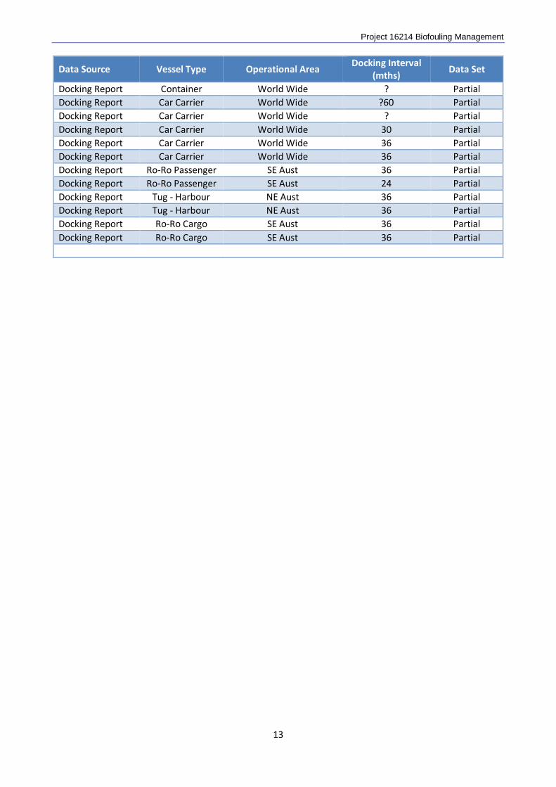
The core data sets, with general information on the type of data and vessels, are listed in Table 1. As listed in previous sections, incomplete information for another 95 vessels was held in the PI’s archive for reference.
11

Project 16214 Biofouling Management
Table 1. Core data sets obtained and analysed in the project.
Data Source Vessel Type Operational Area Docking Interval
(mths) Data Set
Reporting Package
OPSV NW Aust 17 Full
Reporting Package
OPSV W Aust 40 Full
Reporting Package
OPSV Asia Pacific 40 Full
Reporting Package
OPSV NW Pacific 36 Full
Reporting Package
OPSV NW Pacific 30 Full
Reporting Package
Tanker - Oil W Africa / S Asia 60 Partial
Reporting Package
Tanker - Oil NE Atlantic / Persian Gulf 10 Partial
Reporting Package
Tanker - Oil NE Atlantic / Persian Gulf 54 Partial
Reporting Package
Tanker - Oil Arabian Gulf / NW Pacific 30 Partial
Reporting Package
Tanker - Oil Arabian Gulf / NW Pacific 36 Partial
Reporting Package
Tanker- Oil Persian Gulf / S Asia ? Partial
Reporting Package
Tanker - Oil USA/Europe/Asia 30 Partial
Reporting Package
Tanker - Oil USA/Europe/Asia 38 Partial
Reporting Package
Tanker - Oil USA/Europe/Asia 46 Partial
Inspection Type A Passenger SW Pacific 36 Full Inspection Type A Ro-Ro Cargo SE Aust 24 Full Inspection Type A Ro-Ro Passenger SE Aust 23 Full Inspection Type A OPSV SE Aust 30 Partial Inspection Type A OPSV SE Aust 30 Partial Inspection Type B Ro-Ro Cargo SE Aust 24 Full Inspection Type B Seismic Survey NW Aust / PNG 15 Full Inspection Type B Dredger Suez / India 24 Partial
Inspection Type B Hopper Barges
(3) SE Asia 13 Partial
Inspection Type B Dredger Taiwan 7 Full Inspection Type B Ro-Ro Cargo N Aust 7 Partial Inspection Type B Tug - Offshore NW Aust / Indonesia 19 Partial
Inspection Type B Fishing Vessel SW Aust / Southern
Ocean ? Partial
Docking Report Passenger SW Pacific 24 Partial Docking Report Container World Wide 26 Partial
12
Project 16214 Biofouling Management
Data Source Vessel Type Operational Area Docking Interval
(mths) Data Set
Docking Report Container World Wide ? Partial Docking Report Car Carrier World Wide ?60 Partial Docking Report Car Carrier World Wide ? Partial Docking Report Car Carrier World Wide 30 Partial Docking Report Car Carrier World Wide 36 Partial Docking Report Car Carrier World Wide 36 Partial Docking Report Ro-Ro Passenger SE Aust 36 Partial Docking Report Ro-Ro Passenger SE Aust 24 Partial Docking Report Tug - Harbour NE Aust 36 Partial Docking Report Tug - Harbour NE Aust 36 Partial Docking Report Ro-Ro Cargo SE Aust 36 Partial Docking Report Ro-Ro Cargo SE Aust 36 Partial
13
Project 16214 Biofouling Management
6 OBSERVATIONS
6.1 Paint Systems
Vessel data obtained in the present study included vessels painted with CDP, SPC and FRC coatings. For CDP and SPC coatings, data were obtained for both soft and hard formulations. Findings on the different vessel areas are described below.
Hulls
The broad industry classifications of biofouling into “slime”, “soft” and “hard” were applied to analysing the reports, as higher levels of discrimination between organism types were not possible. “Soft” fouling includes macroalgae and animals such as soft corals, sponges, anemones, hydroids, erect bryozoans and ascidians (Callow and Callow 2002). “Hard” fouling includes barnacles, bivalve molluscs and calcareous tubeworms. The observations on the performance of coatings within this study generally conform to the industry understanding of, and expectations for, antifouling coating performance (Lewis 2002; Thomason 2010; AkzoNobel 2013): Boottops
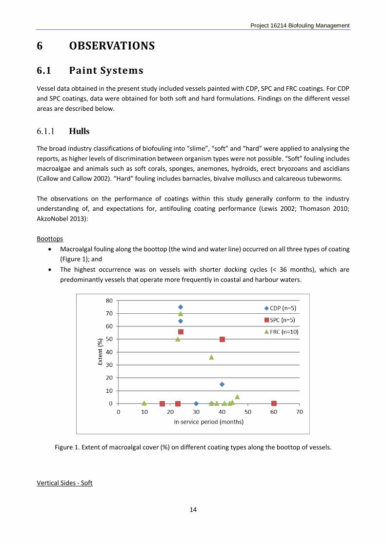
• Macroalgal fouling along the boottop (the wind and water line) occurred on all three types of coating (Figure 1); and
• The highest occurrence was on vessels with shorter docking cycles (< 36 months), which are predominantly vessels that operate more frequently in coastal and harbour waters.
Figure 1. Extent of macroalgal cover (%) on different coating types along the boottop of vessels.
Vertical Sides - Soft
14
Project 16214 Biofouling Management
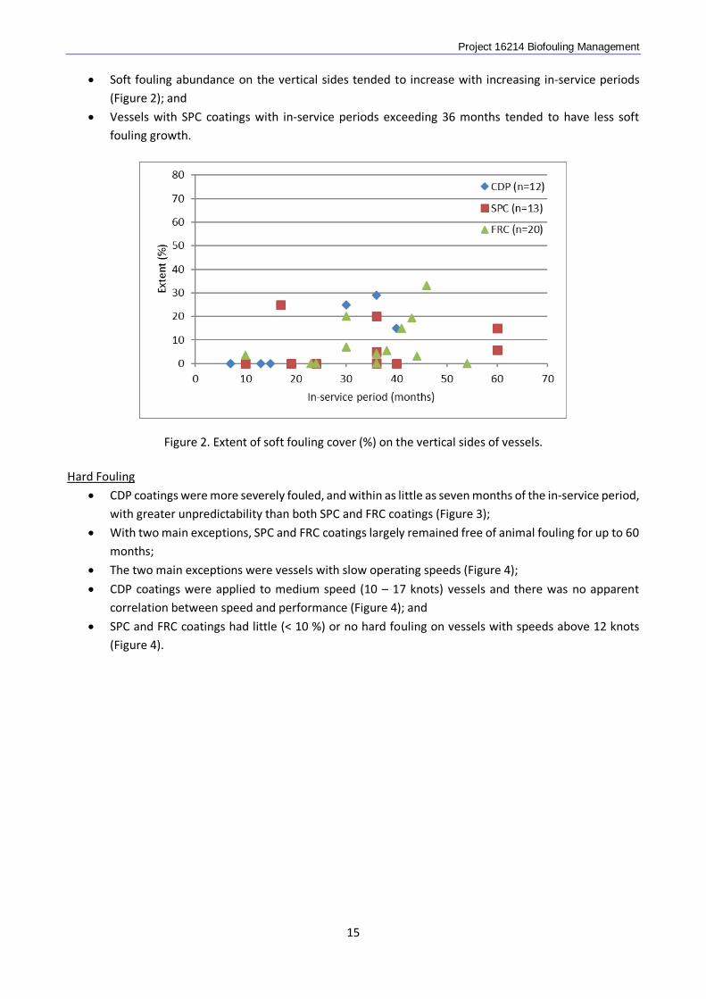
• Soft fouling abundance on the vertical sides tended to increase with increasing in-service periods (Figure 2); and
• Vessels with SPC coatings with in-service periods exceeding 36 months tended to have less soft fouling growth.
Figure 2. Extent of soft fouling cover (%) on the vertical sides of vessels.
Hard Fouling
• CDP coatings were more severely fouled, and within as little as seven months of the in-service period, with greater unpredictability than both SPC and FRC coatings (Figure 3);
• With two main exceptions, SPC and FRC coatings largely remained free of animal fouling for up to 60 months;
• The two main exceptions were vessels with slow operating speeds (Figure 4);
• CDP coatings were applied to medium speed (10 – 17 knots) vessels and there was no apparent correlation between speed and performance (Figure 4); and
• SPC and FRC coatings had little (< 10 %) or no hard fouling on vessels with speeds above 12 knots (Figure 4).
15
Project 16214 Biofouling Management
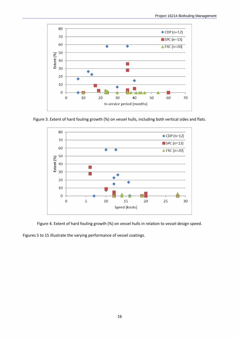
Figure 3. Extent of hard fouling growth (%) on vessel hulls, including both vertical sides and flats.
Figure 4. Extent of hard fouling growth (%) on vessel hulls in relation to vessel design speed. Figures 5 to 15 illustrate the varying performance of vessel coatings.
16
Project 16214 Biofouling Management
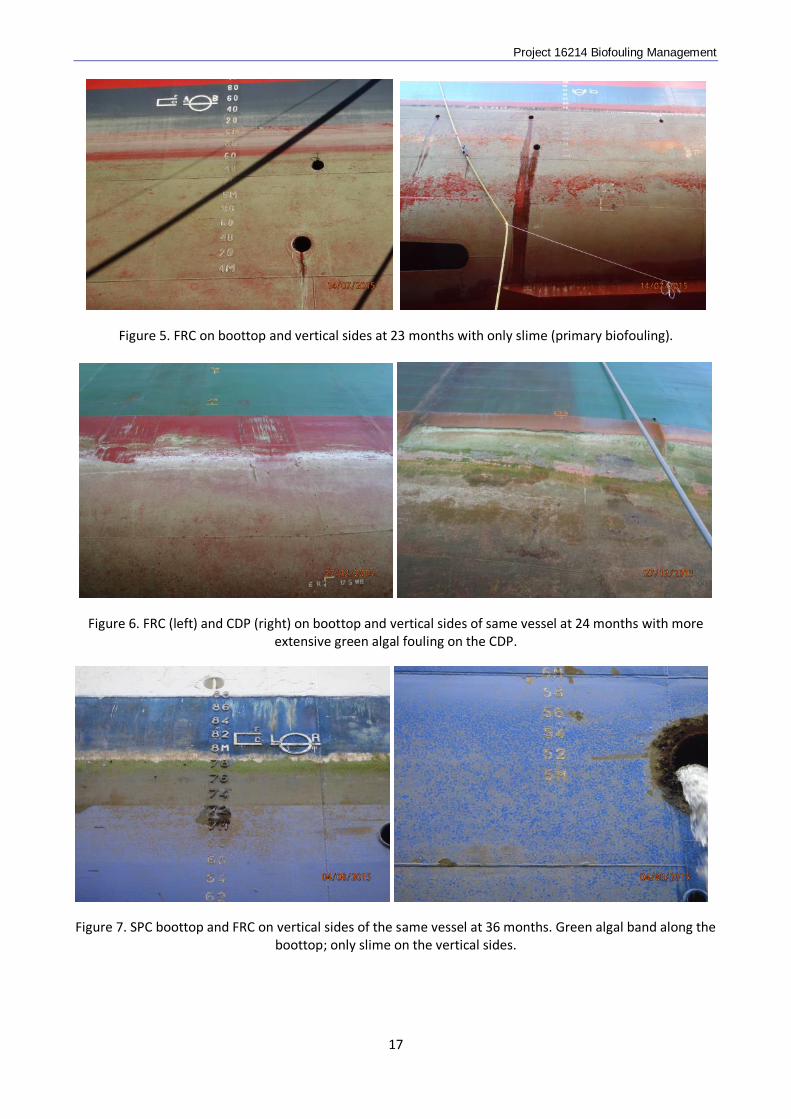
Figure 5. FRC on boottop and vertical sides at 23 months with only slime (primary biofouling).
Figure 6. FRC (left) and CDP (right) on boottop and vertical sides of same vessel at 24 months with more
extensive green algal fouling on the CDP.
Figure 7. SPC boottop and FRC on vertical sides of the same vessel at 36 months. Green algal band along the boottop; only slime on the vertical sides.
17
Project 16214 Biofouling Management
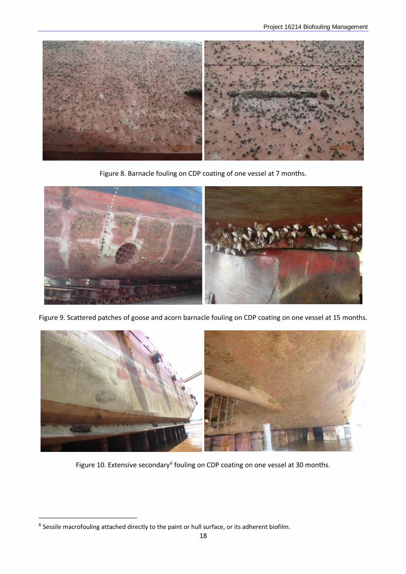
Figure 8. Barnacle fouling on CDP coating of one vessel at 7 months.
Figure 9. Scattered patches of goose and acorn barnacle fouling on CDP coating on one vessel at 15 months.
Figure 10. Extensive secondary6 fouling on CDP coating on one vessel at 30 months.
6 Sessile macrofouling attached directly to the paint or hull surface, or its adherent biofilm. 18
Project 16214 Biofouling Management
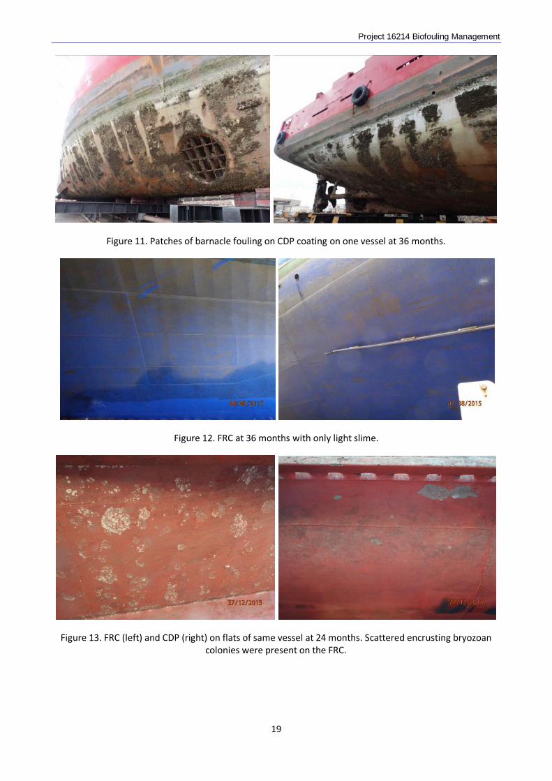
Figure 11. Patches of barnacle fouling on CDP coating on one vessel at 36 months.
Figure 12. FRC at 36 months with only light slime.
Figure 13. FRC (left) and CDP (right) on flats of same vessel at 24 months. Scattered encrusting bryozoan colonies were present on the FRC.
19
Project 16214 Biofouling Management
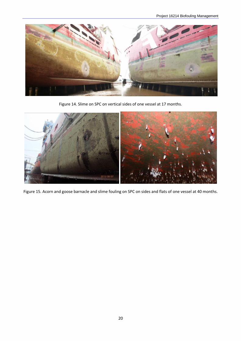
Figure 14. Slime on SPC on vertical sides of one vessel at 17 months.
Figure 15. Acorn and goose barnacle and slime fouling on SPC on sides and flats of one vessel at 40 months.
20
Project 16214 Biofouling Management
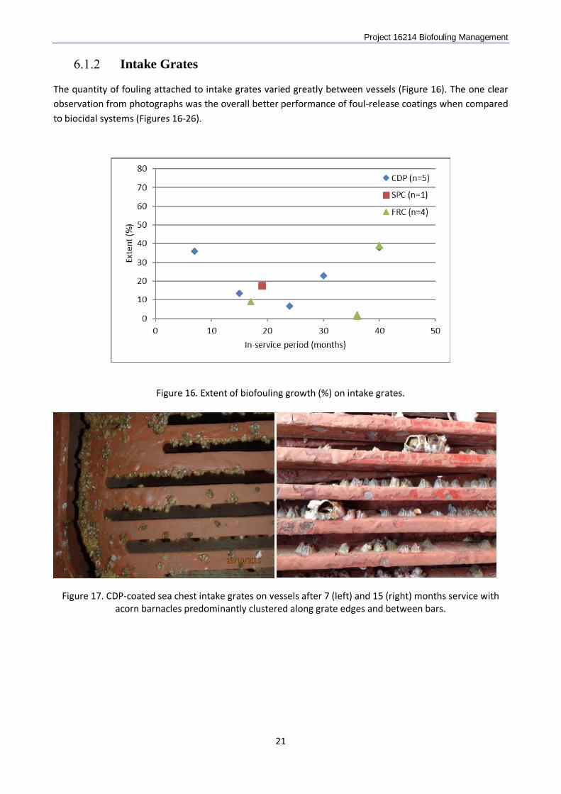
Intake Grates
The quantity of fouling attached to intake grates varied greatly between vessels (Figure 16). The one clear observation from photographs was the overall better performance of foul-release coatings when compared to biocidal systems (Figures 16-26).
Figure 16. Extent of biofouling growth (%) on intake grates.
Figure 17. CDP-coated sea chest intake grates on vessels after 7 (left) and 15 (right) months service with acorn barnacles predominantly clustered along grate edges and between bars.
21
Project 16214 Biofouling Management
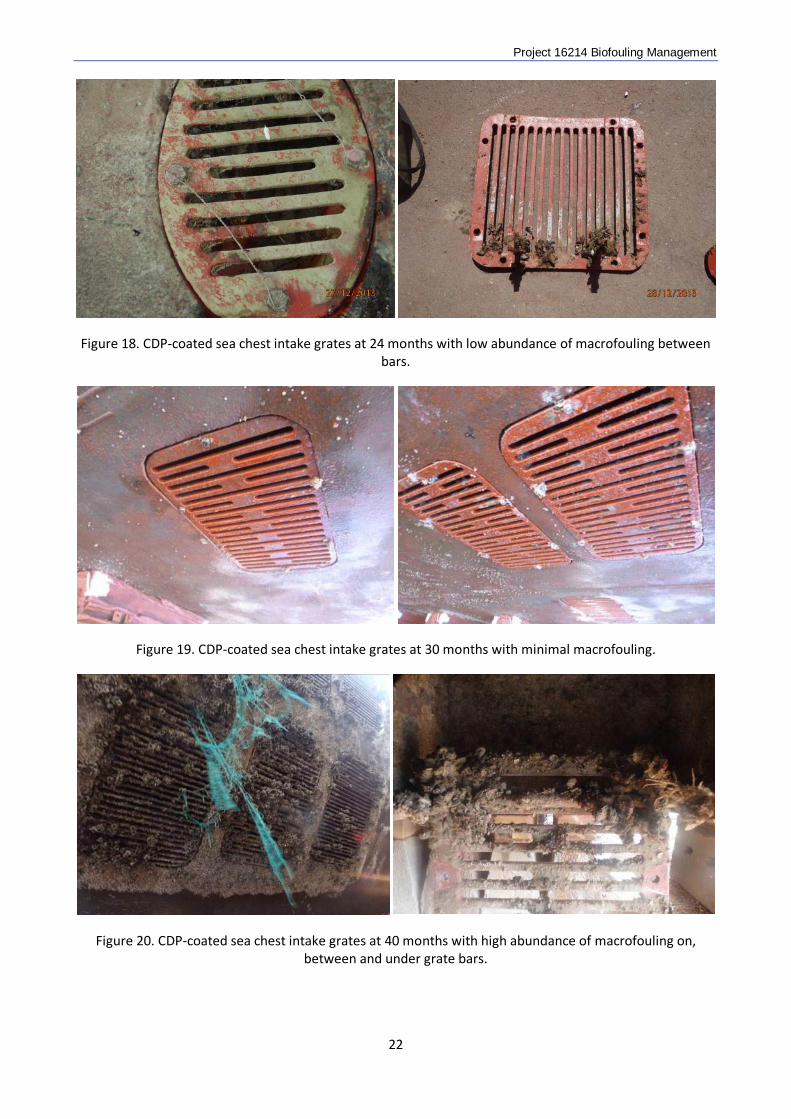
Figure 18. CDP-coated sea chest intake grates at 24 months with low abundance of macrofouling between bars.
Figure 19. CDP-coated sea chest intake grates at 30 months with minimal macrofouling.
Figure 20. CDP-coated sea chest intake grates at 40 months with high abundance of macrofouling on, between and under grate bars.
22
Project 16214 Biofouling Management
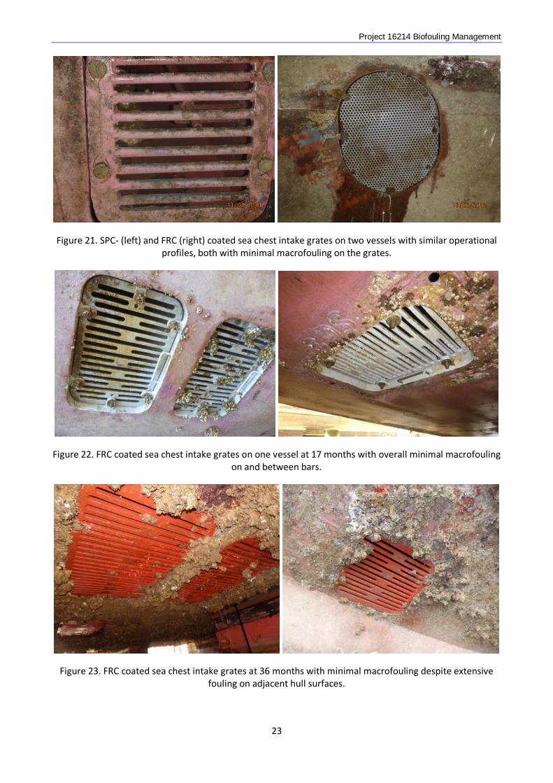
Figure 21. SPC- (left) and FRC (right) coated sea chest intake grates on two vessels with similar operational profiles, both with minimal macrofouling on the grates.
Figure 22. FRC coated sea chest intake grates on one vessel at 17 months with overall minimal macrofouling on and between bars.
Figure 23. FRC coated sea chest intake grates at 36 months with minimal macrofouling despite extensive fouling on adjacent hull surfaces.
23
Project 16214 Biofouling Management
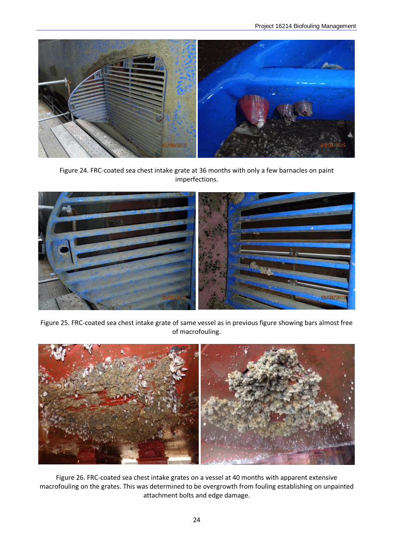
Figure 24. FRC-coated sea chest intake grate at 36 months with only a few barnacles on paint imperfections.
Figure 25. FRC-coated sea chest intake grate of same vessel as in previous figure showing bars almost free
of macrofouling.
Figure 26. FRC-coated sea chest intake grates on a vessel at 40 months with apparent extensive macrofouling on the grates. This was determined to be overgrowth from fouling establishing on unpainted
attachment bolts and edge damage.
24
Project 16214 Biofouling Management
Sea Chests
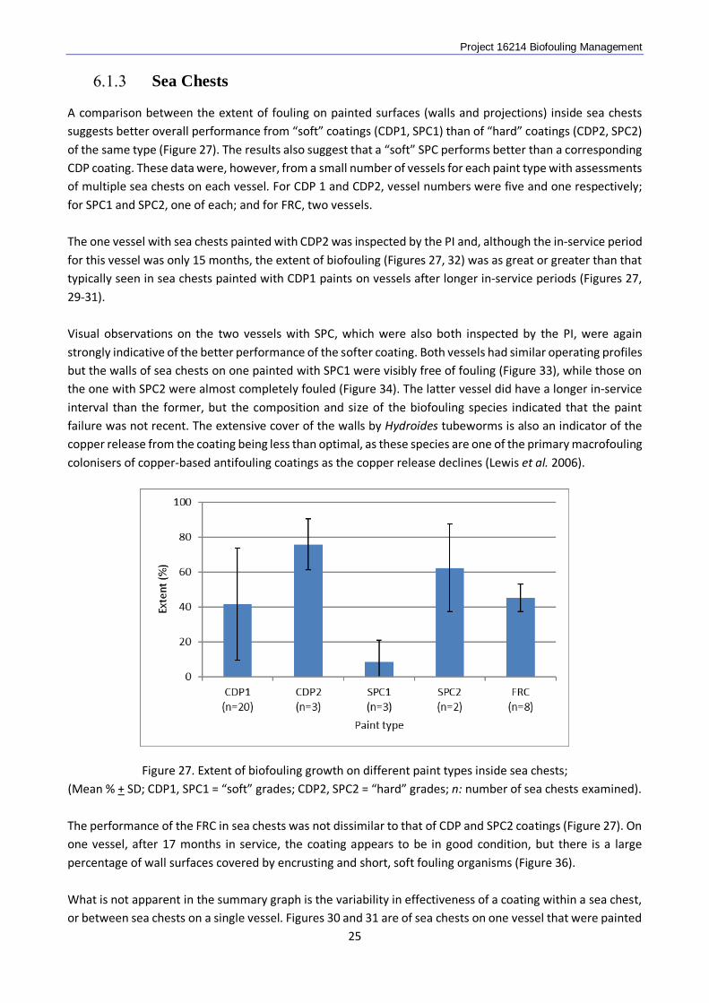
A comparison between the extent of fouling on painted surfaces (walls and projections) inside sea chests suggests better overall performance from “soft” coatings (CDP1, SPC1) than of “hard” coatings (CDP2, SPC2) of the same type (Figure 27). The results also suggest that a “soft” SPC performs better than a corresponding CDP coating. These data were, however, from a small number of vessels for each paint type with assessments of multiple sea chests on each vessel. For CDP 1 and CDP2, vessel numbers were five and one respectively; for SPC1 and SPC2, one of each; and for FRC, two vessels. The one vessel with sea chests painted with CDP2 was inspected by the PI and, although the in-service period for this vessel was only 15 months, the extent of biofouling (Figures 27, 32) was as great or greater than that typically seen in sea chests painted with CDP1 paints on vessels after longer in-service periods (Figures 27, 29-31). Visual observations on the two vessels with SPC, which were also both inspected by the PI, were again strongly indicative of the better performance of the softer coating. Both vessels had similar operating profiles but the walls of sea chests on one painted with SPC1 were visibly free of fouling (Figure 33), while those on the one with SPC2 were almost completely fouled (Figure 34). The latter vessel did have a longer in-service interval than the former, but the composition and size of the biofouling species indicated that the paint failure was not recent. The extensive cover of the walls by Hydroides tubeworms is also an indicator of the copper release from the coating being less than optimal, as these species are one of the primary macrofouling colonisers of copper-based antifouling coatings as the copper release declines (Lewis et al. 2006).
Figure 27. Extent of biofouling growth on different paint types inside sea chests; (Mean % + SD; CDP1, SPC1 = “soft” grades; CDP2, SPC2 = “hard” grades; n: number of sea chests examined). The performance of the FRC in sea chests was not dissimilar to that of CDP and SPC2 coatings (Figure 27). On one vessel, after 17 months in service, the coating appears to be in good condition, but there is a large percentage of wall surfaces covered by encrusting and short, soft fouling organisms (Figure 36). What is not apparent in the summary graph is the variability in effectiveness of a coating within a sea chest, or between sea chests on a single vessel. Figures 30 and 31 are of sea chests on one vessel that were painted
25
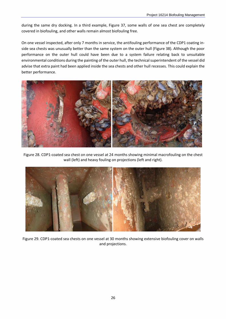
Project 16214 Biofouling Management during the same dry docking. In a third example, Figure 37, some walls of one sea chest are completely covered in biofouling, and other walls remain almost biofouling free. On one vessel inspected, after only 7 months in service, the antifouling performance of the CDP1 coating in-side sea chests was unusually better than the same system on the outer hull (Figure 38). Although the poor performance on the outer hull could have been due to a system failure relating back to unsuitable environmental conditions during the painting of the outer hull, the technical superintendent of the vessel did advise that extra paint had been applied inside the sea chests and other hull recesses. This could explain the better performance.
Figure 28. CDP1-coated sea chest on one vessel at 24 months showing minimal macrofouling on the chest wall (left) and heavy fouling on projections (left and right).
Figure 29. CDP1-coated sea chests on one vessel at 30 months showing extensive biofouling cover on walls and projections.
26
Project 16214 Biofouling Management
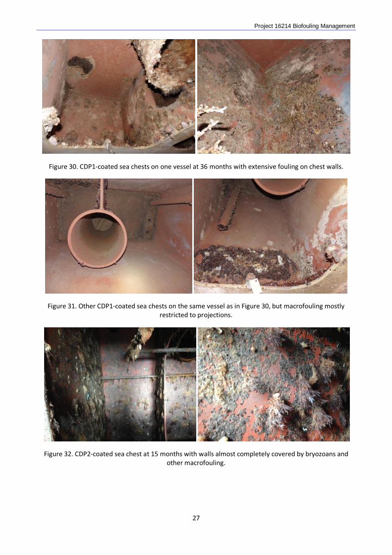
Figure 30. CDP1-coated sea chests on one vessel at 36 months with extensive fouling on chest walls.
Figure 31. Other CDP1-coated sea chests on the same vessel as in Figure 30, but macrofouling mostly restricted to projections.
Figure 32. CDP2-coated sea chest at 15 months with walls almost completely covered by bryozoans and other macrofouling.
27
Project 16214 Biofouling Management
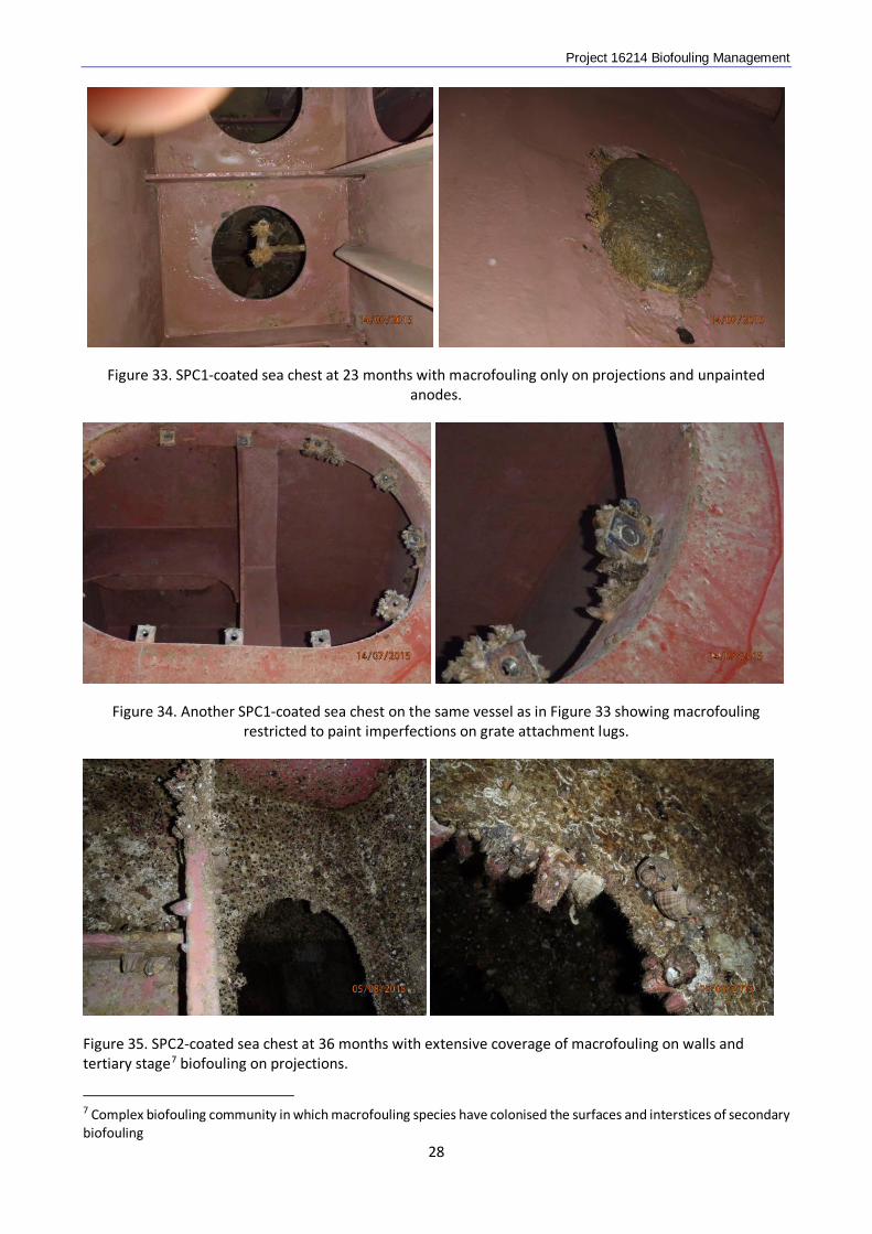
Figure 33. SPC1-coated sea chest at 23 months with macrofouling only on projections and unpainted anodes.
Figure 34. Another SPC1-coated sea chest on the same vessel as in Figure 33 showing macrofouling restricted to paint imperfections on grate attachment lugs.
Figure 35. SPC2-coated sea chest at 36 months with extensive coverage of macrofouling on walls and tertiary stage7 biofouling on projections.
7 Complex biofouling community in which macrofouling species have colonised the surfaces and interstices of secondary biofouling
28
Project 16214 Biofouling Management
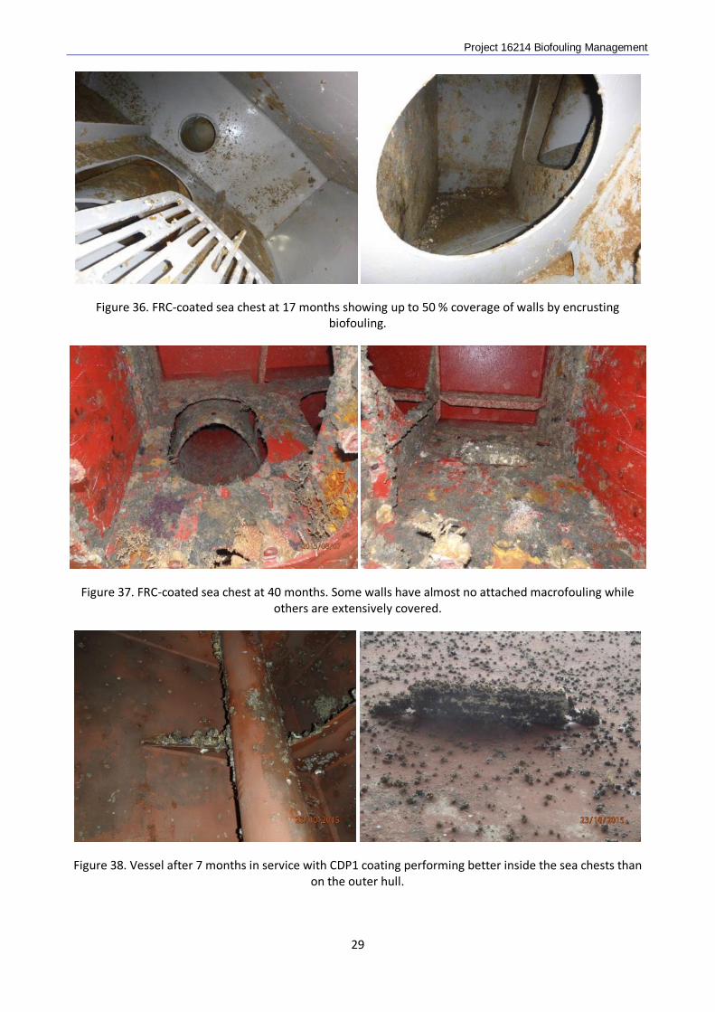
Figure 36. FRC-coated sea chest at 17 months showing up to 50 % coverage of walls by encrusting biofouling.
Figure 37. FRC-coated sea chest at 40 months. Some walls have almost no attached macrofouling while others are extensively covered.
Figure 38. Vessel after 7 months in service with CDP1 coating performing better inside the sea chests than on the outer hull.
29
Project 16214 Biofouling Management
Other Niches
Rudders
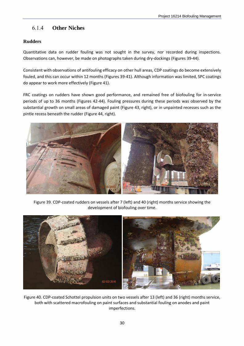
Quantitative data on rudder fouling was not sought in the survey, nor recorded during inspections. Observations can, however, be made on photographs taken during dry-dockings (Figures 39-44). Consistent with observations of antifouling efficacy on other hull areas, CDP coatings do become extensively fouled, and this can occur within 12 months (Figures 39-41). Although information was limited, SPC coatings do appear to work more effectively (Figure 41). FRC coatings on rudders have shown good performance, and remained free of biofouling for in-service periods of up to 36 months (Figures 42-44). Fouling pressures during these periods was observed by the substantial growth on small areas of damaged paint (Figure 43, right), or in unpainted recesses such as the pintle recess beneath the rudder (Figure 44, right).
Figure 39. CDP-coated rudders on vessels after 7 (left) and 40 (right) months service showing the development of biofouling over time.
Figure 40. CDP-coated Schottel propulsion units on two vessels after 13 (left) and 36 (right) months service, both with scattered macrofouling on paint surfaces and substantial fouling on anodes and paint
imperfections.
30
Project 16214 Biofouling Management
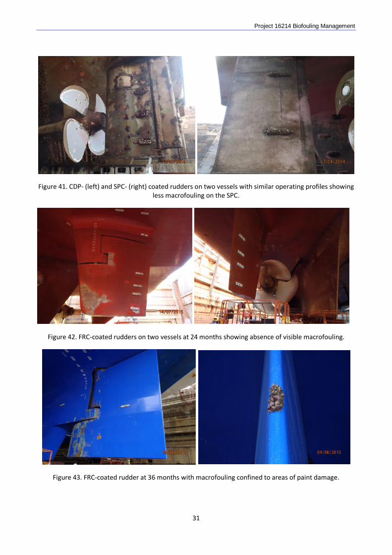
Figure 41. CDP- (left) and SPC- (right) coated rudders on two vessels with similar operating profiles showing less macrofouling on the SPC.
Figure 42. FRC-coated rudders on two vessels at 24 months showing absence of visible macrofouling.
Figure 43. FRC-coated rudder at 36 months with macrofouling confined to areas of paint damage.
31
Project 16214 Biofouling Management
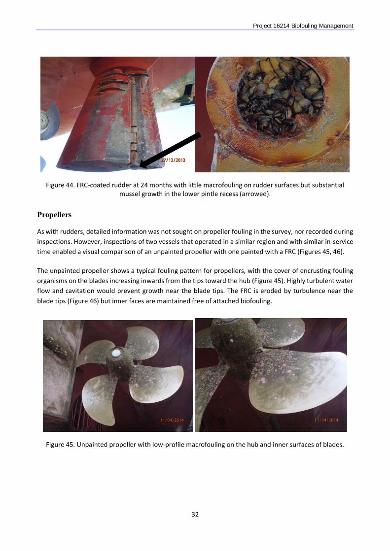
Figure 44. FRC-coated rudder at 24 months with little macrofouling on rudder surfaces but substantial mussel growth in the lower pintle recess (arrowed).
Propellers
As with rudders, detailed information was not sought on propeller fouling in the survey, nor recorded during inspections. However, inspections of two vessels that operated in a similar region and with similar in-service time enabled a visual comparison of an unpainted propeller with one painted with a FRC (Figures 45, 46). The unpainted propeller shows a typical fouling pattern for propellers, with the cover of encrusting fouling organisms on the blades increasing inwards from the tips toward the hub (Figure 45). Highly turbulent water flow and cavitation would prevent growth near the blade tips. The FRC is eroded by turbulence near the blade tips (Figure 46) but inner faces are maintained free of attached biofouling.
Figure 45. Unpainted propeller with low-profile macrofouling on the hub and inner surfaces of blades.
32
Project 16214 Biofouling Management
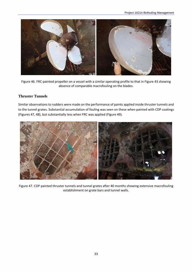
Figure 46. FRC-painted propeller on a vessel with a similar operating profile to that in Figure 43 showing absence of comparable macrofouling on the blades.
Thruster Tunnels
Similar observations to rudders were made on the performance of paints applied inside thruster tunnels and to the tunnel grates. Substantial accumulation of fouling was seen on these when painted with CDP coatings (Figures 47, 48), but substantially less when FRC was applied (Figure 49).
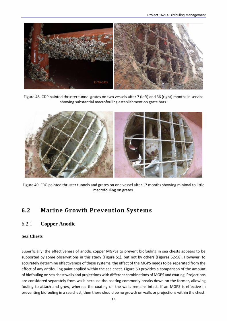
Figure 47. CDP painted thruster tunnels and tunnel grates after 40 months showing extensive macrofouling establishment on grate bars and tunnel walls.
33
Project 16214 Biofouling Management
Figure 48. CDP painted thruster tunnel grates on two vessels after 7 (left) and 36 (right) months in service showing substantial macrofouling establishment on grate bars.
Figure 49. FRC-painted thruster tunnels and grates on one vessel after 17 months showing minimal to little macrofouling on grates.
6.2 Marine Growth Prevention Systems
Copper Anodic
Sea Chests
Superficially, the effectiveness of anodic copper MGPSs to prevent biofouling in sea chests appears to be supported by some observations in this study (Figure 51), but not by others (Figures 52-58). However, to accurately determine effectiveness of these systems, the effect of the MGPS needs to be separated from the effect of any antifouling paint applied within the sea chest. Figure 50 provides a comparison of the amount of biofouling on sea chest walls and projections with different combinations of MGPS and coating. Projections are considered separately from walls because the coating commonly breaks down on the former, allowing fouling to attach and grow, whereas the coating on the walls remains intact. If an MGPS is effective in preventing biofouling in a sea chest, then there should be no growth on walls or projections within the chest.
34
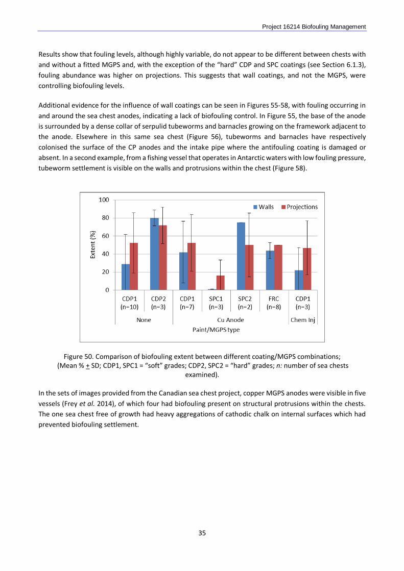
Project 16214 Biofouling Management Results show that fouling levels, although highly variable, do not appear to be different between chests with and without a fitted MGPS and, with the exception of the “hard” CDP and SPC coatings (see Section 6.1.3), fouling abundance was higher on projections. This suggests that wall coatings, and not the MGPS, were controlling biofouling levels. Additional evidence for the influence of wall coatings can be seen in Figures 55-58, with fouling occurring in and around the sea chest anodes, indicating a lack of biofouling control. In Figure 55, the base of the anode is surrounded by a dense collar of serpulid tubeworms and barnacles growing on the framework adjacent to the anode. Elsewhere in this same sea chest (Figure 56), tubeworms and barnacles have respectively colonised the surface of the CP anodes and the intake pipe where the antifouling coating is damaged or absent. In a second example, from a fishing vessel that operates in Antarctic waters with low fouling pressure, tubeworm settlement is visible on the walls and protrusions within the chest (Figure 58).
Figure 50. Comparison of biofouling extent between different coating/MGPS combinations; (Mean % + SD; CDP1, SPC1 = “soft” grades; CDP2, SPC2 = “hard” grades; n: number of sea chests
examined).
In the sets of images provided from the Canadian sea chest project, copper MGPS anodes were visible in five vessels (Frey et al. 2014), of which four had biofouling present on structural protrusions within the chests. The one sea chest free of growth had heavy aggregations of cathodic chalk on internal surfaces which had prevented biofouling settlement.
35
Project 16214 Biofouling Management
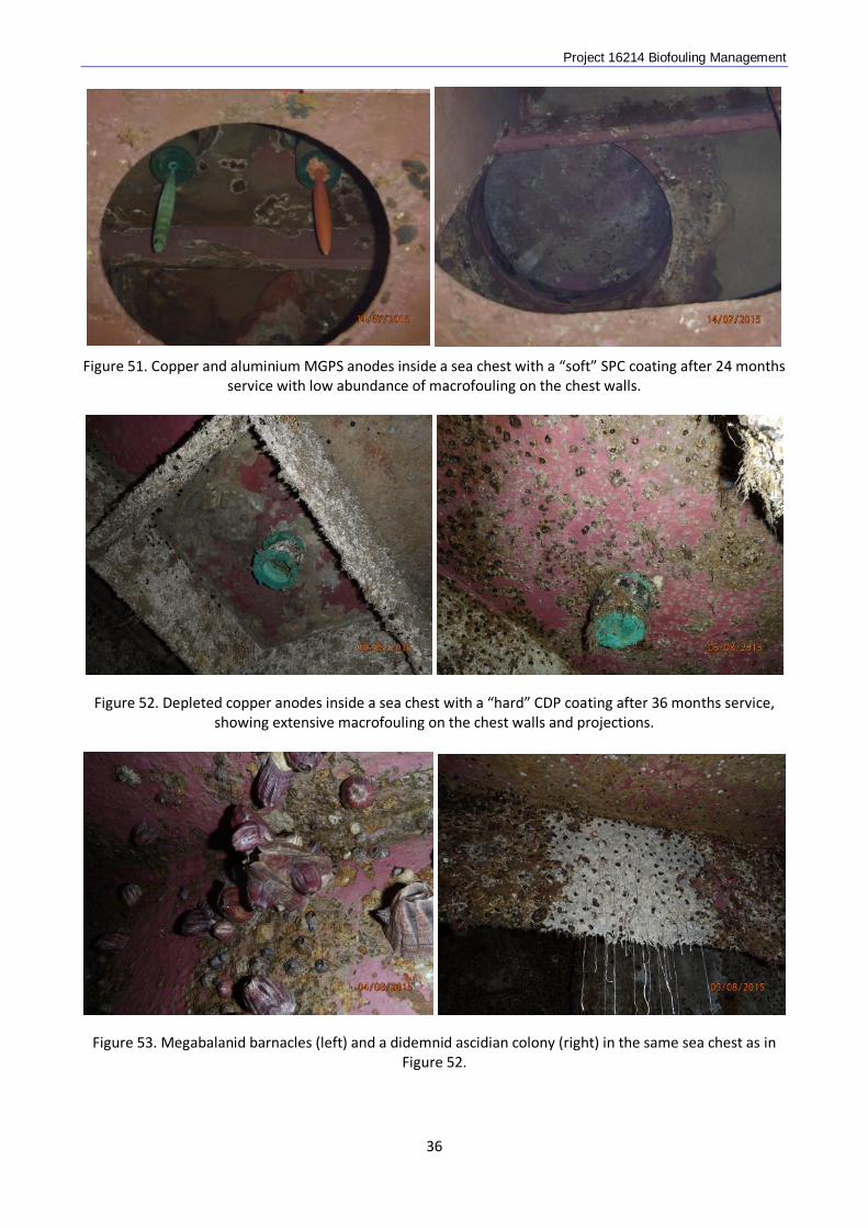
Figure 51. Copper and aluminium MGPS anodes inside a sea chest with a “soft” SPC coating after 24 months
service with low abundance of macrofouling on the chest walls.
Figure 52. Depleted copper anodes inside a sea chest with a “hard” CDP coating after 36 months service, showing extensive macrofouling on the chest walls and projections.
Figure 53. Megabalanid barnacles (left) and a didemnid ascidian colony (right) in the same sea chest as in Figure 52.
36
Project 16214 Biofouling Management
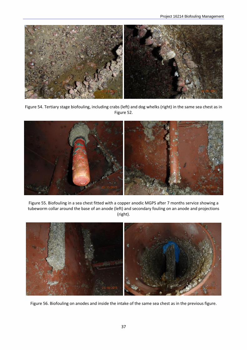
Figure 54. Tertiary stage biofouling, including crabs (left) and dog whelks (right) in the same sea chest as in Figure 52.
Figure 55. Biofouling in a sea chest fitted with a copper anodic MGPS after 7 months service showing a tubeworm collar around the base of an anode (left) and secondary fouling on an anode and projections
(right).
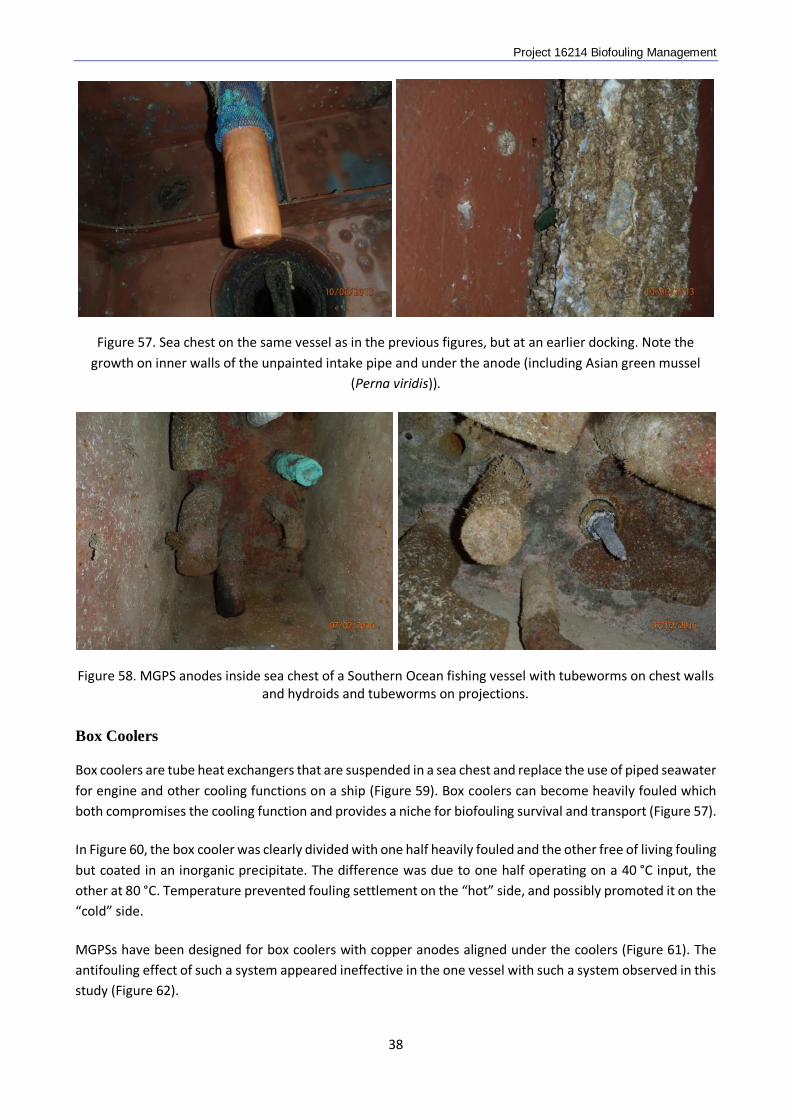
Figure 56. Biofouling on anodes and inside the intake of the same sea chest as in the previous figure.
37
Project 16214 Biofouling Management
Figure 57. Sea chest on the same vessel as in the previous figures, but at an earlier docking. Note the growth on inner walls of the unpainted intake pipe and under the anode (including Asian green mussel
(Perna viridis)).
Figure 58. MGPS anodes inside sea chest of a Southern Ocean fishing vessel with tubeworms on chest walls
and hydroids and tubeworms on projections.
Box Coolers
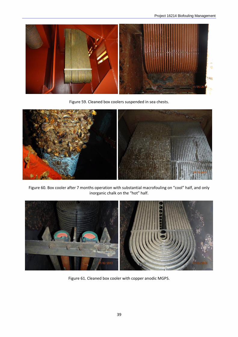
Box coolers are tube heat exchangers that are suspended in a sea chest and replace the use of piped seawater for engine and other cooling functions on a ship (Figure 59). Box coolers can become heavily fouled which both compromises the cooling function and provides a niche for biofouling survival and transport (Figure 57). In Figure 60, the box cooler was clearly divided with one half heavily fouled and the other free of living fouling but coated in an inorganic precipitate. The difference was due to one half operating on a 40 °C input, the other at 80 °C. Temperature prevented fouling settlement on the “hot” side, and possibly promoted it on the “cold” side. MGPSs have been designed for box coolers with copper anodes aligned under the coolers (Figure 61). The antifouling effect of such a system appeared ineffective in the one vessel with such a system observed in this study (Figure 62).
38
Project 16214 Biofouling Management
Figure 59. Cleaned box coolers suspended in sea chests.
Figure 60. Box cooler after 7 months operation with substantial macrofouling on “cool” half, and only inorganic chalk on the “hot” half.
Figure 61. Cleaned box cooler with copper anodic MGPS.
39
Project 16214 Biofouling Management
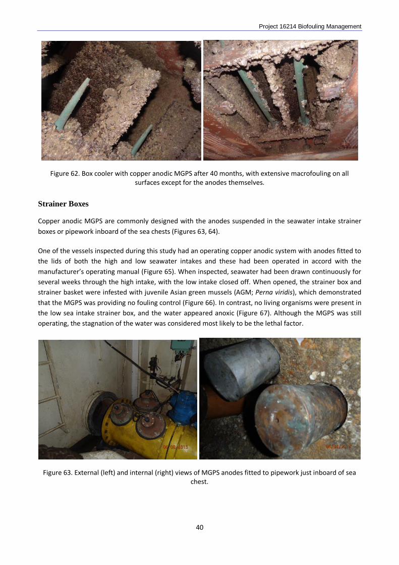
Figure 62. Box cooler with copper anodic MGPS after 40 months, with extensive macrofouling on all surfaces except for the anodes themselves.
Strainer Boxes
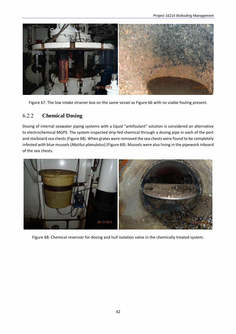
Copper anodic MGPS are commonly designed with the anodes suspended in the seawater intake strainer boxes or pipework inboard of the sea chests (Figures 63, 64). One of the vessels inspected during this study had an operating copper anodic system with anodes fitted to the lids of both the high and low seawater intakes and these had been operated in accord with the manufacturer’s operating manual (Figure 65). When inspected, seawater had been drawn continuously for several weeks through the high intake, with the low intake closed off. When opened, the strainer box and strainer basket were infested with juvenile Asian green mussels (AGM; Perna viridis), which demonstrated that the MGPS was providing no fouling control (Figure 66). In contrast, no living organisms were present in the low sea intake strainer box, and the water appeared anoxic (Figure 67). Although the MGPS was still operating, the stagnation of the water was considered most likely to be the lethal factor.
Figure 63. External (left) and internal (right) views of MGPS anodes fitted to pipework just inboard of sea chest.
40

Project 16214 Biofouling Management
Figure 64. MGPS anodes fitted to the lid of a seawater intake strainer box.
Figure 65. MGPS anodes fitted to the lid of a high intake strainer box.
Figure 66. AGM and other living biofouling inside the strainer box in Figure 65.
41
Project 16214 Biofouling Management
Figure 67. The low intake strainer box on the same vessel as Figure 66 with no viable fouling present.
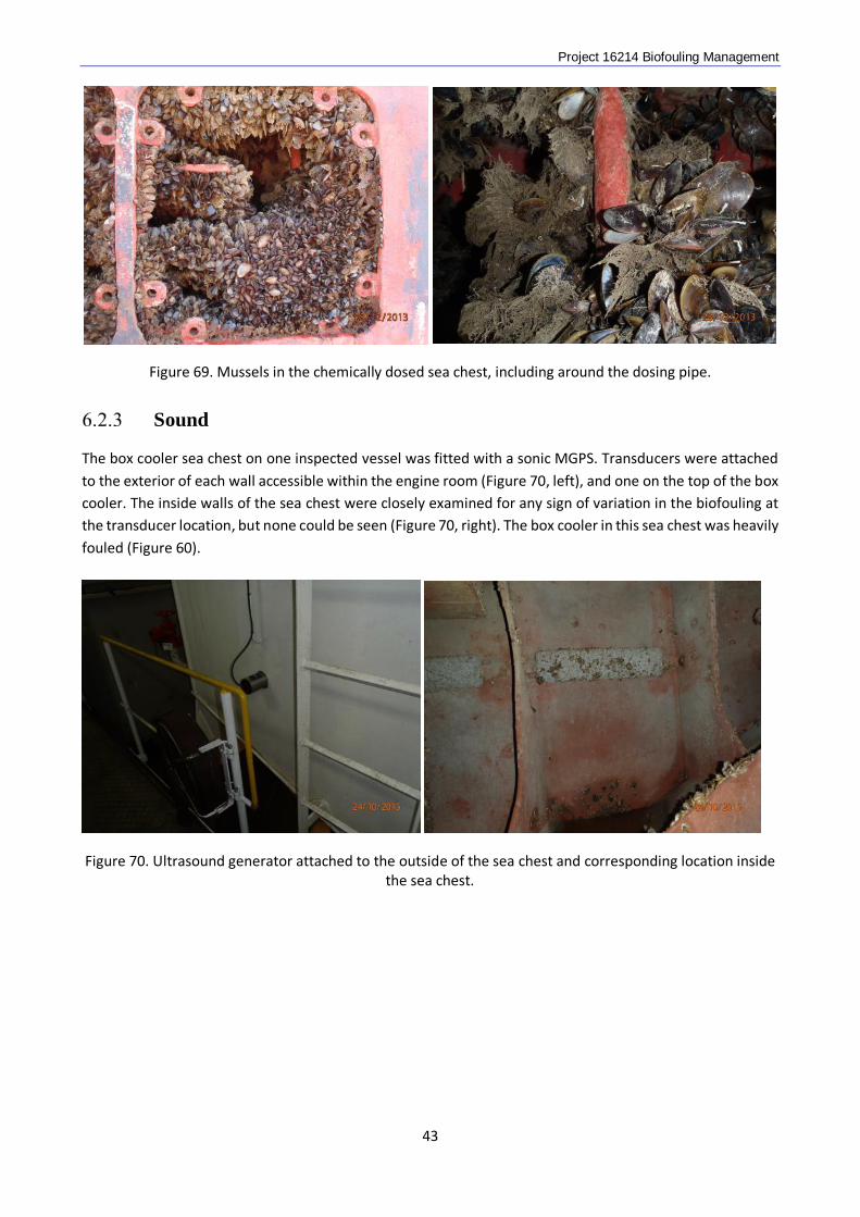
Chemical Dosing
Dosing of internal seawater piping systems with a liquid “antifoulant” solution is considered an alternative to electrochemical MGPS. The system inspected drip-fed chemical through a dosing pipe in each of the port and starboard sea chests (Figure 68). When grates were removed the sea chests were found to be completely infested with blue mussels (Mytilus planulatus) (Figure 69). Mussels were also lining in the pipework inboard of the sea chests.
Figure 68. Chemical reservoir for dosing and hull isolation valve in the chemically treated system.
42
Project 16214 Biofouling Management
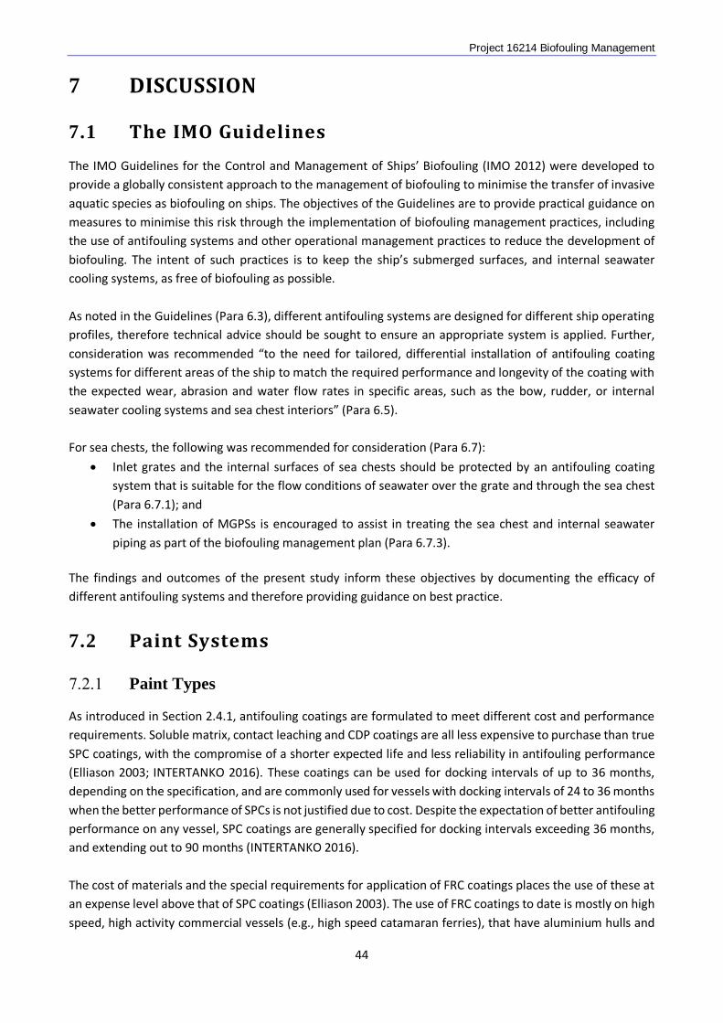
Figure 69. Mussels in the chemically dosed sea chest, including around the dosing pipe.
Sound
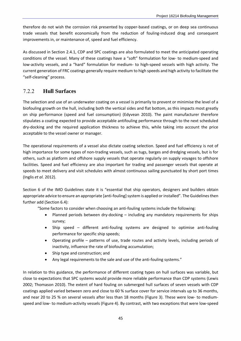
The box cooler sea chest on one inspected vessel was fitted with a sonic MGPS. Transducers were attached to the exterior of each wall accessible within the engine room (Figure 70, left), and one on the top of the box cooler. The inside walls of the sea chest were closely examined for any sign of variation in the biofouling at the transducer location, but none could be seen (Figure 70, right). The box cooler in this sea chest was heavily fouled (Figure 60).
Figure 70. Ultrasound generator attached to the outside of the sea chest and corresponding location inside
the sea chest.
43
Project 16214 Biofouling Management
7 DISCUSSION
7.1 The IMO Guidelines
The IMO Guidelines for the Control and Management of Ships’ Biofouling (IMO 2012) were developed to provide a globally consistent approach to the management of biofouling to minimise the transfer of invasive aquatic species as biofouling on ships. The objectives of the Guidelines are to provide practical guidance on measures to minimise this risk through the implementation of biofouling management practices, including the use of antifouling systems and other operational management practices to reduce the development of biofouling. The intent of such practices is to keep the ship’s submerged surfaces, and internal seawater cooling systems, as free of biofouling as possible. As noted in the Guidelines (Para 6.3), different antifouling systems are designed for different ship operating profiles, therefore technical advice should be sought to ensure an appropriate system is applied. Further, consideration was recommended “to the need for tailored, differential installation of antifouling coating systems for different areas of the ship to match the required performance and longevity of the coating with the expected wear, abrasion and water flow rates in specific areas, such as the bow, rudder, or internal seawater cooling systems and sea chest interiors” (Para 6.5). For sea chests, the following was recommended for consideration (Para 6.7):
• Inlet grates and the internal surfaces of sea chests should be protected by an antifouling coating system that is suitable for the flow conditions of seawater over the grate and through the sea chest (Para 6.7.1); and
• The installation of MGPSs is encouraged to assist in treating the sea chest and internal seawater piping as part of the biofouling management plan (Para 6.7.3).
The findings and outcomes of the present study inform these objectives by documenting the efficacy of different antifouling systems and therefore providing guidance on best practice.
7.2 Paint Systems
Paint Types
As introduced in Section 2.4.1, antifouling coatings are formulated to meet different cost and performance requirements. Soluble matrix, contact leaching and CDP coatings are all less expensive to purchase than true SPC coatings, with the compromise of a shorter expected life and less reliability in antifouling performance (Elliason 2003; INTERTANKO 2016). These coatings can be used for docking intervals of up to 36 months, depending on the specification, and are commonly used for vessels with docking intervals of 24 to 36 months when the better performance of SPCs is not justified due to cost. Despite the expectation of better antifouling performance on any vessel, SPC coatings are generally specified for docking intervals exceeding 36 months, and extending out to 90 months (INTERTANKO 2016). The cost of materials and the special requirements for application of FRC coatings places the use of these at an expense level above that of SPC coatings (Elliason 2003). The use of FRC coatings to date is mostly on high speed, high activity commercial vessels (e.g., high speed catamaran ferries), that have aluminium hulls and
44
Project 16214 Biofouling Management therefore do not wish the corrosion risk presented by copper-based coatings, or on deep sea continuous trade vessels that benefit economically from the reduction of fouling-induced drag and consequent improvements in, or maintenance of, speed and fuel efficiency. As discussed in Section 2.4.1, CDP and SPC coatings are also formulated to meet the anticipated operating conditions of the vessel. Many of these coatings have a “soft” formulation for low- to medium-speed and low-activity vessels, and a “hard” formulation for medium- to high-speed vessels with high activity. The current generation of FRC coatings generally require medium to high speeds and high activity to facilitate the “self-cleaning” process.
Hull Surfaces
The selection and use of an underwater coating on a vessel is primarily to prevent or minimise the level of a biofouling growth on the hull, including both the vertical sides and flat bottom, as this impacts most greatly on ship performance (speed and fuel consumption) (Edyvean 2010). The paint manufacturer therefore stipulates a coating expected to provide acceptable antifouling performance through to the next scheduled dry-docking and the required application thickness to achieve this, while taking into account the price acceptable to the vessel owner or manager. The operational requirements of a vessel also dictate coating selection. Speed and fuel efficiency is not of high importance for some types of non-trading vessels, such as tugs, barges and dredging vessels, but is for others, such as platform and offshore supply vessels that operate regularly on supply voyages to offshore facilities. Speed and fuel efficiency are also important for trading and passenger vessels that operate at speeds to meet delivery and visit schedules with almost continuous sailing punctuated by short port times (Inglis et al. 2012). Section 6 of the IMO Guidelines state it is “essential that ship operators, designers and builders obtain appropriate advice to ensure an appropriate [anti-fouling] system is applied or installed”. The Guidelines then further add (Section 6.4): “Some factors to consider when choosing an anti-fouling systems include the following:
• Planned periods between dry-docking – including any mandatory requirements for ships survey;
• Ship speed – different anti-fouling systems are designed to optimise anti-fouling performance for specific ship speeds;
• Operating profile – patterns of use, trade routes and activity levels, including periods of inactivity, influence the rate of biofouling accumulation;
• Ship type and construction; and
• Any legal requirements to the sale and use of the anti-fouling systems.” In relation to this guidance, the performance of different coating types on hull surfaces was variable, but close to expectations that SPC systems would provide more reliable performance than CDP systems (Lewis 2002; Thomason 2010). The extent of hard fouling on submerged hull surfaces of seven vessels with CDP coatings applied varied between zero and close to 60 % surface cover for service intervals up to 36 months, and near 20 to 25 % on several vessels after less than 18 months (Figure 3). These were low- to medium-speed and low- to medium-activity vessels (Figure 4). By contrast, with two exceptions that were low-speed
45
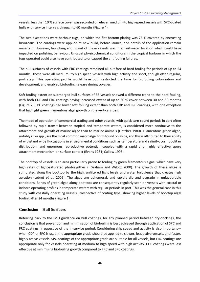
Project 16214 Biofouling Management vessels, less than 10 % surface cover was recorded on eleven medium- to high-speed vessels with SPC-coated hulls with service intervals through to 60 months (Figure 4). The two exceptions were harbour tugs, on which the flat bottom plating was 75 % covered by encrusting bryozoans. The coatings were applied at new build, before launch, and details of the application remain uncertain. However, launching and fit out of these vessels was in a freshwater location which could have impacted on polishing behaviour. Unusual physicochemical conditions in the tropical harbour in which the tugs operated could also have contributed to or caused the antifouling failures. The hull surfaces of vessels with FRC coatings remained all but free of hard fouling for periods of up to 54 months. These were all medium- to high-speed vessels with high activity and short, though often regular, port stays. This operating profile would have both restricted the time for biofouling colonisation and development, and enabled biofouling release during voyages. Soft fouling extent on submerged hull surfaces of 36 vessels showed a different trend to the hard fouling, with both CDP and FRC coatings having increased extent of up to 30 % cover between 30 and 50 months (Figure 2). SPC coatings had lower soft fouling extent than both CDP and FRC coatings, with one exception that had light green filamentous algal growth on the vertical sides. The mode of operation of commercial trading and other vessels, with quick turn-round periods in port often followed by rapid transit between tropical and temperate waters, is considered more conducive to the attachment and growth of marine algae than to marine animals (Fletcher 1980). Filamentous green algae, notably Ulva spp., are the most common macroalgal form found on ships, and this is attributed to their ability of withstand wide fluctuations in environmental conditions such as temperature and salinity, cosmopolitan distribution, and enormous reproductive potential, coupled with a rapid and highly effective spore attachment mechanism on surface contact (Evans 1981; Callow 1996). The boottop of vessels is an area particularly prone to fouling by green filamentous algae, which have very high rates of light-saturated photosynthesis (Graham and Wilcox 2000). The growth of these algae is stimulated along the boottop by the high, unfiltered light levels and water turbulence that creates high aeration (Lebret et al. 2009). The algae are ephemeral, and rapidly die and degrade in unfavourable conditions. Bands of green algae along boottops are consequently regularly seen on vessels with coastal or inshore operating profiles in temperate waters with regular periods in port. This was the general case in this study with coastally operating vessels, irrespective of coating type, showing higher levels of boottop algal fouling after 24 months (Figure 1).
Conclusion – Hull Surfaces
Referring back to the IMO guidance on hull coatings, for any planned period between dry-dockings, the conclusion is that prevention and minimisation of biofouling is best achieved through application of SPC and FRC coatings, irrespective of the in-service period. Considering ship speed and activity is also important—when CDP or SPC is used, the appropriate grade should be applied to slower, less active vessels, and faster, highly active vessels. SPC coatings of the appropriate grade are suitable for all vessels, but FRC coatings are appropriate only for vessels operating at medium to high speed with high activity. CDP coatings were less effective at minimising biofouling growth compared to FRC and SPC coatings.
46
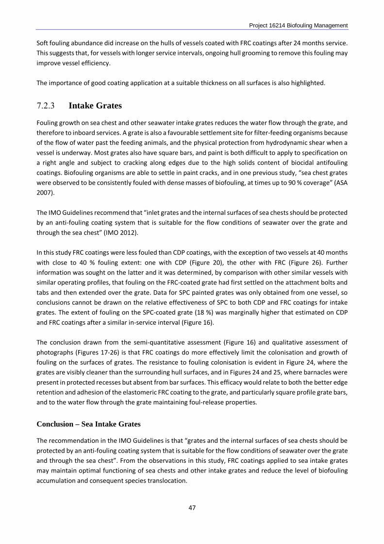
Project 16214 Biofouling Management Soft fouling abundance did increase on the hulls of vessels coated with FRC coatings after 24 months service. This suggests that, for vessels with longer service intervals, ongoing hull grooming to remove this fouling may improve vessel efficiency. The importance of good coating application at a suitable thickness on all surfaces is also highlighted.
Intake Grates
Fouling growth on sea chest and other seawater intake grates reduces the water flow through the grate, and therefore to inboard services. A grate is also a favourable settlement site for filter-feeding organisms because of the flow of water past the feeding animals, and the physical protection from hydrodynamic shear when a vessel is underway. Most grates also have square bars, and paint is both difficult to apply to specification on a right angle and subject to cracking along edges due to the high solids content of biocidal antifouling coatings. Biofouling organisms are able to settle in paint cracks, and in one previous study, “sea chest grates were observed to be consistently fouled with dense masses of biofouling, at times up to 90 % coverage” (ASA 2007). The IMO Guidelines recommend that “inlet grates and the internal surfaces of sea chests should be protected by an anti-fouling coating system that is suitable for the flow conditions of seawater over the grate and through the sea chest” (IMO 2012). In this study FRC coatings were less fouled than CDP coatings, with the exception of two vessels at 40 months with close to 40 % fouling extent: one with CDP (Figure 20), the other with FRC (Figure 26). Further information was sought on the latter and it was determined, by comparison with other similar vessels with similar operating profiles, that fouling on the FRC-coated grate had first settled on the attachment bolts and tabs and then extended over the grate. Data for SPC painted grates was only obtained from one vessel, so conclusions cannot be drawn on the relative effectiveness of SPC to both CDP and FRC coatings for intake grates. The extent of fouling on the SPC-coated grate (18 %) was marginally higher that estimated on CDP and FRC coatings after a similar in-service interval (Figure 16). The conclusion drawn from the semi-quantitative assessment (Figure 16) and qualitative assessment of photographs (Figures 17-26) is that FRC coatings do more effectively limit the colonisation and growth of fouling on the surfaces of grates. The resistance to fouling colonisation is evident in Figure 24, where the grates are visibly cleaner than the surrounding hull surfaces, and in Figures 24 and 25, where barnacles were present in protected recesses but absent from bar surfaces. This efficacy would relate to both the better edge retention and adhesion of the elastomeric FRC coating to the grate, and particularly square profile grate bars, and to the water flow through the grate maintaining foul-release properties.
Conclusion – Sea Intake Grates
The recommendation in the IMO Guidelines is that “grates and the internal surfaces of sea chests should be protected by an anti-fouling coating system that is suitable for the flow conditions of seawater over the grate and through the sea chest”. From the observations in this study, FRC coatings applied to sea intake grates may maintain optimal functioning of sea chests and other intake grates and reduce the level of biofouling accumulation and consequent species translocation.
47
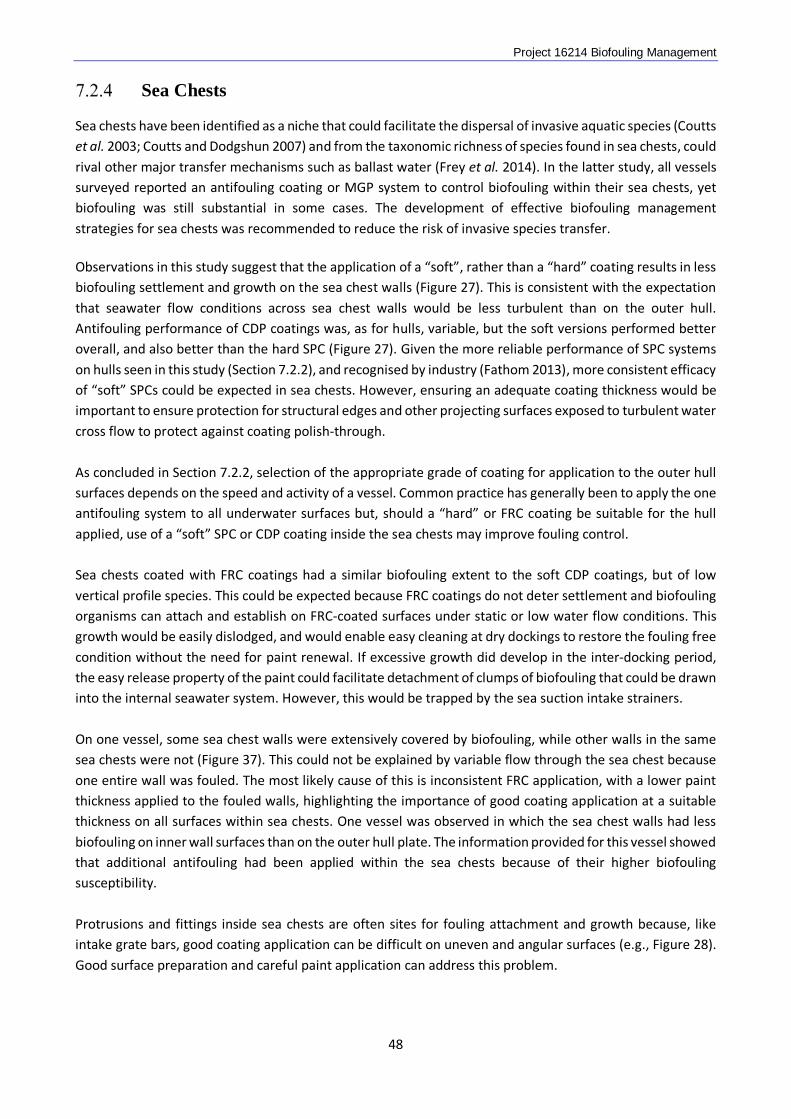
Project 16214 Biofouling Management
Sea Chests
Sea chests have been identified as a niche that could facilitate the dispersal of invasive aquatic species (Coutts et al. 2003; Coutts and Dodgshun 2007) and from the taxonomic richness of species found in sea chests, could rival other major transfer mechanisms such as ballast water (Frey et al. 2014). In the latter study, all vessels surveyed reported an antifouling coating or MGP system to control biofouling within their sea chests, yet biofouling was still substantial in some cases. The development of effective biofouling management strategies for sea chests was recommended to reduce the risk of invasive species transfer. Observations in this study suggest that the application of a “soft”, rather than a “hard” coating results in less biofouling settlement and growth on the sea chest walls (Figure 27). This is consistent with the expectation that seawater flow conditions across sea chest walls would be less turbulent than on the outer hull. Antifouling performance of CDP coatings was, as for hulls, variable, but the soft versions performed better overall, and also better than the hard SPC (Figure 27). Given the more reliable performance of SPC systems on hulls seen in this study (Section 7.2.2), and recognised by industry (Fathom 2013), more consistent efficacy of “soft” SPCs could be expected in sea chests. However, ensuring an adequate coating thickness would be important to ensure protection for structural edges and other projecting surfaces exposed to turbulent water cross flow to protect against coating polish-through. As concluded in Section 7.2.2, selection of the appropriate grade of coating for application to the outer hull surfaces depends on the speed and activity of a vessel. Common practice has generally been to apply the one antifouling system to all underwater surfaces but, should a “hard” or FRC coating be suitable for the hull applied, use of a “soft” SPC or CDP coating inside the sea chests may improve fouling control. Sea chests coated with FRC coatings had a similar biofouling extent to the soft CDP coatings, but of low vertical profile species. This could be expected because FRC coatings do not deter settlement and biofouling organisms can attach and establish on FRC-coated surfaces under static or low water flow conditions. This growth would be easily dislodged, and would enable easy cleaning at dry dockings to restore the fouling free condition without the need for paint renewal. If excessive growth did develop in the inter-docking period, the easy release property of the paint could facilitate detachment of clumps of biofouling that could be drawn into the internal seawater system. However, this would be trapped by the sea suction intake strainers. On one vessel, some sea chest walls were extensively covered by biofouling, while other walls in the same sea chests were not (Figure 37). This could not be explained by variable flow through the sea chest because one entire wall was fouled. The most likely cause of this is inconsistent FRC application, with a lower paint thickness applied to the fouled walls, highlighting the importance of good coating application at a suitable thickness on all surfaces within sea chests. One vessel was observed in which the sea chest walls had less biofouling on inner wall surfaces than on the outer hull plate. The information provided for this vessel showed that additional antifouling had been applied within the sea chests because of their higher biofouling susceptibility. Protrusions and fittings inside sea chests are often sites for fouling attachment and growth because, like intake grate bars, good coating application can be difficult on uneven and angular surfaces (e.g., Figure 28). Good surface preparation and careful paint application can address this problem.
48
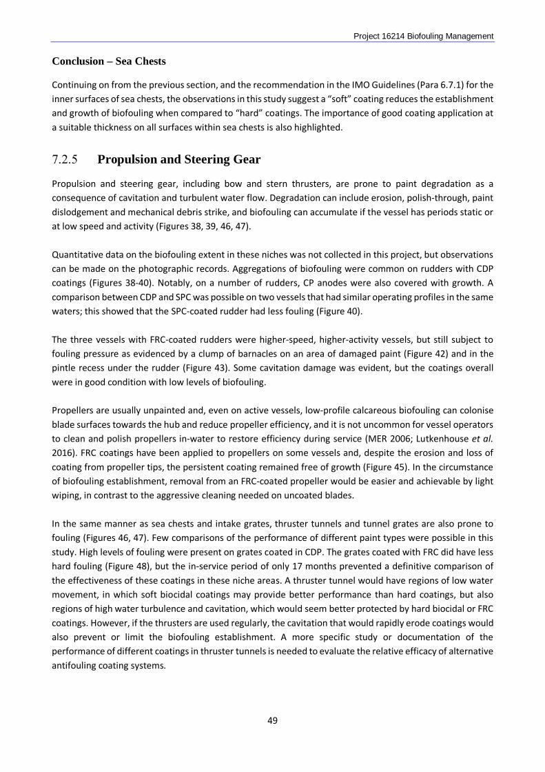
Project 16214 Biofouling Management Conclusion – Sea Chests
Continuing on from the previous section, and the recommendation in the IMO Guidelines (Para 6.7.1) for the inner surfaces of sea chests, the observations in this study suggest a “soft” coating reduces the establishment and growth of biofouling when compared to “hard” coatings. The importance of good coating application at a suitable thickness on all surfaces within sea chests is also highlighted.
Propulsion and Steering Gear
Propulsion and steering gear, including bow and stern thrusters, are prone to paint degradation as a consequence of cavitation and turbulent water flow. Degradation can include erosion, polish-through, paint dislodgement and mechanical debris strike, and biofouling can accumulate if the vessel has periods static or at low speed and activity (Figures 38, 39, 46, 47). Quantitative data on the biofouling extent in these niches was not collected in this project, but observations can be made on the photographic records. Aggregations of biofouling were common on rudders with CDP coatings (Figures 38-40). Notably, on a number of rudders, CP anodes were also covered with growth. A comparison between CDP and SPC was possible on two vessels that had similar operating profiles in the same waters; this showed that the SPC-coated rudder had less fouling (Figure 40). The three vessels with FRC-coated rudders were higher-speed, higher-activity vessels, but still subject to fouling pressure as evidenced by a clump of barnacles on an area of damaged paint (Figure 42) and in the pintle recess under the rudder (Figure 43). Some cavitation damage was evident, but the coatings overall were in good condition with low levels of biofouling. Propellers are usually unpainted and, even on active vessels, low-profile calcareous biofouling can colonise blade surfaces towards the hub and reduce propeller efficiency, and it is not uncommon for vessel operators to clean and polish propellers in-water to restore efficiency during service (MER 2006; Lutkenhouse et al. 2016). FRC coatings have been applied to propellers on some vessels and, despite the erosion and loss of coating from propeller tips, the persistent coating remained free of growth (Figure 45). In the circumstance of biofouling establishment, removal from an FRC-coated propeller would be easier and achievable by light wiping, in contrast to the aggressive cleaning needed on uncoated blades. In the same manner as sea chests and intake grates, thruster tunnels and tunnel grates are also prone to fouling (Figures 46, 47). Few comparisons of the performance of different paint types were possible in this study. High levels of fouling were present on grates coated in CDP. The grates coated with FRC did have less hard fouling (Figure 48), but the in-service period of only 17 months prevented a definitive comparison of the effectiveness of these coatings in these niche areas. A thruster tunnel would have regions of low water movement, in which soft biocidal coatings may provide better performance than hard coatings, but also regions of high water turbulence and cavitation, which would seem better protected by hard biocidal or FRC coatings. However, if the thrusters are used regularly, the cavitation that would rapidly erode coatings would also prevent or limit the biofouling establishment. A more specific study or documentation of the performance of different coatings in thruster tunnels is needed to evaluate the relative efficacy of alternative antifouling coating systems.
49
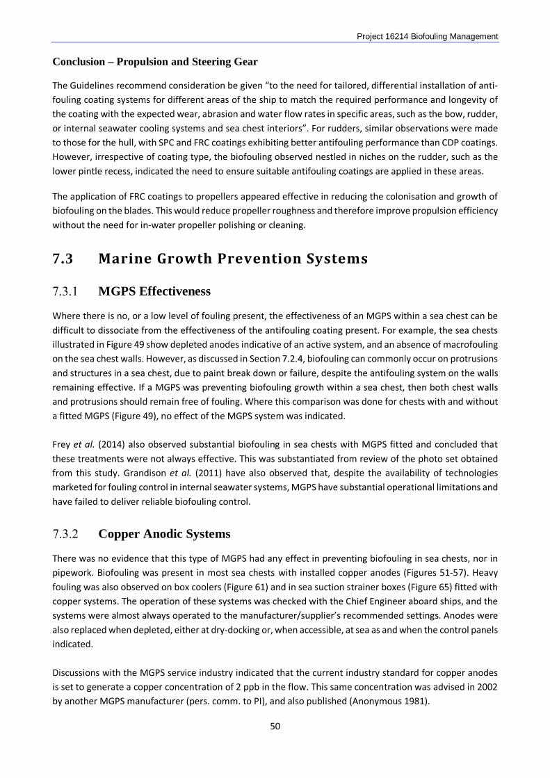
Project 16214 Biofouling Management Conclusion – Propulsion and Steering Gear
The Guidelines recommend consideration be given “to the need for tailored, differential installation of anti-fouling coating systems for different areas of the ship to match the required performance and longevity of the coating with the expected wear, abrasion and water flow rates in specific areas, such as the bow, rudder, or internal seawater cooling systems and sea chest interiors”. For rudders, similar observations were made to those for the hull, with SPC and FRC coatings exhibiting better antifouling performance than CDP coatings. However, irrespective of coating type, the biofouling observed nestled in niches on the rudder, such as the lower pintle recess, indicated the need to ensure suitable antifouling coatings are applied in these areas.
The application of FRC coatings to propellers appeared effective in reducing the colonisation and growth of biofouling on the blades. This would reduce propeller roughness and therefore improve propulsion efficiency without the need for in-water propeller polishing or cleaning.
7.3 Marine Growth Prevention Systems
MGPS Effectiveness
Where there is no, or a low level of fouling present, the effectiveness of an MGPS within a sea chest can be difficult to dissociate from the effectiveness of the antifouling coating present. For example, the sea chests illustrated in Figure 49 show depleted anodes indicative of an active system, and an absence of macrofouling on the sea chest walls. However, as discussed in Section 7.2.4, biofouling can commonly occur on protrusions and structures in a sea chest, due to paint break down or failure, despite the antifouling system on the walls remaining effective. If a MGPS was preventing biofouling growth within a sea chest, then both chest walls and protrusions should remain free of fouling. Where this comparison was done for chests with and without a fitted MGPS (Figure 49), no effect of the MGPS system was indicated. Frey et al. (2014) also observed substantial biofouling in sea chests with MGPS fitted and concluded that these treatments were not always effective. This was substantiated from review of the photo set obtained from this study. Grandison et al. (2011) have also observed that, despite the availability of technologies marketed for fouling control in internal seawater systems, MGPS have substantial operational limitations and have failed to deliver reliable biofouling control.
Copper Anodic Systems There was no evidence that this type of MGPS had any effect in preventing biofouling in sea chests, nor in pipework. Biofouling was present in most sea chests with installed copper anodes (Figures 51-57). Heavy fouling was also observed on box coolers (Figure 61) and in sea suction strainer boxes (Figure 65) fitted with copper systems. The operation of these systems was checked with the Chief Engineer aboard ships, and the systems were almost always operated to the manufacturer/supplier’s recommended settings. Anodes were also replaced when depleted, either at dry-docking or, when accessible, at sea as and when the control panels indicated. Discussions with the MGPS service industry indicated that the current industry standard for copper anodes is set to generate a copper concentration of 2 ppb in the flow. This same concentration was advised in 2002 by another MGPS manufacturer (pers. comm. to PI), and also published (Anonymous 1981).
50
Project 16214 Biofouling Management Experiments were undertaken in Australia in the mid-1980s to determine the concentration of copper needed to prevent biofouling in a submarine seawater system (Lewis et al. 1988). Copper anodic MGPS were fitted to in the intake strainer boxes, but cooling systems had recurrently failed due to the obstruction of internal systems by fouling, despite a dose of 12 ppb copper. An experimental trial compared the effectiveness of electrochemical doses of 0, 10, 100 and 1000 ppb in parallel tanks with the seawater drawn from a harbour embayment. Tubeworm settlement was unaffected at 10 ppb, significantly reduced at 100 ppb, and totally prevented at 1000 ppb. Similar studies by the Royal Navy in the United Kingdom determined that the optimum dose for copper to prevent fouling was in the range 20 to 30 ppb (Hall 1984). Observations in this project are consistent with the above findings: that a target dose of 2 ppb copper is insufficient to prevent biofouling attachment and growth. For some systems fitted in strainer boxes, the manual recommended that the MGPS remain switched on when the seawater system was closed off; for example when seawater supply was switched between high and low intakes. This would cause an elevation of copper concentration in the stagnant water, possibly to a toxic concentration. However, in this circumstance, deoxygenation of the stagnant water could similarly prevent or kill growth depending on the holding period. Although it may be conceivable to generate an effective copper dose from anodes in a flowing system, albeit with higher impressed current settings and consequent anode depletion rates, prevention of fouling in a sea chest would be more difficult. To prevent biofouling growth, the effective copper concentration would need to be uniform at the surface of all walls and fittings throughout the sea chest. To achieve this from a single anode, or even from multiple anodes in a sea chest would be a challenge given the sometimes irregular shape of sea chests and the volume of, and complexity of water flow through them.
Chemical Dosing Systems One vessel with a chemical dosing MGPS was inspected during the course of this study. This vessel had also been inspected at a previous dry-docking. The chemical used in this system is labelled as an “antifoulant” and two active constituents are specified on the material safety data sheet. However, a literature search did not find any other reference to these chemicals acting as antifouling biocides. There was no indication that this chemical dosing system was having any inhibitory effect on biofouling settlement and growth, as biofouling (mussels) were present throughout the treated compartments, including on the drip feeding pipe system (Figure 68). Mussels were also growing in pipework inboard of the sea chest (Figure 67). Chemical dosing was also utilised on a second vessel where the chemical was drip fed continuously into the cross pipe, in combination with a copper anodic system with anodes fitted within the sea chests. The chemical used has previously been shown to be an effective antifouling agent (Lewis and Dimas 2007). However, in this ship, there were barnacles downstream of the feed, so any positive effect of this system could not be judged.
Sonic Systems The ultrasonic system observed in this study had been installed on the vessel during dry-docking 7 months prior. The system is claimed to function by emitting ultrasound vibrations that cause the biofilm to disperse. The frequency of the sound generation was not indicated. Ultrasound transducers were attached to inboard
51
Project 16214 Biofouling Management walls of the box cooler sea chest and to the top of the box cooler. The walls within the sea chest at the positions of the transducers were examined and there was no apparent difference between the biofilm at these locations and other sections of wall. The box cooler was also covered with a thick, complex fouling assemblage dominated by bivalve molluscs, so there was no evidence overall of any antifouling effect. The effect of sound and vibration on biofouling settlement has been experimentally assessed. In one study (Choi et al. 2013), barnacle settlement was reduced on panels vibrated at frequencies between 260 and 445 Hz and there was little or no effect at lower frequencies. The settlement of other biofouling organisms, including tubeworms, bryozoans, ascidians and macroalgae did not appear to be affected. In contrast, sound has been found to stimulate the settlement of common biofouling groups (Stanley et al. 2014).
Electrochlorination Systems Chlorine, as hypochlorite, has been demonstrated to prevent fouling within seawater cooling systems (e.g., López-Galindo et al. 2010; Rubio et al. 2015) and, from its first use in 1924, continues to be the most widely used biocide for biofouling control in industrial seawater cooling systems (Satpathy et al. 2010). Although electrochlorination systems have also been designed and are used on vessels (Grandison et al. 2011), none of the vessels in this study were fitted with such as system. No comments are therefore possible on the effectiveness of these systems for the management of biofouling in sea chests and seawater piping systems.
52
Project 16214 Biofouling Management
8 CONCLUSIONS & RECOMMENDATIONS
8.1 Study Limitations
This study brings together observations on the performance of biofouling management systems from a broad range of vessels of different types and operating profiles. However, given the total number of vessels spread across this range and the absence of complete data sets for all but 14 vessels, validation of the conclusions and recommendations drawn from the study warrant further practical evaluation.
8.2 Coatings
From the evidence collected in this study, it is concluded that application of a suitable antifouling coating system is the best method for minimising the establishment and growth of biofouling on hulls, hull appendages, and in sea chests and other wet-side niches. The type of coating that will be most effective varies for specific applications and, for any one vessel, several different coatings may be needed to achieve maximum protection. The following are general recommendations on coating choice and maintenance.
Hull Surfaces
• SPC and FRC coatings may provide better overall biofouling prevention and reliability on the underwater vertical sides and flats than CDP coatings, irrespective of the in-service period.
• Soft fouling can develop on FRC coatings after 24 months service and, for vessels with longer service intervals, ongoing hull grooming to remove this fouling may improve vessel efficiency.
• Adequate antifouling paint dry film thicknesses are needed to maintain and prolong system service life.
Intake Grates
• The application of FRC coatings to intake grates may result in both reduced paint breakdown and reduced biofouling attachment and growth. This type of coating is therefore recommended for sea chest, thruster tunnel and other intake grates.
Sea Chests
• The use of “soft’ antifouling coatings inside sea chests is recommended, irrespective of the type of antifouling applied to the outer hull, and whether CDP or SPC. Some evidence suggested that SPC coatings may perform better than CDP, but the sample size was too small to make a clear recommendation.
• Adequate antifouling paint film build and dry film thickness in the sea chests appeared important to maintain and prolong antifouling life, and the application of two full coats is recommended.
• Biofouling attachment and growth on structural and functional projections is attributable to paint breakdown along sharp edges or absence of antifouling in difficult to access locations. This should be addressed by careful surface preparation, coating system repair, and antifouling application. Stripe
53
Project 16214 Biofouling Management
coating along edges, and brush or roller touch-up of surfaces inaccessible with spray is recommended.
• The performance of FRC coatings inside sea chests was equivocal and, on one vessel, confounded by the apparent inconsistency in the standard of coating application around the sea chest. Observations suggest that FRC coatings would not prevent biofouling, but could change the biofouling composition within a sea chest, from those painted with biocidal coatings, to favour predominantly low-profile, encrusting life forms.
• FRC coatings may perform better than biocidal coatings on angular projections due to the better edge retention of the paint when applied. However, it is noted that partial application of an FRC coating within a sea chest is impractical due to the complexity and cost of application.
Propulsion and Steering Gear
• SPC and FRC coatings may better minimise fouling on rudders than CDP coatings.
• The application of FRC coatings to propeller blades may reduce biofouling growth and facilitate easy cleaning and removal of any growth that does occur.
8.3 MGPS
• No reduction in the biofouling of sea chests or pipework was observed in systems fitted with copper anodic, chemical dosing or sonic MGPSs.
• No vessel in the study was fitted with an electrochlorination MGPS, so conclusions could not be drawn on their effectiveness without further study.
8.4 Further work
The observations and recommendations in this study provide guidance on the choice, application and use of coatings and other biofouling management systems to more reliably minimise the establishment and growth of biofouling on vessels. Due to the relatively small data set of vessels analysed, further assessment of the recommended methods is needed to better characterise performance. This could be achieved through proactive participation by the marine coating and shipping industry in reporting on the performance of the recommended systems if already applied, or trialling the recommended systems as alternatives to existing systems.
54
Project 16214 Biofouling Management
9 ACKNOWLEDGEMENTS
The following organisations are thanked for their support for this study: Akzo Nobel Pty Ltd, NSW APL Singapore Pte Ltd, Singapore BGP Marine - CNPC, China Carnival Australia, NSW Cathwell AS, Norway Farstad Shipping (Indian Pacific) Pty Ltd, Vic Hempel (Australia) Pty Ltd, Vic International Maritime Organization, UK Jan De Nul (Singapore) Pte Ltd Jotun Australia Pty Ltd, Vic Maersk Singapore Pte Ltd, Singapore Maran Tankers Management Inc, Greece Maritime Industry Australia Ltd, Vic PGM Environment, WA SeaRoad Shipping Pty Ltd, Vic TT-Line Company Pty Ltd, Vic Wilh. Wilhelmsen ASA, Norway World Shipping Council, USA
I would also like to personally thank Eugene Georgiades, Andrew Bell, and Naomi Parker at the Ministry for Primary Industries for initiating and supporting the project. Support and funding for this project was provided by MPI’s Operational Research Programme. This report was peer reviewed by Eugene Georgiades, Abraham Growcott, Liz Jones and Daniel Kluza.
55
Project 16214 Biofouling Management
10 REFERENCES
AkzoNobel (2013). Antifouling coatings range: clean hull solutions for all vessels. International Paint Ltd, Felling Gateshead, UK. 8 pp. Anonymous (1981). Preventing seawater cooling system corrosion and fouling. Marine Engineers Review 81 (9), 24. Anonymous (2010). Antifouling performance at the level you choose. JLA Media Ltd, Wimbledon, UK. [Available from: http://www.international-marine.com/literature/biocidalantifoulings-whitepaper.pdf] ASA (2007). Assessment of introduced marine pest risks associated with niche areas in commercial shipping. Final report. Australian Shipowners Association, Port Melbourne. 24 pp. ASTM (2011). Standard practice for evaluating biofouling resistance and physical performance of marine coating systems. Designation: D6990-05 (2011). ASTM International, West Conshohocken, PA. 12 pp. ASTM (2014). Standard practice for inspecting the coating system of a ship. Designation: F1130-99 (2014). ASTM International, West Conshohocken, PA. 15 pp. Bell A, Phillips S, Denny C, Georgiades E, Kluza D (2011). Risk analysis: vessel biofouling. New Zealand Government, Ministry of Agriculture and Forestry, Wellington, New Zealand. 145 pp. [Available on-line from: http://www.mpi.govt.nz/document-vault/2863] Boudouresque CF (1999). The Red Sea-Mediterranean link: unwanted effects of canals. In: Sandlund OT, Schei PJ, Viken Å (Eds.) Invasive species and biodiversity management. Kluwer Academic Publishers, Dordrecht, The Netherlands. pp. 213-228. Callow ME (1996). Ship fouling: the problem and methods of control. Biodeterioration Abstracts 10(4), 411-421. Callow ME, Callow JA (2002). Marine biofouling: a sticky problem. Biologist 49(1), 1-5. Carlton JT (1999). The scale and ecological consequences of biological invasions in the world’s oceans. In: Sandlund OT, Schei PJ, Viken Å (Eds.) Invasive species and biodiversity management. Kluwer Academic Publishers, Dordrecht, The Netherlands. pp. 195-212. Choi CH, Scardino AJ, Dylejko PG, Fletcher LE, Juniper R (2013). The effect of vibration frequency and amplitude on biofouling deterrence. Biofouling 29(2), 195-202. Coutts ADM, Dodgshun TJ (2007). The nature and extent of organisms in vessel sea-chests: a protected mechanism for marine bioinvasions. Marine Pollution Bulletin 54, 875-886. Coutts ADM, Moore KM, Hewitt CL (2003). Ships’ sea-chests: an overlooked transfer mechanism for non-indigenous marine species? Marine Pollution Bulletin 46, 1504-1515.
56
Project 16214 Biofouling Management Dafforn KA, Lewis JA, Johnston EL (2011). Antifouling strategies: history and regulation, ecological impacts and mitigation. Marine Pollution Bulletin 62, 453-465. Dürr S, Watson DI (2010). Biofouling and antifouling in aquaculture. In: Dürr S, Thomason JC (Eds.) Biofouling. Wiley-Blackwell, Chichester, UK. pp. 267-287. Edyvean R (2010). Consequences of fouling on shipping. In: Dürr S, Thomason JC (Eds.) Biofouling. Wiley-Blackwell, Chichester, UK. pp. 217-225. Elliason J (2003). Economics of coating/corrosion protection of ships – selecting the correct type of anticorrosion protection for underwater application on new buildings. In: Lloyd’s List Event Conference: Prevention and Management of Marine Corrosion, 2-3 April 2003. Lloyds, London UK. [cited in Lejars et al. 2012). Elton CS (1958). The Ecology of Invasions by Animals and Plants. Methuen and Co Ltd, London, UK. 181 pp. Evans LV (1981). Marine algae and fouling: a review, with particular reference to ship-fouling. Botanica Marina 24, 167-171. Fathom (2013). Fathom FOCUS: Hull coatings for vessel performance. Fathom, Windsor, UK. 90 pp. [Available on-line at: http://www.fathommaritimeintelligence.com/hull-coatings-for-vessel-performance.html] Finnie AA, Williams DN (2010). Paint and coatings technology for the control of marine fouling. In: Dürr S, Thomason JC (Eds.) Biofouling. Wiley-Blackwell, Chichester, UK. pp. 185-206. Fletcher RL (1980). Catalogue of Main Marine Fouling Organisms. Volume 6. Algae. ODEMA, Bruxelles, Belgium. 61 pp. Frey MA, Simard N, Robichaud DD, Martin JL, Therriault TW (2014). Fouling around: vessel sea-chests as a vector for the introduction and spread of aquatic invasive species. Management of Biological Invasions 5(1), 21-30. Georgiades E, Kluza D (2014) Science underpinning the thresholds proposed in the CRMS: biofouling on vessels arriving in New Zealand. MPI Technical Paper No: 2014/22. New Zealand Government, Ministry for Primary Industries, Wellington, New Zealand. 18 pp. [Available on-line at: http://www.mpi.govt.nz/document-vault/4148] Graham LE, Wilcox LW (2000). Algae. Prentice-Hall, Upper Saddle River, NJ. 640 + 60 pp. Grandison C, Piola R, Fletcher L (2011). A review of marine growth protection system (MGPS) options for the Royal Australian Navy. Report DSTO-TR-2631. Defence Science and Technology Organisation, Fishermans Bend, Vic. 28 pp. Hall K (1984). The effects of chlorine and copper dosing on fouling and corrosion in seawater systems. Proceedings. Seventh Inter-Naval Corrosion Control Conference. HMSO London. 39 pp.
57
Project 16214 Biofouling Management Hempel (2014). Antifouling. [On-line] http://www.hempel.com/en/marine/underwater-hull/antifouling [Accessed 31 May 2016]. Henderson P (2010). Fouling and antifouling in other industries – power stations. Desalination plants – drinking water and sensors. In: Dürr S, Thomason JC (Eds.) Biofouling. Wiley-Blackwell, Chichester, UK. pp. 288-305. Hewitt C, Campbell M (2010). The relative contributions of vectors to the introduction and translocation of marine invasive species. DAFF, Australia. 56 pp. [Available on-line from: http://www.marinepests.gov.au/marine_pests/publications/Pages/default.aspx] IMO (2009). Ballast water management convention and the guidelines for its implementation. 2009 Edition. International Maritime Organization, London. 234 pp. IMO (2012). Guidelines for the control and management of ships’ biofouling to minimize the transfer of invasive aquatic species. 2012 Edition. International Maritime Organization, London. 34 pp. Inglis G, Floerl O, Woods C (2012). Scenarios of vessel biofouling risk and their management. MAF Technical Paper No: 2012/07. Ministry of Agriculture and Forestry, Wellington, New Zealand. 122 pp. [Available on-line from: https://www.mpi.govt.nz/document-vault/4029] INTERTANKO (2016). INTERTANKO guide to modern antifouling systems and biofouling management, 2016. INTERTANKO (www.intertanko.com). 19 pp. Lebret K, Thabard M, Hellio C (2009). Algae as marine fouling organism: adhesion damage and prevention. In: Hellio C, Yebra D (Eds.) Advances in marine antifouling coatings and technologies. Woodhead Publishing Ltd, Cambridge, UK. pp. 80-112. Lejars M, Margaillan A, Bressy C (2012) Fouling release coatings: a nontoxic alternative to biocidal antifouling coatings. Chemical Reviews 112, 4347-4390. Lewis JA (1998). Marine biofouling and its prevention on underwater surfaces. Materials Forum 22, 41-61. Lewis JA (2002). Hull fouling as a vector for the translocation of marine organisms: report 2 – The significance of the prospective ban on tributyltin antifouling paints on the introduction and translocation of marine pests in Australia. Ballast Water Research Series Report No. 15. Australian Government Department of Agriculture, Fisheries and Forestry, Canberra, ACT. 121 pp. Lewis JA (2009). Non-silicone biocide-free antifouling solutions. In: Hellio C, Yebra D (Eds.) Advances in marine antifouling coatings and technologies. Woodhead Publishing Ltd, Cambridge, UK. pp. 709-724. Lewis JA, Coutts ADM (2010). Biofouling invasions. In: Dürr S, Thomason JC (Eds.) Biofouling. Wiley-Blackwell, Chichester, UK. pp. 348-365. Lewis JA, Dimas J (2007). Treatment of biofouling in internal seawater systems – phase 2. Report DSTO-CR-2006-0441. Maritime Platforms Division, DSTO, Melbourne. 25 pp.
58
Project 16214 Biofouling Management Lewis JA, Smith BS, Taylor RJ, Batten JJ (1988). Fouling of RAN submarine seawater systems and a comparison of electro-chemical control methods. Proceedings, Eighth Inter-Naval Corrosion Control Conference, Plymouth, UK. Paper No. 7. 20 pp. Lewis JA, Watson C, ten Hove HA (2006). Establishment of the Caribbean serpulid tubeworm Hydroides sanctaecrucis Krøyer [in] Mörch, 1863, in northern Australia. Biological Invasions 8, 665-671. López-Galindo C, Casanueva JF, Nebot E (2010). Efficacy of different antifouling treatments for seawater cooling systems. Biofouling 26(8), 923-930. Lutkenhouse C, Brady B, Delbridge J, Haslbeck E, Holm E, Lynn D, Michael T, Ross A, Stamper D, Tseng C, Webb A (2016). Baseline propeller roughness condition assessment and its impact on fuel efficiency. In: Bertram V (Ed.) 1st Hull Performance & Insight Conference (Hull PIC’ 16), Castello di Pavone, 13-15 April 2016. pp. 245-262. MER (2006). Proven paint performance: Analysing foul release coatings impact on fuel performance. Marine Engineers Review 2006 (November), pp. 40, 42-43. Morrisey D, Gadd J, Page M, Floerl O, Woods C, Lewis J, Bell A, Georgiades E (2013). In-water cleaning of vessels: biosecurity and chemical contamination risks. MPI Technical Paper No: 2013/11. New Zealand Government, Ministry for Primary Industries, Wellington, New Zealand. 265 pp. [Available on-line from: https://mpi.govt.nz/document-vault/4092] MPI (2014). Craft risk management standard: biofouling on vessels arriving to New Zealand. CRMS - BIOFOUL. New Zealand Government, Ministry for Primary Industries, Wellington, New Zealand. 8 pp. [Available on-line from: http://www.mpi.govt.nz/document-vault/11668] MPI (draft). Guidance Document: guidance document for the craft risk management standard - biofouling on vessels arriving to New Zealand. New Zealand Government, Ministry for Primary Industries, Wellington, New Zealand. 30 pp. National System (2009). National biofouling management guidelines for commercial vessels. The National System for the Prevention and Management of Marine Pest Incursions. Australian Government, Canberra. 16 pp. [Available on-line from: http://www.marinepests.gov.au/marine_pests/publications/Documents/Biofouling_guidelines_commercial_vessels.pdf] Page HM, Dugan JE, Piltz F (2010). Fouling and antifouling in oil and other offshore industries. In: Dürr S, Thomason JC (Eds.) Biofouling. Wiley-Blackwell, Chichester, UK. pp. 252-266. Rilov G, Crooks JA (2009). Marine bioinvasions: conservation hazards and vehicles for ecological understanding. In: Rilov G, Crooks JA (Eds.) Biological invasions in marine ecosystems. Springer-Verlag, Berlin Heidelberg. pp. 3-11.
59
Project 16214 Biofouling Management Rubio D, Casanueva JF, Nebot E (2015). Assessment of the antifouling effect of five different treatment strategies on a seawater cooling system. Applied Thermal Engineering 85, 124-134. Satpathy KK, Mohanty AK, Sahu G, Biswas S, Prasad MVR, Slvanayagam M (2010). Biofouling and its control in seawater cooled power plant cooling water system – a review. In: Tsvetkov P (Ed.) Nuclear power. InTech. pp. 191-242. [Available on-line from: http://www.intechopen.com/books/nuclear-power/biofouling-and-its-control-in-seawater-cooled-power-plant-cooling-water-system-a-review-] Stanley JA, Wilkens SL, Jeffs AG (2014). Fouling in your own nest: vessel noise increases biofouling. Biofouling 30(7), 837-844. Thomason JC (2010). Fouling on shipping: data-mining the world’s largest antifouling archive. In: Dürr S, Thomason JC (Eds.) Biofouling. Wiley-Blackwell, Chichester, UK. pp. 207-216. Thompson Clarke Shipping (2007). Antifouling performance standards for the maritime industry: development of a framework for the assessment, approval and relevance of effective products. A consultancy for the Australian Heritage Trust. Thompson Clarke Shipping Pty Ltd, Port Melbourne, Australia. 61 pp. [Available on-line from: https://www.environment.gov.au/system/files/resources/00cbf46f-06e7-44c7-8ff5-eb25d4ca3481/files/antifouling-framework.pdf] Townsin RL, Anderson CD (2009). Fouling control coatings using low surfaces energy, foul release technology. In: Hellio C, Yebra D (Eds.) Advances in marine antifouling coatings and technologies. Woodhead Publishing Limited, Cambridge, UK. pp. 693-708. WHOI (1952). Marine fouling and its prevention. Contribution No. 580 from the Woods Hole Oceanographic Institute. U.S. Naval Institute, Annapolis, MD. 388 pp.
60

Project 16214 Biofouling Management
APPENDIX 1 – REPORTING GUIDANCE
61
Ship Biofouling Management Practices Survey – Reporting Guidance
SHIP BIOFOULING MANAGEMENT PRACTICES SURVEY
REPORTING GUIDANCE
May 2014 Version 1.0
Version 1.0 Page ii
Ship Biofouling Management Practices Survey – Reporting Guidance
SHIP BIOFOULING MANAGEMENT PRACTICES SURVEY
REPORTING GUIDANCE
May 2014 Version 1.0
Prepared by:
John A. Lewis Principal Marine Consultant,
ES Link Services Pty Ltd
Version 1.0 Page iii
Ship Biofouling Management Practices Survey – Reporting Guidance
Abbreviations
Abbreviation Description
AFSC International Anti-Fouling System Certificate
AFSR Record of Anti-Fouling Systems
IMO International Maritime Organization
IMS Invasive Marine Species
MGPS Marine Growth Prevention System
MPI [New Zealand] Ministry for Primary Industries
Version 1.0 Page iv
Project 16214 Biofouling Management
Table of Contents
1. Introduction……………….……………………………………………………………….………………………………….3 2. Background……………………………………………………...………….………………………………………………….3
2.1. Invasive Aquatic Species………………………………………………………………………….………………3 2.2. The IMO Guidelines……………………………………………………………………………………..………….4 2.3. This Project…………………………………..…………………………………………………...…………………….4
3. Reporting……………………………………………………………………………………………………………………..….5 Requested Information……………………………………………………………………………..……………….……5 Information Submission……………………………………………………………………………………………….….5
4. Reporting Forms……………………………………………………………………………………………………….……..7 4.1. Page 1 – General Information………………………………………………………………………………….7 4.2. Page 2 – Antifouling System Information……………………………………………………..……….11 4.3. Page 3 – Antifouling Coating Performance……………………………………………………..……..13 4.4. Pages 4 to 7 – Sea Chest Information………………………………………………………………..…..19 4.5. Page 8 – Additional Information……………………………………………………………………………..23
5. Photographic Record……………………………………………………………………………………….………………25 Appendix 1: Biofouling Types……………………………………………………………………………………..………..37
Version 1.0 Page 5
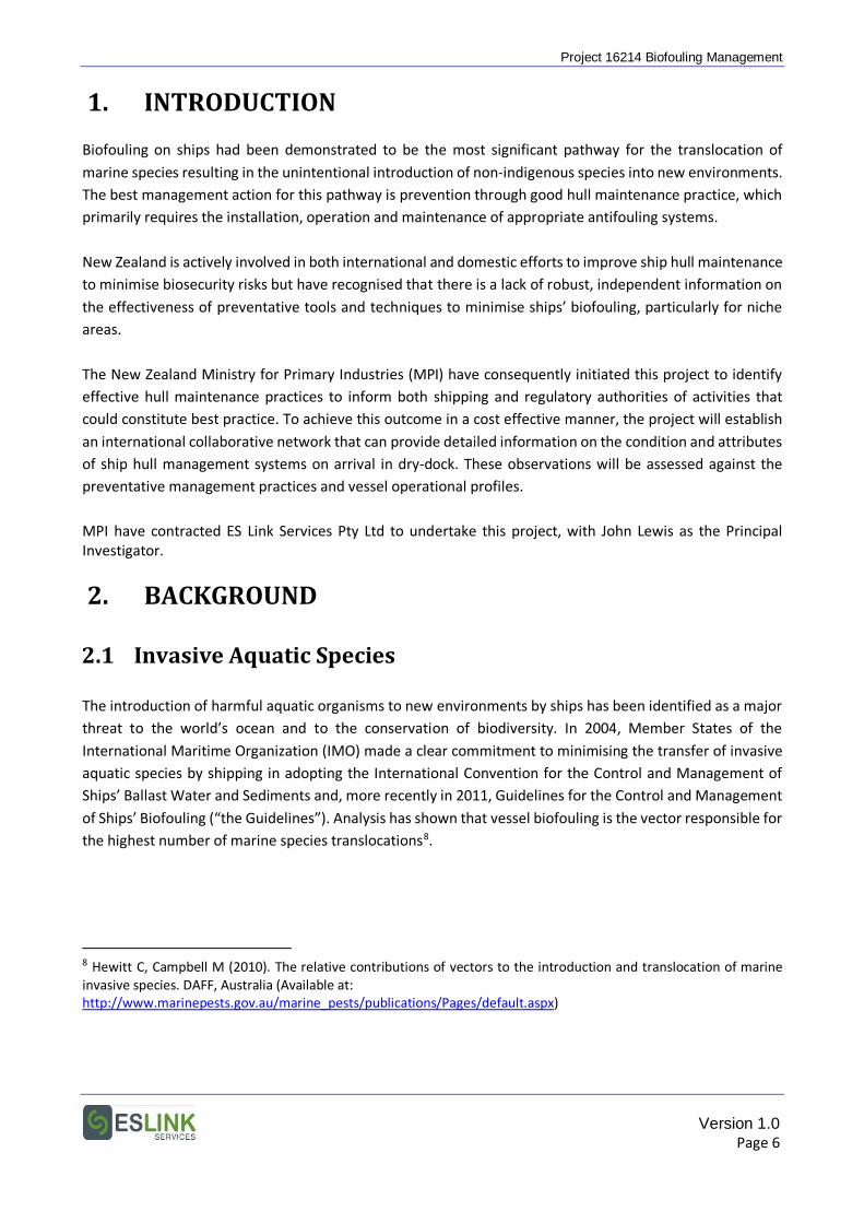
Project 16214 Biofouling Management
1. INTRODUCTION Biofouling on ships had been demonstrated to be the most significant pathway for the translocation of marine species resulting in the unintentional introduction of non-indigenous species into new environments. The best management action for this pathway is prevention through good hull maintenance practice, which primarily requires the installation, operation and maintenance of appropriate antifouling systems. New Zealand is actively involved in both international and domestic efforts to improve ship hull maintenance to minimise biosecurity risks but have recognised that there is a lack of robust, independent information on the effectiveness of preventative tools and techniques to minimise ships’ biofouling, particularly for niche areas. The New Zealand Ministry for Primary Industries (MPI) have consequently initiated this project to identify effective hull maintenance practices to inform both shipping and regulatory authorities of activities that could constitute best practice. To achieve this outcome in a cost effective manner, the project will establish an international collaborative network that can provide detailed information on the condition and attributes of ship hull management systems on arrival in dry-dock. These observations will be assessed against the preventative management practices and vessel operational profiles. MPI have contracted ES Link Services Pty Ltd to undertake this project, with John Lewis as the Principal Investigator.
2. BACKGROUND
2.1 Invasive Aquatic Species
The introduction of harmful aquatic organisms to new environments by ships has been identified as a major threat to the world’s ocean and to the conservation of biodiversity. In 2004, Member States of the International Maritime Organization (IMO) made a clear commitment to minimising the transfer of invasive aquatic species by shipping in adopting the International Convention for the Control and Management of Ships’ Ballast Water and Sediments and, more recently in 2011, Guidelines for the Control and Management of Ships’ Biofouling (“the Guidelines”). Analysis has shown that vessel biofouling is the vector responsible for the highest number of marine species translocations8.
8 Hewitt C, Campbell M (2010). The relative contributions of vectors to the introduction and translocation of marine invasive species. DAFF, Australia (Available at: http://www.marinepests.gov.au/marine_pests/publications/Pages/default.aspx)
Version 1.0 Page 6
Project 16214 Biofouling Management
2.2 The IMO Guidelines
As stated within the IMO Guidelines, the objectives “are to provide practical guidance on measures to minimize the risk of transferring invasive aquatic species from ships’ biofouling”. Ships are encouraged to implement biofouling management practices, including the use of antifouling systems and other operational management practices to reduce the development of biofouling. The intent of such practices is to keep the ship’s submerged surfaces, and internal seawater cooling systems, as free of biofouling as practical. A ship following this guidance and minimising macrofouling would therefore have a reduced potential for transferring invasive aquatic species via biofouling. It is important that biofouling management procedures be effective as well as environmentally safe, practical, designed to minimise costs and delays to the ship, and based on the Guidelines whenever possible.
2.3 This Project
The aim of this project is to obtain information from a large number of vessels of different types, sizes and operational profiles from different locations throughout the world. Such sampling would encompass different antifouling systems and practices, different biofouling pressures, and different ship susceptibilities. To achieve this in a thorough, yet cost effective manner, the data gathering phase of the project would be through collaboration and input from technical representatives of ship owners and operators, marine coatings companies, vessel maintenance facilities and class societies who would be present at the dry-docking or slipping of vessels. Participants are requested to complete and submit a set of standard reporting forms for each vessel. These forms have been developed from existing docking report pro-formas used by coating inspectors and technical advisors from major global marine coatings companies for their internal databases. In designing the reporting forms, the aim has been to keep reporting simple, and for it to be neither demanding nor time consuming. It is important to note that the identity of a ship or vessel will not be associated with data in public reports from the project.
Version 1.0 Page 7
Project 16214 Biofouling Management
3. REPORTING Requested Information The information requested is in two parts:
A. Reporting Forms
• General information on the vessel and its antifouling systems;
• Observations on biofouling composition, severity and extent; and
• Additional comments that could inform the project aims.
Standard reporting forms are provided to record the general information and observations.
B. Photographs
• Representative photographs to illustrate observations.
Information Submission
Completed forms and photographs should be submitted to John Lewis: Electronically to:
Note: if the file package is too large to send via your email system, then file transfer services such as Dropbox (www.dropbox.com), Transfer Big Files (www.transferbigfiles.com ) or similar can be used.
Or, as hard copy or on a USB thumb drive mailed to:
John Lewis ES Link Services Pty Ltd PO Box 10 Castlemaine Vic 3450 AUSTRALIA
If there are any questions or queries, please contact:
John Lewis Email: [email protected] Phone: +61 (0)418 316 227
Version 1.0 Page 8

Project 16214 Biofouling Management
Version 1.0 Page 9
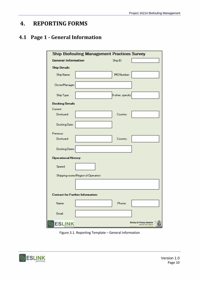
Project 16214 Biofouling Management
4. REPORTING FORMS 4.1 Page 1 - General Information
Figure 3.1. Reporting Template – General Information
Version 1.0 Page 10
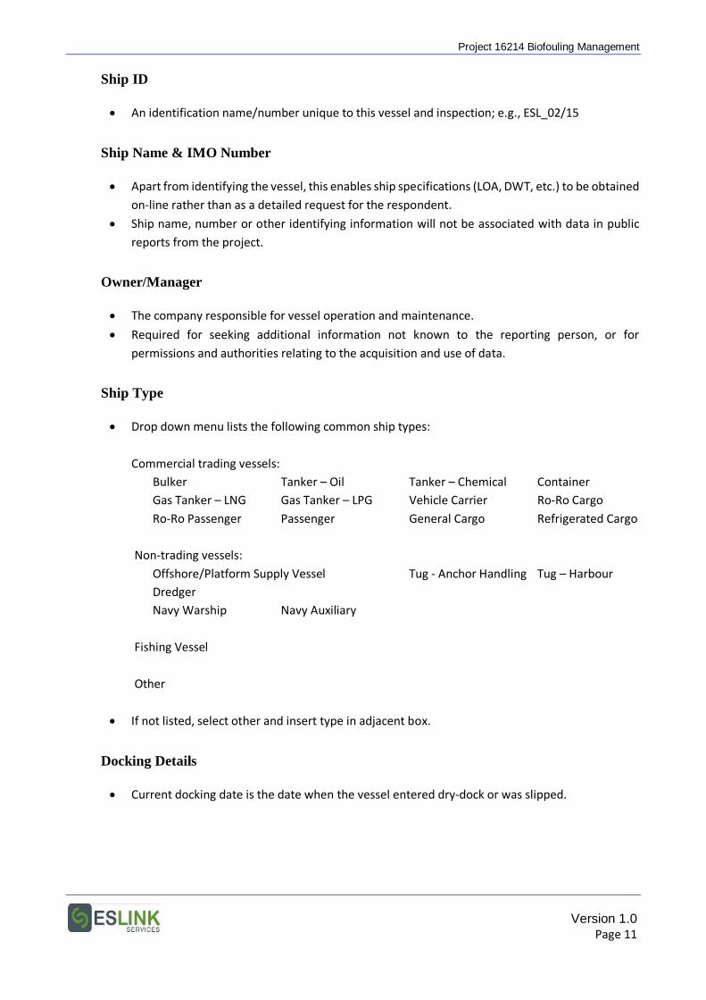
Project 16214 Biofouling Management
Ship ID
• An identification name/number unique to this vessel and inspection; e.g., ESL_02/15
Ship Name & IMO Number
• Apart from identifying the vessel, this enables ship specifications (LOA, DWT, etc.) to be obtained on-line rather than as a detailed request for the respondent.
• Ship name, number or other identifying information will not be associated with data in public reports from the project.
Owner/Manager
• The company responsible for vessel operation and maintenance.
• Required for seeking additional information not known to the reporting person, or for permissions and authorities relating to the acquisition and use of data.
Ship Type
• Drop down menu lists the following common ship types:
Commercial trading vessels: Bulker Tanker – Oil Tanker – Chemical Container
Gas Tanker – LNG Gas Tanker – LPG Vehicle Carrier Ro-Ro Cargo Ro-Ro Passenger Passenger General Cargo Refrigerated Cargo
Non-trading vessels: Offshore/Platform Supply Vessel Tug - Anchor Handling Tug – Harbour Dredger
Navy Warship Navy Auxiliary
Fishing Vessel Other
• If not listed, select other and insert type in adjacent box.
Docking Details
• Current docking date is the date when the vessel entered dry-dock or was slipped.
Version 1.0 Page 11
Project 16214 Biofouling Management
Operational History
• “Speed” is the usual operating speed in knots or, alternatively, the design speed.
• General information on “Shipping Routes/Regions of Operation” is requested; e.g., trans-Tasman; Eastern Australia – NW Pacific; Gulf of Mexico.
Contact for Further Information
• Please provide contact details of the person either completing the forms or who can provide further information on the information reported.
• An aim in the design of reporting forms was to avoid numerous, long reporting sheets requesting details not relevant to all vessels. As a consequence, additional information may be requested from, or through, this point of contact on ship features, biofouling measures etc. to assist in the interpretation of results. An example could be the settings for a marine growth prevention system (MGPS) or the seawater flow rate through a sea chest.
Version 1.0 Page 12
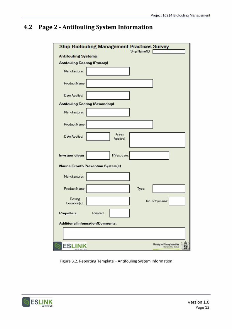
Project 16214 Biofouling Management
4.2 Page 2 - Antifouling System Information
Figure 3.2. Reporting Template – Antifouling System Information
Version 1.0 Page 13
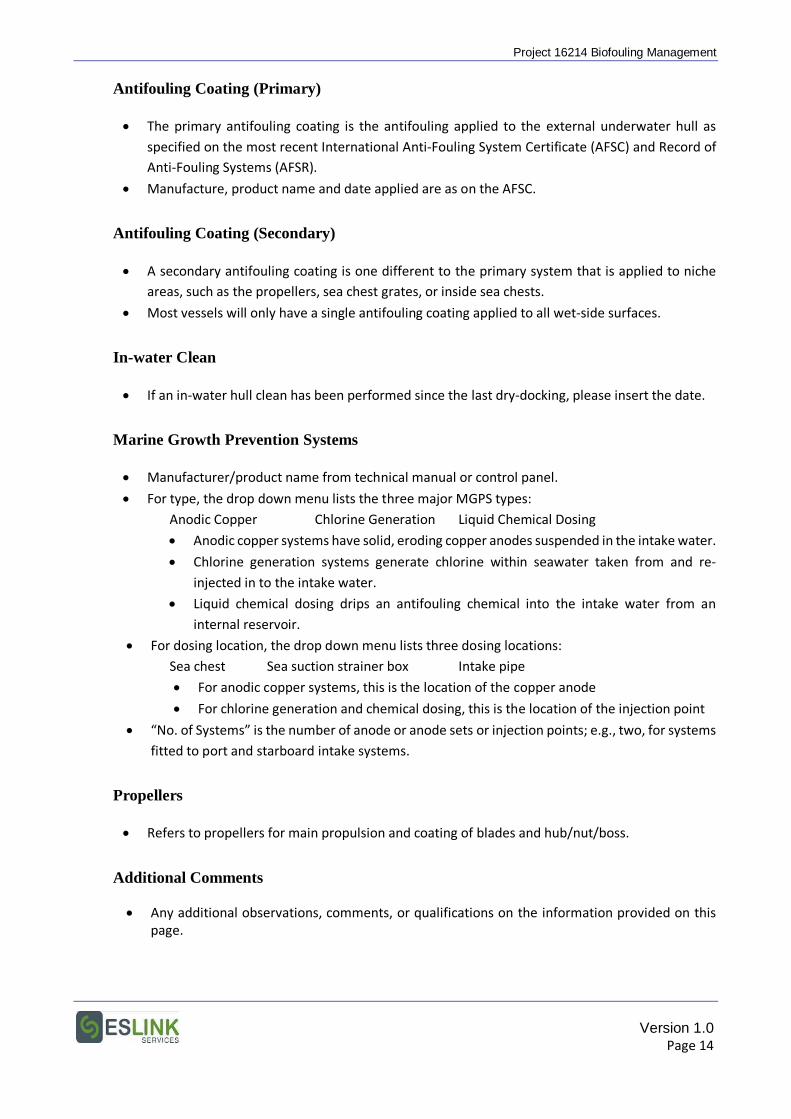
Project 16214 Biofouling Management
Antifouling Coating (Primary)
• The primary antifouling coating is the antifouling applied to the external underwater hull as specified on the most recent International Anti-Fouling System Certificate (AFSC) and Record of Anti-Fouling Systems (AFSR).
• Manufacture, product name and date applied are as on the AFSC.
Antifouling Coating (Secondary)
• A secondary antifouling coating is one different to the primary system that is applied to niche areas, such as the propellers, sea chest grates, or inside sea chests.
• Most vessels will only have a single antifouling coating applied to all wet-side surfaces.
In-water Clean
• If an in-water hull clean has been performed since the last dry-docking, please insert the date.
Marine Growth Prevention Systems
• Manufacturer/product name from technical manual or control panel.
• For type, the drop down menu lists the three major MGPS types: Anodic Copper Chlorine Generation Liquid Chemical Dosing
• Anodic copper systems have solid, eroding copper anodes suspended in the intake water.
• Chlorine generation systems generate chlorine within seawater taken from and re-injected in to the intake water.
• Liquid chemical dosing drips an antifouling chemical into the intake water from an internal reservoir.
• For dosing location, the drop down menu lists three dosing locations: Sea chest Sea suction strainer box Intake pipe
• For anodic copper systems, this is the location of the copper anode
• For chlorine generation and chemical dosing, this is the location of the injection point
• “No. of Systems” is the number of anode or anode sets or injection points; e.g., two, for systems fitted to port and starboard intake systems.
Propellers
• Refers to propellers for main propulsion and coating of blades and hub/nut/boss.
Additional Comments
• Any additional observations, comments, or qualifications on the information provided on this page.
Version 1.0 Page 14
Project 16214 Biofouling Management
4.3 Page 3 - Antifouling Coating Performance
Figure 3.3. Reporting Template – Antifouling Coating Performance
Version 1.0 Page 15
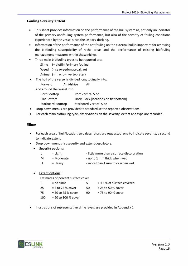
Project 16214 Biofouling Management
Fouling Severity/Extent
• This sheet provides information on the performance of the hull system as, not only an indicator of the primary antifouling system performance, but also of the severity of fouling conditions experienced by the vessel since the last dry-docking.
• Information of the performance of the antifouling on the external hull is important for assessing the biofouling susceptibility of niche areas and the performance of existing biofouling management measures within these niches.
• Three main biofouling types to be reported are: Slime (= biofilm/primary fouling) Weed (= seaweed/macroalgae) Animal (= macro-invertebrates)
• The hull of the vessel is divided longitudinally into: Forward Amidships Aft
and around the vessel into: Port Boottop Port Vertical Side
Flat Bottom Dock Block (locations on flat bottom) Starboard Boottop Starboard Vertical Side
• Drop down menus are provided to standardise the reported observations.
• For each main biofouling type, observations on the severity, extent and type are recorded.
Slime
• For each area of hull/location, two descriptors are requested: one to indicate severity, a second to indicate extent.
• Drop down menus list severity and extent descriptors:
• Severity options: L = Light - little more than a surface discoloration M = Moderate - up to 1 mm thick when wet H = Heavy - more than 1 mm thick when wet
• Extent options: Estimates of percent surface cover 0 = no slime 5 = < 5 % of surface covered 25 = 5 to 25 % cover 50 = 25 to 50 % cover 75 = 50 to 75 % cover 90 = 75 to 90 % cover 100 = 90 to 100 % cover
• Illustrations of representative slime levels are provided in Appendix 1.
Version 1.0 Page 16
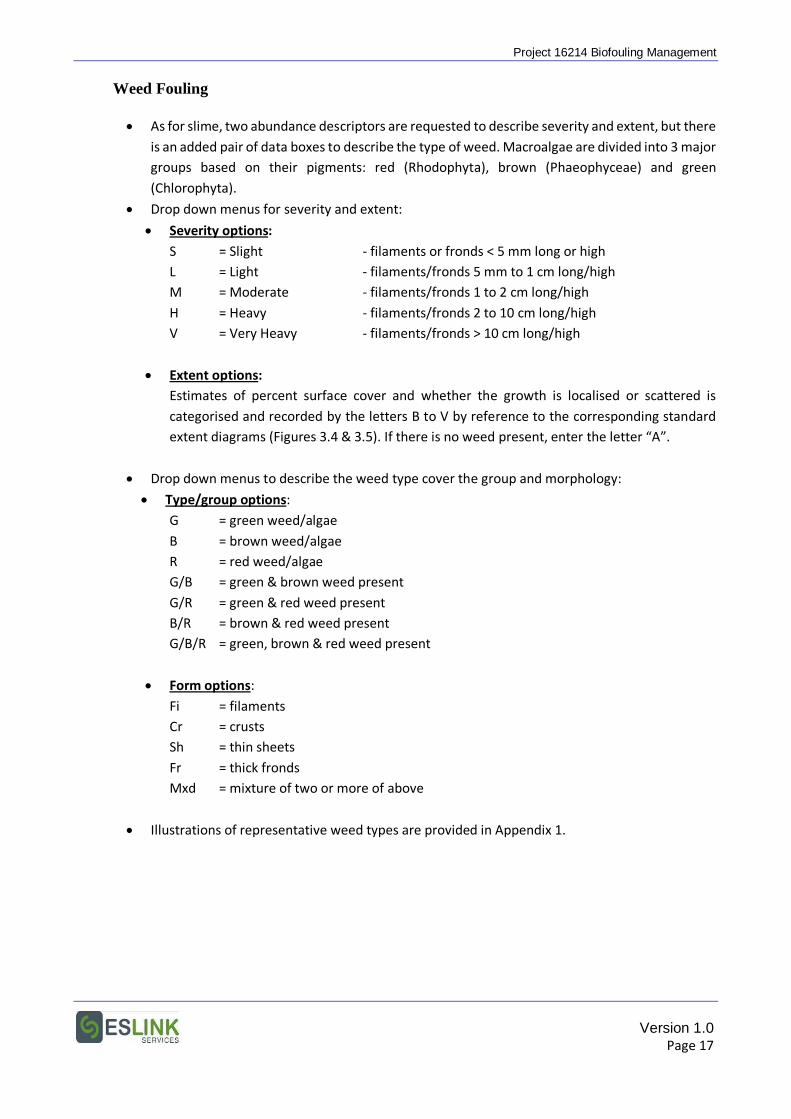
Project 16214 Biofouling Management
Weed Fouling
• As for slime, two abundance descriptors are requested to describe severity and extent, but there is an added pair of data boxes to describe the type of weed. Macroalgae are divided into 3 major groups based on their pigments: red (Rhodophyta), brown (Phaeophyceae) and green (Chlorophyta).
• Drop down menus for severity and extent:
• Severity options: S = Slight - filaments or fronds < 5 mm long or high L = Light - filaments/fronds 5 mm to 1 cm long/high M = Moderate - filaments/fronds 1 to 2 cm long/high H = Heavy - filaments/fronds 2 to 10 cm long/high V = Very Heavy - filaments/fronds > 10 cm long/high
• Extent options: Estimates of percent surface cover and whether the growth is localised or scattered is categorised and recorded by the letters B to V by reference to the corresponding standard extent diagrams (Figures 3.4 & 3.5). If there is no weed present, enter the letter “A”.
• Drop down menus to describe the weed type cover the group and morphology:
• Type/group options: G = green weed/algae B = brown weed/algae R = red weed/algae G/B = green & brown weed present G/R = green & red weed present B/R = brown & red weed present G/B/R = green, brown & red weed present
• Form options: Fi = filaments Cr = crusts Sh = thin sheets Fr = thick fronds Mxd = mixture of two or more of above
• Illustrations of representative weed types are provided in Appendix 1.
Version 1.0 Page 17
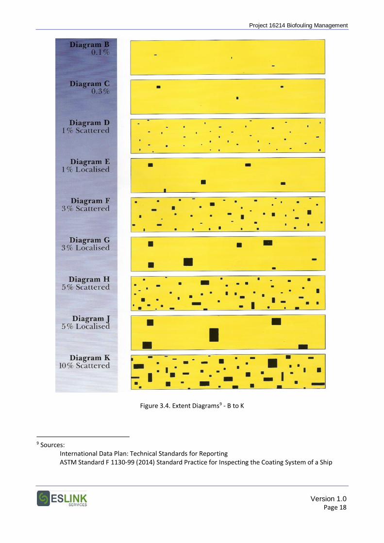
Project 16214 Biofouling Management
Figure 3.4. Extent Diagrams9 - B to K
9 Sources: International Data Plan: Technical Standards for Reporting ASTM Standard F 1130-99 (2014) Standard Practice for Inspecting the Coating System of a Ship
Version 1.0 Page 18
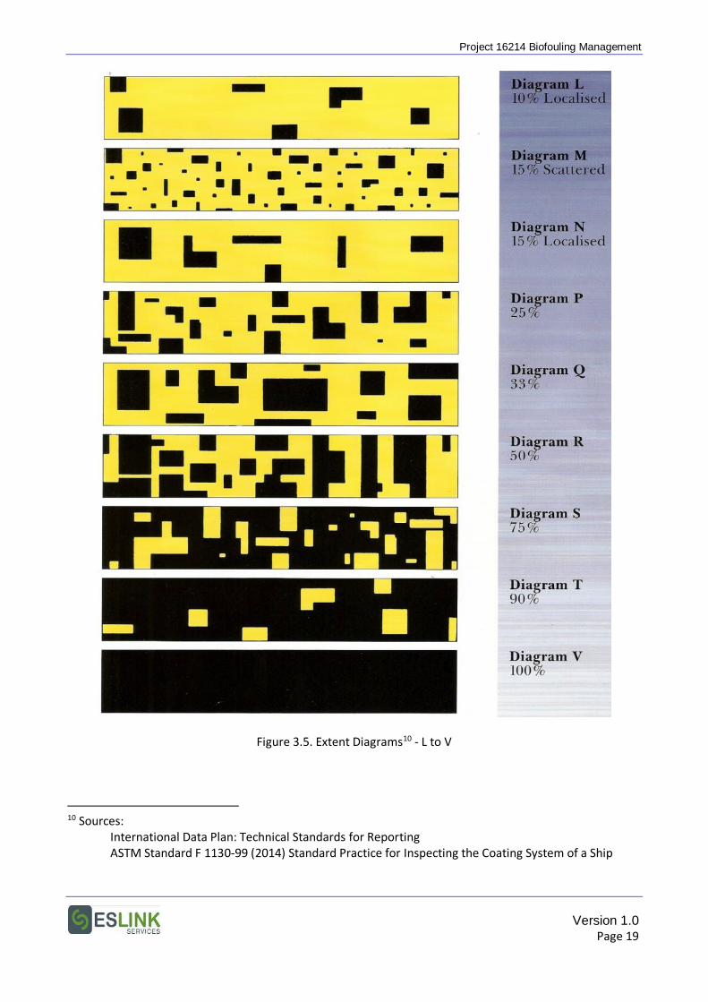
Project 16214 Biofouling Management
Figure 3.5. Extent Diagrams10 - L to V
10 Sources: International Data Plan: Technical Standards for Reporting ASTM Standard F 1130-99 (2014) Standard Practice for Inspecting the Coating System of a Ship
Version 1.0 Page 19
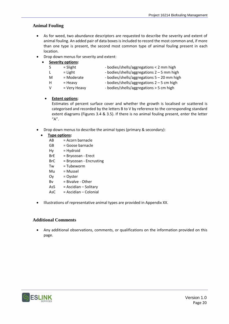
Project 16214 Biofouling Management
Animal Fouling
• As for weed, two abundance descriptors are requested to describe the severity and extent of animal fouling. An added pair of data boxes is included to record the most common and, if more than one type is present, the second most common type of animal fouling present in each location.
• Drop down menus for severity and extent: • Severity options:
S = Slight - bodies/shells/aggregations < 2 mm high L = Light - bodies/shells/aggregations 2 – 5 mm high M = Moderate - bodies/shells/aggregations 5 – 20 mm high H = Heavy - bodies/shells/aggregations 2 – 5 cm high V = Very Heavy - bodies/shells/aggregations > 5 cm high
• Extent options: Estimates of percent surface cover and whether the growth is localised or scattered is categorised and recorded by the letters B to V by reference to the corresponding standard extent diagrams (Figures 3.4 & 3.5). If there is no animal fouling present, enter the letter “A”.
• Drop down menus to describe the animal types (primary & secondary): • Type options:
AB = Acorn barnacle GB = Goose barnacle Hy = Hydroid BrE = Bryozoan - Erect BrC = Bryozoan - Encrusting Tw = Tubeworm Mu = Mussel Oy = Oyster Bv = Bivalve - Other AsS = Ascidian – Solitary AsC = Ascidian – Colonial
• Illustrations of representative animal types are provided in Appendix XX.
Additional Comments
• Any additional observations, comments, or qualifications on the information provided on this page.
Version 1.0 Page 20
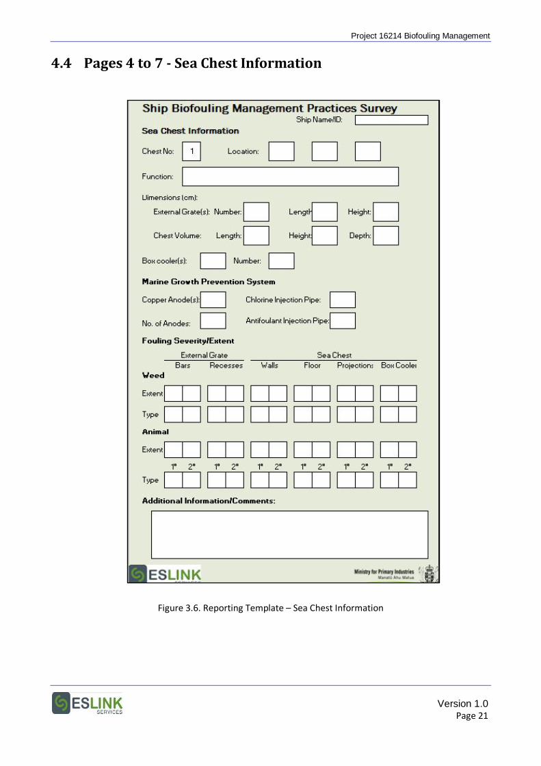
Project 16214 Biofouling Management
4.4 Pages 4 to 7 - Sea Chest Information
Figure 3.6. Reporting Template – Sea Chest Information
Version 1.0 Page 21
Project 16214 Biofouling Management
Sea Chest Information
• Information on the structure, function and biofouling severity and extent in a minimum of four sea chests is requested, and four separate forms are provided for this purpose.
• Ideally, the four sea chests would be two on each side of the vessel, with one of each pair a main engine cooling intake, and the second an auxiliary engine or general services intake. It is understood that all vessels do not have this configuration, and appropriate selection rests with the person observing and completing the forms.
• Information on additional sea chests would also be useful if this can be supplied. The simplest way to record these observations electronically would be to open a second set of reporting forms and to use only the Sea Chest Information sheets in this set.
Location
• Three drop down menus are provided to specify the approximate location of the sea chest:
• Port/Starboard.
• Side Flats.
• Forward/Mid (amidships)/ Aft.
Function
• General information on the purpose of water taken in through the sea chest; e.g., main engine cooling, auxiliary engine cooling, emergency fire-fighting, general services, etc.
Dimensions
• Some chests have a single intake grate, others two or more. If more than one, and they vary in size, please annotate accordingly.
• Chest volume dimensions can be approximate for irregularly shaped chests.
Box Cooler
• If there are box coolers suspended in the sea chest, please indicate yes and provide the number of cooler units in that chest.
Marine Growth Prevention Systems
• Indicate if MGPS anodes or injection pipes are located within the sea chest and, if anodes, the number (usually 1).
Version 1.0 Page 22
Project 16214 Biofouling Management
Fouling Severity/Extent
• Information is requested on the level of fouling on the outside of the grate, and on the inside of the sea chest.
• For the grate, the fouling level on the grate bars and in the recesses around bolts, hinges, and the grate edges is sought.
• Internally, fouling is assessed for the walls, floor, projections (e.g., steam blow out pipes, structural angles, intake pipes) and, if present, box cooler surfaces.
• Drop down menus for the extent and type of both weed and animal fouling are the same as for the antifouling coating performance sheet.
Additional Comments
• For any additional observations, comments, or qualifications on the information provided on this page.
Version 1.0 Page 23
Project 16214 Biofouling Management
Page 8 - Additional Information
Figure 3.7. Reporting Template – Additional Information
Version 1.0 Page 24
Project 16214 Biofouling Management
Additional Information/Comments
• This page is provided for any additional observations, comments, or qualifications that the person observing the vessel or completing the form may consider relevant or useful to the project.
Version 1.0 Page 25
Project 16214 Biofouling Management
5. PHOTOGRAPHIC RECORD
Photographs are requested of representative areas of the following hull surfaces and niches:
A. Hull Surfaces
Hull surface 1: Vertical sides – forward Hull surface 2: Vertical sides – amidships Hull surface 3: Vertical sides – aft Hull surface 4: Flat bottom Hull surface 5: Flat bottom – dock block positions
B. Hull Appendages
Hull appendages 1: Propeller(s) Hull appendages 2: Rudder(s) Hull appendages 3: Cathodic protection (“zinc”) anodes
C. Sea Chests (for each of the sea chests detailed in the Reporting Forms)
Sea chests 1: Grate(s) – general appearance Sea chests 2: Grate(s) – close-up Sea chests 3: Internal view
D. Biofouling Growth
Close-up photos of different weed and animal fouling types and aggregations.
See following pages for examples of the photographs required:
Version 1.0 Page 26
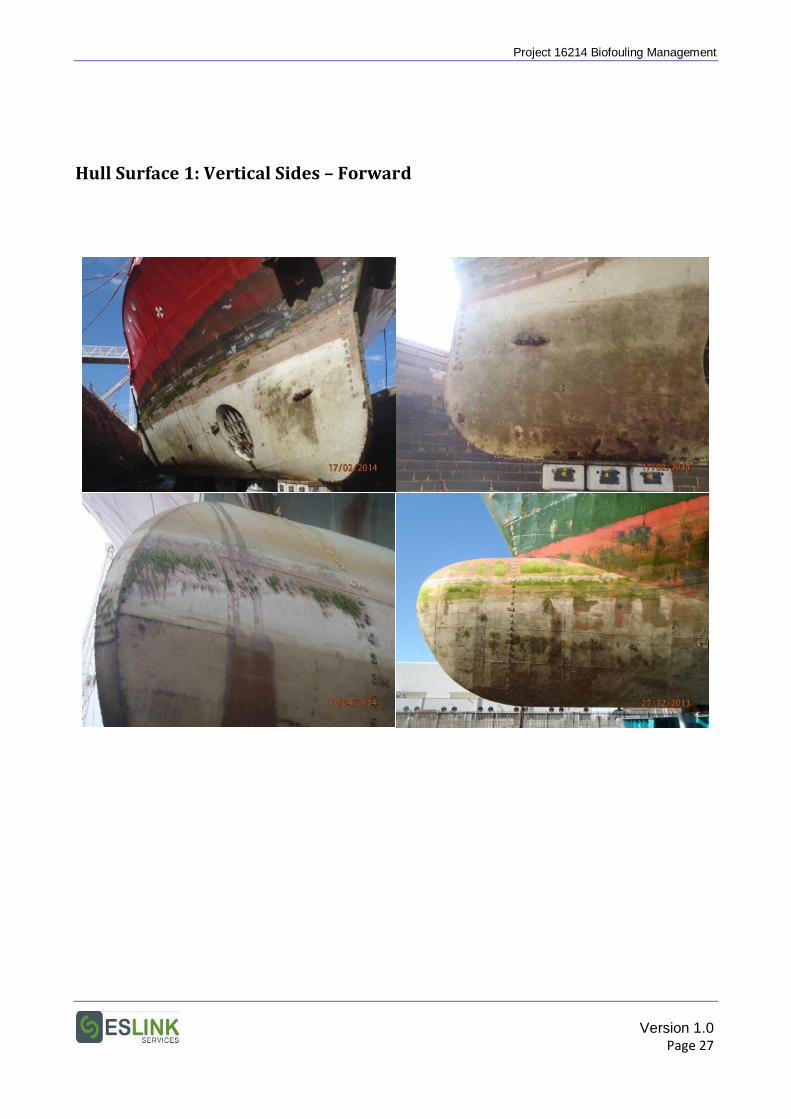
Project 16214 Biofouling Management
Hull Surface 1: Vertical Sides – Forward
Version 1.0 Page 27
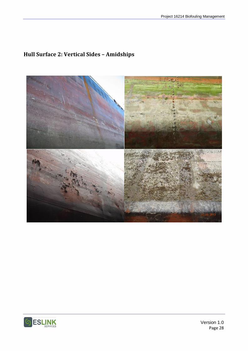
Project 16214 Biofouling Management
Hull Surface 2: Vertical Sides – Amidships
Version 1.0 Page 28
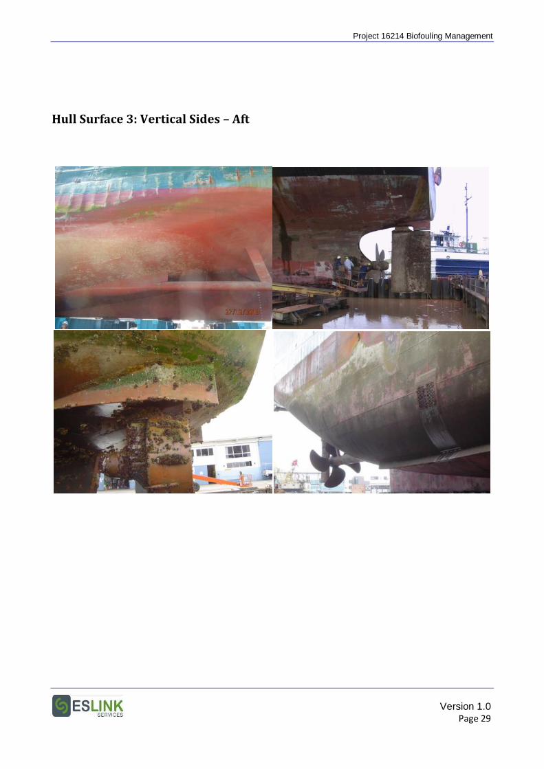
Project 16214 Biofouling Management
Hull Surface 3: Vertical Sides – Aft
Version 1.0 Page 29
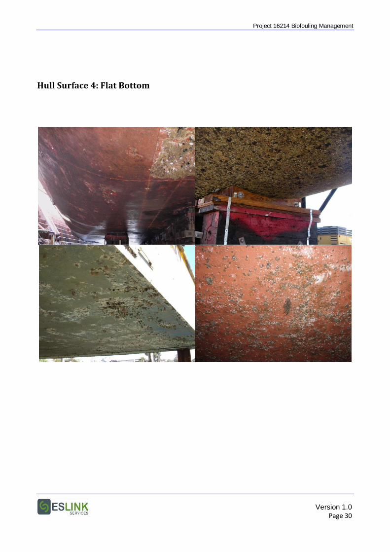
Project 16214 Biofouling Management
Hull Surface 4: Flat Bottom
Version 1.0 Page 30
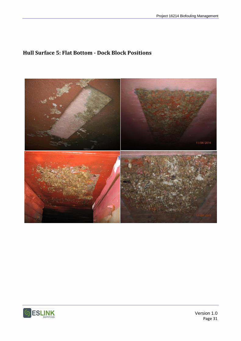
Project 16214 Biofouling Management
Hull Surface 5: Flat Bottom - Dock Block Positions
Version 1.0 Page 31
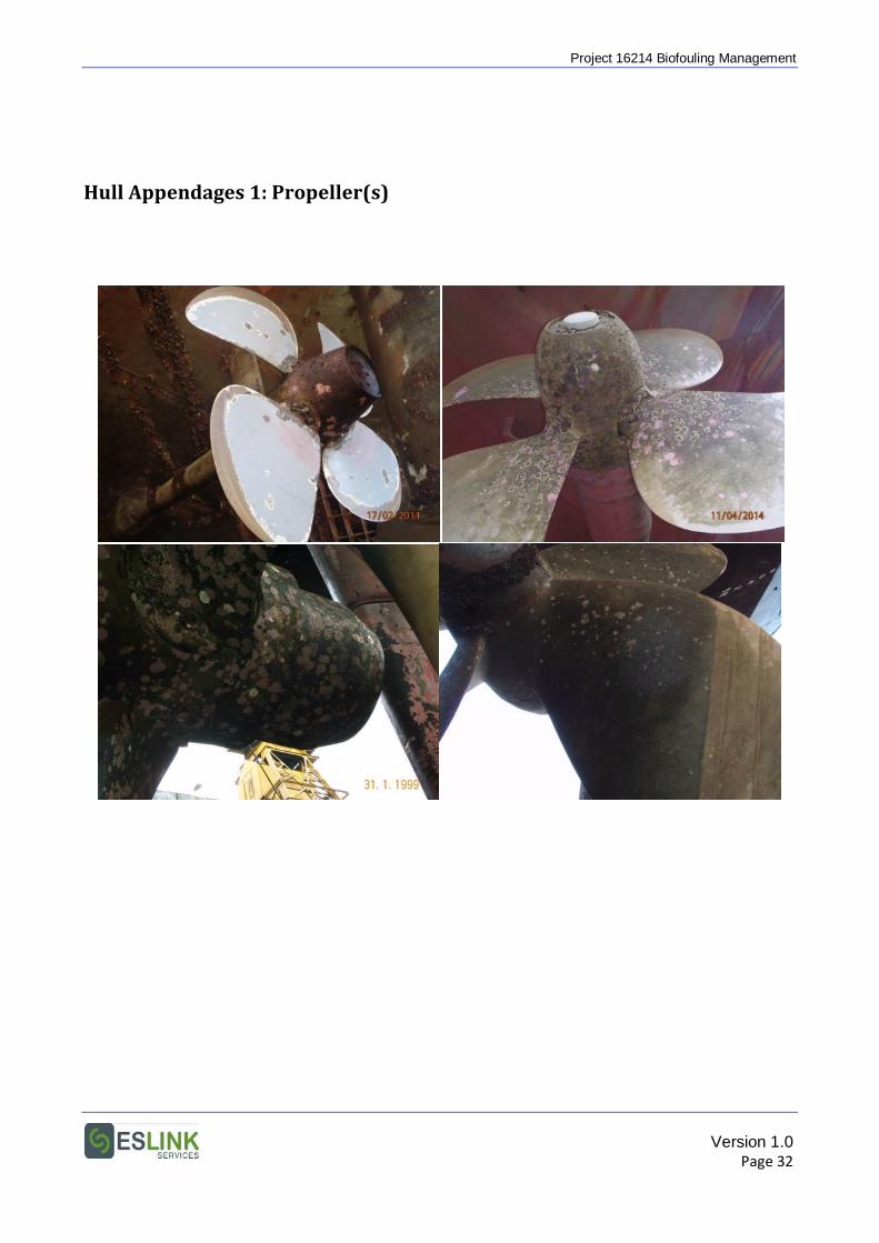
Project 16214 Biofouling Management
Hull Appendages 1: Propeller(s)
Version 1.0 Page 32
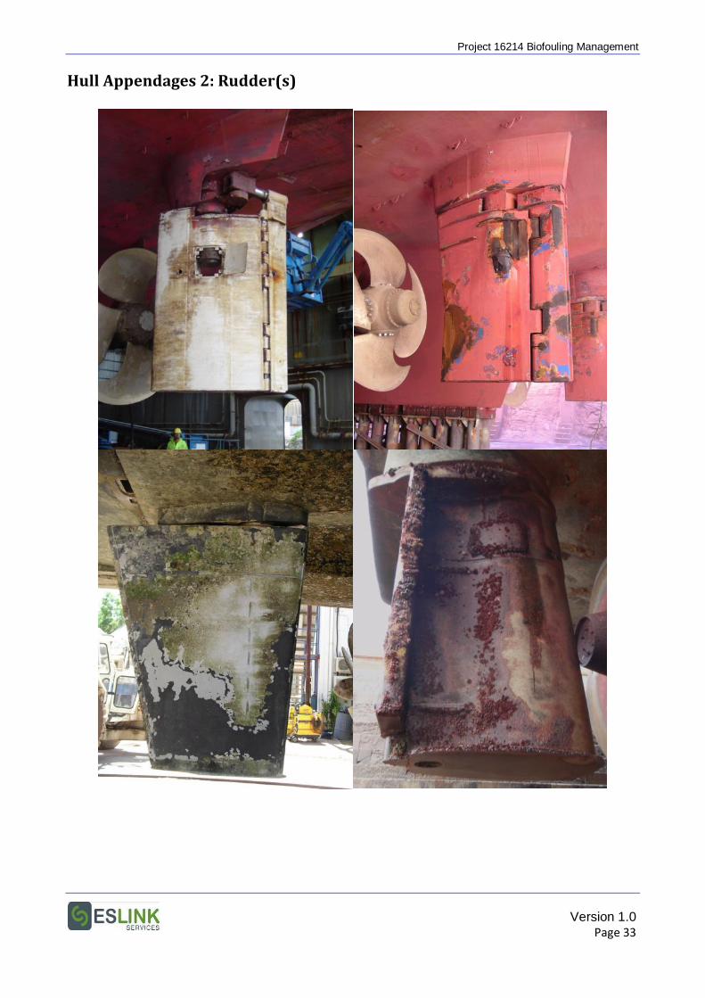
Project 16214 Biofouling Management
Hull Appendages 2: Rudder(s)
Version 1.0 Page 33
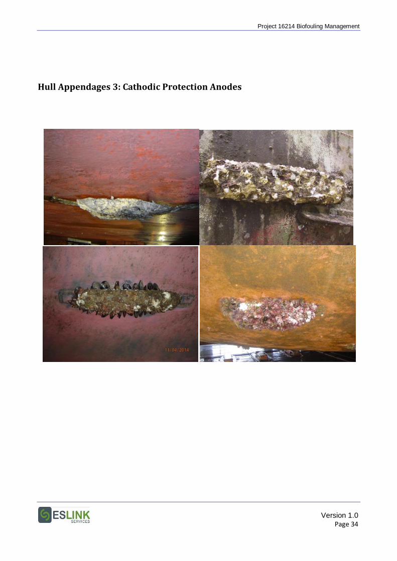
Project 16214 Biofouling Management
Hull Appendages 3: Cathodic Protection Anodes
Version 1.0 Page 34
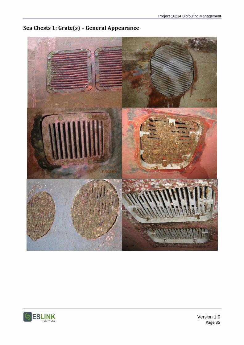
Project 16214 Biofouling Management
Sea Chests 1: Grate(s) – General Appearance
Version 1.0 Page 35

Project 16214 Biofouling Management
Sea Chests 2: Grate(s) – Close-up
Version 1.0 Page 36
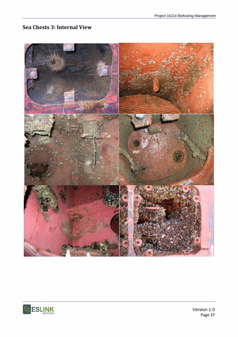
Project 16214 Biofouling Management
Sea Chests 3: Internal View
Version 1.0 Page 37
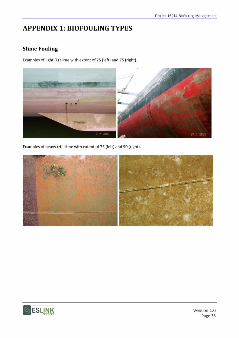
Project 16214 Biofouling Management
APPENDIX 1: BIOFOULING TYPES
Slime Fouling Examples of light (L) slime with extent of 25 (left) and 75 (right).
Examples of heavy (H) slime with extent of 75 (left) and 90 (right).
Version 1.0 Page 38
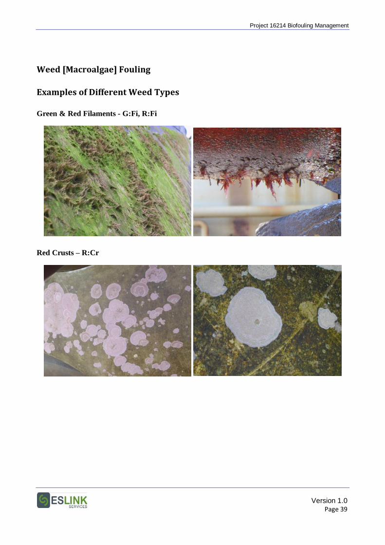
Project 16214 Biofouling Management
Weed [Macroalgae] Fouling Examples of Different Weed Types
Green & Red Filaments - G:Fi, R:Fi
Red Crusts – R:Cr
Version 1.0 Page 39
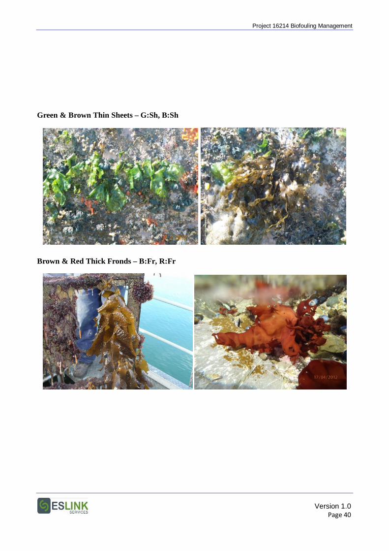
Project 16214 Biofouling Management
Green & Brown Thin Sheets – G:Sh, B:Sh
Brown & Red Thick Fronds – B:Fr, R:Fr
Version 1.0 Page 40
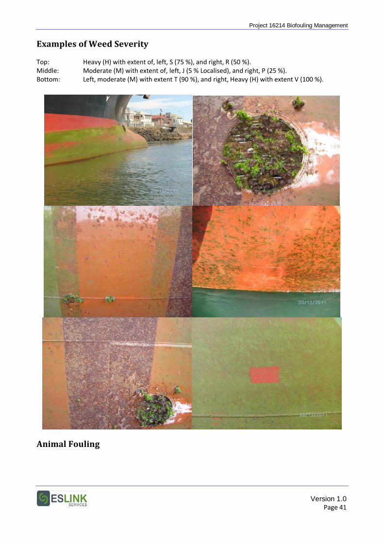
Project 16214 Biofouling Management
Examples of Weed Severity Top: Heavy (H) with extent of, left, S (75 %), and right, R (50 %). Middle: Moderate (M) with extent of, left, J (5 % Localised), and right, P (25 %). Bottom: Left, moderate (M) with extent T (90 %), and right, Heavy (H) with extent V (100 %).
Animal Fouling
Version 1.0 Page 41
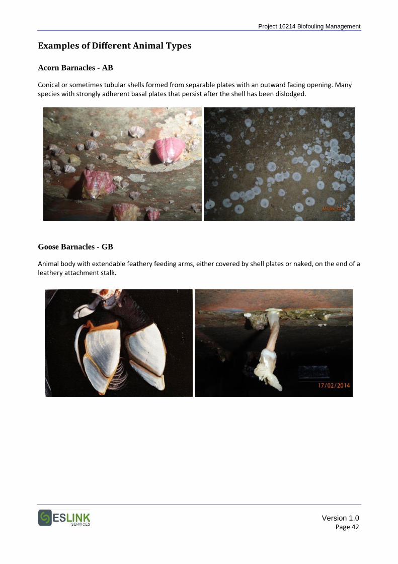
Project 16214 Biofouling Management
Examples of Different Animal Types
Acorn Barnacles - AB
Conical or sometimes tubular shells formed from separable plates with an outward facing opening. Many species with strongly adherent basal plates that persist after the shell has been dislodged.
Goose Barnacles - GB
Animal body with extendable feathery feeding arms, either covered by shell plates or naked, on the end of a leathery attachment stalk.
Version 1.0 Page 42
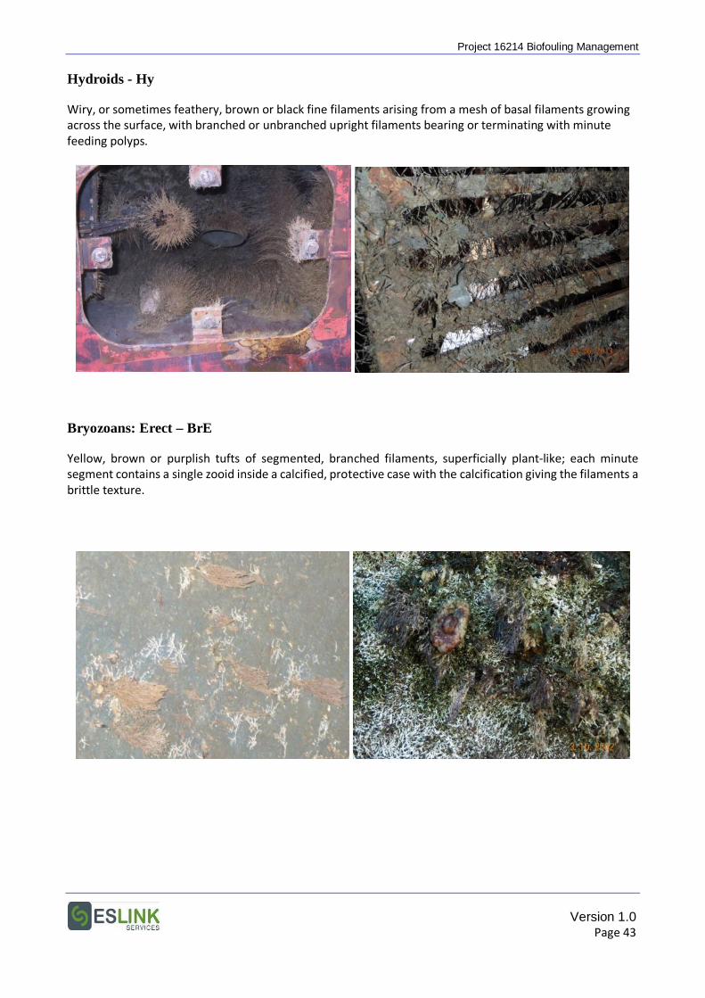
Project 16214 Biofouling Management Hydroids - Hy
Wiry, or sometimes feathery, brown or black fine filaments arising from a mesh of basal filaments growing across the surface, with branched or unbranched upright filaments bearing or terminating with minute feeding polyps.
Bryozoans: Erect – BrE
Yellow, brown or purplish tufts of segmented, branched filaments, superficially plant-like; each minute segment contains a single zooid inside a calcified, protective case with the calcification giving the filaments a brittle texture.
Version 1.0 Page 43
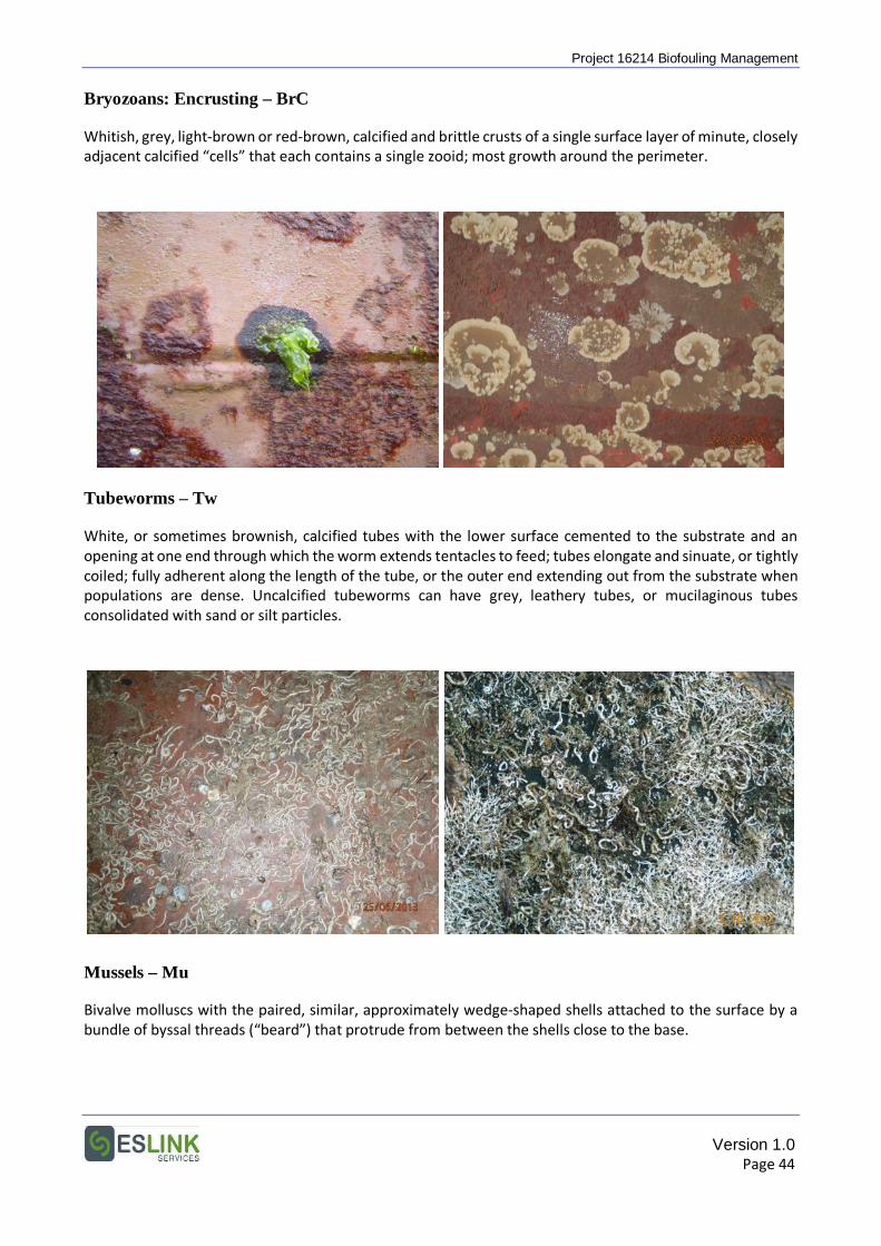
Project 16214 Biofouling Management Bryozoans: Encrusting – BrC
Whitish, grey, light-brown or red-brown, calcified and brittle crusts of a single surface layer of minute, closely adjacent calcified “cells” that each contains a single zooid; most growth around the perimeter.
Tubeworms – Tw
White, or sometimes brownish, calcified tubes with the lower surface cemented to the substrate and an opening at one end through which the worm extends tentacles to feed; tubes elongate and sinuate, or tightly coiled; fully adherent along the length of the tube, or the outer end extending out from the substrate when populations are dense. Uncalcified tubeworms can have grey, leathery tubes, or mucilaginous tubes consolidated with sand or silt particles.
Mussels – Mu
Bivalve molluscs with the paired, similar, approximately wedge-shaped shells attached to the surface by a bundle of byssal threads (“beard”) that protrude from between the shells close to the base.
Version 1.0 Page 44
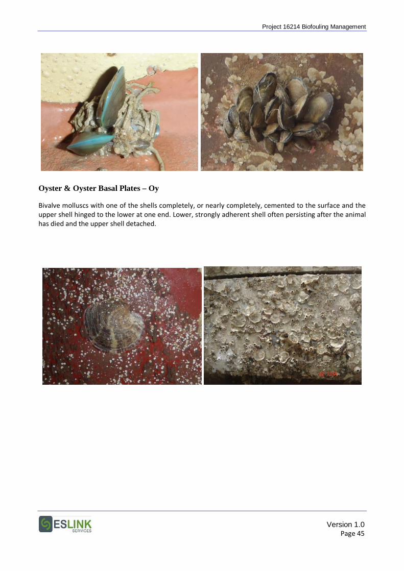
Project 16214 Biofouling Management
Oyster & Oyster Basal Plates – Oy
Bivalve molluscs with one of the shells completely, or nearly completely, cemented to the surface and the upper shell hinged to the lower at one end. Lower, strongly adherent shell often persisting after the animal has died and the upper shell detached.
Version 1.0 Page 45
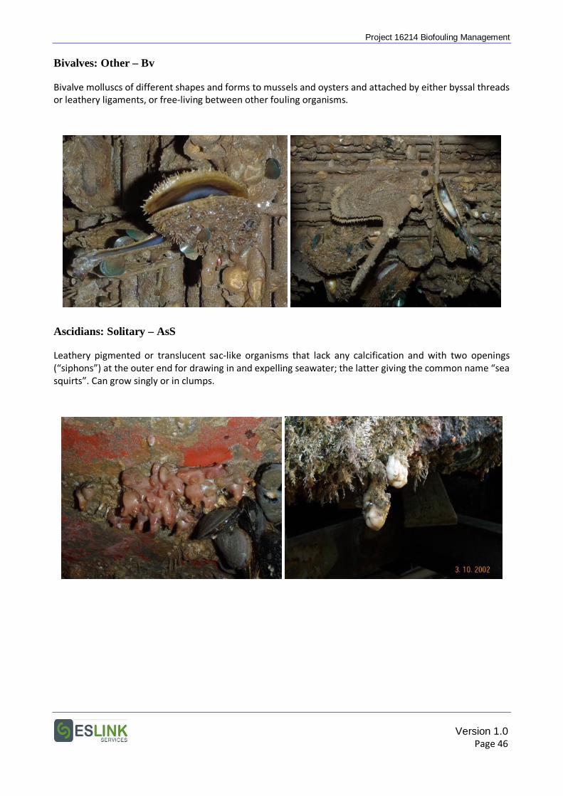
Project 16214 Biofouling Management Bivalves: Other – Bv
Bivalve molluscs of different shapes and forms to mussels and oysters and attached by either byssal threads or leathery ligaments, or free-living between other fouling organisms.
Ascidians: Solitary – AsS
Leathery pigmented or translucent sac-like organisms that lack any calcification and with two openings (“siphons”) at the outer end for drawing in and expelling seawater; the latter giving the common name “sea squirts”. Can grow singly or in clumps.
Version 1.0 Page 46
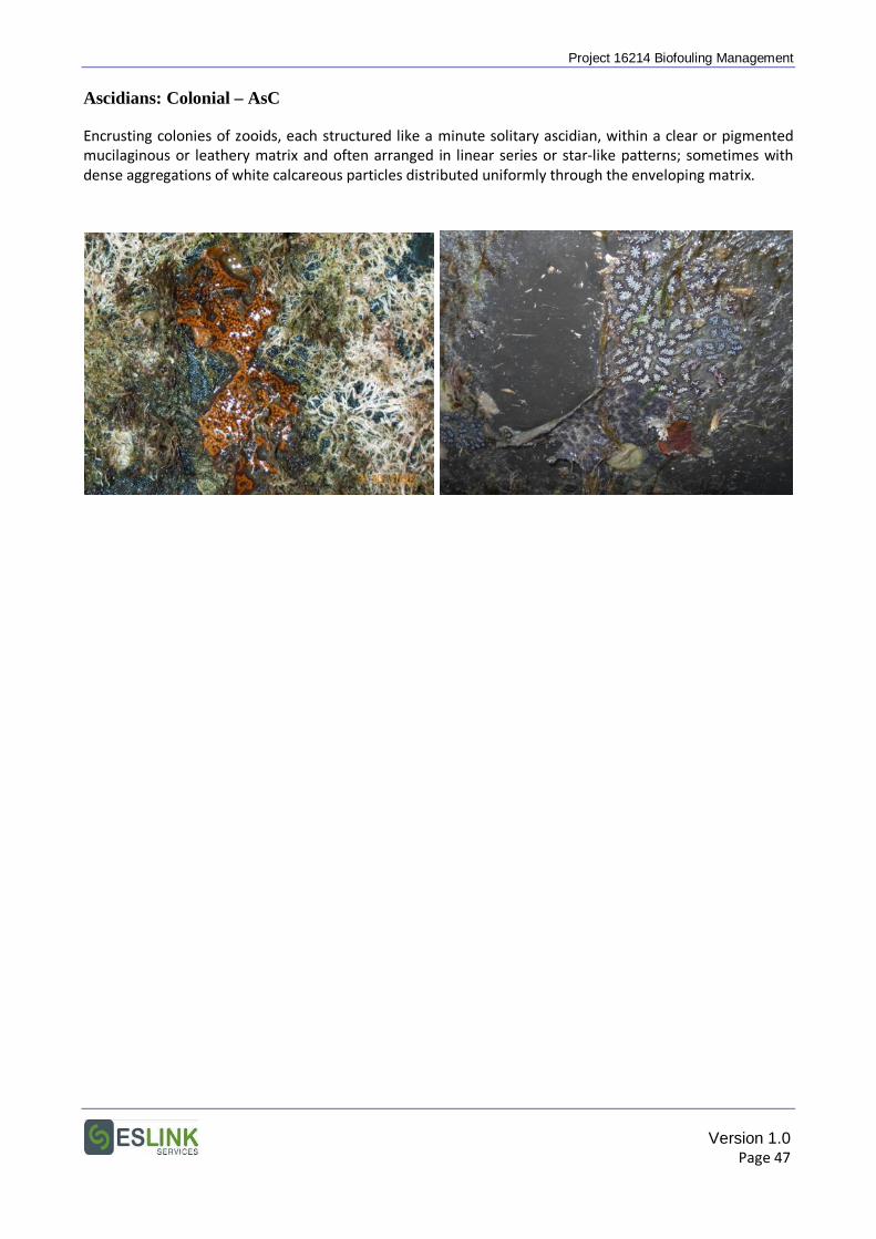
Project 16214 Biofouling Management Ascidians: Colonial – AsC
Encrusting colonies of zooids, each structured like a minute solitary ascidian, within a clear or pigmented mucilaginous or leathery matrix and often arranged in linear series or star-like patterns; sometimes with dense aggregations of white calcareous particles distributed uniformly through the enveloping matrix.
Version 1.0 Page 47
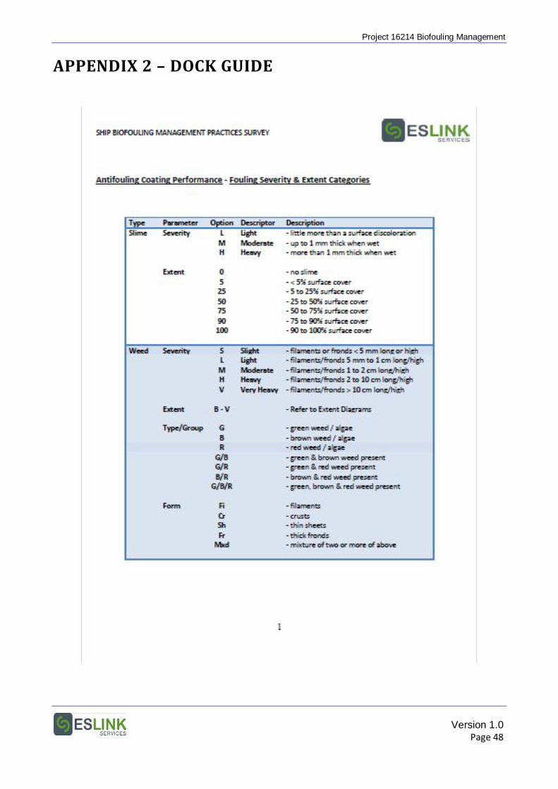
Project 16214 Biofouling Management
APPENDIX 2 – DOCK GUIDE
Version 1.0 Page 48
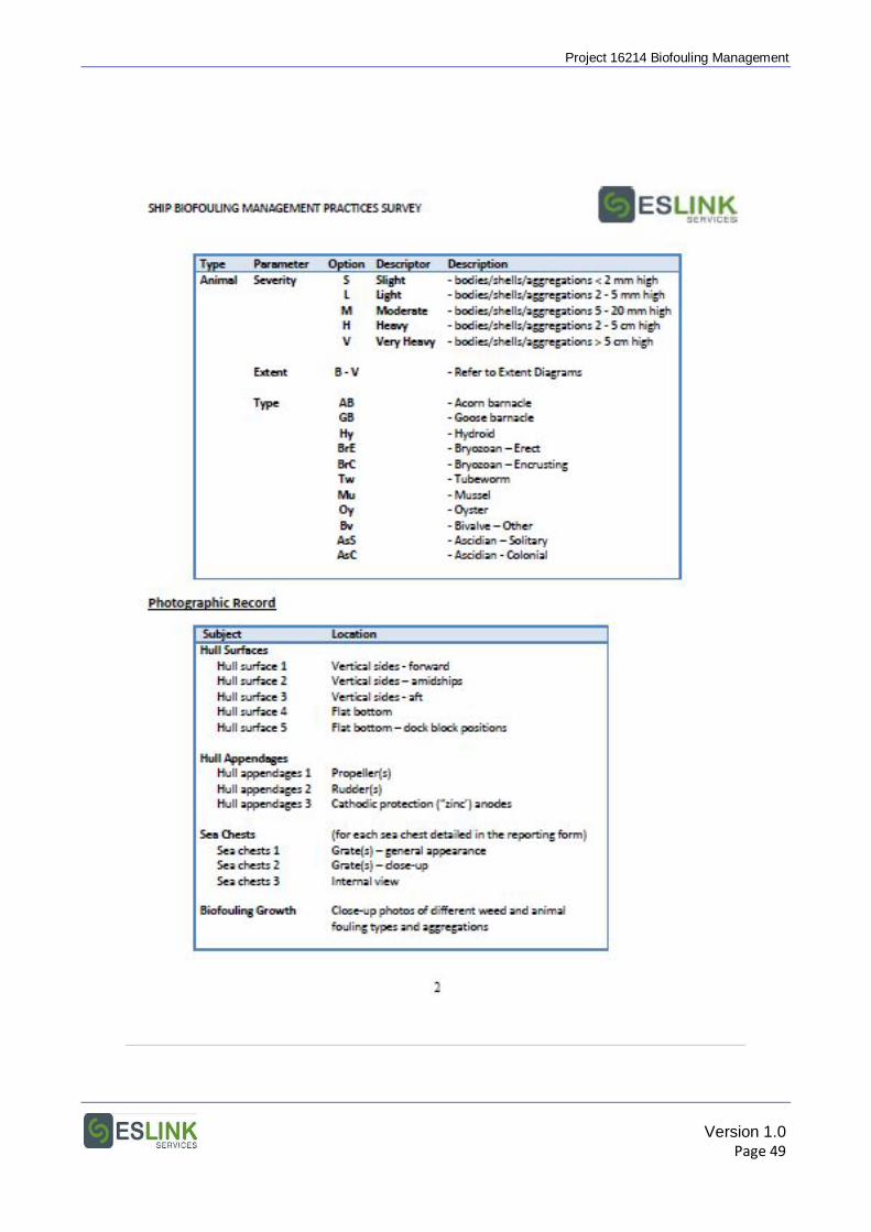
Project 16214 Biofouling Management
Version 1.0 Page 49
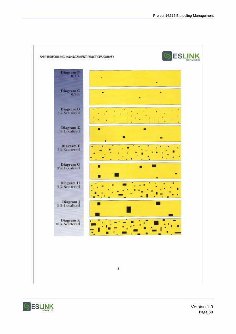
Project 16214 Biofouling Management
Version 1.0 Page 50
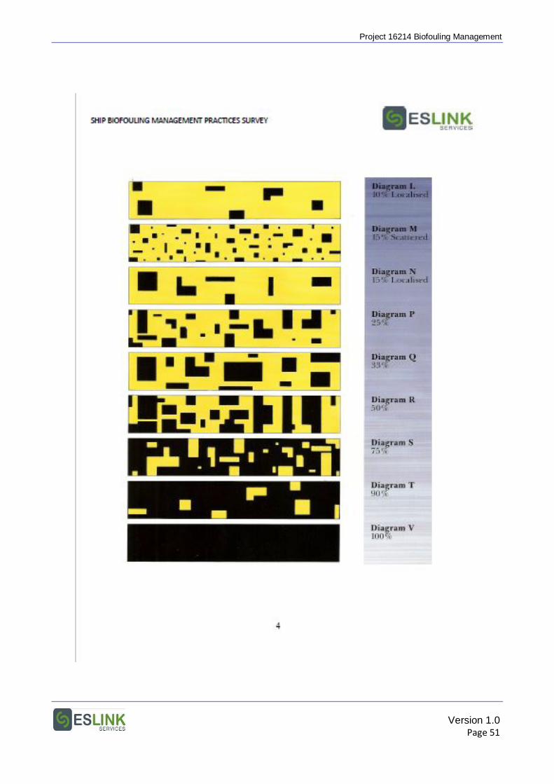
Project 16214 Biofouling Management
Version 1.0 Page 51
Project 16214 Biofouling Management
APPENDIX 3 – MEPC INFORMATION PAPER
Version 1.0 Page 52
Project 16214 Biofouling Management
Version 1.0 Page 2
Project 16214 Biofouling Management
Version 1.0 Page 1
Project 16214 Biofouling Management
Version 1.0 Page 2