Application of Bounding Spectra to Seismic Design of Piping ...
104
NUREG/CR-6240 ORNL/Sub/94-SD427/l • Application of Bounding Spectra to Seismic Design of Piping Based on the Performance of Above Ground Piping in Power Plants Subjected to Strong Motion Earthquakes Manuscript Completed: December 1994 Date Published: February 1995 DISCLAIMER Prepared by J. D. Stevenson Stevenson and Associates 9217 Midwest Avenue Cleveland, OH 44125 Under Contract to: Oak Ridge National Laboratory Managed by Martin Marietta Energy Systems, Inc. Oak Ridge National Laboratory Oak Ridge, TN 37831-6285 Prepared for Division of Engineering Technology Office of Nuclear Regulatory Research U.S. Nuclear Regulatory Commission Washington, DC 20555-0001 NRC Job Code B0850 This report was prepared as an account of work sponsored by an agency of the United States Government. Neither the United States Government nor any agency thereof, nor any of their employees, makes any warranty, express or implied, or assumes any legal liability or responsi- bility for the accuracy, completeness, or usefulness of any information, apparatus, product, or process disclosed, or represents that its use would not infringe privately owned rights. Refer- ence herein to any specific commercial product, process, or service by trade name, trademark, manufacturer, or otherwise does not necessarily constitute or imply its endorsement, recom- mendation, or favoring by the United States Government or any agency thereof. The views and opinions of authors expressed herein do not necessarily state or reflect those of the United States Government or any agency thereof. JiSTRs •4 OE= T H I
-
Upload
khangminh22 -
Category
Documents
-
view
3 -
download
0
Transcript of Application of Bounding Spectra to Seismic Design of Piping ...

NUREG/CR-6240 ORNL/Sub/94-SD427/l
•
Application of Bounding Spectra to Seismic Design of Piping Based on the Performance of Above Ground Piping in Power Plants Subjected to Strong Motion Earthquakes
Manuscript Completed: December 1994 Date Published: February 1995
DISCLAIMER
Prepared by J. D. Stevenson
Stevenson and Associates 9217 Midwest Avenue Cleveland, OH 44125
Under Contract to: Oak Ridge National Laboratory Managed by Martin Marietta Energy Systems, Inc.
Oak Ridge National Laboratory Oak Ridge, TN 37831-6285
Prepared for Division of Engineering Technology Office of Nuclear Regulatory Research U.S. Nuclear Regulatory Commission Washington, DC 20555-0001 NRC Job Code B0850
This report was prepared as an account of work sponsored by an agency of the United States Government. Neither the United States Government nor any agency thereof, nor any of their employees, makes any warranty, express or implied, or assumes any legal liability or responsibility for the accuracy, completeness, or usefulness of any information, apparatus, product, or process disclosed, or represents that its use would not infringe privately owned rights. Reference herein to any specific commercial product, process, or service by trade name, trademark, manufacturer, or otherwise does not necessarily constitute or imply its endorsement, recommendation, or favoring by the United States Government or any agency thereof. The views and opinions of authors expressed herein do not necessarily state or reflect those of the United States Government or any agency thereof.
JiSTRs •4 OE= T H I

i

DISCLAIMER
Portions of this document may be illegible in electronic image products. Images are produced from the best available original document.

ABSTRACT
This report extends the potential application of Bounding Spectra evaluation procedures, developed as part of the A-46 Unresolved Safety Issue applicable to seismic verification of in-situ electrical and mechanical equipment, to in-situ safety related piping in nuclear power plants.
The report presents a summary of earthquake experience data which define the behavior of typical U.S. power plant piping subject to strong motion earthquakes. The report defines those piping system caveats which would assure the seismic adequacy of the piping systems which meet those caveats and whose seismic demand are within the bounding spectra input. Based on the observed behavior of piping in strong motion earthquakes, the report describes the capabilities of the piping system to carry seismic loads as a function of the type of connection (i.e. threaded versus welded).
This report also discusses in some detail the basic causes and mechanisms for earthquake damages and failures to power plant piping systems.
iii

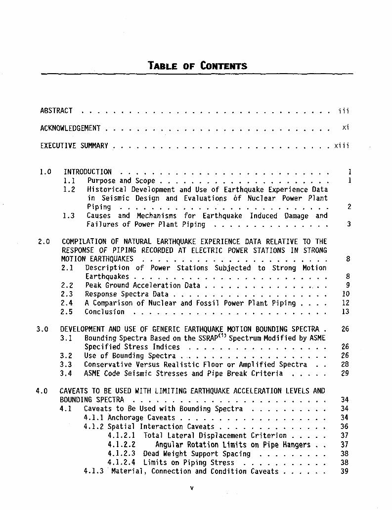
TABLE OF CONTENTS
ABSTRACT iii
ACKNOWLEDGEMENT xi
EXECUTIVE SUMMARY xiii
1.0 INTRODUCTION 1 1.1 Purpose and Scope 1 1.2 Historical Development and Use of Earthquake Experience Data
in Seismic Design and Evaluations of Nuclear Power Plant Piping 2
1.3 Causes and Mechanisms for Earthquake Induced Damage and Failures of Power Plant Piping 3
2.0 COMPILATION OF NATURAL EARTHQUAKE EXPERIENCE DATA RELATIVE TO THE RESPONSE OF PIPING RECORDED AT ELECTRIC POWER STATIONS IN STRONG MOTION EARTHQUAKES 8 2.1 Description of Power Stations Subjected to Strong Motion
Earthquakes 8 2.2 Peak Ground Acceleration Data . 9 2.3 Response Spectra Data 10 2.4 A Comparison of Nuclear and Fossil Power Plant Piping . . . . 12 2.5 Conclusion 13
3.0 DEVELOPMENT AND USE OF GENERIC EARTHQUAKE MOTION BOUNDING SPECTRA . 26 3.1 Bounding Spectra Based on the SSRAP ( 1 ) Spectrum Modified by ASME
Specified Stress Indices 26 3.2 Use of Bounding Spectra 26 3.3 Conservative Versus Realistic Floor or Amplified Spectra . . 28 3.4 ASME Code Seismic Stresses and Pipe Break Criteria 29
4.0 CAVEATS TO BE USED WITH LIMITING EARTHQUAKE ACCELERATION LEVELS AND BOUNDING SPECTRA 34 4.1 Caveats to Be Used with Bounding Spectra 34
4.1.1 Anchorage Caveats 34 4.1.2 Spatial Interaction Caveats 36
4.1.2.1 Total Lateral Displacement Criterion 37 4.1.2.2 Angular Rotation Limits on Pipe Hangers . . 37 4.1.2.3 Dead Weight Support Spacing 38 4.1.2.4 Limits on Piping Stress 38
4.1.3 Material, Connection and Condition Caveats 39
v

4.1.3.1 Materials 39 4.1.3.2 Connections 39 4.1.3.3 Corrosion and Erosion 40 4.1.3.4 Base Plate Gaps 40
4.1.4 Power Operated Valves 40 4.2 Lower Bounds for Seismic Induced Failure of Piping 43
5.0 RECOMMENDATIONS AND CONCLUSIONS 48
6.0 REFERENCES 50
APPENDIX A
Causes and Mechanisms for Earthquake Damage and Failures to Power Plant Piping 53
A.l CAUSES OF PIPING SYSTEM DAMAGE AND FAILURE 54 A.1.1 Seismic Anchor Motion, SAM 54 A.1.2 Spatial Interaction 55 A. 1.3 Corrosion and Erosion 55
A.2 MECHANISMS OF PIPING SYSTEM DAMAGE AND FAILURE 56 A.2.1 Ratcheting 56 A.2.2 Fatigue 59 A.2.3 Plastic Instability or Ductile Rupture 61
A.3 CONCLUSIONS 61
A.4 REFERENCES 61
APPENDIX B
Description of Selected Power Plants Which Have Experienced Strong Motion Earthquakes
with Particular Attention to Piping Systems . . -. 68 B.l LONG BEACH STEAM STATION, LONG BEACH, CALIFORNIA0*-"0 ITEM la of . . 69
B.l.l Plant Description 69 B.l.2 Piping Description 69 B.l.3 Seismic Design Basis 69 B.l.4 Seismic Instrumentation 69
B.2 KERN COUNTY STEAM STATION<B-1), ITEM 2a OF TABLE 2.1 69 B.2.1 Plant Description 69
vi

B.2.2 Piping Description 70 B.2.3 Seismic Design Basis 70 B.2.4 Seismic Instrumentation 70
B.3 VALLEY STEAM PLANT, SAN FERNANDO VALLEY ( B' 1 ) ITEM 5d OF TABLE 2.1 . 70 B.3.1 Plant Description 70 B.3.2 Piping Description 71 B.3.3 Seismic Design Basis 71 B.3.4 Seismic Instrumentation 71
B.4 BURBANK POWER PLANT, SAN FERNANDO VALLEY < B" 1 ) ITEM 5a OF TABLE 2.1 71 B.4.1 Plant Description 71 B.4.2 Piping Description 72 B.4.3 Seismic Design Basis 72 B.4.4 Seismic Instrumentation 72
B.5 GLENDALE POWER PLANT, SAN FERNANDO VALLEY ( B J' B-8) ITEM 5b OF TABLE 2.1 72 B.5.1 Plant Description 72 B.5.2 Piping Description 72 B.5.3 Seismic Design Basis 73 B.5.4 Seismic Instrumentation 73
B.6 PASADENA POWER PLANT, LOS ANGELES BASIN<B-1' B-8> ITEM 5c OF TABLE 2.1 73 B.6.1 Plant Description 73 B.6.2 Piping Description . 73 B.6.3 Seismic Design Basis 73 B.6.4 Seismic Instrumentation 73
B.7 HUMBOLDT BAY POWER PLANT(B"2'B-3'8-7)ITEM 9 OF TABLE 2.1 74 B.7.1 Plant Description 74 B.7.2 Piping Description 74 B.7.3 Seismic Design Basis 74 B.7.4 Seismic Instrumentation 74
B.8 FUKUSHIMA NUCLEAR POWER PLANT C0MPLEX < B- 4\ JAPAN 75 B.8.1 Plant Description 75 B.8.2 Piping Description 76 B.8.3 Seismic Design Basis 76 B.8.4 Seismic Instrumentation 76
B.9 EL CENTRO STEAM POWER P L A N T<B.5,B.6,B.7) n E M 8 a Q F T A B L E Z l _ _ 7 6
B.9.1 Plant Description 76 B.9.2 Piping Description 77 B.9.3 Seismic Design Basis 77 B.9.4 Seismic Instrumentation 77
vii

B.10 REFERENCES 77
APPENDIX C
Example Showing Limiting Pipe Displacements as a Function of Linear
and Non Linear Analysis 83 C.l PROBLEM DESCRIPTION 84
viii

87C1465A\FIGURES FIGURES
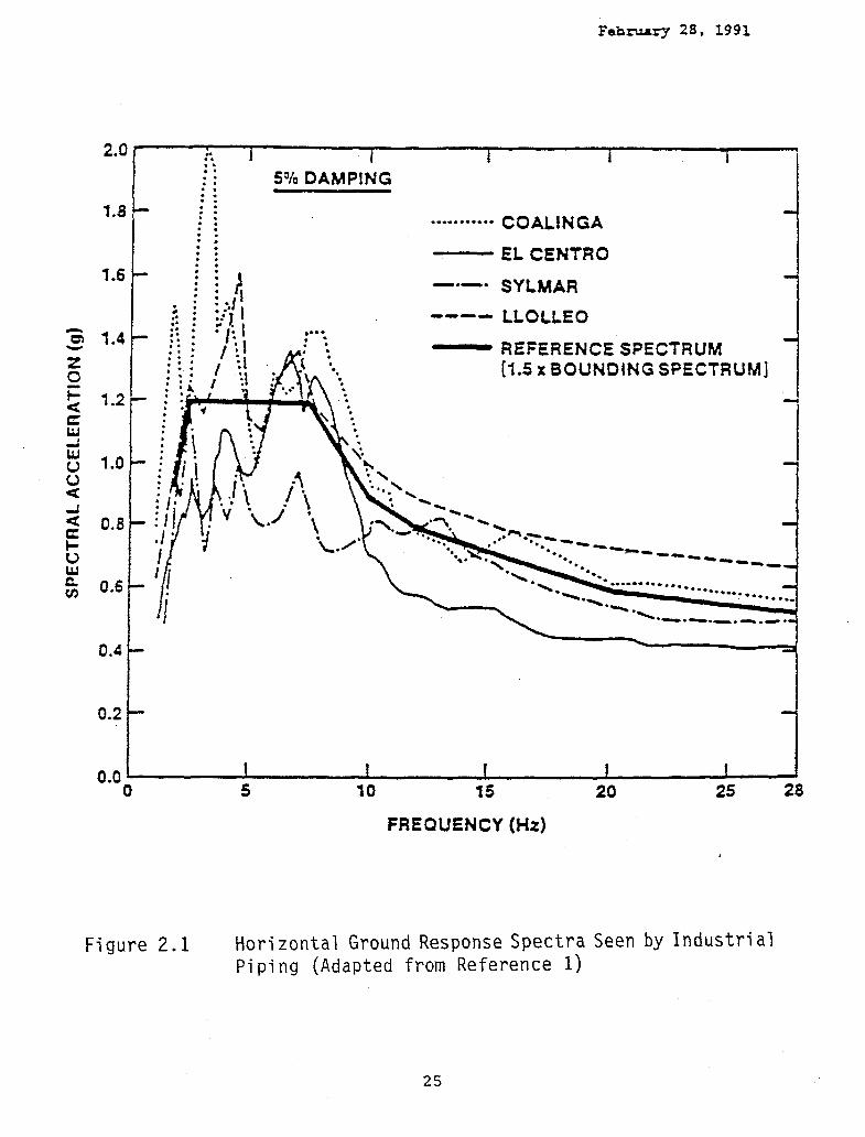
2.1 Horizontal Ground Response Spectra Seen by Industrial Piping 25
3.1 Bounding Spectra for the Seismic Evaluation of Piping.. 32 3.2 Comparison of 5% Bounding Spectra with R.G. 1.60 and
Newmark-Hall Median Shaped 5% Ground Response Spectra 33
4.1 Limits of Experience Data for Air-Operated Diaphragm Valves, Spring-Operated Pressure Relief Valves and Piston-Operated Valves of Light-Weight Construction 45
4.2 Limits of Experience Data for Motor-Operated Valves and Substantial Piston-Operated Valves 46
4.3 Equivalent Linear Lateral Stiffness for Some Typical Pendulum Type Pipe Support Systems 47
A.l Stress Regimes for One-Dimensional Elastic-Perfectly-Plastic Model 63
A.2 Benham-Ford (A.6) Cycle Stress Strain for Carbon Steel 64
A.3 Carbon Steel Ratchet Failure Diagram 65 A.4 Wood's Model for Fatigue Crack Initiation 66 A.5 Possible Model for Fatigue Crack Growth 67
IX

87C1465A\TABLES
TABLES
1.1 Summary of Historical Development of Seismic Design of Nuclear Plant Piping Systems 5
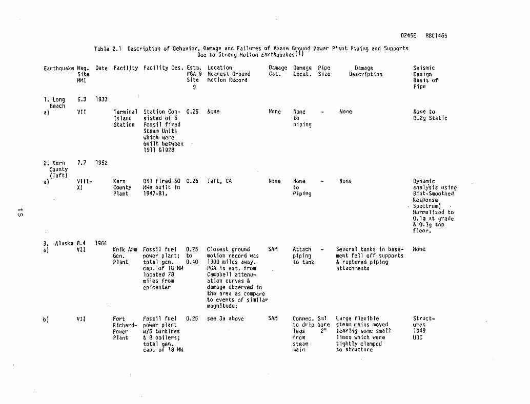
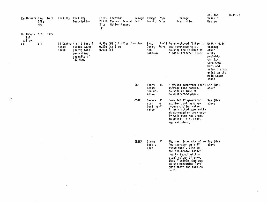
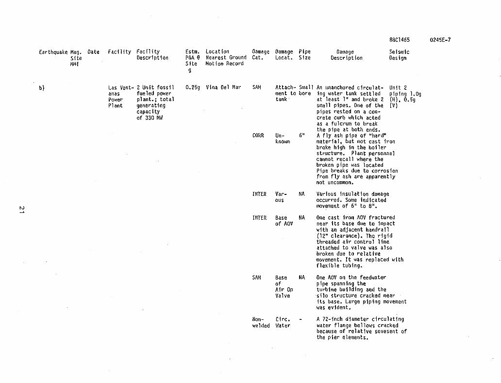
2.1 Description of Behavior, Damage and Failures of Above Ground Power Plant Piping and Supports Due to Strong Motion Earthquakes 15
2.2 Piping Damage and Failure in Power Plants Based on Worldwide Survey of 29 Earthquakes from 1923 to 1985 24
3.1 Seismic Motion Bounding Spectra Digitized Values 31 4.1 Suggested Deadweight Pipe Support Spacing 44 B.l Sample Piping Systems in the Valley Steam Plant 79 B.2 Sample Piping Systems in the Burbank Steam Plants
(Magnol i a and 01 ive) 80 B.3 Sample Piping Systems Within Unit 1 Humboldt Bay
Power PI ant 81 B.4 Sample Piping Systems Within Unit Four El Centro
Power Plant 82 C.l Summary of Analytical Results for a Fixed End 3" Dia.
Sch. 40 Piping System 85
x

ACKNOWLEDGEMENT The author appreciates the help and cooperation of the staffs of the Burbank, El Centro, Glendale, Humboldt Bay, Kern Valley, Pasedena, San Fernando Valley and Moss Landing Power Stations as well as the Utility Owners of these power stations who made this Survey possible.
The author also appreciates the help of Terry Yahr and Sam Moore of the Oak Ridge National Laboratory for their review and comments.
XI


87C1465A(3) 0855REV7
EXECUTIVE SUtMARY
The primary purpose of this report is to review the potential use of Bounding Spectra developed from observations made at industrial plants subjected to large strong motion earthquakes. These spectra may be used to evaluate earthquake performance of above ground piping in nuclear power plants. Section 2.0 presents a summary of the earthquake experience data which may be used to define piping system seismic behavior applicable to nuclear power plants. The Bounding Spectra based on these data are defined in Section 3.0. These spectra may be used together with the caveats and exclusions listed in Section 4.0 of this report for development of seismic design by rule requirements for both piping systems and power operated valves within those piping systems. The Bounding Spectra also can be used to define conservative levels below which experience in strong motion earthquake and tests indicates there is little chance of an earthquake causing significant"3 damages. Section 5 contains recommendations and conclusions and Section 6 contains references.
Appendix A presents a discussion of the causes and mechanisms for seismic induced damage and failure of power plant piping based on strong motion earthquake experience. Appendix B presents more detailed descriptions of the behavior of power plant systems in selected power plants. Appendix C presents an example showing displacements for rod hung piping systems based on linear and non-linear geometry considerations.
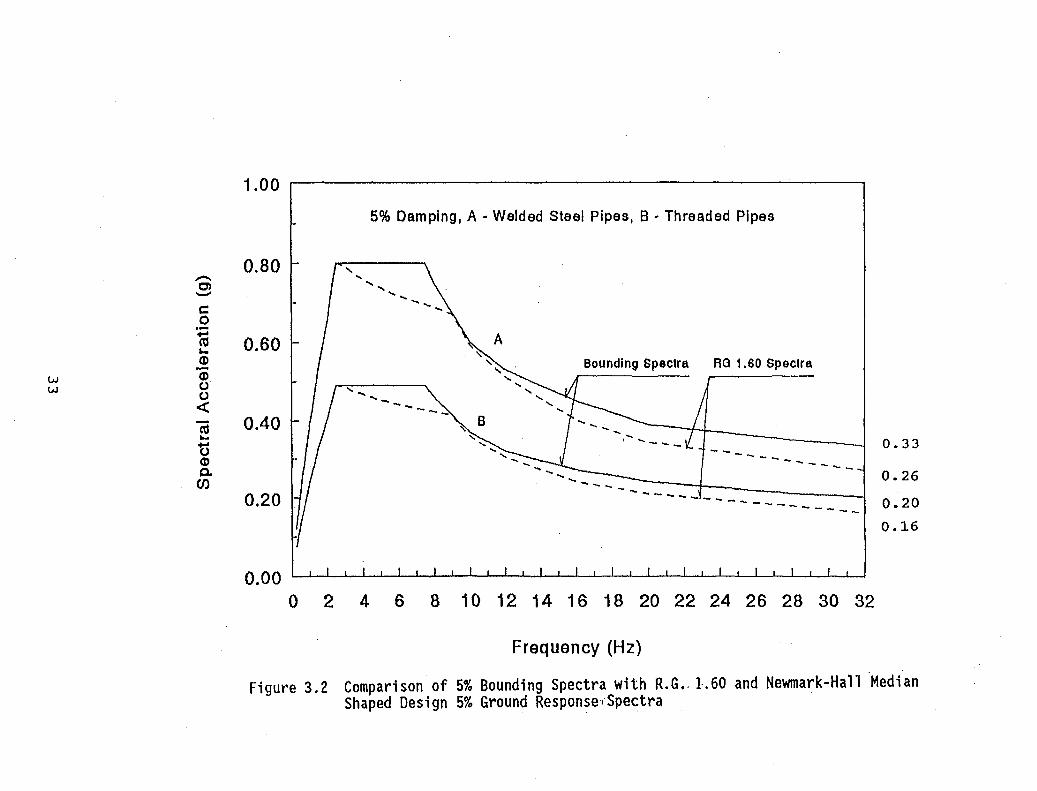
Review of the behavior of essentially non-seismically designed welded steel piping ductily supported in power stations during strong motion earthquake with Peak Ground Acceleration, PGA, less than about 0.33g as also discussed in Ref. 30, suggests that there need not be explicit rigorous earthquake resistant analysis of such piping in order to determine or provide seismic design adequacy. Piping required to resist earthquake motions at or below this value might be based on "Design by Rule" procedures which would not require rigorous analysis. Similar conclusions can be reached for threaded piping at somewhat lower earthquake PGA threshold levels. A comparison of the current R.G. 1.60 design spectra to the Bounding Spectra shows the R.G. 1.60 spectra are enveloped by the Bounding Spectra for welded connection piping at 0.26g and threaded piping at 0.16g PGA respectively. For median shaped seismic design spectra such as that defined in NUREG/CR-0098,(19) the limiting PGA would be about 0.32g and 0.2g
"Significant" as used in this context defines the damage condition at which piping and components supported by piping could no longer perform their required safety function.
xiii

respectively. Since much of the safety related piping in nuclear power plants is connected by welding, this would lead to the conclusion that except for relatively high seismic sites (SSE defined above about 0.3g PGA) there need not be a requirement for explicit rigorous seismic analysis of butt or socket joint welded steel piping. Piping seismic resistant design instead might be based on "Design by Rule" using minimum lateral to horizontal span ratios, use of design caveats, ductile supports and in plant piping system walkdowns.
Such a position would be a revision of current thinking associated with regulatory policy and industry practice used in the seismic resistant design of safety related nuclear power plant piping. However, the results of this report suggest that the rigorous analytical procedures and acceptance criteria used at low to moderate seismicity sites currently in use to seismically design piping systems may be relaxed without loss of seismic resistant design adequacy. In fact, the relaxation of current piping earthquake design criteria would generally result in less restraint of piping which would tend to reduce restraint of free end displacement stresses in piping and supports due to thermal effects during normal operation as well as Seismic Anchor Motion Stresses, SAM, in the event of an earthquake. This, in general, would reduce the potential for pipe failure induced by thermal stress fatigue or ratcheting effects and thereby improve piping system reliability for normal operation. Therefore, current recommendations for changes to the ASME Code to increase damping values and allowable earthquake stresses or simplify and reduce earthquake loads consistent with those observed during earthquakes and in earthquake simulation tests are considered to have a potentially favorable impact on seismic resistant design and should receive active NRC Regulatory evaluation and, as appropriate, NRC support.
A possible immediate implementation of the results of this report would be in the area of "2 over 1" evaluations. The term "2 over 1" is commonly used to describe the condition where non-safety related piping is positioned over, or in close proximity to, safety related equipment or distribution systems. The concern in the past is that such piping, since it is not seismically qualified, would fail in an earthquake and thereby fail or damage safety related equipment in its vicinity. The usual solution to this perceived problem has been to design the non-safety related piping to resist earthquake loads. The results of this report and the conclusions reached in Ref. 30 concerning piping clearly show that there is no need to assume failure of non-seismically qualified piping designed to conventional industrial standards within the limits of the bounding spectra shown in Figure 3.1. Therefore, there should be no need to assume that such piping would fail in an earthquake up to the bounding spectra limits.
A second possible implementation of the results of this report would be to establish a spectra as shown in Figure 3.1 or Figure 3.2 which, where coupled with the caveats contained herein, could be used to exempt sites whose design basis ground response spectrum are enveloped by these bounding spectra from explicit seismic design of small bore piping systems which are usually designed by simplified spacing tables and charts.
xiv

The results of this study when coupled with the results of recently completed EPRI - NRC and other piping component and systems tests points the way to much simpler, more rational, and, in the case of elevated temperature piping, potentially safer, more reliable piping systems.
xv

87C1465A(3) 0855REV7
1.0 INTRODUCTION
1.1 PURPOSE AND SCOPE The primary purpose of this report is to review the use of Bounding Spectra
developed from observations made at industrial plants subjected to large strong motion earthquakes. These spectra may be used to evaluate earthquake performance of above ground piping in nuclear power plants. Section 2.0 presents a summary of the earthquake experience data which may be used to define piping system seismic behavior applicable to nuclear power plants. The Bounding Spectra based on these data are defined in Section 3.0. These spectra may be used together with the caveats and exclusions listed in Section 4.0 of this report for development of seismic design by rule requirements for piping systems and power operated valves within those piping systems. The Bounding Spectra can also be used to define conservative levels below which experience in strong motion earthquake and tests indicates there is little chance of an earthquake causing significantE2] damages. Section 5 contains recommendations and conclusions and Section 6 contains references.
In Appendix A is presents a discussion of the causes and mechanisms for seismic induced damage and failure of power plant piping based on strong motion earthquake experience. Appendix B presents more detailed descriptions of the behavior of power plant systems in selected power plants. Appendix C presents an example showing displacements for rod hung piping systems based on linear and non-linear geometry considerations.
Also identified are recommended reduced bounding spectra as a function of the type of pipe connection used. The bounding spectra are developed based on data taken from the response of piping systems in electric power generating stations which have undergone a significant strong motion and damaging earthquake (Modified Mercalli Intensity, MMI-VII, or larger) equal to or in excess of 0.2g Peak Ground Acceleration, PGA, at the power plant site. Host of the piping included in the experience data base was not designed to be earthquake resistant so the bounding spectra developed in this report should be considered as conservative lower bound estimates of the capacity of seismically designed piping.
"Significant" as used in this context defines the damage condition at which piping and components supported by piping could no longer perform their required safety function.
1

It should also be noted that the bounding spectra developed in Section 3.0 of this report for welded steel pipe is the same as that developed by SSRAP ( 1 ) for the USI-A-46 program concerned with the seismic capability of mechanical and electrical equipment. This is because the bounding spectra developed by SSRAP for the 20 classes of equipment within the scope of A-46 is limited by the behavior of electric and fluid power operated valves in piping systems which are considered to limit the overall operability of the piping system. Furthermore, as recommended by SSRAP a factor of 1.5 has been applied to the best estimate response spectra developed from the data base spectra, to define the bounding spectra. In general, there is currently insufficient earthquake experience data based on existing descriptions of power plant piping to be able to distinguish their seismic behavior as a function of pipe joint type or configuration except for threaded joints. Threaded joints typically make up less than 15 percent of the small bore pipe connections in power plants but account for approximately 55 percent of the observed seismic induced pipe failure. ( 2 , 3 ) Therefore, a bounding spectrum has been developed for threaded joint piping in Section 3.0 which is based on the stress intensification factors developed in Paragraphs NC3600 of Section III of the ASME Boiler and Pressure Vessel Code.
Table 1.1 presents a historical summary of seismic design procedures applied to nuclear power plant piping. This table is presented in order to place the current seismic design requirements into historical perspective.
1.2 HISTORICAL DEVELOPMENT AND USE OF EARTHQUAKE EXPERIENCE DATA IN SEISMIC DESIGN AND EVALUATIONS OF NUCLEAR POWER PLANT PIPING The technical literature and engineering reconnaissance reports on strong
motion earthquake experience dates from at least the 1925 Santa Barbara earthquake.<4) The first known direct use of earthquake experience data which affected the seismic design of a nuclear power plant was the H. B. Robinson Plant in 1967. The initial zero period ground accelerations defined for design of the plant was 0.32g. As a result of a reconnaissance made by R. A. Wiesemann of the Westinghouse Electric Co. on the Alaska 1964 earthquake and reconnaissances made in the spring of 1967 by Westinghouse and Dames and Moore engineers (J. D. Stevenson and D. Leeds) at the sites of the Union, South Carolina, January 1, 1900, the Charleston, 1886 and El Centro, 1940 earthquakes, new physical data were developed which permitted the design basis earthquake zero period ground acceleration to be established at 0.20g instead of 0.32g as originally suggested by the then AEC Staff.
The first comprehensive report on the behavior of mechanical components in general and piping systems in particular during a strong motion earthquake (Alaska, 1964), appears to be a three part article written by J. M. Ayres and T. Y. Sun which appeared in the periodical "Tape/the American Plumbing Engineer" in October - December 1971.(5>
2
Reconnaissances performed from 1971 through 1980 , usually for the Earthquake Engineering Research Institute, were typically performed on major earthquakes worldwide. However, these reconnaissances were generally performed by geotechm'cal and structural engineers with little effort expended on observing the behavior of industrial piping. Notable exceptions to the lack of reporting on mechanical system behavior were the reports prepared by P. Yanev on the Managua 1972 < 6 ) and Miyagi-Ken-Oki 1978 ( 7 ) earthquakes. However, there is no indication that information gained from these reconnaissances was used directly in nuclear power plant licensing at the time.
In September 1980, R. L. Cloud presented a paper ( 8 > entitled "Seismic Performance of Piping in Past Earthquakes" at the ASCE Specialty Conference in Knoxville, Tennessee. This was the first published comprehensive review of the behavior of industrial piping in strong motion earthquakes with potential applications to nuclear power plants . Starting in 1982 under the active sponsorship of the Seismic Qualification Utility Group, SQUG, and the Electric Power Research Institute, EPRI, there have been a series of systematic reconnaissances performed on strong motion (damaging) earthquakes. These reconnaissances have concentrated on the behavior of industrial and power generating facilities.
As part of the comprehensive review of the requirements in the area of nuclear power plant piping undertaken by the NRC in 1983, J. D. Stevenson assembled for the NRC's Seismic Design Task Committee a report on earthquake seismic response and damage to above ground industrial piping. ( 9 )
Under the sponsorship of the Electric Power Research Institute, M. M. Silver et. al. of EQE Inc. prepared a two volume report entitled "Recommended Piping Seismic-Adequacy Criteria Based on Performance During and After Earthquakes." ( 3 , 1 0 ) Since then Stevenson, supported by NRC Research, has visited eight California Power Plant Sites and 20 Units and summarized the behavior of above ground piping during eight strong motion damaging earthquakes whose PGA exceed 0.2g. He also developed a data base for vertical and horizontal piping support spacings from the plants visited.(2> In general, the Cloud, NRC -Stevenson, and EPRI - EQE series of reports have summarized information contained in the earlier reports and added additional detail available from the reconnaissances performed since the previous reports.
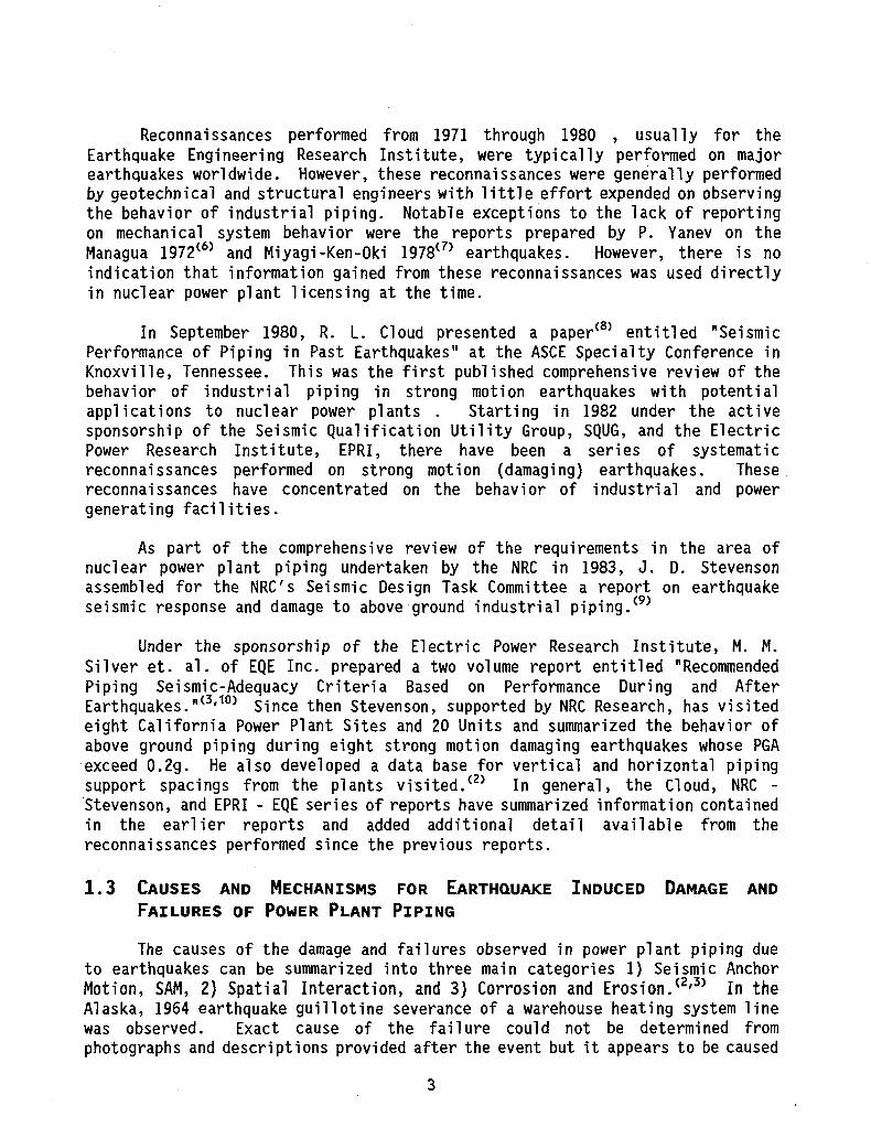
1.3 CAUSES AND MECHANISMS FOR EARTHQUAKE INDUCED DAMAGE AND FAILURES OF POWER PLANT PIPING
The causes of the damage and failures observed in power plant piping due to earthquakes can be summarized into three main categories 1) Seismic Anchor Motion, SAM, 2) Spatial Interaction, and 3) Corrosion and Erosion. ( 2 , 3 ) In the Alaska, 1964 earthquake guillotine severance of a warehouse heating system line was observed. Exact cause of the failure could not be determined from photographs and descriptions provided after the event but it appears to be caused
3

by general failure of the piping support systems. Similar type failures have not been observed in any of the power stations surveyed.
The mechanisms which lead to these damages and failures can also be summarized into three categories as determined by tests 1) seismic stress ratcheting, 2) fatigue and 3) plastic instability or plastic rupture. ( 3' 9' 1 1' 1 2 , 1 3' U )
These causes and mechanisms are discussed further in Appendix A of this report.
4

87C1465A (2) TAB1.1
TABLE 1.1 - SUMMARY OF HISTORICAL DEVELOPMENT OF SEISMIC DESIGN OF NUCLEAR POWER PLANTS
Time Period 1960 -1) Earthquake Design of Structures Uses Conventional Building
Code Requirements 2) Design of Important Safety Related Piping and Pressure Vessels
and Tanks Limited to 0.2g Horizontal Static Acceleration in High Level Earthquake Zones (ZPGA for DBE > 0.2g) only
3) No Seismic Design or Evaluation of Valves 4) No Dynamic Analysis 5) Total Cost of Earthquake Qualification of Plant < < 1.0
Percent of Total Plant Cost 6) Total Earthquake Engineering Effort Expanded per Plant Less
Than 4000 MH B. 1965 -
1) Earthquake Design of Major Structures Uses Dynamic Analysis with Ground Response Spectra (HOUSNER) and Other Criteria from TID 7024 ( 2 7 )
2) Earthquake Dynamic Analysis to Verify Design of Main Reactor, Steam and Feedwater Piping and Major Pressure Vessels and Tanks Uses Horizontal Static Acceleration Based on Peak of Housner Ground Response Spectra Normalized to Peak Floor Acceleration. Damping Values Used for Piping Ranges from 0.5 to 2.0 Percent
3) Typically Valve Procurement Based on a Nominal 2g to 3g Acceleration Requirement for Operability
4) Total Cost of Earthquake Qualification < 1.0 Percent of Total Plant Cost
5) Total Earthquake Engineering Effort Expended Per Plant Less than 10000 MH
1970 -1) Earthquake Design of Structures Begins to Use Upper Bound
Spectra (NEWMARK) Design Basis Earthquake and Double Design or Maximum Hypothetical Earthquake Designations Give Way to 0BE and SSE Nomenclature
2) Floor or Amplified Spectra Begins to be Used in Design of Safety Related Mechanical and Electrical Equipment and Piping Systems. Equivalent Static Method Using Peak of the Applicable Spectra Typically Used. Dynamic Analysis of Equipment and Piping Limited to Major Systems and Components
5

3) Equipment Procurement Specifications (Applicable to Valves) Begin to Contain Detailed Method Requirements for Earthquake Qualification
4) Dynamic Analysis and Test Qualification Extended to More Components
5) Dynamic Analysis of All Elevated Temperature Safety Related Piping Larger than about 6 Inches Begins. Otherwise Simplified Spacing Tables and Charts Are Used (Design by Rule)
6) Total Cost of Earthquake Qualification Approximately 2 Percent of Total Plant Cost
7) Total Earthquake Engineering Effort Expended Approximately 50000 MH
1975 -1) Earthquake Design Based on Mean + One Sigma Spectra from R.G.
1.60. Two Horizontal and Vertical Components Rather than a Single Horizontal and Vertical Component Now Considered. Closely Spaced Modes Combined by ABS Rather than SRSS. Two Different Levels of Damping Defined for OBE and SSE as Contained in R.G. 1.61 Resulting in Separate Earthquake Analyses
2) Ground and Applicable Broadened Floor and Amplified Spectra in General Use in Design and Analysis of ALj. Safety Related Structures, Equipment and Distribution System.
3) Dynamic Response Spectrum Modal Analysis of Safety Related (ASME III - Class 1, 2, and 3) Piping Routinely Performed on All Sizes above 2 1/2 Inches. Support Stiffness Begins to Be Considered in Modeling of Piping Systems. Spectra Developed at Equipment Attachment Panels also Begins to Be Considered in Piping Design. Use of a 1.5 Times the Peak of the Floor Spectra Begins to Be Used in Equivalent Static Analyses of Piping.
4) Equipment Procurement Specifications Contained Detailed Earthquake Method Qualification Requirements
5) More Rigorous Earthquake Qualification Testing of Electrical Equipment Begins (IEEE 344-75 as Compared to IEEE 344-71)
6) Formalized Design Control (Q.A.) Begins to Have a Significant Impact on Engineering Manhours
7) Total Cost of Earthquake Qualification 3-4 Percent of Total Plant Cost
8) Total Earthquake Engineering Effort Approximately 350,000 MH 1980 -1) Vertical Amplification Response is Modified by Modeling
Horizontal Building Elements 2) Amplified Spectra Associated with Major Component or Reactor
Coolant Piping Response Effects Approx. 70 Percent of Piping in Containment Thereby Significantly Increasing Earthquake Requirements on Piping
3) Implementation of I&E Bui. 79-14 on Verification of Piping
6

Design Requires Significant Additional Engineering Effort and Reanalyses
4) Equipment Procurement Specifications Begin to Return to Performance Requirements
5) Total Cost of Earthquake Qualification 5-6 Percent of Total Plant Cost
6) Total Earthquake Engineering Effort Approx. 850,000 MH 1985 -1) Non Conformance Reports in "As Constructed" Versus "As
Designed" Condition Requires Many Earthquake Reanalyses Per System Before Plant is Ready to Operate
2) High Damping Values (Code Case 411) Are Applied on Case by Case Basis to Design of Piping
3) Support Design and Analysis Procedures Become Much More Rigorous
4) Quality Control Inspection of Supports Becomes Much More Rigorous
5) Total Cost of Earthquake Qualification Exceeds 10 Percent of Total Plant Cost
6) Total Earthquake Engineering Effort per Plant Exceeds 1,750,000 MH
1990 -1) A Large Number of Different Procedures Are Proposed to
Simplify the Seismic Design of Piping and Reduce Margins by Industry. Some are Developed as Code Cases to ASME Code to Include Code Cases N451, N462, N468 and by Electric Power Research Institute, NSIG-14
2) NRC-NRR is Reluctant to Accept Any of the Proposed Changes Until Effect on Design Margins Can be Quantified
3) Separate Criteria for Evaluation of Piping "Operability" as Compared to "Design" are Developed for Operating Plants
4) Efforts Begin to Develop Piping Design "By Rule" Rather Than "By Analysis"
5) Otherwise Procedures Developed in 1980 and 1985 for Piping Continue to be Used in Construction of New Plants Modification, Replacement and Additions to Operating Plants
7

2.0 COMPILATION OF NATURAL EARTHOUAKE EXPERIENCE DATA RELATIVE TO THE RESPONSE OF PIPING RECORDED AT ELECTRIC POWER STATIONS IN STRONG MOTION EARTHQUAKES
2.1 DESCRIPTION OF POWER STATIONS SUBJECTED TO STRONG MOTION EARTHQUAKES A summary of earthquake damage to power stations has been developed for the
most part from earthquake reconnaissance reports. Unfortunately, with the notable exceptions of the Alaska 1964, Managua 1972, Miyagi-Ken-Oki 1978 and El Centro 1979 earthquakes, these reports, have until recently, tended to concentrate on the geotechnical and structural damage aspects of earthquake behavior. Starting about 1982 there has been a concerted effort to record the behavior of mechanical and electrical equipment and distribution systems, including piping, in power stations and other industrial facilities during strong motion earthquakes. Unfortunately, even in these more recent cases the details regarding piping as to the design basis, design codes, input motion, type of service, materials, types of connections, types of supports, building frequency and amplification characteristics, etc., often are not included in the descriptions.
Appendix B presents the existing descriptions, taken from the available literature, of the power plants and the above ground piping which have undergone significant strong motion earthquakes. In Appendix B there is also a description of the response of the Fukushima Nuclear power plant complex to the Miyagi-Ken-Oki 1978 earthquake. The peak free field ground acceleration recorded at the Fukushima site was 0.125g with a 30 second strong motion duration. This is one of the largest power plant complexes in the world consisting of 6 BWR units, based on U.S. designs with a current capacity of 4700 MWe. Four of the six units with a capacity of 2812 MWe were apparently operating at the time of the earthquake. These four plants have a total safety related piping inventory of approximately 1,000,000 feet with approximately 300,000 feet of non-safety related piping at risk. There was no recorded damage at the site except to non-safety related insulators. The 0.125g PGA recorded at the site is below the threshold damage to piping suggested by this study in Section 3.0. However, it does provide a data point which confirms the adequacy of the threshold damage spectrum suggested. It should also be noted that the 0.125g exceeds the SSE level design earthquake at several U.S. nuclear power plant sites and exceeds the OBE level design earthquake at most U.S. nuclear plant sites. It should also be noted that the strong motion duration of this earthquake was approximately 30 seconds which exceeds the typical 10-15 seconds duration defined for design basis OBE and SSE earthquakes in the U.S.
8

In addition to the Fukushima plant description, Appendix B contains a description of the effects of the Ferndale 1975 earthquake on the Humboldt Bay power stations (Units 1 and 2 are fossil and Unit 3 is nuclear). While the Ferndale 1975 earthquake at the site was non-damaging (Modified Mercalli V), a PGA as high as 0.3g was recorded at ground surface at the power plant site. The lack of damage is attributable to the relatively short duration, 3 - 5 seconds, of strong motion shaking, but again tends to confirm the lower bound threshold damage spectrum.
2.2 PEAK GROUND ACCELERATION DATA
Table 2.1 presents a summary of the piping experience data developed at 21 power stations during 11 strong motion earthquakes which had estimated power plant site Peak Ground Acceleration, PGA, of at least 0.2g and which had local site damage as indicated by Modified Mercalli Intensities of at least VII as described in Reference 9. It should be noted that the PGA for the sites listed in Table 2.1 are, for the most part, estimated values with no direct measurement of such accelerations in the near vicinity of the site. More definitive measured site data, including ground response spectra developed from recorded time history accelerations, are contained in Section 2.3 of this report.
Using an average of 30,000 feet of pipe per power station as suggested in Reference 3 for the power plants in the Table 2.1 data base, a total of 630,000 feet of typical power plant piping and 52,500 supports (based on 12.0 feet/support) have experienced strong motion earthquakes which range from a peak horizontal ground acceleration of 0.2g up to 0.5g. Reference 2 developed estimates of quantities of both small and large bore piping (> Zk") as a function of plant size. According to Reference 2, in a 50 MWe nominal plant without reheat or hydrogen cooling of the turbine, the quantity of piping would be approximately 22,500 ft. of small bore and 16,500 ft. of large bore pipe.
Piping "failures" are defined to include through wall cracks (leaks), complete or partial severance (breaks), significant flow reduction due to deformation (collapse) and impairment of flow control (valve malfunction). All other observed piping damage anomalies (e.g. insulation damage, denting or scratching of the pipe) are not considered to be piping failure since these phenomena do not breach the pressure boundary or impede flow or control of fluids.
Support "failures" are identified when supports rupture or break or are so badly distorted that they no longer perform their pipe support or restraint function. Support damage is associated with permanent deformation or set of supports but they are still capable of providing a pipe support or resistant function.
In a worldwide survey of seismic effects on piping, reported in Reference 3, which included the review of 29 earthquakes, a total of 66 instances of piping
9

failure and 75 instances of piping damage were recorded in an estimated 1,200,000 feet of power plant piping, and 11 instances of support failure and 29 instances of support damage were recorded in the estimated 100,000 supports as summarized in Table 2.2 of this report.
2.3 RESPONSE SPECTRA DATA
Recorded Earthquake Spectra applicable to industrial facility piping are based primarily on the earthquake data from earthquakes of Magnitude 6.0 and greater and facilities for which the estimated mean peak ground acceleration (average of two horizontal components) was equal to or greater than about 0.4g. This data base consists primarily of data from the Sylmar Converter Station and the Rinaldi Receiving Station subjected to the 1971 San Fernando earthquake, the El Centro Steam Plant subjected to the 1979 Imperial Valley earthquake, the Pleasant Valley Pumping Plant and oil field facilities northeast of Coalinga near the epicenter of the 1983 Coalinga earthquake, and facilities near Llolleo and San Pedro subjected to the 1985 Chile earthquake. Based upon a review of ground motion estimates made for these sites, the following ground motion records have been judged to be representative of the ground motion at these data base sites:
Date Base Site Estimated Ground Notion Record Average Horizontal Ground Acceleration
Cg) Sylmar Converter Station Pacoima Dam Record Scaled to 0.5g 0.5 El Centro Steam Plant Station 5165, El Centro
Differential Array 0.42
Coalinga Pleasant Valley Pumping Plant Free-Field Record
0.5
Chile Llolleo Record 0.55
The Senior Seismic Review and Advisory Panel reviewed these data and constructed an average of these four spectra as shown in Figure 2.1. The Figure 2.1 Spectrum was judged by SSRAP in Appendix A of Reference 1 to be representative of earthquake ground motion at earthquake experience data base sites. For this reason the average of these four ground response spectra was used to determine the shape of the bounding spectra developed by SSRAP for the A-46 SQUG program.
It should be noted that the four data base site ground response spectra shown in Figure 2.1 are considered by SSRAP to be reasonable or conservative representations of free-field surface ground spectra and do not directly relate to the seismic input to the experience data base piping. Building-supported piping would see input which might be either greater or smaller than the free-field spectra would indicate. In this determination the following factors, as suggested by SSRAP in Reference 1, are a consideration:
10

(1) Foundation Size Effects. This effect relates to the averaging of ground motion over the horizontal extent of the foundation of structures such that seismic motion on the foundation of large structures is likely to be significantly less than that of the free-field. Due to this effect alone, the data base equipment would see smaller seismic input than is indicated by the free-field spectra. However, this effect is related to foundation size, and it is noted that the foundation sizes associated with the data base sites are generally less than for most nuclear power plant structures which might contain similar equipment. Therefore, one would generally expect at least as much beneficial size effects for nuclear power plants as might have occurred in the data base plants. As a result, it is concluded that this effect may be ignored in the data base so long as it is also ignored in the nuclear power plants for which the data base is being used.
(2) Embedment Effects. Foundation embedment at soil sites is also expected to reduce the foundation motion below that of the free-field. This effect might also result in the data base equipment seeing lesser seismic input than is indicated by the free-field spectra. However, nearly all of the data base equipment was mounted in structures with shallow foundations. With the exception of the limited data gathered at the Pleasant Valley Pump Station, this effect was judged to be small. Therefore, based on the existing response spectra data, it is conservatively recommended to ignore the potential reduction in response spectra in the data base due to the benefit of embedment effects.
(3) Structural Amplification Effects. As one progresses up the height of structures, input to equipment will usually increase due to structural amplification. Due to this effect, equipment is likely to see input motion greater than that of the free-field ground. One would expect some amplification over ground spectra at the data base sites. It is judged that the use of free-field ground spectra in lieu of unavailable floor or amplified spectra for the data base sites introduced some conservatism. There is no way to remove this conservatism without performing extensive dynamic evaluations of the data base plant structures.
Because floor or amplified spectra are not available in the data base plants, and because realistic (best estimate) floor or amplified spectra are often not available in existing nuclear power plants, the direct comparison of data base free-field ground spectra with free-field ground surface spectra for the nuclear plant sites is recommended. It should also be noted that l)foundation size effects, 2)embedment effects and 3)structural amplification have all been treated in a conservative manner.
Currently acceptable design floor or amplified spectra for nuclear power plants are based on linear elastic response without dynamic mass coupling for a
11

mean plus one standard deviation spectral input. In the dominant frequency range of most nuclear power plant structures, (2.5 to 9 H z) plus an artificial ± 1 5 percent peak broadening, resultant design floor response spectra are very conservatively computed. A more detailed discussion of floor or amplified response spectra versus ground response spectra as developed in Ref. 1 is contained in Section 3.3 of this report.
As suggested by SSRAP, ( 1 ) it is generally believed that the vertical component of earthquake motion will not be more significant relative to the horizontal components for nuclear plants than it was for the data base plants. Therefore, it suggested that bounds on earthquake spectra can be defined purely in terms of horizontal earthquake spectra.
2.4 A COMPARISON OF NUCLEAR AND FOSSIL POWER PLANT PIPING
The only nuclear power plant that has experienced strong motion earthquake shaking in excess of 0.2g is the Humboldt Bay Plant in 1975 and 1980. Therefore, there is insufficient strong motion experience data defining the behavior of nuclear plant piping as compared to fossil plant piping to draw direct comparisons. However, the process piping design parameters for water cooled nuclear power plants [ 3 ] are similar to those used in fossil fired power stations (1500 to 2500 psi versus 1500 to 2000 psi design pressure and 650°F compared to 1000°F design temperature). If anything, the fossil fired service is more severe then nuclear service since operating temperatures for fossil piping are typically in the creep rupture range above 8OO0F where stiffness properties of the piping change with time and the ability of the pipe material to absorb energy due to thermal aging is reduced. It should also be noted that the code used in the design of fossil plant piping (ANSI/ASME B31.1) is very similar to the code, (ASME Section III-NC 3600 and ND-3600) used in the design of ASME Class 2 and 3 nuclear plant piping which forms the bulk to nuclear plant safety related piping.
An exception to the general conclusion that fossil power plant piping has similar or perhaps less tolerance to earthquake loading than nuclear plant piping might be the reactor coolant main loop piping in PWRs. In most PWRs the thermal displacements of the reactor coolant system are accommodated by movement of the main components (steam generator, coolant pump) rather than in the flexibility of the piping.
The conclusions reached here concerning the comparison of fossil to water cooled nuclear plants are generally not applicable to sodium cooled nuclear facilities because of the low design pressures and hence wall thickness of sodium plant piping.
12

2.5 CONCLUSION
The failure and damage statistics given in Table 2.2 suggest less than one hundredth of one percent of all power plant piping and supports subjected to peak ground accelerations equal to or greater than 0.2g failed as a result of the earthquake. From Table 2.1 it can be seen that no piping failures occurred below a PGA of 0.2g and observed damage below 0.2g PGA to piping was limited to deformation of piping insulation and a 20 degree bend in a snubber support.
Because of this extremely low failure rate, it can be concluded that observed failure of piping in earthquakes is caused primarily by local conditions of weakness in or in the vicinity of the piping systems rather than global conditions of piping design or installation. Such potential weaknesses are identified as follows:
(1) relatively low piping flexibility in regions of large displacement demands from attached massive equipment or other piping
(2) low piping ductility associated with the use of cast iron or other low-ductility materials
(3) threaded joints or other regions of reduced cross section with sharp corners susceptible to stress intensification and ratcheting or fatigue failure when subjected to cyclic earthquake loads
(4) regions of degraded pipe caused by corrosion or erosion
(5) weak joints due to poor welding
(6) interaction with other structures or equipment
(7) high stresses induced in piping due to the large eccentricity of power operated valves
Failures of piping systems from any directly induced earthquake phenomena do not occur below 0.2g peak ground acceleration and the inertia or acceleration component of seismic response of piping does not cause pipes to fail. In no case was an inertia-type failure observed in a line with welded connections in the absence of some weakness factor such as significant corrosion.
The relative strength of the pipe supports is important in determining whether or not a pipe will fail. It was observed in some instances that pipe supports adjacent to massive attached equipment that underwent large movements broke or underwent gross deformation. These support failures resulted in increased local flexibility of the piping systems and permitted the pipe to
13

accommodate large equipment motion without failure. In effect, the failed piping support adjacent to equipment acted as a mechanical fuse in keeping the pipe from failing.
14
0245E 88C1465
Earthquake Mag. Site MMI
Table 2.1
Date
1. Long Beach
a)
6.3 1933
VII
Description of Behavior, Damage and Failures of Above Ground Power plant Piping and Supports Due to Strong Motion EarthquakesO)
Facility Facility Oes. Estm. Location PGA 9 Nearest Ground Site
g Motion Record
Terminal Station Con 0.25 None Island sisted of 6 Station Fossil fired
Steam Units which were built between 1911 &1928
Oamage Damage Pipe Cat. Locat, Size
None
Damage Description
None to Piping
None
Seismic Design Basis of Pipe
None to 0.2g Static
en
2. Kern 7.7 19 52 County (Taft)
a) VIII- Kern Oil fired 60 XI County MWe built in
Plant 1947-81. 0.26 Taft, CA None None
to Piping
None Dynamic analysis using Biot-Smoothed Response Spectrum) Normalized to O.lg at grade & 0.3g top floor.
3. Alaska 8.4 1< 364 a) VII Knik Arm Fossil fuel 0.25 Closest ground SAM Attach
Gen. power plant; to motion record was piping Plant total gen.
cap. of 18 MW located 78 miles from epicenter
0.40 1300 miles away. PGA is est. from Campbell attenuation curves & damage observed in the area as compare to events of similar magnitude;
to tank
b) VII Fort Richard-Power Plant
Fossil fuel power plant w/5 turbines h 8 boilers; total gen. cap. of 18 MW
0.25 see 3a above SAM Connec. to drip legs from steam main
Several tanks in base- None ment fell off supports & ruptured piping attachments
Sml Large flexible Struct-to drip bore steam mains moved ures
2" tearing some small 1949 lines which were UBC tightly clamped to structure

Earthquake Hag. Site MMI
Date Facility Facility Estm. Location Damage Description PGA @ Nearest Ground Cat.
Site g
Motion Record INTER
c) VII Bureau of 30 MWe Hydro Reclima- Electric tion ' Plant Plant
0.25 See 3a above Misc
d) VIII Anchorage Two-15 MWe Municipal Gas-Oil Power Steam turb-Station ines
0.35 See 3a above None
e)
4. Chile a)
VIII
1965 7.0
Port of Whittier Power Station
Three-2 MWe diesel gen. located 33 miles from the epicenter
0.50
Las Vent- 2 unit fossil anas Pow- fueled power er Plant plant; total
generating cap. of 330 MWe
See 3a above INTER
Not Not avail, avail.
INTER
5. San Fernando a)
6.5 1971 VII Bur-
bank power Facility
2 plants: 2 unit Olive & 5 unit Magnolia; Both fossil fueled. Total generating capacity of 200 MW.
0.35g Municipal serv- SAM (East- ices Building; West) 533 East 0.29g Broadway (North- Glendale South)
88C1465 0245E-2 Damage Pipe Locat. Size
Damage Description
Seismic Design
Rupture 6" at Cast Iron Pipe Joint
Three sections of Cast Iron Soot Return Line folded & separated at joint due to excessive displacement.
Turbine Intake
Debris from earthslides & breaks In the walls of water intake tunnel clogged penstocks & turbine strainers
None
None to above ground piping
Plant initially tripped off Hne due to vibration turbine trip Gas supply cut by rupture of buried piping.
Not known
Rupture 6" of line at joint
Rupture of condensate return line due to excessive displacement of line
Not known
Various NA Piping oscilating violently, banging against adjacent struct-
Pfpfng-no seismic bracing
ure members. The impacts (various) lagging without damaging the piping.
Exact NA An unanchored deminer-location allzer water tank in the Unknown Magnolia Plant yard
shiftedv breaking attached piping.
Olive Plant structures-0.20g static equipment-generally anchored-no other seismic design Piping-rod hung for gravity only.

88C1465 0245E-3 Facility Facilty Estm. Location Oamage Damage Pipe Oamage Seismic
Description PGA 6 Site 9
Nearest Ground Motion Record
Cat. Locat. Size Description Design
Misc. A 2" diameter pipe con- -necting to the Magnolia Unit 3 cooling water line cracked.
Glendale Five Generating 0.3g Power Units with Ind-Plant ividual genera
ting capacities of 5,20,20,20 and4-MWe were built in the period 1941-1964. See descrip. 8-16.
Pasadena The plant has 0.2g Power four units with Plant capacities of
45, 45, 71 and 45 MWe. All four units are in separate braced steel frame structures.
Valley Four Generating 0.4g Steam Units with in-Plant dividual gener
ating capacities of 100, 100, 157 and 157 MWe were built in the period 1954-1956. All four units located in braced steel structures.
Non-Welded
Munc. Services Non-Bldg. 533. E. Welded Broadway Glendale
Munc. Services None Bldg. 533 E. Broadway Glendale
None to piping
One valve & pipe broke at the deminerallzer tank in the Olive Plant Yard. Two water lines broke, one cooling water line to the induced draft fan and air preheater on the Unit 3 boiler and the other on the No. 2 influent water line to deminerallzer tank.
None
Munc. Services UK Bldg. 533 E. Broadway Glendale
None to Small A few circulating water Some seismic piping tubes tubes in condenser were stop provided (cond- ruptured on long runs enser) of pipe.

88C1465 0245E-4 Earthquake Hag.
Site MMI
Date Facility Facility Estm. Location Damage Description PGA @ Nearest Ground Cat.
Site Motion Record 9
Oamage Locat.
Pipe Size
Oamage Description
Seismic Design
6. Managua 6.2 a) VIII
1972 ENALUF Power Plant
3 unit fossil fueled power plant; total generating capacity of 90 HW
0.4g Esso Refinery' INTER Various
Non-welded
UK
UK
INTER
INTER
Deaer- -ator
Deaer- -ator Boiler -#3 Conden- -sor
7. Point Mugu
a)
5.9 1973 7. Point Mugu
a) VII Ormond Power Plant
2 unit fossil fueled power plant; total generating capacity of 1500 MWe.
0.20g 11 miles from the epicenter.
INTER Various Ni
Snubber -Support
Various Insulation on the main steam lines were dented.
Several failures occurred at bolted gasketed joints. Pipe attached to satur ated vapor valve of de-aerator broke. High pressure pipe of 3 recirculation valves were bent. Piping broke
Air and drain pipe damaged inside condensor
Various insulation was dented, 4 75 ft. vertica steam pipes in Units 1 8. 2 collided with nearby catwalks I structural steel members. Deflections of up to 13" were noted at impact points.
Structures-0.10g static
Structures-1 0.20g static Equipment-anchored for 0.20 g static overturning forces. Piping-most piping designed for gravity loads only. A few braces exist on large diameter pipes.
One snubber buckled Its -support rod to a 20° angle.
Facility Facility Estm. Location Oamage Damage Pipe Damage Description PGA @
Site g
Nearest Ground Motion Record
Cat. Locat. Size Description 88C1465 Seismic Design
0245E-5
El Centro Steam Plant
4 unit fossil fueled power plant; total . generating capacity of 182 MWe.
0.51g (H) 0.6 miles from SAM 37g 93g
!H) (V)
Site
SAM
CORR
Exact Small An unanchored filter 1n locat- bore the pumphouse slid, ion ' causing the failure of unknown a small attached line.
Exact NA location unknown Gener 3" ator & Cooling 4" Water
Unit 4-0.2g static; other units probably similar. Some snub-bers and seismic stops exist on the main steam lines
A ground supported steel See (8a) storage tank rocked, above causing failure to an unattached pipe. Some 3-& 4" generator exciter cooling. & hydrogen cooling water lines cracked apparently at corroded or previously weld-repaired areas In Units 3 1 4 . Leakage was minor.
See (8a) above
INTER Steam 4" The cast iron yoke of an See (8a) Supply AOV operator on a 4" above Line steam supply line to
the evaporator failed due to impact with a steel column 2" away. This flexible line was on the mezzanine level just above the turbine deck.

0245E 86C1465 Earthquake Mag.
Site MMI
Date Facility
a)
Humbolt County
7.0 1980 VII
to o
Humbolt Bay Pwr Plant
Facility Description
Estm. Location PGA @ Nearest Ground Site ' Motion Record 9
Damage Cat.
INTER
Damage Pipe Damage Seismic Locat. Size Description Design
Various 8" & Various Unit 4 main See (8a) 12" steam Hne was dented. above
steam supply Hne to the evaporator failed due to Impact with a steel column 2". away. This flexible line was on the mezzanin level just above the turbine deck.
Non- NA 2" A two Inch component See (8a) welded cooling water lined above
cracked at Vlctaulk coupling at Unit #4
2-units are fossil fueled one unit 1s nuclear; total generating capacity of 159 MW
0.25 Ground Floor of CORR Unit 3 refueling building
Weld 2" A pinhole leak occurred Unit 3-on a boiler feedwater 0.25g (OBE), line. Substantial prior 0.50g wall erosion was evident (SSE)
10. Chile a)
7.8 1985 Laguna 2 unit fossil Verde fueled power Power plant; total Plant generating cap
acity of 54 MWe
0.25
CORR No. 1 -Steam Line
Sheared Pin on Prob Spring Hanger on 0.2g No. 1 Steam Line Static
Valparaiso/Vina CORR Del Mar
Exact NA Locat. Unknown
A condenser pipe leaked NA the day after the earthquake. Seawater is used to cool the plant & cooling water frequently leaks Into the condenser due to corrosion
Supports
INTER
The main steam collector pipe jumped off Its support but did not leak. A condenser pipe leaked. The seawater that is used to cool the plant frequently causes leaks due to corrosion.
Earthquake Mag. Date Facility Facility Estm. Location Damage Site Description PGA @ Nearest Ground Cat. MMI Site Motion Record
9
b) Las Vent- 2 Unit fossil 0.25g Vina Del Mar SAM anas fueled power Power plant.; total Plant generating
capacity of 330 MW
CORR
INTER
t
INTER
SAM
Non-welded
88C1465 0245E-7 Damage Pipe Damage Seismic Locat. Size Description Design
Attach- Small An unanchored circulat- Unit 2 ment to bore ing water tank settled piping l.Og tank at least 1" and broke 2 (H), 0.5g
small pipes. One of the (V) pipes rested on a concrete curb which acted as a fulcrum to break the pipe at both ends.
Un- 6" A fly ash pipe of "hard" known material, but not cast iron
broke high in the boiler structure. Plant personnel cannot recall where the broken pipe was located Pipe breaks due to corrosion from fly ash are apparently not uncommon.
Var- NA Various insulation damage ous occurred. Some Indicated
movement of 6" to 8". Base NA One cast iron AOV fractured of AOV near its base due to impact
with an adjacent handrail (12" clearance). The rigid threaded air control line attached to valve was also broken due to relative movement. It was replaced with flexible tubing.
Base NA One AOV on the feedwater of pipe spanning the Air Op turbine building and the Valve silo structure cracked near
its base. Large piping movement was evident.
Circ. - A 72-inch diameter circulating Water water flange bellows cracked
because of relative sovesent of the pier elements.

88C1465 0245E-8
Earthquake Mag. Site MM I
Date Facility
c)
11. Whtttier 6.1 1987
a)
b)
Facility Description
Estm. Location PGA @ Nearest Ground Site Motion Record 9
Damage Cat.
Supports
Renca 2 Unit fossil 0.30 Santiago Power fueled power Plant plant; total
generating capacity of 100 MWe
Pasadena 4 Unit Gas 0.20 Munc. Service Power Fired Power Bldg. 533 E. Plant Station. Each Broadway
Unit has approx. 40 MWe capacity
Glendale
Glendale 4 Unit Gas 0.20 Munc. Service Power Fired Power Bldg. 533 E. Plant Station. Each Broadway
Unit has approx. 40 MWe capacity
Glendale
None
UK
Damage Locat.
Feed Water Line
Pipe Size
Sup- Main ports Steam
Line
Sup- From ports Super
Heater Pipes
Supports
INTER Various NA
NA NA
Circul- Sm. ating Base Water
Damage Description
Seismic Design
Feedw^ter pipes slid off their vertical supports (no anchorage) and broke the bolts attaching the supports to the plant.
Several main steam snubber supports twisted at the top of the Unit 2 boiler structure. The flange to which they were attached was bent. A couple primary superheater economizer pipes moved off their supports in Unit 1.
Various pipes jumped from their spring supports 1n Unit 2 at elevation 72 feet. Insulation was dented at Piping-various locations. designed
for gravity loads only.
None
Damage of Small Bore pipe 1n Circulating Water System
(1) Strong motion earthquakes are those earthquake which resulted in a 0.2g or larger PGA at the site.

Notes: CORR = CONNECT INTER =
SAM =
OTHER = LOAD = UNK = NONE =
Primary cause of piping or support failure or damage is due to corrosion. = Primary cause of failure of piping is loading at a non-ductile piping connection. Primary cause of piping or support failure or damage is due to spatial interaction (impact or banging) with other piping, structures or equipment. Primary cause of piping or support failure or damage is due to seismic motion of support or nozzle anchor points of piping. Primary cause of piping or support failure is due to causes other than those listed above. Primary cause of support failure or damage is load on the support. Unknown mechanism caused failure or damage. There was no piping support failure or significant damage due to the earthquake identified.
to

87C1465A/0249REV5
Table 2.2 Piping Damage and Failure in Power Plants Based on Worldwide Survey of 29 Earthquakes from 1923 to 1985 [i]
Category
A. Piping - Above Ground Seismic Anchor Movement Corrosion Interaction Non-welded joints Undefined
Total Piping
B. Supports C. Internal equipment
Power Plants Failures Damage
15 0 7 0 3 60 36 10 5 5 66 75
11 29 15 19
1) Estimated total amount of piping at risk: 1,200,000 ft. Based on a total of 40 plants and an average of 30,000 ft. of pipe/plant.
2) Estimated total number of supports at risk: 100,000 Based on a total of 1,200,000 ft. at an average support spacing of 12 ft.
3} The number of non-welded joints typically represent less than 15 percent of total piping joints in a power plant but represent more than 50 percent of the seismic induced piping failures. This suggests that threaded connected joint pipe as a major source of non-welded joints is more susceptable to earthquake induced damage than is welded joint piping.
L UThis Table,which has been extracted from data includes data from earthquakes in addition to those
contained in Reference 3, shown in Table 2.1.
24
February 28, 1991
2.0
1 i h
5% DAMPING
1.5
3 1.4 z o < C u _J u u O < < cr o a
1.2
1.0
0.8
0.6
0.4
0.2
0.0
COALINGA
EL CENTRO
SYLMAR LLOLLEO REFERENCE SPECTRUM [1.5 x BOUNDING SPECTRUM]
10 15
FREQUENCY (Hz) 20 25 28
Figure 2.1 Horizontal Ground Response Spectra Seen by Industrial Piping (Adapted from Reference 1)
25

3.0 DEVELOPMENT AND USE OF GENERIC EARTHQUAKE NOTION BOUNDING SPECTRA
3.1 BOUNDING SPECTRA BASED ON THE SSRAP SPECTRUM MODIFIED BY ASME SPECIFIED STRESS INDICES
Two Bounding Spectra A and B, as a function of piping system connections (as shown in Figure 3.1) are developed from the SSRAP Bounding Spectrum(1} given in Figure 2.1. They are modified by extending the Reference 1 Spectra below 2 Hz using the R.G. 1.60 horizontal shape spectra.
Spectrum A is the Bounding Spectrum for welded steel pipe (including socket welds) constructed to the requirements of the ANSI B 31.1 or the equivalent of ASME-BPVC Section III Class 2 and 3. Spectrum A is the same spectrum found in Figure 3.1 of Reference 1. Its shape is dictated by the limiting effects of power operated valves contained in the piping systems. Piping systems devoid of such valves would be expected to have a somewhat higher seismic bounding spectrum. However, a sufficient data base applicable only to piping systems without power operated valves, necessary to quantify this difference, does not exist in the available literature.
Spectrum B is meant for use with threaded pipe connections and could be conservatively used for other non-welded pipe connections. This Spectrum is based on Spectrum A being divided by the resultant of the stress intensification factor i = 2.3 given in Figure NC-3673.2(b)-l of Paragraph NC 3600 of Section III of the ASME Boiler and Pressure Vessel Code < 1 5 ) divided by the average i factor (1.4) due to a potential mismatch on fit of butt welded pipe in service. The factor 1.4 is based on the average intensification factor taken for butt joined grove welded piping connections as defined in Table D.l of ANSI B 31.1.-1986.(18)
This results in Spectrum B being equal to Spectrum A values divided by 1..64. Digitized values of Spectra A and B are given in Table 3.1. It should be understood that the bounding spectrum for threaded joint piping is based on Code defined intensification factors and not on any explicit evaluation of earthquake experience data other than the observation that threaded pipe joints appear to fail much more frequently in proportion to their use than do welded pipe connections.
Based on the earthquake experience data contained in Table 2.2 no failures of piping or supports were observed below 0.2g PGA. The damage observed was limited to denting of piping insulation and bending of supports.
3.2 USE OF BOUNDING SPECTRA
The Bounding Spectra, A and B of Figure 3.1 are intended for comparison with 5 percent damped realistic horizontal ground response spectrum at a given nuclear power plant. In other words, the earthquake experience data base demonstrates
26

adequate ruggedness when a realistic horizontal ground response spectrum for the nuclear plant site is less than the Bounding Spectrum at the approximate dominate frequency of vibration of the piping system and at all greater frequencies (also referred to as the frequency range of interest). As suggested by SSRAP, ( 1 ) the comparison of the bounding with horizontal ground response spectra is judged to be acceptable for piping systems mounted less than about 40 feet above grade (the top of the ground surrounding the building) in reasonably stiff concrete shear wall structures. In this suggestion SSRAP ( 1 > did not distinguish between "realistic" or "conservative" ground response spectra. To be consistent with the SSRAP recommended use of "realistic" floor spectra for comparison purposes, the bounding spectra comparisons to ground response spectra should also be made on a realistic basis. Unfortunately, few nuclear plant sites currently have realistic ground spectra defined nor, in general, has "realistic", as applied to spectra shape and the associated damping, been defined.
On an interim basis, it is recommended to have the bounding spectra comparison be made to (conservative) horizontal design basis ground spectra. For equipment mounted more than about 40 feet above grade, comparisons of 1.5 times the Bounding Spectrum with horizontal realistic in-structure floor or amplified spectra is recommended(1). However, since the in-structure floor or amplified spectra are typically based on conservative design basis ground response spectra and damping values, a value of 2.25 times the bounding spectra is recommended for use when comparisons are made with conservatively damped in-structure or amplified design basis response spectra. The 2.25 factor is determined as the result of the product of 1.5, which is recommended by SSRAP ( 1 )
for comparison of bounding spectra to realistic floor response spectra, times 1.5, which is the ratio of the conservative R.G. 1.60 amplification factor for 5 percent damping, to the acceleration factor for the more realistic Newmark and Hall median centered 5 percent damped spectrum contained in NUREG/CR 0098. ( 1 7 )
In the case of piping systems with power operated valves with large eccentric operator length to pipe diameter ratios, the application of Bounding Spectrum A should be limited as discussed in Section 4.1.4 of this report.
The comparison criteria are met so long as the design basis horizontal spectrum lies below the appropriate bounding spectrum at frequencies greater than or equal to the fundamental dominate frequency range t 4 ] of the piping systems.
The above recommendation that the seismic Bounding Spectra shown in Figure 3.1 can be compared with the design basis horizontal ground response spectra for piping mounted less than about 40 feet above grade is based upon various judgments developed by SSRAP concerning how structures respond in earthquakes. These are discussed in Section 3.3 of this report.
C ]In cases where the fundamental dominant frequency of the piping is not known, the bounding spectra should essentially envelop the design basis response spectrum in the frequency range below 33 Hz.
27

3.3 CONSERVATIVE VERSUS REALISTIC FLOOR OR AMPLIFIED SPECTRA
As stated by SSRAP C 1 >, the design basis floor spectra for nuclear power plants are often very conservatively computed. In such cases, amplifications greater than 1.5 above ground motion are often found even at elevations below 40 feet above grade. However, when more median-centered or best estimate analyses are performed that use reasonable or best estimate damping levels for the structure, and account for embedment and wave-scattering effects and dynamic coupling, these high amplifications are not observed with most damaging earthquake ground motion records. The Seismic Safety Margin Research Program (SSMRP) < 1 8* 1 9 > has demonstrated the large conservatism which exists in traditionally computed floor spectra versus median floor spectra.
Figure 3.2 shows a comparison of the bounding spectra developed in Figure 3.1 to the R.G. 1.60 horizontal ground response spectra at 5 percent damping. Because of the "conservative" nature of the R.G.1.60 design spectra (higher acceleration amplification ratios for the same value of damping), the bounding spectrum A with ZPA of .33g envelops the .26g R.G. 1.60 ZPA, and bounding spectra B, the .16g R.G. .1.60 ZPA.
The above recommendation that the seismic bounding spectra can be compared with the design horizontal ground response spectra for piping systems mounted less than about 40 feet above grade is based upon the following judgments concerning how structures respond in earthquakes. For embedded structures on soil sites, one would expect deamplification of horizontal ground motion through a moderately stiff structure between the grade and foundation levels. Thus, one would not expect the horizontal motion within the structure at grade level to exceed the horizontal free-field ground motion and at the foundation level it would be somewhat less than the free-field horizontal ground motion. For embedded structures on rock sites, one would not expect much deamplification of horizontal ground motion with depth. On the other hand, if the structure is laterally supported by the surrounding rock, one would expect this surrounding rock to prevent amplification of motion within the structure. Thus, one would expect horizontal motion within the structure at and below grade to nearly correspond to the free-field horizontal ground motions because of this lateral support provided by the surrounding rock. With moderately stiff structures, as found in nuclear power plants, one would not expect amplification of motions by a factor greater than about 1.5 within a 40 feet elevation change. ' Thus, amplification of the horizontal free-field ground spectra by factors greater than 1.5 are considered to be generally unlikely for elevations less than 40 feet above grade.
There are exceptions to these expectations. Some examples are:
(1) Sometimes the exterior side walls of an embedded structure are surrounded by crushable foam insulation or possibly less stiff backfill so as to isolate the structure from significant lateral support by the
28

surrounding rock or soil.
(2) Often the internal structure within the containment building is not laterally tied to the external containment wall so that the internal structure is not laterally supported by the containment shell.
For rock or very stiff soil sites where one does not expect substantial deamplification of horizontal motion with depth, one should consider grade for each structure to be the highest elevation at which that structure is laterally supported by the surrounding rock or soil. For the case of external side walls surrounded by crushable foam insulation, this elevation would correspond to the bottom of the crushable foam insulation. For the case of internal structures not laterally tied to external walls, grade should be considered to be the base of the internal structure. For softer soil sites where one does expect substantial deamplification with depth, the top of the ground surface should be considered to represent grade, even for the above two exceptions. In general, some judgment must be exercised when interpreting the "effective" grade elevation, and in some cases this elevation should be considered to be lower than the top of the ground surrounding the building.
Similarly, unique conditions could exist where amplification greater than about 1.5 would be expected to occur within 40 feet above grade. Reference 1 was unable to identify any realistic example from nuclear power plant structures where greater amplifications would be expected. It should also be noted that the building modal response may have a significant effect on amplification. For example, the 40 foot height in the diesel generator building may be at the roof line where first mode response would dominate. The 40 foot height in containment structure on the other hand would be within the bottom 20 percent of the height of the structure with much less first mode participation. The provision of allowing comparison of the seismic bounds to the design horizontal ground response spectra for equipment mounted less than 40 feet above grade should be applied with judgment.
3.4 ASME CODE SEISMIC STRESSES AND PIPE BREAK CRITERIA In general, piping moments induced by earthquake in ASHE Class 1, 2 and 3
piping designed by analysis are included in applicable Code equations in order to compute resultant seismic stress used to evaluate design adequacy. An exception to the explicit determination of seismic stresses is the design of small bore piping (Nominal diameter < 2.5 inches) where conformance with pre-engineered support spacing tables and charts, rather than computed stresses, are used as the basis for design. Currently in the limit, the implicit maximum seismic stresses used to develop the spacing tables and charts are typically established at 0.9S where S is the allowable stress defined by the ASME Code for
29

the OBE (Service Level B) and 2.4S for the SSE (Service Level D) . l 5 2 These implicit seismic stresses could be reduced in the ratio of the plant specific design ground response spectra to the bounding spectra peak acceleration values shown in Figure 3.1.
An additional need for the computation of seismic stresses is the criteria contained in the NRC's Standard Review Plan, Section 3.6.2, when it is required to determine postulated pipe break locations in high energy piping as a function of seismic stress level relative to ASME Code allowable stress levels. The implicit seismic stresses determined as described above could be used, where necessary, to define seismic stress levels for determination of postulated pipe break locations. It is also expected that application of current "leak before break" methodology will significantly reduce the need to locate postulated pipe break.
[ 5 ]In older plant designs somewhat more conservative values of allowable seismic stress, 0.6S for the OBE and 1.2S for the DBE, were typically used.
30

87C1465A TAB3.1
TABLE 3 . 1
SEISMIC MOTION BOUNDING SPECTRA DIGITIZED VALUES
Frequency (Hz)
0.25 0.5 1.0 1.5 2
2.5 - 7.5 8 10 12 16 20 28
>33
Curve
Spectral Acceleration 5% Damped
A B
(g)
0.16 0.09 0.28 0.17 0.49 0.29 0.68 0.41 0.65 0.40 0.80 0.49 0.75 0.46 0.60 0.37 0.53 0.32 0.45 0.27 0.39 0.24 0.35 0.21 0.33 0.20
31

5% Damping, A - Welded Steel Pipes, B - Threaded Pipes
i i t i i i i i i i i i i i • i } i i i i i i i i i i i i i i
0 2 4 6 8 10 12 14 16 18 20 22 24 26 28 30 32
Frequency (Hz)
Figure 3.1 Bounding Spectra for the Seismic Evaluation of Piping
l .UU
0.80
* 5% Damping, A - Welded Steel Pipes, B - Threaded Pipes
0.80 r̂ --.A 0.60 / " V ' ^ v . Bounding Spectra RQ 1.60 Spectra
0.40 / "^~~^v ^ ^ ^ — X ^ 0.20
' 1 1 ^ ^ ^ ^ ^ E 0.20
1 . i i i > i • i • i i i i . i . i i i . i ,
0.33 0.26 0.20 0.16
0 2 4 6 8 10 12 14 16 18 20 22 24 26 28 30 32
Frequency (Hz) Figure 3.2 Comparison of 5% Bounding Spectra with R.G.. 1.60 and Newmark-Hall Median
Shaped Design 5% Ground Response'Spectra

4 . 0 CAVEATS TO BE USED WITH LIMITING EARTHQUAKE ACCELERATION LEVELS AND BOUNDING SPECTRA
4 . 1 CAVEATS TO BE USED WITH BOUNDING SPECTRA
Caveats applicable with the use of Bounding Spectra to evaluate seismic design adequacy generally f a l l into three basic categories:
y anchorage y spatial interactions y material and condition
These caveats are related to the causes of pipe system damage and failures discussed in Appendix A of this report. It should also be noted that the use of Bounding Spectrum A, as shown in Figure 3.1, is also limited by the behavior of power operated valves which may form part of the piping system. For this reason, the caveats presented in Reference 1 applicable to such valves should also be considered in determining the bounding spectrum for welded steel pipe. For completeness, these caveats applicable to valves developed by SSRAP from Ref. 1 are contained herein in Section 4.1.4.
To permit the use of bounding spectra in the seismic evaluation of piping, it is necessary to physically walkdown all piping systems to assure all applicable caveats have been met.
4.1.1 ANCHORAGE CAVEATS Anchorage caveats are generally applicable to the component to which the
piping is attached. Alternatively, sufficient flexibility must be provided for the piping system in question to accommodate the anticipated motion of the equipment to which the piping is attached rather than anchor the equipment. This is also usually the case when branch piping is attached to piping mains or runs. In such an instance there are typically two basic design or evaluation choices to be made:
• design or evaluate the branch piping to accommodate postulated displacement of the piping main as discussed in Section 4.2.2 for spatial interaction, or
• evaluate the branch piping composite with the main so that movement of the main can be incorporated into the branch analysis and meet design code allowables.
34

In either case it is usually impractical to restrain the main in order to minimize its motion at the location of the branch connection.
For anchorage of equipment or components to which the piping is attached, the caveats and procedures developed by the Seismic Qualification Owners Group (SQUG) and the Electric Power Research Institute (EPRI) sponsorship as part of the resolution of Unresolved Safety Issue A-46 are recommended for use. ( 2 2 , 2 3' 2 A >
Reference 22 contains a summary of procedures and caveats to be followed in the general evaluation of equipment anchorages. Reference 23 contains a detailed review and recommended capacities of various types of equipment anchorage devices and tables and charts which permit a simplified evaluation of anchorages. Reference 24 describes an automated anchorage evaluation microcomputer program available to SQUG utilities and which can be used to evaluate earthquake capacities for a wide range and mixture of anchorage configurations. It can also be used to design equipment anchorage systems.
It is recommended that the following caveats relative to the anchorage of equipment to which piping is attached be met when using the bounding spectra contained in Figure 3-1.
1) The strength of anchorages for positively anchored equipment must be able to resist the earthquake inertia load demand applied to the equipment. This demand load may be determined in either of two ways:
(a) Apply the peak acceleration of the applicable 5 percent equipment damped (assuming 7-10 percent building damping) floor response spectra/ 6 3 at the point of support of the equipment, times the mass of the equipment applied through the center of gravity of the equipment in two orthogonal horizontal directions and one vertical direction, simultaneously,
(b) Apply the peak acceleration from the appropriate spectra curve in Figure 3.1 times 1.5, if within 40 feet of grade, or times 2.25 if above 40 feet of grade times the mass of the equipment through the center of gravity of the equipment in two orthogonal horizontal directions and one vertical direction, simultaneously.
2) For piping attached to equipment or other piping which is not positively anchored the attached piping must be designed with sufficient flexibility to accommodate the anticipated motion of the unanchored
I W I f floor spectra are not available for this purpose and the equipment is supported within 40 feet of grade, apply an acceleration equal to 1.5 times the peak of the 5 percent damped ground response spectra. Above 40 feet from grade a factor of 2.25 times the PGA may be used as a realistic floor spectra. A linear interpretation of spectral amplification between 35 and 40 feet is permitted.
35

equipment or other piping.
3) The stiffness of equipment anchorage systems should not permit excessive rotation or deflection of the anchored equipment. This is seldom a problem for mechanical equipment to which piping is attached. However, piping attached near the top of large thin-walled vertical anchored tanks may have to be evaluated to determine the pipe has sufficient flexibility to accommodate the tanks displacement.
4} In cases where it is necessary to estimate seismic loads on pipe supports, or to estimate the maximum displacements of piping, a static coefficient equal to 1.5 times the peak acceleration of the Figure 3.2 bounding spectra, normalized to the PGA at the site, may be applied to the mass of the piping. Alternatively, a coefficient less than 1.5 can be used if justified/ 2 3' 2 0
5) In cases where it is necessary to compute stresses in piping in order to meet applicable pipe code requirements a static coefficient equal to 1.5 times the peak acceleration of Figure 3.2 Bounding Spectra, normalized to the PGA at the site, may be applied to the mass of the piping. Alternatively, a coefficient less than 1.5 can be used if justified.*23'24*
6) All anchorages are installed as required in applicable plans and specifications or as otherwise consistent with normal construction anchorage practices.
4.1.2 SPATIAL INTERACTION CAVEATS
Spatial interaction caveats for piping, as contained in this report, are generally applicable to the distance the pipe may displace as a result of an earthquake before damage or failure of the pipe or its supports may be of concern. It does not cover cases where the pipe may impact sensitive equipment. It also does not cover those instances where other heavy structures or components may fall on the piping and thereby fail the pipe. Spatial interactions of the type not covered are best addressed by walkdowns of the piping system to determine what equipment may be in the path of the pipe displacement and what other unsupported or poorly supported massive structure or equipment might fall on the piping and thereby cause piping or support damage or failure.
The following caveats relative to limiting pipe displacements during an earthquake must be met in order to use the bounding spectra contained in Figure 3.1. There are three reasons for limitations placed on piping displacements:
• total displacement sufficient to develop kinetic energy at impact which could damage or fail the pipe,
36

• displacements of the pipe sufficient to cause potential failures of the pipe due to fatigue or ratcheting, and,
• displacements of the pipe sufficient to cause overstress and plastic instability of the support.
An evaluation of these limiting displacement criteria has permitted the establishment of a ratio of maximum deadweight spans to laterally restrained spans, c 2 5 ) which may be used in conjunction with the bounding spectra in Figure 3.1 as shown in Appendix C of this report.
4.1.2.1 Total Lateral Displacement Criterion
A maximum total displacement of ± 12.0 inches is suggested as one of the limitations for the applicability of the piping bounding spectra.c73 It is expected that within this + 12.0 inch limitation there could be many impacts between the pipe and adjacent pipe or the pipe and adjacent equipment or structure. Simple dynamic analysis of earthquake induced motion determines that the maximum velocity attained by the pipe within the 12.0 inch displacement limitation is less than 88 in/sec or 5 mph. Therefore, the kinetic energy of the pipe that could develop within this + 12.0 inch displacement and 5 mph velocity limit is judged not to be sufficient to cause significant damage to the pipe. This is not to say impact sensitive equipment within this displacement range would not require a separate evaluation.
4.1.2.2 Angular Rotation Limits on Pipe Hangers
In the limit, it is anticipated that threaded rod type pipe hangers, if fixed at their anchor point, could fail due to low cycle fatigue if subjected to large rotations through the typical limiting 60 cycles of earthquake motion (1 SSE and 5 OBEs including after shocks). It is also necessary to determine that the support anchor will act in a ductile manner (i.e. a plastic hinge will form in the hanger before the anchorage of the hanger fields).
A limit on rotation of 6° has been established for rods fixed at the attachment to the building structures. This limitation is based on potential for a low cycle fatigue or ratchet type failure associated with cyclic tests of threaded rod hangers at various angles to failure. Based on a review of these tests, this limit has been established. It results in a safety factor of approximately 5 against the number of cycles to failure, assuming 60 cycles of
This displacement criterion is not applicable at or near power operated valves in the piping system when electrical, air or oil line leads to the valve operators are not designed with sufficient flexibility or slack to accommodate such relatively large motions. More details concerning caveats applicable to valves were developed by SSRAP in Ref. 1 and are reproduced in Section 4.1.4 of this report.
37

seismic load define the limiting earthquake cyclic input.' Pipe hangers that meet these criteria could be used to carry lateral as well as vertical loads. The lateral load carrying capacity through pendulum behavior is a non-linear phenomenon. However, it is possible to represent the lateral stiffness of hangers with little or no bending resistance by means of a linear spring for small rotations. For 6° or less angular rotation
Kh = W/l (4.1)
where:
K h is equivalent linear lateral stiffness
W = total vertical load on the hanger
1 = length of hanger
For hanger type supports where there is significant bending resistance, equivalent linear lateral stiffnesses are shown in Figure 4.3.
4.1.2.3 Dead Weight Support Spacing
Table NF 3611.1 of the ASME Section III Code and Table 121.5 of ASME/ANSI B31.1, as shown in Table 4.1 of this report, contain recommended deadweight support spacings which will limit dead weight stresses in the piping to approximately 1500 psi or about 0.10Sm or S.
4.1.2.4 Limits on Piping Stress
The maximum stress in the pipe due to earthquake has been established at 2.4S or S m where S or S m are the normal allowable stresses in the pipe (Sm.for ASME Class 1 and S for ASME Class 2 and 3). This value is developed by determining the maximum allowable stress in pipe as 3.0Sm or 3.OS or 2.0 S y for the loading condition (Service Level D) which includes the Safe Shutdown Earthquake less an allowable of 0.1Sm or S for deadweight plus an allowance of 0.5Sm or S for pressure. In the case of an assumed ASME SA106 Grade B piping material, with an S = 35 ksi and an S u = 60 Ksi, the normal allowables of S m = SJ3 = 20 Ksi, S = 2Sy/3 = 23.3 Ksi and S = Sy4 = 15 Ksi are established. Therefore, a minimum limit of 15 x 2.4 = 36 Ksi in this case is available to carry limiting earthquake induced stress for Class 2 and 3 piping.
Based on the three criteria just presented, a)total displacement equal to or less than + 12.0 inches, b)stress in piping equal to less than 2.4S (36 ksi) and c)angular rotation of fixed threaded ductile hangers equal to or less than 6° and the analysis presented in Appendix C, maximum lateral support to vertical support span ratios can be established. It is recommended that the use of Bounding Spectra A be limited to piping systems within the following recommended
38

vertical to lateral support span ratios:
Span Ratio
4 for fixed end rod hung systems with rod lengths < 4.0 ft.
5 for fixed end rod hung systems with rod lengths < 6.0 ft.
6 for fixed rod hung systems with rod lengths > 6.0 ft. or other types of vertical supports not subject to fatigue failure.
4.1.3 MATERIAL, CONNECTION AND CONDITION CAVEATS
Material and condition caveats are generally applicable to the base material used in the piping systems including in-line components such as valves, elbow or tee fittings, strainers, traps, etc., and the corrosion and erosion state of the piping and supports.
4.1.3.1 Materials
The following caveats, relative to materials used in the piping and piping supports, must be met in order to use the bounding spectra contained in Figure 3.1.
1) No use of cast iron in new designs.
2) In the evaluation of existing piping systems which contain cast iron components or fittings, the cast iron component or fitting must meet the following evaluation criteria:
(a) Stresses in the cast iron for all load combinations shall not exceed 0.2SU where S u is the ultimate strength of the cast iron (typically S u = 30 ksi).
(b) Impact velocity of cast iron components and fittings shall not exceed 15 in/sec.
3) No use of reinforced plastics or ceramic piping materials.
4.1.3.2 Connections
(1) Piping 2 1/2 inch diameter or larger shall be joined by welding, bolting or threading including applicable stress intensification factors or indices designed to transfer either the full section capacity of the pipe or the maximum applied resultant moments and forces in the piping system from all design load combinations.
39

(2) No use of slip joint or bell and spigot type joints.
4.1.3.3 Corrosion and Erosion
Localized corrosion and erosion of piping and their supports have been observed to be significant contributors to the pipe failures which have been observed during earthquakes in fossil fired power stations. c 3 , 8 , 9 ) Because erosion and corrosion are well recognized potential problems in nuclear power plants, there are rigorous inservice inspection programs applicable to nuclear power plant piping systems and equipment. As a result, it is not anticipated that corrosion and erosion would be a significant contributor to the damage or failure of nuclear power plant piping systems due to strong motion earthquakes.
Not withstanding the above discussion, the following specific caveats applicable to corrosion and erosion of anchor bolts should be met in order to use the bounding spectra contained in Figure 3.1 for seismic evaluation purposes.
1) All anchor bolts should be checked to determine all nuts are present and tight and erosion or corrosion has not resulted in more than a 10 percent loss of nominal bolt cross section diameter.
2) All anchor welds should be checked to determine that erosion and corrosion has not reduced the weld cross section dimension by more than 10 percent of the nominal value used to evaluate anchorage capacity.
4.1.3.4 Base Plate Gaps
Base plate gaps between the bottom of the support base plate and the concrete or steel bearing surface shall not exceed 0.25 inches. Gaps which exceed this should be evaluated on a case by case basis for sufficient base plate bending, anchor bolts and bearing capacity.
4.1.4 POWER OPERATED VALVES
Caveats concerning power operated valves in piping systems are covered in this section. Included are caveats relative to air-operated diaphragm valves, piston-operated valves, spring-operated pressure relief valves and motor-operated valves. Not included in this section are liquid-operated piston valves such as hydraulic piston-operated valves because of the relatively low number of such valves in the experience data base.
Air-operated diaphragm valves consist of a valve operated by a rod actuated by air pressure against a diaphragm attached to the rod. The actuator is supported by the valve body through a cantilevered yoke. Piston-operated valves or spring-operated pressure relief valves contain air or liquid in a cylinder or chamber which actuates the valve with control provided by a spring.
40
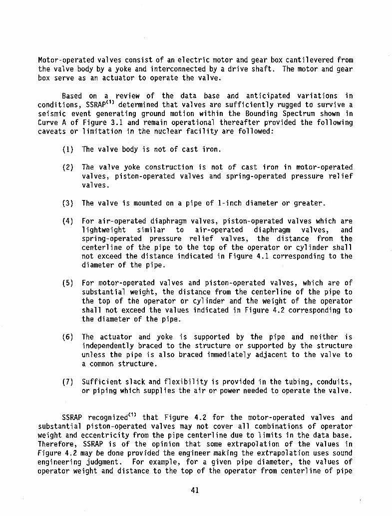
Motor-operated valves consist of an electric motor and gear box canti levered from the valve body by a yoke and interconnected by a drive shaft. The motor and gear box serve as an actuator to operate the valve.
Based on a review of the data base and anticipated variations in conditions, SSRAP ( 1 ) determined that valves are sufficiently rugged to survive a seismic event generating ground motion within the Bounding Spectrum shown in Curve A of Figure 3.1 and remain operational thereafter provided the following caveats or limitation in the nuclear facility are followed:
(1) The valve body is not of cast iron.
(2) The valve yoke construction is not of cast iron in motor-operated valves, piston-operated valves and spring-operated pressure relief valves.
(3) The valve is mounted on a pipe of 1-inch diameter or greater.
(4) For air-operated diaphragm valves, piston-operated valves which are lightweight similar to air-operated diaphragm valves, and spring-operated pressure relief valves, the distance from the centerline of the pipe to the top of the operator or cylinder shall not exceed the distance indicated in Figure 4.1 corresponding to the diameter of the pipe.
(5) For motor-operated valves and piston-operated valves, which are of substantial weight, the distance from the centerline of the pipe to the top of the operator or cylinder and the weight of the operator shall not exceed the values indicated in Figure 4.2 corresponding to the diameter of the pipe.
(6) The actuator and yoke is supported by the pipe and neither is independently braced to the structure or supported by the structure unless the pipe is also braced immediately adjacent to the valve to a common structure.
(7) Sufficient slack and flexibility is provided in the tubing, conduits, or piping which supplies the air or power needed to operate the valve.
SSRAP recognized<1) that Figure 4.2 for the motor-operated valves and substantial piston-operated valves may not cover all combinations of operator weight and eccentricity from the pipe centerline due to limits in the data base. Therefore, SSRAP is of the opinion that some extrapolation of the values in Figure 4.2 may be done provided the engineer making the extrapolation uses sound engineering judgment. For example, for a given pipe diameter, the values of operator weight and distance to the top of the operator from centerline of pipe
41

may be varied provided their product, a measure of the cantilever moment applied to the pipe, does not exceed the value calculated from Figure 4.2. SSRAP recommended that the distance to the top of the operator not be increased by the procedure by more than about 30%. Likewise, if the ground motion spectra for the site is below the SSRAP Bounding Spectrum (Curve A of Figure 3.1) in the entire frequency range possible for the piping and valve network, the operator weight or distance to the top of the operator can be increased by the ratio of the spectra. SSRAP recommends that neither of these values be increased by more than about 30% by this procedure.
SSRAP also pointed out that the operator weights given in Figure 4.2 are from the experience data base and may have been slightly underestimated from available catalogs. Thus, if an actual operator is slightly heavier than the value in Figure 4.2 the engineer evaluating the valve can use some engineering judgment in assigning similarity.
SSRAP also believed that the evaluating engineer can extrapolate the operator length values in Figure 4.2 using the weight and length limits of Figure 4.2 provided the yoke of the air-operated diaphragm valve is not of cast iron. Again, any extrapolation of this type should not exceed about 30% beyond the limits of Figure 4.1.
For air-operated and liquid-operated valves not complying with the above limitations, the seismic ruggedness may be demonstrated by static tests or analysis. In tests, a static force equal to three times the approximate operator weight shall be applied approximately at the center of gravity of the operator non-concurrently in each of the three orthogonal principal axes of the yoke. Such tests should include demonstration of operability following the application of the static load. The limitations other than those related to the distance of the top of the operator to the centerline of the pipe, given above, shall remain in effect. Similarly, static tests can be performed on a mock-up test stand provided the valve details are very similar to those in the plant. If there are numerous valves, a rational test program can be developed to envelop the valve configurations in the plant. Alternately, an analytical evaluation can be made.
In valves where seismic ruggedness is demonstrated by analyses, operability in the absence of a qualification by test is determined by limiting allowable stresses in all parts of the valve to ASME III Service Level B. Structural and leak tight integrity is determined by limiting all pressure retaining parts of the valve to ASME Section III Service Level D.
If the valve body is of cast iron, SSRAP was of the opinion that the valve can remain in the system provided stress analysis of the valve and associated piping reveals very low stresses due to the piping loads. Low stresses for cast iron are defined in Section 4.1.3 of these criteria. It may be necessary to add supports to the piping near the valve to obtain these low stresses.
42

4.2 LOWER BOUNDS FOR SEISMIC INDUCED FAILURE OF PIPING As discussed in Section 2.0 of this report, most of the piping systems in
power plants which experienced at least 0.2g PGA had no seismic or lateral restraint design. However, because of building layout consideration most piping which has experienced strong motion earthquakes had lateral to vertical support ratios which ranged from 4 to 8. ( 2 > The bounding spectra curve B (threaded connections) of Figures 3.1 and 3.2 defines the lower bound seismic capacity equal to, or exceeding, the 0.16g PGA from R.G. 1.60. This suggests there is no potential for seismic failure of piping below .15g ZPGA correlated with a R.G. 1.60 ground spectra up to about 40 feet above grade, even when lateral support to vertical support span ratios less than 8.0 were provided. However, care should be taken to assure that the vertical supports to such piping are ductile and capable of relatively large lateral displacements without failure.
43

87C1465A TAB4.1
Table 4.1 SUGGESTED DEADWEIGHT PIPE SUPPORT SPACING
Nominal Pipe Size Inches
Suggested Maximum Span in Feet Nominal Pipe Size Inches
Water Service Steam, Gas, or Air
Service 3/4 5 7 1 7 9 2 10 13 3 • 12 15 4 14 17 6 17 21 8 19 24 12 23 30 16 27 35 20 30 39 24 32 42
Note 1. Suggested maximum spacing between pipe supports for horizontal straight runs of standard and heavier pipe at maximum operating temperature of 750°F.
Note 2. Does not apply where span calculations are made or where there are concentrated loads between supports such as flanges, valves, specialties, etc.
Note 3. The spacing is based on a maximum combined bending and shear stress of 1500 psi and insulated pipe filled with water or the equivalent weight of steel pipe for steam, gas or air service, and the pitch of the line is such that a sag of 0.1 in. between supports is permissible.
44

Z a
Si til ^ Q °" 2 K -J 5 O s o O f f F o
J= UJ
IS is — o si < & UJ u. s°
60
45
| | OUTSIDE EXPERIENCE DATA
( 2 3 JNSIDE EXPERIENCE DATA
i/-
K->>:w<«:>:->:*:«*x*fc*>:-̂ ^^ - • • • • • - • • • • • • • . • • - . - • • . • • • . - • • . • • : . - . - . - 4 . - . - . - . - . . - . - . - . • • ^ v . ; . . . . . - . - . - . - . - . - . - . - . ; . ; . ; . - . - . - . - . . . - . - . - . - . ' . - . . . .
PIPE DIAMETER (inches)
Figure 4.1 Limits of Experience Data for Air-Operated Diaphragm Valves, Spring-Operated Pressure Relief Valves and Piston-Operated Valves of Light-Weight Construction
45

100 _ [~ | INSIDE EXPERIENCE DATA
80
H — i j 1 r OUTSIDE EXPERIENCE DATA
iA
60
40
30 25
75#:;: ;ioo#s
S200# :&i
:400#!gi:
- - * - - - - r - •
J750**
llNl
ill 1 2 4 6 8 10 12
PIPE DIAMETER (Inches)
•APPROXIMATE MAXIMUM OPERATOR WEIGHT
14
Figure 4.2 Limits of Experience Data for Motor-Operated Valves and Substantial Piston-Operated Valves
46

i=i
1. Fixed-Fixed Single Arm
K = 12EI/13 + W/l w = Vertical Load
2. Fixed - Fixed: Double Arm K= 24EI/13 + W/l w = Vertical Load
3. Fixed - Pin: Single Arm
K= 24EI/13 + W/l w = Vertical Load
Figure 4.3 Equivalent Linear Lateral Stiffness for Some Typical Pendulum Type • Pipe Support System
i I T "i n = 3
r^5- £>
47

5.0 RECOMMENDATIONS AND CONCLUSIONS The review of the behavior of essentially non-seismically designed welded
steel piping ductily supported in power stations during strong motion earthquake with Peak Ground Acceleration, PGA, less than about 0.33g as also discussed in Ref. 30 that there need not be explicit rigorous earthquake resistant analysis of such piping in order to determine or provide seismic design adequacy. Piping required to resist earthquake motions at or below this value could be based on "Design by Rule" procedures which would not require rigorous analysis. Similar conclusions can be reached for threaded piping at somewhat lower earthquake PGA threshold levels as shown in Figure 3.1. A comparison of the current R.G. 1.60 design spectra to the bounding spectra contained in Figure 3.2 shows the R.G. 1.60 spectra are enveloped by bounding Spectrum A at 0.26g and Spectrum B at 0.16g PGA respectively. For median shaped seismic design spectra such as that defined in NUREG/CR-0098(17> for 50 percent exceedance, the limiting PGA would be about 0.32g and 0.2g. Since much of safety related piping in nuclear power plants is welded, this would lead to the conclusion that except for relatively high seismic sites (SSE defined above about 0.3g PGA) there need not be a requirement for explicit rigorous seismic analysis of butt or socket joint welded steel piping. Piping seismic resistant design instead could be based on "Design by Rule" including minimum lateral to horizontal span ratios, use of design caveats, ductile supports and in-plant piping system walkdowns.
Such a position would be a revision of current thinking associated with regulatory policy and industry practice used in the seismic resistant design of safety related nuclear power plant piping. However, the results of this report suggest that the rigorous analytical procedures and acceptance criteria used at low to moderate seismicity sites currently in use to seismically design piping systems may be relaxed without loss of seismic resistant design adequacy. In fact, the relaxation of current piping earthquake design criteria would generally result in less restraint of piping which would tend to reduce restraint of free end displacement stresses in piping and supports due to thermal effects during normal operation as well as Seismic Anchor Motion Stresses, SAM. This, in general, would reduce the potential for pipe failure induced by thermal stress fatigue or ratcheting effects and thereby improve piping system reliability for normal operation. Therefore, current recommendations for changes to the ASME Code to increase damping values and allowable earthquake stresses, or simplify and reduce earthquake loads consistent with those observed during earthquakes and in earthquake simulation tests, should be considered as having a potentially favorable impact on seismic resistant design. Therefore they should receive active NRC regulatory evaluation and, as appropriate, NRC support.
A possible immediate implementation of the results of this report would be in the area of "2 over 1" evaluations. The term "2 over 1" is commonly used to describe the condition where non-safety related piping is positioned over or in close proximity to safety related equipment or distribution systems. The concern in the past is that such piping, since it is not seismically qualified, would
48

fail in an earthquake and thereby fail or damage safety related equipment in its vicinity. The usual solution to this perceived problem has been to design the non-safety related piping to resist earthquake loads. The results of this report and the conclusion reached in Ref. 30 concerning piping clearly show that there is no need to assume failure of non-seismically qualified piping designed to conventional industry standards within the limits of the bounding spectra shown in Figure 3.1. Therefore there should be no need to assume that such piping would fail in an earthquake up to the bounding spectra limits.
A second possible implementation of the results of this report would be to establish spectra as shown in Figure 3.1 or 3.2 which, where coupled with the caveats contained herein, could be used to exempt sites from explicit seismic design of small bore piping systems which are usually designed by simplified spacing tables and charts.
The results of this study when coupled with the results of recently completed EPRI - NRC and other piping component and systems tests points the way to much simpler, more rational and in the case of elevated temperature piping, potentially safer, more reliable piping systems.
49

6.0 REFERENCES
1. Senior Seismic Review and Advisory Panel, "Part I: Use of Seismic Experience and Test Data to Show Ruggedness of Equipment in Nuclear Power Plants," DE92-019328, Sandia National Laboratory, June 1992.
2. Silver, M.M., et al. "Recommended Piping Seismic-Adequacy Criteria Based on Performance During and After Earthquakes," NP-5617 Vol. 1, Summary Document Prepared by EQE Inc., for the Electric Power Research Institute, January 1988.
3. Silver, M.M., et al. "Recommended Piping Seismic Adequacy Criteria Based on Performance During and After Earthquakes," Vol. 2, Reference Document Prepared by EQE Inc., for the Electric Power Research Institute, January 1988.
4. "What Happened to Municipal Utilities at Santa Barbara," Engineering News Record, July 23, 1925
5. Ayres, J.M. and Sun Tsenj-Yao, "Report on Mechanical Damage Due To the 1964 Alaska Earthquake," Parts 1-3 Tape/The American Plumbing Engineer, October-December 1971
6. Yanev, P.I., "Managua, Nicaragua Earthquake of December 23, 1972 -Industrial Damage," Earthquake Engineering Research Institute Conference Proceedings, Volume II, November 1973
7. Yanev, P.I., Editor, "An Investigation of the Miyagi-Ken-Oki, Japan, Earthquake of June 12, 1978," National Bureau of Standards, October 1980
8. Cloud, R.L., "Seismic Performance of Piping in Past Earthquakes," Presented at ASCE Specialty Conference, Knoxville, TN, September 1980
9. Seismic Design Task Group and Stevenson and Associates Inc., "Report of the U.S. Nuclear Regulatory Commission Piping Review Committee, Summary and Evaluation of Historical Strong-Motion Earthquake Seismic Response and Damage to Above Ground Industrial Piping," NUREG-1061 Vol. 2 Addendum, Prepared by Stevenson and Associates for the U.S. Nuclear Regulatory Commission, April 1985
10. Silver, M.M., et. al., "Recommended Piping Seismic Adequacy Criteria Based on Performance During and After Earthquakes," NP-5617 Vol. 2 Reference Document Prepared by EQE Inc. for the Electric Power Research Institute, January 1988.
50

Beaney, E.M., "Response of Pipes to Seismic Excitation - Effect of Pipe Diameter/Wall Thickness Ratio and Material Properties," Central Electricity Generating Broad, July 1985.
DeVita, V., "Seismic Fragility Testing of Representative Nuclear Piping Systems," PVP-VOL. 144, 1988, pp. 237-242.
Hara, F. and Shibata, H., Ratcheting Fatigue in Full-Scale Piping Elements, K 15/3, SMIRT, 1981.
Chen, W.P., Onesto, A.T., and DeVita, V., "Seismic Fragility Test of a 6-Inch Diameter Pipe System," Energy Technology Engineering Center, NUREG/CR-4859, February 1987.
ANSI/ASME Standard Section III of the Boiler Pressure and Vessel Code, "Nuclear Power Plant Components," American Society of Mechanical Engineers, 1986.
ANSI/ASME Standard B31.1 "Power Piping" American Society of Mechanical Engineers, 1989.
Newmark, N.M. and Hall W.J. "Development of Criteria for Seismic Review of Selected Nuclear Power Plants," NUREG/CR-0098 U.S. Nuclear Regulatory Commission, May 1978
Bumpus, S.E., Johnson, J.J., and Smith, P.D., "Best Estimate Method vs. Evaluation Method: A Comparison of Two Techniques in Evaluating Seismic Analysis and Design," prepared for Division of Reactor Safety Research, U.S. Nuclear Regulatory Commission, Lawrence Livermore National Laboratory, Livermore, CA NUREG/CR-1489, UCRL-52746, May 1980.
"Seismic Safety Margins Research Program, Executive Summary Number 1 -Best Estimate vs. Evaluation Method," prepared for U.S. Nuclear Regulatory Commission, Lawrence Livermore Laboratory, Livermore, CA, LLL-TB-026.
MPR Associates, et. al., "Generic Implementation Procedure (GIP) for Seismic Verification of Nuclear Plant Equipment" Rev. 2 May 1988.
EPRI-NP-5228, "Seismic Verification of Nuclear Plant Equipment Anchorage," URS Corporation/John A. Blume & Associates Engineers, San Francisco, CA., May 1987.
Stevenson and Associates, "ANCHOR Users' Guide, 3.0, Rev. 0," August 19, 1990.
Masopust, R. and Stevenson, J.D., "Development of State Coefficients for Use in Seismic Evaluation of Nuclear Safety Related Pipe Systems and
51

Seismic Spacing Tables," Vol. 1 Prepared for the Pressure Vessel Research Council, June 1992.
Standard Review Plan Section 3.7.2 "Seismic System Analysis," Rev. 2 U.S. Nuclear Regulatory Commission, August 1989.
Stevenson and Associates and EQE Engineering, "Procedures for Seismic Evaluation and Design of Small Bore Piping (NCIG-14)," EPRI NP-6628, Electric Power Research Institute, April 1990.
Gasparini, D.A., "Mechanical Tests on 5/8" Threaded Rod," Report No. 82C200-03, Case Western Reserve University, Aug. 1983
Lockheed Aircraft Corp. and Homes and Narver Inc., "Nuclear Reactors and Earthquakes," TID 7024 United States Atomic Energy Commission, August 1963.
52

87C1465A 0855REV7
APPENDIX A CAUSES AND MECHANISMS FOR EARTHQUAKE DAMAGE
AND FAILURES TO POWER PLANT PIPING
53

A.l CAUSES OF PIPING SYSTEM DAMAGE AND FAILURE The causes of the damage and failures observed in power plant piping can be
summarized into three primary categories:
1. Seismic Anchor Motion, SAM
2. Spatial Interaction
3. Corrosion and Erosion
A. 1.1 SEISMIC ANCHOR MOTION, SAM
Seismic Anchor Motion, SAM, causes of piping system damage or failure are associated with relative motion of the piping supports, restraints, anchors and attached equipment or piping. Most observed piping damage or failures have been associated with movement of unanchored equipment to which the piping is rigidly attached. This movement has usually been associated with sliding or rocking movement of the equipment in response to the earthquake motion input. Such equipment is usually quite massive such that the restraint provided by the attached piping is simply not sufficient to resist the movement of the equipment. If the movement is large enough it will exceed the flexibility and ductility capacity of the attached pipe and permanent deformation (damage) or rupture (failure) of the piping or piping supports will result.
Piping damage and failure due to equipment movement can be rather easily eliminated by positively anchoring the equipment to resist earthquake motions or providing sufficient flexibility at piping connections to accommodate potential equipment movement.
A special case of equipment movement is the potential movement of piping mains or runs to which branch piping is attached. In such cases it is usually not practical to anchor or restrain the piping main at or near each branch line connection. It is usually much more practical in such instances to design the branch piping and connection with sufficient flexibility to accommodate the anticipated motion of the main.
Relative seismic motion of supports, restraints and anchors effects on the pipe are normally caused by differential motion of the building structure or structures which support the piping system. In nuclear power plants, most of the supporting building structures are of reinforced concrete shear wall construction, specifically designed to accommodate earthquake effects elastically, with small deformations usually less than 1.0 inches. Therefore, relative motion of piping supports, restraints or anchors, within a building structure, are usually not a problem. This is particularly true when earthquake induced motions in the building structure are correlated, and tend to move in the same direction as is typically the case for cantilever building structures.
54

However, when piping systems run between two different building structures, or pass through construction joints, out of phase motion of the two separate structures may occur with quite large resultant relative motion. Depending on foundation condition, relative differential building motions of 6.0 inches or more might be experienced. As in the case of connections between piping mains and branches, it is essential that flexible piping configurations be developed in runs between building structures and across construction joints which can accommodate the anticipated relative motion of the different structures.
A. 1.2 SPATIAL INTERACTION
Spatial interaction is associated with either:
a) the piping swinging or displacing during the earthquake so as to impact other structure or equipment, or,
b) other structures or equipment displace so as to impact the piping and are of large enough mass or configuration so as to potentially cause failure of the piping.
Under item a) above, the potential swinging or displacement impact of piping induced by earthquake is usually of such relatively low velocity as not to cause damage or failure of the pipe. An exception to this would be relatively brittle piping components, such as cast iron, with little or no dynamic ductility, which may shatter upon impact. Also of concern may be relatively impact- sensitive equipment, such as electronic control and instrumentation devices, which could be potentially damaged or fail due to the impact of the pipe. These concerns are usually best handled by assuring 1) there is sufficient lateral restraint of the piping system so as to limit the potential lateral motion of the pipe to within about ±12 inches, 2) brittle piping components are not used and 3) potentially fragile equipment is located outside the impact trajectory of the pipe. Within this limiting deflection of 12 inches, the local impact of piping can add significantly to the damping of the pipe. So called "impact damping" typically exceeds 15 percent of critical damping of the system.
Under item b) above, it is generally necessary to perform a plant walkdown to identify structures and equipment whose earthquake induced displacement could potentially interact and cause damage or failure of the safety related piping and to assure that such structures or equipment are so restrained or supported such that interaction which potentially could cause pipe system damage and failure would not occur.
A. 1.3 CORROSION AND EROSION
Potential causes of pipe system damage or failure by corrosion or erosion are best accommodated in design by limiting fluid flow velocities and available oxygen (or other potential corrosion agents) in the fluid such that significant
55

corrosion or erosion do not occur. It is also common practice, as part of the ASME BPVC Section III design code, to provide a corrosion allowance for piping and thereby increase the pipe wall thickness beyond that required for the pressure service to accommodate anticipated corrosion in- service.
In cases where the piping system operation cannot preclude the occurrence of corrosion and erosion, beyond those considered in design, an in-service inspection program should be instituted which will determine corrosion or erosion rates and provide for timely repair or replacement before a potentially unsafe condition could occur.
In no case in the earthquake experience data base for undeteriorated welded steel pipe, was damage or failure due to inertia body forces in the failed segment of pipe observed.
All of the pipe and support failures and damage that have been observed as a result of strong motion earthquakes could have been avoided if the caveats suggested in Section 4.0 of this report been followed. In addition, it should be understood that the piping and supports considered in the data base were, in general, not seismically designed, and the earthquake loading experienced at the power stations included in the data were, on an average, two or three times larger (0.5g ZPGA) than the design basis Safe Shutdown Earthquake defined for design of most nuclear power stations (0.15g to 0.2g ZPGA).
A. 2 MECHANISMS OF PIPING SYSTEM DAMAGE AND FAILURE It is concluded, based on the observed piping behavior in natural strong
motion earthquakes, as reviewed in Section 2.0 of this report, and from the experience to date in strong-motion experimental excitation of piping systems,(A'1)
that the mechanisms of failure due to seismic excitation using the ASME Boiler and Pressure Vessel Section III Code terminology are, in order of importance:
1. stress ratcheting 2. fatigue 3. plastic instability, plastic rupture or plastic collapse
A. 2.1 RATCHETING
The basic stress limits of the ASME BPVC Code Section III for primary and secondary stress ranges of twice yield stress are intended to cause shakedown to elastic action in a relatively few cycles. ( A" 2 ) If either or both of the primary or secondary stresses, including the effects of stress intensifications, exceed this limiting range, then shakedown to elastic action may not take place. Instead, some increment of plastic deformation will be experienced on cycles subsequent to the initial cycle in one of two ways. Either, a) the magnitude of the increment of plastic deformation will decrease with each subsequent cycle, and will eventually cease, generally as the result of material strain hardening;
56

or, b) the magnitude of the increment of plastic deformation will remain substantially constant with each subsequent cycle, resulting in a more-or-less monotonic accumulation of plastic strain. The first of these two states leads eventually to shakedown. The second of these states is referred to as ratcheting and has the potential to lead to failure.
Miller ( A* 3 > used a one-dimensional elastic-perfectly-plastic model to define simple criteria for establishing the limiting values of primary and secondary stresses which determine whether shakedown to elastic action will occur. Miller showed that four "regimes" of behavior could be defined, as follows:
1. Elastic Regime (no plastic yielding). In this regime all deformations resulting from loads are elastic and no plastic action is experienced. Hence ratcheting cannot occur.
2. Shakedown Regime (plastic flow on initial cycle only). This regime is defined by the "shakedown theorem" of plasticity. It states that shakedown will occur if, and only if, a state of residual stress can be found such that superposition of the applied cycles of load and temperature upon this state of residual stress nowhere lead to an extension of the yield surface. It is characterized by plastic flow on the initial loading cycle, with purely elastic action taking place during each subsequent cycle.
3. Plastic Cycling Regime (plastic flow with each cycle, but no ratcheting). Plastic flow occurs on each cycle, but the magnitude of the increment of plastic strain decreases with each cycle, and finally ceases. Upon cessation of plastic strain incrementation, shakedown is achieved.
4. Ratcheting Regime (monotonic incremental distortion). Ratcheting is characterized by a monotonic plastic deformation resulting from the successive application of cyclic loads with a non-zero mean value, or cyclic loads superimposed upon a steady-state load. Plastic flow occurs as the cyclic load is applied, followed by only a partial strain reversal during unloading, resulting in a monotonic accumulation of plastic strain.
Examples of these four regions are shown in Figure A.l.
Miller and Bree C A - 4 ) have shown that the boundaries of these stress regimes, using a one dimensional elastic-perfectly-plastic model, where the cyclic component of stress is due to a linear temperature gradient across the wall of the pressure vessel (pipe), can be defined by the following criteria:
The Elastic Regime is defined by
gm + at < 1 ay ay
57
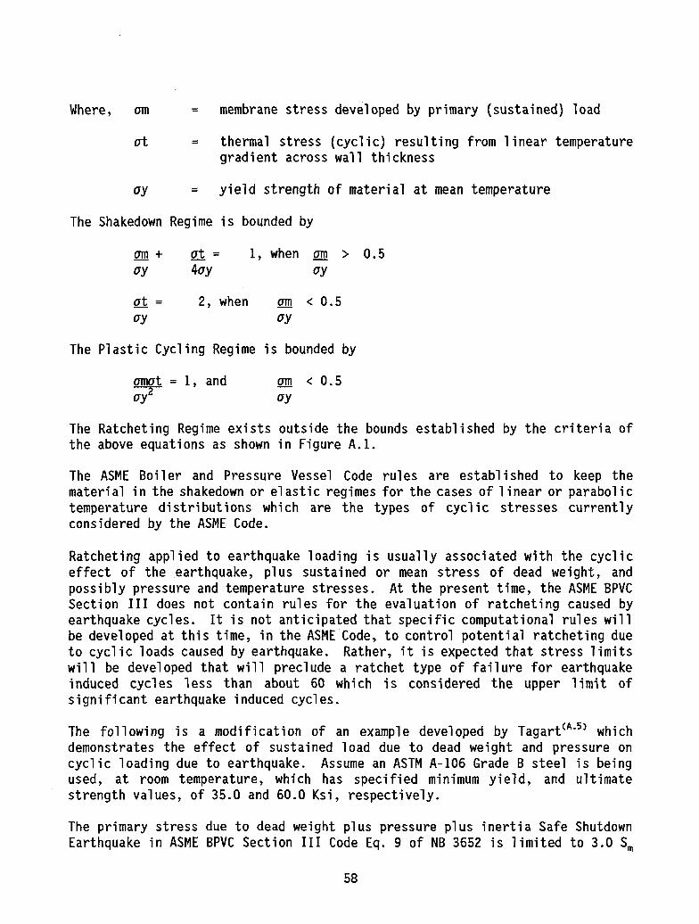
Where, am = membrane stress developed by primary (sustained) load
at = thermal stress (cyclic) resulting from linear temperature gradient across wall thickness
ay = yield strength of material at mean temperature
The Shakedown Regime is bounded by
am + at = 1, when am > 0.5 ay 4ay ay
at = 2, when am < 0.5 ay ay
The Plastic Cycling Regime is bounded by
omot = 1, and am < 0.5 o7~ oy
The Ratcheting Regime exists outside the bounds established by the criteria of the above equations as shown in Figure A.l.
The ASME Boiler and Pressure Vessel Code rules are established to keep the material in the shakedown or elastic regimes for the cases of linear or parabolic temperature distributions which are the types of cyclic stresses currently considered by the ASME Code.
Ratcheting applied to earthquake loading is usually associated with the cyclic effect of the earthquake, plus sustained or mean stress of dead weight, and possibly pressure and temperature stresses. At the present time, the ASME BPVC Section III does not contain rules for the evaluation of ratcheting caused by earthquake cycles. It is not anticipated that specific computational rules will be developed at this time, in the ASME Code, to control potential ratcheting due to cyclic loads caused by earthquake. Rather, it is expected that stress limits will be developed that will preclude a ratchet type of failure for earthquake induced cycles less than about 60 which is considered the upper limit of significant earthquake induced cycles.
The following is a modification of an example developed by Tagart C A" 5 ) which demonstrates the effect of sustained load due to dead weight and pressure on cyclic loading due to earthquake. Assume an ASTM A-106 Grade B steel is being used, at room temperature, which has specified minimum yield, and ultimate strength values, of 35.0 and 60.0 Ksi, respectively.
The primary stress due to dead weight plus pressure plus inertia Safe Shutdown Earthquake in ASME BPVC Section III Code Eq. 9 of NB 3652 is limited to 3.0 S_
58

for Service Condition D. For Service Condition D evaluation of stresses due to temperature effects and anchor motion in the pipe is not required by the ASME Code. Assume the stress due to pressure is 0.75 S m, and that due to dead weight is 0.75 S m, at a fillet welded socket fitting, then the remaining 1.5S is due to seismic inertia load. Consider now the case where a total nominal effective fictitious elastically calculated stress range, which includes secondary (temperature and support motion effects) as well as primary stress, is 140.0 Ksi or 7.0 S m. The real stress range which considers non-linear behavior from Figure A . 2 ( A - 6 ) would be 74.0 Ksi. Of this 74.0 Ksi, 1.5 S m or 30.0 Ksi is applied as a mean or sustained stress. Therefore, the ratio of S m e w/S e = 30.0/74.0 = 0.41. If the two parameters S r a n g e and S y s r a n g e are entered in the ratchet failure diagram developed by Benham-Ford<A'^ as shown in Figure A.3, this results in 330 cycles to failure or an allowable 16 cycles, in accordance with the safety margin of 20, on cycles contained in the ASME Code. If only the cyclic stress range was considered and mean or sustained stresses were taken equal to zero, Figure A.3 would give an estimate of 22,000 cycles to failure or 1100 allowable cycles. Ignoring the ratchet effect of sustained or mean loads into the plastic response region, in this case, would dramatically underestimate cycles to failure and lead to an underdesign condition where the cyclic margin to failure would be 330/60 or 5.5, rather than the cyclic margin of 20 provided by the ASME Code fatigue design curves, 1.9.1 and 1.9.2 of Appendix I to ASME BPVC Section III. It should be noted the particular example sited is an extreme case of applicable Stress Indices, B1 = 0.75 and B 2 = 1.5, and deadweight stress, S D L = 0.5Sm.
A. 2.2 FATIGUE
There are two basic types of metal fracture, < A" 7 ) cleavage (brittle) and ductile (plastic deformation). The fracture can be associated with the single application of load, which is typically referred to as the plastic instability or rupture, and cyclic application of load (fatigue). Ratcheting can be considered as a special case of cyclic application of load as discussed in Section A.2.1. The cleavage (brittle) type of fracture, whether due to a single or a cyclic application of load, is usually precluded by assuring the toughness characteristic of the metal at the service temperature, or the nature of the loading is such that the cleavage (brittle) type fracture will not occur.
Under the action of cyclic loads, cracks can be initiated as a result of cyclic plastic deformation. Even if the nominal stresses in the material are well below the elastic limit, locally the stresses may be above yield due to stress concentrations at existing inclusions, or cracks in the metal mechanical notches or restraint corner. Consequently, plastic deformation occurs locally on a microscale, but it is insufficient to show in engineering terms.
Several equivalent models have been proposed to explain the initiation of fatigue cracks by local plastic deformation. The model of Wood ( A" 8 > is depicted in Figure A.4. During the rising-load part of the cycle, slip occurs on a favorably oriented slip plane. In the falling-load part, slip takes place in the reverse
59

direction, on a parallel slip plane, since slip on the first plane is inhibited by strain hardening and by oxidation of the newly created free surface. This first cyclic slip can give rise to an extrusion or an intrusion in the metal surface. An intrusion can grow into a crack by continuing plastic flow during subsequent cycles. If the fatigue loading is cyclic tension-tension, this mechanism can still work since the plastic deformation occurring at increasing load will give rise to residual compressive stresses during load release.
Several stages of fatigue crack growth are shown in Figure A.5. A sharp crack in a tension field causes a large stress concentration at its tip where slip can occur fairly easily. The material above the crack (stages 1 and 2 in Figure A.5) may slip along a favorable slip plane in the direction of maximum shear stress. Due to that slip, the crack opens, but it also extends in length. Slip can now occur on another plane (stage 3). Work hardening and increasing stress will finally activate other parallel slip planes, which leads to a blunt crack tip (stage 4). During the rising load part of the cycle, the crack has propagated by an amount A.a.
Plastic deformation typically occurs in a small region embedded in an elastic surrounding. During load release the elastic surroundings will contract and the plastically deformed region, which has become too large, no longer fits in its surroundings. In order to make it fit, the elastic material will exert compressive stresses on the plastic region during the decreasing load part of the cycle. These compressive stresses will be above yield again, at least at the crack tip. This means that reversed plastic deformation occurs, which will close and resharpen the crack tip, as is shown in stage 5 of Figure A.5.
The cyclic opening and closing of the crack (stages 1-5 and 6-7) will develop a typical pattern of ripples, every new cycle adding a new ripple. These ripples are typically called fatigue striations. These striations may be either regular or irregular depending on the grain structure of the material.
The potential for cyclic (fatigue) types of failures and the design parameters associated therewith have in the past been developed by tests. The effects of notches or component geometry which act as local stress risers and potential crack initiators are normally represented by stress indices or stress intensification factors which are numerical coefficients applied to the nominal stress in the component. In the case of piping, these indices are given in Table NB 3681 (a)-1 for ASME BPVC Section III piping Class 1, 2, and 3, and intensification factors in Figure NC-3673.2(b)-l for Class 2 and 3 piping.
The growth of fatigue cracks in a constant strain field and the resultant pseudo elastic stress to numbers of cycles to cause a fatigue failure with a factor of safety on stress of 2.0 and 20 on cycles are shown in Figure 1.9.1 and 1.9.2 of the ASME BPVC Section III.
60

A.2.3 PLASTIC INSTABILITY OR DUCTILE RUPTURE
Fracture occurring under the single application of a continuously increasing load can be either brittle cleavage fracture or fracture associated with plastic deformation, which is essentially ductile. The brittle cleavage type fracture is usually precluded by selection of materials having the necessary toughness at service temperature such that this type of rupture does not occur.
The most familiar type of single application, of load ductile fracture is caused by overload in tension, which produces the classic cup and cone (necking down) fracture. After the maximum load has been reached, the plastic elongation of a prismatic-tensile coupon becomes inhomogeneous and concentrates in a small portion of the specimen such that necking occurs, leading to rupture.
There has been no known instance of this type of failure being initiated by the inertia or body type primary stresses developed in the dynamic response of piping to earthquake motions. This is of particular interest since the main equations for earthquake resistant design of piping in Eq. 9 of NB 3652 for Class 1 piping and Eq. 8 of NC/ND 3652 for Class 2 and 3 ASME BPVC Section III piping assume ductile rupture as the design basis mode of failure. Both ratchet and fatigue type failures in piping have been observed in natural earthquake and earthquake simulation tests.
A.3 CONCLUSIONS Both racheting ( A , 9 > fatigue type < A - 1 0 > seismic cyclic-induced inertia failures
of piping systems have been observed in the limited number of tests run to failure to date. In general, it is anticipated that rachet type failure would be more likely in relatively low frequency systems subject to relatively large deformations. Fatigue type failure would be anticipated in relatively stiff systems subjected to a relatively large number of cycles with relatively small deformations but high stresses.
A.4 REFERENCES
A.l English, W.F., "Piping and Fitting Dynamic Reliability Program Fourth Semi-Annual Progress Report November 1986-April 1987, "NEDC-31542 Prepared by G.E. Nuclear Energy for Electric Power Research Institute, January 1988.
A.2 "Criteria of the ASME Boiler and Pressure Vessel Code for Design by Analysis in Section III," Draft, Third Edition for 1983 Code Edition, Nov. 1986
A.3 Miller, D.R. "Thermal-Stress Ratchet Mechanism in Pressure Vessels," ASME Transactions, Vol. 81 Sec. D, Nov. 2, 1959
61

A.4 Bree J., "Incremental Growth Due to Creep and Plastic Yielding of Thin Tubes Subjected to Internal Pressure and Cyclic Thermal Stresses, Journal of Strain Analysis, Vol. 3, No. 2, 1968, P. 122-S.
A.5 Tagart, S.W., "Plastic Fatigue Analysis of Pressure Components," Pressure Vessels and Piping: Design and Analysis-A Decade of Progress, Vol. 1 ASME, 1972
A.6 Benham, P.P. and Ford H., "Low Endurance Fatigue of a Mild Steel and an Aluminum Alloy, "Journal of Mechanical Engineering Science, Vol. 3, 1961.
A.7 Broek D., Elementary Engineering Fracture Mechanics, 4th Ed. Martinus Nijhoff Publishers Dordrecht, Netherlands, 1986.
A.8 Wood, W.A. "Recent Observations on Fatigue Fracture in Metals", ASTM STP 237 (1958) pp.110-121.
A.9 DeVita, V., "Seismic Fragility Testing of Representative Nuclear Piping Systems," PVP-VOL. 144, 1988, pp. 237-242.
A.10 Hara, F. and Shibata, H. Ratcheting Fatigue in Full-Scale Piping Elements, K 15/3, SMIRT, 1981.
62
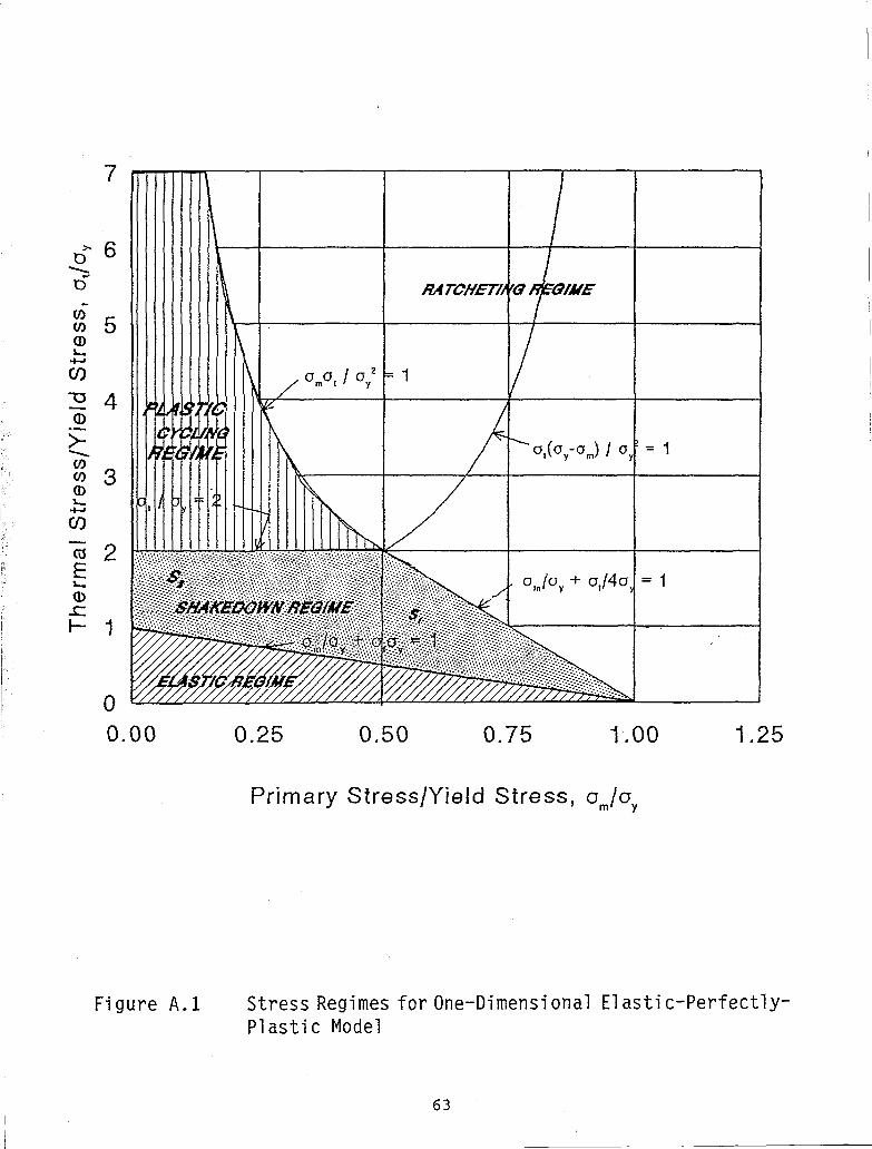
0.00 0.25 0.50 0.75 1.00 1.25
Primary Stress/Yield Stress, o jo. m' y
Figure A. l Stress Regimes for One-Dimensional Elastic-Perfectly-Plastic Model
63

120
100
CO 80
m (D
<60 CO CO UJ ^ 4 0 CO
20
0
1
[ = 2 9 . 4 X 10 s 3 s j ^ ^
i / "
I / 1 /
' 1 / 1 / ^
1 & -/ CO 1 CO
0
PERCENT STRAIN RANGE
Figure A.2 Benham-Ford (A.6) Cycle Stress St ra in f o r Carbon Steel
64

140
1E+00 1E+01 1E+02 1E+03 1E+04 1E+05 1E+06
CYCLES TO FAILURE, N
Figure A.3 Carbon Steel Ratchet Fai lure Diagram
65

u c
• X •'
i > 1 "
#
/ * 6'','+ 6' * /
s V s s
/
Y
''/'extrusion
-> intrusion
Figure A.4 Wood's Model for Fatigue Crack Initiation
66

67

APPENDIX B
DESCRIPTION OF SELECTED POWER PLANTS WHICH HAVE EXPERIENCED STRONG MOTION EARTHQUAKES
WITH PARTICULAR ATTENTION TO PIPING SYSTEMS
68

B. l LONG BEACH STEAM STATION, LONG BEACH, CALIFORNIA < B 1 ) ITEM 1 A OF TABLE 2 . 1
B . l . l PLANT DESCRIPTION
This station was located on Terminal Island in Long Beach, California, about four miles from the fault that caused the Long Beach earthquake on March 10, 1933.
At the steam station si te there were three independent plants. Plant 1 consisted of one unit and was built in 1911. It was either out of service or in intermittent service in 1933 and the building was severe]y damaged in the earthquake. Plant 2 consisted of 2 units and was built in 1922. Plant 3 consisted of 3 units and was built in 1928. Foundations of the plants were heavily reinforced concrete mats supported by wooden piles, 50 to 60 feet long, driven into hard sands.
B . l . 2 PIPING DESCRIPTION
None currently available.
B.1.3 SEISMIC DESIGN BASIS
The plant structures were designed for lateral s ta t ic forces of 0.2g. No information is available on seismic design of the piping and equipment, but considering the state of the art i t is probable that either the 0.2g stat ic design was used, or else seismic design was not considered.
B.1 .4 SEISMIC INSTRUMENTATION
None reported.
B.2 KERN COUNTY STEAM S T A T I O N ( B 1 ) , ITEM 2A OF TABLE 2 . 1 .
B.2.1 PLANT DESCRIPTION
The Kern County Steam Station is located on the Kern River near Bakersfieid, California, about 25 miles from the epicenter of the Kern County
69

earthquake. This oil-fired 60-MW steam plant was designed and built in 1947-1948. Foundations are soil-bearing footings at shallow depth.
B.2.2 PIPING DESCRIPTION
None currently available.
B.2.3 SEISMIC DESIGN BASIS
The structures of the plant were designed for 0.2g lateral load on a static basis with stress limits increased by 0.33 for combined dead, live, and earthquake loadings, in accordance with typical structural design codes. This is one of the first electric power plants to have piping designed by dynamic analysis. The Biot smoothed response spectrum was used for the design of the main steam and boiler feedwater piping. The response spectrum was normalized to O.lg at ground level and 0.3g at the top floor of the buildings, with linear interpolation at other levels. In this way an amplified response spectrum was available at every floor, even though it was of narrow band and heavily damped compared to spectra used for nuclear plants. The spectrum was applied for the steam and feed lines by calculating the first natural frequency of each span of pipe considered as a simply supported beam, then applying the appropriate lateral force. Based on the dynamic analysis of the main piping, pseudostatic g loads were developed for other piping systems. These loads were also used to design guides and stops and to find loads acting on the supporting structure. It is of interest to note that some guides and stops on the main steam line had gaps or rattle space of as much as 2 inches.
B.2.4 SEISMIC INSTRUMENTATION
None reported.
B.3 VALLEY STEAM PLANT, SAN FERNANDO VALLEY < B 1 ) ITEM 5D OF TABLE 2 . 1
B.3.1 PLANT DESCRIPTION
The Valley Steam Plant is located on a 150-acre s i te in the central San Fernando Valley. The plant has four generating units with a total capacity of 513 MW. Units 1 through 4 were constructed in 1954, 1954, 1955, and 1956, respectively, and their individual capacities are 100, 100, 157, and 157 MW, respectively. Because of the area's mild climate, much of the plant piping and equipment is located outdoors.
70
The main structures consist of braced steel frames supporting the boilers, concrete foundations for the turbine-generator units, and concrete-surfaced decks in the steel-framed turbine building. The plant is located in a flat, alluvial area, on sand, gravel, and boulders that extend to a depth of more than 500 feet. The permanent water table is about 200 feet below the surface.
B.3.2 PIPING DESCRIPTION
Although the piping is normally attached to its supports, there are no special seismic braces. For example, the piping is supported only for dead and other operating loads. The supports are typically rods with spring or "constant force" hangers or simply horizontal beam elements on which the pipes rest without transverse restraints. On longer runs of piping, seismic stops are provided to limit the maximum, amount of lateral displacements. Typically, large motor or air-operated valves with large eccentric mass are located within the pipe runs, adding local torsional and bending effects to the piping during an earthquake. Examples of system parameters for piping systems found in the Valley Steam Plant can be found in Table B.l.
B.3.3 SEISMIC DESIGN BASIS
Unreported but probably UBC.
B.3.4 SEISMIC INSTRUMENTATION
None Reported.
B.4 BURBANK POWER PLANT, SAN FERNANDO VALLEY ( B 1 ) ITEM 5A OF TABLE 2.1
B.4.1 PLANT DESCRIPTION
The City of Burbank power plant is located on the eastern edge of the central San Fernando Valley on a flat, alluvial site. The plant complex is made up of two different power plants: the two-unit Olive plant and the five-unit Magnolia plant. The plants have seven generating units with a total capacity of about 200 MW. Olive Units 1 and 2 were constructed in 1958 and 1961. Their capacities are 44 MW each. Magnolia Units ] through 4 were constructed in the 1940s and early 1950s. Their capacities are 10, 10, 20, and 30 MW, respectively. Magnolia Unit 5 is a gas peaking plant. It was constructed in the late 1960s and has a capacity of 20 MW. Both Magnolia units consist of steel-framed boiler structures, concrete turbine-generator pedestals, and a two-story concrete masonry control building that houses the switchgear and control rooms.
71

B.4.2 PIPING DESCRIPTION
The piping is very similar to the Valley Plant. Piping is rod-hung for dead-weight support only. Generally, no provision for lateral restraint was found.
B.4.3 SEISMIC DESIGN BASIS
Structures were apparently designed for an equivalent static force of 0.2g. In general, the design of piping in the plant included no particular seismic design consideration.
B.4.4 SEISMIC INSTRUMENTATION
None reported.
B.5 GLEKDALE POWER PLANT, SAN FERNANDO VALLEYCB-2' B 3 )
ITEM 5 B OF TABLE 2.1 B.5.1 PLANT DESCRIPTION
The City of Glendale power plant is located on the southern edge of the San Fernando Valley. In 1971, the plant had five generating units with a total capacity of 148 MW. The individual capacities for Units 1 through 5 are 20, 20, 20, 44, and 44 MW, and the units were constructed in 1941, 1947, 1953, 1959, and 1964, respectively.
All five units of the plant are housed in a continuous building, which consists of a large concrete basement and operating floor that supports light, steel-framed boiler structures. The turbine operating floor is located about 6 feet above grade. The plant is set low to the ground. Most of the equipment is located in the basement below grade. The plant is situated in a flat area of recent alluvia on the north bank of the Los Angeles River.
B.5.2 PIPING DESCRIPTION
The piping systems at the Glendale Plant are typical of the fossil fuel power plants built during the 40s, 50s, and 60s. Most of the piping is very flexible. The pipes are typically supported by single rod hangers or trapeze hangers. The steel rods are typically supported by pin, spring, or "constant force" hanger mechanisms. The support mechanisms allow the pipes to sway freely in any horizontal direction.
72

Apparently, no seismic braces were incorporated into the piping systems. Most of the lateral support comes from the attached equipment or from seismic stops, if any.
B.5.3 SEISMIC DESIGN BASIS
Unknown but probably UBC.
B.5.4 SEISMIC INSTRUMENTATION
None reported.
B.6 PASADENA POWER PUNT, LOS ANGELES BASIN ( B 1' B 8 )
ITEM 5c OF TABLE 2.1 B.6.1 PLANT DESCRIPTION
The City of Pasadena power plant is located on the southern edge of Pasadena, in the Los Angeles Basis outside the San Fernando Valley. The plant has four generating units with a total capacity of 206 MW. Units Bl and B2, with a capacity of 45 MW each, were built in 1955 and 1957, respectively. Unit B3 is a 71 MW Unit and was built in 1965. Unit 4, the Glenarm Plant, was built in 1949 and has a capacity of 45 MW. Three of the Units are natural gas-fired supported in adjoining open steel frame towers.
All four units are in separate structures, and all except for the turbine-generator pedestals are braced steel-framed structures.
B.6.2 PIPING DESCRIPTION
Apparently the equipment is anchored, but there are no other seismic restraints or seismic braces for piping. Piping in the Pasadena Plant is similar to that in other power plants in the area.
B.6.3 SEISMIC DESIGN BASIS
Unreported but probably UBC.
B.6.4 SEISMIC INSTRUMENTATION
None reported.
73

B.7 HUMBOLDT BAY POWER PLANT 8 2 B 3 B 7 >ITEM 9 OF TABLE 2.1 These power plants, consisting of two fossil and one nuclear power unit,
were not included in the Table 2.1 summary of damage to power plant facilities resulting from the 1975 Ferndale earthquake because the MMI-V intensity determined at the plant site is considered non-damaging and there was no indication of structural or equipment damage at the plant site. The maximum measured peak ground acceleration (in the storage building at the site) was 0.3g, which is above the 0.2g PGA threshold of damage, but the earthquake motion had a strong motion duration of only 3-5 seconds.
The effects of the Eureka, 1980 earthquake on the Humboldt Bay plants is included as Item 9 in Table 2.1.
B.7.1 PLANT DESCRIPTION
The Humboldt Bay Nuclear Power Plant Unit #3 is a 60 MWe Boiling Water Reactor owned by Pacific Gas and Electric Company which began operation in 1962. The reactor itself is contained in a buried caisson. The operating floor, at grade, is covered by a refueling building. The control room and turbine pedestal are located to the south of the refueling building, while the stack is to the north. The plant is located adjacent to two fossil-fueled units. Unit 1 and Unit 2 were put into operation in 1956 and 1958 respectively.
B.7.2 PIPING DESCRIPTION
The description of safety related piping systems for the nuclear unit can be found in the Humboldt Bay SAR. In general, the piping in fossil Units 1 and 2 is supported by vertical rod and spring hangers for gravity loads. Some seismic stops exist on the main steam lines. Line size, temperature, and pressure distributions for Unit 1 are summarized in Table B.l.
B.7.3 SEISMIC DESIGN BASIS
The seismic design basis of the nuclear power plant can be found in the Humboldt Bay SAR. The design of the fossil plants are probably in accordance with UBC.
B.7.4 SEISMIC INSTRUMENTATION
The Humboldt Bay nuclear unit is instrumented with a Teledyne MTS-100 strong motion recording system, with three FB-103 triaxial Force Balance accelerometers. This system was installed in September 1971: one in the refueling building at elevation (+)12 (ground surface elevation), one in the Reactor Caisson at elevation (-)66, and one in the storage building, 330 feet from the reactor, at ground surface elevation. The storage building is a single
74

story concrete block building on a reinforced concrete slab.
The nuclear unit also has a Engdahl peak shock recorder located at the operating floor (+12 ft elevation) in the refueling building. This recorder provides triaxial peak spectral accelerations at selected frequencies.
B.8 FUKUSHIMA NUCLEAR POWER PUNT COMPLEX"'"/JAPAN These power plant facilities were not included in the Table 2.1 summary of
damage to power plant facilities because the peak ground acceleration recorded at the site (0.125g) did not equal or exceed the 0.2g PGA threshold of damage to power plant facilities. However, the experience of these facilities provides a data point which confirms that damage to safety and non-safety related piping in a long duration earthquake with dominate frequencies below 10 Hz does not occur at modern nuclear power stations (BWR- Mark I and Mark II). It should be noted that the 0.125g PGA exceeds the design basis SSE at a number of U.S. nuclear power station sites.
B.8.1 PLANT DESCRIPTION
The Fukushima Nuclear Power Plant Complex is owned and operated by the Tokyo Electric Power Company. It is located on the Pacific Coast of Fukushima Prefecture, about 7 km south of the town of Namie, and is southeast of the town of Fukushima. The site is approximately 140 km from the epicenter of the Miyagi-Ken-Oki - 1978 earthquake. Faulting may have extended as much as 60 km west of the epicenter. In that case, the plant site may be located about 80 km (50 mi) from the nearest location of the source of energy.
Units 1 through 5 have a Mark I (light-bulb-torus) type of containment structure; Unit 6 has a Mark II (over/under) type of containment. URS/Blume Engineers formulated the seismic design criteria for the plant and performed the original seismic analyses for the General Electric Company and the Tokyo Electric Power Company.
The plants are founded on a competent soft mudstone formation with a thickness in excess of 300 m. Extensive cuts were necessary to level the site and to reach the mudstone, which has a shear wave velocity of about 600 m/sec.
A U.S. reconnaissance team inspected the exterior of Unit 1 and the exterior and interior of Unit 6, including the containment structure, the reactor vessel pedestal, some of the equipment on the refueling floor, some of the equipment in the reactor building, the underside of the control rod drive in the containment, miscellaneous critical and non-critical piping, various critical and non-critical cable trays, the reactor building, the turbine building, the turbine overhead crane, and various auxiliary structures, equipment and tanks. There was no damage or evidence of working of connections in any of the inspected areas.
75

The only reported damage to the complex was to some non-critical electrical insulators some distance to the west of Units 1 and 2.
B.8.2 PIPING DESCRIPTION
Safety related piping in the plants follows standard U.S. nuclear power plant practice of the late 1960's and early 1970's. The recirculation, steam and feedwater lines are standard General Electric BWR-4 and BWR-5 layout and design.
B.8.3 SEISMIC DESIGN BASIS
Unit safety related structures and equipment were designed for a peak ground acceleration of 0.18g and a response spectrum based on the Taft record from the Southern California (Kern County) earthquake of 1952.
B.8.4 SEISMIC INSTRUMENTATION
The site is heavily instrumented with strong motion accelerometers. Numerous records were made; the peak ground acceleration was 0.125g and the duration of strong motion was in excess of 30 seconds. Units 1 and 6 are instrumented with between 10 and 30 strong motion accelerometers. The peak ground acceleration, which could be considered to be a "free-field" acceleration, is 0.125g (EW direction). The corresponding accelerations in the NS direction and Up/Down directions are O.lOOg and 0.050g, respectively. The strong motion exceeded 30 seconds in duration. The maximum response acceleration in the buildings was reported to be about 0.5g.
B.9 EL CENTRO STEAM POWER P L A N T < B 5 ' B 6 ' B 7 ) ITEM 8 A OF TABLE 2 . 1
B.9.1 PLANT DESCRIPTION
The El Centro Steam Plant, which is the principal electric-power-generating faci l i ty of the Imperial Irrigation District , is located about 3 miles from the causative fault and about 16 miles from the epicenter of the 1979 Imperial Valley Earthquake. The plant is located in a f lat area. The soil at the s i te consists of very deep alluvial deposits composed primarily of s t i f f to hard clay, interlain with laminations of s i l ty clay loam and sandy loam.
The plant has four natural-gas or oil-fired units. Units 1, 2, and 3 were designed by Gibbs & Hill and were built in 1949, 1952, and 1957, respectively. Unit 4 was designed by Fluor and was built in 1968. The turbine buildings, turbine pedestals, and boiler structures, are constructed on reinforced-concrete floating-raft foundations. Each unit is structurally independent above the
76

foundation. The raft foundation of Unit 4 is isolated from the foundations of the first three units. The reinforced-concrete turbine pedestals are isolated from the moment-resisting steel-frame structures of the turbine buildings. Each boiler structure is a structural-steel-braced frame. The boiler is suspended from the top of the frame.
B.9.2 PIPING DESCRIPTION
The piping at the El Centro Power Plant is typical of most of the fossil fuel power plants built during the 50s and 60s. Most of the piping is very flexible. The pipes are typically supported by single rod hangers or trapeze hangers. The rod hangers are typically supported at the top by pin, spring, or "constant force" mechanisms. All support mechanisms allow the pipes to freely sway in the horizontal direction.
B.9.3 SEISMIC DESIGN BASIS
The structural seismic design criteria for Unit 4 called for a lateral static force equivalent to 20% of the dead and live loads. Seismic design criteria for Units 1, 2, and 3 are probably similar to those for Unit 4.
The main steam lines were designed to 0.2g equivalent static horizontal forces. Therefore, the steam lines contain a few snubbers to prevent excessive displacement during earthquake but allow thermal movement.
The piping runs typically support heavy air-operated or motor-operated valves. The valves have relatively large mass eccentricities. Most of the high temperature lines are insulated.
B.9.4 SEISMIC INSTRUMENTATION
None reported at plant s i t e . The closest strong motion recorded was about 0.6 miles from the plant.
B.10 REFERENCES B.l Seismic Design Task Group and Stevenson and Associates "Report of the U.S.
Nuclear Regulatory Commission Piping Review Committee" - Summary and Evaluation of Historical Strong-Motion Earthquake Seismic Response and Damage to Above Ground Industrial Piping," NUREG-1061 Volume 2 Addendum, U.S. Nuclear Regulatory Commission April, 1985
B.2 Pacific Gas and Electric Co., "Report on the June 7, 1975 Ferndale Earthquake," August 1975
77

B.3 Herring, K.S. Rooney, V. and Chokshi N.C., "Reconnaissance Report: Effect of November 8, 1980 Earthquake on Humboldt Bay Power Plant and Eureka, California Area," NUREG-0766 U.S. Nuclear Regulatory Commission, June 1981
B.4 Yanev, P.I, Editor, "Reconnaissance Report, Miyagi-Ken-Oki, Japan Earthquake, June 12, 1978," Earthquake Engineering Research Institute, December 1978
B.5 Murray, R.C. et. al. "Equipment Response at the El Centro Steam Plant During the October 15, 1979 Imperial Valley Earthquake," NUREG/CR-1665 U.S. Nuclear Regulatory Commission, October 1980
B.6 Swan, S.W. and Yanev, P.I., "Seismic Safety Margins Research Program-An Evaluation of the Response of Equipment at the El Centro Steam Plant to the October 15, 1979 Imperial Valley, California Earthquake," UCRL-15494, NUREG/CR-3064 Lawrence Livermore National Laboratory, October Draft 1982
B.7 Silver, M.M, "Recommended Pipi-ng Seismic-Adequacy Criteria Based on Performance During and After Earthquakes Vol. 2 Reference Document," NP-5617 Vol. 2 Electric Power Research Institute, January 1988
B.8 EQE, Inc. "Summary of the October 1, 1987 Whittier, California Earthquake: An EQE Quick Look Report," EQE Inc. 1987
78

87C1465A/0257E
TABLE B.l SAMPLE PIPING SYSTEMS IN THE VALLEY STEAM PLANT
Approximate PI ant Number System of Lines
Maximum Diameter
Maximum Distance
Design Conditions Support
Main Steam 40 14" 100 ft. from boiler to turbine
1500 psi 1000° F
Rod and spring hangers
Feedwater 60 12" 80 ft. from deaerator (upper boiler structure) to pumps (ground floor)
1800 psi 300° F
Rod and spring hangers
Circulating Water
20 42" 30 ft. from base to top of cooling tower
20 psi Ambient
Much of the piping is buried
Bearing Cooling Water
50 10" 100 ft. from head tank (top of boiler structure) to pumps (ground floor)
70 psi Ambient
Rod hangers
Fuel Gas and Oil
50 10" 1000 ft. from oil tanks to burners
600 psi 100° F
Rod hangers, ground-mounted piping supported on pedestals
Notes: 1. Peak ground acceleration for the plant during the 1971 San Fernando
earthquake is estimated at 0.30g. There were no failures of piping anywhere in the plant.
2. The sytems listed above represent only a portion of the piping in the plant. 3. A "line" is a run of piping from anchor point to anchor point. The number of
lines for each system is an estimate for all four units of the plant. 4. "Maximum Distance" indicates the extent of the piping through the plant, and
the lengths of piping between anchor points. 5. Design conditions are the maximum design pressure and temperature within the
system. 6. "Support" lists the most common mounting configuration for the system.
79

87C1465 0257E-2
TABLE B.2 SAMPLE PIPING SYSTEMS IN THE BURBANK STEAM PLANTS
(MAGNOLIA AND OLIVE)
Plant System Approximate
Number of Lines
Maximum Diameter
Design Conditions Support
Main Steam 60 20" 1500 psig 1000°F
Rod and spring hangers
Feedwater 60 12" 1500 psig 1000°F
Rod and spring hangers
Circulating Water
30 12" 120 psig 110°F
Rod and spring hangers
Fuel Gas and Oil 60 10" 600 psig 100°F
Rod hangers, ground-mounted piping supported on pedestals
Notes: 1. Peak ground acceleration for the plant during the 1971 San Fernando
earthquake was 0.35g. 2. The systems listed above represent only a portion of the piping in the plant. 3. A "Line" is a run of one or more branches of pipe, anchored at all terminal
ends by typical equipment items (e.g., pumps, tanks, boilers, etc.).
80

87C1465 0257E-3
TABLE B.3
SAMPLE PIPING SYSTEMS WITHIN UNIT 1 HUMBOLDT BAY POWER PLANT
Approximate Number of Maximum Design
Lines Diameter Conditions
360 2"
200 6"
80 10"
20 > 12"
360 - < 200 psi
400°F
50 - > 800 psi
35 - < 800°F
20 - > 800°F
81

87C1465 0257E-4
TABLE B.4 SAMPLE PIPING SYSTEMS WITHIN UNIT FOUR
EL CENTRO POWER PLANT
Plant System
Number of Piping Systems
Range of Diameters
Design Conditions Pipe Structure
Main Steam 25 1" - 20" Maximum 1500 psi 1000° F
Welded carbon steel piping, calcium silicate insulation, spring and rod hangers, a few hydraulic snubbers on main steam lines.
Boiler Feed 30 1" - 12" Maximum 1800 psi 400° F
Welded carbon steel piping, calcium silicate insulation, spring and rod hanger supports.
Circulating Water
12 1" - 51" Maximum 30 psi 1006 F
Carbon steel piping with flanged and welded connections,
Service Water
30 1" - 12" Maximum 100 psi 100° F
Fuel Oil and Gas
15 1" - 8" Maximum 650 psi
much of the piping is buried, the exposed sections are typically short unsupported spans. Carbon steel piping with welded, flanged and threaded connections, rod hanger and trapeze supports. This system experienced a few seismic cracks at points of extreme corrosion. Carbon steel piping with welded, flanged and threaded connections, calcium silicate insulation, rod hanger, trapeze and wall bracket supports.
82

87C1465A APEND.C
APPENDIX C EXAMPLE SHOWING LIMITING PIPE DISPLACEMENTS AS A FUNCTION OF LINEAR AND NON LINEAR ANALYSIS
83

87C1465A APEND.C
C.l PROBLEM DESCRIPTION Determine the maximum number of spans allowed for a 3" <f> standard weight
pipe for a 5 ft. and 10 ft. long dead weight hanger for a .8g lateral load. Hanger area = 1.0 in. sq. Assume use of ASME SA106 Grade B pipe with a S = 35 Ksi and S u = 60 Ksi.
1. Acceptance Stress Criteria: 2.4S = 36 Ksi allowable stress in pipe due to
seismic effects where:
S = Su/4 = 60 Ksi/4 = 15 Ksi 2. Displacement acceptance criteria maximum deflection permitted in the
pipe is 12 inches or allowable rotation for threaded support hangers is 6°.
3. Piping system evaluated Deadweight Span Length = 12.0 ft. 3" Sch. 40, 0D = 3.5", t = .216" W t o t = 10.78 LB/FT Pipe Full of Water I = 3.018 in4 Z = 1.724 in3
A straight run of pipe, continuous over several deadweight hangers, with fixed end restraints, is assumed in the analysis.
The linear displacements shown in Table C.l assume standard linear elastic analysis. The non-linear results shown are from ANSYS PC Computer Program which considers the deformed geometry of the piping systems and supports, and includes the restoring force from the pendulum motion of the rod hangers to developed lateral restraint.
84

87C1465A/TABC.1
Table C.l Summary of Analytical Results for a Fixed Piping System
End 3" Dia. Sch. 40
No. Dead-Acceptance Weight Spans Between Lateral Supports
Non-Linear Linear t
Max % Max % (in) (in)
6° Rot.
Limit (in)
Non-Linear
Max. Stress in Pipe (Ksi)
Linear
Max Stress in Pipe (Ksi)
Criteria (2.4S) (Ksi)
Results for 5' Hangers
2 .14 .14 6.2 2.896 2.882 36. 3 .68 .73 6.2 3.083 6.483 36. 4 2.02 2.31 6.2 10.347 11.526 36. *5 4.45 5.63 6.2 14.939 18.008 36. 6 7.92 11.67 6.2 19.170 25.932 36. 7 12.01 22.08 6.2 22.563 35.296 36.
Results for 10' Hangers
2 .14 .14 12.4 2.901 2.882 36. 3 .69 .73 12.4 6.183 6.483 36. 4 2.06 2.31 12.4 10.517 11.526 36. 5 4.66 5.63 12.4 15.501 18.009 36. *6 8.72 11.67 12.4 20.676 25.932 36. 7 14.14 22.08 12.4 25.489 35.296 36. 8 20.33 37.66 12.4 29.443 46.101 36. *Maximum number of spans for fixed threaded rod hangers and supports without potential threaded rod fatigue failure, based on a ± 6 rod hanger
85


NUREG/CR-6240 ORNL/Sub/94-SD427/1
Dist. Category RM
INTERNAL DISTRIBUTION
1. J. M. Corum 2. R. G. Gilliland 3. R. C. Gwaltney 4. J. E. Jones Jr. 5. S. E. Moore 6. A. B. Poole 7. C. E. Pugh 8. J. O. Stiegler
9. W. F. Swinson 10-14. G.T.Yahr
15. ORNL Patent Section 16. Central Research Library 17. Document Reference Section
18-19. Laboratory Records Department 20. Laboratory Records (RC)
EXTERNAL DISTRIBUTION
21. Office of Assistant Manager for Energy Research and Development, DOE-OR, Oak Ridge, TN 37831.
22-23. Office of Scientific and Technical Information, U.S. Department of Energy, P.O. Box 62, Oak Ridge, TN 37831.
24. N. C. Chokshi, U.S. Nuclear Regulatory Commission, Washington, DC 20555-0001. 25. Greg L. Hollinger, BTCE1 A, Babcock and Wilcox Co., P.O. Box 351,20 S. Van Buren Avenue,
Barberton, OH 44203-0351. 26. G. Millman, U. S.-Nuciear Regulatory Commission, NLS 217B, 5650 Nicholson Lane, Rockville,
MD 20852. 27. E. A. Rodriguez, Los Alamos Scientific Laboratory, ET-NPR/SPO, P.O. Box 1663, MS-5775, Los
Alamos, NM 87545. 28. G. C. Slagis, G. C. Slagis Associates, 3520 Eris Court, Walnut Creek, CA 94598-4669.
29-33. J. D. Stevenson, 9217 Midwest Avenue, Cleveland, OH 44125. 34-43. E. O. Woolridge, Division of Engineering, U.S. Nuclear Regulatory Commission, Washington, DC
20555-0001. Distribution as shown in category RM (NT1S-10).
87

NRC *oovi 335 I2S91 MRCM 11C7. 3201 3202
U S . NUCLEAR REGULATORY COMMISSION
BIBLIOGRAPHIC DATA SHEET iSee instruct ions on tne reverse)
2. TITLE AND SUBTITLE
l . BcPORT Nu'.'BER lAuiflnM by NRC Add Vo(.. SUOB.. R»v . •nd Addendum Numbtrs. i' »°v >
NUREG/CR-6240 ORNlVSub/94-SD427/l
Application of Bounding Spectra to Seismic Design of Piping Based on the Performance of Above Ground Piping in Power Plants Subjected to Strong Motion Earthquakes
DATE REPORT PUBLISHED MONTH j '•EiS
February 1995 4. FIN OR GRANT NUMBER
BP83Q, 5. AUTHOR(S)
J. D. Stevenson 6. TYPE OF REPORT
Technical 7. PERIOO COVEREO OncUisiie Ones,
8. PERFORMING ORGANIZATION - NAME ANO ADDRESS IH MIC. eronaa Omsion. Office or Region. U.S. Nuclear Regulatory Commission. ana mailing aaorrss. if contractor, proviar name una mailing adarwss.1
Stevenson and Associates 9217 Midwest Avenue Cleveland, OH 44125
Under Contract to: Oak Ridge National Laboratory Oak Ridge, TN 37831-6285
9. SPONSORING ORGANIZATION - NAME AND ADDRESS tit NRC. type "Same aiaoote : ,1contractor, groriae NRC Division. Office or Region, U.S. Nuclear Regulatory Commission and mailing aOdrmss.1
Division of Engineering Technology Office of Nuclear Regulatory Research V.S. Nuclear Regulatory Commission Washington, DC m555-0O01 10. SUPPLEMENTARY NOTES
J J. A8STRACT (200tons or /ess/
This report extends the potential application of Bounding Spectra evaluation procedures, developed as part of the A-46 Unresolved Safety Issue applicable to seismic verification of in-situ electrical and mechanical equipment, to in-situ safety related piping in nuclear power plants.
The report presents a summary of earthquake experience data which define the behavior of typical U.S. power plant piping subject to strong motion earthquakes. The report defines those piping system caveats which would assure the seismic adequacy of the piping systems which meet those caveats and whose seismic demand are within the bounding spectra input. Based on the observed behavior of piping in strong motion earthquakes, the report distinguishes between the capabilities of the piping system to carry seismic loads as a function of the type of connection (i.e., threaded vs welded).
This report also discusses in some detail the basic causes and mechanisms for earthquake damages and failures to power plant piping systems.
12. KEY WORDS/QESCR'PTORS (List w o * or pnrasas mat mill auist researcners in locating me reoorr ,
Piping, seismic design criteria, earthquake experience.
13. AVAILABILITY STATEMENT
unlimited 14. SECURITY CLASSIFICATION
(This Page)
unclassified (This Report}
unclassified 15. NUMBER OF PAGES
16. PRICE
' . a c F O R M 3JS '2 <J9'