stress indices at lug supports on piping systems
91
7 Z S OKINL-I/V\-42M STRESS INDICES AT LUG SUPPORTS ON PIPING SYSTEMS E. C. Rodabaugh W . G . Dodge S. E. Moore Mi ^ . i * ' UH - <.«.„ v X 4 - 1 ^ ^"L I <• \ « " * ti K * w a H. nJ 1 1 f * * t »» * ^ <M 6 i » 7 _ A * rV ^ > < > V ^ v * 'W-'-f- ^ i * 4* tJ 1 \ ' ' A " ' - * ^ » J"" 1 4, .-V 1 i t l 1 ^ I. 15 W*.- OAK RIDGE NATIONAL LABORATORY 'OPERATED BY UNION CARBIDE .CORPORATION • FOR THE (J/S. ATOMIC ENERGY COMMISSION.
-
Upload
khangminh22 -
Category
Documents
-
view
1 -
download
0
Transcript of stress indices at lug supports on piping systems

7 Z S OKINL-I/V\-42M
STRESS INDICES AT LUG SUPPORTS
O N PIPING SYSTEMS
E. C. Rodabaugh W . G . Dodge S. E. M o o r e
Mi ^ . i * ' UH -<.«.„ v X 4 - 1 "L I
<• \ « " *
ti K * w a H. nJ1 1 f* * t »» * ^ <M 6
i » 7 _ A * rV ^ > < > V ^ v * 'W-'-f-^ i * 4* tJ 1 \ ' ' A " ' -* » J""1
4, .-V1 i
t l 1 ^ I. 15
W*.-
OAK RIDGE NATIONAL LABORATORY 'OPERATED BY UNION CARBIDE .CORPORATION • FOR THE (J/S. ATOMIC ENERGY COMMISSION.


Printed in the United States of America. Available from National Technical Information Service
U.S. Department of Commerce 5285 Port Royal Road. Springfield. Virginia 22151
Price: Printed Copy S5.45; Microfiche S0.95
This report was prepared as an account of work sponsored by the United States Government. Neither the United States nor the United States Atomic Energy Commission, nor any of their employees, nor any of their contractors, subcontractors, or their employees, makes any warranty, express or implied, or assumes any legal liability or responsibility for the accuracy, completeness or usefulness of any information, apparatus, product or process disclosed, or represents that its use would not infringe privately owned rights.

0RNL-TM-U211 UC-79, -T9K -79k
Contract No. W-7Uo5-eng-26
Reactor Division
STRESS INDICES AT LUG SUPPORTS ON PIPING SYSTEMS
E. C. Rodabaugh Battelle-Columbus Laboratories
W. G. Dodge Oak Ridge National Laboratory
S. E. Moore Oak Ridge National Laboratory
N O T I C C TMf report w t m p m d u an account of work sponsored by ttw United S u m Government. Keilhet the United Suit* nor llw United States Atomic Emify Commission, nor any «r tKelr employee*, nor any of their contractor*, subcontractors, or llteir employees, n»t«i any warranty, express or implied, or assumes any legal liability or responsibility for the accuracy, com-pleteness or usefulness of any Information, apparatus, product or process disc toted, or represents thai iu use would not infringe privately owned rights. MAY 1974
OAK RIDGE NATIONAL LABORATORY Oak Ridge, Tennessee 37830
operated by UNION CARBIDE CORPORATION
for the U.S. ATOMIC ENERGY COMMISSION
JISTRISUTION O F THIS DOCUMENT IS UNLIMITED
Otesr

• 1 • 111
CONTENTS
Page
FOREWORD v NOMENCLATURE ix ABSTRACT . 1 1. INTRODUCTION AND SCOPE 1 2. THRUST AND BENDING MOMENT LOADS . 7
Maximum Stress Intensities . 7 Comparisons with ASME Boiler Code, Section I, Paragraph PW-**3 13 Comparisons with Welding Research Council Bulletin 107 Local Stresses 32
3. SHEAR AND TORSIONAL LOADS 34 If. INTERNAL PRESSURE . 37 5. THERMAL GRADIENTS .., . 41 6. CODE USE OF STRESS INDICES 42
Satisfaction of Primary-Stress-Intensity Limit ......... 43 Satisfaction of Primaiy-Plus-Secondary Stress-Intensity Range 46 Satisfaction of Peak-Stress-Intensity Range ... •. 46 Simplified Elastic-Plastic Discontinuity Analysis 48
7. SUMMARY AND CONCLUSIONS 49 ACKNOWLEDGMENTS 51 REFERENCES .................... 51 APPENDIX A: RECOMMENDED ADDITION TO ASME CODE SECTION III TO COVER STRAIGHT PIPE WITH INTEGRAL STRUCTURAL ATTACHMENTS .. 53 APPENDIX B: DIRECTIONS AND LOCATIONS OF MAXIMUM STRESSES FOR THRUST AND MOMENT LOADINGS 58 APPENDIX C: EXAMPLE ANALYSIS OF A LUG SUPPORT 70

V
FOREWORD
The work reported here was performed at Oak Ridge National Laboratory (ORNL) and at Battelle-Columbus Laboratories under Union Carbide Corpora-tion Nuclear Division subcontract No. 2913, as part of the ORNL Piping Program — Design Criteria for Piping, Pumps, and Valves — under the di-rection of W. L. Greenstreet, Associate Head, Solid Mechanics Department, and S. E. Moore, Program Coordinator. The program is funded by the U.S. Atomic Energy Commission (USAEC) as the AEC-supported portion of an AEC-industiy cooperative effort for the development of design criteria for nuclear-power-plant piping components. This joint effort is coordinated by the Pressure Vessel Research Committee (PVRC) of the Welding Research Council, under the Subcommittee to Develop Stress Indices for Piping, Pumps, and Valves.
Prior reports and open literature publications under the ORNL piping program are listed below.
1. W. L. Greenstreet, S. E. Moore, and E, C. Rodabaugh, "Investigations of Piping Components, Valves, and Pumps to Provide Information for Code Writing Bodies," ASME Paper 68-WA/PTC-6, American Society of Mechanical Engineers, New York, Dec. 2, 1968.
2. W. L. Greenstreet, S. E. Moore, and R. C. Gwaltney, Progress Report on Studies in Applied Solid Mechanics, QRNL-U576 (August 1970).
3. E. C. Rodabaugh, Phase Report No. 115-1 on Stress Indices for Small Branch Connections with External"Loadings, 0RNL-TM-30Hf (August 1970).
h9 E. C. Rodabaugh and A. G. Pickett, Survey Report on Structural Design of Piping Systems and Components, TID-25553 (December 1970).
5. E. C. Rodabaugh, Phase Report No, 115-8, Stresses in Out-of-Round Pipe Due to Internal Pressure, 0RNL-TM-32W (January 1971).
6. S, E. Bolt and W. L. Greenstreet, "Experimental Determination of Plas-tic Collapse Loads for Pipe Elbows," ASME paper 71-PVP-37, American Society of Mechanical Engineers, New York, May 1971.
7. G. H. Powell, B. W. Clough, and A. N. Gantayat, "Stress Analysis of BUS.9 Tees by the Finite Element Method," ASME Paper 71-PVP-UO, Ameri-can Society of Mechanical Engineers, flaw York, May 1971.
8. J. K. Hayes and B. Roberts, "Experimental Stress Analysis of 2U-Inch Tees," ASME Paper 71-PVP-28, American Society of Mechanical Engineers, New York. May 1971.

vi
9. J. M. Coram et al., "Experimental and Finite Element Stress Analysis of a Thin-Shell Cylinder-to-Cylinder Model/' ASME Paper 71-PVP-36, American Society of Mechanical Engineers, New York, May 1971.
10. W. L. Greenstreet, S. E. Moore, and J. P. Callahan, Second Annual Progress Report on Studies in Applied Solid Mechanics (Nuclear Safety), 0RNL-U693 (July 1971).
11. J. M. Corum and W. L. Greenstreet, "Experimental Elastic Stress Anal-ysis of Cylinder-to-Cylinder Shell Models and Comparisons with Theo-retical Predictions," Paper No. G2/5, First International Conference on Structural Mechanics in Reactor Technology, Berlin, Germany, Sept. 20-2lv, 1971.
12. R. W. Clough, G. H. Powell, and A. N. Gantayat, "Stress Analysis of BI6.9 Tees by the Finite Element Method," Paper No. FU/7, First In-ternational Conference on Structural Mechanics in Reactor Technology, Berlin, Germany, Sept. 20-21*, 1971.
13. R. L. Johnson, Photoelastic Determination of Stresses in ASA B16.9 Tees, Research Report 7I-9E7-FHOTO-R2, Westinghouse Research Labo-ratory (November 1971)•
lif. E. C. Rodabaugh and S. E. Moore, Phase Report No. 115-10 on Ccmpari-sons of Test Data with Code Methods for Fatigue Evaluations, ORNL-TM-3520 (November 1971}.
15. W. G. Dodge and S. E. Moore, Stress Indices and Flexibility Factors for Moment Loadings on Elbows and Curved Pipe, ORNL-TM-3658 (Metrch
16. J. E. Brock, Elastic Buckling of Heated, Straight-Line Piping Con-figurations, 0RNL-TM-3607 (March 1972).
17. J. M. Corum et al., Theoretical and Experimental Stress Analysis of ORNL Thin-Shell Cylinder-to-Cylinder Model No. 1, ORNL-U553 (October
18. W. G. Dodge and J. E. Smith, A Diagnostic Procedure for the Evaluation of Strain Data from a Linear Elastic Test, ORNL-TM-3^15 (November
19. W. G. Dodge and S. E. Moore, "Stress Indices and Flexibility Factors for Moment Loadings on Elbows and Curved Pipe," Welding Research Council Bulletin 179» December 1972.
20. W. L. Greenstreet, S. E. Moore, and J. P. Callahan, Third Annual Progress Report on Studies in Applied Solid Mechanics (Nuclear Safety), 0RNL-U821 (December 1972).

v i i
21. W. G. Dodge and S. E. Moore, ELB0W; A Fortran Program for the Cal-culation of Stresses, Stress Indices, and Flexibility Factors for Elbows and Curved Pipe, 0RNL-TM-4098 (April 1 9 7 3 ) .
22. W. G. Dodge, Secondary Stress Indices for Integral Structural Attach-ments to Straight Pipe, ORNL-TM-3^76 (June 1973).

i x
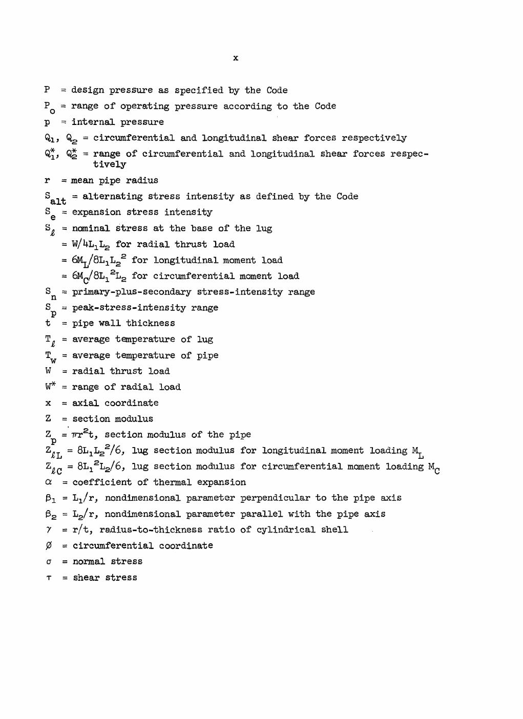
NOMENCLATURE
A^ = LiLg = loaded area (base of lug) A = 2rrrt = cross-sectional area of pipe P B = stress index for sustained loads B^, Bl, Bc = stress indices for radial thrust, longitudinal moment, and
circumferential moment loadings respectively Bx, B2 = stress indices as defined by the Code* C = stress index for primary-plus-secondary stresses CT, C , Cc = stress indices for radial thrust, longitudinal moment, and
circumferential moment loadings respectively; the normalizing stress is the nominal stress at base of the lug
c£, C*, C* = analogous to CT, etc., except that the normalizing stress is the nominal stress in the pipe
ci> C2> c3> C3 = stress indices as defined by the Code Dq = outside diameter of the pipe E = modulus of elasticity as defined by the Code K = stress index for local stresses K = fatigue evaluation factor defined by the Code in Paragraph NB-3653.6 Kg = stress index for local stresses at lug fillet welds K-l, K2, Ks = peak stress indices as defined by the Code Li = one-half the width of the loaded area in the circumferential direc-
tion L2 = one-half the length of the loaded area in the longitudinal direction L = one-half the length of a simply supported cylindrical shell L&, L^, Lq, L j « lug dimensions used in defining indices for shear and
torsional loadings M., Mf = magnitudes of moment-vector ranges as used in the Code* s design
1 analysis ML, M = longitudinal, circumferential, and torsional moments respec-h C T tively
M , = torsional-moment-load term m£, M^ = range of longitudinal, circumferential, and torsional moments
respectively = range of ^
*Code, as used in this report, refers to ASME Boiler and Pressure Vessel Code, Section III, Nuclear Power Plant Components; see Ref. 1.

1
BLANK PAGE
X
P = design pressure as specified by the Code PQ = range of operating pressure according to the Code p = internal pressure Qit 0>2 = circumferential and longitudinal shear forces respectively Q,*, Qj = range of circumferential and longitudinal shear forces respec-
tively r = mean pipe radius Salt = a^ e r n a^i n8 stress intensity as defined by the Code Se = expansion stress intensity S = nominal stress at the base of the lug
= w/Ul^Lg for radial thrust load = 6Ml/8L1L2
2 for longitudinal moment load = 6Mc/8L1
2L2 for circumferential moment load Sn = primary-plus-secondary stress-intensity range Sp = peak-stress-intensity range t = pipe wall thickness T = average temperature of lug T^ = average temperature of pipe W = radial thrust load W* = range of radial load x = axial coordinate Z = section modulus Z = TTTSt, section modulus of the pipe
P „ .
Z£l = 8L1L2 /6, lug section modulus for longitudinal moment loading M^ Z^^ = 8L12L2/6, lug section modulus for circumferential moment loading M( a = coefficient of thermal expansion Pi = nondimensional parameter perpendicular to the pipe axis (32 = L2/r, nondimensional parameter parallel with the pipe axis 7 = r/t, radius-to-thickness ratio of cylindrical shell 0 = circumferential coordinate a a normal stress T = shear stress
STRESS INDICES AT LUG SUPPORTS ON PIPING. SYSTEMS
E. C. Rodabaugh W. G. Dodge S. E. Moore
ABSTRACT
Stress indices and the appropriate simplified design for-mulas are developed for analyzing integral lug attachments on straight pipe according to the philosophy of Section III of the ASME Boiler and Pressure Vessel Code for Class I Piping Sys-tems. Indices- are developed for the evaluation of primary stresses, prirr ry-plus-secondary stresses, and peak stresses due to interna^ pressure in the pipe; for radial thrust and transverse shear forces and torsional and bending moment loads acting on the lug; and for a t.hermal gradient "between the pipe and the lug. The indices for thrust and "bending moment loads are based on an extensive parameter study and are represented by simple formulas that may be used directly by designers and/ or incorporated into codes and standards. From comparisons with other methods of analysis these formulas are considered to be more accurate and easier to use. Indices for the other loadings are based in part on strength-of-materials theory and informa-tion in the literature. Specific recommendations are made for incorporating the stress indices and design formulas into the ASME Code. As an example, a simple pipe support design is ana-lyzed using the recommended formulas.
Key words: stress indices, stress analysis, pipe supports, pipe attachments, straight pipe, piping code, ASME BPV Section III, lugs, lug supports, nuclear piping, pressure vessel code, ORNL piping program.
1. INTRODUCTION AND SCOPE
The ASME Boiler and Pressure Vessel Code, Section III, Nuclear Power Plant Components1 (hereinafter referred to as the Code) includes a "sim-plified" method of design analysis for piping components (Subsubarticle NB-3650)"* which makes use of stress indices. The method uses three types
^References to articles, subartieles, paragraphs, tables, or figures from the Code are identified by number (e.g., NB-xxxx), as appropriate.

2
of indices (B, C, and K), which are related to the three categories of Code-allowable stresses: primary, primary-plus-secondary, and peak, stresses, respectively, in conjunction with five rather simple equations. In the Code the design formulas are given as Eqs. (9) to (l4) in Para-graphs KB-3652 and NB-3653> and stress indices for many commonly used piping components are given in Table NB-3683.2-I. The Code equations are reproduced here in Table l.* Reference to these equations as Eqs. (C9)— (Cl4) is made throughout this report when referring to Code equations in order to avoid confusion with numbered equations of the text.
To the extent that stress indices are provided for the particular piping component and loading, the Code-analysis method is a relatively simple way to check a piping design for compliance with Code requirements. At present, however, stress indices are not provided for lugs or other types of pipe supports. The purpose of this report is to develop stress indices for points on piping systems that are supported or restrained by lugs which are integral with the pipe, that is, attached with full-pene-tration welds.
Three types of loadings are involved in the analysis: (l) mechani-cal loads, such as thrust, shear, and bending moments; (2) internal pres-sure; and (3) thermal gradients. Conceptually B, C, and K stress indices could be developed for each of the loadings and added to Table NB-3683.2-I for direct use in Eqs. (C9)-(ClU). However, since this table and its footnotes are already quite lengthy and involved and since the evaluation of stresses at lugs involves an almost independent set of definitions, the approach taken here is to modify the existing Code equations by add-ing new terms, specifically for integral lugs. The modified equations take the generic form shown in Table 2, where the new terms are identified by the subscript "lug." Definitions for these additions in terms of ap-propriate B C g , and Kg stress indices for each of the three types of loadings are developed in Sections 2 to 5. Their application, as a sup-plement to the present Code analysis, is discussed in Section 6, with specific recommendations for Code use given in Appendix A.
*Table 1 is presented with appropriate definitions given in the no-menclature, but without the accompanying footnotes, qualifications, or cross references given in the Code.

3
Table 1. Equations8, for the simplified design-analysis procedures of the Code
Design stress formula C o d e e<fation number
PD D B i 2 T + B
2 2 ! M i ^ ' 5 sf f i «*>
P D D Sn = "§T + Ca 2>! Mi
+ I + V J « * J a " V J * 3 Sm ( C 1 0 )
P D D \ = K i c i " f t 2 + W . S M i
+ 2(1- v) 1 + W a b I V a - V b l
+ —i-j Ea|ATa| (CU)
Se = g «i * 3Sm (CIS)
^ T + ¥ + ^ J V a " V b l * 3Sm (CI3)
Salt ' F % { C L k )
Abstracted from Paragraph NB-3650 of the Code; see Nomenclature and the Code for symbol definitions.

k
Table 2. Modified stress analysis of pipe with
from other index equations for the design integral attachments remote discontinuities8.
Primary stress-intensity limit:
PD D Bi 2 T * 2? Mi * (PL + V l u g * ^ m
Primary-plus-secondary stress-intensity-range limit;
s n = C l * c a g f M l • g j ^ B t t i ^ r j • ( a j £ 3Sm
Peak stress-intensity range;
S « P V i P D o o 2t — M 21 Mi
2(1*- v) M ^ i l * * ( V l u g
Nominal expansion-stress limit;
D S = Co M* 5 3S e 21 i s 3 i m
Nominal primary-plus-secondary membrane-plus-bending stress-intensity-range limit (excluding thermal-bending and ther-mal-expansion stresses) :
P D D C* - § F * Ca 2? Mi * 3Sm
Alternating stress intensity; S
S - K alt e 2 aSince the intended application is for lugs remote from other dis-
continuities, the term iaaTa ~ in Eqs. (CIO), (Cll), and (C13) is
zero*

5
Maximum stress intensities induced in the pipe-lug component "by the different types of loading are discussed in Sections 2 to 5. Stress in-dices for thrust and bending moment loads applied to the lug are discussed in Section 2 based on the analysis and numerical results given by Bodge2 for the maximum surface stresses (membrane plus bending) in the pipe. The primary-plus-secondary stress indices (C-type indices) developed in Ref. 2 are renormalized to conform with the equations of Table 1. The maximum membrane and surface stresses from the numerical parameter study are tabulated in Appendix B since they were not reported in Ref. 2, Local stresses and the corresponding K-type stress indices for thrust and bend-ing moment loads are also discussed in Section 2.
In addition to the stress-index analysis method for integral lug at-tachments given in this report, there are two methods that are widely used in design: (l) the design equations prescribed in Paragraph FW-1+3 of the ASME Boiler and Pressure Vessel Code, Section I, Power Boilers.3 referred to herein as the PW-U3 method, and (2) the analysis presented in Welding Research Council Bulletin 107 (WRC-107 method).4 Since both of these methods are concerned only with thrust and bending moment loads, compara-tive results with the indices developed in Section 2 are also given in this section. Conclusions drawn from these comparisons indicate that the PW-U3 method gives maximum allowable loadings which are comparable with the results from the stress-index analysis, although the applicable range for the PW«i*3 method is limited. Comparisons with the WRC-107 method show that the results 'tre similar for square lugs but that for long rec-tangular lugs the WRC-107 method may be incorrect.
Stresses due to transverse shear and torsional moment loads on the lug are discussed in Section 3. The analyses are based on rather simple strength-ox*-materials assumptions that are believed to be conservative and therefore adequate for defining stress indices for Code use. An exam-ple calculation for the design of shear lug supports for a vertical pipe section is given in Appendix C.
Calculated stresses due to internal pressure, discussed in Section U, are based on an analysis of a cylindrical shell with a solid circular insert. For square or rectangular lugs, approximations are introduced

6
which should give conservative results, although further study is needed to verily this point.
Stresses due to temperature differences between the lug and the pipe are discussed in Section 5* Here agpin the analytical model is only an approximation, and a more rigorous analysis would be desirable although the results given here are believed to be conservative.
All the basic analyses used in this report are concerned with the stresses in the pipe and not in the lug itself. A portion of the lug, however, is included within the jurisdiction of the Code rules given in Subarticle NB-3600 Piping Design, whereas the remainder of the lug would be covered by Subsection NF, Component Supports.* For the type of lugs considered in this report, the lug-pipe interface and the portion of the lug within a distance of 0.353? from the surface of the pipe, where r is one-half the maximum cross-sectional dimension of the lug, are within the jurisdiction of HB-3600. With relatively simple modifications and/or restrictions, the equations developed in this report for calculating stresses in the pipe wall due to thrust, shear, and moment loads on the lug can also be used to evaluate the adequacy of the lug-pipe interface. These modifications and restrictions are therefore included as appropri-ate. The development of stress indices given here applies basically to rectangular integral lugs on straight pipe remote from other discontinu-ities.
In piping systems, it may also be desirable to place lugs on elbows or tees. While the indices developed here may (with appropriate modifi-cations) be applicable to such components, we believe that such extensions should not be attempted until after the present approach to the integral-lug problem has been studied by potential users.
*According to the December 1972 draft of Subsection NF, this bound-ary is established in Subarticle NF-1000, Paragraph NF-1512.
7
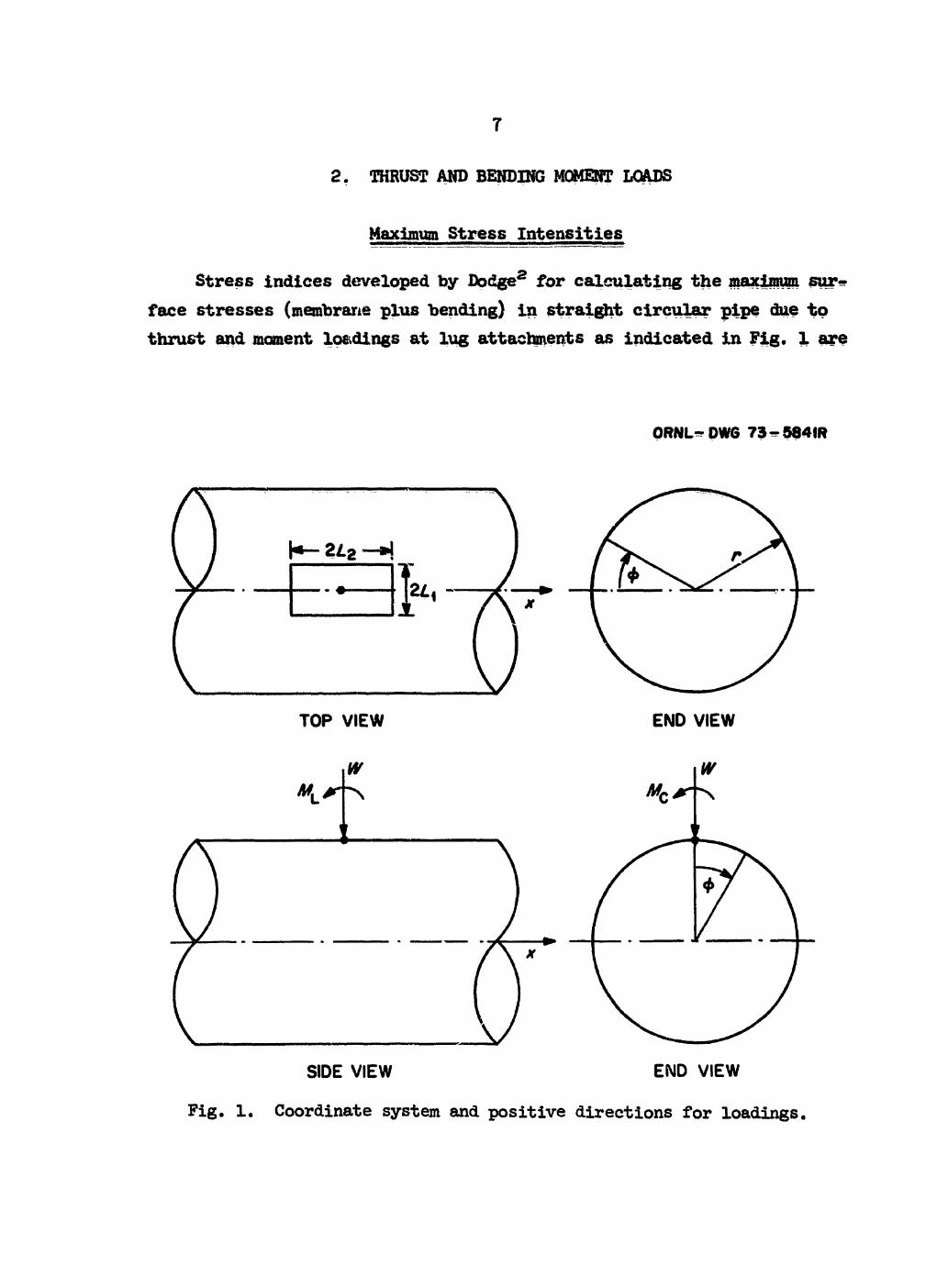
2. THRUST AND BENDING MOMENT LOADS
Maximum Stress Intensities
Stress indices developed by Dodge2 for calculating the maximum sur, face stresses (membrane plus bending) in straight circular pipe due to thrust and moment loadings at lug attachments as indicated in Fig. 1 are
ORNL^DWG 73-584IR
SIDE VIEW END VIEW
Fig. 1. Coordinate system and positive directions for loadings,

8
given "by
r* T = 12.0(r/t)°'64 TI1'54 , (la)
c? u = 1.2(r/t)°'74 n4-74 (lb)
C* = 1.8(r/t)°'90 n3-40 , (lc)
where C* is for a radial thrust load, C* is for a longitudinal moment load, and C* is for a circumferential moment load acting on the lug. The nondimensional parameter ^ is given "by
n = -(X-L cos 6 + Yi sin 0) - j- (Xx sin 9 - Yx cos 0)2 , (id)
where 6 is a constant and X± and Yx are given in teims of the constants X0 and Y0 and the nondimensional width and length parameters and
X2 = XQ + logio Pi , (le)
Yx = Y0 + logio P2 . (If)
Here = Lx/r is one-half the width of the loaded area in the circumfer-ential direction divided "by the mean pipe radius r and fB2 = L2/r is one-half the length of the loaded area in the longitudinal direction divided by r.
Appropriate numerical values for the constants AQ, 9, XQ, and YQ are tabulated below for each of the three different types of load.
Load AQ 9 XQ YQ
Thrust 2.2 kO° 0 0.05 Longitudinal moment 2.0 50° -0.^5 -0.55 Circumferential moment 1.8 ^0° -O.75 -0.60
Maximum stress intensities in the pipe a , a , and cr corresponding to the thrust and moment loadings W, M^, and M^ on the lug are then given

9
"by the following stress-index equations in terms of the pipe dimensions:
aT = C*W/Ap , (2a)
= <1?V ZP > ( 2 b )
where A is the cross-sectional area of the pipe and Z is the section P P
modulus of the pipe. This foim of stress index has certain advantages in that, for moment loading, the nominal stresses (M^/Z^) and ( M
c / a r e the same as used in the Code for moments acting on the pipe cross section. However, as indicated in the Introduction, it appears desirable to con-sider the additional stresses in the pipe caused by the lug separately from the stresses presently covered by the Code. With this approach we may change the normalizing base of Dodge's C*-type indices to the nominal stresses in the lug. Thus C^, C^, and Cc may be defined as
CT = aT/(w/A^ , (3a)
CL = V ( V Z J L > > (3b) CC = V ( V Z J C > > (3c)
where A^ = J+LjLg is the cross-sectional area of the lug at the pipe sur-face, = (V3)LXL2
2 is the section modulus of the lug at the pipe sur-face for an applied moment M^ and = ( V s ) ^ 2 ^ is the section modu-lus of the lug at the pipe surface for an applied moment M^. Conversion from the C* indices to the C indices is obtained by the following relation-ships :
CT = C*(A^/Ap) - C^^Ls/C^nrt)] = C^^/ir) , (be)
CL B ^ i l / V = ^[8L1L22/(67nr2t)] = C*[1^1P227/(3tt)] , (kb)
CC s °C(Zi</V = Ccf8Li2L2/(6l7Tafc^ = i%V(3TT)] , (IKS)
where 7 = r/t is the radius-to-thickness ratio of the pipe.
10
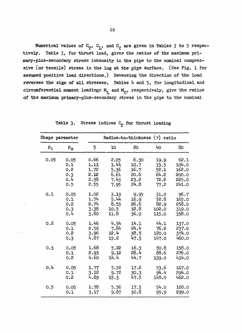
Numerical values of CT, CL, and C^ are given in Tables 3 to 5 respec tively. Table 3, for thrust load, gives the ratios of the maximum pri-mary-plus-secondary stress intensity in the pipe to the nominal compres-sive (or tensile) stress in the lug at the pipe surface. (See Fig. 1 for assumed positive load directions.) Reversing the direction of the load reverses the sign of all stresses. Tables 1* and 5, for longitudinal and circumferential moment loadings M^ and M^, respectively, give the ratios of the maximum primary-plus-secondary stress in the pipe to the nominal
Table 3. Stress indices CL, for thrust loading
Shape parameter Radius-to-thickness (7) ratio
Pi e 2 5 10 20 ko 80
0.05 0.05 0.66 2.05 6.30 19.9 62.1 0.1 1.11 3 M 10.7 33.5 loh.o 0.2 1.72 5.36 16.7 52.1 162.0 0.3 2.12 6.61 20.6 61*.2 200.0 0.1* 2.38 7.^3 23.2 72.2 225.0 0.5 2.55 7.95 21*. 8 77.2 21*1.0
0.1 0.05 1.02 3.19 9.95 31.0 96.7 0.1 1.7^ 16.9 52.8 165.0 0.2 2.7^ 8.53 26.6 82.9 258.0 0.3 3.38 10.5 32.8 102.0 319.0 O.k 3.80 11.8 36.9 115.0 358.0
0.2 0.05 .1.U6 k.5k l k . 1 1*1*. 1 137.0 0.1 2.52 7.81* 2k.k 76.2 237.0 0.2 3.96 12. 1* 38.5 120.0 37^.0 0.3 if.87 15.2 1+7.3 ll*7.0 U60.0
0.3 0.05 1.68 5.22 16.3 50.8 158.0 0.1 2.93 9.12 28. k 88.6 276.0 0.2 i*.6o H*.l* kk.7 139.0 1*3 .0
0.1* 0.05 1.77 5.52 17.2 53.6 167.0 0.1 3.12 9.72 30.3 9k.k 291*. 0 0.2 4.89 15.3 VT.5 ll*8.0 1*62.0
0.5 0.05 1.78 5.56 17.3 5l*.0 168.0 0.1 3.17 9.87 30.8 95.9 299.0
11
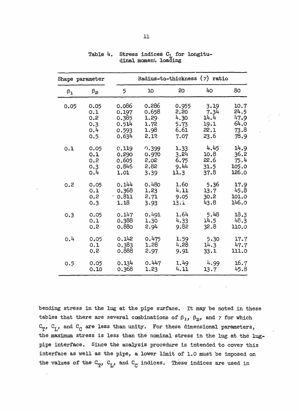
Table 4. Stress indices CL for longitu-dinal moment loading
Shape parameter Radius-to-thickness (7) ratio
Pi 5 3.0 20 4o 80
0.05 0.05 0.086 0.286 0.955 3.19 10.7 0.1 0.197 O.658 2.20 7.34 24.5 0.2 0.385 I.29 4.30 14.4 47.9 0.3 0.51k 1.72 5.73 19.1 64.0 0.4 0.593 I.98 6.61 22.1 73.8 0.5 O.63U 2.12 7.07 23.6 78.9
0.1 0.05 0.119 0.399 1.33 4.45 14.9 0.1 0.290 0.970 3.24 10.8 36.2 0.2 0.605 2.02 6.75 22.6 75.4 0.3 0.846 2.82 9.44 31.5 105.0 0.4 1.01 3.39 11.3 37.8 126.0
0.2 0.05 o.i44 0.480 1.60 5.36 17.9 0.1 0.368 1.23 4c 11 13.7 45.8 0.2 * 0.811 2.71 9.05 30.2 101.0 0.3 1.18 3.93 13.1 43.8 146.0
0.3 0.05 0.147 0.491 1.64 5.48 18.3 0.1 0.388 1.30 4.33 14.5 48.3 0.2 0.880 2.94 9.82 32.8 110.0
0.4 0.05 0.142 0.475 1-59 5.30 17.7 0.1 0.383 1.28 4.28 14.3 47.7 0.2 0.888 2.97 9.91 33.1 111.0
0.5 0.05 0.13^ 0.447 1.49 4.99 16.7 0.10 0.368 1.23 •4,11 13.7 45.8
"bending stress in the lug at the pipe surface. It may be noted in these tables that there are several combinations of {32, and 7 for which C^, C^, and C^ are less than unity. For these dimensional parameters, the maximum stress is less than the nominal stress in the lug at the lug-pipe interface. Since the analysis procedure is intended to cover this interface as well as the pipe, a lower limit of 1.0 must be imposed on the values of the CL,, CT, and Cp indices. These indices are used in
1 2
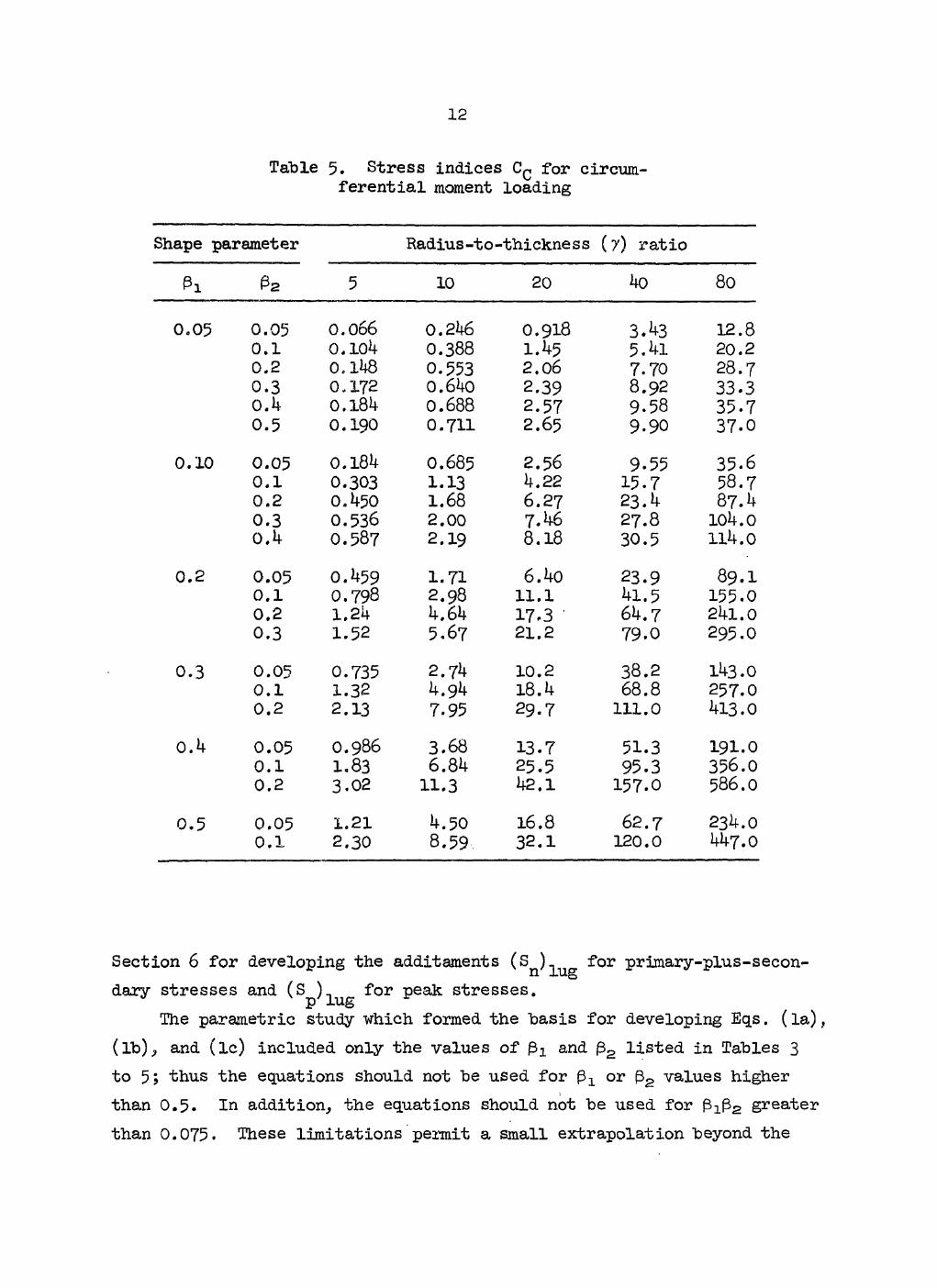
Table 5. Stress indices Cc for circum-ferential moment loading
Shape parameter Radius-to-thickness (7) ratio
Pi P2 5 10 20 4o 80
0.05 0.05 0.066 0.246 0.918 3.43 12.8 0.1 0.104 0.388 1.45 5.41 20.2 0.2 0.11*8 0.553 2.06 7.70 28.7 0.3 0,172 0.640 2.39 8.92 33.3 O.k 0.184 0.688 2.57 9-58 35.7 0.5 0.190 0.711 2.65 9.90 37.0
0.10 0.05 0.184 0.685 2.56 9.55 35.6 0.1 0.303 1.13 4.22 15.7 58.7 0.2 0.450 1.68 6.27 23.4 87.4 0.3 0.536 2.00 7.46 27.8 104.0 O.k 0.587 2.19 8.18 30.5 114.0
0.2 0.05 0.459 1.71 6.4o 23.9 89.1 0.1 0.798 2.98 ll.l 41.5 155.0 0.2 1.24 4.64 17.3 64.7 241.0 0.3 1.52 5.67 21.2 79.0 295.0
0.3 0.05 0.735 2.74 10.2 38.2 143.0 0.1 1.32 4.94 18.4 68.8 257.0 0.2 2.13 7.95 29.7 111.0 413.0
0.4 0.05 0.986 3.68 13.7 51.3 191.0 0.1 1.83 6.84 25.5 95.3 356.0 0.2 3.02 11.3 42.1 157.0 586.0
0.5 0.05 1.21 4.50 16.8 62.7 234.0 0.1 2.30 8.59 32.1 120.0 447.0
Section 6 for developing the additaments (sn)lug
f o r primary-plus-secon-dary stresses and Peak stresses.
The parametric study -which formed the basis for developing Eqs. (la), (lb), and (lc) included only the values of and £2 listed in Tables 3 to 5; thus the equations should not be used for or 32 values higher than 0.5. In addition, the equations should not be used for greater than 0.075. These Imitations permit a small extrapolation beyond the
204
products included in the study "but prevent large extrapolations. While the study included parameter values for 7 up to 80, the general limitation on stress indices of D /t = 100 is recommended for the indices
o'
for lugs. These limitations are included in Appendix A, Recommended Ad-dition to ASME Code Section III to Cover Straight Pipe with Integral Struc-tural Attachments.
Ratios of the maximum calculated membrane stress to the maximum cal-culated secondary stress intensity are given in Tables 6 to 8 for radial thrust, longitudinal moment, and circumferential moment loadings respec-tively. For all three cases the tabulated values show that the membrane stresses are small with respect to the bending stresses. This fact is used in Section 6 as a part of the basis for establishing the B^ indices used in the new term (P^ + P^)^ for primary stresses. The directions and locations of the maximum stresses are included in Appendix B for reference.
Comparisons with ASME Boiler Code, Section I, Paragraph PW-TjJ
Paragraph PW-^3 in Section I of the ASME Boiler Code3 gives a design method for loading on structural attachments which considers only radial thrust and longitudinal moment loadings; circumferential moment loadings are not considered. According to this code, the design is acceptable if the following inequality is satisfied:
W — + — - <; i , o ;
where Y is the maximum allowable load per unit length of the loaded area (lb/in.), W is the radial thrust load (lb), M^ is the longitudinal moment load (in. -lb), and L2 is one-half the length of the loaded area (in.). The maximum load Y is given graphically in Fig. PW-1+3.1 of Ref. 3 (the load being identified there as P). The value of Y depends on whether the direction of loading is tensile or compressive and also on the outside diameter of the pipe for tensile loads. For arbitrary loading directions
6 M L

Ik
Table 6. Ratios of maximum membrane stress to maximum secondary stress intensity9,
for thrust loading
Shape parameter Radius-to-thickness (7) ratio
Pi P2 5 10 20 4o 80
0.05 0.05 0.081 0.098 0.120 0.145 0.168 0.1 0.093 0.112 0.131 0.148 0.187 0.2 0.109 0.122 0.131 0.170 0.210 0.3 0.118 0.122 0.144 O.185 0.224 0.4 0.121 0.116 0.155 0.196 0.235 0.5 0.123 0.117 0.165 0.207 0.248
0.1 0.05 0.103 0.122 0.144 0.164 0.202 0.1 0.116 0.136 0.156 0.169 0.208 0.2 0.135 0.149 0.156 0.190 0.222 0.3 0.145 0.149 0.169 0.210 0.244 0.4 0.151 0.143 0.182 0.227 0.264
0.2 0.05 0.139 0.164 0.187 0.203 0.229 0.1 0.150 O.I67 0.178 0.208 0.244 0.2 0.1.76 0.186 0.183 0.219 0.255 0.3 0.192 0.190 0.181 0.226 0.265
0.3 0.05 0.177 0.203 0.225 0.232 0.229 0.1 0.187 0.202 0.204 0.228 0.250 0.2 0.209 0.210 0.210 0.251 0.280
0.4 0.05 0.217 0.242 0.257 0.252 0.223 0.1 0.227 0.241 0.235 0.233 0.242
0.5 0.05 0.261 0.284 0.290 0.270 0.203
Maximum secondary stress intensity for a nominal thrust load of w/A^ = l.o is the same as the stress index CT = C a s defined by Eq. (4a).

15
Table 7. Ratios of maximum membrane stress to maximum secondary stress intensity8, for
longitudinal moment loading
Shape parameter Radius-to - thickness (7) ratio
Pi P2 5 10 20 40 80
0.05 0.05 0.022+b 0.038+ 0.063 0.105 0.166 0.1 0.038+ 0.064 0.103 0.157 0.214 0.2 0.075 0.115 0.157 0.192 0.191 0.3 0.112 0.149 0.188 0.198 0.179 0.4 0.145 0.166 0.209 0.202 0.159 0.5 0.171 0.174 0.219 0.199 0.194
0.1 0.05 0.031+ 0.053+ 0.087 0.140 0.215 0.1 0.052+ 0.086 0.136 0.202 0.269 0.2 0.094 0.144 0.193 0.219 0.216 0.3 0.136 0.IB0 0.215 0.218 0.186 0.4 0.168 0.193 0.230 0.217 0.168
0.2 0.05 0.050+ 0.085+ 0.131 0.195 O.271 0.1 0,080+ 0.128 0.195 0.272 0.339 0,2 0.137 0.204 0.270 0.295 0.274 0.3 0.191 0.249 0.272 0.239 0.180
0.3 0.05 O.O69+ 0.114+ O.I69 0.233 0.298 0.1 0.110+ 0.168 0.244 0.322 0.369 0.2 0.182 0.263 0.338 0.353 0.304
0.4 0.05 O.O89+ 0.143 0.203 0.264 0.1 0.139+ 0.350 0.287 0.360 0.386
0.5 0.05 0.109+ 0.172 0.234 0.291
Maximum secondary stress intensity for a nominal longi-tudinal moment load of M t/Z^ l = 1.0 is the same as the stress index C_ = Cf [1^^227/(3tt) ], as defined by Eq. (4b).
"b The "+" sign indicates that the maximum value may actu-
ally be larger, since the numerical parameter study did not extend far enough to locate the true maximum,

16
Table 8. Ratios of maximum membrane stress to maximum secondary stress intensity8, for
circumferential moment loading
Shape parameter Radius-to-thickness (7) ratio
Pi P 2 5 10 20 40 80
0 .05 0.05 o .o io+ b 0.017+ 0.028" 0.042+ 0.063 0.1 0.013+ 0.021+ 0.034+ 0.051+ 0 .071 0.2 0.016+ 0.026+ 0.040+ 0.058+ 0.079+ 0.3 0.018+ 0.028+ 0.042+ 0.059+ 0.076+ 0 . 4 0.020+ 0.029+ 0.042+ 0.057+ 0.073+ 0.5 0.021+ 0.030+ 0.042+ 0.055+ O.O69+
0 . 1 0.05 0.017+ 0.027+ 0.041+ 0.060 0.085 0.1 0.020+ 0.032+ 0.049+ 0.069 0.097 0.2 0.025+ 0.039+ 0.059+ 0.080 0.100 0.3 0.029+ 0.043+ 0.062+ 0.083+ 0.101 0 . 4 0.031+ 0.045+ 0.063+ 0.082+ 0.100+
0 .2 0.05 0.034+ 0.046 0 .064 O.O87 0.108 0.1 0.039+ 0.053 0.072 0.095 0.118 0.2 0.048+ 0.065 0.086 0.107 0.126 0.3 0.056+ 0.076+ 0.095 0.113 0.128
0 . 3 0.05 0.048 0 .064 0.085 0.102 0.113 0.1 0.053 0.070 0 .092 0.110 0.115 0 . 2 o .o64 0.084 0.106 0.125 0.129
0 .4 0.05 0.063 0.083 0 .101 0.114 0 .111 0.1 0.068 O.O87 0.107 0.113 0.112
0 . 5 0.05 0.080 0.100 0.118 0.122 0.108
Maximum secondary stress intensity for a nominal circum-ferential moment load of Mq/Z^q = 1.0 is the same as the stress index C-Q = C*[4p12p27/(37r) ], as defined by Eq. (4c).
^The "+" sign indicates that the maximum value may actually be larger, since the numerical parameter study did not extend far enough to locate the true maximum.

17
and all pipe diameters, an approximate value for Y is given by 2
Y = 30,000 ~ , (6)
where t is the pipe wall thickness and D is the outside diameter. Sub-stituting Eq. (6) into Eq. (5), the maximum allowable loads must satisfy the following:
w 6Mt t2
— + — — = 30,000 — . (7) 2L2 4L2
2 D
The basis for the design method is not known to the authors. How-ever, in discussing the background of PW-1+3, Melworm and Berman5 state
"It was assumed that the tube material behaved elasti-cally. Circumferential tube stress determinations were made for pressure and external load. Thick wall (Lam6) theory was used to determine the pressure stresses and thin-ring combined with curved beam theory were used to obtain the stresses caused by external load. The maxi-mum circumferential tube stress was limited to an em-pirical value of 20,000 psi."
Apparently the 20,000-psi limit was placed on the sum of the circum-ferential stresses in the pipe due to both internal pressure and external loads. If that were so, and assuming that the circumferential stress due to pressure was equal to a typical value of 15,000 psi, the allowable stress which would be available for the external loads would be 5000 psi. We can thus write an equation for the maximum allowable stress in the pipe due to W and M^ in terms of the lug dimensions and unknown dimension-less coefficients C^ and
W ]yL CT A" + CT = 5000 psi , (8) 1 L iz
where the cross-sectional area of the lug A^ = 4l2L2 and the section modu-lus = (VsjLjLg2. Simply rearranging the terms in Eq. (7) gives
2LX D 6t t
W *L (k/ 3)L1L22_
5000 psi . (9)

18
From Eqs. (8) and (9),
C^ « C^ = L ^ t 2 ,
or, in terms of nondimensional parameters = Lx/r and 7 = r/t,
C^ = C^ = (2/3)P172 .
It is thus apparent that the PW-43 analysis method implies equal stress indices C^ and for "both thrust and moment loadings, although the width of the lug (2La) does not enter into the PW-43 criteria [Eq. (5)]. Typi-cally the lug width would be about 0.2 times the pipe diameter, in which case =0.1. Using this value for a direct comparison can be made between the PW-43 design method and the stress indices C^ and C^ devel-oped in this report.
Table 9 gives some comparisons of (2/3)p172 with C^ and CL. As judged by the stress index, the PW-43 method tends to be unconservative for thrust load (except for 7 = 4o) and conservative for moment load.
Table 9. Comparison of PW-43 method with C indices for thrust and longitudinal moment loading
Pi p2 Index source
Radius-to-thickness (7) ratio Pi p2
Index source 5 10 20 4o
0.1 Any PW-43a 1.67 6.67 26.7 107.0 0.1 0.2 CT 2.74 8.53 26.6 82.9
CL 0.60 2.02 6.75 22.6 0.1 0.3 CT 3.38 10.5 32.8 102.0
CL 0.85 2.82 9.44 31.5 0.1 0.4 cT 3.80 11.8 36.9 115.0
CL 1.01 3.39 11.3 37.8
aIndex = (2/3)pi72 for both thrust and longi-tudinal moment.
19
In general, however, the PW-U3 method gives permissible loadings in the same range as the stress-index method when the latter method is used with ^Sn^lug = ^000 reason for the conservatism with respect to mo-ment load is that PW-^3 treats the maximum nominal stress due to a moment as equivalent to a thrust load acting along the entire length of the lug; that is, 6M/2L2 = W.
Comparisons with Welding Research Council Bulletin 107
Welding Research Council Bulletin 107, Local Stresses in Spherical and Cylindrical Shells Due to External Loadings,4 is a widely used design guide based on theoretical and numerical results developed by Bijlaard6' 7 for distributed loads on cylindrical shells as shown in Fig. 2. WRC Bulletin 107 also includes empirical corrections to Bijlaard's results that were based principally on results from tests of two models of cylin-drical shells with nozzles. For lack of a more directly applicable anal-ysis, Bijlaard's results have been used to estimate stresses due to thrust or moment loads applied to a nozzle in a cylindrical shell and to loads applied through a lug or other relatively rigid attachment.
The data given in WRC Bulletin 107 for thrust load are based on cal-culations for cylinders with length-to-radius ratios L/r = 8. The value of L/r used for moment loadings is not clearly stated; however, the stresses are only slightly dependent upon this ratio. The stresses for thrust load were calculated for the center of the loaded area, while those for moment loads are for the edge of the loaded area.
Dodge2 calculated stresses based on Bijlaard1 s theory with the fol-lowing refinements: (l) certain terms in the solution were retained in the numerical analysis as recommended by Weil, Laupa, and Murphy in their discussion at the end of Ref. 6; (2) the angularity of the surface loads was taken into consideration; and (3) the stresses due to "beam bending" were subtracted out. For sufficiently large values of L/r, the stresses become independent of L/r. (in using the stress-index method, as given in Section 6, the stresses due to beam bending are included in the exist-ing Code equations.)

20
ORNL- DWG 7 2 - 12146R
\ W
1 1 1 1 1 7
/
• i q L z s i n d<f>
'1 f 2
M\r J qLKxdx
BIJLAARD THEORY
LOADS ARE EQUILIBRATED BY DISTRIBUTED SHEARS AT END OF CYLINDER t x = ± L
U
Fig. 2. Illustration of Bijlaard's distributed-load equivalence with thrust and moment loads.

21
The stress indices CT, CL, and Cc are "based on calculated stresses at the edge of or outside* the loaded area. The major difference "between Bulletin 107 and the stress indices is for thrust loading; Bulletin 107 gives stresses at the center of the loaded area, whereas the stress in-dices are based on stresses at the edge of the loaded area. Detailed com-parisons for each of the three loadings are discussed below.
Thrust loading Table 10 shows comparisons for thrust loadings on square loaded areas.
Dodge** gives maximum stresses at the edge of the loaded area, whereas Bulletin 107 is based on stresses at the center of the loaded area. Stresses calculated using WRC 107 are higher than these reported in Ref. 2, and a check of the detailed calculations indicates the discrepancy is almost entirely due to the difference between the stresses at the center of the loaded area and those at the edge of the loaded area. Indices ob-tained by the approximate formula, Eq. (4a), however, are higher than or of the same order as the maximum stress obtained by Bulletin 107. This is primarily due to the conservatism introduced in developing approximate formulas with the required simplicity; for more details see Ref. 2.
Table 11 shows comparisons for thrust loadings on rectangular loaded areas for ratios of l/4, l/2, 2, and 4. The equations included in WRC 107 are approximations developed by Bijlaard7 based on a relatively few calculated results for these ratios. To avoid additional interpola-tions or extrapolations here, the same ratios were used in making the comparisons. The WRC 107 equations give, in effect, an "equivalent" square area. As shown in the table, the approximate equations of Bulle-tin 107 appear to be adequate, since, with only a few minor exceptions, the stresses obtained with these equations are not less than the more accurate results obtained by Dodge. For thrust loads on rectangular areas,
*For most parameters included in the study, the maximum surface stresses were at the edge of the loaded area. See Appendix B.
**Reference to Dodge in these comparisons is meant to indicate the detailed stresses presented in Ref. 2 and used as the basis for develop-ing the approximate formulas, Eqs. (4a), (4b), and (4c).

2 2
Table 10. Comparisons for thrust loadings on square loaded areasa
0 2 7 Method a 0Js t o^/ S£ a ^ a^/s.
0 .05 0 .05 5 VJRC 107 Dodge Eq. (Ha)
-0 .H9 -0.H2
0 . 6 6
0 .39 0 .32
-O.HH - 0 . 3 3
0.3h 0 . 2 8
10 WRC 107 Dodge Eq. (4a)
- 1 . 7 1 -1 .5U
2.05
1 .35 1 .15
- 1 . 5 2 - 1 . 1 3
1 . 12 0 . 8 7
20 WRC 107 Dodge Eq. (Ha)
- 6 . 0 8 - 5 . 3 9
6 .39
H.H8 3 .96
- 5 . 1 0 - 3 . 8 3
3.5U 2 . 6 2
HO WRC 107 Dodge Eq. (Ha)
-21.HH -18.H6
19-9
15. OH 13.37
- 1 6 . 8 0 - 1 2 . 5 0
11. OH 7.3h
80 WRC 107 Dodge Eq. (Ha)
- 7 3 . ^ - 6 0 . 9 5
6 2 . 1
H9.HH ^3.93
- 5 7 . 6 8 - 3 9 . 3 8
3 U.H8 18. H7
0 .10 0 . 1 0 5 WRC 107 Dodge Eq. (Ha)
- 1 . 5 1 - 1 . 2 6
1 .7^
l . l l 0 .88
- 1 . 3 5 -O.89
0 . 9 ^ 0 .70
10 WRC 107 Dodge Eq. (Ha)
- 5 . 0 2 -H.lH
5 M
3 . 6 6 3 . 1 1
-U.37 - 2 . 9 3
2 . 8 2 1 . 9 6
20 WRC 107 Dodge Eq. (Ha)
- 1 7 . 8 7 - i n . 8 3
1 6 . 9
12 .27 10 .51 -9-31*
8 . 5 6 H.96
Ho WRC 107 Dodge Eq. (Ha)
- 5 8 . 8 8 - H 7 . 8 2
52 .8
37 .12 3^.73
^ 5 . 7 6 ~28.75
23 .36 IO.89
80 WRC 107 Dodge Eq. (Ha)
- 1 7 9 . 5 — 1 H 7 . 7
1 6 5 . 0
115.5 112.5
- 1 3 6 . 8 -87 .^5
53.63 18.99
0 .20 0 . 2 0 5 WRC 107 Dodge Eq. (Ha)
-H.23 - 3 . 2 7
3 . 9 6
2 . 7 8 2 .12
- 3 . 5 9 - 2 . 0 H
2 . 0 7 1 .38
10 WRC 107 Dodge Eq. (Ha)
- 1 3 . 1 5 - 1 0 . 7 ^
12.H
8 .35 7 .33
- 1 0 . 8 3 - 6 . 3 1
5 .30 3 . 0 8
20 WRC 107 Dodge Eq. (Ha)
- H i . 9 2 -3U.03
38 .5
27.20 2H.99
- 3 1 . 7 ^ - 1 9 . 5 3
11.26 5 . 7 6
Ho WRC 107 Dodge Eq. (Ha)
— 1 2 5 , 7 -103.H
120.0
77.06 81 ,91
- 8 9 . 6 0 - 6 0 . 9 6
1 7 . 9 2 8 . 2 3
> 80 WRC 107 Dodge Eq. (Ha)
- 3 5 1 . 5 - 3 0 6 . 2
37^.0
226.0 257.5
- 2 5 U . 2 - 1 9 3 . 0
1 6 . 1 3 2 . 0 0
"For thrust load (W of Fig. 2), S, = W/HLjLg. Subscripts 0 and x refer to the circumferential and axial directions respectively; i is inside surface and o is outside surface.

23
Table 11. Comparisons for thrust loadings on rectangular loaded areas
•Pi P2 7 Method CO
O / S o xo *>
0.05 0.20 5 WRC 107 Dodge Eq. (4a)
-1.58 -1.25 1.72
1.20 0.87
-1.22 -O.89
0.81 0.70
10 WRC 107 Dodge Eq. (4a)
-5.42 ^4.38 5.36
3.9^ 3.07
-3.76 -2.91
2„24 1.95
20 WRC 107 Dodge Eq. (4a)
-18.72 -14.74 16.7
13.92 10.43
-12.00 -9.33
6.24 4.99
4o WRC 107 Dodge Eq. (4a)
-56.OO -47.5 52.1
4o.o 34.4
-32.3 -28.8
11.5 11.0
80 WRC 107 Dodge Eq. (4a)
-189.9 -146.2 162.0
141.9 111.3
-107.5 -85.9
30.7 17.6
0.05 0.10 5 WRC 107 Dodge Eq. (4a)
-0.89 -0.73 l.ll
0.69 0.52
-0.73 -0.59
0.53 0.50
10 WRC 107 Dodge Eq. (4a)
-3.16 -2.60 3.44
2.32 1.83
-2.4l —2*Q4
1.64 1.53
20 WRC 107 Dodge Eq. (4a)
-10.88 -8.97 10.7
8.32 6.16
-8.24 -6.78
5.20 4.41
4o WRC 107 Dodge Eq. (4a)
-37.12 -29.72 33.5
26.24 19.84
-22.88 -21.42
11.68 11.57
80 WRC 107 Dodge Eq. (4a)
-114.4 -•93.79 104.0
77.60 61.37
•-80.00 -64.78
35.20 25.77
0.20 0.10 5 WRC 107 Dodge Eq. (4a)
-2.28 -2.03 2.52
1.51 1.29
-2.16 -1.55
1.39 1.19

215
Table 14 (continued)
Pi e2 y Method 0 /s, XO x> a x A
10 WRC 107 Dodge Eq. (1+a)
-7.52 -6.90 7.81+
4.48 4.35
-6.61 -4.97
3.76 3.14
20 WRC 107 Dodge Eq. (i+a)
-23.81+ -21.11+ 21+.1+
14.56 13.86
-21.44 -15.17
11.20 7.09
1+0 WRC 107 Dodge Eq. (1+a)
-75.20 -66.77 76.2
1+0.00 42.39
-61.57 -44.00
24.45 12.25
8o WRC 107 Dodge Eq. (1+a)
-220.2 -188.3 237.O
117.8 125.3
-170.4 -124.4
38.53 9.04
0.1+0 0.10 5 WRC 107 Dodge Eq. (Ua)
-2.85 -2.81+ 3.12
1.38 1.42
-3.08 -2.36
1.72 1.74
10 WRC 107 Dodge Eq. (1+a)
-8.77 -9.07 9.72
3.33 4.39
-9.02 -7.04
4.22 4.03
20 WRC 107 Dodge Eq. (1+a)
-25.28 -26.51 30.3
9.28 12.20
-24.90 -19.46
8.90 7.08
1+0 WRC 107 Dodge Eq. (1+a)
-71.1+2 -70.57 94.1+
17.66 31.94
-64.00 -49.47 12.80 5.53
80 WRC 107 Dodge Eq. (1+a)
-177.4 -172.5 294.0
31.49 83.69
-165.4 -121.6
6.66 -20.11
^or thrust loads S. = W/^I^Lg; for subscript notation, see foot-note a of Table 10.

25
the stress-index equation, Eq. (4a), tends to he more conservative than either the WRC 107 or Dodge results for Pi/P2 greater than 1; it is also more conservative than Dodge but less conservative than WRC 107 for £2/^2 less than 1.
Moment loadings Tables 12 and 13 show comparisons for longitudinal and circumferen-
tial moment loadings, respectively, on square areas. For the range of parameters covered in these comparisons, the WRC 107 results and those obtained by Dodge are essentially the same — within the accuracy with which the graphs in Bulletin 107 can be read and interpolated. This in-dicates that the modifications made in Ref. 2 do not produce significant changes within this parameter range. The parameters for which large em-pirical corrections were made in Bulletin 107 are not included. For both types of moment loadings, Eqs. (4b) and (4c) tend to be conservative with respect to the other two calculations. For the case where Pi = f32 = 0.2, for example, Eqs. (4b) and (4c) give results which range from about 1.1 to 1.7 times the results of the other two.
Comparisons for longitudinal and circumferential moment loadings on rectangular areas are shown in Tables 14 and 15 respectively. For longi-tudinal moment loadings (Table 14), the approximate equations of Bulletin 107 apparently failed to locate the maximum stress and for some parame-ters tended to underestimate the magnitude. See, for example, the case for = 0.05, P2 = 0.20, and 7 = 80, where WRC 107 gives a maximum stress of —25. 4S on the outside surface in the axial direction (axQ), whereas Dodge's calculations (based on Bijlaard's complete equations) gives a maximum stress of — 3 9 o n the outside surface in the circumferential direction ( . On the other hand, the stress-index equation [for this case, Eq. (4b)] always tends to be conservative with respect to the maxi-mum.
The comparisons for a circumferential moment loading on rectangular areas given in Table 15 show that the approximate equations of WRC 107 give locations and directions for the maximum stresses that generally agree with the more detailed calculations of Dodge. However, for cases
26
Table 12. Comparisons for longitudinal moment loadings on square loaded areas8.
Pi y Method a0i/sz 0 / s . xo I
0 . 0 5 0 . 0 5 5 WRC 107 Dodge Eq. (4b)
- 0 . 0 4 - 0 . 0 3
0 . 0 3 0 . 0 3
- 0 . 0 6 - 0 . 0 5
0 . 0 9
0 .05 0 .05
10 WRC 107 Dodge Eq. (4b)
- 0 . 1 4 - 0 . 1 3
0 . 1 2 0 . 1 2
- 0 . 2 1 - 0 . 2 1
0 . 2 9
0 . 2 1 0 . 2 1
20 WRC 107 Dodge Eq. (4b)
-0.5h - 0 . 5 2
0 . 4 5 0.142
- 0 . 8 1 - 0 . 8 0
0 .95
0 . 7 9 0 . 7 8
uo WRC 107 Dodge Eq. (4b)
- 2 . 1 6 - 2 . 1 1
1 .62 1 . 5 1
- 3 . 2 1 - 3 . 0 5
3 . 1 9
3 -07 2 . 9 1
80 WRC 107 Dodge Eq. (4b)
- 8 . 5 1 - 8 . 2 9
5 . 3 1 ^.93
- 1 1 . 9 5 - 1 1 . 0 8 10.7
11 .09 10 .21
0 . 1 0 0 .10 5 WRC 107 Dodge Eq. (4b)
- 0 . 1 4 - 0 . 1 4
0 . 1 2 0 . 1 2
- 0 . 2 1 - 0 . 2 1
0 . 2 9
0 . 2 1 0 . 2 1
10 WRC 107 Dodge Eq. (4b)
- 0 . 5 5 - 0 . 5 7
0.1»0 0 . 4 2
- 0 . 8 0 - 0 . 8 1
0 . 9 7
0 . 7 6 0 .78
20 WRC 107 Dodge Eq. (4b)
- 2 . 1 6 —2.26
1 . 3 0 1 . 4 0
- 2 . 9 3 - 2 . 9 8 3 . 24
2 . 7 1 2 . 7 6
4o WRC 107 Dodge Eq. (4b)
- 7 . 9 2 - 8 . 5 9
3 . 8 6 4.21
- 1 0 . 0 6 - 1 0 . 2 2
10 .8
8 . 8 9 8 . 9 8
80 WRC 107 Dodge Eq. (4b)
- 2 7 . 1 8 - 3 0 . 1 3
9 . 6 9 10.58
- 2 9 . 7 2 - 3 1 . 5 8
3 6 . 2
23 .53 25.25
0 . 2 0 0 . 2 0 5 WRC 107 Dodge Eq. (4b)
- 0 . 5 6 - 0 . 5 5
0.3^ 0 . 3 3
- 0 . 7 5 - 0 . 7 U 0.81
O .69 O .69
10 WRC 107 Dodge Eq. (4b)
- 2 . 0 6 - 2 . 0 3
0 . 8 8 0 . 9 2
- 2 . 5 3 - 2 . 5 0
2 . 7 1
2 .20 2 . 2 1
20 WRC 107 Dodge Eq. (4b)
- 7 . 1 9 - 7 . 2 5
2 . 2 8 2 . 3 8
- £ . 4 5 - 7 . 5 2
9 .05
6 . 9 1 5 .96
40 WRC 107 Dodge Eq. (4b)
- 2 1 . 6 3 - 2 2 . 1 5
30 .2
^ .99 4.29
- 2 2 . 8 7 - 1 9 . 7 6
16.04 12.77
80 WRC 107 Dodge Eq. (4b)
- 5 8 . 8 8 - 5 0 . 6 5 101.0
2 . 5 6 U.25
-52.56 - 4 8 . 4 8
25.26 21.75
®For longitudinal moment loading, S^ = 6M,/(Sl^Lg2); for sub-script notation see footnote a of Table 10.

27
Table 13. Comparisons for circumferential mcment loadings on square loaded areas8.
P 2 7 Method a f J B i a0i/st 0 / S , xo' i
0 .05 0 . 0 5 5 WRC 107 Dodge Eq. ( U c )
- 0 . 0 5 - 0 . 0 5
0 . 0 6 6
0 . 0 5 0 . 0 5
- 0 . 0 3 - 0 . 0 3
0 . 0 3 0 . 0 3
10 WRC 107 Dodge Eq. ( U c )
- 0 . 2 1 - 0 . 2 0
0 . 2 5
0 . 2 1 0 . 2 0
- 0 . 1 3 - 0 . 1 3
0 . 1 3 0 . 3 2
2 0 WRC 107 Dodge Eq. ( U c )
- 0 . 8 5 - 0 . 7 8
0 . 9 2
0 .83 0 .75
- 0 . 5 1 - 0 . 5 0
0 . 5 0 O.U7
Uo WRC 107 Dodge Eq. ( U c )
- 3 . ^ 3 - 3 . 0 9
3.U3
3 . 2 9 2 . 9 1
- 2 . 0 8 - 1 . 9 9
1 .89 1 . 7 8
80 WRC 107 Dodge Eq. ( U c )
- 1 3 . 3 7 - 1 2 . 1 2
12 .8
12. U9 11.05
- 8 . 0 1 - 7 . 8 0
6 . 8 U 6 . U 5
0 . 1 0 0 . 1 0 5 WRC 107 Dodge Eq. ( U c )
- 0 . 2 1 - 0 . 2 2
0 . 3 0
0 . 2 1 0 . 2 1
- O . l U - 0 . 1 3
0 . 1 3 0 . 1 2
10 WRC 107 Dodge Eq. ( U c )
- 0 . 8 5 - 0 . 8 7
1 .13
0 . 8 1 0 .83
- 0 . 5 3 - 0 . 5 2
0.U8 0 . U 7
2 0 WRC 107 Dodge Eq. ( U c )
- 3 . 3 2 - 3 M
U . 2 2
3 .08 3 . 1 9
- 2 . 0 2 - 2 . 0 U
1 .70 1 .73
U0 WRC 107 Dodge Eq. ( U c )
- 1 2 . 9 3 - 1 3 . 2 1
15 .7
11.65 11.92
- 7 . 8 2 - 7 . 8 6
6 . 0 1 6 . 0 U
80 WRC 107 Dodge Eq. ( U c )
—^7.23 - ^ 9 . 3 7
58 .7
U0.83 U2.88
- 2 9 . 0 8 - 2 9 . 1 7
19 .05 19.0U
0 . 2 0 0 . 2 0 5 WRC 107 Dodge Eq. ( U c )
- 0 . 8 U - 0 . 8 6
1.2U
0 . 7 8 0 .80
- 0 . 5 3 - 0 . 5 3
0 . U 3 O.UU
10 WRC 107 Dodge Eq. ( U c )
- 3 . 1 5 - 3 . 3 9
U . 6 U
2 .93 3 .05
- 2 . 0 2 - 2 . 0 6
1 . 5 0 1 . 5 6
20 WRC 107 Dodge Eq. ( U c )
- 1 2 . 0 6 -12.U5
17 .3
10.U6 10.78
- 7 . 5 3 - 7 . 5 8
U . 7 6 U.87
Uo WRC 107 Dodge Eq. ( U c )
- U l . 3 0 -J+3.87
6 U . 7
3 U . U 7 36 .70
-25.31* - 2 6 . 5 h
12.5U 13 .00
80 WRC 107 Dodge Eq. ( U c )
- 1 3 7 . 7 - 1 U 2 . 5
2U1.0
112 .1 117.U
- 8 6 . 0 2 - 8 5 . 7 2
2U.58 2 U . 9 6
^or circumferential moment loading, S£ = 6Kc/(8L12L2); for sub-
script notation see footnote a of Table 10.
Table l4. Comparisons for longitudinal moment loadings on rectangular loaded areas8.
Pi P 2 7 Method CO 0 /Sp xo x> a x A
0.05 0.20 5 WRC 107 Dodge Eg. (lib)
-0.107 -0.240
0.069 0.183
-0.239 -0.242 0.385
O.233 0.229
10 WRC 107 Dodge Eq. (4b)
-o.4i6 -0.955 1.29
0.180 0.661
-0.863 -O.896
0.827 0.806
20 WRC 107 Dodge Eq. (4b)
-1.57 -3.43 4.30
0.368 2.103
-3.02 -2.82
2.84 2.31
4o WRC 107 Dodge Eq. (4b)
-5.54 -11.85 14.4
0.0107 6.77
-9.85 -6.59
9.05 6.06
80 WRC 107 Dodge Eq. (4b)
-19.64 -39.34 47.9
-4.44 22.27
-25.37 -26.79
22.56 15.33
0.05 0.10 5 WRC 107 Dodge Eq. (4b)
-0.081 -0.098
0.073 0.085
-0.130 -0.124 0.197
0.128 0.122
10 WRC 107 Dodge Eq. (4b)
-0.302 -0.392
0.256 0.314
-0.489 -0.469 O.658
0.475 0.450
20 WRC 107 Dodge Eq. (4b)
-1.174 -1.595
0.910 1.152
-1.839 -1.814 2.20
1.751 1.692
ko WRC 107 Dodge Eq. (4b)
-4.301 -6.199
2.992 3.894
-6.63 HS.43 7.34
6.17 5.70
80 WRC 107 Dodge Eq. (4b)
-15.18 -22.63 24.5
8.91 12.11
-21.45 -20.97
19.0 17.08
0.20 0.10 5 WRC 107 Dodge Eq. (4b)
-0.238 -0.155
0.192 0.108
-0.285 -0.293 0.368
0.268 0.287

29
Table 14 (continued)
Pi e 2 y Method xo' £
10 WRC 107 Dodge Eq. (4b)
-0.897 -0.632
0.621 0.357
-1.05 -1.12 1.23
0.94 1.07
20 WRC 107 Dodge Eq. (4b)
-3.46 -2.48
2.07 0.96
-3.69 -3.97 4.11
3.12 3.66
ko WRC 107 Dodge Eq. (4b)
-12.28 -9.00
6.09 1.54
-12.12 -12.67 13.7
9.24 11.11
80 WRC 107 Dodge Eq. (4b)
-41.57 -28.55
16.43 -25.43
-32.80 -34.06 45.8
19.91 27.40
o.4o 0.10 5 WRC 107 Dodge Eq. (4b)
-0.380 -O.168
0.304 0.090
-0.379 -0.365 0.383
0.345 0.360
10 WRC 107 Dodge Eq. (4b)
-1.42 -0.679
0.980 2.38
-1.29 -1.32 1.28
1.09 1.27
20 WRC 107 Dodge Eq. (4b)
-5.23 -2.57
3.25 3.07
-4.44 -4.38 4.28
3.4O 4.12
ko WRC 107 Dodge Eq. (4b)
-17.65 - 8.65
10.54 —1.405
-13.90 -12.45 14.3
9.15 11.50
80 WRC 107 Dodge Eq. (4b)
-53.72 -25.91
30.06 -11.11
-34.22 -28.52 47.7
15.03 26.4o
^or longitudinal moment loading, S. = 6ML/(8L1L22); for sub-script notation see footnote a of Table 10.

Table 15. Comparisons for circumferential moment loadings on rectangular loaded areas8.
Pi e2 7 Method V s * 0 /s0 xo I
0.05 0.20 5 WRC 107 Dodge Eq. (4c)
-0.100 -0.101 0.148
0.098 0.100
-o.o44 —0.042
0.042 0.039
10 WRC 107 Dodge Eq. (4c)
-0.399 -0.403 0.553
0.393 0.395
-0.167 -0.161
0.156 0.147
20 WRC 107 Dodge Eq. (4c)
-1.57 -1.59 2.06
1.54 1.55
-0.637 -0.654
0.563 0.568
ko WRC 107 Dodge Eq. (4c)
-6.34 -6.22 7.70
6.20 6.01
-2.42 -2.56
2.01 2.06
80 WRC 107 Dodge Eq. (4c)
-23.7 -22.9 28.7
23.12 2.19
-9.68 -9.68
7.38 6.55
0.05 0.10 5 WRC 107 Dodge Eq. (4c)
-0.077 -0.077 0.104
0.076 0.076
-0.039 -0.038
0.037 0.037
10 WRC 107 Dodge Eq. (4c)
-0.310 -0.312 0.388
0.305 0.306
-0.150 -0.157
0.143 0.148
20 WRC 107 Dodge Eq. (4c)
-1.20 -1.23 1.45
1.17 1.19
-O.569 -0.608
0.523 0.549
ko WRC 107 Dodge Eq. (4c)
-4.98 -4.95 5.41
4.81 4.76
-2.29 -2.29
2.02 1.99
80 WRC 107 Dodge Eq. (4c)
-18.62 -19.32 20.2
17.68 18.28
-9.05 -3.95
7.27 7.09
0.20 0.10 5 WRC 107 Dodge Eq. (4c)
-0.447 -0.525 0.798
0.395 0.486
-0.366 -0.392
0.310 0.344

31
Table 15 (continued)
Pi P2 y Method xo' x> ° x A
10 WRC 107 Dodge Eq. (Uc)
-1.72 -2.05 2.98
1.45 1.82
-l.4l -1.51
1.09 ,1.24
20 WRC 107 Dodge Eq. (Uc)
-6.89 -7.75 11.1
5.31 6.50
-5.27 -5.66
3.55 4.13
ko WRC 107 Dodge Eq. (Uc)
-26.6 -27.9 41.5
15.75 21.74
-18.49 -20.03
1.03 1.21
80 WRC 107 Dodge Eq. (Uc)
-86.U5 -92.32 155.0
60.82 . 66.77
-63.63 -64.69
25.89 28.41
0.40 0.10 5 WRC 107 Dodge Eq. (Uc)
-0.90 -1.17 1.83
0.676 1.011
-0.815 -0.830
0.550 0.617
10 WRC 107 Dodge Eq. (Uc)
-3.45 -4.35 6.84
2.4o 3.56
-3.05 -3.00
1.66 1.91
20 WRC 107 Dodge I:q. (Uc)
-12.9 -15.0 25.5
7.92 11,66
-12.91 -10.11
2.15 4.96
ko WRC 107 Dodge Eq. (Uc)
-44.0 -48.2 95.3
25.93 36.67
-35.72 : -31.48
9.79 10,76
80 WRC 107 Dodge Eq. (Uc)
-149.2 -142.5 356.0
96.75 108.1
-113.6 -92.52,
21.39 12.84
^or circumferential moment loading, S = 6Mc/(8L12L2) ; for sub-script notation see footnote a of Table 10.

32
where Pi > f32, the WRC 10J method tends to underestimate the magnitude of the maximum stress. For circumferential moment loadings, Eq. (4c) tends to "be conservative over the entire parameter range.
In summary, for "both thrust and moment loadings, comparisons among the WRC 107 method, Dodge's direct calculations2 of Bijlaard's analysis,6 and the stress-index equations developed in Ref. 2 [Eqs. (4a), (4b), and (4c) herein] show that the stress-index method tends always to be conser-vative. For square loaded areas, the WRC-107 method gives about the same results as the stress-index method. For loaded areas which are not square (i.e., ^ p2), Bulletin 107 uses an approximate method (based on Ref. 7) which appears to be adequate for thrust loadings over the parameter range considered and fair for moment loadings within the parameter range
^ within this range the magnitude is conservative, but the location and direction may be in error. On the other hand, the WRC 107 method may be misleading for moment loadings on integral lugs which are long and narrow (i.e., for cases where pj/|32 < l /4 or Pi/P2 > 4) .
Local Stresses
The C indices represent a combination of membrane stresses and lin-ear through-the-wall-thickness bending stresses. They do not, however, provide any allowance for the highly localized stresses that would be present at the toe of the fillet weld joining the lug to the pipe sur-face. In the Code's analysis procedure of NB-3650, these stresses are evaluated by means of K indices. Different K-index values are provided in Table NB-3683.2-I for butt welds which have been ground smooth and those which have been left as welded. Thus, in keeping with the philoso-phy of NB-3650, Kg indices are proposed for lugs with either as-welded fillet welds or with ground fillet welds as shown in Fig. 3. The K^ in-dices will be used in defining the added term (S ) in Section 6.
p J-Ug An appropriate Kg index for an as-welded lug is deemed to be that
presently given by K2 in Table NB-3683.2-1 for girth fillet welds for socket-weId fittings, slip-on flanges, and socket-welding flanges. The background and justification for this case, where K2 is set equal to 2.0, is given in Ref. 8. Thus for as-welded lugs, K, = 2.0 is proposed.

33
ORNL-DWG 72-12145
Fig. 3. As-welded and ground welds "between lug and pipe.
If the fillet weld joining the lug to the pipe is ground to a smooth radius rf as shown in Fig. 3 and if rf s» t (the wall thickness of the pipe), then Kg = 1.3 would "be appropriate. . This value is "based on the "bending stress-concentration factors shown in Fig. k for r/t s 1.0. These curves were presented "by Wichman, Hopper, and Mershon4 in WRC Bul-letin 107. Use of the bending curve was chosen since the major part of the surface stress at the toe of the weld is a tending stress (see, for example, Tables 5 to 7).

3 4
ORNL-DWG 72-12148R
0 0.05 0.10 0.15 0 .20 0 .25 0 . 3 0 0 .35
RATIO OF FILLET RADIUS TO SHELL OR NOZZLE THICKNESS [r/h)
Fig. k. Stress concentration factors from Ref. k.
It may be noted in Appendix B that for moment loadings there are a number of cases where the maximum surface stress is well outside the loaded area. For these particular cases the local stress at the toe of the fillet weld would not be at the same position as the maximum surface stress. For conservatism, however, we will assume that the surface stress at the toe of the fillet weld is equal to the maximum surface stress, wherever that maximum occurs.
3. SHEAR AND TORSIONAL LOADS
A complete set of external loads which may act on a lug consists of three moments and three forces. T ITO of the moments, M^ and Mc, and one of the forces, radial thrust W, were discussed in the previous section. This section covers the torsional moment M^ and the two shear forces and Qg illustrated in Fig. 5. Equations for calculating the shear stresses
and T2 in the pipe wall (also shown in Fig. 5) due to the shear loads

35
ORNL-DWG 7 3 - 5 8 4 0 R
"1
tl It - T
(a) SHEAR FORCE LOAD
-2LZ
Qz
(£) SHEAR FORCE LOAD Qz
iT3.
Mi
A t
2 Lt
(c) TORSIONAL MOMENT LOAD M-,
Fig. 5. Representation of the nomenclature for shear-force and torsional-moment loadings on a lug.
and" Q2 are given in Ref.
Qi (10) Ti - 1+Llt '
The concept hehind these equations is that the shear load is balanced by membrane shear stresses in the pipe wall parallel to the edges of the lug.

36
A similar equation can be derived for the shear stress Tq in the pipe wall due to the torsional moment M , by writing the force balance equation for the stresses T3 and t / shown in Fig. 5c. Assume that T3 ana t' are constant along the short edges (2Lc) and the long edges (2L^) of the lug, respectively, and that the shear forces acting on the short edges are equal to the shear forces acting on the long edges. That is, 2L(3tT/ = 2Lctra; Lc ^ L^. Then, summing moments gives
Hp = (2LctT3)(2Ld) + (2Ldt)(r3 Lc/L-)(2Lc) .
Solving this equation for T3 and multiplying the result by 2.0 to account for the fact that the shear stress is not uniformly distributed gives an estimate for the maximum shear stress in the pipe wall due to a torsional moment M^:
T3 " 2L L,(l + L /L,)t ' c d c' d' (12)
where - min (L2, Lg) and L^ - max It should be noted that Eqs. (lo) to (12) should give conservative
estimatas for the maximum shear stresses in the pipe wall. They are ob-viously inadequate, However, for the maximum shear stress in the lug at the interface when either Lx or L2 is less than the pipe wall thickness t. In order to cover both the pipe and the pipe-lug interface, Eqs. (lo) and (ll) should be replaced by
Qi T , = 1 ~ UlTL ' 1 a
where L is taken as the smaller of L„ and t, and
(13)
= 2 " ^ '
(i>0
where L^ is taken as the smaller of Lx and t.

37
The maximum shear stress in a rectangular bar under torsional load-ing is given by Timoshenko and Goodier9 as
T 3 max 8k2Lc Lj
where the factor k2 is tabulated as a function of L^/l^ over the range 1.0 L^/Lc £ oo. An approximate fit within the range 1.0 £ La/Lc ^ 1 0 is given by
8k2 = 1.57 + 0.093 (Ld/Lc) .
The approximation agrees with Ref. 9 at L^/L^ = 1.0 and 10 and is up to 16$ conservative for intermediate values. Thus, the maximum shear stress in the lug due to a torsional moment M^ is approximately
Hn t3 = . (15)
(1.57 + 0.093Ld/Lc)Lc2Ld
In application, T should be taken as the greater of the values calcu-lated by Eqs. (12) and (15) in order to cover both the pipe wall and the lug-pipe interface.
These expressions for T1, T2, and T3, multiplied by 2.0 to convert from maximum shear stress to stress intensities, will be used in Section 6 in defining the terms (p_ + P.J- , (S ). , and (S ). . e L b'lug' n'lug' v P lug
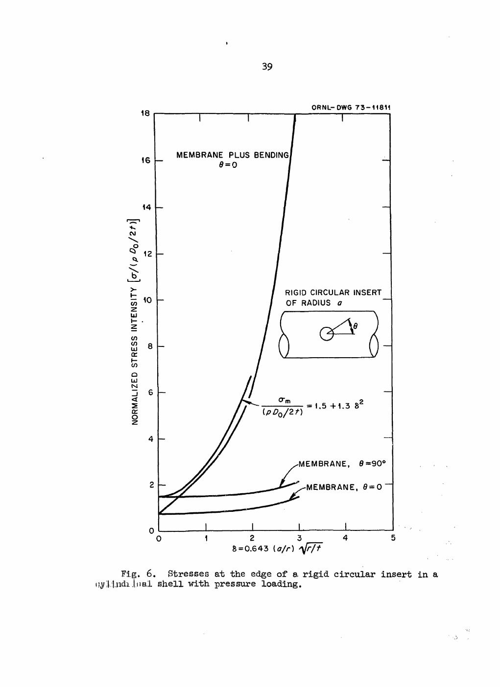
INTERNAL PRESSURE
Internal pressure acting in a pipe with an integral attachment will produce local stresses in the pipe because of the resistance to expansion of the lug. A rough estimate of these stresses can be obtained from the data gi\ 1 by Van Dyke10 for a rigid circular insert in a cylindrical shell with internal pressure loading. The stresses are a function of the parameter 5, defined as:
• V ^ l - V ) , (16) 8rt

38
where a = radius of rigid circular insert, v = Poissonfs ratio, r = cylindrical shell radius, t = cylindrical shell wall thickness.
For Poisson* s ratio of 0.3/ 5 = 0.643(a/r) Membrane stresses at Q = 0 and 90° are plotted in Fig. 6. Membrane
stresses at other values of 0 lie between those shown. It may be noted that for small values of 6 the membrane stresses are the same as those for a rigid insert in a flat plate with a 2-to-l tensile stress field.
Except for values of 5 less than about O.k, the maximum surface stress (membrane plus bending) occurs at 0 =0. This stress is also shown in Fig. 6. The maximum surface stress for values of 5 up to 2.0 is reason-ably well represented by the equation:
P 7 2 t " ^ + ^ = 1.5 + 0.537(a/r)2 (r/t) , (l7)
which is also shown in Fig. 6. Application of the Van Dyke analysis for a rigid circular insert to
lugs requires some engineering judgment as to what is to be used as the equivalent of (a/r) for lugs with dimensions and For lugs with Pi = P2J "would appear appropriate to let Pi = P2 = (a/r) in Eq. (17)5 however, for / p2, an appropriate value for (a/r) is not obvious. Unfortunately, neither a directly applicable analysis nor relevant test data are available. Either the analysis or the test data should be de-veloped. In the meantime, it is considered adequately conservative to let (a/r) in Eq. (17) be equal to (p^) 1/ 2.
With the limitation of <£ 0.075 and D /t 100 (recommended in Section 2, Thrust and Moment Loads), the largest value of 6 will be 0.643 x 0.075 x,/50 = 1.245 and the maximum stress, as determined by Eq. (17), is 3.5l6pDQ/2t.
The stresses defined by Eq. (17) damp out within a short distance from the insert and also decrease rapidly as Q varies from 90 "to 0°. Thus even if the maximum values exceed the yield strength of the material,
I
39
O R N L - D W G 7 3 - 1 1 8 1 1
S = 0 . 6 4 3 ( a / r ) tfjt
Fig. 6. Stresses at the edge of a rigid circular insert in a i]y;|,i,ndi.j,Mal shell with pressure loading.

bo
the maximum strains will he limited "by the surrounding elastic material. For this reason, it seems appropriate to consider the stresses defined "by E(l. (17) a-s peak stresses.
At the toe of the fillet weld, the maximum stress may he intensified if the weld is not ground smooth. Therefore, different values will be assigned for the stress index Kgp (local stress at the lug due to inter-nal pressure), depending upon whether the fillet weld is ground smooth or not, in the same manner as is done for Kg for moment loadings. The peak-stress term to be included in S^ for internal pressure is therefore
pD ffP = % 2 r •
For as-welded fillet welds the index K„ is thus ip
K£p = Kg(1.5 + 1.352)
= 2 .0 (1 .5 + 0.537(3^27) ,
where the value of Kg =2.0 is taken from the previous section and the remainder is taken from Eq.. (17). Similarly for ground fillet welds
K i p = 1 .3 (1 .5 + 0 . 5 3 7 3 i ^ ) >
where Kg =1.3 is the value assigned in the previous section for ground welds.
So far as gross plastic yielding is concerned, the presence of a lug attachment will not adversely affect the behavior of the component; hence, a primary-stress index for lugs is taken as zero. Recall that B-type indices are used in Eq. (C9) for primary-stress evaluation; B^-type in-dices are used to define the added term (PT + F, ), discussed in Section L b lug 6. Similarly, additional primary-plus-secondary stresses due to inter-nal pressure will be negligible; thus an appropriate value for C. is & p also zero.

hi
5. THERMAL GRADIENTS
If the temperature of the lug is different from that of the pipe, the difference in thermal expansions will induce stresses in the pipe wall around the lug. Since these local stresses will damp out within a short distance from the lug, they can be classified as peak stresses and repre-sented by K-type indices to be used in defining the term (S ) . Ther-p lug mal stress contributions to the terms (PT + P, )_ . and (S )., will be v L b'lug x n'lug taken as zero, as was done in the previous section for local-pressure stresses.
In general, the temperature gradients in the vicinity of the lug, will form a rather complex pattern. However, in keeping with current Code practice, it will be assumed that each part is at some average tempera-ture and the thermal stresses will be estimated accordingly. The average temperature of the portion of the lug within 2t of the surface of the pipe is defined as Tg, and the average temperature of the pipe under the lug and within a distance of /rt from the edge of the lug is defined as An approximate estimate of the maximum thermal stresses can be obtained by assuming that the lug is an elliptical insert at temperature T^ in an infinite flat plate at temperature T and that the lug and weld metal have the same modulus of elasticity E and coefficient of thermal expansion a as the pipe. Lugs that are long compared with their width will be cov-ered by assuming that the major axis of the elliptical area is, large com-pared with the minor axis. For this case Goodier11'12 gives the magnitude of the maximum thermal stress as
crT « Ea|Tg - T j . (.18)
The thermal stresses may also be intensified at the toe of the fillet weld for the same reasons given earlier for thrust and/or moment loads and internal pressure. It is therefore recommended that the same values be used for the peak thermal stress index K ^ as were recommended for the other loadings (i.e., K ^ = Kg = 2.0 for as-welded fillet welds, and Kgrj, = Kg = 1.3 for ground fillet welds). The additament (s
p)lug will thus

incorporate the thermal-stress term
(19)
6. CODE USE OF STRESS INDICES
The Code gives stress indices for a number of piping components in Table NB-3683.2-1. Since this table and its footnotes are already quite lengthy and involved and since the evaluation of stresses at lugs in-volves an almost independent set of loadings, it is deemed appropriate to add a new paragraph, NB-3683.3, Indices for Integral Structural Attach-ments. The proposed wording for this ne-w paragraph is included herein as Appendix A. The general intent is to "add on" appropriate terms iden-tified earlier as (PL + !b)lugj (sn)iug> ^ ^ (s
p)lug "to Code equations (C9), (CIO), and (Cll) respectively. In addition, the thermal-stress
• W a b l V a - V b l i n E * - (C11>' C3EaJaaTa - V b l i n * * (C13> will be dropped because the stress indices for lugs developed herein are not intended to apply if the lug is at a "gross discontinuity."
One other departure from current Code practice is also made by estab-lishing criteria for evaluating the adequacy of the lug-pipe interface. This is accomplished by using the lower limit of 1.0 on CT, CL, and Cc introduced in Section 2 and the alternate equations for stresses in the lug-pipe interface introduced in Section 3 for shear and torsional moment loads. Since failure of the interface alone does not constitute failure of the pressure boundary, an aspect is introduced which is not specifi-cally covered in NB-3600, analysis of a zone which is not a pressure boundary but which is within the jurisdiction of NB-3600. Including these special limits for the lug-pipe interface in the manner described below effectively sets the stress limits for the interface just as if it were part of the pressure boundary, including addition of the stresses due to internal pressure, moment loads, and thermal gradient with those due to loads applied to the lug.
terms at a structural discontinuity C

4 3
Satisfaction of Primary-Stress-Intensity Limit
Primary-stress intensities in Class I piping systems are limited to 1.5S by Eq. (C9) (lflB-3652). For points in the vicinity of integral lug attachments, modification of this equation is proposed by adding the term (PL + P^^ugj which includes additional primary local membrane-stress in-tensities P^ and additional primary bending-stress intensities P^ caused by the presence of the lug. Thus
PD D 2 T + 21 Mi + <PL + V l u g * l-5Bm , (20)
where the indices Bi and B2 are those currently given in Table NB-3683.2-I, and the definition of (P^ + P^) in terms of appropriate B^ indices is the subject of this section. It should be noted that the magnitude of the moment vector M^, as determined by an analysis of the piping system, would not be the same on the two sides of the lug, but in most eases the difference would be small. However, for cases where the difference is significant, the intent is to use the absolute mean value of the two. A footnote in the Code will be needed to cover this point.
Equation (C9) is now included as part of Paragraph NB-3652, "Con-sideration of Design Conditions." In USAS B31.7 (Ref. 13), the same equa-tion was included in Paragraph I-705.I, "Satisfaction of Primary Stress Intensity." The change in design concept implied by this change in the title of the heading is not trivial. If the force loads on lugs are not specified as design conditions in the Design Specification, these loads would not be included in the evaluation of Eq. (C9). If Eq. (C9) is to continue to be a valid check of primary-stress intensity, the design specification writer must be careful to include all sustained mechanical loads as design conditions. The present definition of Mi given in NB-3652.2,
"IvL = Resultant moment loading due to loads caused by (l) weight, (2) earthquake, considering only one-half the range of the earthquake and excluding the effects of anchor displacement due to earthquake, and (3) other sustained design mechanic cal loads ...,"

kh
is inadequate in this respect. It is recommended that the definition he changed to read as follows:
"M^ = Magnitude of the resultant moment due to loads caused by (l) weight, (2) earthquake, considering only one-half the range of the earthquake and excluding the effects of anchor displacement due to an earthquake, and (3) all other sustained mechanical loads ... ."
It appears appropriate to assume that most force loads such as weight or earthquake inertial forces on lugs will he "sustained" forces. The intent of Eq. (C9) is to limit the stresses resulting from such forces so that gross plastic deformations do not occur. A lower hound to this limit . can he obtained by simply limiting the calculated elastic-membrane-stress intensity to the yield strength of the pipe material S ., or 1.5sm> since S^ is essentially limited to 2/3S^.* For the six external loadings on lugs, this lower bound will actually be quite conservative, since in ap-plication the loadings causing the maximum stresses will be thrust W and longitudinal and circumferential bending moments M^ and Mc respectively. These loadings produce mainly bending stresses, and for collapse to occur from bending stresses plastic hinges must be formed. A limit-load analy-sis could be used to establish a less-conservative lower bound. However, at present, no such analysis is available, and after formulating the anal-ysis method a rather extensive parameter study would be required to estab-lish appropriate B indices.
Tables 6 to 8 of Section 2 show that the maximum membrane stresses caused by the loadings W, M^, and M^ are always substantially less than 2/3 the maximum surface stresses (membrane-plus-bending stresses repre-sented by the stress indices C^, CL, and Cc s 1.0). Limiting these stresses to 1.5S (where S is the yield stress) thus automatically limits y y the maximum membrane stress intensities to less than S , or 1.5S . Since y m the limit on Eq. (20) is I.5S [the same as Eq. (C9)], an appropriate set
*For some austenitic steels and nonferritic materials, the value of Sm may be up to 0.9 of the nominal yield strength. However, the strain-hardening properties of these materials are generally assumed to be such that the value of Sm is not greater than 2/3 the effective yield strength.

45
of B^ indices for use in the term (PL + P-j^^g i s simply
bt = (2/3)cT ;> 2/3 ,
Bl = (2/3)Cl s 2/3 ,
Bc = (2/3)Cc ;> 2/3 .
Membrane shear stresses -were derived in Section 3 for the transverse shear loads Q,1 and Qg and the torsional moment load M^. Since the mem-brane stress intensity from these loads is twice the maximum shear stress, S^ (or 1.5sm) is an appropriate primary stress limit. Thus 2.0 times the right-hand side of Eqs. (13) and (l4) and twice the greater of Eqs. (12) and (15) can be used directly in defining (PL + Pt^lug'
The quantity (PL + ^ g to be added to the left side of Eq. (C9), including all six external loadings, is therefore
W NL (PT + P, ). = Bm 7- + Bt t?— L b7 lug T A^ L
M c Q 2
where, in order to cover the lug-pipe interface as well as the pipe wall, La is taken as the smaller of L2 and t, is the smaller of Lx and t, and M^ is the greater of
% " L c L d [ l + ( L c / L a ) j t '
and
2Mt M = . ^ [1.57 + 0.093(Ld/Lc)]Lc2Ld
where Lc = min (L-^Lg) and Ld = max (L^I^). In Eq. (2l), the loading terms W, ML, Mc, Qg, and M,p represent the absolute value of the sus-tained loading amplitudes and not the loading ranges.

k6
Satisfaction of Primary-Plus-Secondary Stress-Intensity Range
Primary-plus-secondary stress intensities in Class I piping systems are limited to S^ 3S> "by Eq. (C10)(NB-3653.l). As discussed earlier, we propose to modify this equation "by dropping the term C3E I a a Ta ~~ Q T I and adding the term (s
n)lugj hus
P D D 1 S = Q. + C0 ~ M. + ttj-z r Ealz r, | + (S )_ < 3S . (22) n 1 2t 2 21 x 2(1— v) 1 11 v n'lug J m v '
The stress indices C^, C^, and C^ discussed in Section 2 for thrust W and moment loadings M^ and M^ and twice the shear stresses T2, and T3 discussed in Section 3 are directly applicable in defining (S^)^^. However, even though T1, T2, and R3 are the same as used in defining (P^ + ahove, the resulting stresses will not necessarily be the same because Eq. (C9) is in terms of sustained loading amplitudes where-as Eq. (CIO) is in terms of loading ranges. Additional internal-pressure stresses and thermal-gradient stresses due to the presence of the lug were classified as peak stresses in Sections 4 and 5, and thus does not contain either a pressure term or a temperature term. Thus, for evaluating the stresses in a piping system at an integral lug, the quan-tity (S )_ to be added to S is
• n' lug n W* M? M*
^ = H + + ( 2 3 )
where W*, M^, Q*, and are the ranges of the loads and M^ is calcu-lated using the range of M^.
Satisfaction of Peak-Stress-Intensity Range
Peak stress intensities in Class I piping systems are evaluated by Eq. (Cll) given in NB-3653.2. For the integral-lug problem this equation is to be modified by dropping the term K^CgE^ | aaTa - a^T^ | and adding

1»T
(Vlug :
P D D SP = - § r + 2f Mi
+ ^ l ^ i ! + x r ^ i + ( y l u g , m
where the additament (S ) will define the additional peak stresses p'lug * caused "by the presence of the lug for internal pressure in the pipe; thrust, shear, and/or moment loads on the lug; and a temperature gradient "between the pipe and the lug.
The peak stress due to internal pressure was given in Section 4 as p pD0/2t> w i t h Kip = + ° - 5 3 7P i H o w e v e r , since Eq. (Cll) al-
ready has the internal pressure term K1C1(PQDo/2t), which is retained in Eq. (24), and since K^ = C-l = 1.0 for straight pipe remote from gross dis-continuities, the internal pressure term for J^^g "becomes
[(K£ - i)(l.5 + 0 . 5 3 7 ^ 7 ) ! ^ ^ .
Peak stresses due to thrust and moment loads on the lug are treated in the same manner as for the primary-plus-secondary stresses except that each of the indices C , C^, and Cc is to be multiplied by the index Kg. The thermal-stress term was defined by Eq. (19) in Section 5 as KgEa|Tg — T | , and the local-peak-stress index Kg was defined in Section 2 under the discussion on local stresses as 2.0 for as-welded fillet welds or 1.3 for ground fillet welds.
The quantity (sp)lug is thus defined as the sum of the individual
loading terms:
P D o o ( V l u g = C(K0 ~1)(1-5 + 0-537PiP27)]
W* M* Mj Q* ^
° T + ° L ^ + ° c ^ + ^ + ^ + ^
+ K^Ea|T^ - T j . (25)

48
Simplified Elastic-Plastic Discontinuity Analysis
If the piping system component fails to meet the 3sm limit of Eq..
(CIO) [corresponding to Eq. (22) in the present context] for all pairs of load sets, the Code provides an alternate procedure for qualification under KB-3653.6 provided that the nominal value of the expansion stress intensity S defined by Eq. (C12) is less than 3S and that the range of 6 in stress intensity defined by Eq. (C13) is also less than 33^. The proce-dure is to increase the alternating stress intensity S for fatigue evaluation by the factor Kg s 1.0 prescribed by the Code under Eq. (Cl4).
Equation (C12) establishes a limit on thermal-expansion and anchor-movement stresses -with the intent of limiting the stress range to about the same magnitude as permitted in predecessor piping codes [e.g., ANSI B31.1.0].14 Since these predecessor codes do not limit expansion stresses for pipe with lug attachments to a lower value than for pipe without lug attachments, there is no reason to change Eq. (C12) for a pipe with a lug. Equation (C13) is intended to limit the possibility of ratchetting when S^ exceeds 3sm« The relatively conservative values recommended for the B indices should give more than adequate protection against such a possi-bility. Accordingly, no addition to Eq. (C13) is considered necessary for lugs.
Equation (Cl4) does not require any changes, although, obviously, the numerical results will be influenced by the additional terms included in the evaluation of S [Eqs. (24) and (25)]. For the analysis of lug at-P tachments, however, it seems advisable to impose an additional constraint on the use of Eqs. (Cl4), etc., when the component fails to meet the 3Sm limit of Eq. (22). This is because loadings on the lugs caused by expan-sion of the piping system may add to the primary weight loads to give a total loading which is greater than the capacity of the lug for a single load application. For other piping components the stresses corresponding to the "constraint of free-end displacement" loads are categorized as S^ stresses, which under the rules of NB-3653.6 have a very high absolute upper limit for small numbers of cycles. For example, the S^ limit for type 304 stainless steel can be as high as 400,000 psi. While the fatigue

b9
limitation "based on the peak stresses S would probably prevent the major-F
ity of such conditions frcci occurring in practice, it is considered de-sirable to impose the additional limit for lugs:
W** M?* M** Q** Q** ^ J S g = °T A ^ + CL ^ + 4 + ^ + ^ + * ^ ' ( 2 6 >
where the loads W**, M^*, ..., M^* are defined as the maximum loads from any source.
7. SUMMARY AND CONCLUSIONS
A simplified design analysis procedure using stress indices has been developed for analyzing points in a Class I piping system where an inte-gral lug attachment is welded to straight pipe. The procedure follows the general method outlined in Subsubarticle NB-3650 of the Code and is recommended for addition to the Code in a new paragraph, NB-3683.3, In-dices for Integral Structural Attachments. The proposed wording for this paragraph is given as Appendix A. New terms (additaments) for addition to the Code equations when considering integral structural attachments have been developed. These additaments, defined herein as (P^ + Pt> lug' ^Sn^lug' ^ ^ (Sp^lug' a r e exPressed- "terms of internal pressure in the pipe, applied mechanical loads on the lug, the average temperatures of the lug and the pipe, and appropriate stress indices.
The stress indices developed in this report for the various loadings are based on available analytical solutions, some of which are more accu-rate than others. In each case, however, the results are believed to be conservative within the parameter ranges defined by the limits placed on the stress-index equations. For the cases of thrust and/or bending mo-ments applied to the lugs, rather extensive comparisons between the stress-index analysis method developed here and two existing and widely used design analysis methods were made. These are the PW-43 method3 and the WRC-107 method.4
A three-way comparison for thrust and moment loads among the stress-index analysis method, the WRC-107 method, aid Ref. 2 calculations using

5 0
Bijlaard1s theoretical analysis indicates that the stress-index method is always conservative. The WRC-107 method tends to "be conservative for loaded areas that are square and gives about the same results as the stress-index method. For loaded areas that are not square, the WRC-107 method is generally conservative for thrust loadings but less conserva-tive than the stress-index method. For moment loadings, however, the WRC-107 method tends to break down as the length-to-width (or width-to-length) ratio increases and apparently should not be used when this ratio exceeds 4 (or is less than l/k).
Comparisons made between the stress-index method and the PW-1+3 method, which limits the permissible thrust and longitudinal moment loads rather than the maximum stresses, indicate that the PW-1+3 method would result in higher stresses for thrust loads and lower stresses for longitudinal mo-ment loads. For typical design conditions, indications are that the two methods would give comparable values for the permissible loads. The PW-1+3 method does not consider circumferential moment loads.
The indices presented here for transverse shear and torsional moment loadings on the lug and for a temperature difference between the lug and the pipe are based on approximate analytical models which perhaps could be improved with further study. The indices, however, are believed to be conservative and adequate for piping-system design; and unless user ex-perience indicates the need for more rigorous analyses, no further study is planned.
The indices developed for internal pressure loading are based 011 an analysis of a cylindrical shell with a solid circular insert. For lugs that are square or rectangular, approximations are introduced which should give conservative results; however, further study is needed to verify this point.
Finally, it should be pointed out that the stress-index-analysis method presented here for lugs is both simple to use and at least as accu-rate as any other known method. For those loadings where the accuracy can be questioned, the conservative practice of adding maximum stress in-tensities, even though these maximums may not occur at the same point or be oriented in the same direction, should provide adequate protection to the design.

51
ACKNOWLEDGMENTS
The authors wish to thank the members of Task Group I of the Pres-sure Vessel Research Committee, Subcommittee for Piping, Pumps, and Valves, and the members of the ASME Boiler and Pressure Vessel Code Com' mittee, Subgroup on Piping (SGD)(SC III), for their review and valuable suggestions.
REFERENCES
1. ASME Boiler and Pressure Vessel Code, Section III, Nuclear Power Plant Components, American Society of Mechanical Engineers, New York, 1971,
2. W. G. Dodge, Secondary Stress Indices for Integral Structural Attach-ments to Straight Pipe, ORNL-TM-3476 (June 1973).
3. ASME Boiler and Pressure Vessel Code, Section I, Power Boilers, Ameri-can Society of Mechanical Engineers, New York, 1970.
4. K. R. Wichman, A. D. Hopper, and J. L. Mershon, Local Stresses in Spherical and Cylindrical Shells Due to External Loadings, Welding Research Council Bulletin No. 107, August I965.
5. R. F. Melworm and I. Berman, "Welded Attachments to Tubes - Experi-mentation, Analysis, and Design," Welding J. Res. Suppl. 45(10), 454-64 (1966).
6. P. P. Bijlaard, "Stresses from Local Loadings in Cylindrical Pressure Vessels," Trans. ASME 7£(6), 805-16 (1955).
7. P. P. Bijlaard, "Stresses from Radial Loads and External Moments in Cylindrical Pressure Vessels," Welding J. Res. Suppl. 34(12), 608-17 (1955).
8. E. C. Rodabaugh, W. G. Dodge, and S. E. Moore, Stress Indices for Girth-Welded Joints, Including the Effects of Radial Weld Shrinkage, Mismatch, and Tapered-Wall Transitions, 0RNL-TM-3643 (to be published).
9. S. Timoshenko and J. N. Goodier, Theory of Elasticity, 2d Ed., pp. 275-78, McGraw-Hill, New York, 1951.
10. Peter Van Dyke, "Stresses in a Cylindrical Shell with a Rigid In-clusion," AIAA J. £(l), 125-37 (January 1967).
11. J. N. Goodier, "Thermal Stresses and Deformation," J. Appl. Mech. 24, 467-74 (September 1957).

52
12. R. J. Roark (Ed.), Formulas for Stress and Strain, Uth Ed., p. 375, McGraw-Hill, New York, 1967.
13. USA Standard Code for Pressure Piping, Nuclear Power Piping, USAS B31.7-1969, American Society of Mechanical Engineers, New York, 1969.
lb. Power Piping, USAS B31.1.0, Sect. 1 of the American Standard Code for Pressure Piping, American Society of Mechanical Engineers, New York, 1967.

53
Appendix A
RECOMMENDED ADDITION TO ASME CODE SECTION III TO COVER STRAIGHT PIPE WITH INTEGRAL
STRUCTURAL ATTACHMENTS
The recommended addition to the ASME Boiler Code, Section III, con-sists of a new paragraph, NB-3683.3, to read as follows:
NB-3683.3 STRESS INDICES FOR INTEGRAL STRUCTURAL ATTACHMENTS
(a) Limitations to Applicability of Indices
(1) The attachment is welded tc the pipe with a complete-penetration weld.
(2) The attachment material, weld material, and pipe material have essentially the same moduli of elasticity and coefficients of thermal expansion.
(3) Pi 0.5, P2 < 0.5, and the product x p2 £ 0.075, where and p2 are defined in (c).
(4) The attachment is made on straight pipe, with the nearest edge of the attachment weld located at a minimum distance of rt from any other weld or other discontinuity; r and t are defined in (c).
(5) D /t £ 100.
(b) Equations To Be Satisfied
For points on a piping system with integral structural attachments, the term C3E
al3laaTa ~ O ^ l shall he deleted f*om Eqs. (lo), (ll), and
(13). Equations (9), (10), and (ll) shall use the B, C, and K indices given in Table NB-3683.2-I for "straight pipe, remote from welds or other discontinuities" and shall include the following additional terms [see also Footnote (l)]. Symbols are defined in (c).
1The value of Mi, under equilibrium conditions, is not identical on the two sides of the attachment when ML or MQ is applied to the lug. Usually the change in Mi will be negligible; if it is significant, how-ever, the mean value is to be used in Eqs. (9) to (ll).

5 4
Equation (9), add to left-hand side:
( P L + h h • V ' S + W z i L + B c M c / z i c + « i / 2 L i L a + V 2 ^ + Hr •
Equation (10), add to S^:
Bn$ " CTW*/Ai + + + ^ / 2 L i La + + •
Equation (ll), add to S^:
P D
V = " 1 ) ( 1' 5 + °'537PI627)] + Kg[S^] + K^EalT^ - T J .
The following equation must also he satisfied: s - = ctw-/a , + + c y i g v z i c
+ Q?*/2LiLa + Q S V S L ^ + ^ <S 3 sm .
The value of S shall he the lesser of that for the pipe material or m of that for the lug material. (c) Definitions (see also Fig. UB-3683.3; Fig. A.l herein)
r = mean pipe radius (in.) t = nominal pipe-wall thickness (in.) 7 = r/t Pi = Lx/r (32 = L2/r Lx and L2 are defined in Fig. NB-3683.3 L = lesser of L0 and t a 2
L^ = lesser of and t L = lesser of L-, and L0
L^ = greater of Lj and L2
C T = T ^ / ) 1 - 6 4 ? ! ^ 1 , 5 4 2: 1.0 CL = 0.51 (7)1,T4P:lP22T)4'74 ^ 1-0 Cc = O.76(7)1-90P1%T13-40 ;> 1.0 rj = -(X^ cos 6 + Yx sin 0) - jj- {X1 sin 9 - Y1 cos 0)2
o

55
ORNL-DWG 73-5839
\ ^
(a) Graphic representation of Li, W, Mj^ Q^, Qg, and Mip; L^ and L2 are to "be measured aloig the surface of the run pipe. Welds or fillet radii "between attachment and pipe are not to he included.
ORNL-DWG 7 3 - 6 6 2 9
(b) Ground weld or integrally cast attachment; Kg = 1.3. For as-welded or fillet radii r„ t, use Kg =2.0.
Fig. A. 1. Proposed additional Code illustration entitled "Figure NB-3683.3: Nomenclature Illustration."

56
X-L = X0 + logio Pi Y-l = Y0 + logio P2
Load A0 6 xo Yo Thrust 2.2 bo° 0 0.05 Longitudinal moment 2.0 50° -0.45 -0.55 Circumferential moment 1.8 ho° -0.75 -O.oO
Bt = (2/3)Ct, Bl = (2/3)Cl, Bc = (2/3)Cc kg = UL^s (in.2) Z ^ = UL^ 2/^ (in.3) ZZC = ^lI2l2/3 (in.3) Kg = 2.0 for "as-wel^ed" fillet welds Kg = 1.3 for "ground" fillet welds per Fig. NB-3683.3 W, M^, M^, Q-l, Qg, and M^ are absolute values of the sustained load amplitudes as shown in Fig. UB-3683.3. These are loads caused "by (l) weight, (2) earthquake, considering only one-half the range of the earthquake and excluding the effects of anchor displace-ment due to earthquake, and (3) all other sustained mechanical loads. Units: W, Q-l, and Q^: lb; M^ M^, and M^: in.-lb
W*, Q*, Q*, and M^ are ranges of loadings due to (l) ther-mal expansion, (2) anchor movements from any cause, (3) earth-quake effects, and (4) all other mechanical loads which go through a range of magnitude
W**, M£*, Mg"*, Q*"*, Q**, and M*"* are absolute values of maximum loads from any cause
gj, = greater of M ^ L ^ l + (l/l^]} and [0.8 + 0.05(Ld/Lc)]Lc2Ld
M^ = same as M^, except use the loading range M^ Tg = average temperature of that portion of the lug within a dis-
tance of 2t from the surface of the pipe (°F) T^ = average temperature of the portion of the pipe under the lug
and within a distance of v rt from the edge of the lug (°F)

57
Ba = modulus of elasticity (E) times the mean coefficient of ther-mal expansion (a), "both at room temperature (psi/°F)
Pq = range of operating pressure (psi) D = outside diameter of pipe (in.)

58
Appendix B
DIRECTIONS AND LOCATIONS OF MAXIMUM STRESSES FOR THRUST AND MOMENT LOADINGS
The stress indices developed in Section 2 for thrust and bending mo-ment loads W, M^, and M c were based on the maximum surface stresses (mem-brane plus bending) calculated for the region of the pipe near the pipe-lug interface. Figure B.l shows the region of the pipe-lug intersection and the points at which stresses were calculated. Positions (l) and (2) on the edges of the lug are the locations at which the maximum stress occurred most often. Stresses were calculated using the computer program LUGS (Ref. 2) at each point in the rectangular array, starting at the center of the lug and extending a distance along the pipe of X - X/L-l = 2 or 3 and a distance around the pipe of 0 = J2f/p± = 2 or 3, depending on the width and length parameters p1 and (32 of the particular lug as shown below:
For < 0.05; 0 £ 3.0; A0 = 0.25 For ;> 0.1; 0 < 0 < 2.0; A0 = 0.1667 For p 2 £ 0.1; 0 ^ X 3.0; AX = 0.25 For P 2 ^ 0.2; 0 < X ^ 2.0; AX = 0.1667
Stresses inside the loaded area (underneath the lug) were calculated but not used in establishing the stress indices. Because of symmetry, the stresses were evaluated for only one quadrant.
ORNL-DWG 7 3 - 5 8 3 8
Fig. B.l. Region of the pipe-lug intersection used in calculating stresses.

59
The maximum stresses reported here are the result of a rather exten-sive parameter study for lug-pipe intersection dimensions within the pa-rameter range 0.05 ^ Pi ^ 0.5; 0.05 £ ^ 0.5; and 7 = r/t = 5, 10, 20, 4-0, and 80. The locations and directions of the maximum surface stresses (membrane plus "bending) for the three loadings W, M^, and M^ are tabulated as functions of and in Tables B.l to B.5 for 7 values of 5, 10, 20, Uo, and 80 respectively. The direction is indicated as either "C" or "L" for circumferential or longitudinal under the columns labeled D. The co-ordinates of the maximum stress location are indicated by the pair of numbers under the columns "X" and "0," except when the maximum occurred at positions (l) and (2) shown in Fig. B.l, in which case a (l) or (2)
t
appears under the column labeled "X." In all but the five cases marked, the maximum stress was a compressive stress on the outside surface; and for all but three cases, the maximum 'surface stress was the maximum stress intensity.
Tables B.6 to B.10 give the directions and locations of the maximum membrane stresses for 7 = r/t = 5> 10, 20, 40, and 80, respectively, using the same format as used for the surface stresses. For moment loadings M^ and M ,, there were a number of cases where the maximum membrane stress was apparently located outside the area used in the calculations. These are indicated by ,,3+" in the appropriate columns.

60
Table B.10. Direction and location of maximum m e m b r a n e stresses for pipe radius-
to-thickness ratio of 80
P i Pj D
W
X"
«L e D' a Xv 9 D a
M,
X"
^Direction of the maximum surface stress: C indicates circum-ferential and L indicates longitudinal.
DA (1) or (2) under this column indicates that the location of
the maximum stress corresponds to the positions shown in Fig. B.l. Inside surface, positive sign.
9

61
Table B.10. Direction and location of maximum m e m b r a n e stresses for pipe radius-
to-thickness ratio of 80
W " L M,
Pi D X 9 De 9 D 0
0.05
0.10
0.2
0.3
0 . 4
0 .5
0.05 0.10 0.20 0.30 o.ko 0.50 0.05 0.10 0.20 0.30 o.Uo
0.05 0.10 0.20 0.30
0.05 0.10 0.20
0.05 0.10 0.05
(2)
(1) (1) (2)
(1)
L L C
( 1 ) 1.25
L L L C C
L L L C
0.83 1.00
(1)
1.25 0 (1)
0.17
(2)
1.00 (2) (2) (2)
1.00 (2) (2)
1.00 1.00
1.00
1.75
0.83
0.83
0.67 0.83
0.83 a Direction of the maximum surface stress: C indicates circum-
ferential and L indicates longitudinal. A (l) or (2) under this column indicates that the location of
the maximum stress corresponds to the positions shown in Fig. B.l.

62
Table B.10. Direction and location of maximum membrane stresses for pipe radius-to-thickness ratio of 80
Pi w "x,
0 0
M,
X"
Direction of the maximum surface stress: C indicates circum-ferential and L indicates longitudinal.
A (l) or (2) under this column indicates that the location of the maximum stress corresponds to the positions shown in Pig. B.l.
6

63
Table B.10. Direction and location of maximum membrane stresses for pipe radius-to-thickness ratio of 80
W *L MC trnmmmtfimmtmmmmm^m^-^mmmtmmmmmm*'*'^ m*+*mmmmmmmmrnmm»**mmmmmmmmmmmmmmimim»mim0**** « H W M I * i m m m m m h m m m m m h h m n m i m ^
Da Xb 0 Da Q D a Xb 0
0.05 0 . 0 5 C (1) L (1) c 0 1 . 2 5 0 . 1 0 (2 ) L (1) (2) 0 . 2 0 C (1) 0 1.25 0 . 3 0 C 0.83 1 . 0 0 0 1.7! 0.U0 C 0 . 6 7 1 .00 0 1.25 0 . 5 0 C 0 . 8 3 1 ,00 0 1.25
0.10 0.05 L (1) (2 ) 0,10 (1) L (2) 0.20 (1) C (2) 0.30 (2) C 0 1.17 o.Uo (2) C (2)
1.17
0.2 0.05 CD L 1.00 0.67 0.10 L (2) 0.20 C (2) 0.30 C 1 • (2)
0,3 0.05 h 1.00 0 . 3 3 1.00 0*67 0.10 L (1) 1.00 0.83 0.20 C CD (2)
0.83
0.05 L 1 . 0 0 0 . 5 0 1,00 O.67 0.10 c 1 .00 0 . 1 7 1.00 0.67
0.5 0.05 1 l> 1 . 0 0 0 . 0 5 1,00 0.83 direction of the maximum surface stress; C indicates circum-
ferential and L Indicates longitudinal. J,. A (l) or (2) under this column indicates that the location of
the maximum stress corresponds to the positions shown in Fig. B.l. Maximum stress intensity occurs on inside surface, $T » 169.4,
$ c « -20,69.

64
Table B.5. Direction and location of maximum surface stresses for pipe radius-
to-thickness ratio of 80
D
W
e
" L
&
M,
0.05
0.10
0.2
0.3
0.4
0.5
0.05 0.10 0.20 0.30 0.40 0.50
0.05 0.10 0.20 0.30 0.40
0.05 0.10 0.20 0.30
0.05 0.10 0.20
0.05 0*10
0.05
(1) (2)
(1) L L C C C
L L C C
L c C
C d
1.00 0.33 <T
L C
(1)
0.6? 0.67
(1)
1.00 (1) (1) (1)
1.00 1.00
0.33
1.00 0.50 (1) 1.00 0.50 3* 0 (1)
3* 0
0 (2) 0.17 0 0 0
(2)
1.00 (2) (2) (2)
1.00 1.00 (2)
1.00
1.25 1.50 1.75 1.75 1.75
1.17
0.67
0.67 0.67
0.67 I
i direction of the maximum surface stress: C indicates circum-
ferential and L indicates longitudinal. bA (1) or (2) under this column indicates that the location of
the maximum stress corresponds to the positions shown in Fig. B.l, cMaximura stress intensity occurs on inside surface, S^ a 265.1,
S » —81.46. stress intensity occurs on inside surface* ST ~ 194.4,
s c = -81.78. e0n inside surface.

65
Table B.10. Direction and location of maximum membrane stresses for pipe radius-
to-thickness ratio of 80
W *L MC
^ ^ D* X5 0 D* X5 0 D* X5 0
0.05 0.05 0.10 0.20 0.30 0.U0 0.50
(2)
0.10
0.2
0*3
0.1*
0.05 0.10 0,20 0.30 0.U0
0.05 0.10 0.20 0.30
0.05 0.10 0.20 0.05 0.10
(1) (2) (2) (2)
(1) (1) (2)
(1) (1)
0.5 0.05 (1)
3+ 0 3+ 0 1.17 0 (1) (1) (1)
3+ 0 3+ 0 1.17 0
(1)
3+ 0 3+ 0 1.17 0 (1)
3+ 0 3+ 0 1.33 0
3+ 0 3+ 0
3+ 0
3+
Direction of the minimum surface stress: C indicates circum-ferential and L indicates longitudinal.
A (l) or (2) under this column indicates that the location of the maximum stress corresponds to the positions shown in Fig. B.l.

66
Table B.10. Direction and location of maximum membrane stresses for pipe radius-
to-thickness ratio of 80
W llC
1 2 Da Xb 6 Da Xb 6 Da Xb e
0.05 0.05 C (2) C 3+ 0 0.10 C 1.5 0 0.20 C (1) 0.30 C (l) 0.40 c (1) 0.50 I (1)
0.10 0.05 c 3+ 0 0.10 1.5 0 0.20 (1) 0.30 (1) 0.40 (l)
0.2 0.05 (1) 3+ 0 0.10 (2) 1.67 0 0.20 (2) (1) 0.30 (1) (1)
0.3 0.05 (1) 3+ 0 0.10 (1) 1.67 0 0.20 (2) (1)
0.4 0.05 (1) 3+ 0 0.10 (1) 1.83 0
0.5 0.05 (1) 3+ 0
3+
(2) (2)
(2) a Direction of the maximum surface stress: C indicates circum-
ferential and L indicates longitudinal. A (l) or (2) under this column indicates that the location of
the maximum stress corresponds to the positions shown in Fig. B.l.
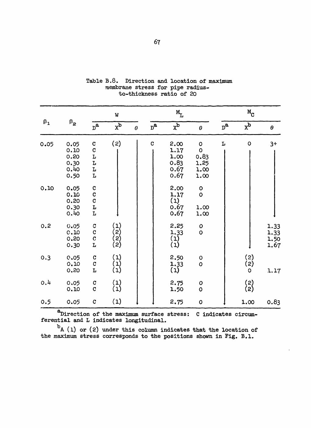
67
Table B.10. Direction and location of maximum membrane stresses for pipe radius-
to-thickness ratio of 80
W ^ M C
D a Xb 0 D a Xb 0 D a Xb 0
0.05 0.05 C (2) C 2.00 0 1 0 3+ 0.10 C 1.17 0 0.20 L 1.00 0.83 0.30 L 0.83 1.25 0.1+0 L 0.67 1.00 0.50 L 0.67 1.00
0.10 0.05 C 2.00 0 0.10 C 1.17 0 0.20 C (1) 0.30 L 0.67 1.00 0.1*0 L O.67 1.00
0.2 0.05 V (1) 2.25 0 1.33 0.10 c (2) 1.33 0 1.33 0.20 c (2) (1) 1.50 0.30 L (2) (1) * 1.67
0.3 0.05 C (1) 2.50 0 (2) 0.10 C (1) 1.33 0 (2) 0.20 L (1) (1) 0 1* 17
0.4 0.05 C (1) 2.75 0 w 0.10 C (1) 1.50 0 (2)
0.5 0.05 C (1) 2.75 0 1.00 O.83 direction of the maximum surface stress: C indicates circum-
ferential and L indicates longitudinal. A (l) or (2) under this column indicates that the location of
the maximum stress corresponds to the positions shown in Fig. B.l.

68
Table B.10. Direction and location of maximum membrane stresses for pipe radius-
to-thickness ratio of 80
W M C
D a G D a 9 D a X° 9
0.05 0.05 C 0.10 C 0.20 L 0.30 L 0.40 L 0.50 L
0.10 0.05 C 0.10 C 0.20 L 0.30 L 0.40 L
0.2 0.05 C 0.10 T.
0.20 L 0.30 L
0.3 0.05 C 0.10 L 0.20 L
0.4 0.05 C 0.10 L
0.5 0.05 C
(2)
(1)
1.50 (1)
0.67
0
1.00
3+
1.50 0 (1) (1)
0.67 1.00 0.67 1.00
1.50 0 1.17 0 (1) (1)
2.00 0 1.17 0 (1)
2.00 0 1.17 0
2.00 0
(2) (2) 0 0
(2) (2) (2)
1.00 (2)
1.00
1.67 1.83
2+ 2+ 2+
1.17 1.13
0.83
0.83 aDirection of the maximum surface stress: C indicates circum-
ferential and L indicates longitudinal. A (l) or (2) under this column indicates that the location of
the maximum stress corresponds to the positions shown in Fig. B.l.

69
Pi Pa
Table B.10. Direction and location of maximum membrane stresses for pipe radius-
to-thickness ratio of 80
w ^ MC
DA X*5 9 DA X13 9 DA XB 9
0.05
0.10
0.2
0.3
O.k
0.05 0.10 0.20 0.30 0.40 0.50
0.05 0.10 0.20 0.30 O.kO
0.05 0.10 0.20 0.30
0.05 0.10 0.20
0.05 0.10
(2)
(1) (1) (2) (2) (2)
(1)
C C C c L L C C n
1.25 (1)
0.67
1.25 (1) (1)
0.67 (1)
1.50 (1) (1) (1)
1.50 (1) (1)
3+ (1)
1.00
0
1.00
0
0
(2) (2) (2) 0
1.00 (2) (2)
1.00 1.00
2.25 2.50
1.33 1.33 1.67 2.00
2+
1.17
0.83
0.67 0.67
0.5 0.05 3+ 0 1.00 0.67
^Direction of the maximum surface stress: C indicates circum-ferential and L indicates longitudinal.
A (l) or (2) under this column indicates that the location of the maximum stress corresponds to the positions shown in Fig. B.l.

70
Appendix C
EXAMPLE ANALYSIS OF A LUG SUPPORT
Loads and Primary-Stress-Intens ity Limit
The determination of the loads applied to the lugs is not a subject of this report. However, the engineering judgment involved in deter-mining the loads can be as significant as the accuracy of the equations relating loads to stresses developed herein. This aspect can be illus-trated by analyzing a 2l|-in. sched-l6o vertical pipe (Dq = 2h in., t = 2.3^3 in.) supported by lugs as shown in Fig. C.l, with the size of the
ORNL- DWG 7 3 - 5 8 3 7
TOTAL LOAD = 1 3 , 5 5 0 lb ( 2 5 f t OF 2 4 - i n . SCHED-160 PIPE)
t = 2 . 3 4 3 in.
W = 5 4 2 l b / f t
Fig. C.l. Example of lugs used to support vertical pipe.

71
lug to be controlled by the modified primary-stress-intensity limit equa-tion given in Table 2 of the text:*
PD D Bi 2 T + 21 Mi + ( PL + V l u g * ^ m '
where, from. Eq. (21) of the text,
( PL + V l u g = Aj" + + Z ^ - + 2L^r + + "t ' < « )
We will assume that the primary stress intensity in the pipe without con-sidering the lug supports is 20,000 psi. Specifically, PD /2t is assumed o to be 20,000 psi, and the magnitude D M^/21 is assumed to be 10,000 psi.** The stress indices 'B1 = 0.5 and B 2 = 1.0 are the values given in Table NB-3683.2-1 of the Code for straight pipe remote from welds or other dis-c ont inuit i es. Thus,
PD D Bi 2 T + Bs 2§ Mi = 2 0> 0 0 0 P s i • (C.3)
It is also assumed that the four support-reaction forces Qg act at some offset distance X from the pipe surface as shown in Fig. C.l. The longi-tudinal moment M^ acting on the pipe is then
^ = QgX . (C.lj.)
Assume further that
1.5sm = 30,000 psi ,
W = M C = Q 1 = M T = 0 , (C.5)
Lx = L2/2 .
*Equations numbered C.l, C.2, etc., in this appendix are not to be confused with equations abstracted from the Code and given similar num-bers in the main text.
**It should be noted that M ± ufiied in Code Eqs. (9) and (13) is a magnitude of a moment vector, whereas M^ used in Code Eqs. (lO), (ll), and (12) is a range of a moment vector. These do not necessarily have the same numerical value.
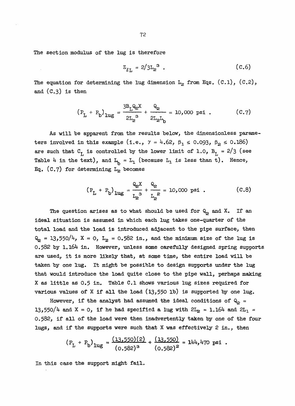
72
The section modulus of the lug is therefore
z i L = 2/3L/ . (C.6)
The equation for determining the lug dimension L 2 from Eqs. (C.l), (C.2), and (C.3) is then
3B QgX Q 2 (P + P, ).. = — + = 10,000 psi . (C.7)
L b 1 U g 2L2 2L2Lb
As will he apparent from the results below, the dimensionless parame-ters involved in this example (i.e., 7 = 4.62, fr^ <, 0.093, P 2 £ 0.186) are such that C^ is controlled by the lower limit of 1.0, B L = 2/3 (see Table 4 in the text), and (because is less than t). Hence, Eq. (C.7) for determining L 2 becomes
QsX Qg ( PL + V l u g = 7 7 + = 1 0> 0 0 0 p S i • <C'8>
2 l2
The question arises as to what should be used for Qg and X. If an ideal situation is assumed in which each lug takes one-quarter of the total load and the load is introduced adjacent to the pipe surface, then Qg = 13,550/4, X = 0, L 2 = 0.582 in., and the minimum size of the lug is 0.582 by 1.164 in. However, unless same carefully designed spring supports are used, it is more likely that, at some time, the entire load will be taken by one lug. It might be possible to design supports under the lug that would introduce the load quite close to the pipe wall, perhaps making X as little as 0.5 in. Table C.l shows various lug sizes required for various values of X if all the load (13,550 lb) is supported by one lug.
However, if the analyst had assumed the ideal conditions of Q,2 = 13,550/4 and X = 0, if he had specified a lug with 2L2 = 1.164 and 2LX = 0.582, if all of the load were then inadvertently taken by one of the four lugs, and if the supports were such that X was effectively 2 in., then
L b'tag ( 0 - 5 8 2 )3 (0.582)2
In this case the support might fail.

73
Table C.l. Minimum lug dimensions for support of the 24-in. sched-160 pipea
b c Stress Stress X L2 due to due to
(in.) (in.) bending shearing (psi) (psi)
0 1.16 0 10,000 2.32 1.16 0.107 0.054 0.5 1.36 2693 7,325 2.72 1.36 0.126 0.063 1.0 1.50 4oi4 6,022 3.00 1.50 0.139 O.O69 2.0 1.71 5419 4,633 3.42 1.71 0.158 0.079 4.0 2.01 6674 3,354 4.02 2.01 0.186 0.093
^otal load = 13,550 lb (25 ft at 542 lb/ft). ^Bending stress = QgX/Lg3. cShearing stress = L 2
2.
Lug size (in.) R ft P 2
pi 2L2 2L1
If the pipe used in the above example had been a 24-in. sched-Uo pipe (t = 0.687 in., r = 11.656 in., W = 542 lb/ft) rather than a sched-160 pipe, it would not have been possible to establish the value of the stress index B^ without evaluating C L for specific lug dimensions as prescribed in Appendix A; that is,
B L = (2/3)Cl = (2/3)0.5l71'74P1322n4'74 a 2/3 . (C.9)
This makes determining the minimum lug size more complex, and a trial-and-error solution is indicated. For this purpose a rather simple time-sharing computer program in the BASIC language was used.* The results are given in Table C.2. It is interesting to note that for the smaller lug sizes, when X 0.5> the stresses in the lug control the design (i.e., B L = 2/3), whereas for the larger sizes the stresses in the pipe are con-trolling.
*The program listing is given at the end of this appendix.

7*1
Table C.2. Minimum lug dimensions for support of the 24-in. sched-40 pipea
Stress^ Stress0 X due to due to 2L, »» BL bending shearing A »»
0 0 10,000 0.65 1 • 2/3 0.5 3765 6,235 0.83 l M 2/3 1.0 5532 4,467 0.98 1.96 0.810 2.0 7569 2,431 1.33 2.66 1.385 4.0 8U82 1,518 2.02 4.04 2,731
» 24 in,, t K 0.687 In., r = 11.656 in.; total load » 4278 lb (25 ft at 171.1 lb/ft),
^Bending stress » cShearing stress ~
Assumed Operating Conditions and Pipe Properties ^wMwwww^MMwwwwwwwwawwiaK*^^ • m> I ml i mww mi m w
The example analysis for the sched~l60 pipe is continued below to illustrate the use of the remainder of the equations given in Appendix A.
A very simple set of operating conditions will be assumed, consist-ing of 50 cycles during which:
P D o 2t varies from 0 to 16,000 psi to 0,
D ~r M^ varies from 0 to 8000 psi to 0,
* vy Boej&Tj varies from 0 to 18,000 psi to 0,
BCX|ATs{ varies from 0 to 9000 psi to 0,
Ba|T. - Twj varies fro® 0 to 15,000 psi to 0,
the thermal expansion of the piping system is such that the ten-sile stress in the pipe below the lugs varies from 0 to 500 psi to 0.
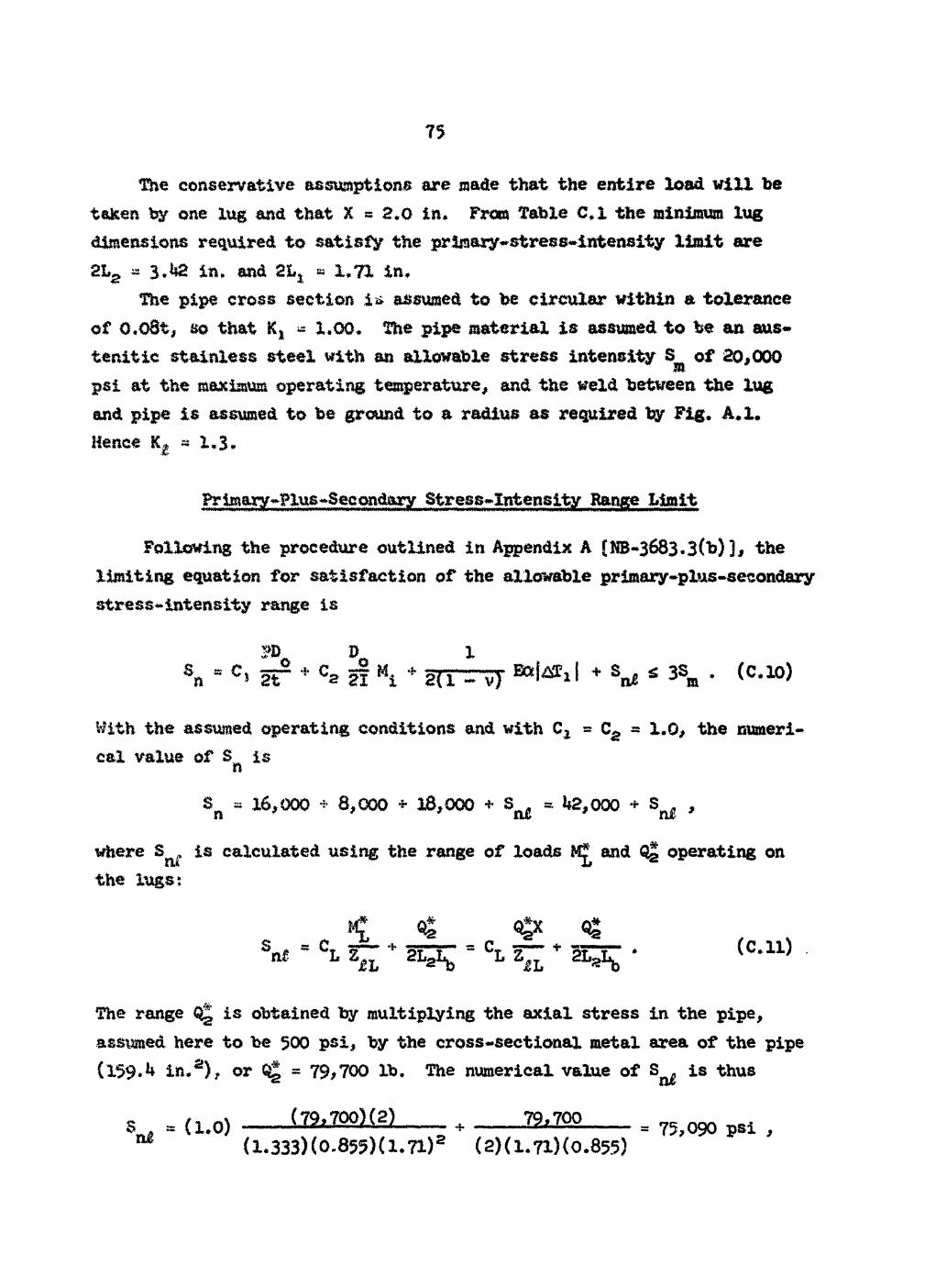
75
The conservative assumptions are made that the entire load will he taken by one lug and that X = 2.0 in. From Table C.l the minimum lug dimensions required to satisfy the primary-stress-intensity limit are 21% « 3.4a in. and 2hx » 1.71 in.
The pipe cross section is assumed to be circular within a tolerance of 0.08t, so that Kj « 1.00. The pipe material is assumed to be an aus-tenitic stainless steel with an allowable stress intensity of 20,000 psi at the maximum operating temperature, and the weld between the lug and pipe is assumed to be ground to a radius as required by Fig. A,l* Hence Kg « 1*3»
Primary-Plus-Second&ry Stress-Intensity Range Limit
Following the procedure outlined in Appendix A (NB~3683.3(b) ], the limiting equation for satisfaction of the allowable primary-plus-secondary stress-intensity range is
B> D 1 Sn s S T * 21 * 2(1 - v) + * 3Sm . (C.10)
With the assumed operating conditions and with C2 » C& « 1.0, the numeri-cal value of S is n
Sn « 16,000 + 8,000 - 38,000 + « 42,000 - S ^ ,
where S ^ is calculated using the range of loads and Q| operating on the lugs:
Snt " CL Z * 2 1 ^ " CL ZiL * ZL^ ' ( C ' U >
The range is obtained by multiplying the axial stress in the pipe, assumed here to be 500 psi, by the cross-sectional metal area of the pipe (159*4 in.2), or = 79/700 lb. The numerical value of S ^ is thus
s = {1.o) l l h m m + 22,700 = 7 5 j 0 9 0 p s i , m (1.333)(0.855)(l.71) (S)(l.7l)(0.855)

76
and
Sr s 42,000 + 75,090 » 1X7,090 psi , (C.12)
which is well above the 3S limit of 60,000 psi. m The lug design might still be acceptable provided that the restric-
tion placed on the maximum load stresses S^J £ 3S^ [see Appendix A, NB-3683.2(b); also Eq. (26) of the text] is met and the design is qualified under the simplified elastic-plastic discontinuity analysis procedures of NB-3653.6 as modified in Appendix A. For this particular design the maximum load stress condition is
Mf* Qg* + (e.13)
where Mjf* =-- and the maximum load Qg* is equal to the range Q| plus the deadweight W; that is,
- 79,700 + 13,550 « 93,250 .
Thus,
s** - (1) (1.333) (0.855) (l.7l) 2
+ 23^250 S 87,850 psi , (C.14) (2)(1.71)(0.855)
which is greater than 3S = 60,000 psi. Therefore the design is unaccept-able. In order to pass this restriction, the tensile stress in the pipe would need to be equal to or less than 315 psi, rather than 500 psi as assumed.
Simplified Elastic-Plastic Discontinuity Analysis [NB-3653.6]
Even though the design failed to pass the maximum-load stress con-dition S ^ ^ 3S , the example is continued to show that the potentially overloaded condition is not necessarily prevented by the fatigue analysis.

77
In order to qualify the design under Paragraph N3-3653.6 of the Code, two conditional equations must first be satisfied; that is, Code Eqs. (12) and (13). (Paragraph NB-3653.2, Satisfaction of Peak Stress Intensity Range, was ruled out since S = 117,000 > 3S .) Code Eq. (12) for the expansion n 1a -stress Se is (see Table 2 of the text):
Se = °a H 3Sffi , (C,15)
where the magnitude of D Q / 2 I was postulated to be 10,000 psi. Kith C2 » 1.0, the expansion stress limit Bq. (C.15) is obviously met.
The other conditional equation [Code Bq. (13), Table 1 of the text] was modified for the analysis of lug supports in that the term involving l°aTa ~ ^b^bl was dropped. Thus the appropriate limit is
P D DM. C1 - § r + c a - f r s 3 Sm ' < c-*>
where Pq is the range of operating pressure and M ^ is the magnitude of the moment vector used in the primary-stress-intensity limit check. Ac-cordingly, with Cj = 1.0, PoDQ/2t = 16,000 psi, and D ^ / 2 1 - 10,000 psi the left-hand side of the above equation is 26,000 psi. This value is less than 3S « 60,000 psi; hence, Code Eq. (13) is also satisfied.
We may thus proceed to evaluate the alternating stress
Salt = Ke (C-1?)
using the modified equation for S^ given in Appendix A [NB-3683.3(b)] and K calculated according to the rules of NB-3653.6(c). The peak-stress intensity range is
P D D SP s Kic* - f r + ^ 21 M i + srr^vj- l y M ^ J
+ rr-7 Bal^l + % £ , (C.lB)

78
and, with Kx = K g = K3 = 1.0, we get
= 16,000 + 8,000 + 18,000 + 9,000 + S ^ = 51,000 + S p i .
Since
Bpl = - 1 ) ( 1- 5 + °-537PiP27)] + + K ^ T , - T j
= [(1.3 - l)(l.5 + 0.031)] X 16,000 + 1.3[75,090] + 1.3 X 15,000
= 7,350 + 97,620 + 19,500 = 124,470 ,
therefore
s = 51,000 + 124,470 = 175,470 . (c.19) XT
For austenitic stainless steel with material parameters m = 1.7 and n = 0.3 from Paragraph NB-3228.3(b) and with 2: 3mSm, that is,
S n = 117,090 > (3)(1.7)(20,000) = 102,000 ,
the factor Kg is given by
K - i - -i. e ~ n " 0.3 *
The alternating stress S ^ from Eq. (C.17) is thus
Salt " - ^ *
From Fig. 1-9.2 of the Code, the allowable number of fatigue cycles N at S = S = 295,000 psi is 60. Because 50 cycles at operating conditions a ait were postulated, the lug design is adequate except for not meeting the overload limitation. For this particular design the new requirement S - - [Eq. (26) of the text] is thus necessary to prevent a poten-tially dangerous condition.

79
LISTING OF THE COMPUTER PROGRAM LUGS (BASIC)
0 0 0 1 0 DIN C ( 3 ) , Z ( 6 ) , L $ ( f t ) 0 0 0 2 0 PRINT 0 0 0 3 0 PRINT 0 0 0 4 0 PRINT" N B - 3 6 8 3 . 1 STRESS I N D I C E S FOB INTEGRAL STRUCTURAL"; 0 0 0 5 0 PRINT" ATTACHMENTS" 0 0 0 6 0 PRINT 0 0 0 7 0 PRINT OOORO PRINT" INPOT DATA" 0 0 0 9 0 PRINT 0 0 1 0 0 PRINT"ATTACH(1ENT LENGTH = 0 0 1 1 0 INPUT L 2 0 0 1 2 0 PRINT" ATTACHMENT WIDTH * 0 0 1 3 0 INPOT L1 0 0 1 4 0 PRINT" NEAN P I P E RADIOS = 0 0 1 5 0 INPUT R 0 0 1 6 0 PRINT" P I P E THICKNESS - " ; 0 0 1 7 0 INPUT T 0 0 1 8 0 PRINT 0 0 1 9 0 POR 1 - 1 TO 6 0 0 2 0 0 LET L $ ( I ) = " P I P E " 0 0 2 1 0 NEXT I 0 0 2 2 0 LET L1 - 0 . 5 * L 1 0 0 2 3 0 LET L 2 = 0 . 5 * L 2 0 0 2 4 0 LET B1 = L l / R 0 0 2 5 0 LET B2 - L 2 / P 0 0 2 6 0 LET D1 = T 0 0 2 7 0 I F L2>T THEN 3 0 0 0 0 2 8 0 LET D1 » L 2 0 0 2 9 0 LET L S { 5 ) - "LUG" 0 0 3 0 0 LET D2 = T 0 0 3 1 0 I F L1>T THEN 3 4 0 0 0 3 2 0 LET D2 = L1 0 0 3 3 0 LET L $ ( 4 ) = "LUG" 0 0 3 4 0 LET D3 « LI 0 0 3 5 0 LET D4 = L2 0 0 3 6 0 I F L K L 2 THEN 3 9 0 0 0 3 7 0 LET D3 = L2 0 0 3 8 0 LET D4 = L1 0 0 3 9 0 PRINT 0 0 4 0 0 I F B K 0 . 5 THEN 4 3 0 0 0 4 1 0 P R I N T " * * * tUBNING * * * BBTA-1 EXCEEDS THE L I N I T OF 0 . 5 " 0 0 4 2 0 PRINT 0 0 4 3 0 I F B 2 < 0 . 5 THEN 4 6 0 0 0 4 4 0 P R I N T " * * * WARNING * * * BETA-2 EXCEEDS THE L I N I T OF 0 . 5 " 0 0 4 5 0 PRINT 0 0 4 6 0 I F B 1 * B 2 < 0 . 0 7 5 THEN 5 0 0 0 0 4 7 0 P R I N T " * * * WARNING * * * THE PRODUCT OF BBTA-1 AND B E T A - 2 EXCEEDS" 0 0 4 8 0 PRINT" THE L I H I T OF 0 . 0 7 5 " 0 0 4 9 0 PRINT 0 0 5 0 0 LET Z ( 1 ) = 4 . 0 * L 1 * L 2 0 0 5 1 0 LET Z ( 2 ) = Z ( 1 ) * L 2 / 3 . 0 0 0 5 2 0 LET Z ( 3 ) = Z ( 1 ) * L 1 / 3 . 0 0 0 5 3 0 LET Z ( 4 ) = 2 . 0 * L 1 * D 1 0 0 5 4 0 LET Z ( 5 ) - 2 . 0 * L 2 * D 2 0 0 5 5 0 LET Z ( 6 ) = D 3 * D 4 * ( 1 . 0 • D 3 / D 4 ) * T 0 0 5 6 0 LET A = D 3 * D 3 * D 4 * ( 0 . 8 • 0 . 0 5 * D U / D 3 )

80
0 0 5 7 0 0 0 5 8 0 0 0 5 9 0 00600 00610 00620 0 0 6 3 0 0 0 6 4 0 0 0 6 5 0 00660 0 0 6 7 0 0 0 6 8 0 0 0 6 9 0 0 0 7 0 0 0 0 7 1 0 0 0 7 2 0 0 0 7 3 0 0 0 7 U 0 0 0 7 5 0 0 0 7 6 0 0 0 7 7 0 0 0 7 8 0 0 0 7 9 0 00800 0 0 8 1 0 0 0 8 2 0 0 0 8 3 0 0 0 8 4 0 0 0 8 5 0 0 0 8 6 0 0 0 8 7 0 00880 0 0 8 9 0 0 0 9 0 0 0 0 9 1 0 0 0 9 2 0 0 0 9 3 0 0 0 9 4 0 0 0 9 5 0 0 0 9 6 0 0 0 9 7 0 0 0 9 8 0 0 0 9 9 0 0 1 0 0 0 01010 01020 0 1 0 3 0 0 1 0 4 0 0 1 0 5 0 01060 0 1 0 7 0 01080 0 1 0 9 0 01100 01110 01120 0 1 1 3 0 0 1 1 4 0 0 1 1 5 0 01160
I P Z ( 6 ) < A THEM 6 0 0 LET Z < 6 ) - A LET L $ ( 6 ) * "LUG" FOR X = 1 TO 6 LET Z ( I ) = 1 . 0 / Z C I ) NEXT I LET 6 = R / T LET X - 0 . 4 3 4 3 * L O G ( B 1 ) LET I » 0 . 0 5 • 0 . 4 3 4 3 * L O G (B2) LET A = 0 . 6 4 2 8 * X - 0 . 7 6 6 0 * Y LET A - - 0 . 4 5 4 5 * A * A LET A s A - ( 0 . 7 6 6 0 * X • 0 . 6 4 2 8 * Y ) LET C ( 1 ) = 7 . 6 4 * B 1 * B 2 * ( G 1 . 6 4 ) * ( A 1 . 5 4 ) I P C ( 1 ) > 1 . 0 THEM LET C ( 1 ) « 1 . 0 LET L $ ( 1 > = "LOG"
7 3 0
X = - 0 . 4 5 • 0 . 4 3 4 3 * L O G < B 1 ) Y » - 0 . 5 5 • 0 . 4 3 4 3 * L O G (B2) A = 0 . 7 6 6 0 * X - 0 . 6 4 2 8 * Y A = - 0 . 5*A*A A « A - ( 0 . 6 4 2 8 * X • 0 . 7 6 6 0 * 1 ) C ( 2 ) = 0 . 5 1 * B 1 * B 2 * B 2 * ( G 1 . 7 4 ) * ( A 4 . 7 4 )
I F C ( 2 ) > 1 . 0 THEN 8 2 0 LET C ( 2 ) = 1 . 0
L S ( 2 ) » "LOG" X = - 0 . 7 5 • 0 . 4 3 4 3 * L O G ( B 1 ) Y - - 0 . 6 0 • 0 . 4 3 4 3 * L 0 6 ( B 2 ) A = 0 . 6 4 2 8 * X - 0 . 7 6 6 0 * Y A - - 0 . 5 5 5 5 * A * A A - A - ( 0 . 7 6 6 0 * 1 • 0 . 6 4 2 8 * Y ) C ( 3 ) = 0 . 7 6 * B 1 * B 1 * B 2 * ( G 1 . 9 0 ) * ( A 3 . 4 0 )
I F C ( 3 ) > 1 . 0 THEN 9 1 0 LET C ( 3 ) = 1 . 0
LET LET LET LET LET LET
LET LET LET LET LET LET LET
"LUG"
P ) B"
LET L S ( 3 ) LET K = 1 P R I N T " ( P P S I N T " L PRINT" PRINT PRINT" PRINT PRINT" PRINT PRINT" PRINT PRINT" PRINT PRINT I F K=2 THEN 1 1 3 0 FOR I - 1 TO 3 LET C ( I ) = 2 . 0 * C ( I ) / 3 . 0 NEXT I PRINT" S = " C ( 1 ) * Z ( 1 ) M
PRINT" N" LET K = K «• 1 GO TO 9 4 0 P R I N T " D O YOU HAVE ANOTHER C A S E ? INPUT Q$ I F Q j = " Y E S " THEN 6 0 END
" C ( 1 ) * Z ( 1 ) « * THRUST
"C ( 2 ) *Z ( 2 ) " * LONG. NOHENT
MC ( 3 ) *Z (3 ) " * C I R . HOHENT
"Z ( 4 ) " * C I R . SHEAR
"Z J 5 ) w * LONG. SHEAR
"Z ( 6 ) "
a "LS ( i )
a "ls(2) a " L S ( 3 )
a "LS(4)
TORQUE
cl "L$ ( 5 )
a " L S ( 6 )
* THRUST 9 "LS ( 1 )
tt