Appendix 1 51 conversion table
19
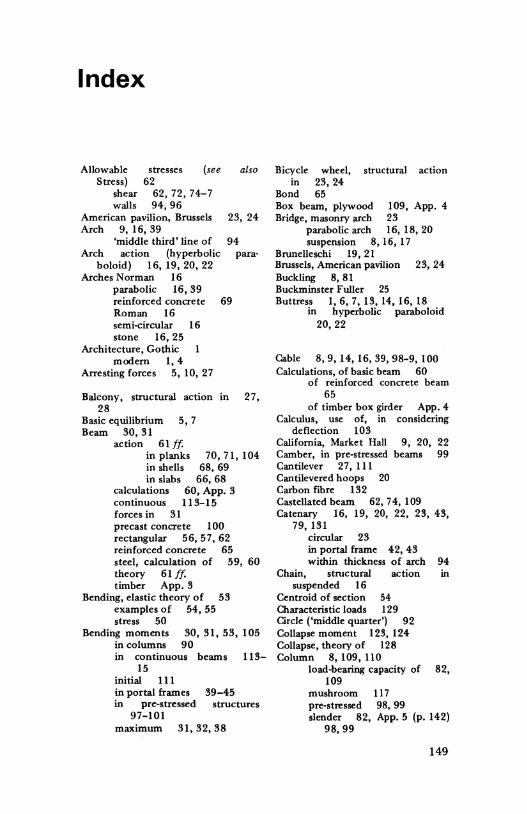
Appendix 1 51 conversion table Imperial SI Metric 1 in. 25.4mm 1 ft 304.8 mm Length 3.28 ft lm 1 in.' 645.2 mm 2 1 ft 2 0.093 m 2 Area 10.7 ft 2 1m 2 llb 0.454 kg 2.2lb 1 kg Mass 1 ton 1016.05 kg (weight) 0.982 tons 1 t 1 ton/ft' 107.2 kN/m 2 1 tonfin 2 15 480 kN/m 2 Live loads 15.48 N/mm 2 20.88 lb/ft 2 1.0 kN/m 2 llbf 4.448 N 0.225lb f IN Force 1 ton f 9964N moments 9.9 kN 1 ton xin. 0.253 kNxm llbfin.' 0.0069 N/mm 2 1 ton/in. 2 15.45 N/mm 2 144.93lb/in.' l Nfmm 2 Stress 1000 lb/in.' 6.9 Nfmm 2 0.065 ton/in.' 1 Nfmm 2 135
-
Upload
khangminh22 -
Category
Documents
-
view
0 -
download
0
Transcript of Appendix 1 51 conversion table
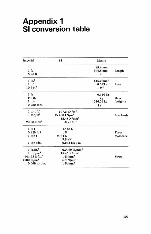
Appendix 1 51 conversion table
Imperial SI Metric
1 in. 25.4mm 1 ft 304.8 mm Length 3.28 ft lm
1 in.' 645.2 mm2
1 ft 2 0.093 m2 Area 10.7 ft 2 1m2
llb 0.454 kg 2.2lb 1 kg Mass 1 ton 1016.05 kg (weight) 0.982 tons 1 t
1 ton/ft' 107.2 kN/m2
1 tonfin2 15 480 kN/m2 Live loads 15.48 N/mm2
20.88 lb/ft2 1.0 kN/m2
llbf 4.448 N 0.225lb f IN Force 1 ton f 9964N moments
9.9 kN 1 ton xin. 0.253 kNxm
llbfin.' 0.0069 N/mm2
1 ton/in. 2 15.45 N/mm2
144.93lb/in.' l Nfmm2 Stress 1000 lb/in.' 6.9 Nfmm2
0.065 ton/in.' 1 Nfmm2
135
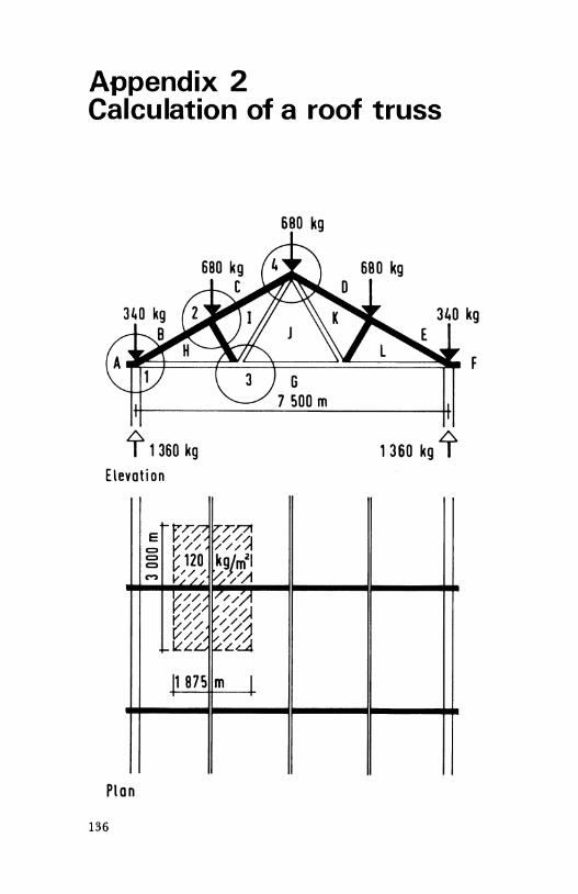
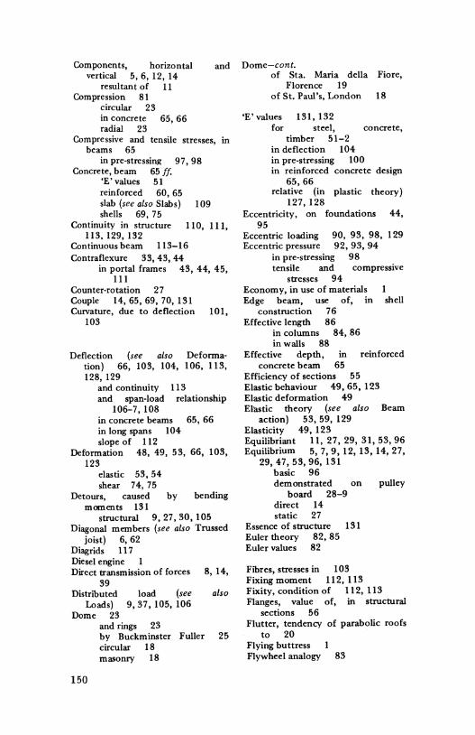
Appendix 2 Calculation of a roof truss
~ 1360 kg Elevation
t-~r~ E // C) ~12o C) C)
c-, ~--;~"
~// / /_/ r: // ~// ~2 ILL
11 87S
Plan
136
680 kg
680 kg
1360 kg i'
~T/71 V//~ ///
kgjm21 ~//I 1// ~(! ~"" / 'il v/'lJ, ~~4 m I
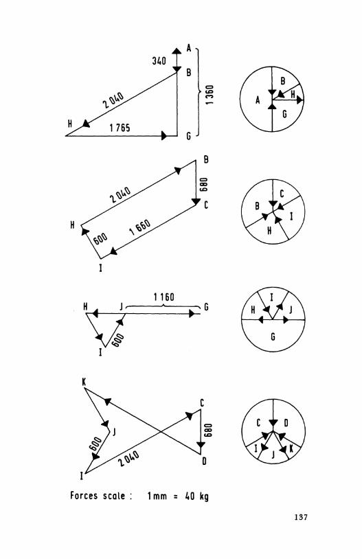
H
1160
K
A
8
G
= = M
• G
Forces scale : 1 mm = 40 kg
137
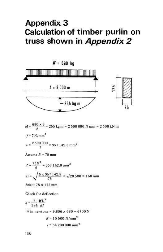
Appendix 3 Calculation of timber purlin on truss shown in Appendix 2
w = 680 kg
~11111111111111111111111111111111111111111111111111111111~ L = 3,000 m
680 X 3 M = 8 255 kg m = 2 500 000 N mm = 2 500 kN m
f=7N/mm 2
Z = 2 500 OOO 357 142.8 mm3 7
Assume B = 75 mm
75D 2 Z = - 6- = 357 142.8 mm3
D = J6 x 357 142.8 = "\128 500 = 168 mm 75
Select 75 X 175 mm
Check for deflection
5 WL 3 d=---
384 E/
Win newtons = 9.806 X 680 = 6700 N
E = 10 500 N/mm2
I= 34 200 000 mm4
138
d= 5x6700x30003
384 X 10 500 X 34 200 000
5x6.7x33 103 x109
3.84 X 1.05 X 3.42 102 X 104 X 107
65.6 6 5 =w= . 6mm
Permissible deflection 3~5 of span
6.56 1 3QOo = 46o span
/= 75 X 1753 = 34.2 X 106 mm4 12
139
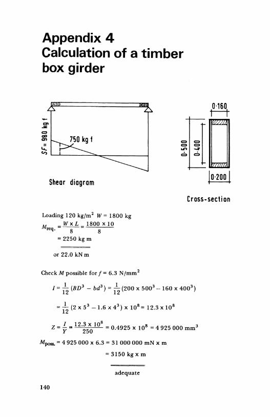
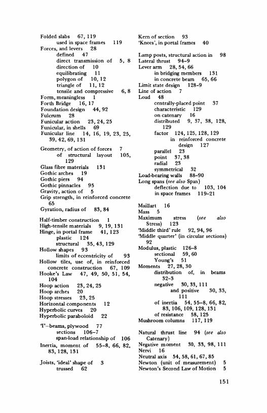
Appendix 4 Calculation of a timber box girder
Shear diagram
Loading 120 kg/m2 W = 1800 kg M = W X L = 1800 X 10
req. 8 8
= 2250 kg m
or 22.0 kNm
Check M possible for f = 6.3 N /mm 2
Cross-section
I= 112 (BD3 - bd3 ) = 1
12 (200 X 5003 -160 X 4003 )
= _!__ (2 X 53 -1.6 X 4 3 ) X 108 = 12.3 X 10⁸ 12
z =!.."' 12·3 x 108 = 0 4925 x 108 = 4925 000 mm3 y 250 .
Mposs. = 4 925 000 X 6.3 = 31 000 000 mN X m
= 3150 kg x m
adequate
140
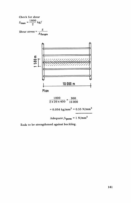
Check for shear
s - 1800 k f max --2- g
s Shear stress = ---
A flanges
1 I l I l
e
~I J/~~~/ //,// ~/ /0/ ,0-~///-:, ~/
'V/ /~ ~// // /'/ ///////////,
I I
10 000 m
Plan
1800 = 900 2x20x400 16000
= 0.056 kg/mm2 = 0.55 N/mm2
Adequatefspenn = 1 N/mm2
Ends to be strengthened against buckling.
141
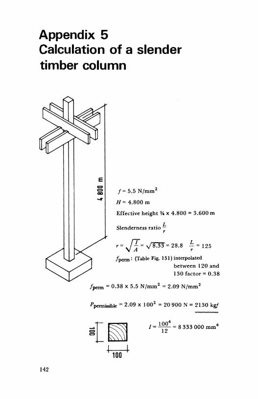
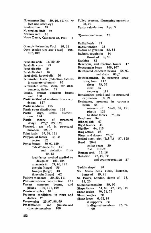
Appendix 5 Calculation of a slender timber column
142
E = = -_,
f= 5.5 N/mm2
H= 4.800 m
Effective height %X 4.800 = 3.600 m
Slenderness ratio !:_ r
r= JI= y8.33= 28.8 ~ = 125
/perm: (Table Fig. 151) interpolated between 120 and 130 factor= 0.38
/perm= 0.38 x 5.5 N/mm2 = 2.09 N/mm2
Ppermissible = 2.09 X 1002 = 20 900 N = 2130 kgf
~{~ 1 1oo I
1004 I=--= 8 333 000 mm4
12
From Euler:
P = L; E/ E (assumed for grade S2 = 10 300 N/mm2)
1r P = 36002 X 10 300 X 8 333 000 N
= ~ X 1 03 X 8 3 104 X l 06 = 20 800 N 3.6 . . 10
= 2120 kgf
143
Appendix 6 "Kern" dimensions for hollow shapes
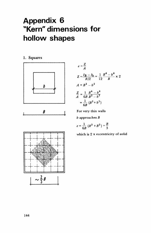
1. Squares
144
8
""la 3
z e=-A
IB - /b - 1 B4 - b4 z- B/2 - 12_B_ x 2
A =B2 -b2
Z 1 B 4 - b4
A= 6B B2 -b2
= .1_ (B2+b2) 6B
For very thin walls
b approaches B
which is 2 X eccentricity of solid
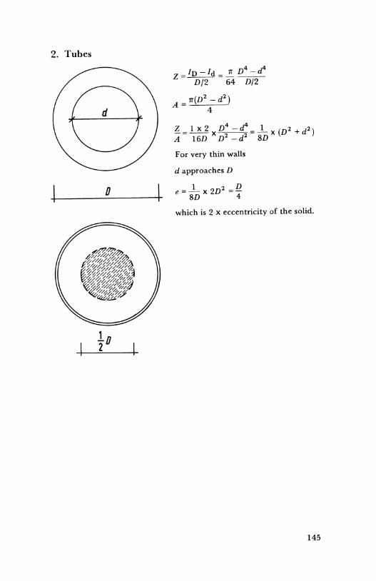
2. Tubes
0
lo 2
z =In- /d = ..!!._ D4- d4
D/2 64 D/2
A= 1T(D2- d2) 4
For very thin walls
d approaches D
which is 2 x eccentricity of the solid.
145
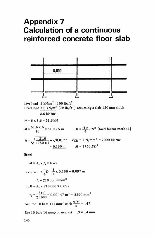
Appendix 7 Calculation of a continuous reinforced concrete floor slab
6.000
Live load 5 kNfm2 [100 lb/ft2 )
Dead load 3.6 kNfm2 [72lb/ft2 ) assuming a slab 150 mm thick
8.6 kNfm2
W= 6 X 8.6 = 51.6kN
M = 51.6 x 6 = 31 0 kN m 10 .
D= ~ =y'0.0177 \I l750 X 1 = 0.130m
Steel
M = A 5 X fs X lever
M = P~B BD2 [load factor method]
PcB = 7 N/mm2 = 7000 kN/m2
M= 1750BD2
Lever arm= 1v = 1 x 0.130 = 0.097 m 4 4
fs = 210 000 kN/m2
31.0 = A 8 X 210 000 X 0.097
A = ___1!:Q_ = 0.00 147m2 = 2290 mm2 s 21 000
rrD 2 Assume 10 bars 147 mm2 each 4 = 147
Use 10 bars 14 mm<fl or nearest D = 14 mm.
146
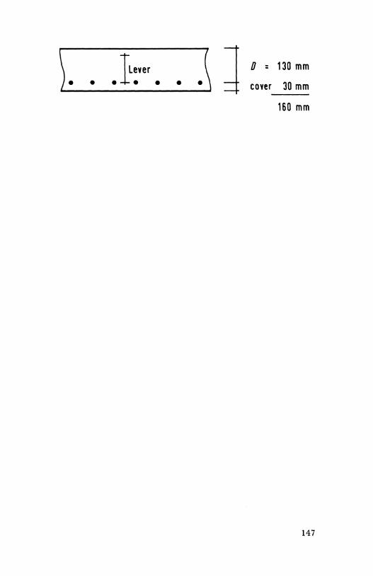
)L.:.,..__~ • _.l:_ver • ____,~• • \ d 0 = 130 mm
cover 30 mm
160 mm
147
Index
stresses (see Allowable Stress)
shear walls
62 62, 72, 74-7 94,96
also
American pavilion, Brussels 23, 24 Arch 9, 16, 39
'middle third'line of 94 Arch action (hyperbolic para-
boloid) 16, 19, 20, 22 Arches Norman 16
parabolic 16, 39 reinforced concrete 69 Roman 16 semi-circular 16 stone 16, 25
Architecture, Gothic modern 1, 4
Arresting forces 5, 10, 27
Balcony, structural action in 2 7, 28
Basic equilibrium 5, 7 Beam 30,31
action 61 ff. in planks 70, 71, 104 in shells 68, 69 in slabs 66, 68
calculations 60, App_ 3 continuous 113-15 forces in 31 precast concrete I 00 rectangular 56, 57, 62 reinforced concrete 65 steel, calculation of 59, 60 theory 61 ff. timber App_ 3
Bending, elastic theory of 53 examples of 54, 55 stress 50
Bending moments 30, 31, 53, 105 in columns 90 in continuous beams 113-
15 initial Ill in portal frames 39-45 in pre-stressed structures
97-101 maximum 31, 32, 38
Bicycle in
Bond
wheel, 23, 24 65
structural action
Box beam, plywood 109, App. 4 Bridge, masonry arch 23
parabolic arch 16, 18, 20 suspension 8, 16, 17
Brunelleschi 19, 21 Brussels, American pavilion 23, 24 Buckling 8, 81 Buckminster Fuller 25 Buttress I, 6, 7, 13, 14, 16, 18
in hyperbolic paraboloid 20,22
Cable 8, 9, 14, 16, 39, 98-9, 100 Calculations, of basic beam 60
of reinforced concrete beam 65
of timber box girder App. 4 Calculus, use of, in considering
deflection 103 California, Market Hall 9, 20, 22 Camber, in pre-stressed beams 99 Cantilever 27, Ill Cantilevered hoops 20 Carbon fibre 132 Castellated beam 62, 74, 109 Catenary 16, 19, 20, 22, 23, 43,
79, 131 circular 23 in portal frame 42, 43 within thickness of arch 94
Chain, structural action in suspended 16
Centroid of section 54 Characteristic loads 129 Circle ('middle quarter') 92 Collapse moment 123, 124 Collapse, theory of 128 Column 8, 109, 110
load-bearin~; capacity of 82, 109
mushroom pre-stressed slender 82,
98,99
117 98, 99 App. 5 (p. 142)
149
Components, horizontal and Dome-cont. vertical 5, 6, 12, 14
resultant of 11 Compression 81
circular 23 in concrete 65, 66 radial 23
Compressive and tensile stresses, in beams 65
in pre-stressing 97, 98 Concrete, beam 65 ff.
'E' values 51 reinforced 60, 65 slab (see also Slabs) 109 shells 69, 7 5
Continuity in structure 110, 111, 113, 129, 132
Continuous beam 113-16 Contraflexure 33, 43, 44
in portal frames 43, 44, 45, 111
Counter-rotation 27 Couple 14, 65, 69, 70, 131 Curvature, due to deflection 101,
103
Deflection (see also Deforma-tion) 66, 103, 104, 106, 113, 128, 129
and continuity 113 and span-load relationship
106-7, 108 in concrete beams 65, 66 in long spans 104 slope of 112
Deformation 48, 49, 53, 66, 103, 123
elastic shear
53,54 74, 75
Detours, caused by bending moments 131
structural 9, 27, 30, 105 Diagonal members (see also Trussed
joist) 6, 62 Diagrids 11 7 Diesel engine Direct transmission of forces 8, 14,
39 Distributed
Loads) Dome 23
load (see 9,37, 105,106
and rings 23
also
by Buckminster Fuller 25 circular 18 masonry 18
150
of Sta. Maria della Fiore, Florence 19
of St. Paul's, London 18
'E' values for
131, 132 steel,
timber 51-2 in deflection 104
concrete,
in pre-stressing 100 in reinforced concrete design
65,66 relative (in plastic theory)
127, 128 Eccentricity, on foundations 44,
95 Eccentric loading 90, 93, 98, 129 Eccentric pressure 92, 93, 94
in pre-stressing 98 tensile and compressive
stresses 94 Economy, in use of materials Edge beam, use of, in shell
construction 76 Effective length 86
in columns 84, 86 in walls 88
Effective depth, in reinforced concrete beam 65
Efficiency of sections 55 Elastic behaviour 49, 65, 123 Elastic deformation 49 Elastic theory (see also Beam
action) 53, 59, 129 Elasticity 49, 123 Equilibriant 11, 27, 29, 31, 53, 96 Equilibrium 5, 7, 9, 12, 13, 14, 27,
29, 47, 53, 96, 131 basic 96 demonstrated on
board 28-9 direct 14 static 27
Essence of structure 131 Euler theory 82, 85 Euler values 82
Fibres, stresses in 103 Fixing moment 112, 113
pulley
Fixity, condition of 112, 113 Flanges, value of, in structural
sections 56 Flutter, tendency of parabolic roofs
to 20 Flying buttress Flywheel analogy 83
Folded slabs 67, 119 used in space frames 119
Forces, and levers 28 defined 47 direct transmission of 5, 8 direction of 10 equilibrating 11 polygon of 10, 12 triangle of 11, 12 tensile and compressive 6, 8
Form, meaningless 1 Forth Bridge 16, 17 Foundation design 44, 92 Fulcrum 28 Funicular action 23, 24, 25 Funicular, in shells 69 Funicular line 14, 16, 19, 23, 25,
39,42,69,131
Geometry, of action of forces 7 of structural layout 105,
129 Glass fibre materials 131 Gothic arches 19 Gothic piers 94 Gothic pinnacles 95 Gravity, action of 5 Grip strength, in reinforced concrete
65 Gyration, radius of 83, 84
Half-timber construction 1 High-tensile materials 9, 19, 131 Hinge, in portal frame 41, 123
plastic 124 structural 35, 43, 129
Hollow shapes 93 limits of eccentricity of 9 3
Hollow tiles, use of, in reinforced concrete construction 67, 109
Hooke's Law 47, 49, 50, 51, 54, 104
Hoop action 23, 24, 25 Hoop arches 20 Hoop stresses 2 3, 2 5 Horizontal components 12 Hyperbolic curves 20 Hyperbolic paraboloid 22
'I' -beams, plywood 7 7 sections 106-7 span-load relationship of 1 06
Inertia, moment of 55-8, 66, 82, 83,128,131
Joists, 'ideal' shape of 3 trussed 62
Kern of section 93 'Knees', in portal frames 40
Lamp posts, structural action in 98 Lateral thrust 9 4-9 Lever arm 28, 54, 66
in bridging members 131 in concrete beam 65, 66
Limit state design 128-9 Line of action 7 Load 48
centrally-placed point 37 characteristic 129 on catenary 16 distributed 9, 37, 38, 128,
129 factor 124, 125, 128, 129
in reinforced concrete design 127
parallel 23 point 37,38 radial 23 symmetrical 32
Load-bearing walls 88-90 Long spans (see also Span)
deflection due to 103, 104 in space frames 119-21
Maillart 16 Mass 5 Maximum stress (see also
Stress) 123 'Middle third' rule 92, 94, 96 'Middle quarter' (in circular sections)
92 Modulus, plastic 126-8
sectional 59, 60 Young's 51
Moments 27, 28, 30 distribution of, in beams
32-3 negative 30, 33, 111
and positive 30, 33, 111
of inertia 54, 55-8, 66, 82, 83, 106, 109, 128, 131
of resistance 58, 125 Mushroom columns 117, 119
Natural thrust line 94 (see also Catenary)
Negative moment 30, 33, 98, 111 Nervi 16 Neutral axis 54, 58, 61, 67, 85 Newton (unit of measurement) 5 Newton's Second Law of Motion 5
151
No-moment line 39, 40, 42, 45, 79 (see also Catenary)
No-shear line 79 No-tension limit 94 Norman arch 16 Notre Dame, Cathedral of, Paris
Olympic Swimming Pool 20, 22 Open section (see also Truss) 105,
107, 109
Parabolic arch 16, 20, 39 Parabolic curve 23 Parabolic ribs 19 Parabolic shell 16 Paraboloid, hyperbolic 20 Permissible loads (reduction factors
in concrete columns) 85 Permissible stress, shear, for steel,
concrete, timber 79 Planks, precast concrete beams
and 100 Plastic method of reinforced concrete
design 127 Plastic modulus 125 Plastic stress distribution 126 Plastic stage, stress distribu-
tion 124 Plastic theory, of structural
design 1231/., 127, 129 Plywood, use of, in structural
members 22, 67 Point loads 37, 38, 131 Polygon, of forces 10, 12
vector 12 Portal frames 39 If., 129
"ideal" shape for 42 and deviation from
42,43 load-factor method applied to
design of 123, 124 moments in 39, 40, 125 one-pin (hinge) 35 two-pin (hinge) 43 three-pin (hinge) 42
Positive moments 30, 33, Ill Post-and-beam construction 131 Precast concrete beams, and
planks 100, 101, 109 Pre-stress cables 99 Pre-stress conditions, in rings and
domes 23 Pre-stressing 23, 97, 98, 99 Pre-tensioned and pre-stressed
concrete members 100
152
Pulley systems, illustrating moments 28, 29
Purlin calculations App. 3
'Queen-post' truss 73
Radialloads 23 Radial tension 23 Radius of gyration 83, 84 Rafters, couples in 14
thrust of 6, 30 Rankine 82 Reactions, and reaction forces 4 7 Rectangularbeam 105, 107 Reinforced concrete beams 65 If.,
and slabs 66 If. Reinforcement, in concrete struc-
tures, bars II 7 shear 75, 76 steel 65 two-way 117
Renaissance period and its structural expression 18, 19
Resistance, moment in concrete beam 65
moment of 58-9, 65, 121 plastic 125 to shear forces 74, 75
Resultant 94 Ribbed slab 67 Rigid frames 44 Rigidity 44, 113 Ring action 23 Rings, and domes 23 If. Rolled steel joist, (R.SJ-) 57, 125 Roof 20-2
collar beam 30 flat 119-21
Roman arch 15, 16 Rotation 27, 29, 72
and counter-rotation 27
'Saddle shape' 20 Sta. Maria della Fiore, Florence,
dome of 19, 21 St. Paul's, London, dome of 18,
19, 20 Sectional modulus 59, 60 Shape factor 54, 69, 125, 126, 129 Shear action 70, 71, 72 Shear couples 70 Shear force 6, 62, 99
at supports 72 in diagonal members 7 3, 7 4,
99
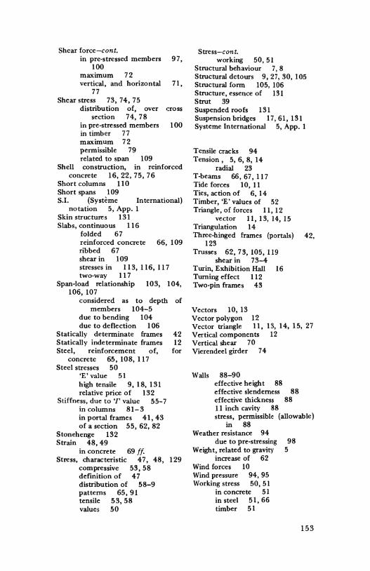
Shear force-cont. in pre-stressed members 97,
100 maximum 72 vertical, and horizontal 71,
77 Shear stress 73, 74, 75
distribution of, over cross section 74, 78
in pre-stressed members I 00 in timber 77 maximum 72 permissible 79 related to span 109
Shell construction, in reinforced concrete 16, 22, 75, 76
Short columns II 0 Short spans 109 S.I. (Systeme International)
notation 5, App. I Skin structures 131 Slabs, continuous 116
folded 67 reinforced concrete 66, 109 ribbed 67 shear in 109 stresses in 113, 116, 117 two-way 117
Span-load relationship 103, 104, 106, 107
considered as to depth of members 104-5
due to bending 104 due to deflection I 06
Statically determinate frames 42 Statically indeterminate frames 12 Steel, reinforcement of, for
concrete 65, 108, 117 Steel stresses 50
'E' value 51 high tensile 9, 18, 131 relative price of 132
Stiffness, due to'/' value 55-7 in columns 81-3 in portal frames 41,43 of a section 55, 62, 82
Stonehenge 132 Strain 48, 49
in concrete 69 ff. Stress, characteristic 4 7, 48, 129
compressive 53, 58 definition of 4 7 distribution of 58-9 patterns 65, 91 tensile 53, 58 values 50
Stress-cont. working 50, 51
Structural behaviour 7, 8 Structural detours 9, 27, 30, 105 Structural form 105, 106 Structure, essence of 131 Strut 39 Suspended roofs 131 Suspension bridges 17, 61, 131 Systeme International 5, App. I
Tensile cracks 94 Tension, 5, 6, 8, 14
radial 23 T-beams 66, 67, 117 Tide forces 10, 11 Ties, action of 6, 14 Timber, 'E' values of 52 Triangle, of forces 11, 12
vector 11, 13, 14, 15 Triangulation 14 Three-hinged frames (portals) 42,
123 Trusses 62, 73, 105, 119
shear in 73-4 Turin, Exhibition Hall 16 Turning effect 112 Two-pin frames 43
Vectors 10, 13 Vector polygon 12 Vector triangle 11, Vertical components Vertical shear 70 Vierendeel girder 74
13, 14, 15, 27 12
Walls 88-90 effective height 88 effective slenderness 88 effective thickness 88 11 inch cavity 88 stress, permissible (allowable)
in 88 Weather resistance 94
due to pre-stressing 98 Weight, related to gravity 5
increase of 62 Wind forces 10 Wind pressure 94, 95 Working stress 50, 51
in concrete 51 in steel 51,66 timber 51
153
Yield point 50, 51 Young 49 Young's Modulus 49, 51, 104
154
Zero moment 43, Ill Zero line 54 Zurich, 1939 Exhibition shell, by
Maillart 16