GS2 to GS20 Conversion Appendix - AutomationDirect
30
GS2 to GS20 Conversion G G G Appendix Appendix Appendix Page G–1 DURApulse GS20 & GS20X AC Drive User Manual – 1st Edition, Rev C Table of Contents Appendix G: GS2 to GS20 Conversion Replacement of GS2 Drives with GS20 � � � � � � � � � � � � � � � � � � � � � � � � � � � � � � � � � � � � � G–2 Step 1: Choosing a Compatible GS20 Model � � � � � � � � � � � � � � � � � � � � � � � � � � � � � � � � � � � �G–3 Step 2: Reviewing the Mounting Dimension Differences � � � � � � � � � � � � � � � � � � � � � � � � � � � � �G–4 Step 3: Reviewing the Fusing Guidelines � � � � � � � � � � � � � � � � � � � � � � � � � � � � � � � � � � � � � �G–6 Step 4: Reviewing the Main Power Wiring Specifications � � � � � � � � � � � � � � � � � � � � � � � � � � � � �G–7 Step 5: Reviewing the Control Wiring Specifications � � � � � � � � � � � � � � � � � � � � � � � � � � � � � � � �G–9 Step 6: Review GS2 Accessories � � � � � � � � � � � � � � � � � � � � � � � � � � � � � � � � � � � � � � � � � � G–12 Step 7: Converting Parameter Structure and GS2 Mode (Optional)� � � � � � � � � � � � � � � � � � � � � � � G–13 Step 8: Converting Your GS2 GSoft Parameter File to a GS20 GSoft2 File � � � � � � � � � � � � � � � � � � � G–30
-
Upload
khangminh22 -
Category
Documents
-
view
0 -
download
0
Transcript of GS2 to GS20 Conversion Appendix - AutomationDirect

GS2 to GS20 Conversion GGGAppendixAppendixAppendix
Page G–1DURApulse GS20 & GS20X AC Drive User Manual – 1st Edition, Rev C
Table of ContentsAppendix G: GS2 to GS20 Conversion
Replacement of GS2 Drives with GS20 G–2Step 1: Choosing a Compatible GS20 Model G–3Step 2: Reviewing the Mounting Dimension Differences G–4Step 3: Reviewing the Fusing Guidelines G–6Step 4: Reviewing the Main Power Wiring Specifications G–7Step 5: Reviewing the Control Wiring Specifications G–9Step 6: Review GS2 Accessories G–12Step 7: Converting Parameter Structure and GS2 Mode (Optional) G–13Step 8: Converting Your GS2 GSoft Parameter File to a GS20 GSoft2 File G–30

Page G–2 DURApulse GS20 & GS20X AC Drive User Manual – 1st Edition, Rev C
Appendix G: GS2 to GS20 Conversion
Replacement of GS2 Drives with GS20The GS20 drive series can be used to replace any GS2 model drive. This appendix will detail the hardware and software changes that need to be considered before converting an existing GS2 drive application to a GS20 drive application. The GS20 drive provides many additional features and functions over the GS2 drive. However, the GS20 drive can be converted to "GS2 mode" which will convert the parameter set to be virtually identical to a GS2 drive. The following sections will guide you through the process of converting to GS20:
1) Choosing a compatible GS20 model2) Reviewing the mounting dimension differences3) Reviewing the fusing guidelines4) Reviewing the Main wiring specifications5) Reviewing the Control wiring specifications6) Reviewing GS2 accessories7) Converting Parameter structure and GS2 mode (optional)8) Converting your GS2 GSoft parameter file to a GS20 GSoft2 file
GS2 GS20

Appendix G: GS2 to GS20 Conversion
Page G–3DURApulse GS20 & GS20X AC Drive User Manual – 1st Edition, Rev C
Step 1: Choosing a Compatible GS20 ModelUse the following reference chart to identify the appropriate GS20 model that should be used to replace an existing GS2 model. Compatible models provide equivalent or higher output amp ratings for variable torque modes.
NOTE: GS2-20P5, GS2-21P0, GS2-22P0, and GS2-23P0 single-phase applications MUST use the applicable GS21 model to ensure adequate rated output current. A 3-phase GS23-2xxx drive is only rated for approximately 50% of the rated 3-phase output current when used with a single phase input.
GS2 to GS20 CompatibilityGS2 Model GS2 Output
VT Amp RatingCompatible GS20
ModelGS20 Output
VT Amp RatingGS2-10P2 16 GS21-10P2 18GS2-10P5 25 GS21-10P5 27GS2-11P0 42 GS21-11P0 55
GS2-20P5Single Phase 25 GS21-20P5 32Three Phase 25 GS23-20P5 32
GS2-21P0Single Phase 50 GS21-21P0 50Three Phase 50 GS23-21P0 50
GS2-22P0Single Phase 70 GS21-22P0 85Three Phase 70 GS23-22P0 85
GS2-23P0Single Phase 100 GS21-23P0 125Three Phase 100 GS23-23P0 125
GS2-25P0 170 GS23-25P0 195GS2-27P5 250 GS23-27P5 270GS2-41P0 30 GS23-41P0 30GS2-42P0 40 GS23-42P0 46GS2-43P0 50 GS23-43P0 65GS2-45P0 82 GS23-45P0 105GS2-47P5 130 GS23-47P5 157GS2-4010 180 GS23-4010 205GS2-51P0 17 GS23-51P0 21GS2-52P0 30 GS23-52P0 36GS2-53P0 42 GS23-53P0 50GS2-55P0 66 GS23-55P0 80GS2-57P5 99 GS23-57P5 115GS2-5010 122 GS23-5010 150

Page G–4 DURApulse GS20 & GS20X AC Drive User Manual – 1st Edition, Rev C
Appendix G: GS2 to GS20 Conversion
Step 2: Reviewing the Mounting Dimension DifferencesCompatible GS20 frame sizes are different from the equivalent GS2 drive. All GS20 models are smaller in height and width than the equivalent GS2 model, however some GS20 models may be up to 12mm deeper.If your existing GS2 drive is panel mounted, new mounting holes will need to be installed for GS20 as the footprints are not the same. Refer to the GS20 dimension drawings in Chapter 2 for exact dimensions of mounting holes. GS20 also offers a mounting plate for top entry/exit and a mounting kit for dinrail. See Appendix A: Accessories for details.Use the following chart to quickly identify the dimension differences in the comparable models.
NOTE: Ensure the depth of the compatible GS20 model will fit in the existing location for replacement. Models noted with an asterisk (*) in the table below are deeper than their GS2 counterparts.
GS2 to GS20 Dimensions Comparison(Units = mm)
GS2 Model GS2 Height
GS2 Width
GS2 Depth GS20 Model GS20
HeightGS20 Width
GS20 Depth
GS2-10P2 161 100 1405 GS21-10P2 128 68 96GS2-10P5 161 100 1405 GS21-10P5 128 68 125GS2-11P0 161 100 1405 GS21-11P0* 157 87 152
GS2-20P5Single Phase 161 100 1405 GS21-20P5 128 68 125Three Phase 161 100 1405 GS23-20P5 128 68 110
GS2-21P0Single Phase 161 100 1405 GS21-21P0* 142 72 143Three Phase 161 100 1405 GS23-21P0* 128 68 143
GS2-22P0Single Phase 161 100 1405 GS21-22P0* 157 87 152Three Phase 161 100 1405 GS23-22P0 142 72 143
GS2-23P0Single Phase 235 125 1895 GS21-23P0 157 87 152Three Phase 235 125 1895 GS23-23P0 157 87 152
GS2-25P0 235 125 1895 GS23-25P0 157 87 152GS2-27P5 235 125 1895 GS23-27P5 207 109 154GS2-41P0 161 100 1405 GS23-41P0* 128 68 143GS2-42P0 161 100 1405 GS23-42P0* 142 72 143GS2-43P0 161 100 1405 GS23-43P0* 157 87 152GS2-45P0 235 125 1895 GS23-45P0 157 87 152GS2-47P5 235 125 1895 GS23-47P5 207 109 154GS2-4010 235 125 1895 GS23-4010 207 109 154GS2-51P0 161 100 1405 GS23-51P0* 128 68 143GS2-52P0 161 100 1405 GS23-52P0* 142 72 143GS2-53P0 161 100 1405 GS23-53P0* 157 87 152GS2-55P0 235 125 1895 GS23-55P0 157 87 152GS2-57P5 235 125 1895 GS23-57P5 207 109 154GS2-5010 235 125 1895 GS23-5010 207 109 154* These models are deeper than their GS2 counterparts.

Appendix G: GS2 to GS20 Conversion
Page G–5DURApulse GS20 & GS20X AC Drive User Manual – 1st Edition, Rev C
GS2 Dimension DrawingsUnits = mm [inch]
GS2-10P2, 10P5, 11P0, 20P5, 21P0, 22P0, 41P0, 42P0, 43P0, 51P0, 52P0, 53P0
GS2-23P0, 25P0, 27P5, 45P0, 47P5, 4010, 55P0, 57P5, 5010

Page G–6 DURApulse GS20 & GS20X AC Drive User Manual – 1st Edition, Rev C
Appendix G: GS2 to GS20 Conversion
Step 3: Reviewing the Fusing GuidelinesFusing for the GS20 drives is significantly different than the equivalent GS2 model. Fuse changes are required to adequately protect the semiconductor components of the GS20 drive or to prevent nuisance faults.Review the following chart to identify required Class T or High Speed J fusing changes before replacing a GS2 drive.
NOTE: These fuse ratings are to protect the semiconductor devices of the drive. Branch fuse circuitry is still required to protect the motor load.
GS2 to GS20 Fusing GuidelineGS2 Model GS2 Input
Amp RatingGS2 Fuse Rating GS20 Model GS20 Input
Amp RatingGS20 Fuse
RatingHigh-Speed Class J Fuses
GS2-10P2 60 20 GS21-10P2 68 10 JHL10GS2-10P5 90 20 GS21-10P5 101 10 JHL10GS2-11P0 160 20 GS21-11P0 206 25 JHL25
GS2-20P5Single Phase 63 20 GS21-20P5 83 15 JHL15Three Phase 32 10 GS23-20P5 38 15 JHL15
GS2-21P0Single Phase 115 30 GS21-21P0 113 20 JHL20Three Phase 63 20 GS23-21P0 60 20 JHL20
GS2-22P0Single Phase 157 45 GS21-22P0 185 35 JHL35Three Phase 90 25 GS23-22P0 96 35 JHL35
GS2-23P0Single Phase 270 60 GS21-23P0 275 50 JHL50Three Phase 125 40 GS23-23P0 150 50 JHL50
GS2-25P0 196 60 GS23-25P0 234 80 JHL80GS2-27P5 280 100 GS23-27P5 324 60 JHL60GS2-41P0 42 10 GS23-41P0 33 15 JHL15GS2-42P0 57 15 GS23-42P0 51 20 JHL20GS2-43P0 60 20 GS23-43P0 72 25 JHL25GS2-45P0 85 30 GS23-45P0 116 45 JHL45GS2-47P5 140 50 GS23-47P5 173 35 JHL35GS2-4010 230 70 GS23-4010 226 45 JHL45GS2-51P0 24 6 GS23-51P0 24 6 JHL6GS2-52P0 42 10 GS23-52P0 42 10 JHL10GS2-53P0 59 15 GS23-53P0 58 10 JHL10GS2-55P0 70 15 GS23-55P0 93 20 JHL20GS2-57P5 105 20 GS23-57P5 134 25 JHL25GS2-5010 129 30 GS23-5010 175` 30 JHL30

Appendix G: GS2 to GS20 Conversion
Page G–7DURApulse GS20 & GS20X AC Drive User Manual – 1st Edition, Rev C
Step 4: Reviewing the Main Power Wiring SpecificationsMain Power Wire Sizing
Review the following wire size charts to ensure the existing main power wiring on a GS2 drive is compatible with the GS20 model. In some cases, larger wiring may not fit in the GS20 main power wiring terminals and could require intermediate terminal blocks GS20 Main power terminals are designed for ring lugs. See GS20 wiring specifications in Chapter 2 for more details.
GS2 to GS20 Wiring ComparisonGS2 Model GS2 Main Power Terminals
Wiring Size GS20 Model GS20 Main Power Terminals Maximum Wiring Size
GS2-10P2 12-14 GS21-10P2 14GS2-10P5 12-14 GS21-10P5 14GS2-11P0 12 GS21-11P0 8
GS2-20P5Single Phase 12-14 GS21-20P5 14Three Phase 12-14 GS23-20P5 14
GS2-21P0Single Phase 12-14 GS21-21P0 12Three Phase 12-14 GS23-21P0 14
GS2-22P0Single Phase 12 GS21-22P0 8Three Phase 12-14 GS23-22P0 12
GS2-23P0Single Phase 8 GS21-23P0 8Three Phase 8-12 GS23-23P0 8
GS2-25P0 8-10 GS23-25P0 8GS2-27P5 8 GS23-27P5 8GS2-41P0 12-14 GS23-41P0 14GS2-42P0 12-14 GS23-42P0 12GS2-43P0 12-14 GS23-43P0 8GS2-45P0 8-14 GS23-45P0 8GS2-47P5 8-12 GS23-47P5 8GS2-4010 8-10 GS23-4010 8GS2-51P0 12-14 GS23-51P0 14GS2-52P0 12-14 GS23-52P0 12GS2-53P0 12-14 GS23-53P0 8GS2-55P0 8-14 GS23-55P0 8GS2-57P5 8-14 GS23-57P5 8GS2-5010 8-14 GS23-5010 8
Page G–8 DURApulse GS20 & GS20X AC Drive User Manual – 1st Edition, Rev C
Appendix G: GS2 to GS20 Conversion
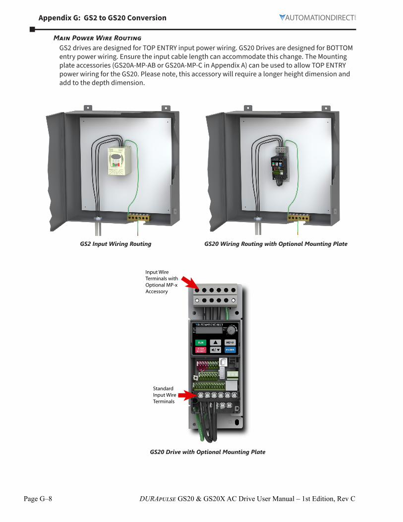
Main Power Wire RoutingGS2 drives are designed for TOP ENTRY input power wiring. GS20 Drives are designed for BOTTOM entry power wiring. Ensure the input cable length can accommodate this change. The Mounting plate accessories (GS20A-MP-AB or GS20A-MP-C in Appendix A) can be used to allow TOP ENTRY power wiring for the GS20. Please note, this accessory will require a longer height dimension and add to the depth dimension.
GS2 Input Wiring Routing GS20 Wiring Routing with Optional Mounting Plate
Input Wire Terminals with Optional MP-x Accessory
Standard Input Wire Terminals
GS20 Drive with Optional Mounting Plate

Appendix G: GS2 to GS20 Conversion
Page G–9DURApulse GS20 & GS20X AC Drive User Manual – 1st Edition, Rev C
Step 5: Reviewing the Control Wiring SpecificationsControl Wire Sizing
For control wiring, the GS2 drive uses screw terminals that accommodate a large range of control wiring sizes. GS20 drive control wiring terminals are screwless “Spring-type” and designed for a MAXIMUM of 18awg wire or 20awg wire with ferrules. Ensure the existing GS2 application control wiring is not larger than 18awg and has enough length to add ferrule connectors (if desired).
Wiring Specifications
Terminal Wiring TypeStripping
Length (mm)
Maximum Wire Guage
Minimum Wire Gauge
Tightening Torque (kg·cm [lb·in])
Relay Solid 6-7 131 mm2(16 AWG)
021 mm2(24 AWG)
5 kg·cm(43 lb·in)Strand
Control
Solid
9
082 mm2(18 AWG) 021 mm2
(24 AWG)n/a
(spring terminals)
StrandStranded with ferrules with
plastic sleeves
05 mm2(20 AWG)
Recommended models or dimensions for ferrule terminalsWire
Gauge Manufacturer Model Name A (MAX) B (MAX) D (MAX) W (MAX)
025 mm2[24 AWG]
PHOENIX CONTACT AI 0,25- 8 YE 125 8 26 11
034 mm2[22 AWG]
PHOENIX CONTACT AI 0,34- 8 TQ 125 8 33 13
05 mm2[20 AWG]
PHOENIX CONTACT AI 0,5 - 8 WH 14 8 35 14Z+F V30AE000006 14 8 26 115
Control I/O terminalsGS20 includes compatible I/O to accommodate existing GS2 drive I/O. However, the I/O specifications differ slightly.
• GS20 digital inputs are configured to NPN sourcing by default and can be wired in a source configuration This criteria should match the configuration of an existing GS2 drive digital input wiring
• GS20 has only 1 relay type digital output compared with 2 relay outputs (R1/R2) on the GS2 drive GS20 digital outputs DO1 or DO2 can be used in place of R2, but you must ensure the field device does not exceed the voltage/current limits of these outputs (DC only) If limits are exceeded, use an intermediate relay If using GS2 mode, Relay2 output configuration is tied to D01 D02 can not be used
• GS20 analog input AI2 is identical to GS2 Analog input AI A dip switch and parameter change is necessary to convert between voltage and current mode

Page G–10 DURApulse GS20 & GS20X AC Drive User Manual – 1st Edition, Rev C
Appendix G: GS2 to GS20 Conversion
Review the following chart to ensure I/O field devices do not exceed the GS20 I/O ratings. Check field I/O devices carefully to ensure compatibility with GS20 I/O. Ensure existing field devices wired to GS2 are compatible with GS20 specifications.
GS2 to GS20 I/O Terminal Comparisons
I/O TypeGS2 I/O #
GS2 I/O Terminals I/O Specifications
GS20 I/O #
GS20 I/O Terminals I/O Specifications
Discrete Outputs-Relay type
2 R1/R1C/R1OR2/R2C/R2O
120VAC/24VDC @5A or 230VAC @25A
1 R1/R1C/R1O
Resistive Load; 3A (NO) / 3A (NC) 250VAC5A (NO) / 3A (NC) 30VDC
Discrete Outputs-Photo Coupler Type
0 N/A N/A 2 DO1/DO2DOC
Max 48VDC 50mA
Discrete Inputs 6 DI1–DI6DCM
Input Voltage Range: 4–12VMin ON Current: 22mA maxMax OFF Current: 11 mA
7 DI1–DI7DCM
+24V +/- 10%, 100mAON: Activation current 33 mA ≥ 11VDCOFF: Cut-off voltage ≤ 5VDC
Analog Inputs 1 AI+10V
0–10V or 0–20mA or 4–20mA+10VDC (10mA max load)
2 AI1AI2
+10V
0–10V or -10V–10V0–10V or 0–20mA or 4–20 mA+105 +/- 05 VDC/20mA
Analog Output 1 A0ACM
0 to +10V Output (2mA max load)
1 A01ACM
Max output current: 2mAMax load: 5kΩ
For further information on GS20 I/O (including additional functionality), see Control Circuit Wiring Terminals in Chapter 2.
Wiring LocationsUse the following chart to determine where to land GS2 I/O wiring on the GS20 drive.
GS2 I/O Wiring to GS20
I/O Type GS2 I/O Terminal Equivalent GS20 I/O Terminal
Discrete Outputs
R10 R10R1C R1CR1 R1R20 DO1*R2C DO1*R2 DO1*
Discrete Inputs
DI1 FWDDI2 REVDI3 DI3DI4 DI4DI5 DI5DI6 DI6
DCM DCM
Analog Input AI AI2+10V +10V
Analog Output A0 A01ACM ACM
* If using GS20 outputs DO1 or DO2 to replace the GS2 R2 output, ensure the field devices do not exceed the lmits of the output. If limits are exceeded, use DO1/DO2 to activate an intermediate relay.If using GS2 mode, Relay2 output configuration is tied to DO1. DO2 can not be used.

Appendix G: GS2 to GS20 Conversion
Page G–11DURApulse GS20 & GS20X AC Drive User Manual – 1st Edition, Rev C
CommunicationsGS20 contains an onboard RJ45 port that is compatible with the GS2 RJ12 port. No changes are required with the physical cable connection. Ensure the communication settings in the GS20 drive are configured as needed for an existing RS485 network. A separate Type B USB port is available on the GS20 drive to connect to GSoft2 for parameter and firmware changes.
GS2 Communications Port GS20 Communications Port

Page G–12 DURApulse GS20 & GS20X AC Drive User Manual – 1st Edition, Rev C
Appendix G: GS2 to GS20 Conversion
Step 6: Review GS2 AccessoriesBraking Resistors, Reactors, and Filters
Depending on the GS2 model, optional accessories may not be compatible with GS20 drives. Check any existing braking resistor, RF filter, line reactor, or EMI filter specifications to ensure they match the recommended specifications for the GS20 drive that is being used. If the accessory ratings do not match, the accessories must be replaced.See Appendix A: Accessories to view the GS20 accessory ratings.
GS-EDRV100The GS-EDRV100 ethernet interface module is used with GS2 drives to connect to an ethernet network. This module is compatible with GS20 drives when the drive is in GS2 mode ONLY.To use GS20 default mode with ethernet, the GS20A-CM-ENETIP communication card is needed.

Appendix G: GS2 to GS20 Conversion
Page G–13DURApulse GS20 & GS20X AC Drive User Manual – 1st Edition, Rev C
Step 7: Converting Parameter Structure and GS2 Mode (Optional)The GS20 drive has an enhanced feature set (~ 630 Parameters) compared to the GS2 drive (~130 parameters). Use the full GS20 parameter set to gain the most functionality and performance from the drive. Parameter excel spreadsheet comparison tables can be accessed on the GS20 support page (https://support.automationdirect.com/products/gs20.html).
If you prefer the GS2 parameter set, the GS20 drive can be configured to run in “GS2 mode”- See Option 2 below. This converts the drive to use an identical parameter set to GS2. In GS2 mode, the following options are not supported:
• GS20 accessory communication cards (GS20A-BPS, GS20A-CM-ENETIP)• I/O points DI7, DO, DO2,AI1
Option 1 – Configure GS20 Default Parameters from an Existing G2 Parameter Set:This option will keep the default GS20 parameter set and configure it with the values from an existing GS2 drive.The following table shows the existing GS20 parameter set and the equivalent GS2 parameters, noting differences in operation where applicable.Configure each of the applicable GS20 parameters to match the same value in the equivalent GS2 parameter. Leave the remaining GS20 parameters at default. This process can be done via the drive keypad or via GSoft2 software. After this is done once, the configuration can be saved and downloaded on all subsequent drives via GSoft2 or via the optional GS4-KPD keypad.
NOTE: A downloadable Gsoft2 GS20 configuration set to a GS2-10P5 defaults can be accessed on the GS20 support page (https://support.automationdirect.com/products/gs20.html).
GS20 to GS2 Parameter Table
DuraPulse GS20 Parameter Summary GS2 Equivalent ParametersGS20
Param.Parameter Description
R/W GS20 Default
GS2 Param.
GS2 Parameter Description
Note
P0000 GS20 Model ID- Identity Code
Read ~ P942 Manufacturer Model Information
P0002 Restore to Default R/W 0 P907 P908
Parameter Lock Restore to Default
GS20 P0002 = 1 for Parameter lock GS20 P0002 = 9,10,11, or 12 to Restore to Default
P0004 User Display ♦R/W 3 P800 User Defined Display Function
P0005 Coefficient Gain in Actual Output Frequency Display (H Page scale)
♦R/W 100 P801 Frequency Scale Factor
P0006 Firmware version Read ~ P939 Firmware VersionP0011 Speed (Velocity)
Control modeR/W 0 P200 Volts/Hertz Settings In addtion, See GS20 Parameters
P0143 and P1300P0017 Carrier frequency R/W 4 P208 PWM Carrier
FrequencyP0020 Master frequency
command source (AUTO, REMOTE)
♦R/W 0 P400 Source of Frequency Command
Selections function differently Keypad Stop is covered in GS20 P0032
P0022 Stop method ♦R/W 0 P100 Stop Methods

Page G–14 DURApulse GS20 & GS20X AC Drive User Manual – 1st Edition, Rev C
Appendix G: GS2 to GS20 Conversion
DuraPulse GS20 Parameter Summary GS2 Equivalent ParametersGS20
Param.Parameter Description
R/W GS20 Default
GS2 Param.
GS2 Parameter Description
Note
P0032 Digital keypad STOP function
♦R/W 0 P300 Source of Operation Command
Keypad stop is separate parameter from Operation command
P0100 Maximum operation frequency
R/W 6000 / 5000 P004 Motor Maximum RPM
Use this parameter to set max operation of drive, not RPM
P0101 Motor 1 Fbase R/W 6000 / 5000 P002 Motor Base Frequency
P0102 Motor 1, Rated Voltage (Nameplate)
R/W 2200 4400 5750
P000 Motor Nameplate Voltage
P0103 Motor 1, Mid-point frequency 1
R/W 300 P204 Mid-point Frequency
P0104 Motor 1, Mid-point voltage 1
♦R/W 110 220 400
P205 Mid-point Voltage
P0107 Motor 1, Minimum output frequency
R/W 050 P206 Min Output Frequency
P0108 Motor 1, Minimum output voltage
♦R/W 10 20 167
P207 Min Output Voltage
P0110 Output frequency upper limit
♦R/W 59900 P615 Upper Bound of Output Frequency
P0111 Output frequency lower limit
♦R/W 000 P616 Lower Bound of Output Frequency
P0112 Acceleration time 1 ♦R/W 1000 100
P101 Acceleration Time 1
P0113 Deceleration time 1 ♦R/W 1000 100
P102 Deceleration Time 1
P0114 Acceleration time 2 ♦R/W 1000 100
P105 Acceleration Time 2
P0115 Deceleration time 2 ♦R/W 1000 100
P106 Deceleration Time 2
P0118 Acceleration time 4 ♦R/W 1000 100
P108 Accel 1 to Accel 2 frequency transition
Set Accel 4 the same as Accel time 2 to function same as GS2 P108/09
P0119 Deceleration time 4 ♦R/W 1000 100
P108 Accel 1 to Accel 2 frequency transition
Set Decel 4 the same as Decel time 2 to function same as GS2 P108/09
P0122 JOG frequency ♦R/W 600 P500 JogP0123 TRANS ACC/DEC1-4
Switch frequency between first and fourth Accel/Decel
♦R/W 000 P108 P109
Accel 1 to Accel 2 frequency transition Decel 2 to Decel 1 frequency transition
Switch frequency must be same for Accel and Decel There is no equivalent GS2 P109 The freq switch is between Accel/Decel 1 and 4
P0124 S-curve for acceleration begin time 1
♦R/W 020 02
P103 Accel S-curve
P0125 S-curve for acceleration arrival time 2
♦R/W 020 02
P103 Accel S-curve
P0126 S-curve for deceleration begin time 1
♦R/W 020 02
P104 Decel S-curve

Appendix G: GS2 to GS20 Conversion
Page G–15DURApulse GS20 & GS20X AC Drive User Manual – 1st Edition, Rev C
DuraPulse GS20 Parameter Summary GS2 Equivalent ParametersGS20
Param.Parameter Description
R/W GS20 Default
GS2 Param.
GS2 Parameter Description
Note
P0127 S-curve for deceleration arrival time 2
♦R/W 020 02
P104 Decel S-curve
P0128 Skip frequency 1 (upper limit)
R/W 000 P110 Skip Frequency 1 GS2 P117 Skip Band Freq-not needed due to upper/lower limits
P0129 Skip frequency 1 (lower limit)
R/W 000 P110 Skip Frequency 1 GS2 P117 Skip Band Freq-not needed due to upper/lower limits
P0130 Skip frequency 2 (upper limit)
R/W 000 P111 Skip Frequency 2 GS2 P117 Skip Band Freq-not needed due to upper/lower limits
P0131 Skip frequency 2 (lower limit)
R/W 000 P111 Skip Frequency 2 GS2 P117 Skip Band Freq-not needed due to upper/lower limits
P0132 Skip frequency 3 (upper limit)
R/W 000 P112 Skip Frequency 3 GS2 P117 Skip Band Freq-not needed due to upper/lower limits
P0133 Skip frequency 3 (lower limit)
R/W 000 P112 Skip Frequency 3 GS2 P117 Skip Band Freq-not needed due to upper/lower limits
P0143 V/F curve selection R/W 0 P200 Volts/Hertz Settings In addition, See GS20 Parameters P0011 and P1300
P0144 Auto-acceleration and auto-deceleration setting
♦R/W 0 P606 Auto Adjustable Accel/Decel
P0203 Multi-function input command 3 (DI3)
R/W 1 P302 Multi-function Input (DI3)
P0204 Multi-function input command 4 (DI4)
R/W 2 P303 Multi-function Input (DI4)
P0205 Multi-function input command 5 (DI5)
R/W 3 P304 Multi-function Input (DI5)
P0206 Multi-function input command 6 (DI6)
R/W 4 P305 Multi-function Input (DI6)
P0213 Multi-function output 1 (R1)
♦R/W 11 P311 Multi-Function Output Terminal 1
P0217 Multi-function output 3 (DO2)
♦R/W 0 P312 Multi-Function Output Terminal 2
GS20 DO2 is a transistor output, not a relay output Ensure DO2 is adequeate to supply enough current for field device
P0222 Desired frequency reached 1
♦R/W 6000 / 5000 P316 Desired Frequency
P0235 External operation control selection after fault reset and reboot
♦R/W 0 P630 Line Start Lockout
P0301 Analog input selection (AI2)
♦R/W 0 P400 Source of Frequency Command
P0304 Analog input bias (AI2)
♦R/W 0 P402 Analog Input Offset GS20 Bias/Gain calculations do not match GS2 Different settings may be needed See GS20 P03 Parameter details for more info

Page G–16 DURApulse GS20 & GS20X AC Drive User Manual – 1st Edition, Rev C
Appendix G: GS2 to GS20 Conversion
DuraPulse GS20 Parameter Summary GS2 Equivalent ParametersGS20
Param.Parameter Description
R/W GS20 Default
GS2 Param.
GS2 Parameter Description
Note
P0308 Positive / negative bias mode (AI2)
♦R/W 0 P401 Analog Input Offset Polarity
GS20 Bias/Gain calculations do not match GS2 Different settings may be needed See GS20 P03 Parameter details for more info
P0310 Reverse setting when analog signal input is negative frequency
♦R/W 0 P404 Analog Input Reverse Motion Enable
P0312 Analog input gain (AI2)
♦R/W 1000 P403 Analog Input Gain GS20 Bias/Gain calculations do not match GS2 Different settings may be needed See GS20 P03 Parameter details for more info
P0319 Signal loss selection for analog input 4-20 mA
♦R/W 0 P405 Loss of ACI Signal (4-20mA)
P0320 Multi-function output (A01)
♦R/W 0 P411 Analog Output Signal
P0321 Analog output gain (A01)
♦R/W 1000 P412 Analog Output Gain
P0400 1st step speed frequency
♦R/W 000 P501 Multi-Speed 1
P0401 2nd step speed frequency
♦R/W 000 P502 Multi-Speed 2
P0402 3rd step speed frequency
♦R/W 000 P503 Multi-Speed 3
P0403 4th step speed frequency
♦R/W 000 P504 Multi-Speed 4
P0404 5th step speed frequency
♦R/W 000 P505 Multi-Speed 5
P0405 6th step speed frequency
♦R/W 000 P506 Multi-Speed 6
P0406 7th step speed frequency
♦R/W 000 P507 Multi-Speed 7
P0501 Induction Motor 1, Full-load amps
R/W Model dependent
P001 Motor Nameplate Amps
P0503 Induction Motor 1, Rated speed (rpm)
♦R/W 1710 P003 Motor Base RPM
P0601 Over-voltage stall prevention
♦R/W 3800 7600 9750
P605 Over-Voltage Stall Prevention
P0603 Over-current stall prevention during acceleration (OCA)
♦R/W 180 P610 Over-Current Stall Prevention during Acceleration
P0604 Over-current stall prevention during operation (OCN)
♦R/W 180 P611 Over-Current Stall Prevention during Operation
P0606 Over-torque detection selection (motor 1)
♦R/W 0 P607 Over-Torque Detection Mode
P0607 Over-torque detection level (motor 1)
♦R/W 120 P608 Over-Torque Detection Level

Appendix G: GS2 to GS20 Conversion
Page G–17DURApulse GS20 & GS20X AC Drive User Manual – 1st Edition, Rev C
DuraPulse GS20 Parameter Summary GS2 Equivalent ParametersGS20
Param.Parameter Description
R/W GS20 Default
GS2 Param.
GS2 Parameter Description
Note
P0608 Over-torque detection time (motor 1)
♦R/W 01 P609 Over-Torque Detection Time
P0613 Electronic thermal relay selection 1 (motor 1)
♦R/W 2 P600 Electronic Thermal Overload Relay
P0617 Fault record 1 Read 0 P631 Present Fault RecordP0618 Fault record 2 Read 0 P632 Second Most Recent
Fault RecordP0619 Fault record 3 Read 0 P633 Third Most Recent
Fault RecordP0620 Fault record 4 Read 0 P634 Fourth Most Recent
Fault RecordP0621 Fault record 5 Read 0 P635 Fifth Most Recent
Fault RecordP0622 Fault record 6 Read 0 P636 Sixth Most Recent
Fault RecordP0701 DC brake current
level♦R/W 0 P118 DC Injection Current
LevelP0702 DC brake time at
start-up♦R/W 00 P120 DC Injection during
Start-upP0703 DC brake time at
STOP♦R/W 00 P121 DC Injection during
StoppingP0704 DC brake frequency
at STOP♦R/W 000 P122 Start-point for DC
InjectionP0706 Restart after
momentary power loss
♦R/W 0 P602 Momentary Power Loss
P0707 Allowed power loss duration
♦R/W 20 P612 Maximum Allowable Power Loss Time
P0708 Base Block time ♦R/W 05 P613 Base-Block Time for Speed Search
P0709 Current limit of speed tracking
♦R/W 100 P614 Maximum Speed Search Current Level
P0711 Number of times of restart after fault
♦R/W 0 P601 Auto Restart after Fault
P0723 Automatic voltage regulation (AVR) function
♦R/W 0 P604 Auto Voltage Regulation
P0726 Torque compensation gain (V/F and SVC control mode)
♦R/W 1 P202 Auto-torque Boost
P0727 Slip compensation gain (V/F and SVC control mode)
♦R/W 000 (Default value is 100 in SVC mode)
P201 Slip Compensation
P0800 Terminal selection of PID feedback
♦R/W 0 P700 Input Terminal for PID Feedback
P0801 Proportional gain (P) ♦R/W 100 P720 Proportional ControlP0802 Integral time (I) ♦R/W 100 P721 Integral ControlP0803 Differential time (D) ♦R/W 000 P722 Derivative ControlP0804 Upper limit of
integral control♦R/W 1000 P723 Upper Bound for
Integral Control

Page G–18 DURApulse GS20 & GS20X AC Drive User Manual – 1st Edition, Rev C
Appendix G: GS2 to GS20 Conversion
DuraPulse GS20 Parameter Summary GS2 Equivalent ParametersGS20
Param.Parameter Description
R/W GS20 Default
GS2 Param.
GS2 Parameter Description
Note
P0805 PID output command limit (positive limit)
♦R/W 1000 P725 PID Output Frequency Limit
P0807 PID delay time ♦R/W 00 P724 Derivative Filter Time Constant
P0808 Feedback signal detection time
♦R/W 00 P726 Feedback Signal Detection Time
P0809 Feedback signal fault treatment
♦R/W 0 P727 PID Feedback Loss
P0813 PID feedback signal error deviation level
♦R/W 100 P318 PID Deviation Level
P0814 PID feedback signal error deviation detection time
♦R/W 50 P319 PID Deviation Time
P0865 PID target value source
♦R/W 0 P702 PID Setpoint Source
P0900 Communication address
♦R/W 1 P900 Communication Address
P0901 COM1 transmission speed
♦R/W 96 P901 Transmission Speed
P0902 COM1 transmission fault treatment
♦R/W 3 P903 Transmission Fault Treatment
P0903 COM1 time-out detection
♦R/W 00 P904 P905
Time Out Detection Time Out Duration
Set GS20 P0903 equal to 0 for equivalent of GS P904 Disable
P0904 COM1 communication protocol
♦R/W 15 P902 Communication Protocol
P0909 Communication response delay time
♦R/W 20 P905* Time Out Duration New paramter not included in GS2 Ensure this timeout setting is adjusted if needed
P0911 Block transfer 1 ♦R/W 0 P911 Block Transfer Parameter 1
P0912 Block transfer 2 ♦R/W 0 P912 Block Transfer Parameter 2
P0913 Block transfer 3 ♦R/W 0 P913 Block Transfer Parameter 3
P0914 Block transfer 4 ♦R/W 0 P914 Block Transfer Parameter 4
P0915 Block transfer 5 ♦R/W 0 P915 Block Transfer Parameter 5
P0916 Block transfer 6 ♦R/W 0 P916 Block Transfer Parameter 6
P0917 Block transfer 7 ♦R/W 0 P917 Block Transfer Parameter 7
P0918 Block transfer 8 ♦R/W 0 P918 Block Transfer Parameter 8
P0919 Block transfer 9 ♦R/W 0 P919 Block Transfer Parameter 9
P0920 Block transfer 10 ♦R/W 0 P920 Block Transfer Parameter 10
P0921 Block transfer 11 ♦R/W 0 P921 Block Transfer Parameter 11
P0922 Block transfer 12 ♦R/W 0 P922 Block Transfer Parameter 12

Appendix G: GS2 to GS20 Conversion
Page G–19DURApulse GS20 & GS20X AC Drive User Manual – 1st Edition, Rev C
DuraPulse GS20 Parameter Summary GS2 Equivalent ParametersGS20
Param.Parameter Description
R/W GS20 Default
GS2 Param.
GS2 Parameter Description
Note
P0923 Block transfer 13 ♦R/W 0 P923 Block Transfer Parameter 13
P0924 Block transfer 14 ♦R/W 0 P924 Block Transfer Parameter 14
P0925 Block transfer 15 ♦R/W 0 P925 Block Transfer Parameter 15
P1300 Industry-specific parameter application
R/W 00 P200 Volts/Hertz Settings In addtion, See GS20 Parameters P0011 and P0143
n/a P109 Decel 2 to Decel 1 frequency transition
No equivalent parameter See GS20 P0123
n/a P117 Skip Frequency Band No equivalent parameter GS20 has upper/lower parameters for skip frequency settings Band not needed
n/a P317 Desired Current No equivalent parameter Use Onboard PLC to set a desired current and set an output
n/a P701 PV 100% Value No equivalent parameter n/a P710 Keypad PID Setpoint No equivalent parameter n/a P711 PID Multi-setpoint 1 No equivalent parameter
Use Onboard PLC to set a PID setpoint based on a given input signal
n/a P712 PID Multi-setpoint 2 No equivalent parameter Use Onboard PLC to set a PID setpoint based on a given input signal
n/a P713 PID Multi-setpoint 3 No equivalent parameter Use Onboard PLC to set a PID setpoint based on a given input signal
n/a P714 PID Multi-setpoint 4 No equivalent parameter Use Onboard PLC to set a PID setpoint based on a given input signal
n/a P715 PID Multi-setpoint 5 No equivalent parameter Use Onboard PLC to set a PID setpoint based on a given input signal
n/a P716 PID Multi-setpoint 6 No equivalent parameter Use Onboard PLC to set a PID setpoint based on a given input signal
n/a P717 PID Multi-setpoint 7 No equivalent parameter Use Onboard PLC to set a PID setpoint based on a given input signal
n/a P926 Serial Comm Speed Reference
Use Command Write Word 2001H (see GS20 P0904 Parameter details for bit)
n/a P927 Serial Comm RUN Command
Use Command Write Word 2000H (see GS20 P0904 Parameter details for bit)

Page G–20 DURApulse GS20 & GS20X AC Drive User Manual – 1st Edition, Rev C
Appendix G: GS2 to GS20 Conversion
DuraPulse GS20 Parameter Summary GS2 Equivalent ParametersGS20
Param.Parameter Description
R/W GS20 Default
GS2 Param.
GS2 Parameter Description
Note
n/a P928 Serial Comm Direction Command
Use Command Write Word 2000H (see GS20 P0904 Parameter details for bit)
n/a P929 Serial Comm External Fault
Use Command Write Word 2002H (see GS20 P0904 Parameter details for bit)
n/a P930 Serial Comm Fault Reset
Use Command Write Word 2002H (see GS20 P0904 Parameter details for bit)
n/a P931 Serial Comm JOG Command
Use Command Write Word 2000H (see GS20 P0904 Parameter details for bit)
n/a P941 GS Series Number No equivalent parameter
Option 2- GS2 Mode:This option describes using GS2 mode and the associated parameter details.
Entering and Exiting “GS2” ModeGS20 drives that have an equivalent GS2 model (same power and HP rating) have the option of being operated in “GS2 Mode”. This allows you to use the new drive in exactly the same role as an older GS2 drive that needs to be replaced, or in conjuction with existing GS2 drives.Note that all drives will come factory standard with GS20 mode as the default setting.
Enter GS2 Mode
NOTE: To enter GS2 mode, parameters cannot be locked or set to read only, and the PLC must be disabled. If any of these requirements are not met, you will be unable to set P00.02 to 20.
NOTE: Switching to GS2 Mode or back to GS20 Mode will reset all parameters to factory default.
1) Set parameter P00.02=2, to reset to GS2 mode (1st parameter) and press ENTER.2) Set parameter P00.02=20 to reset to GS2 mode (2nd parameter) and press ENTER.3) Reboot the drive by cycling power.4) Configure GS2 parameters per the table on the following pages.
Exit GS2 Mode1) Set parameter P09.08=20 to reset to GS20 mode (parameters will reset). Press ENTER.2) Reboot the drive by cycling power.3) Configure GS20 parameters per the table on the previous pages and in the GS20 User Manual.
Advanced KeypadThe optional accessory GS4-KPD advanced keypad can be used in GS20-GS2 mode. See Appendix A for more information on the GS4-KPD.The communication protocol for GS4-KPD is RTU 19200, 8, N, 2. Therefore, you must set GS20-GS2 mode communication parameters so as to connect with the digital keypad GS4-KPD. The setting steps are as follows:
1) P09.01 = 2 (19.2kBaud)2) P09.02 = 3 (8,N,2 RTU)

Appendix G: GS2 to GS20 Conversion
Page G–21DURApulse GS20 & GS20X AC Drive User Manual – 1st Edition, Rev C
To control the drive with the GS4-KPD keypad in G20-GS2mode, the following settings are required:
1) P03.00 = 3: Operation determined by RS-485 interface.2) P04.00 = 5 Frequency determined by RS-485 comm interface
NOTE: The parameter ranges and default values may differ slightly and between GS20 in GS2 mode and actual G2 drives. Verify all parameters.
GS20-GS2 Mode to GS20 Parameter Table
GS20-GS2 Mode Parameters GS20 Equivalent Parameters
GS20-GS2
Mode Param.
GS20-GS2 Mode Parameter Description
Range GS20-GS2 Mode
Default
GS20 Param.
GS20 Parameter Description
Motor ParametersP000 Motor Nameplate
Voltage115V/230V: 200/208/220/230/240460V: 380/400/415/440/460/480575V: 380 to 637
240480575
P0102 Motor 1, Rated Voltage (Nameplate)
P001 Motor Nameplate Amps
Drive Rated Amps X 3 to 10 Drive Rated Amps x 10
P0501 Induction Motor 1, Full-load amps
P002 Motor Base Frequency
50/60/400 60 P0101 Motor 1 Fbase
P003 Motor Base RPM 375 to 9999 RPM 1750 P0503 Induction Motor 1, Rated speed (rpm)
P004 Motor Maximum RPM
P003 to 9999 RPM P003 P0100 Maximum operation frequency
Ramp ParametersP100 Stop Methods 00: Ramp to Stop 01: Coast to Stop 00 P0022 Stop method♦ P101 Acceleration Time 1 01 to 6000 sec 100 P0112 Acceleration time 1♦ P102 Deceleration Time 1 01 to 6000 sec 300 P0113 Deceleration time 1P103 Accel S-curve 0 to 7 00 P0124 S-curve for
acceleration begin time 1
P0125 S-curve for acceleration arrival time 2
P104 Decel S-curve 0 to 7 00 P0126 S-curve for deceleration begin time 1
P0127 S-curve for deceleration arrival time 2
♦ P105 Acceleration Time 2 01 to 6000 sec 100 P0114 Acceleration time 2♦ P106 Deceleration Time 2 01 to 6000 sec 300 P0115 Deceleration time 2P107 Select method to
use 2nd Accel/Decel00: RMP2 from DI terminal 01: Transition Frequencies P108 & P109
00 P201– P0207
Multifunction Input Input Command - 8:
P108 Accel 1 to Accel 2 frequency transition
00 to 4000 Hz 00 P0123 Switch Frequency between First and Fourth Accel/Decel
P0118 Acceleration Time 4P0119 Deceleration Time 4
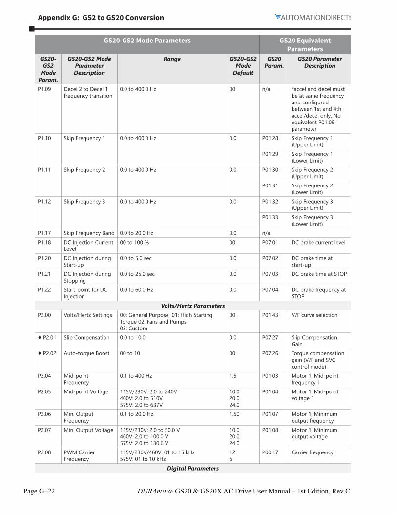
Page G–22 DURApulse GS20 & GS20X AC Drive User Manual – 1st Edition, Rev C
Appendix G: GS2 to GS20 Conversion
GS20-GS2 Mode Parameters GS20 Equivalent Parameters
GS20-GS2
Mode Param.
GS20-GS2 Mode Parameter Description
Range GS20-GS2 Mode
Default
GS20 Param.
GS20 Parameter Description
P109 Decel 2 to Decel 1 frequency transition
00 to 4000 Hz 00 n/a *accel and decel must be at same frequency and configured between 1st and 4th accel/decel only No equivalent P0109 parameter
P110 Skip Frequency 1 00 to 4000 Hz 00 P0128 Skip Frequency 1 (Upper Limit)
P0129 Skip Frequency 1 (Lower Limit)
P111 Skip Frequency 2 00 to 4000 Hz 00 P0130 Skip Frequency 2 (Upper Limit)
P0131 Skip Frequency 2 (Lower Limit)
P112 Skip Frequency 3 00 to 4000 Hz 00 P0132 Skip Frequency 3 (Upper Limit)
P0133 Skip Frequency 3 (Lower Limit)
P117 Skip Frequency Band 00 to 200 Hz 00 n/aP118 DC Injection Current
Level00 to 100 % 00 P0701 DC brake current level
P120 DC Injection during Start-up
00 to 50 sec 00 P0702 DC brake time at start-up
P121 DC Injection during Stopping
00 to 250 sec 00 P0703 DC brake time at STOP
P122 Start-point for DC Injection
00 to 600 Hz 00 P0704 DC brake frequency at STOP
Volts/Hertz ParametersP200 Volts/Hertz Settings 00: General Purpose 01: High Starting
Torque 02: Fans and Pumps 03: Custom
00 P0143 V/F curve selection
♦ P201 Slip Compensation 00 to 100 00 P0727 Slip Compensation Gain
♦ P202 Auto-torque Boost 00 to 10 00 P0726 Torque compensation gain (V/F and SVC control mode)
P204 Mid-point Frequency
01 to 400 Hz 15 P0103 Motor 1, Mid-point frequency 1
P205 Mid-point Voltage 115V/230V: 20 to 240V 460V: 20 to 510V 575V: 20 to 637V
100 200 240
P0104 Motor 1, Mid-point voltage 1
P206 Min Output Frequency
01 to 200 Hz 150 P0107 Motor 1, Minimum output frequency
P207 Min Output Voltage 115V/230V: 20 to 500 V 460V: 20 to 1000 V 575V: 20 to 1306 V
100 200 240
P0108 Motor 1, Minimum output voltage
P208 PWM Carrier Frequency
115V/230V/460V: 01 to 15 kHz 575V: 01 to 10 kHz
12 6
P0017 Carrier frequency:
Digital Parameters

Appendix G: GS2 to GS20 Conversion
Page G–23DURApulse GS20 & GS20X AC Drive User Manual – 1st Edition, Rev C
GS20-GS2 Mode Parameters GS20 Equivalent Parameters
GS20-GS2
Mode Param.
GS20-GS2 Mode Parameter Description
Range GS20-GS2 Mode
Default
GS20 Param.
GS20 Parameter Description
P300 Source of Operation Command
00: Operation determined by digital keypad 01: Operation determined by external control terminals, keypad STOP is enabled 02: Operation determined by external control terminals, keypad STOP is disabled 03: Operation determined by RS-485 interface, keypad STOP is enabled 04: Operation determined by RS-485 interface, keypad STOP is disabled
00 P0200 Two-wire / three- wire operation control
P301 Multi-function Input Terminals (DI1 - DI2)
00: DI1 - FWD / STOP, DI2 - REV / STOP 01: DI1 - RUN / STOP, DI2- REV / FWD 02: DI1 - RUN momentary (NO) DI2 - REV / FWD DI3 - STOP momentary (NC)
00 P0201 Multi-function input command 1 (FWD/DI1)- only use if P0200 = 0
P0202 Multi-function input command 2 (REV/DI2) only use if P0200 = 0
P302 Multi-function Input (DI3)
00: External Fault (NO)01: External Fault (NC) 02: External Reset03: Multi-Speed/PID SP Bit 104: Multi-Speed/PID SP Bit 205: Multi-Speed/PID SP Bit 306: Reserved 07: Reserved08: Reserved09: Jog10: External Base Block (NO)11: External Base Block (NC) 12: Second Accel/Decel Time 13: Speed Hold14: Increase Speed15: Decrease Speed16: Reset Speed to Zero17: PID Disable (NO) 18: PID Disable (NC)99: Input Disable
00 P0203 Multi-function input command 3 (DI3)
P303 Multi-function Input (DI4)
03 P0204 Multi-function input command 4 (DI4)
P304 Multi-function Input (DI5)
04 P0205 Multi-function input command 4 (DI5)
P305 Multi-function Input (DI6)
05 P0206 Multi-function input command 4 (DI6)
P311 Multi-Function Output Terminal 1
00: AC Drive Running01: AC Drive Fault 02: At Speed 03: Zero Speed04: Above Desired Frequency05: Below Desired Frequency06: At Maximum Speed07: Over torque detected 08: Above Desired Current 09: Below Desired Current10: PID Deviation Alarm
00 P0213 Multi-function output 1 (R1)
P312 Multi-Function Output Terminal 2
01 P0216 Multi-function output 2 (DO1)- Transisitor output, not relay outputensure adequante current for field device
♦ P316 Desired Frequency 00 to 4000 Hz 00 P0222 Desired frequency reached 1
♦ P317 Desired Current 00 to <Drive Rated Amps> 00 n/a♦ P318 PID Deviation Level 10 to 500 % 100 P0813 PID feedback signal
error deviation level♦ P319 PID Deviation Time 01 to 3000 sec 50 P0814 PID feedback signal
error deviation time

Page G–24 DURApulse GS20 & GS20X AC Drive User Manual – 1st Edition, Rev C
Appendix G: GS2 to GS20 Conversion
GS20-GS2 Mode Parameters GS20 Equivalent Parameters
GS20-GS2
Mode Param.
GS20-GS2 Mode Parameter Description
Range GS20-GS2 Mode
Default
GS20 Param.
GS20 Parameter Description
Analog ParametersP400 Source of Frequency
Command00: Frequency determined by keypad potentiometer 01: Frequency determined by digital keypad up/down 02: Frequency determined by 0 to +10V input on AI terminal with jumpers 03: Frequency determined by 4 to 20mA input on AI terminal with jumpers 04: Frequency determined by 0 to 20mA input on AI terminal with jumpers 05: Frequency determined by RS-232C/ RS-485 communication interface
00 P0020 Master frequency command source (AUTO, REMOTE)
P0301 Analog input selection (AI2)
P401 Analog Input Offset Polarity
00: No Offset 01: Positive Offset 02: Negative Offset
00 P0307 Positive / negative bias mode (AI1)
♦ P402 Analog Input Offset 00 to 1000% 00 P0304 Analog input bias (AI2)♦ P403 Analog Input Gain 00 to 3000% 1000 P0312 Analog input gain (AI2)P404 Analog Input
Reverse Motion Enable
00: Forward Motion Only 01: Reverse Motion Enable
00 P0310 Reverse setting when analog signal input is negative frequency
P405 Loss of ACI Signal (4-20mA)
00: Decelerate to 0Hz 01: Stop immediately and display error code “EF” 02: Continue operation by the last frequency command
00 P0319 Signal loss selection for analog input 4-20 mA
♦ P411 Analog Output Signal
00: frequency Hz 01: Current A 02: PV
00 P0320 Multi-function output (A01)
♦ P412 Analog Output Gain 00 to 200% 100 P0321 Analog output gain (A01)
Presets♦ P500 Jog 00 to 4000 Hz 60 P0122 JOG frequency♦ P501 Multi-Speed 1 00 to 4000 Hz 00 P0400 1st step speed
frequency♦ P502 Multi-Speed 2 00 to 4000 Hz 00 P0401 2nd step speed
frequency♦ P503 Multi-Speed 3 00 to 4000 Hz 00 P0402 3rd step speed
frequency♦ P504 Multi-Speed 4 00 to 4000 Hz 00 P0403 4th step speed
frequency♦ P505 Multi-Speed 5 00 to 4000 Hz 00 P0404 5th step speed
frequency♦ P506 Multi-Speed 6 00 to 4000 Hz 00 P0405 6th step speed
frequency♦ P507 Multi-Speed 7 00 to 4000 Hz 00 P0406 7th step speed
frequencyProtection Parameters

Appendix G: GS2 to GS20 Conversion
Page G–25DURApulse GS20 & GS20X AC Drive User Manual – 1st Edition, Rev C
GS20-GS2 Mode Parameters GS20 Equivalent Parameters
GS20-GS2
Mode Param.
GS20-GS2 Mode Parameter Description
Range GS20-GS2 Mode
Default
GS20 Param.
GS20 Parameter Description
P600 Electronic Thermal Overload Relay
00 P0613 Electronic thermal relay selection 1 (motor 1)
P601 Auto Restart after Fault
00 P0711 Number of times of restart after fault
P602 Momentary Power Loss
00 P0706 Restart after momentary power loss
P603 Reverse Operation Inhibit
00 P0023 Motor direction control
P604 Auto Voltage Regulation
00 P0723 Auto Voltage Regulation
P605 Over-Voltage Stall Prevention
00 P0601 Over-voltage stall prevention
P606 Auto Adjustable Accel/Decel
00 P0144 Auto-acceleration and auto-deceleration setting
P607 Over-Torque Detection Mode
00 P0606 Over-torque detection selection (motor 1)
P608 Over-Torque Detection Level
150 P0607 Over-torque detection level (motor 1)
P609 Over-Torque Detection Time
01 P0608 Over-torque detection time (motor 1)
P610 Over-Current Stall Prevention during Acceleration
20 to 200% 150 P0603 Over-current stall prevention during acceleration (OCA)
P611 Over-Current Stall Prevention during Operation
20 to 200% 150 P0604 Over-current stall prevention during operation (OCN)
P612 Maximum Allowable Power Loss Time
20 P0707 Allowed power loss duration
P613 Base-Block Time for Speed Search
05 P0708 Base Block time
P614 Maximum Speed Search Current Level
150 P0709 Current limit of speed tracking
P615 Upper Bound of Output Frequency
400 P0110 Output frequency upper limit
P616 Lower Bound of Output Frequency
00 to 400Hz 00 P0111 Output frequency lower limit
P630 Line Start Lockout 00: Enable Line Start Lockout 01: Disable Line Start Lockout
00 P0235 External operation control selection after fault reset and reboot

Page G–26 DURApulse GS20 & GS20X AC Drive User Manual – 1st Edition, Rev C
Appendix G: GS2 to GS20 Conversion
GS20-GS2 Mode Parameters GS20 Equivalent Parameters
GS20-GS2
Mode Param.
GS20-GS2 Mode Parameter Description
Range GS20-GS2 Mode
Default
GS20 Param.
GS20 Parameter Description
P631 Present Fault Record 0: No fault record1: Over-current during acceleration (ocA)2: Over-current during deceleration (ocd)3: Over-current during steady operation
(ocn)4: Ground fault (GFF)6: Over-current at stop (ocS)7: Over-voltage during acceleration (ovA)8: Over-voltage during deceleration (ovd)9: Over-voltage during constant speed
(ovn)10: Over-voltage at stop (ovS)11: Low-voltage during acceleration (LvA)12: Low-voltage during deceleration (Lvd)13: Low-voltage during constant speed
(Lvn)14: Low-voltage at stop (LvS)15: Phase loss protection (orP)16: IGBT overheating (oH1) 18: IGBT temperature detection failure
(tH1o)21: Over load (oL)22: Electronic thermal relay 1 protection
(EoL1)23: Electronic thermal relay 2 protection
(EoL2)24: Motor PTC overheating (oH3) 26: Over torque 1 (ot1)27: Over torque 2 (ot2)28: Under current (uC)31: EEPROM read error (cF2)33: U-phase error (cd1)34: V-phase error (cd2)35: W-phase error (cd3)36: cc (current clamp) hardware error
(Hd0)37: oc (over-current) hardware error (Hd1)40: Auto-tuning error (AUE)41: PID loss AI2 (AFE)43: PG feedback loss (PGF2)48: AI2 loss (ACE)49: External fault (EF)50: Emergency stop (EF1)51: External Base Block (bb)52: Password is locked (Pcod)54: Illegal command (CE1)55: Illegal data address (CE2)56: Illegal data value (CE3)57: Data is written to read-only address
(CE4)58: Modbus transmission time-out (CE10)
00 P0617 Fault record 1
P632 Second Most Recent Fault Record
00 P0618 Fault record 2
P633 Third Most Recent Fault Record
00 P0619 Fault record 3
P634 Fourth Most Recent Fault Record
00 P0620 Fault record 4
P635 Fifth Most Recent Fault Record
00 P0621 Fault record 5
P636 Sixth Most Recent Fault Record
00 P0622 Fault record 6

Appendix G: GS2 to GS20 Conversion
Page G–27DURApulse GS20 & GS20X AC Drive User Manual – 1st Edition, Rev C
GS20-GS2 Mode Parameters GS20 Equivalent Parameters
GS20-GS2
Mode Param.
GS20-GS2 Mode Parameter Description
Range GS20-GS2 Mode
Default
GS20 Param.
GS20 Parameter Description
PID ParametersP700 Input Terminal for
PID Feedback00: Inhibit PID operation 01: Forward-acting (heating loop) PID feedback, PV from AVI (0 to + 10V 02: Forward-acting (heating loop) PID feedback, PV from ACI (4 to 20mA) 03: Reverse-acting (cooling loop) PID feedback, PV from AVI (0 to +10V) 04: Reverse-acting (cooling loop) PID feedback, PV from ACI (4 to 20mA)
00 P0800 Terminal selection of PID feedback
P701 PV 100% Value 00 to 999 1000 n/aP702 PID Setpoint Source 00: Keypad
01: Serial Communications00 P0865 PID target value source
♦ P710 Keypad PID Setpoint 00 to 999 00 n/a Use onBoard PLC to move desired PID value when input signal is present
♦ P711 PID Multi-setpoint 1 00 to 999 00 n/a Use onBoard PLC to move desired PID value when input signal is present
♦ P712 PID Multi-setpoint 2 00 to 999 00 n/a Use onBoard PLC to move desired PID value when input signal is present
♦ P713 PID Multi-setpoint 3 00 to 999 00 n/a Use onBoard PLC to move desired PID value when input signal is present
♦ P714 PID Multi-setpoint 4 00 to 999 00 n/a Use onBoard PLC to move desired PID value when input signal is present
♦ P715 PID Multi-setpoint 5 00 to 999 00 n/a Use onBoard PLC to move desired PID value when input signal is present
♦ P716 PID Multi-setpoint 6 00 to 999 00 n/a Use onBoard PLC to move desired PID value when input signal is present
♦ P717 PID Multi-setpoint 7 00 to 999 00 n/a Use onBoard PLC to move desired PID value when input signal is present
♦ P720 Proportional Control 00 to 100 10 P0801 Proportional gain (P)♦ P721 Integral Control 000 to 1000 sec 100 P0802 Integral time (I)♦ P722 Derivative Control 000 to 100 sec 000 P0803 Differential time (D)P723 Upper Bound for
Integral Control00 to 100% 100 P0804 Upper limit of integral
controlP724 Derivative Filter
Time Constant00 to 25 sec 00 P0807 PID delay time

Page G–28 DURApulse GS20 & GS20X AC Drive User Manual – 1st Edition, Rev C
Appendix G: GS2 to GS20 Conversion
GS20-GS2 Mode Parameters GS20 Equivalent Parameters
GS20-GS2
Mode Param.
GS20-GS2 Mode Parameter Description
Range GS20-GS2 Mode
Default
GS20 Param.
GS20 Parameter Description
P725 PID Output Frequency Limit
00 to 110% 100 P0805 PID output command limit (positive limit)
P726 Feedback Signal Detection Time
00 to 3600 sec 60 P0808 Feedback signal detection time
P727 PID Feedback Loss 00: Warn and AC Drive Stop 01: Warn and Continue Operation
00 P0809 Feedback signal fault treatment
Display Parameters♦ P800 User Defined Display
Function00: Output Frequency (Hz) 01: Motor Speed (RPM) 02: Output Freq X P801 03: Output Current (A) 04: Motor Output Current (%) 05: Output Voltage (V) 06: DC Bus Voltage (V) 07: PID Setpoint 08: PID Feedback Signal (PV) 09: Frequency Setpoint
00 P0004 User Display
♦ P801 Frequency Scale Factor
001 to 1600 10 P0005 Coefficient Gain in Actual Output Frequency Display (H Page scale)
Communications ParametersP900 Communication
Address01 to 254 01 P0900 Communication
addressP901 Transmission Speed 00: 4800 baud
01: 9600 baud 02: 19200 baud 03: 38400 baud
01 P0901 COM1 transmission speed
P902 Communication Protocol
00: Modbus ASCII mode 7 data bits,no parity,2 stop bits 01: Modbus ASCII mode 7 data bits,even parity,1 stop bit 02: Modbus ASCII mode 7 data bits,odd parity,1 stop bit 03: Modbus RTU mode 8 data bits,no parity,2 stop bits 04: Modbus RTU mode 8 data bits,even parity,1 stop bit 05: Modbus RTU mode 8 data bits,odd parity,1 stop bit
00 P0904 COM1 communication protocol
P903 Transmission Fault Treatment
00: Display fault and continue operating 01: Display fault and RAMP to stop 02: Display fault and COAST to stop 03: No fault displayed and continue operating
00 P0902 COM1 transmission fault treatment
P904 Time Out Detection 00: Disable 01: Enable
00 P0903 COM1 time-out detection ( 0 = disable)
P905 Time Out Duration 01 to 600 seconds 05 P0909 Communication response delay time
♦ P907 Parameter Lock 00: All parameters can be set and read 01: All parameters are read-only
00 P0002 Restore to Default = 1 keypad lock
P908 Restore to Default 99: Restores all parameters to factory defaults 20: Restores to GS20 mode
00 P0002 Restore to Default = 9, 10,11, or 12
♦ P911 Block Transfer Parameter 1
P000 to P801, P999 P999 P0911 Block transfer 1

Appendix G: GS2 to GS20 Conversion
Page G–29DURApulse GS20 & GS20X AC Drive User Manual – 1st Edition, Rev C
GS20-GS2 Mode Parameters GS20 Equivalent Parameters
GS20-GS2
Mode Param.
GS20-GS2 Mode Parameter Description
Range GS20-GS2 Mode
Default
GS20 Param.
GS20 Parameter Description
♦ P912 Block Transfer Parameter 2
P000 to P801, P999 P999 P0912 Block transfer 2
♦ P913 Block Transfer Parameter 3
P000 to P801, P999 P999 P0913 Block transfer 3
♦ P914 Block Transfer Parameter 4
P000 to P801, P999 P999 P0914 Block transfer 4
♦ P915 Block Transfer Parameter 5
P000 to P801, P999 P999 P0915 Block transfer 5
♦ P916 Block Transfer Parameter 6
P000 to P801, P999 P999 P0916 Block transfer 6
♦ P917 Block Transfer Parameter 7
P000 to P801, P999 P999 P0917 Block transfer 7
♦ P918 Block Transfer Parameter 8
P000 to P801, P999 P999 P0918 Block transfer 8
♦ P919 Block Transfer Parameter 9
P000 to P801, P999 P999 P0919 Block transfer 9
♦ P920 Block Transfer Parameter 10
P000 to P801, P999 P999 P0920 Block transfer 10
♦ P921 Block Transfer Parameter 11
P000 to P801, P999 P999 P0921 Block transfer 11
♦ P922 Block Transfer Parameter 12
P000 to P801, P999 P999 P0922 Block transfer 12
♦ P923 Block Transfer Parameter 13
P999 P0923 Block transfer 13
♦ P924 Block Transfer Parameter 14
P999 P0924 Block transfer 14
♦ P925 Block Transfer Parameter 15
P999 P0925 Block transfer 15
♦ P926 Serial Comm Speed Reference
600 n/a Use Command Write Word 2001H
♦ P927 Serial Comm RUN Command
00 n/a Use Command Write Word 2000H
♦ P928 Serial Comm Direction Command
00 n/a Use Command Write Word 2000H
♦ P929 Serial Comm External Fault
00 n/a Use Command Write Word 2000H
♦ P930 Serial Comm Fault Reset
00 n/a Use Command Write Word 2000H
♦ P931 Serial Comm JOG Command
00 n/a Use Command Write Word 2000H
P938 GS20 Firmware Version
###
P939 Firmware Version 107 P0006 GS20 Firmware VersionP941 GS Series Number ## n/aP942 Manufacturer Model
Information## P0000 GS20 Model ID-
Identity Code
For detailed parameter descriptions, refer to Chapter 4 in the GS2 User Manual at www.automationdirect.com

Page G–30 DURApulse GS20 & GS20X AC Drive User Manual – 1st Edition, Rev C
Appendix G: GS2 to GS20 Conversion
Step 8: Converting Your GS2 GSoft Parameter File to a GS20 GSoft2 FileIf a GS20 drive is configured to GS2 mode, GSoft2 software can utilize an existing GS2 GSoft parameter file. Use the following steps to load a GS2 parameter file into the GS20 drive in GS2 mode
NOTE: See Chapter 7 for instructions on loading free GSoft2 software.
1) Before removing the GS2 drive, use the GSoft software to backup the latest parameter configuration. Save the “*.gsc” file to a local drive. Ensure that the drive version is saved to V1.07. This is required to prevent errors when downloading to the drive from Gsoft2.
2) Open Gsoft2 software. Click Parameter. Click Open. Navigate to the GS2 drive parameter file (*.gsc extension). Note- you may need to select “All Files” from the window for the .GSC files to show up. Click Open.
3) Gsoft2 will convert the file parameters to a GS20 compatible format and display them in the parameters window. Check the parameter values to ensure they match.
4) Connect Gsoft2 to the GS20 drive in GS2 mode, and click “Write All” in the parameter window. See the “Writing Parameters” section of the GSoft2 Help file for more detail.
5) The GS20 drive in GS2 mode will now have the same parameters as your existing GS2 drive.
NOTE: All GS20 in GS2 mode functions may not perform EXACTLY as the GS2 drive. Complete testing for your specific application to confirm drive functionality is the same.