
ANL-6725 Chemical Separations Processes for Plutonium ...
250
ANL-6725 Chemical Separations Processes for Plutonium and Uranium (TID-4500, 28th Ed.) AEC Research and Development Report ARGONNE NATIONAL LABORATORY 9700 South Cass Avenue Argonne, Illinois 60440 CHEMICAL ENGINEERING DIVISION SUMMARY REPORT A p r i l , iVlay,. J u n e s 1963 S. Lawroski, Division Director R. C. Vogel, Associate Division Director Milton Levenson, Associate Division Director V. H. Munnecke, Assistant Division Director Preceding Quarterly Reports: ANL-6687 January, February, March, 1963 ANL-6648 October, November, December, 1962 ANL-6596 July, August, September, 1962 Operated by The University of Chicago under Contract W-3 1 - 1 09-eng-38 with the U. S. Atomic Energy Commission
-
Upload
khangminh22 -
Category
Documents
-
view
0 -
download
0
Transcript of ANL-6725 Chemical Separations Processes for Plutonium ...

A N L - 6 7 2 5 C h e m i c a l S e p a r a t i o n s P r o c e s s e s
for P l u t o n i u m and U r a n i u m (TID-4500 , 28th Ed. ) AEC R e s e a r c h and
D e v e l o p m e n t R e p o r t
ARGONNE NATIONAL LABORATORY 9700 South C a s s Avenue A r g o n n e , I l l i no i s 60440
C H E M I C A L ENGINEERING DIVISION SUMMARY R E P O R T
A p r i l , iVlay,. Junes 1963
S. L a w r o s k i , D iv i s ion D i r e c t o r R. C. Vogel , A s s o c i a t e D iv i s ion D i r e c t o r
Mi l ton L e v e n s o n , A s s o c i a t e Div is ion D i r e c t o r V. H. M u n n e c k e , A s s i s t a n t Div i s ion D i r e c t o r
P r e c e d i n g Q u a r t e r l y R e p o r t s :
A N L - 6 6 8 7 J a n u a r y , F e b r u a r y , M a r c h , 1963 A N L - 6 6 4 8 O c t o b e r , N o v e m b e r , D e c e m b e r , 1962 A N L - 6 5 9 6 Ju ly , Augus t , S e p t e m b e r , 1962
O p e r a t e d by The U n i v e r s i t y of Chicago u n d e r
C o n t r a c t W-3 1 - 1 0 9 - e n g - 3 8 with the
U. S. A t o m i c E n e r g y C o m m i s s i o n
DISCLAIMER
This report was prepared as an account of work sponsored by an agency of the United States Government. Neither the United States Government nor any agency Thereof, nor any of their employees, makes any warranty, express or implied, or assumes any legal liability or responsibility for the accuracy, completeness, or usefulness of any information, apparatus, product, or process disclosed, or represents that its use would not infringe privately owned rights. Reference herein to any specific commercial product, process, or service by trade name, trademark, manufacturer, or otherwise does not necessarily constitute or imply its endorsement, recommendation, or favoring by the United States Government or any agency thereof. The views and opinions of authors expressed herein do not necessarily state or reflect those of the United States Government or any agency thereof.

DISCLAIMER Portions of this document may be illegible in electronic image products. Images are produced from the best available original document.

ANNOUNCEMENT
Change in Schedule of Chemical Engineering Division Summary Reports
This repor t , Chemical Engineering Division Summary Report , Apri l , May, June, 1963 is the las t in the se r i e s of quar te r ly p r o g r e s s r epor t s that has been issued by the Chemical Engineering Division, Instead of report ing the work of the division on a quar te r ly bas i s , the work will be repor ted henceforth on a semiannual bas i s . The f i rs t Chemical Engineering Division Semiannual Summary Report will be for the period July through December , 1963.

1
TABLE OF CONTENTS
Page
SUMMARY 11
I. CHEMICAL-METALLURGICAL PROCESSING 31
---t^. Pyrometa l lu rg ica l Development 31
1. Melt Refining. 31 2. P r o c e s s e s Employing Liquid Metal Solvents . . . . . . 41
3. Reactor Mater ia l s . . . . . . . . . . . . . . . . . . . . . . . 79
""B. Fue l -p rocess ing Faci l i t ies for EBR-II . 88
1. Status of Fuel Cycle Faci l i ty . . . . . . . . . . . . . . . . 88 2. Service Equipment Development 91
3. P r o c e s s Equipment Development. . 93
'~'C. Chemis t ry of Liquid Metals . 99
1. Solubilities in Liquid Meta ls . 99 2. Liquid Sodium Coolant Chemis t ry . . . . . . . . . . . . . 102 3. Thermodynamic Studies . 104
II. FUEL CYCLE APPLICATIONS OF VOLATILITY AND FLUIDIZATION TECHNIQUES 112
A. Labora tory Investigations of Fluor ide Volatility P r o c e s s e s . . . . . . . . . . . . . . . . . . . . . . . . . . . . . . . . 113
1. Fluid-bed Fluor inat ion of U3O8 113 2. Oxidative "Decladding" of Stainless Steel - and
Zi rca loy-c lad Uranium Dioxide Pel le ts . 122
B. Eng inee r ing-sca le Investigation of Fluid-bed Fluor ide Volatili ty P r o c e s s 131
1. Development of Fluid-bed Fluor ide Volatility P r o c es ses for the Recovery of Uranium and Plutonium from Uranium Dioxide Fue l s 131
2. Fluor inat ion of Dense Uranium Dioxide Fuel Pe l le t s in a Fluidized Bed 134
3. Oxidative Separat ion of Uraniumi Dioxide Fuel from Stainless S tee l -c lad Fuel Segments in a Fluidized Packed Bed 148
4. Design and Construct ion of Plutonium Faci l i ty 155 5. Cleanup of Plutonium Hexafluoride from Cell Ex
haust Air 157 6. Basic Studies of Flu id ized-bed Behavior Related to
P r o c e s s Opera t ions : Solids Mixing 166

2
TABLE OF CONTENTS
Page
7. P r o c e s s Studies on the Recovery of Uranium from Highly Enr iched Uranium Alloy Fuels 176
8. Conversion of Uranium Hexafluoride to Uranium Dioxide: P r epa ra t i on of High-density P a r t i c l e s . . . . 185
/ f l L CALORIMETRY 191
A. Revised Value of the Enthalpy of Format ion of Uranium Hexafluoride 192
B. Explora tory Combustion of Uranium Monosulfide in Fluor ine 192
C. Explora tory Combustions of Carbon and Silicon Carbide
in Fluor ine 194
D. Thermodynamic P r o p e r t i e s of Hydrogen Fluor ide . . . . . 195
E. High- t empera tu re (1500 C) Enthalpy Ca lor imete r 198
F . High- tempera tu re (2500 C) Enthalpy Ca lo r imete r 200
/: IV. REACTOR SAFETY . . . . . . . . . . . . . . . . . . . . . . . . . . . . 201
A. Metal-oxidat ion and -ignition Kinetics 201
1. I so thermal Oxidation of Uranium in Air at T e m p e r a tu re s of 500 C and Above- 201
2. Plutonium-igni t ion Studies 207
B. Meta l -Water React ions 210
1. Studies of Meta l -Water React ions by the L a s e r Heating Method 210
2. Studies of the Aluminum-Water Reaction in TREAT . 212
,; V. ENERGY CONVERSION. . . . . . . . . . . . . . . . . . . . . . . . . . 224
A. Regenera t ive Emf Cell 224
1. Bimetal l ic Cells 225 2. Lithium Hydr ide-Li th ium Chloride Solid-Liquid
Equi l ibr ium Studies . . . . . . . . . . . . . . . . . . . . . . 228 3. Isopiest ic and Transp i r a t ion Techniques in the Study
of Some Aspects of the Regenerat ive Emf Cell P r o b l e m . . . . . . . . . . . . . . . . . . . . . . . . . . . . . . 232
B. Thermoe lec t r i c i ty Resea r ch . 234
1. Liquid Systenas 235 2. Refractory Solid Thermocouple Sys tems 235
VI. DETERMINATION OF NUCLEAR CONSTANTS 243

• LIST OF TABLES
No. Title Page
I-1 Distr ibut ion of Iodine in Exper imenta l Apparatus after Reheating of F iber f rax Fume Trap Used in Melt Refining Exper iment 36
1-2 Activity Distr ibution in AEC Fi l te r -Act iva ted Charcoal Assembl ies Used for Study of Iodine Release from F ibe r f rax 38
1-3 Corros ion of Inconel, Stainless Steel, and Hastelloy Alloys by Titanium Sponge. 40
1-4 Effect of Agitation on Uranium Loss in the In termeta l l ic Compound Prec ip i ta t ion Step of the Skull Reclamation P r o c e s s (Run BJ-19) . 45
1-5 Uranium Mater ia l Balances for Skull Reclamat ion P r o c e s s Demonst ra t ion Runs BJ -18 and BJ-20 48
1-6 F i s s ion Product Removals Effected in Runs BJ-18 and
BJ -20 . 49
1-7 Summary of Blanket P r o c e s s Demonstrat ion Run 7. . . . . . . 61
1-8 Ent ra inment of Uranium and Cer ium during Evaporation of 50 w/o Magnes ium-Zinc Solutions 65
1-9 Cor ros ion of Tungsten and Molybdenum-30 w/o Tungsten Alloy Exposed to the Sal t -Metal System of the Noble Metal Ext rac t ion Step . . . . . . . . . . . . . . . . . . . . . . . . . . . . . . 67
I-10 Pe r fo rmance of P l a s m a - S p r a y e d Coatings Subjected to
The rma l Cycling between 300 and 800 C . . . . . . . . . . . . . . 75
I-11 Composit ion of Uranium Monosulfide Samples . . . . . . . . . . 82
1-12 Effect of Reheating on Insolubles and Oxygen Contents of Uranium Monosulfide 83
1-13 Effect of Flux Composit ion on Reduction of Plutonium Dioxide. . . . . . . . . . . . . . . . . . . . . . . . . . . . . . . . . . . . 86
1-14 Effect of Magnesium Concentrat ion on Reduction of Plutonium Dioxide . . . . . . . . . . . . . . . . . . . . . . . . . . . . . . . . 86
1-15 Solubility of Plutonium in Liquid Zinc . . . . . . . . . . . . . . . 100
II-1 Exper imenta l Conditions Affecting Elut r ia t ion of U30g from a Fluidized Bed during Fluor inat ion. . . . . . . . . . . . . . . . 118
II-2 Effect of T e m p e r a t u r e on the Flu id-bed Fluorinat ion of UsOg. 119

LIST OF TABLES
No. Title Page
II-3 Fluid-bed Fluor inat ion of UjOg 120
II-4 Oxidative Decladding of Uranium Dioxide Pel le ts Clad in Type 304 Stainless S t ee l / z i r c a loy . . . . . . . . . . . . . . . . . 123
II-5 Deconaposition of Plutonium Hexafluoride by Gamma Radiation in the P r e s e n c e of Helium 129
II-6 Operating Conditions and Resul ts for Run UOF-70, A Two-zone Oxidat ion-Fluorinat ion of Uranium Dioxide P e l lets with Gas Pulsing 138
II-7 Uranium Mater ia l Balances for Recent Two-zone Oxidat ion-Fluor inat ions of 12-in.-deep Uranium Dioxide in Fluidized Packed Beds 142
II-8 Operating Conditions for Run UOF-71 , A Two-zone Oxidat ion-Fluorinat ion of a Fluidized Packed Bed of Stainl e s s Steel-clad UO2 Pel le t s 144
II-9 Operating Conditions for Run UOF-72, A Two-zone Oxidat ion-Fluor inat ion of a Fluidized Packed Bed of Stainl e s s Stee l -c lad Pe l le t s 146
11-10 Operating Conditions and Resul ts of Oxidation Runs for Removal of Uranium Dioxide from Stainless Steel Cladding 150
11-11 Operating Conditions and Resul ts of Exper iments for Re moval of Uranium Dioxide from Stainless Steel Cladding Using Oxidation, Reduction, and Reoxidation of the Fuel . . 150
11-12 Effect of Posi t ion of Simulated 304 Stainless Steel -c lad Fuel Segments in a Fluidized Packed Bed on the Oxidative Removal of Uranium Dioxide from the Cladding . . . . . . . . 154
11-13 Resu l t s of Leak Tes t s of P r o c e s s Valves 156
11-14 Reaction Conditions for Hydrochlorinat ion and Fluorinat ion of Miniature Multiplate Uran ium-Zi rcon ium Fuel E l e ment Subassenibl ies . . 179
III-1 Explora tory Combustions of Uranium Monosulfide in Fluor ine . . . . . . . . . . . . . . . . . . . . . . . . . . . . . . . . . . 193
III-2 Heat T rans fe r Cha rac t e r i s t i c s of Dust Shield . . . . . . . . . 199
IV-1 Resul t s of I so thermal Studies of the Reaction of Uranium with Air , Oxygen, and 20 v /o Oxygen-80 v /o Argon Mixture . 204

LIST OF TABLES
No. Title Page
IV-2 Ignition T e m p e r a t u r e s of Plutonium, in Air and Oxygen . . . . 208
IV-3 Resul ts of TREAT Exper iments with Aluminum-Uranium Alloy P la te s 214
IV-4 Compar ison of the Nuclear Excurs ions of the B o r a x - I , S L - 1 , and SPERT-1 Reac tors 220
IV-5 Calculation of Extent of Aluminum-Water Reaction in the S P E R T - 1 Excurs ion . 223
IV-6 Calculation of Extent of Aluminum-Water Reaction in the SL-1 Excurs ion , 223
V-1 Lithium Hydr ide-Li th ium Chloride Solid-Liquid
Equilibriumi. 228
V-2 Therm.odynam.ic Data for LiH in LiH-LiCl System. 231
V-3 Thermodynamic Data for LiCl in LiH-LiCl System 231
V-4 Compar i son of Seebeck Coefficients for Melted Uranium Monosulfide Spec imen . 239

LIST OF FIGURES
No. Title Page
I- l Apparatus for Study of Iodine Release from a F iber f rax Fume Trap 33
1-2 AEC Fi l t e r -Ac t iva ted Charcoal Assembly for Collection of Iodine Released from a F iber f rax Fume Trap . . . . . . . . . . 34
1-3 F ibe r f rax Fume Trap after Melt Refining Exper iment . . . . . 35
1-4 Cumulative Iodine Activity Released to F i l t e r Assenablies during Reheating of F ibe r f rax Fume Trap Used in Melt Refining E x p e r i m e n t . . . . . . . . . . . . . . . . . . . . . . . . . . . 37
1-5 Flowsheet for Skull Reclamat ion P r o c e s s . . . . . . . . . . . . . 42
1-6 Effects of T e m p e r a t u r e and St i r r ing Rate on Ruthenium Extrac t ion in the Noble Metal Ext rac t ion Step . 47
1-7 Distr ibution of Neptunium, between Magnesium Chloride and Zinc-Magnes ium Alloy 55
1-8 Distr ibution of Curium between Zinc-Magnes ium Alloy and Magnesium Chloride 56
1-9 Distr ibution of P ro tac t in ium between Magnesium Chloride and Zinc-Magnesiuna Alloy. 57
I-10 Distr ibut ion of Chromium between Magnesium Chloride and Zinc-Magnes ium Alloy . 57
I-11 Exper imenta l Equipment for P rocess ing Lightly I r rad ia ted
Uranium by the EBR-II Blanket P r o c e s s . . 59
1-12 Metal Evaporat ion Unit 64
1-13 Stability of Solutions of Uranium in Five P e r c e n t Magnesiuna-Zinc Alloy in the P r e s e n c e of Silicon. . . . . . . . 70
1-14 Stability of Solutions of Uranium in Five P e r c e n t Magnesiuna-Zinc Alloy in the P r e s e n c e of 304 Stainless Steel . 70
1-15 Stability of Solutions of Uraniuna in Five P e r c e n t Magnesiuna-Zinc Alloy in the P r e s e n c e of Aluminuna 71
1-16 Stability of Solutions of Uraniuna in Five P e r c e n t Magnes ium-Zinc Alloy in the P r e s e n c e of Beryl l ium . . . . . 72
1-17 Apparatus for the Collection and Measurement of Gas Evolved frona Molten Salt Solutions 77
1-18 Molar Absorptivity of UOj Ion in the Visible and N e a r -inf rared Regions 78

7
LIST OF FIGURES
No. Title Page
1-19 Vacuuna Glovebox for Uranium Monocarbide Prepara t ion . . . 80
1-20 Effect of Thor ium Dioxide to Flux Weight Ratio on the Reduction of Thoriuna Dioxide. . . . . . . . . . . . . . . . . . . . . 84
1-21 Distr ibut ion of Plutonium between Zinc-Magnesiuna Alloy
and Magnesium Chloride . . . . . . . . . . . . . . . . . . . . . . . . 87
1-22 Par t i a l ly Oxidized Melt Refining Skull . . . . . . . . . . . . . . . 94
1-23 Inductive Heating and Mixing Apparatus . . . . . . . . . . . . . . 96
1-24 Overal l Rate of Reduction and Dissolution of Skull Oxide . . . 97
1-25 Magnesiuna-Zinc Disti l lat ion Apparatus . . . . . . . . . . . . . . 98
1-26 Solubility of Plutonium in Liquid Zinc . . . . . . . . . . . . . . . 101
1-27 Emf of Plutonium.-Cadnaiuna Galvanic Cell vs .
T e m p e r a t u r e . . . . . . . . . . . . . . . . . . . . . . . . . . . . . . . . 106
1-28 Schematic Diagrana of Hollow-cathode Discharge Lamp, . . . 109
1-29 Rare Ear th-Cadnaium Sys tems. Typical Effusion I so the rms at 445 C . . . . . . . . . . . . . . . . . . . . . . . . . . . . . I l l
II-1 Fluid-bed Fluor ina t ion Reactor . . . . . . . . . . . . . . . 115 II-2 Specimens of Siiaaulated Segments of Stainless Steel-Clad
Uranium Dioxide Fuel E lements after Various Stages of Oxidation . . . . . . . . . . . . . . . . . . . . . . . . . . . . . . . . . . 124
II-3 Fluor ina t ion of U3O8 . . . . . . . . . . . . . . . . . . . . . . . . . . . 127
II-4 Varia t ion of React ion Rate Constant k' with Tenaperature for the Fluor inat ion of UjOg . . . . . . . . . . . . . . . . . . . . . . 127
II-5 Decomposit ion of Plutoniuna Hexafluoride by Gamma Radiation in Mixtures with Helium . . . . . . . . . . . . . . . . . . . . . 130
II-6 F luor ina to r for Uranium Dioxide Pe l l e t s : Piping and Valve Ar rangemen t for Ex te rna l F i l t e r . . . . . . . . . . . . . . . . . . . 136
II-7 Uraniuna Hexafluoride Product ion and Fluor ine Input Rates for UOF-70. A Two-Zone Oxidat ion-Fluorinat ion of Uran i um Dioxide Pe l l e t s -with Gas Puls ing . . . . . . . . . . . . . . . . 138
II-8 Cumulative Uraniuna Hexafluoride Product Collection for Run UOF-70. A Two-Zone Oxidat ion-Fluorinat ion of Uran i um Oxide Pe l le t s with Gas Pulsing . . . . . . . . . . . . . . . . . 139
II-9 Effect of Oxygen Concentrat ion on the Tinae Required to Collect 90 P e r c e n t of the Charged Uranium as Uraniuna Hexafluoride . . . . . . . . . . . . . . . . . . . . . . . . . . . . . . . . 141

LIST OF FIGURES
No. Title Page
11-10 Typical Specinaens of Type 304 Stainless Steel-Clad Uran i um Dioxide Fuel Segments 143
11-11 Appearance of Typical Stainless Steel Cladding Residues at End of Run UOF-71 . . . . . . . . . . . . . . . . . . . . . . . . . . . . 145
11-12 Uranium Hexafluoride Product ion Rates for Run UOF-72, A Two-Zone Oxidat ion-Fluorinat ion of Stainless Steel-Clad Uranium Dioxide Pe l le t s . . . . . . . . . . . . . . . . . . . . . . . . 147
11-13 Fluidized Packed Bed Consisting of Four Individual Packed Sections 149
11-14 F rac t ion of Released Plutonium Hexafluoride Pass ing
through Two AEC F i l t e r s . . . . . . . . . . . . . . . . . . . . . . . . 157
11-15 Agglonaeration and Loading Functions 161
11-16 Size Distr ibut ion of Hydrolyzed PuF^, and AEC F i l t e r F i b e r s . . . . . . . . . . . . . . . . . . . . . . . . . . 164
11-17 Corre la t ion of Data of F i l t e r Pene t ra t ion in PuF^ Release Experinaents 166
11-18 Schematic Diagram of Apparatus Used in Studies of Mixing of Fluidized Par t i cu la te Solids 169
11-19 Effect of Size of Fixed Packing on Solids Mixing . . . . . . . . 171
11-20 Diffusion Coefficients for Fluidized Packed Bed with Cylindr ica l Packing . . . . . . . . . . . . . . . . . . . . . . . . . . . . . . . 172
11-21 Effect of Size of Fluidized P a r t i c l e s on Solids Mixing. . . . . 173
11-22 General Corre la t ion for Solids Mixing in a Fluidized Packed Bed , . . . . . . . . . . . . . . . . . . . . . . . . . . . . . . . . . . . . 173
11-23 Effect of Size Distr ibution of Fluidized P a r t i c l e s on Solids Mixing . 174
11-24 Effect of Bed Height on Rate of La te ra l Solids Mixing in a Fluidized Bed . . . . . . . . . . . . . . . . . . . . . . . . . . . . . . . 175
11-25 Uranium Loss during Hydrochlorinat ion of Uraniuna-Zi rconium Alloy Fuels . . . . . . . . . . . . . . . . . . . . . . . . . 181
11-26 Inc rease in Density of Uraniuna Dioxide Bed P a r t i c l e s Occur r ing during Deposition of High-Density Oxide from Convers ion of Uranium Hexafluoride with Steam and Hydrogen . 18 7
11-27 Pa r t i c l e Size Behavior during the Conversion of Uraniuna Hexafluoride to Uranium Dioxide in a Fluidized Bed - Run PY-72 188

LIST OF FIGURES
No. Title Page
11-28 Photonaicrographs of Sectioned Uraniuna Dioxide Pa r t i c l e s before and after Densification during Run PY-72 189
III- l Thernaal Conductivity of Dust Shield vs . Mean T e m p e r a t u r e 200
IV-1 Apparatus to Determine the Uraniuna-Air Reaction Kinetics 202
IV-2 Parabol ic Rate Constants for the Initial Reaction of Urani um with Air and with 20 v /o Oxygen-80 v /o Argon Mixture 206
IV-3 Ignition Tenapera tures of Plutonium by the Burning-curve Method 208
IV-4 Burning Curve Ignitions in Air of One-mm-th ick Pure Plutonium Foil Specimens 209
IV-5 Nuclear Energy Input v s . Extent of Reaction for Aluminum-Uraniuna Alloy Pla te Meltdown Exper iments in TREAT. . 215
IV-6 Alunainum-Uranium Alloy (Unclad SL-1 Mater ia l ) after Meltdown Experixaaent CEN-140H. 215
IV-7 Three SPERT ID Pla tes Held in Stainless Steel Holder: In Original Condition and after Meltdown Exper iment CEN-144 217
IV-8 Average P a r t i c l e Size of Aluiaiinuna-Uraniuna Alloy Pla tes after I r r ad ia t ion in TREAT v s . Nuclear Energy Input. . . . 219
V-1 P o t e n t i a l - T e m p e r a t u r e Curves of the Cell L i ( i ) / L i C l - L i F ( i ) / B i ( i ) with X^- (X^^ = Mole F rac t ion of Lithiumi) 226
V-2 Po ten t ia l -Tenapera tu re Curves of the Cell L i ( i ) / L i C l - L i F / S n ( i ) with X (X ^ ^ = Mole F rac t ion of Lithium) 227
V-3 Anonaaly in LiH-LiCl Solid-Liquid Equi l ibr ium Data 229
V-4 Sanaple Configuration during Tinae of Solidification 230
V-5 Compar ison of Heating and Cooling Curves in LiCl-LiH System with Specially Designed Sanaple Holder . . . . . 230
V-6 Exces s F r e e Ene rg i e s in the LiH-LiCl Binary System . . . 232
V-7 Schematic Diagram of Apparatus Used for Measurements of Seebeck Coefficient and Resis t iv i ty as a Function of Tenaperature 237

10
LIST OF FIGURES
No. Title Page
V-8 Compar ison of Absolute Seebeck Coefficient as a Function of Tempera tu re for Uranium Monosulfide Specinaens . . . . 238
V-9 Effect of Higher Sulfides on the Thernaoelectr ic Power of Uraniuna Monosulfide 240
V-10 Resis t ivi ty as a Function of Tempera tu re for Sintered Specinaens of Thor ium Monosulfide and 50-50 m / o US-ThS Solid Solution 240
V-11 Absolute Seebeck Coefficient vs . Tenaperature for Ura niuna Monophosphide 241
VI-1 Neutron Capture Cross Sections of Rheniuna-187 . . . . . . . 244
VI-2 Neutron Total Cross Section of Gadoliniuna . . . . . . . . . . . 245
VI-3 Neutron Capture Cross Section of Erbiuna-170. 246

SUMMARY
CHEMICAL ENGINEERING DIVISION SUMMARY REPORT
I. Chemical-Metal lurgical Process ing (pages 3 1 to 111)
The mel t refining p rocess is a process by which EBR-II fuel is purified while in the molten condition. Major developnaent work on this p rocess has been conapleted, but work is continuing on related problems.
An exper iment was conducted to investigate the behavior of fission product iodine after it is condensed on a Fiberf rax funae t rap in the melt refining p rocess , the naelt refining furnace is opened, and the t rap is exposed to the argon a tmosphere of the EBR-II Fuel Cycle Facil i ty. To sinaulate a high burnup fuel, a 20-g specimen of uranium-f iss ium alloy was spiked with uraniuna tr i iodide and cesium naetal, and was lightly i r radiated to produce iodine-131 t r a c e r activity. The specimen was then melt refined with a F iber f rax cover in place. The Fiberf rax was t r a n s fer red from the mel t refining furnace to a quartz tube furnace. Tempera ture gradients s imi lar to those expected in the plant facility as a resul t of fission product heating were maintained in the Fiberfrax. A slowly flowing argon s t r eam passed over the Fiber f rax and then through charcoal t raps for collection and determinat ion of the iodine activity. With a gradient in the Fiber f rax of 680 to 315 C, the ra te of iodine re lease was nearly constant over the period of 30 hr , with about 0.16 percent of the total activity in the Fiber f rax being re leased each hour. At 150 C, this ra te was reduced substantially. The behavior of the activity was consistent with previous indications that the volatilized iodine activity is either cesiuna iodide or a laiaterial containing both of these e lements .
To prepare for possible future necessi ty of removing nitrogen frona the argon atnaosphere in the EBR-II Fuel Cycle Facili ty, studies were begun of the removal of nitrogen from argon with hot titaniuna sponge. Various Inconel, 300 se r i e s s ta inless s tee ls , and Hastelloy steels have been tes ted and evaluated for the containnaent of titanium sponge metal in argon at 900 C. The steel most res i s tan t to attack by titaniuna was Type 316 s tainless s teel . However, because of its superior high-tenaperature strength, Hastelloy X has been selected as the s t ructura l mater ia l for the h igh- tempera ture equipnaent. However, those par ts of the h igh- tempera ture vesse l s which would come into contact with the titanium sponge will be lined with Type 316 s tainless steel .

W o r k c o n t i n u e d on the d e v e l o p m e n t of the skul l r e c l a n a a t i o n p r o c e s s * for the r e c o v e r y and p u r i f i c a t i o n of f i s s i o n a b l e n a a t e r i a l p r e s e n t in the c r u c i b l e r e s i d u e s ( sku l l s ) r e m a i n i n g a f te r naelt r e f in ing o p e r a t i o n s . The ef fec ts of v a r i o u s p r o c e s s c h a n g e s have b e e n e l u c i d a t e d in snaa l l -s c a l e (lOO g of u r a n i u m ) d e m o n s t r a t i o n r u n s . An a t tenapt to p r e c i p i t a t e z i r con iuna a s a c a r b i d e f r o m the u r a n i u n a - m a g n e s i u n a - z i n c so lu t ion p r e s ent a f t e r the u r a n i u m - r e d u c t i o n s t ep w a s u n s u c c e s s f u l . High u ran iuna l o s s e s in the s u p e r n a t a n t so lu t ion r enaoved a f t e r p r e c i p i t a t i o n of the u r a n i u m - z i n c i n t e r n a e t a l l i c conapound w e r e t r a c e d to e x c e s s i v e s t i r r i n g ( o r i g i n a l l y done to p r e v e n t a c c u m u l a t i o n of c r y s t a l s on the v e s s e l •walls). S t i r r i n g in t h i s s t e p wi l l be d i s c o n t i n u e d . The r a t e of e x t r a c t i o n of r u t h e -niuna in the noble m e t a l - e x t r a c t i o n s t e p w a s i n c r e a s e d by i n c r e a s e in t e m p e r a t u r e wi th in the p e r n a i s s i b l e r a n g e of 650 to 800 C and by i n c r e a s e in the d e g r e e of m i x i n g of the flux and m e t a l p h a s e s .
O p e r a t i o n of the l a r g e - s c a l e i n t e g r a t e d skul l p r o c e s s i n g equipnaent h a s b e e n s t a r t e d . P r i n c i p a l a t t e n t i o n i s be ing g iven to the m a t e r i a l s h a n dl ing o p e r a t i o n s and , in p a r t i c u l a r , to the t r a n s f e r s of laaolten m e t a l and s a l t p h a s e s r e q u i r e d in the p r o c e s s . A c c o r d i n g to p r e s e n t p lan , the two u ran iuna p r e c i p i t a t i o n s t e p s a r e to be c o n d u c t e d in a b e r y l l i a c r u c i b l e . Two l a r g e t h i x o t r o p i c a l l y c a s t b e r y l l i a c r u c i b l e s (11 j - i n . OD by 10- in . ID by 20 in. high) w e r e e a c h u n e x p e c t e d l y w e t t e d by the naeta l p r o c e s s s o l u t i o n s ; t h e r e f o r e , i t w a s not p o s s i b l e to renaove the uraniuiaa p r o d u c t c o n c e n t r a t e for r e t o r t i n g . T h i s w e t t i n g i s c o n t r a r y to e x p e r i e n c e wi th snaal l b e r y l l i a c r u c i b l e s of the s a m e type . D i s c u s s i o n s wi th r e p r e s e n t a t i v e s of the n a a n u f a c t u r e r of t h e s e c r u c i b l e s have r e v e a l e d d i f f e r e n c e s in the m e t h ods of p r e p a r a t i o n of the l a r g e and s m a l l c r u c i b l e s wh ich a r e b e l i e v e d to be r e s p o n s i b l e for d i f f e r e n c e s in the w e t t i n g b e h a v i o r . Unt i l p r o p e r l y p r e p a r e d b e r y l l i a c r u c i b l e s a r e ob t a ined , a l l p r o c e s s s t e p s up to r e t o r t i n g a r e be ing p e r f o r n a e d in the s i n g l e , l a r g e t u n g s t e n c r u c i b l e ( l 2 - i n . OD by 92 ' - in . ID by 19 in. high) u s e d for the noble n a e t a l - e x t r a c t i o n and o x i d e - r e d u c t i o n s t e p s . The d u r a b i l i t y and h igh c o r r o s i o n r e s i s t a n c e of t h i s c r u c i b l e have b e e n g ra t i fy ing . A n u m b e r of a d v a n t a g e s of u s ing a s ing le c r u c i b l e for a l l o p e r a t i o n s p r i o r to r e t o r t i n g have beconae a p p a r e n t , and t h i s naethod of o p e r a t i o n m a y p r o v e to be s u p e r i o r to the t w o - c r u c i b l e m e t h o d .
F u r t h e r r e s u l t s h a v e b e e n o b t a i n e d on s e p a r a t i o n p r o c e s s e s for f a s t b r e e d e r r e a c t o r fuels c o n t a i n i n g u r a n i u m and plutoniuna. One type of s e p a r a t i o n u n d e r s tudy i n v o l v e s e q u i l i b r a t i o n of the fuel c o n s t i t u e n t s b e t w e e n l iquid n a a g n e s i u n a - z i n c a l loys and naol ten n a a g n e s i u m c h l o r i d e at 800 C. Neptuniuna and cu r iuna 'were found to exh ib i t app rox inaa t e ly the
*The process consists of oxidation of the skull material and removal of the skull oxides as a powder, extraction of noble metal impurities into zinc from a slurry of skull oxides in a halide flux, reduction of the uranium oxides by (and dissolution of the uranium in) a magnesium-zinc solution at 800 Cs precipitation of a uranium-zinc intermetallic compound by cooling the solution to 500 to 525 C, decomposition of the intermetallic compound to yield uranium metal by the addition of magnesium, and retorting of the uranium product to evaporate residual magnesium and zinc=
13
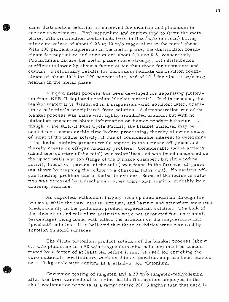
same distr ibut ion behavior as observed for uraniuna and plutoniuna in e a r l i e r exper iments . Both neptunium and cur ium tend to favor the meta l phase, with dis tr ibut ion coefficients (w/o in f l u x / w / o in naetal) having mininauiaa values of about 0.02 at 10 w / o naagnesium in the meta l phase. With 100 percent magnes ium in the meta l phase, the distr ibution coefficients for neptuniuna and cur ium are about 0,9 and 0.6, respect ively . Protactiniuna favors the metal phase naore strongly, with distr ibution coefficients lower by about a factor of ten than those for neptunium and cur ium. P r e l i m i n a r y r e su l t s for chromiuna indicate distr ibution coefficients of about 10"^ for 100 percent zinc, and of 10"^ for zinc-40 w/o magnesium in the naetal phase.
A liquid meta l p rocess has been developed for separat ing plutoniuna frona EBR-II depleted uraniuna blanket ma te r i a l . In this p roces s , the blanket naaterial is dissolved in a magnes ium-z inc solution; la te r , u r a n i um is select ively prec ip i ta ted frona solution. A denaonstration run of the blanket p r o c e s s was laiade with lightly i r r ad ia t ed uranium but with no Plutonium presen t to obtain infornaation on fission product behavior . Although in the EBR-II Fuel Cycle Faci l i ty the blanket ma te r i a l naay be cooled for a cons iderable tinae before process ing , thereby allowing decay of naost of the iodine activity, it was of considerable in t e re s t to deteriaiine if the iodine activity p resen t would appear in the furnace off-gases and thereby c rea t e an off-gas handling problem. Considerable iodine activity (about one -qua r t e r of the total) was volati l ized and was found condensed on the upper walls and top flange of the furnace chanaber, but l i t t le iodine activity (about 0.1 percen t of the total) was found in the furnace off-gases (as shown by t rapping the iodine in a charcoa l filter unit). No ser ious off-gas handling problem due to iodine is evident. Some of the iodine in solution was renaoved by a mechan i sm other than volatil ization, probably by a dross ing react ion.
As expected, rutheniuna largely acconapanied uranium through the p r o c e s s , while the r a r e e a r t h s , yttriuna, and bariuna and strontiuiai appeared predonainantly in the plutoniuna product supernatant solution. The bulk of the zirconiuna and telluriuna act ivi t ies were not accounted for, only smal l percentages being found with e i ther the uran ium or the magnes ium-z inc "product" solution. It is believed that these act ivi t ies were renaoved by sorption on solid su r faces .
The dilute plutoniuna product solution of the blanket p roces s (about 0.1 w/o plutoniuna in a 50 w/o magnesiuiaa-zinc solution) must be concent ra ted by a factor of at l eas t ten before it may be used for enriching the core naater ia l . Pre l inainary -work on this evaporat ion step has been s t a r t ed on a 10-kg scale with ce r i um as a s tand- in for plutoniuna.
Cor ros ion test ing of tungsten and a 30 w/o tungsten-naolybdenum alloy has been c a r r i e d out in a z inc-hal ide flux systena employed in the skull reclanaation p r o c e s s at a tenaperature 200 C higher than that used in

the p roces s (lOOO C ve r sus 800 C). After 500 hr at 1000 C, tungsten was found, by meta l lographic examination, to have been attacked in te rg ranu-lar ly to a depth of 2 to 4 mi l s , and the molybdenuiai-tungsten alloy to a depth of 2 to 8 mi l s . Grain s izes were not greatly affected. Sharp edges remained on the spec imens , and dinaensional changes were l ess than 1 percent .
Several experinaents were made to determine the effects of smal l anaounts of added inapurities on the stability of uranium-containing magnes ium-z inc s y s t e m s . Beryl l ium added to the extent of 0.05 w/o , slightly over i ts solubility value, and aluminum added to the extent of 1 w/o had no effect on uraniuiai concentra t ions . Silicon caused d i rec t p r e cipitation of the uraniuna. Stainless steel had no effect up to a concent ra tion of 0.1 percent , but at a concentrat ion of 1 percent caused a slight ( less than 5 percent) dec rea se in uran ium concentrat ion. This slight dec r e a s e in uraniuna concentrat ion is believed to have been caused by r e a c tion "with e lements , such as carbon or silicon, which a re p resen t at low concentrat ions in s ta in less s teel .
In o rde r to take advantage of the good mechanical p roper t i e s of porous c o a r s e - g r a i n e d cruc ib les (such as Alundum) for the containnaent of meta l and salt s y s t e m s , sealing the pores of such crucib les by i m p r e g nating the inner surfaces with a s lu r ry of low-melt ing oxides has been at tempted. Subsequent firing of the crucible fuses the oxides, thereby sea l ing the po re s . When proper ly applied to smooth sur faces , the coatings have been inapervious and strongly adherent , but imperfect ions in the coatings have pe r s i s t ed in coatings applied to slightly rough sur faces .
Various combinations of p l a s m a - s p r a y e d coatings and subs t ra te m a t e r i a l s a re being evaluated for use as container m a t e r i a l s in liquid naeta l -sa l t p r o c e s s e s . In prelinainary the rmal cycle t e s t s (twelve cycles between 300 and 800 C), no de te r iora t ion of tungsten-coated silicon carbide (n i t r ide- or oxide-bonded), Alundum, and Type 430 s ta in less s teel was evident, nor of Alundum and Type 430 s ta in less steel when sprayed with bery l l ia .
Construct ion and test ing of equipnaent for the p repara t ion of 500-g batches of uran ium monocarbide by precipi ta t ion from liquid naetal solution have been conapleted. The p r o c e s s consis ts of dissolution of uranium naetal in z inc -magnes ium alloy, addition of carbon, removal of the super natant liquid meta l , and re tor t ing of the uranium monocarbide product to el iminate the remaining zinc and magnesiuna.
New methods for the p repara t ion of carb ides a r e also being developed. It has been found that uraniuna naonocarbide can be p repa red by the reac t ion of magnes ium carbide with u ran ium hal ides in naolten chloride solut ions.

15
Work has continued on the prepara t ion of uraniuna monosulfide through the react ion of hydrogen sulfide with hydrided-dehydrided u r an i um meta l , followed by homogenization at 1900 C. In recent p repara t ions , the oxygen content of the uraniuna monosulfide product has been reduced to l ess than 0.1 w/o , and the sulfur- to-uraniuna rat io has been within 3 percen t of the s to ich iometr ic value.
Fu r the r investigation of the z inc-magnes ium reduction of thor ium dioxide suspended in a naolten halide flux has indicated that a thoriuna dioxide-to-flux weight ra t io of l e s s than 0.2 is requi red for complete r e duction under the following conditions: a flux consisting of 10 m / o magnes ium fluoride in magnes ium chlor ide , 10 w/o naagnesiuna in the zinc at the end of the reduction, a t empera tu re of 850 C, a period of 4 h r , and mixing at 1000 rpna. A br ief study of crucible naaterials indicated that the use of graphi te , si l icon carb ide , and alumina naay resu l t in contanaination of the thoriuna product, but that tungsten appears to be a sat isfactory c ru cible ma te r i a l .
Plutonium dioxide is a lso reduced to the meta l by the z inc-magnesiuna reduction technique. The reduction of plutoniuna dioxide, unlike that of uran ium and thor ium oxides, was rapid and complete in fluxes of widely varying composit ion. The extent of plutonium dioxide reduction appears to be governed by the dis t r ibut ion coefficient of plutoniuna between the naetal and the flux.
P rev ious data on the reac t ions of the higher uranium oxides and the oxychlorides with molten chlor ides had indicated the fornaation of a uranium(V) species in solution which was tentatively identified as UOf ion. Compar ison of the visible and n e a r - i n f r a r e d absorption spectruna of this species with the spec t rum repor t ed for the i soelec t ronic ion NpO^''' showed corresponding peaks . The ra t ios of wavelengths of the corresponding peaks a re near ly constant . The UO^ ion is formed by the t he rma l deconaposit ion of uranyl chlor ide :
2 U02Cl2-^=i2 UO2CI + CI2.
Through a conabination of spectrophotonaetr ic naeasurenaents of the UO2 ion and manonaetr ic de te rmina t ions of the aiaiount of chlorine evolved, the s to ichiometry of the reac t ion was confirnaed, and naolar absorptivity data for UO^ were obtained. A preliiaiinary value of about 10"^ atm at 650 C was deternained for the equilibriuna constant of this reac t ion by de te rmin ing the optical absorbance of UO2 as a function of the chlorine p r e s s u r e .
A s e r i e s of t e s t s was per formed while the Argon Cell contained ni t rogen at a p r e s s u r e equal to the outside p r e s s u r e to deteriaiine the effect of opening penet ra t ions into the Argon Cell on the composit ion of the cel l a tmosphe re . Three snaall penet ra t ions were opened for per iods up to

4 m m without a significant i nc rease m the oxygen concentrat ion of the cell atnaosphere. The opening of a 6-ft-diam.eter penetrat ion into the cell caused the oxygen concentrat ion of the cell a tmosphere to r i s e to 300 ppm in 4Y nain.
A glovebox purification systena was received at Idaho, leak tested, aiad successfully operated. Air leakage into the associa ted glovebox was found to be 0.015 percen t per day of the glovebox-glovebox purification systena volume. A second glovebox a tmosphere purification sys tem and two gas analytical ins t rument panelboards were tes ted and shipped to the Idaho site for instal lat ion.
The top shielding plug of the Argonne fue l - t ransfer coffin was naodified to overcome binding at sliding sur faces . The plug assembly was found to function sat isfactor i ly after the naodifications had been conapleted.
Tes t s were made to de termine the behavior of sodiuna-coated fuel pins while contained in a s ta in less s teel naelt refining charging t ray. The t empera tu re of the t ray was naaintained at 450 C in one experinaent and at 300 C in another experiiaient. The sodium coating evaporated from the fuel pins in both experinaents and condensed on the cold a reas of the tes t s ta in less s teel con ta iners . No in teract ion occur red between the pins and the s ta in less s teel conta iners .
A second skull-oxidation furnace is being designed which will allo"w the h e a t e r - c o v e r assembly to be disposed of in a s tandard waste container if the hea te r attached to the cover should fail. The furnace atmosphere control sys t em was successfully tes ted during the oxidation of 12 skulls which ranged in weight from 300 to 1300 g.
Tes t s with inductive heating and mixing have denaonstrated that g r e a t e r than 80 percent reduction of uraniurfa oxide by 5 w/o naagnesiuna-zinc alloy can be obtained in 2 hr at 800 C. The weight of the skull oxide charge used in the tes t s was 2— kg.
Studies on the collection of meta l vapors have continued. With an improved appara tus , four runs were made in which 2-kg charges of magnes ium-z inc were dist i l led at r a t e s of 25, 32, 48, and 62 g/iaiin. In the f i r s t th ree runs , no loss of naagnesiuna-zinc occur red . In the fourth run, 17 g of magnes ium-z inc dist i l la te escaped frona the graphite enc losure and deposited on the F iber f rax insu la to rs .
The solubility of plutonium in liquid zinc naay be r ep resen ted by the enapirical equation
(458 to 752 C) log (a /o plutonium) = 8.612 - 10090T"^+ 1.461 x lO^T-^

Two activation methods for the determinat ion of oxygen in sodium a re being investigated. The f i r s t involves i r radia t ion by fast ( l4.5-MeV) neutrons to produce ni t rogen-16 activity by the react ion
on^ + gO^ -*• yN^ + jH^
The second naethod involves t r i ton i r rad ia t ion to produce fluorine-18 ac tivity by the reac t ion
I T 3 + 80^6 ^ ^pl8 ^ ^^1 _
The t r i tons a re produced in situ by thernaal neutron i r rad ia t ion of li thium (added to the sodium sanaple) by the reac t ion
on^ + sLi^ -> jT^ + ^H* .
The solubility of carbon in liquid sodium is being measu red as a function of t empera tu re and oxygen content as a f i rs t step in a bas ic study of the t r a n s p o r t of carbon by liquid sodium.
The thermodynamics of the plutoniuna-zinc and plutoniuna-cadnaium systenas a re being studied by means of a high-tenaperature galvanic cell method. The activity coefficient of sa tura ted solutions of plutonium in liquid zinc may be r ep re sen t ed by the equation
log 7T3 = 5.312 - 9713T-^ ^ Pu
The activity coefficient of sa tura ted solutions of plutoniuna in liquid cadnaiuna may be r e p r e s e n t e d by the equation
log 7 p ^ =^ 4.786 - 6473T-1
An optical absorpt ion naethod is being developed to study the t h e r -modynanaics of binary solutions of the alkali naetals.
R a r e ea r th metal-cadnaiuna sys tems are being studied by the effusion method. The following sequences of in termedia te phases a re found in binary sys t ems of cadnaiuna with lanthanum, ce r ium, praseodymium, and neodymium: lanthanum-cadnaium systena: LaCdn, La2CdiY, La3Cdi3, LaCdj and LaCd; cer ium-cadna ium, praseodynaium-cadmium, and neodymium-cadmiuna sys tem: MCdu, MCd^, M3Cdi3, M4Cdi3, MCdj, and MCd.

II. Fuel Cycle Applications of Volatility and Fluidizat ion Techniques (pages 112 to 190)
In the conceptual flowsheet of the fluid-bed fluoride volatility p r o c e s s , the uraniuna and plutoniuna content of spent oxide fuels will be r e covered by fluorination to produce the volatile hexafluorides of uraniuna and plutonium. Labora to ry - sca l e work has been concerned with the fluor inat ion of U30g in a l - j - in . -d iamete r fluid-bed f luorinator . This work is being perfornaed to develop and tes t apparatus and p rocedures for use in future work in which plutonium will be handled. The oxide U30g is being used because it is the product which "will be obtained in a proposed oxidative "decladding" step for renaoving the uraniuna and plutonium from s ta in less s tee l -c lad and Z i rca loy-c lad fuel elenaents.
In the experinaental work, the powdered U30g is injected into the fluid bed with the fluidizing ni trogen s t r eam. Fluor ine is brought into the bed jus t above the point at which the powder enters and the fluorination reac t ion occurs as the U30g and fluorine mix. This r e p o r t covers expe r i naental investigation of the effect of var iab les such as tenaperature , U3O8 elutr ia t ion f rom the fluidized bed, and duration of the fluorination period upon the react ion. A react ion scheme employing t"wo per iods at a react ion tenaperature of 500 C has been developed; in the f i rs t period, the U3O8 is fed into the bed and fluorination is c a r r i e d out with 20 v /o fluorine in the gas phase; in the second period a gas phase containing 100 percent fluorine is r ec i r cu la t ed through the fluid bed for a period of 5 h r . By means of this reac t ion scheme, naore than 99 percent of the U3O8 fed to the r e actor was conver ted to u ran ium hexafluoride.
The oxidation of u ran ium dioxide, which re su l t s in the fornaation of a finely divided U3O3 powder, is being considered as pa r t of a decladding step for s ta in less s t ee l - and Z i rca loy-c lad fuel e lements . Fue l - e l emen t naockups consist ing of 5 |-- in.- long sect ions of y~ in . -d i ame te r s ta in less s teel or Zircaloy tubing packed with uran ium dioxide pel lets were oxidized in a fluid bed at 450 C with air as the oxidant and fluidizing gas . Slots (-g- in. x 3^ in.) , with in terva ls of ~|- in. between ends of s lo ts , were mil led along the length of the cladding tubes to promote splitting of the cladding. It was found that the t ime neces sa ry to completely split open a section of cladding along the sl i t line was dependent on the thickness of the tubing. Fo r 10- and 20-mi l wall th icknesses of s ta in less s teel , the tubing split open along i ts ent i re length after 2 and 4 hr of oxidation, respect ively . For 30-mil Z i rca loy , the tubing was conapletely split after 6 hr of oxidation. Complete renaoval of the U3O8 product was acconaplished by 1-2 hr of further oxidation.
Rates have been m e a s u r e d by naeans of a thermobalance for the reac t ion of U30g Awith fluorine over the tenaperature range from 300 to 400 C. Two samples of UjOg were used; one was an analyt ical s tandard sample , the other a conanaercially produced ma te r i a l . The conamercially

produced ma te r i a l is also being used in the fluid bed fluorination work. The data have been t rea ted by a dinainishing-sphere kinetic model which r e l a t e s the reac t ion ra te constant k (in units of nain"^) direct ly to a function of the fraction of the oxide remaining after a react ion tinae t. The reac t ion ra te constants for the comnaercial ly produced naaterial were slightly higher than those for the analyt ical s tandard sanaple at the sanae tenapera tures . An average value of 30 kcal/naole was calculated for the activation energy of this react ion which, within experiiaiental e r r o r , is the saiaie for both naaterials used. Equations a re given which re la te the change in react ion ra te constant with t empera tu r e . An estinaate of the tinae r equ i red to conapletely conver t a par t ic le of U30g, of about 10~naicron dianaeter, to uraniuna hexafluoride, based on an extrapolation of the ra te constant to 500 C, was l e s s than 2 nain.
The study of the effect that the addition of helium, to plutoniuna hexafluoride has on the decomposit ion of plutoniuiai hexafluoride by gananaa i r r ad ia t ion has been continued. Additional data have given G values of 7.2 ± 1 . 1 and 5.8 ± 0.8 for exper iments in which one atnaosphere and two a tmospheres of helium, respec t ive ly , we re added. A conaparison of these G values with the G value of 7.5 ± 0.7 obtained for the decoiaaposition of plutonium hexafluoride alone indicates that hel ium does not significantly influence the decomposit ion.
Engineer ing-sca le invest igat ion of a fluid-bed fluoride volatility p r o c e s s for the r ecovery of u ran ium and plutoniuna frona discharged u r a nium dioxide fuels was continued. In this p rocess the oxides a re direct ly fluorinated to the hexaf luor ides , which a r e then decontaminated and separa ted by volatility techniques. Emphas i s has been placed, for the sake of p r o c e s s s implici ty, on the batch reac t ion of oxide charges in a single v e s sel . The naajor objectives have been to demons t ra te short batch fluorination t ime ( less than 20 hr) and sat isfactory fluorine uti l ization efficiencies (g rea te r than 75 percent ) .
The la tes t and naost successful runs have eiaaployed a two-zone, oxidation-fluorination technique. In this technique, the lower (oxidation) zone of the r e a c t o r cons is t s of a bed of uraniuna dioxide pellets with fused alunaina gra in filling the voids of the bed (fluidized-packed bed); the upper (fluorination) zone cons is t s of a fluidized bed of fused alumina gra in that extends above the fluidized packed bed. By passing an oxygen-ni t rogen naixture through the lower zone, U30g fines (10 to 20 /i) a re p r o duced and t r anspor t ed to the upper fluidization zone, where they a re f luorinated to uran ium hexafluoride vapor .
In recen t studies the t'wo-zone oxidation-fluorination scheme was used successfully with 12- in . -deep, fluidized packed beds of uraniuna dioxide. Caking was avoided, and both high production r a t e s and high fluorine uti l ization efficiencies were at tained. In this work, enaphasis was placed on optinaizing p roces s control by regulat ion of the input of the reagent gases : oxygen and fluorine.

A two-zone run was c a r r i e d out in the 3-in.-dianaeter fluid-bed r eac to r in which a 12-in.-deep, fluidized packed bed of uranium dioxide pel lets was completely fluorinated. Inaproved control of the react ion was evidenced by naore uniforna r a t e s of production of uraniuna hexafluoride and by higher fluorine uti l ization efficiency for the conaplete batch ope ra tion. Ninety percent of the product was collected in 8.2 hr of fluorination, corresponding to a production ra te of 54 lb UFg/(hr)(sq ft) and a fluorine efficiency of 79 percent . A final period of t ime to conaplete the f luorination by recycl ing fluorine extended the total process ing tiiaie to 12.5 hr and reduced the overa l l fluorine uti l ization efficiency to 75 percent . The continuous monitoring of fluorine in the p roces s off-gas with a newly instal led gas thernaal conductivity cell a s s i s t ed in improving p rocess control . F r o m the r e su l t s of this run, it is apparent that optinaum conditions were approached more closely than in previous runs : The fluorination zone was naaintained at 500 C, and the t empera tu re gradient in the oxidation zone was frona 480 C at the top of the bed to 340 C at the bottona; the gas flow to the oxidation zone was 1.0 scfm (at 1 atna and 25 C) and contained 8 p e r cent oxygen in nitrogen; the gas flo-w in the fluorination zone was 1.5 scfna and contained 9 to 15 percent fluorine in ni trogen at the inlet; a smal l amount of gas (about 2 percen t of the total gas flow) was added in pulses at a frequency of 2 pu l se s /min .
Work has been s ta r ted on the evaluation of the t-wo-zone technique for the process ing of s ta in less s t ee l -c lad uranium dioxide pel le ts . Short lengths (~1 in.) of s ta in less steel tubing with both ends open a r e used to contain uran ium dioxide pellets and thereby sinaulate a charge of sheared fuel e lements . Longer e lement sect ions with longitudinal perforat ions or s l i ts a re a lso being evaluated.
In two experinaents c a r r i e d out in the 3-in.-diaiaieter fluid-bed r e ac tor , renaoval of uran ium dioxide from the s ta in less steel tubing was complete with a 1.5-in.-deep fluidized packed section and 95 percent conaplete with a 6-in. packed section. These r e su l t s were obtained in 8.5 and 13.5 h r , respec t ive ly . Operating conditions for both runs were s imi la r : oxidation was c a r r i e d out at 450 C with 22 percen t oxygen, and fluorination was c a r r ied out at 500 C with 4 to 10 percen t fluorine. In each run, u ran ium dioxide remova l from the cladding was enhanced by passage of fluorine through the fluidized packed bed with the sys tem on total off-gas recyc le .
The method of renaoval of u ran ium dioxide fuel frona cladding by oxidation is also being studied separa te ly from the fluorination. A s e r i e s of twelve experinaents has been completed as an initial examination of the extent of remova l of uran ium dioxide frona simulated s ta in less s t ee l -c lad fuel elenaents sheared to a 1-in. length. The "I--in.-dianaeter s ta in less s t ee l -c lad segnaents were charged to the 2- in.-dianaeter fluid-bed r eac to r as random-packed beds of 40 segments . The removal of uranium depends both on the oxidation of the uran ium dioxide pellets to U3OQ and on the

21
physical disengagenaent of the U3O8 from the pellets and cladding as fines, which are then naixed with the fluid bed of iner t fused alunaina grain. Air at a superficial gas ra te of about 0.75 f t / sec was the oxidizing gas . Gas pulsing (with air) was only par t ia l ly beneficial for inaproving the ra te of renaoval of oxide and for inaproving t empera tu re unifornaity in the system. Pu lses of 1-sec duration were used at two frequencies, 0.5 pulse/nain and 6 pulses/nain; in mos t runs the fluidizing gas was cut off during the pu l s ing to enhance the pulse effect. Var ia t ions in the pulsing technique over the range of conditions t r i ed produced li t t le difference in r e su l t s . Runs were c a r r i e d out at constant tenapera tures in a range frona 350 to 550 C. An optinauna overa l l ra te of renaoval appeared to occur at t e m p e r a t u r e s between 400 and 500 C.
Since the separat ion of oxide from the cladding involves two success ive s teps , chemical oxidation and physical reiaioval, the chenaical r e action was observed independently of renaoval by determinat ion of the oxygen consunaption with a gas thernaal conductivity cell ca l ibra ted for oxygen-ni t rogen laiixtures. Frona the gas analysis , it was found that the oxidation react ion had vir tual ly ceased after 7 hr at 550 C and after 9 hr at 450 C. However, only par t ia l renaovals of uraniuna oxide were achieved in these runs .
Difficulty in obtaining conaplete physical renaoval has been encounte red in all t es t s made thus far Reasonable r a t e s of renaoval have been obtained up to 50 to 80 percent r emova l , but overal l r emovals g rea te r than about 80 pe rcen t have not been obtained Sonaewhat higher renaovals were obtained in tubing elenaents located at the top of the fluidized packed bed than at the bottona of the bed.
Additional experinaents were naade with a l ternate steps of oxidation and reduction of the uraniuna dioxide. This technique is capable of pronaoting the pulver izat ion of uraniuiai dioxide a.nd thus may a s s i s t in enhancing the renaoval. (This oxidat ion-reduct ion naethod naay have an advantage over the oxidation-fluorination naethod descr ibed above in that the cladding laaetal is not fluorinated.)
Two oxidat ion-reduct ion exper iments were conducted on the sanae type of charge of s ta in less s t ee l -c lad uraniuna dioxide pellets as was used in a previous experinaent in which the removal of uranium dioxide by oxidation alone was atteiaipted. The reduct ion was perfornaed at 550 C with a laiixture of 5 v /o of hydrogen in ni t rogen This reducing gas was passed through the r eac to r after the initial oxidation had been coiaipleted at 450 C. After reduct ion of the U30g r e s i d u e s , the uranium dioxide was reoxidized at 450 C, However, the renaovals of 80 percent obtained in these two ex-periiaients were not significantly different frona those obtained when oxidation alone was used. The inconaplete renaovals were apparently due to insufficient c i rcula t ion of the ine r t fluid-bed naaterial and insufficient

iiiotion of the individual fuel segments in spite of gas pulsing (pulses of 0 .5-sec durat ion at a ra te of Z pu l ses /min) .
In t wo additional exper iments , which were per formed at the sam.e oxidation and reduction t e m p e r a t u r e s , the fluidized packed bed of fuel e l e ments was divided into four individual packed sections which were each approximately 1^ in. deep and which were separa ted from each other by support p la tes . The fluid bed was continuous between these bed sect ions . This p rocedure , combined with gas pulsing, improved the iner t ma te r i a l c i rcula t ion and the motion of the fuel segments , and resu l ted in an a lmost complete removal of the uranium oxides from the s ta in less steel cladding after a reac t ion t ime of about 13 hr . The separat ion obtained in one run was 100 percent and in the other , 99 percent .
The r e su l t s of these t"wo exper iments indicate that a separat ion of uran ium dioxide from s ta in less s teel cladding is achievable by an oxidation-reduct ion-reoxidat ion p roces s if the iner t fluid-bed ma te r i a l and especial ly the motion of the fuel segments a re not r e s t r i c t ed . F u r t h e r effort i s planned to develop a sat isfactory prac t ica l means of ca r ry ing out the oxidative separa t ion.
Construct ion is under way of a facility for engineer ing-sca le invest igat ion of the seve ra l s teps of a fluid-bed fluoride volatility p roces s for r ecovery of fissionable m a t e r i a l s from spent nuclear r eac to r fuel of the uran ium dioxide type and for reconst i tut ion of the oxide fuel ma te r i a l after i t is freed from fission products . In this p r o c e s s , the dioxides of uran ium and plutonium are fluorinated to form the volatile hexafluoride products . Subsequently, the hexafluorides a r e further purified by f r ac tional dist i l lat ion and converted back to dioxides by react ion with s team and hydrogen. The fluorination equipment is now being instal led. Be cause of its high toxicity, the radioact ive plutonium mus t be completely contained. Therefore , all equipment is being instal led inside a la rge glovebox, 17 ft high by 25 ft long.
In the p r e sen t period, the p r o c e s s piping and valve instal la t ions in the la rge alpha containment box and in the fluorine gas s torage and supply sys tem located in the fluorine cabinet have been completed. Cur ren t work is concerned chiefly with the instal la t ion of the ins t rumenta t ion and auxilia ry l ines inside of the box. The instal la t ion and mounting of the fluorine punip has also begun. Test ing of p roces s valves under extended use has been s ta r ted .
The e levator lifts which provide personnel with access to glove por ts at all levels of the large alpha box have been received and instal led.
The Phase II subcontract for instal la t ion of se rv ices and ventilation has been awarded. The completion date for this work is in ear ly September, 1963.
23
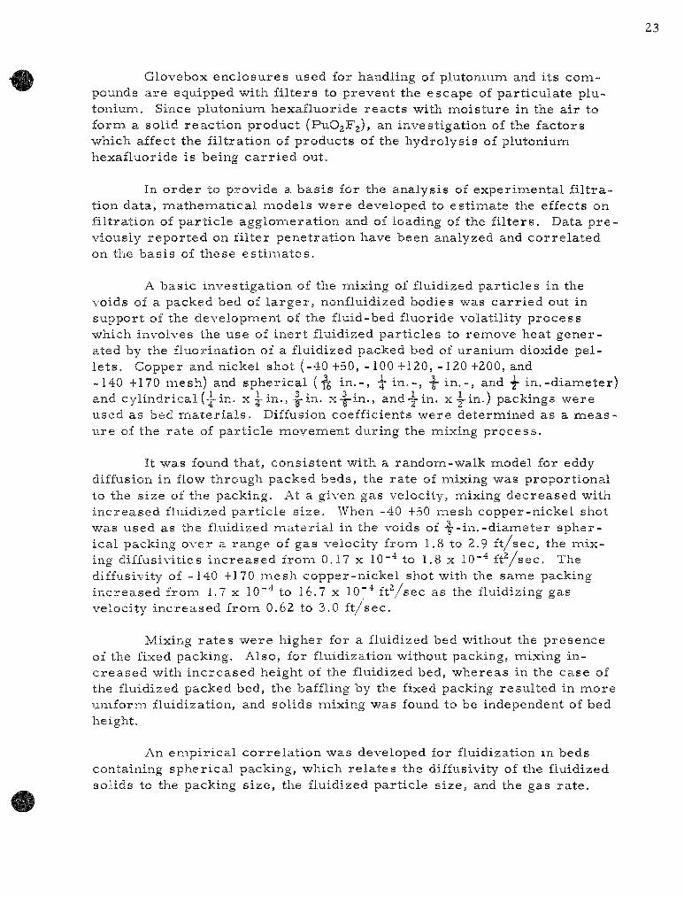
Glovebox enclosures used for handling of plutonium and its compounds a re equipped with f i l ters to prevent the escape of part iculate plu-toniuni. Since plutonium hexafluoride reac t s with moisture in the air to form a solid react ion product (PuOgFj), an investigation of the factors which affect the fil tration of products of the hydrolysis of plutonium hexafluoride is being c a r r i e d out.
In o rder to provide a bas is for the analysis of experimental f i l t ration data, mathemat ical models were developed to est imate the effects on filtration of par t ic le agglomerat ion and of loading of the f i l ters . Data p r e viously repor ted on filter penetrat ion have been analyzed and cor re la ted on the bas is of these e s t ima tes .
A basic investigation of the mixing of fluidized par t ic les in the voids of a packed bed of l a rge r , nonfluidized bodies was ca r r i ed out in support of the developiTient of the fluid-bed fluoride volatility process which involves the use of iner t fluidized par t ic les to remove heat generated by the fluorination of a fluidized packed bed of uranium dioxide pelle t s . Copper and nickel shot (-40 +50, -100 +120, -120 +200, and -140 +170 mesh) and spher ical (•^ in . - , -^ in . - , -|- in . - , and y in . -diameter) and cyl indrical (-i-in. x | - in. , .|-in. x-|-in., and-™ in. x y i n . ) packings were used as bed ma te r i a l s . Diffusion coefficients were determined as a m e a s ure of the ra te of par t ic le movement during the mixing process .
It was found that, consistent with a random-walk model for eddy diffusion in flow through packed beds, the ra te of mixing was proportional to the size of the packing. At a given gas velocity, mixing decreased with increased fluidized par t ic le s ize . When -40 +50 mesh copper-nickel shot was used as the fluidized mate r ia l in the voids of •f '-in.-diameter spherical packing over a range of gas velocity from 1.8 to 2.9 f t / sec , the mixing diffusivities increased from 0.17 x 10"^ to 1.8 x 10""* f t ^ s e c . The diffusivity of -140 +170 mesh copper-nickel shot with the same packing increased from 1.7 x ID"'* to 16.7 x lO""* f t y s e c as the fluidizing gas velocity increased from 0.62 to 3.0 f t / sec .
Mixing ra t e s were higher for a fluidized bed without the presence of the fixed packing. Also, for fluidization without packing, mixing inc reased with increased height of the fluidized bed, whereas in the case of the fluidized packed bed, the baffling by the fixed packing resul ted in more uniform fluidization, and solids mixing was found to be independent of bed height.
An empir ica l cor re la t ion was developed for fluidization in beds containing spherical packing, which re la tes the diffusivity of the fluidized solids to the packing size, the fluidized part icle size, and the gas ra te .

Developnaent work on a fluid-bed volatility p roces s scheme for the recovery of enriched uranium from low uranium-high alloy fuel is in progr e s s . The f i r s t fuel to be studied is u ran ium-z i rcon ium fuel. In the p roc ess scheme, the z i rconium is separated as the volatile te t rachlor ide during hydrochlorinat ion of the alloy, and the uranium is recovered as the hexafluoride in a subsequent fluorination step. The react ions are conducted in an iner t fluidized bed (current ly , fused alumina gra in is being used as the bed mater ia l ) which se rves as a heat t ransfer medium.
In cu r r en t studies in the ]- | -- in.-diameter fluid-bed sys tem, further evaluation of the hydrogen chloride-f luorine react ion sequence was made using, for the f i r s t tinae, minia ture multiplate fuel e lement subassembl ies (normal u ran ium-Zi rca loy alloy clad with Zirca loy; overal l uranium content about one percent) . Two runs were completed, one with high-puri ty, Type RR Alundum and one "with the less cost ly. Type 38 Alundum (Norton Company granular fused aluminas) as fluid-bed ma te r i a l . One charge of -14 +20 mesh, Type 38 Alundum was used as the filter bed for both runs .
Hydrochlorinat ion of each subassembly was conapleted in about 7 hr . Alloy t e m p e r a t u r e s to 750 C were noted, while the maximum fluid-bed t empe ra tu r e was only 500 C. The r eac to r walls in the fluid-bed zone were maintained in the range from 300 to 415 C.
By use of a modified fluorination p rocedure , a lower initial t e m pe ra tu re (250 instead of 350 C) and a relat ively high initial fluorine concentra t ion (50 percent instead of 5 to 10 percent) , reduction of the concentrat ion of uran ium in the final beds to a level of <0.01 w/o (the cu r r en t goal) was achieved for both Type RR and Type 38 Alundum. This is the f i r s t t ime that these levels have been obtained for hydrogen chlor ide-fluorine cycles in the absence of other reagen t s . The concentrat ion of u r a nium in the fil ter bed remained at 0.007 w/o after each run.
Corre la t ion of the loss of uranium during hydrochlorinat ion with absolute t empe ra tu r e now suggests that a major par t of the uranium is lost as vapor (probably as uranium te t rachlor ide) r a the r than as par t iculate sol ids . The ra t e of loss of uranium c o r r e l a t e s with the lowest t e m pera tu re maintained in that pa r t of the r eac to r sys tem that is downstream of the fluid bed. Losses ranged from 0.13 m g / h r at 320 C to 8.7 m g / h r at 390 C. Changing the alumina in the packed-bed filter section from -40 +60 m e s h to a more coa r se fraction, -14 +20 mesh , produced no not iceable effect on the uranium losses sustained during hydrochlorination. This tends to substant iate the belief that u ran ium is lost as a vapor. P r e s sure buildup associa ted with the packed-bed filter was found to be rel ieved by use of the m o r e coa r se -14 +20 mesh bed ma te r i a l .
Inspection of a naultiplate fuel e lement subassembly after one s to ichiometr ic equivalent of hydrogen chloride had been fed to the reac tor showed that the extent of hydrochlorinat ion of the subassembly dec reased

gradually -with inc rease in distance from the gas inlet. The upper portion of the plates appeared completely unreacted.
Infrared and mass spec t romet r i c analyses of the contents of the hexafluoride collection t raps indicate that the same minor const i tuents , including chlorine mono- and t r i f luor ides , were p resen t for both the hydrogen chloride-f luorine cycle and the hydrogen chloride-phosgene-f luorine cycle, although no quantitative data a re available for the la t ter . The data obtained in the cu r r en t run indicated that about 7 percent of the chlorine initially assoc ia ted with the uranium after hydrochlorination was converted to chlorine t r i f luoride during fluorination.
Adaptability of the fluid-bed hydrolysis scheme to the convers ion of aluminum chloride vapor (simulated waste froixi the process ing of a luminum-based alloy fuels) to the more readily s tored oxide has been demonst ra ted . Three exper iments (total run duration of 9 = 5 hr) were conducted in the 6- in . -d ianie ter coluiTin (used previously for hydrolysis of z i rconium te t rachlor ide) at 300 C with aluminum t r ichlor ide feed ra tes of 4 kg /h r and the s team ra te adjusted at four t imes the s toichiometr ic r e quirement Sand was used as the s tar t ing bed ma te r i a l Operations were t rouble- f ree , and excellent overal l m a s s balances were obtained. No t r ace of aluminum was found in the off-gas s t r e a m , indicating that hydrolysis was complete •within the unit.
Excess ive fines formation in recen t z irconium te t rachlor ide hydrolys is studies is now presumed to be associa ted with the presence of unsub-limable m a t e r i a l in the as-suppl ied solid te t rach lor ide .
Instal lat ion has been completed of the pilot-plant facility for the fluid-bed volatili ty r ep rocess ing of highly enriched uranium-al loy fuel. Final leak-checking is in p rog re s s . Shakedown and operation of this facility with noni r radia ted fuel ma te r i a l is scheduled for the ensuing quar te r .
Design of the bench-sca le facility for high-act ivi ty- level studies on the fluid-bed volatili ty p rocess for highly enriched uranium alloy fuels is nearly complete . Fabr ica t ion of the equipment and procurement will s t a r t next qua r t e r . Installation of the facility during the la t ter half of 1963 is planned.
P r o c e s s development studies of a fluid-bed scheme for prepar ing dense uranium dioxide par t ic les direct ly from uranium hexafluoride were continued in a 3 - in . -d iamete r Monel colunin. The scheme involves r e a c tion of the hexafluoride with a mixture of s team and hydrogen (UF^ + H2 + 2H2O -* UO2 + 6HF) in the presence of a s tar t ing bed of uranium oxide maintained at 650 to 700 C
A niethod of up-grading (densifying) low-density (<7.0 g /cc) -ura nium dioxide is being sought; therefore , a study was made in which the

course of the inc rease in density of a s tar t ing bed of low density was observed. The es tabl ished technique of al ternating uran ium hexafluoride feed per iods with periods in which s team and hydrogen only were fed ( r e sidual fluoride cleanup period) was used.
An unexpectedly la rge density i nc rease and no overa l l par t ic le gro-wth were observed over the scheduled 8-hr run period, during which t ime 0.84 bed equivalent of dioxide was produced. The anticipated density i nc rease (based on previous resu l t s ) was about 12 percent^ whereas a 24 percent i nc rease to 8.6 g /cc was obtained; the expected inc rease in average par t ic le size due to deposit ion of new ma te r i a l was about 19 pe r cent. These anomalous r e su l t s suggest that sintering of the ent i re p a r t i cle is occur r ing , and not jus t the surface as was previously believed.
III. Ca lo r imet ry (pages 191 to ZOO)
Refinements in the calculat ions have led to slight revis ions in the der ived the rmal data for the forma,tion of uranium hexafluoride from the e lements at 25 C. The rev i sed data a r e . s tandard energy of formation, AEfjgg, -520.79(c), -509 5i(g)s s tandard enthalpy of formation '\Hf29g, -522.57(c), -510 7o(g); Gibbs energy of formation, AGfzggi, -491 89(c), -490.72(g). The uncertainty in te rva l s a re ± 0.4.1 for uranium in the c r y s tall ine state and ± 0.4^ in the gaseous state
P r e l i m i n a r y invest igat ion is in p rog re s s to develop sat isfactory techniques for the de terminat ion of the heat of formation of uraniuna mono-sulfide. It has been found thatj with proper protect ion of the sample from fluorine before ignition, the fluorine bomb ca lo r ime t r i c method will very likely be suitable.
P r e l i m i n a r y invest igat ion has been in p r o g r e s s to develop s a t i s factory techniques for the de terminat ion of the heats of formation of t e t r a -f luoromethane (CF4) and si l icon carb ide . Satisfactory techniques have been found, and the calor inaetr ic sys tem is being cal ibra ted p repa ra to ry to the ca lo r ime t r i c s tudies .
A cr i t ique of the available l i t e r a tu re data for the heats of fo rmation of hydrogen fluoride gas and its aqueous solutions is being made.
The furnace component of the 1500 C enthalpy ca lo r ime te r has been d i sassembled . It was found that the three s i lver heat shields and three of the five a luminum heat shields had melted to a cons iderable extent. Modifications and simplif ications have been made to the furnace core , and the furnace has been r ea s semb led . Exper imen t s have been p e r formed to obtain heat t r ans fe r data a c r o s s the | -- in. dust shield containing bubbled aluniinum oxide.

IV. Reactor Safety (pages 201 to 223)
The air oxidation of uranium at t empera tu re s above 500 C is being investigated in o rder to determine the nature and degree of protec t iveness of oxide films formed. In cu r r en t s tudies , uranium specimens are heated by induction in a closed loop appara tus . The ra te of the initial react ion is de termined by m e a s u r e m e n t s of p r e s s u r e dec rease , with a p r e s s u r e t r a n s ducer . Studies have been performed with the following oxidants: pure oxygen at 500 and 600 C, dry air between 500 and 1000 C, and 20 v/o oxy-gen-80 v / o argon mixture between 500 and 1000 C. The re su l t s of these exper iments were in tegrated with the r e su l t s of previous studies of the u r a n i u m - a i r react ion in which a once- through flow method was used, and in -which the oxygen and ni trogen depletion was measu red by means of a m a s s spec t rome te r .
The cha rac te r of the oxidation react ion (l inear, parabol ic , or cubic r a t e law) found for a par t i cu la r gas mixture and t empera tu re was consis tent ; however, there was considerable scat ter in the values of the ra te constants and the t imes of t rans i t ion from one react ion stage to another . At 50 0 C, the react ion of uran ium with each of the gases followed the same near ly l inear ra te law. At 600 C, a l inear ra te was found in pure oxygen; however, the reac t ion ra te in a i r and in the oxygen-argon mixture was initially parabol ic and la ter became l inear (para l inear) . At 700, 800, 900, and lOOOC, the u r a n i u m - a i r reac t ion remained para l inear ; however, the parabol ic period of the react ion was much longer at 900 and 1000 C than at the lower t e m p e r a t u r e s . The c ha ra c t e r i s t i c s of the react ion of u ran ium with oxygen-containing gases suggested that the react ion ra te is control led by an adsorpt ion equi l ibr ium at the oxide-gas interface and by the diffusion of oxygen ions through oxide film. The t rans i t ion from a parabol ic to a l inear reac t ion probably occurs when the protect ive oxide film begins to c rack .
Studies of the oxidation and ignition of plutonium are continuing. Resul ts of ign i t ion- tempera tu re de terminat ions with speciniens of cubes and foils of pure plutonium indicated that the var ia t ion of ignition t empe ra tu re with changes in specific a r ea were not continuous. Ignition oc c u r r e d at approximately 500 C for specimens of low specific a r ea and at approximately 300 C for spec imens of high specific a rea . Discontinuities in ignition t e m p e r a t u r e occu r r ed very sharply at a specific a r e a of 1.5 sq c m / g in air and of 6.0 sq c m / g in oxygen. The two reg imes of ignition were consis tent with a change in i so the rma l oxidation kinet ics which had previously been shown to occur jus t above 300 C.
The exper in ienta l p r o g r a m to de te rmine r a t e s of reac t ion of molten r e a c t o r fuel and cladding meta l s with water is continuing. A method of study is under development in -which the energy contained in the light beam from a ruby l a s e r heats single pa r t i c l e s of meta l in a water environment . The l a s e r heating method -will rep lace the condense r -d i scha rge

experinaent. Exper imenta l development of the method is p rogress ing along three l ines: (l) Means a re being developed of (a) focusing the l a s e r beam on meta l par t ic les contained within a g lass react ion cell and (b) measur ing the efficiency of energy t rans fe r . (2) A rap id - re sponse two-color optical pyrometer is being const ructed to deternaine the tenaperatures reached by the heated pa r t i c l e s . (3) Microanalyt ical apparatus to de te rmine the quantity of hydrogen genera ted by me ta l -wa te r react ion in closed glass reac t ion cel ls has been const ructed and tes ted.
Studies of me ta l -wa te r reac t ions initiated by a nuclear t r ans ien t have been continued. In these s tudies , smal l fuel specinaens were submerged in water in h i g h - p r e s s u r e autoclaves -which were placed at the center of TREAT and subjected to severe nuclear t r ans i en t s . Studies repor ted previously included exper iments with specimens of clad SPERT-ID fuel and unclad SL-1 fuel (both a re a luminum-uran ium alloys) react ing in room-tenapera ture water . Four additional exper iments have now been completed in -water which was initially heated to 285 C ( sa tu ra tion p r e s s u r e 1000 psi) p r io r to the r eac to r t r ans i en t s . The energy supplied in two t rans ien t s was calculated to be only enough to mel t the spec imens . Only 0.2 to 0.4% me ta l -wa te r reac t ion occu r r ed in these runSj in agreenaent -with r e su l t s in r o o m - t e m p e r a t u r e water . In the other two experinaents, the nuclear energy input was calculated to bring the specimen tenaperature somewhat above 1200 C. The extents of naetal-water react ion in these two tes ts were 76 and 89%, which was considerably g rea te r than was observed for sinailar e a r l i e r runs in roona- tempera ture water (<20% r e action). The la rge i nc r ea se in reac t ion may have been due in pa r t to higher peak fuel t e m p e r a t u r e s resul t ing from a dec reased hea t - lo s s r a t e during heating in sa tura ted -water compared -with the g rea t e r hea t - lo s s r a t e s oc cur r ing in subcooled water in previous exper iments . The reac t ions , however , did not genera te an explosive p r e s s u r e r i s e .
Two TREAT exper iments were performed, in each of which th ree SPERT-ID fuel spec imens were a r ranged at the end of a long alumina tube. The m e t a l - w a t e r reac t ion per g r a m of meta l was ident ical with that obtained in previous exper iments with single spec imens . There was no indication that a violent water h a m m e r was genera ted during the exper iment such as that observed in the des t ruc t ive t r ans ien t recent ly conducted in the SPERT-1 r eac to r .
P a r t i c l e size de terminat ions -were perfornaed on the res idue from all of the TREAT exper iments with the SPERT-ID and the SL-1 fuel m a t e r i a l . The r e su l t s showed that the surface a r e a exposed to the -water inc r e a s e d by a factor of about 100 when the nuclear energy input exceeded 450 and 530 ca l /g for SPERT naaterial and SL-1 m a t e r i a l , respec t ive ly . The inc reased surface a r e a coincided -with an i nc r ea se in the extent of me ta l -wa te r reac t ion .

A naethod has been developed for conaparing the quantity of naetal-water react ion occurr ing in TREAT experiiaients with that es t imated to have occur red in the SPERT-1 and SL-1 meltdowns. This procedure u t i l izes an es t imate of the percentage of the reac tor core which was cona-pletely melted and an es t imate of the peak fission energy density at the center of the core . This information defined a sphere of melting in which the fission energy at the center of the sphere was a peak value (500 ca l / g for SL-1 and 380 ca l / g for SPERT-1) and the fission energy at the per iphery of the sphere was 220 ca l /g , the energy required to heat aluminuna to its melt ing point and fully mel t it. The sphere was then segmented naathenaatically into regions and each region was assigned an ave r age tenaperature . The extent of chemical react ion was calculated by re fe rence to TREAT resu l t s in which specimens reached a teiaiperature s imi la r to those reached in the SPERT-1 and SL-1 meltdowns. A suiaaiaaa-tion over the sphere of melt ing then yielded an estinaate of the total quantity of me ta l -wa te r react ion. Resul ts calculated frona TREAT data yielded 2 MW-sec of chenaical energy for the SPERT-1 excurs ion and 26 MA¥-sec of chenaical energy for the SL-1 excurs ion. These values may be conapared with estinaates of the extent of me ta l -wa te r react ion based on the post-t r ans ien t collection and analysis of alpha-alunaina in the r eac to r debr i s , nanaely, 3-4 MW-sec of chemica l energy for the SPERT-1 excurs ion and 2 4 + 1 0 MW-sec for the SL-1 excurs ion.
V. Energy Conversion (pages 224 to 242)
Bimetal l ic cel ls a r e sinaple concentrat ion cel ls with a comnaon anode-cathode e lec t ro ly te . The in ternal cell r e s i s t ance can be made very low, with a resul t ing capabili ty of high cu r r en t density (100-500 naa/sq cm) output at one-half open-c i rcu i t voltage.
Temperature-enaf-conaposi t ion data for the lithiuna-bisnauth cell have been obtained over the tenaperature range frona 750 to 1150 K. Simi la r data for the lithiuna-tin sys tem are being deternained. The lithiuna-tin cell de l ivers lo-wer voltages than does a lithiuna-bisnauth cell; however, since the tin vapor p r e s s u r e is lower than that of bismuth, separat ion of the meta l s by vaporizat ion at high tenaperature would be eas i e r . The lithiuna-tin cel l is especia l ly a t t rac t ive because the lithiuna appears to be regenera ted thermal ly as vi r tual ly a pure lithiuna phase.
The anonaalous double exothernaic break above the eutectic halt in the cooling curve of b inary mix tu res of liquid li thium hydride and lithiuna chloride has been explained. Resolution of this anomaly has shifted the lithiuna chloride sol id-l iquid equi l ibr ium tenaperatures to lower values in the phase d iagram. Values for excess cheiaaical potentials and activity coefficients which have been calculated indicate that the sys tem is close to an ideal solution.

30
The solubility of liquid l i thium meta l in liquid lithium chloride was 1.3 a /o at 610 C as determined by an isopies t ic equil ibration. This may be compared with a l i t e ra tu re value of 0.5 ± 0.2 a /o at 650 C. Work on a t r ansp i ra t ion apparatus for the study of l iquid-gas phase equil ibr ia is conaplete.
A 100-g batch of relat ively highly pure uran ium naonosulfide has been p r epa red for use in thernaoelectr ic paranaeter naeasurements and for use by the Calorinaetry Group for naeasuring the heat of formation of u r a nium naonosulfide.
The Seebeck coefficient has been m e a s u r e d as a function of t empe ra tu re for t-wo specinaens of uraniuna naonosulfide (a s in tered pel let containing negligible insolubles and a slab fabricated frona a melted ingot containing one percen t insolubles) . The coefficients for both samples showed a t e m p e r a t u r e dependence. The magnitude of the Seebeck coefficient values were sinailar to those previously repor ted for other uran ium naonosulfide specinaens.
The p resence of higher sulfides such as U2S3 and U3S5 in uran ium naonosulfide r e su l t s in a dec rea se in Seebeck coefficient values -with inc reas ing t e m p e r a t u r e ; a change in the sign of the Seebeck coefficient oc cu r s at approximately 600 C.
A l inear i nc r ea se in res i s t iv i ty with increas ing tenaperature was found for a thoriuna naonosulfide specimen. For a 50-50 m / o US-ThS solid solution, the res i s t iv i ty was found to be vir tual ly constant -with tenaperature .
The Seebeck coefficient as a function of t empera tu re was also m e a s u r e d for a s in tered specimen of uran ium monophosphide. A t e m p e r a ture dependency was sho'wn. The naagnitude of the Seebeck coefficient va l ues was s imi la r to those obtained with uran ium naonosulfide.
VI. Determinat ion of Nuclear Constants (pages 243 to 246)
The prograna for the m e a s u r e m e n t of neutron c r o s s sections of e lements of impor tance to fast r eac to r technology has been continued. P r e l iminary data on the capture c r o s s section of rheniuna-187 were obtained, and studies of neutron total c r o s s sect ions of rheniuna as a function of neut ron energy have begun. The total neutron c r o s s sect ions of gadolinium have been de te rmined as a function of neutron energy between 9 and 1880 keV. The neutron capture c r o s s sections of erbiuna-170 have been deternained for neutron energ ies between 0.34 and 1.9 MeV. The c ro s s sect ion data for the three e lements a re p resen ted in graphical form.
CHEMICAL ENGINEERING DIVISION SUMMARY REPORT
April , May and June, 1963
I. CHEMICAL-METALLURGICAL PROCESSING*
Pyrometa l lu rg i ca l p roces se s for the recovery of fissionable naater i a l from, d ischarged r eac to r fuels offer p romise of achieving a reduction in the r ep roces s ing costs associa ted with nuclear power. The principal c h a r a c t e r i s t i c s of pyrometa l lu rg ica l p r o c e s s e s which a re likely to resu l t in lower costs a r e their sinaplicity, compactness , low-volume dry was tes , and capabili ty for handling shor t -cooled fuels, with a resul t ing reduction in fuel inventor ies . Among the pyrometa l lu rg ica l p roces se s under development a r e mel t refining (a simple mel t ing procedure for metal l ic fuels), and var ious p r o c e s s e s for core and blanket m a t e r i a l s which utilize liquid me ta l solvents as p rocess ing media . Pyrometa l lu rg ica l techniques a lso show promise for the p repara t ion of var ious reac tor - fue l ma te r i a l s , including meta l s and ca rb ides . The mel t refining process is present ly in the mos t advanced state of development, and it will be used for the r e covery of enr iched uran ium from the f i rs t core loading of the second Exper imenta l B reede r Reactor (EBR-Il ) ,** located in Idaho.
A. Py rome ta l lu rg i ca l Development
1. Melt Refining ( R . K. Steunenberg, L. B u r r i s , J r . )
The fuel used in the f i rs t core loading of EBR-II consis ts of approxiiaiately 50 percent enriched uran ium alloyed with about 5 w/o noble me ta l f ission product e lements which improve the stabili ty of the alloy under i r rad ia t ion . The fuel pins a r e clad with s ta in less steel , the rmal ly bonded by a sma l l amount of sodium in the annulus. The pins a r e declad mechanical ly , chopped, and charged to a l ime-s tab i l i zed z i rconia crucible in which they a r e mel ted and liquated under an argon a tmosphere at 1400 C for a period of 3 to 4 h r . During this t r ea tment , approximately two-thi rds of the fission products a r e removed by volat i l izat ion and select ive oxidation by the cruc ib le . The purified m e t a l product is top-poured into a mold to foriai an ingot from which new fuel pins a r e p repa red by injection cast ing. A mix tu re of oxidized and unpoured m e t a l r emains in the crucible as a skull from which uran ium is r ecove red by a separa te p rocess (see Skull Rec lamat ion P r o c e s s ) employing liquid me ta l solvents .
*A s u m m a r y of this section is given on pages 11 to 17.
**Melt refining will be per formed in the Fue l Cycle Faci l i ty , which is adjacent to the EBR-II r eac to r building.

During mel t refining, a F ibe r f rax* fume t r ap on top of the c ru cible is used to collect volati l ized sodiuna and condensable fission products . The exper imenta l work during the quar te r has been concentrated on an a t tempt to es t imate the amount of fission product iodine that may be r e l eased to the cel l a tmosphere when the fume t r ap is removed from the melt r e fining furnace in the EBR-II Fuel Cycle Faci l i ty .
a. Re lease of Iodine from a F iber f rax Fume Trap (N. R . Chellew, D. M. Meyer)
During the mel t refining step in the EBR-II Fuel Cycle Faci l i ty , much of the fission product iodine is expected to condense on a F iber f rax cover located over the mel t refining crucible . This fume t r ap is descr ibed in previous Summary Repor ts ( A N L - 6 1 4 5 , p. 32, and ANL-6287, p. 90). After the melt refining operat ion is completed, the furnace will be allowed to cool to an equi l ibr ium t empera tu re , and gaseous fission products , p r ima r i l y xenon-133 and krypton-85, will be removed by evacuation before the furnace is refi l led with argon and opened. If the fume t r ap is kept on top of the crucible during this period, it is es t imated that fission product decay heat from the mel t refining skull will r a i s e the t empera tu re of the inner surface of the F iber f rax fume t r ap to about 700 C. Under these conditions the outer surface of t he - | - i n . - t h i ck F iber f rax would have a t empe ra tu r e of about 350 C. If the fume t r ap is lifted away from the crucible , however, the fume t r ap is expected to cool to a t empe ra tu r e of 150 to 200 C.
The objective of the exper imenta l work was to estinaate the amount of fission product iodine that would be r e l eased frona the fume t r ap when the melt refining furnace was opened with the funae t r ap at t e m p e r a t u r e s approximating each of the two conditions of fission product heating mentioned above.
Exper imenta l
In this investigation an at tempt was made to s imulate the EBR-II plant conditions as c losely as possible . Previous studies with 7-g charges of highly i r r ad ia ted EBR-II prototype fuel (see Summary R e port ANL-6569, p. 26) had indicated that the iodine which had volati l ized during me l t refining had condensed as ces ium iodide. In the p resen t work, high burnup of a fuel sanaple weighing about 20 g was s imulated by placing uran ium tr i iodide and ces ium me ta l in separa te holes in a na tu ra l u ran ium-5 percent f iss ium capsule and sealing uran ium plugs in the holes by e lec tron beam welding. The ra t ios of cesiuin and iodine to uran ium alloy in
*A product of the Carborundum Corporat ion p repared from amorphous f ibers and colloidal s i l ica binder . The repor ted composit ion in w/o is: AI2O3 (51.2), Si02 (47.4), B2O3 (0.7), and Na^O (0.7).

33
this capsule were , respect ively, about four and thir teen t imes higher than those for EBR-II fuel i r rad ia ted to 2 total a /o burnup. The capsule was lightly i r rad ia ted in a t he rma l flux to produce iodine-131 and cesium-134 activity, and was cooled about 20 days to allow decay of the 30-hr te l lu r ium-13 1 parent .
The apparatus used in the experiment is i l lustrated in Figu re I - l . It consisted of (l) an induction furnace to melt the fuel with a one- inch- thick Fiberf rax cover in p lace ,* (z) a separate quartz tube furnace into which the Fiber f rax fume t r ap could be moved after mel t refining
Figure I- 1
APPARATUS FOR STUDY OF IODINE RELEASE FROM A FIBERFRAX FUME TRAP
(not to scale)
ARGON
RESISTANCE HEATER
QUARTZ TUBE FURNACE (1125 IN ID)
GATE VALVE
TANTALUM TUBE (0 96 IN ID
CRUCIBLE AND CHARGE
108-6862
TANTALUM HOLDER FOR LIFTING FIBERFRAX FUME TRAP
AEC FILTER-ACTIVATED CHARCOAL ASSEMBLY
(SEE FIGURE 1-2)
VENT
FIBERFRAX FUME TRAP ( - 0 9 6 IN ODx IO IN DEPTH)
INDUCTION HEATED MELT REFINING FURNACE
*During this step the t empera tu re gradient in the Fiberf rax (bottom surface, 1015 C; top surface, 540 C) approximated that observed in the fume t r ap during tes t s of the p lant -sca le melt refining furnace.

34
w a s c o m p l e t e d ; the F i b e r f r a x fume t r a p could then be i s o l a t e d and h e a t e d by a r e s i s t a n c e h e a t e r to s i m u l a t e f i s s i o n p r o d u c t hea t ing , and (3) an a s
s e m b l y of A E C f i l t e r s and Figure 1-2
AEC FILTER-ACTIVATED CHARCOAL ASSEMBLY FOR COLLECTION OF IODINE RELEASED FROM A
FIBERFRAX FUME TRAP
AEC FILTER (6 5 mm Dia
ACTIVATED CHARCOAL BED (Type BPL-12x30 mesh)
PYREX TUBE AND BALL"^ JOINT
PYREX „ CONNECTOR
108-6886
a c t i v a t e d c h a r c o a l b e d s * to c o l l e c t the iodine ac t i v i t y r e m o v e d f r o m the i s o l a t e d F i b e r f r a x c o v e r by a s low-f lowing s t r e a m of a r g o n . A d i a g r a m of th i s a s s e m b l y i s shown in F i g u r e 1-2. Two s i m i l a r f i l t e r a s s e m b l i e s , A and B, w e r e u s e d and w e r e a l t e r n a t e d so tha t m e a s u r e n a e n t s of g a m m a a c t i v i t i e s could be m a d e wi thout i n t e r r u p t i n g the run .
In the e x p e r i m e n t , the l ight ly i r r a d i a t e d 19 .97-g fuel c a p s u l e and 0.21 g of s o d i u m (to s inaula te the s o d i u m p r e s e n t as a t h e r m a l bonding m e d i u m in the E B R - I I fuel e l e m e n t ) w e r e c h a r g e d to a snaal l l i m e -s t a b i l i z e d z i r c o n i a c r u c i b l e , the
F i b e r f r a x fume t r a p w a s p l a c e d in i t s l o w e r pos i t ion , and the c h a r g e w a s m e l t r e f ined for one hou r at 1400 C. P r e v i o u s r e s u l t s ( see S u m m a r y R e p o r t A N L - 6 5 6 9 , p- 26) had shown t h a t one hou r of naelt r e f in ing on a s m a l l s c a l e (7 g) i s suff ic ient to r e m o v e o v e r 98 p e r c e n t of the iodine ac t iv i ty . After the m e l t r e f in ing f u r n a c e had coo led ove rn igh t , the F i b e r f r a x w a s w i t h d r a w n in to the u p p e r s e c t i o n of the a p p a r a t u s , and r a d i o a c t i v e k r y p t o n and xenon w e r e r e m o v e d by e v a c u a t i n g the s y s t e m to 7 /i . The F i b e r f r a x fume t r a p w a s then i s o l a t e d f r o m the l ower s ec t i on of the a p p a r a t u s by c l o s i n g the m e t a l ga te v a l v e shown in F i g u r e I - l and w a s p l aced a t a p o s i t ion in the q u a r t z tube f u r n a c e which would a l low the d e s i r e d t e n a p e r a t u r e g r a d i e n t to be ob ta ined . One a t m o s p h e r e of a r g o n w a s then added to the s y s t e m .
F i g u r e 1-3 shows the a p p e a r a n c e of the F i b e r f r a x t r a p a f t e r the m e l t re f in ing o p e r a t i o n . The b l a c k e n i n g of the zone facing the m e l t i s a s s o c i a t e d wi th c h e m i c a l r e a c t i o n b e t w e e n the F i b e r f r a x and the s o d i u m and c e s i u m v o l a t i l i z e d d u r i n g m e l t r e f in ing .
*A s i m i l a r AEC f i l t e r - a c t i v a t e d c h a r c o a l f i l t e r a s s e m b l y w a s found to be ef fect ive in r e m o v i n g iodine a c t i v i t y f rom a s i m i l a r gas s t r e a m in p r e v i o u s e x p e r i m e n t s ( s ee A N L - 6 5 9 6 , p. 30).

35
Figure 1-3
FIBERFRAX FUME TRAP AFTER MELT REFINING EXPERIMENT
TAN TALL HOLDER
inch
FACING THE MELT DURING REFINING :. L - _
108-6076B
After the F iber f rax fume t rap was isolated, argon containing 6 ppm mois tu re and 2.2 ppm oxygen* was passed over the surface of the Fiberf rax (in order to sweep away re leased iodine) and then through the activated charcoal filter a s sembl i e s . The flow ra te was held constant at about 6.6 ft/mrn over the sides of the Fiberf rax and at about 34 ft/iaiin through the filter a s sembl i e s . At frequent intervals , one of the two filter assembl ies (Fi l ter A and F i l te r B ) was removed from the system, and the gamma activi t ies present were measured with a 256-channel analyzer . While an assembly was being counted, it was replaced with the other one so that the a rgon- t ranspor ted activity was collected continuously, except for overnight per iods when the bed was cooled to room tempera ture and maintained in a static argon a tmosphere . On completion of the experiment, the apparatus was dismantled. Samples for the determination of activity r e tained by the Fiber f rax and condensed on the walls of the quartz tube were then obtained by leaching techniques.
Resul ts
The analyt ical resu l t s obtained when the Fiberf rax was r e heated a r e summar ized in Table I - l . Since it was considered likely that
*The argon a tmosphere in the argon cell of the EBR-II Fuel Cycle Faci l i ty is c i rculated through the process cel l to provide heat removal , and provisions have been made to remove oxygen and water vapor so as to maintain the oxygen level below 20 ppm and the water below 5 ppm.

36
Table I - l
DISTRIBUTION OF IODINE IN EXPERIMENTAL APPARATUS AFTER REHEATING O F FIBERFRAX FUME TRAP USED IN
MELT REFINING EXPERIMENT
Exper imen ta l Conditions
Melt Refining Step
Crucib le : L ime- s t ab i l i z ed z i rcon ia
Charge: Lightly i r r a d i a t e d U-5 w/o f i s s ium (19-731 g) spiked -with ce s ium (0.187 g), u r an ium t r i iodide (0.033 g of iodine), and sodium (0.21 g)
F ibe r f r ax Bottom a r e a (facing mel t ) , 1015 C; top a r e a , 540 C; Temiperature: F ibe r f r ax outgassed at 1000 C p r io r to use
Iodine Collection Step
Argon Flow through Carbon Assembly :
F ibe r f r ax T e m p e r a t u r e :
34 f t /min (max)
Indicated below
Iodine Act ivi ty (/iC)
F ibe r f r ax T e m p e r a t u r e
Constant at 680 C, 315 C^
Constant at 150 C, 110 Cb
Varying*^
Total Activity
T ime (hr)
34.2
5.5
17.7
Collected by F i l t e r A s s e m b l i e s
(cumulative)
47.7
2.8
7-9
58.4
•
Volat i l ized to Walls of Appara tus
117.9
J 117.9
Retained by F ibe r f r ax
691.2
691.2
^Appropr ia te c o r r e c t i o n s for decay have been applied.
' ^Tempera tures apply to bottonn and top a r e a s of fume t rap , respec t ive ly ; bottom a r e a faced the me l t during the refining operat ion.
"^Cooling to room t e m p e r a t u r e for overnight holding per iods and reheat ing to exper imen ta l t e m p e r a t u r e s .
the ra te of iodine r e l ea se would be much g rea te r at the higher tenaperature (680 to 315 C), the major portion of the experiment was conducted at this t empera tu re . P re l imina ry resu l t s were obtained for only a short tinae at the lower t empera tu re (l50 to 110 C) because of the analytical l imitation imposed by the short (8-day) half-life of the iodine-131 activity. Of the 867 uC of iodine-131 accounted for, about 80 percent was retained by the Fiberfrax, 14 percent was found on the walls of the appara tus , and the remainder was collected in the activated charcoal f i l ters .

37
Since an a p p r e c i a b l e anaount of the iod ine r e l e a s e d f rom the F i b e r f r a x was r e t a i n e d on the w a l l s of the q u a r t z a p p a r a t u s , which w e r e h e a t e d at e l e v a t e d t e m p e r a t u r e s for ex t ended p e r i o d s of tinae, it a p p e a r s l ike ly tha t m u c h of the iodine w a s c o n d e n s e d in a f o r m o the r than the e l e m e n t a l f o r m . Qua l i t a t i ve a n a l y s e s of a l l s a m p l e s a f t e r m o r e than 99 p e r c e n t of the i o d i n e - 1 3 1 had d e c a y e d showed tha t c e s i u m - 1 3 4 (produced by a c t i v a t i o n of the added c e s i u m ) w a s the only a d d i t i o n a l g a m m a - a c t i v e e l e m e n t p r e s e n t . T h e s e o b s e r v a t i o n s s u g g e s t tha t the iodine found in the F i b e r f r a x , on the w a l l s of the a p p a r a t u s , and in the c h a r c o a l f i l t e r s was p r i m a r i l y c e s i u m iodide . Under a c t u a l p r o c e s s cond i t ions in the F u e l Cycle F a c i l i t y , a f r a c t ion of the t o t a l iodine s i m i l a r to the f r ac t i on found on the q u a r t z wa l l s in t h i s expe r inaen t would p r o b a b l y c o n d e n s e l a r g e l y on coo l e r s u r f a c e s in or n e a r the m e l t re f in ing fu rnace and would not be t r a n s p o r t e d r e a d i l y t h roughout the a r g o n - a t m o s p h e r e ce l l .
The r a t e s of i o d i n e - 1 3 1 co l l ec t ion by the c a r b o n f i l te r a s s e m b l i e s for the two cond i t ions of F i b e r f r a x hea t ing a r e shown in F i g u r e 1-4. The cunaula t ive p e r c e n t a g e of a c t i v i t y co l l ec t ed is b a s e d on the a m o u n t of a c t i v i t y o r i g i n a l l y p r e s e n t in the F i b e r f r a x . At the h i g h e r t e m p e r a t u r e ( g r a d i e n t f r o m 680 C to 315 C), the r a t e a p p e a r e d to be cons t an t a f te r an i n i t i a l p e r i o d of naore r a p i d r e l e a s e . The g r e a t e r r a t e du r ing the i n i t i a l p e r i o d m i g h t have r e s u l t e d f r o m m o r e r a p i d r enaova l of the ac t i v i t y
Figure 1-4
CUMULATIVE IODINE ACTIVITY RELEASED TO FILTER ASSEMBLIES DURING REHEATING OF FIBERFRAX FUME TRAP USED IN
MELT REFINING EXPERIMENT
Initial Iodine Concentration in Fiberfrax: 867.6 j-lC
>
P 3 ID
FIBERFRAX FUME
TRAP TEMPERATURE OF 680to3l5C
FIBERFRAX FUME
TRAP TEMPERATURE OF
-ISOtollOC
J L 12 16 20 24 28
TIME AT TEMPERATURE, hours
32 36
108-6846

which had been deposited on the outer surfaces of the F iber f rax during mel t refining. Comparison of the collection r a t e s at the higher t empera tu res with the much slower r a t e s of iodine collection at the lower t emper a ture (gradient from 150 C to 110 C) indicates that the ra te of iodine r e l ea se frona F iber f rax to the argon s t r e a m is p r imar i ly dependent upon the t empera tu r e .
Distribution data for the iodine-131 and ra t ios of the ce sium and iodine act ivi t ies in the two charcoal filter a ssembl ies a r e p r e sented in Table 1-2. Of the total iodine activity collected in each assembly, over 50 percent was retained by the inlet AEC filter. In each filter a s sembly, the quantity of iodine collected by the granular charcoal decreased
Table 1-2
ACTIVITY DISTRIBUTION IN AEC FILTER-ACTIVATED CHARCOAL ASSEMBLIES^ USED FOR STUDY OF IODINE RELEASE FROM FIBERFRAX
E x p e r i m e n t a l Condit ions: See Table I - l
F i l t e r A s s e m b l y A'^ F i l t e r A s s e m b l y B^
Component
Section I
Inlet AEC F i l t e r Act iva ted Carbon P y r e x Connector
Section II
Act iva ted Carbon P y r e x Connector
Sect ion III
Act iva ted Carbon P y r e x Connector
Section IV
Act iva ted Carbon P y r e x Connector
Section V
Act iva ted Carbon Outlet AEC F i l t e r
Tota l
B e d Depth (cm)
1.28
1.24
1.16
1.36
1.27
Activi ty
j l 31< :
Activi ty (MC)
15.08"! 8.18 y
0.07 J
1.39 0.04
0.89 0.03
0.83 0.03
0.82 0.28
27.64
Cs"*7l"' Activi ty
Rat io ( a r b i t r a r y
uni ts)
(l.O)d
1.6
1.6
1.6
1.4
B e d Depth (cm)
1.35
1.49
1.45
1.16
1.17
j lS lC
Activi ty (MC)
2 1 . 9 5 ] 6.45 > 0.02 J
0.65 0.02
0.49 0.01
0.25 0.01
0.25 0.69
30.79
C s ! 3 4 C / j l 3 1
Activi ty Rat io
( a r b i t r a r y uni ts)
(l.O)c
1.7
1.4
1.4
1.2
^A d i a g r a m of an a s s e m b l y is shown in F i g u r e 1-2.
A p p r o p r i a t e decay c o r r e c t i o n s have been applied to the ac t iv i t ies l i s ted . Es t ima ted p r e c i s i o n of ana lyses ( re la t ive %): i od ine -131 , ±5; ce s ium-134 , ±10.
' -These r e s u l t s a r e to ta l va lues for the t h r e e heat ing condit ions l i s t ed in Table I - l .
Ces ium ana ly se s used to ca lcu la te the act ivi ty r a t i o s a r e cons ide red ques t ionable because of handling p r o b l e m s a s s o c i a t e d with sample p r epa ra t i on .

sharply after penetrat ing the f i rs t bed section (approximately 1.3 cm), and the quantit ies collected in Sections II to V were s imi lar . The rat io of ce sium activi ty to iodine activity remained near ly constant throughout all of the act ivated charcoa l sect ions of the assembly . This observation suggests that much of the iodine collected was t ranspor ted in the effluent argon from the quartz furnace as par t icula te ma te r i a l , probably consisting of ces ium iodide or of reac t ion products formed at elevated t empera tu re s from ce sium, iodine, and contaminants in the argon. Since an appreciable amount of the iodine activity penetra ted the inlet AEC filter, which type of filter is repor ted to be efficient for par t ic les l a rge r than 0.35 /i, some of the iodine-bear ing par t ic les were ve ry smal l .
In summary , the r e su l t s indicate that the ra te of iodine r e l ea se to the argon a tmosphere of the Fuel Cycle Faci l i ty from a F ibe r frax fume t r ap used for mel t refining will depend prinaari ly upon the t e m pe ra tu r e of the t r ap at the t ime the furnace is opened. If the F iber f rax t r ap has a t empera tu re gradient of about 700 to 300 C, it is est imated that approximate ly 0. 16 percent of the activity in the t r ap will be re leased to the cel l a tmosphere during each hour of exposure. Because of the different s ize and geometry of the mel t refining equipment in the EBR-II Fuel Cycle Faci l i ty , this r e su l t cannot be applied d i rec t ly to the p lant -scale operation. However, it might be expected that less than 0.5 percent of the total iodine activity p resen t in the F ibe r f rax fume t r ap would be re leased to the argon cel l for each hour of exposure to the argon a tmosphere .
b. Removal of Nitrogen from Argon with Titaniuna Sponge ( M . Kyle, P. Nelson, and J. Arntzen)
A method is under development for removing nitrogen from the argon a tmosphere of the argon a tmosphere cel l of the EBR-II Fue l Cycle Faci l i ty by get ter ing the ni t rogen on hot titaniuna sponge (see ANL-6648, pp. 38-40). Two sets of exper i inental equipment a r e present ly being constructed: (l) equipment for a study of the kinetics of ni t rogen r emova l from argon on hot titaniuna sponge, and (2) a pilot plant for obtaining overa l l p roces s per formance data and information on component r e liabili ty. Studies will be conducted with argon containing initial ni trogen concentra t ions of between 50 and 5000 ppm.
Containment of Titaniuna Sponge
Several Inconel, s ta in less steel , and Hastelloy alloys were evaluated for the containnaent of t i tanium sponge in 400-hr tes t s at 900 C, the probable operat ing tenaperature of the pilot plant. (Nitrogen r eac t s with t i tanium at p rac t i ca l reac t ion r a t e s at t e m p e r a t u r e s above 850 C.) In these t e s t s , pa r t i c l e s of sponge and a coupon of the tes t m a t e r i a l were placed in int imate contact in an alumina crucible . At the conclusion of the t e s t s , pa r t i c l e s of the titaniuna sponge adhered to the coupons. Metal lu rg ica l examinations of the coupons were made in a r e a s of par t ic le adherence .

A thin react ion layer was present on al l ma te r i a l s except Type 316 s ta in less s teel (Table 1-3). In addition to this react ion layer , gra in-boundary precipi tat ion of an undetermined phase was p resen t in some m a t e r i a l s . Since t i tanium forms compounds with iron, nickel, and ch ro mium, the p resence of a zone of in teract ion is not unexpected. (Titanium is frequently added to alloys of the types tes ted as a deoxidant, hardening agent, or carbon scavenger .)
Table 1-3
CORROSION OF INCONEL, STAINLESS STEEL, AND HASTELLOY ALLOYS BY TITANIUM SPONGE
Tes t Conditions
Time: 400 hr
Tempera tu r e : 900 C
Atmosphere : Argon
Charge: T"™* par t i c les of solid t i tanium sponge (99-4% Ti, melt ing point 1800 C). The par t ic les were placed on or in contact with a coupon of the m a t e r i a l under tes t in an alumina crucible .
Static conditions
Depth of Reaction Zone^ Mate r i a l (mils)
Inconel 702 Inconel 718 Inconel750 Inconel 800
Stainless Steel Type 304 Stainless Steel Type 3 10 Stainless Steel Type 316
Hastel loy C Hastel loy X
3 to 4
3 to
4 to
3 to
4 to
2 to
<1
5 to
5 to
4 5 4b
5b
4b b
7 7
^At the conclusion of each tes t , par t ic les of the t i tanium sponge adhered to al l of the coupons. The depth of the react ion zone was m e a s u r e d in the a r e a of adherence.
^In addition to a reac t ion layer , gra in-boundary p rec ip i tat ion of undetermined phase was observed.
Type 316 s ta in less s teel , although possess ing ve ry good r e s i s t ance to reac t ion with t i tanium sponge, does not possess the requ i red s t rength at the elevated t e m p e r a t u r e to be used. Hastel loy X will be used

41
as the s t ruc tu ra l m a t e r i a l for the h igh- tempera tu re vesse l s of the initial pilot-plant unit. However, those par t s of the Hastelloy X vesse l s which would come in d i rec t contact with t i tanium sponge will be lined with Type 316 s ta in less steel . Other ve s se l s of the sys tem which will be oper ated at lower tenaperatures will be fabricated of Type 310 s tainless steel, p r ima r i l y because of its good r e s i s t ance to external oxidation by a i r .
2. P r o c e s s e s Employing Liquid Metal Solvents
Severa l p r o c e s s e s a r e being developed which employ liquid me ta l s and sa l ts as process ing media. Fu r the r sma l l - sca le demons t ra tion runs have been naade in investigation of the skull reclamat ion p rocess for recover ing the fissionable laiaterial remaining in the crucible res idue (skull) after a mel t refining operation. Equipment development studies and l a r g e - s c a l e demonst ra t ion exper iments a r e also now being conducted in essent ia l ly ful l -scale integrated p rocess equipment.
Demonst ra t ions of a liquid me ta l p rocess for the extract ion of plutonium from EBR-II blanket m a t e r i a l have been continued. Labora tory development work is underway on p r o c e s s e s for other fuel ma te r i a l s , including those which will contain plutonium as a fissionable ma te r i a l .
Supporting fundamental studies of liquid meta l s and molten sal ts of p roces s in te res t a r e in p r o g r e s s . These studies include both the chemical reac t ions involved in p rocess steps and engineering operat ions inaportant to p roces s developnaent, such as disti l lation, heat t ransfer , m a s s t rans fe r , and mixing cha rac t e r i s t i c s of liquid laietals and sa l t s .
a. Development of the Skull Reclamation P r o c e s s
The skull rec lamat ion p rocess is being developed as an auxi l iary to mel t refining for p rocess ing the f i rs t fuel loading of the EBR-II r eac to r . The p rocess has two purposes : (l) r ecovery of fissionable m a t e r ia l s from the skull remaining in the crucible after laielt refining, and (2) separa t ion of fission products from uranium. The recovered and pur i fied uran ium will be re turned to the main EBR-II fuel cycle. The skull rec lamat ion p roces s provides for d isposal of a l l non-volati le fission products in the EBR-II fuel cycle.
The flowsheet for the skull rec lamat ion p rocess has been presented previously (see ANL-6596, p. 46). For re fe rence purposes , this flowsheet is again presented in F igure 1-5.* Resul ts of a study of containment m a t e r i a l s for the skull reclanaation process a r e presented in a following section of this repor t .
*Figure 1-5, which is a rev i sed ve r s ion of the previously published flowsheet, pres.ents the p roces s conditions and p rocess reagents now being evaluated.

42
Figure 1-5
FLOWSHEET FOR SKULL RECLAMATION PROCESS
(Relative weights based on a 120-g uranium charge)
Zinc (3 kg)
Flux (750 g)
46.8 m/o CaCl2, 38.3 m/o MgCl2. 4.9m/oMgF2,
10 m/o ZnC\f
Zinc-5% (Vlagnesium
(3l<g)
Magnesium
~800g
Oxidized Crucible SIcull (160 g Containing - I f f l g o f U)
Noble Metal Extraction
(8(»C)
Waste Zinc Containing Ru, Mo, Pd, and Rh
K3lcg
Skull-Oxide-Flux Slurry Plus about 5% Metal Heel
Reduction of Skull Oxide
(800 C)
4w/oU-4w/oMg-Zinc Solution (~3kg)
Precipitation of Epsilon Intermetallic Compound (~U2Zn23) by Cooling to-525 C
U Precipitate Cake (~13w/oU)
Intermetallic Compound
Decomposition (800 C - 425 C)
U Metal Ppt (~115g) Associated with ~70gof Mgand Zn
Retorting (Evaporation of Mg and Zn)
U Product (~ 115 g)
-Tungsten Crucible with about 5% Metal Heel
Waste Flux Containing MgO and Possibly Unreduced Zr02 Crucible Fragments (~775g)
Zinc Supernatant Solution Containing Zirconium (~2100g)
Supernatant Magnesium-50 w/o Zinc Solution Containing Ba, Sr, Y, and Rare Earths (~ 1500 g)
•- 70 g of ft^ and Zn
'After reaction of all of the ZnCl2 with uranium and magnesium metal heel from the reduction step, the flux composition would become CaCl2 47.5 m/o, /VlgCl2 47.5 m/o, IV^F2 5.0 m/o. However, an excess of ZnCl2 (about 2 m/o) is employed.
108-6855

(l) P a r t i a l Oxidation of Crucible Skulls (R. D. P i e r c e and K. R. Tobias)
The charge m a t e r i a l to the skull rec lamat ion p rocess is oxidized skull m a t e r i a l (skull oxides). In order to remove the skull m a t e r i a l from the z i rconia mel t refining crucible, the skull m a t e r i a l is oxidized and is thereby converted to a powder which can be readi ly poured from the crucible . The possibil i ty of using par t ia l oxidation to free the skull, r a the r than complete oxidation as is now being done, was investigated briefly.
P a r t i a l oxidation of the skull m a t e r i a l was at tempted in upright crucibles in the sanae equipment that is being used for complete oxidation of skull m a t e r i a l (see p. 94) . In this equipnaent the crucible is dumped by par t ia l ly rotat ing the crucible around a horizontal axis , much as water is spilled by a water wheel. In this work, the par t ia l ly oxidized skull was in the form of a tight-fitting cup. Although the skull m a t e r i a l was no longer adhering to the walls of the crucible, it frequently wedged in the crucible when an atteinpt was naade to dunap it out. Thus, par t i a l oxidation in the p resen t equipment is not an a t t ract ive a l ternat ive to the p r e s ent method of skull removal .
The oxidation of skulls from inverted crucibles was next at tempted in two exper iments in the semi -works . The advantage of having the crucible inverted was that any loosened naaterial dropped into the r ece ive r . The oxidations were performed at about 600 C in an a t m o s phere of about 20 percent oxygen in argon. In the f irs t experiment, the z i rconia crucible was f ree-s tanding in the furnace, thus permit t ing sonae oxygen penetrat ion through the crucible walls and oxidation at the skull-crucible interface. The skull m a t e r i a l fell into the rece iver when about 25 percent of it had been oxidized. In the second experiment, the z i rconia crucible was contained in a close-fi t t ing s ta in less s teel can. The oxidation was stopped when about 22 percent of the skull had been oxidized. Later examination showed that much of the skull m a t e r i a l had fallen into the r e ceiver , but a cup-l ike portion which had fallen only par t way was found wedged in the crucible . This "cup" appeared to be near ly broken and probably would have fallen free with ve ry little additional oxidation.
These two experinaents indicate than an appreciable percentage , about 25 percent , of the skull m a t e r i a l must be oxidized be fore the skull is completely freed from the crucible . The resul tant mixture of me ta l and oxide might have some advantage over an al l-oxide charge in the subsequent p rocess (principally in the extract ion of noble naetals), but because of the large fraction of oxide this advantage seems smal l . Therefore , no further development of the procedure for par t i a l oxidation and no design and construct ion of new oxidation equipiaient seem war ran ted .

44
(2) Smal l - sca le Demonstra t ions of the Skull Reclamation P r o c e s s (R. D. P i e r c e , K. R. Tobias)
Smal l - sca le (lOO to 150 g of uranium) demonstra t ions of the skull rec lamat ion p rocess a r e in p rog re s s in equipment located inside an a rgon-a tmosphe re glovebox (shown in Summary Report ANL-6543, pp. 32 to 35). These demonst ra t ion runs a r e being made to expose and rectify any p rocess difficulties and to es tabl ish pe rmis s ib l e ranges of p rocess var ia t ions . The determinat ion of optimum flowsheet conditions in these snaal l -scale runs will pe rmi t emphasis to be given to p rocess m e chanics and equipment per formance in large integrated p rocess equipment, operat ion of which is d i scussed in a following section of this repor t .
Removal of Zirconium as the Carbide
Some remova l of z i rconium, in addition to that achieved in the in termeta l l ic compound precipi ta t ion step, may be n e c e s s a r y if an excess ive amount of z i rconia crucible fragments is frequently present in the skull oxides. A suggested method of increas ing the z i rconium-removal capabili ty of the skull rec lamat ion p rocess is precipi ta t ion as the carbide from the u ran ium-magnes ium-z inc solution present at the conclusion of the uranium oxide-reduct ion step (see ANL-6687, p. 32). It was expected that any z i rconium carbide formed would be suspended in the overlying molten salt phase and d iscarded in this phase.
To tes t this method, carbon was added to the r educ tion solution in a demonst ra t ion run (Run BJ-20) . Carbon addition resul ted in r emova l of only about 10 percent of the z i rconium from solution, and also precipi ta ted some uran ium and cer ium. The uran ium content of the waste flux after carbon addition was about an order of magnitude higher than no rma l (4 percent instead of about 0.4 percent) . About 20 percent of the ce r ium was also removed in the flux, whereas usually about ten pe r cent of the ce r ium is renaoved. It was concluded that the addition of carbon during this step would be of li t t le value for zirconiumi removal .
Investigation of High Uranium Losses in Waste Zinc Solution of the In termeta l l ic Compound Prec ip i ta t ion Step
In s eve ra l runs , as much as 20 percent of the u r a nium has been found in the waste zinc from the in te rmeta l l ic compound precipi ta t ion step. This high loss of uranium has been t raced to the gentle agitation which has been employed during crys ta l l iza t ion of the internaetallic compound. This agitation was employed to avoid accumulation of c rys ta l s on the crucible walls during cooling. To evaluate the possible effect of

agitation, the precipi tat ion of the z inc-uranium internaetallic was pe r formed three t imes in one run: first , without s t i r r ing; second, with the same s t i r r ing as had been used in preceding runs; and finally, again without s t i r r ing . After each performance of the step, the waste ingot was melted, sampled, and then recombined with the cake for another per formance of the step. The uranium contents of the waste ingots a re sumnaarized in Table 1-4. In the absence of s t i r r ing , the uraniuna content of the t r a n s ferred zinc solution was slightly g rea te r than the solubility of uranium, which is 0.03 to 0.04 percent at the t ransfer t empera ture ; with s t i r r ing, the loss was excess ive . Therefore , elimination of s t i r r ing in this step is recommended.
Table 1-4
E F F E C T OF AGITATION ON URANIUM hOSS IN THE INTERMETALLIC COKIPOUND PRECIPITATION S T E P OF
THE SKULL RECLAMATION PROCESS
(Run BJ-19)
P rec ip i t a t ion in a 3- in . - ID be ry l l i a crucible with a 2-in. x - j - in . s lan t -b lade agi ta tor deflecting downward.*^
Agitation ( rpn i )
0 200
0
Init ial and Trans fe r
T e m p e r a t u r e of Solution
(c) 814 to .528 815 to 522 819 to 527
Cooling Tiniu (hr)
1.8 1.7 1.8
Time H at
T e i
T r a n s nperal
(hr)
1.0 0.7 2.5
3ld
f a r u r e
Uranium Content of
T r a n s f e r r e d Zinc Waste
Solution (To)
0.049 0.58 0.060
Calculated P e r c e n t Loss^ of Uranium in T r a n s f e r r e d Zinc Waste
Solution
0.8 9.7 LO
' •The bottom of the agi ta tor blade was 2 in. above the bottom of the container; the top of the blade was just below the surface of the liquid.
•^Based on an or iginal uranium concentra t ion of 4 percent and on 80 percent t r ans fe r of the zinc waste solution.
Effects of Tempera tu re and Agitation on Noble Metal Extract ion
Poor extraction of ruthenium repor ted in ANL-6648, p. 40, was at t r ibuted to a lack of oxidizing power in the molten salt phase (caused by the absence of t r aces of water) . This hypothesis appeared to be confirnaed when good ruthenium removals (near 100 percent) were again achieved by the addition of a smal l quantity of water or of a zinc chloride oxidant to the flux phase in the noble meta l extraction step. However, in the runs in which good ruthenium extract ion was obtained, the quantity of zinc used was reduced in order to increase the concentration of ruthenium in the zinc extract and thereby effect an improvement in the accuracy of ruthenium ana lyses . The resul tant change in zinc volume lowered the

f lux-metal interface from seve ra l inches above the agitator down to near the agi ta tor . The belief has grown that this change in inixing conditions may have contributed substantial ly to the improvement in ruthenium extraction. Therefore , two exper iments (Runs BJ-22A and BJ-23A) have been made to evaluate the effects of both agitation and t empera tu re on the ra te of ru thenium extract ion (believed to be represen ta t ive of the extract ion of al l noble meta l s ) in the noble me ta l - ex t rac t ion step. The effect of t empera tu re was stxidied in o rder to deternaine the lowest p rac t i ca l operating t empera tu r e .
In these experinaents, one conducted initially at 650 C and the other initially at 725 C, the s t i r r ing speed was increased in three s teps, 500, 800, and 1000 rpm (l-|- hr at each s t i r r ing speed at the initial t empe ra tu r e s ) . The agitator was located just below the me ta l - s a l t in te r face. The skull oxide employed was from a comiaion batch of ma te r i a l . Zinc chloride, now a s tandard constituent of the flux to insure oxidation of any meta l l ic uranium present , was present in the flux at an initial concent ra t ion of 1.5 m / o . * In the final 2 hr of each run, the t empera tu re was ra i sed to 800 C and the mel t was s t i r r ed at 1000 rpm to insure good ext rac t ion of noble meta l s and pe rmi t continuation of the n m through the balance of the skull rec lamat ion s teps .
The data obtained a r e presented in F igure 1-6. The extract ion r a t e of ruthenium was found to be higher at both the higher t empera tu re (725 C) and the higher s t i r r ing speeds. However, difficulty in sampling of the zinc ext rac t or in solution stabili ty (insofar as ruthenium is concerned) seenaed to occur at 800 C, and low ruthenium concentrat ions in the zinc ext rac t were obtained. Absorption of ruthenium on the surfaces of the tungsten crucible , naolybdenum-30 percent tungsten agitator, tanta lum thermocouple well, or tantalum sampling tubes could account for the sharp d e c r e a s e s in ruthenium concentrat ion at 800 C. It is known that ruthenium absorbs on tantalum sampling tubes, and although m e a s u r e s have been taken in the analyt ical p roce s se s to remove absorbed ruthenium from the sampling tubes, the analyt ical problem remains a difficult one. The reappearance of high rutheniuna concentrat ions (see F igure 1-6) in the waste zinc ingots, which were r emel t ed and heated to 800 C in tungsten for sampling, refutes the supposition of ruthenium absorpt ion on tungsten. To obtain further information on the stabili ty of solutions of ruthenium in zinc in tungsten c ruc ib les , the waste ingot from Run BJ-22A has been remel ted and held in a tungsten crucible at 650 and 800 C. The samples from this holding exper iment have not been aiaalyzed.
Completed Demonstra t ion Runs
Resul ts a r e available for two demonstra t ion runs (Run BJ-18 and Run BJ-20) . Both of these runs var ied from the flowsheet shown in F igure 1-5. In Run BJ -18 , a skull which had not been oxidized
*The composit ion of the flux on a zinc chlor ide- f ree basis was 47.5 m / o MgCl2, 47.5 m / o CaCl2, and 5.0 m / o MgFj .

47
w a s u s e d . In t h e n o b l e m e t a l - e x t r a c t i o n s t e p f o r t h i s r u n , t h e u r a n i u m w a s o x i d i z e d i n t o t h e m o l t e n s a l t p h a s e w i t h z i n c c h l o r i d e , w h i c h w a s p r e s e n t i n t h e s a l t a t a n a p p r o p r i a t e c o n c e n t r a t i o n . U n d e r t h e s e c o n d i t i o n s , t h e n o b l e m e t a l e x t r a c t i o n w a s p e r f o r m e d a t 650 C r a t h e r t h a n a t 800 C, t h e t e m p e r a t u r e u s e d f o r p r o c e s s i n g s k u l l o x i d e . T h i s l o w e r t e m p e r a t u r e w a s u s e d t o a v o i d e x c e s s i v e v a p o r i z a t i o n of z i n c c h l o r i d e . T h i s i s f e a s i b l e b e c a u s e t h e n o b l e m e t a l s r e m a i n in t h e z i n c p h a s e a n d t h e m o r e d i f f i c u l t e x t r a c t i o n of n o b l e m e t a l s f r o m a n o x i d e m a t r i x i s n o t e n c o u n t e r e d . In R u n B J - 2 0 , c a r b o n w a s a d d e d a f t e r t h e r e d u c t i o n s t e p i n a n a t t e m p t t o p r e c i p i t a t e z i r c o n i u m c a r b i d e . T h e e f f e c t s of t h i s c a r b o n a d d i t i o n w e r e p r e v i o u s l y d i s c u s s e d o n p . 4 4 .
Figure 1-6
EFFECTS OF TEMPERATURE AND STIRRING RATE ON RUTHENIUM EXTRACTION IN THE NOBLE METAL EXTRACTION STEP
Equipment Description:
Tungsten crucible having four integral mixing baffles - 4 l/4-in.-ID, 2-in. by 3/4-in. molybdenum-30 percent tungsten slant-blade agitator, deflecting downward and located just below metal-salt interface.
Tantalum thermocouple well and sampling tubes.
100% RUTHENIUM REMOVAL
Analyses of waste ingots which were remelted in tungsten crucible and sampled at 8000
108-6837
T h e u r a n i u m m a t e r i a l b a l a n c e s fo r t h e s e r u n s a r e g i v e n in T a b l e 1-5. Of n e c e s s i t y , s o m e of t h e f i g u r e s in T a b l e 1-5 w e r e e s t i m a t e d o r c a l c u l a t e d b y m a t e r i a l - b a l a n c e c a l c u l a t i o n s . F o r e x a m p l e , in R u n B J - 1 8 , b e c a u s e i t i s d i f f i c u l t t o o b t a i n a r e l i a b l e s a m p l e of a u r a n i u m - f i s s i u m s k u l l , t h e c h a r g e d u r a n i u m in t h e s k u l l w a s d e t e r m i n e d f r o m t h e a m o u n t of u r a n i u m p r e s e n t i n t h e m e t a l a n d f l ux p h a s e s a f t e r t h e r e d u c t i o n s t e p . A s p o i n t e d o u t p r e v i o u s l y , t h e h i g h u r a n i u m l o s s i n t h e w a s t e f lux p h a s e of R u n B J - 2 0 ( t e n f o l d h i g h e r t h a n u s u a l ) w a s c a u s e d b y t h e a d d i t i o n of c a r b o n . In b o t h r u n s , h i g h u r a n i u n n l o s s e s w e r e e x p e r i e n c e d

48
in the s u p e r n a t a n t so lu t i ons of the i n t e r m e t a l l i c compound p r e c i p i t a t i o n s t ep . As d i s c u s s e d e a r l i e r in t h i s r e p o r t , i t i s now known tha t t h e s e l o s s e s can be r e d u c e d to about 1 p e r c e n t by e l i m i n a t i o n of s t i r r i n g in t h i s s t ep . H o w e v e r , a s a c o n s e q u e n c e of t h e s e high l o s s e s , the y i e ld s of u r a n i u m p r o d u c t in t h e s e r u n s w e r e low, about 80 p e r c e n t .
Table 1-5
URANIUM MATERIAL BALANCES FOR SKULL R E C I ^ M A T I O N PROCESS DEMONSTRATION RUNS B J - 1 8 AND BJ-20
(See F igu re 1-5 for flowsheet and text for modifications)
Weight of Uranium (g)
Charge
U r a n i u m - F i s s i u m Skull
U r a n i u m - F i s s l u m Skull Oxide
Heels
Uran ium Slug
Waste Ingots
Zinc from Noble Meta l Ex t rac
Flux from Reduction Step
Total
tion Step
Run B J -
(76)^
None
{zr None
(78)
0.5
0.4
18 Run BJ-20
None
118
(45)a,b
8
(181)
0.3
3.9
Supernatant Solution f rom In te rmeta l l i c Compound Prec ip i t a t ion Step
Supernatant Solution f rom In te rmeta l l i c Compound Decomposi t ion Step
Heels
Samples
Produc t
Total
13.2
0.8
(4.7)^
0.8
58
78.4
27.7
1.5
33.0
7.4
97.3
171.1
^Values in pa r en the se s were es t imated by m a t e r i a l ba lance .
This value was much higher than typical as a r e su l t of an i ron-addi t ion s tep used in the preceding run (Run BJ-19) in an a t tempt to i n c r e a s e the r e m o v a l of z i r con ium.
F o r e a c h run , the p r o d u c t co inpos i t i on h a s b e e n coin-p a r e d wi th t h a t of the c h a r g e ( s ee Tab le 1-6). R u t h e n i u m r e m o v a l s w e r e v e r y good; the r e m o v a l s of the o the r e l e m e n t s , a l though a d e q u a t e , w e r e

somewhat lower than usual . These lower removals a r e in part due to the lower scale of Run BJ-18 (78 g ve r sus the design scale of 130 g of uranium). Since the percent removal values were calculated by simple comparison of charge and product composit ions, they may, because of the low uranium recover i e s and the large input of recycle m a t e r i a l in Run BJ-20, be somewhat lower than the removals actually achieved. The zirconium removal in Run BJ-20, in which a la rge amount of z irconium was charged, was not good enough. It is believed that this z i rconium content, which resul ted from a ve ry high introduction of z i rconia crucible fragments, is about four to seven t imes l a rger than will be encountered with EBR-II mel t refining skulls .
Table 1-6
FISSION PRODUCT REMOVALS EFFEC1ID IN RUNS BJ-18 AND BJ-20
Run BJ-18 Run BJ-20
Composition, w/o, Composition, w/o. Oxygen-free Basis Percent of Oxygen-free Basis Percent of
Component ~ " Component Component
Ce Zr Ru Mo U
Charge
4.0 L I 1.7 2.1
91.1
Product
L I 0.5 0.15 0.83
97.4
Removed^
73 55 91 60
-
Charge
6.0 13.4 1.6 2.0
77.0
Product
1.8 3.9 0.12 0.83
93.4
Remo\
70 71 92 59
-^These removals are based on product and charge concentrations, which implies 100 percent recovery of
uranium. Since actual uranium recoveries were only about 80 percent in these runs, these are minimum values for fission product removals,- a higher recovery of uranium would give higher apparent removals.
(3) Engineer ing-sca le Integrated Equipment for Skull Reclamation P r o c e s s (l. O. Winsch, D. Grosvenor, G. Rogers , P. Mack)
Engineer ing-sca le integrated equipment is current ly being operated for equipment demonstra t ion as well as for purposes of p rocess demonstrat ion. The design of the equipment was i l lustrated in the preceding quar te r ly r epor t ( A N L - 6 6 8 7 , p. 35) by photographs. The equipment, which was sized for process ing about 2.5 kg of skull oxide per batch, cons is ts essent ia l ly of two large crucibles (about 13 in. in OD by 19 in. high), one tungsten and one beryl l ia , in which the process operations a r e pe r formed. The crucibles a r e heated by radiat ion-cooled induction coils and a r e centra l ly located within two large furnaces (24 in. in OD by 36 in. high) covered with bell j a r s . Enclosure within the furnaces allows an argon atmosphere to be maintained over the p rocess sys tems and allows p r e s s u r i z a -tion of the furnaces, which is requi red for the t ransfer of molten metals and sal ts to a waste container or to the adjacent crucible. The bel l jar covers have three nozzles , one of which is used for a s t i r r e r , the other two of which a re used for inser t ion of t ransfer pipes and other equipment used for sampling, l iquid-level measurement , and tempera ture measurement .
Equipm.ent performance, which has been of principal in teres t , is being determined by performing the neces sa ry process

operat ions in the course of making skull rec lamat ion p rocess runs . Three runs have been completed in the equipment, but analyt ical data a re not yet available for them.
Noble Metal Extract ion
The noble me ta l -ex t rac t ion step is performed in the tungsten crucible at 800 C by contacting a s l u r r y of skull oxides in a halide flux with zinc to leach or ext rac t the noble meta l fission product e lements , molybdenum, ruthenium, rhodium, and palladium. The scale of operation is such that 2.4 kg of skull ma te r i a l , 12 kg of halide flux,* and 35 kg of zinc may be charged. The phases a r e mixed for 4 hr at 800 C, after which the sys tem is cooled to about 525 C to freeze the flux phase. The s t i l l -molten zinc phase is then t r ans f e r r ed by p r e s s u r e through a heated t r a n s fer line to a waste container . Since the solubili t ies of molybdenum and ruthenium a re exceeded at the t ransfe r t empera tu re , the zinc phase is s t i r r ed during the t ransfe r to suspend the precipi ta ted molybdenum and ruthenium pa r t i c l e s .
The percentages of zinc t r ans fe r r ed in three opera tions were 92.5, 96.7, and 93.3, which a r e regarded as very good. In these t e s t s , it was found that the frozen flux c r ea t e s an effective b a r r i e r to t r a n s miss ion of gas p r e s s u r e to force the molten zinc phase out through the t ransfe r pipe. A h igh- res i s t ance route exists along the agitator shaft, which is rotated slowly during freezing of the flux. Consequently, a p r e s sure of about 12 psig was requi red to effect zinc t ransfer , r a ther than the 7 psig calculated to be neces sa ry . It was shown that, if des i rable , the t ransfe r p r e s s u r e could be lowered by maintaining an opening through the flux by means of an open-end pipe having its top opening above the flux phase and its bottom opening in the zinc phase. This pipe was kept open during freezing of the flux to provide a d i rec t path for gas through the frozen flux phase. An agitator shaft with vanes , which would be rotated slowly while the flux was solidifying, could also provide an effective opening through the flux phase.
Reduction Step
The reduction of u ran ium oxides from the flux phase is a lso effected at 800 C in the tungsten crucible , the flux phase being contacted with a 5 percent magnes ium-z inc alloy. As the uranium oxides a r e reduced, the uran ium meta l dissolves in the z inc-magnes ium phase. The uranium concentrat ion of the z inc -magnes ium phase approaches 4 w/o at
*Composition of flux: 47.5 m/o MgCl2, 47.5 m/o CaCl2, and 5 m/o MgF2. If uranium me ta l is p resent in the charge, zinc chloride a lso is added to the flux to oxidize u r a nium into the flux.

complete reduction. The reduction step was effected without difficulty, but r esu l t s of sample analyses a r e needed before it is known whether the agi tation was sufficiently vigorous to effect complete reduction.
Following the reduction, a h igh- tempera ture (800 C) separat ion and t ransfer of the phases from the crucible is required, the flux phase being sent to waste and the u ran ium-bear ing meta l phase to the large bery l l ia crucible in the adjacent bel l ja r furnace. An automatic method of separat ing and t r ans fe r r ing the phases, which leaves behind a smal l heel of each phase in the tungsten crucible , was initially given a t r i a l . Development of this phase separa t ion procedure was repor ted in a previous Summary Report (ANL-6543, p. 39). Difficulty was experienced in the automatic phase separat ion of the flux from the z inc-magnes ium-uranium phase. This difficulty was caused by solidification of m a t e r i a l in the t ransfe r lines at points of low t empe ra tu r e s along the t ransfer tubes. This condition is being remedied by adding more e lec t r ica l hea t e r s . In addition, it was found that the flux at 800 G severely corroded a s ta inless s teel section of the flux t rans fe r line, which was employed between the bel l ja r furnace and the waste r ece ive r . Therefore , a new flux t ransfer line is being fabricated ent i rely of a 70 percent molybdenum-30 percent tungsten alloy.
Because of the inability to effect the automatic phase separat ion, each phase was separa te ly t r ans fe r r ed . By the use of a bubbler- type l iquid-level gauge to locate the interface and to indicate the total depth and weight of each liquid, it was possible to effect a carefully controlled, sequential t r ans fe r of the two phases . The des i red weight of the z inc -magnes ium-uran ium phase was f irs t t r ans fe r r ed through a pipe extending to near the bottom of the ve s se l . The t ransfer pipe was then ra i sed so that its open end was just above the interface and then the flux phase was t r ans f e r r ed . This method of phase separat ion and t ransfer worked so well that it will m e r i t considerat ion iti the design of the final plant equipment.
Uranium Prec ip i ta t ion Steps
After the u ran ium-z inc product solution is t r ans fe r r ed to the adjacent beryl l ia crucible , it is f i rs t cooled to between 500 and 525 C to precipi ta te uranium as a u ran ium-z inc in termeta l l ic compound (the epsilon phase, which is approximately U2Zn23). The supernatant liquid is then p re s su re - s iphoned to waste , and sufficient magnesium is added to the precipi ta ted uran ium-z inc in te rmeta l l i c compound to decompose it. and thereby l ibera te uranium metal , which prec ip i ta tes . The resul tant super natant meta l , a 50 percent magnes ium-z inc solution, is then removed by p r e s s u r e siphoning.

Removals of the supernatant have been lower than previously achieved on a smal le r scale (around 80 percent instead of 90 to 95 percent) . Since much bet ter phase separat ions have been achieved in previous work, the poor phase separa t ions in these ear ly runs a r e at t r ibuted to impure a tmospheres and lack of experience with the new equipment. When operat ional p rocedures have been improved sufficiently, the glovebox will be closed and a dry a i r a tmosphere , to be changed later to an iner t a t mosphere , will be maintained around the equipment.
Of much g rea t e r concern in these steps was wetting of the bery l l ia crucible by the liquid meta l solutions. As a resul t of this wetting, it was not possible to remove the precipi ta ted uranium cake after the second uran ium-prec ip i ta t ion step. Two large thixotropically cas t bery l l ia c rucib les had been procured from the Brush Beryl l ium Co., and both were wetted by the me ta l solutions.
Wetting of the bery l l ia is con t ra ry to previous exper i ence with smal l (4-in. OD by 9 in. high) thixotropically cast beryl l ia c ru cibles . In d iscuss ions with r ep resen ta t ives from the Brush Beryl l ium Co., it was asce r t a ined that the method of fabrication of the large crucibles had differed from the method used to fabricate the previously tested smal l c ruc ib les . The smal l c rucib les had been fired in an e lec t r ic furnace under con t roUed- tempera tu re , cont roUed-a tmosphere conditions. The la rge c rucibles were fired at a slightly lower t empera tu re (1470 instead of 1550 C) in a gas furnace instead of in an iner t a tmosphere , and the resul t ing inoist a tmosphere and lower t empe ra tu r e a r e believed to have caused poor s in te r ing of fine bery l l ia pa r t i c l e s . This would resu l t in a rough and porous su r face suscept ible to wetting by the liquid meta l . Evidencethat the differences in firing conditions were indeed respons ib le for wetting of the large c ru cibles is that smal l beryl l ia c ruc ib les fired in the gas- f i red furnace also were wetted by the liquid meta l . New beryl l ia c rucib les fabricated under the proper firing conditions a r e being procured .
Operation in a Single Tungsten Crucible
The lack of a sat isfactory large bery l l ia crucible led to considerat ion of performing al l p roces s steps in the tungsten crucible . This method of p roces s operat ion has a number of advantages:
l) An ent i re furnace unit is el iminated.
Z) The h igh - t empera tu re separat ion of flux and meta l phases after the reduction step is e l imi nated. Until the p rocess step in which the u r a nium product phase is removed, only waste solutions of flux or meta l s a r e removed from the tungsten crucible .

The disadvantages of this procedure a r e :
1) possible contamination of the uranium product with res idua l flux;
2) difficulty in removing the uraniuin product phase from the crucible .
At the p resen t t ime, uranium is being removed from the tungsten crucible by dissolving it to a 12 percent concentrat ion in a 12 percent magnes ium-zinc alloy.
One run has been completed with the tungsten crucible used for all p rocess s teps . All p rocess steps were performed without difficulty except that for r emova l of the uran ium product. A 98 percent r e -inoval of the zinc ex t rac t was effected, waste flux was easily removed, and 74 and 81 percent r emova l s of the z inc -magnes ium supernatant solutions were rea l ized . Dissolution of the u ran ium product in magnes ium-zinc alloy and its r emova l did not go well because the agitator could not be extended far enough into the crucible to give good agitation. This situation is being remedied . Because new beryl l ia c rucib les will not be available for s eve ra l months, operat ion with only the tungsten crucible will be continued for some t ime.
General Observat ions
The large tungsten crucible has proved to be ve ry durable . F reez ing and remel t ingof ent i re charges were accomplished with no adverse effects. Salt and me ta l vapors within the bell j a r s have caused cor ros ion of the s ta in less s teel pa r t s . This cor ros ion is acce le ra ted by absorption of water vapor by the sa l ts when the furnaces a r e opened. Plans a r e being made to close up the glovebox which contains the furnaces so that an argon cover a tmosphere can be employed. This will el iminate problems caused by the absorpt ion of water by the hygroscopic sal ts which a r e used.
b. P r o c e s s e s for Plutonium Reactor Fuels ( R . K. Steunenberg)
Fuels containing uran ium and plutonium a r e used in fast b r e e d e r r eac to r co re s and blankets . A c r i t i ca l separat ion in the process ing of fuels of this type by pyrometa l lu rg ica l methods is the remova l of r a r e ear th fission products from plutonium.. A promising technique for effecting this , as well as other per t inent separa t ions , involves selective extract ions from z inc -magnes ium solutions by means of molten halide fluxes. Previous work has indicated that p lu ton ium-ra re ear th separat ion factors in these sys t ems a r e la rge enough to provide adequate separat ions by using mul t i stage contacting equipment. However, additional work is needed to

determine the behavior of other fission products such as z irconium, the meta l s used in fuel cladding alloys, and t rans plutonium elements generated during i r rad ia t ion of a fast r eac to r fuel.
Molten Salt Extract ion Studies (J. B. Knighton, J. D. Schilb, J. W. Walsh)
Fu r the r investigations have been conducted on the separat ion of consti tuents of i r rad ia ted r eac to r fuels through equilibration b e tween liquid magnes ium-z inc alloys and molten magnesium chloride. Distr ibution coefficients, K^ = (w/o in flux)/(w/o in metal) , as a function of magnes ium concentrat ion in the me ta l phase have been repor ted p r e viously for thorium, uranium, plutonium, amer ic ium, curium, bar ium, yt t r ium, cer ium, praseodymium, neodymium, zirconium, vanadium, and i ron (see ANL-6687, p. 41; ANL-6648, p. 48, and preceding Summary Repor ts ) . The effects of var iab les such as t empera tu re , concentration, and composit ion of the flux and me ta l phases have also been descr ibed (see ANL-6596, p. 59; ANL-6648, p. 46). During the past quar te r , additional distr ibution data have been obtained for neptunium, curium, protact inium, and chromium.
Neptunium
The dis t r ibut ion coefficients for neptunium between magnes ium chloride and z inc -magnes ium alloy at 800 C have been determined. P r e l i m i n a r y r e su l t s were repor ted previously in ANL-6687, p. 43. The t r a c e r - l e v e l neptunium-239 (half-life, 2.35 days) used in the determinat ions was p repa red by neutron i r rad ia t ion of highly depleted uranium. The u r a nium was not removed pr ior to the exper iments .
Three separa te exper iments have been completed. In the first , NpE-1 , which used t r a c e r - l e v e l neptunium, the equil ibrium was approached from the z inc - r i ch side of the z inc-magnes ium phase. In the second, NpE-2, m a c r o amounts (^0.2 w/o) of neptunium-237, in the form of neptunium dioxide, were spiked with neptunium-239. The equil ibrium was again approached from the z inc - r i ch side. The third experiment , NpE-3, uti l ized neptunium dioxide spiked with neptunium-239 t r a c e r , and equil ibrium was approached from the magnes ium- r i ch side.
F i l t e red samples of the me ta l and salt phases were obtained by withdrawing the samples through porous tantalum fi l ters into tantalum tubes . The neptunium contents of the samples were determined by gamma counting.
The conditions of these exper iments and the distr ibution coefficients as a function of naagnesium concentrat ion in the me ta l phase

55
Figure 1-7
DISTRIBUTION OF NEPTUNIUM BETWEEN MAGNESIUM CHLORIDE AND ZINC-
MAGNESIUM ALLOY
Conditions
Temp: 800 C Mixing Rate: 300 rpm Crucible: Tantalum Atmosphere: Argon
a r e p r e s e n t e d in F i g u r e 1-7. T h e r e s u l t s s h o w t h a t n e p t u n i u m e x h i b i t s t h e s a m e g e n e r a l b e h a v i o r a s p l u t o n i u m a n d c u r i u m . T h e d a t a f r o m t h e t h r e e n e p t u n i u m e x p e r i m e n t s a r e in g o o d a g r e e m e n t , a n d t h e y i n d i c a t e t h a t c h a n g e s i n t h e n e p t u n i u m c o n c e n t r a t i o n f r o m t r a c e r l e v e l t o 0 . 2 w / o i n t h e m e t a l p h a s e h a d n o a p p r e c i a b l e e f f e c t o n t h e d i s t r i b u t i o n c o e f f i c i e n t s .
C u r i u m
F u r t h e r m e a s u r e m e n t s of t h e d i s t r i b u t i o n s of c u r i u m b e t w e e n m a g n e s i u m c h l o r i d e a n d z i n c - m a g n e s i u m a l l o y a t 800 C h a v e b e e n m a d e . ( P r e -l i i n i n a r y d a t a w e r e r e p o r t e d i n A N L - 6 6 8 7 , p . 4 1 . ) In t h i s s t u d y , t w o e x p e r i m e n t s w e r e p e r f o r m e d . In o n e , C m E - 1 , e q u i l i b r i u m w a s a p p r o a c h e d f r o m t h e z i n c - r i c h s i d e , a n d i n t h e o t h e r , C m E - 2 , e q u i l i b r i u m w a s a p p r o a c h e d f r o m t h e m a g n e s i u m - r i c h s i d e . A p p r o x i m a t e l y 0 . 1 m g of c u r i u m - 2 4 4 ( h a l f - l i f e , 17 .6 y r ) w a s u s e d i n e a c h e x p e r i m e n t . In e a c h e x p e r i m e n t , t h e c u r i u m w a s a d d e d
a s t h e t r i f l u o r i d e c a r r i e d o n a b o u t 100 m g of l a n t h a n u m t r i f l u o r i d e . S a m p l e s of t h e m e t a l a n d f l u x p h a s e s w e r e o b t a i n e d b y t h e m e t h o d d e s c r i b e d p r e v i o u s l y i n t h e n e p t u n i u m e x p e r i m e n t s . T h e s p e c i f i c a c t i v i t y of c u r i u m i n t h e s a m p l e s w a s d e t e r m i n e d b y a l p h a c o u n t i n g of t h e c u r i u m - 2 4 4 i s o t o p e .
T h e d i s t r i b u t i o n c o e f f i c i e n t s fo r c u r i u n a ( F i g u r e 1-8) s h o w t h e s a m e g e n e r a l d e p e n d e n c e u p o n t h e m a g n e s i u m c o n c e n t r a t i o n i n t h e m e t a l p h a s e a s d o t h o s e of t h e o t h e r a c t i n i d e a n d l a n t h a n i d e m e t a l s , w i t h a m i n i m u m v a l u e a t a b o u t 10 w / o m a g n e s i u m . T h e a b s o l u t e v a l u e s of t h e d i s t r i b u t i o n c o e f f i c i e n t s fo r c u r i u m a r e v e r y s i m i l a r t o t h o s e f o r p l u t o n i u m , w i t h b o t h e l e m e n t s f a v o r i n g t h e m e t a l p h a s e .
10 20 30 4 0 60 60 70 80 MAGNESIUM CONCENTRATION IN ZINC,
90 H/O
108-6863
A l t h o u g h t h e a g r e e m e n t of t h e d a t a o b t a i n e d i n t h e t w o c u r i u m e x p e r i m e n t s i s a d e q u a t e , t h e r e s u l t s i n d i c a t e t h a t a s m a l l s y s t e m a t i c e r r o r m a y b e p r e s e n t i n e i t h e r o r b o t h s e t s of d a t a . T h e s o u r c e of t h i s d i s c r e p a n c y h a s n o t y e t b e e n e s t a b l i s h e d .

56
Figure 1-8
DISTRIBUTION OF CURIUM BETWEEN ZINC-MAGNESIUM ALLOY AND
MAGNESIUM CHLORIDE
Conditions
Temp: 800 C Mixing Rate: 300 rpm Crucible: Tantalum Atmosphere: Argon
0.01
108-6876
10 20 30 40 50 60 70 80 90 MAGNESIUM CONCENTRATION IN ZINC, w/o
100
P r o t a c t i n i u m
Two e x p e r i m e n t s w e r e p e r f o r m e d in o r d e r to ob ta in d i s t r i b u t i o n coef f i c ien t s of p r o t a c t i n i u m b e t w e e n m a g n e s i u m c h l o r i d e and z i n c - m a g n e s i u m a l loy at 800 C. E q u i l i b r i u m w a s a p p r o a c h e d f r o m the z i n c - r i c h s ide in the f i r s t e x p e r i m e n t and f r o m the m a g n e s i u m - r i c h s ide in t h e s econd . The t r a c e r p r o t a c t i n i u m - 2 3 3 (hal f - l i fe 27.4 days ) u s e d in the e x p e r i m e n t s w a s p r e p a r e d by n e u t r o n i r r a d i a t i o n of t h o r i u m - 2 3 2 . The flux and m e t a l p h a s e s w e r e s a m p l e d by the t echn ique d e s c r i b e d p r e v i o u s l y . The spec i f i c a c t i v i t y of p r o t a c t i n i u m in the s a m p l e s w a s d e t e r m i n e d by g a m m a count ing of the p r o t a c t i n i u m - 2 3 3 i s o t o p e .
The da t a for the e x p e r i m e n t in wh ich e q u i l i b r i u m w a s a p p r o a c h e d f r o m the z i n c - r i c h s ide ( F i g u r e 1-9) show a fa i r d e g r e e of self-c o n s i s t e n c y , a l though s c a t t e r e x i s t s in the r e g i o n of about 5 to 10 w / o m a g n e s i u m . The r e s u l t s f r o m the r e v e r s e e x p e r i m e n t , which a r e not shown, s c a t t e r e d r a n d o m l y , a l though the r e s u l t s w e r e of the s a m e o r d e r of m a g n i t u d e a s t h o s e shown in F i g u r e 1-9. No exp lana t ion for the s c a t t e r h a s b e e n found.
The r e s u l t s f r o m the f i r s t e x p e r i m e n t i nd ica t e t ha t p r o t a c t i n i u m b e h a v e s in a m a n n e r t y p i c a l of the ac t i n ide e l e m e n t s , wi th the d i s t r i b u t i o n coef f ic ien t r e a c h i n g a m i n i m u m v a l u e a t a m a g n e s i u m con c e n t r a t i o n of about 10 w / o in the m e t a l p h a s e . The a b s o l u t e v a l u e s of the d i s t r i b u t i o n coef f ic ien ts a r e about an o r d e r of m a g n i t u d e lower t han t h o s e for p lu ton ium. Add i t iona l e x p e r i m e n t s have b e e n p lanned in o r d e r to o b t a i n m o r e r e l i a b l e da ta on the d i s t r i b u t i o n of p r o t a c t i n i u m .

57
Figure 1-9
DISTRIBUTION OF PROTACTINIUM BETWEEN MAGNESIUM CHLORIDE AND ZINC-
MAGNESIUM ALLOY
Conditions
Temp: 800 C Mixing Rate: 300 rpm Crucible: Tantalum Atmosphere: Argon
10-4 10 20 30 40 50 60 70 80 90 100
WAGMESIUM CONCENTRATION IN ZINC, w/o
108-6864
C h r o m i u m
C h r o m i u m i s o f i n t e r e s t a s a c o n s t i t u e n t of s t a i n l e s s s t e e l ,
w h i c h i s f r e q u e n t l y u s e d a s a f u e l c l a d d i n g m a t e r i a l . A s i n g l e e x p e r i m e n t
w a s p e r f o r m e d i n w h i c h a n a t t e m p t w a s m a d e t o m e a s u r e t h e d i s t r i b u t i o n
b e h a v i o r o f c h r o m i u m b e t w e e n n n a g n e s i u m c h l o r i d e a n d z i n c - m a g n e s i u m
a l l o y . C h r o m i u m - 5 1 t r a c e r ( h a l f - l i f e , 2 7 . 8 d a y s ) w a s p r e p a r e d b y n e u t r o n
i r r a d i a t i o n o f n a t u r a l l y o c c u r r i n g c h r o m i u m . T h e s a m p l i n g t e c h n i q u e s w e r e
i d e n t i c a l w i t h t h o s e d e s c r i b e d a b o v e , a n d t h e s p e c i f i c a c t i v i t y o f t h e c h r o
m i u m t r a c e r w a s d e t e r i n i n e d b y g a m m a c o u n t i n g . T h e r e s u l t s , p r e s e n t e d i n
F i g u r e I - 1 0 , s h o w t h a t c h r o m i u m e x h i b i t s a p r e f e r e n c e f o r t h e m e t a l p h a s e .
lOO
Figure I-IO
DISTRIBUTION OF CHROMIUM BETWEEN MAGNESIUM CHLORIDE AND ZINC-
MAGNESIUM ALLOY
Conditions
Temp: 800 C
Mixing Rate: 300 rpm Crucible: Tantalum Atmosphere: Argon
0 10 20 30 4 0 50 60 70 80 90 100 MAGNESIUM CONCENTRATION IN ZINC, w/o
108-6871

58
Chromium is like i ron and unlike the actinide and lanthanide elements in not distr ibuting to the flux phase at ve ry low magnesium concentrat ions. Above about 42 w/o magnesium, the data showed considerable sca t te r and a r e not included in F igure I- 10 since thei r rel iabil i ty in this region is questionable.
c. Recovery of Plutonium from EBR-II Blanket Mater ia l (I. O. Winsch, T. F . Cannon, P. J. Mack)
In the present ly proposed blanket p rocess (see Summary Repor t ANL-6477, p. 47), uranium blanket m a t e r i a l (from the EBR-II r eac to r ) containing about one percent plutonium is dissolved in a 12 to 14 w/o magnes ium-z inc alloy at 800 C to produce a 12 to 14 w/o uranium solution. The addition of magnes ium to an approximately 50 w/o concent ra t ion prec ip i ta tes the uranium from solution while the plutonium remains in solution. The uranium solubility in the supernatant phase is decreased by cooling to about 400 C pr ior to r emova l of the plutonium-bearing super natant phase. Isolation of the plutonium from this la t ter phase is to be accomplished by evaporating the magnes ium and zinc.
(l) Exper iments Using I r radia ted Uranium Blanket Mate r ia l s
Previous b lanke t -p rocess -demons t ra t ion runs (see ANL-6596, p. 66, and preceding Summary Reports) have demonstra ted that it should be possible to recover about 90 to 95 percent of the plutonium from a u r an ium-1 w/o plutonium blanket m a t e r i a l in a magna s lum-zinc super natant. Subsequent r ecovery of the plutonium product would be accomplished by disti l l ing the magnes iura-z inc solvent. The seventh of a s e r i e s of blanket-p roces s -demons t r a t i on runs has been completed with the use of i r rad ia ted uranium blanket rods . The purpose of this run was to de termine the be havior of iodine and fission products in the blanket p roces s . Even though it is expected that blanket m a t e r i a l will be stored for a long t ime, thus pe r mitt ing essent ia l ly complete decay of iodine-131 and other shor t - l ived isotopes, the behavior of iodine is of in te res t because it may occasionally be des i rab le to p roces s shor t -cooled blanket ma te r i a l .
Depleted uraniuni blanket rods and smal l sect ions of these rods to be used as control samples were encapsulated in aluminum cans and i r rad ia ted in the C P - 5 r eac to r at a flux of about 6 x lO^^n/cm^-sec for a period of about one hour. A cooling period of about 20 days was a l lowed before decanning and process ing of the ma te r i a l . Because of the expected var iabi l i ty of both the i r rad ia t ion t ime of EBR-II blanket m a t e r i a l (between 2 and 20 yr) and the cooling t ime of this ma te r i a l , it is difficult to specify the level of iodine activity which will be encountered. However, it was calculated that after 15 days of cooling, the most active blanket m a t e r i a l (that next to the core) will have an iodine level of l e ss than one-hundredth that of the core ma te r i a l . The level of iodine activity employed

59
in the exper iment was about the same as that calculated for the most active blanket ma te r i a l . In o rde r to facilitate analytical work, plutonium was not used in this experiment . Inactive fission product elements were added* to bring the concentrat ion of fission product elements up to expected p rocess levels . Molybdenum, the element with the highest fission yield, would have a maximum concentration of about 600 ppm in discharged blanket mate r ia l , which would r e su l t in a concentration of about 70 ppm in the 13 w/o u r a nium dissolver solution. All fission product analyses were, therefore, performed by radiochemical methods.
A schematic d iagram of the equipment employed is shown in Figure I -11 . The argon a tmosphere in the dissolver was changed nine t imes during the course of the run (see conditions in Table 1-7) by exhausting the argon before each sampling operation through an act ivated-charcoal t r ap (of 4-in. OD by 7 in. long), and then venting the gas to the building exhaust system. Since the blanket-dissolution and subsequent steps would be effected in a closed system in production operations, changing the a tmosphere seve ra l t imes created a maximum off-gas-handling problem. Glass wool f i l ters were placed on the inlet and outlet sides of the activated-charcoal bed to remove part iculate iodine activity. A l6-in.- long, 1-in.-wide nickel s t r ip was located on the wall of the furnace chamber and on the underside of the water -cooled flange to obtain an indication of the proportion of iodine depositing in the upper section of the furnace.
Figure I- 11
EXPERIMENTAL EQUIPMENT FOR PROCESSING LIGHTLY IRRADIATED URANIUM BY THE EBR-II BLANKET PROCESS
SAMPLE AND MATERIAL ADDITION PORT
I-INCH WIDE NICKEL COUPON STRIP
ELECTRICALLY HEATED SS FURNACE TUBE
SCHARGE TO BUILDING EXHAUST SYSTEM
GLASS WOOL
ARCOAL TRAP
TANTALUM AGITATOR
108-6842
*Elements added were : strontium, zirconium, molybdenum, ruthenium, rhodium, palladium, tel lur ium, bar ium, lanthanum, cer ium, and neodymium.

The dis tr ibut ion of volati l ized iodine activity was as follows:
Pe rcen t of the Total Iodine Activity in
the Charge
Underside of upper water -cooled flange (~200 C) 11.8
Upper furnace walls (200 to 700 C) 12.0
Tantalum cover plate over crucible (-^700 C) 0,5
Act iva ted-charcoa l t r ap^ (room tempera tu re ) 0.03 Inlet section of charcoa l 0.018
Exit section of charcoa l 0.004
Inlet glass wool filter (room tempera tu re ) 0.08
Outlet glass wool filter (room tempera tu re ) 0.006
^Charcoal t r ap was 4 in. deep and 4 in. in d iameter .
Based on analyses of dissolved 1-in. squares of nickel s t r ip and on the assumptions that iodine was symmet r i ca l ly deposited on the upper cylind r i ca l section of the furnace and uniformly deposited on the upper wa te r -cooled flange, it was calculated that about 24 percent of the iodine charged was deposited on the furnace wal ls . Because of the presence of a cover plate over the crucible , it is believed that iodine could have reached the upper furnace walls only by vaporizat ion, probably as a volatile compound, from the melt .
The gradual dec rease in iodine activity through the ac t iva ted-charcoa l bed is m o r e cha rac t e r i s t i c of the removal of par t i cu la te -ca r r i ed iodine activity than of adsorption of molecular iodine. Previous experience on adsorpt ion of molecular iodine in a charcoa l bed (see ANL-6596, p. 38) showed essent ia l ly conaplete iodine adsorption to have occur red in the f i rs t inch of the charcoal bed.
The concentrat ion of iodine in the off-gases was low in this experiment , despite frequent changes of the argon a tmosphere , and there should not be a ser ious iodine-handling problem in blanket-processing operat ions . The use of at leas t one charcoal t r ap in the off-gas line and controlled disposal of off-gases from a ta l l s tack should be adequate to avoid an off-gas-handling problem. The maximum iodine activity in the gases discharged during this exper iment from the stack (i.e., the building exhaust system) was about one-quar te r the maximuin pe rmiss ib le iodine concentrat ion in a i r .

61
The concentrat ions of iodine and other fission products in samples of the meta l solution taken during the run a re shown in Table 1-7. The changes in the concentrat ions of these elements during the course of the run a r e discussed below.
Table 1-7
SUMMARY OF BLANKET PROCESS DEMONSTRATION RUN 7
2384 g Zinc 386 g Magnesium
449 83 g Uranium
I - 3 37 X 10' c/m
Sr Ba - 1 84 X lOlO c/m
Zr - 4 9 X IfllO c/m
Ru - 3 24 X lOlO c/m
i e - 9 73xl08c/m
TRE - 3 23 x lOlO c/m
^ -113 X 10" c/m
y - 2 88 X lOll c/m
Dissolution at 800 C
Time (hr)
UConc (%)
13 13 3 13 7 13 7
% of Theoretical Concentration in Mg-Zn Solution'
U I Sr Ba Zr Ru Te TRE+Y ^
93 5 95 5 98 0 98 0
39 2 42 0 67 60
75 5 70 0 69 0 64 5
92 0 915 93 0 96 4
99 90 97 964
56 2 510 27 0 210
83 0 805 83 8 83 0
810 75 5 76 0 72 0
75 73 5 74 0 70 5
2000g Magnesium
% of Theoretical Concentration m Mg-Zn Solution
Uranium Precipitation
at 784 C
Cooling to 425 C
UConc
m 0 32 0 33
0 035 0 035
I
044 0 42
014 0 09
Sr Ba
55 5 54 0
40 6 40 0
Zr
15 9 17 2
8 76 7 80
Ru
116 12 0
19 2 18 3
Je_
37 40
09 09
TRE+Y
74 76
74 73
P
57 54 8
510 50 0
y
33 0 32 8
27 27 1
Phase Separation
at 434 0
622 g Mg-Zn 442 g Uranium \ •
4145 g Mg-Zn Product Supernatant U Cone 88% Phase TransfeT ^ (%!
Calculated Percent of Theoretical Concentration m Supernatant
0 036
I Sr Ba Zi_
0 098 35 5 6 4 16 5 7
Ru_ Je_ TRE-t-Y _0 _y_
65 44 24
1959 gZmc
Dissolution of U Precipitate at
804 C for 6 hr
U Cone {%}
13 12 5
% Of Theoretical Concentration in U-Mg-Zn Solution'
I Sr Ba Jr_ R}i_ Je_ TRE+Y _ J _ J_
89 0 0 6 85 5 0 11
19 2 15 7
235 735 95 161 720 5 0
14 6 12 2
140 210 12 0 18 0
•Analyses of duplicate samples are given 'Uranium Concentration based on analysis of samples of supernatant at 425 C
108-6892
Iodine
The concentration of iodine in the magnesium-zinc dissolver solution decreased during the course of dissolution of the u r a nium charge (from about 40 percent to about 6 percent of that charged). Less than one percent of the iodine charged was found in the meta l solution samples of succeeding s teps; thus, v i r tual ly all of the iodine activity which was accounted for was the 24 percent found on the upper furnace surfaces . Because of the many active meta l s present in the dissolver solution (for example, magnesium, uranium, s t ront ium, bar ium, and cesium), it is

unreasonable to believe that iodine would exist in the molecular s tate . Rather it would be expected to form inorganic compounds, for example, Mglj, which would be highly insoluble in the zinc solution. Therefore , its d isappearance from solution, if it were in solution, is believed to have occu r r ed by agglomerat ion with other insoluble m a t e r i a l s as a surface d r o s s . The high initial values can be accounted for by the fact that thief samples , r a the r than fi l tered samples , were taken. This made possible inclusion of fine par t icula te ma t te r in the sample.
Bar ium and Strontium
When dissolution had been completed, 65 to 70 pe r cent of the charged b a r i u m and s t ront ium activity was found in the d i s solver solution. The bulk of this activity remained in the supernatant solution on precipi ta t ion of the uranium. Of the ba r ium and s t ront ium charged, 50 to 55 percent was finally accounted for in the product super natant phase and the uranium precipi ta te phase. Bar ium and s t ront ium a re also believed to have been removed from solution through dress ing reac t ions , e.g., with oxygen present as an a tmosphere impuri ty or other less stable oxides p resen t as impur i t ies in the meta l solution or tantalum container.
Zi rconium
About 90 percent of the z i rconium activity charged was presen t in the d issolver solution when dissolution was completed. The bulk of the z i rconium disappeared from solution on precipi tat ion of the u r a nium, but only a smal l portion of it r eappeared in solution when the uranium was la ter redissolved. Considerable analyt ical difficulty was encountered in the z i rconium analyses of the redissolved uran ium solution.
Ruthenium
Essent ia l ly all of the charged ruthenium was found in the d issolver solution. As expected, the bulk of the ruthenium then p r e cipitated with the uranium and was la ter recovered when the uranium was redissolved. The overa l l ruthenium m a t e r i a l balance was between 90 and 95 percent .
Te l lur ium
The behavior of te l lur ium paral le led that of iodine; that is , t e l lu r ium was gradually lost from the dissolver solution, and little was found in ei ther of the product solutions. There was very lit t le tel lur ium activity deposited on the nickel sample p la tes . Dress ing react ions or absorpt ion on crucible walls would account for its d isappearance also.

R a r e Ear ths and Yttr ium
Eighty to 85 percent of the theore t ica l concentration of these e lements was found in the solution from the dissolution step. The amount finally accounted for in the product s t rearas was 80 percent . As expected, mos t of the r a r e ear th e lements remained in the magnesium-zinc supernatant solutions on precipi tat ion of the uranium.
Total Beta and Gamma Activit ies
Changes in these act ivi t ies reflect changes in the concentra t ions of the individual ac t iv i t ies .
Uranium Behavior
The behavior of uranium was not significantly different from that found in previous demonstra t ion runs . Uranium dissolution was essent ia l ly complete after 8 hr at 800 C. The percentages of uranium in solution at 784 and 425 C, after the addition of magnesium to precipi tate it from solution, a r e in agreement with solubility values . Transfer of 88 percent of the magnes ium-z inc product supernatant is good for this scale of operat ions . However, on redissolut ion of the uranium for m a t e r i a l -balance data, only 85 to 89 percent of the charged uranium was put into solution. The redissolut ion was accomplished in a 12 percent magnes ium-zinc solution, whose volume was smal l compared with the previous 50 pe r cent magnes ium-z inc supernatant solution. It is believed that some of the uranium may have adhered to the crucible walls above the level of the final uranium solution and thus escaped redissolut ion.
(2) Concentration of Simulated Plutonium Product Solutions by Evaporat ion (I. O. "Winsch, T. F . Cannon, P. J. Mack)
The final step of the EBR-II blanket p rocess is an evaporation in which the p lu tonium-magnesium-zinc product solution is concentrated by evaporation from an ini t ial plutonium concentration of about 0. 1 w /o to a final concentrat ion of between 1 and 10 w/o plutonium. The final product solution will be fed into the core fuel cycle by adding it at an appropr ia te point into the r ecovery p rocess for the core fue lmater ia l . Since the p lu ton ium-recovery p rocess for plutonium-bearing core m a t e r i a l s has not been selected, the requ i red degree of concentration of the product solution of the blanket p rocess has not been firmly established.
The equipment being employed for the evaporation of simulated product solutions is a slightly modified vers ion of that previously descr ibed in Summary Report ANL-6145, p. 62. For convenience a diag r a m of the modified equipment is shown in Figure 1-12. The capacity of

64
the st i l l pot of the meta l evaporation unit is about 3.2 l i t e r s , which is equivalent to 14 kg of the dilute plutonium-50 w/o magnes ium-zinc solution which is charged to the st i l l pot. Evaporation is conducted at a p r e s sure of about 40 m m Hg p r e s s u r e . The t empera tu re inc reases as the more volati le constituent, zinc, is removed. The t empera tu re of the m a t e r i a l in the st i l l pot is determined by a top-enter ing immers ion thermocouple. The tip of this thermocouple is at the same distance above the bottom of the crucible as the final des i red solution level. When there is a sharp r i s e in the thermocouple t empera tu re , this indicates that the solution level has dropped just below the thermocouple tip.
F igure 1-12
METAL EVAPORATION UNIT
(still pot volume - 3.2 l i ters)
TANTALUM THERMOCOUPLE WELL
VAPOR BAFFLES
RESISTANCE HEATER
TAPER SEAL-
TANTALUM-LINED STAINLESS STEEL STILL POT-
STAINLESS STEEL_ VACUUM CHAMBER
TANTALUM CONDENSER LINER
VACUUM OR • PRESSURE
^ ^ ^ ^ ^
108-6848
The unit was fabricated of Type 304 stainless steel . However, tantalum l iners a r e used to cover those par t s of the sti l l pot and condenser where zinc-containing meta l solutions a re evaporated or where zinc vapors a re condensed. Zinc vapors , which a re not excessively cor ros ive , a re allowed to come in contact with Type 304 s ta inless s teel above the st i l l pot and in the vapor line between the sti l l pot and the condenser.
Four p re l iminary runs have been completed in the me ta l evaporation unit with charges of 50 w/o magnes ium-zinc alloys. The charges were simulated product solutions from inactive (i.e., no plutonium was present) b lanket -process ing runs and contained uranium at or slightly

65
above its solubility value at 405 to 425 C, namely, 0.03 to 0.04 w/o. Two of these charges contained ce r ium at an initial concentration of about 0.5 percent as a s tand-in for plutonium. The fates of uranium (which, per se, is not very important) and of cer ium, i .e. , entrainment and deposition on baffles and st i l l pot walls , a re indicative of the probable fate of plutonium during evaporation.
The resu l t s of the four runs a re given in Table 1-8. The large percentages of ce r ium and uranium which were deposited on the st i l l pot walls in Runs 3 and 4 (between 12 and 40 percent, being la rger in the run in which a l a rger percentage of m a t e r i a l was evaporated) are e s pecially noteworthy. They indicate that a considerable amount of liquid had splashed against or spat tered onto the walls and had evaporated from the wal ls . The st i l l pot walls above the liquid level were undoubtedly hotter than the liquid itself; therefore , any zinc or magnesium that came into contact with the walls was rapidly vaporized, whereas cer ium and uranium, which have comparat ively high melting points (790 and 1130 C, respect ively) , remained on the wall as solids. Plutonium, which has a melt ing point of 640 C, might flow back into the solution when present . The comparat ively smal l amount of deposition of ma te r i a l on the vapor baffles probably is the resu l t of less liquid being splashed onto the baffles and a g rea te r opportunity for the liquid to drop back into solution before vaporizing since the baffles a r e not direct ly heated.
Table 1-8
ENTRAINMENT OF URANIUM AND CERIUM DURING EVAPORATION OF 50 w/o MAGNESIUM-ZINC SOLUTIONS
(Uranium was present in all charges at a concentration of 0.03 to 0.04 w/o; cer ium was added to the charges of Runs 3 and 4 to a concentration of 0.5 and 0.4 w/o, respectively.)
Distillation Conditions
P r e s s u r e : 38-44 mm Hg Tempera ture : 750-780 C
Entrainment of U and Ce Solutes {% of that in charge)
Run No.
1
2
3
4
Charge (kg)
10
9
15
15.3
Percen t of Charge
Mater ia l Evaporated
84
11
54
96
Average Evaporation
Rate (kg/hr)
1.8
2.2
2.2
1.6
Vapor Baffle
U
N.D.^
N.D.^
0.14
4.0
s
Ce
-
-
0.9
1.9
Still Pot Walls
U
N.D.a
N.D.^
18
31
Ce
-
-
12
40
Cond sat
U
2.0
1.4
0.2
3.0
en-e
Ce
-
-
0.2
0.2
^Not determined.

Only 0.2 percent of the ce r ium originally present in the st i l l pot was c a r r i e d over into the condensates . However, up to three percent of the uranium charged was found in the condensates . This is probably associa ted with the fact that uranium is precipi tated from solution during the course of the evaporation, making possible its entrainment in par t icula te form, and, therefore , at concentrat ions higher than i ts solubility value. The high entra inment values in Run 4 as compared to Run 3 a r e probably the resu l t of the m o r e complete evaporation of the charge m a t e r i a l in Run 4.
In the evaporation runs , the fraction of solute m a t e r i a l s deposited on the st i l l pot walls is indicative of a deposition of plutonium that would be large in re la t ion to p rocess r equ i remen t s . The smal l volume of plutonium that will be p resen t [only 5 cc in a 10-kg charge (530 cc) of blanket m a t e r i a l ] could c rea te a problem in collecting the plutonium from such deposi ts . Heating the s t i l l pot from the bottom, r a the r than from the s ides , would probably be an improvement , because the re would be increased opportunity for bathing the st i l l pot walls with reflux ma te r i a l .
d. Mate r ia l s and Equipment Evaluation (P. A. Nelson)
Studies a r e in p r o g r e s s to evaluate the compatabili ty of var ious m a t e r i a l s with liquid meta l and fused salt sys tems of the types contemplated for r ep rocess ing r eac to r fuels. Selection of m a t e r i a l s for EBR-II process ing equipment is the main objective, but data of more gene r a l in te res t a re also being accumulated. Included in this repor t a r e studies of the cor ros ion of tungsten and a 30 percent tungsten-molybdenum alloy at 1000 C in the zinc-hal ide salt sys tems of the skull rec lamat ion p roces s , a study of the stabili ty of u ran ium-z inc solutions, and evaluations of ce ramic and metal l ic coating m a t e r i a l s .
(l) Corros ion Studies ( M . Kyle, M. Deerwes te r )
Corros ion of Tungsten and Molybdenum-30 w/> Tungsten Alloy in Zinc-Halide Flux Systems
Both tungsten and molybdenum-30 w/o tungsten alloy a r e being tes ted as containment m a t e r i a l s for z inc-hal ide flux sys tems . Most of the previous test ing was done at t e m p e r a t u r e s of 800 or 850 C for 100 to 500 hr (see ANL-6596, p. 70, and ANL-6648, p. 66). In an effort to de termine a p rac t i ca l l imit of these m a t e r i a l s for containment of z inc-halide flux sys tems , the m a t e r i a l s have been tes ted at a higher t empe ra tu r e .

67
A r u n h a s b e e n m a d e a t 1000 C for 500 h r to t e s t the c o r r o s i o n r e s i s t a n c e of p r e s s e d - a n d - s i n t e r e d t u n g s t e n and a r c - c a s t m o l y b d e n u m - 3 0 w / o t u n g s t e n ( M O W ) to cond i t ions of the noble m e t a l l e a c h s t e p of the s k u l l r e c l a m a t i o n p r o c e s s . The cond i t ions of the r u n and the r e s u l t s ob ta ined a r e p r e s e n t e d in T a b l e 1-9. After the t e s t , s h a r p edges w e r e s t i l l p r e s e n t on a l l of the s p e c i m e n s . M e t a l l o g r a p h i c examina t i on showed tha t t u n g s t e n w a s a t t a c k e d to a depth of about 2 m i l s . T h e r e w a s s o m e e v i d e n c e tha t c a v i t a t i o n had o c c u r r e d to a s l igh t ly g r e a t e r depth . The e x p o s u r e cond i t i ons did no t g r e a t l y affect g r a i n s i z e , ind ica t ing tha t g r a i n g r o w t h i s not a p r o b l e m wi th t u n g s t e n , even at 1000 C.
T a b l e 1-9
CORROSION O F TUNGSTEN AND M O L Y B D E N U M - 3 0 w / o TUNGSTEN A L L O Y E X P O S E D TO T H E S A L T - M E T A L SYSTEM O F T H E
N O B L E M E T A L E X T R A C T I O N S T E P
Cond i t ions
T i m e . 500 h r
T e m p : 1000 C
M e t a l P h a s e : 40 g z inc
F l u x P h a s e : 20 g of c o m p o s i t i o n ( m / o ) of 46.6 L iCl . 4o.6 MgCL 4 .8 MgF2, 2.0 ZnCl2
Con ta inn ien t : M o - 3 0 w / o W we lded c a p s u l e e n c l o s e d in a 310 SS c a p s u l e
S p e c i m e n Size" 0 09 X 0.09 X 1.5 in ; W, 3.9 g: A4oW, 2.7 g
One c a p s u l e con ta in ing a l l s i x s p e c i m e n s was con ta ined in a r ock ing f u r n a c e which w a s o s c i l l a t e d t h r o u g h 180° at 2 c y c l e s / m i n .
S p e c i m e n T h i c k n e s s
M a t e r i a l
W W W
MoW MoW MoW
In i t i a l (mils
90 .1 89.0 89.5
86.8 90.7 90.7
L) Cha nge (mil)
+0.4 -0 .7 - 0 . 5
+0.3 - 0 . 3 -0 .9
P h o t o m i c r ogr aph R e s u l t s
Some 2- to 4 - m i l c a v i t a t i o n wi th 2 - m i l i n t e r g r a n u l a r a t t a c k
2 - to 8 - m i l i n t e r g r a n u l a r a t t a ck . No obvious m o l y b d e n u m l each ing .
The m o l y b d e n u m - 3 0 w / o t u n g s t e n a l loy wi ths tood a t t a c k b e t t e r t han a n t i c i p a t e d . T h i s i s p r o b a b l y a t t r i b u t a b l e to the m e t h o d of t e s t i n g . I n i t i a l t e s t i n g of the m o l y b d e n u m - t u n g s t e n a l loy at 850 C

(see ANL-6596, pp. 71-72) had indicated that leaching of the molybdenum occur red . In one of these t e s t s , a 500-hr tes t at 850 C, the final molybdenum concentrat ion in zinc was calculated from the weight loss of the specimen to be 0-015 w/o (assuming that al l of the weight loss was as molybdenuin). This concentration is somewhat lower than the molybdenum solubility in zinc, namely, 0.022 w/o at 850 C
These init ial t es t s were run in alumina crucibles so that al l the naolybdenum present in solution could have come only from the tes t specimen. In the tes t s whose r e su l t s a r e given in Table 1-9, it was n e c e s s a r y to contain the tes t specimens in a molybdenum-tungsten capsule having a large surface a r ea compared to that of the specimen itself. The ra t io of exposed molybdenum-30 percent tungsten a r e a to the zinc volume was 10 sq c m / c c as compared with 0.029 sq c m / c c for the previous tes t s made in alumina crucib les . In the capsule test , the molybdenum solubility l imit of 0.022 w/o would have been reached by naolybdenum leaching from the surfaces of the capsule and cor ros ion specimens to a depth of only 0 005 mi l (50 percent renaoval of molybdenum to this depth). It may be concluded that the r a t e of at tack of the molybdenum-tungsten alloy by molybdenum-sa tura ted zinc solutions is very low. However, as indicated by the previous t e s t s in alumina cruc ib les , slow leaching of molybdenum from the alloy may be expected by zinc which is not saturated with molybdenum,
The performance of the welded inolybdenum-tungsten cor ros ion capsule was sat isfactory. The capsule and lid were machined from bar stock and the c losure was made by conventional inert gas Heliarc welding. Satisfactory techniques for welding the molybdenum-tungsten alloy make possible the fabrication of leak-t ight , h igh- tempera tu re c o r r o sion capsules , and also may be useful in the fabrication of p rocess equipment from this alloy.
(2) Mater ia l s Denaonstration Runs (G . A . Bennett, N. Quattropani)
A se r i e s of exper iments to determine the effect of smal l amounts of added impur i t ies on the stabili ty of uranium-containing z inc-5 w/o magnes ium solutions has been completed. In these exper i ments , known amounts of impur i t ies were added to the metal l ic solutions contained in a p r e s s e d - a n d - s i n t e r e d tungsten crucible, which is apparently iner t to dissolved uranium (see ANL-6569, pp. 52 and 53), The t e m p e r a ture was maintained at 800 C, and mixing was effected by means of a molybdenum-30 w/o tungsten agitator (also iner t to dissolved uranium a c cording to the above reference) rotated at 530 rpm.
Runs of this type have been made to determine the effects of added silicon, Type 304 s ta in less steel , aluminum, and beryl l ium.

(Silicon, aluminum, and bery l l ium might be introduced into solution by r e duction of oxide crucibles containing one or more of these e lements . Stainless s tee l might be introduced as fuel cladding fragments.) With the exception of the bery l l ium additions, the runs were made in four s tages: Stage I a "blank" stage in which no added impuri ty was present (to es tablish the init ial concentrat ion and sampling rel iabi l i t ies) ; Stage II a stage with 500 ppm of added impurity; Stage III a stage with 1000 ppm of total added impurity; Stage IV a stage with one or two percent of total added impuri ty.
Because of the low density of beryl l ium (l.85 g/cc) and its re la t ive insolubility in the solution (estimated at 0.03 w/o at 800 C), special precaut ions were taken to insure its dissolution. A known weight of bery l l ium rod was held under the surface of the molten meta l during the dissolution period by raeans of a tantalum tube to which the beryl l ium was fastened. In two separa te beryl l ium additions, 0.027 w/o was added in the first addition and a total of 0.051 w/o (probably beyond the solubility limit) had been added after the second addition. No later additions of beryl l ium were made. The bery l l ium content of the solution as determined spec t ro -graphical ly was 0.04 percent (order of magnitude accuracy) .
Analytical r e su l t s , although not yet complete a r e available and a r e shown in F igures 1-13 to -16. These resu l t s may be summar ized as follows:
(1) The addition of silicon to z inc-magnes ium caused di rect precipi ta t ion of uranium from solution (see Figure 1-13) Since essent ia l ly a l l of the silicon reac ted in Stages II and III (less than 50 ppm of silicon was .left in solution after each stage), it was calculated that be tween 0.7 and 0.9 atom of silicon caused the precipitat ion of one atom of uranium. Examination of the u ran ium-s i l i con phase diagram indicates that the probable compounds formed were UjSis and USi. Silicon addition to a one percent concentrat ion (a considerable excess on the basis of formation of USi) caused essent ia l ly complete precipitat ion of the uranium, the final uranium concentrat ion being about 0.02 percent .
(2) No effect of s ta in less s teel addition on uranium concentrat ion was observable for additions of up to 1000 ppm stainless s teel (see Figure 1-14) as determined from color imet r ic uranium analyses (accuracy, ±5 percent) . Fifteen separa te analyses of samples (taken during the blank, 500 ppm, and 1000 ppm per iods of the run) showed a uranium concentrat ion of 2.00 ± 0.04 percent (±2 percent deviation). This is in agreement with the calculated init ial u ran ium concentration of 2.00 pe r cent. However, when Type 304 s ta in less s teel was added to give a two pe r cent concentrat ion of s ta in less steel , the uranium concentration dropped slightly to an average value of 1.94 percent . This slight dec rease can probably be at t r ibuted to the react ion of uranium with impuri t ies in the

70
s ta in less steel , the pr incipal possibi l i ty being silicon. Differential co lor i me t r i c uranium analyses , accura te to ±1%, are being obtained to check the validity of this apparent dec rease .
Figure 1-13
STABILITY OF SOLUTIONS OF URANIUM IN FIVE PERCENT MAGNESIUM-ZINC ALLOY IN PRESENCE OF SILICON
Test Temperature: 800 C Crucible: Baffled Pressed-and-sintered Tungsten Stirrer: Mo-30 w/o W Stirring Speed: 530 rpm
4 ^ , - x r
cc S T M E i
NO ADDED SILICON
S I A G t S
SILICON ADDED TO 500 ppm
STAGE m
SILICON ADDED TO TOTAL OF
iOOO ppm
STAGES
SILICON ADDED TO I PERCENT
TOTAL CONCENTRATION
2 3
TOTAL STIRRING T I M E ,
-6 5
Initial Concentration
Zn Mg U
Wt(g)
3409 187.0 149.46
Percent
91.00 5.00 4.00
hr
108-6872
Figure 1-14
STABILITY OP SOLUTIONS OF URANIUM IN FIVE PERCENT MAGNESIUM-ZINC ALLOY IN THE PRESENCE OF 304 STAINLESS STEEL
Test Temperature: 800 C Crucible: Baffled Pressed-and-sintered Tungsten Stirrer: Mo-30 w/o W Stirring Speed: 530 rpm
Solid points indicate duplicate samples with analyses agreeing within 2 percent.
Initial Concentration
Zn Mg U
wt(g)
3403 182.81
73.12
Percent
93.00
5.00
2.00
2 2 •
STAGE I
BLANK PORTION-NO STAINLESS STEEL
PRESENT
1 , , J
STAGE n
STAINLESS STEEL
ADDED TO 500 ppm
1
STAGE m STAINLESS
STEEL ADDED TO TOTAL OF IOOO ppm
1
V%
STAGE m STAINLESS STEEL ADDED
TO A TOTAL CONCENTRATION OF
2 PERCENT
L—^v-J 1—1 4 5 6
TOTAL STIRRING TIME, hr
108-6866

7 1
(3) N o e f f e c t of a l u m i n u m a d d i t i o n o n u r a n i u m c o n c e n t r a t i o n w a s o b s e r v a b l e f o r a d d i t i o n s of a l u m i n u m u p t o o n e p e r c e n t t o t a l a l u m i n u m c o n c e n t r a t i o n . T h e d a t a s h o w n i n F i g u r e 1-15 a r e b a s e d o n d i f f e r e n t i a l c o l o r a n a l y s e s ( e s t i m a t e d a c c u r a c y , ±1%) fo r t h e f i r s t t w o s t a g e s of t h e e x p e r i m e n t , a n d o n c o l o r i m e t r i c a n a l y s e s ( e s t i m a t e d a c c u r a c y , ±5%) fo r t h e l a s t t w o s t a g e s of t h e e x p e r i m e n t . T h i s p r o b a b l y a c c o u n t s fo r s e v e r a l h i g h u r a n i u m c o n c e n t r a t i o n v a l u e s ( o n l y o n e of w h i c h e x c e e d s t h e e s t i m . a t e d a n a l y t i c a l a c c u r a c y ) s h o w n f o r t h e l a s t t w o s t a g e s of t h e r u n . T h e u r a n i u m c o n c e n t r a t i o n s fo r t h e s e l a s t t w o s t a g e s a r e b e i n g c h e c k e d b y d i f f e r e n t i a l c o l o r i m e t r i c a n a l y s i s .
Figure 1-15
STABILITY OF SOLUTIONS OF URANIUM IN FIVE PERCENT MAGNESIUM-ZINC ALLOY IN THE PRESENCE OF ALUMINUM
Test Temperature: 800 C Crucible: Baffled Pressed-and-sintered Tungsten Stirrer: Mo-30 w/o W Stirring Speed: 530 rpm
T
S 3
STAGE I
NO ADDED ALUMINUM
S T A S E i
ALUMINUM ADDED TO 500 ppm
STAGE m
ALUMINUM ADDED TO TOTAL OF IOOO ppm
STAGE I g
ALUMINUM ADDED TO I PERCENT TOTAL CONCENTRATION
Initial Concentration
Zn Mg U
Wt(g)
3400 186.84 149.45
Percent
91.00 5.00 4.00
2 3 TOTAL STIRRING TIME, hr
108-6884
(4) T h e d i s s o l v e d u r a n i u m a n d t h e a d d e d b e r y l l i u m d i d n o t r e a c t , a s w a s i n d i c a t e d b y t h e p r e l i m i n a r y s i n g l e - a l i q u o t c o l o r i m e t r i c a n a l y t i c a l r e s u l t s f o r u r a n i u m s h o w n in F i g u r e I - 1 6 . T h e v a r i a t i o n of a n a l y s e s of s a m p l e s t a k e n t h r o u g h o u t t h e rixn d i d n o t e x c e e d t h e e s t i m a t e d 5 p e r c e n t a n a l y t i c a l a c c u r a c y . T h e u r a n i u m c o n t e n t of a few s a m p l e s i s b e i n g d e t e r m i n e d b y m e a n s of d i f f e r e n t i a l c o l o r i m e t r i c a n a l y s i s .
(3) F a b r i c a t i o n of C e r a m i c C o n t a i n e r s ( P . A . N e l s o n , Z . D . J a s t r z e b s k i , * W. P e h l , a n d M . D e e r w e s t e r )
A n e e d f o r l a r g e c e r a i n i c v e s s e l s i s e n v i s i o n e d f o r f u t u r e l a r g e - s c a l e l i q u i d m e t a l p r o c e s s e s . B e r y l l i a , a l u m i n a , a n d m a g n e s i a a r e a m o n g t h e c e r a m i c m a t e r i a l s w h i c h a r e s u f f i c i e n t l y i n e r t t o
-'"Consultant from Lafayette College, Pennsylvania.

p r o c e s s s y s t e m s ( m a g n e s i u m - z i n c a n d h a l i d e s a l t s y s t e m s ) t o b e c o n s i d e r e d a s c o n t a i n e r m a t e r i a l s . N o c o m m e r c i a l s o u r c e of l a r g e c r u c i b l e s of t h e s e m a t e r i a l s h a v i n g g o o d r e s i s t a n c e t o t h e r m a l a n d m e c h a n i c a l s h o c k a n d l o w p e r m e a b i l i t y t o h a l i d e s a l t s h a s b e e n f o u n d . C r u c i b l e s f o r m e d b y r a m m i n g o r c a s t i n g a n d c o n t a i n i n g l a r g e p r e f i r e d a g g r e g a t e s h a v e g o o d m e c h a n i c a l p r o p e r t i e s b u t , u n f o r t u n a t e l y , a l s o h a v e h i g h p o r o s i t y a n d a r e e a s i l y w e t a n d p e n e t r a t e d b y i n o l t e n m a g n e s i u m - z i n c s o l u t i o n s . On t h e o t h e r h a n d , l o w - p o r o s i t y c r u c i b l e s f o r m e d b y s l i p c a s t i n g o r i s o s t a t i c p r e s s i n g f r o m v e r y f i n e , h i g h l y r e a c t i v e p o w d e r s h a v e p o o r t h e r m a l a n d m e c h a n i c a l s h o c k r e s i s t a n c e .
Figure 1-16
STABILITY OF SOLUTIONS OF URANIUM IN FIVE PERCENT MAGNESIUM-ZINC ALLOY IN THE PRESENCE OF BERYLLIUM
Initial Concentration
Zn Mg U
Wt(g)
3402.5 186,81 105.3
Percent
92,09 5,06 2.85
Test Temperature: 800 C Crucible: Baffled, Pressed-and-sintered Tungsten Stirrer: Mo-30 w/o W Stirring Speed: 530 rpm
J 3
STAGE I
NO ADDED BERYLLIUM
— o — o o "0 o-
STAGE n
BERYLLIUM ADDED TO 0 027 w/o
STAGE m
BERYLLIUM ADDED TO 0 051 w/o
4 6 8
TOTAL STIRRING TIME, hr
10
108-6869
In o r d e r t o t a k e a d v a n t a g e of t h e g o o d m e c h a n i c a l p r o p e r t i e s of p o r o u s , c o a r s e - g r a i n e d a l u m i n a c r u c i b l e s , a n a t t e m p t i s b e i n g m a d e t o s e a l t h e p o r e s of t h e s e c r u c i b l e s b y c o a t i n g o r i m p r e g n a t i n g t h e i n n e r s u r f a c e s w i t h a s l u r r y o r t h i n p a s t e c o n t a i n i n g a f i n e l y d i v i d e d m i x t u r e of l o w - m e l t i n g o x i d e s . S u b s e q u e n t f i r i n g of t h e c r u c i b l e f u s e s t h e c o a t i n g o r i m p r e g n a t i n g m a t e r i a l , t h e r e b y s e a l i n g t h e p o r e s .
In t h e l a s t s u m m a r y r e p o r t ( A N L . - 6 6 8 7 , p . 50) i t w a s r e p o r t e d t h a t A l u n d u m c r u c i b l e s t h a t h a d b e e n c o a t e d t w i c e w i t h a n a l c o h o l

s l u r r y of AI2O3-4I percent CaO-7 percent MgO mixture (and fired after each coating at 1300 to 1500 C) were impervious to water . In the cases repor ted , the s lu r ry was formed by premel t ing the proper mixture of AI2O3, CaCOs, and MgC03 (CO2 is dr iven off during melting), and then crushing and ba l l -mi l l ing the melted product. In recent coating t e s t s , the coating m a t e r i a l was made by premel t ing and bal l -mil l ing a mixture of oxides to obtain, it was thought, the same coating ma te r i a l . (The only change in procedure was the use of calcium and magnesium oxides instead of carbonates . ) However, alumina crucib les coated with this m a t e r i a l (especial ly with heavy coatings of this mate r ia l ) developed cracks during the firing operat ion at 1400 C. In one firing, an uncoated crucible which was fired at the same t ime as a coated crucible was unaffected, while the coated crucible cracked.
Later t e s t s have confirmed the supposition that the difference in coating prepara t ion was the p r imary cause of cracking of alumina crucibles coated with the oxide mix ture . Three crucibles coated with a new batch of coating m a t e r i a l p repared from alumina and carbonates of calcium and magnes ium did not c rack on firing, and each was rendered impervious to water with two r a the r thin (5- to 10-mil) coatings.
One of these coated alumina crucibles was tested for its ability to contain z inc-5 percent magnesiuiTi-4 percent uranium solution at 800 C in argon a t inosphere . No noticeable leakage of liquid meta l occu r r ed during the 10-hr holding period, and no c racks were evident. However , the frozen mel t adhered tightly to the crucible coating, indicating that wetting had occur red . On reixielting of the metal , in order to pour it out, the crucible cracked. The surface of the coating had been blackened below the liquid level (indicating oxygen depletion), but otherwise it appeared unaffected. Examination of seve ra l crucible fragments indicated that the coating had adhered ve ry tightly to the subst ra te and that pene t ra tion by the melt had occur red only to a minor extent through a few flaws in the coating.
The other two coated crucibles were tested for their ability to contain a molten salt of the composition (in m/o) : LiCl-47.5 MgCl2-5 MgFj at 800 C. One crucible successfully contained the salt during a 2-hr run. However, a smal l amount of the flux leaked from the second c ru cible at two flaws in the coating which had not been evident in t e s t s with water .
Application of the coating m a t e r i a l to crucibles cas t from cement-bonded castable alumina has not resul ted in an impervious coating because of roughness and a i r pockets on the surface of the cast shape.

It is concluded that although the coating adheres well to alumina and has a m e a s u r e of co r ros ion r e s i s t ance to EBR-II p rocess sys tems , the application of the coating r equ i r e s ex t reme ca r e . Coatings of this type appear to be limited, at present , to application on ra the r smooth sur faces .
(4) Testing of P l a s m a - s p r a y e d and Vapor-deposi ted Coating Mater ia l s (G. A. Bennett, W. A. Pehl , N. Quattropani)
Although pressed-and-s in tered tungsten crucibles have been shown to be sat isfactory for the noble meta l -ext rac t ion and - reduct ion steps of the skull rec lamat ion p roces s , and although thixotropically cas t bery l l ia c ruc ib les have shown promise of being sat isfactory for the p r e cipitation and re tor t ing s teps , fabrication of crucib les from each of these m a t e r i a l s is expensive, and the size of such crucib les may be limited. A possible method of overcoming both of these problems is to p l a s m a - s p r a y coating m a t e r i a l s having good cor ros ion r e s i s t ance on other, l ess expensive m a t e r i a l s which can be fabricated into la rge shapes . Spraying may be done in a i r or in an iner t gas chamber . Various spraying techniques, such as the use of graded coatings (i .e. , coating layers of increas ing p r o portions of coating m a t e r i a l and decreas ing proport ions of subs t ra te ma te r i a l ) , deposit ion of an in te rmedia te layer , or p lasma fusion (which is rea l ly a welding operation), may be employed to inc rease bonding and r e duce the suscept ibi l i ty of the coated crucible to t he rma l shock. By proper use of available techniques, it may be possible to obtain adherent coatings even though the coating m a t e r i a l s have coefficients of t h e r m a l expansion which differ from those of the subs t ra te m a t e r i a l s . The l imitat ions of these methods for crucible fabrication appear to be p r imar i l y geometr ica l , i .e. , the crucible being coated mus t be of sufficient diaineter (approximately 10 in.) to pe rmi t positioning of the sp ray gun at the proper distance from all sur faces to be coated.
In o rde r to survey the applicabili ty of p lasma spraying to the coating of c ruc ib les which mus t contain molten flux and u ran ium-z inc -magnes ium solutions, samples of possible subs t ra te ma te r i a l s (each sample was approximate ly 3 sq in. in a rea) were sent to Western Gear Corporat ion, Lynwood, California, for coating by the var ious p l a s m a - s p r a y techniques. The subs t ra te m a t e r i a l s , which were silicon carbide, graphite , Alundum, and Type 430 s ta in less s teel , were selected because of their fabricabil i ty into large equipment, their low cost, and, in some cases , the compatibi l i ty of their coefficients of t h e r m a l expansion with those of the coating m a t e r i a l s . The coating m a t e r i a l s consis ted of tungsten, beryl l ia , z i rconium diboride, and tantalum monoboride. The last two coating m a t e r i a l s may have r e s i s t ance to at tack by oxide fluxes. The coating thickness and powder par t ic le s izes (lO mi ls and 12 to 44 /i, respect ively) were those recommended by the Wes te rn Gear Corporat ion.

75
The coated samples were tested by the rmal cycling between 300 and 800 C for a total of twelve t imes in an argon a tmosphere . At the conclusion of the run, all samples were visually examined for coating adherence. The resu l t s a r e given in Table I-10.
Table I-10
PERFORMANCE OF PLASMA-SPRAYED COATINGS SUBJECTED TO THERMAL CYCLING BETWEEN 300 AND 800 C
Except when noted, the following conditions were employed:
Spraying Conditions Coating Thickness: 10 mils Powder Par t i c le Size: 12-44 jj. Spray Density: 93% theoret ical (minimum) Glovebox Atinosphere: 5% H2-95% Argon
Sintering Conditions In argon for 3 hr at ~1200 C
Thermal Cycling Conditions Twelve cycles between 300 and 800 C
Substrate Mater ia l
Silicon Nitride-bonded Silicon Carbide
Oxide-bonded Silicon Carbide
Type CS Graphite
Type 430 Stainless Steel
Alundum
Coating Mater ia l
Tungsten Tungsten"^ Tungsten" Tungsten Tantalum Monoboride
•j Tungsten
{Tungsten Zirconium Diboride
Tungsten*"'
Tungsten Tungsten
Tungsten
Tungsten Beryll ium Oxide
Beryll ium Oxide
Tungsten Tungsten Tungsten
Beryll ium Oxide
Spraying Technique
Inert atmosphere box Inert atmosphere box Inert atmosphere box Sprayed in air Inert atmosphere box
hiert atmosphere box
Inert atmosphere box Inert atniosphere box
Inert atmosphere box
Graded coating" Intermediate layer of 1-2 mils molybdenum Intermediate layer of 1-2 mils tantalum Brazing technique^ Brazing technique®
Sprayed in air
Inert atmosphere box Graded coating Litermediate layer of 1-2 mils titanium Sprayed in air
Observed Change after Thermal
Cycling
None None None None
Separation of coating
None
None Coating powdered during cycling
Coating cracked at corners
None Separation of coating Separation of coating
None*^ Could not achieve adherence during plasma spraying
None
None None None
None
^Tungsten layer: 30 mi l s . "Tungsten part ic le size: 8 /.i. •^Sintered in Hj at ~1150 C for 3 hr .
Composition of spray ma te r i a l var ied from 100 percent substrate ma te r i a l to 100 percent coating, in 8 equal increments .
<^Nibrobraz No. 120 used.
Two samples .

No obvious de ter iora t ion was noted, ei ther visually or photomicrographical ly , for tungsten-coated specimens of the following m a t e r i a l s : n i t r ide-bonded or oxide-bonded silicon carbide, graphite , and Alundum. For coating sil icon carbide with tungsten, spraying in air was as sa t i s fac tory a technique as the more complicated and expensive techniques of graded coatings or p lasma fusion. The la t ter methods appear to be n e c e s s a r y , however, for coating of Type 430 s ta inless s tee l with tungsten. Satisfactory adherence of bery l l ium oxide on ei ther Alundum or Type 430 s ta in less s tee l appears obtainable by simple spraying in a i r .
Test c ruc ib les of tungsten-coated silicon carbide and tungsten-coated s ta in less s tee l a r e being obtained for evaluation under p rocess conditions.
A tan ta lum-clad thermocouple was coated with tungsten by a vendor who used the vapor-deposi t ion technique. However, par t of the coating was easi ly peeled from the subs t ra te , and further peeling occur red after four t empe ra tu r e cycles between 300 and 800 C.
e. Supporting Chemical Investigations ( R . K. Steunenberg)
Cer ta in fundamental studies of molten sal ts and liquid me ta l s a r e being conducted in o rde r to supply data for p rocess use and to gain a fuller understanding of the bas ic pr inciples involved. During the quar t e r , additional r esu l t s have been obtained on the na ture of the species formed when uran ium oxides a r e added to molten chloride solvents.
Reactions of Uranium Oxides in Molten Chloride Media (M. D. Adams, D. A. Wenz, J. S. Tait)
It was repor ted previously (see Summary Report ANL-6569, p. 54) that a uranium(V) species tentat ively identified as the UO2 ion is formed by the reac t ions of higher uran ium oxides or oxychlorides with molten halide sa l t s . A cha rac t e r i s t i c absorption spec t rum for this species in the vis ible and nea r - i n f r a r ed regions has been observed in the following solvents: (l) equimolar li thium ch lo r ide -magnes ium chloride, (2) the b inary eutectic at 59 m / o li thium chloride and 41 m / o potass ium chloride, and (3) the t e r n a r y eutectic at 30 i n /o sodium chloride, 20 m / o potass ium chloride, and 50 m / o magnes ium chlor ide .
Fu r the r identification of the uranium(V) species as UO2 ion has been provided by compar ing its spec t rum with that of the i soe lec-t ronic neptunyl ion, NpO^"*". The two spec t ra have the same genera l c h a r a c t e r i s t i c s , and the ra t ios of the wavelengths of the corresponding peaks a r e near ly constant.
•"•Cohen, D., and Taylor, B., Some Observat ions of Np(Vl) in Chloride Solutions, J. Inorg. and Nuclear Chem. 227 151-3 ( l96 l ) .

77
The UO2 ion is f o r m e d by the t h e r m a l d e c o m p o s i t i o n of u r a n y l c h l o r i d e in m o l t e n c h l o r i d e s o l v e n t s at t e m p e r a t u r e s above about 600 C:
2UO2CI2 ^ 2UO2CI + CI2 (1)
An i n v e s t i g a t i o n of R e a c t i o n 1 is be ing m a d e to ob ta in add i t i ona l i n f o r m a t ion on the UO2 ion and i t s s p e c t r u m . Two so lven t s y s t e m s a r e be ing used , the l i t h i u m c h l o r i d e - p o t a s s i u m c h l o r i d e e u t e c t i c , and the t e r n a r y s o d i u m c h l o r i d e - p o t a s s i u m c h l o r i d e - m a g n e s i u m c h l o r i d e e u t e c t i c .
^ + P r e l i m i n a r y m o l a r a b s o r p t i v i t y v a l u e s at 650 C for the
UO2" s p e c i e s and e q u i l i b r i u m da t a for R e a c t i o n 1 have b e e n d e t e r m i n e d wi th a G a r y Mode l 14 s p e c t r o p h o t o m e t e r modi f ied to a c c o m m o d a t e a o n e -c e n t i m e t e r s q u a r e q u a r t z c e l l a t t e m p e r a t u r e s up to about 800 C. F o r t h i s s tudy, the a p p a r a t u s shown s c h e m a t i c a l l y in F i g u r e 1-17 w a s connec ted to the s p e c t r o p h o t o m e t e r c e l l . T h i s a p p a r a t u s p e r m i t t e d s i m u l t a n e o u s m e a s u r e m e n t of the o p t i c a l a b s o r p t i v i t y of the s a l t so lu t ion and d e t e r m i n a t i o n of the a m o u n t of c h l o r i n e evolved by R e a c t i o n 1. E a c h s p e c t r o p h o t o m e t e r c e l l w a s p r o v i d e d with a s topcock t h r o u g h which the c h l o r i n e could be
F i g u r e I- 17
A P P A R A T U S FOR THE C O L L E C T I O N AND MEASUREMENT O F GAS E V O L V E D FROM M O L T E N SALT SOLUTIONS
BOOTH-CROMER RELAY
BOOTH-CROMER / C
PRESSURE TRANSMITTER
J ^
S V,
MERCURY MANOMETER
t SPECTROPHOTOMETER CELL CONTAINING
SAMPLE
/
e^
I I
HEATED SPECTROPHOTOMETER
CELL COMPARTMENT C H L O R ^ ' J E -
TRAP
\ «t< TO
VACUUM \ SYSTEM
V ^
V LIQUID NITROGEN
COOLED TRAP
v_y 108-6851

78
removed and condensed in a liquid ni t rogen cold t rap . The chlorine was then warmed to room t empera tu re and expanded into a section of the apparatus having a known volume, and its quantity was determined by p r e s sure measurement .
In each determination, uranyl chloride was added to the molten chloride solvent, and the amount of chlorine produced was de te r mined. The quantity of chlorine collected proved to be direct ly proport ional to the absorbance of the UO2 peaks. When the uranium concentration in the salt had been determined by chemical analysis , it was then possible to compute molar absorpt ivi ty values in the two solvents. The spec t ra based on these values a r e presented in F igure 1-18.
F igure I- 18
MOLAR ABSORPTIVITY OF UOj ION IN THE VISIBLE AND NEAR-INFRARED REGIONS
25
— UOj^^ IN NaCl-KCI-MgClg AT 650 C
- UOa'^ IN LiCI-KCI AT 650 C
500 I I I I I T < a J - L
1000 1500 WAVELENGTH, m/x
2000
108--6880
The resu l t s of these exper iments indicate that the molar absorpt ivi t ies can be measu red with good precis ion (about 3 percent) in solutions of uniform composition. However, smal l changes in the p ropor tions of the components of the solvents used had a marked effect on the mola r absorpt ivi t ies .
By determining equil ibrium chlorine p r e s s u r e s over the salt as a function of the optical absorbance, it is possible to determine the equil ibrium constant for Reaction 1:
Keq -(U02C1)2 (Pci^ [atm])
(UO2CI2)'
At 650 C, a p re l iminary value of Kgq is about 10~ atm in the lithium chlor ide-potass ium chloride eutectic.

3. Reactor Mater ia l s ( R . K. Steunenberg)
Pyrometa l lu rg ica l methods show pronnise as s imple, economical p rocedures for producing nuclear fuel m a t e r i a l s . Refractory compounds of the actinide elements that a re of in te res t as h igh-performance reac tor fuels can be p repared by reac t ions of the actinide elements with carbon or other e lements in liquid meta l media . Other new synthetic methods for the prepara t ion of r e f rac to ry compounds such as the carbides and sulfides of uranium and plutonium a re being investigated.
An effective procedure for the prepara t ion of metal l ic fuel m a t e r i a l s is the d i rec t reduction of actinide oxides or halides from a molten halide flux by liquid me ta l solutions containing magnesium.
The exper imenta l work during the past quar te r has been concentra ted mainly on the prepara t ion of uranium carbides and sulfides, and the d i rec t reduction of thor ium and plutonium oxides to the respect ive me ta l s .
a. P repa ra t ion of Uranium Monocarbide (E. J. Petkus, J 7 F . Lenc, T. R. Johnson, J. P. LaPlante , M. A. Bowden)
Construction and test ing of equipment for the prepara t ion of uran ium monocarbide on a 500-g scale by the react ion of uranium and carbon in liquid meta l solutions has been completed. The pr incipal component is a he l ium-vacuum glovebox, shown in F igure 1-19- This glovebox can be evacuated with the me ta l covers of the glove ports in place. After the box is filled with high-puri ty hel ium at a tmospher ic p r e s s u r e , the covers a r e removed to pe rmi t use of the gloves. The other major components a r e a reac t ion-phase t ransfe r furnace (shown in position under the glovebox in F igure 1-19) and a vacuum re tor t ing furnace which can be attached to a par t on the floor of the glovebox. Mater ia l s can be t r ans fe r r ed into and out of the glovebox through a vacuum lock, thereby avoiding contamination of the m a t e r i a l s or the box by the a tmosphere . The connection between the furnaces and the glovebox can also be evacuated and filled with h igh-pur i ty helium, then opened to pe rmi t t r ans fe r s of ma te r i a l s b e tween these com.ponents without exposure to a i r .
This equipment is p resen t ly being used to develop p r o cedures for the p repara t ion of 500-g batches of high-puri ty, s toichiometr ic uranium monocarbide . P a r t i c u l a r attention is being given to reducing the oxygen and ni t rogen content of the product to low levels . Subsequent evaluation of the product for fabricat ion into r eac to r fuel shapes will be pe r formed by the Metallurgy Division.

1
Figure I- 19
VACUUM GLOVEBOX FOR URANIUM MONOCARBIDE
PREPARATION
108-6086
The prepara t ive method cur ren t ly under investigation includes the following s teps: (l) dissolution of raetall ic uranium in zinc containing a low concentration of magnesium, (Z) addition to the meta l solution of degassed activated charcoal in the amount required to form u ra nium inonocarbide, (3) a phase separat ion to remove the bulk of the supernatant liquid meta l from the precipi ta ted uranium monocarbide, and (4) re tor t ing under vacuum to remove res idua l zinc and magnesium from the product. Analytical data a r e not yet available for the 500-g batches of m a t e r i a l r ecen t ly prepared .
b . Development of New Methods for Prepara t ion of Uranium Carbide (j P. LaPlante, H. E Griffin)
Attempts a r e being made to develop new methods for the prepara t ion of u ran ium-carbon compounds with different, but reproducible uranium-to-carbon ra t ios , and to determine the effects of impuri t ies and of var ious carbon-to-uranium ra t ios on the physical proper t ies of the product.

81
Severa l scouting exper iments were performed, in which inagnesium carbide , p repa red by the react ion of magnes ium chloride and calcium carbide, was added to uran ium tetraf luoride or magnesium uranate dissolved in a flux (32.4 m / o sodium chloride-19-3 m / o potass ium chlor ide-48.3 m / o inagnesium chloride) . The react ion ves se l consisted of a quartz tube open to the a tmosphere , and the t empera tu re range was about 460 to 750 C. The magnes ium carbide appeared to reac t readi ly with the dissolved uran ium compounds, as evidenced by an immediate change in the color of the flux from yellow or brown to white, and the formation of a black prec ip i ta te . The precipi ta te has been found to reac t with water , but has not been completely charac te r i zed .
An additional exper iment was performed in which magnesium carbide was added to uranium tet raf luor ide dissolved in a flux composed of 35.0 m / o l i thium chloride and 65.0 in /o magnes ium chloride. A black product that precipi ta ted from the solution was separated from the bulk of the flux by fi l trat ion in an iner t a tmosphere . An X-ray diffraction pat tern of the product indicated the major phase to be uranium monocarbide.
Plans a r e being made to per form additional exper iments under m o r e closely controlled conditions in order to cha rac te r i ze the product m o r e fully and to de te rmine its puri ty.
c. P repa ra t ion of Uranium Monosulfide (S. Vogler, J. P. LaPlante , J. A. Tr ischan)
The major objective of this work is to p repare uranium monosulfide that is suitable for evaluation as a reac to r fuel ma te r i a l . A product of controlled composit ion and sat isfactor i ly low impuri ty content is des i red . To fulfill this objective, it is nece s sa ry to cha rac te r i ze by var ious physical and chemica l methods the uranium monosulfide prepared .
P rocedu re
The prepara t ive method of Eas tman and coworkers was chosen for the init ial work. This p rocedure consis ts of three s teps: ( l )bu lk uran ium me ta l is hydrided and dehydrided until a finely divided reac t ive powder is formed, (z) the uranium powder is heated with the s toichiometr ic quantity of hydrogen sulfide requ i red to form uranium monosulfide, and (3) the resul t ing naass of unreacted uran ium and higher sulfides is ground, sieved, mixed, and then heated in vacuum to about 1900 C to form homogeneous uran ium monosulfide.
2 Schneider, A., The P repa ra t ion and Thermal Stability of Magnesium Carbides , MgC2 and Mg2C3, Z. anorg. u. al lgem. Chem. 279, 94 (l955).
- 'Eastman, E. D., Brewer , L., Broinley, L. A., Gilles, P. W., and Lofgren, N. A., P r epa ra t i on and P r o p e r t i e s of the Sulfides of Thor ium and Uranium, J. Am. Chem. Soc. 72, 4019 (l950).

Resul ts
A se r i e s of uranium monosulfide prepara t ions on a 40-g scale has been completed, and the products have been analyzed. Some of the r e su l t s a r e presented in Table I -11 . Common impuri t ies in the product a re the oxides and oxysulfides of uranium, which a r e insoluble in dilute sulfuric acid when p resen t as a separa te phase. Thus a rough es t imate of the puri ty of the product can be obtained readi ly by dissolving the uranium monosulfide in dilute sulfuric acid and weighing the insoluble ma te r i a l . However, m o r e re l iable analyt ical data on the oxygen and nitrogen contents were obtained by d i rec t determinat ions of these e lements .
Table I- 11
COMPOSITION OF URANIUM MONOSULFIDE SAMPLES
R u n No.
12 13A 15 16-1 16-2 16-3 17-1 17-2 18-1 18-2 19-1 19-2 20-1 20-2
Insoluble 8^ (w/o)
0.42 3.2 1.03 0.04 0.04 0.25 2.02 1.95 0 .1 2 .8 0.0 0.0 0.0 0.0
Oxvgen (w/o)
0.23 0.22 0.061 0.089
0.42 0 078
0.24
0.085 0.084
Ni t rogen (w/o)
0.077
0.0095
0.083
0.063
0.0035
0.027
Tota l Uraniumt>
(w/o)
87.50 88.20 87.46 87.79
87.77 87.18 86.65 86.86 86.81 88.22 88.11 87.85 87.83
s/u (atomic r a t i o ) "
1.06 0.98 1.06 1.03
1.03 1.08 1.14 1.12 1.12 0.99 1.00 1.03 1.03
X -
(A)'^
5.480 5.480 5.481 5.487 5.487 5.487 5.482 5.484 5.481 5.484 5.484 5.487 5.485 5.487
r a y Resu l t s
Minor P h a s e s
Poss ib ly U3S5 U3S5, U2S3 Poss ib ly U3S5 Poss ib ly U3S5
^In dilute sulfuric acid.
" D e t e r m i n e d by ignition of the sulfide to UsOg.
' 'La t t i ce p a r a m e t e r .
Calcula ted value , based on u r a n i u m weights c o r r e c t e d for u r an ium content of the inso lubles .
The uranium contents of the products were determined by igniting samples of the sulfide to uranosic oxide, from which the amounts of uranium were calculated. By making correc t ions for the uranium content of the insoluble ma te r i a l , it was possible to compute the sulfur content and the su l fur - to-uranium rat io of the uranium sulfide.
The products from Runs 19 and 20 in Table I-11 appear to be sat isfactory on the bas is of the insolubles content and the uranium content. The products from Run 20 showed an oxygen content g rea te r than 0.1 w/o , but the specific values a r e not listed in Table I-11 because of poor prec is ion of the r e su l t s . The oxygen contents found for the products from

83
Runs 19 and 20 cannot be attributed to the phase that is insoluble in sulfuric acid. It is believed that this oxygen may be present as a solid solution in the uranium monosulfide. This possibility has been discussed by Cater.* In those instances for which a substantial part of the oxygen content cannot be accounted for by the presence of insolubles, values calculated for the sulfur contents of the products may be in error. In order to obtain unambiguous results, direct determinations of the sulfur content will be made in future experii^nents.
The nitrogen contents of the products varied considerably (from 0.0035 to 0.083 w/o). In general, the higher nitrogen contents were associated with smaller lattice parameters. This effect is attributed to the formation of solid solutions of uranium mononitride and uranium monosulfide. An exception to this behavior was found for Run 19-1, in which a small lattice parameter was observed in a sample with a lo-w nitrogen content.
Analyses of several sam.ples of uranium monosulfide showed approximately 1000 ppm carbon to be present in each sample. The source of the carbon is believed to be carbon monoxide or carbon dioxide present as an impurity in the hydrogen sulfide. These ii'npurities can be removed by holding the hydrogen sulfide under vacuum at liquid nitrogen temperature for at least one hour. This purification step will be used in all future experiments.
Several of the uranium monosulfide products were also analyzed spectrographically for metallic impurities. The results indicated
that impurity levels in the uranium metal Table 1-12 and the uranium monosulfide product do
EFFECT OF_REHEATiNG_0N iNsoiuBLESANDjJXYGE^! not differ greatly. Cgm™TS_.W URANIUM MONOSULFIDE
Insolubles (w/oi2 Oxygenjw/o) Effect of Reheating
Several samples that were kno'wn Run No. Initial Reheated Initial Reheated
BA** 3.2 0.56 0.22 0.15 IS** ^ 1.03 0.066 0.058 0.34 to coiitain oxygen were reheated in vac-n-f 1.95 0.0 - - ^° 18-2^ 2.8 0.83 - - uum at 1900 C or arc-melted to determine
ain dilute sulfuric acid. w h e t h e r t h e a m o u n t o f o x y g e n w o u l d t h e r e b y bMaterial from this run arc-melted in argon-helium mixture. b e d e c r e a s e d . T h e r e s u l t s f r o m s e v e r a l '•Materia! from this run heated in vacuum at 1915 C for 4 hr. %1aterial from this run heated in vacuum at 1900 C for 6 hr. s u c h s a m p l e s , p r e s e n t e d i n T a b l e 1 - 1 2 ,
show that the insolubles content of the uranium monosulfide is reduced by reheating in vacuum or by arc-melting. The results of the direct oxygen analyses show a less definite effect and suggest that the principal effect of reheating is the formation of solid solutions.
*E. D. Cater, The Vaporization, Thermodynamics, and Phase Behavior of Uranium Monosulfide, ANL-6140 (March I960).

Figure 1-20
EFFECT OF THORIUM DIOXIDE TO FLUX WEIGHT RATIO ON THE REDUCTION OF
THORIUM DIOXIDE
Temperature: Mixing Rate: Magnesium Concentration: Diffation of Reduction: Atmosphere: Crucible: Flux:
850 C 1000 rpm ~10 w/o in Zn (6u0 g) 4 hr Argon Tantalum 10 m/o MgF2-90 m/o MgCl2 (30u g)
d. Reduction of Thorium Dioxide (W. H. Hauschildt, * J. B. Knighton, J. W. Walsh)
The objective of this work is to develop a prac t ica l method for the reduction of thorium dioxide to the me ta l by means of a liquid me ta l -flux technique. The thorium dioxide, suspended in a molten halide flux of
the proper composition, is reduced to the meta l by liquid magnes ium-zinc alloy. Previous work on this problem has been repor ted in p r e vious Summary Reports ( A N L - 6 4 7 7 ,
p. 43; ANL-6569, p. 66; ANL-6648, p. 90; ANL-6687, p. 59). Fur the r investigations have been made of the relat ionship between the weight ra t io of thorium dioxide feed to flux and the reduction of thorium dioxide. The suitability of various mate r i a l s for use as crucibles in the reduction p rocess was evaluated briefly.
A corre la t ion between the weight rat io of thorium dioxide to flux and the extent of reduction is shown in Figure 1-20. The flux (300 g) consisted of 10 m / o magnesium fluoride and 90 m / o magnesium chloride, the zinc phase (600 g) contained about 10 w/o magnesium at the completion of reduction, and the react ion was ca r r i ed out for 4 hr at 850 C in a baffled tantalum crucible . The amount of thorium dioxide var ied from about 30 to 80 g. It appears that for complete reduction under these conditions, a thorium dioxide-to-flux weight rat io of less than 0.2 is required .
P re l imina ry reductions were performed in crucibles made of the following ma te r i a l s : p res sed -and-s intered tungsten, ATJ graphite, silicon nitr ide-bonded silicon ca r bide (Norton Crystolon 40 l), and
0.1 0.2 WEIGHT RATIO OF
THORIUM DIOXIDE TO FLUX
0.3
108-68 49
*Dow Chemical Co.

85
a l u i n i n a (Nor ton A l u n d u m 213). T h o r i u m dioxide r e d u c t i o n s w e r e c a r r i e d out for 4 h r a t 850 C wi th the 10 m / o m a g n e s i u m f l u o r i d e - 9 0 m / o m a g n e s i u m c h l o r i d e flux, and about 10 w / o m a g n e s i u m in the m a g n e s i u m - z i n c a l loy . The p r o d u c t ingot for e a c h r e d u c t i o n w a s r e t o r t e d to rei^nove the z inc and m a g n e s i u m , and the r e s u l t i n g t h o r i u m m e t a l sponge w a s a r c -m e l t e d . A n a l y s e s of the p r o d u c t s f r o m the r e d u c t i o n in t u n g s t e n showed the t u n g s t e n con ten t to be be low the l i m i t of d e t e c t i o n (^500 ppm) . R e d u c t ion in e i t h e r g r a p h i t e or s i l i con c a r b i d e a p p e a r e d to i n c r e a s e the c a r b o n con ten t of the p r o d u c t , wh ich w a s 0.34 p e r c e n t for the f o r m e r and 0.18 p e r cen t for the l a t t e r , c o m p a r e d wi th about 0.025 p e r c e n t for r e d u c t i o n s p e r f o r m e d in t u n g s t e n and a l u m i n a . The s i l i c o n con ten t of the p r o d u c t f r o m the s i l i c o n c a r b i d e c r u c i b l e w a s one we igh t p e r c e n t o r m o r e , a s d e t e r m i n e d by s p e c t r o g r a p h i c a n a l y s e s . Use of the a l u m i n a c r u c i b l e r e s u l t e d in a p r o d u c t con t a in ing one p e r c e n t or m o r e a l u m i n u m . Al though t a n t a l u m and t u n g s t e n a p p e a r to be s a t i s f a c t o r y c r u c i b l e m a t e r i a l s f r om the v i ewpo in t of i n t e g r i t y and l a c k of p r o d u c t c o n t a m i n a t i o n , it would be d e s i r a b l e to u s e m a t e r i a l s t h a t a r e l e s s e x p e n s i v e and m o r e e a s i l y f a b r i c a t e d .
e. R e d u c t i o n of P l u t o n i u m Dioxide ( j . B . Knighton, J . D. Schi lb , J . W. Walsh)
The d e v e l o p m e n t of r e d u c t i o n p r o c e d u r e s for u r a n i u m and t h o r i u m o x i d e s by z i n c - m a g n e s i u m a l l o y s in the p r e s e n c e of f luxes p r o m p t e d a s tudy to d e t e r m i n e w h e t h e r t h i s t e c h n i q u e could be ex tended to the r e d u c t ion of p l u t o n i u m d iox ide . One p r e v i o u s e x p e r i m e n t , r e p o r t e d in S u m m a r y R e p o r t A N L - 6 2 8 7 , p . 57, had g iven a p r e l i m i n a r y i nd i ca t i on tha t p l u t o n i u m d iox ide could be r e d u c e d by t h i s p r o c e d u r e .
Effect of F l u x C o m p o s i t i o n
The r a t e and e x t e n t of r e d u c t i o n of u r a n i u m and t h o r i u m o x i d e s a r e s t r o n g l y d e p e n d e n t on the c o m p o s i t i o n of the flux. F o u r p l u t o n i u m d iox ide r e d u c t i o n e x p e r i m e n t s w e r e c a r r i e d out wi th f luxes wh ich had r e s u l t e d in both good and poor r e d u c t i o n s of u r a n i u m and t h o r i u m o x i d e s . The a inoun t of p l u t o n i u m d iox ide used w a s suff ic ient to p r o d u c e a 1.0 w / o p l u t o n i u m c o n c e n t r a t i o n in the z i n c - 5 w / o m a g n e s i u m a l loy on c o m p l e t e r e d u c t i o n . ( P l u t o n i u m a t a c o n c e n t r a t i o n of 1.0 w / o i s w e l l be low the s a t u r a t i o n c o n c e n t r a t i o n of p lu ton iu ra in z inc at 800 C.)
The e x p e r i m e n t a l c o n d i t i o n s and r e s u l t s of t h e s e e x p e r i m e n t s a r e p r e s e n t e d in T a b l e 1-13. The r e d u c t i o n of p l u t o n i u m d iox ide , un l ike t h a t of u r a n i u m and t h o r i u m o x i d e s , w a s r a p i d and c o m p l e t e in a l l the f luxes u s e d . The r e d u c t i o n a p p e a r e d to be r e l a t i v e l y independen t of the flux c o m p o s i t i o n and did no t r e q u i r e m a g n e s i u m c h l o r i d e a s a m a j o r c o n s t i t u e n t , a s i s r e q u i r e d for u r a n i u m and t h o r i u m oxide r e d u c t i o n s . T h i s d i f f e r e n c e in r e d u c t i o n b e h a v i o r m a y r e p r e s e n t a m e t h o d of s e p a r a t i n g p l u t o n i u m f r o m u r a n i u m and t h o r i u m .

T a b l e 1-13
E F F E C T O F F L U X COMPOSITION ON R E D U C T I O N O F P L U T O N I U M DIOXIDE
E x p e r i m e n t a l Cond i t ions
T e m p e r a t u r e : 800 C Mixing R a t e : 800 r p m C r u c i b l e : T a n t a l u m A t m o s p h e r e : A r g o n M e t a l : 600 g Z n - 5 w / o Mg F lux : 300 g (of spec i f i ed c o m p o s i t i o n ) PUO2: 7.13 g (1.0 w / o P u in m e t a l p h a s e a t 100% r e d u c t i o n )
F l u x C o m p o s i t i o n
95 m / o MgClj-S.O m / o MgF^
47 .5 m / o L i C l - 4 7 . 5 m / o CaClj-S.O m / o M g F
47.5 m / o K C l - 4 7 . 5 m / o CaCl2-5 .0 m / o M g F
47.5 m / o K C l - 4 7 . 5 m / o L i C l - 5 . 0 m / o M g F ^
P u Cone 120 m i n
In M e t a l
0.95
52 0.88
2 0.97
0.95
a f te r (w/o)
In F lux ,
0.0109
0.0007
0.0034
0.0038
P e r c e n t
R e d u c t i o n of P u O j ^
99.5
99 .94
99.9
99 .4
^ B a s e d on a m o u n t of p l u t o n i u m r e m a i n i n g in the flux a f t e r 120 m i n .
Effect of Magnesium Concentration
Six additional plutonium dioxide-reduction exper iments were conducted, with a 47.5 m / o calcium chloride-47.5 na/o magnesiuna chlor ide-5.0 m / o magnes ium fluoride flux and zinc-magnesium alloy with magnesium concentrat ions ranging from 1 to 70 w/o . The resu l t s a re presented in Table 1-14. The optimum reductions occurred at about 10 w/o magnesium.
T a b l e I- 14
E F F E C T O F MAGNESIUM C O N C E N T R A T I O N ON R E D U C T I O N
Cond i t ions
O F P L U T O N I U M DIOXIDE
T e m p e r a t u r e : 800 C Mixing R a t e : 800 r p m C r u c i b l e : T a n t a l u m A t m o s p h e r e : A r g o n M e t a l : F l u x : PuOj:-
Mg (w/o) in
600 g Z n - M g (of spec i f i ed c o m p o s i t i o n ) 300 g 47.5 m / o CaCl2 -47 .5 m / o MgCl2-5 m / o MgFz 7.13 g (l.O w / o P u in m e t a l p h a s e a t 100% r e d u c t i o n )
P u Cone a f te r 120 m i n (w/o)
, , _ P u cone in flux, In F l u x % R e d u c t i o n ^ P u cone in m e t a l
M g - Z n Al loy In M e t a l (x 10^) a t 120 m i n ^ (x 10^)
1 3 5
10 40 70
0.90 4.00 98.0 4.40 0.89 1.23 99.4 1.38 0.98 1.11 99 .3 1.13 0.92 0.995 99 .5 1.08 0.90 3.60 98.2 4.00 0.81 13.0 93.5 16.1
w / o w / o
^ B a s e d on p l u t o n i u m r e m a i n i n g in flux p h a s e .

87
T h e d i s t r i b u t i o n c o e f f i c i e n t s .
K,-P u c o n e in f lux , w / o
P u c o n e in m e t a l , w / o '
Figure 1-21
DISTRIBUTION OF PLUTONIUM BETWEEN ZINC-MAGNESIUM ALLOY AND MAGNESIUM CHLORIDE
Conditions
Temp: 800 C Mixing Rate: .' 00 rpm, solid curve
SOU rpm, dashed curve Atmosphere: Argon Crucible: Tantalum
I I
fo r p l u t o n i u m b e t w e e n m a g n e s i u m c h l o r i d e a n d z i n c - m a g n e s i u m a l l o y ( s e e A N L - 6 5 6 9 , p . 40 ) s h o w a m i n i m u m a t a b o u t 10 w / o m a g n e s i m - n . T h e s e
d i s t r i b u t i o n c o e f f i c i e n t s a n d t h e d i s t r i b u t i o n s o b t a i n e d in t h e s i x p l u t o n i u m d i o x i d e r e d u c t i o n e x p e r i m e n t s a r e c o m p a r e d in F i g u r e 1 -21 . T h e d i s t r i b u t i o n c o e f f i c i e n t c u r v e f o r t h e r e d u c t i o n e x p e r i m e n t s , s h o w n a s t h e d a s h e d l i n e , i s d i s p l a c e d n e a r l y u n i f o r m l y b e l o w t h e c u r v e for a m a g n e s i u m c h l o r i d e f lux . T h i s d o w n w a r d d i s p l a c e m e n t i s in a g r e e m e n t w i t h t h e r e s u l t s o b t a i n e d in o t h e r d i s t r i b u t i o n e x p e r i m e n t s ( s e e A N L - 6 5 9 6 , p . 64) w h e n t h e m a g n e s i u m chloridt ," c o n c e n t r a t i o n in t h e f l ux w a s l o w e r e d b y d i l u t i o n . It t h e r e f o r e a p p e a r s t h a t t h e d i s t r i b u t i o n c o e f f i c i e n t for p l u t o n i u m b e t w e e n t h e t w o p h a s e s i s t h e f a c t o r w h i c h lii^nits t h e e x t e n t of p l u t o n i u m d i o x i d e r e d u c t i o n .
A n a l y s t ' s of f i l t e r e d m e t a l s a m p l e s a n d f lux s a m p l e s s h o w e d c o n s i d e r a b l e s c a t t e r , a n d w e r e b i a s e d t o w a r d low m a t e r i a l b a l a n c e s . I t w a s found t h a t t h e r e d u c t i o n d a t a b a s e d on t h e f lux s a m p l e s w e r e r e l i a b l e a n d t h a t t h e a p p a r e n t p l u t o n i u m l o s s e s h a d r e s u l t e d f r o m i n t e r a c t i o n s w i t h i m p u r i t i e s , c a u s i n g a s m a l l p e r c e n t a g e of t h e p l u t o n i u m t o p r e c i p i t a t e f r o m t h e l i q u i d m e t a l
s o l u t i o n . F o r e x a m p l e , in o n e e x p e r i m e n t , a n a l y s i s of t h e f i l t e r e d m e t a l s a m p l e s i n d i c a t e d t h a t t h e r e d u c t i o n w a s on ly 90 p e r c e n t c o m p l e t e , w h e r e a s a n a l y s i s of t h e f l u x s a m p l e s s h o w e d 99 p e r c e n t r e m o v a l of t h e p l u t o n i u m fro^m t h e f l ux . W h e n t w o p i e - s h a p e d s a m p l e s of t h e i n g o t w e r e d i s s o l v e d a n d a n a l y z e d , h o w e v e r , 100 p e r c e n t of t h e t h e o r e t i c a l a m o u n t of p l u t o n i u m w a s found in t h e m e t a l p h a s e , t h e r e b y i n d i c a t i n g t h a t a b o u t 10 p e r c e n t of t h e p l u t o n i u m h a d p r e c i p i t a t e d .
10-2
10-5 0
Zn
1(18-6865
t u 1
1
t~ 1 1 1 2 M m kV . »vy
_a-o^
—
~ 1
^ ^
/ ^ ^ .y^ -
/ . X >°" / X / y
jf < / X
/ x C P"02 / • ^"~~--REDUCTION
/ ^° DATA / X
X ^ / ^ •
.^
SOLID CURVE. 100 % Mg CIg FLUX
DASHED CURVE 4 7 5 m/o Mg CIg - 4 7 5 m/o CaCl2-5 m/o MgF2 FLUX
1 1 1 1 1 i 1. 1 J 20 4 0 60 80
MAGNESIUM CONCEMTRATiON IN ZINC, w/o 100 Mg

The liquid metal - f lux method for the reduction of plutonium dioxide to the me ta l appears to be highly sat isfactory, and it has the advantage of a substant ial reduct ion in the neutron hazard in that the (cx,n) react ion is much less efficient in plutonium oxides than in the f luorides. Although this technique may be useful for the p rac t i ca l production of plutonium meta l or for the r ecove ry of plutonium from sc r ap that is gener ated by existing p r o c e s s e s , no further exper imenta l work is planned on this aspect of the problem. Serious considerat ion of a p rocess of this type would requ i re much additional work on techniques for recover ing the r e duced metal , sca le -up probleins , engineering feasibility, and econoraic factors . However, further studies will be made of this technique as a step in the r ep rocess ing of uran ium and plutonium oxide and carbide reac tor fuels byr pyrometa l lu rg ica l methods .
B. Fue l -p rocess ing Fac i l i t i es for EBR-II ( J / H . Schraidt, M. Levenson, L. F . Coleman)
A d i rec t -cyc le fue l - reprocess ing plant based on pyroineta l lurgical p rocedures was designed and is being constructed as par t of the Exper i menta l Breede r Reactor No. II ( E B R - I I ) Projec t . Melt refining, liquid me ta l extract ion, and p r o c e s s e s involving fractional c rys ta l l iza t ion from liquid meta l sys tems a r e methods being examined for the recovery and purification of EBR-II fuels. Based on these studies, p rocess equipment is being designed and tes ted.
1. Status of Fue l Cycle Faci l i ty
a. Building and Building Services ( j . O. Ludlow, M. A. Slawecki, H. L. Stethers)
(l) Operat ion during Argon Cell Leak Tes ts
The a i r in- leakage ra te of the Argon Cell has been determined in a se r i e s of t e s t s (see ANL-6687, p. 63). For the last tes t of the s e r i e s the air in the Argon Cell was replaced with nitrogen. Residual oxygen (one percent) was further reduced by operating the Argon Cell a tmosphere-pur i f ica t ion sys tem. The air in- leakage ra t e was periodical ly determined by measur ing the i nc rease in the oxygen level of the cel l a tmos phere during var ious test ing per iods when the argon-purif icat ion sys tem was not in operation. The re su l t s of the leak tes t s indicated an air in-leakage ra te of less than 0.006 cfm at a p r e s s u r e in the ArgonCel lof -4 in . water .
While the cel l was filled with nitrogen, investigations were undertaken to de te rmine the effect that opening of ce r ta in penetrat ions into the Argon Cell would have on the composit ion of the cel l a tmosphere . The tes t s were n e c e s s a r y because s imi la r openings will be made i m m e diately after the cel l is filled with argon to rep lace shielding plugs in fill

and vent penetrat ions and may^ be made again at some later date. The penet ra t ions into the cel l were opened one at a t ime while the p r e s s u r e in the cel l was near a tmospher ic p r e s s u r e . The openings were maintained for var ious per iods of t ime up to 5 min. The passages that were opened included a horizontal penetrat ion in the wall (of 5-in. d iameter by 5 ft long), a ve r t i ca l penetrat ion in the roof of the cel l (of 7-in. d iameter by 5ft long), and both ends of one of the smal l (Z-sq ft opening) t ransfer locks mounted horizontal ly in the wall between the Argon Cell and the Air Cell. The opening of these penetrat ions caused no significant change in the oxyrgen level of the cel l a tmosphere . When both ends of the large (6-ft-diameter) t ransfe r lock, which is mounted ver t i ca l ly in the floor, were opened for 4~min , the oxygen level in the Argon Cell increased from 10 to about 300 ppm. No detectable i nc rease in the inventory of the gas in the iVrgon Cell occur red during these t e s t s .
During the nine-week period that the Argon Cell contained ni trogen, operat ion of the cel l p r e s s u r e - c o n t r o l sys tem and the argon-purif icat ion sys tem provided an opportunity^ for operat ional testing of the equipment and for t ra ining of ope ra to r s . During this period the cel l p r e s s u r e - c o n t r o l sy^stem was operated continuously, and it was found possible to mainta in the p r e s s u r e in the cel l at set point p r e s s u r e s which were var ied between +0.5 and -6 in. water (usually -4 in.). The effects of changes in the r a t e s of heat evolution in the Argon Cell and in outside t empera tu re and b a r o m e t r i c p r e s s u r e were noted. The ra tes of heat evolution in the cel l var ied from 100,000 to 370,000 B tu /h r . The overal l p ressu re -con t ro l sys tem of the Argon Cell, which includes emergency exhaust and emergency^ fresh gas (argon) feed sys t ems , operated sat isfactori ly and is considered adequate for maintaining the cel l p r e s s u r e within controlled l imits under plant p rocess ing conditions.
Toward the end of the air in-leakage t e s t s , a bearing failed in the c o m p r e s s o r used in the argon-purif icat ion system. The bear ing was removed and is being studied to de termine the probable cause of its fai lure. To remove the bear ing, it was f irs t nece s sa ry to remove the comp r e s s o r from its enc losure . The r emova l was difficult and the compresso r enclosure is being redes igned to overcome this difficulty.
(z) Purif icat ion System for Inert Atmosphere Glovebox
Two iner t a tmosphere glovebox sys tems will be used for work associa ted with fuel process ing . One glovebox sys tem will be installed in the Fuel Cycle Facil i ty; the other will be installed in the Labora to ry and Service Building. Each system, will include a purification sys tem to remove oxy^gen and water vapor continuously? from the argon used in the glovebox (see ANL-6687, p. 68). The components of the sy-stem a re mounted on a portable base and consis t of a Molecular Sieves* dry-er, a palladium
*A product of the Linde Co., Division of Union Carbide.

catalyst bed, a blower, and a control panel. Each sys tem will also include analyt ical ins t ruments to de te rmine the concentrat ions of oxygen, water vapor, and ni t rogen in the glovebox a tmosphere .
One purification sys tem was instal led and leak tes ted in the Fuel Cycle Faci l i ty . The associa ted gloveboxes were then purged with argon and t e s t s s ta r ted to de te rmine the in- leakage ra te . The t e s t s showed that air leakage into the gloveboxes when they a re not being used is 0.015 percent of the sys tem volume per day or 0.037 cu ft per day. Nitrogen in the sys tem was reduced to 0.6 percent or lower by the init ial purging. The oxygen has been reduced to 2 ppm while water in the sys tem has been decreas ing slowly as the box continues to out -gas .
The second purification sys tem for removing water vapor and oxygen from gloveboxes has been fabricated, tested, and shipped to the Idaho si te .
The purification sys tem was connected to a 30-cu ft glovebox for tes t ing. The glovebox a tmosphere was continuously monitored for water vapor and oxygen content while the glovebox gas was being c i r culated through the purification sys tem at a r a t e of approximately 7 cu f t / min. Test r e su l t s indicated that the a tmosphere in the 30-cu ft glovebox can be maintained at an oxygen content of less than 3 ppm and a water vapor content of less than 3 ppm.
Two analyt ical ins t rument panelboards* have been r e ceived, successful ly tested, and shipped to the Idaho si te . Each ins t rument panelboard cons is t s of a water vapor analyzer , with a range of 0-1000 ppm of water vapor , an oxygen analyzer , with a range of 0-1000 ppm of oxygen, and a ni t rogen analyzer , with a range of 0-10 percent nitrogen.
b. Cell Transfer Locks ( G . J . Berns te in , A. A. Chilenskas, J. Graae)
Air Cell Hatch Cover and Drive
The cover for the 7-ft square hatch connecting the Air Cell to the Transfe r Cell is being instal led. The cover is designed to support 10,000 lb, and to be opened and closed by means of a remote ly oper ated e lec t r ic motor dr ive, which opera tes a chain hoist . Limit switches stop the dr ive automat ical ly in the open and closed positions of the hatch cover . The motor dr ive is ident ical with those provided for the window shut ters (see ANL-66B7, p. 65). A slip clutch, which is a lso identical with those used in the window shutter d r ives , prevents overloading the mecha nism. Both the motor dr ive unit and the chain hoist canbe remote ly replaced
*A product of Manufacturers Engineering and Equipment Corp.

c. Miscel laneous Cell Service Equipment ( j . Graae , H. Ste thers , M. Slawecki)
Storage Racks for Fuel Subassemblies
A s torage r ack for four fuel subassembl ies has been designed, and two such racks have been ordered . The rack will fit into a 12- in . -d iameter by 10-ft-deep s torage pit; ten such s torage pits a r e p ro vided in the floor of the Air Cell. Four pits will be modified to provide piping for coolant a i r to the bottom of the pits . The piping in each pit t e rmina te s in a bal l joint which fits a companion socket on the bottom of the s torage rack. Racks will be instal led in two of the pits; t empora ry c losures equipped with sockets will be placed on the bal l joints in the other two pi ts . This procedure pe rmi t s the la t ter pits to be used for other s to r age purposes until such t ime as expanded requ i rement for subassembly s torage makes it n e c e s s a r y to ins ta l l additional racks in those pits.
Cooling air will be supplied by a blower located outside the Air Cell. Each rack will consis t of a c lus ter of four s torage tubes. A valve, located at the bottom of each tube, will automatical ly open when a fuel subassembly is placed into the tube, thereby admitting cooling a i r . An orifice in the valve will pe rmi t passage of some cooling air even when the valve is closed. This prevents overloading of the blower, which will be of the pos i t ive-d isp lacement lobe-ty^pe.
2. Service Equipment Development
a. Interbuilding Fuel Trans fe r Coffins ( G . J . Berns te in , A. A. Chilenskas)
Fuel subassembl ies containing spent or reconst i tuted fuel will be t r anspor t ed between the Reactor Building and the Air Cell of the Fuel Cycle Faci l i ty in 20-ton interbuilding fuel- t ransfer coffins (see ANL-6687, p. 65). One coffin, which was designed and built by a c o m m e r cial fabr icator , has been del ivered to Idaho. A second coffin, which was designed by personnel of Argonne National Laboratory, is cur rent ly being built at Argonne.
Tes t s of the Argonne coffin revealed difficulty in the oper ation of the large shielding plug which sea ls the top of the coffin. This plug is dr iven by a hor izontal screw shaft which passes through a sea l plate. When the plug and the coffin body were filled with lead, the mating surfaces warped, which caused binding of the plug. These surfaces have been r e -finished, and additional support bear ings have been provided for the screw shaft. The plug assembly has been instal led and functions sat isfactori ly.

The gas -c i rcu la t ion blower, the blower motor , valves, and piping a r e being p repared for instal lat ion. The completed coffin will be tes ted with a r e s i s t ance -hea ted subassembly to determine the heat - removal performance and the p r e s s u r e drop in the circulat ing coolant gas .
b. Interact ion of Fue l Pins and Pin Charger (W. E. Mil ler , H. Stethers)
Spent fuel pins, after decanning, will be sheared to approximately l-^-in. lengths. These sheared pins will be collected in a pin charger for t r ans fe r to the crucible in the mel t refining furnace. The sheared pins will have a surface layer of the sodium that is used for t h e r m a l bonding of the fuel pins to their s ta in less s tee l jackets . The pins may be at an e le vated t empe ra tu r e due to radioact ive decay.
The pin charger consis ts of a closed, shallow, rectangular box with a pouring spout at one end. The surfaces contacted by the pins a r e s ta in less s teel . The pins normal ly lie on the bottom of the box, which is held in a hor izontal position until the pins a r e to be poured. For proper operation of the pin charger , the pins mus t slide or ro l l along the bottom of the pin charge r when it is tilted in the pouring operation. Several exper iments were made to de te rmine if in teract ions between a heated s tainless s tee l plate and ba re or sodium-coated pins would prevent free movement of the pins.
In the f i rs t experiment , ba re u ran ium-f i s s ium pins were used. To remove any oxide coating, the pins were polished inside a glovebox (argon a tmosphere containing 3 ppm oxygen, 3 ppm water , and less than one percent nitrogen) and were then placed on a s ta in less s tee l plate at 550 C within the glovebox. The pins were on the plate for 3 hr, during which t ime the t empera tu re of the plate was maintained at 550 C. No inte rac t ion between the pins and plate was noted. When the hot plate was tipped, the pins rol led and slid freely.
In the next experiment , sodium-coated pins were used. The pins were polished inside the glovebox and were then placed in a sodium bath at 450 C. In about l-yhr the pins became wetted with sodium. They were then removed from the sodium bath and placed in a rec tangular s ta in less s tee l box with a removable top cover . The bottom of the box was heated until i ts t e m p e r a t u r e reached 450 C. This t empe ra tu r e was maintained for 2 hr , when the top cover of the box was removed. All the sodium had evaporated from the pins and had deposited on the unders ide of the cover. The exper iment was repeated. However, in this exper iment the bottom of the box was heated to only 300 C. After the t empera tu re had reached 300 C, the top cover of the box was removed at- |--hr in tervals and the condition of the sodium film on the pins was observed. During these

observat ion per iods the pins were moved around on the t r ay to see whether any sticking of the pins to the s ta in less s tee l had occurred . No sticking was observed. The exper iment was te rmina ted after 3 hr, since al l the sodium had evaporated from the pins and was found deposited on the r e movable top cover .
The s ta in less s tee l surfaces were not wetted by the sodium during the exper iments with sodium-coated pins. Therefore, the effect of such wetting on the interact ion between the pins and the s ta inless s teel su r faces is not yet known.
In plant operat ion it is possible that portions of the pin charger will become coated with sodium by condensation of the meta l on the cooler surfaces of the charger . However, it should be possible to remove the sodium deposi ts by heating the ent i re t ray to vaporize the sodium.
c. Miscel laneous Service Equipment Development (G . Bernste in , A. Chilenskas, W. Miller , M. Slawecki)
(l) Exhaust Air Pre f i l t e r
Approximately 5000 cfm of building a i r flows through openings in the Air Cell wall, through the Air Cell, and into the Transfer Cell. F r o m this a rea , the air en te rs a 24-in. square duct which connects to the building exhaust air duct. In o rder to reduce the possibil i ty of p a r t iculate contamination of the building duct, a prefi l ter has been designed for instal lat ion in the Transfe r Cell. The prefi l ter consis ts of a plenum approximately 5 ft high, 3-|-ft wide, and 2 ft deep covering the 24-in. duct opening in the Transfer Cell wall. The face of the plenum is a hinged door which contains six s tandard c o m m e r c i a l 20 x 20 x 1-in. f iberglass f i l te rs . The door containing the f i l ters will be remote ly removable through the Air Cell floor hatch by means of the operat ing manipulator . This operation will pe rmi t the remote rep lacement of the f i l ters .
3. P r o c e s s Equipment Development
a. Skull Oxidation Equipment (W. E. Mil ler , M. A. Slawecki, H. L. Stethers)
After the mel t refining step is ca r r i ed out, a skull r ema ins in the z i rcon ia crucible . The skull contains significant quantit ies of f issionable m a t e r i a l which will be recovered by means of the skull rec lamat ion p r o c e s s . The skull will be removed from the mel t refining crucible by conver t ing the inetal l ic skull to an oxide powder which can be poured out of the cruc ib le . Equipment is being developed for the oxidation of skulls and for the t rans fe r of oxide powders .

The control sys tem (see ANL-6687, p. 70) for the skull oxidation furnace was used to control the oxidation of twelve skulls ranging in weight froi-n 300 to 1300 g. Some of the skulls contained cer ium and some did not. The sys tem worked sat isfactori ly in all ca ses . The oxidized m a t e r i a l was removed from the crucibles by means of a dumper that is being developed for this purpose No crucible fragments were visible in any of the oxide products . A smal l amount of oxide (about 1 to 5 g) r e mained in each crucible after the oxide powder was dumped.
It has been proposed that par t ia l ly oxidized skulls be used in the skull rec lamat ion p roces s . In order to determine the degree of oxidation that is required before a skull can be removed from a crucible, two f i s s ium-ce r ium skulls were par t ia l ly oxidized. The oxidations were ca r r i ed out in the oxidation furnace with the crucible held in a secondary container in the normal , upright position.
A 479-g skull, contained in a z i rconia crucible, was oxidized 37 percent . The s teel container holding the z i rconia crucible was placed in the dumper and inverted, and 237 g of m a t e r i a l fell out. A meta l cup or skull remnant was retained in the crucible . The crucible in its s tee l container was placed back in the oxidation furnace and 10 percent of the res idua l skull ma te r i a l was oxidized. After this additional oxidation, the container and crucible were inverted by hand; however, only a smal l amount of m a t e r i a l fell out. While the crucible was inverted, the steel, secondary container was removed The bottom of the crucible, which had broken away from the side walls during oxidation, was also removed. A m e t a l cup, which was wedged against the cyl indrical portion of the crucible, remained. Figure 1-22 shows the remainder of the crucible which contained the wedged naetal cup. The tape fastened around the crucible was added, before the crucible bottom was removed, to keep the fragmented, upper s ec tion of the crucible intact The res idua l meta l cup weighed about 200 g and was essent ia l ly unoxidized meta l .
F igure 1-22
PARTIALLY OXIDIZED MELT REFINING SKULL
i (Bottom of crucible became separated during the run and is not shown)
1.
108-6000 Rev .

In a second e x p e r i m e n t , a 540-g sku l l was ox id ized to the ex ten t of 50 p e r c e n t . R e s u l t s s i m i l a r to t h o s e d e s c r i b e d above w e r e ob ta ined .
The r e s u l t s of t h e s e e x p e r i m e n t s ind ica te the following:
(1) P a r t i a l ox ida t ion (50% or l e s s ) does not c o m p l e t e l y d e s t r o y the i n t e g r i t y of the skul l , even though such ox ida t ion l o o s e n s the sku l l f r o m the c r u c i b l e wa l l .
(2) When a sku l l is p a r t i a l l y ox id ized in a s t a n d a r d m e l t r e f in ing c r u c i b l e m a i n t a i n e d in an up r igh t pos i t i on du r ing oxida t ion , only^ a p o r t i o n of the skul l m a t e r i a l fa l ls out of the c r u c i b l e when it is i n v e r t e d .
If ox ida t ion o c c u r s in an i n v e r t e d c r u c i b l e ( see p. 43), the sku l l w i l l fa l l out at a d e g r e e of ox ida t ion which i s p robab ly l e s s than tha t r e q u i r e d to a s s u r e r e l e a s e f r o m a c r u c i b l e in which oxidat ion took p l ace in an u p r i g h t pos i t ion . H o w e v e r , the e q u i p m e n t r e q u i r e d to ox id ize the sku l l in an i n v e r t e d c r u c i b l e and to c o l l e c t the oxide as it fa l ls f r o m the c r u c i b l e is considerably? m o r e c o m p l e x than the equ ipmen t now be ing d e v e l oped for sku l l ox ida t ion . The u s e of p a r t i a l l y ox id ized sku l l m a t e r i a l r a t h e r than fully ox id ized m a t e r i a l in the sku l l r e c l a i n a t i o n p r o c e s s does not offer any s ign i f ican t a d v a n t a g e tha t would jus t i fy the d e v e l o p m e n t of an i n v e r t e d ox ida t ion f u r n a c e .
A second sku l l ox ida t ion fu rnace is be ing des igned . The shape of the s econd fu rnace wi l l differ f r o m tha t of the f i r s t ( see Summary? R e p o r t A N L - 6 4 7 7 , p . 87). In the new des ign , a co i l ed r e s i s t a n c e h e a t e r e l e m e n t , which i s u s e d to hea t t he skul l , is m a d e p a r t of a r e m o v a b l e c o v e r . The d i a m e t e r of the c o v e r i s l e s s than 12 in. , which wi l l p e r m i t the c o v e r to fit a s t a n d a r d w a s t e c o n t a i n e r . The h e a t e r - c o v e r a s s e m b l y can be d i s c a r d e d in the even t t ha t the h e a t e r fai ls and r e q u i r e s r e p l a c e m e n t .
b . Skul l Oxide P r o c e s s i n g E q u i p m e n t (G. B e r n s t e i n , W. E . M i l l e r , T. W. E c k e l s , J . H a r a s t )
In the skul l r e c l a m a t i o n p r o c e s s m o l t e n flux o r m o l t e n m e t a l w a s t e s m u s t be r e m o v e d a t the c o m p l e t i o n of each p r o c e s s s t ep . P r e s e n t d e s i g n c o n c e p t s e n v i s i o n t r a n s f e r r i n g th i s m a t e r i a l f ro in the sku l l r e c l a m a t i o n f u r n a c e t h r o u g h a r e m o v a b l e , hea t ed t r a n s f e r l ine into a w a s t e pa i l . A p p r o x i m a t e l y 5 ga l of w a s t e m a t e r i a l w i l l be t r a n s f e r r e d in each s t e p .
c. Induct ive Hea t ing and Mixing (A. A. C h i l e n s k a s , M. A. S lawecki , P . K e l s h e i m e r , E . Johns ton )
The sku l l r e c l a m a t i o n p r o c e s s r e q u i r e s the hea t ing and m i x i n g of m o l t e n m e t a l - m o l t e n sa l t s y s t e m s at t e m p e r a t u r e s up to about

96
800 C. B e c a u s e a h igh r a d i a t i o n field i s a s s o c i a t e d wi th t h i s p r o c e s s , it i s n e c e s s a r y to c a r r y out the p r o c e s s r e m o t e l y . A p p r e c i a b l e s i m p l i f i c a t i o n and g r e a t e r r e l i a b i l i t y of p lan t e q u i p m e n t is a n t i c i p a t e d if induc t ive mix ing can be u s e d i n s t e a d of m e c h a n i c a l m i x i n g .
P r e l i m i n a r y w o r k h a s b e e n conc luded which h a s d e m o n s t r a t e d tha t v i g o r o u s m i x i n g of m o l t e n m e t a l c h a r g e s can be ob ta ined us ing 6 0 - c y c l e p o w e r ( see A N L - 6 5 9 6 , pp. 104 to 105). To d e t e r m i n e w h e t h e r or not an a c c e p t a b l e d e g r e e of m i x i n g of m o l t e n m e t a l wi th m o l t e n s a l t c a n b e a c h i e v e d by induc t ive m i x i n g , the r e d u c t i o n s t e p of the sku l l r e c l a m a t i o n p r o c e s s w a s c h o s e n for the s tudy. In t h i s s t ep , sku l l oxide (main ly UsOg), m a g n e s i u m , z i n c , and sa l t a r e m i x e d for s e v e r a l h o u r s at 800 C. The r e duc t ion of the u r a n i u m oxide to uraniui^n and i t s d i s s o l u t i o n into the m e t a l p h a s e a r e u s e d a s a m e a s u r e of the e f f e c t i v e n e s s of the mix ing .
Two r u n s w e r e a t t e m p t e d on a s c a l e tha t i s p r e s e n t l y p lanned for p lan t o p e r a t i o n . In t h e s e r u n s 5-kg c h a r g e s of sku l l oxide w e r e u s e d . B e c a u s e the g r a p h i t e c r u c i b l e s e m p l o y e d in t h e s e r u n s fa i led, the t e s t s w e r e con t inued on a r e d u c e d (2-^-kg) s c a l e un t i l t ungs t en c r u c i b l e s could be ob ta ined . Two r u n s , IM-17 and I M - 1 9 , w e r e thus m a d e in an un -baffled g r a p h i t e c r u c i b l e . The c h a r g e da ta and c r u c i b l e - c o i l con f igu ra t i on for t h e s e r u n s a r e g iven in F i g u r e 1-23.
F i g u r e 1-23
INDUCTIVE HEATING AND MIXING A P P A R A T U S
(Used for r e d u c t i o n of sku l l oxide in Runs IM-17 and IM-19)
CHARGE
Zn 4 9 Kg Mg 2 7 Kg
MgCIa 5,8 Kg CoCIa 6.7 Kg MgF2 4 5Kg
SKULL OXIDE 2 S Kg
21 in. =
THERMOCOUPLE
GRAPHITE CRUCIBLE (OS GRADE)
|_ l •—-FIBERFRAX SHEET INSULATION
COPPER COIL
ELECTRICAL CONNECTIONS
COIL DATA COPPER BAR 3/8in X lin SPACED Clin. 34 TOTAL TURNS 24 TURNS ELECTRICALLY CONNECTED COIL ID=lhn.
POWER 60 CYCLE
108-6856
Mixing w a s induced in the m e l t by m e a n s of a power input to the co i l of about 15 kW at 60 c y c l e s . C a l c u l a t i o n s showed tha t about one -ha l f of t h i s power w a s c o n s u m e d a s a r e s i s t a n c e l o s s in the co i l whi le

9
t he o the r half w a s a b s o r b e d by the c h a r g e . The power was app l ied i n t e r m i t t e n t l y to p r e v e n t e x c e s s i v e hea t ing and to m a i n t a i n the c h a r g e t e m p e r a t u r e b e t w e e n about 770 and 830 C. Th is w a s a c c o m p l i s h e d by t u r n i n g the power off when the c h a r g e t e m p e r a t u r e r e a c h e d 830 C and tu rn ing the power on when the c h a r g e cooled to 770 C. In Run IM-17 , the power was on for a t o t a l of 2.7 h r , w h e r e a s the t i m e tha t the c h a r g e was be tween 770 and 830 C w a s 4 .4 h r . In Run IM-19 s o m e of the i n su l a t i on s u r r o u n d i n g the c r u c i b l e w a s r e m o v e d to i a c r e a s e the cool ing r a t e . In th i s run , the power was on for a t o t a l of 2 h r , w h e r e a s the t i m e tha t the c h a r g e was a t t e m p e r a t u r e w a s 3 h r .
The m e t a l p h a s e w a s p e r i o d i c a l l y s a m p l e d by m e a n s of q u a r t z t u b e s , and the s a m p l e s w e r e a n a l y z e d for u r a n i u m . A plot of u r a n i u m c o n c e n t r a t i o n in the m e t a l p h a s e a s a function of mix ing t i m e is shown in F i g u r e 1-24. The v a l u e s shown in the plot ind ica te tha t in Run IAl-17 about 86 p e r c e n t r e d u c t i o n w a s ob ta ined , w h e r e a s in Run IM-19 about 80 p e r c e n t r e d u c t i o n w a s ob ta ined . The a c t u a l r e d u c t i o n m a y have been g r e a t e r than tha t i nd i ca t ed by the a n a l y t i c a l v a l u e s , s ince it is known ( see S u m m a r y R e p o r t A N L - 6 3 7 9 , p. 56) tha t l o s s of u r a n i u m f rom the m e t a l so lu t ion can o c c u r by i n t e r a c t i o n of the u r a n i u m with the g r a p h i t e to f o r m inso lub le u r a n i u m c a r b i d e . F u t u r e i n v e s t i g a t i o n s of sku l l oxide r e d u c t i o n s wi l l be done in t u n g s t e n c r u c i b l e s .
F i g u r e 1-24
O V E R A L L R A T E O F REDUCTION AND DISSOLUTION O F SKULL OXIDE
(Runs IM-17 and IM-19)
4 0
't
I 0 h -
^ MAXIMUM THEORETICAL CONCENTRATION 3 86 w/o
. S > #
O RUN IM -17
• RUN I M - 1 9
0 5 10 15 2 0
TOTAL INDUCTIVE MIXING TIME, hr
3 0
108-6888
E x a m i n a t i o n of the c r u c i b l e af ter the runs showed tha t s o m e sku l l oxide had d e p o s i t e d on the c r u c i b l e wa l l above the n o r m a l s a l t l eve l , t h e r e b y ef fec t ive ly r e m o v i n g a s m a l l f r ac t ion of the oxide f rom the

m e t a l - s a l t phases . It is believed that this deposition was caused by salt foaming which occurred when the skull oxide was added to the molten salt . This difficulty can be cor rec ted by degassing the skull oxide pr ior to its addition to the molten salt or by adding the skull oxide to the salt in smal l increments ra ther than in single batches as was done in Runs IM-17 and IM-19.
d. Collection of Metal Vapors (W. E. Miller , H. L. Stethers)
The product from the uranium precipitat ion step of the skull rec lamat ion process is a precipi ta te of uranium in res idual magnes ium-zinc alloy. Distillation is a convenient means of removing the magnes ium-z inc alloy from the uranium. Work was continued on the development of a disti l lation apparatus (2-kg dist i l late scale) suitable for
remote operation (see ANL-6687,
Figure 1-25
MAGNESIUM-ZINC DISTILLATION APPARATUS
FIBERFRAX INSULATOR ~ ~ \
GRAPHITE CONDENSER
DIA 7 i m HEIGHT 7 in
GRAPHITE COLLECTOR
GRAPh-rE FELT SEAL WASHER
GRAPHI'E CRJCIBLE CAP
108-6897
GRAPHITE CRUCIBLE
MELT REFINIWG FURNACE SUSCEPTOR
(GRAPHITE)
73).
Additional tes ts were ca r r i ed out with the apparatus shown in Figure 1-25. The apparatus was heated in an induction furnace which had been used for development of the melt refining p rocess . In the f irs t of two runs, the graphite felt seal washer shown in the figure was not used. In this run, one kg of 50 w/o magnesium-zinc was dist i l led at one m m absolute p r e s s u r e . Of the charge, six percent was found in the condenser, 90 percent was found in the collector, and 4 percent was found between the collector and the crucible cap. There was no m e a s urable loss of dist i l late from the condenser and collector enclosure , other than that found between the
collector and the cap. The condenser could be lifted easily from the collector, and the crucible cap could be lifted easily from the crucible . The collector was bonded to the crucible cap by meta l which had condensed in the annulus between the crucible cap spout and the collector.
In the second run, a graphite felt seal washer was used as shown in Figure 1-25. (Liquid magnes ium-zinc does not penetrate graphite felt.) The magnes ium-zinc was disti l led under conditions that were ident ica l with those of the preceding run. After the run had been completed, all the dist i l late was found in the condenser-col lec tor , and all par ts of the apparatus were separated easilv. No deposit of meta l was found between the

99
cap and collector as had been found in the f irs t run. In the f irs t run, molten me ta l apparent ly had t r ickled down the outside of the cap spout and entered the annulus between the spout and the col lector . In both runs the dist i l lat ion ra t e was about 25 g/min. The final crucible t empera tu re in each run was 750 C.
The modified apparatus was used to make four additional runs which had two p r i m a r y objectives. The first was to determine the maximum dist i l lat ion ra t e which could be achieved with this appara tus . The ra te is l imited by the heat diss ipat ion capability of the condenser since uncondensed vapors would escape from the graphite enclosure . The second objective was to de te rmine whether or not any of the condensate would r e -evaporate from the condenser when the apparatus was heated to 1150 C. It is intended in plant operat ions that the uranium which remains in the c ru cible will be mel ted to consolidate it for ease of remova l and handling.
In each run, 2 kg of 50 w/o magnes ium-zinc was charged to the crucible . Disti l lat ion was perforined at one m m p r e s s u r e and at a t empe ra tu r e range from 660 to 700 C. In the f i rs t th ree runs dist i l lat ion r a t e s of 25, 3 2, and 48 g /min were tes ted. At the conclusion of each run all of the dist i l la te was found in the condenser -co l lec tor , indicating no loss during dist i l lat ion and no reboil ing when the crucible t empera tu re was ra i sed to 1150 C. In the fourth run the dist i l lat ion ra te of 62 g /min exceeded the capacity of the condenser , and 17 g of me ta l escaped from the graphite enclosure and deposited on the F iber f rax insula tors .
C. Chemis t ry of Liquid Metals (L JohrTson, H. M. Fede^r)"
The chemis t ry of liquid me ta l sys t ems is being investigated to p ro vide bas ic concepts and data for the design of methods for the r ep rocess ing of nuclear fuels and to provide a bas i s for the development of liquid alkali me ta l technology. The r e su l t s of these studies may also provide data for the test ing of theor ies of liquid me ta l solutions.
1. Solubilities in Liquid Metals
Of p r ime impor tance in the p rac t i ca l design of fuel-reprocessing methods a r e the solubil i t ies of the meta l s whose separat ions a r e being attempted. These solubil i t ies need to be known as a function of both t e m p e r a ture and solvent composit ion. Since the solubility of a metal l ic phase in a liquid me ta l solvent is re la ted to the difference in free energy of formation of the meta l l ic phase and the pa r t i a l excess free energy of the solute in the sa tura ted solution, information on the t empera tu re coefficient of the solubility gives information on the corresponding enthalpy and entropy diffe rences . The sys temat iza t ion of such data for a wide var ie ty of different sys tems will furnish the empi r i ca l re la t ions which may lead to the r e s o lution of the factors governing the energet ics of formation of liquid inetal

solutions. For such fundamental applicat ions, it is n e c e s s a r y to know the constitution and the thermodynamic proper t i es of the solid phases in equil ibr ium with the sa tura ted liquid phase.
Solubility of Plutonium in Liquid Zinc ( M . G. Chasanov and P. D. Hunt)
The solubility of plutonium in molten zinc was determined by d i rec t sampling of the sa tura ted solution by means of tantalum sample tubes fitted with tantalum f i l te rs . The re su l t s of this exper iment , in which 20.7 g of plutonium (99-85 percent plutonium) were added to 300 g zinc (99.995 pe r cent zinc) contained in a magnes ia crucible , a re given in Table 1-15. The data may be r ep re sen t ed by the empi r i ca l equation
(458 to 752 C) log (a/o plutonium) = 8.612 - 10090 T~^
+ 1.461 X 10^ T"^
The re la t ive s tandard deviation is 4 percent . These data a r e compared in F igure 1-26 with e a r l i e r solubility data repor ted by Elliott and Sweezer (in Summary Repor t ANL-5789, p- 9 l ) . The slightly higher solubili t ies found by Elliott and Sweezer may be the resu l t of shor te r equilibration t imes coupled with the fact that the samples were obtained only on cooling the mel t .
Table 1-15
SOLUBILITY OF PLUTONIUM IN LIQUID ZINC
(Data in chronological o rder )
Temp (c)
481 501 650 602 752 701
Plutonium Content (w/o)
0.0230 0.0356 0.962 0.352 4.82 2.35
Temp (c)
608 725 530 458 632 571
Plutonium Content (w/o)
0.384 3.27 0.0737 0.0134 0.641 0.185
Solubility of R a r e Gases in Liquid Alkali Metals (S. K. Dhar)
The solubility of r a r e gases in liquid alkali meta l s is being studied in o rde r to gain a be t ter understanding of the electronic s t ruc ture of me ta l s and to check the validity of the existing theor ies of solution in mol ten me ta l s , which a r e based on s eve ra l s ta t i s t i ca l mechanica l approaches .

2 0 0 0
I 0 0 0
0.100
• THIS EXPERIMENT
O ELLIOTT AND SWEEZER ANL-5789, Page 91
TEMPERATURE, C 8 0 0 700 6 0 0
J L 1 U_J ^ 0.9
T" 1.0
500 I
Figure 1-26
SOLUBILITY OF PLUTONIUM IN LIQUID ZINC
I000/T,K
108-6873
Analysis of data repor ted in the l i te ra ture on the solubilities of r a r e gases in molten meta l s indicated the desirabi l i ty of having an appara tus capable of yielding significant solubility data in the region below 10"^° atom fraction of gas in the meta l . The apparatus that has been constructed for the present studies is designed to make possible the de ter mination of solubilit ies down to lO"'' atom fraction of the gas in the metal .
The apparatus consis ts of two interconnected vesse l s , each having a capacity of 3.5 kg of sodium. In one vesse l , the liquid metal is sa turated with the r a r e gas solute; in the other, the dissolved gas is r e moved from solution by sparging with a suitable gas or mixture of gases . The eluted r a r e gas is collected by adsorption on charcoal which is cooled by liquid nitrogen. The apparatus is completely self-enclosed, and all operat ions a r e ca r r i ed out by ex terna l manipulations.
The system, which is being tested for leaks, will be used first for the determinat ion of krypton-85 in sodium at t empera tu res up to 500 C and p r e s s u r e s up to 10 atm.

2. Liquid Sodium Coolant Chemis t ry
The util ization of liquid alkali meta l s as heat t ransfer media in h igh-power-dens i ty fast nuclear r e a c t o r s as well as in other power sources makes essen t ia l a continuing advancement in alkali meta l t echnology. To insure a sound technological advance, a comprehensive fundamenta l r e s e a r c h p rog ram is needed. A basic p r o g r a m has been s tar ted to elucidate the chemis t ry of the reac t ions that occur in liquid alkali me ta l solutions; specia l emphasis will be given to liquid sodium, since its p r a c t ical impor tance is g rea tes t .
Sodium of high, known purity is requ i red for significant r e sea rch in this a r ea . Thus the c losely re la ted problems of purification, analysis , and me ta l handling a r e of importance in this r e s e a r c h . Because r e su l t s of h igh - t empera tu re cor ros ion studies indicate that high pur i t ies may also be requ i red for p rac t i ca l sys t ems , basic information re levant to the purification and analysis of sodium may have immediate p rac t i ca l use .
The high chemica l react iv i ty of liquid sodium makes it ve ry prone to contamination. Liquid sodium contaminated with oxygen and c a r bon has been found to be more co r ros ive to s t ruc tu ra l m a t e r i a l s than pure sodium; oxygen facil i tates m a s s t ransfe r whereas carbon causes c a r b u r i z a -tion. The two impur i t ies when present together promote, under some conditions, extensive carbon t rans fe r .
a. Sodium Purif icat ion (G. Lutz, K. E. Anderson)
The remova l of oxygen from sodium is general ly accomplished by cold trapping, hot trapping, or dist i l lat ion. The effectiveness of these p rocedures probably i nc rea se s in the o rder given. For the p reparat ion of sodium with a low oxygen content for use in the studies d iscussed below, a sma l l (one l i ter per day) appara tus has been designed in which oxygen r emova l is accomplished by cold trapping followed by disti l lat ion. The r ece ive r has been designed so that the purified sodium can be t r a n s fe r red to the exper imenta l appara tus without contamination.
b . Sodium Analysis (G . Lutz, K. E. Anderson)
The analyses of sodium for oxygen and carbon a r e of immedia te impor tance in the studies of the carbon-oxygen-sodium sys tem that a r e being undertaken (see Section c below). Severa l methods have been used by other inves t igators for the de terminat ion of oxygen in sodium. In al l these methods , the sodium is separa ted from the very smal l amount of

sodium oxide present , which is then analyzed either chemically or by flame photometry. Of the var ious separa t ion methods, disti l lation of the sodium (under reduced p r e s s u r e ) or dissolution in m e r c u r y have been used mos t often by other inves t iga tors . The accuracy of these methods is good when the oxygen content of the sodium is g r ea t e r than about 100 ppm. When the oxygen content is in the range from 10 to 20 ppm, the accuracy is poor. When the oxygen concentrat ion is l e ss than 10 ppm, the analyt ical r esu l t s a r e open to ser ious question. Since high-puri ty sodium is to be used in the p resen t program, of study, it is des i rab le to develop analytical methods which will give accura te resu l t s with sodium samples containing from 100 ppm oxygen to less than 10 ppm oxygen.
Two activation methods a r e being considered. In the f i rs t method, ^N^ (7.35-sec half-life) is produced by fast (l4.5-MeV) neutron i r rad ia t ion by the reac t ion on'' + 8^^ ~* 7^ + iH . P re l imina ry studies indicate that this method may be useful for analysis of sodium containing oxygen in the range of 1 to 10 ppna.
The second method under investigation involves the p r o duction of F ® from O by tr i ton i r rad ia t ion . A smal l amount (O. 1 percent) of l i thium is added to the sodium and the t r i tons a re produced in situ by the t h e r m a l neutron i r rad ia t ion of the l i thium by the react ion on + 3L1 -> |T + 2H . The t r i tons thus produced r eac t with the oxygen in the sodium to form F^^ by the reac t ion jT^ + gO^ -> gF^^ + gn^ The fluorine activity ( l l 2 - m i n half-life) is separa ted chemical ly from the sodium and counted. Theore t ica l calculat ions indicate that this method is suitable down to less than 1 ppm.
Two c ruc ia l s teps in this method requ i re development. These a r e (l) the addition of l i thium to the sodium sample and (2) the chemica l separa t ion of the fluorine activity from the large aixiount of sodium activity (Na " ) produced by the neutron i r radia t ion. The method which appears sa t is factory for the separa t ion of the fluoride activity involves the following s teps . The i r r ad ia t ed sample is dissolved in water , fluoride c a r r i e r is added, and the fluoride is precipi tated as ba r ium fluor ide by addition of ba r ium ions. The precipi ta te is dissolved in an a m -moniaca l EDTA solution. S o d i u m c a r r i e r is added and excess ba r ium ion to r e - p r e c i p i t a t e BaF j . This is repea ted until sufficient decontamination is achieved. P r e l i m i n a r y r e su l t s indicate that each pass yields a 500-fold separa t ion of fluoride from sodium and a 70 percent yield of fluoride.
The development of a method of alloying lithium with sodium will proceed as soon as suitable iner t a tmosphere glovebox facili t ies a r e in operat ion. These facil i t ies have been assembled and a r e present ly being tes ted.

c. Carbur izat ion Reaction in Liquid Sodium
A potentially ser ious problem associa ted with the use of liquid sodium in nuclear r e a c t o r s is the tendency of meta l s to ca rbur ize or deca rbur i ze . This is caused by the bas ic instabili ty of many metal l ic sys tems with r e spec t to graphi te . Thus, ord inary s tee l is a metas tab le sys tem of fe r r i t e ( a - F e ) and cementi te (FesC). The thermodynamical ly stable sys tem would consis t of fe r r i t e containing a smal le r concentrat ion of carbon and graphite . Liquid sodium can act as a path for the t r a n s -formiation of the metas tab le sys tem to the stable system, thus effecting a decarbur iza t ion . Similar ly, many fe r rous alloys containing nickel and chromium a r e not stable if carbon is available for react ion with the alloy. Thus, sodium may also act as a medium for the t r anspor t of carbon to the alloy to form the more stable carbide sys tem. In ei ther case , whether it be carbur iza t ion or decarbur izat ion, undesi red changes in the mechanica l p roper t i es of the container m a t e r i a l s resu l t .
The mechan i sm by which liquid sodium can act as a m e dium for the t r anspor t of carbon is not understood. Whether carbon exis ts in liquid sodium as single a toms , ions, or more complex molecular species is not known. The role of dissolved oxygen is not known although it is be lieved to be significant.
A basic study of the t r anspo r t of carbon by liquid sodium has been s ta r ted . As a f i rs t step in this study the solubility of graphite in liquid sodium will be m e a s u r e d as a function of t empera tu re and oxygen content. To facili tate the carbon ana lyses , carbon enriched with carbon-14 (5568-yr half-life, 0.15-MeV beta) will be used. The conventional d ry -oxidation miethod for the analys is of carbon will a lso be used. Apparatus has been const ructed to c a r r y out both types of ana lyses . An apparatus to equil ibrate graphite and sodium has been assembled and is undergoing test ing. The apparatus is const ructed so that p rocedures , such as sampling and sodium charging, can be done in a dry iner t a tmosphere glovebox.
3. Thermodynamic Studies
Thermodynamic functions a r e being measu red for e lements that a r e of importance to pyrometa l lu rg ica l separat ions p roce s se s and for e lements that a r e pa r t i cu la r ly useful for the test ing of theor ies of metal l ic Systems. Severa l methods a r e being used. Galvanic cel ls have proved to be especia l ly useful for the measure raen t of act ivi t ies in liquid me ta l solutions as well as for the determinat ion of the free energy of formation of the equi l ibr ium solid phase in solid-l iquid two-phase al loys. For sys tems composed of s eve ra l well-defined in te rmeta l l ic phases , m e a s u r e m e n t of the decoinposition p r e s s u r e by the Knudsen effusion method is proving to be v e r y useful. Systems in which only a smal l difference in e lec t rochemical potential of the components exis ts and in which both components have
near ly the same vapor p r e s s u r e a r e not readi ly studied by either the gal vanic cel l method or the effusion method. For such sys tems a vapor -phase optical absorpt ion method is being developed.
The galvanic cel l method is being used to study sys temat ica l ly b inary plutonium alloys with the low-melt ing B-subgroup meta l s . Resul ts of studies of the plutonium-zinc and plutonium-cadmium sys tems a r e p r e sented below. The effusion method is being used to study the binary r a r e ear th me ta l -z inc and -cadmium sys t ems . Resul ts for binary sys tems of cadmium with lanthanum, cer ium, praseodymium, and neodymium a r e given below. The optical method will be used to study the thermodynamics of b inary alkal i me ta l sys t ems . The basic pr inciples of the method and pe r tinent exper imenta l detai ls a r e d iscussed below.
Thermodynamic Studies of the Plutonium-Zinc System (l. Johnson, M. G. Chasanov, and R. Yonco)
Galvanic cel l data for the plutonium-zinc sys tem were repor ted in ANL-6687, p. 79- These quantit ies have been combined with the plutonium-zinc solubility data repor ted above to compute the activity coefficient of plutonium in a sa tura ted zinc solution. This activity coefficient may be r ep resen ted by the empi r i ca l equation
(420 to 670 C) log 7 p ^ = 5.312 - 9713 T'K
Within exper imenta l e r r o r , the re la t ive pa r t i a l mola l enthalpy and excess par t ia l mola l entropy of plutonium in zinc solution a r e constant over this t empe ra tu r e range, and have the following values :
Lpy^ = -44.4 kca l / g - a tom Pu; ^Pu ~ -24.3 ca l / deg -g -a tom Pu.
These pa r t i a l molal excess quantit ies a r e markedly more negative than those for uranium in liquid zinc solution, thus reflecting the g rea te r deviation from ideali ty of plutoniuin in zinc solution.
Thermodynamics of the Plu tonium-Cadmium System (l. Johnson, M. G. Chasanov, and R. Yonco)
Thermodynamic quantit ies for the plutonium-cadmium sys tem a r e being de termined by emf m e a s u r e m e n t s made on the galvanic cel l
Pu/PuCl3(0 .5 w/o) -KCl-LiCl (eu tec t i c ) /Pu-Cd(2-phase alloy).
The cell react ion consis ts of dissolution of plutonium into the fused salt at the pure plutonium anode and deposition of plutonium into the sa turated
4 Johnson, I., and Feder , H. M., Thermodynamics of Nuclear Mate r ia l s , I.A.E.A., Vienna, 1962, pp. 319-329-

106
l iqu id a l loy e l e c t r o d e . The p h a s e d i a g r a m for th i s s y s t e m is not c o m p l e t e l y known; h o w e v e r , Winsch , Ne l son , and P a u l (see S u m m a r y R e p o r t A N L - 5 9 5 9 , p. 120) have r e p o r t e d ( f rom so lub i l i t y da ta ) tha t a p e r i t e c t i c r e a c t i o n o c c u r s a t 404 C. The i n t e r m e t a l l i c c o m p o u n d s at the c a d m i u m - r i c h end of the d iag rana have n o t ye t b e e n ident i f ied , a l though the m o s t c a d m i u m - r i c h i n t e r i n e t a l l i c is p r o b a b l y PuCdj i .
The c e l l a s s e m b l y u s e d for t h e s e s t u d i e s is i d e n t i c a l to t ha t d e s c r i b e d in A N L - 6 6 8 7 , p . 80, for the p l u t o n i u m - z i n c ga lvan ic ce l l . The d e t a i l s of the p r e p a r a t i o n of the e l e c t r o l y t e , a m i x t u r e of L i C l - K C l e u t e c t i c and PUCI3, and the o p e r a t i n g p r o c e d u r e for the c e l l a r e s i m i l a r to t h o s e r e p o r t e d for the p l u t o n i u m - z i n c s y s t e m . A s m a l l c y l i n d e r of p lu ton ium w a s we lded to a t u n g s t e n w i r e to p r o v i d e the anode ; the ca thode c o n s i s t e d of l iquid c a d m i u m s a t u r a t e d with p lu ton ium and con ta ined in a s m a l l t h o r i a c r u c i b l e - A t u n g s t e n l ead w i r e w a s u s e d for the ca thode . The p lu ton ium u s e d was h i g h - p u r i t y m a t e r i a l , p r o d u c e d by e l e c t r o r e f i n i n g , f u rn i shed by G. B . O 'Keefe of the M e t a l l u r g y Div i s ion .
The da ta for the emf a s a function of c e l l t e m p e r a t u r e , shown in F i g u r e 1-27, w e r e ob ta ined o v e r a p e r i o d of two w e e k s du r ing which the c e l l o p e r a t e d in a r e v e r s i b l e m a n n e r . The da ta can be r e p r e s e n t e d by the e m p i r i c a l e q u a t i o n s :
(358 to 403 C) E (v) = 0.6999 - 0.5746 x 10"^ T, a = 1 mV;
(403 to 570 C) E (V) = 0.5783 - 0.3949 x 10"^ T, a = 0.7 m V .
The i n t e r s e c t i o n of the l ines r e p r e s e n t i n g t h e s e e q u a t i o n s , 403 C, i s in e x c e l l e n t a g r e e m e n t wi th the p e r i t e c t i c a t 404 C found by Winsch , Ne l son , and P a u l .
0 350
0.300
0 250
0 200
UNSATURATED J ALLOY • " 7
mpCd Eutectic Pgritectio imp Pu
Figure 1-27
EMF OF PLUTONIUM-CADMIUM GALVANIC CELL VERSUS
TEMPERATURE
(Data points numbered chronologically)
3 0 0
108-6889
350 4 0 0 4 5 0 5 0 0
TEMPERATURE, C
550 6 0 0 650

The cell data can be combined with the solubility data to compute the activity coefficient of plutonium in sa turated liquid cadmium solutions. The activity coefficient over the range from 358 to 570 C can be rep resen ted by the empi r i ca l equation
(358 to 570 C) log Tp^ = 4.786 - 6473 T ' ^
Thermodynamics of Binary Alkali Metal Solutions (Optical Absorption Method) ( F . Cafasso, V. Khanna, and R. Murray)
The var ious theor ies of liquid solutions which have been u se ful in understanding the thermodynamic behavior of aqueous and organic solutions have not been ve ry useful in understanding liquid meta l solutions. This is likely due to the fact that many factors n e c e s s a r y for an adequate descr ipt ion of meta l l ic solutions a r e bas ica l ly different from the factors controll ing in teract ions in nonmetal l ic sy s t ems . Most likely an understanding of meta l l ic solutions will be accomplished by the fusion of basic electronic theory with theor ies of many-body interact ions . Significant p r o g r e s s is being made in this a rea , and the t ime is approaching when confrontation of the theor ies developed by this fusion with exper imenta l data should occur . The e lect ronic theory of me ta l s has been most highly developed for the alkali me ta l s ; the validity of f i r s t -pr inc ip le calculations for more conaplex meta l s is far m o r e uncer ta in . Thus, the f irs t t es t s of theor \ and exper iment will be best made by comparing the resu l t s for binary alkal i me ta l solutions.
Surpris ingly, prac t ica l ly no information has been published on the thermodynamics of b inary solutions of the alkali ineta ls . This may be due par t ly to the fact that the binary sys tem mos t commonly used, namely, the sod ium-potass ium system, is very near ly ideal, and thus other alkali me ta l sys t ems were a s sumed also to be near ly ideal. Inspection of the phase d iagrams for the binary alkali me ta l sys tems shows that this a s -sunaption is far from being justified. Three types of phase d iagrams a r e found in the l i terature.-*
1. Diagrams which exhibit ei ther a simple eutectic (e.g., the sodium-rubid ium system) or both a simple eutectic and a single compound which has an incongruent melt ing point (e.g., the sodium-potass ium and sod ium-ces ium sys tems) .
2. Diagrams which exhibit a continuous se r i e s of solid solutions (e.g., the po tass ium-rubid ium, po tass ium-ces ium, and rubidium-ces ium sys tems) .
Hansen, M., and Anderko, K., Constitution of Binary Alloys, McGraw-Hil l , New York, N. Y. (1958).
108
3. Diagrams which exhibit extended solubility gaps in ei ther the liquid state (e.g., the l i th ium-sodium system) or both the solid and liquid s tates (e.g., l i th ium-potass ium, l i th ium-rubidium, and l i thium-ces ium sys tems) .
For those sys tems in which compound formation occurs or in which large immiscib i l i ty gaps exist, significant deviations from ideal b e havior a re to be expected. In the p resen t study, the act ivi t ies of the components as a function of t empe ra tu r e and composit ion will be determined for sys tems of types 1 and 2.
The high chemica l react iv i ty and chemica l s imi la r i ty of the alkali meta l s l imit the number of possible exper imenta l methods which may be used to de te rmine thermodynamic ac t iv i t ies . The vapor p r e s s u r e method may be used provided that a means is available for the determinat ion of the pa r t i a l p r e s s u r e of individual species which a r e present in the vapor phase. For binary alkali me ta l solutions the vapor is known to consist of atoms and diatomic molecules . Thus, for sodium-potass ium solutions, the vapor will contain Na, K, Na2, K2, and NaK.
The optical absorpt ion method permi t s the determinat ion of the concentrat ion of each of these spec ies . In prac t ice , it is only n e c e s s a r y to de termine the concentrat ion of e i ther monatomic sodium (Na) or po tas sium (K) in the vapor, since al l the o thers a r e in equil ibrium. The optical absorption technique which v/ill be used in this study pe rmi t s exactly this to be done. In this method light of a frequency cha rac t e r i s t i c of Na alone is passed through the vapor above the solution NaK(X). The amount of light absorbed at any t e m p e r a t u r e is propor t ional to PNaj the pa r t i a l p r e s s u r e of sodium in the vapor at that t e m p e r a t u r e . The par t ia l p r e s s u r e of Na over the pure me ta l (Pi\ja^) can be obtained in the same way by replacing the solution NaK(i ) with pure sodium. The ra t io of the absorbance by the vapor over the solution to the absorbance by the vapor over the pure
/O
PNa> which is identical to the activity of sodium in the binary solution at some t empe ra tu r e T. The activity of the potass ium can be determined in the same manner by measur ing the light absorbed at f re quencies which a r e cha rac t e r i s t i c of K(g) both above the binary solution, NaK(i ) , and above pure potass ium as a function of t empe ra tu r e . TheGibbs -Duhem rela t ion will serve as a tes t of the in ternal consistency of the m e a s u remen t s . The ins t rument which will be used in this study consis ts of th ree pa r t s : a liquid ni t rogen-cooled hollow cathode lamp, a t r ip le -zoned furnace which houses the absorpt ion cell , and a monochromator .
A schematic d iagram of the hollow-cathode lamp is shown in F igure 1-28. The lamp consis ts of two pa r t s : an upper anode and a lower cathode section, which a r e joined by a water -cooled s tandard- taper joint. The anode, which is housed in a g lass envelope, consis ts of a cylinder of high-puri ty nickel which has an in terna l d iameter of -r in. The anode is

109
held in place and sealed through the glass envelope by means of a tungsten rod which is welded to it. The tungsten rod also serves as the e lec t r ica l connection of the anode.
F igure 1-28
SCHEMATIC DIAGRAM OF HOLLOW CATHODE DISCHARGE LAMP
TO VACUUM AND HELIUM GAS RECYCLING SYSTEM
ELECTRODE CONTACT FOR ANODE
WATER-COOLED STANDARD TAPER JOINT
TO VACUUM AND HELIUM GAS RECYCLING SYSTEM
HOUSEKEEPER SEAL
ELECTRODE CONTACT FOR CATHODE
NICKEL CYLINDER ANODE
COPPER CATHODE (REPLACEABLE)
HOUSEKEEPER SEAL
108-6893
The lower section which houses the cathode was fabricated from copper and glass joined together by a housekeeper seal. The cathode consis ts of a copper rod into which a cavity, i in. deep and ~z in. wide, and a channel (for the passage of heliiim) have been drilled. Tlie discharge takes place in this cavity. A few c rys ta l s of sodium iodide placed in this cavity a r e sufficient to generate the sodium D lines.
A quartz window is held onto the upper section by Apiezon W Wax. This wax is also used to establ ish vacuuin tightness at the standard taper joint. In order to warm the wax and thus prevent its fracture when the cathode is immersed in liquid nitrogen, water is circulated around the s tandard- taper joint.
The power for the lamp is generated by a regulated 1500-V, 200-ma, dc power supply (Kepco, model 1520B).
The absorption cel ls , which a r e made from high-purity quartz , a r e housed in a chrome-pla ted copper block provided with channels for a light path and slots to position the cel ls . Two absorption cells (sample and reference) may be placed in the block simultaneously. This block is located in the middle zone of a t r ip le-zoned 15-in.-long Marshal l Furnace . Two

additional blocks, each provided with light paths and thermocouple holes, r es ide in the two end zones . The t empera tu re of e achzonecan be controlled separa te ly . The furnace r e s t s upon a table equipped with a m i c r o m e t e r thread dr ive which will pe rmi t the sample and re ference cells to be accura te ly and a l t e rna te ly positioned in the light path.
The spec t romete r is the J a r r e l l -Ash Model 8200, 0.5-m grating naonochromator. This ins t rument , with a grating of 30,000 grooves per inch, has a resolut ion of at least 0.2 A using a 10-fi slit.
The sodium-potass ium sys tem will be the f i rs t b inary sys tem studied. It is planned to make m e a s u r e m e n t s at t empera tu re s as close to the melt ing points of the alloys as possible . The deviations of a sys tem from ideality may be expected to become more pronounced in the neighborhood of its melt ing point.
In termediate Phases in the Rare Earth-Cadmiuna Systems (Effiision Studies) ( E . Veleckis , E. Van Deventer)
Studies of the phase re la t ions of the binary sys tems of cadmium with lanthanum, cer ium, and praseodymium by means of the r e c o r d ing effusion balance have been repor ted ea r l i e r (see ANL-6569, p. 88). In addition to the line compounds MCdn, M2Cd9, MCd2, and MCd, which a r e common to a l l three sys tems , s eve ra l phases which have ranges of homogeneity were observed. Of the la t ter phases MCd^^ and MCd^^ a r e typical of cer ium-cadnaium and p raseodymium-cadmium sys tems , whereas the phase MCd^g is pecul iar to the lan thanum-cadmium sys tem.
Recently, these studies were resumed to include some r e p r e sentative e lements of the heavier r a r e ea r th s . Because significant changes were made in the apparatus and exper imenta l p rocedure ,* the r e su l t s obtained for the sys tems a l ready studied were a lso reviewed.
The effusion i so the rms (at 445 C) for the sys tems lanthanum-cadmiuna, ce r ium-cadmium, p raseodymium-cadmium, and neodymium-cadmium a r e shown in F igure 1-29 as plots of the logar i thm of the effusion ra te vs . atom ra t io (Cd/M). (To accommodate al l four i so the rms in one figure, the absc i s sae of the neighboring i so therms a r e offset by th ree units of the atom rat io.) The re su l t s of the studies made with the m o r e sensi t ive equipment indicated the following:
• improved sensi t ivi ty and re l iabi l i ty of the effusion apparatus were rea l ized by recent instal lat ion of a new c o m m e r c i a l recording balance. Also, the use of effusion cruc ib les having ex t remely smal l orif ices (of 0.004-in. dia) has grea t ly facili tated the delineation of the exact phase-boundary locations.

I l l
1. A n a r r o w p h a s e hav ing the s to i ch ionae t ry La2CdiY e x i s t s r a t h e r than a p h a s e wi th a wide so lub i l i ty r a n g e as w a s r e p o r t e d p r e v i o u s l y .
2. T h e p h a s e s M C d ^ and M C d ^ ^ tha t w e r e p r e v i o u s l y o b s e r v e d in the c e r i u m - c a d m i u m and p r a s e o d y m i u m - c a d m i u m s y s t e m s a r e l ine compounds M4Cdi3 and MCd^. Ana logous p h a s e s a l so ex i s t in the n e o d y m i u m - c a d m i u m s y s t e m .
3. A l l four s y s t e m s f o r m the compound having the s to ich ionae t r y M3Cdi3 r a t h e r than MgCdg.
4. The s e q u e n c e of c o m p o u n d s f o r m e d in the l a n t h a n u m -c a d m i u m s y s t e m i s : L a C d n , La2CdiY, LasCd^s, LaCd2, and LaCd. The i n t e r m e d i a t e p h a s e s t ha t e x i s t in the b i n a r y s y s t e m s of cadmiuna with c e r i u m , p r a s e o d y n a i u m , and n e o d y m i u m a r e : MCdi^, MCd^, M3Cdi3, M4Cdj3, MCd2, and MCd.
-5.0
-5.5
. -6.0
i
-6.5 —
-7.0
-7.5
I I I I 12 10
^ I j I ^—I—JQ La-C<J SYSTEM
12 J _ J I i ! I I L I I I
10 8 Ce-Cd SYSTEM
Figure 1-29
RARE EARTH-CADMIUM SYSTEMS. TYPICAL EFFUSION ISOTHERMS
AT 445 C
— Pr-Cd SYSTEM _L_J I I I 12 10
J L J L J L
Nd-Cd SYSTEM L- J i l l 12 10 8
ATOM RATIO, Cd/M
108*6843

IL FUEL CYCLE APPLICATIONS OF VOLATILITY AND FLUIDIZATION TECHNIQUES*
The development of a fluid-bed fluoride volati l i ty p r o c e s s for the r ecovery of u ran ium and plutonium from spent u ran ium dioxide fuels was continued. In this p r o c e s s , u ran ium and plutonium dioxides a r e fluorinated to produce hexafluoride products , which a r e then decontaminated and separa ted by volati l i ty techniques.
In the developm.ent of the fluid-bed fluoride volati l i ty p r o c e s s for uranium dioxide-type fuels, cu r r en t emphasis has been placed on the evaluation of a two-zone, oxidation-fluorination scheme as a means of improving per formance of fluidized packed beds of u ran ium dioxide. In this scheme, which is c a r r i e d out in a single react ion vesse l , the lower (oxidation) zone of the r eac to r consis ts of a bed of u ran ium dioxide pel le ts with fused alumina gra in filling the voids of the bed (fluidized packed bed) and the upper (fluorination) zone cons is t s of a fluidized bed of fused alumina grain that extends above the fluidized packed bed. By pass ing an oxygen-nitrogen mixture through the lower zone, U3O8 fines a r e produced and t r anspor t ed to the upper fluidization zone, where the fines a r e fluorinated to uranium, hexafluoride vapor. An evaluation of the two-zone technique for the p rocess ing of s ta inl e s s s t ee l -c lad u ran ium dioxide pel le ts was also s tar ted .
Additional studies w e r e c a r r i e d out on the r emova l of u ran ium dioxide fuel f rom s ta in less s tee l cladding by converting the uraniuin dioxide to U3O8. In this react ion, the u ran ium dioxide pel lets a r e t r ans formed to a fine powder that is removed from the cladding.
Construct ion was continued of a plutonium-handling facility for engineer ing-sca le investigation of the s eve ra l s teps of a fluid-bed fluoride volati l i ty p r o c e s s for r ecove ry of f issionable values from spent nuclear r eac to r fuel of the u ran ium dioxide type and for reconst i tut ion of the oxide fuel m a t e r i a l after it is f reed f rom fission products .
Additional studies of a fluid-bed volati l i ty p r o c e s s scheme for the r ecovery of enr iched u ran ium from low uranium-high alloy fuel were c a r r i e d out. The f i r s t fuel that is being studied is u r an ium-z i r con ium alloy fuel. In the p r o c e s s scheme, the z i rconium is separa ted as the volat i le t e t rach lor ide during hydrochlor inat ion of the alloy, and the uran ium is r ecove red as the hexafluoride in a subsequent fluorination step. The reac t ions a r e conducted in an ine r t fluidized bed (current ly , fused alumina gra in is being used as the bed ma te r i a l ) which s e r v e s as a heat t r ans fe r medium.
Studies were continued on the fluid-bed pyrohydrolys is react ion of z i rconium te t rach lo r ide with s team. The te t rach lor ide , which is produced during the chlorinat ion of u r an ium-z i r con ium alloy fuels, is converted to the solid dioxide, a form which is more convenient for u l t imate waste disposal .
A summary of this sect ion is given on pages 18 to 26.

1
Adaptability of the fluid-bed hydrolysis scheme to the conversion of aluminum chloride vapor (from the p rocess ing of aluminumi-based alloy fuels) to the more readi ly s tored oxide was demonstra ted.
Instal lat ion was completed of the pilot-plant facility for the fluid-bed volati l i ty r ep rocess ing of highly enr iched uranium-al loy fuel.
Additional studies were made of the conversion of uranium hexafluor ide to high-densi ty u ran ium dioxide by the simultaneous react ion of the hexafluoride with s team and hydrogen.
Supporting studies were c a r r i e d out on the bas ic behavior of solids mixing in fluidized-bed sys t ems for the purpose of ass i s t ing in the design and in te rpre ta t ion of p r o c e s s equipment operation.
The study of methods of r emova l of plutonium hexafluoride from ai r was continued.
Labo ra to ry - sca l e fluorinations of UsOg were ca r r i ed out in a 1—-in,-d iameter fluid-bed f luorinator . This work is being performed to develop and to tes t appara tus and p rocedures for use in future work in which plutonium will be handled.
Reaction r a t e s have been m e a s u r e d for the react ion of UsOg with fluorine over the t e m p e r a t u r e range from 300 to 400 C employing a thermobalance .
The study of the effect that the addition of helium, to plutonium hexafluoride has on the decomposit ion of plutonium hexafluoride by gamma i r rad ia t ion was continued.
A, Labora tory Invest igat ions of Fluor ide Volatility P r o c e s s e s ( j , F i sche r ) ^
1, Fluid-bed Fluor inat ion of U3O8 (A, V. Har iharan , R. L. J a r r y , G, Manevy, J. J. Stockbar, T. D, Baker)
In the fluid-bed fluoride volati l i ty p r o c e s s , •*• the uranium and plutonium content of spent oxide fuels will be r ecovered by fluorination to produce the volat i le hexafluorides of u ran ium and plutonium.. The p r o c e s s will employ a fluid-bed r e a c t o r as the fluorination ves se l and will use fused alumina (Alundum, a product of the Norton Co., Worces ter , Mass . ) as the fluidized medium. One of the decladding schemes considered for this p r o c ess would employ an oxidation step to remove the u ran ium dioxide and
1 Jonke, A, A., F i sche r , J. , and Mecham, W, J,, Fluor ide Volatili ty P r o c e s s i n g of Low-enr iched Fue ls , T rans , Am. Nuclear Soc, _4(2), 184-185 (1961),

plutonium dioxide f rom the s ta in less s teel or Zircaloy cladding as a mixture of U3O8 and plutonium dioxide. The oxide mix ture produced by such an oxidation p r o c e s s is a finely divided, free-flowing powder.
Two al ternat ive schemes have been proposed for car ry ing out the combination of oxidation and fluorination reac t ions . In one, the oxidation and fluorination steps would be per formed in the same fluid-bed reac to r ; the oxidation would be c a r r i e d out in the lower section of the fluid bed, and the fluorination of the U3O8 product would be perfornaed in the upper section of the bed. The t r an spo r t of the UsOg fines f rom the oxidation zone to the f luorination zone of the fluid bed would be accomplished by the fluidizing gas s t r eam. The second scheme would employ a separa te oxidation reac to r , and the UsOg powder formed would be fed into the fluid bed of a fluorination reac to r by gas t r anspo r t in a n i t rogen s t r e a m used to fluidize the bed.
In the exper imenta l work, the second scheme was used, A pro totype fluid-bed fluorination r eac to r was set up to t es t and develop appara tus and p rocedures for subsequent work with mix tures of plutonium dioxide and U3O8, A gas and solids d is t r ibutor descr ibed in a previous r epor t (ANL-6648, p, 132) was used to produce a uniform d ispers ion of the oxide powder as it was fed into the fluidized alu3aiina bed in a s t r e a m of nitrogen. The f luorinat-ing gas entered the bed through holes in the d is t r ibutor . A v ibra tory powder feeder, which was also descr ibed in ANL-6648, p, 133, was used to m e t e r oxide powder into the fluidizing ni t rogen s t r e a m at a controlled ra te .
The U3O8 powder used in this work, obtained from a commerc i a l source , had a surface a r e a of 0.74 sq m / g , as m e a s u r e d by nitrogen a d s o r p tion, and an average pa r t i c l e d iamete r of 3,1 /i.. Chemical analysis of the U3O8 powder showed a u ran ium content of 84,46 percent ( theoret ical , 84,80 percent) , and spec t rochemica l analysis indicated that the pr incipal contaminants , exp res sed in ppm, were : Al-30, Cr -10 , Fe-50 , Mo-30, Ni-50, and Si-30. C o m m e r c i a l - g r a d e fluorine was f i r s t passed through a sodiuna fluoride t r ap at 100 C to remove hydrogen fluoride from the fluorine. N i t ro gen, which was used as the fluidizing gas and also as a diluent for the fluorine, was passed through a t r ap containing Molecular Sieves to remove water b e fore being introduced into the fluorination r eac to r . Fused alumina was used for the iner t fluidized bed.
The fluorination appara tus consis ted of the following major components: ( l ) a 1 j - i n . - d i a m e t e r fluid-bed f luorinator , (2) a v ibra tory powder feeder, (3) a sys tem of cold t r aps and a sodium fluoride t rap for trapping u ran ium hexafluoride, (4) a Lapp d iaphragm pump for the c i r cu la tion of the gas phase , (5) act ivated alumina t r aps for the disposal of fluorine, and (6) manifolds supplying fluorine, ni trogen, and vacuum serv ice .
F igure II-1 is a schemat ic represen ta t ion of the fluid-bed fluorination r eac to r . The lower section, which contains the iner t bed of alumina, was fabr icated f rom a 1-ft sect ion of I j - i n , - d i a m e t e r schedule 40 nickel pipe.

115
The u p p e r s e c t i o n of the r e a c t o r , t he d i s engag ing c h a m b e r , was f a b r i c a t e d f r o m a 1-ft s e c t i o n of 3 - i n , - d i a m e t e r s c h e d u l e 40 n i cke l jaipe. T h i s s e c t i o n con ta ined two s i n t e r e d n i c k e l b a y o n e t f i l t e r s t h r o u g h which the exi t ing r e
a c t o r g a s e s p a s s e d . The gas F i g u r e I I -1
F L U I D - B E D FLUORINATION R E A C T O R
(The s c a l e for the r e a c t o r s e c t i o n s is 3 in. = 1 ft)
TO ACTIVATED ALUMINA TRAPS
HIGH PRESSURE NITROGEN
METERING VALVE.^^^ |
AUTOMATIC BLOWBACK - — j — — , SOLENOID VALVES-=£^ '~~^A
COLD TRAPS -
THERMOCOUPLE TO RECORDER
SINTERED NICKEL BAYONtT FILTEl
THERMOCOUPLES TO CONTROLLER
RECORDER
-UjOs
-GAS DISTRIBUTOR CONE
• F , + N ,
and so l ids d i s t r i b u t o r was l oca t ed in the con i ca l bo t tom of the r e a c t o r . The r e a c t o r w a s hea t ed by a t h r e e - e l e m e n t r e s i s t a n c e fu rnace . The l ower r e s i s t a n c e e l e m e n t was cont r o l l e d by a the rnaocoup le in s ide the r e a c t o r a t the l eve l of the f luor ine inlet , w h e r e a s the uppe r two e l e m e n t s w e r e c o n t r o l l e d by a t h e r m o c o u p l e p l aced a t about the m i d d l e of the ou t s ide s u r f a c e of the r e a c t o r .
An a u t o m a t i c b lowback s y s t e m * w a s e m p l o y e d to r e t u r n so l ids which r e a c h e d and w e r e r e t a i n e d on the s u r f a c e of the s i n t e r e d n i cke l f i l t e r s . A V e n t u r i t h r o a t and j e t w e r e used in th is s y s t e m to d e l i \ e r a h i g h - v e l o c i t y flow of n i t r o g e n th rough the bayone t f i l t e r coun-t e r c u r r e n t to the n o r m a l gas flow of the s y s t e m . The b low-back p r o c e d u r e was a l t e r n a t e d be tween the two f i l t e r s and in th i s m a n n e r did not i n t e r f e r e wi th the n o r m a l flow of the r e a c t i o n g a s e s .
108-6887 The cold t r a p s u s e d
to condense the uraniuiai h e x a f luo r ide c o n s i s t e d of t h r e e t r a p s in s e r i e s , which w e r e m a i n t a i n e d at about -80 C by m e a n s of a c a r b o n d i o x i d e - t r i c h l o r o e t h y l e n e s lush . The f i r s t two t r a p s w e r e 4 in. in d i a m e t e r and 1 ft in length; the t h i r d t r a p was 2 in. in d i a m e t e r and 1 ft in length . In the second of the l a r g e t r a p s , a s i n t e r e d n i c k e l bayone t f i l t e r w a s p l aced in the ou t l e t l ine of the gas s t r e a m to r e t a in any p a r t i c u l a t e m a t t e r . A t r a p packed with sodiuna f luor ide was p l a c e d a t the end of the s e r i e s of cold t r a p s . Th i s t r a p was h e a t e d to 100 C to ad s o r b any u r a n i u m h e x a f l u o r i d e tha t w a s not condensed in the cold t r a p s .
* J . W. Loed ing e t a l . , The F l u i d - b e d Ca l c ina t i on of Rad ioac t i ve Was t e . A N L - 6 3 2 2 (May 1961).

116
The U3O8 fluorination is conducted in two per iods . During the f i rs t period, which will be r e f e r r e d to as the feeding-fluorination period, the U3O8 powder is injected into the fluid bed and most of the oxide is converted to u ran ium hexafluoride by react ion with a 20 v / o fluorine in ni t rogen mixture . During the second period, which will be r e f e r r e d to as the recycle period, the fluorine content is r a i s ed to about 100 percen t and the gas is recycled through the fluidized bed by means of the Lapp pumip. The recycle per iod se rves to remove the las t t r a c e s of uran ium from the fluid bed and will l a te r se rve to remove the plutonium fromi the bed.
The genera l operat ing p rocedure for the fluorination is as follows: about 400 to 500 g of 120 mesh fused alumina is placed in the fluid-bed f luorinator and the sys tem is then heated to the operat ing t empera tu re of 500 C, During the heating period, the ni t rogen flow needed to fluidize the bed is s tar ted . The fluidizing ni t rogen en te r s the bottom of the reac to r , as shown in F igure I I -1 , A charge of a mixture of UsOg and alumina in a 2:1 weight ra t io is then placed in the v ibra tory powder feeder. When the fluid bed is at the p roper operat ing t empera tu re , the fluorine flow is s ta r ted into the bed through the gas -d i s t r ibu to r cone. The fluorine, which const i tutes 20 v / o of the total gas flow, is diluted with an equal quantity of ni t rogen before it en te r s the bed. The UsOg-alumina mix tu re is then injected into the fluidizing ni t rogen s t r e a m and thence into the fluid bed at a ra te of about 3 g UsOg/min. The gas velocity in the | - - i n . - d i ame te r fluidizing ni trogen inlet line into which the uranos ic oxide is fed is 5 f t / s ec . Total flow through the fluid bed is 12 l i t e r s / m i n , with the fluidizing ni t rogen contributing approximately 7 l i t e r s / m i n , and the mixture of fluorine and ni trogen contributing approximately 5 l i t e r s / m i n . The superf ic ia l velocity in the fluid bed is about 0,6 f t / sec at room t empera tu re .
The Lapp diaphragm pump, which was used to r ec i r cu la t e the fluorine in the l a t t e r pa r t of the fluorination procedure , had a ra ted flow capacity of 0.5 cu f t /min at a d i scharge p r e s s u r e of 15 psig and a tmospher ic p r e s s u r e intake. The remote head of the pump is const ructed of Monel and nickel on the gas pumping side, and the impulse is transnait ted from the compress ion head by means of a t r a n s m i s s i o n line filled with fluorolube oil. Measurements of flow r a t e s were made by means of a t he rma l flownaeter.* Flow cal ibra t ion of the pump-f lowmeter combination was accompl ished by means of a wet t es t m e t e r with ni t rogen as the tes t gas.
The effluent gas s t r e a m from the fluorinator, when gas r e c i r c u lation was not employed, passed through cold t r aps and a sodium fluoride t r ap to remove uran ium hexafluoride. The gas then passed through an ac t i vated alumina t r ap where excess fluorine was removed before the effluent gas was exhausted to the a tmosphere . This once-through flow was continued
* R. W, Kess ie , The Design and Construct ion of Thermal F lowmete r s . ANL-6531 (March 1962),

1
while the UsOg-alumina mix ture was being fed into the fluid bed and for -j- hr after the feeding has been completed. Following this feeding-fluorination period, the fluorine content of the gas phase was brought to approximately 100 percent and the recycle per iod s tar ted . The recycle flow was c a r r i e d out for a per iod of 5 hr.
After the recycle period had been completed, the cold t r aps , while at -78 C, and the sodiuna fluoride t rap were evacuated to remove the res idual gas phase. The cold t r aps were then warmed to room t empera tu re and the three cold t r aps and the sodium fluoride t r ap were weighed to assay the amount of uran ium hexafluoride collected. No at tempt was made to r ecover the uran ium hexafluoride adsorbed on the sodium fluoride. The fluid-bed alumina was removed from the r eac to r and sampled for uran ium analys is . The mixture of U3O8 and alumina re ta ined in smal l amiount in the disengaging section was removed and analyzed for uranium.
This exper imenta l work, in which U3O8 alone was used, was p r e l iminary to work with mix tu res of plutonium dioxide and U30g. The tes t s were designed to de te rmine the optimum react ion conditions for efficient fluorination and to t e s t the equipment. In the f i r s t s e r i e s of experinaents, the p a r a m e t e r s affecting the elutr iat ion of UsOg frona the alumina bed were explored. It is des i rab le to r eac t the U30g with fluorine while it is in the bed. It is hoped that minimizing the elutr ia t ion will minimize the deposition of solids containing plutonium in the disengaging chamber of the r eac to r and on the f i l te rs . In t e s t s of factors which might affect elutriat ion, the bayonet f i l ters were removed from the disengaging chanaber and any solids that passed through the disengaging chamber were t rapped in a fi l ter placed in a separa te chanaber outside of the reac to r . By weighing the fil ter before and after the experinaent, the quantity of unreac ted U3O8 and alumina e lutr ia ted from the fluid bed could be determined. A determinat ion of the quantity of U3O8 in the e lu t r ia ted solids was made by dissolving the UsOg in ni t r ic acid. The res idue of alumina was then dried and weighed, and the weight of U30g was obtained by difference.
The r e su l t s obtained in exper iments in which the effects of alumina pa r t i c l e s ize , bed height, and fluorine concentrat ion on U3O8 e lu t r i ation were studied a r e shown in Table I I - 1 . When the alumina par t ic le size was dec reased f rom 60 miesh (Exper iment 18) to 120 mesh (Experiment 16), the e lutr ia t ion of U3O8 from the bed was reduced from 19.5 to 9.0 percent of the UsOg fed to the bed. When a 50-50 mix ture of 60 and 120 naesh alumina (Exper iment 19) was used, no significant dec rea se in the amount of UsOg elutr ia ted from the fluid bed was noted.
Var ia t ion of the height of the alumina bed also affected the e lu t r i ation of UsOg f rom the bed. Increas ing the bed height from 4 to 8 in. reduced the e lutr ia t ion f rom 23 to 9 percent , as shown by the resu l t s of Expe r i ments 20 and 16, respect ive ly . A fur ther inc rease in the height (to 12 in. in Exper iment 21) did not r e su l t in a fur ther reduction in the amount of U3O8 elutr ia ted f rom the bed.

118
T a b l e I I -1
E X P E R I M E N T A L CONDITIONS A F F E C T I N G E L U T R I A T I O N O F U3O8 F R O M A F L U I D I Z E D BED DURING FLUORINATION
E x p e r i m e n t a l Cond i t i ons
F l u i d - b e d A l u m i n a : U3O8: U3O8 F e e d R a t e : Bed T e m i p e r a t u r e : T o t a l G a s F l o w R a t e : S u p e r f i c i a l F l u i d i z i n g G a s V e l o c i t y in -|- - in .
AI2O3 E x p e r i m e n t P a r t i c l e Siz
No, ( i nesh )
A. AI2O3 M e s h S ize
16 120 18 60 19 60 + 1 2 0 a
B, B e d He igh t
20 120 16 120 21 120
C, F l u o r i n e C o n c e n t r a t i o n
23 120 16 120 24 120
V e l o c i t y : - d i a F e e d L ine :
Bed s He igh t
(in.)
8 8 8
4 8
12
8 8 8
520 g 100 g A p p r o x 500 C
3 g / m i n
12 l i t e r s / m i n 0,6 f t / s e c a t 25 C 5 f t / s e c
F2 Cone in G a s ( v / o )
20 20 20
20 20 20
10 20 30
; a t 25 C
U3O8 E l u t r i a t e d f r o m B e d
(g)
9,0 19.5 19.0
23,0 9.0 9.5
29.0 9.0 5.7
^ M i x t u r e : 50 w / o 60 m e s h + 50 w / o 120 m e s h .
The quan t i ty of U3O8 e l u t r i a t e d fronn the r e a c t o r d e c r e a s e d a s the c o n c e n t r a t i o n of f l u o r i n e in the r e a c t i o n g a s m i x t u r e w a s i n c r e a s e d . The c o n c e n t r a t i o n s of f l u o r i n e in n i t r o g e n in E x p e r i m e n t s 23, 16, and 24, namiely, 10, 20, and 30 v / o , r e s p e c t i v e l y , r e s u l t e d in e l u t r i a t i o n s of 29, 9-0, and 5,7 p e r c e n t of the anaounts of U3O8 fed to the r e a c t o r . F r o m t h e s e da t a i t i s a p p a r e n t t h a t t he e l u t r i a t i o n of U3O8 f r o m the f luid b e d wi l l d e c r e a s e wi th d e c r e a s i n g p a r t i c l e s i z e of t h e a l u m i n a , i n c r e a s i n g b e d he igh t , and i n c r e a s i n g c o n c e n t r a t ion of f l u o r i n e in the g a s p h a s e .
In a s e c o n d s e r i e s of e x p e r i m e n t s , t he effect of t e m p e r a t u r e on the f l u o r i n a t i o n r e a c t i o n w a s examiined. The b a y o n e t f i l t e r s w e r e r e i n s e r t e d

119
in the d i s e n g a g i n g c h a m b e r , and e a c h f i l t e r w a s b lown b a c k with n i t r o g e n e v e r y 5 m i n d u r i n g the e x p e r i m e n t . The f l u o r i n a t i o n s w e r e c a r r i e d out d u r i n g the f e e d i n g - f l u o r i n a t i o n p e r i o d . No r e c y c l e p e r i o d w a s e m p l o y e d . T a b l e 11-2 l i s t s the da t a o b t a i n e d in e x p e r i m e n t s p e r f o r m e d a t 450, 500, and 550 C. An a p p r e c i a b l e i n c r e a s e in c o n v e r s i o n of UsOg to u r a n i u m h e x a f l u o r i d e o c c u r r e d w h e n the t e m p e r a t u r e w a s i n c r e a s e d f r o m 450 C ( E x p e r i m e n t 48) to 500 C ( E x p e r i m e n t 45) , f r o m about 92 p e r c e n t to 97 ,6 p e r c e n t . When the t e m p e r a t u r e w a s i n c r e a s e d to 550 C ( E x p e r i m e n t 49), the p e r c e n t a g e of U30g c o n v e r t e d w a s no t s ign i f i can t ly g r e a t e r t h a n the p e r c e n t a g e c o n v e r t e d a t 500 C.
T a b l e I I -2
E F F E C T O F T E M P E R A T U R E ON THE F L U I D - B E D F L U O R I N A T I O N O F UaOg
E x p e r i m e n t a l C o n d i t i o n s
Bed: N o r t o n R e f r a c t o r y AI2O3, 120 m e s h , 470 g
F e e d M a t e r i a l : 100 g UjOg (325 m e s h ) , 50 g AI2O3 (120 m e s h )
T o t a l G a s F l o w R a t e (F2 + N2): 12 l i t e r s / m i n F2 C o n c e n t r a t i o n : 20% (2,5 l i t e r s / m i n ) L i n e a r G a s F l o w in Bed: 0 ,575 f t / s e c a t 25 C F i l t e r s a l t e r n a t e l y b lown b a c k e v e r y 5 m i n F l u o r i n a t i o n s c o n t i n u e d for - |-hr a f t e r f e e d i n g - f l u o r i n a t i o n
p e r i o d c o m p l e t e d .
UsOg B e d % C o n v e r s i o n of Run F e e d R a t e T e m p e r a t u r e U3O8 to UF5 B a s e d on No. ( g / m i n ) (C) UF^ C o l l e c t e d
48 2 .4 450 92.0 45 3.6 500 97.6 49 2 .4 550 98 .5
A s e r i e s of e x p e r i m e n t s w a s p e r f o r m e d a t 500 C in wh ich bo th the f e e d i n g - f l u o r i n a t i o n p e r i o d and the 5 - h r r e c y c l e p e r i o d w e r e e m p l o y e d . An a u t o m a t i c b l o w b a c k s y s t e m w a s u s e d in t h e s e r u n s . D u r i n g the r e c y c l e p e r i o d , in w h i c h 100 p e r c e n t f l u o r i n e w a s u s e d , the p o r t i o n of the feed l ine i n a m e d i a t e l y a d j a c e n t to the r e a c t o r w a s h e a t e d to 450 C to f a c i l i t a t e the f l u o r i n a t i o n of any oxide w h i c h m i g h t be p r e s e n t in t h i s a r e a . The r e s u l t s o b t a i n e d in t h e s e e x p e r i m e n t s and the e x p e r i m e n t a l cond i t i ons u s e d a r e l i s t e d in T a b l e I I - 3 . T h e s e da t a show t h a t 99 p e r c e n t o r n a c r e of the U30g can be c o n v e r t e d to u r a n i u m h e x a f l u o r i d e by a f l u i d - b e d f l u o r i n a t i o n u n d e r the r e a c t i o n c o n d i t i o n s e m p l o y e d in t h e s e e x p e r i m e n t s . In E x p e r i m e n t 67, t he

120
5-hr recycle per iod was per formed at a t empera tu re of 550 C; however, the use of this higher t empe ra tu r e did not r e su l t in a g r ea t e r conversion of U3O8 to uranium hexafluoride.
Table II-3
FLUID-BED FLUORINATION OF U^Og
Exper imenta l Conditions
Fluid-bed Alumina:
U3O8-AI2O3 Feed Mixture:
Feeding-Fluor ina t ion Per iod:
Bed Temiperature: Total Gas Flow Rate:
Fluidizing N2 Fluor ine N2 in F luor ine
Superficial Fluidizing Velocity: Gas Velocity i n - | - - in. - dia Feed Line:
Recycle Per iod:
Bed Tenaperature : Total Gas Flow Rate: Fluor ine Cone in Gas Phase : Recycle Tinae: T e m p e r a t u r e of Feed Line:
120 mesh; 520 g in Exp. 63 450 g in Exps. 65, 66, 67
2:1
500 C 12 l i t e r s / m i n at 25 C 7 l i t e r s / m i n 2. 5 l i t e r s / m i n 2. 5 l i t e r s / m i n 1.5 f t / s ec at 500 C 5 f t / s ec
500 C (550 C in Exp. 67) 8 l i t e r s / m i n 100 percen t 5 hr 450 C
% Conversion of U3O8 to UFg on Bas is of
Exper iment No,
63 65 66 67
U3O8
Charge (g)
100 300 300 300
U3O8
Feed R a t e (g/min)
3.7 3.7 2 .5 3.3
UF6 Collected
99.8 98.9 99.0 98.5
Analytical^ Resul ts
99.7 99-9 99.8 99.5
'Mate r i a l re ta ined in disengaging chamber and rep resen ta t ive sample of bed m a t e r i a l analyzed for u ran ium content; the total u ran ium content f rom both of these sources used to calculate the percen t conversion.

The convers ion values l is ted under Analytical Results in Table II-3 a r e based on uran ium analyses performed on represen ta t ive sanaples of the bed m a t e r i a l and on the m a t e r i a l deposited in the disengaging chamber . These values a r e sonaewhat higher than the values that a r e based on the amounts of u ran ium hexafluoride collected which is probably due to weighing inaccurac ies .
Uranium retent ion in the alumina beds ranged from 0.02 to 0,05 w/o, corresponding to total u ran ium contents of 0.1 to 0.3 g for total weights of the r ecove red alumina beds of from 518 to 572 g. Samples of solids deposited in the disengaging chamber ranged in weight from 1 to 3 g and contained from 0.1 to 1.0 g of uranium. The total uranium contents of the alumina beds and samples f rom the disengaging chamber were 0.1 to 0,5 percent of the uraniuin fed to the r eac to r . The m a t e r i a l balance figures were calculated f rom the values for the conversion of U3O8 to uran ium hexafluoride based on the amount of u ran ium hexafluoride collected and on the u ran ium analysis of the bed and disengaging chamber ma te r i a l . The following equation was used:
Mate r ia l Balance % = % UjOg converted (UFg base) + 100 - % U3O8 converted (Analytical base) .
The sonaewhat lower convers ion f igures based on uran ium hexafluoride collected a r e apparent ly not due to loss of hexafluoride, since the amounts found on the sodium fluoride (4.5, 0, 2,5, and 2 g for Exper iments 63, 65, 66, and 67, respect ively) were well below the t es ted capacity of the t rap . It is p rob able that the d iscrepancy is due to weighing inaccurac ies .
Future work will be c a r r i e d out in the fluid-bed appara tus that has been a s sembled for plutonium operat ion. Initially, only U3O8 will be used to t es t the operat ion of the appara tus . This work will be followed by exper i ments in which inixtures of UsOg and plutonium dioxide will be fluorinated. In these exper iments , the pr inc ipa l objectives will be to de te rmine the r e action conditions which will min imize the retention of plutonium on the s u r face of the alumina fluid-bed m a t e r i a l and the deposition of plutonium on the surfaces and f i l ters of the r e a c t o r and which will optimize the removal of plutonium as the volati le hexafluoride f rom the react ion sys tem. In addition, de terminat ions of the quanti t ies of plutonium hexafluoride and uran ium hexafluoride collected as products will be made. Separat ion of plutonium frona u ran ium in the hexafluoride mix tu re by select ive reduction of plutonium hexafluoride to the te t raf luor ide by reac t ion with sulfur te t raf luor ide may be used to de te rmine analyt ical ly the quantit ies of plutonium and uran ium p re sen t in the product mix tu re s .

2, Oxidative "Decladding" of Stainless Steel- and Zi rca loy-c lad Uranium Dioxide Pe l le t s (A, V, Har iharan , R, L. J a r r y , T. D, Baker)
Removal of u ran ium dioxide and plutonium dioxide f rom s ta in less s teel cladding by oxidation of the uran ium dioxide to U3O8 is being considered as a s tep that would p recede fluorination in the fluid-bed fluoride volatili ty p r o c e s s . Oxidation of uran ium dioxide pel le ts r esu l t s in an inc rease in volume and pulver izat ion of the pel le t i na te r i a l as U3O3 is iormed. The feas i bility of the p r o c e s s was deinonstra ted at Atomics International , where successful decladding of uran ium dioxide pel lets clad in Type 304 s ta inless s teel was achieved by oxidation at 400 to 500 C with a i r or oxygen as the oxidant. In these exper iments , in which g rea t e r than 99 percen t of the u r a nium dioxide was oxidatively removed from the cladding, holes at short in terva ls f rom each other were punched through the cladding along the long dimension of the fuel e lements . As a r e su l t of this p rocedure , the cladding ruptured during oxidation, thus allowing g rea t e r access of the oxidizing gas to the uran ium dioxide pe l le ts . The UsOg was separa ted from the cladding by means of mild vibrat ion.
The p resen t r epo r t covers work on the oxidative removal of uran ium dioxide pel le ts from cladding in a fluid-bed reac to r . Apar t from its utili ty in the separa t ion of u ran ium and plutonium oxides from cladding ma te r i a l , the oxidative p r o c e s s can also se rve to produce a uniform feed for the fluid-bed f luorinator . Direc t fluorination of spent u ran ium dioxide r e a c t o r fuel containing c racked and fragmented pel lets would r e su l t in e r r a t i c fluorination conditions. The oxidation step, however, produces finely divided U3O8 powder with an average par t i c le size of about 10,u and a surface a r e a of about 0.5 to 1.0 sq m / g .
Introduction of the powdered U3O8 to the fluid-bed fluorinator may be achieved by ei ther of two methods. In one procedure , sect ions of the spent fuel e lements a r e oxidized and declad in the lower section (oxidation zone) of a fluid-bed reac to r . The oxide fines formed during the oxidation a r e t r anspor t ed by the fluidizing gas streami to the upper section (fluorination zone) of the r eac to r , where the flaorination step is c a r r i e d out. In an a l te rna t ive p rocedure , the oxidation step is pe r formed in a separa te r e a c t o r and the resul t ing oxide powder is then fed naechanically to a fluid-bed f luorinator .
P r e l i m i n a r y exper iments on oxidative "decladding" were c a r r i e d out in a hor izonta l tube furnace with u ran ium dioxide pel lets clad in -f- - in . -long sect ions of Type 304 s ta in less s tee l tubing (wall th ickness , 20 mi ls) which were open at both ends to s imulate shea red fuel segments . The following information Avas der ived f rom the exper iments .
Guon, J. , _et aL, Low Decontamination Reprocess ing Studies on I r r ad i a t ed UOj Reactor Fuel , NAA-SR-7136 (Dec 15, 1961).
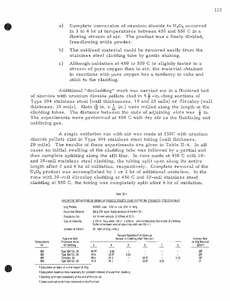
123
a) Complete conversion of uranium dioxide to U30g occurred in 3 to 4 hr at t empera tu re s between 450 and 550 C in a flowing s t r e a m of air . The product was a finely divided, free-flowing oxide powder.
b) The oxidized ma te r i a l could be removed easily from the s ta inless s teel cladding tube by gentle shaking.
c) Although oxidation at 450 to 500 C is slightly faster in a s t r e a m of pure oxygen than in air , the mate r ia l obtained in react ions with pure oxygen has a tendency to cake and stick to the cladding.
Additional "decladding" work was ca r r i ed out in a fluidized bed of alumina with uranium dioxide pellets clad in 5-j - in.-long sections of Type 304 s ta inless steel (wall th icknesses , 10 and 20 mils) or Zircaloy (wall thickness, 30 mils) . Slots (-g-in. x i in.) were milled along the length of the cladding tubes. The distance between the ends of adjoining slots was |- in. The exper iments were performed at 450 C with dry air as the fluidizing and oxidizing gas .
A single oxidation run with a i r was made at 550C with uranium dioxide pellets clad in Type 304 s ta inless steel tubing (wall thickness, 20 mils) . The resu l t s of these exper iments a r e given in Table II-4. In all cases an initial swelling of the cladding tube was followed by a par t ia l and then complete splitting along the slit line. In runs made at 450 C with 10-and 20-mil s ta inless steel cladding, the tubing split open along its ent ire length after 2 and 4 hr of oxidation, respectively. Complete removal of the UsOg product was accomplished by 1 or 2 hr of additional oxidation. In the runs with 30-mil Zircaloy cladding at 450 C and 20-mil s tainless steel cladding at 550 C, the tubing was completely split after 6 hr of oxidation.
Table 1-4
Temperature (C)
450 450 450 550
U02 Pellets
Fluid-bed Material
Fluidizing Gas
Size of Cladding
Number of Pellets
Type and Wall Thickness (mils)
of Cladding
Type 304 SS, 10 Type 304 SS, 20 Zircaloy 30 Type 304 SS 20
NUMEC, size 7/16-in dia, 7/16 m long
500 g 120 mesh AI2O3 (product of Ktorton Co )
Air (linear velocity 0 3 ft/sec at 25 Ci
5 1/2 in long (slots 1/8 in x 1/32 m were milled along the length of cladding Distance between ends of adjoining slots was 3/8 in )
12 total wi UO2 ~120 g
2
65 7C 934 98 6 914
Percent Retention^ of Uranium Dioxide in Cladding after Time (hr)
4 5 6 7 8
0 02 18 2^ 0 03
87 2 - 10 0= - 015 911 - 10 OC 0 03
Average Rate of UO2 Removal
(g/hriti
30d 24° 15^ 17
3 Calculated on basis of initial weight of UO2
b Calculation based on time necessary for complete removal of oxide from cladding
c Cladding split open completely at the end of this period
d Some uranium oxide fines remained in the fluid bed

124
The appearance of s ta inless s tee l -c lad fuel segments at different stages of oxidation a r e shown in Figure II-2. The uranium dioxide pellets in these specimens were clad in s ta inless s teel tubing having a wall thickness of 20 mi ls .
tH
Figure H-2
SPECIMENS OF SIMULATED SEcMENTS OF STAIN • LESS STEEL-CLAD URANIUM DIOXIDE FUEL ELEMENTS AFTER VARIOUS STAGES OF OXIDATION
A -Original Element, 20-mil Stainless Steel Cladding B - After 2 hr of Oxidation C - After 4 hr of Oxidation D -After 5 hr oi Oxidation
ft - C D
108-6081
In Figure II-2, A is the fuel segment before t rea tment , B_ is a s imi la r specimen after 2 hr of oxidation, C is a specimen after 4 hr of oxidation, and D is a specimen after 5 hr of oxidation. D shows the complete removal of the UsOg powder from the cladding. Several observations can be made from the resu l t s of these exper iments :
1) The removal of uranium dioxide pellets from Type 304 stainless steel or Zircaloy cladding by oxidation is feasible in a fluid bed at 450 C with a i r as the oxidant.
2) Slots mil led along the length of the cladding allow grea te r access of the oxidizing gas to the uranium dioxide pellets and promote splitting of the cladding along the slot line, thereby also aiding the re lease of UsOg from the cladding,
3) The time neces sa ry for complete removal of the UsOg formed appears to be dependent on the thickness of the cladding, i .e. , the t ime neces sa ry to achieve complete splitting of the cladding.

The Kinetics of Fluorinat ion of UsOg (R, L. J a r r y , T. D, Baker)
The oxidative "decladding" of uranium dioxide fuel elemients will produce finely divided, powdered UsOg. In a proposed fluid-bed fluoride volatil i ty p roces s , the UsOg powder is to be fluorinated in a fluid-bed reac to r . The UsOg will e i ther be produced in the samie fluid bed in which the f luorination is to be c a r r i e d out, or will be p repa red in a separa te react ion ves se l and injected into the fluid bed of a f luorinator. It is neces sa ry that the UsOg be fluorinated during its res idence t ime in the fluid-bed medium in o rde r to minimize elutr iat ion of powder to cooler port ions of the r eac to r , where r e action would not take place. A study of the kinetics of the react ion of fluorine with U3O8 was made in o rde r to obtain information from which the res idence t ime n e c e s s a r y to completely r eac t a par t ic le of U^OQ with fluorine in a fluid bed could be calculated.
Two batches of U3O8 were used in this study. The f i r s t was a s tandard sample (designated as NB-15), which was p repa red by the New Brunswick Labora tory of the AEG and which had a certif ied purity of 99 p e r cent. The second batch (designated as UCN) was p repa red by Union Carbide Nuclear Corp. Chemical analys is of this sample showed a uranium content of 84.99 pe rcen t ( theoret ica l u ran ium content of U3O8 is 84.80 percent) . The NB-15 and UCN sainples had surface a r e a s , as measured by nitrogen a d s o r p tion, of 0.14 and 0.28 sq m / g , respect ively . The fluorine used was c o m m e r cial grade from which hydrogen fluoride was removed by passing the gas through a t rap filled with sodium fluoride heated to 100 C.
The fluorination exper iments were performed with a the rmoba l -ance that was special ly designed for use with fluorine. The main components of the thermobalance , which have been descr ibed in detai l by Johnson and Fischer,-^ a r e a Sar to r ius Selecta analyt ical balance, equipped for autoweight recording, and a ve r t i ca l , tubular nickel react ion chamber . A nickel sample pan, upon which the UjOg powder was placed, was suspended in the react ion chamber by a Monel chain at tached to the s t i r rup of the Sar tor ius balance. Fluor ine was passed through a p rehea t e r before entering the reac to r , and the flow ra te was m e a s u r e d by means of a the rmal flowmeter. A t h e r m o couple posit ioned d i rec t ly beneath the sample pan sensed the react ion t e m pe ra tu r e . The output of the thermocouple was measu red by means of a Rubicon Type B potent iometer . A multipoint recording potent iometer was used to monitor the t e m p e r a t u r e s of the p rehea te r , the react ion chamber furnace, and the output of the t h e r m a l f lowmeter.
In a typical exper iment , 400 mg of UsOg was placed on a t a red nickel pan and then lowered into the preheated react ion chamber. During this stage of the exper iment , n i t rogen flow was maintained through the
Johnson, C. and F i s che r , J. , J. Phys . Chem., 65, 1849 (1961).

126
r eac to r . The weight of the oxide sample was checked on the Sar tor ius ba l ance while t e m p e r a t u r e equi l ibr ium between gas and solid was being attained. When the reac t ion sys tem had reached a uniform t empera tu re , the ni t rogen flow was stopped and a flow of fluorine at a r a t e of 150 c c / m i n was s ta r ted . During the reac t ion period, a continuous r eco rd of the weight change of the oxide sample v e r s u s reac t ion t ime was obtained.
The data obtained in these exper iments was co r re l a t ed by means of the d imin i sh ing-sphere model. This t r ea tmen t of data was d iscussed in detai l by Johnson and Fischer.-^ Briefly, the method a s s u m e s that in the g a s -solid reac t ion the solid reac tan t cons is t s of spher ica l pa r t i c l e s of uniform d iamete r , and that the reac t ion occurs uniformly on al l the pa r t i c l e s s imul taneously when the layer of solid is thin enough to allow saturat ion with the reac tan t gas . The reac t ion ra t e is then a function of the surface a r ea of the par t i c le , A mathemat ica l t r ea tmen t was developed for this kinetic model based on a gas - so l id reac t ion which occurs at a continuously diminishing spher ica l in terface. The final express ion r e l a t e s the react ion ra te to a function of the fract ion of the solid unreacted, as shown in the following equation:
(1 -F)^/3 = 1 - k ' t , (1)
in which
F = the fraction of solid reac ted;
k' = k / r o p , where ro is the ini t ial rad ius of a par t i c le and p is the bulk density;
t = reac t ion t ime.
A plot of the function (1 - F) v e r s u s t r e su l t s in a s t ra ight l ine, and the reac t ion r a t e constant can be obtained f rom the slope of the line.
Seven exper iments were per formed with the UCN oxide and fourteen with the NB-15 oxide. The t e m p e r a t u r e range covered in the expe r imen t s was f rom 300 to 400 C. The fluorinations were completed in 2 or m o r e hours at 300 C and in about 20 min at 400 C, The plot of (1 - F)^/^ v e r s u s t ime t for each of these exper iments gave a s t ra ight line over a significant por t ion of the data. A plot for a typical exper iment is shown in F igure I I -3 . Deviation f rom the expected kinet ics at the beginning of the exper iment was due to dilution of the fluorine by the ni t rogen initially p r e sen t in the r eac to r . The deviation at the end of the reac t ion per iod is probably due to the sma l l amount of sample remaining. X - r a y diffraction analyses of the r e s idues indicated that uranyl fluoride is an in te rmedia te in this react ion.

127
1 0<
0 9
0 8
0 7
0 6
-
-
-
k
X \
„ [ .
.,1 . F,l/3
where F
\ > t
1 - k't
fraction UjOg reacted
k/Tgp v here TQ IS initial radius of U3O8 particle and p is bulk density of U3O8
reaction time mm
\
X 108-6878
TIME, t ,min
Figure II-3
FLUORINATION OF UjOg
Tempera tu re : 401 C
Fluorine Flow Rate:
UjOg M e s h Fract ion:
120 m l / m i n
-100 +325
Rate constants were calculated from the slopes of the plots of the function (1 - F)^^^ ve r sus t ime t. The var ia t ions of the ra te constants (k' of Equation 1) with t empera tu re for the UCN and NB-15 samples of UsOg a re shown in Figure II-4. F r o m the slopes of the lines drawn through the two sets of data points, values of the activation energy of 3 1 and 30 kcal/ mole were calculated for the react ions of fluorine with NB-15 oxide and UCN oxide, respect ively. The somewhat l a rge r values of the react ion ra te constants obtained for the UCN V^Og is probably due to the l a rge r surface
Figure II-4
VARIATION OF REACTION RATE CONSTANT k' WITH TEMPERATURE FOR THE FLUORINATION
OF U3O8
Tempera tu re Range: 300-400 C
Rate Equation: (l - F)^ /^ = 1 - k ' t
(see F igure II-3 for definition of symbols)
I loU
® UCN UjOa O NB-15 U3O8
165 16 i /T X|0 ' (K)
108-6836

128
a rea of that ma te r i a l . The integrated form of the Arrhenius equation was fitted to the two sets of data shown on Figure II-4 to obtain the following equations represent ing the change in ra te constant with t empera tu re :
NB-15 oxide: log k ' = - — — + 8.4438; (2)
6599 UCN oxide: log k '= - - ^ + 8.3133. (3)
By means of equation (3) an extrapolated value of 0,6 min"'' was calculated for the r a t e constant at 500 C, the t empera tu re for the fluid-bed fluorination of UsOg. To es t imate the t ime neces sa ry to completely fluorin-ate a par t ic le of UsOg, the kinetic equation in the following form was used:
1 - f = k't, (4)
in which
r = radius of the par t ic le at t ime t in the fluorination;
ro = initial radius of the par t ic le .
When r is very small , that i s , when the par t ic le has been essent ial ly completely converted to uranium hexafluoride, then the t ime is equal to the rec ip roca l of the ra te constant. The solution of Equation (4) for t by use of the extrapolated ra te for 500 C gave a value of 1.7 nain. Therefore , if the extrapolated ra te constant is reasonably accura te , a res idence t ime that is severa l t imes g rea t e r than that needed for complete react ion is available. That this is so can be deduced from the data for the fluid-bed fluorination of UjOg presented in another section of this repor t (p. 120). In these exper i ments , which were performed at 500 C and with a superficial fluidizing velocity of 1.5 f t / sec , more than 99 percent of the U3O8 was converted to uranium hexafluoride, and the alumina bed ma te r i a l contained no more than 0.05 w/o uranium.
Decomposition of Plutonium Hexafluoride by Gamma Radiation (M. J. Steindler, D. Steidl)
In the fluid-bed fluoride volatili ty p rocess , plutonium hexafluoride will be subjected to gamma radiation from fission products . The cur rent investigation is intended to demonst ra te the behavior of plutonium hexafluoride in a high gamma field under var ious p rocess conditions and to serve as a fundamental study of the mechanism of the decomposition of plutonium hexafluoride by gamma radiation.

129
Plutonium hexafluoride at p r e s s u r e s of 80 to 100 m m Hg has been shown to decompose with a G value* of 7.5 ± 0,7 molecules in the range from ze ro to 37 x 10^° eV (see ANL-6687, p. 106). Both oxygen and fluorine, which -will be p resen t in p rocess gas s t r eams from the fluorination step of the fluid-bed fluoride volati l i ty p rocess , reduce the decomposition of plutonium hexafluoride by gamma radiation to ra tes that a r e near ly the same as those obtained for plutonium hexafluoride in the absence of gamma radiat ion (see ANL-6596, p. 126; ANL-6687, p. 109). The effect of added helium or krypton on the decomposition of plutonium hexafluoride by gamma i r rad ia t ion has also been studied (see ANL-6596, p. 127; ANL-6687, p, 108). Cur ren t emphasis on the problem has been directed toward a detailed investigation of the effect of added helium on the decomposition of plutonium hexafluoride under gamnaa i r radiat ion.
The exper imenta l p rocedures employed in this work have been previously descr ibed (see Summary Report ANL-6477, p. 118). The resu l t s of cu r r en t as well as previously repor ted experiments with helium a r e shown in Table II-5 and Figure II-5. These experiments were done at
Table 11-5
DECOMPOSITION OF PLUTONIUM HEXAFLUORIDE BY GAMMA RADIATION IN THE PRESENCE OF HELIUM
Average Gamma Energy: 0.75 MeV Dose Rate: 1 x 10* to 4 x 10* rad/min Temperature: 60 to 70 C PuFj Pressure : ~80 mm Hg at 25 C
E x p e r i m e n t
1199F-146 1 0 6
1 1 6 1Z8 1 4 0
1 4 8
7 4 0
118
49
34 10
122
1 5 8 1 3 0 152 1 5 4
132
In i t ia l P u F ^
( m i l l i m o l e s )
0.996 1.010 1.026 1 043 0.982 1,016 1.073a 0.964a 1.015 0.935a
1.035^ 1.097^ 0.967 1.045 1.010 1.022 1.005 1.018
In i t ia l H e
( m i l l i m o l e s )
8.863 8.659 8.413 8.629 8.342 8.998 8.132 8.133 8.566 8.298
17.16 17.29 17.22 17.58 17.31 18.14 17.78 17.58
A b s o r b (eV X
In P u F s
8.0 8 .1
8 .7 14.7 15.1 15.1 15.6 26.7 38,9 40.5
15.6 16.8 25.7 28.2 28.6 30.6 40.8 40.8
3d Dose 10-^°)
In He
1.0 1.0 1.0
1.8
1.9 2 . 0
1.8
3 . 7 5 .5 6.2
3 .7 4 . 0
7 .5 7 .6
7 .6 8 .3
11.8 11.9
PuF£,t> L o s t
( m i l l i m o l e s )
0.072 0.134 0.147 0.185 0.185 0.192 0.252 0,299 0,373 0,361
0.150 0,184 0,315 0,314 0.242 0.216 0,324 0.391
PuF4<= F o r m e d (mi l l i mo le s )
0,084 0.086 0.116 0,139 0.196 0.187 0,222 0.291 0.317 0.436
0.203 0.183 0.223 0.315 0.236 0.231 0.347 0.389
G ^
5.9 8 ,2
9 . 1 6 ,6 7 .6 7 .5
9 . 1 6 ,7 5 .3
5,9
6 ,8
6 .6 6 .3
6 .7 5,0 4 . 4
4 , 9 5 .7
^Presented previously, 1 By tensiometric methods, c By chemical analysis of solid residue. dG value calculated frora the average of PuFj lost and PUF4 formed with
energy absorbed in PuF^ alone.
* Molecules decomposed per 100 eV of absorbed energy.

130
Figure II-5
DECOMPOSITION OF PLUTONIUM HEXAFLUORIDE BY GAMMA RA
DIATION IN MIXTURES WITH HELIUM
0.5
0.4
E
s
6.6 ±1
O I ATM HELIUM A 2 ATM HELIUM
" 0 10 20 30 40 50
ENERGY ABSORBED IN PLUTONIUM HEXAFLUORIDE, e X 10'^'
108-6883
helium p r e s s u r e s of approximately one a tmosphere (~8,5 mil l imoles of helium) and two a tmospheres (~17 mill imoles of helium). The amount of
^plutonium hexafluoride decomposed appears to inc rease a lmost l inearly with absorbed energy in the range studied (8 x 10^° to 41 x 10^° eV),
The data in Figure II-5 may be viewed as showing a deviation from l ineari ty at high total dose. Such behavior has been observed in the study of the alpha decomposition of plutonium hexafluoride and may be at tr ibuted to the increas ing impor tance of the back react ion as the products of the decomposition buildup. Evidence for the synthesis of plutonium hexafluoride from fluorine and plutonium. tetraf luoride by gamma radiation has been presented p r e viously (see ANL-6596, p. 130), and it is likely that the effective G for the decomposition will decrease at la rge doses. Although experiments done with one a tmosphere of helium resu l t in a G value that is slightly higher than that calculated from ex
per iments with two a tmospheres of helium, it is believed that the difference between values is not significant. Since no pronounced effect of the p r e s s u r e of hel ium on the G value was found, a G value for all exper iments with helium has been calculated. This value, G = 6.6 ± 1, is not significantly different from that obtained from experiments with plutonium hexafluoride alone.
The data show, therefore , that when a vesse l that contains plutonium hexafluoride only and a ve s se l that contains the same amount of plutonium hexafluoride together with one or two a tmospheres of helium a re subjected to the same external source of radiation for identical per iods of t ime, the extent of decomposition of plutonium hexafluoride will be the same in both ves se l s , in spite of the fact that the total energy absorbed in the ves se l containing helium is 10 to 20 percent g rea t e r than the energy absorbed in the absence of helium. Since plutonium hexafluoride has an es t imated f i rs t ionization potential of 1 5 eV, and the f i r s t excited state of hel ium is approximately 20 eV, inhibition of plutonium hexafluoride decomposition by helium would involve deactivation of a plutonium hexafluoride

molecule which is both ionized and excited. On the bas is that such excited ions a r e p resen t in very smal l concentration, the slight effect of hel ium is in keeping with theore t ica l expectations.
The effect of krypton on the decomposition of plutonium hexafluoride is now being studied and will be repor ted in the next summary repor t .
The Alpha-radia t ion Decomposit ion Rate of Plutonium Hexafluoride (R. Wagner, W. Shinn)
Studies of the decomposit ion of plutonium hexafluoride due to alpha radiat ion a r e continuing with an investigation of the effect of the gases nitrogen, oxygen, fluorine, helium, or krypton. Binary mix tures of 100 m m of plutonium hexafluoride and each of the above gases have been p repared at room t e m p e r a t u r e in 127-cc nickel spheres . Analysis of the products has begun and the r e su l t s will be published in the next Chemical Engineer ing Summary Report .
'^' Engine e r ing - sca l e Investigation of Fluid-bed Fluoride Volatility P r o c e s s (A. A. Jonke) -»_____,-^ „_ -__ -
1. Development of Fluid-bed Fluor ide Volatility P r o c e s s e s for the Recovery of Uranium and Plutonium from Uranium Dioxide Fuels (W. J. Mecham)
Development of a fluid-bed fluoride volatil i ty p roces s for the r e covery of uran ium and plutonium from i r rad ia ted uranium dioxide fuels has continued. In this p r o c e s s , u ran ium and plutonium oxides a r e reac ted with fluorine to produce hexafluoride products , which a r e then decontaminated and separa ted by volat i l i ty techniques. The fluorination is c a r r i e d out in a fluidized packed-bed reac to r , in which the packed section is formed by u r a nium dioxide pe l le ts . Alumina gra in is used to fill the voids in the uranium dioxide pel let bed and to form a fluidized bed above the pel le ts . Development studies on an engineering scale have thus far been directed toward p r o c e s s optimization of the p r i m a r y fluorination of uranium dioxide pe l le ts . The major objectives of these studies have been to demonst ra te shor t - t ime ( less than 20 hr ) batch fluorination and sat isfactory fluorine util ization eff iciencies (g rea te r than 75 percent) . During the p resen t period, continued emphasis has been placed on the evaluation of a two-zone, oxidation-fluorination technique that is c a r r i e d out in a single vesse l .
In ea r ly one-zone sys tem runs (see ANL-6596, pp. 136 to 139) with shallow beds ( less than 6 in, deep) of r e a c t o r - g r a d e (unirradiated) u r a nium dioxide fuel pe l le t s , sa t i s fac tory heat removal , react ion control, and

the genera l effects of major p r o c e s s var iab les , such as t empera tu re , reagent gas flow, and composit ion, were demonstra ted. Although these runs were made most ly with batch charges of pel le ts , the semicontinuous feeding of pel le ts was a l so demonst ra ted . The introduction of oxygen along with fluor ine in the fluidizing gas was shown to promote the fluorination react ion by the formation of uran ium oxide (U3O8) fines of high specific surface a rea . Satisfactory p r o c e s s control was achieved by mete r ing the inlet fluorine and oxygen gases . Although oxygen is a product of the fluorination react ion and naust be bled from the sys tem, a mathemat ica l analys is (see Summary Report ANL-6543, pp. 131-134) of the use of p roces s off-gas indicates that high fluorine efficiency can be obtained through off-gas recycle while holding r e cycle oxygen to a minimum.
In batch runs util izing deeper pellet beds (18- in . -deep initial batch charges) , caking tendencies were noted (see Summary Report ANL-6569, p. 109). These caking tendencies were apparent ly due to secondary react ions of u ran ium hexafluoride vapor with u ran ium-bea r ing in t e r mediate compounds in the form of solid fines. To prevent caking in these deeper beds, low oxygen concentrat ion was required, which in turn entailed the p rac t i ca l disadvantage of a re la t ively low ra te of UjOg production and a consequent low ra te of u ran ium hexafluoride production and low efficiency of fluorine util ization. It has been found that caking can be prevented by the use of a two-zone oxidation-fluorination scheme. This scheme has been used successfully with 12- in . -deep beds and has allowed both high production ra t e s and high fluorine efficiencies. Although the two-zone method is cons idered promis ing for beds deeper than 12 in., such tes t s have not yet been c a r r i e d out.
In the two-zone p r o c e s s , two dist inct reac t ion zones a r e utilized: The f i r s t is a bed of u ran ium dioxide pel lets with fused alumina grain p a r t ic les in the voids (oxidation zone); the second is a bed of fused alumina grain pa r t i c l e s placed over the u ran ium dioxide pel let bed (fluorination zone). In the oxidation zone, U3O8 fines (about 10 to 20fi in mean d iameter ) a r e p r o duced by contacting the u ran ium dioxide pel le ts with a mixture of oxygen and ni t rogen which also s e rves to fluidize the alumina pa r t i c l e s . The UsOg fines a r e t r anspor t ed f rom the lower zone by the oxygen-ni trogen gas s t r e a m and a r e reac ted in the upper zone with fluorine, which is admit ted to the fluidized bed of alumina jus t above the u ran ium dioxide pel let bed. The fluidized alumina s e rves as a heat t r an s f e r medium. A discuss ion of the two-zone method of operat ion and a s u m m a r y of e a r l i e r runs a r e given in ANL-6687, pp. 112-124.
During the p r e sen t period, improved p r o c e s s control was achieved in the batch fluorination of unclad pel le ts , as shown by sat isfactor i ly high and uniform r a t e s of u ran ium hexafluoride production and by high efficiency of fluorine uti l ization. The improvement in p r o c e s s control was aided by the use of a gas t h e r m a l conductivity ins t rument for the continuous monitoring of fluorine concentrat ion in the p roces s off-gas.

The fluid-bed oxidation-fluorination techniques under development for p rocess ing uran ium dioxide fuel pel le ts may a lso be applied to me ta l -c l ad fuel e lements that have been cut to expose the uranium dioxide to the reagent gases . In this way separa te chemica l decladding s teps , such as chlorination for the r emova l of s ta in less s teel , can be avoided. In an oxidation-fluorination p r o c e s s , the u ran ium dioxide would be removed from the u n r e acted cladding, which would be d i scarded with the solid waste from the fluor ina tor . Thus, by shear ing fuel e lements into approximately one-in. lengths, it is poss ible to r e a c t the exposed u ran ium dioxide with fluorine to form the volati le u ran ium hexafluoride or with oxygen to form a mobile powder of U3O8. Tes ts of the two-zone oxidation-fluorination scheme on var iously cut fuel e lements have been per formed during the p resen t period. In this method, the unreac ted cladding is disposed of as solid waste after r emova l of the uranium.
Separate studies of the oxidation step for the removal of uran ium dioxide fuel from s ta in less s tee l (Type 304) cladding were a lso made. E a r l i e r oxidation studies (see Summary Report ANL-6477, p. 139) of unclad pel lets showed that the oxidation of u ran ium dioxide to U3O8 proceeded rapidly to completion, requi r ing only about 4 hr for a bed of-j--in. pel lets at 500 C. P r e l i m i n a r y t e s t s of the oxidation of one- in . - long segments of s ta in less s t ee l -clad uran ium dioxide fuel e lements in a fluidized packed bed were repor ted in the preceding quar te r ly (ANL-6687, p. 124). The cu r ren t work is d i rec ted toward the development of an oxidation step that may be incorporated into the two-zone oxidation-fluorination scheme in which uranium and plutonium hexafluorides a r e the product.
In the fluid-bed, oxidation-fluorination p roces s , the t r anspo r t of both heat and m a t e r i a l is important , and depends on the mixing of solids and gas in this sys tem. Because no previous work has been repor ted on the mixing behavior of such fluidized packed beds, bas ic studies in this a r ea have been c a r r i e d out as a pa r t of p r o c e s s development. Rates of t r anspor t i-n the longitudinal (axial) and l a t e r a l (radial) direct ions a r e different and have been m e a s u r e d separa te ly . When feasible, these studies have been c a r r i e d out with m a t e r i a l s that a r e m o r e convenient to handle than uran ium or fluor ine . E a r l i e r work on fluidized packed beds dealt with heat t ransfe r and gas mixing. In the preceding qua r t e r ly (ANL-6687, p. 128), studies of r a t e s of elutr iat ion of fines from fluid beds were studied as a function of gas r a t e s , fines concentrat ion in the bed, size of fixed packing, and size of fluidized pa r t i c l e s were repor ted . Studies of heat t r ans fe r r a t e s as a function of fines concentrat ion were a lso repor ted . During the p re sen t period, solids mixing ra t e s in the l a t e r a l d i rect ion were investigated.
An engineer ing-sca le high-alpha facility is being designed and instal led for the purpose of studying the seve ra l steps involved in the fluid-bed fluoride volati l i ty p rocess ing of uranium-plutonium oxide fuel. P r o c e s s equipment is now being insta l led for the fluorination step; equipment for other separa t ions steps is to be insta l led la ter .

2, Fluorinat ion of Dense Uranium Dioxide Fuel Pe l le t s m a Fluidized Bed ( L . Anas tas ia , B. KuUen, R. Kinzler , A. Rashinskas)
In o rde r to improve r e a c t o r operat ion and control during the p rocess ing of uran ium dioxide pel le ts by means of the two-zone oxidation-fluorination scheme, two modifications have been made in the 3 - in . -d iamete r f luorinator sys tem. One modification concerns the disengaging section and fi l ter sys tem, and is intended to minimize problems assoc ia ted with the fluorination of fines of uran ium in te rmedia te compounds which may be e lutr ia ted f rom the fluid bed. The other modification provides a method whereby the fluorine concentrat ion in the p r o c e s s off-gas is continuously measured .
F i l t e r Modification
The function of the disengaging and fi l ter sections is to prevent solids f rom escaping the fluorination zone of the reac to r . The following steps a r e involved:
1) The f reeboard immedia te ly above the fluid bed provides a region in which lowered gas velocity (about •-• that in the dense fluid bed) allows some of the l a rge r , entra ined pa r t i c l e s to fall back into the fluid bed. This is naost effective in p rac t i ce for pa r t i c les of +200 mesh which may acquire high velocity f rom bubble b u r s t s or slugging in the fluid bed. The effectiveness of this f reeboard i n c r e a s e s with height of f reeboard up to about 2 ft.
2) In genera l , disengaging sections of l a r g e r d iameter would be expected to allow m o r e effective sett l ing of the finer pa r t i c l e s because of the consequent d e c r e a s e in gas velocity. In o rde r to achieve a substant ial reduction in the number of ent ra ined pa r t i c l e s of -200 mesh size, very large disengaging sect ions may be neces sa ry . An inc rease in both the d iamete r (for reducing gas velocity) and the height (for increas ing res idence t ime) of the disengaging section would be advantageous, (Also, cyclones a r e somet imes used as an a l te rna t ive to l a rge disengaging sect ions,) The resul t ing low gas veloci t ies may allow col lected powders to accumulate . Vibrat ion may be effective in reducing holdup of fines in this case .
Accumulat ions of u ran ium oxide or oxyfluoride in the disengaging section may be removed by fluorination at t e m p e r a t u r e s of 2 50 C or above. However, because of re la t ive ly poor heat t r ans fe r of such nonfluid-ized m a t e r i a l , this method is cons idered to be limiited in prac t ice to thin (~1. -in.) deposi ts .
Uranium or plutonium compounds that a r e c a r r i e d through the disengaging sect ion a r e collected on porous meta l f i l te rs . These give good

separa t ion per formance due to fil ter cake action, and the cake can be r e moved from the fi l ter and re tu rned to the fluorination zone by r e v e r s e gas flow (blowback). These f i l ters a r e mechanical ly weak (compared with solid metal) and a r e subject to cor ros ion . For use with fluorine, nickel or Monel f i l ters have a long life only at t e m p e r a t u r e s below 200 C, Important in the control of t e m p e r a t u r e is (l) the cooling of hot gas from the react ion zone and (2) the prevent ion of any extensive fluorination of fines on the fi l ter surface. The genera l approach has been to minimize the fines loading on the fil ter and to provide posit ive cooling of the filter chamber and of the gas before it contacts the fi l ter.
In some recen t runs , e lu t r ia ted fines have accumulated in the disengaging and fi l ter section because of low operating t empera tu re s and because of in te rna l surface configurations favoring powder holdup. The t empera tu re of the disengaging section has been maintained at 100 to 200 C during fluorination exper iments in o rde r to maintain the physical integri ty of the two porous me ta l f i l t e r s . The tops of these f i l ters with exposed pipe connections provided seve ra l a r e a s suitable for fines buildup. In addition, a 19-in. length of Schedule 40, 3 - in . -d iamete r pipe attached to the top flange of the r eac to r and per fora ted with s ixty-eight 0. 5 - in . -d iameter holes p r o vided numerous hor izonta l surfaces and an additional ver t i ca l surface upon which fines have deposited. (The per fora ted pipe was originally intended as a miechanical guide for lowering solid charges into the fluorinator.) The pipe and f i l ters have been removed from the disengaging section, and an exte rna l f i l ter a s sembly has been constructed. Prev ious tes t s with external f i l ters have been descr ibed in Summary Report ANL-6333, p. 184. A schemat ic d iagram of the p re sen t sys t em is shown in F igure II-6. The pa r t s of the r eac to r sys tem that have been removed a r e shown in dotted l ines.
In the modified sys tem, a single 3-in. x 18-in. bayonet fi l ter surmounts the disengaging section to f i l ter the p roces s off-gas. A bypass gas path through a second external f i l ter (non-blowback) has been provided to allow blowback of the p r o c e s s fi l ter . The bypass is opened e lec t r ica l ly by means of the blowback t i m e r and a delay re lay. Three seconds before each blowback, the t ime r actuates a solenoid that opera tes a pneumatic valve which in turn opens the bypass line; the delay re lay then actuates the blow-back sys tem. This operat ion completes the t imer cycle; the bypass is closed and no rma l gas flow through the p r o c e s s fil ter is resumed. The p re sen t location of the f i l ters allows the use of higher t empe ra tu r e s for the fluorination of fines in the disengaging section; cal rod hea te r s have been added to the disengaging section for this purpose.
Continuous Fluor ine Analysis of F luor ina tor Off-gas
Since fluorine is m e t e r e d into the r eac to r sys tem at a known ra te , a continuous analys is of fluorine in the off-gas allows immediate knowledge of fluorine uti l izat ion efficiency. Also, since the uranium hexafluoride

136
collection ra te is known independently, the ra te of accumulation of fluorine as in termedia te fluorides can be calculated, (In the two-zone system, uranyl fluoride is the chief in termedia te compound resul t ing from the r e action between fluorine and U3O8 fines,)
Figure II-6
FLUORINATOR FOR URANIUM DIOXIDE PELLETS: PIPING AND VALVE ARRANGEMENT FOR EXTERNAL FILTER
INSTRUMENT
BLOWBACK Nz (30 ps g) PRESSURE TAP
TO CONDENSER
MAIN PROCESS FILTER 3 in X 18-in BAYONET (BLOWBACK) FILTER
NON-BLOWBACK SOLENOID
INSTRUMENT . . f l ATR '^^
N j PURGE (OSsc fh )
£1 -ROTA METER
FORMER POSITION OF FILTERS
FORMER POSITION OF 3 n PIPE EXTENSION
§ - 3 in X 18 in
BAYONET FIL.TER
EXTERNAL FILLER HOUSING
PPESSUPE TAP
108-6841
F rom such information on the ra te of fines accumulation, appropr ia te control action can be taken to l imit the accumulation of fines in the sys tem by reduction of the oxygen/fluorine rat io of the reagent gas input. However, an analytical t ime lag of j to f hr for a separa te fluorine analysis is too long for fines control by regulation of the gas input. Hence, it is des i rab le to have a method of monitoring fluorine and uranium hexafluoride concentration in the off-gas continuously. For this purpose, a method employing the rmal conductivity cells is cur rent ly being applied. With this system fluorine and uranium hexafluoride concentration in the off-gas can be plotted continuously on a s t r i p - cha r t r ecorde r .
In initial tes t s of the f luorine-analysis system, the gas feed for the the rma l conductivity cell is taken from a point downstream of the u r a nium hexafluoride condenser and sodium fluoride t r aps . This gas contains oxygen, nitrogen, and fluorine. After the gas mixture passes through the

reference side of the cell , the fluorine in the mixture is replaced with chlorine (by react ion with sodium chloride) to form the sample gas analyzed by means of t he rma l conductivity. Output of the cell is , therefore, based on chlorine concentration, but the cell is cal ibrated to give readings in t e rms of fluorine concentration. Tes ts of the uranium hexafluoride analysis cell a r e to be made la ter .
Resul ts of Fluorinat ions of Uranium Dioxide Pel le ts
Engineer ing-sca le studies have continued on the development of a two-zone oxidation-fluorination scheme for the conversion of uranium dioxide pellets into uraniuna hexafluoride in a single reac tor . In this scheme, the oxidation (lower) zone consis ts of uranium dioxide pellets with alumina grain filling the voids between the pel le ts . The fluorination (upper) zone consis ts of a fluidized bed of alumina gra ins which extends above the oxidation zone. By passing an oxygen-nitrogen mixture through the oxidation zone, U30g fines a r e produced. These fines a r e t ranspor ted from the oxidation zone to the fluorination zone, where they a re fluorinated to uranium hexafluoride vapor.
In two previous runs, 12-in.-deep beds of uranium dioxide pellets were converted to uranium hexafluoride in 15 hr when 4.5 percent oxygen in ni trogen was used as the oxidant and in 12. 5 hr when 6 percent oxygen in n i t ro gen was used (see Runs UOF-68 and -69, ANL-6687, p. 117). Overall fluorine utilization efficiencies for these runs were 64.5 and 72.5 percent, r e s p e c tively. In these runs , heat was conducted to the pellets from the fluorination zone, which was maintained at 500 C; no attempt was made to maintain p r e determined t empera tu re s in the oxidation zone. In these runs, fluorine input to the fluorination zone was diluted by a par t ia l recycle of off-gas (0.25 cfm) to prevent plugging of the fluorine inlet. Gas pulsing was used to aid fines t r anspor t from the oxidation to the fluorination zone.
Another run (UOF-70) in this se r ies has been completed with sat isfactory resu l t s . A 12-in.-deep bed of pellets was completely reacted in 12.5 hr. The concentrat ion of oxygen in nitrogen in the gas s t r eam to the fluidized-packed bed was 8 percent . An overal l fluorine efficiency of 75 p e r cent was achieved. The operating conditions and resu l t s for Run UOF-70 a r e given in Table II-6 and in Figures II-7 and II-8. Good tempera ture cont rol was achieved in this run, as in other recent two-zone runs.
The changes of the uranium hexafluoride production ra tes with t ime, shown in Figure II-7, were somewhat different than those obtained in the previous run. Run UOF-69. In Run UOF-69, production ra tes vir tually doubled after 5.5 hr of operation, and reached a maximum of 107 lb UF^/ (hr)(sq ft) during the eighth hour, whereas in Run UOF-70, ra te increases were more modera te and a maximum production ra te of 82.5 lb UF6/(hr)(sq ft) was achieved during the seventh hour. The uniformity in the ra te of uranium hexafluoride production is shown by the plot of cumulative product gain with t ime in Figure II-8, and is taken to indicate good react ion control.

138
Table 1 6
OPERATING CONDITIONS AND RESULTS FOR RUN UOF 70 A TWO ZONE OXIDATION FLUORINATION OF URANIUM DIOXIDE PELLETS WITH GAS PUISING
U02 PsIlet Charge
Alumina Charge
Temperatures
Pulsing Conditions
Oxygen Diluent
Fluorine Diluent
Run Duration
Overall Fluorine Efficiency
Gas Flow
Weight 8 8 kg Bed Height 12 in
Weight 7 1 kg (Blue Label Alundum) Static Height al»ve Pellets W in Size Limits (U S Mesh) -40 +170
Fluorination Zone 500 C Oxidation Zone (Pellets) 3 4 0 < T < 4 8 0 C
Duration 0 04 sec Frequency 2pulses(mm Pressure ZOpsig Gas Volume 0 016 cu ft/pulse
N2
Process Off-gas (0 25 cfm)
12 5 hr (9 25 tir once through gas flow 3 25 hr total off-gas recycle)
75 percent
Oxidation Zone Fluorination Zone
Process Time (hrl
0-3 5 3 5-8 5 8 5-9 25
9 25-12 5
Rate (cfm)
02
m Rate (cfm)
104 8 0 144 104 8 0 151 104 SO 142 (0 5 cfm gas recycle *0 (K cfm F2'
Average Fj 1 nput to Reactor
m 10 2 14 4 94
Average fluorine Utilization Efficiency^
m 69 4 85 8 464 42 3
^Fluorine utilization efficiency • 100 3 (mole UF^ produced/hr)
(mole F2 fed/hri
Average Production Rate
[lbUF6;(hr)(sqft)]
37 68 23
9
80
? 70
.UF^ PRODUCTION o
FglNPUT
_^TOTAL OFF_^
fsAS RECYCLT 1 PERIOD I I
hh
-10 25
0 20
0!5
Ho 10
Hoos
Figure II-7
URANIUM HEXAFLUORIDE PRODUCTION AND FLUORINE INPUT RATES FOR
UOF-70. A TWO-ZONE OXIDATION-FLUORINATION OF URANIUM DIOXIDE
PELLETS WITH GAS PULSING
(Run conditions 111 Table 11-6)
6 8 10
RUN TIME.hr
12 i3
108-6850
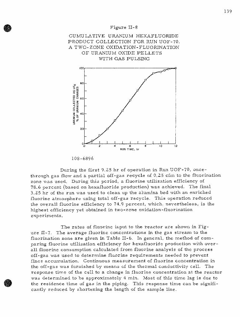
Figure II-8
CUMULATIVE URANIUM HEXAFLUORIDE PRODUCT COLLECTION FOR RUN UOF-70. A TWO-ZONE OXIDATION-FLUORINATION
OF URANIUM OXIDE PELLETS WITH GAS PULSING
RUN TIME, hr
108-6896
During the f i r s t 9.25 hr of operation in Run UOF-70, once-through gas flow and a pa r t i a l off-gas recycle of 0.25 cfm to the fluorination zone was used. During this period, a fluorine utilization efficiency of 78.6 percent (based on hexafluoride production) was achieved. The final 3.25 hr of the run was used to clean up the alumina bed with an enriched fluorine a tmosphere using total off-gas recycle . This operation reduced the overal l fluorine efficiency to 74.9 percent , which, never the less , is the highest efficiency yet obtained in two-zone oxidation-fluorination exper iments .
The ra t e s of fluorine input to the reac tor a re shown in Figure II-7. The average fluorine concentrat ions in the gas s t r eam to the fluorination zone a r e given in Table II-6. In general , the method of comparing fluorine utilization efficiency for hexafluoride production with overall fluorine consumption calculated from fluorine analysis of the process off-gas was used to determine fluorine requi rements needed to prevent fines accumulation. Continuous measu remen t of fluorine concentration in the off-gas was furnished by means of the the rmal conductivity cell. The response time of the cell to a change in fluorine concentration at the reactor was determined to be approximately 4 min. Most of this t ime lag is due to the res idence t ime of gas in the piping. This response t ime can be significantly reduced by shortening the length of the sample line.

140
Fluctuat ions in fluorine concentrat ion in the p roces s off-gas were apparent f rom the cell output. Because the t he rma l conductivity cell is sensi t ive to these fluctuations, it offers a significant improvemient in p r o c e s s ins t rumenta t ion over the previous g rab - sample technique.
The use of a single, cooled, s i n t e r ed -me ta l f i l ter , a heated (400 C) disengaging section, and an a l te rna te gas path during fi l ter blowback gave very p romis ing re su l t s during Run UOF-70. In general , p r e s s u r e drop a c r o s s the single fi l ter was somewhat higher than that a c r o s s the two p a r a l lel f i l ters used previously. Although the total gas ra te of 1.5 cfm (during the run per iod of 3.5 to 8.5 hr ; see Table II-6) was 7 percen t higher than that for a comparable per iod of u ran ium hexafluoride production during Run UOF-69, max imum differential p r e s s u r e s a c r o s s the fi l ter were 12 in, H2O in Run UOF-70 and 7 in. H2O in Run UOF-69. This r esu l t indicated that the solids loading of the exit gases had been reduced. At the same solids loading and gas r a t e s , but with one-half the fil ter a r ea , p r e s s u r e drop is expected to i nc r ea se by a factor of four.*
The bottom cone of the disengaging section was clean and the walls had a re la t ive ly light coating of solids. The s ing le -p rocess fil ter had a layer of solids which was s imi la r to that normal ly obtained on each of the pa ra l l e l f i l ters previously used. The non-blowback fi l ter in the bypass s y s tem had a ba re ly d iscern ib le layer of oxide fines, thereby indicating that the non-blowback fi l ter may not be n e c e s s a r y in s imi la r opera t ions .
Blowback frequency of the main p roces s fi l ter was once every 15 min; this compares with a blowback frequency of once every 30 min for each of the two f i l t e rs in the previous ly used pa ra l l e l a r r angemen t ( i .e. , a blowback of a f i l ter occu r r ed every 15 min, a l ternat ing from one fi l ter to the other) .
The t ime requi red to col lect 90 percent of the amount of uran ium hexafluoride in t e s t s with 12-in. deep beds of pel le ts is shown in F igure II-9 as a function of oxygen concentrat ion in the oxidation zone. Fo r purposes of comparison, it is noted that in Runs UOF-63 and UOF-64 (two-zone oxidation fluorinations in which t h e r m a l gradients in the oxidation zone were p r e sen t but in which no gas pulsing was used) the t ime requ i red for 90 percen t collection was 14 hr with 18 and 31 pe rcen t oxygen and 16 hr with 26 percent oxygen (see ANL-6648, pp. 137 to 143). As shown in Figure II-9, the r e quired p rocess ing t imes were shor t e r with lower oxygen concentrat ions in two-zone oxidation-fluorinations with gas pulsing. These data a l so imply that the use of m o r e than 8 pe rcen t oxygen with gas pulsing m,ay not significantly reduce p rocess ing t ime, and that the concentrat ion range 6 to 8 percen t oxygen is sa t i s fac tory for high uran ium fluoride production r a t e s .
D. B. Pa l l , F i l t ra t ion of Fluid Catalyst Fines f rom Effluent Gases , Ind. Eng. Chem. 45(6), 1197 (1953).

Figure II-9
EFFECT OF OXYGEN CONCENTRATION ON THE TIME REQUIRED TO COLLECT 90 PER
CENT OF THE CHARGED URANIUM AS URANIUM HEXAFLUORIDE
[For 12-in., fluidized packed beds of uranium dioxide pellets (8.8 kg UO2) using two-zone oxidation-fluorination with gas pulsing.!
~o 2 4 6 8 10
COtsiCENTRATION OF OXYGEN IN OXIDATION ZONE, percent
108-6879
Uranium Mater ia l Balances for Runs UOF-68, UOF-69 and UOF-70
The uranium ma te r i a l balances for severa l recent two-zone oxidation-fluorinations utilizing 12-in.-deep beds of bare uranium dioxide pellets a r e shown in Table II-7. Mater ia l balances near 100 percent have been obtained since the recent addition of sodium fluoride t raps downstream of the condenser; p r ior to the use of these t raps , an empir ica l condenser efficiency of 96 percent was used for mater ia l -ba lance calculations. The average condenser efficiency for Runs UOF-68 to UOF-70 was 95.6 percent , whereas for individual runs the efficiencies were 95.0, 96.6, and 95.1 percent for Runs UOF-68, UOF-69, and UOF-70, respectively. For Runs UOF-68, UOF-69, and UOF-70, the overal l uranium balances were 100 ± 0.4 percent.
Fluorination of Stainless Steel-clad Uranium Dioxide Pel le ts
The work descr ibed above has been directed toward the p r o c e s s ing of beds of unclad uranium dioxide pel le ts . In the present period, work has been s tar ted on the evaluation of the two-zone technique for the p r o c e s s ing of s ta inless s tee l -c lad pel le ts . In these tes t s , uranium dioxide pellets a r e placed inside short lengths (about 1 to 2 in.) of s tainless steel tubing to s imulate sheared fuel e lements . Longer-e lement sections with longitudina sli ts a r e also being used in these exper iments .
12
.10 —
10 o
S 2 8
n O 3
ife
-
—
-
—
—
—
—
—
1
F . " ro-d! t icrs
pUOF-68
1 \ \ \ \ \
^ Q U O F - 6 9
•«-., O U O F - 7 0
0-taatio- Zo^^ F u'>[ r c l i o r / o i <
^>'<(V
kur nradiert \ ICi
UO? Gg 340'^430 U0F-fe9 340'0 4^0 UOF 70 340 to 480
1 • 1
Gab MOA 03b How Ratp ^eTo Rate F? 'Cf-- 'O 'Ct r l r<
0 9 -00 U 14 0 9 m 14 V 10 SCO 13 14
, I I I ,
2 —

142
Table II-7
URANIUM MATERIAL BALANCES FOR RECENT TWO-ZONE OXIDATION-FLUORINATIONS OF 12-IN. DEEP URANIUM DIOXIDE IN FLUIDIZED
PACKED BEDS
Runs UOF-68 and UOF-69 Run UOF-70
Initial Weights (g)
UO2 Recovery
UO2 charged 17,610 8,851 AI2O3 charged 7,087^ 7,087
16,726 736 63 20
17,545
99.1
0.25
99.6
8,407 433 13^ 28
8,881
99.9
0.35
100.3
As UF^ in condenser (g UO2) in NaF t r aps (g UO2)
As Nonreacted UO2 (g) As Uranium Compounds in AI2O3 (g UO2)
Total U accounted for (as UO2) (g)
Collection of UF^ Produc t (% of U charged)
Final U Concentrat ion in AI2O3 (w/o)
Overal l Uranium Mater ia l Balance (%)
3-Alumina was not removed from the r eac to r between Runs UOF-68 and UOF-69.
°9-6 g of this m a t e r i a l was UO2 enclosed by a piece of s ta in less s tee l cladding.
Two exper iments (Runs UOF-71 and UOF-72) have been completed in the 3 - in . -d i ame te r r e a c t o r with the objective of determining the completeness of r emova l of u ran ium dioxide pel lets from short p ieces of s ta in less s tee l cladding. These experimients were c a r r i e d out by means of the two-zone oxidation-fluorination technique. In Run UOF-71, a 1.2-kg charge of pel le ts was used. The charge consis ted of 40 s ta in less s tee l -clad e lements which were jf" iii- long and contained two uran ium dioxide pel le ts each, one segnaent which was 1 •§• in. long and contained th ree pe l le t s , and one which was 1 j ^ in. long and contained four pel le ts . Two s ta inless s t ee l -c lad p ieces , which were about 5.2 in. and 10.3 in. long and which had been sl i t longitudinally, were a lso included in the charge. The height of the fluidized packed bed formed by the sma l l e r p ieces was about 2 in., with the longer p ieces protruding above. A 100 percen t removal of uranium dioxide f rom the cladding was achieved in 8.5 hr .

143
In the second exper iment (Run UOF-72), a charge of 3,5 kg of uranium dioxide pellets was used. The pellets were clad in -^ -in. long segments of Type 304 s ta in less s teel (two pellets in each of 175 segments) . The height of the fluidized packed bed was 6 in. In this run, 95 percent of the original uranium was removed from the cladding in 13.5 hr . Typical specimens of s ta inless s tee l -c lad fuel segments before fluorination a r e shown in Figure 11-10.
Figure 11-10
TYPICAL SPECIMENS OF TYPE 304 STAINLESS STEEL-CLAD URANIUM DIOXIDE FUEL SEGMENTS
|'|f|f|l|l||t|l|l|f|lff|ij|f|^
108-6163
The general operating conditions used in the decladding runs were s imi la r to those used in recent runs with unclad pel lets . However, the clad segments were exposed to higher oxygen concentrations than those used in runs with unclad pel lets . In the present two runs, 22 percent oxygen in ni trogen was supplied to the oxidation zone, whereas 8 percent oxygen in nitrogen was used in typical ea r l i e r runs with unclad uranium dioxide pel lets .
Run UOF-71
Operating conditions for Run UOF-71 a r e listed in Table II-8, With the oxidation zone (fluidized packed bed) at 450 C, the fluorination zone at 500 C, and with 22 percent oxygen being passed through the fluidized packed bed, a maximum uranium hexafluoride production ra te of 31 lb UF^ / (hr)(sq ft) was obtained after 3 hr of operation After 4 5 hr of operation, the production ra te dropped off to zero. At this point, 90 percent of the uranium originally p resen t had been collected as the hexafluoride The remaining 10 percent of the uranium was fluorinated by passing fluorine through the fluidized packed bed and using total off-gas recycle . Overall fluorine efficiency, based on conversion to the hexafluoride, for Run UOF-71 was 26.6 percent .

144
Table II-8
OPERATING CONDITIONS FOR RUN UOF-71, A TWO-ZONE OXIDATION-FLUORINATION OF A FLUIDIZED PACKED
BED OF STAINLESS STEEL-CLAD UO2 PELLETS
UO2 Pel le t s : Type 304 SS Cladding:
Mater ia ls Charged:
0.42-in. r ight cylinders 0.45-in. OD; 0.43-in. ID; 0.010 in. thick
Weight of UO2 Pel le t s : Fixed Bed Height: Weight of Cladding:
1224 g 1.5 in. 55 g
Siinulated Fuel Segments: 40 pieces 15/16 in. long (2 pellets each)
1 piece 22/16 in. long (3 pellets) 1 piece 29/16 in. long (4 pellets) 1 piece ^6 in. long (slit, 12 pellets) 1 piece ~12 in. long (slit, 24 pellets)
Weight of Alumina (Blue Label Alundum): 7.1 kg
(size l imi ts : -40 -fl70 mesh)
Pulsing Conditions: Duration Frequency P r e s s u r e Gas Volume
0.04 sec 2 pu l ses /min 20 psig 0.016 cu f t /pulse
For Once-through Gas Flow (5.25 hr)
Oxidation Zone:
Fluorination Zone:
Tempera tu re Oxygen Concentration Diluent Total Gas Rate
Tempera tu re F2 Concentration Total Gas Rate
450 C 22 percent N2
1.1 cfm
500 C 4.2 to 10 percent 1.4 cfm
For Total Off-gas Recycle (3.25 hr)
Tempera tu re Max Fj Concentration Total Gas Rate
500 C 58 percent 0.59 cfm
Run Duration 8.5 hr

145
The forty-two smal l e r pieces of s ta inless steel cladding were recovered from the reac tor in vi r tual ly the same form as charged; however, only smal l , thin fragments of the slit, longer sections of cladding were r e covered. These fragments were about 1 sq in. in a r ea by 0.003 in, thick. All of the s ta inless cladding sections had undergone fluorine attack, as was evident from surface scale formation. A photograph of the tubing elements after exposure to fluorine is shown in F igure 11-11; one unexposed fuel segment is shown at the left. The reason is not known why in this run the s ta in less s teel in the 6- and 12-in. segments were more severely attacked than the ~ -in. segments . Because the longer elements projected out of the packed bed and may have been c a r r i e d upward out of the pellet bed, they may have been subjected to a l te rna te oxidizing and fluorinating environments .
F igure II-11
APPEARANCE OF TYPICAL STAINLESS STEEL CLADDING RESIDUES AT END OF RUN UOF-71
FRAGMENTS FROM SLIT PIECES
« c h
CLADDING SEGMENT
T H R E E ^ P E L L E T f CLADDING SEGMENT THREE PELLETS ^^^^^ CONTAINED
FOUR PELLETS
SCALE I
I inch
r ORIGINAL FORM
CLADDING SEGMENTS WHICH CONTAINED TWO PELLETS
108-6899
Run UOF-72
For Run UOF-72, the height of the fluidized packed bed of clad pellets was increased to 6 in. The length of the s tainless steel cladding segments was j | in. Operating conditions for this run a r e given in Table II-9.

146
Table II-9
OPERATING CONDITIONS FOR RUN UOF-72, A TWO-ZONE OXIDATION-FLUORINATION OF A FLUIDIZED PACKED
BED OF STAINLESS STEEL-CLAD PELLETS
UO2 Pe l l e t s : Type 304 SS Cladding:
0.42-in. r ight cyl inders 0.45-in. OD; 0.43-in. ID; 0.010 in. thick
Mater ia l s Charged: Weight of UO2 Pe l le t s : Fixed Bed Height: Length and Weight of
Cladding:
Weight of Alumina (Blue Label Alundum):
3484 g 6 in.
175 pieces 15/16 in. (length) 287 g
7087 g (size linaits:
-40 + 170 mesh)
Pulsing Conditions: Frequency P r e s s u r e Duration
2 p u l s e s / m i n 20, 30, and 40 psig 0.04 sec
For Once-through Gas Flow (6.75 hr)
Oxidation Zone:
Fluor inat ion Zone:
Tempera tu re Oxygen Concentrat ion Diluent Total Gas Rate
Tempera tu re F2 Concentrat ion Total Gas Rate
450 C 22 percent Nz 1.1 cfm
500 C 4.0 to 10.3 percent 1.5 cfm
For Total Off-gas Recycle (6.75 hr)
T e m p e r a t u r e Max F2 Concentrat ion Total Gas Rate
500 C 25 percent 0.56 cfm
Run Duration 13.5 hr

147
The initial operating conditions were identical with those used successfully in Run UOF-71; however, when the uranium hexafluoride production ra t e s began to drop off after 3.5 hr of operation, pulsing p r e s s u r e s were inc reased in an effort to inc rease the ra te of hexafluoride production. As shown in Figure 11-12, the higher pulse p r e s s u r e s were not effective for this purpose.
g 30
-ONCE-THROUGH-GAS FLOW
TOTAL OFF - -SAS RECYCLE
20 psig d» 30 psig —Jf»-^'^-tia-OfF-J»-'*°-Jf-OFF—»
PULSING PRESSURES
1 Figure 11-12
URANIUM HEXAFLUORIDE PRODUCTION RATES FOR RUN UOF-72, A TWO-ZONE OXIDATION-
FLUORINATION OF STAINLESS STEEL-CLAD URANIUM DIOXIDE PELLETS
(See Run Conditions in Table II-9)
RUN TIME, hours
108-6881
The maximum uranium hexafluoride production ra te obtained in Run UOF-72 was 42 lb UFg/(hr)(sq ft). In general , production ra tes were lower than those obtained in oxidation-fluorination experiments with bare pel le ts . The overa l l fluorine efficiency based on conversion to the hexafluoride was 51 percent in Run UOF-72.
In 6.75 hr, 67 percent of the uranium charge had been collected as uranium hexafluoride with oxygen passing through the oxidation zone (fluidized packed bed) and using once-through gas flow. The remaining 28 percent was fluorinated by passing fluorine through the fluidized packed bed and using total off-gas recycle . The total removal of uranium dioxide was 95 percent for a total run time of 13.5 hr .
Operationally, Run UOF-72 is not considered sat isfactory be cause a high p r e s s u r e drop occur red a c r o s s the packed zone after 12.8 hr of operation, thereby indicating the formation of a caked bed. F r o m subsequent examination of the bed, it appeared that cladding pieces at the bottom of the fluidized packed bed contained unreacted uranium oxide. F r o m the appearance of this res idual mate r ia l , it is believed to be unconver ted uranium dioxide. Incomplete conversion of the dioxide may have been caused by excessive cooling of the fluidized packed bed when la rger quantities of ambient ni t rogen were introduced into the system to increase the pulse p r e s s u r e . Fur ther studies of the two-zone scheme for the "decladding" and conversion of uranium dioxide fuels to uranium hexafluor ide a re being planned.

3. Oxidative Separat ion of Uranium Dioxide Fuel from Stainless Steel-c lad Fuel Segments in a Fluidized Packed Bed ( M . Bae rns , R. Kinzler)
Studies have been continued to de termine the feasibility of the r emova l of u ran ium dioxide from s ta in less s tee l -c lad fuel segments with both ends open by oxidation of the uran ium dioxide to UsOg in fluidized packed beds. The oxidation product, UsOg, tends to spall off the surface of the uran ium dioxide because of the differences in density of the two oxides. In these t e s t s , shor t fuel segments form a randomly packed (fixed) bed and alumina gra in is fluidized in the voids of the packed bed. Air is used both as fluidizing and oxidizing gas . The UsOg fines formed in this p rocess mix with the fluid bed m a t e r i a l and may be conveyed to a separa te fluorina-tion zone for the production of uranium hexafluoride.
The p resen t studies of oxidative separat ion a re intended to evaluate such a method of process ing sheared or chopped fuel e lements of the s ta in less s t ee l -c lad uranium dioxide type. This oxidation step could be performed as a separa te step pr ior to the fluorination or incorporated into the two-zone oxidation-fluorination p rocess c a r r i e d out in a single ves se l .
The r e su l t s of the f i rs t five exper iments of this type were p r e sented in the preceding qua r t e r ly r epo r t (see ANL-6687, p. 124). In these exper iments it was found that higher r a t e s of r emova l were obtained by increas ing the t e m p e r a t u r e from 350 C to about 450 C and by using gas pulsing. Removal r a t e s were near ly constant for removals of up to approximate ly 80 percent of the uran ium oxide. The runs were te rmina ted before complete r emova l s of uranium dioxide were obtained.
In the cu r r en t t e s t s , the emphas is was placed upon finding the conditions for complete r emova l of the oxide from the cladding. Additional runs were made in which the effect of bed t empe ra tu r e and of gas pulsing was studied fur ther . However, a complete r emova l of the oxide was not achieved in any of these runs made thus far. A further effort is under way to invest igate addit ional techniques for improving the oxide remova l from sections of cladding. Three methods appear worthy of investigation:
(1) the fluorination of oxide res idues (mainly UaOg) to uranium hexafluoride;
(2) mechanica l agitation or vibrat ion to loosen the oxide res idues from the cladding;
(3) loosening of oxide r e s idues by density changes involved in the reduction to UO2 followed by reoxidation to UsOg.

149
P r e l i m i n a r y t e s t s of method (l) a re discussed in the previous section of this repor t . In this section a r e repor ted some scouting tes ts showing that methods (2) and (3) resu l t in inaproved separation of the u r a nium dioxide from the cladding.
Expe r imental
The 2- in . -d iameter reac to r sys tem used for these experiments was descr ibed in the preceding quar te r ly repor t (see ANL-6687, p. 125).
In the first se r i e s of fluidized packed Figure 11-13
FLUIDIZED PACKED BED CONSISTING OF FOUR INDIVIDUAL
PACKED SECTIONS
FLUIDIZED-PACKED BED
INERT FLUID BED MATERIAL
(no packing)
SUPPORT PLATES
GAS INLET
108-6858
bed runs (Runs XO- 1 to XO- 14), the batch charge of each run consisted of a randomly packed bed (about 6 in. deep) of forty simulated fuel segments and fused alumina grain, which was fluidized in the voids of of the packed bed and above it. Each fuel segment consisted of two dense uranium dioxide pellets (0.42 in. in diameter and 0.42 in. in length) placed in close-fitting s tainless s teel (Type 304) tubes ( l | - in . long by 0.5 in. in OD). The wall thickness of these tubes was 0.035 in. in Runs XO-1 to XO-8 and 0.010 in. in Runs XO-9 to XO- 16. In Runs XO-15 and XO-16, the reactor was charged with 32 fuel segments and alumina grain. In these two runs, the packed bed of fuel segments was divided into four sections (see Figure 11-13). Each section was approximately 1.5 in. high and was supported by a perforated plate.
The alumina grain was fluidized throughout the voids of the four sections. This a r rangement was expected to improve the c i rculation of the alumina grain and to allow the fuel segments to have g rea te r freedom of motion with gas pulsing. The bed was fluidized with nitrogen during the preheating period
and with air during the oxidation. In the experiment in which U3O8 was r e duced to uranium dioxide, a mixture of approximately 5 v /o hydrogen in ni trogen was used as fluidizing gas . Oxygen consumption in the fluidizing a i r was measured by a gas t h e r m a l conductivity cell in severa l exper iments .

150
The p r i m a r y purpose of measur ing the oxygen consumption was to indicate the t ime at which oxygen consumption ceased.
A descr ipt ion of Runs XO-6 to XO-16, which were performed in this r epor t period, is given below. Detailed conditions and exper i menta l r e su l t s a re summar ized in Tables 11-10 and 11-11. Runs XO-7
Table 1-10
OPERATING CONDITIONS AND RESULTS OF OXIDATION RUNS FOR REMOVAL OF URAWIUW DIOXIPE FROM STAINLESS STEEL CLADDING'
Equipment 2-m-diameter column Inert Bed Charge 741) g of fused alumina gram -40 +170 mesh
Oxidizing Gas Air
Run No
XO-5 (pulsed)C XO-6 (pulsediC XO-9 (nonpulsed) XO-10 (pulsedi<: XO-U (pulsed)" XO-12 (pulsedis
Weight of UO2 Pellets^ (gl
796 782 795 798 795 5 797
Temperature (C)
445 ± 10 452 ± 10 550 ± 10 400 to 490 450 to 400
Approx 390
Superficial Gas Velocity" (ft/sec)
0 75 0 75 0 77
Approx 0 75 Approx 0 1 Approx 0 74
Time of Reaction (hr l
9 14 75 9
15 9 9
UO2 Removed (%)
86 86 53 67 71 58
Elutriated Fines (%)
53 54 36 4 30 5 210 64
^Added as forty random-packed pieces of simulated sheared fuel segments which were made by placing two UO2 pellets (0 42-in diameter and length) in close-fitt ing stainless steel tubes These tubes were open at both ends
''Corresponding to reaction temperature and pressure
^Gas pulses introduced into bottom of reactor column Ten gas pulses of air every 15 mm at a frequency of 10 puises/min and a pulse
duration of 1 sec
• Gas pulses were introduced into the bottom of reactor column throughout the run at a frequency of 6 pulses/mm and a pulse duration of I sec
^Gas pulses were introduced into the bottom of reactor column after 2 5 hr of process time for the remainder of the run at a frequency of 6 puises/min and a duration of 1 sec
Table E - U
OPERATING CONDITIONS AND RESULTS OF EXPERIMENTS FOR REMOVAL OF URANIUM DIOXIDE FROM STAINLESS STEEL CLADDING USING OXIDATION REDUCTION AND REOXIDATION OF THE FUEL
Equipment 2 in -diameter column Inert Bed Charge 740 g (Run XO-13) and 1500 g (Run A O - 1 4 to XO-I61 of alumina gram ( 40 +170 mesh) Oxidizing Gas Air Reduction Gas 5 v/o hydrogen and 95 v/o nitrogen
Run No and Reaction Sequence
XO-13 Oxidation Reduction Reduction Reoxidation
X0-14<=
Oxidation Reduction Reoxidation Reduction Reoxidation
XO-B"^ ^ Oxidation Reduction Reoxidation
xo-ie" <^ Oxidation Reduction Reoxidation Reduction Reoxidation
Weight of UO2 Pellets^ (g)
795
794
639
641
Temperature (C)
410 to 480 500 to 600 550 to 600 430 to 460
420 to 470 580 to 610 435 to 465 3 l0 to590
440 to 455
430 to 465 580 to 610 445 to 465
430 to 465 540 to 600 440 to 465 580 to 605 435 to 450
Superficial Gas
Velocity" (ft/sec)
20 18 19 16
08 11 08 18 16
08 22 08
16 19 16 20 16
Time of Reaction (hr)
5 75 4 25 25 4 5
Total 17
65 3 75 35 3 75 3 75
Total 21 25
73 2 75 3 2>
Total 13 3
50 175 2 25 133 2 00
Total 12 33
UO2 Removed (^)
65
80
74
80
91 96
100
88
98 8
Elutriated
U3O8 Fines (%)
64
26
37
36 39
43
50
^Added as forty (Runs XO-13 and XO-14) and thir ty-two (Runs XO 15 and XO-16) respectively random packed pieces of simulated sheared fuel segments which were made by placing two UO2 pellets (0 42 in diameter and length! m close f i t t ing stainless steel tubes These tubes were open at both ends
'•Corresponding to reaction temperature and pressure
'-Gas pulses introduced into the bottom of reactor column (frequency 2/min, duration 0 5 sec) Pulsing gas *as air dur ing oxidation and
nitrogen dur ing reduction
''packed bed was divided into four individual 1 5 - i n -h igh sections (see text po 149 and 153 and Figure n-14)

and XO-8 were el iminated from analysis because of malfunction of the t e m p e r a t u r e - m e a s u r e m e n t ins t ruments .
Run XO-6
The conditions of gas pulsing in Run XO-6 were the same as in the previous Run XO-5: ten gas pulses of air were introduced into the column below the gas dis tr ibut ion plate (see ANL-6687, p. 125, Figure II-8) every 15 min at a frequency of 10 p u i s e s / m i n and a pulse duration of 1 sec . During the pulsing period the continuous flow of fluidizing gas was turned off to maximize the pulse effect. On the bas is of ea r l i e r obse rvations made with this mode of pulsing, the upper fuel segxnents in the packed section of the bed a r e believed to be lifted and agitated by the gas pulsing. Final r emova l in this run was 86 percent .
Run XO-9
This run was performed at 550 C without gas pulsing. Poor remova l of uran ium oxide from the cladding is believed to be due to highly compressed U3O8 inside the cladding. Such a condition is consistent with the observat ion of bulging of the cladding which occurred in this run. Final r emova l was 53 percent .
Run XO-10
Gas pulsing was applied in the same manner as in Runs XO-5 and XO-6. However, after 1.6 hr of operat ion the bed became par t ia l ly caked, as indicated by a t empe ra tu r e gradient (400 to 490 C) in the bed. This gradient pe r s i s t ed during the r ema inde r of the run. Final r emova l was 67 percent .
Run X O - U
Gas pulses of a i r (frequency, 6/min; duration, 1 sec) were introduced into the r eac to r throughout the run. In addition, air at a constant velocity was fed into the bottom of the bed to provide enough oxygen for the oxidation reac t ion during the in terva ls between pulses . The velocity of the air s t r e a m (about 0.1 f t / sec) was l e s s than the minimum gas velocity r e quired for fluidization. This low velocity was used because ea r l i e r t es t s showed that gas pulsing moved pellets m o r e effectively if the bed is not fluidized. In this run, a uniform bed t empera tu re could not be maintained after 4 hr of react ion, probably because of poor fluidization. The t e m p e r a tu re of the fluidized packed bed was init ial ly 450 C, but as the run p r o ceeded the t e m p e r a t u r e in the upper par t of the bed dropped to 400 C. Final r emova l was 71 percent .

152
Run XQ-12
It was planned to c a r r y out Run XO- 12 at 400 C without applying gas pulsing. However, a uniform t empera tu re could not be maintained throughout the bed after 2.5 hr of react ion; to promote solids movement, gas pulses (frequency, 6/min; duration, 1 sec) were then introduced for the balance of the run. The maintenance of a uniform t empe ra tu r e (about 400 C) throughout the fluidized-packed bed was aided by the pulsing. Final r e moval was 58 percent .
Run XO-13
In this run higher gas veloci t ies and an oxidat ion-reduct ion-oxidation cycle were used. The p resence of UsOg fines at sufficiently high concentrat ions in the alumina is believed to impair fluidization quality. In o rde r to e lu t r ia te UsOg fines from the bed in this run, the velocity of the fluidizing a i r was inc reased to approximate ly 2 f t / sec , which was about 2 Y t i m e s g rea t e r than that used in the previous oxidation runs . The oxidation, c a r r i e d out at about 450 C, was te rmina ted after 5.75 hr, since no further oxygen consumption occur red after this t ime (as indicated by the gas t h e r m a l conductivity cell) . After the r eac to r sys tem had been evacuated twice at room t empe ra tu r e to remove t r a c e s of oxygen, the t empera tu re of the fluidized packed bed was increased while passing a s t r e a m of n i t ro gen through the bed. At 500 C, hydrogen was added to the ni trogen flow in an amount sufficient to give a concentrat ion of about 5 v / o for the r e duction. The reduction was t e rmina ted after 4.25 hr . The bed was then cooled, drained, and examined. Since it was not ce r ta in that the res idues remaining in the cladding were completely reduced back to UO2, the r e duction was continued after recharg ing the r eac to r for an additional 2.5 hr under the same exper imenta l conditions as those descr ibed above. The r e s idua l u ran ium dioxide was then oxidized again to UsOg. The oxidation stopped after 4.5 hr , as indicated by oxygen consumption. Final r emova l was 80 percent .
Run XO- 14
Gas pulses of a i r (frequency, 2/min; duration, 0.5 sec) were he re super imposed upon the fluidizing a i r s t r eam. In this run, as in the following ones, the r eac to r was charged with twice the weight of alumina gra in used in the previous Runs XO-1 to XO-13, because it was thought that the quality and t e m p e r a t u r e control of the fluidized bed might be improved by decreas ing the concentra t ion of U30g fines in the bed during oxidation. T e m p e r a t u r e cont ro l did appear to improve . The complete t r ea tmen t consis ted of 6.5 hr of oxidation, followed by 3,75 hr of reduction, and finally, 3.5 hr of oxidation. However, a r emova l of only 74 percent of the oxide was obtained in this run, and the res idua l charge m a t e r i a l was re tu rned to the r eac to r , and the reduct ion (3.75 hr) and reoxidation (3.75 hr) p rocedures were repeated . The final oxide remova l was 80 percent .

Runs XO-15 and XO-16
In these two runs the packed section of the bed was divided into four sections in the a r r angemen t mentioned above. Gas pulsing (frequency, 2/min; duration, 0.5 sec) was super imposed upon the fluidizing gas. The reduction and reoxidation procedures were again applied (see Table II-11). No difficulties were experienced in maintaining a reasonable constant t e m pe ra tu re throughout the bed. In Run XO-15, the U3O8 fines were separa ted from alumina grain after the f i rs t oxidation to improve the fluidization quality. This procedure is justified because the fines would be continuously t r anspor t ed from the oxidation zone in the two-zone oxidation-fluorination p r o c e s s . The final r emova l was complete in Run XO-15. At the end of Run XO-16, after the fluid bed was drained, an inspection of the fuel segments showed that some of the fuel segments had become wedged together in the two lower packed sect ions . These segments could not be moved by gas pulsing. The uran ium oxide was not removed from these immobil ized pieces , while the uran ium oxide was completely removed from the other fuel segments , which were free and therefore capable of moving by pulsing. In Run XO-16, an additional reduction step and reoxidation step were p e r formed to further improve the removal . The final r emova l was about 99 percent .
Discussion
The exper imenta l r e s u l t s a r e summar ized in Tables 11-10 and 11-11 in t e r m s of the percentage of uranium dioxide that was removed from the s ta in less s teel cladding in the var ious runs . The re su l t s a re d iscussed below.
Effect of Tempera tu re on the Separation
The r e su l t s of the nonpulsed Run XO-9 and those of previous nonpulsed runs (Runs XO-2 and XO-3, ANL-6687, p. 126, Table 11-12) indicate that the optimum t e m p e r a t u r e for the oxidative separat ion of UO2 from naetal cladding is between 400 and 500 C. Although the oxidation ra t e i nc r ea se s further with increas ing t e m p e r a t u r e , the overa l l ra te of r emova l d e c r e a s e s , probably because of compaction of the oxide in the cladding.
Effect of Gas Puls ing on the Separat ion
Gas pulsing increased the ini t ial r a t e of remova l of UO2 as was shown in the preceding qua r t e r ly r epor t (see ANL-6687, p. 127, Figure II-9), but the final anaount of removed UO2 could not be improved significantly. Compar ison of the r e su l t s of Run XO-5 with those obtained in Run XO-6 indicates that no improvement in separa t ion occur red in Run XO-6 in spite of the 5 hr of additional run t ime . This is taken to indicate that gas pulsing

154
is not capable of achieving complete remova l for the packed bed as a whole. The effect of pulsing is not uniform throughout the whole packed section of the fluidized packed bed. In severa l exper iments , the s ta inless s teel cladding tubes containing the UO2 pellets were numbered, and the position of each tube in the reac tor was known. In each experiment, the 40 tubes were divided into four pa r t s , each containing ten tubes. The r e moval of UO2 frona the layer of fuel segments (Nos. 1 to lO) just above the gas distr ibution plate was poorer than the remova l from the topmost layer of fuel pieces (Nos. 3 1 to 40). Some of these r e su l t s , which a re given in Table 11-12, may be explained by the degree of movement or vibration of the fuel segments . The upper fuel segments a r e inore readi ly moved and agitated than the lower ones. The motion of the fuel pieces, in turn, p ro motes the loosening and separat ion of the oxide res idues from the cladding. A l e s s e r degree of movability of the lower fuel pieces is cer tainly caused by the weight of the total bed that is res t ing on them. That this is actually the case was shown in Runs XO-15 and XO-16, in which the movability of the fuel pieces was a s su red by using ve ry shallow beds with gas pulsing.
Table 11-12
E F F E C T OF POSITION OF SIMULATED 304 STAINLESS STEEL-CLAD F U E L SEGMENTS IN A FLUIDIZED PACKED BED ON THE OXIDATIVE
REMOVAL OF URANIUM DIOXIDE FROM THE CLADDING
Pe rcen t of Uranium Dioxide Removed from Each of Four Layers of Stainless Steel -c lad Fue l Segments^
R u n No.
XO-9 XO-10 XO-11 XO-12
1st (Nos
Layer 1 to
41 46 51 43
10) 2nd
(Nos. Layer 11 to
55 61 74 45
20) 3rd
(Nos. Layer 21 to
49 72 88 57
30) 4 th
(Nos. Layer 31 to 40)
68 88 70 85
^A total of 40 s ta in less s t ee l -c lad fuel segments , each containing two UO2 pel le ts , was divided into four l aye r s , each layer consist ing of ten segmen t s . Segments No. 1 to 10 formed the bottom layer , and segments 31 to 40 formed the top layer in the packed bed.
Effect of the Reduction-Oxidation Cycles on the Separation
As a bas is for this approach, it was assumed that the UsOg which was not removed from the cladding by oxidation may be loosened enough that further oxidation is more effective in achieving separation from the cladding. A possible advantage of this reduction method over the fluorination method (see p. 150 ) is that the s ta inless s teel cladding undergoes less react ion with hydrogen or oxygen than it does with fluorine. The resu l t s of the four experiments XO-13, XO-14, XO-15, and XO-16 indicate that some improvement can be obtained by the oxidation-reduction-reoxidation procedure .

Conclusions and Future Work
Complete separa t ion of uranium dioxide from sheared fuel segments was not obtained by oxidation of the UO2 fuel to UsOg in a fluidized packed bed in these t e s t s . Gas pulsing and a reduction-oxidation cycle were auxi l iary techniques which resu l ted only in minor improvement in removal . However, it was shown that the separat ion can be significantly improved if the fuel segments a r e naoved and agitated during the p roces s . Therefore , some further considerat ions will be given to mechanical v ib ra tion of the fuel seginents during the p roces s to promote removal of u r a nium dioxide from s ta in less s teel cladding under oxidizing conditions in fluidized packed beds .
4. Design and Construct ion of Plutonium Facil i ty (G. J. Vogel, E. L. Car l s , W. Murphy)
Construct ion is under way of a facility for engineer ing-scale investigation of the s eve ra l s teps of a fluid-bed fluoride volatility p rocess for r ecovery of fissionable values from spent nuclear reac tor fuel of the uranium dioxide type and for reconst i tu t ion of the oxide fuel m a t e r i a l after it is freed from fission products . In this p roces s , the dioxides of uranium and plutonium a re fluorinated to form volati le hexafluoride products . Subsequently, the hexafluorides a r e further purified by fractional dist i l lat ion and converted back to dioxides by reac t ion with s team and hydrogen.
Because of the high toxicity of plutonium, it must be completely contained. Therefore , a l l equipment is being installed inside a large glove-box, 17 ft high by 25 ft long. The fluorination equipment is now being instal led. The pr incipal features of the facility have been descr ibed previously (see Summary Report ANL-6569, p- llO).
Essent ia l ly al l of the p roces s piping and valve instal lat ions in the large a lpha-containment box and in the fluorine gas s torage and supply sys tem located in the fluorine cabinet have been completed. Current work is concerned chiefly with the ins t rumenta t ion and auxi l iary lines inside the glovebox. The instal lat ion and mounting of the fluorine pump has also begun.
The elevator lifts which provide personnel with complete a c cess to glove por ts at al l levels of the la rge alpha box have been received and instal led.
The Phase II subcontract for the installat ion of se rv ices and venti lat ion has been awarded. This work is scheduled to be completed ear ly in September 1963.
Test ing of p roces s valves under extended use has been s tar ted . F i r s t r e su l t s a r e descr ibed below.
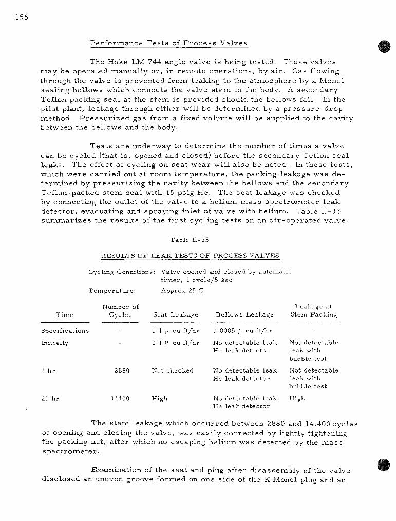
156
Per fo rmance Tes ts of P r o c e s s Valves
The Hoke LM 744 angle valve is being tested. These valves may be operated manually or, in remote operat ions, by a i r . Gas flowing through the valve is prevented from leaking to the a tmosphere by a Monel sealing bellows which connects the valve s tem to the body. A secondary Teflon packing sea l at the s tem is provided should the bellows fail. In the pilot plant, leakage through either will be determined by a p r e s s u r e - d r o p naethod. P r e s s u r i z e d gas from a fixed volume will be supplied to the cavity between the bellows and the body.
Tes ts a r e underway to de termine the number of t i ines a valve can be cycled (that is , opened and closed) before the secondary Teflon seal leaks. The effect of cycling on seat wear will also be noted. In these t e s t s , which were ca r r i ed out at room t empera tu re , the packing leakage was determined by p ressu r i z ing the cavity between the bellows and the secondary Teflon-packed s tem seal with 15 psig He. The seat leakage was checked by connecting the outlet of the valve to a helium m a s s spec t rometer leak detector , evacuating and spraying inlet of valve with helium. Table 11-13 summar i zes the resu l t s of the f irs t cycling tes t s on an a i r -opera ted valve.
Table II- 13
RESULTS OF LEAK TESTS OF PROCESS VALVES
Cycling Conditions: Valve opened and closed by automatic t imer , 1 cyc l e /5 sec
Time
T e m p e r a t u r e :
Number of Cycles
Specifications
Initially
4 hr
20 hr
2880
14400
Approx 25 C
Seat Leakage
0.1 jU cu f t /hr
0.1 /i cu f t /hr
Not checked
High
Bellows Leakage
0.0005 /i cu f t /hr
No detectable leak He leak detector
No detectable leak He leak detector
No detectable leak He leak detector
Leakage at Stem Packing
Not detectable leak with bubble tes t
Not detectable leak with bubble tes t
High
The s tem leakage which occur red between 2880 and 14,400 cycles of opening and closing the valve, was easi ly cor rec ted by lightly tightening the packing nut, after which no escaping helium was detected by the m a s s spec t romete r .
Examination of the seat and plug after d isassembly of the valve disclosed an uneven groove formed on one side of the K Monel plug and an

157
apparent wearing down of the edge of the seating surface of the seat, which is made of s tandard Monel. Tes ts a r e being planned for the investigation of the duration of leak t ightness of the valve seats and s tem seals under elevated t empe ra tu r e s and of the means of servicing the valves after p roc ess installat ion.
5. Cleanup of Plutonium Hexafluoride from Cell Exhaust Air (R. W. Kessie]
A study is under way of fluoride (PuFg) from a i r . The objec
Figure 11-14
FRACTION OF RELEASED PLUTONIUM HEXAFLUORIDE PASSING THROUGH
TWO AEG FILTERS
* L L .
- 3
- 4
O - 5
- 6
- 7
- 9 -
"F • empirical penetration factor
_ Pu passing through two AEC filters Pu rele ileased
O
o o o o CQO oOo
o ^ ;
o o
- 2
108-6852
LOG PufQX
methods of removal of plutonium hexa-tive of this study is to obtain infornaa-
tion needed for the design of equipment capable of cleaning up the ventilation air exhausted from gloveboxes or other plutonium-handling a reas which might become contaminated with plutonium fluorides. The method studied was to reac t plutonium hexafluoride with water in the vapor phase to yield solid plutonyl fluoride (PUOF2) and to pass the air through a high-efficiency filter. In a previous repor t (ANL-6596, pp. 123-125), the resu l t s were p r e sented of experiments in which sma l l - sca le controlled r e l ea ses of plutonium hexafluoride, 25 mg or l e ss , were made into an a tmosphere of known mois ture content. The r e sulting air mixtures were passed at a controlled flow ra te through AEC f i l ters , a water bubbler, and Mil le-pore fil ters in s e r i e s . Alpha and gamma counts of fi l ters were used to determine the penetration of plutonium hexafluoride through the f i l ters . These ear l ie r data a re shown in Figure II- 14.
The data in Figure II- 14 show considerable sca t ter . One source of this var iat ion is the different amounts of PuF^ re leased into the ino is ture-containing a tmosphere . The resu l t ing differences in the production of plutonyl fluoride may affect the filt ra t ion by two mechanisms:

(1) The pa r t i c l e s of the hydrolysis product may agglomierate at different r a t e s before reaching the filter,
(2) Solid product may accumulate on the filter at different r a t e s and may thereby affect the fil ter efficiency.
In o rder to obtain an improved cor re la t ion of filter efficiency by including the amount of PuF^ re l eased , a ma themat ica l model was developed for the p r o c e s s e s of agglomerat ion and of f i l t rat ion under loading. This model may also se rve to indicate the range of operating conditions in which the effects of agglomerat ion and filter loading a r e appreciable .
a. Model of the Agglomerat ion P r o c e s s Affecting Fi l t ra t ion
In the model developed below, the change with t ime in the number of pa r t i c l e s in the mixing chamber (up s t r e a m of the fil ter) is exp r e s s e d in t e r m s of s imple naathematical re la t ions for the p r o c e s s e s of agglomerat ion and gas purging of the mixing chamber . The assumpt ions involved in deriving the ma themat i ca l express ions a r e given below:
1. The plutonium hexafluoride and water vapor a r e combined in a reac t ion chamber , where they a r e instantly reac ted and the solid product is perfect ly mixed, i .e. , evenly dis tr ibuted in the chainber . Subsequently, the product pa r t i c les a r e swept out by a i r passing through the chamber and to the f i l te rs . The gas purge sweeps out pa r t i c les r e g a r d less of s ize .
2. The hydrolysis product par t ic les a r e init ially of the same size (unagglomerated), and the range of s izes of the agglomerated par t i c les may be descr ibed by a Po isson distr ibution.
3. All the penetrat ion of the filter is due to unagglomera ted pa r t i c l e s , that i s , the agglomera ted par t ic les make a negligible contribution to amount of m a t e r i a l penetrat ing the fi l ter. A penetrat ion factor for unagglomerated pa r t i c l e s is taken as a proper ty of the filter.
Other worke r s have found that, when agglomerat ion alone is considered, the par t ic le concentrat ion v a r i e s with t ime as follows:
- 1 = " ^ + K t , (1) n no
where n is the number of pa r t i c l e s per unit volume at t ime t, n = ng at t = 0, and
K = 4k T C / 3 11, (2)
Handbook on Aeroso l s , United States Atomic Energy Commission, Washington, D. C , p. 69-

159
wi th k the B o l t z m a n n c o n s t a n t , T the a b s o l u t e t e m p e r a t u r e , C Cunningh a m ' s c o r r e c t i o n f a c t o r to S t o k e s ' law, and /i the gas v i s c o s i t y .
D i f f e r e n t i a t i o n of E q u a t i o n ( l ) g ives
- ^ = ^ • (3)
This d e s c r i b e s the change in p a r t i c l e c o n c e n t r a t i o n due to a g g l o m e r a t i o n a l o n e .
The l o s s of p a r t i c l e s in the m i x i n g c h a m b e r due to the g a s p u r g e is t r e a t e d a s fo l lows . P e r f e c t m i x i n g wi thout a g g l o m e r a t i o n would give
dn R n , , x - d7 = — ( ^
w h e r e R is the gas flow r a t e and V is the v o l u m e of the m i x i n g c h a m b e r . F o r both a g g l o m e r a t i o n and m i x i n g , we have
- ^ = Kn^ + (R /V) n. (S)
Kn^ + ( R / V ) n no ' "0
(6)
or
- R t / V
n = ' ^ ^ ^ r ^ . (7) l+(KV„„/R)(l-e-I^'A)'
The effect of gas p u r g e in E q u a t i o n (4) m a y be e x p r e s s e d a l s o in m a s s t e r m s , in wh ich f o r m it is i ndependen t of a g g l o m e r a t i o n . The weigh t w of p l u t o n i u m in the m i x i n g c h a m b e r i s i ndependen t of a g g l o m e r a t ion , and the r a t e of d e c r e a s e of w is g iven by
dw _ R /QN
- "5f- V w (8)
or
w = Wo e / , (9)
w h e r e WQ is the i n i t i a l we igh t r e l e a s e d a t t = 0.

160
F o r the whole c o l l e c t i o n of p a r t i c l e s in the m i x i n g c h a m b e r , the i n i t i a l ( u n a g g l o m e r a t e d ) p a r t i c l e we igh t mo i s g iven by
mo = Wo/ngV. (lO)
S i m i l a r l y , the a v e r a g e p a r t i c l e we igh t m a t any t i m e is g iven by
m = w / n V . (11)
The a v e r a g e n u m b e r of p a r t i c l e s , M, p e r a g g l o m e r a t e is the r a t i o of the a v e r a g e p a r t i c l e we igh t to the weigh t of the i n i t i a l p a r t i c l e , and is g iven by
M = ^ = ^ . (12)
mo Won
Subs t i tu t ion of (7) and (9) in ( l2 ) g ives
KVno M = 1 + R
( l - e - ^ ' A ) . (13)
The f r a c t i o n p of u n a g g l o m e r a t e d p a r t i c l e s i s ob ta ined by a s s u m i n g tha t t h e r e i s a P o i s s o n d i s t r i b u t i o n of the n u m b e r x of (o r ig ina l ) p a r t i c l e s in an a g g l o m e r a t e . By the w e l l - k n o w n s t a t i s t i c a l p r o p e r t y of the m e a n we m a y w r i t e th i s a s
( M - i ) ( - ' ) . - ( ^ - ' ) p ( x - l ) ^ ' - - " . ' •. (14)
( x - 1)1
Subs t i tu t ion of ( l3 ) in ( l4 ) and se t t i ng x = 1 for u n a g g l o m e r a t e d p a r t i c l e s g ives
p = e .(KVno/R)(l-e-RtA)_ ^ ^
The t o t a l a m o u n t of p lu ton ium p a s s i n g t h r o u g h the f i l t e r is t ha t f r a c t i o n of u n a g g l o m e r a t e d m a t e r i a l swept out of the mix ing c h a m b e r wh ich a l s o is not t r a p p e d on the f i l t e r . T h u s ,
WoP = / np (wo/noV)PoR dt, ( l6)
w h e r e P is the a v e r a g e weigh t f r ac t i on p e n e t r a t i o n m e a s u r e d and PQ is the weigh t f r ac t i on of u n a g g l o m e r a t e d m a t e r i a l t ha t p a s s e s t h rough the f i l t e r . Th i s PQ is a s t a n d a r d p r o p e r t y of the f i l te r (for a p a r t i c u l a r p a r t i c l e s i ze ) and is not the e m p i r i c a l , o v e r a l l p e n e t r a t i o n P m e a s u r e d for a g g l o m e r a t i o n . The r a t i o P / P Q is g r e a t e r than one in a l l a c t u a l c a s e s in

161
which s o m e a g g l o m e r a t i o n o c c u r s . Subs t i tu t ion of Equa t ions (7) and ( l5 ) in ( l6) and l e t t ing
K V U O / R ^ a (17)
g ives
_P Po
•R t /V + ^ ( l _ e " R t / v ) dt
1 + a 1 - e (l-e-^^A) (18)
The change of v a r i a b l e s
1 4 a ( l - e - ^ V ^ ) (19)
g ives
P
Po
.i+a e a
d Z (20)
This i n t e g r a l is known a s the exponen t i a l i n t e g r a l and has been t abu la t ed . ° The function i s p lo t ted in F i g u r e 11-15.
FORo OR L > 3 , P/^ IS APPROXIMATED BY
OR-l,RESPECTIVELY
0 596
I AGGLOMERATION
0 2 ^ FUNCTION
F i g u r e 11-15
AGGLOMERATION AND LOADING FUNCTIONS
10 2 0
a OR L
108-6870
The funct ion P / P Q is the r a t i o of the weight f r a c t i o n s :
m e a s u r e d p e n e t r a t i o n
p e n e t r a t i o n by u n a g g l o m e r a t e d p a r t i c l e s
The a b s c i s s a a in F i g u r e 11-15 is the d i m e n s i o n l e s s a g g l o m e r a t i o n n u m b e r defined in Equa t i ons ( l7 ) and (2) above in t e r m s of p h y s i c a l c o n s t a n t s , gas p r o p e r t i e s , flow r a t e , and the i n i t i a l quan t i ty of p a r t i c l e s r e l e a s e d .
" T a b l e s of Sine, C o s i n e and E x p o n e n t i a l I n t e g r a l s , F e d e r a l Works Agency W o r k P r o j e c t s A d m i n i s t r a t i o n , New York City ( l940) .

162
b. Model of the Effect of Filter Loading on Filtration Efficiency
A model for filter loading was developed along the same lines as those used for the agglomeration process. A mathematical relation was initially taken for the instantaneous penetration of the filter and the total surface of the filter (including the loading of trapped solid); subsequently an integrated relation including the weight fraction of filter penetration was developed. Finally, in a subsequent discussion, a new correlation of experimental filtration data is discussed with reference to these models.
The following assumptions were made for filter loading:
1. For the type of filter and fume particles of interest, the diffusion mechanism of filtration is controlling.
2. The filtration performance at any instant of time is a function of the total surface of the filter, which includes both the surface of the filter medium and of the collected fume particles.
The diffusion mechanism gives for the instantaneous weight penetration
Pi = e'^K (21)
where k is a diffusion constant for the process and
At = Af + AcW. (22)
Here A£ is internal filter area and A^ is the specific surface area per unit weight w of the deposited fume particles.
The average penetration P integrated over the total collection of a single release starting with a clean filter is
rwo P Wo = I Pi dw. (23)
-^0
For a clean filter without loading
P. = e-kAf| k = i 2 ^ . (24)
Substitution in (2l) gives

163
In (l/Po),, ^ ^ ^ ^ (Af+ Acw)
Pi = e ^ (25)
-Ac(w/A£) In l/Po , . Po e ' . (26)
Combination of (26) and (23) yields
P 1 / '° -Ac(w/Af) In (l/Po)
-Ac(wo/Af) In (l/Po)
AcWo\ 1
This function is plotted in Figure 11-15 as
P _ 1 - e"^
Po ~ L '
dw (27)
(28)
(29)
where P/PQ is the ratio of the same quantities defined in Section a above. However, the ratio here describes the decrease in the penetration of the filter due to loading. In Figure 11-15, the abscissa L is the dimensionless loading number:
^c^o 1 , ,
Thus, L relates P/PQ to the specific area of the filter medium and of the fume, to the filtration efficiency of the unloaded filter, and to the weight of particles released.
c. Discussion of Experimental Results
The models developed above may be used as a basis for estiinating the experimental conditions under which agglomeration and filter loading have important effects on filtration efficiency. For this application of the model, information is required about the surface area and size of the fume particles and the filter medium.
The size distribution of particles resulting from the vapor-phase hydrolysis of plutonium hexafluoride has been determined for one of the experiments of the type summarized in Figure 11-14 and described

164
ea r l i e r in Summary Report ANL-6543, pp. 122-126. The part iculate m a t ter was produced from the r e l ea se of 6.0 mg of plutonium hexafluoride into a 385-ml volume containing a i r at one a tmosphere and water vapor at 7.66 m m Hg. The par t ic les resul t ing from the hydrolysis were collected by an e lec t ros ta t ic precipi ta tor , with a carbon film collector. F r o m a photograph made by an e lect ron microscope , the par t ic le size distr ibution of the hydrolysis fume par t ic les was determined; this resu l t is shown in Figure 11-16. The same figure shows the fiber size distribution of AEC filter media as determined in a separa te electron photomicrograph. The e lec t ros ta t ic precipi ta tor and the photographs of the filter were descr ibed previously in Summary Report ANL-6477, pp. 114 and 115. In Figure 11-16, the ordinate values a re the integrals of the frequency factor f from zero d iameter to the d iameter indicated on the absc i ssa . The data indicate that both frequency distr ibutions a r e accura te ly descr ibed by the log normal frequency distribution. In Figure 11-16 the mean par t ic le size, dg, is based on the number of pa r t i c les . Also shown is Og, the geometr ic standard deviation, Because of the high resolution (20 A) of the electron m i c r o scope used in these measu remen t s , it was possible to es t imate the size of individual par t ic les from the photograph even in the cases of agglomerates made of seve ra l par t i c les . The size distr ibution of Figure 11-16 is for unagglomerated par t ic les .
F igure II- 16
SIZE DISTRIBUTION OF HYDROLYZED PuF^ AND AEC FILTER FIBERS
; | L I I 1 1 I 1111 I I I I I 1111 \ I I •.01 0.1 1.0 10
DIAMETER, microns
108-6890
The agglomeration effects of experiments made thus far may be evaluated in t e r m s of the above determination of unagglomerated

par t ic le size and the theore t ica l model developed in Section a above. The par t ic le size distr ibution of F igure 11-16 was converted to a weight bas i s , and the d imensionless agglomerat ion factor a was calculated from Equation (17) above, with the resu l t that a = 0.02 (WQ/R), where WQ is the init ial weight r e l e a s e of plutonium hexafluoride in mi l l ig rams and R is the a i r flow ra te in m l / s e c . In this form, the agglomerat ion factor does not contain the volume of the mixing chamber explicitly. In the exper iments summar i zed in F igure 11-14, r e l e a s e s up to 25 mg PuFg were used, and the values of a ranged from 8 to 140. Therefore , it appears that agglomerat ion has a significant effect. An important r e su l t here is that the value of a can be es t imated for other operat ing sys t ems .
The loading effect is evaluated in t e r m s of surface a r e a s according to the model in Section b above. The diameter of the par t ic le of mean weight (derived from the dis t r ibut ion of F igure 11-16) was approximately 0.1 /i . F r o m this mean d iamete r it was est imated that the hydrolysis product of this par t ic le size from 1 mg of PuFg had a surface a r ea of 75 cm^. The AEC filter mediuna had a total fiber surface of 77 cm / c m of the superf icial a r ea . Thus, the total surface a r ea of the filter was approximate ly doubled when the product from 1 mg PuFg was collected on one cm^ of superf icial surface a rea . In t e r m s of the model, loading would be considered controll ing when the loading factor L [see Equation (30) and F igure 11-15] is g r ea t e r than one.
In o rder to apply this agglomerat ion model to the p lu ton ium-re lease exper iments r e f e r r e d to above, L was calculated for the above-mentioned specific surface a r e a s of the filter mediuin and the par t ic les resul t ing from the hydrolysis of plutonium hexafluoride. A value of 10" was taken for the penetrat ion factor PQ, which also en te rs into the calculation of L by Equation (30). The values of L calculated for the plutonium r e l e a s e exper iments va r i ed from 2 to 30. This r esu l t is taken to indicate that filter loading is jus t enough to be controlling in these exper iments . F r o m the same data, it was es t imated that filter loading would have a significant effect on s imi l a r p lu tonium-re lease exper iments where
WO/A > 5,
where WQ is the r e l e a s e of PuFg in mi l l i g r ams and A is the superf icial a r ea of the AEC filter in square cen t ime t e r s .
According to the above analys is , an effect of the quantity of PuFg r e l eased would be expected to appear in the filter penetrat ion r e sults shown in F igure 11-14. Consequently, a function including both the overa l l penetrat ion factor F and the weight Wo of PuF^ re l eased may give a be t ter cor re la t ion (against the PuFg/H20 naole rat io) than does F alone. Tes ts were made of Fwo, FWQ, and FWQ; the best cor re la t ion was obtained

166
with Fwo, which is plotted in Figure 11-17. Although a good deal of sca t ter r emains in Figure 11-17, a g rea te r regular i ty of the data points a r e shown he re than in F igure 11-14, and it is believed that this corre la t ion is super io r to the original one. The dependence of P / P Q on the square of Wo is what would be expected when the effects of agglomerat ion and loading take place simultaneously, since each factor (a or L ) is proport ional to WQ. Fur the r exper imenta l study will include the kinetics of the hydrolysis r e action, and at tempts to improve and to general ize the corre la t ion of resu l t s .
CO
o
2 -
I -
- 2 -
- 3 -
- 4 -
- 5
- 6
- 7 h
*F = empirical penetration factor
Pu passing through two AEC filters Pu released ^^
WQ • weight of PuFj release, milligrams _
O
-
-
O
O " O
- o
1,
o
o
°0°
1 1
Figure II- 17
CORRELATION OF DATA OF FILTER PENETRATION IN
PuF j RELEASE EXPERIMENTS
/PuFgX LOG T-TT- MOLE
108-6840
Basic Studies of Fluidized-bed Behavior Related to P r o c e s s Operat ions: Solids Mixing (j. D. Gabor, P. L. Katz,* and J. Savage)
A study was made of the mixing of part iculate solids fluidized in the voids of a packed bed of l a rger , nonfluidized bodies. This study was ca r r i ed out in support of work at Argonne National Laboratory on the application of inert fluidized par t ic les in chemical reac tor sys tems to improve the removal of the heat generated by the exothermic react ion of l a rge r bodies. Heat t ransfer ra tes a r e dependent on the movement of
*Student Aide, Illinois Institute of Technology.

167
fluidized par t ic les in such a sys tem. A m e a s u r e of the par t ic le movement was achieved in this study by the determinat ion of diffusion coefficients for the r a t e s of solids mixing in the l a t e r a l direct ion for me ta l shot fluidized in the voids of spher ica l and cyl indr ical packing. Exper imenta l data showed that the par t ic le mixing was re la ted to the void s t ruc ture of the packed bed by a random-walk model . A genera l cor re la t ion was made for fluidized solids diffusivity in spher ica l ly packed beds.
There a r e few re fe rences to fluidized packed beds in the l i te r a t u r e . Sutherland and O s b e r g ' were in te res ted in fluidized packed beds because the baffling effect of the fixed packing permi t s smooth fluidization (without slugging) for la rge he igh t - to -d iameter r a t ios . However, the baffling has some adve r se effects in that it hinders the inovement of the fluidized ma te r i a l . Recently, Z ieg le r " has published data and discussed the mechan i sm of r ad ia l heat t r ans fe r in fluidized packed beds. This work was performed at Argonne National Labora tory in cooperation with Northwestern Universi ty.
No work on solids mixing in fluidized packed beds was found. However, invest igations of solids mixing have been made with fluidized beds (without packing). Bar t ,9 Mass i in i l la and Braca le , 1^ and Hayakawa et al. 11 obtained quantitative m e a s u r e m e n t s for longitudinal solids mixing in the fluidized beds . Work on solids mixing in fluidized beds in the l a t e ra l
. . 1 - 7
direct ion was done by Brotz . Although the above re fe rences a re in te r esting as to analysis and technique, the re fe rences do not indicate the effect that fixed packing would have on mixing r a t e s .
In genera l , fluidized packed beds would be expected to show features which a r e conabinations of those of packed beds and of fluidized beds . The p r i m a r y motion of the fluidized m a t e r i a l is determined by pa r ticle size and gas velocity, whereas the dimensions of the packed naaterial de termine the void s t ruc tu re within which fluidization takes place. The
"^Sutherland, J. P . , and Osberg, G. L., The Effect of Fixed Packing in a Fluidized Bed, For ty-Seventh Annual Meeting, AIChE, Bal t imore (May 1962).
o
Ziegler , E. N., Radia l Heat Transfe r in a Packed-Fluid ized Bed, M. S. Thes is , Nor thwes tern Univers i ty ( l96 l ) .
•^Bart, R., Ph. D. thes i s , Cambridge, Massachuse t t s Institute of Technology (l950).
l^Mass imi l la , L., and Braca l e , S., R i ce r ca Sci., _26_, 487 (l956).
11 Hayakawa, T., Graham, W., and Osberg, G. L., Canadian R e s e a r c h Council, unpublished data.
l^BrStz, W., Chem. Ing. Tech., 28, 165 (l956).

168
presen t study concerns the m e a s u r e m e n t of mixing in the l a t e ra l (or radial ) direct ion of solids fluidized in the voids of a fixed bed and the effect of s y s tem var iab les on the r a t e of this mixing.
Exper imenta l Design
In the p resen t study, the exper imenta l method of measur ing the r a t e of solids mixing was pat terned after that of Brotz . The genera l method is based on the use of two solids which a r e s imi la r with respec t to the physical p roper t i e s that de te rmine mixing behavior, but which a r e different with r e spec t to some proper ty that is usable for analysis of composition. The analyt ical p roper ty employed by Brotz was color . In the p resen t study, the differences in magnet ic p roper t i e s of nickel and copper were used. Since nickel and copper have the same density (8.9 gm/cc ) , it would be expected that nickel and copper par t ic les having the same size and shape would exhibit ident ical fluidizing c h a r a c t e r i s t i c s .
Determinat ion of Solids Composition by Magnetic Separation
P u r e copper and nickel par t ic les a r e placed in a rec tangular cel l and a r e separa ted from each other by a cent ra l ly located part i t ion. The par t i c les a r e fluidized and when the part i t ion is removed, mixing occurs on each side of the center line. After a ce r ta in mixing t ime, the fluidizing gas is cut off and the mixing is a r r e s t e d . Bed samples a re then taken at points of known distance from the or iginal par t i t ion location. The samples a r e analyzed for weight concentrat ion by magnetic separat ion. F r o m the sample analyses and the locations at which the samples were withdrawn a concentrat ion profile can be determined.
Diffusion Equation for Solids Mixing
A diffusion coefficient for the bed of fluidized solids was used to cha r ac t e r i z e the r a t e of solids mixing. The usual differential equation for diffusion in one dimension is
6c_ ^ a^c .X
S e ^ " 6 x ^ - ^^
The key to the symbols used in the above equation and below is
C Concentrat ion, fract ional weight
d Diameter of fluidized par t i c le , ft
D Diffusion coefficient, sq f t / sec
Dp Fixed packing d iameter , ft
R Half-width of column, ft

169
VQ S u p e r f i c i a l g a s ve loc i ty , f t / s e c
"^omf M i n i m u m s u p e r f i c i a l gas f lu id iza t ion ve loc i ty , f t / s e c
X D i s t a n c e f r o m c e n t e r of co lumn , ft
e P a c k i n g void s p a c e
9 T i m e , sec
The so lu t ion of the above equa t ion is g iven by Sherwood and Reed :
(in - i^ f s m 2R
+ ~ exp •25 R '
571X ,
sm - ,_ + 2R (2 )
In this equation, values of C a r e related to values of diffusion distance x in t e r m s of the diffusivity D, one half the column width R, and the time 0 of mixing. Thus, D was found from the value of the pa ramete r which fit the experimental ly measu red profile of C as a function of x.
Apparatus and Procedure
A schematic d iagram of the apparatus is shown in Figure 11-18. Nitrogen, the fluidizing gas, was distr ibuted by a porous meta l plate
Figure 11-18
SCHEMATIC DIAGRAM OF APPARATUS USED IN STUDIES OF MIXING OF FLUIDIZED PARTICULATE SOLIDS
RECTAI GULAR COLUMN Tin X | { | in X |0 m
BROOKS 8 cu ft per min ROTAMETER
HOKE QUICK-OPENING
TOGGLE VALVE
M>^==>^ HOKE NEEDLE VALVE
CONNECTION TO 35psig N2 LINE
108-6193 Rev. 2
1-^Sherwood, T. K., and Reed, C. E., Applied Mathematics in Chemical Engineering, McGraw-Hil l Book Co., Inc., New York (l939).

(not shown in figure). A ro t ame te r m e a s u r e d gas flow r a t e s . Sampling was accomplished by a hor izonta l row of 1-j-in.-long, fixed hypodermic needles , which were l o c a t e d ^ i n . above the bottom of the column, and were spaced 1 in. apar t . Also, samples were taken by a 9-in.- long needle which was injected into the bed to the des i red position. The concentrat ion p ro file was invar iant with r e spec t to height because of high v e r t i c a l mixing r a t e s .
The fluidizing gas was humidified to prevent static charges on the fluidized pa r t i c l e s by a separa te 1-ft packed column par t ia l ly filled with water .
The fluidizing m a t e r i a l consis ted of copper and nickel shot of -40 -fSO, -100 +120, -120 +200, and -140 +170 m e s h s izes . Fixed packing consisted of ™-, -|--, •j-, and - ^ - i n . - d i a m e t e r s tee l spheres and y in. x y i n . , - in. x-|"in., and j in. x-^-in. b r a s s cy l inders . A set of runs was also made without fixed packing, i .e. , a n o r m a l open-tube fluidized bed was used. The run t ime var ied from 0.5 to 20 min depending on the gas velocity and the s izes of the fluidized pa r t i c l e s . Smooth fluidization was attained in the o rder of about a second after introduction of the fluidizing gas . It was , therefore , expected that init ial s ta r tup dis turbance would have negligible effect on the data.
Exper imenta l Resul t s
The mixing exper iments performed resu l ted in obtaining values of the diffusion coefficient D as a function of gas veloci t ies for var ious fluidized packed bed s y s t e m s . Var ia t ions of D were investigated for different s izes of spher ica l and of cyl indr ica l packings as well as different s izes and heights of fluidized m a t e r i a l . The r e su l t s a r e presented also in the form of a genera l co r re l a t ion which is closely re la ted to the random-walk theore t ica l model . Reference cases for fluidization without packing a r e also presented .
Effect of Size of Spher ica l Packing
A s e r i e s of runs was made with packing consisting of -r--, -g--, —•-, and Y?-in . -diameter s tee l sphe res and with 0 .0038- in . -d iameter copper and nickel shot. The data for the seve ra l packings a r e plotted as the diffusion constant D v e r s u s average gas velocity in F igure 11-19- The diffusion coefficients inc reased with packing size over the range tes ted. Fluidizat ion was also at tempted in a bed of ^ - i n . - d i a m e t e r spheres , but the par t ic le motion was grea t ly inhibited and channeling occur red . For open-tube fluidization (no packing), bed diffusion coefficients a r e about th ree and one-half t imes higher than for the same fluidized pa r t i c l e s at the samie superf ic ia l gas veloci ty in a bed containing-|—in.-diameter

packing. These fluidized-bed data were for an expanded bed height of approximately 1 in. The open-tube fluidized bed mixing ra te increased strongly with bed height; this effect is discussed further in a later section.
Figure 11-19
EFFECT OF SIZE OF FIXED PACKING ON SOLIDS
MIXING
J L^_j 0 1 0 2 0 4 06 08 10 2 4 6
Vo/e, ft/sec
108-6189 Rev. 2
The data in F igure 11-19 indicate that the diffusivity D is direct ly proport ional to the packing diameter Dp over the range of gas velocit ies used. This appears to be a genera l relat ion holding between the mixing r a t e s of fluidized par t ic les and the void s t ruc ture of a packed bed of spheres in which the fluidization takes place. A mathemat ical theory of this effect has been developed and will be presented in a topical report . The mean par t ic le veloci t ies predicted by this theory a re consistent with independent observat ions of par t ic le velocity made photographically.
Effect of Cylindrical Packing
The solids diffusivities of 0.0038-in.-diameter fluidized par t icles in voids of cyl indrical packing having the following dimensions: -i-in. x-yin., -|-in. x-|-in., and -|-in. x ^ i n . , a re plotted in Figure 11-20. The slopes for these curves a r e somewhat less than those for spher ical packing (see Figure 11-19). Aside from the difference in shape, the la rger cylinders exhibited a g rea te r tendency for "bridging" than spheres when randomly packed. This bridging resul ted in nonuniform void fractions throughout the bed and caused the resu l t s to be slightly e r r a t i c .
In order to determine if length of t ime of fluidization affected the solids diffusivity, a run was made with the -|-in. x-^-in. cylindrical
3_ SPHERICAL PACKING,0 0038 in DIAMETER FLUIDIZED PARTICLES
• SYMBOL
•: 0 8 —
04|—
o z U
i
I I I ! , I ! I

172
packing in which samples were taken after 2.15, 3.84, and 4.84 min of fluidization. The diffusivity was found to be t ime- invar ian t to within about 1.5 percent .
= 1-0 Z ^ 0 . 8 -
K 0 .6h -a
0.4
CYLINDRICAL PACKING, 0.0038 in. DIAMETER FLUIDIZED PARTICLES
PACKING SYMBOL SIZE, in.
O 1/4 K 1/4 D 3/8 X 3/8 A 1/2 » 1/2
0.1 I I I I M I I I I I
Figure 11-20
DIFFUSION COEFFICIENTS FOR FLUIDIZED PACKED BED WITH
CYLINDRICAL PACKING
0.6 0.8 1.0 Vo /e , ft /sec
108-6191 Rev.
Effect of Fluidized Par t i c l e Size
Runs were made with -40 +50, -100 +120, and -140 +170 mesh copper and nickel in the voids of ^ - i n . - d i a m e t e r spher ica l packing to determine the effect of par t ic le size on mixing r a t e s . Diffusivities ve r sus superficial gas veloci t ies for the var ious par t ic le s izes a r e given in F igure 11-21. The smal le r -s ized fluidized par t ic les showed higher diffusivities.
Generalized Corre la t ion
F r o m the above data on the dependencies of solids diffusivity on sys tem var iab les , a general ized corre la t ion was made relat ing D/Dp to the fluidized par t ic le d iameter d and the average gas velocity in the voids of the packed bed, Vo/c, as cor rec ted for the minimum fluidization average gas velocity, V^j^f/e. A plot is given in Figure 11-22. In numer ical t e r m s the cor re la t ion is
D = D, ^omf
d e
1.15
(1.22 X 10"^) sq f t / sec .
In this dimensional equation, a l l units of dimension a r e in feet and seconds.
The effects of gas viscosi ty and fluidized par t ic le density were not considered he re .

173
2 0
Figure 11-21
EFFECT OF SIZE OF FLUIDIZED PARTICLES ON SOLIDS MIXING
04 06 08 10 %/e, ft/s®c
108-6184 Rev. 3
Figure n-22
GENERAL CORRELATION FOR SOLIDS MIXING IN A FLUIDIZED PACKED BED
108-6182 Rev. 2

174
The above cor re la t ion was made with nar row cuts in screen s izes . Several runs were made with -120 +200 mesh par t ic les which have approximately the same average d iameter as -140 +170 mesh par t ic les (0.0038 in.) but have a g rea te r spread in size distribution. A comparison was made of the effect of par t ic le size distr ibution on the solids mixing for fixed packings of -i~in.- and—-in. -diameter spheres (see Figure 11-23). It was found that mixing is g rea te r with -120 +200 mesh par t ic les , i.e., with par t ic les having a wider size spread. Also, it appeared that the diffusion coefficient for the -120 +200 mesh par t ic les was not a simple logari thmic function of gas velocity. It was observed that with par t ic les of this mesh size, the fluidized bed segregated into two phases when the gas velocit ies were increased sufficiently. There was a dilute, highly agitated phase in the upper portion of the packed bed, and a denser phase in the lower portion of the column.
6
4
2
| i o ^ 0 8
^ O C o
0 4
0 2
01
- SYMBOL
0
• D
_ •
—
— —
-
,
PACKING DIAM, in
1/4 1/4 1/2 1/2
1 1 1
FLUIDIZED RARTICLE
SIZE,MESH
-140 + (70 -120 + 200 -140 4- 170 -120+ 200
" ^ « / J
/ / —r "^ /
\\\\\ 1
• / ^
/ / f i hf w
/ / : .
/
i
\ ^
Figure 11-23
EFFECT OF SIZE DISTRIBUTION OF FLUIDIZED PARTICLES ON
SOLIDS MIXING
01 02 04 06 08 10 Vo/e, ft/sec
108-6188 Rev. 2
Effect of Bed Height for Fluidized and for Fluidized Packed Beds
A brief examination was made of fluidized-bed raixing, i.e., mixing with no fixed packing present . In Figure 11-19, a comparison was made of the mixing r a t e s of a fluidized bed (static height of 0.7 in.) and of fluidized packed beds. The mixing ra te was g rea te r for the fluidized bed because of the absence of baffling effects of fixed packing.
In the studies with the fluidized bed, it was also observed that slugging increased with depth of bed. As the slugging increased, the motion of the par t ic les became more vigorous, and an increased incidence of

175
22
8 1 8 -
CO
O 14
10
SUPERFICIAL FLUIDIZING GAS VELOCITY 0 5 f t /sec -140 +170 MESH Cu - Ni
Figure 11-24 p a r t i c l e s b e i n g t h r o w n i n t o t h e a i r
EFFECT OF BED HEIGHT ON RATE OF LATERAL o c c u r r e d a s a r e s u l t of b u b b l e b u r s t s SOLIDS MIXING IN A FLUIDIZED BED a t t h e s u r f a c e . R u n s w e r e t h e r e f o r e
m a d e t o d e t e r m i n e t h e e f f e c t of b e d h e i g h t on s o l i d s m i x i n g fo r b o t h t h e f l u i d i z e d b e d a n d t h e p a c k e d f l u i d i z e d b e d . F i g u r e 11-24 s h o w s t h e r e l a t i o n of t h e s o l i d s d i f f u s i o n c o e f f i c i e n t t o b e d h e i g h t f o r a f l u i d i z e d b e d . T h e f l u i d i z i n g g a s v e l o c i t y w a s t h e s a m e ( 0 . 5 f t / s e c ) in e a c h of t h r e e r u n s . T h e b e d d e p t h s w e r e m e a s u r e d in t h e s t a t i c c o n d i t i o n . T h e r e w a s a v e r y s i g n i f i c a n t i n c r e a s e in s o l i d s m i x i n g w i t h i n c r e a s e d h e i g h t of b e d . T h e e x p a n s i o n r a t i o fo r t h e f l u i d i z e d b e d a t a g a s v e l o c i t y of 0 .5 f t / s e c w a s 1.4.
T h e m i x i n g d i f f u s i o n c o e f f i c i e n t s f o r t h r e e d i f f e r e n t i n i t i a l f l u i d i z e d p a r t i c l e b e d d e p t h s ( i j i n . , 2 ^ i n . , a n d 3-g-in.) f o r a f l u i d i z e d p a c k e d b e d w i t h -g - " ! ! ^ . -d i ame te r s p h e r i c a l p a c k i n g w e r e m e a s u r e d . W i t h i n t h e e x p e r i m e n t a l a c c u r a c y t h e r e w a s n o e f f e c t of h e i g h t of
f l u i d i z e d b e d on t h e d i f f u s i v i t y . T h e p a c k i n g e f f e c t i v e l y b a f f l e s t h e s l u g s in t h e f l u i d i z e d b e d a n d , a s a r e s u l t , a s m o o t h , u n i f o r m f l u i d i z a t i o n o c c u r s . F r o m t h e a b o v e d a t a i t i s e x p e c t e d in p r a c t i c a l c a s e s t h a t m i x i n g in o p e n -t u b e f l u i d i z a t i o n w o u l d b e c o n s i d e r a b l y g r e a t e r t h a n in f l u i d i z e d p a c k e d b e d s .
C o n c l u s i o n s
1. The l a t e r a l m i x i n g b e h a v i o r of p a r t i c l e s f lu idized in the vo ids of a packed bed i s not ana logous to the r a n d o m m o t i o n of gas m o l e c u l e s , but r e s e m b l e s eddy diffusion in a flowing gas s t r e a m .
2. A r a n d o m - w a l k m o d e l m a y be u sed to r e l a t e t h e s e so l ids d i f fus iv i t ies to the void s t r u c t u r e of the packed bed. Mean p a r t i c l e v e l o c i t i e s c a l c u l a t e d f rom th i s t h e o r e t i c a l m o d e l a p p e a r e d to be c o n s i s t e n t wi th o b s e r v a t i o n s of p a r t i c l e v e l o c i t y m a d e pho tog raph i ca l l y . Depending on the s i z e of the p a r t i c l e , the p a r t i c l e ve loc i t y i s a fac tor of four to two h u n d r e d lower than the a v e r a g e l i n e a r gas ve loc i t y in the packed bed.
0 5 10 15 BED HEIGHTCat static condit ions), in
108-6190 Rev.
3 . A d i m e n s i o n a l c o r r e l a t i o n fo r s o l i d s d i f f u s i v i t y in a s p h e r i c a l l y p a c k e d b e d w a s e m p i r i c a l l y d e d u c e d a n d h a s t h e f o l l o w i n g f o r m :

1.15
(1.22 X 10"^) sq f t / sec .
Velocity dimensions a r e in feet per second, and par t ic le s izes a r e in feet. Fu r the r exper imenta l work involving var ia t ion of gas p roper t i e s and f lu idized-par t ic le densi t ies is n e c e s s a r y before a completely general ized cor re la t ion can be made .
4. The ra t e of change of solids diffusivity with gas velocity is l e ss for cyl indr ical ly packed beds than for spher ica l ly packed beds .
5. The ra te of solids mixing inc reases with bed height for open-tube fluidization (no packing), but is v i r tua l ly independent of height for fluidized packed beds .
7. P r o c e s s Studies on the Recovery of Uranium from Highly Enr iched Uranium Alloy Fuels ( N . Levitz)
A fluid-bed volatil i ty p rocess for the r ecove ry of uranium from highly enriched u ran ium alloy fuels is being developed. Initial studies a r e being performed with u ran ium-z i r con ium alloy fuel. The process involves two highly exothermic react ions c a r r i e d out in sequence, namely, hydro-chlorination of the alloy, followed by fluorination of the res idues to r e cover the uranium. During hydrochlorinat ion, the z i rconium is separa ted as the volati le t e t rach lor ide (sublimation point, 331 C at 14.7 psia), while the uranium is re ta ined as par t icula te ch lor ides . The uranium is r ecovered as the volat i le hexafluoride during the fluorination step. The reac t ions a r e conducted in a fluidized bed of granular alumina which se rves as a heat t ransfe r medium. Solids entrained from the fluid bed a re retained by a packed bed of granular alumina which se rves as a fi l ter.
The p r o c e s s studies a r e being conducted in a bench-sca le fluid-bed r eac to r unit consis t ing of a l y - i n . - d i a m e t e r fluid-bed reac tor connected in s e r i e s with a l y - i n . - d i a m e t e r packed-bed filter section. The p r o g r e s s of the reac t ions is followed by the continuous measu remen t of the concentrat ion of key reac t ion products by ther ina l conductivity ce l l s .
P rev ious exper imenta l r e su l t s proved the feasibili ty of this fluid-bed volat i l i ty p r o c e s s . Granular , fused alumina (Alundum, a product of the Norton Company) has been found to be a sa t is factory iner t bed m a t e r i a l under a l l the p r o c e s s conditions tes ted. High (~99 percent) overa l l r ecove r i e s of u ran ium have been achieved (see ANL-6648, p. 154, and A N L - 6 6 8 7 , p. 141). Uranium losses were due p r ima r i l y to: (a) re tent ion of u ran ium by the alumina in the fluid bed and filter bed at the end of the react ion sequence, and (b) passage of uranium through the packed-bed
D = D, Vn ^omf
d e

177
filter during the hydrochlor inat ion s tep, e i ther as a volatile chloride spe cies or as par t icula te solids by entra inment in the gas s t r e a m . General ly , the u ran ium losses have been less than 0.2 percent of the uran ium in the initial charge .
An a im of these studies has been to find conditions which would resu l t in a minimal amount of u ran ium being retained by the alumina after a single reac t ion cycle . The concentrat ion l imit that has been set is a value corresponding to a loss of one percent or less of the uranium in the initial charge . In the cu r r en t flowsheet, this loss is equivalent to a concentrat ion of about 0.01 w/o uran ium re ta ined by alumina. A level of 0.03 w/o u r a nium in alumina was achieved in previous studies (see Summary Report ANL-6569, p . 115) when large quantities of hydrogen chloride and long hydrochlorinat ion t imes (11 to 25 t imes s to ichiometr ic , run duration up to 28 hr) were used p r io r to a two-s tep fluorination (the f irs t step at 400 C and the second at 500 C). However, these conditions a r e unsuitable, be cause u ran ium loss appears to be a d i rec t function of hydrochlorination t ime . In other s tudies , res idual u ran ium levels in the range from 0.03 to 0.1 w/o were achieved by fluorination at 350 to 400 C; these levels were reduced to values in the range of 0.02 to 0.03 w/o by a follow-up high-t empera tu re (500 C) fluorination (see ANL-6569, p. 149).
The following p rocedures were successful in limiting the r e tention losses to about one percent of the u ran ium in the initial charge:
(1) use of the same bed for success ive hydrochlorinat ion-fluorination cyc les ; in a s e r i e s of five runs , the uranium concentrat ion leveled off after the second use of the bed (see Summiary Report ANL-6543, p. 150);
(2) use of a single fluorination after severa l success ive hydrochlor inat ions , a modification of (l) above (see ANL-6648, p. 154, and ANL-6687, p. 141).
In cu r r en t work, a t tempts were made to reduce the uranium retent ion further by employing a modified fluorination procedure in which the initial fluorination t e m p e r a t u r e was lowered and in which a high initial fluorine concentra t ion was used. A s e r i e s of runs is being made in which minia ture mult iplate fuel element subassembl ies a r e being processed . The f i rs t two runs of this s e r i e s have been completed, and the resu l t s obtained a r e repor ted below.
The ear ly packed-bed f i l t rat ion studies (see Summary Report ANL-6413, p. 138) were made with re la t ively fine alumina (-40 +200 ixiesh) in the fil ter beds . However, s eve re plugging of the filter occur red as a resu l t of filling of the voids by the par t icu la te solids entrained from the fluid bed (see Summary Repor ts ANL-6543, p . 150, and ANL-6569, p. 115).

Subsequently, use of graded alumina beds (- 14 +20 mesh along with finer m e s h mate r i a l ) that had l a rge r voids was successful in reducing the plugging problem (see ANL-6648, p. 168). Current ly, beds consisting ent i re ly of -14 +20 mesh alumina a r e being used.
Related studies during this period were concerned with the fluid-bed hydrolysis of a luminum chloride, which simulated the process ing of the off-gas from hydrochlorinat ion of a luminum-based fuels. Also, instal lat ion was completed of the pilot-plant facility that is intended for a demonst ra t ion of the fluid-bed volati l i ty p rocess for enriched uranium alloy fuels. Shakedown work will be s ta r ted soon with nonir radia ted fuel m a t e r ia l . Design of equipment for r ep rocess ing studies of highly i r rad ia ted u ran ium-z i rcon ium alloy fuel specimens is near ly complete . The study of the convers ion of uranium hexafluoride to dense uranium dioxide par t ic les was continued. The course of inc rease in density of a bed of uranium dioxide par t ic les of re la t ively low init ial density was investigated.
a. Hydrochlorination and Fluorination Reaction Studies on Uran ium-Zi rcon ium Alloy Fuels and Evaluation of Fixed-bed F i l t e r s ( D . Ramaswami , D. Goeser)
P r o c e s s development studies of the hydrochlorination and fluorination steps of a fluid-bed volati l i ty p rocess for the recovery of enr iched uranium from low uranium-high alloy fuels a r e being ca r r i ed out in nickel equipment. Initial studies a r e being conducted on u ran ium-z i rconium-a l loy fuel. The assembly consis ts of a 1-™-in.-diameter fluid-bed r eac to r connected in s e r i e s with a 1-j-in.-diameter packed-bed filter section. Granular alumina (Norton Company's Alundum) is being used as a heat t ransfe r medium in the fluid-bed reac tor and as a filter medium in the packed-bed filter section. The p r o g r e s s of the reac t ions is followed by means of t h e r m a l conductivity ce l l s . Details of the appara tus , the a s sociated equipment, and the exper imenta l procedure were descr ibed p r e viously (see Summary Report ANL-6569, pp. 114 to 118). The f irst two of a cu r r en t s e r i e s of runs with min ia tu re u ran ium-Zi rca loy-a l loy fuel e l e ment subassembl ies were made during this quar ter ; previously, alloy chips had been used.
Current P r o c e s s Studies
A total of th ree fuel e lement subassembl ies were processed (one in Run 37 and two in Run 38) in further at tempts to improve the hydrogen chlor ide-f luor ine reac t ion cycle. The effect of a modified fluorination procedure on uranium remova l from two types of alumina (Type RR Alundum and the less costly Type 38 Alunduni) was investigated. A lower init ial fluorination t empera tu re (250 C as opposed to 350 C) was coupled with high init ial fluorine concentrat ions (about 50 percent from the outset instead of an init ial concentrat ion of about 10 percent) .
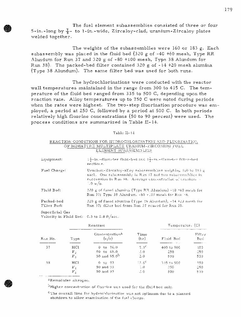
179
The fuel element subassembl ies consisted of three or four 5-in.-long by- |-- to l - in . -wide , Zircaloy-clad, u ran ium-Zirca loy plates welded together.
The weights of the subassembl ies were 160 or 183 g. Each subassembly was placed in the fluid bed (320 g of -40 +60 mesh, Type RR Alundum for Run 37 and 3 20 g of -80 +100 mesh. Type 38 Alundum for Run 38). The packed-bed filter contained 320 g of - 14 +20 mesh alumina (Type 38 Alundum). The same filter bed was used for both runs.
The hydrochlorinations were conducted with the reac tor wall t empe ra tu r e s maintained in the range from 300 to 415 C. The t empera tu re of the fluid bed ranged from 335 to 500 C, depending upon the react ion ra t e . Alloy t empera tu re s up to 750 C were noted during periods when the r a t e s were highest. The two-s tep fluorination procedure was employed, a period at 250 C, followed by a period at 500 C. In both periods relat ively high fluorine concentrat ions (50 to 90 percent) were used. The process conditions a re summar ized in Table 11-14.
T a b l e I I - 14
R E A C T I O N C O N D I T I O N S F O R H Y D R O C H L O R I N A T I O N AND F L U O R I N A T I O ^ O F M I N I A T U R E M U L T I P L A T E U R A N I U M - Z I R C O N I U M F U E L
E L E M E N T S U B A S S E M B L I E S
E q u i p m e n t :
F u e l C h a r g e :
F l u i d B e d :
P a c k e d - b e d F i l t e r B e d :
l i - i n s e c t i o n s .
d i a m e t e r f l u i d - b e d and l - ~ - i n . - d i a n i e t t - r f i l t e r - b e d
U r a n i u m - Z i r c a l o y - a l l o y s u b a s s e m b l i e s w e i g h i n g IbO to 183 g e a c h . One s u b a s s e m b l y in Run 37 and two s u b a s s e m b l i e s in s u c c e s s i o n in R u n 38 . A v e r a g e c o n c e n t r a t i o n of u r a n i u m -1.0 w / o .
3<iO g of fused a l u m i n a ( T y p e RR A l u n d u m ) -40 -^60 m e s h for R u n 37; T y p e 38 A l u n d u m , - 8 0 +100 m e s h for Run r>8.
320 g of fu sed a l u m i n a ( T y p e 38 A l u n d u m ) , - 1 4 +20 m e s h for R u n 37; f i l t e r b e d f r o n i Run 37 r e u s e d for Run 38.
S u p e r f i c i a l G a s V e l o c i t y in F l u i d Bed : 0.5 t o 0.8 f t / s e c .
R e a c t a n t T e i T i p e r a t u r e (C)
R u n No .
37
T y p e
H C l
H C l
F ,
C o n c e n t r a t i o n ^ ( v / o )
0 t o 76 .0 50 t o 65.0 50 and 95.o'='
0 to 90 50 and 90 50 and 90
T i m e (h r )
7.3'~ 2.0 2.0
13.6^^ 1.0 2.0
F l u i d Bed
400 to 500 250 500
335 to 500 250 500
F i l t e r Bed
400 250 500
350 250 500
^ R e m i a i n d e r n i t r o g e n .
H i g h e r c o n c e n t r a t i o n of f l u o r i n e w a s u s e d for t he f luid b e d only .
•-The o v e r a l l t i m e for h y d r o c h l o r i n a t i o n w a s no t o p t i m u m due to a p l a n n e d shu tdov /n t o a l l o w e x a m i n a t i o n of t h e fue l c h a r g e .

180
The subassembly p rocessed in Run 37 was examined after one s to ichiometr ic amount of hydrogen chloride had been fed to the column. Penet ra t ion of al l th ree plates was found to be re la t ively uniform and was m o r e pronounced at the bottom of the subassembly, the region that was f i rs t contacted by the inlet gas . The top of the subassembly appeared completely unreacted, thereby indicating that ve ry high util ization of the r e actant gas was achieved during this period (2.5 hr) . For Run 38, each subassembly was reac ted to completion and then a single fluorination was conducted.
Resul ts and Discussion
In the cu r r en t exper iments , the operat ions proceeded without difficulty, and the re tent ions of uran ium by alumina were the lowest that have thus far been achieved; the concentrat ion of uranium in alumina was reduced to less than 0.01 w/o (limit of detection by an X- r ay spect rographic method). Although mos t of the fluorination periods were of 2-hr duration, analyt ical r e su l t s of fluid-bed samples taken at in te r media te t imes showed, with one exception, that only one hour at each t e m pe ra tu r e was needed to r each an equi l ibr ium uranium value. The exception was the 2-hr fluorination at the higher t empe ra tu r e when Type 38 Alundum was in use (Run 38). The new fluorination procedure thus appears to enhance overa l l uranium recove ry when ei ther of these two types of alumina a re used.
The final concentrat ion of uranium in the packed-bed filter (-14 +20 mesh , Type 38 Alundum) after Run 37 was 0.007 w/o (as de te r mined by wet chemica l analyses) . It is a lso of significance that the u r a nium concentrat ion remained at this level after r e - u s e during Run 38. No p r e s s u r e buildup a c r o s s the a l l - c o a r s e Alundum down-flow filter bed occur red in ei ther run. In view of the encouraging re su l t s obtained for Type 38 Alundum, this m a t e r i a l will continue to be used in both the fluid bed and the filter bed.
Uranium Losses during Hydrochlorinat ion
Corre la t ion of the exper imenta l data that have been ac cumulated to date indicates that the uran ium loss through the packed-bed filter during hydrochlorinat ion is a function only of the lowest t empera tu re downst ream of the fluid bed (but within the reac tor sys tem) . A semi- log dependency was found (see F igu re 11-25), indicating that loss by vapor iza tion is the probable mechan i sm. The probable vaporizing species is u ran ium te t rach lo r ide (since the vapor p r e s s u r e of uran ium t r ich lor ide is negligible in this t e m p e r a t u r e range from 320 to 390 C). This dependency, plotted as average ra te of uran ium lost (as de termined from the uran ium content of the condensed z i rconium te t rach lor ide phase) against 1 / T , appears to be unaffected by:

181
(a) the total mas s of uranium in the initial charge (2 to 3 6 g);
(b) the ra te at which the alloy is hydrochlorinated (average ra tes of 9 to 70 g of alloy per hour with instantaneous r a t e s up to 110 g of alloy per hour);
(c) the quantity and nnesh size of alumina in the filter section (in the range 90 to 14 mesh);
(d) the t empera tu re of the filter bed alone (325 to 550 C).
3U.U
10.0
1.0
0.1
\ .
^
--
---
-
(NUMBERS REFER TO SPECIFIC RUNS)
\
25
\
390 1
CALCULATED LOSS IF THE EXIT SAS \ ^ ~ STREAM
2 4 o ^
• 3 4
IS SATURATED WITH UCI4
\ \ \ \
\ v \
\ \ \ ^
o35 X \
TEMPERATURE, C X _ , . 370
1 1, 1 ' ' 1
350 330 H , -
1 1
1.54 1.58 1.62 103/T, K
1.66 1.70
Figure 11-25
URANIUM LOSS DURING HYDROCHLORINATION OF URANIUM-ZIRCONIUM ALLOY FUELS
Average rate of uranium loss vs. 1/T, where T(K) the lowest temperature measured in the reactor assembly between the fluid bed and the distal side of packed-bed filter.
O Hydrochlorination with packed-bed filter connected in series with the fluid bed.
X An empty 1-1/2-in. "settling" chamber installed between the fluid-bed reactor and the packed-bed filter.
A Packed-bed filter connected in series with the fluid bed but contained no bed.
D Hydrogen introduced along with the feed; packed-bed filter connected in series with the fluid bed.
1U8-6885
Calculations based on reported values for the vapor p r e s sure! '* of uranium te t rachlor ide indicate that the exit gas was about 50 percent sa turated under most of the run conditions. The main conclusion to be drawn from this information is that to minimize losses the unit should be operated at as low a t empera tu re as possible, especially in the region of the disengaging section above the fluid bed, in the connecting line be tween the two reac tor sections, and in the filter section. In future studies, operating conditions will be modified with this in mind.
These resu l t s further suggest that the solution of the overal l problem of retaining uranium in the system may not depend on filtration alone, but ra ther on a combination of filtration and condensation of a volatile species , with the lat ter being possibly of grea ter importance. This is somewhat indicated by the resu l t s of those runs in which an empty filter
l^StoUer, S. M., and R. B. Richards , Reactor Handbook, Vol. II, Fuel Reprocess ing , Interscience Publ i shers , Inc., New York (l96 l), p. 267.

182
chamber , maintained at operat ing t empera tu re , was used (Runs 27 and 3 2, F igure 11-25); for these runs the uranium losses were not ex t reme . The bare walls apparent ly provided sufficient surface for condensation.
Format ion of Interhalogen Compounds during Fluorinat ion
Infrared ana lyses* and m a s s spec t romet r i c ana lyses** of the contents of the uranium hexafluoride cold t raps from Run 38 were made to es tabl ish the extent of formation of interhalogen compounds under the cu r r en t p rocess conditions. The infrared analyses indicated that the cold t r aps contained the same fluorination products as those found during a previous run, in which t r ea tmen t with phosgene and hydrogen chloride pr ior to fluorination was included. These products were uranium hexafluoride, chlorine t r i f luoride, and an unidentified m a t e r i a l whose wave numbers were in the range of 535 to 560 cm"'' (see ANL-6596, pp. 151 and 152).
In addition to confirming the r e su l t s obtained by infrared analysis , the m a s s spec t romet r i c analyses revealed the presence of: (a) a la rge amount of chlorine and an insignificant amount of chlorine monofluoride, and (b) unidentified compounds with m a s s numbers 47, 51, 67, 83, 119, 13 1, and 169 (no further identification of these was made) . Calculations indicate that about seven percent of the chlorine initially a s sociated with the uranium after hydrochlorinat ion was converted to chlorine tr if luoride during fluorination. F u r t h e r considerat ion will be given to t r ea t ing the uran ium chlor ides with hydrogen fluoride as a safe means of r e -naoving the bulk of the chlorine (the uran ium will be converted to the te traf luoride) pr ior to the introduction of fluorine, thereby precluding the formation of chlorine t r i f luor ide .
Fu ture Work
Studies will be concerned with the effects of water vapor (at concentra t ions of the o rde r of 1000 ppm) in the hydrogen chloride feed (a) on the hydrochlor inat ion r a t e s and (b) on overa l l u ran ium recovery , and with the effect of siraulated fission products on overa l l uranium recove ry and bed behavior (caking effects). P r o c e s s studies on other types of fuels (e.g., u ran ium-a luminum alloy and U02-Zr02, clad with Zircaloy) a r e planned.
*Carr ied out by Dr. Mar t in J. Steindler and W. H. Gunther, Chemical Engineering Division, Argonne National Labora tory .
**Carr ied out by Dr. Mart in H. Studier, Chemis t ry Division, Argonne National Labora tory .

b. Fluid-bed Hydrolysis of Zirconium Tetrachlor ide and Aluininum Tr ich lor ide (K. S. Sutherland, D. J. Raue)
In the proposed fluid-bed volatil i ty scheme for process ing reac tor fuels consist ing of uranium alloyed with either z irconium or aluminum, the f i rs t step is the hydrochlorinat ion of the fuel elennent. The r e sulting z i rconium te t rach lor ide or aluminum t r ichlor ide vapor is a react ive waste product and mus t be converted to a stable solid form for sat isfactory s torage . One of the most stable forms is the oxide, and it is proposed that conversion of the chloride to oxide be effected by the hydrolysis react ion with s team in a fluidized bed.
Previous work (see ANL-6648, pp. 169 to 172, and ANL-6687, pp. 144 to 147) has demonst ra ted the feasibility of the p rocess for z i rconium te t rach lor ide for a wide va r ie ty of operating conditions. However, in the mos t recen t runs (Run CO-45 to Run CO-48, see ANL-6687, p. 146) unexpectedly large quantit ies of fines (-200 mesh) were found in the final bed. Two further runs , made during this period in an at tempt to discover the r ea son for the excess ive fines production, were inconclusive for r easons d i scussed below.
In other cu r r en t work the hydrolysis p rocess was tested with aluminum t r i ch lo r ide .
Hydrolysis of Zi rconium Tet rachlor ide
The two runs with z i rconium te t rachlor ide (Runs CO-49 and CO-50) were c a r r i e d out in a 6 - in . -d iamete r reac to r column under conditions identical with those of Run CO-48. At the end of each run a considerable quantity of unsublimed solid in the form of fine powder was found in the sublimation furnace, in the line between the furnace and the reac to r , and in the section of the r eac to r below the dis t r ibutor plate (see Summary Report ANL-6569, p. 119). Subsequent t es t s showed that between 7.5 and 10 percent of the feed m a t e r i a l had remained unsublimed at 500 C (ZrCl4 subl imes at 331 C). This batch of te t rachlor ide had been used in Run CO-45 and subsequent runs , and it is now believed that the presence of this unsublimable m a t e r i a l was the cause of the high ra te of fines formation. The fines were produced in the bed par t ly by t r anspor t of the fine unsublimed m a t e r i a l into the bed and par t ly by at t r i t ion of bed m a t e r i a l near the d is t r ibutor plate. The major i ty of the 48 holes in the gas d i s t r ibutor plate were found to be plugged, and significant at t r i t ion in the region of the plate could have occur red as a resu l t of h ighe r - than-normal inlet gas veloci t ies through the few (possibly as few as four) remaining unblocked holes .
Never the less , the work on the fluid-bed hydrolysis of z i r conium te t rach lor ide has demons t ra ted that t e t rach lor ide feed r a t e s of
184
between 4 and 5 kg /h r can be p rocessed in a 6- in . -d iameter unit containing a bed of alumina or sand, 24 in. in depth and having a par t ic le size dis tr ibut ion such that 90 percent is -60 +200 mesh . The bed should be maintained at a t empera tu re near 350 C, and about th ree t imes the s toichiometr ic r equ i r emen t of s t eam should be supplied, with an overa l l gas flow ra te approximately twice the min imum fluidization value. In view of this sa t is factory state of the z i rconium te t rachlor ide hydrolysis work, the study of this reac t ion in the 6- in . -d iameter unit was concluded. Any further investigation that might become n e c e s s a r y can be performed in the pilot plant now under construct ion.
Hydrolysis of Aluminum Tr ichlor ide
Insofar as a hydrochlorinat ion process ing plant might be called upon to handle aluminum alloy fuels in addition to those of z i r c o nium, it was considered advisable to tes t the hydrolysis of aluminum t r i chloride under conditions s imi la r to those used for z i rconium te t rachlor ide . Accordingly, th ree runs were made with the equipment exactly as in Runs CO-49 and CO-50. Sand was used as the s tar t ing bed; a bed t empe ra tu r e of 300 C and a feed ra t e of about 4 kg/hr of aluminum t r ich lor ide were used. The s team ra te was equivalent to four t imes s t o i c h i o m e t r i c * Duration of the three runs totalled 9-5 hr . The runs were t roublefree in operation, and excellent overa l l m a s s balances were obtained. No t race of a luminum was found in the off-gas s t r eam.
It has thus been demonst ra ted that aluminum t r ich lor ide vapor can be hydrolyzed readi ly in a fluidized bed under conditions s imi lar to those used for z i rconium te t rach lor ide and at sa t is factor i ly high r a t e s . No further hydrolysis work in the unit is planned.
c. Pilot Plant Faci l i ty for Demonstrat ion of the Fluid-bed Volatility P r o c e s s for Recovery of Uranium from Enr iched Uranium-Alloy Fuels (N. Levitz, J. Barghusen, J. Holmes, C. SchoffstoU, W. Kremsner )
Installation of the pilot-plant facility for demonstra t ion of the fluid-bed volat i l i ty p rocess for r ep rocess ing enriched uran ium-a l loy fuel has been completed. F ina l leak-checking of the equipment is in progr e s s . During the ensuing qua r t e r , operat ional t e s t s of sys tem components, such as the cold t r aps and the coolant sys tem on the main reac to r , will be made and will be followed by pre-f luor inat ion and shake-down exper iments . The planned p r o g r a m on noni r rad ia ted u ran ium-z i rcon ium and u ran ium-aluminum fuel m a t e r i a l (up to 30 kg of alloy per charge) will then be initiated.
*Based on the react ion: 2AICI3 + 3H2O ^ AI2O3 + 6HCL

d. High-act iv i ty- level Studies of Enriched Uranium-Alloy Fuels ( j . W. Loeding, K. S. Turner )
Efforts di rected toward the installation of a bench-sca le , h igh-radia t ion- leve l facility to study the fluid-bed volatili ty process for highly enriched uran ium-a l loy fuels a r e continuing. Equipment design is near ly complete, and detailing of the design drawings is underway. Fab r icat ion of the p rocess equipment is expected to s ta r t during the next qua r t e r . I r rad ia ted fuel specimens will be used in resolving the following: (a) the dis tr ibut ion of fission products throughout the various process steps and the decontamination factors that may be real ized, (b) the behavior of i r rad ia ted fuel with r e spec t to react ion ra te and the effect of radiation on uran ium recovery and retent ion ( losses) by the bed mater ia l , and (c) the s h o r t - t e r m effects of radiat ion on p rocess equipment and components, in genera l . In addition, experience in the design and operation of remote ly operable equipment will be gained.
The equipment is s imi la r to that cur rent ly in use for inactive fue l - reprocess ing studies (see Summary Report ANL-6569, p. 114) and includes a 1—-in.-diameter fluid-bed reac tor and a packed-bed filter with associa ted equipment for the containment of volatile chlorides and uran ium hexafluoride produced in the p r o c e s s . It is planned to instal l the proposed unit in an existing cave in the Chemical Engineering Division facili t ies during the la t ter half of 1963. Manipulators will be used for the operat ion and maintenance of the equipment.
8. Conversion of Uranium Hexafluoride to Uranium Dioxide: P repa ra t ion of High-density Pa r t i c l e s (l. Knudsen, N. Levitz, J. Kincinas)
A fluid-bed p rocess for prepar ing high-density, spheroidal u ran ium dioxide par t ic les direct ly from uranium hexafluoride is being studied. The p rocess involves the react ion of uranium hexafluoride with a mix ture of s team and hydrogen at t empera tu re s of 650 to 700 C. Uranium dioxide par t ic les with densi t ies of 89 percent of theore t ica l density have been produced direct ly at 700 C; final par t ic le densit ies of 96.5 pe r cent of theore t ica l density were obtained by sintering in hydrogen at 1725 C. The dense uranium dioxide par t ic les would be intended for use in d ispers ion fuels or in bulk form in packed fuel e lements .
P rev ious work* has been concerned p r imar i ly with es tabl ishing the effect of p rocess var iab les such as reactant concentration, reac tant r a t e s , r eac to r t empera tu re , and bed height, on the density of the uranium dioxide product. The amount of s team in the reactant s t r eam was found
*See Summary Repor ts ANL-6569, p. 121; ANL-6596, p. 158; ANL-6648, p. 173; ANL-6687, p. 149.

186
to have a pronounced effect on the par t ic le density, n e a r - s t o i c h i o m e t r i c * quantit ies resul t ing in maximum density. Other p rocess var iables had only minor effects on the density of the uran ium dioxide product.
In ea r l i e r work, unusually rapid inc reases in par t ic le density were noted when the s tar t ing bed was initiated. The a im of this study was to de te rmine whether a procedure could be establ ished for densifying a low-density m a t e r i a l and to obtain data to aid in understanding the densi -fication mechanism.
The studies a r e being conducted in a 3 - in . -d iameter cone-bottom Monel column descr ibed previously (see Summary Report ANL-6379, p. 183). In this unit, u ran ium hexafluoride is fed di rect ly into a bed of u r a nium dioxide par t i c les which a r e fluidized with the s team and hydrogen. The operat ing procedure involves al ternat ing 30-min periods of uranium hexafluoride feed with 30-min periods of fluoride cleanup. During the cleanup period, only s team and hydrogen a r e fed in order to complete the conversion of the deposited solids to the dioxide. Product is removed semicontinuously (at the end of each cleanup period) in such an amount that the bed weight r ema ins approximately constant.
In the cu r r en t study (Run PY-72), the uran ium dioxide used as a s tar t ing bed was of re la t ively low par t ic le density, 6.7 g /cc (61 percent of theore t i ca l density), and in the size range -20 +325 mesh [average pa r t ic le d iameter (volume/surface) of 192 / i ] . The bed weight averaged about 5.5 kg during the run, thus providing a bed height (static) of about 8 in. The bed was p re t r ea t ed with s team and hydrogen at 650 C for 4 hr . The p r e t r ea tmen t period was followed by 8 hr of run t ime at 650 C with a u r a nium hexafluoride feed ra t e of 25 g/min. The s team ra te was 3,3 g /min (corresponding to about 1.3 t imes the s to ichiometr ic requi rement) , and the hydrogen ra te was 1.0 scfm. The combined s team and hydrogen flows, exclusive of ni t rogen purges and uran ium hexafluoride feed, gave a super ficial velocity of 1.0 f t / s ec . No seed par t i c les were added during the run so that the changes in the s tar t ing m a t e r i a l could be observed more readi ly. The uranium dioxide products were analyzed for changes in par t ic le s ize, density, and surface a r ea , and photomicrographs were made of sectioned pa r t i c l e s .
Resul t s
A 24 percent i nc r ea se in par t ic le density from about 6.92 to about 8.58 g /cc (values obtained for composite bed samples) was effected during the 8-hr hexafluoride feed portion of the run; l i t t le or no density change occur red during the 4-hr p r e t r ea tmen t with s team and hydrogen. The sma l l e r pa r t i c l e s were found to be m o r e dense than the c o a r s e r mater ia l , about a 13 percent difference in density being noted between the
*Based on the reac t ion UF^ + 2H2O + H2 -* UO2 + 6HF.

187
- 4 0 +60 m e s h f r a c t i o n a n d t h e - 1 0 0 +140 m e s h f r a c t i o n ( s e e F i g u r e 11-26) . D e n s i t y m e a s u r e m e n t s of s a m p l e s t a k e n f r o m t h e b e d i m m e d i a t e l y a f t e r a h e x a f l u o r i d e f e e d p e r i o d a n d a g a i n a f t e r t h e c l e a n u p p e r i o d g a v e s i m i l a r r e s u l t s , i n d i c a t i n g t h a t d e n s i f i c a t i o n o c c u r r e d p r i m a r i l y d u r i n g t h e h e x a f l u o r i d e f e e d p e r i o d . T h e c h a n g e i n s u r f a c e a r e a of t h e m a t e r i a l r e f l e c t e d t h e i n c r e a s e s i n d e n s i t y , f o r e x a m p l e , t h e a r e a of - 4 0 +60 m e s h s a m p l e s d e c r e a s e d f r o m 0 .7 sq m / g t o 0 .3 s q m / g d u r i n g t h e r u n p e r i o d . A t o t a l of a b o u t 0 . 8 4 b e d e q u i v a l e n t of u r a n i u n a d i o x i d e w a s p r o d u c e d . F i n e s e q u i v a l e n t t o 12 p e r c e n t of t h e h e x a f l u o r i d e f e e d w e r e found i n t h e f i l t e r v e s s e l .
F i g u r e 11-26
I N C R E A S E IN D E N S I T Y O F U R A N I U M D I O X I D E B E D P A R T I C L E S O C C U R R I N G D U R I N G D E P O S I T I O N O F H I G H - D E N S I T Y O X I D E
F R O M C O N V E R S I O N O F U R A N I U M H E X A F L U O R I D E W I T H S T E A M A N D H Y D R O G E N
Run PY-72 Conditions
650 C 25 g/min for 30 min/hr 1.3 times stoichiometric
requirement HydrogenFeed Rate: 1.0 scfm
Temperature: UFg Feed Rate: Steam Feed Rate:
10 II 12
108-6877
The b e h a v i o r of ind iv idua l p a r t i c l e s i ze f r ac t i ons of the bed d u r i n g the r u n p e r i o d is shown in F i g u r e 11-27. Unexpec ted ly , s o m e b r e a k u p of the c o a r s e r m e s h f r a c t i o n s (the -40 +60 m e s h f r ac t i on and p o s s i b l y a l s o the +40 m e s h f r ac t ion ) w a s noted du r ing the in i t i a l 2 h r of the p r e t r e a t m e n t p e r i o d . No o v e r a l l p a r t i c l e g rowth w a s o b s e r v e d , a l though, du r ing the l a t t e r p a r t of the run , the -100 +140 m e s h f r ac t ion inc r e a s e d a s the nex t s m a l l e r f r ac t i on (-140 +200 m e s h ) d e c r e a s e d .

188
Figure 11-27
PARTICLE SIZE BEHAVIOR DURING THE CONVERSION OF URANIUM HEXAFLUORIDE TO URANIUM DIOXIDE IN A FLUIDIZED BED -
RUN PY-72
After 4 hr, additional UO2 was added to increase the size of the bed and sieve
analysis of the bed was retaken.
108-6853
Discussion
Calculations based on operat ional data (such as the quantity of hexafluoride fed, the ra te of bed displacement, the average start ing pa r ticle size) predicted a 19 percent inc rease in par t ic le diameter and an overal l inc rease in par t ic le density of 12 percent . These calculations a s sumed the density of the deposited m a t e r i a l to be 9-3 g /cc , the value achieved in previous studies under conditions s imilar to those used in the cur ren t run. The rapid and continued increase in par t ic le density (up to 24 percent , see Figure 11-26) and the unexpected phenomenon of no overal l par t ic le growth suggest that the ent i re par t ic le m a s s was undergoing densification ( refer red to subsequently as "part icle sintering") during the entire run. A concurrent p rocess , "surface s in ter ing," is believed to have occurred; low-melting mixtures of uranium dioxide and uranium tetrafluoride were presumably formed•*• ^'•'•" during the deposition of the newly formed solids.
Evidence that "part icle s inter ing" occurred is shown in the photomicrographs of sectioned par t ic les (see Figure 11-28). Pa r t i c l e s from the s tar t ing bed (see Figures II-28a and II-28b) c lear ly exhibited large
•''^Ewing, R. A., and Bea r se , A. E., Differential Thermal Analysis of Uranium Tetrafluoride-Uranium Dioxide Mixtures , BMI-1103 (June 1956).
Barber , E. J., Solid-Liquid Equil ibrium and Sintering Tempera tu res of Uranium Tetraf luor ide-Uranium Dioxide Mixtures , KLI-3588 (1955).

189
Figure 11-28
PHOTOMICROGRAPHb OF SECTIONED URANIUM DIOXIDE PARTICLEb BEFORE AND AFTER DENblFIC \TION DURING RUN PY-7-
Starling Material
(a) -4u +60 mesh 266X (b) -luu +140 mesh
Final Pmduct
4uuX
(c) -4ii •'fjii mesh
108-6898
26bX (d) - iuu -14u mesh 4uuX

voids and would be of re la t ive ly low density, whereas pa r t i c l e s taken from the bed at the end of the run (see F igures II-28c and II-28d) showed a dense layer s t ruc tu re , the smal le r par t ic le appearing to be dense throughout. With such a densification mechan i sm in effect, the density of the smal le r pa r t i c les would r each a maximum firs t ; par t ic le growth would then commence . This was found to be the case in this exper iment (see Figure 11-27). With additional t ime, the par t ic les in the remaining fractions would also r each a maximum (or s teady-s ta te) density value. The cu r ren t scheme thus appears to be suitable for upgrading low-density m a t e r i a l .
Future Work
Future work will be concerned with determining the effect of the r e t u r n of filter fines to the bed on the prepara t ion of dense pa r t i c l e s . The filter v e s s e l will be re located di rect ly above the reac to r to facili tate this work. Evaluation of the product in compaction t e s t s is planned.
The feasibili ty of prepar ing , by the cur ren t fluid-bed techniques, "homogeneous" UO2-PUO2 solids for plutonium recycle applications will be determined in a unit now being designed. Operations will involve the feeding of mix tures of uranium and plutonium hexafluoride.

III. CALORIMETRY* (W. N. Hubbard, H. M. Feder )
Thermodynamic data a r e lacking for m.any compounds of in te res t in h igh - t empera tu re chemis t ry because of the exper imental difficulties involved in making the n e c e s s a r y m e a s u r e m e n t s . A p r o g r a m has been under taken to de termine some of these data.
The bas ic data needed a r e heats of formation at 25 C. P a r t of the p r o g r a m of the group cons is t s of determinat ions of heats of formation by the niethod of oxygen bomb ca lo r ime t ry . However, many of the compounds of in t e re s t a r e difficult to burn in oxygen and, consequently, cannot be studied by oxygen bomb ca lo r ime t ry . To study compounds of in te res t that a r e difficult to burn in oxygen and thus not ainenable to oxygen boinb ca lo r ime t ry , the techniques of the bomb ca lo r ime t r i c method (a method which has been developed to a high degree of p rec is ion and accuracy) have been modified so that fluorine can be used as the oxidant.
The accumulat ion of bas ic heat of formation data for fluorides is a n e c e s s a r y p r e l im ina ry adjunct to the genera l use of fluorine bomb ca lo r ime t ry for the study of compounds and is a valuable p r o g r a m in i ts own m e r i t . To date, heat of formation values have been de termined for the following f luorides: the difluorides of cadmium, magnes ium, and zinc; the t r i f luor ides of boron and alum.inum; the te t raf luor ides of t i tanium, z i rconium, hafnium and silicon; and the hexafluorides of molybdenum and uran ium. The hea ts of formation of th ree compounds: boron n i t r ide , s i l icon dioxide, and z i rconium diboride, have also been determined by fluor ine bomb ca lo r ime t ry . To obtain the heat of formation for boron ni t r ide r equ i red the use of the value obtained previous ly for boron t r i f luoride; for silicon dioxide, the value for silicon te t raf luor ide was required; and for z i rcon ium diboride, the values for boron tr if luoride and z i rconium te t raf luor ide were requi red .
To de termine thermodynamic p r o p e r t i e s at high t e m p e r a t u r e s , the heats of formation at 25 C from oxygen or fluorine combustion ca lor i ine t ry will be combined with the change in enthalpy values m e a s u r e d by a h igh - t empera tu r e enthalpy ca lo r ime t e r . The calorimietric sys tem, which is to be used for m e a s u r e m e n t s up to 1500 C, has been designed and is now being a s sembled and tes ted. Design concepts for an electron beam furnace for a drop ca lo r ime te r to operate up to 2500 C a r e being tes ted in the labora tory .
*A s u m m a r y of this section is given on page 26.

192
A. Revised Value of the Enthalpy of Format ion of Uranium Hexafluoride ( j . Settle)
Recalculation of the experimiental data obtained from the combustion of u ran ium in fluorine has resu l ted in a slight revis ion of the previous ly repor ted der ived s tandard t h e r m a l data for the formation of u ran ium hexafluoride from the e lements at 25 C (see ANL-6648, p . 179). The rev i sed va lues , in kca l /mo le , a r e :
UF6(c) UF6(g)
- 5 0 9 . 5 i
-510.7o -490.72
± ± ±
0 0 0
46 46 46
AEf° -520.7, ± 0.44 AHf° -522.57 ± 0.44 AGf° -491.89 ± 0.44
B. Explora tory Combustion of Uranium Monosulfide in F luor ine (jT. Settle)
With the determinat ion of the s tandard the rmal data for the formation of u ran ium hexafluoride, it is now possible to m e a s u r e the enthalpies of formation of va r ious u ran ium corapounds for which ade quate the rmochemica l data is not now avai lable . One of the compounds of in t e re s t in h igh - t empera tu re r eac to r technology is u ran ium monosulfide (US).
Exper imen t s have been pe r fo rmed to indicate (a) the extent of spontaneous react ion between u ran ium monosulfide and fluorine at room t empe ra tu r e and (b) the effect of ce r ta in va r i ab les on the combustion cha rac t e r i s t i c s of u ran ium monosulfide in fluorine. The u ran ium monosulfide used in these exper iments was in powdered form, making it n e c e s s a r y to use a support dish.
To de termine the extent of react ion between fluorine and u ran ium monosulfide in a bomb p r i o r to intentional ignition, 0.5-g samples of u ran ium nnonosulfide v/ere exposed to fluorine at 5 a tm p r e s s u r e . The samples gained weight at a ra te of approximately 0.52 m g / h r . The fluorination products were not de termined, but the exper iments demons t ra ted that it will be n e c e s s a r y to p ro tec t u r an ium monosulfide from exposure to fluorine before intentional ignition is c a r r i e d out in the ca lo r ime t r i c combust ions . One way of providing protect ion is to enclose the sample in a bag made of du Fon t ' s hea t - sca lab le Tef lon-FEP fluorocarbon film. P r e l i m i n a r y t e s t s indicate that leak-f ree bags can be made by conventional hea t - sea l ing techniques. If this method of protect ing the sample is adopted, the energy of combustion of Tef lon-FEP film will have to be de termined.
The r e su l t s of explora tory combust ions , in which u ran ium monosulfide was not p ro tec ted f rom fluorine before ignition, a r e summar i ed

193
in Table I I I - l . As may be seen, the var iab les investigated to date a r e : the support dish naaterial , the m a s s of sample, and the initial fluorine p r e s s u r e in the boixib. The values for the m a s s of solid residue l is ted in column 4 are the weights of nonvolatile products of combustion, such as uranium tetraf luoride. Several mi l l ig rams of apparently unreacted uran ium monosulfide were recoveredwhen a prefluorinated zirconium support dish was used. No unreac ted uran ium monosulfide was r e covered -when a quartz dish was used. The support dish was always fluorinated to some extent during a combustion. The extent of reaction is given in the next two columns. It is assumed that the volatile products of combustion are u ran ium hexafluoride and sulfur hexafluoride, but this has not yet been confirmed by analyses . The extent of conversion to volatile products is given in the las t column.
Suppor t D i s h
M a t e r i a l
Z r Z r Z r Z r Z r Z r Z r Z r Z r
Si02 Si02 Si02 SiOj Si02
Tab le I I I - 1
E X P L O R A T O R Y COMBUSTIONS O F URANIUM MONOSULFIDE IN F L U O R I N E
M a s s of US
(g)
0.551 0.967 0.898 1.297 1.507 1.477 2.016 1.955 1.968
0.524 0.80237 1.40204 1.42582 1.34912
In i t i a l
F^ P r e s s u r e
(a tm)
5.0 7 . 5
10.0 12.5 15.0 19.5 12.5 15.0 20.0
5.0 10.0 10.0 15.0 12.5
M a s s of Sol id
Re s idue
(g)
0 .2 0 .2 0 .2 0.063 0.149 0.184 0.328 0.088 0.252
0 .2 0.00098 0.0224 0.00061
<0 .001
Z r R e a c t e d
(g)
> 0 . 0 0 5 >0 .003 >0 .002 p-0.006 ^ 0 . 0 0 1 >0 .006 >0 .004 >0 .004 >0 .009
-
---
-
Si02 R e a c t e d
(g)
--------
1.5 1.77095 0.51772 3.56424 1.827
C o n v e r s i o n of US
to Vola t i le P r o d u c t s
(%)
35 80 80 95 90 88 84 95 87
62 99.86 98.41 99.96
>99.9
In each of the combustions done with a zirconium dish, a large amount of solid residue was left. The analysis of such res idues , consisting of mixtures of u ran ium monosulfide, severa l uranium fluorides, and z i r conium te t raf luor ide, p resen t s a difficult problem. Consequently, a z i r conium support dish is not very sat isfactory.

194
Of the combustions on quar tz d ishes , th ree were excellent in that 99.9 pe rcen t of the u ran ium monosulfide was converted to volati le products . However, so much quar tz r eac ted that more energy was produced from this source than f rom the fluorination of the sulfide. This fact s eems to r equ i re a more p r e c i s e determinat ion of the energy of combustion of g lassy quar tz than has been made thus far . It is intended to invest igate severa l other me ta l s and c e r a m i c s as support dish ma te r i a l in an effort to find the one which will yield the bes t combustion of u ran ium monosulfide while itself suffering min imum attack.
These exper iments have indicated that the sample size is not c r i t i cal, but the fluorine p r e s s u r e mus t be in the region of 10 to 15 a tm in o rder to obtain complete combustion of u ran ium monosulfide.
In summary , it has been found that application of the techniques of fluorine bomb ca lo r ime t ry may yield a p r e c i s e value for the enthalpy of formation of u ran ium monosulfide as ref inements in the combustion method a re made .
C. Explora tory Combustions of Carbon and Silicon Carbide in F luor ine ( E . Greenberg , C. Natke)
During this pas t qua r t e r , a suitable technique was developed for the combustion of powdered sil icon carbide in fluorine. P r o g r e s s was a lso made in working out analyt ical raethods for identifying and determining the gaseous products f rom the combustion of e i ther carbon or sil icon carbide in f luorine. A new bomb head, designed for the combustion of sil icon carb ide , has been fitted to bomb Ni -T-A. The c a lo r ime t r i c sys t em is cur ren t ly being cal ibra ted . Work has been r e sumed on the development of a suitable technique for combustion of carbon in f luorine.
Exposure to fluorine of a weighed sample of the sil icon carbide indicated no significant spontaneous react ion. As indicated in ANL-6687, p . 161, molybdenum fuse wi re p laced jus t above the sample has been successfully used for ignition of sil icon carb ide . Quar tz d ishes of v a r ious th icknesses were t r i ed as sample suppor ts , but in each case extensive react ion of the quar tz was obtained. Nickel d i shes , on the other hand, were vi r tual ly un reac t ed when used as suppor ts . Quantitative studies indicate that a nickel dish gains l e s s than one m i l l i g r a m per combustion. This i s quite sa t i s fac tory for ca lo r ime t r i c -work. In o rde r to promote m o r e complete combustion, the sample is confined to the center of the dish by means of a thick nickel r ing. No technique has been found for burning the silicon carbide sample completely, but combustion of more than 99 pe rcen t of the sample has been achieved in some c a s e s . Over the range of about 80 to 200 mesh , there appears to be no significant difference in the combustion c h a r a c t e r i s t i c s of the sample .

In explora tory work utilizing the glass bomb,-'- difficulty was exper ienced because some of the silicon carbide sample was swept out of the support dish during combustion. The use of a nickel cover or shield over the dish reduced the problem. Under these conditions, it is expected that the quantity of unburned silicon carbide can be determined by simply weighing the dish and contents after combustion. It is suspected that p a r t of the scat ter ing of the sample is caused by gas cu r r en t s c rea ted during charging of the g lass bomb, because of the relat ive locations of the bomb valves and the sample dish. In the nickel bomb, the situation is much more favorable; r ecen t exper iments indicate that it may be possible to el iminate the cover over the sample dish.
A p rob lem common to the combustions of both carbon and silicon carbide is the quantitative determinat ion of the var ious carbon-containing compounds that a re formed. Approximately 99 percent of the carbon is converted to te t raf luoromethane , with the remainder forming higher homo-logs. The re la t ive amount of these higher f luorocarbons depends very much on the combustion conditions employed. A suitable gas ch romato graphic method has been developed^ for analyzing this mixture of f luorocarbons . The higher f luorocarbon combustion products have been identified as C2F5 and CsFg, and the amounts of these can be determined to about 5 percen t re la t ive accuracy , which is sufficient for our ca lo r ime t r i c work.
No suitable gas chromatographic column has been found for analysis of the sil icon f luor ides . However, m a s s spec t romet r i c analysis of the gaseous products f rom a typical silicon carbide combustion revealed only silicon te t ra f luor ide , with no evidence of any higher homologs. The combustion gases f rom typical c a lo r ime t r i c exper iments will therefore be submitted for ana lys is by m a s s spec t rome t ry in o rder to a sce r t a in that all of the sil icon has been burned to sil icon te t raf luor ide .
A new rotat ing bomb ca lo r ime te r (ANL-R2) has been instal led in the l abora to ry and now appea r s to be in sa t is factory operating condition.
D. Thermodynamic P r o p e r t i e s of Hydrogen Fluor ide (E. Rudzitis)
Hydrogen F luor ide (gas). The s tandard enthalpy of formation of gaseous hydrogen f luoride, AHf° ( H F ) , * is a fundamental constant in the t h e r m o c h e m i s t r y of f luorine-containing coiTipounds. It is an essent ia l quantity for cor re la t ing data obtained by fluorine bomb ca lor i ine t ry with those der ived by other m e a n s . To be useful in making cor re la t ions , the
*A11 values re fer to 298.16 K.
1 R . L . Nuttall , M. A. F r i s c h , and W. N. Hubbard, Rev. Sci. Ins t r . , 31, 461 (I960).
^M. Runner, Chemical R e s e a r c h Serv ices , Inc. , Addison, I l l inois .

196
rel iabi l i ty of the AHf°(HF) value should be within the attainable p r e cision l imi ts of fluorine bomb ca lo r imet ry , i .e . , within approximately 0.1%. The data found in the l i t e r a tu re vary from. -63.8 to -65.1 k c a l / mole. To some extent, the var ia t ions a r e due to uncer ta in t ies in the nonideality cor rec t ion for the gas due to a tendency toward ex t reme associa t ion.
El iminat ion of the data requir ing such cor rec t ions leaves the following AHf°(HF) values (kcal /mole) : -64.45 ± 0.1,3 _64.92 +0.12,4 and -65.1 ± 0.4.5
The f i rs t of those va lues , -64.45 kca l /mo le , was obtained by measur ing the heat of Reaction 1 direct ly:
1/2 H2(g) + 1/2 F2(g) = HF(g), (1)
in a flow ca lo r ime te r at 100 C. At this t e m p e r a t u r e , no significant non-ideality co r rec t ions a r e requ i red .
The value of -64.92 kca l /mo le was der ived fron:i conabination of the the rmochemica l data of React ions 2, 3, 4, and 5:
Si02 (a-quar tz) + 2 F2(g) = SiF4(g) + 02(g) (2)
SiOj (crystobali te) = Si02 (a,-quartz) (3)
2 H2(g) + 02(g) = 2H20(g ) (4)
SiF4(g) + 2 H20(g) = SiOj (crystobali te) + 4 HF(g) (5)
The s tandard enthalpy of Reaction 5, which includes hydrogen fluoride gas , has been der ived froin equi l ibr ium m e a s u r e m e n t s at elevated t e m p e r a t u r e s , again without the need for nonideality cor rec t ion .
The value -65.1 kca l /mo le resu l ted f rom the analys is of the u l t ravio le t spec t ra of HF(g) in hel ium under ideal conditions. It is difficult to ra t ional ize the a lmos t 0. 5 -kca l /mole var iance between the di rect ly m e a s u r e d value^ and the va lues of -64.92 and -65.1 which a r e in reasonable ag reemen t with each other . This i l l u s t r a t e s the fact that the rel iabi l i ty of the s tandard enthalpy of formation of gaseous hydrogen fluoride is not commensura t e with its fundamental impor tance .
3 H . War tenberg and H. Schutza, Z. anorg. a l lgem. Chera. 206, 65(1932).
4 H . M . F e d e r , W. N. Hubbard, S. S. Wise, and J. L. Margrave , J. Phys . Chem. _67_, 1148 (1963).
^J. W. C. Johns and R. F . Bar row, P r o c . Roy. See. (London), A251, 504 (1959).

197
Hydrogen Fluor ide (aqueous). Another inaportant constant in the t he rmochemis t ry of f luorine-containing comipounds is the s tandard enthalpy of formation of aqueous HF, AHf (HF • x H p ) , Reaction 6.
1/2 Hzlg) + 1/2 F2(g) f xH20(liq) ^ HF • xH20(liq). (6)
This quantity is pa r t i cu la r ly useful for the cor re la t ion of values between nonaqueous and aqueous fluorine the rmochemis t ry . In NBS Circular 500° AHf values a r e tabulated over a concentrat ion range of HF • 2 H2O to HF • 00H2O; these data a re given to the n e a r e s t 0.01 kcal . Examination of the cited re fe rences revea led that Reaction 6 is a summation of Reactions 1, 7, and 8:
HF(g) + 400 H20(liq) = HF -400 H2O (liq) (7)
HF • 400 H2O + (x - 400)H2O(liq) = HF • xH20(liq) (8)
To obtain a AH£°(HF gas) va lue , the compi le r s of Ci rcu la r 500 averaged three repor ted values (kcal /mole) : -63.8 ± 0.3,7,9 -64.2 ± 0.38>9 and -64.45 ± 0.1,3 obtaining -64.2 kcal/m.ole as the "best" value. The f i rs t two values were obtained by the react ion of fluorine with hydrogen under conditions where apprec iable (0.5 to 1 kcal) nonideality cor rec t ions were requ i red . Reaction 7 a l so r equ i r ed a nonideali ty cor rec t ion of the same iTiagnitude, a condition which in itself would be favorable because of cancell ing out of the nonideali ty co r rec t ions of Reactions 1 and 7, provided that the averaging of AHf°(HF gas) values would not have included -64.45 ± 0.1 kca l /mo le which was der ived without the necess i ty for nonideality corrections.-^ An additional uncer ta in ty r ema ins because the conditions of Reaction 7 requ i red extrapolat ion of HF p r e s s u r e f rom its original sa tura ted vapor p r e s s u r e in the range between -21 C and 0 C to the p r e s s u r e at the dissolution t empe ra tu r e of 32 C. Since no exper imenta l data were avai lable, the calculat ions were based on a simple associat ion model which is now recognized as i nco r r ec t .
The hea t effect of Reaction 8, which is of re la t ively minor impor tance , both numer ica l ly and for this d iscuss ion, seems to have been re l iably m e a s u r e d and in t e rp re t ed by W. A. Roth and coworkers (for original refe rences see C i rcu la r 500).o
OF. D. Rossini , D. D. Wagman, W. H. Evans , S. Levine, and I. Jaffe, Selected Values of Chemical Thermodynamic P r o p e r t i e s , NBS Ci rcu la r 500 (1952).
'H. V. Wartenberg and O. F i t zne r , Z. anorg. a l lgem. Chem. 151, 313 (1926).
80 . Ruff and F . L a a s s , ibid., 183, 217 (1929).
9o . Ruff and W. Menzel , ibid., 198, 375 (1931).

198
It is evident that although the number of significant f igures given for the l is ted AHf°(HF • XH2O) values ,^ e.g. , AHf°(HF • 400 H2O) = -75.74 kcal (mole H F ) ~ ^ , is n e c e s s a r y for relat ing data of aqueous the rmochemis t ry , the absolute accuracy implied by the significant figures is unrea l i s t i c for comparing values between aqueous and nonaqueous fluorine t he rmochemis t ry . An indication of the magnitude of uncer ta inty assoc ia ted with AHf°(HF • 400 H2O) was obtained by combining and averaging individual p a i r s of data for Reactions 1 and 7 obtained under comparable conditions. Nineteen data p a i r s yielded an average value of AHf°(HF • 400 H2O) = -75.6 kcal (mole HF)"^ with an uncer ta in ty interval (twice the s tandard deviation) of ± 0.4 kcal . Although it is possible that the absolute value of AHf may change due to the ref inements in calculat ions, it is l e s s l ikely that the uncer ta in ty in terval will change appreciably.
In conclusion, it can be stated that at the p r e s e n t t ime the t h e r m o -chemical data for hydrogen fluoride a r e unsat i s fac tory for supplementing data obtained by fluorine bomb ca lo r ime t ry . This evaluation will be continued, and a t tempts will be made to co r r e l a t e the extensive exper imenta l and theore t ica l information on hydrogen fluoride in t e r m s of t h e r m o dynamics of associa t ion.
E. High- tempera tu re (1500 C) Enthalpy Ca lo r ime te r (D. R. F r e d r i c k s o n , R. L. Nuttall , R. Kleb, and J. E. Brugger)
In the preceding quar t e r ly r epor t (ANL-6687, p. 164), mention was made of the increas ing difficulty in controlling the t empe ra tu r e of the furnace of the h igh - t empera tu r e drop ca lo r ime te r . When the de ter iora t ion of t empe ra tu r e control culminated in the loss of the main shield control thermocouple , the furnace was opened and its in ternal components examined (for drawings of the furnace, see ANL-6477, p . 165, and ANL-6648, p . 184). The outer radiat ion shields - five of a luminum followed by three of s i lver -were extensively damaged by melting and by the action of a low-melt ing s i lve r -a luminum alloy. The three inner molybdenum radiat ion shields, the alumina-f i l led tanta lum dust shield, and the molybdenum core were intact. One thermocouple had mel ted at the junction, two others had opened through mechanical s t ra in , and all exposed thermocouples showed evi dence of surface at tack. The tantalum hea te r windings had embr i t t led , and X- r ay ana lys is indicated that some tanta lum ni t r ide had formed. This fai lure of furnace components was not a iTiajor setback and presumably a r o s e f rom an overes t imat ion of the effectiveness of the dust shield and from a misa l ignment of the shie lds .
In o rde r to obtain heat t r ans fe r data for the original dust shield, which consis ts of two nes ted tanta lum cans having a -|—in. annular space filled with bubbled Alunduna gra in (Norton type E 163 -8 +72 mesh 99.5% alumina), a siinplified vers ion of the furnace was assembled . The molybdenum core was rep laced by a 12-in. length of grooved Alundum tube

199
having two 5-in. windings of plat inum wi re . Three pa i r s of ea r s fashioned from alumina thermocouple tubing were cemented near the top of the Alundum tube to position it within the dust shield. Of the radiation shields, only the three (undamaged) molybdenum shields •were installed. At the top, the center , and the bottoin of the core , platinum-10% rhodium, platinum thermocouples were fastened. Thermocouples were also attached to the inner and the outer walls of the dust shield and to the outermost molybdenum shield. All thermocouple leads were taken to the cold portion of the furnace in alumina tubing and then out of the furnace at the rubber gasket of the junction box.
Per t inen t t empera tu re and power input data a re summar ized in Table III-2. These data were used to compute the coefficient of thermal conductivity, K, for the dust shield by a s tandard formula. F igure III- l is a plot of the coefficient of thermal conductivity in W cm"^ deg C~^ ve r sus the mean t empera tu re of the dust (average of Col. 2 and 3 of Table III-2).
It was believed that this heat t ransfe r ac ros s the dust was p r imar i ly by radiation ra ther than conduction. To tes t the validity of this belief, the quantity Z(deg K'* W ^ ) = [(T^ + 273)* - (T2 + 273 ) ' * ] /Q was calculated. The constancy of Z, as shown in the sixth column of Table III-2, indicates that heat t r ans fe r ac ros s the dust shield is essent ia l ly by radiation. The curvature of the plot in F igure III- l further cor robora tes this hypothesis.
Exper iments a re now under^way to evaluate the effectiveness of finer mesh powders and of different filler ma te r i a l s (Morganite-brand alumina and Carborundum-brand silicon carbide) for the dust shield.
Power (W)
30 68
260 400 512 905
Q
Table III-2
HEAT TRANSFER CHARACTERISTICS OF DUST SHIELD
Inner Surface of Dust Shield,
T i
396 555 896.
1021 1102 1317
T e m p e r a t u r e
Outer Surface of Dust Shield,
T2
175 271 4 8 5 550
599 708
(c)
AT, Ti - T3
221 284 411 4 7 1 503 609
Outermost Molybdenum
Shield, T3
69 121 250 285 308 342
Z (deg K"* W ' X 10-9)
5.4 5.6 5.9 5.9 5.9 5.3

Figure I I I - l
THERMAL CONDUCTIVITY OF DUST SHIELD VS. MEAN TEMPERATURE
0 100 200 300 400 500 600 700 800 900 1000 1100 1200 1300 1400
MEAN TEMPERATURE,C
108-6839
F . High- tempera ture (2500 C) Enthalpy Calor imeter (R. L. Nuttall)
A ca lo r ime t r i c sys tem is being developed for measurement s of enthalpy changes between 25 and 2500 C (see ANL-6687, p. 165). The power supply for the electron guns (used to heat the sample) has been repa i red , and testing is continuing. Design for the ca lor imeter pa r t of the sys tem is near ly complete. Design of a p re l iminary tes t ca lo r imete r r ece ive r which can be used for p re l iminary measuremen t s has been s tar ted.
IV. REACTOR SAFETY*
The oxidation, ignition, and combustion p r o c e s s e s of substances used in nuclear technology a r e being studied to provide information needed to minimize the haza rds assoc ia ted with the handling of these m a t e r i a l s .
A. Metal-oxidation and -ignition Kinetics ( L . Baker)
1. I so thermal Oxidation of Uranium in Air at Tempera tu re s of 500 C and Above (R. Wilson, L. Baker , R. Koonz)
The a i r oxidation of u ran ium at t empe ra tu r e s above 500 C is being studied in o rde r to determine the na ture and degree of pro tec t iveness of oxide films formed at high t e m p e r a t u r e s . The existence of protect ive oxide filras at high t e m p e r a t u r e s is indicated by the cyclic var ia t ions of t empera tu re that have been observed in ignition studies. •'• These protect ive oxide fi lms a re effective in preventing a rapid sustained burning of mass ive specimens of u ran ium which have ignited. Ignition resu l t s have suggested that the oxide is inore protect ive in a ir than in pure oxygen. An important p a r t of this study is therefore an a s s e s s m e n t of the role of ni trogen in the oxidation react ion. A p re l imina ry phase of this p r o g r a m was repor ted in the previous quar t e r ly repor t (ANL-6687, p. 167). The p re l iminary studies were pe r fo rmed by passing a gas consisting of 94 v /o air and 6 v /o argon over induction-heated uran ium cubes in a once-through flow system. The react ion ra te was de te rmined by m a s s spec t romet r i c measuremen t of the concentrat ion of oxygen and ni t rogen re la t ive to the argon p re sen t in the effluent gas .
In the p re l imina ry study (see ANL-6687, p. 167), m a s s spect r o m e t r i c analyses indicated that the re was no measurab le uptake of ni trogen by the u ran ium specimens over the ent i re t empera tu re range studied (500 to 1000 C). Individual analyses of the composition of the effluent s t r e a m were made at 2-min in te rva l s , the frequency of analyses being limtited by the t ime requ i red to scan the m a s s spect ra from m a s s -to -charge ra t ios of 14 to 40. This l imitat ion prevented accura te de t e r mination of the initial r a t e s of oxidation. A ne-w exper imental p rocedure was therefore devised which perixiitted miore detailed studies of the initial oxidation react ion and took advantage of the observation that n i t r o gen does not r eac t to a measurab le degree with uranium in the p resence of oxygen.
*A s u m m a r y of this section is given on pp. 27 to 29.
^Schnizlein, J .G., et a l . . Ignition Behavior and Kinetics of the Reactor Meta ls , Uranium, Zirconium, Plutonium and Thorium, and Binary Alloys of Each, ANL-5974 (June 1959), p. 31.

202
a. Apparatus and P rocedure
Studies of the intial ra te of the u ran ium-a i r react ion employed a closed system, with a recording p r e s s u r e t ransducer to indicate the disappearance of oxygen from the gas phase . To prevent localized depletion of oxygen in the vicinity of each sample, the react ion cell was a r ranged in the form of a convective loop, as shown in Figure IV-1 . The sample was a nominal one-cm cube of uran ium* which was supported on a s ta inless s tee l -c lad thermocouple and was contained in a quartz tube in the lower portion of the left-hand ver t i ca l leg of the loop. The r e mainder of the loop was constructed of 1 j - i n . -d i amie te r copper tubing. The upper port ion of the left-hand ver t i ca l leg of the loop was heated by external n ichrome heating wire to t e inpera tures of about 400 C. The r ight-hand ver t ica l leg of the loop was cooled by an external coil containing flowing tap water . Simultaneous heating of the left leg of the loop and cooling of the right leg resu l ted in vigorous circulat ion of the oxidizing gas .
Figure IV- 1
APPARATUS TO DETERMINE THE URANIUM-AIR REACTION KINETICS
PRESSURE TRANSDUCER
HEATER
INDUCTION COIL
COOLER
Q
VACUUM PUMP
®
< 7
AIR VENT
7=^=:
MANOMETER
-THERMOCOUPLE
108-6767
Three different oxidizing gas compositions were used: (a) pure oxygen at an initial p r e s s u r e of 200 mm, (b) dry air at one atm, and (c) a synthetic ' 'a ir" consisting of 20 v / o oxygen-80 v /o argon at one atm. In addition, a few exper iments Avere per formed with a i r in which the
*The total impurity content of the uranium is about 250 ppm. A detailed analysis of the metal may be found in Ref. 1, p. 146.

bottom of the loop contained Dr ie r i t e and Ascar i te to ensure that there were no t r a c e s of water vapor and carbon dioxide in the oxidizing gas .
Samples were heated to 500, 600, 700, 800, 900, and 1000 C by induction from a s ingle- turn coil which was external to the react ion cell loop. The sample was brought to the tes t t empera ture in 15 to 30 sec and was maintained at a constant t empera ture by manual adjustment of the power of the induction genera tor . In this way, it was possible to compensate for heat genera ted by the oxidation reaction. P r e s s u r e decrease in the sys tem was recorded as a function of t ime, using a s t ra in-gage- type p r e s s u r e t r ansducer* from which a signal was fed into a s t r i p - cha r t r eco rde r having a relat ively rapid response .** The resu l t s of blank runs with a 1-cm platinum cube were used to cor r ec t the p r e s s u r e - t i m e curves for the initial changes of p r e s s u r e r e sulting from sample heating. In the blank runs , it was shown that the heated port ion of the copper tubing in the reaction cell loop did not oxidize at a significant ra te .
b . Results and Discussion
The duration of individual experiments was l imited by oxygen depletion of the oxidizing gas mix tu res . Runs were discontinued when approximately one-half of the oxygen in the reaction cell was consumed. The p re l iminary exper iments , in which mass spec t rometry was employed (see ANL-6687, p. 167), had not been limited in duration, being continued until approximately 80% of each sample cube was oxidized in the 600 to 1000 C range.
The resu l t s of both studies a re summarized in digest form in Table IV-1 . Reactions with pure oxygen and with oxygen-argon mixtures were studied only in the loop apparatus for short per iods of t ime. The resu l t s showed that there were as many as three distinct s tages to the oxidation reac t ions . Although the charac te r of the oxidation react ion (linear, parabol ic , or cubic) was reproducible for a given oxidizing gas and for a given specimen t empera tu re , there was considerable var ia t ion from one run to another in the ra te constants and the t imes corresponding to the t ransi t ion from one stage to another. The ranges of ra te constant values and t ransi t ion t imes l is ted in Table IV-1 indicate the magnitude of exper imental sca t te r . Eight runs at var ious t e m p e r a tu res were per formed with Ascar i te and Dr ie r i t e p resen t in the react ion cell loop. The resul ts of these runs were indistinguishable f rom those of the other runs .
*Statham, Model 5870, 0-15 psia .
•Minneapolis-Honeywell Brown Recorder , i - s e c response .

T a b l e I V - 1
R E S U L T S OF ISOTHERMAL. STUDIES OF THE R E A C T I O N OF URANIUM WITH " A I R , O X Y G E N , and 20 v / o OXYGEN-80 v / o ARGON MIXTURE
(Nomina l o n e - c m U r a n i u m Cube S p e c i m e n s )
I s o t h e r m a l R e a c t i o n Ra te Law? and Range of R a t e Cons tan t s ' ^
T e m p e r a t u r e N u m b e r Oxid iz ing ( C )
5 0 0
5 0 0
5 0 0
6 0 0
6 0 0
6 0 0
7 0 0
7 0 0
8 0 0
8 0 0
9 0 0
9 0 0
1000 1000
of Runs
6
3
6
6
4
13
5
13
4
9
3
7
3
7
G a s
Oa Oz-Ar
A i r
O2 0 2 - A r
A i r
0 2 - A r A i r
0 2 - A r A i r
O j - A r A i r
0 2 - A r A i r
F i r s t S tage
L i n e a r (0 .8 -1 .5 ) L i n e a r (0 .7 -1 .0 ) L i n e a r (1 .1 -2 ,3 )
L i n e a r (2 .4 -6 .6 ) P a r a b o l i c (26-94) P a r a b o l i c (29-58)
P a r a b o l i c (17 f -211) P a r a b o l i c (124-172)
P a r a b o l i c (234-308) P a r a b o l i c (229-273)
P a r a b o l i c (341-387) P a r a b o l i c (354-1053)
Cubic (15 ,000-22 ,000) P a r a b o l i c (790-1640)
D u r a t i o n of E x p e r i m e n t o r
T r a n s i t i o n T i m e (min)
~30t> 8-21
18-35
-20^^ 3-4 2 - 5
~10b
2-4
~5b 3-4
18-27
~3b 16-40
Second Stage
L i n e a r (0 .9 -1 .2 ) L i n e a r (1 .5 -3 .4 )
L i n e a r (1 .8 -3 .0 ) L i n e a r (1 .6 -4 .4 )
L i n e a r (1 .8 -8 .8)
L i n e a r (5 .1 -7 .7 )
L i n e a r (2 .1 -3 .0 )
L i n e a r (2 .7 -4 .5 )
D u r a t i o n of E x p e r i m e n t or
T r a n s i t i o n T i m e (min)
27 -36b 4 0 - 6 0 b
~15b 20 -30
45-60l>
40-60^"
60-90b
60-90b
T h i r d Stage
D u r a t i o n of E x p e r i m e n t
(min)
L i n e a r (3 .8 -4 .4 ) 4 5 - 6 0 ^
3-Linear r a t e c o n s t a n t s in ( m g O j / s q c m ) / m i n P a r a b o l i c r a t e c o n s t a n t s in (mg O^/'sq c m ) y m i n Cubic r a t e c o n s t a n t s in (mg Oj, ' sq c m ) ' ' / m i n
'End of e x p e r i m e n t .

205
Results at 500 C indicated that there was no significant difference in react ion between pure oxygen, a i r , and the 20 v / o oxygen-80 v / o argon mix ture . The react ion followed a near ly l inear ra te in all c a se s , although the ra te values sca t te red considerably. The react ion ra te was not appreciably different f rom that repor ted to occur in pure oxygen in previous studies using a heat sink react ion cell (see Summary Report ANL-6543, p. 168). Reaction r a t e s in the la t ter study were r e por ted to be decelera t ing slightly in the 500-600 C range. At 600 C in the p r e sen t study, the nea r ly l inear react ion in pure oxygen pe r s i s t ed , in ag reemen t with the previous study. The react ion of u ran ium with air and with the oxygen-argon mixture at 600 C was initially parabol ic and became l inear only after 2 to 5 min. There was no difference, however, between the react ion with a i r and with the oxygen-argon mixture at 600 C.
Reaction of u ran ium with pure oxygen could not be studied accura te ly at t e m p e r a t u r e s above 600 C because of self-heating and ignition. In severa l a t tempts to study the react ion at higher t e m p e r a t u r e s , the formation of pro tec t ive oxides was indicated, although it was not p o s sible to obtain accura te ra te data.
At 700, 800, and 900 C, the react ion with the oxygen-argon mixture was parabol ic , whe reas at 1000 C the react ion was bes t descr ibed by the cubic ra te law. The react ion with a i r was initially parabol ic over the 600 to 1000 C range; however , a t rans i t ion to a l inear react ion occur red at each t e m p e r a t u r e . At 600, 700, and 800 C, the t rans i t ion to a l inear react ion occur red in 2 to 5 min and cor responded to the consumption of be tween 8 and 33 mg 02 / sq cm react ion. At 900 and 1000 C, the parabol ic react ion in a i r p e r s i s t e d for 16 to 40 min and cor responded to the consumption of between 125 and 217 mg Og/sq cmi react ion. The values of the p a r a bolic ra te constants obtained for the init ial react ion of u ran ium with a i r and with 20 v / o oxygen-80 v / o argon mixture a re plotted as ranges in F igure IV-2 as a function of r ec ip roca l t e m p e r a t u r e . The nature of the plot suggests that the initial react ion with both a i r and the oxygen-argon mixture is control led by the same mechan i sm over the t empe ra tu r e range from 600 to 1000 C.
The kinet ics of the h igh - t empera tu re u ran ium react ion with oxygen-containing gases can be accounted for by a mechan i sm involving adsorpt ion and so l id-s ta te diffusion. The initial stage of reac t ions with air and the oxygen-argon mixture at 600 C and above can be co r re l a t ed by means of a parabol ic ra te la"w, suggesting that the react ion ra te var ia t ion with t ime is control led by the so l id-s ta te diffusion of oxygen ions. The absolute value of the react ion ra te is probably also de termined by an adsorption equi l ibr ium at the oxide-gas interface. The competit ion for adsorption s i tes by ni t rogen and argon molecules in the gas mix tures is probably respons ib le for the differences between the react ion ra t e with pure oxygen at 600 C and that with the gas mix tu res at 600 C. It was concluded

206
in a previous study^ that adsorption at the oxide-gas interface is a key factor in the react ion naechanism at lower t empe ra tu r e s .
F igure IV-2
PARABOLIC RATE CONSTANTS FOR THE INITIAL REACTION OF URANIUM WITH AIR AND
WITH 20 v / o OXYGEN-80 v /o ARGON MIXTURE
(One-cm Cubes of Uranium)
2000
1000
. k = 6.8 X I05 exp (-16,500/RT)
The resu l t s repor ted p r e viously for the u r a n i u m - s t e a m r e action a r e a l so consis tent with this mechan ism (see Summary Report ANL-6569, p. 148). The s team r e action was also parabol ic above 600 C with an activation energy (18.6 kcal /mole) which is exper i mentally identical with the value obtained for the a i r react ion (16.5 kca l /mole) . The react ion ra te with air (or Avith the oxygen-argon mixture) was about ten t imes more rapid than the ra te with s team. This would resul t from the g rea t e r par t ia l p r e s s u r e of oxygen in a i r than that in equil ibrium with water for ac t i vated adsorption.
The change from a parabol ic to a l inear react ion is usually taken to imply that the diffusion b a r r i e r film develops c racks at a more or l e s s definite film thickness which depends on the plast ici ty and adher ence of the film. On this bas i s , it can be concluded that the oxide film produced in air oxidation has a much g rea t e r plast ici ty and adherence at 900 and 1000 C than it does at lower t empera tu re s . The exper imental r e sults at 700 and 800 C would indicate that the nitrogen in the a i r causes cracking and transi t ion to the l inear
react ion to occur at an ea r l i e r t ime than does the argon in the oxygen-argon mixture . The marked pro tec t iveness of the oxide film formed in a i r at 900 and 1000 C would account for the cyclic var ia t ions of t empera tu re observed in ignition exper iments and the failure of mass ive pieces of u ran ium to undergo sustained burning in a i r .
100
<
10
1000 TEMPERATURE,
900 800 C 700
J _ 600
I 1 — ' — I r
7 0 8.0 9.0 10.0 110 12.0 RECIPROCAL ABSOLUTE TEMPERATURE, lO^/T, K
108-6766
Leibowitz, L., Schnizlein, J. G. Bingle, J. D., and Vogel, R. C , J. E lec t rochem. Soc. 108, 1155 (1961).

2. Plutonium-ignit ion Studies ( j . G. Schnizlein, D. F . F i s c h e r )
The increas ing use of plutonium in the nuclear energy p r o g r a m makes safe handling p rocedures impera t ive . Detailed knowledge of the oxidation and ignition cha rac t e r i s t i c s of plutonium and plutonium alloys is being acquired to allow appra i sa l of the haza rds . Studies of the i so thermal oxidation of plutonium between 140 and 450 C were repor ted in the previous quar te r ly r epo r t (ANL-6687, p. 171). The p resen t r epor t desc r ibes resu l t s of ignition studies with specimens of pure plutonium.
The faci l i t ies , including the gloveboxes and the specially cons t ructed thermobalance used in the exper iments , were descr ibed previously (see Suminary Report ANL-6413, p. 168). The plutonium cubes and foil specimens used in the exper iments were p repa red at Hanford.* The speci mens were 5-mmi cubes and 3 x 20 -mm sections of foil having th icknesses of 1, 0.5, 0.22, 0.17, and 0.12 mm. The specific a r e a of the specimens ranged from 0.65 to 11 sq c m / g .
Burn ing-curve exper iments and shielded-ignition exper iments were pe r fo rmed with the pure plutonium specimens in both air and oxygen. In a burning-curve exper iment , the specimen is supported on a thermio-couple and is heated at a uniform ra te (usually 10 c / m i n ) in a flowing oxidizing gas until ignition occurs . Ignition t empera tu re is de termined graphical ly as the in te rsec t ion of the pre- igni t ion heating curve with the post- igni t ion self-heating curve .
In a shielded-ignit ion experi inent , the sample is heated to the tes t t empera tu re in a protect ive a tmosphere of hel ium. The protect ive gas is then rapidly rep laced by the oxidant to determine whether ignition occurs at the tes t t e m p e r a t u r e . Ignition t empera tu re is given as the range between the highest t e m p e r a t u r e at which ignition does not occur and the lowest t empera tu re at which ignition does occur .
Resul t s of ignition t e m p e r a t u r e s determined by both methods a r e l is ted in Table IV-2. Ignition t e m p e r a t u r e s obtained by the burning-curve method a r e plotted as a function of specific a r e a in F igure IV-3. Some of the data for 5 -mm cubes included in F igure IV-3 were repor ted previously (see ANL-6648, p. 193). Ignition data fromi Derapsey and Kay^ and from C a r t e r , Foy, and Stewart^ a r e a lso included in F igure IV-3. The ignition t e m p e r a t u r e s ranged from 535 to 280 C. The var ia t ion of ignition
^Prepara t ions were under the supervision of R. R. King, P . G. P a l l m e r , T. Nelson, and O. J. Wick, Genera l E lec t r i c Co., Hanford Atomic Produc t s Division, Richland, Washington.
^Dempsey, E . , and Kay, A. E. , J. Institute Metals 86, 379 (1958).
"^Carter, R. F . , Foy, B. , and Stewart , K., The Par t i cu la te Mater ia l F o r m e d by Oxidation of Plutonium, AE RO - C onS/sJl 960). ~~~

T a b l e I V - 2
IGNITION T E M P E R A T U R E S OF P L U T O N I U M IN AIR AND OXYGEN
F o i l
T h i c k n e s s (mm)
~5 (cube)
1 0
0 52
0 22
0 17
0 12
Specif ic A r e a
(sq c m / g )
0 65
1 5
2 5
5 3
6 7
U 0
Burn i i
T e m p e i
A i r
520 508
492 322
310 314
518 520 535 519^ 5 2 l b
2 8 2
2 8 2
i g - c u i i t ion a t u r e
r've
s (C)
512 494
4 9 0
468 505
524 527
2 9 9
3 0 5
Shie lded Igni t ion T e m p e r a t u r e s ^ - (C)
4 i r
4 4 2 - 4 9 2
378-408
303-337
375-403
266-280
O ,
-
327-374
353-398
322-350
273-284
3-Indicated a s the h i g h e s t t e m p e r a t u r e a t wh ich igni t ion did no t o c c u r and the l o w e s t t e m p e r a t u r e a t wh ich ign i t ion did o c c u r
^ S a m p l e s w e r e p o l i s h e d wi th 600 g r i t SiC p a p e r , a l l o t h e r s a s r e c e i v e d
Figure IV-3
IGNITION TEMPERATURES OF PLUTONIUM BY THE BURNING CURVE METHOD
700
600 1—
500 —
5 400 — a:
s UJ
^ 300 —
200
100
IN 0 , IN AIR
ANL D E M P S E Y AND K A Y ^
C A R T E R , FOY A N D S T E W A R T * CJ Pu 8 Pu
0 I
108-6764
10 0 5 0 2 0 1 APPROX FOIL THICKNESS, mm
J I 1 I I I J I I L_L_La_ I 10
SPECIFIC AREA, sq cm/g
6 9
o H D
iS
J 1 I I I LJ_J_ 100

209
t empera tu re with specific a r ea , however, is not smooth. Ignition occurs in one of two r e g i m e s , one at approximately 300 C and the other at approximately 500 C.
Results of a pa i r of burning-curve ignition experiments with 1.0-mm-thick (1.5-sq cm/g) foil specimens in a i r (shown in Figure IV-4) i l lus t ra te the manner in which ignition might occur in ei ther regime. The sharpness of the change of ignition t empera tu re from the low- tempera ture regime to the high - te nap er a ture regime is emphasized by the fact that the difference of specific a r ea of the two samples was indistinguishable. A discontinuity in ignition t empe ra tu r e s in a i r occurs at a specific a rea of 1.5 sq cm/g and at 6.0 sq cm/g if the specimen is in oxygen. The 0.22-mm-th ick foil "was exceptional in that it ignited consistently in the high-t empera tu re regime in a i r , even though its specific a rea , 5.3 sq cm/g , was considerably g r e a t e r than the 1,5-sq cm/g dividing line. Possible causes of this anomalous ignition behavior, which a re being explored, might be unique heat t r ea tmen t during fabrication that tends to stabilize del ta-phase plutonium, or contamination with aluminum or silicon which could cause increased ignition t empe ra tu r e s .
F igure IV-4
BURNING-CURVE IGNITIONS IN AIR OF ONE-mm-THICK PURE PLUTONIUM FOIL SPECIMENS
(Specific Area, 1.5 sq cm/g)
900
LLI
% 500 I -< tr UJ QL
S 400 UJ
492 C
IGNITION TEMPERATURES
25 TIME, min
50

The ignition resu l t s by Dempsey and Kay-^ and Ca r t e r , Foy, and Stewart4 were genera l ly consis tentwi th the other resu l t s plotted in F igure IV-3 . The ignition observed by Dempsey and Kay during an exper iment intended to be i so the rmal at 487 C occu r r ed after oxidation had proceeded for about 300 min. The t e s t s by C a r t e r etal_. were per formed with both alpha plutonium and del ta-s tabi l ized plutonium in two forms: 10-g bi l le ts and 1-g to 2-g collections of turn ings .
The exis tence of two reg imes of ignition is consistent with the oxidation behavior of plutonium. During the oxidation of plutonium, a change in the i so the rmal oxidation kinet ics occurs just above 300 C (see ANL-6687, p . 171). The oxidation ra te was shown to dec rease sharply between 3 50 and 450 C. Evidently, the ra te of hea t generat ion by oxidation in the region of 300 C is jus t sufficient to cause ignition of specimens having la rge specific a r e a s . Specimens having smal le r specific a r e a s have g rea t e r t he rma l iner t ia , and the t empe ra tu r e inc rease caused by self-heating occurs more slowly. This allows the formation of more protect ive oxide at t e m p e r a t u r e s nea r 400 C, where there is a minimuin in the oxidation ra t e . The dec reased oxidation ra te p reven ts ignition from occurr ing until the sample t e m p e r a t u r e is i nc reased by ex terna l heating beyond 450 C, and the oxidation ra te again rapidly i n c r e a s e s with increas ing t e m p e r a t u r e .
Ignition studies a r e continuing with a s e r i e s of binary plutonium alloys which contain 2 a / o each of aluminum, carbon, chromium, ce r ium, cobalt, i ron, nickel , silicon, and uraniuin.
B. Meta l -Water React ions (L. Baker)
1. Studies of Meta l -Water Reactions by the L a s e r Heating Method (L. Leibowitz, R. E. Wilson, L. Mishler )
The l a s e r heating exper iment is an at tempt to obtain fundamental data concerning the r a t e s of chemical reac t ion and heat t ransfer bet-ween meta l p a r t i c l e s and wate r . In the exper iment , an intense beam of light f rom a ruby l a s e r is focused on a smal l pa r t i c l e of metal in a water environment . Near ly instantaneous heating s imula tes the rapid contacting of heated p a r t i c l e s with water that would occur in a wa te r -coo led nuclear r eac to r in the event of a violent meltdown. (Either a nuclear runaway or a sudden loss of coolant might r e su l t in the injection of heated pa r t i c l e s of cladding or fuel into the water . ) Knowledge of the ra te of exchange of both chemical and t he rma l energy f rom individual pa r t i c l e s to the water is of p r i m e impor tance in the analys is of r eac to r acc idents .
Considerable information concerning the react ion of heated pa r t i c l e s of z i rconium, u ran ium, and s ta in less s teel with water was obtained by the condense r -d i scha rge method and r epor t ed in ANL-6687 and preceding

quar te r ly r e p o r t s . The condense r -d i scharge exper iment has the disadvantage that a number of pa r t i c l e s a re genera ted in each run, whereas only one par t ic le is involved in a l a s e r exper iment . Also, condenser-d ischarge exper iments with a luminum w i r e s were unsuccessful : nonuniform heating of a luminum occur red in a t tempted runs , and very little of the a luminum reac ted (see Sunamary Report ANL-6101, p. 142). It is expected that the l a s e r exper iment will be applicable to studies of the a luminum-water react ion. Also, the l a s e r exper iment should be applicable to nonmetals as well as me ta l s ; the condenser -d i scharge exper iment could be per formed only with m a t e r i a l s having a high e lec t r ica l conductivity, i .e . , me ta l s .
Descr ipt ions of the theory and prac t ice of l a se r operation a r e widely avai lable ,5 and no repet i t ion of this information is given he re . It is sufficient to note that a l a s e r beam is a highly direct ional , easily focused, brief pulse of high-intensi ty light. With commerc ia l ly available ruby l a s e r sys t ems , outputs of 30 J (7.2 cal) at 6943 A may be obtained in about 0.001 sec . This energy is sufficient to heat a 2 -mm-d iame te r a luminum sphere from room t empe ra tu r e to about 2000 C, which is slightly belo-w the boiling point of a luminum. In pr inciple , the l a se r as a heating device seenas well suited to these s tudies .
F o r this work, a Mase r Optics* 3020 l a s e r sys tem has been obtained. This sys tem employs a 6-| x 4 - i n . ruby rod, uncoated on one end and with a reflecting d ie lec t r ic coating on the other. The rod is closely coupled by means of a highly polished ell iptical cavity to an Edgerton, Germeshausen , and Gr i e r , Inc.** FX-45 xenon flashlamp with a 6-in. a r c gap. The l a s e r head enaploys liquid nitrogen cooling, and flashlamp outputs up to 3500 J may be used. Lase r outputs up to 26 J a r e repor ted .
P r e l i m i n a r y energy de terminat ions have been c a r r i e d out. The t e rapera tu re r i s e of a pol ished tantalum disc was measu red by means of a thermocouple spotwelded to the r e a r face of the disc , while the unfocused l a s e r beam impinged on the front face. The energy absorbed was propor t ional to the t empera tu re r i s e . The tenaperature r i se was used to calculate the energy after cor rec t ing for the emiss iv i ty of the disc m a t e r ia l . These p re l imina ry m e a s u r e m e n t s verif ied the repor ted output of about 25 J. It is planned to c a r r y out m o r e p r e c i s e energy m e a s u r e m e n t s by using coinnaercially available optical c a l o r i m e t e r s or still naore p r e cisely by using l igh t - sca t te r ing naethods. The la t te r technique involves scat ter ing of the l a s e r beam by an MgO surface and measu remen t of the light intensity some distance f rom the MgO. With suitable ca l ibra t ions , the intensity of the original beam may be found.
*Maser Optics, Inc. , 89 Brighton Avenue, Boston 34, Mass . **Edgerton, Germeshausen , and G r i e r , Inc. , 160 Br ookline Avenue,
Boston 15, Mass . ^Lengyel, B. A., L a s e r s , John Wiley and Sons, Inc. , New York (1962).
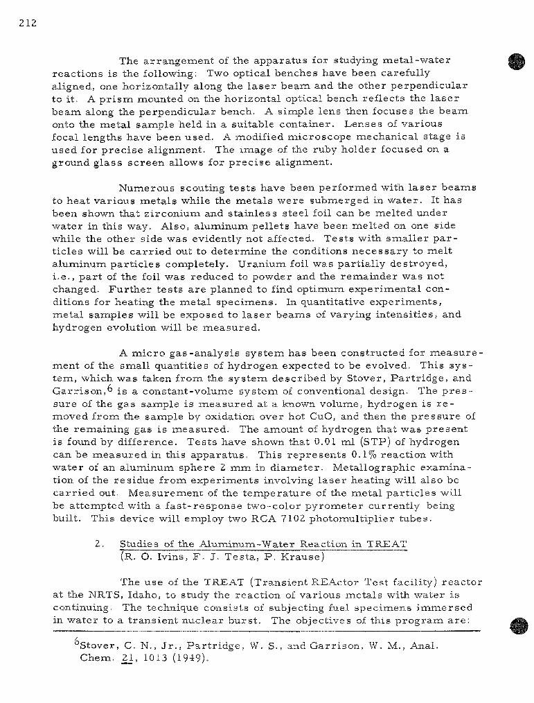
The a r r angemen t of the appara tus for studying me ta l -wa te r react ions is the following: Two optical benches have been carefully aligned, one horizontal ly along the l a s e r beam and the other perpendicular to it. A p r i s m mounted on the horizontal optical bench ref lects the l a s e r beam along the perpendicular bench. A simple lens then focuses the beam onto the m,etal sample held in a suitable container . Lenses of var ious focal lengths have been used. A modified microscope mechanical stage is used for p r e c i s e al ignment. The image of the ruby holder focused on a ground g lass sc reen allows for p r e c i s e alignment.
Numerous scouting t e s t s have been per formed with l a s e r beams to heat var ious meta l s while the me ta l s were submerged in wate r . It has been shown that z i rconium and s ta in less steel foil can be mel ted under water in this way, Also, aluminum pel le ts have been melted on one side while the other side was evidently not affected. Tes t s with sma l l e r p a r t ic les will be c a r r i e d out to de te rmine the conditions n e c e s s a r y to mel t a luminum pa r t i c l e s completely. Uranium foil was par t ia l ly destroyed, i .e . , p a r t of the foil was reduced to powder and the remainder was not changed. F u r t h e r t e s t s a re planned to find optimumi exper imenta l conditions for heating the naetal specimiens. In quantitative exper iments , meta l samples will be exposed to l a s e r beams of varying in tens i t ies , and hydrogen evolution will be measu red .
A m i c r o gas -ana lys i s sys t em has been constructed for m e a s u r e -jaaent of the smal l quanti t ies of hydrogen expected to be evolved. This s y s tem, which was taken from the sys t em descr ibed by Stover, P a r t r i d g e , and G a r r i s o n , " i s a constant-volume sys tem of conventional design. The p r e s sure of the gas sample is m e a s u r e d at a known volume, hydrogen is r e moved from the sample by oxidation over hot CuO, and then the p r e s s u r e of the remaining gas is measured . The amount of hydrogen that was p re sen t is found by difference. Tes t s have shown that 0.01 ml (STP) of hydrogen can be m e a s u r e d in this appara tus . This r e p r e s e n t s 0.1% react ion with water of an aluminum sphere 2 m m in d iameter . Metal lographic examination of the res idue from exper iments involving l a se r heating will also be c a r r i e d out. Measurement of the t e inpera tu re of the meta l pa r t i c l e s will be a t tempted with a f a s t - r e sponse two-color py rome te r cur ren t ly being built. This device will employ two RCA 7102 photomult ipl ier tubes .
2. Studies of the Aluminum-Water Reaction in TREAT (R. O. Ivins, F . J. Tes ta , P . Krause)
The use of the TREAT (Transient REActor Test facility) r eac to r at the NRTS, Idaho, to study the reac t ion of var ious me ta l s with water is continuing. The technique consis ts of subjecting fuel spec imens i m m e r s e d in water to a t r ans ien t nuc lear burs t . The objectives of this p r o g r a m a r e :
Stover, C. N., J r . , P a r t r i d g e , W. S., and Gar r i son , W. M., Anal. Chem. 21, 1013 (1949).

213
1. to de termine the extent of react ion between the metal and water ;
2. to de termine the fuel t empera tu re and p r e s s u r e his tory during the excursion;
3. to deternaine the physical damage that occurs as a resu l t of the t rans ien t ; this is acconaplished by such means as metal lographic and par t ic le size evaluations.
The re su l t s of severa l exper iments in which a luminum-uranium alloy fuel p la tes were subjected to des t ruct ive t rans ien t s in TREAT have been repor t ed in previous quar te r ly r epor t s (ANL-6648, p . 201, and ANL-6687, p . 179). These studies were pe r fo rmed with the sample fuel p la tes submerged in r o o m - t e m p e r a t u r e wate r . These resu l t s will be compared with those of cu r r en t runs in which samples were immiersed in water at 286 C (p re s su re of 1000 psia) . The same two types of alloy plates were tes ted in the e a r l i e r studies as were tes ted in the cur ren t q u a r t e r ' s work in which heated water was used. They were :
(1) a 6061 a luminum-clad , 77 w/o aluminum-23 w/o uran ium (fully enriched) plate cut from a standard SPERT-ID pla te . Each cladding layer and the core mate r ia l were 20 mi l s thick. These p la tes had the nominal dimensions of 0.06 by 0.5 by 1.4 in. The edges of these plates -were not clad.
(2) an unclad 81 w / o a luminum-17 w/o uran ium (fully en-riched)-2 w / o nickel alloy, which was the core mate r ia l of the SL-1 fuel p la te s . These plates had the nonainal dimensions of 0.2 by 0.5 by 0.5 in.
a. Exper iments in Heated Water
Four exper iments were conducted in water which was heated to 285 C and had a p r e s s u r e of 1000 ps ia (sa tura ted s team). Two exper i ments were conducted with SPERT p la tes , and two with samples of SL-1 core ma te r i a l . The p a r a m e t e r s and the r e su l t s of these exper iments a re summ a r i z e d in Table IV-3 . The samples were subjected to neutron burs t s in TREAT at energy levels se lected to cor respond with exper iments previously conducted in room-tenapera ture wate r .
F o r each of the two types of samples , one t rans ien t (CEN 141H and 142H) was run at a r eac to r energy calculated to supply only enough energy to mel t the pla te . In these runs , the p la tes reac ted with water in only negligible anaounts, as was the case in the previous room- tenapera tu re -water exper imen t s .
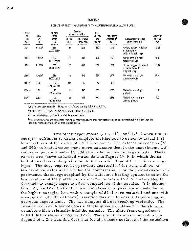
214
Table W-3
RESULTS OF TREAT EXPERIMENTS WITH ALUMINUM-URANIUM ALLOY PLATES
TREAT Exp. CEN No.
141H
140H
142H
143H
144-lC
144-20
145c
Fuel Wt (g)
2.4850a
2.38853
2.1605b
1.9295b
6.64
6.64
6.32
Initial Water Temp (C)
285 (1000 psig)
285 (1000 psig)
285 (1000 psig)
285 (1(M0 psig)
25 (20 psia He)
25 (20 psia He)
25 (20 psia He)
Reactor Characteristics
Period (ms)
87
86
63
46
118
62
50
1 nt Power (MW-sec)
236
348
430
650
109
410
543
Calc Energy Input (cal/g)
350
500
m
570
92
353
467
Peak Temp Adiabaticfl
«C)
1130
1700
1275
1975
400
1375
1875
Appearance of Fuel after Transient
Melted, bulged; retained a resemblance to its original shape
Melted into a single porous globule
Melted, sagged; retained a resemblance to its original shape
Melted into a single porous globule
-
Melted into a single globule
Melted into a single porous globule
Extent of Reaction
(%)
0.24
76.0
0.35
89.0
-
0.4
5.0
aynclad SL-1 core material: 81 w/o Al-17 w/o U-2 w/o Ni; 0.2 x 0,2 x 0.5 in.
bAI-clad SPERT-ID plate: 77 w/o AI-23 w/o U; 0.06 x 0.5 x 1.4 in.
CThree SPERT-ID plates held in a stainless steel holder.
^These temperatures are calculated from the energy input and thermodynamic data, and are considerably higher than that actually reached by the sample due to heat losses.
Two other exper iments (CEN-140H and-143H) were run at energies sufficient to cause complete melting and to generate actual fuel t empera tu re s of the order of 1200 C or m o r e . The extents of react ion (76 and 89%) in heated water were m o r e extensive than in the experinaents with r o o m - t e m p e r a t u r e water (<20%) at s imi lar nuclear energy inputs. These resu l t s a r e shown as hea ted-water data in F igure IV-5, in which the extent of react ion of the plates is plotted as a function of the nuclear energy input. The data (reported in previous quar te r l i es ) for runs with room-tempera tu re water a r e included for comparison. F o r the hea ted-water expe r imen t s , the energy supplied by the autoclave heating sys tem to r a i se the t empera tu re of the plates from room tempera tu re to 285 C was added to the nuclear energy input to allow comparison of the r e su l t s . It is obvious f rom Figure IV-5 that in the two heated-water exper iments conducted at the higher energies (one with a sample of SL-1 core ma te r i a l and one with a sample of SPERT-ID plate) , react ion was much more extensive than in previous exper iments . The two samples did not break up violently. The res idue from each sample was a single globule contained in the alumina crucible which originally held the sample. The plate froxn experiment CEN-140H is shown in F igure IV-6. The crucibles were cracked, and a deposit of a fine alumina dust was found on inner surfaces of the autoclave.

215
Figure IV-5
NUCLEAR ENERGY INPUT VS. EXTENT OF REACTION FOR ALUMINUM-URANIUM ALLOY PLATE MELTDOWN EXPERIMENTS IN TREAT
9 0
80 —
60 —
_, 50
4 0 —
2 0 —
10 —
—
-
-
1 1
s
1
S + L
0 |
L
O.f
®
PLATE BREAKUP
SPERT SL-1 1 1
r y ^ n ^ 1
(S
/ .
1
S L - I SPERT-ID
3 SPERT ID PLATES
•
.y <
1 1
HEATED WATER
®
X
IGNITION REGION
1 1
ROOM TEMP WATER
X •
i
X
1 1 1 2 0 0 4 0 0 6 0 0 8 0 0 1000
NUCLEAR ENERGY INPUT, c o l / g of p l a t t 1200 1400
6 6 0 1 2 0 0 - 1 4 0 0 1750
ESTIMATED TEMPERATURE PEAK, C
108-6765
Figure IV-6
ALUMINUM-URANIUM ALLOY (UNCLAD SL-l MATERIAL) AFTER MELTDOWN
EXPERIMENT CEN-140H
_ J
108-6110

The reasons for extensive react ion a re elusive. The p o s sibility exis ts that the p r e s s u r e and t empera tu re used c rea ted a kinetic effect unlike any previously noted in these studies. It is thought that the difference in react ion r a t e s may be re la ted not only to differences in p r e s sure in the autoclaves , but a lso to the fact that the heat l o s se s in subcooled boiling ( roona- tempera ture water ) a r e much g r e a t e r than in sa tura ted boiling (heated water ) . This difference in heat loss may have the effect of grea t ly diminishing the net energy input to specinaens in roona- tempera ture wate r . To overconae the hea t loss in the experinaents with r o o m - t e m p e r a t u r e wa te r , a nuc lear heating ra te much higher than in the exper iments conducted in heated water may be requi red . Several investigators ' ' ' have repor ted unusually high "burnout" heat fluxes (i .e. , more recent ly r e f e r r e d to as DNB or Depar tu re f rom Nucleate Boiling). The difference in the heat flux r e quired to exceed the "burnout" t empera tu re causes a difference in the effective nuclear energy input and the resul t ing sample t e m p e r a t u r e , depending on the initial water t e m p e r a t u r e . F u r t h e r study is r equ i red in o rder to in t e rp re t the r e su l t s of the exper iments in heated water .
T r a n s i e n t - p r e s s u r e m e a s u r e m e n t s indicated that no explosive p r e s s u r e i n c r e a s e s occur red . Detailed react ion ra t e s could not be der ived f rom the p r e s s u r e - t i m e t r a c e s because of e lec t r i ca l in te r fe r ence of the t r ans ien t neutron flux on the s t ra in -gage c i rcu i t ry . Methods for locating p r e s s u r e t r a n s d u c e r s out of the high-flux region of the r eac to r core in future experinaents a r e cur ren t ly under study. It is anticipated that dec reased fidelity resul t ing f rom placing the t r ansduce r at the end of a long tube 'will be more than offset by the dec reased in ter ference f rom the t r ans ien t flux.
b. Expe r imen t s with Clus te rs of Fuel P l a t e s
In each of two additional exper iments , th ree SPERT-ID pla tes r a the r than one were i r r ad i a t ed (see Table IV-3) to de termine the effect of multiple p la tes on the extent of react ion. Three p la tes , submerged in r o o m - t e m p e r a t u r e wa te r and held ver t ica l ly in a slotted U-shaped s ta inless steel support , we re subjected to t rans ien t b u r s t s of the TREAT r e a c t o r .
The autoclave used in the f i r s t exper iment (CEN-144) was subjected to two t r a n s i e n t s , the f i r s t impart ing an energy of 92 ca l /g to the p la tes (heating the p la tes to ~400 C) and the second melting the p la tes with an energy of 353 c a l / g . The p la tes r eac ted to the extent of 0.4%, based on the amount of hydrogen evolved.
In the second exper iment (CEN-145) the t r ans ien t inaparted an energy of 467 ca l /g to the p la tes . These p la tes r eac ted to the extent of 5.0%. In F igure IV-5 , the extent of reac t ion for these t e s t s is compared with the previous ly r e p o r t e d exper iments with individual SPERT-ID p la tes . The inc rease in the number of p la tes did not affect the extent of react ion.
'Drew, T. B. , and Hoopes, J. W., J r . , Advances in Chemical Engineer -ing, Vol. 11, Academic P r e s s , New York, pp. 21-27 (1958).
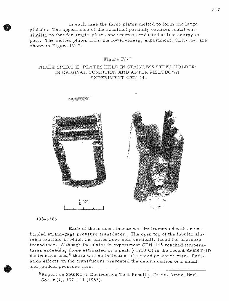
217
In each case the three plates melted to forna one large globule. The appearance of the resul tan t par t ia l ly oxidized metal was s imi la r to that for s ingle-plate exper iments conducted at like energy inputs . The iTielted plates frona the lower-energy experiment , CEN-144, a re shown m F igure IV-7.
Figure IV-7
THREE SPERT ID PLATES HELD IN STAINLESS STEEL HOLDER: IN ORIGINAL CONDITION AND AFTER MELTDOWN
EXPERIMENT CEN-144
ilnch
108-6166
Each of these exper iments was instrunaented with an unbonded s t ra in-gage p r e s s u r e t r ansducer . The open top of the tubular alumina crucible in which the plates were held ver t ica l ly faced the p r e s su re t r ansducer . Although the pla tes in exper iment CEN-145 reached t empera tu res exceeding those es t imated as a peak (-^1250 C) in the recent SPERT-ID destruct ive tes t ,8 there was no indication of a rapid p r e s s u r e r i s e . Radiation effects on the t r ansduce r s prevented the determination of a snaall and gradual p r e s s u r e r i s e .
^Report on SPERT-1 Destruct ive Test Resul ts , T rans . Amer . Nucl. Soc. 6 (1), 137-141 (1963).

c. Breakup and Pa r t i c l e Size Determinat ions
In order to evaluate the me ta l -wa te r react ion and to ca l culate the heat t r ans fe r to the coolant that would occur during an actual core des t ruct ion, a determinat ion of the size dis tr ibut ion of the pa r t i c l e s c rea ted is n e c e s s a r y . Unfortunately, the re appears to be no sat isfactory theore t ica l approach to predict ing the size of pa r t i c l e s produced in an excurs ion.
As p a r t of the pos t - t r ans i en t examination, a sieve sc reen analysis of TREAT specimens in which breakup occu r r ed has been made in o rde r to de te rmine the par t i c le size distr ibution. The distr ibution data have been p re sen ted in the form of h i s t og rams in preceding qua r t e r ly r e p o r t s . The weight pe rcen t of pa r t i c l e s v e r s u s par t ic le d iameter and the mean surface-volume d i a m e t e r s * (Sauter naean d iamete r s ) were tabulated (see ANL-6648, p . 201, and ANL-6687, p . 179). This average d iameter is based on the specific surface pe r unit volume (i .e. , the d iameter of a sphere having the same sur face- to-volume ra t io as the group of pa r t i c l e s it r e p r e s e n t s ) .
In F igu re IV-8, the mean surface-volume d iameter is plotted as a function of nuclear energy input for the SL-1 and SPERT plate whose percent reac t ion is co r r e l a t ed with nuclear energy input in F i g u re IV-5 . F o r a sample in which breakup did not occur , the d iamete r chosen was that of a hypothetical sphere of the same m a s s as the original sample .
In F igure IV-8 it can be seen that a tenfold dec rea se in d iameter (an i nc r ea se in surface a r e a by a factor of 100) occur red with a snaall i nc r ea se in energy above that r equ i r ed for breakup. The t h r e s h old of breakup occu r r ed at about 450 and 530 ca l /g for the two types of s amples .
d. Calculation of the Extent of Aluminum-Water Reaction Occurr ing in the SL-1 and SPERT-ID Dest ruct ive Trans i en t s
The ra te and extent of me ta l -wa te r react ion occurr ing during a r e a c t o r accident a r e u l t imate ly analyzed by a synthes is of r e ac tor kinetic and chemical react ion calculat ions . Although considerable knowledge exis ts in both a r e a s , no r igorous means has been developed to analyze an accident involving core meltdown. The pr incipal stumbling block has been uncer ta in ty regarding the mechan i sm of f ragmentat ion of the core and, in p a r t i c u l a r , the pa r t i c l e s izes produced. Knowledge is l imi ted to the r e su l t s obtained in s m a l l - s c a l e meltdown experinaents such as those desc r ibed in the preceding sect ions of this r epor t . In these s tudies , the effect of sca le -up on the fragmentat ion of the m a t e r i a l s has not been deternained.
*^sv ~ 2nd /End where n is the number of pa r t i c l e s of d iamete r d.

219
Figure IV-8
AVERAGE PARTICLE SIZE OF ALUMINUM-URANIUM ALLOY PLATES AFTER IRRADIATION IN TREAT VERSUS
NUCLEAR ENERGY INPUT
1000
800
600
400
300
200 > m
-a
< Q
UJ -J
H 100 h-(r a 80 UJ
o ^ 60 UJ
>
40
30
20
_\d____V__ii^_V
X SL-1 PLATE
• SPERT PLATE
^ 3 SPERT PLATES
1 1 1 200 400 600 800 1000
NUCLEAR ENERGY INPUT, cal/g 1200 1400
108-6763

220
In three separa te faci l i t ies , aluminuna-uranium alloy r e actor cores have sustained nuclear excurs ions (see Table IV-4), result ing in extensive damage. Two of these excurs ions , those in Borax-l9 and in SPERT-l^ ' lO' l - ' • r e a c t o r s , were ful l-scale excursion exper iments ; one, that in the SL-1 reac to r , •'• ~ •'•'* was an accident.
Table IV-4
COMPARISON OF THE NUCLEAR EXCURSIONS OF THE BORAX-1, SL-1, AND SPERT-1 REACTORS
Borax- I
7/22/54 exper iment
- 6 0 -5 .0
2.6 19,000(est.)
135 --
_ _
Reactor
SL-1
1/3/61 accident
185 14.0 - 4
19,000 (est.) 130 24 ± 10 500
>2000 32
SPERT-1
12/5/62 experiment
51 4.0 3.2
2,300 31
3-4 380
1200-1300 35
Date of Event Category of Event Aluminum P r e s e n t in Core , kg Uranium P r e s e n t in Core , kg Reactor Per iod , ms Peak Power , MW Integrated Power , MW-sec Chem Energy Release , MW-sec Peak Core Energy Density, ca l /g Peak Core Tempera tu re , C
(estimated) P e r c e n t of Core Melted
The three incidents were very s imi la r . Each reactor had a core of aluminum-clad, a luminum-uranium alloy plates . The excursion was initiated in each case by the rapid removal of a control rod. A large portion of the center of the core was melted and fragmented. Violent laioveinent of a large portion of the coolant up and out of the reac tor core occurred in each incident. In all th ree excurs ions , the core debris had a s imilar appearance . Por t ions of core that had been completely melted were spongy, and considerable quantities of metal l ic oxides were present .
Dietrich J. R,, Experimental Investigation of the Self-limitation of Power during Reactivity Transients in a Subcooled Water Moderated Reactor, Borax I Experiments, AECD-3668 (1954).
lOwilson T. R.,An Engineering Description of the SPERT-1 Reactor Facility, IDO-16318 (1957).
llQuarterly Technical Report, SPERT Project, Jan., Feb., March, 196.3, IDO-16893 (1963).
l^Final Report of SL-1 Recovery Operation, IDO-19331 (1962), p. IV-21.
•^^Buchanan, J. R., SL-1 Final Report, Nuclear Safety; A Quarterly Progress Review, _4, No. 3, 83 (March 1963).
•'•' Report on the Nuclear Incident at the SL-1 Reactor, January 3, 1961 at the National Reactor Testing Station. IDO-19302 (1962).

221
Whereas no a t tempt to determine the extent of react ion of the core with water in the Borax- I exper iment has been repor ted , in the pos t -excurs ion analysis of both the SL-1 and SPERT-1 destruct ive excurs ions , por t ions of the debr is were analyzed for alpha alumina. (Alpha alunaina is the react ion product formed at t empera tu re s above 600 C.) Based on the r e su l t s of these ana lyses , combined with an overal l ma te r i a l balance, chemical energy r e l e a s e s were es t imated to be 24 ± 10 MW-sec and 3 to 4 MW-sec for the SL-1 and SPERT-1 excurs ions , respect ively .
In o rder to es t imate the extent of me ta l -wa te r react ion which occur red in the SPERT and SL-1 excurs ions frona the TREAT data, a calculation was made as follows:
1) The port ion of core which became naolten was assumed to be spher ica l , with x = 0 at the center and x = 1 at the surface . Therefore , the volumie = 47T/3 .
2) The energy density was assumed to vary l inear ly with the distance f rom the center of the sphere . This a s sumption is probably valid as a f i rs t approximation. This relat ionship was expressed as
Ev = E-rnax " Ax,
where
Ej^ = Energy density at position x
^ m a x ~ Energy density at center (naaximum)
A - Constant.
3) The max imum energy densi t ies were taken from the l i t e r a tu re as
a) E ^ a x ( S L - l ) = 500 ca l /g ; 12
b) E ^ a x ( S P E R T - l ) = 380 ca l /g .^
4) The energy density at the surface of the sphere (x= 1) was taken as 220 ca l / g , the energy requ i red to heat a luminum to i ts naelting point and completely mel t i t .* The equations for energy distr ibution were then det e rmined to be
(SL-1) E^ = 500 - 280 x;
(SPERT-l )Ej^ = 380 - 160 x.
*Energies based on E = 0 at 25 C.

222
These equations were then used to calculate the energy distr ibution in the sphere by calculating the dis tances from the center of the sphere that achieved energ ies corresponding to var ious t e m p e r a t u r e s . The fraction of the sphere attaining a se lected t empera tu re or higher was then calculated as x . In s teps of 100 C, the amounts of metal that achieved var ious energy levels were calculated.
The extent of react ion -was then calculated f rom the TREAT data (see F igu re IV-5). This was done by assuming the following:
1) A TREAT energy input of 220 ca l /g resu l t s in complete melting of the m a t e r i a l .
2) The b reak point of 530 ca l /g (see F igure IV-8) in the TREAT data co r responds to the t empera tu re range of 1200 to 1400 C.
3) The marked inc rease in extent of react ion at 750 ca l /g in the TREAT data cor responds to a t empera tu re of 1750 C.
The t e m p e r a t u r e s between these points v^ere l inear ly interpolated. These assumpt ions were based on physical observat ions and metal lographic examinat ions of the TREAT samples . The absc i s sa in F igure IV-5 includes both TREAT energ ies and a s sumed t e m p e r a t u r e s . The calculations a re summar ized in Tables IV-5 and IV-6. The e s t ima tes of chemical energy r e l ea se calculated f rom TREAT data a r e in excellent ag reement with the values (see Table IV-4) obtained by the pos t -excurs ion analyses of the SPERT-1 and SL-1 deb r i s . The analys is of debr is for a-a lumina yielded 3.5 MW-sec of chemical energy r e l ea se for SPERT-1 and 24 ± 10 MW-sec for S L - 1 . The calculat ions based on TREAT data yielded values of 2 MW-sec for SPERT-1 and 26 MW-sec for S L - 1 .
In this es t imat ion, the extent of react ion is based on the peak t e m p e r a t u r e s reached by the molten co re . This is n e c e s s a r y because the duration of the t r ans ien t s differed, being 40 to 100 ms in the TREAT exper iments and 2 to 4 ms in the excurs ions . This method is applicable to other r aa te r i a l s of core construct ion. Considerable exper i raenta l data obtained with the TREAT reac to r has been published. ^^
^^R. C. Li imatainen e t a l . , ANL-6250 (Jan. 1962).

223
Table IV-5
CALCULATION OF EXTENT OF ALUMINUM-WATER REACTION IN THE SPERT-1 EXCURSION
(Based on 18 kg of molten core material]
T e m p e r a t u r e R e a c h e d
T (C)
1250 1200 1100 1000
900 800 700 660
0 . 1 0 9 7 kg
E n e r g y D e n s i t y E ( c a l / g )
380 3 6 8 342 316
290 2 6 4 2 3 8 220
X 18 M W -
D i s t a n c e f r o m
R e a c t o r C e n t e r ,
X
0
0 . 0 7 5 0 . 2 3 8 0 . 4 0 0
0 . 5 6 2 0 . 7 2 5 0 . 8 8 8 1.000
3 e c / k g = 2^
x-
0 0 . 0 0 0 4 0 . 0 1 0 5 0 . 0 6 4
0 . 1 7 8 0 . 3 8 2 0 . 7 0 0 1.000
0 M W - s e c
W e i g h t of M e t a l w i t h i n
S p h e r e of R a d i u s x ,
W (kg)
0
0 . 0 0 7 2
0 . 1 8 9 1.15
3 . 2 4 b . 8 8
12.bO 1 8 . 0 0
D i f f e r e n t i a l W e i g h t - W (kg)
0 . 0 0 7 2 0 . 1 8 2 0 . 9 5 2 . 0 9 3 . 6 4 5 .72 5 .40
T o t a l n ie
c h e m i c a l e n e r g y r e l e a s e
P e r c e n t R e a c t i o n
10 .0 7 .0 3 .4
1.2 O.b 0 .2 0 .1
t a l r e a c t e d
M e t a l R e a c t e d
(kg j
0
0 . 0 0 0 7 0 . 0 1 2 7 0 . 0 3 2 b 0 . 0 2 5 1 0 . 0 2 1 8 0 . 0 1 1 4 0 . 0 0 5 4
0 . 1 0 9 7
Table IV-b
CALCULATION OF EXTENl OF ALUMINUM-WATER REACTION IN THE SL-1 EXCURSION
(Based on 60 kg of molten core material)
T e m p t r a t u r e R e a c h e d
I (C)
1700 IbOO 1500 1400
1300 1200 1100 1000
900 800 700 660
1.44 5 kg
E n e r g y D e n s i t y E ( c a l ; g j
500 4 7 4
4 4 8 4 2 2
396 368 342 U b 290 2 6 4 2 3 8 220
X 18 M W -
D i s t a n c e f r o m
R e a c t o r C e n t e r ,
X
0
0 . 0 9 3 0 . 1 8 6
0 . 2 7 9 0 . 3 7 2 0 . 4 7 2 0 . 5 6 4 0 . 6 5 8 0 . 7 5 0 0 . 8 4 3 0 . 9 3 5 1.000
s e c / k g = 26
X''
0
o.ooos 0 . 0 0 b 6 0 . 0 2 3 0 . 0 5 1 0 . 1 0 5 0 . 1 8 0 0 . 2 8 4 0 . 4 2 2 0 . 6 0 0
0 .817
W e i g h t of M e t a l w i t h i n
S p h e r e of R a d i u s x ,
W (kg]
0
0 . 0 4 8 0 . 3 9 5
1.39 3 . 0 6
6 . 2 9 1 0 . 8 1 7 . 0 2 5 . 3
3 5 . 9 4 8 . 9
D i f f e r e n t i a l W e i g h t £.W Ikg)
0 . 0 4 b O.o47
0 . 9 9 l . b 7 5 . 2 3 4 . 5 6.2 8.3
10 .b 13 .0
1.000 6 0 . 0 11 .1
T o t a l m e
0 M W - s e c c h e m i c a l e n e r g y r e l e a s e
P e r c e n t R e a c t i o n
19 .9 17 .2 11 .0
11 .0 11 .0
7 .0
3 .4 1.2 O.b 0 .2 0 .1
t a l r e a c t e d
M e t a l R e a c t e d
(kg)
0 0 . 0 1 0 0 . 0 6 0
0 . 1 0 9 0 . 1 8 4 0 . 3 5 5 0 . 3 1 5 0 . 2 1 1 0 . 1 0 0 0 . 0 b 4
0 . 0 2 6 0 O i l
1 .445

V. ENERGY CONVERSION*
Two methods of d i rect ly converting nuclear energy into e lect r ic i ty a re being investigated. One method involves the use of the rmal ly r egene r ative cel ls ; the other method, involving l e s s effort, depends upon the the r mocouple effect for the conversion.
A. Regenera t ive Emf Cell (C. E. Crouthamel)
The basic studies of a regenera t ive cell sys tem to convert heat into e lec t r ic i ty a r e continuing, the eventual goal being to couple a ther inal ly regenera t ive emf cell with a r eac to r heat source in a closed cyclic opera tion. The sys tems which appear to have the best chance of succeeding in this application a r e (l) the l i thium hydride cell and (2) b imetal l ic cel ls employing fused salt e lec t ro ly tes and liquid meta l e lec t rodes . Many of the bas ic chemical and physical p rope r t i e s of these sys tems a re unkno-wn, so that a considerable amount of basic r e s e a r c h is n e c e s s a r y to provide an adequate foundation for both cell design and cyclic operat ions .
The basic studies that were c a r r i e d oiit during the quar te r were re la ted to the following major ca tegor ies of r e s e a r c h : (l) development of regenera t ive b imeta l l ic ce l l s , (2) development of a regenera t ive l i thium hydride cel l , and (3) studies of cell regenera t ion at high t e m p e r a t u r e s .
The emf - t empera tu re -compos i t ion d iagram for a l i th ium-bismuth bimetal l ic cell is complete , and analys is of the data is in p r o g r e s s . The emf - t empera tu re -compos i t ion diagram, for the l i th ium-t in cell has been par t ia l ly completed.
In the solid-l iquid equi l ibr ium studies of the b inary l i thium hydr ide-l i thium chloride systena, a difficulty (an additional unexplainable b reak in the cooling curve vfhich appeared only on the l i thium chloride solid-l iquid equilibrium, side of the phase d iagram) was experienced when l i thium ch lo r ide - r i ch mixt i i res Avere cooled. This difficulty may be typical of other fused-sa l t cool ing-curve data in the l i t e r a t u r e in which l i thium chloride is a component. Data in the l i t e r a t u r e on severa l fused salt b inary sys tems involving l i thium chloride as one of the components a r e being checked.
The equil ibrat ion of two liquid phases by the i sopies t ic technique is being examined for poss ible application in liquid m e t a l - s a l t equi l ibrat ions. Of pa r t i cu l a r i n t e r e s t in the regenera t ive cell p r o g r a m a r e m e t a l - s a l t solubil i t ies at cell operat ing t en ipe ra tu re ( i sothermal equilibration) and the vapor -phase equil ibrat ion of a bi inetal l ic solution at high t e m p e r a t u r e (up to 1000°C) with a pure liquid (usually alkali metal) at lower t e m p e r a ture . Metal solubility in the cell e lec t rolyte will t r ans fe r the anode liquid to the cathode by an i r r e v e r s i b l e p r o c e s s , and thereby lov,^er the cell
*A su inmary of this section is given on pages 29 and 30.

voltage and efficiency. The h igh - t empera tu re vapor -phase equilibria will de te rmine the p a r a m e t e r s for the regenera t ion of the cell reac tants from the bimetal l ic cell product. An evaluation of the resu l t s is still incomplete,
1. Bimetal l ic Cel ls ( M . F o s t e r , R. Eppley)
Thermodynamic functions of binary liquid metal sys tems and the assoc ia ted solid in te rmeta l l i c compounds which may be of in te res t in a regenera t ive cell sys tem a re under investigation. Two bimetal l ic sys tems a r e being studied: the l i th ium-bismuth and the l i th ium-t in systenis . Galvanic cells in which the e lec t ro ly tes a r e molten sal ts a r e being used in these studies.
Measu remen t s of the l i th ium-bismuth sys tem have been continued. The electrolyte was the eutectic mixture of L iC l -L iF . The data for a galvanic cell having a pure l i thium anode and a bismuth cathode sa t u ra ted with Li3Bi(s) were repor ted previous ly (see ANL-6687, p. 191). The cathode in the previous m e a s u r e m e n t s remained sa tura ted with Li3Bi(s) up to 60 a /o l i thium in bismuth. This composit ion is a homogeneous solution at 775 C; below this t e m p e r a t u r e Li3Bi solid p rec ip i ta tes , according to the known phase d iagram. Reproducible data were obtained up to a t empera tu re of 825 C.
This anode was then used as a re fe rence anode for cells with var ious unsa tura ted liquid meta l cathodes in which the mole fractions of l i thium (XLJ_) were 0.05, 0.20, 0.30 and 0.40. By use of this technique, the activity of l i thium in the anode is reduced considerably over that of pure l i thium meta l , and thus the activity of l i thium in solution (due to solubility) is correspondingly reduced. Final ly , the i r r e v e r s i b l e t ransfer of l i thium from the anode to the cathode is great ly reduced. These cel ls , with Li3Bi-sa tura ted anodes and dilute cathodes, yielded voltages which were quite stable with r e spec t to t ime , even at the higher t empe ra tu r e s . The data were adjusted to yield the points shown in F igure V - 1 . The curves cor responding to XLJ^ = 0.05 and liquid bismuth sa tura ted with Li3Biare derived from data taken in two independent runs at each concentration; the other curves a r e der ived from data taken from single exper iments . The rmodynamic quanti t ies a r e being calculated from these data.
Owing to an insufficient difference in the vapor p r e s s u r e of the t-wo m e t a l s , it may be imprac t i ca l to r egene ra t e the cell by vaporizing l i thium from the l i th ium-bismuth alloy. Fo r example, at 900 C the equil ibrium vapor p r e s s u r e s of pure l i thium and bismuth a r e 12 m m and 0.5 mm, r e spectively. This would appreciably lower the cell output by returning a l i th ium-r ich alloy of l i thium and bismuth to the anode (and a b i smuth- r i ch alloy to the cathode). A meta l which has a lower vapor p r e s s u r e than b i s muth appears a t t rac t ive in that the vapor separa t ion of near ly pure l i thium

might be much eas ier . Such a meta l is tin, which has a normal boiling point of 2780 K- - and at 900 C an equil ibrium vapor p r e s s u r e of 2 x 10"^ mm.
F igure V- 1
POTENTIAL-TEMPERATURE CURVES OF THE CELL
L i ( l ) / L i C l - L i F ( l ) / B i ( l ) with X^i (^Li - Mole Frac t ion of Lithium)
0.96 —
0.88 —
0.80
XL | = 0 , 0 5
<T = ± 5MV.
0.72
0 .64
X L !
<T =
X l i o- =
XLi 0- =
= 0.20
± 3 M V
= 0 .30 + 3MV.
= 0 .40 + 3MV.
°n, -L .
\ . Bi(l)satd. w.LisBHs)
^ 0- = ± 3 M V .
_L '60 840 1000 1080
CELL TEMP, K
1160 1240
108-6875
Labora tory studies of l i th ium-t in cells a re underway. The methods used a r e identical with those used previously. Data for cells utilizing LiCl -LiF eutectic as electrolyte in which a pure l i thium anode and a saturated l i thium-t in cathode were used a r e shown in F igure V-2.
Pronounced breaks in the enaf- temperature plot a r e attr ibuted to phase changes occurr ing in the cathode, e.g., in the upper curve, b reaks a r e shown at 775 K and 963 K. At 775 K, the solid in equil ibrium with a liquid alloy changes from LigSn to Li5Sn2, and at ~963 K there is a t r a n s i tion from a t'wo-phase sys tem to a single liquid phase (unsaturated). It should be noted that in F igure V-2 the per i tec t ic t empera tu re (or the lower phase change) remains the same when the mole fraction of the lithium in the cathode is changed from 0. 65 to 0. 70. However, the t ransi t ion to a one-phase
I j . A. Cahill and A. D. Kirshenbaum, J. Inorg. Nucl. Chem. 2_5, 501 (1963).

227
s y s t e m o c c u r s at a h i g h e r t e m . p e r a t u r e whenX]_,i = 0. 70 than w h e n X L ^ = 0 .65 , a s would be expec ted . A c c o r d i n g to the p h a s e d i a g r a m , ^ the u p p e r t r a n s i t i o n in e a c h r e s p e c t i v e ce l l should t ake p l a c e a t the t e m p e r a t u r e s naa rked wi th t r i a n g l e s on F i g u r e V - 2 . T h e s e a r e s l igh t ly l o w e r than the t e m p e r a t u r e s o b s e r v e d - i ndeed , the o b s e r v e d t e m p e r a t u r e (~1003 K) of h i g h e s t t r a n s f o r m a t i o n i s h i g h e r t han the r e p o r t e d m e l t i n g po in t (993 K) of sol id Li5Sn2, I n v e s t i g a t i o n s of the p h a s e d i a g r a m wi l l be conduc ted to c l a r i fy t h i s diff e r e n c e . F u r t h e r t h e r m o d y n a m i c s t u d i e s of the l i t h i u m - t i n s y s t e m a r e con t inu ing .
F i g u r e V-2
P O T E N T I A L - T E M P E R A T U R E CURVES OF THE C E L L
L i ( l ) / L i C l - L i F / S n ( l ) wi th X L ^ (Xj^^ ~ Mole F r a c t i o n of L i t h i u m )
0 4 4
, 0 40
o
0 28
LrgSnCs A SOLID SOLID AND SOLID LIQUID
EQUILIBRIUM TEMPERATURES^
'""^^ ( UNSATURATED CATHODE)
108-6833
—Ai 1 1 1 ! 1 ! \ LA J A -800 840 880 920 960 1000 1040 1080 1120
CELL TEMP, K
A c o m p a r i s o n of the s a t u r a t e d l i t h i u m - b i s m u t h e l e c t r o d e p o t e n t i a l s ( F i g u r e V - l ) wi th the s a t u r a t e d l i t h i u m - t i n e l e c t r o d e p o t e n t i a l s ( F i g u r e V-2) shows a d e c r e a s e of approx im.a te ly 0.25 V for the l a t t e r . Both p o t e n t i a l s w e r e n a e a s u r e d wi th r e f e r e n c e to a p u r e l iquid l i t h i u m m e t a l anode , and bo th s a t u r a t e d e l e c t r o d e s con ta in c o m p a r a b l e a m o u n t s of l i t h i u m , i . e . , m o l e f r a c t i o n s of l i t h i u m in each s a t u r a t e d s y s t e m at 1000 K i s b e t w e e n 0.6 to 0.7. At c o m p a r a b l e c o n c e n t r a t i o n s of the u n s a t u r a t e d e l e c t r o d e s the l i t h i u m - t i n s y s t e m wi l l r e m a i n about 0.25 V below the l i t h i u m - b i s m u t h e l e c t r o d e po t en t i a l . Th i s d i f f e rence m a y be offset by the b e t t e r v a p o r - p h a s e s e p a r a t i o n of l i t h i u m frona tin.
^ H a n s e n , M. , and K. A n d e r k o , Cons t i t u t i on of B i n a r y Al loys , Second Ed . , M c G r a w - H i l l Book Co . , I nc . , New York (1958)

2 2 8
2. Li th ium. H y d r i d e - L i t h i u m C h l o r i d e S o l i d - L i q u i d E q u i l i b r i u m S tud ie s (C. J o h n s o n , J . Al len)
The s o l i d - l i q u i d e q u i l i b r i u m c u r v e s of v a r i o u s e l e c t r o l y t e s a l t s y s t e m s a r e n e e d e d for the d e s i g n of both the l i t h i u m h y d r i d e ce l l and the b i m e t a l l i c ce l l . The da t a of the L i H - L i C l b i n a r y s y s t e m w e r e ob ta ined by a p p a r a t u s p r e v i o u s l y d e s c r i b e d in A N L - 6 5 9 6 , p . 203, and the m e t h o d d e s c r i b e d in A N L - 6 6 4 8 , p , 214, The p h a s e d i a g r a m given in A N L - 6 6 8 7 , p . 195, i n d i c a t e d h i g h e r s o l i d - l i q u i d e q u i l i b r i u m t e m p e r a t u r e s a t the l i t h i u m c h l o r i d e - r i c h s ide of the d i a g r a m than does T a b l e V - l , wh ich p r e s e n t s the f inal da ta . The e u t e c t i c m e l t i n g poin t , 495,6 C, and the e u t e c t i c c o m p o s i t ion , 34.0 p e r c e n t l i t h i u m h y d r i d e , r e m a i n unchanged .
L I T H I U M H Y D R I D E -
L i H ( m o l e f r a c t i o n )
0 0 .050 0 .061 0 .101 0 .151 0 .210 0 .249 0 .289 0.340 0 .382
Sol i d -
T a b l e
-LITHIUxM C H L O R I D E
l iqu id Equ i T e m p e r a t u r e
6 0 6 . 8 595.0 592 .4 581 .5 567 .5 551 .6 538 .5 521.7 495 .6 52 3.2
i b r i u m (C)
V- 1
S O L I D - L I Q U I D
LiH ( m o l e f r a c t i o n )
0 .401 0 .495 0 .522 0.576 0 .6^4
0 .698 0.786 0 .852 O.QOl 1.00
E Q U I L I B R I U M
S o l i d -Tt
l iqu id E q u i l i b r i u m m i p e r a t u r e (C)
520. I - 6 1 . 6 572 .3 385 .8 605 .9 61Q.7 639 .5 6 5 5,0 665.1 685 .8
A typ ica l cool ing c u r v e on the l i t h i u m c h l o r i d e - r i c h s ide of the s o l i d - l i q u i d e q u i l i b r i u m d i a g r a m a lways con ta ined two e x o t h e r m i c b r e a k s in add i t ion to the e u t e c t i c ha l t . Th i s a n o m a l o u s b e h a v i o r w a s c o m p l e t e l y a b s e n t wi th the l i t h i u m h y d r i d e - r i c h s ide of the so l i d - l i qu id equi l ib r iuna d i a g r a m .
If the f i r s t b r e a k w a s a s s u m e d to r e f l e c t the p r e c i p i t a t i o n of a p u r e so l id p h a s e , l i t h i u m c h l o r i d e , the second e x o t h e r m i c b r e a k in the cooling c u r v e above the e u t e c t i c h a l t w a s difficult to expla in . The p r o b l e m i s i l l u s t r a t e d in F i g u r e V - 3 by t h r e e t y p i c a l cool ing c u r v e s ob ta ined wi th a s a m p l e cup of the o r i g i n a l d e s i g n , and p l o t s of the a n o m a l o u s b r e a k s c o m p a r e d wi th the f inal s o l i d - l i q u i d e q u i l i b r i u m da ta ob ta ined with a s a m p l e cup of modi f ied des ign .
On the cool ing c u r v e s for s a l t m i x t u r e s conta in ing 5, 20, and 33 m / o l i t h i u m h y d r i d e , t h e r e w e r e t h r e e r e g i o n s above the eu t ec t i c ha l t . E a c h l ine AB in F i g u r e V - 3 r e p r e s e n t s a b i n a r y fused sa l t s y s t e m cool ing a s a h o m o g e n e o u s l iquid m i x t u r e . The s y s t e m w a s m e c h a n i c a l l y s t i r r e d

a t the h igh t e m p e r a t u r e to i n s u r e c o m p l e t e mix ing of the l iquid s a l t s and then w a s coo led wi th no add i t i ona l s t i r r i n g . At po in t B , p r e c i p i t a t i o n of the p u r e s o l i d - p h a s e l i t h i u m c h l o r i d e s t a r t e d and w a s expec ted to cont inue un t i l the e u t e c t i c ha l t w a s r e a c h e d a t po in t D. H o w e v e r , at point C in each of the t h r e e c u r v e s , a s econd u n e x p e c t e d e x o t h e r m i c b r e a k a p p e a r e d . The b r e a k at po in t C w a s s h a r p e r than the f i r s t one at poin t B , and when p lo t ted gave the l o w e r a n o m a l o u s c u r v e in F i g u r e V - 3 .
F i g u r e V - 3
ANOMALY IN L i H - L i C l SOLID-LIQUID EQUILIBRIUM DATA
620| -|
0 10 20 30 40 50
LiH, mole percent
108-6895
E x p e r i m e n t s have been done with a newly des igned s a m p l e h o l d e r con ta in ing two c i r c u l a r h e a t - c o n d u c t i n g fins and a t h e r m o c o u p l e we l l wh ich ex tends to the b a s e of the cup. The two sanaple ho lde r a r r a n g e m e n t s a r e shown in F i g u r e V - 4 . When the new s a m p l e ho lde r (B in F i g u r e V-4) w a s u s e d , the two b r e a k s above the eu t ec t i c ha l t w e r e r e p l a c e d wi th a s ing le b r e a k . In F i g u r e V - 4 , the conf igu ra t ion of the sa l t m i x t u r e on cool ing in the f i r s t cup u s e d i s dep i c t ed to a id in the u n d e r s t a n d i n g of the r e a s o n u n d e r l y i n g the o c c u r r e n c e of the anonnalous b r e a k s . Solid l i t h i u m c h l o r i d e f o r m s in i t i a l l y on the w a l l s of the c o n t a i n e r . When the f i r s t l i t h i u m c h l o r i d e a p p e a r s , the t h e r i n o c o u p l e in the c e n t r a l l y l oca t ed we l l r e c o r d s a t e m p e r a t u r e s o m e w h a t above the t r u e so l id - l i qu id e q u i l i b r i u m t e m p e r a t u r e . The u n e x p e c t e d and s h a r p b r e a k at point C in F i g u r e V - 3 a p p e a r s w h e n suff ic ient so l id i f i ca t ion h a s o c c u r r e d so tha t the l iquid s a l t s t r a p p e d in the s h e l l of l i t h i u m c h l o r i d e sol id l o s e wet con tac t wi th the i r o n v e s s e l , a s dep ic t ed in F i g u r e V-4A. H e a t t r a n s f e r t h rough sol id l i t h i u m c h l o r i d e i s low, and t h e r e f o r e the a n o m a l o u s e x o t h e r m i c b r e a k in the cool ing c u r v e i s v e r y s h a r p . In c o n t r a s t , conduc t ion of h e a t th rough l i t h i u m

2 30
hydride solid was good enough so that no appreciable e r r o r s appeared in cooling curves on the l i thium hydride side of the phase diagram. Never thel e s s , with the old sample holder A in F igure V-4, heating curves were very poor on both sides of the phase diagram. Using sample holder B in F ig ure V-4, we were able to elinainate the anomalous break and to obtain cor responding solid-liquid breaks on both heating and cooling. F igure V-5 shows typical heating and cooling curves on the lithium chloride side of the phase diagram. The l iquid-solid breaks v^ere sharp on both curves and differ by l e s s than 3 C.
LIQUID--...,^
SOLID
\
1
\
n.
i
f
\
^^^^
r
pf
1
I
^ ^ ^
• IN
xV...^-- lin . '—B.
1 in. DIAMETER ' IRON TUBE -
.
1- :in
f fin
1 fin *
- ^ p"
V
<
IRON • METAL
FINS
Figure V-4
SAMPLE CONFIGURATION DURING TIME OF SOLIDIFICATION
Figure V-5
108-6859
COMPARISON OF HEATING AND COOLING CURVES IN LiCl-LiH SYSTEM WITH
SPECIALLY DESIGNED SAMPLE HOLDER
AT <3 DEGREES, C
COOLING
TIME TIME
108-6891

T h e r m o d y n a m i c funct ions for each componen t w e r e ob ta ined f r o m the l i q u i d - s o l i d e q u i l i b r i u m da ta by the m e t h o d ou t l ined by W a g n e r . ^ In the a n a l y s i s of t h e s e da t a , only the h e t e r o g e n e o u s equi l ibr iuna b e t w e e n p u r e so l id and a b i n a r y l iqu id m i x t u r e -was c o n s i d e r e d With no ev idence for so l id so lu t ion m the hea t i ng and cool ing c u r v e s , i t was a s s u m e d tha t only p u r e so l id s p r e c i p i t a t e d f r o m so lu t ion . The da ta a r e g iven m T a b l e s V - 2 and V - 3 . An i n t e g r a t e d f o r m of the G i b b s - D u h e m equa t ion w a s u s e d to ob ta in the e x c e s s c h e m i c a l p o t e n t i a l of one componen t m the r e g i o n of the o t h e r , a s g iven m F i g u r e V-6
Table V-2
THERMODYNAMIC DATA i OR L iH IN L i H - L i C l SYSTEM
LiH le fraction)
0 340(e) 0 38Z 0 401 0 495 0 522 0 576 0 654 0 698 0 786 0 852 0 901 1 0
Te(a) (K)
768 8 796 4 802 3 834 8 845 5 859 0 889 1 892 9 912 7
929 1 938 3
959 0
7M(b) (cal mole)
-1089 8 -926 9 -892 7 -701 7 -648 4 -561 9 -447 2 -368 0 -256 7 -163 9 -114 3 -
,,xs(c) Ml (cai/mole)
558 4 597 1 565 2 464 2 442 7
379 9 294 6 269 4 178 9 132 0
79 8 -
7(d)
at 1000 C
1 324 1 350
1 329 1 263 1 250 1 211 1 160 1 145 1 094 1 069 1 041 1 00
(a-)Te = S o l i d - l i q u i d e q u i l i b r i u m t e m p e r a t u r e
(b)irM _ R e l a t i v e p a r t i a l m o l a r i r e e e n e r g y of l i t h i u m h y d r i d e
('-'Ml''' - E x c e s s p a r t i a l m o l a i f r e e ene ig> of l i t h i u m h y d r i d e
W'i - Activi ty coef f ic ien t , > = 1 for p u r e L iH
V^JEutectic c o m p o s i t i o n
T a b l t V - 3
THERMODlcNAMIC DATA F O R L iC l IK L i H - L i C l SYSTEM
LiCl le fraction)
0 660(ei 0 711 0 751 0 790 0 84q
0 899 0 939 0 9 50 1 0
Te(^) (K)
768 8 794 9
811 7 824 8 840 7 854 7 865 6 868 2
879 9
pM(b)
(cdl mole)
-59 7 -453 9 -348 1 -295 2 -205 1 -135 4 -76 8 -64 3 -
Mr^^) (cal/mole)
44 3 84 9 113 8 91 2 68 7 45 4 31 5 24 2 -
7(d)
at 1000 C
1 023 1 044
1 059 1 047 1 035 1 023 1 016 1 012 1 00
(>i)Tg = S o l i d - l i q u i d e q u i l i b r i u n i t e m p e r a t u r e
(b)F2 - R c l a t i \ e p ^ i t i a l raolar f i e e energy of l i t h i u m c h l o i i a e
(<-)^f^ ExccbS p a i t i a l m o l a r t r e e energy of l i t h i u m c h l o r i d e
(d)-y _ Act iv i ty coeff ic ient , •> - 1 00 to i p u r e L iCl
(•^JEutectic conapofaition
^Wagner, C., Thermodynamics of Alloys, Addison-Wesley Press, Cambridge, Mass. (1952).
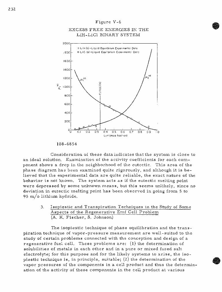
232
Figure V-6
EXCESS F R E E ENERGIES IN THE LiH-LiCl BINARY SYSTEM
2000
1800
1600
1400
1200
£ 1000
800
600
400
200
"0 0.1 02 03 04 05 06 0.7 08 09 10 LiH (mole fraction)
108-6854
Considerat ion of these data indicates that the system is close to an ideal solution. Examination of the activity coefficients for each component shows a drop in the neighborhood of the eutectic. This a rea of the phase d iagram has been examined quite r igorously, and although it is be lieved that the exper imental data a r e quite re l iable , the exact nature of the behavior is not known. The sys tem acts as if the eutectic melting point were depressed by some unknown means , but this seems unlikely, since no deviation in eutectic melt ing point has been observed in going from 5 to 95 m / o li thium hydride.
3. Isopiest ic and Transpi ra t ion Techniques in the Study of Some Aspects of the Regenerat ive Emf Cell P rob lem (A. K. F i s c h e r , S. Johnson)
The isopiest ic technique of phase equilibration and the t r a n s pi ra t ion technique of v a p o r - p r e s s u r e measuremen t a r e wel l-sui ted to the study of cer ta in p rob lems connected with the conception and design of a regenera t ive fuel cell. These problems a r e : (l) the determination of solubili t ies of meta ls in each other and in a pure or naixed fused salt e lectrolyte; for this purpose and for the likely sys tems to a r i s e , the i so pies t ic technique i s , in pr inciple , suitable; (2) the determinat ion of the vapor p r e s s u r e s of the coraponents in a cell product and thus the de termination of the activity of these components in the cell product at var ious

t e m p e r a t u r e s ; for this purpose , the t ransp i ra t ion technique is one of severa l which may be used, depending on the na ture of the sys tem of in te res t .
The f i rs t p roblem, the determinat ion of solubilit ies of meta l s in fused sa l ts and of meta l s in each other , is associa ted with the regenera t ive emf cell p rob lem in that the degree of solubility of the react ive e lectrode in the electrolyte p laces a l imit on the potential and output of the cell , and thus needs to be known. Development and evaluation of the isopiest ic technique for these solubility measure inen t s has been undertaken.
The isopies t ic technique is •well established for work with aqueous sys tems near room t e m p e r a t u r e , but l i t t le work has been repor ted in which the i sopies t ic technique has been applied at high t empe ra tu r e s . Non-application of the method in h igh - t empera tu re -work has apparently s temmed from the lack, until fair ly recent ly , of means to enclose samples in envelopes which a r e iner t and vacuum-t ight at high t empera tu re s . Provis ion of a uniforna h igh - t empera tu re field, though t roublesome, has not been impos sible. This accompl ishment has led to further study on our pa r t of the high-t e m p e r a t u r e isopies t ic method with the uncovering of other difficulties.
In p repa ra t ion for the application of the isopies t ic technique to p rob lems in the regenera t ive emf cell p rog ra m, the following Avork has been done: (l) a furnace tube and a sys tem of copper blocks which se rve as a h igh- t empera tu re the rmos ta t has been designed, and (2) a crucible and enclosing tube sys tem which can be sealed under vacuum and then placed in the h igh- t empera tu re the rmos ta t , has also been designed. The copper blocks, c ruc ib les , and enclosing tube a re placed in a furnace tube provided with an argon a tmosphere to p ro tec t the copper from oxidation. The Marsha l l furnace windings a r e control led in sections to provide a uniform t e m p e r a tu re zone.
As a p r e l i m i n a r y check on the isopiest ic technique, some solubility determinat ions on the l i th ium-l i th ium chloride sys tem have been undertaken. This sys tem is of i n t e r e s t in regenera t ive cells with a l i thium elect rode and with l i thium chloride as the electrolyte or as an electrolyte component. The smal l amount of data on the l i thiuna-li thium chloride s y s tem available in the l i t e r a tu r e can be compared with experimental values as a pa r t i a l check on the re l iabi l i ty of the technique. Three naeasurements of the solubility of l i thium in l i thium chloride have been completed to date. The re su l t s a r e : 1.3 a /o at 609 C, 3.1 a /o at 727 C, and 2.6 a /o at 770 C. At the opposite ends of the t ie l ines , the solubili t ies of l i thium chloride in l i thium were found to be 8.5 a /o at 609 C, 9.6 a /o at 727 C, and 8.8 a/o at 770 C. Additional experinaents a r e needed to appra i se the technique adequately and to cha rac t e r i ze the l i th ium-l i th ium chloride system. The only l i t e r a tu r e values for the solubility of l i thium in l i thium chloride a re 0.5 ± 0.2 a /o at 650 C and 2.0 ± 0.2 a /o at 1000 C.4
4 A . S. Dworkin, H. R. Bronste in , and M. A. Bredig , J. Phys . Chem. 66, 572 (1962).

B e c a u s e of the s c a r c i t y of da t a on the l i t h i u m - l i t h i u m c h l o r i d e s y s t e m , a m o r e t h o r o u g h l y r e p o r t e d s y s t e m ( such a s p o t a s s i u m - p o t a s s i u m c h l o r i d e ) m a y be s t u d i e d to p e r m i t m o r e a c c u r a t e t e s t i n g of the i s o p i e s t i c t e c h n i q u e . The p o t a s s i u m - p o t a s s i u m c h l o r i d e s y s t e m has no d i r e c t b e a r i n g on any of the r e g e n e r a t i v e c e l l s t h a t a r e now being s tud ied .
D u r i n g the p r e l i n a i n a r y t e s t i n g of the e q u i p m e n t , a n a l y s e s of the u p p e r and l o w e r r e g i o n s of the s a m p l e t u b e , and of the o u t s i d e s of the c r u c i b l e s , have shown tha t "wi ld" d i s t i l l a t i o n (d i s t i l l a t i on to s i t e s o t h e r t han in the e q u i l i b r a t i n g p h a s e s ) i s low and a p p a r e n t l y i s not a m a j o r s o u r c e of e r r o r as we conduc t the e x p e r i m e n t . At the p r e s e n t t i m e , i t i s b e l i e v e d tha t the da ta o b t a i n e d in the i s o p i e s t i c e x p e r i m e n t s a r e f a i r l y r e l i a b l e , but t h a t a n u m b e r of v a r i a b l e s , s u c h a s d u r a t i o n of e q u i l i b r a t i o n , quench ing r a t e , and s a m p l e s i z e r a t i o , need to be t e s t e d to ga in a s s u r a n c e of the va l i d i t y of r e s u l t s . If the i s o p i e s t i c p r o c e d u r e i s r e l i a b l e at high t e m p e r a t u r e s , a v e r s a t i l e tool wi l l be a v a i l a b l e for so lub i l i t y m e a s u r e m e n t s and, t h u s , for t r a c i n g the m i s c i b i l i t y gap in p h a s e d i a g r a m s of b i n a r y l iqu id s y s t e m s .
In c o n t r a s t wi th the i s o p i e s t i c t e c h n i q u e , wh ich is r e l a t i v e l y n e g l e c t e d , the t r a n s p i r a t i o n t e c h n i q u e i s w i d e l y app l i ed in h i g h - t e m p e r a t u r e c h e m i s t r y and i s u s e d to m e a s u r e v a p o r p r e s s u r e s . M a t e r i a l s hav ing v a p o r p r e s s u r e s t ha t a r e too high to be m e a s u r e d by t h e K n u d s e n m e t h o d m a y be s tud ied by the t r a n s p i r a t i o n m e t h o d . M a t e r i a l s having high v a p o r p r e s s u r e s a r e l i ke ly to be u s e d in t h e r m a l l y r e g e n e r a t i v e emf c e l l s in wh ich a ce l l p r o d u c t i s to be d e c o m p o s e d t h e r m a l l y . (Low v a p o r p r e s s u r e for c o m p o n e n t s would a r g u e a g a i n s t the f e a s i b i l i t y of the d e s i r e d r e g e n e r a t i o n . ) M e a s u r e m e n t of the v a p o r p r e s s u r e of, for e x a m p l e , l i t h i u m a n d / o r b i s m u t h o v e r Li3Bi and o v e r L i 3 B i - L i m i x t u r e s a t v a r i o u s t e m p e r a t u r e s wi l l p e r m i t c a l c u l a t i o n of the a c t i v i t i e s of both c o m p o n e n t s in t h e ce l l p r o d u c t a t the v a r i o u s t e m p e r a t u r e s . T h i s i n f o r m a t i o n , then , w o u l d be u s e d to d e t e r m i n e the f e a s i b i l i t y and the o p t i m u m cond i t ions for the r e g e n e r a t i o n .
A t r a n s p i r a t i o n a p p a r a t u s h a s been a s s e m b l e d and h a s b e e n t e s t e d for l e a k s . E s s e n t i a l l y , the t r a n s p i r a t i o n a p p a r a t u s i s of conven t iona l de s ign , be ing a v e r t i c a l - t u b e type wi th a f r i t t e d d i s c to s u p p o r t the s a m p l e and to p e r m i t a r g o n to p a s s t h r o u g h the s a m p l e .
B. T h e r m o e l e c t r i c i t y ^ R e s e a r c h (R. K. E d w a r d s and H. M. F e d e r )
S tud ie s in t h e r i n o e l e c t r i c i t y a r e u n d e r w a y to c o n t r i b u t e to the fu ture t e c h n o l o g i c a l d e v e l o p m e n t of d i r e c t c o n v e r s i o n of n u c l e a r r e a c t o r h e a t e n e r g y into e l e c t r i c a l p o w e r by m e a n s of the t h e r m o c o u p l e effect.
Two l i m i t e d m a t e r i a l s a r e a s have b e e n s e l e c t e d a s of s p e c i a l i n t e r es t . L i q u i d t h e r m o c o u p l e m a t e r i a l s a r e u n d e r i n v e s t i g a t i o n b e c a u s e of
23
f a v o r a b l e e x p e r i m e n t a l f a c t o r s . R e f r a c t o r y so l id t h e r m o c o u p l e s y s t e m s f o r m the o t h e r m a j o r a r e a , s i n c e t hey a r e c o n s i d e r e d to be of p a r t i c u l a r i n t e r e s t to r e a c t o r e n e r g y c o n v e r s i o n .
The p e r s o n n e l a s s o c i a t e d Avith t h e r m o e l e c t r i c i t y r e s e a r c h a r e u n d e r tak ing a d d i t i o n a l r e s e a r c h in the a r e a of h i g h - t e m p e r a t u r e m a t e r i a l s . A p r o g r a m of h i g h - t e m p e r a t u r e c h e m i s t r y h a s b e e n begun which i s c e n t e r e d about l i k e l y h i g h - p e r f o r m a n c e fuels in t h e i r o p e r a t i n g e n v i r o n m e n t s . C u r r e n t l y , e q u i p m e n t p l ann ing and a c q u i s i t i o n a r e in p r o g r e s s . The following s t u d i e s of r e f r a c t o r y m a t e r i a l s a r e p l a n n e d : (a) effusion and m a s s s p e c t r o m e t r i c s t u d i e s of the g a s e o u s d e c o m p o s i t i o n p r o d u c t s , (b) g a s e o u s t r a n s p i r a t i o n s t u d i e s , (c) p h a s e d i a g r a m and i n t e r d i f f u s i o n s t u d i e s .
1. L i q u i d S y s t e m s (R. K. E d w a r d s , P . D a n i e l s o n )
The s t u d i e s of S e e b e c k coe f f i c i en t s in l iqu id s y s t e m s -were d e f e r r e d d u r i n g th i s r e p o r t p e r i o d in f avo r of e q u i p m e n t p l ann ing , d e s i g n i n g , and a c q u i s i t i o n for p r o j e c t e d h i g h - t e m p e r a t u r e s t u d i e s .
F u t u r e p l a n s a r e to c a r r y out m e a s u r e m e n t s of S e e b e c k coeff i c i e n t v a l u e s in t h e l i qu id i n d i u m - b i s m u t h s y s t e m a t 750 C so tha t t h e r e s u l t s of the t h r e e r e l a t e d s y s t e m s : i n d i u m - b i s m u t h , i n d i u m - a n t i m o n y , and a n t i m o n y -b i s m u t h , m a y be c o m p a r e d for the s a m e t e m p e r a t u r e . P l a n s a r e a l s o u n d e r way for m e a s u r e m e n t of e l e c t r i c a l c o n d u c t i v i t i e s in t h e s e s y s t e m s , and e q u i p m e n t i s be ing m o d i f i e d for t h i s p u r p o s e .
2. R e f r a c t o r y Sol id T h e r m o c o u p l e S y s t e m s (M. T e t e n b a u m , F . M r a z e k )
F o r e n e r g y - c o n v e r s i o n d e v i c e s tha t a r e to be u s e d a t h igh t e m p e r a t u r e s , a s in c e r t a i n n u c l e a r r e a c t o r s y s t e m s , m a t e r i a l s p o s s e s s i n g high m e l t i n g p o i n t s and low v a p o r p r e s s u r e s a r e d e s i r a b l e . The l a n t h a n i d e and a c t i n i d e sul f ide s y s t e m s a r e h igh ly r e f r a c t o r y and have p h a s e s wi th c a r r i e r c o n c e n t r a t i o n s in the s e m i c o n d u c t i n g r a n g e . The u r a n i u m sulf ide and t h o r i u m sul f ide s y s t e m s and t h e i r so l id s o l u t i o n s h a v e b e e n s e l e c t e d for the in i t i a l s t u d i e s . In add i t i on , p r e l i m i n a r y s t u d i e s on u r a n i u m m o n o p h o s p h i d e have b e e n i n i t i a t e d d u r i n g the p a s t q u a r t e r .
P r e p a r a t i o n of U r a n i u m Monosu l f ide
A 100-g b a t c h of r e l a t i v e l y h i g h - p u r i t y u r a n i u m m o n o s u l f i d e w a s p r e p a r e d du r ing the p a s t q u a r t e r for m e a s u r e m e n t s of the h e a t of f o r m a t i o n of u r a n i u m m o n o s u l f i d e by the C a l o r i m e t r y Group and for t h e r m o e l e c t r i c p a r a m e t e r m e a s u r e m e n t s . T h e p e r t i n e n t s t e p s invo lved in the p r e p a r a t i o n a r e a s fo l lows : l) p r e p a r a t i o n of the h y d r i d e , 2) i t s t h e r m a l d e c o m p o s i t i o n to give f inely d iv ided m e t a l , 3) r e a c t i o n of the f ine ly d iv ided m e t a l wi th h y d r o g e n sul f ide to give a m i x t u r e of m e t a l and h i g h e r su l f i de s , and 4) h o m o g e n i z i n g by

236
h e a t i n g t h i s m i x t u r e in a t u n g s t e n c r u c i b l e to a p p r o x i m a t e l y 2000 C in v a c u u m (~10~ mm. Hg) to p r o d u c e s i n t e r e d c r y s t a l l i n e u r a n i u m m o n o s u l fide. C e r t a i n m o d i f i c a t i o n s in hand l ing t e c h n i q u e s w e r e i n c o r p o r a t e d in to the p r o c e d u r e in o r d e r to m i n i m i z e e x p o s u r e of the c r u d e sul f ide p r o d u c t to a i r when the c h a r g e i s t r a n s f e r r e d in to the NRC f u r n a c e . * T h i s v/as a c -c o i n p l i s h e d a s fo l l ows : Af te r the sulf iding s t ep and p r i o r to h o m o g e n i z a t i o n , the c r u d e sul f ide p r o d u c t w a s l o a d e d in to t u n g s t e n c r u c i b l e s in a d r y box, and the c r u c i b l e s w e r e s e a l e d in p l a s t i c b a g s . The c r u c i b l e s in t h e i r p l a s t i c b a g s w e r e r e m o v e d f r o m the d r y box, i n s e r t e d in to the NRC f u r n a c e , and the p a c k a g e f i r e d by s lowly hea t i ng to ~2000 C. The p l a s t i c v o l a t i l i z e d at a p p r o x i m a t e l y 500 C. A l iqu id n i t r o g e n t r a p w a s i n c o r p o r a t e d in to the NRC f u r n a c e un i t to m i n i m i z e b a c k diffusion of oi l v a p o r f r o m the diffusion p u m p .
B e c a u s e of the l i m i t a t i o n of c r u c i b l e s i z e , the 100-g b a t c h of c r u d e sul f ide p r o d u c t w a s d iv ided in to five equa l b a t c h e s wh ich w e r e f i red i nd iv idua l ly in o r d e r to h o m o g e n i z e the m a t e r i a l . The m a x i m u m h o m o g e n i za t ion t e n a p e r a t u r e w a s a p p r o x i m a t e l y 1900-1950 C. Af t e r h o m o g e n i z a t i o n , the i ngo t s w e r e a l l b r i g h t and shiny. A n a l y t i c a l r e s u l t s o b t a i n e d thus far a r e sho"wn be low.
B a t c h I n s o l u b l e s (%) S (%) A t o m R a t i o , S / u
1.05 1.02 1.04 1.08 1.07
X - r a y a n a l y s i s of Ba t ch 2 gave a l a t t i c e p a r a m e t e r of ao = 5.488 ± 0.005 A,
The u r a n i u m m o n o s u l f i d e p r o d u c t r e p r e s e n t e d by B a t c h 2 w a s u l t i m a t e l y u s e d to p r e p a r e s o m e of the s p e c i m e n s for the t h e r m o e l e c t r i c p a r a m e t e r s t u d i e s d e s c r i b e d below. The r e m a i n d e r of the b a t c h wi l l be u s e d by the C a l o r i m e t r y G r o u p for m e a s u r i n g the h e a t of f o r m a t i o n of u r a n i u m m o n o s u l f i d e .
D e t e r m i n a t i o n of S e e b e c k Coef f i c i en t s
The e s s e n t i a l f e a t u r e s of t h e a p p a r a t u s u s e d for S e e b e c k m e a s u r e m e n t s a r e shown s c h e m a t i c a l l y in F i g u r e V-7 . The s p e c i m e n s w e r e p r e s s e d b e t w e e n two tan ta luna p l a t e s by m e a n s of a s p r i n g - o p e r a t e d t h r u s t rod i m p i n g i n g on the s u r f a c e of the u p p e r t a n t a l u m p l a t e . P l a t inuna -p la t inuna , 10 p e r c e n t r h o d i u m t h e r m o c o u p l e s , s p o t - w e l d e d on t h e t a n t a l u m p l a t e s , w e r e u s e d to m e a s u r e both the t e i a i p e r a t u r e g r a d i e n t and the S e e b e c k v o l t a g e ( r e l a t i ve to p l a t i n u m ) a c r o s s the s a m p l e s . The emf' s d e v e l o p e d \ v e r e n a e a s u r e d by m e a n s of a L e e d s and N o r t h r u p K 3 p o t e n t i o m e t e r . The t e n a p e r a t u r e
* M a n u f a c t u r e d by NRC E q u i p m e n t C o r p o r a t i o n , Newton , M a s s a c h u s e t t s .
1 7 Li
3 4 5
0.00 0.00 0 .14 0.56 0.00
12.39 12.10 12.30 12.70 12.55

237
Figure V-7
SCHEMATIC DIAGRAM OF APPARATUS USED FOR MEASUREMENTS OF SEEBECK COEFFICIENT AND RESISTIVITY AS A FUNCTION OF TEMPERATURE
SPRING LOADED • 'AN-ALJM PcUNGER-
^
'ANTA.UW PLATE
Pt Pt ( 0 % Pn THERMOCOLPLES
\
. - - X / X - -PLATINU-ll POTENTIAL PROBES rOR RESISTIVITY MEASUREMENTS
g r a d i e n t ex i s t ing in the f u r n a c e * w a s u s e d to g e n e r a t e the S e e b e c k po t en t i a l . The t e m p e r a t u r e g r a d i e n t a c r o s s the s p e c i m e n g e n e r a l l y w a s 10 to 15 C. The s p e c i m e n and a s s e m b l y shown in F i g u r e V - 7 w e r e hoxised in an Incone l t u b e , and a l l m e a s u r e m e n t s w e r e m a d e in v a c u u m (lO~^ to 10"^ m m Hg), The d i f f e ren t i a l S e e b e c k coeff ic ient cig_p^ of the s p e c i m e n S r e l a t i v e to p l a t i n u m i s defined by
„ l i m AV_ °^S-Pt AT-*0 AT '
-TANTALUM PLATE a n d i s t a k e n to b e e f f e c t i v e l y AV/A T f o r t h e s m a l l A T v a l u e s u s e d , w h e r e
108-6861 A V i s t h e S e e b e c k v o l t a g e d e v e l o p e d
a s a r e s u l t of t h e t e m p e r a t u r e diff e r e n c e AT . T h e a b s o l u t e S e e b e c k c o e f f i c i e n t of t h e s p e c i m e n c a n b e o b t a i n e d b y a l g e b r a i c a l l y s u b t r a c t i n g t h e S e e b e c k c o e f f i c i e n t v a l u e of p l a t i n u m f r o m t h e d i f f e r e n t i a l S e e b e c k c o e f f i c i e n t .
R e s i s t i v i t y M e a s u r e m e n t s
T h e r e s i s t i v i t y w a s m e a s u r e d b y p a s s i n g a d i r e c t c u r r e n t ( g e n e r a l l y 5 0 - 1 0 0 m A ) t h r o u g h t h e s p e c i m e n a n d m e a s u r i n g t h e v o l t a g e p r o d u c e d b e t w e e n t h e t w o p l a t i n u m p r o b e s w r a p p e d a r o u n d t h e s p e c i m e n ( F i g u r e V - 7 ) , (A l e g f r o m e a c h t h e r m o c o u p l e a t t h e e n d s of t h e s p e c i m e n s e r v e d a s c u r r e n t l e a d s . ) T h e c u r r e n t w a s r e v e r s e d , a n d a s e c o n d v o l t a g e r e a d i n g w a s t a k e n i m m e d i a t e l y ; t h e m e a n v o l t a g e w a s u s e d t o c a l c u l a t e t h e r e s i s t i v i t y p b y m e a n s of t h e f o l l o w i n g f o r m u l a :
w h e r e
p = V A / I d ,
V = n a e a n v o l t a g e n a e a s u r e d b e t w e e n p r o b e s I = c u r r e n t
A - c r o s s - s e c t i o n a l a r e a of t h e s p e c i m e n d = d i s t a n c e b e t w e e n p r o b e s
T h e v o l t a g e d r o p a c r o s s t h e p r o b e s w a s m e a s u r e d w i t h e i t h e r a n L & N K 3 p o t e n t i o m . e t e r o r a n L & N D C M i c r o v o l t I n d i c a t i n g A i n p l i f i e r ( M o d e l 9 8 3 5 B ) . T h e c u r r e n t t h r o u g h t h e s p e c i m e n w a s d e t e r m i n e d b y m e a s u r i n g t h e v o l t a g e d r o p a c r o s s a s t a n d a r d r e s i s t a n c e i n s e r i e s w i t h t h e s p e c i m e n , w i t h a c o n v e n t i o n a l p o t e n t i o m e t e r .
• M a n u f a c t u r e d by t h e M a r s h a l l F u r n a c e C o m p a n y , C o l u m b u s , O h i o .

Thermoelec t r i c Power Measurements on Uranium Monosulfide
Measurements of the Seebeck coefficient as a function of t empera tu re have been made for a s in tered pellet of re la t ively high-puri ty (see section. P repa ra t ion of Uranium Monosulfide) monosulfide (negligible insolubles content; S/U, ~1.02) and for a slab of uran ium monosulfide (7,8-mm length and 2,6-mna width) which was fabricated from a melted ingot* ( l , l p e r cent insolubles; S/U. ^0 ,97) . The resu l t s a re shown in F igure V-8, It is apparent from Figure V-8 that the t rend and magnitude of the Seebeck coefficient values -with t empera tu re a r e approximately the same for the s intered specimen as for the melted specimen.
F igure V-8
COMPARISON OF ABSOLUTE SEEBECK COEFFICIENT AS A FUNCTION OF TEMPERATURE FOR URANIUM
MONOSULFIDE SPECIMENS
70
o 60 —
50
g 40
o S 30 UJ UJ
20
10
• ^ . ^ ^
O SINTERED US ( 0 % msolublts, S/U ~ i . 02 )
MELTED US ( 1 % insolubles. S/U ~0.97)
• MEASURED OVER LENGTH (7.8 mm) OF SPECIMEN
X MEASURED OVER WIDTH (2 6mm) OF SPECIMEN
L L L 100 200 300 400 500 600 700
TEMPERATURE,C
800 9 0 0 1000 1100
108-6844
It should be noted that the Seebeck data shown for the uranium monosulfide slab were obtained by two independent sets of measuremen t s . In one set, the specimen was sandwiched lengthwise between the tantalum pla tes ; in the second set of m e a s u r e m e n t s , the specimen was sandwiched widthwise. Table V-4 allows a compar ison of the differential Seebeck coefficient values obtained when measur ing over the length or the width of the specimen at roughly corresponding t empera tu res but with different t emper a ture gradients ac ros s the specimen. It is apparent that agreement for the two sets of measurenaents is good, and that the Seebeck apparatus (Figure V-7) is capable of yielding reproducible data.
*We a re indebted to R. Noland of the Metallurgy Division for supplying the ingot.

2 39
T a b l e V - 4
COMPARISON OF S E E B E C K C O E F F I C I E N T S F O R M E L T E D URANIUM MONOSULFIDE S P E C I M E N
L e n g t h of S p e c i m e n : 7.8 m m Width of S p e c i m e n : 2.6 m m
L e n g t h Width
L e n g t h Width
L e n g t h Width
L e n g t h Width
A v e r a g e T e m p e r a t u r e
172.1 179.7
282.8 295 .1
387.0 386.6
1086.2 1080.7
(c)
Effect of H i g h e r Coef f ic ien t Valu
T e m p e r a c r o s s
Sul f ides e s
a t u r e G r a S p e c i m e n
22.0 5.7
12.8 10.1
12.3 9.0
9.5 7.1
d ient (C)
Differe Coeffi
n t ia l S e e b e c k c ien t ildV/c)
62.8 61,6
65,6 66,2
67.2 67.2
63 .3 61.6
in U r a n i u m Monosu l f ide on S e e b e c k
A c u r s o r y e x a m i n a t i o n of t h e effect of h i g h e r su l f ides on the t h e r m o e l e c t r i c p o w e r of u r a n i u m m o n o s u l f i d e w a s naade dur ing th i s q u a r t e r . X - r a y a n a l y s i s of the u r a n i u m m o n o s u l f i d e p o w d e r (S/U = 1.3) con ta in ing h i g h e r su l f ides r e v e a l e d the p r e s e n c e of the fol lowing p h a s e s : US, U2S3, and U3S5. T h e po-wder w a s cold p r e s s e d in to a p e l l e t and w a s s i n t e r e d for a p p r o x i m a t e l y one h o u r at 1200 C in vacuum.. S e e b e c k coeff ic ient v a l u e s a s a funct ion of t e m p e r a t u r e for the s i n t e r e d p e l l e t and for p u r e u r a n i u m m o n o sulf ide v / e r e d e t e r m i n e d and a r e shown in F i g u r e V - 9 . The p r e s e n c e of h i g h e r su l f ides in u r a n i u m m o n o s u l f i d e a p p a r e n t l y r e s u l t s in a c o n s i d e r a b l e d e c r e a s e in the v a l u e of the S e e b e c k coef f ic ien t as the t e m p e r a t u r e i s i n c r e a s e d . U l t i m a t e l y , in the v i c i n i t y of 600 C, the s ign of the S e e b e c k coeff ic ien t c h a n g e s . S l igh t ly h i g h e r v a l u e s w e r e ob t a ined du r ing the cool ing c y c l e , a p p a r e n t l y b e c a u s e of c o m p o s i t i o n c h a n g e s o c c u r r i n g du r ing the n a e a s u r e m e n t s .
R e s i s t i v i t y of T h o r i u m Monosu l f ide and 50-50 US-ThS Solid So lu t ion
R e s i s t i v i t y h a s b e e n m e a s u r e d a s a funct ion of t e m p e r a t u r e for s i n t e r e d s p e c i m e n s of t h o r i u m m o n o s u l f i d e and a 50-50 m / o so l id so lu t ion of u r a n i u m m o n o s u l f i d e and t h o r i u m m o n o s u l f i d e . The r e s u l t s a r e shewn on F i g u r e V - 1 0 . The tho r iuna m o n o s u l f i d e s p e c i m e n showed a l i n e a r i n c r e a s e of r e s i s t i v i t y wi th i n c r e a s i n g t e m p e r a t u r e , wh ich i s c h a r a c t e r i s t i c of m e t a l l i c b e h a v i o r , and i s a l s o c o n s i s t e n t wi th the t r e n d in S e e b e c k v a l u e s o b t a i n e d

240
Figure V-9
EFFECT OF HIGHER SULFIDES ON THE THERMOELECTRIC POWER OF URANIUM MONOSULFIDE
70
60 -
iJ 50 > a, I-" z 40
20
10
< 0
- 2 0
O HEATING CYCLE
• COOLING CYCLE
O • US + UsSs+UsSg
I i L J L 0 too 200 300 400 500 600 700 800 900 1000 1100
TEMPERATURE, C
108-6857
Figure V-10
RESISTIVITY AS A FUNCTION OF TEMPERATURE FOR SINTERED SPECIMENS OF THORIUM MONOSULFIDE AND 50-50 m/o US-ThS SOLID SOLUTION
320
100 200 300 400 500 600 700 800 900 1000 1100 TEMPERATURE, C
108-6847

2 4 1
with th i s m a t e r i a l , n a m e l y , an i n c r e a s e in Seebeck coeff ic ient wi th t e m p e r a t u r e (at 25 C , a S - 5 / iV/deg ; at 1000 C, a S= -12 jUV/deg). F o r the 50-50 so l id so lu t ion , the r e s i s t i v i t y i s n e a r l y c o n s t a n t wi th t e m p e r a t u r e . S i m i l a r b e h a v i o r v/as p r e v i o u s l y r e p o r t e d for a s i n t e r e d s p e c i m e n of u r a n i u m naono-sulf ide con ta in ing a p p r o x i m a t e l y 5 w / o i n s o l u b l e s ( see A N L - 6 6 4 8 , p, 230),
The t e m p e r a t u r e d e p e n d e n c e of r e s i s t i v i t y for spec inaens of c o m p o s i t i o n s (mole p e r c e n t ) 25 US-75 ThS and 75 US-25 ThS i s to be m e a s u r e d .
T h e r m o e l e c t r i c P a r a m e t e r M e a s u r e m e n t s on U r a n i u m Monophosph ide
D e t e r m i n a t i o n s of the S e e b e c k coeff ic ient a s a function of t e m p e r a t u r e and m e a s u r e m e n t s of the r o o m t e m p e r a t u r e r e s i s t i v i t y of a s i n t e r e d p e l l e t of u ran iuna m o n o p h o s p h i d e * have been m a d e . The naagnitude and t r e n d in Seebeck coeff ic ient v a l u e s for u r a n i u m monophosph ide (see F i g u r e V - l l ) a r e a l m o s t i d e n t i c a l wi th the v a l u e s ob t a ined with uraniuna m o n o sul f ide . The r o o m - t e m p e r a t u r e r e s i s t i v i t y of u r a n i u m m onophos ph i de w a s found to be a p p r o x i m a t e l y 250 x 10" ohna-cna, which i s a l so conaparab le wi th the r o o m - t e i a i p e r a t u r e r e s i s t i v i t y of u r a n i u m monosu l f ide .
F i g u r e V - 11
A B S O L U T E S E E B E C K C O E F F I C I E N T VS. T E M P E R A T U R E FOR URANIUM
MONOPHOSPHIDE
100 200 300 400 500 600 700 TEMPERATURE, C
800 900 1000 1100
108-6860
*We a r e indeb ted to Yehuda B a s k i n of the M e t a l l u r g y Div is ion for p r e p a r i n g the specinaen.

The r o o m - t e m p e r a t u r e Seebeck coefficient and res i s t iv i ty val ues m e a s u r e d by other inves t iga tors^ a r e shown below to allow compar ison with ANL values.
Seebeck Experinaent Coefficient Resis t iv i ty
No, Mater ia l a- (jdV/C) (ohm-cm x 10^)
114 UP +52.6 1460 115 UP +50.0 1180
a-The composit ion of the u ran ium phosphide compacts is unknown.
The room- tenapera tu re Seebeck values shown in the table a r e in good agreement with our m e a s u r e m e n t s ; however, the res i s t iv i ty value m e a s ured by us is lower by a factor of approximately five. The Seebeck coefficients de te rmined at ANL with var ious specimens of u ran ium monosulfide were also found to be re la t ively insensi t ive to the res i s t iv i ty of the specimens investigated.
The Canadian Report^ gives a value of approximately 0.0571 W/ cm-deg for the r o o m - t e m p e r a t u r e t he rma l conductivity of uran ium monophosphide. With the use of this value and the values of the average Seebeck coefficient and res i s t iv i ty obtained from the above table, the value for the figure of m e r i t Z of u ran ium monophosphide at roona t empera tu re was cal culated to be approximate ly 3.5 x 10"^. This figure of m e r i t value is about th ree tinaes lower than the r o o m - t e m p e r a t u r e Z value obtained with u r an i um monosulfide from ANL m e a s u r e m e n t s of t he rmoe lec t r i c p a r a m e t e r s . In addition, with the use of the Canadian data, a Wiedeinann-Franz rat io of approximately 25.2 x 10" (V/deg)^ -was calculated for u ran ium monosulfide. With our res i s t iv i ty value, the ratio was found to be about 4.8 x 10" (V/deg)^. Fo r a degenerate ( c a r r i e r density ^ lO^y cc) m a t e r i a l , the theore t ica l value is 2.45 X 10" (V/deg)^. It appea r s , there fore , that the lower res i s t iv i ty val ue is m o r e near ly the c o r r e c t one. Using the ANL res i s t iv i ty value to es t i mate the r o o m - t e m p e r a t u r e figure of 3aierit for u ran ium monophosphide, we find Z S 1,2 X 10" , which is comparable with the Z value obtained with u r a nium monosulfide, Ho^vever, these r o o m - t e m p e r a t u r e values for the figure of m e r i t a r e too low for useful power generat ion by a factor of approximately ten.
P r o g r e s s Repor t No. 3, Depar tment of Metal lurgy, Univers i ty of Br i t i sh Columbia, September 1961.

VI. DETERMINATION_OF NUCLEAR CONSTANTS* (C. E. Crouthamel)
The fast r eac to r p rogram continues to require fast neutron c ross section data as new elements begin to receive consideration for use in reac tor construct ion. Total neutron c ross sections are being measured for neutron energies between about 10 keV and 2 MeV, and capture c ro s s sections as a function of neutron energy between 0.2 MeV and 2 MeV.
Recent work with rhenium has yielded capture c ross sections for neutron energies between 150 keV and 2 MeV; total neutron c ross - sec t ion naeasurements for this e lement a re in p r o g r e s s . Results a re also given for the total neutron c ro s s sections of gadolinium and the neutron capture c ros s sections of e rb ium-170.
F a s t Neutron Cross Sections (C. E. Crouthanaelj D. C. Stupegia, A. A. Madson, and M. Jones)
Rheniuna: This dense metal has recently received attention for possible use as a reac to r naaterial because of its favorable high-t empera tu re p roper t i e s . It is being considered for use in an alloy with tungsten as a fuel e lement mat r ix ma te r i a l . A study of its fast neutron c ross sections has therefore been undertaken, and pre l iminary neutron capture c r o s s section values have been determined.
Rhenium consis ts isotopically of 37.07 percent rhenium-185 and 62.93 percent rhenium-187. Neutron i r radia t ion of rhenium produces the following three capture reac t ions :
Re 187
188m
20 min
R e 188 17 hr |3,7
Os 188
Re 185 n, 7 -Re 186 90 hr
/3,7 Os 186
By suitable choice of length of i r rad ia t ion and gamma analyses following i r radia t ion, the c ro s s sections for all three p rocesses can be measured .
In this work the monoenergetic neutron source was the reaction Li'^ (p,n) Be'^ produced when protons from the Van de Graaff accelera tor bombard a lithium target . The neutron flux was measured with a fission chamber which counted fissions in a sample of uraniuna. After i r radia t ion.
*A summary of this section is given on page 30.

244
the ta rge t was analyzed for the ganama-ray spec t rum of i ts activation products by naeans of a Nal c rys ta l and multichannel analyzer . The absolute dis integrat ion ra te corresponding to the gamnaa spec t rum of the i r radiated ta rge t was determined by comparing this spec t rum with that of a known activity of the same species counted in the same geometry, the activity of the la t te r having been deternained by absolute beta counting.
I r radia t ions of severa l hours were ca r r i ed out, following which gamma analyses were done on the t a rge t s . These i r rad ia t ions yielded the data necessa ry for the deternaination of the c r o s s section of rhenium-185 and of the c r o s s section for the production of both states of rheniuiai-187. I r radia t ions of 20-min duration were ca r r i ed out and the ta rge ts were analyzed for the gamma ray of 20-min rhenium-188m. Thus when the c ro s s sections for the production of the 20-min state and of the sum of both rhenium-188 s ta tes a re known, the c ros s section for each state alone can be calculated.
Prel inainary data for the capture c ros s section of rhenium-187 are given in Figure VI-1 . The c ross sections given r ep re sen t the sum for the production of both s ta tes of rhenium-188. The absolute cal ibrat ion of the rhenium-187 c ro s s section has not yet been completed, but the values given in the figure have been es t imated to be accurate to ±50%. The values of the points relat ive to each other are believed to be c o r r e c t to ±7%. The data have not yet been analyzed to the point where the c r o s s sections for the production of the two s ta tes of rhenium-188 can be given separate ly , nor has the c ros s section of rheniuna-185 been calculated. These analyses are in p r o g r e s s .
Figure VI-1
NEUTRON CAPTURE CROSS SECTIONS OF RHENIUM-187
2 0 0 4 0 0 700 1000 NEUTRON ENERGY, Kev
2 0 0 0 3 0 0 0
108-6832
Total neutron c ro s s sections of rhenium, as a function of neutron energy are also being determined in this p rogram. The resu l t s of this work will be repor ted when more data are available.

Cross Sections of Rare E a r t h Elements
Some of the r a r e ea r th s , such as Gd, Sm, Eu, and Dy, have been considered as possible r eac to r control ma te r i a l s and as constituents of ce ramic control elements (see Summary Report ANL-6379, p. 226). In the p resen t repor t , total neutron c r o s s sections of gadolinium and neutron capture c r o s s sections of erbiuna are given.
Gadolinium: The total neutron c ro s s section of gadolinium has been deternained as a function of neutron energy between 9 keV and 1880 keV. The resu l t s are shown in Figure VI-2. The standard deviations of the c ro s s section values a re about ±2%, and the neutron-energy spreads at each point a re general ly such that they just overlap between successive points. This work was done with use of the Van de Graaff acce le ra tor of the Physics Division.
F igure VI-2
NEUTRON TOTAL CROSS SECTION OF GADOLINIUM
e i I I I I I 11 \ I I I I I I I I ' I I I I I I I I i I 9 II 15 20 30 40 50 70 100 150 200 300 500 700 1000 1500 2000
NEUTRON ENERGY, kev
108-6845
Erb ium- 170: The neutron capture c ross section of erbiuna-170 has been determined for neutron energies between 0.34 and 1.9 MeV. The r e sults a r e given in Figure VI-3. The neut ron-energy spreads at each point a r e about ±25 keV. Standard deviations of the c ross sections a re about ±8%. The exper imenta l p rocedures were basically the same as those descr ibed above for rhenium.

246
Figure VI-3
NEUTRON CAPTURE CROSS SECTION OF ERBIUM-170
0 5 0 6 0 8 i 0 NEUTRON ENERGY. Mev
I 5 2 0
108-6834