and GENERAL INFORMATION - Motooff.ru
389
and GENERAL INFORMATION MC_Inboard_0804 1 1
-
Upload
khangminh22 -
Category
Documents
-
view
0 -
download
0
Transcript of and GENERAL INFORMATION - Motooff.ru

andGENERAL INFORMATION
MC_Inboard_0804
1
1

Table of Contents
Required 496 MAG / 496 MAG HO / 8.1S / 8.1S HO Push RodReplacement
Lack of Serpentine Belt Adjustment
Serpentine Belt Shredding on Inboard Models
GM EFI Black Scorpion
2
Warranty Information Service Information Bulletin No. 2001-06Parts Information OEM No. 2001-6
Circulate to: Sales Manager Accounting Service Manager Technician Parts Manager
THE INFORMATION IN THIS DOCUMENT IS CONFIDENTIAL AND PROTECTED BY COPYRIGHT AND IS THE PROPERTY OF MERCURY MARINE.
This document is provided for the sole and exclusive use of the original recipient as prescribed by Mercury Marine and may not be distributed or copied, digitally orotherwise, without the prior written consent of Mercury Marine.
2001-06R1 AUGUST 2003 © 2003, Mercury Marine Page 1 / 5
▲= Revised August 2003. This bulletin supersedes the previous bulletin 2001-6 April 2001
▲Required 496 MAG / 496 MAG HO / 8.1S / 8.1S HO Push RodReplacementModelsMCM 496 MAG Sterndrive Engines
S/N’s 0M061079, 0M061080, 0M061118, 0M061225, 0M061274, 0M061317, 0M061319,0M061325, 0M061531, 0M061588, 0M061600, 0M061602, 0M061603, 0M061627,0M061664, 0M061676, 0M061845, 0M061866, 0M061883, 0M061912
MCM 496 MAG HO Sterndrive EnginesS/N 0M025976 – 0M025985 & S/N 0M061091 – 0M061773
MIE 8.1 S Inboard EnginesS/N’s 0M026649, 0M026650, 0M026654, 0M026666, 0M026676, 0M026677, 0M026715,0M026717, 0M026718, 0M026719, 0M026723, 0M026754, 0M026755, 0M026765,0M026766, 0M026769, 0M026772, 0M026773, 0M026778, 0M026782, 0M026787,0M026804, 0M026843, 0M026869, 0M026870, 0M026888, 0M026908, 0M026909,0M026917, 0M026932, 0M026937, 0M026940, 0M026941, 0M026943, 0M027025,0M027040, 0M027053, 0M027054, 0M027055, 0M027058, 0M027061, 0M027067,0M027072, 0M027075, 0M027118, 0M027119, 0M027121, 0M027122, 0M027124,0M027125, 0M027135, 0M027137, 0M0271138, 0M027142, 0M027160, 0M027180,0M027183, 0M027184
MIE 8.1S HO Inboard EnginesS/N 0M026663 – 0M027049
SituationA machining operation was omitted on the intake and exhaust valve push rods used in theabove listed engines. This situation can cause the push rods to fail due to interferencewith the rocker arm.
Correction / InspectionAll straight intake and exhaust valve push rods must be replaced with new push rods thathave a machined taper on each end.
3

▲REQUIRED 496 MAG / 496 MAG HO / 8.1S / 8.1S HO PUSH ROD REPLACEMENT
THE INFORMATION IN THIS DOCUMENT IS CONFIDENTIAL AND PROTECTED BY COPYRIGHT AND IS THE PROPERTY OF MERCURY MARINE.
This document is provided for the sole and exclusive use of the original recipient as prescribed by Mercury Marine and may not be distributed or copied, digitally orotherwise, without the prior written consent of Mercury Marine.
Page 2 / 5 © 2003, Mercury Marine AUGUST 2003 2001-06R1
If a white mark is visible on the brass fitting on the top port side of the heat exchangerthat connects the hose from the heat exchanger to the overflow bottle, the engine hasbeen previously repaired at the factory. If a mark is not visible on this fitting, verify viaMercNET.
Removal
IMPORTANT: Place rocker arm assemblies in a rack for reassembly in their originallocations.
1. Remove rocker arm covers.2. Examine pushrods.
• Tapered Design - If tapered reinstall the rocker cover (see installation step 4)
mc79670 • Straight Design - If straight, replace all pushrods
mc79669
4
▲REQUIRED 496 MAG / 496 MAG HO / 8.1S / 8.1S HO PUSH ROD REPLACEMENT
THE INFORMATION IN THIS DOCUMENT IS CONFIDENTIAL AND PROTECTED BY COPYRIGHT AND IS THE PROPERTY OF MERCURY MARINE.
This document is provided for the sole and exclusive use of the original recipient as prescribed by Mercury Marine and may not be distributed or copied, digitally orotherwise, without the prior written consent of Mercury Marine.
2001-06R1 AUGUST 2003 © 2003, Mercury Marine Page 3 / 5
IMPORTANT: The rocker arm cover gaskets may be reused if not removed from therocker arm covers.
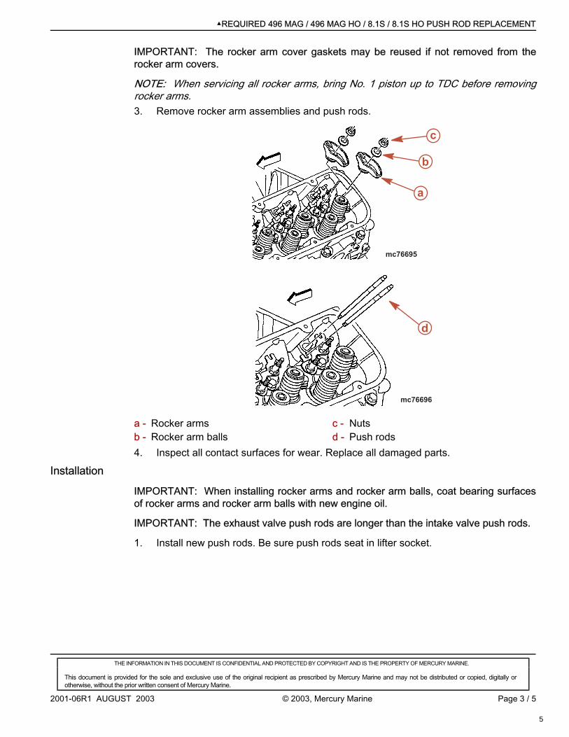
NOTE: When servicing all rocker arms, bring No. 1 piston up to TDC before removingrocker arms.3. Remove rocker arm assemblies and push rods.
a
b
c
mc76695
d
mc76696
a - Rocker armsb - Rocker arm balls
c - Nutsd - Push rods
4. Inspect all contact surfaces for wear. Replace all damaged parts.
Installation
IMPORTANT: When installing rocker arms and rocker arm balls, coat bearing surfacesof rocker arms and rocker arm balls with new engine oil.
IMPORTANT: The exhaust valve push rods are longer than the intake valve push rods.
1. Install new push rods. Be sure push rods seat in lifter socket.
5

▲REQUIRED 496 MAG / 496 MAG HO / 8.1S / 8.1S HO PUSH ROD REPLACEMENT
THE INFORMATION IN THIS DOCUMENT IS CONFIDENTIAL AND PROTECTED BY COPYRIGHT AND IS THE PROPERTY OF MERCURY MARINE.
This document is provided for the sole and exclusive use of the original recipient as prescribed by Mercury Marine and may not be distributed or copied, digitally orotherwise, without the prior written consent of Mercury Marine.
Page 4 / 5 © 2003, Mercury Marine AUGUST 2003 2001-06R1
2. Install rocker arm assemblies in their original locations.
d
mc76696
a
b
c
mc76695
a - Rocker armsb - Rocker arm balls
c - Nutsd - Push rods
3. Torque rocker arm nuts slowly to 25 Nm (19 lb-ft).
NOTE: Valve lash is automatically set when rocker arm nuts are torqued to 25 Nm (19lb-ft).4. Install rocker arm cover. Torque bolts to 12 Nm (106 lb-in).
Part RequiredP/N 881682A1 (Qty. 1) Intake valve push rod setP/N 881683A1 (Qty. 1) Exhaust valve push rod setP/N 27-46820 (Qty. 2) Exhaust manifold to cylinder head gasketIf parts are damaged or worn:P/N 27-881622 Rocker arm cover gasketP/N 881687 Rocker arm
WarrantyMercury Marine will credit the dealer for the cost of labor through August 31, 2006.Submit warranty claim through your normal warranty-processing channel, listing:• Mercruiser serial number.
6

▲REQUIRED 496 MAG / 496 MAG HO / 8.1S / 8.1S HO PUSH ROD REPLACEMENT
THE INFORMATION IN THIS DOCUMENT IS CONFIDENTIAL AND PROTECTED BY COPYRIGHT AND IS THE PROPERTY OF MERCURY MARINE.
This document is provided for the sole and exclusive use of the original recipient as prescribed by Mercury Marine and may not be distributed or copied, digitally orotherwise, without the prior written consent of Mercury Marine.
2001-06R1 AUGUST 2003 © 2003, Mercury Marine Page 5 / 5
Inspection Only• Flat Rate Codes and Labor - MX16 1.5 For Each Manifold and EXCP 1.0• Part Code - 423• Fail Code - 40Push Rod Replacement• Flat Rate Codes and Labor - MX16 1.5 For Each Manifold and MM 72 2.0• Part Code - 423• Failure Code - 40Old Part or Parts:• USA and Canada: Return with warranty claim• International: Follow instructions issued by your Marine Power International office or by
your distributor.
7

2002-09 JUNE 2002 Printed in U.S.A. - 2002, Mercury Marine Page 1 of 2
�� ����� ����� �� ��� ���� ��� �� ������������ ��� ��������� �� ������� ��� �� �� �������� �� ������ ������
This document is provided for the sole and exclusive use of the original recipient as prescribed by Mercury Marine and may not be distributed orcopied, digitally or otherwise, without the prior written consent of Mercury Marine.
Bulletin No. 2002-09WARRANTY INFORMATION SERVICE INFORMATIONPARTS INFORMATION
Sales ManagerCirculate to: Accounting Service Manager Technician Parts Manager
OEM No. 2002-04
Lack of Serpentine Belt Adjustment
Models AffectedMCM V6 4.3L/V8 5.0L, 5.7L, 6.2L Sterndrive engines: S/N 0M320025-0M343008.
MIE 5.7L Carb Tow Sports engines: S/N 0L678785-0L679322.
MIE 350 MPI Tow Sports engines: S/N 0M310022-0M312139.
MIE Black Scorpion-5.7L Tow Sports engines: S/N 0L678037-0L679433.
MIE Black Scorpion-6.2L Tow Sports engines: S/N 0L679131-0L679177.
MIE 5.7L Carb Inboard engines: S/N 0L677227-0L679322.
MIE 350 MPI Inboard engines: S/N 0L678399-0M312139.
MIE 6.2L Inboard engines: S/N 0M310100-0M312049.
NOTE: MCM models with Compact Hydraulic Steering or the second engine in dual engineboats were the Power Steering Pump has been removed will not experience this condition.
SituationThe serpentine belt adjustment pinion may be at or near the end of its travel. If that is thecase, the belt may not be capable of being properly adjusted.
The engines listed in the serial number ranges above were produced with a 76 mm (3 in.)diameter pulley.
The use of a 108 mm (4-1/4 in.) diameter pulley (outlined below) will give a better range forbelt adjustment.
NOTE: Production started to install the 108 mm (4-1/4 in.) diameter pulley on engines start-ing at the last S/N listed for each model.
8

Page 2 of 2 JUNE 2002 2002-09
�� ����� ����� �� ��� ���� ��� �� ������������ ��� ��������� �� ������� ��� �� �� �������� �� ������ ������
This document is provided for the sole and exclusive use of the original recipient as prescribed by Mercury Marine and may not be distributed orcopied, digitally or otherwise, without the prior written consent of Mercury Marine.
CorrectionIf you have this condition, order a new 108 mm (4-1/4 in.) diameter pulley and install it atthe location outlined for the type of engine being worked on.
NOTE: The pulley to be changed is used for different functions between MCM and MIEengines. Refer to type A or B for the engine being worked on to determine which pulley tochange.
A. MCM Sterndrive engines: Change the serpentine belt adjustment pinion pulley. It islocated on the upper, right side when looking at the belt from in front of the engine.
B. MIE Tow Sports and Inboard engines: Change the serpentine belt idler pulley. It islocated on the upper, right side when looking at the belt from in front of the engine.Do not change the belt adjustment pinion pulley. It is located on the upper, left sideand remains a 76 mm (3 in.) diameter pulley.
After changing the pulley, adjust the belt so that it can be depressed 6 mm (1/4 in.) at themidway point between the 2 pulleys with the longest distance between them.
Part NumbersQty 1 P/N 864625T Pulley, 108 mm (4-1/4 in.) diameter.
If the serpentine belt is damaged, order the correct belt from the list below.
Qty 1 P/N 57-863876 4 Serpentine Belt, Alpha V6 4.3L, V8 5.0L, 5.7L.
Qty 1 P/N 57-863876 3 Serpentine Belt, Bravo V6 4.3L, V8 5.0L, 5.7L, 6.2L.
Qty 1 P/N 57-863876 5 Serpentine Belt, all Tow Sports and Inboard V8 5.7L, 6.2L.
WarrantySubmit a warranty claim through your normal warranty-processing channel.
Warranty Code and Labor: MC21 0.3 Hours.
Uniform Failure Observation (UFO) Code: 699 - 01
Old Part. USA and Canada: Scrap old pulley.
International: Retain for disposition by a Marine Power representative.
9

Service BulletinWarranty Information Service Information Bulletin No. 2003-04Parts Information
Circulate to: Sales Manager Accounting Service Manager Technician Parts Manager
THE INFORMATION IN THIS DOCUMENT IS CONFIDENTIAL AND PROTECTED BY COPYRIGHT AND IS THE PROPERTY OF MERCURY MARINE.
This document is provided for the sole and exclusive use of the original recipient as prescribed by Mercury Marine and may not be distributed or copied, digitally orotherwise, without the prior written consent of Mercury Marine.
2003-04R MAY 2003 © 2003, Mercury Marine Page 1 / 4
Serpentine Belt Shredding on Inboard ModelsModels Affected
Model Serial Number or Year
MIE 5.7L Carbureted Tow Sports engines 0L678785 to 0M391480
MIE 350 MPI Tow Sports engines 0M310022 to 0M391480
MIE Black Scorpion (5.7L) Tow Sports engines 0L678037 to 0M391480
MIE Black Scorpion (6.2L) Tow Sports engines 0L679131 to 0M390795
MIE 5.7L Carbureted Inboard engines 0L677227 to 0M391480
MIE 350 MPI Inboard engines 0L678399 to 0M391480
MIE 6.2L Inboard engines 0M310100 to 0M390795
NOTE: This does not affect MCM sterndrive engines.
SituationIf you have had a repeat serpentine belt shredding condition on an engine between theserial numbers given above, check the alternator pulley alignment.
Inspection / CorrectionAlternator Pulley Alignment
1. Use a sturdy, metal straight edge that is at least 40.7 cm (16 in.) long.2. Place the straight edge across the crankshaft pulley and then move it up to the
alternator pulley. The straight edge should be just under the alternator pulley, notacross the pulley itself.
3. Compare the angle of the outer face of the alternator pulley to the straight edge. Itshould be almost parallel. The outer face of the alternator pulley may be slightly infront of or behind the straight edge, but this does not cause a problem.
10

SERPENTINE BELT SHREDDING ON INBOARD MODELS
THE INFORMATION IN THIS DOCUMENT IS CONFIDENTIAL AND PROTECTED BY COPYRIGHT AND IS THE PROPERTY OF MERCURY MARINE.
This document is provided for the sole and exclusive use of the original recipient as prescribed by Mercury Marine and may not be distributed or copied, digitally orotherwise, without the prior written consent of Mercury Marine.
Page 2 / 4 © 2003, Mercury Marine MAY 2003 2003-04R
NOTE: The alternator pulley does not have to be touching the straight edge. However, itmust be parallel to it.
mc79281-1
a cb
a - Straight edgeb - Crankshaft pulley
c - Alternator pulley parallel to straight edge
4. If the pulley is not parallel to the straight edge, remove the serpentine belt andloosen the 2 mounting bolts and nuts at the upper alternator mounting bracket.
5. Remove the single M8 bolt from the lower alternator mounting brace.
NOTE: Ensure that the 2 upper alternator mounting bolts and nuts are loose enough sothat you can move the alternator around. When doing step 7., the alternator must be freeto pivot.6. Add spacer, P/N 23-52095, between lower mount brace and the alternator.7. Install the M8 bolt through the lower brace, spacer, and into the alternator. Torque
only the M8 bolt, leaving both upper alternator mounting bolts and nuts loose.
mc79283-1
c
a
b d
a - Upper mounting bolts and nutsb - Lower M8 bolt
c - Lower alternator braced - Spacer positioned between lower
alternator brace and alternator.
Description Nm lb-in. lb-ft.
M8 bolt 11 8
11

SERPENTINE BELT SHREDDING ON INBOARD MODELS
THE INFORMATION IN THIS DOCUMENT IS CONFIDENTIAL AND PROTECTED BY COPYRIGHT AND IS THE PROPERTY OF MERCURY MARINE.
This document is provided for the sole and exclusive use of the original recipient as prescribed by Mercury Marine and may not be distributed or copied, digitally orotherwise, without the prior written consent of Mercury Marine.
2003-04R MAY 2003 © 2003, Mercury Marine Page 3 / 4
8. Recheck the alignment of the alternator pulley with straight edge.
NOTE: The alternator pulley does not have to be touching the straight edge. However, itmust be parallel to it.9. If the alternator pulley is parallel to the straight edge, tighten the 2 upper alternator
mounting bolts and nuts. Torque the alternator mounting nuts.Description Nm lb-in. lb-ft.
Alternator mounting nuts 48 35
Seawater Pump Pulley AlignmentWhile this does not normally cause a belt shredding problem, this pulley should bechecked also.1. Use straight edge and check the seawater pump pulley the same way you checked
the alternator pulley.
mc79282-1
c
a
b
a - Straight edgeb - Crankshaft pulley
c - Seawater pump pulley parallel tostraight edge
2. The seawater pump pulley must be parallel within 1.5 mm (1/16 in.) of the straightedge. If pulley is not as outlined, replace the pump’s bracket with P/N 865143T.
3. Install pump to new bracket. Torque seawater pump fasteners.Description Nm lb-in. lb-ft.
Seawater pump fasteners 9.9 88
NOTE: If original seawater pump bracket had washers between it and the enginecylinder block, discard these washers. New bracket does not use a washer between it andthe cylinder block.
NOTE: There has been a stiffening tab added to the new bracket. Because of this, thelocation of the mounting stud and bolt (to the cylinder block) has to be changed wheninstalling this bracket.4. Move stud from lower cylinder block hole up to the one that had the bolt in it.5. Install the bracket onto the stud and then rotate the bracket to install the original bolt
through the lower bracket hole.
12

SERPENTINE BELT SHREDDING ON INBOARD MODELS
THE INFORMATION IN THIS DOCUMENT IS CONFIDENTIAL AND PROTECTED BY COPYRIGHT AND IS THE PROPERTY OF MERCURY MARINE.
This document is provided for the sole and exclusive use of the original recipient as prescribed by Mercury Marine and may not be distributed or copied, digitally orotherwise, without the prior written consent of Mercury Marine.
Page 4 / 4 © 2003, Mercury Marine MAY 2003 2003-04R
6. Torque seawater pump bracket fasteners.Description Nm lb-in. lb-ft.
Seawater pump bracket fasteners 41 30
Serpentine Belt1. Reinstall new serpentine belt and adjust it until there is 15-19 mm (5/8-3/4 in.)
deflection between the upper 2 pulleys.
Part NumbersDescription Part Number
Spacer 23-52095
Seawater pump bracket 865143T
Serpentine belt 57-865423005
WarrantyMercury Marine will credit the dealer for the cost of labor through June 30, 2006. Submitwarranty claim through your normal warranty-processing channel, listing:• MerCruiser serial numberFor alternator pulley.• 0.8 hour labor• Flat Rate Code and Labor – ME51• Part Code – 301• Failure Code – 46For changing seawater pump bracket.• 1.5 hour labor• Flat Rate Code and Labor – MC17• Part Code – 614• Failure Code – 46Old Part or Parts:• USA and Canada: Return with warranty claim.• International: Follow Instructions issued by Marine Power International Office or by
your distributor.
13

GM EFI Black ScorpionGM EFI Black ScorpionTopicsTopics
•• General ConfigurationGeneral Configuration•• Electrical ComponentsElectrical Components•• Dry-Joint ExhaustDry-Joint Exhaust•• Cooling SystemCooling System•• HVS IndexingHVS Indexing•• SmartCraftSmartCraft
14

GM EFI Black ScorpionGM EFI Black Scorpion•• SOP April 2003SOP April 2003•• Starting Serial NumbersStarting Serial Numbers
–– 350 Black Scorpion 0M391600350 Black Scorpion 0M391600–– 6.2 Black Scorpion 0M3917506.2 Black Scorpion 0M391750–– Parts Catalog Completed & Available on SISParts Catalog Completed & Available on SIS
and Mercnetand Mercnet–– EPC Update June 2003EPC Update June 2003–– Service Manual June 2003Service Manual June 2003
15

GM EFI Black ScorpionGM EFI Black ScorpionGeneral ConfigurationGeneral Configuration
•• What’s different from previous ScorpionWhat’s different from previous Scorpion–– ECM 555ECM 555–– Electrical Box eliminated, electrical components now mountedElectrical Box eliminated, electrical components now mounted
under the plenum overhangunder the plenum overhang–– Dry-Joint Exhaust w/ 7Dry-Joint Exhaust w/ 7OO or 14 or 14OO Exhaust Outlet Exhaust Outlet–– Uses PWM (Pulse Width Modulated) Idle Air Control Valve,Uses PWM (Pulse Width Modulated) Idle Air Control Valve,
same as other GM EFIsame as other GM EFI•• Idle Air Valve on side rail of upper intake manifold flangeIdle Air Valve on side rail of upper intake manifold flange•• Flame ArrestorFlame Arrestor incorporated into Idle Air Valve Gasket incorporated into Idle Air Valve Gasket
–– Cooling SystemCooling System•• Standard RWC w/ Multi-point DrainStandard RWC w/ Multi-point Drain•• Unique Thermostat housing to clear plenumUnique Thermostat housing to clear plenum•• No Single Point Drain plannedNo Single Point Drain planned•• Brass Sea Water PumpBrass Sea Water Pump
16

GM EFI Black ScorpionGM EFI Black ScorpionGeneral ConfigurationGeneral Configuration
Reason for unique Thermostat HousingReason for unique Thermostat Housing17

GM EFI Black ScorpionGM EFI Black ScorpionGeneral ConfigurationGeneral Configuration
IAC Flame ArrestorIAC Flame Arrestor18

GM EFI Black ScorpionGM EFI Black ScorpionGeneral ConfigurationGeneral Configuration
IAC & Electrical Component MountingIAC & Electrical Component Mounting19

GM EFI Black ScorpionGM EFI Black ScorpionGeneral ConfigurationGeneral Configuration
IAC MountingIAC Mounting20

GM EFI Black ScorpionGM EFI Black ScorpionGeneral ConfigurationGeneral Configuration
Separate MAT & MAP SensorsSeparate MAT & MAP Sensors
21

GM EFI Black ScorpionGM EFI Black ScorpionGeneral ConfigurationGeneral Configuration
V-Drive Shaft Log Seal Cooling Water TapV-Drive Shaft Log Seal Cooling Water Tap22

GM EFI Black ScorpionGM EFI Black ScorpionGeneral ConfigurationGeneral Configuration
ECM MountingECM Mounting 23

GM EFI Black Scorpion GM EFI Black Scorpion ElectricalElectricalComponentsComponents
•• MerCruiser Distributor utilized as High Voltage SwitchMerCruiser Distributor utilized as High Voltage Switch–– "Timing" Procedure"Timing" Procedure
•• SmartCraft CompatibleSmartCraft Compatible–– 2 Tank Level Inputs, Pitot & Paddle Wheel Speed Sensors, Steering2 Tank Level Inputs, Pitot & Paddle Wheel Speed Sensors, Steering
Angle Sensor, & Depth TransducerAngle Sensor, & Depth Transducer–– MIE In-gear Diode harnessMIE In-gear Diode harness
•• Electrical Box on flywheel housing eliminatedElectrical Box on flywheel housing eliminated–– Components relocated under Plenum overhangComponents relocated under Plenum overhang–– Separate MAP and MAT sensorsSeparate MAP and MAT sensors–– Unique electrical harnessUnique electrical harness
•• Same ECM pin-outs as GM EFI Bravo or MIESame ECM pin-outs as GM EFI Bravo or MIE–– Manual #36, ECM 555 DiagnosticsManual #36, ECM 555 Diagnostics
•• No distributor sensor in distributor housingNo distributor sensor in distributor housing
24

GM EFI Black ScorpionGM EFI Black ScorpionDry-Joint ExhaustDry-Joint Exhaust
•• 77OO Exhaust Elbows Exhaust Elbows–– Standard on Inline modelsStandard on Inline models–– 9090OO intermediate elbows standard intermediate elbows standard–– S-pipes optionalS-pipes optional
•• 1414OO Exhaust Elbows Exhaust Elbows–– Standard on V-drive modelsStandard on V-drive models–– Elbows installed in reversed (V-drive) positionElbows installed in reversed (V-drive) position
•• Eliminates potential for problems due to builder removingEliminates potential for problems due to builder removingexhaust elbows to reverseexhaust elbows to reverse
•• New fitting for shaft log water tapNew fitting for shaft log water tap•• Turbulator restrictor gasketsTurbulator restrictor gaskets
25

GM EFI Black ScorpionGM EFI Black ScorpionCooling SystemCooling System
•• RWC standardRWC standard–– Unique Thermostat housing, shortened to clear PlenumUnique Thermostat housing, shortened to clear Plenum–– No FWC available (never has been for Black Scorpion)No FWC available (never has been for Black Scorpion)
•• Multi-point DrainMulti-point Drain–– No single point drain offeredNo single point drain offered
•• Water flow similar to other GM EFI RWC models:Water flow similar to other GM EFI RWC models:–– Exceptions: drain housing, block drains, and exhaustExceptions: drain housing, block drains, and exhaust
manifold drains are eliminatedmanifold drains are eliminated–– Water (warm) from thermostat goes to manifoldsWater (warm) from thermostat goes to manifolds–– Excess raw water (cold) goes to exhaust elbowsExcess raw water (cold) goes to exhaust elbows
•• Transmission Cooler mounted on back of engineTransmission Cooler mounted on back of enginelike MIElike MIE–– Unique BracketUnique Bracket
26

GM EFI Black GM EFI Black ScorpionScorpionHVS HVS IndexingIndexing
•• Rotate crank shaft until #1 piston is at TDC ofRotate crank shaft until #1 piston is at TDC ofcompression strokecompression stroke
•• Remove distributor capRemove distributor cap•• Loosen distributor hold-down screwLoosen distributor hold-down screw•• Align mark in distributor housing with rotor pointing atAlign mark in distributor housing with rotor pointing at
10 o’ clock position (# 1 cylinder on distributor cap)10 o’ clock position (# 1 cylinder on distributor cap)•• Tighten hold-down screw and reinstall distributor capTighten hold-down screw and reinstall distributor cap
27

GM EFI Black ScorpionGM EFI Black Scorpion HVS Indexing HVS Indexing
28

GM EFI Black ScorpionGM EFI Black ScorpionSmartCraftSmartCraft
•• Same capabilities as other GM EFI MIE ModelsSame capabilities as other GM EFI MIE Models–– 2 Tank Level Inputs2 Tank Level Inputs–– Steering Position & Pitot Speed InputsSteering Position & Pitot Speed Inputs–– Paddle Wheel Speed InputPaddle Wheel Speed Input–– Depth Transducer Input (Diagnostic Link)Depth Transducer Input (Diagnostic Link)–– MIE In-gear diode harnessMIE In-gear diode harness
•• Connects to same side of neutral safety switch as YEL/BLKConnects to same side of neutral safety switch as YEL/BLKkey switch lead.key switch lead.
•• Diode blocks current flow to ECM during start-upDiode blocks current flow to ECM during start-up
29

MC_Inboard_0804
2
30

Table of Contents
EFI / MPI Fuel Pumps With Low Pressure
Official Notification Under the U.S. Federal Boat Safety Act -Stainless Steel Electric Fuel Pumps
Required Boost Pump Installation
Electric Fuel Pump Troubleshooting
Inline Fuel Filter Kit
496 MAG / 8.1S Fuel Line and Fuel Rail Outlet Plug Connections
Quad-Rings and O-Rings for Fuel Pressure Gauge Schrader ValveAdaptor Kit, P/N 91-803135.
Priming Fuel System
New Gasoline EFI/MPI Engine Fogging Procedure
Gasoline Engine Vapor Locking
Mercury MerCruiser Engine Emission Regulations Changes EffectiveJanuary 1, 2003.
496 Mag & 8.1S Calibrations that Reduce the Amount of SootProduced
31

99-8 JUNE 1999 Printed in U.S.A. - 1999, Mercury Marine Page 1 of 2
No. 99-8
WARRANTY INFORMATION SERVICE INFORMATION
EFI / MPI Fuel Pumps With Low Pressure
ModelsAlpha Sterndrive Engines.
MCM 4.3L EFI: S/N 0L360469-0L360789.
MCM 5.0L EFI: S/N 0L359672-0L376549.
MCM 5.7L EFI: S/N 0L359121-0L375658.
MCM 350 Mag MPI: S/N 0L372105-0L376283.
Bravo Sterndrive Engines.
MCM 4.3L EFI: S/N 0L360474-0L360638.
MCM 5.0L EFI: S/N 0L359653-0L372286.
MCM 5.7L EFI: S/N 0L346472-0L375995.
MCM 350 Mag MPI: S/N 0L359066-0L376282.
MCM 7.4L MPI: S/N 0L362686-0L373270.
MCM 454 Mag MPI: S/N 0L352940-0L370234.
MCM 502 Mag MPI: S/N 0L352957-0L370246.
Ski Engines.
MIE 350 Mag MPI: S/N 0L305670-0L305774.
MIE Black Scorpion: S/N 0L305536-0L305577.
Inboard Engines.
MIE 350 Mag MPI: S/N 0L303829-0L303890.
MIE 350 Mag MPI Horizon: S/N 0L305377-0L305813.
MIE 7.4L MPI: S/N 0L303950-0L304264.
MIE 454 Mag MPI Horizon: S/N 0L303787-0L304120.
MIE 8.2L MPI: S/N 0L303516-0L303517.
SituationEngines within the serial number ranges listed may be equipped with an electric fuel pumpthat is painted black with a brass outlet. Under certain conditions, the check valve in thebrass outlet of this pump may ‘cock’. This will cause low pump pressure above 4000 rpmand a loss of engine performance.
NOTE: Painted pumps with an aluminum outlet or unpainted pumps with the brass outlethave a different style check valve and spring that will not ‘cock’. Refer to the drawing.
32

Page 2 of 2 JUNE 1999 99-8
InspectionIf one of the engines listed has a loss of power above 4000 rpm, use a fuel pressure gaugeto measure the fuel pump pressure. Any reading below 22 psi (152 kPa) at 4000 rpm andabove would indicate this check valve problem. Also, a 0 reading on the pressure gaugeshortly after shutting the engine off is another indication.
Remove cover from the cool fuel assembly to see if the fuel pump is one that may have thecheck valve problem.
76328
a
c
b b
dc
Good Good Suspecta - Aluminum Outletb - Brass Outletc - Area of Pump Painted Blackd - Unpainted Pump With Brass Outlet
CorrectionReplace fuel pump with new one and retest pump pressure.
Part Required(1) 861156A 1 Fuel Pump Assembly.
WarrantyFill out warranty claim and send it to your normal warranty processing center.
NOTE: The replacement of part (s) and labor under warranty, to the products outlined in thisservice bulletin, will expire December 31, 2000.
Warranty Code and Labor: MJ32 2.0 Hours
Diagnosis/Test: MJ40 1.0 Hours
Old Part: USA and Canada: Return with warranty claim.
All Others: Retain for disposition by a Marine Power representative.
33

2000-5 MARCH 2000 Printed in U.S.A. - 2000, Mercury Marine Page 1 of 3
No. 2000-5
WARRANTY INFORMATION SERVICE INFORMATION
Revised March 2000. This bulletin supercedes the previous bulletin 2000-5. This bulletin was reprintedto improve the print quality of the art.
Official Notification Under the U.S. Federal Boat Safety Act -Stainless Steel Electric Fuel Pumps
ModelsMCM 4.3LH Engines, S/N 0L654815 - 0L658152
MCM 4.3L EFI Engines, S/N 0L647917 - 0L658366
MCM 5.0L Engines, S/N 0L654187 - 0L658223
MCM 5.0L EFI Engines, S/N 0L654187 - 0L658223
MCM 5.7L Engines, S/N 0L654116 - 0L658324
MCM 5.7L EFI Engines, S/N 0L654602 - 0L658145
MCM 350 MAG MPI Engines, S/N 0L654350 - 0L656214
MCM 7.4L MPI Engines, S/N 0L644495 - 0L655222
MCM 454 MAG MPI Engines, S/N 0L604282 - 0L632796
MCM 502 MAG MPI Engines, S/N 0L632682 - 0L632764
MIE 5.7L Engines, S/N 0L393670 - 0L395314
MIE 350 MAG MPI Engines, S/N 0L395246 - 0L396029
MIE 7.4L MPI Engines, S/N 0L395656 - 0L395724
MIE 454 MAG MPI Engines, S/N 0L395915 - 0L396234
MIE 8.2L MPI Engines, S/N 0L395753 - 0L395767
SituationThese engines have an electric fuel pump that was not properly manufactured. It is possiblefor the pump to crack allowing fuel to leak. If the pump leaks in the presence of an ignitionsource, a fire or explosion could result. Mercury MerCruiser has initiated a product recallpursuant to the terms of the Federal Boat Safety Act.
34

STAINLESS STEEL ELECTRIC FUEL PUMPS
Page 2 of 3 MARCH 2000 2000-5
Inspection1. Inspect the engine to determine if it falls within the serial number ranges identified
above. If it does not, the inspection is over and you do not need to continue. If the engineis within the serial number ranges identified above, please continue.
2. For engines within the specified serial number ranges, inspect the electric fuel pump fora date code. The date code is a four number code located on the stainless steel bodyof the fuel pump. If the date code is any one of the following it must be inspected further:0180, 0190, 0020, 0210. If the date code on the pump does not match one of these datecodes, the inspection is over. Please notify Mercury MerCruiser as identified in item 4.below.
3. If the date code on the pump matches one of the date codes identified in item 2. above,then the inspection must continue.
a. Carbureted models: If the brass inlet fitting has a white marking on it, the pump wasproperly manufactured and does not need to be replaced; the inspection for thatengine is over. Please notify Mercury MerCruiser as identified in item 4. below. If thepump does not have a white marking on the brass inlet fitting, it needs to be replacedwith a new electric fuel pump.(P/N: 861155A 6)
b. EFI/MPI models: If the bronze outlet has a white marking on it, the pump was prop-erly manufactured and does not need to be replaced; the inspection for that engineis over. Please notify Mercury MerCruiser as identified in item 4. below. If the pumpdoes not have a white marking on the bronze outlet, it needs to be replaced with anew electric fuel pump. (P/N: 861156A 1)
4. Please report the serial number of each engine within the specified serial numberranges that is inspected only or inspected and repaired, along with the original pumpdate code to Mercury MerCruiser Customer Service.
Identification
76678
76677
a
a
861155-2 Carbureted Engines 861156-1 EFI/MPI Enginesa - Position Of White Mark
35

STAINLESS STEEL ELECTRIC FUEL PUMPS
2000-5 MARCH 2000 Page 3 of 3
CorrectionReplace the electric fuel pump with a Quicksilver replacement fuel pump kit.
USA and Canada only: When an engine is registered at Mercury Marine, the serial numberwill be checked to see if this recall has been done. If our records do not show that the recallwas done, the customer will be contacted by mail, telling them to have it done by a dealer.
Part RequiredCarbureted engines: (1) 861155A 6
EFI/MPI engines: (1) 861156A 1
WarrantyFill out a warranty claim and send it to your normal warranty processing center. More thanone engine can be put on the warranty claim if you list the part number, engine model, serialnumber, warranty code and labor hours for each engine on separate lines on warranty claim.
Warranty Code and Labor for inspection and replacement:
MF18 1.0 Hour
EXCP 1.0 Hour
Warranty Code and Labor for inspection only:
EXCP 1.0 Hour
Old Part:
USA and Canada: Return with warranty claim.
All Others: Retain for disposition by a Marine Power representative.

2002-03 APRIL 2002 Printed in U.S.A. - 2002, Mercury Marine Page 1 of 2
THE INFORMATION IN THIS DOCUMENT IS CONFIDENTIAL AND PROTECTED BY COPYRIGHT AND IS THE PROPERTY OF MERCURY MARINE.
This document is provided for the sole and exclusive use of the original recipient as prescribed by Mercury Marine and may not be distributed orcopied, digitally or otherwise, without the prior written consent of Mercury Marine.
Bulletin No. 2002-03WARRANTY INFORMATION SERVICE INFORMATIONPARTS INFORMATION
Sales ManagerCirculate to: Accounting Service Manager Technician Parts Manager
Required Boost Pump Installation
ModelsMIE 350 MPI Tow Sport engines: S/N 0M310010-0M312122.
MIE Black Scorpion (5.7L) Tow Sport engines: S/N 0L678037-0L679432.
MIE Black Scorpion (6.2L) Tow Sport engines: S/N 0L679125-0L679176.
NOTE: Not all products in the serial number range given are affected by this fix. Some prod-ucts may have been repaired before they left the factory. Dealers on MercNET should firstcheck the product history before starting the repair to verify that the product they are workingon still has an open fix program for it.
SituationUnder certain conditions, vapor locking may occur on these engines. When this happens,the engine will not restart or be difficult to restart after a shut down of 15 to 45 minutes.
CorrectionInstalling the Boost Pump Kit listed in this bulletin will allow the engine to restart if it experi-ences a vapor lock condition.
NOTE: This Boost Pump Kit will not prevent or correct vapor locking.
Before ordering the Boost Pump Kit, look at the engine to see if one has already beeninstalled. The boost pump mounts to the fuel filter base. This kit includes an In-line Fuel Filterthat is mounted between the boat’s fuel tank and boost pump inlet. Follow the instructionssupplied in the kit, mounting filter to the engine or boat’s structure with the clip provided inthe kit. Do not let the filter hang by hose connections or off of the fuel pump inlet.
IMPORTANT: Do not mount the In-line Filter Kit directly to the inlet of the Boost Pump.Per CFR 183.570, Fuel Filters and strainers: Installation (Code of Federal Registry -USCG). “Each fuel filter and strainer must be supported on the engine or the boatstructure independent from its fuel line connections, unless the fuel filter or straineris inside a fuel tank.”

Page 2 of 2 APRIL 2002 2002-03
THE INFORMATION IN THIS DOCUMENT IS CONFIDENTIAL AND PROTECTED BY COPYRIGHT AND IS THE PROPERTY OF MERCURY MARINE.
This document is provided to be used for solely and exclusively by the original recipient and as prescribed by Mercury Marine and may not bedistributed or copied, digitally or otherwise, without the prior written consent of Mercury Marine.
a
b
c
d
ef
a - Insulator Plateb - Fuel Filter Basec - Collarsd - Boost Pump Assemblye - Locknutsf - Fuel Inlet Fitting
Ordering KitQty 1 P/N 861155A12 Boost Pump Assembly-Ski.
WarrantySubmit warranty claim through your normal warranty-processing channel.
Warranty Code and Labor: MF18 1.0 Hours.
Uniform Failure Observation (UFO) Code: 777 - 40.

Service BulletinWarranty Information Service Information Bulletin No. 2004-01Parts Information
Circulate to: Sales Manager Accounting Service Manager Technician Parts Manager
THE INFORMATION IN THIS DOCUMENT IS CONFIDENTIAL AND PROTECTED BY COPYRIGHT AND IS THE PROPERTY OF MERCURY MARINE.
This document is provided for the sole and exclusive use of the original recipient as prescribed by Mercury Marine and may not be distributed or copied, digitally orotherwise, without the prior written consent of Mercury Marine.
2004-01R JANUARY 2004 © 2003, Mercury Marine Page 1 / 2
Electric Fuel Pump TroubleshootingModels Affected
All MerCruiser V6 and V8 carburetor, EFI and MPI gas engines.
SituationMercury MerCruiser receives electric fuel pumps returned for warranty that functionproperly when tested (No Trouble Found).Engines that are not run for extended periods of time or are placed in storage withuntreated fuel are at risk of forming fuel gum. The accumulation of fuel gum can seizeelectric fuel pumps, which typically results in the replacement of a mechanically soundfuel pump.
NOTE: Boost pumps used on EFI or MPI models are the same low pressure pump usedon carbureted models. The pumps used to pressurize the EFI or MPI system is a highpressure pump.
IMPORTANT: Electric fuel pump can be run dry for 10 seconds. Do not run the pump dryrepeatedly or internal damage may occur.
A lot can be learned by putting your hand on the fuel pump when voltage is applied to thepump.1. If the pump does not run but feels like a solenoid closing when battery voltage is
applied, it is locked up. In most cases, the pump is locked up because of fuel gum andcan be freed by doing the following.a. Leave the pump full of a mixture of fresh gasoline and Fuel System Treatment
and Stabilizer overnight.b. Use mixture as outlined in the fogging procedure in MerCruiser Service Bulletin
2001-15.
IMPORTANT: Do not use the FSTS concentrate when doing this. Other fuel systemcomponents that may be gummed up should be treated with this same mixture.
c. Use 29 ml (1 fl. oz.) of the FSTS per 3.7 L (1 US gal) of fuel for the next 75.7 L(20 US gal) of fuel used in the engine.

ELECTRIC FUEL PUMP TROUBLESHOOTING
THE INFORMATION IN THIS DOCUMENT IS CONFIDENTIAL AND PROTECTED BY COPYRIGHT AND IS THE PROPERTY OF MERCURY MARINE.
This document is provided for the sole and exclusive use of the original recipient as prescribed by Mercury Marine and may not be distributed or copied, digitally orotherwise, without the prior written consent of Mercury Marine.
Page 2 / 2 © 2003, Mercury Marine JANUARY 2004 2004-01R
NOTE: On low pressure boost or carburetor fuel pumps, plugging the outlet, and thenrunning the pump against this blockage for a short time can loosen the stuck internalcheck valve.2. If the pump runs but feels like a rough ball bearing when battery voltage is applied, it
more than likely has an internal problem and needs to be replaced. A normal pumprunning will not feel "rough". The low pressure pump has less vibration to it than thehigh pressure pump.
3. If the pump does not run at all when battery voltage is applied, check for batteryvoltage at the pump. Check the following.
NOTE: Use the wiring diagrams, pressure gauge connections and observe all Warningsand Cautions as outlined in the Service Manual for the engine being worked on. Itemslisted below may not apply to the engine that you are working on.• Ignition key, cannon plug connector corrosion, loose connection at 50A circuit
breaker, blown fuse, etc.• Check fuel pump electric harness connector. The pump needs good positive and
ground connection.• Fuel pump relay (EFI or MPI models).• Oil pressure switch (carb models).4. If the pump runs when battery voltage is applied, check fuel pump pressure. Connect a
service test fuel gauge to the location outlined in the Service Manual. On MPI engine, aSchrader valve is provided for this purpose. On EFI (TBI) models and carburetedmodels, a test Tee-fitting is required to connect the test gauge. Compare pressurereading to the specifications listed in the Service Manual.
If the pressure is higher than specifications:• The pump’s internal check valve may be stuck from fuel gum.• A defective fuel pressure regulator (EFI or MPI models).• Check for a pinched or plugged hose going to fuel pressure regulator (EFI or MPI
models).If the pressure is lower than specifications:• Low battery voltage to the pump.• Fuel tank pickup, fuel tank vent hose, fuel filter or fuel line restriction.• Faulty anti-siphon valve.• Air leak somewhere in boat’s fuel line.• Vapor locking.• Faulty fuel pressure regulator (EFI or MPI models).
NOTE: Refer to MerCruiser Service Bulletins 1998-04, 1998-05, 1999-07, 1999-08 and2001-04 for additional information concerning electric fuel pumps.
WarrantyAny electric fuel pumps returned to Mercury MerCruiser for warranty and found to functionproperly (No Trouble Found) may be subject to claim denial and parts returned to thedealer.

2002-02 MARCH 2002 Printed in U.S.A. - ©�2002, Mercury Marine Page 1 of 1
� WARRANTY INFORMATION � SERVICE INFORMATION Bulletin No. 2002-02
� PARTS INFORMATION OEM No. 2002-01
Circulate to: � Sales Manager � Accounting � Service Manager � Technician � Parts Manager
Inline Fuel Filter KitModels Affected
Any Mercury MerCruiser EFI, TBI, or MPI engine with a fuel boost pump installedbetween the fuel tank and the engine mounted water separating fuel filter.
SituationDebris in boat fuel tanks can clog the inlet screen of factory-installed or dealer-installedfuel boost pumps on fuel injected engines. A water-separating fuel filter may be toorestrictive to be used ahead of the boost pump.
CorrectionMercury MerCruiser has introduced a low-restriction inline fuel filter that can be installedbetween the fuel tank and the fuel boost pump. The filter is available in a kit for use onengines that are already in the field with a boost pump but without a filter ahead of thepump, or for scheduled replacement. The filter should be changed every 100 hours oronce a year, whichever comes first.
As of January 2002, one of these filters is shipped with all Mercury MerCruiserproduction engines that are equipped with a fuel boost pump. This filter should beinstalled by the boat builder in an accessible location in the fuel line between the anti-siphon valve or shutoff valve and the fuel boost pump. Refer to Service Bulletin 99-7 forinformation regarding fuel boost pump kits for engines that do not have factory installedfuel boost pumps.
IMPORTANT: Inline Fuel Filter must be mounted in the manner described by theinstructions included with the kit in order to be in compliance with U.S. CoastGuard regulations.
Part RequiredP/N 35-864572A 1 Kit, Inline Filter
THE INFORMATION IN THIS DOCUMENT IS CONFIDENTIAL AND PROTECTED BY COPYRIGHT AND IS THE PROPERTY OF MERCURY MARINE.This document is provided for the sole and exclusive use of the original recipient as prescribed by Mercury Marine and may not be distributed or copied,digitally or otherwise, without the prior written consent of Mercury Marine.

2001-5 APRIL 2001 Printed in U.S.A. - 2001, Mercury Marine Page 1 of 3
No. 2001-5
WARRANTY INFORMATION SERVICE INFORMATION
Official Notification U.S. Federal Boat Safety Act
496 MAG / 8.1S Fuel Line and Fuel Rail Outlet PlugConnections
ModelsMCM 496 MAG Sterndrive Engines, S/N 0M025000 - 0M061418
MCM 496 MAG HO Sterndrive Engines, S/N 0M025000 - 0M061418
MIE 8.1S Horizon Inboard Engines, S/N 0M025000 - 0M061418
MIE 8.1S HO Inboard Engines, S/N 0M025000 - 0M061418
SituationThe possibility exists that the fuel line, p/n 32-862359, and/or fuel rail outlet plug, p/n22-862360 1, may not be properly connected to the fuel rail.
InspectionFuel Line Connection
The fuel line is connected to the fuel rail on the port side of the engine (see following illustra-tion). Follow the steps listed below to check the integrity of this connection:
a
a - Fuel Line Connection

496 MAG / 8.1S FUEL LINE AND FUEL RAIL OUTLET PLUG CONNECTIONS
Page 2 of 3 APRIL 2001 2001-5
1. Remove the engine cover.
2. Slide protective sleeve back on fuel line.
3. Pull on the fuel line near the connection point with an approximate force of 10 lbf. (44N). There will be some movement due to the design of the connection. If the fuel linedoes not become separated from the fuel rail when force is applied, the fuel line is con-nected and sealed properly.
4. If the fuel line does become separated from the fuel rail, reassemble by pushing the fuelline on the fuel rail until a “click” is heard and the requirements in step 3 above for check-ing the integrity of the connection are satisfied.
5. When all steps have been completed, check for any leaks at this connection.
Fuel Rail Outlet Plug
The fuel rail outlet plug must also be inspected. This plug is also connected to the fuel railon the rear port side of the engine, above the intake manifold and below the fuel lineconnection (see following illustration). Follow the steps listed below to check the integrityof this connection:
a
a - Fuel Rail Outlet Plug Connection
1. Remove the 3-1/2 in. (89 mm) long protective sleeve from the fuel rail outlet plug.
2. Using pliers on the flat surface of the plug, pull on the outlet plug near the connectionpoint with an approximate force of 10 lbf. (44 N). There will be some movement due tothe design of the connection. If the outlet plug does not become separated from the fuelrail when force is applied, the outlet plug is connected and sealed properly.
3. If the outlet plug does become separated from the fuel rail, reassemble by pushing theoutlet plug on the fuel rail until a “click” is heard and the requirements in step 2 abovefor checking the integrity of the connection are satisfied.

496 MAG / 8.1S FUEL LINE AND FUEL RAIL OUTLET PLUG CONNECTIONS
2001-5 APRIL 2001 Page 3 of 3
4. When the inspection is complete check for any leaks at this connection.
5. The protective sleeve must be replaced on the fuel rail outlet plug.
6. Replace engine cover.
USA and Canada Only: When an engine is registered at Mercury Marine, the serial numberwill be checked to see if this recall has been done. If our records do not show that the recallwas done, the customer will be contacted by mail, telling them to have it done by a dealer.
WarrantySubmit warranty claim through your normal warranty-processing channel.
Warranty Code and Labor: MF15 0.5 Hours.
Uniform Failure Observation (UFO) Code: 736 - 40

Quad-Rings and O-Rings for Fuel Pressure Gauge SchraderValve Adaptor Kit, P/N 91-803135.
The following is a list of replacement sealing components for this Adaptor Kit.
Qty. Snap-On P/N Description1 8-4814 Quad-Ring for GM style schrader valve adaptor.1 8-4914 Quad-Ring for MC (Ford) style schrader valve
adaptor.2 8-4614 O-Ring, 1 ea. for GM and MerCruiser (Ford) style
schrader valves.
Mercury Parts does not stock these replacement quad-rings or o-rings. Pleaseorder them directly from your local Snap-On Tool supplier.

2001-4 APRIL 2001 Printed in U.S.A. - 2001, Mercury Marine Page 1 of 1
No. 2001-4
WARRANTY INFORMATION SERVICE INFORMATION
Priming Fuel System
ModelsAll Sterndrive, Ski and Inboard engines with electric fuel pumps.
SituationNew engines and engines coming out of storage have a dry fuel system. During initial start-up, the engine is often difficult to start and keep running. Also, the electric fuel pump relieson gasoline to lubricate it while running.
Priming the fuel system prior to starting the engine will make it start quicker and continueto run plus lubricate the electric fuel pump.
Priming Fuel SystemTo prime the fuel system, use a small, portable outboard fuel tank with primer bulb fuel line.
WARNINGBe careful when working on fuel system. Gasoline is extremely flammable and high-ly explosive under certain conditions. Do not smoke or allow spark or open flamein area. Wipe up any spilled fuel immediately.
1. Disconnect and plug boat’s fuel line from fitting at inlet of engine’s Water Separating FuelFilter.
2. Attach outboard fuel tank with primer bulb fuel line to the fitting and secure tightly.
3. Squeeze the primer bulb until the bulb becomes firm.
4. Turn the ignition switch to the ‘RUN’ position for three seconds and then turn ‘OFF’.
NOTE: Do not turn the key switch to the ‘START’ position during the priming.
5. Repeat steps 3 and 4 three more times.
IMPORTANT: Before disconnecting the fuel line primer bulb, make sure the bulb is‘soft’ to prevent spilling fuel.
6. Disconnect primer bulb fuel line from fitting. Reconnect boat’s fuel line and tighten se-curely.
7. Start engine and let it idle for 3 minutes. Do not advance the throttle during this idle time.
WARNINGMake sure no fuel leaks exist, before closing engine hatch.

2001-15 SEPTEMBER 2001 Printed in U.S.A. - 2001, Mercury Marine Page 1 of 2
No. 2001-15
WARRANTY INFORMATION SERVICE INFORMATION
New Gasoline EFI/MPI Engine Fogging Procedure
ModelsAll MerCruiser gasoline EFI and MPI engines produced in Stillwater.
NOTE: This change does not apply to carbureted engines produced in Stillwater or Hi-Per-formance engines produced by Mercury Racing.
ChangeFollow this new fogging procedure when laying an engine up for storage.
Fogging MixtureIn a 6 US gal (23 L) remote outboard fuel tank, mix:
5 US gal (19 L) regular unleaded 87 octane (90 RON) gasoline.
64 fl oz. (1.89 L) Mercury or Quicksilver Premium Plus 2-Cycle TC-W3 Outboard oil.
5 fl oz. (150 mL) Mercury or Quicksilver Fuel System Treatment and Stabilizer, OR1 fl oz. (30 mL) Mercury or Quicksilver Fuel System Treatment and StabilizerConcentrate.

Page 2 of 2 SEPTEMBER 2001 2001-15
New Fogging Procedure1. Disconnect and plug boat’s fuel line from Water Separating Fuel Filter inlet.
2. Connect remote outboard fuel tank (with the fogging mixture) to the inlet of the WaterSeparating Fuel Filter.
IMPORTANT: If the boat is out of the water, follow instructions for running engine onflush device as found in service manual for the engine being fogged.
3. a. Cool Fuel models: Start and run engine at 1300 rpm for 5 minutes.
b. VST models: Start and run engine at 1300 rpm for 10 minutes.
4. After specified running time is complete, slowly return throttle to idle rpm and shut engineoff.
IMPORTANT: Do not run engine’s fuel system dry of this fogging mixture in the 6 USgal (23 L) remote outboard fuel tank.

99-7 NOVEMBER 2001 Printed in U.S.A. - 2001, Mercury Marine Page 1 of 6
No. 99-7
WARRANTY INFORMATION SERVICE INFORMATION
� = Revised November 2001
Gasoline Engine Vapor Locking
ModelsAll Mercury MerCruiser 4 Cylinder, V6 and V8 engines.
SituationUnder certain conditions, engines may experience a ‘vapor lock’ condition. The three mostcommon complaints that vapor locking cause are:
1. The engine starts. When the throttle is advanced, the engine quits running and will notrestart.
2. If the engine does restart, it quits when advancing the throttle to get the boat up on planeor to pull up a water skier.
3. After running the boat and shutting the engine off for 1 to 3 hours, the engine does notwant to restart.
Conditions That Affect Vapor LockingFuels containing alcohol and ‘winter grade’ fuels will cause vapor locking complaints toincrease.
NOTE: The new ‘Reformulated’ fuels have the RVP (Reid Vapor Pressure) very carefullycontrolled.
It will normally take several following conditions to make an engine ‘vapor lock’. These con-ditions include but are not limited to:
1. Type, formulation and RVP of the gasoline in the boat’s fuel tank or sold in the area. ‘Win-ter grade’ fuels sold from October through March in most areas have the highest RVP.
2. Engine compartment air temperature and its ventilation system.
3. Temperature and vacuum on the fuel that is being delivered to the engine.
4. The location of the fuel tank.

GASOLINE ENGINE VAPOR LOCKING
Page 2 of 6 NOVEMBER 2001 99-7
5. The boat’s fuel supply system. This includes Inside Diameter (ID) of fuel line and fittings,fuel line length, routing, bends or kinks and the clamps that secure it. Extra fuel filters,fuel manifolds, anti-siphon valves, shut off valves, tank selector valves and the numberof 90 degree fittings used.
6. Engine coolant temperature.
7. How quickly the engine is shut off after running at cruising or higher rpms and how longthe engine and engine compartment are allowed to cool off after use.
8. The outside air temperature on the day the boat is being operated.
Corrections That Can Be Done To Help Minimize Vapor LockingBefore looking at the customer’s problem as a vapor locking condition, make sure some-thing else is not causing the running problem.
�Air leak in the engine or boat fuel system. Check the tightness of all fuel fittings andclamps. Check for a cracked housing where a brass fuel fitting is threaded in it.
IMPORTANT: �Do not pressurize the boat’s fuel tank(s) in this test.
�Disconnect the fuel line from fuel tank(s). Pressurize the fuel system that goes to the en-gine to 8 psi (55 kPa) with a hand pump to see if it holds this pressure. Often systems willleak air but not fuel. Always use a wrench to hold a brass fitting that is threaded into an alumi-num casting when tightening another fitting threaded into it to prevent the casting fromcracking.
Check the complete fuel supply system of the boat for a fuel restriction. Include the brassfitting threaded into the engine’s inlet in this test. Use a portable outboard fuel tank con-nected directly to the engine’s fuel inlet fitting as a quick way to test the system.
If these more common problems are not causing the complaint, then continue.
1. Follow instructions below:
a. Find out what type of fuel is in the boat’s fuel tank. Fuels containing alcohol are morelikely to vapor lock on hot days.
b. Find out what the RVP of the fuel in the boat’s fuel tank is. 11 to 15 RVP (cool to coldweather) fuel will change from liquid to a vapor at lower fuel temperature than 8 to10 RVP (warm to hot weather) fuel will. Refilling the boat’s fuel tank with lower RVPfuel will decrease the chance of vapor locking. Fuels purchased in most areas of theUSA from late September through early April will cause most of the problems.
2. Follow instructions below:
a. Over the last several years, engine compartments have been designed to be quieter.This is done by using an insulation material and by making ‘engine covers’ tighter.This can cause high air temperature inside the engine compartment while the engineis operating and for a period of time after it is shut off. This period of time is calledthe ‘heat soak’ time. The air temperature inside the engine compartment during a‘heat soak’ will rise higher than during the engine’s ‘running time’. This is becausethere is no air movement inside the compartment and no coolant flow through theengine. Normally, the quieter the engine compartment is, the hotter the air tempera-ture will be on the inside during the ‘heat soak’. The highest air temperatures duringa ‘heat soak’ will occur 30-40 minutes after the engine is shut off and can stay at thatpeak for up to 1-1/2 hours. This greatly increases the chances of vapor locking.

GASOLINE ENGINE VAPOR LOCKING
99-7 NOVEMBER 2001 Page 3 of 6
b. Mercury MerCruiser engine compartment air temperature specification that becameeffective January 1, 1996 is:
Under the hottest outside air temperature condition that the boat will be operated in,the maximum air temperature inside the engine compartment, measured at theflame arrestor, shall not exceed 176o F (80o C).
c. Increasing engine compartment ventilation to move the hot air out of it during a ‘heatsoak’ will decrease vapor locking. Other items that can help reduce vapor lockingare:
Letting an engine idle for 3-5 minutes before shutting it off.
Open the engine cover to let the hot air escape.
Operate the bilge blower to remove the hot air.
3. Follow instructions below:
a. Fuel temperature (at the engine’s fuel inlet fitting) and the amount of vacuumrequired by the fuel pump to draw the fuel from the boat’s fuel tank can contributeto vapor locking.
Mercury MerCruiser’s maximum engine fuel temperature specification that becameeffective January 1, 1996 is:
Under the hottest outside air temperature condition that the boat will be operatedin, the temperature of the fuel being supplied to the engine shall not exceed 110o F(43o C) at any location between the fuel tank and the engine’s fuel pump.
Mercury MerCruiser’s specification for the maximum vacuum measured at the fuelinlet of any MerCruiser engine is:
2 in. Hg (7 kPa) maximum at idle rpm, 3000, full throttle and back at idle rpm.
Use an accurate digital vacuum gauge that reads in either in. Hg (inches of mercury)or (kPa) to check this specification. Common vacuum gauges to check an engineintake manifold vacuum are not accurate enough to make this type of measure-ment.
b. Reducing the temperature and maximum vacuum of the fuel being supplied to theengine will help reduce vapor locking problems.
NOTE: Carbureted and EFI/MPI with VST models only: The Water Separating Fuel Filtercan be removed from the engine to a lower, cooler location. Use a Coast Guard approvedfuel line between the filter and the fuel pump.
4. Check to see if the fuel tank is in an area where engine compartment heat or sun canpreheat the fuel that is in the fuel tank. Putting insulation between the fuel tank and theheat source can help keep the fuel cooler.

GASOLINE ENGINE VAPOR LOCKING
Page 4 of 6 NOVEMBER 2001 99-7
5. Follow instructions below:
a. The fuel supply system can be a major cause of vapor locking. Remove all kinks inany of the fuel lines. Move the fuel line to be as close to the bottom of the boat aspossible to keep it in the coolest area of the engine compartment. Replace clampsused to support the fuel line with larger clamps if the fuel line is being pinched orconstricted with the current clamp.
b. Reduce the total length of the fuel line to be as short as possible. Eliminate or reducethe number of 90 degree fittings used in the system to no more than 2.
c. Any anti-siphon valve or restriction that causes a higher than specified vacuumreading can contribute to vapor locking and other driveability problems. If thevacuum reading is too high, try a less restrictive anti-siphon valve or the ElectricAnti-Siphon Valve Kit.
NOTE: An engine that has a vapor locking condition may show a very low vacuum reading.This could be a false reading because vapor can give a very low vacuum reading. Checkthe inlet fuel line to ensure that a good solid flow of fuel is in the line instead of a mixture offuel and vapors. As a test only, use a clear plastic hose between the engine and the supplyline to look at the fuel flow visually.
d. Going to the next larger Inside Diameter (ID) fuel line and fittings can help lower thevacuum and help correct vapor locking conditions. An example is shown below.
5/16 in. (8 mm) fuel line and fittings ID 5.5 in. Hg (17.8 kPa), too high.
3/8 in. (9.5 mm) fuel line and fittings ID 2.5 in. Hg (8.2 kPa), too high.
� in. (12.5 mm) fuel line and fittings ID 0.8 in. Hg (2.7 kPa), good.
NOTE: Engines with 3/8 in. (9.5 mm) ID fuel line and 15 ft (4.5 m) total length or less: Goingto a � in. (12.5 mm) ID fuel line will not give much improvement. Fuel systems longer than15 ft (4.5 m) may see an improvement by going to � in. (12.5 mm) fuel line and fittings.
e. Mount fuel manifolds as low as possible in the engine compartment to lower the fueltemperature or remove them if possible.
6. Follow instructions below:
a. Make sure that the engine has the correct degree thermostat in it. Replace with thecorrect one.
b. Keep fuel lines as far away from engine cooling hoses as possible.

GASOLINE ENGINE VAPOR LOCKING
99-7 NOVEMBER 2001 Page 5 of 6
c. EFI and MPI engines with the ‘Cool Fuel’ system should have the fuel cooler temper-ature measured after the engine is shut off. The coolant hose going to the ‘fuelcooler’ should not get much hotter to the touch after the engine is shut off for 10-20minutes than what it is with the engine running. If it gets hot after the engine is shutoff, hot water from the cylinder block might be siphoning back. Installing the CheckValve Kit will stop this backward water flow.
NOTE: On inboard engines with water cooled prop shaft seals, make sure the water tap forthis seal is not causing the siphoning. The only approved location from Mercury MerCruiserfor this water supply is the raw water hose that goes to the 90-degree fitting (with Blue drainplug) in the bottom of the port exhaust manifold.
7. How quickly the engine is shut off after running at cruising or higher rpms and how longthe engine and engine compartment are allowed to cool off after use can greatly affectvapor locking. To help the boat owner reduce their chances of vapor locking, suggestthat they do the items listed under 2c.
8. Nothing can be done about the air temperature the boat is being operated in. By follow-ing suggestions outlined in 1 through 7, the causes for most vapor locking complaintscan be greatly reduced.
9. If all suggestions 1 through 7 have been done and engine still does not restart after itis shut off, the Fuel Pump Kit can be used. This kit will help a vapor locked engine torestart. IT DOES NOT CURE VAPOR LOCKING! The engine may still bog on accelera-tion. Kit contains a low pressure electric fuel pump, Check Valve Kit and installation in-structions. This low pressure fuel pump helps feed fuel to the pump in the cool fuel sys-tem.
NOTE: If the items in this Service Bulletin are not checked and corrected before putting theFuel Pump Kit on, the kit might not correct the restarting of the vapor locked engine.
Kit Part NumbersP/N 21-862271A 1 Check Valve Kit.
P/N 862733A 1 Electric Anti–Siphon Valve Kit.
P/N 862264A 3 Fuel Pump Kit, (contains Check Valve Kit).
Test EquipmentFollowing is a list of equipment that can be used to testing.
Testing Fuel RVP:
SPX OTC sells a test kit, Gasoline Quality Testing Kit - P/N 7670.

GASOLINE ENGINE VAPOR LOCKING
Page 6 of 6 NOVEMBER 2001 99-7
Testing Fuel Temperature or Vacuum:
Fittings required to make connections between engine fuel inlet and the boat’s fuel lineand fitting.
(1) Pipe Fitting - � in. pipe thread at both ends, 1-1/2 in. (38 mm) long.
(1) Tee Fitting - � in. female pipe thread.
(1) Schrader Valve - P/N 22-805408.
(1) Cap, Schrader Valve - P/N 22-805515.
Tools required to measure fuel vacuum at fuel inlet of the engine.
(1) Digital Compound Gauge, that has an accuracy of within 2% of the reading.Cole-Parmer P/N P-68950-00. (Note 1)
(1) Gauge Guard (30 in. Hg to 15 psi). Cole-Parmer P/N U-07359-02. (Note 1)
(1) Gauge Guard Liquid (4 fl oz). Cole-Parmer P/N U-07359-50. (Note 2)
(1) Hose connected to digital gauge with adaptor to connect to the Schrader valve. Can use hose and Schrader valve connector from Fuel Pressure Kit, P/N 91-881833A 2.
Tools required to measure fuel temperature at fuel inlet of the engine.
(1) DMT 2000 Meter - P/N 91-854009A 3.
(1) Reducer Bushing - � in. male to 1/8 in. female pipe thread - P/N 22-48556.
(1) Temp Probe Compression Fitting - 1/8 in. pipe thread. Cole-Parmer P/N H-08539-04.
(1) Temp Probe - 4 in. long with K connector. Cole-Parmer P/N P-08117-45.
(1) Temp Probe Extension Cable - 10 ft long with K connector. Cole-Parmer P/N H-08516-30.
Cole-Parmer Instrument Company
Phone: 847.549.7600 or 800.323.4340.
Fax: 847.247.2929 International Fax: 847.549.1700.
NOTE: 1. The Gauge Guard has to be used with the gauge listed to protect it from liquidgasoline or vapors. Failure to use the Gauge Guard will damage the gauge. When using theGuard, the maximum range that can be applied to this Guard installed on the Gauge is 30in. Hg to 15 psi.
NOTE: 2. The Gauge Guard Liquid has to be filled under a vacuum. You have to pull a vacu-um through the diaphragm seal with a vacuum pump and fill the Guard through fill port onthe side. Failure to do this will cause an incorrect gauge reading.

Mercury MerCruiser Engine Emission Regulations Changes EffectiveJanuary 1, 2003.
The changes that become effective January 1, 2003, regarding emission regulations, pertain toall Mercury MerCruiser gas Sterndrives, Inboards and Tow Sports models, as well as theScorpion 377 and HP500 EFI Racing Sterndrive (hereafter referred to as MerCruiser engines)certified to California emissions standards.
All MerCruiser engines (500 hp and below) with a production date of January 1, 2003, or laterare factory-certified to meet the California Air Resources Board’s (CARB) 2003 exhaustemission standards. Each factory-certified engine includes a Consumer Information Hang Tagand two California three-star labels, one on the engine and one with instructions for properinstallation by the boat builder on MerCruiser-powered boats. The star label is required by theState of California to be affixed to the hull per their guidelines.
Dealers in CA, AZ, NV and OR received further information found below:
Please note that MerCruiser engines built prior to January 1, 2003 do not require CARBcertification and may be sold without restriction. Specifically, MerCruiser engines in yourinventory that were built prior to the effective date do not require certification (three-star label)and may be sold in California. Also note that the HP900 SC Dry-Sump, HP575 SCi and theHP525 EFI Mercury Racing Sterndrive engines do not require certification and may be sold inCalifornia.
The length of warranty coverage on certain components considered as emissions relatedcomponents by California CARB certification is also different.
All carburetors on 3.0L, 4.3L, 5.0L and 5.7L engines, boxed after 1.Jan 2003, have a sealed idlemixture screw.
The idle mixture screw adjustment is strictly regulated by CARB. However, if the carburetor isoverhauled, CARB allows the adjustment of the mixture screw back to original specifications.The idle mixture screw is located under the sealed cap. After the overhaul, install a new TamperProof Idle Mixture Screw Kit, leaving the cap off. Adjust the idle mixture screw back to theoriginal factory specified 'turns out' (see reference list below), then install the tamper proofsealing cap.
NOTE: Access to the idle mixture screw can only be made by removing the seal. The sealingcap can be removed by carefully cutting both sides of the outer seal. Use a screwdriver to prythe outer seal apart at the cuts until you can get the cap out. It is recommended that additionalTamper Proof Idle Mixture Screw Kits be ordered for stock because the original seal will bedamaged during the removal process.
P/N 3302-803930 Tamper Proof Idle Mixture Screw Kit. (Kit includes a new idle mixture screw,spring, seal cup and seal cap).
3.0L: P/N 3310-864940A01 w/sealed idle mixture screw: Screw set at 1-1/2 turns out.4.3L: P/N 3310-864941A01 w/sealed idle mixture screw: Screw set at 1-1/4 turns out.5.0L: P/N 3310-864942A01 w/sealed idle mixture screw: Screw set at 1-1/2 turns out.5.7L: P/N 3310-864943A01 w/sealed idle mixture screw: Screw set at 1-1/2 turns out.
NOTE: The carburetor P/N listed is the complete replacement service carburetor that must beused on engines built after January 1, 2003.

496 Mag & 8.1S Calibrations that Reduce the Amount of SootProduced
There have been complaints of MCM 496 MAG and MIE 8.1s units, both Baseand H.O., causing soot deposits on boats. A new calibration has been releasedthat significantly reduces the amount of soot produced. These calibrations will beavailable through P&A in replacement PCM's.Whether, or not, a boat will develop soot deposits is very much dependent on theboat design, especially the exhaust locations and transom configuration. Boatswith molded swim platforms with thru-transom exhaust exiting below the swimplatform, are most likely to experience sooting. This is because a low pressurearea develops beneath the swim platform, when the boat is moving, which holdsthe exhaust in this area and allows it to settle on the boat surfaces. This "stationwagon" effect in some boats has also caused soot to settle on the top side of theswim platform, on the engine cover/sun deck and on other surfaces. If acustomer's boat, with a 496 Mag/8.1S engine, has this problem then contactMerCruiser Service.
The next page shows the before and after view of a boat that had this sootingproblem. The calibration change made a 70-80% improvement in this condition.
It is recommend to use a cleaning product called Castrol Super Clean whencleaning the boat. Some cleaning products, such as wax and PowerTune, leavea residue that promotes the formation of soot deposits. Castrol Super Clean hasbeen found to not leave such a residue, and will remove the residue left byprevious cleaning products.

• A twin 496/8.1L HO in a 33 Foot Boat, after 15 minutes at WOT.
Old Cal New Cal
496/8.1 Engine Soot Update

MC_Inboard_0804
3

Table of Contents
Starting System Information
Multiple EFI Engine Battery Precautions
New Minimum EFI and MPI Cranking Battery Requirements
New Battery Cable Gauge Recommendation Information.
Testing Starter Motors
Charging System Information
Testing Alternators
Ignition system Information
Sensor Failures in MEFI-3 Mercury Distributors Used on V6and V8 305/350 cid Engines
Black Sensor Failures in MEFI-3 Mercury Distributors Used onV6 and V8 305/350 cid Engines
V6 and V8 GMEFI with No Start, Engine Miss-Fire or EngineShut-off Conditions
Required 496 Mag / 8.1S Engine Electrical System Repair
Required MIE 8.1S/8.1S HO PCM 555 Replacement
SmartCraft System Information
SmartCraft Communication Problem
MerCruiser Product Changes Related to SmartCraft
Delayed Engine Shutdown due to Depth Transducer
Diagnostic Tools
Digital Diagnostic Terminal (DDT) Cartridge - 1.31 Version
Computer Diagnostic System (CDS)
Service/Repair of Electrical Test Equipment


97-5 699Printed in U.S.A. (OVER)
�������������No. 97-5TO: SERVICE MANAGER TECHNICIANS
PARTS MANAGER
Revised June 1999. Information underlined is new.
Multiple EFI Engine Battery Precautions
Models
MCM, MIE Engines with Electronic Fuel Injection.
Situation
Alternators: They are designed to charge the battery that supplies electrical power to the enginethat the alternator is mounted on. When batteries for two different engines are connected, onealternator will supply all the charging current for both batteries. Normally, the other engine’s alter-nator will not be required to supply any charging current.
EFI Electronic Control Module (ECM): The ECM requires a stable voltage source. During multipleengine boat operation, an electrical onboard device may cause a sudden drain of voltage at theengine’s battery. The voltage may go below the ECM’s minimum required voltage. Also, the idlealternator on the other engine may now start charging and this could cause a voltage ‘spike’ inthe engine’s electrical system. In either case, the ECM could shut off. When the voltage returnsto the range that the ECM requires, the ECM resets itself. The engine will now run normally. ThisECM shut down usually happens so fast that the engine just appears to have an ‘ignition miss’.
Recommendations
Batteries: Boats with multi-engine EFI power packages require each engine to be connected toits own battery. This ensures that the engine’s Electronic Control Module (ECM) has a stable volt-age source.
Battery Switches: While engines are running, battery switches should be positioned so eachengine is running off its own individual battery. DO NOT run engines with battery switches in“BOTH” or “ALL” position. In an emergency, another engine’s battery can be used to start anengine with a dead battery.

97-5 699 - 2 -
Battery Isolators: Isolators can be used to charge an auxiliary battery used for powering accesso-ries in the boat. They should not be used to charge the battery of another engine in the boat unlessthe type of isolator is specifically designed for this purpose.
NOTE: Sure Power Industries Inc., Model 32023A meets this design specification.
1. The boat may have 2 engines connected to a single Model 32023A battery isolator.
2. The Model 32023A battery isolator is connected to 2 banks of batteries.
3. Each bank contains 2 batteries with the cranking battery for 1 engine in each bank.
4. The second battery in each bank is connected in parallel to the cranking battery.
5. The Model 32023A battery isolator is designed for this type of use; 2 battery banks, 2 charging sources, 120amps (maximum alternator output).
6. When the engines are running, either engine’s alternator could be charging either bank of batteries throughthe Model 32023A battery isolator.
Any other manufacturer’s battery isolator that is the same type as the Sure Power Inc., Model32023A could also be used.
Generators: The generator’s battery should be considered in the same manner as anotherengine’s battery.

2002-12R1 JANUARY 2003 Printed in U.S.A. - 2003, Mercury Marine Page 1 of 1
��� ��������� �� ���� �� ���� �� ���������� �� ����� ��� �� �������� �� �� ��� �������� �� �� ��� �����
This document is provided for the sole and exclusive use of the original recipient as prescribed by Mercury Marine and may not be distributed orcopied, digitally or otherwise, without the prior written consent of Mercury Marine.
Bulletin No. 2002-12WARRANTY INFORMATION SERVICE INFORMATIONPARTS INFORMATION
Sales ManagerCirculate to: Accounting Service Manager Technician Parts Manager
OEM No. 2002-07
� = Revised January 2003. This bulletin supercedes the previous bulletin 2002-12 September 2002.
New Minimum EFI and MPI Cranking Battery Requirements
Models AffectedAll EFI (TBI) and MPI models, including all product produced prior to this service bulletin.
NOTE: � All EFI and MPI products produced prior to this bulletin have to meet this newrequirement when the current battery in the boat has to be replaced.
NOTE: Carbureted engine minimum battery requirements remain the same as before.
SituationDue to increasing current requirements with MerCruiser gasoline EFI or MPI engines,MerCruiser has changed the minimum battery requirement for all of these engines.
� New minimum: 750 cca, 950 mca, OR 180 Ah.
NOTE: � When selecting a battery, any one of the ratings must be met. It is not necessaryto select a battery that meets all three ratings.

New Battery Cable Gauge Recommendation Information.
This new battery cable recommendation will be going into the service manualsand installation manuals.
NOTE: Battery should be located as close to engine as possible.1. Select proper size positive (+) and negative (-) battery cables using the chart.
a. Add the positive and negative cable lengths together.b. Divide by 2 to obtain the average cable length.
IMPORTANT: Terminals must be soldered to cable ends to ensure goodelectrical contact. Use electrical grade (resin flux) solder only. Do NOT useacid flux solder, as it may cause corrosion and a subsequent failure.
Cable Length Cable Gauge
Up to 1.1 m (3–1/2 ft.) 25 mm2 (4)1.1–1.8 m (3–1/2 – 6 ft.) 35 mm2 (2)1.8–2.3 m (6 – 7–1/2 ft.) 50 mm2 (1)2.3–2.9 m (7–1/2 – 9–1/2 ft.) 50 mm2 (0)2.9–3.7 m (9–1/2 – 12 ft.) 70 mm2 (00)3.7–4.6 m (12 – 15 ft.) 95 mm2 (000)4.6–5.8 m (15 – 19 ft.) 120 mm2 (0000)
With the old battery cable recommendation, the negative (-) and the positive (+)battery cables were measured separately. Then you selected the correct cablegauge to fit the length measured for each. This was OK if they were both thesame length. It did not work well if there was a battery switch installed in thepositive (+) battery cable, between the engine and battery. Then, the positive (+)cable had to use a much larger gauge than the negative (-) did. In the examplebelow, this would have meant the shorter 91.4 cm (36 in.) length negative (-)
cable would have used a 25 mm2 (4) gauge cable. The longer 579.1 cm (228 in.)
positive (+) cable would have used 120 mm2 (0000) gauge.
Example:A person measures 91.4 cm (36 in.) length of negative (-) cable between engineand battery. They measure 274.3 cm (108 in.) of positive (+) cable between theengine and the battery switch and 304.8 cm (120 in.) between the battery switchand battery. Add 91.4 cm (36 in.) + 274.3 cm (108 in.) + 304.8 cm (120 in.) =670.5 cm (264 in.) divide by 2 = 335.3 cm (132 in.) or 3.4 m (11 ft.). So BOTH
the negative (-) AND positive (+) battery cable use the 70 mm2 (00) gauge cable.
By using the same gauge battery cable, 70 mm2 (00) gauge in the exampleabove, for BOTH the negative (-) and positive (+) cable, the longer length positive(+) cable can use a smaller gauge cable than it would have if the negative (-) andpositive (+) gauges were sized to their respective lengths.

2001-11 AUGUST 2001 Printed in U.S.A. - 2001, Mercury Marine Page 1 of 4
No. 2001-11
WARRANTY INFORMATION SERVICE INFORMATION
This Service Bulletin replaces Service Bulletin 99-1 and 95-20.
Testing Starter Motors
ModelsAll MerCruiser gas engines.
No Trouble Found or Water in Starter MotorsWe receive starter motors returned for warranty that function properly when tested. The firsttest that should be done on an engine with a starter motor problem is to check the conditionof the engine’s cranking battery. If the fault is not with the battery, test the starter motor volt-age as outlined in this bulletin.
We also have found either water or corrosion inside starter motors returned for warranty.Condensation will not cause the amount of damage found. Inspect all starter motor failuresfor signs of water damage before sending it in for warranty.
Testing the Starter Motor with a VoltmeterOther than water damage, low voltage is the number one cause of shortening the expectedlife of a starter motor. Low voltage causes excessive heat to build up in the starter motor.It can also cause starter motor solenoid contact problems. Perform these tests before re-moving starter from the engine.
1. An analog or digital voltmeter can be used, but the digital meter is best.
NOTE: Be sure to ‘0’ meter before making the test and that the boat’s battery is fully charged.
2. Remove the coil wire from distributor cap and ground it so engine does not start.
3. Connect voltmeter positive (+) lead directly to the large, threaded starter motor terminalthat the battery positive (+) cable is connected to.
4. Connect voltmeter negative (–) lead directly to an unpainted metal surface on starterhousing.
5. Crank engine over with key switch for about 10-15 seconds and watch the voltmeter.

TESTING STARTER MOTORS
Page 2 of 4 AUGUST 2001 2001-11
6. A voltmeter reading of 9.5 volts or more indicates that there is sufficient voltage beingsupplied to the starter to operate properly.
a. If the starter does not function like it should, there could be a problem with the starteror the engine. Remove the spark plugs and try turning the engine over by hand torule out the engine itself.
7. A meter reading below 9.5v indicate voltage loss between the starter motor and the bat-tery. Example: Voltage measured at the battery posts indicates 12.5v. You measure 9vat the starter. That means there is a 3.5v drop between the battery posts and the starter.Corroded battery cables, loose or dirty connections, loose battery cable terminal crimps,under size battery cable gauge for length used in boat, painted surfaces or batteryswitches could be the cause for this voltage drop.
Look for cause of low voltage by using the following test.
8. Test the battery positive (+) cable first. Connect voltmeter (+) lead directly to the battery(+) post, not the battery cable ring terminal. Connect voltmeter (–) lead directly to thelarge, threaded starter motor terminal that the battery (+) cable is connected to.
NOTE: Remove one voltmeter lead before starter motor is turned off or voltmeter damagemay occur. The starter may produce a voltage spike that can damage a voltmeter.
a. Crank engine over while looking at the voltmeter.
The maximum allowed drop is 0.25v.
b. To find the point where the resistance is highest, leave the voltmeter (+) lead on thebattery post and move the voltmeter (–) lead to the battery (+) cable ring terminal,that is on the threaded starter terminal.
c. Next, move voltmeter (–) lead to the battery cable itself that is inside the crimpedbattery cable ring terminal.
d. Test each battery cable connection in this manner all the way back to the battery (+)post. If a battery switch is used, check between the battery cable ring terminal andthe switch’s terminal.
9. Check for voltage drop on battery negative (–) cable. Connect voltmeter (–) lead directlyto the battery (–) post, not the battery cable ring terminal. Connect voltmeter (+) lead toan unpainted surface of the starter housing.
NOTE: Remove one voltmeter lead before starter motor is turned off or voltmeter damagemay occur. The starter may produce a voltage spike that can damage a voltmeter.
a. Crank engine over while looking at the voltmeter.
The maximum allowed drop is 0.25v.
b. To find the point where the resistance is highest, leave voltmeter (–) lead on battery(–) post and move voltmeter (+) lead to the ground stud where the battery (–) cableis connected.
c. Then move the voltmeter (+) lead to the battery (–) cable ring terminal, that is on theground stud.
d. Next, move voltmeter (+) lead to the battery cable itself that is inside the crimpedbattery cable ring terminal.
e. Test each battery cable connection in this manner all the way back to the batterypost.
10. After testing to ensure that the starter motor is getting at least 9.5v, test the starter motorsolenoid to see if it is getting at least 9.5v from the slave solenoid during cranking. Lowvoltage at the starter solenoid can cause intermittent operation of the solenoid contactsand shorten the life of it.

TESTING STARTER MOTORS
2001-11 AUGUST 2001 Page 3 of 4
a. Connect the voltmeter (+) lead to the terminal on the starter solenoid that has theYEL/RED wire from the slave solenoid connected to it. Connect the voltmeter (–)lead to unpainted surface of the starter housing.
b. Crank engine over and watch the voltmeter. If the starter solenoid is not getting 9.5v,the YEL/RED wire or the slave solenoid could be the cause of the low voltage.
Water or Corrosion Inspection1. Delco PG260 models only, remove the 2 short screws from the end cap and look at the
threads.
a. If they are clean and gold in color, the starter motor did not have water inside of it.
b. If they are dirty and black or gray in color, the starter motor may have had water onthe inside of it, go to step 2.
2. Remove the 2 long bolts to disassemble and inspect the inside of the starter motor.
a. Heavy rust and corrosion inside the starter motor indicates water damage.
b. If starter motor has little or no signs of rust or corrosion on the inside, go to step 3.
3. Remove starter solenoid. Look at condition of solenoid plunger grease.
a. Brown or red rust colored grease or if the plunger is rusty, solenoid has been underwater.
4. If no signs of rust or corrosion is found after steps 1-3, place all loose parts in a sealedplastic bag. Return starter motor and bagged parts with warranty claim.
a
b
74041
All Delco Starter Motorsa - Short Screws, PG260 Models Onlyb - Long Screws

TESTING STARTER MOTORS
Page 4 of 4 AUGUST 2001 2001-11
Replacing Starter MotorsWhen a starter motor is replaced, retest the voltage at the starter motor to ensure that it isgetting a minimum of 9.5 volts.
If a complete starter motor is needed for warranty replacement, it must be ordered from Mer-cury Parts. The use of any other company’s starter motor as a warranty replacement is notallowed.
WarrantyAny starter motor returned for warranty that has either a “no trouble found condition” or signsof water being on the inside of it, will have the warranty claim rejected and the part returnedto the dealer.


2001-12 AUGUST 2001 Printed in U.S.A. - 2001, Mercury Marine Page 1 of 3
No. 2001-12
WARRANTY INFORMATION SERVICE INFORMATION
Testing Alternators
ModelsAll MerCruiser engines.
No Trouble FoundWe receive alternators returned for warranty that function properly when tested. The firsttest that should be done on an engine with a charging problem is to check the condition andtightness of the alternator drive belt. Next, check the condition of the cranking battery. If thefault is not with the belt or battery, test the alternator as outlined in this bulletin.
NOTE: Each time an engine is started, the alternator has to reach about 1000 engine rpmbefore it will put out charging current.
Testing the Charging SystemPerform this test before removing the alternator from the engine.
1. An analog or digital voltmeter can be used, but the digital meter is best.
NOTE: Be sure to ‘0’ meter before making the test and that the boat’s battery is fully charged.
2. Connect voltmeter positive (+) lead directly on the battery positive (+) post, not the bat-tery cable ring terminal
3. Connect voltmeter negative (–) lead directly on the battery negative (–) post, not the bat-tery cable ring terminal.
4. Start the engine, increase rpm to 1300, and observe voltmeter reading.
a. Most systems will give a reading of 13.8 to 14.2 volts. Some gel cell batteries havea lower voltage setting of 13.5 to 13.8v.
5. If the voltmeter is within range, leave the engine running, and switch voltmeter to the ACvolt position and observe voltmeter reading.
a. A reading of 0.25 AC volt or less while charging indicates the diodes are good.
b. A reading of more than 0.25 AC volt indicates that the alternator has defectivediodes.

TESTING ALTERNATORS
Page 2 of 3 AUGUST 2001 2001-12
6. If voltmeter reading stays above 15v all the time, the alternator is over charging the bat-tery and alternator needs to be repaired.
7. If the voltmeter reading is below 13.5v, the alternator is not charging properly.
a. Check for battery voltage at the RED/PUR wire at the alternator.
b. Check for battery voltage at the PUR wire at the alternator with the key switch ‘ON’.
NOTE: Make sure engine wiring harness leads and the alternator leads are not reversed.
c. If both wires have battery voltage, go to step 8.
8. If voltmeter reading is below 13.5v, connect voltmeter (+) lead to output terminal on thealternator and the voltmeter (–) lead to the ground terminal on the alternator.
9. Repeat step 4. If reading now is within range, resistance in the charging circuit is theproblem.
10. Test for resistance on the alternator output circuit first. Loose or corroded connectionsin the alternator output circuit can cause charging system problems.
a. Discharge the battery by grounding the ignition coil high tension wire and crank theengines over for 10-15 seconds.
b. Turn off all accessories.
c. Connect voltmeter (+) lead directly to the alternator output terminal, not the ORNwire ring terminal. Connect voltmeter (–) lead directly to the battery (+) post.
d. Start engine, increase rpm to 1300, and observe voltmeter reading.
The maximum allowed is 0.5v.
e. To find the point where the resistance is highest, leave the voltmeter (–) lead on thebattery post and move the voltmeter (+) lead to the alternator ORN wire ring terminal.
f. Next, move voltmeter (+) lead to the ORN wire itself that is inside the crimped ringterminal.
g. Test each alternator output wire connection in this manner all the way back to thebattery (+) post. If a battery switch is used, check between the battery cable ring ter-minal and the switch’s terminal.
11. Test for resistance on the alternator ground next.
a. Repeat ‘a’ and ‘b’ in step 10.
b. Connect voltmeter (–) lead to ground terminal on the alternator, not the BLK wire ringterminal. Connect voltmeter (+) lead directly to the battery (–) post.
NOTE: If alternator does not have a BLK wire connected to it, it is grounded internally. Con-nect voltmeter (–) lead to unpainted surface of the alternator.
c. Start engine, increase rpm to 1300, and observe voltmeter reading.
The maximum allowed is 0.5v.
d. To find the point where the resistance is highest, leave the voltmeter (+) lead on thebattery post and move the voltmeter (–) lead to the alternator BLK wire ring terminal.

TESTING ALTERNATORS
2001-12 AUGUST 2001 Page 3 of 3
NOTE: If alternator does not have a BLK wire connected to it, go to ‘f’.
e. Then move voltmeter (–) lead to the BLK wire itself that is inside the crimped ringterminal.
f. Next, move voltmeter (–) lead to the ground stud where the battery (–) cable is con-nected.
g. Move the voltmeter (–) lead to the battery (–) cable ring terminal, that is on theground stud.
h. Move voltmeter (–) lead to the battery cable itself that is inside the crimped batterycable ring terminal.
i. Test each battery cable connection in this manner all the way back to the batterypost.
Replacing AlternatorsWhen an alternator is replaced, retest the voltage at the battery posts to ensure that thealternator is charging the battery.
If a complete alternator is needed for warranty replacement, it must be ordered fromMercury Parts. The use of any other company’s alternator as a warranty replacement is notallowed.
WarrantyAny alternator returned for warranty that has a “no trouble found condition”, will have thewarranty claim rejected and the part returned to the dealer.


99-4 MAY 2000 Printed in U.S.A. - 2000, Mercury Marine Page 1 of 2
No. 99-4
WARRANTY INFORMATION SERVICE INFORMATION
� = Revised May 2000
Sensor Failures in MEFI-3 Mercury Distributors Used on V6and V8 305/350 cid Engines
ModelsSterndrive Engines:
MCM V6 4.3L EFI: S/N 0L360000-0L360197.
MCM V8 305/350 cid EFI and MPI: S/N 0L331599-0L335999.
MCM 5.0L EFI: S/N 0L340000-0L364685.
MCM 5.7L EFI: S/N 0L340000-0L364240.
MCM 350 Mag MPI: S/N 0L340000-0L364475.
Ski and Inboard Engines:
MIE 350 Mag MPI Ski: S/N 0L304600-0L305403.
MIE 350 Mag MPI Inboard: S/N 0L302200-0L303442.
MIE 350 Mag MPI Horizon Inboard: S/N 0L304700-0L305326.
NOTE: Black Scorpion Ski engines are not affected by this problem because they use theDelco ignition system.
SituationThese MEFI-3 EFI and MPI engines use the same type of Mercury distributor used on thecarbureted engines with the Thunderbolt V ignition system.
We have had some failures to the gray colored sensor in the distributor. A new sensor foruse in the MEFI-3 distributors is now in production and in Mercury Parts stock. The colorof the new sensor’s material is black.
Two common ignition problems reported with these sensor failures are: a ‘no start condition’or a ‘rough running condition’.
CorrectionNo Start Condition: The engine fails to start when trying to start it, follow ‘TroubleshootingChart’ shown in Service Bulletin 99-2 or the latest service manuals that cover MEFI-3 onthese engines.
NOTE: Some sensors have failed without causing a blown 10A fuse.
Rough Running Condition: The engine will not run very well above idle rpm. Sometimes ittakes several minutes of running time before this condition occurs. Check all the commoncauses for an engine to run rough, such as fouled spark plugs. If these all check good,replace the sensor.

Page 2 of 2 MAY 2000 99-4
�IMPORTANT: To make sure that the ‘fingers’ on the rotor/sensor wheel do not touchthe sensor when the engine is cranked, follow the directions below.
�During installation, push sensor outward until the rubber gasket is slightly compressedagainst the distributor housing then tightening the sensor mounting screws
77072
c
b
a
d
a
a - Mounting Screws.b - Rubber Gasket on Sensor.c - Distributor Housing.d - Push Sensor Outward.
Parts RequiredP/N 87-861780A 2 Sensor Assembly-Distributor.
P/N 88-804638 10A Fuse.
Order these parts only if damaged during removal.
P/N 13524A 6 V6 Rotor/Sensor Wheel.
P/N 13524T 1 V8 Rotor/Sensor Wheel.
WarrantyFill out warranty claim and send it to your normal warranty processing center.
NOTE: The replacement of part(s) and labor under warranty, to the products outlined in thisservice bulletin, will expire November 2000.
Warranty Code and Labor: MI17 0.5 Hours.
Old Part: USA and Canada: Return with warranty claim.
All Others: Retain for disposition by a Marine Power representative.
2000-14 OCTOBER 2000 Printed in U.S.A. - 2000, Mercury Marine Page 1 of 2
No. 2000-14
WARRANTY INFORMATION SERVICE INFORMATION
Black Sensor Failures in MEFI-3 Mercury Distributors Usedon V6 and V8 305/350 cid Engines
ModelsMCM V6 4.3L EFI Sterndrive Engines: S/N 0L360000-0M019879.
MCM V8 305/350 cid EFI/MPI Sterndrive Engines: S/N 0L331599-0L335999.
MCM V8 305/350 cid EFI/MPI Sterndrive Engines: S/N 0L340000-0M019762.
MIE 350 Mag MPI Ski and Inboard engines: S/N 0L302200-0L671800.
NOTE: Black Scorpion Ski engines are not affected by this problem because they use theDelco EST ignition system.
SituationTwo ignition problems have been reported with the black sensor used on these modelengines. They are; ‘a no start condition’ or ‘a rough running condition’. The most commonproblem is the ‘no start condition’.
CorrectionNo Start Condition: Before looking anywhere else on these engines, check for spark at theignition coil. If there is no spark, the most likely cause is a failed ignition sensor in thedistributor. Troubleshooting Chart in Service Bulletin 99-2 or the latest service manuals thatcover MEFI-3 on these engines can be used also.
Rough Running Condition: The engine will not run very well above idle rpm. Sometimes ittakes several minutes of running time before this condition occurs. Check all the commoncauses for an engine to run rough, such as fouled spark plugs. If these all check good,replace the sensor.
Most of these sensor failures are caused by a ‘voltage spike’ that occurs in the ignitionsystem. To prevent ‘voltage spikes’ make sure the positive and negative battery cables areclean and tight at the engine and battery ends.
IMPORTANT: The battery cable terminals should be the type that clamps around thebattery post, not wing nut terminal connectors. If wing nut connectors are used at thebattery post, remove them and use a lockwasher and hex nut instead.
Make sure the distributor sensor bullet connectors are seated firmly into the engine harnessbullet connectors after changing the sensor.
IMPORTANT: To make sure that the ‘fingers’ on the rotor/sensor wheel do not touchthe sensor when the engine is cranked, follow installation directions.

Page 2 of 2 OCTOBER 2000 2000-14
During installation, push the sensor outward until the rubber gasket is slightly compressedagainst the distributor housing then tightening the sensor mounting screws.
77072
c
b
a
d
a
a - Mounting Screwsb - Rubber Gasket On Sensorc - Distributor Housingd - Push Sensor Outward
Part RequiredP/N 87-861780A 2 Sensor Assembly-Distributor.
Order these parts only if damaged during removal.
P/N 13524A 6 V6 Rotor/Sensor Wheel.
P/N 13524T 1 V8 Rotor/Sensor Wheel.
WarrantyFill out warranty claim and send it to your normal warranty processing center.
NOTE: The replacement of part(s) and labor under warranty, to the products outlined in thisservice bulletin, will expire December 31, 2001.
Warranty Code and Labor: MI17 0.5 Hours.
Old Part: USA and Canada: Return with warranty claim. All Others: Retain for disposition by a Marine Power representative.

������������� �������������������� � �������������������� ������������������
������������������
����������� ��������� �� !������� ������������ �� "��#������ ���������� ��
"$%���&'(�!"�'�����"$���)'�*�%�"�����'�&�)%�"�!+�!�)��('"%�"%)��,��'�,(�-$"�!�)����"$%��('�%(",�'&��%(�*(,��!(��%�
"#���.����������/����.�.������#��������.��0�������������#����� ��������/��������/������1�.�1������������������.���������1��.�����1��.������/��.2�.� ���������#��3���2�3��#����#��/�����3��������������������������������
�������(��4*�%�������� �������2��������������� ��� ��5�6��
�
7�� ��.� 78� -�%&�� 3��#� ��� �����2� %� ���� �����&���� ��� %� ����#���������.������
��.���!������.
��.� ��������1������,���
����7��9��+���� �����:85����9;:8�
����78�;��+���� �����95;����9���;
����78��;����� �����;<�����9���;
����78��=�������� ������59����9���;
��%��;������"�3��/���� ���5��5�����<5�89
��%��;��������1���. ���5���5����<5�89
��%��=�����������1���. ���5���8����<5:�:
��������
*�.��������������.������2������ ���������0/������������������������#�����.�����������.�
���.�����6����������
������������.�����
"#���������������� ������������/���� �#��.����!����� ����� � �#���� ����������.� �#�� �����
����2��#���� �����������3�������#�����������#��.����"#��/��1������������� �����#����0�
���� ��!�����3��#�#� #�#��.��������������>�������0/���������#���/��1����(�������#�
$7��.�����1������/������������/����1���������0/�������� ��#��/��1����+��>�����.��/���
�����������������.�������������#������.������#����/��������#��������
�'"%���)�������������3#����/�3.������.�����1������/�������.����������������������?.��/�������3����@�#������1��/��������.����#����/�
���.��/�������3���������/�����������.���#����/2���.�������3�$7��.�����1�����)�����1�������
�����������������>�#��������.��� ��.������������������3�1������������������������.�
�#�� ��/� ��� /������� �#�� ���������� ������������ %� �����3��#� �� #� #��� �6�� �#��� �#�
��.�� ��6������.��1����#�����#����3�$7��.�����1����
)�����/���� �������1��
7��$7��)�����1��� 888:;5!��
78�$7��)�����1��� 889:<9!��

7��!�)�78�-�%&�� �"$��'��"!("2�%�-��%������&�(%�'(�%�-��%��$*"�'&&��'�)�"�'��
"$%���&'(�!"�'�����"$���)'�*�%�"�����'�&�)%�"�!+�!�)��('"%�"%)��,��'�,(�-$"�!�)����"$%��('�%(",�'&��%(�*(,��!(��%�
"#���.����������/����.�.������#��������.��0�������������#����� ��������/��������/������1�.�1������������������.���������1��.�����1��.������/��.2�.� ���������#��3���2�3��#����#��/�����3��������������������������������
�� ����6��� �������2��������������� �4*�%�������� �������(
�
%� ���������&�������.�����
&����2���>�����������������/��>�/ ������������#���/�����#����������� ��#������.���������
�#����#���������������#����1������������.2��#����#��>��#�����3�� ��������.��������#
��/������� ����
5� 7����.�78��� ����
�� #���������>�� ������$7�������.�/��1�����>�������#��������?�.����#����/@
����� #������#��.�����1�����#�����"#��������/�����.�������.�����#�.�����1���1����
������������������#�������6�����/������������#���#���������������.�����#��2���.����
��3�$7��)�����1����
1� ��� �#���� ��� ���������� ��� 3#���2� /�3.��� 1�.�/� ��� �#�� $7�� .�����1���� ��/
������.��������� �#�� �����2� ��/���� �#�� ��������.�.�����1���� ��/� ��� �������� �#�
/��1���
�'"%���%����������������?.��/�������3����@����/�������
)�����/���� �������1��
��/�����7��$7��)�����1��� 888:�5
��/�����78�$7��)�����1��� 889:<�
(���������7�����78�$7��)�����1��� 889:<�
�� 78� �� ����� ����� ��� �#�� /����������� ��� 5�� ��.� 51� ?�1���@� .���� ���� ������� �#�
/��1��2�1��� ��#���� �������")��?����� @��(�������#��$7��.�����1������/���.�������
�#����#�����������/������ �����#��������������� ����>2�82�����#��$7��#���� �1��3���
�#����������#�3��1��3������#�������������2����������#��$7����/�����>������������
��������#��$7��.�����1������.�����>��������.�?������>��3�3#�����#��.�����1���
3��������.����������������������#�����3�� ����/@��+�������#��.�����1���A�����/��
����3� ��.� ������� �#�� .�����1���� 5��� .� ����� ���>3���� ?���3�.� ����� ��/@2� �#��
���� #�����#��.�����1���A�����/�� �����3��"#���� �����#�.���3����3���������.���
���2��#�������������������1��>�����#����� ���������#���������>�.�1������
�
�
�
��������
� �
��� (�������� 1�� B8B����#����

7��!�)�78�-�%&�� �"$��'��"!("2�%�-��%������&�(%�'(�%�-��%��$*"�'&&��'�)�"�'��
"$%���&'(�!"�'�����"$���)'�*�%�"�����'�&�)%�"�!+�!�)��('"%�"%)��,��'�,(�-$"�!�)����"$%��('�%(",�'&��%(�*(,��!(��%�
"#���.����������/����.�.������#��������.��0�������������#����� ��������/��������/������1�.�1������������������.���������1��.�����1��.������/��.2�.� ���������#��3���2�3��#����#��/�����3��������������������������������
�������(��4*�%�������� �������2��������������� ��� ����6��
�
� ��!*"�'�
#���/�������� ��#�������2��#��1��������1������#��3������"#��.���������3��1��.���������
��������� �������.���#�������������������#���3����3��#���� �������1���#��������� ���
�������#�����������#����#���#����������/���3���#�����1������������.�����#���� ����3����
#�������� ����1������/�����.�� �1��>�����#��.��>�
�� ����7�� ��.� 78����� !/#�� �� ����� ����� ��� ��� #���� ��� !/#�� �� ���� 3��#� ��
�� �������������� ��� ��� �#�� �� ���� �#��� ���� �1���� 5���� �/�2� �#�� /��1������� 1�
����.�1���#���#����������/���3���#��"��.�������������#��������/���3���#�����#������2
.�����������#���3���#�������#���� ����3���� �#��������*���������C�/���3������� �
1��3�����#��!���.����������������#���� ����#�����������������
�� ���
����������
�
�
�
��
�
��� ���
���
������������
���
���
�� ���
�
�
�
��������
� �
��� �#����������/���3���#
1�� %� ����#�����������������
��� 4�/���3����1��3����!���.�����������
��� �#�� C�/��� 3���� ��������� �#�� �� ���� ����� � ���.�����2� �� ��3� %��� 3��#� �#�� �����
���1��������#�.�1�� ������.��!/#���� �����1����1���� �#���6��1��3�#���� �#����3
%���;;;��������%���������.�.2���.����#������������������.�1��3�
��.��)�����/���� %����������1�� ��3�%���������� ���������1��
����9��+�����!/#��( ���������)��4�����%0#����������.�3��#�& �
8�9�:�"�� ���::�:5
����9��+�����!/#��)���4����%0#����������.�3��#�& �
8�;���"�� ���:895�
����;��+�����!/#��( ���������)��4�����%0#����������.�3��#�& �
8�9�:5"�; �����8;8
����;��+�����!/#��)���4����%0#����������.�3��#�& �
8�;���"�� ����9��8
�����;������!/#��( ���������)��4�����%0#����������.�3��#�& �
8�9�:�"�; ����99;�
�����;������!/#��)���4�����%0#���������.�3��#�& �
8�;��9"�� ����99;�
%� �����#��'������.������!1����5�����/�
�������/����.���%� ���������&�������.�������(�/��������%����6����.�������� ��� ���
�6��3#����#��%���3���������/��.��������������.�

2001-14 AUGUST 2001 Printed in U.S.A. - 2001, Mercury Marine Page 1 of 2
No. 2001-14
WARRANTY INFORMATION SERVICE INFORMATION
Official Notification U.S. Federal Boat Safety Act
Required 496 Mag / 8.1S Engine Electrical System Repair
ModelsMCM 496 Mag Sterndrive Engines, S/N 0M025000 – 0M095102.
MCM 496 Mag HO Sterndrive Engines, S/N 0M025000 – 0M095120.
MIE 8.1S Horizon Inboard Engines, S/N 0M025000 – 0M027750.
MIE 8.1S HO Inboard Engines, S/N 0M025000 – 0M027747.
SituationThe possibility exists on the engines listed above that the boat operator will not be able toturn off the engine with the key switch. The cause for this condition is the failure of a diodein the engine’s PCM 555. When this diode fails, the PCM 555 will not recognize the keyswitch being turned to “OFF” position.
If you have an engine that has a failed diode in the PCM 555 and the engine will not shutoff with the key switch, there are 2 ways to shut the engine off. Always return engine to neu-tral gear, idle position first.
1. If boat is equipped with battery switch, turn switch to ‘OFF’.
2. If boat does not have battery switch, disconnect the main power supply to the EFI har-ness. This connection is located near the aft (flywheel) end of the port rocker arm cover.It has 2 PUR/RED wires from the engine harness connected to 2 RED wires from theEFI harness.
CorrectionInstall the Harness Assembly Adapter Kit to prevent this condition from occurring. If the en-gine has a failed diode in the PCM 555, that part has to be replaced also.
NOTE: If a running engine can be shut off with the key switch, the PCM 555 is good and doesnot have to be replaced.
USA and Canada Only: When an engine is registered at Mercury Marine, the serial numberwill be checked to see if this recall has been done. If our records do not show that the recallwas done, the customer will be contacted by mail, telling them to have it done by a dealer.

Page 2 of 2 AUGUST 2001 2001-14
InstallationLocate the CAN Line that is located just above the aft (flywheel) end of the port rocker armcover. It has 8 wires going to the 10-pin connector on it with these main colors, 3 YEL, 2ORN, 1 PNK, 1 RED, 1 BLK and 2 blank. The inside of the connector is purple.
1. Engines with a protective cap on CAN Line 10-pin connector.
a. Remove the protective cap from 10-pin connector.
b. Connect Harness Assembly Adapter Kit to the 10-pin CAN Line connector.
c. Install the protective cap to the other end of the Harness Assembly Adapter Kit.
2. Engines with CAN Line connected to 10-pin CAN Line connector.
a. Disconnect CAN Line from the CAN Line 10-pin connector.
b. Connect Harness Assembly Adapter Kit to the 10-pin CAN Line connector.
c. Reconnect the CAN Line to the other end of the Harness Assembly Adapter Kit.
Part RequiredP/N 84-884515A 3 Harness Assembly Adapter Kit.
Order PCM 555 only if internal diode has failed and engine will not shut off with key switch.
P/N 863618T 7 PCM 555 - MCM 496 Mag.
P/N 863619T 7 PCM 555 - MCM 496 Mag HO
P/N 863620T 2 PCM 555 - MIE 8.1S Horizon.
P/N 863621T 2 PCM 555 - MIE 8.1S HO.
WarrantySubmit warranty claim through your normal warranty-processing channel.
Warranty Code and Labor:
Install Harness Assembly Adapter Kit. ME75 0.5 Hours.
Replace PCM 555 (if required). MJ23 0.8 Hours.
Uniform Failure Observation (UFO) Code: 331 - 40

2001-16 OCTOBER 2001 Printed in U.S.A. - 2001, Mercury Marine Page 1 of 1
No. 2001-16
WARRANTY INFORMATION SERVICE INFORMATION
Required MIE 8.1S/8.1S HO PCM 555 Replacement
ModelsMIE 8.1S Horizon Inboard Engines, S/N 0M027318 – 0M027798.
MIE 8.1S HO Inboard Engines, S/N 0M027318 – 0M027816.
SituationUnder certain conditions, a transmission ‘rattle’ may be heard at idle rpm in or out of gear.
Inspection/CorrectionLook at the white label on the Propulsion Control Module (PCM) near the harness connector.If it has 863620-1 or 863621-1, it has to be replaced.
If the white label has the check sum number 863620-2 or 863621-2, as shown on the exam-ples below, it does not have to be replaced.
496 MAG BASE MIE or 8.1L S 496 MAG HO MIE or 8.1L S HO
863620-2 863621-2
859610 859610
Part RequiredP/N 863620T 2 PCM 555 for MIE 8.1S Horizon.
P/N 863621T 2 PCM 555 for MIE 8.1S HO.
WarrantySubmit warranty claim through your normal warranty-processing channel.
Warranty Code and Labor: MJ23 0.8 Hours.
Uniform Failure Observation (UFO) Code: 731 – 40.
Old Part. USA and Canada: Return with warranty claim.
All Other: Retain for disposition by a Marine Power representative.


MC Service Bulletin 2002-10
SmartCraft Communication Problem
Models Affected
All Mercury MerCruiser Sterndrive, Inboard, or Tow Sports engines connected toa SmartCraft Instrumentation system (SC 1000 System Tachometer, SystemSpeedometer, System Monitor, or SC 5000 System View).
Situation
There have been some reported instances of SmartCraft InstrumentationSystems not being able to communicate with the engine or engines, even thoughthey are correctly connected. The instrumentation will power up and display thevarious screens, but will not display any engine data. The cause has been tracedto the blue & white leads within the blue data harness, or CAN line, used toconnect the engine or engines to the instrumentation system. Only CAN lineswith either 1 or 2 termination resistors in the harness have exhibited this problem.
The factory test procedure for these harnesses has been modified to detect thisfailure mode and all Mercury stock has been tested. Harnesses tested with thenew procedure have a green date code label.
System Check
If a SmartCraft Instrumentation System exhibits this problem, check the CAN linewiring system as follows:
1. Verify that the CAN line wiring system includes exactly 2 termination resistors,either built into the CAN lines or plugged into a junction box, and that thetermination resistors are at the furthest ends of the main data bus trunk(resistors are as far apart from each other as possible). Reconfigure the CANline wiring system if necessary and retest the system before proceeding.
2. Determine if any CAN line being used has a built-in termination resistor.Harnesses with termination resistors have a yellow label around the blackplastic conduit that reads “TERMINATION RESISTOR ON THIS END”. CANlines with 2 built-in resistors will have a yellow label at both ends. CAN lineswith built-in termination resistors will have one of the following part numbers:84-879981-Axx, 84-879982-Axx.
3. If communication still cannot be established, inspect all CAN lines with built-inresistors as described below.

Inspection
Inspect both ends of any CAN line with built-in resistors, as follows:
1. Slide the convoluted tubing away from the retainer. This will allow the retainerto open so wire placement can be checked.
2. Verify that the BLUE wire is in position K (corner position) and the WHITE wireis in position J.
� If the BLUE wire is in position K and the WHITE wire is in position J, thewires were installed correctly. Close the retainer and push the convolutedtubing onto the retainer.
� If the BLUE wire is not in position K, then the BLUE and WHITE wireswere installed incorrectly, and must be corrected. Refer to the“CORRECTION” section.

Correction
Perform the following procedure only on harness ends found to be wiredincorrectly.
1. Disconnect the retainer from the connector by using a small straight bladescrewdriver to lift the retainer latches located on both sides of the retainer.Slide the retainer away from the connector.
2. Remove the PURPLE terminal cap located on the front side of the connectorby using a small straight blade screwdriver to lift the cap out of the connector.

3. Remove the BLUE and WHITE wires from the connector. For each wire, use astraight blade screwdriver to push and hold the retaining clip away from thewire terminal and pull the wire out of the back of the connector.
4. Insert the BLUE wire in position K and the WHITE wire in position J. Pusheach wire terminal into the connector until it locks in place and cannot bepulled out.
5. Install the PURPLE terminal cap.

6. Reassemble the retainer to the connector. Close the retainer and push thetubing onto the retainer.
Warranty
Mercury Marine will credit the dealer for the cost of parts and labor for threeyears from the issuance of this bulletin. Please note the month and year locatedat the lower left corner of the front page of this document.
Submit a warranty claim through your normal warranty-processing channel.Submit a claim only if the CAN line is found to be wired incorrectly. Include on theclaim form the date code from the label on the CAN line.
� Warranty Code and Labor - EXCP 0.5 Hours.
� Part Code - 936
� Failure Code - 03

MIE Information from MC Service Bulletin 2002-13
MerCruiser Product Changes Related to SmartCraft
The product changes described in this bulletin only affect MerCruiser MPIengines connected to SmartCraft instrumentation systems. These changes donot affect installation or servicing of engines connected to analog gauges. Thevarious changes described below affect different models and serial numberranges. Refer to the Models Affected section under each change.
Corrected Engine Wiring Harness Connections– Paddle Wheel Speed Sensor– Tank Level Connections (all models) and
2 Tank Level Inputs (MIE Models)
Models Affected
Incorrect Paddle Wheel Speed Sensor Connector & Tank 1 Input at Pin CMCM 4.3 MPI Sterndrive Engines, 0M300000 to 0M357536MCM 5.0 MPI Sterndrive Engines, 0M300000 to 0M356705MCM 350 MAG MPI Sterndrive Engines, 0M300000 to 0M356767MCM MX 6.2 MPI Sterndrive Engines, 0M300000 to 0M323262MIE 350 MAG MPI Inboard & Tow Sports Engines, 0M300000 to 0M313490MIE MX 6.2 MPI Inboard & Tow Sports Engines, 0M300000 to 0M313057
Incorrect Paddle Wheel Speed Sensor Connector onlyMCM 496 MAG MPI Sterndrive Engines, 0M000000 to 0M364615MIE 8.1S Inboard Engines, 0M000000 to 0M314537
2 Tank Level InputsMIE 350 MAG MPI Inboard and Tow Sports Engines, 0M318191 & upMIE MX6.2L MPI Inboard and Tow Sports Engines, 0M317972 & up
Paddle Wheel Speed Sensor ConnectorUnits in the serial number ranges given were equipped with the same connectoras the paddle wheel speed sensor rather than the mating connector. To allow thesensor to be connected, an adapter harness, P/N 87-864553T, was created.Later engines have the correct connector on the engine wiring harness, so theadapter harness is not required. When replacing the engine wiring harness or thecomplete engine on units in the serial number ranges given, the replacementharness should have the correct connector for the paddle wheel speed sensor. Ifit does, then the adapter harness, P/N 87-864553T, can be removed anddiscarded.

Tank Level Connections on all MCM/MIE models and2 Tank Level Inputs on MIE ModelsAll MerCruiser MPI models use the same 3-pin tank level connector on theengine wiring harness to accept tank level inputs for SmartCraft instrumentation.Various models have different tank level capabilities and wiring configurations,and the wiring configuration for tank level input has been changed on somemodels to make the tank level connections more consistent for all models.
All MCM 496 MAG MPI and MIE 8.1S MPI models accept 2 tank level inputs withTank 1 at pin B and Tank 2 at pin C.
MCM 4.3 MPI, 5.0 MPI, 350 MAG MPI, and MX 6.2 MPI sterndrive modelsaccept only 1 tank level input. Early units had Tank 1 input at pin C. Current unitshave had Tank 1 moved to Pin B to be consistent with 496 MAG & 8.1S models.
MIE 350 MAG MPI and MX 6.2 MPI Inboard and Tow Sports models initiallyaccepted only 1 tank level input. The earliest units had Tank 1 at Pin C. Tank 1was then moved to Pin B to be consistent with 496 MAG & 8.1S models. Currentunits accept 2 tank level inputs with tank 1 at pin B and Tank 2 at pin C (same as496 MAG & 8.1S models).
When replacing the engine wiring harness on units other than MCM 496 MAGand MIE 8.1S models, the wire positions at the tank level input connector may bedifferent on the replacement harness than on the harness being replaced. It maybe necessary to change the wire locations at the tank level input connector,either on the engine harness or on the boat fuel tank harness. If the boat isequipped with SmartCraft tank harness P/N 87-864218, it is possible to changethe wire locations at the bullet connectors in this harness. The bullet connectorsare located approximately 305 mm (12 in.) from the fuel level sender.

Tank Level Input Configurations
Models and Serial Number Ranges Tank Level Connector Wiring
MCM 496 MAG MPI Sterndrive Engines– All (0M300000 & up)MIE 8.1S Inboard Engines– All (0M300000 & up)MIE 350 MAG MPI Inboard & Tow SportsEngines– 0M318191 & upMIE MX 6.2 MPI Inboard & Tow SportsEngines– 0M317972 & up
MCM 4.3 MPI Sterndrive Engines– 0M300000 to 0M357536MCM 5.0 MPI Sterndrive Engines– 0M300000 to 0M356705MCM 350 MAG MPI Sterndrive Engines– 0M300000 to 0M356767MCM MX 6.2 MPI Sterndrive Engines– 0M300000 to 0M323262MIE 350 MAG MPI Inboard & Tow SportsEngines– 0M300000 to 0M313490MIE MX 6.2 MPI Inboard & Tow SportsEngines– 0M300000 to 0M313057
MCM 4.3 MPI Sterndrive Engines– 0M357537 & UpMCM 5.0 MPI Sterndrive Engines– 0M356706 & UpMCM 350 MAG MPI Sterndrive Engines– 0M356768 & UpMCM MX 6.2 MPI Sterndrive Engines– 0M323263 & UpMIE 350 MAG MPI Inboard & Tow SportsEngines– 0M313491 to 0M317819MIE MX 6.2 MPI Inboard & Tow SportsEngines– 0M313058 to 0M317484

All models have a Black/Pink 5V filtered sensor ground wire in pin “A” of theconnector. DO NOT CONNECT THIS WIRE TO ANYTHING. If this wire isconnected to a 12V ground, such as the fuel tank sender, the filter in the ECMthat provides a constant 5 Volts reference voltage to all of the sensors isbypassed. This can cause erratic performance of all sensors and damage to theECM.
All affected models can use SmartCraft tank harness P/N 87-864218 andstandard 240-ohm tank level senders (Mercury P/N 851052Q or equivalent).

Subject: Delayed Engine Shutdown due to Depth Transducer
The Depth Transducers used with SmartCraft Instrumentation Systems haveenough electrical capacitance to maintain voltage on the purple lead (Pin A1 atPCM/ECM) for a short period of time after key-off. The result is the enginecontinues to run for up to 2 seconds after key-off. The typical complaint is thatthe engine continues to run for a couple seconds after key-off. This issue affectsall MerCruiser MPI engines (MCM & MIE, 8.1/496 & GM EFI) connected toSmartCraft Instrumentation Systems that include a depth transducer.
To correct this issue, the depth transducers will have a diode added internally toact like a check valve to allow voltage to pass to the transducers but block anyvoltage coming out of the transducer. All transducers in P&A stock have beenreworked by adding the blocking diode in the transducer harness. Reworkedtransducers and transducers with the internal diode are marked with a yellowband on the wiring harness near the connector.
To avoid replacing transducers already installed in boats, harness P/N 84-865399A01 has been created, and is commonly referred to as the DepthTransducer Dongle. This installs between the depth transducer harness andthe diagnostic link/depth transducer connector on the MerCruiser engine wiringharness. This harness has the blocking diode on the purple wire.
Remember that there is only one depth transducer PER BOAT, not one perengine.


Digital Diagnostic Terminal (DDT) Cartridge - 1.31 Version
WHAT’S NEW FOR CARTRIDGE VERSION 1.31 – SMARTCRAFTPCM’S/ECM’S
� Guardian Active Due To: – Fault Status 2004 MY and up
� Demand % – Data Monitor (DTS production models only)
� ‘Master Print All’ Function – History
� Set Maximum Trim Limit Position – Special Functions
� Set Maximum Trailer Limit Position – Special Functions
� Start/Stop Engine (DTS models only) – Output Load Test
� Shift Engine (DTS models only) – Output Load Test
� TDC Offset (OB) – Special Functions
� Glossary of terms updated
� FAQ updated
� Tach Link Config – Special Functions
� All prior PCM/ECM 555 models supported
P/N 91-880118A04


������������� �������������������� � �������������������� ����������������59
������������������
����������� ��������� �� !������� ������������ �� "��#������ ���������� ��
"$%���&'(�!"�'�����"$���)'�*�%�"�����'�&�)%�"�!+�!�)��('"%�"%)��,��'�,(�-$"�!�)����"$%��('�%(",�'&��%(�*(,��!(��%�
"#���.����������/����.�.������#��������.��0�������������#����� ��������/��������/������1�.�1������������������.���������1��.�����1��.������/��.2�.� ���������#��3���2�3��#����#��/�����3��������������������������������
�����59(��)%�%��%(�������� �������2��������������� ��� ��5�6��
�
�������6(�/�������%��������"����%D�/����
������
"#���1�������/�����������������������������<:�5��
"����%D�/����
!����������������D�/���������1��������.�����#�����.��������/�����������������������
��/������.6�����/��������/������!������������������D�/������������.����&��.�.�+��
�#��1��������.�����#�����.���� �������� ����������3��#��#��1�������/���������#�//��
�#�� ���� ��� �1����� �#�//�� 2� ��������� ��.� ��/���� .������� "#�� �..������� ��.� /#���
��1�����������3�� �
7��.�� %D�/���� �������1��
%����������/��������2�����
�99<��������)����
�/��� �-����2��+����85
?85;@��:;�585�
&�0�?85;@��:;��<�;
"���� �+� #��?������������.@ <5�<<�:<
���������6)7! <5�<<:;�
�������#�)� ����"��#������ :<�5:�<5!5
%&��"����� <5�55��5!�
�'"%�� � )� ���� 7��� ������ ��� ���� ��������1��� ���#���� �� ��.� D����� 5���� � �#����/�.������������� �5���� ��#�����/�.����2�����������3�%&������������������E��
7��.�� %D�/���� �������1��
�����'�"��������������)�/�������
�5;������#
��'����0�988
!����2����98���
?85�@�:<8�8;;;
&�0�?85�@�:<8�����
"��#6)3������� <5�;<��<
� �������!���E�� <5�:����

�%(7��%6(%�!�(�'&�%+%�"(��!+�"%�"�%F*���%�"
"$%���&'(�!"�'�����"$���)'�*�%�"�����'�&�)%�"�!+�!�)��('"%�"%)��,��'�,(�-$"�!�)����"$%��('�%(",�'&��%(�*(,��!(��%�
"#���.����������/����.�.������#��������.��0�������������#����� ��������/��������/������1�.�1������������������.���������1��.�����1��.������/��.2�.� ���������#��3���2�3��#����#��/�����3��������������������������������
�� ����6��� �������2��������������� �)%�%��%(�������� �����59(
�
7��.�� %D�/���� �������1��
���������1��
(�/��������/������������������1��
"#�.��1���� �������!���E�� <5���;��!5
7'!������ <5���;��
���>�5�"����� <5��9�9;!5
7��.�� %D�/���� �������1��
��=����/�������
��������>�)����
'3������2����;;���
?8��@��99�9�5�
��������������?;8�@�;:9�����
)� ����)�� �������"������?))"@ <5�8���8�!��
�'"%���!������������ ������D�/������������.����&��.�.�+����#��1��������.�����#����.���
7��.�� %D�/���� �������1��
������������.���
<�5;�� �!�����.������5�9
���������2�'(�<:��;
?888@��8���;��
)�"������)� ����"��#���������������� <5�8;9��<
)�"�����!�)� ����"��#������
���������
<5�8;9��<���
�'"%�� ������� ��� ��.���>�� ��/���� ����� ������� /����� ��� ���.�� ����������������"��#�������.������������������������#�����8����!����;���������������"����G����

MC_Inboard_0804
4

Table of ContentsRequired 496/8.1S Water Rail Parts ReplacementPart Numbers for Water Distribution Housings for MerCruiser
Simplified/Single Point Water Drain SystemsRequired MCM and MIE Water Inlet Hose ReplacementPropeller Shaft Log Seal ConnectionsWater HeatersWater Supply Test
Seawater Cooled ModelsSeawater Inlet RecommendationsSeawater PickupsSea StrainerSeawater Pickup PumpWater Circulating PumpDrive Belt Tension AdjustmentThermostatWater Flow Diagrams
Closed Cooled (Fresh Water) ModelsDescriptionMaintaining Coolant LevelPressure Cap MaintenanceSeawater Pickup Pump MaintenanceHeat Exchanger RepairTesting Closed Cooling SystemThermostatChanging CoolantCleaning SystemFilling Closed Cooling SectionHeat Exchanger Bracket HardwareHeat Exchanger Hose ConnectionsClosed Cooling System Water Flow Diagrams
Draining Instructions for New Drain Systems

2002-04R2 APRIL 2003 Printed in U.S.A. - 2003, Mercury Marine Page 1 of 4
���������������������� ��������������� ��������� �������� ��������������� ����������������������������
This document is provided for the sole and exclusive use of the original recipient as prescribed by Mercury Marine and may not be distributed orcopied, digitally or otherwise, without the prior written consent of Mercury Marine.
Bulletin No. 2002-04WARRANTY INFORMATION SERVICE INFORMATIONPARTS INFORMATION
Sales ManagerCirculate to: Accounting Service Manager Technician Parts Manager
� = Revised April 2003. This bulletin supersedes the previous bulletin 2002-04 May 2002.
�Required 496/8.1S Water Rail Parts Replacement
Models AffectedMCM 496 MAG Sterndrive Engines, S/N 0M025000 - 0M095324
MCM 496 MAG HO Sterndrive Engines, S/N 0M025000 - 0M095324
MIE 8.1S Horizon Inboard Engines, S/N 0M025000 - 0M027850
MIE 8.1S HO Inboard Engines, S/N 0M025000 - 0M027850
Any MCM 496 or MIE 8.1S Engine equipped with Water Rails on the exhaust manifold.
NOTE: Not all products in the serial number range given are affected by this fix. Some prod-ucts may have been updated before they left the factory, or have been updated by the boatbuilder or another dealer. Dealers on MercNET should first check the product history beforestarting the repair to verify that the product they are working on still has an open fix programfor it.
�SituationUnder certain circumstances, corrosion to the aluminum water rail may occur at the brassfitting locations. This is more likely to occur when the boat is used in salt water, brackishwater, or water with a high mineral content.
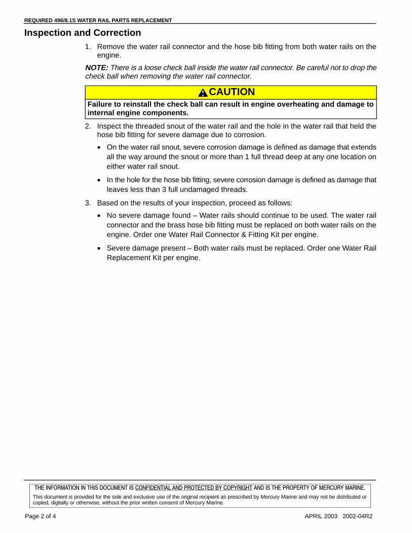
REQUIRED 496/8.1S WATER RAIL PARTS REPLACEMENT
Page 2 of 4 APRIL 2003 2002-04R2
���������������������� ��������������� ��������� �������� ��������������� ����������������������������
This document is provided for the sole and exclusive use of the original recipient as prescribed by Mercury Marine and may not be distributed orcopied, digitally or otherwise, without the prior written consent of Mercury Marine.
Inspection and Correction1. Remove the water rail connector and the hose bib fitting from both water rails on the
engine.
NOTE: There is a loose check ball inside the water rail connector. Be careful not to drop thecheck ball when removing the water rail connector.
CAUTIONFailure to reinstall the check ball can result in engine overheating and damage tointernal engine components.
2. Inspect the threaded snout of the water rail and the hole in the water rail that held thehose bib fitting for severe damage due to corrosion.
• On the water rail snout, severe corrosion damage is defined as damage that extendsall the way around the snout or more than 1 full thread deep at any one location oneither water rail snout.
• In the hole for the hose bib fitting, severe corrosion damage is defined as damage thatleaves less than 3 full undamaged threads.
3. Based on the results of your inspection, proceed as follows:
• No severe damage found – Water rails should continue to be used. The water railconnector and the brass hose bib fitting must be replaced on both water rails on theengine. Order one Water Rail Connector & Fitting Kit per engine.
• Severe damage present – Both water rails must be replaced. Order one Water RailReplacement Kit per engine.

REQUIRED 496/8.1S WATER RAIL PARTS REPLACEMENT
2002-04R2 APRIL 2003 Page 3 of 4
���������������������� ��������������� ��������� �������� ��������������� ����������������������������
This document is provided for the sole and exclusive use of the original recipient as prescribed by Mercury Marine and may not be distributed orcopied, digitally or otherwise, without the prior written consent of Mercury Marine.
Ordering Replacement KitQty 1 P/N 863116A1 Water Rail Connector & Fitting Kit
Qty 1 P/N 862992A1 Water Rail Replacement Kit
b
a
c
a - Water Rail Snoutb - Water Rail Connectorc - Hose Bib Fitting
�Owner NotificationUSA and Canada Only: A letter will be sent to the registered owner of the affected MercuryMerCruiser engine. The letter will reference Service Bulletin 2002-04 and will advise theowner to return their boat to the selling dealer, or any authorized Mercury MerCruiser servicedealer, for this inspection and replacement of water rail connector and fitting.

REQUIRED 496/8.1S WATER RAIL PARTS REPLACEMENT
Page 4 of 4 APRIL 2003 2002-04R2
���������������������� ��������������� ��������� �������� ��������������� ����������������������������
This document is provided for the sole and exclusive use of the original recipient as prescribed by Mercury Marine and may not be distributed orcopied, digitally or otherwise, without the prior written consent of Mercury Marine.
�WarrantyMercury Marine will credit the dealer for the cost of labor through May 31, 2005.
Submit a warranty claim through your normal warranty-processing channel, listing:
• MerCruiser serial number.
For P/N 863116A 1 Water Rail Connector Kit Installation.
• Flat Rate Code and Labor – EXCP 0.5.
• Part Code – 699.
• Failure Code – 40.
For P/N 862992A 1 Water Rail Replacement Kit Installation.
• Flat Rate Code and Labor – EXCP 1.0.
• Part Code – 699.
• Failure Code – 40.
Old Part or Parts:
• USA and Canada: Scrap.
• International: Follow instructions issued by your Marine Power International officeor by your distributor.
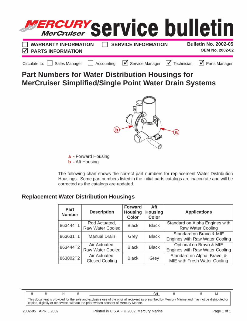
2002-05 APRIL 2002 Printed in U.S.A. - 2002, Mercury Marine Page 1 of 1
� � �� �
This document is provided for the sole and exclusive use of the original recipient as prescribed by Mercury Marine and may not be distributed orcopied, digitally or otherwise, without the prior written consent of Mercury Marine.
Bulletin No. 2002-05OEM No. 2002-02
WARRANTY INFORMATION SERVICE INFORMATIONPARTS INFORMATION
Sales ManagerCirculate to: Accounting Service Manager Technician Parts Manager
Part Numbers for Water Distribution Housings forMerCruiser Simplified/Single Point Water Drain Systems
ab
a - Forward Housingb - Aft Housing
The following chart shows the correct part numbers for replacement Water DistributionHousings. Some part numbers listed in the initial parts catalogs are inaccurate and will becorrected as the catalogs are updated.
Replacement Water Distribution Housings
PartNumber Description
ForwardHousing
Color
AftHousing
ColorApplications
863444T1 Rod Actuated,Raw Water Cooled
Black Black Standard on Alpha Engines withRaw Water Cooling
863631T1 Manual Drain Grey Black Standard on Bravo & MIEEngines with Raw Water Cooling
863444T2 Air Actuated,Raw Water Cooled
Black Black Optional on Bravo & MIEEngines with Raw Water Cooling
863802T2 Air Actuated,Closed Cooling
Black Grey Standard on Alpha, Bravo, &MIE with Fresh Water Cooling

MC Service Bulletin 2003-01
Required MCM and MIE Water Inlet Hose Replacement
Models Affected
MCM 4.3L carb or MPI Bravo engines: S/N 0M624475-0M626063.MCM 5.0L carb or MPI Bravo engines: S/N 0M623564-0M627156.MCM 5.7L carb Bravo engines: S/N 0M623728-0M623779.MCM 350 MPI Bravo engines: S/N 0M623800-0M627674.MCM MX6.2 MPI Bravo engines: S/N 0M624135-0M627379.MCM 496 Mag Bravo: S/N 0M382495-0M383508.MCM 496 Mag HO Bravo engines: S/N 0M383187-0M383508.MIE 8.1S Inboard engines: S/N 0M315631-0M315763.MIE 8.1S HO Inboard engines: S/N 0M315665-0M315753.
NOTE: Not all products in the serial number range given are affected by this fix. Someproducts may have been updated before they left the factory, or have been updated bythe boat builder or another dealer. Dealers on MercNET should first check the product’shistory before starting the repair to verify that the product they are working on still has anopen fix program for it.
Situation
The walls of the water inlet hose(s) used on the engines listed above are thinner thanrequired and can collapse during engine operation.
Owner NotificationA letter will be sent to the registered owner of an affected MerCruiser engine. The letterwill reference Service Bulletin 2003-01 and will advise the owner to return his boat to theselling dealer, or any Mercury MerCruiser service dealer, for inspection and possiblereplacement of the water inlet hose.
Dealer Engine Inventory
Affected engines in dealer stock, whether boxed or in a boat, MUST be inspected priorto delivery to a customer. Replace the water inlet hose if required (see “Correction” and“Parts Required” sections of this bulletin).
Correction
Only certain water inlet hoses on the engine are affected. Refer to the drawing to identifythe inlet hoses that need to be changed. A wrapped hose with a stripe (white or blue)along it’s length needs to be replaced. If the hose does not have a stripe on it, it does notneed to be replaced. The suspect hose locations are listed below.
MCM 4.3L, 5.0L, 5.7L, 350 and MX6.2 Sterndrive engines: The 91.5 cm (36 in.) longhose from the water inlet fitting on the transom plate to the belt driven water pump inlet.
NOTE: On Closed Cooled models, if the original hose had a ‘Y’ fitting in it, the new hosewill have to be cut to insert the ‘Y’ fitting in it.

MCM 496 Sterndrive models: The 59.7 cm (23-1/2 in.) long hose from the transom platefitting to the starboard drain and the 25.4 cm (10 in.) long hose from the drain to the beltdriven water pump.
MIE 8.1S Inboard models: The 25.4 cm (10 in.) long hose from the drain to the beltdriven water pump.
NOTE: On MCM 496 Mag Sterndrive engines and MIE 8.1S Inboard engines, removingthe 2 fasteners that hold the starboard drain has to be done so the 25.4 cm (10 in.) longhose from the drain to the belt driven water pump can be changed.
Part Required
Order 1 qty P/N 32-863343 65 Water Hose, 96.5 cm (38 in.) long.
1. MCM 4.3L, 5.0L, 5.7L, 350 and MX6.2 Bravo Sterndrive engines: Use hose as is.2. MCM 496 Mag Sterndrive engines: Cut a 59.7 cm (23-1/2 in.) long hose and a 25.4
cm (10 in.) long hose from this hose. Use in locations described previously.3. MIE 8.1S Inboard engines: Cut 25.4 cm (10 in.) long hose and use at location
described previously.
Warranty
Mercury Marine will credit the dealer for the cost of labor through March 31, 2006.Submit warranty claim through your normal warranty-processing channel, listing:• MerCruiser serial number• 0.8 hours• Flat Rate Code and Labor - NJC 0.8• Part Code - 619• Failure Code - 40
Old Part or Parts
USA and Canada: Scrap part.
International: Follow instructions issued by Marine Power International Office or by yourdistributor.

TRANSMISSION AND DRIVE LINE PRODUCT APPLICATIONS MANUAL
Page 6 of 20 90-863758020 AUGUST 2002
Propeller Shaft Log Seal Connections
CAUTIONAvoid overheating damage. Mercury MerCruiser is not responsible for engine dam-age caused by improper cooling system connections for the propeller shaft logseal.
The propeller shaft log seal hose should be routed so that a portion of the hose extendsabove the top of the engine exhaust elbows (to prevent a siphoning action when engine isnot running). Hose must be securely fastened to keep it properly positioned.
CAUTIONEngine damage may result from failure to route propeller shaft log seal hose proper-ly. This could cause increased exhaust system corrosion, submersion damage orfreeze damage to engine.
8.1S ModelsConnect the shaft log seal hose to the reducer fitting on the end of the starboard exhaustmanifold. The reducer fitting has been carefully sized to maintain the proper pressurebalance in cooling system and MUST NOT REMAIN INSTALLED IN PORT EXHAUSTMANIFOLD.
77663
a
Propeller Shaft Log Seal Connection - 8.1S Modelsa - Reducer Fitting
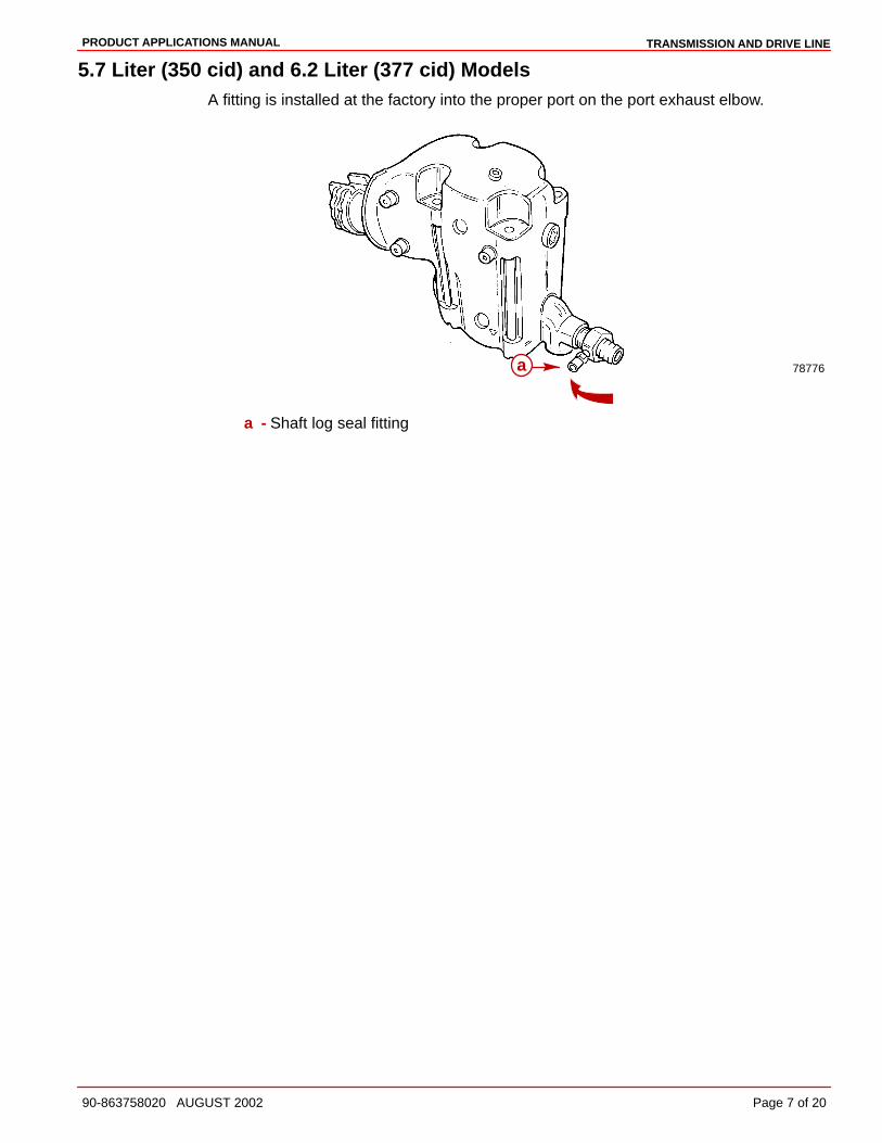
TRANSMISSION AND DRIVE LINEPRODUCT APPLICATIONS MANUAL
90-863758020 AUGUST 2002 Page 7 of 20
5.7 Liter (350 cid) and 6.2 Liter (377 cid) ModelsA fitting is installed at the factory into the proper port on the port exhaust elbow.
78776a
a - Shaft log seal fitting

COOLING SYSTEMPRODUCT APPLICATIONS MANUAL
90-863758020 AUGUST 2002 Page 11 of 14
Water Heaters
CAUTIONAvoid overheating damage. Mercury MerCruiser is not responsible for engine dam-age caused by improper heater installation.
Mercury MerCruiser engines are designed to allow connection of a water heater.
Ensure that the water heater complies with the following:
¶ Engine operating temperature range: 160-175 degrees F (71-79 degrees C).
¶ Maximum pressure at the heater connections on engine: 25 psi (172 kPa).
IMPORTANT: Engine may not maintain proper temperature if heater supply andreturn hoses are too large.
¶ Maximum ID of heater supply and return hose: 5/8 in. (16 mm).
¶ Make heater connections only at locations specified.
¶ Do not reposition the temperature senders or switches for the purpose of making theconnections. Senders and switches may not operate properly if repositioned.
¶ Heater should be mounted so that heater element is below connections on engine toavoid air locking. On closed cooled models trapped air will eventually work its wayback into the cooling system and could cause overheating.
¶ The system should be arranged so that the heater hoses slope progressively upward(toward the engine) to minimize the need for air venting. Avoid U-bends in the hoses.
¶ Hoses should be kept as short as possible with a minimum number of bends.
¶ Hoses should be properly supported to prevent chafing and interference with movingparts on engine.
¶ Drain plugs should be fitted at the lowest point in the system for draining.
¶ On closed cooled models, additional coolant must be added to the fresh watersystem to fill the heater. Refer to Anti–Freeze Recommendation. Operate enginewhile filling and recheck level several times to ensure that all air has been purgedfrom system.
IMPORTANT: Closed cooling system capacity will be different than shown inOperation, Maintenance and Warranty manual. Be sure to advise owner of the propercapacity for your application.
¶ Refer to heater manufacturer’s instructions for specific installation details.

COOLING SYSTEM PRODUCT APPLICATIONS MANUAL
Page 12 of 14 90-863758020 AUGUST 2002
Hose Connection PointsMPI MODELS SUPPLY HOSE CONNECTION
78692a
Seawater Cooled Modelsa - Supply Hose Connection Locations
78691a
Closed Cooled Modelsa - Supply Hose Connection Locations

COOLING SYSTEMPRODUCT APPLICATIONS MANUAL
90-863758020 AUGUST 2002 Page 13 of 14
CARBURETED MODELS SUPPLY HOSE CONNECTION
78752 74973
a
a
a - Location For Hot Water Supply
ALL MODELS RETURN HOSE CONNECTION
77954
a
a - Water Circulating Pump
8.1S MODELS
77013
a
b
c
a - Supply Hose Connectionb - Return Hose Connectionc - Heat Exchanger

COOLING SYSTEMPRODUCT APPLICATIONS MANUAL
90-863758020 AUGUST 2002 Page 7 of 14
Water Supply Test
Water Inlet Restriction TestMaximum seawater inlet restriction must not exceed 2.5 psi (17 kPa) when measured at theinlet side of the seawater pump. Pressure can be tested using pressure gauge andhardware included in boat audit tool kit (as shown in SECTION 1 – Important Information).Gauge must be capable of accurately reading a vacuum (below atmospheric pressure).
7. Install an adapter into the water inlet hose at the seawater pump to allow the connectionof a pressure gauge.
8. Connect a pressure gauge to the adapter. Be sure to zero the gauge before making theconnection.
9. With boat in the water and while underway, operate engine at 1000, 2000, 3000, 4000and WOT while observing gauge.
10. Pressure should be steady and not exceed 2.5 psi (17 kPa). Check the following ifabnormal readings are obtained.
FLUCTUATING READINGS
¶ Pickup located too far forward or outboard on boat allowing air to enter system.
¶ Pickup located too close to propeller or some other object and picking up disturbedwater flow.
¶ Loose connection in system allowing air to enter.
¶ Water inlet hose collapsing - wire reinforced hose not used.
EXCESSIVE PRESSURE READING
¶ Seawater supply components improperly sized.
¶ Water pickup not located on hull in an area with a solid, air–free flow of water.
¶ Excessive bends in water inlet hose.
¶ Water inlet hose collapsing - wire reinforced hose not used.
77655
a
b
c
a - Pressure Gauge Connectionb - Adapterc - Seawater Pump Inlet Connection

COOLING SYSTEM PRODUCT APPLICATIONS MANUAL
Page 8 of 14 90-863758020 AUGUST 2002
Water Aeration TestThe engine cooling system must receive a solid, air-free stream of water in order to operateeffectively.
1. Install a piece of clear plastic wire reinforced tubing in water inlet hose of seawaterpickup pump.
2. Operate engine from idle to WOT, while putting the boat through normal operatingmaneuvers. Simultaneously, watch water flow through the clear plastic tubing.
3. Water flow should be solid with only tiny bubbles being acceptable (due topseudo-cavitation). If it is not:
¶ Pickup located too far forward or outboard on boat allowing air to enter system.
¶ Pickup located too close to propeller or some other object and picking up disturbedwater flow.
¶ Loose connection in system allowing air to enter.

COOLING SYSTEMS -
Cooling System
Seawater Cooled Models

- COOLING SYSTEMS
Seawater Inlet Recommendations
Transom Mounted or Through-Hull Seawater Pickups and HoseWater pickup must be large enough to permit sufficient water flow to engine seawater pickuppump for adequate engine cooling [30 gal. per min. (114 L per min.) minimum]. Pickup alsomust supply a positive head while underway.
CAUTIONDo not install water pickup directly in line with propeller, as pickup may createturbulence and allow air to flow into the “propeller slipstream.” This will causepropeller ventilation and will adversely affect boat performance.
Water pickup should be located as close to seawater pickup pump inlet as possible and inan area where an uninterrupted, solid stream of water will flow past when boat is underway.Connect water pickup to seawater pickup pump inlet with 1-1/4 in. (32 mm) I.D. wire rein-forced hose of adequate wall thickness to prevent it from collapsing from pump suction. Besure to secure hose connections with hose clamps.
Seacock (Seawater Inlet Valve)If a seacock is being used, it must be installed between water pickup and seawater pickuppump (or sea strainer), to allow operator to shut off the seawater in case of a leak or whenboat is not in use. This will allow the operator to flush or drain the engine, or clean the seastrainer while boat is in the water. Seacock used must have an internal cross-sectional areaequal to or greater than hose to prevent restricting water flow. Install seacock in an area whereit will be easily accessible and self-supporting to prevent hose fatigue.
70355
a
b
c d
Seacock (with Thru-Hull Pickup Shown)a - Hose Connector 1-1/4 In. (32 mm) I.D. To Seawater Pump Inletb - Seacock 1-1/4 In. (32 mm) Brass Ball Or Gate Valvec - Seawater Pickupd - Direction Of Seawater Flow
Sea StrainerIf boat is equipped with a sea strainer, it must be of sufficient size to ensure that an adequatesupply of water is maintained for engine cooling. Install seawater strainer in an area whereit will be easily accessible for inspection and cleaning. Strainer should be installed in waterinlet hose after water inlet valve to allow operator to shut off water when cleaning strainer.

Seawater Pickups
NOTICE
Refer to manufacturer’s instructions for information on removal and installation ofother than Quicksilver Seawater Pickups.
IMPORTANT: Seal the inside edges of any hole made through the hull with a suitablesealant to prevent water absorption and deterioration.
Through-Hull Mounted
72639a
b
c
d
a - Seawater Pickupb - Seawater Inlet Slots (Must Face Forward - Parallel With Water Flow)c - Mounting Screw Holes (If Equipped)d - Nut
1. Seal inside edges of 1-3/4 in. (44 mm) hole in hull using a suitable sealer.
2. Apply marine caulking (sealer) to mounting surface on seawater pickup where hull con-tact will occur when installed.
3. Ensure slots in seawater pickup are facing forward (toward bow of boat) and install sea-water pickup through hull. The slots must be parallel with flow of water.
4. Fasten pickup with four appropriate mounting screws (if so designed).
5. Apply marine caulking as needed inside boat. Apply Loctite 27131 to threads of nut andinstall on pickup on inside of boat. Torque nut to 35 lb-ft (42 Nm).
NOTE: If pickup being installed does not have mounting screws on underside where mountedto hull, be certain, after nut is torqued, that slots are still facing forward.

- COOLING SYSTEMS
Transom Mounted
72640
a bc
de
f
gh
ij
a - Hose Nippleb - Nut (4)c - Gasket - Between Pickup and Transomd - O-Ring (4)e - Washer (4)f - Bolt (4)g - Plastic Pugh - Pickupi - Screenj - Screw (2)
1. Seal the inside edges of the 1-1/2 in. (38 mm) hole hose nipple.
2. Be certain hose nipple and plastic plug are in place and threads have been sealed withLoctite Pipe Sealant with Teflon prior to tightening each securely.
NOTE: Use a sharp knife or wood chisel to remove excess plastic plug material so that plugis flush with pickup casting.
3. Position one flat washer and one rubber O-ring on each 5/16 in. x 4 in. (102 mm) long,round head bolt as shown. Coat each bolt shaft with silicone sealant or equivalent.

COOLING SYSTEMS -
4. Place new gasket on pickup housing and hold pickup in place on transom. Install fourround head bolt (with washers and O-rings in place) into pickup mounting holes andthrough drilled 21/64 in. (8 mm) holes in transom.
NOTE: Some installations may have 7/32 in. (5 mm) holes drilled in transom using four 5/16in. diameter stainless steel lag bolts in place of round head screws. In any case, flat washersand O-rings are required as outlined.
72641
ab
Water Pickup Installed on Transoma - Diagonal Mount - Leading Edge Of Pickup 1/8 In. (3.2 mm) From Boat Bottom.b - Vertical Mount - Corner Of Leading Edge Of Pickup 1/8 In. 3.2 mm) From Boat
Bottom
5. Secure water pickup from inside with locknuts and washers (unless using lag bolts).
6. Tighten fasteners securely.

- COOLING SYSTEMS
Sea Strainer
NOTICE
Refer to manufacturer’s instructions for information on removal and installation ofother than Quicksilver Sea Strainer
Removal
CAUTIONIf boat is in water while working on seawater strainer, close seacock, if so equipped.If boat is not equipped with a seacock, remove and plug seawater inlet hose to pre-vent a siphoning action that may occur, allowing seawater to flow from the drainholes or removed hoses and enter boat.
IMPORTANT: Be certain engine is off and cooling system is cold.
1. Follow “a” or “b” instructions:
a. Models Equipped with Seacock:
(1.)Close seacock (seawater inlet valve).
(2.)Disconnect seawater inlet hose from seawater strainer.
72691
a
b
a - Seawater Inlet Hoseb - Seawater Strainer
b. Models without Seacock:
(1.)Disconnect seawater inlet hose from seawater strainer inlet and plug seawater in-let hose.
70062
ab c d
a - Seawater Inlet Hoseb - Seawater Strainerc - Seawater Strainer Inletd - Plug
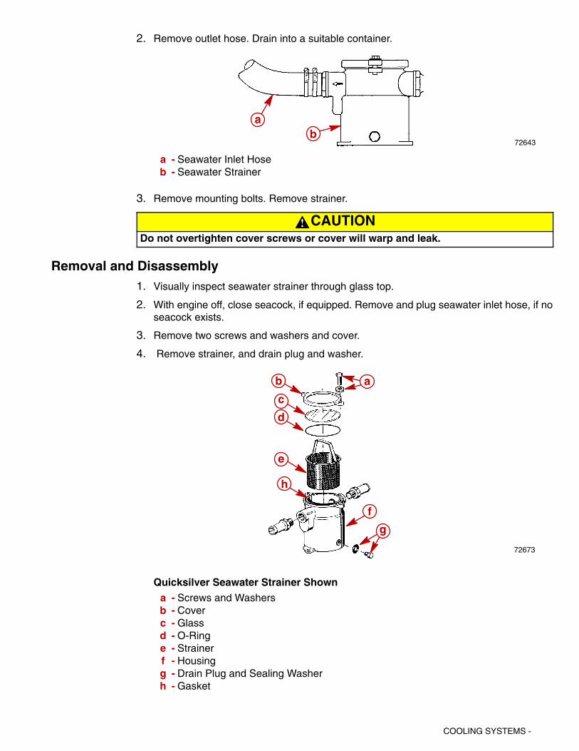
COOLING SYSTEMS -
2. Remove outlet hose. Drain into a suitable container.
72643
ab
a - Seawater Inlet Hoseb - Seawater Strainer
3. Remove mounting bolts. Remove strainer.
CAUTIONDo not overtighten cover screws or cover will warp and leak.
Removal and Disassembly1. Visually inspect seawater strainer through glass top.
2. With engine off, close seacock, if equipped. Remove and plug seawater inlet hose, if noseacock exists.
3. Remove two screws and washers and cover.
4. Remove strainer, and drain plug and washer.
72673
ab
c
d
e
f
g
h
Quicksilver Seawater Strainer Showna - Screws and Washersb - Coverc - Glassd - O-Ringe - Strainerf - Housingg - Drain Plug and Sealing Washerh - Gasket

- COOLING SYSTEMS
Cleaning and Inspection1. Clean any debris from strainer housing.
2. Flush both strainer and housing with clean water.
3. Check gasket; replace when necessary (if it leaks).
Reassembly1. Reinstall strainer, drain plug and washer.
2. Reattach cover with screws and washers.
3. Open seacock, or unplug and reconnect seawater inlet hose.
4. Tighten hose clamps securely.
5. After starting engine, check for leaks and/or air in system, which would indicate an exter-nal leak.
InstallationIMPORTANT: Mount seawater strainer in a vibration-free location. Never mount it onthe engine or transmission. Hoses must not be kinked or allowed to come in contactwith hot or moving engine or transmission parts.
1. Mount seawater strainer. Arrow indicates required water flow direction and must point to-ward seawater pump. Tighten mounting bolts securely.
72644
a
b
cc
a - Seawater Strainerb - Arrowc - Mounting Bolt Hole Location (Bolts Not Shown)
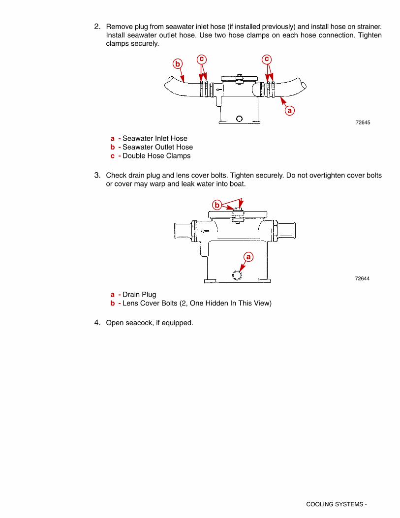
COOLING SYSTEMS -
2. Remove plug from seawater inlet hose (if installed previously) and install hose on strainer.Install seawater outlet hose. Use two hose clamps on each hose connection. Tightenclamps securely.
72645
a
bcc
a - Seawater Inlet Hoseb - Seawater Outlet Hosec - Double Hose Clamps
3. Check drain plug and lens cover bolts. Tighten securely. Do not overtighten cover boltsor cover may warp and leak water into boat.
72644
a
b
a - Drain Plugb - Lens Cover Bolts (2, One Hidden In This View)
4. Open seacock, if equipped.

- COOLING SYSTEMS
Seawater Pickup Pump
Output TestIf an overheating problem exists, use this test to determine if a sufficient amount of water isbeing supplied to cool the engine.
IMPORTANT: The following information should be observed before proceeding withtest:
• BOAT MUST BE IN THE WATER FOR THIS TEST. This test CANNOT BE performedwith a flush-test device and water hose.
• The ability of this test to detect a problem is greatly dependent upon the accuracywith which it is performed. An error in setting the engine RPM, timing the test ormeasuring the water output will affect the overall accuracy of the test and mayproduce misleading results. To help ensure accurate results, a shop tachometerwith an error of less than 5% should be used. The boat tachometer definitely shouldnot be used as its accuracy is questionable. A stop watch should be used to timethe duration of the test to help ensure that the accuracy is maintained within onesecond. An 8 qt. (7.6 L) or larger capacity container should be used to measurewater output.
• Due to the manner in which this test is performed, it may not be possible to detect amarginal condition or a high-speed water pump output problem.
1. Models with Engine Mounted Seawater Pump – Remove water hose, which runs be-tween pump outlet and engine, and replace with another hose of same diameter, but ap-proximately 3 ft (1 m) longer. Hose should be wire reinforced or of adequate wall thicknessto prevent it from kinking when performing test. Clamp hose at pump outlet only. Do notclamp hose at engine end.
75533a
b
a - Seawater Inlet Hoseb - Hose To Cooler

COOLING SYSTEMS -
2. Place an 8 qt. (7.6 L) or larger container near unclamped end of hose.
3. With assistance of another person, start engine and adjust speed to exactly 1000 RPMwhile holding unclamped end of hose on connection on engine. Remove hose from con-nection on engine and direct water flow into container for exactly 15 seconds. At the endof 15 seconds, direct the water flow overboard, return engine to idle and stop engine. Re-connect hose to engine.
4. Measure quantity of water discharged into container and compare with specifications giv-en in the following chart.
5. Repeat test four times to ensure common results.
Belt Driven Pump Output For a 15 Second Period
7.5 U.S. Qt. (7.1 L) Minimum

- COOLING SYSTEMS
Water Circulating Pump
Removal1. Drain water from cylinder block.
2. Break loose circulating pump pulley attaching bolts. Do not remove bolts at this time.
3. Loosen alternator tensioner pulley, then pivot alternator inward and remove the serpen-tine drive belt.
4. Remove pump pulley attaching bolts, lockwashers, clamping ring (if equipped) and pulley.
5. Disconnect hose(s) from pump.
6. Remove bolts, which secure pump to cylinder block, and remove pump and old gaskets(discard gaskets).
Cleaning and Inspection1. Clean gasket surfaces on water pump and cylinder block.
2. Inspect water pump for blockage, cracks, sand holes, corrosion or other damage. Inspectpump impeller for cracks and erosion. Replace complete pump if any damage exists.
3. Check impeller shaft and bearings for excessive side play. If play can be felt, replace com-plete pump.
4. Inspect pump pulley for bends, cracks, corrosion or other physical damage. Inspect pulleyfor rotational trueness. Replace pulley if damaged or untrue.
Installation1. Coat both sides of new circulating pump gasket with Quicksilver Perfect Seal, then posi-
tion gaskets and circulating pump on cylinder block. Coat threads of circulating pump at-taching bolts with Quicksilver Perfect Seal and install bolts and alternator brace (if appli-cable). Torque bolts to specifications.
2. Reconnect hoses to pump.
3. Install pump pulley and clamping ring (if used) on pump hub and secure with bolts andlockwashers. Tighten bolts securely.
4. Install drive belts and adjust tension as outlined in “Drive Belt Tension Adjustment,” follow-ing.
5. Start engine and check for leaks.

COOLING SYSTEMS -
Drive Belt Tension Adjustment1. Loosen 5/8 in. locking nut on adjustment stud. Leave wrench on adjustment stud.
NOTE: Belt deflection is to be measured on the belt at the location that has the longest dis-tance between two pulleys. Normally this location is between the seawater pump and the idlerpulley.
2. Use 5/16 in. socket and tighten adjusting stud until the correct deflection of the belt is ob-tained at location specified above.
3. While holding adjustment stud at the correct belt tension, tighten 5/8 in. locking nut.
75484
a
a - Adjustment Stud and Pulley
4. Run engine for a short period of time and recheck belt adjustment.

- COOLING SYSTEMS
Thermostat
Removal1. Drain water from cylinder block and exhaust manifolds.
2. Remove thermostat housing and related components.
3. Remove thermostat from thermostat housing or cover.
71758
a
b
c
d
e
a - Housingb - O-Ringc - Thermostat (Stainless Steel)d - Spacere - Gasket
Testing
1. Clean thermostat in soap and water to remove any deposits or debris.
2. Inspect thermostat for corrosion or other visible damage.
3. If thermostat is suspected of producing insufficient engine temperature, check thermostatfor leakage by holding it up to a lighted background. Light leakage around the thermostatvalve indicates that thermostat is not closing completely and should be replaced. (A smallamount of leakage at one or two points around the valve perimeter is acceptable.)
72717a
a - Check For Light Leakage Around Perimeter Of Valve

COOLING SYSTEMS -
4. Check opening and closing temperature of thermostat (using a tester similar to the oneshown) as follows:
a. Fill tester to within 1 in. (25 mm) of top with tap water. Do not use distilled water.
b. Open thermostat valve and insert nylon string. Position thermostat on string so thatit will be just below water level when suspended, then allow valve to close. Suspendthermostat in water.
c. Place thermometer in container and position so that bottom of thermometer is evenwith bottom of thermostat. Do not allow thermometer to touch container.
72675
a
b
c
a - Thermometerb - Nylon Stringc - Thermostat
IMPORTANT: When performing procedures “d”-“f,” water must be agitated thoroughlyto obtain accurate results.
d. Plug in tester and observe temperature at which thermostat opens (thermostat dropsoff thread). Thermostat must open at specified temperature stamped on thermostat.
e. Continue to heat water until a temperature 25°F (14°C) above temperature specifiedon thermostat is obtained. Thermostat valve must be completely open at this temper-ature.
f. Unplug tester and allow water to cool to a temperature 10°F (5°C) below specifiedtemperature on thermostat. Thermostat must be completely closed at this tempera-ture.
g. Replace a thermostat that fails to meet all of the preceding tests.

COOLING SYSTEMS
Installation
1. Clean gasket surfaces on thermostat housing and intake manifold.
IMPORTANT: Gasket has continuity rivets. Do not coat with Quicksilver Perfect Seal,or Audio Warning Temperature Switch may not work properly.
2. Place O-ring in the thermostat housing. Be certain it is positioned properly in housing.
3. Place thermostat in thermostat housing with thermostatic element end toward housingbottom, as shown.
4. Align sleeve with groove in thermostat housing bore and install sleeve into housing.
5. Coat both sides of new thermostat housing gasket with Quicksilver Perfect Seal andposition on intake manifold.
6. Reinstall thermostat housing and torque screws with lockwashers to 30 lb-ft (41 Nm).
7. Reconnect hose(s) to thermostat housing. Tighten hose clamps securely.
8. Start engine and inspect for leaks.
71758
a
b
c
d
e
a - Housingb - O-Ringc - Thermostat (Stainless Steel)d - Spacere - Gasket

COOLING SYSTEMS
Water Flow Diagrams305 cid and 350 cid Bravo, Inboard and Ski Engines
NOTE: Certain components in the following diagram may look different than on your particu-lar power package, but the water flow paths remain similar on all engines.
75149
�
�
�
�
�
�
�
�
�
��
��
1 - Seawater Intake (From Sterndrive)2 - Seawater Pump3 - Power Steering Fluid Cooler Or Transmission Fluid Cooler4 - Fuel Cooler (EFI and MPI Models)5 - Thermostat Housing and Cover Assembly6 - Engine Water Circulating Pump7 - Engine Block and Cylinder Head Assembly8 - Exhaust Manifold, Typical9 - Restrictor Gasket
10 - Exhaust Elbow Assembly, Typical11 - Water Flow Overboard

COOLING SYSTEMS -
Big Block V8 MCM / MIE Models With Raw Water Cooling
75151
�
�
�
�
�
�
�
��
�
�
NOTE: Certain components in the following diagram may look different than on your particu-lar power package, but the water flow paths remain similar on all engines.
1 - Thermostat Housing2 - Engine Circulating Pump3 - Seawater Pickup Pump4 - Seawater Inlet5 - Engine Oil Cooler6 - Exhaust Elbow7 - Restrictor Gasket8 - Exhaust Manifold9 - Power Steering Cooler (MCM) or Transmission Cooler (MIE)
10 - Fuel Cooler

- COOLING SYSTEMS
Cooling System
Closed Cooled(Fresh Water)
Models

COOLING SYSTEMS -
Description
There are several configurations of this cooling system, but the operation is essentially identi-cal. Basically, the system is composed of two separate subsystems: the seawater system andthe closed cooling system. The seawater system is similar in function to the fan used in anautomobile because it absorbs heat (from the closed cooling system) as it passes throughthe heat exchanger. The closed cooling system is similar in function to the rest of the coolingsystem in an automobile.
The coolant recovery system keeps the reservoir full. Normal coolant overflow into recoverybottle is approximately 1/2 pint (230 mL) during warm-up. The coolant recovery system drawscoolant back into the reservoir from the recovery bottle as the engine cools. As long as thereis coolant in the recovery bottle, the reservoir should remain completely full. If not, there isa vacuum leak, usually at the hose leaving the reservoir, or the gasket under the recovery fillercap. The gasket seals against the outer rim of the filler neck.
IMPORTANT: The coolant (antifreeze) flows around the outside of the cooling tubeswhile seawater flows through the inside of the cooling tubes in the heat exchanger.
Maintaining Coolant Level
72520
a
Coolant Recovery Bottlea - Fill Cap
Before starting engine each day, ensure that coolant is visible in coolant recovery bottle.
If coolant is not visible, check fresh water section of cooling system (including coolant recov-ery system) for leaks and repair, as necessary. Refill fresh water section with recommendedcoolant solution, as outlined under “Changing Coolant,” following.
If coolant is visible, start engine and run until it reaches normal operating temperature, thenrecheck coolant level in coolant recovery bottle. Coolant level MUST BE between the ADDand FULL marks (on front of bottle).
WARNINGAllow engine to cool before removing pressure cap, as sudden loss of pressurecould cause hot coolant to boil and discharge violently. After engine has cooled, turncap 1/4 turn to allow any pressure to escape slowly, then push down and turn cap allthe way off.
If level is low, remove fill cap from coolant recovery bottle and add required amount of coolantsolution. Refer to Maintenance Section of Engine Service Manual for coolant recommenda-tions.

COOLING SYSTEMS
IMPORTANT: ALCOHOL OR METHANOL BASE ANTIFREEZE OR PLAIN WATER ARENOT RECOMMENDED FOR USE IN COOLING SYSTEM AT ANY TIME. In areas whereethylene glycol is not available, and the possibility of freezing does not exist, it is per-missible to use a solution of rust inhibitor and pure, soft water (mixed to manufactur-er’s recommendations).
Occasionally, ensure that coolant recovery system is functioning properly by removingpressure cap from heat exchanger and checking level. Coolant level should be up to bottomof heat exchanger filler neck. If low, examine entire fresh water section (especially coolantrecovery system) for leaks and repair, if necessary.
IMPORTANT: When reinstalling pressure cap, be sure to tighten it until it contactsstops on filler neck.
Pressure Cap Maintenance
Pressure cap is designed to maintain pressure in fresh water section of closed cooling systemonce the engine has attained normal operating temperature. This raises the boiling point ofthe coolant, thereby increasing the efficiency of the cooling system. To help ensure properoperation, cap should be cleaned, inspected and pressure tested periodically as follows:
WARNINGAllow engine to cool before removing pressure cap (in next step), as sudden loss ofpressure could cause hot coolant to boil and discharge violently. After engine hascooled, turn cap 1/4 turn to allow any pressure to escape slowly, then push down andturn cap all the way off.
1. Remove pressure cap from heat exchanger.
2. Wash cap with clean water to remove any deposits or debris from sealing surfaces.
3. Inspect rubber seal on cap for cuts, cracks or other signs of deterioration. If seal is dam-aged, cap MUST BE replaced.
4. Inspect coolant recovery gasket for deterioration and replace if bad.
5. Check condition of locking tabs on cap. Replace cap if tabs are bent or cracked.
72714
a
b
c
a - Rubber Seal (Cap MUST BE Replaced If Damaged)b - Gasket (Look For Cracks Under Gasket)c - Locking Tabs (1 Hidden)
6. Refer to “Testing Pressure Cap” and test as outlined.
7. Clean sealing surfaces on heat exchanger filler neck with a cloth. Inspect surfaces for anydamage or deposits that may prevent cap from sealing properly.

COOLING SYSTEMS -
8. Clean coolant recovery passage in heat exchanger filler neck with a wire and blow out withcompressed air.
72715
a
b
a - Inspect For Damageb - Clean Coolant Recovery Passages
9. Reinstall pressure cap, being sure to tighten until it contacts stops on filler neck.
Seawater Pickup Pump MaintenanceWhenever insufficient water flow is suspected, seawater pickup pump should be disas-sembled and inspected by an authorized MerCruiser Dealer.
Heat Exchanger RepairIMPORTANT: Braze with BCUP 2 rod or silver solder. Care must be taken not to meltother joints during repair.
1. Internal leaks can be repaired by brazing shut the ends of the leaking tube. This is onlya temporary fix because usually another tube will start leaking after a short period of timeand this also causes a reduction in cooling capacity. Do not close more than three tubes.
2. Nipples and drains that have been broken off the heat exchanger can be reattached bybrazing.
Testing Closed Cooling SystemTesting Coolant for Alkalinity
WARNINGAllow engine to cool before removing pressure cap as sudden loss of pressure couldcause hot coolant to boil and discharge violently. After engine has cooled, turn cap1/4 turn to allow any pressure to escape slowly, then push down and turn cap all theway off.
Coolant in fresh water section should be changed per Maintenance Schedule recommenda-tions and should be checked for alkalinity at least once between change intervals. To checkcoolant for alkalinity, proceed as follows:
1. Obtain pink litmus paper from a local supplier (drug store, pet shop, etc.).
2. Remove pressure cap from heat exchanger and insert one end of litmus paper into cool-ant.
3. If pink litmus paper turns blue, coolant is alkaline and need not be replaced.
4. If pink litmus paper remains pink, coolant is not alkaline and MUST BE REPLACED,as explained under “Changing Coolant.”

COOLING SYSTEMS
Pressure Testing System
WARNINGAllow engine to cool before removing pressure cap. Sudden loss of pressure couldcause hot coolant to boil and discharge violently. After engine has cooled, turn cap1/4 turn to allow any pressure to escape slowly, then push down and turn cap all theway off.
If coolant section of closed cooling system is suspected of leaking or not holding sufficientpressure, and no visible signs of leakage can be found, perform the following test:
1. Remove pressure cap from heat exchanger or reservoir.
2. Clean, inspect and pressure test pressure cap, as outlined under “Testing Pressure Cap,”to eliminate the possibility that cap is not maintaining proper pressure in system and iscausing coolant to boil over.
3. Clean inside of filler neck to remove any deposits or debris. Examine lower inside sealingsurface for nicks or other damage. Surface must be perfectly smooth to achieve a goodseal between it and rubber seal on cap. Also check locking cams on sides of filler neckto be sure that they are not bent or damaged. If locking cams are bent or damaged, pres-sure cap will not hold the proper pressure.
4. Adjust coolant level in fresh water section to 1 in. (25 mm) below filler neck.
5. Attach an automotive-type cooling system pressure tester to filler neck and pressurizeclosed cooling section to amount specified in following chart, based on pressure caprating for your engine.
Pressure Cap Rating Amount of Pressure Applied to ClosedCooling System
16 PSI (110 kPa) 20 PSI (138 kPa)
6. Observe gauge reading for approximately two minutes; pressure should not drop duringthis time. If pressure drops, proceed with the following steps until leakage is found.
7. While maintaining specified pressure on closed cooling section, visually inspect externalportion of cooling system (hoses, gaskets, drain plugs, petcocks, core plugs, circulatingpump seal, etc.) for leakage. Also listen closely for bubbling or hissing, as either is usuallya sure indication of a leak.
8. Refer to “Testing Heat Exchanger” in this section and test as outlined.
9. If no leakage could be found in above steps, engine is leaking internally, and it probablyis due to one or more of the following: (1) loose cylinder head bolts or damaged gasket,(2) loose intake manifold bolts or damaged gasket, (3) loose exhaust elbow or distributionblock retaining nuts or damaged gasket, (4) cracked or porous cylinder head or block, or(5) cracked or porous exhaust manifold. Proceed as follows until location of internal leakis found.
a. Start engine. Re-pressurize system to previously specified amount and observe pres-sure gauge on tester. If needle in gauge vibrates, compression or combustion is leak-ing into closed cooling section from a leak in the combustion chamber. Exact cylinderswhere leakage is taking place, can sometimes be found by removing spark plug wires(one at a time) while observing pressure gauge. Vibration will decrease or stop whenplug wire is removed from leaking cylinder. Stop engine.
b. Remove spark plugs (one at a time) from cylinders and examine for presence of cool-ant. A spark plug that is perfectly clean or milky appearing is a sure indication of a leak.

COOLING SYSTEMS -
c. Drain oil from engine and examine for presence of coolant. Oil usually will be milkyif coolant is present. If coolant is present, remove engine from boat and drop the oilpan. With engine in the upright position, re-pressurize closed cooling section topreviously specified amount and examine internal surfaces of engine to locate leak.
d. If no leakage can be found in above steps, entire engine must be disassembled andinspected for leakage.
Testing for Cylinder Head Gasket LeakA leaking head gasket will cause combustion gas to be forced into the cooling system. Themixture of coolant and tiny air bubbles is a poor heat conductor and will overheat an enginequickly. Compression tests or cooling system pressure check normally will not detect the leakbecause the test pressure is far below the combustion pressures which cause the leak. Aneffective test is as follows:
IMPORTANT: Run boat in lake for this test. It is best to run the engine at or above cruis-ing speed during this test. Usually a failed head gasket will not cause the engine tooverheat below cruising speed.
1. Install a clear plastic hose between the reservoir and coolant recovery bottle. Use a 2-3ft (610-910 mm) long hose for this test.
2. Route this hose so a “U” is formed.
3. Put enough coolant into hose to fill the center 4 or 5 inches (100-130 mm) of the “U.”
4. Observe the “U” while the engine is running.
a. During Idle and Warm-Up: Some coolant and/or air will leave the reservoir.
b. During Cruising Speed (2500-3500 rpm): Coolant and/or air leaving the reservoirshould stop after approximately five minutes running at a given rpm. A leaking headgasket will produce air bubbling through the “U,” going to the coolant recovery bottle.The frequency and size of the bubbles will depend on the size of the leak.
c. At Higher Speeds (4000+ rpm): Normal operation is the same as described in “b”above. A failed head gasket will cause the bubbles to come faster and may beaccompanied by violent, intermittent bursts of coolant.
It is important not to confuse normal warm-up expansion with a failed head gasket. Normalwarm-up produces an intermittent flow of coolant which will stop within approximately fiveminutes at a given rpm. A head gasket leak will not stop because the one thing that marksa failed head gasket is the continued passage of air. This may be accompanied by violent,intermittent bursts of coolant leaving the reservoir. If coolant continues to flow smoothly fromthe reservoir at cruising speed, something other than the head gasket is causing the engineto overheat.

- COOLING SYSTEMS
Testing Heat Exchanger
FOR INTERNAL LEAK
An internal leak will cause coolant to go into the seawater circuit when pressure is put on theclosed cooling circuit.
1. Remove a seawater hose from the exchanger. Do not drain the exchanger.
2. Pressurize the closed cooling circuit to 16-20 PSI (110-138 kPa) with a radiator tester.
3. If seawater begins to flow from the nipple there is a leak.
FOR BLOCKAGE
IMPORTANT: Seawater flows THROUGH the tubes in the exchanger. Closed coolingcoolant flows AROUND the tubes.
1. Remove end caps and inspect for any blockage in the seawater circuit (broken impellerblades, weeds, etc.).
2. Remove closed cooling circuit hoses and inspect the tubes just inside the nipples.Because the complete exchanger cannot be inspected, the heat exchanger should bereplaced if blockage is suspected.
Testing Pressure CapPressure cap is designed to maintain a pressure of approximately its rated capacity (refer to“Specifications”) in closed cooling section once engine has attained operating temperature.Cap should be cleaned, inspected and pressure-tested at regular tune-up intervals or when-ever cap is suspected of maintaining improper pressure as follows:
WARNINGAllow engine to cool before removing pressure cap. Sudden loss of pressure couldcause hot coolant to boil and discharge violently. After engine has cooled, turn cap1/4 turn to allow any pressure to escape slowly, then push down and turn cap all theway off.
1. Carefully remove pressure cap from reservoir or heat exchanger.
2. Wash cap with clean water to remove any deposits or debris from sealing surfaces.
3. Inspect gasket (if used) and rubber seal on cap for tears, cuts, cracks or other signs ofdeterioration. Replace gasket, if damaged, or entire cap if rubber seal is damaged.
72714
a
b
c
a - Rubber Seal (Cap MUST BE Replaced If Damaged)b - Gasket (Look For Cracks Under Gasket)c - Locking Tabs (1 Hidden)
4. Check that locking tabs on cap are not bent or damaged.

COOLING SYSTEMS -
5. Using a cooling system pressure tester (similar to one shown), test cap to be sure thatit releases at proper pressure and does not leak. (Refer to instructions which accompanytester for correct test procedure.) Cap must relieve pressure at 16 PSI (110 kPa), andmust hold rated pressure for 30 seconds without going below 11 PSI. Replace cap if it failsto fall within these limits.
72716
IMPORTANT: Before reinstalling cap in next step, examine lower inside sealing surfacein filler neck to ensure that it is perfectly smooth and free of debris. Also, inspect camlock flanges on sides of filler neck to be sure that they are not bent.
72715
a
b
a - Inspect For Damageb - Cam Lock Flange
6. Reinstall cap on reservoir or heat exchanger.

- COOLING SYSTEMS
Thermostat
RemovalNOTE: If coolant flow is restricted or fails to occur, a wire should be repeatedly inserted intoall drain holes to ensure there are no obstructions in passages. Remove petcock, if neces-sary, to insert wire completely into drain hole.
1. Drain engine block by removing drain plug. Be sure to drain both port and starboard sides.
74130a
Starboard Side Shown (Port Side Similar)a - Hoseb - Drain Plug In Exhaust Manifold Elbow
2. Disconnect hoses from thermostat cover.
3. Remove thermostat cover attaching bolts and lockwashers, then remove cover and gas-ket.
4. Remove thermostat from thermostat housing.
75746
a
bc
d
a - Thermostat Housingb - Thermostatc - Gasketd - Thermostat Housing Cover

COOLING SYSTEMS -
Testing
1. Clean thermostat in soap and water to remove any deposits or debris.
2. Inspect thermostat for corrosion or other visible damage.
75747
3. If thermostat is suspected of producing insufficient engine temperature, check thermostatfor leakage by holding it up to lighted background. Light leakage around the thermostatvalve indicates that thermostat is not closing completely and should be replaced. (A smallamount of leakage at one or two points around the valve perimeter is acceptable.)
4. Check opening and closing temperature of thermostat (using a tester similar to the oneshown), as follows:
a. Fill tester to within 1 in. (25 mm) of top with tap water. Do not use distilled water.
b. Open thermostat valve and insert thread. Position thermostat on nylon string so thatit will be just below water level when suspended, then allow valve to close. Suspendthermostat in water.
72675
ab
c
a - Thermometerb - Nylon Stringc - Thermostat (Typical)
c. Place thermometer in container and position so that bottom of thermometer is evenwith bottom of thermostat. Do not allow thermometer to touch container.
IMPORTANT: When performing instructions “d” and “e,” water must be agitated thor-oughly to obtain accurate results.
d. Plug in tester and observe temperature at which thermostat opens (thermostat dropsoff thread).
e. Unplug tester and allow water to cool to a temperature 10°F (5°C) below specifiedtemperature on thermostat. Thermostat must be completely closed at this tempera-ture.
f. Replace a thermostat that fails to meet all of the preceding tests.

COOLING SYSTEMS
Installation
CAUTIONAvoid seawater pickup pump impeller damage. DO NOT operate engine without cool-ing water being supplied to seawater pickup pump.
1. Remove thermostat housing and gaskets. Discard gaskets.
2. Clean gasket surfaces on thermostat cover, thermostat housing and intake manifold.
3. Position gasket on intake manifold. Place thermostat housing on gasket.
IMPORTANT: If gasket has continuity rivets, do not coat with Quicksilver Perfect Seal,or audio warning temperature switch may not work properly.
4. Install thermostat, as previously shown, into thermostat housing.
5. Position gasket on thermostat and reinstall thermostat cover. Torque bolts to 30 lb-ft (41Nm).
75746
a
b
c
d
a - Thermostat Housingb - Thermostatc - Gasketd - Thermostat Housing Cover
6. Connect hoses to thermostat cover. Tighten hose clamps securely.
7. With boat in the water and/or cooling water properly supplied to seawater pickup pump,start engine and inspect for leaks.

COOLING SYSTEMS -
Changing Coolant
NOTICE
For information and procedures on draining the seawater cooling system of Seawa-ter Cooled (Raw-water) Cooled Models, refer to SECTION 6A (of the Engine ServiceManual). For information and procedures on draining the Seawater Section of ClosedCooling (Coolant) Models refer to SECTION 1B (Service Manual). For cold weatheror extended storage, refer to SECTION 1B (Service Manual).
Closed Cooling SectionClosed cooling section of closed cooling system should be kept filled year-round withrecommended coolant solution. Do not drain closed cooling section for storage, as this willpromote rusting of internal surfaces. If engine will be exposed to freezing temperatures, makesure that closed cooling section is filled with Extended Life 5/100 Coolant or an ethylene glycolantifreeze and water solution, mixed to manufacturer’s recommended proportions, to protectengine to lowest temperature to which it will be exposed. If necessary, change coolant.
Coolant Recommendations
CAUTIONAlcohol or Methanol base antifreeze or plain water are not recommended for use infresh water section of cooling system at any time.
NOTE: All factory installed closed cooling systems come filled with Extended Life 5/100 Cool-ant. This antifreeze requires draining and replacing every five years or 1000 hour of operation,whichever comes first. The color of this antifreeze is orange. For best results any “top-off” fluidused should be Extended Life 5/100 Coolant. If Extended Life 5/100 Coolant is unavailable,any type of ethylene glycol based antifreeze may be used, but it will require the draining andreplacing of the coolant every two years or 400 hours of operation, whichever comes first.
In areas where the possibility of freezing DOES NOT exist, it is permissible to use a solutionof rust inhibitor and water (mixed to manufacturer’s recommendations).
Change IntervalsIf the closed cooling system is factory installed, drain and flush coolant from the closed coolingsystem at least every five years or 1000 hours of operation, whichever comes first. It shouldalso be changed whenever exhaust gases have entered the system.
If the system is not factory installed or has had anti-freeze other than Extended Life 5/100Coolant added, it must be changed every two years or 400 hours of operation, whichevercomes first.
Draining Instructions
WARNINGAllow engine to cool before removing pressure cap. Sudden loss of pressure couldcause hot coolant to boil and discharge violently. After engine has cooled, turn cap1/4 turn to allow any pressure to escape slowly, then push down and turn cap all theway off.
IMPORTANT: A wire should be inserted into drain holes to ensure that foreign materialis not obstructing the drain holes. On some models with two piece petcock, removalof petcock may be required so that wire can be inserted completely into drain hole.

COOLING SYSTEMS
IMPORTANT: Engine must be as level as possible to ensure complete draining of cool-ing system.
IMPORTANT: Closed cooling section must be kept filled year round with recom-mended coolant. If engine will be exposed to freezing temperatures, make sure closedcooling section is filled with Extended Life 5/100 Coolant or an ethylene glycol anti-freeze and water solution properly mixed to protect engine to lowest temperature towhich it will be exposed.
The following draining instructions apply to all engines equipped with closed cooling. The lo-cation of petcocks that require opening and hoses that require removal are represented onthe following pages for the individual engines.
IMPORTANT: Observe precautions previously outlined before proceeding.
1. Remove pressure cap from coolant tank.
2. Drain coolant from locations as shown in the “Draining Diagram.”
3. After coolant has drained completely, reinstall petcocks and hoses. Tighten clamps andpetcocks securely.
4. Remove coolant recovery bottle from mounting bracket and pour out coolant.
5. Clean system as outlined in “Cleaning System.”
6. Fill system as outlined in “Filling Closed Cooling Section.”
Cleaning System
Closed Cooling SectionClosed cooling section of closed cooling system should be cleaned at least once every twoyears or whenever decreased cooling efficiency is experienced.
A good grade automotive cooling system cleaning solution may be used to remove rust, scaleor other foreign material. Always follow manufacturer’s instructions for the cleaner.
If closed cooling section is extremely dirty, a pressure flushing device may be used to flushout remaining deposits. Flushing should be done in direction opposite normal coolant flow toallow water to get behind deposits and force them out. Refer to instructions which accompanyflushing device for proper hookup and flushing procedure.
NOTICE
For information and procedures for draining and flushing Seawater Section ofClosed Cooling (Coolant) Models, refer to SECTION 1B (of the Engine ServiceManual). For cold weather or extended storage, refer to SECTION 1B (ServiceManual).

COOLING SYSTEMS -
Seawater SectionCooling efficiency of an engine with closed cooling is greatly dependent upon heat transferthrough the tubes within the heat exchanger. During engine operation, contaminants withinthe seawater (such as salt, silt, lime, etc.) collect on the inside of the tubes, thus reducing heattransfer and greatly decreasing heat exchanger efficiency. It is, therefore, recommended thatthe seawater section of the heat exchanger be cleaned at least once every two years or when-ever decreased cooling efficiency is suspected, as follows:
1. Remove bolts which secure end plates to each end of heat exchanger, then remove endplates, seal washers and gaskets. Discard seal washers and gaskets. Clean gasketmaterial from end plates and heat exchanger.
71515
a
b
c
d
a - Heat Exchangerb - Sealing Washerc - End Capd - Gasket
2. Clean water passages in heat exchanger by inserting a suitable size wire brush into eachpassage. Use compressed air to blow loose particles out of water passages.
3. Apply Quicksilver Perfect Seal to both sides of new end plate gaskets, then reinstall endplates, using new gaskets and seal washers. (Be sure to install seal washers between endplates and gaskets.) Torque end plate bolts to specifications.
CAUTIONAvoid seawater pickup pump impeller damage. DO NOT operate engine withoutwater being supplied to seawater pickup pump.
4. With boat in the water and/or cooling water properly supplied to seawater pickup pump,start engine and inspect for leaks.

- COOLING SYSTEMS
Filling Closed Cooling SectionCAUTION
Alcohol or Methanol base antifreeze or plain water are not recommended for use incoolant section of Closed Cooling System at any time.
It is recommended that coolant section of Closed Cooling System be filled with a 50/50 mix-ture of Extended Life 5/100 Coolant and pure, soft water. This coolant MUST BE used regard-less of whether freezing temperatures are or are not expected to provide adequate corrosionprotection. In areas where Extended Life 5/100 Coolant is not available and the possibility offreezing DOES NOT exist, it is permissible to use a solution of rust inhibitor and pure, softwater (mixed to manufacturer’s recommendations).
NOTE: Coolant system capacity is found in the Maintenance Section of the Engine ServiceManual.
1. Fill coolant section of Closed Cooling System with coolant mixture as follows:
a. Open bleeder valve on thermostat housing.
75598
a
a - Hex Head Bleeder Valve
b. Fill with coolant mixture through heat exchanger fill neck until coolant appears atbleeder valve opening.
c. Close bleeder valve securely.
d. Continue filling until coolant level is into filler neck and begins to flow into coolant re-covery bottle plastic tubing.
CAUTIONDO NOT operate engine without water flowing through seawater pickup pump, aspump impeller may be damaged and subsequent overheating damage to engine orsterndrive unit may result.
CAUTIONFront of engine should be higher than rear to purge trapped air out of the system dur-ing initial filling. This will minimize the possibility of air being trapped in the closedcooling section which can cause engine to overheat.
IMPORTANT: This closed cooling system flows coolant at a high rate. Higher idlespeeds increase dispersion of trapped air into system making it more difficult to purgetrapped air. Operate at idle during filling and air purging when specified.

COOLING SYSTEMS -
2. Start engine and run AT IDLE. Add coolant solution to heat exchanger, as required, tomaintain coolant level at filler neck. After engine has reached normal operating tempera-ture (thermostat is fully open), and coolant level remains constant, fill heat exchanger untilcoolant level is into filler neck and begins to flow into coolant recovery bottle plastic tubing.
3. Remove cap from coolant recovery reservoir and fill to “Full” mark with coolant solution.Reinstall cap.
4. Lift recovery bottle and plastic tubing above heat exchanger filler neck. Allow coolant toflow down through tubing to purge air through filler neck fitting.
5. Install pressure cap on heat exchanger.
6. With engine still running, check hose connections, fittings and gaskets for leaks. Also ob-serve engine temperature gauge to make sure that engine operating temperature is nor-mal. If gauge indicates excessive temperature, stop engine immediately and examine forcause.
WARNINGAllow engine to cool down before removing pressure cap. Sudden loss of pressurecould cause hot coolant to boil and discharge violently. After engine has cooleddown, turn cap 1/4-turn to allow any pressure to escape slowly, then push down andturn cap all the way off.
7. Recheck coolant level after first boat test and add coolant, if necessary.
8. Maintain coolant level in coolant recovery reservoir between “Add” and “Full” marks withengine at normal operating temperature.
Coolant section of Closed Cooling System should be kept filled year around with recom-mended coolant solution. DO NOT drain coolant from fresh water section for storage, as thiswill promote rusting of internal surfaces. If engine will be exposed to freezing temperatures,make sure that coolant section is filled with Extended Life 5/100 Coolant and water solution,mixed to manufacturer’s recommended proportion, to protect engine to lowest temperatureto which it will be exposed.

- COOLING SYSTEMS
Heat Exchanger Bracket Hardware
74791
71495
71494
a b
c
d
e
f
g
h
i
j
k
f
h
f
Typical MIE (Inboard) Engine Shown, All Similara - Starboard Thermostat Housing-To-Heat Exchanger Hoseb - Port Thermostat Housing-To-Heat Exchanger Hosec - Engine Water Circulating Pump-To-Heat Exchanger Hosed - Upper Alternator Bracket And Fuel Line Clip Screwe - Heat Exchanger Bracketf - Large Diameter Washerg - Spacerh - 7/16-14x1-3/4 in. (44 mm) Long Screwi - 7/16-14x1 in. (25 mm) Long Screwj - Foam Pads (2)k - Spacers

COOLING SYSTEMS -
Heat Exchanger Hose Connections
74789
74073
74073
74788
a
b
c
ef
g
h
a
c
e
MIE (Inboard) Engine Shown, All Similara - Heat Exchangerb - Large Hose Clampsc - Starboard Heat Exchanger-To-Exhaust Manifold Hosed - Port Heat Exchanger-To-Exhaust Manifold Hosee - Oil Cooler-To-Heat Exchanger Hosef - Coolant Identification Decalg - Bypass Hose (Back Side Of Heat Exchanger)

COOLING SYSTEMS -
Closed Cooling System Water Flow Diagram“Small Block” V8 MCM / MIE Models
75005
�
�
�
�
�
�
�
��
��
ab
��
1 - Seawater Inlet Hose2 - Seawater Pump3 - Transmission Fluid Cooler, or Power Steering Cooler4 - Fuel Cooler5 - Heat Exchanger, Typical6 - Thermostat Housing and Cover Assembly7 - Engine Water Circulating Pump8 - Engine Block and Cylinder Head Assembly9 - Exhaust Manifold, Typical
10 - Exhaust Elbow Assembly, Typical11 - Overboard (Water and Exhaust Discharge)
a - Freshwater (Coolant/Anti-Freeze) Flowb - Seawater (Raw Water) Flow

- COOLING SYSTEMS
Draining Diagram (Coolant Section of System)“Small Block” V8
75005
a
b
b
a - Remove Hoses (Lift, Lower or Bend To Completely Drain).b - Remove Block Plugs (Repeatedly Clean Out Holes Using A Stiff Wire Until Entire
System Is Drained).

COOLING SYSTEMS -
Closed Cooling System Water Flow Diagram“Big Block” V8 MCM / MIE Models
75748
�
�
�
�
�
�
��
�
��
����
1 - Seawater Intake2 - Power Steering Cooler (MCM) or Transmission Cooler (MIE)3 - Fuel Cooler4 - Heat Exchanger5 - Thermostat Housing and Cover Assembly6 - Engine Water Circulating Pump7 - Engine Block and Cylinder Head Assembly8 - Exhaust Manifold9 - Exhaust Elbow
10 - Overboard Water Flow11 - Bypass Hose12 - Engine Oil Cooler13 - Coolant Reservoir Bottle

- COOLING SYSTEMS
Draining Diagram (Coolant Section of System)“Big Block” V8
75005
a
b
b
a - Remove Hoses (Lift, Lower or Bend To Completely Drain).b - Remove Block Plugs (Repeatedly Clean Out Holes Using A Stiff Wire Until Entire
System Is Drained).

COOLING SYSTEMS -
Water Flow Diagrams - Small Block V-8 Models (ECM/PCM 555 EFI Engines)
Seawater Cooled Models With An Engine Mounted Seawater Pump
77929
a
b
c
f
g
h
i
e
d
j
a - Exhaust Elbowb - Exhaust Manifoldc - Seawater Pumpd - Water Circulating Pumpe - Thermostat Housingf - Water Distribution Housingg - Cool Fuel Boxh - Check Valvei - Power Steering Coolerj - Shaft Log Seal Connection Point

- COOLING SYSTEMS
Seawater Cooled Models Without An Engine Mounted Seawater Pump
77931
a
b
f
g
h
e
c
d
a - Exhaust Elbowb - Exhaust Manifoldc - Water Circulating Pumpd - Thermostat Housinge - Water Distribution Housingf - Cool Fuel Boxg - Check Valveh - Power Steering Cooler

COOLING SYSTEMS -
Closed Cooled Models
77928
a
b
c
d
e
f
g
h
i
j
kl
m
a - Exhaust Elbowb - Exhaust Manifoldc - Seawater Pumpd - Heat Exchangere - Water Circulating Pumpf - Thermostat Housingg - Water Distribution Housingh - Cool Fuel Boxi - Check Valvej - Power Steering Coolerk - Flush Fitting (Inboard Models)l - Flush Connection (Inboard Models)
m - Shaft Log Seal Connection Point

- COOLING SYSTEMS
Coolant and Water Flow Diagrams8.1L/496 Models
NOTE: Certain components in the following diagram may look different than on your particu-lar power package, but the water and coolant flow paths remain similar on engines.

COOLING SYSTEMS -
1 - Seapump2 - Air Actuator3 - Power Steering Cooler4 - Oil Cooler5 - Fuel Cooler6 - Air Actuator7 - Heat Exchanger8 - Thermostat9 - Crossover
10 - Water Circulating Pump11 - Coolant Reservoir12 - Exhaust Manifold13 - Elbow14 - Water And Exhaust Outlet
a - Seawaterb - Coolantc - To Air Actuatord - Seawater Inlet

COOLING SYSTEMS
Draining Instructions for New Drain Systems
CAUTIONEnsure that boat is out of the water or seacock is closed and bilge pump is operatingbefore beginning procedure. Excess water in bilge can damage engine or cause boatto sink.
CAUTIONDo not operate engine with drain system open. Excess water in bilge can damage en-gine or cause boat to sink.
IMPORTANT: Boat must be as level as possible to ensure complete draining of coolingsystem.
Your power package is equipped with one of two drain systems. Refer to Identification onthe following page to determine which instructions apply to your power package.
The power package should be drained before flushing or prior to extended or cold weatherstorage.
IMPORTANT: The boat must not be operating at any point during this procedure.

GASOLINE ENGINE TOW SPORTS AND INBOARD MODELS
IdentificationAIR ACTUATED SINGLE POINT DRAIN SYSTEM
78643
77955
a
b
c
d
ba
c
d
Closed Cooled Models Seawater Cooled Modelsa - Blue Drain Plug Locationb - Blue Air Pumpc - Air Manifoldd - Green Indicators
3 POINT MANUAL DRAIN SYSTEM
7790878642
a
a
a - Blue Drain Plug

GASOLINE ENGINE TOW SPORTS AND INBOARD MODELS
Boat In WaterAIR ACTUATED SINGLE POINT DRAIN SYSTEM
NOTE: This procedure is written for the air pump that is attached to the engine. However,any air source can be used.
1. Close the seacock.
2. Remove the blue air pump from the engine.
3. Ensure that lever on top of pump is flush with the handle (horizontal).
4. Install air pump on the fitting in the air manifold.
77638
a
a - Green Indicators
5. Pull lever on air pump up (vertical) to lock pump on the fitting.
6. Pump air into the system until both green indicators extend and water drains from bothsides of the engine. The port side will begin draining before the starboard side.
7. Immediately remove the blue drain plug from the side of the thermostat housing or theheat exchanger. This must be removed within 30 seconds to properly vent the coolingsystem.
78643
77955
a
b
c
d
ba
c
d
Closed Cooled Models Seawater Cooled Modelsa - Blue Drain Plug Locationb - Blue Air Pumpc - Air Manifoldd - Green Indicators

GASOLINE ENGINE TOW SPORTS AND INBOARD MODELS
8. Verify that water is draining from each opening. If not, use the 3 Point Manual DrainSystem instructions.
78646
78642
b
a
a - Port Side Drain Locationb - Starboard Side Drain Location
9. Allow the system to drain for a minimum of 5 minutes. Add air as necessary to keep thegreen indicators extended.
10. Crank engine over slightly with starter motor to purge any water trapped in seawaterpump. DO NOT allow engine to start.
11. Reinstall the blue drain plug in the thermostat housing.
12. Remove the air pump from the air manifold and return it to the mounting bracket.
13. Mercury MerCruiser recommends leaving the drain system open while transporting theboat or while performing other maintenance. This helps ensure that all water is drained.
IMPORTANT: Mercury MerCruiser recommends that propylene glycol (a nontoxicand environmentally safe) antifreeze be used in the seawater section of the coolingsystem for cold weather or extended storage. Make sure that the propylene glycolantifreeze contains a rust inhibitor and is recommended for use in marine engines.Be certain to follow the propylene glycol manufacturer’s recommendations.
14. Before launching boat, pull up on manual release valve. Verify that green indicators areno longer extended.
77638a
a - Green Indicators
15. Open the seacock prior to operating the engine.

GASOLINE ENGINE TOW SPORTS AND INBOARD MODELS
3 POINT MANUAL DRAIN SYSTEM
NOTE: Use this procedure if your engine is not equipped with an air actuated single pointdrain system or if the single point drain system fails.
1. Close the seacock.
2. Remove the blue drain plug from the distribution housing (lower front, port side).
77917
a
a - Blue Drain Plug
3. Immediately remove the blue drain plug from the side of the thermostat housing. Thismust be removed within 30 seconds to properly vent the cooling system.
77949
a
a - Blue Drain Plug Location

GASOLINE ENGINE TOW SPORTS AND INBOARD MODELS
4. Remove the two blue drain plugs from the seawater pickup pump (front, starboard side).
77908a
5. Verify that water is draining from each opening.
6. Allow the system to drain for a minimum of 5 minutes. Mercury MerCruiser recommendsleaving the drain system open while transporting the boat or while performing othermaintenance.
7. Crank engine over slightly with starter motor to purge any water trapped in seawaterpickup pump. Do NOT allow engine to start.
8. Prior to launching boat or starting the engine, close the drain system by installing the4 blue drain plugs.
IMPORTANT: Mercury MerCruiser recommends that propylene glycol (a nontoxicand environmentally safe) antifreeze be used in the seawater section of the coolingsystem for cold weather or extended storage. Make sure that the propylene glycolantifreeze contains a rust inhibitor and is recommended for use in marine engines.Be certain to follow the propylene glycol manufacturer’s recommendations.
9. Open the seacock prior to operating the engine.

GASOLINE ENGINE TOW SPORTS AND INBOARD MODELS
Boat Out Of The WaterAIR ACTUATED SINGLE POINT DRAIN SYSTEM
NOTE: This procedure is written for the air pump that is attached to the engine. However,any air source can be used.
1. Remove the blue air pump from the engine.
2. Ensure that lever on top of pump is flush with the handle (horizontal).
3. Install air pump on the fitting in the air manifold.
77638
a
a - Green Indicators
4. Pull lever on air pump up (vertical) to lock pump on the fitting.
5. Pump air into the system until both green indicators extend and water drains from bothsides of the engine. The port side will begin draining before the starboard side.
78643
77955
a
b
c
d
ba
c
d
Closed Cooled Models Seawater Cooled Modelsa - Blue Drain Plug Locationb - Blue Air Pumpc - Air Manifoldd - Green Indicators

GASOLINE ENGINE TOW SPORTS AND INBOARD MODELS
6. Verify that water is draining from each opening. If not, use the 3 Point Manual DrainSystem.
78646
78642
b
a
a - Port Side Drain Locationb - Starboard Side Drain Location
7. Allow the system to drain for a minimum of 5 minutes. Add air as necessary to keep thegreen indicators extended.
8. Crank engine over slightly with starter motor to purge any water trapped in seawaterpump. DO NOT allow engine to start.
9. Remove the air pump from the air manifold and return it to the mounting bracket.
10. Mercury MerCruiser recommends leaving the plugs out while transporting the boat orwhile performing other maintenance to ensure that all water is drained.
IMPORTANT: Mercury MerCruiser recommends that propylene glycol (a nontoxicand environmentally safe) antifreeze be used in the seawater section of the coolingsystem for cold weather or extended storage. Make sure that the propylene glycolantifreeze contains a rust inhibitor and is recommended for use in marine engines.Be certain to follow the propylene glycol manufacturer’s recommendations.
11. Before launching boat, pull up on the manual release valve. Verify that the greenindicators are no longer extended.
77638a
a - Green Indicators

GASOLINE ENGINE TOW SPORTS AND INBOARD MODELS
3 POINT MANUAL DRAIN SYSTEM
NOTE: Use this procedure if your engine is not equipped with an air actuated single pointdrain system or if the single point drain system fails.
1. Remove three blue drain plugs: One from the distribution housing (lower front, port side)and two from the seawater pickup pump (front, starboard side).
7790877917
aa
a - Blue Drain Plug
2. Verify that water is draining from each opening.
3. Allow the system to drain for a minimum of 5 minutes. Mercury MerCruiser recommendsleaving the plugs out while transporting the boat or while performing other maintenanceto ensure that all water is drained.
4. Crank engine over slightly with starter motor to purge any water trapped in seawaterpickup pump. DO NOT allow engine to start.
IMPORTANT: Mercury MerCruiser recommends that propylene glycol (a nontoxicand environmentally safe) antifreeze be used in the seawater section of the coolingsystem for cold weather or extended storage. Make sure that the propylene glycolantifreeze contains a rust inhibitor and is recommended for use in marine engines.Be certain to follow the propylene glycol manufacturer’s recommendations.
5. Prior to launching boat or starting the engine, close the drain system by re-installing thethree blue drain plugs.
All Models1. For additional assurance against freezing and corrosion, fill the cooling system with a
mixture of propylene glycol antifreeze and tap water mixed to manufacturer’srecommendation to protect engine to the lowest temperature to which it will be exposedduring cold weather or extended storage.
a. Remove thermostat housing or hose and fill with propylene glycol coolant until blockand head are full. If thermostat housing was removed, reinstall and tighten coverbolts securely.

MC_Inboard_0804
5

Table of Contents
Exhaust Manifolds, Risers and Exhaust Elbows - Inspection and Re-assembly
Gasoline Engines and Water Intrusion
Typical Guidelines for Diagnosing Cause for Water Ingestion
MerCruiser Inboard Engine Product Applications Manual - Section 6 -Exhaust System (Specifications, Installation and Testing)
MerCruiser Dry Joint Exhaust and Cooling System for V6, V8 SmallBlock Engines
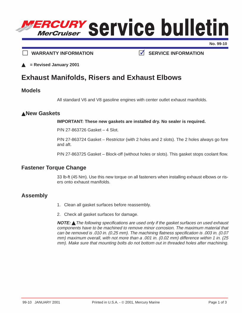
99-10 JANUARY 2001 Printed in U.S.A. - 2001, Mercury Marine Page 1 of 3
No. 99-10
WARRANTY INFORMATION SERVICE INFORMATION
� = Revised January 2001
Exhaust Manifolds, Risers and Exhaust Elbows
Models
All standard V6 and V8 gasoline engines with center outlet exhaust manifolds.
�New GasketsIMPORTANT: These new gaskets are installed dry. No sealer is required.
P/N 27-863726 Gasket – 4 Slot.
P/N 27-863724 Gasket – Restrictor (with 2 holes and 2 slots). The 2 holes always go foreand aft.
P/N 27-863725 Gasket – Block-off (without holes or slots). This gasket stops coolant flow.
Fastener Torque Change
33 lb-ft (45 Nm). Use this new torque on all fasteners when installing exhaust elbows or ris-ers onto exhaust manifolds.
Assembly
1. Clean all gasket surfaces before reassembly.
2. Check all gasket surfaces for damage.
NOTE: �The following specifications are used only if the gasket surfaces on used exhaustcomponents have to be machined to remove minor corrosion. The maximum material thatcan be removed is .010 in. (0.25 mm). The machining flatness specification is .003 in. (0.07mm) maximum overall, with not more than a .001 in. (0.02 mm) difference within 1 in. (25mm). Make sure that mounting bolts do not bottom out in threaded holes after machining.

EXHAUST MANIFOLDS, RISERS AND EXHAUST ELBOWS
Page 2 of 3 JANUARY 2001 99-10
3. Look at the condition of the metal around the exhaust outlet in the casting. Inspect fordamaged metal caused by salt water or exhaust gas corrosion in the manifold, elbowand riser (if equipped). Replace all damaged parts.
76341
a
a - Inspect Area Around Exhaust Outlet
NOTE: The type of gasket used in certain locations has changed from what is shown in olderservice literature.
4a. �Raw water cooled engines with all the water from the thermostat housing going to the90-degree fitting on bottom of the exhaust manifold:
Use P/N 27-863726 Gasket – 4 Slot between the exhaust manifold and the exhaustelbow.
If the engine has 3 in. (76 mm) or 6 in. (152 mm) risers, use P/N 27-863726 Gasket –4 Slot between the riser and the exhaust manifold and exhaust elbow.
4b. �Raw water cooled engines with the bypass water from the thermostat housing goingto the fitting on the exhaust elbow and the warm water from the thermostat housing go-ing to the 90-degree fitting on bottom of the exhaust manifold:
Use P/N 27-863724 Gasket – Restrictor between the exhaust manifold and the exhaustelbow.
If the engine has 3 in. (76 mm) or 6 in. (152 mm) risers, use P/N 27-863724 Gasket –Restrictor between the riser and the exhaust elbow. Use P/N 27-863726 Gasket – 4 Slotbetween the exhaust manifold and riser.
4c. �Closed Cooled engines with the raw water from the heat exchanger going to the90-degree fitting on bottom of the exhaust manifold:
Use P/N 27-863726 Gasket – 4 Slot between the exhaust manifold and the exhaustelbow.
If the engine has 3 in. (76 mm) or 6 in. (152 mm) risers, use P/N 27-863726 Gasket –4 Slot between the riser and the exhaust manifold and exhaust elbow.

EXHAUST MANIFOLDS, RISERS AND EXHAUST ELBOWS
99-10 JANUARY 2001 Page 3 of 3
4d. �Closed Cooled engines with the exhaust manifolds closed cooled and the raw waterfrom the heat exchanger going to the fitting on the exhaust elbow:
Use P/N 27-863725 Gasket – Block-off between the exhaust manifold and the exhaustelbow.
If the engine has 3 in. (76 mm) or 6 in. (152 mm) risers, use P/N 27-863725 Gasket –Block-off between the exhaust manifold and the riser. Use P/N 27-863726 Gasket – 4Slot between the riser and the exhaust elbow.
5. Assembly parts and torque fasteners to 33 lb-ft (45 Nm).

2001-13 AUGUST 2001 Printed in U.S.A. - 2001, Mercury Marine Page 1 of 8
No. 2001-13
WARRANTY INFORMATION SERVICE INFORMATION
Gasoline Engines and Water Intrusion
ModelsAll gasoline 4, V6 and V8 MerCruiser engines.
SituationThis bulletin is meant to help marine dealers troubleshoot engines, in or out of the warrantyperiod, that have water intrusion.
Marine engines are built to perform in harsh conditions, including saltwater. The vast major-ity of these engines perform reliably. Occasionally, an engine inadvertently will have waterenter it and this water has the potential to cause damage. This water can be found in theoil or on top of the pistons. Rarely is water found in both locations. Sometimes, water is foundinside the exhaust manifold but not inside the engine. To properly diagnose the failure, youneed to know where the water was found.
1. Quiz the boat owner when they first report this problem to your dealership about who,what, when, where and how they first noticed the problem. Find out as much informationas possible about what occurred just prior to the boater discovering the problem.
2. Ask if the boat sank or had a lot of water in the bilge.
a. If this has happened to the boat, drying all electrical components and getting the en-gine running as soon as possible after getting the water out of the bilge is critical.Once air (oxygen) comes in contact with the submerged components, corrosion willstart.
Attach this information to the work order to help the technician when they work on theengine.
First, Save the EngineWhen a product comes in for repair that has water in the engine or the exhaust system,speed is an important factor. The primary goal is to save the engine itself. This has to bedone immediately after the boat owner contacts the dealership with the problem.
1. Check engine oil to see if water is in the oil. If there is, change oil and filter.

GASOLINE ENGINES AND WATER INTRUSION
Page 2 of 8 AUGUST 2001 2001-13
2. Check for water on the top of the pistons. Remove the spark plugs and inspect them forsigns of water. Ground the coil high-tension wire, then crank the engine over to purgeany water out of the cylinders. Squirt engine oil into the cylinders through the spark plugholes and crank the engine over again.
3. Install new spark plugs and start the engine. If engine starts, run it at 1300 rpm until itreaches its’ normal operating temperature.
4. Write on the repair order where water was found in the engine and what was done tosave it. This will help the technician when they are ready to work on the engine.
a. When working on an engine with water intrusion, replacing the damaged parts is notenough. The root cause has to be determined and fixed so the boater will not be backlater with the same problem.
Water Found in Engine OilRefer to information noted on repair order during 1-4 above, preceding.
1. Water in oil, but not on top of pistons.
a. Start and run engine the second time at 1300 rpm until it reaches operating tempera-ture. Check for water in engine oil again.
b. If water is in the oil again, the most likely reason is an intake manifold gasket or crackin the intake manifold, cylinder head or cylinder block.
c. If water is not in the oil again, the engine is sound and the water got in by an unknownway.
2. Water in oil and on top of pistons.
a. Do step 1. If water is not in the engine’s oil again, then water got on top of the pistonsand ran past the rings into the oil pan while the engine was not running. See “Wateron Top of Pistons”.
Water on Top of PistonsIf water is found only on the top of pistons, the most likely way it got there is through the in-take or exhaust valve. Rarely is it caused by a crack in the cylinder head or a bad cylinderhead gasket.
1. Water entering through intake valve.
a. Sometimes water is found on top of the pistons and it is thought that it came inthrough the exhaust system. Look for signs of water entering the carburetor orthrottle body then going into the intake manifold. The most common cause for waterentering the engine this way is rainwater drainage onto the carburetor or throttlebody.

GASOLINE ENGINES AND WATER INTRUSION
2001-13 AUGUST 2001 Page 3 of 8
2. Water entering through exhaust valve.
a. Water entering the engine through the exhaust valve can be caused by many rea-sons or conditions. Refer to “Water Coming Back In Through the Exhaust System”.
3. Bad cylinder head gasket or cracked cylinder head or cylinder.
a. This type of failure normally is in one cylinder only. The water may foul out the sparkplug and draw water backward through the exhaust system into the exhaust man-ifold. The only way to find this problem is to remove the cylinder head and inspectcylinder, cylinder head and gasket.
Water Coming Back In Through the Exhaust SystemWater getting into the cylinders through the exhaust valve or even just getting back into theexhaust ports in the manifold can have many different causes. Unlike automotive engineexhaust systems, marine engine exhaust systems are wet and very close to water. A marineengine’s cooling water and exhaust mix at the end of the exhaust elbow on the engine. Be-cause of this, the engine’s exhaust system is where water gets back into the engine the easi-est. The primary causes for water to get back into the engine through the exhaust systemare 1) Engine Running Conditions, 2) Boat’s Waterline, 3) Water Ingestion and 4) EngineExhaust System Component. Each is described in depth following.
Engine Running Conditions1. Ignition misfire (fouled spark plug).
a. If an engine has a spark plug that is not firing, that cylinder will act like an air compres-sor and it can draw water backward into the exhaust manifold. Inspect all sparkplugs, wires and the ignition system to make sure this was not the cause for waterin the engine.
2. Engine run-on (dieseling).
a. An engine that continues to run after shutting the ignition key off can draw waterbackward into the exhaust manifold. Engine can run in reverse direction when it ‘die-sels’. If an engine ‘diesels’ when the key is turned off, turn key back on and increaserpm (in neutral) to 1300 for 40 seconds then return engine to idle rpm. Let enginecontinue to idle for 60-90 seconds and then turn key off. Refer to Service Bulletin97-17 for additional information.
3. Bad valves.
a. Valves that are not seating properly can draw water backward into the engine. Takeengine compression. If low, grind valves and seats.
4. Sticking exhaust valve.
a. An exhaust valve that sticks in its valve guide can draw water backward. Cylinderwill act like an air compressor. Repair cylinder head, as necessary.

GASOLINE ENGINES AND WATER INTRUSION
Page 4 of 8 AUGUST 2001 2001-13
Boat’s WaterlineThe normal symptom for this problem is the engine ran fine until the boater turned the engineoff for a period of time. When they went to restart the engine, it was ‘locked up’ or it did notrun smoothly.
1. Swim platforms and transom plate ‘pockets’.
a. Rapid boat de-acceleration and then shutting the engine off on boats with either ofthese can cause water to be forced back up the exhaust system. The sudden rushof water against the boat’s transom can ‘push’ water higher than normal up insidethe exhaust system. Boats with exhaust outlets on the side of the hull or that use‘water lift’ type canister mufflers rarely will have this type of problem.
2. Exhaust elbow height too low.
a. With the boat setting at rest in the water, measure the distance from the boat’s waterline to the top of the engine’s exhaust elbow. Compare your measurement to thespecifications in the service manual for the engine that you are measuring. If themeasurement does not meet specifications, 3 in. (76 mm) or 6 in. (152 mm), RiserKits will have to be installed.
3. Too much weight at stern of the boat or boat was ‘beached’. The customer has to bequizzed as how the boat was loaded or what was done just prior to the problem occur-ring. It is important to duplicate what was done to the boat just prior to the customer hav-ing the problem.
a. If the exhaust elbow height meets the specification, the water could have come inbecause of too much weight being in the stern of the boat. This weight could be eithergear or people at the stern or on the swim platform while the boat was ‘at rest’ in thewater. Equal weight has to be placed at the stern or on the swim platform and thenrecheck exhaust elbow height.
b. If the boat was ‘beached’ when the problem occurred, do the same and then recheckexhaust elbow height.
4. Exhaust hose/collect/muffler downward angle (engines with thru-hull exhaust only).
a. If 1, 2 or 3 was not the cause of the water entering the engine, then the boat’s exhaustsystem has to be examined. Measure the downward angle of all exhaust compo-nents from the engine to where it exits the boat’s hull to make sure they are withinspecifications. Make sure no component of the exhaust system is running ‘up hill’,allowing water to drain backward into the engine. See “Inboard Engine Exhaust Sys-tems” in this bulletin.

GASOLINE ENGINES AND WATER INTRUSION
2001-13 AUGUST 2001 Page 5 of 8
Water IngestionEngine cooling water mixes with the exhaust at the end of the exhaust elbow to go over-board. Under certain conditions, a fine mist or droplets of water can be drawn backward intothe exhaust passage of the exhaust elbow while the engine is idling. They can travel back-ward until they ‘wet’ the vertical exhaust passage. When the engine is shut off, these drop-lets flow downward and collect in the exhaust manifold runners that go to the cylinder head.In saltwater areas, the water evaporates and leaves a salt crystal deposit in the runner. Overtime, these salt crystals will cause rust to form on the exposed surface of an open exhaustvalve. When this valve sticks, it will cause more water from the exhaust elbow discharge tobe drawn backward into the engine.
This condition is more likely to occur on engines that have exhaust systems that exit out theboat’s hull. Sterndrive engines that have thru-prop exhaust are least likely to see this condi-tion. This condition is seen more in saltwater areas, but rarely seen in fresh water areas un-less there is a poor engine running condition. Look inside the exhaust passage (at hose endof the exhaust elbow) to see if a salt or rust trail is present from that point on backward towardthe manifold. If there is, the engine could have water ingestion.
1. All engines have valve overlap, even 4 cylinder engines. Gen+ V6 and V8 engines havemore valve overlap than the older engines. The higher horsepower big block V8 engineshave more than the base big block engines. This ‘valve overlap’ coupled with the ‘tuning’of the boat’s exhaust system can cause water ingestion. Valve overlap is more likely tocause water ingestion at idle or low engine rpm than it is at higher engine rpm.
2. Extended idling before shutting the engine off.
a. This affects an engine with thru-hull exhaust outlets more that thru-prop exhaustmodels. Because of ‘No Wake’ zones and other conditions, engines that idle 30+minutes prior to being shut off, tend to be more likely to have water ingestion. Quizthe boat operator about their idle times. One way to stop or minimize this conditionis to increase engine rpm (in neutral gear) to 1300 for 45 seconds then slowly returnthrottle to idle position and shut the engine off.
3. Throttle ‘chops’.
a. Doing ‘throttle chops’ can cause water exiting from the exhaust elbow to be drawnbackward into the engine on either thru-hull or thru-prop exhaust engines. Also, itcan happen with the boat in the water or on a trailer with a flush device. Caution tech-nicians and boat owners about doing ‘throttle chops’.
4. Missing internal shutters in exhaust tips (sterndrive engines only).
a. Sterndrive engines with thru-transom exhaust are more likely to have water inges-tion if the internal shutters are missing. The exhaust hose length is short on theseinstallations. The internal shutters help break up the ‘tuning’ effect of the shorthoses. Install exhaust tips that have internal shutters that will not burn out or breakoff. Installing exhaust tip silencers is another option. If there is room in the exhausthose, installing the Exhaust Resonator Kit will help correct this condition also.

GASOLINE ENGINES AND WATER INTRUSION
Page 6 of 8 AUGUST 2001 2001-13
5. Silent Choice type exhaust systems (sterndrive engines only).
a. Sterndrive engines equipped with Silent Choice type of exhaust system normally willnot have water ingestion if the boat owner directs the exhaust thru-prop while in ‘NoWake’ zones or while idling for an extended time. If the exhaust system is in the ‘thru-hull’ mode during this low speed operation, the engine may ingest water if the inter-nal shutters of the exhaust tips are missing.
6. Boat exhaust systems (engines with thru-hull exhaust only).
a. Engines with thru-hull exhaust systems can have a ‘tuning’ effect. Exhaust hoselength, 45�, or 90� fittings, location of collector and/or muffler and the thru-hull ex-haust tip all can affect water ingestion. The only way to test for this condition is tomonitor the amount of water that collects in the runners of the exhaust manifold afteridling for 45 minutes. Engine has to be at normal operating temperature before start-ing the idle test. Using Exhaust Resonator Kits in the exhaust hoses will help stopthe ‘tuning’ affect in the exhaust system. The Mercury Parts Exhaust Resonator Kitdoes not cause any horsepower loss.
Engine Exhaust System ComponentJust because there are streaks of rust on the outside of the manifold does not mean the el-bow gasket was leaking toward the inside into the exhaust passage. The water pressurein the water passages of the engine exhaust system that these gaskets seal is lower thanthe exhaust gas pressure.
Before disassembly of exhaust system components, always draw a chalk line from the man-ifold up to the exhaust elbow. Use a single line on one side of the engine and two lines onthe other side. By doing this, you can look at how the parts fit together while it was on theengine. This is important when trying to find the cause of the problem.
Drain water from exhaust components before disassembly. If possible, leave exhaust man-ifolds on the engine and remove just the exhaust elbow (and riser) so you can look downinto the manifolds to see the condition of the exhaust ports. Do one side at a time.
1. Inspect gaskets.
a. On Fire Ring gaskets, look for a water path from one of the water passages to theexhaust passage. If black exhaust carbon is evident between where the fire ring wason the part’s gasket surface and the exhaust opening, the gasket probability did nothave a water leak to the exhaust passage. A water leak normally will prevent exhaustcarbon from forming. Verify if the fire ring sealed all the way around the exhaustopening of the component on both sides of the gasket.
b. On Non-Fire Ring gaskets, look for a water path from the water passage to the ex-haust passage. If the gasket has to be scraped off of the component’s surface, itprobability did not leak.

GASOLINE ENGINES AND WATER INTRUSION
2001-13 AUGUST 2001 Page 7 of 8
2. Inspect gasket surfaces. Look at the gasket surface on the exhaust manifold, riser (ifused) and exhaust elbow.
a. Look for damaged gasket surface. If the gasket surface of a new or used part hasa dent, groove or porosity that goes into a water passage, do not use the part.
b. Inspect gasket surfaces closely for corrosion. If the gasket surface has areas thatare corroded away, replace the part.
3. Internal crack.
a. An internal casting crack in the exhaust manifold, riser (if used) or exhaust elbow willusually occur early in the life of the part. Do not confuse the casting’s parting line fora crack. Check for freeze cracks. Freeze cracks always have one side of the crackpushed outward. Replace the cracked part.
4. Low inner gasket surface (exhaust elbow only).
a. Make sure the inner gasket surface (around exhaust passage) is the same heightas the outer gasket surface. If it is not, replace the part.
5. Hole corroded through exhaust elbow (at hose end of the exhaust elbow).
a. Inspect exit end of the exhaust elbow for any holes that have been corroded throughit. Replace any exhaust elbow that has a hole corroded through it.
6. External exhaust component problems. Several external failures may occur but they willnot cause water in the exhaust. These problems will only cause an external leak.
a. Cracked casting at the core plug. Most frequently at the 2 core holes in the exhaustmanifold, on either side of the exhaust elbow. Occurs when metal plug is installedtoo deep into the manifold. Seldom seen with a composite plug. Composite plugshas a Torx socket, cast iron plug has square socket and brass plug has hex socket.Rarely happens in risers or exhaust elbow.
b. Leaking composite 90� elbow at the bottom of the exhaust manifold. Leak occursat the thread of fitting. Caused by engine over heat or if used with a closed coolingsystem that has the exhaust manifolds included in the closed cooling system. Failureis seen more on V8 454/502 cid engines because the 90� elbow is threaded into apartially water-cooled exhaust runner. Very rarely is this seen on V6 or 305/350 cidengines. Correction is to clean threads in exhaust manifold and use brass 90� elbow.
c. The V8 454/502 cid exhaust manifolds used a composite core plug on the side to-ward the cylinder head. If engine is slightly over heated, these plugs may start toleak. Correction is to clean threads in manifold and use either cast iron or brass plug.Make sure the metal plugs clear the cylinder head when the exhaust manifold isbolted up. V6 and V8 305/350 cid manifolds, risers and exhaust elbows rarely leak.

GASOLINE ENGINES AND WATER INTRUSION
Page 8 of 8 AUGUST 2001 2001-13
7. Repair.
a. Use a gasket scraper or a wide blade ‘putty knife’ to remove the old gasket. Do notuse a wire brush or sanding disk on a drill to clean the surfaces because the surfaceswill be rounded. Surface can be machined slightly to clean it up. See MerCruiser Ser-vice Bulletin 99-10 for machining specifications. Look around exhaust passage fordiscolored metal (dark in color). If the metal is dark after cleaning, replace the part.
b. Do not remove the paint from the gasket surface of new Mercury Parts exhaust com-ponents. This paint is a coating to help prevent corrosion. Sometimes a paint run ora build-up of the ceramic coating is on the gasket surface of a replacement manifold,riser or exhaust elbow. Use a file to remove just that defect. Leave the rest of thesurface painted.
Inboard Engine Exhaust SystemsWhen working on an inboard engine powered boat, check the boat’s exhaust system also.
1. The muffler, collector and exhaust hoses must be supported adequately to maintainproper orientation and to prevent overstressing any exhaust component.
2. The drop in the exhaust hose must be continuously sloping downward so that a low spotdoes not exist at any point. The exhaust collector or y-pipe must also have the properdownward slope to prevent the retention of water.
a. Boats built prior to March 2001: ABYC recommends a minimum drop of � in. per 1foot (42 mm per 1 m) with an overall drop of not less than 4 in. (102 mm) betweenthe exhaust elbow outlet and the boat outlet.
b. Boats built after March 2001: MerCruiser recommends a minimum of 18 in. 457 mm)of exhaust hose be used between the exhaust elbows and the collector, y-pipe, firstangular fitting or muffler. This portion of the exhaust hose must have a 6� downwardslope for conventional inboards, including ski models, and 4� for V-drives.
c. The 496 cid (8.1L) models must be within + or – 5� of the exhaust outlet angle onthe exhaust elbow.

EXHAUST SYSTEMS - 3B-390-883777-1 (10/02)
Typical Guidelines for Diagnosing Cause for Water Ingestion
• How many and which cylinders have water in them?
• How much water is present?
• When did the water enter the cylinders?
• Has the engine been exposed to rainwater?
• What is ignition timing and compression?
• Does customer recall the engine dieseling the last time it was shut off?
• Has the condition of the spark plugs and wires been inspected?
• Is there any sign of chafing of the wires or that the plugs may be misfiring?
• Did the customer shut the engine down at an RPM above idle?
• Does the customer idle for an extended period of time?
• What is the elbow height with engine in the water and a normal load in the boat?
• What type exhaust is in the boat, i.e., thru transom, thru prop, lift system?
• Are internal and external shutters in place on the thru transom models?
• Is the exhaust tip above the waterline?
• Is there sufficient drop on exhaust hoses (1/2 inch per foot)?
When working on an inboard engine powered boat, check the boat’s exhaust system:
1. The muffler, collector and exhaust hoses must be supported adequately to main-tain proper orientation and to prevent overstressing any exhaust component.
2. The drop in the exhaust hose must be continuously sloping downward so that alow spot does not exist at any point. The exhaust collector or y–pipe must alsohave the proper downward slope to prevent the retention of water.
a. Boats built prior to March 2001: ABYC recommends a minimum drop of 1/2in. per 1 foot (42 mm per 1 m) with an overall drop of not less than 4 in. (102mm) between the exhaust elbow outlet and the boat outlet.
b. Boats built after March 2001: MerCruiser recommends a minimum of 18 in.457 mm) of exhaust hose be used between the exhaust elbows and the collec-tor, y–pipe, first angular fitting or muffler. This portion of the exhaust hose musthave a 6� downward slope for conventional inboards, including ski models,and 4� for V–drives.
c. The 496 cid (8.1L) models must be within + or – 5� of the exhaust outlet angleon the exhaust elbow.
• What is the condition of the exhaust system? (corrosion, gaskets, cracks, etc.)
• If the boat is on a trailer, does customer flush the engine in his driveway?
• Is it possible that they do it with the bow low?
• What is the angle of the boat ramp the customer uses?
• Does the customer beach the boat with waves slapping the transom of the boat?

Exhaust System 6
90-863758020 AUGUST 2002 Page 1 of 26
SECTION 6 - Exhaust System
Important Information 2. . . . . . . . . . . . . . . . . . . . . . . . . . . . . . . . . . . . Glossary 2. . . . . . . . . . . . . . . . . . . . . . . . . . . . . . . . . . . . . . . . . . . .
Exhaust System Specifications 3. . . . . . . . . . . . . . . . . . . . . . . . . . . . Collector Inlet/Outlet Specifications 4. . . . . . . . . . . . . . . . . . . . . In-Line Muffler 5. . . . . . . . . . . . . . . . . . . . . . . . . . . . . . . . . . . . . . . . T Junction With In-Line Muffler 7. . . . . . . . . . . . . . . . . . . . . . . . . V-Pipe And In-Line Muffler 8. . . . . . . . . . . . . . . . . . . . . . . . . . . . . Collector And Water Lift Muffler 9. . . . . . . . . . . . . . . . . . . . . . . . . S-pipe Used With Water Lift Muffler 9. . . . . . . . . . . . . . . . . . . . .
Measuring Exhaust Elbow Height 10. . . . . . . . . . . . . . . . . . . . . . . . . Exploded Views 12. . . . . . . . . . . . . . . . . . . . . . . . . . . . . . . . . . . . . Measurement Methods 15. . . . . . . . . . . . . . . . . . . . . . . . . . . . . . .
Water Lift Muffler 17. . . . . . . . . . . . . . . . . . . . . . . . . . . . . . . . . . . . . . . Exhaust Resonators 18. . . . . . . . . . . . . . . . . . . . . . . . . . . . . . . . . . . . Exhaust Connections 19. . . . . . . . . . . . . . . . . . . . . . . . . . . . . . . . . . . Exhaust Through The Hull Fittings 21. . . . . . . . . . . . . . . . . . . . . . . . Checking For Water Intrusion 22. . . . . . . . . . . . . . . . . . . . . . . . . . . .
Preparation 22. . . . . . . . . . . . . . . . . . . . . . . . . . . . . . . . . . . . . . . . . Extended Idle Test 22. . . . . . . . . . . . . . . . . . . . . . . . . . . . . . . . . . . Checking By Exhaust Elbow Removal Method 23. . . . . . . . . . . Checking By Drilling And Tapping Exhaust Manifolds 23. . . . . Interpreting Results 24. . . . . . . . . . . . . . . . . . . . . . . . . . . . . . . . . .
Exhaust Back Pressure 25. . . . . . . . . . . . . . . . . . . . . . . . . . . . . . . . . Exhaust Back Pressure Test 26. . . . . . . . . . . . . . . . . . . . . . . . . .

EXHAUST SYSTEM PRODUCT APPLICATIONS MANUAL
Page 2 of 26 90-863758020 AUGUST 2002
Important Information
IMPORTANT: The boat manufacturer or the installing dealer is responsible forproperly locating the engine in the boat hull and installing the exhaust system.Improper installation may allow water to enter the exhaust manifolds andcombustion chambers and severely damage the engine. Damage caused by waterintrusion will not be covered by the Mercury MerCruiser warranty, unless thisdamage is the result of defective parts or workmanship on the part of MercuryMerCruiser.
The exhaust system must be installed in accordance with the specifications contained in thissection. Special care must be taken as the custom designed exhaust systems used cancreate a tuning effect that can cause water to be forced back into the engine. Theinstructions in Checking for Water Intrusion must be performed to ensure that waterintrusion is not occurring. It is the boat manufacturer’s responsibility for ensuring that waterintrusion does not exist with their unique exhaust system.
WARNINGApplicable boating industry standards and regulations (NMMA, ABYC, SAE, USGC,EUs, RCD, ISO) for the markets where the boat will be sold must be adhered to whendesigning and installing exhaust system.
GlossaryWater lift muffler - A muffler that exhausts above the inlet in order to muffle by lifting a col-umn of water.
Inline muffler - A muffler that has an outlet that is parallel and level with the inlet.
Collector - A collection device that joins 2 exhaust banks into a perpendicular chamberwithout providing any noise reduction.

EXHAUST SYSTEMPRODUCT APPLICATIONS MANUAL
90-863758020 AUGUST 2002 Page 3 of 26
Exhaust System Specifications
These engines are equipped with a wet exhaust system in which exhaust is mixed with waterin the exhaust elbows. This cools the exhaust and allows the use of heat resistant rubberhose on the outlet side of the system. These specifications must be observed by the OEMand muffler manufacturer when designing, manufacturing and installing the exhaustsystem:
¶ Exhaust elbow outlets must be a prescribed distance above the water line. Installexhaust risers if necessary. (Refer to Measuring Exhaust Elbow Height)
¶ Riser height for systems using a water lift muffler is measured to the water line in themuffler
Minimum Exhaust Elbow Height
Model Specification
MIE And V-drive Tow Sport Models 15 in. (381 mm)
Tow Sports Inline Transmission Models 13 in. (330 mm)
¶ A minimum of 457 mm (18 in.) of exhaust hose must be used between the exhaustelbows and the collector, Y-pipe, muffler or first angular fitting. This portion of theexhaust hose must have a minimum of 10 degrees downward slope. After the first457 mm (18 in.), the exhaust system must have a minimum of 3 degrees downwardslope. (Refer to Measuring Exhaust Elbow Height)
¶ Exhaust hoses can be installed with up to a 5�degree angle relative to the exhaustelbow outlets. (Refer to Exhaust Hose Connections)
¶ Exhaust Back Pressure must meet the required specification. (Refer to ExhaustBack Pressure Test)
Models Exhaust Back Pressure At WOT
All Gasoline Engines 1–2 psi (7–14 kPa)
IMPORTANT: Exhaust collectors must drain sufficiently during engine shut-downand idle. To provide the drainage necessary for these operational conditions. Use thefollowing specifications when designing the collector.

EXHAUST SYSTEM PRODUCT APPLICATIONS MANUAL
Page 4 of 26 90-863758020 AUGUST 2002
Collector Inlet/Outlet Specifications13. The inlet hose for the collector must be placed above and within 180 degrees of the
horizontal centerline of the collector.
14. The outlet hose of the collector must be placed below the horizontal centerline of thecollector and within 90 degrees of the vertical centerline of the collector.
78786
a
b d
e
c
f
b - Collectorc - Vertical center lined - Horizontal center linee - Inlet side of collectorf - 90 degree range for placement of collector outletg - 180 degrees above horizontal centerline
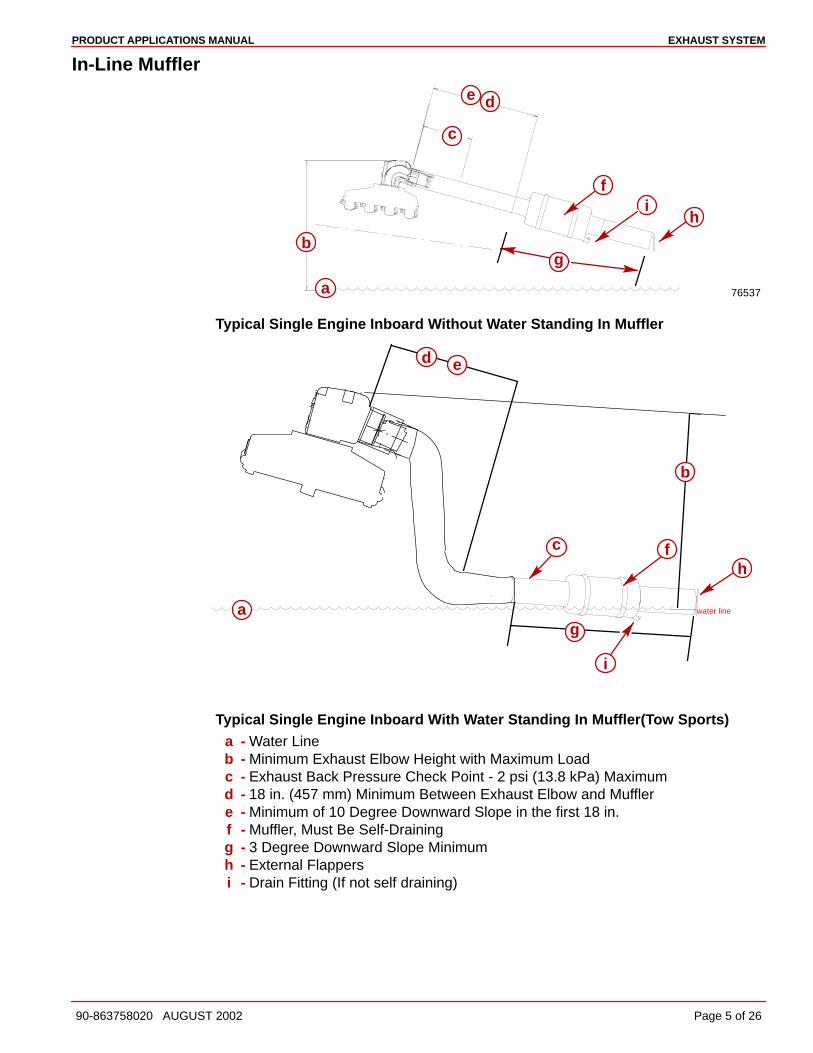
EXHAUST SYSTEMPRODUCT APPLICATIONS MANUAL
90-863758020 AUGUST 2002 Page 5 of 26
In-Line Muffler
76537a
b
e
c
d
g
if
h
Typical Single Engine Inboard Without Water Standing In Muffler
water linea
d e
fh
c
g
i
b
Typical Single Engine Inboard With Water Standing In Muffler(Tow Sports)a - Water Lineb - Minimum Exhaust Elbow Height with Maximum Loadc - Exhaust Back Pressure Check Point - 2 psi (13.8 kPa) Maximumd - 18 in. (457 mm) Minimum Between Exhaust Elbow and Mufflere - Minimum of 10 Degree Downward Slope in the first 18 in.f - Muffler, Must Be Self-Drainingg - 3 Degree Downward Slope Minimumh - External Flappersi - Drain Fitting (If not self draining)

EXHAUST SYSTEM PRODUCT APPLICATIONS MANUAL
Page 6 of 26 90-863758020 AUGUST 2002
¶ Applications with through transom fittings must be equipped with exhaust flappers toprevent the reverse flow of water into the engine. (Refer to Exhaust Through TheHull Fittings)
¶ The muffler, collector and exhaust hoses must be adequately supported for properorientation and to prevent overstressing the exhaust manifolds and elbows. Thesupport requirements will vary with exhaust system design and the amount ofG-forces to be encountered.
¶ Exhaust resonators can be used on any models that may experience a waterintrusion problem associated with the tuning effects of the exhaust system. (Refer toExhaust Resonators)
¶ Larger exhaust hoses should be used on applications with long hose runs.
Minimum Exhaust Hose Size
Model Dual Outlet System Single Outlet System
Dual HosePortion
Single HosePortion
8.1S Models 4 in. (102 mm) 4 in. (102 mm) 5 in. (127 mm)
All Others 3 in. (102 mm) 3 in. (102 mm) 4 in. (102 mm)
¶ Heat resistant exhaust hose that complies with specifications SAE J2006 or UL 1129should be used (ABYC standard).
¶ Every exhaust hose connection must be secured with at least 2 hose clamps. Theclamps should be stainless steel and at least 1/2 in. (13 mm) wide. Clamps whichrely solely on spring tension should not be used. (ABYC Standard)
¶ The system must have the capability to be serviced, reassembled and replaced whilemaintaining all of the specifications. The boat builder must provide documentation, suchas, manuals, drawings, or orientation marks on production assemblies.
¶ It is strongly recommended that orientation marks be used on all production exhaustsystem assemblies.
¶ in-line mufflers, collectors, and hoses must self drain after engine shut-down. Seemuffler/collector section.

EXHAUST SYSTEMPRODUCT APPLICATIONS MANUAL
90-863758020 AUGUST 2002 Page 7 of 26
T Junction With In-Line Muffler
76538
a
b
c
d
e f
g
h
i
kj
g
Typicala - Water Lineb - Minimum Exhaust Elbow Height with Maximum Loadc - Exhaust Back Pressure Check Point - 2 psi (13.8 kPa) Maximumd - Resonatore - 18 in. (457 mm) Minimum Between Exhaust Elbow and Collectorf - 10 Degrees Downward Slope Minimumg - Collector, 3 Degree Downward Slope Minimumh - 30-to-60 Degree Angle at T-Junction – Do Not Use Straight Connectioni - 3 Degree Downward Slope Minimumj - Muffler, Must Be Self-Draining (Or have drain fittings).k - External Flappers

EXHAUST SYSTEM PRODUCT APPLICATIONS MANUAL
Page 8 of 26 90-863758020 AUGUST 2002
V-Pipe And In-Line Muffler
76540
a
b
c
e f
kj
d
g
g
h
i
Typicala - Water Lineb - Minimum Exhaust Elbow Height with Maximum Loadc - Exhaust Back Pressure Check Point - 2 psi (13.8 kPa) Maximumd - Resonatore - 18 in. (457 mm) Minimum Between Exhaust Elbow and Y-Pipef - Minimum of 10 Degree Downward Slope in the first 18 in.g - Y-pipeh - 30-to-60 Degree Angle at Junction - Do Not Use Straight T-Connectioni - 3 Degree Downward Slope Minimumj - Muffler, Must Be Self-Drainingk - External Flappers

EXHAUST SYSTEMPRODUCT APPLICATIONS MANUAL
90-863758020 AUGUST 2002 Page 9 of 26
Collector And Water Lift Muffler
76536
a
b
e f
g
k
c
ih
d
j
Typicala - Water Lineb - Siphon Break (Vacuum Valve) Must Be Installed in Cooling Water Circuit If Ex-
haust Elbows Are At or Below Water Level – See Muffler Manufacturing Rec-ommendations*
c - Exhaust Back Pressure Check Point - 2 psi (13.8 kPa) Maximumd - Resonator (Refer to exhaust resonator section).e - 18 in. (457 mm) Minimum Between Exhaust Elbow and Collectorf - 10 Degree Downward Slope Minimumg - 3 Degree Downward Slope minimumh - Collector (See muffler /collector section).i - Minimum Exhaust Elbow Height with Maximum Loadj - Drain Cockk - External Flappers
S-pipe Used With Water Lift Muffler
a
b
c 78768
a - Water Lineb - Minimum Exhaust Elbow Height with Maximum Loadc - Drain Plug

EXHAUST SYSTEM PRODUCT APPLICATIONS MANUAL
Page 10 of 26 90-863758020 AUGUST 2002
Measuring Exhaust Elbow Height
The height of the exhaust elbows and the slope of the exhaust hoses must be within thedimensions specified to prevent water intrusion problems. Exhaust elbow risers must beinstalled, if needed, to obtain the proper height and/or slope. Measurement must be takenwith the boat in the water. It is important that the boat be loaded as outlined to simulate theextreme loading conditions likely to be encountered in normal operation.
IMPORTANT: Load distribution recommendations are the responsibility of the boatmanufacturer. Any load distribution conditions that will affect the exhaust systemheight and slope compliance must be clearly communicated to the operator in theowner’s manual. For example, the number of people that can be located on the swimplatform simultaneously should be included in the manual, if this could pose aproblem.
1. Fill fuel, water, gray water and heater tanks to maximum capacity. People or weights canbe used to simulate these loads if desired. Refer to conversions:
¶ 1 U.S. Gallon of Water = 8.3 lb.
¶ 1 Liter of Water = 1 kg.
¶ 1 U.S. Gallon of Gasoline = 6 lb.
¶ 1 Liter of Gasoline = 0.72 kg.
2. Add maximum allowable cargo weight to boat in areas where it will be stowed, includingrefrigerator and lockers. Do not forget the PWC, if applicable.
3. Add average passenger weight in all locations where each passenger will sit during nor-mal operation.
NOTE: ABYC specifies an average passenger weight of 141 lb. (64.0 kg.) for boat loadingcalculations. This should be used as a minimum. An average passenger weight of 190 lb.(86kg) is desirable.
4. Measure exhaust elbow height as outlined under Measurement Methods, following.Also, measure exhaust system slope as shown below.
NOTE: Exhaust elbow height is measured from the water lift muffler on applications soequipped. Refer to muffler manufacturer’s instructions for required height and procedure.
75203
a
b
a - Inclinometerb - Exhaust Hose

EXHAUST SYSTEMPRODUCT APPLICATIONS MANUAL
90-863758020 AUGUST 2002 Page 11 of 26
5. Leave fluid and cargo weights where they are, but remove passenger weights from boat.Beginning at the bow, reload passenger weight (the equivalent of one person at a time)while retaking readings. Use all of the available seating areas in the bow first. Continueadding passenger weight (and taking readings), moving from the bow to the stern, untilthe maximum people weight has been added back on board.
6. Repeat Step 5, but this time start at stern of boat and work toward bow.
7. Measurements under all loading conditions should be within these specifications:
Minimum Exhaust Elbow Height
Model Specification
MIE And V-drive Tow Sport Models 15 in. (381 mm)
Tow Sports Inline Transmission Models 13 in. (330 mm)
Minimum Exhaust Hose Slope
Model Specification
Within 18 in. (457 mm) ofEngine
Remainder of System
All Models 10 Degrees 3 Degrees
Slope Conversion
Degrees Drop vs. Run
3� 5/8 in. per ft. 52 mm per m
10� 2-1/8 in per ft. 177 mm per m
¶ Define height. The vertical dimension from the outer height of the exhaust elbow to theboat water-line or the muffler water-line in the case of a water- lift muffler.
¶ Water line in a water-lift muffler can be measured from the stand pipe.
8. Install risers if height is insufficient. Modify exhaust system and/or install risers, if slopeis insufficient. Refer to the Mercury Precision Parts / Quicksilver Accessory Guide forpart numbers.
Riser Options
Model Low Medium High *
8.1S 2 in. (51 mm) 6 in. (152 mm) 8 in. (203 mm)
All Others 3 in. (76 mm) 6 in. (152 mm) 9 in. (229 mm)
*High rise option is obtained by using the low and medium riser kits together. This is themaximum height that Mercury MerCruiser recommends.

EXHAUST SYSTEM PRODUCT APPLICATIONS MANUAL
Page 12 of 26 90-863758020 AUGUST 2002
Exploded Views
ALL MODELS
Serial numbers 0M317000 through 0M389999
78684 78802 78803
��
�
�
�
�
�
��
�
�
��
�
�
No Riser 3 Inch Warm Riser 6 Inch Warm Riser1 - Exhaust Manifold2 - Bolt, Manifold-To-Cylinder Head3 - Restrictor Gasket, With Turbulator (Seawater Cooled Models)4 - Block Off Gasket, With Turbulator (Closed Cooled Models)5 - 3 Inch Warm Riser6 - 6 Inch Warm Riser7 - Full Flow Full Flow Gasket, With Turbulator8 - Exhaust Elbow9 - Hose Fitting
10 - Small Pipe Plug11 - Large Pipe Plug12 - Bolt, Exhaust Elbow To Exhaust Manifold

EXHAUST SYSTEMPRODUCT APPLICATIONS MANUAL
90-863758020 AUGUST 2002 Page 13 of 26
CLOSED COOLED MODELS
Serial numbers 0M390000 and above.
788037880278684
��
��
��
��
�
�
�
�
�
�
�
�
�
�
�
�
No Riser 3 Inch Warm Riser 6 Inch Warm Riser1 - Exhaust Manifold2 - Bolt, Manifold-To-Cylinder Head3 - Block Off Gasket, With Turbulator (Closed Cooled Models Only)4 - Full Flow Gasket, With Turbulator5 - 3 Inch Warm Riser6 - 6 Inch Warm Riser7 - Exhaust Elbow8 - Bolt, Exhaust Elbow To Exhaust Manifold9 - Small Pipe Plug
10 - Large Pipe Plug11 - Hose Fitting12 - Bolt, Exhaust Elbow To Riser13 - Bolt, Riser To Exhaust Manifold

EXHAUST SYSTEM PRODUCT APPLICATIONS MANUAL
Page 14 of 26 90-863758020 AUGUST 2002
SEAWATER COOLED MODELS
Serial numbers 0M390000 and above.
7868478802 78803
��
�
�
��
�
��
�
�
��
�
�
��
�
�
�
No Riser 3 Inch Warm Riser 6 Inch Warm Riser1 - Exhaust Manifold2 - Bolt, Manifold-To-Cylinder Head3 - Restrictor Gasket, With Turbulator (Seawater Cooled Models)4 - 3 Inch Warm Riser5 - 6 Inch Warm Riser6 - Full Flow Full Flow Gasket, With Turbulator7 - Exhaust Elbow8 - Hose Fitting9 - Small Pipe Plug
10 - Large Pipe Plug11 - Bolt, Exhaust Elbow To Exhaust Manifold12 - Bolt, Exhaust Elbow To Riser13 - Bolt, Riser To Exhaust Manifold

EXHAUST SYSTEMPRODUCT APPLICATIONS MANUAL
90-863758020 AUGUST 2002 Page 15 of 26
Measurement MethodsIMPORTANT: Refer to Measuring Exhaust Elbow Height for instructions on properloading of the boat and complete measurement instructions.
STRAIGHT EDGE METHOD
1. Place a straight edge across boat.
2. With the straight edge above the engine and parallel to the water, measure the distancesbetween the straight edge and the top of the exhaust elbow.
3. With the straight edge above the engine and parallel to the water measure the distancebetween the straight edge and the outside waterline, or the muffler water-line.
4. The difference between these two measurements is the exhaust elbow height above thewater line. Refer to Measuring Exhaust Elbow Height and compare measurement toMercury MerCruiser’s specifications.
72700
bc
d
ae
76859
a - Waterlineb - Top Of Exhaust Elbowc - Straight Edged - Measurement Between Straight Edge And Top Of Exhaust Elbowe - Measurement Between Straight Edge And Water Line

EXHAUST SYSTEM PRODUCT APPLICATIONS MANUAL
Page 16 of 26 90-863758020 AUGUST 2002
CLEAR HOSE METHOD
1. Obtain a 5/16 – 3/8 in. (8–10 mm) ID hose approximately 15 ft. (4.5 m) long. Put a metalfitting or a weight on one end of the hose to keep that end of the hose below the waterline.
2. Put the weighted end of the hose over the port or starboard side of the boat, keepingit in line with the engine’s exhaust elbow.
3. Route the remainder of the hose toward the engine’s exhaust manifold and elbow.Ensure that this open end section of the hose is as vertical as possible from the boat’sbilge to the top of the exhaust elbow
4. Coil excess hose in bilge of boat, keeping it below the water line.
5. Lower open end of hose and siphon water until it starts to come out of the hose. Put afinger over the hose and lift open end until it is at the top of the exhaust elbow.
6. Slowly take finger off end of hose to let the water level stabilize. The water will seek thelevel of the water outside the boat. Keep hose close to exhaust elbow and as verticalas possible.
7. Insure that the boat is level from side to side using a level or inclinometer.
8. The measurement between water in hose and top of exhaust elbow is the exhaust elbowheight. Relative to the boat water line.
72700
bc
d
a
ea76859
a - Waterlineb - Top Of Exhaust Elbowc - Clear Plastic Hosed - Weighte - Measurement - Waterline To Top Of Exhaust Elbow
9. An application using a water lift muffler will require the height between the boat waterlineand the muffler waterline to be measured and factored into the resulting riser height cal-culation to find the defining riser height.

EXHAUST SYSTEMPRODUCT APPLICATIONS MANUAL
90-863758020 AUGUST 2002 Page 17 of 26
Water Lift Muffler
The following important information must be observed if using water lift mufflers:
¶ Mufflers must be installed per the manufacturer’s specified distance below the top of theexhaust elbows to avoid water ingestion. Use exhaust elbow risers if needed to obtainspecified distance.
¶ The muffler riser must also extend the manufacturer’s specified distance above thewaterline to prevent the muffler from filling with water.
¶ A siphon break (vacuum valve) must be installed in the cooling water circuit if exhaustelbows area at or below water level. Refer to manufacturers recommendations.
¶ A drain must provided to drain the muffler.
76536
a
b
c
76536
c a
b
Typical Water Lift Mufflera - Muffler Must Be Positioned per Manufacturer’s Specified Distance Below Ex-
haust Elbowsb - Muffler Riser Must Extend Manufacturer’s Specified Distance Above Water Linec - Siphon Break (Vacuum Valve) Must Be Installed in Cooling Water Circuit If Ex-
haust Elbows Are At or Below Water Level

EXHAUST SYSTEM PRODUCT APPLICATIONS MANUAL
Page 18 of 26 90-863758020 AUGUST 2002
Exhaust Resonators
The design of the exhaust pipe and muffler system can cause a tuning effect that can con-tribute to a water intrusion problem. This tuning effect can be caused by a combination offactors, including but not limited to:
¶ Configuration of exhaust outlets
¶ Design and size of muffler and/or collector
¶ Length of exhaust hoses
¶ Amount of back pressure in system
The interactive nature of these factors makes it difficult to predict which exhaust system de-signs will be susceptible to the tuning effect. To address this situation, Mercury MerCruiserhas developed exhaust resonators that can be installed 13-17 in. aft of the exhaust elbowoutlets. The boat builder must test to find the optimum resonator placement for the each typeof exhaust system. The resonators help to break up the reverse pulsations, yet do not affectengine performance. In some cases, a performance increase is actually realized by usingthe resonators.
Resonators are typically more beneficial for large engines, but the kit can be used on othermodels as well and is available through Mercury Precision Parts / Quicksilver Accessories.
Resonators are installed as shown. Because of the critical nature of the placement of theresonator, Mercury MerCruiser will license this technology free of charge to allow the reso-nator to be built into your collector or muffler. Contact your SAE for details.
75203
aeb
c
d
a - Exhaust Resonatorb - Exhaust Hosec - Dimension To Inside Flat Surface Of Resonator - 13-17 in. (330-432 mm) [17 in.
Ideal] –– MUST BE EQUAL BOTH SIDES OF ENGINEd - No Less Than 2 in. (51 mm) Between Resonator and Closest Hose Connectione - Hose Clamp Positioned Around Center Of Resonator

EXHAUST SYSTEMPRODUCT APPLICATIONS MANUAL
90-863758020 AUGUST 2002 Page 19 of 26
Exhaust Connections
CAUTIONAvoid exhaust hose failure. Discharge water from exhaust elbow must flow aroundentire inside diameter of hose to avoid causing hot spots that could eventually re-sult in burned-through exhaust hoses. Exhaust hoses and/or tubes must be cor-rectly connected to exhaust elbows so that they do not restrict the flow of dischargewater from exhaust elbow.
Exhaust hoses must be properly installed on exhaust elbow outlets. Discharge water fromthe exhaust elbow must flow around the entire inside diameter of hose to avoid causing hotspots that could burn through the hose. Exhaust hoses must be installed at the angle shownfollowing.
78715
Correct Incorrect
Exhaust Connection On All Models Except 8.1S
a
bc
a - Reference Line Parallel to Crankshaft Centerlineb - Centerline Of Exhaust Outlet And Hosec - 7¯ Down Angle

EXHAUST SYSTEM PRODUCT APPLICATIONS MANUAL
Page 20 of 26 90-863758020 AUGUST 2002
77701
a
bc
d
e
8.1L Exhaust Connectiona - Maximum Misalignment +/–5 Degreesb - Exhaust Outlet Centerline (14 Degrees vs. Crankshaft Centerline)c - Exhaust Hose Centerlined - See Chart For Angle vs. Horizone - Horizon (Level Surface)
¶ Every exhaust hose connection must be secured with at least 2 hose clamps. Theclamps should be stainless steel and at least 1/2 in. (13 mm) wide. Clamps whichrely solely on spring tension should not be used. (ABYC Standard)
73961
a
a - Hose Clamps

EXHAUST SYSTEMPRODUCT APPLICATIONS MANUAL
90-863758020 AUGUST 2002 Page 21 of 26
Exhaust Through The Hull Fittings
All applications with through transom exhaust fittings must be equipped with external flap-pers to prevent water intrusion problems. Applications which discharge exhaust through theside of the hull do not require flappers.
72740
a
b
a - Flapperb - Through Transom Exhaust Fitting

EXHAUST SYSTEM PRODUCT APPLICATIONS MANUAL
Page 22 of 26 90-863758020 AUGUST 2002
Checking For Water Intrusion
IMPORTANT: A check for water intrusion must be performed on all new applicationswith through transom / hull exhaust.
There are two methods to check for water in the exhaust manifolds. The simplest and leasttime consuming way is the exhaust elbow removal method. With this method, however, itis difficult to accurately determine the amount of water in the manifolds. The exhaust man-ifold tap method provides a more accurate means to measure the water, but requires thata hole be drilled in each manifold. The manifolds must be replaced after performing thischeck, so this procedure is best performed by Mercury MerCruiser’s Sales Applications En-gineers, or where repeated testing will be performed at your facility.
IMPORTANT: If there is no water in one manifold, do not assume that there will notbe water in the other manifold. Check each manifold.
PreparationData to consider while performing these test are exhaust hose lengths and angle, exhaustelbow height to the water line, water lift muffler exhaust outlet angles, water lift muffler waterheight, idle relief angles, exhaust collector angles air temperature water temperature, andhumidity.
Extended Idle Test1. Operate engine until it is at normal operating temperature [160¯ F (73¯ C)]. If necessary,
perform a compression test of the engine.
2. Place the remote control in NEUTRAL. Increase the engine speed to 3000 rpm for 1 min-ute.
3. Bring engine back to idle SLOWLY after 1 minute.
4. Shut engine OFF.
5. Restart engine and operate at idle speed for 15 minutes.
6. Shut engine OFF.
7. Check for water. (Refer to Interpreting Results)
IMPORTANT: If it becomes necessary to repeat the test, ensure that the engine is atnormal operating temperature and that the 3000 rpm step is repeated to clear themanifolds of water.

EXHAUST SYSTEMPRODUCT APPLICATIONS MANUAL
90-863758020 AUGUST 2002 Page 23 of 26
Checking By Exhaust Elbow Removal Method1. After the 15 minute extended idle test, drain exhaust manifolds of water.
2. Remove the exhaust elbows.
3. Check for water in the exhaust manifold. Use a flashlight if needed to aid inspection. Ifwater is found, record the amount. (Refer to Interpreting Results)
NOTE: A suction device with a rubber hose attached to the end can be used to suck thewater from the manifold and discharge it into a container. Clean the inside of the elbows thor-oughly before performing a new set of tests to avoid biasing the results.
4. Replace the elbows using new gaskets. Refer to the appropriate Mercury MerCruiserservice manual for installation procedure.
Checking By Drilling And Tapping Exhaust Manifolds1. Drill and tap 1/8 in. NPT hole into the bottom and center of the exhaust manifold runners
for cylinders 4 and 5 (second cylinder from front on starboard bank and third cylinderon port bank).
76859
Starboard Port
2. Insert brass drain plugs (Quicksilver P/N 22-32802-1) into holes.
3. Operate the engine as outlined in Extended Idle Test.
4. Drain water from manifolds into a suitable container. Measure and record amount of wa-ter using a graduated cylinder.
5. Replace the manifolds with new manifolds.

EXHAUST SYSTEM PRODUCT APPLICATIONS MANUAL
Page 24 of 26 90-863758020 AUGUST 2002
Interpreting ResultsWater vapor is a normal by–product of the combustion process, so a small amount of water[0.2 fl oz. (5 ml.) ] is acceptable. This condensation has not shown to cause a problem. Wateramounts in excess of this could be an indication of a water intrusion problem that requirescorrective action. If water intrusion is occurring, traces of salt may be present on the wallsof the elbow or at the bottom in the middle exhaust runners. Some of the more commoncauses for this condition are:
¶ Insufficient exhaust riser height. (Refer to Measuring Exhaust Elbow Height)
¶ Improper Exhaust Hose Slope.
¶ Failure to have at least 18 in. (457 mm) between exhaust outlet and muffler, collectoror first angular fitting. (Refer to Exhaust System Design)
¶ Exhaust resonators missing or mispositioned. (Refer to Exhaust Resonators)
¶ Improperly sized or incorrectly installed water lift mufflers.
¶ Leaking exhaust elbows and/or risers (example: loose screws, damaged gasket anddamaged sealing surfaces).
¶ Collector or Y-pipe improperly designed. (Refer to Exhaust System Design)
¶ Exhaust system causing a tuning effect. (Refer to Exhaust Resonators)
¶ Improperly functioning or missing water shutters and or flappers.
¶ Muffler not draining.
¶ Engine damage.

EXHAUST SYSTEMPRODUCT APPLICATIONS MANUAL
90-863758020 AUGUST 2002 Page 25 of 26
Exhaust Back Pressure
IMPORTANT: It is recommended that exhaust back pressure be checked on all newapplications to ensure that it is within specifications.
All exhaust systems have some restriction to flow or exhaust back pressure. The power out-put of an engine is directly related to the amount of exhaust that can flow out of the exhaustsystem. For example, large displacement engines will generally lose approximately 10horsepower for the first 1 psi (7 kPa) of exhaust back pressure. For every additional 1 psi(7 kPa) of back pressure, an engine may lose approximately 5 horsepower. Back pressureat WOT must fall within the range shown below.
Models Exhaust Back Pressure At WOT
All Gasoline Engines 1-2 psi (7-14 kPa)
IMPORTANT: Some exhaust back pressure is required to prevent water reversion inthe exhaust system. Do not go below 1 psi (7 kPa).
A higher output engine will cause a greater back pressure using the same size exhaust sys-tem as an engine with less output. The boat’s exhaust system should be designed andtested for the highest horsepower engine to be offered in that boat.
Ensure that both cylinder banks of any engine are tested. Record the highest back pressurereadings. If pressure is excessive, changes must be made to the system to reduce thepressure. These changes include:
¶ Reduce exhaust system length.
¶ Eliminate sharp bends.
¶ Increase exhaust system diameter.
¶ Reduce muffler, collector or Y-pipe restriction.
¶ Verify that the muffler is self-draining with boat at maximum load. This is one of the mostsignificant causes of higher than specified back pressure.

EXHAUST SYSTEM PRODUCT APPLICATIONS MANUAL
Page 26 of 26 90-863758020 AUGUST 2002
Exhaust Back Pressure Test
TOOLS
Description Part Number
Drill and 3/8 in. Drill Bits or Bits That Match Fittings Obtain Locally
Service Tachometer Obtain Locally
Schraeder Valve, 2 Required 22-860226*
Brass 1/8 in. NPT Male Adapter Fitting - 2 Required 22-808002*
Pressure Gauge Accurate to 1 psi (7 kPa) *
* Included in Boat Audit Tool Kit (91–823686A2).
PROCEDURE
The boat should be in the water and underway. No special loading of the boat is necessary.Engine must be capable of reaching the specified WOT rpm as verified using an accurateservice tachometer or scan tool. Both banks of each engine must be tested. Use the highestreading.
1. Drill 3/8 in. hole at the 12 o’clock position (facing up) in the exhaust hose 12 - 24 in. (305- 610 mm) from the engine exhaust elbow or directly aft of S-pipe.
2. Assemble the Schraeder valve and brass adapter. Insert the 1/8 in. NPT male end ofadapter into the hole in the exhaust hose.
75203
a
c
b
Testing Back Pressurea - Brass Adaptorb - Schraeder Valvec - Exhaust Hose
3. Set pressure gauge to zero before connecting it to engine.
4. While underway, operate engine at 1000, 2000, 3000, 4000 and WOT rpm respectively.Record back pressure at each setting.
5. Repeat steps for second cylinder bank and remaining engines on multiple engine ap-plications.
6. Replace exhaust hoses.
If pressure is excessive, changes must be made to the system to reduce the pressure.

MerCruiserMerCruiser
Dry JointDry Joint
Exhaust and Cooling SystemExhaust and Cooling System
V6, V8 Small BlockV6, V8 Small Block

Reasons Behind MerCruiser Exhaust System Changes
• Build the Industry’s Most Robust Exhaust
System.
• More Durability and Reliability.
• Promote Boating as a Leisure Activity with Fewer
Hassles.

Strategy Behind MerCruiser Exhaust System Changes
• Prevent Coolant Leaks.
• Eliminate Water from Leaking into Exhaust
Passages.
• Help Prevent Reversion.
• Insure More Robust Exhaust Collection &
Muffling System.

Start of Dry Joint System
• MCM V6 Models: S/N 0M615000-UP.
• MCM V8 Models: S/N 0M600000-UP.
• MIE V8 Models: S/N 0M0317000-UP.

Dry Joint Design Changes
• New Exhaust Manifold.
• New Exhaust Elbow.
• New Gaskets.
• New Risers.

Dry Joint Exhaust Manifold
• EDP Coated Only, No
Ceramic Coating.

Dry Joint Exhaust Elbow
• Ceramic and EDP Coated.
• 7o & 14o Version.

7o Exhaust Elbow
• Used on MCM and MIE Tow Sports with In-Line
Transmission.
• Fastener Torque is 61 Nm (45 lb-ft).
• Cast-in 316 ss Drain Tube.
– Prevents Corrosion Plugging.

14o Exhaust Elbow
• Used on MIE Inboards and MIE Tow Sports with
V-Drive Transmission.
• Fastener Torque is 61 Nm (45 lb-ft).
• More Drop for Inboard Use.
• Internal Dam.
• Wet Propshaft Log Water Tap.
– Port Side, Barb Fitting Included.
• Cast-in 316 ss Drain Tube.
– Prevents Corrosion Plugging.

Dry Joint Gaskets
• Built-in Turbulator
– Traps Condensation From Elbow
– Traps Water Reversion
– Increases Local Flow Velocity
• Water & Exhaust Separated
– Better Sealing
– No Leakage into Exhaust

Dry Joint Gaskets
• New Materials
– 18 gauge 316 ss Core.
– Two Layer 5000o F GrafoilTM, Seals Exhaust Passage.
– High Temp 4 Bead Silicone Seals Water Ports.
– Perfect Seal Protects Manifold and Elbow.

Dry Joint Gaskets
• Coat Edge of All Water Ports with Perfect Seal.
• If Bare Metal on Gasket Surface, use Perfect
Seal.
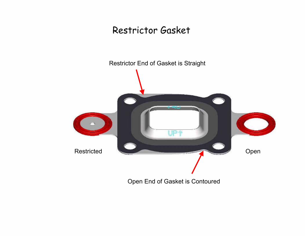
Restrictor Gasket
Restrictor End of Gasket is Straight
Restricted
Open End of Gasket is Contoured
Open

Restrictor Gasket
• Used on All Raw Water Cooled Engines
on the Manifold.
• Restrictor Opening Goes Toward End That
Bypass Water Comes From Thermostat
Housing Into Exhaust Elbow.
• Turbulator Points Upward.

Full Flow Gasket
Both Ends of Gasket are Contoured
OpenOpen

Full Flow Gasket
• Used on All Engines with Risers.
• Goes Between the Riser and Exhaust Elbow.
• Turbulator Points Upward.

Block Off Gasket
Both Ends of Gasket are Straight
Closed Closed

Block Off Gasket
• Used on All Closed Cooled Engines.
• Goes Between the Exhaust Manifold and Riser.
• Turbulator Points Upward.

Dry Joint 3 in. Risers
• Ceramic & EDP Coated.
• Bolted Fasteners Only.
– No Studs.
• New 3 in. Riser Kits.
• Fastener Torque is 61 Nm
(45 lb-ft).
– All Locations.

Dry Joint 6 in. Risers
• Ceramic & EDP Coated.
• Bolted Fasteners Only.
– No Studs.
• New 6 in. Riser Kits.
• Fastener Torque is 61 Nm
(45 lb-ft).
– All Locations.

RWC 3 in. & 6 in. withCold Dry Joint Risers
• No V6 Engines Built with Cold Risers.
• MCM V8 Engines: S/N 0M600000-0M614999.
• MIE V8 Engines: MIE S/N 0M0317000-
0M389999.

RWC 3 in. & 6 in. withWarm Dry Joint Risers
• MCM V6 Engines: S/N 0M615000-UP.
– V6 Carb & MPI - Only 3 in., No 6 in. Risers.
• No Hose Kit for 6 in. Riser Available.
• MCM V8 Engines: S/N 0M615000-UP.
• MIE V8 Engines: MIE S/N 0M390000-UP.

FWC 3 in. & 6 in. withCold Dry Joint Risers
• No Early V6 Engines Were Built Like This.
• Early V8 Carb & MPI Engines had Cold Risers
with Factory Installed FWC.
– MCM S/N 0M600000-0M614999.
– MIE S/N 0M0317000-0M389999.
• Early V8 Carb and MPI Engines will Get Warm
Risers if FWC Kit is Installed.
– MCM S/N 0M600000-0M614999.
– MIE S/N 0M0317000-0M389999.

FWC 3 in. & 6 in.Warm Risers
• V6 MPI have Warm 3 in. Risers on Factory
Installed FWC or FWC Kit.
– FWC Not Available for V6 Carb Engines.
– No 6 in. Risers Available.
– MCM S/N 0M0M615000-UP.
• V8 Carb have Warm Risers with FWC Kit.
– No Factory Installed FWC Available.
– MCM S/N 0M615000-UP.
– MIE S/N 0M390000-UP.
• V8 MPI have Warm Risers on Factory Installed
FWC or FWC Kit.
– MCM S/N 0M615000-UP.
– MIE S/N 0M390000-UP.

3 in. & 6 in. D J Riser Gaskets
• Warm Riser Gasket Location.
• RWC or FWC Engine - Gasket Between
Manifold and Riser.
– Full Flow Gasket.
• RWC Engine - Gasket Between Riser and
Exhaust Elbow.
– Restrictor Gasket.
• FWC Engine - Gasket Between Riser and
Exhaust Elbow.
– Block Off Gasket.

Dry Joint Installation Changes
• MCM Sterndrive
– Relocated Remote Oil Filter.
– No Other Changes.
• MIE Tow Sports In-Line.
– Relocated Remote Oil Filter.
– No Other Changes.

Dry Joint Installation Changes
• MIE Inboard and Tow Sports V-Drive.
– Relocated Remote Oil Filter.
– Exhaust Elbow is 38 mm (1-1/2 in.) Higher Because
of 14o Downward Angle.
– New Exhaust Specifications.
• 381 mm (15 in.) Above Waterline.
• Hose Slope is 10o Within 457 mm (18 in.) of Engine,
3o After That.
• Hose Installed Within 5o Relative Angle to Elbow.
• Use Orientation Marks for Service and Assembly.
– Will Require OEM Exhaust Systems to be
Redesigned for V8 MIE and Ski V-Drives.

Oil Filter Relocated

Installation Reminder
• Current MIE Inboard and Tow Sports V-Drive
Requirements.
– Test & Verify Exhaust System Designs
– 6.9-13.7 kPa (1-2 psi) Exhaust Back Pressure.
– Maintain Adequate Support of System Components.
– Use Exhaust Resonators if They Help.
– Use at Least Minimum Size Exhaust Hoses.
– Use Heat Resistant Exhaust Hose.
– Use at Least 2 Clamps per Connection.

Dry Joint 14o Exhaust Elbow

Dry Joint 14o Exhaust Elbow

14o Elbow with 3 in. Riser

14o Elbow with 6 in. Riser

Thermostat Housings
• RWC Carb and MPI
with Multi Point
Drain.
– New Housing with
Check Balls.
– 160o F Thermostat.
– Warm Exhaust
Manifolds.

Thermostat Housings
• RWC MPI with
Drain Systems.
– New Housing.
– 160o F Thermostat.
– Warm Exhaust
Manifolds.

Thermostat Housings
• FWC Carb and MPI.
– New Housing.
– 170o F Thermostat.
– Manifolds in Closed Cooling
System.

Dry Joint Closed Cooling
• V6 Carb - No Factory Option or Kit.
• V8 Carb - No Factory Option, Kit Only.
• V6 or V8 MPI - Factory or Kit.
• Larger 5 in. Heat Exchanger.
– Makes Engine Slightly Longer, 6 mm (1/4 in.).
• V8 Has Smaller Diameter Circulating Pump
Pulley.
• Closed Cooling has Manifolds in Coolant.
– V6 Alpha Requires Belt Driven Seawater Pump.
– Bravo Models Require Dual Water Pickup, Needs
114 L/min (30 gal/min) @ 4000 rpm.

Ordering Dry Joint FWC Kits
• Manifolds with Kit Will be Warm.
– Risers will be Warm Also.
• More Sub Kits Needed.
– MPI ECM 555 Because of Cal Change for Warm
Manifolds.
– Hose Kits.
• No Kits for V6 Carb Models.
• No Kits for Black Scorpion Models.
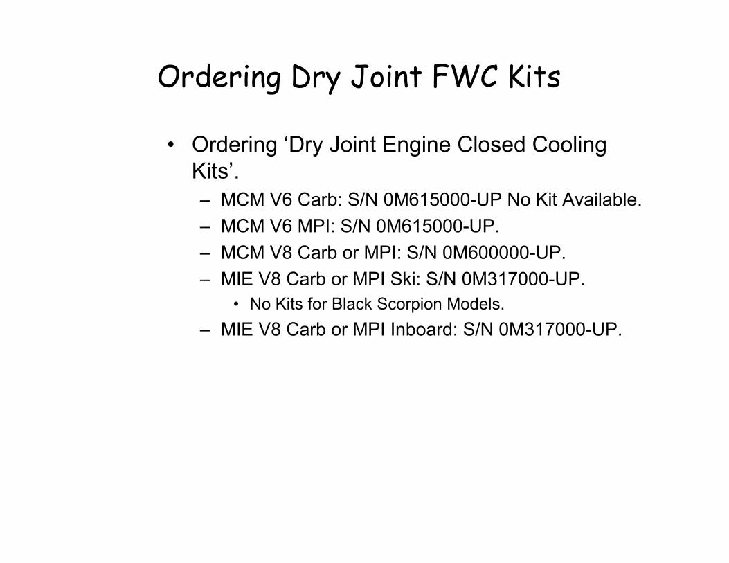
Ordering Dry Joint FWC Kits
• Ordering ‘Dry Joint Engine Closed Cooling
Kits’.
– MCM V6 Carb: S/N 0M615000-UP No Kit Available.
– MCM V6 MPI: S/N 0M615000-UP.
– MCM V8 Carb or MPI: S/N 0M600000-UP.
– MIE V8 Carb or MPI Ski: S/N 0M317000-UP.
• No Kits for Black Scorpion Models.
– MIE V8 Carb or MPI Inboard: S/N 0M317000-UP.

Dry Joint Service Manual
• Nbr 37 V8 Service Manual Supplement.
– 90-864260020 Oct 2002.
• Section 6 Cooling System.
– All Models.
– Seawater System.
– Closed Cooling System.
• Section 7 Exhaust System.
– Manifolds and Elbows.
– Cold Riser Models.
– Warm Riser Models.
• Section 10 Color Diagrams.
– Water Flow Diagrams.

Ordering Non-Dry JointGMEFI Engine FWC Kits
• Kits are Half System Like Factory Installed
FWC.
• Ordering ‘Non-Dry Joint GMEFI Engine Closed
Cooling Kits’.
– MCM V6 MPI: S/N 0M300000-0M599999.
– MCM V8 MPI: S/N 0M300000-0M599999.
– MIE V8 MPI Ski: S/N 0M310000-0M316999.
• No Kits for Black Scorpion Models.
– MIE V8 MPI Inboard: S/N 0M310000-0M316999.

MC_Inboard_0804
6
Table of Contents
Engine Rotation
Transmission Identification
Engine/Transmission Installation Drawings
Transmission Internal Components
Transmission Operation
Propeller Rotation
Checking Transmission Fluid Level
Hurth/Velvet Drive Correct Oil Level Service Bulletins
Transmission Troubleshooting
Cross-Reference of Transmission Vendor to MerCruiser PartNumbers
Transmission Gear Ratios Available
Velvet Drive Marine Gear Distributors (USA and International)
Hurth Marine Gear Distributors (USA and Canada Only)

TRANSMISSIONS -
Transmissions
Engine RotationEngine rotation is described when observed from the rear of the engine (transmission end)looking forward (water pump end).
Engine rotation is indicated on engine specifications and serial number decal.
Identification
VELVET DRIVE TRANSMISSIONS
On Velvet Drive In-Line and V-Drive Transmissions (71C, 72C, 72C V-Drive, with or withoutWalter transmissions) the gear ratio (in forward gear) is marked on transmission identificationplate. Transmission output shaft rotation and propeller rotation required (in forward gear) isindicated on a decal on transmission case. Transmission rotation is described when viewedfrom the rear of transmission.
22556
a
b
c
In-Line Transmission Shown (Others Similarly Located)a - Transmission Identification Plateb - Gear Ratio (In Forward Gear)c - Output Flange Rotation Decal (In Forward Gear)
On the Velvet Drive 5000A and 5000V Transmissions the transmission identification plateindicates gear ratio, serial number and model.
71778
a
Velvet Drive 5000A - 8° Down-Angle Transmission Shown (5000V - V-Drive Similar)a - Transmission Identification Plate

- TRANSMISSIONS
ZF / HURTH TRANSMISSIONS
On the Hurth 8° Down-Angle and V-Drive Transmissions the transmission identification plateindicates gear ratio, serial number and model.
73587
a
Typical Hurth Down-Angle Transmission Shown (V-Drive Identification PlateSimilarly Located)
a - Transmission Identification Plate
WALTER V-DRIVE TRANSMISSIONS
On the Walter V-Drive Transmissions the transmission identification plate indicates gear ratio,serial number and model.
75195
a
Walter V-Drivea - Transmission Identification Plate


Transmission Internal Components
� Velvet Drive 5000A
� ZF/Hurth 630A (63A)


Velvet Drive Transmission Parts List
P-1 Transmission Assembly, S5000 Marine
1 Dipstick (Late Production, After 5/1/93)
1A Dipstick (Early Production, Ending 5/1/93)
2 Plug, Drain
3 Bolt, Hex head, M10 x 1.5 x 70
3A Bolt, M5 x 0.8 x 30
3B Washer
4 Valve & Pump Assembly
5 Gasket
6 Shim
7 Bolt, Hex head, M8 x 1.25 x 20
8 Bolt, Hex head, M10 x 1.5 x 30
9 Bolt, Hex head, M12 x 1.75 x 35
10 Washer
12 Cup, Bearing
13 Cup, Bearing
14 Case Cover & Magnet Assembly
15 Gasket
16 Seal, Oil
17 Nut, Flange
18 Flange, output
19 Seal, Oil
20 Cone, Bearing
21 Shim
22 Sleeve (Supersedes 2001-103-001)
22A Sleeve (Superseded by Two 2001-103-003)
23 Shaft Assembly, Output
24 Cone, Bearing
25 Bolt, Socket head, M8 x 1.25 x 30
26 Gear, Output
27 Shaft, Output
28 Shaft Assembly, Input
29 Shaft Assembly, Lay
30 Cup, Bearing
31 Cone, Bearing
32 Bolt, Hex head, M6 x 1.0 x 102
33 Baffle, Oil
34 Tube Assembly, Suction (Late Production Starting 5/1/93)
34A Tube Assembly, Suction (Early Production Ending 5/1/93)
35 O-Ring
36 Breather
37 Rivet
38 Tag, Identification
39 Tube Assembly, Dipstick (Late Production Starting 5/1/93)
39A Tube, Dipstick (Early Production Ending 5/1/93)
40 Plug, Pipe
42 Insert, Thread
43 Pin, Tapered
44 Cup, Bearing
45 Cup, Bearing
46 Case, Transmission
47 Bolt, Socket Head, M5 x 0.8 x 25


Velvet Drive Transmission Parts List (cont.)
P-2 Valve & Pump Housing Assembly
201 Bolt, Socket head, M6 x 1.0 x 25
202 Pump Assembly
203 Switch Assembly
204 Nut, Hex, M8 x 1.25
205 Washer, Lock
206 Washer, Flat
207 Lever, Control
208 Ball, Steel
209 Spring
210 Ring, Snap
211 Valve, Control
212 O-Ring
214 Bolt, Hex head
215 Plate, Cover
216 Gasket
217 Spring M6 x 1.0 x 16
217A Spring (Used in addition to spring [217] with valve piston [218]
and washer [219] only)
218 Piston, Valve (Late Production)
218A Piston, Valve (Early Production)
219 Washer
220 Screen
221 Pin, Spring
222 Housing, Valve


Velvet Drive Transmission Parts List (cont.)
P-3 Shaft Assembly, Input
301 Cone, Bearing
302 Spacer
303 Washer, Thrust
304 Gear, Clutch
305 Ring, Snap
306 Bearing, Needle
307 Ring, Snap
308 Ring, Snap
309 Plate, Backing
309A Plate, Backing
310 Plate, Clutch
311 Disc Assembly, Clutch (drive)
312 Disc, Clutch (driven)
313 Bolt, M6 x 1.0 x 20
315 Cylinder, Clutch Gear (RH)
316 Ring, Snap
317 Retainer, Spring
318 Spring
318A Spring
319 Piston Assembly, Clutch
320 Ring Assembly, Sealing
321 Ring, Sealing
322 0-Ring
323 Ring Assembly, Sealing
324 Ring, Sealing
325 O-Ring
326 O-Ring
327 Ring, Oil seal
328 Ring, Seal (steel)
329 Shaft, Input


Velvet Drive Transmission Parts List (cont.)
P-4 Shaft Assembly, Lay
402 Cone, Bearing
403 Gear, Clutch
404 Bearing, Needle
405 Ring, Snap
406 Ring, Snap
407 Plate, Backing
407A Plate, Backing
408 Plate, Clutch, Steel
409 Disc Assembly, Clutch (drive)
410 Disc, Clutch (driven)
411 Bolt, M6 x 1.0 x 20
413 Cylinder, Clutch Gear (LH)
414 Ring, Snap
415 Washer, Thrust
416 Retainer, Spring
417 Spring
417A Spring
418 Piston Assembly, Clutch
419 Ring Assembly, Sealing
420 Ring, Sealing
421 O-Ring
422 Ring Assembly, Sealing
423 Ring, Sealing
424 O-Ring
425 O-Ring
426 Ring, Oil seal
427 Shaft, Lay
428 Ring, Snap
429 Spacer
430 Spring
431 Ball


ZF – Hurth Transmission Parts List
100 Hex Screw (carters)
100a Hex Screw (suction pipe clamp)
100b Lock washer (carters)
102 Locator Pin
103 Gasket (control block)
104 Input Shaft Seal
105 Oil Filter
106 Seal (suction pipe)
107 Breather Valve
108 Lock Washer
109 Lock Washer
110 Hex Plug
111 Hex Head Bolt
112 Hex Head bolt
113 Hex Head bolt
114 Hex Socket Head Bolt
115 Output Shaft Seal
116 Distributor Shaft Seal
117 Control Block Assembly
118 Shift Lever
119 Plug (control block)
120 Washer (control block)
121 Plug (control block)
122 Neutral Safety Switch
123 Nut (shift lever)
124 Cover (housing)
125 Housing
126 Suction Pipe
127 Filter Cover
128 O-Ring
129 O-Ring
130 Dipstick (no O-Ring 132 required)
130 Dipstick + O-Ring
131 Suction Pipe Clamp
132 O-Ring
133 Oil Filter Complete
136 Hex Head Bolt
137 Baffle
138 Baffle Plate
139 Baffle Plate
140 Centering Ring


ZF – Hurth Transmission Parts List (cont.)
137 Baffle
201 Input Shaft and Complete Clutch Assembly
202 Needle Bearing
202a Needle Bearing
203 Reverse Gear
204 Butting Ring
204a Butting Ring
205 Tapered Roller Bearing
206 Tapered Roller Bearing
207 Input Shaft and Clutch Housing
208 Piston Ring
209 Key
210 Shim
211 Inner Clutch Disc
212 Outer Clutch Disc
213 Snap Ring
214 End Disc
215 Clutch Piston
216 Outer Clutch Piston Ring
217 Inner Clutch Piston Ring
218 Ball
219 Cup Spring
220 Retainer Ring
221 Tapered Roller Bearing
222 Tapered Roller Bearing
223 O-Ring
224 Output Flange
225 Hexhead Bolt
226 Disk
226 Ring Nut
227 Tapered Roller Bearing
228 Tapered Roller Bearing
229 Shim
230 Spacer
240 Butting Ring Ball
241 Retainer Ring
301 Forward Gear
302 Intermediate Shaft
305 Out Shaft


- TRANSMISSIONS -
Propeller Rotation
Velvet Drive 71C and 72CTransmission gear ratio (in forward gear) is marked on transmission identification plate,which is located on the port (left) side of transmission. Transmission output shaft rotationand propeller rotation required is indicated on a decal on transmission case. Transmissionrotation is described when viewed from the rear of transmission with transmission in forwardgear selector position.
On MIE engines equipped with in-line transmissions having 1:1 gear ratio, transmission out-put shaft rotation is the same as engine rotation with transmission in forward gear. Enginerotation is LH (CCW), so a LH propeller is required.
1. DO NOT start or crank engine without fluid in transmission.
2. Use only recommended fluid in transmission.
3. Except in an emergency, never shift transmission at engine speeds above 1000 rpm.
4. Free wheeling of one propeller (in a twin engine boat) at trolling speeds will not causedamage to the transmission. However, boat operation above trolling speed should beavoided. Be sure proper fluid level exists before free wheeling propeller.
5. DO NOT paint shift lever poppet ball and spring. An accumulation of paint will preventproper action of the detent.
6. Always replace oil cooler and hoses after a transmission failure or prior to installing a newor rebuilt transmission. Metallic particles from a failure tend to collect in the cooler andhoses, and will gradually flow back into the fluid system and damage transmission.
7. Always use specified oil cooler, hoses and fittings. Hoses must be at least 13/32 in. (10.5mm) I.D. Oil cooler, hoses and fittings must be sufficient size to maintain transmission fluid(in sump) at 140-190�F (60-88�C).

- TRANSMISSIONS
Propeller Rotation (Continued)
Velvet Drive 5000A and VPropeller rotation is not necessarily the same as engine rotation. Refer to the appropriatefollowing information and drawings for specific information.
These transmissions are “full power reversing” transmissions, allowing a standard (LHrotation) engine to be used for both propeller rotations. Propeller rotation (output shaftrotation) is determined by shift cable attachment at the remote control. Be sure to use correctrotation propeller and shift cable hook up for direction desired.
a
b
c
b71888
d
e
Velvet Drive 5000A - 8° Down-Angle Transmission
a
b
f
74604
b
g
d
Velvet Drive 5000V - V-Drive Transmissionsa - Direction of Shift Lever Engagement (Toward Flywheel)b - Engine/Transmission Input Shaft Rotation Direction (LH)c - Transmission Output/Propeller Shaft Rotation Direction (LH)d - Direction of Shift Lever Engagement (Away From Flywheel)e - Transmission Output/Propeller Shaft Rotation Direction (RH)f - Transmission Output/Propeller Shaft Rotation Direction (LH as viewed at
propeller)g - Transmission Output/Propeller Shaft Rotation Direction (RH as viewed at the
propeller)

- TRANSMISSIONS -
Propeller Rotation (Continued)
Hurth 630A and V, 800A
c
25506
a
b
d
e
b
Hurth 630A or 800A - 8° Down-Angle Transmissions
7295972959
a
b
c
d
e
b
Hurth 630V - V-Drive Transmissionsa - Direction of Shift Lever Engagement (Toward Flywheel)b - Engine/Transmission Input Shaft Rotation Direction (LH)c - Transmission Output/Propeller Shaft Rotation Direction (LH)d - Direction of Shift Lever Engagement (Away From Flywheel)e - Transmission Output/Propeller Shaft Rotation Direction (RH)
Propeller Rotation on Dual InstallationsBest all-around performance usually is obtained by installing engines so that propellers turnoutboard (looking at the stern).
22457
a
c b
a - Outboard Propeller Rotationb - RH Rotationc - LH Rotation

- TRANSMISSIONS
Application / Ratio SelectionThe propeller shaft speed is determined by engine speed and the transmission ratio. Everyboat has a most desirable shaft speed which has a direct relationship to boat speed. If shaftspeeds are too high an inordinately small propeller must be used which will result in poorperformance. If they are too low then too large a prop must be used. Fast boats do best withdirect drive or small reductions. Heavier and slower boats require corresponding greaterratios of reduction. 100 rpm of prop shaft speed for each MPH of boat speed is a rough “ruleof thumb” for selecting the drive ratio.
CouplingThe coupling is a flange type coupler (available through Quicksilver Accessories). All couplerbolts must be SAE Grade 8 (Metric Grade 10.9) or better, with a shoulder (grip length) longenough to pass through the face mating plane of couplers. All coupler bolts must be torquedto 50 lb-ft (68 Nm).
Engine/Propeller Shaft Installation AngleThe transmission and engine should be mounted so that the angle relative to horizontal is asshown in the installation drawings. Refer to individual installation drawings for each specificengine and transmission.
IMPORTANT: Relative to horizontal, never install the engine with the front (pulley end)down.
IMPORTANT: On all engines, a high angle of installation [front (pulley end) of engineup] along with low transmission oil levels can permit transmission pump cavitation onsome models when operating in rough water.
Propeller Shaft DiameterPropeller shaft diameter should be of sufficient size for the type of application.
Velvet Drive In-Line and V-Drive Transmissions (Except 5000 Series) – 71C and 72C Models
IMPORTANT: Velvet Drive In-Line and V-Drive Transmissions Only – Use of properrotation propeller (specified on transmission output flange rotation decal) is criticalsince the transmission must be operated in forward gear selector position only todrive boat forward. If the wrong rotation propeller is installed and transmission isoperated in reverse to propel the boat forward, transmission failure WILL occur.
IMPORTANT: On engines which are equipped with Velvet Drive In-line transmissions,a LH propeller is required.

TRANSMISSIONS -
Checking Transmission Fluid Level – Velvet Drive 71C and72C
IMPORTANT: Use only specified transmission fluid. Refer to “Specifications.”
IMPORTANT: To accurately check fluid level, engine must be run at 1500 rpm for 2 min-utes immediately prior to checking level.
72526
a
c
b
a - Dipstickb - Full Markc - Dipstick Tube
1. Start engine and run at 1500 rpm for 2 minutes to fill all hydraulic circuits.
IMPORTANT: Be sure to push dipstick all the way down into dipstick tube when check-ing fluid level.
2. Stop engine and check fluid level. Add transmission fluid, if necessary, to bring level upto full mark on dipstick.
3. Reinstall dipstick. Be sure to tighten T-handle securely. DO NOT overtighten.
4. If transmission fluid level was extremely low, carefully check transmission, fluid cooler andhoses for leaks.
Fluid Specifications (Note: Dexron III-Red Colored, Mobil 424-Light Tan Colored)
Make and Model Capacity Fluid Type
Velvet Drive71C In-Line
1-1/2 (1.33)1
Dexron III Automatic Transmission Fluid - Std.or, Mobil 424Do Not Mix!
Velvet Drive72 Series
V-Drive3 (2.75)1
Mobil 424 - Std.or, Dexron III Automatic Transmission Fluid
Do Not Mix!
NOTE: 1 Use dipstick to determine fluid exact level. Warm Fluid Level Check: The transmission should be at operating temperature [190° F(90° C) maximum] to receive an accurate oil level reading.Cold Fluid Level Check: To ease checking fluid level, the dipstick can be marked or scribed.First the procedure for warm fluid level must be performed, then allow boat to sit overnight.Remove and wipe clean the dipstick. Insert clean dipstick and mark the cold fluid level.

- TRANSMISSIONS
Checking Transmission Fluid Level - Velvet Drive 5000IMPORTANT: Use only specified transmission fluid. Refer to “Specifications.”
Check transmission fluid before running engine each day, as follows:
1. Remove dipstick. Check fluid level as indicated on dipstick. Fluid level may be somewhatover full mark, as some of the fluid from transmission fluid cooler and hoses may havedrained back into transmission. If low, add specified transmission fluid to bring level upto full mark on dipstick.
73250
a - Dipstickb - Full Markc - Dipstick Tube
Fluid Type
Automatic Transmission Fluid(Dexron III) or Equivalent
IMPORTANT: To accurately check fluid level, engine must be run at 1500 RPM for twominutes immediately prior to checking level.
2. Start engine and run at 1500 RPM for two minutes to fill all hydraulic circuits.
IMPORTANT: Be sure to push dipstick all the way down into dipstick tube when check-ing fluid level.
3. Stop engine and quickly check fluid level. Add transmission fluid, if necessary, to bringlevel up to full mark on dipstick.
4. Reinstall dipstick.
5. If transmission fluid level was extremely low, carefully check transmission, fluid cooler andhoses for leaks.
Transmission Fluid Capacities
Model U.S. Quarts (Liters)
5000V 3 (2.75)1
NOTE: 1 Use dipstick to determine exact fluid level. Warm Fluid Level Check: The transmission should be at operating temperature [190° F(90° C) maximum] to receive an accurate oil level reading.Cold Fluid Level Check: To ease checking fluid level, the dipstick can be marked or scribed.First the procedure for warm fluid level must be performed, then allow boat to sit overnight.Remove and wipe clean the dipstick. Insert clean dipstick and mark the cold fluid level.
Model U.S. Quarts (Liters)
5000A Down Angle (All Ratios) 3 (2.75)1
1 : Always use dipstick to determine exact quantity of fluid required.

- TRANSMISSIONS -
Checking Transmission Fluid Level - Hurth ModelsIMPORTANT: Use only specified transmission fluid; refer to “Transmission Fluid Spec-ifications.”
IMPORTANT: The fluid level dipstick is located on the port side of transmission. DONOT remove T-handle on starboard side of transmission.
Check transmission fluid before starting engine each day, as follows:
1. Remove dipstick. Check fluid level as indicated on dipstick. Fluid level may be somewhatover full mark, as some of the fluid from transmission fluid cooler and hoses may havedrained back into transmission. If low, add transmission fluid to bring level up to full markon dipstick.
27661
Typical Hurth Transmission
IMPORTANT: To accurately check fluid level, engine must be operated at 1500 RPM fortwo minutes immediately prior to checking level.
2. Start engine and operate at 1500 RPM for two minutes to fill all hydraulic circuits.
IMPORTANT: Push non-threaded dipstick all the way down into dipstick tube when check-ing fluid level. Rest threaded dipstick on top of case when checking fluid level.
3. Stop engine and quickly check fluid level. Add automatic transmission fluid, if necessary,to bring level up to full mark on dipstick.
4. Reinstall dipstick.
5. If transmission fluid level was extremely low, carefully check transmission, fluid cooler andhoses for leaks.
Fluid Specifications
Make and Model Capacity Fluid Type
ZF (Hurth)630V
630A
800A
4.2 (4.0)
3.2 (3.0)
5.8 (5.5)
Dexron III Automatic Transmission Fluid
NOTE: 1 Use dipstick to determine fluid exact level. Warm Fluid Level Check: The transmission should be at operating temperature [190° F(90° C) maximum] to receive an accurate oil level reading.Cold Fluid Level Check: To ease checking fluid level, the dipstick can be marked or scribed.First the procedure for warm fluid level must be performed, then allow boat to sit overnight.Remove and wipe clean the dipstick. Insert clean dipstick and mark the cold fluid level.

- TRANSMISSIONS
Checking Transmission Fluid Level - Walter V-Drive
75192
a
c
b
a - Oil Level Gage (#21)b - Breather Cap (#12)c - Angle Housing (#23)
NOTE: If engine is equipped with a Walter V-Drive Transmission, the transmission fluid levelshould also be checked on the Velvet Drive Transmission. The two units do not share fluid.It is also important to note that the units use a different type of fluid.

- TRANSMISSIONS -
*The above information reprinted with the permission of The Walter Machine Company, Inc., Jersey City, NJ

96-11 496Printed in U.S.A.
service bulletinNo. 96-11TO: SERVICE MANAGER TECHNICIANS
PARTS MANAGER
Hurth Transmissions
Models
HSW 630-A Marine Transmissions
Problem
Fluid levels higher than the full mark when the engine and transmission are installed in the boat.
Solution
Fluid levels should be checked with the boat at rest in water. If transmission fluid appears to behigher than the full mark on the dipstick before running engine package, remove fluid from transmis-sion to read between the A and B mark on the dipstick (shown below). Run engine, shifting trans-mission in and out of gear to bring up the temperature of transmission fluid. After running enginepackage to increase the temperature of the transmission fluid (to compensate for expansion), shutdown engine and immediately check the level of the transmission fluid. If fluid level is above the fullmark (A), remove excess fluid to read between the A and B mark on the dipstick.
71383
AB

99-05 MAY 1999 Printed in U.S.A. - 1999, Mercury Marine Page 1 of 1
No. 99-05
WARRANTY INFORMATION SERVICE INFORMATION
Proper Oil Fill Level On Velvet Drive Transmissions
ModelsAll Velvet Drive 5000 Down Angles and 5000 V-Drives
SituationThere is one “Full Hot” mark on the dipstick of the above listed models that indicates theproper operating fluid level. The distance between the “Full Hot” mark and the bottom ofthe dipstick is not an operating range.
The proper method used to determine that the transmission fluid level is full is listed below:
1. Bring the engine up to operating temperature, place control lever in the neutral positionand shut down the engine.
2. Immediately remove the dipstick by holding the base and turning the T-handle counterclockwise.
3. Wipe the dipstick clean and insert fully back into the transmission case, withdraw andcheck fluid level.
4. Add or remove fluid to bring the level to the “Full Hot” mark on the dipstick.
5. Install dipstick and tighten by holding the base and turning T-handle clockwise.
For convenience a cold fill mark may be added to the dipstick for reference.
1. Perform the 5 steps listed above to determine the “Full Hot” mark.
2. Allow the transmission to fully cool down and remove the dipstick to find the fluid levelwhile cold.
3. Mark the dipstick at this cold level by using a small file and the fluid can now be checkedaccurately before operation.


TRANSMISSIONS -
Transmission Troubleshooting
Pressure Test - 71C and 72C Velvet Drive
1. Install pressure gauge.
72845
a
a - Main Line Pressure Tap - Remove Temperature Switch (3/8” NPT)
2. With boat in water, start engine and run until normal operating temperature is reached.
3. Refer to “Specifications” for pressure readings.
Transmission Repair
Mercury Marine does not stock or sell replacement parts for the in-line transmission. VelvetDrive has a network of distributors throughout the world to service their product. These distrib-utors, in turn, have a dealer network to service the transmissions. Also, service manuals (foreach transmission) can be obtained from Velvet Drive.
For the location of your closest distributor or service literature contact:
Velvet Drive TransmissionsDivision of Regal Beloit
Theodore Rice BoulevardIndustrial Park
New Bedford, MA 02745Phone: (508) 995-2616
Pressure Specifications - 71C and 72C
Enginerpm
Neutral Gear PSI (kPa) Forward Gear PSI(kPa)
Reverse Gear PSI(kPa)
rpmMIn. Max. Min. Max. Min. Max.
250 – – 70 (483) – 70 (483) –
600 115 (793) 135 (931) 115 (793) 140 (965) 120 (827) 140 (965)
2000 – – 125 (862) 160 (1103) 125 (862) 160 (1103)
3000 – – 135 (931) 180 (1241) – –

- TRANSMISSIONS
Pressure Test - Velvet Drive 5000 Models1. Remove transmission temperature switch and install a suitable pressure gauge.
73247
a
a - Main Line Pressure Tap - Remove Temperature Switch (3/8” NPT)
2. With boat in water, start engine and run until normal operating temperature is reached.
3. Refer to “Operating Specifications” for test rpms and respective pressure readings.
Transmission Pressure Specifications - 5000A Down Angle and 5000 V-Drive
Engine rpmNeutral Gear PSI (kPa) Forward Gear or Reverse Gear
PSI (kPa)Engine rpmMIn. Max. Min. Max.
900 10 (69) 50 (344)200 (1379) 400 (2757)
2400 50 (344) 70 (483)200 (1379) 400 (2757)
Transmission RepairMercury Marine does not stock or sell replacement parts for the down angle transmission.Velvet Drive has a network of distributors throughout the world to service their product. Thesedistributors, in turn, have a dealer network to service the transmissions. Also, service manu-als (for each transmission) can be obtained from Velvet Drive.
For the location of your closest distributor or service literature contact:Velvet Drive TransmissionsDivision of Regal BeloitTheodore Rice BoulevardIndustrial ParkNew Bedford, MA 02745Phone: (508) 995-2616

VD_Inboard_Trans_Troubleshooting_112003
Velvet DriveInboard Transmission
Troubleshooting
Functional Test
1. Connect 0-500psi pressure gauge to port as shown in service manual.
2. Proper fluid level (follow fluid checking procedure)
a. Velvet Drive 5000A fluid level increased by 14oz
1.) Surging cooler lines indicate low oil level.
3. Is fluid discolored?
4. Does it have a burnt odor?
5. Check proper shift cable adjustment.
a. Shift remote control in full forward
b. Remove shift cable from transmission without moving transmission shift lever
c. Make sure transmission lever is at full travel
d. If lever moves then adjust cable so that it slides over studs
e. Shift remote control lever to full reverse
f. Remove shift cable from transmission
g. Make sure transmission lever is at full travel
h. If not, then the shift system isn’t providing proper shift throw.
i. If controls and cables don’t allow proper throw then adjust control system so thattransmission shift lever if fully engaged in both directions
6. EFI Check if transmission overtemp circuit has been activated (Certain models only)
7. Start engine and verify neutral
a. If propshaft(s) rotate while transmission is in neutral it is certain the transmissionclutches are failed or beginning to fail.
b. If Forward clutches are seized the engine will suddenly die when shifted toreverse.
c. If clutches are beginning to fail the propshaft will rotate in neutral but might notkill engine when shifted to reverse.
8. Check hydraulic system pressure
a. Shift transmission to Forward gear
1.) Verify system operating pressure per Service Manual

VD_Inboard_Trans_Troubleshooting_112003
b. Shift Transmission to Reverse gear
1.) Verify system operating pressure
9. Transmission Temperature
a. Measure transmission temperature by a thermocouple installed in place of theaudio warning switch. Make sure your meter is set to the correct thermocoupletype, E, K, etc. The color of thermocouples correlate to type.
Violet = EYellow = KBlue = TBlack = J
10. Cooler Design (INBOARD ONLY) was changed from 12” to 16” to increase SafetyMargin.
Max Transmission Temperature
12” 190�F
16” 175�F
11. Slipping clutches will result in Temperature Alarm activation. Don't forget to check forcooler, or sea water strainer plugging.
Noise
1. Describe the noise:
a. High pitch?
b. Low pitch?
c. Continuous?
d. Does it occur in Forward or Reverse?
1.) Port Forward
2.) Port Reverse
3.) Starboard Forward
4.) Starboard Reverse
2. Is it only at idle speeds?
3. Does it go away if rpm is increased?
4. Is the engine running smoothly at idle?
a. Check IAC on scan tool. If an engine is running poorly at idle the IAC will be at ahigher value.


98-3 FEBRUARY 1998 Printed in U.S.A. - 1998, Mercury Marine Page 1 of 1
service bulletinNo. 98-3TO: SERVICE MANAGER TECHNICIANS
PARTS MANAGER
Regulator Piston for Velvet Drive Transmissions
ModelsAll Models Of 5000A and 5000V Transmissions Within The Following Serial Numbers:
5000A 1.5:1 S/N: 3895-40645000V 1.5:1 S/N: 1375-1962
5000A 2.0:1 S/N: 5534-60445000V 2.0:1 S/N: 1430-1809
5000A 2.5:1 S/N: 4955-50445000V 2.5:1 S/N: 1438-1829
5000A 2.8:1 S/N: 4301-4500
SituationThe above listed transmissions could have excessive noise (squealing) during operationdue to the regulator piston. If the transmission is within the serial ranges listed above, theregulator piston should be replaced. The regulator piston can be replaced as follows:
1. Remove the six bolts on the side cover of the pump housing.
2. Remove and discard old gasket.
3. Remove the two springs and the old piston.
4. Install 2 o-rings on new piston. Then put a thin layer of petroleum lube on o-rings. Donot install piston into transmission with dry o-rings.
5. Install piston back into pump housing with springs and new cover plate gasket.
6. Torque bolts on cover plate to 4-5 lb.ft.,(5-7N·m).
These kits are not in Quicksilver but can be ordered through MerCruiser Technical Assis-tance Phone: (405) 743-6555 or Fax: (405) 743-6570 or through a Velvet Drive Distributor,refer to Service Bulletin 95-23 for Velvet Drive Distributor locations.
WarrantyFill out warranty claim and send it to your normal warranty-processing center. More than oneengine can be put on the warranty claim if you list the part number, engine model, serial num-ber, warranty code and labor hours for each engine on separate lines on warranty claim.
Warranty Code and Labor:
Diagnosis & Installation: MK18 0.5 Hours.
Old Piston Only: Return them along with warranty claim.

- TRANSMISSIONS -
Functional Tests - Hurth Models1. Connect a pressure gauge and thermometer to fluid pump at locations shown.
50686
ab
Description
Thermometer (3/8 In. Thread, 0-270�F[-18 to -132�C])
Pressure Gauge (M10x1 Thread)or 1/8” NPT
TOOLS
a - Pressure Gauge (Use with Sealing Washer, M10x1 Thread - Remove Plug) (or 1/8” NPT)
b - Thermometer (3/8 In. Thread) - Remove Temperature Sender
2. Perform functional tests as shown in chart following. Refer to “Operating Specifications”for correct readings.
Tests to Be Carried Out:
1. Leakages
2. Noise emission
3. Direction of rotation, LH/RH
4. Fluid temperature
5. Shifting pressure
Motor Speed RPM Shift LeverPosition Duration Minutes Tests
800-1000 Neutral 5 1 2
600-800 (IdlingSpeed)
A↔B PositionRepeatedly
–– 1 2 3
1500-2500 B Position 1 1 2 4
600-800 (IdlingSpeed)
A↔B PositionRepeatedly
–– 1 2 3
Idling MaximumSpeed
A Position –– 1 2 5 2
600 -800 From A → B Posi-tion
–– 1 2
Idling MaximumSpeed
B Position –– 1 2 5 2
1Until fluid temperature of 167-176°F (75-80°C) has been reached2At different speeds
Operating Specifications
Description Specification
Shifting Pressure 312-377 PSI (2151-2599 kPa)
Operating Temperature 130°-200°F (54°-94°C)

Hurth_Inboard_Trans_Troubleshooting_112003 1
Hurth (ZF Marine) Transmission Troubleshooting
Trouble Possible Cause Remedy
1. Transmission gearscannot be shifted
A. Shifting lever loose
B. Remote control does notpermit lever travel requiredfor testing
C. Remote control faulty
D. No Shifting pressureavailable
A. Tighten clamping screw onshifting lever
B. Lift remote control off, if gearscan be shifted by hand,correct remote control
C. Repair remote control
D. Refer to 7
2. Delayed shift time A. Shift linkage misadjusted notallowing full engagement
A. Disconnect shift linkage andshift gear by hand and checkdelay time in transmission. Ifthe shift time is still delayed,replace the control block
3. Clutch is slipping;propeller speed toolow as compared toengine speed
A. Incorrect fluid used
B. Fluid contains water
C. Shifting pressure too low
D. Wear on clutch discs
E. Piston rings in clutch aredamaged
F. Pump shaft sealing ringsworn
A. Drain and refill with correctfluid, flush transmission whileengine runs in neutralposition drain fluid, refilltransmission
B. Refer to 9
C. Refer to 6
D. Disassemble transmissionreplace clutch discs
E. Disassemble transmissionreplace clutch
F. Replace sealing rings
4. Transmission lockedin gear
A. Medium piston ring in inputshaft in control block is faulty
B. Warped discs due tooverheating of slipping clutch
A. Remove control block,replace piston ring, replacecontrol block if worn
B. Refer to 3

Hurth_Inboard_Trans_Troubleshooting_112003 2
Trouble Possible Cause Remedy
4. Transmission lockedin gear (cont.)
C. Needle Bearings on inputshaft are worn out
C. Disassemble transmissionand repair
5. Output shaft turns inneutral position
A. Rotary slide valve in controlblock is worn
B. Faulty needle bearing oninput shaft
C. Dished discs due tooverheating of slipping clutch
A. Replace control block
B. Disassemble transmissionand input shaft, replacebearing
C. Refer to 3
6. Shifting pressure toolow
A. Fluid filter clogged
B. Fluid level in transmission
C. Fluid pump is worn out
D. Spring in shifting pressurerelief valve in broken
E. Piston rings on input shaftare faulty
F. Piston Rings in clutch arefaulty
A. Replace fine filter
B. Top-off with fluid; in case offluid loss, checktransmission, cooler andpipelines for leakage andremedy same, also refer to10 through 13
C. Replace control blockcontaining fluid pump
D. Replace control block
E. Remove control block andreplace piston rings. In caseof wear in control block dueto faulty piston rings, replaceblock as well
F. Disassemble transmission,replace clutch
7. No shifting pressureavailable
A. Direction of engine rotationdoes not agree with arrow ontransmission
B. No fluid in the transmission
C. Fine filter is dirty
A. Replace with engine ofcorrect rotation
B. Refill with fluid
C. Replace fine filter

Hurth_Inboard_Trans_Troubleshooting_112003 3
Trouble Possible Cause Remedy
7. No shifting pressureavailable (cont.)
D. Fluid level in transmission istoo low
E. Fluid pump worn out
F. Fitting key in input shaft forfluid pump drive is broken
G. Spring of shifting pressurerelief valve is broken
D. Top-off with fluid. In case ofloss of fluid checktransmission, cooler andpipelines for leakage andremedy same, also refer to10 through 13
E. Replace control block
F. Replace fitting key, replaceany other faulty parts
G. Replace control block
8. Excessive fluid A. Fluid cooler is too small
B. Excessive fluid intransmission
C. Fluid cooler is dirty on waterside
D. Worn fluid pump in controlblock
E. Faulty piston rings in controlblock
F. Clutch is slipping
G. Clutch does not opencompletely due to worn discsupport
H. Clutch does not opencompletely due to worn discsupport
A. Use a larger fluid cooler
B. Remove excessive fluid withcommercial suction pump
C. Detach coolant water linesand clean fluid cooler onwater side
D. Replace control blockcontaining fluid pump
E. Remove control block,replace piston rings. In caseof wear in the control block,due to faulty piston rings,replace control block as well
F. Refer to 3
G. Dismount transmission andcoupling, replace all faultyparts
H. Dismount transmission,replace inner disc supportand/or clutch

Hurth_Inboard_Trans_Troubleshooting_112003 4
Trouble Possible Cause Remedy
8. Excessive fluid(cont.)
I. With fluid cooler in by-passand unfavorable arrangementof pipelines, too little coolantwater flows through by-passto cooler
I. Correct by-pass pipeline
9. Water is in the fluid,fluid looks milky
A. Fluid cooler faulty
B. High water level in enginecompartment, water enteringthrough output shaft seal
A. Repair leakage at cooler, orreplace cooler. Changetransmission fluid
B. Remedy cause for water levelin engine compartment,change transmission
10. Fluid leakage atoutput shaft
A. Breather clogged with paintor dirt
B. Shaft seal faulty
C. Bent propshaft, or improperalignment
A. Remove paint or dirt frombreather
B. Disassemble transmission,replace seal. If seal locationon output shaft is worn seal-lip should be mounted offset
C. Check propshaft and couplerfor straightness and properalignment
11.Fluid leakage atbreather
A. Excessive fluid intransmission
A. Pump excessive fluid out withcommercial hand pump
12. Fluid leakage atjoints
A. Bolts are not tight
B. Seals on bolts have beenused several times
C. Mating surfaces arecontaminated, no surfaceseal applied
A. Tighten bolts with prescribedtorque
B. Replace seals, tighten boltswith prescribed torque
C. Unscrew housing half, finishmating faces with oilstone orfinishing file, apply surfaceseal. Assembletransmission, tighten boltswith correct torque
13. Transmission noisebecomes louder
A. Fluid level too low so thatpump sucks in air
A. Top-off with fluid to markingon dipstick

Hurth_Inboard_Trans_Troubleshooting_112003 5
Trouble Possible Cause Remedy
13. Transmission noisebecomes louder(cont.)
B. Damage starting on flexiblecoupling due to wear orfatigue, possibly due tomisalignment betweenengine and transmission
C. Beginning damage ofbearings in transmission, e.g.due to torsional vibrations,running without fluid,overload, wrong alignment oftransmission excessiveengine output
D. Beginning damage ofgearings, e.g. due totorsional vibrations, runningwithout fluid, overload
E. Fluid suction pipe intransmission has come loose
B. Replace flexible coupling.Check alignment betweenengine and transmission
C. Disassemble transmission,replace bearings concernedand other faulty parts. Findcauses and remedy
D. Disassemble transmission,remove faulty parts
E. Disassemble transmission, fixfluid suction pipe
14. Chatteringtransmission noisemainly at lowengine speed
A. The engine or propellergenerate torsional vibrationsin the drive unit whichproduce a chattering noise inthe transmission
B. Misaligned cardan shafts oninput or output
A. Mount a flexible coupling withanother stiffness factorbetween engine andtransmission; a coupling witha higher stiffness factormight be sufficient.Otherwise analyze thetorsional vibrations to find outthe required stiffness for thecoupling
B. Mount and align cardan shaftstrictly according toinstructions issued by cardanshaft manufacturer

- TRANSMISSIONS -
Walter V-Drive Models *
* The following pages of information are reprinted with the permission of The Walter Machine Company, Inc., Jersey City, NJ

- TRANSMISSIONS
Walter V-Drive Models (cont.)

- TRANSMISSIONS -
Walter V-Drive Models (cont.)
OUTDRIVING FLANGEFROM REVERSE GEAR
LOCKNUT FROMREVERSE GEAR
#38D SPLINEDADAPTER FLANGE
(Velvet DriveTransmission)

- TRANSMISSIONS
Walter V-Drive Models (cont.)

- TRANSMISSIONS -
Walter V-Drive Troubleshooting Guide

- - TRANSMISSIONS )
Walter V-Drive Troubleshooting Guide (cont.)

- TRANSMISSIONS -

Cross-Reference of Transmission Vendorto MerCruiser Part Numbers
This chart provides cross-references between the Mercury Marine part numbers and the VelvetDrive or Hurth part numbers for the transmission models used by Mercury MerCruiser. Theseare being provided to allow positive identification of transmissions when handling fieldproblems.
Velvet Drive 71/72 SeriesQuicksilver P/N Advertised
RatioActual Ratio Description Velvet Drive Tag
Number
60959A 6 1.50 1.51 72C V-Drive 10-05-011
60960A 6 **NLA** 1.99 1.99 72C V-Drive 10-05-002
60961A 6 (Gear) 2.49 2.49 72C V-Drive 10-05-005
60961A 8 (Chain) 2.49 2.50 72C V-Drive 10-05-004
47810A 19 1.00 1.00 72C Direct 10-18-002
47811A 7 1.50 1.52 72C In-line 10-18-004
47812A 7 **NLA** 1.90 1.91 72C In-line 10-18-006
47813A 7 2.57 2.57 72C In-line 10-18-010
47814A 7 2.90 2.91 72C In-line 10-18-012
47805A 7 1.00 1.00 71C Direct 10-17-004
47806A 7 **NLA** 1.50 1.52 71C In-line 10-17-006
47808A 7 **NLA** 2.57 2.57 71C In-line 10-17-012
Velvet Drive 5000 SeriesQuicksilver P/N Advertised
RatioActual Ratio Description Velvet Drive Tag
Number
805495A 8 1.25 1.30 5000A 2001-000-002
805495A 6 1.50 1.59 5000A 2001-000-003
805495A 4 2.10 2.04 5000A 2001-000-004
805495A 5 2.50 2.45 5000A 2001-000-005
805495A 7 2.80 2.80 5000A 2001-000-006
807481A 5 1.50 1.50 5000V 2002-000-003
807481A 6 2.10 1.99 5000V 2002-000-004
807481A 7 2.50 2.50 5000V 2002-000-005
Hurth (All)Quicksilver
P/NSupersededFrom P/N
AdvertisedRatio
Actual RatioA (R.H.)
Actual Ratio B(L.H.)
Description Hurth P/N
863744T2 18900A1 1.50 1.56 1.58 630A 22 - # # # # #
863744T3 18901A1 2.00 2.04 2.10 630A 24 - # # # # #
863744T4 18902A1 2.50 2.52 2.54 630A 25 - # # # # #
863744T5 862220A1 2.70 2.68 2.68 630A 978.25.000.30
863745T2 814437A1 1.55 1.56 1.57 630V 15 - # # # # #
863745T3 814438A1 2.00 2.00 2.03 630V 16 - # # # # #
863745T4 814439A1 2.50 2.48 2.53 630V 17 - # # # # #
806730A1 2.85 2.85 2.85 800A2 20 - # # # # #

TRANSMISSION AND DRIVE LINE PRODUCT APPLICATIONS MANUAL
Page 8 of 20 90-863758020 AUGUST 2002
Transmissions
Gear Ratios
Velvet Drive ZF Marine
71C 72C 5000A 5000V 45C 63A 63IV 80A
Tow Sports
5.7L 1.0:1 1.0:1
350 MagMPI 1.0:1 1.5:1 1.0:1
BlackScorpion 1.0:1 1.0:1
MX6.2LBlackScorpion2
1.0:1 1.0:1
Inboard
5.7L 1.0:1 1.0:1
1.25,1.5, 2.0,
2.5,2.8:1
1.5, 2.0,2.5:1
1.5, 2.0,2.5,
2.7:1
1.5, 2.0,2.5:1
350 MagMPI 1.0:1 1.0:1
1.25,1.5, 2.0,
2.5,2.8:1
1.5, 2.0,2.5:1
1.5, 2.0,2.5,
2.7:1
1.5, 2.0,2.5:1
350 MagMPI
Horizon1.0:1 1.0:1
1.251.5, 2.0,
2.5,2.8:1
1.5, 2.0,2.5:1
1.5, 2.0,2.5,
2.7:1
1.5, 2.0,2.5:1
6.2L MXMPI 1.0:1
1.5, 2.0,2.5,
2.8:1
1.5, 2.0,2.5:1
1.5, 2.0,2.5,
2.7:1
1.5, 2.0,2.5:1
6.2L MXMPI Hori-zon
1.0:11.5, 2.0,
2.5,2.8:1
1.5, 2.0,2.5:1
1.5, 2.0,2.5,
2.7:1
1.5, 2.0,2.5:1
8.1S HO 1.0:111.5, 2.0,
2.5,2.8:1
1.5, 2.0,2.5:1
1.5, 2.0,2.5,
2.7:1
1.5, 2.0,2.5:1 2.8:1
8.1S Hori-zon 1.0:11
1.5, 2.0,2.5,
2.8:1
1.5, 2.0,2.5:1
1.5, 2.0,2.5,
2.7:1
1.5, 2.0,2.5:1 2.8:1
1 V-Drive Installation only, used only with level mounted engine coupled to a drive shaft with forward-facingexhaust elbows.
2 1.46:1 Factory installed Walter V-Drive is optional.

2001-7 MAY 2001 Printed in U.S.A. - 2001, Mercury Marine Page 1 of 3
No. 2001-7
WARRANTY INFORMATION SERVICE INFORMATION
This bulletin replaces bulletin 95-23. Destroy that older bulletin.
Velvet Drive Marine Gear Distributors (USA and International)
Velvet Drive has a marine distribution program to provide service for its marine customers.Mercury MerCruiser dealers who have interest in becoming Velvet Drive dealers for trans-mission sales, service, and direct processing of warranty should contact the Velvet Drivedistributor in their area for more details on obtaining parts and/or service.
Velvet Drive distributors and their dealers may perform warranty repairs for the Velvet Drivetransmissions installed on Mercury MerCruiser engines and submit claims directly to VelvetDrive. The Mercury MerCruiser dealer must deliver the transmission to the distributor/deal-er, or ship it freight prepaid. The transmission will be repaired at no charge if the failure wasdetermined to be caused by Velvet Drive defects. The transmission may be picked up orreturned freight collect. Warranty claims are submitted through the normal warranty proc-essing channels for labor to remove and replace the transmission, and shipping charges.Normal rebuilding and repair service is also available through Velvet Drive’s distributor/deal-ership organization. Contact your area Velvet Drive distributor for warranty and/or service.Submit warranty claim through your normal warranty-processing channel.
United States
Boatswains Locker Sea Power Marine931 w. 18th Street 333 Kennedy StreetCosta Mesa, CA 92627 Oakland, CA 94606Phone: 949-642-6800 Phone: 510-533-9290Fax: 949-642-1463 Fax: 510-534-0908California, Arizona, Utah, California, Arizona, Utah,Nevada, Colorado, Hawaii, West Mexico Nevada, Colorado, Hawaii
M&L Engine Atlantis Marine Gear Supply1212 St. Charles Street 418 Boston RoadHouma, LA 70360 Topsfield, MA 01983Phone: 504-457-8000 Phone: 978-887-0001Fax: 504-851-0006 Fax: 978-887-5599Arkansas, Louisiana, Maine, New Hampshire,Mississippi, Alabama, Tennessee Vermont, Massachusetts
Mack Boring and Parts Co. Palmer Power Corp.2365 Rt. 22 6451 Rupley CircleUnion, NJ 07083 Houston, TX 77087Phone: 908-964-0700 Phone: 713-644-6410 or 800-364-3677Fax: 908-964-8475 Fax: 713-644-2873New Jersey, New York, Texas, Oklahoma, New Mexico,Connecticut, Rhode Island, Pennsylvania East Mexico

VELVET DRIVE MARINE GEAR DISTRIBUTORS (USA and INTERNATIONAL)
Page 2 of 3 MAY 2001 2001-7
Atlantis Power Hale Marine1956 Starr Batt Drive Highway 3 EastRochester Hills, MI 48309 Warsaw, VA 22572Phone: 248-299-3900 Phone: 804-333-3677 or 800-544-3677Fax: 248-299-8350 Fax: 804-333-0239Wisconsin, Illinois, Michigan, Ohio Delaware, North Carolina, Maryland,Ohio, Minnesota, North Dakota, Virginia, West Virginia, DC, BermudaNebraska, Kansas, Iowa, Missouri,Indiana, South Dakota, Kentucky
Doc Freeman’s Inc. Transmission Marine1401 NW Leary Way 223 SW 33rd CourtSeattle, WA 98107 Ft. Lauderdale, FL 33315Phone: 206-633-1500 or 800-423-8641 Phone: 954-467-1540Fax: 206-545-1813 Fax: 954-467-1525Washington, Oregon, Idaho, Montana Florida, Georgia, South Carolina,Wyoming, Alaska Caribbean
CanadaIndustrial Engines Anthony Keats Marine Ltd.1020 Cliveden Ave. 78 Talbot StreetAmaric Island Wheatley, OntarioDelta, British Columbia Canada NOP 2POCanada V3M-5R5 Phone: 519-825-4631Phone: 604-266-4126 Fax 519-825-7752Fax: 604-266-4129 Ontario, QuebecWestern Canada: British Columbia,Alberta, Saskatchewan, Manitoba,Yukon and NW Territory
Mermaid Marine Engines26 Fourth StreetWest Royalty Ind. ParkCharlottetown PEICanada C1E 2B3Phone: 902-566-1220Fax: 902-368-3660Eastern Canada: New Brunswick,Nova Scotia, Newfoundland, PEI
Argentina SingaporeBarrera’s Nautic Shop S.R.L. Multico Power Drive Pte. Ltd.Tigre CP. 1648 19 Jalan BurohArgentia JurongPhone: 54 1-7491916 Singapore 619476Fax: 54 1-7311794 Phone: 65 2655411
Fax: 65 2687643
Australia South AfricaAlltrac Pty. Ltd. Gearmax Parts and Service55 Zenith Road Unit 1A Wriggle RoadDandedong VIC 3175 Heritdale, JohannesburgPhone: 61 297947123 South AfricaFax: 61 297940955 Phone: 27 11 6181074
Fax: 27 11 6263168

VELVET DRIVE MARINE GEAR DISTRIBUTORS (USA and INTERNATIONAL)
2001-7 MAY 2001 Page 3 of 3
Chile New ZealandJaras S.A. Lee’s Delta Marine Ltd.Baron de Juras Reales 5250 345 Great South RoadCasilla 10114 Takannia, AuklandSantiago, Chile New ZealandPhone: 56 2-6231547 Phone: 64-9-299-6019Fax: 56 2-6231555 Fax: 64-9-298-9986
Northern Europe / Skandanavia TurkeyNewage Transmissions Ltd. Denpar Makina Ith. Ihr. San veBarlow Road Tic . Ltd.Coventry CV2 2LD Nazmi Akbaci Tic Merk No 212England Maslak – Istanbul TurkeyPhone: 44 1203 617141 Phone: 212 285 0334Fax: 44 1203 611845 Fax: 212 285 0311United Kingdom, Ireland, Turkey, North Africa, MiddleNetherlands, Belgium, East, Pakistan, IndiaGermany, Denmark, Finland,Norway, Sweden
Southern EuropeIdemar S.p.AVia Guido Rossa, 4216012 BusallaPhone: 39 010 9641927Fax: 39 010 9641920Italy, France, Spain, Greece,Portugal, Cyprus, Austria

2001-8 MAY 2001 Printed in U.S.A. - 2001, Mercury Marine Page 1 of 5
No. 2001-8
WARRANTY INFORMATION SERVICE INFORMATION
This bulletin replaces bulletin 95-24. Destroy that older bulletin.
Hurth Marine Gear Distributors (USA and Canada Only)
Hurth has a marine distribution program to provide service for its marine customers. Mercu-ry MerCruiser dealers who have interest in becoming Hurth dealers for transmission sales,service, and direct processing of warranty should contact the Hurth distributor in their areafor more details on obtaining parts and/or service.
Hurth distributors and their dealers may perform warranty repairs for the Hurth transmis-sions installed on Mercury MerCruiser engines and submit claims directly to Hurth. The Mer-cury MerCruiser dealer must deliver the transmission to the distributor/dealer, or ship itfreight prepaid. The transmission will be repaired at no charge if the failure was determinedto be caused by Hurth defects. The transmission may be picked up or returned freight col-lect. Warranty claims are submitted through the normal warranty processing channels forlabor to remove and replace the transmission, and shipping charges. Normal rebuilding andrepair service is also available through Hurth’s distributor/dealership organization. Contactyour area Hurth distributor for warranty and/or service.
Submit warranty claim through your normal warranty-processing channel.
AlaskaCummins Northwest Construction Machinery, Inc.2618 Commercial Drive North TongassAnchorage, Alaska 99501-3905 Ketchikan, Alaska 99901Tel: (907) 279-7594 Tel: (907) 247-2228Fax: (907) 276-6340 Fax: (907) 247-1405
AlabamaMiddleton Marine Engine Service, Inc. Thompson Tractor5004 Dauphin Island Parkway 30950 State Hwy. 181Mobile, Alabama 36605 Spanish Fort, Alabama 36527Tel: (334) 478-4432 Tel: (334) 626-5100Fax: (334) 478-4465 Fax: (334) 626-7041
CaliforniaBoatswain’s Locker, Inc. Seapower Marine931 W. 18th Street 333 Kennedy StreetCosta Mesa, California 92627 Oakland, California 94606Tel: (714) 642-6800 Tel: (510) 533-9290Fax: (714) 642-1463 Fax: (510) 534-0908
Harbor Diesel and Equipment537 West Anaheim StreetLong Beach, California 90813Tel: (562) 591-5665Fax: (562) 591-2941

HURTH MARINE GEAR DISTRIBUTORS (USA AND CANADA ONLY)
Page 2 of 5 MAY 2001 2001-8
ConnecticutPaul’s DieselFoot of Broad St.Stratford, Connecticut 06497-6075Tel: (203) 377-7741Fax: (203) 378-5549
FloridaBob Mack (Part of ZFI Marine) Keys Diesel Repair, Inc.6186 9th Ave. Circle N.E. Marathon BranchBradenton, Florida 34202 Marathon, Florida, 33050Tel: (941) 741-8574 Tel: (305)-872-2722Fax: (941) 741-8574 Fax: (305)-289-4410
Gulf Coast Power Diesel Tech6108 28th Street, East 20855 NE 16th Avenue - C30Bradenton, Florida 34203 Miami, Florida 33179Tel: (941) 753-8805 Tel: (305) 653-8890Fax: (941) 753-9576 Fax: (305) 653-9193
Transmission Marine Ringhaver Palm Bay223 S.W. 33rd Court 415 Grassland Road SEFort Lauderdale, Florida 33335-1086 Palm Bay, Florida 32909Tel: (954) 467-1540 Tel: (407) 952-3001Fax: (954) 467-1525 Fax: (407) 952-3007
ZFI Marine US Headquarters American Marine Tech Inc.3131 SW 42nd Street 2225 Idlewild Road Bay #2Fort Lauderdale, Florida 33312 Palm Beach Gard., Florida 33410Tel: (954) 581-4040 Tel: (561)691-3388Fax: (954) 581-4077 Fax: (561) 691-6955
Florida Detroit Diesel Ringhaver Equipment2305 Rockfill Road 9797 Gibsonton DriveFort Myers, Florida 33916 Riverview, Florida 33569Tel: (941) 332-3100 Tel: (813) 671-3700Fax: (941) 332-4857 Fax: (813) 671-3223
Diesel Tech Florida Marine Tech3305 Industrial 25th St. 951 West 13th Street, #9Fort Pierce, Florida 34946 Riviera Beach, Florida 33404Tel: (561) 465-2107 Tel: (407) 844-7007Fax: (561) 465-3161 Fax: (407) 844-4404
Ring Power Equipment Mastry Engine8040 Phillips Highway 2895 46th Ave., NorthJacksonville, Florida 32256 St. Petersburg, Florida 33714Tel: (904) 737-7730 Tel: (813) 522-9471Fax: (904) 281-0221 Fax: (813) 527-7013
Keys Diesel Repair, Inc. Cummins Southeastern Power Inc.6840 Front Street, Stock Island 5912 E. Hillsborough AvenueKey West, Florida 33040 Tampa, Florida 33610Tel: (305) 293-9900 Tel: (813) 626-1101Fax: (305) 289-4410 Fax: (813) 626-8888

HURTH MARINE GEAR DISTRIBUTORS (USA AND CANADA ONLY)
2001-8 MAY 2001 Page 3 of 5
Georgia HawaiiPerformance Diesel Shinn’s Marine110F Central Junction Drive 2829 C Awaawaloa StreetSavannah, Georgia 31405 Honolulu, Hawaii 96819Tel: (912) 232-0300 Tel: (808) 839-1607Fax: (912) 232-0011 Fax: (808) 836-2345
IllinoisMarine (Chicago) Federal Marine777 Hickory Hill Drive 5310 East AvenueVernon Hills, Illinois 60061 Countryside, Illinois 60525Tel: (847) 478-5824 Tel: (708) 352-2200Fax: (847) 478-5825 Fax: (708) 352-2205
LouisianaZF Marine Gulf Coast Facility Commercial MarineCommercial Marine Center 5402 Paris Road161 James Dr. West, Suite 120 Chalmette, Louisiana 70043St. Rose, Louisiana 70087 Tel: (504) 271-7201Tel: (504) 443-0501 Fax: (504) 277-4024Fax: (504) 443-0504
MaineToppins Marine Billings DieselP.O. Box 32 Point Street P.O. Box 67Columbia Falls, Maine 04623 Stonington, Maine 04681Tel: (207) 483-2382 Tel: (207) 367-2328Fax: (207) 483-4564 Fax: (207) 367-5925
Cummins Northeast Inc.10 Gibson RoadScarborough, Maine 04681Tel: (207) 883-8155Fax: (207) 883-5526
MarylandAlban Engine Power Systems American Marine Transmission6455 Washington Blvd. 74 Mayo RoadBaltimore, Maryland 21227 Edgewater, Maryland 21037Tel: (410) 796-8000 Tel: (410) 956-2100Fax: (410) 379-0911 Fax: (410) 956-8013
Bramble Engine21085 Tolchester Beach RoadChestertown, Maryland 21620Tel: (410) 778-1400Fax: (410) 778-6570
MassachusettsMack Boring and Parts Hansen Marine587 Granite St. 32 Tioga WayBraintree, Massachusetts 02184 Marblehead, Massachusetts 02541Tel: (617) 848-9300 Tel: (617) 631-3282Fax: (617) 848-0335 Fax: (617) 639-1467

HURTH MARINE GEAR DISTRIBUTORS (USA AND CANADA ONLY)
Page 4 of 5 MAY 2001 2001-8
MassachusettsCummins Northeast Inc. Gorham’s Diesel, Inc.100 Allied Drive 141 Howard StreetDedham, Massachusetts 02026 Braintree, Massachusetts 02184Tel: (781) 329-1750 Tel: (781) 843-0816Fax: (781) 329-2460 Fax: (781) 849-1508
MichiganWilliams Detroit Diesel Allison Williams Detroit Diesel Allison4000 Stecker Avenue 500 Gordon Industrial CourtDearborn, Michigan 48126-2402 Grand Rapids, Michigan 49509Tel: (313) 584-6150 Tel: (616) 878-7071Fax: (313) 584-1444 Fax: (616) 878-0659
Cummins Michigan Williams Detroit Diesel Allison3715 Clay Avenue, SW 715 S. Outer DriveGrand Rapids, Michigan 49548 Saginaw, Michigan 48601-6599Tel: (616) 538-2250 Tel: (517) 753-4411Fax: (616) 538-3830 Fax: (517) 753-1620
Michigan New JerseyMichigan Caterpillar Flag Service Marine4525 Clyde Park P.O. Box 217Grand Rapids, Michigan 49509 Thorofare, New Jersey 08086Tel: (616) 827-3406 Tel: (609) 848-2901Fax: (616) 538-6670 Fax: (609) 845-4387
North CarolinaZFI Marine (Jarrett Bay) DeMann Marine530 Sensation Way 107 Bryan RoadBeaufort, North Carolina 28516 Wilmington, North Carolina 28412Tel: (252) 504-3700 Tel: (910) 791-6222Fax: (252) 504-3773 Fax: (910) 791-7056
New YorkL.L. Marine Engine & Transmission, Inc. Long Island Diesel Service327-A Skidmore Road 925-9 Lincoln Ave.Deer Park, New York 11729 Old Brook, New York 11741Tel: (516) 242-5757 Tel: (631)567-0228Fax: (516) 242-5757 Fax: (631)567-0790
OhioWilliams Detroit Diesel Allison Williams Detroit Diesel Allison1176 Industrial Pkwy., N. 3325 Libbey RoadBrunswick, Ohio 44212-2342 Lemoyne, Ohio 43441-0427Tel: (330) 225-7751 Tel: (419) 837-5067Fax: (330) 273-8110 Fax: (419) 837-5229
Rhode Island South CarolinaRhode Island Engine Co. Inc. Marine Propulsion Inc.79 State Street 3611 Woodscape CourtNarragansett, Rhode Island 02882-0543 Johns Island, South Carolina 29457Tel: (401) 789-1021 Tel: (803) 559-1025Fax: (401) 789-1066 Fax: (803) 559-0095

HURTH MARINE GEAR DISTRIBUTORS (USA AND CANADA ONLY)
2001-8 MAY 2001 Page 5 of 5
TennesseeMarysville Marine South855 Springfield HWY 104Nashville, Tennessee 37272Tel: (615) 851-9456Fax: (615) 851-9465
TexasPalmer Power Blue Water Ships Stores Inc.6451 Rupley Circle 2030 FM 2094Houston, Texas 77087 Kemah, Texas 77565Tel: (713) 644-6410 Tel: (281) 334-7583Fax: (713) 644-2873 Fax: (281) 334-3147
VirginiaCarter Power Systems Ocean Marine1601 S. Main Street 10 Crawford ParkwayNorfolk, Virginia 23523 Portsmith, Virginia 23704Tel: (804) 545-1400 Tel: (757) 399-2920Fax: (804) 545-9527 Fax: (757) 399-3088
Washington WisconsinZF Marine West Coast Branch Marysville Marine West1095 Andover Park East 405 S. Thompson Rd.Seattle, Washington 98188 Sun Prairie, Wisconsin 53590Tel: (206) 574-0375 Tel: (608) 825-3878Fax: (206) 574-0868 Fax: (608) 825-2790
CanadaCummins Diesel50 Simmons DriveDartmouth, NS, B3B,1R3, CanadaTel: (902) 468-7938Fax: (902) 468-5177

MC_Inboard_0804
7

Table of Contents
General Information
� Gear Ratio Selection
� Engine / Propeller Shaft Installation Angle
� Propeller Shaft Rotation and Spacing on Dual Installations
� Propeller Blade Tip Clearance
� Propeller Shaft Coupling
� Propeller Shaft
� Propeller Selection
� Cruising RPM
Gasoline and Diesel Engine Propeller Selection
Engine Alignment
Shift Cable Installation and Adjustment
Troubleshooting Shift Problems
Uneven or Increased Handle Effort After Control Installation –Commander 3000 Classic Panel Mount Remote Control
4000/4500 GEN II Control Box
Issue with Early Gen II Throttle/Shift Remote Control Cables

TRANSMISSION AND DRIVE LINE PRODUCT APPLICATIONS MANUAL
90-863758020 AUGUST 2002
General Information
Gear Ratio SelectionThe transmission gear ratio and propeller must provide the optimum match between theengine and the boat application. Gear ratio and propeller selection are affected bynumerous factors including engine horsepower, WOT rpm, hull design, propeller clearance,boat weight and other factors. Several computer programs are available to assist inanalyzing all of these variables and selecting the proper propeller and gear ratio. Typically,a higher reduction transmission coupled with a slower turning, larger diameter propellerprovides the best efficiency for larger, heavier boats. Conversely, a lower reductiontransmission and a smaller diameter, faster turning propeller will generally provide superiorperformance on lighter, faster applications (35 mph and above).
Engine / Propeller Shaft Installation AngleThe transmission and engine should be mounted so that the angle relative to horizontal iswithin the range shown on the installation drawings. As a general rule, the propeller shaftangle should position a properly sized propeller at least one propeller diameter below thewaterline.
Installing the engine with the front end too high can cause aeration of the transmission fluidand engine oil. Special care must be taken on 350 cid/5.7L and 377 cid/6.2L V-driveapplications with propeller shaft angles of less than 9 degrees to avoid water reversionproblems through exhaust system (Refer to Exhaust System). The exhaust elbow outletswill have less than their prescribed amount of downward slope with the exhaust elbowsinstalled in their normal orientation. On these applications, reverse the exhaust elbows toget the proper slope. The engine can be obtained from the factory with this orientation.
NOTE: 8.1 L models have increased slope in the exhaust elbow outlets and canaccommodate any propeller shaft angle(within the specified range) in V-Drive applicationswithout the need to reverse elbows.

TRANSMISSION AND DRIVE LINEPRODUCT APPLICATIONS MANUAL
90-863758020 AUGUST 2002
Propeller Shaft Rotation and Spacing on Dual InstallationsBest all-around performance is typically obtained by installing the engines so that thepropellers turn outboard (looking from the stern). As a general rule, the centerline tocenterline spacing between the propellers should be a minimum of 2.5 times the propellerdiameter. Insufficient spacing will reduce efficiency and increase vibration. Shaft spacingmust provide the minimum distances between engines as specified in table below to allowfor servicing.
22457
a b
c d cd
a - Inboard Propeller Rotationb - Outboard Propeller Rotationc - RH Rotationd - LH Rotation
Minimum Distance Between Engine Centerlines
Model Measurement [ in. (mm) ]
All Except 8.1S 33 (838)
8.1S 37-1/2 (927)

TRANSMISSION AND DRIVE LINE PRODUCT APPLICATIONS MANUAL
90-863758020 AUGUST 2002
Propeller Blade Tip ClearanceSufficient clearance is required between the propeller blade tips and the boat bottom toprevent a water hammering action against the hull. Insufficient clearance will contribute toexcessive noise and vibration and could result in cavitation problems. A clearance of10-15% of the propeller diameter is typical for most boats.
77658
a
a - 10-15% of Propeller Diameter Min.

TRANSMISSION AND DRIVE LINEPRODUCT APPLICATIONS MANUAL
90-863758020 AUGUST 2002
Propeller Shaft CouplingSince the engine has flexible mounts, some provision must be provided in the propeller shaftand coupling to accommodate for slight engine movement. On recreational boats, this istypically provided by the use of a flexible stuffing box and a single strut bearing. In thesecases, a rigid propeller shaft coupling can be used. Rigid propeller shaft couplings can beordered with the engine or purchased through Mercury Precision Parts / QuicksilverAccessories. Alignment with these couplings is critical; refer to SECTION 3 - Engine.
Typically, a minimum distance of 20 times the propeller shaft diameter should be providedbetween the transmission output flange and the first fixed bearing to minimize vibration. Ifthis distance is not available, a flexible coupling can be used. Flexible couplings providevibration isolation and are more tolerant to engine misalignment. They also reduce the needfor periodic realignment of the engine.
If an aftermarket coupling is to be used, the flange must conform with the specifications onthe installation drawing. The transmission output flanges comply with:
¶ Velvet Drive 71C and ZF 45C- SAE J756 Type 410
¶ All Other Transmissions - SAE J756 Type 510
All coupler bolts must be SAE Grade 8 (Metric Grade 10.9) or better, with a shoulder (griplength) long enough to pass through the coupler and transmission output flange. All couplerbolts must be torqued to 50 lb-ft (68 Nm).
Propeller ShaftThe required propeller shaft diameter can vary significantly depending on the material used,strut and bearing design, engine horsepower and shaft rpm. Information is available fromthe propeller shaft manufacturer and in marine handbooks for selecting the proper diameter.Sufficient shaft diameter is critical for durability and to minimize vibration. As a guideline,the propeller shaft should be a minimum of 1/14 the diameter of the propeller.

TRANSMISSION AND DRIVE LINE PRODUCT APPLICATIONS MANUAL
90-863758020 AUGUST 2002
CC1027
Propeller Selection
CAUTIONInstalled propeller must allow engine to run near the maximum rpm of the engine’sspecified wide open throttle (WOT) rpm range to avoid engine damage.
It is the responsibility of the boat manufacturer and/or the selling dealer to equip the powerpackage with the correct propeller. Select a propeller that will allow the engine to operateat the maximum rpm of the engine’s specified wide open throttle (WOT) rpm range. (SeeSECTION 1 - Important Information for specifications). Use an accurate service tachometerto verify rpm.
Example: Prop engine as close to 4800 RPM as possible on an engine with a specifiedWOT rpm range of 4400-4800.
Boat must be loaded the way an average boater would load and distribute the weight in theboat. Propping the power package in this manner, will help to ensure that the rpm remainswithin the specified range when a heavy load is placed aboard the boat.
NOTE: The engines covered in this manual are equipped with an rpm rev-limiter. Therev-limiter is set slightly above the specified WOT range of the engine and is designed tohelp prevent damage from a temporary excessive engine rpm condition. Rev limiter mustnot be operated against continuously. When rev-limiter is activated, the engine will appearto have a misfire. Once the rpm drops into the specified operating rpm range, normal engineoperation resumes. On carbureted engines with Thunderbolt V Ignition, service (or boat)tachometer is not able to give an accurate rpm reading when the rev-limiter is activated.

TRANSMISSION AND DRIVE LINEPRODUCT APPLICATIONS MANUAL
90-863758020 AUGUST 2002
Using a propeller that does not allow engine to operate within the specified WOT rpm rangecan cause detonation or preignition damage to engine (even if the engine is not operatedat WOT). Conversely, using a propeller that allows engine to operate above the specifiedmaximum rpm will cause higher than normal wear and/or damage. A lower pitch or smallerdiameter propeller must be used if rpm is too low, while a higher pitch or larger diameter mustbe used if rpm is too high. There is a change in rpm between propeller pitches that isgeneralized as follows:
MIE Models Diameter orPitch Change
Rpm Change
Gasoline 1 Inch 150
72425
Detonation Damage From Over-Propping
72424
Pre-Ignition Damage From Over-Propping
For better acceleration, such as is needed for water skiing, the next lower pitch propellercan be used. Care must be exercised when not pulling skiers to prevent over-revving theengine.
Because of the many variables of boat design, only testing will determine the best propellerfor a particular application.
After initial propeller selection, the following factors may cause a loss of engine rpm andrequire the use of a lower pitch or smaller diameter propeller:
¶ Warmer weather and greater humidity.
¶ Operating in a higher elevation.
¶ Operating with a damaged propeller or dirty boat bottom.
¶ Operating with increased loads (additional passengers, pulling skiers).

TRANSMISSION AND DRIVE LINE PRODUCT APPLICATIONS MANUAL
90-863758020 AUGUST 2002
Cruising RPMModern inboard engines operate at higher engine speeds than those produced just a fewyears ago. This increased rpm along with better breathing is largely responsible for thesignificant increase in horsepower of these new engines. Along with the higher WOT rpmcomes higher cruising rpm. This higher rpm is critical for optimum performance andefficiency. The materials and design of the new engines allow these higher speeds withoutdurability penalty. In fact, over-propping the boat to reduce the cruising rpm to previouslevels will increase the susceptibility to engine damage from detonation and pre-ignition.The recommended cruising rpm ranges are:
Cruising RPM for Peak Efficiency
Model RPM Range
5.7L 3200-3600
350 Mag MPI 3400-3800
350 Mag MPI Horizon 3400-3800
MX 6.2L MPI 3600-4000
8.1S Horizon 3200-3600
8.1S HO 3400-3800

2001-3 MARCH 2001 Printed in U.S.A. - 2001, Mercury Marine Page 1 of 2
No. 2001-3
WARRANTY INFORMATION SERVICE INFORMATION
Gasoline and Diesel Engine Propeller Selection
ModelsAll new or used Sterndrive, Ski or Inboard gasoline engines and diesel Sterndrive and In-board engines.
Engine Wide-Open-Throttle (WOT) RPM RangeIMPORTANT: The installed propeller on a power package must allow the engine to runnear the maximum rpm of the engine’s specified wide-open-throttle (WOT) rpm rangeto avoid engine damage.
It is the responsibility of the boat manufacturer and/or the selling dealer to equip the powerpackage with the correct propeller. Select a propeller that will allow the engine to operatenear the maximum rpm of the engine’s specified wide-open-throttle (WOT) rpm range.
Example for gas engine: Near 4800 on engine with a WOT rpm range of 4400-4800.Example for diesel engine: Near 3800 on engine with a WOT rpm range of 3600-3800.
Operating an engine with a propeller that does not allow it to operate near the maximum rpmof the engine’s specified WOT range can cause damage to it even if the engine is not oper-ated at WOT. Prolonged operation under this condition can cause piston and/or valve dam-age. Also, using a propeller that allows engine to operate above the specified maximum rpmwill cause higher than normal wear and/or damage.
NOTE: Engines equipped with a rev-limiter must not be operated against the rev-limiter con-tinuously.
Propeller Testing and SelectionIMPORTANT: Use an accurate service tachometer (not the boat’s tachometer) toverify engine rpm. On D-Tronic model diesels, the service scan tool can be used toverify engine rpm. On gasoline Thunderbolt V models or standard diesel models, aphoto or strobe type tachometer can be used to measure crankshaft speed accu-rately.
NOTE: On carburetor engines with Thunderbolt V ignition, tachometers are not able to givethe true engine rpm when it is at the rev-limiter. Tachometers count the spark impulses inan ignition system. When the engine is at the rev-limiter, the Thunderbolt V ignition moduleremoves spark impulses to certain cylinders to lower the engine’s rpm. Use the next higherpitch propeller to get below the rev-limiter.

Page 2 of 2 MARCH 2001 2001-3
During propeller testing, the boat should be loaded with the following guidelines: Half-fullfuel tank(s), full water tank(s) and 4 people. Locate the people in the seats at the helm andin the seats at the stern.
190 lb (86 kg) = 1 person (includes gear brought onboard by them).6 lb (2.721 kg) = 1 US gal gasoline (L = 0.72 kg).7.2 lb (3.265 kg) = 1 US gal Number 2 diesel fuel (L = 0.86 kg).8.3 lb (3.764 kg) = 1 US gal water (L = 1 kg).
By propping the power package this way, it helps ensure that the engine rpm does not fallbelow the specified range with a full load aboard. Using a propeller with a higher pitch maygive slightly more speed and fuel economy, but generally, this will cause the engine rpm tobe on the low side or even below the specified WOT rpm of the engine, which can damagethe engine.
IMPORTANT: On sterndrive models, do not use excessive Power Trim angle when de-termining correct propeller pitch.
NOTE: Engines with a rev-limiter may appear to have an ignition misfire. When the enginerpm returns to within the specified WOT rpm range, the ignition misfire will disappear.
MCM Sterndrive engines: A 2-inch pitch change gives about a 200-300 rpm change (whenusing the same type of propeller).
On MIE inboard or ski engines, 1-inch pitch or diameter change gives about 150 rpmchange.
Example: Changing from a 21-inch pitch to a 19-inch pitch propeller increases engine rpmat WOT. Switching from a 19-inch pitch to a 21-inch pitch propeller decreases engine rpm.On inboard or ski engines, a change in propeller diameter or cupping a propeller will alsochange engine rpm.
Because of the many variables of boat design, only testing will determine the best propellerfor a particular application. Just because a certain size propeller is used on a given modelboat does not mean all boats like that model can use the same propeller pitch. The load add-ed to the boat by the boat owner can require a propeller change to get the engine back nearthe maximum rpm of the engine’s specified wide-open-throttle (WOT) rpm range.
For better acceleration when pulling up a water skier, use the next lower pitch propeller. Donot exceed maximum WOT engine rpm when using this lower pitch propeller. When cruis-ing, use the higher pitch propeller.
After initial propeller selection, the following common factors may cause a loss of enginerpm and require that the propeller be changed to a lower pitch:
Warmer weather and greater humidity.Increased load or weight (additional passengers, pulling skiers).A dirty boat bottom.Operating in a higher elevation.
It is also important to tell the boat owner that their maximum WOT engine rpm should bechecked after they have 50 hours on the engine. By this time, the engine has gone throughits’ break-in period.


Engine AlignmentEngine Mount Pre-Adjustment
1. Remove hardware holding engine to shipping pallet. Attach a suitable sling to lifting eyeson engine. Lift engine from pallet with an overhead hoist.
2. Remove “L” shaped shipping bracket from both rear (transmission) mounts as shown. Re-torque mount bracket attaching screw to 47 lb-ft (64 Nm).
74623
a
b
Typicala - “L” Shaped Bracketb - Transmission Mount Bracket Attaching Screw
IMPORTANT: Engine mounts must be adjusted, as explained in Steps 3. and 4., to cen-ter mount adjustment and establish a uniform height on all mounts.
3. Check all 4 engine mounts (2 front, 2 rear) to ensure that distance from bottom of mountto bottom of trunnion is as shown. If not, loosen mount locking nut and turn adjusting nutin direction required to obtain proper dimension, then retighten locking nut. Be sure toleave mount positioned so that slot is forward.
4. Loosen clamping screws and nuts on all 4 engine mount brackets to ensure the following:
• Large diameter of mount trunnion extended as shown.
• Mount base slotted mounting hole forward, if so designed.

• Each mount base is downward. Tighten clamping screws and nuts slightly to prevent mov-ing in or out. Mounts must be free to pivot when installing engine.
70140 70158
a
e
d
fb
cg
a
b
ce
f
g
Front Mount Typical Rear Mounta - Locking Nutb - Adjusting Nutc - Trunnion Clamp Screw(s) and Nut(s), with Lockwasher(s)d - Slot Forwarde - 3/8 in. + 1/16 in. (10mm + 2mm)f - 2-5/8 in. + 1/16 in. (67mm + 2mm)g - Mount Trunnion
Initial Engine Alignment
MODELS WITH 8° DOWN ANGLE TRANSMISSIONS - VELVET DRIVE OR HURTH
1. Lift engine into boat and position on engine bed so that transmission output flange andpropeller shaft coupler are visibly aligned (no gap can be seen between coupling faceswhen butted together). Adjust engine bed height if necessary to obtain proper align-ment. DO NOT use mount adjustments to adjust engine position at this time.
75532 74510
a
b
a - Rear Lifting Eyeb - Front Lifting Eye

IMPORTANT: Engine bed must position engine so that a minimum of 1/4 in. (6 mm) upand down adjustment still exists on all 4 mounts after performing initial alignment.This is necessary to allow for final engine alignment.
74546ab
c
a - Propeller Shaftb - Propeller Shaft Couplerc - Transmission Output Flange
2. Ensure that all 4 mounts are still positioned properly, then fasten mounts to engine bedwith 3/8 in. (10 mm) diameter lag screws (of sufficient length) and flat washers. Tightenlag bolts securely.
3. Disconnect overhead hoist and remove sling.
MODELS WITH V-DRIVE TRANSMISSIONS - VELVET DRIVE OR HURTH
1. Lift engine into boat and position so that enough propeller shaft protrudes through trans-mission and output flange for propeller shaft coupler to be attached. Then install couplerand position engine (no gap can be seen between coupling faces when butted together).Adjust engine bed height if necessary to obtain proper alignment. DO NOT use mountadjustments to adjust engine position at this time.
IMPORTANT: Engine bed must position engine so that a minimum of 1/4 in. (6 mm) upand down adjustment still exists on all 4 mounts after performing final alignment. Thisis necessary to allow for final engine alignment.
IMPORTANT: For Walter V-Drive equipped models, see Walter V-Drive Owner’s Manualinformation after this section.
75534
ab
cd
Velvet Drive

50608 50608ab
c
d
Hurth 630Va - Propeller Shaftb - Propeller Shaft Couplerc - Transmission Output Flanged - No Gap Allowed
2. Ensure that all 4 mounts are still positioned properly. Fasten mounts to engine bed with3/8 in. (10 mm) diameter lag screws (of sufficient length) and flat washers. Tighten lagscrews securely.
3. Disconnect overhead hoist and remove sling.
Final Engine Alignment for Velvet Drive and Hurth Models
(Walter V-Drive Alignment instructions follow this section. Information on this pagealso applys to Walter V-Drive installations.)
IMPORTANT: Engine alignment MUST BE RECHECKED with boat in the water, fueltanks filled and with a normal load on board.
Engine must be aligned so that transmission and propeller shaft coupling centerlines arealigned and coupling faces are parallel within .003 in. (0.07 mm). This applies to installationswith solid couplings as well as flexible couplings.
1. Check mating faces on transmission output flange and propeller shaft coupler to makesure they are clean and flat.
2. Center propeller shaft in shaft log as follows:
a. Push down and then lift shaft as far as it will move. Then place shaft in the middle ofthe movement.
b. Move shaft to port and then to starboard as far as shaft will move. Then place shaftin the middle of the movement.

c. With shaft in the center of shaft log as determined by above procedures “a” and “b,”align engine to shaft.
72595
ad
bc
Typical Down Angle (V-Drive Similar)a - Upb - Downc - Portd - Starboard
3. Check that coupling centerlines align by butting propeller shaft coupler against transmis-sion output flange. Shoulder on propeller shaft coupler face should engage recess ontransmission output flange face with no resistance.
72597
Incorrect Correct
NOTE: Some propeller shaft couplers may not have a shoulder on mating face. On these in-stallations, use a straight edge to check centerline alignment.
72598
a
b
c
a - Transmission Output Flangeb - Propeller Shaft Couplerc - Propeller Shaft
4. Check for angular misalignment by hand holding coupling faces tightly together andchecking for a gap between coupling faces with a .003 in. (0.07 mm) feeler gauge.

5. Check the gap at 90° intervals.
75534
a
b c
Velvet Drive
50608a
a
b
bc
c
50609
Hurth

6. If coupling centerlines are not aligned or if coupling faces are more than .003 in. (0.07mm) out of parallel, adjust engine mounts.
a. TO ADJUST ENGINE UP OR DOWN: Loosen locking nut on mounts requiringadjustment and turn adjusting nuts in desired direction to raise or lower.
IMPORTANT: Both front mounts (or rear mounts) adjusting nuts must be turned equal-ly to keep engine level from side to side.
70056
a
b
c
d
e
Typicala - Locking Nutb - Adjusting Nutc - Clamping Screw(s) and Nut(s), with Lockwasher(s)d - Lag Screwse - Slot Forward
NOTE: Some rear mounts have one (1) clamping screw and nut on each side.
b. TO MOVE ENGINE TO THE LEFT OR RIGHT: Loosen clamping screws and nuts onall 4 mount brackets and move engine to the left or right as necessary to obtain properalignment. A small amount of adjustment can be obtained with slot on front end ofsome mounts. Loosen lag screws (which fasten mounts to engine bed) and move en-gine, as required. Retighten lag screws securely.
IMPORTANT: Large diameter of mount trunnion MUST NOT extend over 1 3/4 in.(45 mm) from mount brackets on any of the mounts.
7. After engine has been properly aligned, secure engine mounts.
8. Torque clamping screws and nuts on all 4 mount brackets to 50 lb-ft (68 Nm).
9. Tighten locknut on all four mounts.

10.Bend one of the tabs on the tab washer down onto the flat of the adjusting nut.
70057
ab
c
d
a - Clamping Screws and Nutsb - Locknuts On All 4 Mountsc - Tab on Tab Washerd - Measurement - 1-3/4 in. (45 mm)
NOTE: Some rear mounts have one (1) clamping screw and nut on each side.
IMPORTANT: All coupler bolts must be SAE Grade 8 (Metric Grade 10.9) or better, witha shoulder (grip length) sufficient to pass through the mating face plane of thecouplers.
11. Secure coupling together with bolts, lockwashers and nuts. Torque to 50 lb-ft (68 Nm).
75535
a
b
a - Boltsb - Transmission Coupler
a. If propeller shaft coupler has set screws, remove set screws and mark dimple loca-tions using a transfer punch.
b. To drill dimples, remove propeller shaft coupler and drill shallow dimples at locationsmarked with punch.

c. Reinstall propeller shaft coupler and torque bolts to 50 lb-ft (68 Nm). Install set screwsand tighten securely. Safety wire set screws to ensure they do not loosen.
50608
a
b
cd
e
a - Propeller Shaft Couplerb - Boltsc - Set Screwsd - Safety Wiree - Transmission Output Flange
Walter V-Drive Alignment Instructions *

-
Walter V-Drive Alignment Instructions (cont.) *
*The above information reprinted with the permission of The Walter Machine Company, Inc., Jersey City, NJ
GEAR SHAFTFLANGE(#11A)
PROP SHAFTFLANGE
(#25)
PROPELLERSHAFT
SET SCREW
CHECK

Shift Cable Installationand Adjustment
� Velvet Drive In-Line Transmissions
� Velvet Drive 5000 Transmissions
� ZF Hurth 630/800 Transmissions

VELVET DRIVE IN-LINE AND V-DRIVE TRANSMISSIONSERVICE MANUAL NUMBER 31
90-864260 OCTOBER 2001 Page 8A-15
Velvet Drive In-Line and V-Drive Transmission Shift Lever and Shift Cable BracketIMPORTANT: The Velvet Drive Warranty is jeopardized if the shift lever poppet ball orthe spring is permanently removed, if the shift lever is repositioned or changed in anymanner, or if the remote control and the shift cable do not position the shift leverexactly as shown.
The lever has three holes as illustrated following. The shift lever stud is placed in theforward-middle hole when using Quicksilver remote control cables.
7130172601
F - N - R
F
R
a
b
c
de
a - Transmission Shift Leverb - Shift Lever Must Be Over This Letter When Propelling Boat FORWARDc - Shift Lever Must Be Over This Letter When Propelling Boat In REVERSEd - Poppet Ball Must Be Centered In Detent Hole For Each F-N-R Position
(Forward Gear Shown)e - Shift Cable Anchor Stud Location
IMPORTANT: The distance between the anchor studs in the shift lever and the shiftcable bracket must be 181 mm (7-1/8 in.).

SERVICE MANUAL NUMBER 31VELVET DRIVE IN-LINE AND V-DRIVE TRANSMISSION
Page 8A-16 90-864260 OCTOBER 2001
Installation and AdjustmentIMPORTANT: When installing shift cables, ensure that cables are routed in such away as to avoid sharp bends and/or contact with moving parts. Do NOT fasten anyitems to the shift cables.
NOTE: On models with other than Quicksilver shift cables, refer to the shift cablemanufacturer’s instructions.
IMPORTANT: The Velvet Drive Warranty is jeopardized if the shift lever poppet ball orthe spring is permanently removed, if the shift lever is repositioned or changed in anymanner, or if the remote control and the shift cable do not position the shift leverexactly as shown.
1. Verify that the shift cable stud is in appropriate stud hole as indicated. Tighten the elasticstop nut securely.
50947
a
a - Shift Cable Anchor Stud Hole
2. Place the remote control shift lever and the transmission shift lever in the NEUTRALposition.
3. Remove the nuts and washers from the shift cable attaching studs.
4. Locate the center of the remote control and the control shift cable play (backlash), asfollows:
a. Ensure that the remote control is in the NEUTRAL position.
b. Push in on the control cable end with enough pressure to remove the play and markposition “a” on the tube.
c. Pull out on the control cable end with enough pressure to remove the play and markposition “b” on the tube.
d. Measure the distance between marks “a” and “b,” and mark position “c,” halfwaybetween marks “a” and “b.”
22024
b c
a
c

VELVET DRIVE IN-LINE AND V-DRIVE TRANSMISSIONSERVICE MANUAL NUMBER 31
90-864260 OCTOBER 2001 Page 8A-17
5. Center the cable-end play, then adjust the cable barrel to align the holes in the barreland in the cable end guide with the attaching points on the transmission.
6. Temporarily install the shift cable. Do NOT secure at this time.
IMPORTANT: Transmission is fully in gear when shift lever comes to a stop in eitherdirection.
CAUTIONRemote control and shift cable must position transmission shift lever exactly asshown, or transmission failure may occur. Do not remove poppet ball or spring.
7. Place remote control shift lever in gear and check position of transmission shift lever.Shift lever must be positioned as shown.
8. Place remote control shift lever in opposite gear position and check transmission shiftlever position. Shift lever must be positioned as shown.
9. If the transmission shift lever will position properly in one gear, but not in the other gear,recheck the shift cable adjustment. If the transmission shift lever will not positionproperly in either gear, move the transmission shift lever stud from the top hole in theshift lever to the bottom hole and recheck for proper positioning. If proper positioning isstill not obtained, the remote control does not provide sufficient shift cable travel andmust be replaced.
72601
F - N - R
F
R
a
b
c
de
a - Transmission Shift Leverb - Shift Lever Must Be Over This Letter When Propelling Boat FORWARDc - Shift Lever Must Be Over This Letter When Propelling Boat In REVERSEd - Poppet Ball Must Be Centered In Detent Hole For Each F-N-R Position
(Forward Gear Shown)e - Shift Lever Stud Holes
NOTE: Move the shift lever stud to lower hole if necessary, to center the poppet ball in theFORWARD and REVERSE detent holes.
10. Install the nut and the washer to the cable end guide stud. Tighten until the nut contacts,then loosen 1/2 turn.
11. Install the nut and the washer to the cable barrel stud. Tighten until the nut contacts.Tighten securely, but DO NOT overtighten.
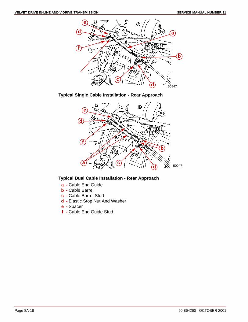
SERVICE MANUAL NUMBER 31VELVET DRIVE IN-LINE AND V-DRIVE TRANSMISSION
Page 8A-18 90-864260 OCTOBER 2001
50947
a
b
cd
f
e
d
Typical Single Cable Installation - Rear Approach
50947a
b
cd
e
f
d
Typical Dual Cable Installation - Rear Approacha - Cable End Guideb - Cable Barrelc - Cable Barrel Studd - Elastic Stop Nut And Washere - Spacerf - Cable End Guide Stud

VELVET DRIVE IN-LINE AND V-DRIVE TRANSMISSIONSERVICE MANUAL NUMBER 31
90-864260 OCTOBER 2001 Page 8A-19
50946
a
b
c
d
ef d
Typical Single Cable Installation - Front Approach
50946
ab
c
d
f
e
d
Typical Dual Cable Installation - Front Approacha - Cable End Guideb - Cable Barrelc - Cable Barrel Studd - Elastic Stop Nut And Washere - Spacerf - Cable End Guide Stud
NOTE: For models equipped with a dual station shift bracket such as the one shown, referto the shift cable manufacturer’s instructions for adjusting the cable. The shift lever must bepositioned as stated in the preceding steps.
22457
Dual Station Shift Bracket (Not Quicksilver)

VELVET DRIVE 5000 SERIES TRANSMISSIONSERVICE MANUAL NUMBER 31
90-864260 OCTOBER 2001 Page 8B-13
Velvet Drive 5000 Transmission Shift Control And Cables
IMPORTANT: The Velvet Drive Warranty is jeopardized if the shift lever poppet ball orthe spring is permanently removed, if the shift lever is repositioned or changed in anymanner, or if the remote control and the shift cable do not position the shift leverexactly as shown.
The remote control also must provide a total shift cable travel (at the transmission) of at least70 mm (2-3/4 in.) to position transmission shift lever fully in the Position A and Position Bgear positions. Insufficient shift cable travel will cause the transmission to slip andeventually fail.
72602
a
c
b
a - Position Ab - Position Bc - 70 mm (2-3/4 in.) Minimum

SERVICE MANUAL NUMBER 31VELVET DRIVE 5000 SERIES TRANSMISSION
Page 8B-14 90-864260 OCTOBER 2001
Transmission Shift Lever and Shift Cable BracketIMPORTANT: The Velvet Drive Warranty is jeopardized if the shift lever poppet ball orthe spring is permanently removed, if the shift lever is repositioned or changed in anymanner, or if the remote control and the shift cable do not position the shift leverexactly as shown.
The lever has three holes. The shift lever stud is placed in the forward-middle hole whenusing Quicksilver remote control cables.
73249
a
73248
a
b c
d
e e
a - Transmission Shift Leverb - Poppet Ball Must Be Centered In This Detent Hole When Left-Hand Propeller
Shaft Rotation Is Desiredc - Poppet Ball Must Be Centered In This Detent Hole When Right-Hand Propeller
Shaft Rotation Is Desiredd - Poppet Ball Must Be Centered In This Detent Hole For NEUTRAL Positione - Shift Lever Stud Location (For Quicksilver Shift Cables)
For Left-Hand Propeller Shaft Rotation: Shift cable hookup at remote control must resultin shift cable end guide moving in direction “A” when remote control handle is placed inforward position.
For Right-Hand Propeller Shaft Rotation: Shift cable hookup at remote control mustresult in shift cable end guide moving in direction “B” when remote control handle is placedin forward position.
23242
A
B

VELVET DRIVE 5000 SERIES TRANSMISSIONSERVICE MANUAL NUMBER 31
90-864260 OCTOBER 2001 Page 8B-15
WARNINGAvoid serious personal injury or property damage caused by improper shifting.Anchor stud for shift cable must be installed in the correct hole when using bracketwith four anchor location holes.
IMPORTANT: Ensure that the anchor stud is installed in the front hole as shown inthe illustration following.
7328474090
a
b
a - Shift Cable Bracketb - Anchor Stud In Front Hole (For Quicksilver Shift Cables)
IMPORTANT: The distance between the anchor studs in the shift lever and the shiftcable bracket must be 181 mm (7-1/8 in.).
73284
a
bbc
d
a - Shift Leverb - Anchor Studc - Dimension Between Studs - 181 mm (7-1/8 in.)d - Shift Cable Bracket

SERVICE MANUAL NUMBER 31VELVET DRIVE 5000 SERIES TRANSMISSION
Page 8B-16 90-864260 OCTOBER 2001
Installation and AdjustmentIMPORTANT: When installing shift cables, ensure that cables are routed to avoidsharp bends and/or contact with moving parts. Do NOT fasten any items to shiftcables.
NOTE: On models with other than Quicksilver shift cables refer to the shift cablemanufacturer’s instructions.
IMPORTANT: The Velvet Drive Warranty is jeopardized if the shift lever poppet ball orthe spring is permanently removed, if the shift lever is repositioned or changed in anymanner, or if the remote control and the shift cable do not position the shift leverexactly as shown.
1. Place the remote control shift lever and the transmission shift lever in the NEUTRALposition.
2. Remove the nuts and the washers from the shift cable attaching studs.
3. Locate the center of the remote control and the control shift cable play (backlash) asfollows:
a. Ensure that the remote control is in the NEUTRAL position.
b. Push in on the control cable end with enough pressure to remove the play and markposition “a” on the tube.
c. Pull out on the control cable end with enough pressure to remove the play and markposition “b” on the tube.
d. Measure the distance between marks “a” and “b,” and mark position “c,” halfwaybetween marks “a” and “b.”
c
c
72603
b
a
4. Center the cable-end play, then adjust the cable barrel to align the holes in the barreland in the cable end guide, with the attaching points on the transmission.
5. Temporarily install the shift cable. Do NOT secure at this time.

VELVET DRIVE 5000 SERIES TRANSMISSIONSERVICE MANUAL NUMBER 31
90-864260 OCTOBER 2001 Page 8B-17
IMPORTANT: Transmission is fully in gear when detent ball is positioned in leverdetent hole in either direction.
CAUTIONRemote control and shift cable must position transmission shift lever exactly asshown, or transmission failure may occur. Do not remove poppet ball or spring.
6. Place remote control shift lever in gear and check position of transmission shift lever.Shift lever must be positioned as shown.
7. Place remote control shift lever in opposite gear position and again check transmissionshift lever position. Shift lever must be positioned as shown.
8. If the transmission shift lever will position properly in one gear, but not in the other gear,recheck the shift cable adjustment. If the transmission shift lever will not positionproperly in either gear, move the transmission shift lever stud from the top hole in theshift lever to the bottom hole and recheck for proper positioning. If proper positioning isstill not obtained, the remote control does not provide sufficient shift cable travel andmust be replaced.
73248
ea
b c
d
a - Transmission Shift Leverb - Poppet Ball Must Be Centered In This Detent Hole For Left-hand Propeller
Shaft Rotationc - Poppet Ball Must Be Centered In This Detent Hole For Right-hand Propeller
Shaft Rotationd - Poppet Ball Must Be Centered In This Detent Hole For NEUTRAL Positione - Shift Lever Stud Hole For Quicksilver Shift Cables
NOTE: Move the shift lever stud to lower hole if necessary, to center the poppet ball in theFORWARD and REVERSE detent holes.
9. Install the nut and washer to the cable end guide stud. Tighten until the nut contacts, thenloosen 1/2 turn.
10. Install the nut and the washer to the cable barrel stud. Tighten until the nut contacts.Tighten securely, but Do NOT overtighten.

SERVICE MANUAL NUMBER 31VELVET DRIVE 5000 SERIES TRANSMISSION
Page 8B-18 90-864260 OCTOBER 2001
71780 71972
a
f
g ab
cg
c bd
e
f
Typical Single Cable Installation - Rear Approacha - Cable End Guideb - Spacer (As Required)c - Elastic Stop Nut And Washerd - Bushingse - Cable Barrels [Positions Only Indicated In Right Drawing]f - Cable Barrel Studg - Cable End Guide Stud
71897 50073
d
a
f
a
g
a
g
f
e
b
c
Typical Dual Cable Installation - Rear Approacha - Cable End Guideb - Spacer (As Required)c - Elastic Stop Nut And Washerd - Bushingse - Cable Barrels [Positions Only Indicated In Right Drawing]f - Cable Barrel Studg - Cable End Guide Stud

VELVET DRIVE 5000 SERIES TRANSMISSIONSERVICE MANUAL NUMBER 31
90-864260 OCTOBER 2001 Page 8B-19
50946
a
b
c
d
ef
d
Typical Single Cable Installation - Front Approach
50946
ab
c
d
f
e
d
Typical Dual Cable Installation - Front Approacha - Cable End Guideb - Cable Barrelc - Cable Barrel Studd - Elastic Stop Nut And Washere - Spacerf - Cable End Guide Stud

ZF/HURTH 630 AND 800 SERIES TRANSMISSIONSERVICE MANUAL NUMBER 31
90-864260 OCTOBER 2001 Page 8C-13
Hurth 630/800 Transmission Shift Control And Cables
Transmission Shift Lever and Shift Cable BracketThe shift lever has two holes. The shift cable anchor stud is installed in the top hole whenusing Quicksilver remote control cables.
77520
b
a
a - Shift Leverb - Shift Cable Anchor Stud Location (For Quicksilver Remote Control Cables)
WARNINGAvoid serious personal injury or property damage caused by improper shifting.Anchor stud for shift cable must be installed in the correct hole when using bracketwith two anchor location holes.
1. On bracket with two anchor location holes: Be certain anchor stud is installed in thecorrect hole for application 630 or 800.
71020
71041
b
a
cc
b
a
Shift Cable Bracket - Anchor Stud Position Shown for 630 Transmissiona - Shift Cable Bracketb - Shift Cable Anchor Studc - Bracket Fasteners

SERVICE MANUAL NUMBER 31ZF/HURTH 630 AND 800 SERIES TRANSMISSION
Page 8C-14 90-864260 OCTOBER 2001
IMPORTANT: Ensure that shift lever is positioned approximately 10 degrees aft ofvertical as shown when in the neutral detent position. Also, ensure that the distancebetween studs in the following is set at 181 mm (7-1/8 in.). If necessary, loosenclamping bolt and position lever so that dimension “c” is as shown when in theNEUTRAL detent position, and retighten clamping bolt.
72958 50228
b 10°
ad
c
d
a
Typical ZF/Hurth Transmission Showna - Shift Leverb - Shift Lever In NEUTRAL Detentc - Dimension Between Studs - 181 mm (7-1/8 in.)d - Clamping Bolt
IMPORTANT: Transmission propeller rotation is determined by the shift cableinstallation in the remote control.
For Right-Hand Propeller Rotation - Control cable will have to be installed in remotecontrol so that cable end will move in direction “A” when shift handle is placed in the forwardposition.
For Left-Hand Propeller Rotation - Control cable will have to be installed in remote controlso that cable end will move in direction “B” when shift handle is placed in the forwardposition.
23242
A
B

ZF/HURTH 630 AND 800 SERIES TRANSMISSIONSERVICE MANUAL NUMBER 31
90-864260 OCTOBER 2001 Page 8C-15
Installation and AdjustmentIMPORTANT: When installing shift cables, ensure that cables are routed to avoidsharp bends and/or contact with moving parts. Do NOT fasten any items to shiftcables.
NOTE: On models with other than Quicksilver shift cables refer to the shift cablemanufacturer’s instructions.
1. Place remote control shift lever and transmission shift lever in neutral position.
2. Remove nuts and washers from shift cable attaching studs.
3. Locate center of remote control and control shift cable play (backlash), as follows:
a. Ensure that remote control is in NEUTRAL position.
b. Push in on control cable end with enough pressure to remove play; mark position“a” on tube.
c. Pull out on control cable end with enough effort to remove play; mark position “b”on tube.
d. Measure distance between marks “a” and “b,” and mark position “c” halfwaybetween marks “a” and “b.”
22024
c
c a
b
4. Center cable-end play, then adjust cable barrel to align holes in barrel and in cable endguide with attaching points on transmission.
5. Temporarily install shift cable. Do NOT secure at this time.
IMPORTANT: Transmission is fully in gear when shift lever comes to a stop, in eitherdirection.

SERVICE MANUAL NUMBER 31ZF/HURTH 630 AND 800 SERIES TRANSMISSION
Page 8C-16 90-864260 OCTOBER 2001
6. Place remote control shift lever in FORWARD gear position. Ensure transmission is fullyin gear, as follows:
a. Hold shift lever in position.
b. Carefully slide shift cable off of anchor points.
c. Attempt to move shift lever further.
7. Place remote control shift lever in REVERSE gear position. Ensure transmission is fullyin gear as follows:
a. Hold shift lever in position.
b. Carefully slide shift cable off of anchor points.
c. Attempt to move shift lever further.
8. If transmission shift lever will position properly in one gear, but not in the other, recheckshift cable adjustment. If transmission shift lever will not position properly in either gear,move transmission shift lever stud from top hole in shift lever to bottom hole and recheckfor proper positioning. If proper positioning is still not obtained, remote control does notprovide sufficient shift cable travel and must be replaced.
50228a
b
c
a
a - Shift Lever Stud (In Bottom Hole, If Required)b - Lever, In Neutral Detent, Must Be Approximately 10 Degrees Of Verticalc - Shift Lever Top Hole
9. Install nut and washer to cable end guide stud. Tighten until the nuts contact, then loosen1/2 turn.
10. Install nut and washer to cable barrel stud. Tighten until the nuts contact, then loosen1/2 turn.

ZF/HURTH 630 AND 800 SERIES TRANSMISSIONSERVICE MANUAL NUMBER 31
90-864260 OCTOBER 2001 Page 8C-17
NOTE: To change cable approach direction on single or dual station installations, only thespacer/bushings have to be switched to the opposite stud. The studs are identical.
72955 71210
bc
d
b
af
g
h
e
Typical Single Cable Installation - Forward Approacha - Cable End Guideb - Locknut and Washerc - Spacer (Fits Over Bushings)d - Bushinge - Cable Barrelf - Spacers (Fits Over Stud)g - Cable Barrel Studh - Cable End Guide Stud
72957 50229
ab
f
d
g
h
e
bc
Typical Single Cable Installation - Rear Approacha - Cable End Guideb - Locknut And Washerc - Spacer (Fits Over Bushings)d - Bushinge - Cable Barrelf - Spacers (Fits Over Stud)g - Cable Barrel Studh - Cable End Guide Stud
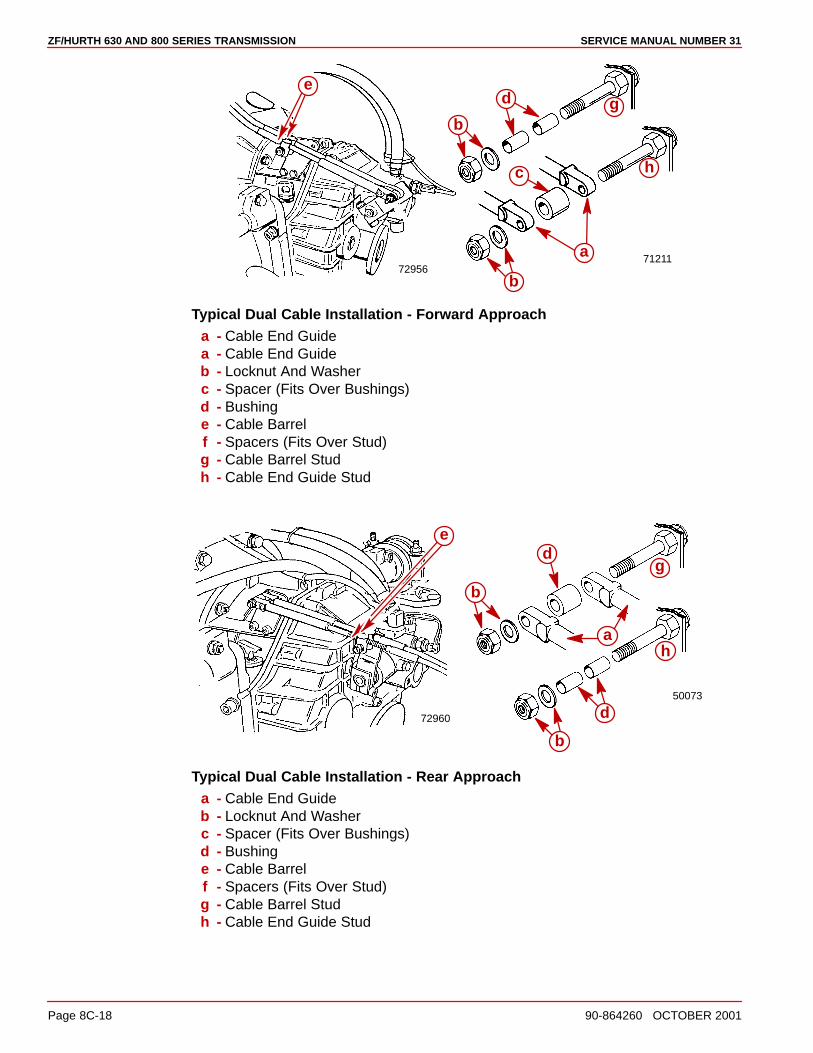
SERVICE MANUAL NUMBER 31ZF/HURTH 630 AND 800 SERIES TRANSMISSION
Page 8C-18 90-864260 OCTOBER 2001
7295671211
b
b
d
a
c
g
h
e
Typical Dual Cable Installation - Forward Approacha - Cable End Guidea - Cable End Guideb - Locknut And Washerc - Spacer (Fits Over Bushings)d - Bushinge - Cable Barrelf - Spacers (Fits Over Stud)g - Cable Barrel Studh - Cable End Guide Stud
72960
50073
b
d
a
b
d
g
h
e
Typical Dual Cable Installation - Rear Approacha - Cable End Guideb - Locknut And Washerc - Spacer (Fits Over Bushings)d - Bushinge - Cable Barrelf - Spacers (Fits Over Stud)g - Cable Barrel Studh - Cable End Guide Stud

96-5 NOVEMBER 1999 Printed in U.S.A. - 1998, Mercury Marine Page 1 of 4
�������������No. 96-5TO: SERVICE MANAGER TECHNICIANS
PARTS MANAGER
� = Revised November 1999. This bulletin supercedes the previous bulletin 96-5.
Troubleshooting Shift Problems
ModelsAll models
SituationHard shifting or chucking / racheting when shifting into forward gear.
1. When installing the control box in the side panel of the boat make sure that the cableshave enough clearance to operate, because the cables do move up and down when theshift handle is moved. If the control box is mounted too far back towards any fiberglassstructure the cables will be interfered with, this will cause very hard shifting.
NOTE: The control box housing can be rotated in 30° increments to improve cable routing.
74688 74689
Proper cable bend Improper cable bend
2. Make sure that when the shift cable from the control box is lead through the side gunnelof the hull, that it does not have any extremely sharp bends in it as this will cause thestiff shifting.

Page 2 of 4 NOVEMBER 1999 96-5
3. Before installing the shift cable into the control box, extend the stainless rod eye end ofthe cable and grease it with (2-4-C Marine Lubricant, with Teflon) move it back and forthto allow even distribution of the grease.
22005
4. Do not strap or clamp the control cables to any other cables or rigid structure within threefeet of the control box.
5. Be sure the cables are not permanently kinked.
6. Make sure there is proper clearance for cable movement when the control box isinstalled in the side panel. The cables must have room to move up and down when thecontrol handle is shifted into either forward or reverse.
7. Check to make sure that the engine was not set down on the intermediate shift cableduring installation as this will crush the inner cable tubing and cause improper and / orstiff shifting.
8. DO NOT fasten the shift cable with straps or clamps to any other cable within five feetof the shift plate.
9. DO NOT fasten the shift cable to the transom with any type of plastic clips or fastenerswith in five feet of the shift plate.
10. DO NOT over tighten the throttle or shift cable attaching nuts at the engine end. Barreland cable end must be free to rotate on the mounting stud.
11. Check the intermediate shift cable routing from the transom assembly to the shift plateas follows:
a. The cable should come through the transom, above the exhaust pipe and make aturn towards the starboard side of the boat between the exhaust pipe and the engineflywheel housing.
b. The cable should then be routed under the starboard rear engine mount, and turntowards the transom.
c. Then go up behind the power steering valve and loop over to the shift plate on theengine, where it is connected to the anchor points on the shift plate.
Following this routing will prevent the engine coupler from damaging the cable.

96-5 NOVEMBER 1999 Page 3 of 4
Shift Cable Routing
74903
3.0L & 3.0LX Model Only
74901All V-6 & V-8 Alpha Models
74904
All V-6 & V-8 Bravo Models

Page 4 of 4 NOVEMBER 1999 96-5
Shift Cable Routing
74902
V-8 Diesel Model
74905
In-line Diesel Model
75767
� On 7.4L MPI MCM
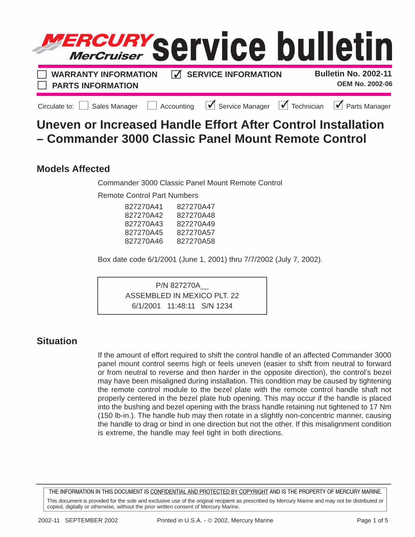
2002-11 SEPTEMBER 2002 Printed in U.S.A. - 2002, Mercury Marine Page 1 of 5
��� ��������� �� ���� �� ���� �� ���������� �� ����� ��� �� �������� �� �� ��� �������� �� �� ��� �����
This document is provided for the sole and exclusive use of the original recipient as prescribed by Mercury Marine and may not be distributed orcopied, digitally or otherwise, without the prior written consent of Mercury Marine.
Bulletin No. 2002-11WARRANTY INFORMATION SERVICE INFORMATIONPARTS INFORMATION
Sales ManagerCirculate to: Accounting Service Manager Technician Parts Manager
OEM No. 2002-06
Uneven or Increased Handle Effort After Control Installation– Commander 3000 Classic Panel Mount Remote Control
Models AffectedCommander 3000 Classic Panel Mount Remote Control
Remote Control Part Numbers
827270A41827270A42827270A43827270A45827270A46
827270A47827270A48827270A49827270A57827270A58
Box date code 6/1/2001 (June 1, 2001) thru 7/7/2002 (July 7, 2002).
P/N 827270A__ASSEMBLED IN MEXICO PLT. 22
6/1/2001 11:48:11 S/N 1234
SituationIf the amount of effort required to shift the control handle of an affected Commander 3000panel mount control seems high or feels uneven (easier to shift from neutral to forwardor from neutral to reverse and then harder in the opposite direction), the control’s bezelmay have been misaligned during installation. This condition may be caused by tighteningthe remote control module to the bezel plate with the remote control handle shaft notproperly centered in the bezel plate hub opening. This may occur if the handle is placedinto the bushing and bezel opening with the brass handle retaining nut tightened to 17 Nm(150 lb-in.). The handle hub may then rotate in a slightly non-concentric manner, causingthe handle to drag or bind in one direction but not the other. If this misalignment conditionis extreme, the handle may feel tight in both directions.

COMMANDER 3000 CLASSIC PANEL MOUNT REMOTE CONTROL
Page 2 of 5 SEPTEMBER 2002 2002-11
��� ��������� �� ���� �� ���� �� ���������� �� ����� ��� �� �������� �� �� ��� �������� �� �� ��� �����
This document is provided for the sole and exclusive use of the original recipient as prescribed by Mercury Marine and may not be distributed orcopied, digitally or otherwise, without the prior written consent of Mercury Marine.
IMPORTANT: If you believe that this condition may exist, the shift and throttle cablesmust be disconnected from the outboard or MerCruiser before taking any furtheraction to align the control components. Do not mistake this for normal shift operationof the outboard or MerCruiser shift system.
Misaligned Condition
a
b
c
d
a - Bezelb - Handle Hub Openingc - Handled - Remote Control Module
Properly Aligned

COMMANDER 3000 CLASSIC PANEL MOUNT REMOTE CONTROL
2002-11 SEPTEMBER 2002 Page 3 of 5
��� ��������� �� ���� �� ���� �� ���������� �� ����� ��� �� �������� �� �� ��� �������� �� �� ��� �����
This document is provided for the sole and exclusive use of the original recipient as prescribed by Mercury Marine and may not be distributed orcopied, digitally or otherwise, without the prior written consent of Mercury Marine.
CorrectionThis procedure may be followed when installing the control for the first time or if thiscondition is found after the control has been completely installed.
NOTE: Verify that the control handle friction screw located on the hub of the bezel plate isbacked off before checking for this condition.
74411
a
a - Control Handle Friction Screw Location
With the shift and throttle cables disconnected from the engine end, rotate the shift/throttlehandle to the full throttle positions (both forward and reverse), feeling for handle rotation thatis even in both directions. If the handle effort is higher in one direction over the other, removethe throttle only button and the handle nut. Pull off the control handle then remove the bezelcover plate. It is not necessary to remove the trim wiring, just pull the handle assembly outfrom the bezel and leave the wiring connected.
NOTE: Refer to the remote control installation manual for proper control handle removalprocedures.
Loosen the (3) 1/4-20 screws securing the module assembly to the bezel plate just enoughto allow for module free movement.

COMMANDER 3000 CLASSIC PANEL MOUNT REMOTE CONTROL
Page 4 of 5 SEPTEMBER 2002 2002-11
��� ��������� �� ���� �� ���� �� ���������� �� ����� ��� �� �������� �� �� ��� �������� �� �� ��� �����
This document is provided for the sole and exclusive use of the original recipient as prescribed by Mercury Marine and may not be distributed orcopied, digitally or otherwise, without the prior written consent of Mercury Marine.
Hint: The following instructions are written assuming the original control handle is beingused. However, using a spare control handle as an alignment tool makes this procedureeasier. You may leave the original handle assembly hang while performing the centeringprocedure.
Pull the trim switch harness out far enough to allow slack and let the bezel cover plate hang.
59551
a
a
b
c
a
a - Mounting Screws (3)b - Bezelc - Remote Control Handle
Place the handle hub bushing back into position in the bezel plate opening. Using thehandle hub as a centering tool, and with the bezel plate cover out of the way, push thehandle hub in firmly towards the module letting the module align itself with the bezel plate.Using a � in. drive 7/16 in. deep well socket and a short extension, begin tightening one ortwo of the 1/4-20 screws just enough to loosely draw the module up to the bezel plate whilerotating the handle back and fourth several times, allowing the module to center itself intoposition.
Remove the handle assembly and finish tightening the (3) 1/4-20 screws securely. Installthe bezel cover plate and handle assembly back into position. Place a small drop of Loctite271 (only needed if the original locking material seal was broken) onto the brass handle nutthreads and tighten to 17 Nm (150 lb-in.). This procedure should help improve thecomponent alignment and reduce or even out the normal handle friction rate. The handleshould now rotate in both directions with the same amount of effort. Reconnect the throttleand shift cables at the engine end.

COMMANDER 3000 CLASSIC PANEL MOUNT REMOTE CONTROL
2002-11 SEPTEMBER 2002 Page 5 of 5
��� ��������� �� ���� �� ���� �� ���������� �� ����� ��� �� �������� �� �� ��� �������� �� �� ��� �����
This document is provided for the sole and exclusive use of the original recipient as prescribed by Mercury Marine and may not be distributed orcopied, digitally or otherwise, without the prior written consent of Mercury Marine.
OPTIONAL HANDLE CENTERING AID
Wrapping a temporary piece of duct tape around the handle hub two times will help centerthe module to the bezel opening even quicker and may not require rotation of the handle.If used, don’t forget to remove the tape before securing the handle to the module for the finalassembly.
59550
a
a - Duct Tape
WarrantyThis service bulletin is issued as a procedural change to be used when installing one of thelisted Commander 3000 Classic Panel Mount Remote Controls into a boat. Warranty wouldonly apply to a previously installed Commander 3000 Classic Panel Mount Remote Controlthat is listed on this bulletin and has the described misalignment condition.
Mercury Marine will credit the dealer for the cost of labor through September 30, 2005.Submit a warranty claim through your normal warranty processing channel, listing:
• Outboard/MerCruiser serial number
• 0.5 hour labor
• Flat Rate Code and Labor - NJC 0.5
• Part Code - 346
• Failure Code - 00

������������������ � ���������������� ��������������������
��������������� � ��������������
����������! ���������"�� #�������" �����������"�� $��%������ ����������"��
$&����'�(�#$�������$&� �)� *���$�� � ��'�)��$�#+�#�)��(�$� $�)��,� ��,(�-&$�#�)�� �$&���(���($,��'���( *(,��#(����
$%���.����������/���.�.����%��������.��0��������������%����"���������/��������/������1�.�1�������������������.��������1��.�����1���.����/��.2�.�"��������
�%��3���2�3��%����%��/����3������������������������������
�������(��#*-* $�������� �������2���������������� ���"��4�5�6
�
7���576���-������ ������0
�������
$%�����3�7���576���-������������%�����.���.��0�����������������%���%��������.
�%�����1�����*�.����0��������1��������"���.�������%���3����%��/�������8���%��5�%�����
%��.�����.���#��3��%�/�������������2�������1����.9���������3��������������1����.�����%�� ��"���� �� �%���� ��� �� ���.� �� .�������1��� �%�� ������ 10� �� ��:�� ��1��
�.9���������
�������
� �
� �
��� ������������ 1�� -�����������
��$�!��$%����3�-������������������������3�-�������%��������.��%�����1����
'�����������3������
� ��3�������"�/�����.���"�����3��/����������;7����-������+�:�1������<4�#===>
������ �� 1�� ��������.� �� ���%��� /��� �� ����1��.� ��.�� ��� ���� ����������� ��� �%�
%��8�����/������
� (�?���������?����%��������.��%�����1����
� #�����1������/�������.������������

7���576���-������ ��$(�+���@
$&����'�(�#$�������$&� �)� *���$�� � ��'�)��$�#+�#�)��(�$� $�)��,� ��,(�-&$�#�)�� �$&���(���($,��'���( *(,��#(����
$%���.����������/���.�.����%��������.��0��������������%����"���������/��������/������1�.�1�������������������.��������1��.�����1���.����/��.2�.�"��������
�%��3���2�3��%����%��/����3������������������������������
��"����5�6� �������2���������������� �#*-* $�������� �������(
�
� #�����1���3��%�/�����"��/�����:�1���%��.���.���"��;��������.�'���%>�
� �����10�%����"�����//�0����������45�����%�����"���
� ������������0�����������������%��������.��%�����1����
� $%������%��.����������/����������������
� ��3���:�1���%��.���%������"��/�.���"��
� �����������������.��3���%�3�����3����%����1���������������
� �0����%�9��/������.�/��/3�����������������2������3��%��5���������
� +�"� �0������� ����� 3��%� ���� �5 � ������ ������� ;��� �����.�.� ��� �%�� �5 � /�����������>�
-������ �����
�����$�/� ��������1�� &��.��� ���� (�/���������'�! #//��������
�� �7���
�������������
����
���<�A#�4 ������-��/
�������
����1��.���.�
���
�6�BA�#45#6 #���������1��.�2
�����������
�������5��������
B��%����6
�����:�2����%��
46�7����:�2'����7��&����.
�/�;4AA����.
��3��>�3��%��
����
�� �7���
�������������
����
���<4�#�4 +�:�����
�������
����1��.���/��
��.�
��<�<�#745#76 #���������1��.�2
�����������
�������5��������
B��%����6
�����:�2����%��
46�7����:�2
'����7��&����.�/�;4AA����.
��3��>�3��%��
����
�� �7�������%
$��������������
���<�A#�� ������-��/�
�������
����1��.���.�
���
(�/������/���
�6�BA�#�5#B5#��
#����������
�������5
�������2�'���
7��&����.��/
;4AA����.
��3��>�3��%�����
�� �7�������%
$��������������
���<4�#�� +�:�����
�������
����1��.���/��
��.�
��<�<�#7�5#7B5
#7�
#����������
�������5
�������2�'���
7��&����.��/
;4AA����.��3��>�3��%�����

7���576���-������ ��$(�+���@
$&����'�(�#$�������$&� �)� *���$�� � ��'�)��$�#+�#�)��(�$� $�)��,� ��,(�-&$�#�)�� �$&���(���($,��'���( *(,��#(����
$%���.����������/���.�.����%��������.��0��������������%����"���������/��������/������1�.�1�������������������.��������1��.�����1���.����/��.2�.�"��������
�%��3���2�3��%����%��/����3������������������������������
�������(��#*-* $�������� �������2���������������� ���"����5�6
�
�����$�/� ��������1�� &��.��� ���� (�/���������'�! #//��������
�� �7�������%
$��������������
���<�A#�� ������-��/�
�����������1��.���.�
���
�6�BA�#�5#<#A #���� ����.
�������5����������7+�3��%
�0�����������
�� �7�������%
$��������������
���<4�#�� +�:�����
�����������1��.���/��
��.�
��<�<�#7�2
7<27A
#���� ����.
�������5����������7+�3��%
�0�����������
� �76��
�������� ������������"��
���<44#44 (�.���"��.
(�11���"��/
��B��#��2
�<<<��#44
#���������1��.�2
������������������5
�������2�'���
7��&����.��/
;4AA����.
��3��>�3��%��
����
� �76������%
$���� ������������"��
���<44#4� (�.���"��.
(�11���"��/
��B��#��2
�<<<��#4�
#����������
�������5�������2�'���
7��&����.��/
;4AA����.
��3��>�3��%�����
� �76������%
$���� ����
��������"��
���<44#4� (�.���"��.
(�11���"��/
��B��#�72
�<<<��#4�
#���� ����.
�������5��������
��7+�3��%�0�����������
� �76������
$���� ����
������.���
���<44#�4 (�.���"��.
(�11���"��/
��B��#�B2
�<<<��#4
#���������1��.�2
�����������
�������5�������2�'���
7��&����.��/
;4AA����.
��3��>�3��%��
����
� �76������%
$���� ����������.���
���<44#�� (�.���"��.
(�11���"��/
��B��#��2
�<<<��#�
#����������
�������5�������2�'���
7��&����.��/
;4AA����.
��3��>�3��%�����
� �76������%
$���� ����
������.���
���<44#�� (�.���"��.
(�11���"��/
��B��#A�2
�<<<��#�
#���� ����.
�������5��������
��7+�3��%�0�����������

7���576���-������ ��$(�+���@
$&����'�(�#$�������$&� �)� *���$�� � ��'�)��$�#+�#�)��(�$� $�)��,� ��,(�-&$�#�)�� �$&���(���($,��'���( *(,��#(����
$%���.����������/���.�.����%��������.��0��������������%����"���������/��������/������1�.�1�������������������.��������1��.�����1���.����/��.2�.�"��������
�%��3���2�3��%����%��/����3������������������������������
��"��7�5�6� �������2���������������� �#*-* $�������� �������(
�
$%�����5 %��� �1���
��3��%��������.��%�����1���/�������1�� )�����/���
���<4A#=== ���.��.�-��������1���;���"���/��:>�3��%�4B
����3���5������/����������.�����3���
���<��#=== ���������-��������1���;���"���/��:>4B����
3���5��0�1�������3���
���<4A�=== ���:�/��:� ���.��.���1���
���<���=== ���:�/��:������������1���
��$�!� � ����.��� ������� ;��B��#� ===>� ��.� ��.�� ����� ������;��44<�#====������� 3���� �������� �� ���� �%������ ��.� �%��� ��1���� �6�<4B#===� ��.�<<<<�#====�
��3�-��������������1�����������10���.
�������
� �� �
��� -��������������1��������������3���
;����.9����1��>
1�� -��������������1������������1��
%����"�3�.����%����%������.��.� #�
��1��
����� �1���C������
���1��.���������1����;�%��������.��%��>�"������������������%����.�������?��������������
+������!�-����������%�������%���������0/���������1���3��%���������.����1����3���������%�
����.��%����"�;"���������B�3���>2���.�%��������.������������3��������%��/�1��.�����
��.��3��%��%�����/�����1��2��%�������%����"�3����.������.�/���/�����������%��������
����3�������������"��%��������.��%�����.��$%�����1���3����/���������������������%��
����� 3%���� �%���� ��� �� ������.� ���1��� � 1��.�� ��� �%�� ��1��� ��.� �%�� 1��.�� ���� ����
"��.�������/�/���%��.���"���%�����1���/���������������������������������.����3%��%3�������������������.��%��������.��%�����.��
�������� �
+���������1��!�B�3������������.��%����"���.����.�����3���

7���576���-������ ��$(�+���@
$&����'�(�#$�������$&� �)� *���$�� � ��'�)��$�#+�#�)��(�$� $�)��,� ��,(�-&$�#�)�� �$&���(���($,��'���( *(,��#(����
$%���.����������/���.�.����%��������.��0��������������%����"���������/��������/������1�.�1�������������������.��������1��.�����1���.����/��.2�.�"��������
�%��3���2�3��%����%��/����3������������������������������
�������(��#*-* $�������� �������2���������������� ���"��6�5�6
�
+������!�$%�����.�"��.����1���%�������3���������%������.��%����"2����������������.
�������������/���������1����$%������/������1����"������������������������.�����������
3����
��������� �%�� ��������.����1����3����� ��� �%�������%����"2� �%��� ��/�����1������
��:�� ���� �""�������� 1��.�� 3��%��� �%�� ����� %����"� .�����"�� �.���� �� ������
������1����3%�����%����1������:������0����1��.�1��3�����%����������.��%����"�������������������.�.�?�����������������������������1��.���.�� ���//���������
�������� �
+���������1��!�'������/�������3�����������.��%����"2����.�����3���
+����� 4!� $%�� %�"%���� "��.�5������ 4� ��1���� %���� �� �%��:��� ����� %����"� 3��%� ���
��/��������3����2���.�����0�1��������������3������.��������"������3%���������%��
�%�����������1����1��.��������?����.����""��������1��.������%����1���������?����.�
(������.�.����������1������?�����"�4B�'$���1��������"���
�������� �
+����� 4� ��1��!� '���� ��/������� �3����� ��� ����.�� %����"2� �%��:��� %����"� ��0�1��
�����������3���

a
b
3703


MC_Inboard_0804
8

90-862315007 OCTOBER 2003 Printed in U.S.A. - â 2003, Mercury Marine Page 1 of 3
MERCRUISER SERVICE MANUAL INDEXServiceManual No. Part Number Year Description
#1 90-68648 1963-1973 Engines and Drives - All
#2 90-71707 1974-1977 Engines and Drives - All
#3 90-95693 1978-1984 Engines - All 4, L6 and V8
#4 90-86137 1978-1982 Sterndrives - MC 120 to 260
#5 90-12935 1978-1993 Sterndrives - TR and TRS
#6 90-12934--2 1983-1990 Sterndrives - R, MR, Alpha One and Alpha One SS
#7 90-12410 1983-1993 Engines - GM V6
#8 90-44553 1985-1989 Engines - Mercury Marine 4 Cylinder
#9 90-14499--1 1985-1988 Engines - GM V8
#10 90-14693--1 1985-1989 Engines - GM 4 Cylinder
#11 90-17431--4 1988-1998 Sterndrives - Bravo
#12 90-814099--2 1989-1993 Engines - 5 and 6 Cylinder Diesel
#13 90-816462 1990-1997 Engines - GM 4 Cylinder
#14 90-818177--3 1991- Sterndrives - Alpha One Gen II
#15 90-816463 1989-1992 Engines - GM V8 (No Hi Perf.)
#16 90-823224--2 1993-1997 Engines - GM V8 454 and 502 cid (Gen V - Gen VI)
#17 90-823225--1 1993-1997 Engines - GM V8 305 and 350 cid (5.0L 93-95)
#18 90-823226--1 1993-1997 Engines - GM V6 Gen II Balance Shaft
#19 90-823227 1994-1996 Engines - V8 7.3L (IDI) Diesel
#20 90-823228 1994-1998 Sterndrives - Blackhawk
#21 90-806934 1994- Engines - 5 and 6 Cylinder 3.0L, 3.6L, and 4.2L (IDI)Diesel
#22 90-860074--1 1997-Engines - D-Tronic 2.8L and 4.2L (DI) Diesel
Serial Number 0K000001 and Above
#22 Sup. 90-860074020 2002- Engines - D4.2L 300 Diesel
#23 90-861326--1 1998-2001
Engines - GM V8 Gen VI
MCM 454 Mag MPI (SN 0L010029 and Above)
MCM 502 Mag MPI (SN 0L017000 and Above)
MIE 454 Mag MPI Horizon (SN 0L002200 and Above)
MIE 8.2L MPI (SN 0L002450 and Above)
Engines - GM V8 L-29
MCM 7.4L MPI (SN 0L010003 and Above)
MIE 7.4L MPI (SN 0L002006 and Above)

90-862315007 OCTOBER 2003 Page 2 of 3
MERCRUISER SERVICE MANUAL INDEXServiceManual No. Part Number Year Description
#24 90-861327--1 1998-2001
Engines - GM V8 305 and 350 cid
MCM 5.0L 0L15751 through 0M087347
MCM 5.0L EFI 0L12052 and Above
MCM 5.7L 0L010037 through 0M087347
MCM 5.7L EFI 0L010037 and Above
MCM 350 Mag MPI 0M010019 through 0M299999
5.7L Comp Ski 0L002005 and Above
350 Mag MPI Ski 0L002600 through 0M309999
Black Scorpion 0L002700 through 0M391599
MIE 5.7L 0L002003 through 0L677226
MIE 350 Mag MPI 0L002008 through 0M309999
#24 Sup. 90-861327000 2000-2001 Engines - GM V8 377 cid (6.2L)
#25 90-861328--1 1998-2001
Engines - GM V6(S/N 4.3L 0L125850 and Above)(S/N 4.3H 0L110850 and Above)(S/N 4.3L EFI 0L110850 Through 0M299999)
#26 90-861329--1 1998-Engines - GM 4 Cylinder MCM 3.0L Alpha
Serial Number 0L010042 and Above
#27 90-861784--1 1998-2002 Engines - V8 D7.3L D-Tronic (DI) Diesel
#27 Sup. 90-861784990 1998-2001 Engines - V8 D7.3L D-Tronic and D-Tronic LD Diesel
#28 90-863160--1 2000- Sterndrives - Bravo One, Two, Three and XZ/XR
#29 90-863016 2000-Engines - MCM D1.7L DTI In-Line Diesel
Serial Number 0M055001 and Above
#30 90-863161001 2000-Engines - 8.1 liter (496 cid)
Serial Number 0M000000 and Above
#31 90-864260001 2001-
Engines - 5.0 liter (305 cid), 5.7 liter (350 cid) and6.2 liter (377 cid)
MCM Serial Number 0M300000 and Above
MIE Serial Number 0M310000 and Above
#32 90-864261 2001-Engines - MCM 4.3L MPI
Serial Number 0M300000 and Above
#33 90-863757--1 2000- PCM 555 Diagnostics
#34 90-863616 2001- Engines - D4.2L LD In-Line Diesel
#35 90-864212 2001- Precision Pilot
#36 90-864573 2001- ECM 555 Diagnostics

90-862315005 APRIL 2003 Page 3 of 3
MERCRUISER SERVICE MANUAL INDEXServiceManual No. Part Number Year Description
#37 90-864260020 2002-
Dry Joint Exhaust System
MCM Serial Number 0M600000 and Above
MIE Serial Number 0M317000 and Above
HP #1 90-817110 1989-1992 Engines - Hi-Performance (Mark IVHP420/HP425/HP465, HP500 Bulldog, HP575)
HP #2 90-815526 1982- Sterndrives - III and II, III, IV and V SSM
SupplementHP #2 90-849776 All Sterndrives - III A
HP #3 90-848294 1992-1998Engines - Hi-Performance(Gen V HP425/HP450/HP465/HP500, Mark IV, andGen V HP525SC and HP600SC, HP 800SC)
HP #4 90-848656 All Sterndrives - VI and VII (Non Dry Sump)
HP #5 90-840250 1999- Sterndrives - VI (Dry Sump)
HP #6 90-840283R01 1999- Engines HP500 EFI Service Manual
HP #7 90-840500 1999- Engines - HP377 EFI
HP #8 90-841053 2001-Engines - HP575 SCi Diagnostic Manual
Serial Number 0L601000 and Above
HP #8 90-840542 2001-Engines - HP575 SCi Service Manual
Serial Number 0L601000 and Above
HP #9 90-843188 2003- Engines HP525 EFI Diagnostic Manual
HP #9 90-843189 2003- Engines HP525 EFI Service Manual