CONTENTS Part 1 General Information ...
392
CONTENTS Part 1 General Information................................................................................... 1 Part 2 Indoor unit..................................................................................................7 4-way Cassette type(AB12~AB60)............................................................8 Convertible type(AC12~AC60)............................................................... 50 Duct type(AD12~AD72).......................................................................... 92 Cabinet type(AP42~AP48).................................................................... 168 Wall mounted type(AS18)..................................................................... 183 Part 3 Outdoor units.......................................................................................... 195 Part 4 Electrical control..................................................................................... 238 Part 5 Maintenance........................................................................................... 324 Part 6 Control Devices...................................................................................... 356 Appendix-Control Data..................................................................................... 390
-
Upload
khangminh22 -
Category
Documents
-
view
3 -
download
0
Transcript of CONTENTS Part 1 General Information ...

CONTENTS
Part 1 General Information................................................................................... 1
Part 2 Indoor unit..................................................................................................7
4-way Cassette type(AB12~AB60)............................................................8
Convertible type(AC12~AC60)............................................................... 50
Duct type(AD12~AD72).......................................................................... 92
Cabinet type(AP42~AP48).................................................................... 168
Wall mounted type(AS18)..................................................................... 183
Part 3 Outdoor units.......................................................................................... 195
Part 4 Electrical control..................................................................................... 238
Part 5 Maintenance........................................................................................... 324
Part 6 Control Devices...................................................................................... 356
Appendix-Control Data..................................................................................... 3 90
Part 1 General Information
1. Nomenclature............................................................................................................. 2
2. Capacity range........................................................................................................... 3
3. External appearance.................................................................................................. 4
4. Operation temperature range .................................................................................... 6
Unitary Smart
-1-
!
"
#
$
%
! %
%
&
%
'
( '
% #) !
'
#
!
$
*
"
%
)
)"
)
%
)
)
)"
#
'+
*
),
%- % .
/
/
/$ % $ ! !
'
)
)
)
)
)'
% &
$
%
%
+
'
Unitary Smart
-2-
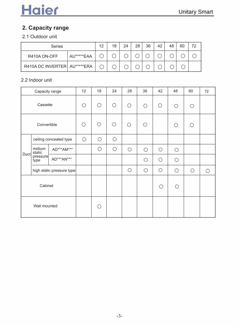
'( )
* $
)' $!$
)' "!)/)
'+++++''
'+++++)'
* "
0
"
'+++'#+++
'+++'!+++
Cassette
Unitary Smart
-3-
72
, %- ''* $
'''''''' ''+''
''"'''!'"'''!'"'''!'"''
'!'1''
'')''')'''+)''')'
'')'
'''''!'''
''''''''
''''''''
''''''''
'')''')' '')'
'')''')'
'!'")''!'")'
*
''''''''''''
''''''''''''''''
'')''')''')''')'
''''''''''''''''''''
'')''')''')''')'
*
'')''')''')'
'"!'/''AU362ALEAA
Unitary Smart
-4-

'')'
''2''''''
''1''''1''''1''
''#''''#''''#''''#''
''#''
''#)'''#)'''#)'
''1)'''1)'''1)'
*
''''''''
'')''')'
''#)'
''''''''
''!''''!''''!''
''!)'
'')'
*
* 0
'"'''
Unitary Smart
-5-

* )' $!$
"
$
) #- #" # " * " "
0 0
"
$ 0
0
$
"
) #- #
"
#
"
*
" "
0 0
"
0
0
* )' "
Unitary Smart
-6-

Part 2 Indoor units
1. 4-way Cassette type(AB12~AB60) ......................................................................... 8
2. Convertible type(AC12~AC60) ............................................................................... 50
3. Duct type(AD12~AD72) .......................................................................................... 92
4. Cabinet type(AP42~AP48) ......................................................................................168
5. Wall mounted type(AS18) .......................................................................................183
Unitary Smart
-7-

4-way Cassette indoor unit
(AB12~AB60)
1. Features…………………………………………….. 9
2.1 For DC inverter unit…………………………..11
2.2 For fixed frequency unit……………………...16
3. Curves………………………………………………22
3.1 Performance curves………………………..…22
3.2 Noise level……………………………………..24
3.3 Air velocity distribution………………………..3
4. Dimensions……………………........................…34
5. Part name……………………………...................39
6. Installation…………………………......................41
4-way Cassette type
-8-
2. Specifications………………………………..……..11
1
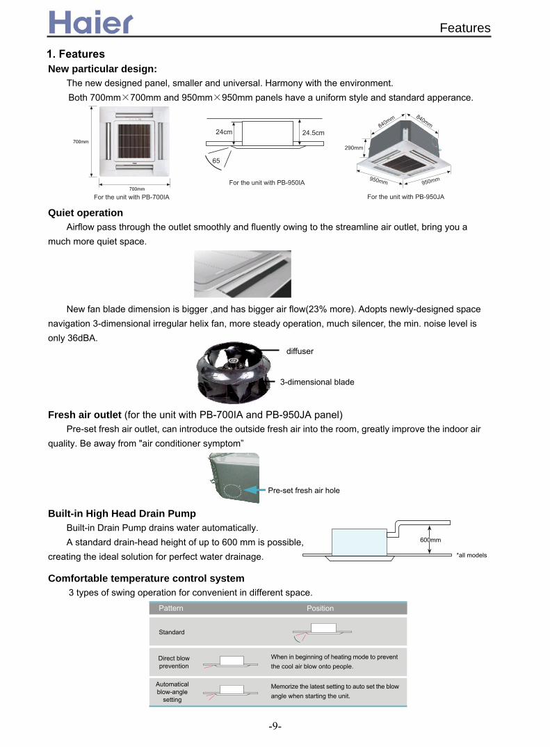
1. FeaturesNew particular design:
The new designed panel, smaller and universal. Harmony with the environment. Both 700mm×700mm and 950mm×950mm panels have a uniform style and standard apperance.
Quiet operation Airflow pass through the outlet smoothly and fluently owing to the streamline air outlet, bring you a
much more quiet space.
New fan blade dimension is bigger ,and has bigger air flow(23% more). Adopts newly-designed space navigation 3-dimensional irregular helix fan, more steady operation, much silencer, the min. noise level is only 36dBA.
Fresh air outlet (for the unit with PB-700IA and PB-950JA panel) Pre-set fresh air outlet, can introduce the outside fresh air into the room, greatly improve the indoor air
quality. Be away from "air conditioner symptom”
Built-in High Head Drain Pump
Built-in Drain Pump drains water automatically. A standard drain-head height of up to 600 mm is possible,
creating the ideal solution for perfect water drainage.
Comfortable temperature control system 3 types of swing operation for convenient in different space.
3-dimensional blade
diffuser
700mm
700mm
Direct blow prevention
Pattern
Standard
Automatical blow-angle
setting
Memorize the latest setting to auto set the blow angle when starting the unit.
Position
When in beginning of heating mode to prevent the cool air blow onto people.
600mm
*all models
Pre-set fresh air hole
950mm 950mm
840mm 840mm
290mm
24.5cm24cm
65
For the unit with PB-700IA
For the unit with PB-950IA
For the unit with PB-950JA
Features
-9-
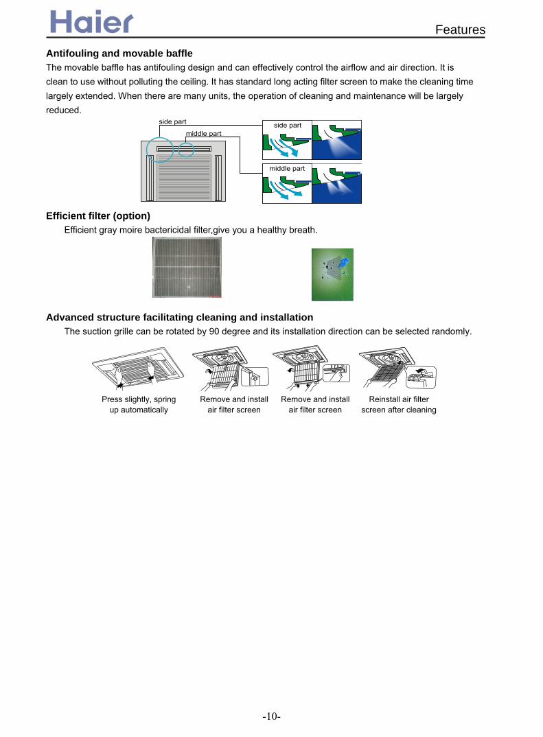
Antifouling and movable baffle The movable baffle has antifouling design and can effectively control the airflow and air direction. It is clean to use without polluting the ceiling. It has standard long acting filter screen to make the cleaning time largely extended. When there are many units, the operation of cleaning and maintenance will be largely reduced.
Efficient filter (option)
Efficient gray moire bactericidal filter,give you a healthy breath.
Advanced structure facilitating cleaning and installation
The suction grille can be rotated by 90 degree and its installation direction can be selected randomly.
side part
middle part
middle part
side part
Press slightly, spring up automatically
Remove and install air filter screen
Remove and install air filter screen
Reinstall air filter screen after cleaning
Features
-10-

2. Specifications2.1 For DC inverter unit
Function cooling heatingCapacity kW 3.52(0.9--4.4) 4.4(1.0---4.8)Sensible heat ratio 0.71
W 1250(280---1650) 1210(280--1650)W 1650 1650
EER or COP W/W 2.81(C) 3.64(A)
Dehumidifying capacity 10‐³×m³/hPower cablePower source N, V, Hz
A / A 6.0(1.4--8.0)A/8A 6.0(1.4--8.0)A/8AStart Current A 3 3 Circuit breaker A 13 13
Unit model (color)Type × NumberSpeed(H-M-L) r/minFan motor output power kWAir-flow(H-M-L) m³/h Type / Diameter mmTotal Area m²Temp. scope External (L×W×H)mm×mm×mm
Package (L×W×H)mm×mm×mm
Drainage pipe (material , I.D./O.D.) mmControl type (Remote /wired)Fresh air hole dimension mm
dB(A)kg / kg
External (L×W×H)mm×mm×mm
Package (L×W×H)mm×mm×mm
kg / kg
Function cooling heatingCapacity kW 5.0(1.8--5.8) 5.2(2.0---6.2)Sensible heat ratio 0.71
W 1660(550---2400) 1730(600--2300)W 2650 2650
EER or COP W/W 3.01 3.01Dehumidifying capacity 10‐³×m³/h
A / A 7.8(3.0--10.5)A/12.0A 8.0(3.2--10)A/12.0AUnit model (color)
Type × NumberSpeed(H-M-L) r/minFan motor output power kWAir-flow(H-M-L) m³/h Type / Diameter mmTotal Area m²Temp. scope External (L×W×H)mm×mm×mm
Package (L×W×H)mm×mm×mm
Drainage pipe (material , I.D./O.D.) mmControl type (Remote /wired)Fresh air hole dimension mm
dB(A)kg / kg
External (L×W×H)mm×mm×mm
Package (L×W×H)mm×mm×mm
kg / kg
2.1Running /Max.Running current
700×700×60 740×750×115
3.5/4.5
45/40/32
718×680×380
Total power inputMax. power input
Weight (Net / Shipping)
Pan
el Dimension
Weight (Net / Shipping)
Noise level (H-M-L)
Remote95
Item Model AB182ACERA
Indo
or u
nit
Black
Fan
centrifugal*1760/650/520
0.065700/620/520
PVC 26/32
Running /Max.Running current
Heat exchanger inner grooved pipe/φ7
2-7
Dimension 570×570×260
Weight (Net / Shipping) 18.5/23
Pan
el Dimension 700×700×60mm 740×750×115mm
Weight (Net / Shipping) 3.5/4.5
PVC 26/32Remote
95Noise level (H-M-L) 45/40/32
0.2722-7
Dimension 570×570×260mm718×680×380mm
1, 220--230, 50
Indo
or u
nit
AB122ACERA(BLACK)
Fan
Centrifugal fan*1756/650/520±50
0.065700/620/520
Heat exchanger inner grooved pipe/φ7
ENERGY CLASS 1.61.5
3×2.5
item Model AB122ACERA
Total power inputMax. power input
0.272
18.5/23
Specifications
-11-

Function cooling heatingCapacity kW 7.0(2.0---8.0) 7.8(2.5--8.5)Sensible heat ratio 0.72
W 2300(500---3250)W 2.25(500---2750)WW 3300W 3300W
EER or COP W/W 3.04 3.46Dehumidifying capacity 10‐³×m³/h
A / A 11.0(2.5--14.5)A/15.0A 10.0(2.5--12.0)A/15.0AUnit model (color)
Type × NumberSpeed(H-M-L) r/minFan motor output power kWAir-flow(H-M-L) m³/h Type / Diameter mmTotal Area m²Temp. scope External (L×W×H)mm×mm×mm
Package (L×W×H)mm×mm×mm
Drainage pipe (material , I.D./O.D.) mmControl type (Remote /wired)Fresh air hole dimension mm
dB(A)kg / kg
External (L×W×H)mm×mm×mm
Package (L×W×H)mm×mm×mm
kg / kg
Function cooling heatingCapacity kW 7.0(2.0---8.0) 7.8(2.5--8.5)Sensible heat ratio 0.72
W 2300(500---3250)W 2.25(500---2750)WW 3300W 3300W
EER or COP W/W 3.04(B) 3.46(B)Dehumidifying capacity 10‐³×m³/h
A / A 11.0(2.5--14.5)A/15.0A 10.0(2.5--12.0)A/15.0AUnit model (color)
Type × NumberSpeed(H-M-L) r/minFan motor output power kWAir-flow(H-M-L) m³/h Type / Diameter mmTotal Area m²Temp. scope External (L×W×H)mm×mm×mm
Package (L×W×H)mm×mm×mm
Drainage pipe (material , I.D./O.D.) mmControl type (Remote /wired)Fresh air hole dimension mm
dB(A)kg / kg
External (L×W×H)mm×mm×mm
Package (L×W×H)mm×mm×mm
kg / kg
Weight (Net / Shipping)
670±40/550±50/460±50
Running /Max.Running current
Max. power input
1.8
26.8/32.6
Pan
el Dimension 950*950*80980*980*100
Weight (Net / Shipping) 6/9
Indo
or u
nit
AB242ACERA(black)
Fan
Remote or wired
Noise level (H-M-L) 48/44/39
Dimension 840*840*240930*930*330PVC 26/32
Heat exchanger Inner grooved type /φ7
0.492-7
Centrifugal × 1670±40/550±50/460±50
0.161300/1100/870
item Model AB242ACERA
Total power input
item Model AB242AEERA
Total power inputMax. power input
1.8
Indo
or u
nit
AB242AEERA(black)
Fan
Centrifugal × 1
0.161300/1100/870
Heat exchanger Inner grooved type /φ7
930*930*330
0.492-7
Dimension 840*840*240
46/43/39
PVC 26/32Remote or wired
Running /Max.Running current
Weight (Net / Shipping) 26.8/32.6
Pan
el Dimension 950/950/60985/985/115
Weight (Net / Shipping) 6.0/9.0
Noise level (H-M-L)
/
/
Specifications
-12-

Function cooling heatingCapacity BTU/h 27600 31400Capacity kW 8.1(2.2~9.5)Sensible heat ratio 0.73
W 2750(500---3800) 2600(500---3800)W 3800 3800
EER or COP W/W 3.27Dehumidifying capacity 10‐³×m³/h B B
A / A 11.2(2.3-17.0)/17.0 11.2(2.3-17.0)/17.0Unit model (color)
Type × NumberSpeed(H-M-L) r/minFan motor output power kWAir-flow(H-M-L) m³/h Type / Diameter mmTotal Area m²Temp. scope External (L×W×H)mm×mm×mm
Package (L×W×H)mm×mm×mm
Drainage pipe (material , I.D./O.D.) mmControl type (Remote /wired)Fresh air hole dimension mm
dB(A)kg / kg
External (L×W×H)mm×mm×mm
Package (L×W×H)mm×mm×mm
kg / kg
Function cooling heatingCapacity Btu/h 33800 38200Capacity kW 9.9(2.2~11.6) 11.2(2.5~12.0)Sensible heat ratio 0.73Total power input W 3290(650---3800) 3280(650---3800)Max. power input W 4300 4300EER or COP W/W 3.01 3.41Energy efficiency stage BDehumidifying capacity 10‐³×m³/h
A / A 14.3(2.9-17.0)/19.3 14.3(2.9-17.0)/19.3Unit model (color)
Type × NumberSpeed(H-M-L) r/minAir-flow(H-M-L) m³/h Type / Diameter mmTotal Area m²Temp. scope External (L×W×H)mm×mm×mm
Package (L×W×H)mm×mm×mm
Drainage pipe (material , I.D./O.D.) mmControl type (Remote /wired)
dB(A)kg / kg
External (L×W×H)mm×mm×mm
Package (L×W×H)mm×mm×mm
kg / kg
Running /Max.Running current
with
AU
362A
HE
RA
Pan
el Dimension 1340/950/801400/995/115
Weight (Net / Shipping) 8.4/12
remote/wiredNoise level (H-M-L) 50/46/42Weight (Net / Shipping) 46/53
Dimension 1230/840/2801325/920/370
PVC 26/32
1850/1600/1350
Heat exchanger inner grooved type/φ7
0.5832-7
item Model AB362ACERA
3.8
Indo
or u
nit
AB362ACERA(BLACK)
Fan Centrifugal fan * 1620/450/390±40
item Model AB282AEERA
Total power inputMax. power input
Indo
or u
nit
AB282AEERA(black)
Fan
Centrifugal × 1680/600/530
0.151600/1450/1300
Heat exchanger Inner grooved type /φ7
0.52-7
Dimension 840/840/290935/925/390
47/42/37
PVC 26/32Remote or wired
69
Running /Max.Running current
Weight (Net / Shipping) 38/45
Pan
el Dimension 950/950/60985/985/115
Weight (Net / Shipping) 6.0/9.0
Noise level (H-M-L)
B
2.95
9.2(2.5~10.5)
Specifications
-13-

Function cooling heatingCapacity Btu/h 33700 37500Capacity kW 9.5(2.2~11.6) 11.0(2.5~12.0)Sensible heat ratio 0.73Total power input W 3350(650---3800) 3400(650---3800)Max. power input W 4300 4300EER or COP W/W 2.88 3.24Energy efficiency stage C CDehumidifying capacity 10‐³×m³/h
A / A 14.3(2.9-17.0)/19.3 15.0(2.9-17.0)/19.3Unit model (color)
Type × NumberSpeed(H-M-L) r/minFan motor output power kWAir-flow(H-M-L) m³/h Type / Diameter mmTotal Area m²Temp. scope External (L×W×H)mm×mm×mm
Package (L×W×H)mm×mm×mm
Drainage pipe (material , I.D./O.D.) mmControl type (Remote /wired)Fresh air hole dimension mm
dB(A)kg / kg
External (L×W×H)mm×mm×mm
Package (L×W×H)mm×mm×mm
kg / kg
Function cooling heatingCapacity Btu/hCapacity kW 12.0(6.0~14.0) 13.0(6.0~16.0)Sensible heat ratio 0.73
W 4.6(2.0---6.0) 4.6(2.0----6.0)W 00 6000
EER or COP W/W ( ) (
Energy efficiency stage C CDehumidifying capacity 10‐³×m³/h
A / A 8.0(2.9-9.5)/ .5 8.0(2.9-9.5)/10.5Unit model (color)
Type × NumberSpeed(H-M-L) r/minFan motor output power kWAir-flow(H-M-L) m³/h Type / Diameter mmTemp. scope External (L×W×H)mm×mm×mm
Package (L×W×H)mm×mm×mm
Drainage pipe (material , I.D./O.D.) mmControl type (Remote /wired)
mmdB(A)kg / kg
External (L×W×H)mm×mm×mm
Package (L×W×H)mm×mm×mm
kg / kg
0.15
50/46/42
remote/wired
Pan
el Dimension 950/950/60985/985/115
Weight (Net / Shipping) 6.0/9.0
PVC 26/32
Noise level (H-M-L)Weight (Net / Shipping) 38/45
2-7
Dimension 840/840/290910/910/370
3.8Running /Max.Running current
Indo
or u
nit
AB482AEERA(BLACK)
Fan
Centrifugal fan * 1890/760/520
1650/1400/1300
Heat exchanger inner grooved type/φ7
Total power inputMax. power input
Indo
or u
nit
AB362AEERA(BLACK)
Fan
item Model AB482AEERA
Weight (Net / Shipping)
Pan
el Dimension 950/950/60985/985/115
Weight (Net / Shipping)
remote/wired
Noise level (H-M-L) 47/42/3738/45
6.0/9.0
69
Dimension 840/840/290935/925/390PVC 26/32
Centrifugal fan * 1680/600/530
1600/1450/1300
Heat exchanger inner grooved type/φ7
0.52-7
0.15
item Model AB362AEERA
3.8Running /Max.Running current
with
AU
362A
HE
RA
45000 52000
Fresh air hole dimension 100
D2.61 E) 2.83
10
63
Specifications
-14-

Function cooling heatingCapacity Btu/h 54000 61400Capacity kW 15.8(6.0~16.5) 18.0(6.0~19.0)Sensible heat ratio 0.73
W 5.6(2.0---6.0) 5.6(2.0----6.0)W 6000 6000
EER or COP W/W 2.82(C) 3.21(C)
Dehumidifying capacity 10‐³×m³/hA / A 9.5(2.9-10.5)/10.5 9.5(2.9-10.5)/10.5
Unit model (color)Type × NumberSpeed(H-M-L) r/minFan motor output power kWAir-flow(H-M-L) m³/h Type / Diameter mmTotal Area m²Temp. scope External (L×W×H)mm×mm×mm
Package (L×W×H)mm×mm×mm
Drainage pipe (material , I.D./O.D.) mmControl type (Remote /wired)
dB(A)kg / kg
External (L×W×H)mm×mm×mm
Package (L×W×H)mm×mm×mm
kg / kg
Weight (Net / Shipping) 46/53
Pan
el Dimension 1340/950/801400/995/115
Weight (Net / Shipping) 8.4/12.0
PVC 32/26remote/wired
Noise level (H-M-L) 51/47/43
2-7
Dimension 1230/840/2801325/920/370
Running /Max.Running current
Indo
or u
nit
AB602ACERA(BLACK)
Fan
Centrifugal fan * 1670/550/460±50
1980/-/-
Heat exchanger inner grooved type/φ7
0.583
item Model AB602ACERA
Total power inputMax. power input
5.0
0.15
Specifications
-15-

2.2 For Fixed frequency unit
Function cooling heatingCapacity 3.5 3.8kW
0.71W 1160 1110W 1650 1650
EER or COP W/W 3.01(A) 3.41(A)
Dehumidifying capacity 10‐³×m³/hA / A 4.9A/7.4A 4.9A/7.4A
Start Current A 20 20Unit model (color)
Type × NumberSpeed(H-M-L) r/minFan motor output power kWAir-flow(H-M-L) m³/h Type / Diameter mmTotal Area m²Temp. scope External (L×W×H)mm×mm×mm
Package (L×W×H)mm×mm×mm
Drainage pipe (material , I.D./O.D.) mmControl type (Remote /wired /model)Fresh air hole dimension mm
dB(A)kg / kg
External (L×W×H)mm×mm×mm
Package (L×W×H)mm×mm×mm
kg / kg
Function cooling heatingCapacity BTU/h 15700 16700Capacity kW 4.6 4.9
W 1650 1600W 2050 1950
EER or COP W/W 2.79 3.06A / A
Start Current AMax. operating pressure of heat side Mpa 4.5Max. operating pressure of cold side Mpa 4.5
Unit model (color) AB182ACEAA GreyType × NumberSpeed(H-M-L) r/minFan motor output power kWAir-flow(H-M-L) m³/h Type / Diameter mmTotal Area m²Temp. scope External (L×W×H)mm×mm×mm
Package (L×W×H)mm×mm×mm
Drainage pipe (material , I.D./O.D.) mmControl type (Remote /wired /model)Fresh air hole dimension mm
dB(A)kg / kg
External (L×W×H)mm×mm×mm
Package (L×W×H)mm×mm×mm
kg / kg
3.5/4.5
50
45/40/3218.5/23
700×700×60mm 740×750×115mm
718×680×380mmPVC 26/32
Remote95
inner grooved pipe/φ70.2722-7
570×570×260mm
Pan
el Dimension
Weight (Net / Shipping)
AB122ACEAAIn
door
uni
t
Fan
Heat exchanger
Dimension
Noise level (H-M-L)Weight (Net / Shipping)
item Model
Total power inputMax. power input
Running /Max.Running current
ENERGY CLASS
Weight (Net / Shipping) 19/23.5
Pan
el Dimension 700×700×60740×750×115
Weight (Net / Shipping) 3.5/4.5
remote / 0010451255ф100
Noise level (H-M-L) 45/42/40
Dimension570x570x260718x680x380PVC 14/16
item Model AB182ACEAA
Total power inputMax. power input
Running /Max.Running current cooling: 7.5A /10.5A heating: 7.0A /10.0A
Indo
or u
nit
Fan
axial fan X 1 750±20 / 650±30/ 520±30
50700/640/480
Heat exchanger TP2M/7X0.5
0.4412-7
1.61.5
AB122ACEAA(BLACK)centrifugal fan*1760/690/550±50
0.065700/620/520
Sensible heat ratio
Specifications
-16-

Function cooling heatingCapacity kW 7.25 7.4Sensible heat ratio 0.72 /
W 2400 2300W 3100W 3000W
EER or COP W/W 3.02 3.22Dehumidifying capacity 10‐³×m³/h
A / A 11.0A/13.9A 10.5A/13.4AUnit model (color)
Type × NumberSpeed(H-M-L) r/minFan motor output power kWAir-flow(H-M-L) m³/h Type / Diameter mmTotal Area m²Temp. scope External (L×W×H)mm×mm×mm
Package (L×W×H)mm×mm×mm
Drainage pipe (material , I.D./O.D.) mmControl type (Remote /wired)Fresh air hole dimension mm
kWdB(A)kg / kg
External (L×W×H)mm×mm×mm
Package (L×W×H)mm×mm×mm
kg / kg
PVC 26/32Remote /wired (optional)
2.5
Weight (Net / Shipping) 26.8/32.6
Pan
el Dimension 950*950*60(PB-950JA)985*985*115
Weight (Net / Shipping) 6.0/9.0
Dimension 840*840*240930*930*330
Noise level (H-M-L) 48/44/390
inner grooved type/φ70.492-7
Running /Max.Running
Indo
or u
nit
AB242AEEAA(grey)
Fan
Centrifugal fan*1670±40/600±50/460±50
0.161300/1100/870
Heat exchanger
Electricity Heater
item Model AB242AEEAA
Total power inputMax. power input
Pan
el Dimension 950*950*80980*980*100
Weight (Net / Shipping) 6/9
Noise level (H-M-L) 48/44/39Weight (Net / Shipping) 26.8/32.6
PVC 26/32Remote /wired (optional)
Electricity Heater 0
inner grooved pipe/φ70.492-7
Dimension 840*840*240930*930*330
2.5Running /Max.Running
Indo
or u
nit
grey
Fan
centrifugal fan*1670±40/550±50/460±50
0.161300/-/-
Heat exchanger
item Model AB242ACEAA
Total power inputMax. power input
/
/
Specifications
-17-
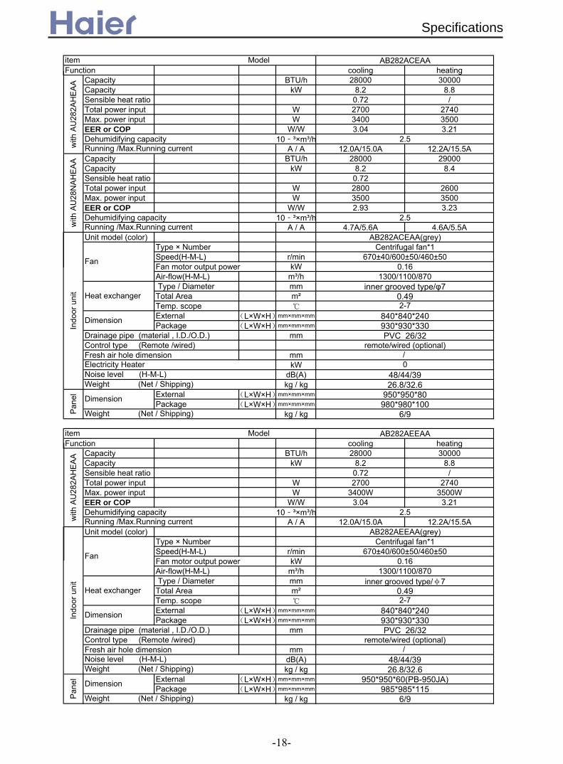
Function cooling heatingCapacity BTU/h 28000 30000Capacity kW 8.2 8.8Sensible heat ratio 0.72 /Total power input W 2700 2740Max. power input W 3400 3500EER or COP W/W 3.04 3.21Dehumidifying capacity 10‐³×m³/h
A / A 12.0A/15.0A 12.2A/15.5ACapacity BTU/h 28000 29000Capacity kW 8.2 8.4Sensible heat ratio 0.72Total power input W 2800 2600Max. power input W 3500 3500EER or COP W/W 2.93 3.23Dehumidifying capacity 10‐³×m³/h
A / A 4.7A/5.6A 4.6A/5.5AUnit model (color)
Type × NumberSpeed(H-M-L) r/minFan motor output power kWAir-flow(H-M-L) m³/h Type / Diameter mmTotal Area m²Temp. scope External (L×W×H)mm×mm×mm
Package (L×W×H)mm×mm×mm
Drainage pipe (material , I.D./O.D.) mmControl type (Remote /wired)Fresh air hole dimension mm
kWdB(A)kg / kg
External (L×W×H)mm×mm×mm
Package (L×W×H)mm×mm×mm
kg / kg
Function cooling heatingCapacity BTU/h 28000 30000Capacity kW 8.2 8.8Sensible heat ratio 0.72 /Total power input W 2700 2740Max. power input W 3400W 3500WEER or COP W/W 3.04 3.21Dehumidifying capacity 10‐³×m³/h
A / A 12.0A/15.0A 12.2A/15.5AUnit model (color)
Type × NumberSpeed(H-M-L) r/minFan motor output power kWAir-flow(H-M-L) m³/h Type / Diameter mmTotal Area m²Temp. scope External (L×W×H)mm×mm×mm
Package (L×W×H)mm×mm×mm
Drainage pipe (material , I.D./O.D.) mmControl type (Remote /wired)Fresh air hole dimension mm
dB(A)kg / kg
External (L×W×H)mm×mm×mm
Package (L×W×H)mm×mm×mm
kg / kgWeight (Net / Shipping)
Running /Max.Running current
Indo
or u
nit
Weight (Net / Shipping)Noise level (H-M-L)
Pan
el Dimension
AB282AEEAA(grey)
Fan
Heat exchanger
Dimension930*930*330
Centrifugal fan*1
remote/wired (optional)
985*985*1156/9
26.8/32.6950*950*60(PB-950JA)
48/44/39
0.161300/1100/870
inner grooved type/φ70.492-7
840*840*240
Indo
or u
nit
AB282ACEAA(grey)
Fan
670±40/600±50/460±50
AB282AEEAAitem Model
with
AU
282A
HE
AA
PVC 26/32
Noise level (H-M-L) 48/44/39Weight (Net / Shipping) 26.8/32.6
2.5
2.5
PVC 26/32remote/wired (optional)
Dimension 840*840*240930*930*330
item Model AB282ACEAA
Running /Max.Running currentwith
AU
28N
AH
EA
A
2.5Running /Max.Running currentw
ith A
U28
2AH
EA
A
Centrifugal fan*1670±40/600±50/460±50
Electricity Heater 0
0.161300/1100/870
Heat exchanger inner grooved type/φ7
0.492-7
Pan
el Dimension 950*950*80980*980*100
Weight (Net / Shipping) 6/9
/
/
Specifications
-18-

Function cooling heatingCapacity kW 10 10.5Sensible heat ratio 0.72Total power input W 3300 3500Max. power input W 3900 3950EER or COP W/W 3.03(B) 3.00(C)
A / A 15.8A/18.5A 16.5A/18.7ACapacity kW 11.5 12Sensible heat ratio 0.72Total power input W 3800 3900Max. power input W 4700 4800EER or COP W/W 3.03 3.08
A / A 6.4A/8.0A 6.5A/8.0AUnit model (color)
Type × NumberSpeed(H-M-L) r/minFan motor output power kWAir-flow(H-M-L) m³/h Type / Diameter mmTotal Area m²Temp. scope External (L×W×H)mm×mm×mm
Package (L×W×H)mm×mm×mm
Drainage pipe (material , I.D./O.D.) mmControl type (Remote /wired)
kWdB(A)kg / kg
External (L×W×H)mm×mm×mm
Package (L×W×H)mm×mm×mm
kg / kg
Function cooling heatingCapacity BTU/h 42000 45000Capacity kW 12.3 13.2
W 4710 5350W 6200 6200
EER or COP W/W 2.61 2.47Dehumidifying capacity 10‐³×m³/h
A / AStart Current AClass of anti electric shock CLASS I CLASS ICircuit breaker AMax. operating pressure of heat side Mpa 4.15 4.15Max. operating pressure of cold side Mpa 4.15 4.15
Unit model (color)Type × NumberSpeed(H-M-L) r/minFan motor output power kWAir-flow(H-M-L) m³/h Type / Diameter mmTemp. scope External (L×W×H)mm×mm×mm
Package (L×W×H)mm×mm×mm
Drainage pipe (material , I.D./O.D.) mmControl type (Remote /wired /model)
dB(A)kg / kg
External (L×W×H)mm×mm×mm
Package (L×W×H)mm×mm×mm
kg / kgPan
el Dimension 950×950×60 985×985×115
Weight (Net / Shipping) 6/9
Noise level (H-M-L) 47/42/37Weight (Net / Shipping) 38/45
Remote
Dimension 840×840×290mm930×930×390mm
PVC 26/32
Heat exchanger inner grooved/φ72-7
20
950×950×60
4.0
Indo
or u
nit
AB422AEEAA(Grey)
Fan
centrifugal680/600/530
0.11600
remote/wired (optional)
38/45
Cooling 8.5A/10.1A Heating 9.3/10.1A50
PVC 26/32
Indo
or u
nit
AB362ACEAA
Fan
Centrifugal fan*1700/600/550
0.11600/1450/1300
Electricity Heater
Weight (Net / Shipping)
inner grooved type/φ70.532-7
930/930/390
item Model
item Model
with
AU
362A
IEA
Heat exchanger
Running /Max.Running current
Noise level (H-M-L)
with
AU
36N
AIE
A
Running /Max.Running current
840/840/290
Max. power input
Dimension
985×985×1156/9P
anel Dimension
Weight (Net / Shipping)
AB422AEEAA
Total power input
0
AB362ACEAA
51
Running /Max.Running
Specifications
-19-
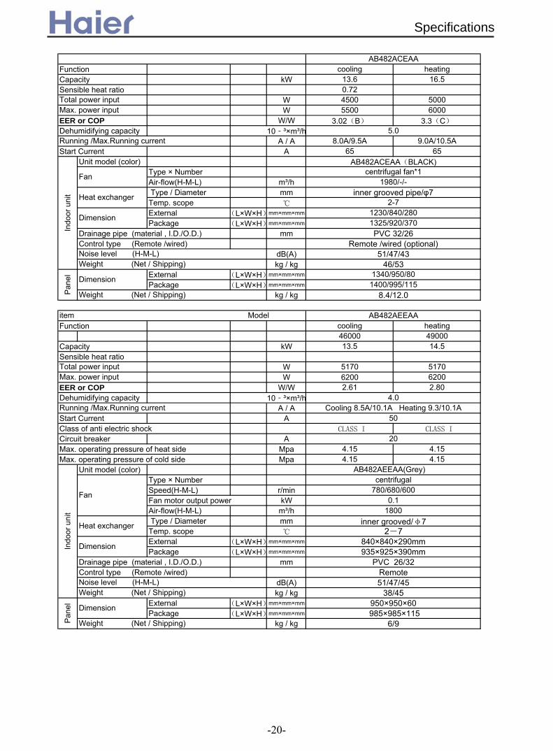
Function cooling heatingCapacity kW 13.6 16.5Sensible heat ratio 0.72
W 4500 5000W 5500 6000
EER or COP W/W 3.02(B) 3.3(C)
Dehumidifying capacity 10‐³×m³/hA / A 8.0A/9.5A 9.0A/10.5A
Start Current A 65 65Unit model (color)
Type × NumberAir-flow(H-M-L) m³/h Type / Diameter mmTemp. scope External (L×W×H)mm×mm×mm
Package (L×W×H)mm×mm×mm
Drainage pipe (material , I.D./O.D.) mmControl type (Remote /wired)
dB(A)kg / kg
External (L×W×H)mm×mm×mm
Package (L×W×H)mm×mm×mm
kg / kg
Function cooling heating46000 49000
Capacity kW 13.5 14.5Sensible heat ratio
W 5170 5170W 6200 6200
EER or COP W/W 2.61 2.80Dehumidifying capacity 10‐³×m³/h
A / AStart Current AClass of anti electric shock CLASS I CLASS I
Circuit breaker AMax. operating pressure of heat side Mpa 4.15 4.15Max. operating pressure of cold side Mpa 4.15 4.15
Unit model (color)Type × NumberSpeed(H-M-L) r/minFan motor output power kWAir-flow(H-M-L) m³/h Type / Diameter mmTemp. scope External (L×W×H)mm×mm×mm
Package (L×W×H)mm×mm×mm
Drainage pipe (material , I.D./O.D.) mmControl type (Remote /wired)
dB(A)kg / kg
External (L×W×H)mm×mm×mm
Package (L×W×H)mm×mm×mm
kg / kg
20
780/680/6000.1
840×840×290mm
4.0Cooling 8.5A/10.1A Heating 9.3/10.1A
50
Remote /wired (optional)
Weight (Net / Shipping) 38/45
Pan
el Dimension 950×950× 0 985×985×115
Weight (Net / Shipping) 6/9
935×925×390mmPVC 26/32
RemoteNoise level (H-M-L) 51/47/45
Running /Max.Running current
Indo
or u
nit
AB482AEEAA(Grey)
Fan
centrifugal
1800
Heat exchanger 2-7
Dimension
inner grooved/φ7
item Model AB482AEEAA
Total power inputMax. power input
Pan
el Dimension 1340/950/801400/995/115
Weight (Net / Shipping) 8.4/12.0
Noise level (H-M-L) 51/47/43Weight (Net / Shipping) 46/53
Dimension 1230/840/2801325/920/370PVC 32/26
5.0Running /Max.Running current
Indo
or u
nit
AB482ACEAA(BLACK)
Fan centrifugal fan*11980/-/-
Heat exchanger inner grooved pipe/φ72-7
AB482ACEAA
Total power inputMax. power input
6
Specifications
-20-

Function cooling heatingCapacity kW 15.5 18.5Sensible heat ratio 0.72
W 5100W 5350WW 6200W 6200W
EER or COP W/W 3.02(B) 3.44(B)Dehumidifying capacity 10‐³×m³/h
A / A 9.0A/10.5A 9.5A/10.5AStart Current A 65 65
Unit model (color)Type × NumberAir-flow(H-M-L) m³/h Type / Diameter mmTemp. scope External (L×W×H)mm×mm×mm
Package (L×W×H)mm×mm×mm
Drainage pipe (material , I.D./O.D.) mmControl type (Remote /wired)
dB(A)kg / kg
External (L×W×H)mm×mm×mm
Package (L×W×H)mm×mm×mm
kg / kg
Note: ⊙ is the real timeanalyser position
Pan
el Dimension 1340/950/801400/995/115
Weight (Net / Shipping) 8.4/12.0
Remote /wired (optional)Noise level (H-M-L) 51/47/43Weight (Net / Shipping) 46/53
Dimension 1230/840/2801325/920/370PVC 32/26
5.0
Indo
or u
nit
AB602ACEAA(black)
Fan centrifugal fan*11980/-/-
Heat exchanger inner grooved pipe/φ72-7
item Model AB602ACEAA
Total power inputMax. power input
Norminal condition: indoor temperature (cooling): 27DB/19WB, indoor temperature (heating): 20DBOutdoor temperature(cooling): 35DB/24WB, outdoor temperature(heating): 7DB/6WBThe noise level will be measured in the third octave band limited values, using a Real Time Analyser calibrated sound intensity meter. Itis a sound pressure noise level. The detailed method please refer to the following information:
Installation state: the unit should be placed on the flat floor or be mounted in horizontaldirection.Testing method:built-in-ceiling unit:
1.4m
Running /Max.Running current
Specifications
-21-
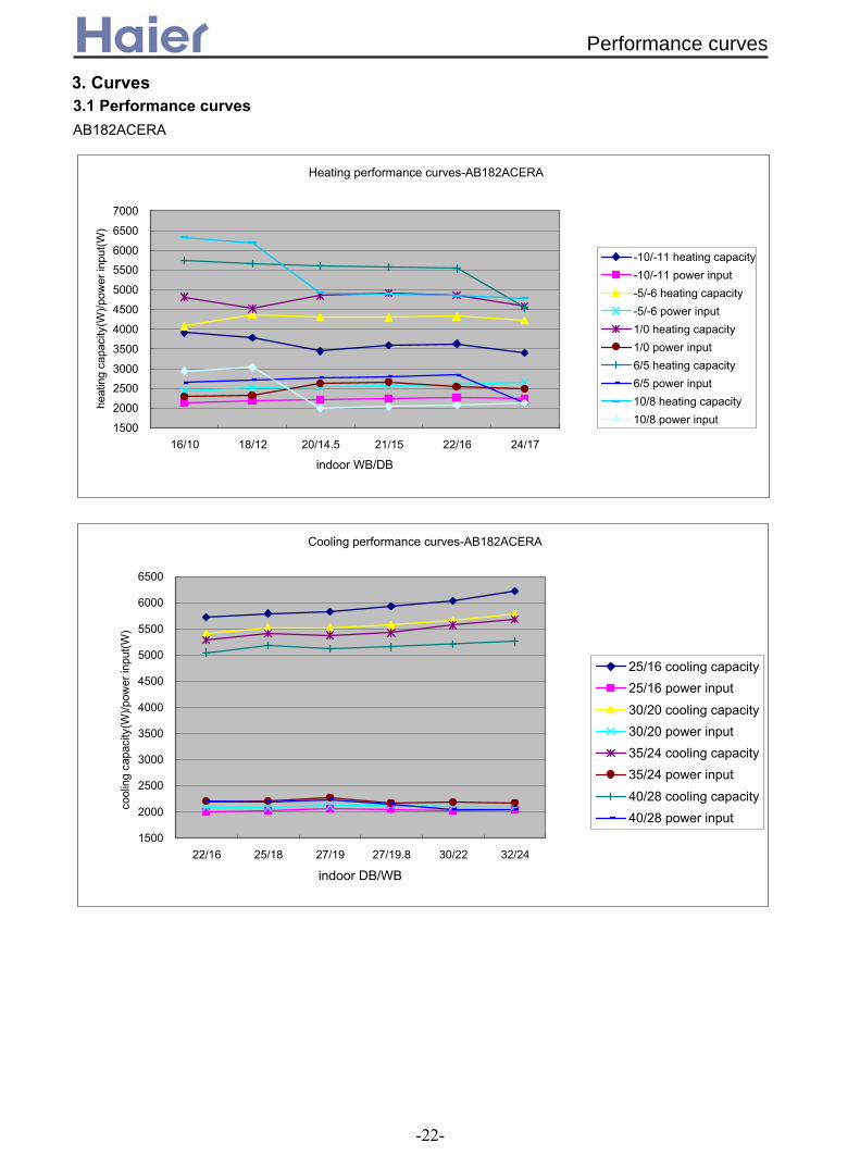
Heating performance curves-AB182ACERA
1500
2000
2500
3000
3500
4000
4500
5000
5500
6000
6500
7000
16/10 18/12 20/14.5 21/15 22/16 24/17
indoor WB/DB
heat
ing
capa
city
(W)/p
ower
inpu
t(W)
-10/-11 heating capacity-10/-11 power input-5/-6 heating capacity-5/-6 power input1/0 heating capacity1/0 power input6/5 heating capacity6/5 power input10/8 heating capacity10/8 power input
Cooling performance curves-AB182ACERA
1500
2000
2500
3000
3500
4000
4500
5000
5500
6000
6500
22/16 25/18 27/19 27/19.8 30/22 32/24
indoor DB/WB
cool
ing
capa
city
(W)/p
ower
inpu
t(W)
25/16 cooling capacity25/16 power input30/20 cooling capacity30/20 power input35/24 cooling capacity35/24 power input40/28 cooling capacity40/28 power input
AB182ACERA
3. Curves3.1 Performance curves
Performance curves
-22-
AB422AEEAA
Cooling performance curves-AB422AEEAA
400045005000550060006500700075008000850090009500
1000010500110001150012000125001300013500
18/12 20/14 22/16 25/18 27/19 30/22 32/24indoor DB/WB
cool
ing
capa
city
(W)/p
ower
inpu
t(W)
20 cooling capacity20 power input25 cooling capacity25 power input32 cooling capacity32 power input35 cooling capacity35 power input40 cooling capacity40 power input
Heating performance curves-AB422AEEAA
400045005000550060006500700075008000850090009500
1000010500110001150012000125001300013500140001450015000
16/10 18/12 20/14.5 21/15 22/16 24/17 26/18indoor WB/DB
heat
ing
capa
city
(W)/p
ower
inpu
t(W)
-6/-7 heating capacity-6/-7 power input-4/-5 heating capacity-4/-5 power input-1/-2 heating capacity-1/-2 power input1/0 heating capacity1/0 power input6/5 heating capacity6/5 power input7/6 heating capacity7/6 power input12/10 heating capacity12/10 power input16/15 heating capacity16/15 power input
Performance curves
-23-

3.2 Noise level
Noise level-A
B122A
CE
RA
10 14 18 22 26 30 34 38 42 46 50 54
2531.5
40
50
63
80
100
125
160
200
250
315
400
500
630
8001000125016002000250031504000500063008000
100001250016000020000
Third octave band frequency Hz
Sound pressure level DB
heating lowheating m
iddleheating highcooling lowcooling m
iddlecooling highfan lowfan m
iddlefan high
1/3 octave band noise level-AB
182AC
ER
A
0.05.0
10.015.020.025.030.035.040.045.050.055.060.0
25.031.540.050.063.080.0
100.0125.0160.0200.0250.0315.0400.0500.0630.0800.01000.01250.01600.02000.02500.03150.04000.05000.06300.08000.010000.012500.016000.020000.0
third octave band frequency Hz
Sound pressure level DB
cooling highcooling m
edcooling lowfan highfan m
edfan lowheating highheating m
edheating low
3.2.1 For inverter unit
Noise Level
-24-
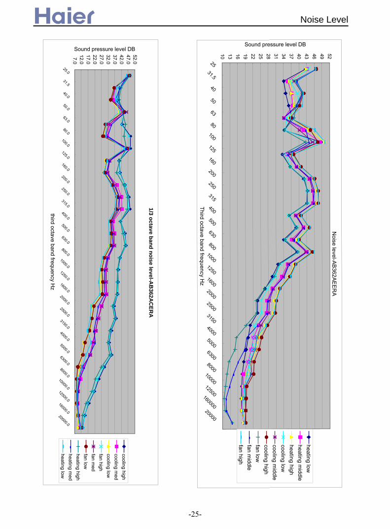
1/3 octave band noise level-AB
362AC
ERA
7.012.017.022.027.032.037.042.047.052.0
25.0
31.5
40.0
50.0
63.0
80.0
100.0
125.0
160.0
200.0
250.0
315.0
400.0
500.0
630.0
800.01000.01250.01600.02000.02500.03150.04000.05000.06300.08000.0
10000.012500.016000.020000.0
third octave band frequency Hz
Sound pressure level DB
cooling highcooling m
edcooling lowfan highfan m
edfan lowheating highheating m
edheating low
Noise Level
Noise level-A
B362A
EE
RA
10 13 16 19 22 25 28 31 34 37 40 43 46 49 5225
31.5
40
50
63
80
100
125
160
200
250
315
400
500
630
8001000125016002000250031504000500063008000
100001250016000020000
Third octave band frequency Hz
Sound pressure level DB
heating lowheating m
iddleheating highcooling lowcooling m
iddlecooling highfan lowfan m
iddlefan high
-25-

Noise level-A
B482A
EE
RA
10 15 20 25 30 35 40 45 50 55
2531.5
40
50
63
80
100
125160
200
250
315
400
500
630
8001000125016002000250031504000500063008000
100001250016000020000
Third octave band frequency Hz
Sound pressure level DB
heating lowheating m
iddleheating highcooling lowcooling m
iddlecooling highfan lowfan m
iddlefan high
-26-

3.2.2 For fix frequency unit
1/3 octave band noise level-AB
182AC
EAA
8.013.018.023.028.033.038.043.048.053.0
25.0
31.5
40.0
50.0
63.0
80.0100.0125.0160.0200.0250.0315.0400.0500.0630.0800.0
1000.01250.01600.02000.02500.03150.04000.05000.06300.08000.010000.012500.016000.020000.0
third octave band frequency Hz
Sound pressure level DB
cooling highcooling m
edcooling lowfan highfan m
edfan lowheating highheating m
edheating low
Noise level-A
B242A
CE
AA
8 11 14 17 20 23 26 29 32 35 38 41 44 47 50 53
2531.5
40
50
63
80
100
125
160
200
250
315
400
500
630
8001000125016002000250031504000500063008000
100001250016000020000
Third octave band frequency Hz
Sound pressure level DB
heating lowheating m
iddleheating highcooling lowcooling m
iddlecooling highfan lowfan m
iddlefan high
Noise Level
-27-

1/3 octave band noise level-AB
282AC
EAA
8.013.018.023.028.033.038.043.048.053.0
25.0
31.5
40.0
50.0
63.0
80.0100.0125.0160.0200.0250.0315.0400.0500.0630.0800.0
1000.01250.01600.02000.02500.03150.04000.05000.06300.08000.010000.012500.016000.020000.0
third octave band frequency Hz
Sound pressure level DB
cooling highcooling m
edcooling lowfan highfan m
edfan lowheating highheating m
edheating low
1/3 octave band noise level-AB
362AC
EAA
8.013.018.023.028.033.038.043.048.053.058.0
25.0
31.5
40.0
50.0
63.0
80.0
100.0
125.0
160.0
200.0
250.0
315.0
400.0
500.0
630.0
800.01000.01250.01600.02000.02500.03150.04000.05000.06300.08000.0
10000.012500.016000.020000.0
third octave band frequency Hz
Sound pressure level DB
cooling highcooling m
edcooling lowfan highfan m
edfan lowheating highheating m
edheating low
Noise Level
-28-

33
8.013.018.023.028.033.038.043.048.053.058.0
25.0
31.5
40.0
50.0
63.0
80.0
100.0
125.0
160.0
200.0
250.0
315.0
400.0
500.0
630.0
800.01000.01250.01600.02000.02500.03150.04000.05000.06300.08000.0
10000.012500.016000.020000.0
third octave band frequency Hz
Sound pressure level DB
cooling highcooling m
edcooling lowfan highfan m
edfan lowheating highheating m
edheating low
1/3 octave band noise level-AB
422AEEA
A
1/3 octave band noise level-AB
482AC
EAA
8.013.018.023.028.033.038.043.048.053.0
25.0
31.5
40.0
50.0
63.0
80.0100.0125.0160.0200.0250.0315.0400.0500.0630.0800.0
1000.01250.01600.02000.02500.03150.04000.05000.06300.08000.010000.012500.016000.020000.0
third octave band frequency Hz
Sound pressure level DB
cooling highcooling m
edcooling lowfan highfan m
edfan lowheating highheating m
edheating low
Noise Level
-29-

Noise level-A
B602A
CE
AA
8 12 16 20 24 28 32 36 40 44 48 52 56 60 64
2531.5
40
50
63
80
100
125
160
200
250
315
400
500
630
8001000125016002000250031504000500063008000
100001250016000020000
Third octave band frequency Hz
Sound pressure level DB
heating lowheating m
iddleheating highcooling lowcooling m
iddlecooling highfan lowfan m
iddlefan high
Noise Level
-30-

3.3 Air velocity distribution
4 2 1
m/s
10 2
m/s
04
2
04 2 1
27
25
22
1 2
22
27
25
04
2
Air Velocity Distribution
CoolingBlowy angle:40
Temperature Distribution
CoolingBlowy angle:40
a. Cooling / Air Velocity Distribution
b. Cooling / Temperature Distribution
For AB12*
4 2 1
m/s
10 20
4
m/s 2
HeatingBlowy angle:70Air velocity Distribution
c. Heating / Air Velocity Distribution
4 2 1
22
27
25
22
0 1 2 40
25
27 2
d. Heating / Temperature Distribution
Temperature Distribution
HeatingBlowy angle:70
Air Velocity Distribution
-31-

For AB18*
4 2 1
m/s
10 2
m/s
04
2
04 2 1
27
25
22
1 2
22
27
25
04
2
Air Velocity Distribution
CoolingBlowy angle:40
Temperature Distribution
CoolingBlowy angle:40
a. Cooling / Air Velocity Distribution
b. Cooling / Temperature Distribution
4 2 1
m/s
10 20
4
m/s 2
HeatingBlowy angle:70Air velocity Distribution
c. Heating / Air Velocity Distribution
4 2 1
22
27
25
22
0 1 2 40
25
27 2
d. Heating / Temperature Distribution
Temperature Distribution
HeatingBlowy angle:70
Air Velocity Distribution
-32-

For AB24* and AB28*
Air Velocity Distribution
CoolingBlowy angle:40
Temperature Distribution
CoolingBlowy angle:40
a. Cooling / Air Velocity Distribution
b. Cooling / Temperature Distribution
4 2 1 0 1 20
4
m/s m/s 2
4 2 1
27
25
22
27
10 2
25
22
04
2
Air Velocity Distribution
-33-

For AB36* and AB42*
Air Velocity Distribution
CoolingBlowy angle:40
Temperature Distribution
CoolingBlowy angle:40
a. Cooling / Air Velocity Distribution
b. Cooling / Temperature Distribution
04 2 1
m/s
1 20
4
m/s
2
27
4 2 1
25
22
0 1 2
27
04
25
22
2
Air Velocity Distribution
-34-

VIE
W D
VIE
W B
VIE
W C
VIE
W C
VIE
W B
VIE
W D
620~650 (ceiling hole)535 (hanging position)
620~650 (ceiling hole)535 (hanging position)
0( 1)#(1$%over
over
over
over
1000over
4. Dimension4.1 AB12, AB18 (used for the unit with PB-700IA panel)
Dimension
-35-

4.2 AB24, AB28 (used for the unit with old PB-950IA panel) and AB242AEERA, AB242AEEAA,V
IEW
D
VIE
W B
VIE
W C
VIE
W C
VIE
W B
VIE
W D
740 (hanging position)860~890 (ceiling hole)
740 (hanging position)860~890 (ceiling hole)
VIE
W A
VIE
W A
1000over
over
over
over
over
AB282AEEAA (used for the unit with new PB-950JA panel)
Dimension
-36-
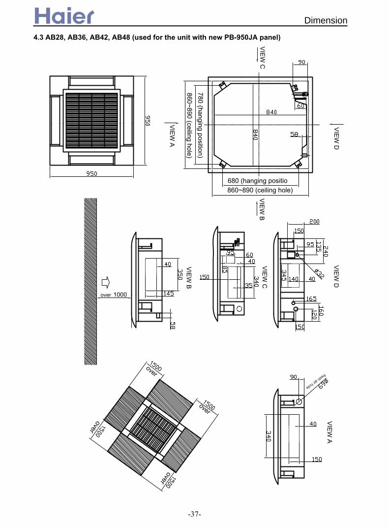
4.3 AB28, AB36, AB42, AB48 (used for the unit with new PB-950JA panel)
VIE
W D
VIE
W B
VIE
W C
VIE
W C
VIE
W B
VIE
W D
860~890 (ceiling hole)860~890 (ceiling hole)
VIE
W A
VIE
W A
780 (hanging position)680 (hanging positio
0( 1)#(1$%
1000over
over
over
over
over
Dimension
-37-

4.4 AB48, AB60 (used for the unit with PB-1340IA panel)
1250~1280 (ceiling hole)
1070 (hanging position)
780 (hanging position)
860 - 890 (ceiling hole)
over
over
over
over
1000over
Dimension
-38-
9+
6
$"#
B
6
&(
;
9&(
&(
!!"#!%!"#!!"#$
6&<76A;-/ (
;/
&;;/(
B">
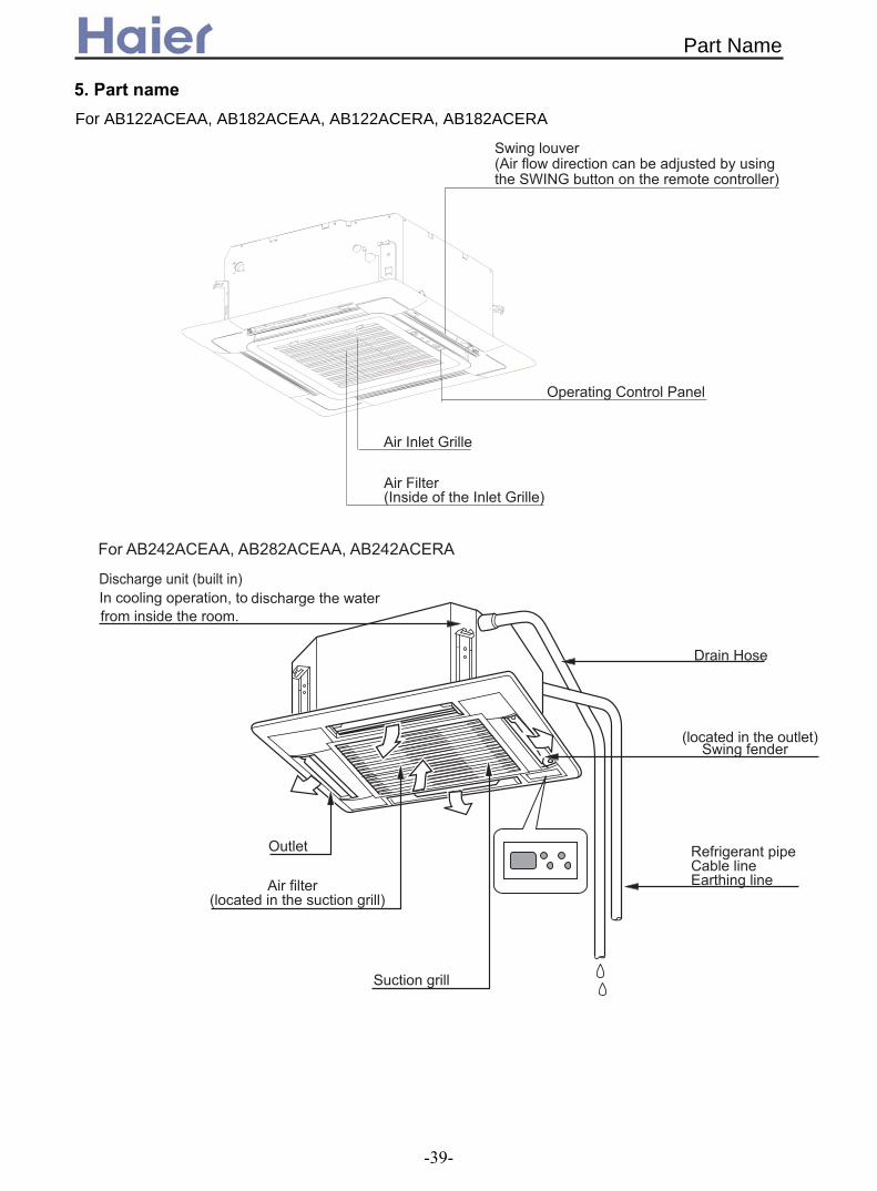
5. Part name
For AB122ACEAA, AB182ACEAA, AB122ACERA, AB182ACERA
Part Name
-39-

&<7< (
6
!!"#$ %!"#$
!!"#!%!"#!!"#$
%!"#3,!"#.3!"#$3,!"#$
> >
>2,,;
>8,;
>8,C
.3!"#!!##!%!##
!!##%!##!!##$
!%!##$.3!##$%!##$
> .,;%!"#3,!"#.3!"#$
3,!"#$
.,' ., 7 7
8,'8,77
2,,'2,,
8,'8,
AB122ACEAA, AB182ACEAA,
.3!"#!!##!%!##!%!##$.3!##$%!##$
!!##%!##!!##$
Part Name
-40-
6. Installation
D>4444@" 7D47 4 ?&;7 (9:*&(B 14 74&(A" 7 4&(A:7 &(A &(1
@A"*
AE6<7 "E;<7
"D;B-E
"D;B-6*F"F747
;7:77;44;@;44B44 7DB<A4 7 )4; 7471@D1;G 74D1 711 4> 7771 74;44 > "44$ "7 4
A$-;-/E
#
9:
$
Installation
-41-
& (>
&!(";!. &$;@ (
&.(;"447
(
;
& (; 7 *>-4A >># ; &$;@(; 7 ?&# 4(
9 779: 4;447
!
>
&!("7&71(
&.(;&D@ ,(
717<
#$
-* "
$H
6
$ "&(&(" 7 "7
,I
,,
&9 4$
+
!,,B
,,B ,,B
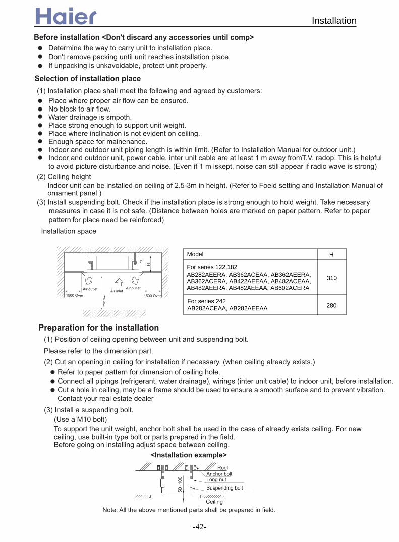
For series 122,182 AB282AEERA, AB362ACEAA, AB362AEERA, AB362ACERA, AB422AEEAA, AB482ACEAA, AB482AEERA, AB482AEEAA, AB602ACERA
For series 242AB282ACEAA, AB282AEEAA
Model H
280
310
Installation
-42-

##
%&.(<&$& ((&("4:G
A 4G >?"&; 74(
&($ &3($
&!( 47" 4" [email protected]
& (; 7>44
#$
61
">>
6&7(6&7(
J1K
& (; 7>4414 7&!(<&$& ((
-&>(
A&>(
6
&(
;
A1
&(J 7K
H>7
!
3
&.(>F;F
Installation
-43-
#
' &% ( (B G 7.D) & 7 4("4<4;"< )
& (;>)&775G*! 5B9*.! (9 = ,, ;: 4 L 4 4
6 = ,,
&-(
;<
6 )
& (2 :7
@ G &7(
$,I,%
8,,
!
"<
A8;
)
><
" .
/H)
;&7(
&)(;&7(
&(
&"<(
>G
) & (
8! .!2,I.88,- &...I,24 (
3 %,I2,- &3.,I22,4 ( %%
8,82!,I %3,- &88,I ! ,4 (
!,I !
%3I 8,
!!8I!..
2
%
2
M N
2
6&7(
,,
"
&A( 6
.,, I
!%,
,,
!!,
9&7(
64
" &7(
;!%, .,,
B ,
,
&7(
&7(HG
"
,
3. !,I 2!,- & I 234 (
%.I%2
D ;
Installation
-44-

"4G74 4
4 1 7 71"7 "; 4 ,7
MH N
; 4 7
& !! %!(
>BA#$6D>>HO* >+!!,!.,?I,+G
! . H -
! .
#1
O=/
O=/
&!("4
" !,,%
-D 7
"4
&!!!%!.3!!!%!3,!(
*
;-9BB$D-;#$@;-HHB"L
BD9BB$D-;#$@;-HHB"L
$ 1 >+ ! 4
For AB122ACEAA, AB122ACERA and AB182ACEAA
Installation
-45-

@
"
"
A ,,
,,
A
&9 (
6 @
;
!.9
BD9BB$D-;#$@;-HHB"L
;-9BB$D-;#$@;-HHB"L
>BA#$6D>>HO*.%,,,?.-I,+G
$ 6 - ! .
! .O=/
O=/
O=/ ! .
>+!!,!.,?I,+G>BA#$6D>>HO*
;-9BB$D-;#$@;-HHB"L
H-
! .O=/
&.3!!!%!3,!(
&!!!%!.3! %!"#$(
BD9BB$D-;#$@;-HHB"L
* D7A 4 4 7)4 77 6;@4"$ 1& ( " 4A !& 7(D1& (&!(
"1
>"
4
"
4
Installation
-46-
;@+, 4
#
-! . B <9:7 7
& (' ,
>&$ (H 14&$!(
B@ 7;@A !.6.
!
&!(' &$.(
*$
% !
B7 4*9: 4&H 7("
"
9:
9:
*%'+#+/NN
!
!
-0& (B .
&!(>7"D7&$(;$3
"
> H
3
4
"1& ($
/
"1&!(
B;
9: 7 $
-*+6& G(&A(
!
6
.
!
Installation
-47-

& ("-# -
2 ; > 74&!(>4&"4 (6 &>(< 24 %
;G <
; % 7
;<&$8(
H 8
/4
/4
" @1
%
&!(
!
.
P%
.
!
!
+
>
6
2
6;"
B
+4
"
&.(A " &!(&$ ,(
; &2( 6 4
6
,
A 6
&-#
;;F> F;<7;< )
& (
*(1 -
>
6
Installation
-48-

; ; &$ !(
&!(
6
!
!
#1
! 1
4 1
; 7Q
;44 Q
;7Q
; Q
; Q
;7Q
;7Q
;GQ
7Q
; Q
D 4
7
9 7
9 7
> 7
> 7
4
> 7
7
;
%2+#3+,(1-
Installation
-49-

Convertible indoor unit (AC12~AC60)
Convertible type
-50-
1. Features............................................................................51
2. Specifications....................................................................53
2.1 For DC inverter unit....................................................53
2.2 For fixed frequency unit..............................................57
3. Curves...............................................................................61
3.1 Performance curves...................................................61
3.2 Noise level..................................................................63
3.3 Air velocity distribution................................................69
4. Dimensions.......................................................................74
5. Part name.........................................................................75
6. Installation........................................................................76
6.1 For AC12,AC18,AC24................................................76
6.2 For AC28,AC36,AC48,AC60......................................82
1. FeaturesStreamline appearance
The unit adopts streamline design that makes it so compact and has a popular appearance. So it can add elegance to any style of interior. Optional installation mode
The indoor unit can be installed on the floor or to the ceiling. It always greatly decreases the space needed and also it can provide the same comfort to us. At the same time make service and Installation more convenient and easy.
Optional Drain water modes Optional drain water lift-up mechanism offers more
flexible installation. more choices for water pipe installation.
Fresh-air intake There is pre-set 200mm-diameter large fresh air intake holes in the unit, which can make the air more
comfortable. The fresh function can be set at any time according to the request of you
Automatically control of airflow direction In order to realize the comfortable space with uniform temperature, the air conditioner adopts two
stepping motors to adjust the airflow automatically for sending the air to every corner of the room. When heating, it will send download large quantity of hot air in order to quickly and effectively warm up
the floor, and it will send the airflow from top to bottom from the very beginning when cooling to send the cool air to every corner of the room.
For AC28~60, the airflow direction can be controlled in 5 steps from up to down and from left to right. More selectable, more flexible.
Fresh air hole
ConcealedopenWall mounted
for all only for units AC28~60
Indoor
Fresh air
Outdoor
up and down
5 steps selectable5 steps selectable
Right and left
SwingSteps
Features
-51-

Ultra-thin unit body, only thick 199 mm
The convertible indoor unit adopts a double drain pan design, the unit body is very thin, only 199 mm. It is beautiful and elegant and the most important-space saving (for model 12, 18, 24). Long-life and high efficiency air purify filter
The units adopts high efficiency air purify filter, greatly improve the room air quality; at the same time, the filter is with the pulling hole, can be easily taken down and cleaned.
Particular drive deviceWith single fan motor, the fans connect with motoraxis by the flexible gimbal so that the ratio of damageable parts can be reduced, and the noise level down to 47dB.
Variable control mode Standard control method: Infrared controller YR-H71 for AC12~24 and YR-H50 for AC28~60. Optional control method: a. Wired&Group controller: YR-E12 which can control at most 16 indoor units and operate them
synchronously, all the indoor units work in the same state(working mode, set temperature, fan speed and etc.), thus it makes a easy management. Central Controller:YCZ-A001 which can control at most 128 indoor units, all the indoor units work in the different modes.
b.
Convertible type
-52-

2. Specifications2.1 For DC inverter unit
Function cooling heatingCapacity kW 4.1(0.9--4.6) 4.4(1.0---5.1)Sensible heat ratio 0.71
W 1270(280---1650) 1210(280--1650)W 1650 1650
EER or COP W/W 3.23(A) 3.64(A)Dehumidifying capacity 10‐³×m³/hPower cable
A / A 6.0(1.4--8.0)A/8A 6.0(1.4--8.0)A/8AStart Current A 3 3 Circuit breaker A 13 13
Unit model (color)Type × NumberSpeed(H-M-L) r/minFan motor output power kWAir-flow(H-M-L) m³/h Type / Diameter mmTotal Area m²Temp. scope
External (L×W×H)mm×mm×mm
Package (L×W×H)mm×mm×mm
Drainage pipe (material , I.D./O.D.) mmControl type (Remote /wired)
dB(A)kg / kg
Function cooling heatingCapacity kW 5.1(1.8--5.8) 6.0(2.0---7.1)Sensible heat ratio 0.71
W 1690(550---2650) 1650(600--2650)W 2650 2650
EER or COP W/W 3.01 3.63Dehumidifying capacity 10‐³×m³/h
A / AUnit model (color)
Type × NumberSpeed(H-M-L) r/minFan motor output power kWAir-flow(H-M-L) m³/h Type / Diameter mmTotal Area m²Temp. scope
External (L×W×H)mm×mm×mm
Package (L×W×H)mm×mm×mm
Drainage pipe (material , I.D./O.D.) mmControl type (Remote /wired)
dB(A)kg / kg
Item Model AC122ACERA
Total power inputMax. power input
Indo
or u
nit
White
Fan
CENTRIFUGALX21150/1050/850
0.05750/650/550
Heat exchanger inner grooved pipe/φ7
0.45
Heat exchanger inner grooved pipe/φ7
0.20
1.63×2.5
Dimension990×655×1991150×750×300
Indo
or u
nit
AC122ACERA(WHITE)
Fan
Centrifugal fan*21200/1080/880
0.09750/650/550
Weight (Net / Shipping) 28.3/34.3
Running /Max.Running current
Item Model AC182ACERA
PVC 18/20Remote
Noise level (H-M-L) 46/44/42
2-7
2-7
Dimension990×655×1991150×750×300
30/39
Total power inputMax. power input
1.8Running /Max.Running current
PVC 18/20Remote
Noise level (H-M-L) 48/46/44 Weight (Net / Shipping)
8.0(3.0--12.0)A/12A 7.8(3.2--12.0)A/12A
Specifications
-53-

Function cooling heatingCapacity kW 6.1(2.0-7.1) 7.5(2.5-8.5)Sensible heat ratio 0.72
W 2170(500-3250) 2550(500-3250)W 3300W 3300W
EER or COP W/W 2.81(C) 2.94(E)Dehumidifying capacity 10‐³×m³/h
A / A 10(2.5-14.5)A/15A 11.5(2.5-14.5)A/15AUnit model (color)
Type × NumberSpeed(H-M-L) r/minFan motor output power kWAir-flow(H-M-L) m³/h Type / Diameter mmTotal Area m²Temp. scope
External (L×W×H)mm×mm×mm
Package (L×W×H)mm×mm×mm
Drainage pipe (material , I.D./O.D.) mmControl type (Remote /wired)
dB(A)kg / kg
Function cooling heatingCapacity Btu/h 28000 35800Capacity kW 8.2(2.2~11.3) 10.5(2.5~11.4)Sensible heat ratio 0.73
W 2550(500---3900) 2750(500---3900)W 3900 3900
EER or COP W/W 3.21 3.81Energy efficiency stage A ADehumidifying capacity 10‐³×m³/h
A / A 11Unit model (color)
Type × NumberSpeed(H-M-L) r/min
Fan motor output power kWAir-flow(H-M-L) m³/h
Type / Diameter mmTotal Area m²
Temp. scope
External (L×W×H)mm×mm×mm
Package (L×W×H)mm×mm×mm
Drainage pipe (material , I.D./O.D.) mmControl type (Remote /wired)
dB(A)kg / kg
Remote or wired
Dimension1580/700/2401710/790/315
PP20/25
Noise level (H-M-L) 51/49/47Weight (Net / Shipping) 50/57
Inner grooved type /φ70.340
2-7
Running /Max.Running current
Max. power input
3.0
Indo
or u
nit
AC282AFERA(WHITE)
Fan
Centrifugal × 41150/1100/950
0.181800/1600/1400
Heat exchanger
Heat exchanger
item Model AC242ACERA
Total power inputMax. power input
Fan
Centrifugal × 21220±40/1190±50/1050±50/980±50r/min
0.10800/-/-
990*665*1991150*750*300
2.0
AC242ACERA(WHITE)
PVC 18/20Remote or wired
48/46/44Weight (Net / Shipping) 28.3/34.3
item Model AC282AFERA
Total power input
Running /Max.Running current
Indo
or u
nit
Noise level (H-M-L)
Inner grooved type /φ70.492-7
Dimension
2.0(2.3-17.5)/17.5(2.3-17.5)/17.5 1
Specifications
-54-

Function cooling heatingCapacity Btu/h 35000 39000Capacity kW 10.3(2.2~11.5) 11.4(2.5~12.0)Sensible heat ratio 0.73Total power input W 3200(500---3900) 3250(500---3900)Max. power input W 4300 4300EER or COP W/W 3.22 3.51Energy efficiency stage A BDehumidifying capacity 10‐³×m³/h
A / A 14.3(2.3-17.5)/19.3 14.3(2.3-17.5)/19.3Unit model (color)
Type × NumberSpeed(H-M-L) r/minAir-flow(H-M-L) m³/h Type / Diameter mmTotal Area m²Temp. scope
External (L×W×H)mm×mm×mm
Package (L×W×H)mm×mm×mm
Drainage pipe (material , I.D./O.D.) mmControl type (Remote /wired)
dB(A)kg / kg
Function cooling heatingCapacity kW 13.0(6.0~14.5) 15.0(6.0~17.5)Sensible heat ratio 0.73
W 4.6(2.0---6.0) 4.65(2.0----6.0)W
EER or COP W/W ( ) 3.23( )
Dehumidifying capacity 10‐³×m³/hA / A 8.0(2.9-9.5)/ .5 8.0(2.9-9.5)/ .5
Unit model (color)Type × NumberSpeed(H-M-L) r/minFan motor output power kWAir-flow(H-M-L) m³/h Type / Diameter mmTotal Area m²Temp. scope
External (L×W×H)mm×mm×mm
Package (L×W×H)mm×mm×mm
Drainage pipe (material , I.D./O.D.) mmControl type (Remote /wired)
dB(A)kg / kg
4.0
1580/700/2401710/790/315
item Model AC362AFERA
inner grooved type/φ70.340
PP20/25
Indo
or u
nit
AC362AFERA(WHITE)
Fan Centrifugal fan * 4
1150/1100/9501800/1600/1400
Heat exchanger 2-7
AC482AFERA
remoteNoise level (H-M-L) 51/49/47Weight (Net / Shipping) 54/61
5.3Running /Max.Running current
Indo
or u
nit
AC482AFERA(WHITE)
Fan
Centrifugal fan * 41250/1150/1100
0.182000/1800/1400
Heat exchanger inner grooved type/φ7
0.3122-7
Dimension1580/700/2401710/790/315
PP 20/25remote
Noise level (H-M-L) 53/51/49Weight (Net / Shipping) 54/61
Total power input
Running /Max.Running current
with
AU
362A
HE
RA
item Model
Dimension
Max. power input 6300 6300C 2.83 C
10 10
Specifications
-55-
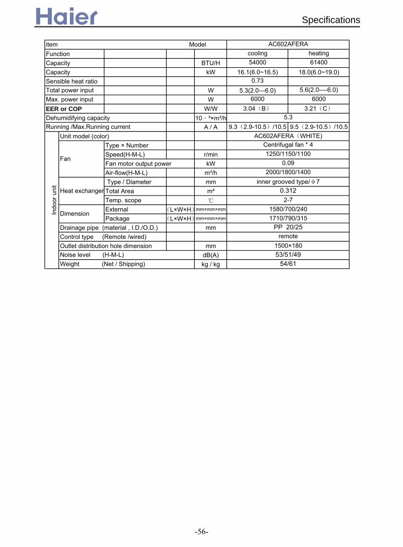
Function cooling heatingCapacity BTU/H 54000 61400Capacity kW 16.1(6.0~16.5) 18.0(6.0~19.0)Sensible heat ratio 0.73
W 5.3(2.0---6.0) 5.6(2.0----6.0)W 6000 6000
EER or COP W/W 3.04(B) 3.21(C)
Dehumidifying capacity 10‐³×m³/hA / A 9.3(2.9-10.5)/10.5 9.5(2.9-10.5)/10.5
Unit model (color)Type × NumberSpeed(H-M-L) r/minFan motor output power kWAir-flow(H-M-L) m³/h Type / Diameter mmTotal Area m²Temp. scope
External (L×W×H)mm×mm×mm
Package (L×W×H)mm×mm×mm
Drainage pipe (material , I.D./O.D.) mmControl type (Remote /wired)Outlet distribution hole dimension mm
dB(A)kg / kg
item Model AC602AFERA
Heat exchanger inner grooved type/φ7
0.312
Total power inputMax. power input
Running /Max.Running current
Centrifugal fan * 41250/1150/1100
0.092000/1800/1400
Weight (Net / Shipping) 54/61
PP 20/25remote
Noise level (H-M-L) 53/51/49
5.3
AC602AFERA(WHITE)
1500×180
2-7
Dimension1580/700/2401710/790/315
Indo
or u
nit
Fan
Specifications
-56-
2.2 For fixed frequency unit
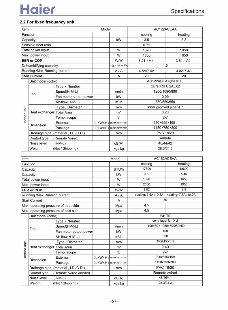
Function cooling heatingCapacity kW 3.5 3.8Sensible heat ratio 0.71
W 1090 1050W 1650 1650
EER or COP W/W 3.21(A) 3.61(A)Dehumidifying capacity 10‐³×m³/h
A / A 4.8A/7.4A 4.8A/7.4AStart Current A 20 20
Unit model (color)Type × NumberSpeed(H-M-L) r/minFan motor output power kWAir-flow(H-M-L) m³/h Type / Diameter mmTotal Area m²Temp. scope
External (L×W×H)mm×mm×mm
Package (L×W×H)mm×mm×mm
Drainage pipe (material , I.D./O.D.) mmControl type (Remote /wired)
dB(A)kg / kg
Function cooling heatingCapacity BTU/h 17500 18600
Capacity kW 5.1 5.45
W 1690 1650
W 2000 1950
EER or COP W/W 3.02 3.3
A / AStart Current AMax. operating pressure of heat side Mpa 4.5Max. operating pressure of cold side Mpa 4.5
Unit model (color)Type × NumberSpeed(H-M-L) r/minFan motor output power kWAir-flow(H-M-L) m³/h Type / Diameter mmTotal Area m²Temp. scope
External (L×W×H)mm×mm×mm
Package (L×W×H)mm×mm×mm
Drainage pipe (material , I.D./O.D.) mmControl type (Remote /wired /model)
dB(A)kg / kg
Item Model AC122ACEAA
Total power inputMax. power input
1.6Running /Max.Running current
Indo
or u
nit
AC122ACEAA(WHITE)
Fan
CENTRIFUGALX21200/1080/880
0.09750/650/550
Heat exchanger inner grooved pipe/φ7
0.202-7
Dimension990×655×1991150×750×300
PVC 18/20Remote
Noise level (H-M-L) 46/44/42Weight (Net / Shipping) 28.3/34.3
Running /Max.Running current cooling: 7.6A /10.5A heating: 7.5A /10.0A
Indo
or u
nit
WHITE
Remote /wiredNoise level (H-M-L) 48/46/44
Fan
centrifugal fan X 21190±50 / 1050±50/980±50
item Model AC182ACEAA
Total power inputMax. power input
100800
Heat exchanger TP2M/7X0.5
0.492-7
Dimension990x655x199
1150x750x300
PVC 18/20
Weight (Net / Shipping) 28.3/34.3
50
Specifications
-57-

Function cooling heatingCapacity kW 6.8 7.4Sensible heat ratio 0.72 /
W 2400 2450W 3100W 3000W
EER or COP W/W 2.83 3.02Dehumidifying capacity 10‐³×m³/h
A / A 10.5A/13.9A 11.2A/13.4AUnit model (color)
Type × NumberSpeed(H-M-L) r/minFan motor output power kWAir-flow(H-M-L) m³/h Type / Diameter mmTotal Area m²Temp. scope External (L×W×H)mm×mm×mm
Package (L×W×H)mm×mm×mm
Drainage pipe (material , I.D./O.D.) mmControl type (Remote /wired)Fresh air hole dimension mm
dB(A)kg / kg
Function cooling heatingCapacity BTU/h 28000 32500Capacity kW 8.6 9.5Sensible heat ratio 0.72 /Total power input W 2680 2630Max. power input W 3400 3500EER or COP W/W 3.21 3.61Dehumidifying capacity 10‐³×m³/h
A / A 12.0A/15.0A 11.7A/15.0ACapacity BTU/h 28000.00 28600.00Capacity kW 8.2 8.4Sensible heat ratio 0.72Total power input W 2800 2600Max. power input W 3500 3500EER or COP W/W 2.93 3.23Dehumidifying capacity 10‐³×m³/h
A / A 4.7A/5.6A 4.6A/5.5AUnit model (color)
Type × NumberSpeed(H-M-L) r/minFan motor output power kWAir-flow(H-M-L) m³/h Type / Diameter mmTotal Area m²Temp. scope External (L×W×H)mm×mm×mm
Package (L×W×H)mm×mm×mm
Drainage pipe (material , I.D./O.D.) mmControl type (Remote /wired)
kWdB(A)kg / kg
2.5Running /Max.Running currentw
ith A
U28
2AH
EA
A
Total power inputMax. power input
2.5
item Model AC242ACEAA
800/-/-
Heat exchanger inner grooved pipe/φ7
0.492-7
Dimension 990*655*1991150*750*300
PVC 18/20Remote /wired (optional)
/Noise level (H-M-L) 48/46/44Weight (Net / Shipping) 28.3/34.3
item Model AC282AFEAA
Indo
or u
nit
WHITE
Fan
centrifugal fan*21220±40/1190±50/1050±50/980±50r/min
0.10
Indo
or u
nit
AC282AFEAA(WHITE)
Fan
Centrifugal fan*4950±40/850±40/750±40r/min
0.101550/1300/1000
Heat exchanger
remote/wired (optional)Electricity Heater 0
inner grooved type/φ70.532-7
Dimension 1580*700*2401710*790*315
with
AU
28N
AH
EA
A
Running /Max.Running current2.5
Noise level (H-M-L) 50/48/46Weight (Net / Shipping) 50/57
PVC 18/20
Running /Max.Running current
Specifications
-58-

Function cooling heatingCapacity kW 11 12Sensible heat ratio 0.72 /Total power input W 3400 3500Max. power input W 3950 3950EER or COP W/W 3.24 3.43
A / A 16.0A/18.7A 16.5A/18.7ACapacity kW 11.5 13Sensible heat ratio 0.72Total power input W 3900 3900Max. power input W 4700 4500EER or COP W/W 2.95 3.33
A / A 6.6A/8.0A 6.5A/7.8AUnit model (color)
Type × NumberSpeed(H-M-L) r/minAir-flow(H-M-L) m³/h Type / Diameter mmTotal Area m²Temp. scope
External (L×W×H)mm×mm×mm
Package (L×W×H)mm×mm×mm
Drainage pipe (material , I.D./O.D.) mmControl type (Remote /wired)
kWdB(A)kg / kg
Function cooling heatingCapacity kW 14.06 17.0Sensible heat ratio 0.72
W 4600 4950W 5500 6000
EER or COP W/W 3.06(B) 3.43(B)Dehumidifying capacity 10‐³×m³/h
A / A 8.0A/9.5A 9.0A/10.5AStart Current A 65 65
Unit model (color)Type × NumberSpeed(H-M-L) r/minFan motor output power kWAir-flow(H-M-L) m³/h Type / Diameter mmTotal Area m²Temp. scope
External (L×W×H)mm×mm×mm
Package (L×W×H)mm×mm×mm
Drainage pipe (material , I.D./O.D.) mmControl type (Remote /wired)
dB(A)kg / kg
remote/wired (optional)0
inner grooved type/φ7
Noise level (H-M-L) 51
1710/790/315PVC 18/20
2-71580/700/240
AC362AFEAACentrifugal fan*4
1150/-/-1800/-/-
with
AU
36N
AIE
AA
Running /Max.Running current
with
AU
362A
IEAA
Running /Max.Running current
item Model AC362AFEAA
item Model AC482AFEAA
Indo
or u
nit
Fan
Heat exchanger
Dimension
Electricity Heater
Weight (Net / Shipping) 54/61
0.53
Total power inputMax. power input
5.3Running /Max.Running current
2000/1800/1400
Heat exchanger inner grooved pipe/φ7
0.102-7
53/51/49Weight (Net / Shipping) 54/61
Dimension 1580/700/2401710/790/315
PVC
Indo
or u
nit
AC482AFEAA(WHITE)
Fan
centrifugal fan*41250/1150/1100
0.09
RemoteNoise level (H-M-L)
Specifications
-59-

Function cooling heatingCapacity kW 16.1 18.5Sensible heat ratio 0.72
W 5100W 5350WW 6200W 6200W
EER or COP W/W 3.16(B) 3.46(B)Dehumidifying capacity 10‐³×m³/h
A / A 9.0A/10.5A 9.5A/10.5AStart Current A 65 65
Unit model (color)Type × NumberSpeed(H-M-L) r/minFan motor output power kWAir-flow(H-M-L) m³/h Type / Diameter mmTotal Area m²Temp. scope
External (L×W×H)mm×mm×mm
Package (L×W×H)mm×mm×mm
Drainage pipe (material , I.D./O.D.) mmControl type (Remote /wired)
dB(A)kg / kg
Note: ⊙ is the realtime analyser position
Norminal condition: indoor temperature (cooling): 27DB/19WB, indoor temperature (heating): 20DBOutdoor temperature(cooling): 35DB/24WB, outdoor temperature(heating): 7DB/6WBThe noise level will be measured in the third octave band limited values, using a Real Time Analyser calibrated sound intensitymeter. It is a sound pressure noise level. The detailed method please refer to the following information:
Installation state: the unit should be placed on the flat floor or be mounted in horizontaldirection.Testing method:mounting-on-ceiling unit:
item Model AC602AFEAA
Heat exchanger inner grooved pipe/φ7
0.10
Total power inputMax. power input
5.5
Dimension1580/700/2401710/790/315
Indo
or u
nit
AC602AFEAA(WHITE)
Fan
centrifugal fan*41250/1150/1100
0.092000/1800/1400
Weight (Net / Shipping) 54/61
Running /Max.Running current
PVCRemote /wired (optional)
Noise level (H-M-L) 53/51/49
2-7
1m
1m
Specifications
-60-
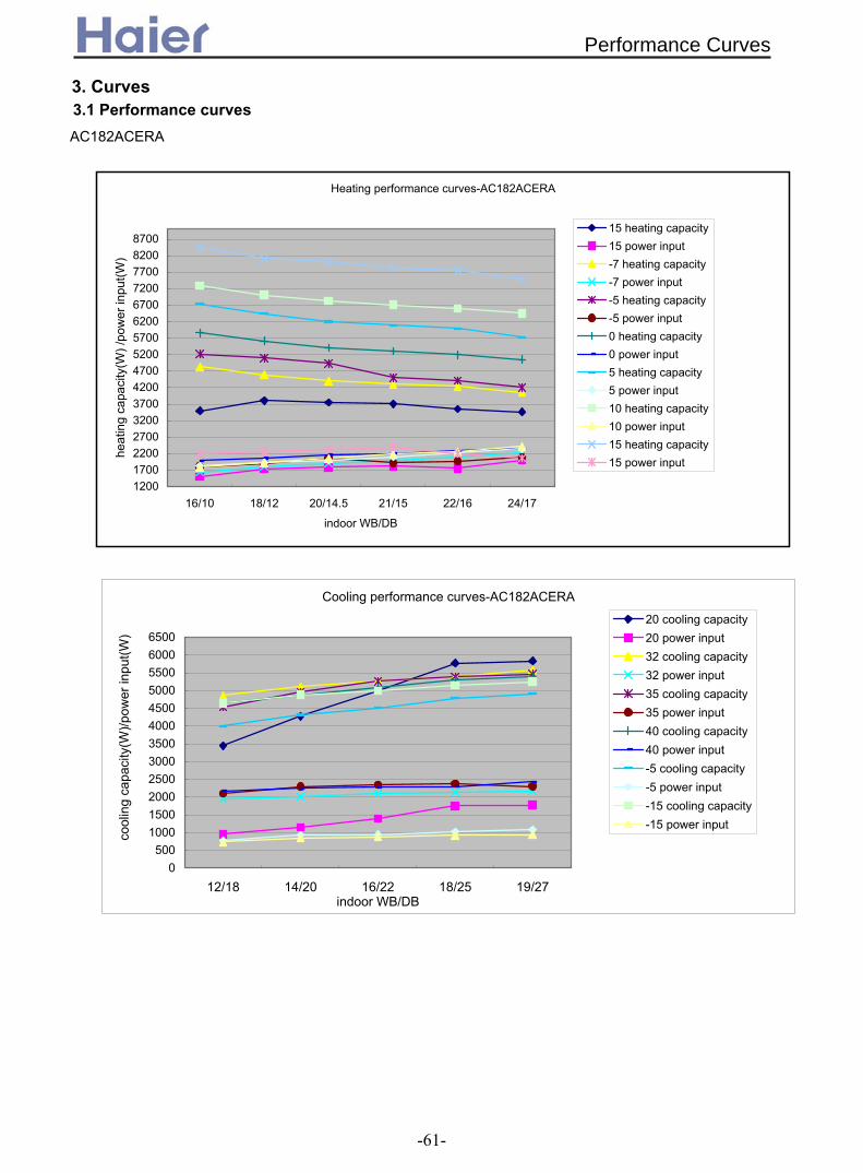
Cooling performance curves-AC182ACERA
0500
100015002000250030003500400045005000550060006500
12/18 14/20 16/22 18/25 19/27indoor WB/DB
cool
ing
capa
city
(W)/p
ower
inpu
t(W)
20 cooling capacity20 power input32 cooling capacity32 power input35 cooling capacity35 power input40 cooling capacity40 power input-5 cooling capacity-5 power input-15 cooling capacity-15 power input
Heating performance curves-AC182ACERA
1200170022002700320037004200470052005700620067007200770082008700
16/10 18/12 20/14.5 21/15 22/16 24/17
indoor WB/DB
heat
ing
capa
city
(W) /
pow
er in
put(W
)
15 heating capacity15 power input-7 heating capacity-7 power input-5 heating capacity-5 power input0 heating capacity0 power input5 heating capacity5 power input10 heating capacity10 power input15 heating capacity15 power input
AC182ACERA
3. Curves3.1 Performance curves
Performance Curves
-61-
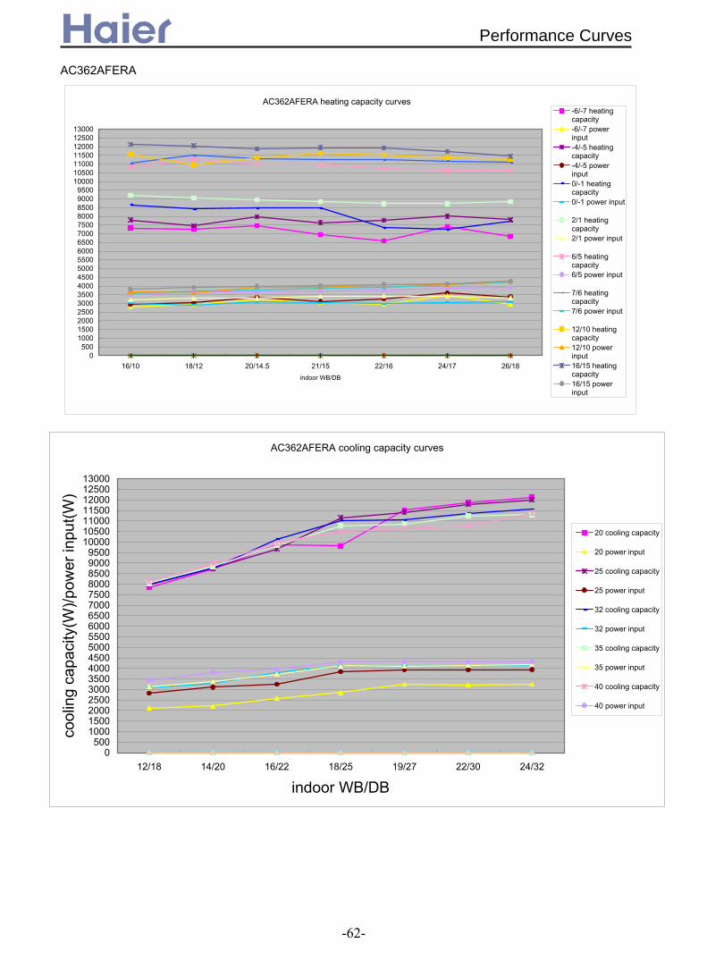
AC362AFERA heating capacity curves
0500
100015002000250030003500400045005000550060006500700075008000850090009500
10000105001100011500120001250013000
16/10 18/12 20/14.5 21/15 22/16 24/17 26/18indoor WB/DB
-6/-7 heatingcapacity-6/-7 powerinput-4/-5 heatingcapacity-4/-5 powerinput0/-1 heatingcapacity0/-1 power input
2/1 heatingcapacity2/1 power input
6/5 heatingcapacity6/5 power input
7/6 heatingcapacity7/6 power input
12/10 heatingcapacity12/10 powerinput16/15 heatingcapacity16/15 powerinput
AC362AFERA
43
AC362AFERA cooling capacity curves
0500
100015002000250030003500400045005000550060006500700075008000850090009500
10000105001100011500120001250013000
12/18 14/20 16/22 18/25 19/27 22/30 24/32
indoor WB/DB
cool
ing
capa
city
(W)/p
ower
inpu
t(W)
20 cooling capacity
20 power input
25 cooling capacity
25 power input
32 cooling capacity
32 power input
35 cooling capacity
35 power input
40 cooling capacity
40 power input
Performance Curves
-62-

3.2 Noise level3.2.1 For inverter unit
Noise level-A
C122A
CE
RA
10 14 18 22 26 30 34 38 42 46 50
2531.5
40
50
63
80
100
125
160
200
250
315
400
500
630
8001000125016002000250031504000500063008000
100001250016000020000
Third octave band frequency Hz
Sound pressure level DB
heating lowheating m
iddleheating highcooling lowcooling m
iddlecooling highfan lowfan m
iddlefan high
1/3 octave band noise level-AC
182AC
ER
A
0.05.0
10.015.020.025.030.035.040.045.050.055.060.065.070.0
25.031.540.050.063.080.0
100.0125.0160.0200.0250.0315.0400.0500.0630.0800.01000.01250.01600.02000.02500.03150.04000.05000.06300.08000.010000.012500.016000.020000.0
third octave band frequency Hz
Sound pressure level DB
cooling highcooling m
edcooling lowfan highfan m
edfan lowheating highheating m
edheating low
Noise Level
-63-

1/3 octave band noise level-AC
242AC
ERA
8.013.018.023.028.033.038.043.048.053.0
25.0
31.5
40.0
50.0
63.0
80.0100.0125.0160.0200.0250.0315.0400.0500.0630.0800.0
1000.01250.01600.02000.02500.03150.04000.05000.06300.08000.010000.012500.016000.020000.0
third octave band frequency Hz
Sound pressure level DB
cooling highcooling m
edcooling lowfan highfan m
edfan lowheating highheating m
edheating low
Noise level-A
C362A
FER
A
10 15 20 25 30 35 40 45 5025
31.5
40
50
63
80100125160200250315400500630800
1000125016002000250031504000500063008000
100001250016000020000
Third octave band frequency Hz
Sound pressure level DB
heating lowheating m
iddleheating highcooling lowcooling m
iddlecooling highfan lowfan m
iddlefan high
Noise Level
-64-
-64
Noise level-A
C482A
FER
A
10 15 20 25 30 35 40 45 50 55
2531.5
40
50
63
80
100
125160
200
250
315
400
500
630
8001000125016002000250031504000500063008000
100001250016000020000
Third octave band frequency Hz
Sound pressure level DB
heating lowheating m
iddleheating highcooling lowcooling m
iddlecooling highfan lowfan m
iddlefan high
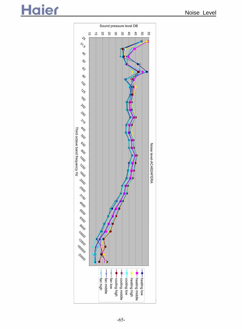
Noise Level
-65-

3.2.2 For fix frequency unit
1/3 octave band noise level-AC
182AC
EAA
16.021.026.031.036.041.046.051.056.0
25.0
31.5
40.0
50.0
63.0
80.0
100.0
125.0
160.0
200.0
250.0
315.0
400.0
500.0
630.0
800.01000.01250.01600.02000.02500.03150.04000.05000.06300.08000.0
10000.012500.016000.020000.0
third octave band frequency Hz
Sound pressure level DB
cooling highcooling m
edcooling lowfan highfan m
edfan lowheating highheating m
edheating low
Noise level-A
C242A
CE
AA
11 15 19 23 27 31 35 39 43 47 51 55
2531.5
40
50
63
80100125160200250315400500630800
1000125016002000250031504000500063008000
100001250016000020000
Third octave band frequency Hz
Sound pressure level DB
heating lowheating m
iddleheating highcooling lowcooling m
iddlecooling highfan lowfan m
iddlefan high
Noise Level
-66-

1/3 octave band noise level-AC
282AFEA
A
8.013.018.023.028.033.038.043.048.0
25.0
31.5
40.0
50.0
63.0
80.0
100.0
125.0
160.0
200.0
250.0
315.0
400.0
500.0
630.0
800.01000.01250.01600.02000.02500.03150.04000.05000.06300.08000.0
10000.012500.016000.020000.0
third octave band frequency Hz
Sound pressure level DB
cooling highcooling m
edcooling lowfan highfan m
edfan lowheating highheating m
edheating low
Noise level-A
C362A
FEA
A
8 12 16 20 24 28 32 36 40 44 48
2531.5
40
50
63
80
100
125
160
200
250
315
400
500
630
8001000125016002000250031504000500063008000
100001250016000020000
Third octave band frequency Hz
Sound pressure level DB
heating lowheating m
iddleheating highcooling lowcooling m
iddlecooling highfan lowfan m
iddlefan high
Noise Level
-67-
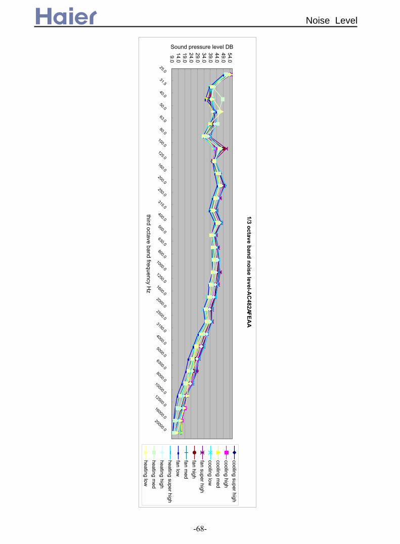
25
9.014.019.024.029.034.039.044.049.054.0
25.0
31.5
40.0
50.0
63.0
80.0
100.0
125.0
160.0
200.0
250.0
315.0
400.0
500.0
630.0
800.01000.01250.01600.02000.02500.03150.04000.05000.06300.08000.0
10000.012500.016000.020000.0
third octave band frequency Hz
Sound pressure level DB
cooling super highcooling highcooling m
edcooling lowfan super highfan highfan m
edfan lowheating super highheating highheating m
edheating low
1/3 octave band noise level-AC
482A FE
AA
Noise Level
-68-
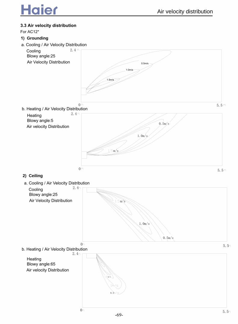
3.3 Air velocity distributionFor AC12*
Air Velocity Distribution
CoolingBlowy angle:25
a. Cooling / Air Velocity Distribution
2.4
5.5
1.5m/s
1.0m/s
0.5m/s
HeatingBlowy angle:5Air velocity Distribution
b. Heating / Air Velocity Distribution
5.50
2.4
m/s
1.0m/s
0.5m/s
0
Air Velocity Distribution
CoolingBlowy angle:25
5.50
2.4
m/s
1.0m/s
0.5m/s
2) Ceiling
a. Cooling / Air Velocity Distribution
HeatingBlowy angle:65Air velocity Distribution
0
0.5
m/s
2.4
5.5
b. Heating / Air Velocity Distribution
Grounding1)
Air velocity distribution
-69-
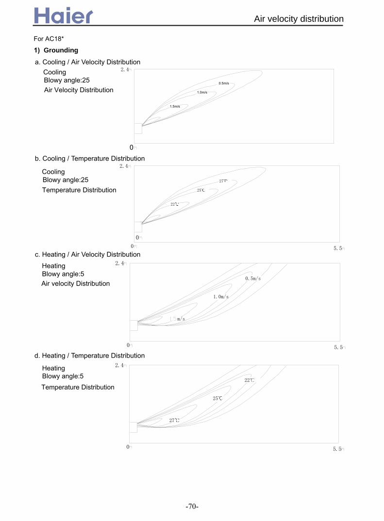
For AC18* Grounding
Air Velocity Distribution
CoolingBlowy angle:25
a. Cooling / Air Velocity Distribution
2.4
0
1.5m/s
1.0m/s
0.5m/s
Temperature Distribution
CoolingBlowy angle:25
b. Cooling / Temperature Distribution
0
2.4
22
25
27
5.5
0
HeatingBlowy angle:5Air velocity Distribution
c. Heating / Air Velocity Distribution
5.50
2.4
m/s
1.0m/s
0.5m/s
d. Heating / Temperature Distribution
Temperature Distribution
HeatingBlowy angle:5
0
2.4
27
25
22
5.5
1)
Air velocity distribution
-70-
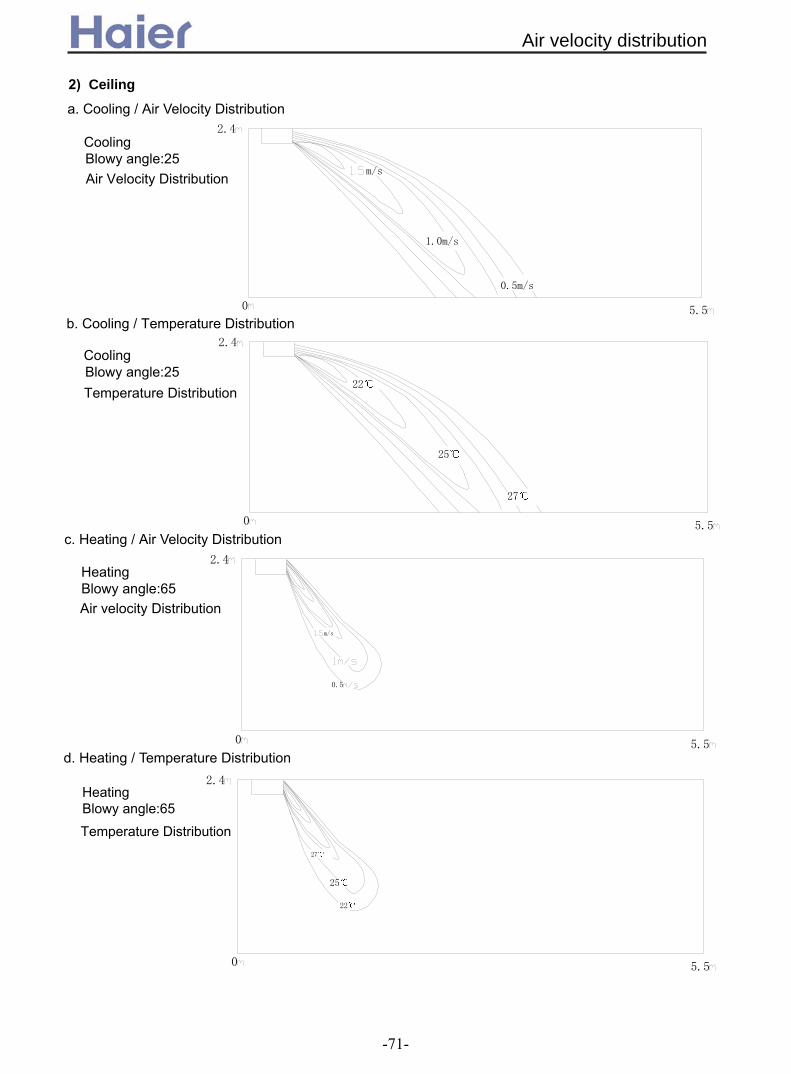
Air Velocity Distribution
CoolingBlowy angle:25
Temperature Distribution
CoolingBlowy angle:25
5.50
2.4
m/s
1.0m/s
0.5m/s
0
2.4
22
25
27
5.5
Ceiling
a. Cooling / Air Velocity Distribution
b. Cooling / Temperature Distribution
HeatingBlowy angle:65Air velocity Distribution
Temperature Distribution
HeatingBlowy angle:65
0
0.5
m/s
2.4
5.5
c. Heating / Air Velocity Distribution
d. Heating / Temperature Distribution
0 5.5
2.4
25
27
22
2)
Air velocity distribution
-71-

For AC28*
Air Velocity Distribution
CoolingBlowy angle:25
Temperature Distribution
CoolingBlowy angle:25
a. Cooling / Air Velocity Distribution
b. Cooling / Temperature Distribution
0
2.4
5.5
25
0
2.4
22
27
5.5
1.5m/s
1.0m/s
0.5m/s
Air velocity distribution
-72-

For AC36*
Air Velocity Distribution
CoolingBlowy angle:25
Temperature Distribution
CoolingBlowy angle:25
a. Cooling / Air Velocity Distribution
b. Cooling / Temperature Distribution
0
2.4
5.5
27
0
2.4
22
25
5.5
27
0
2.4
22
25
5.5
1.5m/s
1.0m/s
0.5m/s
Air velocity distribution
-73-

4. Dimension4.1 AC12, AC18, AC24
240
100
900
990
655
200
880
620
605
600
40 35 35 30
199(mm)
4.2 AC28, AC36, AC48, AC60
D=25
60
300
40
440 D = 47
150
95D = 47
D = 47 D = 47
D=200
114
36
55
90
495598
285
640570
240
700
1580
Dimension
-74-

5. Part name
+ , -
.
'&$ &' )*
*
/&*'
0
& ' # ! ' ( &' )& ( )* ( ( % 34 4 ( 4 (
34 4
+
-
1
0
'&$
&'
)*
&*'
* /
,
1
!"
$
% &
'()*+
,*
AC122ACEAA, AC182ACEAA, AC242ACEAA, AC122ACERA, AC182ACERA, AC242ACERA
AC282AFEAA, AC362AFEAA, AC482AFEAA, AC602AFEAA, AC282AFERA, AC362AFERA
AC482AFERA, AC602AFERA
Part Name
-75-

6. Installation6.1 For AC12, AC18, AC24
!"
#$%#$ &$
'(" ')"
!"#$#%&#'()'*+%"#)++$#%,#,%--)-&%%"+,%..+.%#,%--%+#+)
/
*"!+$!,$*+"--
.&+##&%+#0$#%
.
/
1
!
*
0
+
1
!
*
+
!2!
*2*
3 45 65
)
75
#
8
)-
&
% !
!2!
Installation
-76-

5 &"
1
75
'84-1 9"
#" %"
4
4
'
#
!:&
5
!+$!,$*+$5- 1$
6
#-
&11
991: *+1
&1
!*1 !:
&1
10
+1 %
01
'
'
35
7 2
'
'
'"
'
8
4
'
4
9 /$-" !:"
:
#;
'
'-
*::
9::
Installation
-77-

!!"
)"
)
1
-$
1 9 9#$,:1:!1:
#&
&:%:
!*%
#,%--%")#"+,%%";%,"+$-)#+%'#,%--)+#%"%+.+"%,)
9
5
5
7)"7("
7
5-
!0"
-$
!+"
#$!*%8
6
6
)- !&
Installation
-78-

8-
,!0
3$5--
7
7 7
6 - 0"$5 &"#" %"75
4
.
77"
<
. ;
2
=
)
4
'
3
4$>
<<
!";?$-*1*"$"-0"$--+"5$-5
45- 2
4
8
#-< 8
+,+-)&+(#+=&'- (Fig. 20A)
Installation
-79-

!";?$-!:
*"$"-
0"$5
+".$
4--$$
<> <9
*1
!:
)
+-)( 9%#)(
)
#
-
)
#
1:
-;
<#?!$:1!:$.<;--
<
!"/--@5-
*";5-5
0"45$5"
+"45
9+,%#)(# (Fig. 20B)
,-.
,-.
Installation
-80-

!!" #$%&'( &%&)&*
#+$%&'( &%&)&*&'
,-./
0
&%&)&*&'
%&'((-
#$%&'(& %#.$1&(&(&&&&(%&(&,-#+$&(&(&&& &(% ) &2
#/$,(&&&(& %#3$,(&(&&&((
!"
1& &#%%.$
,#$
.3
+4
&&&#%%.$
453
,-.
&%&)&*
,-.. &%&)&*
%&'(&-
&&%&'((%&'6( &%&)&*
453
/4
/4
#.$1 &( &%&)&*
,-.+
&%&)&*
!
!
!
!"#$%"" #&$$'& (")
&%"" #&$$'& (")
&%"" #&$$'& (")
"#$%"" #&$$'& (")
122, 182 242
AC122ACEAA, AC122ACERA, AC182ACEAA
AC182ACERA, AC242ACEAA, AC242ACERA
25
Fig. 25
Installation
-81-
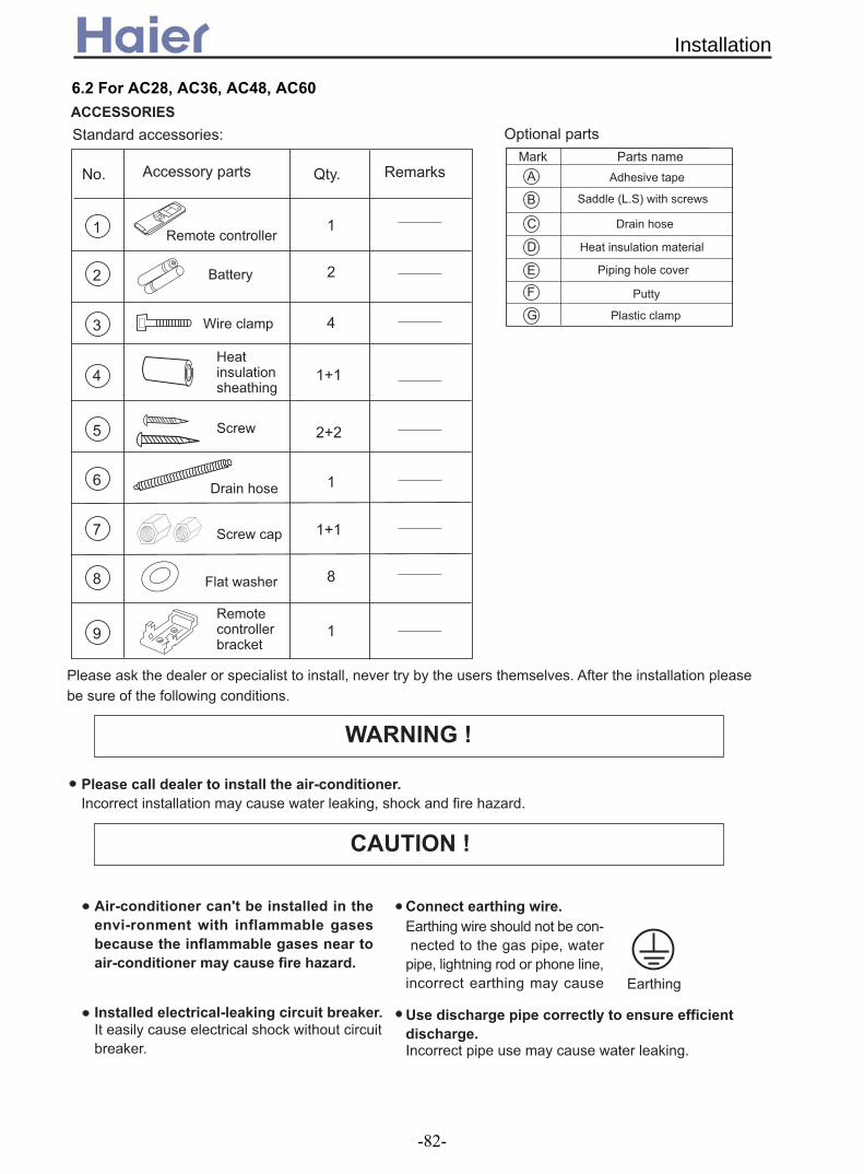
6.2 For AC28, AC36, AC48, AC60
; 65565
"@
" 3"!
7
+
1
)
7
(
-
A
,
.
/
0
4
,
.
0
,C,
.C.
# ?
<
1
D
+
"
"
<
5
6
,
,C,
<
7 ,
B
> >-
!"#!"$#!%
&"#&
"
"''$#!!"
(
(
Installation
-82-
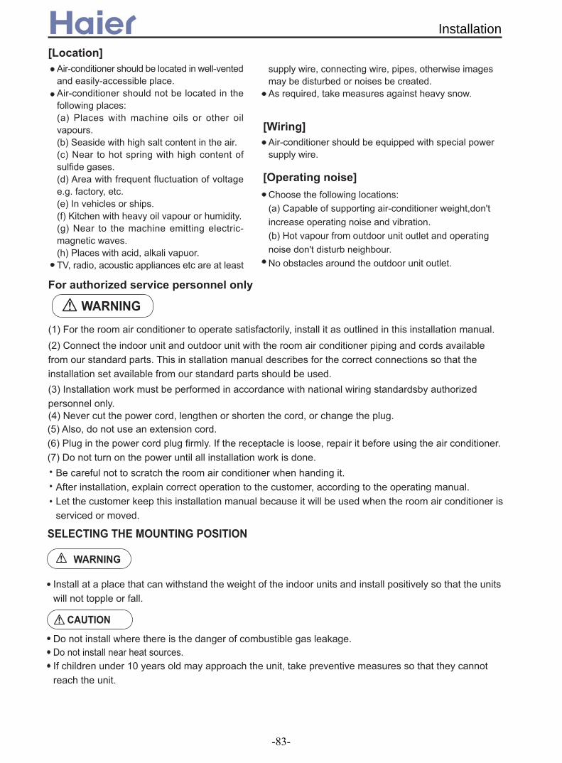
()*
("*
('"*
! !" !# !$ ! !% !# ! &'
$
$
) !) * !+ *#
+#%'$
,!-
.!) &
/! 0!#
56)6768 5
12 3
4!2 5! 6!7
77,8
Installation
-83-
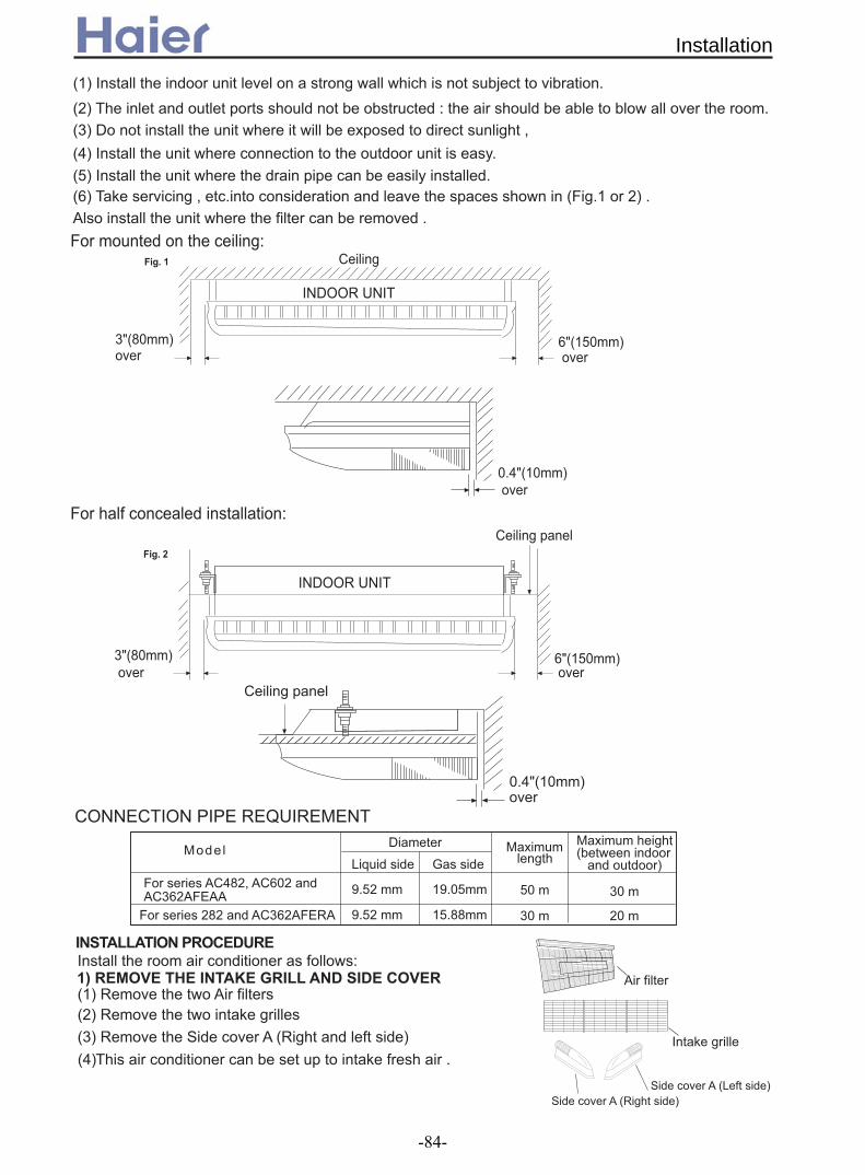
,!9
.!& /!72
5!& -,.!
0! 4!
80: ,8!
-)
#7;;<=#&
/: >8!
5: ,48!
+"4
-
/: >8!
5: ,48!
) +"/
#7;;<=#&
80: ,8!
)
5)) 696
);##()&;#(<(?=<(@(#&
4368:676;6))9596:6 ,!< .!< /!<" <! 0!&
" <!" 3!
!!
" #$%!& #$' #$ '#"(##" ! #$ '#"()#
Installation
-84-

.!3;)&;#;-)(3#A"="(#";#1;3&"
+!" -0
); ,4/808 08
)
" 2/848
); 508
)
,4
" 2/848
" ,4/8
/8 /8
#7;;<=#& &;'(D!
7 " <$!
,8,44
/88
+"<
+"-
7<33#A&+(+;3("#7&&)+#A&+("=(#";#1;3&"
-="#A#)+;<1;3&"
,!7 # ! .! :1: ! @,8 "-5!
,!7.4-diameter & &@,8!<-4 .! " 1@,8
)
,8,4
" !
@,8 ;!" 1 !
1" B>8,068# ,88&;,48!+"2
1" B>8,068# ,88&;,48!
@,8# ;!
" 1 !
,8
,4
@,8# ;!
+"=
Installation
-85-

5))76 )6765)
!
"
5))769
,!3 ! "->!
-;<+3-);#)("3(7#"&33&;#
&">###"!#!!#> &"$#
D7
A ,8.8!
#7;;<=#& & !
D
)
.!- :1:@,8@
+"?
)
DD
)
+", +"0
Installation
-86-

D2
# !
# !
#
)
9 ,E48,E,88! = '.4!F/>G7 D -,,!7 >!
@9 @9
1454 ,4.!
+"44
) !
) !
) !
) !
+"4A
9
Installation
-87-
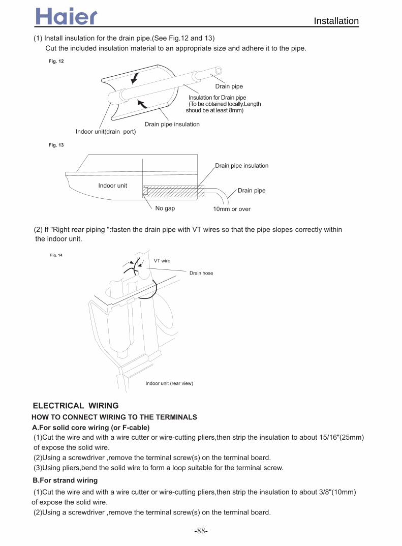
,! "-,.,/!)
7 &3 be at least 8mm)
!7
7
# ,8
7
7
.!:< : '&
+"4/
+"4<
6)6)767668)5
,!) ,4E,5: .4!2 .!= ! /!=
@+ "
,!) /E>: ,8!2 .!= !
+ ".+3
!
'&
7
+"4-
Installation
-88-

)
='D,84,8')
,!@(
.!)
/! !
0!
6)6)6B686(
-,5
7+C699 6@)6769)8
"
<
D
&
"
<
D
5 @5
<3
"
,4E
,5:
.4
!
"
,4E
,5:
.4
!
+"42
Fig. 16
!
! "#
$ " !% %#
& '
(
") !*!+ %!
!#, !
!
- # . ! ' !/ ' #
) %! !*!)&
) "*!+ %!
Installation
-89-

,!< .! -.8 /!)
0!- 4!-
+657;6 ,!&-,6 !
,!D ! !
.!D !9
.!- !-,> !
(!'"D95))D* /!) 0!"
7
+"4,
+"40
+"4?
-
< !
695
5! T
Installation
-90-

!
! "#
"#
$%&'()*+,-./',0! 1%234%%&2)(35
!
"#!
! "#
$%&3.&,,-./',0 1%234%%&2)(35
! " # $ ! %
" % " # "
& '" % ! " (
) * !% ! %
+,-+ ./0 12,13 +,4-/5 677 .+ * " 8 9 % 8# 9 " ( 8& * 8
:5 7.+677 .+ * ( % 8 ; < < " %8# * % !%8
$ " " ; ""< %
; (% "" < (%
1.+7
Installation
-91-

Duct indoor unit (AD12~AD72)
Duct type
-92-
1. Features...........................................................................93
2. Specifications...................................................................95
2.1 For DC inverter unit...................................................95
2.2 For fixed frequency unit...........................................101
3. Curves...........................................................................110
3.1 Performance curves................................................110
3.2 Noise level...............................................................124
3.3 Air velocity distribution.............................................133
4. Dimensions....................................................................137
5. Part name.......................................................................141
6. Installation......................................................................143
6.1 For ceiling concealed duct type(ESP 30Pa).............143
6.2 For medium static pressure duct type(ESP 50Pa)....149
6.3 For high static pressure duct type(ESP 100Pa)........161

High efficiency filter & Static pressure optional The unit adopts G3 grade filter, can efficiently filter the dirt etc, and improve the room air quality, at the
same time, the filter can pull out from downside, convenient for maintenance and cleaning.
Ultra-thin design and two-side drainage pipe For the ceiling concealed duct type indoor units, the unit thickness is only 220mm, ultra-thin design;
the depth is 500mm, and space saving, completely matching with the indoor decoration. There are two drainage pipes designed on the ceiling concealed indoor units, it is convenient for the
drainage piping design for installation. Special Up-drainage water pump(optional)
The unit has a water pump which the max. drainage height can be up to 600mm(more than 24000BTU/h duct unit.), that is convenient for you to install.
Multi-mode for installation
The indoor unit can be installed with an air return duct or without an air return duct according to the installation need.
Free setting of air discharge duct
The number of the airflow outlet and its installation position can be freely selected according to the environment of the room, sufficiently considering the load of the room and the uniform temperature of the room to realize more perfect comfort.
1. Features
500mm
220m
m
max. 600mm
Hanging from the Ceiling Embedded the CeilingHanging from the Ceiling Embedded the Ceiling
Features
-93-

Variable control mode The indoor unit can use one wired remote controller, also, it can use a remote controller ( with new
remote reciever ) and central controller( optional ) .
Auto–restart function (optional)
All indoor units have auto-restart function. When the power supply cut off suddenly, the unit will automatically recover the previous running mode once the power supply is on.
Auto checking malfunction Failure codes displayed by LED or controllers are so detailed for us to find the fail place more
quickly,and can judge the failure content easily
infrared control method. A standard signal receiver is available to connect with the indoor unit.standard control method
1 )
E / 1 )
High SP design
Features
-94-

2. Specifications2.1 For DC inverter unit
Function cooling heatingCapacity kW 3.8(0.9--4.4) 4.1(1.0---4.8)Sensible heat ratio 0.71
W 1260(280--1650) 1260(280--1650)W 1650 1650
EER or COP W/W 3.02(B) 3.25(C)
Dehumidifying capacity 10‐³×m³/hPower cablePower source N, V, Hz
A / A 6.0(1.4--8.0)A/8A 6.0(1.4--8.0)A/8AStart Current A 3 3 Circuit breaker A 13 13
Unit model (color)Type × NumberSpeed(H-M-L) r/minFan motor output power kWAir-flow(H-M-L) m³/h Type / Diameter mmTotal Area m²Temp. scope
External (L×W×H)mm×mm×mm
Package (L×W×H)mm×mm×mm
Drainage pipe (material , I.D./O.D.) mmControl type (Remote /wired)
dB(A)kg / kg
Function cooling heatingCapacity BTU/h 17500 19500Capacity kW 4.8(1.8---5.8) 5.5(2.0---6.8)
KW 1.65(0.55---2.65) 1.70(0.60---2.65)W 2650 2650
EER or COP W/W 3.24(C)Dehumidifying capacity 10‐³×m³/h
A / A 7.5(3.0---12.0)/12A 7.5(3.0---12.0)/12AStart Current AClass of anti electric shock Class 1Max. operating pressure of heat side Mpa 4.15Max. operating pressure of cold side Mpa 4.15
Unit model (color) AD182ALERA GreyType × NumberSpeed(H-M-L) r/minFan motor output power kWAir-flow(H-M-L) m³/h Type / Diameter mmTotal Area m²Temp. scope
External (L×W×H)mm×mm×mm
Package (L×W×H)mm×mm×mm
Air sending angleDrainage pipe (material , I.D./O.D.) mmControl type (Remote /wired /model)
dB(A)kg / kg
Running /Max.Running current
Weight (Net / Shipping) 23/26.5
PVC 16/12wired control
Noise level (H-M-L) 45/41/37
2-7
Dimension1090×500×220 1174×545×280
Fan
centrifugal fan X 2700±30 / 540±30 / 400±30
50780
Heat exchanger TP2M/7X0.5
0.34
Item Model AD122ALERA
Total power inputMax. power input
Heat exchanger inner grooved pipe/φ7
0.11
1.63×2.5
1, 220--230, 50
Dimension 610×483×220695×536×265
Running /Max.Running current
1000/900/800±500.05
550/450/400
AD122ALERA(GREY)
Fan
Weight (Net / Shipping) 14/16
2-7
20/18wired
Noise level (H-M-L) 35/32/30
Indo
or u
nit
Centrifugal fan*1
item Model AD182ALERA
Total power inputMax. power input
1.8
50
Indo
or u
nit
2.91(C)
Specifications
-95-
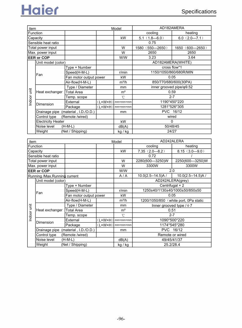
Function cooling heatingCapacity kW 5.1(1.8---6.0) 6.0(2.0---7.1)Sensible heat ratio 0.75
W 1580(550---2650) 1650(600---2650)W 2650 2650
EER or COP W/W 3.23 3.64Unit model (color)
Type × NumberSpeed(H-M-L) r/minFan motor output power kWAir-flow(H-M-L) m³/h Type / Diameter mmTotal Area m²Temp. scope
External (L×W×H)mm×mm×mm
Package (L×W×H)mm×mm×mm
Drainage pipe (material , I.D./O.D.) mmControl type (Remote /wired)
kWdB(A)kg / kg
Function cooling heatingCapacity kW 7.35(2.0---8.2) 8.15(3.0---9.0)Sensible heat ratio 0.72 /
W 2280(600---3250)W 2250(600---3250)WW 3300W 3300W
EER or COP W/WA / A 10.0(2.5--14.5)A / 10.0(2.5--14.5)A /
Unit model (color)Type × NumberSpeed(H-M-L) r/minFan motor output power kWAir-flow(H-M-L) m³/h Type / Diameter mmTotal Area m²Temp. scope
External (L×W×H)mm×mm×mm
Package (L×W×H)mm×mm×mm
Drainage pipe (material , I.D./O.D.) mmControl type (Remote /wired)
dB(A)kg / kg
Total power input
AD182AMERA
Max. power input
Indo
or u
nit
AD182AMERA(WHITE)
Fan
cross flow*11150/1050/860/680R/MIN
0.05850/770/680/600(30PA)
Heat exchanger inner grooved pipe/φ9.52
0.592-7
Dimension 1190*450*2201281*526*305PVC 16/12
wiredElectricity Heater 0Noise level (H-M-L) 50/48/45Weight (Net / Shipping) 24/27
AD242ALERA
Total power inputMax. power input
2.0
Indo
or u
nit
AD242ALERA(grey)
Fan
Centrifugal × 21250±40/1130±40/1000±50/850±50
0.051200/1050/850(white port, 0Pa static
Heat exchanger Inner grooved type /φ7
0.512-7
Dimension 1090*500*2201174*545*280PVC 16/12
Remote or wiredNoise level (H-M-L) 49/45/41/37Weight (Net / Shipping) 25.2/28.4
Running /Max.Running current
item Model
item Model
Specifications
-96-

Function cooling heatingCapacity kW 7.35(2.0---8.2) 8.15(2.5-9.0)Sensible heat ratio 0.72
W 2280(600---3250)W 2250(600---3250)WW 3300W 3300W
EER or COP W/W 3.22 3.62Dehumidifying capacity 10‐³×m³/h
A / A 10.5(2.5--14.5)A / 15A 10.0(2.5--14.5)A /1 5AUnit model (color)
Type × NumberSpeed(H-M-L) r/minFan motor output power kWAir-flow(H-M-L) m³/h Type / Diameter mmTotal Area m²Temp. scope
External (L×W×H)mm×mm×mm
Package (L×W×H)mm×mm×mm
Drainage pipe (material , I.D./O.D.) mmControl type (Remote /wired)Fresh air hole dimension mm
dB(A)kg / kg
Function cooling heatingCapacity BTU/h 27300 32400Capacity kW 8.0(2.2~10.0) 9.5(2.5~11.4)Sensible heat ratio 0.73
KW 2.65(0.5---3.8) 2.6(0.5---3.8)W 3800 3800
EER or COP W/W 3.02 3.65Energy efficiency stage B ADehumidifying capacity 10‐³×m³/h
A / A 11.0(2.3-17)/17 12.0(2.3-17)/17Unit model (color)
Type × NumberSpeed(H-M-L) r/minFan motor output power kWAir-flow(H-M-L) m³/h Type / Diameter mmTotal Area m²Temp. scope
External (L×W×H)mm×mm×mm
Package (L×W×H)mm×mm×mm
Drainage pipe (material , I.D./O.D.) mmControl type (Remote /wired)Fresh air hole dimension mm
dB(A)kg / kg
item Model AD282AMERA
150Noise level (H-M-L)Weight (Net / Shipping) 40/46.4
50/47/43/41
Indo
or u
nit
Fan
Heat exchanger
Dimension
item AD242AMERA
Total power inputMax. power input
2.1
1200/1050/850
Heat exchanger Inner grooved type /φ7
0.492-7
Noise level (H-M-L) 47/43/39
Dimension 990*650*3001170*860*340
PVC 32/26
Weight (Net / Shipping) 39/40.4
Indo
or u
nit
AD242AMERA(grey)
Fan
Centrifugal × 21000±40/940±40/860±40/780±50
0.18
wired150
Total power inputMax. power input
2-7990*650*300
1110±50/ 1060±40 / 950±40 / 790±50r/min0.23
1470/1300/1100/950Inner grooved type /φ7
3.0
AD282AMERA(grey)Centrifugal × 2
1152*860*325PVC 26/32
wired
0.328
Model
Running /Max.Running current
Running /Max.Running current
Specifications
-97-

Function cooling heatingCapacity Btu/h 32400 38000Capacity kW 9.5(2.2~10.8) 11.0(2.5~12.0)Sensible heat ratio 0.73Total power input W 3280(500---3900) 3430(500---3900)Max. power input W 4300 4300EER or COP W/W 2.9 3.21Energy efficiency stage C CDehumidifying capacity 10‐³×m³/h
A / A 14.3(2.3-17.5)/19.3 15.0(2.3-17.5)/19.3Unit model (color)
Type × NumberSpeed(H-M-L) r/minAir-flow(H-M-L) m³/h Type / Diameter mmTotal Area m²Temp. scope
External (L×W×H)mm×mm×mm
Package (L×W×H)mm×mm×mm
Drainage pipe (material , I.D./O.D.) mmControl type (Remote /wired)Fresh air hole dimension mm
dB(A)kg / kg
Function cooling heatingCapacity BTU/h 32400 38900Capacity kW 9.5(2.2~10.5) 11.4(2.5~12.0)Sensible heat ratio 0.73
kW 3.38(0.5---3.9) 3.15(0.5--3.9)W 4300 4300
EER or COP W/W 2.81 3.62Energy efficiency stage CDehumidifying capacity 10‐³×m³/h
A / A 15.3(2.3-17.5)/19.3 15.0(2.3-17.5)/19.3Unit model (color)
Type × NumberSpeed(H-M-L) r/minFan motor output power kWAir-flow(H-M-L) m³/h Type / Diameter mmTotal Area m²Temp. scope
External (L×W×H)mm×mm×mm
Package (L×W×H)mm×mm×mm
Drainage pipe (material , I.D./O.D.) mmControl type (Remote /wired)
mmdB(A)kg / kgWeight (Net / Shipping)
Noise level (H-M-L)
PVC 26/32wired
2-7
Dimension 1197×830×350 1430×940×420In
door
uni
t
Fan
centrifugal X21090±30/ - / 930±50 min
0.40
Heat exchanger inner grooved type/φ7
0.479
item Model AD362AHERA
Total power input
item Model AD362AMERAw
ith A
U36
2AH
ERA
3.6Running /Max.Running current
Indo
or u
nit
AD362AMERA(grey)
Fan Centrifugal fan * 2
1110±50/ 1060±40 / 950±40 / 790±50r/min1470/1300/1100/950
Heat exchanger inner grooved type/φ7
0.3282-7
Dimension 990*650*3001152*860*325
PVC 15/20wired150
Noise level (H-M-L) 50/47/43/41Weight (Net / Shipping) 40/5746.4
Max. power input
3.4
AD362AHERA(grey)Running /Max.Running current
50/46/4262/70
2400/2070/1760
Outlet distribution hole dimension 853*254
A
Specifications
-98-

Function cooling heatingCapacity kW 12.0(6.0~14.5) 14.5(6.0~16.5)Sensible heat ratio 0.73
W 4.6(2.0---6.0) 4.7(2.0----6.0)W 6300
EER or COP W/W 3.23(C)
Dehumidifying capacity 10‐³×m³/h C CA / A 8.0(2.9-9.5)/10.5 8.0(2.9-9.5)/10.5
Unit model (color)Type × NumberSpeed(H-M-L) r/minFan motor output power kWAir-flow(H-M-L) m³/h Type / Diameter mmTotal Area m²Temp. scope
External (L×W×H)mm×mm×mm
Package (L×W×H)mm×mm×mm
Drainage pipe (material , I.D./O.D.) mmControl type (Remote /wired)Fresh air hole dimension mm
dB(A)kg / kg
Function cooling heatingCapacity kW 12.3(6.0~14.5) 15.5(6.0~17.5)Sensible heat ratio 0.73
W 4.7(2.0---6.0) 4.5(2.0----6.0)W
EER or COP ( ) ( )
Dehumidifying capacity 10‐³×m³/hA / A 8.0(2.9-9.5)/10.5 8.0(2.9-9.5)/10.5
Unit model (color)Type × NumberSpeed(H-M-L) r/minFan motor output power kWAir-flow(H-M-L) m³/h Type / Diameter mmTotal Area m²Temp. scope
External (L×W×H)mm×mm×mm
Package (L×W×H)mm×mm×mm
Drainage pipe (material , I.D./O.D.) mmControl type (Remote /wired)Outlet distribution hole dimension mm
dB(A)kg / kg
item Model AD482ANERA
Total power inputMax. power input
Running /Max.Running current
1700m³/h(80pa)
Heat exchanger TP2M/7.0
0.3712-7
150
Weight (Net / Shipping) 52/55
Dimension 1135×742×270 1300×850×380
51/49/47/43
AD482AHERA
Indo
or u
nit
AD482ANERA(grey)
Fan
centrifugal X21330/1230/1130/1030
0.25
wired
Noise level (H-M-L)
Total power inputMax. power input
5.0Running /Max.Running current
2580/2070/1560
Heat exchanger TP2M/9.52
0.4792-7
50/46/42Weight (Net / Shipping) 62/70
Dimension 1197×830×3501430×940×420
PVC 26/32
853×254
Indo
or u
nit
AD482AHEAA(grey)
Fan
centrifugal X21090+30/-/930+50
0.4
wired
Noise level (H-M-L)
W/W
item Model
/
2.61(D)
6300 63002.62 D 3.44 B
6300
Specifications
-99-
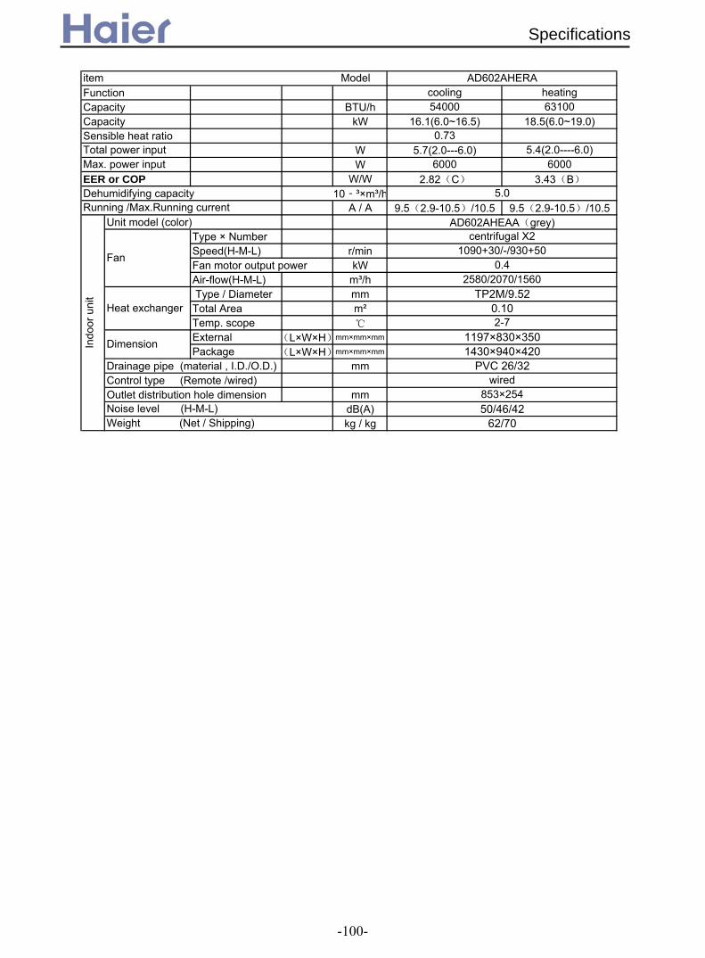
Function cooling heatingCapacity BTU/h 54000 63100Capacity kW 16.1(6.0~16.5) 18.5(6.0~19.0)Sensible heat ratio 0.73
W 5.7(2.0---6.0) 5.4(2.0----6.0)W 6000 6000
EER or COP W/W 2.82(C) 3.43(B)Dehumidifying capacity 10‐³×m³/h
A / A 9.5(2.9-10.5)/10.5 9.5(2.9-10.5)/10.5Unit model (color)
Type × NumberSpeed(H-M-L) r/minFan motor output power kWAir-flow(H-M-L) m³/h Type / Diameter mmTotal Area m²Temp. scope
External (L×W×H)mm×mm×mm
Package (L×W×H)mm×mm×mm
Drainage pipe (material , I.D./O.D.) mmControl type (Remote /wired)Outlet distribution hole dimension mm
dB(A)kg / kg
AD602AHERA
Total power inputMax. power input
5.0Running /Max.Running current
Indo
or u
nit
AD602AHEAA(grey)
Fan
centrifugal X21090+30/-/930+50
0.42580/2070/1560
Heat exchanger TP2M/9.52
0.102-7
Dimension 1197×830×3501430×940×420
Weight (Net / Shipping) 62/70
PVC 26/32wired
Noise level (H-M-L) 50/46/42853×254
item Model
Specifications
-100-

2.2 For fixed frequency unit
Function cooling heatingCapacity kW 3.5 3.8Sensible heat ratio 0.71
W 1160 1110W 1650 1650
EER or COP W/W 3.01(A) 3.41(A)Dehumidifying capacity 10‐³×m³/h
A / A 4.9A/7.4A 4.9A/7.4AStart Current A 20 20
Unit model (color)Type × NumberSpeed(H-M-L) r/minFan motor output power kWAir-flow(H-M-L) m³/h Type / Diameter mmTotal Area m²Temp. scope
External (L×W×H)mm×mm×mm
Package (L×W×H)mm×mm×mm
Drainage pipe (material , I.D./O.D.) mmControl type (Remote /wired)
dB(A)kg / kg
Function cooling heatingCapacity BTU/h 16400 17000
Capacity kW 4.8 5.0
W 1700 1600
W 2000 1950
EER or COP W/W 2.82 3.12
A / AStart Current AClass of anti electric shock Class 1
Unit model (color) AD182ALEAA Grey
Type × NumberSpeed(H-M-L) r/minFan motor output power kWAir-flow(H-M-L) m³/h Type / Diameter mmTotal Area m²Temp. scope
External (L×W×H)mm×mm×mm
Package (L×W×H)mm×mm×mm
Drainage pipe (material , I.D./O.D.) mmControl type (Remote /wired /model)
dB(A)kg / kg
50
wired controlNoise level (H-M-L) 45/41/37
Weight (Net / Shipping) 23/26.5
Dimension1090×500×220 1174×545×280
PVC 16/12
Indo
or u
nit
Fan
centrifugal fan X 2700±30 / 540±30 / 400±30
50780
Heat exchanger TP2M/7X0.5
0.342-7
Total power inputMax. power input
Running /Max.Running current cooling: 7.8A /9.5A heating 7.3A /9.3A
Weight (Net / Shipping) 14/16
item Model AD182ALEAA
20/18wired
Noise level (H-M-L) 42/40/36
inner grooved pipe/φ70.112-7
Dimension610×695×536×265
1.6Running /Max.Running current
Indo
or u
nit
AD122ALEAA(grey)
Fan
CENTRIFUGALX11000/900/800±50
0.05550/450/400
Heat exchanger
Item Model AD122ALEAA
Total power inputMax. power input
Specifications
500 ×200
-101-

Function cooling heatingCapacity BTU/h 18000 18770
Capacity kW 5.3 5.5
W 1890 1700
W 2150 2050
EER or COP W/W 2.81 3.32
A / AStart Current A
Unit model (color) AD182AMEAA Grey
Type × NumberSpeed(H-M-L) r/minFan motor output power kWAir-flow(H-M-L) m³/h Type / Diameter mmTotal Area m²Temp. scope
External (L×W×H)mm×mm×mm
Package (L×W×H)mm×mm×mm
Drainage pipe (material , I.D./O.D.) mmControl type (Remote /wired /model)Fresh air hole dimension mm
dB(A)kg / kg
Function cooling heatingCapacity kW 7.25 7.6Sensible heat ratio 0.72 /
W 2400 2300W 3100W 3000W
EER or COP W/W 3.02 3.30Dehumidifying capacity 10‐³×m³/h
A / A 11.0A/13.9A 10.5A/13.4AUnit model (color)
Type × NumberSpeed(H-M-L) r/minFan motor output power kWAir-flow(H-M-L) m³/h Type / Diameter mmTotal Area m²Temp. scope
External (L×W×H)mm×mm×mm
Package (L×W×H)mm×mm×mm
Drainage pipe (material , I.D./O.D.) mmControl type (Remote /wired)
dB(A)kg / kg
wired controlNoise level (H-M-L) 49/45/41/37Weight (Net / Shipping) 25.2/28.4
Dimension1090*500*2201174*545*280PVC 16/12
Heat exchanger inner grooved pipe/φ7
0.512-7
Max. power input
1.8Running/Max Running
Indo
or u
nit
grey
Fan
centrifugal fan*21250±40/1130±40/1000±50/850±50
0.051200/1050/850 (white port: 0Pa ESP)
PVC 14/16wired control
ф100
2-7
50
1167x860x345
cooling: 8.5A /11.5A heating: 7.5A /10.5A
39/45
Running /Max.Running current
Noise level (H-M-L) 45/42/40
Heat exchanger TP2M/9.52X0.7
0.52
Dimension990x650x300
item Model AD242ALEAA
Total power input
Indo
or u
nit
Fan
centrifugal fan X 21000±40 / 840±40 / 730±40/ 670±50
1801200/1050/850
Weight (Net / Shipping)
item Model AD182AMEAA
Total power inputMax. power input
Specifications
-102-

Function cooling heatingCapacity kW 7.25 7.6Sensible heat ratio 0.72 /
W 2400 2300W 3100W 3000W
EER or COP W/W 3.02 3.30Dehumidifying capacity 10‐³×m³/h
A / A 11.0A/13.9A 10.5A/13.4AStart Current A 62 62
Unit model (color)Type × NumberSpeed(H-M-L) r/minFan motor output power kWAir-flow(H-M-L) m³/h Type / Diameter mmTotal Area m²Temp. scope External (L×W×H)mm×mm×mm
Package (L×W×H)mm×mm×mm
Drainage pipe (material , I.D./O.D.) mmControl type (Remote /wired)Fresh air hole dimension mm
dB(A)kg / kg
Function cooling heatingCapacity BTU/h 28000 31000Capacity kW 8.5 9.1Sensible heat ratio 0.72 /Total power input W 2820 2800Max. power input W 3500W 3500WEER or COP W/W 3.01 3.25Dehumidifying capacity 10‐³×m³/h
A / A 12.0A/15.5A 12.0A/15.5ACapacity BTU/h 28000 31000Capacity kW 8.5 9Sensible heat ratio 0.72Total power input W 2800 2650Max. power input W 3500 3500EER or COP W/W 3.04 3.40Dehumidifying capacity 10‐³×m³/h
A / A 4.7A/5.6A 4.6A/5.5AUnit model (color)
Type × NumberSpeed(H-M-L) r/minFan motor output power kWAir-flow(H-M-L) m³/h Type / Diameter mmTotal Area m²Temp. scope External (L×W×H)mm×mm×mm
Package (L×W×H)mm×mm×mm
Drainage pipe (material , I.D./O.D.) mmControl type (Remote /wired)Fresh air hole dimension mm
kWdB(A)
Pakg / kg
Running /Max.Running current
Weight (Net / Shipping) 39/40.4
Indo
or u
nit
AD282AMEAA(grey)
Fan
Centrifugal fan*2(1070±40/)970±40/900±40/820±50r/min
0.18
Noise level (H-M-L) (47)43/40/38Static pressure 50
wired150
Electricity Heater 0
Dimension 990*650*3001167*860*345
PVC 32/26
1470/1300/1100
Heat exchanger inner grooved type/φ7
0.492-7
with
AU
282A
HE
AA
2.5Running /Max.Running current
with
AU
28N
AH
EA
A
2.5Running /Max.Running current
Weight (Net / Shipping) 39/40.4
item Model AD282AMEAA
PVC 32/26wired control
150Noise level (H-M-L) 47/43/39
0.492-7
Dimension 990*650*3001167*860*345
2.5
Indo
or u
nit
AD242AMEAA(grey)
Fan
centrifugal fan*21000±40/940±40/860±40/780±50
0.181470/1300/1100
Heat exchanger inner grooved pipe/φ7
item Model AD242AMEAA
Total power inputMax. power input
Specifications
-103-

Function cooling heatingCapacity BTU/h 28000 31000Capacity kW 8.5 9.1Sensible heat ratio 0.72 /Total power input W 2950 2830Max. power input W 3500W 3500WEER or COP W/W 2.88 3.22Dehumidifying capacity 10‐³×m³/h
A / A 12.7A/15.5A 12.3A/15.5ACapacity BTU/h 27500 29000Capacity kW 8 8.5Sensible heat ratio 0.72Total power input W 2950 2820Max. power input W 3500 3500EER or COP W/W 2.71 3.01Dehumidifying capacity 10‐³×m³/h
A / A 4.8A/5.6A 4.8A/5.6AUnit model (color)
Type × NumberSpeed(H-M-L) r/minFan motor output power kWAir-flow(H-M-L) m³/h Type / Diameter mmTotal Area m²Temp. scope
External (L×W×H)mm×mm×mm
Package (L×W×H)mm×mm×mm
Drainage pipe (material , I.D./O.D.) mmControl type (Remote /wired)
kWdB(A)
Pakg / kg
Indo
or u
nit
AD282AHEAA(grey)
Fan
Centrifugal fan*21270+30/1130+40/970+50
0.15
Static pressure 100Weight (Net / Shipping) 48/58
wiredElectricity Heater 0Noise level (H-M-L) 53/51/49
Dimension820*830*350
940*1050*420PVC 32/26
1470/1300/1100(100 Pa Static pressure)
Heat exchanger inner grooved type/φ9.52
0.452-7
with
AU
282A
HE
AA
1.8Running /Max.Running current
with
AU
28N
AH
EA
A
1.8Running /Max.Running current
item Model AD282AHEAA
Specifications
-104-

Function cooling heatingCapacity kW 10.5 11Sensible heat ratio 0.72Total power input W 3400 3500Max. power input W 3900 3950EER or COP W/W 3.09 3.15
A / A 16.0A/18.5A 16.5A/18.7ACapacity kW 11 12.5Sensible heat ratio 0.72Total power input W 3650 4300Max. power input W 4700 4800EER or COP W/W 3.01 2.91
A / A 6.4A/8.0A 7.3A/8.0AUnit model (color)
Type × NumberSpeed(H-M-L) r/minFan motor output power kWAir-flow(H-M-L) m³/h Type / Diameter mmTotal Area m²Temp. scope
External (L×W×H)mm×mm×mm
Package (L×W×H)mm×mm×mm
Drainage pipe (material , I.D./O.D.) mmControl type (Remote /wired)
kWdB(A)kg / kg
Function cooling heatingCapacity BTU/h 36000 40000Capacity kW 10.5 11.7Sensible heat ratio 70%Total power input W 3370 3240Max. power input W 4100 4100EER or COP W/W 3.12 3.61
A / AStart Current AClass of anti electric shock CLASS I CLASS I
Circuit breaker AMax. operating pressure of heat side Mpa 4.15 4.15Max. operating pressure of cold side Mpa 4.15 4.15Unit model (color)
Type × NumberSpeed(H-M-L) r/minFan motor output power kWAir-flow(H-M-L) m³/h Type / Diameter mmTemp. scope
External (L×W×H)mm×mm×mm
Package (L×W×H)mm×mm×mm
Control type (Remote /wired)dB(A)kg / kg
Cooling 15.3A/18.6A Heating 14.6/18.6A50
20
with
AU
362A
LEA
A
item Model AD362ANEAA
Running /Max.Running current
Noise level (H-M-L) 47/45/43
Noise level (H-M-L) 51/49/47/43Weight (Net / Shipping) 52/55
Indo
or u
nit
AD362ANEAA(WHITE)
Fan
centrifugal
wired
2-7
Dimension 1135×742×270 1370×820×325
1330/1230/1130/10300.1
1700(80pa)
Heat exchanger inner grooved/φ7
Weight (Net / Shipping) 40/57
PVC 26/32wired
Electricity Heater 0
inner grooved type/φ70.532-7
Dimension 990/650/3001167/860/345
with
AU
36N
AIE
AA
Running /Max.Running current
Indo
or u
nit
AD362AMEAA
Fan
Centrifugal fan*21200/1100/1000
0.161500/1350/1200
Heat exchanger
with
AU
362A
IEA
A
Running /Max.Running current
item Model AD362AMEAA
Specifications
-105-

Function cooling heatingCapacity kW 10 11Sensible heat ratio 0.72Total power input W 3550 3650Max. power input W 3900 3950EER or COP W/W 2.8 3.01
A / A 16.8A/18.5A 17.5A/18.7ACapacity kW 10.5 12Sensible heat ratio 0.72Total power input W 3880 4200Max. power input W 4700 4800EER or COP W/W 2.71 2.86
A / A 6.7A/8.0A 6.8A/8.0AUnit model (color)
Type × NumberSpeed(H-M-L) r/minFan motor output power kWAir-flow(H-M-L) m³/h Type / Diameter mmTotal Area m²Temp. scope
External (L×W×H)mm×mm×mm
Package (L×W×H)mm×mm×mm
Drainage pipe (material , I.D./O.D.) mmControl type (Remote /wired)
kWdB(A)kg / kg
Function cooling heatingCapacity BTU/h 42000 45000Capacity kW 12.3 13.2Sensible heat ratio 70%
W 4850 4800W 6200 6200
EER or COP W/W 2.54 2.75Dehumidifying capacity 10‐³×m³/h
A / AStart Current AClass of anti electric shock CLASS I CLASS ICircuit breaker AMax. operating pressure of heat side Mpa 4.15 4.15Max. operating pressure of cold side Mpa 4.15 4.15
Unit model (color)Type × NumberSpeed(H-M-L) r/minFan motor output power kWAir-flow(H-M-L) m³/h Type / Diameter mmTemp. scope
External (L×W×H)mm×mm×mm
Package (L×W×H)mm×mm×mm
Control type (Remote /wired /model)dB(A)kg / kg 52/55
Running /Max.Running current
Noise level (H-M-L) 51/49/47/43wired
2-7
Dimension 1135×742×270 1370×820×325
Indo
or u
nit
AD422ANEAA(WHITE)
Fan
centrifugal1330/1230/1130/1030
0.1
item Model AD422ANEAA
Total power inputMax. power input
4.0
Heat exchanger
Cooling 8.7A/10.1A Heating 8.7/10.1A50
20
1700(80pa)inner grooved/φ7
Weight (Net / Shipping)
Noise level (H-M-L) 53Weight (Net / Shipping) 48/58
PVC 32/26wired
Electricity Heater 0
2-7
Dimension 820/830/350940/1050/420In
door
uni
t
AD362AHEAA
Fan
Centrifugal fan*21350/1250/1050
0.21500/1350/1200
Heat exchanger inner grooved type/φ7
0.53
with
AU
362A
IEA
A
Running /Max.Running current
with
AU
36N
AIE
AA
Running /Max.Running current
item Model AD362AHEAA
Specifications
-106-
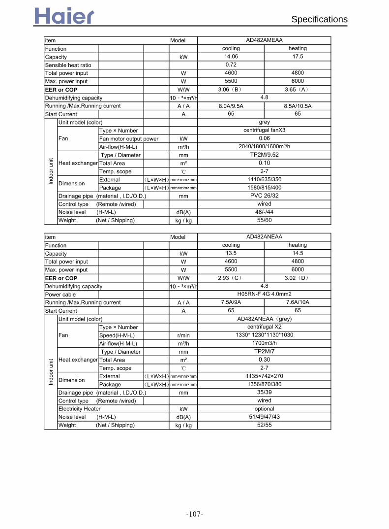
Function cooling heatingCapacity kW 14.06 17.5Sensible heat ratio 0.72
W 4600 4800W 5500 6000
EER or COP W/W 3.06(B) 3.65(A)Dehumidifying capacity 10‐³×m³/h
A / A 8.0A/9.5A 8.5A/10.5AStart Current A 65 65
Unit model (color)Type × NumberFan motor output power kWAir-flow(H-M-L) m³/h Type / Diameter mmTotal Area m²Temp. scope
External (L×W×H)mm×mm×mm
Package (L×W×H)mm×mm×mm
Drainage pipe (material , I.D./O.D.) mmControl type (Remote /wired)
dB(A)kg / kg
Function cooling heatingCapacity kW 13.5 14.5
W 4600 4800W 5500 6000
EER or COP W/W 2.93(C) 3.02(D)
Dehumidifying capacity 10‐³×m³/hPower cable
A / A 7.5A/9A 7.6A/10AStart Current A 65 65
Unit model (color)Type × NumberSpeed(H-M-L) r/minAir-flow(H-M-L) m³/h Type / Diameter mmTotal Area m²Temp. scope
External (L×W×H)mm×mm×mm
Package (L×W×H)mm×mm×mm
Drainage pipe (material , I.D./O.D.) mmControl type (Remote /wired)
kWdB(A)kg / kg
4.8
Total power input
Noise level (H-M-L) 51/49/47/43
Indo
or u
nit
Weight (Net / Shipping) 52/55
35/39wired
Electricity Heater optional
0.302-7
Dimension1135×742×2701356/870/380
H05RN-F 4G 4.0mm2Running /Max.Running current
AD482ANEAA(grey)
Fan centrifugal X2
1330* 1230*1130*10301700m3/h
Heat exchanger TP2M/7
item Model AD482ANEAA
Max. power input
wiredNoise level (H-M-L) 48/-/44Weight (Net / Shipping) 55/60
Dimension1410/635/3501580/815/400PVC 26/32
Indo
or u
nit
grey
Fan centrifugal fanX3
0.062040/1800/1600m³/h
Heat exchanger TP2M/9.52
0.102-7
Total power inputMax. power input
4.8Running /Max.Running current
item Model AD482AMEAA
Specifications
-107-
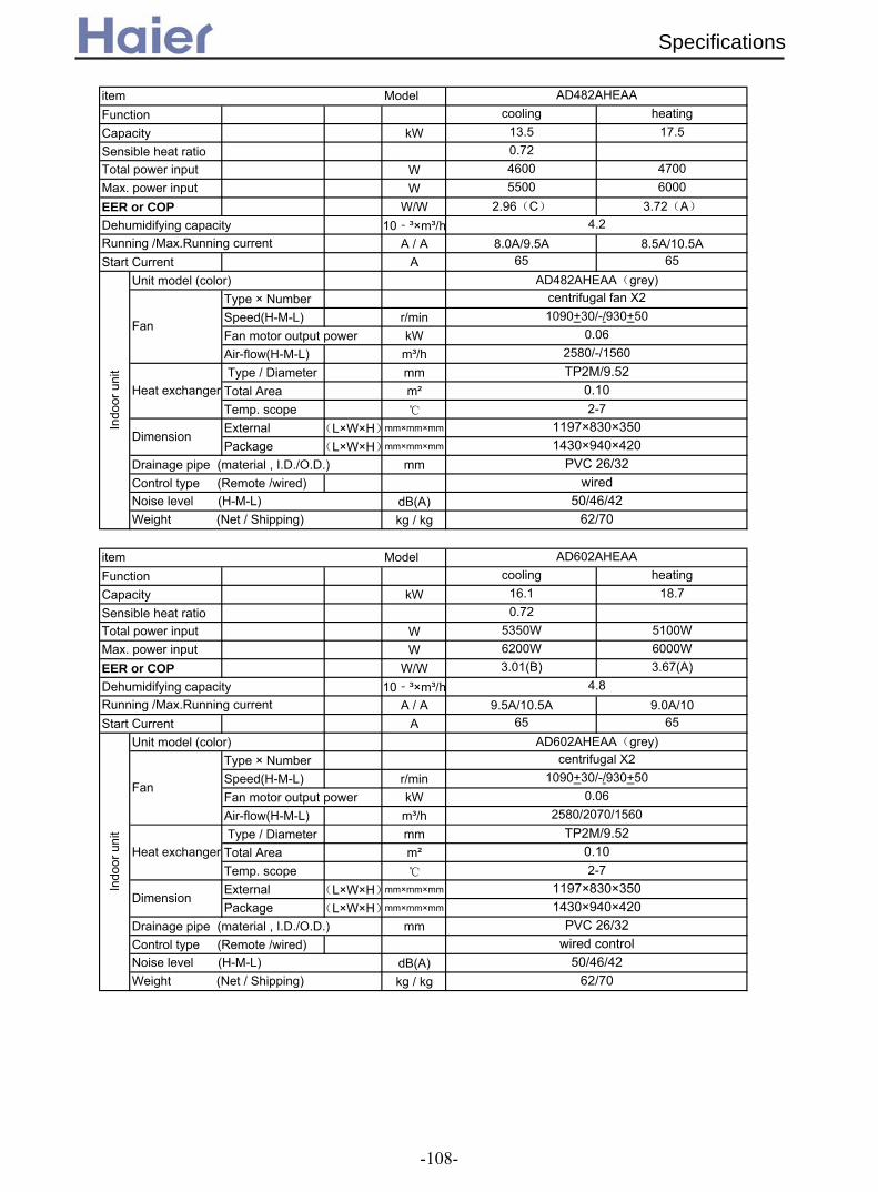
Function cooling heatingCapacity kW 13.5 17.5Sensible heat ratio 0.72
W 4600 4700W 5500 6000
EER or COP W/W 2.96(C) 3.72(A)Dehumidifying capacity 10‐³×m³/h
A / A 8.0A/9.5A 8.5A/10.5AStart Current A 65 65
Unit model (color)Type × NumberSpeed(H-M-L) r/minFan motor output power kWAir-flow(H-M-L) m³/h Type / Diameter mmTotal Area m²Temp. scope
External (L×W×H)mm×mm×mm
Package (L×W×H)mm×mm×mm
Drainage pipe (material , I.D./O.D.) mmControl type (Remote /wired)
dB(A)kg / kg
Function cooling heatingCapacity kW 16.1 18.7Sensible heat ratio 0.72
W 5350W 5100WW 6200W 6000W
EER or COP W/W 3.01(B) 3.67(A)Dehumidifying capacity 10‐³×m³/h
A / A 9.5A/10.5A 9.0A/10Start Current A 65 65
Unit model (color)Type × NumberSpeed(H-M-L) r/minFan motor output power kWAir-flow(H-M-L) m³/h Type / Diameter mmTotal Area m²Temp. scope
External (L×W×H)mm×mm×mm
Package (L×W×H)mm×mm×mm
Drainage pipe (material , I.D./O.D.) mmControl type (Remote /wired)
dB(A)kg / kg
Running /Max.Running current
Indo
or u
nit
AD602AHEAA(grey)
Fan
centrifugal X21090+30/-/930+50
0.06
wired controlNoise level (H-M-L) 50/46/42Weight (Net / Shipping) 62/70
Dimension1197×830×3501430×940×420
PVC 26/32
2580/2070/1560
Heat exchanger TP2M/9.52
0.102-7
Total power inputMax. power input
4.8
Weight (Net / Shipping) 62/70
item Model AD602AHEAA
Indo
or u
nit
AD482AHEAA(grey)
Fan
PVC 26/32wired
Noise level (H-M-L) 50/46/42
2-7
Dimension1197×830×3501430×940×420
Heat exchanger TP2M/9.52
0.10
centrifugal fan X21090+30/-/930+50
0.062580/-/1560
item Model AD482AHEAA
Running /Max.Running current
Total power inputMax. power input
4.2
Specifications
-108-

Function cooling heatingCapacity kW 24000 26000
W 7060 7000W 8800 8800
EER or COP W/W 3.41(A) 3.71(A)Dehumidifying capacity 10‐³×m³/hPower cable
A / A 12A/15A 12A/15AStart Current A 65 65
Unit model (color)Type × NumberSpeed(H-M-L) r/minFan motor output power kWAir-flow(H-M-L) m³/h Type / Diameter mmTemp. scope
External (L×W×H)mm×mm×mm
Package (L×W×H)mm×mm×mm
Drainage pipe (material , I.D./O.D.) mmControl type (Remote /wired)
kWdB(A)kg / kg
Note: ⊙ is the real timeanalyser position
Noise level (H-M-L) 60/-Weight (Net / Shipping)
Running /Max.Running current
PVC 26/32wired
Electricity Heater optional
2-7
Dimension1570×840×3601800×1051×510In
door
uni
t
AD722AHEAA(grey)
Fan
centrifugal X41300±50/1150 /930±50
0.084000
Heat exchanger TP2M/9.52
Max. power input
7.5H05RN-F 4G 4.0mm2
Norminal condition: indoor temperature (cooling): 27DB/19WB, indoor temperature (heating): 20DBOutdoor temperature(cooling): 35DB/24WB, outdoor temperature(heating): 7DB/6WBThe noise level will be measured in the third octave band limited values, using a Real Time Analyser calibrated sound intensitymeter. It is a sound pressure noise level. The detailed method please refer to the following information:
item Model AD722AHEAA
Installation state: the unit should be placed on the flat floor or be mounted in horizontal direction.Testing method:
duct unit without auxiliary duct: duct unit with auxiliary duct:
92/100
Total power input
1.4m
2m
duct auxiliary duct
2m
1.4m
1m
auxiliary duct
Specifications
±50
-109-

performance curves in cooling mode
0400800
1200160020002400280032003600400044004800520056006000640068007200
12/18 14/20 16/22 18/25 19/27 22/30 24/32
indoor WB/DB
cool
ing
capa
city
(KW
)
20 cooling capacity20 power input25 cooling capacity25 power input32 cooling capacity32 power input35 cooling capacity35 power input40 cooling capacity40 power input-5 cooling capacity-5 power input
AD182AMERA
performance curves in heating mode
1200
1800
2400
3000
3600
4200
4800
5400
6000
6600
7200
7800
8400
9000
9600
10200
16/10 18/12 20/14.5 21/15 22/16 24/17 26/18
indoor WB/DB
heat
ing
capa
city
(KW
)
-6/-7 heating capacity-6/-7 power input-4/-5 heating capacity-4/-5 power input-1/-2 heating capacity-1/-2 power input1/0 heating capacity1/0 power input7/6 heating capacity7/6 power input6/5 heating capacity6/5 power input12/10 heating capacity12/10 power input16/15 heating capacity16/15 power input
cooling capacity/power input/air flow and external static pressure curves
5001000150020002500300035004000450050005500600065007000
indoor 27/19outdoor 35/24 (inverter 70Hz)
indoor 20/14.5outdoor 7/6 (inverter 68Hz)
indoor 27/19outdoor 35/24 (fixed frequency
55Hz)
indoor 20/14.5outdoor 7/6 (fixed frequency
58Hz)operation condition
perfo
rman
ce v
alue
0Pa cooling capacity
0Pa power input
0Pa air flow
10Pa cooling capacity
10Pa power input
10Pa air flow
20Pa cooling capacity
20Pa power input
20Pa air flow
30Pa cooling capacity
30Pa power input
30Pa air flow
40Pa cooling capacity
40Pa power input
40Pa air flow
50Pa cooling capacity
50Pa power input
50Pa air flow
3. Curves3.1 Performance curves
Performance Curves
-110-
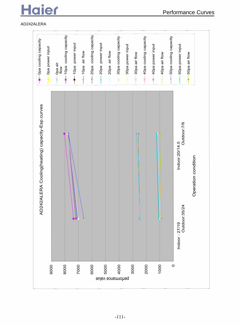
AD
242A
LER
A C
oolin
g(he
atin
g) c
apac
ity-E
sp.c
urve
s
0
1000
2000
3000
4000
5000
6000
7000
8000
9000
Indo
or :
27/1
9
Out
door
:35/
24In
door
:20/
14.5
Out
door
:7/6
Ope
ratio
n co
nditi
on
performance value0p
a co
olin
g ca
paci
ty
0pa
pow
er in
put
0pa
air
flow
10pa
coo
ling
capa
city
10pa
pow
er in
put
10pa
air
flow
20pa
coo
ling
capa
city
20pa
pow
er in
put
20pa
air
flow
30pa
coo
ling
capa
city
30pa
pow
er in
put
30pa
air
flow
40pa
coo
ling
capa
city
40pa
pow
er in
put
40pa
air
flow
50pa
coo
ling
capa
city
50pa
pow
er in
put
50pa
air
flow
AD242ALERA
Performance Curves
-111-

AD242ALERA Cooling performance curves
0
1000
2000
3000
4000
5000
6000
7000
8000
9000
10000
18/12 20/14.5 22/16 25/18 27/19 30/22 32/23
Indoor WB/DB
Cool
ing
capa
city(
W)
10/6 cooling capacity10/6 power input21/15 cooling capacity21/15 power input25/18 cooling capacity25/18 power input32 cooling capacity32 power input35/24 cooling capacity35/24 power input43/26 cooling capacity43/26 power input
AD242ALERA Heating performance curves
0
2000
4000
6000
8000
10000
12000
16/10 18/12 20/14.5 22/16 24/17 27/18
Indoor WB/DB
Indo
or W
B/DB
-5/-6 heating capacity-5/-6 power input2/1.5 heating capacity2/1.5 power input7/6 heating capacity7/6 power input10/6 heating capacity10/6 power input21/15 heating capacity21/15 power input24/18 heating capacity24/18 power input
Performance Curves
-112-

AD362AMERA cooling(heating) capacity -Esp. curves
0
1000
2000
3000
4000
5000
6000
7000
8000
9000
10000
11000
indoor: 27/19 outdoor: 35/24(FQY: 85HZ) cooling
indoor: 20/14.5 outdoor: 7/6(FQY: 90HZ) heating
operation condition
perfo
rman
ce v
alue
0pa cooling capacity
0pa power input
10pa cooling capacity
10pa power input
20pa cooling capacity
20pa power input
30pa cooling capacity
30pa power input
40pa cooling capacity
40pa power input
50pa cooling capacity
50pa power input
AD362AMERA
AD362AHERA cooling(heating) capacity-Esp. curves
0
2000
4000
6000
8000
10000
12000
14000
Indoor:27/19 Outdoor:35/24
Indoor:20/14.5 Outdoor:7/6
Operation condition
Cool
ing
capa
city(
W)
70pa cooling capacity
70pa power input
70pa air flow
80pa cooling capacity
80pa power input
80pa air flow
90pa cooling capacity
90pa power input
90pa air flow
100pa cooling capacity
100pa power input
100pa air flow
110pa cooling capacity
110pa power input
110pa airflow
120pa cooling capacity
120pa power input
120pa airflow
130pa cooling capacity
130pa power input
130pa air flow
150pa cooling capacity
150pa power input
150pa air flow
AD362AHERA
Performance Curves
-113-

AD362AHERA heating capacity curves
0
2000
4000
6000
8000
10000
12000
14000
16/10 18/12 20/14.5 21/15 22/16 24/17 26/18
Indoor WB/DB
Heat
ing ca
pacit
y(W)
-7/-8 heating capacity-7/-8 power input-5/-6 heating capacity-5/-6 power input2/1 heating capacity2/1 power input1/0 heating capacity1/0 power input7/6 heating capacity7/6 power input12/10 heating capacity12/10 power input16/15 heating capacity16/15 power input
AD362AHERA cooling capacity curves
0
2000
4000
6000
8000
10000
12000
12/18 14/20 16/22 18/25 19/27 22/30 24/32Indoor WB/DB
Cooli
ng ca
pacit
y(W
)
20 cooling capacity20 power input25 cooling capacity25 power input32 cooling capacity32 power input35 cooling capacity35 power input40 cooling capacity40 power input
Performance Curves
-114-
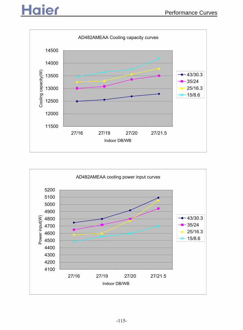
AD482AMEAA Cooling capacity curves
11500
12000
12500
13000
13500
14000
14500
27/16 27/19 27/20 27/21.5Indoor DB/WB
Coo
ling
capa
city
(W)
43/30.335/2425/16.315/8.6
AD482AMEAA cooling power input curves
410042004300440045004600470048004900500051005200
27/16 27/19 27/20 27/21.5Indoor DB/WB
Pow
er in
put(W
) 43/30.335/2425/16.315/8.6
Performance Curves
-115-

AD482AMEAA heating capacity curves
0
2000
4000
6000
8000
10000
12000
14000
16000
18000
20000
-7 -5 0 7 10 15
outdoor DB
Hea
ting
capa
city
(W)
16/1018/1220/14.522/1624/1726/18
AD482AMEAA heating power input curves
4200
4300
4400
4500
4600
4700
4800
4900
5000
5100
5200
5300
-7 -5 0 7 10 15
outdoor DB
cool
ing
capa
city
(W)
16/1018/1220/14.522/1624/1726/18
Performance Curves
-116-
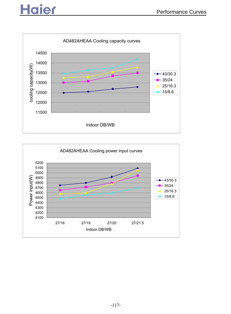
AD482AHEAA Cooling capacity curves
11500
12000
12500
13000
13500
14000
14500
Indoor DB/WB
cool
ing
capa
city
(W)
43/30.335/2425/16.315/8.6
AD482AHEAA Cooling power input curves
410042004300440045004600470048004900500051005200
27/16 27/19 27/20 27/21.5
Indoor DB/WB
Pow
er in
put(W
)
43/30.335/2425/16.315/8.6
Performance Curves
-117-

AD482AHEAA Heating capacity curves
0
2000
4000
6000
8000
10000
12000
14000
16000
18000
20000
-7 -5 0 7 10 15
outdoor DB
Hea
ting
capa
city
(W)
16/1018/1220/14.522/1624/1726/18
AD482AHEAA Heating power input curves
3800
4000
4200
4400
4600
4800
5000
5200
-7 -5 0 7 10 15
outdoor DB
Pow
er in
put(W
)
16/1018/1220/14.522/1624/1726/18
Performance Curves
-118-
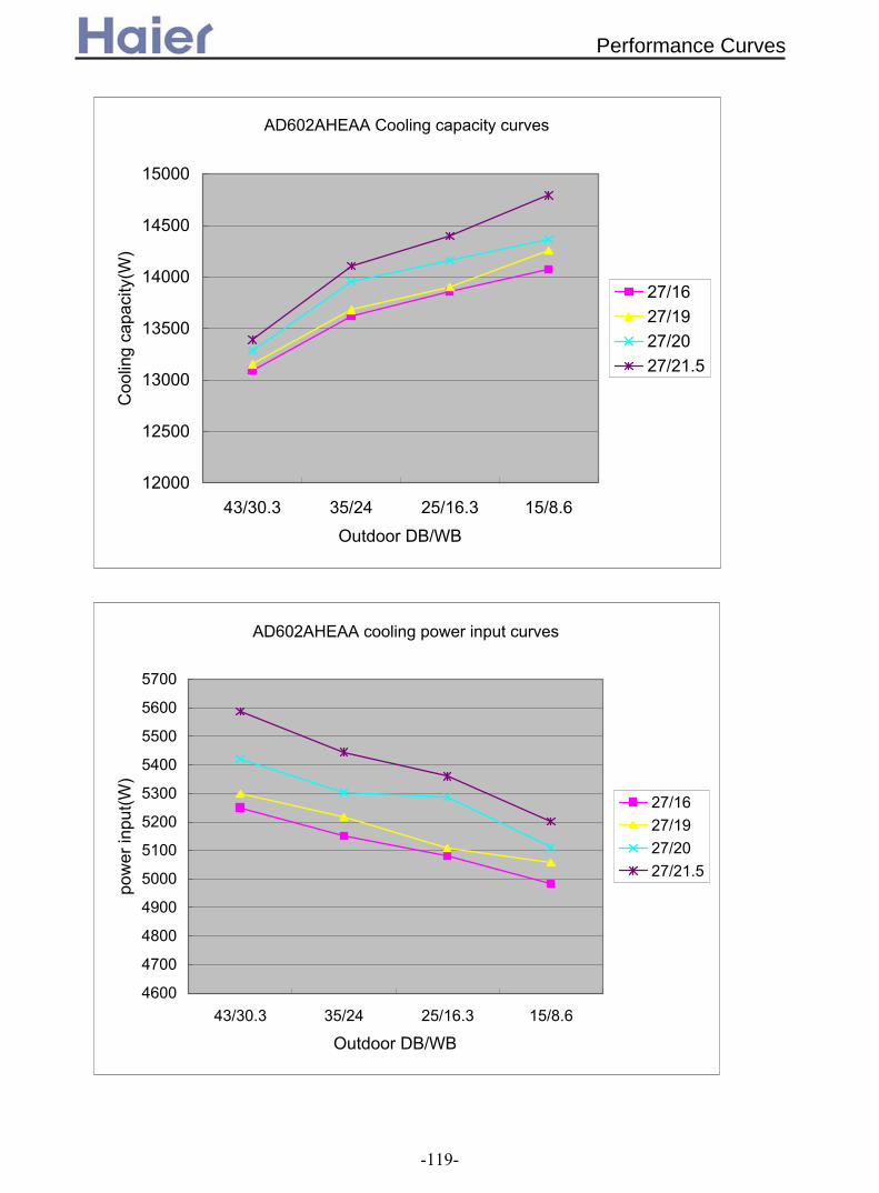
AD602AHEAA Cooling capacity curves
12000
12500
13000
13500
14000
14500
15000
43/30.3 35/24 25/16.3 15/8.6Outdoor DB/WB
Coo
ling
capa
city
(W)
27/1627/1927/2027/21.5
AD602AHEAA cooling power input curves
4600
4700
4800
4900
5000
5100
5200
5300
5400
5500
5600
5700
43/30.3 35/24 25/16.3 15/8.6
Outdoor DB/WB
pow
er in
put(W
)
27/1627/1927/2027/21.5
Performance Curves
-119-

AD602AHEAA heating capacity curves
0
2000
4000
6000
8000
10000
12000
14000
16000
18000
20000
-7 -5 0 7 10 15Outdoor DB
heat
ing
capa
city
(W) 16/10
18/1220/14.522/1624/1726/18
AD602AHEAA Heating power input curves
4200
4300
4400
4500
4600
4700
4800
4900
5000
5100
5200
5300
-7 -5 0 7 10 15Outdoor DB
pow
er in
put(W
) 16/1018/1220/14.522/1624/1726/18
Performance Curves
-120-

AD422ANEAA external static pressure curves
1200130014001500160017001800190020002100220023002400
0 10 20 30 40 50 60 70 80 90 100
external static pressure
super high speedhigh speedmiddle speedlow speed
AD422ANEAA
3.2 External static pressure
AD122ALEAA,AD122ALERA
50 250150100 200 350300 400
10
20
500450 550 600
ESP(Pa)
Super highhighmiddlelow
air flow(m /h)
AD182ALEAA,AD182ALERA
200
50
40
30
20
10
01200400 600 800 1000
high speed
low speedmid speed
super high speed
3Air flow(m/h)
External static pressure(Pa)
Static pressure curves
-121-
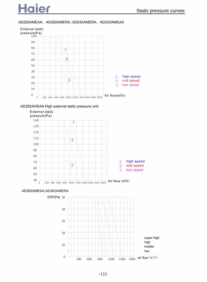
AD282AMEAA,AD282AMERA;AD242AMERA,AD242AMEAA
100
90
80
70
60
50
40
30
20
10
00 200 20001200800400 600 1000 16001400 1800
3
2
1
1
3
2
External static pressure(Pa)
Air flow(m/h)3
high speedmid speedlow speed
AD282AHEAA High external static pressure unit:
140
130
120
110
100
90
80
70
60
50
400 200 20001200800400 600 1000 16001400 1800
3
2
1
1
3
2
External static pressure(Pa)
Air flow(m/h)3
high speedmid speedlow speed
50
40
30
20
10
0300 900600 1200 18001500
super highhigh
middlelow
air flow
ESP(Pa)
(m/h)
AD362AMEAA,AD362AMERA
Static pressure curves
-122-

Static pressure curves
140
130
120
110
100
90
80
70
60
50
400 300 300018001200600 900 1500 24002100 2700
(m/h)
3
2
1
1
3
4
2
super highhighmiddle
low
air flow
ESP(Pa)
AD362AHEAA
AD48-602AMEAA Med external static pressure unit:
3
2
1
100
90
80
70
60
50
40
30
20
10
0
External static pressure(Pa)
3Air flow(m/h)
low speed
mid speed
high speed1
3
2
6000 300 300018001200900 1500 24002100 2700
AD48-602AHEAA,AD482AHERA,AD602AHERA
140
130
120
110
100
90
80
70
60
50
400 300 300018001200600 900 1500 24002100 2700
Air flow(m/h)3
3
2
1
low speed
mid speed
high speed1
3
2
External static pressure(Pa)
-123-

3.2 Noise level3.2.1 For inverter unit
Noise level-A
D122A
LER
A
9 13 17 21 25 29 33 37 41 45 49 53
2531.5
40
50
63
80
100
125
160
200
250
315
400
500
630
8001000125016002000250031504000500063008000
100001250016000020000
Third octave band frequency Hz
Sound pressure level DB
heating lowheating m
iddleheating highsuper heating highcooling lowcooling m
iddlecooling highsuper cooling highfan lowfan m
iddlefan highsuper fan high
1/3
octa
ve b
and n
oise
leve
l-AD
182A
ME
RA
0.05.0
10.015.020.025.030.035.040.045.050.055.060.065.0
25.031.540.050.063.080.0
100.0125.0160.0200.0250.0315.0400.0500.0630.0800.01000.01250.01600.02000.02500.03150.04000.05000.06300.08000.010000.012500.016000.020000.0
third octave band frequency Hz
sound pressure level DB
cooling superhighcooling highcooling m
edcooling lowfan superhighfan highfan m
edfan lowheating superhighheating highheating m
edheating low
Noise Level
-124-

1/3 octave band noise level-AD
242ALER
A
8.013.018.023.028.033.038.043.048.053.0
25.031.540.050.063.080.0
100.0125.0160.0200.0250.0315.0400.0500.0630.0800.0
1000.01250.01600.02000.02500.03150.04000.05000.06300.08000.010000.012500.016000.020000.0
third octave band frequency Hz
Sound pressure level DB
cooling super highcooling highcooling m
edcooling lowfan super highfan highfan m
edfan lowheating super highheating highheating m
edheating low
1/3 octave band noise level-AD
242AM
ERA
8.013.018.023.028.033.038.043.048.053.0
25.031.540.050.063.080.0
100.0125.0160.0200.0250.0315.0400.0500.0630.0800.0
1000.01250.01600.02000.02500.03150.04000.05000.06300.08000.010000.012500.016000.020000.0
third octave band frequency Hz
Sound pressure level DB
cooling super highcooling highcooling m
edcooling lowfan super highfan highfan m
edfan lowheating super highheating highheating m
edheating low
Noise Level
-125-

Noise level-A
D362A
ME
RA
7 11 15 19 23 27 31 35 39 43 47 51 55
2531.5
40
50
63
80
100
125
160
200
250
315
400
500
630
8001000125016002000250031504000500063008000
100001250016000020000
Third octave band frequency Hz
Sound pressure level DB
heating lowheating m
iddleheating highsuper heating highcooling lowcooling m
iddlecooling highsuper cooling highfan lowfan m
iddlefan highsuper fan high
Noise Level
Noise level-A
D362A
HE
RA
16 19 22 25 28 31 34 37 40 43 46 49 52 55
2531.5
40
50
63
80
100
125
160
200
250
315
400
500
630
8001000125016002000250031504000500063008000
100001250016000020000
Third octave band frequency Hz
Sound pressure level DB
heating lowheating m
iddleheating highcooling lowcooling m
iddlecooling highfan lowfan m
iddlefan high
-126-
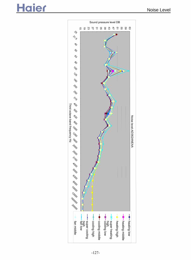
Noise level-A
D362A
NE
AA
15 19 23 27 31 35 39 43 47 51 55 59 63
2531.5
40
50
63
80
100
125
160
200
250
315
400
500
630
8001000125016002000250031504000500063008000
100001250016000020000
Third octave band frequency Hz
Sound pressure level DB
heating low
heating middle
heating high
super heatinghighcooling low
cooling middle
cooling high
super coolinghighfan low
fan middle
Noise Level
-127-

3.2.2 For fix frequency unit
1/3 octave band noise level-AD
182ALEA
A
8.013.018.023.028.033.038.043.048.053.0
25.0
31.5
40.0
50.0
63.0
80.0
100.0
125.0
160.0
200.0
250.0
315.0
400.0
500.0
630.0
800.01000.01250.01600.02000.02500.03150.04000.05000.06300.08000.0
10000.012500.016000.020000.0
third octave band frequency Hz
Sound pressure level DB
cooling super highcooling highcooling m
edcooling lowfan super highfan highfan m
edfan lowheating super highheating highheating m
edheating low
1/3 octave band noise level-AD
182AM
EAA
8.013.018.023.028.033.038.043.048.053.0
25.0
31.5
40.0
50.0
63.0
80.0
100.0
125.0
160.0
200.0
250.0
315.0
400.0
500.0
630.0
800.01000.01250.01600.02000.02500.03150.04000.05000.06300.08000.0
10000.012500.016000.020000.0
third octave band frequency Hz
Sound pressure level DB
cooling super highcooling highcooling m
edcooling lowfan super highfan highfan m
edfan lowheating super highheating highheating m
edheating low
Noise Level
-128-

Noise level-A
D242A
LEA
A
7 11 15 19 23 27 31 35 39 43 47 51 55
2531.5
40
50
63
80
100
125
160
200
250
315
400
500
630
8001000125016002000250031504000500063008000
100001250016000020000
Third octave band frequency Hz
Sound pressure level DB
heating lowheating m
iddleheating highsuper heating highcooling lowcooling m
iddlecooling highsuper cooling highfan lowfan m
iddlefan highsuper fan high
Noise level-A
D242A
ME
AA
8 12 16 20 24 28 32 36 40 44 48 52 5625
31.5
40
50
63
80
100
125
160
200
250
315
400
500
630
8001000125016002000250031504000500063008000
100001250016000020000
Third octave band frequency Hz
Sound pressure level DB
heating lowheating m
iddleheating highsuper heating highcooling lowcooling m
iddlecooling highsuper cooling highfan lowfan m
iddlefan highsuper fan high
Noise Level
-129-

Noise level-A
D282A
ME
AA
7 10 13 16 19 22 25 28 31 34 37 40 43 46 49 52 55
2531.5
40
50
63
80
100
125
160
200
250
315
400
500
630
8001000125016002000250031504000500063008000
100001250016000020000
Third octave band frequency Hz
Sound pressure level DB
heating lowheating m
iddleheating highsuper heating highcooling lowcooling m
iddlecooling highsuper cooling highfan lowfan m
iddlefan highsuper fan high
Noise level-A
D282A
HE
AA
15 18 21 24 27 30 33 36 39 42 45 48 51 54 57 60
2531.5
40
50
63
80
100
125
160
200
250
315
400
500
630
8001000125016002000250031504000500063008000
100001250016000020000
Third octave band frequency Hz
Sound pressure level DB
heating lowheating m
iddleheating highcooling lowcooling m
iddlecooling highfan lowfan m
iddlefan high
Noise Level
-130-

Noise level-A
D362A
ME
AA
8 11 14 17 20 23 26 29 32 35 38 41 44 47 50 53
2531.5
40
50
63
80
100
125
160
200
250
315
400
500
630
8001000125016002000250031504000500063008000
100001250016000020000
Third octave band frequency Hz
Sound pressure level DB
heating lowheating m
iddleheating highsuper heating highcooling lowcooling m
iddlecooling highsuper cooling highfan lowfan m
iddlefan highsuper fan high
Noise level-A
D362A
HE
AA
15 19 23 27 31 35 39 43 47 51 55 59 6325
31.5
40
50
63
80
100
125
160
200
250
315
400
500
630
8001000125016002000250031504000500063008000
100001250016000020000
Third octave band frequency Hz
Sound pressure level DB
heating lowheating m
iddleheating highcooling lowcooling m
iddlecooling highfan lowfan m
iddlefan high
Noise Level
-131-

1/3 octave band noise level-AD
482AH
EAA
8.013.018.023.028.033.038.043.048.053.058.0
25.0
31.5
40.0
50.0
63.0
80.0
100.0
125.0
160.0
200.0
250.0
315.0
400.0
500.0
630.0
800.01000.01250.01600.02000.02500.03150.04000.05000.06300.08000.0
10000.012500.016000.020000.0
third octave band frequency Hz
Sound pressure level DB
cooling highcooling m
edcooling lowfan highfan m
edfan lowheating highheating m
edheating low 29
1/3 octave band noise level-AD
602AH
EAA
8.013.018.023.028.033.038.043.048.053.058.0
25.031.540.050.063.080.0
100.0125.0160.0200.0250.0315.0400.0500.0630.0800.0
1000.01250.01600.02000.02500.03150.04000.05000.06300.08000.010000.012500.016000.020000.0
third octave band frequency Hz
Sound pressure level DB
cooling highcooling m
edcooling lowfan highfan m
edfan lowheating highheating m
edheating low
Noise Level
-132-

3.3 Air velocity distributionFor AD12*
1.8
2.4
0 5.5
0.5
air discharge angle 5
0
1.822
2.4
5.5
25
27
cooling
coolingair discharge angle 5
0
1.8
2.4
5.5
1.00.5
Air Velocity distribution
Temperature distribution
heatingair discharge angle 45Air Velocity distribution
1.8
0
2.4
25
27
22
5.5
heatingair discharge angle 45Temperature distribution
Air Velocity Distribution
-133-

For AD18*
1.8
2.4
0 5.5
0.5
air discharge angle 5
0
1.822
2.4
5.5
25
27
cooling
coolingair discharge angle 5
0
1.8
2.4
5.5
1.00.5
Air Velocity distribution
Temperature distribution
heatingair discharge angle 45Air Velocity distribution
1.8
0
2.4
25
27
22
5.5
heatingair discharge angle 45Temperature distribution
Air Velocity Distribution
-134-

cooling
coolingair discharge angle 5
Air Velocity distribution
Temperature distribution
0
1.8
2.4
0.5
5.5
air discharge angle 5
1.8
0
22
25
27
5.5
2.4
For AD28* midium static pressure duct
Air Velocity Distribution
-135-

For AD36* and AD42* midium static pressure duct
cooling
coolingair discharge angle 5
Air Velocity distribution
Temperature distribution
air discharge angle 5
0
1.8
2.4
0.5
5.5
25
0
1.8
2227
5.5
2.4
Air Velocity Distribution
-136-

4. Dimension4.1 For Ceiling concealed duct type (ESP 30Pa)
!
"# $ $%" $ & ' "(&(&
"
)
)
##
!
c
i
Dimension
-137-

26027535
350
R100
85
260
275
A-A
gas pipe liquid pipedrainage pipe
235
165
120
100
150
265
85
545
655
1370
1406
240
1280
(mm)
130
200
170
890
200
200
260275
A
35 10
300
R100
85
70
20
545
635
960
986
890
A-A
gas pipe liquid pipe drainage pipe
235
165
120
100150
265
(mm)
Model: AD482AMEAA
4.2 For Medium static pressure duct type (ESP 50Pa)
Model: AD182AMEAA, AD242AMEAA, AD282AMEAA, AD362AMEAA, AD242AMERA, AD282AMERA, AD362AMERA
Dimension
-138-

Model: AD362ANEAA, AD422ANEAA, AD482ANEAA, AD482ANERA
4.3 For High static pressure duct type (ESP 100Pa)
800
960
60
250
750
30
840
170 205
130
120
365
185
830
Model: AD282AHEAA, AD362AHEAA
Dimension
-139-

800
1320
830
1200
170 270
250
365
185 25
060 45
1105
(mm)
Model: AD722AHEAA
Model: AD482AHEAA, AD602AHEAA,
Control Box
Gas pipeLiquid pipe
8307941825 18
1570
1690
100
25
80
95 60
1640
60
12.7(1/2") 28.58(1-1/8")
Air inlet
65 13 138
250 13 13
8
13
163
356x200=1200
1500
200
M5x20pcs
13
16335
Air outlet
M10x4pcs
M5x20pcs
138
131313
8
60
138
250
77
13
200
6X200=1200
145060
138
13
45
25
49
DRAIN PIPE VP25
2551080
30310
360
106
25
170185
530
A
Installation dimension
Over 900 Over 900
Check Hole
Over 100
Ceiling
Over 300
(600x600)
(900x1730)
60100
over 400Over 200
35
900
35
(mm)
AD362AHERA, AD482AHERA, AD602AHERA
Dimension
-140-
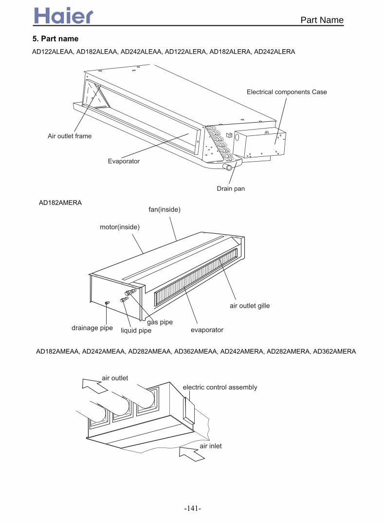
5. Part name
#
;?
';?
0
AD182AMERA
AD122ALEAA, AD182ALEAA, AD242ALEAA, AD122ALERA, AD182ALERA, AD242ALERA
AD182AMEAA, AD242AMEAA, AD282AMEAA, AD362AMEAA, AD242AMERA, AD282AMERA, AD362AMERA
Part Name
-141-

7
#
AD482AMEAA
AD362ANEAA, AD422ANEAA, AD482ANEAA, AD482ANERA
!
AD282AHEAA, AD482AHEAA, AD602AHEAA, AD722AHEAA, AD362AHERA, AD482AHERA, AD602AHERA
Part Name
-142-

6. Installation6.1 For Ceiling concealed duct type (ESP 30Pa)
! " " #$ % & ' ( " )
! "# " $* + , ,
-
. ,
/ + $ *0 1 % , 2 3 4 ) 1,
5
$ *
"" "
"" " $* 6 78 & *9*:: + $ -- ; < % 6 . = ! 1 , , </ + 0 8 ,
$ -
( ' < *0: < *> ? 8 ,
Installation
-143-
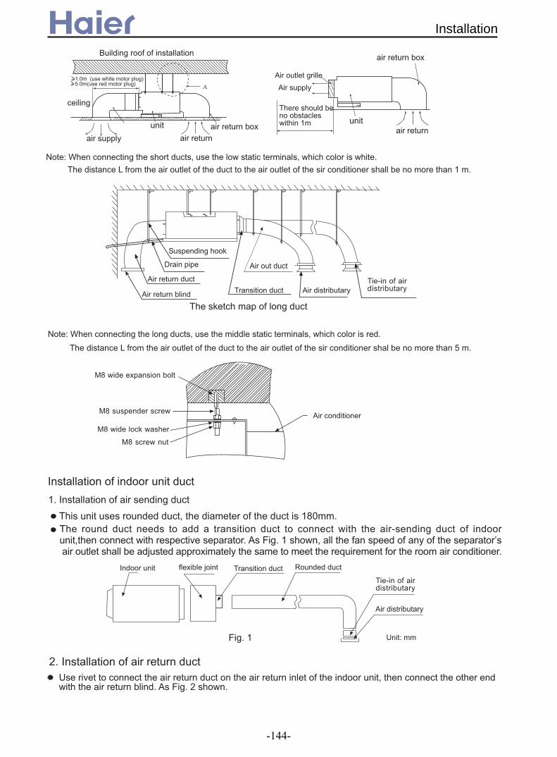
5 ? , , " *
@
@
@
+ <
6
@
<
&
5 ? , ,
=A '
=A
=A <
=A
@
" 0
1
* 1
, *A: & , @ $ * , B % ' )
1 ' % C
D $ *
@
&
- 1 D , @ $ -
*: 0:
E
;
'
*
@
@
'
Installation
-144-

. @ & $ < , ' $ @ $ .
$ .
1 D =A =*: /, ' :F ,=*: !
? @ )
5 ,
4 D ,
+ D
+) ;
+
G H
$
1
#
+ +
$ -
1
@ @
# $ @ ,% 0
1 , 1 <
I %"
Installation
-145-

! " # $ ! % & # ' ( )
*
*+' +*#
, *- ( .
*
$
/0 "1 234 *+' 5 6 *+'
0 ( * "
$ 17 !
0 0 ! ( (
7
8
0
+*2
0
%9#
$
0
/ /
$
*+'
$ ! (! ( : ! ( (
:
* "
; <=
Installation
-146-

8
' ' (
7 ( > ?
' 80
@A2%
@B%#
@#.
@%??
$ C6
? #(6
#3% #% (6
3B % (6
.?3 ? (6
* * )" *#D
* "
E @#.
F @A2%
* "
E @%??F @B%#
+
8
E (
$
7 ! -
8
' ( ( (
' 0 !
# '
06
, ##?#
, #3#
:
$
,
Installation
-147-

- 7:C$CE
0:CE- 8, G80$FH $CIJH 8 0-:/JC 8,, -F-'$' *87-: '$'J$ G-:K- 8 *87- 8J'- G-,8-D:K$CE :CH -F-'$' '8CC-'$8C E8JC0 '8CC-'$8C DJ G-'8D*F--0 G-,8- D:K$CE F$C- +8F:E- '8CC-'$8C
" * - - ( " 0 ( : J
LMN OP QRQD( !
2:
$ * (:
' (
8
*
"
3 #A #%#
(
- ( (
F(
3:
2: 3 #A 3# 3:
" # #S
:0?#:D-::0#3#:F-::0#3#:F-::
8J088 JC$-D$C:F GF8'K
*/! ##6#2+9! %/"*87- J**FH1
$C088 JC$-D$C:F GF8'K
# 2
# 2F C
8J088 JC$-D$C:F GF8'K
*/! ##6#2+9! %/"*87- J**FH1
$C088 JC$-D$C:F GF8'K
# 2
# 2 C F
, ##?#
, #3#
:0##:F-:::0##:F-::0?#:F-::
HE
HE
HE
HE
Installation
-148-

6.2 For Medium static pressure duct type (ESP 50Pa)
! " # $ % & ' (# )* )
+%,-$-.
% # # / 0& % + 1 & $ # $ & &2 + ! 0& # $ 2 & # & $ & % & $ 3 $ + &
, ! &% 7 8 7
6%8$9-
0& / $ - / 2 $#
Installation
-149-

-9$60 ! !"#$ %&'(%)*&&%+)(,)-./)&'(%
+%,-$-.:08,09,0%/"00$-,86$9-6%,028;;<:029,0:0.$--$-.$-%;;%$9-2%$1;8,0929;;9+"00$-,86$9-698;/6%800,$98$-=8,<9,/0%"0>8$*0-
" : " #$ ! !0 " # '( +&? $ ' ( '( 1 '( 1 @A A5B'+ ('(6
12 " '(& '($ & ' ( ' ( ' ( $ & '(!# 1 #.
C5
9
55
55
555
8D
$
" " 3 " 4,!0 $ " 5
C %
:
6
'" (
'67(
'(
?
?5
?5
'6E (
'6E
(
'" (
'67(
'(
CC4C
F5
C5
5
'
(
6
4
8
6.2.1 Installtion instruction for AD182/242/282/362/482AMEAA and AD242/282/362AMERA
Installation
-150-

06 0 8 installed.
" *5
"1 "1
$
6
7' 2&
+ !
%
8 2
'(%!1 *!
' ( 8 !
& " 0$ "!
& "0$ ""! # " 0#!"#" "! * * "2 9 0: $0$
+ '(/ '3C5E355(
H6
+
5EC
:
" *5
*
*5
*5
/
I
%
%
.""CE@
"
% 355
,
<
+
'( ":
+
6
6
6 &
*
*
,
:
,
<
+
:
,
<
+
: +
:
,
6
improper""
Installation
-151-

+ & %&
2 H6 H1@C'$/( + H6 % ' (
/ /
/
*
H@C!' ( ' (
J K' (
H@C' (
J K' (
/ ' (
'(J K' (
6' ( %
' (
'(
H?5
' &55(
% 355
/
= H@C'; (
'*&
(
,
@F5E?@C
%
/ *
/
, *
$ @5E?5 '$ (
&!
+ 55 8H1?5'34( : H6 / C55 & + C55 1# % /
+
6 / $ :
555 6
'(
'(
'(
'(
'(
'$ &! (
Installation
-152-

' $9
6 &
;$ @1?141@55 / -'( @1'@( ?1; @D, , '6 , (
8 6
, *:
+ "
< $ 8 &' (
: 9 8&
.&:&:&
6
"
'(
%
: '9(
%:'9 (
"
'(' (
'
(
$
+%,-$-./%-.0,92:9/$;<$-=8,<9,/0%"
8,-9220;06,$69+0,%6$,68$:,0%I0,9,9+0,98,60:029,0*%I$-.%-<0;06,$669--06$9-.,98-/69--06$9-*8:069*;00/:029,0*%I$-.;$-0H9;%.069--06$9-
3"$""#
$
0 7 / % 8
0& ! "
,
< <
Installation
-153-

! " !
#
$
%
&
'
$
( )
%
*
+ %
(
(, - . ) -
/-0
(
+1
, (234
#15''671#*6#1%+8+'&9
$':*6 ,$;"<(=>");7$$+2?
234, ('75''671#*6#1%+8+'&9
/,0
, - . . -/0
/0(.-0
(
(
(, - . - -/-
, ( 1 +
, (
$':*6 ,$;"<(=>");7$$+2?
'75''671#*6#1%+8+'&9
#15''671#*6#1%+8+'&9
$':*67$$+2?(0<-="(1>");
6 1 , (
, (234
234
! " !
#15''671#*6#1%+8+'&9
'75''671#*6#1%+8+'&9
234
234
(.
/AD182AMEAA
/0(.--0 362
Installation
-154-
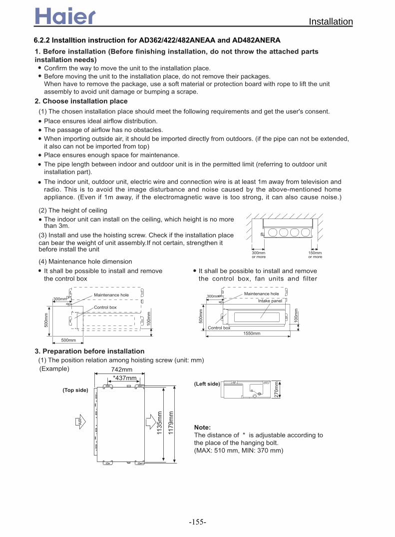
6.2.2 Installtion instruction for AD362/422/482ANEAA and AD482ANERA
#$%& '()#&* '+& ',*(-&& ',*+# '.$ #.%&*. *' (
"/' '#$*0*1'(
'#$.(/ *##$.'(- *+. '%#(# '.2+'. # '* '#'(/ *.$ #* (
/++''$''$"$%#&(/ & *.''.% .&3 '(& #"$%+ # '*'$& *+ ''(
/*#'*/''*+$'*(
*'$(',# ''.$*#.%(#'+*.#
. .&'.2
. .& ' .2+ # #
4'
"/ **'$5!"
#$/'#67.''* '#**.(4859":+45;:
2
<
::
"9:
"::
9::
9::
::4'
.2
9::
::
"99:
"::
4'
.2
,
%
;:
&
;6;
"";=
""9
Installation
-155-

#'%+' *'',*'*(#'*
)#+# $,# #*+*$$'''$+''$#+#+%'.%''$(
*'*(4%.*'*, '*& # & '* #&.( + ' .(
>*.
)'# *'$(
>**.4":
>3'>3 *
'
4":'$.
.$*#+#2'*+*#'$.+#$'*+*.%*.'$.+.%*'$. ()#**+ 7 * $ '*(
'
2*.(#0+ . .+'(!'%.%#.$**.(
>**.4":
4
4":$
4": *$
?$'# $=(""(;"("::"9:,*#('
($ ) *
-#'*'+'.7$#**.',(
#
>**.4":@.'%
*+ ,
73#&*&.%#$*(
4,7.$$#'# $&.'*&.$(
. 7& %+#'*###$'%''(
-.
''**&#$*#*
)&''&**#
)A'&* #
B&*$'''(/.*#:9
#
<
<
% /
? ')
-@.'%
? '
>*
!:39
&
0 B
! ""
:
@(!(
:
!@(!(/' '#'%*
Installation
-156-
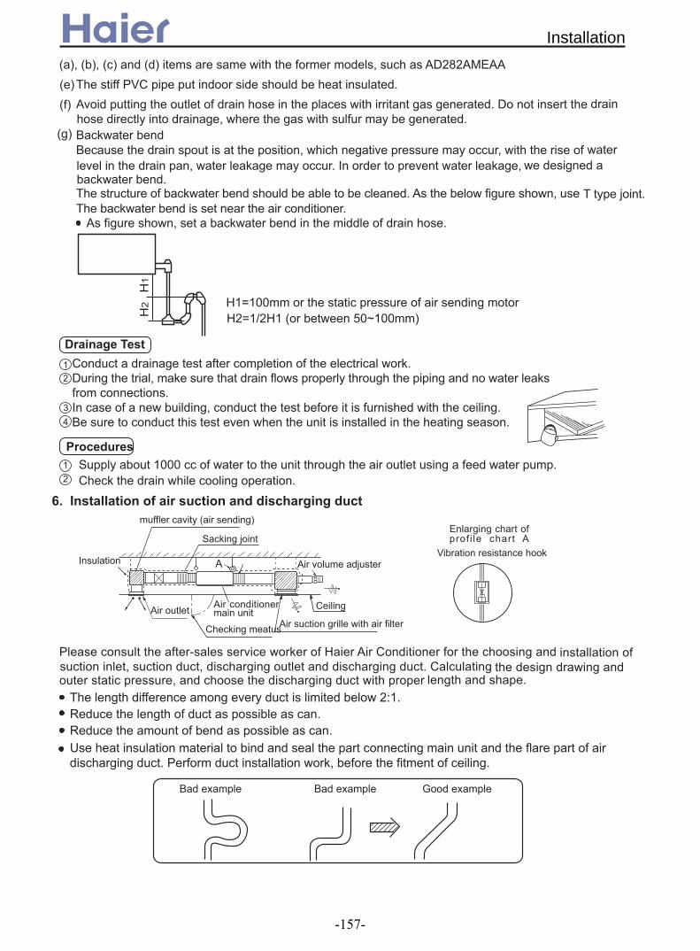
.&
'*#' #''$,(!*+,#$ %* *$,#''('#$.*+''.##$'*()''&$*(
? %.":::''#$**#$ (',$'* (
*
"
"
/##C .(
# & *# '$**(!
)',$.)' +$'*& %''+$#
/'#.',$....'(.$#*$+ /% 7(/.',$.'(#*$+.',$.#(
>"
> >"D"::' #*
>D"E>".$9:F"::
0
**'# # '
C.',
##'&%*
?',*7
&7
',*
'
*
'*$#
'#3&'$,#>#'*
* (
+.+'$#+'!4
/*##'*&%'.$5"(<'*#' .'(<'#. .'( . ''*# #'**'(#'$,+.###'*(
'%*+$*$#%.*(
$& +$,*%''( &$,*+ $*.',$.(
#'+''+'**'**'('* *$*' +''**'$
B2 )2 )2
Installation
-157-
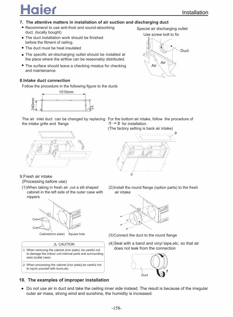
1&,2
!'
? ''** '$.#2
34$ '#$*#*'
/''.'*.% '*,*#*
.,+#$ '##(/#'%*.',,
<'3#3..*'('%.*/'$,.#.###'*(/'.(
/ '#'3'**. '$#$'..%.(
/#'&'',*#'',*'(
=(,'*.#
-,*#+' '.##'$
" #* #,
''#*
":"9
:
. ?0
?$.&% +'(,#''
!'
/@
"
-&*'. +.'#* *'
- '*'. +.'#7%#$.+'(
5&62 2
!','*(/.'#*+*$+%'(
Installation
-158-

'**#
2
/%.$ #'('$''+&#,*'*'+%$.*(+*#. # &$(.*#.
##'.%' '%#'**#+*$'$'+$*&2'+'*$#2'*$&#$+*$,*(
4%.2'* #2 5$%.. 9+$.. +%&#' (
/ +0 .##%+#+%'$,*(
/.'*$#*(
-''* * #+ #$#*$+ 0 *(
-'''+#' $#*( $3*+#$ (
<#*/.'##0(*%**,*
',#'' ,++.$#*$(
@%'.7 # (#*
/0
?
7
4A'''% '. 7
>''%#0
#* >''%
B 0
/
7-<B
!B<@)@!GH <G@<!/>/ <@/<@-</< /)<I<@<@-<?@ <)@<4IBG/<@/@?(B<@ !@/@?4 ?/)@4/!)@<4IBC@/B@/@?(
8 9 )
'#''$*
''$*$,.''%.%A (
!''$.',($%% ' *$* #$(
Installation
-159-

' ''%(?'$A'' '#..$(/.$:*$$J&* (
(
4,$* % $+ $# .%(
!!!!<
!
">+:3:CF+9:>A@-< ? G5
!@@< //<4)@I
"
" @ /!@@< //<4)@I
G EB
G EB
4?$'.,
'.,
@&' '
$'$A
?$'.,
,*.,
,'
: : (9 : :!!!<
:" : : (: :
!
: : (: : :
!
@ /!@@< //<4)@I
!@@< //<4)@I
@-<? G5:3::C+F+9:>A
<?/ "
" G EB
G EB
Installation
-160-

6.3 For High static pressure duct type (ESP 100Pa)
0
-( ," 12 -
("" "$ " "% """$ %8" "".""$- 8" "%
"
"9"
3# -(4 5 5-
!
$:22:22%
7822 7;22
#
#
4"
4
792
27<2
2
4 ""= ""(" " """
," 69:2 B;2
<C2
3;1
:22
3C2
,
6
9:2 8<32<C2
3;1
BC9
8829
,
6
3- 5
AD282AHEAA
AD482AHEAA
AD362AHEAA
AD602AHEAA
AD362AHERA
,-. /. &
AD482AHERA
AD602AHERA
4 4
0*(
1)
AD AHEAA722
Installation
-161-

35
6
'82
..
!
4
#& 4 -#
= $ %$% ""4' "/
$6'82%! " =
-#
/! ",
(" ""
!
7 8
$%#. "'" "
$%6""" "
D4
(
2EC""$2E2<%
=
'82
'
'82
'82
, ,
,
'
D<C$ %$%
F G$%
D<C$ %
F G$ %
,$%
$"%F G$%
4"$% #
/D4D.<C$!,8%(D4 "#" $%
$%
-'$%,$80C2E80822%"
( #
,
H "
#
#
*
8C"E<"
# 80822"
$%
Improper piping
Installation
-162-

,
4 " ," "! =
8222 "4
$%
8<
9
1
8<
D92
$822""%
# 80822"
( ""822"" 6D.92$8801%
$%
$% D4
$ % # , "== " "! #
# "
8
< 8I822"" "
<I80<8$C2E822""%
9-#
!
" $%
#"
#
- #
D
4"
#"
4
#
. #4 4
+"="="
""<J8) )" 6"" "
Installation
-163-

" 5
=
#
#$ %
48"880"
-9E1"
4<C
4C20
4120
:-( 1" " 80"" <C2""J
*J80"I28""#0"
"
"90$"90%
$""""%
!"#"
,"
"90$"90%
$""""%
!"#"
,"
#
- $%
;-"8
)"". .$% " " . " "
<-"= , """ /" "# " " $ %
# ""
##
,
6
'"$ "J"9C"<1%" "
AD722AHEAA
Installation
-164-

#
!""
,>-"
" !"$"%""/! "# "#"/!!"*# " "! 68%( <%,89% /!!" ." " " " 1%( " " K*CL
)$"J* 8 E * B%
7 ""( " 4=
( " 4= "
4 "> $"822%
7 -"
>" 6"
"$"90"%
" " "J8%! .8B2"91"90"/!!K "L" *<<%! :2"9<"90"/!!K "L" *1,,-)
F " "G
/8 /<
Installation
-165-

-
$8% 5
-5,""#"" 6
5 "$<2"<M%
(" " ( 69.1 ) ! " $""%4 " 7
8<2E8<1
8B:E8;2
9<32E9;;2*"$999E123 "%
:8B2E3C12*"$:92E332 "%
$""%
44"#$""%
<<;E<99;3<2E88B:2*"$;;2E8<82 "%
> + -6
# #
,,D<CD4
4
'5$%$6 %
4"
$%$ %
$ %$%
+>
(#)*!*+,#*+-)7/=7,!>?!*@6)?7),-#
6)*7//->-4)!47(-)#4!)46!=)-#H-)7)7(-)76)4-=-/7)-'#H!*+#*?->-4)!447**-4!7*+)76*,47**-4!7*'6=-47'>--,=-/7)-'#H!*+>!*-D7>#+-47**-4!7*
Installation
-166-

#$% &' ()(
*+, -. /001 0- 2 3 / + 0- 4 2 / /002 51+/6
7
*28+/
9- 5+,
: 5+,
;0
8- /- /<
6
9-5+,
+ +,+. 5+,
=+,
83>?@3<8;A 9!88=BC
7D ;; !D7EE*7D= =;:F
= D
6
;!E ;; !D7EE*7D= =;:F
7D ;; !D7EE*7D= =;:F
8;A 9!88=BC >?3 D@3<
9 ED
6
;!E ;; !D7EE*7D= =;:F
B G
B G
B G
B G
Installation
-167-

Cabinet indoor unit
(AP42~AP48)
Cabinet type
-168-
1. Features......................................................................169
2. Specifications..............................................................171
3. Curves.........................................................................173
3.1 Performance curves.............................................173
3.2 Noise level............................................................175
4. Dimensions..................................................................176
5. Part name....................................................................177
6. Installation....................................................................178

1. FeaturesLong Distance Air Sending
Wide angle 180 kinds of air sending modes, and the distance of air sending can reach to 15m Auxiliary Electric Heating Function
The unit has a optional auxiliary electric heating function, so if the outdoor temperature is too low, it can be used normally, and heating rapidly Optional Healthy Module
Healthy Nanometer silver ion filter,lonizer to bring The refreshing air to your room.Enjoy the feeling of a forest at home.
Photic bacteria-killing medium function,it can absorb deleterious gas generated by fitment.
Fresh air function can realize air convection between inside and outside, not only ensure indoor air fresh, but also make interior air keep plus pressure, avoid dirty air enter the room.(need to handtailor) 3-D airflow (for AP482AKEAA)
The air conditioner adopts two stepping motors to combines vertical and horizontal auto-swing to circulate cool/warm air to the every corner of the room New Structure Design
Patent “H” shape appearance design and entire closed type air outlet grille, add elegance to any style of interior
Features
-169-

Bigger LCD Screen The cabinet type with the model of AP482AKEAA has a very big LCD screen, so operation state of the
unit will be clear at a glance, it is very convenient to use
Features
-170-
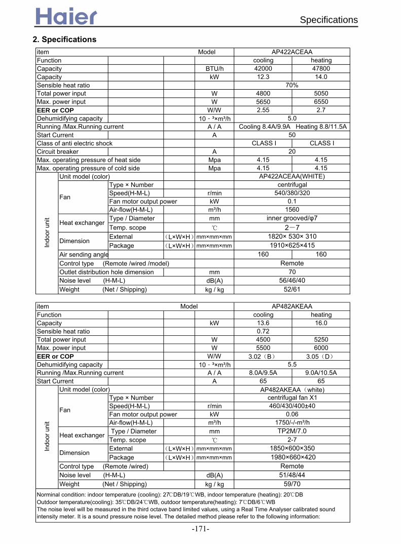
2. Specifications
Function cooling heatingCapacity BTU/h 42000 47800Capacity kW 12.3 14.0Sensible heat ratio
W 4800 5050W 5650 6550
EER or COP W/W 2.55 2.7Dehumidifying capacity 10‐³×m³/h
A / AStart Current AClass of anti electric shock CLASS I CLASS ICircuit breaker AMax. operating pressure of heat side Mpa 4.15 4.15Max. operating pressure of cold side Mpa 4.15 4.15
Unit model (color)Type × NumberSpeed(H-M-L) r/minFan motor output power kWAir-flow(H-M-L) m³/hType / Diameter mmTemp. scope
External (L×W×H)mm×mm×mmPackage (L×W×H)mm×mm×mm
Air sending angle 160 160Control type (Remote /wired /model)Outlet distribution hole dimension mm
dB(A)kg / kg
Function cooling heatingCapacity kW 13.6 16.0Sensible heat ratio 0.72
W 4500 5250W 5500 6000
EER or COP W/W 3.02(B) 3.05(D)
Dehumidifying capacity 10‐³×m³/hA / A 8.0A/9.5A 9.0A/10.5A
Start Current A 65 65Unit model (color)
Type × NumberSpeed(H-M-L) r/minFan motor output power kWAir-flow(H-M-L) m³/h Type / Diameter mmTemp. scope
External (L×W×H)mm×mm×mmPackage (L×W×H)mm×mm×mm
Control type (Remote /wired)dB(A)kg / kg
Norminal condition: indoor temperature (cooling): 27DB/19WB, indoor temperature (heating): 20DBOutdoor temperature(cooling): 35DB/24WB, outdoor temperature(heating): 7DB/6WBThe noise level will be measured in the third octave band limited values, using a Real Time Analyser calibrated soundintensity meter. It is a sound pressure noise level. The detailed method please refer to the following information:
Weight (Net / Shipping) 52/61
item Model AP482AKEAA
Remote70
Noise level (H-M-L) 56/46/40
Heat exchanger inner grooved/φ7
2-7
Dimension1820× 530× 3101910×625×415
AP422ACEAA(WHITE)
Fan
centrifugal540/380/320
0.11560
Max. power input
5.0
Max. power input
5.5
Running /Max.Running current Cooling 8.4A/9.9A Heating 8.8/11.5A50
Total power input
20
Indo
or u
nit
item Model AP422ACEAA
70%Total power input
Running /Max.Running current
Indo
or u
nit
AP482AKEAA(white)
Fan
centrifugal fan X1460/430/400±40
0.061750/-/-m³/h
Heat exchanger TP2M/7.02-7
Dimension1850×600×350 1980×660×420
RemoteNoise level (H-M-L) 51/48/44Weight (Net / Shipping) 59/70
Specifications
-171-

Testing method:
front, left, right directions respectively.
1m
1m
Installation state: the unit should be placed on the flat floor or be mounted in horizontal
standing-on-floor unit: If the unit cooling capacity is over 28000W, the noise level should be measured at the
direction.
Specifications
-172-

10000
10500
11000
11500
12000
12500
13000
13500
14000
14500
15000
15500
16/10 18/12 20/14.5 21/15 22/16 24/17 26/18
-6/-7
-4/-5
-1/-2
1/0
6/5
7/6
12/10
16/15
4400
4600
4800
5000
5200
5400
5600
5800
-6/-7 -4/-5 -1/-2 1/0 6/5 7/6 12/10 16/15
16/10
18/12
20/14.5
21/15
22/16
24/17
26/18
Heating capacity curves
indoor DB/WB
Hea
ting
capa
city
(W)
Power input curves in heating mode
indoor DB/WB
Pow
er in
put (
W)
3. Curves
3.1 Performance curves
Heating capacity curves
3.1.1 AP422ACEAA
Performance Curves
-173-

11500117501200012250125001275013000132501350013750
18/12 20/14 22/16 25/18 27/19 30/22 32/24
-5
20
25
32
35
40
4300
4400
4500
4600
4700
4800
4900
5000
5100
5200
18/12 20/14 22/16 25/18 27/19 30/22 32/24
-5
20
25
32
35
40
Cooling capacity curves
Cooling capacity curves
indoor DB/WB
Coo
ling
capa
city
(W)
indoor DB/WB
Power input curves in cooling mode
Pow
er in
put (
W)
Performance Curves
-174-
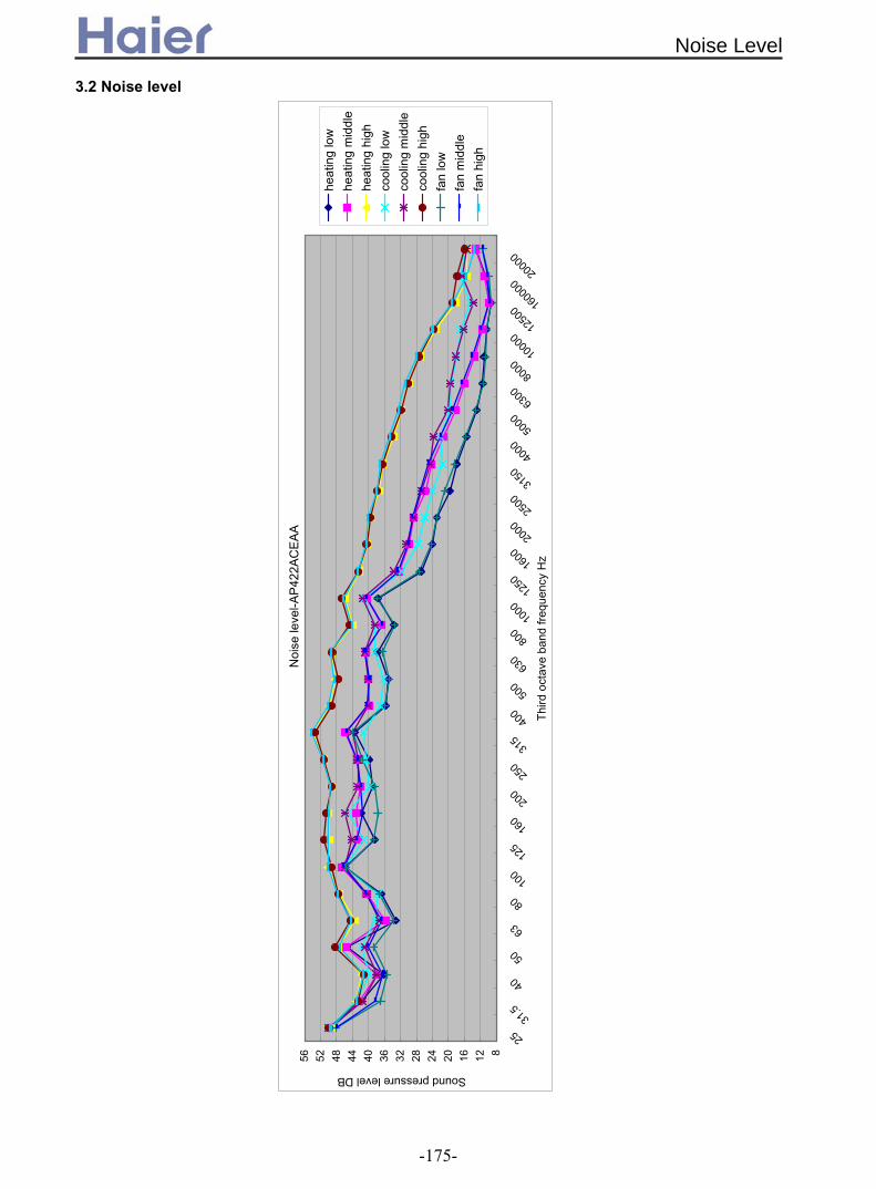
3.2 Noise level
30
Noi
se le
vel-A
P42
2AC
EA
A
8121620242832364044485256
25
31.5
40
50
63
80
100
125
160
200
250
315
400
500
630
800
1000
1250
1600
2000
2500
3150
4000
5000
6300
8000
1000
012
500 16
0000
2000
0
Thi
rd o
ctav
e ba
nd fr
eque
ncy
Hz
Sound pressure level DB
heat
ing
low
heat
ing
mid
dle
heat
ing
high
cool
ing
low
cool
ing
mid
dle
cool
ing
high
fan
low
fan
mid
dle
fan
high
Noise Level
-175-
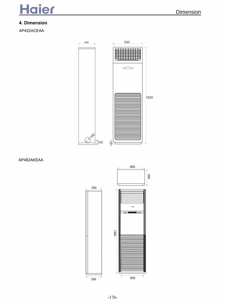
4. Dimension
530
!
"
" # $ %&%
"
"#&
$
' "$
''
350
350
336 500
1851
600
AP422ACEAA
AP482AKEAA
Dimension
-176-

5. Part name
#
* +
, -" # .
/ 01 ) # ! 234 42 " 5
/6110 + "" " # ! #
# # #
'&4 7/ +84 34 4
/611
'&4 7/ +84 34 4/611
AP422ACEAA
)'##%
.!! $(# ! "#$% "#$% &#'"&)#"&/$
"#$%
&#'"&
"$#)'##%
"#$%&/$)#"
)'##%"$#&#'"&
.!! $(# ! )#"
"#$%
&/$
&#'"&
"$#
AP482AKEAA
Part name
-177-
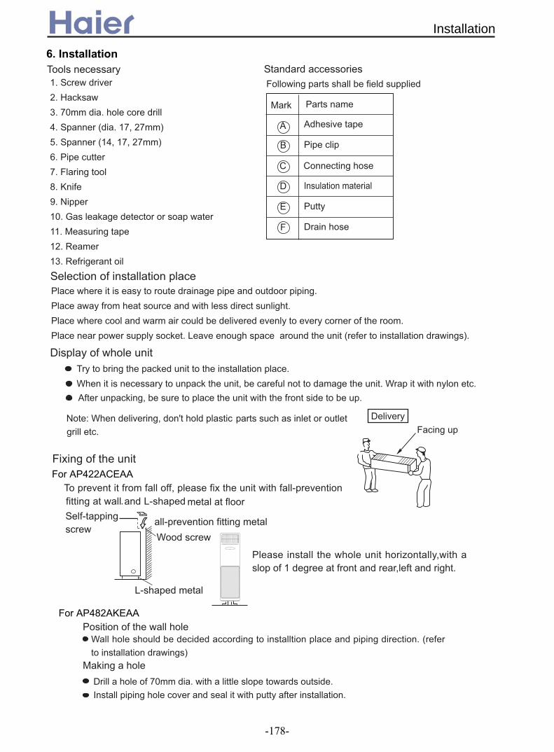
6. Installation " "") % """ %
39"
* :
, % ; :! :<
% ;,! :! :<
' #
: 1
= >
? /
@" 9 "
8"#
*
1 " " "#
89 ' "
"
'
A "
+"#
'# )
B "
A
B
4
1
!
" #
$
%& '
(
% " ' " ") # #
' ) "# "" "#
' # ) )
' "#) "9 # " # # ; " "<
For AP422ACEAA ! " # $ $"
%$ "
$
& "
$"
'" " # ( )! " !
For AP482AKEAA
Installation
-178-

'))* +', )-))* +',
" . #
%&
<. . !+?.$ $ +?
5+$?.!+!. .?6
''
" $
/8
/-
))' '
(2
*
,*(2,
= > ! / ! / ?
$$ $ + $6$=
.$ 6 + $6$=
/
=
!
.
@
2
! /
Installation
-179-
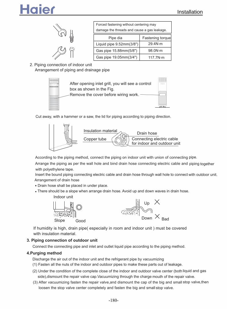
( A
0A BCD"EFGH#
I 2CGG"CFGH#
DBJ
BG&
I 2B&C"EFJH# 22%%
D (
! *
˜ £ ˚ ‰ • ¸¿ “ / „ ˛ ´ ¶ ¨ + ‰ ¡ ¿˛ ´ ¶ ¨ -
.
'
.
.
'
'
+ I
-
@
' " #
. A
:4 1
"D# - " A
# L 1
O4
"2#
"E# 1
Installation
-180-

M4N
N , A
' !( 0 (
/
* ' !( 0 ( *
'
)Q )
'
;<
?:*
*
*
& " ! " " "
',A4
+/B 7/+ 48+/ A>
*=$,C!*/D!3(
E6@E6@
',=>4
7 B 7/+ 48+/ A>
'&4 %7''E
*
/ * %
Installation
-181-
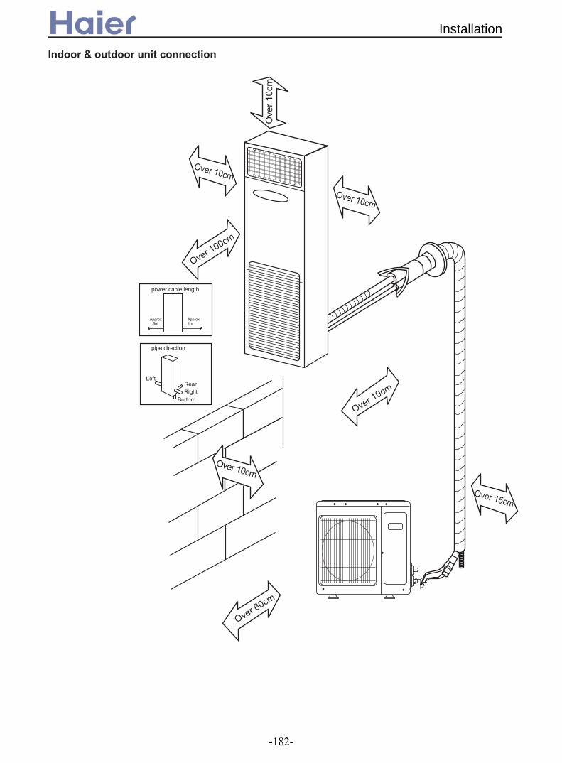
Installation
-182-

Wall mounted indoor unit
Wall mounted type
-183-
1. Features.........................................................................184
2. Specifications.................................................................185
3. Curves............................................................................186
3.1 Performance curves................................................186
3.2 Noise level...............................................................187
4. Dimensions....................................................................188
5. Part Name......................................................................188
6. Installation......................................................................1
(AS18)
89

1. FeaturesNewly designed V- appearance indoor unit
The wall mounted type indoor unit adopts the newly designed V appearance, more fashion, more beautiful. Intelligent control
The new flap changes the delivery angle to horizontal for cooling and vertical for heating operation (Heating: It directs warm air to the floor; Cooling:It directs cool air across the room ), to prevent cold or warm air from blowing directly onto your body. Optional healthy module
Healthy negative ions, lonizer to bring the refreshing air to your room. Enjoy the feeling of a forest at home.
Photic bacteria-killing medium function, it can absorb deleterious gas generated by fitment.
UV ray generator. It can eliminate and prevent bacteria in air effectively. Breathe fresh air to assure health.It is harmless to human body. New designed fan and panel
The unit adopts inisometry cross flow fan, 3D airflow, low noise, feel more comfortable, more healthy. Attractive new appearance design with blue LCD display.It makes stylish air conditioner more
beautiful and distinguished Smart newly designed infrared remote controller
The unit can be controlled by the newly designed infrared remote controller YR-H49, which can realize many functions such as heating, cooling, fan, swing, fresh, health, etc. Furthermore, the remote controller can be fixed on the necessary places with a remote controller holder.
Features
-184-

2. Specifications
Function cooling heatingCapacity kW 5.1(1.8---6.0) 6.0(2.0---7.1)Sensible heat ratio 0.75
WW 2650 2650
EER or COP W/W 3.23 3.64
A / A 7.5(3.0---12.0) 7.8(3.2---12.0)/12
Unit model (color)Type × NumberSpeed(H-M-L) r/minFan motor output power kWAir-flow(H-M-L) m³/h Type / Diameter mmTotal Area m²Temp. scope External (L×W×H)mm×mm×mmPackage (L×W×H)mm×mm×mm
Drainage pipe (material , I.D./O.D.) mmControl type (Remote /wired)
dB(A)kg / kg
Norminal condition: indoor temperature (cooling): 27DB/19WB, indoor temperature (heating): 20DBOutdoor temperature(cooling): 35DB/24WB, outdoor temperature(heating): 7DB/6WBThe noise level will be measured in the third octave band limited values, using a Real Time Analyser calibrated soundintensity meter. It is a sound pressure noise level. The detailed method please refer to the following information:
Installation state: the unit should be placed on the flat floor or be mounted inhorizontal direction.Testing method:mounting-on-wall unit:
0.868
item Model AS182AVERA
Total power inputMax. power input
962*312*365
Indo
or u
nit
AS182AVERA(WHITE)
Fan
cross flow*11250/1150/1050
0.05760/-----
Heat exchanger inner grooved pipe/φ7
Weight (Net / Shipping) 12/15
Running /Max.Running current
PVC 16/12Remote
Noise level (H-M-L) 44/----
2-7
Dimension 870*305*225
0.8m
1m
/12.0
1580(550---2650) 1650(600---2650)
Specifications
-185-

3. Curves
3.1 Performance curves
performance curves in cooling mode
0300600900
1200150018002100240027003000330036003900420045004800510054005700600063006600
12/18 14/20 16/22 18/25 19/27 22/30 24/32
indoor WB/DB
cool
ing
capa
city
(KW
)
20 cooling capacity20 power input25 cooling capacity25 power input32 cooling capacity32 power input35 cooling capacity35 power input40 cooling capacity40 power input-5 cooling capacity-5 power input
performance curves in heating mode
15002000250030003500400045005000550060006500700075008000850090009500
16/10 18/12 20/14.5 21/15 22/16 24/17 26/18
indoor WB/DB
heat
ing
capa
city
(KW
)
-15/-16 heating capacity-15/-16 power input-6/-7 heating capacity-6/-7 power input-4/-5 heating capacity-4/-5 power input-1/-2 heating capacity-1/-2 power input1/0 heating capacity1/0 power input7/6 heating capacity7/6 power input12/10 heating capacity12/10 power input16/15 heating capacity16/15 power input
Performance curves
-186-
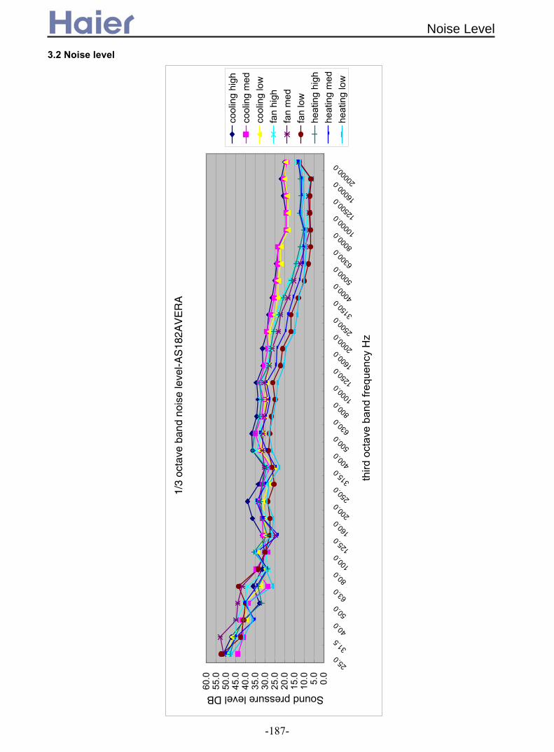
3.2 Noise level
1/3
octa
ve b
and
nois
e le
vel-A
S18
2AV
ER
A
0.0
5.0
10.0
15.0
20.0
25.0
30.0
35.0
40.0
45.0
50.0
55.0
60.0
25.0
31.5
40.0
50.0
63.0
80.0
100.0
125.0
160.0
200.0
250.0
315.0
400.0
500.0
630.0
800.0
1000
.012
50.0
1600
.020
00.0
2500
.031
50.0
4000
.050
00.0
6300
.080
00.0 10
000.0
1250
0.016
000.0
2000
0.0
third
oct
ave
band
freq
uenc
y H
z
Sound pressure level DB
cool
ing
high
cool
ing
med
cool
ing
low
fan
high
fan
med
fan
low
heat
ing
high
heat
ing
med
heat
ing
low
Noise Level
-187-

870
305
225
Front panel
Air inlet grille
Air inlet grille
Louver
Display board
4. Dimension
5. Part name
Dimension&Part name
-188-

Please read these "Safety Precautions" first then accurately execute the installation work.The precautionary points indicated herein are divided under two headings:
WARNING and CAUTION those points which are related to the strong possibility of an installation done in error resulting in death or serious injury are listed in the WARNING section. However, there is also a possibility of serious consequences in relationship to the points listed in the CAUTION section as well.
observe all that is mentioned.After completing the installation, along with confirming that no abnormalities were seenfrom the operation tests, please explain operating methods as well as maintenance methods to the user of this equipment, based on the owner's manual.Moreover, ask the customer to keep this sheet together with the owner's manual.
WARNING
Please entrust installation to either the company which sold you the equipment or to aprofessional contractor. Defects from improper installations can be the cause of water leakageelectric shocks and fires.Execute the installation accurately, based on following the installation manual. Again improperinstallations can result in water leakage, electric shocks and fires.Please install your air conditioner on a wall or any place which can holder the weight of theair conditioner. And it cannot be installed on a non-professional metal structure (such as aburglary-resisting net). Otherwise injury would occur due to a falling of the unit.Execute the prescribed installation construction to prepare for earthquakes and the strong airsof typhoons and hurricanes, etc. Improper installations can result in accidents due to a violentfalling over of the unit.Wiring shall be done with the specified cable and the connection shall be firm and reliable.And the terminal connector shall be fixed firmly and reliably not to let external force exerciseon the cables. Any improper connection or fixing would cause heat, fire, and other accidents.Wiring shall be done in a correct shape not to make any section rise upward, and accuratelyinstall the air conditioner. The cable shall not be clamped by the lid or outer plate. Anyimproper installation would lead to fire, heat, or other accidents.When setting up or moving the location of the air conditioner, do not mix air etc, or anythingother than the designated refrigerant (R407C) within the refrigeration cycle, for such mixingwould result in rupture and injury caused by abnormal high pressure. Always use accessory parts and authorized parts for installation construction. Using parts notauthorized by this company can result in water leakage, electric shock, fire and refrigerantleakage.The drain pipe must not be placed or connected into the sewage tank where harmful gas suchas sulphurous gas and etc would exist, otherwise the harmful gas would enter the room.During installation, if the refrigerant is leaked, please immediately take measures ofventilation, otherwise a harmful gas would be generated whenever the refrigerant meets fire.After installation, please ensure that the refrigerant is not leaked, because the leakage ofrefrigerant would produce a harmful gas if it meets fire or heating stoves.Don't install the air conditioner where a flammable gas would be probably produced,otherwise in case the flammable gas is leaked and exists around the unit, fire would be caused.For the drain pipe, follow the installation manual to insure that it allows proper drainage andthermally insulate it to prevent condensation. Inadequate plumbing can result in waterleakage and water damage to interior items.The refrigerant gas pipe and liquid pipe shall all be thermally insulated to preserve the temperature. Any improper insulation would make the unit moist and the water would droponto the floor or wet the indoor items.
INSTRUCTIONS TO INSTALLATION
6 Installation
In either case, important safety related information is indicated, so by all means, properly
Installation
-189-

PRECAUTION
Execute proper grounding. Do not connect the earth wire to a gas pipe, water pipe, lighteningrod, or a telephone ground wire.Improper placement of earth wires can result in electric shock.An electric leakage breaker must be installed, otherwise electric shock or other accidentswould occur.After completion of the installation, the air conditioner shall be electrified to check forelectric leakage.
Preparation for installation
Installation Tools
1. Screw Driver (slotted head, cross head, triangle)
2. Steel Saw
3. 60mm Drill
4. Inner Hexagon Spanner
5. Shifting Spanner
6. Spanner
7. Pipe Cutter
8. Pipe Expander
9. Knives
10. Clippers
11. Leakage Checker or Soap Liquid
12. Measuring Tape
13. Scraper or File
14. Refrigeration Oil
Self-contained Accessories
Electrical Requirements
Power supply voltage: Single Phase 1PH, 220-230V~, 50Hz.
A specialized power supply wire, which shall be installed by a competent person as per the
rules of the national standard.
Power supply must be grounded effectively.
An electric leakage breaker shall be installed.
Layout of power supply wiring shall be Y connection. If the power supply wire is damaged, it
must be replaced by the manufacturer or its service center or professional person (the power
supply wire shall be self-contained).
For connection of the power supply plug, L shall be connected with the live wire, N shall be
connected with neutral line, shall be connected with earth wire.
Power supply wire parameters:H05RN-F,3 G(1.0-1.5)mm ;
Signal wire parameters:H05RN-F,2 (0.75-1.5)mm . (User shall self-provide signal wire )
Name ofParts
No. A B C D E F
Non-adhesiveTape
Adhesivetape
ConnectingHose
Gypsumpowder
Drain hoseHeatinsulationmaterial
2
2X
INSTRUCTIONS TO INSTALLATION
Note:The signal wire and connection wire should be provided by oneself.
The signal wire must be shielded wire
Installation
-190-

Hose Expander
A
Expansion Size
Hose dia. Size (mm)A
0.8-1.5
1.0-2.0
6.35 mm(1/4)
12.7 mm(1/2)
WARNING
BE SURE TO READ THESE INSTRUCTIONS CAREFULLY BEFORE BEGINNING INSTALLATION. FAILURE TO
FOLLOW THESE INSTRUCTIONS COULD CAUSE SERIOUS INJURY OR DEATH, EQUIPMENT MALFUNCTION
AND/OR PROPERTY DAMAGE.
BE SURE TO READ INSTALLATION MANUAL FOR INDOOR UNIT WITH THIS MANUAL.
1.Accessories
Confirm accessories shown below are attached in the bag with this Installation manual. Accessories Delivered with Your Air Conditioner Please check if your unit is delivered with the following accessories.
x4 25 screw Expansionbushing
Cementsteel nail
Piping holecover
Screw Plastic supportingplate
10987
8 1 2 166
65
Drain hoseMounting plateBatteriesRemotecontroller
1 2 3 4
1121
Name
and
shape
No.
Qty
!
INSTRUCTIONS TO INSTALLATION
Indoor UnitInstall the indoor unit where the weight of the unit can be supported.Install the indoor unit where the heat source and steam source are not close and the unit inletand outlet are not blocked.Install the indoor unit where the drainage is easy and the outdoor unit can be easilyconnected.Install the indoor unit where its cold air and hot air can be easily sent to all the comers of theroom.Install the indoor unit where the power socket is near and there is sufficient space around theindoor unit.Install the indoor unit where there is no T.V set, radio set, and wireless appliance underneath,and the sunlight lamp is over one meter away.If the remote controller is installed on the wall, the indoor unit shall be ensured to receive thesignal while the sunlight lamp is on.
Method for Cutting and Expanding Pipes.When the pipe is too long or the mouth is damaged, the pipe needs to cut or expanded.
1.cutting hose
Correct Not Correct
2.Removing burr 3.Put on nut 4.Expand Hose
cracks on expanded mouth burr incomplete too longTilting
Installation
-191-

When the mounting plate is first fixed
1. Carry out, based on the neighboring pillars or lintels, a proper leveling for the plate to be fixed against the wall, then temporarily fasten the plate with one steel nail.2. Make sure once more the proper level of the plate, by hanging a thread with a weight from the central top of the plate, then fasten securely the plate with the attachment steel nail.
3. Making a Hole on the wall and Fitting the piping Hole cover Make a hole of 60mm in diameter, slightly descending to outside the wall. Install piping hole cover and seal it off with putty after installation.
4. Drawing of pipe Rear piping Draw pipes and the drain hose, then fasten them with the adhesive tape. Left Left-rear, piping In case of left side piping, cut away, with a nipper, the lid for left piping. In case of left-rear piping, bend the pipes according to the piping direction to the mark of hole for left-rear piping which is marked on heat insulation materials.a. Insert the drain hose into the dent of heat insulation materials of indoor unit.b. Insert the indoor/outdoor electric cord from backside of indoor unit, and pull it out on the front side, then connect them.c. Coat the flaring seal face with refrigerant oil and connect pipes. Cover the connection part with heat insulation materials closely, and make sure fixing with adhesive tape.
Indoor/outdoor electric cord and drain hose must be bound with refrigerant piping by protecting tape.
Indoor side Outdoor side
Wall hole Thicknessof wall60mm
(Section of wall hole) Piping hole pipe
Indoor/OutdoorElectric cable
Pipe supportingplate
Heat insulationmaterial
Drain hose
Lid for left pipingLid for right piping
Lid for under piping pipe
Fix with adhesive tape
Piping
INSTALLATION PROCEDURE
Installation
-192-

Other direction piping Cut away, with a nipper, the lid for piping according to the piping direction and then bend the pipe according to the position of wall hole. When bending, be careful not to crash pipes. Connect beforehand the indoor/outdoor electric cable, and then pull out the connected to the heat insulation of connecting part specially.5.Fixing the indoor unit body Hang surely the unit body onto the upper notches of the mounting plate. Move the body from side to verify its secure fixing. In order to fix the body onto the mounting plate, hold up the body aslant from the underside and then put it down perpendicularly. Putty
INSTALLATION PROCEDURE
Insert the cord from the back side of the unit, then pull it out on the front side.Loosen the screws and insert the cord ends fully into terminal block, thentighten the screws.Pull the cord slightly to make sure the cords have been properly inserted andtightened.After the cord connection, never fail to fasten the connected cord with thewiring cover.Note: when connecting the cord, confirm the terminal number of indoor and outdoor units carefully. If wiring is not correct, proper operation can not be carried out and will cause defect.
(1) Cut the wire with a wire cutter or wire-cutting pliers, then strip the insulation to about 25mm of the exposed solid wire.(2) Using a screwdriver, remove the terminal screw (s) on the terminal board.(3) Using pliers, bend the solid wire to form a loop suitable for the terminal screw.(4) Shape the loop wire properly, place it on the terminal board and tighten securely with the terminal screw using a screw driver.
(1) Cut the wire with a wire cutter or wire-cutting pliers, then strip the insulation to about 10mm of the exposed strand wiring.(2) Using a screwdriver, remove the terminal screw (s) on the terminal board.(3) Using a round terminal fastener or pliers, securely clamp a round terminal to each stripped wire end.(4) Position the round terminal wire, and replace and tighten the terminal screw using a screw driver.
ELECTRICAL WIRING
CAUTION!
After connecting the piping, check the joints for gas leakage with gas leakage detector.
When connecting the cord before installing the indoor unit
HOW TO CONNECT WIRING TO THE TERMINALS A. For solid core wiring (or F-cable)(Fig.17A)
B. For strand wiring (Fig.17B)
Fig. 17
A. Solid
Roundterminal
Loop
Insulation
Strip
25m
m
Strip
10m
m
Use VW-1, 0.5 to 1.0 mm thick, PVC tube as the insulation tube.
After passing the connection cord and power cable through theinsulation tube, fasten it with the cord clamp, as shown in Fig.18
B. Strand wire
-29-
Installation
-193-
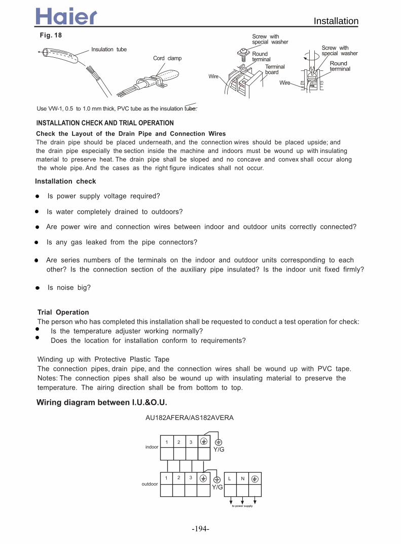
Screw withspecial washer
Screw withspecial washerRound
terminalRoundterminalTerminal
boardWire
Wire
Fig. 18
Use VW-1, 0.5 to 1.0 mm thick, PVC tube as the insulation tube.
Insulation tube
Cord clamp
Check the Layout of the Drain Pipe and Connection Wires
The drain pipe should be placed underneath, and the connection wires should be placed upside; and
the drain pipe especially the section inside the machine and indoors must be wound up with insulating
material to preserve heat. The drain pipe shall be sloped and no concave and convex shall occur along
the whole pipe. And the cases as the right figure indicates shall not occur.
Installation check
Is power supply voltage required?
Is water completely drained to outdoors?
Are power wire and connection wires between indoor and outdoor units correctly connected?
Is any gas leaked from the pipe connectors?
Are series numbers of the terminals on the indoor and outdoor units corresponding to each
other? Is the connection section of the auxiliary pipe insulated? Is the indoor unit fixed firmly?
Is noise big?
The person who has completed this installation shall be requested to conduct a test operation for check:
Is the temperature adjuster working normally?
Does the location for installation conform to requirements?
Winding up with Protective Plastic Tape
The connection pipes, drain pipe, and the connection wires shall be wound up with PVC tape.
Notes: The connection pipes shall also be wound up with insulating material to preserve the
temperature. The airing direction shall be from bottom to top.
Trial Operation
INSTALLATION CHECK AND TRIAL OPERATION
$%%&' (%)')* +& ,-.-/0-.-
!"#
-31-
-181-
AU182AFERA/AS182AVERA
234
234
Installation
-194-

Part 3 Outdoor Units
Outdoor units
1. Features ............................................................................................................. 196
2. Specifications ..................................................................................................... 198
2.1 For DC Inverter unit ................................................................................... 198
2.2 For fixed frequency unit ............................................................................. 202
3. Curves ............................................................................................................... 209
3.1 Performance Curves ........................................................................ ......... 209
3.2 Noise Level ................................................................................................ 214
4. Dimensions ....................................................................................................... 222
5. Part name ......................................................................................................... 226
6. Refrigerant circuit .............................................................................................. 267
7. Installation ........................................................................................................ 230
-195-

Adopt the much friendlier refrigerant R410a The air conditioner system adopts the greatly friendly refrigerant R410a, which is protective for the
ozone layer and is good to avoid the earth getting warmer. Benefit for the environment.
Universal outdoor unit
The outdoor unit has been uniformed which can be connected with different type indoor units with
identical capacity such as cassette type, duct type, convertible type etc.. convenient to design and not affect
the indoor décor. Long distribution pipe and high drop
The unit can realize long distribution pipe and high drop, the detailed information please refer to the
specification, consequently, the installation can be more free, and can meet various need of the customer.
Quiet operation
Adopting optimum designed blower and new designed insulation material amoug the pipe or out of the
compresspr, outdoor unit with well-known brand compressor, reducing the operation noise. For some unit,
the electric control systerm can adjust the noise by fixing the frequency.
Optional safety devices and much more precision control device
a. Ambient temperature sensor, coil temperature sensor and compressor temperature make the
temperature control and defrosting control more precise.
b. High/low pressure switch can feel the discharging pipe pressure and suction pipe pressure on time
and precisely. If the pressure is too high or too low, it will stop the compressor to prevent it being damaged
for the sake of pressure.
c. Low ambient cooling kit: It is an optional part for the system.
If you want to realize cooling mode when the exterior ambient temperature
is too low, you can choose it.
d. CT protection: for the inverter unit, there is CT protection. If the system current is too high, the
electric system will reduce the frequency or stop the unit automatically.
e. 3 minutes delay protection for the compressor. The device can protect the compressor from some
damages and make the compressor have a long life.
1. Features
FSF-42Swith EMC filter
50M 30M
3min
Features
-196-

Advanced PWM Control
New compressor (for inverter unit) The Reluctance DC motor of compressor utilise powerful neodymium magnets that are 10 times more
powerful than conventional magnets. Twin mechanism and DC inverter control have achieved low vibration and low noise drastically
Auto checking malfunction
Without PAM Control With PAM Control
Supply VoltageCurrent
Time Time
PWM adjust the form of the current wave so that it becomes close to that of the supply voltage wave. High harmonice are reduced and 99% of the electricity is utilized
Failure codes displayed by LED or controllers are so detailed for us to find the fail place more quickly, and can judge the failure content easily
Features
-197-

2. Specifications2.1 For DC inverter unit
Power cablePower source N, V, HzStart Current A
Unit model (color)Model / ManufactureTypeType × NumberSpeed r/minFan motor output power kWAir-flow(H-M-L) m³/hType / Diameter mmTotal area m²Temp. scope External (L×W×H)mm×mm×mm
Package (L×W×H)mm×mm×mm
Refrigerant control method mm/mm
Noise level dB(A)
material of reduce noise crankcase heater power W
kg / kgType / Charge gRecharge quantity g/mLiquid mmGas mm
Connecting Methodmm
Power cablePower source N, V, HzStart Current A 3A 3ACircuit breaker A 25A 25A
Unit model (color)Model / ManufactureOil modelOil chargingTypeType × NumberSpeed r/minFan motor output power kWAir-flow(H-M-L) m³/hType / Diameter mmRow / Fin pitchTemp. scope External (L×W×H)mm×mm×mm
Package (L×W×H)mm×mm×mm
Refrigerant control method mm/mm
Volume of Accumulator LNoise level dB(A)
crankcase heater power Wkg / kg
Type / Charge gRecharge quantity g/mLiquid mmGas mm
Connecting Methodmm
Item Model AU122AEERA3×2.5
1, 220-230, 503
Out
door
uni
t
AU122AEERA(WHITE)
Compressor C-6RZ092H1Atwin rotary
Fan
axial*1840r/min±50
0.062500/-/-
Heat exchangerTP2M/Φ9.52
0.37443-60
Dimension 775x640x245901x341x712
Capillary tube: main φ3×φ1.8×920, assistant φ3×φ1.8×780Defrosting auto
55Type of Four way valve SHF-4-10A
XPE37
Weight(Net / Shipping) 39/43
PIP
ING
Refrigerant R410A 130030
Pipe 6.3512.7
flared
Between I.D &O.D MAX.DropMAX.Piping length 20
15MAX.Piping length
10
0.082500
PIP
ING
Refrigerant R410A/185035
Pipe 6.3512.7
flared
Between I.D &O.D MAX.Drop
Type of Four way valve STF-0218G30
Weight (Net / Shipping) 52/55
Dimension 810*288*680960*405*760
main capillary φ1.6*400mm, sub capillary φ1.6*200mmDefrosting AUTO
2.556
Heat exchangerhydrophilic finned Aluminum foil /φ7
3/1.5543-60
Out
door
uni
t
WHITE
Compressor
TNB175FLBM1/MITSUBISHI ELECTRICMEL56670ML
scroll type
Fan
axial×1860±30
item Mod AU182AFERA3G 4.0mm2
1, 220--230, 50
30
Specifications
-198-

Power cablePower source N, V, HzStart Current A 3 3
Unit model (color)Model / ManufactureOil model MEL56Oil charging 670MLTypeType × NumberSpeed r/minFan motor output power kWAir-flow(H-M-L) m³/hType / Diameter mmRow / Fin pitchTemp. scope External (L×W×H)mm×mm×mm
Package (L×W×H)mm×mm×mm
Refrigerant control method mm/mm
Volume of Accumulator LNoise level dB(A)
crankcase heater power Wkg / kg
Type / Charge gRecharge quantity g/mLiquid mmGas mm
Connecting Methodmm
Power cablePower source N, V, HzStart Current A
Unit model (color)Model / ManufactureTypeType × NumberSpeed r/minFan motor output power kWAir-flow(H-M-L) m³/hType / Diameter mmTotal area m²Temp. scope External (L×W×H)mm×mm×mm
Package (L×W×H)mm×mm×mm
Refrigerant control method mm/mm
Volume of Accumulator LNoise level dB(A)crankcase heater power W
kg / kgType / Charge gRecharge quantity g/mLiquid mmGas mm
Connecting Methodmm
flared
Between I.D &O.D MAX.Drop 20MAX.Piping length 30
37Weight(Net / Shipping) 74/80
PIP
ING
Refrigerant R410A 265065
Pipe 9.5215.88
Defrosting auto3.560
Dimension 948*340*8401050*410*990
2.2mm EEV
4000/-/-
Heat exchangerTP2M/Φ7
0.77643-60
3
Out
door
uni
t
AU282AHERA(WHITE)
Compressor TNB220FLBM/(MITSUBISHI)Rotary
Fan
axial*1950r/min±50
0.06
Item Mode AU282AHERA3*4.0
1, 220-230, 50
2.4mm EEV
3000
1PH,220-230VAC,50HZH05RN-F 3G 4.0mm2
865*335*732995*420*815
AUTO
37
356
910±300.06
Heat exchangerhlydrophilic Al foil slit fin / φ7
3/1.4643-60
Type of Four way valve SHF-4-10A
Dimension
Out
door
uni
t
WHITE
Compressor
TNB175FLBM1(MITSUBISHI)
Rotary
Fan
axial×1
Defrosting
item Mod AU242AGERA
30
Weight (Net / Shipping) 57/60.5
9.5215.88
PIP
ING
Refrigerant R410A/230050
Pipe
Flare cnnection
Between I.D &O.D MAX.Drop 15MAX.Piping length
Specifications
-199-
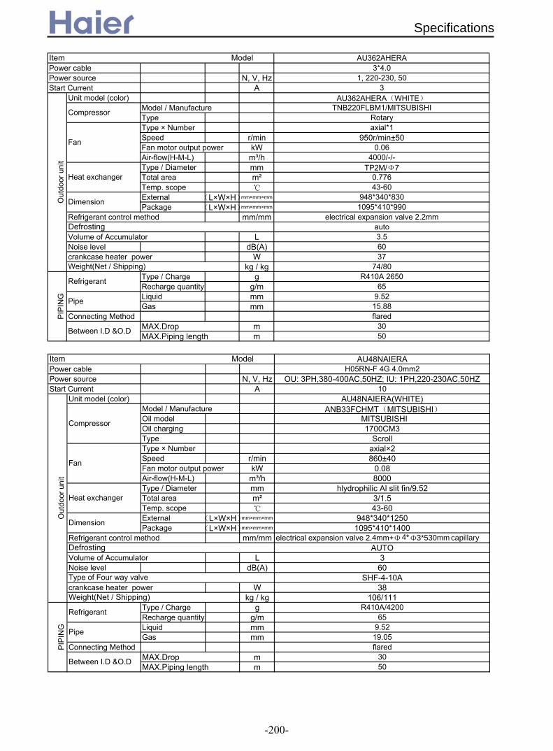
Power cablePower source N, V, HzStart Current A
Unit model (color)Model / ManufactureTypeType × NumberSpeed r/minFan motor output power kWAir-flow(H-M-L) m³/hType / Diameter mmTotal area m²Temp. scope External (L×W×H)mm×mm×mm
Package (L×W×H)mm×mm×mm
Refrigerant control method mm/mm
Volume of Accumulator LNoise level dB(A)crankcase heater power W
kg / kgType / Charge gRecharge quantity g/mLiquid mmGas mm
Connecting Methodmm
Item Model AU362AHERA3*4.0
1, 220-230, 503
Out
door
uni
t
AU362AHERA(WHITE)
Compressor TNB220FLBM1/MITSUBISHIRotary
Fan
axial*1950r/min±50
0.064000/-/-
Heat exchangerTP2M/Φ7
0.77643-60
Dimension 948*340*8301095*410*990
electrical expansion valve 2.2mmDefrosting auto
3.56037
Weight(Net / Shipping) 74/80
PIP
ING
Refrigerant R410A 265065
Pipe 9.5215.88flared
Between I.D &O.D MAX.Drop 30MAX.Piping length 50
Power cablePower source N, V, HzStart Current A
Unit model (color)Model / ManufactureOil modelOil chargingTypeType × NumberSpeed r/minFan motor output power kWAir-flow(H-M-L) m³/hType / Diameter mmTotal area m²Temp. scope External (L×W×H)mm×mm×mm
Package (L×W×H)mm×mm×mm
Refrigerant control method mm/mm
Volume of Accumulator LNoise level dB(A)
crankcase heater power Wkg / kg
Type / Charge gRecharge quantity g/mLiquid mmGas mm
Connecting Methodmm
Item Model AU48NAIERAH05RN-F 4G 4.0mm2
OU: 3PH,380-400AC,50HZ; IU: 1PH,220-230AC,50HZ10
Out
door
uni
t
ANB33FCHMT(MITSUBISHI)
Compressor
Scroll
Fan
axial×2860±40
0.088000
Heat exchangerhlydrophilic Al slit fin/9.52
3/1.543-60
Dimension 948*340*12501095*410*1400
Weight(Net / Shipping) 106/111
30MAX.Piping length
PIP
ING
Refrigerant R410A/420065
Pipe 9.5219.05flared
Between I.D &O.D MAX.Drop50
AU48NAIERA(WHITE)
MITSUBISHI1700CM3
electrical expansion valve 2.4mm+Defrosting AUTO
360
Type of Four way valve SHF-4-10A
Φ4*Φ3*530mm capillary
38
Specifications
-200-
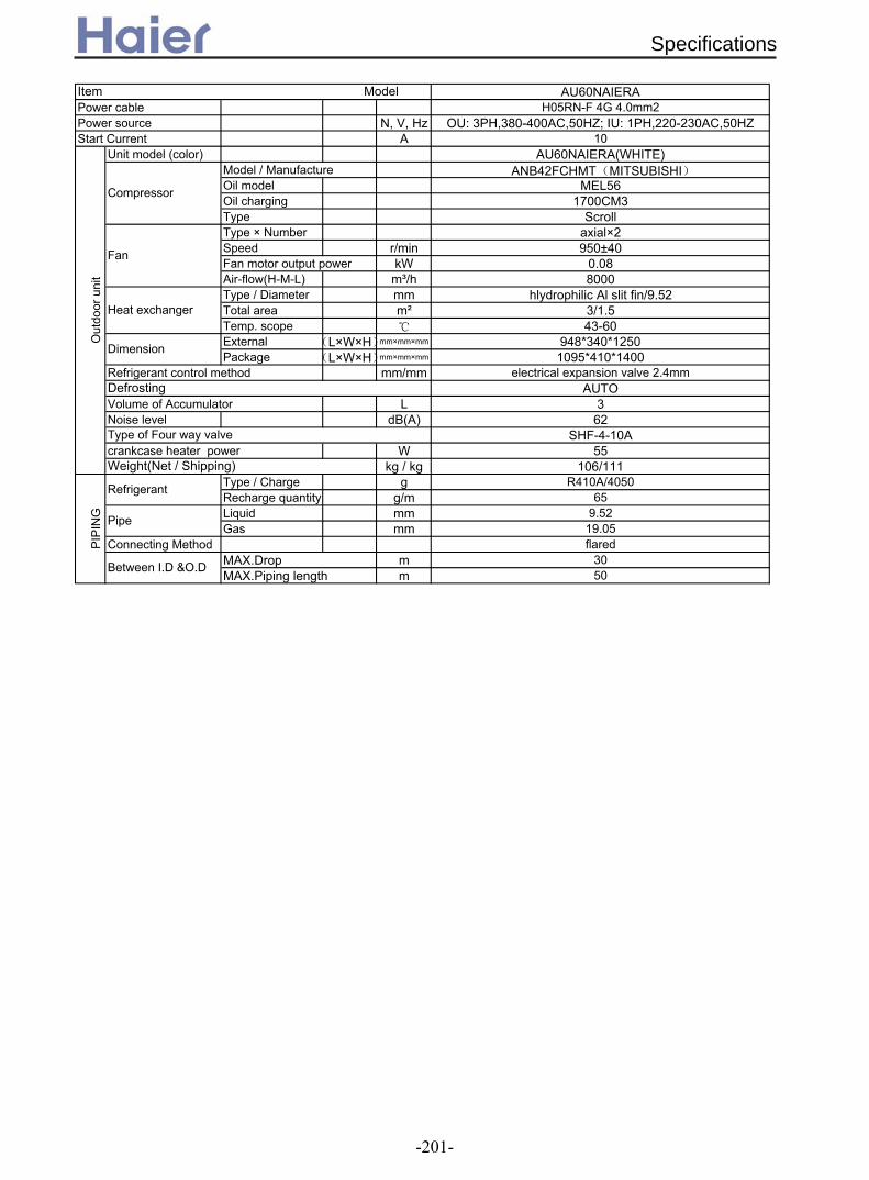
Power cablePower source N, V, HzStart Current A
Unit model (color)Model / ManufactureOil modelOil chargingTypeType × NumberSpeed r/minFan motor output power kWAir-flow(H-M-L) m³/hType / Diameter mmTotal area m²Temp. scope External (L×W×H)mm×mm×mm
Package (L×W×H)mm×mm×mm
Refrigerant control method mm/mm
Volume of Accumulator LNoise level dB(A)
crankcase heater power Wkg / kg
Type / Charge gRecharge quantity g/mLiquid mmGas mm
Connecting Methodmm
1700CM3
Item Model
OU: 3PH,380-400AC,50HZ; IU: 1PH,220-230AC,50HZH05RN-F 4G 4.0mm2
10
AU60NAIERAO
utdo
or u
nit
ANB42FCHMT(MITSUBISHI)
Compressor
Scroll
Fan
axial×2950±40
0.08
MEL56
Heat exchanger
PIP
ING
Refrigerant R410A/405065
Pipe 9.5219.05
Between I.D &O.D MAX.DropMAX.Piping length
62
Weight(Net / Shipping)
SHF-4-10A
50
Type of Four way valve55
106/111
30
AU60NAIERA(WHITE)
electrical expansion valve 2.4mm
3
948*340*12501095*410*1400
8000
AUTO
hlydrophilic Al slit fin/9.523/1.5
flared
Defrosting
Dimension
43-60
Specifications
-201-

2.2 For fixed frequency unit
Function cooling heatingPower cablePower source N, V, HzStart Current A
Unit model (color)Model / ManufactureTypeType × NumberSpeed r/minFan motor output power kWAir-flow(H-M-L) m³/hType / Diameter mmTotal area m²Temp. scope External (L×W×H) mm×mm×mm
Package (L×W×H) mm×mm×mm
Refrigerant control method mm/mm
Noise level dB(A)
material of reduce noise crankcase heater power W
kg / kgType / Charge gRecharge quantity g/mLiquid mmGas mm
Connecting Methodmm
Function cooling heatingDehumidifying capacity 10‐³×m³/hSignal cable section 3 2.5Connecting cable section 4 0.75Power source N, V, Hz
Unit model (color)Model / ManufactureTypeType × NumberSpeed r/minFan motor output power kWAir-flow(H-M-L) m³/hType / Diameter mmTemp. scope External (L×W×H) mm×mm×mm
Package (L×W×H) mm×mm×mm
Refrigerant control method mm/mm
Noise level dB(A)material of reduce noise
kg / kgType / Charge gRecharge quantity g/mLiquid mmGas mm
Connecting Methodmm
item Model AU182AEEAA
1.8
1 PH 220-230 V 50 Hz
Out
door
uni
t
AU182AEEAA (WHITE)
Between I.D &O.D MAX.DropMAX.Piping length 15
Weight(Net / Shipping) 39/43
PIP
ING
Refrigerant R410A 130020
Pipe 6.359.52flared
Defrosting auto55
XPE
Heat exchangerTP2M/Φ9.52
43-60
Dimension 780x640x245901x341x712
CompressorPA200X2CS-4KU1/Toshiba
Rotary
Fan
Axial X 1860±40
352300
Heat exchangerTP2M/7X0.5
43-60
Dimension780x640x245
901x341x712Capillary tube
Defrosting controlled by coil temp.
/Rotary
Fan
axial*1840r/min±50
0.062500/-/-
56XPE
Weight (Net / Shipping) 42/45
PIP
ING
RefrigerantR410A/1500
20
Pipe6.3512.7
flared
Between I.D &O.D MAX.Drop 10MAX.Piping length 20
item Model AU122AEEAA
3×2.5
20
Out
door
uni
t
AU122AEEAA(WHITE)
Compressor
Type of Four way valve SHF-4-10A
37
1, 220-230, 50
0.374
Capillary tube
5
Specifications
-202-

Power cablePower source N, V, Hz
Unit model (color)Model / ManufactureOil model VG74Oil charging 950MLTypeType × NumberSpeed r/minFan motor output power kWAir-flow(H-M-L) m³/hType / Diameter mmRow / Fin pitchTemp. scope External (L×W×H) mm×mm×mm
Package (L×W×H) mm×mm×mm
RefrigEAAnt control method mm/mm
Volume of Accumulator LNoise level dB(A)
crankcase heater power Wkg / kg
Type / Charge gRecharge quantity g/mLiquid mmGas mm
Connecting Methodmm
colorPower cablePower source N, V, Hz
Model / ManufactureOil model FV50SOil charging 1300CC.TypeType × NumberSpeed r/minFan motor output power kWAir-flow(H-M-L) m³/hType / Diameter mmRow / Fin pitchTemp. scope External (L×W×H) mm×mm×mm
Package (L×W×H) mm×mm×mm
RefrigEAAnt control method mm/mm
Volume of Accumulator LNoise level dB(A)
crankcase heater power Wkg / kg
Type / Charge gRecharge quantity g/mLiquid mmGas mm
Connecting Methodmm
H05RN-F 3G 4.0mm21PH,220-230VAC,50HZ
item Model AU242AGEAAO
utdo
or u
nit
WHITE
Compressor
PA290X3CS-4MU1(TOSHIBA)
Rotary
Fan
axial×11000±50
0.063000
Heat exchangerhlydrophilic foil slit fin/φ7
3/1.4643-60
Dimension 865*335*732995*420*815
Φ1.8*300 capillaryDefrosting AUTO
357
Type of Four way valve SHF-4-10A37
Weight (Net / Shipping) 57/60.5
Between I.D &O.D MAX.Drop 15/10MAX.Piping length 30
item Model AU282AHEAA
PIP
ING
RefrigEAAnt R410A/210050
Pipe 9.5215.88flare
WHITEH05RN-F 3G 4.0mm2
1PH,220-230VAC,50HZ
Out
door
uni
t
Compressor
NN33VAAMT(MITSUBISHI)
Rotary
Fan
axial×1920±50
0.064000
Heat exchangerhlydrophilic foil slit fin/φ7.94
2/1.743-60
Dimension 948*340*8401095*410*990
CapillaryDefrosting Automatic
3.558
Type of Four way valve SHF-4-10A40
Weight (Net / Shipping) 74/89
Between I.D &O.D MAX.Drop 15/10MAX.Piping length 30
PIP
ING
RefrigEAAnt R410A/245050
Pipe 9.5215.88
Flare cnnection
Specifications
-203-

Power cablePower source N, V, HzStart Current A 33A/36A 33A/36A
Unit model (color)Model / ManufactureOil model FV50SOil charging 1300CC.TypeType × NumberSpeed r/minFan motor output power kWAir-flow(H-M-L) m³/hType / Diameter mmRow / Fin pitchTemp. scope External (L×W×H) mm×mm×mm
Package (L×W×H) mm×mm×mm
Refrigerant control method mm/mm
Volume of Accumulator LNoise level dB(A)
crankcase heater power Wkg / kg
Type / Charge gRecharge quantity g/mLiquid mmGas mm
Connecting Methodmm
Power cable sectionSignal cable sectionConnecting cable sectionPower source N, V, Hz
Oil modelOil typeOil chargingTypeProtection typeStarting methodType × NumberSpeed r/minFan motor output power kWAir-flow(H-M-L) m³/hType / Diameter mmRow / Fin pitchTemp. scope External (L×W×H) mm×mm×mm
Package (L×W×H) mm×mm×mm
Refrigerant control method mm/mm
Noise level dB(A)crankcase heater power W
kg / kgType / Charge gRecharge quantity g/mLiquid mmGas mm
Connecting Methodmm
Unit model (color)
item Model AU28NAHEAAH05RN-F 3G 4.0mm2
3PH,380-400VAC,50HZO
utdo
or u
nit
AU28NAHEAA(WHITE)
Compressor
NN33YCAMT(MITSUBISHI)
Rotary
Fan
axial×1920±50
0.064000
Heat exchangerhlydrophilic foil slit fin/φ7.94
2/1.743-60
Dimension 948*340*8401095*410*990
Capillary
Weight (Net / Shipping) 74/89
Defrosting Automatic3.558
PIP
ING
Refrigerant R410A/245050
Pipe 9.5215.88
Flare connection
Between I.D &O.D MAX.Drop
DAPHNEFVC68D
hard startup
Fan 740
item Model AU362ALEAA5G×2.5mm2
Axial*1
0.15*15500
Heat exchangerinner grooved/φ9.52
2/1.643-60
Dimension 1008×447×8301130×490×930Capillary tube
37Weight (Net / Shipping) 90/101
Defrosting Automatic59
Between I.D &O.D MAX.Drop 30MAX.Piping length 50
PIP
ING
Refrigerant R410A/300054
Pipe φ9.52φ19.05Flared
4G×0.75mm2
15/10MAX.Piping length 30
Type of Four way valve SHF-4-10A40
OUTDOOR UNIT:1PH,220-230AC,50HZ,AU362ALEAA(WHITE)
1500LSCROLL
Inner thermal protection
Specifications
-204-
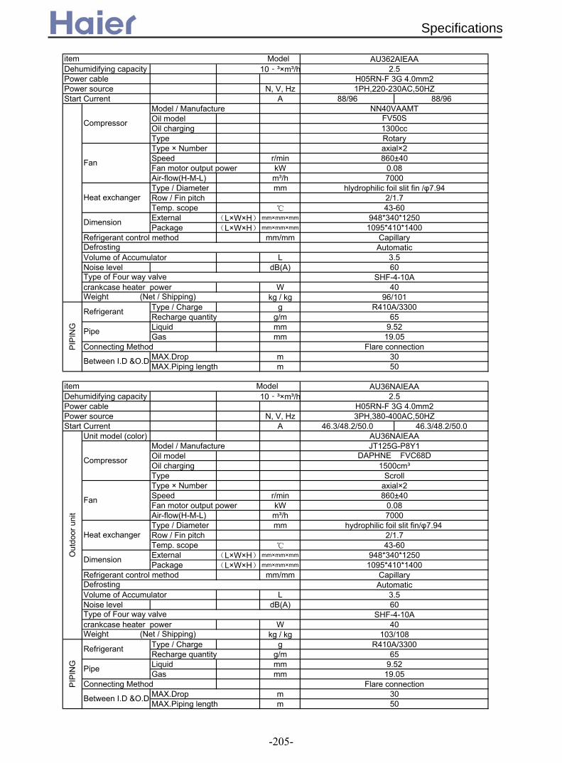
Dehumidifying capacity 10‐³×m³/hPower cablePower source N, V, HzStart Current A 88/96 88/96
Model / ManufactureOil modelOil chargingTypeType × NumberSpeed r/minFan motor output power kWAir-flow(H-M-L) m³/hType / Diameter mmRow / Fin pitchTemp. scope External (L×W×H) mm×mm×mm
Package (L×W×H) mm×mm×mm
Refrigerant control method mm/mm
Volume of Accumulator LNoise level dB(A)
crankcase heater power Wkg / kg
Type / Charge gRecharge quantity g/mLiquid mmGas mm
Connecting Methodmm
Dehumidifying capacity 10‐³×m³/hPower cablePower source N, V, HzStart Current A 46.3/48.2/50.0 46.3/48.2/50.0
Unit model (color)Model / ManufactureOil modelOil chargingTypeType × NumberSpeed r/minFan motor output power kWAir-flow(H-M-L) m³/hType / Diameter mmRow / Fin pitchTemp. scope External (L×W×H) mm×mm×mm
Package (L×W×H) mm×mm×mm
Refrigerant control method mm/mm
Volume of Accumulator LNoise level dB(A)
crankcase heater power Wkg / kg
Type / Charge gRecharge quantity g/mLiquid mmGas mm
Connecting Methodmm
2.5H05RN-F 3G 4.0mm21PH,220-230AC,50HZ
Compressor
NN40VAAMT
item Model AU362AIEAA
FV50S1300ccRotary
Fan
axial×2860±40
0.087000
Heat exchangerhlydrophilic foil slit fin /φ7.94
2/1.743-60
Dimension 948*340*12501095*410*1400
Capillary
R410A/330065
Defrosting Automatic3.560
Type of Four way valve SHF-4-10A40
Weight (Net / Shipping) 96/101
Pipe 9.5219.05
30Flare connection
Between I.D &O.D MAX.DropMAX.Piping length 50
PIP
ING
Refrigerant
item Model AU36NAIEAA2.5
H05RN-F 3G 4.0mm23PH,380-400AC,50HZ
Out
door
uni
t
AU36NAIEAA
Compressor
JT125G-P8Y1DAPHNE FVC68D
1500cm³Scroll
Fan
axial×2860±40
0.087000
Heat exchangerhydrophilic foil slit fin/φ7.94
2/1.743-60
Dimension 948*340*12501095*410*1400
CapillaryDefrosting Automatic
3.560
Type of Four way valve SHF-4-10A40
Weight (Net / Shipping) 103/108
Between I.D &O.D MAX.Drop 30MAX.Piping length 50
PIP
ING
Refrigerant R410A/330065
Pipe 9.5219.05
Flare connection
Specifications
-205-

Function cooling heatingPower cable sectionSignal cable sectionConnecting cable sectionPower source N, V, Hz
Unit model (color)Model / ManufactureOil modelOil typeOil chargingTypeProtection typeStarting methodType × NumberSpeed r/minFan motor output power kWAir-flow(H-M-L) m³/hType / Diameter mmRow / Fin pitchTemp. scope External (L×W×H) mm×mm×mm
Package (L×W×H) mm×mm×mm
Refrigerant control method mm/mm
Noise level dB(A)crankcase heater power W
kg / kgType / Charge gRecharge quantity g/mLiquid mmGas mm
Connecting Methodmm
Power cablePower source N, V, Hz
Unit model (color)Model / ManufactureOil modelOil typeOil chargingTypeProtection typeStarting methodType × NumberSpeed r/minFan motor output power kWAir-flow(H-M-L) m³/hType / Diameter mmRow / Fin pitchTemp. scope External (L×W×H) mm×mm×mm
Package (L×W×H) mm×mm×mm
Refrigerant control method mm/mm
Volume of Accumulator LNoise level dB(A)
crankcase heater power Wkg / kg
Type / Charge gRecharge quantity g/mLiquid mmGas mm
Connecting Methodmm
item Model AU42NALEAA
5G×2.5mm2
Between I.D &O.D MAX.Drop 30MAX.Piping length 50
4G×0.75mm2
OUTDOOR UNIT:3N, 380-400V, 50HZ INDOOR
Type of Four way valve SHF-4-10A
PIP
ING
Refrigerant R410A/370065
Pipe 9.5219.05flare
55Weight (Net / Shipping) 106/111
Defrosting AUTO3
60
Dimension 948*340*12501095*410*1400
capillary 2.4*150
Heat exchangerhlydrophilic foil slit fin/9.52
3/1.5543-60
Fan
axial×2860±40
0.087000
Fan
Axial*1740
0.15*15500
Heat exchangerinner grooved/φ9.52
2/1.643-60
Dimension 1008×447×8301140×500×955
Out
door
uni
t
WHITEJT160G-P8Y1(R410A) /DAKIN
DAPHNEFVC68D1500L
SCROLL
Capillary tubeDefrosting Automatic
OU:380-400V,3N,50HZ IU:1PH,220-230V,50HZ
59
item Model AU48NAIEAAH07RN-F 5G 4.0mm2
Out
door
uni
t
AU42NALEAA(WHITE)
Compressor
JT160G-P8Y1(R410A) /DAKINDAPHNEFVC68D1500L
SCROLLInner thermal protection
hard startup
37Weight (Net / Shipping) 91/102
PIP
ING
Refrigerant R410A/310065
Pipe φ9.52φ19.05
Compressor
Inner thermal protectionhard startup
Flared
Between I.D &O.D MAX.Drop 30MAX.Piping length 50
Specifications
-206-

Power source N, V, HzUnit model (color)
Model / ManufactureOil model DAPHNEOil type FVC68DOil charging 1500CM3TypeType × NumberSpeed r/minFan motor output power kWAir-flow(H-M-L) m³/hType / Diameter mmRow / Fin pitchTemp. scope External (L×W×H) mm×mm×mm
Package (L×W×H) mm×mm×mm
Refrigerant control method mm/mm
Volume of Accumulator LNoise level dB(A)
crankcase heater power Wkg / kg
Type / Charge gRecharge quantity g/mLiquid mmGas mm
Connecting Methodmm
Power source N, V, Hz
Unit model (color)Model / ManufactureOil modelOil typeOil chargingTypeType × NumberSpeed r/minFan motor output power kWAir-flow(H-M-L) m³/hType / Diameter mmRow / Fin pitchTemp. scope External (L×W×H) mm×mm×mm
Package (L×W×H) mm×mm×mm
Refrigerant control method mm/mm
Volume of Accumulator LNoise level dB(A)crankcase heater power W
kg / kgType / Charge gRecharge quantity g/mLiquid mmGas mm
Connecting Methodmm
item Model AU60NAIEAAPower cable H07RN-F 5G 4.0mm2connectting cable H05RN-F 4G 0.75mm2
OU: 380-400V, 3N, 50HZ IU:1PH, 220-230V, 50HZ
Out
door
uni
t
WHITE
Compressor
JT170G-P8Y1(DAIKIN)
Scroll
Fan
axial×2
Dimension 948*340*12501095*410*1400
860±400.087000
Heat exchangerhlydrophilic foil slit fin/9.52
3/1.543-60
capillary Φ2.4*150Defrosting AUTO
360
Type of Four way valve SHF-4-10A55
Weight (Net / Shipping) 106/111
PIP
ING
Refrigerant R410A/405065
Pipe 9.5219.05flare
3050
Between I.D &O.D MAX.Drop 30MAX.Piping length 50
Out
door
uni
t
AU72NATEAA(WHITE)
Compressor
JT125G-P8Y1 / DAIKINDAPHNEFVC68D1500CM3
Scroll
Fan
axial×1850±50/720±50
0.610000/-/6000
Heat exchangerTP2M/9.52
1.843-60
60
Dimension 990*760*17001155*925*1870
capillary
Between I.D &O.D MAX.DropMAX.Piping length
34*2Weight (Net / Shipping) 161
Refrigerant R410A/3700*265
Pipe
item Model AU72NATEAAOU: 3PH,380-400AC,50HZ; IU: 1PH,220-
230AC,50HZ
flaredPIP
ING 9.52
19.05
Defrosting AUTO8
Specifications
-207-

Note: ⊙ is the real timeanalyser position
outdoor unit:1.air outlet from side: the noise level is the average sound pressure level measured from front, left, right directions.2.air outlet from top: the noise level is the average sound pressure level measured from front, back, left, rightdirections.measured point:H ( height to the ground) = (h (unit height) + 1m) /2and, it is 1m to each side.
Norminal condition: indoor temperature (cooling): 27DB/19WB, indoor temperature (heating): 20DBOutdoor temperature(cooling): 35DB/24WB, outdoor temperature(heating): 7DB/6WBThe noise level will be measured in the third octave band limited values, using a Real Time Analyser calibrated sound intensitymeter. It is a sound pressure noise level. The detailed method please refer to the following information:
Installation state: the unit should be placed on the flat floor or be mounted in horizontaldirection.Testing method:
h
1m1m
1m1m
Specifications
-208-

3. Curves3.1 Performance curves
Heating capacity curves
30003500400045005000550060006500700075008000
16/10 18/12 20/14.5 22/16 24/17 26/18
indoor DB/WB
Heat
ing ca
pacit
y (W
)
-7-5071015
Power input curves in heating mode
2.5
3.0
3.5
4.0
4.5
16/10 18/12 20/14.5 22/16 24/17 26/18indoor DB/WB
COP
-7-5071015
Cooling capacity curves
4000
4500
5000
5500
6000
6500
7000
20/14 22/16 25/18 27/19 30/22 32/24
indoor DB/WB
Cooli
ng ca
pacit
y (W
)
-5515253543
Power input curves in cooling mode
1.00
2.00
3.00
4.00
5.00
20/14 22/16 25/18 27/19 30/22 32/24
indoor DB/WB
EER)
-5515253543
AU182AEEAA
Performance Curves
-209-

Heating capacity curves
4000
5000
6000
7000
8000
9000
10000
16/10 18/12 20/14.5 21/15 22/16 24/17 26/18
indoor DB/WB
Heati
ng ca
pacit
y (W
)
-6/-7-4/-5-1/-21/06/57/612/1016/15
24
Power input curves in heating mode
1700
1900
2100
2300
2500
2700
2900
16/10 18/12 20/14.5 21/15 22/16 24/17 26/18indoor DB/WB
Powe
r inpu
t (W
)
-6/-7-4/-5-1/-21/06/57/612/1016/15
Cooling capacity curves
3000
4000
5000
6000
7000
8000
9000
10000
18/12 20/14 22/16 25/18 27/19 30/22 32/24
indoor DB/WB
Coolin
g cap
acity
(W)
-52025323540
Power input curves in cooling mode
0
500
1000
1500
2000
2500
3000
3500
18/12 20/14 22/16 25/18 27/19 30/22 32/24
indoor DB/WB
Powe
r inpu
t (W) -5
2025323540
AU242AGEAA
Performance Curves
-210-

Heating capacity curves
4000
5000
6000
7000
8000
9000
10000
11000
12000
16/10 18/12 20/14.5 21/15 22/16 24/17 26/18
indoor DB/WB
Hea
ting
capa
city
(W)
-6/-7-4/-5-1/-21/06/57/612/1016/15
53
Power input curves in heating mode
1700
1900
2100
2300
2500
2700
2900
3100
3300
3500
3700
16/10 18/12 20/14.5 21/15 22/16 24/17 26/18
indoor DB/WB
Pow
er in
put (
W)
-6/-7-4/-5-1/-21/06/57/612/1016/15
Cooling capacity curves
3000
4000
5000
6000
7000
8000
9000
10000
18/12 20/14 22/16 25/18 27/19 30/22 32/24
indoor DB/WB
Coo
ling
capa
city
(W)
-52025323540
Power input curves in cooling mode
0
500
1000
1500
2000
2500
3000
3500
18/12 20/14 22/16 25/18 27/19 30/22 32/24
indoor DB/WB
Pow
er in
put (
W) -5
2025323540
AU282AHEAA
Performance Curves
-211-

AU362AIEAA
Heating capacity curves
8000850090009500
10000105001100011500120001250013000
16/10 18/12 20/14.5 21/15 22/16 24/17 26/18
indoor DB/WB
Hea
ting
capa
city
(W)
-6/-7-4/-5-1/-21/06/57/612/1016/15
Cooling capacity curves
8000
9000
10000
11000
12000
13000
18/12 20/14 22/16 25/18 27/19 30/22 32/24
indoor DB/WB
Coo
ling
capa
city
(W)
-52025323540
Performance Curves
-212-

100001050011000115001200012500130001350014000145001500015500
16/10 18/12 20/14.5 21/15 22/16 24/17 26/18
-6/-7-4/-5-1/-21/06/57/612/1016/15
4400
4600
4800
5000
5200
5400
5600
5800
-6/-7 -4/-5 -1/-2 1/0 6/5 7/6 12/10 16/15
16/1018/1220/14.521/1522/1624/1726/18
Heating capacity curves
Cooling capacity curves
11500117501200012250125001275013000132501350013750
18/12 20/14 22/16 25/18 27/19 30/22 32/24
-52025323540
4300440045004600470048004900500051005200
18/12 20/14 22/16 25/18 27/19 30/22 32/24
-52025323540
AU42NALEAA
Performance Curves
-213-
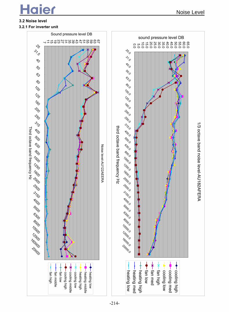
Noise level-A
U122A
EE
RA
7 11 15 19 23 27 31 35 39 43 47 51 55 59 63 67
2531.5
40
50
63
80100125160200250315400500630800
1000125016002000250031504000500063008000100001250016000020000
Third octave band frequency Hz
Sound pressure level DB
heating lowheating m
iddleheating highcooling lowcooling m
iddlecooling highfan lowfan m
iddlefan high
1/3 octave band noise level-AU
182AF
ER
A
0.05.0
10.015.020.025.030.035.040.045.050.055.060.065.0
25.031.540.050.063.080.0
100.0125.0160.0200.0250.0315.0400.0500.0630.0800.01000.01250.01600.02000.02500.03150.04000.05000.06300.08000.010000.012500.016000.020000.0
third octave band frequency Hz
sound pressure level DB
cooling highcooling m
edcooling lowfan highfan m
edfan lowheating highheating m
edheating low
3.2 Noise level3.2.1 For inverter unit
Noise Level
-214-

1/3 octave band noise level-AU
242AG
ERA
1.06.0
11.016.021.026.031.036.041.046.051.056.0
25.0
31.5
40.0
50.0
63.0
80.0100.0125.0160.0200.0250.0315.0400.0500.0630.0800.0
1000.01250.01600.02000.02500.03150.04000.05000.06300.08000.010000.012500.016000.020000.0
third octave band frequency Hz
sound pressure level DB
cooling highcooling m
edcooling lowfan highfan m
edfan lowheating highheating m
edheating low
1/3 octave band noise level-AU
362AH
ERA
5 10 15 20 25 30 35 40 45 50 55 60 65 70
25.0
31.5
40.0
50.0
63.0
80.0
100.0
125.0
160.0
200.0
250.0
315.0
400.0
500.0
630.0
800.01000.01250.01600.02000.02500.03150.04000.05000.06300.08000.0
10000.012500.016000.020000.0
third octave band frequency Hz
sound pressure level DB
cooling highcooling m
edcooling lowfan highfan m
edfan lowheating highheating m
edheating low
Noise Level
-215-

-64-
Noise level-A
U48N
AIE
RA
10 15 20 25 30 35 40 45 50 55
2531.5
40
50
63
80100125160200250315400500630800
1000125016002000250031504000500063008000
100001250016000020000
Third octave band frequency Hz
Sound pressure level DB
heating lowheating m
iddleheating highcooling lowcooling m
iddlecooling highfan lowfan m
iddlefan high
Noise Level
-216-

1/3 octave band noise level-AU
182AEEA
A
4 9 14 19 24 29 34 39 44 49 54 59 64 69
25.0
31.5
40.0
50.0
63.0
80.0
100.0
125.0
160.0
200.0
250.0
315.0
400.0
500.0
630.0
800.01000.01250.01600.02000.02500.03150.04000.05000.06300.08000.0
10000.012500.016000.020000.0
third octave band frequency Hz
sound pressure level DB
cooling super highcooling highcooling m
edcooling lowfan super highfan highfan m
edfan lowheating super highheating highheating m
edheating low
Noise level-A
U242A
GE
AA
8 12 16 20 24 28 32 36 40 44 48 52 56 60 64 68
2531.5
40
50
63
80100125160200250315400500630800
1000125016002000250031504000500063008000100001250016000020000
Third octave band frequency Hz
Sound pressure level DB
heating lowheating m
iddleheating highsuper heating highcooling lowcooling m
iddlecooling highsuper cooling highfan lowfan m
iddlefan highsuper fan high
3.2.2 For fix frequency unit
Noise Level
-217-

58
1/3 octave band noise level-AU
282AH
EAA
5 10 15 20 25 30 35 40 45 50 55 60 65 70
25.0
31.5
40.0
50.0
63.0
80.0
100.0
125.0
160.0
200.0
250.0
315.0
400.0
500.0
630.0
800.01000.01250.01600.02000.02500.03150.04000.05000.06300.08000.0
10000.012500.016000.020000.0
third octave band frequency Hz
sound pressure level DB
cooling highcooling m
edcooling lowfan highfan m
edfan lowheating highheating m
edheating low
Noise level-A
U28N
AH
EA
A
7 11 15 19 23 27 31 35 39 43 47 51 55 59 63 67 71
2531.5
40
50
63
80100125160200250315400500630800
1000125016002000250031504000500063008000100001250016000020000
Third octave band frequency Hz
Sound pressure level DB
heating lowheating m
iddleheating highcooling lowcooling m
iddlecooling highfan lowfan m
iddlefan high
Noise Level
-218-

59
1/3 octave band noise level-AU
362AIEA
A
4 9 14 19 24 29 34 39 44 49 54 59 64 69 74
25.0
31.5
40.0
50.0
63.0
80.0
100.0
125.0
160.0
200.0
250.0
315.0
400.0
500.0
630.0
800.01000.01250.01600.02000.02500.03150.04000.05000.06300.08000.0
10000.012500.016000.020000.0
third octave band frequency Hz
sound pressure level DB
cooling highcooling m
edcooling lowfan highfan m
edfan lowheating highheating m
edheating low
Noise level-A
U36N
AIE
AA
6 10 14 18 22 26 30 34 38 42 46 50 54 58 62 66 70
2531.5
40
50
63
80100125160200250315400500630800
1000125016002000250031504000500063008000100001250016000020000
Third octave band frequency Hz
Sound pressure level DB
heating lowheating m
iddleheating highcooling lowcooling m
iddlecooling highfan lowfan m
iddlefan high
Noise Level
-219-

Noise level-A
U42N
ALE
AA
6 10 14 18 22 26 30 34 38 42 46 50 54 58 62 66 70 7425
31.5
40
50
63
80100125160200250315400500630800
1000125016002000250031504000500063008000
100001250016000020000
Third octave band frequency H
z
Sound pressure level DB
heating low
heating middle
heating high
cooling low
cooling middle
cooling high
fan low
fan middle
fan high
Noise Level
Noise level-A
U362A
LEA
A
14 18 22 26 30 34 38 42 46 50 54 58 62 66
2531.5
40
50
63
80100125160200250315400500630800
1000125016002000250031504000500063008000100001250016000020000
Third octave band frequency Hz
Sound pressure level DB
heating lowheating m
iddleheating highsuper heating highcooling lowcooling m
iddlecooling highsuper cooling highfan lowfan m
iddlefan highsuper fan high
-220-

24
15.020.025.030.035.040.045.050.055.060.065.070.0
25.0
31.5
40.0
50.0
63.0
80.0100.0125.0160.0200.0250.0315.0400.0500.0630.0800.0
1000.01250.01600.02000.02500.03150.04000.05000.06300.08000.010000.012500.016000.020000.0
third octave band frequency Hz
sound pressure level DB
cooling highcooling m
edcooling lowfan highfan m
edfan lowheating highheating m
edheating low
1/3 octave band noise level-AU
60NA
IEA
A
Noise Level
1/3 octave band noise level-AU
48NA
IEAA
4 9 14 19 24 29 34 39 44 49 54 59 64 69
25.0
31.5
40.0
50.0
63.0
80.0
100.0
125.0
160.0
200.0
250.0
315.0
400.0
500.0
630.0
800.0
1000.0
1250.0
1600.0
2000.0
2500.0
3150.0
4000.0
5000.0
6300.0
8000.010000.012500.016000.020000.0
third octave band frequency Hz
sound pressure level DB
cooling highcooling m
edcooling lowfan highfan m
edfan lowheating highheating m
edheating low
-221-

4. Dimension
AU182AFERA
AU122AEEAA, AU182AEEAA, AU122AEERA
Dimension
-222-

AU242AGEAA, AU242AGERA
>600
184
>150
340
580
>100
>100
>600
70
Power wiring terminal
25
18
55
948
70
184
380
840
AU282AHEAA, AU28NAHEAA, AU282AHERA, AU362AHERA, AU36NAHERA
Dimension
-223-

410
Power wiring terminal
20
20
60
1006
70
180
447
825
>300
180
>150
646
>100
>100
>600 (4xM10)
AU362ALEAA, AU42NALEAA
948
1250
25
Power wiring Terminal
184 184
55
Screw Hole
580
70
380
18
340
18
(4xM10)
AU362AIEAA, AU36NAIEAA, AU48NAIEAA, AU60NAIEAA, AU362AIERA, AU48NAIERA, AU60NAIERA
Dimension
-224-

AU72NATEAA
Dimension
-225-
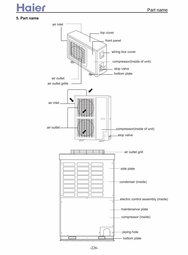
7
5. Part name
Part name
-226-
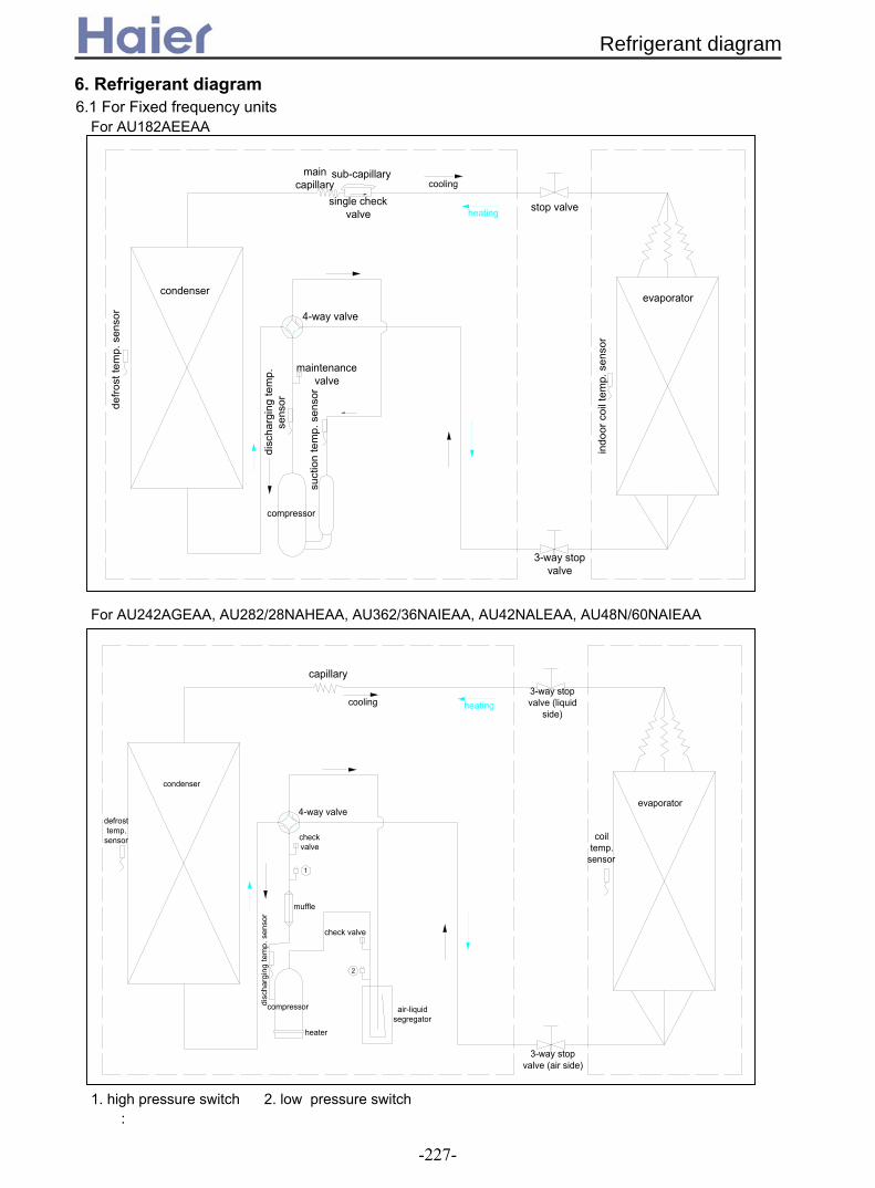
For AU182AEEAA
1. high pressure switch 2. low pressure switch
cooling
heating
evaporator
indo
or c
oil t
emp.
sen
sor
3-way stop valve
suct
ion
tem
p. s
enso
r
disc
harg
ing
tem
p.
sens
or
maintenance valve
4-way valve
single check valve
main capillary
sub-capillary
compressor
stop valve
condenser
defro
st te
mp.
sen
sor
muffle
compressor air-liquid segregator
check valve
check valve
4-way valve
3-way stop valve (air side)
coil temp.
sensor
evaporator
2
1
capillary3-way stop valve (liquid
side)cooling heating
defrost temp.
sensor
condenser
disc
harg
ing
tem
p. s
enso
r
heater
:
For AU242AGEAA, AU282/28NAHEAA, AU362/36NAIEAA, AU42NALEAA, AU48N/60NAIEAA
6. Refrigerant diagram6.1 For Fixed frequency units
Refrigerant diagram
-227-

1. high pressure switch 2. low pressure switch 3. for AU182AFERA, is 2-way stop valve 4. forAU182AFERA, is main capillary 5. for AU182AFERA, is sub-capillary and single check valvefor AU182AFERA, No. 1 and 2 are avaliable
3-way stop valve (air side)
evaporator
coil temp.
sensor
3-way stop valve (liquid side)
filter
filter
electrical expansion valve
air-liquid segregator
compressor
check valve
check valve
condenser
defrost temp.
sensor
cooling heating
4-way valve
muffle
2
1
3
4
5
disc
harg
ing
tem
p.
sens
or
suct
ion
tem
p.
sens
or
filter
air-liquid separator
compressor
muffle
4-way valve
3-way stop valve (air side)
condenser
evaporator
defrost temp.
sensor Te
indoor coil
temp. sensor
Tcdischange
temp. sensor
Td
suction temp.
sensor Ts
check valve
filter
electrical expansion
valve
low pressure
switch
high pressure switch
heatingcooling
condenser air-inlet temp. sensor Tci
oil return capillary
outdoor ambient
temp. sensor
Tao
indoor ambient
temp. sensor
Tai
3-way stop valve (liquid side)
For AU362AHERA
6.2 For inverter units
Refrigerant diagram
-228-
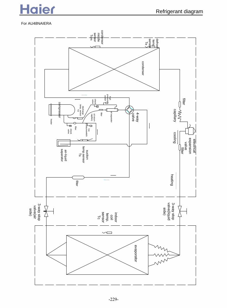
For AU48NAIERA
Refrigerant diagram
-229-

!
"" #" #$ !
# " '" -." ".
/ 0"
" !
#
#
"."
#" .#"" #$ "
!
7. Installation
Installation
-230-

* )#"+ #""#"#"" * ",
"" ""
$ !% %
$
"*$#$
!
-"#" "# "
#
$"" + $
!
""
"" #" "#
#
" # " "
( ) * "
& !
" *"
' %
Installation
-231-

#$% &!% '& !
() (! ! !% "
*! ! !
)
, ",!!% !%", %& ", % & &", -! %",& ", %& "
. - & "/ - +!! - "
/
0 "
0 ! %1&! "
2 %
3
3#
3
455
*-
$
$
$
6
7 %%
455
4545 #55
#55 #55
3
3
3#
0 00 000
! &
+
% %+& !% "
- ! ",! &! "$%% !
!"
! ! "%$7'$8)9$"
6!
$&
6!
7
1! &&
&
6!
7
$&
0 ! %&#"
Installation
-232-

8
3 2
0
# --
# --
# --8
3 2
0
--
$7:$))$$$7$))9$$7:$)9$
$7'$8)$$$7:$<)$$$7:$<)$$$7#;$0)$$$7#;$0)$$$7#;$3)$$ $7'$3)$$$7':$0)$$ $7;5$0)$$ $7=$0)$$ $7'$8)9$ $7:$<)9$ $7#;$<)9$
$7#;$<)9$$7#;$0)9$ $7':$0)9$ $7;5$0)9$
, ?
#3 % ! - !!"
, !! "@ % "@ &"A & 2 "6! !"
$! ! !"1& + - & "/ + &+! "@!! %+ "
0%-! &+! "
. B !!&
5%
$7#;$0)$$$7#;$0)$$$7'$3)$$$7':$0)$$$7;5$0)$$$7=$0)$$$7#;$<)9$$7#;$<)9$$7#;$0)9$$7':$0)9$$7;5$0)9$
$7:$))$$$7$))9$
$7'$8)$$$7:$<)$$$7:$<)$$$7:$)9$$7'$8)9$$7:$<)9$
8 4"::"5%%
3 2
8
>"45":%%
>"54"5%%
3 2 >"45":%%
8 "="5%%
3 2 ;"#45":%%
>5C5"4
$7#;$0)$$$7#;$0)$$$7#;$3)$$$7'$3)$$$7':$0)$$$7;5$0)$$$7=$0)$$$7':$0)9$$7;5$0)9$
$7'$8)$$$7:$<)$$$7:$<)$$$7'$8)9$$7:$<)9$$7#;$<)9$$7#;$<)9$$7#;$0)9$
$7:$))$$$7$))9$$7:$)9$
#5%
4%
4%
45% #5%
Installation
-233-

6 % $! ! !"1& + - & "/ + @!! %+ "
',
! %%"
, % 23 2 ;"#4%%
8 4"::%%
3 2 >"4%%
8 >"54%%
'" =""%
;": =4"'"%
#"= #>">"%
>=" :";"%
8 "=%% '>"4 ;5"#"%
&+! "
$!! !! + !% "1 -
1 2 -- "0- 2 --"
7-%%!%-% ? "0 !& !
$! +-%%
!
6%
6%
.
--
# --8
3 ?%
< ?%
.
--
--3 2
B3 B<
0
0
0! + !+ D
$!! % + "
6
5"#.,#"5E% ?-#% "*"4.4E% ?-#% "3 &!"1 #"5.,#5E% ?&'"3 &!"
% ? '+ !!!%& % %
6 !1 1 "
%! ! "
%! + --&! - &
degree"0& "
5"5.,5"E%
! +! +"%! "
%- %"
! ! "
Installation
-234-

0-%%! =44%%< -%
1-% ? %! + F"
0!!-% ? + -%& =44%%<+ &
0!!#-% ? + -%& =44%%<+ ! %"0!!--% ? +-% & =44%%<+B3B
"$!! &--% ? +-%% ! % ! "
# --3 2
0
0
6%
6%
B%%
--
# --8
3 ?%< ?%
.B3 B<
,
/3! 4%+
0! 34%+ . ! %"1 9! %G3 4. 2 ;"#4%%+.G#5 2 >"4%%+.G;4 6308 ! "/ +! &!% ??!--"@! ! + % %+%
"#
$%&
* ! ?! "
$8)9@03H0I79H9)$1<179)3)61906,/)9$16096701@9)$A)99,/)9*796)@)9).$A08$H)3)619066)610*"8976)610*.7*1@)6.,3)1)@)9).$A0830)B31$8)6)610*"
/$908J
, !)
-'5E% "
/-% ? + &! %& 2 --"
-% ?!"
<%-% ? "! % !-% "0!+ %"6
! "
! 2 "
) && ?"% % &"$
7"* ? !%&&"1 &5%
%% ! "
K-"
Installation
-235-

#5%$
0%
.,
* &$
6 &-
, ?
% %%
'5 ; "4%%
;5 '5 '"5%%
* &
)&
3
'5$ #5%$
;5$
$7:$))$$$7$))9$$7:$)9$
$7'$8)9$$7#;$<)9$$7:$<)9$
$7#;$0)9$ ;5 '5 ;"5%% ;5$ #5%$
$7:$<)$$$7#;$0)$$$7#;$<)9$$7':$0)9$
# #5 5 "4%% #5$ #5%$
$7':$0)$$$7;5$0)$$$7;5$0)9$
# #5 5 '"5%% #5$ #5%$
$7'$8)$$ '5 ; '"5%% '5$ #5%$$7:$<)$$$7#;$0)$$ '5 ; ;"5%% '5$ #5%$
/ + %"
$7:$))$$$7$))9$
08"
7197011)9.0$3@36A
08"
#
107
HE8
$7'$8)$$$7:$<)$$$7#;$0)$$$7:$)9$$7'$8)9$$7:$<)9$$7#;$<)9$$7#;$0)9$
3
,/)9*7,,3H#:5 '55B+#F+45<?
#HE8
107
9 * 1 08"#
$7:$<)$$$7#;$0)$$$7':$0)$$$7;5$0)$$ $7#;$<)9$$7':$0)9$
$7;5$0)9$
7197011)9.0$3@36A
,/)9*7,,3H,<+5 #5BF+45<?
#HE8
7197011)9.0$3@36A
107
'(()*01)96)6108/09)*.7*1@)/09)$66908108"+08"+ 08"#0699)61/0908.$H6$7*))L70,.)1$.$8)"#/
9%- &! !!! ! "6 % &! %2
#9 !
&% &"
"
Installation
-236-

!"# $ % &' () *!+ &, - $ "" ./0
1 2%!!% & - 3 $ !%4 4&"4 $ % /&! 2205!&%/ 2%!!% & - 3 *2%!! % ,!&%/ 2206*2%&% ,$$% '. %% &% &, !22"# &% $ % , % 0
78 9:;6<=>? 6@<1 ;><6A<BB CD 16:6D5 <>16:>6BEA<6@=;6 F=>F =GD:6<=>A@D> DBD96<9 G=AD<1 1;GGB<D50CD 1;D 6= DHD9;6D F=IIF =GD:6<=> CDI=D DBD96<9 G=AD <1 5<19=>>D96D5I= 1DJ<9<>K0
6! &! & $ $ & *& %!&% !#!* &$% % 4%/ 2 .% ! 22&/0
9 $%* .% 2 .% ! % '%&-% L*& !.M $ &! ' %, $ % 4% NO %! %/P %&-&! &% &,4& $ 2%& 0
Oil trap is required no mater the outdoor unit is upper or lower than indoor unit, only when
Trap dimensions: Setting method: install one oil trap for every 10 meters at the gas pipe.
Note: the drop between the oil trops should be 10m.
L
R
R
Gas pipe diameter Min. R (mm) L (mm) φ15.88 40 80 φ19.05 40 80 φ25.4 40 80 φ31.8 60 90 φ38.1 60 100
the piping drop is more than 10m.
Oil trap setting requirement:
Installation
-237-

Part 4 Electrical Control
1. Electrical wiring diagram and PCB photo ...……….....................................................239
1.1 For indoor unit……………………………………………………...........................239
1.2 For outdoor unit………………………………………………….............................263
2. Sensor characteristic...…………………………………................................................276
3. Electric control fuctions……………………...........................………...............................….....
3.1 For the unit with 0010452478E and 0010452325E PCB……........................................281
3.2 For the unit with 0010451167E and 0010451690E PCB….......….....................288
3.3 For the unit with 0010400911E PCB(AP422ACEAA)……….............................293
3.4 For the unit with 0010452322E PCB(AP482AKEAA)……….............................299
3.5 For the unit with 0010452042E PCB(AS182AVERA)………...........................
3.6 For fixed frequency outdoor unit(*EAA)……………………................................311
3.7 For DC inverter outdoor unit(*ERA)………………………........................….......315
Electrical Control
-238-
.281
..304

1. Electrical wiring diagram and PCB photo1.1 For indoor units
CIRCUIT DIAGRAM OF INDOOR UNIT 0010576979
FUSE1
CN1
CN15CN20
LOWMID
HIGH
CN21 CN22
N2
TRANS.-ICN4
SIGNAL
LED3CN3
NCN2
L
T3.15A/250VAC
CN13TRANS.-II
CN12
CN11REMOTECN10
FLOATCN8
ALARMCN7
RECEVIERCN6
STEPMOTOR
PIPE ROOMCN14
CONTROLLER
CN16
CN17
N1CN18
PUMP
MWIREDCONTROLLER
ROOMTEMP. SENSOR
PIPING TEMP.SENSOR
RECEIVE BOARD FLOAT
SWITCH
REMOTECENTRALIZED CONTROLLER
MPUMPMOTOR
TRANSFORMER
BM4
ON1234
ON12
ON1234
ON1234
BM3 BM2BM1
STEPMOTOR
1Y/GR
R R Y BL W
B
B
W
W
Y Y
32
Y/G
Y/GNOTE:1.THE PARTS IN DASHED FRAME ARE OPTIONAL2.REFER TO OPERATION MANUAL TO SET BM3 AND BM43.USER SHOULD NOT TO SET BM1 AND BM2W:WHITE B:BLACK BR:BROWN BL:BLUE R:RED Y:YELLOW Y/G:YELLOW/GREEN TEMP.:TEMPERATURE
LED2 LED1
Y/GL
BL
BL
BR
BR
N
TO OUTDOOR UNITPOWER SUPPLY
Itophome
MOTOR CAPACITOR
MFAN MOTOR
Y/G
AB122ACERA
AB182ACERA
CIRCUIT DIAGRAM OF INDOOR UNIT 0010576971
FUSE1
CN1
TRANS.-I
CN4
SCN3
NCN2
L
T3.15A/250VAC
CN13TRANS.-II
CN12
REMOTE
CN10
FLOAT
CN8
ALARMCN7
RECEVIERCN6
STEP MOTOR
PIPE ROOMCN14
CONTROLLER
CN16
CN17
N1CN18
PUMP
1Y/GR
R
YY
B
B
W
W
32
MWIREDCONTROLLER
ROOMTEMP. SENSOR
PIPING TEMP.SENSOR
RECEIVE BOARD
FLOATSWITCH
REMOTECENTRALIZEDCONTROLLER
MPUMPMOTOR
TRANSFORMER
BM4 BM3 BM2BM1
STEP MOTOR
Y/G
NOTE:1.THE PARTS IN DASHED FRAME ARE OPTIONAL2.REFER TO OPERATION MANUAL TO SET BM3 AND BM43.USER SHOULD NOT TO SET BM1 AND BM2
TO OUTDOOR UNIT
ON1234
ON12
ON1234
ON1234
LED2 LED1
W:WHITE B:BLACK BR:BROWN BL:BLUE R:RED Y:YELLOW Y/G:YELLOW/GREED TEMP.:TEMPERATURE
CN11
ItophomeCN15 LOW
MID
HIGH
CN21CN20 CN22
N2
R Y BL W
MOTOR CAPACITOR
MFAN MOTOR Y/G
TEMP. SENSOR
Electrical wiring diagram and PCB photo
-239-

CN4
CN15
CN17
CN20
CN21
CN22
CN6
CN7
CN8
CN10
CN11
CN12
CN13
CN14
LED1
LED2
BM2
BM1
BM3
BM4
CN19
CN16
CN3
CN1
CN2
CN18
0010452325E for AB122ACERA and AB182ACERA
Electrical wiring diagram and PCB photo
-240-
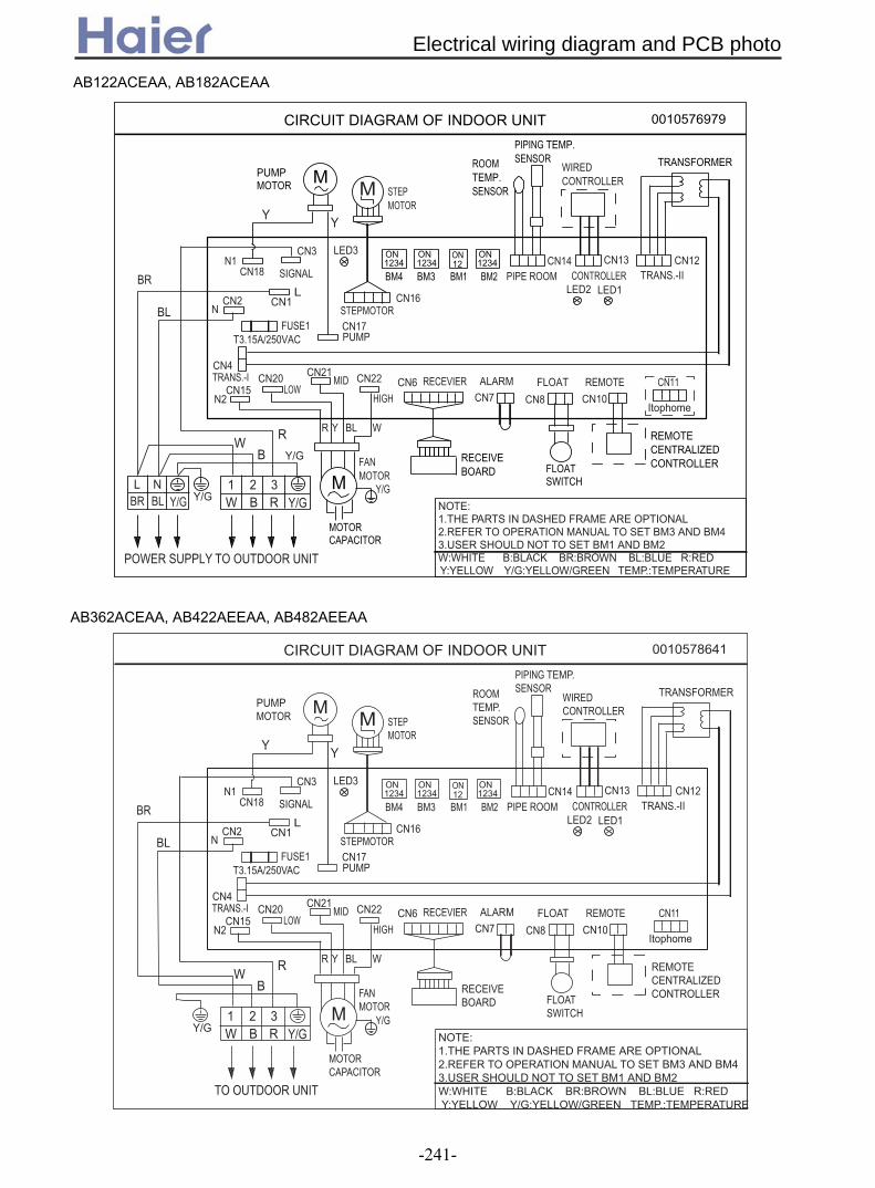
CIRCUIT DIAGRAM OF INDOOR UNIT 0010576979
FUSE1
CN1
CN15CN20
LOWMID
HIGH
CN21 CN22
N2
TRANS.-ICN4
SIGNAL
LED3CN3
NCN2
L
T3.15A/250VAC
CN13TRANS.-II
CN12
CN11REMOTE
CN10
FLOAT
CN8
ALARMCN7
RECEVIERCN6
STEPMOTOR
PIPE ROOMCN14
CONTROLLER
CN16
CN17
N1CN18
PUMP
MWIREDCONTROLLER
ROOMTEMP. SENSOR
PIPING TEMP.SENSOR
RECEIVE BOARD FLOAT
SWITCH
REMOTECENTRALIZED CONTROLLER
MPUMPMOTOR
TRANSFORMER
BM4
ON1234
ON12
ON1234
ON1234
BM3 BM2BM1
STEPMOTOR
1Y/GR
R R Y BL W
B
B
W
W
YY
32
Y/G
Y/GNOTE:1.THE PARTS IN DASHED FRAME ARE OPTIONAL2.REFER TO OPERATION MANUAL TO SET BM3 AND BM43.USER SHOULD NOT TO SET BM1 AND BM2W:WHITE B:BLACK BR:BROWN BL:BLUE R:RED Y:YELLOW Y/G:YELLOW/GREEN TEMP.:TEMPERATURE
LED2 LED1
Y/GL
BL
BL
BR
BR
N
TO OUTDOOR UNITPOWER SUPPLY
Itophome
MOTOR CAPACITOR
MFAN MOTOR
Y/G
AB122ACEAA, AB182ACEAA
CIRCUIT DIAGRAM OF INDOOR UNIT 0010578641
FUSE1
CN1
CN15CN20
LOWMID
HIGH
CN21 CN22
N2
TRANS.-ICN4
SIGNAL
LED3CN3
NCN2
L
T3.15A/250VAC
CN13TRANS.-II
CN12
CN11REMOTECN10
FLOATCN8
ALARMCN7
RECEVIERCN6
STEPMOTOR
PIPE ROOMCN14
CONTROLLER
CN16
CN17
N1CN18
PUMP
MWIREDCONTROLLER
ROOMTEMP. SENSOR
PIPING TEMP.SENSOR
RECEIVE BOARD FLOAT
SWITCH
REMOTECENTRALIZED CONTROLLER
MPUMPMOTOR
TRANSFORMER
BM4
ON1234
ON12
ON1234
ON1234
BM3 BM2BM1
STEPMOTOR
1Y/GR
R R Y BL W
B
B
W
W
Y Y
32Y/G
NOTE:1.THE PARTS IN DASHED FRAME ARE OPTIONAL2.REFER TO OPERATION MANUAL TO SET BM3 AND BM43.USER SHOULD NOT TO SET BM1 AND BM2W:WHITE B:BLACK BR:BROWN BL:BLUE R:RED Y:YELLOW Y/G:YELLOW/GREEN TEMP.:TEMPERATURE
LED2 LED1
BL
BR
TO OUTDOOR UNIT
Itophome
MOTOR CAPACITOR
MFAN MOTOR
Y/G
AB362ACEAA, AB422AEEAA, AB482AEEAA
Electrical wiring diagram and PCB photo
-241-

CN13
BM2
CN14
CN6
CN11
CN12
BM1
CN19
LED1
LED2
BM3
BM4
CN16
LED3
CN3
CN1
CN18
CN2
CN4
CN17
CN15
CN20
CN21
CN22
CN7
CN8
CN10
0010452478E
Electrical wiring diagram and PCB photo
-242-

Time shorting switch CN7
Emergency switch SW1(receiver)
BM1(1) BM1(2)
Time shorting switch Time shorting * * * Emergency switch * Emergency * * No outdoor PCB * * × ×
Jumper selection (√shows jumper connected, ON; ×shows jumper disconnected, OFF; * showsno limitation)
With outdoor PCB, fixed speed single split unit
* * √ ×
With outdoor PCB, fixed speed multi split unit
* * × √
With outdoor PCB, inverter single split unit
* * √ √
Inverter unit selection BM2(1) BM2(2) BM2(3) BM2(4) Temp. compensation 4 available/not available
√/× * * *
Wired control/ infrared control
* √/× * *
Cooling only/heatpump * * √/× * Master/slave wired controller
* * * √/×
BM4 BM3 address 1 2 3 4 1 2 3 4 1 × × × × × × × ×shows
2 √ × × × × × × 3 × √ × × × × × 4 √ √ × × × × ×
no network home
appliance
5 × × √ × × × × 6 √ × √ × × × × …… …… …… …… …… …… …… 126 √ × √ √ √ √ √ 127 × √ √ √ √ √ √ 128 √ √ √ √ √ √ √
√with network home
appliance
Network address selection (√shows jumper connected, ON; ×shows jumper disconnected, OFF)
0010452325E / 0010452478E information - function selection
Electrical wiring diagram and PCB photo
-243-

CIRCUIT DIAGRAM OF INDOOR UNIT 0010576547
(FREEZE)CN8
SW2BL
P13
(HUM
I)
(PUM
P)
(HEAT
)
Y
(L)(FRE
SH)
P8 P9P7 P12P10 P11
(COM
M)
W(N')(M
)
(H)
SW3P17(L')P14 P15
SW5SW4
P16
CN4
CN5
CN1
TRANS.
SWITCH
(DOOR)
(CONTROLLER)WIRED CONTROLLER
(FLOAT)CN15
CN13
(UP-DOWN)CN14
A B (ALARM)CN16
(REMOTE) CN11
CN12
FLOAT
REMOTE RECEIVER
ON 12
ON 1234CN19
UP-DN L-R
CN20
3
W:WHITE B:BLACK R:RED Y:YELLOW OR:ORANGE BL:BLUE BR:BROWN Y/G:YELLOW/GREENCAP.:FAN MOTOR CAPACITORTRANS.:TRANSFORMER
(RECEIVE BOARD)
(SW
ING)
(OXY
GEN)
OR Y Y
M SWING MOTOR
FAN MOTOR
2
12
1
5
8
9
7
CN21
CN7
FUSE
T3.15
A/25
0VACP4(N2)
M
P5(N3)
TO OUTDOOR UNIT
R2 31BW
W RB
W
B
OR
P1(L)
P2(N)
P3(N1)
MOTOR MOTORSWING PUMP
RP6(N4)
SW1(ROOM/PIPE)CN6
TEMP. SENSOR
SENSOR PIPING TEMP.
ROOM
64
Y/GY/G
10
1413
M M
CAP.
Y/GY/G M11
CAP.
M
ON 1234
ON 1234
ON 1234
6. PARTS AND CONNECTED WIRES IN DASHED FRAME 12 13 ONLY AVAILABLE IN AC***AFBEA TYPE7. REFER TO OPERATION MANUAL TO SET SW1-SW5
1. PARTS 1 2 3 IN DASHED FRAME ARE NOT AVAILABLE2. PARTS 4 5 6 ARE OPTIONAL, AND THE LINE MARKED 14 ONLY AVAILABLE IN CONVERTIBLE TYPE3. PARTS AND CONNECTED WIRES IN DASHED FRAME 7 9 ARE NOT AVAILABLE IN CONVERTIBLE TYPE, AND CORRESPONDINGLY THERE IS A CLIP ON PCB4. PARTS AND CONNECTED WIRES IN DASHED FRAME 8 ARE NOT AVAILABLE IN DUCT TYPE5. PARTS AND CONNCETED WIRES IN DASHED FRAME 10 11 DETERMINED BY PRODUCTS TYPE
CN17(12V/ALM)
NOTE:
REMOTECONTROLLER CENTRALIZED
AB242/362ACERA, AB242/282/482/602ACEAA, AC282/362/482/602AFEAA, AD242ALERA, AD242ALEAA,
AC122/182/242ACERA, AC122/182/242ACEAA, AD122ALERA, AD182AMERA, AD122/182ALEAA
AD242/282/362/482AMEAA, AD242/282/362AMERA
CIRCUIT DIAGRAM OF INDOOR UNIT 0010576546
(FREEZE)CN8
SW2
BL
P13
(HU
MI)
(PUM
P)
(HEA
T)
Y
(L)
(FRE
SH)
P8 P9P7 P12P10 P11
(CO
MM
)
W
(N')(M)
(H)
SW3P17
(L')P14 P15
SW5
SW4
P16
CN4
CN17
CN5
MOTORFILTER
CN1
TRANS.
SWITCH
(DOOR)
(CONTROLLER)
(FLOAT)CN15
CN13(UP-DOWN)(12V/ALM)
CN14A B
(ALARM)CN16
(REMOTE) CN11
CN12
FLOAT
REMOTE RECEIVER
REMOTE
CN2 PCN1
MC1 COMMC2 N
ON 12
ON
1234CN19 CN20
3
W:WHITE B:BLACK
R:RED Y:YELLOW
OR:ORANGE BL:BLUE
BR:BROWN
Y/G:YELLOW/GREEN
TRANS.:TRANSFORMER
FG L
CONTROLLER CENTRALIZED
R BLB B W
FUSE T2.0A/250VAC
(RECEIVE
BOARD)
(SW
ING
)
(OXY
GEN)
OR Y Y
M
SWING MOTOR
MFAN MOTOR
M
2
11
1
4
8
7 9
10
CN21
CN7
FUS
ET6
.3A/
250V
AC
T3.1
5A/2
50VA
C
P4(N2)
POWER SUPPLY
M
P5(N3)
TO OUTDOOR UNIT
R
2 31BW
LBRBL
NY/G
W RB
W
B
Y/G
OR
P1(L)
P2(N)
P3(N1)
FAN CAP.
Y/G
MOTOR MOTOR
M
SWING PUMP
RP6(N4)
SW1
@
@
12
(ROOM/PIPE)CN6
TEMP.
SENSOR
SENSOR PIPING TEMP. ROOM
6
513
M
M
ON
1234
ON
1234
ON
1234
6. IN AC242ACBEA/AC242ACEAA, DASHED LINES MARKED @ CONNECTED TO "1 , 2" ON TERMINAL BLOCK, AND THERE ARE NO
LINES BETWEEN "1 AND L" , "2 AND N". IN *******BIA OR ******ERA TYPE,THE POWER SUPPLY COME FROM OUTDOOR UNIT(
EXCEPT FOR **122**ERA), AND THE FUSE TYPE IS T3.15A/250VAC 7.ABOUT THE TERMINAL BLOCK,MARK "BL" IS EQUAL "B" AND THE "BR" IS EQUAL "W".REFER TO OPERATION MANUAL TO SET SW1-SW5
NOTE:
1. PARTS 1 2 3 ARE NOT
AVAILABLE
2. PARTS 4 5 6 ARE
OPTIONAL, AND THE LINE
MARKED 13 ONLY AVAILABLE
IN CONVERTIBLE TYPE
3. PART 7 NOT AVAILABLE
IN DUCT TYPE
4. PARTS AND CONNECTED
WIRES IN DASHED FRAME 8
ONLY FOR AB14/182ACBEA5.PARTS AND CONNECTED WIRES IN DASHED FRAME 9 10 ARE NOT AVAILABLE IN AD14/182AMBEA, AND IN CONVERTIBLE TYPE,
CORRESPONDINGLY THERE IS A CLIP ON PCB. PARTS AND CONNECTED WIRES IN DASHED FRAME 11 ONLY FOR
AC142/182/242ACBEA/AC242ACEAA TYPE .PARTS AND CONNECTED WIRES IN DASHED FRAME 12 DETERMINED BY
PRODUCTS TYPE.
WIRED
CONTROLLER
Electrical wiring diagram and PCB photo
-244-
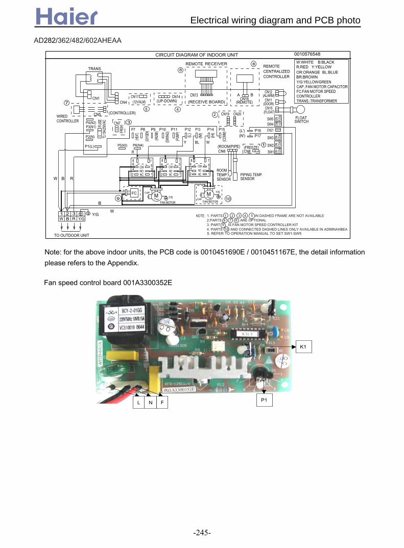
CIRCUIT DIAGRAM OF INDOOR UNIT 0010576548
(FREEZE)CN8
SW2BL
P13
(HUM
I)
(PUM
P)
(HEAT
)
Y
(L)(FR
ESH)
P8 P9P7 P12P10 P11
(COM
M)
W
(N')(M)
(H)
SW3P17(L')P14 P15
SW5SW4
P16
CN4
CN5
CN1
TRANS.
SWITCH
(DOOR)
(CONTROLLER)WIRED CONTROLLER
(FLOAT)CN15
CN13(UP-DOWN)
CN14 A B (ALARM)CN16
(REMOTE) CN11
CN12
FLOAT
REMOTE RECEIVERREMOTE
ON 12
ON 1234
CN19 CN20 4
W:WHITE B:BLACK R:RED Y:YELLOW OR:ORANGE BL:BLUE BR:BROWN Y/G:YELLOW/GREENCAP.:FAN MOTOR CAPACITORFC:FAN MOTOR SPEED CONTROLLERTRANS.:TRANSFORMER
CONTROLLER CENTRALIZED
(RECEIVE BOARD)
(SW
ING)
(OXYG
EN)
3
1
10FC
CN21
CN7
FUSE
T3.15
A/250
VAC
P4(N2)
TO OUTDOOR UNIT
P5(N3)
R2 31BW
W RB
W
B
P1(L)
P2(N)
P3(N1)
R
P6(N4)
SW1(ROOM/PIPE)CN6
TEMP. SENSOR SENSOR
PIPING TEMP. ROOM
8
6
Y/GY/G
9
2
CAP.
Y/GM
ON 1234
ON 1234
ON 1234
5. REFER TO OPERATION MANUAL TO SET SW1-SW5
1. PARTS 1 2 3 4 5 IN DASHED FRAME ARE NOT AVAILABLE2.PARTS 6 7 8 ARE OPTIONAL3. PART 9 IS FAN MOTOR SPEED CONTROLLER KIT4. PARTS 10 AND CONNECTED DASHED LINES ONLY AVAILABLE IN AD88NAHBEA
5
COMNONC
COMNONC
COM
8642
531
7 8642
531
7 8642
531
7
NONC
CAP.
Y/GM
7
FAN MOTOR FAN MOTOR
NOTE:
CN17(12V/ALM)
Note: for the above indoor units, the PCB code is 0010451690E / 0010451167E, the detail information
please refers to the Appendix.
AD282/362/482/602AHEAA
P1 FNL
K1
Fan speed control board 001A3300352E
Electrical wiring diagram and PCB photo
-245-
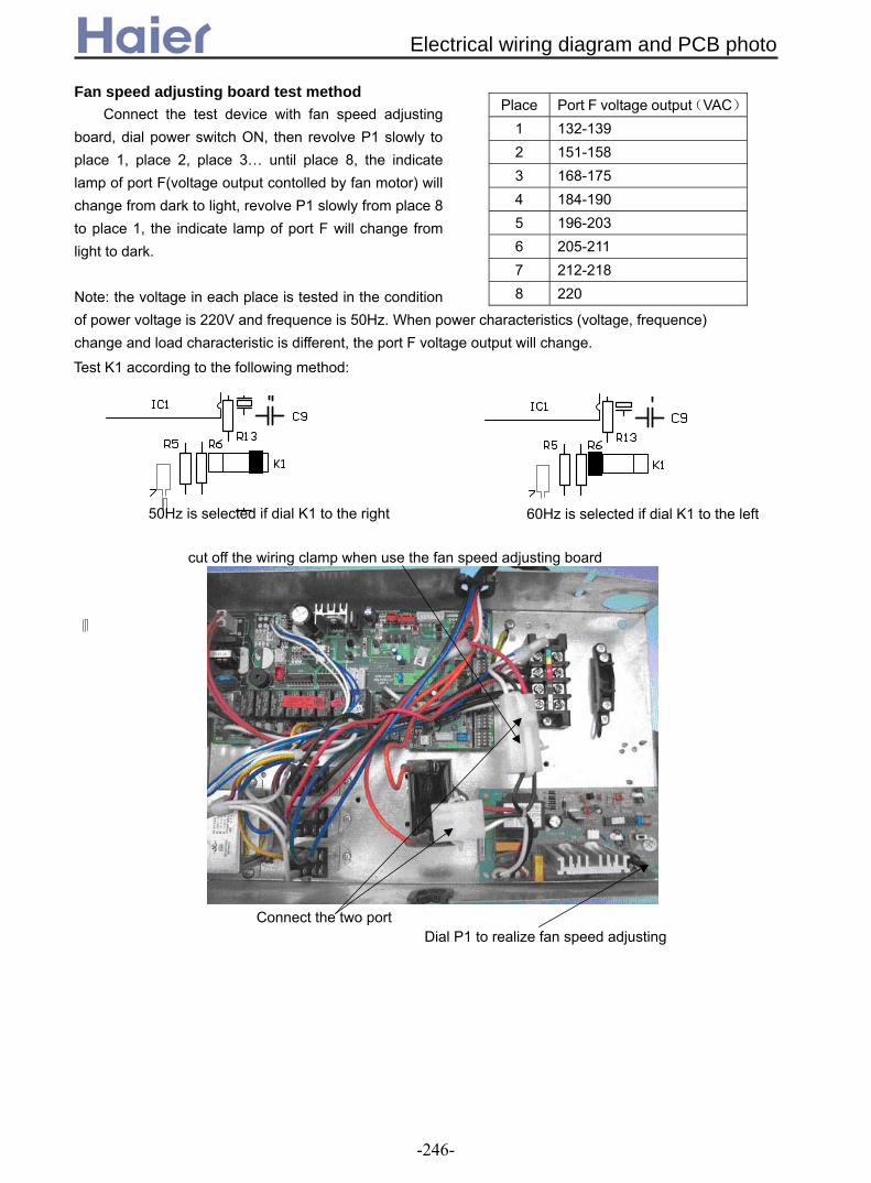
Test K1 according to the following method:
50Hz is selected if dial K1 to the right
60Hz is selected if dial K1 to the left
cut off the wiring clamp when use the fan speed adjusting board
Connect the two port Dial P1 to realize fan speed adjusting
Fan speed adjusting board test method Connect the test device with fan speed adjusting
board, dial power switch ON, then revolve P1 slowly to place 1, place 2, place 3… until place 8, the indicate lamp of port F(voltage output contolled by fan motor) will change from dark to light, revolve P1 slowly from place 8 to place 1, the indicate lamp of port F will change from light to dark. Note: the voltage in each place is tested in the condition of power voltage is 220V and frequence is 50Hz. When power characteristics (voltage, frequence) change and load characteristic is different, the port F voltage output will change.
Place Port F voltage output(VAC)
1 132-139 2 151-158 3 168-175 4 184-190 5 196-203 6 205-211 7 212-218 8 220
Electrical wiring diagram and PCB photo
-246-

0010451690E
CN12
CN15
CN16
CN11
CN17
LED1
CN14
CN13
CN20
SW3SW2
CN21SW5
SW4
CN19
CN7
LED4
LED5
CN5
CN4
P5
P7
P9
P6
P8
P10
P12
P11
P15
P14
P13
P17
CN1
P4 P3 P2
P1
P16
CN8
CN6
SW1
Electrical wiring diagram and PCB photo
-247-

0010451690E information - function selection
Short-circuit -ON-
√
Open-circuit -OFF-× Function description Note
Bit0 Address code “1” Address code “0” Central control indoor address
Bit0/wired control indoor address Bit0
Bit1 Address code “1” Address code “0” Central control indoor address
Bit1/wired control indoor address Bit1
Bit2 Address code “1” Address code “0” Central control indoor address
Bit2/wired control indoor address Bit2
SW1-1
2
3
4
Bit3 Address code “1” Address code “0” Central control indoor address
Bit3/wired control indoor address Bit3
Bit4 Address code “1” Address code “0” Central control indoor address Bit4
Bit5 Address code “1” Address code “0” Central control indoor address Bit5
Bit6 Address code “1” Address code “0” Central control indoor address Bit6
SW2-1
2
3
4 SLCT Control
combination: AND
Control combination: the
later entering in priority
Control mode: remotr or wired control
and passive port control
J1 Control type:
remote control
Control type: wired
control
Select control type, communication
port and protocol selection
J2 Heating temp.
compensation 4
Heating temp.
compensation 0
Select temp. compensation
J3 Control type: with
outdoor PCB
Control type: without
outdoor PCB
Select control type, control board
SW3-1
2
3
4
J4 Heat pump type Colling only type
1/60 1/60 In time shorting
state
Normal state
CHECK CHECK Use compulsory
switch
Normal state
J5 Ornarment or not ×/√ SW4-1
2 J6 Oxygen or not ×/√
J7 Other/2P convertible type √/×
J8 Single split/multi split √/×
J9 Indoor address 0 Setting indoor address
by SW1
Select the address of wired control
type multi indoor unit
SW5-1
2
3
4
J10 Fixed frequency Inverter
Central control indoor address: the indoor unit should be connected by the different uniquely address when select
central control type, or will influence the control. For example, if the address repeat, the control information will conflict or
communication system will breakdowm. Central control address = dip switch value+1.
Wired control indoor address: the indoor unit should be connected by the different uniquely address when select
wired control type, or will influence the control. For example, if J9=ON, the wired controller can only indicate 1 indoor unit
no matter how many indoor units its connected. Wired control address = dip switch value.
Electrical wiring diagram and PCB photo
-248-
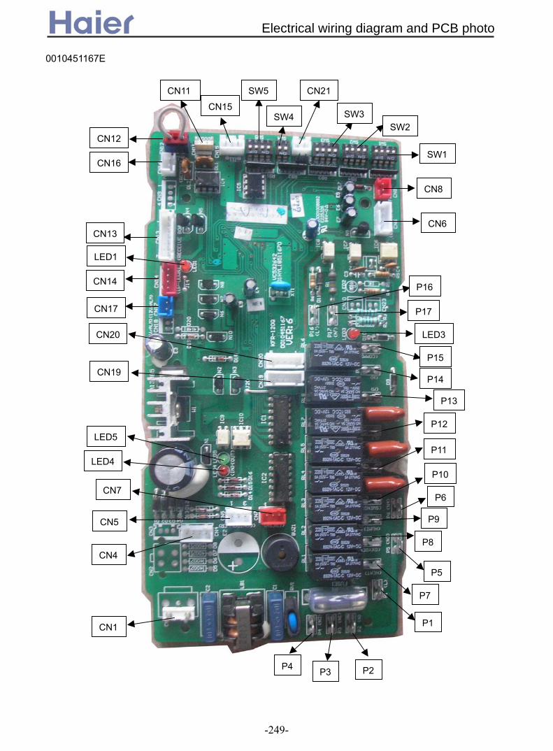
0010451167E
CN12
CN15
CN16
CN11
CN17
LED1
CN14
CN13
CN19
CN20
CN7
LED4
LED5
CN5
CN4
CN1
P4 P3 P2
P5
P7
P1
P9
P6
P8
P10
P12
P11
P15
P14
P13
P17
P16
LED3
CN8
CN6
SW1
SW3SW2
CN21SW5
SW4
Electrical wiring diagram and PCB photo
-249-
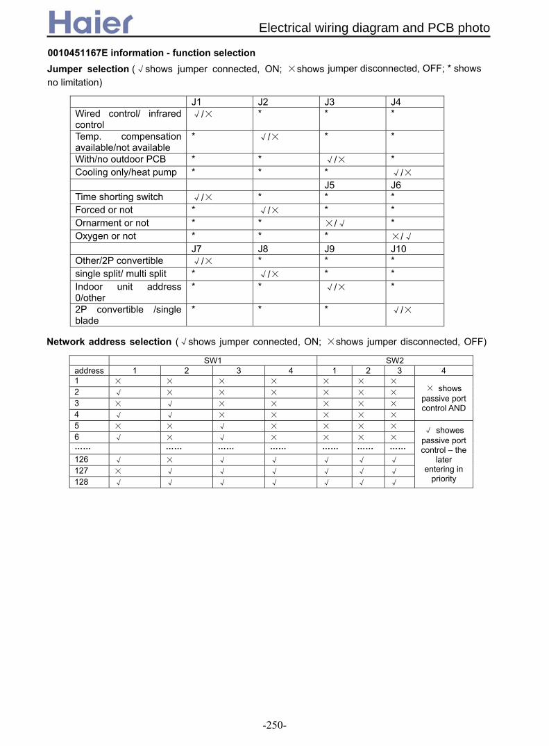
J1 J2 J3 J4 Wired control/ infrared control
√/× * * *
Temp. compensation available/not available
* √/× * *
With/no outdoor PCB * * √/× * Cooling only/heat pump * * * √/× J5 J6 Time shorting switch √/× * * * Forced or not * √/× * * Ornarment or not * * ×/√ * Oxygen or not * * * ×/√ J7 J8 J9 J10 Other/2P convertible √/× * * * single split/ multi split * √/× * * Indoor unit address 0/other
* * √/× *
2P convertible /single blade
* * * √/×
SW1 SW2 address 1 2 3 4 1 2 3 4 1 × × × × × × × 2 √ × × × × × × 3 × √ × × × × × 4 √ √ × × × × ×
passive port control AND
5 × × √ × × × × 6 √ × √ × × × × …… …… …… …… …… …… …… 126 √ × √ √ √ √ √ 127 × √ √ √ √ √ √ 128 √ √ √ √ √ √ √
√ showes passive port control – the
later entering in
priority
× shows
Network address selection (√shows jumper connected, ON; ×shows jumper disconnected, OFF)
0010451167E information - function selection
Jumper selection (√shows jumper connected, ON; ×shows jumper disconnected, OFF; * shows no limitation)
Electrical wiring diagram and PCB photo
-250-

Condition for the PCB data:
1.Working ambient temperature:-10~70, relative humidity:30%~95% 2.Preserved ambient temperature:-20~80,relative humidity:30%~95% 3.Power supply:220VAC、50/60Hz,voltage range:160V~250V 4.Precise of temperature control:±1
0010451167E PCB information – port and definition P1——connect to external power supply, live line: L (220VAC) P2——connect to external power supply, neutral line: N (0VAC) P3、4、5、6——control external load, neutral line: N1、N2、N3、N4(0VAC) P7——control external load, electrical heat: HEAT (control output 220VAC) P8——control external load, health function: OXYGEN (control output 220VAC) P9——control external load, humidification: HUMI (control output 220VAC) P10——control external load, SWING(control output 220VAC) P11——control external load, WATER PUMP(control output 220VAC) P12——control external load, indoor fan motor low speed: L(control output 220VAC) P13——control external load, indoor fan motor mid speed: M(control output 220VAC) P14——control external load, indoor fan motor high speed: H(control output 220VAC) P15——communication with fixed frequency single outdoor unit: COMM(0~220VAC) P16——input control, signal live line: L’(220VAC) P17——input control, signal neutral line: N’(0VAC) CN1——input port of transformer (220VAC) CN2——input port 1 of transformer (no use) CN3——input port 2 of transformer (no use) CN4——input port 3 of transformer (1-2、14VAC,3-4、12VAC) CN5——input control, connecting port to wired controller: CONTROLLER(three bits: 1. power supply:
12VAC, 2. power supply: 0VAC, 3. communication: COMM.). CN6——input control, ambient temp.-coil temp. sensor connecting port: ROOM/PIPE(1-2、ROOM,3-4、
PIPE。) Indoor ambient temp. sensor: R25=23KΩ+-2.5%,B25/50=4200K+-3%,range:(-40,80) Indoor coil temp. sensor: R25=10KΩ+-3%,B25/50=3700K+-3%,range:(-20,90) CN7——control external load, fresh air control: FRESH(1. blank, 2. power supply 0VDC, 3. control output:
12VDC.) CN8——input signal: FREEZE(no use) CN9——input control(no use) CN10——communication with fixed frequency single outdoor unit: (0~12VDC) CN11——input signal, door switch: DOOR(1-2 short circuit is normal, cut off P8 output) CN12——input signal, external alarm input: ALARM(1-3 short circuit is normal, if cut off, air conditioner
stops work.) Note: For convertible type, cassette type, duct type units, CN11 and CN12 must be in short circuit, or
PCB will display failure information. CN13——input signal, wiring port of remote receiver board: RECEIVE BOARD(1. power supply 5VDC, 2.
power supply 0VDC, 3. remote signal, 4. signal output of running lamp 0VDC, 5. signal output of timer lamp 0VDC,6. signal output of power lamp 0VDC, 7. signal output of water pump running lamp 0VDC)
CN14——control external load, auto elevating function (1. signal of door switch close, 2. output of elevating direction control 0VDC, 3. output of elevating power control 0VDC, 4. power supply 12VDC)
Electrical wiring diagram and PCB photo
-251-

CN15——input signal, detecting water level of float switch (1-3 short circuit is normal, cut off shows that
level exceeds the limitation).If float switch cuts off or occurs other failure, LED1 will flash 10 times. CN16——input control, wiring port of central controller: REMOTE(1、RS485-B,2、RS485-A。) CN17——output signal, output signal of failure alarm, control external load, 12V/ALM(1. control output
0VDC, 2. power supply 12VDC) CN18——output signal (no use) CN19——control external load, swing 1(1、16VDC,2、0VDC,3、0VDC,4、0VDC,5、0VDC.).
CN20——control external load, swing 2(1、16VDC,2、0VDC,3、0VDC,4、0VDC,5、0VDC.). CN21——input signal, spring switch, CHECK(1、input signal of earthing, 2. power supply 0VDC) CN22——short circuit means selecting single split communication type.( no use) CN23——short circuit means selecting multi split communication type.( no use) 0010451167E PCB information – function selection(ON is 1, OFF is 0)
The standard condition for PCB in factory SW1:4 bits are OFF SW2:4 bits are OFF SW3:4 bits are ON SW4:2 bits are ON SW5:4 bits are ON
SW3-SW5: used for indoor unit to select different functions.(every dip switches are corresponding to J1-J10. SW2-4——logistic relationship of control function(door card control and remote/ wired control)0 means
logistic relationship is “and”, 1 means the later coming is preferential. J1,SW3-1——function selection-control type: 1 means remote control, 0 means wired control. J2,SW3-2——function selection-temperature compensation in heating mode: 1means “yes”, 0means “no”. J3,SW3-3——function selection-outdoor communication: 1means “yes”, 0means “no”. This PCB must be 1. J4,SW3-4——function selection-heat pump unit: 1means “heat pump”, 0means “cooling only”. 1/60——test in short circuit, but in operation short circuit mustn’t be permitted. CHECK——short spring switch control, it also can be used as switch of convertible type except for testing. J5,SW4-1——function selection-elevating function: 1means “yes”, 0 means “no”. J6,SW4-2——function selection –health function: 1means common (indoor fan motor running); 0 means
special (indoor, outdoor running). J7,SW5-1——function selection –swing mode: 1 means common(simultaneous motor), 0 means special
(swing motor). J8,SW5-2——function selection – system combination: 1means fixed frequency single unit, 0 means fixed
frequency multi split. J9,SW5-3——function selection –group control: 1 stands for the master unit (its address in wired controller
is 0), 0 stands for the slave units (the address should be set by the dip switch, their addresses only can be in the range: 1~15)
0010451167E PCB information- control type
Control type selection between remote and wired: select by dip switch J1, SW3-1(1 means remote control;
0 means wired control.)
For remote control type, please use remote controller YR-H71, and a remote receiver is equipped with indoor unit. For wired control type, wired controller YR-E12 will be used, 3-core shied wire is equipped with
SW1-SW2: used for indoor unit to set unit address from 1 to 128’
J10,SW5-4——function selection –preset.
Electrical wiring diagram and PCB photo
-252-

indoor unit. Door card control: controls ON/OFF, the start up setting will comply with last time request memorized
according to condition memorize function. Its difference with emergency switch of convertible type unit lies: the emergency switch control will perform in the condition: 24degrees, auto fan speed in auto mode.
The function combination between door card and remote/wired control type: select by dip switch: SW2-4(0 means “and”, 1 means later coming is preferential.)
Dip switch position in wired control type: Only one indoor unit of all indoor units connected with wired controller is the master unit, whose address is 0, function selection switch(J9,SW5-3)is 1. The others are slave units, and the quantity can be 0~15, whose addresses are(SW1:1~4)from 1 ~15, and cannot repeat.
Wiring request in wired control type: the wired controller ports A-B-C are connected with indoor port CN5(1-2-3) through 3-core shield wire. Requirements:
1. Port A only connects with either of indoor port CN5(1) 2. Port B connects with port CN5 (2) of all indoor units. 3. Port C connects with port CN5 (3) of all indoor units. Dip switch position in central control type: the addresses (SW1:1~4;SW2:1~4)of indoor units connected
with central controller can not repeat. In principle, they should be in the order from small to big. Wiring request in central control type: port A-B is connected with indoor port CN16(A-B)through 2-core
shield wire. Requirements: 1. Port A connects with port CN16(A)of all indoor units. 2. Port B connects with port CN16(B)of all indoor units. When only use remote control type, please select remote control unit, and install according to installation
manual, there is no other special request. When only use wired control type, please select wired control unit, and install according to installation
manual. When control multi indoor units, take care the requirements of dip switch and wiring, there is no other special request.
When only use central control type, please firstly install according to air conditioner requests and set the dipswitch, there is no other special request.
When central control type(128×)and remote control type are used simultaneously, set the dip switch according to central control type, there is no other special request.
When central control type(128×)and wired control type (16×)are used simultaneously, max. indoor units sets: 128×16 can be controller. Address setting of central controller can be met firstly, and then modulate the address setting of slave unit wired controlled. LED in indoor PCB: 1. LED1:is the state lamp for remote receiver as well as failure lamp. If indoor unit is normal, LED1 is on, or if
failure occurs, LED1 flashes regularly, and you can adjust failure type according to the flash times. 2. LED2:is used for multi split units as communication lamp. If communication between indoor and outdoor is
normal, LED2 will be on. 3. LED3:is used for single split units as communication lamp. If communication between indoor and outdoor is
normal, LED3 will be on. 4. LED4、LED5:is the lamp that shows the data receiving or sending between wired controller and PCB, If
LED4、LED5 be on in turn, communication between wired controller and PCB is normal.
Electrical wiring diagram and PCB photo
-253-

CIRCUIT DIAGRAM OF INDOOR UNIT 0150500547
(FREEZE)CN33
BL
CN8
(PUMP
)
(HEAT)
Y
(L)
(FRES
H)CN12CN13 CN9CN1 CN10
(COM
M)
W(N')(M
)
(H)
CN31(L')CN7 CN21
SW3SW4
CN30
CN18
CN20
CN17
TRANS.
SWITCH
(DOOR)
WIRED CONTROLLER
(FLOAT)CN24
CN26(UP-DOWN)
CN25A B (ALARM)
CN34(REMOTE) CN23
CN22
FLOAT
REMOTE RECEIVER
ON 12
ON 1234CN16
UP-DN L-RCN15
3
W:WHITE B:BLACK R:RED Y:YELLOW OR:ORANGE BL:BLUE BR:BROWN Y/G:YELLOW/GREENCAP.:FAN MOTOR CAPACITORTRANS.:TRANSFORMER
(RECEIVE BOARD)
(SWI
NG)
(OXYG
EN)
OR Y Y
M SWING MOTOR
FAN MOTOR
2
12
1
6
8
9
7
CN27
CN14
FUSE
CN2(N2)
M
CN5(N3)
TO OUTDOOR UNIT
R2 31BW
W RB
W
B
OR
CN1(L)
CN4(N)
CN3(N1)
MOTOR MOTORSWING PUMP
RCN6(N4) (ROOM/PIPE)
CN32
TEMP. SENSOR
SENSOR PIPING TEMP.
ROOM
45
Y/GY/G
10
1413
M M
CAP.
Y/GY/G M11
CAP.
M
SW2SW1
ON 1234
ON 1234
6. PARTS AND CONNECTED WIRES IN DASHED FRAME 12 13 ONLY AVAILABLE IN AC***AFBEA TYPE7. IN ******BIA OR ******ERA TYPE, THE FUSE TYPE IS T3.15A/250VAC8. REFER TO OPERATION MANUAL TO SET SW1-SW4
1. PARTS 1 2 3 IN DASHED FRAME ARE NOT AVAILABLE2. PARTS 4 5 6 ARE OPTIONAL, AND THE LINE MARKED 14 ONLY AVAILABLE IN CONVERTIBLE TYPE3. PARTS AND CONNECTED WIRES IN DASHED FRAME 7 9 ARE NOT AVAILABLE IN CONVERTIBLE TYPE, AND ALSO NOT AVAILABLE IN AD***AMBEA(ECO) ,AND CORRESPONDINGLY THERE IS A CLIP ON PCB4. PARTS AND CONNECTED WIRES IN DASHED FRAME 8 ARE NOT AVAILABLE IN DUCT TYPE5. PARTS AND CONNECTED WIRES IN DASHED FRAME 10 11 DETERMINED BY PRODUCTS TYPE
CN28(12V/ALM)
NOTE:
REMOTECONTROLLER CENTRALIZED
T3.15
A/250
VAC
AC282 362AFERA/
0010452984 dip-swich functions: J60(SW4(2)) J61(SW4(1)) Wired /remote control √/× * * *
Temp. compensation available / inavailable
* √/× * *
J62(SW3(4)) J63(SW3(3)) J64(SW3(2)) J65(SW3(1)) * * * * Wire control indoor slave / master unit
* √/× * *
2HP convertible/other * * √/× * * * * √/×
SW1 and SW2 are used to set net address: SW1 SW2 Address 1 2 3 4 1 2 3 4 1 × × × × × × × 2 √ × × × × × × 3 × √ × × × × × 4 √ √ × × × × ×
× shows passive port switch control
AND
5 × × √ × × × × 6 √ × √ × × × × …… …… …… …… …… …… ……126 √ × √ √ √ √ √ 127 × √ √ √ √ √ √ 128 √ √ √ √ √ √ √
√ showes passive port
switch control – the later entering
in priority
LED2/LED3: communication indicate lamp for wired controller LED1: failure incate lamp, flash when failure occurs.
I nterligent wind/single blade
Electrical wiring diagram and PCB photo
-254-

CN15 CN22 CN23 CN24 SW3 CN27 SW4 SW2
SW1
CN32
CN21
CN7
CN8
CN6
CN9
CN10
CN11
CN12
CN5
CN13
CN1
CN3 CN4CN2CN20CN19 CN17
LED2
LED3
CN28
CN14
CN34
CN35
CN25
LED1
CN26
CN16
001045298 4
Electrical wiring diagram and PCB photo
-255-

AP422ACEAA
TO OUTDOOR UNIT
TERMINAL BLOCK
REMOTE
TRANS.
ROOM TEMP.
PIPING TEMP.
FAN MOTOR
FAN MOTOR CAP.MOTORSWING
FUSE
T6.3A/250VAC1 2
CIRCUIT DARGRMA OF INDOOR UNIT
CN19 CN6 CN8 CN9
CN16
CN17
CN2
CN10
SW3
CN14
CN3
CN15
CN12 CN21 LED1CN22CN23 CN24 CN25 CN26
CN1
L
CN5
0010451432
SW3 -1 ON/OFF cooling only / heat pump SW3 -2 ON/OFF wired control / remote controlSW3 - 3 P re-setSW 3- 4 with/without temperature compensation
Electrical wiring diagram and PCB photo
-256-

B:BLACK NOTE 1 REMOTE CONTROLLER IS OPTIONAL . 2 REFER TO OPERATION INDOOR MANUL TO SET DIP BM1-BM4 . PLEASE DO NOT CHANGE THE DIP SWITCH RANDOM. 3 NO ELECTRIC HEATING TYPE WITHOUT ELECTRIC HEATER.
R:RED BL:BLUEW:WHITE
Y/G:YELLOW/GREEN
21
3
CN13CN12CN11CN22 CN2
SWING MOTOR
CONTROL PANEL
ROOM TEMP. SENSOR
PIPING TEMP. SENSOR
SWING MOTOR
REMOTE CONTROLLERY/G
Y/G
FAN MOTOR
HEATER
TO O
UTD
OO
R U
NIT
W
ONE-OFF FUSE
RESUMABLE PROTECTOR
B
R
CAPACITOR
FUSE
M
MBYBLR
T3.15A/250VAC
CN23
CN3
BM2BM1
CN4CN24
CN25
CN10
BM4BM3
CN7
CN5 CN6
TRANSFORMER
CIRCUIT DIAGRAM OF INDOOR UNIT
M
0010578100
AP482AKEAA
CN22 CN20CN13 CN12 CN11
CN4 CN19
CN5
CN3
CN25
LED
CN2
BM1
CN7
BM4
CN10
BM3
BM2
CN6
0010452322
BM1 Funcion selection BM1-1 ON/OFF cooling only / heat pump
BM2 and BM3
BM4 Panel selection Select the panel according to the 2 dip switch
Style of panel 1 2 Cabinet V panel OFF ON Cabinet Z panel ON OFF Wired controller ON ON
used for indoor unit to set unit address from 1 to 128’
BM1-2 ON/OFF Automatic run B / A mode
Electrical wiring diagram and PCB photo
-257-

AS182AVERA
R-MOTOR
T3.15A/250VACFUSE
CN4
SWINGMOTOR 1
WIRING DIAGRAM OF WALL MOUNTED UNIT 0010576611
3.SW4-5: USED TO SET THE INDOOR UNIT NUMBER WHEN IN GROUP CONTROL
1.DASHED PART IS OPTIONAL FOR CENTRAL CONTROL FUNCTION
DC FAN MOTOR
2.SW2: USED TO SELECT MODEL ,SW3: USED TO SELECT TEMP. COMPENSATE FUNCTION OF HEATING MODE ,USER SHOULD NOT CHANGE THEM
NOTE:
ON
SW2
1
ON
SW3
OFF OFF
NEGATIVE ION GENERATOR
MY/G
CN1
CON3CN5
RECEIVER M
CENTRALIZED CONTROLLER
B:BLACK W:WHITE R:REDY/G:YELLOW/GREENTEMP.:TEMPERATURETO OUTDOOR UNIT
SIGNAL
L N
2 3(c)1
B RW
CON2CON1
Y/G
SW1
CN10
EMERGENCYSWITCH
SW4
SW5
UP DOWNL-MOTORCN3
1 2 3 4 ON
1 2
3 4
ON CN7
CN2
CN6
SWINGMOTOR 3
M
SWINGMOTOR 2
MM
SWINGMOTOR 4
PIPING TEMP.SENSOR
ROOM TEMP.SENSOR
1
0010452042
CN5
CN4
CN6
CN10 CN3 CN7 CN2 CN1
CN8
SW4
SW5 SW2
SW3
SW2 select capacity: ON/OFF --- 2HP/1.5HP unitSW3 select temp. compensation: ON/OFF --- with/without temp. compensationSW4 and SW5 are used to select central control address
Electrical wiring diagram and PCB photo
-258-

AC 2AFERA
AD482AHERA,AD482ANERA
CIRCUIT DIAGRAM OF INDOOR UNIT
SW2BL
CN8
(PUMP
)
(HEAT)
Y
(L)
CN12CN13 CN9CN11 CN10
(COMM
)
W(N')(M
)
(H)
CN31(L')CN7 CN21
SW3SW4
CN30
CN19
CN20
CN17
TRANS.
SWITCH
(DOOR)
(CONTROLLER)WIREDCONTROLLER
(FLOAT)CN24
CN26 A B (ALARM)CN34
(REMOTE) CN23
CN22
FLOAT
REMOTE RECEIVER REMOTE
ON 12ON 12
34
CN15 CN16
W:WHITE B:BLACKR:RED Y:YELLOWOR:ORANGE BL:BLUEBR:BROWNY/G:YELLOW/GREENCAP.:FAN MOTOR CAPACITORFC:FAN MOTOR SPEED CONTROLLERTRANS.:TRANSFORMER
CONTROLLERCENTRALIZED
(RECEIVE BOARD)
(SWING
)
(OXYG
EN)
FC
CN27
FUSE
T3.15
A/250
VACCN2(N2)
TO OUTDOOR UNIT
CN5(N3)
R2 31BW
W RB
W
B
CN1(L)
CN4(N)
CN3(N1)
R
CN6(N4)
SW1(ROOM/PIPE)CN32
TEMP.SENSOR SENSOR
PIPING TEMP. ROOM
53
Y/GY/G
6
1
CAP.
Y/GM
ON 1234
ON 1234
4. REFER TO OPERATION MANUAL TO SET SW1-SW4
1. PARTS 1 2 IN DASHED FRAME ARE NOT AVAILABLE2.PARTS 3 4 5 ARE OPTIONAL3. PART 6 IS FAN MOTOR SPEED CONTROLLER KIT
2
COMNONC
COMNONC
COM
8642
531
7 8642
531
7 8642
531
7
NONC
4
FAN MOTOR
NOTE:
CN28(12V/ALM)
0150503467
CIRCUIT DIAGRAM OF INDOOR UNIT 0150503468
BL
CN8
(PUMP
)
(HEAT)
Y
(L)
CN12CN13 CN9CN11 CN10
(COMM
)
W(N')(M
)
(H)
CN31(L')CN7 CN21
SW3SW4
CN30
CN19
CN20
CN17
TRANS.
(DOOR)
WIRED CONTROLLER
(FLOAT)CN24
CN265VGNDTXRX
CN35A B (ALARM)
CN34(REMOTE) CN23
CN22
REMOTE RECEIVER
ON 12 ON 12
34CN16UP-DN L-R
CN15
1
W:WHITE B:BLACK R:RED Y:YELLOW OR:ORANGE BL:BLUE BR:BROWN Y/G:YELLOW/GREENCAP.:FAN MOTOR CAPACITORTRANS.:TRANSFORMER
(RECEIVE BOARD)
(SWING
)
(OXYG
EN)
SWING MOTOR
FAN MOTOR
2
3
CN27
FUSE
CN2(N2)
CN5(N3)
TO OUTDOOR UNIT
R2 31BW
W RB
W
B
CN1(L)
CN4(N)
CN3(N1)
RCN6(N4) (ROOM/PIPE)
CN32
TEMP. SENSOR
SENSOR PIPING TEMP.
ROOM
45
Y/GY/G
6
M M
CAP.
Y/GM
SW2SW1
ON 1234
ON 1234
3. REFER TO OPERATION MANUAL TO SET SW1-SW4
1. PARTS 1 2 IN DASHED FRAME ARE NOT AVAILABLE2. PARTS 3 4 5 ARE OPTIONAL, AND THE LINE MARKED 6 ONLY AVAILABLE IN AC482 TYPE
CN28(12V/ALM)
NOTE:
REMOTECONTROLLER CENTRALIZED
T3.15
A/250
VACh
48
Electrical wiring diagram and PCB photo
-259-

-64-
0151800071
LED2
LED1
LED3
CN18
CN17
CN19 CN20 CN2 CN3 CN4
CN1
CN13
CN5
CN12
CN11
CN10
CN9
CN8
CN7
CN6
CN21
CN31(N’)
CN30(L’)
CN32
SW1 SW2 SW4 CN27 SW3
CN16
LED1
LED1
LED1
CN15
CN23
CN28 CN28
CN35
LED1:Running and failure indicator lamp.when the unit ,LED1 is on,when the unit is OFF,LED1 is
OFF,and will blink when failure occurs. LED2、LED3:Wired controller’s communication indicator lamp,when communication with wired controller is normal,LED2,LED3 will . blink
starts up
Electrical wiring diagram and PCB photo
-260-

CIRCUIT DIAGRAM OF INDOOR UNIT 0150503466
BL
CN8
(PUMP
)
(HEAT)
Y
(L)
CN12CN13 CN9CN10
(COMM
)
W
(M)
(H)
CN7 CN21
SW4
CN19
CN20
CN17
TRANS.
SWITCH
(DOOR)
WIRED CONTROLLER
(FLOAT)CN24
CN26 A B (ALARM)CN34
(REMOTE) CN23
CN22
FLOAT
REMOTE RECEIVER
ON 12CN15
W:WHITE B:BLACK R:RED Y:YELLOW OR:ORANGE BL:BLUE BR:BROWN Y/G:YELLOW/GREENCAP.:FAN MOTOR CAPACITORTRANS.:TRANSFORMER
(RECEIVE BOARD)
(OXYG
EN)
Y Y
M SWING MOTOR
FAN MOTOR
3
FUSE
CN4(N)
CN3(N3)
TO OUTDOOR UNIT
R2 31BW
W RB
W
B
CN1(L)
CN2(N)
MOTORPUMP
RCN5(N4) (ROOM/PIPE)
CN32
TEMP. SENSOR
SENSOR PIPING TEMP.
ROOM
12
Y/GY/G
M
CAP.
Y/GM
SW2SW1
ON 1234
ON 1234
2. REFER TO OPERATION MANUAL TO SET SW1-SW41. PARTS 1 2 3 ARE OPTIONAL
CN29(5V/ALM)
NOTE:
REMOTECONTROLLER CENTRALIZED
T3.15
A/250
VAC
SW3 ON 1234
CN355VGNDRXTX
SW1 SW2
Address 1 2 3 4 5 6 7 8
1 × × × × × × ××shows passive port switch control
AND
2 √ × × × × × ×√shows passive port switch
control-later entering in priority
3 × √ × × × × ×
4 √ √ × × × × ×
5 × × √ × × × ×
6 √ × √ × × × ×
…
…
126 √ × √ √ √ √ √
127 × √ √ √ √ √ √
128 √ √ √ √ √ √ √ SW4-1(J60) SW4-2(J61)
Wired/remote control √/× *
Temp.compensation available/inavailable
* √/×
SW3-1(J62) SW3-2(J63)
Wireless network/concentrated control
√/× *
Wired control slave/master indoor unit
* √/×
Blade control SW3-3(J64) SW3-4(J65)
High- voltage OFF OFF
2Pconvertible ON OFF
5Pconvertible dual blade ON ON
Cassette OFF ON
0151800071 and 0151800077 dip switch function defination: SW1,SW2 used for centralized network control address selection and roomcard switch OR,AND function selection
AB482AEERA
Electrical wiring diagram and PCB photo
-261-

CN4
CN1 CN3
CN10
CN13
CN9
CN8
CN40
CN41
LED2
LED3
LED1 SW3
SW1
SW2
SW4
CN20
CN19
CN29
CN24
LED1 CN28
CN22
CN15
CN35
CN4 CN17
CN7
CN5
CN21
CN23 CN34
0151800077
Electrical wiring diagram and PCB photo
-262-

1.2 For outdoor units1.2.1 For DC inverter outdoor unitsAU122AEERA
RE
AC
TOR
CA
PAC
ITOR
BO
AR
D
LX1
NO
TES
:
1.DA
SH
ED
PAR
TS
AR
E JU
ST C
AN
SE
LEC
T ON
E B
ETW
EE
N
THIS
TWO
FAN
MO
TOR
2.PAR
TS IN
DA
SH
ED
FRA
ME
S
A
RE
OP
TION
AL
3. THE
LED
1-5 ON
LED
BO
AR
D A
RE
US
ED
FOR
ER
RO
R A
LAR
M
4.PLE
AS
E D
O N
OT P
RE
SS
SW
1-4 IN D
AS
HE
D FR
AM
E
5.PLE
AS
E D
O N
OT C
HA
NG
THE
DIP S
WITC
H O
N LE
D B
OA
RD
CO
ND
EN
SE
R IN
LET TE
MP. S
EN
SO
R
DE
FRO
ST TE
MP.S
EN
SO
R
LOW
PR
ES
SU
RE
S
WITC
H
AM
BIE
NT TE
MP. S
EN
SO
R
HIG
H P
RE
SS
UR
E
SW
ITCH
MEE
V
PC
N3
CN
18
CN
16
PC
N17
CN
8
CN
10
CN
6
CN
7S
W3
SW
1
SW
2
CN
5
CN
15
SW
4
CN
11
TO INDOOR UNIT
P6
P5
P2
P3
P1
NL
CO
M
W
R
RR
BL
BL
BL
RB
P4
12
3 Ground
MA
IN B
OA
RD
CN
13C
N1
CN
12
Y/G
Y/G
WIR
ING
DIAG
RAM
OF O
UTD
OO
R U
NIT
0150501661
4-WAY
VALV
E
CO
MP
RE
SS
OR
DIS
CH
AR
GE
SE
NS
OR
CO
MP
RE
SS
OR
SU
CTIO
N S
EN
SO
R
ON
LED
BO
AR
D
LED
3
LED
4
LED
5
14
3
4 3
5
12
34
6
7
5
7
12
LED
1
LED
2A
C FA
N M
OTO
R
DC
FAN
MO
TOR
M
SP
DU
L(IN)
N(IN
)
CN
5
B:B
LAC
K
BL:B
LUE
W:W
HITE
R:R
ED
Y/G
:YE
LLOW
/GR
EE
N
TEM
P.:TEM
PE
RATU
RE
CN
2
Y/G
CN
3M
2
MS
(W)
V
COMPRESSOR
LX2
P
CO
N24C
ON
22C
N20
CO
N21C
ON
23
N
W
P(O
UT+)
N(O
UT-)
C(T)
UR
OR
:OR
AN
GE
RWB
P6 P7
CR
AN
KC
AS
E
HE
ATER
6
T25A /250VAC
FUS
E101
Electrical wiring diagram and PCB photo
-263-

P5
P1
CN16
CN1
CN2
CN19
CN20
CN18
CN17
CN24
LED001
CN5 CN6 CN7 CN10 CN8CN11 CN3 SW3 SW2
SW1
CN12
CN15
CN13
P7
P6
P8
P2
P3
P4
SW4
O u tdoor PCB 0151800037 for AU122AEERA
LED5
LED1
LED2
LED3
LED4SW05
CN25
Outdoor indicator board 0010452047E
SW05 on 0010452047E is used for factory quality control engineers, the default position is: OFF OFF
OFF OFF for AU122AEERA, and there are also module board 0010404120 and capacity board 0010403697.
. the actual fan motor
Electrical wiring diagram and PCB photo
-264-
huangli1883
Line
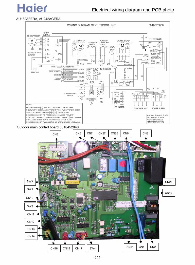
AU182AFERA, AU242AGERA
Outdoor main control board 0010452040
CN9 CN8 CN26CN27CN7CN6 CN3
CN10
CN11
CN12
CN13
CN14
CN16 CN15 CN17 CN21 CN1 CN2
SW3
SW1
SW2
SW4
CN19
CN25
REACTOR
ELECTROLYTIC CAPACITOR
RO
NOTES:
1.DASHED PARTS ARE JUST CAN SELECT ONE BETWEEN THIS TWO FAN MOTOR,AND DIFFERENT TYPE HAVE DIFFERENT MOTOR2.PARTS IN DASHED FRAMES ARE OPTIONAL3.USER SHOULD NOT TO PRESS SW1-4 IN DASHED FRAME
6.USER SHOULD NOT TO CHANG THE DIP SWITCH SW5 ON LED BOARD5.THE LED1-5 ON LED BOARD ARE USED FOR ERROR ALARM
COMPRESSOR INHALE SENSOR
DEFROST TEMP.SENSOR
LOW PRESSURE SWITCH
AMBIENT TEMP. SENSOR
HIGH PRESSURE SWITCH
M
EEV
CN17CN16
CN10
CN3
P P
CN15CN14
CN13
CN11
CN12
SW3SW1
SW2 SW4
POWER SUPPLYTO INDOOR UNIT
N(in)
CN2
W
W
W
W
W
Y/GY/G
RB
B
B
B
B
CN1
L(in)Sig
CN21
CN19
CN25
CN8PTC
RL1
1 2 3 L N
CN2
CN7
CN6
CN3
CN1220VAC-N
220VAC-L
CN9 CN4CN5CN8
AC FAN MOTOR CAP.
WIRING DIAGRAM OF OUTDOOR UNIT 0010576606
4-WAY VALVE
COMPRESSOR VENT SENSOR
ON
SERIAL
CN25
SW5
LED3
LED4
LED5
1 43
4
3
5
1 2
3 4 67
5
8
1
2
LED1
LED2
AC FAN MOTORDC FAN MOTOR
M
ACL
ACN
OR
OR
OR
BLP(+)
N(-)
CN10
B:BLACK BL:BLUE
W:WHITE R:RED
Y/G:YELLOW/GREEN TEMP.:TEMPERATURE
Y/GM
M V V
DC COMPRESSOR
RI
WW
UU
OR:ORANGE
BWR
2
4.AUXILIARY CRANKCASE HEATER IN DASHED FRAME ARE OPTIONAL 8
CN6CN7
CRANKCASE HEATER
6 7
CN26
CN27
CRANKCASE AUXILIARY
HEATER
T3.15
A - 25
0VAC
T25A 250VAC
FUSE1 FUSE
FUSE1
Electrical wiring diagram and PCB photo
-265-

CN8 CN2
CN1
CN5
CN4
CN3
SW05 is used for factory quality control engineers, the default position is: OFF OFF OFF ON for AU182AFERA, as for AU242AGERA, the default position is: OFF OFF OFF OFF, for the above models, there are also module board 0010403555.
Outdoor filter board 0010403645
LED5
LED1
LED2
LED3
LED4SW05
CN25 Outdoor indicator board 0010452047E
Five-indicator combination shows the failure code. SW5(1) SW5(2) SW5(3) SW5(4) compulsory heating/normal operation √/× * * * compulsory cooling/normal operation * √/× * * AU182AFERA/AU242AGERA * * √/× * AC / DC motor * * * √/×
NL
M
LED2
LED1CN25
CRANKCASE HEATER
CN3
4-WAY VALVEAC FAN 2 MOTOR
WU
COMPRESSOR
V
CN1
2 1
T25A 250VACFUSEM
To Power Supply
250VAC T5AFUSE1
2.USER SHOULD NOT TO CHANGE THE DIP SWITCH SW1,SW6.
1.DESHAED FRAMES ARE OPTIONAL, AND IN SOME MODELS ARE NOT AVAILABLE.
NOTE:
CN20N L M
CN12
PMV
SV2
CN19
ON
PTC
SIG
CN1N
SW4 SW5
SW2SW3FA
B : BLACK R : RED
OR : ORANGE W : WHITEY/G : YELLOW/GREEN
HCN17
CN21
CN2L
CN22
CN14
CN2
CN5
CONTROL CIRCUIT BOARD
CN4CN3
CN8
CN7
CIRCUIT BOARD
POWER
U V W
R
T/RB
S
P1N(-) P(+)
+-
ISPM
Y/G
ORBL
BL : BLUE
CAPACITOR
capacitor
REACTOR
SW11 2 3 4 567 8
CN13TO ISPM
To Indoor Unit
CN4
HPLP
CN5CN6CN7CN8CN9CN10CN11
TC TS TD TE TA
SERIAL
CN
15
DC F
AN M
OTOR
M
CN
16
DC F
AN M
OTOR
M
MAC FAN 1 MOTOR
N L M HCN18
capacitor
SV1
CN23
SPDU
SW6
ON
4321
FAN
UP
DOWN COM
ALARM
3Y/G
0150500546CIRCUIT DIAGRAM OF OUTDOOR UNIT
AU282AHERA, AU362AHERA
Electrical wiring diagram and PCB photo
-266-
huangli1883
Line

CN18 CN17 CN19CN14CN13 CN22 CN23 CN1
CN20
CN2
CN21
CN3
CN25
LED1
LED2
SW1
CN24
SW2
SW6
CN4
CN5CN6 CN7
SW5
CN8CN10
CN9SW4
CN11
CN12
SW3CN16 CN15
Outdoor PCB 0010452929
number“1” number“2” Outdoor horse power number “1” Rating OFF OFF 3P OFF Without OFF ON 4P ON With ON OFF 5P number “2” Defrost selection ON ON 6P OFF Normal defrost
number“3” Module selection SW6
ON Defrost without stopping unitOFF Gangda module number“3” Standby ON Hitachi module OFF Pre-set number“4” Motor selection ON Pre-set OFF AC 3-speed number“4” Standby
SW1
ON DC fan motor OFF Pre-set
number“5” number“6” Defrost parameter ON Pre-set OFF OFF 6 OFF ON 7 ON OFF 10 ON ON 7 number“7” Standby OFF Pre-set ON Pre-set number“8” Quiet operation selection OFF Without ON With
Electrical wiring diagram and PCB photo
-267-

AU48NAIERA
M
LED1 LED2
CN19
CRANKCASE HEATER
CON1
4-WAY VALVE
DOWN AC FAN MOTOR
W U
COMPRESSOR
B
B
B
V
M
220VAC T6.3AFUSE1
2.USER SHOULD NOT TO CHANGE THE DIP SWITCH SW1,SW6.
1.DESHAED FRAMES ARE OPTIONAL, AND IN SOME MODELS ARE NOT AVAILABLE.
NOTE:
CN20N L M
CN8
PMV
UNLOADVALVE
CN16
ON
PTC
SIG
CON2N
SW5 SW4
SW2SW3FA
B : BLACK R : RED Y : YELLOW W : WHITEY/G : YELLOW/GREEN
HCN15
CON3L
CN17
CONTROL BOARD
UVWR S TSCP1
SCP2SCN
CON3
+ -
BL : BLUE
CAPACITOR
capacitor
REACTORRELAY
SW11 2 3 4 567 8
CN11
TO ISPM
B
Y Y
YY
R W B
CN1
R
W
BL
L1
L2
L3
N
E
L1’
L2’
L3’
N’
E’
HPLP
CN2CN9CN10 CN3CN4CN6CN5CN7
TC TS TD TE TA
SERIAL
CN
12
DC F
AN M
OTO
R
M
CN
13
DC F
AN M
OTO
R
M
M UP AC FAN MOTOR
Y/G Y/G
N L M HCN14
capacitor
SPRAY VALVE
CN18
SW6
ON
4321
FAN
UP
DOWN
COMALARM
R
W
0150503464CIRCUIT DIAGRAM OF OUTDOOR UNIT
L N
R S T N 1 2Y/G
POWER SUPPLY TO INDOOR UNIT
Y/G
TC: MIDDLE PIPE TEMPERATURE SENSORTS: COMPRESSOR INHALE SENSORTD: COMPRESSOR VENT SENSORTE: DEFROST TEMPREATURE SENSORTA: AMBIENT TEMPERATURE SENSOR
Y/G
NOTE:
FILTER
MODULE
3Y/G
+ -
ONSW1-1 SW1-248000 BTU
60000 BTU ONSW1-1 SW1-2
ONSW1-4DC FAN MOTOR
AC FAN MOTORON
SW1-4
UNITARY SMART INVERTER 4P,5P.6P,7P dip-switch defination number“1” number“2” Outdoor horse power number“1” Rating
OFF OFF 4P OFF without
OFF ON 5P ON with
ON OFF 6P number“2” Defrost selection ON ON 7P OFF Normal defrost
number“3” Module selection SW6 ON Compelling defrost
OFF APY module number“3” Compelling selection
ON Homemade moudule OFF Normal
number“4” Moter selection ON Compelling cooling
OFF AC 3-speed number“4” Compelling heating
SW1
ON DC fan motor OFF Normal
number“5” number“6” Defrost parameter ON Compelling heating
OFF OFF 8
OFF ON 6
ON OFF 10
ON ON 8
number“7” Power source selection
OFF Triplicate-phase
ON Single-phase
number“8” Quiet operation
selection
OFF without
ON with
Electrical wiring diagram and PCB photo
-268-

CN1
CN2
CN3
CN4
CN6
CN5
CN8
SW4
SW2 SW6 SW1 CN19 CON1 CON3
CON2
CN18
CN17
CON4
CON5
CN16
CN15
CN14
CN13 CN12
LED1
LED2
CN11
CN10
CN9
SW3
SW5
CN7
Outdoor PCB 0151800054
LED1 red light:power indicator and failure alarm lamp.when outdoor is normal,LED1 is on,or falsh when failure occurs. LED2 green light:communication indocator lamp.when communication between indoor and outdoor is normal,LED2 will be on,or will be off.
Electrical wiring diagram and PCB photo
-269-
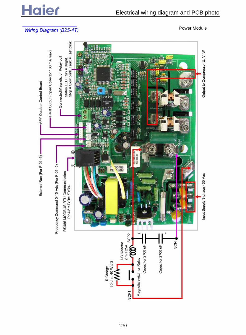
Electrical wiring diagram and PCB photo
-270-
Wiring Diagram (B25-4T)
Power Module
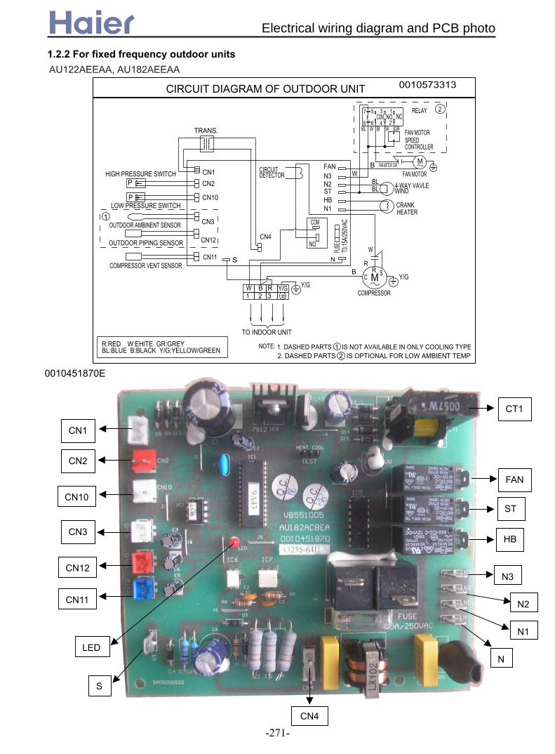
1.2.2 For fixed frequency outdoor units
TO INDOOR UNIT
Y/GBW R21 3
Y/G
N
CN4
OUTDOOR AMBINENT SENSOR
COMPRESSOR VENT SENSOR
OUTDOOR PIPING SENSOR
LOW PRESSURE SWITCH
HIGH PRESSURE SWITCH
SCN11
CN12
CN3
CN1
CN10
CN2
TRANS.
CIRCUIT DETECTOR
FUSE
FAN MOTOR
W
WB
BWFAN MOTOR SPEED CONTROLLER
4-WAY VAVLE WIND
GR
M
NCCOMRELAY
NO2
FAN MOTOR CAP.
NOTE:
1
M
COM
NO
CRANK HEATER
FANN3N2ST
BLBL
BL
CIRCUIT DIAGRAM OF OUTDOOR UNIT 0010573313
W
RB R S
C Y/G
T3.15
A/25
0VAC
1357
8 6 4 2
COMPRESSOR
R:RED W:EHITE GR:GREY BL:BLUE B:BLACK Y/G:YELLOW/GREEN
P
P HBN1
1. DASHED PARTS 1 IS NOT AVAILABLE IN ONLY COOLING TYPE2. DASHED PARTS 2 IS OPTIONAL FOR LOW AMBIENT TEMP
0010451870E
CN2
CN3
CN10 ST
FAN
CT1
HB
CN1
CN11
CN12 N3
N2
N
N1
CN4
LED
S
AU122AEEAA, AU182AEEAA
Electrical wiring diagram and PCB photo
-271-
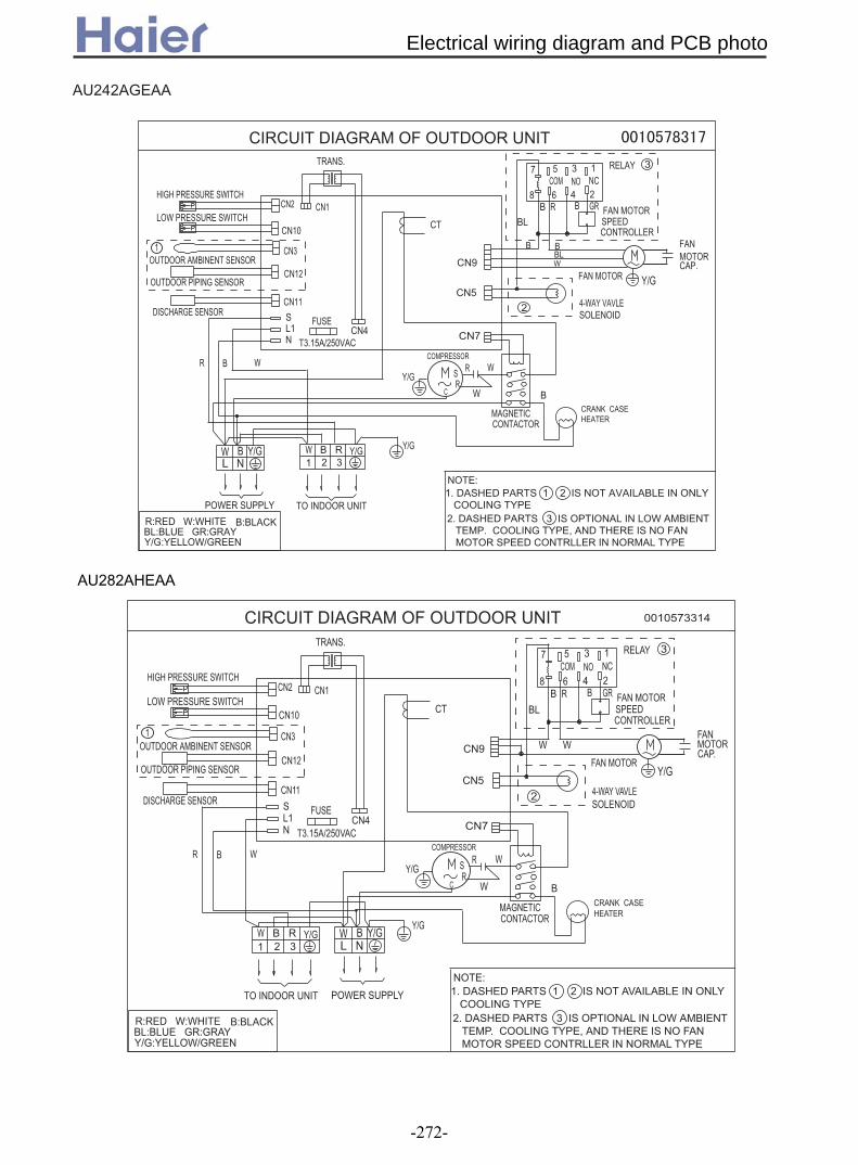
AU242AGEAA
TO INDOOR UNIT
Y/GBW
W
1 2 3R
L1N
CN4 CN7
OUTDOOR AMBINENT SENSOR
DISCHARGE SENSOR
OUTDOOR PIPING SENSOR
LOW PRESSURE SWITCH
HIGH PRESSURE SWITCH
S
CN11
CN12
CN3
CN10
CN2 CN1
TRANS.
CT
MAGNETICCONTACTOR
T3.15A/250VAC
FUSE
FAN MOTOR
B
CN9
CN5
RB
BLFAN MOTOR SPEEDCONTROLLER
GR
NOCOM
RELAY 31357
2468NC
FANMOTORCAP.
Y/G
NOTE:1. DASHED PARTS 1 2 IS NOT AVAILABLE IN ONLY COOLING TYPE
CIRCUIT DIAGRAM OF OUTDOOR UNIT
L NW B Y/G Y/G
POWER SUPPLY
R:RED W:WHITEBL:BLUE GR:GRAY
B:BLACK
Y/G:YELLOW/GREEN
4-WAY VAVLESOLENOID
2
W
WR
BRS
C W
Y/G
COMPRESSOR
CRANK CASEHEATER
1
BR
2. DASHED PARTS 3 IS OPTIONAL IN LOW AMBIENT TEMP. COOLING TYPE, AND THERE IS NO FAN MOTOR SPEED CONTRLLER IN NORMAL TYPE
BLB B
AU282AHEAA
TO INDOOR UNIT
Y/GBW
W
1 2 3R
L1N
CN4 CN7
OUTDOOR AMBINENT SENSOR
DISCHARGE SENSOR
OUTDOOR PIPING SENSOR
LOW PRESSURE SWITCH
HIGH PRESSURE SWITCH
SCN11
CN12
CN3
CN10
CN2 CN1
TRANS.
0010573314
CT
MAGNETIC CONTACTOR
T3.15A/250VAC
FUSE
FAN MOTOR
B
CN9
CN5
RBBL
FAN MOTOR SPEED CONTROLLER
GR
NOCOMRELAY 31357
2468NC
FAN MOTOR CAP.
Y/G
NOTE:1. DASHED PARTS 1 2 IS NOT AVAILABLE IN ONLY COOLING TYPE
CIRCUIT DIAGRAM OF OUTDOOR UNIT
L NW B Y/G Y/G
POWER SUPPLY
R:RED W:WHITE BL:BLUE GR:GRAY
B:BLACK
Y/G:YELLOW/GREEN
4-WAY VAVLESOLENOID
2
WW
WR
BRS
C WY/G
COMPRESSOR
CRANK CASEHEATER
1
BR
2. DASHED PARTS 3 IS OPTIONAL IN LOW AMBIENT TEMP. COOLING TYPE, AND THERE IS NO FAN MOTOR SPEED CONTRLLER IN NORMAL TYPE
Electrical wiring diagram and PCB photo
-272-
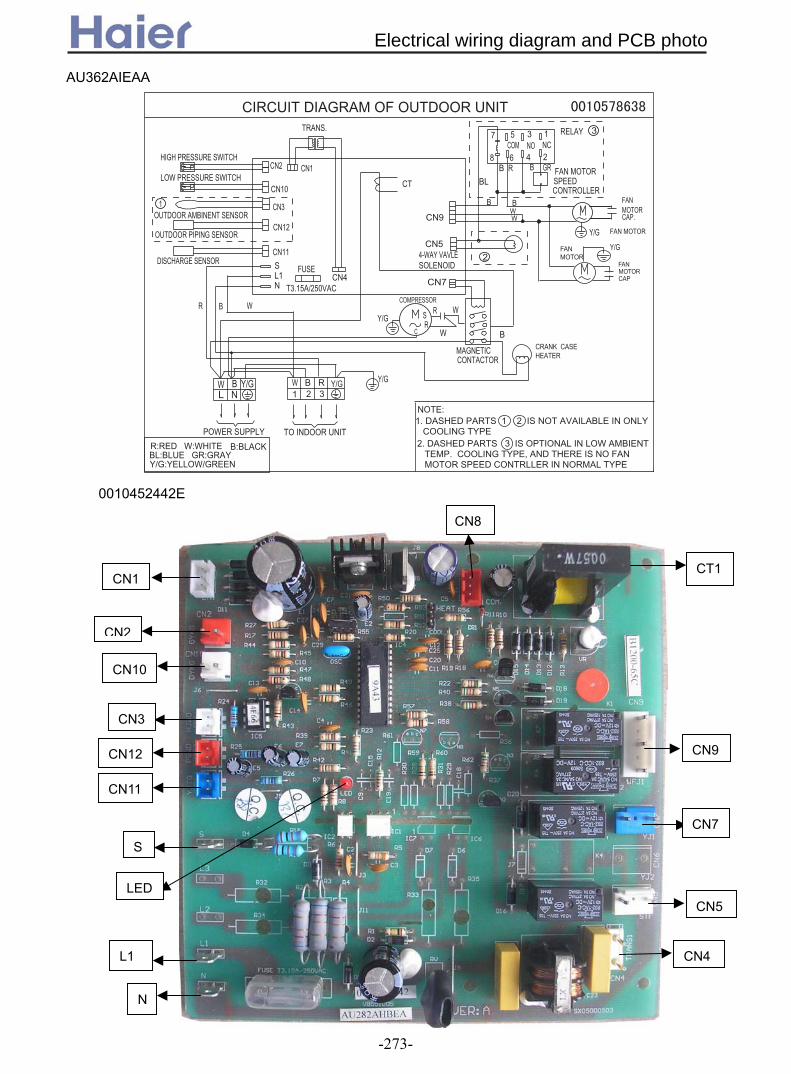
0010452442E
CN8
CN2
CN3
CN10
CN9
CT1
CN7
CN1
CN12
CN5
CN11
S
L1
N
LED
CN4
TO INDOOR UNIT
Y/GBW
W
1 2 3R
L1N
CN4 CN7
OUTDOOR AMBINENT SENSOR
DISCHARGE SENSOR
OUTDOOR PIPING SENSOR
LOW PRESSURE SWITCH
HIGH PRESSURE SWITCH
S
CN11
CN12
CN3
CN10
CN2 CN1
TRANS.
CT
MAGNETICCONTACTOR
T3.15A/250VAC
FUSE
FAN MOTOR
B
CN9
CN5
RB
BLFAN MOTOR SPEEDCONTROLLER
GR
NOCOM
RELAY 31357
2468NC
FANMOTORCAP.
Y/G
NOTE:1. DASHED PARTS 1 2 IS NOT AVAILABLE IN ONLY COOLING TYPE
CIRCUIT DIAGRAM OF OUTDOOR UNIT
L NW B Y/G Y/G
POWER SUPPLY
R:RED W:WHITEBL:BLUE GR:GRAY
B:BLACK
Y/G:YELLOW/GREEN
4-WAY VAVLESOLENOID
2
W
WR
BRS
C W
Y/G
COMPRESSOR
CRANK CASEHEATER
1
BR
2. DASHED PARTS 3 IS OPTIONAL IN LOW AMBIENT TEMP. COOLING TYPE, AND THERE IS NO FAN MOTOR SPEED CONTRLLER IN NORMAL TYPE
B B
FAN MOTOR
FAN MOTOR CAP
Y/G
W
AU362AIEAA
Electrical wiring diagram and PCB photo
-273-

CIRCUIT DIAGRAM OF OUTDOOR UNIT 0010573510
B:BLACKBL:BLUE
TO INDOOR UNIT
HIGH PRESSURE SWITCH
LOW PRESSURE SWITCH
OUTDOOR PIPING SENSOR
COMPRESSOR VENT SENSOR
OUTDOOR AMBINENT SENSOR
Y/G:YELLOW/GREENR:RED
CN2
CN10
CN1
CN3
CN12
CN11
POWER SUPPLY
W
W:WHITE
R BL
B
RR
SW
TBL
RN
S
L2L1
L3
WN 1B
2B Y/G Y/G
3R
T3.15A/250VAC
FUSE
TRANS.
NOTE:
FAN MOTOR
FAN MOTOR
CRANK CASE HEATER
2468
B
CN4
CN9
CN7
CN5
W
RB
BL
B
Y/G
COMPRESSOR
4-WAY VALVE SOLENOID
RW
GR
M
NO7
COM5 3
NC1
FAN MOTOR CAP
FAN MOTOR CAP
2
5CT
1
3
6
4
Y/G
Y/G
1. DASHED PARTS 1 IS NOT AVAILABLE IN COOLING CAPACITY BELOW 36000Btu2. DASHED PARTS 2 3 IS NOT AVAILABLE IN ONLY COOLING TYPE3. DASHED PARTS 4 IS OPTIONAL FOR LOW AMBIENT TEMP. COOLING, AND THERE IS NO FAN MOTOR SPEED CONTRLLER IN NORMAL TYPE4. DASHED PARTS 5 6 ARE NOT AVAILABLE IN SOME TYPE
FAN MOTOR SPEED CONTROLLER
MAGNETIC CONTACTOR
AU28NAHEAA, AU36NAIEAA, AU48NAIEAA, AU60NAIEAA
CIRCUIT DIAGRAM OF OUTDOOR UNIT 0150500023
B:BLACKBL:BLUEGR:GRAY TO INDOOR UNIT
HIGH PRESSURE SWITCH
LOW PRESSURE SWITCH
OUTDOOR PIPING SENSOR
COMPRESSOR VENT SENSOR
OUTDOOR AMBIENT SENSOR
Y/G:YELLOW/GREENR:RED
CN2
CN10
CN1
CN3
CN12
CN11
POWER SUPPLY
W
W:WHITE
R BL
B
B
R S T
RN
S
10P5P
SW1
L2L1
L3
N 1 2Y/G
3
T3.15A/250VAC
FUSE
TRANS.
NOTE:
FAN MOTOR
CRANKCASE HEATER
2468B
CN4
CN9
CN7
CN5
RB
YR
BL
BL
BL
B
Y/G
COMPRESSOR
4-WAY VALVE SOLENOID
RR
ST
W
GR
M
NO7
COM5 3
NC1
FAN MOTOR CAP
1
4CT
2
5
3
Y/G
1. DASHED PARTS 1 2 ARE NOT AVAILABLE IN ONLY COOLING TYPE
5. FOR COOLING CAPACITY IS 52000BTU TYPE,THE LINE THROUGH CT IS ONE CIRCUIT,FOR COOLING CAPACITY IS 42000BTU 36000BTU AND 28000BTU TYPES,THE LINE THROUGH CT IS TWO CIRCUITS.
2. DASHED PART 3 IS OPTIONAL FOR LOW AMBIENT TEMP. COOLING, AND THERE IS NO FAN MOTOR SPEED CONTRLLER IN NORMAL TYPE3. DASHED PARTS 4 5 ARE NOT AVAILABLE IN SOME TYPE
4. FOR COOLING CAPACITY IS 52000BTU AND 28000BTU TYPES,THE DIP SWITCH SW1 IS ON 5P SIDE,FOR COOLING CAPACITY IS 42000BTU AND 36000BTU TYPES,THE DIP SWITCH SW1 IS ON 10P SIDE.
FAN MOTOR SPEED CONTROLLER
MAGNETIC CONTACTOR
AU42NALEAA
Electrical wiring diagram and PCB photo
-274-
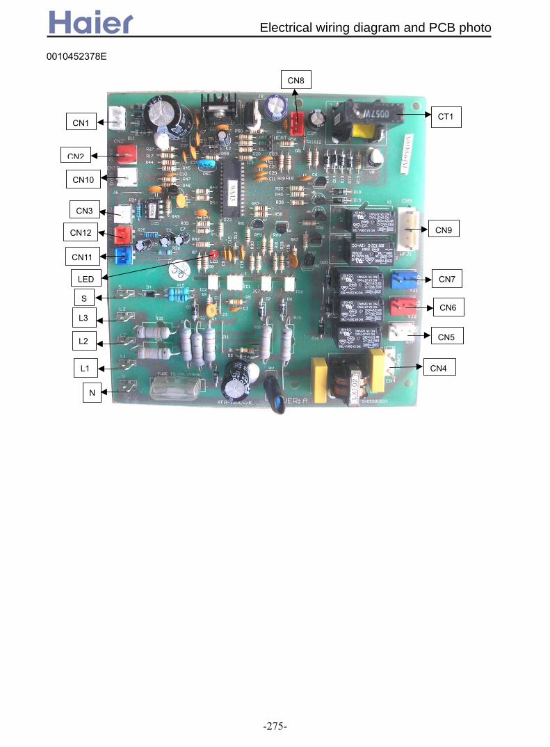
CN8
CN2
CN3
CN10
CN9
CT1
CN7
CN1
CN12
CN11
S
LED
CN5
L1
N
CN4
L3
L2
CN6
0010452378E
Electrical wiring diagram and PCB photo
-275-

2. Sensor characteristic
model name code sub-part code characteristic
outdoor ambient temperaturesensor 0010450192 001A3800082 R25=10KΩ±3%
B25/50=3700K±3%
mid-condenser temperature sensor 0010450195 001A3800093 R25=10KΩ±3%B25/50=3700K±3%
oil temperature sensor 0010451305 001A3800093 R25=10KΩ±3%B25/50=3700K±3%
discharging temperature sensor 0010451313 001A3800096 R80=50KΩ±3%B25/80=4450K±3%
ambient temperature sensor 001A3900159
001A3900003
R25=23KΩ±2.5%B25/50=4200K±3%
coil temperature sensor 001A3900006
001A3900004
R25=10KΩ±3%B25/50=3700K±3%
ambient temperature sensor 0010451323001A3900003
R25=23KΩ±2.5%B25/50=4200K±3%
coil temperature sensor 001A3900006001A3900004
R25=10KΩ±3%B25/50=3700K±3%
ambient temperature sensor 0010451323001A3900003
R25=23KΩ±2.5%B25/50=4200K±3%
coil temperature sensor 001A3800128001A3900004
R25=10KΩ±3%B25/50=3700K±3%
ambient temperature sensor 001A3900005 001A3900003 R25=23KΩ±2.5%B25/50=4200K±3%
coil temperature sensor 001A3900006 001A3900004 R25=10KΩ±3%B25/50=3700K±3%
AB122ACERAAC122ACERAAB182ACERAAC242ACERAAB482AEERAAC482AFERAAB182ACEAAAC182ACEAAAB242ACEAAAD242ALEAAAD242AMEAAAC282AFEAAAC282AFERAAD282AMEAAAD282AHEAAAB362ACEAAAC362AFEAAAC362AFERAAD362AMEAAAD362AHEAAAB422AEEAAAD482AHEAAAD602AHEAA
AU242AGERA
AB242ACERAAB282ACEAAAB282AEERAAB362ACERAAB482ACEAAAB602ACEAA
AD122ALERAAD242ALERAAD182ALEAAAC242ACEAA
AD242AMERAAD282AMERAAD362AMERA
Sensor characteristic
-276-
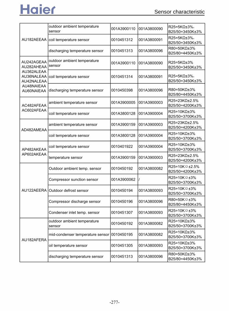
outdoor ambient temperaturesensor 001A3900110 001A3800090 R25=5KΩ±3%,
B25/50=3450K±3%
coil temperature sensor 0010451312 001A3800091 R25=5KΩ±3%,B25/50=3450K±3%
discharging temperature sensor 0010451313 001A3800096 R80=50KΩ±3%B25/80=4450K±3%
outdoor ambient temperaturesensor 001A3900110 001A3800090 R25=5KΩ±3%
B25/50=3450K±3%
coil temperature sensor 0010451314 001A3800091 R25=5KΩ±3%,B25/50=3450K±3%
discharging temperature sensor 0010450398 001A3800096 R80=50KΩ±3%B25/80=4450K±3%
ambient temperature sensor 001A3900005 001A3900003 R25=23KΩ±2.5%B25/50=4200K±3%
coil temperature sensor 001A3800128 001A3900004 R25=10KΩ±3%B25/50=3700K±3%
ambient temperature sensor 001A3900159 001A3900003 R25=23KΩ±2.5%B25/50=4200K±3%
coil temperature sensor 001A3800128 001A3900004 R25=10KΩ±3%B25/50=3700K±3%
coil temperature sensor 0010401922 001A3900004 R25=10KΩ±3%B25/50=3700K±3%
temperature sensor 001A3900159 001A3900003 R25=23KΩ±2.5%B25/50=4200K±3%
Outdoor ambient temp. sensor 0010450192 001A3800082 R25=10KΩ±2.5%B25/50=4200K±3%
Compressor sunction sensor 001A3900062 / R25=10KΩ±3%B25/50=3700K±3%
Outdoor defrost sensor 0010450194 001A3800093 R25=10KΩ±3%B25/50=3700K±3%
Compressor discharge sensor 0010450196 001A3800096 R80=50KΩ±3%B25/80=4450K±3%
Condenser inlet temp. sensor 0010451307 001A3800093 R25=10KΩ±3%B25/50=3700K±3%
outdoor ambient temperaturesensor 0010450192 001A3800082 R25=10KΩ±3%
B25/50=3700K±3%
mid-condenser temperature sensor 0010450195 001A3800082 R25=10KΩ±3%B25/50=3700K±3%
oil temperature sensor 0010451305 001A3800093 R25=10KΩ±3%B25/50=3700K±3%
discharging temperature sensor 0010451313 001A3800096 R80=50KΩ±3%B25/80=4450K±3%
AC482AFEAAAC602AFEAA
AD482AMEAA
AU182AFERA
AU122AEERA
AP482AKEAAAP602AKEAA
AU242AGEAAAU282AHEAAAU362ALEAAAU36NALEAAAU42NALEAAAU48NAIEAAAU60NAIEAA
AU182AEEAA
Sensor characteristic
-277-

outdoor ambient temperaturesensor 0010450192 001A3800082 R25=10KΩ±3%
B25/50=3700K±3%
mid-condenser temperature sensor 0010450195 001A3800082 R25=10KΩ±3%B25/50=3700K±3%
oil temperature sensor 0010451305 001A3800093 R25=10KΩ±3%B25/50=3700K±3%
discharging temperature sensor 0010451313 001A3800096 R80=50KΩ±3%B25/80=4450K±3%
Condenser inlet temp. sensor 0010451329 001A3800093 R25=10KΩ±3%B25/50=3700K±3%
temperature sensor 001A3900005 001A3900003 R25=23KΩ±2.5%B25/50=4200K±3%
coil temperature sensor 001A3900006 001A3900004 R25=10KΩ±3%B25/50=3700K±3%
AS182AVERA coil temperature sensor 001A3900059 /
1.R25=10KΩ±3%B25/50=3700K±3%2.R25=23KΩ±2.5%B25/50=4200K±3%
ambient temperature sensor 001A3800127 001A3900003 R25=23KΩ±2.5%B25/50=4200K±3%
coil temperature sensor 0010401922 001A3900004 R25=10KΩ±3%B25/50=3700K±3%
ambient temperature sensor 001A3900005 001A3900003 R25=23KΩ±2.5%B25/50=4200K±3%
coil temperature sensor 001A3800128 001A3900004 R25=10KΩ±3%B25/50=3700K±3%
Outdoor ambient temp. sensor 0010450192 001A3800082 R25=10KΩ±2.5%B25/50=4200K±3%
Compressor sunction sensor 0010450194 001A3900004 R25=10KΩ±3%B25/50=3700K±3%
Outdoor defrost sensor 0010451307 001A3900004 R25=10KΩ±3%B25/50=3700K±3%
Compressor discharge sensor 0010451303 001A3800096 R80=50KΩ±3%B25/80=4450K±3%
mid-condenser temperature sensor 0010451329 001A3900004 R25=10KΩ±3%B25/50=3700K±3%
Indoor ambient temp. sensor 001A3900159 001A3900003 R25=23KΩ±2.5%B25/50=4200K±3%
Indoor coil temp. sensor 0010401922 001A3900004 R25=10KΩ±3%B25/50=3700K±3%
Indoor ambient temp. sensor 001A3900005 001A3900003 R25=23KΩ±2.5%B25/50=4200K±3%
Indoor coil temp. sensor 0010401922 001A3900004 R25=10KΩ±3%B25/50=3700K±3%
AD482AHERA
AU48NAIERA
AD482ANERA
AP422ACEAA
AD282AHEAAAD362AHEAA
AC182ACERAAD182AMERA
AU282AHERAAU362AHERA
Sensor characteristic
-278-

T() Rnom(KΩ) T() Rnom(KΩ) T() Rnom(KΩ) T() Rnom(KΩ)-20 47.12 1 16.55 22 5.744 43 2.339-19 45.17 2 15.7 23 5.482 44 2.25-18 43.24 3 14.89 24 5.235 45 2.165-17 41.35 4 14.13 25 5 46 2.084-16 39.49 5 13.41 26 4.778 47 2.006-15 37.68 6 12.73 27 4.567 48 1.932-14 35.92 7 12.08 28 4.36 49 1.862-13 34.21 8 11.47 29 4.179 50 1.793-12 32.56 9 10.9 30 3.993 51 1.729-11 30.37 10 10.35 31 3.819 52 1.667-10 29.44 11 9.837 32 3.657 53 1.608-9 27.57 12 9.351 33 3.514 54 1.551-8 26.57 13 8.892 34 3.368 55 1.457-7 25.22 14 8.458 35 3.23 56 1.445-6 23.94 15 8.048 36 3.098 57 1.395-5 22.72 16 7.661 37 2.973 58 1.347-4 21.55 17 7.295 38 2.845 59 1.301-3 20.45 18 6.949 39 2.741 60 1.257-2 19.39 19 6.622 40 2.633-1 18.39 20 6.313 41 2.5360 17.45 21 6.021 42 2.432
R25=5KΩ±1%B25/50=3450K±1%
Sensor characteristic
-279-

T() Rnom(KΩ) T() Rnom(KΩ) T() Rnom(KΩ) T() Rnom(KΩ) T() Rnom(KΩ)T()Rnom(KΩ)-20 281.34 32 16.65 -30 11600 22 592 -20 90.79 32 7.52-19 263.56 33 15.92 -29 10860 23 553.6 -19 85.72 33 7.23-18 247.04 34 15.22 -28 10170 24 536.6 -18 80.96 34 6.95-17 231.66 35 14.56 -27 9529 25 511.1 -17 76.51 35 6.68-16 217.35 36 13.93 -26 8932 26 486.9 -16 72.33 36 5.43-15 204.02 37 13.34 -25 8375 27 464 -15 68.41 37 5.6-14 191.61 38 12.77 -24 7856 28 442.3 -14 64.73 38 5.59-13 180.04 39 12.23 -23 7372 29 421.7 -13 61.27 39 5.73-12 169.24 40 11.71 -22 6920 30 402.1 -12 58.02 40 5.52-11 159.17 41 11.22 -21 6498 31 383.6 -11 54.97 41 5.32-10 149.77 42 10.76 -20 6104 32 366 -10 52.1 42 5.12-9 140.99 43 10.31 -19 5736 33 349.3 -9 49.4 43 4.93-8 132.78 44 9.89 -18 5392 34 333.5 -8 46.86 44 4.9-7 125.11 45 9.49 -17 5071 35 318.4 -7 44.46 45 4.58-6 117.93 46 9.1 -16 4770 36 304.1 -6 42.21 46 4.42-5 111.22 47 8.74 -15 4488 37 290.5 -5 40.08 47 4.26-4 104.93 48 8.39 -14 4225 38 277.6 -4 38.08 48 4.11-3 99.04 49 8.05 -13 3978 39 265.3 -3 36.19 49 3.97-2 93.52 50 7.73 -12 3747 40 253.6 -2 34.41 50 3.83-1 88.35 51 7.43 -11 3531 41 242.5 -1 32.73 51 3.70 83.5 52 7.14 -10 3328 42 232 0 31.14 52 3.571 78.94 53 6.86 -9 3138 43 221.9 1 29.64 53 3.452 74.67 54 6.6 -8 2960 44 212.3 2 28.22 54 3.333 70.65 55 6.34 -7 2793 45 203.2 3 26.4 55 3.224 66.88 56 6.1 -6 2636 46 194.5 4 25.61 56 3.115 63.33 57 5.87 -5 2489 47 186.3 5 24.41 57 3.116 60 58 5.65 -4 2351 48 178.4 6 23.27 58 2.97 56.86 59 5.44 -3 2221 49 170.9 7 22.2 59 2.818 53.91 60 5.24 -2 2099 50 163.7 8 21.18 60 2.729 51.13 -1 1984 51 155.9 9 20.21 61 2.6310 48.51 0 1877 52 150.4 10 19.3 62 2.5411 46.04 1 1775 53 144.2 11 18.43 63 2.4912 43.72 2 1680 54 138.3 12 17.61 64 2.3813 41.52 3 1590 55 132.7 13 16.83 65 2.314 39.45 4 1506 56 127.3 14 16.09 66 2.2315 37.5 5 1426 57 122.1 15 15.38 67 2.1616 35.66 6 1351 58 117.2 16 14.71 68 2.0917 33.92 7 1280 59 112.5 17 14.08 69 2.0318 32.27 8 1214 60 108 18 13.48 70 1.9619 30.72 9 1151 61 103.8 19 12.9 71 1.920 29.25 10 1092 62 99.68 20 12.36 72 1.8521 27.86 11 1036 21 11.84 73 1.7922 26.54 12 983.2 22 11.34 74 1.7323 25.3 13 933.4 23 10.87 75 1.6824 24.12 14 886.4 24 10.43 76 1.6325 23 15 841.9 25 10 77 1.5826 21.94 16 800 26 9.59 78 1.5427 20.94 17 760.8 27 9.21 79 1.4928 19.99 18 722.8 28 8.84 80 1.4529 19.09 19 687.3 29 8.4830 18.23 20 653.8 30 8.1531 17.42 21 622 31 7.83
R25=23KΩ±2.5%B25/50=4200K±3%
R80=50KΩ±3%B25/80=4450K±3%
R25=10KΩ±3%B25/50=3700K±3%
Sensor characteristic
-280-

1.5
2. Indoor AUTO FAN control
peed is AUTO MED, when
3. AUTO mode control
Tr<Ts-3 select HEAT or FAN mode
the unit will enter HEAT or FAN mode, or the unit will still be in COOL mode; 3.4 For the heat pump unit, if the unit is in HEAT mode at present, when it arrives compressor-stop
1.General features 1.1 The running mode includes AUTO, COOL, DRY, FAN and HEAT; can set the compulsory cooling function; AUTO/HIGH/LOW 3-speed for indoor motor; can set the TIMER ON,TIMER OFF, TIMER ON/OFF and SLEEP function; auto-check water level and control the water drainage of water pump; the swing is controlled by stepping motor; 3-minute protection for compressor; anti-overload protection, anti-freezed protection and bad-sendor protection; check indoor ambient temperature, indoor coil temperature and outdoor coil temperature; can be controlled by central controller. 1.2 LED indication: when the unit is switched on by the controller, the POWER LED will be ON, when being switched off, the POWER LED will be OFF. If the controller is in TIMER and SLEEP mode, the TIMER LED will be on; if it is not in TIMER and SLEEP mode, the TIMER LED will be off. When the compressor is running, the compressor LED will be on; when it stops, this LED will be off. 1.3 Temperature compensation control: select the 4 degree compensation or no compensation by the dip switch on indoor PCB. 1.4 There is set temperature in AUTO mode as default.
Tr stands for room temperature; Ts stands for set temperature; Tc stands for defrosting temperature; t stands for compensation temperature; ΔT stands for temperature difference. 1.6 ΔT=Tr-Ts+t (t=0 in cooling mode) 1.7 Δ T=Ts-Tr+t (t=compensation value, with compensation in heating mode; t=0, without compensation in heating mode)
2.1 If the unit enters AUTO FAN for the first time, when ΔT>2, select high speed; whenΔT≤0, select low speed; or it will select med speed; when thermostat is OFF, fan will be low speed. (the conversion temperature difference is 1 degree). 2.2 If the present fan speed is AUTO HIGH, whenΔT<2, fan speed will change to AUTO MED. 2.3 If the present fan s ΔT<0, fan speed will change to AUTO LOW; whenΔT>3, fan speed will change to AUTO HIGH. 2.4 If the present fan speed is AUTO LOW, whenΔT>1, fan speed will chenge to AUTO MED. 2.5 Fan speed conversion in AUTO FAN mode: the conversion will delay for 3 minutes from HIGH to LOW, and no delay from LOW to HIGH. 2.6 When the fan speed is HIGH/LOW/MED, on the condition that the protection does not act, the unit will run at the set fan speed; when the protection acts, for the sake of the normal operation, the fan speed will be forced to conversion; in Dry mode, fan motor will be changed as request. 3. AUTO mode control 3.1 When entering AUTO for the first time, the unit will select the running mode due to the below conditions, then perform the selected mode.
Tr≥Ts-3 select COOL mode (includes FAN mode) Tr<Ts-3 select HEAT or FAN mode
3.2 After entering the AUTO mode, the mode can change over among COOL, HEAT or FAN modes according to the indoor ambient temperature (conversion temperature difference is ±3). 3.3 If the unit is in COOL mode, when it arrives compressor-stop temperature, the compressor will stop; after compressor stops for 15 minutes, the unit will check the room temperature, if Tr<Ts-3,
the unit will enter HEAT or FAN mode, or the unit will still be in COOL mode;
3. Electric control functions 3.1 Electric control function for the unit with 0010452478E and 0010452325E unit
Electric control functions
-281-

temperature, the compressor will stop; after the compressor stops for 15 minutes, the unit will check the room temperature, if Tr>Ts+3, the unit will enter COOL mode, or it will still be in HEAT mode. 3.5 For cooling only unit, if the unit is at FAN mode, if Tr>Ts+3, the unit will enter COOL mode. 3.6 When the unit is in HEAT mode, if indoor heat exchanger temperature rises up to over 63, the unit will change into COOL mode. And within 1 hour, the heat exchanger temperature will not be limited, the heating operation will stop temporarily. 1 hour later, the unit will select the proper mode due to the above condition. 4. COOL mode control 4.1 4-way valve being powered off, compressor run/stop will depends on the temperature difference between the room temperature and the set temperature. 4.2 In cooling mode, every time the compressor starts up, within 6 minutes, the compressor will not be limited by the temperature sensor, but the set temperature change, shutoff signal and protection action will not be limited by 6-minute protection, and the compressor can stop immediately. 4.3 ΔT≥1 compressor will run;
ΔT≤-1 compressor will stop; -1<ΔT<1 compressor will stay in original state
4.4 Anti-freezed protection (invalid in compulsory operation, trial running, heating mode) When the unit has run for over 6 minutes after compressor starts up, if indoor coil temperature Tg<1, the compressor and the outdoor motor will stop, and the unit will change to FAN mode; 9 minutes later after compressor stops and when indoor coil temperature rises to 10, the unit will resume to COOL mode, the compressor and the outdoor motor will run again. 4.5 Temperature cutoff protection In cooling mode, the unit will check indoor coil temperature every time the compressor has run for 1 minutes, when indoor coil temperature Tg>Tr+5, the unit will stop and 3 minutes later restart up; if the temperature cutoff occurs for 3 times continuously, the unit will stop and alarm. 5. DRY mode control 5.1 When the uint enters DRY mode for the first time, the compressor, outdoor motor and indoor motor will perform according to the below conditions: ΔT>2, the compressor and the outdoor motor will run continuously, indoor motor will run at the set speed, this area is defined as Area A; 0≤ΔT≤2, the compressor and the outdoor motor will always run for 10 minutes and then stop for 6 minutes, indoor motor will be LOW speed, this area is defined as Area B; ΔT<0, the compressor and the outdoor motor will stop, indoor motor will run at Low speed, this area is defined as Area C. 5.2 After the unit is running in DRY mode, the system will change over among Area A, Area B, and Area C (the conversion temperature difference ±1) If the system is in Area A, when ΔT<1, change to Area B; If the system is in Area C, when ΔT>1, change to Area B; If the system is in Area B, when ΔT>3, change to Area A; WhenΔT<-1, change to Area C.
The inverter unit DRY operation: Tr-Ts>2, running in COOL mode; Tr-Ts≤2, the compressor will run at 34Hz and 60Hz by turns, the duration time is 6 minutes at 34Hz, and the duration time is 10 minutes at 60Hz; Tr-Ts<15, (Ts=16), the compressor wil run intermittently, run for 10 minutes and stop for 6
3.4 For the heat pump unit, if the unit is in HEAT mode at present, when it arrives compressor-stop
Electric control functions
-282-

minutes by turns at 60Hz. 6. FAN mode control The compressor and the outdoor motor will stop running, indoor motor can be set at high/med/low speed, the fan blade can swing or stay at one position. In this mode, you can set the TIMER and SLEEP function. 7. HEAT mode control 7.1 4-way valve control: in heating mode, compressor startup----4-way valve being electrified 10 seconds ahead; compressor running----4-way valve retains original state; compressor shutoff----4-way valve being powered off 2 minutes and 50 seconds later (except for defrosting, 4-way valve being electrified 5 seconds ahead, and being powered off 55 seconds later). 7.2 In heating mode, for everytime the compressor startup (thermostat ON), within 6 minutes, the 4-way valve will not be limited by the temperature sensor, but for the set temperature change, shutoff signal and the protection, the compressor can stop immediately without 6-minute limitation. 7.3 ΔT≥1 compressor running, indoor motor runs at anti-cold air mode;
ΔT≤-1 compressor stops, indoor motor runs at blowing remaining heat mode; -1<ΔT<1 compressor retains original state
7.4 Overheat protection (for the unit with outdoor PCB, the outdoor motor is controlled by outdoor unit, but the compressor is still controlled by indoor unit, and their temperature points will not be accordant completely) In heating mode, compressor has started up and indoor motor has run for over 30 seconds, if indoor coil temperature Tg>60, outdoor motor will stop; if Tg<56, and outdoor motor has stop for 45s, outdoor motor will run again; if Tg>73, the compressor will stop and indoor motor will run according to the thermostat state. After the compressor stops for 3 minutes and Tg reduces to 48, the unit will resume to heating mode, and the compressor and the outdoor motor will run again. 7.5 Temperature cutoff protection In heating mode (besides the defrosting), the unit will check indoor coil temperature every time the compressor has run for 1 minutes, when indoor coil temperature Tg<Tr-5, the unit will stop and 3 minutes later restart up; if the temperature cutoff occurs for 3 times continuously, the unit will stop and alarm. 7.6 Anti-cold air function in heating mode After entering heating mode, or last defrosting is over, the compressor will start up, if Tg<28, indoor motor will stop; if 38>Tg≥28, indoor motor will run at low speed; if Tg≥38 or the compressor has run for over 4 minutes, indoor motor will run at the set speed; once the motor has started up, it will not stop because of Tg reduction. 7.7 Blowing remaining heat function In heating mode, the thermostat is OFF, the compressor stops, indoor motor will run at low speed until Tg<28 and has run for 50 seconds at least. 7.8 Note: in heating mode, “the compressor stops----indoor motor delays to stop” adjust if the pipe
blows remaining heat; “the compressor startup----indoor motor delays to start up” adjust if the pipe is anti-cold air; in other conditions, the compressor and the indoor motor are allowable not to be in company. In cooling mode, the motor will run according to the control, not together with the compressor. 7.9 Defrosting function in heating mode In defrosting and when the compressor resumes to run for 3 minutes after defrosting is over, the unit will not adjust the sensor failure.
Manual defrost: In heating mode, the set temperature 30 and in high speed, in 5 seconds, press
Electric control functions
-283-

SLEEP button 6 times continuously, then the buzzer will sound 3 times, you can enter the manual defrosting. At this moment, the unit will not adjust the enter condition of defrost and begin to defrost function directly, whose procedure is as the same as the auto defrost; the quit condition is that the defrosting time is up to 5 minutes. Auto defrost: Project 1: with outdoor PCB a. Enter condition In heating mode, the compressor has run for 45 minutes continuously. The compressor has run for 60 minutes in all and has run for over 5 minutes continuously. If one of the above conditions can be met, and indoor unit receives the defrosting temp. arrival signal from outdoor, the unit begins to defrost and sends the defrosting beginning signal to outdoor. b. Quit condition The defrosting temp. arrival signal from outdoor is cancelled or the defrosting time is over 12 minutes (including each 1-minute conversion time for before and after defrosting), the defrosting is over and sends the defrosting cancelled signal to outdoor unit. Project 2: For the unit without outdoor PCB and defrosting sensor a. Enter condition Indoor occurs overload protection and outdoor motor stops, if outdoor motor can not enter
overheat state in 10 minutes after it runs again, also the compressor runs for 45 minutes in all and has run for over 20 minutes continuously, Tg is below 43;
The compressor runs for 20 minutes continuously, Tg will reduce 1 for every 6 minutes, and Tg is below 40, 5 minutes later after the compressor restarts up.
The compressor runs for 3 hours in all and has run for over 20 minutes continuously, Tg is below 40;
The temperature difference between Tg and Tr is below 16 and the compressor runs for 45 minutes in all and has run for over 20 minutes continuously, Tg is below 40
If one of the above conditions can be met, the unit will enter the defrost. b. Quit condition The defrosting time is over 10 minutes (excluding conversion time for before and after defrosting). Project 3: For the unit without outdoor PCB but with defrosting sensor a. Enter condition In heating mode, after the compressor starts up, the compressor and the outdoor motor have run for at least 5 minutes; The compressor total running time is over 30 minutes, Tp<-18, enter defrosting (signal time over 5 minutes);
The compressor total running time is over 30 minutes, Tp<-6, enter defrosting (signal time over 5 minutes); b. Quit condition The defrosting time is over 10 minutes (excluding conversion time for before and after defrosting). Or Tp>12, quit defrosting. After defrosting begins, the loads will operate as below: a. In defrosting: For the unit with outdoor PCB: the operation of the compressor and the 4-way valve is controlled by indoor unit, the outdoor motor operation is controlled by outdoor unit. For the uit without outdoor PCB: the compressor and the outdoor motor stop, meanwhile, indoor motor will stop too. 55 seconds later, 4-way valve will close. Another 5 seconds later, the
Electric control functions
-284-

b. Quit defrosting: The compressor will not stop, outdoor motor starts up and after it runs for 30 seconds, 4-way valve will open, indoor motor will run as anti-cold air state. For the unit with auxiliary electric heating function: a. If the auxiliary electric heating function is working when the defrosting condition is met, please
stop electric heater firstly, 20 seconds later, defrosting can begin; b. After defrosting, the unit will adjust the working state of electric heater according to the setting
before defrosting. 8. Auxiliary electric heating function (valid in heating mode or heating state in AUTO mode)
Enter condition: 1) ΔT>1 2) Thermostat ON and running for 1 minute 3) Tr<26 4) Indoor motor running 5) Electric heating function start signal available (cancelled) 6) The system working in heating mode or in heating state of AUTO mode 7) Tg<48 If the above conditions can all be met, the electric heating function will work.
Quit condition: 1) ΔT≤1 2) Thermostat OFF 3) Tr>26 4) Indoor motor stops 5) Electric heating function start signal not available (cancelled) 6) The system in non-heating operation 7) Tg>52 If one of the above conditions can be met, the electric heater will stop. 9. Special functions 9.1 CLOCK setting and TIMER function The unit can set 24-hour TIMER ON/OFF, and the min. unit is 1 minute, after being set, the timer lamp of indoor will be on, and after the timer is over, the timer lamp will be off. TIMER ON: RUN LED is off, compressor LED is off, and TIMER LED is on, the unit is in stop state. When timer is over, the unit begins to run, and the timer LED is off. The unit operation begins from receiving the timer signal for the last time. The SLEEP function only can be set before the TIMER ON begins. TIMER OFF: the unit running, the timer LED on, while the timer is over, timer LED off, the unit will stop, the sleep can be set, the sleep time will replace the original time of TIMER ON/OFF. TIMER ON/OFF set at the same time: when the timer on/off is set, the timer LED will be off; the sleep function can be set, the sleep time will replace the original time of TIMER ON/OFF.
compressor starts up.
9.2 SLEEP function (energy saving function at night) 9.2.1 Standard sleep function: in cooling or dry mode, after running at SLEEP mode for 1 hour, the set temperature will rise 1, another 1 hour later, the set temperature will rise another 1; the unit continues running for 6 hours, then the unit will stop. 9.2.2 Standard sleep function: in heating mode, after running at SLEEP mode for 1 hour, the set temperature reduces 2, another 1 hour later, the set temperature will reduce 2, and another 3 hours later, the set temperature rises 1; the unit continues running for 3 hours, then the unit will stop. 9.2.3 Non-standard SLEEP function: the sleep function can realize 1~8 hours sleep mode when being combined with the TIMER function.
1) When in Auto mode, the unit will make SLEEP operation due to the setting. 2) After setting SLEEP function, the clock can not be adjusted. 3) If sleep time is no more than 8 hours, when the time arrives, the unit wil shut off. 4) If sleep function is set after setting TIMER OFF function, the unit will execute as the SLEEP
Electric control functions
-285-
function. 5) If SLEEP function is set, the TIMER function can not be set. 6) If sleep function is set after setting TIMER ON function, the sleep function only can be set
befroe the TIMER ON time arrives. After setting sleep function, press CLOCK button to check the clock; press TEMP button to display the set temperature, and press again to change the set temperature. 9.3 Emergency operation Press emergency button for over 1 second continuously, when loosing it, the buzzer will sound once. Emergency operation: AUTO cooling state, the set temperature 24, indoor motor at high speed, not adjusting the temperature sensor abnormal and the protection, the thermostat ON, 3 minutes later, the compressor starts up, and another 3 minutes later, quit the trial running and enter the normal operation as the setting; Press again, enter the shutoff state. 9.4 Compulsory cooling operation In OFF state, press compulsory button for over 10 seconds continuously, loose it and the buzzer will sound twice, then the unit enters the compulsory cooling operation, or after the panel receives the compulsory cooling signal, the unit enters the compulsory cooling state. For the first time, there is no compressor 3-minute protection, the unit will run for 5 minutes in cooling mode, and indoor/outdoor motors are in high speed; in the 5 minutes, the system will not adjust the protection and not be limited by the ambient temperature, but the compressor will be limited by 3-minute protection. 5 minutes later, the unit will enter the normal state. In the compulsory cooling state, you can press any button to quit the state. For the unit with outdoor PCB, the compressor and the outdoor motor will be controlled by outdoor PCB. 9.5 Water level inspection and water pump control 1) In COOL (including cooling state of AUTO mode and the compulsory cooling) and DRY mode, as long as the compressor runs, water pump will work; and once the compressor stops, water pump will stop 5 minutes later; 2) In standby state of cooling mode, heating mode and fan mode (including auto fan mode), after
water tank is full, the float switch will disconnect, if the controller detects this signal for 2 seconds, the water pump will begin to work. After the float resets, water pump will continue working and stops 5 minutes later;
3) If the water-full signal is detected for over 5 minutes, the compressor will stop; water pump will work for 5 minutes and stop for 5 minutes, then repeat as a cycle, until the float resets, the water pump will stop 5 minutes later; if water pump has repeated for 4 cycles, the float can not reset, and the unit will alarm water drainage abnormal. And the water pump will continue the cycle.
9.6 High pressure switch control: 3 minutes later after compressor starts up, the system will check the pipe pressure. If the pipe
pressure is over high and high pressure switch acts for over 30 seconds, the compressor and outdoor motor will stop, 3 minutes later, the unit will resume. If in 30 minutes the unit stops for 3 times because of overhigh pressure, the system will alarm, then compressor will not start up again; when being electrified after being powered off, the protection will be cancelled.
Low pressure switch control (without outdoor PCB): When compressor is running, the unit will check pipe pressure, when pipe pressure is over low
and low pressure switch acts for 30 seconds, compressor and outdoor motor stop, the unit will
Electric control functions
-286-
alarm, and compressor will not start up; when being electrified after being powered off, the protection will be cancelled. 9.7 Exterior alarm input: In normal state, it is off. When the exterior environment is abnormal, the system cannot ensure the normal signal input, so the air conditioning system will stop and alarm, until the normal signal resumes, the air conditioner will resume automatically. 9.8 Time shorting function If the time shorting port is in short circuit, the unit will perform a 1/60 time shorting control. 9.9 Auto-restart a. Entering condition: In 5 seconds press the SLEEP button for 10 times, the buzzer sounds 4 times. At the same time, the present state will be saved in EEPROM. b. After entering the auto-restart state, the following information will be memorized: ON/OFF, running mode (AUTO, HEAT, COOL, DRY, FAN), fan speed (AUTO, HIGH, MED, LOW), the set temperature (16-30), the louver position and HEALTH; while the TIMER, SLEEP and CLOCK will not be memorized. c. Quit condition: in 5 seconds press SLEEP button 10 times, the buzzer will sound 2 times. 9.10 Auto check function Before being electrifed, it is in short circuit; after being electrified, 10 seconds later, it will enter auto-check circuit. Before auto-check, please ensure the input values (sensor, pressure switch) normal, or the buzzer will sound 5 times to show there is abnormal; all the ports will output as the following sequence: run lamp-timer lamp-electric heater-water pump-compressor/compressor lamp-outdoor motor-4-way valve; after the auto-check is finished, the buzzer sounds once. 9.11 Outdoor crankcase heater (only for the unit with low ambient cooling function) For the unit without outdoor PCB, but with low ambient cooling function, outdoor crankcase heater will be controlled by indoor unit. Once being electrified, electric heater will begin to work until the compressor is running.
10. System protection 10.1 3-minute protection for compressor startup After the compressor stops, at least 3 minutes later, the compressor can restart up; if the unit is powered off in running, after being electrified, 3 minutes later, the compressor can restart up. Being electrifed for the first time, there is 3-minute delay protection. 10.2 Anti-current rush 2 seconds later after compressor is running, outdoor motor can work.
Electric control functions
-287-

High
Mid
3
1
Mid
Low
Low
High 2
0 ΔT
ΔT
1.General features 1.1 Control mode: remotr or wired control + connecting port of long-distance control + passive
port control. 1.2 Temperature control: 16-30;
1.3 Precise of temperature control: ±1;
1.4 Indoor fan speed: AUTO, HIGH, MIDDLE, LOW (no AUTO when in FAN mode); 1.5 Swing control: the swing are controlled by the synchronous motor, main control board
receive usable signal and set in swing mode or remain in other mode; 1.6 running mode: AUTO , COOL, DRY, FAN and HEAT; 1.7 Healthy function: 5VDC UV generator, 12VDC negrative ion generator - high voltage
collecting-dirt, 220VAC negrative ion generator – oxygen pump; 1.8 Filter up-down control: adopt double-direction synchronous motor; 1.9 Auxiliary electric heating function: 12VDC control signal, 220VAC control signal or control
switch; 1.10 Fresh air control: 12VDC DC motor,220VAC AC control port output; 1.11 CLOCK setting, TIMER ON, OFF, ON/OFF and SLEEP fuction (only TIMER function is
viable and temperature variety is unviable when running the SLEEP function in FAN mode); 1.12 Drain system function: Water level inspection and water pump control 1.13 Compulsory cooling operation; 1.14 Safety and protection devices: 3-minute protection for compressor startup, freeze
protection device, overheat protection device, temperature cutoff protection, sensor failure, drainage, pressure, communication etc. protection.
1.15 Indoor ambient temperature, indoor and outdoor coil temperature inspection. 1.16 start current control: the outdoor fan start after compressor running 2s in normal situation.
2. LED function: The LED for remote control type includes POWER, TIMER, COMPRESSOR, WATER PUMP;
the POWER LED also indicate failure; when the unit is switched on by the controller, the POWER LED will be ON, when being switched off, the POWER LED will be OFF.; If the controller is in TIMER and SLEEP mode, the TIMER LED will be on; if it is not in TIMER and SLEEP mode, the TIMER LED will be off. When the compressor is running, the compressor LED will be on; when it stops, this LED will be off. POWER LED flashes when there are system failure, the flash times ti indicate the failure code. 3. Indoor AUTO FAN control
a) If the unit enters AUTO FAN for the first time, when ΔT>2, select high speed; whenΔT≤0, select low speed; or it will select med speed; when thermostat is OFF, fan will be low speed. (the conversion temperature difference is 1 degree).
b) If the present fan speed is AUTO HIGH, whenΔT<2, fan speed will change to AUTO MED.
c) If the present fan speed is AUTO MED, whenΔT<0, fan speed will change to AUTO LOW; whenΔT> 3, fan speed will change to
AUTO HIGH. d) If the present fan speed is AUTO LOW, whenΔT>1, fan speed will chenge to AUTO MED. e) Fan speed conversion in AUTO FAN mode: the conversion will delay for 3 minutes from HIGH to
LOW, and no delay from LOW to HIGH. f) When the fan speed is HIGH/LOW/MED, on the condition that the protection does not act, the unit
will run at the set fan speed; when the protection acts, for the sake of the normal operation, the fan speed will be forced to conversion; in Dry mode, fan motor will be changed as request.
4. AUTO mode control 4.1 When entering AUTO for the first time, the unit will select the running mode due to the below
conditions, then perform the selected mode.
3.2 Electric control function for the unit with 0010451167E and 0010451690E unit
Electric control functions
-288-

Tr≥Ts-3 select COOL mode (includes FAN mode) Tr<Ts-3 select HEAT or FAN mode
4.2 After entering the AUTO mode, the mode can change over among COOL, HEAT or FAN modes according to the indoor ambient temperature (conversion temperature difference is ±3).
4.3 If the unit is in COOL mode, when it arrives compressor-stop temperature, the compressor will stop; after compressor stops for 15 minutes, the unit will check the room temperature, if Tr<Ts-3 , the unit will enter HEAT or FAN mode, or the unit will still be in COOL mode;
4.4 For the heat pump unit, if the unit is in HEAT mode at present, when it arrives compressor-stop temperature, the compressor will stop; after the compressor stops for 15 minutes, the unit will check the room temperature, if Tr>Ts+3, the unit will enter COOL mode, or it will still be in HEAT mode.
4.5 For cooling only unit, if the unit is at FAN mode, if Tr>Ts+3, the unit will enter COOL mode. 4.6 When the unit is in HEAT mode, if indoor heat exchanger temperature rises up to over 63,
the unit will change into COOL mode. And within 1 hour, the heat exchanger temperature will not be limited, the heating operation will stop temporarily. 1 hour later, the unit will select the proper mode due to the above condition. 5. COOL mode control 5.1 4-way valve being powered off, compressor run/stop will depends on the temperature difference between the room temperature and the set temperature. 5.2 In cooling mode, every time the compressor starts up, within 6 minutes, the compressor will not be limited by the temperature sensor, but the set temperature change, shutoff signal and protection action will not be limited by 6-minute protection, and the compressor can stop immediately. 5.3 ΔT≥1 compressor will run;
ΔT≤-1 compressor will stop; -1<ΔT<1 compressor will stay in original state
5.4 Anti-freezed protection (invalid in compulsory operation, trial running, heating mode)
When the unit has run for over 6 minutes after compressor starts up, if indoor coil temperature Tg<1, the compressor and the outdoor motor will stop, and the unit will change to FAN mode; 9 minutes later after compressor stops and when indoor coil temperature rises to 10, the unit will resume to COOL mode, the compressor and the outdoor motor will run again. 5.5 Outdoor fan control: (realized by outdoor when with outdoor conmmunication function)
if the temp. of indoor coil sensor Tg<6, control the outdoor fan by the temp. of outdoor coil sensor;
if the temp. of outdoor defrost sensor Tc<34, the outdoor fan will be OFF and lasted 45s at least; if the temp. of outdoor defrost sensor Tc>44, the outdoor fan will be ON; if the temp. of outdoor defrost sensor 34≤Tc≤44, the outdoor fan will remain in the original
state. 5.6 Temperature cutoff protection
In cooling mode, the unit will check indoor coil temperature every time the compressor has run for 1 minutes, when indoor coil temperature Tg>Tr+5, the unit will stop and 3 minutes later restart up; if the temperature cutoff occurs for 3 times continuously, the unit will stop and alarm. 6. DRY mode control 6.1 When the uint enters DRY mode for the first time, the compressor, outdoor motor and indoor motor will perform according to the below conditions: ΔT>2, the compressor and the outdoor motor will run continuously, indoor motor will run at the set
Ts+3
Ts-3
cooling
heating/blowing
cooling
Temp.
rising
Temp.
falling
heating/blowing
run
stop
1
-1
run
stop ΔT
ΔT
speed, this area is defined as Area A; 0≤ΔT≤2, the compressor and the outdoor motor will always run for 10 minutes and then stop for 6 minutes, indoor motor will be LOW speed, this area is defined as Area B;
Electric control functions
-289-

ΔT<0, the compressor and the outdoor motor will stop, indoor motor will run at Low speed, this area is defined as Area C. 6.2 After the unit is running in DRY mode, the system will change over among Area A, Area B, and Area C (the conversion temperature difference ±1) If the system is in Area A, when ΔT<1, change to Area B; If the system is in Area C, when ΔT>1, change to Area B; If the system is in Area B, when ΔT>3, change to Area A; WhenΔT<-1, change to Area C. 6.3 Anti-freezed protection (invalid in compulsory operation, trial running, heating mode)
When the unit has run for over 6 minutes after compressor starts up, if indoor coil temperature Tg<1, the compressor and the outdoor motor will stop, and the unit will change to FAN mode; 9 minutes later after compressor stops and when indoor coil temperature rises to 10, the unit will resume to COOL mode, the compressor and the outdoor motor will run again. 6.4 Outdoor fan control: (realized by outdoor when with outdoor conmmunication function)
if the temp. of indoor coil sensor Tg<6, control the outdoor fan by the temp. of outdoor coil sensor;
if the temp. of outdoor defrost sensor Tc<34, the outdoor fan will be OFF and lasted 45s at least; if the temp. of outdoor defrost sensor Tc>44, the outdoor fan will be ON; if the temp. of outdoor defrost sensor 34≤Tc≤44, the outdoor fan will remain in the original
state. 6.5 Temperature cutoff protection
In cooling mode, the unit will check indoor coil temperature every time the compressor has run for 1 minutes, when indoor coil temperature Tg>Tr+5, the unit will stop and 3 minutes later restart up; if the temperature cutoff occurs for 3 times continuously, the unit will stop and alarm. 7. HEAT mode control 7.1 4-way valve control: in heating mode, compressor startup----4-way valve being electrified 10 seconds ahead; compressor running----4-way valve retains original state; compressor shutoff----4-way valve being powered off 2 minutes and 50 seconds later (except for defrosting, 4-way valve being electrified 5 seconds ahead, and being powered off 55 seconds later). 7.2 In heating mode, for everytime the compressor startup (thermostat ON), within 6 minutes, the 4-way valve will not be limited by the temperature sensor, but for the set temperature change, shutoff signal and the protection, the compressor can stop immediately without 6-minute limitation. 7.3 ΔT≥1 compressor running, indoor motor runs at anti-cold air mode;
ΔT≤-1 compressor stops, indoor motor runs at blowing remaining heat mode; -1<ΔT<1 compressor retains original state
7.4 Overheat protection (for the unit with outdoor PCB, the outdoor motor is controlled by outdoor unit, but the compressor is still controlled by indoor unit, and their temperature points will not be accordant completely)
In heating mode, compressor has started up and indoor motor has run for over 30 seconds, if indoor coil temperature Tg>60, outdoor motor will stop; if Tg<56, and outdoor motor has stop for 45s, outdoor motor will run again; if Tg>73, the compressor will stop and indoor motor will run according to the thermostat state. After the compressor stops for 3 minutes and Tg reduces to 48, the unit will resume to heating mode, and the compressor and the outdoor motor will run again. 7.5 Temperature cutoff protection
In heating mode (besides the defrosting), the unit will check indoor coil temperature every time the compressor has run for 1 minutes, when indoor coil temperature Tg<Tr-5, the unit will stop and 3 minutes later restart up; if the temperature cutoff occurs for 3 times continuously, the unit will stop and alarm.
A
B
3
-1
11 B
C
C
A
ΔT
ΔT
7.6 Anti-cold air function in heating mode After entering heating mode, or last defrosting is over, the compressor will start up, if Tg<28,
indoor motor will stop; if 38>Tg≥28, indoor motor will run at low speed; if Tg≥38 or the compressor has run for over 4 minutes, indoor motor will run at the set speed; once the motor has started up, it will not stop because of Tg reduction.
Electric control functions
-290-

7.7 Blowing remaining heat function In heating mode, the thermostat is OFF, the compressor stops, indoor motor will run at low speed
until Tg<28 and has run for 50 seconds at least. Note: in heating mode, “the compressor stops----indoor motor delays to stop” adjust if the pipe
blows remaining heat; “the compressor startup----indoor motor delays to start up” adjust if the pipe is anti-cold air; in other conditions, the compressor and the indoor motor are allowable not to be in company. In cooling mode, the motor will run according to the control, not together with the compressor. 7.8 Defrosting function in heating mode In defrosting and when the compressor resumes to run for 3 minutes after defrosting is over, the unit will not adjust the sensor failure. 7.8.1 Manual defrost: In heating mode, the set temperature 30 and in high speed, in 5 seconds, press SLEEP button 6 times continuously, then the buzzer will sound 3 times, you can enter the manual defrosting. At this moment, the unit will not adjust the enter condition of defrost and begin to defrost function directly, whose procedure is as the same as the auto defrost; the quit condition is that the defrosting time is up to 5 minutes. 7.8.2 Auto defrost enter condition: a) the compressor has run for 45 minutes continuously or for 75 minutes in all and has run for over 10 minutes continuously. b) the compressor and outdoor fan running normally. c) the temp. of indoor coil sensor lower than 45, d) the defrosting temp. lower than –8 (use the defrosting start signal from outdoor in the condition of with outdoor communication ). 7.8.3 Auto defrost quit condition: The defrosting temp. over 14 or the defrosting time is over 12 minutes (use the defrosting end signal from outdoor in the condition of with outdoor communication ) 7.8.4 Defrost process : a) enter defrosting mode, the compressor, outdoor and indoor fan motor stops; b) 55 seconds later, 4-way valve will be reverse, after more 5 sensonds, compressor begins to run; c) defrosting is over, compressor stops, outdoor fan running at high speed; d) 55 seconds later, 4-way valve runs and compressor starts up. The indoor fan motor will run at anti-cold air condition. 7.8.5 For the unit with auxiliary electric heating function: a. If the auxiliary electric heating function is working when the defrosting condition is met, please
stop electric heater firstly, 20 seconds later, defrosting can begin; b. After defrosting, the unit will adjust the working state of electric heater according to the setting
before defrosting. 7.9 Auxiliary electric heating function (valid in heating mode or heating state in AUTO mode) Enter condition: 1) ΔT>1; 2) Thermostat ON and running for 1 minute; 3) Tr<26; 4) Indoor motor running; 5) Electric heating function start signal available (cancelled); 6) The system working in heating mode or in heating state of AUTO mode; 7) Tg<48
If the above conditions can all be met, the electric heating function will work. Quit condition: 1) ΔT≤1; 2) Thermostat OFF; 3) Tr>26; 4) Indoor motor stops; 5) Electric heating function start signal not available (cancelled); 6) The system in non-heating operation; 7) Tg>52
If one of the above conditions can be met, the electric heater will stop. 8. FAN mode control
The compressor and the outdoor motor will stop running, indoor motor can be set at high/med/low speed, the fan blade can swing or stay at one position. In this mode, you can set the TIMER and SLEEP function. 9. CLOCK setting and TIMER function The unit can set 24-hour TIMER ON/OFF, and the min. unit is 1 minute, after being set, the timer lamp of indoor will be on, and after the timer is over, the timer lamp will be off. TIMER ON: RUN LED is off, compressor LED is off, and TIMER LED is on, the unit is in stop state. When timer is over, the unit begins to run, and the timer LED is off. The unit operation begins from
receiving the timer signal for the last time. The SLEEP function only can be set before the TIMER ON begins. TIMER OFF: the unit running, the timer LED on, while the timer is over, timer LED off, the unit will stop, the sleep can be set, the sleep time will replace the original time of TIMER ON/OFF. TIMER ON/OFF set at the same time: when the timer on/off is set, the timer LED will be off; the SLEEP function can be set, the sleep time will replace the original time of TIMER ON/OFF.
Electric control functions
-291-

10 SLEEP function (energy saving function at night) 101 Standard sleep function: in cooling or dry mode, after running at SLEEP mode for 1 hour, the set temperature will rise 1, another 1 hour later, the set temperature will rise another 1; the unit continues running for 6 hours, then the unit will stop.
10.2 Standard sleep function: in heating mode, after running at SLEEP mode for 1 hour, the set temperature reduces 2, another 1 hour later, the set temperature will reduce 2 , and another 3 hours later, the set temperature rises 1; the unit continues running for 3 hours, then the unit will stop. 10.3 Non-standard SLEEP function: the sleep function
can realize 1~8 hours sleep mode when being combined with the TIMER function. 1) When in Auto mode, the unit will make SLEEP operation due to the setting. 2) After setting SLEEP function, the clock can not be adjusted. 3) If sleep time is no more than 8 hours, when the time arrives, the unit wil shut off. 4) If sleep function is set after setting TIMER OFF function, the unit will execute as the SLEEP
function. 5) If SLEEP function is set, the TIMER function can not be set. 6) If sleep function is set after setting TIMER ON function, the sleep function only can be set
befroe the TIMER ON time arrives. 7) After setting sleep function, press CLOCK button to check the clock; press TEMP button to
display the set temperature, and press again to change the set temperature. 11 Water level inspection and water pump control 1) In COOL (including cooling state of AUTO mode and the compulsory cooling) and DRY mode, as long as the compressor runs, water pump will work; and once the compressor stops, water pump will stop 5 minutes later; 2) In standby state of cooling mode, heating mode and fan mode (including auto fan mode), after
water tank is full, the float switch will disconnect, if the controller detects this signal for 2 seconds, the water pump will begin to work. After the float resets, water pump will continue working and stops 5 minutes later;
3) If the water-full signal is detected for over 5 minutes, the compressor will stop; water pump will work for 5 minutes and stop for 5 minutes, then repeat as a cycle, until the float resets, the water pump will stop 5 minutes later; if water pump has repeated for 4 cycles, the float can not reset, and the unit will alarm water drainage abnormal. And the water pump will continue the cycle.
12. System protection 12.1 3-minute protection for compressor startup After the compressor stops, at least 3 minutes later, the compressor can restart up; the compressor can restart up. Being electrifed for the first time, there is 3-minute delay protection. 12.2 Time shorting function If the time shorting port is in short circuit, the unit will perform a 1/60 time shorting control. 12.3 High pressure protection
After compressor is running for 3 minutes, the unit will check the pipe pressure, when the pipe pressure is too high, 30 seconds later, compressor and outdoor fan motor will stop, and then 3 minutes later, the unit will be normal. Within 30 minutes, if the compressor stops and will send failure because of too high pressure for 3 times.
12.4 Low pressure protection After compressor is running for 3 minutes, the unit will check the pipe pressure, when the pipe
TsTs+1Ts+2
Ts
Ts-2 Ts-3 Ts-4
pressure is too low and low pressure switch is running for 30 senconds, compressor and outdoor fan motor will stop and will send failure
Electric control functions
-292-

1. Communication control 1.1 Remote receive function, with remote controller YR-H71. 1.2 Long-distance communication, the long-distance control function is pre-setted. 1.3 Wired controller communication, the wired controller can be used for communication by
dip-switch selection. The display board is not available when use wired controller. Select one control type between wired and remote control, long-distance control can be used with wire/remote control. 2. Function description 2.1 The running mode includes AUTO, COOL, DRY, FAN and HEAT; can set the compulsory cooling function; AUTO/HIGH/LOW 3-speed for indoor motor; can set the TIMER ON,TIMER OFF, TIMER ON/OFF and SLEEP function; auto-check water level and control the water drainage of water pump; the swing is controlled by stepping motor; 3-minute protection for compressor; anti-overload protection, anti-freezed protection, temperature cutoff protection and bad-sensor protection; communication failure detect function; check indoor ambient temperature and indoor coil temperature; can be controlled by central controller. 2.2 LED indication: when the unit is switched on by the controller, the POWER LED will be ON, when being switched off, the POWER LED will be OFF. When the compressor is running, the compressor LED will be on; when it stops, this LED will be off. If the controller is in TIMER and SLEEP mode, the TIMER LED will be on; if it is not in TIMER and SLEEP mode, the TIMER LED will be off. 2.3 Temperature compensation 4 control: select by the dip switch on indoor PCB. 2.4 There is set temperature in AUTO mode as default. 2.5 Tr stands for room temperature; Ts stands for set temperature; Tg stands for indoor coil temperature; Tc stands for defrosting temperature; t stands for compensation temperature; ΔT stands for temperature difference. 2.6 ΔT=Tr-Ts+t (t=0 in cooling mode). 2.7 Δ T=Ts-Tr+t (t=compensation value, with compensation in heating mode; t=0, without compensation in heating mode). 3. Mode control 3.1 Indoor AUTO FAN control 3.1.1 If the unit enters AUTO FAN for the first time, when ΔT>2, select high speed; whenΔT≤0, select low speed; or it will select med speed; when thermostat is OFF, fan will be low speed. (the conversion temperature difference is 1 degree). 3.1.2 If the present fan speed is AUTO HIGH, whenΔT<2, fan speed will change to AUTO MED. 3.1.3 If the present fan speed is AUTO MED, whenΔT<0, fan speed will change to AUTO LOW; whenΔT>3, fan speed will change to AUTO HIGH. 3.1.4 If the present fan speed is AUTO LOW, whenΔT>1, fan speed will chenge to AUTO MED. 3.1.5 Fan speed conversion in AUTO FAN mode: the conversion will delay for 3 minutes from HIGH to LOW, and no delay from LOW to HIGH. 3.1.6 When the fan speed is HIGH/LOW/MED, on the condition that the protection does not act, the unit will run at the set fan speed; when the protection acts, for the sake of the normal operation, the fan speed will be forced to conversion; in Dry mode, fan motor will be changed as request. 3.2 AUTO mode control 3.2.1 When entering AUTO for the first time, the unit will select the running mode due to the below conditions, then perform the selected mode.
3.3 Electric control function For the unit with 0010400911E PCB(AP422ACEAA)
Electric control functions
-293-
Tr≥Ts-3 select COOL mode (includes FAN mode) Tr<Ts-3 select HEAT or FAN mode
3.2.2 After entering the AUTO mode, the mode can change over among COOL, HEAT or FAN modes according to the indoor ambient temperature (conversion temperature difference is ±3). 3.2.3 If the unit is in COOL mode, when it arrives compressor-stop temperature, the compressor will stop; after compressor stops for 15 minutes, the unit will check the room temperature, if Tr<Ts-3, the unit will enter HEAT or FAN mode, or the unit will still be in COOL mode; 3.2.4 For the heat pump unit, if the unit is in HEAT mode at present, when it arrives compressor-stop temperature, the compressor will stop; after the compressor stops for 15 minutes, the unit will check the room temperature, if Tr>Ts+3, the unit will enter COOL mode, or it will still be in HEAT mode. 3.2.5 For cooling only unit, if the unit is at FAN mode, if Tr>Ts+3, the unit will enter COOL mode. 3.2.6 When the unit is in HEAT mode, if indoor heat exchanger temperature rises up to over 63, the unit will change into COOL mode. And within 1 hour, the heat exchanger temperature will not be limited, the heating operation will stop temporarily. 1 hour later, the unit will select the proper mode due to the above condition. 3.3 COOL mode control 3.3.1 4-way valve being powered off, compressor run/stop will depends on the temperature difference between the room temperature at present and the set temperature. 3.3.2 In cooling mode, every time the compressor starts up(thermostat ON), within 6 minutes, the compressor will not be limited by the temperature sensor, but the set temperature change, shutoff signal and protection action will not be limited by 6-minute protection, and the compressor can stop immediately. 3.3.3 ΔT≥1 compressor will run;
ΔT≤-1 compressor will stop; -1<ΔT<1 compressor will stay in original state
3.3.4 Anti-freezed protection (invalid in compulsory operation, trial running, heating mode) Indoor coil temperature Tg≥15, outdoor motor run in compulsory HIGH and resume to normal HIGH when Tg<13. Indoor coil temperature Tg<5, outdoor motor run in compulsory LOW and resume to normal HIGH when Tg>7. Outdoor motor run in normal HIGH when 5 ≤ Tg<15. When the unit has run for over 6 minutes after compressor starts up, if indoor coil temperature Tg<1 and lasts for 1 minute, the compressor and the outdoor motor will stop, and the unit will change to FAN mode; 9 minutes later after compressor stops and when indoor coil temperature rises to 10, the unit will resume to COOL mode, the compressor and the outdoor motor will run again. 3.3.5 Temperature cutoff protection In cooling mode, the unit will check indoor coil temperature every time the compressor start and has run for 5 minutes, when indoor coil temperature Tg>Tr+5, the unit will stop and 3 minutes later restart up; if the temperature cutoff occurs for 3 times continuously, the unit will stop and alarm. 3.4 DRY mode control 3.4.1 When the uint enters DRY mode for the first time, the compressor, outdoor motor and indoor motor will perform according to the below conditions: ΔT>2, the compressor and the outdoor motor will run continuously, indoor motor will run at the set speed, this area is defined as Area A; 0≤ΔT≤2, the compressor and the outdoor motor will always run for 10 minutes and then stop for 6 minutes, indoor motor will be LOW speed, this area is defined as Area B; ΔT<0, the compressor and the outdoor motor will stop, indoor motor will run at Low speed, this
Electric control functions
-294-
area is defined as Area C. 3.4.2 After the unit is running in DRY mode, the system will change over among Area A, Area B, and Area C (the conversion temperature difference ±1) If the system is in Area A, when ΔT<1, change to Area B; If the system is in Area C, when ΔT>1, change to Area B; If the system is in Area B, when ΔT>3, change to Area A; WhenΔT<-1, change to Area C. 3.5 FAN mode control The compressor and the outdoor motor will stop running, indoor motor can be set at high/med/low speed, the fan blade can swing or stay at one position. In this mode, you can set the TIMER and SLEEP function. 3.6 HEAT mode control 3.6.1 4-way valve control a. 4-way valve being electrified after compressor has started for 3 seconds when heating for the first time, then the 4-way valve will be electrified before compressor start; b. Only in cooling(not heating) mode, 4-way valve and compressor will power off at the same time, the 4-way valve keeps being powered when shutoff, thermostat OFF and compressor stop . Note: 4-way valve control is realized by outdoor unit for the unit with outdoor PCB, not concurrent completely. 3.6.2 In heating mode, for every time the compressor startup (thermostat ON), within 6 minutes, the 4-way valve will not be limited by the temperature sensor, but for the set temperature change, shutoff signal and the protection, the compressor can stop immediately without 6-minute limitation. 3.6.3 ΔT≥1 compressor running, indoor motor runs at anti-cold air mode;
ΔT≤-1 compressor stops, indoor motor runs at blowing remaining heat mode; -1<ΔT<1 compressor retains original state
3.6.4 Overheat protection Indoor coil temperature Tg>56, outdoor motor run in compulsory LOW and resume to normal HIGH when Tg<54. Indoor coil temperature Tg<40, outdoor motor run in compulsory HIGH
40 ≤ Tg<56. In heating mode, compressor has started up and indoor motor has run for over 30 seconds, if indoor coil temperature Tg>60, outdoor motor will stop; if Tg<56, and outdoor motor has stop for 45 seconds, outdoor motor will run again; if Tg>68, the compressor will stop and indoor motor will run in thermostat OFF. After the compressor stops for 3 minutes and Tg reduces to 48, the unit will resume to heating mode, and the compressor and the outdoor motor will run again. 3.6.5 Temperature cutoff protection
In heating mode (besides the defrosting), the unit will check indoor coil temperature every time the compressor has run for 5 minutes, when indoor coil temperature Tg<Tr-5, the unit will stop and 3 minutes later restart up; if the temperature cutoff occurs for 3 times continuously, the unit will stop and alarm(not check in defrost and within 3 minutes after defrost).
and resume to normal HIGH when Tg>42. Outdoor motor run in HIGH(normal state) when
3.6.6 Anti-cold air function in heating mode After entering heating mode, or last defrosting is over, the compressor will start up, if Tg<28(HW_D2), indoor motor will stop; if 38(HW_D1)>Tg≥28(HW_D2), indoor motor will run at low speed; if Tg≥38(HW_D1) or the compressor has run for over 4 minutes, indoor motor will run at the set speed; once the motor has started up, it will not stop because of Tg reduction. 3.6.7 Blowing remaining heat function
Electric control functions
-295-

In heating mode, the thermostat is OFF, the compressor stops, indoor motor will run at low speed until Tg<28(HW_D3) and has run for 50 seconds at least. If Tg always over 28(HW_D3), compressor will stop after running for at max. 3 minutes. 3.6.8 Note: in heating mode, “the compressor stops----indoor motor delays to stop” adjust if the pipe blows remaining heat; “the compressor startup----indoor motor delays to start up” adjust if the pipe is anti-cold air; in other conditions, the compressor and the indoor motor are allowable not to be in company. In cooling mode, the motor will run according to the control, not together with the compressor. 3.6.9 Defrosting function in heating mode In defrosting and when the compressor resumes to run for 3 minutes after defrosting is over, the unit will not adjust the sensor failure. Manual defrost: In heating mode, the set temperature 30 and in high speed, in 5 seconds, press SLEEP button 6 times continuously, then the buzzer will sound 3 times, you can enter the manual defrosting. Send manual defrost to outdoor unit, the indoor unit will control accordingly after received the outdoor defrost signal, the procedure is as the same as the auto defrost; the quit is controlled by outdoor unit. Auto defrost: For the unit with outdoor PCB, please refer to the outdoor control functions. For the unit with auxiliary electric heating function: a. If the auxiliary electric heating function is working when the defrosting condition is met, please stop electric heater firstly, 20 seconds later, defrosting can begin; b. After defrosting, the unit will adjust the working state of electric heater according to the setting before defrosting. 3.6.10 Auxiliary electric heating function (valid in heating mode or heating state in AUTO mode) Enter condition: 1) ΔT>1 2) Thermostat ON and running for 1 minute 3) Tr<25 4) Indoor motor running 5) Electric heating function start signal available 6) The system working in heating mode or in heating state of AUTO mode If the above conditions can all be met, the electric heating function will work. Quit condition: 1) ΔT≤1 2) Thermostat OFF 3) Tr>26 4) Indoor motor stops 5) Electric heating function start signal not available 6) The system in non-heating operation If one of the above conditions can be met, the electric heater will stop. 3.8 Indoor motor compulsory speed control in heating mode: if indoor coil temperature Tg>56, indoor motor LOW speed invalid, change to MIDDLE speed automatically; when Tg>60, indoor motor MIDDLE speed invalid, change to HIGH speed automatically; when Tg below 52, resume the orIginal fan speed, outdoor MCU will work in overheat protection due to the temperature value. 3.7 Special functions 3.7.1 CLOCK setting and TIMER function The unit can set 24-hour TIMER ON/OFF, and the min. unit is 1 minute(the min. unit of set time is concerned with remote controller), after being set, the TIMER lamp of indoor will be on, and after the timer is over, the TIMER lamp will be off. TIMER ON: RUN LED is off, compressor LED is off, and TIMER LED is on, the unit is in stop state. When timer is over, the unit begins to run, and the timer LED is off. The unit operation begins from receiving the timer signal for the last time. The SLEEP function only can be set before the TIMER ON begins. TIMER OFF: the unit running, the TIMER LED on, while the timer is over, TIMER LED off, the unit will stop, the sleep can be set, the sleep time will replace the original time of TIMER ON/OFF.
Electric control functions
-296-

TIMER ON/OFF set at the same time: when the timer on/off is set, the timer LED will be off; the sleep function can be set, the sleep time will replace the original time of TIMER ON/OFF. 3.7.2 SLEEP function (energy saving function at night) 3.7.2.1 Standard sleep function in cooling or dry mode, after running at SLEEP mode for 1 hour, the set temperature will rise 1, another 1 hour later, the set temperature will rise another 1; the unit continues running for 6 hours, then the unit will stop. 3.7.2.2 Standard sleep function in heating mode, after running at SLEEP mode for 1 hour, the set temperature reduces 2, another 1 hour later, the set temperature will reduce 2, and another 3 hours later, the set temperature rises 1; the unit continues running for 3 hours, then the unit will stop. 3.7.2.3 Non-standard SLEEP function: the sleep function can realize 1~8 hours sleep mode when being combined with the TIMER function. 1) When in Auto mode, the unit will make SLEEP operation due to the setting. 2) After setting SLEEP function, the clock can not be adjusted. 3) If sleep time is no more than 8 hours, when the time arrives, the unit wil shut off. 4) If sleep function is set after setting TIMER OFF function, the unit will execute as the SLEEP function. 5) If SLEEP function is set, the TIMER function can not be set.
the TIMER ON time arrives. 7) After setting sleep function, press CLOCK button to check the clock; press TEMP button to display the set temperature, and press again to change the set temperature. 3.7.3 Emergency operation Press emergency button for over 1 second continuously, when loosing it, the buzzer will sound once. Press and will enter emergency operation. Emergency operation: AUTO cooling state, the set temperature 24, indoor motor at high speed, not adjusting the temperature sensor abnormal and the protection, the thermostat ON, 3 minutes later, the compressor starts up, and another 3 minutes later, quit the trial running and enter the normal operation as the setting(resume temperature sensor and protection); Press again, enter the shutoff state. 3.7.4 Compulsory cooling operation In OFF state, press compulsory button for over 10 seconds continuously, loose it and the buzzer will sound twice, then the unit enters the compulsory cooling operation, or after the panel receives the compulsory cooling signal from wired controller, the unit enters the compulsory cooling state, there is no compressor 3-minute protection, the unit will run in cooling mode, and indoor/outdoor motors are in high speed for 5 minutes; in the 5 minutes, the system will not adjust the protection and not
6) If sleep function is set after setting TIMER ON function, the sleep function only can be set before
be limited by the ambient temperature, 5 minutes later, the unit will enter the normal state. In the compulsory cooling state, you can press any button to quit the state. 3.7.5 Water level inspection and water pump control 1) In COOL (including cooling state of AUTO mode and the compulsory cooling) and DRY mode, as long as the compressor runs, water pump will work; and once the compressor stops, water pump will stop 5 minutes later; 2)In standby state of cooling mode, heating mode and fan mode, after water tank is full, the float switch will disconnect, if the controller detects this signal for 2 seconds, the water pump will begin to work. After the float resets, water pump will continue working and stops 5 minutes later; 3) If the water-full signal is detected for over 5 minutes, the compressor will stop; water pump will
Electric control functions
-297-

work for 5 minutes and stop for 5 minutes, then repeat as a cycle, until the float resets, the water pump will stop 5 minutes later; if water pump has repeated for 4 cycles and the float can not reset, and the unit will alarm water drainage abnormal, and the water pump will continue the cycle. 3.7.6 Time shorting function If the time shorting port is in short circuit for 2 seconds after conditioner being electrified, the buzzer will sound once and enter time shorting operation, the unit will perform a 1/60 time shorting control. 3.7.7 Auto-restart function In 5 seconds press the SLEEP button for 10 times, the buzzer sounds 4 times, that is setted as auto-restart mode, if shutoff and power again, the system will run in the original state before been shuttoff. The following information will be memorized: ON/OFF, running mode (AUTO, HEAT, COOL, DRY, FAN), fan speed (AUTO, MANUAL(HIGH, MED, LOW)), the set temperature (16-30) and HEALTH, while the louver position, TIMER, SLEEP and CLOCK will not be memorized. Press SLEEP button 10 times again, the buzzer will sound 2 times and auto-restart function is cancelled. 3.7.8 Auto check function Short connect the emergency switch before being electrifed, after being electrified, 10 seconds later, it will enter auto-check circuit. Before auto-check, please ensure the input values (sensor, pressure switch) normal, or the buzzer will sound 5 times to show there is abnormal; all the ports will output as the following sequence: run lamp-timer lamp-electric heater-water pump/pump lamp-compressor/compressor lamp-(outdoor motor-4-way valve) –HIGH speed-MED speed-LOW speed-swing-HEALTH ; after the auto-check is finished, the buzzer sounds once. 3.8 System protection 3.8.1 3-minute protection for compressor startup After the compressor stops, at least 3 minutes later, the compressor can restart up; if the unit is powered off in running, after being electrified, 3 minutes later, the compressor can restart up. Being electrifed for the first time, there is 3-minute delay protection. 3.8.2 Anti-current rush 2 seconds later after compressor is running, outdoor motor can work. 3.8.3 Sensor failure
circuit, short circuit or close to short circuit for 2 minutes continuously, the mainboard will confirm that sensor is failure, the system will stop running, alarm occurs; If the signal is resumed, the system will resume automatically. Shield indoor coil temperature sensor failure in 3 minutes before compressor start and dring defrost procedure(include defrost finish and quit).
Indoor ambient/coil/outdoor defrost temperature sensor: Mainboard checks that the sensor is in open
Electric control functions
-298-

1.Indoor AUTO FAN control A. During cooling program.
If the unit enters AUTO FAN for the first time, when Tr>Ts+2, select high speed; when Tr≤Ts, select low speed; or it will select med speed; If the present fan speed is AUTO HIGH, when Tr<Ts+2, fan speed will change to AUTO MED. If the present fan speed is AUTO MED, when Tr<Ts, fan speed will change to AUTO LOW; when Tr>Ts+3, fan speed will change to AUTO HIGH. If the present fan speed is AUTO LOW, when Tr>Ts+1, fan speed will chenge to AUTO MED. Fan speed conversion in AUTO FAN mode: the conversion will delay for 3 minutes from HIGH to LOW, and no delay from LOW to HIGH.
B. During heating program. If the unit enters AUTO FAN for the first time, when Tr>Ts-1, select low speed; when Tr≤Ts-3,
select high speed; or it will select med speed; If the present fan speed is AUTO LOW, when Tr<Ts-1, fan speed will change to AUTO MED. If the present fan speed is AUTO MED, when Tr>Ts, fan speed will change to AUTO LOW; when Tr<Ts-3, fan speed will change to AUTO HIGH. If the present fan speed is AUTO HIGH, when Tr>Ts-2, fan speed will chenge to AUTO MED (Ts means setting temperature on the wired controller). Fan speed conversion in AUTO FAN mode: the conversion will delay for 3 minutes from HIGH to LOW, and no delay from LOW to HIGH.
2. Automatic run 1). Cooling-heating type
After the machine being started and running mode changes to AUTO, the system will decide running mode according to difference between the present room temperature and setting temperature, then runs as the decided mode. In the following selections, Tr means room
Ts 2
Ts 1 Medium speed
Low speed
High speed Ts 3
Ts Low speed
Medium speed
High speed
temperature
falling
temperature
rising
Ts 1
Ts 2
Ts
Ts 3
High speed
High speed
Medium speed
Medium speed Low speed
Low speed
temperature
falling
temperature
rising
temperature and Ts means setting temperature. Select running mode according to the following conditions at the first time to enter Auto mode:
3.4 Electric control function For the unit with 0010452322 PCB(AP482AKEAA)
Electric control functions
-299-

temperature and Ts means setting temperature.
Select running mode according to the following conditions at the first time to enter Auto mode: Tr≥Ts-3 to select cooling mode (with setting temperature being Ts +3) Tr<Ts-3 to select heating mode (with setting temperature being Ts) After the system entering auto run mode, the running mode can convert automatically
according to variation of room temperature between cooling and heating. If the unit is in cooling mode, when the temperature arrives stop value, the compressor stops; the system will measure the temperature after compressor stops for 3 minutes. At this time, if Tr<Ts-3, the unit will enter heating mode, or it will still be cooling mode. If the unit is in heating mode, when the temperature arrives stop value, the compressor stops; the system will measure the temperature after compressor stops for 3 minutes. At this time, if Tr<Ts+3, the unit will enter cooling mode, or it will still be heating mode.
If the unit is in heating mode, when indoor heat exchanger temperature is over 63, the unit will turn into cooling mode automatically, in 1 hour, the indoor heat exchanger temperature will not be limited, and heating operation will stop temporarily, 1 hour later, the system will adjust the working mode due to the above conditions. If the unit is in heating mode for the first time, compressor motor will start up, within 8 minutes the system will not measure indoor ambient temperature, the remote controller will be off. 2). Single Cooling type
Select running mode according to the following conditions at the first time to enter Auto mode: Tr≥Ts+3 to select cooling mode Tr<Ts-3 to select blowing mode
After entering Auto mode, the operation mode can be changed between cooling mode and fan mode according to indoor ambient temperature: if the unit now is in cooling mode, when Tr<Ts-3, the mode will be changed to Fan; if the unit is in Fan mode, when Tr≥Ts+3, the mode will be changed to cooling mode. 3. COOL mode control
4-way valve being powered off, compressor run/stop will depends on the temperature difference between the room temperature and the set temperature.
Tr≥Ts+1 compressor will run; Tr≤Ts-1 compressor will stop; Ts-1<Tr<Ts+1 compressor will stay in original state
Anti-freezed protection When the unit has run for over 6 minutes after compressor starts up, if indoor coil temperature
Tg<1 last 1 minute, the compressor and the outdoor motor will stop; 9 minutes later after compressor stops and when indoor coil temperature rises to 10, the compressor and the outdoor motor will run again.
run
stop
1
-1
run
stop ΔT
ΔT
Current peak value protection Controlled by outdoor unit.
Electric control functions
-300-
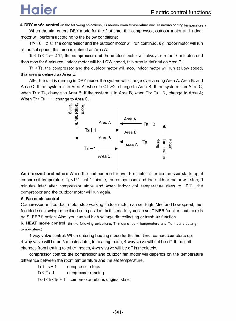
4. DRY mode control (in the following selections, Tr means room temperature and Ts means setting temperature.) When the uint enters DRY mode for the first time, the compressor, outdoor motor and indoor
motor will perform according to the below conditions: Tr> Ts+2 the compressor and the outdoor motor will run continuously, indoor motor will run
at the set speed, this area is defined as Area A; Ts≤Tr≤Ts+2, the compressor and the outdoor motor will always run for 10 minutes and
then stop for 6 minutes, indoor motor will be LOW speed, this area is defined as Area B; Tr < Ts, the compressor and the outdoor motor will stop, indoor motor will run at Low speed,
this area is defined as Area C. After the unit is running in DRY mode, the system will change over among Area A, Area B, and
Area C. If the system is in Area A, when Tr<Ts+2, change to Area B; If the system is in Area C, when Tr > Ts, change to Area B; If the system is in Area B, when Tr> Ts+3, change to Area A; When Tr<Ts-1, change to Area C. Anti-freezed protection: When the unit has run for over 6 minutes after compressor starts up, if indoor coil temperature Tg<1 last 1 minute, the compressor and the outdoor motor will stop; 9 minutes later after compressor stops and when indoor coil temperature rises to 10 , the compressor and the outdoor motor will run again. 5. Fan mode control Compressor and outdoor motor stop working, indoor motor can set High, Med and Low speed, the fan blade can swing or be fixed on a position. In this mode, you can set TIMER function, but there is no SLEEP function. Also, you can set high voltage dirt collecting or fresh air function. 6. HEAT mode control (in the following selections, Tr means room temperature and Ts means setting temperature.)
4-way valve control: When entering heating mode for the first time, compressor starts up, 4-way valve will be on 3 minutes later; in heating mode, 4-way valve will not be off. If the unit changes from heating to other modes, 4-way valve will be off immediately.
compressor control: the compressor and outdoor fan motor will depends on the temperature difference between the room temperature and the set temperature.
Tr≥Ts + 1 compressor stops Tr≤Ts- 1 compressor running
Area BArea B
Area C Ts
Area A Area A Ts 3
Ts 1
Ts 1 Area C
Room
tem
perature rising
Room
tem
perature falling
Ts-1<Tr<Ts + 1 compressor retains original state
Electric control functions
-301-

Outdoor motor and the compressor runs or stops simultaneously (except for overheat
protection), indoor fan speed can be set at High, Med, Low or Auto speed, and the fan blade can swing or be fixed on one position. You can set TIMER or SLEEP mode. Overheat protection
In heating mode, compressor has started up and indoor motor has run for over 30 seconds, if indoor coil temperature Tg>56, outdoor motor will chenge to LOW; if Tg<52, and outdoor motor has stop for 45s, outdoor motor will run again; if indoor coil temperature Tg>60, outdoor motor will stop; if Tg<56, and outdoor motor has stop for 45s, outdoor motor will run again; if Tg>68, the compressor will stop and indoor motor will run according to the thermostat OFF state. After the compressor stops for 9 minutes and Tg reduces to 48, the unit will resume to heating mode, and the compressor and the outdoor motor will run again. Anti-cold air function in heating mode
When the uint enters heating mode for the first time, or last defrosting is over, if Tg<28, indoor motor will stop; if 38>Tg≥28, indoor motor will run at low speed; if Tg≥38 or the compressor has run for over 4 minutes, indoor motor will run at the set speed. Blowing remaining heat function
In heating mode, the thermostat is OFF, the compressor stops, indoor motor will run at low speed at least 50 seconds. Auxiliary electric heating function
Enter condition: 1) Tr≤Ts-2 2) compressor ON and running for 1 minute 3) Tr≤23 4) Indoor motor running 5) Electric heating function start signal available (cancelled) If the above conditions can all be met, the electric heating function will work. If one of the below conditions can be met, the electric heater will stop: 1) Tr≥Ts-1 2) compressor OFF or indoor motor stops 3) Tr≥25 4) Electric heating function start signal not available (cancelled)
Manual defrost: In heating mode, the set temperature 30 and in high speed, in 5 seconds, press SLEEP
button 6 times continuously, then the buzzer will sound 3 times, you can enter the manual
run
stop
Ts+1
Ts-1
Room
tem
perature falling
Room
tem
perature rising
defrosting. For the unit with auxiliary electric heating function, If the auxiliary electric heating function is
working when the defrosting condition is met, please stop electric heater firstly, 3 seconds later,
Electric control functions
-302-
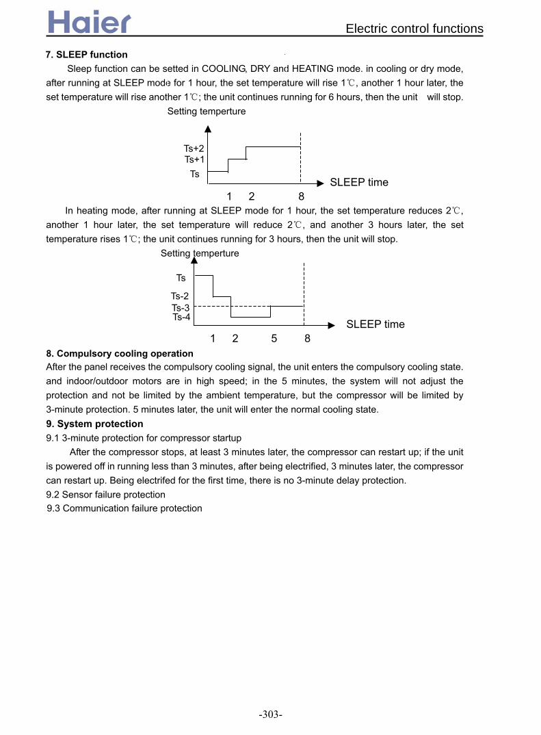
7. SLEEP function Sleep function can be setted in COOLING, DRY and HEATING mode. in cooling or dry mode,
after running at SLEEP mode for 1 hour, the set temperature will rise 1, another 1 hour later, the set temperature will rise another 1; the unit continues running for 6 hours, then the unit will stop.
Setting temperture SLEEP time 1 2 8
In heating mode, after running at SLEEP mode for 1 hour, the set temperature reduces 2, another 1 hour later, the set temperature will reduce 2, and another 3 hours later, the set temperature rises 1; the unit continues running for 3 hours, then the unit will stop. Setting temperture SLEEP time 1 2 5 8 8. Compulsory cooling operation After the panel receives the compulsory cooling signal, the unit enters the compulsory cooling state. and indoor/outdoor motors are in high speed; in the 5 minutes, the system will not adjust the protection and not be limited by the ambient temperature, but the compressor will be limited by 3-minute protection. 5 minutes later, the unit will enter the normal cooling state. 9. System protection 9.1 3-minute protection for compressor startup
After the compressor stops, at least 3 minutes later, the compressor can restart up; if the unit is powered off in running less than 3 minutes, after being electrified, 3 minutes later, the compressor can restart up. Being electrifed for the first time, there is no 3-minute delay protection. 9.2 Sensor failure protection 9.3 Communication failure protection
TsTs+1Ts+2
Ts
Ts-2 Ts-3 Ts-4
Electric control functions
-303-

1. Temperature adjustment function 1.1 In this function, outdoor running frequency depends on the indoor temperature and the set temperature. 1.2 In auto mode, indoor fan speed will be changed according to the request of temperature adjustment. 1.3 In heating operation, indoor fan speed will be controlled according to the coil temperature. 1.4 Defrosting In heating mode, outdoor transfers the defrosting signal to indoor unit, then indoor unit will enter defrosting mode until outdoor transfers defrost-cancelling signal, then indoor unit will enter heating mode. In defrosting, there is no over load protection. 1.5 Air flow limitation When compressor is running, the air flow of indoor fan motor and the limited frequency are as follow:
Frequency-limited variable Limited frequency Air flow (Med) FQLIMMD 90Hz Air flow (Low) FQLIMLO 52Hz Healthy mode FUPHEAL 30Hz
2. Indoor fan motor control 2.1 If air flow is adjusted by hand, the target rotation is (High+Low)/2. If air flow is adjusted automatically, the target rotation is (Auto High+Auto Low)/2, it will not be counted if being below 10rpm. 2.2 Heat operation 2.2.1 Hot start up In heating, anti-cold air control is as the following chart:
Heat exchanger temp. THHOT3 37.0 THHOT2 35.2 THHOT1 25.2 4minutes THHOT0 23 stop ultra low low set value low ultra low stop According to the heat exchanger temperature, fan motor will be controlled due to the above chart. 1) When heat exchanger temp. rises up, adjust the fan speed due to the heat exchanger temp. If heat exchanger temp. is below 35.2, fan speed is ultra low (When being electrified for the first time, enter heating mode or defrosting is over, if heat exchanger temp. is below 25.2, fan motor stops; if higher than 25.2 and lower than 35.2, fan speed is ultra low); If heat exchanger temp. is between 35.2 and 37, fan speed is low; If heat exchanger temp. is higher than 37, fan motor will run at set speed. 2) When heat exchanger temp. reduces, adjust the fan speed due to the heat exchanger temp. If heat exchanger is below 35.2 and over 25.2, fan speed is low; If heat exchanger is below 25.2, fan speed is ultra low, and remain the state (When being electrified for the first time, enter heating mode or defrosting is over, if heat exchanger temp. is below 25.2 and over 16, fan speed is ultra low; if heat exchanger temp. reduces below 23, fan motor speeds.). 3) When heat exchanger temp. rises, fan speed will be ultra low and low state, if 4 minutes later, heat exchanger temp. can not enter the last period, fan speed will rise up to the last speed. When up to the set speed,
.5 Electric control function For the unit with 0010452042E PCB(AS182AVERA)3
Electric control functions
-304-
fan speed will stay at this state for 4 minutes and then adjust fan speed due to the heat exchanger temp. 4) When heat exchanger temp. reduces, if fan speed is low for over 4 minutes, the fan motor will go back to the
set speed. 2.2.2 3-minute protection when compressor stops
1) After compressor stops (thermostat is OFF), if coil temperature is below 25.2, indoor motor stops; if coil temperature is over 25.2, fan motor will be in low speed, after the fan time is over 50 seconds, if coil temperature is over 28, fan motor will be in low speed; if coil temperature is below 23, indoor motor will stop. 2) If the unit is shutoff by remote controller, indoor motor will stop after running at ultra low speed for 10 seconds. 2.2.3 Compressor restart up After hot startup, the fan speed is the state set by remote controller. When in Auto Fan mode, the air flow depends on the temperature. 2.2.4 In defrosting, after running at low speed for 20 seconds, fan motor stops. After defrosting is over, if compressor stops, indoor motor will stop too. When compressor re-starts up, air flow can be set at High, Med, Low according to the heat exchanger temperature. 2.3 Cooling operation When in Auto Fan mode, the air flow will be confirmed according to the temperature. 2.4 Dry operation 2.4.1 If compressor is OFF, and in 3-minute standby: 1)Compressor stops, fan motor will stop too. 2)If 3-minute protection is over, fan is in ultra low state. 3)After 3-minute standby state, compressor will run. 2.4.2 If compressor is ON: Fan motor will run at the set speed. When in auto fan mode, the air flow will be adjusted due to the temperature. 3. Power operation (depend on the remote controller, not available for this model) 1) Power operation will keep for 15 minutes. 2) The unit stops or 15 minutes later, the power operation will stop. 3) If changing the operation modes, the power operation will stop. 4) If at soft mode or TIMER ON function works, the power operation stops. 5) In Auto mode, the Power/Soft function can work. In cooling mode, the unit will run at Cooling Power/Soft
mode. In heating mode, the unit will run at Heating Power/Soft mode. In Fan mode, there is no Power/Soft function.
3.1 Power heating operation 1) Adjust the set temperature, can modulate the temperature. 2) Air flow is Auto Med speed. 3) In defrosting, outdoor unit will not the communication signal of power operation. 4) After Power operation works for 15 minutes, within 10 minutes, compressor can not be OFF, excluding the
failure condition. 3.2 Power cooling operation 1) Modulate the set temperature. 2) Air flow is Manual High speed. 3) After compressor is running, in 3 minutes, the unit will not make low load protection. 3.3 Not available for Fan, Dry mode. 4. Soft operation The indoor unit will send the Soft operation signal to outdoor. 4.1 Soft heating
Electric control functions
-305-

When compressor is running, air flow is SSLO. When compressor stops, in 20 seconds, air flow is SSLO, and then turn into ultra low. 4.2 Soft cooling Air flow is SSLO. 4.3 Not available for Fan, Dry mode. 5. Negative ion function 1) When receiving the command, if fan motor is running, the negative ion generator will work to realize the
negative ion emission function. 2) If fan motor stops, the negative ion generator is OFF. 3) When negative ion generator is OFF, at this time, if you set the negative ion function, when fan motor begins
to runs again, the negative ion generator will be ON automatically. 6. TIMER operation 1) Count the time according to the difference between TIMER CLOCK and the present CLOCK time. 2) When TIMER function works, the TIMER lamp on the indicator board is ON. 3) TIMER OFF When TIMER OFF is set, the indication on the panel will not change (background lamp is OFF), the timer icon will display. When timer clock arrives, the operation will stop. 4) TIMER ON When TIMER ON is set, the indication on the panel only displays the TIMER icon(background lamp is OFF), When timer clock arrives, the unit will run at the set state. 5) TIMER ON/OFF The operation will be performed as the set state. 7. SLEEP operation Sleep function: energy saving function at night, TIMER lamp will be ON. 7.1 Standard sleep function: in cooling or dry mode, after running at SLEEP mode for 1 hour, the set temperature will rise 1, another 1 hour later, the set temperature will rise another 1; the unit continues running for 6 hours, then the unit will stop.
7.2 Standard sleep function: in heating mode, after running at SLEEP mode for 1 hour, the set temperature reduces 2, another 1 hour later, the set temperature will reduce 2, and another 3 hours later, the set temperature rises 1; the unit continues running for 3 hours, then the unit will stop.
7.3 Non-standard SLEEP function: the sleep function can realize 1~8 hours sleep mode when being combined with the TIMER function.
1) When in Auto mode, the unit will make SLEEP operation due to the setting.
Ts Ts+1 Ts+2
Ts
Ts-2 Ts-3 Ts-4
Electric control functions
-306-

2) After setting SLEEP function, the clock can not be adjusted. 3) If sleep time is no more than 8 hours, when the time arrives, the unit wil shut off. 4) If sleep function is set after setting TIMER OFF function, the unit will execute as the SLEEP function. 5) If SLEEP function is set, the TIMER function can not be set. 6) If sleep function is set after setting TIMER ON function, the sleep function only can be set befroe the
TIMER ON time arrives. 7) After setting sleep function, press CLOCK button to check the clock; press TEMP button to display the
set temperature, and press again to change the set temperature. 8. Auto operation Full auto operation If the unit is at Auto mode, the system will adjust the operation mode according to the temperature difference between the set temperature and the room temperature. Below Tr stands for room temperature, Ts stands for room temperature. If entering Auto mode for the first time, the unit will execute as follow:
Tr≥Ts-3 select cooling mode Tr<Ts-3 select heating mode
After entering Auto mode, the operation mode can be changed between cooling and heating: if the unit is in cooling mode at present, when the compressor arrives the stop temperature, the compressor stops; after compressor stops for 15 minutes, the unit will check the temperature again, at this time, if Tr<Ts-3, the unit will enter heating mode, or it will still be in cooling mode; if the unit is in heating mode at present, when the compressor arrives the stop temperature, compressor will stop, afte compressor stops for 15 minutes, the unit will check the room temperature, if Tr>Ts+3, the unit will enter cooling mode, or it will still be in heating mode. In this mode, TIMER mode and SLEEP mode are available. In cooling mode, the unit will be in COOL SLEEP; in heating, the unit will be in HEAT SLEEP. Fan blade can swing or be fixed on one position, and fan speed can be set at High, Med, Low or Auto. 9. Trial running The frequency is 58Hz, and the unit is in cooling mode, fan speed is High. After the trial running time is 30 minutes, the unit will shut off. In trial running, the unit will quit this state if receiving the remote signal. There is no low load protection. 10. Low load protection In cooling/dry mode, make the low load protection due to the heat exchanger temperature. heat exchanger temp. THLHEATBL3 THLHEATBL2 THLHEATBL1 THLHEATBL0 Indication area normal area 2 area 1 stop area 1 area 2 normalIn trial running, the low load protection is ignored.
Electric control functions
-307-

After compulsory cooling begins for 1 minute, for 3 minutes, the low load protection is cancelled temporarily. (THLH[3,2,1,0]= 7 ,4.6,2.2,-0.5) 11. High load protection In heating mode, make high load protection due to the heat exchanger temperature. heat exchanger temp. frequency when high load protection begins THHEAT6 74.7 THHEAT5 70.3 THHEAT4 65.1 THHEAT3 62.2 THHEAT2 52.9 THHEAT1 51.6 THHEAT0 47.1
Indication FQY normal C D E standby D C B A B C D E stop High load protection When the heat exchanger temperature is not up to "THHEAT[2]", the temperature will resume the control of normal temperature area.
12. Temperature cutoff protection In cooling mode, every time compressor runs for 1 minute after startup, the unit will check the indoor coil temperature, when Tg>Tr+5, the unit will shut off for 3 minutes, and then re-start up; if it the temperature cutoff protection has occurred for 3 times contineously, the unit will stop and alarm. In heating mode (except for defrosting), every time compressor runs for 1 minute after startup, the unit will check the indoor coil temperature, when Tg<Tr-5, the unit will shut off for 3 minutes, and then re-start up; if it the temperature cutoff protection has occurred for 3 times contineously, the unit will stop and alarm (in defrosting and in 2 minutes after defrosting is over, the unit will not measure temperature). 13. EEPROM control When outdoor being electrified, if parameter of EEPROM is different from the data of check sum, EEPROM will be abnormal. Once indoor receives the EEPROM abnormal signal from outdoor, the unit will display EEPROM abnormal. At this time, control and emergency operation will not be received. Only power off the unit, the failure can be resumed. 14. Failure record
Temp. point Temp. FQY point FQY THHEAT3 62.6 FQHHEAT2 70 THHEAT4 65.1 FQHHEAT3 40 THHEAT5 70.3 FQHHEAT4 30 THHEAT6 74.4 Stop
Electric control functions
-308-

If there is no failure code record, nothing displays. Failure code will be over automatically 10 seconds later. According to the switch or the stop signal of remote controller, the failure record will be over. For the unit with EEPROM, the failure record will be saved after power supply is reset. 15. Special functions 15.1 Auto-restart a. Entering condition: In 7 seconds press the SLEEP button for 10 times, the buzzer sounds 4 times. At the same time, the present state will be saved in EEPROM. b. After entering the auto-restart state, the indoor will execute as follow: The indoor unit will run at the state set by the remote controller and the emergency set state, and the present state will be saved in indoor EEPROM. The outdoor will run at the state set on the panel and this state will be saved in EEPROM. After entering the auto-restart, if being electrified after being powered off, the outdoor unit will send the signal of the present operation and auto-restart signal to indoor panel. When panel receives the feedback information, it will remain the auto-restart state. c. Quit condition: in 7 seconds press SLEEP button 10 times, the buzzer will sound 2 times. d. If in auto-restart state, set TIMER, and SLEEP functions, when being electrified after being powered off, the unit memory will be OFF state. 15.2 Rated operation 15.2.1 Rated cooling
a. High speed at cooling, the set temperature is 16, press temp. “-“ and SET button simultaneously, after the buzzer sounds 2 times, enter the condition.
b. In this condition, the unit will execute as follow: entering the rated frequency operation; on the panel there will be cooling mode; in communication, there is rated indication.
c. Quit condition: once receiving the remote signal, the unit will quit the rated operation and then turn into remote control state.
15.2.2 Rated heating a. High speed at heating, the set temperature is 30, press temp. “+” and SET button simultaneously,
after the buzzer sounds 2 times, enter the condition. b. In this condition, the unit will execute as follow: entering the rated frequency operation; on the panel
there will be heating mode; in communication, there is rated indication. c. Quit condition: once receiving the remote signal, the unit will quit the rated operation and then turn into
remote control state.
operation as Auto mode.
begin trial running in cooling mode (30 minutes later quit the trial running).
show the previous failure.
over 15 seconds, the unit will in OFF state, and can receive the remote signal.
16.2 In OFF state, press emergency switch for over 5 seconds and below 10 seconds contineously, the unit will
16. Emergency switch
16.3 In OFF state, press emergency switch for over 10 seconds and below 15 seconds contineously, the unit will
16.1 In OFF state, press emergency switch for below 5 seconds contineously, the unit will begin emergency
16.4 In OFF state, press emergency switch, there will be Auto operation on the panel.
16.6 In running, press emergency switch, the unit will shut off.
16.5 In OFF state, press emergency switch for less than 15 seconds, the unit will not receive the remote signal. If
16.7 If abnormal condition occurs, press emergency switch, the unit will shut off. 16.8 When failure code displays, press emergency switch, the failure code will not display.
Electric control functions
-309-

contineously, at this case, the unit can receive the remote signal.
Press emergency switch for up to 10 seconds, and sounds 3 times, if releasing the switch, the unit will display failure record. If pressing the switch time is up to 15 seconds, no display on the panel, and the failure record is cancelled. Remark: The latest record will not be cancelled when being powered off, and the data will be saved in EEPROM. The previous alarm will display on the indication board. 10 seconds later, the failure record will be cancelled.
16.9 In running, when the unit is normal or abnormal, or failure code occurs, press emergency switch
16.10 Failure code display
Electric control functions
-310-

1. Outdoor motor control When the system does not occur overcooling, overheating, and over current protections, the outdoor motor will occur the below changes according to the outdoor ambient temperature and indoor coil temperature. 1.1 General information Outdoor motor is 2-speed type: high, low and stop. The fan speed will change unless every step has been run for 45 seconds. 1.2 Cooling mode 1.2.1 Indoor coil temp.≥15, outdoor motor runs at high speed. 1.2.2 Indoor coil temp.<5, outdoor motor runs at low speed. 1.2.3 5≤Indoor coil temp.<15, outdoor motor will change due to the outdoor ambient temp. Outdoor ambient temp. >28, enter high speed; outdoor ambient temp.<26, enter high speed; 26≤outdoor ambient temp.≤28, keep the current speed. In running, the system will be controlled as 2 temperature tolerance; if outdoor ambient temp. <26, enter low speed; if outdoor ambient temp.>28, enter high speed. 1.3 Heating mode (heat pump model) 1.3.1 Indoor coil temp.≥50, outdoor motor will run at low speed. 1.3.2 Indoor coil temp. <40, outdoor motor will run at high speed. 1.3.3 40≤indoor coil temp.<50, outdoor motor will change with outdoor ambient temp. Outdoor ambient temp.<13, enter high speed; Outdoor ambient temp.>15, enter low speed; 13≤Outdoor ambient temp.≤15, keep the current speed; In running, the system will be controlled as 2 temperature tolerance; if outdoor ambient temp. <13, enter high speed; if outdoor ambient temp.>15, enter low speed. Every step will run at least 45 seconds, and the motor will start up 2 seconds earlier than compressor. 2. Defrost control 2.1 Defrosting condition In heating mode, the compressor will run for 30 minutes continuously or run for 45 minutes in all and for over 5 minutes contineously, outdoor motor at least runs for 2 minutes; If the outdoor ambient temperature and outdoor coil temperature can comply with the shadow area in the figure and keep for 1 minute, the defrost will work and send defrost signal to indoor unit, then indoor unit will control indoor motor accordingly. 2.2 Quit condition Outdoor coil temp. arrives the defrost-end temp. 14 or the defrost time is over 12 minutes, the defrost will finish and send signal to indoor unit. 2.3 Defrost operation Compressor and outdoor motor stop, indoor motor stops meanwhile; 55 seconds later, the reversing valve will close. Another 5 seconds later, compressor starts up. After defrost is over, compressor stops, outdoor motor runs at high speed; 55 seconds later, the reversing valve will open. Another 5 seconds later, compressor starts up and indoor motor runs at anti-code mode. Type 1: Standard defrost 1) If Tr≥-2, when Tp≤-6, enter defrost. 2) If -12≤Tr<-2, when Tp≤-6, please refer to the following chart. 3) No matter the ambient temperature, when Tp≤-16, enter defrost.
3.6 Electric control function for fixed frequency outdoor unit(*EAA)
Electric control functions
-311-

Type 2: Non-standard defrost (rectify defrost data by the device)
1) If Tr≥6, when Tp≤-6, enter defrost.
2) If -18≤Tr<-6, when Tp≤-6, please refer to the following chart. 3) No matter the ambient temperature, when Tp≤-18, enter defrost.
2.4 Manual defrost Indoor sends defrost signal to outdoor, and the outdoor will receive the defrost signal when
compressor is running in heating mode, then enter the defrost process. When outdoor coil
temperature arrives the defrost-end point and the defrost time is over 5 minutes, outdoor will send
the defrost-end signal to finish the defrost. 3. Compressor crankcase heater working condition By the N.C. (normal close) auxiliary point of AC contactor to control, when compressor stops, the heater will work; when compressor works, the heater will stop.
4. System protection function 4.1 Anti-freezed protection
-6
Ambient
Coil temp.()6-18
-6
-18
Ambient
Coil temp.() -2-12
-16
When compressor has run for over 6 minutes, to prevent indoor evaporator freezing (in cooling/dry
mode), if indoor coil temp. is below -1 degree for over 1 minutes, compressor and outdoor motor will
stop and enter Fan mode. After compressor stops for 9 minutes, and indoor coil temp. rises up to 10
, the unit resumes to cooling mode, compressor and outdoor motor will work again. 4.2 Overheat protection In heating mode, if indoor motor is running and the compressor has run for over 30 seconds, the
Electric control functions
-312-
sensor will check the indoor coil temperature, and send the temp. to outdoor; if indoor coil temp. >T1(53), the outdoor motor will enter low speed; if indoor coil temp.<T2(50), outdoor motor will enter high speed; if indoor coil temp. >T3(56), outdoor motor will stop; if indoor coil temp.<T4(53), outdoor motor will resume low speed; when indoor PCB receive the signal of outdoor motor stop from outdoor PCB over 2 minutes, if indoor coil temp. >T6(70)or 10 minutes later indoor coil temp. >T5(56), send compressor stop signal to outdoor unit; if indoor coil temp.<46 and the compressor has stopped over 3 minutes, send compressor run signal to outdoor unit, and compressor resume to normal. The outdoor motor is control by oudoor unit. 4.3 Over current protection 4.3.1 In heating mode After compressor running for 40 seconds, if the current thermostat has measured that system working current is more than 21A and keep it for 5 seconds, outdoor motor will convert into low speed; if working current is less than 18A, it will resume to high speed; if working current is more than 25A and keep it for 5 seconds, outdoor motor will stop; if working current is less than 22A, outdoor will resume to low speed (fan speed conversion frequency must be more than 45 seconds); after compressor running for 5 minutes, if working current is more than 34A and keep it for 5 seconds, compressor will stop and will resume 3 minutes later. If within 30 minutes there are 3 times compressor over current protection, compressor will not start up, meanwhile, LCD will display E5. Only shut off and powered on again, the protection can be cancelled. 4.3.2 Not in heating mode After compressor running for 5 minutes, if working current is more than 34A and keep it for 5 seconds, compressor will stop and will resume 3 minutes later. If within 30 minutes there are 3 times compressor over current protection, compressor will not start up, meanwhile, LCD will display E5. Only shut off and powered on again, the protection can be cancelled. 4.4 Power protection 4.5 High/Low Pressure protection (cooling only unit without this function)
After compressor running for 8 minutes, the system will check the pipe pressure. If pipe pressure is over high, high pressure switch has acteivated more than 15 seconds, compressor, outdoor motor will stop and 3 minutes later it will resume. If within 30 minutes there are stop phenomenon 3 times because of pressure over high, the compressor will stop and LCD will display E6. only shut off and powered on again, the protection can be cancelled.
Low pressure protection (1) After compressor running for 3 minutes, if low pressure switch has acteivated for 15 seconds
continuously, compressor will stop and alarm. (2) Check the low pressure switch when compressor is stop, the compressor will not run if low
pressure switch act, low pressure switch has acteivated more than 30 seconds, LCD will display Low pressure abnormal
(3) In defrosting and in 6 minute after defrost is over , low pressure switch will not be checked. (4) In heating, compressor run and outdoor motor stop, low pressure switch will be shielded. (5) Low pressure protection can be resumable when power-off. 4.6 3-minutes protection for compressor
After compressor stops, it cannot be started until 3 minutes later. During the machine’s running, if the time not more than 3 minutes after power is off, the compressor cannot be restarted until 3
Electric control functions
-313-

minutes later after it is powered on again 4.7 Sensor broken down protection a. Check if sensor breaks down
After compressor has run for 2 minutes, the unit will check the sensor, Outdoor board checks the sensor in short circuit or in open circuit or near to short/open circuit for 2 minutes continuously, then it will adjust the sensor broken down. b. How to deal with it?
If the outdoor ambient temperature sensor and the outdoor coil temperature sensor have broken down, the unit will stop running, and alarm E3, E4, E4 simultaneously. 4.8 Starting current control
Outdoor unit load control: after the outdoor motor running for 2 seconds, main compressor start up, the secondary compressor will run 2 seconds later. 4.9 4-way valve control 5. Outdoor PCB test (1) There are three pins marked with TEST, please make the two ones near to COOL in short circuit. Outdoor begin to run in cooling mode, that is, compressor run and outdoor motor works at high speed. (2) There are three pins marked with TEST, please make the two ones near to HEAT in short circuit. Outdoor begin to run in heating mode, that is, compressor and 4-way valve run, outdoor motor works at low speed.
Electric control functions
-314-

many differences, please refer to the corresponding Service Manual to reach the detailed information. Note: Take the electric control function of AU362AHERA as an example, as for other models, there are
Definition of sensor sign: Taoi=indoor ambient temp., Tao=outdoor ambient temp., Tc=indoor coil, Td=dischange, Te= outdoor coil, Ts=suction, Tci=condenser air inlet temp. Control purpose: make condensate pressure and vaporing pressure normal, systerm running reposefully. 1.1 Outdoor running frequency and the control procedure 1.1.1 Outdoor running frequency control Outdoor running frequency range:
Outdoor temp. ~15 15~38 38~ Cooling frequency range 20RPS 50RPS 35RPS 85RPS 20RPS 78RPS
Outdoor temp. ~0 0~15 15~ Heating frequency range 35RPS 95RPS 20RPS 90RPS 20RPS 65RPS
Defrost frequency 85RPS 1.1.2 Compressor startup
Every time compressor is from OFF to ON, no matter how is the indoor target frequency, compressor running frequency must be stay at 40Hz and 54Hz (E) for 1 minutes (At outdoor discharging temp. overhigh protection and compressor overcurrent protection, the frequency will be reduced), and then rise up to the target frequency. After the unit is in normal, the above procedure is not available. General startup: Target frequency 60sec 54Hz 40Hz Inverter compressor 0Hz 30sec 60sec 60 sec ON
SV1/SV2 valve OFF Fiducial open angle EEV A Current pls Special condition:
If the target frequency is less than 40Hz, the startup must run for 1 minute at both 40Hz and 54Hz, then run to the target frequency.
The jump frequency point(syntonic point) should be avoided during rise frequency process, so some jump frequency points(about 4~5) should be pre-setted.
The jump frequency points of compressor are: 50HZ (E), 60 HZ (E), 70 HZ (E), 80HZ (E) and 90HZ (E) 1.1.3 Heating mode, cooling mode and dehumidification
After performing the compressor startup procedure, the unit will run according to the indoor frequency. 2 minutes later, the unit will compensate the running frequency due to the relative condition.
1.1.4 Compressor frequency rising/reducing speed Rapid rising/reducing frequency speed 1----1Hz/second Slow rising/reducing frequency speed 2----1Hz/10 seconds
1.2 Outdoor motor control Note: When the outdoor motor needs to change the class, there will be 20-second interval to avoid the fan
3.7 Electric control function for DC inverter outdoor unit(*ERA)
Electric control functions
-315-

speed changing frequently. 1.2.1 Fan motor speed class has 7 steps, the rotation and class is as follow: Class-0 Class-1 Class-2 Class-3 Class-4 Class-5 Class-6 Class-7DC motor
Stop 250(E) 350(E) 450(E) 550(E) 650(E) 850(E) 950(E)AC 3-speed motor Stop Low speed Middle speed High speed
1.2.2 Blowing remain heat after compressor shuts off In cooling mode, when compressor shuts off, outdoor motor will enter speed Class-3 automatically, and
will shut off after blowing remaining heat for 30 seconds. Note: adopt this control when defrost is over, outdoor motor will enter speed Class-7 when compressor
stops, and will shut off after blowing remaining water 30 seconds later, but do not blow to the air outlet grille, or ice will be appeared 1.2.3 Outdoor motor control in cooling/dry mode Speed range: class 1-7 Fan motor locked rotor: When fan motor is requested to work, if fan speed is measured to be below
50RPM and keep for 15 seconds, the compressor will stop, but 3 minutes later, it will re-start up again. If within 10 minutes, the condition occurs 3 times, the unit will stop and alarm.
When compressor starts up, the unit will adjust automatically in 3 minutes according to the outdoor ambient temperature, and 3 minutes later, the unit will adjust according to the outdoor ambient temperature and compressor running frequency. Fan speed chart in 3 minutes after compressor starts up (control fan speed according to ambient temp. 3
minutes later): Ambient temp. ~10 10~25 25~
Cool, dry Class-3 Class-5 Class-7
heat Class-7 Class-5 Class-3 Fan speed chart in 3 minutes after compressor starts up due to the ambient temp. and running frequency: Compressor frequency in cooling F<25Hz 25Hz≤F<45Hz 45≤F
Over 28 Class-3 Class-5 Class-7 Tao Below 28 Class-1 Class-3 Class-5
Compressor frequency in heating F<25Hz 25Hz≤F<45Hz 45≤F Over 15 Class-2 Class-4 Class-5 Tao Below 15 Class-3 Class-5 Class-7
1.3 Electronic expansion valve (EEV) control 1.3.1 Electronic characteristic
Max. open angle 500 pulse Driving speed PPS
1.3.2 Initialization of EEV EEV driving speed: open direction: 31.25 PPS (32MS)(E); close direction: 31.25 PPS (32MS)(E) Movement of EEV full-open, full-close: Full-open: 470 pulse open(E); Full-close: after 540 pulse close for 3 times (60 pulse close, 5 pulse open, stop at 5 open range at last).
1.3.3 Open angle limitation of EEV Unit stop Adjustable upper limitation Thermostat ON Thermostat OFF Adjustable lower limitation
Cool/ dry
5(E) 470(E) standard open angle+tolerance
5(E) 90(E)
Electric control functions
-316-

heat 52(E) 400(E) standard open angle+tolerance
52(E) 80(E)
1.3.4 The movement of valve after compressor startup/shut off Compressor startup: the compressor will startup after the open angle of valve has reached the fiducial
open angle; Compressor shut off: valve begin to full-close after the compressor has stopped.
1.3.5 Enter the fiducial open angle after compressor startup(no matter 2 minutes later or 2 minutes ago), 4 minutes later adjust automatically according to the target over-heat value, 10 minutes later begin to modify the over-heat value and open angle of valve. Cool, dry Outdoor temp. ~22 22~ Compressor frquency ~50 50~80 80~ ~50 50~80 80~
PMV open angle 180 200 220 180 200 240 Heat Outdoor temp. ~6 6~ Compressor frquency ~50 50~80 80~ ~50 50~80 80~
PMV open angle 200 180 220 220 200 240 1.3.6: Min. open angle during compressor running(not the fixed open angle, but the min. limited open angle according to the different frequency) Cool, dry Outdoor temp. ~22 22~ Compressor frquency ~50 50~80 80~ ~50 50~80 80~
PMV open angle 80 100 145 70 145 170 Heat Outdoor temp. ~6 6~ Compressor frquency ~50 50~80 80~ ~50 50~80 80~
PMV open angle 80 100 145 100 120 145 1.3.7 Confirmation of over-heat degree Standarded over-heat degree (E) Actual running Hz ~60 ~70 ~80 ~90 90~
Cool, dry 3 6 6 4 2 TSH0 () heat 2 2 1 1 1 When discharging temp. Td is too high or too low, modify the EEV angle. Act after compressor has started up for 10 minutes
Mode Modification angle Max. modification Cooling Td>95, standarded over-heat degree -1 degree / 2 minutes
50< Td<95, keep the angle TD<50, +1 degree / 2 minutes, and plus to 0 degree gradually
Max. -5
Cooling Td<55, standarded over-heat degree +1 degree / 2 minutes 50< Td<95, keep the angle Td>95, -1 degree / 2 minutes, and reduce to 0 degree gradually
Max. +5
Heating Td>95, standarded over-heat degree -1 degree / 2 minutes 50< Td<95, keep the angle TD<50, +1 degree / 2 minutes, and plus to 0 degree gradually
Max. -5
Heating Td<55, standarded over-heat degree +1 degree / 2 minutes 50< Td<95, keep the angle Td>95, -1 degree / 2 minutes, and reduce to 0 degree gradually
Max. +5
Electric control functions
-317-

1.3.8 Modify the EEV angle according to the discharging temp. Td If the upper limitation of open range reachs 470, stop add the tolerance. Within 10 minutes after
compressor starts up, it will not modify. The detecting period is 2 miunites. Cooling mode Modification angle
103< discharging temp. +5 degree/2 miunites, it will stop until up to the max. permitted opening angle +50
90< discharging temp.<=103 Keep the angle <=90 -1 degree/2 miunites, and reduce to 0 degree gradually
Heating mode Modification angle 102< discharging temp. +5 degree/2 miunites, it will stop until up to the max. permitted
opening angle +50 88< discharging temp.<=102 Keep the angle
<=88 -1 degree/2 miunites, and reduce to 0 degree gradually 1.4 4-way valve control The 4-way valve control in defrosting: refer to the defrosting procedure. 4-way valve control in other modes:
In heating mode, 4-way valve will open in 15 seconds after compressor starts up. When compressor not startup or in non-heating mode, 4-way valve will close to ensure the compressor has stopped for at least 2 minutes and 55 seconds. compressor ON OFF 4-way valve ON OFF 15 seconds (E) 2 minutes and 55 seconds 1.5 Outdoor defrosting control
There are two defrost methods according to the different system. The outdoor dip-switch is used to realize the defrost method change-over because of the same PCB for 3HP, 4HP, 5HP and 6HP unit. For the samll outdoor unit such as AU362AHERA adopt the ordinary defrost method, that is stop unit and change to cooling defrost, for the double fan system auch as AU48NAIERA, AU60NAIERA etc. adopt realtime bypass defrost, that is some refrigerant is bypassed to condenser for defrosting in heating mode without stop the unit, meanwhile ensure the heating progress of indoor unit. When there is a little frost on condenser, some refrigerant is bypassed to condenser for defrosting to ensure the outdoor fan motor works in the small wind resistance condition. The ordinary defrost method can also be used for the double fan system. A. Ordinary defrost
In heating mode, defrosting temp. sensor Te will check the frosting condition of outdoor heat exchanger
and make defrosting control.
1.5.1 Tao>15(E), not enter defrost;
1.5.2 In heating mode, if the compressor has run for 10 minutes (E) and run for 45 minutes in all, the system
will measure the defrosting temperature sensor Te(check the frosting condition of outdoor heat exchanger)
and outdoor ambient temp. sensor Tao, if the below condition can be met for continous 5 minutes, the unit will
enter defrosting operation:
a. 5(E)<Tao<15, Te<=-6(E);
Electric control functions
-318-

b. -6(E)<Tao<5, Te≤C×Tao-α;
Set αas the following according to the selection of dip-switch:
Jumper selection L M H
α() 10(E) 7(E) 6(E)
In the place easy to frost, it is H; in the place difficult to frost, it is L; when out of factory, it is M.
Herein: C: Tao<0, C=0.8 Tao≥0,C=0.6
c. Tao<-6, Te≤-12(E) and defrost compressor has run for 65 minutes (E) in all.
1.5.3 The control details refer to the following figure. 1.5.4 Cancel condition:
a. It will take 10 minutes(E) from beginning defrosting to quit it. b. Te sensor will measure the condition of outdoor heat exchanger, if the temp. is over 10 for 60
seconds in all or is up to 14 for 30 seconds in all, the defrosting will be over. Ordinary defrost operation flow char:
beginning end inverter compressor indicated FQY 60s defrosting FQY 85 Hz(E) 60s soft startup 0HZ 0HZ 10s
outdoor motor ON send defrosting signal to indoor auto OFF
4-way valve ON OFF ON Unloading valve SV1 OFF auto
350-pulse(E) expansion valve PMV auto open angle auto open angle all indoor motors ON
OFF anti-cold air function B. Realtime bypass defrost: when the second bit is ON, defrost can be finished in heating mode directly and not need to enter cooling mode by the open angle of SV1 and SV2 to bypass the refrigerant to condenser, meanwhile ensure the indoor unit is heating.. Enter condition
1. When Tao>15(E), not enter defrost;
2. In heating mode, compressor is running for 10 minutes(E) contineously, or has run for 30 minutes(E) in all,
by measuring the defrosting sensor Te(detect the outdoor heat exchanger frost condition) and outdoor
ambient temp. sensor Tao, if for 5 minutes the below conditions can be met contineously, system will enter
Electric control functions
-319-
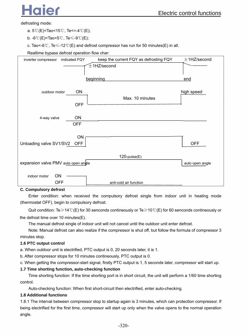
defrosting mode:
a. 5(E)<Tao<15, Te<=-4(E);
b. -6(E)<Tao<5, Te≤-9(E);
c. Tao<-6, Te≤-12(E) and defrost compressor has run for 50 minutes(E) in all.
Realtime bypass defrost operation flow char: inverter compressor indicated FQY keep the current FQY as defrosting FQY ±1HZ/second
±1HZ/second beginning end
outdoor motor ON high speed Max. 10 minutes OFF
4-way valve ON OFF ON Unloading valve SV1/SV2 OFF OFF
120-pulse(E) expansion valve PMV auto open angle auto open angle
indoor motor ON
OFF anti-cold air function C. Compulsory defrost
Enter condition: when received the compulsory defrost single from indoor unit in heating mode (thermostat OFF), begin to compulsory defrost.
Quit condition: Te≥14(E) for 30 senconds contineously or Te≥10(E) for 60 senconds contineously or
the defrost time over 10 minutes(E). The manual defrost single of indoor unit will not cancel until the outdoor unit enter defrost. Note: Manual defrost can also realize if the compressor is shut off, but follow the formula of compressor 3
minutes stop. 1.6 PTC output control a. When outdoor unit is electrified, PTC output is 0, 20 seconds later, it is 1. b. After compressor stops for 10 minutes contineously, PTC output is 0. c. When getting the compressor-start signal, firstly PTC output is 1, 5 seconds later, compressor will start up. 1.7 Time shorting function, auto-checking function
Time shorting function: If the time shorting port is in short circuit, the unit will perform a 1/60 time shorting control.
Auto-checking function: When first short-circuit then electrified, enter auto-checking. 1.8 Additional functions 1.8.1 The interval between compressor stop to startup again is 3 minutes, which can protection compressor. If being electrified for the first time, compressor will start up only when the valve opens to the normal operation angle.
Electric control functions
-320-
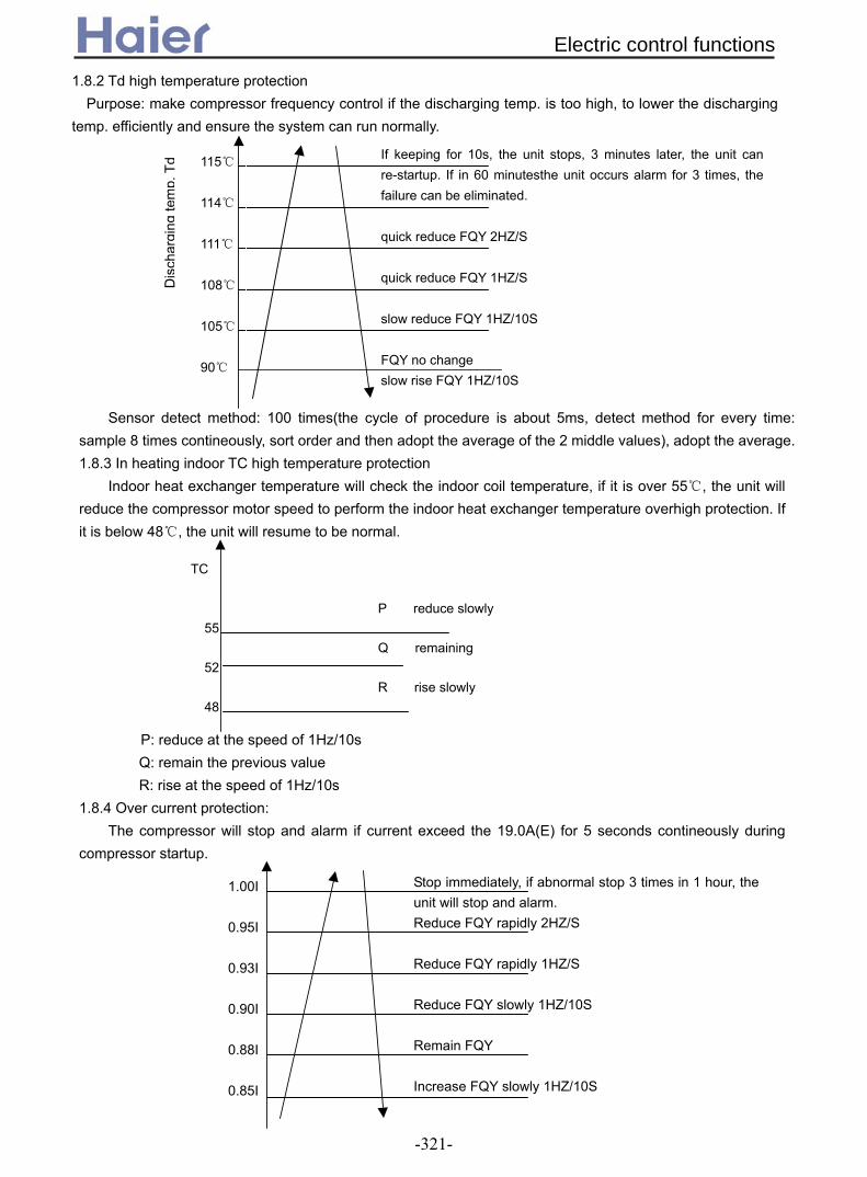
1.8.2 Td high temperature protection Purpose: make compressor frequency control if the discharging temp. is too high, to lower the discharging
temp. efficiently and ensure the system can run normally.
Sensor detect method: 100 times(the cycle of procedure is about 5ms, detect method for every time: sample 8 times contineously, sort order and then adopt the average of the 2 middle values), adopt the average. 1.8.3 In heating indoor TC high temperature protection
Indoor heat exchanger temperature will check the indoor coil temperature, if it is over 55, the unit will reduce the compressor motor speed to perform the indoor heat exchanger temperature overhigh protection. If it is below 48, the unit will resume to be normal.
TC
P reduce slowly 55 Q remaining 52 R rise slowly 48
P: reduce at the speed of 1Hz/10s Q: remain the previous value R: rise at the speed of 1Hz/10s
1.8.4 Over current protection: The compressor will stop and alarm if current exceed the 19.0A(E) for 5 seconds contineously during
compressor startup.
0.85I
If keeping for 10s, the unit stops, 3 minutes later, the unit canre-startup. If in 60 minutesthe unit occurs alarm for 3 times, thefailure can be eliminated. quick reduce FQY 2HZ/S quick reduce FQY 1HZ/S slow reduce FQY 1HZ/10S FQY no change slow rise FQY 1HZ/10S
115 114 111 108 105 90
Di s
char
gin g
t em
p. T
d
1.00I 0.95I 0.93I 0.90I 0.88I 0.85I
Stop immediately, if abnormal stop 3 times in 1 hour, theunit will stop and alarm. Reduce FQY rapidly 2HZ/S Reduce FQY rapidly 1HZ/S Reduce FQY slowly 1HZ/10S Remain FQY Increase FQY slowly 1HZ/10S
Electric control functions
-321-
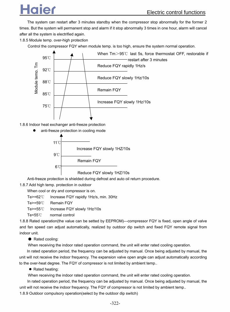
The system can restart after 3 minutes standby when the compressor stop abnormally for the former 2 times. But the system will permanent stop and alarm if it stop abnormally 3 times in one hour, alarm will cancel after all the system is electrified again. 1.8.5 Module temp. over-high protection
Control the compressor FQY when module temp. is too high, ensure the system normal operation. 1.8.6 Indoor heat exchanger anti-freeze protection
anti-freeze protection in cooling mode 11 Increase FQY slowly 1HZ/10s
9 Remain FQY 6 Reduce FQY slowly 1HZ/10s Anti-freeze protection is shielded during defrost and auto oil return procedure.
1.8.7 Add high temp. protection in outdoor When cool or dry and compressor is on. Te>=62 Increase FQY rapidly 1Hz/s, min. 30Hz
Te>=59 Remain FQY Te>=55 Increase FQY slowly 1Hz/10s
Te<55 normal control 1.8.8 Rated operation(the value can be setted by EEPROM)---compressor FQY is fixed, open angle of valve and fan speed can adjust automatically, realized by outdoor dip switch and fixed FQY remote signal from indoor unit.
Rated cooling: When receiving the indoor rated operation command, the unit will enter rated cooling operation. In rated operation period, the frequency can be adjusted by manual. Once being adjusted by manual, the
unit will not receive the indoor frequency. The expansion valve open angle can adjust automatically according to the over-heat degree. The FQY of compressor is not limited by ambient temp..
Rated heating: When receiving the indoor rated operation command, the unit will enter rated cooling operation. In rated operation period, the frequency can be adjusted by manual. Once being adjusted by manual, the
unit will not receive the indoor frequency. The FQY of compressor is not limited by ambient temp.. 1.8.9 Outdoor compulsory operation(select by the outdoor dip switch)
When Tm>95 last 5s, force thermostat OFF, restorable ifrestart after 3 minutes
Reduce FQY rapidly 1Hz/s Reduce FQY slowly 1Hz/10s Remain FQY Increase FQY slowly 1Hz/10s
95 92 88 85 75
Mod
ule
tem
p. T
m
Electric control functions
-322-
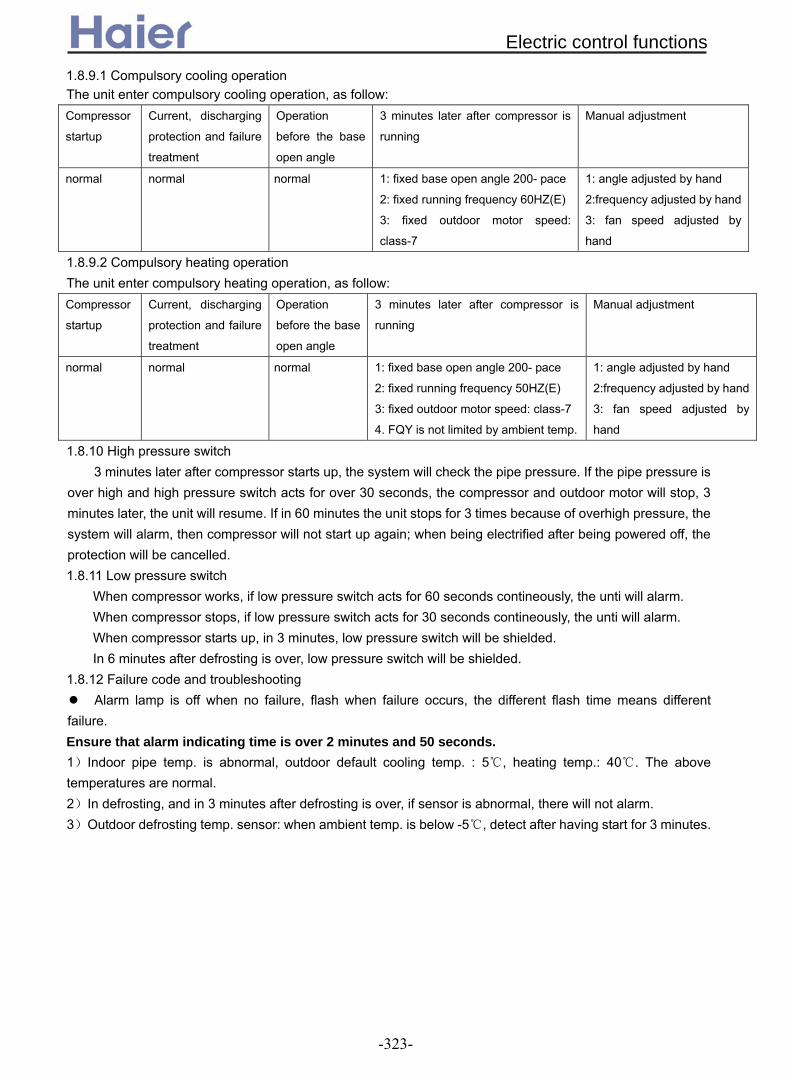
1.8.9.1 Compulsory cooling operation The unit enter compulsory cooling operation, as follow: Compressor
startup
Current, discharging
protection and failure
treatment
Operation
before the base
open angle
3 minutes later after compressor is
running
Manual adjustment
normal normal normal 1: fixed base open angle 200- pace
2: fixed running frequency 60HZ(E)
3: fixed outdoor motor speed:
class-7
1: angle adjusted by hand
2:frequency adjusted by hand
3: fan speed adjusted by
hand
1.8.9.2 Compulsory heating operation The unit enter compulsory heating operation, as follow: Compressor
startup
Current, discharging
protection and failure
treatment
Operation
before the base
open angle
3 minutes later after compressor is
running
Manual adjustment
normal normal normal 1: fixed base open angle 200- pace
2: fixed running frequency 50HZ(E)
3: fixed outdoor motor speed: class-7
4. FQY is not limited by ambient temp.
1: angle adjusted by hand
2:frequency adjusted by hand
3: fan speed adjusted by
hand
1.8.10 High pressure switch 3 minutes later after compressor starts up, the system will check the pipe pressure. If the pipe pressure is
over high and high pressure switch acts for over 30 seconds, the compressor and outdoor motor will stop, 3 minutes later, the unit will resume. If in 60 minutes the unit stops for 3 times because of overhigh pressure, the system will alarm, then compressor will not start up again; when being electrified after being powered off, the protection will be cancelled. 1.8.11 Low pressure switch
When compressor works, if low pressure switch acts for 60 seconds contineously, the unti will alarm. When compressor stops, if low pressure switch acts for 30 seconds contineously, the unti will alarm. When compressor starts up, in 3 minutes, low pressure switch will be shielded. In 6 minutes after defrosting is over, low pressure switch will be shielded.
1.8.12 Failure code and troubleshooting Alarm lamp is off when no failure, flash when failure occurs, the different flash time means different
failure. Ensure that alarm indicating time is over 2 minutes and 50 seconds. 1)Indoor pipe temp. is abnormal, outdoor default cooling temp. : 5, heating temp.: 40. The above temperatures are normal. 2)In defrosting, and in 3 minutes after defrosting is over, if sensor is abnormal, there will not alarm. 3)Outdoor defrosting temp. sensor: when ambient temp. is below -5, detect after having start for 3 minutes.
Electric control functions
-323-

Part 5
Maintenance
1. Failure code…………………….………........................................................................301
1.1 For indoor unit……………………………..............................................................301
1.2 For outdoor unit…………………………................................................................305
2. Troubleshooting……...……….....................................................................................309
2.1 For fixed frequency unit(*EAA)..……………………………..................................309
2 For DC inverter unit(*ERA)….……………………………….............................. .319
Maintenance
-324-
....2

Num
ber
of
flash
es o
f re
mot
e co
ntro
l and
in
door
ligh
ts
Wire
co
ntro
l re
adou
t
Cen
tral
ize
read
out
F
ault
desc
riptio
n
Pos
sibl
e ca
use
Rem
edy
P
urpo
se
Item
s to
be
chec
ked
10
08
21
Fau
lt in
dra
in s
yste
m
Flo
at s
witc
h is
dis
conn
ecte
d 25
min
or
long
er.
R
esto
rabl
e w
hen
give
n co
rrec
tive
sign
al.
To
prev
ent
cond
ensa
te
spill
ing
out o
f dra
in p
an
Wat
er
line,
w
ater
pu
mp,
flo
at s
witc
h, I/
O v
olta
ge
1 01
01
F
ault
in
indo
or
ambi
ent
tem
pera
ture
se
nsor
Sen
sor
is
open
-circ
uit
or
shor
t-ci
rcui
t fo
r 2m
in
or
long
er.
Res
tora
ble
whe
n gi
ven
corr
ectiv
e si
gnal
. To
te
st
inpu
t si
gnal
of
sy
stem
. H
ardw
are
conn
ectio
n, I
/O
volta
ge d
ivis
ion
2 02
02
F
ault
in
indo
or
coil
tem
pera
ture
sen
sor
Sen
sor
is
open
-circ
uit
or
shor
t-ci
rcui
t fo
r 2m
in
or
long
er.
Res
tora
ble
whe
n gi
ven
corr
ectiv
e si
gnal
. To
te
st
inpu
t si
gnal
of
sy
stem
. H
ardw
are
conn
ectio
n, I
/O
volta
ge d
ivis
ion
3 4A
11
F
ault
in
outd
oor
ambi
ent
tem
pera
ture
se
nsor
Sen
sor
is
open
-circ
uit
or
shor
t-ci
rcui
t fo
r 2m
in
or
long
er.
Res
tora
ble
whe
n gi
ven
corr
ectiv
e si
gnal
. To
te
st
inpu
t si
gnal
of
sy
stem
. H
ardw
are
conn
ectio
n, I
/O
volta
ge d
ivis
ion
4 49
12
F
ault
in
outd
oor
coil
tem
pera
ture
sen
sor
Sen
sor
is
open
-circ
uit
or
shor
t-ci
rcui
t fo
r 2m
in
or
long
er.
Res
tora
ble
whe
n gi
ven
corr
ectiv
e si
gnal
. To
te
st
inpu
t si
gnal
of
sy
stem
. H
ardw
are
conn
ectio
n, I
/O
volta
ge d
ivis
ion
5 48
10
O
verc
urre
nt
Det
ecte
d C
T
curr
ent
is
abov
e th
e lim
it th
ree
times
w
ithin
30m
in.
Res
tora
ble
afte
r re
pair.
To
pr
even
t ov
erlo
ad
(ele
ctric
par
amet
er).
P
ower
su
pply
, w
iring
, co
mpr
esso
r, pr
essu
re
6 53
14
F
ault
with
hi
gh
pres
sure
H
igh
pres
sure
sw
itch
is
activ
ated
thr
ee t
imes
with
in
30m
in.
Res
tora
ble
afte
r re
pair.
To
pr
even
t ov
erlo
ad
(pre
ssur
e pa
ram
eter
).
Wiri
ng,
circ
uit,
pres
sure
sw
itch,
re
frig
erat
ion
syst
em
Pow
er fa
ilure
W
rong
pha
se,
phas
e fa
ilure
or
pha
se lo
ss.
R
esto
rabl
e af
ter
repa
ir.
To e
nsur
e po
wer
sup
ply.
W
iring
, co
ntro
l bo
ard,
po
wer
sup
ply
8 07
06
C
omm
unic
atio
n er
ror
betw
een
wire
con
trol
an
d in
door
uni
t
Com
mun
icat
ion
erro
r la
sts
4min
or
long
er.
Res
tora
ble
whe
n gi
ven
corr
ectiv
e si
gnal
. To
ens
ure
tran
smis
sion
to
and
from
con
trol
boa
rd.
Wiri
ng,
circ
uit,
tran
smis
sion
vol
tage
9 06
05
C
omm
unic
atio
n er
ror
betw
een
indo
or a
nd
outd
oor
units
Com
mun
icat
ion
erro
r la
sts
4min
or
long
er.
Res
tora
ble
whe
n gi
ven
corr
ectiv
e si
gnal
. To
ens
ure
tran
smis
sion
to
and
from
con
trol
boa
rd.
Wiri
ng,
circ
uit,
tran
smis
sion
vol
tage
11
0B
30
Ext
erna
l al
arm
sig
nal
inpu
t E
xter
nal
sign
al i
s cu
t ou
t fo
r 10
s or
long
er.
Res
tora
ble
whe
n gi
ven
corr
ectiv
e si
gnal
. To
co
ntro
l ex
tern
al
conn
ectio
n pr
ovid
ed
for
build
ing.
Ext
erna
l si
gnal
, w
iring
, co
ntro
l boa
rd
12
03
20
Fau
lt in
ou
tdoo
r co
il/su
ctio
n lin
e se
nsor
Sen
sor
is
open
-circ
uit
or
shor
t-ci
rcui
t fo
r 2m
in
or
long
er.
Res
tora
ble
whe
n gi
ven
corr
ectiv
e si
gnal
. To
te
st
inpu
t si
gnal
of
sy
stem
. H
ardw
are
conn
ectio
n, I
/O
volta
ge d
ivis
ion
13
0D
31
Tem
pera
ture
shu
t-of
f D
irect
iona
l val
ve m
alfu
nctio
n re
peat
s th
ree
times
. R
esto
rabl
e af
ter
repa
ir.
To p
reve
nt m
alfu
nctio
n of
fo
ur-w
ay v
alve
.
Sen
sor,
four
-way
va
lve,
sy
stem
, con
trol
boa
rd
7 47
22
1.1
Fo
r in
do
or
un
its
1. F
ailu
re c
od
e
1.1.
1 Fo
r ind
oor u
nit w
ith n
ew w
ired
cont
rolle
r YR
-E12
(001
0451
521E
)Fo
r the
inve
rter u
nit
d
cont
rol
Failu
re c
ode
-325-

14
4C
15
Fau
lt in
di
scha
rgin
g te
mpe
ratu
re s
enso
r S
enso
r is
op
en-c
ircui
t or
sh
ort-
circ
uit
for
2min
or
lo
nger
.
Res
tora
ble
whe
n gi
ven
corr
ectiv
e si
gnal
. To
te
st
inpu
t si
gnal
of
sy
stem
. H
ardw
are
conn
ectio
n, I
/O
volta
ge d
ivis
ion
15
05
17
EE
PR
OM
err
or
EE
PR
OM
dat
a lo
ss
Def
ault
oper
atio
n/re
set
rest
orat
ion.
To
se
t da
ta/c
ontr
ol
para
met
er.
E
EP
RO
M,
data
m
atch
, co
ntro
l boa
rd
16
54
26
Fau
lt w
ith
low
pr
essu
re
Low
pr
essu
re
switc
h is
ac
tivat
ed.
R
esto
rabl
e af
ter
repa
ir.
To p
reve
nt re
frig
eran
t lea
k.W
iring
, ci
rcui
t, pr
essu
re
switc
h,
refr
iger
atio
n sy
stem
17
50
15
D
etec
ted
tem
pera
ture
of
di
scha
rge
line
is h
ighe
r th
an
120°
C.
Res
tora
ble
whe
n lo
wer
th
an 1
00°C
. To
pr
even
t ov
erlo
ad
(tem
pera
ture
par
amet
er).
Te
mpe
ratu
re,
fan
mot
or,
pres
sure
, sys
tem
mod
e di
ffere
nt m
odes
.
oper
atio
n m
ode.
m
ode.
U
ser
setti
ng
19
4B
Out
door
coi
l B
Sen
sor
is
open
-circ
uit
or
shor
t-ci
rcui
t fo
r 2m
in
or
long
er.
Res
tora
ble
whe
n gi
ven
corr
ectiv
e si
gnal
. To
te
st
inpu
t si
gnal
of
sy
stem
. H
ardw
are
conn
ectio
n, I
/O
volta
ge d
ivis
ion
20
4D
15
Out
door
di
scha
rgin
g B
S
enso
r is
op
en-c
ircui
t or
sh
ort-
circ
uit
for
2min
or
lo
nger
.
Res
tora
ble
whe
n gi
ven
corr
ectiv
e si
gnal
. To
te
st
inpu
t si
gnal
of
sy
stem
. H
ardw
are
conn
ectio
n, I
/O
volta
ge d
ivis
ion
21
20
07
Mod
ule
erro
r M
odul
e ov
erhe
at,
over
curr
ent,
lack
of
curr
ent,
shor
t-ci
rcui
t.
Res
tora
ble
whe
n gi
ven
corr
ectiv
e si
gnal
. To
pr
even
t ov
erlo
ad
(ulti
mat
e st
ate)
. P
ower
su
pply
, fe
edba
ck,
com
pres
sor,
cont
rol b
oard
Ove
rcur
rent
D
etec
ted
CT
cu
rren
t is
ab
ove
the
limit
thre
e tim
es
with
in 3
0min
.
Res
tora
ble
afte
r re
pair.
To
pr
even
t ov
erlo
ad
(ele
ctric
par
amet
er).
P
ower
su
pply
, w
iring
, co
mpr
esso
r, pr
essu
re
5 48
10
P
ower
failu
re
Wro
ng p
hase
, ph
ase
failu
re
or p
hase
loss
.
Res
tora
ble
afte
r re
pair.
To
ens
ure
pow
er s
uppl
y.W
iring
, co
ntro
l boa
rd,
pow
er
supp
ly
Fau
lt in
ou
tdoo
r co
il te
mpe
ratu
re s
enso
r S
enso
r is
op
en-c
ircui
t or
sh
ort-
circ
uit
for
2min
or
lo
nger
.
Res
tora
ble
whe
n gi
ven
corr
ectiv
e si
gnal
. To
te
st
inpu
t si
gnal
of
sy
stem
. H
ardw
are
conn
ectio
n,
I/O
volta
ge d
ivis
ion
4 49
12
F
ault
in
disc
harg
ing
tem
pera
ture
sen
sor
Sen
sor
is
open
-circ
uit
or
shor
t-ci
rcui
t fo
r 2m
in
or
long
er.
Res
tora
ble
whe
n gi
ven
corr
ectiv
e si
gnal
. To
te
st
inpu
t si
gnal
of
sy
stem
. H
ardw
are
conn
ectio
n,
I/O
volta
ge d
ivis
ion
Fau
lt w
ith
high
pr
essu
re
Hig
h pr
essu
re
switc
h is
ac
tivat
ed t
hree
tim
es w
ithin
30
min
.
Res
tora
ble
afte
r re
pair.
To
pr
even
t ov
erlo
ad
(pre
ssur
e pa
ram
eter
).
Wiri
ng,
circ
uit,
pres
sure
sw
itch,
ref
riger
atio
n sy
stem
6
53
14
Fau
lt w
ith
low
pr
essu
re
Low
pr
essu
re
switc
h is
ac
tivat
ed.
R
esto
rabl
e af
ter
repa
ir.
To
prev
ent
refr
iger
ant
leak
. W
iring
, ci
rcui
t, pr
essu
re
switc
h, r
efrig
erat
ion
syst
em
The
oth
ers
are
the
sam
e as
inve
rter
uni
t.
Com
pres
sor
over
heat
Not
e: A
s fo
r th
e fix
ed f
requ
ency
uni
ts,
rem
ote
cont
rol
and
indo
or l
ight
s fla
sh t
imes
12
and
21(M
odul
e er
ror)
is
not
avai
labl
e. W
hile
7 (
Pow
er f
ailu
re)
14
(fau
lt in
dis
char
ging
tem
pera
ture
sen
sor)
and
16
(Fau
lt w
ith lo
w p
ress
ure)
is s
how
n as
follo
win
g:
18
0C
23
Fau
lt in
op
erat
ion
Indo
or
units
op
erat
e in
R
esto
rabl
e in
sa
me
To e
nsur
e sa
me
oper
atio
n
18
Failu
re c
ode
-326-

Receive board flash times
U-home
Central controller display
Wired controller display
Fault description Possible caused Remedy
1 F36 01D E1 Indoor ambient temp. sensor failure
Sensor is open-circuit or short-circuit for over 2min
Restorable when given corrective signal
2 F6 02D E2 Indoor coil temp. sensor failure
Sensor is open-circuit or short-circuit for over 2min
Restorable when given corrective signal
3 F15 11D E3 Outdoor ambient temp. sensor failure
Sensor is open-circuit or short-circuit for over 2min
Restorable when given corrective signal
4 F16 12D E4 Outdoor coil temp. sensor failure
Sensor is open-circuit or short-circuit for over 2min
Restorable when given corrective signal
5 F14 10D E5 Overcurrent / power failure
Detected CT is over the limit 3 times in 30min
Restorable after repair
6 F19 14D E6 High pressure failure High pressure switch is activated 3 times in 30min
Restorable after repair
9 F9 05D E9 Communication error between indoor and outdoor unit
Communication error lasts for 4min or longer
Restorable when given corrective signal
10 F26 21D E0 Fault in frain system Float switch is disconnected for 25min or longer
Restorable when given corrective signal
13 F38 31D E7 Temp. shut-off 4-way valve malfunction repeats 3 times
Restorable after repair
16 F19 26D E6 Low pressure failure Send outdoor pressure failure to indoor unit
Restorable after repair
-- -- 05D E8 Communication error between wired controller and indoor PCB
Communication error lasts for 4min or longer
Restorable when given corrective signal
1.1.2 For AP422ACEAA
Failure code
-327-

No. Fault description Operation panel display
1 Indoor ambient temp. sensor failure E1
2 Indoor coil temp. sensor failure E2 3 Outdoor ambient temp. sensor failure E3 4 Outdoor coil temp. sensor failure E4 5 CT current failure E5 6 Pressure protection E6 7 E8 8 Communication failure between indoor and outdoor PCB E9
Communication failure between indoor units and panel
1.1.3 For AP482AK EAA
1.1.4 For AS182A ERAVFailure
code
description Remark
E1 Indoor room temperature sensor failure Indoor room temp. sensor in short circuit, or open
circuit, it can resume due to the signal.
E2 Indoor coil temperature sensor failure Indoor coil temp. sensor in short circuit, or open
circuit, it can resume due to the signal.
E4 EEPROM wrong Being electrified to test E2 check sum, or E2 is
broken down.
E7 Communication failure between indoor and
outdoor
Communication failure alarms for 4 minutes
contineously, it can resume due to the signal.
E14 Indoor fan motor failure Indoor fan motor wrong wiring or indoor fan motor
abnormal.
E18 Temperature cutoff protection Outdoor 4-way valve response abnormal.
F1 Module failure Outdoor module abnormal
F2 Outdoor DC motor failure Outdoor DC motor abnormal
F4 Compressor overheat / discharging
temperature protection
Compressor discharging temperature over high
protection
F5 Module over current / current transducer
failure
F6 Outdoor ambient temp. sensor abnormal Outdoor ambient temp. sensor in short current or
open circuit
F7 Outdoor suction/defrosting temp. sensor
abnormal
Outdoor suction/defrosting temp. sensor in short
circuit or open circuit
F8 High pressure abnormal High pressure too high
F9 Low pressure abnormal Low pressure abnormal
F10 No AC power supply
F11 Outdoor PCB EEPROM abnormal Being electrified to test if the E2 check sum is
correct or failure
F13 Communication failure between outdoor
PCB and module
F14 Compressor discharging temp. sensor
failure
Outdoor compressor discharging temp. sensor in
short circuit or open circuit
F15 Compressor running faulty Resumable
F16 Running state-detecting circuit failure Outdoor DC compressor running state-detecting
circuit failure, or compressor abnormal, resumable
Failure code
-328-

1.2 For outdoor units
Code on wiredcontroller
Flash times of indoorreceiver board
Room temp. sensor abnormal 01 Power LED flashes 1 timeIndoor coil temp. sensor abnormal 02 Power LED flashes 2 timesOutdoor temp. sensor abnormal 4A Power LED flashes 3 timesOutdoor coil temp. sensor abnormal 49 Power LED flashes 4 times
48 Power LED flashes 5 timesHigh / Low pressure abnormal 53 Power LED flashes 6 times
Communication malfunction between indoor and wiredcontroller 07 Power LED flashes 8 times
Communication malfunction between indoor and outdoorabnormal 06 Power LED flashes 9 times
Drainage system malfunction 08 Power LED flashes 10 timesAlarm of exterior annunciator 0B Power LED flashes 11 timesCoil gas pipe temp. Sensor abnormal 03 Power LED flashes 12 timesTemperature protection malfunction 0D Power LED flashes 13 times
Failure description
Over-current malfunction/Power failure
1.2.1 For fixed frequency outdoor unit( EAA) *
Failure code
-329-

Trouble descriptionDisplay ofLED borad
LED 5-4-3-2-1Analyze and diagnose
Flash timesof LED onmainborad
01111
Eeprom failure 01110 Outdoor main board eeprom fail 14
IPM failure 00001 IPM failure 1
Compressor U-phaseover-current 00101 The current of compressor U-phase is too high 32
Communication error betweenmain board and spdu module 10110 Communication fail over 4min 22
High pressure protection 01000 System high pressure over 4.5Mpa 8
Module over-voltage protection(only for ISPM) 11010 Send from ISPM module 26
Compressor start-up abnormal 10001 Compressor start-up abnormal 17
Compressor dischargingtemprerture protection 00100 Compressor discharging tempreature over 120
centigrade 4
Abnormal of DC moter 00010 Jam of DC motor or motor failure 2
Abnormal of piping sensor 00111 Piping sensor short-circuit or open-circuit last60 sec 7
Abnormal of Compressorsuction sensor 10101 Compressor suction sensor short-circuit or
open-circuit last 60 sec 21
Abnormal of outdoor ambientsensor 00110 Outdoor ambient sensor short-circuit or
open-circuit last 60 sec 6
Abnormal of compressordischarge sensor 01001 Compressor discharge sensor short-circuit or
open-circuit last 60 sec 9
Spdu / IPM module overcurrent protection 00101 Current of spdu / ISPM module over limit 5
Communication error betweenindoor and outdoor unit 00011 Communication fail over 4min 3
Compressor V-phaseover-current 00101 The current of compressor V-phase is too high 33
Compressor W-phaseover-current 00101 The current of compressor W-phase is too high 34
Compressor jam(only for spdu) Inner compressor is abnormal jamed 15
Compressor phase loss 11110 U/V/W loss 30
Module lack-voltage protection(only for ISPM) 11011 Send from ISPM module 27
Module PWM select circuit error 01011 Module PWM select wrong circuit 11
Detect PFC over-current 01100 The current of PFC circuit is too high 12
Compressor parameter error 10010 Wrong compressor parameter is selected in theEeprom 18
SPDU Communication error 10110 Communication error send from SPDU 22
Circuit error detected by current 10011 Circuit damage detected by the current 19
PFC voltage abnormal 11111 Voltage of PFC circuit is abnormal 31
Module error 01101 Module error 13
The power supply is not the50Hz 01010 The power supply is not the 50Hz 10
Condenser air inlet temp. sensorfailure 11001 Condenser air inlet temp. sensor short-circuit or
open-circuit last 60 sec 25
Low pressure protection 11000 System low pressure under 0.05Mpa 24
4-way valve reverse failure 11100Alarm and stop if detect Td-Tci<=25 last for 1minafter compressor has started for 10min in heatingmode, confirm the failure if it appears 3 timesin one hour.
28
Lack off refrigerant or dischargeside dirty 11101
Alarm and stop if detect Td-Tci>=25 last for 1minafter compressor has started for 10min in coolingmode, confirm the failure if it appears 3 timesin one hour
29
For AU121.2.2 For inverter outdoor unit( ERA) *
Failure code
-330-

%"
&'
' " "
( )" "
& "
* "
&
' +&,
&" "
' )
% # -*.
&.
( (
' / 0"
$/ """
' ' ")
'"#
# "
+'
'")1
' " )2"
' )2&1" /"" /""3"$ "/"" /""3"
( )1-,
' "/"" /""
% # -*.
4" +&,' )#/ ' /
0" #/ $/ """ ' 4 " )1"'"#
(# -,
( " (
-/1/3/2/
For A
'"#
U18/24
!" #"$" "
Failure code
-331-
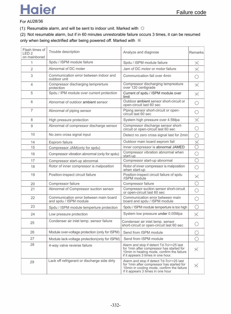
(1): Resumable alarm, and will be sent to indoor unit. Marked with
only when being electrified after being powered off. Marked with ※
!"# $
"# $
% &
' (
'
)
* ) +
,
-
+
.
/
0
1
2
3
4
-/-0
-1
-2
-3
-4
+5+-
++
+/
-5
+.
#&
!
/
-+5
6 ' ' 15 ' ' 15
# /70
' ' 15
6
! ' '
( ' ' ' ' 15
# 5750
(8
+0 7 ' ' 15
7
' "# $
8' "# $
/' # '9:+0 - -5 ; . 7
)8 # '<:+0 - -5 ; .
+1
+2
+3
+4
& +
(2): Not resumable alarm, but if in 60 minutes unrestorable failure occurs 3 times, it can be resumed
For AU28/36
Failure code
-332-

2. Troubleshooting
Is actual pressure detected by pressure gage acceptable?
yes
nolow pressure failure no high pressure failure
yesyes
Is high pressure too low? no is pipe blocked?yes
Refrigerant charge is needed. Check if there is refrigerant leak. If yes, replace pipe.
yes
dredge piping
Change pressure switch
no
Make them in short circuit
Note: The confirmation time of low pressure failure may be shorter, but high pressure failure confirmation time is at least 1 hour. Besides, take the ambient temperature into consideration.
1) Pressure protection
Confirm the fault according to the fault code list
Does system have pressure switch?
Are CN17 and CN18 in PCB cut off?
noReplace PCB
yesyes
no
no
no
yes
yes
yes
yes
Replace PCB
Is DC voltage between both ends of sensor near 5V or 0V?
Replace sensorIs sensor resistance acceptable?
Replace sensorIs sensor short-circuit or open-circuit?
check if the wiring is correct according to wiring diagram
2) Sensor failure
noreconnect
Relocateif sensor is fixed well
Re
2.1 For fixed frequency units (*EAA)
Troubleshooting
-333-

Confirm the fault according to the fault code list
Are connectors of pressure switch in good condition?
noCheck and reconnect
yes
Is low side pressure switch activated? (If not, DC voltage is 0V.)
noReplace PCB
Is the low side pressure detected by the gage lower than threshold value? The threshold value is indicated on the switch
yes
yes
noReplace low pressure switch
yes
if outdoor stop valves of gas pipe and liquid pipe are open totally
noOpen the valves
yes
Is piping twisted or deformed?yes
Repair pipe
no
Does indoor fan work properly during cooling cycle? Does outdoor fan work properly during heating cycle?
no Repair fan motor or fan capacitor
yes
Is indoor filter or heat exchanger dirty?
yesCleaning
no
Measure equalized pressure and time to reach equalization to see if the system has leakage. Lack of refrigerant? Is capillary blocked?
yes Conduct leak test. Evacuate and recharge
no
Bad operation codition, such as ultra low outdoor temperature
3) Low pressure protection - Wired controller shows 53
Troubleshooting
-334-

yes
if outdoor stop valves of gas pipe and liquid pipe are open totally Open the valves
no
Is indoor filter or heat exchanger dirty? Cleaning
yes
yes
Repair fan motor or fan capacitor
no
no
Repair pipeyes
Is piping twisted or deformed?
yes
Does indoor fan work properly during cooling cycle? Does outdoor fan work properly during heating cycle?
no
Check if system is overfed according to equalized pressure in halt.
yes Evacuate and recharge
no
Is reading of discharging pressure gage oscillatory?
no Bad operation codition, such as ultra low outdoor temperature
yes
There is air in system. Evacuate and recharge
4) High pressure protection - Wired controller shows 53 Confirm the fault according to the fault code list
yes
Check and reconnectnoAre connectors of pressure switch in good
condition?
Is high side pressure switch activated? (If not, DC voltage is 0V.)
yes
Replace PCBno
Is the high side pressure detected by the gage higher than threshold value? The threshold value is indicated on the switch
yes
Replace high pressure switch
no
Troubleshooting
-335-
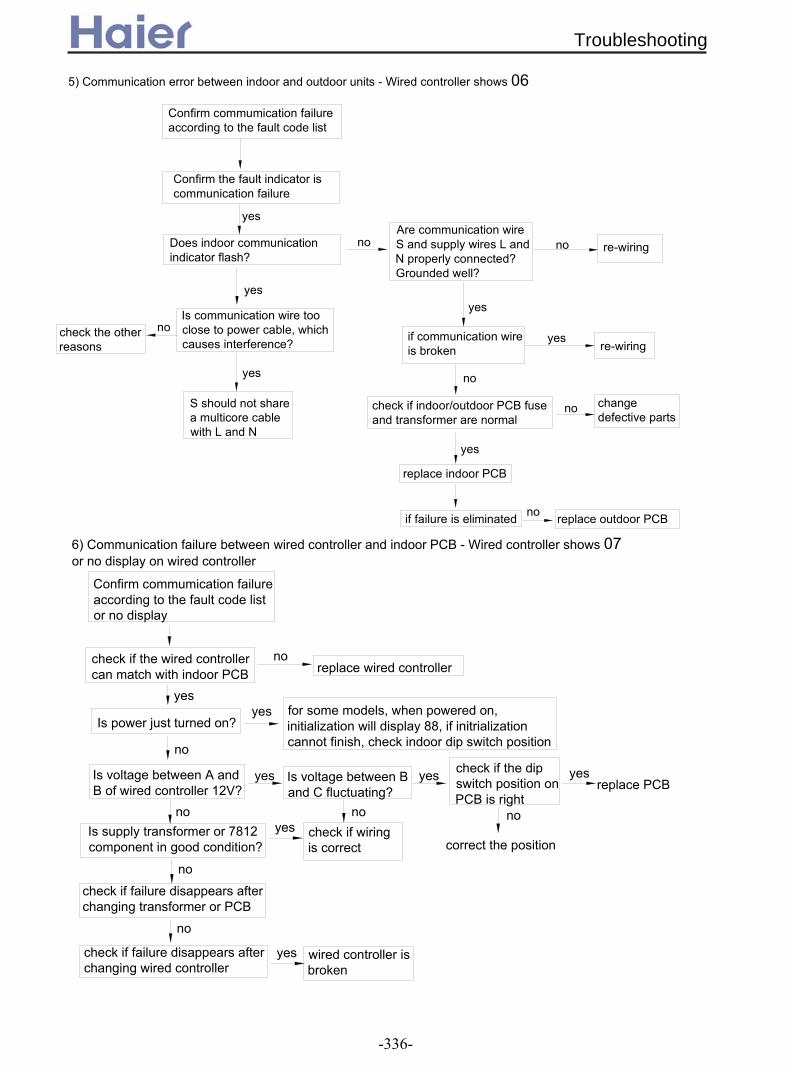
check if indoor/outdoor PCB fuse and transformer are normal
if failure is eliminated replace outdoor PCB
replace indoor PCB
if communication wire is broken
Are communication wire S and supply wires L and N properly connected? Grounded well?
Is communication wire too close to power cable, which causes interference?
Confirm the fault indicator is communication failure
Does indoor communication indicator flash?
check the other reasons
no
yes
change defective parts
re-wiring
Confirm commumication failure according to the fault code list
5) Communication error between indoor and outdoor units - Wired controller shows 06
yes
yes
S should not share a multicore cable with L and N
no no
no
no
no
yes
yes
yes
re-wiring
Is supply transformer or 7812 component in good condition?
yes check if wiring is correct
check if failure disappears after changing transformer or PCB
no
no
check if failure disappears after changing wired controller
yes wired controller is broken
6) Communication failure between wired controller and indoor PCB - Wired controller shows 07 or no display on wired controller
Confirm commumication failure according to the fault code list or no display
yesyes for some models, when powered on,
initialization will display 88, if initrialization cannot finish, check indoor dip switch position no
Is voltage between A and B of wired controller 12V?
yes yes yesIs voltage between B and C fluctuating? replace PCB
no nono
check if the wired controller can match with indoor PCB replace wired controller
no
Is power just turned on?
check if the dip switch position on PCB is right
correct the position
Troubleshooting
-336-

7) High current protection in 3-phase fixed frequency models - Wired controller shows 48Is three-phase circuit not balanced? Is supply voltage too low? Is supply voltage too low at compressor start-up?
yes
nore-wiring
yes
Is compressor current more than overcurrent protection limit? Is current detecting circuit in good condition?
Confirm detecting circuit is abnormal,replace outdoor PCB
no
yes
yesreplace AC contactor
yes
if compressor is normalno Is resistance of compressor
winding incorrect? Is it stuck?yes
replace compressor
yes
if pressure is normal
no
Check: 1. Is a valve in system shut off;2. Is piping clogged; 3. Is system overfed; is there air in system;4. (Cooling cycle) Is condenser dirty? Does outdoor fan motor run at low speed or stop?5. (Heating cycle) Is evaporator or filter dirty? Does indoor fan motor run at low speed or stop?6. Is ambient temperature too high? Is system overloaded?
Is power cable or compressor wire securely connected? Properly?
Modify power supply circuityes
Is AC contactor in poor contact?
Short connect that terminal
if failure disappear after PCB is changed
yes
no
replace PCB
yes Solve problem accordingly
yes
Is an external alarm connected to the system?
8) External alarm- Wired controller shows 0B
no
Is ALARM terminal in mainboard disconnected?
An external alarm is identified according to the list of fault codes
Troubleshooting
-337-
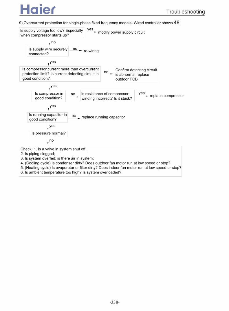
9) Overcurrent protection for single-phase fixed frequency models- Wired controller shows 48
Is supply voltage too low? Especially when compressor starts up?
modify power supply circuit
no
no re-wiring
yes
Is compressor current more than overcurrent protection limit? Is current detecting circuit in good condition?
no Confirm detecting circuit is abnormal,replace outdoor PCB
yes
Is compressor in good condition?
no Is resistance of compressor winding incorrect? Is it stuck?
replace compressoryes
yes
Is running capacitor in good condition?
no replace running capacitor
yes
Is pressure normal?
no
Check: 1. Is a valve in system shut off;2. Is piping clogged; 3. Is system overfed; is there air in system;4. (Cooling cycle) Is condenser dirty? Does outdoor fan motor run at low speed or stop?5. (Heating cycle) Is evaporator or filter dirty? Does indoor fan motor run at low speed or stop?6. Is ambient temperature too high? Is system overloaded?
yes
Is supply wire securely connected?
Troubleshooting
-338-

10) Temperature cutoff protection- Wired controller shows 0Dconfirm the malfunction according to the fault code list
yes
yes
no
yes
no
yes
no
yes
no
yes
noReplace sensor
yes
Replace indoor PCB
Are indoor sensors for ambient temperature and coil properly located?
Is resistance of indoor sensor correct?
Does four-way valve work properly?
Relocate
Replace four-way valve
Is outdoor four-way valve in good condition during heating cycle?
Does small relay coil of four-way valve have a voltage of 12V DC?
no Relay is broken. Replace PCB
Is indoor unit malfunction caused by lack of refrigerant?
charge refrigerant
Is heat exchange effect adversely affected by heavy dust in indoor and outdoor units?
cleaning
Troubleshooting
-339-

11) Fault in drain system- Wired controller shows 08confirm the malfunction according to the fault code list
no
yes Replace water pump
yes
yesClean drain pan
no
Is float switch holder tinted that float can't move, or too close to pump motor that interference arises?
yesAdjust holder
no
yes Replace float switch
no
Replace indoor PCB
Note: Float switch is close in normal state, when being activated, it is open. Voltage between both ends is 0V when close, approximately 5V when open.
Unclog pipe and water pump
Is drain pan dirty and float switch ineffective?
Is pump motor in good condition?
Is drain pipe clogged?yes
Check if float switch is in good condition with multimeter
confirm the malfunction according to the fault code list
no
no
no adjust power supply
no
no
replace outdoor PCB
if the failure disappear after correcting the wiring
Is there phase loss or phase failure?
Is fault corrected after sequence of either two of three RST phases is adjusted?
Check if the phase detecting circuit is correct according to ourdoor wiring diagram
yes
12) Phase loss or phase failure- Wired controller shows 48
Troubleshooting
-340-
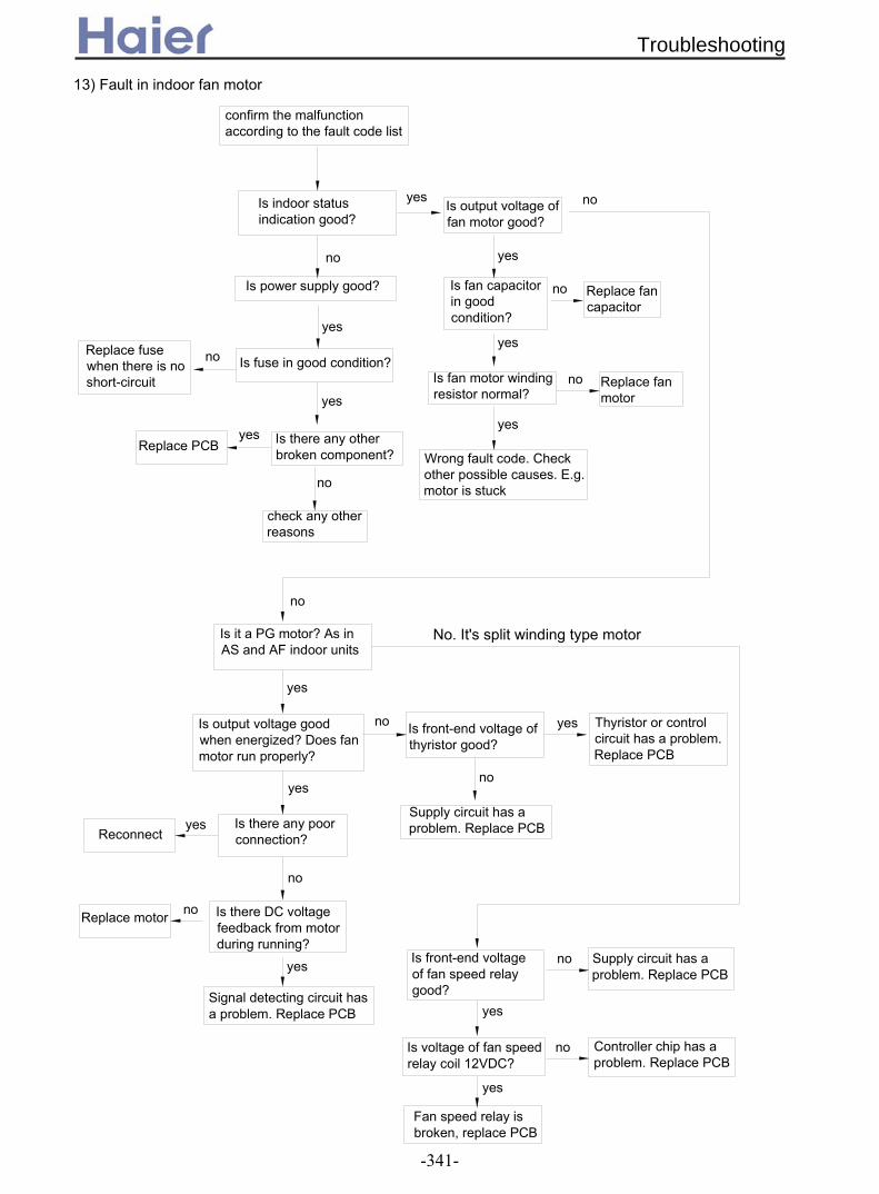
13) Fault in indoor fan motor
confirm the malfunction according to the fault code list
no
no
yes
no
yes
yes
no
no
yes
yes
yes
no
no
no
no
yes
yes
yes
yes
yes
no
no Replace fan motor
no
no
yes
yes
Is power supply good?
yesIs indoor status indication good?
Is fuse in good condition?Replace fuse when there is no short-circuit
Is there any other broken component?
check any other reasons
Is output voltage of fan motor good?
Is fan capacitor in good condition?
Is fan motor winding resistor normal?
Wrong fault code. Check other possible causes. E.g. motor is stuck
Replace fan capacitor
Replace PCB
No. It's split winding type motorIs it a PG motor? As in AS and AF indoor units
Is output voltage good when energized? Does fan motor run properly?
Is there DC voltage feedback from motor during running?
Signal detecting circuit has a problem. Replace PCB
Replace motor
Is front-end voltage of thyristor good?
Supply circuit has a problem. Replace PCB
Thyristor or control circuit has a problem. Replace PCB
Is front-end voltage of fan speed relay good?
Is voltage of fan speed relay coil 12VDC?
Supply circuit has a problem. Replace PCB
Controller chip has a problem. Replace PCB
Fan speed relay is broken, replace PCB
Is there any poor connection?Reconnect
Troubleshooting
-341-

Confirm operating conditions
no
yes
yesno No need to replace mainboard. The fault may
be caused by power supply
yes
no
Does the same fault occur before?
yes
no No need to replace mainboard. Contactor wasn't in good contact
No need to replace mainboard. (Check operating status in details, e.g. TIMER feature, supply failure, thunder storm, interference from other appliances, etc.) Explain causes of fault to user.
1.Is supply voltage acceptable?2.Is temperature setting correct? (e.g. too high)3.Is system in TIMER mode?4.Is user aware of product features, etc.
Check the system thoroughly, e.g. technical data of components when power-off, and voltage and current of check points when power-on
Disconnect contactor and reconnect it. (check if fuse or varistor is broken.)
Does the same fault occur before?
Switch off air conditioner temporarily. Switchon air conditioner again after 1 minute
Does the same fault occur before?
yes
no
Switch on air conditioner
Is the feature not available for present product?
Fault confirmation
Explain product features to user
For example: no cooling, etc.
Service call
14) Troubleshooting (before replacement of PCB)
Troubleshooting
-342-

2.2 For DC inverter units (*ERA)2.2.1 For AU122AEERA
yes if the refrigerant is normal
improve the ventilation condition
no no
stop the unit, restart up until power module temperature has reduced
yes if compressor wiring is correct
yes if compressor winding is normal, and the each phase resistor is in balance
no
compressor can not start up
nowiring correctly no
replace compressor
Alarm condition: ambient temperature sensor is in short circuit or open circuit
if sensor is fixed well
Relocate
reconnectno
check if the wiring is correct according to wiring diagram
Is sensor short-circuit or open-circuit?
Replace sensorIs sensor resistance acceptable?
Replace sensor
yes
yes
yes
no
no
no
1) Sensor failure
Replace PCB
Check if the power normal
outdoor indicator indicate the above failure
check if the any current among compressor input port U-V-W is over high
check if the system is blocked
yes
yes
no
check if module bottom temperature is over high, more than 90degree
if ventilation beside the module radiator is good
yes
compressor startup procedure is abnormal, and vibrates seriously
2) Outdoor power module failureThe following troubleshooting is available for:a. IPM failure(00001)b. Compressor U-phase,V-phase and W-phase over-current(00101), total unit over-current(00101)c. Compressor start-up abnormal(10001), Compressor jam(01111), Compressor phase loss(11110), Module lack-voltage protection(11011), Detect PFC over-current(01100), PFC voltage abnormal(11111)
yes yes if the total load is too big
no adjust the power supply as 220-230VAC, 50Hz
if the total unit operate normally
replace the module
no
Troubleshooting
-343-

no
yes
Alarm condition: outdoor DC motor is blocked rotor or broken, abnormal.
outdoor indicator LED indicate DC motor abnormal
3) Outdoor DC motor abnormal
adjust fan blade to make it run normally
adjust lead wire of fan motor
yes
no
Check if the lead wire of DC motor is broken or short-connected
Check if the outdoor unit fan blade is blocked by some objects
Replace motorWarning: For outdoor DC fan motor, forbidden to pull off the plug when being electrified.4) Communication error between indoor and outdoor unitsindoor unit troubleshooting
no
check if the failure is eliminated
yes
compressor can not startup after unit is switched on for 4 minutes, indoor failure indicator flashes 9 times
no
check if wiring between indoor and outdoor is correct, power supply is 50Hz
if indoor unit alarms other failure codes
check if the indoor PCB worked normally
yeseliminate other faults
adjust wiring and power supply, note not connect the outdoor connecting port 1/2 wrong
Replace outdoor PCBno
no check the indoor wires, confirm the normal operation of indoor PCB
yes
5) Compressor discharging temperature protectionAlarm condition: Within one hour after compressor is running, compressor discharging temperature is over 115degree for 3 times continously.
adjust piping
nono
replace sensor
yes
replace PCB
yes
no
check if discharging temp. sensor resistance is normal
check if refrigerant is too much or too less
check if the system piping is blocked
adjust refrigerant
yes
outdoor indicator indicate the above failure
Troubleshooting
-344-

if high pressure switch is normal
check if the refrigerant is too much or less by the pressure gauge
no
no
yes
outdoor failure indicator indicate high pressure failure
check if the wiring between indoor and outdoor is correct
no
outdoor indicator shows power faliure
check if power supply is normal
yes
no
adjust power supply as 50HZ,220-230VAC
EEPROM data is missing, replace PCB
check if EEPROM welded points on outdoor PCB is in good condition
outdoor indicator shows the above failures
yes
noadjust EEPROM welded point
outdoor indicator shows the above failures
replace the outdoor module
when compressor starting up, unit stops abnormally and can not start up normally
yes
6) Outdoor high pressure protectionAlarm condition: When compressor running, high pressure is over 4.5 MPa for 30 seconds continously
check if the piping is blockedyes
adjust refrigerant
adjust piping
yesreplace sensor
7) Outdoor power supply is abnormalAlarm condition: if power supply is not 50Hz as standard, which will affect the normal communication and cause air conditioner bad operation.
adjust wiring
8) EEPROM failure(01110), Compressor parameter error(10010)Alarm condition: EEPROM is fault or data is missing
9) Circuit error detected by current(10011), Module error(01101), Module PWM select circuit error(01011)Alarm condition: when compressor is running, the unit will be abnormal or stop
Replace the outdoor PCB
yes
Troubleshooting
-345-
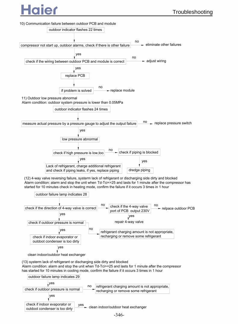
measure actual pressure by a pressure gauge to adjust the output failure
Lack of refrigerant, charge additional refrigerant and check if piping leaks, if yes, replace piping
check if high pressure is low,tooyes
check if piping is blocked
dredge piping
yes
replace pressure switch
low pressure abnormal
no
yes
check if the wiring between outdoor PCB and module is correct
compressor not start up, outdoor alarms, check if there is other failure
outdoor indicator flashes 22 times
yesno
noeliminate other failures
replace PCB
yes
if problem is solvedno
outdoor indicator flashes 24 times
adjust wiring
replace module
Alarm condition: outdoor system pressure is lower than 0.05MPa
no
yes norefrigerant charging amount is not appropriate, recharging or remove some refrigerant
yesrepair 4-way valve
norelpace outdoor PCBcheck if the direction of 4-way valve is correct
clean indoor/outdoor heat exchanger
check if indoor evaporator or outdoot condenser is too dirty
yes
check if the 4-way valve port of PCB output 230V
check if outdoor pressure is normal
no
yes
outdoor failure lamp indicates 28
(12) 4-way valve reversing failure, systerm lack of refrigerant or discharging side dirty and blockedAlarm condition: alarm and stop the unit when Td-Tci<=25 and lasts for 1 minute after the compressor has started for 10 minutes check in heating mode, confirm the failure if it occurs 3 times in 1 hour
(13) systerm lack of refrigerant or discharging side dirty and blockedAlarm condition: alarm and stop the unit when Td-Tci>=25 and lasts for 1 minute after the compressor has started for 10 minutes in cooling mode, confirm the failure if it occurs 3 times in 1 hour
outdoor failure lamp indicates 29
check if outdoor pressure is normalrefrigerant charging amount is not appropriate, recharging or remove some refrigerant
no
yes
check if indoor evaporator or outdoot condenser is too dirty
yes
yes clean indoor/outdoor heat exchanger
10) Communication failure between outdoor PCB and module
11) Outdoor low pressure abnormal
Troubleshooting
-346-

2.2.2 For AU182AFERA and AU242AGERA
Replace sensor
yes
Replace PCBno
Below the indication on indicator board sequence is LED5-LED4-LED3-LED2-LED1, 0: OFF; 1: ON1) Sensor failure
no
no
no
yes
yes
yes
For sensor failure of ambient, suction and coil temperature, check if resistor R31/R32/R33 value of outdoor PCB is 20K; for d ischarging temperature sensor failure, check if R46 is 47K
Replace sensor
Is sensor resistance acceptable? Replace sensor
Is sensor short-circuit or open-circuit?
check if the w iring is correct according to w iring diagram
noreconnect
Relocateif sensor is fixed well
A larm condition: ambient temperature sensor is in short circuit or open circuit for 3 seconds continously.Outdoor indicator displays 00110 or 00111, or 01001
replace compressorno
wiring correctlyno
compressor can not start up
no
if compressor winding is normal, and the each phase resistor is in balance
yesif compressor wiring is correct
yes
stop the unit, restart up until power module temperature has reduced
nono
improve the ventilation condition
if the refrigerant is normal
yesif the total load is too big
yesyes
2) Outdoor power module failure
compressor startup procedure is abnormal, and vibrates seriously
yes
if ventilation beside the module radiator is good
check if module bottom temperature is over high, more than 90degree
no
yes
yes check if the system is blocked
check if the any current among compressor input port U-V-W is over high
outdoor indicator displays 00001
Alarm condition: outdoor indicator displays 10111, 00001, or 01111, 10000, 100001, or 10100
Re-electrified after being powered off
Troubleshooting
-347-

Warning: For outdoor DC fan motor, forbidden to pull off the plug when being electrified.
Replace motor
Check if the outdoor unit fan blade is blocked by some objects
Check if the lead wire of DC motor is broken or short-connected
no
yes
adjust lead wire of fan motor
adjust fan blade to make it run normally
3) Outdoor DC motor abnormal
outdoor indicator shows 00010
Outdoor indicator displays 00010.Alarm condition:outdoor DC motor is blocked rotor or broken, abnormal.This fault is only used when indoor unit is with DC fan motor.
yes
no
For wall mounted unit:
yes
check if the failure is eliminated
yes
no
4) Communication error between indoor and outdoor unitsOutdoor indicator shows 00011
LCD of wall mounted displays E7
yes
If communication wire is damaged or broken off
Check if communication wiring between indoor and outdoor is correct and if power wiring is correct
Replace indoor PCB
no adjust wiring
re-wiring
Replace outdoor PCB
no
Replace indoor PCB
yes
adjust the position
no
no Replace outdoor PCB
adjust wiring and power supply
eliminate other faults
yes
check the 4th bit of SW5 on PCB is at "OFF", the others are at "ON"
if indoor unit alarms other failure codes
check if wiring between indoor and outdoor is correct, power supply is 50Hz
no
compressor can not startup after unit is switched on for 4 minutes
yes
check if the failure is eliminated
yes
For convertible unit and ceiling concealed unit:
Troubleshooting
-348-

replace PCB
yes
replace sensorno
no
adjust piping
outdoor indicator shows 00100
yes
adjust refrigerant
check if the system piping is blocked
check if refrigerant is too much or too less
check if discharging temp. sensor value is normal
no
yes
5) Compressor discharging temperature protectionOutdoor indicator shows 00100.Alarm condition: Within half an hour after compressor is running, compressor discharging temp. is over 120degree for 3 times continously.
adjust piping
Outdoor indicator shows 00101.Alarm condition: When compressor running, the module current is over 21A.
6) Outdoor SPDU module over current protection
replace SPDU module
adjust refrigerant
yes
no
yes
no
outdoor failure indicator shows 00101
check if the refrigerant is too much or too less
check if the piping is blocked
replace sensoryes
adjust piping
adjust refrigerant
yescheck if the piping is blocked
Outdoor indicator shows 01000Alarm condition: When compressor running, high pressure is over 4.5 MPa for 30 seconds continously.
7) Outdoor high pressure protection
outdoor failure indicator shows 01000
yes
no
no
check if the refrigerant is too much or less by the pressure gauge
if high pressure switch is normal
Outdoor indicator shows 01010Alarm condition: if power supply is not 50Hz as standard, which will affect the normal communication and cause air conditioner bad operation.
8) Outdoor power supply is abnormal
Troubleshooting
-349-
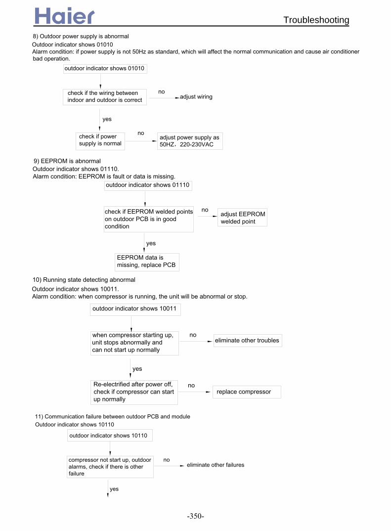
adjust wiring
Outdoor indicator shows 01010Alarm condition: if power supply is not 50Hz as standard, which will affect the bad operation.
8) Outdoor power supply is abnormal
adjust power supply as 50HZ,220-230VAC
no
yes
check if power supply is normal
outdoor indicator shows 01010
no
check if the wiring between indoor and outdoor is correct
normal communication and cause air conditioner
Outdoor indicator shows 01110.Alarm condition: EEPROM is fault or data is missing.
9) EEPROM is abnormal
adjust EEPROM welded point
no
yes
outdoor indicator shows 01110
check if EEPROM welded points on outdoor PCB is in good condition
EEPROM data is missing, replace PCB
replace compressor
Outdoor indicator shows 10011.Alarm condition: when compressor is running, the unit will be abnormal or stop.
10) Running state detecting abnormal
no
eliminate other troublesno
yes
when compressor starting up, unit stops abnormally and can not start up normally
Re-electrified after power off, check if compressor can start up normally
outdoor indicator shows 10011
Outdoor indicator shows 1011011) Communication failure between outdoor PCB and module
eliminate other failuresno
outdoor indicator shows 10110
compressor not start up, outdoor alarms, check if there is other failure
yes
Troubleshooting
-350-
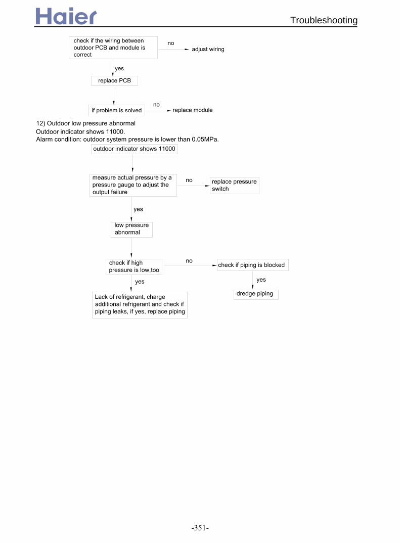
replace module
adjust wiring
noif problem is solved
yes
replace PCB
nocheck if the wiring between outdoor PCB and module is correct
no
Outdoor indicator shows 11000.Alarm condition: outdoor system pressure is lower than 0.05MPa.
12) Outdoor low pressure abnormal
outdoor indicator shows 11000
yes
no
low pressure abnormal
replace pressure switch
yes
dredge piping
check if piping is blocked
yes
check if high pressure is low,too
Lack of refrigerant, charge additional refrigerant and check if piping leaks, if yes, replace piping
measure actual pressure by a pressure gauge to adjust the output failure
Troubleshooting
-351-

2.2.3 For AU362AHERA
Alarm condition: ambient temperature sensor is in short circuit or open circuit for 60 seconds continously.
if sensor is fixed well
Relocate
reconnectno
check if the wiring is correct according to wiring diagram
Is sensor short-circuit or open-circuit?
Replace sensorIs sensor resistance acceptable?
Replace sensor
For sensor failure of ambient, suction, coil and condenser air inlet temperature, check if resistor R74/R75/R77/R78 value of outdoor PCB is 20K; for discharging temperature sensor failure, check if R76 is 47K
yes
yes
yes
no
no
no
1) Sensor failure
noReplace PCB
yes
Replace sensor
Re-electrified after being powered off
outdoor indicator LED2 flashes 1 time
check if the any current among compressor input port U-V-W is over high
check if the system is blocked
yes
yes
no
check if module bottom temperature is over high, more than 90degree
if ventilation beside the module radiator is good
yes
compressor startup procedure is abnormal, and vibrates seriously
yes yes if the total load is too big
LED1 is the indicator for communication between indoor and outdoor unit LED2 is the failure indicator
yes if the refrigerant is normal
improve the ventilation condition
no no
stop the unit, restart up until power module temperature has reduced
yes if compressor wiring is correct
yes if compressor winding is normal, and the each phase resistor is in balance
no
compressor can not start up
nowiring correctly
noreplace compressor
2) O utdoor power module failure
Troubleshooting
-352-

yes
no
check if discharging temp. sensor value is normal
check if refrigerant is too much or too less
check if the system piping is blocked
adjust refrigerant
yes
outdoor indicator LED2 flashes 4 times
replace sensor
yes
replace PCB
no
yes
Alarm condition: outdoor DC motor is blocked rotor or broken, abnormal.
outdoor indicator LED2 flashes 2 times
3) Outdoor DC motor abnormal
adjust fan blade to make it run normally
adjust lead wire of fan motor
yes
no
Check if the lead wire of DC motor is broken or short-connected
Check if the outdoor unit fan blade is blocked by some objects
Replace motor
Warning: For outdoor DC fan motor, forbidden to pull off the plug when being electrified.
4) Communication error between indoor and outdoor unitsoutdoor indicator LED2 flashes 3 times
yes
check if the failure is eliminated
yes
compressor can not startup after unit is switched on for 4 minutes
no
check if wiring between indoor and outdoor is correct, power supply is 50Hz
if indoor unit alarms other failure codes
check the 4th bit of SW5 on PCB is at "OFF", the others are at "ON"
yes eliminate other faults
adjust wiring and power supply, note not connect L/N wrong
Replace outdoor PCB
no
no adjust the position
yes
Replace indoor PCB
5) Compressor discharging temperature protectionoutdoor indicator LED2 flashes 4 timesAlarm condition: Within one hour after compressor is running, compressor discharging temperature is over 120degree for 3 times continously.
adjust piping
no
no
Troubleshooting
-353-

check if the piping is blocked
check if the refrigerant is too much or too less
outdoor failure indicator flashes 5 times
no
yes
no
yes
adjust refrigerant
replace SPDU module
if high pressure switch is normal
check if the refrigerant is too much or less by the pressure gauge
no
no
yes
outdoor failure indicator flashes 8 times
check if the wiring between indoor and outdoor is correct
no
outdoor indicator flashes 10 times
check if power supply is normal
yes
no
adjust power supply as 50HZ,220-230VAC
EEPROM data is missing, replace PCB
check if EEPROM welded points on outdoor PCB is in good condition
outdoor indicator flashes 14 times
yes
noadjust EEPROM welded point
6) Outdoor SPDU/ISPM module over current protectionAlarm condition: When the module detect the current too high and over the limit value
adjust piping
7) Outdoor high pressure protectionOutdoor indicator flashes 8 timesAlarm condition: When compressor running, high pressure is over 4.5 MPa for 30 seconds continously.
check if the piping is blocked
yes
adjust refrigerant
adjust piping
yesreplace sensor
8) Outdoor power supply is abnormalAlarm condition: if power supply is not 50Hz as standard, which will affect the normal communication and cause air conditioner bad operation.
adjust wiring
9) EEPROM is abnormal
Alarm condition: EEPROM is fault or data is missing.
Troubleshooting
-354-

measure actual pressure by a pressure gauge to adjust the output failure
Lack of refrigerant, charge additional refrigerant and check if piping leaks, if yes, replace piping
check if high pressure is low,too
yes
check if piping is blocked
dredge piping
yes
replace pressure switch
low pressure abnormal
no
yes
outdoor indicator flashes 19 times
Re-electrified after power off, check if compressor can start up normally
when compressor starting up, unit stops abnormally and can not start up normally
yes
noeliminate other troubles
no
check if the wiring between outdoor PCB and module is correct
compressor not start up, outdoor alarms, check if there is other failure
outdoor indicator flashes 22 times
yes
no
no
eliminate other failures
replace PCB
yes
if problem is solvedno
outdoor indicator flashes 24 times
10) Running state detecting abnormalAlarm condition: when compressor is running, the unit will be abnormal or stop.
replace compressor
11) Communication failure between outdoor PCB and module
adjust wiring
replace module
12) Outdoor low pressure abnormal
Alarm condition: outdoor system pressure is lower than 0.05MPa.
no
Troubleshooting
-355-

Part 6 Control Devices
1. Infrared controllers………………………….........................………............................333
1.1 YR-H71…………...………………………………………….....................…….....333
1.2 YR-H50…………...……………………………………………..............................344
1.3 YR-H49…………...……………………………………………....................…......345
2. Wired controller YR-E12……………………......................……....................……......346
3. Central controller YCZ-A001………………………....................................................358
4. Weekly timer YCS-A001……………………………….............................................
Control Devices
-356-
Control Devices
..361
Control Devices

)
67
68
65
69
98
:
;
;
5
6
9
<
8
=
>
5?
59
5=
57
7
@
5@
5>
669<
99
6<
6=6@
96
95
9?
976?
5
58
5A A C58 9? D : ! " " "E " ! "A6A#$ " % & ' E ! !' (A" % & ' E & ( !") & A9A ! $: "
;" ! E & " ! % & ( B)" E #$ DA
<A A(% % ' E & " ! *C
8A + A
; ;$; ,
=A C $EE $:AB$ C " " $ & E $: ' D
5?A & ' '% & & " & " E AA " ) " " 'A
7A;
59A ;- .
57A " + A
@A : ! " " "A
/0123 5A &( & % " &A6A E & " A9A: ' & ' ( : E & " ; " F&& " F ! ' % " 57 A
>A ; E $ % ;A; % G & E & & A
5655
6>
5<A: A
55A & & 56A + . ' % C '% & ' E & ' " " . % H " % E . !' ( . % ! A
58A "& E & ! ! "& A
7 @ 5< 58
;C
;
9=
9=55
+
;$
$
#$
+
044
5610
Infrared controller
-357-

' (&2 / 2 / ) / * 3 ) 7 : 2 3 > /.+)$ " "# 3 7 : / 9 ! 9 9 $ 9 /2)0)$ )) 2 . ) ) / 2 3 : 7 ) . 6:1)-)!/ ) * /)7 99 + ! $ /2 *7.2 : .: *)
%+! ) ) * $ ) / )
)
!"#$ %
&' ( ) * ( +
,-.)%"
%-.)! %)-).
/ !#-#! ,-). ,!,
%! %
" " " ) #""! ) ' ) , ) ) )
) %
" %0-).
- -!
- ")
0 ( * ( * 4 * *( + + ( * + + 4 * 3*
& (
# * - ")" + +
56 7890 ( * 4
+ * 4 + */ * + + +* * 4 * +(*(
%! & 1 * + + ( * ) & !"0-,-., "-
# - * ( ( + * + *1
0 + -! +
# #
# &
:;<7
!"0 - ,-., "
#
, & /
& (&
=8>9? @ A8 + ** 3 4 (4*589? @ A8 686 9> + ** 43B98 9 + + - +
* 4 + ** %( (( + ** *1 C D * + * 4 + ** + ( ( + 4
) - ** + + * 4 * ** * / * (** * * + 0 + 0 + * (
%,
,-.,%"-
%
-!
,!,
% !"#$
%!"
#!"#$
#" !-.,
,
Infrared controller
-358-
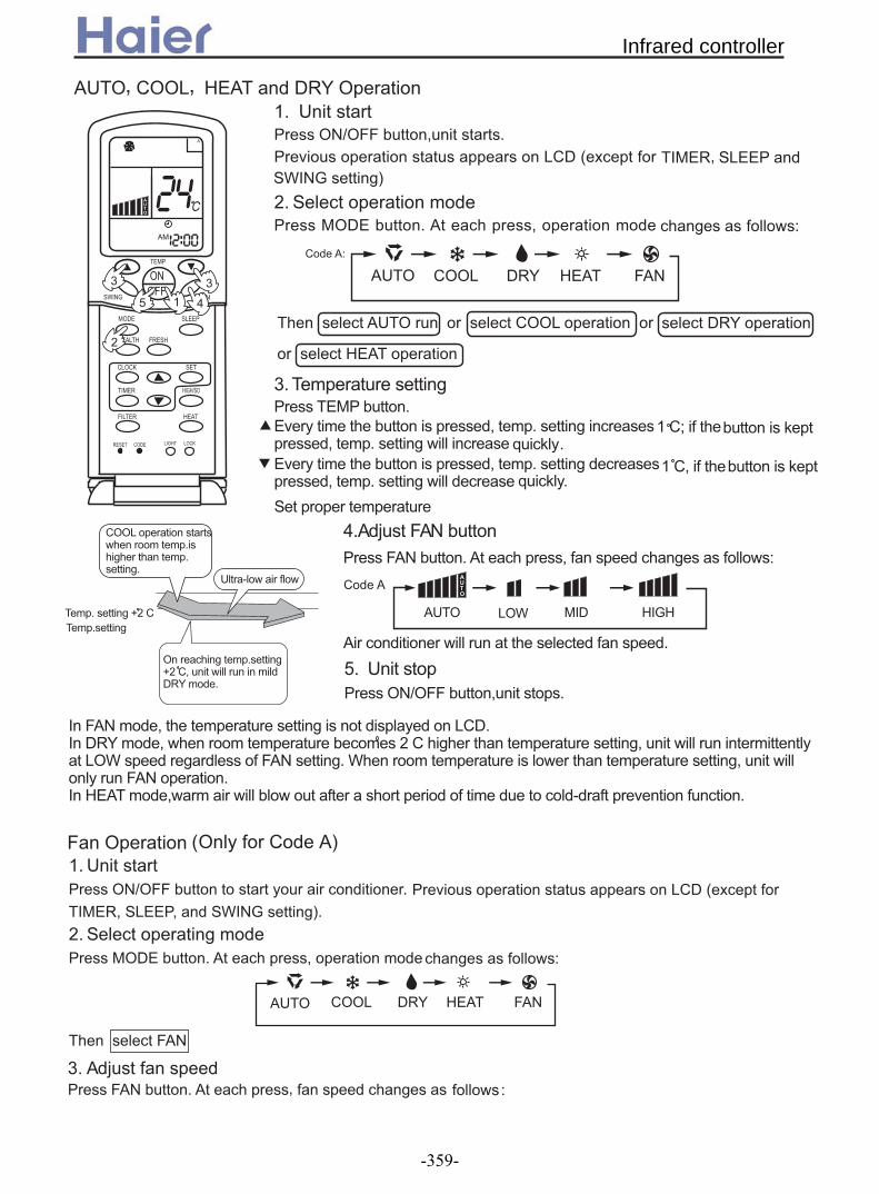
;E E ; , 5A $: ' E A( B) " E#$ D
9A
& ;
;
6A ' A ; & E " !C
' A(% & ' E A E A ! *.%A(% & ' E A E A ! *.%A
<A;- ;$ ' ;$ ' A ; & E " & " !C
; ! & " A
7A $: ' E A
;$ E & % A , E !& ' 6 && & E ! % # " ;$ A#& ! & E ! % ;$ A ; E! ! ' ! " & " J" ( " A
; ;$; ,
; #
:
;
;
+
;$
$
#$
+
5610
;C
;
;
A I6 A
& AI6 E ! , A
J ! " !
!& A&& & AA
9
7 5
9
<
6
5610
&
5 H " &
5 E " &
,
' .
' .
5A $: ' % A ( B) " E E #$ DA
6A ' A ; & E & " !C
9A ;- " ;$ ' A ; & E " & " ! C
& ;$
; ;$; ,
B% " ;D
Infrared controller
-359-
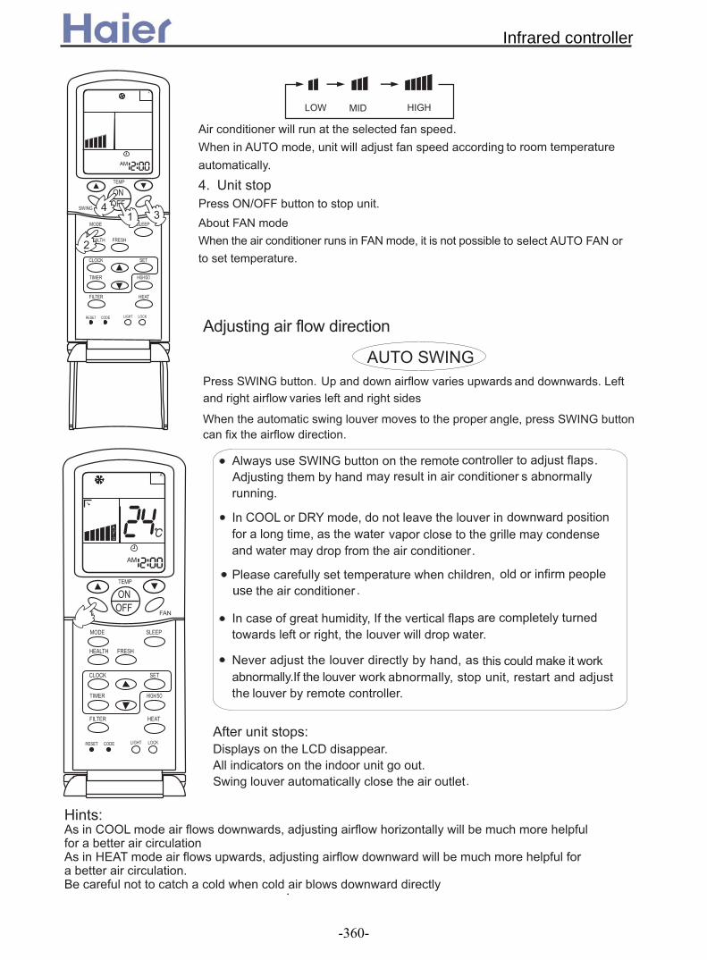
)
; ! & " A#& ; E ! - " %A
<A $: ' A
;' ;$
#& & ;$ E '
A
;
:
;
+
;$
$
#$
+
<5 9
6
;
#
; ;$
#$ ' A ! " ! ( ! & " ! ( " &
; #$
;- " !
#& & ! ( ( & ") & " ! A
!!A "
E #$ '
;!% #$ ' & - ";- & '% &A
% & A; & A! ( % & A
;" C
"% !& &E& A
" &%E " & ( " ! " &E & ( ! !A
$( - & ( % '% &E ' %A" & ( ! .& ( '% A
C; " ! !!E - " ! & Q % ! ' & &"" ' ; ; " ! !E - " ! !! ! ' & &" " ' A " & !& ' ! !! %
, E ( & ( " E & ! ! % " & A
:
;
;
+
;$
$
#$
+
;
;
A% ' %
!! ( & %
" use A
%
& . ! .' %E E -
Infrared controller
-360-
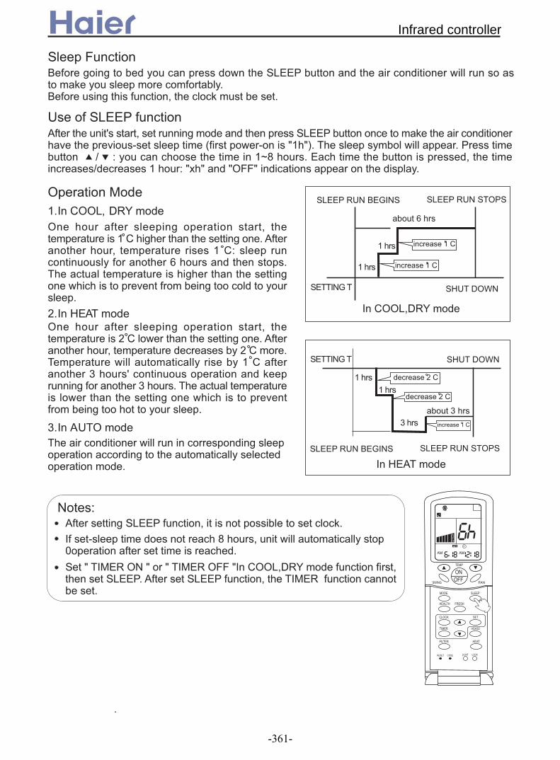
)
" ' % ! & ' & ! . % " '%A" & " E & . ' A
" " ;" & G E & ' . & &( & ( J B" !J F5&FDA & %' ! A ' : C % & & 5R@ & A & & ' E & : 5 & C F)&F FF & %A
5A E , & " E & 5 && & & A ;" & & E 5 C % " & 8 & & A& && & & !&& ( " ' % A
6A ; & " E & 6 ! & & A ;" & & E '% 6 A ! % '% 5 " & 9 & G . " & 9 & A & ! & & !&& (" ' & % A
9A ; & ! & % A
$ $ $
$ #$
' 8 &
5 &
E,
5
5
$ $ $
$ #$
5 &5 &
9 &' 9 &
5
6
6
$ C;" " E ' .A" J & @ & E ! % ? " &A
F $ F F F E, " "E& A ;" " E & " ' A
;
:
;
;
+
;$
$
#$
+
044
5610
;
5 &
Infrared controller
-361-
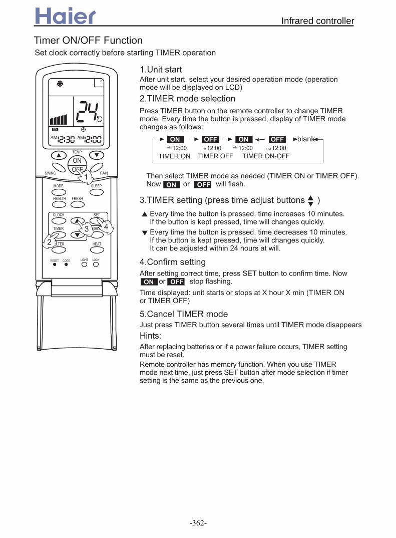
(% & ' E 5? A" & ' . E ! & *.%A
$: . % '"
5A ;" E % B ! ' % D
6A ' & & A (% & ' E % " & " !C
0/ 044 0/ 044;56C?? ;56C??56C?? 56C??
$ $J
'.
& B $ DA$ ! ! "&A
9A B - ' D
(% & ' E 5? A" & ' . E ! & *.%A ' - !& 6< & !A
<A " ;" E ' " A $ !
%C S & S B $ D
7A T ' (
C;" ' " ! " E ' A & % " A#& % ) E - ' " " & & ( A
0/ 044
0/ 044 "&A
:
;
;
+
;$
$
#$
+
5
6
9 <
;
Infrared controller
-362-

$J . % '" 5A ;" E % B ! ' % D
6A ' & & A (% & ' E % " & " !C
044
9A " $
<A " " $;" E ' " A $ !
7A " ' " ! & F " $F
'
0/ "&E !& "&A
8A " " ;" E ' " A "&A
%C S & S A
=A T ' ( A; & * " $ E & J J ' QA" & " $ & E $J " ' A
0/& $J A ! "&A
(% & ' E 5? A" & ' . E ! & *.%A
(% & ' E 5? A" & ' . E ! & *.%A ' - !& 6< & !A; " " " A
044
:
;
;
0/ 044 0/ 044;56C?? ;56C??56C?? 56C??
$ $J
'.
;
+
;$
$
#$
+
044
9 87<
6
5
Infrared controller
-363-

;" & & " E & & "E & " : ! " ' A & " ( & " " A
5A#&& E % ' " 9 E & " : ! ! B!& E & "&E " . % & A% & ' E & ' F F F F ' (DA
6A ' ' ": ! ! C & : ! & .& " ( !! && & ) A
9A ' ' ": ! ! C & : ! & . &" ( ! & " ' & % - B!& - E ! ' '% & & -J "&DA
<A ( !!E ' ' C ( A
7A ( !E ' ' C ( A
8A % ' 9 & " : ! ! B E & % ! "&E & " '. & E & '. "" % . %DA
$ C" & " & &% '. & E % ( %A
: !
F F
F F
F F
F F
F F
F FF F
F F
:
;
;
+
;$
$
#$
+
5
;
Infrared controller
-364-

)
& : ' !
$ C#& & F & F E ( " % & ( & A;%!%E F& FE " & 57 E & % A
F & F
" & ' E & % A " % & ' E '" F& F A
& : '
& & % " & F& F A& ; " % & %A & E " G ' -A
" F& F
& " ' !& & & %A& ' F:FE " & " E ""( B ; :%: DA
$
:
;
;
+
;$
$
#$
+
;
5;
' & &
:
& E & -
" '. &
I< D< JKLJM;0 E @9<
F " F
" & ' E & " & G %A " % & ' E " '. & '" F " F A
I< D< JKLJM;0 E @9<
& & % " & F " F A& ; " % & %A
08@< N <?@ @ O;N PB<O
F " FE E ' !&E AA " A& ' F:FE " & E : B ; :%: DA
0/
044
:
;
;
+
;$
$
#$
+
044
5610
5
& '
""(
Infrared controller
-365-
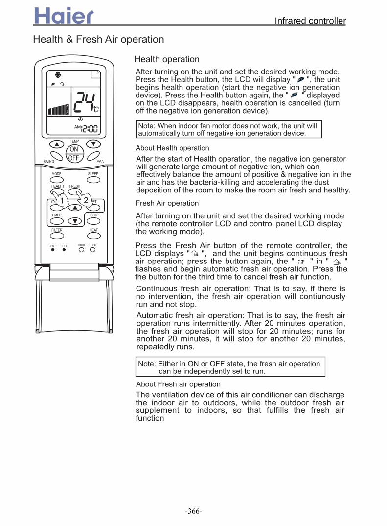
:
;
;
+
;$
$
#$
+
044
5610
& ;
;" & & ! . B& %& ! . DA
& & ; ' " & E & % F FE & ' "& H & ' E & F F F F"& ' "& A && ' " & & "& " A
"& C & %E " & ( E & "& ! % A; "& C & %E & "& %A ;" 6? E& "& ! " 6? H " & 6? E ! " & 6? E% A
$ C & $ E & "& ' % A
;' & & ( ( " & && E !& & "& E & "" & "& "
;
5 6
;" & & ! . A & & ' E & ! % F FE & ' && B & ( (DA & & ' E & F F % & E && B "" & ( (DA
$ C#& " ! .E & ! % "" ( (A
&
;" & " & E & ( ! " ( E !&& ""(% ' & " ( K ( & & & 'J. & " & . & "& &&%A
;' &
& K & ;
Infrared controller
-366-

" * . * )2 / 4 +/ 2 . * *) )/1 2 . * )
))* 1 .20 ) * )+ &2 2 ) .: *7 2 ) 3*2)- )) * )+ &2 2 3 * ) * *7 2 ) 3*2) )$. )+ !/ 2 7 2 ) 3*2 .2 2 22 *7 2 ) 2 * /) * 3 ))
7 ) )) + 2 ) ))
/ 4 1 / 2 ) 4 47 2 4 1 *2 *2 72 / / *7 / // *1 /) 2 7 2 4 1 05)) 2 *) 2 *2 4 4 .22 4 . ) * 7 32 2. . 2 37 3 2 * ) /5 2 ) . / /) * 1 42 2 . * / *27 : 7 )6 .: 1 42 2 . * / 2 7 2 7 )6)
0)$ 2 2 /5 /)7 1 2 2 / . ) 3 2 * / 2 /)
)5 2 4 1 .2 . 2
)
$ 40
" *-. / 0123 4456 " 6'
1$7&5 ) 4
82109: & ; 2.1<:
$ $
+', ( $ ," ( $ &
' $%7
:
;
;
;
+
;$
$
#$
+
044
5610
Infrared controller
-367-

$&*
(
5 C&%DC$&*DC!D / 7 2 2 3/ ) .2 8:97 / 8:9 ) )C. *D / +
A D3
. * 4
4E 46 . / *2
4? 46
5
$ 2 &%* /5 2 2? 4 1 )
. *
$ &% 22? 4 )4/) . )
5
$ 2 &%* /5 2 44 1 )
. *
$ &% 24 4 )4 /)/ *2)
! !51 2$&*
.*/
(
$*'&% * * * )
&%
$ 4 * . 2 * ))2 . 3 2/ : 4 ) ))
%+
* 1 7 E 2? 4 . . / * )7 * )*2 * /) ' E 5 1 : .) / * ))
%+
%
$
! !%
'
$ &%
" "#
"#
!
(
(
!
$
$ 0
$ -
$
$ 7
$ ,
$ 9
$ ;
C" *'8*!%*!4" 6!E %D
4! &%6
$
$ 0
$ -
$
$ 7
$ ,
!
Note: For new apperance convertible unit, the position 3 and position 4 are "Auto Swing".
Infrared controller
-368-

R "#2 ) / / 8:= ) .2 8:757 / 8:9 8:75 ) )
%
$
! !%
'
$ &%
" "#
"#
!
!
Infrared controller
-369-
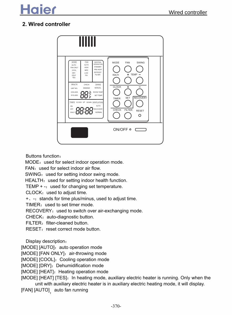
Buttons function: MODE:used for select indoor operation mode. FAN:used for select indoor air flow. SWING:used for setting indoor swing mode. HEALTH:used for setting indoor health function. TEMP + -:used for changing set temperature. CLOCK:used to adjust time. +、-:stands for time plus/minus, used to adjust time. TIMER:used to set timer mode. RECOVERY:used to switch over air-exchanging mode. CHECK:auto-diagnostic button. FILTER:filter-cleaned button.
RESET:reset correct mode button. Display description:
[MODE] [AUTO]:auto operation mode [MODE] [FAN ONLY]:air-throwing mode [MODE] [COOL]:Cooling operation mode [MODE] [DRY]:Dehumidification mode [MODE] [HEAT]:Heating operation mode [MODE] [HEAT] [TES]:In heating mode, auxiliary electric heater is running. Only when the
unit with auxiliary electric heater is in auxiliary electric heating mode, it will display. [FAN] [AUTO]
:auto fan running
2. Wired controller
Wired controller
-370-

[FAN] [HIGH]:high fan speed [FAN] [MED]: medium fan speed [FAN] [LOW]: low fan speed [FAN] [FIX]: fixed fan speed, it will display only when fixed fan speed is requested to main
indoor unit. [CENTRAL]: central control mode [OPERATION] :running mode [STAND BY] : waiting mode [PRE-HEAT] : pre-heating mode [DEFROST]: defrosting mode [FILTER] : request of filter to be cleaned [HEALTH]:health function [UNIT NO.] [CEN.ADD]:central control address, the address number will display on “88” [SYS.ADD.]:system address, the address number will display on “88”
[SWING]:swing mode [ROOM TEMP.]:indoor ambient temperature
[TIMER][OFF] :timer function is off [TIMER][ON][OFF] :timer function ON-OFF [TIMER][ON][OFF][DAILY]:timer ON-OFF will switch over in turn daily [CLOCK]:clock display, the displaying time is the current time of the clock. [UP]、[DOWN]:indicator of filter elevating [VENTILATION][AUTO]:auto ventilation mode [VENTILATION][RECOVERY]:fully heat exchanging ventilation mode [VENTILATION][NORMAL]:normal ventilation mode FAN ONLY OPERATION: 1)Start up operation: press the button of ON/OFF, the system will start up, and will display [MODE][AUTO];[FAN][AUTO];[ROOM TEMP.]+“24”;[CLOCK]+”12:00”. 2) Select MODE: press the MODE button, then you will see in the display section [MODE]
switch over in below sequence:[FAN ONLY]→[COOL]→[DRY]→[HEAT]→[AUTO]→[FAN ONLY]. Select [FAN ONLY].
3)Select fan speed: press FAN button, then you see in the display section [FAN] switch over in below sequence: [HIGH]→[MED]→[LOW]→[HIGH]. Select proper fan speed. 4)Power off: press ON/OFF button, indoor unit will be powered off, there are only time and the ambient temperature in the screen.
[TIMER][ON] :timer function is on.
[CHECK]:auto-diagnostic, trouble shooting [DEMAND]:compulsory operation function, when it works, [CENTRAL] will flash
[SET TEMP.]:set admired temperature.
Wired controller
-371-
AUTO operation, COOLING, HEATING and DEHUMIDIFICATION operation 1) Start up operation: press the button of ON/OFF, the system will start up, and will display [MODE][AUTO];[FAN][AUTO];[ROOM TEMP.]+“24”;[CLOCK]+”12:00”. 2) Select MODE: press the MODE button, then you will see in the display section [MODE] switch over in below sequence:[FAN ONLY]→[COOL]→[DRY]→[HEAT]→[AUTO]→[FAN
temperature will increase/reduce 1(F). 4) Select fan speed: press FAN button, then you see in the display section [FAN] switch over in below sequence: [AUTO]→[HIGH]→[MED]→[LOW]→[AUTO]. Select proper fan speed. 5) Select [SWING]: press [SWING] button, swing function is valid. Press again, swing
function is invalid. 6) Set [HEALTH]: used to set the indoor health function. Press it once, [HEALTH] will display in the display section, then indoor health function is valid. Press it again, [HEALTH] will disappear, then the health function is invalid. This function is valid only for the unit with health function. 7) Power off: press ON/OFF button, indoor unit is powered off. There are only time and the ambient temperature in the screen. Set TIMER operation: Adjust clock: when powered on, for the first time to set timer function, the clock will be adjusted. Press “CLOCK” button, and set the current clock. Now, “CLOCK” will flash at the frequency of 2Hz. Press the clock +/- button; the current clock can be adjusted. Until the proper time comes, press [SET]. TIMER ON operation: Press TIMER button, and keep pressing it, in the display section [TIMER] will switch over in below sequence: [ON]→[OFF]→[ON][OFF] → [ON][OFF][DAILY] →[ ]. Select [TIMER] [ON], then [TIMER] [ON] flashes, press the clock +/- button to adjust the time of TIMER ON, press [SET] button. TIMER OFF operation: Press TIMER button, and keep pressing it, in the display section [TIMER] will switch over in below sequence: [ON]→[OFF]→[ON][OFF] → [ON][OFF][DAILY] →[ ]. Select [TIMER] [OFF], then [TIMER] [OFF] flashes, press the clock +/- button to adjust the time of TIMER OFF, press [SET] button. TIMER ON-OFF operation: Press TIMER button, and keep pressing it, in the display section [TIMER] will switch over in below sequence: [ON]→[OFF]→[ON][OFF] → [ON][OFF][DAILY] →[ ]. Select [TIMER] [ON] [OFF]. Firstly, [TIMER][ON] flashes, press the clock +/- button to adjust the time of
3) Change set temperature: press TEMP + or – every time, [SET] will display, and set ONLY]. Select [COOL] .
Wired controller
-372-

TIMER ON, press [TIMER]. [TIMER][ON] will be constant on. Then [TIMER] [OFF] flashes, press the clock +/- button to adjust the time of TIMER OFF, press [SET]. The time sequence of timer on and timer off will determine the mode is [TIMER] [ON] →[OFF] or [TIMER] [OFF] →[ON]. If you want the current time, press [CLOCK] once, current time will display; press again, [CLOCK] will flash, and press [+][-] to adjust the time. Note: 1. If the two times are same, the timer state which is set later will flash, in this case, timer can not be set. 2. When entering TIMER setting state, if you do not input any button in continuous 10 seconds, the unit will quit from the TIMER mode. Cancel TIMER operation: In the timer operation state, press [TIMER] button, the unit will quit from the current timer operation state, and the set data will be memorized, then enter the next timer mode. [FILTER] function When the wired controller receives the filter-cleaned signal from indoor unit, [FILTER] will display. After finishing clean, press [FILTER], the sign [FILTER] disappears, and the controller will send the filter reset signal to indoor unit. When the sign [FILTER] not display, it is invalid to press [FILTER] in short time. FILTER ELEVATING function: (only for the unit with elevating function) When the filter needs to be cleaned, the panel can be lowered to the admired height by the [FILTER][UP][DOWN] function. Method is below: In power off state, press [HEALTH] for 10 seconds to enter filter elevating set state. In this state, the sign [FILTER] will flash and [UP] [DOWN] will display simultaneously, Press TEMP [+], in timer section [UP] will display, while press TEMP [-], in timer section [DOWN] will display. When it arrives the appropriate position, press [UP], [UP][DOWN] will display simultaneously, filter will stop going down. Press [UP] again, filter will go up. Press [FILTER] button to quit the mode. DEMAND operation function: By this function, all the indoor units can be made in nominal mode. Set the operation mode in cooling and then shut off the unit. In the stop state, press [ON/OFF] button for 5 seconds to enter cooling trial operation state. If it is in heating mode before shut off the unit, then press [ON/OFF] button for 5 minutes, it will enter heating trial operation state. In cooling, there will be “LL” in the position where the set temperature displays. In heating, there will be “HH” in the position where the set temperature displays. The wired controller will send the [DEMAND] signal to indoor unit. In the [DEMAND] operation, “COOL” or “HEAT” will display at 1Hz frequency. Indoor fan motor will be fixed at “AUTO” mode. The indoor units in the same group will quit the [DEMAND] in turn. At this time, only the buttons of [ON/OFF] and temperature [+] [-] are valid. Press [ON/OFF] to quit [DEMAND] mode.
Wired controller
-373-

CENTRAL control function When the central controller selects [CENTRAL] mode, the buttons in the wired controller except for [CHECK] will be invalid. VENTILATION mode (only for the unit with fresh air function or heat recovery function) Press [RECOVERY] button, then the unit will switch over the ventilation mode: [ ] → [VENTILATION][AUTO] → [VENTILATION][RECOVERY] → [VENTALATION][NORMAL] →[ ], please select appropriate ventilation mode. Query indoor malfunction history: In the state of power on or power off, press [CHECK] button, enter the malfunction-querying mode of all indoor units in the group. Then [CHECK] and [UNIT NO.] will display, and the actual indoor numbers will be displayed in some sequence (unit number is in decimals). At the same time, in the time region, there will be the current malfunction and the latest time malfunction, the displaying format is [XX:YY], in which XX stands for the current malfunction, if normal, it will display “――”; YY stands for the latest time malfunction. The failure code of every unit will display for 3 seconds. After the failure codes of all indoor units in the whole group are displayed, the mode will quit automatically. Clear abnormal state and malfunction history: In normal state, press [CHECK] button for 5 seconds to clear abnormal states, at the same time, wired controller will send the data of “clear abnormal state”, but the malfunction history still retains. In normal state, press [CHECK] button for 15 seconds, except for malfunction states, the malfunction history in wired controller will be cleared. Query indoor performance state: In normal state, press both buttons of [CHECK] and [FILTER] for 5 seconds, in the set temperature region in the screen, [XX] will display, XX is indoor number, which can be selected by pressing [TEMP] [+] [-]. In the timer region in the screen, [YZZZ] will display, in which Y stands for data type, ZZZ stands for the corresponding data. which can be selected by pressing [CLOCK] [+] [-].
Y ZZZ Type A Indoor capacity (W) Nominal cooling
capacity/10, decimal B Request of indoor capacity(Hz) Actual value, decimal C Temperature of indoor ambient
temp. sensor TA Actual value, decimal
d Temperature of indoor gas pipe sensor TC1
Actual value, decimal
E Temperature of indoor liquid pipe sensor TC2
Actual value, decimal
F Open degree of indoor PMV Actual value, decimal
Wired controller
-374-

g Preset ――― H Outdoor total capacity Actual value, decimal
In check mode, press [CHECK] to quit the check mode, and go into normal running mode.
How to change the function switches? new type
old type
function state of switch function description
Connected Set as simple controller D9 J02 Changeover of type of wired controller Cut off Set as standard controller
Connected Use the sensor in the wired controller
D12 J06 Selection of room temp. sensor
Cut off Use the sensor in the indoor unit
Connected Common control D15 J07 Auto reset after power failure Cut off Auto reset after power failure
Connected Yes D14 J03 Display of room temperatureCut off No ON Set as slave controller SW
① SW20①
Changeover of master or slave controller OFF Set as master controller
ON SW②
SW20②
or OFF Connected Indoor unit in shorted time
function JP8 D1 Shorten time function
Cut off Common control Connected Send compulsorily defrost
signal to indoor unit JP7 D2 Compulsorily defrost
Cut off Common control Note: The switches in grey can be operated after opening the cover of wired controller. The old type: there are resistors of J03 and J06 beside the dip switch.
Wired controller
-375-

1 2
OFF OFF OFF ON
Setting address method: The address setting can be realized by setting indoor PCB. If you use the group control function, there should be a master unit and 15 sets of slave units. For the master unit, the SW5-3 should be at “ON”. For the slave units, the SW5-3 should be at “OFF”. Please refer the below table,
Indoor unit
address SW1-4 SW1-3 SW1-2 SW1-1
3 OFF OFF ON OFF
5 OFF ON OFF OFF
6 OFF ON OFF ON
7 OFF ON ON OFF
8 OFF ON ON ON
9 ON OFF OFF OFF
10 ON OFF OFF ON
11 ON OFF ON OFF
12 ON OFF ON ON
14 ON ON OFF ON
15 ON ON ON OFF ON ON ON ON
If you use central control type, SW1, SW2 will be used simultaneously. Wiring request in central control type: port A-B is connected with indoor port CN16(A-B)through 2-core shield wire. Requirements: 1. Port A connects with port CN16(A)of all indoor units. 2. Port B connects with port CN16(B)of all indoor units.
Address on central controller
Indoor unit address
SW2-3 SW2-2 SW2-1 SW1-4 SW1-3 SW1-2 SW1-1
1 1 OFF OFF OFF OFF OFF OFF OFF 2 2 OFF OFF OFF OFF OFF OFF ON 3 3 OFF OFF OFF OFF OFF ON OFF 4 4 OFF OFF OFF OFF OFF ON ON 5 5 OFF OFF OFF OFF ON OFF OFF 6 6 OFF OFF OFF OFF ON OFF ON
4 OFF OFF ON ON
13 ON ON OFF OFF
Wired controller
-376-

7 7 OFF OFF OFF OFF ON ON OFF 8 8 OFF OFF OFF OFF ON ON ON 9 9 OFF OFF OFF ON OFF OFF OFF 10 10 OFF OFF OFF ON OFF OFF ON 11 11 OFF OFF OFF ON OFF ON OFF 12 12 OFF OFF OFF ON OFF ON ON 13 13 OFF OFF OFF ON ON OFF OFF 14 14 OFF OFF OFF ON ON OFF ON 15 15 OFF OFF OFF ON ON ON OFF 16 16 OFF OFF OFF ON ON ON ON 17 17 OFF OFF ON OFF OFF OFF OFF 18 18 OFF OFF ON OFF OFF OFF ON 19 19 OFF OFF ON OFF OFF ON OFF 20 20 OFF OFF ON OFF OFF ON ON 21 21 OFF OFF ON OFF ON OFF OFF 22 22 OFF OFF ON OFF ON OFF ON 23 23 OFF OFF ON OFF ON ON OFF 24 24 OFF OFF ON OFF ON ON ON 25 25 OFF OFF ON ON OFF OFF OFF 26 26 OFF OFF ON ON OFF OFF ON 27 27 OFF OFF ON ON OFF ON OFF 28 28 OFF OFF ON ON OFF ON ON 29 29 OFF OFF ON ON ON OFF OFF 30 30 OFF OFF ON ON ON OFF ON 31 31 OFF OFF ON ON ON ON OFF 32 32 OFF OFF ON ON ON ON ON 33 33 OFF ON OFF OFF OFF OFF OFF 34 34 OFF ON OFF OFF OFF OFF ON 35 35 OFF ON OFF OFF OFF ON OFF 36 36 OFF ON OFF OFF OFF ON ON 37 37 OFF ON OFF OFF ON OFF OFF 38 38 OFF ON OFF OFF ON OFF ON 39 39 OFF ON OFF OFF ON ON OFF 40 40 OFF ON OFF OFF ON ON ON 41 41 OFF ON OFF ON OFF OFF OFF 42 42 OFF ON OFF ON OFF OFF ON 43 43 OFF ON OFF ON OFF ON OFF 44 44 OFF ON OFF ON OFF ON ON 45 45 OFF ON OFF ON ON OFF OFF 46 46 OFF ON OFF ON ON OFF ON 47 47 OFF ON OFF ON ON ON OFF 48 48 OFF ON OFF ON ON ON ON 49 49 OFF ON ON OFF OFF OFF OFF 50 50 OFF ON ON OFF OFF OFF ON
Wired controller
-377-

51 51 OFF ON ON OFF OFF ON OFF 52 52 OFF ON ON OFF OFF ON ON 53 53 OFF ON ON OFF ON OFF OFF 54 54 OFF ON ON OFF ON OFF ON 55 55 OFF ON ON OFF ON ON OFF 56 56 OFF ON ON OFF ON ON ON 57 57 OFF ON ON ON OFF OFF OFF 58 58 OFF ON ON ON OFF OFF ON 59 59 OFF ON ON ON OFF ON OFF 60 60 OFF ON ON ON OFF ON ON 61 61 OFF ON ON ON ON OFF OFF 62 62 OFF ON ON ON ON OFF ON 63 63 OFF ON ON ON ON ON OFF 64 64 OFF ON ON ON ON ON ON 65 65 ON OFF OFF OFF OFF OFF OFF 66 66 ON OFF OFF OFF OFF OFF ON 67 67 ON OFF OFF OFF OFF ON OFF 68 68 ON OFF OFF OFF OFF ON ON 69 69 ON OFF OFF OFF ON OFF OFF 70 70 ON OFF OFF OFF ON OFF ON 71 71 ON OFF OFF OFF ON ON OFF 72 72 ON OFF OFF OFF ON ON ON 73 73 ON OFF OFF ON OFF OFF OFF 74 74 ON OFF OFF ON OFF OFF ON 75 75 ON OFF OFF ON OFF ON OFF 76 76 ON OFF OFF ON OFF ON ON 77 77 ON OFF OFF ON ON OFF OFF 78 78 ON OFF OFF ON ON OFF ON 79 79 ON OFF OFF ON ON ON OFF 80 80 ON OFF OFF ON ON ON ON 81 81 ON OFF ON OFF OFF OFF OFF 82 82 ON OFF ON OFF OFF OFF ON 83 83 ON OFF ON OFF OFF ON OFF 84 84 ON OFF ON OFF OFF ON ON 85 85 ON OFF ON OFF ON OFF OFF 86 86 ON OFF ON OFF ON OFF ON 87 87 ON OFF ON OFF ON ON OFF 88 88 ON OFF ON OFF ON ON ON 89 89 ON OFF ON ON OFF OFF OFF 90 90 ON OFF ON ON OFF OFF ON 91 91 ON OFF ON ON OFF ON OFF 92 92 ON OFF ON ON OFF ON ON 93 93 ON OFF ON ON ON OFF OFF 94 94 ON OFF ON ON ON OFF ON
Wired controller
-378-

95 95 ON OFF ON ON ON ON OFF 96 96 ON OFF ON ON ON ON ON 97 97 ON ON OFF OFF OFF OFF OFF 98 98 ON ON OFF OFF OFF OFF ON 99 99 ON ON OFF OFF OFF ON OFF 100 100 ON ON OFF OFF OFF ON ON 101 101 ON ON OFF OFF ON OFF OFF 102 102 ON ON OFF OFF ON OFF ON 103 103 ON ON OFF OFF ON ON OFF 104 104 ON ON OFF OFF ON ON ON 105 105 ON ON OFF ON OFF OFF OFF 106 106 ON ON OFF ON OFF OFF ON 107 107 ON ON OFF ON OFF ON OFF 108 108 ON ON OFF ON OFF ON ON 109 109 ON ON OFF ON ON OFF OFF 110 110 ON ON OFF ON ON OFF ON 111 111 ON ON OFF ON ON ON OFF 112 112 ON ON OFF ON ON ON ON 113 113 ON ON ON OFF OFF OFF OFF 114 114 ON ON ON OFF OFF OFF ON 115 115 ON ON ON OFF OFF ON OFF 116 116 ON ON ON OFF OFF ON ON 117 117 ON ON ON OFF ON OFF OFF 118 118 ON ON ON OFF ON OFF ON 119 119 ON ON ON OFF ON ON OFF 120 120 ON ON ON OFF ON ON ON 121 121 ON ON ON ON OFF OFF OFF 122 122 ON ON ON ON OFF OFF ON 123 123 ON ON ON ON OFF ON OFF 124 124 ON ON ON ON OFF ON ON 125 125 ON ON ON ON ON OFF OFF 126 126 ON ON ON ON ON OFF ON 127 127 ON ON ON ON ON ON OFF 128 128 ON ON ON ON ON ON ON
Wired controller
-379-

Electrical functions of wired controller: 1.Function difference between master wired controller and slave one: Contrastive items Master wired controller Slave wired controller Function All of functions Only with below functions:
ON/OFF, MODE, FAN SPEED, SET TEMP., SWING
2. Function difference between simple wired controller and the standard one: Contrastive item Standard wired controller Simple wired controller Function With all functions Only can control ON/OFF, MODE,
FAN, TEMP.,SWING. Master/Slave selection
Can be either of Master and Slave controller
Only can be Master controller
3. Wiring connections of wired controller:
indoor N
BA C
wired controller
indoor 1 indoor 2
indoor 1
21 3
A B C A B C
indoor 16
control wiring of wired controller, polar.
indoor 15
1 2 3
A B C
wired controller wired controller wired controller
wired controller wired controller
wired controller
wired controller
indoor 1
wired controller wired controller wired controller
A
B C
(master unit)
polar wirepolar wire
polar wire
There are three methods to connection wired controller and the indoor units:
A. One wired controller can control max. up to 16 sets of indoor units, and 3 pieces of polar wire must connect the wired controller and the master unit (the indoor unit connected with wired controller directly), the others connect with the master unit through 2 pieces of polar wire. B. One wired controller controls one indoor unit, and the indoor unit connects with the wired controller through 3 pieces of polar wire. C. Two wired controllers control one indoor unit. The wired controller
Wired controller
-380-

connected with indoor unit is called master one, the other is called slave one. Master wired controller and indoor unit; master and slave wired controllers are all connected through 3 pieces of polar wire. 3. Communication wiring: The wired controller is equipped with special communication wiring in the accessories. 3-core terminal (1-white 2-yellow 3-red) is connected with the terminal A、B、C of wired controller respectively. The communication wiring is 4 meter long; if the actual length is more than it, please distribute wiring according to below table:
Communication wiring length(m) Dimensions of wiring <100 0.3mm2X3-core shielded wire ≥100 and <200 0.5mm2X3-core shielded wire ≥200 and <300 0.75mm2X3-core shielded wire ≥300 and <400 1.25mm2X3-core shielded wire ≥400 and <600 2mm2X3-core shielded wire
※ One side of the shielded sheet of communication wire must be earthed.
Wired controller
-381-

!"#$ %&'()* +,-$.,,/.,0!",12.,3%%%%4(546645
466466466466466466466,013/4(!2!7$689:;:(4(4(4(4(4(4(4(
/4(!2!7$689:;:(
! "
#
$!%
&$'&((
84)8;/ (4
,013
:!,4(466
:!04(466
(4
)*!"+ 84)8;/ .
,(<#< ="
-: ,*/4(+0*!+1*2!7+3*$+*689+*:;+*:(+ >4( $ 466 $ 466 &(,(0 7$/. .
3.
Weekly timer
-382-

, ?@ "?
%
$!;A$
(
/47! 6;( :29()
!/
%A4%B
9/!8 :! 8!%4C!8D
%$!%B 69A!8 8!:!
/47! 6;(
;4 ;4
6;(4(AD
%44A
78D$!;!:
$9)$
/!7
A42
69E
%!(8;A4 !8;94(
:;(7FD
8!$!;
7!684:
69A!8
$!;A$ %$!%B :29()
(9(4 7!/;(7 /;(;A
%!(;77
:D:;77
844/!/
:!!/
9/!8 %A4%B 742( C!(9A;94(
4(
466
7;9AD
;4
8!%4C!8D
(48/;A
4(5466
$!;A$
(
/47! 6;( :29()
!/
%A4%B
9/!8 :! 8!%4C!8D
%$!%B 69A!8 8!:!
/47! 6;(
;4 ;4
6;(4(AD
%44A
78D$!;!:
$9)$
/!7
A42
69E
%!(8;A4 !8;94(
:;(7FD
8!$!;
7!684:
69A!8
$!;A$ %$!%B :29()
(9(4 7!/;(7 /;(;A
%!(;77
:D:;77
844/!/
:!!/
9/!8 %A4%B 742( C!(9A;94(
4(
466
7;9AD
;4
8!%4C!8D
(48/;A
4(5466
, 0 1%(
, 0 1%(
, 0 1%(
, 0 1%(
466466466466466466466
/4(!2!7$689:;:(4(4(4(4(4(4(4(
/4(!2!7$689:;:(
$ (
$ %
/ %
2
8
5
C
9
4
;%$/98
! "
#
$!%
&$'&((
84)8;/ (4
,013
,013
:!,4(466
:!04(466
(4
,.*/ 0/ #!"1?
3";@;
>
0"*;F+8:3#
-.*/ 0/!*!"2 3#!"1?
3"
03
>
0"*;F+8:3#
Weekly timer
-383-

9
466466466466466466466,013/4(!2!7$689:;:(4(4(4(4(4(4(4(
/4(!2!7$689:;:(
4(
,013
! "
#
$!%
84)8;/ (4
,013
:!,4(466
:!04(466
(4
F ; ,0C7%
4
8:3#
! "
#
$!%
&$'&((
84)8;/ (4
,013
,013
:!,4(466
:!04(466
(4
Weekly timer
-384-
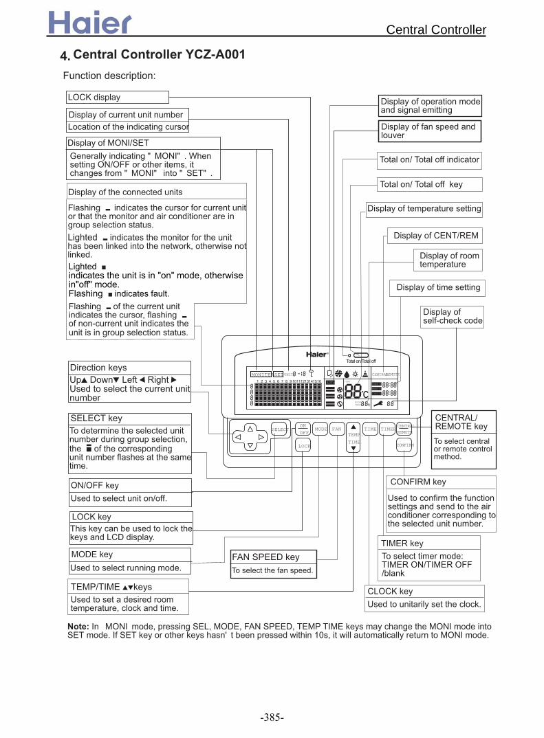
MONITERSETUNIT
AUTO TEMP
ROOMTEMP
CENTRALREMOTE
TIMER ON
EVERY DAY
SELECTON
OFFMODE FAN
TEMP.
TIME
TIME TIMERCENTRAL
REMOTE
CONFIRMLOCK
TIMER OFF
! " " $% && ' " " " " $
& $ ( )(' ) ($ **' )**$& $& '+ $
(, ) - ,
( ' $
( ( ( ($
&&(
, $
(
, $
.
(
&/0( $
'''&/0' 0 ( $ ( (' ) 23' ) $
0 (, '( $
(
, ($
-( 4 - -&&(
&-(
, $
-/- (
$
+(
-
& 4
4. Central Controller YCZ-A001
Central Controller
-385-

89$2:;92< =' 9 $
) 0> )( ) 0> -+?;58/'>=$
.0>@ .
')( )0> $ 8 9 AA& A/ A $=@ )( ) 8'' ' ' '' =@
)( 8 '( ' =$
((( 4$ !"
B ' )( $& ' .) )+ ) $
#$ %" &'' 89$2:; = 9 $
(. 4' ' ' ' @
( )( 4&&''&/0' 0' '' -' -' @
B/ B
(
&/ %!
0
- -C-6
B & - -
&/
/, /,
&/6
-6B/
B!B
%
&D
-/0-/
/>6
0-+B/
&-
& -
B/ B B %!
, $ / /,/
$/$
6$/$
- 0$
0$
- ,0 % C /
&&
/6
/,
-C-6
-/
&&
B/ B
(
&/ %!
0
- -C-6
B & - -
&/
/, /,
&/6
-6B/
B!B
%
&D
-/0-/
/>6
0-+B/
&-
& -
B/ B B %!
, $ / /,/
$/$
6$/$
- 0$
0$
- ,0 % C /
&&
/6
/,
-C-6
-/
&&
2 : E 2 : E5 5
2 : E5
2 : E5
Central Controller
-386-

F$, G)( H G)( ' 9 $
&&&&&&&&&&&&&&
,% B,&-/ ,
,% B,&-/ ,
0 B
B
$
%(
-
CN2 CN2 CN2 CN2
-+?;5,/)>
-.)
C) 0)
0)
CN2 CN2 CN2 CN2 CN2 CN2 CN2 CN2
I$-H ) +. ) ' )
' ' $
;$-H ) ' ) '
' $
Central Controller
-387-

8&$2=
2;32:3
MONITER SET UNIT
AUTO TEMP
ROOMTEMP
CENTRAL REMOTE
TIMER ON
EVERY DAY
SELECTONOFF
MODE FANTEMP.
TIME
TIME TIMER CENTRALREMOTE
CONFIRMLOCK
TIMER OFF
9
20B'::3+:?3CJ'53BH
)
2$%
-+:E: A B
0)
:$ /)9. $ 9 ) ) ?)8)=$
0 . /::3+:?3C )$ . ) ' ') ) ) ) ) )$
-+?;5
Total on/Total off
SELECT ONOFF MODE
FAN
TEMP.TIME
TIMETIMER CENTERCONTROL
CONFIRM
LOCK
91.5mm
15mm
19mm
86mm
-.)
Central Controller
-388-

8&$:=
* +("',&("',&-.' /0 "10&'2
<?$?
Central Controller
-389-

Appendix - Control dataNo. Series Type Model PCB code Controller code
1 AB122ACEAA+PB-700IA 0010452478E 0010451255 YR-H712 AB182ACEAA+PB-700IA 0010452478E 0010451255 YR-H713 AB242ACEAA+PB-950IA 0010451167E 0010451255 YR-H714 AB282ACEAA+PB-950IA 0010451167E 0010451255 YR-H715 AB362ACEAA+PB-950JA 0010452478E 0010451255 YR-H716 AB482ACEAA+PB-1340IA 0010451167E 0010451255 YR-H717 AB602ACEAA+PB-1340IA 0010451167E 0010451255 YR-H718 AB242AEEAA+PB-950JA 0010451167E 0010451255 YR-H719 AB282AEEAA+PB-950JA 0010451167E 0010451255 YR-H7110 AB422AEEAA+PB-950JA 0010452478E 0010451255 YR-H7111 AB482AEEAA+PB-950JA 0010452478E 0010451255 YR-H7112 AC122ACEAA 0010451167E 0010451255 YR-H7113 AC182ACEAA 0010451167E 0010451255 YR-H7114 AC242ACEAA 0010451167E 0010451255 YR-H7115 AC282AEEAA 0010451167E 0010452300 YR-H5016 AC282AFEAA 0010451167E 0010452300 YR-H5017 AC362AFEAA 0010451167E 0010452300 YR-H5018 AC482AFEAA 0010451167E 0010452300 YR-H5019 AC602AFEAA 0010451167E 0010452300 YR-H5020 AD122ALEAA 0010451167E 0010451521E YR-E1221 AD182ALEAA 0010451167E 0010451521E YR-E1222 AD242ALEAA 0010451167E 0010451521E YR-E1223 AD182AMEAA 0010451167E 0010451521E YR-E1224 AD242AMEAA 0010451167E 0010451521E YR-E1225 AD282AMEAA 0010451167E 0010451521E YR-E1226 AD362AMEAA 0010451167E 0010451521E YR-E1227 AD362ANEAA 0010451167E 0010451521E YR-E1228 AD422ANEAA 0010451167E 0010451521E YR-E1229 AD482AMEAA 0010451167E 0010451521E YR-E1230 AD482ANEAA 0010451167E 0010451521E YR-E1231 AD282AHEAA 0010451167E 0010451521E YR-E1232 AD362AHEAA 0010451167E 0010451521E YR-E1233 AD482AHEAA 0010451167E 0010451521E YR-E1234 AD602AHEAA 0010451167E 0010451521E YR-E1235 AD722AHEAA during design 0010451521E YR-E1236 AP422ACEAA 0010451432 0010451255 YR-H7137 AP482AKEAA 0010452322 0010451047 YR-H4938 AU122AEEAA 0010451870E /39 AU182AEEAA 0010451870E /40 AU242AGEAA 0010452442E /41 AU282AHEAA 0010452442E /42 AU28NAHEAA 0010452378E /43 AU362AIEAA 0010452442E /44 AU36NAIEAA 0010452378E /45 AU362ALEAA 0010452442E /46 AU42NALEAA 0010452378E /47 AU48NAIEAA 0010452378E /48 AU60NAIEAA 0010452378E /49 AU72NAIEAA during design /
FloorCeiling
4-WayCassette
UN
ITA
RY
FR
EE
R41
0A O
N-O
FF
High StaticDuct
Low StaticDuct
Cabinet
OutdoorUnits
MediaStatic Duct
Appendix
-390-
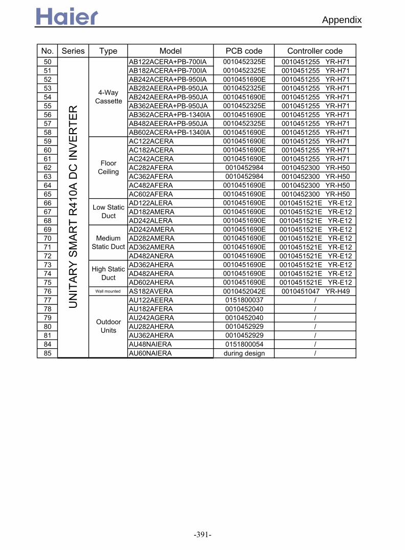
Appendix
No. Series Type Model PCB code Controller code50 AB122ACERA+PB-700IA 0010452325E 0010451255 YR-H7151 AB182ACERA+PB-700IA 0010452325E 0010451255 YR-H7152 AB242ACERA+PB-950IA 0010451690E 0010451255 YR-H7153 AB282AEERA+PB-950JA 0010452325E 0010451255 YR-H7154 AB242AEERA+PB-950JA 0010451690E 0010451255 YR-H7155 AB362AEERA+PB-950JA 0010452325E 0010451255 YR-H7156 AB362ACERA+PB-1340IA 0010451690E 0010451255 YR-H7157 AB482AEERA+PB-950JA 0010452325E 0010451255 YR-H7158 AB602ACERA+PB-1340IA 0010451690E 0010451255 YR-H7159 AC122ACERA 0010451690E 0010451255 YR-H7160 AC182ACERA 0010451690E 0010451255 YR-H7161 AC242ACERA 0010451690E 0010451255 YR-H7162 AC282AFERA 0010452984 0010452300 YR-H5063 AC362AFERA 0010452984 0010452300 YR-H5064 AC482AFERA 0010451690E 0010452300 YR-H5065 AC602AFERA 0010451690E 0010452300 YR-H5066 AD122ALERA 0010451690E 0010451521E YR-E1267 AD182AMERA 0010451690E 0010451521E YR-E1268 AD242ALERA 0010451690E 0010451521E YR-E1269 AD242AMERA 0010451690E 0010451521E YR-E1270 AD282AMERA 0010451690E 0010451521E YR-E1271 AD362AMERA 0010451690E 0010451521E YR-E1272 AD482ANERA 0010451690E 0010451521E YR-E1273 AD362AHERA 0010451690E 0010451521E YR-E1274 AD482AHERA 0010451690E 0010451521E YR-E1275 AD602AHERA 0010451690E 0010451521E YR-E1276 Wall mounted AS182AVERA 0010452042E 0010451047 YR-H4977 AU122AEERA 0151800037 /78 AU182AFERA 0010452040 /79 AU242AGERA 0010452040 /80 AU282AHERA 0010452929 /81 AU362AHERA 0010452929 /84 AU48NAIERA 0151800054 /85 AU60NAIERA during design /
OutdoorUnits
UN
ITA
RY
SM
AR
T R
410A
DC
INV
ER
TER
4-WayCassette
FloorCeiling
Low StaticDuct
MediumStatic Duct
High StaticDuct
-391-