General Information
215
General Information
-
Upload
khangminh22 -
Category
Documents
-
view
3 -
download
0
Transcript of General Information

General Information
25912591
GENERAL INFORMATION
The General Information describes reference informationand reference test methods necessary to assure the quality ofmedicines, which is attached to the JP. Therefore, theGeneral Information is positioned as important informationsupplementing the JP although it should not be taken as in-dicating standards for conformity of drugs, except in thecase specified when the drugs are granted approval based onthe Law on Securing Quality, Efficacy and Safety ofProducts Including Pharmaceuticals and Medical Devices.Combination use of the General Information and the JP cancontribute to improve quality of the JP and user's con-venience.
The general information is classified into the followingcategories according to their contents, and each general in-formation is individually numbered.
G0. Basic Concepts on Pharmaceutical QualityG1. Physics and ChemistryG2. Solid-state PropertiesG3. Biotechnological/Biological ProductsG4. MicroorganismsG5. Crude DrugsG6. Drug FormulationG7. Containers and PackageG8. Reference StandardsGZ. Others
The salient points of the revision in this volume are as fol-lows:
1. Each general information was individually numbered ac-cording to the following rule.
An individual number consists of three blocks. The leftblock indicates the category number and the central block in-dicates the number in the category. The figures in right blockconsist of the first two digits from the left indicating the JPat the recent revision (or new preparation, if not revised) andthe third digit indicating as follows: 0 for major revision, 1for supplement I, 2 for supplement II, and 3 for partial revi-sion. For citation between the general information, the num-ber corresponding to the general information is indicated inangle brackets < >.
2. Categories were reviewed.(1) As basic concepts on pharmaceutical quality, ``G0
Basic Concepts on Pharmaceutical Quality'' was newlyadded at the opening.
(2) ``Others'' was located at the end as ``GZ'', consider-ing that any new categories would possibly be added after``G9''.
(3) Water-related categories were abolished and includedin ``GZ Others''.
3. The following were newly prepared.(1) Basic Concept of the Quality Assurance on
Biotechnological Products (Biopharmaceuticals) <G3-1-180>(2) Control of Culture Media and Strains of Microor-
ganisms Used for Microbial Tests <G4-2-180>(3) Bacterial Endotoxins Test and Alternative Methods
using Recombinant Protein-reagents for Endotoxin Assay<G4-4-180>
(4) Radioactivity Measurements Method for CrudeDrugs <G5-8-180>
(5) Tablet Hardness Determinations <G6-4-180>(6) Packaging Integrity Evaluation of Sterile Products
<G7-4-180>(7) Leak Tests for Packaging of Sterile Products
<G7-5-180>
4. The following were revised.(1) Capillary Electrophoresis <G3-7-180>(2) On the Scientific Names of Crude Drugs listed in the
JP <G5-1-180>(3) International Harmonization Implemented in the
Japanese Pharmacopoeia Eighteenth Edition <GZ-3-180>
5. The following was deleted.(1) Control of Elemental Impurities in Drug Products
G0 Basic Concepts on Pharmaceu-tical Quality
Basic Concepts for QualityAssurance of Drug Substances and
Drug Products <G0-1-172>
IntroductionQuality of drug substances and products are generally as-
sured through manufacturing and testing under appropriateGood Manufacturing Practice (GMP) conditions re‰ectingknowledge obtained from designing and developmentalstages and manufacturing stage on management of raw ma-terials and other materials, control of manufacturing proc-ess, speciˆcations, etc. As shown in the General Notice 5, JPlisted drugs are to be tested according to the provisions givenin the pertinent monographs, General Notices, GeneralRules for Crude Drugs, General Rules for Preparations, andGeneral Tests for their conformity to the Japanese Pharma-copoeia. In addition to these, compliance with GMP,management of raw materials and other materials, andmanagement of manufacturing process are fundamental fac-tors required to assure the quality of JP listed products in ac-tual production.
The present chapter summarizes general concepts concern-ing measures for quality assurance of drug substances andproducts mainly aimed at chemicals, including chemicallysynthesized antibiotics and semisynthetic antibiotics, syn-thetic peptides, oligonucleotides, and biotechnological/biological products, and shows the principle idea of qualityassurance in the process listing a drug as an individual mono-graph in the JP. Although radiopharmaceuticals, crudedrugs, herbal products, and crude products of animal orplant origin are excluded from the subjects of the concepts,these concepts are useful for the management of any type ofdrugs.
Basic ConceptIn recent years, the mainstream concept for quality con-
trol of drugs has been implemented according to a controlstrategy that their quality is assured by control of manufac-
25922592 JP XVIIIBasic Concepts on Pharmaceutical Quality / General Information
turing process, including management of raw material andother materials, and quality testing of ˆnal products (drugsubstances or drug products) that are conducted mutuallycomplementary. The control strategy is implemented basedon Quality Risk Management (QRM). The ˆrst and most im-portant step is identifying Critical Quality Attributes (CQAs)which are the attributes or properties required to ensure thedesired product quality, and it is necessary to specify physi-cal, chemical, biological, microbiological characteristics orproperties of the product which should be within the ap-propriate limits, ranges and distributions. The next step is toguarantee that the CQA falls within the deˆned range, limit,and distribution by using speciˆcation tests, in-process testsand various measures, for that the quality of the drug willeventually be realized.
The speciˆcation is one of the elements of control strategyand not all the CQA need to be included in the speciˆca-tions. CQA is (1) included in speciˆcations and conˆrmed bytesting ˆnal products (including periodical or skip testing,described later), (2) included in speciˆcations and conˆrmedby process controls (e.g., real time release testing, describedlater), or (3) not included in speciˆcations but can be ensuredby controlling starting materials, raw materials andmanufacturing process. As an example of (3), eŠective con-trol over robust manufacturing processes can assure that cer-tain impurities are controlled at an acceptable risk level orare eŠiciently removed below an acceptable level, and some-times the purity testing for the ˆnal product may not be re-quired and omitted from speciˆcations. However, in the caseof a drug listed in the JP monograph, regarding themanufacturing process control related to CQA, if necessary,the control method and control value are indicated in theManufacture in individual monograph.
What kind of control strategy should be applied to a cer-tain CQA is individually determined by QRM according tothe understanding and risk of the manufacturing process.
1. Management of manufacturing process1.1. Considerations of manufacturing process
Adequate design of manufacturing processes andknowledge of their capacity are important to establishmanufacturing processes yielding drug substances or drugproducts that meet speciˆcations and fulˆll CQA, and toperform consistent manufacturing control, quality control,etc. appropriately.
From this standpoint, the limits for control of manufac-turing processes should be based on information obtainedfrom the entire process spanning the period from the earlydevelopment through commercial scale production. The ap-propriateness of the limits also needs to be conˆrmed byevaluation, veriˆcation, review, and other examinations ofmanufacturing processes based on QRM.
In-process tests are tests that may be performed during themanufacture of either the drug substance or drug product,rather than speciˆcation tests for the ˆnal product. In-process tests are performed for quality veriˆcation duringmanufacturing processes that are likely to in‰uence drugsubstance or drug product quality, or for conˆrmation ofproper functioning of the manufacturing process. In-processtests may also be used for the evaluation of CQA.
Usually an in-process test is properly designed accordingto the risk on quality, however, the use of internal actionlimits by the manufacturer to assess the consistency of theprocess at less critical steps is also important. Provisional ac-tion limits should be set for the manufacturing process basedon data obtained during development of the drug and duringevaluation and veriˆcation of the manufacturing process,
and should be further reˆned based on additional manufac-turing experience and data accumulated after product ap-proval for marketing.1.2. Considerations of raw materials and other materials(starting materials, excipients, packaging materials, etc.)
The raw materials and other materials used in the produc-tion of drug substances (or drug products) should meet qual-ity standards, appropriate for their intended use, and ap-propriate setting of speciˆcations and test methods assuringCQA are required. Especially, biological raw/source mate-rials may require careful evaluation to establish the presenceor the absence of deleterious endogenous or adventitiousagents. Procedures that make use of aŠinity chromatogra-phy (for example, employing monoclonal antibodies),should be accompanied by appropriate risk management toensure that such process-related impurities or potential con-taminants arising from their production and use do not com-promise the quality and safety of the drug substance or drugproduct.
The quality of the excipients used in the drug product for-mulation (and in some cases, in the production of drug sub-stance), as well as the primary packaging materials, shouldbe controlled with speciˆcations established based on thecharacteristics of the drug. If speciˆcations and test proce-dures for a material are described by the JP, as a rule, atleast the JP criteria should be satisˆed. Concerning ex-cipients and other materials not listed in the JP, appropriatespeciˆcations and test procedures should be established indi-vidually.
2. Quality tests of products (speciˆcations)A speciˆcation is deˆned as a list of tests, references to
analytical procedures, and appropriate acceptance criteriawhich are numerical limits, ranges, or other criteria for thetests described. Speciˆcations and test methods of the JPmonograph are deˆned sets of quality characteristics neededfor determination of whether the use of a drug substance ora drug product is appropriate for the intended purpose.``Conformance to the speciˆcations of the JP monograph''means that the JP-listed drug substances and drug products,when tested according to the procedures described in generaltests and drug monographs, will meet the all acceptancecriteria except criteria of ``Description'', ``Containers andstorage (for drug products)'' and ``Shelf life'' in the JPmonographs.
However, as described in ``Basic Concept'' speciˆcationsof monographs and test procedures for drug substance anddrug product are one part of a total control strategy forassurance of the quality and consistency of the substances/products. Other parts of control strategies include thoroughcharacterization of the drug in developmental stage (speciˆ-cations and test procedures are established based on thecharacterization), and management of manufacturing proc-ess and products' quality, such as evaluation, veriˆcationand review of manufacturing process, and management ofraw materials, other materials and manufacturing process,that is to say, compliance with the GMP.
3. Periodic or Skip TestingPeriodic or skip testing is the performance of speciˆed
tests at release on preselected batches and/or at predeter-mined intervals, rather than on a batch-to-batch basis withthe understanding that those batches not being tested stillmust meet all acceptance criteria established for thatproduct. When this concept is applied, it is necessary toshow its appropriateness and be approved previously byregulatory authority. This concept may be applicable to, forexample, residual solvents and microbiological testing for
25932593JP XVIII General Information / Basic Concepts on Pharmaceutical Quality
solid oral dosage forms. It is recognized that only limiteddata may be available at the time of submission of an appli-cation for marketing approval. Implementation of this con-cept should therefore generally be considered post-approval.When tested, any failure to meet acceptance criteria estab-lished for the periodic test should be handled by propernotiˆcation of the appropriate regulatory authorities. Ifthese data demonstrate a need of testing for all lots, thenbatch-by-batch release testing should be reinstated.
4. Real-time release testing (RTRT) and parametric releaseRTRT is a type of tests to evaluate the quality of in-
process or ˆnal products based on process data (includingresults of in-process testing and data on process parameters)and to assure that the quality is acceptable. RTRT is a kindof speciˆcations and consists of a valid combination ofmaterials attribute (intermediate products) pre-evaluated andprocess control. RTRT is used for judgement of productsrelease instead of the release testing of ˆnal products whenthe application containing RTRT is approved by a regulatoryauthority.
The usage of RTRT does not mean unnecessity of settingtests of a ˆnal product directly. Even if the decision ofrelease is made by RTRT, the tests for ˆnal products need tobe set as speciˆcations. It is because ˆnal product testingmay be requested for some reasons such as failure of dataacquisition due to troubles of equipments used for RTRTand evaluation of stability of ˆnal products. The ˆnal prod-ucts, of course, need to meet their speciˆcations, whentested.
Likewise, in the case that the drugs that was approved formarketing with the RTRT is listed in the JP monograph, theRTRT can be continued to use for release judgement.However speciˆcation and test procedure that assure thequality as same as the RTRT for ˆnal products should be setin the monograph. Even for drugs whose speciˆcations arelisted in the monographs, when a new application (or appli-cation for partial change) containing RTRT is approved bythe regulatory authority, the products release can be judgedbased on the results of the RTRT instead of the testsprescribed in the monograph. In addition, it is necessary tocomply with the speciˆcation in the case of conducting thecompendial tests. In either case, it is unnecessary to setspeciˆcation for RTRT in ``Manufacture'' of the mono-graph since the control criteria for the target CQA is alreadyshown for the RTRT.
If RTRT results fail or trend toward failure, RTRT shouldnot easily be substituted by ˆnal product testing. In this case,it is important to investigate the cause properly and need totake corrective action. Also, if RTRT results fail, the prod-ucts cannot be released unless they were caused by analysisfailure such as equipment failure. If RTRT results are trend-ing toward failure, the products release should be made care-fully based on the results of the investigation.
Parametric release can be considered a type of real timerelease. One example of parametric release is to determinethe suitability for release of terminally sterilized drug prod-ucts based on the data on sterilizing process instead of theresults of sterility testing. In this case, the release of eachbatch is based on satisfactory results from monitoringspeciˆc parameters, e.g., temperature, pressure, and timeduring the terminal sterilization phase(s) of drug productmanufacturing. Parametric release based on aboveparameters is more reliable in predicting sterility assurancethan determination of suitability for release based on sterilitytesting using limited number of ˆnal products. Besides, evenif parametric release is applied, the ˆnal product testing need
to be set because the testing is necessary in stability testingand post-marketing surveillance. If in-process data used forparametric release are not acceptable, the products cannot bereleased. The parametric release diŠers from RTRT in thecase, for example where the data of monitoring speciˆcparameters in terminally sterilized process is failed to obtainby a certain reason such as analysis failure by equipmentfailure and so on. The incomplete data acquisition means noassurance on sterilization process, it is impossible to sub-stitute parametric release by sterility testing of ˆnal productsin principle.
Basic Concept of Quality RiskManagement <G0-2-170>
IntroductionQuality Risk Management (QRM) is a crucial constituent
of Pharmaceutical Quality System (PQS). PQS is a kind ofthe Quality System to control pharmaceutical quality in in-dustries. Quality System is a basic concept of InternationalStandards such as ISO 9001, ISO 14001, and ISO 27001.With its framework of maintenance and continuous im-provement of business operation based on PDCA cycle (Plan→Do→Check→Act), PQS has been incorporated in ICHQ10 guideline as the basic philosophy. QRM is applicable tosecure quality of every pharmaceuticals including drug sub-stances, drug (medicinal) products, and biological andbiotechnological products. Cooperating with a controlstrategy reflecting latest knowledge and understandings onproducts and manufacturing process, QRM contributes torealization and maintenance with consistent quality byresponding flexibly and securely to risk regarding qualities.
Risks associated with the quality of pharmaceutical prod-ucts are evaluated in the process of listing in the JapanesePharmacopoeia and the results are reflected in specificationsof the individual monograph. However, the pharmaceuticalsspecified in the same monograph may each have differentquality risk derived from difference in their manufacturingmethods. Therefore, appropriate assessment and manage-ment is required for such risk to manufacturing quality inthe course of actual drug development and manufacturing.Further, quality risk of pharmaceuticals should be re-eval-uated on a regular basis during their lifecycle, i.e. from theirinitial development through commercialization to the end ofmanufacturing and sales, and it is required to take appropri-ate measures based on the results.
About a relationship between QRM and the JapanesePharmacopoeia, it may be said additionally as follows. Inaddition to conduction of the standard tests of JapanesePharmacopoeia, it is important to plan and carry out meas-ures to properly control elusive risk, which derived from al-terations of manufacturing and quality management such aschanges of raw materials and resources, in order to properlyhold the pharmaceutical quality. Besides, depending on theresults of risk re-evaluation, it may become necessary to re-vise specification tests specified by the Japanese Pharmaco-poeia.
1. Significance of QRMIt is commonly understood that risk is defined as the com-
bination of the probability of occurrence of harm and theseverity of that harm. However, achieving a shared under-standing of the application of risk management amongdiverse stakeholders is difficult because of a large gap be-tween stakeholders in type and size of risk recognized. In re-
2594
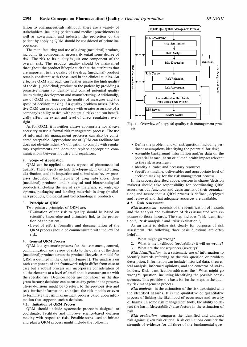
Fig. 1 Overview of a typical quality risk management proc-ess
2594 JP XVIIIBasic Concepts on Pharmaceutical Quality / General Information
lation to pharmaceuticals, although there are a variety ofstakeholders, including patients and medical practitioners aswell as government and industry, the protection of thepatient by applying QRM should be considered of prime im-portance.
The manufacturing and use of a drug (medicinal) product,including its components, necessarily entail some degree ofrisk. The risk to its quality is just one component of theoverall risk. The product quality should be maintainedthroughout the product lifecycle such that the attributes thatare important to the quality of the drug (medicinal) productremain consistent with those used in the clinical studies. Aneffective QRM approach can further ensure the high qualityof the drug (medicinal) product to the patient by providing aproactive means to identify and control potential qualityissues during development and manufacturing. Additionally,use of QRM can improve the quality of measures and thespeed of decision making if a quality problem arises. Effec-tive QRM can provide regulators with greater assurance of acompany's ability to deal with potential risks and can benefi-cially affect the extent and level of direct regulatory over-sight.
As for QRM, it is neither always appropriate nor alwaysnecessary to use a formal risk management process. The useof informal risk management processes can also be consi-dered acceptable. Appropriate use of QRM can facilitate butdoes not obviate industry's obligation to comply with regula-tory requirements and does not replace appropriate com-munications between industry and regulators.
2. Scope of ApplicationQRM can be applied to every aspects of pharmaceutical
quality. These aspects include development, manufacturing,distribution, and the inspection and submission/review proc-esses throughout the lifecycle of drug substances, drug(medicinal) products, and biological and biotechnologicalproducts (including the use of raw materials, solvents, ex-cipients, packaging and labeling materials in drug (medici-nal) products, biological and biotechnological products).
3. Principle of QRMTwo primary principles of QRM are:Evaluation of the risk to quality should be based on
scientific knowledge and ultimately link to the protec-tion of the patient.
Level of effort, formality and documentation of theQRM process should be commensurate with the level ofrisk.
4. General QRM ProcessQRM is a systematic process for the assessment, control,
communication and review of risks to the quality of the drug(medicinal) product across the product lifecycle. A model forQRM is outlined in the diagram (Figure 1). The emphasis oneach component of the framework might differ from case tocase but a robust process will incorporate consideration ofall the elements at a level of detail that is commensurate withthe specific risk. Decision nodes are not shown in the dia-gram because decisions can occur at any point in the process.These decisions might be to return to the previous step andseek further information, to adjust the risk models or evento terminate the risk management process based upon infor-mation that supports such a decision.4.1. Initiation of QRM Process
QRM should include systematic processes designed tocoordinate, facilitate and improve science-based decisionmaking with respect to risk. Possible steps used to initiateand plan a QRM process might include the following:
Define the problem and/or risk question, including per-tinent assumptions identifying the potential for risk;
Assemble background information and/or data on thepotential hazard, harm or human health impact relevantto the risk assessment;
Identify a leader and necessary resources;Specify a timeline, deliverables and appropriate level of
decision making for the risk management process.In the process described above, persons in charge (decision
makers) should take responsibility for coordinating QRMacross various functions and departments of their organiza-tion; and assure that a QRM process is defined, deployedand reviewed and that adequate resources are available.4.2. Risk Assessment
Risk assessment consists of the identification of hazardsand the analysis and evaluation of risks associated with ex-posure to those hazards. The step includes ``risk identifica-tion'', ``risk analysis'' and ``risk evaluation'',
As an assist to define risk clearly for purposes of riskassessment, the following three basic questions are oftenhelpful.
1. What might go wrong?2. What is the likelihood (probability) it will go wrong?3. What are the consequences (severity)?Risk identification is a systematic use of information to
identify hazards referring to the risk question or problemdescription. Information can include historical data, theoret-ical analysis, informed opinions, and the concerns of stake-holders. Risk identification addresses the ``What might gowrong?'' question, including identifying the possible conse-quences. This provides the basis for further steps in the qual-ity risk management process.
Risk analysis is the estimation of the risk associated withthe identified hazards. It is the qualitative or quantitativeprocess of linking the likelihood of occurrence and severityof harms. In some risk management tools, the ability to de-tect the harm (detectability) also factors in the estimation ofrisk.
Risk evaluation compares the identified and analyzedrisk against given risk criteria. Risk evaluations consider thestrength of evidence for all three of the fundamental ques-
25952595JP XVIII General Information / Basic Concepts on Pharmaceutical Quality
tions.The output of a risk assessment is either a quantitative es-
timate of risk or a qualitative description of a range of risk.When risk is expressed quantitatively, a numerical probabil-ity is used. Alternatively, risk can be expressed using qualita-tive descriptors, such as ``high'', ``medium'', or ``low'',which should be defined in as much detail as possible. Some-times a ``risk score'' is used to further define descriptors inrisk ranking. In quantitative risk assessments, a risk estimateprovides the likelihood of a specific consequence, given a setof risk-generating circumstances. Thus, quantitative risk es-timation is useful for one particular consequence at a time.Alternatively, some risk management tools use a relative riskmeasure to combine multiple levels of severity and probabil-ity into an overall estimate of relative risk. The intermediatesteps within a scoring process can sometimes employ quan-titative risk estimation.4.3. Risk Control
Risk control includes decision making to reduce and/oraccept risks. The purpose of risk control is to reduce the riskto an acceptable level. The amount of effort used for riskcontrol should be proportional to the significance of therisk. Decision makers might use different processes, includ-ing benefit-cost analysis, for understanding the optimal levelof risk control.
Risk control might focus on the following questions:Is the risk above an acceptable level?What can be done to reduce or eliminate risks?What is the appropriate balance among benefits, risks
and resources?Are new risks introduced as a result of the identified
risks being controlled?Risk reduction focuses on processes for mitigation or
avoidance of quality risk when it exceeds a specified (accept-able) level (see Fig. 1). Risk reduction might include actionstaken to mitigate the severity and probability of harm. Proc-esses that improve the detectability of hazards and qualityrisks might also be used as part of a risk control strategy.The implementation of risk reduction measures can in-troduce new risks into the system or increase the significanceof other existing risks. Hence, it might be appropriate torevisit the risk assessment to identify and evaluate any possi-ble change in risk after implementing a risk reduction proc-ess.
Risk acceptance is a decision to accept risk. Risk accep-tance can be a formal decision to accept the residual risk or itcan be a passive decision in which residual risks are not spe-cified. For some types of harms, even the best quality riskmanagement practices might not entirely eliminate risk. Inthese circumstances, it might be agreed that an appropriatequality risk management strategy has been applied and thatquality risk is reduced to a specified (acceptable) level. This(specified) acceptable level will depend on many parametersand should be decided on a case-by-case basis.4.4. Risk Communication
Risk communication is the sharing of information aboutrisk and risk management between the decision makers andothers. Parties can communicate at any stage of the riskmanagement process (see Fig. 1: dashed arrows). The out-put/result of the quality risk management process should beappropriately communicated and documented (see Fig. 1:solid arrows). Communications might include those amonginterested parties; e.g., regulators and industry, industry andthe patient, within a company, industry or regulatoryauthority, etc. The included information might relate to theexistence, nature, form, probability, severity, acceptability,control, treatment, detectability or other aspects of risks to
quality. Communication need not be carried out for eachand every risk acceptance. Between the industry and regula-tory authorities, communication concerning quality riskmanagement decisions might be effected through existingchannels as specified in regulations and guidances.4.5. Risk Review
Risk management should be an ongoing part of the qualitymanagement process. A mechanism to review or monitorevents should be implemented.
The output/results of the risk management process shouldbe reviewed to take into account new knowledge and experi-ence. Once a quality risk management process has been in-itiated, that process should continue to be utilized for eventsthat might impact the original quality risk management deci-sion, whether these events are planned (e.g., results ofproduct review, inspections, audits, change control) or un-planned (e.g., root cause from failure investigations, recall).The frequency of any review should be based upon the levelof risk. Risk review might include reconsideration of risk ac-ceptance decisions (section 4.3).
5. SummaryThe degree of rigor and formality of quality risk manage-
ment should reflect available knowledge and be commen-surate with the complexity and/ or criticality of the issue tobe addressed.
Quality risk management is a process that supportsscience-based and practical decisions when integrated intoquality systems. Appropriate use of QRM, however, doesnot obviate industry's obligation to comply with regulatoryrequirements.
6. Definitions
Decision Maker(s): Person(s) with the competence andauthority to make appropriate and timely quality riskmanagement decisions.
Detectability: The ability to discover or determine the ex-istence, presence, or fact of a hazard.
Harm: Damage to health, including the damage that canoccur from loss of product quality or availability.
Hazard: The potential source of harm (ISO/IEC Guide51).
Product Lifecycle: All phases in the life of the productfrom the initial development through marketing until theproduct's discontinuation.
Quality: The degree to which a set of inherent propertiesof a product, system or process fulfills requirements. Thesuitability of either a drug substance or drug product for itsintended use. This term includes such attributes as identity,strength, and purity.
Quality Risk Management: A systematic process for theassessment, control, communication and review of risks tothe quality of the drug (medicinal) product across theproduct lifecycle.
Quality System: The sum of all aspects of a system thatimplements quality policy and ensures that quality objectivesare met.
Requirements: The explicit or implicit needs or expecta-tions of the patients or their surrogates (e.g., health-careprofessionals, regulators and legislators). In this document,``requirements'' refers not only to statutory, legislative, orregulatory requirements, but also to such needs and expecta-tions.
25962596 JP XVIIIBasic Concepts on Pharmaceutical Quality / General Information
Risk: The combination of the probability of occurrence ofharm and the severity of that harm (ISO/IEC Guide 51).
Risk Acceptance: The decision to accept risk (ISO Guide73).
Risk Analysis: The estimation of the risk associated withthe identified hazards.
Risk Assessment: A systematic process of organizing in-formation to support a risk decision to be made within a riskmanagement process. It consists of the identification of haz-ards and the analysis and evaluation of risks associated withexposure to those hazards.
Risk Communication: The sharing of information aboutrisk and risk management between the decision maker andother stakeholders.
Risk Control: Actions implementing risk management de-cisions (ISO Guide 73).
Risk Evaluation: The comparison of the estimated risk togiven risk criteria using a quantitative or qualitative scale todetermine the significance of the risk.
Risk Identification: The systematic use of information toidentify potential sources of harm (hazards) referring to therisk question or problem description.
Risk Management: The systematic application of qualitymanagement policies, procedures, and practices to the tasksof assessing, controlling, communicating and reviewing risk.
Risk Reduction: Actions taken to lessen the probability ofoccurrence of harm and the severity of that harm.
Risk Review: Review or monitoring of output/results ofthe risk management process considering (if appropriate)new knowledge and experience about the risk.
Severity: A measure of the possible consequences of a haz-ard.
Stakeholder: Any individual, group or organization thatcan affect, be affected by, or perceive itself to be affected bya risk. Decision makers might also be stakeholders. For thepurposes of this guideline, the primary stakeholders are thepatient, healthcare professional, regulatory authority, andindustry.
Concept on Impurities inChemically synthesized Drug
Substances and Drug Products<G0-3-172>
1. Classiˆcation of impurities found in chemically synthe-sized pharmaceuticals and the guidance to comply with theircontrol
Impurities found in chemically synthesized pharmaceuti-cals are roughly classiˆed into organic impurities, inorganicimpurities and residual solvents. Those impurities in the newdrug substances and the products are controlled by the fol-lowing guidelines agreed upon at the International Councilfor Harmonisation of Technical Requirements for Phar-maceuticals for Human Use (hereinafter referred to as``ICH''). More speciˆcally, ``Impurities in New Drugs Sub-stances (PAB/PCD Notiˆcation No. 877 dated September25, 1995)'' (hereinafter referred to as ``ICH Q3A
Guideline'')1) on speciˆcations for organic impurities in drugsubstances applies to applications for marketing approvalafter April 1, 1997, while ``Impurities in New Drug Products(PAB/PCD Notiˆcation No. 539 dated June 23, 1997''(hereinafter referred to as ``ICH Q3B Guideline'')2) onspeciˆcations for organic impurities in drug products appliesto applications for marketing approval after April 1, 1999.Meanwhile, speciˆcations for inorganic impurities were spe-ciˆed by Japanese pharmacopoeial standards and knownsafety data. Now ``Guidelines for Elemental Impurities(PFSB/ELD Notiˆcation No. 4 dated September 30, 2015)''apply to applications for marketing approval after April 1,2017. In regard to residual solvents, ``Impurities: Guidelinesfor Residual Solvents (PAB/ELD Notiˆcation No. 307 datedMarch 30, 1998)'' (hereinafter referred to as ``ICH Q3CGuideline'') applies to applications for marketing approvalafter April 1, 2000. Especially in regard to DNA-reactive im-purities, ``Assessment and control of DNA reactive (muta-genic) impurities in pharmaceuticals to limit potential car-cinogenic risk (PSEHB/ELD Notiˆcation No. 3 datedNovember 10, 2015)'' applies to applications for marketingapproval after January 15, 2016. Although ICH Q3A guide-line does not cover optical enantiomers, a type of organicimpurities, ``Speciˆcations: Test Procedures and AcceptanceCriteria for New Drug Substances and New Drug Products:Chemical Substances (PMSB/ELD Notiˆcation No. 568 dat-ed May 1, 2001)'' (hereinafter referred to as ``ICH Q6AGuideline''), which was published subsequently, providesthat enantiomers are impurities that should be controlledand, if measurable, should be controlled in accordance withthe principle of ICH Q3A guideline.
Control of impurities in accordance with the guidelinesmentioned above is expected also for pharmaceuticals otherthan new drug substances and new drug products. Theirapplications for marketing (or applications for partialchanges) are subject to those guidelines when necessary. TheGeneral Notices of the JP 17th Edition states that residualsolvents of all JP-listed drugs, in principle, have to be con-trolled in accordance with speciˆcation ``Residual Solvents''in General Tests unless otherwise speciˆed in the individualmonograph. In regard to elemental impurities, it has beendecided in the basic principles for the preparation of the JP18th Edition to create a roadmap for their incorporation intothe JP for listing and to address its implementation.
2. The concept of ICH Q3A and Q3B guidelines for thecontrol of organic impurities
ICH Q3A and Q3B guidelines require setting acceptancecriteria for organic impurities based on the informationgained from development stages for new drugs. Concerningimpurities in drug substances, ICH Q3A guideline refers tothe items to be examined from chemical and safety perspec-tives. ICH Q3B guideline complements Q3A guideline, andhave the same basic concept as Q3A. Chemical aspects to beexamined include classiˆcation and identiˆcation of impuri-ties, their reporting method, speciˆcation settings and ana-lytical methods. Safety aspects include speciˆc guidelines forqualifying the safety of impurities that were not present, orwere present at substantially lower levels, in batches of adrug substance used in safety and clinical studies.
Qualiˆcation of the safety is the process of acquiring andevaluating data that establishes the biological safety of an in-dividual impurity or a given impurity proˆle at the level(s)speciˆed. The applicant should describe a rationale for es-tablishing impurity acceptance criteria that includes safetyconsiderations in attachments when applicated for approval.The level of any impurities present in a new drug substance
25972597JP XVIII General Information / Basic Concepts on Pharmaceutical Quality
that has been adequately tested in safety and/or clinical stu-dies would be considered qualiˆed.
Identiˆed impurities, unidentiˆed impurities and total im-purities are speciˆed based on the data obtained according tothe guidelines. The threshold of unspeciˆed impurities in adrug substance is determined depending on the daily intakeof the drug substance. When the maximum daily dosage isnot more than 2 g, it is set at 0.10z. The establishment ofindividual speciˆcations is required for impurities at a levelgreater than 0.10z.
In regard to drug products, ICH Q3B guideline cover thedegradation products of drug substances or reaction prod-ucts between the drug substance and additive/primary pack-aging. Therefore, even if organic impurities other thandegradation products (e.g., by-products and synthetic inter-mediates) in the drug substance are found as impurities inthe drug product, they need not be monitored or speciˆedsince they have already been controlled as the drug substancespeciˆcations. However, degradation products elevated inthe drug product need to be monitored and speciˆed.
3. Principles for controlling organic impurities in the arti-cles listed in the JP
Conventionally in the JP, speciˆed impurities, unspeciˆedimpurities and total impurities are speciˆed in accordancewith ICH Q3A and Q3B guidelines for pharmaceutical prod-ucts, whose impurities have been controlled by those guide-lines, in the process listing in the JP. (However, this shall notapply to the long-term listed pharmaceutical products whichhad existed in the JP before these guidelines were applicable.However, when a new application is ˆled for those JP-listedpharmaceutical products, control of impurities in accor-dance with ICH Q3A and Q3B guidelines may be required, ifnecessary.) In order to specify the impurities, analysis dataduring development submitted from the drafting companyand impurity analysis data from commercial productionbatches after consistent manufacturing is achieved should beassessed. Safety evaluation is not required again for theprocess listing in the JP since it has been performed at thetime of approval.
ICH Q3A and Q3B guidelines cover impurities in the drugsubstances manufactured by chemical syntheses and the drugproducts manufactured with those drug substances. Similar-ly, the following types of products are not covered in the JP:biological/biotechnological products, peptides, oligonucleo-tides, radiopharmaceuticals, fermentation products andsemi-synthetic products derived therefrom, herbal productsand crude products of animal or plant origin.
When organic impurities assessed in accordance with theprinciples of ICH Q3A and Q3B guidelines are listed as JPtests of purity, the operational rationality of the JP is consi-dered and its own modiˆcation is added. (i) Except in excep-tional circumstances, impurity reference standards are notestablished. In order to identify an impurity using liquidchromatography, the relative retention time of the impurityto the drug substance is used for identiˆcation. (ii) Whenonly unidentiˆed impurities in highly pure pharmaceuticalproducts (not more than 0.1z) are speciˆed, it is generallyexempted to set acceptance criteria for total impurities. (iii)When acceptance criteria set based only on actual measuredvalues result in many impurities with slightly diŠerent accep-tance criteria, consideration can be given so that the puritytest consists of a small number of representative acceptancecriteria, if possible. (iv) Chemical structural information andthe chemical name of the impurities are not disclosed. Thosemeasures enable impurity control without impurity referencestandards, and can simplify system suitability test for highly
pure pharmaceutical products.Meanwhile, the method to identify impurities by use of
relative retention time is column-dependent and analysisbecomes diŠicult when appropriate columns are not availa-ble. Therefore, the JP 17th Edition also allows the use of theanalysis method with impurity reference standards whendesigning purity tests for a drug substance. In addition, theJP adopted a policy to disclose chemical names and structureformulas as the information on impurities including, in prin-ciple, optical enantiomers.
The JP-speciˆc consideration may be given to purity testsfor organic impurities in drug products in the process listingin the JP. Also in the JP, impurities derived from the prod-ucts of the reaction between the drug substance and addi-tive/primary packaging are speciˆed as impurities in thedrug product. Those impurities are formulation-dependentand may not be formed in diŠerent formulations. Since theJP is an oŠicial compendium that allows a wide variety offormulations, when it is not appropriate to specify impuritiesuniformly in the individual monograph, they are subject tothe speciˆcations at the time of approval, along with thestatement ``Being speciˆed separately when the drug is grant-ed approval based on the Law.''
When the speciˆcations for impurities are reviewed for anew entry of a pharmaceutical product in an individualmonograph of the JP, acceptance criteria for impurities maybe included in the review according to the following con-cepts. ICH Q6A guideline point out: Data available upon themarketing application are limited and it has to be taken intoconsideration that the limited data may in‰uence the designof acceptance criteria. Regarding impurities, since impurityproˆles gained during the manufacturing stages may some-times be diŠerent from that gained from development stage,it is stated that changes in impurity proˆles at the manufac-turing stage should be considered as appropriate. Accordingto this concept, for impurities which should be speciˆed inthe process listing in the JP, not only information from de-velopment stage but also information about impurity proˆlesif there are changes at the manufacturing stage, and infor-mation at the stage after the product manufacturing becomesstable (hereinafter referred to as the ``stable productionstage'') should be taken into consideration.
However, it is undesirable to remove impurities that arepresent at substantially lower levels, or become undetectableat the stable production stage indiscriminately from the listof candidate compounds to be speciˆed. JP-listed drugs areaccepted as drugs by conformance to the speciˆcations in theindividual monograph. However, generic drugs, whosemanufacturing methods are not necessarily the same as thatof the drug substance used for JP monograph, may havediŠerent impurity proˆles and contain such impurities.Providing information in the process listing in the JP basedon the detection results during development stage may resultin encompassing impurities found in drug substances anddrug products distributed as JP drugs.
Therefore, before the removal of impurities that arepresent at substantially lower levels or become undetectableat the stable production stage from the JP speciˆcation list,the need to establish speciˆcations should be fully examinedbased on ICH Q3A and Q3B guidelines with respect tosafety.
For a drug substance that was approved by the method toidentify its impurities with impurity reference materials, it isdesirable also in the individual JP monograph, in principle,to establish speciˆcations and test methods appropriately sothat the speciˆed impurity becomes identiˆable. In regard toimpurity control during the manufacturing process, impuri-
25982598 JP XVIIIBasic Concepts on Pharmaceutical Quality / General Information
ties can be controlled by establishing an appropriate controlstrategy including release testing, in-process tests and processparameters control.
4. References1) ICH: Guideline for Q3A, Impurities in New Drug Sub-
stances.2) ICH: Guideline for Q3B, Impurities in New Drug
Products.
Stability Testing of DrugSubstances and Drug Products
<G0-4-171>
1. IntroductionIt is essential that the quality of a drug is maintained dur-
ing the period from being manufactured to being ad-ministered in a patient. Stability testing is performed inorder to ensure that the quality is maintained during theperiod. The purpose of stability testing is to provide evidenceon how the quality of a drug substance or drug product va-ries with time under the influence of a variety of environ-mental factors such as temperature, humidity and light, andto establish a re-test period for the drug substance or a shelflife for the drug product and recommended storage condi-tions.
The re-test period of a drug substance is the period of timeduring which the drug substance is expected to remain withinits specification and, therefore, can be used in the manufac-ture of a given drug product, provided that the drug sub-stance has been stored under the defined conditions. Afterthis period, a batch of drug substance destined for use in themanufacture of a drug product should be re-tested for com-pliance with the specification and then used immediately. Abatch of drug substance can be re-tested multiple times. Forcertain antibiotics known to be labile, it is more appropriateto establish a shelf life than a re-test period. The shelf life ofa drug product is the period in which a batch of the productis expected to remain within the approved shelf life specifica-tion if stored under defined conditions.
This general information mainly illustrates a standard im-plementation that can be set when we perform stability testsof a chemical drug substance and the associated drugproduct, and it is also helpful in stability tests of pharmaceu-ticals other than chemical drugs. Also, this leaves sufficientflexibility to encompass the variety of different practicalsituations that may be encountered due to specific scientificconsiderations and characteristics of the materials beingevaluated. Alternative approaches can be used when thereare scientifically justifiable reasons.
2. Conditions of stability testingStress testing, long term testing, accelerated testing and if
necessary intermediate testing are performed as stability test-ing for drugs.2.1 Stress testing
Stress testing of the drug substance can help identify thelikely degradation products, which can in turn help establishthe degradation pathways and the intrinsic stability of themolecule and validate the stability indicating power of theanalytical procedures used. Stress testing should include theeffect of temperatures (in 109C increments (e.g., 509C,609C, etc.) above that for accelerated testing), humidity(e.g., 75z RH or greater) where appropriate, oxidation, andphotolysis on the drug substance. The testing should also
evaluate the susceptibility of the drug substance to hydrolysisacross a wide range of pH values when in solution or suspen-sion.
Stress testing of the drug product is undertaken to assessthe effect of severe conditions on the drug product. Such stu-dies include photostability testing and specific testing on cer-tain products, (e.g., metered dose inhalers, creams, emul-sions, refrigerated aqueous liquid products).2.2 Long term testing, accelerated testing and intermediatetesting
Long term testing is undertaken on batches of a drug sub-stance or drug product according to a prescribed stabilityprotocol to establish the re-test period of the drug substanceor the shelf life of the drug product.
Accelerated testing is a stability study designed to increasethe rate of chemical degradation or physical change of adrug substance or drug product by using exaggerated storageconditions. Data from these studies, in addition to long termstability studies, can be used to assess longer term chemicaleffects at non-accelerated conditions and to evaluate the ef-fect of short term excursions outside the label storage condi-tions such as might occur during shipping.
Intermediate testing is conducted at 309C/65z RH anddesigned to moderately increase the rate of chemical degra-dation or physical changes for a drug substance or drugproduct intended to be stored long term at 259C. Intermedi-ate testing is implemented only when a significant change oc-curs in the accelerated testing.
Long term and accelerated testing, also if needed inter-mediate testing should be performed on at least three prima-ry batches. The primary batches of the drug substanceshould be manufactured to a minimum of pilot scale by thesame synthetic route as, and using a method of manufactureand procedure that simulates the final process to be used for,production batches. The overall quality of the batches ofdrug substance placed on the stability studies should berepresentative of the quality of the material to be made on aproduction scale. The stability studies should be conductedon the drug substance packaged in a container closure sys-tem that is the same as or simulates the packaging proposedfor storage and distribution. The primary batches of thedrug product should be of the same formulation and pack-aged in the same container closure system as proposed formarketing (including, as appropriate, any secondary packag-ing and container label). The manufacturing process used forprimary batches should simulate that to be applied toproduction batches and should provide the product of thesame quality and meeting the same specification as that in-tended for marketing. Two of the three batches should be atleast pilot scale batches and the third one can be smaller, ifjustified. The primary batch may be a production batch.Where possible, batches of the drug product should bemanufactured by using different batches of the drug sub-stance. The pilot scale batch is a batch of a drug substance ordrug product manufactured by a procedure fully representa-tive of and simulating that to be applied to a full productionscale batch. For solid oral dosage forms, a pilot scale is gen-erally, at a minimum, one-tenth that of a full productionscale or 100,000 tablets or capsules, whichever is the larger.
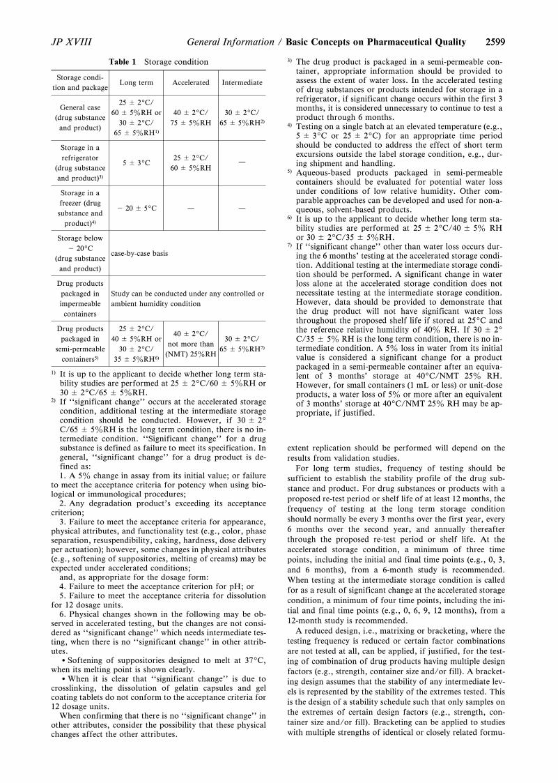
The storage conditions used for stability testing are shownin Table 1.3. Testing attributes and testing frequency
Stability studies should include testing of those attributesof the drug substance or the product that are susceptible tochange during storage and are likely to influence quality,safety, and/or efficacy. Validated stability-indicating ana-lytical procedures should be applied. Whether and to what
2599
Table 1 Storage condition
Storage condi-tion and package
Long term Accelerated Intermediate
General case(drug substanceand product)
25 ± 29C/60 ± 5zRH or
30 ± 29C/65 ± 5zRH1)
40 ± 29C/75 ± 5zRH
30 ± 29C/65 ± 5zRH2)
Storage in arefrigerator
(drug substanceand product)3)
5 ± 39C25 ± 29C/
60 ± 5zRH—
Storage in afreezer (drugsubstance and
product)4)
- 20 ± 59C — —
Storage below- 209C
(drug substanceand product)
case-by-case basis
Drug productspackaged inimpermeablecontainers
Study can be conducted under any controlled orambient humidity condition
Drug productspackaged in
semi-permeablecontainers5)
25 ± 29C/40 ± 5zRH or
30 ± 29C/35 ± 5zRH6)
40 ± 29C/not more than
(NMT) 25zRH
30 ± 29C/65 ± 5zRH7)
1) It is up to the applicant to decide whether long term sta-bility studies are performed at 25 ± 29C/60 ± 5zRH or30 ± 29C/65 ± 5zRH.
2) If ``significant change'' occurs at the accelerated storagecondition, additional testing at the intermediate storagecondition should be conducted. However, if 30 ± 29C/65 ± 5zRH is the long term condition, there is no in-termediate condition. ``Significant change'' for a drugsubstance is defined as failure to meet its specification. Ingeneral, ``significant change'' for a drug product is de-fined as:1. A 5z change in assay from its initial value; or failure
to meet the acceptance criteria for potency when using bio-logical or immunological procedures;
2. Any degradation product's exceeding its acceptancecriterion;
3. Failure to meet the acceptance criteria for appearance,physical attributes, and functionality test (e.g., color, phaseseparation, resuspendibility, caking, hardness, dose deliveryper actuation); however, some changes in physical attributes(e.g., softening of suppositories, melting of creams) may beexpected under accelerated conditions;
and, as appropriate for the dosage form:4. Failure to meet the acceptance criterion for pH; or5. Failure to meet the acceptance criteria for dissolution
for 12 dosage units.6. Physical changes shown in the following may be ob-
served in accelerated testing, but the changes are not consi-dered as ``significant change'' which needs intermediate tes-ting, when there is no ``significant change'' in other attrib-utes.
Softening of suppositories designed to melt at 379C,when its melting point is shown clearly.
When it is clear that ``significant change'' is due tocrosslinking, the dissolution of gelatin capsules and gelcoating tablets do not conform to the acceptance criteria for12 dosage units.
When confirming that there is no ``significant change'' inother attributes, consider the possibility that these physicalchanges affect the other attributes.
3) The drug product is packaged in a semi-permeable con-tainer, appropriate information should be provided toassess the extent of water loss. In the accelerated testingof drug substances or products intended for storage in arefrigerator, if significant change occurs within the first 3months, it is considered unnecessary to continue to test aproduct through 6 months.
4) Testing on a single batch at an elevated temperature (e.g.,5 ± 39C or 25 ± 29C) for an appropriate time periodshould be conducted to address the effect of short termexcursions outside the label storage condition, e.g., dur-ing shipment and handling.
5) Aqueous-based products packaged in semi-permeablecontainers should be evaluated for potential water lossunder conditions of low relative humidity. Other com-parable approaches can be developed and used for non-a-queous, solvent-based products.
6) It is up to the applicant to decide whether long term sta-bility studies are performed at 25 ± 29C/40 ± 5z RHor 30 ± 29C/35 ± 5zRH.
7) If ``significant change'' other than water loss occurs dur-ing the 6 months' testing at the accelerated storage condi-tion. Additional testing at the intermediate storage condi-tion should be performed. A significant change in waterloss alone at the accelerated storage condition does notnecessitate testing at the intermediate storage condition.However, data should be provided to demonstrate thatthe drug product will not have significant water lossthroughout the proposed shelf life if stored at 259C andthe reference relative humidity of 40z RH. If 30 ± 29C/35 ± 5z RH is the long term condition, there is no in-termediate condition. A 5z loss in water from its initialvalue is considered a significant change for a productpackaged in a semi-permeable container after an equiva-lent of 3 months' storage at 409C/NMT 25z RH.However, for small containers (1 mL or less) or unit-doseproducts, a water loss of 5z or more after an equivalentof 3 months' storage at 409C/NMT 25z RH may be ap-propriate, if justified.
2599JP XVIII General Information / Basic Concepts on Pharmaceutical Quality
extent replication should be performed will depend on theresults from validation studies.
For long term studies, frequency of testing should besufficient to establish the stability profile of the drug sub-stance and product. For drug substances or products with aproposed re-test period or shelf life of at least 12 months, thefrequency of testing at the long term storage conditionshould normally be every 3 months over the first year, every6 months over the second year, and annually thereafterthrough the proposed re-test period or shelf life. At theaccelerated storage condition, a minimum of three timepoints, including the initial and final time points (e.g., 0, 3,and 6 months), from a 6-month study is recommended.When testing at the intermediate storage condition is calledfor as a result of significant change at the accelerated storagecondition, a minimum of four time points, including the ini-tial and final time points (e.g., 0, 6, 9, 12 months), from a12-month study is recommended.
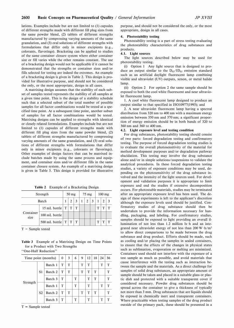
A reduced design, i.e., matrixing or bracketing, where thetesting frequency is reduced or certain factor combinationsare not tested at all, can be applied, if justified, for the test-ing of combination of drug products having multiple designfactors (e.g., strength, container size and/or fill). A bracket-ing design assumes that the stability of any intermediate lev-els is represented by the stability of the extremes tested. Thisis the design of a stability schedule such that only samples onthe extremes of certain design factors (e.g., strength, con-tainer size and/or fill). Bracketing can be applied to studieswith multiple strengths of identical or closely related formu-
2600
Table 2 Example of a Bracketing Design
Strength 50 mg 75 mg 100 mg
Batch 1 2 3 1 2 3 1 2 3
Containersize
15 mL bottle T T T T T T
100 mL bottle
500 mL bottle T T T T T T
T = Sample tested
Table 3 Example of a Matrixing Design on Time Pointsfor a Product with Two Strengths
``One-Half Reduction''
Time point (months) 0 3 6 9 12 18 24 36
Strength
S1
Batch 1 T T T T T T
Batch 2 T T T T T T
Batch 3 T T T T T
S2
Batch 1 T T T T T
Batch 2 T T T T T T
Batch 3 T T T T T
T = Sample tested
2600 JP XVIIIBasic Concepts on Pharmaceutical Quality / General Information
lations. Examples include but are not limited to (1) capsulesof different strengths made with different fill plug sizes fromthe same powder blend, (2) tablets of different strengthsmanufactured by compressing varying amounts of the samegranulation, and (3) oral solutions of different strengths withformulations that differ only in minor excipients (e.g.,colorants, flavorings). Bracketing can be applied to studiesof the same container closure system where either containersize or fill varies while the other remains constant. The useof a bracketing design would not be applicable if it cannot bedemonstrated that the strengths or container sizes and/orfills selected for testing are indeed the extremes. An exampleof a bracketing design is given in Table 2. This design is pro-vided for illustrative purpose, and should not be consideredthe only, or the most appropriate, design in all cases.
A matrixing design assumes that the stability of each sub-set of samples tested represents the stability of all samples ata given time point. This is the design of a stability schedulesuch that a selected subset of the total number of possiblesamples for all factor combinations would be tested at a spe-cified time point. At a subsequent time point, another subsetof samples for all factor combinations would be tested.Matrixing designs can be applied to strengths with identicalor closely related formulations. Examples include but are notlimited to (1) capsules of different strengths made withdifferent fill plug sizes from the same powder blend, (2)tablets of different strengths manufactured by compressingvarying amounts of the same granulation, and (3) oral solu-tions of different strengths with formulations that differonly in minor excipients (e.g., colorants or flavorings).Other examples of design factors that can be matrixed in-clude batches made by using the same process and equip-ment, and container sizes and/or different fills in the samecontainer closure system. An example of a matrixing designis given in Table 3. This design is provided for illustrative
purpose, and should not be considered the only, or the mostappropriate, design in all cases.
4. Photostability testingPhotostability testing is a part of stress testing evaluating
the photostability characteristics of drug substances andproducts.4.1. Light sources
The light sources described below may be used forphotostability testing.
(i) Option 1 Any light source that is designed to pro-duce an output similar to the D65/ID65 emission standardsuch as an artificial daylight fluorescent lamp combiningvisible and ultraviolet (UV) outputs, xenon, or metal halidelamp.
(ii) Option 2 For option 2 the same sample should beexposed to both the cool white fluorescent and near ultravio-let fluorescent lamp.
1. A cool white fluorescent lamp designed to produce anoutput similar to that specified in ISO10977(1993); and
2. A near ultraviolet fluorescent lamp having a spectraldistribution from 320 nm to 400 nm with a maximum energyemission between 350 nm and 370 nm; a significant propor-tion of energy emission should be in both bands of 320 to360 nm and 360 to 400 nm.4.2. Light exposure level and testing condition
For drug substances, photostability testing should consistof two parts: forced degradation testing and confirmatorytesting. The purpose of forced degradation testing studies isto evaluate the overall photosensitivity of the material formethod development purposes and/or degradation pathwayelucidation. This testing may involve the drug substancealone and/or in simple solutions/suspensions to validate theanalytical procedures. In these forced degradation testingstudies, a variety of exposure conditions may be used, de-pending on the photosensitivity of the drug substance in-volved and the intensity of the light sources used. For devel-opment and validation purposes it is appropriate to limitexposure and end the studies if extensive decompositionoccurs. For photostable materials, studies may be terminatedafter an appropriate exposure level has been used. The de-sign of these experiments is left to the applicant's discretionalthough the exposure levels used should be justified. Con-firmatory studies of drug substance should then beundertaken to provide the information necessary for han-dling, packaging, and labeling. For confirmatory studies,samples should be exposed to light providing an overall il-lumination of not less than 1.2 million lx・h and an inte-grated near ultraviolet energy of not less than 200 W・h/m2
to allow direct comparisons to be made between the drugsubstance and drug product. Efforts should be made, suchas cooling and/or placing the samples in sealed containers,to ensure that the effects of the changes in physical statessuch as sublimation, evaporation or melting are minimized.Containers used should not interfere with the exposure of atest sample as much as possible, and avoid materials thatcause interference with the testing such as interaction be-tween the sample and the materials. As a direct challenge forsamples of solid drug substances, an appropriate amount ofsample should be taken and placed in a suitable glass or plas-tic dish and protected with a suitable transparent cover ifconsidered necessary. Powder drug substances should bespread across the container to give a thickness of typicallynot more than 3 mm. Drug substances that are liquids shouldbe exposed in chemically inert and transparent containers.Where practicable when testing samples of the drug productoutside of the primary pack, these should be presented in a
26012601JP XVIII General Information / Basic Concepts on Pharmaceutical Quality
way similar to the conditions mentioned for the drug sub-stance. The samples should be positioned to provide maxi-mum area of exposure to the light source. For example,tablets, capsules, etc., should be spread in a single layer. Ifdirect exposure is not practical (e.g., due to oxidation of aproduct), the sample should be placed in a suitable protec-tive inert transparent container (e.g., quartz). If testing ofthe drug product in the immediate container or as marketedis needed, the samples should be placed horizontally ortransversely with respect to the light source, whichever pro-vides for the most uniform exposure of the samples. Someadjustment of testing conditions may have to be made whentesting large volume containers (e.g., dispensing packs).
5. Evaluation of stability dataIn the stability data evaluation, data from long term and
accelerated testing, also if needed from intermediate testingand, as appropriate, supporting data (data of stability testingusing drug substances and products in developing stage)should be evaluated to determine the critical quality attrib-utes likely to influence the quality and performance of thedrug substance or product. Each attribute should be assessedseparately, and an overall assessment should be made of thefindings for the purpose of proposing a re-test period orshelf life. An approach for analyzing data of a quantitativeattribute that is expected to change with time is to determinethe time at which the 95z one-sided confidence limit for themean curve intersects the acceptance criterion. The re-testperiod or shelf life proposed should not exceed that predict-ed for any single attribute.
Basic Requirements and Terms forthe Packaging of Pharmaceutical
Products <G0-5-170>
This chapter describes the basic requirements for thepackaging of pharmaceutical products as well as the termsand their definitions used for the packaging as taking intoaccount the aspects in quality assurance of the pharmaceu-tical products and the point of view of internationalharmonization.1)
In this chapter, the concept of packaging for pharmaceuti-cal products, or packaging, includes putting or holding thedrugs in container. In addition, the information presented asbasic requirements shall be a central focus on packaging fordrug products, as well as for ensuring quality on the trans-portation and storage of drug substances or additives.
1. Basic requirements of packaging for pharmaceuticalproducts
For the packaging for pharmaceutical products, it is im-portant to settle the requirements of the packaging based onthe evaluation of the packaging suitability in the develop-ment stage so as to be able to ensure the quality standards ofpreparations defined over the shelf life of preparations. Thesuitability of packaging for pharmaceutical products must bemaintained through the product life cycle on the basis of therequirements of packaging settled in the development stage.
For the packaging of drug products, it is also necessary toconsider for the suitability for proper use and for ensuringsafe application in addition to quality assurance. Thestringency of the evaluation for suitability of packaging forpreparations differs depending on the degree of the risk ac-cording to the route of administration, such as intravenousadministration, oral administration, or dermal administra-
tion and the risk due to interaction between the products andthe primary packaging according to injections, liquids andsolutions, semi-solid or solid dosage forms.1.1. Suitability evaluation and requirements of packagingin the design stage
The packaging suitability to be evaluated in the designstage includes protection, compatibility, safety, and per-formance.
The basic items to be evaluated as suitability are describedin the course of the packaging design.1.1.1. Safety of materials used for packaging
Leachables or migrants, such as the monomers of thepolymer resins, additives or metal impurities, from the mate-rials used for the primary packaging such as plastic or glasscontainers should not deteriorate drug safety. The amountof leachable or migratable chemical substances from theprimary packaging materials to the contents must besufficiently small from a safety perspective.
The primary packaging materials of the containers that arein direct contact with the drugs should be used which qualitysuch as on toxicity has been appropriately evaluated by thesuppliers according to ``Basic Requirements for Plastic Con-tainers for Pharmaceutical Use and Rubber Closures forContainers for Aqueous Infusions <G7-2-162>'' in GeneralInformation or the like. In the design stage, the informationon quality evaluation of the packing materials is desirable tobe obtained as far as possible from the suppliers.1.1.2. Compatibility with the contents
The primary packaging must not reduce the quality ofpharmaceutical products over the shelf life of preparations.The contents adsorbing onto the surface of primary packag-ing, or migrating inside of the materials, must not lead to adrug concentration change of more than a certain level.Moreover, the interaction between the contents and the ma-terials must not lead to degradation of drugs.
The primary packaging should not be deformed, deterio-rated, or degraded by the contents.
In the design stage, the compatibility of the primary pack-aging with the content is examined by the combination of in-dividual candidate material and the content drugs, togetherwith other evaluation items. And chose the applicable mate-rial based on the results of the study on the prototype prima-ry packaging for complying with the essential requirements,i.e. the design specifications, for the issues about the protec-tion from moisture and light, the sorption to and leachingfrom the primary packaging, etc., based on the data fromthe experiments and/or information from the scientificdocumentation. When selecting the primary packaging mate-rial, the suitability of the material for the secondary packag-ing is also to be evaluated as needed.1.1.3. Protection by packaging
The packaging should be able to prevent loss, efflores-cence, deliquescence, or evaporation of the contents and toprotect the contents by the addition of moisture resistance,light shielding, or a gas barrier, depending on the character-istic of the contents. In the case of not being able to ensurethe quality of the contents by the primary packaging alone, itshould be ensured by the combination of multiple packagingmaterials, including the secondary packaging. Furthermore,the containers for injections or ophthalmic solutions arepreferable to be made of a high transparency material, sothat foreign matter contamination can be observed visually.
For pharmaceutical products susceptible to moisture suchas by hydrolysis, the packaging used with desiccants or pri-mary packaging materials with gas-barrier function can bemoisture-proof packaging. For preparations susceptible toevaporation of water, gas-barrier materials for the primary
26022602 JP XVIIIBasic Concepts on Pharmaceutical Quality / General Information
packaging can be used. For the pharmaceutical products thatare easily oxidized, the packaging with deoxidants or thelow-gas-permeability materials can be used for the primarypackaging to protect the pharmaceutical products fromoxygen in the air.
Protection by the packaging should be evaluated in thepackaging design stage, and finally confirmed by stabilitytests. Resistance to physical shock during transportation isalso necessary to be verified.1.1.4. Container integrity (microbial contaminationprevention)
The packaging should be able to protect the contents frommicrobial contamination, depending on the characteristics ofthe content drug or dosage form, and especially for the con-tainers used for sterile preparations, the integrity of primarypackaging, through the tests such as the fitting compatibilitytests for containers and closures, must be confirmed.
In the case of pharmaceutical products that must be steri-lized, the primary packaging must meet the above-mentionedsuitability for safety, compatibility and protection even afterthe sterilization. There should not be any residue or genera-tion of toxic substances of more than a certain safety levelafter the sterilization. In addition, the primary packagingshould have a structure and/or material that must preventany microbial contamination of the pharmaceutical productscontained therein during storage and transportation aftersterilization.1.1.5. Packaging performance
The packaging design with consideration for discrimina-tion, usability, and disposal should be performed.
With regard to discrimination, for example, a displayshould be considered for patients so that the proper adminis-tration and use of the drugs can be ensured and even foraged patients to be able to idenify easily. An easy-to-under-stand display or container for preventing accidental misuseor a prank, such as tamper-resistant packaging and child-resistant packaging, is preferable.
With regard to usability, items such as easy handling ofthe drug in dispensing, easy dosaging for children with smalldoses, easy removal from the container when the drug is ad-ministered or used, successful administration, and preferablestorage and portability should be considered for each prepa-ration.
On packaging-related waste, the choice or determinationof the containers must be considered for disposal, sincepaying attention to the effect of use of resources, followingthe Containers and Packaging Recycling Act and the rules ofeach local government, and striving to reduce wastes are re-quired. In the primary packaging, the recycled packagingmaterials that are not assured for material composition mustnot be used.1.1.6. Requirements of packaging
Based on the test methods and/or the evaluation tech-niques used for study of the packaging suitability in the de-sign stage of pharmaceutical preparations, the necessary andsufficient items of the quality control for maintaining thepackaging suitability are established. Generally, the require-ments of packaging are composed of the control of the mate-rial quality, specifications and test methods, in-process tests,and the like.1.2. Examples of suitability evaluation in the design stageof packaging for pharmaceutical products
The following are the examples of the suitability evalua-tion in the design stage.1.2.1. Suitability evaluation of packaging to be used forsolid oral dosage forms
For the suitability evaluation of the packaging for solid
oral dosage forms, the following tests should be included.If bottles are used, the measurement of opening torques
with selected stoppers should be performed.If PTP packaging or strip packaging is used, the mois-
ture permeability test should be performed.1.2.2. Suitability evaluation of containers to be used for in-jections
For the suitability evaluation of containers to be used forinjections, the following tests should be included.
The injections using ampules should perform pinholetests, and the integrity must be confirmed.
The injections using vials, rubber closures, or prefilledglass syringes, except ampules, should perform the fit-ting compatibility tests, and the integrity as a containermust be confirmed.
The plastic containers for pharmaceutical products usedfor injections (prefilled syringes, plastic bottles, plasticbags, etc.) should be verified as ``tight containers inwhich microorganisms will not be contaminated'' overthe shelf life of preparations.
1.2.3. Suitability evaluation on metal impurities for a con-tainer closure system
If leaching of metal impurities from the primary packag-ing materials used for injections, liquids, or semi-solidpreparations is suspected, it is necessary to confirm that theamount of metal impurities contained in preparations issufficiently low from the viewpoint of safety using AtomicAbsorption Spectrophotometry <2.23>, Inductively CoupledPlasma Emission Spectrometry and Inductively CoupledPlasma-Mass Spectrometry <2.63>, etc.1.2.4. Suitability evaluation of kit products
If dispensing devices, such as prefilled syringes, injectioncartridges, or metered-dose preparations for inhalation, areused, the accurate dose with reproducibility in conditions asclose as possible to the product usage must be verified.1.2.5. Suitability evaluation of light resistant packaging
If active substances are susceptible to the light and the for-mulation design alone cannot overcome the effect of light,the light resistant packaging including containers should beconsidered. A selection of an appropriate light resistantpackaging must be verified using a photostability test andthe like as severe tests.1.3. Selection, change control, stability monitoring, etc. ofthe packaging materials in the packaging process develop-ment
To maintain appropriately the quality assurance of phar-maceutical products by packaging, the properness of therequirements of the packaging must be confirmed throughthe appropriate change control, stability monitoring and thelike in the packaging process development and productionstages, together with the suitability evaluation performed inthe design stage.
For the primary packaging materials used in the manufac-ture of preparations, whether the quality of material ischanged by the supplier must be appropriately managed.Therefore, all information concerning the manufacturingprocess of containers including the information about sub-stances added is desirable to be obtained.
The finally selected packaging for pharmaceutical prod-ucts should be evaluated whether it meets the requirementsas designed. If it does not meet the requirements, the pack-aging form or material must be changed through changecontrol.1.3.1. Selection or change of packaging materials in thepackaging process development
The packaging materials should be selected in considera-tion of the manufacturability and the prevention capability
26032603JP XVIII General Information / Basic Concepts on Pharmaceutical Quality
of adhesion of foreign matters or insects in addition to meet-ing the requirements determined in the design stage. For thefinally selected packaging, it should be verified to withstandagainst temperature change during storage and transporta-tion, physical shock during transportation, and the like.
The suitability of the selected packaging materials shall beconfirmed, using the applicable tests in the General Tests, 7.Test for Containers and Packing Materials. For the tests thatare not described in the General Tests, set the applicable testand judge the suitability.1.3.2. Stability monitoring, etc.
It must be confirmed that the packaging form does not ad-versely affect the stability of preparations through stabilitymonitoring or reference sample stored. If the packaging isconsidered to affect the quality of stability of the prepara-tions, the applicable packaging and management should beselected to ensuring quality, where the quality of the lotsusing this should be monitored, and the packaging should beimproved through change control, if necessary.1.4. Examples of quality control in the packaging processof pharmaceutical products
To maintain the suitability of the packaging of phar-maceutical products, it must be confirmed by performing thetest such as process control test before shipment that thepackaging meets the requirements.
The following shows the examples.1.4.1. Examples of solid oral dosage forms
The PTP packaged tablets must be confirmed whether theintegrity of the seal as designed is secured in the airtight testsfor PTP sheets (e.g. water pressure reduction tests).1.4.2. Examples of injections
Aqueous injections using ampules should be checked ifit has no pinholes.
The plastic containers for pharmaceutical products usedfor injections (prefilled syringes, plastic bottles, plasticbags, etc.) should be checked when they are shipped tothe market if they have been produced as tight contain-ers, as designed, where microorganisms are not con-taminated.
2. Terms of packaging for pharmaceutical products2.1. Basic termsPrimary packaging: Any packaging that is in direct contactwith active substances, excipients, or preparations, andshould not give a physical or chemical change to the con-tents. The primary packaging holds the quality of the phar-maceutical products and provides better performance includ-ing convenience.
For example, the primary packaging includes an ampulethat is an ``immediate container'' for injections, and a PTPpackaging which is an ``inner bag'' for tablets or capsules.Outside container or outside wrapper: A container or wrap-per that is used to contain or to wrap immediate containersor immediate wrappers for the pharmaceutical products forsale or distribution and has a legal label by ordinance2) on it.Tight container: A container that protects the contents fromextraneous solids or liquids, from loss of the contents, andfrom efflorescence, deliquescence, or evaporation under or-dinary or customary conditions of handling, shipment, andstorage. Where a tight container is specified, it may bereplaced by a hermetic container. (General Notices 44)
The tight container includes containers made of plasticresins as the examples of container and packaging often used(bottles, vials, syringes, blister (PTP) packaging, strip pack-aging, etc.).Final packaging or marketed packaging: Any packaging thatis for pharmaceutical products for sale or distribution and a
form of the shipped products to the market by labeling asdefined by ordinance2,3).
The final packaging may be used for irradiation when aradiation sterilization method is used.Labeling and packaging materials4): Product's containers,wrappers, and labeling including package insert.Immediate wrapper: A container in which pharmaceuticalproducts are contained directly (papers, clothes, plastics,and aluminum bags). It can be sold or distributed as it is bylabeling as defined by ordinance3). There is an inner bag asan example of immediate wrapper that it is not sold or dis-tributed as it is and does not require a legal label byordinance3).
The immediate wrapper in which the pharmaceutical prod-ucts are contained directly is also referred to as the primarypackaging.Immediate container: A solid container in which the drugsare directly contained (cans, bottles, ampules, vials, tubes,containers for eye drops, boxes, etc.). It can be sold or dis-tributed as it is by labeling as defined by ordinance3). In ad-dition, the paper boxes will be the immediate container, ifthey use the PTP packaging as an inner bag like tablets.
The immediate container in which the drugs are containeddirectly is also referred to as a primary packaging.Inner bag: For example, a plastic bag used under the wrap-per for moisture-proof and light resistance and a drug bagthat contains each single dose of powder. It is referred as aplastic bag, strip packaging, blister packaging (such as aPTP packaging), and a plastic container for suppositories.In addition, when the pharmaceutical products are containeddirectly in the inner bag, it corresponds to an immediatepackaging, however, if it is not sold or distributed as it is, alegal label by ordinance3) is not required.
The inner bag in which the drugs are contained directly isalso referred to as a primary packaging.Secondary packaging: Any packaging that is a single or mul-tiple packaging to compensate for a primary packaging andis not in direct contact with active substances, excipients, orpreparations. Any secondary packaging can keep the qualityof pharmaceutical products and add performance, such aspreventing errors and convenience in the use of pharmaceuti-cal products.Wrapper: A container or parcel made of soft materials suchas paper, cloth, plastic, and aluminum bag. As examples ofthe wrapper for pharmaceutical products, there are medicineenvelope, plastic bag, strip packaging, and blister packaging(such as a PTP packaging).Labeling5): A labeling defined by ordinance2,3), which is aproduct label and package insert.Sealing: Sealing from which drugs cannot be taken outunless opened and does not allow its original state to beeasily restored after being opened, according to ordinance.6)
Packaging7): The appropriate materials, containers or wrap-pers to keep the quality of pharmaceutical products underordinary or customary conditions of handling, shipment,storage, or usage, and techniques to hold the products inthem, or a packaged state.Hermetic container: A container that is impervious to air orany other gas under ordinary or customary conditions ofhandling, shipment, and storage. (General Notices 45)
For the injections, ampules, container closure systems,such as vials/rubber closures, glass prefilled syringes may beused as this container. For the other dosage forms, blister(PTP) packaging with both sides of aluminum and metal ex-trusion tubes may be used as this container.Well-closed container: A container that protects the contentsfrom extraneous solids and from loss of the drug under ordi-
26042604 JP XVIIIBasic Concepts on Pharmaceutical Quality / General Information
nary or customary conditions of handling, shipment, andstorage. Where a well-closed container is specified, it may bereplaced by a tight container. (General Notices 43)
The well-closed container includes paper or plastic bagswith one opening made of a flexible material, and cans withmetal or plastic resins, etc., as the examples of often used.Container: A device that holds drugs. The stopper or cap isincluded as a part of the container. The containers have nophysical and chemical reactivity affecting the specifieddescription and quality of the contents (General Notices 42).
As examples of the container for pharmaceutical prod-ucts, there are cans, bottles, tubes, ampules, vials, andboxes.Container closure system: A packaging form that consists ofthe materials used for a primary packaging that is in directcontact with active substances, excipients, or preparationsand composed of other materials. A container closure systemshould be considered in combination with the contents,where the quality cannot be guaranteed with primary pack-aging alone, the materials used for a secondary packagingshould be included.2.2. Terms of individual packaging or containersAmpule: A container that is made of a clear or colored glassor plastic that encapsulates drug solution such as injections,or freeze-dried contents. The opening is usually sealed orwelded.Collapsible tube7): A container that has a nozzle and cap atone end, and the other end is closed, having flexibility to ex-trude the contents of ointments. This includes metal tubes,plastic tubes, and laminated tubes, etc.Syringe: A container that is composed of an external cylin-der (barrel), a gasket, a pusher (plunger), and a top cap. Thismay include a needle. It is used for prefilled syringes.Strip packaging7): A packaging in which tablets, capsules,powder, and granules are directly tucked between two mate-rials and bonded to the surrounding. It is also referred to asthe SP packaging and corresponds to an inner bag or prima-ry packaging as the pharmaceutical products are directlycontained.Vial: A container, a type of bottle, that is made of a clear orcolored glass, or plastic used for injections. This is sealedwith a rubber closure and aluminum cap.PTP packaging7) (Press through packaging): Any packagingthat is a kind of a blister packaging, using collapsible mate-rials such as aluminum foils to extrude the opening of theplastic forming products. This corresponds to an inner bagor primary packaging as the capsules or tablets are directlycontained.Pillow type packaging7): Any packaging that is a kind ofbag-shaped. For example, in which the vertical central por-tion is bonded and the top and bottom edges are sealed.Where the primary packaging alone is difficult to ensurequality, a secondary packaging, which consists of compositefilms laminated with aluminum foils for protection frommoisture and lights, is often used.Plastic bags: A soft container that uses polyethylene or poly-propylene resins as single or composite materials, and whichhas one or more openings. This usually uses a rubber closureas a plug body. It is used as a large volume injection con-tainer such as parenteral infusions.Blister packaging7): Any packaging where plastic or alumi-num foils are heat formed and given one or more pocketsand the preparations are put therein, the opening is coveredwith plastic films, sheets, or aluminum foil, and the periph-ery to the substrate is bonded or fixed. It refers to the formthat is carried out by peeling the film or foil as the prepara-tions are removed, and used for capsules, tablets, prefilled
syringes agent, kit products containing a plurality of am-pules.
In addition, where the tables, etc. are directly contained, itcorresponds to an inner bag or primary packaging.Single-dose packages: Preparations in single-dose packages.For example, a strip packaging which contains powders orgranules for a single dose corresponds to this.2.3. Terms of packaging performanceGas barrier packaging7): Any packaging that gives the func-tion of suppressing gas permeability aimed. This is a low-gas-permeability packaging.Light resistant container and packaging: A container orpackaging which prevents light permeability to protect if thelight affects the quality of the contents under ordinary orcustomary conditions of handling, shipment, and storage.(General Notices 46)
In addition to colored containers to be used, the contain-ers may be covered with shrink films.Tamper-resistant packaging, tamper-proof packaging7): Anypackaging that is designed to prevent a risk if a person unin-tentionally handles, or ``plays a prank''.Child-resistant packaging, childproof packaging7): Anypackaging that is intended for prevention of accidental inges-tion by children and may be used for adults properly not tolet children open it accidentally.Moisture-proof packaging7): Any packaging that uses a ma-terial with moisture-proof performance to protect the phar-maceutical products from the effects of moisture, if neces-sary, using desiccant to keep the inside dry.
3. Reference1) FDA Guidance for Industry ``Container Closure Sys-
tems for Packaging Human Drugs and Biologics'', May1999.
2) November 25, 2014 enforcement, ``The Law on SecuringQuality, Efficacy and Safety of Products includingPharmaceuticals and Medical Devices'' provide in Arti-cle 51
3) ``The Law on Securing Quality, Efficacy and Safety ofProducts including Pharmaceuticals and MedicalDevices'' provided in Article 50
4) MHLW Ministerial Ordinance No. 179, ``MinisterialOrdinance on Standards for Manufacturing Control andQuality Control for Drugs and Quasi-drugs'' of Decem-ber 24, 2004 provided in Article 2 Paragraph 2
5) PFSB/CND Notification No. 0830 – 1 Office Memoran-dum, ''Ministerial Ordinance on Standards forManufacturing Control and Quality Control for Drugsand Quasi-drugs`` of August 30, 2013
6) ``The Law on Securing Quality, Efficacy and Safety ofProducts including Pharmaceuticals and MedicalDevices'' provided in Article 58
7) Japanese Industrial Standards JIS Z 0108: 2012 ``Pack-aging-Vocabulary''
Glossary for Quality by Design(QbD), Quality Risk Management
(QRM) and Pharmaceutical QualitySystem (PQS) <G0-6-172>
1. IntroductionThe purpose of this glossary is to deˆne terms, used for
developing the new concept of quality assurance in ICH Q8to 11 guidelines so-called Q quartet, and to explain the con-
26052605JP XVIII General Information / Basic Concepts on Pharmaceutical Quality
cept. The terms shown here are determined as the result ofdiscussion for long time in ICH, and are most important tounderstand the concept of systematic quality assurancebased on science and quality risk management, as shown bythe guidelines. The usage may not necessarily accord withgeneral usage, however it is necessary to keep in mind thatthe following deˆnition is used in the regulatory applicationof pharmaceuticals. The terms used in ICH Q8 to Q11 areshown below in their order. For terms explained in morethan one guideline, the name of duplicated guideline isdescribed in parentheses at the end of the corresponding sen-tence.
2. Glossary[ICH Q8 Guideline]Control Strategy: A planned set of controls, derived fromcurrent product and process understanding, that ensuresprocess performance and product quality. The controls caninclude parameters and attributes related to drug substanceand drug product materials and components, facility and eq-uipment operating conditions, in-process controls, ˆnishedproduct speciˆcations, and the associated methods and fre-quency of monitoring and control (ICH Q10, Q11). A con-trol strategy is expected irrespective of development ap-proaches. Under the development approach using Quality byDesign, testing, monitoring or controlling can be shiftedearlier into the process.
Quality by Design (QbD): A systematic approach to develop-ment that begins with predeˆned objectives and emphasizesproduct and process understanding and process control,based on sound science and quality risk management.
Continuous Process Veriˆcation: An alternative approach toprocess validation in which manufacturing process per-formance is continuously monitored and evaluated. Processvalidation protocol can use Continuous Process Veriˆcation(CPV) to the process validation protocol for the initial andongoing commercial production (ICH Q11). Generally, forinitial process validation, CPV is more appropriate whenQbD approach has been applied. However, it can also beused when extensive process knowledge has been gainedthrough commercial manufacturing experience.
Process Robustness: Ability of a process to tolerate variabil-ity of materials and changes of the process and equipmentwithout negative impact on quality (ICH Q11).
Critical Process Parameter (CPP): A process parameterwhose variability has an impact on a critical quality attributeand therefore should be monitored or controlled to ensurethe process produces the desired quality.
Critical Quality Attribute (CQA): A physical, chemical, bio-logical or microbiological property or characteristic thatshould be within an appropriate limit, range, or distributionto ensure the desired product quality (ICH Q11). For exam-ple, CQAs of solid oral dosage forms are typically thoseaspects aŠecting product purity, strength, drug release andstability as described in ICH Q8, however it is usual to in-clude product purity and strength itself in CQAs.
Formal Experimental Design: A structured, organizedmethod for determining the relationship between factorsaŠecting a process and the output of that process. Alsoknown as ``Design of Experiments'' (DoE). The factors tobe studied in a DoE could come from the risk assessment ex-ercise or prior knowledge.
Design Space (DS): The multidimensional combination andinteraction of input variables (e.g., material attributes) and
process parameters that have been demonstrated to provideassurance of quality. Working within the design space is notconsidered as a change. Movement out of the design space isconsidered to be a change and would normally initiate aregulatory post approval change process. Design space isproposed by the applicant and is subject to regulatory assess-ment and approval (ICH Q10, Q11). Design space can be up-dated over the lifecycle as additional knowledge is gained.Since Proven Acceptable Range (PAR) from only univariateexperimentation may lack an understanding of interactionsbetween process parameters and/or material attributes, itshould be noted that a combination of PAR does not con-stitute a design space.
Quality: The degree to which a set of inherent properties of aproduct, system or process fulˆlls requirements (ICH Q6A,Q8, Q10). The suitability of either a drug substance or adrug product for its intended use. This term includes such at-tributes as the identity, strength, and purity (ICH Q6A, Q8,Q9, Q10).
Process Analytical Technology (PAT): A system for design-ing, analyzing, and controlling manufacturing through time-ly measurements (i.e., during processing) of critical qualityand performance attributes of raw and in-process materialsand processes with the goal of ensuring ˆnal product quality.
Quality Target Product Proˆle (QTPP): A prospective sum-mary of the quality characteristics of a drug product thatideally will be achieved to ensure the desired quality, takinginto account safety and eŠicacy of the drug product. QualityTarget Product Proˆle describes the design criteria for theproduct, and should therefore form the basis for develop-ment of the product (ICH Q8).
Lifecycle: All phases in the life of a product from the initialdevelopment through marketing until the product's discon-tinuation (ICH Q11).
Real Time Release Testing (RTRT): The ability to evaluateand ensure the quality of in-process and/or ˆnal productbased on process data, which typically include a valid combi-nation of measured material attributes and process controls(ICHQ11). Parametric release is one type of Real TimeRelease Testing. It is based on process data rather than test-ing of material and/or a sample for a speciˆc attribute. Fordetails, refer to ``Basic Concepts for Quality Assurance ofDrug Substances and Drug Products <G0-1-172>'' in GeneralInformation.
Proven Acceptable Range (PAR): A characterized range of aprocess parameter for which operation within this range,while keeping other parameters constant, will result inproducing a material meeting relevant quality criteria.
[ICH Q9 Guideline]Decision Maker(s): Person(s) with the competence andauthority to make appropriate and timely quality riskmanagement decisions.
Harm: Damage to health, including the damage that can oc-cur from loss of product quality or availability.
Trend: A statistical term referring to the direction or rate ofchange of a variable(s).
Detectability: The ability to discover or determine the exis-tence, presence, or fact of a hazard.
Severity: A measure of the possible consequences of a haz-ard.
Product Lifecycle: All phases in the life of the product from
26062606 JP XVIIIBasic Concepts on Pharmaceutical Quality / General Information
the initial development through marketing until theproduct's discontinuation.
Hazard: The potential source of harm (ISO/IEC Guide 51).
Quality System: The sum of all aspects of a system that im-plements quality policy and ensures that quality objectivesare met.Requirements: The explicit or implicit needs or expectationsof the patients or their surrogates (e.g., health care profes-sionals, regulators and legislators). In this document (ICHQ9), ``requirements'' refers not only to statutory, legislative,or regulatory requirements, but also to such needs and ex-pectations.
Stakeholder: Any individual, group or organization that canaŠect, be aŠected by, or perceive itself to be aŠected by arisk. Decision makers might also be stakeholders. For thepurposes of this guideline, the primary stakeholders are thepatient, healthcare professional, regulatory authority, andindustry.
Risk: The combination of the probability of occurrence ofharm and the severity of that harm (ISO/IEC Guide 51).
Risk Assessment: A systematic process of organizing infor-mation to support a risk decision to be made within a riskmanagement process. It consists of the identiˆcation of haz-ards and the analysis and evaluation of risks associated withexposure to those hazards.
Risk Communication: The sharing of information about riskand risk management between the decision maker and otherstakeholders.
Risk Control: Actions implementing risk management deci-sions (ISO Guide 73).
Risk Acceptance: The decision to accept risk (ISO Guide 73).
Risk Reduction: Actions taken to lessen the probability ofoccurrence of harm and the severity of that harm.
Risk Identiˆcation: The systematic use of information toidentify potential sources of harm (hazards) referring to therisk question or problem description.
Risk Evaluation: The comparison of the estimated risk togiven risk criteria using a quantitative or qualitative scale todetermine the signiˆcance of the risk.
Risk Analysis: The estimation of the risk associated with theidentiˆed hazards.
Risk Management: The systematic application of qualitymanagement policies, procedures, and practices to the tasksof assessing, controlling, communicating and reviewing risk.
Risk Review: Review or monitoring of output/results of therisk management process considering (if appropriate) newknowledge and experience about the risk.
[ICH Q10 Guideline]Innovation: The introduction of new technologies ormethodologies.
Pharmaceutical Quality System (PQS): Management systemto direct and control a pharmaceutical company with regardto quality (ICH Q10 based upon ISO 9000:2005) .
Outsourced Activities: Activities conducted by a contract ac-ceptor under a written agreement with a contract giver.
State of Control: A condition in which the set of controlsconsistently provides assurance of continued process per-formance and product quality.
Performance Indicators: Measurable values used to quantifyquality objectives to re‰ect the performance of an organiza-tion, process or system, also known as ``performancemetrics'' in some regions.
Continual Improvement: Recurring activity to increase theability to fulˆl requirements (ISO 9000:2005).
Senior Management: Person(s) who direct and control acompany or site at the highest levels with the authority andresponsibility to mobilize resources within the company orsite (ICH Q10 based in part on ISO 9000:2005).
Capability of a Process: Ability of a process to realize aproduct that will fulˆl the requirements of that product. Theconcept of process capability can also be deˆned in statisticalterms (ISO 9000:2005).
Product Realization: Achievement of a product with thequality attributes appropriate to meet the needs of patients,health care professionals, and regulatory authorities (includ-ing compliance with marketing authorization) and internalcustomers requirements.
Corrective Action: Action to eliminate the cause of a detect-ed non-conformity or other undesirable situation. NOTE:Corrective action is taken to prevent recurrence whereaspreventive action is taken to prevent occurrence (ISO9000:2005).
Enabler: A tool or process which provides the means toachieve an objective.
Knowledge Management: Systematic approach to acquiring,analyzing, storing, and disseminating information related toproducts, manufacturing processes and components.
Quality Planning: Part of quality management focused onsetting quality objectives and specifying necessary operation-al processes and related resources to fulˆl the quality objec-tives (ISO 9000:2005).
Quality Policy: Overall intentions and direction of an or-ganization related to quality as formally expressed by seniormanagement (ISO 9000:2005).
Quality Manual: Document specifying the quality manage-ment system of an organization (ISO 9000:2005).
Quality Objectives: A means to translate the quality policyand strategies into measurable activities.
Quality Risk Management (QRM): A systematic process forthe assessment, control, communication and review of risksto the quality of the drug (medicinal) product across theproduct lifecycle (ICH Q9, Q10). For details, refer to ``BasicConcept of Quality Risk Management <G0-2-170>'' in Gener-al Information.
Feedback/Feedforward: The modiˆcation or control of aprocess or system by its results or eŠects. Feedback/feedfor-ward can be applied technically in process control strategiesand conceptually in quality management. Feedback is tore‰ect results to a previous process (for example: a control ofthe supply of materials in a previous process), and feedfor-ward is to re‰ect results to a subsequent process (forexample: a control of time for drying in a subsequentprocess).
Change Management: A systematic approach to proposing,evaluating, approving, implementing and reviewing changes.
Preventive Action: Action to eliminate the cause of a poten-tial non-conformity or other undesirable potential situation.
26072607JP XVIII General Information / Physics and Chemistry
Note: Preventive action is taken to prevent occurrencewhereas corrective action is taken to prevent recurrence (ISO9000:2005).
[ICH Q11 Guideline]Chemical Transformation Step: For Chemical Entities, astep involved in the synthesis of the chemical structure of thedrug substance from precursor molecular fragments. Typi-cally it involves C—X or C—C bond formation or breaking.
Contaminants: Any adventitiously introduced materials(e.g., chemical, biochemical, or microbial species) not in-tended to be part of the manufacturing process of the drugsubstance or drug product (ICH Q6B).
3. References1) ICH: Guideline for Q8(R2), Pharmaceutical Develop-
ment.2) ICH: Guideline for Q9, Quality Risk Management.3) ICH: Guideline for Q10, Pharmaceutical Quality Sys-
tems.4) ICH: Guideline for Q11, Development and Manufacture
of Drug Substance (Chemical Entities andBiotechnological/Biological Entities).
5) ICH: Quality Implementation Working Group, Pointsto Consider (R2), ICH-Endorsed Guide for ICHQ8/Q9/Q10 Implementation
6) ICH: Quality Implementation Working Group on Q8,Q9 and Q10 Questions & Answers (R4)
G1 Physics and Chemistry
Validation of Analytical Procedures<G1-1-130>
The validation of an analytical procedure is the process ofconfirming that the analytical procedure employed for a testof pharmaceutics is suitable for its intended use. In otherword, the validation of an analytical procedure requires usto demonstrate scientifically that risks in decision by testingcaused by errors from analytical steps are acceptably small.The performance of an analytical procedure is established byvarious kinds of validation characteristics. The validity of aproposed analytical procedure can be shown by demonstrat-ing experimentally that the validation characteristics of theanalytical procedure satisfy the standards set up according tothe acceptable limits of testing.
When an analytical procedure is to be newly carried in theJapanese Pharmacopoeia, when a test carried in theJapanese Pharmacopoeia is to be revised, and when the testcarried in the Japanese Pharmacopoeia is to be replaced witha new test according to regulations in general notices, ana-lytical procedures employed for these tests should be validat-ed according to this document.
1. Required data for analytical procedures to be carried inthe Japanese Pharmacopoeia1.1. Outline
This section should provide a brief explanation of theprinciple of a proposed analytical procedure, identify thenecessity of the analytical procedure and its advantage com-pared with other procedures, and summarize the validation.When an analytical procedure is revised, the limitation of thecurrent analytical procedure and the advantage offered bythe new analytical procedure should be described.
1.2. Analytical procedureThis section should contain a complete description of the
analytical procedure to enable skilled persons to evaluatecorrectly the analytical procedure and replicate it if neces-sary. Analytical procedures include all important operatingprocedures for performing analyses, the preparation ofstandard samples, reagents and test solutions, precautions,procedures to verify system suitability (e.g. the verificationof the separating performance of a chromatographic sys-tem), formulas to obtain results, the number of replicationsand so forth. Any instruments and apparatus that are notstated in the Japanese Pharmacopoeia should be described indetail. The physical, chemical or biological characteristics ofany new reference standards should be clarified and their tes-ting methods should be established.1.3. Data showing the validity of analytical procedures
This section should provide complete data showing thevalidity of the analytical procedures. This includes the ex-perimental design to determine the validation characteristics,experimental data, calculation results and results of hypothe-sis tests.
2. Validation characteristicsThe definition of typical validation characteristics to be
assessed in validation of analytical procedures and examplesof assessing procedures are given below.
The terminology and definitions of the validation charac-teristics may possibly vary depending upon the fields towhich analytical procedures are applied. The terminologyand definitions shown in this document are established forthe purpose of the Japanese Pharmacopoeia. Typicalmethods for assessing the validation characteristics areshown in the item of assessment. Various kinds of methodsto determine the validation characteristics have beenproposed and any methods that are widely accepted will beaccepted for the present purpose. However, since values ofthe validation characteristics may possibly depend uponmethods of determination, it is required to present themethods of determining the validation characteristics, thedata and calculation methods in sufficient detail.
Although robustness is not listed as a validation character-istic, it should be considered during the development of ana-lytical procedures. Studying the robustness may help to im-prove analytical procedures and to establish appropriateanalytical conditions including precautions.2.1. Accuracy/Trueness2.1.1. Definition
The accuracy is a measure of the bias of observed valuesobtained by an analytical procedure. The accuracy is ex-pressed as the difference between the average value obtainedfrom a large series of observed values and the true value.2.1.2. Assessment
The estimate of accuracy of an analytical method is ex-pressed as the difference between the total mean of observedvalues obtained during investigation of the reproducibilityand the true value. A certified value or a consensus valuemay be used as the true value. When an analytical procedurefor a drug product is considered, the observed value of thestandard solution of the drug substance may be used as theconsensus value.
It may be inferred from specificity data that an analyticalprocedure is unbiased.
A 95z confidence interval of the accuracy should be cal-culated using the obtained estimate of accuracy and thestandard error based on the reproducibility (intermediateprecision). It should be confirmed that the confidence inter-val includes zero or that the upper or lower confidence limits
26082608 JP XVIIIPhysics and Chemistry / General Information
are within the range of the accuracy required of the analyti-cal procedure.2.2. Precision2.2.1. Definition
The precision is a measure of the closeness of agreementbetween observed values obtained independently from multi-ple samplings of a homogenous sample and is expressed asthe variance, standard deviation or relative standard devia-tion (coefficient of variation) of observed values.
The precision should be considered at three levels withdifferent repetition conditions; repeatability, intermediateprecision and reproducibility.
(i) Repeatability/Intra-assay precisionThe repeatability expresses the precision of observed
values obtained from multiple samplings of a homogenoussample over a short time interval within a laboratory, by thesame analyst, using the same apparatus and instruments, lotsof reagents and so forth (repeatability conditions).
(ii) Intermediate precisionThe intermediate precision expresses the precision of ob-
served values obtained from multiple samplings of a homo-genous sample by changing a part of or all of the operatingconditions including analysts, experimental dates, apparatusand instruments and lots of reagents within a laboratory (in-termediate precision condition).
(iii) ReproducibilityThe reproducibility expresses the precision of observed
values obtained from multiple samplings of a homogenoussample in different laboratories (reproducibility condition).2.2.2. Assessment
A sufficient volume of a homogenous sample should beprepared before studying the precision. The solution is as-sumed to be homogenous. When it is difficult to obtain ahomogenous sample, the following samples may be used ashomogenous samples; e.g., a large amount of drug productsor mixture of drug substance and vehicles that are crushedand mixed well until they can be assumed to be homogenous.
Suitable experimental designs such as one-way layout maybe employed when more than one level of precision is to beinvestigated simultaneously. A sufficient number of repeti-tions, levels of operating conditions and laboratories shouldbe employed. Sources of variations affecting analyticalresults should be evaluated as thoroughly as possible throughthe validation.
It is required to show the variance, standard deviation andrelative standard deviation (coefficient of variation) of eachlevel of precision. The 90z confidence interval of the vari-ance and corresponding intervals of the standard deviationshould also be established. The validity of the proposed ana-lytical procedure for its intended use may be confirmed bycomparing obtained values with the reference values of pre-cision required for the analytical procedure. Whether theproposed analytical procedure is acceptable may normally bedecided based on the reproducibility.2.3. Specificity2.3.1. Definition
The specificity is the ability of an analytical procedure tomeasure accurately an analyte in the presence of componentsthat may be expected to be present in the sample matrix. Thespecificity is a measure of discriminating ability. Lack ofspecificity of an analytical procedure may be compensatedby other supporting analytical procedures.2.3.2. Assessment
It should be confirmed that the proposed analytical proce-dure can identify an analyte or that it can accurately measurethe amount or concentration of an analyte in a sample. Forexample, the specificity may be assessed by comparing ana-
lytical results obtained from a sample containing the analyteonly with results obtained from samples containing ex-cipients, related substances or degradation products, and in-cluding or excluding the analyte. If reference standards ofimpurities are unavailable, samples that are expected to con-tain impurities or degradation products may be used (e.g.samples after accelerated or stress tests).2.4. Detection limit2.4.1. Definition
The detection limit is the lowest amount or concentrationof the analyte in a sample that is detectable, but not neces-sarily quantifiable.2.4.2. Assessment
The detection limit should be normally determined so thatproducer's and consumer's risks are less than 5z. The detec-tion limit may be calculated using the standard deviation ofresponses of blank samples or samples containing an analyteclose to the detection limit and the slope of the calibrationcurve close to the detection limit. The following equation isan example to determine the detection limit using the stand-ard deviation of responses of blank samples and the slope ofthe calibration curve.
DL = 3.3s/slope
DL: detection limits: the standard deviation of responses of blank samplesslope: slope of the calibration curve
The noise level may be used as the standard deviation ofresponses of blank samples in chromatographic methods.
It should be ensured that the detection limit of the analyti-cal procedure is lower than the specified limit for testing.2.5. Quantitation limit2.5.1. Definition
The quantitation limit is the lowest amount or concentra-tion of the analyte in a sample that can be determined. Theprecision expressed as the relative standard deviation of sam-ples containing an analyte at the quantitation limit is usually10z.2.5.2. Assessment
The quantitation limit may be calculated using the stand-ard deviation of responses of blank samples or samples con-taining an analyte close to the quantitation limit and theslope of the calibration curve close to the quantitation limit.The following equation is an example to determine the quan-titation limit using the standard deviation of responses ofblank samples and the slope of the calibration curve.
QL = 10s/slope
QL: quantitation limits: the standard deviation of responses of blank samplesslope: slope of the calibration curve
The noise level may be used as the standard deviation ofresponses of blank samples in chromatographic methods.
It should be ensured that the quantitation limit of the ana-lytical procedure is lower than the specified limit for testing.2.6. Linearity2.6.1. Definition
The linearity is the ability of an analytical procedure toelicit responses linearly related to the amount or concentra-tion of an analyte in samples. A well-defined mathematicaltransformation may sometimes be necessary to obtain alinear relationship.2.6.2. Assessment
Responses are obtained after analyzing samples repeatedlywith various amounts or concentrations of an analyte ac-cording to described operating procedures. The linearity may
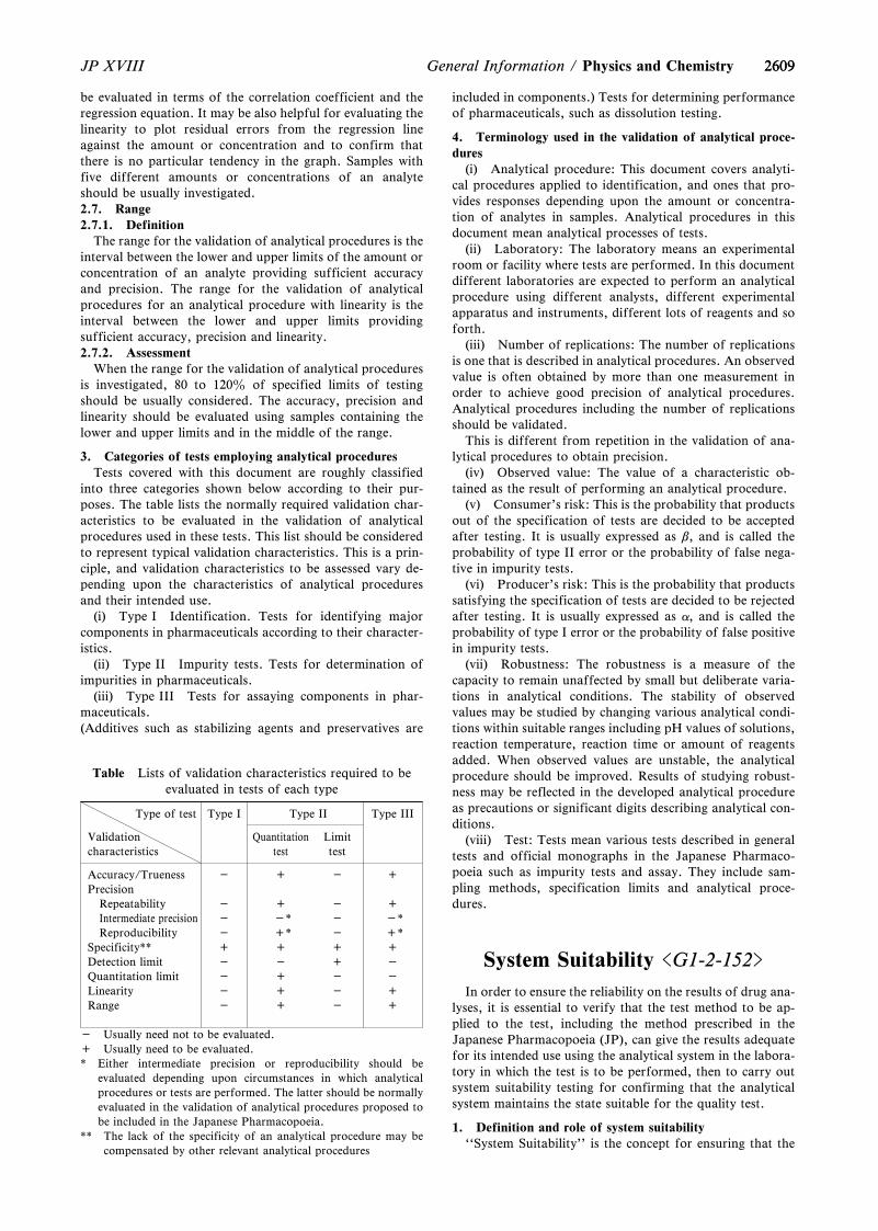
2609
Table Lists of validation characteristics required to beevaluated in tests of each type
Type of test Type I Type II Type III
Validationcharacteristics
Quantitationtest
Limittest
Accuracy/Trueness - + - +
PrecisionRepeatability - + - +
Intermediate precision - -* - -*Reproducibility - +* - +*
Specificity** + + + +
Detection limit - - + -
Quantitation limit - + - -
Linearity - + - +
Range - + - +
- Usually need not to be evaluated.+ Usually need to be evaluated.* Either intermediate precision or reproducibility should be
evaluated depending upon circumstances in which analyticalprocedures or tests are performed. The latter should be normallyevaluated in the validation of analytical procedures proposed tobe included in the Japanese Pharmacopoeia.
** The lack of the specificity of an analytical procedure may becompensated by other relevant analytical procedures
2609JP XVIII General Information / Physics and Chemistry
be evaluated in terms of the correlation coefficient and theregression equation. It may be also helpful for evaluating thelinearity to plot residual errors from the regression lineagainst the amount or concentration and to confirm thatthere is no particular tendency in the graph. Samples withfive different amounts or concentrations of an analyteshould be usually investigated.2.7. Range2.7.1. Definition
The range for the validation of analytical procedures is theinterval between the lower and upper limits of the amount orconcentration of an analyte providing sufficient accuracyand precision. The range for the validation of analyticalprocedures for an analytical procedure with linearity is theinterval between the lower and upper limits providingsufficient accuracy, precision and linearity.2.7.2. Assessment
When the range for the validation of analytical proceduresis investigated, 80 to 120z of specified limits of testingshould be usually considered. The accuracy, precision andlinearity should be evaluated using samples containing thelower and upper limits and in the middle of the range.
3. Categories of tests employing analytical proceduresTests covered with this document are roughly classified
into three categories shown below according to their pur-poses. The table lists the normally required validation char-acteristics to be evaluated in the validation of analyticalprocedures used in these tests. This list should be consideredto represent typical validation characteristics. This is a prin-ciple, and validation characteristics to be assessed vary de-pending upon the characteristics of analytical proceduresand their intended use.
(i) Type I Identification. Tests for identifying majorcomponents in pharmaceuticals according to their character-istics.
(ii) Type II Impurity tests. Tests for determination ofimpurities in pharmaceuticals.
(iii) Type III Tests for assaying components in phar-maceuticals.(Additives such as stabilizing agents and preservatives are
included in components.) Tests for determining performanceof pharmaceuticals, such as dissolution testing.
4. Terminology used in the validation of analytical proce-dures
(i) Analytical procedure: This document covers analyti-cal procedures applied to identification, and ones that pro-vides responses depending upon the amount or concentra-tion of analytes in samples. Analytical procedures in thisdocument mean analytical processes of tests.
(ii) Laboratory: The laboratory means an experimentalroom or facility where tests are performed. In this documentdifferent laboratories are expected to perform an analyticalprocedure using different analysts, different experimentalapparatus and instruments, different lots of reagents and soforth.
(iii) Number of replications: The number of replicationsis one that is described in analytical procedures. An observedvalue is often obtained by more than one measurement inorder to achieve good precision of analytical procedures.Analytical procedures including the number of replicationsshould be validated.
This is different from repetition in the validation of ana-lytical procedures to obtain precision.
(iv) Observed value: The value of a characteristic ob-tained as the result of performing an analytical procedure.
(v) Consumer's risk: This is the probability that productsout of the specification of tests are decided to be acceptedafter testing. It is usually expressed as b, and is called theprobability of type II error or the probability of false nega-tive in impurity tests.
(vi) Producer's risk: This is the probability that productssatisfying the specification of tests are decided to be rejectedafter testing. It is usually expressed as a, and is called theprobability of type I error or the probability of false positivein impurity tests.
(vii) Robustness: The robustness is a measure of thecapacity to remain unaffected by small but deliberate varia-tions in analytical conditions. The stability of observedvalues may be studied by changing various analytical condi-tions within suitable ranges including pH values of solutions,reaction temperature, reaction time or amount of reagentsadded. When observed values are unstable, the analyticalprocedure should be improved. Results of studying robust-ness may be reflected in the developed analytical procedureas precautions or significant digits describing analytical con-ditions.
(viii) Test: Tests mean various tests described in generaltests and official monographs in the Japanese Pharmaco-poeia such as impurity tests and assay. They include sam-pling methods, specification limits and analytical proce-dures.
System Suitability <G1-2-152>
In order to ensure the reliability on the results of drug ana-lyses, it is essential to verify that the test method to be ap-plied to the test, including the method prescribed in theJapanese Pharmacopoeia (JP), can give the results adequatefor its intended use using the analytical system in the labora-tory in which the test is to be performed, then to carry outsystem suitability testing for confirming that the analyticalsystem maintains the state suitable for the quality test.
1. Definition and role of system suitability``System Suitability'' is the concept for ensuring that the
2610
Table Allowable limits to be attained in the test at 3 – 5 replicate injections (n = 3 – 5) to keep the quality of test equivalentto that of test at n = 6*
Allowable limit (RSD)
Allowable limitprescribed in the test
of n = 61z 2z 3z 4z 5z 10z
Allowablelimit to be
attained
n = 5 0.88z 1.76z 2.64z 3.52z 4.40z 8.81z
n = 4 0.72z 1.43z 2.15z 2.86z 3.58z 7.16z
n = 3 0.47z 0.95z 1.42z 1.89z 2.37z 4.73z
* The probability for inadequate analytical systems to meet the requirements of system suitability testing, is supposed to be5z.
2610 JP XVIIIPhysics and Chemistry / General Information
performance of the analytical system is as suitable for theanalysis of the drug as was at the time when the verificationof the test method was performed using the system. Usually,system suitability testing should be carried out at every seriesof drug analysis. The test procedures and acceptance criteriaof system suitability testing must be prescribed in the testmethods of drugs. The results of drug analyses are not ac-ceptable unless the requirements of system suitability havebeen met.
System suitability testing is an integral part of testmethods using analytical instruments, and based on the con-cept that the equipments, electronic data processing systems,analytical operations, samples to be analyzed and operatorsconstitute an integral system that can be evaluated, when thetest procedures and acceptance criteria of system suitabilitytesting are prescribed in the test methods.
2. Points to consider in setting system suitabilityParameters of system suitability testing to be prescribed in
the test method depend on the intended use and type of ana-lytical method. Since system suitability testing is to be car-ried out in a routine manner, it is preferable to select theparameters necessary for ensuring that the analytical systemmaintains the state suitable for the analysis of the drug andto prescribe its test procedure able to carry out easily andrapidly.
For example, in the case of quantitative purity tests usingliquid chromatography or gas chromatography, the evalua-tion of parameters such as ``System performance'' (to con-firm the ability to analyze target substance specifically),``System repeatability'' (to confirm that the degree of varia-tion in the analytical results of target substance in replicateinjections is within the allowable limit) and ``Test for re-quired detectability'' (to confirm the linearity of chromato-graphic response around the specification limit) are usuallyrequired.
The followings are supplements to the section of systemsuitability prescribed in ``Liquid Chromatography''.2.1. System repeatability of HPLC and GC2.1.1. Allowable limit of system repeatability
It is described in the section of system suitability in ``Liq-uid Chromatography'' that ``In principle, total number ofreplicate injections should be 6'', and ``The allowable limitof ``System repeatability'' should be set at an appropriatelevel based on the data when suitability of the method forthe evaluation of quality of the drug was verified, and theprecision necessary for the quality test''. Based on the abovedescription, an allowable limit of system repeatability for 6replicate injections should be set in consideration with thefollowing descriptions. However, in the case that the testmethod prescribed in the JP monograph is used for the test,
the allowable limit of system repeatability prescribed in themonograph should be applied.
(i) Assay for drug substance (for drug substance with thecontent nearby 100z): An adequate allowable limit shouldbe set at the level that the chromatographic system is able togive the precision suitable for the evaluation of variation inthe content of active ingredient within and among thebatches of drug substance. For example, the allowable limitof ``not more than 1.0z'' is usually recommended for thedrug substances whose width of content specification are notmore than 5z, as is in the case of content specification of98.0 – 102.0z which is often observed in the assay using liq-uid chromatography.
(ii) Assay for drug products: An adequate allowablelimit should be set considering the width of content specifi-cation of the drug product and the allowable limit prescribedin the assay of drug substance (when the drug product is ana-lyzed by a method with the same chromatographic condi-tions as those used for the analysis of drug substance).
(iii) Purity test for related substances: An adequateallowable limit should be set considering the concentrationof active ingredients in the solution used for the systemrepeatability testing such as a standard solution or solutionfor system suitability testing. In the case that a solution withactive ingredient concentration of 0.5 – 1.0z is used for thetest of system repeatability, an allowable limit of ``not morethan 2.0z'' is usually recommended.
Recommendations for allowable limits described aboveshould not be applicable to gas chromatography.2.1.2. Method for decreasing the number of replicate injec-tions without losing the quality of system repeatability test-ing
It is described in the section of system suitability in ``Liq-uid Chromatography'' that ``In principle, total number ofreplicate injections should be 6. However, in the case that along time is necessary for one analysis, such as the analysisusing the gradient method, or the analysis of samples con-taining late eluting components, it may be acceptable todecrease the number of replicate injections by adopting newallowable limit of ``System repeatability'' which can guaran-tee a level of ``System repeatability'' equivalent to that at 6replicate injections.'' In consideration of the above descrip-tion, a method for decreasing the number of replicate injec-tions without losing the quality of system repeatability test-ing is described below. One can set the test for system repeat-ability with reduced number of replicate injections by utiliz-ing this method, if necessary, and routine quality tests can beperformed based on the same approach.
The following table shows the allowable limits to be at-tained in the test at 3 – 5 replicate injections (n = 3 – 5) to
26112611JP XVIII General Information / Physics and Chemistry
keep the quality test equivalent to that of test at n = 6.However, it should be kept in mind that since decrease in
the number of replicate injections results in increase in theweight of each injection, it becomes more important to per-form the test by the experienced operator, and to maintainthe equipment in a suitable state.
3. Points to consider at the change of analytical system(Change control of analytical system)
When the test method and analytical system verified iscontinuously used for the quality test without any change, itis sufficient to confirm the compliance to the requirementsof system suitability at every series of drug analysis.
However, when the test is performed for a long period, asituation in which some changes in the analytical system areinevitable, may occur. These changes don't affect the qualityof the product itself, but they affect the scale in the evalua-tion of product quality. If the change in the analytical systemmay induce a significant deviation of the scale, it may lead tothe acceptance of products with inadequate quality and/orthe rejection of products with adequate quality. Thus, at thetime of change in the analytical system, it is necessary tocheck whether the change is appropriate or not, to avoid thedeviation of the scale in the evaluation of product quality.
In the case of the change of test method, it is required toperform an adequate validation depending on the extent ofthe change. On the other hand, in the case of the change ofanalytical system in a laboratory, such as renewal of appa-ratus or column of liquid chromatography, and the changeof operator, it is necessary to perform at least system suita-bility testing using the system after change, and to confirmthat the equivalency of the results before and after change.
In the case that equivalent results would not be obtainedafter change, for example, when a renewal of column ofliquid chromatograph may induce a significant change ofelution pattern, such as the reversal of elution order betweentarget ingredient of the test and substance for checking reso-lution, it is required to perform a revalidation of the analyti-cal system for the test using new column, since it is uncertainwhether the specificity and/or other validation characteris-tics necessary for estimating target ingredient is kept or not.
Near Infrared Spectrometry<G1-3-161>
Near infrared spectrometry (NIR) is one of spectroscopicmethods used to qualitatively and quantitatively evaluatesubstances from analysis of data obtained by determiningtheir absorption spectrum of light in the near-infrared range.
The near-infrared range lies between the visible light andinfrared light, typically of wavelengths (wave numbers) be-tween 750 and 2500 nm (13,333 – 4000 cm-1). The absorp-tion of near-infrared light occurs due to harmonic overtonesfrom normal vibration or combination tones in the infraredrange (4000 to 400 cm-1), primarily absorption of O-H,N-H, C-H and S-H that involve hydrogen atoms, in particu-lar. For instance the asymmetrical stretching vibration ofN-H occurs in the vicinity of 3400 cm-1, but the absorptiondue to the first harmonic overtone occurs in the vicinity of6600 cm-1 (wavelength 1515 nm), which is near double3400 cm-1.
Absorption in the near-infrared range is far weaker thanabsorption due to normal vibration that occurs in the in-frared range. Furthermore, in comparison with visible light,near-infrared light has longer wavelength, which makes it
possible for the light to penetrate to a depth of several mminto solid specimens including fine particles. This method isoften utilized as a nondestructive analysis, as changes occur-ring with absorbed light spectrum (transmitted light orreflected light) in this process provide physical and chemicalinformation pertaining to specimens.
Conventional spectrometry, such as calibration curvemethod, is used as a method for analyzing near-infraredabsorption spectrum whenever applicable. Ordinarily,however, chemometrics methods are used for analysis.Chemometrics ordinarily involve quantification of chemicaldata, as well as numerical and statistical procedures forcomputerization of information. Chemometrics for near-infrared spectrometry includes various types of multivariateanalysis such as multiple regression analysis, to performqualitative or quantitative evaluation of active substances.
Near-infrared spectrometry is used as a rapid and nondes-tructive method of analysis that replaces conventional andestablished analysis methods for water determinations orsubstance verifications. It is necessary to perform a compari-son test to evaluate this method against an existing analysismethod, to verify that this method is equivalent to such ex-isting analysis method, before using this analysis method asa quality evaluation test method in routine tests.
Applications of near-infrared spectrometry in the phar-maceutical field include qualitative or quantitative evalua-tion of ingredients, additives or water contents of activesubstances or preparations. Furthermore, near-infraredspectrometry can also be used for evaluation of physicalconditions of substances, such as crystal forms, crystallinity,particle diameters. It is also possible to perform spectrome-try on samples that are located in a remote location awayfrom equipment main units, without sampling, by usingoptical fibers. It can therefore be used as an effective meansto perform pharmaceutical manufacturing process controlonline (or in-line).
1. EquipmentNear-infrared spectrophotometers can either be a dis-
tributed near-infrared spectrophotometer or a Fourier trans-form near-infrared spectrophotometer1). Interference filter-type near-infrared spectrophotometers that use interferencefilter in the spectrometry section are also available, however,this type of equipment is hardly used in the field of phar-maceutical quality control.1.1. Distributed near-infrared spectrophotometer
This equipment is comprised of light source section, sam-ple section, spectrometry section, photometry section, signalprocessing section, data processing section, display-record-output section. Halogen lamps, tungsten lamps, light emit-ting diodes and other such devices that can emit high inten-sity near-infrared light in a stable manner are used in thelight source section. The sample section is comprised of asample cell and a sample holder. Equipment that has an opti-cal fiber section that is comprised of optical fibers and a col-limator are equipped with a function for transmitting light tosample section, which is remotely located away from thespectrophotometer main unit. Quartz is ordinarily used asmaterial for optical fibers.
The spectrometry section is intended to extract light of re-quired wavelength, using dispersive devices and is comprisedof slits, mirrors and dispersive devices. Potential dispersivedevices include prisms, diffraction grating, acousto-opticaltunable filters (AOTF), or liquid crystal tunable filters(LCTF). The photometry section is comprised of detectorsand amplifiers. Sensors include semiconductor detectors(silicon, lead sulfide, indium-gallium-arsenic, indium-anti-
26122612 JP XVIIIPhysics and Chemistry / General Information
mony), as well as photomultiplier tubes. Detecting methodsthat use semiconductor detectors generally perform detec-tions with single elements, but there are also occasions wherearraytype detectors that use multiple elements are used. Suchdetectors are capable of simultaneously detecting multiplewavelengths (wave numbers). The signal processing sectionseparates signals required for measurements from output sig-nals fed by amplifiers and then outputs such isolated signals.The data processing section performs data conversions andspectral analysis, etc. The display-record-output section out-puts data, analysis results and data processing results to aprinter.1.2. Fourier transform near-infrared spectrophotometer
The configuration of the equipment is fundamentallysame as that of the distributed-type equipment described inSection 1.1., except for the spectrometry section and the sig-nal processing section.
The spectrometry section is comprised of interferometers,sampling signal generators, detectors, amplifiers, A/D con-version devices, etc. Interferometers include Michelson inter-ferometers, transept interferometers and polarization inter-ferometers. The signal processing section is equipped withfunctions that are required for spectrometer, as well as afunction for translating acquired interference waveform(interferogram) into absorption spectrum by Fourier trans-formation.
2. DeterminationThere are three types of measurement methods that are
used with near-infrared spectrometry: transmittancemethod, diffuse reflectance method and transmittancereflectance method. The selection of measurement methodsrelies on the shape of samples and applications. The trans-mittance method or diffuse reflectance method is used forsolid samples, including fine particles. The transmittancemethod or transmittance reflectance method is used for liq-uid samples.2.1. Transmittance method
The degree of decay for incident light intensity as the lightfrom a light source passes through a sample, is representedas transmittance rate T (z) or absorbance A with the trans-mittance method. A sample is placed in the light path be-tween a light source and a detector, the arrangement ofwhich is ordinarily same as that of the spectroscopic method.
T = 100tt = I/I0 = 10-acl
I0: Incident light intensityI: Transmitted light intensitya: Absorptivityc: Solution concentrationl: Layer length (sample thickness)
A = -log t = log (1/t ) = log (I0/I ) = acl
This method is applied for taking measurements of sam-ples that are liquids and solutions. Quartz glass cells andflow cells are used, with the layer length of 1 – 5 mm along.Furthermore, this method can also be applied for takingmeasurements of samples that are solids, including fine par-ticles. It is also known as diffuse transmittance method.Selecting appropriate layer length is critical for this method,since the transmitted light intensity varies depending ongrain sizes and surface condition of samples.2.2. Diffuse reflectance method
The ratio of the reflection light intensity I, emitted fromthe sample in a wide reflectance range and a control reflec-tion light intensity Ir emitted from surface of a substance, is
expressed as reflectance R (z) with the diffuse reflectancemethod. The near-infrared light penetrates to a depth ofseveral mm into solid samples, including fine particles. Inthat process, transmission, refraction, reflection and disper-sion are repeated, and diffusion takes place, but a portion ofthe diffused light is emitted again from the surface of thesample and captured by a detector. The spectrum for thediffuse reflectance absorbance (Ar) can ordinarily be ob-tained by plotting logarithm of inverse numbers for reflec-tance (1/r) against wavelengths (wave numbers).
R = 100rr = I/Ir
I: Reflection light intensity of light, diffuse reflected offthe sample
Ir: Control reflection light intensity of light emitted fromsurface of reference substance
Ar = log (1/r) = log (Ir/I )
The intensity of diffuse reflectance spectrum can also beexpressed with the Kubelka-Munk (K-M) function. The K-Mfunction is derived, based on the existence of a sample withsufficient thickness, and expressed in terms of light scatter-ing coefficient, which is determined by absorptivity, grainsize, shape and fill condition (compression).
This method is applied to solid samples, including fineparticles, and requires a diffuse reflector.2.3. Transmittance reflectance method
The transmittance reflectance method is a combination ofthe transmittance method and reflectance method. A mirroris used to re-reflect a light that has passed through a samplein order to take a measurement of transmittance reflectancerate, T* (z). Light path must be twice the thickness of thesample. On the other hand, the light reflected by a mirrorand being introduced into a detector is used as the controllight. When this method is applied to suspended samples,however, a metal plate or a ceramic reflector with rough sur-face that causes diffuse reflectance is used instead of a mir-ror.
Transmittance reflectance absorbance (A*) is obtained bythe following formula with this method:
T* = 100t*t* = I/IT
I: Intensity of transmitted and reflected light, in caseswhere a sample is placed
IT: Intensity of reflected light, in cases where there is nosample
A* = log (1/t*)
This is a method that is applied to solid samples, includingfine particles, as well as liquids and suspended samples. Thethickness of a sample must be adjusted when applying thismethod to a solid sample. Ordinarily adjustment is made bysetting absorbance to 0.1 – 2 (transmittance of 79 – 1z),which provides the best linearity and SN ratio of detector. Acell with appropriate layer length, according to the grain sizeof the fine particle, must be selected when applying themethod to a fine particle sample.
3. Factors that affect spectrumFollowing items must be considered as factors that can
affect spectrum when applying near-infrared spectrometry,particularly when conducting quantitative analysis.
(i) Sample temperature: A significant change (wave-length shift, for example) can occur when the temperaturevaries by a several degree (9C). Care must be taken, particu-
26132613JP XVIII General Information / Physics and Chemistry
larly when the sample is a solution or contains water.(ii) Water or residual solvent: Water or residual solvent
contents of a sample, as well as water (humidity) in the en-vironment wherein measurements are taken, can significant-ly affect absorption band of the near-infrared range.
(iii) Sample thickness: The thickness of a sample is a fac-tor for spectral changes and therefore needs to be controlledat a certain thickness. A sample may be considered to be ofadequate thickness for the diffuse reflectance method,however, if the thickness is less than a certain amount, forexample, the sample may have to be placed on a supportplate with high reflectance to take measurements by thetransmittance reflectance method.
(iv) Fill condition of sample: The condition of sample fillcan potentially affect a spectrum, when taking measure-ments of samples that are solids or fine particles. Care mustbe taken with filling samples in a cell, to ensure that a certainamount is filled through a specific procedure.
(v) Optical characteristics of samples: When a sample isphysically, chemically or optically uneven, relatively largebeam size must be used, multiple samples must be used,measurements must be taken at multiple points on the samesamples, or a sample must be pulverized to ensure averagingof the sample. Grain size, fill condition, as well as roughnessof surface can also affect fine particle samples.
(vi) Polymorphism: Variations in crystal structures(polymorphism) can also affect spectrum. In cases wheremultiple crystal forms exist, it is necessary to have considera-tion for characteristics of samples to be considered and caremust be taken to ensure that even standard samples forcalibration curve method have diversified distributions simi-lar to that of samples that are subject to analysis.
(vii) Temporal changes in characteristics of samples:Samples can potentially undergo chemical, physical or opti-cal property changes, due to passing of time or storage aftersampling, and such changes affect spectrum in a subtlemanner. For instance even with identical samples, if elapsedtimes differ, then their characteristics of near-infrared spec-trum can vary significantly. In creating calibration curves,therefore, the samples to be used must be prepared with ade-quate considerations for reducing the time to be measured,such as the measurement is carried out offline in a laborato-ry or online in manufacturing process (or inline).
4. Control of equipment performance2,3)
4.1. Accuracy of wavelengths (wave numbers)The accuracy of wavelengths (wave numbers) of an equip-
ment is derived from the deviation of the absorption peaksof substances for which peak absorption wavelengths (wavenumbers) have been defined, such as polystyrene, mixture ofrare earth oxides (dysprosium, holmium and erbium; 1:1:1)or steam, from the figures indicated on the equipment.Tolerance figures in the vicinity of 3 peaks are ordinarily setin the following manner, though appropriate tolerancefigures can be set, depending on the intended purpose:
1200 ± 1 nm (8300 ± 8 cm-1)1600 ± 1 nm (6250 ± 4 cm-1)2000 ± 1.5 nm (5000 ± 4 cm-1)
Since the location of absorption peaks vary, depending onthe substance used as reference, absorption peaks of wave-lengths (wave numbers) that are closest to the above 3 peaksare selected for suitability evaluations. A mixture of rareearth oxides, for instance, would indicate characteristic ab-sorption peaks at 1261 nm, 1681 nm and 1971 nm.
Absorption peaks at 1155 nm, 1417 nm, 1649 nm, 2352nm (layer length: 1.0 nm) can be used, when taking measure-
ments with the transmittance method that involve the use ofdichloromethane as reference. The absorption peak of steamat 7306.7 cm-1 can be used with a Fourier transformation-type spectrophotometer, as its wave number resolution abil-ity is high.
Other substances can also be used as reference, so long astheir adequacy for the purpose can be verified.4.2. Spectroscopic linearity
Appropriate standard plates, such as plate-shaped poly-mer impregnated with varying concentrations of carbon(Carbon-doped polymer standards), can be used to evaluatespectroscopic linearity. In order to verify linearity, however,standard plates with not less than 4 levels of concentrationwithin the reflectance of 10 – 90z must be used. When mea-surements are expected to be taken with absorbance of noless than 1.0, it is necessary to add standard plates withreflectance of either 2z or 5z or both.
In order to plot absorbance (AOBS) of such standard platesat locations in the vicinity of wavelengths 1200 nm, 1600 nmand 2000 nm against absorbance (AREF) assigned to eachstandard plate, verifications must be made to ensure that thegradient of linearity obtained are ordinarily within the range1.0 ± 0.05 for each of these wavelengths and 0 ± 0.05 forordinate intercept. Depending on the intended purpose, ap-propriate tolerance figures can be set.4.3. Spectrophotometric noise
The spectrophotometric noise of the equipment can bechecked using appropriate reflectance standard plates, suchas white-colored reflecting ceramic tiles or reflective ther-moplastic resin (such as polytetrafluoroethylene).4.3.1. High flux noise
Spectrophotometric noise is evaluated by using standardplates with high reflectance, such as reflectance of 99z.Standard plates are used to take measurements for both sam-ples and control samples. Generally, the average value ob-tained from calculation of mean square root (RMS) of noisefor each 100 nm segments in the wavelength range of 1200 –2200 nm ordinarily must not be more than 0.3 × 10⁻³ andindividual values must not exceed 0.8 × 10⁻³. Depending onthe intended purpose, appropriate tolerance figures can beset.
RMS ={1/N・S (Ai - Am)2}1/2
N: Number of measurement points per segmentAi: Absorbance at each measurement point of segmentAm: Average absorbance for segment
4.3.2. Low flux noiseSpectrophotometric noise is evaluated by using standard
plates with low reflectance, such as reflectance of 10z,when the amount of light is low. In such cases, light source,optical system, detector and electronic circuit systems allhave some impact on noise. Similar to the cases of high fluxnoise, generally, the average value obtained from calculationof RMS for each 100 nm segments in the wavelength rangeof 1200 – 2200 nm ordinarily must not be more than 1.0 ×10⁻³ and individual values must not exceed 2.0 × 10⁻³.Depending on the intended purpose, appropriate tolerancefigures can be set.
5. Application of qualitative or quantitative analysisUnlike in the infrared range, mainly harmonic overtones
and combinations manifest as spectrum in the near-infraredrange. Such absorbance spectrums are often observed asoverlay of absorption bands of functional groups and atomicgroups. The near-infrared spectrometry, therefore, differsfrom conventional analysis methods that correspond to eachapplication, by preparing model analysis methods using
26142614 JP XVIIISolid-state Properties / General Information
methodologies of chemometrics, such as multivariate analy-sis, and needs to establish analytical methods depending onthe intended purpose.
Characteristics of near-infrared absorption spectrum mustbe emphasized and effects of complexities of spectrums, aswell as overlay of absorption bands must be reduced by per-forming mathematical preprocesses, such as primary or sec-ondary spectral differentiation processes or normalizations,which becomes one of vital procedures in establishing analy-sis methods that use methodologies of chemometrics. Whilethere are many chemometrics methodologies and mathemati-cal preprocessing methods for data, appropriate combina-tions must be selected that suit the purposes of intendedanalysis.
Evaluation of validity based on analysis parameters is or-dinarily required for the analysis validation when establish-ing a near-infrared analysis method. Selection of parametersthat are appropriate for applications must be made for itsintended use. Furthermore, following issues must be consi-dered, in conformity with attributes of the near-infraredspectrometry.
(i) Whether or not wavelengths (wave numbers) intendedfor the particular analysis method, are suitable for evalua-tion of characteristics of a sample in performing analysisunder given conditions.
(ii) Whether or not the method is adequately robust todeal with variables such as handling of samples (for instancefill condition for fine particle samples, etc.) and configura-tion matrix.
(iii) Whether or not about the same level of accuracy orprecision can be obtained, in comparison with the existingand established analysis methods, which are available asstandards.
(iv) Sustaining and managing performance of an analysismethod, once established, are critical. Continuous and sys-tematic maintenance and inspection work must therefore beimplemented. Furthermore, it must be determined whetheror not appropriate evaluation procedures are available todeal with change controls or implementation of re-validationon changes made in manufacturing processes or raw mate-rials, as well as changes arising from replacement of majorcomponents in equipment.
(v) Whether or not there are appropriate evaluationprocedures in place to verify validity of transferring im-plementation of an analysis, which presupposed the use of aspecific equipment, from such originally intended equipmentto another equipment (model transfer) for the purpose ofsharing the analysis method.5.1. Qualitative analysis
Qualitative analysis, such as verification of substances, isperformed after preparing a reference library that includesinter-lot variations within tolerance range and establishinganalytical methods by using chemometrics methodologies,such as multivariate analysis. Minute quality characteristicvariations between lots can also be established by using thismethod.
Furthermore, multivariate analysis includes direct analysismethods that consider wavelengths (wave numbers) andabsorption as variables, such as wavelength correlationmethod, residual sum of squares, range sum of squares,along with factor analysis method, cluster analysis method,discriminant analysis method, as well as SIMCA (Soft in-dependent modeling of class analogy), which are appliedafter preprocessing such as principal component analysis.
It is also possible to consider the overall near-infraredabsorption spectrum as a single pattern and to identifyparameters obtained by applying multivariate analysis
methods or peak heights at characteristic wavelengths (wavenumbers) peaks of the sample substance as indices formonitoring, for the purpose of manufacturing process con-trol for active substances or preparations.5.2. Quantitative analysis
Quantitative analysis uses spectrums of sample groups andanalysis values obtained through the existing and establishedanalysis methods, to obtain quantitative models withmethodologies of chemometrics. These are used to calculateconcentrations of individual ingredients and material valuesof samples being measured, using conversion formulas.Chemometrics methodologies for obtaining quantitativemodels include multiple regression analysis method, main in-gredient regression analysis method and PLS (Partial leastsquares) regression analysis method.
In cases where the composition of a sample is simple, con-centrations of ingredients in the sample that are subject toanalysis can be calculated, by plotting a calibration curveusing the absorbance of a specific wavelength (wave number)or the correlating relationship between the parameters andconcentration, using samples for preparation of calibrationcurves with known concentrations (calibration curvemethod).
6. References1) JIS K 0134 (2002), Japanese Industrial Standards,
General Rules for Near-infrared SpectrophotometricAnalysis
2) Near-Infrared Spectrophotometry, 2.2.40, EuropeanPharmacopoeia 5.0 (2005)
3) Near-Infrared Spectrophotometry, <1119>, US Pharma-copeia 30 (2007)
G2 Solid-state Properties
Solid and Particle Densities<G2-1-171>
Density of a solid or a powder as a state of aggregationhas different definitions depending on the way of includingof the interparticulate and intraparticulate voids that existbetween the particles or inside the powder. Different figuresare obtained in each case, and there are different practicalmeanings. Generally, there are three levels of definitions ofthe solid or powder density.
(1) Crystal density: It is assumed that the system is ho-mogeneous with no intraparticulate void. Crystal density isalso called true density.
(2) Particle density: The sealed pores or the experimen-tally non-accessible open pores are also included as a part ofthe volumes of the solid or the powder.
(3) Bulk density: The interparticulate void formed in thepowder bed is also included as a part of the volumes of thesolid or the powder. Bulk density is also called apparent den-sity. Generally, the powder densities at loose packing and attapping are defined as the bulk density and the tapped den-sity, respectively.
Generally, the densities of liquid or gas are affected onlyby temperature and pressure, but the solid or powder densityis affected by the state of aggregation of the molecules or theparticles. Therefore, the solid or powder densities naturallyvary depending on crystal structure or crystallinity of thesubstance concerned, and also varies depending on themethod of preparation or handling if the sample is amor-
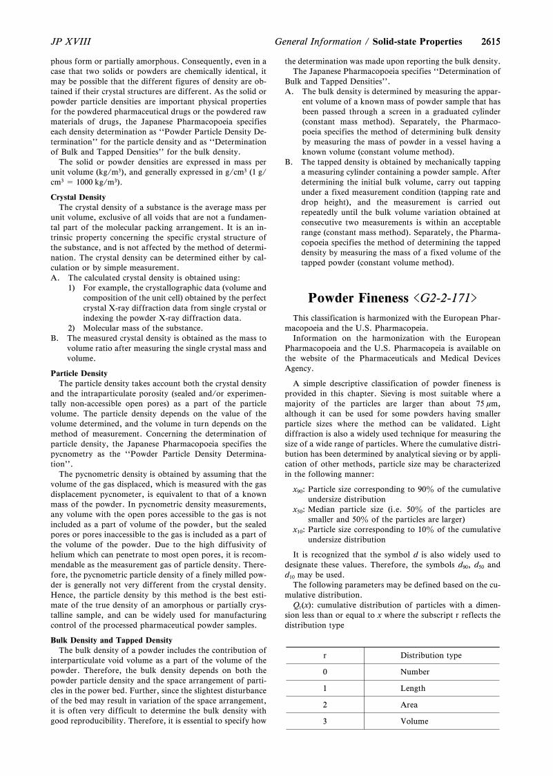
2615
r Distribution type
0 Number
1 Length
2 Area
3 Volume
2615JP XVIII General Information / Solid-state Properties
phous form or partially amorphous. Consequently, even in acase that two solids or powders are chemically identical, itmay be possible that the different figures of density are ob-tained if their crystal structures are different. As the solid orpowder particle densities are important physical propertiesfor the powdered pharmaceutical drugs or the powdered rawmaterials of drugs, the Japanese Pharmacopoeia specifieseach density determination as ``Powder Particle Density De-termination'' for the particle density and as ``Determinationof Bulk and Tapped Densities'' for the bulk density.
The solid or powder densities are expressed in mass perunit volume (kg/m3), and generally expressed in g/cm3 (1 g/cm3 = 1000 kg/m3).
Crystal DensityThe crystal density of a substance is the average mass per
unit volume, exclusive of all voids that are not a fundamen-tal part of the molecular packing arrangement. It is an in-trinsic property concerning the specific crystal structure ofthe substance, and is not affected by the method of determi-nation. The crystal density can be determined either by cal-culation or by simple measurement.A. The calculated crystal density is obtained using:
1) For example, the crystallographic data (volume andcomposition of the unit cell) obtained by the perfectcrystal X-ray diffraction data from single crystal orindexing the powder X-ray diffraction data.
2) Molecular mass of the substance.B. The measured crystal density is obtained as the mass to
volume ratio after measuring the single crystal mass andvolume.
Particle DensityThe particle density takes account both the crystal density
and the intraparticulate porosity (sealed and/or experimen-tally non-accessible open pores) as a part of the particlevolume. The particle density depends on the value of thevolume determined, and the volume in turn depends on themethod of measurement. Concerning the determination ofparticle density, the Japanese Pharmacopoeia specifies thepycnometry as the ``Powder Particle Density Determina-tion''.
The pycnometric density is obtained by assuming that thevolume of the gas displaced, which is measured with the gasdisplacement pycnometer, is equivalent to that of a knownmass of the powder. In pycnometric density measurements,any volume with the open pores accessible to the gas is notincluded as a part of volume of the powder, but the sealedpores or pores inaccessible to the gas is included as a part ofthe volume of the powder. Due to the high diffusivity ofhelium which can penetrate to most open pores, it is recom-mendable as the measurement gas of particle density. There-fore, the pycnometric particle density of a finely milled pow-der is generally not very different from the crystal density.Hence, the particle density by this method is the best esti-mate of the true density of an amorphous or partially crys-talline sample, and can be widely used for manufacturingcontrol of the processed pharmaceutical powder samples.
Bulk Density and Tapped DensityThe bulk density of a powder includes the contribution of
interparticulate void volume as a part of the volume of thepowder. Therefore, the bulk density depends on both thepowder particle density and the space arrangement of parti-cles in the power bed. Further, since the slightest disturbanceof the bed may result in variation of the space arrangement,it is often very difficult to determine the bulk density withgood reproducibility. Therefore, it is essential to specify how
the determination was made upon reporting the bulk density.The Japanese Pharmacopoeia specifies ``Determination of
Bulk and Tapped Densities''.A. The bulk density is determined by measuring the appar-
ent volume of a known mass of powder sample that hasbeen passed through a screen in a graduated cylinder(constant mass method). Separately, the Pharmaco-poeia specifies the method of determining bulk densityby measuring the mass of powder in a vessel having aknown volume (constant volume method).
B. The tapped density is obtained by mechanically tappinga measuring cylinder containing a powder sample. Afterdetermining the initial bulk volume, carry out tappingunder a fixed measurement condition (tapping rate anddrop height), and the measurement is carried outrepeatedly until the bulk volume variation obtained atconsecutive two measurements is within an acceptablerange (constant mass method). Separately, the Pharma-copoeia specifies the method of determining the tappeddensity by measuring the mass of a fixed volume of thetapped powder (constant volume method).
Powder Fineness <G2-2-171>
This classification is harmonized with the European Phar-macopoeia and the U.S. Pharmacopeia.
Information on the harmonization with the EuropeanPharmacopoeia and the U.S. Pharmacopeia is available onthe website of the Pharmaceuticals and Medical DevicesAgency.
A simple descriptive classification of powder fineness isprovided in this chapter. Sieving is most suitable where amajority of the particles are larger than about 75 mm,although it can be used for some powders having smallerparticle sizes where the method can be validated. Lightdiffraction is also a widely used technique for measuring thesize of a wide range of particles. Where the cumulative distri-bution has been determined by analytical sieving or by appli-cation of other methods, particle size may be characterizedin the following manner:
x90: Particle size corresponding to 90z of the cumulativeundersize distribution
x50: Median particle size (i.e. 50z of the particles aresmaller and 50z of the particles are larger)
x10: Particle size corresponding to 10z of the cumulativeundersize distribution
It is recognized that the symbol d is also widely used todesignate these values. Therefore, the symbols d90, d50 andd10 may be used.
The following parameters may be defined based on the cu-mulative distribution.
Qr(x): cumulative distribution of particles with a dimen-sion less than or equal to x where the subscript r reflects thedistribution type
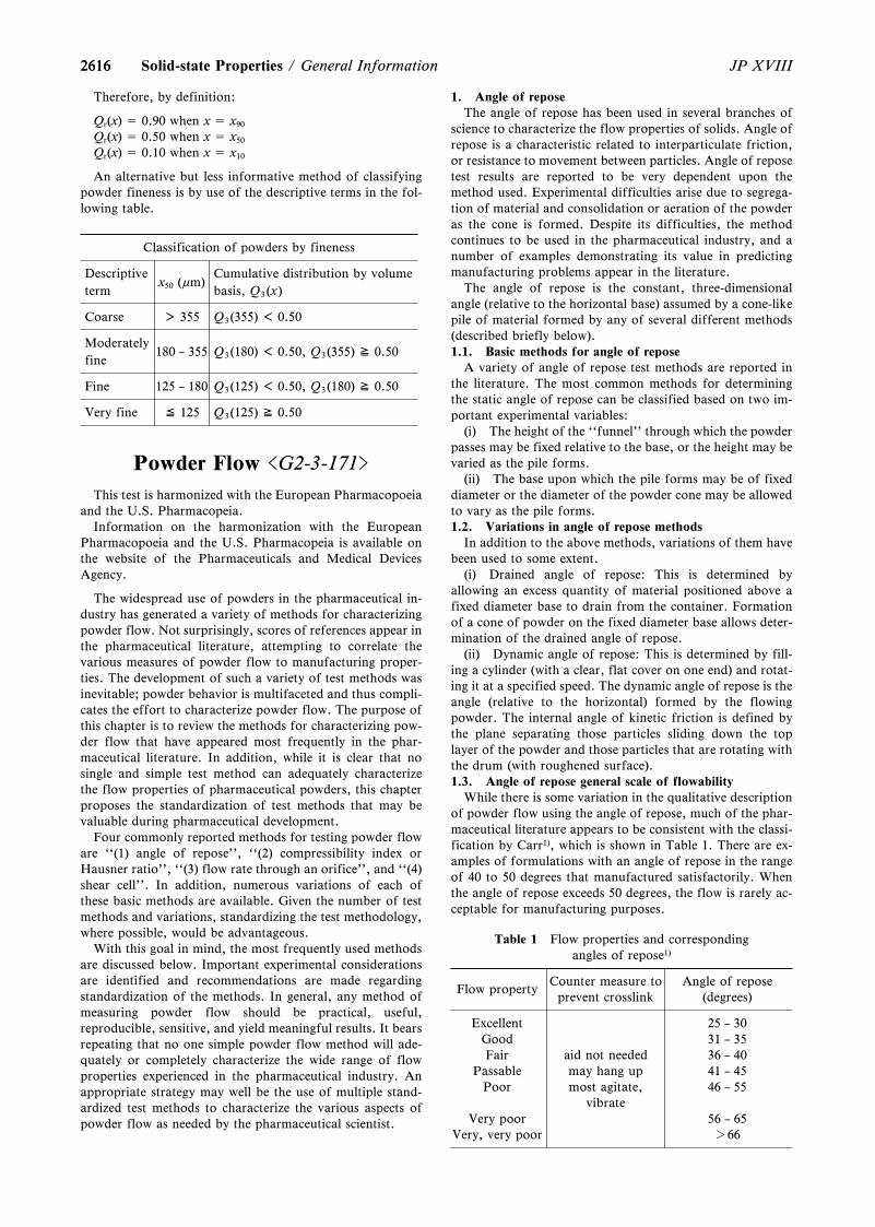
2616
Classification of powders by fineness
Descriptiveterm
x50 (mm)Cumulative distribution by volumebasis, Q3(x)
Coarse > 355 Q3(355) < 0.50
Moderatelyfine
180 – 355 Q3(180) < 0.50, Q3(355) ≧ 0.50
Fine 125 – 180 Q3(125) < 0.50, Q3(180) ≧ 0.50
Very fine ≦ 125 Q3(125) ≧ 0.50
2616 JP XVIIISolid-state Properties / General Information
Therefore, by definition:
Qr(x) = 0.90 when x = x90
Qr(x) = 0.50 when x = x50
Qr(x) = 0.10 when x = x10
An alternative but less informative method of classifyingpowder fineness is by use of the descriptive terms in the fol-lowing table.
Powder Flow <G2-3-171>
This test is harmonized with the European Pharmacopoeiaand the U.S. Pharmacopeia.
Information on the harmonization with the EuropeanPharmacopoeia and the U.S. Pharmacopeia is available onthe website of the Pharmaceuticals and Medical DevicesAgency.
The widespread use of powders in the pharmaceutical in-dustry has generated a variety of methods for characterizingpowder flow. Not surprisingly, scores of references appear inthe pharmaceutical literature, attempting to correlate thevarious measures of powder flow to manufacturing proper-ties. The development of such a variety of test methods wasinevitable; powder behavior is multifaceted and thus compli-cates the effort to characterize powder flow. The purpose ofthis chapter is to review the methods for characterizing pow-der flow that have appeared most frequently in the phar-maceutical literature. In addition, while it is clear that nosingle and simple test method can adequately characterizethe flow properties of pharmaceutical powders, this chapterproposes the standardization of test methods that may bevaluable during pharmaceutical development.
Four commonly reported methods for testing powder floware ``(1) angle of repose'', ``(2) compressibility index orHausner ratio'', ``(3) flow rate through an orifice'', and ``(4)shear cell''. In addition, numerous variations of each ofthese basic methods are available. Given the number of testmethods and variations, standardizing the test methodology,where possible, would be advantageous.
With this goal in mind, the most frequently used methodsare discussed below. Important experimental considerationsare identified and recommendations are made regardingstandardization of the methods. In general, any method ofmeasuring powder flow should be practical, useful,reproducible, sensitive, and yield meaningful results. It bearsrepeating that no one simple powder flow method will ade-quately or completely characterize the wide range of flowproperties experienced in the pharmaceutical industry. Anappropriate strategy may well be the use of multiple stand-ardized test methods to characterize the various aspects ofpowder flow as needed by the pharmaceutical scientist.
1. Angle of reposeThe angle of repose has been used in several branches of
science to characterize the flow properties of solids. Angle ofrepose is a characteristic related to interparticulate friction,or resistance to movement between particles. Angle of reposetest results are reported to be very dependent upon themethod used. Experimental difficulties arise due to segrega-tion of material and consolidation or aeration of the powderas the cone is formed. Despite its difficulties, the methodcontinues to be used in the pharmaceutical industry, and anumber of examples demonstrating its value in predictingmanufacturing problems appear in the literature.
The angle of repose is the constant, three-dimensionalangle (relative to the horizontal base) assumed by a cone-likepile of material formed by any of several different methods(described briefly below).1.1. Basic methods for angle of repose
A variety of angle of repose test methods are reported inthe literature. The most common methods for determiningthe static angle of repose can be classified based on two im-portant experimental variables:
(i) The height of the ``funnel'' through which the powderpasses may be fixed relative to the base, or the height may bevaried as the pile forms.
(ii) The base upon which the pile forms may be of fixeddiameter or the diameter of the powder cone may be allowedto vary as the pile forms.1.2. Variations in angle of repose methods
In addition to the above methods, variations of them havebeen used to some extent.
(i) Drained angle of repose: This is determined byallowing an excess quantity of material positioned above afixed diameter base to drain from the container. Formationof a cone of powder on the fixed diameter base allows deter-mination of the drained angle of repose.
(ii) Dynamic angle of repose: This is determined by fill-ing a cylinder (with a clear, flat cover on one end) and rotat-ing it at a specified speed. The dynamic angle of repose is theangle (relative to the horizontal) formed by the flowingpowder. The internal angle of kinetic friction is defined bythe plane separating those particles sliding down the toplayer of the powder and those particles that are rotating withthe drum (with roughened surface).1.3. Angle of repose general scale of flowability
While there is some variation in the qualitative descriptionof powder flow using the angle of repose, much of the phar-maceutical literature appears to be consistent with the classi-fication by Carr1), which is shown in Table 1. There are ex-amples of formulations with an angle of repose in the rangeof 40 to 50 degrees that manufactured satisfactorily. Whenthe angle of repose exceeds 50 degrees, the flow is rarely ac-ceptable for manufacturing purposes.
Table 1 Flow properties and correspondingangles of repose1)
Flow propertyCounter measure toprevent crosslink
Angle of repose(degrees)
Excellent 25 – 30Good 31 – 35Fair aid not needed 36 – 40
Passable may hang up 41 – 45Poor most agitate,
vibrate46 – 55
Very poor 56 – 65Very, very poor >66
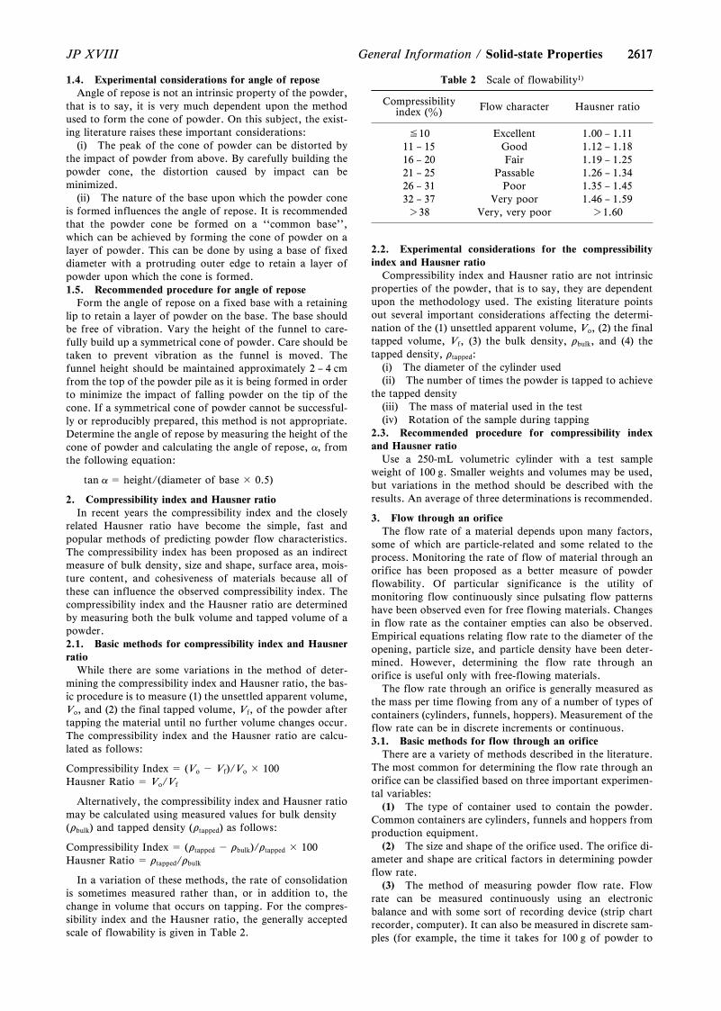
26172617JP XVIII General Information / Solid-state Properties
1.4. Experimental considerations for angle of reposeAngle of repose is not an intrinsic property of the powder,
that is to say, it is very much dependent upon the methodused to form the cone of powder. On this subject, the exist-ing literature raises these important considerations:
(i) The peak of the cone of powder can be distorted bythe impact of powder from above. By carefully building thepowder cone, the distortion caused by impact can beminimized.
(ii) The nature of the base upon which the powder coneis formed influences the angle of repose. It is recommendedthat the powder cone be formed on a ``common base'',which can be achieved by forming the cone of powder on alayer of powder. This can be done by using a base of fixeddiameter with a protruding outer edge to retain a layer ofpowder upon which the cone is formed.1.5. Recommended procedure for angle of repose
Form the angle of repose on a fixed base with a retaininglip to retain a layer of powder on the base. The base shouldbe free of vibration. Vary the height of the funnel to care-fully build up a symmetrical cone of powder. Care should betaken to prevent vibration as the funnel is moved. Thefunnel height should be maintained approximately 2 – 4 cmfrom the top of the powder pile as it is being formed in orderto minimize the impact of falling powder on the tip of thecone. If a symmetrical cone of powder cannot be successful-ly or reproducibly prepared, this method is not appropriate.Determine the angle of repose by measuring the height of thecone of powder and calculating the angle of repose, a, fromthe following equation:
tan a = height/(diameter of base × 0.5)
2. Compressibility index and Hausner ratioIn recent years the compressibility index and the closely
related Hausner ratio have become the simple, fast andpopular methods of predicting powder flow characteristics.The compressibility index has been proposed as an indirectmeasure of bulk density, size and shape, surface area, mois-ture content, and cohesiveness of materials because all ofthese can influence the observed compressibility index. Thecompressibility index and the Hausner ratio are determinedby measuring both the bulk volume and tapped volume of apowder.2.1. Basic methods for compressibility index and Hausnerratio
While there are some variations in the method of deter-mining the compressibility index and Hausner ratio, the bas-ic procedure is to measure (1) the unsettled apparent volume,Vo, and (2) the final tapped volume, Vf, of the powder aftertapping the material until no further volume changes occur.The compressibility index and the Hausner ratio are calcu-lated as follows:
Compressibility Index = (Vo - Vf)/Vo × 100Hausner Ratio = Vo/Vf
Alternatively, the compressibility index and Hausner ratiomay be calculated using measured values for bulk density(rbulk) and tapped density (rtapped) as follows:
Compressibility Index = (rtapped - rbulk)/rtapped × 100Hausner Ratio = rtapped/rbulk
In a variation of these methods, the rate of consolidationis sometimes measured rather than, or in addition to, thechange in volume that occurs on tapping. For the compres-sibility index and the Hausner ratio, the generally acceptedscale of flowability is given in Table 2.
Table 2 Scale of flowability1)
Compressibilityindex (z) Flow character Hausner ratio
≦10 Excellent 1.00 – 1.1111 – 15 Good 1.12 – 1.1816 – 20 Fair 1.19 – 1.2521 – 25 Passable 1.26 – 1.3426 – 31 Poor 1.35 – 1.4532 – 37 Very poor 1.46 – 1.59>38 Very, very poor >1.60
2.2. Experimental considerations for the compressibilityindex and Hausner ratio
Compressibility index and Hausner ratio are not intrinsicproperties of the powder, that is to say, they are dependentupon the methodology used. The existing literature pointsout several important considerations affecting the determi-nation of the (1) unsettled apparent volume, Vo, (2) the finaltapped volume, Vf, (3) the bulk density, rbulk, and (4) thetapped density, rtapped:
(i) The diameter of the cylinder used(ii) The number of times the powder is tapped to achieve
the tapped density(iii) The mass of material used in the test(iv) Rotation of the sample during tapping
2.3. Recommended procedure for compressibility indexand Hausner ratio
Use a 250-mL volumetric cylinder with a test sampleweight of 100 g. Smaller weights and volumes may be used,but variations in the method should be described with theresults. An average of three determinations is recommended.
3. Flow through an orificeThe flow rate of a material depends upon many factors,
some of which are particle-related and some related to theprocess. Monitoring the rate of flow of material through anorifice has been proposed as a better measure of powderflowability. Of particular significance is the utility ofmonitoring flow continuously since pulsating flow patternshave been observed even for free flowing materials. Changesin flow rate as the container empties can also be observed.Empirical equations relating flow rate to the diameter of theopening, particle size, and particle density have been deter-mined. However, determining the flow rate through anorifice is useful only with free-flowing materials.
The flow rate through an orifice is generally measured asthe mass per time flowing from any of a number of types ofcontainers (cylinders, funnels, hoppers). Measurement of theflow rate can be in discrete increments or continuous.3.1. Basic methods for flow through an orifice
There are a variety of methods described in the literature.The most common for determining the flow rate through anorifice can be classified based on three important experimen-tal variables:
(1) The type of container used to contain the powder.Common containers are cylinders, funnels and hoppers fromproduction equipment.
(2) The size and shape of the orifice used. The orifice di-ameter and shape are critical factors in determining powderflow rate.
(3) The method of measuring powder flow rate. Flowrate can be measured continuously using an electronicbalance and with some sort of recording device (strip chartrecorder, computer). It can also be measured in discrete sam-ples (for example, the time it takes for 100 g of powder to
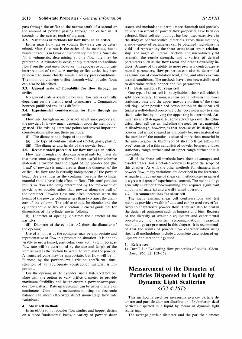
26182618 JP XVIIISolid-state Properties / General Information
pass through the orifice to the nearest tenth of a second orthe amount of powder passing through the orifice in 10seconds to the nearest tenth of a gram).3.2. Variations in methods for flow through an orifice
Either mass flow rate or volume flow rate can be deter-mined. Mass flow rate is the easier of the methods, but itbiases the results in favor of high-density materials. Since diefill is volumetric, determining volume flow rate may bepreferable. A vibrator is occasionally attached to facilitateflow from the container, however, this appears to complicateinterpretation of results. A moving orifice device has beenproposed to more closely simulate rotary press conditions.The minimum diameter orifice through which powder flowscan also be identified.3.3. General scale of flowability for flow through anorifice
No general scale is available because flow rate is criticallydependent on the method used to measure it. Comparisonbetween published results is difficult.3.4. Experimental considerations for flow through anorifice
Flow rate through an orifice is not an intrinsic property ofthe powder. It is very much dependent upon the methodolo-gy used. The existing literature points out several importantconsiderations affecting these methods:
(i) The diameter and shape of the orifice(ii) The type of container material (metal, glass, plastic)(iii) The diameter and height of the powder bed.
3.5. Recommended procedure for flow through an orificeFlow rate through an orifice can be used only for materials
that have some capacity to flow. It is not useful for cohesivematerials. Provided that the height of the powder bed (the`head' of powder) is much greater than the diameter of theorifice, the flow rate is virtually independent of the powderhead. Use a cylinder as the container because the cylindermaterial should have little effect on flow. This configurationresults in flow rate being determined by the movement ofpowder over powder rather than powder along the wall ofthe container. Powder flow rate often increases when theheight of the powder column is less than two times the diam-eter of the column. The orifice should be circular and thecylinder should be free of vibration. General guidelines fordimensions of the cylinder are as follows:
(i) Diameter of opening >6 times the diameter of theparticles
(ii) Diameter of the cylinder >2 times the diameter ofthe opening
Use of a hopper as the container may be appropriate andrepresentative of flow in a production situation. It is not ad-visable to use a funnel, particularly one with a stem, becauseflow rate will be determined by the size and length of thestem as well as the friction between the stem and the powder.A truncated cone may be appropriate, but flow will be in-fluenced by the powder—wall friction coefficient, thus,selection of an appropriate construction material is im-portant.
For the opening in the cylinder, use a flat-faced bottomplate with the option to vary orifice diameter to providemaximum flexibility and better ensure a powder-over-pow-der flow pattern. Rate measurement can be either discrete orcontinuous. Continuous measurement using an electronicbalance can more effectively detect momentary flow ratevariations.
4. Shear cell methodsIn an effort to put powder flow studies and hopper design
on a more fundamental basis, a variety of powder shear
testers and methods that permit more thorough and preciselydefined assessment of powder flow properties have been de-veloped. Shear cell methodology has been used extensively inthe study of pharmaceutical materials. From these methods,a wide variety of parameters can be obtained, including theyield loci representing the shear stress-shear strain relation-ship, the angle of internal friction, the unconfined yieldstrength, the tensile strength, and a variety of derivedparameters such as the flow factor and other flowability in-dices. Because of the ability to more precisely control experi-mental parameters, flow properties can also be determinedas a function of consolidation load, time, and other environ-mental conditions. The methods have been successfully usedto determine critical hopper and bin parameters.4.1. Basic methods for shear cell
One type of shear cell is the cylindrical shear cell which issplit horizontally, forming a shear plane between the lowerstationary base and the upper movable portion of the shearcell ring. After powder bed consolidation in the shear cell(using a well-defined procedure), the force necessary to shearthe powder bed by moving the upper ring is determined. An-nular shear cell designs offer some advantages over the cylin-drical shear cell design, including the need for less material.A disadvantage, however, is that because of its design, thepowder bed is not sheared as uniformly because material onthe outside of the annulus is sheared more than material inthe inner region. A third type of shear cell (parallel-platetype) consists of a thin sandwich of powder between a lowerstationary rough surface and an upper rough surface that ismoveable.
All of the shear cell methods have their advantages anddisadvantages, but a detailed review is beyond the scope ofthis chapter. As with the other methods for characterizingpowder flow, many variations are described in the literature.A significant advantage of shear cell methodology in generalis a greater degree of experimental control. The methodologygenerally is rather time-consuming and requires significantamounts of material and a well-trained operator.4.2. Recommendations for shear cell
The many existing shear cell configurations and testmethods provide a wealth of data and can be used very effec-tively to characterize powder flow. They are also helpful inthe design of equipment such as hoppers and bins. Becauseof the diversity of available equipment and experimentalprocedures, no specific recommendations regardingmethodology are presented in this chapter. It is recommend-ed that the results of powder flow characterization usingshear cell methodology include a complete description of eq-uipment and methodology used.
5. References1) Carr R.L.: Evaluating flow properties of solids. Chem.
Eng. 1965; 72: 163–168.
Measurement of the Diameter ofParticles Dispersed in Liquid by
Dynamic Light Scattering<G2-4-161>
This method is used for measuring average particle di-ameter and particle diameter distribution of submicron-sizedparticles dispersed in a liquid by means of dynamic lightscattering.
The average particle diameter and the particle diameter
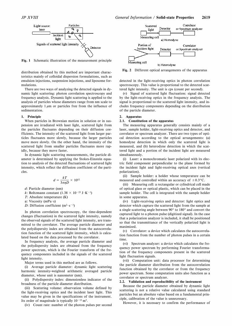
2619
Fig. 1 Schematic illustration of the measurement principle
Fig. 2 Different optical arrangements of the apparatus
2619JP XVIII General Information / Solid-state Properties
distribution obtained by this method are important charac-teristics mainly of colloidal dispersion formulations, such asemulsion injections, suspension injections, and liposome for-mulations.
There are two ways of analyzing the detected signals in dy-namic light scattering: photon correlation spectroscopy andfrequency analysis. Dynamic light scattering is applied to theanalysis of particles whose diameters range from nm scale toapproximately 1 mm or particles free from the influence ofsedimentation.
1. PrincipleWhen particles in Brownian motion in solution or in sus-
pension are irradiated with laser light, scattered light fromthe particles fluctuates depending on their diffusion coe-fficients. The intensity of the scattered light from larger par-ticles fluctuates more slowly, because the larger particlesmove more slowly. On the other hand, the intensity of thescattered light from smaller particles fluctuates more rap-idly, because they move faster.
In dynamic light scattering measurements, the particle di-ameter is determined by applying the Stokes-Einstein equa-tion to analysis of the detected fluctuations of scattered lightintensity, which reflect the diffusion coefficient of the parti-cles.
d =kT
3phD× 1012
d: Particle diameter (nm)k: Boltzmann constant (1.38 × 10⁻²³ J・K-1)T: Absolute temperature (K)h: Viscosity (mPa・s)D: Diffusion coefficient (m2・s-1)
In photon correlation spectroscopy, the time-dependentchanges (fluctuation) in the scattered light intensity, namelythe observed signals of the scattered light intensity, are trans-mitted to the correlator. The average particle diameter andthe polydispersity index are obtained from the autocorrela-tion function of the scattered light intensity, which is calcu-lated based on the data processed by the correlator.
In frequency analysis, the average particle diameter andthe polydispersity index are obtained from the frequencypower spectrum, which is the Fourier transform of the fre-quency components included in the signals of the scatteredlight intensity.
Major terms used in this method are as follows.(i) Average particle diameter: dynamic light scattering
harmonic intensity-weighted arithmetic averaged particlediameter, whose unit is nanometer (nm).
(ii) Polydispersity index: dimensionless indicator of thebroadness of the particle diameter distribution.
(iii) Scattering volume: observation volume defined bythe light-receiving optics and the incident laser light. Thisvalue may be given in the specifications of the instrument.Its order of magnitude is typically 10-12 m3.
(iv) Count rate: number of the photon pulses per second
detected in the light-receiving optics in photon correlationspectroscopy. This value is proportional to the detected scat-tered light intensity. The unit is cps (count per second).
(v) Signal of scattered light fluctuation: signal detectedby the light-receiving optics in the frequency analysis. Thesignal is proportional to the scattered light intensity, and in-cludes frequency components depending on the distributionof the particle diameter.
2. Apparatus2.1. Constitution of the apparatus
The measuring apparatus generally consists mainly of alaser, sample holder, light-receiving optics and detector, andcorrelator or spectrum analyzer. There are two types of opti-cal detection according to the optical arrangements: (a)homodyne detection in which only the scattered light ismeasured, and (b) heterodyne detection in which the scat-tered light and a portion of the incident light are measuredsimultaneously.
(i) Laser: a monochromatic laser polarized with its elec-tric field component perpendicular to the plane formed bythe incident light and light-receiving optical axes (verticalpolarization).
(ii) Sample holder: a holder whose temperature can bemeasured and controlled within an accuracy of ±0.39C.
(iii) Measuring cell: a rectangular or cylindrical cell madeof optical glass or optical plastic, which can be placed in thesample holder. The cell is integrated with the sample holderin some apparatus.
(iv) Light-receiving optics and detector: light optics anddetector which capture the scattered light from the sample ata single scattering angle between 909to 1809and convert thecaptured light to a photon pulse (digitized signal). In the casethat a polarization analyzer is included, it shall be positionedso that the transmittance of the vertically polarized light ismaximized.
(v) Correlator: a device which calculates the autocorrela-tion function from the number of photon pulses in a certaintime.
(vi) Spectrum analyzer: a device which calculates the fre-quency power spectrum by performing Fourier transforma-tion of the frequency components present in the scatteredlight fluctuation signals.
(vii) Computation unit: data processor for determiningthe particle diameter distribution from the autocorrelationfunction obtained by the correlator or from the frequencypower spectrum. Some computation units also function as acorrelator or spectrum analyzer.2.2. Validation and reproducibility of the instrument
Because the particle diameter obtained by dynamic lightscattering is not a relative value calculated using standardparticles but an absolute value based on a fundamental prin-ciple, calibration of the value is unnecessary.
However, it is necessary to confirm the performance of
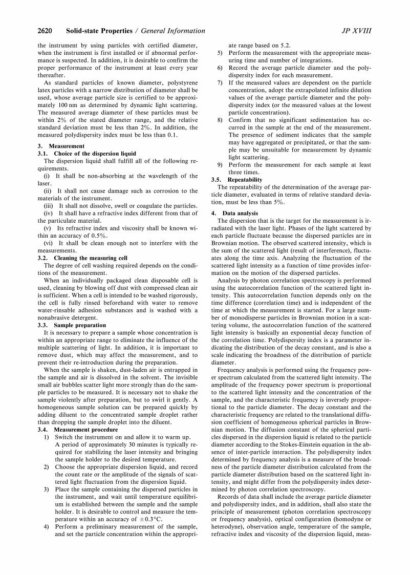
26202620 JP XVIIISolid-state Properties / General Information
the instrument by using particles with certified diameter,when the instrument is first installed or if abnormal perfor-mance is suspected. In addition, it is desirable to confirm theproper performance of the instrument at least every yearthereafter.
As standard particles of known diameter, polystyrenelatex particles with a narrow distribution of diameter shall beused, whose average particle size is certified to be approxi-mately 100 nm as determined by dynamic light scattering.The measured average diameter of these particles must bewithin 2z of the stated diameter range, and the relativestandard deviation must be less than 2z. In addition, themeasured polydispersity index must be less than 0.1.
3. Measurement3.1. Choice of the dispersion liquid
The dispersion liquid shall fulfill all of the following re-quirements.
(i) It shall be non-absorbing at the wavelength of thelaser.
(ii) It shall not cause damage such as corrosion to thematerials of the instrument.
(iii) It shall not dissolve, swell or coagulate the particles.(iv) It shall have a refractive index different from that of
the particulate material.(v) Its refractive index and viscosity shall be known wi-
thin an accuracy of 0.5z.(vi) It shall be clean enough not to interfere with the
measurements.3.2. Cleaning the measuring cell
The degree of cell washing required depends on the condi-tions of the measurement.
When an individually packaged clean disposable cell isused, cleaning by blowing off dust with compressed clean airis sufficient. When a cell is intended to be washed rigorously,the cell is fully rinsed beforehand with water to removewater-rinsable adhesion substances and is washed with anonabrasive detergent.3.3. Sample preparation
It is necessary to prepare a sample whose concentration iswithin an appropriate range to eliminate the influence of themultiple scattering of light. In addition, it is important toremove dust, which may affect the measurement, and toprevent their re-introduction during the preparation.
When the sample is shaken, dust-laden air is entrapped inthe sample and air is dissolved in the solvent. The invisiblesmall air bubbles scatter light more strongly than do the sam-ple particles to be measured. It is necessary not to shake thesample violently after preparation, but to swirl it gently. Ahomogeneous sample solution can be prepared quickly byadding diluent to the concentrated sample droplet ratherthan dropping the sample droplet into the diluent.3.4. Measurement procedure
1) Switch the instrument on and allow it to warm up.A period of approximately 30 minutes is typically re-quired for stabilizing the laser intensity and bringingthe sample holder to the desired temperature.
2) Choose the appropriate dispersion liquid, and recordthe count rate or the amplitude of the signals of scat-tered light fluctuation from the dispersion liquid.
3) Place the sample containing the dispersed particles inthe instrument, and wait until temperature equilibri-um is established between the sample and the sampleholder. It is desirable to control and measure the tem-perature within an accuracy of ±0.39C.
4) Perform a preliminary measurement of the sample,and set the particle concentration within the appropri-
ate range based on 5.2.5) Perform the measurement with the appropriate meas-
uring time and number of integrations.6) Record the average particle diameter and the poly-
dispersity index for each measurement.7) If the measured values are dependent on the particle
concentration, adopt the extrapolated infinite dilutionvalues of the average particle diameter and the poly-dispersity index (or the measured values at the lowestparticle concentration).
8) Confirm that no significant sedimentation has oc-curred in the sample at the end of the measurement.The presence of sediment indicates that the samplemay have aggregated or precipitated, or that the sam-ple may be unsuitable for measurement by dynamiclight scattering.
9) Perform the measurement for each sample at leastthree times.
3.5. RepeatabilityThe repeatability of the determination of the average par-
ticle diameter, evaluated in terms of relative standard devia-tion, must be less than 5z.
4. Data analysisThe dispersion that is the target for the measurement is ir-
radiated with the laser light. Phases of the light scattered byeach particle fluctuate because the dispersed particles are inBrownian motion. The observed scattered intensity, which isthe sum of the scattered light (result of interference), fluctu-ates along the time axis. Analyzing the fluctuation of thescattered light intensity as a function of time provides infor-mation on the motion of the dispersed particles.
Analysis by photon correlation spectroscopy is performedusing the autocorrelation function of the scattered light in-tensity. This autocorrelation function depends only on thetime difference (correlation time) and is independent of thetime at which the measurement is started. For a large num-ber of monodisperse particles in Brownian motion in a scat-tering volume, the autocorrelation function of the scatteredlight intensity is basically an exponential decay function ofthe correlation time. Polydispersity index is a parameter in-dicating the distribution of the decay constant, and is also ascale indicating the broadness of the distribution of particlediameter.
Frequency analysis is performed using the frequency pow-er spectrum calculated from the scattered light intensity. Theamplitude of the frequency power spectrum is proportionalto the scattered light intensity and the concentration of thesample, and the characteristic frequency is inversely propor-tional to the particle diameter. The decay constant and thecharacteristic frequency are related to the translational diffu-sion coefficient of homogeneous spherical particles in Brow-nian motion. The diffusion constant of the spherical parti-cles dispersed in the dispersion liquid is related to the particlediameter according to the Stokes-Einstein equation in the ab-sence of inter-particle interaction. The polydispersity indexdetermined by frequency analysis is a measure of the broad-ness of the particle diameter distribution calculated from theparticle diameter distribution based on the scattered light in-tensity, and might differ from the polydispersity index deter-mined by photon correlation spectroscopy.
Records of data shall include the average particle diameterand polydispersity index, and in addition, shall also state theprinciple of measurement (photon correlation spectroscopyor frequency analysis), optical configuration (homodyne orheterodyne), observation angle, temperature of the sample,refractive index and viscosity of the dispersion liquid, meas-
26212621JP XVIII General Information / Biotechnological/Biological Products
uring time or number of integrations, and sample concentra-tion.
5. Points to note regarding the measurement5.1. Shape of particles
The particles are assumed to be homogeneous and spheri-cal in the data analysis of dynamic light scattering.5.2. Particle concentration
For measurement, it is necessary to prepare a samplewhose concentration falls in the range satisfying the follow-ing conditions.
(i) The sample consists of dispersion liquid and particleswell-dispersed in the liquid.
(ii) The range of the particle concentration is determinedso that consistent results can be obtained in particle diametermeasurements. The range is determined beforehand basedon measurements of systematically diluted samples.5.3. Purification of the dispersion liquid
Scattered light signals from the dispersion liquid used forsample dilution must normally be undetected or very weak.If the situations described in cases (i) or (ii) below are found,particulate substances are likely to have become mixed in thesample, and in such cases the dispersion liquid shall be fur-ther purified (by filtration, distillation, and so on) beforeuse. The lower limit of the particle concentration is deter-mined mainly so that scattered light from the dispersion liq-uid and contaminating substances will not affect the meas-urement. When water is chosen as the dispersion liquid, useof fresh distilled water (prepared by quartz-glass distillation)or desalted and filtered (pore size 0.2 mm) water is recom-mended.
(i) Large fluctuations of the count rate or of the ampli-tude of the scattered light fluctuation signals, accompaniedby abnormally strong signals, are recorded.
(ii) Light spots appear in the path of the laser light in thesample.5.4. Others
(i) When particles are highly charged with electricity,long-range interactions between the particles may affect themeasurement result, and in such cases, a small amount ofsalt (for example, sodium chloride: around 10-2 mol/L) maybe added to the dispersion liquid to reduce the effect.
(ii) Traceable polystyrene latex particles for use in thevalidation of the instrument are commercially available.
6. Reference1) JIS Z8826: 2005 Particle size analysis—Photon correla-
tion spectroscopy2) ISO 13321: 1996 Particle size analysis—Photon correla-
tion spectroscopy3) ISO 22412: 2008 Particle size analysis—Dynamic light
scattering (DLS)
G3 Biotechnological/BiologicalProducts
Basic Concept of the Quality Con-trol on Biotechnological Products(Biopharmaceuticals) <G3-1-180>
IntroductionThis document provides general principle to ensure the
quality of biotechnological products (hereinafter referred to
as ``biopharmaceuticals'') focusing on the elements peculiarto biopharmaceuticals on the basis of the recommendationsin a series of so-called Q-quartet guidelines from ICH Q8 toQ11 and those in Q5A to Q5E and Q6B guidelines1-6) on thequality of biopharmaceuticals. The general concepts for as-surance of drug substances and drug products are describedin the General Information, ``Basic Concepts for Quality As-surance of Drug Substances and Drug Products <G0-1-172>''.
The principles of this General Information apply tobiopharmaceuticals: proteins and peptides, their derivatives,and products of which they are components. These proteinsand polypeptides are produced from recombinant or non-recombinant cell-culture expression systems. The principlesoutlined in this document may also apply to other types ofbiotechnological/biological products.
In the case of biopharmaceuticals, an inherent degree ofstructural heterogeneity occurs in molecular structure due tothe biosynthetic processes used by living organisms toproduce them. In addition to post-translational modificationsuch as glycosylation, they may receive various modifica-tions such as oxidation and deamidation during the produc-tion process and storage periods. Impurities that may remainin the drug substance of biopharmaceuticals include thosewith molecular diversity, such as proteins derived from cellsused for production, and there is a risk of contaminationsuch as viruses. Such quality profiles can vary due to variousfactors on the manufacturing process.
In order to ensure the quality of biopharmaceuticals, it isnecessary to establish an appropriate quality control strategyin consideration of the above characteristics. ``Basic Con-cepts for Quality Assurance of Drug Substances and DrugProducts <G0-2-170>'' described in General Information G0is useful for this. First, the quality attributes are clarified bythorough characteristic analysis. Then, identify the criticalquality attributes (CQAs) in consideration of the quality tar-get product profile (QTPP), and construct a quality controlstrategy to keep the CQAs within the appropriate ranges,limits and distributions. If the manufacturing process is tobe changed during the development period or the post-mar-keting period, conduct comparability exercise of before andafter the change made in the manufacturing process, andcheck the validity of the change by verifying that the changewill not have adverse impact on the quality, safety and effi-cacy of the drug product. New manufacturing and analyticaltechnology of biopharmaceuticals are continuously being de-veloped day by day, and desired to be utilized for continuousimprovement of product quality throughout the product lifecycle.
1. Quality evaluation and control of biopharmaceuticals1.1. Quality evaluation1.1.1. Characterization
Characterization of products is an essential step in iden-tifying CQAs and establishing quality control strategies. Inthe characterization of biopharmaceuticals, detailed analysisis performed as much as possible for the structure and phys-icochemical properties, biological activity, molecular vari-ants of a desired product, process-related impurities, and soon. The desired product is the protein which has an expectedstructure and is expected from the DNA sequence, the pro-tein which is expected from anticipated post-translationalmodification, and/or expected from the intended down-stream processing/modification. Among the molecular vari-ants of the desired product, those with properties compara-ble to the desired product with respect to biological activity,efficacy and safety can be classified as product-related sub-stances. Otherwise, those without the same properties can be
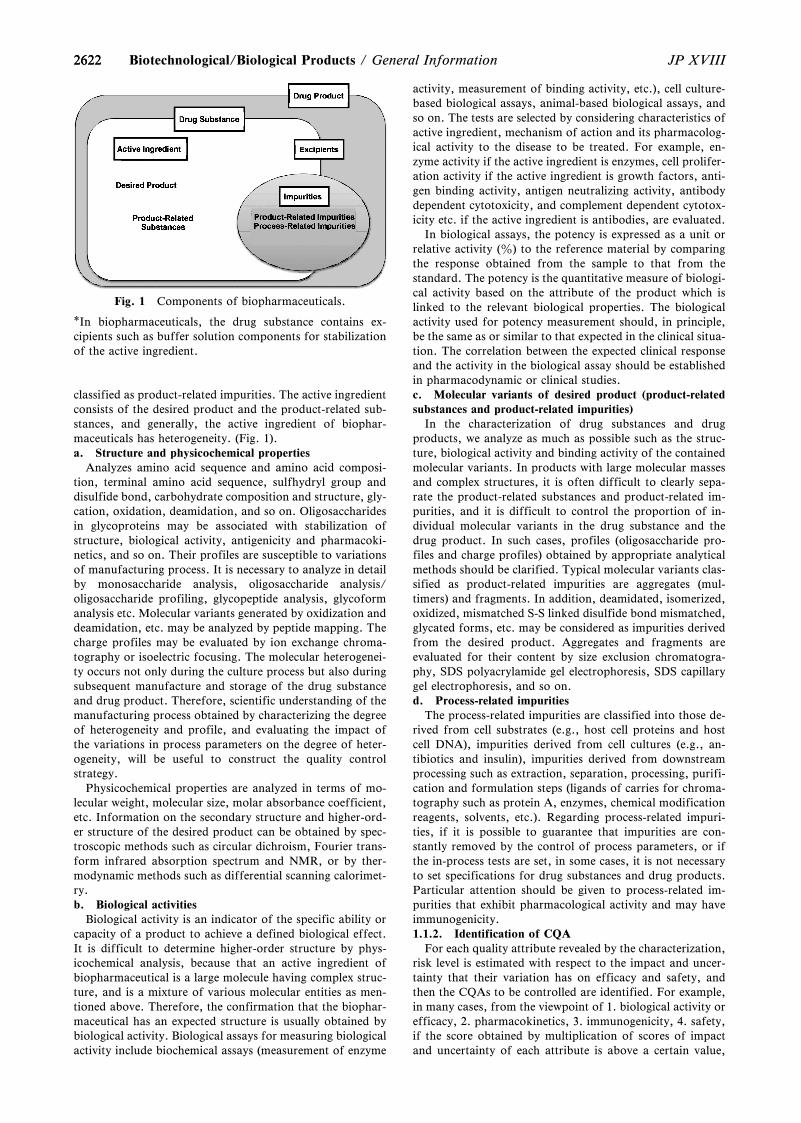
2622
Fig. 1 Components of biopharmaceuticals.
*In biopharmaceuticals, the drug substance contains ex-cipients such as buffer solution components for stabilizationof the active ingredient.
2622 JP XVIIIBiotechnological/Biological Products / General Information
classified as product-related impurities. The active ingredientconsists of the desired product and the product-related sub-stances, and generally, the active ingredient of biophar-maceuticals has heterogeneity. (Fig. 1).a. Structure and physicochemical properties
Analyzes amino acid sequence and amino acid composi-tion, terminal amino acid sequence, sulfhydryl group anddisulfide bond, carbohydrate composition and structure, gly-cation, oxidation, deamidation, and so on. Oligosaccharidesin glycoproteins may be associated with stabilization ofstructure, biological activity, antigenicity and pharmacoki-netics, and so on. Their profiles are susceptible to variationsof manufacturing process. It is necessary to analyze in detailby monosaccharide analysis, oligosaccharide analysis/oligosaccharide profiling, glycopeptide analysis, glycoformanalysis etc. Molecular variants generated by oxidization anddeamidation, etc. may be analyzed by peptide mapping. Thecharge profiles may be evaluated by ion exchange chroma-tography or isoelectric focusing. The molecular heterogenei-ty occurs not only during the culture process but also duringsubsequent manufacture and storage of the drug substanceand drug product. Therefore, scientific understanding of themanufacturing process obtained by characterizing the degreeof heterogeneity and profile, and evaluating the impact ofthe variations in process parameters on the degree of heter-ogeneity, will be useful to construct the quality controlstrategy.
Physicochemical properties are analyzed in terms of mo-lecular weight, molecular size, molar absorbance coefficient,etc. Information on the secondary structure and higher-ord-er structure of the desired product can be obtained by spec-troscopic methods such as circular dichroism, Fourier trans-form infrared absorption spectrum and NMR, or by ther-modynamic methods such as differential scanning calorimet-ry.b. Biological activities
Biological activity is an indicator of the specific ability orcapacity of a product to achieve a defined biological effect.It is difficult to determine higher-order structure by phys-icochemical analysis, because that an active ingredient ofbiopharmaceutical is a large molecule having complex struc-ture, and is a mixture of various molecular entities as men-tioned above. Therefore, the confirmation that the biophar-maceutical has an expected structure is usually obtained bybiological activity. Biological assays for measuring biologicalactivity include biochemical assays (measurement of enzyme
activity, measurement of binding activity, etc.), cell culture-based biological assays, animal-based biological assays, andso on. The tests are selected by considering characteristics ofactive ingredient, mechanism of action and its pharmacolog-ical activity to the disease to be treated. For example, en-zyme activity if the active ingredient is enzymes, cell prolifer-ation activity if the active ingredient is growth factors, anti-gen binding activity, antigen neutralizing activity, antibodydependent cytotoxicity, and complement dependent cytotox-icity etc. if the active ingredient is antibodies, are evaluated.
In biological assays, the potency is expressed as a unit orrelative activity (z) to the reference material by comparingthe response obtained from the sample to that from thestandard. The potency is the quantitative measure of biologi-cal activity based on the attribute of the product which islinked to the relevant biological properties. The biologicalactivity used for potency measurement should, in principle,be the same as or similar to that expected in the clinical situa-tion. The correlation between the expected clinical responseand the activity in the biological assay should be establishedin pharmacodynamic or clinical studies.c. Molecular variants of desired product (product-relatedsubstances and product-related impurities)
In the characterization of drug substances and drugproducts, we analyze as much as possible such as the struc-ture, biological activity and binding activity of the containedmolecular variants. In products with large molecular massesand complex structures, it is often difficult to clearly sepa-rate the product-related substances and product-related im-purities, and it is difficult to control the proportion of in-dividual molecular variants in the drug substance and thedrug product. In such cases, profiles (oligosaccharide pro-files and charge profiles) obtained by appropriate analyticalmethods should be clarified. Typical molecular variants clas-sified as product-related impurities are aggregates (mul-timers) and fragments. In addition, deamidated, isomerized,oxidized, mismatched S-S linked disulfide bond mismatched,glycated forms, etc. may be considered as impurities derivedfrom the desired product. Aggregates and fragments areevaluated for their content by size exclusion chromatogra-phy, SDS polyacrylamide gel electrophoresis, SDS capillarygel electrophoresis, and so on.d. Process-related impurities
The process-related impurities are classified into those de-rived from cell substrates (e.g., host cell proteins and hostcell DNA), impurities derived from cell cultures (e.g., an-tibiotics and insulin), impurities derived from downstreamprocessing such as extraction, separation, processing, purifi-cation and formulation steps (ligands of carries for chroma-tography such as protein A, enzymes, chemical modificationreagents, solvents, etc.). Regarding process-related impuri-ties, if it is possible to guarantee that impurities are con-stantly removed by the control of process parameters, or ifthe in-process tests are set, in some cases, it is not necessaryto set specifications for drug substances and drug products.Particular attention should be given to process-related im-purities that exhibit pharmacological activity and may haveimmunogenicity.1.1.2. Identification of CQA
For each quality attribute revealed by the characterization,risk level is estimated with respect to the impact and uncer-tainty that their variation has on efficacy and safety, andthen the CQAs to be controlled are identified. For example,in many cases, from the viewpoint of 1. biological activity orefficacy, 2. pharmacokinetics, 3. immunogenicity, 4. safety,if the score obtained by multiplication of scores of impactand uncertainty of each attribute is above a certain value,
26232623JP XVIII General Information / Biotechnological/Biological Products
that attribute is identified as CQA. Risk level can also be es-timated from the severity and probability of their impact onefficacy and safety.1.2. Establishment of quality control strategy
The quality control strategy defines a set of controls to br-ing the CQAs within appropriate limits, ranges and distribu-tions. Quality control strategies include such as raw materialcontrol, manufacturing process control, specifications andstability testing. Acceptable ranges and target managementcriteria of CQAs are set based on characterization results, lotanalysis results based on specifications, stability tests results,and clinical tests results, and so on. In stability testing, theanalytical results of the quality attributes (i.e. the proportionof molecular variants such as fragments, oxidized forms anddeamidated forms) and biological activity of the forceddegradation samples in the stress stability testing and acceler-ated stability testing, are useful for setting acceptable rangesand target management criteria of each CQA. In the courseof developing the manufacturing process of biopharmaceuti-cals, identify the raw material characteristics and processparameters affecting the CQAs, and construct the controlmethod of the manufacturing process so that the CQAs arewithin the target range. Based on these results, construct anappropriate quality control strategy consisting of raw mate-rial specifications, process parameter control, in-process tes-ting, drug substance and/or drug product specifications.1.2.1. Raw materials control
Raw materials for biopharmaceuticals include cell banks,media used in culture processes, media additives, resins andcarriers for chromatography used in purification processes,buffers, washing solutions, and filters, and they also includePEGylation reagents used in the modification process, addi-tives used in the formulation process, and the like.a. Evaluation and control of cell bank (including evalua-tion of gene expression construct)
Cell substrates are generally controlled in a two-tiered cellbank, where Working Cell Banks are prepared from aMaster Cell Bank, and their characteristics are clarified byconducting characterization and purity tests. Also, confirmthat the cell substrate is suitable for pharmaceutical produc-tion. In addition, the same evaluation is performed at theupper limit of in vitro cell age that can be used for produc-tion, and the stability of the cell substrate during the cultureperiod is confirmed. In the purity test, it is evaluated that thecell bank is not contaminated with adventitious microbialcontaminants (see 1.2.3 for virus). In the characterizationtests, cell morphology, viable cell number, expression of tar-get protein, etc. are evaluated. In the case of a cell line towhich a gene expression construct is introduced, the gene ex-pression construct should be evaluated for copy number andinsertions or deletions, and coding sequence of desired pro-tein, etc.b. Control of other raw materials
Raw materials used in the manufacturing process are usedafter confirming that they fulfill the criteria for their in-tended use. When using raw materials derived from humansor animals, such as serum and enzymes, make sure that theymeet the ``Biological Raw Material Standards''.1.2.2. Manufacturing process control
The manufacturing process of biopharmaceuticals consistsmainly of drug substance process containing culture processand purification process, and formulation process. Becauseprocess parameters of culture process and purification proc-ess may affect the heterogeneity profile and impurity profile,etc., sufficient understanding of these processes and the es-tablishment of appropriate control methods (setting andevaluation of process parameters, in-process test etc.) are
essential for quality consistency. The constructed manufac-turing process is qualified by process validation/evaluation.Process validation is usually performed on a commercial-scale, however it can be performed on a small-scale modelthat has been qualified for investigating the ability to removeand inactivate virus and the number of reuses of purificationcolumns and so on.a. Process parameter control
The process parameters to be controlled and their controlranges in each manufacturing process are set based on theprevious manufacturing results and univariate experiments,or on the relationships between the process parameters andthe CQAs clarified by a systematic approach. When develop-ing a manufacturing process with the latter method, estimatethe risk level related to the impact of each process parameteron each CQA, and set the operating range of each processparameter so that each CQA does not exceed its acceptablerange. When estimating the risk level during the establish-ment of the control strategy, consider the severity, probabil-ity, and detectability of the impact that the parameter varia-tions may have on each CQA. As an example of processparameters to be controlled, in the culture process, tempera-ture, medium additives concentration, dissolved oxygen con-centration, dissolved carbon dioxide concentration, pH, stir-ring speed, culture time, etc., and in the purification process,column size, loading amount, buffer solution composition,flow velocity, etc. can be mentioned. The acceptable rangeof purification process parameters is set in consideration ofthe impact on the heterogeneity profile and the impurityremoval efficiency. In addition, it is considered necessary toensure that the characteristics of each process, such as celldensity and viability in the culture process and recovery ratein the purification process, fall within a certain range. Proc-esses that have a particularly large impact on quality are re-garded as critical processes. Major examples of critical proc-esses include production culture processes, virus inactivationand removal processes, and affinity chromatography proc-esses.b. In-process tests
In the quality control of biopharmaceuticals, in-processtests are considered possible or appropriate to control con-tamination with such as process-related impurities, virusesand adventitious infectious factors. Examples of in-processtesting include adventitious virus test after production cul-ture, filter integrity tests of virus removal filters and sterilefilters, testing for process-related impurities such as host cellproteins and host cell DNA, bioburden test, and so on. In-process tests are also evaluated for their validity by appropri-ate approaches such as analytical procedure validation.1.2.3. Evaluation and control of contaminants
Contaminants are substances that should not be present inmanufacturing processes, such as adventitious chemicals,biochemical materials, or microorganisms. From the view-point of ensuring safety, contaminants should be strictlyavoided, and after constructing an appropriate manufactur-ing process. As mentioned above, it should be appropriatelycontrolled by raw material control, in-process testing orspecifications.
Viruses may contaminate as an adventitious factor fromproduction processes and may be present as an endogenousfactor in cell substrates used. The following three majorcomplementary approaches are taken as rational measures toprevent the virus contamination specific to products usingbiological origin and to ensure the safety. 1) Selecting andtesting cell lines and other raw materials, including mediacomponents, for the absence of undesirable viruses whichmay be infectious and/or pathogenic for humans. 2) Assess-
26242624 JP XVIIIBiotechnological/Biological Products / General Information
ing the capacity of production processes to clear infectiousviruses. 3) Testing the product at appropriate steps ofproduction for absence of contaminating infectious viruses.The details are described in General Information: ``Basic Re-quirements for Viral Safety of Biotechnological/BiologicalProducts listed in Japanese Pharmacopoeia <G3-13-141>''.1.2.4. Specificationsa. Justification of specifications
The items and test methods adopted for the specificationdiffer depending on the quality control strategy established.It is necessary to clarify the justification of the acceptancecriteria. The acceptance criteria are set on the basis of thedata obtained from lots used in clinical trials, the data ob-tained from lots used to indicate the consistency of produc-tion, stability test data, and appropriate data in the productdevelopment stages.b. Description
It qualitatively defines the physical state (e.g., solid, liq-uid) and color of a drug substance and drug product.Prescribe the transparency of a drug product if it is solution.c. Identification test
Set up specific tests based on the structural features andspecific properties of an active ingredient(s). In order to con-firm the identity, not less than two types of tests (physicaland chemical test, biological test, immunochemical test, etc.)are usually to be set up for a drug substance. For a drugproduct, one type of test may be sufficient, but some prod-ucts may require more than one type of test.d. Specific physical and/or chemical values
The quality attributes to be set as the specific physicaland/or chemical values include oligosaccharide, charge, mo-lecular mass/size, and so on. In the case where the product-related substances and the product-related impurities aredifficult to separate and can not be set as the purity tests, theheterogeneity profiles are specified as the physical and/orchemical values. Typical examples include oligosaccharideprofiles and charge profiles. In addition, set the specificationfor attributes that are important in ensuring the quality of adrug substance and drug product. Examples of the items in-clude pH and osmotic pressure, etc.e. Purity tests
Purity is usually assessed by a combination of analyticalmethods. In the choice and optimization of test methods forimpurities, emphasis should be placed on separating or iden-tifying the desired product and product-related substancesfrom impurities (product-related impurities and process-related impurities).f. Biological activities
Specifications for biopharmaceuticals should usually con-tain the tests for biological activity. Considering the actionmechanism of the active ingredient, a suitable one of themethods used for the characterization is set as a biologicalactivity test. The acceptance criterion is expressed in units/mL when the potency in the solution is used as an index, andwhen using the potency per protein amount as an index, it isexpressed in units/mg. The potency per amount of protein iscalled the specific activity. Besides these, the specific activitymay be compared with a standard material, and this may beexpressed as a percentage (z) to obtain an acceptancecriterion. In recent years, there has been an increasing num-ber of cases where the ratio (z) of specific activity to a refer-ence material is set as an acceptance criterion without settinga unit.
g. QuantityThe quantity of active ingredient contained in a drug sub-
stance and drug product is expressed as protein content
(mass) or potency (unit). As it is a critical factor of productquality, measure it using an appropriate quantitativemethod. For tests to determine the protein content, themethods described in the General Information ``Total Pro-tein Assay <G3-12-172>'', the method comparing peak areaswith the reference material using HPLC, etc. are used. Abiological test is used to determine the potency.
If physicochemical testing has provided sufficient phys-icochemical information on the product, including informa-tion on higher order structure, and proper correlation withbiological activity has been well demonstrated, in addition, ifthe manufacturing experience is well established, biologicaltests for determining potency can be replaced by phys-icochemical testing. For insulins, etc., the quantity (unit) ofthe active ingredient in a sample is determined by comparingthe peak area with the reference material indicated by theunit by the quantitative method using HPLC.h. Tests for preparations
Conduct tests for preparations according to the dosageform. Since most biopharmaceuticals are injections, sterilitytest, bacterial endotoxin test, test for extractable volume ofparenteral preparations, insoluble particulate matter test forinjections and foreign insoluble matter test for injections,etc. are conducted.1.2.5. Stability testinga. Conditions of stability testing
The shelf life of biopharmaceuticals is usually set based onthe results of long term testing at actual storage temperaturesfor the actual storage period of the product to be applied.The accelerated testing and the stress testing can providesupplementary information for setting the shelf life and use-ful information for elucidating the mechanism of qualitychange, as well as evaluating the validity of the analyticalmethods and the influence of storage conditions on the qual-ity such as during transportation.b. Attributes to be evaluated
During the storage of biopharmaceuticals, the bioactivityand the physicochemical properties may change, so it is nec-essary to comprehensively evaluate the quality characteristicsby various analytical methods. In the stability testing, usu-ally, adopting the appropriate attributes and tests used incharacterization, evaluate the changes according to the char-acteristics of the product, such as biological activity, molecu-lar heterogeneity, and product-related impurities.
2. Comparability of biopharmaceuticals subject to changesin their manufacturing process
When changing the manufacturing process of biophar-maceuticals, evaluation work on comparability will be car-ried out in order to ensure the quality, efficacy and safety ofthe drug product produced by the changed manufacturingprocess. The demonstration of comparability does not neces-sarily mean that the quality attributes of the pre-change andpost-change product are identical, but that they are highlysimilar and that the existing knowledge is sufficiently predic-tive to ensure that any differences in quality attributes haveno adverse impact upon safety and efficacy of the drugproduct. However, where the relationship between specificquality attributes and safety or efficacy has not been estab-lished, it might be appropriate to include a combination ofquality, nonclinical, and/or clinical studies in the com-parability exercise.2.1. Considerations for the comparability exercise
The extent to which the test to prove the comparability be-fore and after the change should be conducted is consideredon the production step where the changes were introduced,on the risk level of potential impact of the changes on the
26252625JP XVIII General Information / Biotechnological/Biological Products
quality characteristics, on the suitability of the analyticaltechniques used, and on the relationship between quality at-tributes and safety or efficacy based on overall nonclinicaland clinical experience. The judgment of productcomparability should be done by considering characteriza-tion data, stability data providing insight into potentialproduct differences in the changes and the degradation ofthe protein, and data of lots used for demonstration ofmanufacturing consistency. The historical data that provideinsight into changes of quality attributes with respect to safe-ty and efficacy following manufacturing process change, andnonclinical or clinical characteristics of the drug product andits therapeutic indications should also be considered.2.2. Quality considerations
By re-executing all or part of the characterization that hasalready been carried out (if it is a part, it is necessary to ex-plain its appropriateness), compare the quality characteris-tics before and after the change directly, to obtain the dataneeded to determine the comparability. However, it is neces-sary to evaluate the meaning of the difference by additionalcharacterization, such as when difference in heterogeneityand/or impurity profile are found before and after thechange. Even when evaluating the same quality attributes, itis necessary to apply multiple analysis methods and analysismethods having different measurement principles, and de-vise to be able to detect the change of the quality characteris-tics that may occur due to the change of manufacturingprocess. In addition, changes in the manufacturing process,even minor one, may affect the stability of the product, sowhen changing the manufacturing process that possibly af-fect the quality characteristics, also evaluate the influence onthe stability of the product.2.3. Manufacturing process considerations
Confirm that the process controls in the modified processprovide at least similar or more effective control of theproduct quality, compared to those of the original process.A careful consideration of potential impacts of the plannedchange on steps downstream and quality attributes related tothese steps is extremely important. The modified processsteps should be re-evaluated and/or re-validated, as ap-propriate.
3. References1) ICH: Guideline for Q5A (R1), Viral Safety Evaluation
of Biotechnology Products Derived from Cell Lines ofHuman or Animal Origin.
2) ICH: Guideline for Q5B, Quality of BiotechnologicalProducts: Analysis of the Expression Construct in CellsUsed for Production of R-DNA Derived ProteinProducts.
3) ICH: Guideline for Q5C, Quality of BiotechnologicalProducts: Stability Testing of Biotechnological/Biologi-cal Products.
4) ICH: Guideline for Q5D, Derivation and Characteriza-tion of Cell Substrates Used for Production ofBiotechnological/Biological Products.
5) ICH: Guideline for Q5E, Comparability ofBiotechnological/Biological Products Subject toChanges in Their Manufacturing Process.
6) ICH: Guideline for Q6B, Specifications: Test Proce-dures and Acceptance Criteria for Biotechnological/Bio-logical Products.
Amino Acid Analysis <G3-2-171>
This test is harmonized with the European Pharmacopoeiaand the U.S. Pharmacopeia.
Information on the harmonization with the EuropeanPharmacopoeia and the U.S. Pharmacopeia is available onthe website of the Pharmaceuticals and Medical DevicesAgency.
Amino acid analysis refers to the methodology used to de-termine the amino acid composition or content of proteins,peptides, and other pharmaceutical preparations. Proteinsand peptides are macromolecules consisting of covalentlybonded amino acid residues organized as a linear polymer.The sequence of the amino acids in a protein or peptidedetermines the properties of the molecule. Proteins areconsidered large molecules that commonly exist as foldedstructures with a specific conformation, while peptides aresmaller and may consist of only a few amino acids. Aminoacid analysis can be used to quantify protein and peptides, todetermine the identity of proteins or peptides based on theiramino acid composition, to support protein and peptidestructure analysis, to evaluate fragmentation strategies forpeptide mapping, and to detect atypical amino acids thatmight be present in a protein or peptide. It is necessary tohydrolyze a protein/peptide to its individual amino acidconstituents before amino acid analysis. Following protein/peptide hydrolysis, the amino acid analysis procedure can bethe same as that practiced for free amino acids in other phar-maceutical preparations. The amino acid constituents of thetest sample are typically derivatized for analysis.
ApparatusMethods used for amino acid analysis are usually based on
a chromatographic separation of the amino acids present inthe test sample. Current techniques take advantage of theautomated chromatographic instrumentation designed foranalytical methodologies. An amino acid analysis instrumentwill typically be a low-pressure or high-pressure liquid chro-matograph capable of generating mobile phase gradientsthat separate the amino acid analytes on a chromatographiccolumn. The instrument must have postcolumn derivatiza-tion capability, unless the sample is analyzed using precol-umn derivatization. The detector is usually an ultraviolet-visible or fluorescence detector depending on the derivatiza-tion method used. A recording device (e.g., integrator) isused for transforming the analog signal from the detectorand for quantitation. It is preferred that instrumentation bededicated particularly for amino acid analysis.
General PrecautionsBackground contamination is always a concern for the
analyst in performing amino acid analysis. High purity rea-gents are necessary (e.g., low purity hydrochloric acid cancontribute to glycine contamination). Analytical reagents arechanged routinely every few weeks using only high-pressureliquid chromatography (HPLC) grade solvents. Potentialmicrobial contamination and foreign material that might bepresent in the solvents are reduced by filtering solvents be-fore use, keeping solvent reservoirs covered, and not placingamino acid analysis instrumentation in direct sunlight.
Laboratory practices can determine the quality of theamino acid analysis. Place the instrumentation in a lowtraffic area of the laboratory. Keep the laboratory clean.Clean and calibrate pipets according to a maintenance sched-ule. Keep pipet tips in a covered box; the analysts may nothandle pipet tips with their hands. The analysts may wear
26262626 JP XVIIIBiotechnological/Biological Products / General Information
powder-free latex or equivalent gloves. Limit the number oftimes a test sample vial is opened and closed because dustcan contribute to elevated levels of glycine, serine, andalanine.
A well-maintained instrument is necessary for acceptableamino acid analysis results. If the instrument is used on aroutine basis, it is to be checked daily for leaks, detector andlamp stability, and the ability of the column to maintainresolution of the individual amino acids. Clean or replace allinstrument filters and other maintenance items on a routineschedule.
Reference Standard MaterialAcceptable amino acid standards are commercially availa-
ble for amino acid analysis and typically consist of an aque-ous mixture of amino acids. When determining amino acidcomposition, protein or peptide standards are analyzed withthe test material as a control to demonstrate the integrity ofthe entire procedure. Highly purified bovine serum albuminhas been used as a protein standard for this purpose.
Calibration of InstrumentationCalibration of amino acid analysis instrumentation typi-
cally involves analyzing the amino acid standard, which con-sists of a mixture of amino acids at a number of concentra-tions, to determine the response factor and range of analysisfor each amino acid. The concentration of each amino acidin the standard is known. In the calibration procedure, theanalyst dilutes the amino acid standard to several differentanalyte levels within the expected linear range of the aminoacid analysis technique. Then, replicates at each of thedifferent analyte levels can be analyzed. Peak areas obtainedfor each amino acid are plotted versus the known concentra-tion for each of the amino acids in the standard dilution.These results will allow the analyst to determine the range ofamino acid concentrations where the peak area of a givenamino acid is an approximately linear function of the aminoacid concentration. It is important that the analyst preparethe samples for amino acid analysis so that they are withinthe analytical limits (e.g., linear working range) of the tech-nique employed in order to obtain accurate and repeatableresults.
Four to six amino acid standard levels are analyzed to de-termine a response factor for each amino acid. The responsefactor is calculated as the average peak area or peak heightper nmol of amino acid present in the standard. A calibra-tion file consisting of the response factor for each aminoacid is prepared and used to calculate the concentration ofeach amino acid present in the test sample. This calculationinvolves dividing the peak area corresponding to a givenamino acid by the response factor for that amino acid to givethe nmol of the amino acid. For routine analysis, a single-point calibration may be sufficient; however, the calibrationfile is updated frequently and tested by the analysis of ana-lytical controls to ensure its integrity.
RepeatabilityConsistent high quality amino acid analysis results from
an analytical laboratory require attention to the repeatabilityof the assay. During analysis of the chromatographic separa-tion of the amino acids or their derivatives, numerous peakscan be observed on the chromatogram that correspond to theamino acids. The large number of peaks makes it necessaryto have an amino acid analysis system that can repeatedlyidentify the peaks based on retention time and integrate thepeak areas for quantitation. A typical repeatability evalua-tion involves preparing a standard amino acid solution andanalyzing many replicates (i.e., six analyses or more) of the
same standard solution. The relative standard deviation(RSD) is determined for the retention time and integratedpeak area of each amino acid. An evaluation of the repeata-bility is expanded to include multiple assays conducted overseveral days by different analysts. Multiple assays includethe preparation of standard dilutions from starting materialsto determine the variation due to sample handling. Often theamino acid composition of a standard protein (e.g., bovineserum albumin) is analyzed as part of the repeatability evalu-ation. By evaluating the replicate variation (i.e., RSD), thelaboratory can establish analytical limits to ensure that theanalyses from the laboratory are under control. It is desira-ble to establish the lowest practical variation limits to ensurethe best results. Areas to focus on to lower the variability ofthe amino acid analysis include sample preparation, highbackground spectral interference due to quality of reagentsand/or laboratory practices, instrument performance andmaintenance, data analysis and interpretation, and analystperformance and habits. All parameters involved are fullyinvestigated in the scope of the validation work.
Sample PreparationAccurate results from amino acid analysis require purified
protein and peptide samples. Buffer components (e.g., salts,urea, detergents) can interfere with the amino acid analysisand are removed from the sample before analysis. Methodsthat utilize postcolumn derivatization of the amino acids aregenerally not affected by buffer components to the extentseen with precolumn derivatization methods. It is desirableto limit the number of sample manipulations to reducepotential background contamination, to improve analyterecovery, and to reduce labor. Common techniques used toremove buffer components from protein samples include thefollowing methods: (1) injecting the protein sample onto areversed-phase HPLC system, eluting the protein with avolatile solvent containing a sufficient organic component,and drying the sample in a vacuum centrifuge; (2) dialysisagainst a volatile buffer or water; (3) centrifugal ultrafiltra-tion for buffer replacement with a volatile buffer or water;(4) precipitating the protein from the buffer using an organicsolvent (e.g., acetone); and (5) gel filtration.
Internal StandardsIt is recommended that an internal standard be used to
monitor physical and chemical losses and variations duringamino acid analysis. An accurately known amount of inter-nal standard can be added to a protein solution prior to hy-drolysis. The recovery of the internal standard gives the gen-eral recovery of the amino acids of the protein solution. Freeamino acids, however, do not behave in the same way asprotein-bound amino acids during hydrolysis because theirrates of release or destruction are variable. Therefore, theuse of an internal standard to correct for losses during hy-drolysis may give unreliable results. It will be necessary totake this point under consideration when interpreting theresults. Internal standards can also be added to the mixtureof amino acids after hydrolysis to correct for differences insample application and changes in reagent stability and flowrates. Ideally, an internal standard is an unnaturally occur-ring primary amino acid that is commercially available andinexpensive. It should also be stable during hydrolysis, itsresponse factor should be linear with concentration, and itneeds to elute with a unique retention time without overlap-ping other amino acids. Commonly used amino acid stand-ards include norleucine, nitrotyrosine, and a-aminobutyricacid.
26272627JP XVIII General Information / Biotechnological/Biological Products
Protein HydrolysisHydrolysis of protein and peptide samples is necessary for
amino acid analysis of these molecules. The glassware usedfor hydrolysis must be very clean to avoid erroneous results.Glove powders and fingerprints on hydrolysis tubes maycause contamination. To clean glass hydrolysis tubes, boiltubes for 1 hour in 1 mol/L hydrochloric acid or soak tubesin concentrated nitric acid or in a mixture of concentratedhydrochloric acid and concentrated nitric acid (1:1). Cleanhydrolysis tubes are rinsed with high-purity water followedby a rinse with HPLC grade methanol, dried overnight in anoven, and stored covered until use. Alternatively, pyrolysisof clean glassware at 5009C for 4 hours may also be used toeliminate contamination from hydrolysis tubes. Adequatedisposable laboratory material can also be used.
Acid hydrolysis is the most common method for hydrolyz-ing a protein sample before amino acid analysis. The acidhydrolysis technique can contribute to the variation of theanalysis due to complete or partial destruction of severalamino acids. Tryptophan is destroyed; serine and threonineare partially destroyed; methionine might undergo oxida-tion; and cysteine is typically recovered as cystine (but cys-tine recovery is usually poor because of partial destruction orreduction to cysteine). Application of adequate vacuum(≦less than 200 mm of mercury or 26.7 Pa) or introductionof an inert gas (argon) in the headspace of the reaction vesselcan reduce the level of oxidative destruction. In peptidebonds involving isoleucine and valine the amido bonds ofIle-Ile, Val-Val, Ile-Val, and Val-Ile are partially cleaved;and asparagine and glutamine are deamidated, resulting inaspartic acid and glutamic acid, respectively. The loss oftryptophan, asparagine, and glutamine during an acid hy-drolysis limits quantitation to 17 amino acids. Some of thehydrolysis techniques described are used to address theseconcerns. Some of the hydrolysis techniques described (i.e.,Methods 4-11) may cause modifications to other aminoacids. Therefore, the benefits of using a given hydrolysistechnique are weighed against the concerns with the tech-nique and are tested adequately before employing a methodother than acid hydrolysis.
A time-course study (i.e., amino acid analysis at acid hy-drolysis times of 24, 48, and 72 hours) is often employed toanalyze the starting concentration of amino acids that arepartially destroyed or slow to cleave. By plotting the ob-served concentration of labile amino acids (i.e., serine andthreonine) versus hydrolysis time, the line can be extrapo-lated to the origin to determine the starting concentration ofthese amino acids. Time-course hydrolysis studies are alsoused with amino acids that are slow to cleave (e.g., isoleucineand valine). During the hydrolysis time course, the analystwill observe a plateau in these residues. The level of thisplateau is taken as the residue concentration. If the hydroly-sis time is too long, the residue concentration of the samplewill begin to decrease, indicating destruction by the hydroly-sis conditions.
An acceptable alternative to the time-course study is tosubject an amino acid calibration standard to the same hy-drolysis conditions as the test sample. The amino acid in freeform may not completely represent the rate of destruction oflabile amino acids within a peptide or protein during the hy-drolysis. This is especially true for peptide bonds that areslow to cleave (e.g., Ile-Val bonds). However, this techniquewill allow the analyst to account for some residue destruc-tion. Microwave acid hydrolysis has been used and is rapidbut requires special equipment as well as special precautions.The optimal conditions for microwave hydrolysis must beinvestigated for each individual protein/peptide sample. The
microwave hydrolysis technique typically requires only a fewminutes, but even a deviation of one minute may give inade-quate results (e.g., incomplete hydrolysis or destruction oflabile amino acids). Complete proteolysis, using a mixture ofproteases, has been used but can be complicated, requiresthe proper controls, and is typically more applicable to pep-tides than proteins.
Note: During initial analyses of an unknown protein, ex-periments with various hydrolysis time and temperature con-ditions are conducted to determine the optimal conditions.
Method 1Acid hydrolysis using hydrochloric acid containing phenol
is the most common procedure used for protein/peptide hy-drolysis preceding amino acid analysis. The addition ofphenol to the reaction prevents the halogenation of tyrosine.
Hydrolysis Solution 6 mol/L hydrochloric acid contain-ing 0.1z to 1.0z of phenol.
Procedure—Liquid Phase Hydrolysis Place the protein or peptide
sample in a hydrolysis tube, and dry. [Note: The sample isdried so that water in the sample will not dilute the acid usedfor the hydrolysis.] Add 200 mL of Hydrolysis Solution per500 mg of lyophilized protein. Freeze the sample tube in a dryice-acetone bath, and flame seal in vacuum. Samples aretypically hydrolyzed at 1109C for 24 hours in vacuum orinert atmosphere to prevent oxidation. Longer hydrolysistimes (e.g., 48 and 72 hours) are investigated if there is aconcern that the protein is not completely hydrolyzed.
Vapor Phase Hydrolysis This is one of the most commonacid hydrolysis procedures, and it is preferred for microanal-ysis when only small amounts of the sample are available.Contamination of the sample from the acid reagent is alsominimized by using vapor phase hydrolysis. Place vials con-taining the dried samples in a vessel that contains an ap-propriate amount of Hydrolysis Solution. The HydrolysisSolution does not come in contact with the test sample.Apply an inert atmosphere or vacuum (≦less than 200 mm ofmercury or 26.7 Pa) to the headspace of the vessel, and heatto about 1109C for a 24-hour hydrolysis time. Acid vaporhydrolyzes the dried sample. Any condensation of the acid inthe sample vials is minimized. After hydrolysis, dry the testsample in vacuum to remove any residual acid.
Method 2Tryptophan oxidation during hydrolysis is decreased by
using mercaptoethanesulfonic acid (MESA) as the reducingacid.
Hydrolysis Solution 2.5 mol/L MESA solution.Vapor Phase Hydrolysis About 1 to 100 mg of the pro-
tein/peptide under test is dried in a hydrolysis tube. The hy-drolysis tube is placed in a larger tube with about 200 mL ofthe Hydrolysis Solution. The larger tube is sealed in vacuum(about 50 mm of mercury or 6.7 Pa) to vaporize the Hydroly-sis Solution. The hydrolysis tube is heated to 1709C to 1859Cfor about 12.5 minutes. After hydrolysis, the hydrolysis tubeis dried in vacuum for 15 minutes to remove the residualacid.
Method 3Tryptophan oxidation during hydrolysis is prevented by
using thioglycolic acid (TGA) as the reducing acid.Hydrolysis Solution A solution containing 7 mol/L hy-
drochloric acid, 10z of trifluoroacetic acid, 20z of thiogly-colic acid, and 1z of phenol.
Vapor Phase Hydrolysis About 10 to 50 mg of the pro-tein/peptide under test is dried in a sample tube. The sampletube is placed in a larger tube with about 200 mL of the
26282628 JP XVIIIBiotechnological/Biological Products / General Information
Hydrolysis Solution. The larger tube is sealed in vacuum(about 50 mm of mercury or 6.7 Pa) to vaporize the TGA.The sample tube is heated to 1669C for about 15 to 30minutes. After hydrolysis, the sample tube is dried in vacu-um for 5 minutes to remove the residual acid. Recovery oftryptophan by this method may be dependent on the amountof sample present.
Method 4Cysteine-cystine and methionine oxidation is performed
with performic acid before the protein hydrolysis.Oxidation Solution The performic acid is prepared fresh
by mixing formic acid and 30 percent hydrogen peroxide(9:1), and incubated at room temperature for 1 hour.
Procedure The protein/peptide sample is dissolved in 20mL of formic acid, and heated at 509C for 5 minutes; then100 mL of the Oxidation Solution is added. The oxidation isallowed to proceed for 10 to 30 minutes. In this reaction,cysteine is converted to cysteic acid and methionine is con-verted to methionine sulfone. The excess reagent is removedfrom the sample in a vacuum centrifuge. This technique maycause modifications to tyrosine residues in the presence ofhalides. The oxidized protein can then be acid hydrolyzedusing Method 1 or Method 2.
Method 5Cysteine-cystine oxidation is accomplished during the liq-
uid phase hydrolysis with sodium azide.Hydrolysis Solution 6 mol/L hydrochloric acid contain-
ing 0.2z of phenol, to which sodium azide is added to ob-tain a final concentration of 0.2z (w/v). The added phenolprevents halogenation of tyrosine.
Liquid Phase Hydrolysis The protein/peptide hydrolysisis conducted at about 1109C for 24 hours. During the hy-drolysis, the cysteine-cystine present in the sample is con-verted to cysteic acid by the sodium azide present in theHydrolysis Solution. This technique allows better tyrosinerecovery than Method 4, but it is not quantitative formethionine. Methionine is converted to a mixture of the par-ent methionine and its two oxidative products, methioninesulfoxide and methionine sulfone.
Method 6Cysteine-cystine oxidation is accomplished with dimethyl
sulfoxide (DMSO).Hydrolysis Solution 6 mol/L hydrochloric acid contain-
ing 0.1z to 1.0z of phenol, to which DMSO is added to ob-tain a final concentration of 2z (v/v).
Vapor Phase Hydrolysis The protein/peptide hydrolysisis conducted at about 1109C for 24 hours. During thehydrolysis, the cysteine-cystine present in the sample isconverted to cysteic acid by the DMSO present in theHydrolysis Solution. As an approach to limit variability andcompensate for partial destruction, it is recommended toevaluate the cysteic acid recovery from oxidative hydrolysesof standard proteins containing 1 to 8 mol of cysteine permol of protein. The response factors from protein/peptidehydrolysates are typically about 30z lower than those fornonhydrolyzed cysteic acid standards. Because histidine,methionine, tyrosine, and tryptophan are also modified, acomplete compositional analysis is not obtained with thistechnique.
Method 7Cysteine-cystine reduction and alkylation is accomplished
by a vapor phase pyridylethylation reaction.Reducing Solution Transfer 83.3 mL of pyridine, 16.7 mL
of 4-vinylpyridine, 16.7 mL of tributylphosphine, and 83.3mL of water to a suitable container, and mix.
Procedure Add the protein/peptide (between 1 mg and100 mg) to a hydrolysis tube, and place in a larger tube.Transfer the Reducing Solution to the large tube, seal invacuum (about 50 mm of mercury or 6.7 Pa), and incubate atabout 1009C for 5 minutes. Then remove the inner hydroly-sis tube, and dry it in a vacuum desiccator for 15 minutes toremove residual reagents. The pyridylethylated protein/pep-tide can then be acid hydrolyzed using previously describedprocedures. The pyridylethylation reaction is performedsimultaneously with a protein standard sample containing 1to 8 mol of cysteine per mol of protein to improve accuracyin the pyridylethylcysteine recovery. Longer incubation timesfor the pyridylethylation reaction can cause modifications tothe a-amino terminal group and the e-amino group of lysinein the protein.
Method 8Cysteine-cystine reduction and alkylation is accomplished
by a liquid phase pyridylethylation reaction.Stock Solutions Prepare and filter three solutions: 1
mol/L Tris hydrochloride (pH 8.5) containing 4 mmol/Ldisodium dihydrogen ethylendiamine tetraacetate (Stock So-lution A), 8 mol/L guanidine hydrochloride (Stock SolutionB), and 10z of 2-mercaptoethanol in water (Stock SolutionC ).
Reducing Solution Prepare a mixture of Stock SolutionB and Stock Solution A (3:1) to obtain a buffered solutionof 6 mol/L guanidine hydrochloride in 0.25 mol/L Tris hy-drochloride.
Procedure Dissolve about 10 mg of the test sample in 50mL of the Reducing Solution, and add about 2.5 mL of StockSolution C. Store under nitrogen or argon for 2 hours atroom temperature in the dark. To achieve the pyridylethyla-tion reaction, add about 2 mL of 4-vinylpyridine to the pro-tein solution, and incubate for an additional 2 hours at roomtemperature in the dark. The protein/peptide is desalted bycollecting the protein/peptide fraction from a reversed-phaseHPLC separation. The collected sample can be dried in avacuum centrifuge before acid hydrolysis.
Method 9Cysteine-cystine reduction and alkylation is accomplished
by a liquid phase carboxymethylation reaction.Stock Solutions Prepare as directed for Method 8.Carboxymethylation Solution Prepare a solution con-
taining 100 mg of iodoacetamide per mL of ethanol (95).Buffer Solution Use the Reducing Solution, prepared as
directed for Method 8.Procedure Dissolve the test sample in 50 mL of the
Buffer Solution, and add about 2.5 mL of Stock Solution C.Store under nitrogen or argon for 2 hours at room tempera-ture in the dark. Add the Carboxymethylation Solution in aratio 1.5 fold per total theoretical content of thiols, and in-cubate for an additional 30 minutes at room temperature inthe dark. [Note: If the thiol content of the protein isunknown, then add 5 mL of 100 mmol/L iodoacetamide forevery 20 nmol of protein present.] The reaction is stopped byadding excess of 2-mercaptoethanol. The protein/peptide isdesalted by collecting the protein/peptide fraction from areversed-phase HPLC separation. The collected sample canbe dried in a vacuum centrifuge before acid hydrolysis. TheS-carboxyamidomethyl-cysteine formed will be converted toS-carboxymethylcysteine during acid hydrolysis.
Method 10Cysteine-cystine is reacted with dithiodiglycolic acid or
dithiodipropionic acid to produce a mixed disulfide. [Note:The choice of dithiodiglycolic acid or dithiodipropionic acid
26292629JP XVIII General Information / Biotechnological/Biological Products
depends on the required resolution of the amino acid analy-sis method.]
Reducing Solution A solution containing 10 mg ofdithiodiglycolic acid (or dithiodipropionic acid) per mL of0.2 mol/L sodium hydroxide.
Procedure Transfer about 20 mg of the test sample to ahydrolysis tube, and add 5 mL of the Reducing Solution.Add 10 mL of isopropyl alcohol, and then remove all of thesample liquid by vacuum centrifugation. The sample is thenhydrolyzed using Method 1. This method has the advantagethat other amino acid residues are not derivatized by sidereactions, and the sample does not need to be desalted priorto hydrolysis.
Method 11Asparagine and glutamine are converted to aspartic acid
and glutamic acid, respectively, during acid hydrolysis.Asparagine and aspartic acid residues are added and repre-sented by Asx, while glutamine and glutamic acid residuesare added and represented by Glx. Proteins/peptides can bereacted with bis(1,1-trifluoroacetoxy)iodobenzene (BTI) toconvert the asparagine and glutamine residues to diamino-propionic acid and diaminobutyric acid residues, respec-tively, upon acid hydrolysis. These conversions allow theanalyst to determine the asparagine and glutamine content ofa protein/peptide in the presence of aspartic acid and glu-tamic acid residues.
Reducing Solutions Prepare and filter three solutions: asolution of 10 mmol/L trifluoroacetic acid (Solution A), asolution of 5 mol/L guanidine hydrochloride and 10 mmol/L trifluoroacetic acid (Solution B), and a freshly preparedsolution of N,N-dimethylformamide containing 36 mg ofBTI per mL (Solution C ).
Procedure In a clean hydrolysis tube, transfer about 200mg of the test sample, and add 2 mL of Solution A or Solu-tion B and 2 mL of Solution C. Seal the hydrolysis tube invacuum. Heat the sample at 609C for 4 hours in the dark.The sample is then dialyzed with water to remove the excessreagents. Extract the dialyzed sample three times with equalvolumes of n-butyl acetate, and then lyophilize. The proteincan then be acid hydrolyzed using previously describedprocedures. The a,b-diaminopropionic and a,g-diaminobu-tyric acid residues do not typically resolve from the lysineresidues upon ion-exchange chromatography based onamino acid analysis. Therefore, when using ion-exchange asthe mode of amino acid separation, the asparagine andglutamine contents are the quantitative difference in theaspartic acid and glutamic acid content assayed withunderivatized and BTI-derivatized acid hydrolysis. [Note:The threonine, methionine, cysteine, tyrosine, and histidineassayed content can be altered by BTI derivatization; a hy-drolysis without BTI will have to be performed if the analystis interested in the composition of these other amino acidresidues of the protein/peptide.]
Methodologies of Amino Acid Analysis General PrinciplesMany amino acid analysis techniques exist, and the choice
of any one technique often depends on the sensitivity re-quired from the assay. In general, about one-half of theamino acid analysis techniques employed rely on the separa-tion of the free amino acids by ion-exchange chromatogra-phy followed by postcolumn derivatization (e.g., with nin-hydrin or o-phthalaldehyde). Postcolumn detection tech-niques can be used with samples that contain small amountsof buffer components, such as salts and urea, and generallyrequire between 5 and 10 mg of protein sample per analysis.The remaining amino acid techniques typically involve pre-column derivatization of the free amino acids (e.g., phenyl
isothiocyanate; 6-aminoquinolyl-N-hydroxysuccinimidylcarbamate or o-phthalaldehyde; (dimethylamino)azoben-zenesulfonyl chloride; 9-fluorenylmethylchloroformate; and,7-fluoro-4-nitrobenzo-2-oxa-1,3-diazole) followed by rever-sed-phase HPLC. Precolumn derivatization techniques arevery sensitive and usually require between 0.5 and 1.0 mg ofprotein sample per analysis but may be influenced by buffersalts in the samples. Precolumn derivatization techniquesmay also result in multiple derivatives of a given amino acid,which complicates the result interpretation. Postcolumnderivatization techniques are generally influenced less byperformance variation of the assay than precolumn derivati-zation techniques.
The following Methods may be used for quantitativeamino acid analysis. Instruments and reagents for theseprocedures are available commercially. Furthermore, manymodifications of these methodologies exist with differentreagent preparations, reaction procedures, chromatographicsystems, etc. Specific parameters may vary according to theexact equipment and procedure used. Many laboratories willutilize more than one amino acid analysis technique toexploit the advantages offered by each. In each of theseMethods, the analog signal is visualized by means of a dataacquisition system, and the peak areas are integrated forquantification purposes.
Method 1—Postcolumn Ninhydrin Detection General Prin-ciple
Ion-exchange chromatography with postcolumn ninhydrindetection is one of the most common methods employed forquantitative amino acid analysis. As a rule, a Li-basedcation-exchange system is employed for the analysis of themore complex physiological samples, and the faster Na-based cation-exchange system is used for the more simplisticamino acid mixtures obtained with protein hydrolysates(typically containing 17 amino acid components). Separationof the amino acids on an ion-exchange column is accom-plished through a combination of changes in pH and cationstrength. A temperature gradient is often employed toenhance separation.
When the amino acid reacts with ninhydrin, the reactanthas characteristic purple or yellow color. Amino acids, ex-cept imino acid, give a purple color, and show the maximumabsorption at 570 nm. The imino acids such as proline give ayellow color, and show the maximum absorption at 440 nm.The postcolumn reaction between ninhydrin and amino acideluted from column is monitored at 440 and 570 nm, and thechromatogram obtained is used for the determination ofamino acid composition.
Detection limit is considered to be 10 pmol for most of theamino acid derivatives, but 50 pmol for proline. Responselinearity is obtained in the range of 20 to 500 pmol with cor-relation coefficients exceeding 0.999. To obtain good com-position data, samples larger than 1 mg before hydrolysis arebest suited for this amino acid analysis of protein/peptide.
Method 2—Postcolumn OPA Fluorometric DetectionGeneral Principle
o-Phthalaldehyde (OPA) reacts with primary amines inthe presence of thiol compound, to form highly fluorescentisoindole products. This reaction is utilized for the postcol-umn derivatization in analysis of amino acids by ion-exchange chromatography. The rule of the separation is thesame as Method 1. Instruments and reagents for this form ofamino acid analysis are available commercially. Manymodifications of this methodology exist.
Although OPA does not react with secondary amines(imino acids such as proline) to form fluorescent substances,

26302630 JP XVIIIBiotechnological/Biological Products / General Information
the oxidation with sodium hypochlorite allows secondaryamines to react with OPA. The procedure employs astrongly acidic cation-exchange column for separation offree amino acids followed by postcolumn oxidation withsodium hypochlorite and postcolumn derivatization usingOPA and thiol compound such as N-acetyl-L-cysteine and 2-mercaptoethanol. The derivatization of primary amino acidsis not noticeably affected by the continuous supply ofsodium hypochlorite.
Separation of the amino acids on an ion-exchange columnis accomplished through a combination of changes in pHand cation strength. After postcolumn derivatization ofeluted amino acids with OPA, the reactant passes throughthe fluorometric detector. Fluorescence intensity of OPA-derivatized amino acids is monitored with an excitationwavelength of 348 nm and an emission wavelength of 450nm.
Detection limit is considered to be a few tens of picomolelevel for most of the amino acid derivatives. Responselinearity is obtained in the range of a few picomole level to afew tens of nanomole level. To obtain good compositionaldata, the starting with greater than 500 ng of sample beforehydrolysis is best suited for the amino acid analysis of pro-tein/peptide.
Method 3—Precolumn PITC Derivatization General Princi-ple
Phenylisothiocyanate (PITC) reacts with amino acids toform phenylthiocarbamyl (PTC) derivatives which can bedetected with high sensitivity at 245 nm. Therefore, precol-umn derivatization of amino acids with PITC followed byreversed-phase HPLC separation with UV detection is usedto analyze the amino acid composition.
After the reagent is removed under vacuum, the deriva-tized amino acids can be stored dry and frozen for severalweeks with no significant degradation. If the solution for in-jection is kept cold, no noticeable loss in chromatographicresponse occurs after three days.
Separation of the PTC-amino acids on a reversed-phaseHPLC with ODS column is accomplished through a combi-nation of changes in concentrations of acetonitrile andbuffer ionic strength. PTC-amino acids eluted from thecolumn are monitored at 254 nm.
Detection limit is considered to be 1 pmol for most of theamino acid derivatives. Response linearity is obtained in therange of 20 to 500 pmol with correlation coefficientsexceeding 0.999. To obtain good compositional data, sam-ples larger than 500 ng of protein/peptide before hydrolysisis best suited for this amino acid analysis of proteins/peptides.
Method 4—Precolumn AQC Derivatization General Princi-ple
Precolumn derivatization of amino acids with 6-amino-quinolyl-N-hydroxysuccinimidyl carbamate (AQC) followedby reversed-phase HPLC separation with fluorometric detec-tion is used.
AQC reacts with amino acids to form stable, fluorescentunsymmetric urea derivatives (AQC-amino acids) which arereadily amenable to analysis by reversed-phase HPLC.Therefore, precolumn derivatization of amino acids withAQC followed by reversed-phase HPLC separation is usedto analyze the amino acid composition.
Separation of the AQC-amino acids on an ODS column isaccomplished through a combination of changes in concen-trations of acetonitrile and salt. Selective fluorescence detec-tion of the derivatives with excitation wavelength at 250 nmand emission wavelength at 395 nm allows for the direct
injection of the reaction mixture with no significant interfer-ence from the only major fluorescent reagent by-product,6-aminoquinoline. Excess reagent is rapidly hydrolyzed(t1/2 < 15 seconds) to yield 6-aminoquinoline, N-hydroxy-succinimide and carbon dioxide, and after 1 minute no fur-ther derivatization can take place.
Peak areas for AQC-amino acids are essentially un-changed for at least 1 week at room temperature, and thederivatives have more than sufficient stability to allow forovernight automated chromatographic analysis.
Detection limit is considered to be ranging from ca. 40 to320 fmol for each amino acid, except for Cys. Detectionlimit for Cys is approximately 800 fmol. Response linearityis obtained in the range of 2.5 to 200 mmol/L with correla-tion coefficients exceeding 0.999. Good compositional datacould be obtained from the analysis of derivatized proteinhydrolysates containing as little as 30 ng of protein/peptide.
Method 5—Precolumn OPA Derivatization General Princi-ple
Precolumn derivatization of amino acids with o-phthalal-dehyde (OPA) followed by reversed-phase HPLC separationwith fluorometric detection is used. This technique does notdetect amino acids that exist as secondary amines (e.g.,proline).
OPA in conjunction with a thiol reagent reacts withprimary amine groups to form highly fluorescent isoindoleproducts. 2-Mercaptoethanol or 3-mercaptopropionic acidcan be used as thiol. OPA itself does not fluoresce and con-sequently produces no interfering peaks. In addition, itssolubility and stability in aqueous solution, along with therapid kinetics for the reaction, make it amenable to automat-ed derivatization and analysis using an autosampler to mixthe sample with the reagent. However, lack of reactivity withsecondary amino acids has been a predominant drawback.This method does not detect amino acids that exist assecondary amines (e.g., proline). To compensate for thisdrawback, this technique may be combined with anothertechnique described in Method 7 or Method 8.
Precolumn derivatization of amino acids with OPA is fol-lowed by reversed-phase HPLC separation. Because of theinstability of the OPA-amino acid derivative, HPLC separa-tion and analysis are performed immediately followingderivatization. The liquid chromatograph is equipped with afluorometric detector for the detection of derivatized aminoacids. Fluorescence intensity of OPA-derivatized aminoacids is monitored with an excitation wavelength of 348 nmand an emission wavelength of 450 nm.
Detection limits as low as 50 fmol via fluorescence havebeen reported, although the practical limit of analysisremains at 1 pmol.
Method 6—Precolumn DABS-Cl Derivatization GeneralPrinciple
Precolumn derivatization of amino acids with(dimethylamino)azobenzenesulfonyl chloride (DABS-Cl)followed by reversed-phase HPLC separation with visiblelight detection is used.
DABS-Cl is a chromophoric reagent employed for thelabeling of amino acids. Amino acids labeled with DABS-Cl(DABS-amino acids) are highly stable and show the maxi-mum absorption at 436 nm.
DABS-amino acids, all 19 naturally occurring amino acidsderivatives, can be separated on an ODS column of reversed-phase HPLC by employing gradient systems consisting ofacetonitrile and aqueous buffer mixture. Separated DABS-amino acids eluted from the column are detected at 436 nmin the visible region.
26312631JP XVIII General Information / Biotechnological/Biological Products
This Method can analyze the imino acids such as prolinetogether with the amino acids at the same degree of sensi-tivity, DABS-Cl derivatization method permits the simul-taneous quantification of tryptophan residues by previoushydrolysis of the protein/peptide with sulfonic acids such asmercaptoethanesulfonic acid, p-toluenesulfonic acid ormethanesulfonic acid described under Method 2 in ``ProteinHydrolysis''. The other acid-labile residues, asparagine andglutamine, can also be analysed by previous conversion intodiaminopropionic acid and diaminobutyric acid, respec-tively, by treatment of protein/peptide with BTI describedunder Method 11 in ``Protein Hydrolysis''.
The non-proteinogenic amino acid, norleucine cannot beused as internal standard in this method, as this compound iseluted in a chromatographic region crowded with peaks ofprimary amino acids. Nitrotyrosine can be used as an inter-nal standard, because it is eluted in a clean region.
Detection limit of DABS-amino acid is about 1 pmol. Aslittle as 2 to 5 pmol of an individual DABS-amino acid canbe quantitatively analyzed with reliability, and only 10 to 30ng of the dabsylated protein hydrolysate is required for eachanalysis.
Method 7—Precolumn FMOC-Cl Derivatization GeneralPrinciple
Precolumn derivatization of amino acids with 9-fluorenylmethyl chloroformate (FMOC-Cl) followed byreversed-phase HPLC separation with fluorometric detec-tion is used.
FMOC-Cl reacts with both primary and secondary aminoacids to form highly fluorescent products. The reaction ofFMOC-Cl with amino acid proceeds under mild conditionsin aqueous solution and is completed in 30 seconds. Thederivatives are stable, only the histidine derivative showingany breakdown. Although FMOC-Cl is fluorescent itself,the reagent excess and fluorescent side-products can beeliminated without loss of FMOC-amino acids.
FMOC-amino acids are separated by a reversed-phaseHPLC using an ODS column. The separation is carried outby gradient elution varied linearly from a mixture of aceto-nitrile methanol and acetic acid buffer (10:40:50) to a mix-ture of acetonitrile and acetic acid buffer (50:50), and 20amino acid derivatives are separated in 20 minutes. Eachderivative eluted from the column is monitored by a fluoro-metric detector set at an excitation wavelength of 260 nmand an emission wavelength of 313 nm.
The detection limit is in the low fmol range. A linearityrange of 0.1 to 50 mmol/L is obtained for most of the aminoacids.
Method 8—Precolumn NBD-F Derivatization General Prin-ciple
Precolumn derivatization of amino acids with 7-fluoro-4-nitrobenzo-2-oxa-1.3-diazole (NBD-F) followed by reversed-phase HPLC separation with fluorometric detection is used.
NBD-F reacts with both primary and secondary aminoacids to form highly fluorescent products. Amino acids arederivatized with NBD-F by heating to 609C for 5 minutes.
NBD-amino acid derivatives are separated on an ODScolumn of reversed-phase HPLC by employing gradientelution system consisting of acetonitrile and aqueous buffermixture, and 17 amino acid derivatives are separated in 35minutes. e-Aminocaproic acid can be used as an internalstandard, because it is eluted in a clean chromatographicregion. Each derivative eluted from the column is monitoredby a fluorometric detector set at an excitation wavelength of480 nm and an emission wavelength of 530 nm.
The sensitivity of this method is almost the same as for
precolumn OPA derivatization method (Method 5), exclud-ing proline to which OPA is not reactive, and might be ad-vantageous for NBD-F against OPA. The detection limit foreach amino acid is about 10 fmol. Profile analysis wasachieved for about 1.5 mg of protein hydrolysates in the finalprecolumn labeling reaction mixture for HPLC.
Data Calculation and AnalysisWhen determining the amino acid content of a protein/
peptide hydrolysate, it should be noted that the acid hydroly-sis step destroys tryptophan and cysteine. Serine and threo-nine are partially destroyed by acid hydrolysis, while isoleu-cine and valine residues may be only partially cleaved.Methionine can undergo oxidation during acid hydrolysis,and some amino acids (e.g., glycine and serine) are commoncontaminants. Application of adequate vacuum (≦0.0267kPa) or introduction of inert gas (argon) in the headspace ofthe reaction vessel during vapor phase hydrolysis can reducethe level of oxidative destruction. Therefore, the quantitativeresults obtained for cysteine, tryptophan, threonine, isoleu-cine, valine, methionine, glycine, and serine from a protein/peptide hydrolysate may be variable and may warrant fur-ther investigation and consideration.
CalculationsAmino Acid Mole Percent This is the number of specific
amino acid residues per 100 residues in a protein. This resultmay be useful for evaluating amino acid analysis data whenthe molecular weight of the protein under investigation isunknown. This information can be used to corroborate theidentity of a protein/peptide and has other applications.Carefully identify and integrate the peaks obtained as di-rected for each Procedure. Calculate the mole percent foreach amino acid present in the test sample by the formula:
100rU/r,
in which rU is the peak response, in nmol, of the amino acidunder test; and r is the sum of peak responses, in nmol, forall amino acids present in the test sample. Comparison of themole percent of the amino acids under test to data fromknown proteins can help establish or corroborate the identityof the sample protein.
Unknown Protein Samples This data analysis techniquecan be used to estimate the protein concentration of anunknown protein sample using the amino acid analysis data.Calculate the mass, in mg, of each recovered amino acid bythe formula:
mMW/1000,
in which m is the recovered quantity, in nmol, of the aminoacid under test; and MW is the average molecular weight forthat amino acid, corrected for the weight of the water molec-ule that was eliminated during peptide bond formation. Thesum of the masses of the recovered amino acids will give anestimate of the total mass of the protein analyzed after ap-propriate correction for partially and completely destroyedamino acids. If the molecular weight of the unknown proteinis available (i.e., by SDS-PAGE analysis or mass spectros-copy), the amino acid composition of the unknown proteincan be predicted. Calculate the number of residues of eachamino acid by the formula:
m/(1000M/MWT),
in which m is the recovered quantity, in nmol, of the aminoacid under test; M is the total mass, in mg, of the protein;and MWT is the molecular weight of the unknown protein.
Known Protein Samples This data analysis technique canbe used to investigate the amino acid composition and pro-
26322632 JP XVIIIBiotechnological/Biological Products / General Information
tein concentration of a protein sample of known molecularweight and amino acid composition using the amino acidanalysis data. When the composition of the protein beinganalyzed is known, one can exploit the fact that some aminoacids are recovered well, while other amino acid recoveriesmay be compromised because of complete or partial destruc-tion (e.g., tryptophan, cysteine, threonine, serine, methio-nine), incomplete bond cleavage (i.e., for isoleucine andvaline) and free amino acid contamination (i.e., by glycineand serine).
Because those amino acids that are recovered bestrepresent the protein, these amino acids are chosen to quan-tify the amount of protein. Well-recovered amino acidsare, typically, aspartate-asparagine, glutamate-glutamine,alanine, leucine, phenylalanine, lysine, and arginine. Thislist can be modified based on experience with one's ownanalysis system. Divide the quantity, in nmol, of each of thewell-recovered amino acids by the expected number ofresidues for that amino acid to obtain the protein contentbased on each well-recovered amino acid. Average the pro-tein content results calculated. The protein content deter-mined for each of the well-recovered amino acids should beevenly distributed about the mean. Discard protein contentvalues for those amino acids that have an unacceptable de-viation from the mean. Typically ≧greater than 5z varia-tion from the mean is considered unacceptable. Recalculatethe mean protein content from the remaining values to ob-tain the protein content of the sample. Divide the content ofeach amino acid by the calculated mean protein content todetermine the amino acid composition of the sample byanalysis.
Calculate the relative compositional error, in percentage,by the formula:
100m/mS,
in which m is the experimentally determined quantity, innmol per amino acid residue, of the amino acid under test;and mS is the known residue value for that amino acid. Theaverage relative compositional error is the average of theabsolute values of the relative compositional errors of theindividual amino acids, typically excluding tryptophan andcysteine from this calculation. The average relative composi-tional error can provide important information on the stabil-ity of analysis run over time. The agreement in the aminoacid composition between the protein sample and the knowncomposition can be used to corroborate the identity andpurity of the protein in the sample.
Peptide Mapping <G3-3-142>
This test is harmonized with the European Pharmacopoeiaand the U.S. Pharmacopeia.
Information on the harmonization with the EuropeanPharmacopoeia and the U.S. Pharmacopeia is available onthe website of the Pharmaceuticals and Medical DevicesAgency.
Peptide mapping is an identity test for proteins, especiallythose obtained by r-DNA technology. It involves the chemi-cal or enzymatic treatment of a protein, resulting in the for-mation of peptide fragments, followed by separation andidentification of the fragments in a reproducible manner. Itis a powerful test that is capable of identifying single aminoacid changes resulting from events such as errors in the read-ing of complementary DNA (cDNA) sequences or point mu-tations. Peptide mapping is a comparative procedure be-
cause the information obtained, compared to a referencestandard or reference material similarly treated, confirms theprimary structure of the protein, is capable of detectingwhether alterations in structure have occurred, and demon-strates process consistency and genetic stability. Each pro-tein presents unique characteristics which must be wellunderstood so that the scientific and analytical approachespermit validated development of a peptide map that providessufficient specificity.
This chapter provides detailed assistance in the applicationof peptide mapping and its validation to characterize thedesired protein product, to evaluate the stability of theexpression construct of cells used for recombinant DNAproducts, to evaluate the consistency of the overall processand to assess product stability as well as to ensure the identi-ty of the protein product, or to detect the presence of proteinvariant.
1. Peptide MapPeptide mapping is not a general method, but involves de-
veloping specific maps for each unique protein. Althoughthe technology is evolving rapidly, there are certain methodsthat are generally accepted. Variations of these methods willbe indicated, when appropriate, in specific monographs.
A peptide map may be viewed as a fingerprint of a proteinand is the end product of several chemical processes thatprovide a comprehensive understanding of the protein beinganalyzed. Four major steps are necessary for the develop-ment of the procedure: isolation and purification of the pro-tein, if the protein is part of a formulation; selective cleavageof the peptide bonds; chromatographic separation of thepeptides; and analysis and identification of the peptides. Atest sample is digested and assayed in parallel with a refer-ence standard or a reference material. Complete cleavage ofpeptide bonds is more likely to occur when enzymes such asendoproteases (e.g., trypsin) are used, instead of chemicalcleavage reagents. A map should contain enough peptides tobe meaningful. On the other hand, if there are too manyfragments, the map might lose its specificity because manyproteins will then have the same profiles.
2. Isolation and PurificationIsolation and purification are necessary for analysis of
bulk drugs or dosage forms containing interfering excipientsand carrier proteins and, when required, will be specified inthe monograph. Quantitative recovery of protein from thedosage form should be validated.
3. Selective Cleavage of Peptide BondsThe selection of the approach used for the cleavage of
peptide bonds will depend on the protein under test. Thisselection process involves determination of the type ofcleavage to be employed —enzymatic or chemical— and thetype of cleavage agent within the chosen category. Severalcleavage agents and their specificity are shown in Table 1.This list is not all-inclusive and will be expanded as othercleavage agents are identified.3.1. Pretreatment of Sample
Depending on the size or the configuration of the protein,different approaches in the pretreatment of samples can beused. For monoclonal antibodies, the heavy and light chainswill need to be separated before mapping. If trypsin is usedas a cleavage agent for proteins with a molecular mass great-er than 100,000 Da, lysine residues must be protected bycitraconylation or maleylation; otherwise, too many peptideswill be generated.3.2. Pretreatment of the Cleavage Agent
Pretreatment of cleavage agents —especially enzymatic
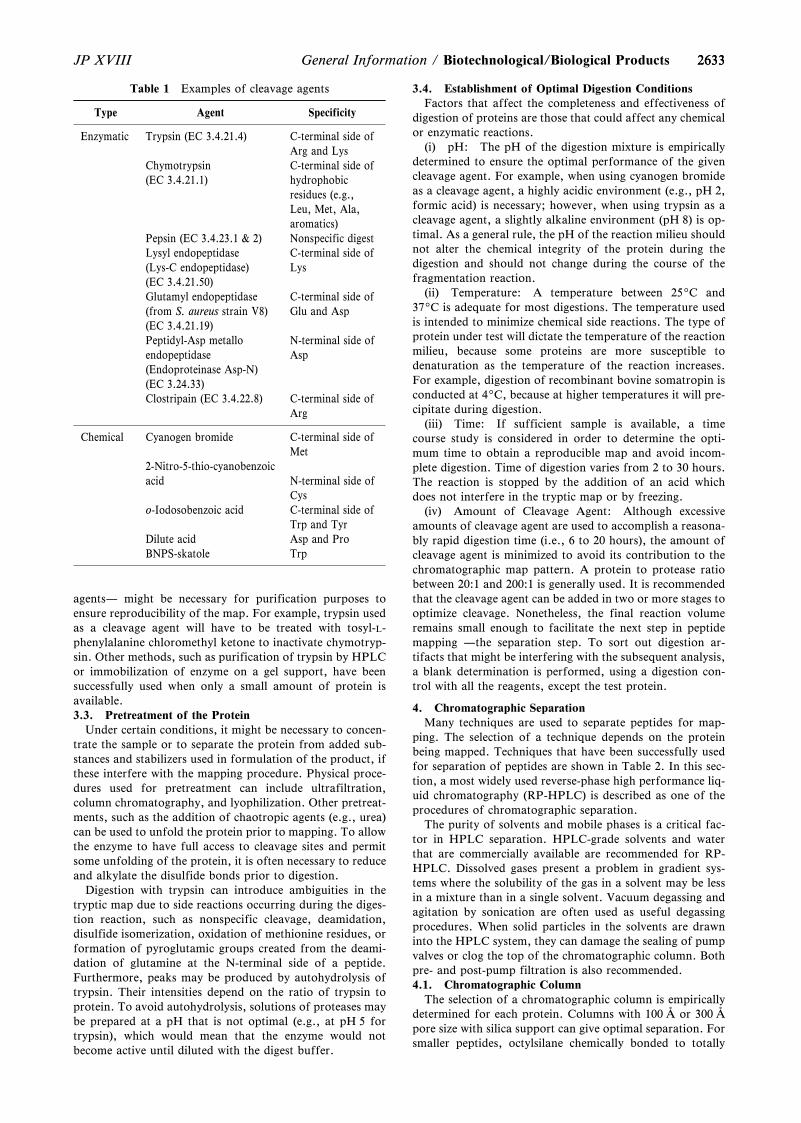
2633
Table 1 Examples of cleavage agents
Type Agent Specificity
Enzymatic Trypsin (EC 3.4.21.4) C-terminal side ofArg and Lys
Chymotrypsin(EC 3.4.21.1)
C-terminal side ofhydrophobicresidues (e.g.,Leu, Met, Ala,aromatics)
Pepsin (EC 3.4.23.1 & 2) Nonspecific digestLysyl endopeptidase(Lys-C endopeptidase)(EC 3.4.21.50)
C-terminal side ofLys
Glutamyl endopeptidase(from S. aureus strain V8)(EC 3.4.21.19)
C-terminal side ofGlu and Asp
Peptidyl-Asp metalloendopeptidase(Endoproteinase Asp-N)(EC 3.24.33)
N-terminal side ofAsp
Clostripain (EC 3.4.22.8) C-terminal side ofArg
Chemical Cyanogen bromide C-terminal side ofMet
2-Nitro-5-thio-cyanobenzoicacid N-terminal side of
Cyso-Iodosobenzoic acid C-terminal side of
Trp and TyrDilute acid Asp and ProBNPS-skatole Trp
2633JP XVIII General Information / Biotechnological/Biological Products
agents— might be necessary for purification purposes toensure reproducibility of the map. For example, trypsin usedas a cleavage agent will have to be treated with tosyl-L-phenylalanine chloromethyl ketone to inactivate chymotryp-sin. Other methods, such as purification of trypsin by HPLCor immobilization of enzyme on a gel support, have beensuccessfully used when only a small amount of protein isavailable.3.3. Pretreatment of the Protein
Under certain conditions, it might be necessary to concen-trate the sample or to separate the protein from added sub-stances and stabilizers used in formulation of the product, ifthese interfere with the mapping procedure. Physical proce-dures used for pretreatment can include ultrafiltration,column chromatography, and lyophilization. Other pretreat-ments, such as the addition of chaotropic agents (e.g., urea)can be used to unfold the protein prior to mapping. To allowthe enzyme to have full access to cleavage sites and permitsome unfolding of the protein, it is often necessary to reduceand alkylate the disulfide bonds prior to digestion.
Digestion with trypsin can introduce ambiguities in thetryptic map due to side reactions occurring during the diges-tion reaction, such as nonspecific cleavage, deamidation,disulfide isomerization, oxidation of methionine residues, orformation of pyroglutamic groups created from the deami-dation of glutamine at the N-terminal side of a peptide.Furthermore, peaks may be produced by autohydrolysis oftrypsin. Their intensities depend on the ratio of trypsin toprotein. To avoid autohydrolysis, solutions of proteases maybe prepared at a pH that is not optimal (e.g., at pH 5 fortrypsin), which would mean that the enzyme would notbecome active until diluted with the digest buffer.
3.4. Establishment of Optimal Digestion ConditionsFactors that affect the completeness and effectiveness of
digestion of proteins are those that could affect any chemicalor enzymatic reactions.
(i) pH: The pH of the digestion mixture is empiricallydetermined to ensure the optimal performance of the givencleavage agent. For example, when using cyanogen bromideas a cleavage agent, a highly acidic environment (e.g., pH 2,formic acid) is necessary; however, when using trypsin as acleavage agent, a slightly alkaline environment (pH 8) is op-timal. As a general rule, the pH of the reaction milieu shouldnot alter the chemical integrity of the protein during thedigestion and should not change during the course of thefragmentation reaction.
(ii) Temperature: A temperature between 259C and379C is adequate for most digestions. The temperature usedis intended to minimize chemical side reactions. The type ofprotein under test will dictate the temperature of the reactionmilieu, because some proteins are more susceptible todenaturation as the temperature of the reaction increases.For example, digestion of recombinant bovine somatropin isconducted at 49C, because at higher temperatures it will pre-cipitate during digestion.
(iii) Time: If sufficient sample is available, a timecourse study is considered in order to determine the opti-mum time to obtain a reproducible map and avoid incom-plete digestion. Time of digestion varies from 2 to 30 hours.The reaction is stopped by the addition of an acid whichdoes not interfere in the tryptic map or by freezing.
(iv) Amount of Cleavage Agent: Although excessiveamounts of cleavage agent are used to accomplish a reasona-bly rapid digestion time (i.e., 6 to 20 hours), the amount ofcleavage agent is minimized to avoid its contribution to thechromatographic map pattern. A protein to protease ratiobetween 20:1 and 200:1 is generally used. It is recommendedthat the cleavage agent can be added in two or more stages tooptimize cleavage. Nonetheless, the final reaction volumeremains small enough to facilitate the next step in peptidemapping —the separation step. To sort out digestion ar-tifacts that might be interfering with the subsequent analysis,a blank determination is performed, using a digestion con-trol with all the reagents, except the test protein.
4. Chromatographic SeparationMany techniques are used to separate peptides for map-
ping. The selection of a technique depends on the proteinbeing mapped. Techniques that have been successfully usedfor separation of peptides are shown in Table 2. In this sec-tion, a most widely used reverse-phase high performance liq-uid chromatography (RP-HPLC) is described as one of theprocedures of chromatographic separation.
The purity of solvents and mobile phases is a critical fac-tor in HPLC separation. HPLC-grade solvents and waterthat are commercially available are recommended for RP-HPLC. Dissolved gases present a problem in gradient sys-tems where the solubility of the gas in a solvent may be lessin a mixture than in a single solvent. Vacuum degassing andagitation by sonication are often used as useful degassingprocedures. When solid particles in the solvents are drawninto the HPLC system, they can damage the sealing of pumpvalves or clog the top of the chromatographic column. Bothpre- and post-pump filtration is also recommended.4.1. Chromatographic Column
The selection of a chromatographic column is empiricallydetermined for each protein. Columns with 100 Å or 300 Åpore size with silica support can give optimal separation. Forsmaller peptides, octylsilane chemically bonded to totally
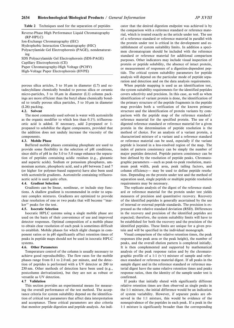
2634
Table 2 Techniques used for the separation of peptides
Reverse-Phase High Performance Liquid Chromatography(RP-HPLC)
Ion-Exchange Chromatography (IEC)Hydrophobic Interaction Chromatography (HIC)Polyacrylamide Gel Electrophoresis (PAGE), nondenaturat-
ingSDS Polyacrylamide Gel Electrophoresis (SDS-PAGE)Capillary Electrophoresis (CE)Paper Chromatography-High Voltage (PCHV)High-Voltage Paper Electrophoresis (HVPE)
2634 JP XVIIIBiotechnological/Biological Products / General Information
porous silica articles, 3 to 10 mm in diameter (L7) and oc-tadecylsilane chemically bonded to porous silica or ceramicmicro-particles, 3 to 10 mm in diameter (L1) column pack-ings are more efficient than the butyl silane chemically bond-ed to totally porous silica particles, 5 to 10 mm in diameter(L26) packing.4.2. Solvent
The most commonly used solvent is water with acetonitrileas the organic modifier to which less than 0.1z trifluoroa-cetic acid is added. If necessary, add 2-propanol or 1-propanol to solubilize the digest components, provided thatthe addition does not unduly increase the viscosity of thecomponents.4.3. Mobile Phase
Buffered mobile phases containing phosphate are used toprovide some flexibility in the selection of pH conditions,since shifts of pH in the 3.0 to 5.0 range enhance the separa-tion of peptides containing acidic residues (e.g., glutamicand aspartic acids). Sodium or potassium phosphates, am-monium acetate, phosphoric acid, and a pH between 2 and 7(or higher for polymer-based supports) have also been usedwith acetonitrile gradients. Acetonitrile containing trifluoro-acetic acid is used quite often.4.4. Gradient Selection
Gradients can be linear, nonlinear, or include step func-tions. A shallow gradient is recommended in order to sepa-rate complex mixtures. Gradients are optimized to provideclear resolution of one or two peaks that will become ``mar-ker'' peaks for the test.4.5. Isocratic Selection
Isocratic HPLC systems using a single mobile phase areused on the basis of their convenience of use and improveddetector responses. Optimal composition of a mobile phaseto obtain clear resolution of each peak is sometimes difficultto establish. Mobile phases for which slight changes in com-ponent ratios or in pH significantly affect retention times ofpeaks in peptide maps should not be used in isocratic HPLCsystems.4.6. Other Parameters
Temperature control of the column is usually necessary toachieve good reproducibility. The flow rates for the mobilephases range from 0.1 to 2.0 mL per minute, and the detec-tion of peptides is performed with a UV detector at 200 to230 nm. Other methods of detection have been used (e.g.,postcolumn derivatization), but they are not as robust orversatile as UV detection.4.7 Validation
This section provides an experimental means for measur-ing the overall performance of the test method. The accep-tance criteria for system suitability depend on the identifica-tion of critical test parameters that affect data interpretationand acceptance. These critical parameters are also criteriathat monitor peptide digestion and peptide analysis. An indi-
cator that the desired digestion endpoint was achieved is bythe comparison with a reference standard or reference mate-rial, which is treated exactly as the article under test. The useof a reference standard or reference material in parallel withthe protein under test is critical in the development and es-tablishment of system suitability limits. In addition a speci-men chromatogram should be included with the referencestandard or reference material for additional comparisonpurposes. Other indicators may include visual inspection ofprotein or peptide solubility, the absence of intact protein,or measurement of responses of a digestion-dependent pep-tide. The critical system suitability parameters for peptideanalysis will depend on the particular mode of peptide sepa-ration and detection and on the data analysis requirements.
When peptide mapping is used as an identification test,the system suitability requirements for the identified peptidescovers selectivity and precision. In this case, as well as whenidentification of variant protein is done, the identification ofthe primary structure of the peptide fragments in the peptidemap provides both a verification of the known primarystructure and the identification of protein variants by com-parison with the peptide map of the reference standard/reference material for the specified protein. The use of adigested reference standard or reference material for a givenprotein in the determination of peptide resolution is themethod of choice. For an analysis of a variant protein, acharacterized mixture of a variant and a reference standardor reference material can be used, especially if the variantpeptide is located in a less-resolved region of the map. Theindex of pattern consistency can be simply the number ofmajor peptides detected. Peptide pattern consistency can bebest defined by the resolution of peptide peaks. Chromato-graphic parameters —such as peak-to-peak resolution, maxi-mum peak width, peak area, peak tailing factors, andcolumn efficiency— may be used to define peptide resolu-tion. Depending on the protein under test and the method ofseparation used, single peptide or multiple peptide resolutionrequirements may be necessary.
The replicate analysis of the digest of the reference stand-ard or reference material for the protein under test yieldsmeasures of precision and quantitative recovery. Recoveryof the identified peptides is generally ascertained by the useof internal or external peptide standards. The precision is ex-pressed as the relative standard deviation (RSD). Differencesin the recovery and precision of the identified peptides areexpected; therefore, the system suitability limits will have tobe established for both the recovery and the precision of theidentified peptides. These limits are unique for a given pro-tein and will be specified in the individual monograph.
Visual comparison of the relative retention times, the peakresponses (the peak area or the peak height), the number ofpeaks, and the overall elution pattern is completed initially.It is then complemented and supported by mathematicalanalysis of the peak response ratios and by the chromato-graphic profile of a 1:1 (v/v) mixture of sample and refer-ence standard or reference material digest. If all peaks in thesample digest and in the reference standard or reference ma-terial digest have the same relative retention times and peaksresponse ratios, then the identity of the sample under test isconfirmed.
If peaks that initially eluted with significantly differentrelative retention times are then observed as single peaks inthe 1:1 mixture, the initial difference would be an indicationof system variability. However, if separate peaks are ob-served in the 1:1 mixture, this would be evidence of thenonequivalence of the peptides in each peak. If a peak in the1:1 mixture is significantly broader than the corresponding
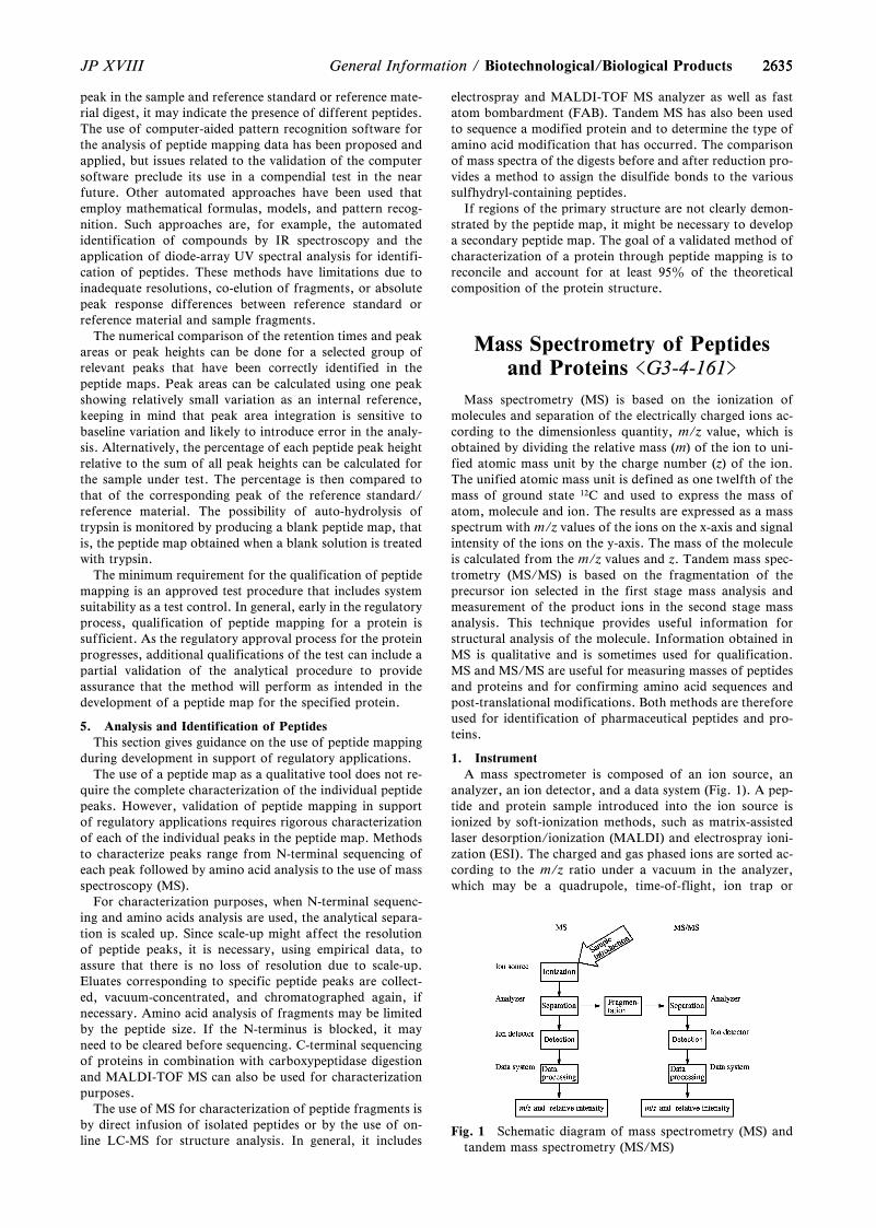
2635
Fig. 1 Schematic diagram of mass spectrometry (MS) andtandem mass spectrometry (MS/MS)
2635JP XVIII General Information / Biotechnological/Biological Products
peak in the sample and reference standard or reference mate-rial digest, it may indicate the presence of different peptides.The use of computer-aided pattern recognition software forthe analysis of peptide mapping data has been proposed andapplied, but issues related to the validation of the computersoftware preclude its use in a compendial test in the nearfuture. Other automated approaches have been used thatemploy mathematical formulas, models, and pattern recog-nition. Such approaches are, for example, the automatedidentification of compounds by IR spectroscopy and theapplication of diode-array UV spectral analysis for identifi-cation of peptides. These methods have limitations due toinadequate resolutions, co-elution of fragments, or absolutepeak response differences between reference standard orreference material and sample fragments.
The numerical comparison of the retention times and peakareas or peak heights can be done for a selected group ofrelevant peaks that have been correctly identified in thepeptide maps. Peak areas can be calculated using one peakshowing relatively small variation as an internal reference,keeping in mind that peak area integration is sensitive tobaseline variation and likely to introduce error in the analy-sis. Alternatively, the percentage of each peptide peak heightrelative to the sum of all peak heights can be calculated forthe sample under test. The percentage is then compared tothat of the corresponding peak of the reference standard/reference material. The possibility of auto-hydrolysis oftrypsin is monitored by producing a blank peptide map, thatis, the peptide map obtained when a blank solution is treatedwith trypsin.
The minimum requirement for the qualification of peptidemapping is an approved test procedure that includes systemsuitability as a test control. In general, early in the regulatoryprocess, qualification of peptide mapping for a protein issufficient. As the regulatory approval process for the proteinprogresses, additional qualifications of the test can include apartial validation of the analytical procedure to provideassurance that the method will perform as intended in thedevelopment of a peptide map for the specified protein.
5. Analysis and Identification of PeptidesThis section gives guidance on the use of peptide mapping
during development in support of regulatory applications.The use of a peptide map as a qualitative tool does not re-
quire the complete characterization of the individual peptidepeaks. However, validation of peptide mapping in supportof regulatory applications requires rigorous characterizationof each of the individual peaks in the peptide map. Methodsto characterize peaks range from N-terminal sequencing ofeach peak followed by amino acid analysis to the use of massspectroscopy (MS).
For characterization purposes, when N-terminal sequenc-ing and amino acids analysis are used, the analytical separa-tion is scaled up. Since scale-up might affect the resolutionof peptide peaks, it is necessary, using empirical data, toassure that there is no loss of resolution due to scale-up.Eluates corresponding to specific peptide peaks are collect-ed, vacuum-concentrated, and chromatographed again, ifnecessary. Amino acid analysis of fragments may be limitedby the peptide size. If the N-terminus is blocked, it mayneed to be cleared before sequencing. C-terminal sequencingof proteins in combination with carboxypeptidase digestionand MALDI-TOF MS can also be used for characterizationpurposes.
The use of MS for characterization of peptide fragments isby direct infusion of isolated peptides or by the use of on-line LC-MS for structure analysis. In general, it includes
electrospray and MALDI-TOF MS analyzer as well as fastatom bombardment (FAB). Tandem MS has also been usedto sequence a modified protein and to determine the type ofamino acid modification that has occurred. The comparisonof mass spectra of the digests before and after reduction pro-vides a method to assign the disulfide bonds to the varioussulfhydryl-containing peptides.
If regions of the primary structure are not clearly demon-strated by the peptide map, it might be necessary to developa secondary peptide map. The goal of a validated method ofcharacterization of a protein through peptide mapping is toreconcile and account for at least 95z of the theoreticalcomposition of the protein structure.
Mass Spectrometry of Peptidesand Proteins <G3-4-161>
Mass spectrometry (MS) is based on the ionization ofmolecules and separation of the electrically charged ions ac-cording to the dimensionless quantity, m/z value, which isobtained by dividing the relative mass (m) of the ion to uni-fied atomic mass unit by the charge number (z) of the ion.The unified atomic mass unit is defined as one twelfth of themass of ground state 12C and used to express the mass ofatom, molecule and ion. The results are expressed as a massspectrum with m/z values of the ions on the x-axis and signalintensity of the ions on the y-axis. The mass of the moleculeis calculated from the m/z values and z. Tandem mass spec-trometry (MS/MS) is based on the fragmentation of theprecursor ion selected in the first stage mass analysis andmeasurement of the product ions in the second stage massanalysis. This technique provides useful information forstructural analysis of the molecule. Information obtained inMS is qualitative and is sometimes used for qualification.MS and MS/MS are useful for measuring masses of peptidesand proteins and for confirming amino acid sequences andpost-translational modifications. Both methods are thereforeused for identification of pharmaceutical peptides and pro-teins.
1. InstrumentA mass spectrometer is composed of an ion source, an
analyzer, an ion detector, and a data system (Fig. 1). A pep-tide and protein sample introduced into the ion source isionized by soft-ionization methods, such as matrix-assistedlaser desorption/ionization (MALDI) and electrospray ioni-zation (ESI). The charged and gas phased ions are sorted ac-cording to the m/z ratio under a vacuum in the analyzer,which may be a quadrupole, time-of-flight, ion trap or

26362636 JP XVIIIBiotechnological/Biological Products / General Information
Fourier transform ion cyclotron resonance analyzer. The ionflux collected in the detector is converted to an electric sig-nal. Then the signal is recorded as a mass spectrum. MS/MSis carried out by using two mass spectrometers connected inseries, an ion-trap mass spectrometer and Fourier transformion cyclotron resonance mass spectrometer. The precursorions are generally fragmented by collision-induced dissocia-tion (CID), post-source decay (PSD), electron capture dis-sociation (ECO), etc.
2. Analytical mode2.1. MS
There are two useful modes for MS:(1) Total ion monitoring
The signals of the entire ion are acquired over the chosenrange of m/z value. This mode provides information on themasses of the molecule of interest and different species.(2) Selected ion monitoring
The signals of the ion at chosen m/z value are acquired.This mode is useful for the sensitive measurement of thechosen molecule.2.2. MS/MS
There are four essential modes for MS/MS:(1) Product ion analysis
The signals of all the product ions produced from theprecursor ion at chosen m/z value are acquired. This modeprovides structural information on the substrates and vari-ous co-existing species.(2) Precursor ion scan mode
The signals of the precursor ion that yields the product ionat chosen m/z value are monitored. This mode is used forsorting the molecules containing a component of interest.(3) Constant neutral loss scan mode
The signals of the precursor ion that loses the fragment atchosen m/z value are monitored. This mode is useful to sortthe molecules containing a component of interest.(4) Selected reaction monitoring
The signals of product ions at chosen m/z value that areproduced from the precursor ion at chosen m/z value aremonitored. This mode allows for sensitive and selectivemeasurement and is used for quantification of a molecule ina complex mixture.
3. Analytical procedure3.1. MS
In advance, it should be confirmed if the detectability andthe difference between the calculated mass and observedmass meet the criteria stated in the monograph by massmeasuring using a test solution specified in the systemsuitability in the monograph. If they do not meet the criteria,the system should be optimized by adjustment of the voltageof the ion source, analyzer and detector, as well as bycalibration using appropriate mass calibrator. After con-firming that the criteria are met, MS is performed accordingto the sample preparation and operating conditions indicatedin the monograph. The general procedure is described as fol-lows.(1) Matrix-assisted laser desorption/ionization (MALDI)
A desalted peptide and protein sample is dissolved in anappropriate solvent, e.g., an aqueous solution of trifluoroa-cetic acid. A suitable matrix, such as a-ciano-4-hydroxycin-namic acid, 2,5-dihydroxybenzoic acid, or sinapic acid, isdissolved in an aqueous solution containing acetonitrile andtrifluoroacetic acid. A mixture of sample solution andmatrix solution is deposited on a sample plate and dried. Thesample on the plate is set in the ion source, and ionized by alaser beam at suitable intensity.
(2) Electrospray ionization (ESI)A desalted peptide and protein sample is dissolved in a
suitable solvent, such as an aqueous solution containingacetic acid and methanol or acetonitrile. The sample solutionis introduced by using a syringe or HPLC. The sample isionized by applying voltage to obtain the spectrum.3.2. MS/MS
System suitability is tested by MS/MS of the test samplespecified in the monograph. The detectability and systemperformance should be confirmed based on the detection ofthe product ions specified in the monograph. The sample isionized in the same way as for MS, and the chosen precursoris fragmented by the suitable conditions specified in themonograph. The signals are recorded as a mass spectrum. Apeptide containing disulfide bonds is generally reduced bydithiothreitol, 2-mercaptethanol and tris(2-carboxyethyl)phosphine. The reduced peptides are alkylated with monoio-doacetic acid, iodoacetamide, and 4-vinylpyridine.
4. Identification test4.1. Mass of the molecule
The monoisotopic mass of the peptide and protein molec-ules is measured by MS. If the monoisotopic peak is detecta-ble, the monoisotopic mass is determined from the peak. Ifthe monoisotopic peak is not detectable, the average mass iscalculated from the top of the ion peak. Deconvolution is ef-fective for calculating the average mass of multiply-chargedions from proteins. The mass should meet the criteria speci-fied in the monograph.4.2. Amino acid sequence
After measuring the mass of the sample peptide, thepresence of the specified product ions that arise from theselected precursor ion is confirmed according to the condi-tions indicated in the monograph. Digestion of sample pro-teins with a suitable enzyme followed by MS/MS is some-times effective for sequencing of the high-molecular weightproteins which provide insufficient product ions. Details ofthe digestion procedure are provided in ``Peptide Mapping<G3-3-142>'' in General Information.
5. GlossaryIon-trap (IT)
Ion-trap refers to the quadrupole ion trap mass analyzer ina restricted sense. Ions stored in the analyzer by applying ra-dio frequency voltage to ring electrodes are separated bysubsequent ejection of the ions from the analyzer by varyingthe voltage on the ring electrodes. This allows multiple stageMS (MSn) in which a selected ion is repeatedly trapped, frag-mented and ejected.
Electrospray ionization (ESI)The sample in solution is sprayed through a needle tip and
held at high-voltage at atmospheric pressure. The sample isionized by a formation of charged liquid droplets. High-molecular mass proteins are detected as multiply-chargedions. The analyzer can be connected with HPLC.
Quadrupole (Q)The analyzer is composed of four parallel electrodes which
have a hyperboloidal or corresponding cross-section. Theions transmitted to the analyzer are separated by varying thepotential of direct and radio frequency components appliedto the rods so that the filter for sorting the m/z values ofions is changed.
Collision-induced dissociation (CID)When an ion collides with a neutral collision gas (He, Ar,
N2 and so on), some of the translational energy of the colli-sion is converted into internal energy, thereby causing ion
26372637JP XVIII General Information / Biotechnological/Biological Products
excitation and dissociation. The terms low-energy CID andhigh-energy CID refer to those CIDs for which the transla-tional energy of the precursor ions is lower than 1000 eV andhigher than 1000 eV, respectively.
Electron capture dissociation (ECD)Multiply-charged positive ions interact with low energy
electrons producing charge-reduced radical ions, which rea-dily dissociate. This method is primarily used for MS/MS inFT-ICR MS or IT MS.
Time-of-flight (TOF)The ionized sample is accelerated at high-voltage and sepa-
rated based on the time required for an ion to travel to thedetector. There are two types of analyzer, a linear type inwhich ions travel linearly from the ion source to the detector,and a reflectron type where ions are inverted by a reflectron.The latter type allows high-resolution measurement by cor-rection of the variation in the initial energy of ions.
Fourier transform ion cyclotron resonance (FT-ICR)The analyzer is based on the principle that the cyclotron
frequency of the rotating (cyclotron motion) ions in a mag-netic field is inversely proportional to its m/z value. Ions areexcited using radio frequency energy and their image currentis detected on a detection electrode. The resulting data aredevolved by applying a Fourier transform to give a massspectrum.
Post-source decay (PSD)Metastable ion decay occurs by excess internal energy and
collision with residual gas during ion acceleration out of theMALDI ion source and prior to reaching the detector. Thismethod is used for MS/MS by using MALDI-TOF MS witha reflectron mode.
Matrix-assisted laser desorption/ionization (MALDI)The sample, which is mixed with a suitable matrix, is
ionized by irradiation with nanosecond laser pulses. Pro-teins, carbohydrates, oligonucleotides, and lipids can beionized without any dissociation. Singly-charged ions aremainly detected.
Monosaccharide Analysis andOligosaccharide Analysis/Oligosaccharide Profiling
<G3-5-170>
Glycosylation analysis is a method to confirm the con-sistency of the oligosaccharides attached to glycoproteindrug substance, product or material. When oligosaccharidesattached to the glycoprotein affect efficacy and safety or thepossibility cannot be denied, oligosaccharides are consideredas critical quality attribute, and strategy should be designedin order to ensure the consistency of glycosylation. One ofthe strategies is glycosylation analysis, which involves 1)analysis of released monosaccharides (monosaccharideanalysis), 2) analysis of released oligosaccharides (oligosac-charide analysis/oligosaccharide profiling), 3) analysis ofglycopeptides (glycopeptide analysis), and 4) analysis ofintact glycoprotein (glycoform analysis). These methodsprovide monosaccharide compositions, oligosaccharideidentities and distribution in whole glycoprotein, site-specificglycosylation identities and distribution, and overall glycosy-lation characteristics and distribution of glycoprotein, re-spectively. In the setting specification of glycosylation analy-
sis, proper methods should be selected and used alone or incombination, in consideration of the relationship betweenthe oligosaccharide structures and functions, such as biologi-cal activity, pharmacodynamics, pharmacokinetics, immu-nogenicity, stability, and solubility. Glycosylation consisten-cy may be ensured not only by oligosaccharide analysis butalso at manufacturing process. Glycosylation analysis can bealso used as in-process test, and as method to confirmglycosylation consistency during process development.Methods and general consideration of monosaccharideanalysis and oligosaccharide analysis/oligosaccharide profil-ing are described below. For glycopeptide analysis, GeneralTest <2.62> Mass Spectrometry, and General InformationPeptide Mapping and Mass Spectrometry of Peptides andProteins would be helpful, and for glycoform analysis,General Information Isoelectric Focusing and CapillaryElectrophoresis, and General Test <2.62> Mass Spectrometrywould be helpful.
1. Monosaccharide analysisMonosaccharides are released by cleavage of glycosidic
bond using acid hydrolysis, exoglycosidase or methanolysis.Released monosaccharides are dried and purified if needed,and then analyzed using liquid chromatography, gas chro-matography, or capillary electrophoresis. Internal standardmethod or absolute calibration method are used for quan-titative measurement. The analytical results are typicallyexpressed as molar ratio of individual monosaccharides toglycoprotein.1.1. Isolation and purification of glycoprotein
Monosaccharide analysis is generally performed afterglycoprotein is isolated and purified in an appropriatemanner, because excipients and salts may affect hydrolysis,derivatization of monosaccharides, and chromatographicseparation. When purification of the glycoprotein is re-quired, the procedure is specified in the specific monograph.1.2. Release of monosaccharide1.2.1. Acid hydrolysis
Acid hydrolysis is the most common procedure to releaseneutral and amino sugars. In general, monosaccharides maybe released by acid hydrolysis of glycosidic bond under con-ditions such as 2 to 7 mol/L trifluoroacetic acid at about1009C. Since amino sugar residue directly attached to pro-tein is difficult to release, for accurate quantification ofamino sugars, acid hydrolysis should be performed sepa-rately under conditions such as 2 to 6 mol/L hydrochlorideat 1009C. Because hydrolysis rate is dependent on the identi-ty of the monosaccharide, the anomeric configuration, andposition of the glycosidic linkage, it is recommended thatrelease and degradation of individual monosaccharides areconfirmed by time-course study. Because N-acetyl groups ofamino sugars are removed under acid hydrolysis conditions,re-N-acetylation may be performed if needed. Since sialicacid is labile, sialic acids are released separately under condi-tions such as 0.1 mol/L hydrochloride, 0.1 mol/L sulfuricacid, or 2 mol/L acetic acid at 809C.1.2.2. Enzymatic treatment
Exoglycosidase digestion is also used for release of sialicacids from glycoprotein. Typically, sialidases with broadspecificity, such as those derived from Arthrobacter ureafa-ciens or Clostridium perfringens are used. Digestion condi-tions should be optimized in consideration of the identity ofsialic acids, linkage, O-acetylation and others. Other en-zymes with high specificity may be used to distinguish sialicacid having different types of linkage.1.2.3. Methanolysis
Dried sample is heated under methanolic hydrogen chlo-
2638
Table 1 Examples of enzymatic cleavage agents
Enzyme Specificity
N-linked oligosaccharide releasePeptide-N 4-(N-acetyl-b-glucosaminyl)asparagine amidase (EC 3.5.1.52)
Hydrolysis of peptide-N 4-(N-acetyl-b-D-glucosaminyl) asparagine residuein which the glucosamine residue may be further glycosylated, to yield a(substituted) N-acetyl-b-D-glucosaminylamine and a peptide containing anaspartate residue
—Peptide N-glycosidase F (PNGase F) Release of N-linked oligosaccharides but no release of N-linked oligosac-charides containing (a1,3)-linked core fucose
—Peptide N-glycosidase A Release of N-linked oligosaccharides including those containing (a1,3)-linked core fucose
Mannosyl-glycoprotein endo-b-N-acetyl-glucosaminidase (EC 3.2.1.96)
Endohydrolysis of the N,N?-diacetylchitobiosyl unit in high-mannoseglycopeptides/glycoproteins containing the—[Man(GlcNAc)2]Asn struc-ture [Man(GlcNAc)2]Asn
—Endo-b-N-acetylglucosaminidase F (endo F) Release of high-mannose, hybrid, and complex oligosaccharides—Endo-b-N-acetylglucosaminidase H (endo H) Release of high-mannose and hybrid oligosaccharidesO-linked oligosaccharide releaseGlycopeptide a-N-acetylgalactosaminidase (EC3.2.1.97)*
Release of D-galactose-(a1,3)-N-acetylgalactosamine a-linked to serine/threonine residue
* This enzyme has limited usage because of its high substrate specificity.
2638 JP XVIIIBiotechnological/Biological Products / General Information
ride. Monosaccharides are released as methyl glycosides.Degradation of released monosaccharides is low comparedto acid hydrolysis.1.3. Quantification of the released monosaccharides1.3.1. High-pH anion-exchange chromatography withpulsed amperometric detection
Acid is removed from the hydrolysate if needed. Monosac-charides can be separated and quantified without derivatiza-tion using high-pH anion-exchange chromatography withpulsed amperometric detection. Monosaccharides haveabout 12 to 14 of acid dissociation constant (pKa). They areionized under high pH conditions (pH 12 to 13), and can beseparated by strong anion-exchange chromatography usingpolymer-based stationary phase containing quaternary am-monium groups. Amperometric detection is a method to de-tect electrochemically active ions by measuring the currentwhen analyte is oxidized or reduced at electrodes. Sugar isionized at high pH and can be selectively detected by am-perometry. Because oxidized products of sugars foul theelectrodes and reduce the signals, pulsed amperometry,where electrode surface is cleaned by changing positive andnegative potentials after data acquisition, is used. Sinceamino acids are also detectable by amperometry, it is notedthat analysis may be interfered in the case of theglycoprotein with low oligosaccharide contents. This analyti-cal method can be used for oligosaccharide analysis as wellas for analysis of neutral and amino sugars, and sialic acids.1.3.2. Derivatization and liquid chromatography
(1) Neutral and amino sugarsMonosaccharides obtained by acid hydrolysis are treated
to remove the acid, re-N-acetylated if needed, then reduc-tively aminated with 2-aminobenzoic acid, 2-aminopyridine,or ethyl-4-aminobenzoate, or derivatized with 3-methyl-1-phenyl-5-pyrazolone. Impurities derived from reagents mayinterfere the analysis, attention should be paid to the purityof the reagents used. To prevent excessive reagents to affecttest results, derivatized monosaccharides are purified ifneeded. The derivatized monosaccharides may be separatedusing reversed-phase chromatography, or anion-exchangechromatography with formation of borate complex.Separated monosaccharides are detected by fluorometric orultraviolet detector. Underivatized monosaccharides may beseparated by ion-exchange chromatography, post-column
derivatization using such as arginine, and then detected.(2) Sialic acidReleased sialic acids by mild acid hydrolysis or sialidase
digestion are derivatized with 1,2-diamino-4.5-methylenedioxybenzen or 1,2-phenylenediamine, which reactwith a-keto acid specifically. This reaction proceeds in acidicconditions, thus acid hydrolysate can be used for derivatiza-tion without removal of the acid. Derivatized sialic acids areseparated by reversed-phase chromatography and detectedby fluorometric detector.1.3.3. Gas chromatography
There are several methods for gas chromatography;monosaccharides obtained by methanolysis are re-N-acetylated and trimethylsilylated (trimethylsilyl derivatives),and the monosaccharides obtained by acid hydrolysis arereduced and then acetylated (alditol acetate derivatives). Theformer can quantitate sialic acids simultaneously withoutdegradation, but each sugar gives several peaks due to a- andb-anomers and isomers, and chromatogram becomes com-plex.
Methylation analysis provides the structural informationor the glycosidic linkage of individual monosaccharides.After all hydroxy groups in the oligosaccharide are methylat-ed, permethylated oligosaccharide is subject to acid hydroly-sis and resultant partially O-methylated monosaccharides arereduced and acetylated. Partially O-methylated alditol ace-tates are separated and quantified using gas chromatogra-phy.1.4. Acceptance criteria
Confirmation of compliance of the test material is typi-cally achieved by demonstrating that contents of individualmonosaccharides per protein are within a specified range. Inorder to set acceptance criteria properly, it is needed to con-sider the relationship between characteristics of glycosyla-tion, and efficacy and safety.1.5. Monosaccharide reference materials
Monosaccharides to be analyzed are often used as refer-ence materials for monosaccharide analysis. In this case,monosaccharide reference material mixtrure is prepared asmixing each monosaccharide equally, or at similar ratio ex-pected in test substance.1.6. System suitability
The solution for system suitability test should be prepared
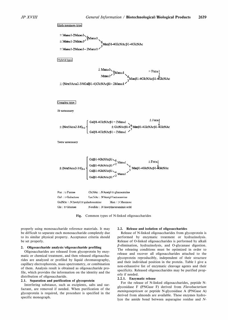
2639
Fig. Common types of N-linked oligosaccharides
2639JP XVIII General Information / Biotechnological/Biological Products
properly using monosaccharide reference materials. It maybe difficult to separate each monosaccharide completely dueto its similar physical property. Acceptance criteria shouldbe set properly.
2. Oligosaccharide analysis/oligosaccharide profilingOligosaccharides are released from glycoprotein by enzy-
matic or chemical treatment, and then released oligosaccha-rides are analyzed or profiled by liquid chromatography,capillary electrophoresis, mass spectrometry, or combinationof them. Analysis result is obtained as oligosaccharide pro-file, which provides the information on the identity and thedistribution of oligosaccharide.2.1. Separation and purification of glycoprotein
Interfering substance, such as excipients, salts and sur-factant, are removed if needed. When purification of theglycoprotein is required, the procedure is specified in thespecific monograph.
2.2. Release and isolation of oligosaccharidesRelease of N-linked oligosaccharides from glycoprotein is
performed by enzymatic treatment or hydrazinolysis.Release of O-linked oligosaccharides is performed by alkalib-elimination, hydrazinolysis, and O-glycanase digestion.The releasing conditions must be optimized in order torelease and recover all oligosaccharides attached to theglycoprotein reproducibly, independent of their structureand their individual position in the protein. Table 1 give anon-exhaustive list of enzymatic cleavage agents and theirspecificity. Released oligosaccharides may be purified prop-erly if needed.2.2.1. Enzymatic release
For the release of N-linked oligosaccharides, peptide N-glycosidase F (PNGase F) derived from Flavobacteriummeningosepticum or peptide N-glycosidase A (PNGase A)derived from almonds are available. These enzymes hydro-lyze the amide bond between asparagine residue and N-
2640
Table 2 Examples of derivatizing agents and suitable analytical techniques.
Agent Structure Acronym Analytical techniques Fluorescent or UV detection
2-Aminobenzoic acid 2-AA LC, CE, MS Ex: 360 nm, Em: 425 nmEx: 325 nm, Em: 405 nm
2-Aminobenzamide 2-AB LC, MS Ex: 330 nm, Em: 420 nm
2-Aminopyridine 2-AP LC, MS Ex: 310 nm, Em: 380 nmEx: 320 nm, Em: 400 nm
Trisodium 8-aminopyrene-1,3,6-trisulfonic salt
APTS CE Ex: 488 nm, Em: 520 nm
3-methyl-1-phenyl-5-pyrazolone PMP LC, MS UV 245 nm
2640 JP XVIIIBiotechnological/Biological Products / General Information
acetylglucosamine residue at reducing end of oligosaccha-rides to produce glycosylamine derivative and aspartic acidresidue. Glycosylamine derivative is subsequently hydrolyzednon-enzymatically under weak acidic conditions to ammoniaand free oligosaccharide. O-glycanase from Diplococcuspneumoniae is available to release O-linked oligosaccharides,but specificity of this enzyme is too narrow.2.2.1.1. PNGase F digestion
PNGase F have an optimum pH 7 to 9. Glycoprotein istreated directly or under presence of a reducing agent, sur-factant, and/or denaturing agent. Glycoprotein may betreated with PNGase F after reduced and alkylated, or afterdigested into glycopeptides. Glycoproteins from some insectcells and plants may have a (a1,3)-linked fucose attached tothe proximal GlcNAc of the core chitobiose, and N-linkedoligosaccharides containing this structure are not released bythis enzyme.2.2.1.2. PNGase A digestion
PNGase A have an optimum pH 4 to 6. Since this enzymeis difficult to release oligosaccharides directly from wholeglycoprotein, a glycoprotein sample is digested with a pro-teolytic agent, such as endoprotease, and then glycopeptidesare treated with this enzyme to release oligosaccharides.2.2.2. Chemical cleavage2.2.2.1. Hydrazinolysis
To well-dried glycoprotein anhydrous hydrazine is addedand heated. Hydrazine cleaves glycosylamine linkage be-tween oligosaccharide and peptide as well as peptide bond.With careful control of reaction conditions, selective releaseof N-linked oligosaccharide and/or O-linked oligosaccha-rides can be achieved. Because de-N-acetylation of amino su-gar and sialic acid in oligosaccharides also occurs, aminogroups are re-N-acetylated after removing hydrazine. Atten-tion should be paid to the possibility of loss of sialic acid,and successive degradation from reducing end of released O-linked oligosaccharides (peeling reaction).2.2.2.2. Alkali b-elimination
Heating glycoprotein under alkaline conditions results inrelease of O-linked oligosaccharides by b-elimination. Toprevent peeling reactions, reaction is conducted in thepresence of a reducing agent, such as sodium tetra-hydroborate. It is noted that reducing end of obtained O-
linked oligosaccharides is already reduced, thus, cannot bederivatized. There is a method to release the oligosaccharidesand simultaneously to derivatize with 3-methyl-1-phenyl-5-pyrazolone.2.3. Analysis of released oligosaccharides
Oligosaccharides are analyzed directly or after derivatized.Table 2 gives a non-exhaustive list of commonly used fluo-rescent labels and suitable analytical techniques. The analy-sis method is needed to separate and detect individualoligosaccharides or family of oligosaccharides with the struc-ture which affects efficacy and safety.2.3.1. Liquid chromatography <2.01>2.3.1.1. Derivatization and liquid chromatography/fluoro-metric or UV detection
Profiling of derivatized oligosaccharides by liquid chro-matography is the most common methods. Oligosaccharidesderivatized with 2-aminobenzamide, 2-aminobenzoic acid,2-aminopyridine or others are separated by hydrophilicinteraction, reversed-phase, ion-exchange, or mixed-modechromatography, and then detected by fluorometry.Oligosaccharides derivatized with 3-methyl-1-phenyl-5-pyrazolone are separated by reversed-phase chromatogra-phy, and then detected by UV spectrometry. Hydrophilic in-teraction liquid chromatography separates oligosaccharideson the basis of hydrophilicity (i.e. size, the number of sialicacid, ...). Reversed-phase chromatography separatesoligosaccharides on the basis of hydrophobicity (i.e. type ofoligosaccharide, branching, number of sialic acid, ...). Ion-exchange chromatography separates oligosaccharides on thebasis of number of charges. A mix mode of ion-exchangeand hydrophilic interaction separates oligosaccharides on thebasis of structure as well as number of charges.2.3.1.2. High-pH anion-exchange chromatography/pulsedamperometric detection
Released oligosaccharides are separated by strong anion-exchange chromatography using polymer-based stationaryphase containing quaternary ammonium groups, and detect-ed by pulsed amperometry. This method can separate anddetect sialo-oligosaccharides according to the number of sial-ic acids and linkage differences. This method has often beenused for profiling of sialo-oligosaccharides because of noneed of derivatization (no loss of sialic acid and no loss of
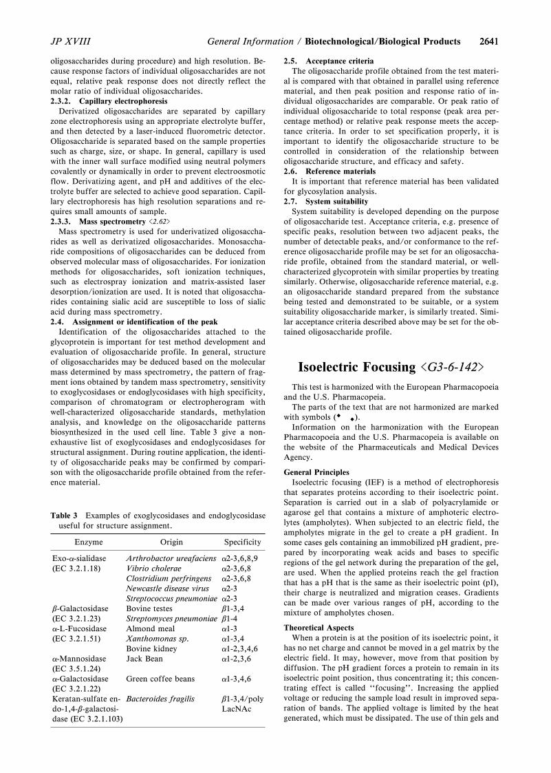
2641
Table 3 Examples of exoglycosidases and endoglycosidaseuseful for structure assignment.
Enzyme Origin Specificity
Exo-a-sialidase(EC 3.2.1.18)
Arthrobactor ureafaciens a2-3,6,8,9Vibrio cholerae a2-3,6,8Clostridium perfringens a2-3,6,8Newcastle disease virus a2-3Streptococcus pneumoniae a2-3
b-Galactosidase(EC 3.2.1.23)
Bovine testes b1-3,4Streptomyces pneumoniae b1-4
a-L-Fucosidase(EC 3.2.1.51)
Almond meal a1-3Xanthomonas sp. a1-3,4Bovine kidney a1-2,3,4,6
a-Mannosidase(EC 3.5.1.24)
Jack Bean a1-2,3,6
a-Galactosidase(EC 3.2.1.22)
Green coffee beans a1-3,4,6
Keratan-sulfate en-do-1,4-b-galactosi-dase (EC 3.2.1.103)
Bacteroides fragilis b1-3,4/polyLacNAc
2641JP XVIII General Information / Biotechnological/Biological Products
oligosaccharides during procedure) and high resolution. Be-cause response factors of individual oligosaccharides are notequal, relative peak response does not directly reflect themolar ratio of individual oligosaccharides.2.3.2. Capillary electrophoresis
Derivatized oligosaccharides are separated by capillaryzone electrophoresis using an appropriate electrolyte buffer,and then detected by a laser-induced fluorometric detector.Oligosaccharide is separated based on the sample propertiessuch as charge, size, or shape. In general, capillary is usedwith the inner wall surface modified using neutral polymerscovalently or dynamically in order to prevent electroosmoticflow. Derivatizing agent, and pH and additives of the elec-trolyte buffer are selected to achieve good separation. Capil-lary electrophoresis has high resolution separations and re-quires small amounts of sample.2.3.3. Mass spectrometry <2.62>
Mass spectrometry is used for underivatized oligosaccha-rides as well as derivatized oligosaccharides. Monosaccha-ride compositions of oligosaccharides can be deduced fromobserved molecular mass of oligosaccharides. For ionizationmethods for oligosaccharides, soft ionization techniques,such as electrospray ionization and matrix-assisted laserdesorption/ionization are used. It is noted that oligosaccha-rides containing sialic acid are susceptible to loss of sialicacid during mass spectrometry.2.4. Assignment or identification of the peak
Identification of the oligosaccharides attached to theglycoprotein is important for test method development andevaluation of oligosaccharide profile. In general, structureof oligosaccharides may be deduced based on the molecularmass determined by mass spectrometry, the pattern of frag-ment ions obtained by tandem mass spectrometry, sensitivityto exoglycosidases or endoglycosidases with high specificity,comparison of chromatogram or electropherogram withwell-characterized oligosaccharide standards, methylationanalysis, and knowledge on the oligosaccharide patternsbiosynthesized in the used cell line. Table 3 give a non-exhaustive list of exoglycosidases and endoglycosidases forstructural assignment. During routine application, the identi-ty of oligosaccharide peaks may be confirmed by compari-son with the oligosaccharide profile obtained from the refer-ence material.
2.5. Acceptance criteriaThe oligosaccharide profile obtained from the test materi-
al is compared with that obtained in parallel using referencematerial, and then peak position and response ratio of in-dividual oligosaccharides are comparable. Or peak ratio ofindividual oligosaccharide to total response (peak area per-centage method) or relative peak response meets the accep-tance criteria. In order to set specification properly, it isimportant to identify the oligosaccharide structure to becontrolled in consideration of the relationship betweenoligosaccharide structure, and efficacy and safety.2.6. Reference materials
It is important that reference material has been validatedfor glycosylation analysis.2.7. System suitability
System suitability is developed depending on the purposeof oligosaccharide test. Acceptance criteria, e.g. presence ofspecific peaks, resolution between two adjacent peaks, thenumber of detectable peaks, and/or conformance to the ref-erence oligosaccharide profile may be set for an oligosaccha-ride profile, obtained from the standard material, or well-characterized glycoprotein with similar properties by treatingsimilarly. Otherwise, oligosaccharide reference material, e.g.an oligosaccharide standard prepared from the substancebeing tested and demonstrated to be suitable, or a systemsuitability oligosaccharide marker, is similarly treated. Simi-lar acceptance criteria described above may be set for the ob-tained oligosaccharide profile.
Isoelectric Focusing <G3-6-142>
This test is harmonized with the European Pharmacopoeiaand the U.S. Pharmacopeia.
The parts of the text that are not harmonized are markedwith symbols ( ).
Information on the harmonization with the EuropeanPharmacopoeia and the U.S. Pharmacopeia is available onthe website of the Pharmaceuticals and Medical DevicesAgency.
General PrinciplesIsoelectric focusing (IEF) is a method of electrophoresis
that separates proteins according to their isoelectric point.Separation is carried out in a slab of polyacrylamide oragarose gel that contains a mixture of amphoteric electro-lytes (ampholytes). When subjected to an electric field, theampholytes migrate in the gel to create a pH gradient. Insome cases gels containing an immobilized pH gradient, pre-pared by incorporating weak acids and bases to specificregions of the gel network during the preparation of the gel,are used. When the applied proteins reach the gel fractionthat has a pH that is the same as their isoelectric point (pI),their charge is neutralized and migration ceases. Gradientscan be made over various ranges of pH, according to themixture of ampholytes chosen.
Theoretical AspectsWhen a protein is at the position of its isoelectric point, it
has no net charge and cannot be moved in a gel matrix by theelectric field. It may, however, move from that position bydiffusion. The pH gradient forces a protein to remain in itsisoelectric point position, thus concentrating it; this concen-trating effect is called ``focusing''. Increasing the appliedvoltage or reducing the sample load result in improved sepa-ration of bands. The applied voltage is limited by the heatgenerated, which must be dissipated. The use of thin gels and
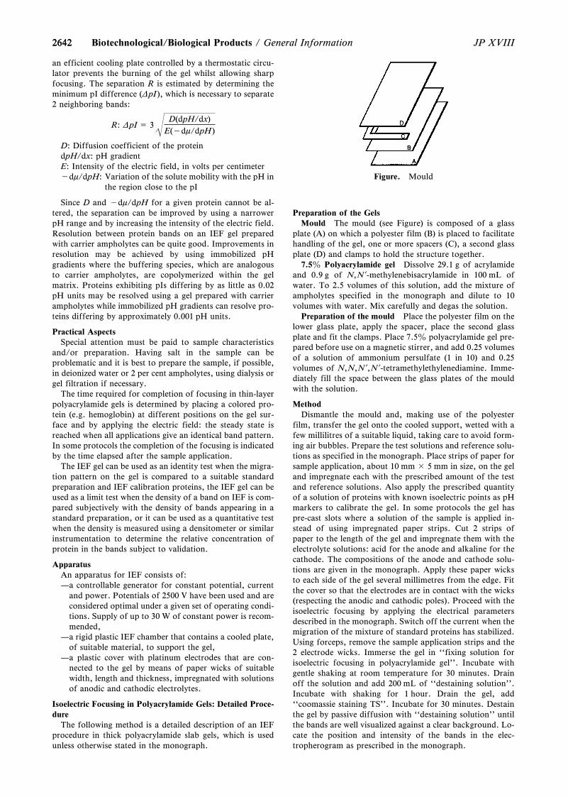
2642
Figure. Mould
2642 JP XVIIIBiotechnological/Biological Products / General Information
an efficient cooling plate controlled by a thermostatic circu-lator prevents the burning of the gel whilst allowing sharpfocusing. The separation R is estimated by determining theminimum pI difference (DpI ), which is necessary to separate2 neighboring bands:
R: DpI = 3D(dpH/dx)
E(-dm/dpH )
D: Diffusion coefficient of the proteindpH/dx: pH gradientE: Intensity of the electric field, in volts per centimeter-dm/dpH: Variation of the solute mobility with the pH in
the region close to the pI
Since D and -dm/dpH for a given protein cannot be al-tered, the separation can be improved by using a narrowerpH range and by increasing the intensity of the electric field.Resolution between protein bands on an IEF gel preparedwith carrier ampholytes can be quite good. Improvements inresolution may be achieved by using immobilized pHgradients where the buffering species, which are analogousto carrier ampholytes, are copolymerized within the gelmatrix. Proteins exhibiting pIs differing by as little as 0.02pH units may be resolved using a gel prepared with carrierampholytes while immobilized pH gradients can resolve pro-teins differing by approximately 0.001 pH units.
Practical AspectsSpecial attention must be paid to sample characteristics
and/or preparation. Having salt in the sample can beproblematic and it is best to prepare the sample, if possible,in deionized water or 2 per cent ampholytes, using dialysis orgel filtration if necessary.
The time required for completion of focusing in thin-layerpolyacrylamide gels is determined by placing a colored pro-tein (e.g. hemoglobin) at different positions on the gel sur-face and by applying the electric field: the steady state isreached when all applications give an identical band pattern.In some protocols the completion of the focusing is indicatedby the time elapsed after the sample application.
The IEF gel can be used as an identity test when the migra-tion pattern on the gel is compared to a suitable standardpreparation and IEF calibration proteins, the IEF gel can beused as a limit test when the density of a band on IEF is com-pared subjectively with the density of bands appearing in astandard preparation, or it can be used as a quantitative testwhen the density is measured using a densitometer or similarinstrumentation to determine the relative concentration ofprotein in the bands subject to validation.
ApparatusAn apparatus for IEF consists of:—a controllable generator for constant potential, current
and power. Potentials of 2500 V have been used and areconsidered optimal under a given set of operating condi-tions. Supply of up to 30 W of constant power is recom-mended,
—a rigid plastic IEF chamber that contains a cooled plate,of suitable material, to support the gel,
—a plastic cover with platinum electrodes that are con-nected to the gel by means of paper wicks of suitablewidth, length and thickness, impregnated with solutionsof anodic and cathodic electrolytes.
Isoelectric Focusing in Polyacrylamide Gels: Detailed Proce-dure
The following method is a detailed description of an IEFprocedure in thick polyacrylamide slab gels, which is usedunless otherwise stated in the monograph.
Preparation of the GelsMould The mould (see Figure) is composed of a glass
plate (A) on which a polyester film (B) is placed to facilitatehandling of the gel, one or more spacers (C), a second glassplate (D) and clamps to hold the structure together.
7.5z Polyacrylamide gel Dissolve 29.1 g of acrylamideand 0.9 g of N,N?-methylenebisacrylamide in 100 mL ofwater. To 2.5 volumes of this solution, add the mixture ofampholytes specified in the monograph and dilute to 10volumes with water. Mix carefully and degas the solution.
Preparation of the mould Place the polyester film on thelower glass plate, apply the spacer, place the second glassplate and fit the clamps. Place 7.5z polyacrylamide gel pre-pared before use on a magnetic stirrer, and add 0.25 volumesof a solution of ammonium persulfate (1 in 10) and 0.25volumes of N,N,N?,N?-tetramethylethylenediamine. Imme-diately fill the space between the glass plates of the mouldwith the solution.
MethodDismantle the mould and, making use of the polyester
film, transfer the gel onto the cooled support, wetted with afew millilitres of a suitable liquid, taking care to avoid form-ing air bubbles. Prepare the test solutions and reference solu-tions as specified in the monograph. Place strips of paper forsample application, about 10 mm × 5 mm in size, on the geland impregnate each with the prescribed amount of the testand reference solutions. Also apply the prescribed quantityof a solution of proteins with known isoelectric points as pHmarkers to calibrate the gel. In some protocols the gel haspre-cast slots where a solution of the sample is applied in-stead of using impregnated paper strips. Cut 2 strips ofpaper to the length of the gel and impregnate them with theelectrolyte solutions: acid for the anode and alkaline for thecathode. The compositions of the anode and cathode solu-tions are given in the monograph. Apply these paper wicksto each side of the gel several millimetres from the edge. Fitthe cover so that the electrodes are in contact with the wicks(respecting the anodic and cathodic poles). Proceed with theisoelectric focusing by applying the electrical parametersdescribed in the monograph. Switch off the current when themigration of the mixture of standard proteins has stabilized.Using forceps, remove the sample application strips and the2 electrode wicks. Immerse the gel in ``fixing solution forisoelectric focusing in polyacrylamide gel''. Incubate withgentle shaking at room temperature for 30 minutes. Drainoff the solution and add 200 mL of ``destaining solution''.Incubate with shaking for 1 hour. Drain the gel, add``coomassie staining TS''. Incubate for 30 minutes. Destainthe gel by passive diffusion with ``destaining solution'' untilthe bands are well visualized against a clear background. Lo-cate the position and intensity of the bands in the elec-tropherogram as prescribed in the monograph.

26432643JP XVIII General Information / Biotechnological/Biological Products
Variations to the Detailed Procedure (Subject to Validation)Where reference to the general method on isoelectric
focusing is made, variations in methodology or proceduremay be made subject to validation. These include:(1) the use of commercially available pre-cast gels and of
commercial staining and destaining kits,(2) the use of immobilized pH gradients,(3) the use of rod gels,(4) the use of gel cassettes of different dimensions, includ-
ing ultra-thin (0.2 mm) gels,(5) variations in the sample application procedure, includ-
ing different sample volumes or the use of sample appli-cation masks or wicks other than paper,
(6) the use of alternate running conditions, including varia-tions in the electric field depending on gel dimensionsand equipment, and the use of fixed migration timesrather than subjective interpretation of band stability,
(7) the inclusion of a pre-focusing step,(8) the use of automated instrumentation,(9) the use of agarose gels.
Validation of Iso-Electric Focusing ProceduresWhere alternative methods to the detailed procedure are
employed they must be validated. The following criteria maybe used to validate the separation:(1) formation of a stable pH gradient of desired character-
istics, assessed for example using colored pH markersof known isoelectric points,
(2) comparison with the electropherogram provided withthe chemical reference substance for the preparation tobe examined,
(3) any other validation criteria as prescribed in the mono-graph.
Specified Variations to the General MethodVariations to the general method required for the analysis
of specific substances may be specified in detail in mono-graphs. These include:(1) the addition of urea in the gel (3 mol/L concentration is
often satisfactory to keep protein in solution but up to 8mol/L can be used): some proteins precipitate at theirisoelectric point. In this case, urea is included in the gelformulation to keep the protein in solution. If urea isused, only fresh solutions should be used to preventcarbamylation of the protein,
(2) the use of alternative staining methods,(3) the use of gel additives such as non-ionic detergents
(e.g. octylglucoside) or zwitterionic detergents (e.g., 3-[(3-Cholamidopropyl)dimethylammonio]-1-propanesul-fonate (CHAPS) or 3-[(3-Cholamidopropyl)dimethylammonio]-2-hydroxy-1-propanesulfonate (CHAPSO)),and the addition of ampholyte to the sample, to preventproteins from aggregating or precipitating.
Points to ConsiderSamples can be applied to any area on the gel, but to pro-
tect the proteins from extreme pH environments samplesshould not be applied close to either electrode. Duringmethod development the analyst can try applying the proteinin 3 positions on the gel (i.e. middle and both ends); the pat-tern of a protein applied at opposite ends of the gel may notbe identical.
A phenomenon known as cathodic drift, where the pHgradient decays over time, may occur if a gel is focused toolong. Although not well understood, electroendoosmosis andabsorption of carbon dioxide may be factors that lead tocathodic drift. Cathodic drift is observed as focused proteinmigrating off the cathode end of the gel. Immobilized pH
gradients may be used to address this problem.Efficient cooling (approximately 49C) of the bed that the
gel lies on during focusing is important. High field strengthsused during isoelectric focusing can lead to overheating andaffect the quality of the focused gel.
Reagents and Solutions—Fixing solution for isoelectric focusing in polyacrylamide
gel Dissolve 35 g of 5-sulfosalicylic acid dihydrate and100 g of trichloroacetic acid in water to make 1000 mL.
Coomassie staining TS Dissolve 125 mg of coomassiebrilliant blue R-250 in 100 mL of a mixture of water, metha-nol and acetic acid (100) (5:4:1), and filter.
Destaining solution A mixture of water, methanol andacetic acid (100) (5:4:1).
Capillary Electrophoresis<G3-7-180>
This test is harmonized with the European Pharmacopoeiaand the U.S. Pharmacopeia.
Information on the harmonization with the EuropeanPharmacopoeia and the U.S. Pharmacopeia is available onthe website of the Pharmaceuticals and Medical DevicesAgency.
1. General PrinciplesCapillary electrophoresis is a physical method of analysis
based on the migration, inside a capillary, of charged ana-lytes dissolved in an electrolyte solution, under the influenceof a direct-current electric field.
The migration velocity of an analyte under an electric fieldof intensity E, is determined by the electrophoretic mobilityof the analyte and the electroosmotic mobility of the bufferinside the capillary. The electrophoretic mobility of a solute(mep) depends on the characteristics of the solute (electriccharge, molecular size and shape) and those of the buffer inwhich the migration takes place (type and ionic strength ofthe electrolyte, pH, viscosity and additives). The elec-trophoretic velocity (yep) of a solute, assuming a sphericalshape, is given by the equation:
yep = mepE = Ø q
6phr»ØVL»q: Effective charge of the solute,h: Viscosity of the electrolyte solution,r: Stoke's radius of the solute,V: Applied voltage,L: Total length of the capillary.
When an electric field is applied through the capillaryfilled with buffer, a flow of solvent is generated inside thecapillary, called electroosmotic flow. The velocity of theelectroosmotic flow depends on the electroosmotic mobility(meo) which in turn depends on the charge density on thecapillary internal wall and the buffer characteristics. Theelectroosmotic velocity (yeo) is given by the equation:
yeo = meoE = Øezh »ØVL»e: Dielectric constant of the buffer,z: Zeta potential of the capillary surface.
The velocity of the solute (y) is given by:
y = yep + yeo
The electrophoretic mobility of the analyte and the elec-
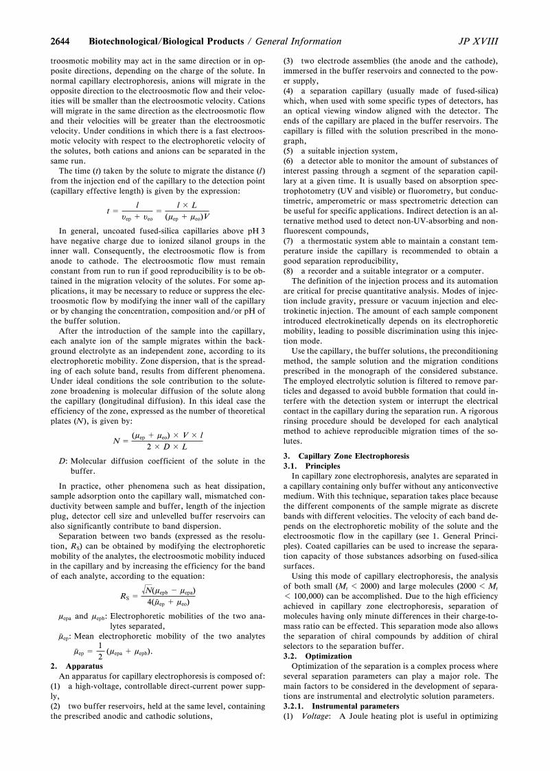
26442644 JP XVIIIBiotechnological/Biological Products / General Information
troosmotic mobility may act in the same direction or in op-posite directions, depending on the charge of the solute. Innormal capillary electrophoresis, anions will migrate in theopposite direction to the electroosmotic flow and their veloc-ities will be smaller than the electroosmotic velocity. Cationswill migrate in the same direction as the electroosmotic flowand their velocities will be greater than the electroosmoticvelocity. Under conditions in which there is a fast electroos-motic velocity with respect to the electrophoretic velocity ofthe solutes, both cations and anions can be separated in thesame run.
The time (t) taken by the solute to migrate the distance (l )from the injection end of the capillary to the detection point(capillary effective length) is given by the expression:
t =l
yep + yeo=
l × L
(mep + meo)V
In general, uncoated fused-silica capillaries above pH 3have negative charge due to ionized silanol groups in theinner wall. Consequently, the electroosmotic flow is fromanode to cathode. The electroosmotic flow must remainconstant from run to run if good reproducibility is to be ob-tained in the migration velocity of the solutes. For some ap-plications, it may be necessary to reduce or suppress the elec-troosmotic flow by modifying the inner wall of the capillaryor by changing the concentration, composition and/or pH ofthe buffer solution.
After the introduction of the sample into the capillary,each analyte ion of the sample migrates within the back-ground electrolyte as an independent zone, according to itselectrophoretic mobility. Zone dispersion, that is the spread-ing of each solute band, results from different phenomena.Under ideal conditions the sole contribution to the solute-zone broadening is molecular diffusion of the solute alongthe capillary (longitudinal diffusion). In this ideal case theefficiency of the zone, expressed as the number of theoreticalplates (N ), is given by:
N =(mep + meo) × V × l
2 × D × L
D: Molecular diffusion coefficient of the solute in thebuffer.
In practice, other phenomena such as heat dissipation,sample adsorption onto the capillary wall, mismatched con-ductivity between sample and buffer, length of the injectionplug, detector cell size and unlevelled buffer reservoirs canalso significantly contribute to band dispersion.
Separation between two bands (expressed as the resolu-tion, RS) can be obtained by modifying the electrophoreticmobility of the analytes, the electroosmotic mobility inducedin the capillary and by increasing the efficiency for the bandof each analyte, according to the equation:
RS =N(mepb - mepa)4( šmep + meo)
mepa and mepb: Electrophoretic mobilities of the two ana-lytes separated,
šmep: Mean electrophoretic mobility of the two analytes
šmep =12
(mepa + mepb).
2. ApparatusAn apparatus for capillary electrophoresis is composed of:
(1) a high-voltage, controllable direct-current power supp-ly,(2) two buffer reservoirs, held at the same level, containingthe prescribed anodic and cathodic solutions,
(3) two electrode assemblies (the anode and the cathode),immersed in the buffer reservoirs and connected to the pow-er supply,(4) a separation capillary (usually made of fused-silica)which, when used with some specific types of detectors, hasan optical viewing window aligned with the detector. Theends of the capillary are placed in the buffer reservoirs. Thecapillary is filled with the solution prescribed in the mono-graph,(5) a suitable injection system,(6) a detector able to monitor the amount of substances ofinterest passing through a segment of the separation capil-lary at a given time. It is usually based on absorption spec-trophotometry (UV and visible) or fluorometry, but conduc-timetric, amperometric or mass spectrometric detection canbe useful for specific applications. Indirect detection is an al-ternative method used to detect non-UV-absorbing and non-fluorescent compounds,(7) a thermostatic system able to maintain a constant tem-perature inside the capillary is recommended to obtain agood separation reproducibility,(8) a recorder and a suitable integrator or a computer.
The definition of the injection process and its automationare critical for precise quantitative analysis. Modes of injec-tion include gravity, pressure or vacuum injection and elec-trokinetic injection. The amount of each sample componentintroduced electrokinetically depends on its electrophoreticmobility, leading to possible discrimination using this injec-tion mode.
Use the capillary, the buffer solutions, the preconditioningmethod, the sample solution and the migration conditionsprescribed in the monograph of the considered substance.The employed electrolytic solution is filtered to remove par-ticles and degassed to avoid bubble formation that could in-terfere with the detection system or interrupt the electricalcontact in the capillary during the separation run. A rigorousrinsing procedure should be developed for each analyticalmethod to achieve reproducible migration times of the so-lutes.
3. Capillary Zone Electrophoresis3.1. Principles
In capillary zone electrophoresis, analytes are separated ina capillary containing only buffer without any anticonvectivemedium. With this technique, separation takes place becausethe different components of the sample migrate as discretebands with different velocities. The velocity of each band de-pends on the electrophoretic mobility of the solute and theelectroosmotic flow in the capillary (see 1. General Princi-ples). Coated capillaries can be used to increase the separa-tion capacity of those substances adsorbing on fused-silicasurfaces.
Using this mode of capillary electrophoresis, the analysisof both small (Mr < 2000) and large molecules (2000 < Mr
< 100,000) can be accomplished. Due to the high efficiencyachieved in capillary zone electrophoresis, separation ofmolecules having only minute differences in their charge-to-mass ratio can be effected. This separation mode also allowsthe separation of chiral compounds by addition of chiralselectors to the separation buffer.3.2. Optimization
Optimization of the separation is a complex process whereseveral separation parameters can play a major role. Themain factors to be considered in the development of separa-tions are instrumental and electrolytic solution parameters.3.2.1. Instrumental parameters(1) Voltage: A Joule heating plot is useful in optimizing
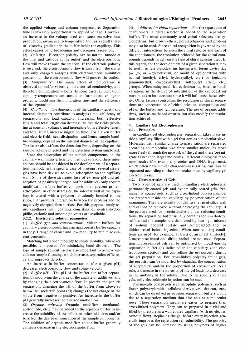
26452645JP XVIII General Information / Biotechnological/Biological Products
the applied voltage and column temperature. Separationtime is inversely proportional to applied voltage. However,an increase in the voltage used can cause excessive heatproduction, giving rise to temperature and, as a result there-of, viscosity gradients in the buffer inside the capillary. Thiseffect causes band broadening and decreases resolution.(2) Polarity: Electrode polarity can be normal (anode atthe inlet and cathode at the outlet) and the electroosmoticflow will move toward the cathode. If the electrode polarityis reversed, the electroosmotic flow is away from the outletand only charged analytes with electroosmotic mobilitiesgreater than the electroosmotic flow will pass to the outlet.(3) Temperature: The main effect of temperature isobserved on buffer viscosity and electrical conductivity, andtherefore on migration velocity. In some cases, an increase incapillary temperature can cause a conformational change inproteins, modifying their migration time and the efficiencyof the separation.(4) Capillary: The dimensions of the capillary (length andinternal diameter) contribute to analysis time, efficiency ofseparations and load capacity. Increasing both effectivelength and total length can decrease the electric fields (work-ing at constant voltage), and increasing both effective lengthand total length increase migration time. For a given bufferand electric field, heat dissipation, and hence sample band-broadening, depend on the internal diameter of the capillary.The latter also affects the detection limit, depending on thesample volume injected and the detection system employed.
Since the adsorption of the sample components on thecapillary wall limits efficiency, methods to avoid these inter-actions should be considered in the development of a separa-tion method. In the specific case of proteins, several strate-gies have been devised to avoid adsorption on the capillarywall. Some of these strategies (use of extreme pH and ad-sorption of positively charged buffer additives) only requiremodification of the buffer composition to prevent proteinadsorption. In other strategies, the internal wall of the capil-lary is coated with a polymer, covalently bonded to thesilica, that prevents interaction between the proteins and thenegatively charged silica surface. For this purpose, ready-to-use capillaries with coatings consisting of neutral-hydro-philic, cationic and anionic polymers are available.3.2.2. Electrolytic solution parameters(1) Buffer type and concentration: Suitable buffers forcapillary electrophoresis have an appropriate buffer capacityin the pH range of choice and low mobility to minimize cur-rent generation.
Matching buffer-ion mobility to solute mobility, wheneverpossible, is important for minimizing band distortion. Thetype of sample solvent used is also important to achieve on-column sample focusing, which increases separation efficien-cy and improves detection.
An increase in buffer concentration (for a given pH)decreases electroosmotic flow and solute velocity.(2) Buffer pH: The pH of the buffer can affect separa-tion by modifying the charge of the analyte or additives, andby changing the electroosmotic flow. In protein and peptideseparation, changing the pH of the buffer from above tobelow the isoelectric point (pI) changes the net charge of thesolute from negative to positive. An increase in the bufferpH generally increases the electroosmotic flow.(3) Organic solvents: Organic modifiers (methanol,acetonitrile, etc.) may be added to the aqueous buffer to in-crease the solubility of the solute or other additives and/orto affect the degree of ionization of the sample components.The addition of organic modifiers to the buffer generallycauses a decrease in the electroosmotic flow.
(4) Additives for chiral separations: For the separation ofenantiomers, a chiral selector is added to the separationbuffer. The most commonly used chiral selectors are cy-clodextrins, but crown ethers, polysaccharides and proteinsmay also be used. Since chiral recognition is governed by thedifferent interactions between the chiral selector and each ofthe enantiomers, the resolution achieved for the chiral com-pounds depends largely on the type of chiral selector used. Inthis regard, for the development of a given separation it maybe useful to test cyclodextrins having a different cavity size(a-, b-, or g-cyclodextrin) or modified cyclodextrins withneutral (methyl, ethyl, hydroxyalkyl, etc.) or ionizable(aminomethyl, carboxymethyl, sulfobutyl ether, etc.)groups. When using modified cyclodextrins, batch-to-batchvariations in the degree of substitution of the cyclodextrinsmust be taken into account since it will influence the selectiv-ity. Other factors controlling the resolution in chiral separa-tions are concentration of chiral selector, composition andpH of the buffer and temperature. The use of organic addi-tives, such as methanol or urea can also modify the resolu-tion achieved.
4. Capillary Gel Electrophoresis4.1. Principles
In capillary gel electrophoresis, separation takes place in-side a capillary filled with a gel that acts as a molecular sieve.Molecules with similar charge-to-mass ratios are separatedaccording to molecular size since smaller molecules movemore freely through the network of the gel and therefore mi-grate faster than larger molecules. Different biological mac-romolecules (for example, proteins and DNA fragments),which often have similar charge-to-mass ratios, can thus beseparated according to their molecular mass by capillary gelelectrophoresis.4.2. Characteristics of Gels
Two types of gels are used in capillary electrophoresis:permanently coated gels and dynamically coated gels. Per-manently coated gels, such as cross-linked polyacrylamide,are prepared inside the capillary by polymerization of themonomers. They are usually bonded to the fused-silica walland cannot be removed without destroying the capillary. Ifthe gels are used for protein analysis under reducing condi-tions, the separation buffer usually contains sodium dodecylsulfate and the samples are denatured by heating a mixtureof sodium dodecyl sulfate and 2-mercaptoethanol ordithiothreitol before injection. When non-reducing condi-tions are used (for example, analysis of an intact antibody),2-mercaptoethanol and dithiothreitol are not used. Separa-tion in cross-linked gels can be optimized by modifying theseparation buffer (as indicated in the capillary zone elec-trophoresis section) and controlling the gel porosity duringthe gel preparation. For cross-linked polyacrylamide gels,the porosity can be modified by changing the concentrationof acrylamide and/or the proportion of cross-linker. As arule, a decrease in the porosity of the gel leads to a decreasein the mobility of the solutes. Due to the rigidity of thesegels, only electrokinetic injection can be used.
Dynamically coated gels are hydrophilic polymers, such aslinear polyacrylamide, cellulose derivatives, dextran, etc.,which can be dissolved in aqueous separation buffers givingrise to a separation medium that also acts as a molecularsieve. These separation media are easier to prepare thancross-linked polymers. They can be prepared in a vial andfilled by pressure in a wall-coated capillary (with no electro-osmotic flow). Replacing the gel before every injection gen-erally improves the separation reproducibility. The porosityof the gels can be increased by using polymers of higher
26462646 JP XVIIIBiotechnological/Biological Products / General Information
molecular mass (at a given polymer concentration) or bydecreasing the polymer concentration (for a given polymermolecular mass). A reduction in the gel porosity leads to adecrease in the mobility of the solute for the same buffer.Since the dissolution of these polymers in the buffer giveslow viscosity solutions, both hydrodynamic and electroki-netic injection techniques can be used.
5. Capillary Isoelectric Focusing5.1. Principles
In isoelectric focusing, the molecules migrate under theinfluence of the electric field, so long as they are charged, ina pH gradient generated by ampholytes having pI values in awide range (poly-aminocarboxylic acids), dissolved in theseparation buffer.
The three basic steps of isoelectric focusing are loading,focusing and mobilization.(1) Loading step: Two methods may be employed:
( i ) loading in one step: the sample is mixed with ampho-lytes and introduced into the capillary either by pres-sure or vacuum;
(ii) sequential loading: a leading buffer, then the ampho-lytes, then the sample mixed with ampholytes, againampholytes alone and finally the terminating bufferare introduced into the capillary. The volume of thesample must be small enough not to modify the pHgradient.
(2) Focusing step: When the voltage is applied, ampho-lytes migrate toward the cathode or the anode, according totheir net charge, thus creating a pH gradient from anode(lower pH) to cathode (higher pH). During this step the com-ponents to be separated migrate until they reach a pH cor-responding to their isoelectric point (pI) and the currentdrops to very low values.(3) Mobilization step: If mobilization is required for de-tection, use one of the following methods. Three methodsare available:
( i ) mobilization is accomplished during the focusingstep under the effect of the electroosmotic flow; theelectroosmotic flow must be small enough to allowthe focusing of the components;
( ii ) mobilization is accomplished by applying positivepressure after the focusing step;
(iii) mobilization is achieved after the focusing step byadding salts to the cathode reservoir or the anodereservoir (depending on the direction chosen formobilization) in order to alter the pH in the capillarywhen the voltage is applied. As the pH is changed,the proteins and ampholytes are mobilized in thedirection of the reservoir which contains the addedsalts and pass the detector.
The separation achieved, expressed as DpI, depends on thepH gradient (dpH/dx), the number of ampholytes havingdifferent pI values, the molecular diffusion coefficient (D),the intensity of the electric field (E) and the variation of theelectrophoretic mobility of the analyte with the pH (-dm/dpH ):
DpI = 3D(dpH/dx)
E(-dm/dpH )
5.2. OptimizationThe main parameters to be considered in the development
of separations are:(1) Voltage: Capillary isoelectric focusing utilises veryhigh electric fields, 300 V/cm to 1000 V/cm in the focusingstep.(2) Capillary: The electroosmotic flow must be reduced
or suppressed depending on the mobilization strategy (seeabove). Coated capillaries tend to reduce the electroosmoticflow.(3) Solutions: The anode buffer reservoir is filled with asolution with a pH lower than the pI of the most acidic am-pholyte and the cathode reservoir is filled with a solutionwith a pH higher than the pI of the most basic ampholyte.Phosphoric acid for the anode and sodium hydroxide for thecathode are frequently used.
Addition of a polymer, such as methylcellulose, in the am-pholyte solution tends to suppress convective forces (if any)and electroosmotic flow by increasing the viscosity. Com-mercial ampholytes are available covering many pH rangesand may be mixed if necessary to obtain an expanded pHrange. Broad pH ranges are used to estimate the isoelectricpoint whereas narrower ranges are employed to improve ac-curacy. Calibration can be done by correlating migrationtime with isoelectric point for a series of protein markers.
During the focusing step precipitation of proteins at theirisoelectric point can be prevented, if necessary, using bufferadditives such as glycerol, surfactants, urea or zwitterionicbuffers. However, depending on the concentration, ureadenatures proteins.
6. Micellar Electrokinetic Chromatography (MEKC)6.1. Principles
In micellar electrokinetic chromatography, separationtakes place in an electrolyte solution which contains a sur-factant at a concentration above the critical micellar concen-tration (cmc). The solute molecules are distributed betweenthe aqueous buffer and the pseudo-stationary phase com-posed of micelles, according to the partition coefficient ofthe solute. The technique can therefore be considered as ahybrid of electrophoresis and chromatography. It is a tech-nique that can be used for the separation of both neutral andcharged solutes, maintaining the efficiency, speed and in-strumental suitability of capillary electrophoresis. One of themost widely used surfactants in MEKC is the anionic sur-factant sodium dodecyl sulfate, although other surfactants,for example cationic surfactants such as cetyltrimethylam-monium salts, are also used.
The separation mechanism is as follows. At neutral andalkaline pH, a strong electroosmotic flow is generated andmoves the separation buffer ions in the direction of thecathode. If sodium dodecyl sulfate is employed as the sur-factant, the electrophoretic migration of the anionic micelleis in the opposite direction, towards the anode. As a result,the overall micelle migration velocity is slowed down com-pared to the bulk flow of the electrolytic solution. In the caseof neutral solutes, since the analyte can partition between themicelle and the aqueous buffer, and has no electrophoreticmobility, the analyte migration velocity will depend only onthe partition coefficient between the micelle and the aqueousbuffer. In the electropherogram, the peaks corresponding toeach uncharged solute are always between that of the electro-osmotic flow marker and that of the micelle (the timeelapsed between these two peaks is called the separation win-dow). For electrically charged solutes, the migration velocitydepends on both the partition coefficient of the solute be-tween the micelle and the aqueous buffer, and on the elec-trophoretic mobility of the solute in the absence of micelle.
Since the mechanism in MEKC of neutral and weaklyionized solutes is essentially chromatographic, migration ofthe solute and resolution can be rationalized in terms of theretention factor (k?), also referred to as mass distributionratio (Dm), which is the ratio of the number of moles of so-lute in the micelle to those in the mobile phase. For a neutral
26472647JP XVIII General Information / Biotechnological/Biological Products
compound, k? is given by:
k?=tR - t0
t0 Ø1 -tR
tmc»= K
VS
VM
tR: Migration time of the solute,t0: Analysis time of an unretained solute (determined by
injecting an electroosmotic flow marker which does notenter the micelle, for instance methanol),
tmc: Micelle migration time (measured by injecting amicelle marker, such as Sudan III, which migrateswhile continuously associated in the micelle),
K: Partition coefficient of the solute,VS: Volume of the micellar phase,VM: Volume of the mobile phase.
Likewise, the resolution between two closely-migrating so-lutes (RS) is given by:
RS =N
4×
a - 1a
×k?b
k?b + 1×
1 - Ø t0
tmc»1 + Ø t0
tmc» k?a
N: Number of theoretical plates for one of the solutes,a: Selectivity,k?a and k?b: Retention factors for both solutes, respectively
(k?b > k?a).
Similar, but not identical, equations give k? and RS valuesfor electrically charged solutes.6.2. Optimization
The main parameters to be considered in the developmentof separations by MEKC are instrumental and electrolyticsolution parameters.6.2.1. Instrumental parameters(1) Voltage: Separation time is inversely proportional toapplied voltage. However, an increase in voltage can causeexcessive heat production that gives rise to temperaturegradients and viscosity gradients of the buffer in the cross-section of the capillary. This effect can be significant withhigh conductivity buffers such as those containing micelles.Poor heat dissipation causes band broadening and decreasesresolution.(2) Temperature: Variations in capillary temperature af-fect the partition coefficient of the solute between the bufferand the micelles, the critical micellar concentration and theviscosity of the buffer. These parameters contribute to themigration time of the solutes. The use of a good cooling sys-tem improves the reproducibility of the migration time forthe solutes.(3) Capillary: As in capillary zone electrophoresis, thedimensions of the capillary (length and internal diameter)contribute to analysis time and efficiency of separations. In-creasing both effective length and total length can decreasethe electric fields (working at constant voltage), increasemigration time and improve the separation efficiency. Theinternal diameter controls heat dissipation (for a givenbuffer and electric field) and consequently the sample bandbroadening.6.2.2. Electrolytic solution parameters(1) Surfactant type and concentration: The type of sur-factant, in the same way as the stationary phase in chroma-tography, affects the resolution since it modifies separationselectivity. Also, the log k? of a neutral compound increaseslinearly with the concentration of surfactant in the mobilephase. Since resolution in MEKC reaches a maximum whenk? approaches the value of tm/t0, modifying the concentra-
tion of surfactant in the mobile phase changes the resolutionobtained.(2) Buffer pH: Although pH does not modify the parti-tion coefficient of non-ionized solutes, it can modify theelectroosmotic flow in uncoated capillaries. A decrease in thebuffer pH decreases the electroosmotic flow and thereforeincreases the resolution of the neutral solutes in MEKC,resulting in a longer analysis time.(3) Organic solvents: To improve MEKC separation ofhydrophobic compounds, organic modifiers (methanol,propanol, acetonitrile, etc.) can be added to the electrolyticsolution. The addition of these modifiers usually decreasesmigration time and the selectivity of the separation. Sincethe addition of organic modifiers affects the critical micellarconcentration, a given surfactant concentration can be usedonly within a certain percentage of organic modifier beforethe micellization is inhibited or adversely affected, resultingin the absence of micelles and, therefore, in the absence ofpartition. The dissociation of micelles in the presence of ahigh content of organic solvent does not always mean thatthe separation will no longer be possible; in some cases thehydrophobic interaction between the ionic surfactantmonomer and the neutral solutes forms solvophobic com-plexes that can be separated electrophoretically.(4) Additives for chiral separations: For the separation ofenantiomers using MEKC, a chiral selector is included in themicellar system, either covalently bound to the surfactant oradded to the micellar separation electrolyte. Micelles thathave a moiety with chiral discrimination properties includesalts of N-dodecanoyl-L-amino acids, bile salts, etc. Chiralresolution can also be achieved using chiral discriminators,such as cyclodextrins, added to the electrolytic solutionswhich contain micellized achiral surfactants.(5) Other additives: Several strategies can be carried outto modify selectivity, by adding chemicals to the buffer. Theaddition of several types of cyclodextrins to the buffer canalso be used to reduce the interaction of hydrophobic soluteswith the micelle, thus increasing the selectivity for this typeof compound.
The addition of substances able to modify solute-micelleinteractions by adsorption on the latter, is used to improvethe selectivity of the separations in MEKC. These additivesmay be a second surfactant (ionic or non-ionic) which givesrise to mixed micelles or metallic cations which dissolve inthe micelle and form co-ordination complexes with the so-lutes.
7. QuantificationPeak areas must be divided by the corresponding migra-
tion time to give the corrected peak area in order to:(1) compensate for the shift in migration time from run to
run, thus reducing the variation of the response,(2) compensate for the different responses of sample con-
stituents with different migration times.Where an internal standard is used, verify that no peak of
the substance to be examined is masked by that of the inter-nal standard.7.1. Calculations
From the values obtained, calculate the content of thecomponent or components being examined. Whenprescribed, the percentage content of one or more compo-nents of the sample to be examined is calculated by deter-mining the corrected area(s) of the peak(s) as a percentage ofthe total of the corrected areas of all peaks, excluding thosedue to solvents or any added reagents (normalization proce-dure). The use of an automatic integration system (integratoror data acquisition and processing system) is recommended.
26482648 JP XVIIIBiotechnological/Biological Products / General Information
8. System SuitabilityIn order to check the behavior of the capillary electropho-
resis system, system suitability parameters are used. Thechoice of these parameters depends on the mode of capillaryelectrophoresis used. They are retention factor (k?) (only formicellar electrokinetic chromatography), apparent numberof theoretical plates (N ), symmetry factor (AS) and resolu-tion (RS). In previous sections, the theoretical expressionsfor N and RS have been described, but more practical equa-tions that allow these parameters to be calculated from theelectropherograms are given below.
Apparent Number of Theoretical PlatesThe apparent number of theoretical plates (N ) may be cal-
culated using the expression:
N = 5.54 Ø tR
wh»2
tR: Migration time or distance along the baseline from thepoint of injection to the perpendicular dropped fromthe maximum of the peak corresponding to the compo-nent,
wh: Width of the peak at half-height.
ResolutionThe resolution (RS) between peaks of similar height of two
components may be calculated using the expression:
RS =1.18(tR2 - tR1)
wh1 + wh2
tR2 > tR1
tR1 and tR2: Migration times or distances along the baselinefrom the point of injection to the perpendicu-lars dropped from the maxima of two adjacentpeaks,
wh1 and wh2: Peak widths at half-height.
When appropriate, the resolution may be calculated bymeasuring the height of the valley (Hv) between two partlyresolved peaks in a standard preparation and the height ofthe smaller peak (Hp) and calculating the peak-to-valley ratio(r/y):
p/y =Hp
Hv
Symmetry FactorThe symmetry factor (AS) of a peak may be calculated
using the expression:
AS =w0.05
2d
w0.05: Width of the peak at one-twentieth of the peakheight,
d: Distance between the perpendicular dropped from thepeak maximum and the leading edge of the peak at one-twentieth of the peak height.
Tests for peak area repeatability (standard deviation ofareas or of the area/migration-time ratio) and for migrationtime repeatability (standard deviation of migration time) areintroduced as suitability parameters. Migration time repeata-bility provides a test for the suitability of the capillary wash-ing procedures. An alternative practice to avoid the lack ofrepeatability of the migration time is to use migration timerelative to an internal standard.
A test for the verification of the signal-to-noise ratio for astandard preparation (or the determination of the limit ofquantification) may also be useful for the determination of
related substances.
Signal-to-noise Ratio (S/N)The detection limit and the quantification limit are equiva-
lent to signal-to-noise ratios of 3 and 10, respectively. Thesignal-to-noise ratio (S/N) is calculated using the expression:
S/N =2H
h
H: Height of the peak corresponding to the componentconcerned, in the electropherogram obtained with theprescribed reference solution, measured from the max-imum of the peak to the extrapolated baseline of thesignal observed over a distance equal to twenty timesthe width at half-height,
h: Range of the background in an electropherogram ob-tained after injection of a blank, observed over a dis-tance equal to twenty times the width at the half-heightof the peak in the electropherogram obtained with theprescribed reference solution and, if possible, situatedequally around the place where this peak would befound.
SDS-Polyacrylamide GelElectrophoresis <G3-8-170>
This test is harmonized with the European Pharmacopoeiaand the U.S. Pharmacopeia.
Information on the harmonization with the EuropeanPharmacopoeia and the U.S. Pharmacopeia is available onthe website of the Pharmaceuticals and Medical DevicesAgency.
Polyacrylamide gel electrophoresis is used for the qualita-tive characterisation of proteins in biological preparations,for control of purity and for quantitative determinations.
Analytical gel electrophoresis is an appropriate methodwith which to identify and to assess the homogeneity of pro-teins in pharmaceutical preparations. The method is routine-ly used for the estimation of protein subunit molecularmasses and for determination of the subunit compositions ofpurified proteins.
Ready-to-use gels and reagents are commercially availableand can be used instead of those described in this text, pro-vided that they give equivalent results and that they meet thevalidity requirements given below under Validation of thetest.
1. Characteristics of Polyacrylamide GelsThe sieving properties of polyacrylamide gels are estab-
lished by the three-dimensional network of fibres and poreswhich is formed as the bifunctional bisacrylamide cross-linksadjacent polyacrylamide chains. Polymerisation is usuallycatalysed by a free radical-generating system composed ofammonium persulfate and N,N,N?,N?-tetramethylethylene-diamine (TEMED).
As the acrylamide concentration of a gel increases, its ef-fective pore size decreases. The effective pore size of a gel isoperationally defined by its sieving properties; that is, by theresistance it imparts to the migration of macromolecules.There are limits on the acrylamide concentrations that can beused. At high acrylamide concentrations, gels break muchmore easily and are difficult to handle. As the pore size of agel decreases, the migration rate of a protein through the geldecreases. By adjusting the pore size of a gel, throughmanipulating the acrylamide concentration, the resolution of
26492649JP XVIII General Information / Biotechnological/Biological Products
the method can be optimised for a given protein product.Thus, a given gel is physically characterised by its respectivecomposition of acrylamide and bisacrylamide.
In addition to the composition of the gel, the state of theprotein is an important component to the electrophoreticmobility. In the case of proteins, the electrophoretic mobilityis dependent on the pK value of the charged groups and thesize of the molecule. It is influenced by the type, the concen-tration and the pH of the buffer, by the temperature and thefield strength, and by the nature of the support material.
2. Denaturing Polyacrylamide Gel ElectrophoresisThe method cited as an example is limited to the analysis
of monomeric polypeptides with a mass range of 14,000 to100,000 daltons. It is possible to extend this mass range byvarious techniques (e.g. gradient gels, particular buffer sys-tem). For instance, tricine sodium dodecyl sulfate (SDS)gels, using tricine as the trailing ion in the electrophoresisrunning buffer (instead of glycine as in the method describedhere), can separate very small proteins and peptides under10,000-15,000 daltons.
Denaturing polyacrylamide gel electrophoresis using gly-cine SDS (SDS-PAGE) is the most common mode of elec-trophoresis used in assessing the pharmaceutical quality ofprotein products and will be the focus of the examplemethod. Typically, analytical electrophoresis of proteins iscarried out in polyacrylamide gels under conditions that en-sure dissociation of the proteins into their individual poly-peptide subunits and that minimize aggregation. Most com-monly, the strongly anionic detergent SDS is used in combi-nation with heat to dissociate the proteins before they areloaded on the gel. The denatured polypeptides bind to SDS,become negatively charged and exhibit a consistent charge-to-mass ratio regardless of protein type. Because the amountof SDS bound is almost always proportional to the molecu-lar mass of the polypeptide and is independent of its se-quence, SDS-polypeptide complexes migrate through poly-acrylamide gels with mobilities dependent on the size of thepolypeptide.
The electrophoretic mobilities of the resultant detergent-polypeptide complexes all assume the same functionalrelationship to their molecular masses. SDS complexes willmigrate toward the anode in a predictable manner, with lowmolecular mass complexes migrating faster than larger ones.The molecular mass of a protein can therefore be estimatedfrom its relative mobility in calibrated SDS-PAGE and theintensity of a single band relative to other undesired bands insuch a gel can be a measure of purity.
Modifications to the polypeptide backbone, such as N- orO-linked glycosylation, can change the apparent molecularmass of a protein since SDS does not bind to a carbohydratemoiety in a manner similar to a polypeptide; therefore, aconsistent charge-to-mass ratio is not maintained.
Depending on the extent of glycosylation and other post-translational modifications, the apparent molecular mass ofproteins may not be a true reflection of the mass of the poly-peptide chain.2.1. Reducing conditions
Polypeptide subunits and three-dimensional structure areoften maintained in proteins by the presence of disulfidebonds. A goal of SDS-PAGE analysis under reducing condi-tions is to disrupt this structure by reducing disulfide bonds.Complete denaturation and dissociation of proteins by treat-ment with 2-mercaptoethanol (2-ME) or dithiothreitol (DTT)will result in unfolding of the polypeptide backbone and sub-sequent complexation with SDS. Using these conditions, themolecular mass of the polypeptide subunits can reasonably
be calculated by linear regression (or, more closely, by nonlinear regression) in the presence of suitable molecular massstandards.2.2. Non-reducing conditions
For some analyses, complete dissociation of the proteininto subunit peptides is not desirable. In the absence of treat-ment with reducing agents such as 2-ME or DTT, disulfidecovalent bonds remain intact, preserving the oligomericform of the protein. Oligomeric SDS-protein complexes mi-grate more slowly than their SDS-polypeptide subunits. Inaddition, non-reduced proteins may not be completely satu-rated with SDS and, hence, may not bind the detergent in aconstant mass ratio. Moreover, intra-chain disulphide bondsconstrain the molecular shape, usually in such a way as toreduce the Stokes radius of the molecule, thereby reducingthe apparent molecular mass Mr. This makes molecular massdeterminations of these molecules by SDS-PAGE lessstraightforward than analyses of fully denatured polypep-tides, since it is necessary that both standards and unknownproteins be in similar configurations for valid comparisons.
3. Characteristics of Discontinuous Buffer System GelElectrophoresis
The most popular electrophoretic method for the charac-terisation of complex mixtures of proteins uses a discontinu-ous buffer system involving two contiguous, but distinctgels: a resolving or separating (lower) gel and a stacking (up-per) gel. The two gels are cast with different porosities, pH,and ionic strengths. In addition, different mobile ions areused in the gel and electrode buffers. The buffer discontinui-ty acts to concentrate large volume samples in the stackinggel, resulting in improved resolution. When power is ap-plied, a voltage drop develops across the sample solutionwhich drives the proteins into the stacking gel. Glycinateions from the electrode buffer follow the proteins into thestacking gel. A moving boundary region is rapidly formedwith the highly mobile chloride ions in the front and the rela-tively slow glycinate ions in the rear. A localised high-voltagegradient forms between the leading and trailing ion fronts,causing the SDS-protein complexes to form into a thin zone(stack) and migrate between the chloride and glycinatephases. Within broad limits, regardless of the height of theapplied sample, all SDS-proteins condense into a very nar-row region and enter the resolving gel as a well-defined, thinzone of high protein density. The large-pore stacking geldoes not retard the migration of most proteins and servesmainly as an anti-convective medium. At the interface of thestacking and resolving gels, the proteins undergo a sharp in-crease in retardation due to the restrictive pore size of theresolving gel and the buffer discontinuity, which also con-tributes to focusing of the proteins. Once in the resolvinggel, proteins continue to be slowed by the sieving of thematrix. The glycinate ions overtake the proteins, which thenmove in a space of uniform pH formed by the 2-amino-2-hydroxymethyl-1,3-propanediol and glycine. Molecular siev-ing causes the SDS-polypeptide complexes to separate on thebasis of their molecular masses.
4. Preparing Vertical Discontinuous Buffer SDS Poly-acrylamide Gels
This section describes the preparation of gels using par-ticular instrumentation. This does not apply to pre-cast gels.For pre-cast gels or any other commercially available equip-ment, the manufacturer's instructions must be used forguidance.
The use of commercial reagents that have been purified insolution is recommended. When this is not the case andwhere the purity of the reagents used is not sufficient, a pre-
26502650 JP XVIIIBiotechnological/Biological Products / General Information
treatment is applied. For instance, any solution sufficientlyimpure to require filtration must also be deionized with amixed bed (anion/cation exchange) resin to remove acrylicacid and other charged degradation products. When storedaccording to recommendations, acrylamide/bisacrylamidesolutions and solid persulfate are stable for long periods.4.1. Assembling the gel moulding cassette
Clean the two glass plates (size: e.g. 10 cm × 8 cm), thepolytetrafluoroethylene comb, the two spacers and the sili-cone rubber tubing (diameter e.g. 0.6 mm × 35 cm) withmild detergent and rinse extensively with water, followed bydehydrated alcohol, and allow the plates to dry at room tem-perature. Lubricate the spacers and the tubing with non-sili-cone grease. Apply the spacers along each of the two shortsides of the glass plate 2 mm away from the edges and 2 mmaway from the long side corresponding to the bottom of thegel. Begin to lay the tubing on the glass plate by using onespacer as a guide. Carefully twist the tubing at the bottom ofthe spacer and follow the long side of the glass plate. Whileholding the tubing with one finger along the long side twistagain the tubing and lay it on the second short side of theglass plate, using the spacer as a guide. Place the secondglass plate in perfect alignment and hold the mould togetherby hand pressure. Apply two clamps on each of the twoshort sides of the mould. Carefully apply four clamps on thelonger side of the gel mould thus forming the bottom of thegel mould. Verify that the tubing is running along the edgeof the glass plates and has not been extruded while placingthe clamps. The gel mould is now ready for pouring the gel.4.2. Preparation of the gel
In a discontinuous buffer SDS polyacrylamide gel, it isrecommended to pour the resolving gel, let the gel set, andthen pour the stacking gel since the composition of the twogels in acrylamide-bisacrylamide, buffer and pH are differ-ent.4.2.1. Preparation of the resolving gel
In a conical flask, prepare the appropriate volume of solu-tion containing the desired concentration of acrylamide forthe resolving gel, using the values given in Table 1. Mix thecomponents in the order shown. Where appropriate, beforeadding the ammonium persulfate solution and the TEMED,filter the solution if necessary under vacuum through a cellu-lose acetate membrane (pore diameter 0.45 mm). Keep the so-lution under vacuum, while swirling the filtration unit, untilno more bubbles are formed in the solution. Add appropri-ate amounts of ammonium persulfate solution and TEMEDas indicated in Table 1, swirl and pour immediately into thegap between the two glass plates of the mould. Leavesufficient space for the stacking gel (the length of the teethof the comb plus 1 cm). Using a tapered glass pipette, care-fully overlay the solution with water-saturated isobutanol.Leave the gel in a vertical position at room temperature toallow polymerization.4.2.2. Preparation of the stacking gel
After polymerization is complete (about 30 minutes), pouroff the isobutanol and wash the top of the gel several timeswith water to remove the isobutanol overlay and any un-polymerized acrylamide. Drain as much fluid as possiblefrom the top of the gel, and then remove any remainingwater with the edge of a paper towel.
In a conical flask, prepare the appropriate volume of solu-tion containing the desired concentration of acrylamide,using the values given in Table 2. Mix the components in theorder shown. Where appropriate, before adding the ammo-nium persulfate solution and the TEMED, filter the solutionif necessary under vacuum through a cellulose acetate mem-brane (pore diameter: 0.45 mm). Keep the solution under
vacuum, while swirling the filtration unit, until no morebubbles are formed in the solution. Add appropriateamounts of ammonium persulfate solution and TEMED asindicated in Table 2. Swirl and pour immediately into thegap between the two glass plates of the mould directly ontothe surface of the polymerized resolving gel. Immediately in-sert a clean polytetrafluoroethylene comb into the stackinggel solution, being careful to avoid trapping air bubbles.Add more stacking gel solution to fill the spaces of the combcompletely. Leave the gel in a vertical position and allow topolymerize at room temperature.4.3. Preparation of the sample
Unless otherwise specified in the specific monograph thesamples can be prepared as follows:
Sample solution (non-reducing conditions). Mix equalvolumes of: a mixture comprising water plus the preparationor the reference solutions, and concentrated SDS-PAGEsample buffer.
Sample solution (reducing conditions). Mix equal volumesof: a mixture comprising water plus the preparation or thereference solutions, and concentrated SDS-PAGE samplebuffer for reducing conditions containing 2-ME (or DTT) asreducing agent.
The concentration prescribed in the monograph can varydepending on the protein and staining method.
Sample treatment: keep for 5 minutes in a boiling waterbath or in a block heater set at 1009C, then chill. (Note thattemperature and time may vary in the monograph since pro-tein cleavage may occur during the heat treatment.)4.4. Mounting the gel in the electrophoresis apparatus andelectrophoretic separation
After polymerization is complete (about 30 minutes), re-move the polytetrafluoroethylene comb carefully. Rinse thewells immediately with water or with the SDS-PAGE run-ning buffer to remove any unpolymerized acrylamide. If nec-essary, straighten the teeth of the stacking gel with a blunthypodermic needle attached to a syringe. Remove the clampson one short side, carefully pull out the tubing and replacethe clamps. Proceed similarly on the other short side. Re-move the tubing from the bottom part of the gel. Mount thegel in the electrophoresis apparatus. Add the electrophoresisbuffers to the top and bottom reservoirs. Remove any bub-bles that become trapped at the bottom of the gel betweenthe glass plates. This is best done with a bent hypodermicneedle attached to a syringe. Never pre-run the gel beforeloading the samples, since this will destroy the discontinuityof the buffer systems. Before loading the sample carefullyrinse each well with SDS-PAGE running buffer. Prepare thetest and reference solutions in the recommended samplebuffer and treat as specified in the individual monograph.Apply the appropriate volume of each solution to the stack-ing gel wells. Start the electrophoresis using the conditionsrecommended by the manufacturer of the equipment.Manufacturers of SDS-PAGE equipment may provide gelsof different surface area and thickness and electrophoresisrunning time and current/voltage may vary in order toachieve optimal separation. Check that the dye front is mov-ing into the resolving gel. When the dye is near the bottom ofthe gel, stop the electrophoresis. Remove the gel assemblyfrom the apparatus and carefully separate the glass plates.Remove the spacers, cut off and discard the stacking gel andimmediately proceed with staining.4.5. Sodium dodecyl sulfate polyacrylamide gel electropho-resis (SDS-PAGE)―Gradient concentration gels
Gradient gels (resolving gels) are prepared with an increas-ing concentration of acrylamide from the top to the bottom.Preparation of gradient gels requires a gradient forming ap-

26512651JP XVIII General Information / Biotechnological/Biological Products
paratus. Ready-to-use gradient gels are commercially availa-ble with specific recommended protocols. Gradient gels offersome advantages over fixed concentration gels. Some pro-teins which co-migrate on fixed concentration gels can beresolved within gradient gels. During electrophoresis the pro-teins migrate until the pore size stops further progress andtherefore a stacking effect occurs, resulting in sharper bands.Per the table below, gradient gels also allow separation of awider range of proteins molecular masses than on a singlefixed concentration gel.
The table below gives suggested compositions of the lineargradient, relating the range of acrylamide concentrations tothe appropriate protein molecular ranges. Note that othergradient shapes (e.g. concave) can be prepared for specificapplications.
Acrylamide (z) Protein range (kDa)
5–15 20–2505–20 10–200
10–20 10–1508–20 8–150
Gradient gels are also used for molecular mass determina-tion and protein purity determination.4.6. Detection of proteins in gels
Coomassie and silver staining are the most common pro-tein staining methods and are described in more detailbelow. Several other commercial stains, detection methodsand commercial kits are available. For example, fluorescentstains are visualised using a fluorescent imager and oftenprovide a linear response over a wide range of protein con-centrations, often several orders of magnitude depending onthe protein.
Coomassie staining has a protein detection level of ap-proximately 1 to 10 mg of protein per band. Silver staining isthe most sensitive method for staining proteins in gels and aband containing 10 ng to 100 ng can be detected. Thesefigures are considered robust in the context of these gels. Im-proved sensitivity of one or two orders of magnitude hassometimes been reported in the literature.
Coomassie staining responds in a more linear manner thansilver staining; however the response and range depend onthe protein and development time. Both Coomassie and sil-ver staining can be less reproducible if staining is stopped ina subjective manner, i.e. when the staining is deemed satis-factory. Wide dynamic ranges of reference proteins are veryimportant to use since they help assess the intra-experimentalsensitivity and linearity. All gel staining steps are done whilewearing gloves, at room temperature, with gentle shaking(e.g. on an orbital shaker platform) and using any con-venient container.4.6.1. Coomassie staining
Immerse the gel in a large excess of Coomassie staining so-lution and allow to stand for at least 1 hour. Remove thestaining solution.
Destain the gel with a large excess of destaining solution.Change the destaining solution several times, until thestained protein bands are clearly distinguishable on a clearbackground. The more thoroughly the gel is destained, thesmaller is the amount of protein that can be detected by themethod. Destaining can be speeded up by including a fewgrams of anion-exchange resin or a small sponge in thedestaining solution.
The acid-alcohol solutions used in this procedure do notcompletely fix proteins in the gel. This can lead to losses of
some low-molecular-mass proteins during the staining anddestaining of thin gels. Permanent fixation is obtainable byallowing the gel to stand in a mixture of 1 volume oftrichloroacetic acid, 4 volumes of methanol and 5 volumesof water for 1 hour before it is immersed in the Coomassiestaining solution.4.6.2. Silver staining
Immerse the gel in a large excess of fixing solution andallow to stand for 1 hour. Remove the fixing solution, addfresh fixing solution and incubate either for at least 1 houror overnight, if convenient. Discard the fixing solution andwash the gel in a large excess of water for 1 hour. Soak thegel for 15 minutes in a 1 volz solution of glutaraldehyde.Wash the gel twice for 15 minutes in a large excess of water.Soak the gel in fresh silver nitrate reagent for 15 minutes, indarkness. Wash the gel three times for 5 minutes in a largeexcess of water. Immerse the gel for about 1 minute in de-veloper solution until satisfactory staining has been ob-tained. Stop the development by incubation in the blockingsolution for 15 minutes. Rinse the gel with water.4.7. Recording of the results
Gels are photographed or scanned while they are still wetor after an appropriate drying procedure. Currently, ``gelscanning'' systems with data analysis software are commer-cially available to photograph and analyze the wet gel imme-diately.
Depending on the staining method used, gels are treated ina slightly different way. For Coomassie staining, after thedestaining step, allow the gel to stand in a 100 g/L solutionof glycerol for at least 2 hours (overnight incubation is possi-ble).
For silver staining, add to the final rinsing a step of 5minutes in a 20 g/L solution of glycerol.
Drying of stained SDS Polyacrylamide gels is one of themethods to have permanent documentation. This methodfrequently results in the ``cracking of gel'' during drying be-tween cellulose films.
Immerse two sheets of porous cellulose film in water andincubate for 5 minutes to 10 minutes. Place one of the sheetson a drying frame. Carefully lift the gel and place it on thecellulose film. Remove any trapped air bubbles and pour afew millilitres of water around the edges of the gel. Place thesecond sheet on top and remove any trapped air bubbles.Complete the assembly of the drying frame. Place in an ovenor leave at room temperature until dry.4.8. Molecular mass determination
Molecular masses of proteins are determined by compari-son of their mobilities with those of several marker proteinsof known molecular weight. Mixtures of pre-stained and un-stained proteins with precisely known molecular massesblended for uniform staining are available for calibratinggels. They are available in various molecular mass ranges.Concentrated stock solutions of proteins of known molecu-lar mass are diluted in the appropriate sample buffer andloaded on the same gel as the protein sample to be studied.
Immediately after the gel has been run, the position of thebromophenol blue tracking dye is marked to identify theleading edge of the electrophoretic ion front. This can bedone by cutting notches in the edges of the gel or by insertinga needle soaked in India ink into the gel at the dye front.After staining, measure the migration distances of each pro-tein band (markers and unknowns) from the top of theresolving gel. Divide the migration distance of each proteinby the distance travelled by the tracking dye. The normalizedmigration distances are referred to as the relative mobilitiesof the proteins (relative to the dye front), or Rf. Constructa plot of the logarithm of the relative molecular masses (Mr)
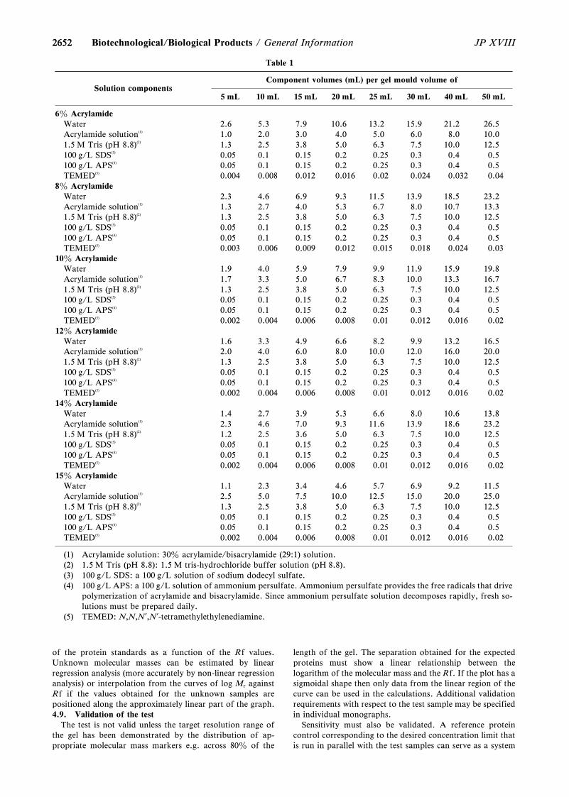
2652
Table 1
Solution componentsComponent volumes (mL) per gel mould volume of
5 mL 10 mL 15 mL 20 mL 25 mL 30 mL 40 mL 50 mL
6z AcrylamideWater 2.6 5.3 7.9 10.6 13.2 15.9 21.2 26.5Acrylamide solution(1) 1.0 2.0 3.0 4.0 5.0 6.0 8.0 10.01.5 M Tris (pH 8.8)(2) 1.3 2.5 3.8 5.0 6.3 7.5 10.0 12.5100 g/L SDS(3) 0.05 0.1 0.15 0.2 0.25 0.3 0.4 0.5100 g/L APS(4) 0.05 0.1 0.15 0.2 0.25 0.3 0.4 0.5TEMED(5) 0.004 0.008 0.012 0.016 0.02 0.024 0.032 0.04
8z AcrylamideWater 2.3 4.6 6.9 9.3 11.5 13.9 18.5 23.2Acrylamide solution(1) 1.3 2.7 4.0 5.3 6.7 8.0 10.7 13.31.5 M Tris (pH 8.8)(2) 1.3 2.5 3.8 5.0 6.3 7.5 10.0 12.5100 g/L SDS(3) 0.05 0.1 0.15 0.2 0.25 0.3 0.4 0.5100 g/L APS(4) 0.05 0.1 0.15 0.2 0.25 0.3 0.4 0.5TEMED(5) 0.003 0.006 0.009 0.012 0.015 0.018 0.024 0.03
10z AcrylamideWater 1.9 4.0 5.9 7.9 9.9 11.9 15.9 19.8Acrylamide solution(1) 1.7 3.3 5.0 6.7 8.3 10.0 13.3 16.71.5 M Tris (pH 8.8)(2) 1.3 2.5 3.8 5.0 6.3 7.5 10.0 12.5100 g/L SDS(3) 0.05 0.1 0.15 0.2 0.25 0.3 0.4 0.5100 g/L APS(4) 0.05 0.1 0.15 0.2 0.25 0.3 0.4 0.5TEMED(5) 0.002 0.004 0.006 0.008 0.01 0.012 0.016 0.02
12z AcrylamideWater 1.6 3.3 4.9 6.6 8.2 9.9 13.2 16.5Acrylamide solution(1) 2.0 4.0 6.0 8.0 10.0 12.0 16.0 20.01.5 M Tris (pH 8.8)(2) 1.3 2.5 3.8 5.0 6.3 7.5 10.0 12.5100 g/L SDS(3) 0.05 0.1 0.15 0.2 0.25 0.3 0.4 0.5100 g/L APS(4) 0.05 0.1 0.15 0.2 0.25 0.3 0.4 0.5TEMED(5) 0.002 0.004 0.006 0.008 0.01 0.012 0.016 0.02
14z AcrylamideWater 1.4 2.7 3.9 5.3 6.6 8.0 10.6 13.8Acrylamide solution(1) 2.3 4.6 7.0 9.3 11.6 13.9 18.6 23.21.5 M Tris (pH 8.8)(2) 1.2 2.5 3.6 5.0 6.3 7.5 10.0 12.5100 g/L SDS(3) 0.05 0.1 0.15 0.2 0.25 0.3 0.4 0.5100 g/L APS(4) 0.05 0.1 0.15 0.2 0.25 0.3 0.4 0.5TEMED(5) 0.002 0.004 0.006 0.008 0.01 0.012 0.016 0.02
15z AcrylamideWater 1.1 2.3 3.4 4.6 5.7 6.9 9.2 11.5Acrylamide solution(1) 2.5 5.0 7.5 10.0 12.5 15.0 20.0 25.01.5 M Tris (pH 8.8)(2) 1.3 2.5 3.8 5.0 6.3 7.5 10.0 12.5100 g/L SDS(3) 0.05 0.1 0.15 0.2 0.25 0.3 0.4 0.5100 g/L APS(4) 0.05 0.1 0.15 0.2 0.25 0.3 0.4 0.5TEMED(5) 0.002 0.004 0.006 0.008 0.01 0.012 0.016 0.02
(1) Acrylamide solution: 30z acrylamide/bisacrylamide (29:1) solution.(2) 1.5 M Tris (pH 8.8): 1.5 M tris-hydrochloride buffer solution (pH 8.8).(3) 100 g/L SDS: a 100 g/L solution of sodium dodecyl sulfate.(4) 100 g/L APS: a 100 g/L solution of ammonium persulfate. Ammonium persulfate provides the free radicals that drive
polymerization of acrylamide and bisacrylamide. Since ammonium persulfate solution decomposes rapidly, fresh so-lutions must be prepared daily.
(5) TEMED: N,N,N?,N?-tetramethylethylenediamine.
2652 JP XVIIIBiotechnological/Biological Products / General Information
of the protein standards as a function of the Rf values.Unknown molecular masses can be estimated by linearregression analysis (more accurately by non-linear regressionanalysis) or interpolation from the curves of log Mr againstRf if the values obtained for the unknown samples arepositioned along the approximately linear part of the graph.4.9. Validation of the test
The test is not valid unless the target resolution range ofthe gel has been demonstrated by the distribution of ap-propriate molecular mass markers e.g. across 80z of the
length of the gel. The separation obtained for the expectedproteins must show a linear relationship between thelogarithm of the molecular mass and the Rf. If the plot has asigmoidal shape then only data from the linear region of thecurve can be used in the calculations. Additional validationrequirements with respect to the test sample may be specifiedin individual monographs.
Sensitivity must also be validated. A reference proteincontrol corresponding to the desired concentration limit thatis run in parallel with the test samples can serve as a system
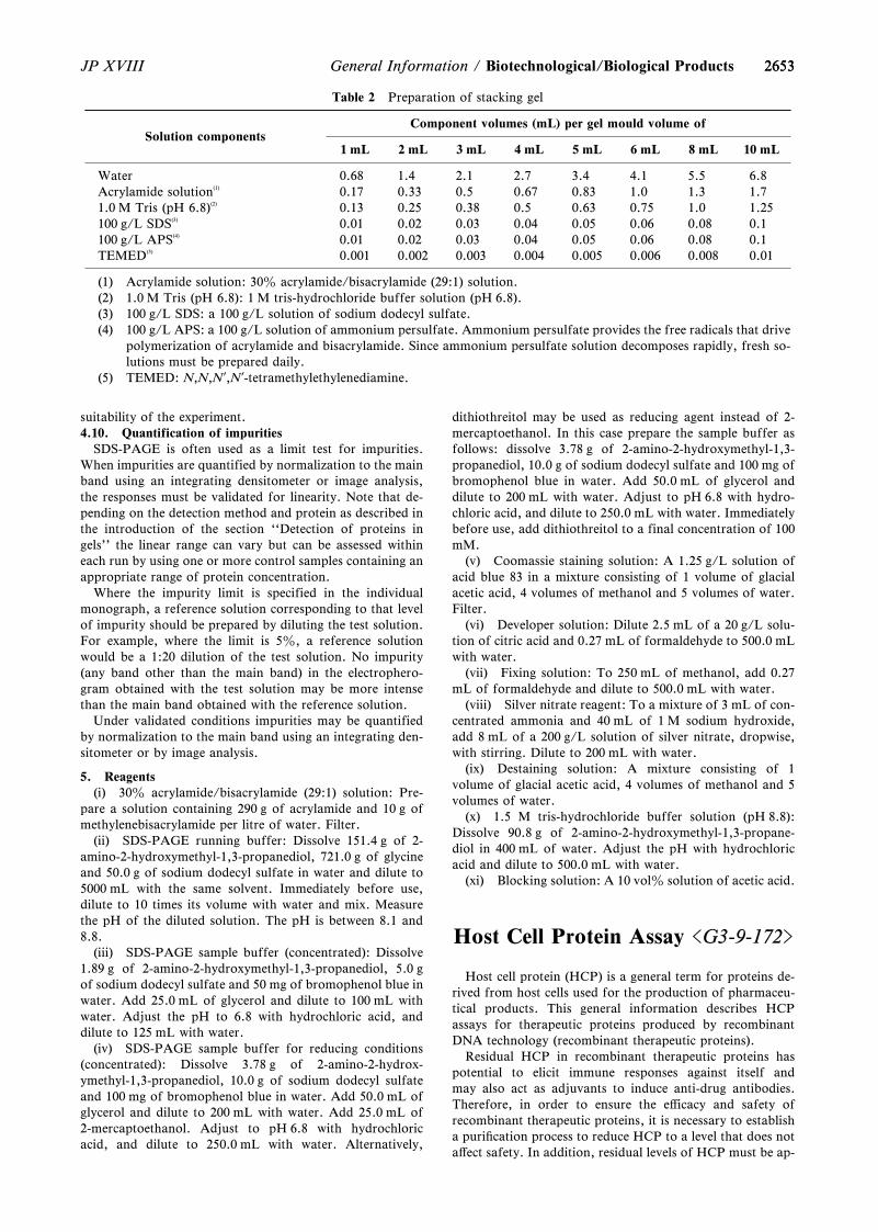
2653
Table 2 Preparation of stacking gel
Solution componentsComponent volumes (mL) per gel mould volume of
1 mL 2 mL 3 mL 4 mL 5 mL 6 mL 8 mL 10 mL
Water 0.68 1.4 2.1 2.7 3.4 4.1 5.5 6.8Acrylamide solution(1) 0.17 0.33 0.5 0.67 0.83 1.0 1.3 1.71.0 M Tris (pH 6.8)(2) 0.13 0.25 0.38 0.5 0.63 0.75 1.0 1.25100 g/L SDS(3) 0.01 0.02 0.03 0.04 0.05 0.06 0.08 0.1100 g/L APS(4) 0.01 0.02 0.03 0.04 0.05 0.06 0.08 0.1TEMED(5) 0.001 0.002 0.003 0.004 0.005 0.006 0.008 0.01
(1) Acrylamide solution: 30z acrylamide/bisacrylamide (29:1) solution.(2) 1.0 M Tris (pH 6.8): 1 M tris-hydrochloride buffer solution (pH 6.8).(3) 100 g/L SDS: a 100 g/L solution of sodium dodecyl sulfate.(4) 100 g/L APS: a 100 g/L solution of ammonium persulfate. Ammonium persulfate provides the free radicals that drive
polymerization of acrylamide and bisacrylamide. Since ammonium persulfate solution decomposes rapidly, fresh so-lutions must be prepared daily.
(5) TEMED: N,N,N?,N?-tetramethylethylenediamine.
2653JP XVIII General Information / Biotechnological/Biological Products
suitability of the experiment.4.10. Quantification of impurities
SDS-PAGE is often used as a limit test for impurities.When impurities are quantified by normalization to the mainband using an integrating densitometer or image analysis,the responses must be validated for linearity. Note that de-pending on the detection method and protein as described inthe introduction of the section ``Detection of proteins ingels'' the linear range can vary but can be assessed withineach run by using one or more control samples containing anappropriate range of protein concentration.
Where the impurity limit is specified in the individualmonograph, a reference solution corresponding to that levelof impurity should be prepared by diluting the test solution.For example, where the limit is 5z, a reference solutionwould be a 1:20 dilution of the test solution. No impurity(any band other than the main band) in the electrophero-gram obtained with the test solution may be more intensethan the main band obtained with the reference solution.
Under validated conditions impurities may be quantifiedby normalization to the main band using an integrating den-sitometer or by image analysis.
5. Reagents(i) 30z acrylamide/bisacrylamide (29:1) solution: Pre-
pare a solution containing 290 g of acrylamide and 10 g ofmethylenebisacrylamide per litre of water. Filter.
(ii) SDS-PAGE running buffer: Dissolve 151.4 g of 2-amino-2-hydroxymethyl-1,3-propanediol, 721.0 g of glycineand 50.0 g of sodium dodecyl sulfate in water and dilute to5000 mL with the same solvent. Immediately before use,dilute to 10 times its volume with water and mix. Measurethe pH of the diluted solution. The pH is between 8.1 and8.8.
(iii) SDS-PAGE sample buffer (concentrated): Dissolve1.89 g of 2-amino-2-hydroxymethyl-1,3-propanediol, 5.0 gof sodium dodecyl sulfate and 50 mg of bromophenol blue inwater. Add 25.0 mL of glycerol and dilute to 100 mL withwater. Adjust the pH to 6.8 with hydrochloric acid, anddilute to 125 mL with water.
(iv) SDS-PAGE sample buffer for reducing conditions(concentrated): Dissolve 3.78 g of 2-amino-2-hydrox-ymethyl-1,3-propanediol, 10.0 g of sodium dodecyl sulfateand 100 mg of bromophenol blue in water. Add 50.0 mL ofglycerol and dilute to 200 mL with water. Add 25.0 mL of2-mercaptoethanol. Adjust to pH 6.8 with hydrochloricacid, and dilute to 250.0 mL with water. Alternatively,
dithiothreitol may be used as reducing agent instead of 2-mercaptoethanol. In this case prepare the sample buffer asfollows: dissolve 3.78 g of 2-amino-2-hydroxymethyl-1,3-propanediol, 10.0 g of sodium dodecyl sulfate and 100 mg ofbromophenol blue in water. Add 50.0 mL of glycerol anddilute to 200 mL with water. Adjust to pH 6.8 with hydro-chloric acid, and dilute to 250.0 mL with water. Immediatelybefore use, add dithiothreitol to a final concentration of 100mM.
(v) Coomassie staining solution: A 1.25 g/L solution ofacid blue 83 in a mixture consisting of 1 volume of glacialacetic acid, 4 volumes of methanol and 5 volumes of water.Filter.
(vi) Developer solution: Dilute 2.5 mL of a 20 g/L solu-tion of citric acid and 0.27 mL of formaldehyde to 500.0 mLwith water.
(vii) Fixing solution: To 250 mL of methanol, add 0.27mL of formaldehyde and dilute to 500.0 mL with water.
(viii) Silver nitrate reagent: To a mixture of 3 mL of con-centrated ammonia and 40 mL of 1 M sodium hydroxide,add 8 mL of a 200 g/L solution of silver nitrate, dropwise,with stirring. Dilute to 200 mL with water.
(ix) Destaining solution: A mixture consisting of 1volume of glacial acetic acid, 4 volumes of methanol and 5volumes of water.
(x) 1.5 M tris-hydrochloride buffer solution (pH 8.8):Dissolve 90.8 g of 2-amino-2-hydroxymethyl-1,3-propane-diol in 400 mL of water. Adjust the pH with hydrochloricacid and dilute to 500.0 mL with water.
(xi) Blocking solution: A 10 volz solution of acetic acid.
Host Cell Protein Assay <G3-9-172>
Host cell protein (HCP) is a general term for proteins de-rived from host cells used for the production of pharmaceu-tical products. This general information describes HCPassays for therapeutic proteins produced by recombinantDNA technology (recombinant therapeutic proteins).
Residual HCP in recombinant therapeutic proteins haspotential to elicit immune responses against itself andmay also act as adjuvants to induce anti-drug antibodies.Therefore, in order to ensure the eŠicacy and safety ofrecombinant therapeutic proteins, it is necessary to establisha puriˆcation process to reduce HCP to a level that does notaŠect safety. In addition, residual levels of HCP must be ap-
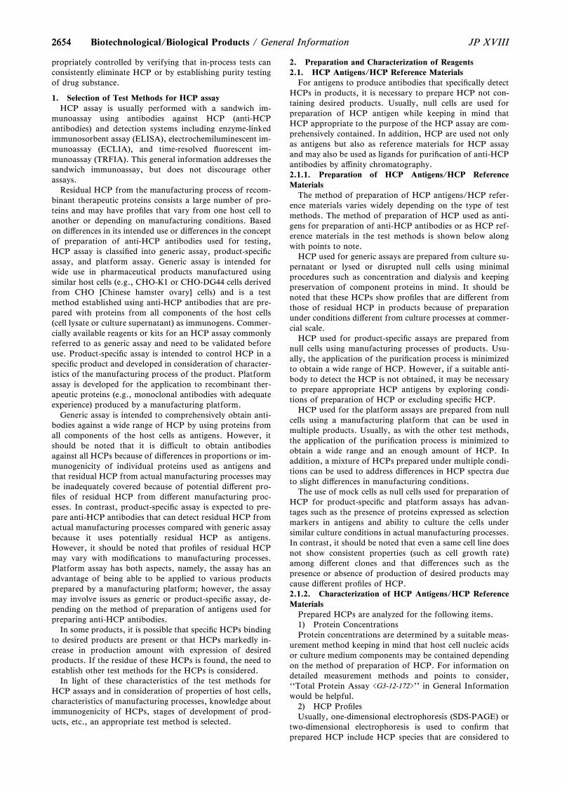
26542654 JP XVIIIBiotechnological/Biological Products / General Information
propriately controlled by verifying that in-process tests canconsistently eliminate HCP or by establishing purity testingof drug substance.
1. Selection of Test Methods for HCP assayHCP assay is usually performed with a sandwich im-
munoassay using antibodies against HCP (anti-HCPantibodies) and detection systems including enzyme-linkedimmunosorbent assay (ELISA), electrochemiluminescent im-munoassay (ECLIA), and time-resolved ‰uorescent im-munoassay (TRFIA). This general information addresses thesandwich immunoassay, but does not discourage otherassays.
Residual HCP from the manufacturing process of recom-binant therapeutic proteins consists a large number of pro-teins and may have proˆles that vary from one host cell toanother or depending on manufacturing conditions. Basedon diŠerences in its intended use or diŠerences in the conceptof preparation of anti-HCP antibodies used for testing,HCP assay is classiˆed into generic assay, product-speciˆcassay, and platform assay. Generic assay is intended forwide use in pharmaceutical products manufactured usingsimilar host cells (e.g., CHO-K1 or CHO-DG44 cells derivedfrom CHO [Chinese hamster ovary] cells) and is a testmethod established using anti-HCP antibodies that are pre-pared with proteins from all components of the host cells(cell lysate or culture supernatant) as immunogens. Commer-cially available reagents or kits for an HCP assay commonlyreferred to as generic assay and need to be validated beforeuse. Product-speciˆc assay is intended to control HCP in aspeciˆc product and developed in consideration of character-istics of the manufacturing process of the product. Platformassay is developed for the application to recombinant ther-apeutic proteins (e.g., monoclonal antibodies with adequateexperience) produced by a manufacturing platform.
Generic assay is intended to comprehensively obtain anti-bodies against a wide range of HCP by using proteins fromall components of the host cells as antigens. However, itshould be noted that it is diŠicult to obtain antibodiesagainst all HCPs because of diŠerences in proportions or im-munogenicity of individual proteins used as antigens andthat residual HCP from actual manufacturing processes maybe inadequately covered because of potential diŠerent pro-ˆles of residual HCP from diŠerent manufacturing proc-esses. In contrast, product-speciˆc assay is expected to pre-pare anti-HCP antibodies that can detect residual HCP fromactual manufacturing processes compared with generic assaybecause it uses potentially residual HCP as antigens.However, it should be noted that proˆles of residual HCPmay vary with modiˆcations to manufacturing processes.Platform assay has both aspects, namely, the assay has anadvantage of being able to be applied to various productsprepared by a manufacturing platform; however, the assaymay involve issues as generic or product-speciˆc assay, de-pending on the method of preparation of antigens used forpreparing anti-HCP antibodies.
In some products, it is possible that speciˆc HCPs bindingto desired products are present or that HCPs markedly in-crease in production amount with expression of desiredproducts. If the residue of these HCPs is found, the need toestablish other test methods for the HCPs is considered.
In light of these characteristics of the test methods forHCP assays and in consideration of properties of host cells,characteristics of manufacturing processes, knowledge aboutimmunogenicity of HCPs, stages of development of prod-ucts, etc., an appropriate test method is selected.
2. Preparation and Characterization of Reagents2.1. HCP Antigens/HCP Reference Materials
For antigens to produce antibodies that speciˆcally detectHCPs in products, it is necessary to prepare HCP not con-taining desired products. Usually, null cells are used forpreparation of HCP antigen while keeping in mind thatHCP appropriate to the purpose of the HCP assay are com-prehensively contained. In addition, HCP are used not onlyas antigens but also as reference materials for HCP assayand may also be used as ligands for puriˆcation of anti-HCPantibodies by aŠinity chromatography.2.1.1. Preparation of HCP Antigens/HCP ReferenceMaterials
The method of preparation of HCP antigens/HCP refer-ence materials varies widely depending on the type of testmethods. The method of preparation of HCP used as anti-gens for preparation of anti-HCP antibodies or as HCP ref-erence materials in the test methods is shown below alongwith points to note.
HCP used for generic assays are prepared from culture su-pernatant or lysed or disrupted null cells using minimalprocedures such as concentration and dialysis and keepingpreservation of component proteins in mind. It should benoted that these HCPs show proˆles that are diŠerent fromthose of residual HCP in products because of preparationunder conditions diŠerent from culture processes at commer-cial scale.
HCP used for product-speciˆc assays are prepared fromnull cells using manufacturing processes of products. Usu-ally, the application of the puriˆcation process is minimizedto obtain a wide range of HCP. However, if a suitable anti-body to detect the HCP is not obtained, it may be necessaryto prepare appropriate HCP antigens by exploring condi-tions of preparation of HCP or excluding speciˆc HCP.
HCP used for the platform assays are prepared from nullcells using a manufacturing platform that can be used inmultiple products. Usually, as with the other test methods,the application of the puriˆcation process is minimized toobtain a wide range and an enough amount of HCP. Inaddition, a mixture of HCPs prepared under multiple condi-tions can be used to address diŠerences in HCP spectra dueto slight diŠerences in manufacturing conditions.
The use of mock cells as null cells used for preparation ofHCP for product-speciˆc and platform assays has advan-tages such as the presence of proteins expressed as selectionmarkers in antigens and ability to culture the cells undersimilar culture conditions in actual manufacturing processes.In contrast, it should be noted that even a same cell line doesnot show consistent properties (such as cell growth rate)among diŠerent clones and that diŠerences such as thepresence or absence of production of desired products maycause diŠerent proˆles of HCP.2.1.2. Characterization of HCP Antigens/HCP ReferenceMaterials
Prepared HCPs are analyzed for the following items.1) Protein ConcentrationsProtein concentrations are determined by a suitable meas-
urement method keeping in mind that host cell nucleic acidsor culture medium components may be contained dependingon the method of preparation of HCP. For information ondetailed measurement methods and points to consider,``Total Protein Assay <G3-12-172>'' in General Informationwould be helpful.
2) HCP ProˆlesUsually, one-dimensional electrophoresis (SDS-PAGE) or
two-dimensional electrophoresis is used to conˆrm thatprepared HCP include HCP species that are considered to
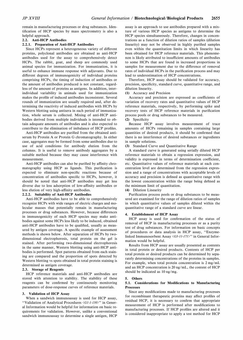
26552655JP XVIII General Information / Biotechnological/Biological Products
remain in manufacturing processes or drug substances. Iden-tiˆcation of HCP species by mass spectrometry is also ahelpful approach.2.2. Anti-HCP Antibodies2.2.1. Preparation of Anti-HCP Antibodies
Since HCPs represent a heterogeneous variety of diŠerentproteins, polyclonal antibodies are obtained as anti-HCPantibodies used for the assay to comprehensively detectHCPs. The rabbit, goat, and sheep are commonly usedanimal species for immunization. For immunization, it isuseful to enhance immune response with adjuvants. Due todiŠerent degrees of immunogenicity of individual proteinscomprising HCPs, the timing of induction of antibodies orthe amount of antibodies produced is not constant, regard-less of the amount of proteins as antigens. In addition, inter-individual variability in animals used for immunizationmakes the proˆle of induced antibodies inconsistent. Severalrounds of immunization are usually required and, after de-termining the reactivity of induced antibodies with HCPs byWestern blotting using antisera in each period of immuniza-tion, whole serum is collected. Mixing of anti-HCP anti-bodies derived from multiple individuals is intended to ob-tain adequate amounts of antibodies and is also expected tocontribute to the elimination of imbalance of HCP proˆles.
Anti-HCP antibodies are puriˆed from the obtained anti-serum by Protein A or Protein G chromatography. In eithercase, aggregates may be formed from some antibodies due touse of acid conditions for antibody elution from thecolumns. It is useful to remove antibody aggregates by asuitable method because they may cause interference withmeasurement.
Anti-HCP antibodies can also be puriˆed by aŠinity chro-matography using HCP as ligands. This puriˆcation isexpected to eliminate non-speciˆc reactions because ofconcentration of antibodies speciˆc to HCPs, however, itshould be noted that anti-HCP antibodies may get lessdiverse due to less adsorption of low-aŠinity antibodies orless elution of very high-aŠinity antibodies.2.2.2. Suitability of Anti-HCP Antibodies
Anti-HCP antibodies have to be able to comprehensivelyrecognize HCPs with wide ranges of electric charges and mo-lecular masses that potentially remain in manufacturingprocesses or drug substances. However, because diŠerencesin immunogenicity of each HCP species may make anti-bodies against some HCPs less likely to be induced, obtainedanti-HCP antibodies have to be qualiˆed, usually as meas-ured by antigen coverage. A speciˆc example of assessmentmethods is shown below. After separation of HCPs by two-dimensional electrophoresis, total protein on the gel isstained. After performing two-dimensional electrophoresisin the same manner, Western blotting using anti-HCP anti-bodies is performed. Spot patterns obtained from each stain-ing are compared and the proportion of spots detected byWestern blotting vs spots obtained in total protein staining isdetermined as antigen coverage.2.3. Storage of Reagents
HCP reference materials and anti-HCP antibodies arestored with attention to stability. The stability of thesereagents can be conˆrmed by continuously monitoringparameters of dose-response curves of reference materials.
3. Validation of HCP AssayWhen a sandwich immunoassay is used for HCP assay,
``Validation of Analytical Procedures <G1-1-130>'' in Gener-al Information would be helpful for information on basic re-quirements for validation. However, unlike a conventionalsandwich immunoassay to determine a single antigen, HCP
assay is an approach to use antibodies prepared with a mix-ture of various HCP species as antigens to determine theHCP species simultaneously. Therefore, changes in concen-trations as a function of dilution ratios of samples (dilutionlinearity) may not be observed in highly puriˆed sampleseven within the quantitation limits in which linearity hasbeen obtained for HCP reference materials. This phenome-non is likely attributed to insuŠicient amounts of antibodiesto some HCPs that are found in increased proportions insamples for measurement due to the diŠerence of removalrates of individual HCPs in the puriˆcation process and maylead to underestimation of HCP concentrations.
Therefore, HCP assay should be validated for accuracy,precision, speciˆcity, standard curve, quantitative range, anddilution linearity.(1) Accuracy and Precision
Accuracy and precision are expressed as coeŠicients ofvariation of recovery rates and quantitative values of HCPreference materials, respectively, by performing spike andrecovery tests of HCP reference materials in puriˆcationprocess pools or drug substances to be measured.(2) Speciˆcity
Because HCP assay involves measurement of traceamounts of HCPs remaining in samples containing largequantities of desired products, it should be conˆrmed thatthere is no interference of desired substances or ingredientsin sample solutions.(3) Standard Curve and Quantitative Range
A standard curve is generated using serially diluted HCPreference materials to obtain a regression expression, andvalidity is expressed in terms of determination coeŠicient,etc. Quantitative values of reference materials at each con-centration level are determined from the regression expres-sion and a range of concentrations with acceptable levels ofaccuracy and precision is deˆned as quantitative range withthe lowest concentration within the range being deˆned asthe minimum limit of quantitation.(4) Dilution Linearity
Puriˆcation process pools or drug substances to be meas-ured are examined for the range of dilution ratios of samplesin which quantitative values of samples diluted within thequantitative range of a standard curve are linear.
4. Establishment of HCP AssayHCP assay is used for conˆrmation of the status of
removal of HCP in manufacturing processes or as a puritytest of drug substances. For information on basic conceptsof procedures or data analysis in HCP assay, ``Enzyme-linked Immunosorbent Assay <G3-11-171>'' in General Infor-mation would be helpful.
Results from HCP assay are usually presented as contentsin total protein or desired products. Contents of HCP pertotal protein or desired products can be determined by sepa-rately determining concentrations of the proteins in samples.For example, when total protein concentration is 2 mg/mLand an HCP concentration is 20 ng/mL, the content of HCPshould be indicated as 10 ng/mg.
5. Others5.1. Considerations for Modiˆcations to ManufacturingProcesses
Since any modiˆcations made to manufacturing processesfor recombinant therapeutic proteins may aŠect proˆles ofresidual HCP, it is necessary to conˆrm that appropriatemeasurement of HCP is performed after modiˆcations tomanufacturing processes. If HCP proˆles are altered and itis considered inappropriate to apply a test method for HCP
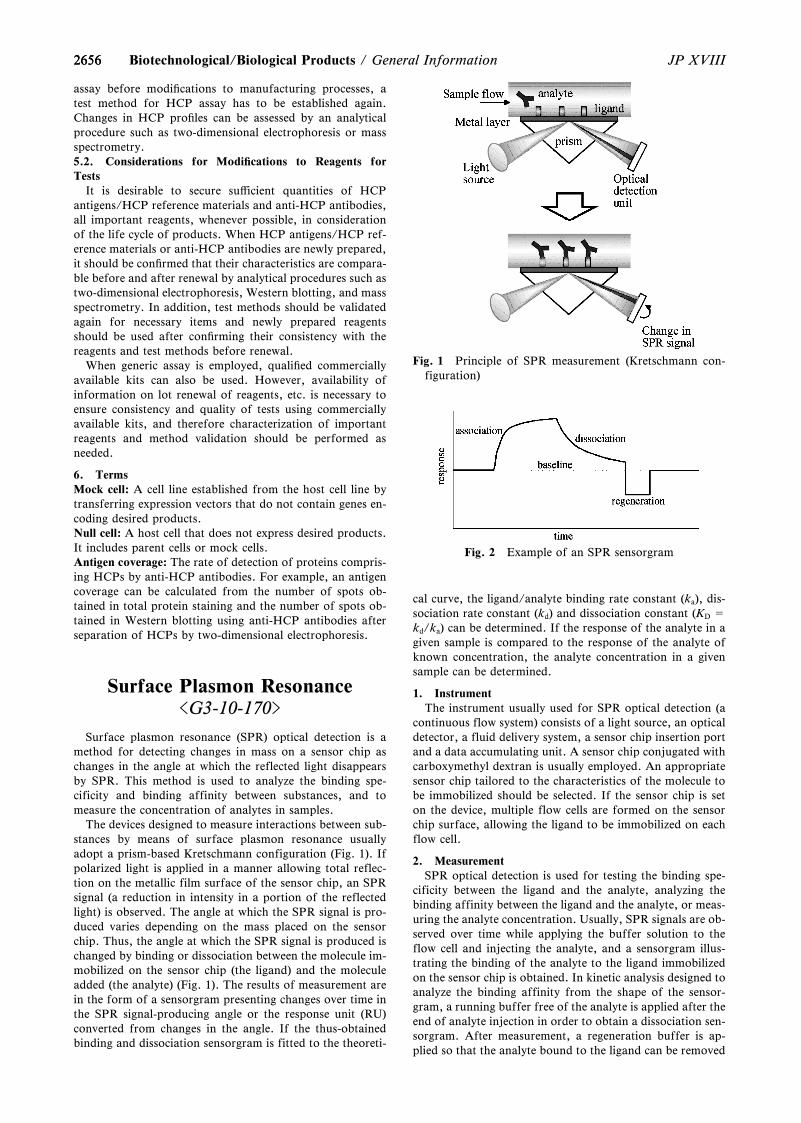
2656
Fig. 1 Principle of SPR measurement (Kretschmann con-figuration)
Fig. 2 Example of an SPR sensorgram
2656 JP XVIIIBiotechnological/Biological Products / General Information
assay before modiˆcations to manufacturing processes, atest method for HCP assay has to be established again.Changes in HCP proˆles can be assessed by an analyticalprocedure such as two-dimensional electrophoresis or massspectrometry.5.2. Considerations for Modiˆcations to Reagents forTests
It is desirable to secure suŠicient quantities of HCPantigens/HCP reference materials and anti-HCP antibodies,all important reagents, whenever possible, in considerationof the life cycle of products. When HCP antigens/HCP ref-erence materials or anti-HCP antibodies are newly prepared,it should be conˆrmed that their characteristics are compara-ble before and after renewal by analytical procedures such astwo-dimensional electrophoresis, Western blotting, and massspectrometry. In addition, test methods should be validatedagain for necessary items and newly prepared reagentsshould be used after conˆrming their consistency with thereagents and test methods before renewal.
When generic assay is employed, qualiˆed commerciallyavailable kits can also be used. However, availability ofinformation on lot renewal of reagents, etc. is necessary toensure consistency and quality of tests using commerciallyavailable kits, and therefore characterization of importantreagents and method validation should be performed asneeded.
6. TermsMock cell: A cell line established from the host cell line bytransferring expression vectors that do not contain genes en-coding desired products.Null cell: A host cell that does not express desired products.It includes parent cells or mock cells.Antigen coverage: The rate of detection of proteins compris-ing HCPs by anti-HCP antibodies. For example, an antigencoverage can be calculated from the number of spots ob-tained in total protein staining and the number of spots ob-tained in Western blotting using anti-HCP antibodies afterseparation of HCPs by two-dimensional electrophoresis.
Surface Plasmon Resonance<G3-10-170>
Surface plasmon resonance (SPR) optical detection is amethod for detecting changes in mass on a sensor chip aschanges in the angle at which the reflected light disappearsby SPR. This method is used to analyze the binding spe-cificity and binding affinity between substances, and tomeasure the concentration of analytes in samples.
The devices designed to measure interactions between sub-stances by means of surface plasmon resonance usuallyadopt a prism-based Kretschmann configuration (Fig. 1). Ifpolarized light is applied in a manner allowing total reflec-tion on the metallic film surface of the sensor chip, an SPRsignal (a reduction in intensity in a portion of the reflectedlight) is observed. The angle at which the SPR signal is pro-duced varies depending on the mass placed on the sensorchip. Thus, the angle at which the SPR signal is produced ischanged by binding or dissociation between the molecule im-mobilized on the sensor chip (the ligand) and the moleculeadded (the analyte) (Fig. 1). The results of measurement arein the form of a sensorgram presenting changes over time inthe SPR signal-producing angle or the response unit (RU)converted from changes in the angle. If the thus-obtainedbinding and dissociation sensorgram is fitted to the theoreti-
cal curve, the ligand/analyte binding rate constant (ka), dis-sociation rate constant (kd) and dissociation constant (KD =kd/ka) can be determined. If the response of the analyte in agiven sample is compared to the response of the analyte ofknown concentration, the analyte concentration in a givensample can be determined.
1. InstrumentThe instrument usually used for SPR optical detection (a
continuous flow system) consists of a light source, an opticaldetector, a fluid delivery system, a sensor chip insertion portand a data accumulating unit. A sensor chip conjugated withcarboxymethyl dextran is usually employed. An appropriatesensor chip tailored to the characteristics of the molecule tobe immobilized should be selected. If the sensor chip is seton the device, multiple flow cells are formed on the sensorchip surface, allowing the ligand to be immobilized on eachflow cell.
2. MeasurementSPR optical detection is used for testing the binding spe-
cificity between the ligand and the analyte, analyzing thebinding affinity between the ligand and the analyte, or meas-uring the analyte concentration. Usually, SPR signals are ob-served over time while applying the buffer solution to theflow cell and injecting the analyte, and a sensorgram illus-trating the binding of the analyte to the ligand immobilizedon the sensor chip is obtained. In kinetic analysis designed toanalyze the binding affinity from the shape of the sensor-gram, a running buffer free of the analyte is applied after theend of analyte injection in order to obtain a dissociation sen-sorgram. After measurement, a regeneration buffer is ap-plied so that the analyte bound to the ligand can be removed
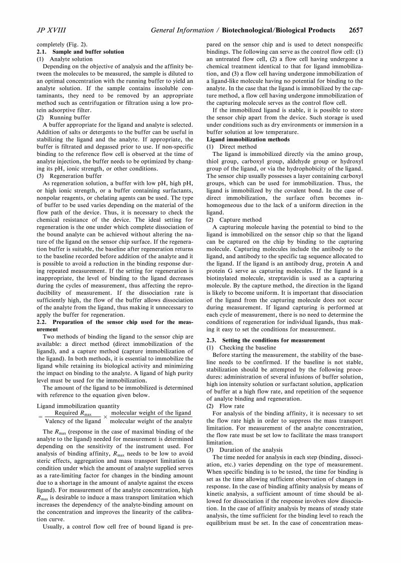
26572657JP XVIII General Information / Biotechnological/Biological Products
completely (Fig. 2).2.1. Sample and buffer solution(1) Analyte solution
Depending on the objective of analysis and the affinity be-tween the molecules to be measured, the sample is diluted toan optimal concentration with the running buffer to yield ananalyte solution. If the sample contains insoluble con-taminants, they need to be removed by an appropriatemethod such as centrifugation or filtration using a low pro-tein adsorptive filter.(2) Running buffer
A buffer appropriate for the ligand and analyte is selected.Addition of salts or detergents to the buffer can be useful instabilizing the ligand and the analyte. If appropriate, thebuffer is filtrated and degassed prior to use. If non-specificbinding to the reference flow cell is observed at the time ofanalyte injection, the buffer needs to be optimized by chang-ing its pH, ionic strength, or other conditions.(3) Regeneration buffer
As regeneration solution, a buffer with low pH, high pH,or high ionic strength, or a buffer containing surfactants,nonpolar reagents, or chelating agents can be used. The typeof buffer to be used varies depending on the material of theflow path of the device. Thus, it is necessary to check thechemical resistance of the device. The ideal setting forregeneration is the one under which complete dissociation ofthe bound analyte can be achieved without altering the na-ture of the ligand on the sensor chip surface. If the regenera-tion buffer is suitable, the baseline after regeneration returnsto the baseline recorded before addition of the analyte and itis possible to avoid a reduction in the binding response dur-ing repeated measurement. If the setting for regeneration isinappropriate, the level of binding to the ligand decreasesduring the cycles of measurement, thus affecting the repro-ducibility of measurement. If the dissociation rate issufficiently high, the flow of the buffer allows dissociationof the analyte from the ligand, thus making it unnecessary toapply the buffer for regeneration.2.2. Preparation of the sensor chip used for the meas-urement
Two methods of binding the ligand to the sensor chip areavailable: a direct method (direct immobilization of theligand), and a capture method (capture immobilization ofthe ligand). In both methods, it is essential to immobilize theligand while retaining its biological activity and minimizingthe impact on binding to the analyte. A ligand of high puritylevel must be used for the immobilization.
The amount of the ligand to be immobilized is determinedwith reference to the equation given below.
Ligand immobilization quantity
=Required Rmax
Valency of the ligand×
molecular weight of the ligandmolecular weight of the analyte
The Rmax (response in the case of maximal binding of theanalyte to the ligand) needed for measurement is determineddepending on the sensitivity of the instrument used. Foranalysis of binding affinity, Rmax needs to be low to avoidsteric effects, aggregation and mass transport limitation (acondition under which the amount of analyte supplied servesas a rate-limiting factor for changes in the binding amountdue to a shortage in the amount of analyte against the excessligand). For measurement of the analyte concentration, highRmax is desirable to induce a mass transport limitation whichincreases the dependency of the analyte-binding amount onthe concentration and improves the linearity of the calibra-tion curve.
Usually, a control flow cell free of bound ligand is pre-
pared on the sensor chip and is used to detect nonspecificbindings. The following can serve as the control flow cell: (1)an untreated flow cell, (2) a flow cell having undergone achemical treatment identical to that for ligand immobiliza-tion, and (3) a flow cell having undergone immobilization ofa ligand-like molecule having no potential for binding to theanalyte. In the case that the ligand is immobilized by the cap-ture method, a flow cell having undergone immobilization ofthe capturing molecule serves as the control flow cell.
If the immobilized ligand is stable, it is possible to storethe sensor chip apart from the device. Such storage is usedunder conditions such as dry environments or immersion in abuffer solution at low temperature.Ligand immobilization methods(1) Direct method
The ligand is immobilized directly via the amino group,thiol group, carboxyl group, aldehyde group or hydroxylgroup of the ligand, or via the hydrophobicity of the ligand.The sensor chip usually possesses a layer containing carboxylgroups, which can be used for immobilization. Thus, theligand is immobilized by the covalent bond. In the case ofdirect immobilization, the surface often becomes in-homogeneous due to the lack of a uniform direction in theligand.(2) Capture method
A capturing molecule having the potential to bind to theligand is immobilized on the sensor chip so that the ligandcan be captured on the chip by binding to the capturingmolecule. Capturing molecules include the antibody to theligand, and antibody to the specific tag sequence allocated tothe ligand. If the ligand is an antibody drug, protein A andprotein G serve as capturing molecules. If the ligand is abiotinylated molecule, streptavidin is used as a capturingmolecule. By the capture method, the direction in the ligandis likely to become uniform. It is important that dissociationof the ligand from the capturing molecule does not occurduring measurement. If ligand capturing is performed ateach cycle of measurement, there is no need to determine theconditions of regeneration for individual ligands, thus mak-ing it easy to set the conditions for measurement.
2.3. Setting the conditions for measurement(1) Checking the baseline
Before starting the measurement, the stability of the base-line needs to be confirmed. If the baseline is not stable,stabilization should be attempted by the following proce-dures: administration of several infusions of buffer solution,high ion intensity solution or surfactant solution, applicationof buffer at a high flow rate, and repetition of the sequenceof analyte binding and regeneration.(2) Flow rate
For analysis of the binding affinity, it is necessary to setthe flow rate high in order to suppress the mass transportlimitation. For measurement of the analyte concentration,the flow rate must be set low to facilitate the mass transportlimitation.(3) Duration of the analysis
The time needed for analysis in each step (binding, dissoci-ation, etc.) varies depending on the type of measurement.When specific binding is to be tested, the time for binding isset as the time allowing sufficient observation of changes inresponse. In the case of binding affinity analysis by means ofkinetic analysis, a sufficient amount of time should be al-lowed for dissociation if the response involves slow dissocia-tion. In the case of affinity analysis by means of steady stateanalysis, the time sufficient for the binding level to reach theequilibrium must be set. In the case of concentration meas-
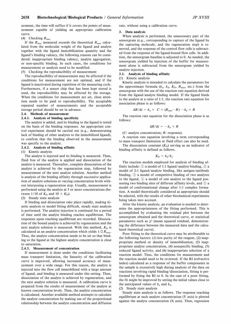
26582658 JP XVIIIBiotechnological/Biological Products / General Information
urement, the time will suffice if it covers the points of meas-urement capable of yielding an appropriate calibrationcurve.(4) Checking Rmax
If the Rmax measured exceeds the theoretical Rmax calcu-lated from the molecular weight of the ligand and analytetogether with the ligand immobilization quantity and theligand's binding valency, the following reasons can be consi-dered: inappropriate binding valency, analyte aggregation,or non-specific binding. In such cases, the conditions formeasurement or analysis need to be modified.(5) Checking the reproducibility of measurement
The reproducibility of measurement may be affected if theconditions for measurement are not optimal, and if theligand is inactivated during repetition of the measuring cycle.Furthermore, if a sensor chip that has been kept stored isused, the reproducibility may be affected by the storage.When the conditions for measurement are set, close atten-tion needs to be paid to reproducibility. The acceptablerepeated number of measurements and the acceptablestorage period should be set in advance.2.4. Methods of measurement2.4.1. Analysis of binding specificity
The analyte is added, and its binding to the ligand is testedon the basis of the binding responses. An appropriate con-trol experiment should be carried out (e.g., demonstratinglack of binding of other analytes to the immobilized ligand),to confirm that the binding observed in the measurementwas specific to the analyte.2.4.2. Analysis of binding affinity(1) Kinetic analysis
The analyte is injected and its binding is measured. Then,fluid free of the analyte is applied and dissociation of theanalyte is measured. Thereafter, complete dissociation of theanalyte is achieved by the regeneration step, followed bymeasurement of the next analyte solution. Another methodis analysis of the binding affinity through successive applica-tion of analyte solutions at varying concentration levels with-out interposing a regeneration step. Usually, measurement isperformed using the analyte at 5 or more concentrations (be-tween 1/10 of KD and 10 × KD).(2) Steady state analysis
If binding and dissociation take place rapidly, making ki-netic analysis or model fitting difficult, steady state analysisis performed. The analyte injection is continued for a periodof time until the analyte binding reaches equilibrium. Theresponses upon reaching equilibrium are recorded. Dissocia-tion of the bound analyte is achieved by regeneration and thenext analyte solution is measured. With this method, KD iscalculated as an analyte concentration which yields 1/2 Rmax.Thus, the analyte concentration needs to be set so that bind-ing to the ligand at the highest analyte concentration is closeto saturation.2.4.3. Measurement of concentration
If measurement is done under the conditions facilitatingmass transport limitation, the linearity of the calibrationcurve is improved, allowing increased accuracy of meas-urement over a wide range. For this reason, the analyte isinjected into the flow cell immobilized with a large amountof ligand, and binding is measured under this setting. Then,dissociation of the analyte is achieved by regeneration, andthe next analyte solution is measured. A calibration curve isprepared from the results of measurement of the analyte atknown concentration levels. Then, the analyte concentrationis calculated. Another available method attempts to calculatethe analyte concentration by making use of the proportionalrelationship between the analyte concentration and diffusion
rate, without using a calibration curve.
3. Data analysisWhen analysis is performed, the unnecessary part of the
sensorgram (e.g., corresponding to capture of the ligand bythe capturing molecule, and the regeneration step) is re-moved, and the response of the control flow cells is subtract-ed from the response of the ligand-bound flow cells. In addi-tion, the sensorgram baseline is adjusted to 0. As needed, thesensorgram yielded by injection of the buffer for measure-ment alone is subtracted from the sensorgram yielded byanalyte injection.3.1. Analysis of binding affinity(1) Kinetic analysis
Kinetic analysis is intended to calculate the parameters forthe approximate formula (ka, kd, KD, Rmax, etc.) from thesensorgram with the use of the reaction rate equation derivedfrom the ligand/analyte binding model. If the ligand bindsto the analyte at a ratio of 1:1, the reaction rate equation forassociation phase is as follows:
dR/dt = ka × C × (Rmax-R) -kd × R
The reaction rate equation for the dissociation phase is asfollows:
dR/dt = -kd × R
(C: analyte concentration; R: response).A reaction rate equation involving a term corresponding
to mass transport limitation or fluid effect can also be used.The dissociation constant (KD) serving as an indicator of
binding affinity is defined as follows.
KD = kd/ka
The reaction models employed for analysis of binding af-finity include: a model of 1:1 ligand/analyte binding, amodel of 2:1 ligand/analyte binding, like antigen/antibodybinding, a model of competitive binding of two analytesto the ligand, a model of one analyte to the ligand pos-sessing two binding sites of different affinity levels, and amodel of conformational change after 1:1 complex forma-tion. A model theoretically considered as appropriate shouldbe selected, with the results of other biochemical experimentsbeing taken into account.
After the kinetic analysis, an evaluation is needed to deter-mine the appropriateness of the fitting performed. This isaccomplished by evaluating the residual plot between thesensorgram obtained and the theoretical curve, or statisticalparameters such as x2 (mean squared residual, demonstrat-ing the difference between the measured data and the calcu-lated theoretical curve).
Poor fitting to the theoretical curve may be attributable tothe following factors: (1) low purity of the reagent, (2) inap-propriate method or density of immobilization, (3) inap-propriate analyte concentration, (4) nonspecific binding, (5)reduced ligand activity, and (6) inappropriate selection of areaction model. Thus, the conditions for measurement andthe reaction model need to be reviewed. If the RI (refractiveindex) calculated as a response of the buffer components inthe sample is excessively high during analysis of the data onreactions involving rapid binding/dissociation, fitting is per-formed by fixing the RI to 0. In the case of a poor fitting,the fit might be improved by setting the initial values close tothe anticipated values of ka and kd.(2) Steady state analysis
Steady state analysis is as follows. The response reachingequilibrium at each analyte concentration (Y axis) is plottedagainst the analyte concentration (X axis). Then, regression

26592659JP XVIII General Information / Biotechnological/Biological Products
is performed using the following equation:
Steady state response equation:
Equilibrium level at analyte concentration
= analyte concentration ×Rmax
analyte concentration + KD
In this way, the KD shown by the response of 1/2 Rmax isdetermined. The KD calculated with this equation is the valuewhen 1:1 ligand/analyte binding is assumed. If the actuallymeasured response converges at Rmax, good analysis is possi-ble. However, if it is in a range lower than Rmax, the analyti-cal data are less reliable and it is desirable to repeat the mea-surement by expanding the range of measured concentra-tions to cover the higher concentration levels.3.2. Measurement of concentration
From the sensorgram derived by injecting an analyte ofknown concentration, the slope of the sensorgram near thestart of injection or the response at a certain time after start-ing the injection is determined and plotted against the ana-lyte concentration. A calibration curve is prepared with anappropriate formula for approximation (e.g., the formulafor 4-parameter logistic regression, linear regression). Then,the slope or the response is determined from measurement ofthe sample as an analyte, followed by calculation of the sam-ple concentration from the calibration curve.
4. Application to various tests4.1. Example of application to identification test
This test is aimed at confirming binding of the sample tothe ligand by testing the specific binding as described in2.4.1. To evaluate the system performance, measurement isperformed on the reference material and a negative control(a substance distinguishable from the ligand in terms of theligand-binding activity) to confirm the specificity of thebinding.4.2. Example of application to binding affinity test
This test is aimed at determining the KD of the referencematerial and the sample, making use of the binding affinityanalysis described in section 2.4.2. The criterion valuerelated to the binding affinity may be set as the KD or relativeKD (sample KD/reference material KD).
Regarding system suitability, the system performance andsystem repeatability are set. For example, concerning the sys-tem performance, it is confirmed that the ligand immobiliza-tion quantity is within the predetermined range; that thecalculated KD of known ligand-binding affinity samples isconsistent with the order of affinity levels; and that x2 is notmore than the predetermined level. System repeatability isconfirmed by checking that the relative standard deviationfor KD during repeated measurement is not more than thepredetermined level.4.3. Example of application to measurement of specific ac-tivity based on the binding quantity to the target molecule
When specific activity is calculated with the quantity ofbinding to the target molecule, the measurement is per-formed using the concentration measuring method describedin 2.4.3. On the basis of the calibration curve prepared fromthe reference material, the relative potency to the referencematerial is calculated using the data on the response of thesample solution, and then the potency is divided by the pro-tein concentration to yield the specific activity.
Regarding system suitability, the system performance andsystem repeatability are confirmed. For example, concerningsystem performance, it is confirmed that the ligand im-mobilization quantity is within the predetermined range; andthat the correlation coefficient or determination coefficientof the calibration curve is not less than the predetermined
level. System repeatability is confirmed by checking that therelative standard deviation of the response during repeatedmeasurement is not more than the predetermined level.
Enzyme-linked ImmunosorbentAssay (ELISA) <G3-11-171>
ELISA (Enzyme-linked immunosorbent assay) is one ofthe immunological assay methods to detect analytes byantigen-antibody reaction, in which an enzyme-labeled rea-gent is used as a detection reagent. In general, 96-well-platesand such are used, on which capture molecules specificallybound to the analyte are immobilized. A test sample, anenzyme-labeled reagent and other required reagents aresequentially added and washed to have the enzyme-labeledreagent bind onto a plate. After reaction by adding a sub-strate for the labeled enzyme, the response (e.g., absorbance)by the enzymatic reaction is measured to determine the con-centration or binding activity of the analyte in the test sam-ple. ELISA is also used as a qualitative test to detect thepresence or absence of binding of the analyte with specificmolecules.
In tests for biotechnological/biological products, ELISAis mainly used for two different purposes. One is to quan-titate the target product or process-related impurities usuallyby measuring the concentration of the analyte with anti-bodies which specifically bind to the analyte. Another is toevaluate the biological activity of products such as therapeu-tic antibodies. For the latter purpose, ELISA is used toevaluate the binding activity of the target product withmolecules related to its pharmacological action, or to evalu-ate the cell response based on the amount of the endogenousprotein secreted from the cells treated with the test samplescontaining the target product.
1. Analytical methodsELISA is broadly classified into competitive and noncom-
petitive methods, and also classified into direct and indirectdetection methods based on the detection procedures (Fig.1). In addition, ELISA is also classified into direct and in-direct immobilization methods by the method for immobiliz-ing capture molecules (Fig. 2).
An analyte bound to a solid phase is detected by the anti-body against the analyte or other reagents (Fig. 1). In thedirect detection method, an enzyme-labelled antibodyagainst the analyte is used. In the indirect detection method,a molecule indirectly bound to the analyte such as an anti-body (secondary antibody) against the antibody binding tothe analyte (primary antibody), is used. The procedure of thedirect detection method is simple, but the enzyme-labeledantibody against the analyte is required for each analyte.Compared to the direct detection method, the procedure ofthe indirect detection method is more complex, however, itallows for using a common secondary antibody such as ananti-IgG antibody even if the analyte is different.
When ELISA is used for measuring analyte concentration,an antibody against the analyte is typically used as a capturemolecule. When ELISA is used to evaluate biological activityby measuring binding activity, the target molecule of a druginvolved in its pharmacologic action is used as a capturemolecule.1.1. Noncompetitive method
In the noncompetitive method, an analyte is bound to acapture molecule without competing with other molecules(Fig. 1). This method can be used when the analyte possesses
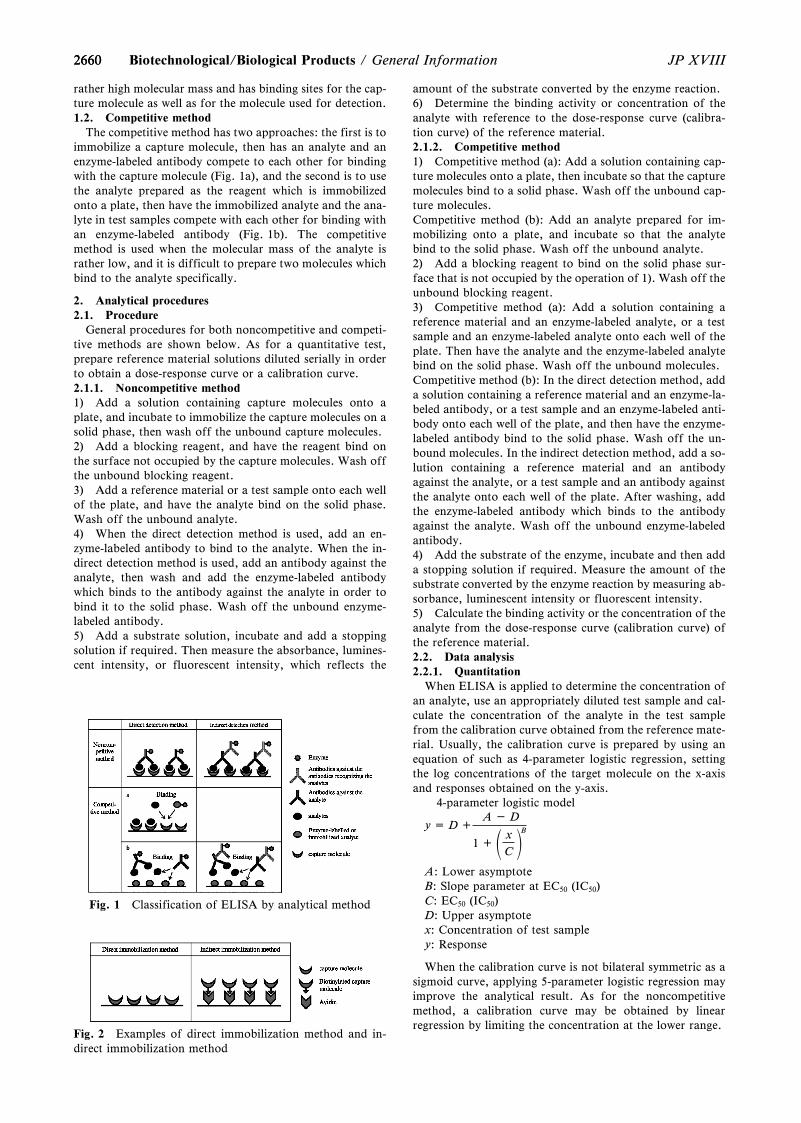
2660
Fig. 1 Classification of ELISA by analytical method
Fig. 2 Examples of direct immobilization method and in-direct immobilization method
2660 JP XVIIIBiotechnological/Biological Products / General Information
rather high molecular mass and has binding sites for the cap-ture molecule as well as for the molecule used for detection.1.2. Competitive method
The competitive method has two approaches: the first is toimmobilize a capture molecule, then has an analyte and anenzyme-labeled antibody compete to each other for bindingwith the capture molecule (Fig. 1a), and the second is to usethe analyte prepared as the reagent which is immobilizedonto a plate, then have the immobilized analyte and the ana-lyte in test samples compete with each other for binding withan enzyme-labeled antibody (Fig. 1b). The competitivemethod is used when the molecular mass of the analyte israther low, and it is difficult to prepare two molecules whichbind to the analyte specifically.
2. Analytical procedures2.1. Procedure
General procedures for both noncompetitive and competi-tive methods are shown below. As for a quantitative test,prepare reference material solutions diluted serially in orderto obtain a dose-response curve or a calibration curve.2.1.1. Noncompetitive method1) Add a solution containing capture molecules onto aplate, and incubate to immobilize the capture molecules on asolid phase, then wash off the unbound capture molecules.2) Add a blocking reagent, and have the reagent bind onthe surface not occupied by the capture molecules. Wash offthe unbound blocking reagent.3) Add a reference material or a test sample onto each wellof the plate, and have the analyte bind on the solid phase.Wash off the unbound analyte.4) When the direct detection method is used, add an en-zyme-labeled antibody to bind to the analyte. When the in-direct detection method is used, add an antibody against theanalyte, then wash and add the enzyme-labeled antibodywhich binds to the antibody against the analyte in order tobind it to the solid phase. Wash off the unbound enzyme-labeled antibody.5) Add a substrate solution, incubate and add a stoppingsolution if required. Then measure the absorbance, lumines-cent intensity, or fluorescent intensity, which reflects the
amount of the substrate converted by the enzyme reaction.6) Determine the binding activity or concentration of theanalyte with reference to the dose-response curve (calibra-tion curve) of the reference material.2.1.2. Competitive method1) Competitive method (a): Add a solution containing cap-ture molecules onto a plate, then incubate so that the capturemolecules bind to a solid phase. Wash off the unbound cap-ture molecules.Competitive method (b): Add an analyte prepared for im-mobilizing onto a plate, and incubate so that the analytebind to the solid phase. Wash off the unbound analyte.2) Add a blocking reagent to bind on the solid phase sur-face that is not occupied by the operation of 1). Wash off theunbound blocking reagent.3) Competitive method (a): Add a solution containing areference material and an enzyme-labeled analyte, or a testsample and an enzyme-labeled analyte onto each well of theplate. Then have the analyte and the enzyme-labeled analytebind on the solid phase. Wash off the unbound molecules.Competitive method (b): In the direct detection method, adda solution containing a reference material and an enzyme-la-beled antibody, or a test sample and an enzyme-labeled anti-body onto each well of the plate, and then have the enzyme-labeled antibody bind to the solid phase. Wash off the un-bound molecules. In the indirect detection method, add a so-lution containing a reference material and an antibodyagainst the analyte, or a test sample and an antibody againstthe analyte onto each well of the plate. After washing, addthe enzyme-labeled antibody which binds to the antibodyagainst the analyte. Wash off the unbound enzyme-labeledantibody.4) Add the substrate of the enzyme, incubate and then adda stopping solution if required. Measure the amount of thesubstrate converted by the enzyme reaction by measuring ab-sorbance, luminescent intensity or fluorescent intensity.5) Calculate the binding activity or the concentration of theanalyte from the dose-response curve (calibration curve) ofthe reference material.2.2. Data analysis2.2.1. Quantitation
When ELISA is applied to determine the concentration ofan analyte, use an appropriately diluted test sample and cal-culate the concentration of the analyte in the test samplefrom the calibration curve obtained from the reference mate-rial. Usually, the calibration curve is prepared by using anequation of such as 4-parameter logistic regression, settingthe log concentrations of the target molecule on the x-axisand responses obtained on the y-axis.
4-parameter logistic model
y = D +A - D
1 + Ø x
C »B
A: Lower asymptoteB: Slope parameter at EC50 (IC50)C: EC50 (IC50)D: Upper asymptotex: Concentration of test sampley: Response
When the calibration curve is not bilateral symmetric as asigmoid curve, applying 5-parameter logistic regression mayimprove the analytical result. As for the noncompetitivemethod, a calibration curve may be obtained by linearregression by limiting the concentration at the lower range.
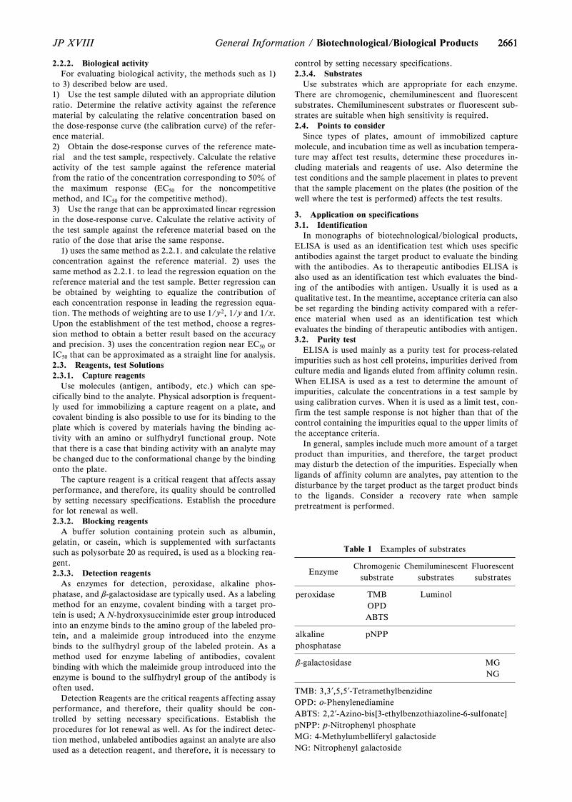
2661
Table 1 Examples of substrates
EnzymeChromogenic
substrateChemiluminescent
substratesFluorescentsubstrates
peroxidase TMBOPDABTS
Luminol
alkalinephosphatase
pNPP
b-galactosidase MGNG
TMB: 3,3?,5,5?-TetramethylbenzidineOPD: o-PhenylenediamineABTS: 2,2?-Azino-bis[3-ethylbenzothiazoline-6-sulfonate]pNPP: p-Nitrophenyl phosphateMG: 4-Methylumbelliferyl galactosideNG: Nitrophenyl galactoside
2661JP XVIII General Information / Biotechnological/Biological Products
2.2.2. Biological activityFor evaluating biological activity, the methods such as 1)
to 3) described below are used.1) Use the test sample diluted with an appropriate dilutionratio. Determine the relative activity against the referencematerial by calculating the relative concentration based onthe dose-response curve (the calibration curve) of the refer-ence material.2) Obtain the dose-response curves of the reference mate-rial and the test sample, respectively. Calculate the relativeactivity of the test sample against the reference materialfrom the ratio of the concentration corresponding to 50z ofthe maximum response (EC50 for the noncompetitivemethod, and IC50 for the competitive method).3) Use the range that can be approximated linear regressionin the dose-response curve. Calculate the relative activity ofthe test sample against the reference material based on theratio of the dose that arise the same response.
1) uses the same method as 2.2.1. and calculate the relativeconcentration against the reference material. 2) uses thesame method as 2.2.1. to lead the regression equation on thereference material and the test sample. Better regression canbe obtained by weighting to equalize the contribution ofeach concentration response in leading the regression equa-tion. The methods of weighting are to use 1/y2, 1/y and 1/x.Upon the establishment of the test method, choose a regres-sion method to obtain a better result based on the accuracyand precision. 3) uses the concentration region near EC50 orIC50 that can be approximated as a straight line for analysis.2.3. Reagents, test Solutions2.3.1. Capture reagents
Use molecules (antigen, antibody, etc.) which can spe-cifically bind to the analyte. Physical adsorption is frequent-ly used for immobilizing a capture reagent on a plate, andcovalent binding is also possible to use for its binding to theplate which is covered by materials having the binding ac-tivity with an amino or sulfhydryl functional group. Notethat there is a case that binding activity with an analyte maybe changed due to the conformational change by the bindingonto the plate.
The capture reagent is a critical reagent that affects assayperformance, and therefore, its quality should be controlledby setting necessary specifications. Establish the procedurefor lot renewal as well.2.3.2. Blocking reagents
A buffer solution containing protein such as albumin,gelatin, or casein, which is supplemented with surfactantssuch as polysorbate 20 as required, is used as a blocking rea-gent.2.3.3. Detection reagents
As enzymes for detection, peroxidase, alkaline phos-phatase, and b-galactosidase are typically used. As a labelingmethod for an enzyme, covalent binding with a target pro-tein is used; A N-hydroxysuccinimide ester group introducedinto an enzyme binds to the amino group of the labeled pro-tein, and a maleimide group introduced into the enzymebinds to the sulfhydryl group of the labeled protein. As amethod used for enzyme labeling of antibodies, covalentbinding with which the maleimide group introduced into theenzyme is bound to the sulfhydryl group of the antibody isoften used.
Detection Reagents are the critical reagents affecting assayperformance, and therefore, their quality should be con-trolled by setting necessary specifications. Establish theprocedures for lot renewal as well. As for the indirect detec-tion method, unlabeled antibodies against an analyte are alsoused as a detection reagent, and therefore, it is necessary to
control by setting necessary specifications.2.3.4. Substrates
Use substrates which are appropriate for each enzyme.There are chromogenic, chemiluminescent and fluorescentsubstrates. Chemiluminescent substrates or fluorescent sub-strates are suitable when high sensitivity is required.2.4. Points to consider
Since types of plates, amount of immobilized capturemolecule, and incubation time as well as incubation tempera-ture may affect test results, determine these procedures in-cluding materials and reagents of use. Also determine thetest conditions and the sample placement in plates to preventthat the sample placement on the plates (the position of thewell where the test is performed) affects the test results.
3. Application on specifications3.1. Identification
In monographs of biotechnological/biological products,ELISA is used as an identification test which uses specificantibodies against the target product to evaluate the bindingwith the antibodies. As to therapeutic antibodies ELISA isalso used as an identification test which evaluates the bind-ing of the antibodies with antigen. Usually it is used as aqualitative test. In the meantime, acceptance criteria can alsobe set regarding the binding activity compared with a refer-ence material when used as an identification test whichevaluates the binding of therapeutic antibodies with antigen.3.2. Purity test
ELISA is used mainly as a purity test for process-relatedimpurities such as host cell proteins, impurities derived fromculture media and ligands eluted from affinity column resin.When ELISA is used as a test to determine the amount ofimpurities, calculate the concentrations in a test sample byusing calibration curves. When it is used as a limit test, con-firm the test sample response is not higher than that of thecontrol containing the impurities equal to the upper limits ofthe acceptance criteria.
In general, samples include much more amount of a targetproduct than impurities, and therefore, the target productmay disturb the detection of the impurities. Especially whenligands of affinity column are analytes, pay attention to thedisturbance by the target product as the target product bindsto the ligands. Consider a recovery rate when samplepretreatment is performed.
26622662 JP XVIIIBiotechnological/Biological Products / General Information
3.3. Biological assayELISA is used as a test to determine the binding activity of
a therapeutic antibody as the target product with its targetmolecule, and used to quantitate bioactive proteins secretedfrom the cells treated with test samples containing the targetproduct in cell-based assay.
Determine relative activity by the method indicated in2.2.2. 1) to 3).3.4. Assay
ELISA is used for measuring the amount of target prod-ucts. Obtain the calibration curve of reference materials andcalculate the concentration of the target products.
4. Validity of testIn general, the validity of the test can be set as follows; use
those in combination as necessary.4.1. Identification
Confirm the results of reference materials and a negativecontrol pass the acceptance criteria specified in the mono-graph.4.2. Purity test
As for a quantitative test, confirm the reliability ofcalibration curves. Accuracy and/or precision of each con-centration of material solutions for the calibration curve andthe coefficient of determination (R2 Value) calculated from aregression equation are used to confirm the reliability. Preci-sion of test samples or accuracy of control samples preparedfrom the known concentration of a reference material (Qual-ity Control Sample: QC sample) could be set as the testsuitability. As for a limit test, confirm the response of thecontrol sample containing the analyte at a concentrationequal to the upper limit of the acceptance criteria satisfiesthe criterion specified in the monograph.4.3. Biological assay
When determining biological activity by using the methodof 1) of 2.2.2., confirm the reliability of the dose-responsecurve (the calibration curve) of the reference material . Toconfirm the reliability of the dose-response curve, accuracyand/or precision of each concentration of the reference ma-terial and R2 value calculated from the regression equationor each parameter value of the regression equation obtainedfrom the dose-response curve of the reference material canbe used. Magnitude of the response of test samples, preci-sion of the relative activity calculated from the response oraccuracy of the concentration of QC samples can also beused to confirm the validity of the test.
When determining biological activity by using the methodof 2) of 2.2.2., confirm the parallelism of the two regressioncurves obtained from a reference material and a test sample.As for the parallelism confirmation, following methods arethe examples. Obtain the ratio of the difference between theupper asymptote and the lower asymptote (D - A of the 4-parameter regression equation in 2.2.1.) of the test sample tothat of the reference material or the ratio of the slopeparameter (B of the 4-parameter regression equation in2.2.1.), then confirm that those ratios are within thepredetermined range. R2 value of the dose-response curves ofthe reference material and the test sample, and accuracy ofthe QC samples are also used to confirm the validity of thetest.
When determining biological activity by using the methodof 3) of 2.2.2., confirm the linearity of the dose-responselines of a reference material and a test sample as well as theparallelism of these lines.
As for 2) and 3) of 2.2.2., there is a method to confirm theparallelism by comparing the residual variances of tworegression curves, using the constrained model for control
and sample data and using unconstrained models for thecontrol and sample data, and determining the parallelism ofthe two regression curves by the method of analysis of vari-ance. However, it should be noted that if the precision of thedata is low, then the determination can be unrigorous.4.4. Assay
Confirm the reliability of calibration curves obtained fromthe dose-response curves of reference materials. To confirmthe reliability of the calibration curve, accuracy and/or pre-cision of each concentration of the reference material calcu-lated from the regression equation, each parameter value ofthe regression equation and R2 value can be used. Precisionof the measured results of test samples or accuracy of QCsamples is also used to confirm the validity of the test.
Total Protein Assay <G3-12-172>
The following procedures are provided as illustrations ofthe determination of total protein content in pharmacopoeialpreparations. Other techniques, such as HPLC, are also ac-ceptable if total protein recovery is demonstrated. Many ofthe total protein assay methods described below can be per-formed successfully using kits from commercial sources.
Note: Where water is required, use distilled water.
Method 1 (UV method)Protein in solution absorbs UV light at a wavelength of
280 nm, due to the presence of aromatic amino acids, mainlytyrosine and tryptophan. This property is the basis of thismethod. Protein determination at 280 nm is mainly a func-tion of the tyrosine and tryptophan content of the protein. Ifthe buffer used to dissolve the protein has a high absorbancerelative to that of water, there is an interfering substance inthe buffer. This interference can be compensated for whenthe spectrophotometer is adjusted to zero buffer absorbance.If the interference results in a large absorbance thatchallenges the limit of sensitivity of the spectrophotometer,the results may be compromised. Furthermore, at low con-centrations protein can be absorbed onto the cuvette, there-by reducing the content in solution. This can be prevented bypreparing samples at higher concentrations or by using anonionic detergent in the preparation.
Note: Keep the Test Solution, the Standard Solution, andthe buffer at the same temperature during testing.Standard Solution Unless otherwise specified in the in-dividual monograph, prepare a solution of the referencestandard or reference material for the protein under test inthe same buffer and at the same concentration as the TestSolution.Test Solution Dissolve a suitable quantity of the proteinunder test in the appropriate buffer to obtain a solution hav-ing a concentration of 0.2 to 2 mg per mL.Procedure Concomitantly determine the absorbances ofthe Standard Solution and the Test Solution in quartz cells ata wavelength of 280 nm, with a suitable spectrophotometer,using the buffer as the blank. To obtain accurate results, theresponse should be linear in the range of protein concentra-tions to be assayed.Light-Scattering The accuracy of the UV spectroscopic de-termination of protein can be decreased by the scattering oflight by the test specimen. If the proteins in solution exist asparticles comparable in size to the wavelength of the measur-ing light (250 to 300 nm), scattering of the light beam resultsin an apparent increase in absorbance of the test specimen.To calculate the absorbance at 280 nm due to light-scatter-ing, determine the absorbances of the Test Solution at wave-
26632663JP XVIII General Information / Biotechnological/Biological Products
lengths of 320, 325, 330, 335, 340, 345, and 350 nm. Usingthe linear regression method, plot the log of the observed ab-sorbance versus the log of the wavelength, and determine thestandard curve best fitting the plotted points. From thegraph so obtained, extrapolate the absorbance value due tolight-scattering at 280 nm. Subtract the absorbance fromlight-scattering from the total absorbance at 280 nm toobtain the absorbance value of the protein in solution.Filtration with a filter having a 0.2-mm porosity or clarifica-tion by centrifugation may be performed to reduce the effectof light-scattering, especially if the solution is noticeablyturbid.Calculations Calculate the concentration, CU, of protein inthe test specimen by the formula:
CU = CS (AU/AS),
in which CS is the concentration of the Standard Solution;and AU and AS are the corrected absorbances of the TestSolution and the Standard Solution, respectively.
Method 2 (Lowry method)This method, commonly referred to as the Lowry assay, is
based on the reduction by protein of the phosphomolybdic-tungstic mixed acid chromogen in the Folin-Ciocalteu'sphenol reagent, resulting in an absorbance maximum at 750nm. The Folin-Ciocalteu's phenol reagent (Folin's TS) reactsprimarily with tyrosine residues in the protein, which canlead to variation in the response of the assay to differentproteins. Because the method is sensitive to interfering sub-stances, a procedure for precipitation of the protein from thetest specimen may be used. Where separation of interferingsubstances from the protein in the test specimen is necessary,proceed as directed below for Interfering Substances prior topreparation of the Test Solution. The effect of interferingsubstances can be minimized by dilution provided the con-centration of the protein under test remains sufficient for ac-curate measurement. Variations of the Lowry test that areindicated in national regulatory documents1) can be substit-uted for the method described below.Standard Solutions Unless otherwise specified in the in-dividual monograph, dissolve the reference standard or ref-erence material for the protein under test in the buffer usedto prepare the Test Solution. Dilute portions of this solutionwith the same buffer to obtain not fewer than five StandardSolutions having concentrations between 5 mg and 100 mg ofprotein per mL, the concentrations being evenly spaced.Test Solution Dissolve a suitable quantity of the proteinunder test in the appropriate buffer to obtain a solution hav-ing a concentration within the range of the concentrations ofthe Standard Solutions. An appropriate buffer will producea pH in the range of 10 to 10.5.Blank Use the buffer used for the Test Solution and theStandard Solutions.Reagents and Solutions—
Copper Sulfate Reagent Dissolve 100 mg of copper (II)sulfate pentahydrate and 200 mg of sodium tartrate dihy-drate in water, dilute with water to 50 mL, and mix. Dissolve10 g of anhydrous sodium carbonate in water to a finalvolume of 50 mL, and mix. Slowly pour the sodium carbon-ate solution into the copper sulfate solution with mixing.Prepare this solution fresh daily.
5z SDS TS Dissolve 5 g of sodium dodecyl sulfate inwater, and dilute with water to 100 mL.
Alkaline Copper Reagent Prepare a mixture of 5z SDSTS, Copper Sulfate Reagent, and Sodium Hydroxide Solu-tion (4 in 125) (2:1:1). This reagent may be stored at roomtemperature for up to 2 weeks.
Diluted Folin's TS Mix 10 mL of Folin's TS with 50 mLof water. Store in an amber bottle, at room temperature.Procedure To 1 mL of each Standard Solution, the TestSolution, and the Blank, add 1 mL of Alkaline Copper Rea-gent, and mix. Allow to stand at room temperature for 10minutes. Add 0.5 mL of the Diluted Folin's TS to each solu-tion, and mix each tube immediately after the addition, andallow to stand at room temperature for 30 minutes. Deter-mine the absorbances of the solutions from the Standard So-lutions and the Test Solution at the wavelength of maximumabsorbance at 750 nm, with a suitable spectrophotometer,using the solution from the Blank to set the instrument tozero.Calculations [Note: The relationship of absorbance to pro-tein concentration is nonlinear; however, if the standardcurve concentration range is sufficiently small, it will ap-proach linearity.] Using the linear regression method, plotthe absorbances of the solutions from the Standard Solu-tions versus the protein concentrations, and determine thestandard curve best fitting the plotted points. From thestandard curve so obtained and the absorbance of the TestSolution, determine the concentration of protein in the TestSolution.Interfering Substances In the following procedure, deoxy-cholate-trichloroacetic acid is added to a test specimen to re-move interfering substances by precipitation of proteins be-fore testing. This technique also can be used to concentrateproteins from a dilute solution.
Sodium Deoxycholate Reagent Prepare a solution of so-dium deoxycholate in water having a concentration of 150mg in 100 mL.
Trichloroacetic Acid Reagent Prepare a solution oftrichloroacetic acid in water having a concentration of 72 gin 100 mL.Procedure Add 0.1 mL of Sodium Deoxycholate Reagentto 1 mL of a solution of the protein under test. Mix on a vor-tex mixer, and allow to stand at room temperature for 10minutes. Add 0.1 mL of Trichloroacetic Acid Reagent, andmix on a vortex mixer. Centrifuge at 3000 × g for 30minutes, decant the liquid, and remove any residual liquidwith a pipet. Redissolve the protein pellet in 1 mL of Alka-line Copper Reagent. Proceed as directed for the Test Solu-tion. [Note: Color development reaches a maximum in 20 to30 minutes during incubation at room temperature, afterwhich there is a gradual loss of color. Most interfering sub-stances cause a lower color yield; however, some detergentscause a slight increase in color. A high salt concentrationmay cause a precipitate to form. Because different proteinspecies may give different color response intensities, thestandard protein and test protein should be the same.]
Method 3 (Bradford method)This method, commonly referred to as the Bradford assay,
is based on the absorption shift from 470 nm to 595 nm ob-served when Coomassie brilliant blue G-250 binds to protein.Coomassie brilliant blue G-250 binds most readily to arginyland lysyl residues in the protein, which can lead to variationin the response of the assay to different proteins.Standard Solutions Unless otherwise specified in the in-dividual monograph, dissolve the reference standard or thereference material for the protein under test in the bufferused to prepare the Test Solution. Dilute portions of thissolution with the same buffer to obtain not fewer than fiveStandard Solutions having concentrations between 100 mgand 1 mg of protein per mL, the concentrations being evenlyspaced.Test Solution Dissolve a suitable quantity of the protein
26642664 JP XVIIIBiotechnological/Biological Products / General Information
under test in the appropriate buffer to obtain a solution hav-ing a concentration within the range of the concentrations ofthe Standard Solutions.Blank Use the buffer used to prepare the Test Solution andthe Standard Solutions.Coomassie Reagent Dissolve 100 mg of Coomassie brilliantblue G-2502) in 50 mL of ethanol (95). [Note: Not all dyeshave the same brilliant blue G content, and different prod-ucts may give different results.] Add 100 mL of phosphoricacid, dilute with water to 1000 mL, and mix. Filter the solu-tion through filter paper (Whatman No.1 or equivalent), andstore the filtered reagent in an amber bottle at room tem-perature. [Note: Slow precipitation of the dye will occur dur-ing storage of the reagent. Filter the reagent before use.]Procedure Add 5 mL of the Coomassie Reagent to 100 mLof each Standard Solution, the Test Solution, and the Blank,and mix by inversion. Avoid foaming, which will lead topoor reproducibility. Determine the absorbances of the solu-tions from the Standard Solutions and the Test Solution at595 nm, with a suitable spectrophotometer, using the Blankto set the instrument to zero.
[Note: Do not use quartz (silica) spectrophotometer cells:the dye binds to this material. Because different protein spe-cies may give different color response intensities, the stand-ard protein and test protein should be the same.] There arerelatively few interfering substances, but detergents and am-pholytes in the test specimen should be avoided. Highly alka-line specimens may interfere with the acidic reagent.Calculations [Note: The relationship of absorbance to pro-tein concentration is nonlinear; however, if the standardcurve concentration range is sufficiently small, it will ap-proach linearity.] Using the linear regression method, plotthe absorbances of the solutions from the Standard Solu-tions versus the protein concentrations, and determine thestandard curve best fitting the plotted points. From thestandard curve so obtained and the absorbance of the TestSolution, determine the concentration of protein in the TestSolution.
Method 4 (Bicinchoninic acid method)This method, commonly referred to as the bicinchoninic
acid or BCA assay, is based on reduction of the cupric(Cu2+) ion to cuprous (Cu+) ion by protein. The bicincho-ninic acid reagent is used to detect the cuprous ion. Themethod has few interfering substances. When interferingsubstances are present, their effect may be minimized by di-lution, provided that the concentration of the protein undertest remains sufficient for accurate measurement.Standard Solutions Unless otherwise specified in the in-dividual monograph, dissolve the reference standard or thereference material for the protein under test in the bufferused to prepare the Test Solution. Dilute portions of this so-lution with the same buffer to obtain not fewer than fiveStandard Solutions having concentrations between 10 mg and1200 mg of protein per mL, the concentrations being evenlyspaced.Test Solution Dissolve a suitable quantity of the proteinunder test in the appropriate buffer to obtain a solution hav-ing a concentration within the range of the concentrations ofthe Standard Solutions.Blank Use the buffer used to prepare the Test Solution andthe Standard Solutions.Reagents and Solutions—
BCA Reagent Dissolve about 10 g of bicinchoninic acid,20 g of sodium carbonate monohydrate, 1.6 g of sodiumtartrate dihydrate, 4 g of sodium hydroxide, and 9.5 g ofsodium hydrogen carbonate in water. Adjust, if necessary,
with sodium hydroxide or sodium hydrogen carbonate to apH of 11.25. Dilute with water to 1000 mL, and mix.
Copper Sulfate Reagent Dissolve about 2 g of copper (II)sulfate pentahydrate in water to a final volume of 50 mL.
Copper-BCA Reagent Mix 1 mL of Copper Sulfate Rea-gent and 50 mL of BCA Reagent.Procedure Mix 0.1 mL of each Standard Solution, the TestSolution, and the Blank with 2 mL of the Copper-BCA Rea-gent. Incubate the solutions at 379C for 30 minutes, note thetime, and allow to come to room temperature. Within 60minutes following the incubation time, determine the absor-bances of the solutions from the Standard Solutions and theTest Solution in quartz cells at 562 nm, with a suitable spec-trophotometer, using the Blank to set the instrument to zero.After the solutions are cooled to room temperature, thecolor intensity continues to increase gradually. If substancesthat will cause interference in the test are present, proceed asdirected for Interfering Substances under Method 2. Becausedifferent protein species may give different color responseintensities, the standard protein and test protein should bethe same.Calculations [Note: The relationship of absorbance to pro-tein concentration is nonlinear; however, if the standardcurve concentration range is sufficiently small, it will ap-proach linearity.] Using the linear regression method, plotthe absorbances of the solutions from the Standard Solu-tions versus the protein concentrations, and determine thestandard curve best fitting the plotted points. From thestandard curve so obtained and the absorbance of the TestSolution, determine the concentration of protein in the TestSolution.
Method 5 (Biuret method)This method, commonly referred to as the Biuret assay, is
based on the interaction of cupric (Cu2 + ) ion with protein inan alkaline solution and the resultant development of absor-bance at 545 nm.Standard Solutions Unless otherwise specified in the in-dividual monograph, prepare a solution of Albumin Humanfor which the protein content has been previously deter-mined by nitrogen analysis (using the nitrogen-to-proteinconversion factor of 6.25) or of the reference standard orreference material for the protein under test in sodium chlo-ride solution (9 in 1000). Dilute portions of this solution withsodium chloride solution (9 in 1000) to obtain not fewer thanthree Standard Solutions having concentrations between 0.5mg and 10 mg per mL, the concentrations being evenlyspaced. [Note: Low responses may be observed if the sampleunder test has significantly different level of proline thanthat of Albumin Human. A different standard protein maybe employed in such cases.]Test Solution Prepare a solution of the test protein in so-dium chloride solution (9 in 1000) having a concentrationwithin the range of the concentrations of the Standard Solu-tions.Blank Use sodium chloride solution (9 in 1000).Biuret Reagent Dissolve about 3.46 g of copper (II) sulfatepentahydrate in 10 mL of water, with heating if necessary,and allow to cool (Solution A). Dissolve about 34.6 g of so-dium citrate dihydrate and 20.0 g of anhydrous sodium car-bonate in 80 mL of water, with heating if necessary, andallow to cool (Solution B). Mix Solutions A and B, anddilute with water to 200 mL. This Biuret Reagent is stable atroom temperature for 6 months. Do not use the reagent if itdevelops turbidity or contains any precipitate.Procedure To one volume of the Standard Solutions and asolution of the Test Solution add an equal volume of sodium
26652665JP XVIII General Information / Biotechnological/Biological Products
hydroxide solution (6 in 100), and mix. Immediately add avolume of Biuret Reagent equivalent to 0.4 volume of theTest Solution, and mix. Allow to stand at a temperature be-tween 159C and 259C for not less than 15 minutes. Within90 minutes after the addition of the Biuret Reagent, deter-mine the absorbances of the Standard Solutions and the so-lution from the Test Solution at the wavelength of maximumabsorbance at 545 nm, with a suitable spectrophotometer,using the Blank to set the instrument to zero. [Note: Any so-lution that develops turbidity or a precipitate is not accepta-ble for calculation of protein concentration.]Calculations Using the least-squares linear regressionmethod, plot the absorbances of the Standard Solutions ver-sus the protein concentrations, and determine the standardcurve best fitting the plotted points, and calculate the corre-lation coefficient for the line. [Note: Within the given rangeof the standards, the relationship of absorbance to proteinconcentration is approximately linear.] A suitable system isone that yields a line having a correlation coefficient of notless than 0.99. From the standard curve and the absorbanceof the Test Solution, determine the concentration of proteinin the test specimen, making any necessary correction.Interfering Substances To minimize the effect of interfer-ing substances, the protein can be precipitated from the ini-tial test specimen as follows. Add 0.1 volume of 50z trichlo-roacetic acid to 1 volume of a solution of the test specimen,withdraw the supernatant layer, and dissolve the precipitatein a small volume of 0.5 mol/L sodium hydroxide TS. Usethe solution so obtained to prepare the Test Solution.Comments This test shows minimal difference betweenequivalent IgG and albumin samples. Addition of the so-dium hydroxide and the Biuret Reagent as a combined rea-gent, insufficient mixing after the addition of the sodiumhydroxide, or an extended time between the addition of thesodium hydroxide solution and the addition of the BiuretReagent will give IgG samples a higher response than albu-min samples. The trichloroacetic acid method used tominimize the effects of interfering substances also can beused to determine the protein content in test specimens atconcentrations below 500 mg per mL.
Method 6 (Fluorometric method)This fluorometric method is based on the derivatization of
the protein with o-phthalaldehyde (OPA), which reacts withthe primary amines of the protein (i.e., NH2-terminal aminoacid and the e-amino group of the lysine residues). The sensi-tivity of the test can be increased by hydrolyzing the proteinbefore testing. Hydrolysis makes the a-amino group of theconstituent amino acids of the protein available for reactionwith the OPA reagent. The method requires very small quan-tities of the protein.
Primary amines, such as tris(hydroxymethyl)amino-methane and amino acid buffers, react with OPA and mustbe avoided or removed. Ammonia at high concentrationswill react with OPA as well. The fluorescence obtained whenamine reacts with OPA can be unstable. The use of automat-ed procedures to standardize this procedure may improve theaccuracy and precision of the test.Standard Solutions Unless otherwise specified in the in-dividual monograph, dissolve the reference standard or thereference material for the protein under test in the bufferused to prepare the Test Solution. Dilute portions of this so-lution with the same buffer to obtain not fewer than fiveStandard Solutions having concentrations between 10 and200 mg of protein per mL, the concentrations being evenlyspaced.Test Solution Dissolve a suitable quantity of the protein
under test in the appropriate buffer to obtain a solution hav-ing a concentration within the range of the concentrations ofthe Standard Solutions.Blank Use the buffer used to prepare the Test Solution andthe Standard Solutions.Reagents and Solutions—
Borate Buffer Dissolve about 61.83 g of boric acid inwater, and adjust with potassium hydroxide to a pH of 10.4.Dilute with water to 1000 mL, and mix.
Stock OPA Reagent Dissolve about 120 mg of o-phthalaldehyde in 1.5 mL of methanol, add 100 mL ofBorate Buffer, and mix. Add 0.6 mL of polyoxyethylene (23)lauryl ether, and mix. This solution is stable at room tem-perature for at least 3 weeks.
OPA Reagent To 5 mL of Stock OPA Reagent add 15mL of 2-mercaptoethanol. Prepare at least 30 minutes priorto use. This reagent is stable for one day.Procedure Adjust each of the Standard Solutions and theTest Solution to a pH between 8.0 and 10.5. Mix 10 mL ofthe Test Solution and each of the Standard Solutions with100 mL of OPA Reagent, and allow to stand at room tem-perature for 15 minutes. Add 3 mL of 0.5 mol/L sodiumhydroxide TS, and mix. Using a suitable fluorometer,determine the fluorescent intensities of solutions from theStandard Solutions and the Test Solution at an excitationwavelength of 340 nm and an emission wavelength between440 nm and 455 nm. [Note: The fluorescence of an individ-ual specimen is read only once because irradiation decreasesthe fluorescent intensity.]Calculations The relationship of fluorescence to proteinconcentration is linear. Using the linear regression method,plot the fluorescent intensities of the solutions from theStandard Solutions versus the protein concentrations, anddetermine the standard curve best fitting the plotted points.From the standard curve so obtained and the fluorescentintensity of the Test Solution, determine the concentrationof protein in the test specimen.
Method 7 (Nitrogen method)This method is based on nitrogen analysis as a means of
protein determination. Interference caused by the presenceof other nitrogen-containing substances in the test proteincan affect the determination of protein by this method.Nitrogen analysis techniques destroy the protein under testbut are not limited to protein presentation in an aqueousenvironment.Procedure A Determine the nitrogen content of the proteinunder test as directed elsewhere in the Pharmacopoeia. Com-mercial instrumentation is available for the Kjeldahl nitro-gen assay.Procedure B Commercial instrumentation is available fornitrogen analysis. Most nitrogen analysis instruments usepyrolysis (i.e., combustion of the sample in oxygen at tem-peratures approaching 10009C), which produces nitric oxide(NO) and other oxides of nitrogen (NOx) from the nitrogenpresent in the test protein. Some instruments convert thenitric oxides to nitrogen gas, which is quantified with athermal conductivity detector. Other instruments mix nitricoxide (NO) with ozone (O3) to produce excited nitrogendioxide (NO2) which emits light when it decays and can bequantified with a chemiluminescence detector. A protein ref-erence standard or reference material that is relatively pureand is similar in composition to the test proteins is used tooptimize the injection and pyrolysis parameters and to evalu-ate consistency in the analysis.Calculations The protein concentration is calculated bydividing the nitrogen content of the sample by the known
26662666 JP XVIIIBiotechnological/Biological Products / General Information
nitrogen content of the protein. The known nitrogen contentof the protein can be determined from the chemical composi-tion of the protein or by comparison with the nitrogen con-tent of the appropriate reference standard or reference mate-rial.
1) Example: Minimum Requirements for BiologicalProducts and individual monograph in JP.2) Purity of the reagent is important.
Basic Requirements for Viral Safetyof Biotechnological/Biological
Products listed in JapanesePharmacopoeia <G3-13-141>
IntroductionThe primary role of specification of biotechnological/
biological products listed in the Japanese Pharmacopoeia(JP) is not only for securing quality control or consistency ofthe quality but also for assuring their efficacy and safety. Inthe meantime, the requirements to assure quality and safetyof drugs have come to be quite strict recently, and a rigid at-titude addressing safety assurance is expected for biotechno-logical/biological products. The key points for quality andsafety assurance of biotechnological/biological products areselection and appropriate evaluation of source material, ap-propriate evaluation of manufacturing process and main-tenance of manufacturing consistency, and control of spe-cific physical properties of the products. Now, how to assurequality and safety of such drugs within a scope of the JP hascome to be questioned. This General Information describeswhat sorts of approaches are available to overcome theseissues.
It is desired that quality and safety assurance of JP listedproducts are achieved by state-of-the-art methods and con-cepts which reflect progress of science and accumulation ofexperiences. This General Information challenges to showthe highest level of current scientific speculation. It is ex-pected that this information will contribute to promotion ofscientific understanding of quality and safety assurance ofnot only JP listed products but also the other biotechnologi-cal/biological products and to promotion of active discus-sion of each Official Monograph in JP.
1. Fundamental measures to ensure viral safety of JP listedbiotechnological/biological products
JP listed biotechnological/biological products includes theproducts derived from living tissue and body fluid (urine,blood, etc.) of mammals, etc. Protein drugs derived fromcell lines of human or animal origin (e.g., recombinant DNAdrug, cell culture drug) are also included. The fundamentalmeasures required for comprehensive viral safety of JP listedbiotechnological/biological products are as follows: 1) ac-quaintance of possible virus contamination (source of con-tamination); 2) careful examination of eligibility of raw ma-terials and their sources, e.g. human/animal, and thoroughanalysis and screening of the sample chosen as a substratefor drug production (e.g., pooled body fluid, cell bank, etc.)to determine any virus contamination and determination oftype and nature of the virus, if contaminated; 3) evaluationto determine virus titer and virus-like particles hazardous tohuman, if exists; 4) selection of production related material(e.g., reagent, immune antibody column) free from infecti-ous or pathogenic virus; 5) performance of virus free test atan appropriate stage of manufacturing including the final
product, if necessary; 6) adoption of effective viral clearancemethod in the manufacturing process to remove/inactivatevirus. A combined method sometimes achieves higher levelof clearance; 7) development of a deliberate viral clearancescheme; 8) performance of the test to evaluate viral removaland inactivation. It is considered that the stepwise and sup-plemental adoption of the said measures will contribute toensure viral safety and its improvement.
2. Safety assurance measures described in the OfficialMonograph and this General Information
As mentioned in above 1, this General Informationdescribes, in package, points to be concerned with and con-crete information on the measures taken for viral safety ofJP listed products. Except where any specific caution isprovided in Official Monograph of a product in question,Official Monograph provides in general that ``Any raw ma-terial, substrate for drug production and production relatedmaterials used for production of drug should be derivedfrom healthy animals and should be shown to be free of la-tent virus which is infectious or pathogenic to human'',``Cell line and culture method well evaluated in aspects ofappropriateness and rationality on viral safety are used forproduction, and the presence of infectious or pathogenic la-tent virus to human in process related materials derived fromliving organisms should be denied'', and ``biotechnological/biological drug should be produced through a manufactur-ing process which is capable of removing infectious orpathogenic virus'', etc., to raise awareness on viral safetyand on necessity to conduct test and process evaluation forviral safety.
3. Items and contents described in this General InformationAs for viral safety of protein drug derived from cell line of
human or animal origin, there is a Notice in Japan entitled``Viral safety evaluation of biotechnology products derivedfrom cell lines of human or animal origin'' (Iyakushin No.329 issued on February 22, 2000 by Director, Evaluation andLicensing Division, Pharmaceutical and Medical SafetyBureau, Ministry of Health and Welfare) to reflect the inter-nationally harmonized ICH Guideline, and as for bloodplasma protein fraction preparations, there is a documententitled ``Guideline for ensuring viral safety of blood plasmaprotein fraction preparations''. This General Informationfor ensuring viral safety of JP listed biotechnological/bio-logical products has been written, referencing the contents ofthose guidelines, to cover general points and their details tobe concerned for ensuring viral safety of not only JP listedbiotechnological/biological products but also all productswhich would be listed in the JP in future, i.e., biologicalproducts derived from living tissue and body fluid, such asurine, and protein drugs derived from cell lines of human oranimal origin (Table 1).3.1. Purpose
The purpose of this document is to propose the compre-hensive concepts of the measures to be taken for ensuringviral safety of biotechnological/biological products derivedfrom living tissue or body fluid of mammals, etc. and ofprotein drugs derived from cell lines of human or animalorigin. That is to say, this document describes the measuresand the points of concern on the items, such as considera-tion of the source of virus contamination; appropriateevaluation on eligibility at selecting the raw material and onqualification of its source, e.g. human or animal; virustest, and its analysis and evaluation at a stage of cell sub-strate for drug production; appropriate evaluation tochoose product related materials derived from living organ-isms (e.g. reagent, immune antibody column, etc.); con-
2667
Table 1 Items described in General Informationfor viral safety assurance of JP listedbiotechnological/biological products
I. Introduction1. Fundamental measures to ensure viral safety of JP list-
ed biotechnological/biological products2. Safety assurance measures described in the Official
Monograph and this General Information3. Items and contents described in this General Informa-
tionII. General Matters
1. Purpose2. Background3. Unknown risk on the measures taken for ensuring viral
safety4. Applicable range5. Possible viral contamination to a JP listed biotechno-
logical/biological product (source of virus contamina-tion)
6. Basis for ensuring viral safety7. Limit of virus test8. Roles of viral clearance studies
III. Raw material/substrate for drug production1. Issues relating to animal species and its region as a
source of raw material substrate for drug productionand countermeasures to be taken thereto
2. Qualification evaluation test on human or animal as asource of raw material/substrate for drug production
IV. Points of concern with respect to manufacturing andvirus testing
1. Virus test conducted in advance of purification process2. Virus test as an acceptance test of an intermediate
material, etc.3. Virus test on a final product
V. Process evaluation on viral clearance1. Rationale, objective and general items to be concerned
with respect to viral clearance process evaluation2. Selection of virus3. Design of viral clearance studies4. Interpretation of viral clearance studies
1) Evaluation of viral clearance factor2) Calculation of viral clearance index3) Interpretation of results and items to be concerned at
evaluationVI. Statistics
1. Statistical considerations for assessing virus assays2. Reproducibility and confidence limit of viral clearance
studiesVII. Re-evaluation of viral clearanceVIII. Measurement for viral clearance studies
1. Measurement of virus infective titer2. Testing by nucleic-acid amplification test (NAT)
IX. Reporting and preservationX. Others
2667JP XVIII General Information / Biotechnological/Biological Products
duct of necessary virus test on the product at an appropriatestage of manufacturing; development of viral clearancetest scheme; performance and evaluation of viral clear-ance test. This document is also purposed to comprehen-sively describe in details that supplemental and combiningadoption of the said measures will contribute to secure viralsafety and its improvement.3.2. Background
One of the most important issues to be cautioned forsafety of a biological product, which is directly derived fromhuman or animal, or of a protein drug, which is derivedfrom cell line of human or animal origin (recombinant DNAderived product, cell culture derived product, etc.), is a riskof virus contamination. Virus contamination may cause seri-ous situation at clinical use once it occurs. Virus contamina-tion may be from a raw material or from a cell substrate fordrug production, or may be from an adventitious factor in-troduced to the manufacturing process.
JP listed biological drugs or protein drugs derived fromcell line have achieved drastic contribution to the medicalsociety, and to date, there has not been any evidence of anysafety problem on them caused by virus. But, social require-ment of health hazard prevention is strong, and it is nowvery important to prevent accidental incidence, takingsecurity measures carefully supported by scientific ration-ality. It is always great concern among the persons involvedthat under what sort of viewpoint and to what extent wehave to pursue for ensuring viral safety of a biotechnolo-gical/biological product.
Before discussing these issues, two fundamental pointshave to be reconfirmed. One is that; we have to considerscientific, medical, and social profiles a drug has. In otherwords, ``Medicine is a social asset which is utilized in medi-cal practice paying attention to the risk and benefit from thestandpoints of science and society''. It is the destination andthe mission of the medical/pharmaceutical society to realizeprompt and stable supply of such a social asset, drug, amongthe medical work front to bring gospel to the patients.
The other is that; issue of viral safety is independent fromsafety of the components of a drug per se (narrow sense ofsafety). It is important to consider that this is the matter ofgeneral safety of a drug (broad sense of safety). In case of adrug which has been used for a long time in the medicalfront, such as a JP listed product, its broad sense of safety isconsidered to have been established epidemiologically, andits usage past records have a great meaning. However,different from safety of drug per se (its components), takinginto account any possibility of virus contamination, we haveto say that only the results accumulated can not alwaysassure viral safety of a drug used in future. Accordingly, thebasis for securing broad sense of viral safety of JP listedbiotechnological/biological products is to pay every atten-tion to the measures to take for prevention, while evaluatingthe accumulated results.
Adopting strict regulations and conducting tests at maxi-mum level to the extent theoretically considered may be theways off assuring safety, but applying such way generally,without sufficient scientific review of the ways and evalua-tion of usage results, causes the excessive requirement ofregulations and tests not having scientific rationality. As theresults, effective and prompt supply of an important drug,already having enough accumulation of experiences, to themedical work front will be hampered, and the drug, a socialasset, may not to be utilized effectively. Medicine is a swordused in medical field having double-edge named effective-ness and safety. Effectiveness and safety factors have to bederived as the fruits of leading edge of science, and relatively
evaluated on a balance sheet of usefulness. Usefulness evalu-ation should not be unbalanced in a way that too much em-phasis is placed on safety concern without back-up of ap-propriate scientific rationality. A drug can play an importantrole as a social asset only when well balanced appropriatescientific usefulness evaluation in addition to social concernof the age are given. In other words, a drug is a common as-set utilized by society for medication as a fruit of science ofthe age, and the key point of its utilization lies on a balanceof risk and benefit produced from scientific and social evalu-
26682668 JP XVIIIBiotechnological/Biological Products / General Information
ation. So, those factors have to be taken into account whentarget and pursuance levels for ensuring viral safety of a JPlisted biotechnological/biological product are reviewed.
And, in general, the risk and benefit of drugs should beconsidered with the relative comparison to alternative drugsor medical treatment. The usefulness of a certain drugshould be reviewed finally after the competitive assessmenton the risk and benefit on the alternative drugs, relevantdrugs and/or alternative medical treatment.
Under such background, the purpose of this article is todescribe the scientific and rational measures to be taken forensuring viral safety of JP listed biotechnological/biologicalproducts. Giving scientific and rational measures mean that;appropriate and effective measures, elaborated from the cur-rent scientific level, are given to the issues assumable underthe current scientific knowledge. In other words, a possiblecontaminant virus is assumed to have the natures of genus,morph, particle size, physical/chemical properties, etc.which are within the range of knowledge of existingvirology, and is those assumed to exist in human and animal,tissue and body fluid, which are the source of biotechnolo-gical/biological products, reagent, material, additives, etc.Accordingly, viral clearance studies using a detectionmethod which target those viruses have to be designed.3.3. Unknown risk on the measures taken for ensuringviral safety
There are known and unknown risks.It is easy to determine a test method and an evaluation
standard on the known risk, which exists in the drug per se(pharmaceutical component) or inevitably exists due to aquality threshold, and quantification of such risk is possible.In other words, it is easy to evaluate the known risk on abalance sheet in relation to the benefit, and we can say thatthe valuation of JP listed products even in this respect hasbeen established to some extent.
On the other hand, as for the unknown risk which is in-evitable for ensuring viral safety, the subject of the risk cannot be defined and quantitative concept is hard to introduce,and, therefore, taking a counter measure and evaluating itseffect are not so easy. Therefore, this is the subject to bechallenged calling upon wisdom of the related parties amongthe society of drugs.
Talking about the unknown risk, there are view pointsthat say ``It is risky because it is unknown.'' and ``What arethe unknowns, and how do we cope with them in ensuringsafety?''.
The view of ``It is risky because it is unknown.'' is alreadynothing but a sort of evaluation result, and directly connectsto a final decision if it can be used as a drug. Such evalu-ation/decision has to be made based upon a rational, scien-tific or social judgment.
For example, in the case that ``In a manufacturing processof a drug, virus, virus-like particle or retrovirus was detect-ed, but its identification could not be confirmed, and, there-fore, its risk can not be denied.'', the evaluation of ``It isrisky because it is unknown.'' is scientifically rational andreasonable. On the other hand, however, if we reach a deci-sion of ``It is risky because it is unknown.'' due to the reasonthat ``In a manufacturing process of a drug, virus, virus-likeparticle or retrovirus was not detected, but there is a `con-cern' that something unknown may exist.'', it can not besaid that such evaluation is based upon a rational, scientificor social judgment. It goes without saying that the utmostcare has to be taken for viral safety, but the substance of`concern' has to be at least clearly explainable. Otherwise,the `concern' may result in causing contradiction in themeaningful mission to utilize a social asset, drug, in medical
practice.From a scientific view point, we should not be narrow
minded by saying ``it is risky'' because ``there is a `concern'that something unknown may exists'', but challenge to clari-fy the subject of ``What is unknown, and how to cope with itfor ensuring safety'' using wisdom. What is important at thetime is to define ``what is unknown'' based upon currentscientific knowledge. Only through this way, is it possiblefor us to elaborate the measures for ensuring safety.
Once we chase up the substance of unknown risk for viralsafety without premises of ``what is unknown'', ``unknown''will be an endless question because it theoretically remainsunresolved forever. If this kind of approach is taken, theissue and the measure can not be scientifically connected toeach other, which will result in the excessive requirement ofregulations and of tests to be conducted. Yet, it is unlikelythat the measure which has no relation with science will beeffective to the subject of ``What is unknown is unknown.''
For example, ``what is unknown'' at the ``evaluation of apurification process which can completely clear up everyvirus that contaminated in a manufacturing process'' shouldbe the subject of ``what sort of existing virus that contami-nated is unknown'', not on the subject of ``what sort ofvirus that exist in the world is unknown. In the former sub-ject, the premise of the study is based on all the knowledgeon viruses including DNA/RNA-virus, virus with/withoutenvelope, particle size, physical/chemical properties, etc.The premise is that the virus contaminated should be withinrange of existing wisdom and knowledge of virus such asspecies, type, nature, etc., even though the virus that con-taminated is unknown. Under such premise, when evalua-tion is made on a purification process to decide its capabilityof clearing a derived virus, which is within the range of exist-ing wisdom and learning, specific viral clearance studiesdesigned to combine a few model viruses with different na-tures, such as type of nucleic acid, with/without envelope,particle size, physical/chemical properties, etc., would beenough to simulate every sort of the virus already known,and will be a good measure for ``ensuring safety''.
The issue of ``the sort of viruses that exist in the world isunknown'' may be a future study item, but it is not an ap-propriate subject for the viral clearance test. Further, even ifthe subject of ``unknown viruses, which have a particle sizesmaller than that of currently known viruses, may exists'' or``unknown viruses, which have special physical/chemicalproperties that can not be matched to any of the currentlyknown viruses, may exists'' is set up as an armchair theory,any experimental work can not be pursued under the currentscientific level, since such virus model is not available. Fur-ther, any viral clearance test performed by using the current-ly available methods and technologies will be meaningless``for ensuring safety'', since particle size or natures of suchspeculated virus are unknown. Likewise, any counter meas-ures can not be taken on the subject of ``unknown virus,which can not be detected by currently available screeningmethod, may exist'', and conducting any virus detection testat any stage will be useless ``for ensuring safety''.
The requirement of regulations or tests excessively overscientific rationality will raise human, economical and tem-poral burden to the pharmaceutical companies, and will ad-versely affect prompt, effective and economical supply of adrug to the medical front. As a drug is a sort of social asset,which has to be scientifically evaluated, how to assure max-imization of its safety by means of scientifically rational ap-proach at minimum human, economical and time resourcesis important.
It is also important to reconfirm that achievement of those
26692669JP XVIII General Information / Biotechnological/Biological Products
issues is on the premise that appropriate measures are takenon the supply source of drugs. For example, in a case of ``Ina manufacturing process of drug, virus, virus-like particle orretrovirus was not detected, but there is a `concern' thatsomething unknown may exist.'', appropriateness of thetest, which resulted in the judgment that ``virus, virus-likeparticle or retrovirus was not detected in a process of drugproduction'', should be a prerequisite premise when judgedby the science standard at the time. If there is any questionon the premise, it is quite natural that the question of ``thereis a `concern' that unknown something may exist.'' will beeffective.3.4. Applicable range
This General Information is on JP listed biological prod-ucts, derived from living tissue or body fluid, and proteindrugs, derived from human or animal cell line, that inJapan. In the case of protein drugs derived from human oranimal cell line, the products developed and approved afterenforcement of the Notice Iyakushin No. 329 entitled ``Viralsafety evaluation of biotechnology products derived fromcell lines of human or animal origin'' should have been treat-ed under the Notice, and it is inevitable that some productsapproved before the Notice might not have been sufficientlytreated. It is expected that such biodrug will be sufficientlyexamined to meet such General Information before beinglisted in the JP. On the other hand, blood preparations listedin the biological products standard and covered by ``Guide-line for securing safety of blood plasma protein fractionpreparations against virus'', are out of the scope of thisGeneral Information. Further, in case of a relatively lowermolecular biogenous substance, such as amino acid, saccha-ride and glycerin, and of gelatin, which is even classified asinfectious or pathogenic polymer, there are cases that viralcontamination can not be considered due to its manufactur-ing or purification process, and that potent viral inactivation/removal procedure that can not be applied to protein, canbe used, and, therefore, it is considered reasonable to omitsuch substances from the subject for application. However,some part of this General Information may be used as refer-ence. Further, a comprehensive assurance measure for viralsafety is recommendable on a biotechnological/biologicalproduct not listed in the JP using this document as a refer-ence so long as it is similar to JP listed biotechnological/bio-logical products.3.5. Possible viral contamination to a JP listed biotech-nological/biological product (source of virus contamination)
Promoting awareness of virus contamination to a JP listedbiotechnological/biological product (source of virus con-tamination) and citing countermeasures are important foreradicating any possible virus contamination and raisingprobability of safety assurance. Many biotechnological/biological products are produced from a ``substrate for drugproduction'' which is derived from human or animal tissue,body fluid, etc. as an origin/raw material, and in purifica-tion or pharmaceutical processing of such products columnmaterials or additives, which are living organism origin, areoccasionally used. Accordingly, enough safety measuresshould be taken against diffusion of the contaminant virus.Further, as mentioned in Notice Iyakushin No. 329, any pro-tein drug derived from cell lines of human or animal originshould be carefully examined with respect to the risk of viruscontamination through the cell line, the cell substrate fordrug production, and through the manufacturing process ap-plied thereafter.
``Substrate for drug production'' is defined as a startingmaterial which is at a stage where it is deemed to be in aposition to ensure quality/safety of a drug substance. The
``substrate for drug production'' is sometimes tissue, bodyfluid, etc. of human or animal per se and pooled materialsuch as urine, and sometimes a material after some treat-ment. In many cases, it is considered rational that the start-ing point of a full-scale test, evaluation and control shouldbe at the stage of ``substrate for drug production''. Themore strict levels of test, evaluation and control achieved atthe stage of ``substrate for drug production'' can more ra-tionalize evaluation and control of the raw material or in-dividual level of an upper stream. On the contrary, strictevaluation and control of the raw material or individual levelat an upper stream stage can rationalize tests, evaluation orquality control at the stage of ``substrate for drug produc-tion''.
The measures taken for ensuring viral safety on abiotechnological/biological product currently listed in the JPcan be assumed from the provisions of the manufacturingmethod, specification and test methods of each preparation.However, unitary principles or information with respect tothe measures to be taken for ensuring viral safety, totallyreviewing the entire process up to the final product rationallyand comprehensively, including source/raw material/sub-strate, purification process, etc. have not been clarified. Themost important thing for ensuring viral safety is to takethorough measures to eliminate the risk of virus contamina-tion at any stage of source animal, raw material and sub-strate. Although not the cases of a biotechnological/biologi-cal product, known examples of a virus contamination froma raw material/substrate for drug production in old timesare Hepatitis A Virus (HAV) or Hepatitis C Virus (HCV)contamination in blood protein fraction preparations. It isalso well known that Human Immunodeficiency Virus (HIV)infection caused by blood plasma protein fraction prepara-tions occurred in 1980s. The aim of this General Informationis to show concrete guidelines for comprehensive viral safetyassurance of JP listed biotechnological/biological products.The pathogenic infectious viruses, currently known to con-taminate to raw materials, etc. of drug and have to be cau-tioned, are HIV, HAV, Hepatitis B Virus (HBV), HCV, Hu-man T-Lymphotropic Virus (HTLV-I/II), Human Parvovi-rus B19, Cytomegalovirus (CMV), etc. Biotechnolo-gical/biological products produced from raw material/sub-strate for drug production derived from tissue or body fluidof human or animal origin always have a risk of contamina-tion of pathogenic or other latent virus. Therefore, safetymeasures should be thoroughly taken. There is also the casethat a material, other than the biological component such asraw material/substrate for drug production, causes viruscontamination. Using an enzymatic or monoclonal antibodycolumn or using albumin etc. as a stabilizer, is the exampleof the case, in which caution has to be taken on risk of viruscontamination from the source animal or cell. Further, thereis a possibility of contamination from environment or per-sonnel in charge of production or at handling of the product.So, caution has to be taken on these respects as well.
In case of protein drugs derived from cell line of human oranimal origin, there may be cases where latent or persistentinfectious viruses (e.g., herpesvirus) or endogenous retro-viruses exist in the cell. Further, adventitious viruses may beintroduced through the routes such as: 1) derivation of a cellline from an infected animal; 2) use of a virus to drive a cellline; 3) use of a contaminated biological reagent (e.g.,animal serum components); 4) contamination during cellhandling. In the manufacturing process of drugs, an adven-titious virus may contaminate the final product through theroutes, such as 1) contamination through a reagent of livingbeing origin, such as serum component, which is used for
26702670 JP XVIIIBiotechnological/Biological Products / General Information
culturing, etc.; 2) use of a virus for introduction of a specificgene expression to code an objective protein; 3) contamina-tion through a reagent used for purification such asmonoclonal antibody affinity column; 4) contaminationthrough an additive used for formulation production; 5)contamination at handling of cells and culture media, etc. Itis reported that monitoring of cell culture parameters may behelpful for early detection of an adventitious viral contami-nation.3.6. Basis for ensuring viral safety
Viral safety of a biotechnological/biological product pro-duced from a raw material/substrate, which derived fromtissue, body fluid, cell line, etc. of human or animal origin,can be achieved by supplemental and appropriate adoptionof the following plural methods.(1) Acquaintance of possible virus contamination (source
of contamination).(2) Careful examination of eligibility of the raw material
and its source, i.e., human or animal, thorough analysisand screening of the sample chosen as the substrate fordrug production to determine virus contamination andthrough examination of the type of virus and its nature,if contaminated.
(3) Evaluation to determine hazardous properties of the vi-rus or virus-like particle to human, if exists.
(4) Choosing a product related material of living organismorigin (e.g., reagent, immune anti-body column, etc.)which is free from an infectious or pathogenic virus.
(5) Conduct virus free test at an appropriate stage ofmanufacturing including the final product, if necessary.
(6) Adoption of an effective method to remove/inactivatethe virus in the manufacturing process for viral clear-ance. Combined processes sometimes achieve higherlevel of viral clearance.
(7) Develop a deliberate viral clearance scheme.(8) Conduct the test and evaluation to confirm removal/in-
activation of the virus.Manufacturers are responsible for explaining rationality
of the way of approach adopted among the comprehensivestrategy for viral safety on each product and its manufactur-ing process. At the time, the approach described in thisGeneral Information shall be applicable as far as possible.3.7. Limit of virus test
A virus test has to be conducted to define existence of vi-rus, but it should be noted that the virus test alone can notreach a conclusion of inexistence of virus nor sufficient to se-cure safety of the product. Examples of a virus not being de-tected are as follows: 1) Due to statistical reason, there is aninherent quantitative limit, such as detection sensitivity atlower concentration depending upon the sample size. 2)Generally, every virus test has a detection limit, and anynegative result of a virus test can not completely deny exis-tence of a virus. 3) A virus test applied is not always ap-propriate in terms of specificity or sensitivity for detection ofa virus which exists in the tissue or body fluid of human oranimal origin.
A virus testing method is improved as science and tech-nology progress, and it is important to apply scientificallythe most advanced technology at the time of testing so that itcan be possible to raise the assurance level of virus detection.It should be noted, however, that the limit as mentionedabove can not always be completely overcome. Further, riskof virus contamination in a manufacturing process can notbe completely denied, and, therefore, it is necessary toelaborate the countermeasure taken these effects into ac-count.
Reliable assurance of a viral free final product can not be
obtained only by negative test results on the raw material/substrate for drug production or on the product in general,it is also necessary to demonstrate inactivation/removalcapability of the purification process.3.8. Roles of viral clearance studies
Under the premises as mentioned in the preceding clausethat there is a limit of a virus test, that there is a possibilityof existence of latent virus in a raw material/substrate fordrug production of human or animal origin and that there isa risk of entry of a non-endogenous virus in a manufacturingprocess, one of the important measures for viral safety ishow to remove or inactivate the virus, which exists in a rawmaterial, etc. and can not be detected, or the virus, which iscontingently contaminated in a manufacturing process. Thepurpose of a viral clearance study is to experimentally evalu-ate the viral removal/inactivation capability of a step thatmounted in a manufacturing process. So, it is necessary toconduct an experimental scale spike test using an appropriatevirus that is selected by taking account the properties, suchas particle size, shape, with or without envelope, type ofnucleic acid (DNA type, RNA type), heat and chemical treat-ment tolerance, etc., with an aim to determine removal/inac-tivation capability of the virus that can not be detected in araw material or contingently contaminated.
As mentioned above, the role of the viral clearance studyis to speculate removal/inactivation capability of a processthrough a model test, and it contributes to give scientificbasis to assure that a biotechnological/biological product ofhuman or animal origin has reached an acceptable level inaspect of viral safety.
At a viral clearance study, it is necessary to adopt an ap-propriate approach method which is definitive and rationaland can assure viral safety of a final product, taking intoconsideration the source and the properties of the raw mate-rial/substrate for drug production as well as the manufactur-ing process.
4. Raw material/substrate for drug production4.1. Issues relating to animal species and its region as asource of raw material/substrate for drug production andcountermeasures to be taken thereto
For manufacturing JP listed biotechnological/biologicalproducts, which require measures for viral safety, a raw ma-terial/substrate for drug production derived mainly from hu-man, bovine, swine or equine is used, and it is obvious thatsuch human and animal has to be healthy nature. A wildanimal should be avoided, and it is recommended to useanimals derived from a colony controlled by an appropriateSPF (Specific Pathogen-Free) condition and bred under awell designed hygienic control, including appropriate controlfor prevention of microbial contamination and contamina-tion monitoring system. If a meat standard for food is avail-able, an animal meeting this standard has to be used. Thetype of virus to be concerned about depend on animal spe-cies, but it may be possible to narrow down the virus for in-vestigation by means of examining the hygiene control, ap-plicability of a meat standard for food, etc. On the otherhand, even with the animals of the same species, a differentapproach may be necessary depending upon the region wherethe specimen for a raw material/substrate for drug produc-tion is taken. For example, in case of obtaining raw material/substrate for drug production from blood or other specificregion, it is necessary to be aware of the risk level, virus mul-tiplication risk, etc. which may specifically exists dependingupon its region. Such approach may be different from thoseapplied to body waste such as urine, milk, etc. as a source ofraw material/substrate for drug production. Further, cau-
26712671JP XVIII General Information / Biotechnological/Biological Products
tion has to be taken on transmissible spongiform en-cephalopathy (TSE) when pituitary gland, etc. is used as araw material. This report does not include detailed explana-tion on TSE, but recommendations are to use raw materialderived from 1) animals originated in the countries (area)where incidence of TSE has not been reported; 2) animalsnot infected by TSE; or 3) species of animal which has notbeen reported on TSE. It is recommended to discuss the mat-ters concerned with TSE with the regulatory authority ifthere is any unclear point.
Followings are the raw material/substrate used formanufacturing biotechnological/biological products inJapan.(1) Biological products derived from human
Blood plasma, placenta, urine, etc. derived from humanare used as the sources of raw material of biotechnological/biological products. As for these raw materials, there aretwo cases: 1) Appropriateness can be confirmed by interviewor by examination of the individual who supplies each rawmaterial, and 2) Such sufficient interview or examination ofthe individual can not be made due to the type of raw mate-rial. In case that sufficient examination of individual level isnot possible, it is necessary to perform the test to deny viruscontamination at an appropriate manufacturing stage, forexample, the stage to decide it as a substrate for drugproduction.(2) Biological products derived from animal besides human
Heparin, gonadotropin, etc. are manufactured from bloodplasma or from various organs of bovine, swine and equine.(3) Protein drug derived from cell line of human or animalorigin
In the case of protein drugs derived from cell line of hu-man or animal origin, a cell line of human or animal is theraw material per se, and the substrate for drug production isa cell bank prepared from a cloned cell line (master cell bankor working cell bank). Examination at cell bank level is con-sidered enough for viral safety qualification, but it goeswithout saying that the more appropriate and rationalqualification evaluation test of the master cell bank can berealized when more information is available on the virus ofthe source animal or on the prehistory of driving the cellline, the base of the cell bank.4.2. Qualification evaluation test on human or animal as asource of raw material/substrate for drug production(1) Biological products derived from human
Body fluid etc. obtained from healthy human must beused for biological products production. Further, in casethat interview or examination of the individual, who suppliesthe raw material, can be possible and is necessary, interviewunder an appropriate protocol and a serologic test well eval-uated in aspects of specificity, sensitivity and accuracy haveto be performed, so that only the raw material, which is de-nied latent HBV, HCV and HIV, will be used. In addition tothe above, it is necessary to test for the gene of HBV, HCVand HIV by a nucleic amplification test (NAT) well evaluat-ed in aspects of specificity, sensitivity and accuracy.
In case of the raw material (e.g., urine), which can not betested over the general medical examination of the individualwho supplies the material, or of the raw material which isirrational to conduct individual test, the pooled raw mate-rial, as the substrate for drug production, has to be conduct-ed at least to deny existence of HBV, HCV and HIV, using amethod well evaluated in aspects of specificity, sensitivityand accuracy, such as the antigen test or NAT.(2) Biological products derived from animal besides human
The animal used for manufacturing biological productshas to be under appropriate health control, and has to be
confirmed of its health by various tests. Further, it is neces-sary that the population, to which the animal belongs, hasbeen under an appropriate breeding condition, and that noabnormal individual has been observed in the population.Further, it is necessary to demonstrate information or scien-tific basis which can deny known causes infection or diseaseto human, or to deny such animal inherent latent virus by aserologic test or by a nucleic amplification test (NAT). Theinfectious virus that is known to be common between humanand animal, and known to cause infection in each animal aretentatively listed in Table 2. It is necessary that the table iscompleted under careful examination, and denial of all ofthem, by means of tests on individual animal, tissue, bodyfluid, etc. as a raw material, or on pooled raw material (as adirect substrate for drug production), is not always neces-sary. Table 2 can be used as reference information, in addi-tion to the other information, such as; source of animal,health condition, health and breeding control, conformity tothe meat standard for food, etc., to elaborate to which viruswhat kind of test has to be performed, and for which virus itis not always necessary to test for, etc. It is important toclarify and record the basis of choosing the virus and the testconducted thereof.(3) Protein drug derived from cell line of human or animalorigin
It is important to conduct thorough investigation on latentendogenous and non-endogenous virus contamination in amaster cell bank (MCB), which is the cell substrate for drugproduction, in accordance with the Notice Iyakushin No.329 entitled ``Viral safety evaluation of biotechnology prod-ucts derived from cell lines of human or animal origin''. Fur-ther, it is necessary to conduct an appropriate adventitiousvirus test (e.g., in vitro and in vivo test) and a latentendogenous virus test on the cell at the limit of in vitro cellage (CAL) for drug production. Each working cell bank(WCB) as a starting cell substrate for drug productionshould be tested for adventitious virus either by direct testingor by analysis of cells at the CAL, initiated from the WCB.When appropriate non-endogenous virus tests have been per-formed on the MCB and cells cultured up to or beyond theCAL have been derived from the WCB and used for testingfor the presence of adventitious viruses, similar tests neednot be performed on the initial WCB.
5. Points of concern with respect to manufacturing andvirus testing
To ensure viral safety of a biological product derived fromtissue, body fluid etc. of human or animal origin, it is neces-sary to exclude any possibility of virus contamination from araw material, such as tissue and body fluid, or a substrate,paying attention to the source of virus contamination asmentioned in above 3.5, and to adopt appropriate manufac-turing conditions and technologies in addition to enhance-ment of manufacturing environment, so that virus contami-nation in the course of process and handling and from oper-ators, facilities and environment can be minimized.
In addition to the above, effective virus tests and viral in-activation/removal technology, which are reflected by rapidprogress of science, have to be introduced. Adoption of twoor more steps with different principles is recommended forvirus inactivation/removal process. Further, it is importantto minimize any possible virus derivation by using a reagent,of which quality is equivalent to that of a drug. Examples ofvirus inactivation/removal processes are heating (It isreported that almost viruses are inactivated by heating at55 – 609C for 30 minutes with exceptions of hepatitis virus,etc. and that liquid heating at 609C for 10 – 24 hours or dry
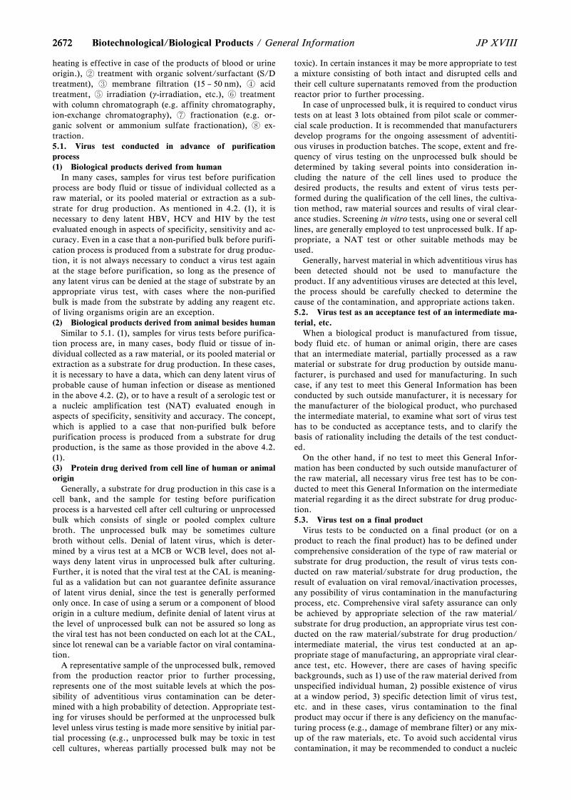
26722672 JP XVIIIBiotechnological/Biological Products / General Information
heating is effective in case of the products of blood or urineorigin.), treatment with organic solvent/surfactant (S/Dtreatment), membrane filtration (15 – 50 nm), acidtreatment, irradiation (g-irradiation, etc.), treatmentwith column chromatograph (e.g. affinity chromatography,ion-exchange chromatography), fractionation (e.g. or-ganic solvent or ammonium sulfate fractionation), ex-traction.5.1. Virus test conducted in advance of purificationprocess(1) Biological products derived from human
In many cases, samples for virus test before purificationprocess are body fluid or tissue of individual collected as araw material, or its pooled material or extraction as a sub-strate for drug production. As mentioned in 4.2. (1), it isnecessary to deny latent HBV, HCV and HIV by the testevaluated enough in aspects of specificity, sensitivity and ac-curacy. Even in a case that a non-purified bulk before purifi-cation process is produced from a substrate for drug produc-tion, it is not always necessary to conduct a virus test againat the stage before purification, so long as the presence ofany latent virus can be denied at the stage of substrate by anappropriate virus test, with cases where the non-purifiedbulk is made from the substrate by adding any reagent etc.of living organisms origin are an exception.(2) Biological products derived from animal besides human
Similar to 5.1. (1), samples for virus tests before purifica-tion process are, in many cases, body fluid or tissue of in-dividual collected as a raw material, or its pooled material orextraction as a substrate for drug production. In these cases,it is necessary to have a data, which can deny latent virus ofprobable cause of human infection or disease as mentionedin the above 4.2. (2), or to have a result of a serologic test ora nucleic amplification test (NAT) evaluated enough inaspects of specificity, sensitivity and accuracy. The concept,which is applied to a case that non-purified bulk beforepurification process is produced from a substrate for drugproduction, is the same as those provided in the above 4.2.(1).(3) Protein drug derived from cell line of human or animalorigin
Generally, a substrate for drug production in this case is acell bank, and the sample for testing before purificationprocess is a harvested cell after cell culturing or unprocessedbulk which consists of single or pooled complex culturebroth. The unprocessed bulk may be sometimes culturebroth without cells. Denial of latent virus, which is deter-mined by a virus test at a MCB or WCB level, does not al-ways deny latent virus in unprocessed bulk after culturing.Further, it is noted that the viral test at the CAL is meaning-ful as a validation but can not guarantee definite assuranceof latent virus denial, since the test is generally performedonly once. In case of using a serum or a component of bloodorigin in a culture medium, definite denial of latent virus atthe level of unprocessed bulk can not be assured so long asthe viral test has not been conducted on each lot at the CAL,since lot renewal can be a variable factor on viral contamina-tion.
A representative sample of the unprocessed bulk, removedfrom the production reactor prior to further processing,represents one of the most suitable levels at which the pos-sibility of adventitious virus contamination can be deter-mined with a high probability of detection. Appropriate test-ing for viruses should be performed at the unprocessed bulklevel unless virus testing is made more sensitive by initial par-tial processing (e.g., unprocessed bulk may be toxic in testcell cultures, whereas partially processed bulk may not be
toxic). In certain instances it may be more appropriate to testa mixture consisting of both intact and disrupted cells andtheir cell culture supernatants removed from the productionreactor prior to further processing.
In case of unprocessed bulk, it is required to conduct virustests on at least 3 lots obtained from pilot scale or commer-cial scale production. It is recommended that manufacturersdevelop programs for the ongoing assessment of adventiti-ous viruses in production batches. The scope, extent and fre-quency of virus testing on the unprocessed bulk should bedetermined by taking several points into consideration in-cluding the nature of the cell lines used to produce thedesired products, the results and extent of virus tests per-formed during the qualification of the cell lines, the cultiva-tion method, raw material sources and results of viral clear-ance studies. Screening in vitro tests, using one or several celllines, are generally employed to test unprocessed bulk. If ap-propriate, a NAT test or other suitable methods may beused.
Generally, harvest material in which adventitious virus hasbeen detected should not be used to manufacture theproduct. If any adventitious viruses are detected at this level,the process should be carefully checked to determine thecause of the contamination, and appropriate actions taken.5.2. Virus test as an acceptance test of an intermediate ma-terial, etc.
When a biological product is manufactured from tissue,body fluid etc. of human or animal origin, there are casesthat an intermediate material, partially processed as a rawmaterial or substrate for drug production by outside manu-facturer, is purchased and used for manufacturing. In suchcase, if any test to meet this General Information has beenconducted by such outside manufacturer, it is necessary forthe manufacturer of the biological product, who purchasedthe intermediate material, to examine what sort of virus testhas to be conducted as acceptance tests, and to clarify thebasis of rationality including the details of the test conduct-ed.
On the other hand, if no test to meet this General Infor-mation has been conducted by such outside manufacturer ofthe raw material, all necessary virus free test has to be con-ducted to meet this General Information on the intermediatematerial regarding it as the direct substrate for drug produc-tion.5.3. Virus test on a final product
Virus tests to be conducted on a final product (or on aproduct to reach the final product) has to be defined undercomprehensive consideration of the type of raw material orsubstrate for drug production, the result of virus tests con-ducted on raw material/substrate for drug production, theresult of evaluation on viral removal/inactivation processes,any possibility of virus contamination in the manufacturingprocess, etc. Comprehensive viral safety assurance can onlybe achieved by appropriate selection of the raw material/substrate for drug production, an appropriate virus test con-ducted on the raw material/substrate for drug production/intermediate material, the virus test conducted at an ap-propriate stage of manufacturing, an appropriate viral clear-ance test, etc. However, there are cases of having specificbackgrounds, such as 1) use of the raw material derived fromunspecified individual human, 2) possible existence of virusat a window period, 3) specific detection limit of virus test,etc. and in these cases, virus contamination to the finalproduct may occur if there is any deficiency on the manufac-turing process (e.g., damage of membrane filter) or any mix-up of the raw materials, etc. To avoid such accidental viruscontamination, it may be recommended to conduct a nucleic
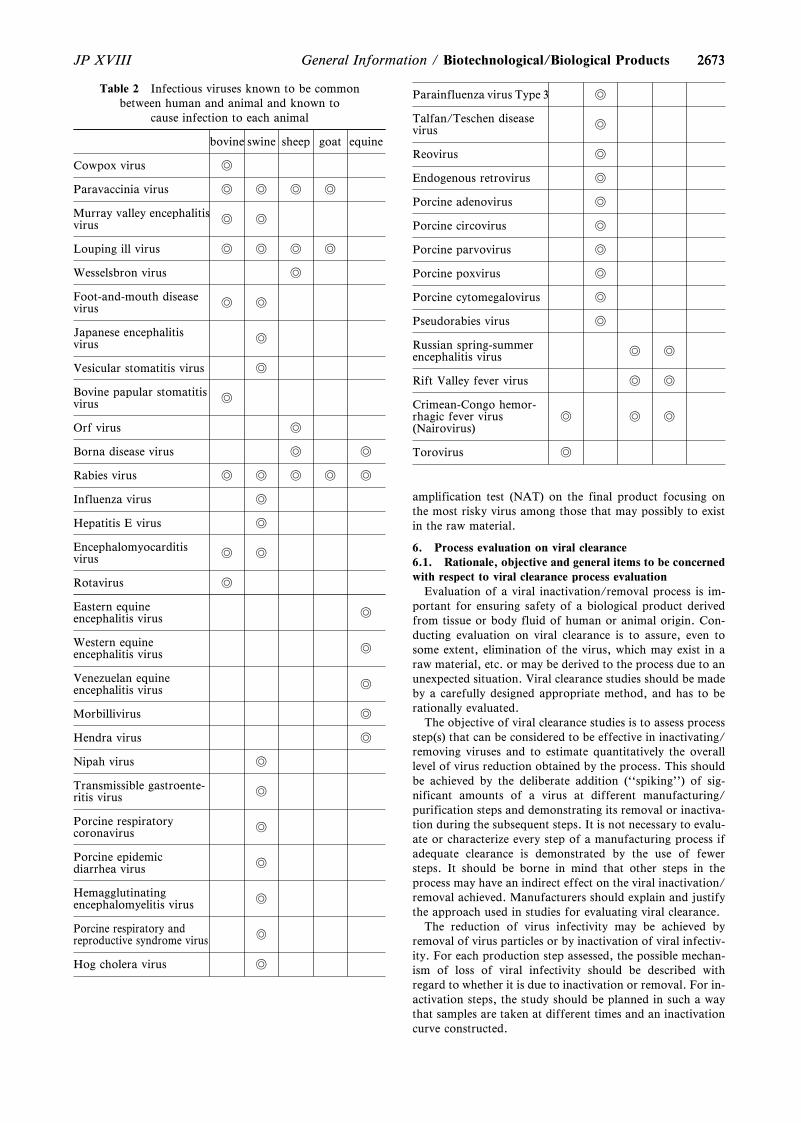
2673
Table 2 Infectious viruses known to be commonbetween human and animal and known to
cause infection to each animal
bovine swine sheep goat equine
Cowpox virus w
Paravaccinia virus w w w w
Murray valley encephalitisvirus w w
Louping ill virus w w w w
Wesselsbron virus w
Foot-and-mouth diseasevirus w w
Japanese encephalitisvirus w
Vesicular stomatitis virus w
Bovine papular stomatitisvirus w
Orf virus w
Borna disease virus w w
Rabies virus w w w w w
Influenza virus w
Hepatitis E virus w
Encephalomyocarditisvirus w w
Rotavirus w
Eastern equineencephalitis virus w
Western equineencephalitis virus w
Venezuelan equineencephalitis virus w
Morbillivirus w
Hendra virus w
Nipah virus w
Transmissible gastroente-ritis virus w
Porcine respiratorycoronavirus w
Porcine epidemicdiarrhea virus w
Hemagglutinatingencephalomyelitis virus w
Porcine respiratory andreproductive syndrome virus w
Hog cholera virus w
Parainfluenza virus Type 3 w
Talfan/Teschen diseasevirus w
Reovirus w
Endogenous retrovirus w
Porcine adenovirus w
Porcine circovirus w
Porcine parvovirus w
Porcine poxvirus w
Porcine cytomegalovirus w
Pseudorabies virus w
Russian spring-summerencephalitis virus w w
Rift Valley fever virus w w
Crimean-Congo hemor-rhagic fever virus(Nairovirus)
w w w
Torovirus w
2673JP XVIII General Information / Biotechnological/Biological Products
amplification test (NAT) on the final product focusing onthe most risky virus among those that may possibly to existin the raw material.
6. Process evaluation on viral clearance6.1. Rationale, objective and general items to be concernedwith respect to viral clearance process evaluation
Evaluation of a viral inactivation/removal process is im-portant for ensuring safety of a biological product derivedfrom tissue or body fluid of human or animal origin. Con-ducting evaluation on viral clearance is to assure, even tosome extent, elimination of the virus, which may exist in araw material, etc. or may be derived to the process due to anunexpected situation. Viral clearance studies should be madeby a carefully designed appropriate method, and has to berationally evaluated.
The objective of viral clearance studies is to assess processstep(s) that can be considered to be effective in inactivating/removing viruses and to estimate quantitatively the overalllevel of virus reduction obtained by the process. This shouldbe achieved by the deliberate addition (``spiking'') of sig-nificant amounts of a virus at different manufacturing/purification steps and demonstrating its removal or inactiva-tion during the subsequent steps. It is not necessary to evalu-ate or characterize every step of a manufacturing process ifadequate clearance is demonstrated by the use of fewersteps. It should be borne in mind that other steps in theprocess may have an indirect effect on the viral inactivation/removal achieved. Manufacturers should explain and justifythe approach used in studies for evaluating viral clearance.
The reduction of virus infectivity may be achieved byremoval of virus particles or by inactivation of viral infectiv-ity. For each production step assessed, the possible mechan-ism of loss of viral infectivity should be described withregard to whether it is due to inactivation or removal. For in-activation steps, the study should be planned in such a waythat samples are taken at different times and an inactivationcurve constructed.
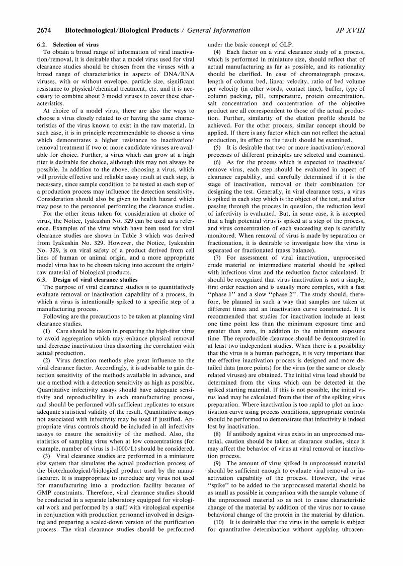
26742674 JP XVIIIBiotechnological/Biological Products / General Information
6.2. Selection of virusTo obtain a broad range of information of viral inactiva-
tion/removal, it is desirable that a model virus used for viralclearance studies should be chosen from the viruses with abroad range of characteristics in aspects of DNA/RNAviruses, with or without envelope, particle size, significantresistance to physical/chemical treatment, etc. and it is nec-essary to combine about 3 model viruses to cover these char-acteristics.
At choice of a model virus, there are also the ways tochoose a virus closely related to or having the same charac-teristics of the virus known to exist in the raw material. Insuch case, it is in principle recommendable to choose a viruswhich demonstrates a higher resistance to inactivation/removal treatment if two or more candidate viruses are avail-able for choice. Further, a virus which can grow at a hightiter is desirable for choice, although this may not always bepossible. In addition to the above, choosing a virus, whichwill provide effective and reliable assay result at each step, isnecessary, since sample condition to be tested at each step ofa production process may influence the detection sensitivity.Consideration should also be given to health hazard whichmay pose to the personnel performing the clearance studies.
For the other items taken for consideration at choice ofvirus, the Notice, Iyakushin No. 329 can be used as a refer-ence. Examples of the virus which have been used for viralclearance studies are shown in Table 3 which was derivedfrom Iyakushin No. 329. However, the Notice, IyakushinNo. 329, is on viral safety of a product derived from celllines of human or animal origin, and a more appropriatemodel virus has to be chosen taking into account the origin/raw material of biological products.6.3. Design of viral clearance studies
The purpose of viral clearance studies is to quantitativelyevaluate removal or inactivation capability of a process, inwhich a virus is intentionally spiked to a specific step of amanufacturing process.
Following are the precautions to be taken at planning viralclearance studies.
(1) Care should be taken in preparing the high-titer virusto avoid aggregation which may enhance physical removaland decrease inactivation thus distorting the correlation withactual production.
(2) Virus detection methods give great influence to theviral clearance factor. Accordingly, it is advisable to gain de-tection sensitivity of the methods available in advance, anduse a method with a detection sensitivity as high as possible.Quantitative infectivity assays should have adequate sensi-tivity and reproducibility in each manufacturing process,and should be performed with sufficient replicates to ensureadequate statistical validity of the result. Quantitative assaysnot associated with infectivity may be used if justified. Ap-propriate virus controls should be included in all infectivityassays to ensure the sensitivity of the method. Also, thestatistics of sampling virus when at low concentrations (forexample, number of virus is 1-1000/L) should be considered.
(3) Viral clearance studies are performed in a miniaturesize system that simulates the actual production process ofthe biotechnological/biological product used by the manu-facturer. It is inappropriate to introduce any virus not usedfor manufacturing into a production facility because ofGMP constraints. Therefore, viral clearance studies shouldbe conducted in a separate laboratory equipped for virologi-cal work and performed by a staff with virological expertisein conjunction with production personnel involved in design-ing and preparing a scaled-down version of the purificationprocess. The viral clearance studies should be performed
under the basic concept of GLP.(4) Each factor on a viral clearance study of a process,
which is performed in miniature size, should reflect that ofactual manufacturing as far as possible, and its rationalityshould be clarified. In case of chromatograph process,length of column bed, linear velocity, ratio of bed volumeper velocity (in other words, contact time), buffer, type ofcolumn packing, pH, temperature, protein concentration,salt concentration and concentration of the objectiveproduct are all correspondent to those of the actual produc-tion. Further, similarity of the elution profile should beachieved. For the other process, similar concept should beapplied. If there is any factor which can not reflect the actualproduction, its effect to the result should be examined.
(5) It is desirable that two or more inactivation/removalprocesses of different principles are selected and examined.
(6) As for the process which is expected to inactivate/remove virus, each step should be evaluated in aspect ofclearance capability, and carefully determined if it is thestage of inactivation, removal or their combination fordesigning the test. Generally, in viral clearance tests, a virusis spiked in each step which is the object of the test, and afterpassing through the process in question, the reduction levelof infectivity is evaluated. But, in some case, it is acceptedthat a high potential virus is spiked at a step of the process,and virus concentration of each succeeding step is carefullymonitored. When removal of virus is made by separation orfractionation, it is desirable to investigate how the virus isseparated or fractionated (mass balance).
(7) For assessment of viral inactivation, unprocessedcrude material or intermediate material should be spikedwith infectious virus and the reduction factor calculated. Itshould be recognized that virus inactivation is not a simple,first order reaction and is usually more complex, with a fast``phase 1'' and a slow ``phase 2''. The study should, there-fore, be planned in such a way that samples are taken atdifferent times and an inactivation curve constructed. It isrecommended that studies for inactivation include at leastone time point less than the minimum exposure time andgreater than zero, in addition to the minimum exposuretime. The reproducible clearance should be demonstrated inat least two independent studies. When there is a possibilitythat the virus is a human pathogen, it is very important thatthe effective inactivation process is designed and more de-tailed data (more points) for the virus (or the same or closelyrelated viruses) are obtained. The initial virus load should bedetermined from the virus which can be detected in thespiked starting material. If this is not possible, the initial vi-rus load may be calculated from the titer of the spiking viruspreparation. Where inactivation is too rapid to plot an inac-tivation curve using process conditions, appropriate controlsshould be performed to demonstrate that infectivity is indeedlost by inactivation.
(8) If antibody against virus exists in an unprocessed ma-terial, caution should be taken at clearance studies, since itmay affect the behavior of virus at viral removal or inactiva-tion process.
(9) The amount of virus spiked in unprocessed materialshould be sufficient enough to evaluate viral removal or in-activation capability of the process. However, the virus``spike'' to be added to the unprocessed material should beas small as possible in comparison with the sample volume ofthe unprocessed material so as not to cause characteristicchange of the material by addition of the virus nor to causebehavioral change of the protein in the material by dilution.
(10) It is desirable that the virus in the sample is subjectfor quantitative determination without applying ultracen-
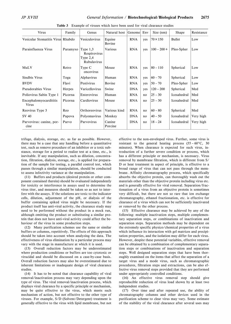
2675
Table 3 Example of viruses which have been used for viral clearance studies
Virus Family Genus Natural host Genome Env Size (nm) Shape Resistance
Vesicular Stomatitis Virus Rhabdo Vesiculovirus EquineBovine
RNA yes 70×150 Bullet Low
Parainfluenza Virus Paramyxo Type 1,3Respirovirus
Type 2,4Rubulavirus
Various RNA yes 100 – 200+ Pleo-Spher Low
MuLV Retro Type Concovirus
Mouse RNA yes 80 – 110 Spherical Low
Sindbis Virus Toga Alphavirus Human RNA yes 60 – 70 Spherical Low
BVDV Flavi Pestivirus Bovine RNA yes 50 – 70 Pleo-Spher Low
Pseudorabies Virus Herpes Varicellovirus Swine DNA yes 120 – 200 Spherical Med
Poliovirus Sabin Type 1 Picorna Enterovirus Human RNA no 25 – 30 Icosahedral Med
EncephalomyocardititisVirus
Picorna Cardiovirus Mouse RNA no 25 – 30 Icosahedral Med
Reovirus Type 3 Reo Orthoreovirus Various kind RNA no 60 – 80 Spherical Med
SV 40 Papova Polyomavirus Monkey DNA no 40 – 50 Icosahedral Very high
Parvovirus: canine, por-cine
Parvo Parvovirus CaninePorcine
DNA no 18 – 24 Icosahedral Very high
2675JP XVIII General Information / Biotechnological/Biological Products
trifuge, dialysis, storage, etc. as far as possible. However,there may be a case that any handling before a quantitativetest, such as remove procedure of an inhibitor or a toxic sub-stance, storage for a period to realize test at a time, etc., isinevitable. If any manipulation, such as dilution, concentra-tion, filtration, dialysis, storage, etc., is applied for prepara-tion of the sample for testing, a parallel control test, whichpasses through a similar manipulation, should be conductedto assess infectivity variance at the manipulation.
(11) Buffers and products (desired protein or other com-ponent contained therein) should be evaluated independentlyfor toxicity or interference in assays used to determine thevirus titer, and measures should be taken so as not to inter-fere with the assays. If the solutions are toxic to the indicatorcells, dilution, adjustment of the pH, or dialysis of thebuffer containing spiked virus might be necessary. If theproduct itself has anti-viral activity, the clearance study mayneed to be performed without the product in a mock run,although omitting the product or substituting a similar pro-tein that does not have anti-viral activity could affect the be-haviour of the virus in some production steps.
(12) Many purification schemes use the same or similarbuffers or columns, repetitively. The effects of this approachshould be taken into account when analyzing the data. Theeffectiveness of virus elimination by a particular process mayvary with the stage in manufacture at which it is used.
(13) Overall reduction factors may be underestimatedwhere production conditions or buffers are too cytotoxic orvirucidal and should be discussed on a case-by-case basis.Overall reduction factors may also be overestimated due toinherent limitations or inadequate design of viral clearancestudies.
(14) It has to be noted that clearance capability of viralremoval/inactivation process may vary depending upon thetype of virus. The viral removal/inactivation process, whichdisplays viral clearance by a specific principle or mechanism,may be quite effective to the virus, which meets suchmechanism of action, but not effective to the other type ofviruses. For example, S/D (Solvent/Detergent) treatment isgenerally effective to the virus with lipid membrane, but not
effective to the non-enveloped virus. Further, some virus isresistant to the general heating process (55 – 609C, 30minutes). When clearance is expected for such virus, in-troduction of a further severe condition or process, whichhas a different principle or mechanism, is necessary. Virusremoval by membrane filtration, which is different from S/D or heat treatment in aspect of principle, is effective to abroad range of virus that can not pass through the mem-brane. Affinity chromatography process, which specificallyabsorbs the objective protein, can thoroughly wash out thematerials other than the objective protein including virus etc.and is generally effective for viral removal. Separation/frac-tionation of a virus from an objective protein is sometimesvery difficult, but there are not so rare that ion exchangechromatography, ethanol fractionation, etc. is effective forclearance of a virus which can not be sufficiently inactivatedor removed by the other process.
(15) Effective clearance may be achieved by any of thefollowing: multiple inactivation steps, multiple complemen-tary separation steps, or combinations of inactivation andseparation steps. Separation methods may be dependent onthe extremely specific physico/chemical properties of a viruswhich influence its interaction with gel matrices and precipi-tation properties, and the isolation may differ for each virus.However, despite these potential variables, effective removalcan be obtained by a combination of complementary separa-tion steps or combinations of inactivation and separationsteps. Well designed separation steps that have been thor-oughly examined on the items that affect the separation of atarget virus and a mode virus, such as chromatographicprocedures, filtration steps and extractions, can be also ef-fective virus removal steps provided that they are performedunder appropriately controlled conditions.
(16) An effective virus removal step should givereproducible reduction of virus load shown by at least twoindependent studies.
(17) Over time and after repeated use, the ability ofchromatography columns and other devices used in thepurification scheme to clear virus may vary. Some estimateof the stability of the viral clearance after several uses may
26762676 JP XVIIIBiotechnological/Biological Products / General Information
provide support for repeated use of such columns.(18) The Notice, Iyakushin No. 329, would be used as a
reference when viral clearance studies on biological productsare designed.6.4. Interpretation of viral clearance studies6.4.1. Evaluation on viral clearance factor
The viral clearance factor is a logarithm of reduction ratioof viral amount (infectious titer) between each step appliedfor viral clearance of a manufacturing process. The totalviral clearance factor throughout the process is sum of theviral clearance factor of each step appropriately evaluated.
Whether each and total viral clearance factor obtained areacceptable or should not be evaluated in aspects of every vi-rus that can be realistically anticipated to derive into the rawmaterial or the manufacturing process, and its rationalityshould be shown.
In case that existence of any viral particle is recognized ina substrate for drug production, e.g., a substrate of rodentorigin for biodrug production, it is important not only todemonstrate removal or inactivation of such virus, but alsoto demonstrate that the purification process has enoughcapability over the required level to assure safety of the finalproduct at an appropriate level. The virus amount removedor inactivated in a manufacturing process should be com-pared with the virus amount assumed to exist in the substrateetc. used for manufacturing drug, and for this purpose, it isnecessary to obtain the virus amount in the raw materials/substrate for drug production, etc. Such figure can be ob-tained by measuring infectious titer or by the other methodsuch as transmission electron microscope (TEM). For evalu-ation of overall process, a virus amount, far larger than thatassumed to exist in the amount of the raw materials/sub-strate for drug production which is equivalent to single ad-ministration of the final product, has to be removed. It isquite rare that existence of virus can be assumed in a sub-strate for drug production, with the exception of the sub-strate of rodent origin, and such suspicious raw material/substrate for drug production should not be used formanufacturing drug with a special exceptional case that thedrug in question is not available from the other process andis clinically indispensable, and that the information includ-ing infectious properties of the virus particle assumed to ex-ist has been clarified.
Any virus contaminations in the substrates for drugproduction of biotechnological/biological products are usu-ally denied by some tests or examinations. In such case, aspecific virus that can possibly contaminate may be used as amodel. However, in general, it would be necessary to per-form a viral clearance test by choosing a combination ofappropriate model viruses that can show the capability forclearance of a wide variety of viruses in the process, as indi-cated in 6.2. In this case, a common numerical goal cannotbe established on the viral clearance. Therefore, the validityof viral clearance factor of the process should be taken intoaccount, considering various information on factual pos-sibility of virus contaminations of the substrates and others,detection sensitivity of the virus free test, and other cases inpublications.6.4.2. Calculation of viral clearance factor
The viral clearance factor, ``R'', for viral removal/inacti-vation process can be calculated by the following formula.
R = log[(V1 × T1)/(V2 × T2)]
In whichR: Logarithm of reduction ratioV1: Sample volume of the unprocessed materialT1: Virus amount (titer) of the unprocessed material
V2: Sample volume of the processed materialT2: Virus amount (titer) of the processed material
At the calculation of the viral clearance factor, it is recom-mendable to use the virus titer detected in the sample prepa-ration of the unprocessed material after addition of virus,not the viral titer added to the sample preparation whereverpossible. If this is not possible, loaded virus amount is calcu-lated from virus titer of the solution used for spike.6.4.3. Interpretation of results and items to be concernedat evaluation
At the interpretation and the evaluation of the data on ef-fectiveness of viral inactivation/removal process, there arevarious factors to be comprehensively taken into account,such as appropriateness of the virus used for the test, design of the viral clearance studies, virus reduction ratioshown in logarithm, time dependence of inactivation, factors/items which give influence to the inactivation/removal process, sensitivity limit of virus assay method, possible effect of the inactivation/removal process whichis specific to certain class of viruses.
Additional items to be concerned at appropriate interpre-tation and evaluation of the viral clearance data are asfollows:(1) Behavior of virus used to the test
At interpretation of the vial clearance results, it is neces-sary to recognize that clearance mechanism may differ de-pending upon the virus used for the test. Virus used for a testis generally produced in tissue culture, but behavior of thevirus prepared in the tissue culture may be different fromthat of the native virus. Examples are possible differences ofpurity and degree of aggregation between the native and thecultured viruses. Further, change of surface properties of avirus, e.g., addition of a sucrose chain which is ascribed tospecific nature of a separation process, may give effect to theseparation. These matters should be also considered at inter-pretation of the results.(2) Design of test
Viral clearance tests should have been designed taking intoaccount variation factors of the manufacturing process andscaling down, but there still remain some variance from ac-tual production scale. It is necessary to consider such vari-ance at the interpretation of the data and limitation of thetest.(3) Acceptability of viral reduction data
The total viral clearance factor is expressed as a sum oflogarithm of reduction ratio obtained at each step. The sum-mation of the reduction factors of multiple steps, particu-larly of steps with little reduction (e.g., below 1 log10), mayoverestimate viral removal/inactivation capability of theoverall process. Therefore, virus titer of the order of 1 log10
or less has to be ignored unless justified. Further, a viralclearance factor achieved by repeated use of the same orsimilar method should be ignored for calculation unlessjustified.(4) Time dependence of inactivation
Inactivation of virus infectivity frequently shows biphasiccurve, which consists of a rapid initial phase and subsequentslow phase. It is possible that a virus not inactivated in a stepmay be more resistant to the subsequent step. For example,if an inactivated virus forms coagulation, it may be resistantto any chemical treatment and heating.(5) Evaluation of viral reduction ratio shown in logarithm
The viral clearance factor shown in logarithm of reductionratio of virus titer can demonstrate drastic reduction ofresidual infectious virus, but there is a limit that infectioustiter can never be reduced to zero. For example, reduction in
26772677JP XVIII General Information / Biotechnological/Biological Products
infectivity of a preparation containing 8 log10 infectious unitper mL by a factor of 8 log10 leaves zero log10 per mL or oneinfectious unit per mL, taking into account the detectionlimit of the assay.(6) Variable factor of manufacturing process
Minor variance of a variation factor of a manufacturingprocess, e.g., contact time of a spiked sample to a buffer ora column, will sometimes give influence to viral removal orinactivation effect. In such case, it may be necessary to in-vestigate to what extent such variance of the factor has giveninfluence to the process concerned in aspect of viral inactiva-tion.(7) Existence of anti-viral antibody
Anti-viral antibody that exists in the sample preparationused for a test may affect sensitivity of distribution or inacti-vation of a virus, which may result in not only defusing thevirus titer but complicating interpretation of the test result.So, existence of anti-viral antibody is one of the importantvariable factors.(8) Introduction of a new process for removal/inactivation
Viral clearance is an important factor for securing safetyof a drug. In case that an achievement level of infectiveclearance of a process is considered insufficient, a processwhich is characterized by an inactivation/removal mechan-ism to meet the purpose or an inactivation/removal processwhich can mutually complement to the existence process hasto be introduced.(9) Limit of viral clearance studies
Viral clearance studies are useful for contributing to theassurance that an acceptable level of safety in the finalproduct is achieved but do not by themselves establish safe-ty. However, a number of factors in the design and execu-tion of viral clearance studies, and the interpretation of theresults may lead to an incorrect estimate of the ability of theprocess to remove virus infectivity, as described above.
7. StatisticsThe viral clearance studies should include the use of
statistical analysis of the data to evaluate the results. Thestudy results should be statistically valid to support the con-clusions reached.7.1. Statistical considerations for assessing virus assays
Virus titrations suffer the problems of variation commonto all biological assay systems. Assessment of the accuracyof the virus titrations and the reduction factors derived fromthem and the validity of the assays should be performed todefine the reliability of a study. The objective of statisticalevaluation is to establish that the study has been carried outto an acceptable level of virological competence.
1. Assay methods may be either semiquantitative orquantitative. Both semiquantitative and quantitative assaysare amenable to statistical evaluation.
2. Variation can arise within an assay as a result of dilu-tion errors, statistical effects and differences within the assaysystem which are either unknown or difficult to control.These effects are likely to be greater when different assayruns are compared (between-assay variation) than whenresults within a single assay run are compared (within-assayvariation).
3. The 95z confidence limits for results of within-assayvariation normally should be on the order of ±0.5 log10 ofthe mean. Within-assay variation can be assessed by stand-ard textbook methods. Between-assay variation can be moni-tored by the inclusion of a reference preparation, the esti-mate of whose potency should be within approximately 0.5log10 of the mean estimate established in the laboratory forthe assay to be acceptable. Assays with lower precision may
be acceptable with appropriate justification.7.2. Reproducibility and confidence limit of viral clearancestudies
An effective virus inactivation/removal step should givereproducible reduction of virus load shown by at least twoindependent studies.
The 95z confidence limits for the reduction factor ob-served should be calculated wherever possible in studies ofviral clearance. If the 95z confidence limits for the viralassays of the starting material are ±s, and for the viralassays of the material after the step are ±a, the 95z confi-dence limits for the reduction factor are ± s2 + a2.
8. Re-evaluation of viral clearanceWhenever significant changes in the production or purifi-
cation process are made, the effect of that change, bothdirect and indirect, on viral clearance should be re-evaluatedas needed. Changes in process steps may also change theextent of viral clearance.
9. Measurement for viral clearance studies9.1. Measurement of virus infective titer
Assay methods may be either semiquantitative or quan-titative. Semiquantitative methods include infectivity assaysin animals or in cultured cell infections dose (CCID) assays,in which the animal or cell culture is scored as either infectedor not. Infectivity titers are then measured by the proportionof animals or culture infected. In quantitative methods, theinfectivity measured varies continuously with the virus input.Quantitative methods include plaque assays where eachplaque counted corresponds to a single infectious unit. Themethods should be sufficiently sensitive and reproducible,and controls should be used to obtain statistically analyzableresults. Both quantal and quantitative assays are amenableto statistical evaluation.9.2. Testing by nucleic-acid-amplification test (NAT)
NAT can detect virus genomes in individual samples,pooled raw material/cell substrate for drug production orproducts at a high sensitivity even in a stage that a serum teston each virus is negative. Further, it can detect HBV or HCVgene, which can not be measured in culture system. Windowperiods can be drastically shortened at the test on HBV,HCV and HIV, and the method is expected to contribute asan effective measure for ensuring viral safety. However, de-pending upon a choice of primer, there may be a case thatnot all the subtype of objective virus can be detected by thismethod, and, therefore, it is recommendable to evaluate, inadvance, if subtypes of a broad range can be detected.
NAT will be an effective evaluation method for virusremoval capability for viral clearance. However, in case ofviral inactivation process, viral inactivation obtained by thismethod may be underrated, since there is a case that inacti-vated virus still shows positive on nucleic acid. Further, atintroduction of NAT, cautions should be taken onrationality of detection sensitivity, choice of a standardwhich is used as run-control, quality assurance and main-tenance of a reagent used for primer, interpretation of posi-tive and negative results, etc.
10. Reporting and preservationAll the items relating to virus test and viral clearance stu-
dies should be reported and preserved.
11. OthersThe Notice, Iyakushin No. 329, should be used as a refer-
ence at virus tests and viral clearance studies.
ConclusionAs mentioned at the Introduction, assurance of quality/
26782678 JP XVIIIBiotechnological/Biological Products / General Information
safety etc. of JP listed drugs should be achieved by state-of-the-art methods and concepts reflecting the progress ofscience and accumulation of experiences.
The basis for ensuring viral safety of JP listed biotechno-logical/biological products is detailed in this General Infor-mation. What is discussed here is that an almost equal levelof measures are required for both development of new drugsand for existing products as well, which means that the simi-lar level of concerns should be paid on both existing and newproducts in aspect of viral safety. This document is intendedto introduce a basic concept that quality and safety assur-ance of JP listed product should be based upon the most ad-vanced methods and concepts. This document has been writ-ten to cover all conceivable cases, which can be applied to allbiotechnological/biological products. Therefore, there maybe cases that it is not so rational to pursue virus tests andviral clearance studies in accordance with this document oneach product, which has been used for a long time withoutany safety issue. So, it will be necessary to elaborate themost rational ways under a case-by-case principle taking intodue consideration source, origin, type, manufacturingprocess, characteristics, usages at clinical stage, accumula-tion of the past usage record, etc. relating to such biotechno-logical/biological products.
Mycoplasma Testing for CellSubstrates used for the Production
of Biotechnological/BiologicalProducts <G3-14-170>
This document describes the currently available methodsof mycoplasma testing that should be performed for cell sub-strates that are used in the manufacture of biotechnological/biological products.
Methods suggested for detection of mycoplasma are, A.culture method, B. indicator cell culture method, and C.nucleic acid amplification test (NAT) method.
Mycoplasma testing should be performed on the mastercell bank (MCB) and the working cell bank (WCB), as wellas on the cell cultures used during the manufacturing processof the product. For the assessment of these cells, mycoplas-ma testing should be performed using both methods A andB. Note that method C may be used as an alternative tomethods A and/or B after suitable validation.
Prior to mycoplasma testing by methods A or B, the sam-ple should be tested to detect the presence of any factorsinhibiting the growth of mycoplasma. If such growth-inhibiting factors are detected, they should be neutralized oreliminated by an appropriate method, such as centrifugationor cell passage.
If the test will be performed within 24 hours of obtainingthe sample, the sample should be stored at 2 – 89C. If morethan 24 hours will elapse before the test is performed, thesample should be stored at -609C or lower.
If mycoplasma is detected, additional testing to identifythe species may be helpful in determining the source of con-tamination.
A. Culture Method1. Culture Medium
Both agar plates and broth are used. Each batch of agarand broth medium should be free of antibiotics except forpenicillin. Refer to the Minimum Requirements for Biologi-cal Products regarding selection of the culture media. Other
culture media may be used if they fulfill the requirementsdescribed in the following section 2.2. Suitability of Culture Medium
Each batch of medium should be examined for mycoplas-ma growth-promoting properties. To demonstrate the capac-ity of the media to detect known mycoplasma, each testshould include control cultures of at least two known speciesor strains of mycoplasma, one of which should be a dextrosefermenter (i.e., Mycoplasma pneumoniae ATCC 15531,NBRC 14401 or equivalent species or strains) and one ofwhich should be an arginine hydrolyser (i.e., Mycoplasmaorale ATCC 23714, NBRC 14477 or equivalent species orstrains). The mycoplasma strains used for the positive con-trol tests should be those with a low number of passages ob-tained from an official or suitably accredited agency, andhandled appropriately. Inoculate the culture medium with100 colony-forming units (CFU) or 100 color-changing units(CCU) or less.3. Culture and Observation
1) Inoculate no less than 0.2 mL of the test sample (cellsuspension) in evenly distributed amounts over the surface ofeach of two or more agar plates. After the surfaces of the in-oculated plates are dried, the plates should be incubated inan atmosphere of nitrogen containing 5 – 10z carbon diox-ide and adequate humidity at 35 – 379C for no less than 14days.
2) Inoculate no less than 10 mL of the test sample (cellsuspension) into each of one or more vessels containing 100mL of broth medium, and incubate at 35 – 379C.
If the culture medium for the sample cells contains anygrowth-inhibiting factors, such as antibiotics, these factorsshould be removed. Refer to the Validation tests for growth-inhibiting factors described in the Minimum Requirementsfor Biological Products for the detection of growth-inhibit-ing factors.
3) Subculture 0.2 mL of broth culture from each vesselon the 3rd, 7th, and 14th days of incubation onto two or moreagar plates. Observe the broth media every 2 or 3 days and ifa color change occurs, subculture. The plates should be incu-bated in nitrogen containing 5 – 10z carbon dioxide andadequate humidity at 35 – 379C for no less than 14 days.
4) Examination of all plates for mycoplasma coloniesshould be done microscopically on the 7th and 14th day at 100times magnification or greater.
B. Indicator Cell Culture MethodUsing Vero cell culture substrate, pretest the suitability of
the method using an inoculum of 100 CFU or 100 CCU orless of Mycoplasma hyorhinis (ATCC 29052, ATCC 17981,NBRC 14858 or equivalent species or strains) and M. orale(ATCC 23714, NBRC 14477 or equivalent species or strains).
Indicator cell substrate equivalent to Vero cells and suita-ble mycoplasma strains may be acceptable if data demon-strate at least equal sensitivity for the detection of knownmycoplasma contaminants. The mycoplasma strains shouldbe those with a low number of passages obtained from anofficial or suitably accredited agency, and handled appropri-ately, and the unit of inoculation should be determined be-fore use. The cell substrate used should be obtained from aqualified cell bank and certified to be mycoplasma free. Theacquired cells should be carefully cultured and propagated,and sufficient volumes of seed stock should be prepared withthe proper precautions to avoid mycoplasma contamination.The stock should be tested for mycoplasma contaminationusing at least one of the methods described in this document,then frozen for storage. For each test this stock should bethawed and used within 6 passages.
26792679JP XVIII General Information / Biotechnological/Biological Products
Indicator cell cultures should be grown on cover slips sub-merged in culture dishes or equivalent containers for oneday. Inoculate no less than 1 mL of the test sample (cell cul-ture supernatant) into two or more of the culture dishes.
The test should include a negative (non-infected) controland two positive mycoplasma controls, such as M. hyorhinis(ATCC 29052, ATCC 17981, NBRC 14858 or equivalentspecies or strains) and M. orale (ATCC 23714, NBRC 14477or equivalent species or strains). Use an inoculum of 100CFU or 100 CCU or less for the positive controls.
Incubate the cell cultures at 35 – 389C for 3 – 6 days in anatmosphere of air containing 5z carbon dioxide.
Examine the cell cultures after fixation for the presence ofmycoplasma by epifluorescence microscopy (400 to 600times magnification or greater) using a DNA-bindingfluorochrome, such as bisbenzimide or an equivalent stain.Compare the microscopical appearance of the test cultureswith that of the negative and positive controls.Procedure
1) Aseptically place a sterilized glass cover slip into eachcell culture dish (35 mm diameter).
2) Prepare Vero cell suspension in Eagle's minimumessential medium containing 10z fetal calf serum at a con-centration of 1 × 10⁴ cells per mL. The fetal calf serumshould be tested and confirmed to be free from mycoplasmaprior to use.
3) Inoculate aliquots of 2 mL of the Vero cell suspensioninto each culture dish. Ensure that the cover slips are com-pletely submerged, and not floating on the surface of theculture medium. Incubate the cultures at 35 – 389C in an at-mosphere of air containing 5z carbon dioxide for one day,so that the cells are attached to the glass cover slip.
4) Replace 2 mL of the culture medium with fresh me-dium, then add 0.5 mL of the test sample (cell culture super-natant) to each of two or more culture dishes. Perform thesame procedure for the positive (2 types of mycoplasmas,such as M. hyorhinis (ATCC 29052, ATCC 17981, NBRC14858 or equivalent species or strains) and M. orale (ATCC23714, NBRC 14477 or equivalent species or strains) andnegative controls.
5) Incubate the cultures at 35 – 389C for 3 – 6 days in anatmosphere of air containing 5z carbon dioxide.
6) Remove the culture medium from the culture dishes,and add 2 mL of a mixture of acetic acid (100) and methanol(1:3) (fixative) to each dish; then, allow them to stand for 5minutes.
7) Remove the fixative from each dish, then add thesame amount of fixative again, and leave the dishes to standfor 10 minutes.
8) Remove the fixative and then completely air-dry allthe dishes.
9) Add 2 mL of bisbenzimide fluorochrome staining so-lution to each culture dish. Cover the dishes and let themstand at room temperature for 30 minutes.
10) Aspirate the staining solution and rinse each dishwith 2 mL of distilled water 3 times. Take out the glass coverslips and dry them.
11) Mount each cover slip with a drop of a mountingfluid. Blot off surplus mounting fluid from the edges of thecover slips.
12) Examine by epifluorescence microscopy at 400 to 600times magnification or greater.
13) Compare the microscopic appearance of the testsample with those of the negative and positive controls.
14) The test result is judged to be positive if there aremore than 5 cells per 1000 (0.5z) that have minute fluores-cent spots that appear to surround, but are outside, the cell
nucleus.
C. Nucleic Acid Amplification Test (NAT)Nucleic acid amplification test (NAT) is a detection
method of genes or mRNA transcribed from genes of targetcells or viruses by enzymatic amplification with specificprimers for target nucleic acid sequences, and the amplifiedproducts are detected by several ways. When NAT is usedfor detection of mycoplasma, high sensitivity detection isexpected for the presence or absence of the target sequencederived from mycoplasma by amplification of nucleic acidextracted from a test sample (cell suspension or cell culturesupernatant) with specific primers/probes. NAT indicatesthe presence of a target sequence and not necessarily thepresence of viable mycoplasmas.
A number of different NAT methods are available. Thisgeneral information does not prescribe a particular method.NAT method applied should be validated for sufficient sen-sitivity, specificity, and robustness of results that remain un-affected by small variations in extraction method parametersor in composition of the reaction mix. Any NAT method isavailable if the specificity and the sensitivity is properly vali-dated as described in this section. Where a commercial kit isused, certain elements of the validation may be carried outby the manufacturer and information provided to the user.However, it should be remembered that the different resultsmight be obtained by user depending on the instrument usedand the target cells tested. The user should confirm themanufacturer's validation results by own facilities. Especial-ly, when the target cell substrate is different from cells vali-dated by the manufacturer, the detection limit and repro-ducibility of the kit should be confirmed with the cells of in-terest. When the user's extraction method or instrumentsused for detection etc. are different from the method or theinstrument specified by the manufacturer, the employedmethod or the instrument should be validated.
In addition, when the information on the primers/probesor the kit reagents may not be available from the manufac-turer, countermeasure is required to obtain the informationfrom the manufacturer about the modification of the kitproduction when modified. If the composition of the kit rea-gents is modified, user should confirm that the detectionlimit and the detection accuracy of the modified kit fortarget mycoplasma is comparable to the previous one, asneeded. On the other hand, appropriate alternative methodshould be considered, since the production of the kit may bediscontinued.
Basically, cell suspension but not cell culture supernatantwill be used as a test sample, since mycoplasma contaminat-ed in cell culture mainly growth in a cell-dependent manner.When cell culture supernatant is used as test samples, valida-tion is required that the method employed is able to fully de-tect the mycoplasma contamination in cell cultures.
NAT may be used instead of methods A and/or B, aftersuitable validation described below, and the validation re-vealed sufficient sensitivity for all of the listed mycoplasmaspecies.
In order to increase the detection sensitivity of nucleic acidderived from infectious mycoplasma, it is possible to per-form NAT after enrichment of mycoplasma that may bepresent in test samples by culturing with Vero cells. In thiscase, again, validation is required to show sufficient sensi-tivity for all of the listed mycoplasma species.C-1. Mycoplasma testing by NAT
The tests should include both a positive control (run con-trol) (such as M. hyorhinis (ATCC 17981, NBRC 14858 orequivalent species or strains) of 100 CFU or 100 CCU or

26802680 JP XVIIIBiotechnological/Biological Products / General Information
less) and a negative control. The mycoplasma strains usedfor the positive control tests should be those within a lownumber of passages obtained from an official or suitably ac-credited agency, and handled appropriately. The unit of in-oculation should be determined before use. When cell sus-pension is used as a test sample, a preliminary test is requiredfor the effect of cellular nucleic acid to NAT with the cellsconfirmed to be mycoplasma-free as a negative control, andconfirm that no positive signals are obtained from the nega-tive control. The test result is judged to pass the test if nomycoplasma sequences are amplified from the test sample.C-2. Precautions for the test
Because NAT enables the detection of trace amounts ofnucleic acid, false positive results may be obtained by con-tamination of the facilities, instruments and reagents etc.with amplified products. To prevent the risk of contamina-tion, wherever possible, each step of the storage and prepa-ration of reagents, the extraction of nucleic acid, the amplifi-cation of nucleic acid, and the detection of amplified prod-ucts should be performed in separate facilities or equipmentswith special precautions for handling. To exclude false-posi-tive results by contamination of carry-over amplified prod-ucts, Uracil-N-glycosylase (UNG) procedure may be availa-ble. To exclude the false-negative results by low efficiency ofextraction or interfering substances for NAT in test samples,simultaneously detection of house-keeping genes of the testcells as internal control is recommended.
On the other hand, if an automatic closed system from ex-traction to amplification is used to prevent cross-contamina-tion, segregation of the area is not always required.However, measures to prevent contamination are requiredwhen disposing the amplified products from the automaticsystem.C-3. Validation of NAT for the detection of mycoplasmas
NAT methods for the detection of target sequences areeither qualitative or quantitative tests. To detect mycoplas-ma contamination of cell substrates, qualitative tests are ade-quate and may be considered to be limit tests. This sectiondescribes methods to validate qualitative NAT analyticalprocedures for assessing mycoplasma contamination. Thesevalidation methods may also be applicable for quantitativeNAT with an optimal cut-off point.
The most important parameters for validation of the ana-lytical procedure by NAT are the specificity and the detec-tion limit. In addition, the robustness of the analyticalprocedure should be evaluated. Note that for the purpose ofthis document, validation of NAT method is defined as thecomplete procedure from extraction of nucleic acid to detec-tion of the amplified products.
Where commercial kits are used for a part or all of theanalytical procedure, documented full validation data al-ready covered by the kit manufacturer can replace validationdata by the user, and a full validation by the user is unneces-sary. Nevertheless, the performance of the kit with respect toits intended use and user's test system should be demonstrat-ed by the user (e.g. specificity, detection limit).
NAT may be used as:a test for in-process control purposes;an alternative method to replace methods A and/or B.This section will thus separate these 2 objectives by
presenting first a guideline for the validation of the NATthemselves, and second, a guideline for a comparabilitystudy between NAT and methods A or B.
Mycoplasma reference strains evaluated for concentrationeither in CFUs or equivalent copies are required at variousstages during validation of specificity or detection limit ofNAT. During routine application of the test, mycoplasma
reference strains or the test sample calibrated for concentra-tion using reference strains are used as positive controls. Inthe test, mycoplasma or mycoplasma nucleic acid (e.g. plas-mid) may be used as a positive control. Mycoplasma is re-quired for validation of the procedure including extractionefficiency.1) Evaluation parameters
Three parameters should be evaluated: specificity, detec-tion limit, and robustness.2) Specificity
Specificity of NAT is the ability to unequivocally detect atarget nucleic acid in the presence of test samples that maybe expected to be present. The specificity of NAT is depend-ent on the choice of primers/probes and the strictness of thetest conditions (both of the amplification and the detectionsteps).
It is important to use primers/probes by choosing nucleicacid sequences that are specific and well conserved for a widerange of mycoplasmas (the bacterial class Mollicutes such asthe genus Mycoplasma and related genera such as Urea-plasma, Spiroplasma, Acholeplasma etc.). The ability ofNAT to detect a large panel of mycoplasma species shouldbe demonstrated by experimental results using referencemycoplasmas described in 3), and evaluation only by the the-oretical analysis of primers/probes comparing with data-bases is not recommended.3) Detection limit
The detection limit of an individual analytical procedure isthe lowest amount of a target nucleic acid in a sample thatcan be detected but not necessarily quantitated as an exactvalue. For establishment of the detection limit, a positivecut-off point should be determined for NAT. The positivecut-off point is the target sequence copies per volume ofsample that can be detected in 95z of test runs. This posi-tive cut-off point is influenced by the nucleic acid sequencesof target mycoplasma in the individual samples being testedand by factors such as enzyme efficiency, and can result indifferent 95z cut-off values for individual analytical testruns. To determine the positive cut-off point, a dilutionseries of characterized and calibrated (either in CFUs ornucleic acid copies) mycoplasma reference strains or interna-tional standards should be tested on different days to exa-mine variation between test runs.
For validation of the limit of detection, the following spe-cies should be used. These species represent an optimal selec-tion in terms of the frequency of occurrence as contaminantsof mammalian culture cells used for production ofbiotechnological/biological products, phylogenetic relation-ships, and animal-derived components used during cultureand production processes. Note that the list is only for vali-dation of NAT and not for used as positive run control inroutine tests.
Acholeplasma laidlawii (ATCC 23206, NBRC 14400 orequivalent strains)
Mycoplasma arginini (ATCC 23838 or equivalentstrains)
Mycoplasma fermentans (ATCC 19989, NBRC 14854 orequivalent strains)
Mycoplasma hyorhinis (ATCC 17981, NBRC 14858 orequivalent strains)
Mycoplasma orale (ATCC 23714, NBRC 14477 orequivalent strains)
Mycoplasma pneumoniae (ATCC 15531, NBRC 14401or equivalent strains)
Mycoplasma salivarium (ATCC 23064, NBRC 14478 orequivalent strains)
Where there is use of insect or plant cells during produc-
26812681JP XVIII General Information / Biotechnological/Biological Products
tion, mycoplasma strains derived from insect or plant (e.g.Spiroplasma citri) should be tested in addition to the abovelist. Where there is use of avian cells or materials duringproduction, mycoplasma species derived from avian shouldbe tested whether avian mycoplasmas (e.g. Mycoplasma syn-oviae ) can be detected.
For establishment of the detection limit, appropriate dilu-tion series (10-fold or 100.5-fold dilution) should be preparedfrom the undiluted mycoplasma evaluated for concentration(CFU etc.), and tests by NAT should be performed for eachdilution. Based on the dilution factor that shows the limit ofthe detection, a positive cut-off point should be determinedas the minimum number of CFUs of target sequences in thetest sample. In case amplified products are separated by elec-trophoresis and the positive band is detected by fluorescentstaining, confirmation is required whether no positive bandis appeared from the test sample of mycoplasma-free cells.Detection using quantitative real-time PCR requires to set anadequate cut-off point of amplification cycles, and the set-ting of the cut-off point should be validated. Since ex-traction efficiency of nucleic acid from the test sample af-fects the detection, the detection sensitivity of mycoplasmain cell suspension should be evaluated.
For each mycoplasma reference strain described above, atleast 3 independent 10-fold dilution series should be tested,with a sufficient number of replicates at each dilution to givea total number of 24 test results for each dilution, to enable astatistical analysis of the results. For example, a laboratorymay test 3 dilution series on different days with 8 replicatesfor each dilution, 4 dilution series on different days with 6replicates for each dilution, or 6 dilution series on differentdays with 4 replicates for each dilution. In order to keep thenumber of dilutions at a manageable level, a preliminary testshould be performed to obtain a preliminary value for thepositive cut-off point (i.e. the highest dilution giving a posi-tive signal). The range of dilutions can then be chosenaround the determined preliminary cut-off point. The con-centration of mycoplasmas (CFUs, etc.) that can be detectedin 95z of test runs can then be calculated using an appropri-ate statistical evaluation. These results may also serve toevaluate the variability of the analytical procedure.4) Robustness
The robustness of an analytical procedure is a measure ofits capacity to remain unaffected by small but deliberatevariations in method parameters, and provides an indicationof its reliability during normal usage. The evaluation ofrobustness should be considered during the developmentphase. It should show the reliability of the analytical proce-dure with respect to deliberate variations in methodparameters. For NAT, small variations in the methodparameters can be crucial. However, the robustness of themethod can be demonstrated during its development whensmall variations in the concentrations of reagents (e.g.MgCl2, primers, and deoxyribonucleotides) are tested.Modifications of extraction kits or extraction procedures aswell as different thermal cycler types may also be evaluated.5) Use of NAT instead of methods A and/or B
NAT may be used instead of methods A (culture method)and/or B (indicator cell culture method). In this case, acomparability study should be carried out. This comparabil-ity study should include mainly a comparison of the respec-tive detection limits of the NAT and methods A and/or B.However, specificity (mycoplasma panel detected, putativefalse positive results) should also be considered.
For the detection limit, acceptability criteria are defined asfollows:if the alternative method is proposed to replace method A
(the culture method), the NAT system should be shown todetect 10 CFU/mL for each mycoplasma test species de-scribed in 3).if the alternative method is proposed to replace method B(the indicator cell culture method), the NAT system shouldbe shown to detect 100 CFU/mL for each mycoplasma testspecies described in 3).
For both cases, suitable references calibrated for the num-ber of CFUs may be used for establishing that theseacceptability criteria are reached.
One of the following 2 strategies can be used to performthis comparability study:perform the NAT alternative method in parallel with themethods A or B to evaluate simultaneously the detectionlimit of both methods using the same samples of calibratedstrains with CFUs.compare the performance of the NAT alternative methodusing previously obtained data from methods A or B. In thiscase, calibration of CFUs of reference strains used for bothvalidations as well as their stabilities should be describedcarefully.
Alternatively, comparability of detection limit may bedemonstrated by the number of nucleic acid copies, etc. ofmycoplasma in test samples. In this case, the relation be-tween CFUs and the number of nucleic acid copies for thereference preparations should be previously established.6) ControlsInternal controls: For validation, internal controls are use-ful to confirm appropriate nucleic acid amplification with-out effect of inhibitory substances derived from test samples.Internal controls are also necessary for routine verificationof extraction and absence of inhibition to NAT reaction.The internal control may contain the primer binding-site, orsome other suitable sequence may be used. It is preferablyadded to the test material before isolating the nucleic acidand therefore acts as an overall control for extraction,reverse transcription, amplification, and detection. Cellulargenes derived from test samples may also be used as the in-ternal control.External controls: The external positive control contains adefined number of target-sequence copies or CFUs from oneor more suitable species of mycoplasma chosen from thoseused during validation of the test conditions. One of thepositive controls is set close to the positive cut-off point todemonstrate that the expected sensitivity is achieved. The ex-ternal negative control contains no target sequence but doesnot necessarily represent the same matrix as the test article.7) Interpretation of results
The primers/probes used may also amplify non-mycoplas-ma nucleic acid, leading to false-positive results. Proceduresare established at the time of validation for dealing with con-firmation of positive results, where necessary.C-4 Method of cultivating mycoplasma with Vero cells
1) Use at least two cell culture dishes for each of the testsample, positive control and negative control.
2) Into each cell culture dish (35 mm diameter), inoculate2 mL of the Vero cell suspension (1 × 10⁴ cells per mL) inEagle's minimum essential medium containing 10z fetalcalf serum (tested in advance using the NAT method to veri-fy that it does not contain any detectable mycoplasmaDNA). Incubate the cultures at 35 – 389C in an atmosphereof air containing 5z carbon dioxide for one day.
3) Replace the culture media with fresh media, and add0.5 mL of the test sample (cell culture supernatant) to eachof two or more Vero cell culture dishes. Perform the sameprocedure for the positive (such as 100 CFU or 100 CCU orless of M. hyorhinis (ATCC 17981, NBRC 14858 or equiva-
26822682 JP XVIIIBiotechnological/Biological Products / General Information
lent species or strains)) and negative controls.4) Incubate the Vero cell culture dishes for the test sam-
ple, positive and negative controls for 3 – 6 days at 35 – 389Cin an atmosphere of air containing 5z carbon dioxide.
Qualification of Animals as Originof Animal-derived Medicinal
Products provided in the GeneralNotices of Japanese Pharmacopoeiaand Other Standards <G3-15-141>
IntroductionThe Official Gazette issued on March 29, 2002 announced
that General Notices of the Japanese Pharmacopoeia andother standards were amended to add a provision that``When a drug product or a drug substance which is used tomanufacture a drug product, is manufactured from a rawmaterial of animal origin, the animal in question should bein principle a healthy subject, if not otherwise provided.''.
The Notice Iyaku-hatsu No. 0329001, which was issued onthe same date, provided that ``Healthy subject herein provid-ed is the animal which does not cause any disease or any in-fection to human being at an appropriate use of the drugproduct, and as for the oral or external drug for example,the animal, as its raw material of animal origin, should beconfirmed at this stage to meet the Food Standard. It has tobe noted that this standard of healthy subject has to berevised timely taking into account the up-to-date informa-tion with respect to the amphixenosis infections common be-tween human beings and animals.''.
This General Information describes safety assuranceagainst infection associated with the use of drugs, which aremanufactured from raw materials of animal origin, to followup the Notice as mentioned above.
1. Basic conceptWhen drugs derived from raw materials of animal origin
including human are used, it is important to take into ac-count any possibility that communicable disease agents suchas virus may cause infectious disease or any possible hazardsto patients. In such case, it goes without saying that the pri-mary subject that has to be considered is the absence of anyinfectious agents such as virus in the raw materials of animalorigin including human as the source of the drug. More im-portant point is whether there is any possibility of transmis-sion of infectious agents when the drugs containing such in-fectious agents are administered to patient. The eligibility ofanimals including human, as the source of raw materials ofdrugs, in other words ``the subject which is free from anydisease or transmission of infectious agents that is infectiousto human being at an appropriate use of the drug product''is that ``The drug should be entirely free from any risk of in-fections by means of whole procedures which include evalua-tion of appropriateness of the animals including human asthe source of their raw materials, establishment of appropri-ate production processes and their appropriate control, andstrict adherence to the clinical indications of the finalproduct.''
2. Animals including human as the source of raw materialsof drugs
The most clear and appropriate preventive measuresagainst infection to human being due to administration ofdrugs which are derived from animals including human are
to assure the absence of any infectious agents such as virus inits raw materials or an appropriate critical raw material byeither of the following: (1) the use of raw materials ofhealthy animal origin, which are proved to be free fromcommunicable disease agents to human, or (2) the use of ap-propriate critical raw materials for drug production, whichare proved to be free from communicable disease agentsafter certain appropriate processing on raw materials ofanimal origin.
As for raw materials of drugs of human origin, cell/tissue,blood, placenta, urine, etc. are used. Whenever it is possiblefor each donor of such raw materials to be asked or inspect-ed about his (her) health condition, the appropriateness as adonor should be confirmed at this stage from the standpointof safety concerning communicable disease agents such asvirus.
For example, ``Basic concept on handling and use of adrug product, etc. which is derived from cell/tissue''(Attachment 1 of the Notice Iyaku-Hatsu No. 1314 datedDecember 26, 2000) issued by the Director-General of theMedicinal Safety Bureau, Ministry of Health and Welfare,states that since the cell/tissue supplied by a human donorcomes to be applied to patients without processing throughany sufficient inactivation or removal of communicable dis-ease agents, the selection and qualification criteria on suchdonor has to be established. These criteria are to be com-posed with the respect to the check items on the case historyand the physical conditions as well as the test items on thevarious transmission of infectious agents through cell/tissue,and that the appropriateness of these criteria has to be clari-fied. Hepatitis Type-B (HBV), Hepatitis Type-C (HCV),Human Immune Deficiency Viral infections (HIV), AdultT-Cell Leukemia and Parvovirus B19 Infections should bedenied through the interview to the donor and the tests(serologic test, nucleic acid amplification test, etc.). Further,if necessary, Cytomegalovirus infection and EB Virus infec-tion should be denied by tests. ``Infections caused by bacter-ia such as Treponema pallidum, Chlamydia, Gonococci,Tubercule bacillus, etc.'', ``septicemia and its suspiciouscase'', ``vicious tumor'', ``serious metabolic or endocrine-related disorders'', ``collagenosis and haematological disord-er'', ``hepatic disease'' and ``dementia (transmissible spon-giform encephalopathies and its suspicious case)'' should bechecked on the case history or by the interview, etc. and theexperience of being transfused or/and transplanted shouldbe checked to confirm eligibility as a donor. The most ap-propriate check items and test methods then available are tobe used, which need to be reconsidered at appropriate timingtaking into account the updated knowledge and the progressof the science and the technologies. At screening of a donor,reexaminations have to be made at appropriate timing usingthe eligible check items and the test methods taking intoaccount the window period (Initial period after infection,in which antibody against bacteria, fungi or virus is notdetected).
In the case of plasma derivatives produced from the do-nated blood in Japan, the donor should be checked by meansof self-assessed report about health conditions, and a sero-logic check and a nucleic acid amplification test (NAT) onmini pooled plasma targeted for HBV, HCV and HIVshould be performed at the stage of donated blood. Further,the plasma material for fractionation should be stored 4months in minimum so that the arrangement could be takenbased on the information available after collection of theblood and the blood infusion to exclude the possibility ofusing any critical raw material which might cause infectionto patients.
26832683JP XVIII General Information / Biotechnological/Biological Products
On the other hand, as for the materials such as urinewhich are taken from the unspecified number of the donorsand come to be critical raw materials for drug productionafter some treatments, it is unrealistic and not practical toconduct the tests of virus infection, etc. on the individualdonor. Consequently, appropriate tests such as virus test hasto be performed on such pooled raw materials for drugproduction.
In the case of the animals besides human, the wild onesshould be excluded. Only the animals, which are raisedunder well sanitarily controlled conditions taken to preventbacterial contamination or under the effective bacterial pol-lution monitoring systems, have to be used, and it is recom-mended that the animals from a colony appropriately con-trolled under specific pathogen-free (SPF) environment areto be used as far as possible. Further, for the animals regu-lated under the Food Standard, only the animals that metthis standard should be used. It should be confirmed by ap-propriate tests that the animals were free from pathogen, ifnecessary.
The concrete measures to avoid transmittance or spread ofinfectivity of prion, which is considered to be the pathogenof transmissible spongiform encephalopathies (TSEs), as faras possible are the followings: avoidance of use ofanimals, which are raised in the areas where high incidenceor high risk of TSEs (Scrapie in sheep and goat, bovinespongiform encephalopathies (BSE) in cattle, chronic wast-ing disease (CWD) in deer, new type of Creutzfeldt-Jacob-Disease (CJD) in human, etc.) is reported, and humans, whohave stayed long time (more than 6 months) in such areas, asraw materials or related substances of drugs; avoidance ofuse of any substances that are derived from the individual in-fected with scrapie, BSE, CJD, etc.; avoidance of using amaterial derived from organ, tissue and cell, etc. of high riskof TSEs; and taking appropriate measures basing on theinformation collected, which includes incidence of TSEs, theresults of epidemiological investigation and the experimentalresearch on prion, and incidence of tardive infection ondonors after collecting raw materials, etc.
3. Human or animal cells which are used as critical rawmaterials for drug production
Cell substrates derived from humans or animals are usedfor drug production. In such case, it is desirable that thehumans or the animals, which are the origins of the cell sub-strates, are healthy subjects. However, it is considered prac-tical that viral safety of the drugs derived from the cell sub-strates are evaluated on the cells, which are so called criticalraw materials for production of such drugs. In such case, thesafety should be confirmed through the test and analysis onestablished cell bank thoroughly with respect to virus etc., asfar as possible. The items and the methods of the tests thathave been followed in this case are described in detail in theNotice of Japanese version on the internationally acceptedICH Guideline entitled ``Viral safety evaluation ofbiotechnology products derived from cell lines of human oranimal origin'' (Iyakushin No. 329 issued on February 22,2000 by Director, Evaluation and Licensing Division, Phar-maceutical and Medical Safety Bureau, Ministry of Healthand Welfare). In the meantime, it is important how to han-dle the cell in case that any virus has been detected under thecell level tests. This Notice describes how to cope with thissituation as follows: ``It is recognised that some cell linesused for the manufacture of product will contain endoge-nous retroviruses, other viruses or viral sequences. In suchcircumstances, the action plan recommended for manufac-turer is described in Section V (Rationale and action plan for
viral clearance studies and virus tests on purified bulk) of theNotice. The acceptability of cell lines containing virusesother than endogenous retroviruses will be considered on anindividual basis by the regulatory authorities, by taking intoaccount a risk/benefit analysis based on the benefit of theproduct and its intended clinical use, the nature of the con-taminating viruses, their potential for infecting humans orfor causing disease in humans, the purification process forthe product (e.g., viral clearance evaluation data), and theextent of the virus tests conducted on the purified bulk.'' Forexample, it is well known that Type A-, R- and C-particleslike endogenous retrovirus are observed in the cells of the ro-dents used most often for drug production. It is also knownthat they are not infectious to human and is not dangerous,and CHO cells are generally used for drug production. Theestablished cell lines (e.g., NAMALWA Cell, BALL-1 Cell,etc.) derived from cancer patients are sometimes used, butthrough the thorough virus tests, etc., their safety is con-firmed. The established cell lines are assumed to be saferthan the primary cultured cells which are hard to conduct thethorough virus test.
4. Establishment and control of appropriate productionprocess and adherence to the clinical indication of finalproduct for safety assurance
Safety assurance against potential infections at only thelevel of animals that are source of raw materials of drugs islimited. Further, ``health of animal'' can not be definedunivocally, and the various factors have to be taken intoaccount. The final goal of this subject is to protect humanfrom any infectious disease caused by drugs. Achieving thisgoal, the establishment and control of appropriate produc-tion processes of each drug and the adherence to the clinicalindications of the final product are important.
As mentioned above, the rodent cells used most often forthe production of the drugs are known to have endogenousretrovirus-like particles sometimes. The reason why suchcells can be used for the production of the drugs is that mul-tiple measures are applied for safety in the purificationstages which include appropriate inactivation or removalprocesses. There are cases in which the production procedureinvolves intentional use of a virus or a microorganism. Inthis case, relevant measures capable of removing or inac-tivating of such virus or microorganism are appropriatelyincorporated in the purification process, so that the risk ofinfection to human can be fully denied and its safety can beassured when it is used as a drug. Further, even in the casethat it is difficult to clarify the risk of contamination of theinfectious agents or that the raw material is contaminated byviruses etc., the raw material in question may be used for theproduction of drugs so long as appropriate inactivation orremoval processes are introduced, their effectiveness can beconfirmed and the safety can be assured by appropriate con-trol of the manufacturing processes under GMP, etc.
5. ConclusionThe qualification of animals including human, as the
source of raw materials of drugs, in other words ``the subjectwhich does not cause any infectious diseases to human beingat an appropriate use of the drug product'' is that ``the drughas to be entirely free from any risk of infections by meansof whole procedures which include evaluation of ap-propriateness of the animal including human as the source oftheir raw materials, establishment of appropriate productionprocesses and their appropriate control, and strict adherenceto the clinical indication of the final product.''
To cope with this subject, the advanced scientific meas-ures, which actually reflect the updated knowledge and
26842684 JP XVIIIMicroorganisms / General Information
progress of the science and the technology about infectiousdiseases in human and infection of animal origin, have to betaken into account timely.
G4 Microorganisms
Microbial Attributes of Non-sterilePharmaceutical Products
<G4-1-170>
This chapter is harmonized with the European Pharmaco-poeia and the U.S. Pharmacopeia. The parts of the text thatare not harmonized are marked with symbols ( ).
Information on the harmonization with the EuropeanPharmacopoeia and the U.S. Pharmacopeia is available onthe website of the Pharmaceuticals and Medical DevicesAgency.
The presence of certain micro-organisms in non-sterilepreparations may have the potential to reduce or even inacti-vate the therapeutic activity of the product and has a poten-tial to adversely affect the health of the patient. Manufac-turers have therefore to ensure a low bioburden of finisheddosage forms by implementing current guidelines on GoodManufacturing Practice during the manufacture, storage anddistribution of pharmaceutical preparations. This chapterprovides guidelines for acceptable limits of viable micro-organisms (bacteria and fungi) existing in raw materials andnon-sterile pharmaceutical products. Microbial examina-tion of non-sterile products is performed according to themethods given in the Microbiological Examination of Non-sterile Products <4.05> on Microbiological Examination ofNon-sterile Products: I. Microbial Enumeration Tests andII. Tests for Specified Micro-organisms. When these testsare carried out, a microbial control program must be estab-lished as an important part of the quality management sys-tem of the product. Personnel responsible for conducting thetests should have specialized training in microbiology,biosafety measures and in the interpretation of the testingresults.1. Definitions
(i) Non-sterile pharmaceutical products: Non-steriledrugs shown in monographs of the JP and non-sterilefinished dosage forms.
(ii) Raw materials: All materials, including raw ingredi-ents and excipients, used for the preparation of drugs, exceptfor water and gases.
(iii) Bioburden: Number and type of viable micro-organ-isms existing in non-sterile pharmaceutical products.
(iv) Action levels: Established bioburden levels that re-quire immediate follow-up and corrective action if they areexceeded.
(v) Alert levels: Established bioburden levels that giveearly warning of a potential drift from normal bioburdenlevel, but which are not necessary grounds for definitive cor-rective action, though they may require follow-up investiga-tion.
(vi) Quality management system: The procedures, opera-tion methods and organizational structure of a manufacturer(including responsibilities, authorities and relationships be-tween these) needed to implement quality management.
2. ScopeIn general, Microbial Enumeration Tests is not applied to
drugs containing viable micro-organisms as an active ingre-dient.
3. Sampling plan and frequency of testing3.1. Sampling methods
Microbial contaminants are usually not uniformly dis-tributed throughout the batches of non-sterile pharmaceuti-cal products or raw materials. A biased sampling plan, there-fore, cannot be used to estimate the real bioburden in theproduct. A sampling plan which can properly reflect the sta-tus of the product batch should be established on the basis ofthe bioburden data obtained by retrospective validation and/or concurrent validation. In general, a mixture of samplesrandomly taken from at least different three portions,almost the same amount for each portion, is used for thetests of the product.
When the sampling is difficult in a clean area, special careis required during sampling to avoid introducing microbialcontamination into the product or affecting the nature of theproduct bioburden. If it is confirmed that the product bio-burden is stable for a certain period, as in the case of non-aqueous or dried products, it is not necessary to do the tests,immediately after the sampling.3.2. Testing frequency
The frequency of the tests should be established on thebasis of a variety of factors unless otherwise specified. Thesefactors include:
(i) Dosage forms of non-sterile pharmaceutical products(usage);
(ii) Manufacturing processes;(iii) Manufacturing frequency;(iv) Characteristics of raw materials (natural raw mate-
rial, synthetic compound, etc.);(v) Batch sizes;(vi) Variations in bioburden estimates (changes in batch-
es, seasonal variations, etc.);(vii) Changes affecting the product bioburden (changes
in manufacturing process, supplier of raw materials, batchnumber of raw materials, etc.);
(viii) Others.In general, the tests may be performed at a high frequency
during the initial production of a drug to get information onthe microbiological attributes of the product or raw mate-rials used for the production. However, this frequency maybe reduced as bioburden data are accumulated throughretrospective validation and/or concurrent validation. Forexample, the tests may be performed at a frequency based ontime (e.g., weekly, monthly or seasonally), or on alternatebatches.
4. Microbial control programWhen the ``Microbiological Examination of Non-sterile
Products <4.05>'' is applied to a non-sterile pharmaceuticalproduct, the methods for the recovery, cultivation and esti-mation of the bioburden from the product must be validatedand a ``Microbial control program'' covering the items listedbelow must be prepared.
(i) Subject pharmaceutical name (product name);(ii) Frequency of sampling and testing;(iii) Sampling methods (including responsible person,
quantity, environment, etc. for sampling);(iv) Transfer methods of the samples to the testing area
(including storage condition until the tests);(v) Treatment of the samples (recovery methods of
microbial contaminants);(vi) Enumeration of viable micro-organisms (including

2685
Table 1 Acceptance criteria for microbiological quality ofnon-sterile substances for pharmaceutical use
Total AerobicMicrobial Count(CFU/g or CFU/mL)
Total CombinedYeasts/MouldsCount(CFU/g or CFU/mL)
Substances forpharmaceuticaluse
103 102
2685JP XVIII General Information / Microorganisms
testing quantity, culture media, growth-supporting test ofthe media, culturing methods, etc.);
(vii) Detection of specified micro-organisms (includingtesting quantity, culture media, growth-supporting test ofthe media, culturing methods, etc.);
(viii) Estimation of the number of and characterizationof microbial contaminants;
(ix) Establishment of ``Microbial acceptance criteria''(including alert level and action level);
(x) Actions to be taken when the levels exceed ``Microbi-al acceptance criteria'';
(xi) Persons responsible for the testing and evaluation,etc.;
(xii) Other necessary items.5. Microbial acceptance criteria for non-sterile pharmaceu-tical products
By establishing ``Microbial acceptance criteria'' for non-sterile pharmaceutical products based upon the total aerobicmicrobial count (TAMC) and the total combined yeasts/moulds count (TYMC), it is possible to evaluate at the ini-tial processing stage of the product whether the microbiolog-ical quality of the raw materials is adequate or not. Further-more, it is then possible to implement appropriate correctiveaction as needed to maintain or improve the microbiologicalquality of the product.
The target limits of microbial levels for raw materials (syn-thetic compounds and minerals) are shown in Table 1. Ingeneral, synthetic compounds have low bioburden levels dueto the high temperatures, organic solvents, etc., used in theirmanufacturing processes. Raw materials originated fromplants and animals in general have higher bioburdens thansynthetic compounds.
The microbial quality of the water used in the processingof active ingredients or non-sterile pharmaceuticals mayhave a direct effect on the quality of the finished dosageform. This means it is necessary to keep the level of microbi-al contaminants in the water as low as possible.
Acceptance criteria for microbiological quality for non-sterile finished dosage forms are shown in Table 2. Thesemicrobial limits are based primarily on the type of dosageform, water activity, and so on. For oral liquids and phar-maceutical products having a high water activity, in general,low microbial acceptance criteria are given.
Table 2 includes a list of specified micro-organisms forwhich acceptance criteria are set. The list is not necessarilyexhaustive and for a given preparation it may be necessary totest for other micro-organisms depending on the nature ofthe starting materials and the manufacturing process.
If it has been shown that none of the prescribed tests willallow valid enumeration of micro-organisms at the levelprescribed, a validated method with a limit of detection asclose as possible to the indicated acceptance criterion is used.
In addition to the micro-organisms listed in Table 2, the
significance of other micro-organisms recovered should beevaluated in terms of:
( i ) the use of the product: hazard varies according tothe route of administration (eye, nose, respiratorytract);
( ii ) the nature of the product: does the product supportgrowth, does it have adequate antimicrobial preser-vation?
(iii) the method of application;(iv) the intended recipient: risk may differ for neonates,
infants, the debilitated;( v ) use of immunosuppressive agents, corticosteroids;(vi) presence of disease, wounds, organ damage.Where warranted, a risk-based assessment of the relevant
factors is conducted by personnel with specialized training inmicrobiology and the interpretation of microbiological data.
For raw materials, the assessment takes account ofprocessing to which the product is subjected, the currenttechnology of testing and the availability of materials of thedesired quality. Acceptance criteria are based on individualresults or on the average of replicate counts when replicatecounts are performed (e.g. direct plating methods).
When an acceptance criterion for microbiological qualityis prescribed it is interpreted as follows:—101 CFU: maximum acceptable count = 20,—102 CFU: maximum acceptable count = 200,—103 CFU: maximum acceptable count = 2000, and soforth.
6. Acceptance criteria for crude drugs and crude drug-containing preparations
Target limits of microbial contamination for crude drugsand crude drug-containing preparations are shown in Table3. Category 1 includes crude drugs and crude drug prepara-tions which are used for extraction by boiling water or towhich boiling water is added before use. Category 2 includescrude drugs which are taken directly without extraction proc-ess and directly consumed crude drug preparations contain-ing powdered crude drugs. In this guideline, bile-tolerantgram-negative bacteria, Escherichia coli and Salmonella arementioned as specified micro-organisms, but other micro-organisms (such as certain species of Bacillus cereus, Clos-tridia, Pseudomonas, Burkholderia, Staphylococcus aureus,Asperigillus and Enterobacter species) are also necessary tobe tested depending on the origin of raw materials for crudedrugs or the preparation method of crude drug-containingpreparations. The target limit of microbial contaminationfor the raw materials is to be set based on the risk assessmentbeing taken into account the provided process of those mate-rials or the desired quality specification for them.
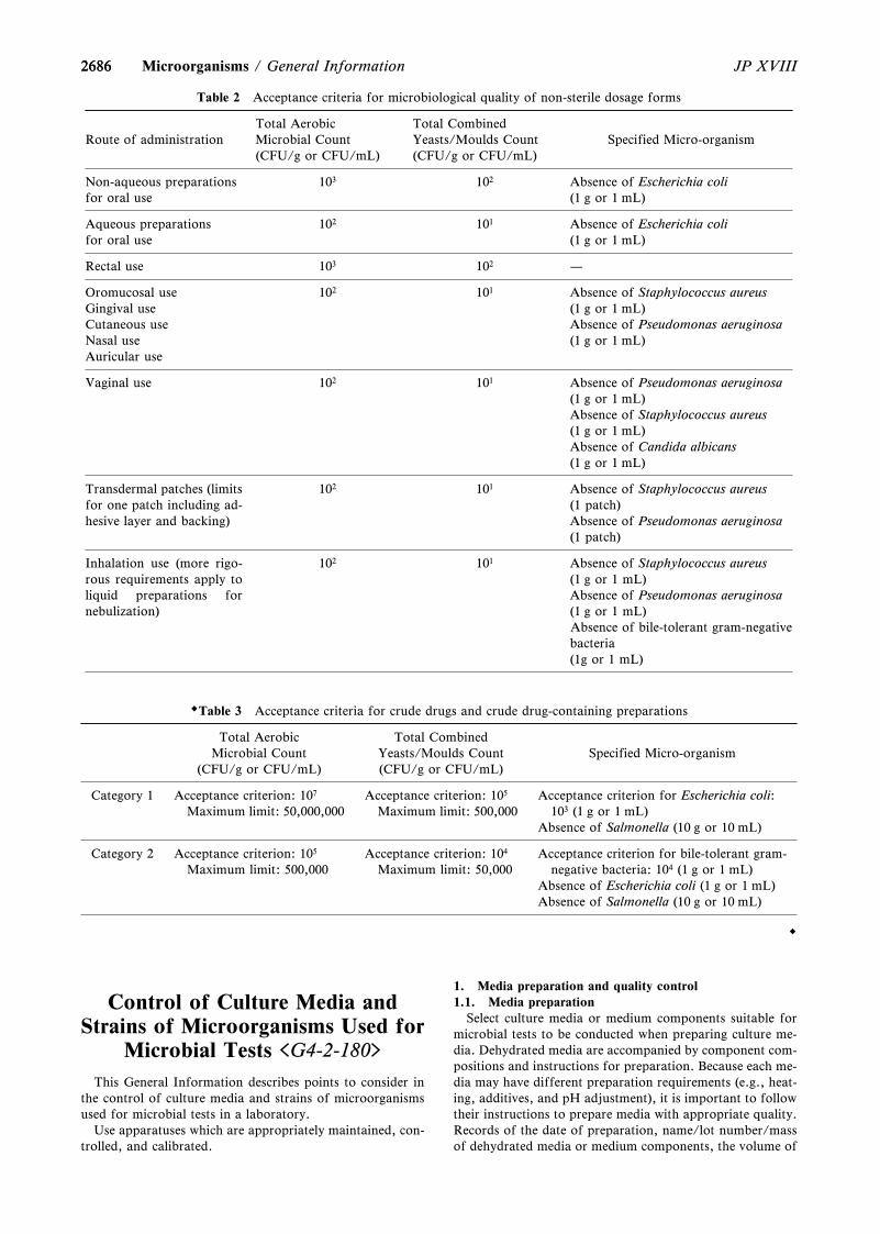
2686
Table 2 Acceptance criteria for microbiological quality of non-sterile dosage forms
Route of administrationTotal AerobicMicrobial Count(CFU/g or CFU/mL)
Total CombinedYeasts/Moulds Count(CFU/g or CFU/mL)
Specified Micro-organism
Non-aqueous preparationsfor oral use
103 102 Absence of Escherichia coli(1 g or 1 mL)
Aqueous preparationsfor oral use
102 101 Absence of Escherichia coli(1 g or 1 mL)
Rectal use 103 102 —
Oromucosal useGingival useCutaneous useNasal useAuricular use
102 101 Absence of Staphylococcus aureus(1 g or 1 mL)Absence of Pseudomonas aeruginosa(1 g or 1 mL)
Vaginal use 102 101 Absence of Pseudomonas aeruginosa(1 g or 1 mL)Absence of Staphylococcus aureus(1 g or 1 mL)Absence of Candida albicans(1 g or 1 mL)
Transdermal patches (limitsfor one patch including ad-hesive layer and backing)
102 101 Absence of Staphylococcus aureus(1 patch)Absence of Pseudomonas aeruginosa(1 patch)
Inhalation use (more rigo-rous requirements apply toliquid preparations fornebulization)
102 101 Absence of Staphylococcus aureus(1 g or 1 mL)Absence of Pseudomonas aeruginosa(1 g or 1 mL)Absence of bile-tolerant gram-negativebacteria(1g or 1 mL)
Table 3 Acceptance criteria for crude drugs and crude drug-containing preparations
Total AerobicMicrobial Count
(CFU/g or CFU/mL)
Total CombinedYeasts/Moulds Count(CFU/g or CFU/mL)
Specified Micro-organism
Category 1 Acceptance criterion: 107
Maximum limit: 50,000,000Acceptance criterion: 105
Maximum limit: 500,000Acceptance criterion for Escherichia coli:
103 (1 g or 1 mL)Absence of Salmonella (10 g or 10 mL)
Category 2 Acceptance criterion: 105
Maximum limit: 500,000Acceptance criterion: 104
Maximum limit: 50,000Acceptance criterion for bile-tolerant gram-
negative bacteria: 104 (1 g or 1 mL)Absence of Escherichia coli (1 g or 1 mL)Absence of Salmonella (10 g or 10 mL)
2686 JP XVIIIMicroorganisms / General Information
Control of Culture Media andStrains of Microorganisms Used for
Microbial Tests <G4-2-180>
This General Information describes points to consider inthe control of culture media and strains of microorganismsused for microbial tests in a laboratory.
Use apparatuses which are appropriately maintained, con-trolled, and calibrated.
1. Media preparation and quality control1.1. Media preparation
Select culture media or medium components suitable formicrobial tests to be conducted when preparing culture me-dia. Dehydrated media are accompanied by component com-positions and instructions for preparation. Because each me-dia may have different preparation requirements (e.g., heat-ing, additives, and pH adjustment), it is important to followtheir instructions to prepare media with appropriate quality.Records of the date of preparation, name/lot number/massof dehydrated media or medium components, the volume of
26872687JP XVIII General Information / Microorganisms
water used, sterilization conditions, pH after sterilization,and equipment/instrument used, etc. are useful to inves-tigate cause when a problem occurs.
Dehydrated media or medium components should beweighed appropriately. In addition, clean containers andtools should be used to prevent contamination with foreignmatters during preparation. Water suitable for performingthe relevant test should be used to prepare culture media,and purified water is most often used.
Dehydrated media should be dissolved in water beforesterilization, or shaken thoroughly to disperse sufficiently.When dispensing before sterilization, media should be thor-oughly dissolved in water. If heating is necessary to dissolvemedia, care should be taken not to overheat media. Brown-ing of media by the Maillard reaction etc. is one of the indi-cation of overheating. Appropriate equipment and toolsshould be used for heating, stirring and mixing in the prepa-ration of media. When adding components that cannot beheated, they should be aseptically added to media cooled toan appropriate temperature after sterilization, and mixedthoroughly.
If poorly cleaned tools are used to prepare media, sub-stances that inhibit the growth of microorganisms may con-taminate the media. Inhibitory substances are derived fromdetergent residues after cleaning tools, etc., substances usedbefore cleaning tools, or residues during manufacturing evenwhen unused tools are used. In the cleaning process, residuesand foreign matters should be removed certainly, and finallydetergents, etc. should be washed out completely using puri-fied water, etc.
Sterilization of media should be performed withinparameters (temperature, pressure, exposure time, etc.) pro-vided by a supplier or parameters validated by users. Sterili-zation in an autoclave is preferred, unless media contain me-dium components that are unstable to heat. Sterilization byfiltration may be appropriate for some medium composi-tions.
When an autoclave is used, the sterilization should be per-formed in the sterilization cycles in which the temperature ofall objects to be sterilized (temperature of media) meets spe-cified temperature and exposure time, depending on theloading format of loads (loading pattern). Loading patternincludes the shape, size, number and arrangement of con-tainers, and the type and liquid volume of an object to besterilized, etc. Sterilization cycle includes the process wherethe temperature of objects to be sterilized rises to specifiedtemperature and the process from the completion of sterili-zation until the falling to the temperature to be able to takeout the objects. The sterilization cycles in which temperaturerises slowly may result in the overheating of media. In gener-al, the more the liquid volume of an object to be sterilized,the longer the sterilization cycle. However, since the cycle isaffected by the size and number of dispensing containerseven if the total volume of liquid is the same, so appropriateconditions should be selected. After the completion of sterili-zation cycle, the media should be taken out immediately,and cooled, if necessary. The effects of the sterilization cy-cles should be verified by the growth promotion test (refer toMicrobiological Examination of Non-sterile Products <4.05>,Sterility Test <4.06>, etc.) together with confirmation of thesterility of media (no microbial contamination).
Take into consideration that improper preparation mayresult in the deterioration of growth promoting propertiesand inhibitory properties, and in the deviation of the proper-ties, such as color, clarity, gel strength and pH, from the ac-ceptable range.
The pH of a medium should be confirmed after it has
cooled to room temperature or another specified tempera-ture by aseptically withdrawing a test sample every eachsterile batch (unit to be sterilized at one time, hereinaftercalled as ``batch''). If it cannot be measured at the specifiedtemperature, the pH should be corrected for the specifiedtemperature. A flat pH probe is recommended for agar sur-faces, and an immersion probe is recommended for liquids.The pH of media should be within a specified range.However, unless when it is confirmed that a wider range isacceptable by the growth promotion test or suitability test(refer to Microbiological Examination of Non-sterileProducts <4.05>, Sterility Test <4.06>, etc.).
Prepared media (agar plate or media dispensed to testtubes etc.) are identified by name, batch number, prepara-tion date, etc. Also, pay attention to the following terms.
(i) Container fracture(ii) Unequal dispensing volume between containers(iii) Dirt of containers due to adhesion of medium com-
ponents, etc.(iv) Browning or discoloration(v) Air bubbles(vi) Status of redox indicator (if applicable)(vii) Hemolysis (if applicable)(viii) Formation of crystals, etc.(ix) Drying that causes cracks and dimples(x) Microbial contamination
1.2. Media storageWhen storing media and medium components, the follow-
ing points should be noted, including transport conditionsuntil acquisition, in order to prevent the deterioration ofquality.
(i) Drying, evaporation, moisture absorption(ii) Temperature(iii) Microbial contamination(iv) Contamination of foreign matters(v) FractureIn addition, media or medium components should be
labelled with names, batch or lot numbers, storage condi-tions, expiration dates, etc. and identified.
The storage conditions and the expiration dates of the me-dia after preparation is set after the stability is confirmed byverifying that the performance of the media meet the accep-tance criteria up to the end of the expiration date by thegrowth promotion test and other necessary quality testswhen media are stored under the set conditions.
For long-term storage, packaging materials, packagingtypes, containers and stoppers that can prevent evaporationof water should be selected. Also, protect from light, if nec-essary. The agar media should be stored avoiding freezingbecause freezing damage the gel structure of agar.
In addition, agar media that have been remelted afterstorage can be used within the confirmed expiration date, ifperformance tests are performed to confirm the suitability.Also, it is desirable to remelt agar media only once to avoidthe possibility of deterioration and contamination due tooverheating. It is recommended that remelting is performedin a heated water bath or in free-flowing steam. When usinga microwave oven or a heating plate for melting media, careshould be taken because whole media may not be uniformlyheated, and deterioration of the media and breakage of thecontainer due to overheating may occur.
Agar media immediately after sterilization, or remeltedmedia should be held at 45 to 509C or another specified tem-perature, but holding for a long-time should be avoided inconsideration of the risk of deterioration and contamina-tion. In addition, if media are held in a water bath, be care-ful of contamination derived from water in a bath when
26882688 JP XVIIIMicroorganisms / General Information
pouring them into petri dishes.When discarding used or expired media, sterilize as needed
and take care to prevent contamination.1.3. Quality control testing
Perform the following quality control tests for each batchor lot for all prepared media. The prepared media includeready-prepared media and ready-to use swabs, strips, etc.
(i) Growth promotion (growth promoting properties,and, as needed, inhibitory properties or indicative proper-ties)
(ii) pH (as needed, for ready-prepared media)Media purchased or stored under a refrigeration condition
should be returned to room temperature or a temperaturebeing specified separately, and confirmed.
(iii) Sterility (no microbial contamination)Media used for environmental monitoring of Grade A and
B in processing areas for sterile pharmaceutical productsshould be multiple-wrapped or carried into the areas accord-ing to a specified procedure after disinfecting or decon-taminating the exterior. If sterilization after packaging is notperformed, all media (100z) should be subjected to incuba-tion prior to use and confirmed to be free of microbial con-tamination in order to prevent extraneous contaminationfrom being carried into controlled environments and preventfalse-positive results.
A certificate of analysis describing storage conditions andan expiration date accompanies ready-prepared media, aswell as the standard microbial strain used in growth promo-tion testing. When the data of testing are obtained from asupplier at the time of acceptance, if the data is reliable asthe result of writing or site investigation etc. and the validityof the growth promotion testing result and the expirationdate can be confirmed, the quality control test may be per-formed regularly instead of every batch or lot.
Similar to media, those requiring quality control tests in-clude reagents for microbial identification tests such asGram staining reagents and oxidase reagents. These shouldbe subjected to quality control tests at the time of acceptanceor use using appropriate standard microbial strains selected.
2. Maintenance and control of microbial strainsThe appropriate treatment of stock microbial strains is
very important to maintain the accuracy and repeatability ofresults of microbial tests. The storage and handling ofmicrobial strains in a laboratory should be done in such away that will minimize changes in the growth characteristicsof the microorganism, paying attention to contamination.Microbial strains used in the compendial methods are availa-ble in frozen, lyophilized, slant cultured or ready-to-useforms from an organization for culture collections or an ap-propriate supplier. Obtained microbial strains should beconfirmed to be contaminated with no other strains beforeor at use for quality control testing by the observation ofemerged colonies being single, etc. when spread on plate me-dia having no selectivity. In addition, if necessary, confirmthe distributed microbial species.
Stock microbial strains are resuscitated according to themethod specified by an organization for culture collections,etc. The application of seed lot culture maintenance tech-niques (seed-lot systems) is recommended to control thepreservation of microbial strains. The seed-lot system is asystem to control the number of passage of stock microbialstrains in order to avoid property changes due to passages.One passage is defined as the transfer of organisms from aviable culture to a fresh medium with growth of the microor-ganisms. Any form of subculturing is considered to be a pas-sage. At least the following terms should be noted in the con-
trol.(i) Count a culture obtained by resuscitating (the number
of passage is first) a microbial strain distributed from an or-ganization for culture collections, etc. as the first generation.
(ii) Control the number of passages.(iii) Microbial strains must not be used more than 5 pas-
sages for growth promotion tests and suitability tests.There are methods by freezing, by drying, by serial subcul-
ture, etc. for the preservation of microbial strains, and anexample of the method by freezing is shown. A standardmicrobial strain distributed from an organization for culturecollections etc. is resuscitated and grown in appropriate me-dium. Aliquot of this culture (the first generation) is sus-pended in a solution containing a protective agent that pre-vents freezing damage, transferred to a vial or the like, andcryopreserved at an appropriate temperature according tothe microbial species. Many microbial strains can be storedfor a long time by maintaining at the temperature notexceeding -709C. If the second and subsequent generationsare prepared in large quantities, the frequency of acquiringand preparing standard microbial strains can be reduced.
Microbial strains in once opened containers should be dis-carded without refreezing to avoid the risk of reduced viabil-ity and contamination of stored microbial strains.
3. References1) WHO, WHO Good Practices for PharmaceuticalMicrobiology Laboratories (WHO Technical Report Series,No. 961, Annex 2, 2011).2) US Pharmacopeia 43 (2020), <1117> MicrobiologicalBest Laboratory Practices.
Preservatives-Effectiveness Tests<G4-3-170>
The purpose of the Preservatives-Effectiveness Tests is toassess microbiologically the preservative efficacy, either dueto the action of product components themselves or anyadded preservative(s), for multi-dose containers1,2). The effi-cacy of the preservatives is assessed by direct inoculation andmixing of the test strains in the product, and determinationof survival of the test strains with time.
Water activity in products plays an important role in thegrowth of contaminating microorganisms. In the case of ar-ticles packaged in a multiple-dose container, the degenera-tion change in quality could be occurred during use due tothe microbial secondary contamination, and if such contami-nated product is used it could cause not only a decreasing inmedical effect but also a hazard to the patient from infec-tion. From these reasons, to the products packaged in multi-ple-dose containers addition of appropriate preservatives ispermitted by General Rules for Preparations in the JP.
Preservatives must not be used solely to comply with GMPfor drugs or to reduce viable aerobic (bacteria andyeasts/moulds) counts. In addition, preservatives show thetoxicity depending on quantity. Therefore, preservativesmust not be added to products in amounts which mightjeopardize the safety of human beings, and considerationmust be given to minimizing the amounts of preservativeused. These tests are commonly used to verify that productsmaintain their preservative effectiveness at the design phaseof formulation or in the case of periodic monitoring.Although these tests are not performed for lot release test-ing, antimicrobial action of the product itself or the efficacyof the preservative added to the product should be verified
2689
Table 1 Product categories
Category Products
IA ・Injections・Sterile products made by dissolving or sus-
pending in aqueous vehicles (ophthalmicpreparations, ear preparations, nasal prepa-rations, etc.)
IB ・Topically used non-sterile products made bydissolving or suspending in aqueous vehiclesor by mixing with aqueous bases (ear prepa-rations, nasal preparations, inhalations, in-cluding those applied to mucous membranes,etc.)
IC ・Preparations for oral administration otherthan antacids made by dissolving or suspend-ing in aqueous vehicles or by mixing withaqueous bases and those applied to the oralcavity.
ID ・Antacids made with aqueous vehicles orbases
II ・All the dosage forms listed under Category Imade with non-aqueous bases or vehicles
Table 2 Test microorganisms and culture conditions
Organism Strain MediumIncubationtemperature
Inoculumincubation
time
Escherichia
coli
ATCC8739NBRC3972
Soybean-CaseinDigest Medium
Soybean-CaseinDigest AgarMedium
30 – 359C 18 – 24hours
Pseudomonas
aeruginosa
ATCC9027NBRC13275
Soybean-CaseinDigest Medium
Soybean-CaseinDigest AgarMedium
30 – 359C 18 – 24hours
Staphylococ-
cus aureus
ATCC6538NBRC13276
Soybean-CaseinDigest Medium
Soybean-CaseinDigest AgarMedium
30 – 359C 18 – 24hours
Candida
albicans
ATCC10231NBRC1594
Fluid SabouraudGlucose Medium
Sabouraud GlucoseAgar Medium
20 – 259C 44 – 52hours
Aspergillus
brasiliensis
ATCC16404NBRC9455
Sabouraud GlucoseAgar Medium
20 – 259C 6 – 10days
2689JP XVIII General Information / Microorganisms
over the shelf life. Testing for antimicrobial preservativecontent should normally be performed at release. Under cer-tain circumstances, in-process testing may suffice in lieu ofrelease testing.
1. Products and their CategoriesThe products have been divided into two categories for
these tests (Table 1). Category I products are those madewith aqueous bases or vehicles, and having a water activityof not less than 0.6. Category II products are those madewith nonaqueous bases or vehicles. Oil-in-water emulsionsare considered Category I products, and water-in-oil emul-sions Category II products.
2. Test Microorganisms, Growth Promotion Test andSuitability of the Counting Method2.1. Preparation of test strains
Seed lot culture maintenance techniques (seed-lot systems)are used so that the viable micro-organisms used for inocula-tion are not more than 5 passages removed from the originalmaster seed-lot. Grow each of the bacterial and fungal teststrains separately as described in Table 2. The strains shownin Table 2 or those considered to be equivalent are used asthe test microorganisms.
In addition to these strains designated as test microorgan-isms, it is desirable to use strains that might contaminate theproduct and grow on or in it, depending on its characteris-tics. It is desirable, for example, that Zygosaccharomycesrouxii (NCYC 381; IP 2021.92; NBRC 1960) is used for theproducts like as Syrups containing a high concentration ofsugar. The test strains can be harvested by growth on solidagar or liquid media.
Cultures on agar media: Inoculate each of the five teststrains on the surface of agar plates or agar slants. Forgrowth of bacteria, use Soybean-Casein Digest Agar Medi-um, and for yeasts and moulds, use Sabouraud GlucoseAgar Medium. Incubate bacterial cultures at 30 – 359C for18 to 24 hours, the culture of Candida albicans at 20 – 259Cfor 44 to 52 hours and the culture of Aspergillus brasiliensisat 20 – 259C for 6 to 10 days or until good sporulation is ob-tained. For the bacteria and C. albicans, harvest the culturedcells aseptically. Suspend the collected cells in physiologicalsaline and adjust the viable cell count to about 108 CFU/mL.In the case of A. brasiliensis, suspend the cultured cells inphysiological saline containing 0.05 w/vz of polysorbate 80and adjust the spore count to about 108 CFU/mL. Filter, ifneeded, the spore suspension through a sterilized gauze orglass wool to remove hyphae. The medium components mustbe removed from all of the cells so prepared by centrifuga-tion if needed. Use these suspensions as the inocula.
Liquid cultures: After cultivation each of the four strainsexcept for A. brasiliensis in Soybean-Casein Digest Mediumor in Fluid Sabouraud Glucose Medium, remove the mediumby centrifugation. Wash the cells in physiological saline andresuspend them in the same solution with the viable cellcount of the inoculum adjusted to about 108 CFU/mL.
When strains other than the five listed above are cultured,select a culture medium suitable for growth of the strain con-cerned. The cell suspension may also be prepared by amethod suitable for that strain. If it is not possible to inocu-late the microbial suspensions into the test specimens within2 hours after they have been prepared from the cultivationson agar media or in liquid media, keep them at 2 – 89C anduse within 24 hours. Usually, the spore of A. brasiliensismay be stored at 2 – 89C for up to 7 days. Determine the via-ble cell count of the inocula immediately before use, andthen calculate the theoretical viable cell count per mL or pergram of the product present just after inoculation.
2.2. Growth Promotion of the MediaAn appropriate culture medium among Soybean-Casein
Digest Ager Medium and Sabouraud Glucose Agar Mediumis used for these tests. Other media also may be used if theyhave similar nutritive ingredients and growth-promotingproperties for the microorganisms to be tested. For the me-dia to be used, the growth promotion test should be per-formed using the strains specified in Table 2 or those consi-dered to be equivalent. The incubation times are not more
26902690 JP XVIIIMicroorganisms / General Information
than 3 days for Soybean-Casein Digest Agar Medium, andnot more than 5 days for Sabouraud Glucose Agar Medium.
By the agar media the colony counts should be obtained atleast 50z of the standardized cell counts. For a freshly pre-pared inoculum, growth of the micro-organisms comparableto that previously obtained with a previously tested and ap-proved batch of medium occurs.2.3. Suitability of the Counting Method
Dilute 1 mL or 1 g of the product to be examined with 9times its mass of physiological saline or other appropriateneutral diluting solution (10-1 dilution), mix, and preparemore two dilutions of this solution by serial 10-fold dilution(10-2 and 10-3 dilutions). Add a suitable count of the teststrains to each tube of these dilutions, mix, and inoculatethem so as to yield less than 250 CFU/plate for bacteria andC. albicans (ideally 25 – 250 CFU) or less than 80 CFU/platefor A. brasiliensis (ideally 8 – 80 CFU). This plating shouldbe performed minimally in duplicate (or more to minimizevariability in the plate count estimate). A positive control forthis procedure is to introduce the same inocula into salineand transfer similar volumes of saline to agar plates. A suita-ble recovery scheme is the one that provides at least 50z ofthis saline control count (averaged). If the growth of the cellsis inhibited an effective inactivator may be added in thebuffer solution or liquid medium to be used for dilution ofthe test specimen, as well as in the agar plate count medium.However, it is necessary to confirm that the inactivator hasno effect on the growth of the microorganisms. When theoccurrence of the preservative or the product itself affectsdetermination of the viable cell count and there is no suitableinactivator available, calculate the viable cell counts by theMembrane filtration method in Microbiological Examina-tion of Non-sterile Products <4.05>. In the case where anychange is occurred in the test material or procedure or in theproduct to be examined which might give any effects to thetest result, the validation must be performed for the test onceagain. In the validation study, if the cell recovery count isnot less than 50z of the inoculated cell counts, the inoculat-ed cell counts at 0 day may be used as the theoretical inocu-late cell count. See 3.2 for more information to obtain suita-ble counting method for the Category II products.
3. Test Procedure3.1. Category I products
Inject each of the cell suspensions aseptically into five con-tainers containing the product and mix uniformly. Single-strain challenges rather than mixed cultures should be used.When it is difficult to inject the cell suspension into the con-tainer aseptically or the volume of the product in each con-tainer is too small to be tested, transfer aseptically asufficient volume of the product into each of alternativesterile containers, and mix the inoculum. When the productis not sterile, incubate additional containers containing theuninoculated product as controls and calculate their viablecell counts. The volume of the suspension mixed in theproduct is 0.5 – 1.0z of the volume of the product. General-ly, the cell suspension is inoculated and mixed so that theconcentration of viable cells is 1 × 10⁵ to 1 × 10⁶ CPU permL or per g of the product. For Category ID products (an-tacids) inoculate so that the final concentration of viablecells is 1 × 10³ to 1 × 10⁴ CFU per mL of the product. Incu-bate these inoculated containers at 20 – 259C with protectionfrom light, and calculate the viable cell count of the testpreparations at 0, 7 (Category IA only), 14 and 28 days.Record any marked changes (e.g., changes in color or the de-velopment of a bad odor or fungus) when observed in thetest preparations during this time. Such changes should be
considered when assessing the preservative efficacy of theproduct concerned. The sequential changes in the viablecounts are expressed as changes in term of log reductionagainst the inoculated cell counts (CFU/mg or g). Determi-nation of the viable cell counts is based, in principle, on thePlate-count methods (Pour-plate methods; Surface-spreadmethod) or the Membrane filtration method in ``Microbio-logical Examination of Non-sterile Products <4.05>''. Alter-native microbiological procedures, including an automatedmethod, may be used for the products of Categories I and II,provided that they give a result equal to or better than thatof the Pharmacopoeial methods3).3.2. Category II products
The procedures are the same as those described for Cate-gory I products, but special procedures and considerationsare required for both uniform dispersion of the test microor-ganism in the product and determination of viable cellcounts in the test preparations.
For semisolid ointment bases, heat the test preparation to459C to 509C until it becomes oily, add the cell suspensionand disperse the inoculum uniformly with a sterile glass rodor spatula. Surfactants may also be added to achieveuniform dispersion, but it is necessary to confirm that thesurfactant added has no effect on survival or growth of thetest microorganisms and that it does not potentiate thepreservative efficacy of the product. For determination ofthe viable cell count, a surfactant or emulsifier may be addedto disperse the test preparations uniformly in the buffer solu-tion or liquid medium. Sorbitan monooleate, polysorbate 80or lecithin may be added to improve miscibility between thebuffer solution or the liquid medium and semisolid oint-ments or oils in which test microorganisms were inoculated.These agents serve to inactivate or neutralize many of themost commonly used preservatives.
4. InterpretationInterpret the preservative efficacy of the product accord-
ing to Table 3. When the results described in Table 3 are ob-tained, the product examined is considered to be met the re-quirement of the test. There is a strong possibility of massivemicrobial contamination having occurred when microorgan-isms other than the inoculated ones are found in the sterileproduct to be examined, and caution is required in the testprocedures and/or the control of the manufacturing processof the product. When the contamination level in a nonsterileproduct to be examined exceeds the microbial enumerationlimit specified in ``Microbial Attributes of Nonsterile Phar-maceutical Products <G4-1-170>'' in General Information,caution is also required in the test procedures and/or thecontrol of the manufacturing process of the product. Thestatement ``No increase from the initial count'' means notmore than 0.5 log10 increase from the initial calculatedcount.
5. Culture MediaCulture media used for Preservatives Effectiveness Tests
are described below. Other media may be used if they havesimilar nutritive ingredients and selective and growth-promoting properties for the microorganisms to be tested.(i) Soybean-Casein Digest Medium
Casein peptone 17.0 gSoybean peptone 3.0 gSodium chloride 5.0 gDipotassium hydrogen phosphate 2.5 gGlucose monohydrate 2.5 gWater 1000 mL
Adjust the pH so that after sterilization it is 7.1 – 7.5 at259C. Sterilize in an autoclave using a validated cycle.
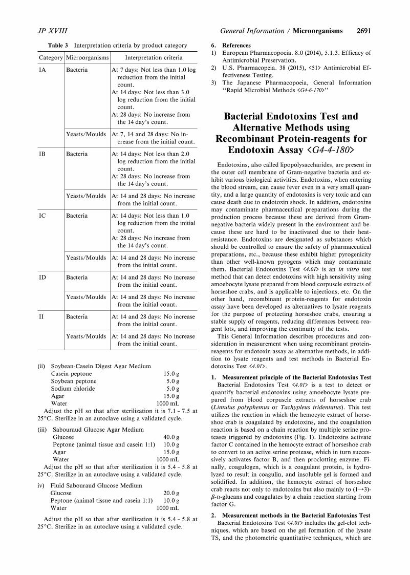
2691
Table 3 Interpretation criteria by product category
Category Microorganisms Interpretation criteria
IA Bacteria At 7 days: Not less than 1.0 logreduction from the initialcount.
At 14 days: Not less than 3.0log reduction from the initialcount.
At 28 days: No increase fromthe 14 day's count.
Yeasts/Moulds At 7, 14 and 28 days: No in-crease from the initial count.
IB Bacteria At 14 days: Not less than 2.0log reduction from the initialcount.
At 28 days: No increase fromthe 14 day's count.
Yeasts/Moulds At 14 and 28 days: No increasefrom the initial count.
IC Bacteria At 14 days: Not less than 1.0log reduction from the initialcount.
At 28 days: No increase fromthe 14 day's count.
Yeasts/Moulds At 14 and 28 days: No increasefrom the initial count.
ID Bacteria At 14 and 28 days: No increasefrom the initial count.
Yeasts/Moulds At 14 and 28 days: No increasefrom the initial count.
II Bacteria At 14 and 28 days: No increasefrom the initial count.
Yeasts/Moulds At 14 and 28 days: No increasefrom the initial count.
2691JP XVIII General Information / Microorganisms
(ii) Soybean-Casein Digest Agar MediumCasein peptone 15.0 gSoybean peptone 5.0 gSodium chloride 5.0 gAgar 15.0 gWater 1000 mL
Adjust the pH so that after sterilization it is 7.1 – 7.5 at259C. Sterilize in an autoclave using a validated cycle.
(iii) Sabouraud Glucose Agar MediumGlucose 40.0 gPeptone (animal tissue and casein 1:1) 10.0 gAgar 15.0 gWater 1000 mL
Adjust the pH so that after sterilization it is 5.4 – 5.8 at259C. Sterilize in an autoclave using a validated cycle.
iv) Fluid Sabouraud Glucose MediumGlucose 20.0 gPeptone (animal tissue and casein 1:1) 10.0 gWater 1000 mL
Adjust the pH so that after sterilization it is 5.4 – 5.8 at259C. Sterilize in an autoclave using a validated cycle.
6. References1) European Pharmacopoeia. 8.0 (2014), 5.1.3. Efficacy of
Antimicrobial Preservation.2) U.S. Pharmacopeia. 38 (2015), <51> Antimicrobial Ef-
fectiveness Testing.3) The Japanese Pharmacopoeia, General Information
``Rapid Microbial Methods <G4-6-170>''
Bacterial Endotoxins Test andAlternative Methods using
Recombinant Protein-reagents forEndotoxin Assay <G4-4-180>
Endotoxins, also called lipopolysaccharides, are present inthe outer cell membrane of Gram-negative bacteria and ex-hibit various biological activities. Endotoxins, when enteringthe blood stream, can cause fever even in a very small quan-tity, and a large quantity of endotoxins is very toxic and cancause death due to endotoxin shock. In addition, endotoxinsmay contaminate pharmaceutical preparations during theproduction process because these are derived from Gram-negative bacteria widely present in the environment and be-cause these are hard to be inactivated due to their heat-resistance. Endotoxins are designated as substances whichshould be controlled to ensure the safety of pharmaceuticalpreparations, etc., because these exhibit higher pyrogenicitythan other well-known pyrogens which may contaminatethem. Bacterial Endotoxins Test <4.01> is an in vitro testmethod that can detect endotoxins with high sensitivity usingamoebocyte lysate prepared from blood corpuscle extracts ofhorseshoe crabs, and is applicable to injections, etc. On theother hand, recombinant protein-reagents for endotoxinassay have been developed as alternatives to lysate reagentsfor the purpose of protecting horseshoe crabs, ensuring astable supply of reagents, reducing differences between rea-gent lots, and improving the continuity of the tests.
This General Information describes procedures and con-sideration in measurement when using recombinant protein-reagents for endotoxin assay as alternative methods, in addi-tion to lysate reagents and test methods in Bacterial En-dotoxins Test <4.01>.
1. Measurement principle of the Bacterial Endotoxins TestBacterial Endotoxins Test <4.01> is a test to detect or
quantify bacterial endotoxins using amoebocyte lysate pre-pared from blood corpuscle extracts of horseshoe crab(Limulus polyphemus or Tachypleus tridentatus). This testutilizes the reaction in which the hemocyte extract of horse-shoe crab is coagulated by endotoxins, and the coagulationreaction is based on a chain reaction by multiple serine pro-teases triggered by endotoxins (Fig. 1). Endotoxins activatefactor C contained in the hemocyte extract of horseshoe crabto convert to an active serine protease, which in turn succes-sively activates factor B, and then proclotting enzyme. Fi-nally, coagulogen, which is a coagulant protein, is hydro-lyzed to result in coagulin, and insoluble gel is formed andsolidified. In addition, the hemocyte extract of horseshoecrab reacts not only to endotoxins but also mainly to (1→3)-b-D-glucans and coagulates by a chain reaction starting fromfactor G.
2. Measurement methods in the Bacterial Endotoxins TestBacterial Endotoxins Test <4.01> includes the gel-clot tech-
niques, which are based on the gel formation of the lysateTS, and the photometric quantitative techniques, which are
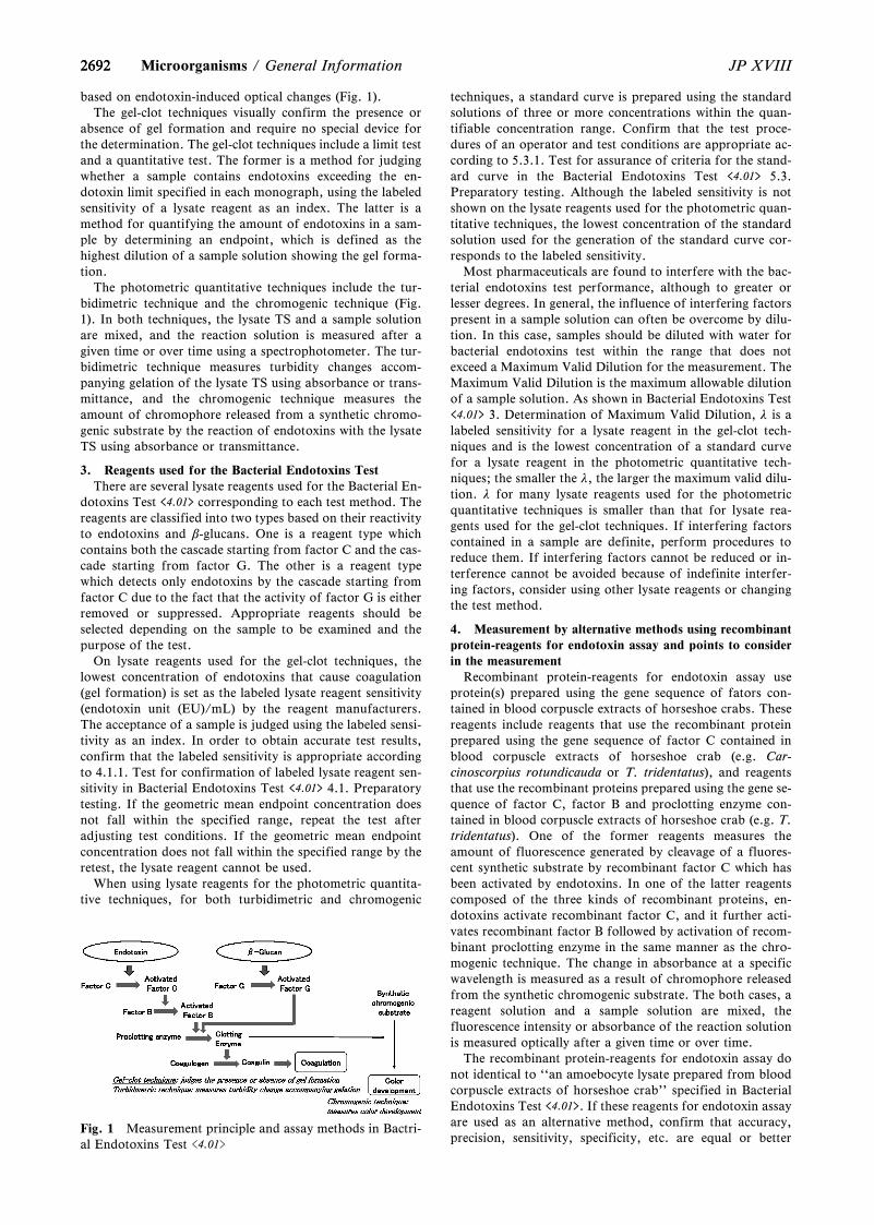
2692
Fig. 1 Measurement principle and assay methods in Bactri-al Endotoxins Test <4.01>
2692 JP XVIIIMicroorganisms / General Information
based on endotoxin-induced optical changes (Fig. 1).The gel-clot techniques visually confirm the presence or
absence of gel formation and require no special device forthe determination. The gel-clot techniques include a limit testand a quantitative test. The former is a method for judgingwhether a sample contains endotoxins exceeding the en-dotoxin limit specified in each monograph, using the labeledsensitivity of a lysate reagent as an index. The latter is amethod for quantifying the amount of endotoxins in a sam-ple by determining an endpoint, which is defined as thehighest dilution of a sample solution showing the gel forma-tion.
The photometric quantitative techniques include the tur-bidimetric technique and the chromogenic technique (Fig.1). In both techniques, the lysate TS and a sample solutionare mixed, and the reaction solution is measured after agiven time or over time using a spectrophotometer. The tur-bidimetric technique measures turbidity changes accom-panying gelation of the lysate TS using absorbance or trans-mittance, and the chromogenic technique measures theamount of chromophore released from a synthetic chromo-genic substrate by the reaction of endotoxins with the lysateTS using absorbance or transmittance.
3. Reagents used for the Bacterial Endotoxins TestThere are several lysate reagents used for the Bacterial En-
dotoxins Test <4.01> corresponding to each test method. Thereagents are classified into two types based on their reactivityto endotoxins and b-glucans. One is a reagent type whichcontains both the cascade starting from factor C and the cas-cade starting from factor G. The other is a reagent typewhich detects only endotoxins by the cascade starting fromfactor C due to the fact that the activity of factor G is eitherremoved or suppressed. Appropriate reagents should beselected depending on the sample to be examined and thepurpose of the test.
On lysate reagents used for the gel-clot techniques, thelowest concentration of endotoxins that cause coagulation(gel formation) is set as the labeled lysate reagent sensitivity(endotoxin unit (EU)/mL) by the reagent manufacturers.The acceptance of a sample is judged using the labeled sensi-tivity as an index. In order to obtain accurate test results,confirm that the labeled sensitivity is appropriate accordingto 4.1.1. Test for confirmation of labeled lysate reagent sen-sitivity in Bacterial Endotoxins Test <4.01> 4.1. Preparatorytesting. If the geometric mean endpoint concentration doesnot fall within the specified range, repeat the test afteradjusting test conditions. If the geometric mean endpointconcentration does not fall within the specified range by theretest, the lysate reagent cannot be used.
When using lysate reagents for the photometric quantita-tive techniques, for both turbidimetric and chromogenic
techniques, a standard curve is prepared using the standardsolutions of three or more concentrations within the quan-tifiable concentration range. Confirm that the test proce-dures of an operator and test conditions are appropriate ac-cording to 5.3.1. Test for assurance of criteria for the stand-ard curve in the Bacterial Endotoxins Test <4.01> 5.3.Preparatory testing. Although the labeled sensitivity is notshown on the lysate reagents used for the photometric quan-titative techniques, the lowest concentration of the standardsolution used for the generation of the standard curve cor-responds to the labeled sensitivity.
Most pharmaceuticals are found to interfere with the bac-terial endotoxins test performance, although to greater orlesser degrees. In general, the influence of interfering factorspresent in a sample solution can often be overcome by dilu-tion. In this case, samples should be diluted with water forbacterial endotoxins test within the range that does notexceed a Maximum Valid Dilution for the measurement. TheMaximum Valid Dilution is the maximum allowable dilutionof a sample solution. As shown in Bacterial Endotoxins Test<4.01> 3. Determination of Maximum Valid Dilution, l is alabeled sensitivity for a lysate reagent in the gel-clot tech-niques and is the lowest concentration of a standard curvefor a lysate reagent in the photometric quantitative tech-niques; the smaller the l, the larger the maximum valid dilu-tion. l for many lysate reagents used for the photometricquantitative techniques is smaller than that for lysate rea-gents used for the gel-clot techniques. If interfering factorscontained in a sample are definite, perform procedures toreduce them. If interfering factors cannot be reduced or in-terference cannot be avoided because of indefinite interfer-ing factors, consider using other lysate reagents or changingthe test method.
4. Measurement by alternative methods using recombinantprotein-reagents for endotoxin assay and points to considerin the measurement
Recombinant protein-reagents for endotoxin assay useprotein(s) prepared using the gene sequence of fators con-tained in blood corpuscle extracts of horseshoe crabs. Thesereagents include reagents that use the recombinant proteinprepared using the gene sequence of factor C contained inblood corpuscle extracts of horseshoe crab (e.g. Car-cinoscorpius rotundicauda or T. tridentatus), and reagentsthat use the recombinant proteins prepared using the gene se-quence of factor C, factor B and proclotting enzyme con-tained in blood corpuscle extracts of horseshoe crab (e.g. T.tridentatus). One of the former reagents measures theamount of fluorescence generated by cleavage of a fluores-cent synthetic substrate by recombinant factor C which hasbeen activated by endotoxins. In one of the latter reagentscomposed of the three kinds of recombinant proteins, en-dotoxins activate recombinant factor C, and it further acti-vates recombinant factor B followed by activation of recom-binant proclotting enzyme in the same manner as the chro-mogenic technique. The change in absorbance at a specificwavelength is measured as a result of chromophore releasedfrom the synthetic chromogenic substrate. The both cases, areagent solution and a sample solution are mixed, thefluorescence intensity or absorbance of the reaction solutionis measured optically after a given time or over time.
The recombinant protein-reagents for endotoxin assay donot identical to ``an amoebocyte lysate prepared from bloodcorpuscle extracts of horseshoe crab'' specified in BacterialEndotoxins Test <4.01>. If these reagents for endotoxin assayare used as an alternative method, confirm that accuracy,precision, sensitivity, specificity, etc. are equal or better
26932693JP XVIII General Information / Microorganisms
compared to Bacterial Endotoxins Test <4.01> using lysatereagents. Among the recombinant protein-reagents for en-dotoxin assay, some have been reported to have sensitivityand specificity equal to or better than the method usinglysate reagents. When bacterial endotoxins tests <4.01> forpharmaceuticals, etc. are performed using recombinant pro-tein-reagents, it is necessary to conduct 5.3.1.Test for assur-ance of criteria for the standard curve 5.3. Preparatory test-ing as with the Photometric quantitative techniques in Bac-terial Endotoxins Test <4.01>, and in that case the lowestconcentration of the standard curve corresponds to l (EU/mL). In addition, it is necessary to pay attention to interfer-ence, and 5.3.2.Test for interfering factors should be per-formed. In the case where measurement methods that arenot used in Bacterial Endotoxins Test <4.01> such as themethods that measure the amount of fluorescence are used,it is also necessary to be careful of potential interference be-cause even substances that do not disturb the measurementwhen using lysate reagents may exhibit interference such asthe inhibition of the generation of fluorescence. In addition,regarding reagents prepared using the gene sequence of theproteins of different species of horseshoe crab from horse-shoe crab (L. polyphemus or T. tridentatus ) specified inBacterial Endotoxins Test <4.01>, it should be noted thatdifference of the recombinant proteins may affect the reac-tivity to endotoxins.
Decision of Limit for BacterialEndotoxins <G4-5-131>
The endotoxin limit for injections is to be decided asfollows:
Endotoxin limit = K/M
where K is a threshold pyrogenic dose of endotoxin per kgbody mass (EU/kg), and depending on the administrationroute, values for K are set as in the following table.
Intended route of administration K (EU/kg)
Intravenous 5.0
Intravenous, forradiopharmaceuticals 2.5
Intraspinal 0.2
M is equal to the maximum bolus dose of product per kgbody mass. When the product is to be injected at frequentintervals or infused continuously, M is the maximum totaldose administered in a single hour period. M is expressed inmL/kg for products to be administered by volume, in mg/kgor mEq/kg for products to be administered by mass, and inUnit/kg for products to be administered by biological units.Notes:
1) For products to be administered by mass or by units,the endotoxin limit should be decided based on the labeledamount of the principal drug.
2) Sixty kg should be used as the average body mass ofan adult when calculating the maximum adult dose per kg.
3) The pediatric dose per kg body mass should be usedwhen this is higher than the adult dose.
4) The K values for the intravenous route are applicableto drugs to be administered by any route other than thoseshown in the table.
Rapid Microbial Methods<G4-6-170>
Advances in science and technology have provided newmethods to perform high-precision measurements of bacteri-al physiological activities, intracellular components, and soon, and consequently new techniques for bacterial detection,enumeration and quantification have appeared. Since the1980s it has become clear that the majority of bacteria in thenatural environment have low growth ability in conventionalculture media, and the detection, enumeration and identifi-cation of these bacteria are difficult by means of culturemethods alone. The bacterial cell counts obtained vary frommethod to method, and it should be noted that it is difficultto obtain a reliable value even applied with a new method.Moreover, even if type strains exist for method validation, itis not easy to standardize the physiological activity.
Compared to the conventional methods, these newmethods are not necessarily superior in every respect, butthey usually offer greater speed and accuracy, and can be ap-plied not only to bacteria, but also to fungi and viruses.Therefore, these new methods are very useful to improve thestandards of microbial control in critical areas, and todecrease the risk of hazardous microbial contamination.
The conventional cultivation-based methods use colonyformation or turbidity change due to cell growth as an indi-cator, whereas the new methods vary greatly as regards thedetection target and the detection principle. The newmethods may be more suitable for obtaining a comprehen-sive understanding of the microbial community, as well asfor identifying specific microorganisms. Among thesemethods, phylogenic analysis based on gene sequences hasbecome popular, and the dramatic development of sequenc-ing techniques in recent years now allows us to analyze thecomposition of the microbial community in a short time. Inthis information chapter, the principles of the new methodsand their range of applicability are introduced, and keypoints in the usage of these methods are described.
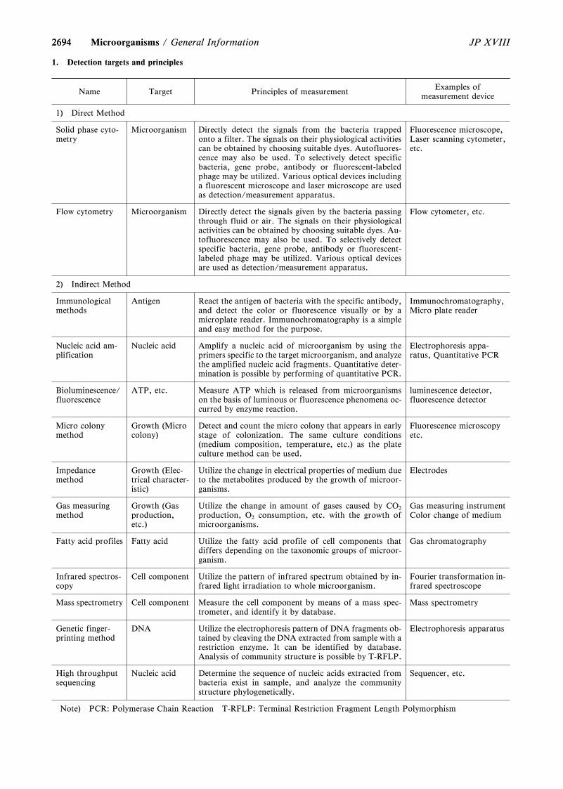
2694
Name Target Principles of measurement Examples ofmeasurement device
1) Direct Method
Solid phase cyto-metry
Microorganism Directly detect the signals from the bacteria trappedonto a filter. The signals on their physiological activitiescan be obtained by choosing suitable dyes. Autofluores-cence may also be used. To selectively detect specificbacteria, gene probe, antibody or fluorescent-labeledphage may be utilized. Various optical devices includinga fluorescent microscope and laser microscope are usedas detection/measurement apparatus.
Fluorescence microscope,Laser scanning cytometer,etc.
Flow cytometry Microorganism Directly detect the signals given by the bacteria passingthrough fluid or air. The signals on their physiologicalactivities can be obtained by choosing suitable dyes. Au-tofluorescence may also be used. To selectively detectspecific bacteria, gene probe, antibody or fluorescent-labeled phage may be utilized. Various optical devicesare used as detection/measurement apparatus.
Flow cytometer, etc.
2) Indirect Method
Immunologicalmethods
Antigen React the antigen of bacteria with the specific antibody,and detect the color or fluorescence visually or by amicroplate reader. Immunochromatography is a simpleand easy method for the purpose.
Immunochromatography,Micro plate reader
Nucleic acid am-plification
Nucleic acid Amplify a nucleic acid of microorganism by using theprimers specific to the target microorganism, and analyzethe amplified nucleic acid fragments. Quantitative deter-mination is possible by performing of quantitative PCR.
Electrophoresis appa-ratus, Quantitative PCR
Bioluminescence/fluorescence
ATP, etc. Measure ATP which is released from microorganismson the basis of luminous or fluorescence phenomena oc-curred by enzyme reaction.
luminescence detector,fluorescence detector
Micro colonymethod
Growth (Microcolony)
Detect and count the micro colony that appears in earlystage of colonization. The same culture conditions(medium composition, temperature, etc.) as the plateculture method can be used.
Fluorescence microscopyetc.
Impedancemethod
Growth (Elec-trical character-istic)
Utilize the change in electrical properties of medium dueto the metabolites produced by the growth of microor-ganisms.
Electrodes
Gas measuringmethod
Growth (Gasproduction,etc.)
Utilize the change in amount of gases caused by CO2
production, O2 consumption, etc. with the growth ofmicroorganisms.
Gas measuring instrumentColor change of medium
Fatty acid profiles Fatty acid Utilize the fatty acid profile of cell components thatdiffers depending on the taxonomic groups of microor-ganism.
Gas chromatography
Infrared spectros-copy
Cell component Utilize the pattern of infrared spectrum obtained by in-frared light irradiation to whole microorganism.
Fourier transformation in-frared spectroscope
Mass spectrometry Cell component Measure the cell component by means of a mass spec-trometer, and identify it by database.
Mass spectrometry
Genetic finger-printing method
DNA Utilize the electrophoresis pattern of DNA fragments ob-tained by cleaving the DNA extracted from sample with arestriction enzyme. It can be identified by database.Analysis of community structure is possible by T-RFLP.
Electrophoresis apparatus
High throughputsequencing
Nucleic acid Determine the sequence of nucleic acids extracted frombacteria exist in sample, and analyze the communitystructure phylogenetically.
Sequencer, etc.
Note) PCR: Polymerase Chain Reaction T-RFLP: Terminal Restriction Fragment Length Polymorphism
2694 JP XVIIIMicroorganisms / General Information
1. Detection targets and principles
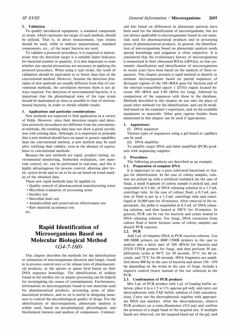
26952695JP XVIII General Information / Microorganisms
2. ValidationTo qualify introduced equipment, a standard component
or strain, which represents the target of each method, shouldbe utilized. That is, in direct measurement, type strainsshould be used, while in indirect measurement, standardcomponents, etc., of the target bacteria are used.
To validate a protocol/procedure, it is required to demon-strate that the detection target is a suitable index/indicatorfor bacterial number or quantity. It is also important to statewhether any special precautions are necessary in applying theprotocol/procedure. When using a type strain, the result ofvalidation should be equivalent to or better than that of theconventional method. However, because the detection prin-ciples of new methods are usually different from that of con-ventional methods, the correlation between them is not al-ways required. For detection of environmental bacteria, it isimportant that the physiological state of the type strainshould be maintained as close as possible to that of environ-mental bacteria, in order to obtain reliable results.
3. Applications and particular considerations:New methods are expected to find application in a variety
of fields. However, since their detection targets and detec-tion protocols/procedures are different from the convention-al methods, the resulting data may not show a good correla-tion with existing data. Although, it is important in principlethat a new method should have an equal or greater capabilitythan the conventional method, a new method may be usedafter verifying their validity, even in the absence of equiva-lence to conventional methods.
Because the new methods are rapid, product testing, en-vironmental monitoring, bioburden evaluation, raw mate-rials control, etc. can be performed in real-time, and this ishighly advantageous for process control, allowing alert lev-els, action levels and so on to be set up based on trend analy-sis of the obtained data.
These new rapid methods may be applied to;Quality control of pharmaceutical manufacturing waterMicrobial evaluation of processing areasSterility testMicrobial limit testAntimicrobial and preservatives effectiveness testRaw material acceptance testetc.
Rapid Identification ofMicroorganisms Based on
Molecular Biological Method<G4-7-160>
This chapter describes the methods for the identificationor estimation of microorganisms (bacteria and fungi), foundin in-process control tests or lot release tests of pharmaceuti-cal products, at the species or genus level based on theirDNA sequence homology. The identification of isolatesfound in the sterility test or aseptic processing can be helpfulfor investigating the causes of contamination. Furthermore,information on microorganisms found in raw materials usedfor pharmaceutical products, processing areas of phar-maceutical products, and so on is useful in designing meas-ures to control the microbiological quality of drugs. For theidentification of microorganisms, phenotypic analysis iswidely used, based on morphological, physiological, andbiochemical features and analysis of components. Commer-
cial kits based on differences in phenotype patterns havebeen used for the identification of microorganisms, but arenot always applicable to microorganisms found in raw mate-rials used for pharmaceutical products and in processingareas of pharmaceutical products. In general, the identifica-tion of microorganisms based on phenotypic analysis needsspecial knowledge and judgment is often subjective. It isconsidered that the evolutionary history of microorganismsis memorized in their ribosomal RNAs (rRNAs), so that sys-tematic classification and identification of microorganismsin recent years have been based on the analysis of these se-quences. This chapter presents a rapid method to identify orestimate microorganisms based on partial sequences ofdivergent regions of the 16S rRNA gene for bacteria and ofthe internal transcribed spacer 1 (ITS1) region located be-tween 18S rRNA and 5.8S rRNA for fungi, followed bycomparison of the sequences with those in the database.Methods described in this chapter do not take the place ofusual other methods for the identification, and can be modi-fied based on the examiner's experience, and on the availableequipment or materials. Other gene regions besides thosementioned in this chapter can be used if appropriate.
1. Apparatuses(i) DNA sequencerVarious types of sequencers using a gel board or capillary
can be used.(ii) DNA amplifierTo amplify target DNA and label amplified (PCR) prod-
ucts with sequencing reagents.
2. ProceduresThe following procedures are described as an example.
2.1. Preparation of template DNAIt is important to use a pure cultivated bacterium or fun-
gus for identification. In the case of colony samples, colo-nies are picked up with a sterilized toothpick (in the case offungi, a small fragment of colony sample is picked up), andsuspended in 0.3 mL of DNA releasing solution in a 1.5 mLcentrifuge tube. In the case of culture fluid, a 0.5 mL por-tion of fluid is put in a 1.5 mL centrifuge tube and centri-fuged at 10,000 rpm for 10 minutes. After removal of the su-pernatant, the pellet is suspended in 0.3 mL of DNA releas-ing solution, and then heated at 1009C for 10 minutes. Ingeneral, PCR can be run for bacteria and yeasts heated inDNA releasing solution. For fungi, DNA extraction fromculture fluid is better because some of colony samples candisturb PCR reaction.2.2. PCR
Add 2 mL of template DNA in PCR reaction solution. Use10F/800R primers (or 800F/1500R primers in the case toanalyze also a latter part of 16S rRNA) for bacteria andITS1F/ITS1R primers for fungi, and then perform 30 am-plification cycles at 949C for 30 seconds, 559C for 60 se-conds, and 729C for 60 seconds. DNA fragments are ampli-fied about 800 bp in the case of bacteria and about 150 – 470bp depending on the strain in the case of fungi. Include anegative control (water instead of the test solution) in thePCR.2.3. Confirmation of PCR products
Mix 5 mL of PCR product with 1 mL of loading buffer so-lution, place it in a 1.5 w/vz agarose gel well, and carry outelectrophoresis with TAE buffer solution (1-fold concentra-tion). Carry out the electrophoresis together with appropri-ate DNA size markers. After the electrophoresis, observePCR products on a trans-illuminator (312 nm) and confirmthe presence of a single band of the targeted size. If multiplebands are observed, cut the targeted band out of the gel, and
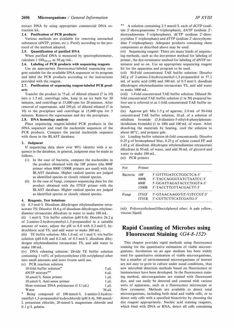
26962696 JP XVIIIMicroorganisms / General Information
extract DNA by using appropriate commercial DNA ex-traction kit.2.4. Purification of PCR products
Various methods are available for removing unreachedsubstances (dNTP, prime, etc.). Purify according to the pro-tocol of the method adopted.2.5. Quantification of purified DNA
When purified DNA is measured by spectrophotometer,calculate 1 OD260 nm as 50 mg/mL.2.6. Labeling of PCR products with sequencing reagents
Use an appropriate fluorescence-labeled sequencing rea-gent suitable for the available DNA sequencer or its programand label the PCR products according to the instructionsprovided with the reagent.2.7. Purification of sequencing reagent-labeled PCR prod-ucts
Transfer the product in 75 mL of diluted ethanol (7 in 10)into a 1.5 mL centrifuge tube, keep in an ice bath for 20minutes, and centrifuge at 15,000 rpm for 20 minutes. Afterremoval of supernatant, add 250 mL of diluted ethanol (7 in10) to the precipitate and centrifuge at 15,000 rpm for 5minutes. Remove the supernatant and dry the precipitate.2.8. DNA homology analysis
Place sequencing reagent-labeled PCR products in theDNA sequencer and read the nucleotide sequences of thePCR products. Compare the partial nucleotide sequencewith those in the BLAST database.
3. JudgmentIf sequencing data show over 90z identity with a se-
quence in the database, in general, judgment may be made asfollows.
( i ) In the case of bacteria, compare the nucleotides inthe product obtained with the 10F primer (the 800Fprimer when 800F/1500R primers are used) with theBLAST database. Higher ranked species are judgedas identified species or closely related species.
(ii) In the case of fungi, compare sequencing data for theproduct obtained with the ITS1F primer with theBLAST database. Higher ranked species are judgedas identified species or closely related species.
4. Reagents, Test Solutions(i) 0.5 mol/L Disodium dihydrogen ethylenediamine tetra-acetate TS: Dissolve 18.6 g of disodium dihydrogen ethylene-diamine tetraacetate dihydrate in water to make 100 mL.(ii) 1 mol/L Tris buffer solution (pH 8.0): Dissolve 24.2 gof 2-amino-2-hydroxymethyl-1,3-propanediol in a suitableamount of water, adjust the pH to 8.0 with 0.2 mol/L hy-drochloric acid TS, and add water to make 200 mL.(iii) TE buffer solution: Mix 1.0 mL of 1 mol/L tris buffersolution (pH 8.0) and 0.2 mL of 0.5 mol/L disodium dihy-drogen ethylenediamine tetraacetate TS, and add water tomake 100 mL.(iv) DNA releasing solution: Divide TE buffer solutioncontaining 1 volz of polyoxyethylene (10) octylphenyl etherinto small amounts and store frozen until use.(v) PCR reaction solution
10-fold buffer solution* 5 mLdNTP mixture** 4 mL10 mmol/L Sense primer 1 mL10 mmol/L Anti-sense primer 1 mLHeat-resistant DNA polymerase (1 U/mL) 1 mLWater 36 mL
* Being composed of 100 mmol/L 2-amino-2-hydrox-ymethyl-1,3-propanediol hydrochloride (pH 8.4), 500 mmol/L potassium chloride, 20 mmol/L magnesium chloride and0.1 g/L gelatin.
** A solution containing 2.5 mmol/L each of dGTP (sodi-um 2?-deoxyguanosine 5?-triphosphate), dATP (sodium 2?-deoxyadenosine 5?-triphosphate), dCTP (sodium 2?-deox-ycytidine 5?-triphosphate) and dTTP (sodium 2?-deoxythymi-dine 5?-triphosphate). Adequate products containing thesecomponents as described above may be used.(vi) Sequencing reagent: There are many kinds of sequenc-ing methods, such as the dye-primer method for labeling ofprimer, the dye-terminator method for labeling of dNTP ter-minator and so on. Use an appropriate sequencing reagentkit for the apparatus and program to be used.(vii) 50-Fold concentrated TAE buffer solution: Dissolve242 g of 2-amino-2-hydroxymethyl-1,3-propanediol in 57.1mL of acetic acid (100) and 100 mL of 0.5 mol/L disodiumdihydrogen ethylenediamine tetraacetate TS, and add waterto make 1000 mL.(viii) 1-Fold concentrated TAE buffer solution: Diluted 50-fold concentrated TAE buffer solution (1 in 50) prepared be-fore use is referred to as 1-fold concentrated TAE buffer so-lution.(ix) Agarose gel: Mix 1.5 g of agarose, 2.0 mL of 50-foldconcentrated TAE buffer solution, 10 mL of a solution ofethidium bromide (3,8-diamino-5-ethyl-6-phenylphenan-thridinium bromide) (1 in 100) and 100 mL of water. Afterdissolving the materials by heating, cool the solution toabout 609C, and prepare gels.(x) Loading buffer solution (6-fold concentrated): Dissolve0.25 g of bromophenol blue, 0.25 g of xylene cyanol FF and1.63 g of disodium dihydrogen ethylenediamine tetraacetatedihydrate in 50 mL of water, and add 30 mL of glycerol andwater to make 100 mL.(xi) PCR primers
For Primer
Bacteria 10F800R
5?-GTTTGATCCTGGCTCA-3?5?-TACCAGGGTATCTAATCC-3?
800F 5?-GGATTAGATACCCTGGTA-3?1500R 5?-TACCTTGTTACGACTT-3?
Fungi ITS1FITS1R
5?-GTAACAAGGT(T/C)TCCGT-3?5?-CGTTCTTCATCGATG-3?
(xii) Polyoxyethylene(10)octylphenyl ether: A pale yellow,viscous liquid.
Rapid Counting of Microbes usingFluorescent Staining <G4-8-152>
This chapter provides rapid methods using fluorescencestaining for the quantitative estimation of viable microor-ganisms. Incubation on an agar medium has been widelyused for quantitative estimation of viable microorganisms,but a number of environmental microorganisms of interestare not easy to grow in culture under usual conditions, thusnew microbial detection methods based on fluorescence orluminescence have been developed. In the fluorescence stain-ing method, microorganisms are stained with fluorescentdye, and can easily be detected and counted with varioussorts of apparatus, such as a fluorescence microscope orflow cytometer. Methods are available to detect totalmicroorganisms, including both dead and viable cells, or todetect only cells with a specified bioactivity by choosing thedye reagent appropriately. Nucleic acid staining reagents,which bind with DNA or RNA, detect all cells containing
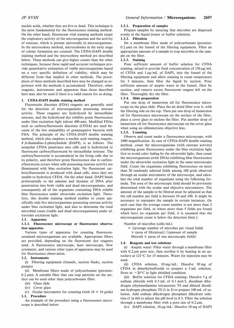
26972697JP XVIII General Information / Microorganisms
nucleic acids, whether they are live or dead. This technique isthe most fundamental for the fluorescence staining method.On the other hand, fluorescent vital staining methods targetthe respiratory activity of the microorganism and the activityof esterase, which is present universally in microorganisms.In the microcolony method, microcolonies in the early stageof colony formation are counted. The CFDA-DAPI doublestaining method and the microcolony method are describedbelow. These methods can give higher counts than the othertechniques, because these rapid and accurate techniques pro-vide quantitative estimation of viable microorganisms basedon a very specific definition of viability, which may bedifferent from that implicit in other methods. The proce-dures of these methods described here may be changed as ex-perience with the methods is accumulated. Therefore, otherreagents, instruments and apparatus than those describedhere may also be used if there is a valid reason for so doing.
1. CFDA-DAPI double staining methodFluorescein diacetate (FDA) reagents are generally used
for the detection of microorganisms possessing esteraseactivity. These reagents are hydrolyzed by intracellularesterase, and the hydrolyzed dye exhibits green fluorescenceunder blue excitation light (about 490 nm). Modified FDAssuch as carboxyfluorescein diacetate (CFDA) are used be-cause of the low stainability of gramnegative bacteria withFDA. The principle of the CFDA-DAPI double stainingmethod, which also employs a nucleic acid staining reagent,4?,6-diamidino-2-phenylindole (DAPI), is as follows. Thenonpolar CFDA penetrates into cells and is hydrolyzed tofluorescent carboxyfluorescein by intracellular esterase. Thecarboxyfluorescein is accumulated in the living cells due toits polarity, and therefore green fluorescence due to carbox-yfluorescein occurs when cells possessing esterase activity areilluminated with blue excitation light. No fluorescent car-boxyfluorescein is produced with dead cells, since they areunable to hydrolyze CFDA. On the other hand, DAPI bindspreferentially to the adenine and thymine of DNA afterpenetration into both viable and dead microorganisms, andconsequently all of the organisms containing DNA exhibitblue fluorescence under ultraviolet excitation light. There-fore, this double staining method enables to count spe-cifically only live microorganisms possessing esterase activityunder blue excitation light, and also to determine the totalmicrobial count (viable and dead microorganisms) under ul-traviolet excitation light.1.1. Apparatus1.1.1. Fluorescence microscope or fluorescence observa-tion apparatus
Various types of apparatus for counting fluorescen-cestained microorganisms are available. Appropriate filtersare provided, depending on the fluorescent dye reagentsused. A fluorescence microscope, laser microscope, flowcytometer, and various other types of apparatus may be usedfor fluorescence observation.1.2. Instruments
(i) Filtering equipment (funnels, suction flasks, suctionpumps)
(ii) Membrane filters made of polycarbonate (poresize:0.2 mm); A suitable filter that can trap particles on the sur-face can be used other than polycarbonate filter.
(iii) Glass slide(iv) Cover glass(v) Ocular micrometer for counting (with 10 × 10 grids)
1.3. ProcedureAn example of the procedure using a fluorescence micro-
scope is described below.
1.3.1. Preparation of samplesPrepare samples by ensuring that microbes are dispersed
evenly in the liquid (water or buffer solution).1.3.2. Filtration
Set a membrane filter made of polycarbonate (poresize:0.2 mm) on the funnel of the filtering equipment. Filter anappropriate amount of a sample to trap microbes in the sam-ple on the filter.1.3.3. Staining
Pour sufficient amount of buffer solution for CFDAstaining, mixed to provide final concentration of 150 mg/mLof CFDA and 1 mg/mL of DAPI, into the funnel of thefiltering equipment and allow staining in room temperaturefor 3 minutes, then filter the liquid by suction. Poursufficient amount of aseptic water in the funnel, filter bysuction, and remove excess fluorescent reagent left on thefilter. Thoroughly dry the filter.1.3.4. Slide preparation
Put one drop of immersion oil for fluorescence micro-scope on the glass slide. Place the air dried filter over it, withthe filtering side on the top. Then put one drop of immersionoil for fluorescence microscope on the surface of the filter,place a cover glass to enclose the filter. Put another drop ofimmersion oil for fluorescence microscope on the cover glasswhen using an oilimmersion objective lens.1.3.5. Counting
Observe and count under a fluorescence microscope, with1000 magnification. In case of CFDA-DAPI double stainingmethod, count the microorganisms (with esterase activity)exhibiting green fluorescence under the blue excitation lightfirst to avoid color fading by the ultraviolet light, then countthe microorganisms (with DNA) exhibiting blue fluorescenceunder the ultraviolet excitation light in the same microscopicfield. Count the organisms exhibiting fluorescence on morethan 20 randomly selected fields among 100 grids observedthrough an ocular micrometer of the microscope, and calcu-late the total number of organisms using the following for-mula. The area of the microscopic field should be previouslydetermined with the ocular and objective micrometers. Theamount of the sample to be filtered must be adjusted so thatthe cell number per field is between 10 and 100. It might benecessary to reprepare the sample in certain instances. (Insuch case that the average count number is not more than 2organisms per field, or where more than 5 fields are foundwhich have no organism per field, it is assumed that themicroorganism count is below the detection limit.)
Number of microbes (cells/mL)= s(average number of microbes per visual field)
× (area of filtration)t/s(amount of samplefiltered) × (area of one microscopic field)t
1.4. Reagents and test solutions(i) Aseptic water: Filter water through a membrane filter
with 0.2 mm pore size, then sterilize it by heating in an au-toclave at 1219C for 15 minutes. Water for injection may beused.
(ii) CFDA solution, 10 mg/mL: Dissolve 50 mg ofCFDA in dimethylsulfoxide to prepare a 5 mL solution.Store at -209C in light shielded condition.
(iii) Buffer solution for CFDA staining: Dissolve 5 g ofsodium chloride with 0.5 mL of 0.1 mol/L disodium dihy-drogen ethylenediamine tetraacetate TS and diluted disodi-um hydrogen phosphate TS (1 in 3) to prepare 100 mL of so-lution. Add sodium dihydrogen phosphate dihydrate solu-tion (1 in 64) to adjust the pH level to 8.5. Filter the solutionthrough a membrane filter with a pore size of 0.2 mm.
(iv) DAPI solution, 10 mg/mL: Dissolve 10 mg of DAPI
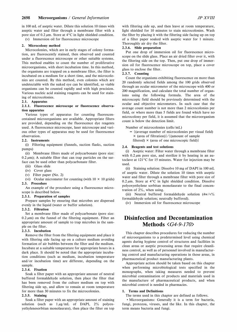
26982698 JP XVIIIMicroorganisms / General Information
in 100 mL of aseptic water. Dilute this solution 10 times withaseptic water and filter through a membrane filter with apore size of 0.2 mm. Store at 49C in light shielded condition.
(v) Immersion oil for fluorescence microscope
2. Microcolony methodMicrocolonies, which are in early stages of colony forma-
tion, are fluorescently stained, then observed and countedunder a fluorescence microscope or other suitable systems.This method enables to count the number of proliferativemicroorganisms, with short incubation time. In this method,the organisms are trapped on a membrane filter, the filter isincubated on a medium for a short time, and the microcolo-nies are counted. By this method, even colonies which areundetectable with the naked eye can be identified, so viableorganisms can be counted rapidly and with high precision.Various nucleic acid staining reagents can be used for stain-ing of microcolonies.2.1. Apparatus2.1.1. Fluorescence microscope or fluorescence observa-tion apparatus
Various types of apparatus for counting fluorescen-cestained microorganisms are available. Appropriate filtersare provided, depending on the fluorescence dye reagentsused. A fluorescence microscope, laser microscope and vari-ous other types of apparatus may be used for fluorescenceobservation.2.2. Instruments
(i) Filtering equipment (funnels, suction flasks, suctionpumps)
(ii) Membrane filters made of polycarbonate (pore size:0.2 mm); A suitable filter that can trap particles on the sur-face can be used other than polycarbonate filter.
(iii) Glass slide(iv) Cover glass(v) Filter paper (No. 2)(vi) Ocular micrometer for counting (with 10 × 10 grids)
2.3. ProcedureAn example of the procedure using a fluorescence micro-
scope is described below.2.3.1. Preparation of samples
Prepare samples by ensuring that microbes are dispersedevenly in the liquid (water or buffer solution).2.3.2. Filtration
Set a membrane filter made of polycarbonate (pore size:0.2 mm) on the funnel of the filtering equipment. Filter anappropriate amount of sample to trap microbes in the sam-ple on the filter.2.3.3. Incubation
Remove the filter from the filtering equipment and place itwith filtering side facing up on a culture medium avoidingformation of air bubbles between the filter and the medium.Incubate at a suitable temperature for appropriate hours in adark place. It should be noted that the appropriate incuba-tion conditions (such as medium, incubation temperatureand/or incubation time) are different, depending on thesample.2.3.4. Fixation
Soak a filter paper with an appropriate amount of neutralbuffered formaldehyde solution, then place the filter thathas been removed from the culture medium on top withfiltering side up, and allow to remain at room temperaturefor more than 30 minutes to fix the microcolonies.2.3.5. Staining
Soak a filter paper with an appropriate amount of stainingsolution (such as 1 mg/mL of DAPI, 2z polyox-yethylenesorbitan monolaurate), then place the filter on top
with filtering side up, and then leave at room temperature,light shielded for 10 minutes to stain microcolonies. Washthe filter by placing it with the filtering side facing up on topof a filter paper soaked with aseptic water for 1 minute.Thoroughly air dry the filter.2.3.6. Slide preparation
Put one drop of immersion oil for fluorescence micro-scope on the slide glass. Place an air dried filter over it, withthe filtering side on the top. Then, put one drop of immer-sion oil for fluorescence microscope on top, place a coverglass to enclose the filter.2.3.7. Counting
Count the organisms exhibiting fluorescence on more than20 randomly selected fields among the 100 grids observedthrough an ocular micrometer of the microscope with 400 or200 magnification, and calculate the total number of organ-isms using the following formula. The area of themicroscopic field should be previously determined with theocular and objective micrometers. In such case that theaverage count number is not more than 2 microcolonies perfield, or where more than 5 fields are found which have nomicrocolony per field, it is assumed that the microorganismcount is below the detection limit.
Number of microcolonies (cells/mL)= s(average number of microcolonies per visual field)
× (area of filtration)t/s(amount of samplefiltered) × (area of one microscopic field)t
2.4. Reagents and test solutions(i) Aseptic water: Filter water through a membrane filter
with 0.2 mm pore size, and sterilize it by heating in an au-toclave at 1219C for 15 minutes. Water for injection may beused.
(ii) Staining solution: Dissolve 10 mg of DAPI in 100 mLof aseptic water. Dilute the solution 10 times with asepticwater and filter through a membrane filter with pore size of0.2 mm. Store at 49C in light shielded condition. Dissolvepolyoxyethylene sorbitan monolaurate to the final concen-tration of 2z, when using.
(iii) Neutral buffered formaldehyde solution (4w/vzformaldehyde solution; neutrally buffered).
(iv) Immersion oil for fluorescence microscope
Disinfection and DecontaminationMethods <G4-9-170>
This chapter describes procedures for reducing the numberof microorganisms to a predetermined level using chemicalagents during hygiene control of structures and facilities inclean areas or aseptic processing areas that require cleanli-ness control, as well as of personnel involved in manufactur-ing control and manufacturing operations in those areas, inpharmaceutical product manufacturing plants.
Appropriate action should be taken based on this chapterwhen performing microbiological tests specified in themonographs, when taking measures needed to preventmicrobial contamination of products and materials used inthe manufacture of pharmaceutical products, and whenmicrobial control is needed in pharmacies.
1. Terms and DefinitionsThe terms used in this chapter are defined as follows.Microorganisms: Generally it is a term for bacteria,
fungi, protozoa, viruses, and the like. In this chapter, theterm means bacteria and fungi.
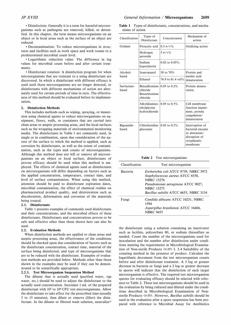
2699
Table 1 Types of disinfectants, concentrations, and mecha-nisms of action
ClassificationTypes of
DisinfectantConcentration
Mechanism ofaction
Oxidant Peracetic acid 0.3 w/vz Oxidizing action
Hydrogenperoxide
3 w/vz
Sodiumhypochlorite
0.02 to 0.05z
Alcohol-based
Isopropanol 50 to 70z Protein andnucleic aciddenaturationEthanol 76.9 to 81.4 volz
Surfactant-based
BenzalkoniumchlorideBenzethoniumchloride
0.05 to 0.2z Protein denatu-ration
Alkyldiamino-ethylglycinehydrochloride
0.05 to 0.5z Cell membranefunction impair-ment, proteincoagulation/denaturation
Biguanide-based
Chlorhexidinegluconate
0.05 to 0.5z Interruption ofbacterial enzymeor alteration/disruption ofcytoplasmicmembrane
Table 2 Test microorganisms
Classification Test microorganism
Bacteria Escherichia coli ATCC 8739, NBRC 3972Staphylococcus aureus ATCC 6538,NBRC 13276Pseudomonas aeruginosa ATCC 9027,NBRC 13275Bacillus subtilis ATCC 6633, NBRC 3134
Fungi Candida albicans ATCC 10231, NBRC1594Aspergillus brasiliensis ATCC 16404,NBRC 9455
2699JP XVIII General Information / Microorganisms
Disinfection: Generally it is a term for harmful microor-ganisms such as pathogens are removed, killed, or detoxi-fied. In this chapter, the term means microorganisms on anobject or in local areas such as the surface of an object arereduced.
Decontamination: To reduce microorganisms in struc-tures and facilities such as work space and work rooms to apredetermined microbial count level.
Logarithmic reduction value: The difference in logvalues for microbial count before and after certain treat-ments.
Disinfectant rotation: A disinfection program for whenmicroorganisms that are resistant to a using disinfectant arediscovered. In which a disinfectant with different efficacy isused until those microorganisms are no longer detected, ordisinfectants with different mechanisms of action are alter-nately used for certain periods of time in turn. The effective-ness of this method should be evaluated before its implemen-tation.
2. Disinfection MethodsThis includes methods such as wiping, spraying, or immer-
sion using chemical agents to reduce microorganisms on eq-uipment, floors, walls, or containers that are carried intoclean areas or aseptic processing areas, and the local surfacessuch as the wrapping materials of environmental monitoringmedia. The disinfectants in Table 1 are commonly used, insingle or in combination, upon due consideration of the na-ture of the surface to which the method is applied, such ascorrosion by disinfectants, as well as the extent of contami-nation, such as the types and counts of microorganisms.Although this method does not kill or remove all microor-ganisms on an object or local surface, disinfectants ofproven efficacy should be used when this method is em-ployed. The effects of chemical agents used as disinfectantson microorganisms will differ depending on factors such asthe applied concentration, temperature, contact time, andlevel of surface contamination. When using this method,attention should be paid to disinfectant expiration dates,microbial contamination, the effect of chemical residue onpharmaceutical product quality, and deterioration such asdiscoloration, deformation and corrosion of the materialsbeing treated.2.1. Disinfectants
Table 1 presents examples of commonly used disinfectantsand their concentrations, and the microbial effects of thesedisinfectants. Disinfectants and concentrations proven to besafe and effective other than those shown here can also beused.2.2. Evaluation Methods
When disinfection methods are applied to clean areas andaseptic processing areas, the effectiveness of the conditionsshould be checked upon due consideration of factors such asthe disinfectant concentration, contact time, material of thesurface being disinfected, and type of microorganisms thatare to be reduced with the disinfectant. Examples of evalua-tion methods are provided below. Methods other than thoseshown in the examples may be used if they can be demon-strated to be scientifically appropriate.2.2.1. Test Microorganism Suspension Method
The diluent that is actually used (purified water, tapwater, etc.) should be used to adjust the disinfectant to theactually used concentration. Inoculate 1 mL of the prepareddisinfectant with 105 to 106 CFU test microorganisms. Allowthe disinfectant to take effect for the prescribed time (usually5 to 15 minutes), then dilute or remove (filter) the disin-fectant. In the diluent or filtered wash solution, neutralize1)
the disinfectant using a solution containing an inactivatorsuch as lecithin, polysorbate 80, or sodium thiosulfate asneeded. Count the number of the microorganisms used forinoculation and the number after disinfection under condi-tions meeting the requirements in Microbiological Examina-tion of Non-sterile Products <4.05> I. 3.4 Suitability of thecounting method in the presence of product. Calculate thelogarithmic decrement from the test microorganism countsbefore and after disinfectant treatment. A 3 log or greaterdecrease in bacteria or fungi and a 2 log or greater decreasein spores will indicate that the disinfection of each targetmicroorganism is effective. The required test microorganismspecies for evaluating efficacy should be selected with refer-ence to Table 2. These test microorganisms should be used inthe evaluation by being cultured and diluted under the condi-tions described in Microbiological Examination of Non-sterile Products <4.05>. However, Bacillus subtilis should beused in the evaluation after a spore suspension has been pre-pared with reference to Microbial Assay for Antibiotics
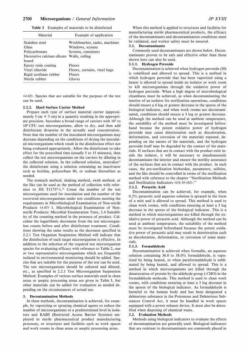
2700
Table 3 Examples of materials to be disinfected
Material Example of application
Stainless steel Workbenches, tanks, machinesGlass Windows, screensPolycarbonate Screens, containersDecorative calcium silicateboard
Walls, ceiling
Epoxy resin coating FloorsVinyl chloride Floors, curtains, vinyl bagsRigid urethane rubber FloorsNitrile rubber Gloves
2700 JP XVIIIMicroorganisms / General Information
<4.02>. Species that are suitable for the purpose of the testcan be used.
2.2.2. Hard Surface Carrier MethodPrepare each type of surface material carrier (approxi-
mately 5 cm × 5 cm) in a quantity resulting in the appropri-ate precision. Inoculate a broad range of carriers with 105 to106 CFU test microorganisms, allow to dry, and then adddisinfectant dropwise in the actually used concentration.Note that the number of the inoculated microorganisms maydecrease depending on the conditions of drying the inoculat-ed microorganisms which result in the disinfection effect notbeing evaluated appropriately. Allow the disinfectant to takeeffect for the prescribed time (usually 5 to 15 minutes), thencollect the test microorganisms on the carriers by diluting inthe collected solution. In the collected solution, neutralize1)
the disinfectant using a solution containing an inactivatorsuch as lecithin, polysorbate 80, or sodium thiosulfate asneeded.
The stomach method, shaking method, swab method, orthe like can be used as the method of collection with refer-ence to JIS T11737-1.2) Count the number of the testmicroorganisms used for inoculation and the number of therecovered microorganisms under test conditions meeting therequirements in Microbiological Examination of Non-sterileProducts <4.05> I. Microbiological Examination of Non-sterile Products: Microbial Enumeration Tests, 3.4 Suitabil-ity of the counting method in the presence of product. Cal-culate the logarithmic decrement from the test microorgan-ism counts before and after disinfectant treatment. Condi-tions showing the same results as the decreases specified in2.2.1 Test Organism Suspension Method will indicate thatthe disinfection of each target microorganism is effective. Inaddition to the selection of the required test microorganismspecies for evaluating efficacy with reference to Table 2, oneor two representative microorganisms which are frequentlyisolated in environmental monitoring should be added. Spe-cies that are suitable for the purpose of the test can be used.The test microorganisms should be cultured and diluted,etc., as specified in 2.2.1 Test Microorganism SuspensionMethod. Examples of various surface materials used in cleanareas or aseptic processing areas are given in Table 3, butother materials can be added for evaluation as needed de-pending on the circumstances of actual use.
3. Decontamination MethodsIn these methods, decontamination is achieved, for exam-
ple, by vaporizing or spraying chemical agents to reduce thenumber of microorganisms to a predetermined level in isola-tors and RABS (Restricted Access Barrier Systems) em-ployed in sterile pharmaceutical product manufacturingprocesses, or structures and facilities such as work spacesand work rooms in clean areas or aseptic processing areas.
When this method is applied to structures and facilities formanufacturing sterile pharmaceutical products, the efficacyof the decontaminants and decontamination conditions mustbe validated, and worker safety must be ensured.3.1. Decontaminants
Commonly used decontaminants are shown below. Decon-taminants proven to be safe and effective other than thoseshown here can also be used.3.1.1. Hydrogen Peroxide
Decontamination is achieved when hydrogen peroxide (30)is volatilized and allowed to spread. This is a method inwhich hydrogen peroxide that has been vaporized using aheater is allowed to spread inside an isolator or work roomto kill microorganisms through the oxidative power ofhydrogen peroxide. When a high degree of microbiologicalcleanliness must be achieved, as when decontaminating theinterior of an isolator for sterilization operations, conditionsshould ensure a 6 log or greater decrease in the spores of thebiological indicator, and when work rooms are decontami-nated, conditions should ensure a 3 log or greater decrease.Although the method can be used at ambient temperature,the suitability of the method must be investigated before-hand because the potent oxidative power of hydrogenperoxide may cause deterioration such as discoloration,deformation, and corrosion of the materials exposed, de-pending on the nature of the materials, and the hydrogenperoxide itself may be degraded by the contact of the mate-rials. If surfaces that are in contact with the product exist in-side the isolator, it will be necessary to simultaneouslydecontaminate the interior and ensure the sterility assuranceof the surfaces that are in contact with the product. In suchcases, the pre-sterilization bioburden, parameters, utilities,and the like should be controlled in terms of the sterilizationmethod with reference to the chapter ``Sterilization Methodsand Sterilization Indicators <G4-10-162>.''3.1.2. Peracetic Acid
Decontamination can be achieved, for example, when0.2z peracetic acid aqueous solution is sprayed in the formof a mist and is allowed to spread. This method is used toclean work rooms, with conditions ensuring at least a 3 logdecrease in the spores of the biological indicator. This is amethod in which microorganisms are killed through the ox-idative power of peracetic acid. Although the method can beused at ambient temperature, the suitability of the methodmust be investigated beforehand because the potent oxida-tive power of peracetic acid may result in deterioration suchas discoloration, deformation, or corrosion of some mate-rials.3.1.3. Formaldehyde
Decontamination is achieved when formalin, an aqueoussolution containing 36.0 to 38.0z formaldehyde, is vapo-rized by being heated, or when paraformaldehyde is subli-mated by being heated, and allowed to spread. This is amethod in which microorganisms are killed through thedenaturation of protein by the aldehyde group (-CHO) in theformaldehyde molecule. This method is used to clean workrooms, with conditions ensuring at least a 3 log decrease inthe spores of the biological indicator. As formaldehyde isharmful to the human body and has been designated adeleterious substance in the Poisonous and Deleterious Sub-stances Control Act, it must be handled in work spacesequipped with a power exhaust device. It must also be detox-ified when disposing of chemical waste.3.2. Evaluation Methods
Methods using biological indicators to evaluate the effectsof decontamination are generally used. Biological indicatorsthat are resistant to decontaminants are commonly placed in
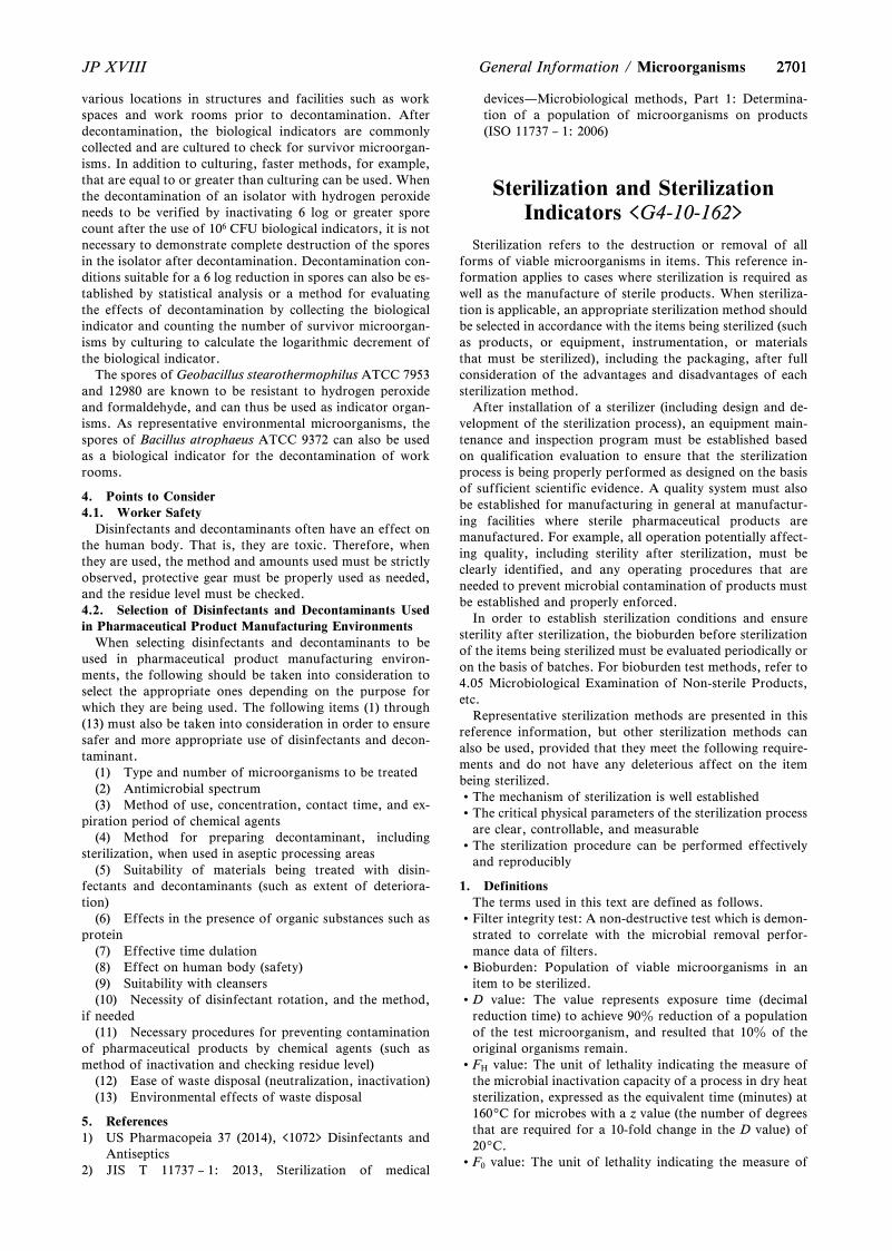
27012701JP XVIII General Information / Microorganisms
various locations in structures and facilities such as workspaces and work rooms prior to decontamination. Afterdecontamination, the biological indicators are commonlycollected and are cultured to check for survivor microorgan-isms. In addition to culturing, faster methods, for example,that are equal to or greater than culturing can be used. Whenthe decontamination of an isolator with hydrogen peroxideneeds to be verified by inactivating 6 log or greater sporecount after the use of 106 CFU biological indicators, it is notnecessary to demonstrate complete destruction of the sporesin the isolator after decontamination. Decontamination con-ditions suitable for a 6 log reduction in spores can also be es-tablished by statistical analysis or a method for evaluatingthe effects of decontamination by collecting the biologicalindicator and counting the number of survivor microorgan-isms by culturing to calculate the logarithmic decrement ofthe biological indicator.
The spores of Geobacillus stearothermophilus ATCC 7953and 12980 are known to be resistant to hydrogen peroxideand formaldehyde, and can thus be used as indicator organ-isms. As representative environmental microorganisms, thespores of Bacillus atrophaeus ATCC 9372 can also be usedas a biological indicator for the decontamination of workrooms.
4. Points to Consider4.1. Worker Safety
Disinfectants and decontaminants often have an effect onthe human body. That is, they are toxic. Therefore, whenthey are used, the method and amounts used must be strictlyobserved, protective gear must be properly used as needed,and the residue level must be checked.4.2. Selection of Disinfectants and Decontaminants Usedin Pharmaceutical Product Manufacturing Environments
When selecting disinfectants and decontaminants to beused in pharmaceutical product manufacturing environ-ments, the following should be taken into consideration toselect the appropriate ones depending on the purpose forwhich they are being used. The following items (1) through(13) must also be taken into consideration in order to ensuresafer and more appropriate use of disinfectants and decon-taminant.
(1) Type and number of microorganisms to be treated(2) Antimicrobial spectrum(3) Method of use, concentration, contact time, and ex-
piration period of chemical agents(4) Method for preparing decontaminant, including
sterilization, when used in aseptic processing areas(5) Suitability of materials being treated with disin-
fectants and decontaminants (such as extent of deteriora-tion)
(6) Effects in the presence of organic substances such asprotein
(7) Effective time dulation(8) Effect on human body (safety)(9) Suitability with cleansers(10) Necessity of disinfectant rotation, and the method,
if needed(11) Necessary procedures for preventing contamination
of pharmaceutical products by chemical agents (such asmethod of inactivation and checking residue level)
(12) Ease of waste disposal (neutralization, inactivation)(13) Environmental effects of waste disposal
5. References1) US Pharmacopeia 37 (2014), <1072> Disinfectants and
Antiseptics2) JIS T 11737 – 1: 2013, Sterilization of medical
devices—Microbiological methods, Part 1: Determina-tion of a population of microorganisms on products(ISO 11737 – 1: 2006)
Sterilization and SterilizationIndicators <G4-10-162>
Sterilization refers to the destruction or removal of allforms of viable microorganisms in items. This reference in-formation applies to cases where sterilization is required aswell as the manufacture of sterile products. When steriliza-tion is applicable, an appropriate sterilization method shouldbe selected in accordance with the items being sterilized (suchas products, or equipment, instrumentation, or materialsthat must be sterilized), including the packaging, after fullconsideration of the advantages and disadvantages of eachsterilization method.
After installation of a sterilizer (including design and de-velopment of the sterilization process), an equipment main-tenance and inspection program must be established basedon qualification evaluation to ensure that the sterilizationprocess is being properly performed as designed on the basisof sufficient scientific evidence. A quality system must alsobe established for manufacturing in general at manufactur-ing facilities where sterile pharmaceutical products aremanufactured. For example, all operation potentially affect-ing quality, including sterility after sterilization, must beclearly identified, and any operating procedures that areneeded to prevent microbial contamination of products mustbe established and properly enforced.
In order to establish sterilization conditions and ensuresterility after sterilization, the bioburden before sterilizationof the items being sterilized must be evaluated periodically oron the basis of batches. For bioburden test methods, refer to4.05 Microbiological Examination of Non-sterile Products,etc.
Representative sterilization methods are presented in thisreference information, but other sterilization methods canalso be used, provided that they meet the following require-ments and do not have any deleterious affect on the itembeing sterilized.The mechanism of sterilization is well establishedThe critical physical parameters of the sterilization process
are clear, controllable, and measurableThe sterilization procedure can be performed effectively
and reproducibly
1. DefinitionsThe terms used in this text are defined as follows.
Filter integrity test: A non-destructive test which is demon-strated to correlate with the microbial removal perfor-mance data of filters.
Bioburden: Population of viable microorganisms in anitem to be sterilized.
D value: The value represents exposure time (decimalreduction time) to achieve 90z reduction of a populationof the test microorganism, and resulted that 10z of theoriginal organisms remain.
FH value: The unit of lethality indicating the measure ofthe microbial inactivation capacity of a process in dry heatsterilization, expressed as the equivalent time (minutes) at1609C for microbes with a z value (the number of degreesthat are required for a 10-fold change in the D value) of209C.
F0 value: The unit of lethality indicating the measure of
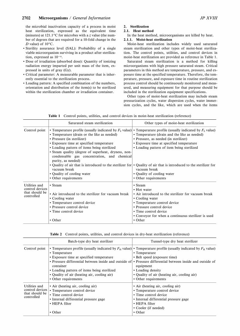
2702
Table 1 Control points, utilities, and control devices in moist-heat sterilization (reference)
Saturated steam sterilization Other types of moist-heat sterilization
Control point Temperature profile (usually indicated by F0 value)Temperature (drain or the like as needed)Pressure (in sterilizer)Exposure time at specified temperatureLoading pattern of items being sterilizedSteam quality (degree of superheat, dryness, non-
condensable gas concentration, and chemicalpurity, as needed)
Quality of air that is introduced to the sterilizer forvacuum break
Quality of cooling waterOther requirements
Temperature profile (usually indicated by F0 value)Temperature (drain and the like as needed)Pressure, as needed (in sterilizer)Exposure time at specified temperatureLoading pattern of item being sterilized
Quality of air that is introduced to the sterilizer forvacuum break
Quality of cooling waterOther requirements
Utilities andcontrol devicesthat should becontrolled
Steam
Air introduced to the sterilizer for vacuum breakCooling waterTemperature control devicePressure control deviceTime control device
Other
SteamHot waterAir introduced to the sterilizer for vacuum breakCooling waterTemperature control devicePressure control deviceTime control deviceConveyor for when a continuous sterilizer is usedOther
Table 2 Control points, utilities, and control devices in dry-heat sterilization (reference)
Batch-type dry heat sterilizer Tunnel-type dry heat sterilizer
Control point Temperature profile (usually indicated by FH value)TemperatureExposure time at specified temperaturePressure differential between inside and outside of
containerLoading pattern of items being sterilizedQuality of air (heating air, cooling air)Other requirements
Temperature profile (usually indicated by FH value)TemperatureBelt speed (exposure time)Pressure differential between inside and outside of
equipmentLoading densityQuality of air (heating air, cooling air)Other requirements
Utilities andcontrol devicesthat should becontrolled
Air (heating air, cooling air)Temperature control deviceTime control deviceInternal differential pressure gageHEPA filter
Other
Air (heating air, cooling air)Temperature control deviceTime control deviceInternal differential pressure gageHEPA filterCooler (if needed)Other
2702 JP XVIIIMicroorganisms / General Information
the microbial inactivation capacity of a process in moistheat sterilization, expressed as the equivalent time(minutes) at 121.19C for microbes with a z value (the num-ber of degrees that are required for a 10-fold change in theD value) of 109C.
Sterility assurance level (SAL): Probability of a singleviable microorganism surviving in a product after steriliza-tion, expressed as 10-n.
Dose of irradiation (absorbed dose): Quantity of ionizingradiation energy imparted per unit mass of the item, ex-pressed in units of gray (Gy).
Critical parameter: A measurable parameter that is inher-ently essential to the sterilization process.
Loading pattern: A specified combination of the numbers,orientation and distribution of the item(s) to be sterilizedwithin the sterilization chamber or irradiation container.
2. Sterilization2.1. Heat method
In the heat method, microorganisms are killed by heat.2.1.1. Moist-heat sterilization
Moist-heat sterilization includes widely used saturatedsteam sterilization and other types of moist-heat steriliza-tion. The control points, utilities, and control devices inmoist-heat sterilization are provided as reference in Table 1.
Saturated steam sterilization is a method for killingmicroorganisms with high pressure saturated steam. Criticalparameters in this method are temperature, pressure, and ex-posure time at the specified temperature. Therefore, the tem-perature, pressure, and exposure time in routine sterilizationprocess control should be continuously monitored and meas-ured, and measuring equipment for that purpose should beincluded in the sterilization equipment specifications.
Other types of moist-heat sterilization may include steampressurization cycles, water dispersion cycles, water immer-sion cycles, and the like, which are used when the items
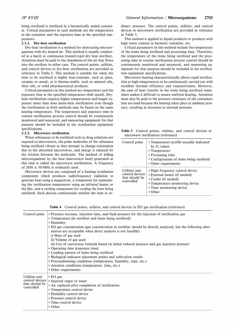
2703
Table 3 Control points, utilities, and control devices inmicrowave sterilization (reference)
Control point Temperature profile (usually indicatedby F0 value)
TemperatureProcessing timeConfiguration of items being sterilizedOther requirements
Utilities andcontrol devicesthat should becontrolled
High frequency control deviceExternal heater (if needed)Cooler (if needed)Temperature monitoring deviceTime monitoring deviceOther
Table 4 Control points, utilities, and control devices in EO gas sterilization (reference)
Control point Pressure increase, injection time, and final pressure for the injection of sterilization gasTemperature (in sterilizer and items being sterilized)HumidityEO gas concentration (gas concentration in sterilizer should be directly analyzed, but the following alter-
natives are acceptable when direct analysis is not feasible)i) Mass of gas usedii) Volume of gas usediii) Use of conversion formula based on initial reduced pressure and gas injection pressure
Operating time (exposure time)Loading pattern of items being sterilizedBiological indicator placement points and cultivation resultsPreconditioning conditions (temperature, humidity, time, etc.)Aeration conditions (temperature, time, etc.)Other requirements
Utilities andcontrol devicesthat should becontrolled
EO gasInjected vapor or waterAir replaced after completion of sterilizationTemperature control deviceHumidity control devicePressure control deviceTime control deviceOther
2703JP XVIII General Information / Microorganisms
being sterilized is sterilized in a hermetically sealed contain-er. Critical parameters in such methods are the temperaturein the container and the exposure time at the specified tem-perature.2.1.2. Dry-heat sterilization
Dry-heat sterilization is a method for destructing microor-ganisms with dry heated air. This method is usually conduct-ed in a batch or continuous (tunnel-type) dry heat sterilizer.Attention must be paid to the cleanliness of the air that flowsinto the sterilizer in either case. The control points, utilities,and control devices in dry-heat sterilization are provided asreference in Table 2. This method is suitable for when theitem to be sterilized is highly heat-resistant, such as glass,ceramic or metal, or is thermo-stable, such as mineral oils,fatty oils, or solid pharmaceutical products.
Critical parameters in this method are temperature and theexposure time at the specified temperature (belt speed). Dry-heat sterilization requires higher temperatures and longer ex-posure times than does moist-heat sterilization even thoughthe sterilization in both methods may be based on the sameheating temperature. The temperature and exposure time inroutine sterilization process control should be continuouslymonitored and measured, and measuring equipment for thatpurpose should be included in the sterilization equipmentspecifications.2.1.3. Microwave sterilization
When substances to be sterilized such as drug solutions areexposed to microwaves, the polar molecules of the substancebeing sterilized vibrate as they attempt to change orientationdue to the absorbed microwaves, and energy is released bythe friction between the molecules. The method of killingmicroorganisms by the heat (microwave heat) generated atthis time is called the microwave sterilization. A frequencyof 2450 ± 50 MHz is ordinarily used.
Microwave devices are composed of a heating irradiationcomponent which produces radiofrequency radiation togenerate heat using a magnetron, a component for maintain-ing the sterilization temperature using an infrared heater orthe like, and a cooling component for cooling the item beingsterilized. Such devices continuously sterilize the item at or-
dinary pressure. The control points, utilities, and controldevices in microwave sterilization are provided as referencein Table 3.
This method is applied to liquid products or products withhigh water content in hermetic container, etc.
Critical parameters in this method include the temperatureof the items being sterilized and processing time. Therefore,the temperature of the items being sterilized and the proc-essing time in routine sterilization process control should becontinuously monitored and measured, and measuring eq-uipment for that purpose should be included in the steriliza-tion equipment specifications.
Microwave heating characteristically allows rapid steriliza-tion at high temperatures to be continuously carried out withexcellent thermal efficiency and responsiveness. However,the ease of heat transfer in the items being sterilized some-times makes it difficult to ensure uniform heating. Attentionmust also be paid to the pressure resistance of the containersthat are used because the heating takes place at ambient pres-sure, resulting in increases in internal pressure.
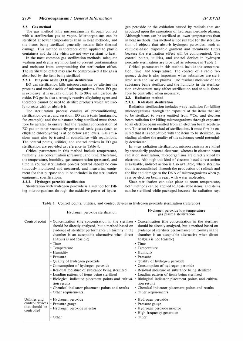
2704
Table 5 Control points, utilities, and control devices in hydrogen peroxide sterilization (reference)
Hydrogen peroxide sterilization Hydrogen peroxide low temperaturegas plasma sterilization
Control point Concentration (the concentration in the sterilizershould be directly analyzed, but a method based onevidence of sterilizer performance uniformity in thechamber is an acceptable alternative when directanalysis is not feasible)
TimeTemperatureHumidityPressureQuality of hydrogen peroxideConsumption of hydrogen peroxideResidual moisture of substance being sterilizedLoading pattern of items being sterilizedBiological indicator placement points and cultiva-
tion resultsChemical indicator placement points and resultsOther requirements
Concentration (the concentration in the sterilizershould be directly analyzed, but a method based onevidence of sterilizer performance uniformity in thechamber is an acceptable alternative when directanalysis is not feasible)
TimeTemperatureHumidityPressureQuality of hydrogen peroxideConsumption of hydrogen peroxideResidual moisture of substance being sterilizedLoading pattern of items being sterilizedBiological indicator placement points and cultiva-
tion resultsChemical indicator placement points and resultsOther requirements
Utilities andcontrol devicesthat should becontrolled
Hydrogen peroxidePressure gaugeHydrogen peroxide injector
Other
Hydrogen peroxidePressure gaugeHydrogen peroxide injectorHigh frequency generatorOther
2704 JP XVIIIMicroorganisms / General Information
2.2. Gas methodThe gas method kills microorganisms through contact
with a sterilization gas or vapor. Microorganisms can besterilized at lower temperatures than in heat methods, andthe items being sterilized generally sustain little thermaldamage. This method is therefore often applied to plasticcontainers and the like which are not very resistant to heat.
In the most common gas sterilization methods, adequatewashing and drying are important to prevent contaminationand moisture from compromising the sterilization effect.The sterilization effect may also be compromised if the gas isabsorbed by the item being sterilized.2.2.1. Ethylene oxide (EO) gas sterilization
EO gas sterilization kills microorganisms by altering theproteins and nucleic acids of microorganisms. Since EO gasis explosive, it is usually diluted 10 to 30z with carbon di-oxide. EO gas is also a strongly reactive alkylating agent andtherefore cannot be used to sterilize products which are like-ly to react with or absorb it.
The sterilization process consists of preconditioning,sterilization cycles, and aeration. EO gas is toxic (mutagenic,for example), and the substance being sterilized must there-fore be aerated to ensure that the residual concentration ofEO gas or other secondarily generated toxic gases (such asethylene chlorohydrin) is at or below safe levels. Gas emis-sions must also be treated in compliance with regulations.The control points, utilities, and control devices in EO gassterilization are provided as reference in Table 4.
Critical parameters in this method include temperature,humidity, gas concentration (pressure), and time. Therefore,the temperature, humidity, gas concentration (pressure), andtime in routine sterilization process control should be con-tinuously monitored and measured, and measuring equip-ment for that purpose should be included in the sterilizationequipment specifications.2.2.2. Hydrogen peroxide sterilization
Sterilization with hydrogen peroxide is a method for kill-ing microorganisms through the oxidative power of hydro-
gen peroxide or the oxidation caused by radicals that areproduced upon the generation of hydrogen peroxide plasma.Although items can be sterilized at lower temperatures thanin heat methods, this method is not suitable for the steriliza-tion of objects that absorb hydrogen peroxides, such ascellulose-based disposable garment and membrane filtersbecause the sterilization effect will be compromised. Thecontrol points, utilities, and control devices in hydrogenperoxide sterilization are provided as reference in Table 5.
Critical parameters in this method include the concentra-tion, time, and temperature. The control of a radio fre-quency device is also important when substances are steri-lized with the use of plasma. The residual moisture of thesubstance being sterilized and the humidity in the steriliza-tion environment may affect sterilization and should there-fore be controlled when necessary.2.3. Radiation method2.3.1. Radiation sterilization
Radiation sterilization includes g-ray radiation for killingmicroorganisms through the exposure of the items that areto be sterilized to g-rays emitted from 60Co, and electronbeam radiation for killing microorganisms through exposureto an electron beam emitted from an electron beam accelera-tor. To select the method of sterilization, it must first be en-sured that it is compatible with the items to be sterilized, in-cluding whether the quality of the substance could potential-ly deteriorate.
In g-ray radiation sterilization, microorganisms are killedby secondarily produced electrons, whereas in electron beamradiation sterilization, microorganisms are directly killed byelectrons. Although this kind of electron-based direct actionis available, indirect action is also available, where steriliza-tion is accomplished through the production of radicals andthe like and damage to the DNA of microorganisms when g-rays or electron beams react with water molecules.
Since sterilization can take place at room temperature,both methods can be applied to heat-labile items, and itemscan be sterilized while packaged because the radiation rays
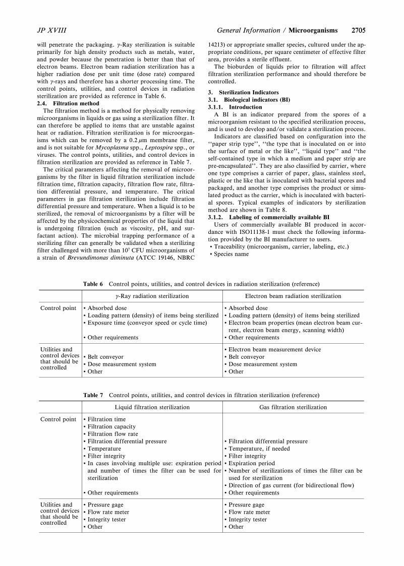
2705
Table 6 Control points, utilities, and control devices in radiation sterilization (reference)
g-Ray radiation sterilization Electron beam radiation sterilization
Control point Absorbed doseLoading pattern (density) of items being sterilizedExposure time (conveyor speed or cycle time)
Other requirements
Absorbed doseLoading pattern (density) of items being sterilizedElectron beam properties (mean electron beam cur-
rent, electron beam energy, scanning width)Other requirements
Utilities andcontrol devicesthat should becontrolled
Belt conveyorDose measurement systemOther
Electron beam measurement deviceBelt conveyorDose measurement systemOther
Table 7 Control points, utilities, and control devices in filtration sterilization (reference)
Liquid filtration sterilization Gas filtration sterilization
Control point Filtration timeFiltration capacityFiltration flow rateFiltration differential pressureTemperatureFilter integrityIn cases involving multiple use: expiration period
and number of times the filter can be used forsterilization
Other requirements
Filtration differential pressureTemperature, if neededFilter integrityExpiration periodNumber of sterilizations of times the filter can be
used for sterilizationDirection of gas current (for bidirectional flow)Other requirements
Utilities andcontrol devicesthat should becontrolled
Pressure gageFlow rate meterIntegrity testerOther
Pressure gageFlow rate meterIntegrity testerOther
2705JP XVIII General Information / Microorganisms
will penetrate the packaging. g-Ray sterilization is suitableprimarily for high density products such as metals, water,and powder because the penetration is better than that ofelectron beams. Electron beam radiation sterilization has ahigher radiation dose per unit time (dose rate) comparedwith g-rays and therefore has a shorter processing time. Thecontrol points, utilities, and control devices in radiationsterilization are provided as reference in Table 6.2.4. Filtration method
The filtration method is a method for physically removingmicroorganisms in liquids or gas using a sterilization filter. Itcan therefore be applied to items that are unstable againstheat or radiation. Filtration sterilization is for microorgan-isms which can be removed by a 0.2 mm membrane filter,and is not suitable for Mycoplasma spp., Leptospira spp., orviruses. The control points, utilities, and control devices infiltration sterilization are provided as reference in Table 7.
The critical parameters affecting the removal of microor-ganisms by the filter in liquid filtration sterilization includefiltration time, filtration capacity, filtration flow rate, filtra-tion differential pressure, and temperature. The criticalparameters in gas filtration sterilization include filtrationdifferential pressure and temperature. When a liquid is to besterilized, the removal of microorganisms by a filter will beaffected by the physicochemical properties of the liquid thatis undergoing filtration (such as viscosity, pH, and sur-factant action). The microbial trapping performance of asterilizing filter can generally be validated when a sterilizingfilter challenged with more than 107 CFU microorganisms ofa strain of Brevundimonas diminuta (ATCC 19146, NBRC
14213) or appropriate smaller species, cultured under the ap-propriate conditions, per square centimeter of effective filterarea, provides a sterile effluent.
The bioburden of liquids prior to filtration will affectfiltration sterilization performance and should therefore becontrolled.
3. Sterilization Indicators3.1. Biological indicators (BI)3.1.1. Introduction
A BI is an indicator prepared from the spores of amicroorganism resistant to the specified sterilization process,and is used to develop and/or validate a sterilization process.
Indicators are classified based on configuration into the``paper strip type'', ``the type that is inoculated on or intothe surface of metal or the like'', ``liquid type'' and ``theself-contained type in which a medium and paper strip arepre-encapsulated''. They are also classified by carrier, whereone type comprises a carrier of paper, glass, stainless steel,plastic or the like that is inoculated with bacterial spores andpackaged, and another type comprises the product or simu-lated product as the carrier, which is inoculated with bacteri-al spores. Typical examples of indicators by sterilizationmethod are shown in Table 8.3.1.2. Labeling of commercially available BI
Users of commercially available BI produced in accor-dance with ISO11138-1 must check the following informa-tion provided by the BI manufacturer to users.Traceability (microorganism, carrier, labeling, etc.)Species name
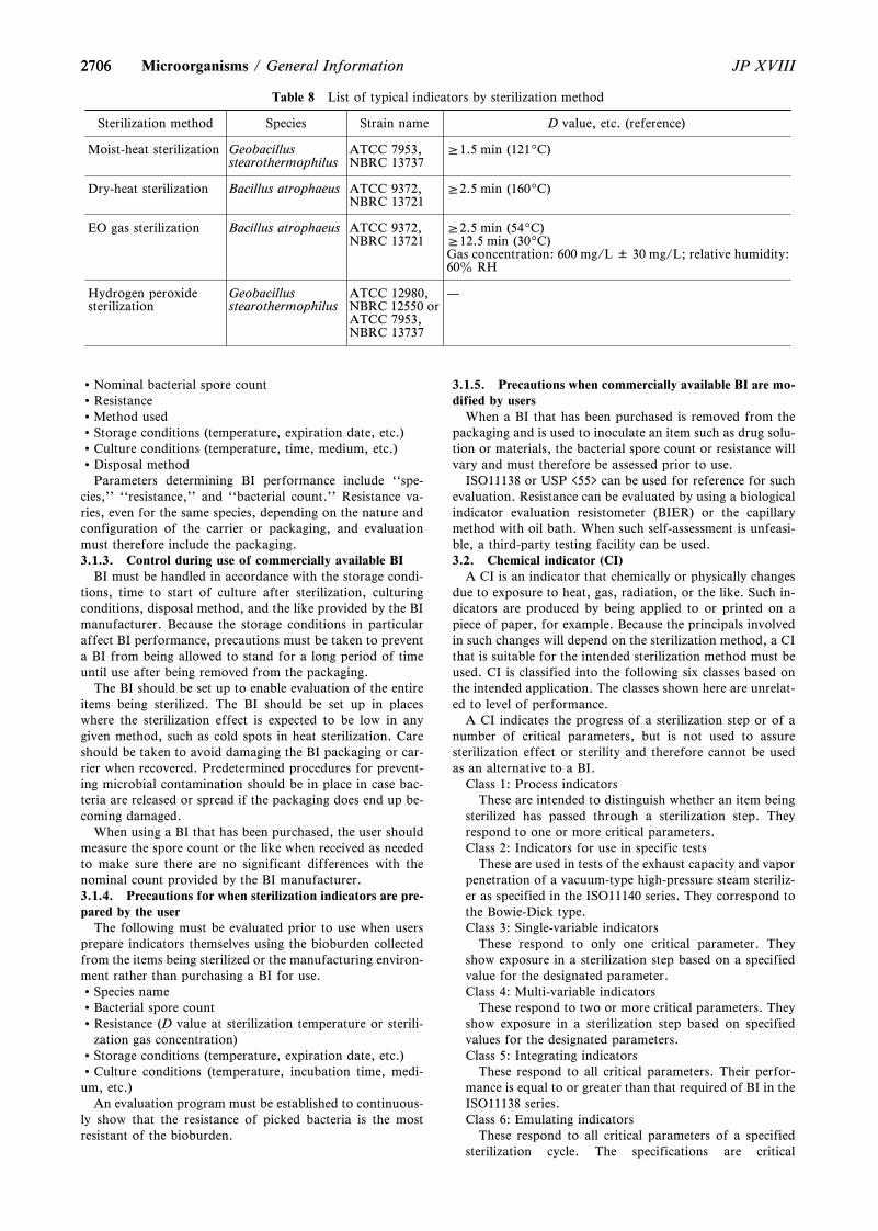
2706
Table 8 List of typical indicators by sterilization method
Sterilization method Species Strain name D value, etc. (reference)
Moist-heat sterilization Geobacillusstearothermophilus
ATCC 7953,NBRC 13737
Æ1.5 min (1219C)
Dry-heat sterilization Bacillus atrophaeus ATCC 9372,NBRC 13721
Æ2.5 min (1609C)
EO gas sterilization Bacillus atrophaeus ATCC 9372,NBRC 13721
Æ2.5 min (549C)Æ12.5 min (309C)Gas concentration: 600 mg/L ± 30 mg/L; relative humidity:60z RH
Hydrogen peroxidesterilization
Geobacillusstearothermophilus
ATCC 12980,NBRC 12550 orATCC 7953,NBRC 13737
—
2706 JP XVIIIMicroorganisms / General Information
Nominal bacterial spore countResistanceMethod usedStorage conditions (temperature, expiration date, etc.)Culture conditions (temperature, time, medium, etc.)Disposal method
Parameters determining BI performance include ``spe-cies,'' ``resistance,'' and ``bacterial count.'' Resistance va-ries, even for the same species, depending on the nature andconfiguration of the carrier or packaging, and evaluationmust therefore include the packaging.3.1.3. Control during use of commercially available BI
BI must be handled in accordance with the storage condi-tions, time to start of culture after sterilization, culturingconditions, disposal method, and the like provided by the BImanufacturer. Because the storage conditions in particularaffect BI performance, precautions must be taken to preventa BI from being allowed to stand for a long period of timeuntil use after being removed from the packaging.
The BI should be set up to enable evaluation of the entireitems being sterilized. The BI should be set up in placeswhere the sterilization effect is expected to be low in anygiven method, such as cold spots in heat sterilization. Careshould be taken to avoid damaging the BI packaging or car-rier when recovered. Predetermined procedures for prevent-ing microbial contamination should be in place in case bac-teria are released or spread if the packaging does end up be-coming damaged.
When using a BI that has been purchased, the user shouldmeasure the spore count or the like when received as neededto make sure there are no significant differences with thenominal count provided by the BI manufacturer.3.1.4. Precautions for when sterilization indicators are pre-pared by the user
The following must be evaluated prior to use when usersprepare indicators themselves using the bioburden collectedfrom the items being sterilized or the manufacturing environ-ment rather than purchasing a BI for use.Species nameBacterial spore countResistance (D value at sterilization temperature or sterili-
zation gas concentration)Storage conditions (temperature, expiration date, etc.)Culture conditions (temperature, incubation time, medi-um, etc.)
An evaluation program must be established to continuous-ly show that the resistance of picked bacteria is the mostresistant of the bioburden.
3.1.5. Precautions when commercially available BI are mo-dified by users
When a BI that has been purchased is removed from thepackaging and is used to inoculate an item such as drug solu-tion or materials, the bacterial spore count or resistance willvary and must therefore be assessed prior to use.
ISO11138 or USP <55> can be used for reference for suchevaluation. Resistance can be evaluated by using a biologicalindicator evaluation resistometer (BIER) or the capillarymethod with oil bath. When such self-assessment is unfeasi-ble, a third-party testing facility can be used.3.2. Chemical indicator (CI)
A CI is an indicator that chemically or physically changesdue to exposure to heat, gas, radiation, or the like. Such in-dicators are produced by being applied to or printed on apiece of paper, for example. Because the principals involvedin such changes will depend on the sterilization method, a CIthat is suitable for the intended sterilization method must beused. CI is classified into the following six classes based onthe intended application. The classes shown here are unrelat-ed to level of performance.
A CI indicates the progress of a sterilization step or of anumber of critical parameters, but is not used to assuresterilization effect or sterility and therefore cannot be usedas an alternative to a BI.
Class 1: Process indicatorsThese are intended to distinguish whether an item being
sterilized has passed through a sterilization step. Theyrespond to one or more critical parameters.Class 2: Indicators for use in specific tests
These are used in tests of the exhaust capacity and vaporpenetration of a vacuum-type high-pressure steam steriliz-er as specified in the ISO11140 series. They correspond tothe Bowie-Dick type.Class 3: Single-variable indicators
These respond to only one critical parameter. Theyshow exposure in a sterilization step based on a specifiedvalue for the designated parameter.Class 4: Multi-variable indicators
These respond to two or more critical parameters. Theyshow exposure in a sterilization step based on specifiedvalues for the designated parameters.Class 5: Integrating indicators
These respond to all critical parameters. Their perfor-mance is equal to or greater than that required of BI in theISO11138 series.Class 6: Emulating indicators
These respond to all critical parameters of a specifiedsterilization cycle. The specifications are critical
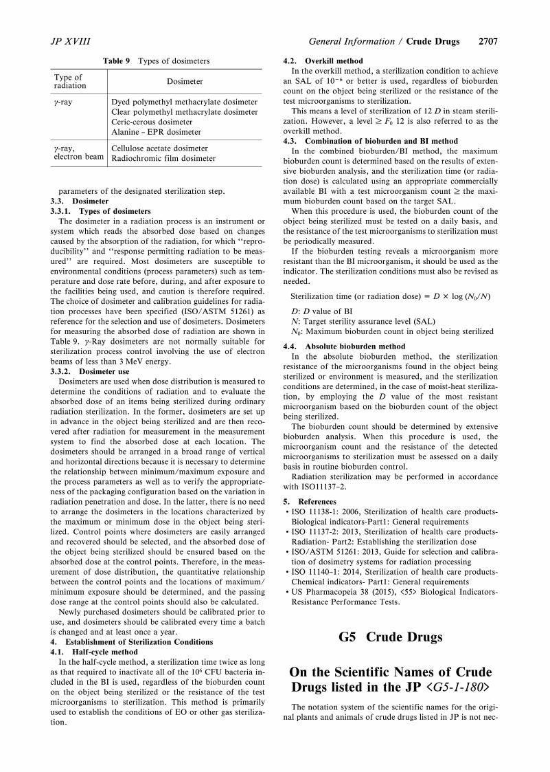
2707
Table 9 Types of dosimeters
Type ofradiation Dosimeter
g-ray Dyed polymethyl methacrylate dosimeterClear polymethyl methacrylate dosimeterCeric-cerous dosimeterAlanine – EPR dosimeter
g-ray,electron beam
Cellulose acetate dosimeterRadiochromic film dosimeter
2707JP XVIII General Information / Crude Drugs
parameters of the designated sterilization step.3.3. Dosimeter3.3.1. Types of dosimeters
The dosimeter in a radiation process is an instrument orsystem which reads the absorbed dose based on changescaused by the absorption of the radiation, for which ``repro-ducibility'' and ``response permitting radiation to be meas-ured'' are required. Most dosimeters are susceptible toenvironmental conditions (process parameters) such as tem-perature and dose rate before, during, and after exposure tothe facilities being used, and caution is therefore required.The choice of dosimeter and calibration guidelines for radia-tion processes have been specified (ISO/ASTM 51261) asreference for the selection and use of dosimeters. Dosimetersfor measuring the absorbed dose of radiation are shown inTable 9. g-Ray dosimeters are not normally suitable forsterilization process control involving the use of electronbeams of less than 3 MeV energy.3.3.2. Dosimeter use
Dosimeters are used when dose distribution is measured todetermine the conditions of radiation and to evaluate theabsorbed dose of an items being sterilized during ordinaryradiation sterilization. In the former, dosimeters are set upin advance in the object being sterilized and are then reco-vered after radiation for measurement in the measurementsystem to find the absorbed dose at each location. Thedosimeters should be arranged in a broad range of verticaland horizontal directions because it is necessary to determinethe relationship between minimum/maximum exposure andthe process parameters as well as to verify the appropriate-ness of the packaging configuration based on the variation inradiation penetration and dose. In the latter, there is no needto arrange the dosimeters in the locations characterized bythe maximum or minimum dose in the object being steri-lized. Control points where dosimeters are easily arrangedand recovered should be selected, and the absorbed dose ofthe object being sterilized should be ensured based on theabsorbed dose at the control points. Therefore, in the meas-urement of dose distribution, the quantitative relationshipbetween the control points and the locations of maximum/minimum exposure should be determined, and the passingdose range at the control points should also be calculated.
Newly purchased dosimeters should be calibrated prior touse, and dosimeters should be calibrated every time a batchis changed and at least once a year.4. Establishment of Sterilization Conditions4.1. Half-cycle method
In the half-cycle method, a sterilization time twice as longas that required to inactivate all of the 106 CFU bacteria in-cluded in the BI is used, regardless of the bioburden counton the object being sterilized or the resistance of the testmicroorganisms to sterilization. This method is primarilyused to establish the conditions of EO or other gas steriliza-tion.
4.2. Overkill methodIn the overkill method, a sterilization condition to achieve
an SAL of 10-6 or better is used, regardless of bioburdencount on the object being sterilized or the resistance of thetest microorganisms to sterilization.
This means a level of sterilization of 12 D in steam sterili-zation. However, a level F0 12 is also referred to as theoverkill method.4.3. Combination of bioburden and BI method
In the combined bioburden/BI method, the maximumbioburden count is determined based on the results of exten-sive bioburden analysis, and the sterilization time (or radia-tion dose) is calculated using an appropriate commerciallyavailable BI with a test microorganism count the maxi-mum bioburden count based on the target SAL.
When this procedure is used, the bioburden count of theobject being sterilized must be tested on a daily basis, andthe resistance of the test microorganisms to sterilization mustbe periodically measured.
If the bioburden testing reveals a microorganism moreresistant than the BI microorganism, it should be used as theindicator. The sterilization conditions must also be revised asneeded.
Sterilization time (or radiation dose) = D × log (N0/N)
D: D value of BIN: Target sterility assurance level (SAL)N0: Maximum bioburden count in object being sterilized
4.4. Absolute bioburden methodIn the absolute bioburden method, the sterilization
resistance of the microorganisms found in the object beingsterilized or environment is measured, and the sterilizationconditions are determined, in the case of moist-heat steriliza-tion, by employing the D value of the most resistantmicroorganism based on the bioburden count of the objectbeing sterilized.
The bioburden count should be determined by extensivebioburden analysis. When this procedure is used, themicroorganism count and the resistance of the detectedmicroorganisms to sterilization must be assessed on a dailybasis in routine bioburden control.
Radiation sterilization may be performed in accordancewith ISO11137–2.
5. ReferencesISO 11138-1: 2006, Sterilization of health care products-
Biological indicators-Part1: General requirementsISO 11137-2: 2013, Sterilization of health care products-
Radiation- Part2: Establishing the sterilization doseISO/ASTM 51261: 2013, Guide for selection and calibra-
tion of dosimetry systems for radiation processingISO 11140–1: 2014, Sterilization of health care products-
Chemical indicators- Part1: General requirementsUS Pharmacopeia 38 (2015), <55> Biological Indicators-
Resistance Performance Tests.
G5 Crude Drugs
On the Scientific Names of CrudeDrugs listed in the JP <G5-1-180>
The notation system of the scientific names for the origi-nal plants and animals of crude drugs listed in JP is not nec-
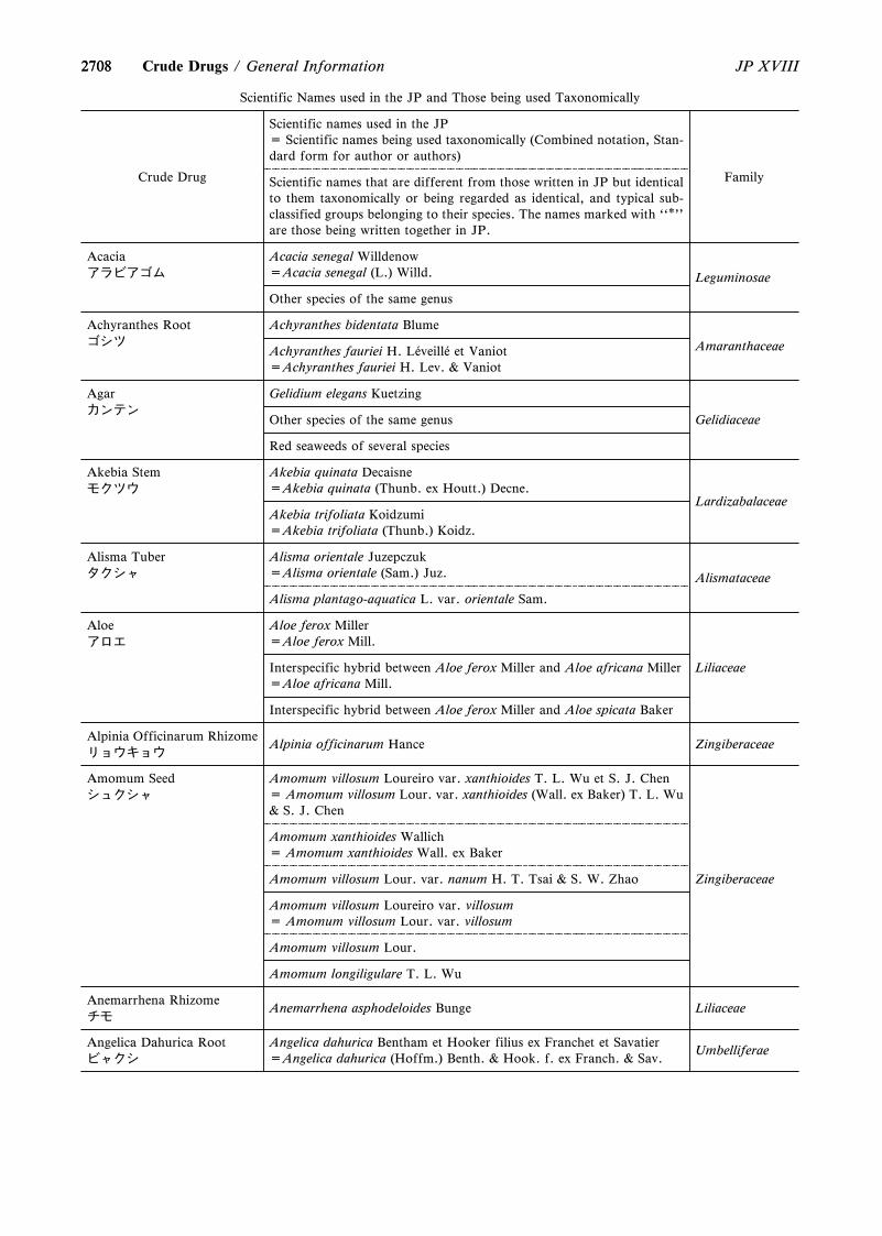
2708
Scientific Names used in the JP and Those being used Taxonomically
Crude Drug
Scientific names used in the JP= Scientific names being used taxonomically (Combined notation, Stan-dard form for author or authors)
FamilyScientific names that are different from those written in JP but identicalto them taxonomically or being regarded as identical, and typical sub-classified groups belonging to their species. The names marked with ``*''are those being written together in JP.
Acaciaアラビアゴム
Acacia senegal Willdenow=Acacia senegal (L.) Willd. Leguminosae
Other species of the same genus
Achyranthes Rootゴシツ
Achyranthes bidentata Blume
AmaranthaceaeAchyranthes fauriei H. L áeveill áe et Vaniot=Achyranthes fauriei H. Lev. & Vaniot
Agarカンテン
Gelidium elegans Kuetzing
GelidiaceaeOther species of the same genus
Red seaweeds of several species
Akebia Stemモクツウ
Akebia quinata Decaisne=Akebia quinata (Thunb. ex Houtt.) Decne.
LardizabalaceaeAkebia trifoliata Koidzumi=Akebia trifoliata (Thunb.) Koidz.
Alisma Tuberタクシャ
Alisma orientale Juzepczuk=Alisma orientale (Sam.) Juz. Alismataceae
Alisma plantago-aquatica L. var. orientale Sam.
Aloeアロエ
Aloe ferox Miller=Aloe ferox Mill.
LiliaceaeInterspecific hybrid between Aloe ferox Miller and Aloe africana Miller=Aloe africana Mill.
Interspecific hybrid between Aloe ferox Miller and Aloe spicata Baker
Alpinia Officinarum Rhizomeリョウキョウ
Alpinia officinarum Hance Zingiberaceae
Amomum Seedシュクシャ
Amomum villosum Loureiro var. xanthioides T. L. Wu et S. J. Chen= Amomum villosum Lour. var. xanthioides (Wall. ex Baker) T. L. Wu& S. J. Chen
Zingiberaceae
Amomum xanthioides Wallich= Amomum xanthioides Wall. ex Baker
Amomum villosum Lour. var. nanum H. T. Tsai & S. W. Zhao
Amomum villosum Loureiro var. villosum= Amomum villosum Lour. var. villosum
Amomum villosum Lour.
Amomum longiligulare T. L. Wu
Anemarrhena Rhizomeチモ
Anemarrhena asphodeloides Bunge Liliaceae
Angelica Dahurica Rootビャクシ
Angelica dahurica Bentham et Hooker filius ex Franchet et Savatier=Angelica dahurica (Hoffm.) Benth. & Hook. f. ex Franch. & Sav.
Umbelliferae
2708 JP XVIIICrude Drugs / General Information
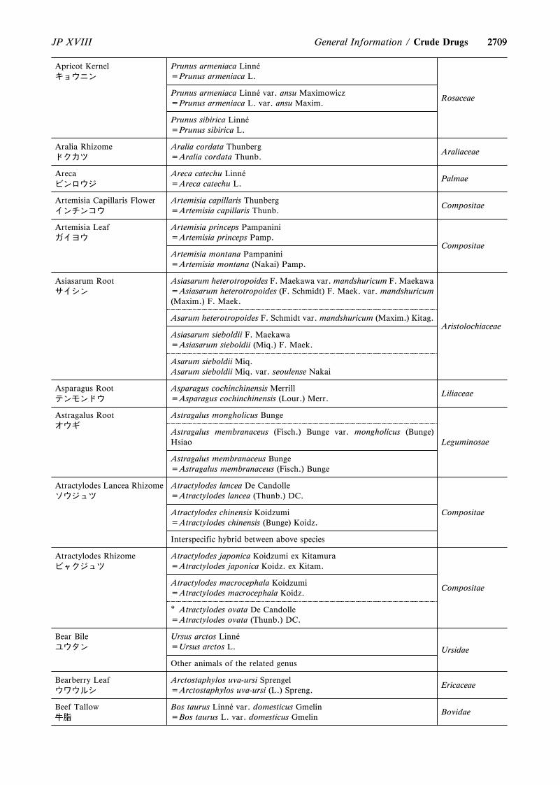
2709
Apricot Kernelキョウニン
Prunus armeniaca Linn áe=Prunus armeniaca L.
RosaceaePrunus armeniaca Linn áe var. ansu Maximowicz=Prunus armeniaca L. var. ansu Maxim.
Prunus sibirica Linn áe=Prunus sibirica L.
Aralia Rhizomeドクカツ
Aralia cordata Thunberg=Aralia cordata Thunb.
Araliaceae
Arecaビンロウジ
Areca catechu Linn áe=Areca catechu L.
Palmae
Artemisia Capillaris Flowerインチンコウ
Artemisia capillaris Thunberg=Artemisia capillaris Thunb.
Compositae
Artemisia Leafガイヨウ
Artemisia princeps Pampanini=Artemisia princeps Pamp.
CompositaeArtemisia montana Pampanini=Artemisia montana (Nakai) Pamp.
Asiasarum Rootサイシン
Asiasarum heterotropoides F. Maekawa var. mandshuricum F. Maekawa=Asiasarum heterotropoides (F. Schmidt) F. Maek. var. mandshuricum(Maxim.) F. Maek.
AristolochiaceaeAsarum heterotropoides F. Schmidt var. mandshuricum (Maxim.) Kitag.
Asiasarum sieboldii F. Maekawa=Asiasarum sieboldii (Miq.) F. Maek.
Asarum sieboldii Miq.Asarum sieboldii Miq. var. seoulense Nakai
Asparagus Rootテンモンドウ
Asparagus cochinchinensis Merrill=Asparagus cochinchinensis (Lour.) Merr.
Liliaceae
Astragalus Rootオウギ
Astragalus mongholicus Bunge
LeguminosaeAstragalus membranaceus (Fisch.) Bunge var. mongholicus (Bunge)Hsiao
Astragalus membranaceus Bunge=Astragalus membranaceus (Fisch.) Bunge
Atractylodes Lancea Rhizomeソウジュツ
Atractylodes lancea De Candolle=Atractylodes lancea (Thunb.) DC.
CompositaeAtractylodes chinensis Koidzumi=Atractylodes chinensis (Bunge) Koidz.
Interspecific hybrid between above species
Atractylodes Rhizomeビャクジュツ
Atractylodes japonica Koidzumi ex Kitamura=Atractylodes japonica Koidz. ex Kitam.
CompositaeAtractylodes macrocephala Koidzumi=Atractylodes macrocephala Koidz.
* Atractylodes ovata De Candolle=Atractylodes ovata (Thunb.) DC.
Bear Bileユウタン
Ursus arctos Linn áe=Ursus arctos L. Ursidae
Other animals of the related genus
Bearberry Leafウワウルシ
Arctostaphylos uva-ursi Sprengel=Arctostaphylos uva-ursi (L.) Spreng.
Ericaceae
Beef Tallow牛脂
Bos taurus Linn áe var. domesticus Gmelin=Bos taurus L. var. domesticus Gmelin
Bovidae
2709JP XVIII General Information / Crude Drugs
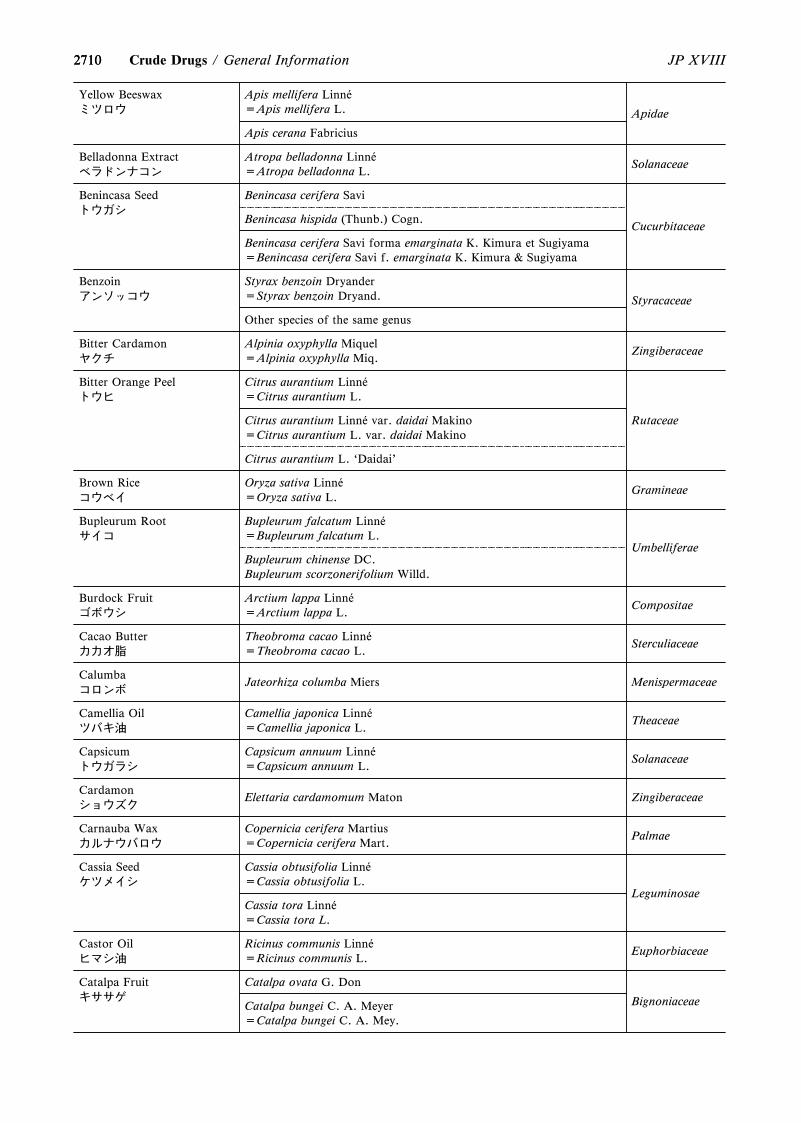
2710
Yellow Beeswaxミツロウ
Apis mellifera Linn áe=Apis mellifera L. Apidae
Apis cerana Fabricius
Belladonna Extractベラドンナコン
Atropa belladonna Linn áe=Atropa belladonna L.
Solanaceae
Benincasa Seedトウガシ
Benincasa cerifera Savi
CucurbitaceaeBenincasa hispida (Thunb.) Cogn.
Benincasa cerifera Savi forma emarginata K. Kimura et Sugiyama=Benincasa cerifera Savi f. emarginata K. Kimura & Sugiyama
Benzoinアンソッコウ
Styrax benzoin Dryander=Styrax benzoin Dryand. Styracaceae
Other species of the same genus
Bitter Cardamonヤクチ
Alpinia oxyphylla Miquel=Alpinia oxyphylla Miq.
Zingiberaceae
Bitter Orange Peelトウヒ
Citrus aurantium Linn áe=Citrus aurantium L.
RutaceaeCitrus aurantium Linn áe var. daidai Makino=Citrus aurantium L. var. daidai Makino
Citrus aurantium L. `Daidai'
Brown Riceコウベイ
Oryza sativa Linn áe=Oryza sativa L.
Gramineae
Bupleurum Rootサイコ
Bupleurum falcatum Linn áe=Bupleurum falcatum L.
UmbelliferaeBupleurum chinense DC.Bupleurum scorzonerifolium Willd.
Burdock Fruitゴボウシ
Arctium lappa Linn áe=Arctium lappa L.
Compositae
Cacao Butterカカオ脂
Theobroma cacao Linn áe=Theobroma cacao L.
Sterculiaceae
Calumbaコロンボ
Jateorhiza columba Miers Menispermaceae
Camellia Oilツバキ油
Camellia japonica Linn áe=Camellia japonica L.
Theaceae
Capsicumトウガラシ
Capsicum annuum Linn áe=Capsicum annuum L.
Solanaceae
Cardamonショウズク
Elettaria cardamomum Maton Zingiberaceae
Carnauba Waxカルナウバロウ
Copernicia cerifera Martius=Copernicia cerifera Mart.
Palmae
Cassia Seedケツメイシ
Cassia obtusifolia Linn áe=Cassia obtusifolia L.
LeguminosaeCassia tora Linn áe=Cassia tora L.
Castor Oilヒマシ油
Ricinus communis Linn áe=Ricinus communis L.
Euphorbiaceae
Catalpa Fruitキササゲ
Catalpa ovata G. Don
BignoniaceaeCatalpa bungei C. A. Meyer=Catalpa bungei C. A. Mey.
2710 JP XVIIICrude Drugs / General Information
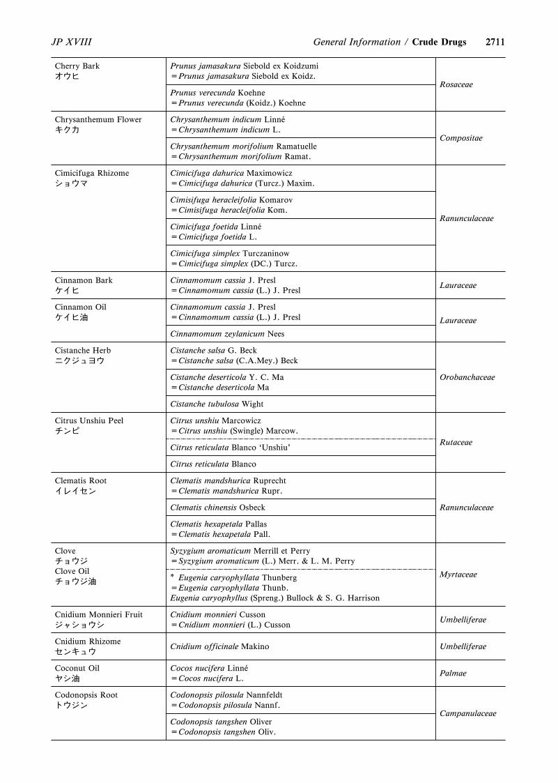
2711
Cherry Barkオウヒ
Prunus jamasakura Siebold ex Koidzumi=Prunus jamasakura Siebold ex Koidz.
RosaceaePrunus verecunda Koehne=Prunus verecunda (Koidz.) Koehne
Chrysanthemum Flowerキクカ
Chrysanthemum indicum Linn áe=Chrysanthemum indicum L.
CompositaeChrysanthemum morifolium Ramatuelle=Chrysanthemum morifolium Ramat.
Cimicifuga Rhizomeショウマ
Cimicifuga dahurica Maximowicz=Cimicifuga dahurica (Turcz.) Maxim.
Ranunculaceae
Cimisifuga heracleifolia Komarov=Cimisifuga heracleifolia Kom.
Cimicifuga foetida Linn áe=Cimicifuga foetida L.
Cimicifuga simplex Turczaninow=Cimicifuga simplex (DC.) Turcz.
Cinnamon Barkケイヒ
Cinnamomum cassia J. Presl=Cinnamomum cassia (L.) J. Presl
Lauraceae
Cinnamon Oilケイヒ油
Cinnamomum cassia J. Presl=Cinnamomum cassia (L.) J. Presl Lauraceae
Cinnamomum zeylanicum Nees
Cistanche Herbニクジュヨウ
Cistanche salsa G. Beck=Cistanche salsa (C.A.Mey.) Beck
OrobanchaceaeCistanche deserticola Y. C. Ma=Cistanche deserticola Ma
Cistanche tubulosa Wight
Citrus Unshiu Peelチンピ
Citrus unshiu Marcowicz=Citrus unshiu (Swingle) Marcow.
RutaceaeCitrus reticulata Blanco `Unshiu'
Citrus reticulata Blanco
Clematis Rootイレイセン
Clematis mandshurica Ruprecht=Clematis mandshurica Rupr.
RanunculaceaeClematis chinensis Osbeck
Clematis hexapetala Pallas=Clematis hexapetala Pall.
CloveチョウジClove Oilチョウジ油
Syzygium aromaticum Merrill et Perry=Syzygium aromaticum (L.) Merr. & L. M. Perry
Myrtaceae* Eugenia caryophyllata Thunberg=Eugenia caryophyllata Thunb.Eugenia caryophyllus (Spreng.) Bullock & S. G. Harrison
Cnidium Monnieri Fruitジャショウシ
Cnidium monnieri Cusson=Cnidium monnieri (L.) Cusson
Umbelliferae
Cnidium Rhizomeセンキュウ
Cnidium officinale Makino Umbelliferae
Coconut Oilヤシ油
Cocos nucifera Linn áe=Cocos nucifera L.
Palmae
Codonopsis Rootトウジン
Codonopsis pilosula Nannfeldt=Codonopsis pilosula Nannf.
CampanulaceaeCodonopsis tangshen Oliver=Codonopsis tangshen Oliv.
2711JP XVIII General Information / Crude Drugs
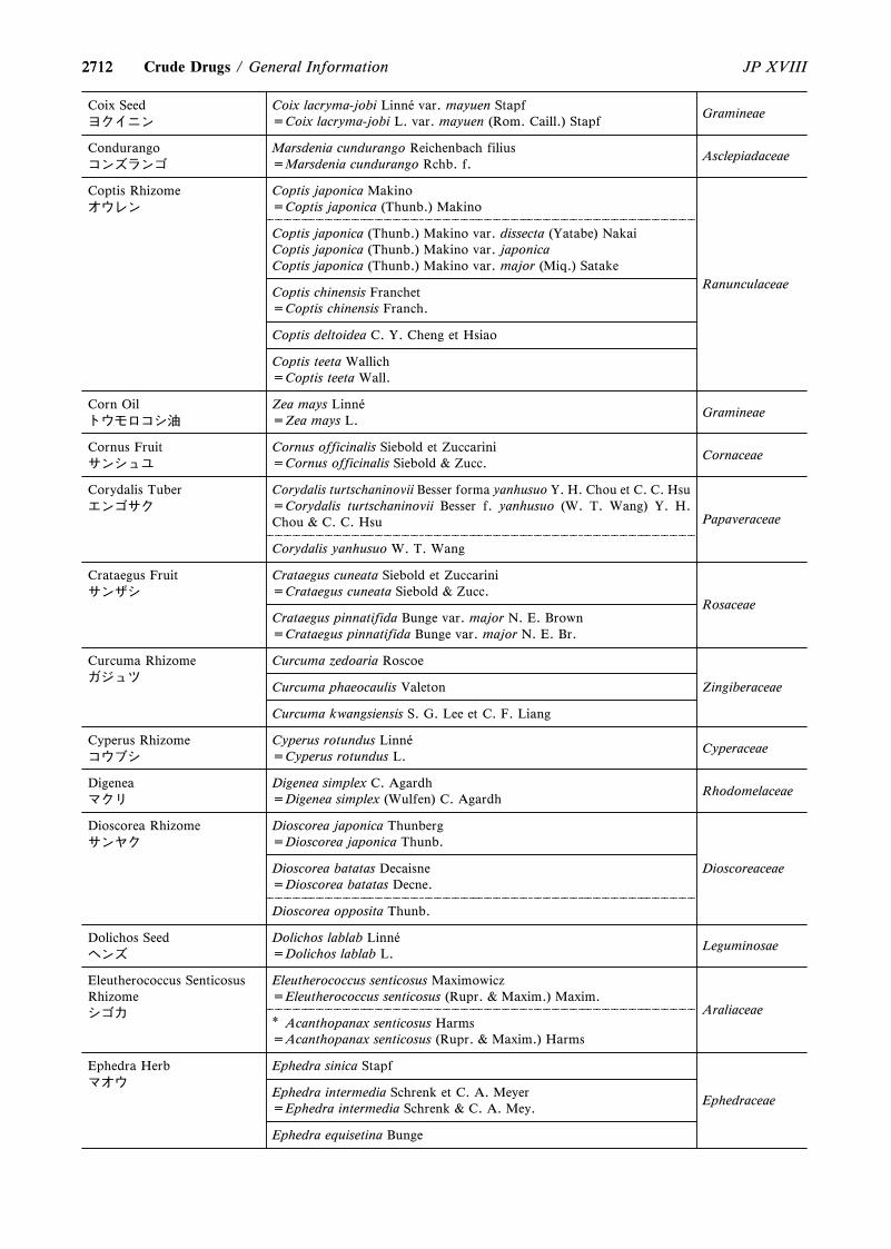
2712
Coix Seedヨクイニン
Coix lacryma-jobi Linn áe var. mayuen Stapf=Coix lacryma-jobi L. var. mayuen (Rom. Caill.) Stapf
Gramineae
Condurangoコンズランゴ
Marsdenia cundurango Reichenbach filius=Marsdenia cundurango Rchb. f.
Asclepiadaceae
Coptis Rhizomeオウレン
Coptis japonica Makino=Coptis japonica (Thunb.) Makino
Ranunculaceae
Coptis japonica (Thunb.) Makino var. dissecta (Yatabe) NakaiCoptis japonica (Thunb.) Makino var. japonicaCoptis japonica (Thunb.) Makino var. major (Miq.) Satake
Coptis chinensis Franchet=Coptis chinensis Franch.
Coptis deltoidea C. Y. Cheng et Hsiao
Coptis teeta Wallich=Coptis teeta Wall.
Corn Oilトウモロコシ油
Zea mays Linn áe=Zea mays L.
Gramineae
Cornus Fruitサンシュユ
Cornus officinalis Siebold et Zuccarini=Cornus officinalis Siebold & Zucc.
Cornaceae
Corydalis Tuberエンゴサク
Corydalis turtschaninovii Besser forma yanhusuo Y. H. Chou et C. C. Hsu=Corydalis turtschaninovii Besser f. yanhusuo (W. T. Wang) Y. H.Chou & C. C. Hsu Papaveraceae
Corydalis yanhusuo W. T. Wang
Crataegus Fruitサンザシ
Crataegus cuneata Siebold et Zuccarini=Crataegus cuneata Siebold & Zucc.
RosaceaeCrataegus pinnatifida Bunge var. major N. E. Brown=Crataegus pinnatifida Bunge var. major N. E. Br.
Curcuma Rhizomeガジュツ
Curcuma zedoaria Roscoe
ZingiberaceaeCurcuma phaeocaulis Valeton
Curcuma kwangsiensis S. G. Lee et C. F. Liang
Cyperus Rhizomeコウブシ
Cyperus rotundus Linn áe=Cyperus rotundus L.
Cyperaceae
Digeneaマクリ
Digenea simplex C. Agardh=Digenea simplex (Wulfen) C. Agardh
Rhodomelaceae
Dioscorea Rhizomeサンヤク
Dioscorea japonica Thunberg=Dioscorea japonica Thunb.
DioscoreaceaeDioscorea batatas Decaisne=Dioscorea batatas Decne.
Dioscorea opposita Thunb.
Dolichos Seedヘンズ
Dolichos lablab Linn áe=Dolichos lablab L.
Leguminosae
Eleutherococcus SenticosusRhizomeシゴカ
Eleutherococcus senticosus Maximowicz=Eleutherococcus senticosus (Rupr. & Maxim.) Maxim.
Araliaceae* Acanthopanax senticosus Harms=Acanthopanax senticosus (Rupr. & Maxim.) Harms
Ephedra Herbマオウ
Ephedra sinica Stapf
EphedraceaeEphedra intermedia Schrenk et C. A. Meyer=Ephedra intermedia Schrenk & C. A. Mey.
Ephedra equisetina Bunge
2712 JP XVIIICrude Drugs / General Information
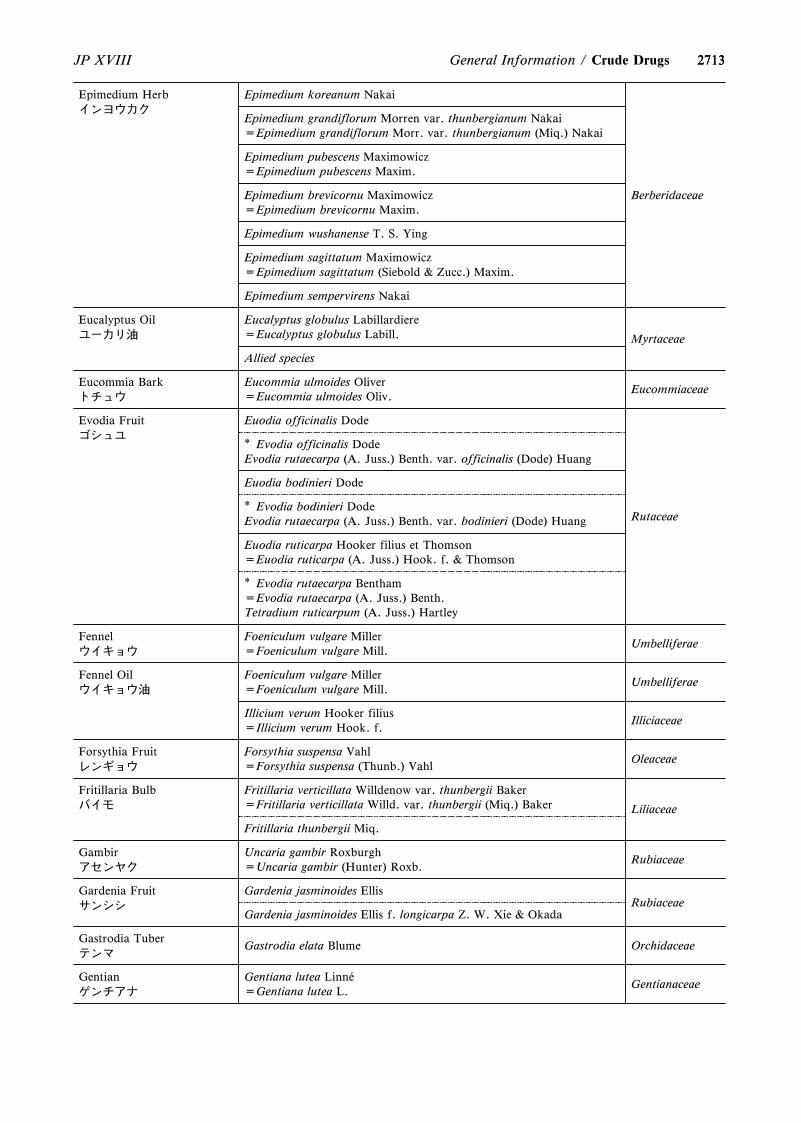
2713
Epimedium Herbインヨウカク
Epimedium koreanum Nakai
Epimedium grandiflorum Morren var. thunbergianum Nakai=Epimedium grandiflorum Morr. var. thunbergianum (Miq.) Nakai
Epimedium pubescens Maximowicz=Epimedium pubescens Maxim.
Epimedium brevicornu Maximowicz=Epimedium brevicornu Maxim.
Epimedium wushanense T. S. Ying
Epimedium sagittatum Maximowicz=Epimedium sagittatum (Siebold & Zucc.) Maxim.
Epimedium sempervirens Nakai
Berberidaceae
Eucalyptus Oilユーカリ油
Eucalyptus globulus Labillardiere=Eucalyptus globulus Labill. Myrtaceae
Allied species
Eucommia Barkトチュウ
Eucommia ulmoides Oliver=Eucommia ulmoides Oliv.
Eucommiaceae
Evodia Fruitゴシュユ
Euodia officinalis Dode
* Evodia officinalis DodeEvodia rutaecarpa (A. Juss.) Benth. var. officinalis (Dode) Huang
Euodia bodinieri Dode
* Evodia bodinieri DodeEvodia rutaecarpa (A. Juss.) Benth. var. bodinieri (Dode) Huang
Euodia ruticarpa Hooker filius et Thomson=Euodia ruticarpa (A. Juss.) Hook. f. & Thomson
* Evodia rutaecarpa Bentham=Evodia rutaecarpa (A. Juss.) Benth.Tetradium ruticarpum (A. Juss.) Hartley
Rutaceae
Fennelウイキョウ
Foeniculum vulgare Miller=Foeniculum vulgare Mill.
Umbelliferae
Fennel Oilウイキョウ油
Foeniculum vulgare Miller=Foeniculum vulgare Mill.
Umbelliferae
Illicium verum Hooker filius=Illicium verum Hook. f.
Illiciaceae
Forsythia Fruitレンギョウ
Forsythia suspensa Vahl=Forsythia suspensa (Thunb.) Vahl
Oleaceae
Fritillaria Bulbバイモ
Fritillaria verticillata Willdenow var. thunbergii Baker=Fritillaria verticillata Willd. var. thunbergii (Miq.) Baker Liliaceae
Fritillaria thunbergii Miq.
Gambirアセンヤク
Uncaria gambir Roxburgh=Uncaria gambir (Hunter) Roxb.
Rubiaceae
Gardenia Fruitサンシシ
Gardenia jasminoides EllisRubiaceae
Gardenia jasminoides Ellis f. longicarpa Z. W. Xie & Okada
Gastrodia Tuberテンマ
Gastrodia elata Blume Orchidaceae
Gentianゲンチアナ
Gentiana lutea Linn áe=Gentiana lutea L.
Gentianaceae
2713JP XVIII General Information / Crude Drugs
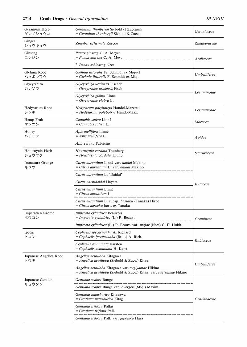
2714
Geranium Herbゲンノショウコ
Geranium thunbergii Siebold et Zuccarini=Geranium thunbergii Siebold & Zucc.
Geraniaceae
Gingerショウキョウ
Zingiber officinale Roscoe Zingiberaceae
Ginsengニンジン
Panax ginseng C. A. Meyer=Panax ginseng C. A. Mey. Araliaceae
* Panax schinseng Nees
Glehnia Rootハマボウフウ
Glehnia littoralis Fr. Schmidt ex Miquel=Glehnia littoralis F. Schmidt ex Miq.
Umbelliferae
Glycyrrhizaカンゾウ
Glycyrrhiza uralensis Fischer=Glycyrrhiza uralensis Fisch.
LeguminosaeGlycyrrhiza glabra Linn áe=Glycyrrhiza glabra L.
Hedysarum Rootシンギ
Hedysarum polybotrys Handel-Mazzetti=Hedysarum polybotrys Hand.-Mazz.
Leguminosae
Hemp Fruitマシニン
Cannabis sativa Linn áe=Cannabis sativa L.
Moracea
Honeyハチミツ
Apis mellifera Linn áe=Apis mellifera L. Apidae
Apis cerana Fabricius
Houttuynia Herbジュウヤク
Houttuynia cordata Thunberg=Houttuynia cordata Thunb.
Saururaceae
Immature Orangeキジツ
Citrus aurantium Linn áe var. daidai Makino=Citrus aurantium L. var. daidai Makino
Rutaceae
Citrus aurantium L. `Daidai'
Citrus natsudaidai Hayata
Citrus aurantium Linn áe=Citrus aurantium L.
Citrus aurantium L. subsp. hassaku (Tanaka) Hiroe=Citrus hassaku hort. ex Tanaka
Imperata Rhizomeボウコン
Imperata cylindrica Beauvois=Imperata cylindrica (L.) P. Beauv. Gramineae
Imperata cylindrica (L.) P. Beauv. var. major (Nees) C. E. Hubb.
Ipecacトコン
Cephaelis ipecacuanha A. Richard=Cephaelis ipecacuanha (Brot.) A. Rich.
RubiaceaeCephaelis acuminata Karsten=Cephaelis acuminata H. Karst.
Japanese Angelica Rootトウキ
Angelica acutiloba Kitagawa=Angelica acutiloba (Siebold & Zucc.) Kitag.
UmbelliferaeAngelica acutiloba Kitagawa var. sugiyamae Hikino=Angelica acutiloba (Siebold & Zucc.) Kitag. var. sugiyamae Hikino
Japanese Gentianリュウタン
Gentiana scabra Bunge
Gentianaceae
Gentiana scabra Bunge var. buergeri (Miq.) Maxim.
Gentiana manshurica Kitagawa=Gentiana manshurica Kitag.
Gentiana triflora Pallas=Gentiana triflora Pall.
Gentiana triflora Pall. var. japonica Hara
2714 JP XVIIICrude Drugs / General Information
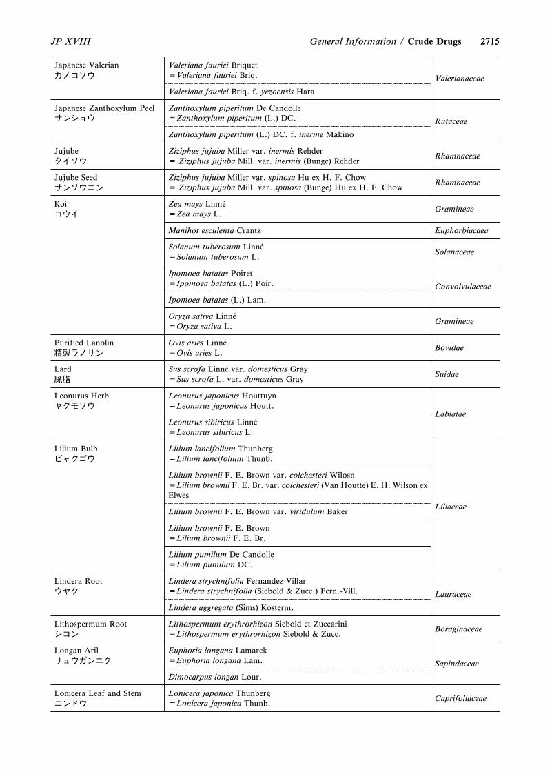
2715
Japanese Valerianカノコソウ
Valeriana fauriei Briquet=Valeriana fauriei Briq. Valerianaceae
Valeriana fauriei Briq. f. yezoensis Hara
Japanese Zanthoxylum Peelサンショウ
Zanthoxylum piperitum De Candolle=Zanthoxylum piperitum (L.) DC. Rutaceae
Zanthoxylum piperitum (L.) DC. f. inerme Makino
Jujubeタイソウ
Ziziphus jujuba Miller var. inermis Rehder= Ziziphus jujuba Mill. var. inermis (Bunge) Rehder
Rhamnaceae
Jujube Seedサンソウニン
Ziziphus jujuba Miller var. spinosa Hu ex H. F. Chow= Ziziphus jujuba Mill. var. spinosa (Bunge) Hu ex H. F. Chow
Rhamnaceae
Koiコウイ
Zea mays Linn áe=Zea mays L.
Gramineae
Manihot esculenta Crantz Euphorbiacaea
Solanum tuberosum Linn áe=Solanum tuberosum L.
Solanaceae
Ipomoea batatas Poiret=Ipomoea batatas (L.) Poir. Convolvulaceae
Ipomoea batatas (L.) Lam.
Oryza sativa Linn áe=Oryza sativa L.
Gramineae
Purified Lanolin精製ラノリン
Ovis aries Linn áe=Ovis aries L.
Bovidae
Lard豚脂
Sus scrofa Linn áe var. domesticus Gray=Sus scrofa L. var. domesticus Gray
Suidae
Leonurus Herbヤクモソウ
Leonurus japonicus Houttuyn=Leonurus japonicus Houtt.
LabiataeLeonurus sibiricus Linn áe=Leonurus sibiricus L.
Lilium Bulbビャクゴウ
Lilium lancifolium Thunberg=Lilium lancifolium Thunb.
Liliaceae
Lilium brownii F. E. Brown var. colchesteri Wilosn=Lilium brownii F. E. Br. var. colchesteri (Van Houtte) E. H. Wilson exElwes
Lilium brownii F. E. Brown var. viridulum Baker
Lilium brownii F. E. Brown=Lilium brownii F. E. Br.
Lilium pumilum De Candolle=Lilium pumilum DC.
Lindera Rootウヤク
Lindera strychnifolia Fernandez-Villar=Lindera strychnifolia (Siebold & Zucc.) Fern.-Vill. Lauraceae
Lindera aggregata (Sims) Kosterm.
Lithospermum Rootシコン
Lithospermum erythrorhizon Siebold et Zuccarini=Lithospermum erythrorhizon Siebold & Zucc.
Boraginaceae
Longan Arilリュウガンニク
Euphoria longana Lamarck=Euphoria longana Lam. Sapindaceae
Dimocarpus longan Lour.
Lonicera Leaf and Stemニンドウ
Lonicera japonica Thunberg=Lonicera japonica Thunb.
Caprifoliaceae
2715JP XVIII General Information / Crude Drugs
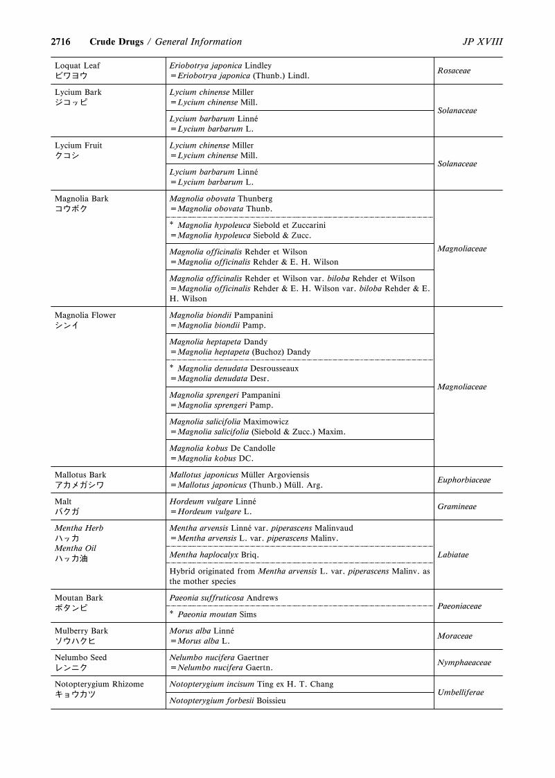
2716
Loquat Leafビワヨウ
Eriobotrya japonica Lindley=Eriobotrya japonica (Thunb.) Lindl.
Rosaceae
Lycium Barkジコッピ
Lycium chinense Miller=Lycium chinense Mill.
SolanaceaeLycium barbarum Linn áe=Lycium barbarum L.
Lycium Fruitクコシ
Lycium chinense Miller=Lycium chinense Mill.
SolanaceaeLycium barbarum Linn áe=Lycium barbarum L.
Magnolia Barkコウボク
Magnolia obovata Thunberg=Magnolia obovata Thunb.
Magnoliaceae
* Magnolia hypoleuca Siebold et Zuccarini=Magnolia hypoleuca Siebold & Zucc.
Magnolia officinalis Rehder et Wilson=Magnolia officinalis Rehder & E. H. Wilson
Magnolia officinalis Rehder et Wilson var. biloba Rehder et Wilson=Magnolia officinalis Rehder & E. H. Wilson var. biloba Rehder & E.H. Wilson
Magnolia Flowerシンイ
Magnolia biondii Pampanini=Magnolia biondii Pamp.
Magnolia heptapeta Dandy=Magnolia heptapeta (Buchoz) Dandy
* Magnolia denudata Desrousseaux=Magnolia denudata Desr.
Magnolia sprengeri Pampanini=Magnolia sprengeri Pamp.
Magnolia salicifolia Maximowicz=Magnolia salicifolia (Siebold & Zucc.) Maxim.
Magnolia kobus De Candolle=Magnolia kobus DC.
Magnoliaceae
Mallotus Barkアカメガシワ
Mallotus japonicus M äuller Argoviensis=Mallotus japonicus (Thunb.) M äull. Arg.
Euphorbiaceae
Maltバクガ
Hordeum vulgare Linn áe=Hordeum vulgare L.
Gramineae
Mentha HerbハッカMentha Oilハッカ油
Mentha arvensis Linn áe var. piperascens Malinvaud=Mentha arvensis L. var. piperascens Malinv.
LabiataeMentha haplocalyx Briq.
Hybrid originated from Mentha arvensis L. var. piperascens Malinv. asthe mother species
Moutan Barkボタンピ
Paeonia suffruticosa AndrewsPaeoniaceae
* Paeonia moutan Sims
Mulberry Barkソウハクヒ
Morus alba Linn áe=Morus alba L.
Moraceae
Nelumbo Seedレンニク
Nelumbo nucifera Gaertner=Nelumbo nucifera Gaertn.
Nymphaeaceae
Notopterygium Rhizomeキョウカツ
Notopterygium incisum Ting ex H. T. ChangUmbelliferae
Notopterygium forbesii Boissieu
2716 JP XVIIICrude Drugs / General Information
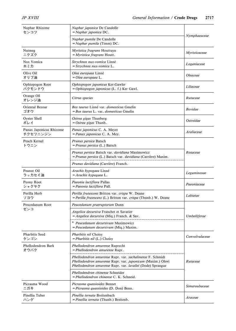
2717
Nuphar Rhizomeセンコツ
Nuphar japonica De Candolle=Nuphar japonica DC.
Nuphar pumila De Candolle=Nuphar pumila (Timm) DC.
Nymphaeaceae
Nutmegニクズク
Myristica fragrans Houttuyn=Myristica fragrans Houtt.
Myristicaceae
Nux Vomicaホミカ
Strychnos nux-vomica Linn áe=Strychnos nux-vomica L.
Loganiaceae
Olive Oilオリブ油
Olea europaea Linn áe=Olea europaea L.
Oleaceae
Ophiopogon Rootバクモンドウ
Ophiopogon japonicus Ker-Gawler=Ophiopogon japonicus (L. f.) Ker Gawl.
Liliaceae
Orange Oilオレンジ油
Citrus species Rutaceae
Oriental Bezoarゴオウ
Bos taurus Linn áe var. domesticus Gmelin=Bos taurus L. var. domesticus Gmelin
Bovidae
Oyster Shellボレイ
Ostrea gigas Thunberg=Ostrea gigas Thunb.
Ostreidae
Panax Japonicus Rhizomeチクセツニンジン
Panax japonicus C. A. Meyer=Panax japonicus C. A. Mey.
Araliaceae
Peach Kernelトウニン
Prunus persica Batsch=Prunus persica (L.) Batsch
RosaceaePrunus persica Batsch var. davidiana Maximowicz=Prunus persica (L.) Batsch var. davidiana (Carri àere) Maxim.
Prunus davidiana (Carri àere) Franch.
Peanut Oilラッカセイ油
Arachis hypogaea Linn áe=Arachis hypogaea L.
Leguminosae
Peony Rootシャクヤク
Paeonia lactiflora Pallas=Paeonia lactiflora Pall.
Paeoniaceae
Perilla Herbソヨウ
Perilla frutescens Britton var. crispa W. Deane=Perilla frutescens (L.) Britton var. crispa (Thunb.) W. Deane
Labiatae
Peucedanum Rootゼンコ
Peucedanum praeruptorum Dunn
UmbelliferaeAngelica decursiva Franchet et Savatier=Angelica decursiva (Miq.) Franch. & Sav.
* Peucedanum decursivum Maximowicz=Peucedanum decursivum (Miq.) Maxim.
Pharbitis Seedケンゴシ
Pharbitis nil Choisy=Pharbitis nil (L.) Choisy
Convolvulaceae
Phellodendron Barkオウバク
Phellodendron amurense Ruprecht=Phellodendron amurense Rupr.
RutaceaePhellodendron amurense Rupr. var. sachalinense F. SchmidtPhellodendron amurense Rupr. var. japonicum (Maxim.) OhwiPhellodendron amurense Rupr. var. lavallei (Dode) Sprangue
Phellodendron chinense Schneider=Phellodendron chinense C. K. Schneid.
Picrasma Woodニガキ
Picrasma quassioides Bennet=Picrasma quassioides (D. Don) Benn.
Simaroubaceae
Pinellia Tuberハンゲ
Pinellia ternata Breitenbach=Pinellia ternata (Thunb.) Breitenb.
Araceae
2717JP XVIII General Information / Crude Drugs
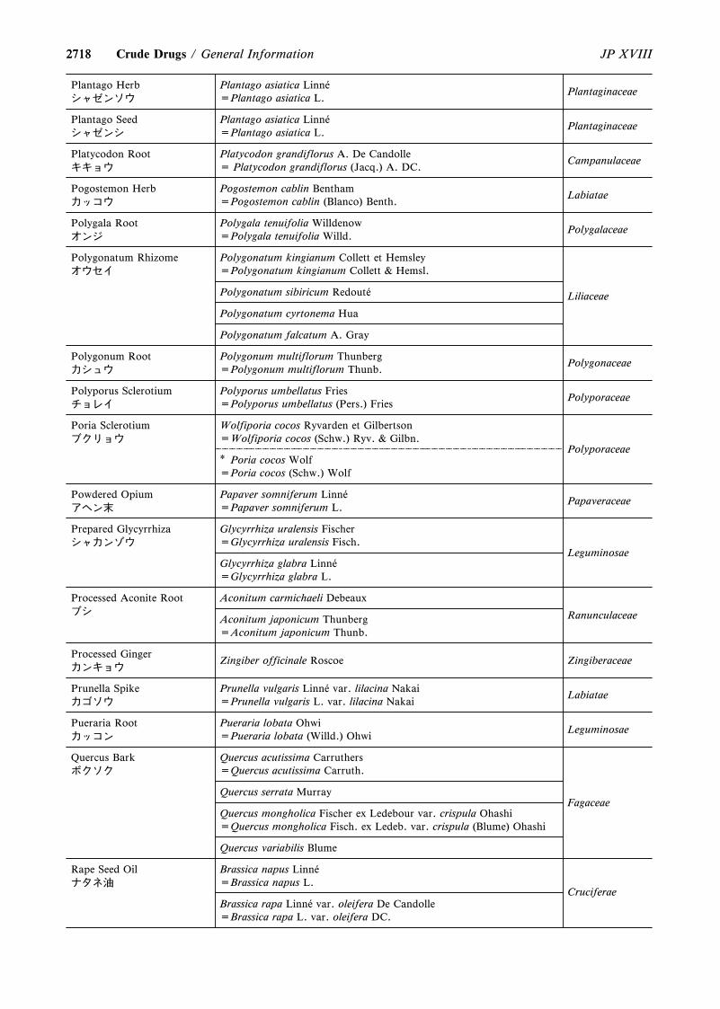
2718
Plantago Herbシャゼンソウ
Plantago asiatica Linn áe=Plantago asiatica L.
Plantaginaceae
Plantago Seedシャゼンシ
Plantago asiatica Linn áe=Plantago asiatica L.
Plantaginaceae
Platycodon Rootキキョウ
Platycodon grandiflorus A. De Candolle= Platycodon grandiflorus (Jacq.) A. DC.
Campanulaceae
Pogostemon Herbカッコウ
Pogostemon cablin Bentham=Pogostemon cablin (Blanco) Benth.
Labiatae
Polygala Rootオンジ
Polygala tenuifolia Willdenow=Polygala tenuifolia Willd.
Polygalaceae
Polygonatum Rhizomeオウセイ
Polygonatum kingianum Collett et Hemsley=Polygonatum kingianum Collett & Hemsl.
Polygonatum sibiricum Redout áe
Polygonatum cyrtonema Hua
Polygonatum falcatum A. Gray
Liliaceae
Polygonum Rootカシュウ
Polygonum multiflorum Thunberg=Polygonum multiflorum Thunb.
Polygonaceae
Polyporus Sclerotiumチョレイ
Polyporus umbellatus Fries=Polyporus umbellatus (Pers.) Fries
Polyporaceae
Poria Sclerotiumブクリョウ
Wolfiporia cocos Ryvarden et Gilbertson=Wolfiporia cocos (Schw.) Ryv. & Gilbn.
Polyporaceae* Poria cocos Wolf=Poria cocos (Schw.) Wolf
Powdered Opiumアヘン末
Papaver somniferum Linn áe=Papaver somniferum L.
Papaveraceae
Prepared Glycyrrhizaシャカンゾウ
Glycyrrhiza uralensis Fischer=Glycyrrhiza uralensis Fisch.
LeguminosaeGlycyrrhiza glabra Linn áe=Glycyrrhiza glabra L.
Processed Aconite Rootブシ
Aconitum carmichaeli Debeaux
RanunculaceaeAconitum japonicum Thunberg=Aconitum japonicum Thunb.
Processed Gingerカンキョウ
Zingiber officinale Roscoe Zingiberaceae
Prunella Spikeカゴソウ
Prunella vulgaris Linn áe var. lilacina Nakai=Prunella vulgaris L. var. lilacina Nakai
Labiatae
Pueraria Rootカッコン
Pueraria lobata Ohwi=Pueraria lobata (Willd.) Ohwi
Leguminosae
Quercus Barkボクソク
Quercus acutissima Carruthers=Quercus acutissima Carruth.
FagaceaeQuercus serrata Murray
Quercus mongholica Fischer ex Ledebour var. crispula Ohashi=Quercus mongholica Fisch. ex Ledeb. var. crispula (Blume) Ohashi
Quercus variabilis Blume
Rape Seed Oilナタネ油
Brassica napus Linn áe=Brassica napus L.
Brassica rapa Linn áe var. oleifera De Candolle=Brassica rapa L. var. oleifera DC.
Cruciferae
2718 JP XVIIICrude Drugs / General Information
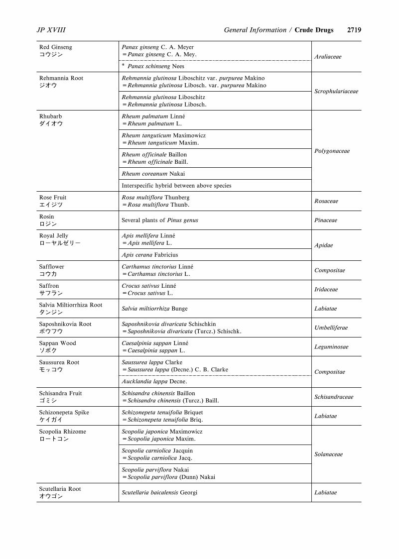
2719
Red Ginsengコウジン
Panax ginseng C. A. Meyer=Panax ginseng C. A. Mey. Araliaceae
* Panax schinseng Nees
Rehmannia Rootジオウ
Rehmannia glutinosa Liboschitz var. purpurea Makino=Rehmannia glutinosa Libosch. var. purpurea Makino
ScrophulariaceaeRehmannia glutinosa Liboschitz=Rehmannia glutinosa Libosch.
Rhubarbダイオウ
Rheum palmatum Linn áe=Rheum palmatum L.
Polygonaceae
Rheum tanguticum Maximowicz=Rheum tanguticum Maxim.
Rheum officinale Baillon=Rheum officinale Baill.
Rheum coreanum Nakai
Interspecific hybrid between above species
Rose Fruitエイジツ
Rosa multiflora Thunberg=Rosa multiflora Thunb.
Rosaceae
Rosinロジン
Several plants of Pinus genus Pinaceae
Royal Jellyローヤルゼリー
Apis mellifera Linn áe=Apis mellifera L. Apidae
Apis cerana Fabricius
Safflowerコウカ
Carthamus tinctorius Linn áe=Carthamus tinctorius L.
Compositae
Saffronサフラン
Crocus sativus Linn áe=Crocus sativus L.
Iridaceae
Salvia Miltiorrhiza Rootタンジン
Salvia miltiorrhiza Bunge Labiatae
Saposhnikovia Rootボウフウ
Saposhnikovia divaricata Schischkin=Saposhnikovia divaricata (Turcz.) Schischk.
Umbelliferae
Sappan Woodソボク
Caesalpinia sappan Linn áe=Caesalpinia sappan L.
Leguminosae
Saussurea Rootモッコウ
Saussurea lappa Clarke=Saussurea lappa (Decne.) C. B. Clarke Compositae
Aucklandia lappa Decne.
Schisandra Fruitゴミシ
Schisandra chinensis Baillon=Schisandra chinensis (Turcz.) Baill.
Schisandraceae
Schizonepeta Spikeケイガイ
Schizonepeta tenuifolia Briquet=Schizonepeta tenuifolia Briq.
Labiatae
Scopolia Rhizomeロートコン
Scopolia japonica Maximowicz=Scopolia japonica Maxim.
SolanaceaeScopolia carniolica Jacquin=Scopolia carniolica Jacq.
Scopolia parviflora Nakai=Scopolia parviflora (Dunn) Nakai
Scutellaria Rootオウゴン
Scutellaria baicalensis Georgi Labiatae
2719JP XVIII General Information / Crude Drugs
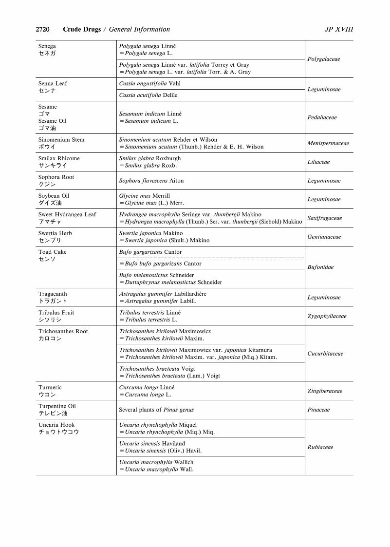
2720
Senegaセネガ
Polygala senega Linn áe=Polygala senega L.
PolygalaceaePolygala senega Linn áe var. latifolia Torrey et Gray=Polygala senega L. var. latifolia Torr. & A. Gray
Senna Leafセンナ
Cassia angustifolia VahlLeguminosae
Cassia acutifolia Delile
SesameゴマSesame Oilゴマ油
Sesamum indicum Linn áe=Sesamum indicum L.
Pedaliaceae
Sinomenium Stemボウイ
Sinomenium acutum Rehder et Wilson=Sinomenium acutum (Thunb.) Rehder & E. H. Wilson
Menispermaceae
Smilax Rhizomeサンキライ
Smilax glabra Roxburgh=Smilax glabra Roxb.
Liliaceae
Sophora Rootクジン
Sophora flavescens Aiton Leguminosae
Soybean Oilダイズ油
Glycine max Merrill=Glycine max (L.) Merr.
Leguminosae
Sweet Hydrangea Leafアマチャ
Hydrangea macrophylla Seringe var. thunbergii Makino=Hydrangea macrophylla (Thunb.) Ser. var. thunbergii (Siebold) Makino
Saxifragaceae
Swertia Herbセンブリ
Swertia japonica Makino=Swertia japonica (Shult.) Makino
Gentianaceae
Toad Cakeセンソ
Bufo gargarizans Cantor
=Bufo bufo gargarizans CantorBufonidae
Bufo melanostictus Schneider=Duttaphrynus melanostictus Schneider
Tragacanthトラガント
Astragalus gummifer Labillardi áere=Astragalus gummifer Labill.
Leguminosae
Tribulus Fruitシツリシ
Tribulus terrestris Linn áe=Tribulus terrestris L.
Zygophyllaceae
Trichosanthes Rootカロコン
Trichosanthes kirilowii Maximowicz=Trichosanthes kirilowii Maxim.
CucurbitaceaeTrichosanthes kirilowii Maximowicz var. japonica Kitamura=Trichosanthes kirilowii Maxim. var. japonica (Miq.) Kitam.
Trichosanthes bracteata Voigt=Trichosanthes bracteata (Lam.) Voigt
Turmericウコン
Curcuma longa Linn áe=Curcuma longa L.
Zingiberaceae
Turpentine Oilテレビン油
Several plants of Pinus genus Pinaceae
Uncaria Hookチョウトウコウ
Uncaria rhynchophylla Miquel=Uncaria rhynchophylla (Miq.) Miq.
RubiaceaeUncaria sinensis Haviland=Uncaria sinensis (Oliv.) Havil.
Uncaria macrophylla Wallich=Uncaria macrophylla Wall.
2720 JP XVIIICrude Drugs / General Information

2721
Wood Creosote木クレオソート
Several plants of Pinus genus Pinaceae
Several plants of Cryptomeria genus Taxodiaceae
Several plants of Fagus genus Fagaceae
Several plants of Afzelia (Intsia) genus Leguminosae
Several plants of Shorea genus Dipterocarpaceae
Several plants of Tectona genus Verbenaceae
When ``Other species of the same genus'' is included as its original plants the scientific name is not written in Monograph,however, it is written in this table.Reference
Terabayashi S. et al.: Pharmaceutical and Medical Device Regulatory Science, 41(5), 407 – 418 (2010).
2721JP XVIII General Information / Crude Drugs
essary the same as the taxonomic system used in theliterature. The reason for this is that the JP is not an aca-demic text, but an ordinance. The relationship between thescientific names used in the JP and those generally usedtaxonomically is indicated in the following table, to avoidmisunderstanding by JP users owing to differences in thenotation system.
Notification for the QuantitativeMarker Constituents of Crude
Drugs and Crude Drug Preparations<G5-2-170>
One of the highly distinctive features of the crude drugsand preparations containing crude drugs as main ingredient(crude drug preparations) is the fact that they are multicom-ponent systems composed of a prodigious number of com-pounds. As an example, glycyrrhiza, one of the most im-portant crude drugs worldwide has been demonstrated thatthey harbor more than 100 kinds of secondary metabolites,and this number could be counted up to more than 1000when the intermediates occurred in the biosynthetic path-ways were included. The whole members of the compoundsare supposed to be integrated to reveal the effects of glycyr-rhiza.
A wide diversity of constituents in the drugs made frombotanical raw materials is fundamentally derived from awide variety of secondary metabolites occurred in plants.However, there are more reasons for the diversity. The spe-cies of plants used as raw materials for drugs are specified inthe approval documents of the drugs, though, a variation oftheir composition derived from the genetic variation of theplants will be produced since each botanical species includesa significant genetic divergence. The secondary metabolitesof plants will be further differentiated in their quality andquantity according to the environmental factors such as soil(soil texture, water retentivity, pH, etc.) and weather(amount of precipitation, temperature, humidity, etc.) con-ditions. Furthermore, the constituents will change dependingon wild or cultivation, cultivation method and harvestperiod. Also crude drugs are finally processed by excludingperiderm, steaming, roasting, etc. and consequently the con-stituents are different according to the process method.
The stipulation on the contents (quantitative values) ofmarker constituents in crude drugs and crude drug prepara-tions has very important implications for standardization ofthe quality of pharmaceutical natural products. The stipula-tions on crude drugs generally provide the minimum requi-
site amount of marker compounds. For example, glycyrrhizaof the Japanese Pharmacopoeia is ordered to contain notless than 2.0z of glycyrrhizic acid. Crude drugs are knownto exhibit large difference in the content of secondarymetabolites among individual plants that caused from multi-ple reasons described in the previous paragraph. It is report-ed that the glycyrrhizic acid content of glycyrrhiza in oneplant can contain some 10 times the content of another plantwhen they are grown together in one farm field and harvest-ed simultaneously. Accordingly, it is hard to standardize theranges of content for marker constituents of crude drugs ona policy of the efficient use of natural resources for crudedrugs. However, the crude drug preparations as finishedproducts are required to contain a certain amount of activeingredients from a perspective of the reproducibility of medi-cal treatments. Consequently, the marker constituents of theKampo formulations and conventional crude drug prepara-tions as the final stage of crude drug preparations are gener-ally specified by the range of content values. Crude drugscontaining different amount of marker constituents are ap-propriately blended to prepare the finished products with aparticular amount of marker constituents.
It should be noted that the marker constituents of crudedrugs for regulations include a variety of types. Followingsare the examples of some different types. Sennosides, themarker constituents of senna leaf are the obvious active in-gredients that accounts for the laxative effects of senna leafto some extent. Other compounds of the anthraquinone-typefound in senna leaf, such as rhein and aloe-emodin, are alsopotent as laxative, though, because of their large differencein content in senna leaf, a medicinal effect of senna leaf canbe standardized by managing the content of sennosides.However, sennosides are likely to be broken down into an-thraquinones by heating and other factors that not only sen-nosides but also the increased rhein may be targeted forstandardization in cases of the Kampo formula extracts in-cluding rhubarb, one of the sennoside-containing crudedrugs, as a component. On the other hand, glycyrrhizic acid,a very famous bioactive component of glycyrrhiza, is an ac-tive ingredient that contributes to some parts of the medicaleffect of glycyrrhiza. Though, many components other thanglycyrrhizic acid are also known to play a part in the medicaleffects of glycyrrhiza. Consequently, glycyrrhizic acidshould be regarded as one of the multiple active ingredientsof glycyrrhiza that being specified its content as a markerconstituent. In other cases of the marker constituents thatseemed to have less biological effects such as 10-hydroxy-2-(E)-decenoic acid in royal jelly or (E)-cinnamic acid in someextracts of Kampo formula, their content are standardized asa distinctive compound of each pharmaceutical product.Referring to the biosyntheses of natural products, the con-
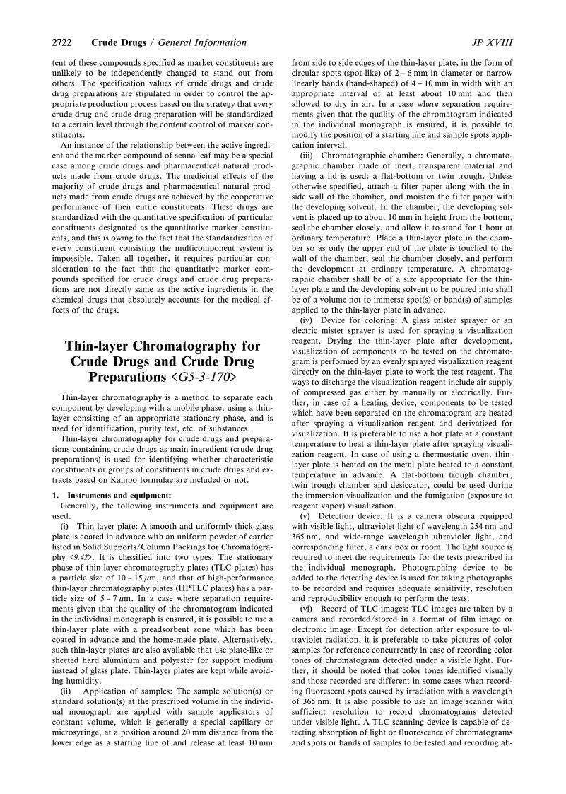
27222722 JP XVIIICrude Drugs / General Information
tent of these compounds specified as marker constituents areunlikely to be independently changed to stand out fromothers. The specification values of crude drugs and crudedrug preparations are stipulated in order to control the ap-propriate production process based on the strategy that everycrude drug and crude drug preparation will be standardizedto a certain level through the content control of marker con-stituents.
An instance of the relationship between the active ingredi-ent and the marker compound of senna leaf may be a specialcase among crude drugs and pharmaceutical natural prod-ucts made from crude drugs. The medicinal effects of themajority of crude drugs and pharmaceutical natural prod-ucts made from crude drugs are achieved by the cooperativeperformance of their entire constituents. These drugs arestandardized with the quantitative specification of particularconstituents designated as the quantitative marker constitu-ents, and this is owing to the fact that the standardization ofevery constituent consisting the multicomponent system isimpossible. Taken all together, it requires particular con-sideration to the fact that the quantitative marker com-pounds specified for crude drugs and crude drug prepara-tions are not directly same as the active ingredients in thechemical drugs that absolutely accounts for the medical ef-fects of the drugs.
Thin-layer Chromatography forCrude Drugs and Crude Drug
Preparations <G5-3-170>
Thin-layer chromatography is a method to separate eachcomponent by developing with a mobile phase, using a thin-layer consisting of an appropriate stationary phase, and isused for identification, purity test, etc. of substances.
Thin-layer chromatography for crude drugs and prepara-tions containing crude drugs as main ingredient (crude drugpreparations) is used for identifying whether characteristicconstituents or groups of constituents in crude drugs and ex-tracts based on Kampo formulae are included or not.
1. Instruments and equipment:Generally, the following instruments and equipment are
used.(i) Thin-layer plate: A smooth and uniformly thick glass
plate is coated in advance with an uniform powder of carrierlisted in Solid Supports/Column Packings for Chromatogra-phy <9.42>. It is classified into two types. The stationaryphase of thin-layer chromatography plates (TLC plates) hasa particle size of 10 – 15 mm, and that of high-performancethin-layer chromatography plates (HPTLC plates) has a par-ticle size of 5 – 7 mm. In a case where separation require-ments given that the quality of the chromatogram indicatedin the individual monograph is ensured, it is possible to use athin-layer plate with a preadsorbent zone which has beencoated in advance and the home-made plate. Alternatively,such thin-layer plates are also available that use plate-like orsheeted hard aluminum and polyester for support mediuminstead of glass plate. Thin-layer plates are kept while avoid-ing humidity.
(ii) Application of samples: The sample solution(s) orstandard solution(s) at the prescribed volume in the individ-ual monograph are applied with sample applicators ofconstant volume, which is generally a special capillary ormicrosyringe, at a position around 20 mm distance from thelower edge as a starting line of and release at least 10 mm
from side to side edges of the thin-layer plate, in the form ofcircular spots (spot-like) of 2 – 6 mm in diameter or narrowlinearly bands (band-shaped) of 4 – 10 mm in width with anappropriate interval of at least about 10 mm and thenallowed to dry in air. In a case where separation require-ments given that the quality of the chromatogram indicatedin the individual monograph is ensured, it is possible tomodify the position of a starting line and sample spots appli-cation interval.
(iii) Chromatographic chamber: Generally, a chromato-graphic chamber made of inert, transparent material andhaving a lid is used: a flat-bottom or twin trough. Unlessotherwise specified, attach a filter paper along with the in-side wall of the chamber, and moisten the filter paper withthe developing solvent. In the chamber, the developing sol-vent is placed up to about 10 mm in height from the bottom,seal the chamber closely, and allow it to stand for 1 hour atordinary temperature. Place a thin-layer plate in the cham-ber so as only the upper end of the plate is touched to thewall of the chamber, seal the chamber closely, and performthe development at ordinary temperature. A chromatog-raphic chamber shall be of a size appropriate for the thin-layer plate and the developing solvent to be poured into shallbe of a volume not to immerse spot(s) or band(s) of samplesapplied to the thin-layer plate in advance.
(iv) Device for coloring: A glass mister sprayer or anelectric mister sprayer is used for spraying a visualizationreagent. Drying the thin-layer plate after development,visualization of components to be tested on the chromato-gram is performed by an evenly sprayed visualization reagentdirectly on the thin-layer plate to work the test reagent. Theways to discharge the visualization reagent include air supplyof compressed gas either by manually or electrically. Fur-ther, in case of a heating device, components to be testedwhich have been separated on the chromatogram are heatedafter spraying a visualization reagent and derivatized forvisualization. It is preferable to use a hot plate at a constanttemperature to heat a thin-layer plate after spraying visuali-zation reagent. In case of using a thermostatic oven, thin-layer plate is heated on the metal plate heated to a constanttemperature in advance. A flat-bottom trough chamber,twin trough chamber and desiccator, could be used duringthe immersion visualization and the fumigation (exposure toreagent vapor) visualization.
(v) Detection device: It is a camera obscura equippedwith visible light, ultraviolet light of wavelength 254 nm and365 nm, and wide-range wavelength ultraviolet light, andcorresponding filter, a dark box or room. The light source isrequired to meet the requirements for the tests prescribed inthe individual monograph. Photographing device to beadded to the detecting device is used for taking photographsto be recorded and requires adequate sensitivity, resolutionand reproducibility enough to perform the tests.
(vi) Record of TLC images: TLC images are taken by acamera and recorded/stored in a format of film image orelectronic image. Except for detection after exposure to ul-traviolet radiation, it is preferable to take pictures of colorsamples for reference concurrently in case of recording colortones of chromatogram detected under a visible light. Fur-ther, it should be noted that color tones identified visuallyand those recorded are different in some cases when record-ing fluorescent spots caused by irradiation with a wavelengthof 365 nm. It is also possible to use an image scanner withsufficient resolution to record chromatograms detectedunder visible light. A TLC scanning device is capable of de-tecting absorption of light or fluorescence of chromatogramsand spots or bands of samples to be tested and recording ab-
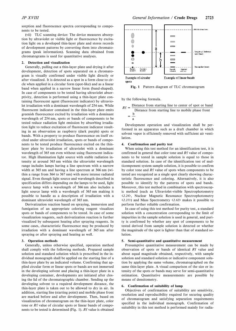
2723
Fig. 1 Pattern diagram of TLC chromatogram
2723JP XVIII General Information / Crude Drugs
sorption and fluorescence spectra corresponding to compo-nents to be tested.
(vii) TLC scanning device: The device measures absorp-tion by ultraviolet or visible light or fluorescence by excita-tion light on a developed thin-layer plate and stores recordsof development patterns by converting them into chromato-grams (peak information). Scanning data obtained fromchromatograms is used for quantitative analyses.
2. Detection and visualizationGenerally, pulling out a thin-layer plate and drying it after
development, detection of spots separated on a chromato-gram is visually confirmed under visible light directly orafter visualized. It is detected as a spot in a form close to cir-cle when applied in a circular form (spot-like) and as a linearband when applied in a narrow linear form (band-shaped).In case of components to be tested having ultraviolet absor-ptivity, detection is performed using a thin-layer plate con-taining fluorescent agent (fluorescent indicator) by ultravio-let irradiation with a dominant wavelength of 254 nm. Whilefluorescent indicator contained in the thin-layer plate emitsgreenish fluorescence excited by irradiation with a dominantwavelength of 254 nm, spots or bands of components to betested reduce radiation light emission by absorbing irradia-tion light to reduce excitation of fluorescent indicator result-ing in an observation as raspberry (dark purple) spots orbands. With a property to produce fluorescence on itself ex-cited under ultraviolet irradiation, spots or bands of compo-nents to be tested produce fluorescence excited on the thin-layer plate by irradiation of ultraviolet with a dominantwavelength of 365 nm even without using fluorescent indica-tor. High illumination light source with stable radiation in-tensity at around 365 nm within the ultraviolet wavelengthrange includes lamps having a line spectrum with a narrowwidth at 365 nm and having a line spectrum at 366 nm (wi-thin a range from 364 to 367 nm) with more intense radiatedsignal. Even though light source and wavelength described inspecification differs depending on the lamps to be used, lightsource lamp with a wavelength of 366 nm also includes alight source lamp with a wavelength of 365 nm making itpossible to handle as a description of irradiation with adominant ultraviolet wavelength of 365 nm.
Derivatization reaction based on spraying, immersion andfumigation of an appropriate coloring reagent visualizesspots or bands of components to be tested. In case of somevisualization reagents, such derivatization reaction is furthervisualized by subsequent heating after spraying reagents. Insome cases, characteristic fluorescence may be produced byirradiation with a dominant wavelength of 365 nm afterspraying or after spraying and heating as well.
3. Operation methodsGenerally, unless otherwise specified, operation method
shall comply with the following methods. Prepared samplesolution and standard solution which is prescribed in the in-dividual monograph shall be applied on the starting line of athin-layer plate by an indicated volume. Confirming that ap-plied circular form or linear spots or bands are not immersedin the developing solvent and placing a thin-layer plate in adeveloping container, developments are initiated after clos-ing the lid of the chromatographic chamber. Sending up thedeveloping solvent to a required development distance, thethin-layer plate is taken out to be allowed to dry in air. Inaddition, starting line (starting point) and mobile phase frontare marked before and after development. Then, based onvisualization of chromatogram on the thin-layer plate, colortone or Rf value of circular spots or linear bands of compo-nents to be tested is determined (Fig. 1). Rf value is obtained
by the following formula.
Rf =Distance from starting line to center of spot or band
Distance from starting line to mobile phase front
=ba
Development operation and visualization shall be per-formed in an apparatus such as a draft chamber in whichsolvent vapor is efficiently removed with sufficient air venti-lation.
4. Confirmation and purity testWhen using this test method for an identification test, it is
confirmed in general that color tone and Rf value of compo-nents to be tested in sample solution is equal to those instandard solution. In case of the identification test of mul-ticomponent system sample solution, it is possible to confirmby color tone and Rf value of spots when components to betested are recognized as a single spot clearly showing charac-teristic fluorescence and coloring. Alternatively, it is alsopossible to identify by the patterns of spots and bands.Moreover, this test method in combination with spectroscop-ic method (such as Ultraviolet-visible Spectrophotometry<2.24>, Nuclear Magnetic Resonance Spectrophotometry<2.21>) and Mass Spectrometry <2.62> makes it possible toperform further reliable confirmation.
In case of using this test method for purity test, a standardsolution with a concentration corresponding to the limit ofimpurities in the sample solution is used in general, and puri-ty is confirmed by whether any spot of components to betested derived from sample solution is detected or whetherthe magnitude of the spot is lighter than that of standard so-lution.
5. Semi-quantitative and quantitative measurementPresumptive quantitative measurement can be made by
observation of spots or bands of identical Rf value andabout equal magnitude obtained, respectively, with samplesolution and standard solution or indicative component solu-tion by applying the same volume, chromatographed on thesame thin-layer plate. A visual comparison of the size or in-tensity of the spots or bands may serve for semi-quantitativeestimation. Quantitative measurements are possible bymeans of densitometry.
6. Confirmation of suitability of lampObjectives of confirmation of suitability are sensitivity,
resolution and reproducibility required for securing qualityof chromatogram and satisfying separation requirementsspecified in the individual monograph. Confirmation ofsuitability in this test method is performed mainly for radia-
27242724 JP XVIIICrude Drugs / General Information
tion intensity of line light source used for ultraviolet irradia-tion. In other words, the test is performed if specified spot(or band) is not recognized by irradiation with a wavelengthof line light source specified in the individual monograph orspecification of irradiation system was changed. Generally,in case of irradiation with a dominant wavelength of 254 nmto a thin-layer plate containing fluorescent agent, it is con-firmed whether the thin-layer plate produce a green fluores-cence. Alternatively, in case of irradiation with a dominantwavelength of 365 nm (366 nm), whether blue-white fluores-cence is produced is confirmed by 2 mL spotting the 0.5mg/mL scopoletin for thin-layer chromatography solution ona thin-layer plate.
In case of automated sample application equipment andTLC scanning device using densitometry, specifications ofsystem suitability in Liquid Chromatography <2.01> is ap-plied as required.
7. Point to consider regarding test conditionsAmong tests prescribed in individual monograph, in iden-
tification tests using reagents of the Reference Standard orcomponents to be tested (such as reagents for thin-layerchromatography), it is possible to modify developing tem-perature, developing distance, composition of developingsolvent, developing rate, coloring reagent composition, heat-ing temperature and duration of thin-layer plate within arange of better accuracy and precision than those prescribedis secured. However, such semi-quantitative identificationtests are excluded that judgment criteria is based on size andstrength of spots. On the other hand, in identification testswhich do not use reagents of the Reference Standard or com-ponents to be tested, it is possible to modify developing dis-tance, heating temperature and duration of thin-layer platewithin a range where separation, Rf value and color toneprescribed in individual monograph is observed. Further,even in case of identification tests without specification forthe Reference Standard or components to be tested, it is pos-sible to make a confirmation based on conformity of colortone for reference and Rf value using the Reference Stand-ard or components to be tested.
8. Reference1) MHLW Notification No. 65 of March 24, 2011, The
Japanese Pharmacopoeia Sixteenth Edition/GeneralTest Procedures/2. Physical Test Procedures/2.01 Liq-uid Chromatography/2.03 Thin-layer Chromatography
2) EP 8.0 (2014), 2.2.27/Thin-Layer Chromatography3) USP 37 (2014), <621> Chromatography, <201> Thin-
Layer Chromatographic Identification Test4) Pharmacopoeia of the People's Republic of China
(2010), A-42 Appendix VI B Thin-Layer Chromatogra-phy (English version)
5) Y. Goda: The Japanese Journal of Pharmacognosy, 66,63 (2012).
Aristolochic Acid <G5-4-141>
Aristolochic acid, which occurs in plants of Aristolochia-ceae, is suspected to cause renal damage. It is also reportedto be oncogenic (see References).
Aristolochic acid toxicity will not be a problem if crudedrugs of the origin and parts designated in the JP are used,but there may be differences in crude drug nomenclature be-tween different countries, and it is known that crude drugpreparations not meeting the specifications of the JP are cir-culating in some countries. Consequently, when crude drugs
or their preparations are used, it is important that the mate-rials should not include any plant containing aristolochicacid.
Since Supplement I to JP14, the test for aristolochic acid Iwas added to the Purity under Asiasarum Root, which con-sists of the rhizome and root. Because the aerial part of theplant may contain aristolochic acid and may have been im-properly contaminated in Asiasarum Root.
It is considered that Akebia Stem, Sinomenium Stem andSaussurea Root do not contain aristolochic acid, unlessplants of origin other than that designated in the JP areused. However, contamination of aristolochic acid mightoccur, as mentioned above. In this case, the test described inthe Purity under Asiasarum Root is useful for checking thepresence of aristolochic acid.
1. References1) Drug & Medical Device Safety Information, No. 161,
July, 2000, https://www.pmda.go.jp/safety/info-ser-vices/drugs/calling-attention/safety-info/0092.html#10(Reference: 2019-7-18).
2) J. L. Nortier, et al., N. Engl. J. Med., 342, 1686 – 1692(2000).
3) A. Kohara, et al., Mutation Research, 515, 63 – 72(2002).
Quantitative Analytical TechniqueUtilizing Nuclear Magnetic
Resonance (NMR) Spectroscopyand its Application to Reagents in
the Japanese Pharmacopoeia<G5-5-170>
1. Marker Compounds for the Assay of Crude Drugs in theJP and Establishment of Reference Substances for Quantita-tive Analyses
When the quantitative assay values are specified in themonographs of crude drugs and extracts of Kampo formula-tions in the JP, it is more difficult to establish and preparetheir JP Reference Standards than those for synthetic chemi-cal pharmaceutical substances, because the marker com-pounds for their assay are derived from natural sources.
Unlike the synthetic chemical pharmaceutical substances,crude drugs and extracts of Kampo formulations are mix-tures of a great deal of compounds. Although it is necessaryto choose a substance contained at the level of 0.1z toseveral z in the crude drugs and the extracts of Kampo for-mulations as the marker compounds for their quantitativeassay, the synthesis of such compounds is not so easy inmost cases. Therefore, the marker compound would be sepa-rated from natural materials and be isolated to havesufficient purity. However, the preparation of the referencesubstance in such a way would require high economical costand a great deal of effort. In addition, the composition ofimpurities contained in the reference substance prepared insuch a way would be different batch by batch according tothe difference of raw materials and their processes of ex-traction, isolation and purification. Accordingly, the differ-ence among batches of reference materials is much largerthan that of synthetic substances, and the control of theirpurity as the official reference standards is very difficult.Furthermore, in many cases of substances of natural origin,the greatest impurity would be water. For determining water
27252725JP XVIII General Information / Crude Drugs
contents precisely, it is necessary to use Karl Fischer method,and as the result, a large quantity of the valuable referencestandard would be consumed.
Because there are such bottlenecks mentioned above inmany cases of monographs of crude drugs and extracts ofKampo formulations, the establishment of the JP ReferenceStandard is difficult. Instead, reagents, which are commer-cially available or ready to put into the market, are designat-ed as the reference substances for the quantitative assay, andthe method and the content specification using the reagentare specified in monographs of crude drugs and extracts ofKampo formulations. In these cases, the specifications oftheir marker substances are defined in the section of Rea-gents and Test Solutions of the JP. However, in a strictsense, since the assay values obtained in this manner are notcertified metrologically, the reliability of the analytical valueobtained by using them is somewhat ambiguous.
2. Application of Quantitative NMR to Reference Sub-stances Used in the Assay of Crude Drugs and Extracts ofKampo Formulations
The application of quantitative NMR can solve the issueon the purity of reagents derived from natural source. Thesereagents are used as the reference substances with metrologi-cal traceability, when the precise contents of these reagentsare determined metrologically by using quantitative NMRbased on the idea shown in 10.1 Principle of QuantitativeAnalytical Technique Utilizing Nuclear Magnetic Resonance(NMR) Spectroscopy under <5.01> Crude Drugs Test.
Currently, the quantitative NMR is being carried out forthese reagents defined for the quantitative assay of crudedrugs in the JP and a report in which the points to practi-cally consider at determination of absolute purities of thereagents by using quantitative NMR are discussed has beenpublished.1) In addition, a validation study of quantitativeNMR has also been performed using the substances whichwill be used with high possibility as the reference substancesfor HPLC quantitative analysis. For the analyte compoundhaving molecular mass of around 300, when about 10 mg ofthe compound was used for the quantitative NMR meas-urement, it was demonstrated that an accuracy of 2 sig-nificant digits for the determined value was achieved at theordinary laboratory level, even when the error among theNMR instruments used was included.2) Usually, the contentsof marker compounds for the quantitative assay of crudedrugs are several z at the maximum, and the minimum unitfor the content specification is at the level of 0.1z. There-fore, when variability of content in crude drugs is consi-dered, the assurance of 2 significant digits for accuracyseems sufficient for the reference substances, which are usedfor the quantitative assay of crude drugs.
When discussion above is considered, the ambiguity ofanalytical values obtained by the use of the reagents derivedfrom natural source as the reference substances for the quan-titative assay of crude drugs can be avoided practically, byusing the reagents certified by quantitative NMR as the ref-erence substances in HPLC, etc., and by incorporating thecertified purity of such reagents into the calculation of thequantitative value of the sample. For example, for GardeniaFruit in the JP, the content of geniposide is specified at notless than 3.0z based on the HPLC analysis. The report citedabove1) demonstrated that the absolute purity of geniposideused as the reference substance in the quantitative assay ofGardenia Fruit is determined to be about 92z by quantita-tive NMR. Therefore, in the case that the quantitative valueof 3.0z in Gardenia Fruit sample is obtained as a result ofHPLC analysis by using this reagent as the reference sub-
stance assuming its purity as 100z, the true value for thesample is evaluated to be 2.8z taking it into considerationof the absolute purity determined by quantitative NMR withthe assurance of metrological traceability.
3. Supply of Certified Reagents by Using QuantitativeNMR
Currently, in the accreditation system of the InternationalAccreditation Japan (IA Japan), the National Institute ofTechnology and Evaluation (ASNITE), a feasibility studyhow the accreditation should be given to the organizationwhich performs the assay certification of the reagents usingcalibrated NMR apparatus has been in progress. In addition,in the IA Japan, addition of``Quantitative NMR''to the testmethod categories is scheduled. Therefore, in the near fu-ture, the reagent manufacturers will become able to performthe assay certification of the reagent after having this ac-creditation. Under such situation, the user of the reagentwould not be required to perform qualitative NMR individu-ally to obtain the purity value with SI traceability. Further-more, the inter-institutional errors (including inter-instru-mental errors) would become negligible, and we will be ableto carry out more precise and accurate quantitation assay ofthe sample by incorporating the labeled certified value on thereagent into the calculation of the quantitative value of thesample.
The certified reference materials (NMIJ CRM) to be usedfor the SI traceable metrological determination of the inter-nal reference compounds are supplied from the NationalMetrology Institute of Japan, National Institute of Ad-vanced Industrial Science and Technology (NMIJ AIST).
4. Management of Instrument Performance for Quantita-tive NMR
Quantitative NMR used to determine the purity of rea-gents for the JP, is an internal standard method that an ana-lyte compound and a SI traceable reference material in aNMR tube are measured at the same time.3) In this method,the number of nuclei are measured using NMR phenome-non, which means that the molar quantity of an analytecompound in a sample solution is directly calibrated with areference material.
In the management of instrument performance for quan-titative NMR measurements, it should be confirmed that in-tegral value of the targeted signals can be determined cor-rectly within the spectrum where the signals are measured (ingeneral, 0 – 10 ppm). The important point here is not to in-clude the signals derived from impure substances in thequantitative spectrum when integrate. Therefore, to manageinstrument performance, a high-purity compound of alreadyknown purity (determined by quantitative NMR and not lessthan 99.0z is preferable) should be used. In addition, sig-nals derived from simpler spin system should be selected andintegrated, and the ratio of theoretical number of nucleiamong signals should be accurate (for example, when eachof the two signals is derived from 1H, the ratio of the inte-grated values of the both is 0.995 – 1.005).
Considering the excitation bandwidth of a NMR pulse,when an instrument of 800 MHz is used under the followingconditions; center of spectrum window around 5 ppm, spec-tral width at 20 ppm (the conditions stipulated in the assayusing qNMR in the section of reagents), with a 909pulsewidth of 10 microseconds, the excitation efficiency of thepulse in the range of 0 – 10 ppm, where signals of an analytecompound are observed, is usually not less than 99.95z.Thus, the instrument, when the probe is well tuned and shimis adjusted properly, can assure an accuracy of 2 significantdigits at routine level of measurement. Furthermore, when
27262726 JP XVIIICrude Drugs / General Information
an instrument of 400 MHz is used, similar excitation ef-ficiency can be obtained up to 20 microseconds for 909pulsewidth, so quantitative NMR can be measured sufficientlywith a standard probe.
5. Reference1) J. Hosoe, et al., Pharmaceutical and Medical Device
Regulatory Science, 41, 960 – 970 (2010)2) J. Hosoe, et al., Pharmaceutical and Medical Device
Regulatory Science, 43, 182 – 193 (2012)3) J. Hosoe, et al., Pharmaceutical and Medical Device
Regulatory Science, 45, 243 – 250 (2014)
Purity Tests on Crude Drugsusing Genetic Information
<G5-6-172>
The ˆrst step in the quality assurance of natural productsis the use of raw materials from the right part of the rightorigin. Therefore, it is clearly stated in Article 4 of theGeneral Rules For Crude Drugs that the source of a crudedrug is an approval or rejection criterion. There are variousmethods for diŠerentiating the sources of crude drugs, suchas morphological methods, organoleptic tests, and chemicalmethods, and appropriate methods for each are described inthe individual monographs. Morphological methods, or-ganoleptic tests, and chemical methods are discriminationmethods for species that are based on the phenotypic charac-teristics of the crude drugs. On the other hand, together withrecent progress in molecular biology techniques and the ac-cumulation of genetic information on plants, diŠerentiatingmethods of crude drugs based on genotypes is being estab-lished. Unlike morphological and other methods that arebased on phenotypic characteristics, the genotypic methodsare not aŠected by environmental factors. Also, the methodshave several advantages, such as specialized expertise andskill for classiˆcation are not needed, and objective resultsare easily obtained.
The evolution of living organisms is accomplished bygenetic mutation, and diŠerences among the nucleotide se-quences of genes of closely related species re‰ect the strainrelationships between the species. Based on this theory,methods that classify species phylogenetically using thenucleotide sequence of rDNA that codes for ribosomal RNA(rRNA) on the nuclear genome have recently been adoptedfor the classiˆcation of microorganisms. In the same way,the sequence of this rDNA is also most often used in theclassiˆcation of higher plants based on the genotype. In par-ticular, it is very easy to classify closely related species usingthe internal transcribed spacer (ITS) region of the rDNA,since nucleotide substitution is more often undertaken bycomparison with the coded gene region. Furthermore, sincethe genes on the nuclear genome originate from the parents'genomes, there is an advantage that interspecies hybrids canbe detected. Higher plants also have mitochondrial genesand chloroplastic genes. Although the genes on these ge-nomes are also often used for classiˆcation, interspecieshybrids cannot be conˆrmed because the genes are normallyuniparental inheritance.
The three methods presented here are, 1) the purity test ofAtractylodes Rhizome for Atractylodes Lancea Rhizome, 2)the purity test of Saposhnikovia Root and Rhizome for Peu-cedanum ledebourielloides, which are developed based onthe diŠerence of the gene sequence of the ITS region of
rDNA recently reported1-4), and the inter-laboratory valida-tion study have been completed.
The plant sources for Atractylodes Lancea Rhizome stipu-lated in the individual monographs are Atractylodes lanceaDe Candolle and A. chinensis Koidzumi (Compositae), whilethose for Atractylodes Rhizome are A. japonica Koidzumiex Kitamura and A. macrocephala Koidzumi (Compositae).The approval or rejection of the both sources is, in principle,determined by the description of the crude drug, includingmicroscopy, together with thin-layer chromatography inidentiˆcation tests. In the above scientiˆc paper, it wasshown that these 4 plant species can be clearly classiˆed bycomparing the nucleotide sequences of the ITS region men-tioned above, and that the species can be easily classiˆedwithout performing sequence analysis by performing PCRusing a species-speciˆc primer pair or by using a restrictionenzyme which recognizes species-speciˆc sequence.
Likewise, the plant source of Saposhnikovia Root andRhizome is stipulated as Saposhnikovia divaricataSchischkin (Umbelliferae), and the approval or rejection ofthe source is determined by the description of the crude drugand thin-layer chromatography in identiˆcation tests. Ac-cording to the report4), crude drugs treated as SaposhnikoviaRoot and Rhizome in Shaanxi and Shanxi Provinces are fre-quently derived from Peucedanum ledebourielloides, and itwas shown that the diŠerentiation of the both is possible byusing the nucleotide sequence in the ITS region of the rDNA.
In purity tests on crude drugs using genetic information,the simplicity of the test is given maximum consideration.We established methods that observe PCR ampliˆcationbands using species-speciˆc primer pair (Mutant AlleleSpeciˆc Ampliˆcation: Method 1) and methods that observeDNA fragments produced by restriction enzyme treatmentof the PCR products, which are prepared using a primer paircommon to each plant source (PCR—Restriction FragmentLength Polymorphism: Method 2), without nucleotide se-quence analyses. In these methods based on PCR, anextremely small amount of template DNA is ampliˆed to bil-lions to hundreds of billions times. Therefore, when usingthem as identiˆcation tests for powdered crude drugs, thetarget DNA fragment can be observed even if the vastmajority of the crude drug for analysis is not appropriateplant species and there is only a minute amount of powderfrom a crude drug derived from a suitable plant. Conse-quently, in identiˆcation tests, either a cut or a whole crudedrug must be used, as long as one is careful to avoid con-tamination by powder originating from other crude drugs.On the other hand, when used as a purity test, the form ofthe crude drug is irrelevant as long as the gene ampliˆcationis performed properly and the target gene is not polymor-phic, so if DNA fragments of an inappropriate plant to beexamined are conˆrmed in the purity test, regardless of theform of the crude drug, it becomes clear there is contamina-tion by an inappropriate crude drug to be examined.
The methods shown here are general information and atthe present stage results obtained using the methods do notaŠect the approval or rejection of the crude drug in eachmonograph. Furthermore, by performing the sequenceanalysis outlined in the previous paper for a crude drug sam-ple derived from a single individual, it goes without sayingthat more accurate decision concerning the source speciescan be made.
1. DNA Ampliˆcation EquipmentDNA ampliˆcation equipment is used to amplify the DNA
which is extracted from a crude drug and then puriˆed. Sincethere are slight diŠerences in the methods of temperature
27272727JP XVIII General Information / Crude Drugs
control, and so on depending on the equipment used, theremay be diŠerences in the intensity, etc. of the PCR ampliˆ-cation bands even if PCR is carried out under the stipulatedconditions. Therefore, when judging results based solely onthe presence or absence of PCR ampliˆcation bands as inMethods 1, the use of equipment described in the JAS ana-lytical test handbook: genetically modiˆed food quality,labeling analysis manual for individual products5) is recom-mended. When other equipment is used, conˆrm that onlyproper ampliˆcation bands are obtained by performing PCRusing DNA obtained from samples conˆrmed beforehand tobe the source species. If proper ampliˆcation bands are notobtained, the PCR temperature conditions should be slightlyadjusted. This equipment can be used for the restriction en-zyme treatment in Method 2.
2. General precautionsCrude drugs are diŠerent from fresh plants in that they are
dried products and a certain amount of time has passed sincethey were harvested. Therefore, in many cases the DNA hasundergone fragmentation. Furthermore, various substancesthat can block or interfere with the PCR reaction may bepresent in the plant. For these reasons, the extraction andpuriˆcation of template DNA is the process that shouldreceive the greatest amount of attention. In the case ofAtractylodes crude drugs, the periderm should be removedusing a clean scalpel or other clean instrument before pul-verizing the sample because very often there are inhibitorysubstances present in the periderm.
The PCR used for this test is the technique that amplifythe target DNA more than hundreds of millions times, and atrace of contamination leads an incorrect result. Therefore,careful attention is required to prevent contamination. Fortreatment to prevent contamination, refer to the preventionof contamination section6) in the above manual.
3. Purity test of Atractylodes Rhizome for AtractylodesLancea Rhizome3.1. Method 1 (Mutant Allele Speciˆc AmpliˆcationMethod)
Generally, this method is referred to as Mutant AlleleSpeciˆc Ampliˆcation (MASA) or Ampliˆcation RefractoryMutation System (ARMS), and it provides nucleotide se-quence information of sample-derived template DNA, basedupon the presence or absence of DNA ampliˆcation in PCRusing a species speciˆc primer pair.3.1.1. Procedure
The following is an example procedure.3.1.1.1. Preparation of template DNA
There are various methods with which to extract and puri-fy DNA from the samples. It is recommended that commer-cially available DNA extraction kits be used when consider-ing their advantages of not using any noxious reagents andnot requiring any complicated puriˆcation procedures. Inthis case, attention should be paid to the ˆnal amount (con-centration) of DNA obtained, and the initial amount of ini-tial sample and the volume of liquid to elute the DNA needto be controlled. When extraction and puriˆcation are per-formed using silica gel membrane type kits stipulated innotiˆcations7) related to inspection methods of the foodsproduced by recombinant DNA techniques, it is appropriateto use 200 mg of sample, 1 mL of AP1 buŠer solution, 2 mLof RNase A, and 325 mL of AP2 buŠer solution. Also, themost important things are that the supernatant loaded on theˆrst column is clear and that there is no need to load 1 mLunreasonably. Furthermore, 50 mL is an appropriate volumeused in the ˆnal elution of the DNA, and normally the initialeluate is used as the DNA sample stock solution.
3.1.1.2. Conˆrmation of purity of DNA in DNA samplestock solution and assay of DNA
The purity of the DNA in the stock solution can be con-ˆrmed by the OD260 nm/OD280 nm ratio using a spectropho-tometer. A ratio of 1.5 indicates that the DNA has been ade-quately puriˆed. The amount of DNA is calculated using 1OD260 nm = 50 mg/mL. The measurement mentioned above isperformed using the appropriately diluted DNA samplestock solution. Based on the results obtained, dilute withwater to the concentration needed for the subsequent PCRreactions, dispense the solution into micro tubes as the sam-ple DNA solution, and if necessary store frozen at not over-209C. The dispensed DNA sample is used immediatelyafter thawing and any remaining solution should be dis-carded and not refrozen. If the concentration of the DNAsample stock solution does not reach the concentration stipu-lated in PCR, it is used as a DNA sample solution.3.1.1.3. PCR
When a commercially available PCR enzyme mentioned inthe above notiˆcation8) is used, it is appropriate that 25 mLof a reaction mixture consisting of 2.5 mL of the PCR buŠersolution containing magnesium, dNTP (0.2 mmol/L), 5?and3?primer (0.4 mmol/L), Taq DNA polymerase (1.25 units),and 5 mL of 10 ng/mL sample DNA solution (50 ng of DNA)is prepared on ice. Among them, the PCR buŠer solutionand dNTP are provided as adjuncts to the enzyme. Whenconducting purity tests on Atractylodes Lancea Rhizome inAtractylodes Rhizome, the primer sets used are C and D (Cis positive with A. lancea, D is positive with A. chinensis) asdescribed in the paper1) mentioned above, however, whenprimer sets A and B are used, it is possible to conˆrm thesource species of each of the respective specimens. In orderto conˆrm that the DNA has been extracted correctly, thereaction solution containing the positive control primer pair(Pf and Pr) as shown below should be prepared. In addition,the negative control solutions which are not containing DNAsample or either of the primer pair should be prepared andsimultaneously conduct PCR.
Pf: 5?-CAT TGT CGA AGC CTG CAC AGC A-3?Pr: 5?-CGA TGC GTG AGC CGA GAT ATC C-3?
The PCR reaction is performed under the following condi-tions: starting the reaction at 959C for 10 minutes, 30 cyclesof 0.5 minutes at 959C and 0.75 minutes at 689C (699C onlywhen using the primer set C), terminate the reaction at 729Cfor 7 minutes, and store at 49C. The resulting reaction mix-ture is used for the following process as PCR ampliˆcationreaction solution.3.1.1.4. Agarose gel electrophoresis and detection of PCRproducts
After completion of the PCR reaction, mix 5 mL of thePCR ampliˆcation reaction solution with an appropriatevolume of gel loading buŠer solution, add the mixture to thewells of 2 w/vz agarose gel, and then perform electrophore-sis using 1-fold TAE buŠer solution (refer to General Infor-mation, ``Rapid Identiˆcation of Microorganisms Based onMolecular Biological Method <G4-7-160>''). Carry out theelectrophoresis together with an appropriate DNA molecularmarker. Electrophoresis is terminated when the bromophe-nol blue dye in the gel loading buŠer has advanced to a pointcorresponding to 1/2 to 2/3 the length of the gel.
Stain the gel after electrophoresis when not using gelstained in advance with ethidium bromide. Place the gel thathas undergone electrophoresis and staining in a gel imageanalyzer, irradiate with ultraviolet light (312 nm), and detectits electrophoresis pattern. Compare this to the DNA mo-lecular marker and determine the absence or presence of the
27282728 JP XVIIICrude Drugs / General Information
target ampliˆcation band.3.1.2. Judgment
Conˆrm at ˆrst that a 305 bp band is found with the reac-tion solution to which the positive control primer pair hasbeen added, and conˆrm there are no bands in a solutionwith no primer sets and a solution with no sample DNA so-lution. Next, if a 226 bp band is conˆrmed when the primerset C is added or if a 200 bp band is conˆrmed when theprimer set D is added, the sample is judged to be Atrac-tylodes Lancea Rhizome (in the case of cut crude drug, con-tamination of Atractylodes Lancea Rhizome is observed)and it is rejected. The sample is judged not to be Atrac-tylodes Lancea Rhizome (in the case of cut crude drug, thereis no contamination of Atractylodes Lancea Rhizome) andthe purity test is acceptable if a 305 bp band is conˆrmedwith the positive control primer pair, bands are not observedin the reaction solution without primer and the reaction solu-tion without DNA sample solution, and a 226 bp band is notobserved with the primer set C and a 200 bp band is not ob-served with the primer set D. If a band is not observed withthe positive control primer pair, it is to be concluded that theDNA extraction failed and the procedure should be startedover again from the DNA extraction step. If bands are con-ˆrmed in reaction solutions without primer sets or withoutDNA sample solution, it should be assumed that there wasan error in the PCR procedure and therefore the procedureshould be repeated again from the step 3.1.1.3. PCR.3.2. Method 2 (PCR—Restriction Fragment Length Poly-morphism)
Generally, this method is referred to as PCR—RestrictionFragment Length Polymorphism (RFLP), and it providesnucleotide sequence information of sample-derived templateDNA, based upon the DNA fragment pattern produced byrestriction enzyme treatment of the PCR products, which areampliˆed by using a primer pair common to the DNA se-quence of the objective plant.
The test is performed with 25 samples randomly takenfrom a lot, and each sample is designated with a numberfrom 1 to 25. DiŠerentiation of the sources is performed byindividual PCR—RFLP measurement of the samples, anddecision of the acceptability of the purity is dependent onhow many nonconforming samples are present in the ˆrst 20samples, taken in numerical order, for which judgment ispossible as described below.3.2.1. Procedure
The following is an example procedure.3.2.1.1. Preparation of template DNA
There are various methods with which to extract and puri-fy DNA from the samples. It is recommended that commer-cially available DNA extraction kits be used, when consider-ing their advantages of not using noxious reagents and notrequiring complicated puriˆcation procedures. Recently,PCR reagents that inhibit the eŠect of PCR enzymeinhibit-ing substances present in samples have become commerciallyavailable, and by using these reagents, it is possible to pre-pare the template DNA from the sample simply by incubat-ing the sample with the DNA extraction reagent. Here, arecommended DNA preparing procedure using such PCRreagents is described for the convenience of experimenters.
Cut 20 mg of the sample into small pieces with a cleanknife, add 400 mL of the DNA extraction reagent, and incu-bate at 559C overnight (16 – 18 hours). Then heat at 959Cfor 5 minutes to inactivate the enzyme in the reagent. Centri-fuge to precipitate the sample, and use 50 mL of the superna-tant liquid as the template DNA solution. The DNA solutionprepared in this method can not be used for concentrationmeasurement based on OD260 nm, because it contains many
foreign substances aŠecting OD260 nm value from the sample.The composition of the DNA extraction reagent is as
follows:
2-Amino-2-hydroxymethyl-1,3-propanediol-hydrochloric acid (pH 8.0) 20 mmol/LEthylenediamine tetraacetate 5 mmol/LSodium chloride 400 mmol/LSodium dodecyl sulfate 0.3zProteinase K 200 mg/mL
3.2.1.2. PCRIn the method using the PCR enzyme and PCR reagent as
described3), the reaction mixture is prepared on an ice bath ina total volume of 20 mL of a solution containing 10.0 mL of2-fold concentrated PCR reagent, 5?- and 3?-primers (0.5mmol/L), Taq DNA polymerase (0.5 units) and 0.5 mL oftemplate DNA solution.
The PCR reaction is performed under the following condi-tions: 959C for 10 minutes, 40 cycles of 959C for 0.5 minute,659C for 0.25 minute, and 729C for 0.25 minute and 729Cfor 7 minutes. Store the solution at 49C, and use this solu-tion as the PCR ampliˆcation reaction solution. A negativecontrol (containing water instead of the template DNA solu-tion) must be included in the procedure.
The sequence of each primer is as follows:
5?-primer: 5?-GGC ACA ACA CGT GCC AAG GAAAA-3?
3?-primer: 5?-CGA TGC GTG AGC CGA GAT ATC C-3?
3.2.1.3. Restriction enzyme treatmentThe treatment is performed on individual reaction solu-
tions using two enzymes, Fau I and Msp I. In the case of FauI, to an appropriate amount of the reaction solution, com-posed of a reaction buŠer containing 1.0 unit of enzyme, add3.0 mL of PCR products while cooling in an ice bath to make15.0 mL. In the case of Msp I, to an appropriate amount ofthe reaction solution, composed of a reaction buŠer contain-ing 20.0 units of enzyme, add 3.0 mL of PCR products whilecooling in an ice bath to make 15.0 mL. Incubate these solu-tions at the temperature recommended by the manufacturerfor 2 hours, and then inactivate the enzyme by heating at 729C for 10 minutes. The negative control of the PCR reactionis also treated in the same manner.3.2.1.4. Agarose gel electrophoresis and detection of DNAfragments
After the restriction enzyme treatment, mix the totalamount of the reaction solution and an appropriate amountof the gel loading buŠer solution, place it in a 4 w/vzagarose gel well, and carry out electrophoresis with 1-foldconcentrated TAE buŠer solution (see ``Rapid Identiˆcationof Microorganisms Based on Molecular Biological Methods<G4-7-160>'' under General Information). Carry out the elec-trophoresis together with appropriate DNA molecular mar-kers. Stop the electrophoresis when the bromophenol blueincluded in the loading buŠer solution has moved about 2 cmfrom the well. The 4 w/vz agarose gel is sticky, diŠicult toprepare and hard to handle, so that it is better to use a com-mercially available precast gel.
After the electrophoresis, stain the gel, if it is not alreadystained, with ethidium bromide, and observe the gel on an il-luminating device under ultraviolet light (312 nm) to conˆrmthe electrophoretic pattern.3.2.2. Judgment3.2.2.1. Judgment of each sample
Conˆrm that no band is obtained with the negative controlof the PCR, other than the primer dimer (about 40 bp) band.A sample treated with Fau I, showing bands of about 80 bp
27292729JP XVIII General Information / Crude Drugs
and 60 bp, or that treated with Msp I, showing bands ofabout 90 bp and 50 bp, is judged as Atractylodes LanceaRhizome. A sample not showing any band other than a bandat about 140 bp and the primer dimer band is judged asAtractylodes Rhizome. If a sample does not show any bandother than the primer dimer band, it is considered that PCRproducts were not obtained, and judgment is impossible forthe sample.3.2.2.2. Judgment of the purity
Judgment of the purity is based on the result of the judg-ment of each sample. If there is no sample that is judged asAtractylodes Lancea Rhizome among 20 samples taken inorder of the numbering, excluding any sample for whichjudgment is impossible, the lot is acceptable for purity.When there is one sample that is judged as Atractylodes Lan-cea Rhizome among the 20 samples, perform the same testwith 25 newly taken samples from the lot, and if there is nosample that is judged as Atractylodes Lancea Rhizome, thelot is acceptable for purity. When there is a sample that isjudged as Atractylodes Lancea Rhizome in the second test,or there is more than one sample that is judged as Atrac-tylodes Lancea Rhizome in the ˆrst test, the lot is not ac-ceptable for purity.
4. Purity test of Saposhnikovia Root and Rhizome forPeucedanum ledebourielloides4.1. Method 1
Similarly as 3.1., this method provides nucleotide se-quence information of sample-derived template DNA, basedupon the presence or absence of DNA ampliˆcation band inPCR using a species speciˆc primer pair.4.1.1. Procedure
The following is an example procedure.4.1.1.1. Preparation of template DNA
For Atractylodes crude drugs, a preparation procedureusing a silica gel membrane type kit is adopted, howeverfor the test of Saposhnikovia Root and Rhizome, andPeucedanum ledebourielloides, the simple preparationprocedure shown below is adopted for the convenience of ex-perimenters, because it was conˆrmed that the PCR productis stably obtained in using a DNA sample solution preparedby the simple preparation procedure shown in 3.2.1.1. as atemplate.
Cut 10 mg of the sample into small pieces with a cleanknife, add 400 mL of the DNA extraction reagent, and incu-bate at 559C overnight (16 – 18 hours). Then heat at 959Cfor 5 minutes to inactivate the enzyme in the reagent. Centri-fuge to precipitate the sample, and use 50 mL of the superna-tant liquid as the template DNA solution. The DNA solutionprepared in this method can not be used for concentrationmeasurement based on OD260nm, because it contains manyforeign substances aŠecting OD260nm value from the sample.
The composition of the DNA extraction reagent is asfollows:
2-Amino-2-hydroxymethyl-1,3-propanediol-hydrochloric acid (pH 8.0) 20 mmol/LEthylenediamine tetraacetate 5 mmol/LSodium chloride 400 mmol/LSodium dodecyl sulfate 0.3zProteinase K 200 mg/mL
4.1.1.2. PCRIn the method using the PCR enzyme and PCR reagent as
described3), the reaction mixture is prepared on an ice bath ina total volume of 20 mL of a solution containing 10.0 mL of2-fold concentrated PCR reagent, 5?- and 3?-primers (0.5mmol/L), Taq DNA polymerase (0.5 units) and 0.5 mL of
template DNA solution.When the purity test of Saposhnikovia Root and Rhizome
for Peucedanum ledebourielloides is performed, the reactionsolution containing the positive control primer pair as shownbelow should be prepared besides the reaction solution con-taining a species speciˆc primer pair in order to conˆrm thatthe DNA has been extracted correctly. In addition, the nega-tive control solutions which are not containing the DNAsample solution should be prepared and simultaneously con-duct PCR.
The PCR reaction is performed under the following condi-tions: 959C for 10 minutes, 45 cycles of 959C for 0.5 minute,629C for 0.5 minute, and 729C for 0.75 minute and 729C for7 minutes. Store the solution at 49C, and use this solution asthe PCR ampliˆcation reaction solution. The sequence ofeach primer is as follows. The positive control 3?-primer forPCR and the species speciˆc 3?-primer for PCR have thesame sequence.
5?-primer for positive control PCR: 5?-GCG TGG GTGTCA CGC ATC G-3?
3?-primer for positive control PCR: 5?-GTA GTC CCGCCT GAC CTG-3?
5?-primer for species speciˆc PCR: 5?-CTG AGA AGTTGT GCC CGG-3?
3?-primer for species speciˆc PCR: 5?-GTA GTC CCGCCT GAC CTG-3?4.1.1.3. Agarose gel electrophoresis and detection of PCRproducts
After completion of PCR reaction, mix 5 mL of the PCRampliˆcation reaction solution with an appropriate volumeof gel loading buŠer solution, add the mixture to the wells of2 w/vz agarose gel, and then perform electrophoresis using1-fold TAE buŠer solution (refer to General Information,``Rapid Identiˆcation of Microorganisms Based on Molecu-lar Biological Method <G4-7-160>''). Carry out the elec-trophoresis together with an appropriate DNA molecularmarker. Electrophoresis is terminated when the bromophe-nol blue dye in the gel loading buŠer has moved about 2 cmfrom the well.
Stain the gel after electrophoresis when not using gelstained in advance with ethidium bromide. Place the gel thathas undergone electrophoresis and staining in a gel imageanalyzer, irradiate with ultraviolet light (312 nm), and con-ˆrm its electrophoresis pattern. Compare this to the DNAmolecular marker and determine the absence or presence ofthe target ampliˆcation band.4.2. Judgment
Conˆrm at ˆrst that a 250 bp band is found with the reac-tion solution to which the positive control primer pair hasbeen added, and conˆrm there are no bands other than theprimer dimer (about 40 bp) in a solution with no sampleDNA solution. Next, if a 200 bp band is conˆrmed when thespecies speciˆc primer pair is added, the sample is judged tobe contaminated with Peucedanum ledebourielloides and itis rejected. The sample is judged not to be contaminatedwith Peucedanum ledebourielloides and the purity test isacceptable if a 250 bp band is conˆrmed with the positivecontrol primer pair, bands are not observed in the reactionsolution without DNA sample solution, and a 200 bp band isnot observed with the species speciˆc primer pair. If a bandis not observed with the positive control primer pair, it is tobe concluded that the DNA extraction failed and the proce-dure should be started over again from the DNA extractionstep. If bands are conˆrmed in the reaction solution withoutDNA sample solution, it should be assumed that there wasan error in the PCR procedure and therefore the procedureshould be repeated again from the step 4.1.1.2. PCR.
27302730 JP XVIIICrude Drugs / General Information
5. Reference1) Y. Guo, et al., J. Nat. Med., 60, 149-156 (2006).2) K. Kondo, et al., J. Jpn. Bot., 84, 356-359 (2009).3) T. Maruyama, et al., Shoyakugaku Zasshi 64, 96-101
(2010).4) T. Maruyama, et al., J. Nat. Med., in press.5) JAS analytical test handbook: genetically modified food
quality, labeling analysis manual for individualproducts, ver. 3, I Fundamental procedure 4.4.1 PCR,(September 24, 2012). Incorporated AdministrativeAgency Food and Agricultural Materials InspectionCenter
6) JAS analytical test handbook: genetically modified foodquality, labeling analysis manual for individualproducts, ver. 3, IV Contamination prevention, (Sep-tember 24, 2012). Food and Agricultural Materials In-spection Center Independent Administrative Organiza-tion
7) Notification No. 110, Director of Food Health Depart-ment, March 2001; Partial Amendment: NotificationNo. 0629002, 2.2.1.2, Director of Food Safety Depart-ment, June 2006.
8) Notification No. 0629002, 2.1.3.1.1, Director of FoodSafety Department, June 2006.
Analytical Methods for Aflatoxinsin Crude Drug and Crude Drug
Preparations <G5-7-170>
Aflatoxins are carcinogenic secondary metabolites pro-duced by some fungal strains1). They are found in agricultur-al products such as cereals, tree nuts and spices. Many coun-tries including Japan have set regulatory limits on aflatoxinsin foods2,3). Not only foods but also crude drugs may be con-taminated by aflatoxins because aflatoxin contamination inthe ingredients of botanical products has been reported insome foreign countries4 – 6). Therefore, aflatoxin testing incrude drugs and preparations containing crude drugs as mainingredient (crude drug preparations) is required to be per-formed. Concerning the risk of aflatoxin contamination, it isnecessary to consider the presence of producing bacteria andthe possibility of contamination in processes of processingand manufacturing.
In this connection, the regulatory limit for aflatoxins (sumof B1, B2, G1 and G2) has been set at 10 mg/kg for all foods inJapan3).
1. SummaryThe methods based on HPLC with fluorescence detection
and LC-MS are used for aflatoxins instrumentalanalysis7 – 10). Aflatoxin standards should be handled withcare because they are highly toxic compounds. (Refer to 4.Points to note) Simple measurement equipment and quan-titative test kits are also used for the simple analysis ofaflatoxin and some of them enable aflatoxin determinationwithout using aflatoxin standards.
Aflatoxins are generally purified from the samples by car-tridge-type columns such as immunoaffinity column andmultifunctional column. An immunoaffinity column is use-ful for purification of aflatoxin from crude drug prepara-tions, but in some cases, a multifunctional column is effec-tive.
In this document, the analytical methods for aflatoxinsusing simple measurement kits, which are useful for screen-ing, and HPLC with fluorescence detection are described.
The methods should be selected according to the characteris-tics and aflatoxin contamination levels of the samples.Method optimization and validation are required to be per-formed. As references, an official method of Japan foraflatoxin analysis in food7,11), analytical methods describedin European and US Pharmacopeia, and WHO guidelinescan be used8 – 10).
2. Analytical methods2.1. An analytical method using a qualitative kit
The kit can detect the presence or absence of aflatoxin inthe sample by using an antigen-antibody interaction. A kitfor the detection of total aflatoxins can be used for qualita-tive test. The following method can be used for detectingaflatoxins in some extracts (Orengedokuto, Kakkonto,Shoseiryuto, Hachimijiogan, Goshajinkigan, Daiokanzotoand Mukoi-Daikenchuto) listed in Japanese Pharmacopoeiaat cut-off levels of 4 ppb12). In order to quantify aflatoxins inthe positive samples, instrumental analysis is required to bedone.(i) Preparation for sample solution
Weigh accurately about 1 g of the powdered sample, addexactly 4 mL of a mixture of acetonitrile, water andmethanol (6:4:1) and then shake for 30 minutes. After cen-trifugation, dilute exactly 2 mL of the supernatant to 50 mLwith phosphate buffered saline (PBS) containing 4z ofpolysorbate 20. Apply the diluted extract to an immuno-affinity column, which is preequilibrated with PBS. Washthe column with 10 mL of PBS containing 0.01z of polysor-bate 20 followed by 10 mL of water. Apply 1 mL of aceto-nitrile on the column and collect eluate. Wait 5 minutes andapply 2 mL of acetonitrile. Collect applied elution solvent.Evaporate the eluate to dryness under nitrogen. Dissolve theresidue in exactly 0.5 mL of diluted methanol (7 in 10), anduse this as the sample solution. In this method, 0.5 mL of thesample solution is equivalent to 0.5 g of the sample matrix.(ii) Measurement and evaluation
Prepare the test strips, the microwells with the inner bot-tom covered by gold colloid, and the assay diluent attachedwith the kit. Add exactly 50 mL of the assay diluent to eachmicrowell. Dissolve the coating conjugate in the microwellby pipetting. Add exactly 50 mL of sample extracts to eachmicrowell and mix the content in each well by pipetting it upand down. Put one test strip into one well and allow the teststrip to develop color for 5 minutes. Interpret test resultsfrom the lines formed in the test zone and the control zone.If the two lines are visible, this indicates the sample containstotal aflatoxin less than 4 ppb (negative sample).2.2. An instrumental method of analysis
Aflatoxins can be detected by a fluorescence detector be-cause they are fluorescent substances. In order to enhancethe fluorescent intensities of AFB1 and AFG1, the intensitiesof which are weak in polar solvents, a derivatization step isperformed. Precolumn derivatization with trifluoroaceticacid and postcolumn derivatization with a photochemicalreactor or an electrochemical cell are known. AFB2 andAFG2 are not derivatized by the above methods. The follow-ing method can be used for quantification of aflatoxins insome extracts listed in Japanese Pharmacopoeia12). Thismethod is an example and the other method can also beused.(i) Preparation for sample solution
Weigh accurately about 1 g of the powdered sample andadd exactly 4 mL of a mixture of acetonitrile, water andmethanol (6:4:1) and then shake for 30 minutes. After cen-trifugation, dilute exactly 2 mL of the supernatant to 50 mLwith phosphate buffered saline (PBS) containing 4z of
27312731JP XVIII General Information / Crude Drugs
polysorbate 20. Apply the diluted extract to an immuno-affinity column, which is preequilibrated with PBS. Washthe column with 10 mL of PBS containing 0.01z of polysor-bate 20 followed by 10 mL of water. Apply 1 mL of aceto-nitrile on the column and collect eluate. Wait 5 minutes andapply 2 mL of acetonitrile. Collect applied elution solvent.Evaporate the eluate to dryness under nitrogen. Redissolvethe residue in exactly 0.5 mL of 70z methanol in water. Inthis method, 0.5 mL of the sample solution is equivalent to0.5 g of the sample matrix.(ii) Measurement and evaluation
Use an ODS column for separation. Aflatoxins can be de-tected by an HPLC equipped with a fluorescence detectorbecause they are fluorescent (excitation l = 365 nm, emis-sion l = 430 nm). Use trifluoroacetic acid (TFA) forderivatization of aflatoxins. Aflatoxins elute in the order ofAFG2a (a derivative of AFG1), AFB2a (a derivative of AFB1),AFG2 and AFB2 when a mixture of acetonitrile, water andmethanol (6:3:1) is used as a mobile solvent. Postcolumnderivatization with a photochemical reactor is useful whenperforming continuous monitoring of aflatoxins. In thatcase, aflatoxins elute in the order of AFG2, AFG2a, AFB2
and AFB2a. Prepare some standard solutions in whichaflatoxins are present at the concentrations from 0.5 to 20mg/L, and verify linearity in the range.
3. Reagents and solutionsSome reagents and solutions prescribed in Japanese Phar-
macopoeia and those listed below are used.(i) PBS containing 0.01z or 4z of polysorbate 20 Dis-solve 8.0 g of NaCl, 0.2 g of KCl, 2.9 g of Na2HPO4.12H2O,0.2 g of KH2PO4 and 0.1 g (0.01z) or 40 g (4z) of polysor-bate 20 in 900 mL of water and adjust to pH 7.4 with 0.1mol/L hydrochloric acid TS or dilute sodium hydroxide TS,and add water to make 1000 mL. Keep the solution at 2 –89C.(ii) Aflatoxin solution Dilute the aflatoxin standard stocksolution with acetonitrile or methanol. Use the commerciallyavailable standard stock solution which is precisely preparedin concentration.
4. Points to note(i) Aflatoxins are highly cardiotoxic compounds, andsufficient caution is required when handling them. Especiallyin cases when handling a high concentration of aflatoxins,pay maximum attention. Wear a protect coat, gloves, a maskand goggles. All handling should be performed in a fumehood.(ii) Soak the used labware in 0.5 – 1.0z sodiumhypochlorite (NaClO) solution for more than 2 hours beforediscarding and washing it. Commercially available sodiumhypochlorite solutions for disinfection or for food additivemay also be used after adjusting the concentration.(iii) Keep the aflatoxin solution in a dark and cool place.Keep the commercially available standard stock solutionunder specified conditions.(iv) Aflatoxins may be absorbed by a glass vessel. In orderto avoid absorption, using silanized glass vials may be effec-tive. The vial should be washed with 20z acetonitrile andair-dried before use.(v) Be cautious that there are no big air bubbles or cracksin the gel of the immunoaffinity column. If there are bubblesor cracks, remove them by applying pressure from the upperpart of the column.(vi) Confirm the performance of the immunoaffinitycolumn by performing a spike and recovery test if necessary.(vii) In case of using a multifunctional column for prepar-ing the sample solution, it is necessary to assess its per-
formance beforehand by performing a spike and recoverytest.
5. References1) IARC, ``IARC Monographs on the Evaluation of Car-
cinogenic Risks to Humans'', Vol. 82 (2002).2) FAO, ``FAO Food and Nutrition Paper 81, Worldwide
Regulations for Mycotoxins in Food and Feed in 2003''(2004).
3) Notification No. 0331-5, Director of Food SafetyDepartment, Pharmaceutical and Food Safety Bureau,MHLW, March 31, 2011, ``Management of Food Con-taining Aflatoxin''
4) M. Trucksess, et al., J. AOAC Int., 89 (3), 624 – 630(2006).
5) C. Bircan, Int. J. Food Science and Technology, 40,929 – 934 (2005).
6) H. Tosun and R. Arslan, The Scientific World Journal,2013, Article ID 874093 (2013).
7) Notification No. 0816-1, Director of Food SafetyDepartment, Pharmaceutical and Food Safety Bureau,MHLW, August 16, 2011, ``Method for testing totalaflatoxins.''
8) European Pharmacopoeia 8.0 (2013), 2.8.18. Determi-nation of aflatoxin B1 in herbal drugs.
9) US Pharmacopeia 37 (2014), <561> Articles of Botani-cal Origin.
10) WHO: WHO Guidelines for Assessing Quality of Her-bal Medicines with Reference to Contaminants andResidues.
11) Notification No. 0816-7, Director of Inspection andSafety Division of Food Safety Department, Phar-maceutical and Food Safety Bureau, MHLW, August16, 2011, ``Test Methods Related to Aflatoxin Con-tained in Corns.''
12) H. Sakuma, et al. Shoyakugaku Zasshi, 68 (2), 53 – 57(2014).
Radioactivity MeasurementsMethod for Crude Drugs <G5-8-180>
Crude drugs are natural products produced by harvestingcultivated plants/reared animals or collecting wild resourcesand processing them through washing and drying. ThisGeneral Information describes the radioactivity meas-urement method of crude drugs that can be applied whenthere is a concern about the contamination of radioactivematerials in more amounts exceeding that from natural ori-gin.
The measurement methods described here are proceduresto measure radioactivity by g-ray spectrometry, and its targetnuclides are 131I, 134Cs and 137Cs.
1. Principle1)
In order to measure the radioactivity of a radionuclide in asample, radioactive materials are identified based on theenergy of radiation by measuring a-rays being helium nuclei,b-rays being electrons and g-rays being photons, emittedwhen radionuclides decayed, and radioactivity is determinedfrom the number of radiations counted per unit time. Radia-tions have different penetrating powers depending on theirkind and energy. Generally, a-rays have the weakestpenetrating power and are shieldable by papers. b-Rays havestronger penetrating power than a-rays, being shieldable by alight metal plate with a few millimeters thickness, and areclassified to the weak penetrating power radiation. On the
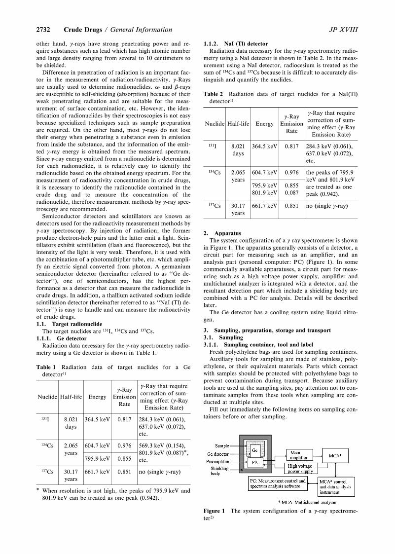
2732
Figure 1 The system configuration of a g-ray spectrome-ter2)
2732 JP XVIIICrude Drugs / General Information
other hand, g-rays have strong penetrating power and re-quire substances such as lead which has high atomic numberand large density ranging from several to 10 centimeters tobe shielded.
Difference in penetration of radiation is an important fac-tor in the measurement of radiation/radioactivity. g-Raysare usually used to determine radionuclides. a- and b-raysare susceptible to self-shielding (absorption) because of theirweak penetrating radiation and are suitable for the meas-urement of surface contamination, etc. However, the iden-tification of radionuclides by their spectroscopies is not easybecause specialized techniques such as sample preparationare required. On the other hand, most g-rays do not losetheir energy when penetrating a substance even in emissionfrom inside the substance, and the information of the emit-ted g-ray energy is obtained from the measured spectrum.Since g-ray energy emitted from a radionuclide is determinedfor each radionuclide, it is relatively easy to identify theradionuclide based on the obtained energy spectrum. For themeasurement of radioactivity concentration in crude drugs,it is necessary to identify the radionuclide contained in thecrude drug and to measure the concentration of theradionuclide, therefore measurement methods by g-ray spec-troscopy are recommended.
Semiconductor detectors and scintillators are known asdetectors used for the radioactivity measurement methods byg-ray spectroscopy. By injection of radiation, the formerproduce electron-hole pairs and the latter emit a light. Scin-tillators exhibit scintillation (flash and fluorescence), but theintensity of the light is very weak. Therefore, it is used withthe combination of a photomultiplier tube, etc. which ampli-fy an electric signal converted from photon. A germaniumsemiconductor detector (hereinafter referred to as ``Ge de-tector''), one of semiconductors, has the highest per-formance as a detector that can measure the radionuclide incrude drugs. In addition, a thallium activated sodium iodidescintillation detector (hereinafter referred to as ``NaI (Tl) de-tector'') is easy to handle and can measure the radioactivityof crude drugs.1.1. Target radionuclide
The target nuclides are 131I, 134Cs and 137Cs.1.1.1. Ge detector
Radiation data necessary for the g-ray spectrometry radio-metry using a Ge detector is shown in Table 1.
Table 1 Radiation data of target nuclides for a Gedetector1)
Nuclide Half-life Energyg-Ray
EmissionRate
g-Ray that requirecorrection of sum-ming effect (g-Ray
Emission Rate)
131I 8.021days
364.5 keV 0.817 284.3 keV (0.061),637.0 keV (0.072),etc.
134Cs 2.065years
604.7 keV 0.976 569.3 keV (0.154),801.9 keV (0.087)*,etc.795.9 keV 0.855
137Cs 30.17years
661.7 keV 0.851 no (single g-ray)
* When resolution is not high, the peaks of 795.9 keV and801.9 keV can be treated as one peak (0.942).
1.1.2. NaI (Tl) detectorRadiation data necessary for the g-ray spectrometry radio-
metry using a NaI detector is shown in Table 2. In the meas-urement using a NaI detector, radiocesium is treated as thesum of 134Cs and 137Cs because it is difficult to accurately dis-tinguish and quantify the nuclides.
Table 2 Radiation data of target nuclides for a NaI(Tl)detector1)
Nuclide Half-life Energyg-Ray
EmissionRate
g-Ray that requirecorrection of sum-ming effect (g-Ray
Emission Rate)
131I 8.021days
364.5 keV 0.817 284.3 keV (0.061),637.0 keV (0.072),etc.
134Cs 2.065years
604.7 keV 0.976 the peaks of 795.9keV and 801.9 keVare treated as onepeak (0.942).
795.9 keV 0.855801.9 keV 0.087
137Cs 30.17years
661.7 keV 0.851 no (single g-ray)
2. ApparatusThe system configuration of a g-ray spectrometer is shown
in Figure 1. The apparatus generally consists of a detector, acircuit part for measuring such as an amplifier, and ananalysis part (personal computer: PC) (Figure 1). In somecommercially available apparatuses, a circuit part for meas-uring such as a high voltage power supply, amplifier andmultichannel analyzer is integrated with a detector, and theresultant detection part which include a shielding body arecombined with a PC for analysis. Details will be describedlater.
The Ge detector has a cooling system using liquid nitro-gen.
3. Sampling, preparation, storage and transport3.1. Sampling3.1.1. Sampling container, tool and label
Fresh polyethylene bags are used for sampling containers.Auxiliary tools for sampling are made of stainless, poly-
ethylene, or their equivalent materials. Parts which contactwith samples should be protected with polyethylene bags toprevent contamination during transport. Because auxiliarytools are used at the sampling sites, pay attention not to con-taminate samples from these tools when sampling are con-ducted at multiple sites.
Fill out immediately the following items on sampling con-tainers before or after sampling.
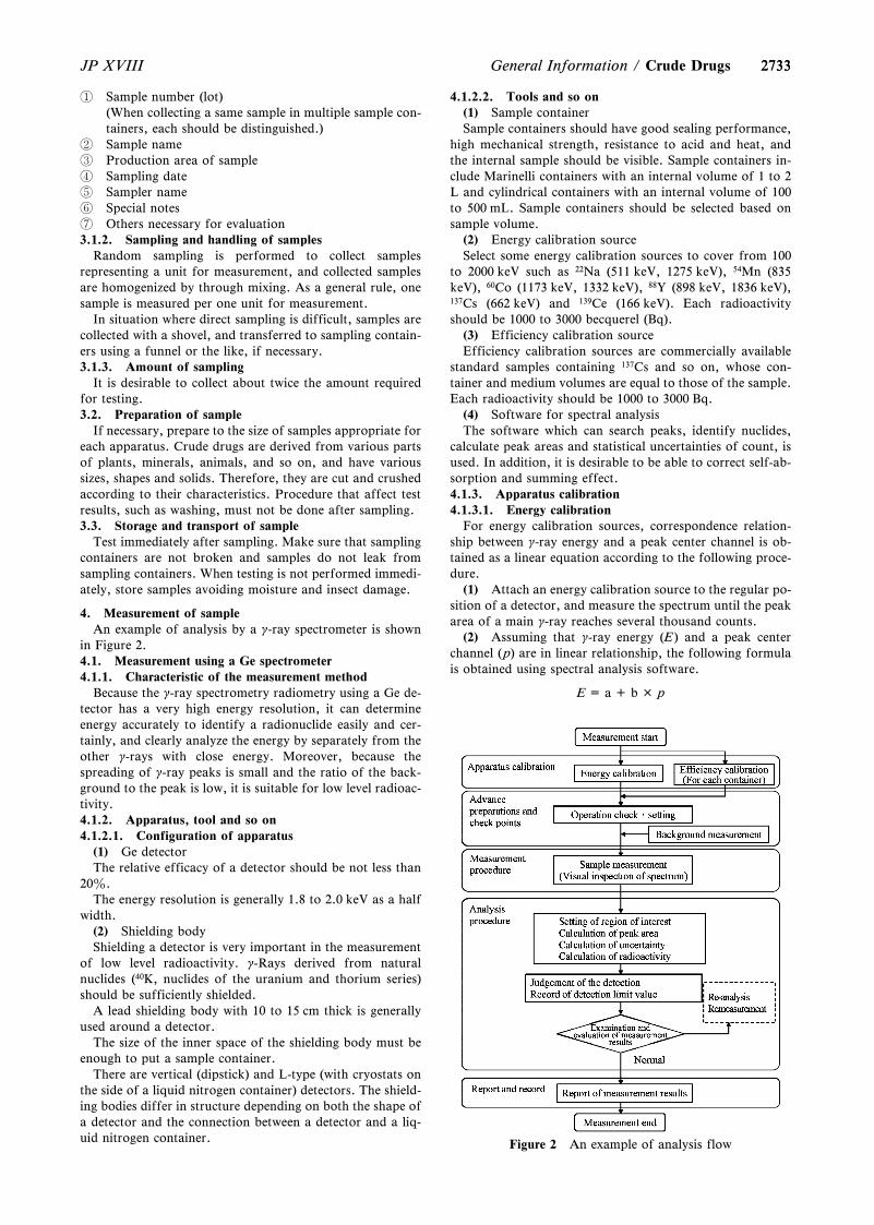
2733
Figure 2 An example of analysis flow
2733JP XVIII General Information / Crude Drugs
Sample number (lot)(When collecting a same sample in multiple sample con-tainers, each should be distinguished.)
Sample name Production area of sample Sampling date Sampler name Special notes Others necessary for evaluation3.1.2. Sampling and handling of samples
Random sampling is performed to collect samplesrepresenting a unit for measurement, and collected samplesare homogenized by through mixing. As a general rule, onesample is measured per one unit for measurement.
In situation where direct sampling is difficult, samples arecollected with a shovel, and transferred to sampling contain-ers using a funnel or the like, if necessary.3.1.3. Amount of sampling
It is desirable to collect about twice the amount requiredfor testing.3.2. Preparation of sample
If necessary, prepare to the size of samples appropriate foreach apparatus. Crude drugs are derived from various partsof plants, minerals, animals, and so on, and have varioussizes, shapes and solids. Therefore, they are cut and crushedaccording to their characteristics. Procedure that affect testresults, such as washing, must not be done after sampling.3.3. Storage and transport of sample
Test immediately after sampling. Make sure that samplingcontainers are not broken and samples do not leak fromsampling containers. When testing is not performed immedi-ately, store samples avoiding moisture and insect damage.
4. Measurement of sampleAn example of analysis by a g-ray spectrometer is shown
in Figure 2.4.1. Measurement using a Ge spectrometer4.1.1. Characteristic of the measurement method
Because the g-ray spectrometry radiometry using a Ge de-tector has a very high energy resolution, it can determineenergy accurately to identify a radionuclide easily and cer-tainly, and clearly analyze the energy by separately from theother g-rays with close energy. Moreover, because thespreading of g-ray peaks is small and the ratio of the back-ground to the peak is low, it is suitable for low level radioac-tivity.4.1.2. Apparatus, tool and so on4.1.2.1. Configuration of apparatus
(1) Ge detectorThe relative efficacy of a detector should be not less than
20z.The energy resolution is generally 1.8 to 2.0 keV as a half
width.(2) Shielding bodyShielding a detector is very important in the measurement
of low level radioactivity. g-Rays derived from naturalnuclides (40K, nuclides of the uranium and thorium series)should be sufficiently shielded.
A lead shielding body with 10 to 15 cm thick is generallyused around a detector.
The size of the inner space of the shielding body must beenough to put a sample container.
There are vertical (dipstick) and L-type (with cryostats onthe side of a liquid nitrogen container) detectors. The shield-ing bodies differ in structure depending on both the shape ofa detector and the connection between a detector and a liq-uid nitrogen container.
4.1.2.2. Tools and so on(1) Sample containerSample containers should have good sealing performance,
high mechanical strength, resistance to acid and heat, andthe internal sample should be visible. Sample containers in-clude Marinelli containers with an internal volume of 1 to 2L and cylindrical containers with an internal volume of 100to 500 mL. Sample containers should be selected based onsample volume.
(2) Energy calibration sourceSelect some energy calibration sources to cover from 100
to 2000 keV such as 22Na (511 keV, 1275 keV), 54Mn (835keV), 60Co (1173 keV, 1332 keV), 88Y (898 keV, 1836 keV),137Cs (662 keV) and 139Ce (166 keV). Each radioactivityshould be 1000 to 3000 becquerel (Bq).
(3) Efficiency calibration sourceEfficiency calibration sources are commercially available
standard samples containing 137Cs and so on, whose con-tainer and medium volumes are equal to those of the sample.Each radioactivity should be 1000 to 3000 Bq.
(4) Software for spectral analysisThe software which can search peaks, identify nuclides,
calculate peak areas and statistical uncertainties of count, isused. In addition, it is desirable to be able to correct self-ab-sorption and summing effect.4.1.3. Apparatus calibration4.1.3.1. Energy calibration
For energy calibration sources, correspondence relation-ship between g-ray energy and a peak center channel is ob-tained as a linear equation according to the following proce-dure.
(1) Attach an energy calibration source to the regular po-sition of a detector, and measure the spectrum until the peakarea of a main g-ray reaches several thousand counts.
(2) Assuming that g-ray energy (E ) and a peak centerchannel (p) are in linear relationship, the following formulais obtained using spectral analysis software.
E = a + b × p
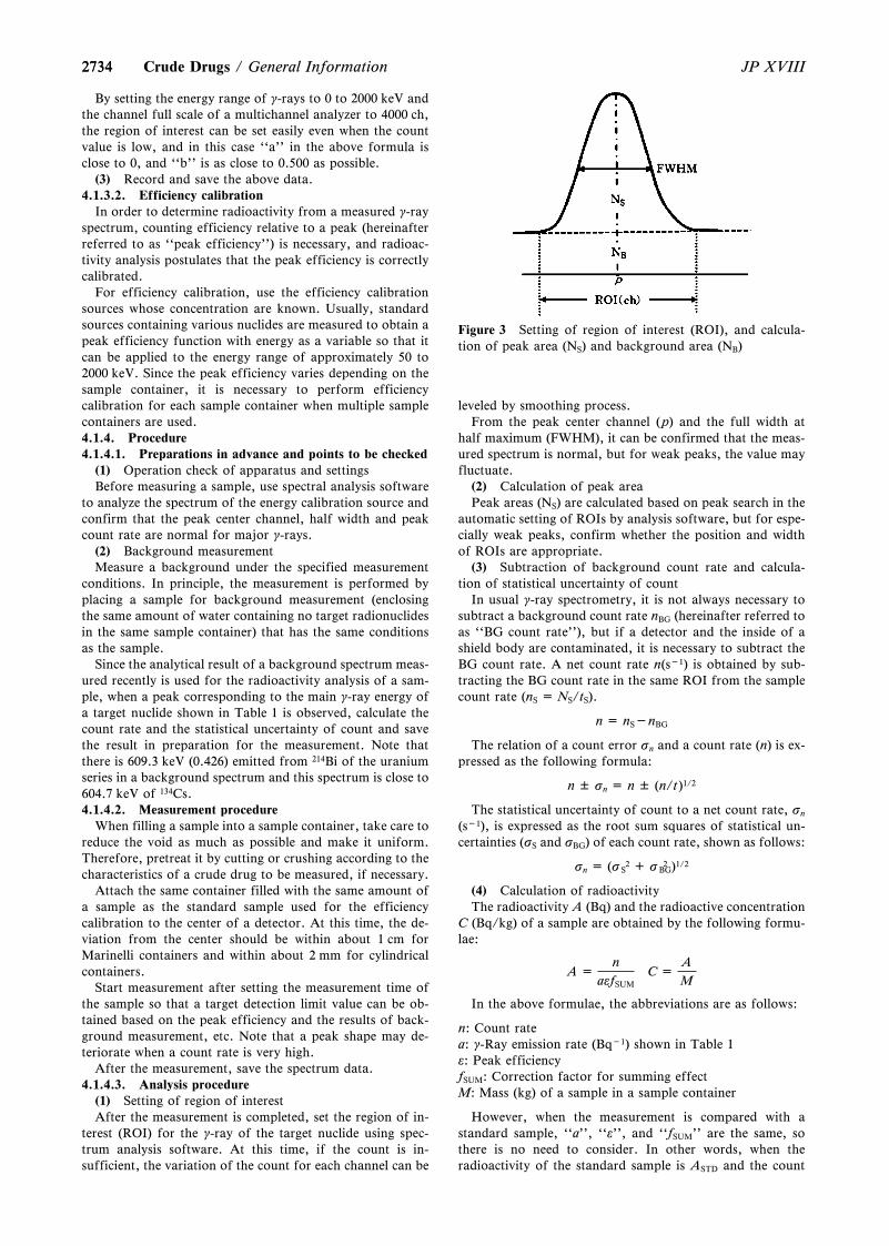
2734
Figure 3 Setting of region of interest (ROI), and calcula-tion of peak area (NS) and background area (NB)
2734 JP XVIIICrude Drugs / General Information
By setting the energy range of g-rays to 0 to 2000 keV andthe channel full scale of a multichannel analyzer to 4000 ch,the region of interest can be set easily even when the countvalue is low, and in this case ``a'' in the above formula isclose to 0, and ``b'' is as close to 0.500 as possible.
(3) Record and save the above data.4.1.3.2. Efficiency calibration
In order to determine radioactivity from a measured g-rayspectrum, counting efficiency relative to a peak (hereinafterreferred to as ``peak efficiency'') is necessary, and radioac-tivity analysis postulates that the peak efficiency is correctlycalibrated.
For efficiency calibration, use the efficiency calibrationsources whose concentration are known. Usually, standardsources containing various nuclides are measured to obtain apeak efficiency function with energy as a variable so that itcan be applied to the energy range of approximately 50 to2000 keV. Since the peak efficiency varies depending on thesample container, it is necessary to perform efficiencycalibration for each sample container when multiple samplecontainers are used.4.1.4. Procedure4.1.4.1. Preparations in advance and points to be checked
(1) Operation check of apparatus and settingsBefore measuring a sample, use spectral analysis software
to analyze the spectrum of the energy calibration source andconfirm that the peak center channel, half width and peakcount rate are normal for major g-rays.
(2) Background measurementMeasure a background under the specified measurement
conditions. In principle, the measurement is performed byplacing a sample for background measurement (enclosingthe same amount of water containing no target radionuclidesin the same sample container) that has the same conditionsas the sample.
Since the analytical result of a background spectrum meas-ured recently is used for the radioactivity analysis of a sam-ple, when a peak corresponding to the main g-ray energy ofa target nuclide shown in Table 1 is observed, calculate thecount rate and the statistical uncertainty of count and savethe result in preparation for the measurement. Note thatthere is 609.3 keV (0.426) emitted from 214Bi of the uraniumseries in a background spectrum and this spectrum is close to604.7 keV of 134Cs.4.1.4.2. Measurement procedure
When filling a sample into a sample container, take care toreduce the void as much as possible and make it uniform.Therefore, pretreat it by cutting or crushing according to thecharacteristics of a crude drug to be measured, if necessary.
Attach the same container filled with the same amount ofa sample as the standard sample used for the efficiencycalibration to the center of a detector. At this time, the de-viation from the center should be within about 1 cm forMarinelli containers and within about 2 mm for cylindricalcontainers.
Start measurement after setting the measurement time ofthe sample so that a target detection limit value can be ob-tained based on the peak efficiency and the results of back-ground measurement, etc. Note that a peak shape may de-teriorate when a count rate is very high.
After the measurement, save the spectrum data.4.1.4.3. Analysis procedure
(1) Setting of region of interestAfter the measurement is completed, set the region of in-
terest (ROI) for the g-ray of the target nuclide using spec-trum analysis software. At this time, if the count is in-sufficient, the variation of the count for each channel can be
leveled by smoothing process.From the peak center channel (p) and the full width at
half maximum (FWHM), it can be confirmed that the meas-ured spectrum is normal, but for weak peaks, the value mayfluctuate.
(2) Calculation of peak areaPeak areas (NS) are calculated based on peak search in the
automatic setting of ROIs by analysis software, but for espe-cially weak peaks, confirm whether the position and widthof ROIs are appropriate.
(3) Subtraction of background count rate and calcula-tion of statistical uncertainty of count
In usual g-ray spectrometry, it is not always necessary tosubtract a background count rate nBG (hereinafter referred toas ``BG count rate''), but if a detector and the inside of ashield body are contaminated, it is necessary to subtract theBG count rate. A net count rate n(s-1) is obtained by sub-tracting the BG count rate in the same ROI from the samplecount rate (nS = NS/tS).
n = nS-nBG
The relation of a count error sn and a count rate (n) is ex-pressed as the following formula:
n ± sn = n ± (n/t)1/2
The statistical uncertainty of count to a net count rate, sn
(s-1), is expressed as the root sum squares of statistical un-certainties (sS and sBG) of each count rate, shown as follows:
sn = (s 2S + s 2
BG)1/2
(4) Calculation of radioactivityThe radioactivity A (Bq) and the radioactive concentration
C (Bq/kg) of a sample are obtained by the following formu-lae:
A =n
aefSUMC =
A
M
In the above formulae, the abbreviations are as follows:
n: Count ratea: g-Ray emission rate (Bq-1) shown in Table 1e: Peak efficiencyfSUM: Correction factor for summing effectM: Mass (kg) of a sample in a sample container
However, when the measurement is compared with astandard sample, ``a'', ``e'', and ``fSUM'' are the same, sothere is no need to consider. In other words, when theradioactivity of the standard sample is ASTD and the count
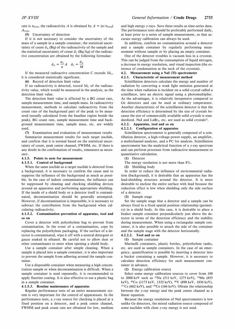
27352735JP XVIII General Information / Crude Drugs
rate is nSTD, the radioactivity A is obtained by A = (n/nSTD)ASTD.
(5) Uncertainty of detectionIf it is not necessary to consider the uncertainty of the
mass of a sample in a sample container, the statistical uncer-tainty of count dA (Bq) of the radioactivity of the sample andthe statistical uncertainty of count dC (Bq/kg) of the radioac-tive concentration are obtained by the following formulae:
dA =sn
nA dC =
dA
M
If the measured radioactive concentration C exceeds 3dC,it is considered statistically significant.
(6) Record of detection limit valueIf no radioactivity is detected, record 3dC of the radioac-
tivity value, which would be measured in the analysis, as thedetection limit value.
The detection limit value is affected by a BG count rate,sample measurement time, and sample mass. In radioactivitymeasurement, methods to calculate radioactivity from thecount rate of the background part of the peak to be meas-ured (usually calculated from the baseline region beside thepeak), BG count rate, sample measurement time and back-ground measurement time, sample mass, etc. are widelyused.
(7) Examination and evaluation of measurement resultsSummarize measurement results for each target nuclide,
and confirm that it is normal based on the statistical uncer-tainty of count, peak center channel, FWHM, etc. If there isany doubt in the confirmation of results, remeasure as neces-sary.4.1.5. Points to note for measurement4.1.5.1. Control of background
When the same nuclide as a target nuclide is detected froma background, it is necessary to confirm the cause and tosuppress the influence of the background as much as possi-ble. In the case of indoor contamination, the influence canbe suppressed by cleaning and checking shielding devicesaround an apparatus and performing appropriate shielding.If the inside of a shield body or a detector itself is contami-nated, decontamination should be generally attempted.However, if decontamination is impossible, it is necessary tosubtract the contribution from the background when cal-culating radioactivity.4.1.5.2. Contamination prevention of apparatus, tool andso on
Cover a detector with polyethylene bag to prevent fromcontamination. In the event of a contamination, cope byreplacing the polyethylene packaging. If the surface of a de-tector is contaminated, wipe it off with a neutral detergent orgauze soaked in ethanol. Be careful not to allow dust orother contaminants to enter when opening a shield body.
Use a sample container after simple cleaning. When asample is placed into a sample container, it is also importantto prevent the sample from adhering around the sample con-tainer.
Use a disposable container when measuring a high concen-tration sample or when decontamination is difficult. When asample container is used repeatedly, it is recommended toapply fluorine coating. It is also effective to use a plastic bagin a sample container.4.1.5.3. Routine maintenance of apparatus
Regular performance tests of an entire measurement sys-tem is very important for the control of apparatuses. In theperformance tests, a g-ray source for checking is placed at afixed position on a detector, and a peak center channel,FWHM and peak count rate are obtained for low, medium
and high energy g-rays. Save these results as time-series data.The performance tests should be preferably performed daily,at least prior to a series of sample measurement, so that ac-curate energy calibration can always be used.
In addition, confirm no contamination around a detectorand a sample container by regularly performing meas-urement without sample or by placing an empty container.
One of the detector troubles is vacuum loss in a cryostat.This can be judged from the consumption of liquid nitrogen,a decrease in energy resolution, and visual inspection (the ex-istence of condensation at the neck of the cryostat).4.2. Measurement using a NaI (Tl) spectrometer4.2.1. Characteristic of measurement method
Scintillation detectors calculate the energy and number ofradiation by converting a weak light emission generated atthe time when radiation is incident on a solid crystal called ascintillator, into an electric signal using a photomultiplier.As the advantages, it is relatively inexpensive compared toGe detectors and can be used at ordinary temperature.Another characteristic of the scintillation detector is that thedetection efficiency is determined by the size of crystals be-cause the size of commercially available solid crystals is stan-dardized. NaI and LaBr3, etc. are used as solid crystals3).4.2.2. Apparatus, tool and so on4.2.2.1. Configuration of apparatus
Scintillation spectrometer is generally composed of a scin-tillation detector, a high-voltage power supply, an amplifier,a multichannel analyzer, and a PC for analysis. Scintillationspectrometer has the analytical function of a g-ray spectrumand can perform processes from radioactive measurement toquantitative calculation.
(1) DetectorThe energy resolution is not more than 8z.(2) Shielding bodyIn order to reduce the influence of environmental radia-
tion (background), it is desirable that an apparatus has thelead-shielding structure around the detector. It is moredesirable to enclose the entire surface with lead because thereduction effect is low when shielding only the side surfaceof a detector.
(3) Sample stageSet the sample stage that a detector and a sample can be
always fixed in a fixed spatial position relationship (geomet-ry) in a shield body. In this case, it is desirable to place abeaker sample container perpendicularly just above the de-tector in terms of the detection efficiency and the stabilityduring measurement. When using a rectangular sample con-tainer, it is also possible to attach the side of the containerand the sample stage with the detector horizontally.4.2.2.2. Tool and so on
(1) Sample containerMarinelli containers, plastic bottles, polyethylene tanks,
etc. are used as sample containers. In the case of an emer-gency, quantification is possible by inserting a detector intoa bucket containing a sample. However, it is necessary tocalculate detection efficiency for each measurement con-tainer in advance.
(2) Energy calibration sourceSelect some energy calibration sources to cover from 100
to 2000 keV such as 22Na (511 keV, 1275 keV), 54Mn (835keV), 60Co (1173 keV, 1332 keV), 88Y (898 keV, 1836 keV),137Cs (662 keV), and 139Ce (166 keV). Obtain the relationshipbetween the g-ray energy and the peak center channel as alinear equation.
Because the energy resolution of NaI spectrometers is lowunlike Ge detectors, the mixed radiation source composed ofsome nuclides with close g-ray energy is not used.
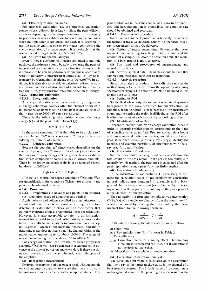
27362736 JP XVIIICrude Drugs / General Information
(3) Efficiency calibration sourceFor efficiency calibration, use the efficiency calibration
source whose radioactivity is known. Since the peak efficien-cy varies depending on the sample container, it is necessaryto perform efficiency calibration for each sample containerwhen multiple sample containers are used. It is desirable touse the nuclide emitting one or two g-rays, considering theenergy resolution of a spectrometer. It is desirable that thesource includes target nuclides, 134Cs and 137Cs.
(4) Software for spectral analysisEven if there is overlapping of peaks attributed to multiple
nuclides, the software should be able to separate the peak ofinterest and calculate its area by peak function fitting, etc. Itis desirable to be able to perform peak analysis in accordancewith ``Radioactivity measurement series No.7, g-Ray Spec-trometry by Germanium Semiconductor Detector''4). In ad-dition, it is desirable to be able to calculate radioactive con-centration from the radiation data of a nuclide to be quanti-fied (half-life, g-ray emission rate) and detection efficiency.4.2.3. Apparatus calibration4.2.3.1. Energy calibration
An energy calibration equation is obtained by using sever-al energy calibration sources after the channel width of amultichannel analyzer is set to about 1000 ch and adjusted sothat g-rays up to 2000 keV can be measured.
There is the following relationship between the g-rayenergy (E) and the peak center channel (p):
E = a + b × p
In the above equation, ``a'' is desirable to be as close to 0as possible, and ``b'' is to be as close to 2.0 as possible, con-sidering the number of channels.4.2.3.2. Efficiency calibration
Because the counting efficiency varies depending on theenergy of g-rays, the efficiency calibration (e ) is obtained asthe function of g-ray energy (E ) using an efficiency calibra-tion source composed of some nuclides in known amounts.There is the following relationship in the region of severalhundreds to 2000 keV.
log(e ) = a + b × log(E )
If there is a calibration source containing 134Cs and 137Csfor quantification, the counting efficiency for a target g-raypeak can be obtained directly.4.2.4. Procedure4.2.4.1. Preparations in advance and points to be checked
(1) Operation check of apparatus and settingsApply polarity and voltage specified by a manufacturer to
a photomultiplier tube. When a source is brought close to adetector, it is desirable to check with an oscilloscope thatoutput waveforms from a preamplifier meet specifications.However, it is also acceptable to refer to an instructionmanual for a model to be used. Alternatively, connect a de-tector to a multichannel analyzer to ensure that no noise sig-nal is present, which is not normally observed, and that adead time meter does not scale out. The channel width of themultichannel analyzer is set to about 1000 ch. The range ofmeasurement energy is to be about 100 to 2000 keV.
For energy calibration, confirm that reference g-rays (forexample, 137Cs or 40K) can be detected in a channel set in ad-vance at the time of power-on and every day. If there is a sig-nificant deviation from the set channel, adjust the gain ofthe amplifier.
(2) Background measurementPerform measurement about once a week without sample
or with an empty container to ensure that there is no con-tamination around a detector and a sample container. If a
peak is observed in the same channel as a g-ray to be quanti-fied and decontamination is impossible, the counting rateshould be obtained and recorded.4.2.4.2. Measurement procedure
Since the measurement procedure is basically the same asthe method using a Ge detector, follow the operation of a g-ray spectrometer using a Ge detector.
(1) Setting of measurement time: Determine the meas-urement time according to a target detection limit and theamount of a sample. To lower the detection limit, the reduc-tion of a background is most effective.
(2) Start and end procedures of measurement, andrecord of the times.
(3) Store of spectral data: File names should be such thatsamples and measured dates can be identified.4.2.4.3. Analysis procedure
Since the analysis procedure is basically the same as themethod using a Ge detector, follow the operation of a g-rayspectrometer using a Ge detector. Points to be noted in thisanalysis are as follows:
(1) Setting of ROISet the ROI where a significant count is obtained against a
background as the g-ray peak used for quantification. Atthis time, if the variation is large because of an insufficientcount and the setting the region is difficult, set the ROI afterleveling the count of each channel by smoothing process.
(2) Identification of nuclidePrepare to convert data by an energy calibration curve in
order to determine which channel corresponds to the g-rayof a nuclide to be quantified. Prepare nuclear data booksand environmental radiation spectra, and if an unknownpeak is detected, investigate the g-ray energy, identify thenuclide, and examine possibility of interference with the g-ray used for quantification.
(3) Calculation of peak areaSubtract the count of a background below a peak from the
total count of the peak region. If the peak is too multiple toquantify by this method, the peak area is calculated after thepeak separation using a peak function fitting method.
(4) Calculation of radioactivityIn the calculation of radioactivity it is necessary to esti-
mate the calculation result of radioactivity by consideringnatural radioisotopes contained in a sample and a back-ground. In this case, a net count (n) is obtained by subtract-ing a count in the region corresponding to the g-ray peak ofa nuclide used for quantification.
The radioactivity A (Bq) and the radioactive concentrationC (Bq/kg) of a sample are obtained from the count rate (n),which is obtained by dividing the net count by the meas-urement time, by the following formulae.
A =n
aefSUMC =
A
M
In the above formula, the abbreviations are as follows.
n: Count ratea: g-Ray emission rate (Bq-1) shown in Table 2e: Peak efficiencyfSUM: Correction factor for summing effect. The summing
effect must be corrected for 134Cs, but if correction isnot performed, state that.
M: Mass (kg) of a sample in a sample container
(5) Calculation of detection limit valueThe detection limit value is calculated on the assumption
that the g-ray of the target nuclide exists in the channel of abackground spectrum. The 3 folds value of the count errorin background count of the peak region is expressed as the
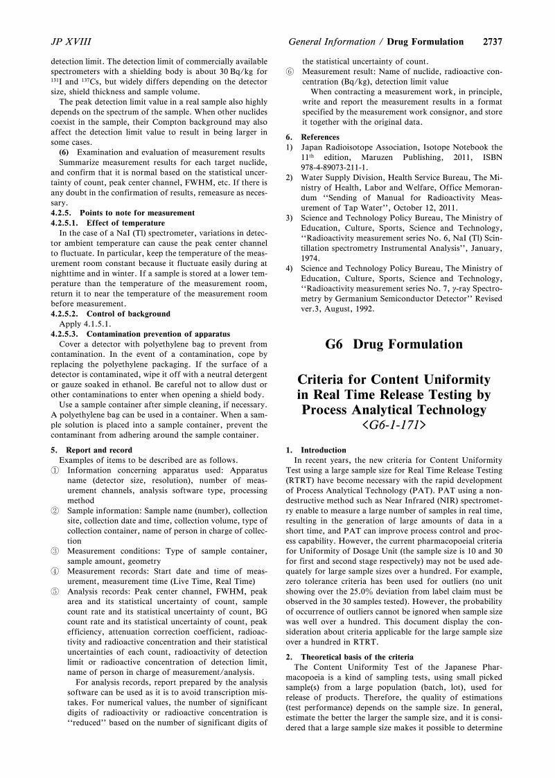
27372737JP XVIII General Information / Drug Formulation
detection limit. The detection limit of commercially availablespectrometers with a shielding body is about 30 Bq/kg for131I and 137Cs, but widely differs depending on the detectorsize, shield thickness and sample volume.
The peak detection limit value in a real sample also highlydepends on the spectrum of the sample. When other nuclidescoexist in the sample, their Compton background may alsoaffect the detection limit value to result in being larger insome cases.
(6) Examination and evaluation of measurement resultsSummarize measurement results for each target nuclide,
and confirm that it is normal based on the statistical uncer-tainty of count, peak center channel, FWHM, etc. If there isany doubt in the confirmation of results, remeasure as neces-sary.4.2.5. Points to note for measurement4.2.5.1. Effect of temperature
In the case of a NaI (Tl) spectrometer, variations in detec-tor ambient temperature can cause the peak center channelto fluctuate. In particular, keep the temperature of the meas-urement room constant because it fluctuate easily during atnighttime and in winter. If a sample is stored at a lower tem-perature than the temperature of the measurement room,return it to near the temperature of the measurement roombefore measurement.4.2.5.2. Control of background
Apply 4.1.5.1.4.2.5.3. Contamination prevention of apparatus
Cover a detector with polyethylene bag to prevent fromcontamination. In the event of a contamination, cope byreplacing the polyethylene packaging. If the surface of adetector is contaminated, wipe it off with a neutral detergentor gauze soaked in ethanol. Be careful not to allow dust orother contaminations to enter when opening a shield body.
Use a sample container after simple cleaning, if necessary.A polyethylene bag can be used in a container. When a sam-ple solution is placed into a sample container, prevent thecontaminant from adhering around the sample container.
5. Report and recordExamples of items to be described are as follows.
Information concerning apparatus used: Apparatusname (detector size, resolution), number of meas-urement channels, analysis software type, processingmethod
Sample information: Sample name (number), collectionsite, collection date and time, collection volume, type ofcollection container, name of person in charge of collec-tion
Measurement conditions: Type of sample container,sample amount, geometry
Measurement records: Start date and time of meas-urement, measurement time (Live Time, Real Time)
Analysis records: Peak center channel, FWHM, peakarea and its statistical uncertainty of count, samplecount rate and its statistical uncertainty of count, BGcount rate and its statistical uncertainty of count, peakefficiency, attenuation correction coefficient, radioac-tivity and radioactive concentration and their statisticaluncertainties of each count, radioactivity of detectionlimit or radioactive concentration of detection limit,name of person in charge of measurement/analysis.
For analysis records, report prepared by the analysissoftware can be used as it is to avoid transcription mis-takes. For numerical values, the number of significantdigits of radioactivity or radioactive concentration is``reduced'' based on the number of significant digits of
the statistical uncertainty of count. Measurement result: Name of nuclide, radioactive con-
centration (Bq/kg), detection limit valueWhen contracting a measurement work, in principle,
write and report the measurement results in a formatspecified by the measurement work consignor, and storeit together with the original data.
6. References1) Japan Radioisotope Association, Isotope Notebook the
11th edition, Maruzen Publishing, 2011, ISBN978-4-89073-211-1.
2) Water Supply Division, Health Service Bureau, The Mi-nistry of Health, Labor and Welfare, Office Memoran-dum ``Sending of Manual for Radioactivity Meas-urement of Tap Water'', October 12, 2011.
3) Science and Technology Policy Bureau, The Ministry ofEducation, Culture, Sports, Science and Technology,``Radioactivity measurement series No. 6, NaI (Tl) Scin-tillation spectrometry Instrumental Analysis'', January,1974.
4) Science and Technology Policy Bureau, The Ministry ofEducation, Culture, Sports, Science and Technology,``Radioactivity measurement series No. 7, g-ray Spectro-metry by Germanium Semiconductor Detector'' Revisedver.3, August, 1992.
G6 Drug Formulation
Criteria for Content Uniformityin Real Time Release Testing byProcess Analytical Technology
<G6-1-171>
1. IntroductionIn recent years, the new criteria for Content Uniformity
Test using a large sample size for Real Time Release Testing(RTRT) have become necessary with the rapid developmentof Process Analytical Technology (PAT). PAT using a non-destructive method such as Near Infrared (NIR) spectromet-ry enable to measure a large number of samples in real time,resulting in the generation of large amounts of data in ashort time, and PAT can improve process control and proc-ess capability. However, the current pharmacopoeial criteriafor Uniformity of Dosage Unit (the sample size is 10 and 30for first and second stage respectively) may not be used ade-quately for large sample sizes over a hundred. For example,zero tolerance criteria has been used for outliers (no unitshowing over the 25.0z deviation from label claim must beobserved in the 30 samples tested). However, the probabilityof occurrence of outliers cannot be ignored when sample sizewas well over a hundred. This document display the con-sideration about criteria applicable for the large sample sizeover a hundred in RTRT.
2. Theoretical basis of the criteriaThe Content Uniformity Test of the Japanese Phar-
macopoeia is a kind of sampling tests, using small pickedsample(s) from a large population (batch, lot), used forrelease of products. Therefore, the quality of estimations(test performance) depends on the sample size. In general,estimate the better the larger the sample size, and it is consi-dered that a large sample size makes it possible to determine
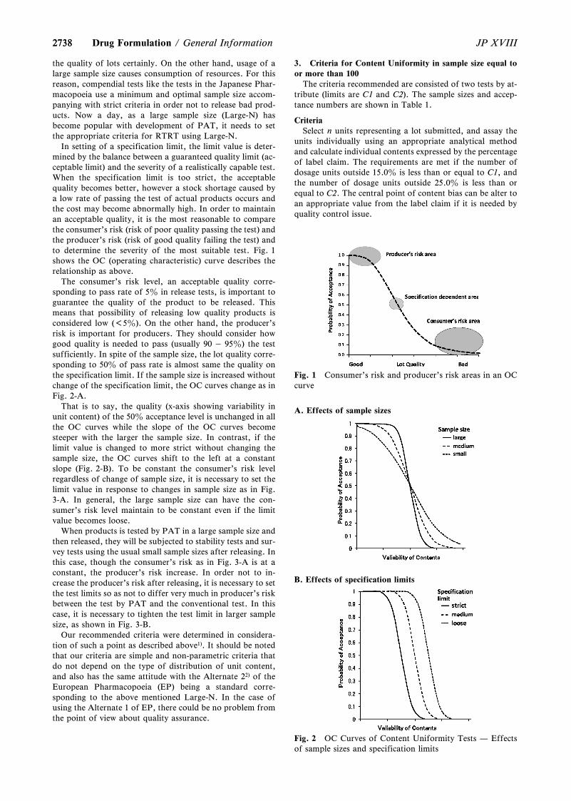
2738
Fig. 1 Consumer's risk and producer's risk areas in an OCcurve
A. Effects of sample sizes
B. Effects of specification limits
Fig. 2 OC Curves of Content Uniformity Tests — Effectsof sample sizes and specification limits
2738 JP XVIIIDrug Formulation / General Information
the quality of lots certainly. On the other hand, usage of alarge sample size causes consumption of resources. For thisreason, compendial tests like the tests in the Japanese Phar-macopoeia use a minimum and optimal sample size accom-panying with strict criteria in order not to release bad prod-ucts. Now a day, as a large sample size (Large-N) hasbecome popular with development of PAT, it needs to setthe appropriate criteria for RTRT using Large-N.
In setting of a specification limit, the limit value is deter-mined by the balance between a guaranteed quality limit (ac-ceptable limit) and the severity of a realistically capable test.When the specification limit is too strict, the acceptablequality becomes better, however a stock shortage caused bya low rate of passing the test of actual products occurs andthe cost may become abnormally high. In order to maintainan acceptable quality, it is the most reasonable to comparethe consumer's risk (risk of poor quality passing the test) andthe producer's risk (risk of good quality failing the test) andto determine the severity of the most suitable test. Fig. 1shows the OC (operating characteristic) curve describes therelationship as above.
The consumer's risk level, an acceptable quality corre-sponding to pass rate of 5z in release tests, is important toguarantee the quality of the product to be released. Thismeans that possibility of releasing low quality products isconsidered low (<5z). On the other hand, the producer'srisk is important for producers. They should consider howgood quality is needed to pass (usually 90 „ 95z) the testsufficiently. In spite of the sample size, the lot quality corre-sponding to 50z of pass rate is almost same the quality onthe specification limit. If the sample size is increased withoutchange of the specification limit, the OC curves change as inFig. 2-A.
That is to say, the quality (x-axis showing variability inunit content) of the 50z acceptance level is unchanged in allthe OC curves while the slope of the OC curves becomesteeper with the larger the sample size. In contrast, if thelimit value is changed to more strict without changing thesample size, the OC curves shift to the left at a constantslope (Fig. 2-B). To be constant the consumer's risk levelregardless of change of sample size, it is necessary to set thelimit value in response to changes in sample size as in Fig.3-A. In general, the large sample size can have the con-sumer's risk level maintain to be constant even if the limitvalue becomes loose.
When products is tested by PAT in a large sample size andthen released, they will be subjected to stability tests and sur-vey tests using the usual small sample sizes after releasing. Inthis case, though the consumer's risk as in Fig. 3-A is at aconstant, the producer's risk increase. In order not to in-crease the producer's risk after releasing, it is necessary to setthe test limits so as not to differ very much in producer's riskbetween the test by PAT and the conventional test. In thiscase, it is necessary to tighten the test limit in larger samplesize, as shown in Fig. 3-B.
Our recommended criteria were determined in considera-tion of such a point as described above1). It should be notedthat our criteria are simple and non-parametric criteria thatdo not depend on the type of distribution of unit content,and also has the same attitude with the Alternate 22) of theEuropean Pharmacopoeia (EP) being a standard corre-sponding to the above mentioned Large-N. In the case ofusing the Alternate 1 of EP, there could be no problem fromthe point of view about quality assurance.
3. Criteria for Content Uniformity in sample size equal toor more than 100
The criteria recommended are consisted of two tests by at-tribute (limits are C1 and C2). The sample sizes and accep-tance numbers are shown in Table 1.
CriteriaSelect n units representing a lot submitted, and assay the
units individually using an appropriate analytical methodand calculate individual contents expressed by the percentageof label claim. The requirements are met if the number ofdosage units outside 15.0z is less than or equal to C1, andthe number of dosage units outside 25.0z is less than orequal to C2. The central point of content bias can be alter toan appropriate value from the label claim if it is needed byquality control issue.
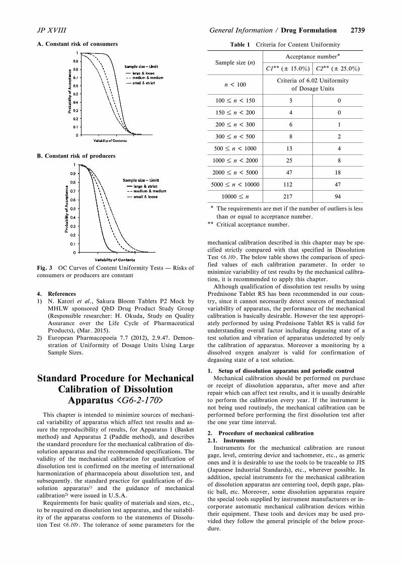
2739
Table 1 Criteria for Content Uniformity
Sample size (n)Acceptance number*
C1** (± 15.0z) C2** (± 25.0z)
n < 100Criteria of 6.02 Uniformity
of Dosage Units
100 n < 150 3 0
150 n < 200 4 0
200 n < 300 6 1
300 n < 500 8 2
500 n < 1000 13 4
1000 n < 2000 25 8
2000 n < 5000 47 18
5000 n < 10000 112 47
10000 n 217 94
* The requirements are met if the number of outliers is lessthan or equal to acceptance number.
** Critical acceptance number.
A. Constant risk of consumers
B. Constant risk of producers
Fig. 3 OC Curves of Content Uniformity Tests — Risks ofconsumers or producers are constant
2739JP XVIII General Information / Drug Formulation
4. References1) N. Katori et al., Sakura Bloom Tablets P2 Mock by
MHLW sponsored QbD Drug Product Study Group(Responsible researcher: H. Okuda, Study on QualityAssurance over the Life Cycle of PharmaceuticalProducts), (Mar. 2015).
2) European Pharmacopoeia 7.7 (2012), 2.9.47. Demon-stration of Uniformity of Dosage Units Using LargeSample Sizes.
Standard Procedure for MechanicalCalibration of Dissolution
Apparatus <G6-2-170>
This chapter is intended to minimize sources of mechani-cal variability of apparatus which affect test results and as-sure the reproducibility of results, for Apparatus 1 (Basketmethod) and Apparatus 2 (Paddle method), and describesthe standard procedure for the mechanical calibration of dis-solution apparatus and the recommended specifications. Thevalidity of the mechanical calibration for qualification ofdissolution test is confirmed on the meeting of internationalharmonization of pharmacopeia about dissolution test, andsubsequently. the standard practice for qualification of dis-solution apparatus1) and the guidance of mechanicalcalibration2) were issued in U.S.A.
Requirements for basic quality of materials and sizes, etc.,to be required on dissolution test apparatus, and the suitabil-ity of the apparatus conform to the statements of Dissolu-tion Test <6.10>. The tolerance of some parameters for the
mechanical calibration described in this chapter may be spe-cified strictly compared with that specified in DissolutionTest <6.10>. The below table shows the comparison of speci-fied values of each calibration parameter. In order tominimize variability of test results by the mechanical calibra-tion, it is recommended to apply this chapter.
Although qualification of dissolution test results by usingPrednisone Tablet RS has been recommended in our coun-try, since it cannot necessarily detect sources of mechanicalvariability of apparatus, the performance of the mechanicalcalibration is basically desirable. However the test appropri-ately performed by using Prednisone Tablet RS is valid forunderstanding overall factor including degassing state of atest solution and vibration of apparatus undetected by onlythe calibration of apparatus. Moreover a monitoring by adissolved oxygen analyzer is valid for confirmation ofdegassing state of a test solution.
1. Setup of dissolution apparatus and periodic controlMechanical calibration should be performed on purchase
or receipt of dissolution apparatus, after move and afterrepair which can affect test results, and it is usually desirableto perform the calibration every year. If the instrument isnot being used routinely, the mechanical calibration can beperformed before performing the first dissolution test afterthe one year time interval.
2. Procedure of mechanical calibration2.1. Instruments
Instruments for the mechanical calibration are runoutgage, level, centering device and tachometer, etc., as genericones and it is desirable to use the tools to be traceable to JIS(Japanese Industrial Standards), etc., wherever possible. Inaddition, special instruments for the mechanical calibrationof dissolution apparatus are centering tool, depth gage, plas-tic ball, etc. Moreover, some dissolution apparatus requirethe special tools supplied by instrument manufacturers or in-corporate automatic mechanical calibration devices withintheir equipment. These tools and devices may be used pro-vided they follow the general principle of the below proce-dure.
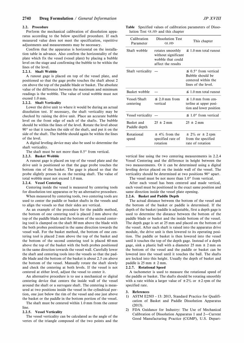
2740
Table Specified values of calibration parameters of Disso-lution Test <6.10> and this chapter
CalibrationParameter
Dissolution Test<6.10>
This chapter
Shaft wobble rotates smoothlywithout significantwobble that couldaffect the results
≦ 1.0 mm total runout
Shaft verticality — ≦ 0.59from verticalBubble should becentered within thelines of the level.
Basket wobble — ≦ 1.0 mm total runout
Vessel/Shaftcentering
≦ 2.0 mm fromvertical
≦ 1.0 mm from cen-terline at upper posi-tion and lower position
Vessel verticality — ≦ 1.09from vertical
Basket andPaddle depth
25 ± 2 mm 25 ± 2 mm
Rotationalspeed
± 4z from thespecified rate ofrotation
± 2z or ± 2 rpmfrom the specifiedrate of rotation
2740 JP XVIIIDrug Formulation / General Information
2.2. ProcedurePerform the mechanical calibration of dissolution appa-
ratus according to the below specified procedure. If eachmeasured value does not meet the specification, repetitiveadjustments and measurements may be necessary.
Confirm that the apparatus is horizontal on the installa-tion table in advance. Also confirm the horizontality of theplate which fix the vessel (vessel plate) by placing a bubblelevel on the stage and confirming the bubble to be within thelines of the level.2.2.1. Shaft Wobble
A runout gage is placed on top of the vessel plate, andpositioned so that the gage probe touches the shaft about 2cm above the top of the paddle blade or basket. The absolutevalue of the difference between the maximum and minimumreadings is the wobble. The value of total wobble must notexceed 1.0 mm.2.2.2. Shaft Verticality
Lower the drive unit to where it would be during an actualdissolution test. If necessary, the shaft verticality may bechecked by raising the drive unit. Place an accurate bubblelevel on the front edge of each of the shafts. The bubbleshould be within the lines of the level. Rotate the level about909so that it touches the side of the shaft, and put it on theside of the shaft. The bubble should again be within the linesof the level.
A digital leveling device may also be used to determine theshaft verticality.
The shaft must be not more than 0.59from vertical.2.2.3. Basket Wobble
A runout gage is placed on top of the vessel plate and thedrive unit is positioned so that the gage probe touches thebottom rim of the basket. The gage is placed so that theprobe slightly presses in on the turning shaft. The value oftotal wobble must not exceed 1.0 mm.2.2.4. Vessel Centering
Centering inside the vessel is measured by centering toolsfor dissolution test apparatus or by an alternative procedure.
When measured by centering tools, two centering tools areused to center the paddle or basket shafts in the vessels andto align the vessels so that their sides are vertical.
As an example of the procedure for the paddle method,the bottom of one centering tool is placed 2 mm above thetop of the paddle blade and the bottom of the second center-ing tool is clamped on the shaft 80 mm above the blade withthe both probes positioned in the same direction towards thevessel wall. For the basket method, the bottom of one cen-tering tool is placed 2 mm above the top of the basket andthe bottom of the second centering tool is placed 60 mmabove the top of the basket with the both probes positionedin the same direction towards the vessel wall. Carefully lowerthe shaft and centering tools into the vessels so that the pad-dle blade and the bottom of the basket is about 2.5 cm abovethe bottom of the vessel. Manually rotate the shaft slowlyand check the centering at both levels. If the vessel is notcentered at either level, adjust the vessel to center it.
An alternative procedure is to use a mechanical or digitalcentering device that centers the inside wall of the vesselaround the shaft or a surrogate shaft. The centering is meas-ured at two positions inside the vessel in the cylindrical por-tion, one just below the rim of the vessel and one just abovethe basket or the paddle in the bottom portion of the vessel.
The shaft must be centered within 1.0 mm from the centerline.2.2.5. Vessel Verticality
The vessel verticality can be calculated as the angle of thevertex of the triangle composed of the two points and the
vertical line using the two centering measurements in 2.2.4Vessel Centering and the difference in height between thetwo measurements. Or it can be determined using a digitalleveling device placed on the inside wall of the vessel. Theverticality should be determined at two positions 909apart.
The vessel must be not more than 1.09from vertical.After each vessel has been centered and made vertical,
each vessel must be positioned in the exact same position andsame direction inside the vessel plate opening.2.2.6. Basket and Paddle Depth
The actual distance between the bottom of the vessel andthe bottom of the basket or paddle is determined. If thedepth of the basket/paddle is adjustable, first a depth gage isused to determine the distance between the bottom of thepaddle blade or basket and the inside bottom of the vessel.The depth gage is set at 25 mm and placed on the bottom ofthe vessel. After each shaft is raised into the apparatus drivemodule, the drive unit is then lowered to its operating posi-tion. The paddle or basket is then lowered into the vesseluntil it touches the top of the depth gage. Instead of a depthgage, sink a plastic ball with a diameter 25 mm ± 2 mm onthe bottom of the vessel and the paddle or basket can belowered into the vessel until it touches the ball. The shaftsare locked into this height. Usually the depth of basket andpaddle is 25 mm ± 2 mm.2.2.7. Rotational Speed
A tachometer is used to measure the rotational speed ofthe paddle or basket. The shafts should be rotating smoothlywith a rate within a larger value of ±2z or ±2 rpm of thespecified rate.
3. References1) ASTM E2503 – 13: 2013, Standard Practice for Qualifi-
cation of Basket and Paddle Dissolution Apparatus(2013).
2) FDA Guidance for Industry: The Use of MechanicalCalibration of Dissolution Apparatus 1 and 2—CurrentGood Manufacturing Practice (CGMP), U.S. Depart-
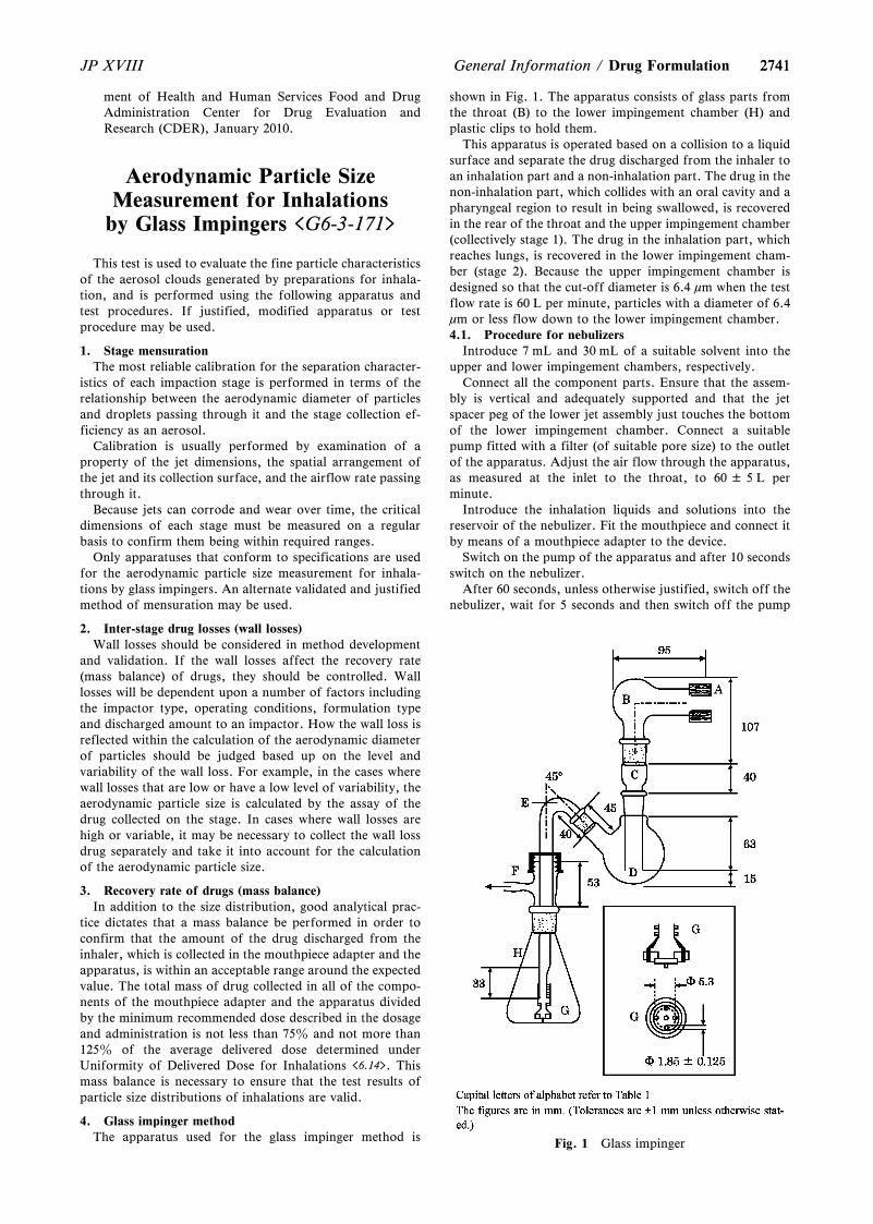
2741
Fig. 1 Glass impinger
2741JP XVIII General Information / Drug Formulation
ment of Health and Human Services Food and DrugAdministration Center for Drug Evaluation andResearch (CDER), January 2010.
Aerodynamic Particle SizeMeasurement for Inhalations
by Glass Impingers <G6-3-171>
This test is used to evaluate the fine particle characteristicsof the aerosol clouds generated by preparations for inhala-tion, and is performed using the following apparatus andtest procedures. If justified, modified apparatus or testprocedure may be used.
1. Stage mensurationThe most reliable calibration for the separation character-
istics of each impaction stage is performed in terms of therelationship between the aerodynamic diameter of particlesand droplets passing through it and the stage collection ef-ficiency as an aerosol.
Calibration is usually performed by examination of aproperty of the jet dimensions, the spatial arrangement ofthe jet and its collection surface, and the airflow rate passingthrough it.
Because jets can corrode and wear over time, the criticaldimensions of each stage must be measured on a regularbasis to confirm them being within required ranges.
Only apparatuses that conform to specifications are usedfor the aerodynamic particle size measurement for inhala-tions by glass impingers. An alternate validated and justifiedmethod of mensuration may be used.
2. Inter-stage drug losses (wall losses)Wall losses should be considered in method development
and validation. If the wall losses affect the recovery rate(mass balance) of drugs, they should be controlled. Walllosses will be dependent upon a number of factors includingthe impactor type, operating conditions, formulation typeand discharged amount to an impactor. How the wall loss isreflected within the calculation of the aerodynamic diameterof particles should be judged based up on the level andvariability of the wall loss. For example, in the cases wherewall losses that are low or have a low level of variability, theaerodynamic particle size is calculated by the assay of thedrug collected on the stage. In cases where wall losses arehigh or variable, it may be necessary to collect the wall lossdrug separately and take it into account for the calculationof the aerodynamic particle size.
3. Recovery rate of drugs (mass balance)In addition to the size distribution, good analytical prac-
tice dictates that a mass balance be performed in order toconfirm that the amount of the drug discharged from theinhaler, which is collected in the mouthpiece adapter and theapparatus, is within an acceptable range around the expectedvalue. The total mass of drug collected in all of the compo-nents of the mouthpiece adapter and the apparatus dividedby the minimum recommended dose described in the dosageand administration is not less than 75z and not more than125z of the average delivered dose determined underUniformity of Delivered Dose for Inhalations <6.14>. Thismass balance is necessary to ensure that the test results ofparticle size distributions of inhalations are valid.
4. Glass impinger methodThe apparatus used for the glass impinger method is
shown in Fig. 1. The apparatus consists of glass parts fromthe throat (B) to the lower impingement chamber (H) andplastic clips to hold them.
This apparatus is operated based on a collision to a liquidsurface and separate the drug discharged from the inhaler toan inhalation part and a non-inhalation part. The drug in thenon-inhalation part, which collides with an oral cavity and apharyngeal region to result in being swallowed, is recoveredin the rear of the throat and the upper impingement chamber(collectively stage 1). The drug in the inhalation part, whichreaches lungs, is recovered in the lower impingement cham-ber (stage 2). Because the upper impingement chamber isdesigned so that the cut-off diameter is 6.4 mm when the testflow rate is 60 L per minute, particles with a diameter of 6.4mm or less flow down to the lower impingement chamber.4.1. Procedure for nebulizers
Introduce 7 mL and 30 mL of a suitable solvent into theupper and lower impingement chambers, respectively.
Connect all the component parts. Ensure that the assem-bly is vertical and adequately supported and that the jetspacer peg of the lower jet assembly just touches the bottomof the lower impingement chamber. Connect a suitablepump fitted with a filter (of suitable pore size) to the outletof the apparatus. Adjust the air flow through the apparatus,as measured at the inlet to the throat, to 60 ± 5 L perminute.
Introduce the inhalation liquids and solutions into thereservoir of the nebulizer. Fit the mouthpiece and connect itby means of a mouthpiece adapter to the device.
Switch on the pump of the apparatus and after 10 secondsswitch on the nebulizer.
After 60 seconds, unless otherwise justified, switch off thenebulizer, wait for 5 seconds and then switch off the pump
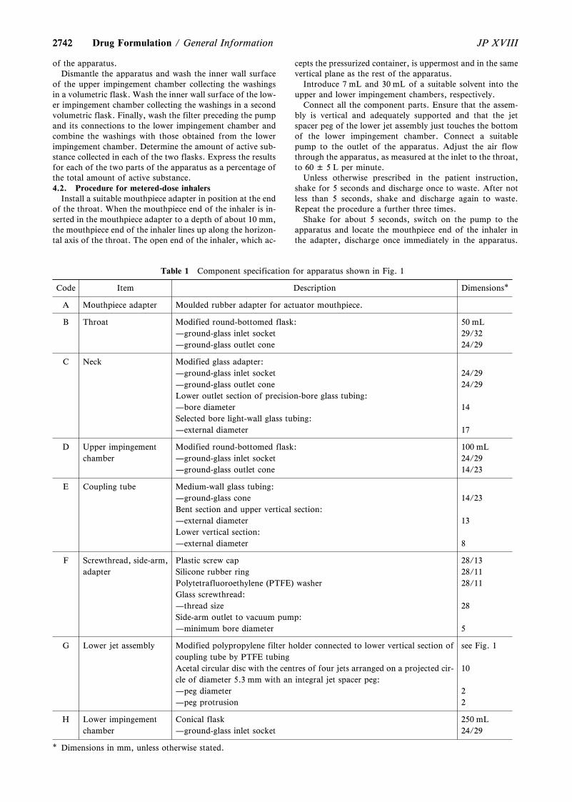
2742
Table 1 Component specification for apparatus shown in Fig. 1
Code Item Description Dimensions*
A Mouthpiece adapter Moulded rubber adapter for actuator mouthpiece.
B Throat Modified round-bottomed flask: 50 mL—ground-glass inlet socket 29/32—ground-glass outlet cone 24/29
C Neck Modified glass adapter:—ground-glass inlet socket 24/29—ground-glass outlet cone 24/29Lower outlet section of precision-bore glass tubing:—bore diameter 14Selected bore light-wall glass tubing:—external diameter 17
D Upper impingementchamber
Modified round-bottomed flask: 100 mL—ground-glass inlet socket 24/29—ground-glass outlet cone 14/23
E Coupling tube Medium-wall glass tubing:—ground-glass cone 14/23Bent section and upper vertical section:—external diameter 13Lower vertical section:—external diameter 8
F Screwthread, side-arm,adapter
Plastic screw cap 28/13Silicone rubber ring 28/11Polytetrafluoroethylene (PTFE) washer 28/11Glass screwthread:—thread size 28Side-arm outlet to vacuum pump:—minimum bore diameter 5
G Lower jet assembly Modified polypropylene filter holder connected to lower vertical section ofcoupling tube by PTFE tubing
see Fig. 1
Acetal circular disc with the centres of four jets arranged on a projected cir-cle of diameter 5.3 mm with an integral jet spacer peg:
10
—peg diameter 2—peg protrusion 2
H Lower impingementchamber
Conical flask 250 mL—ground-glass inlet socket 24/29
* Dimensions in mm, unless otherwise stated.
2742 JP XVIIIDrug Formulation / General Information
of the apparatus.Dismantle the apparatus and wash the inner wall surface
of the upper impingement chamber collecting the washingsin a volumetric flask. Wash the inner wall surface of the low-er impingement chamber collecting the washings in a secondvolumetric flask. Finally, wash the filter preceding the pumpand its connections to the lower impingement chamber andcombine the washings with those obtained from the lowerimpingement chamber. Determine the amount of active sub-stance collected in each of the two flasks. Express the resultsfor each of the two parts of the apparatus as a percentage ofthe total amount of active substance.4.2. Procedure for metered-dose inhalers
Install a suitable mouthpiece adapter in position at the endof the throat. When the mouthpiece end of the inhaler is in-serted in the mouthpiece adapter to a depth of about 10 mm,the mouthpiece end of the inhaler lines up along the horizon-tal axis of the throat. The open end of the inhaler, which ac-
cepts the pressurized container, is uppermost and in the samevertical plane as the rest of the apparatus.
Introduce 7 mL and 30 mL of a suitable solvent into theupper and lower impingement chambers, respectively.
Connect all the component parts. Ensure that the assem-bly is vertical and adequately supported and that the jetspacer peg of the lower jet assembly just touches the bottomof the lower impingement chamber. Connect a suitablepump to the outlet of the apparatus. Adjust the air flowthrough the apparatus, as measured at the inlet to the throat,to 60 ± 5 L per minute.
Unless otherwise prescribed in the patient instruction,shake for 5 seconds and discharge once to waste. After notless than 5 seconds, shake and discharge again to waste.Repeat the procedure a further three times.
Shake for about 5 seconds, switch on the pump to theapparatus and locate the mouthpiece end of the inhaler inthe adapter, discharge once immediately in the apparatus.
27432743JP XVIII General Information / Drug Formulation
Remove the assembled inhaler from the adapter, shake fornot less than 5 seconds, relocate the mouthpiece end of theinhaler in the adapter and discharge again. Repeat the dis-charge sequence. The number of discharges should beminimized and typically would not be greater than 10. Afterthe final discharge wait for not less than 5 seconds and thenswitch off the pump.
Dismantle the apparatus. Wash the inner wall surface ofthe coupling tube to the lower impingement chamber and itsouter wall surface that projects into the chamber with a suit-able solvent, collecting the washings in the lower impinge-ment chamber. Determine the content of active substance inthis solution. Calculate the amount of active substance col-lected in the lower impingement chamber per discharge andexpress the results as a percentage of the active substancestated on the label.4.3. Procedure for dry powder inhalers
Introduce 7 mL and 30 mL of a suitable solvent into theupper and lower impingement chambers, respectively.
Connect all the component parts. Ensure that the assem-bly is vertical and adequately supported and that the jetspacer peg of the lower jet assembly just touches the bottomof the lower impingement chamber. Connect a suitablepump to the outlet of the apparatus. Adjust the air flowthrough the apparatus, as measured at the inlet to the throat,to 60 ± 5 L per minute.
Prepare an inhaler and connect it to the throat using asuitable adapter. Switch on the pump of the apparatus, after5 seconds switch off the pump of the apparatus, and repeatthe discharge sequence. The number of discharges should beminimized and typically would not be greater than 10.
Dismantle the apparatus. Wash the inner wall surface ofthe coupling tube to the lower impingement chamber and itsouter wall surface that projects into the chamber with a suit-able solvent, collecting the washings in the lower impinge-ment chamber. Determine the content of active substance inthis solution. Calculate the amount of active substance col-lected in the lower impingement chamber per discharge andexpress the results as a percentage of the active substancestated on the label.
Tablet Hardness Determinations<G6-4-180>
This General Information summarizes the principle, type,instrument configuration and points to be considered in thetablet hardness determination. Results, together with otherinformation on physical integrity of tablets such as friability,are used to ensure their mechanical strength against stressessuch as impact and pressure they experience from manufac-turing process to usage.
The measurement is usually performed by placing a tabletbetween two platens and moving the one platen at a constantspeed to obtain the force (N) just before the tablet is broken.The tablet hardness values reflect either the breaking forcewith which a compressive load generates breakage in a spe-cific tablet plane, or the crushing strength with which sub-stantial breaking cause the loss of structure, or both, de-pending on an apparatus used. In some cases, the tablet ap-pearance may be lost after breakage. Criteria of the tablethardness obtained by this measurement is different from thedefinition of hardness generally used in the field of materialsscience etc. (the resistance of a surface against penetrationand pushing by a small probe).
Multiple hardness testers with different structure of the
tablet-mounted part, the transfer mechanism of the platen,the measurement method of force, etc. are used. Manual orrelatively simple-structured hardness testers include Mon-santo (Stokes) tablet hardness tester which compresses atablet with an indenter via a spring gauge and a screw, Pfizertablet hardness tester which applies pressure to a tablet witha plier, Strong Cobb hardness tester which applies a load toa tablet by compressed air, and Erweka tablet hardness testerwhich applies a load to a tablet with an indenter using anelectrically-powered weight load. Apparatuses which auto-mate the process of hardness determination, correspond tovarious measurement modes and have a data correctionfunction, etc. are also used.
The measurement of tablet hardness is affected by theshape, size, and orientation of a sample tablet, as well as thestructure of an apparatus and the measurement conditions.Therefore, it is important to record the name of apparatusand conditions as well as results. The direct comparison ofdata requires measurements under the same conditions. Thefollowing points should be also considered in the meas-urement.
(i) Platen: Two platens with smooth area contacting atablet should be used in parallel. The contact surface shouldbe larger than the area of contact with the tablet. Make surethat tablets should be free of displacement by bending ortwisting when the load is applied.
(ii) Loading rate: An apparatus having the mechanismwhich keeps the constant loading rate of compression forceby platens should be used for the measurements. Or, themeasurements should be performed by moving the platen ata low rate from a certain point immediately before contactwith a tablet using an apparatus which keeps the movingspeed of platens constant to suppress the variation of theloading rate. Faster movement of the platen would allowrapid measurement, while possible variation in the loadingrate often leads to uncontrollable crushing and the rapid ac-cumulation of compressive loads.
(iii) Measurement unit and calibration of apparatuses:An apparatus calibrated with accuracy of 1N or less shouldbe used for the measurement.
(iv) Change of apparatus: It is desirable to change an ap-paratus to that having a similar mechanism because themechanism such as the loading method of compression forceand the measuring method force would vary between them.The risk due to the apparatus change should be controlled byconsidering their measurement mechanisms and by compar-ing the results obtained by multiple measurement parameterssuch as the loading rate, and the moving speed of platens,using the sample in a same lot.
(v) Tablet orientation: A round non-scored tablet is usu-ally placed between two platens to allow the compression oc-curs across the tablet diameter. In the measurement of ascored tablet, the tablet is placed so that the score is perpen-dicular or parallel to the platens. In the case of tablets withunique or complicated shape, it is desirable to place them inthe same orientation that can be easily reproduced. In gener-al, a load is applied either across the diameter or parallel tothe longest axis.
(vi) Unit: As a unit of tablet hardness, kgf, kp or StrongCobb Unit (SCU), etc. as well as N is used.
(vii) Number of samples: In addition to the average ofthe measured values of tablet hardness, their variationshould be also important. Therefore, the number of samplesshould be statistically appropriate for the purpose of meas-urement. Usually 6 or more samples, often 10 samples, aremeasured.
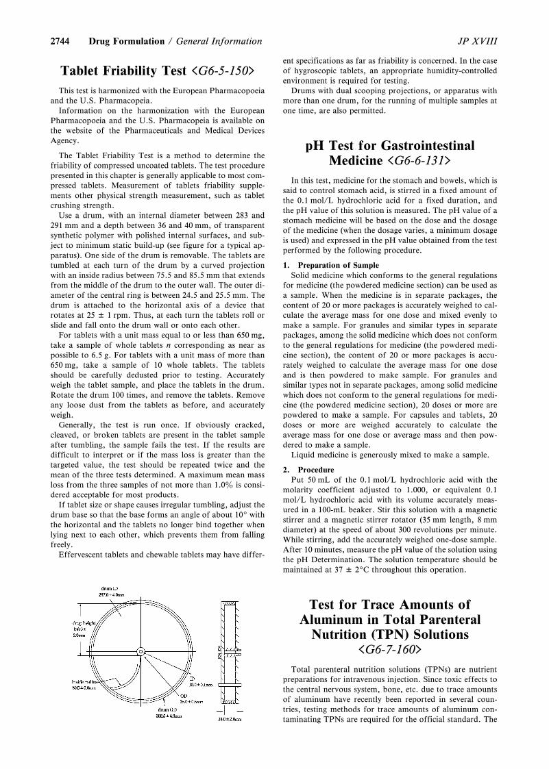
27442744 JP XVIIIDrug Formulation / General Information
Tablet Friability Test <G6-5-150>
This test is harmonized with the European Pharmacopoeiaand the U.S. Pharmacopeia.
Information on the harmonization with the EuropeanPharmacopoeia and the U.S. Pharmacopeia is available onthe website of the Pharmaceuticals and Medical DevicesAgency.
The Tablet Friability Test is a method to determine thefriability of compressed uncoated tablets. The test procedurepresented in this chapter is generally applicable to most com-pressed tablets. Measurement of tablets friability supple-ments other physical strength measurement, such as tabletcrushing strength.
Use a drum, with an internal diameter between 283 and291 mm and a depth between 36 and 40 mm, of transparentsynthetic polymer with polished internal surfaces, and sub-ject to minimum static build-up (see figure for a typical ap-paratus). One side of the drum is removable. The tablets aretumbled at each turn of the drum by a curved projectionwith an inside radius between 75.5 and 85.5 mm that extendsfrom the middle of the drum to the outer wall. The outer di-ameter of the central ring is between 24.5 and 25.5 mm. Thedrum is attached to the horizontal axis of a device thatrotates at 25 ± 1 rpm. Thus, at each turn the tablets roll orslide and fall onto the drum wall or onto each other.
For tablets with a unit mass equal to or less than 650 mg,take a sample of whole tablets n corresponding as near aspossible to 6.5 g. For tablets with a unit mass of more than650 mg, take a sample of 10 whole tablets. The tabletsshould be carefully dedusted prior to testing. Accuratelyweigh the tablet sample, and place the tablets in the drum.Rotate the drum 100 times, and remove the tablets. Removeany loose dust from the tablets as before, and accuratelyweigh.
Generally, the test is run once. If obviously cracked,cleaved, or broken tablets are present in the tablet sampleafter tumbling, the sample fails the test. If the results aredifficult to interpret or if the mass loss is greater than thetargeted value, the test should be repeated twice and themean of the three tests determined. A maximum mean massloss from the three samples of not more than 1.0z is consi-dered acceptable for most products.
If tablet size or shape causes irregular tumbling, adjust thedrum base so that the base forms an angle of about 109withthe horizontal and the tablets no longer bind together whenlying next to each other, which prevents them from fallingfreely.
Effervescent tablets and chewable tablets may have differ-
ent specifications as far as friability is concerned. In the caseof hygroscopic tablets, an appropriate humidity-controlledenvironment is required for testing.
Drums with dual scooping projections, or apparatus withmore than one drum, for the running of multiple samples atone time, are also permitted.
pH Test for GastrointestinalMedicine <G6-6-131>
In this test, medicine for the stomach and bowels, which issaid to control stomach acid, is stirred in a fixed amount ofthe 0.1 mol/L hydrochloric acid for a fixed duration, andthe pH value of this solution is measured. The pH value of astomach medicine will be based on the dose and the dosageof the medicine (when the dosage varies, a minimum dosageis used) and expressed in the pH value obtained from the testperformed by the following procedure.
1. Preparation of SampleSolid medicine which conforms to the general regulations
for medicine (the powdered medicine section) can be used asa sample. When the medicine is in separate packages, thecontent of 20 or more packages is accurately weighed to cal-culate the average mass for one dose and mixed evenly tomake a sample. For granules and similar types in separatepackages, among the solid medicine which does not conformto the general regulations for medicine (the powdered medi-cine section), the content of 20 or more packages is accu-rately weighed to calculate the average mass for one doseand is then powdered to make sample. For granules andsimilar types not in separate packages, among solid medicinewhich does not conform to the general regulations for medi-cine (the powdered medicine section), 20 doses or more arepowdered to make a sample. For capsules and tablets, 20doses or more are weighed accurately to calculate theaverage mass for one dose or average mass and then pow-dered to make a sample.
Liquid medicine is generously mixed to make a sample.
2. ProcedurePut 50 mL of the 0.1 mol/L hydrochloric acid with the
molarity coefficient adjusted to 1.000, or equivalent 0.1mol/L hydrochloric acid with its volume accurately meas-ured in a 100-mL beaker. Stir this solution with a magneticstirrer and a magnetic stirrer rotator (35 mm length, 8 mmdiameter) at the speed of about 300 revolutions per minute.While stirring, add the accurately weighed one-dose sample.After 10 minutes, measure the pH value of the solution usingthe pH Determination. The solution temperature should bemaintained at 37 ± 29C throughout this operation.
Test for Trace Amounts ofAluminum in Total Parenteral
Nutrition (TPN) Solutions<G6-7-160>
Total parenteral nutrition solutions (TPNs) are nutrientpreparations for intravenous injection. Since toxic effects tothe central nervous system, bone, etc. due to trace amountsof aluminum have recently been reported in several coun-tries, testing methods for trace amounts of aluminum con-taminating TPNs are required for the official standard. The
27452745JP XVIII General Information / Drug Formulation
following three analytical methods are available: High-Performance Liquid Chromatography using a fluorescencephotometric detector (HPLC with fluorescence detection),Inductivity Coupled Plasma-Atomic Emission Spectrometry(ICP-AES method), Inductivity Coupled Plasma-MassSpectrometry (ICP-MS method). Detection sensitivity byHPLC with fluorescence detection is about 1 mg/L (ppb),while ICP-AES fitted with special apparatus and ICP-MShave higher sensitivity.
Since TPNs are nutrient preparations, they contain manynutrients such as sugars, amino acids, electrolytes, etc., invarious compositions. Thus, care is needed in the selectionof a suitable analytical method, because these coexistingcomponents may affect the measurement of trace amountsof aluminum.
In view of the general availability of HPLC apparatus, thepresent general information describes procedures for the de-termination of trace levels of aluminum in TPNs by meansof HPLC with a fluorescence photometric detector, usingtwo kinds of fluorescent chelating agents, i.e., Quinolinolcomplexing method, Lumogallion complexing method.
1. Quinolinol complexing methodAfter forming a complex of aluminum ion in the sample
solution with quinolinol, the assay for aluminum by HPLCfitted with a fluorescence photometer is performed.1.1. Preparation of sample solution
Pipet 1 mL of the sample (TPNs) exactly, and after adding10 mL of water for aluminum test, make up the sample solu-tion to 10 mL exactly by adding the mobile phase.1.2. Preparation of a series of standard solutions forcalibration curve
Pipet 1 mL of water for aluminum test exactly, and afteradding 10 mL each of standard solutions of aluminum (1)–(5), make up the standard solutions for calibration curve to10 mL exactly by adding the mobile phase (Aluminum con-centration: 0, 1.25, 2.5, 5.0, and 10.0 ppb).1.3. Standard testing method
Pipet 0.1 mL each of the sample solution and standard so-lutions, and perform the test by HPLC under the followingconditions. Calculate the aluminum cotent in the sample so-lution using a calibration curve method.Operating conditions—
Detector: A fluorescence photometer (excitation wave-length: 380 nm, emission wavelength: 520 nm).
Column: A stainless steel column 4.6 mm in inside diame-ter and 15 cm in length, packed with phenylsilanized silicagel for liquid chromatography (5 mm in particle diameter).
Column temperature: A constant temperature of about409C.
Mobile phase: A mixture of 8-quinolinol in acetonitrile (3in 100) and diluted 0.5 mol/L ammonium acetate TS (2 in 5)(1:1).
Flow rate: Adjust so that the retention time of aluminum/8-quinolinol complex is about 9 minutes.System suitability—
The correlation coefficient of the calibration curve, whichis prepared using a series of standard solutions, is not lessthan 0.99.
Furthermore there is an alternative method, in which thechelating agent 8-quinolinol is not included in the mobilephase.
In this method also, aluminum is detected as a complexwith 8-quinolinol in the sample solution by using HPLC fit-ted with a fluorescence photometer. But it is necessary toform a more stable aluminum/8-quinolinol complex in thesample solution, because the chelating agent is not included
in the mobile phase. Further, since the analytical wavelengthfor the fluorescence detection is different from that in thestandard method, excitation wavelength: 370 nm, emissionwavelength: 504 nm, the detection sensitivity is different.Thus, it is appropriate to obtain the calibration curve be-tween 0 – 25 ppb of aluminum. Other than the above- men-tioned differences, the size of column, column temperature,and the mobile phase are also different from those used inthe standard method, so suitable analytical conditionsshould be established for performing precise and reproduci-ble examinations of trace amounts of aluminum in the sam-ple specimen.
2. Lumogallion complexing methodAfter forming a complex of aluminum ion in the sample
specimen with the fluorescent reagent of lumogallion, thesolution is examined by HPLC fitted with a fluorescencephotometer.2.1. Preparation of sample solution
Pipet 70 mL of the sample specimen (TPN) exactly, add0.15 mL of lumogallion hydrochloric acid TS and 0.6 mL ofbuffer solution for aluminum test (pH 7.2) exactly, then mixthe solution. After this solution has been allowed to standfor 4 hours at 409C, it can be used for the measurement as asample solution.2.2. Preparation of a series of standard solutions forcalibration curve
Pipet 1 mL each of standard aluminum solutions (1) – (5)exactly, and add diluted nitric acid for aluminum test (1 in100) to make exactly 100 mL. Pipet 70 mL each of these solu-tions exactly, and add exactly 0.15 mL of lumogallion hy-drochloric acid TS and exactly 0.6 mL of buffer solution foraluminum test (pH 7.2) then allow to stand for 4 hours at409C to make a series of standard solutions for obtaining thecalibration curve (Aluminum: 0, 1.07, 2.13, 4.27, and 8.54ppb).2.3. Standard examination method
Take 0.1 mL each of the sample solution and standard so-lutions for the calibration curve, and perform HPLC analy-sis under the following conditions. Calculate the aluminumcontent in the sample solution by using a calibration curvemethod.Operating conditions—
Detector: A fluorescence photometer(excitation wave-length 505 nm, emission wavelength 574 nm).
Column: A stainless steel column 6.0 mm in inside diame-ter and 10 cm in length, packed with octylsilanized silica gelfor liquid chromatography (5 mm in particle diameter).
Column temperature: A constant temperature of about409C.
Mobile phase: Take 100 mL of 2-propanol, and add adiluted 1 mol/L acetic acid-sodium acetate buffer solution ofpH 5.0 (1 in 10) to make 1000 mL.
Flow rate: Adjust so that the retention time of aluminum/lumogallion complex is about 5 minutes.System suitability—
The correlation coefficient of the calibration curve, whichis prepared using a series of standard solutions for calibra-tion curve, is not less than 0.99.
3. Notes(i) Regarding water, solvents, reagents, vessels and other
tools used for the examination, select those not contaminat-ed with aluminum. Further, keep the testing environmentclean and free from dust in the testing room.
(ii) Before the measurement, it is necessary to confirmthat the characteristic properties of the sample do not affectthe formation of the complex.
27462746 JP XVIIIContainers and Package / General Information
(iii) Reference substances of river water for analysis oftrace elements, commercially distributed by the Japan Socie-ty for Analytical Chemistry, can be used to estimate thevalidity of test methods and results.
4. Standard Solutions, Reagents and Test SolutionsOther than the standard solutions, reagents and test solu-
tions specified in the Japanese Pharmacopoeia, thosedescribed below can be used in this test.
(i) N,N-Bis(2-hydroxyethyl)-2-aminoethane sulfonic acidC6H15NO5S White crystals or powder.
(ii) Hydrochloric acid for aluminum test Same as thereagent Hydrochloric acid. Further, it contains not morethan 1 ppb of aluminum.
(iii) Lumogallion C12H9ClN2O6S Red-brown to darkbrown powder. Further, it contains not more than 1 ppm ofaluminum.
(iv) Lumogallion hydrochloric acid TS Dissolve 0.86 gof lumogallion in 300 mL of 2-propanol, and add 350 mL ofdiluted Hydrochloric acid for aluminum test (9 in 50) andWater for aluminum test to make 1000 mL exactly.
(v) Nitric acid for aluminum test Same as the reagentNitric acid. Further, it contains not more than 1 ppb of alu-minum.
(vi) pH buffer solution for aluminum test (pH 7.2) Dis-solve 106.6 g of N,N-bis(2-hydroxyethyl)-2-aminoethane sul-fonic acid in 800 mL of Water for aluminum test, adjust thepH 7.2 by using Tetramethylammonium hydroxide aqueoussolution, and add Water for aluminum test to make 1000mL.
(vii) Standard aluminum solution Pipet a constantvolume each of Water for aluminum test or the Standardaluminum stock solution, dilute and adjust the aluminumconcentration to 0, 1.25, 2.5, 5.0, and 10 ppm by usingdiluted Nitric acid for aluminum test (1 in 100), to makeStandard aluminum solutions (1) – (5).
(viii) Tetramethylammonium hydroxide TS [(CH3)4NOH] It is a 25z aqueous solution, prepared for alumi-num test. Further, it contains not more than 1 ppb of alumi-num.
(ix) Water for aluminum test It contains not more than1 ppb of aluminum.
G7 Containers and Package
Glass Containers forPharmaceutical Products
<G7-1-171>
Glass containers for pharmaceutical products are widelyused. Glass bottles are used for tight and well-closed con-tainers for bulk packaging of solid preparations for oral ad-ministration such as tablets and capsules etc., and ampules,vials or glass syringes are for hermetic containers of injec-tions etc.
Glass containers used as a primary packaging have charac-teristics of high chemical durability etc. in addition to highstrength, high transparency, no air permeability and nomoisture permeability. On the other hand, they are heavy,bulky, fragile and easy to be broken by a physical shock dur-ing manufacturing or transportation, so they requireattention on handling.
This chapter provides basic information about glass con-
tainers, items to be confirmed for the selection of glass con-tainers and for the proper performance of a quality evalua-tion that comes along with the selection, and informationabout the quality control at the manufacturing stage ofpreparations.
1. Basic information about glass containers for phar-maceutical products
Glass containers for pharmaceutical products do not inter-act physically or chemically with the contained medicamentsto alter any property or quality. Glass containers for injec-tions can protect the contained medicaments from the inva-sion of microbes by means of perfect sealing or other suita-ble process.
To ensure the quality of contained medicaments over theshelf life, it is necessary to select a suitable glass container.In the selection of container, it is necessary to consider thephysicochemical condition of the contained medicaments,i.e., solid or liquid and the adoption of a well-closed con-tainer, a tight container, a hermetic container or a coloredcontainer to ensure the chemical stability of the containedmedicaments. Furthermore, it is necessary to consider sur-face treatment on the inner surface of containers in the casewhere it is assumed that foreign substances occur by interac-tions with the preparation ingredients.1.1 Glass composition and molding
Composition of the glass used for primary packaging ofpharmaceutical products is either borosilicate glass or so-dalime glass.
Borosilicate glass has a reticulated network made ofsilicon dioxide (silica: SiO2) and diboron trioxide (B2O3).Borosilicate glass has a small coefficient of thermalexpansion, relatively high hardness and high hydrolyticresistance1). Containers made of this chemical compositionare classified as Type I glass in the USP and the EP.
Cylinder-shaped and long material glass tubes made ofborosilicate glass are cut and undergo secondary processingto mold ampules, vials or syringes, which are mostly used forcontainers of small amount of injections or lyophilizedpreparations.
Sodalime glass is composed of silicon dioxide (silica:SiO2), sodium oxide (Na2O) and calcium oxide (CaO) as theprincipal components. It has low water resistance as a draw-back, but it is easy to manufacture and process1). Containersmade of this chemical composition are classified as Type IIor III glass in the USP and the EP.
A glass container made of sodalime glass is called a blownbottle or a molded bottle because it is molded by pouringmelted glass into a mold and blowing air. Also it is called astandard bottle or an automatic bottle because of its massproduction at low cost. It is widely used not only for glassbottles of solid preparations for oral administration but alsoas containers for injections such as large volume vials ofparenteral infusions or vials of powder injections for an-tibiotics etc.1.2 Surface treatment of inner surface of glass containersfor pharmaceutical products
Surface treatments are performed to modify the nature ofthe inner surface of glass containers. The treatments are suchas dealkalization treatment and coating, etc.
The dealkalization treatment is a method to neutralize thesurface layer of the glass by selectively extracting and remov-ing alkali components using sulfur compounds at high tem-perature above the glass-transition, which results in exposureof the silica-rich surface. This treatment reduce the elutionof alkali components. The coating includes methods usingsilica (SiO2), silicon resin and fluorine resin, etc.
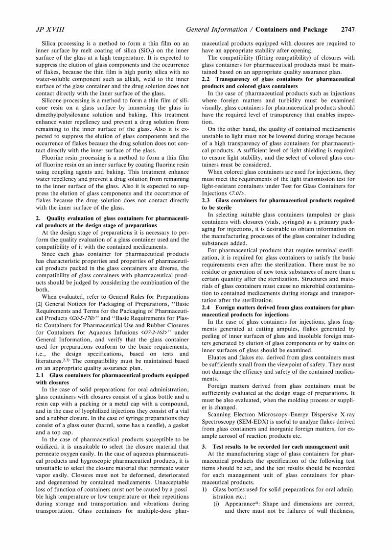
27472747JP XVIII General Information / Containers and Package
Silica processing is a method to form a thin film on aninner surface by melt coating of silica (SiO2) on the innersurface of the glass at a high temperature. It is expected tosuppress the elution of glass components and the occurrenceof flakes, because the thin film is high purity silica with nowater-soluble component such as alkali, weld to the innersurface of the glass container and the drug solution does notcontact directly with the inner surface of the glass.
Silicone processing is a method to form a thin film of sili-cone resin on a glass surface by immersing the glass indimethylpolysiloxane solution and baking. This treatmentenhance water repellency and prevent a drug solution fromremaining to the inner surface of the glass. Also it is ex-pected to suppress the elution of glass components and theoccurrence of flakes because the drug solution does not con-tact directly with the inner surface of the glass.
Fluorine resin processing is a method to form a thin filmof fluorine resin on an inner surface by coating fluorine resinusing coupling agents and baking. This treatment enhancewater repellency and prevent a drug solution from remainingto the inner surface of the glass. Also it is expected to sup-press the elution of glass components and the occurrence offlakes because the drug solution does not contact directlywith the inner surface of the glass.
2. Quality evaluation of glass containers for pharmaceuti-cal products at the design stage of preparations
At the design stage of preparations it is necessary to per-form the quality evaluation of a glass container used and thecompatibility of it with the contained medicaments.
Since each glass container for pharmaceutical productshas characteristic properties and properties of pharmaceuti-cal products packed in the glass containers are diverse, thecompatibility of glass containers with pharmaceutical prod-ucts should be judged by considering the combination of theboth.
When evaluated, refer to General Rules for Preparations[2] General Notices for Packaging of Preparations, ``BasicRequirements and Terms for the Packaging of Pharmaceuti-cal Products <G0-5-170>'' and ``Basic Requirements for Plas-tic Containers for Pharmaceutical Use and Rubber Closuresfor Containers for Aqueous Infusions <G7-2-162>'' underGeneral Information, and verify that the glass containerused for preparations conform to the basic requirements,i.e., the design specifications, based on tests andliteratures.2,3) The compatibility must be maintained basedon an appropriate quality assurance plan.2.1 Glass containers for pharmaceutical products equippedwith closures
In the case of solid preparations for oral administration,glass containers with closures consist of a glass bottle and aresin cap with a packing or a metal cap with a compound,and in the case of lyophilized injections they consist of a vialand a rubber closure. In the case of syringe preparations theyconsist of a glass outer (barrel, some has a needle), a gasketand a top cap.
In the case of pharmaceutical products susceptible to beoxidized, it is unsuitable to select the closure material thatpermeate oxygen easily. In the case of aqueous pharmaceuti-cal products and hygroscopic pharmaceutical products, it isunsuitable to select the closure material that permeate watervapor easily. Closures must not be deformed, deterioratedand degenerated by contained medicaments. Unacceptableloss of function of containers must not be caused by a possi-ble high temperature or low temperature or their repetitionsduring storage and transportation and vibrations duringtransportation. Glass containers for multiple-dose phar-
maceutical products equipped with closures are required tohave an appropriate stability after opening.
The compatibility (fitting compatibility) of closures withglass containers for pharmaceutical products must be main-tained based on an appropriate quality assurance plan.2.2 Transparency of glass containers for pharmaceuticalproducts and colored glass containers
In the case of pharmaceutical products such as injectionswhere foreign matters and turbidity must be examinedvisually, glass containers for pharmaceutical products shouldhave the required level of transparency that enables inspec-tion.
On the other hand, the quality of contained medicamentsunstable to light must not be lowered during storage becauseof a high transparency of glass containers for pharmaceuti-cal products. A sufficient level of light shielding is requiredto ensure light stability, and the select of colored glass con-tainers must be considered.
When colored glass containers are used for injections, theymust meet the requirements of the light transmission test forlight-resistant containers under Test for Glass Containers forInjections <7.01>.2.3 Glass containers for pharmaceutical products requiredto be sterile
In selecting suitable glass containers (ampules) or glasscontainers with closures (vials, syringes) as a primary pack-aging for injections, it is desirable to obtain information onthe manufacturing processes of the glass container includingsubstances added.
For pharmaceutical products that require terminal sterili-zation, it is required for glass containers to satisfy the basicrequirements even after the sterilization. There must be noresidue or generation of new toxic substances of more than acertain quantity after the sterilization. Structures and mate-rials of glass containers must cause no microbial contamina-tion to contained medicaments during storage and transpor-tation after the sterilization.2.4 Foreign matters derived from glass containers for phar-maceutical products for injections
In the case of glass containers for injections, glass frag-ments generated at cutting ampules, flakes generated bypeeling of inner surfaces of glass and insoluble foreign mat-ters generated by elution of glass components or by stains oninner surfaces of glass should be examined.
Eluates and flakes etc. derived from glass containers mustbe sufficiently small from the viewpoint of safety. They mustnot damage the efficacy and safety of the contained medica-ments.
Foreign matters derived from glass containers must besufficiently evaluated at the design stage of preparations. Itmust be also evaluated, when the molding process or suppli-er is changed.
Scanning Electron Microscopy–Energy Dispersive X-raySpectroscopy (SEM-EDX) is useful to analyze flakes derivedfrom glass containers and inorganic foreign matters, for ex-ample aerosol of reaction products etc.
3. Test results to be recorded for each management unitAt the manufacturing stage of glass containers for phar-
maceutical products the specification of the following testitems should be set, and the test results should be recordedfor each management unit of glass containers for phar-maceutical products.1) Glass bottles used for solid preparations for oral admin-
istration etc.:(i) Appearance4): Shape and dimensions are correct,
and there must not be failures of wall thickness,
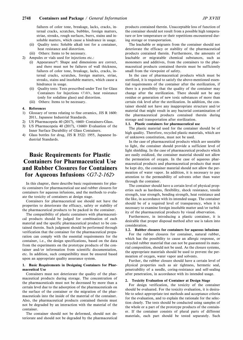
27482748 JP XVIIIContainers and Package / General Information
failures of color tone, breakage, lacks, cracks, in-ternal cracks, scratches, bubbles, foreign matters,striae, streaks, rough surfaces, burrs, stains and in-soluble matters, which cause a hindrance in usage.
(ii) Quality tests: Soluble alkali test for a container,heat resistance and distortion.
(iii) Others: Items to be necessary.2) Ampules or vials used for injections etc.:
(i) Appearance4): Shape and dimensions are correct,and there must not be failures of wall thickness,failures of color tone, breakage, lacks, cracks, in-ternal cracks, scratches, foreign matters, striae,streaks, stains and insoluble matters, which cause ahindrance in usage.
(ii) Quality tests: Tests prescribed under Test for GlassContainers for Injections <7.01>, heat resistance(only for sodalime glass) and distortion.
(iii) Others: Items to be necessary.
4. References1) Glossary of terms relating to fine ceramics, JIS R 1600:
2011, Japanese Industrial Standards.2) US Pharmacopeia 40 (2017), <660> Containers-Glass.3) US Pharmacopeia 40 (2017), <1660> Evaluation of the
Inner Surface Durability of Glass Containers.4) Glass bottles for drug, JIS R 3522: 1955, Japanese In-
dustrial Standards.
Basic Requirements for PlasticContainers for Pharmaceutical Useand Rubber Closures for Containersfor Aqueous Infusions <G7-2-162>
In this chapter, there describe basic requirements for plas-tic containers for pharmaceutical use and rubber closures forcontainers for aqueous infusions, and the methods to evalu-ate the toxicity of containers at design stage.
Containers for pharmaceutical use should not have theproperties to deteriorate the efficacy, safety or stability ofthe pharmaceutical products to be packed in the container.
The compatibility of plastic containers with pharmaceuti-cal products should be judged for combination of eachmaterial and the specific pharmaceutical product to be con-tained therein. Such judgment should be performed throughverification that the container for the pharmaceutical prepa-ration can comply with the essential requirements for thecontainer, i.e., the design specifications, based on the datafrom the experiments on the prototype products of the con-tainer and/or information from scientific documentation,etc. In addition, such compatibility must be ensured basedupon an appropriate quality assurance system.
1. Basic Requirements in Designing Containers for Phar-maceutical Use
Containers must not deteriorate the quality of the phar-maceutical products during storage. The concentration ofthe pharmaceuticals must not be decreased by more than acertain level due to the adsorption of the pharmaceuticals onthe surface of the container or the migration of the phar-maceuticals into the inside of the material of the container.Also, the pharmaceutical products contained therein mustnot be degraded by an interaction with the material of thecontainer.
The container should not be deformed, should not de-teriorate and should not be degraded by the pharmaceutical
products contained therein. Unacceptable loss of function ofthe container should not result from a possible high tempera-ture or low temperature or their repetitions encountered dur-ing storage or transportation.
The leachable or migrants from the container should notdeteriorate the efficacy or stability of the pharmaceuticalproducts contained therein. Furthermore, the amounts ofleachable or migratable chemical substances, such asmonomers and additives, from the containers to the phar-maceutical products contained therein must be sufficientlysmall from the viewpoint of safety.
In the case of pharmaceutical products which must besterilized, it is required to satisfy the above-mentioned essen-tial requirements of the container after the sterilization, ifthere is a possibility that the quality of the container maychange after the sterilization. There should not be anyresidue or generation of new toxic substances of more thancertain risk level after the sterilization. In addition, the con-tainer should not have any inappropriate structure and/ormaterial that might result in any bacterial contamination ofthe pharmaceutical products contained therein duringstorage and transportation after sterilization.1.1. Plastic containers for pharmaceutical use
The plastic material used for the container should be ofhigh quality. Therefore, recycled plastic materials, which areof unknown constitution, must not be used.
In the case of pharmaceutical products which are unstableto light, the container should provide a sufficient level oflight shielding. In the case of pharmaceutical products whichare easily oxidized, the container material should not allowthe permeation of oxygen. In the case of aqueous phar-maceutical products and pharmaceutical products that mustbe kept dry, the container material should not allow the per-meation of water vapor. In addition, it is necessary to payattention to the permeability of solvents other than waterthrough the container.
The container should have a certain level of physical prop-erties such as hardness, flexibility, shock resistance, tensilestrength, tear strength, bending strength, heat resistance andthe like, in accordance with its intended usage. The containershould be of a required level of transparency, when it isnecessary to examine foreign insoluble matter and/or turbid-ity of the pharmaceutical products by visual observation.
Furthermore, in introducing a plastic container, it isdesirable that proper disposal method after use is taken intoconsideration.1.2. Rubber closures for containers for aqueous infusions
For the rubber closures for container, natural rubber,which has the possibility to cause an allergic response, orrecycled rubber material that can not be guaranteed its mate-rial composition, should not be used. As the closure systems,the appropriate materials should be used to prevent the per-meation of oxygen, water vapor and solvents.
Further, the rubber closure should have a certain level ofphysical properties such as air tightness, hermetic seal,penetrability of a needle, coring-resistance and self-sealingafter penetration, in accordance with its intended usage.
2. Toxicity Evaluation of Container at Design StageFor design verification, the toxicity of the container
should be evaluated. For the toxicity evaluation, it is desira-ble to select appropriate test methods and acceptance criteriafor the evaluation, and to explain the rationale for the selec-tion clearly. The tests should be conducted using samples ofthe whole or a part of the prototype products of the contain-er. If the container consists of plural parts of differentmaterials, each part should be tested separately. Such
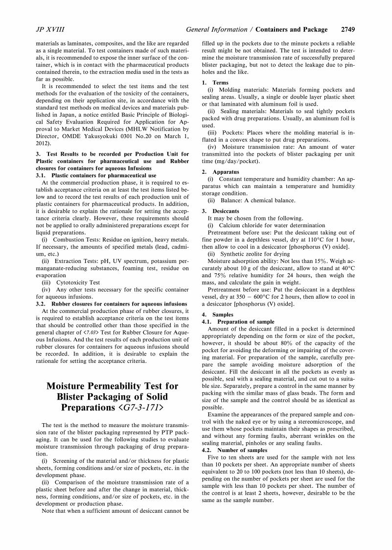
27492749JP XVIII General Information / Containers and Package
materials as laminates, composites, and the like are regardedas a single material. To test containers made of such materi-als, it is recommended to expose the inner surface of the con-tainer, which is in contact with the pharmaceutical productscontained therein, to the extraction media used in the tests asfar as possible.
It is recommended to select the test items and the testmethods for the evaluation of the toxicity of the containers,depending on their application site, in accordance with thestandard test methods on medical devices and materials pub-lished in Japan, a notice entitled Basic Principle of Biologi-cal Safety Evaluation Required for Application for Ap-proval to Market Medical Devices (MHLW Notification byDirector, OMDE Yakusyokuki 0301 No.20 on March 1,2012).
3. Test Results to be recorded per Production Unit forPlastic containers for pharmaceutical use and Rubberclosures for containers for aqueous Infusions3.1. Plastic containers for pharmaceutical use
At the commercial production phase, it is required to es-tablish acceptance criteria on at least the test items listed be-low and to record the test results of each production unit ofplastic containers for pharmaceutical products. In addition,it is desirable to explain the rationale for setting the accep-tance criteria clearly. However, these requirements shouldnot be applied to orally administered preparations except forliquid preparations.
(i) Combustion Tests: Residue on ignition, heavy metals.If necessary, the amounts of specified metals (lead, cadmi-um, etc.)
(ii) Extraction Tests: pH, UV spectrum, potassium per-manganate-reducing substances, foaming test, residue onevaporation
(iii) Cytotoxicity Test(iv) Any other tests necessary for the specific container
for aqueous infusions.3.2. Rubber closures for containers for aqueous infusions
At the commercial production phase of rubber closures, itis required to establish acceptance criteria on the test itemsthat should be controlled other than those specified in thegeneral chapter of <7.03> Test for Rubber Closure for Aque-ous Infusions. And the test results of each production unit ofrubber closures for containers for aqueous infusions shouldbe recorded. In addition, it is desirable to explain therationale for setting the acceptance criteria.
Moisture Permeability Test forBlister Packaging of SolidPreparations <G7-3-171>
The test is the method to measure the moisture transmis-sion rate of the blister packaging represented by PTP pack-aging. It can be used for the following studies to evaluatemoisture transmission through packaging of drug prepara-tion.
(i) Screening of the material and/or thickness for plasticsheets, forming conditions and/or size of pockets, etc. in thedevelopment phase.
(ii) Comparison of the moisture transmission rate of aplastic sheet before and after the change in material, thick-ness, forming conditions, and/or size of pockets, etc. in thedevelopment or production phase.
Note that when a sufficient amount of desiccant cannot be
filled up in the pockets due to the minute pockets a reliableresult might be not obtained. The test is intended to deter-mine the moisture transmission rate of successfully preparedblister packaging, but not to detect the leakage due to pin-holes and the like.
1. Terms(i) Molding materials: Materials forming pockets and
sealing areas. Usually, a single or double layer plastic sheetor that laminated with aluminum foil is used.
(ii) Sealing materials: Materials to seal tightly pocketspacked with drug preparations. Usually, an aluminum foil isused.
(iii) Pockets: Places where the molding material is in-flated in a convex shape to put drug preparations.
(iv) Moisture transmission rate: An amount of watertransmitted into the pockets of blister packaging per unittime (mg/day/pocket).
2. Apparatus(i) Constant temperature and humidity chamber: An ap-
paratus which can maintain a temperature and humiditystorage condition.
(ii) Balance: A chemical balance.
3. DesiccantsIt may be chosen from the following.(i) Calcium chloride for water determinationPretreatment before use: Put the desiccant taking out of
fine powder in a depthless vessel, dry at 1109C for 1 hour,then allow to cool in a desiccator [phosphorus (V) oxide].
(ii) Synthetic zeolite for dryingMoisture adsorption ability: Not less than 15z. Weigh ac-
curately about 10 g of the desiccant, allow to stand at 409Cand 75z relative humidity for 24 hours, then weigh themass, and calculate the gain in weight.
Pretreatment before use: Put the desiccant in a depthlessvessel, dry at 350 „ 6009C for 2 hours, then allow to cool ina desiccator [phosphorus (V) oxide].
4. Samples4.1. Preparation of sample
Amount of the desiccant filled in a pocket is determinedappropriately depending on the form or size of the pocket,however, it should be about 80z of the capacity of thepocket for avoiding the deforming or impairing of the cover-ing material. For preparation of the sample, carefully pre-pare the sample avoiding moisture adsorption of thedesiccant. Fill the desiccant in all the pockets as evenly aspossible, seal with a sealing material, and cut out to a suita-ble size. Separately, prepare a control in the same manner bypacking with the similar mass of glass beads. The form andsize of the sample and the control should be as identical aspossible.
Examine the appearances of the prepared sample and con-trol with the naked eye or by using a stereomicroscope, anduse them whose pockets maintain their shapes as prescribed,and without any forming faults, aberrant wrinkles on thesealing material, pinholes or any sealing faults.4.2. Number of samples
Five to ten sheets are used for the sample with not lessthan 10 pockets per sheet. An appropriate number of sheetsequivalent to 20 to 100 pockets (not less than 10 sheets), de-pending on the number of pockets per sheet are used for thesample with less than 10 pockets per sheet. The number ofthe control is at least 2 sheets, however, desirable to be thesame as the sample number.
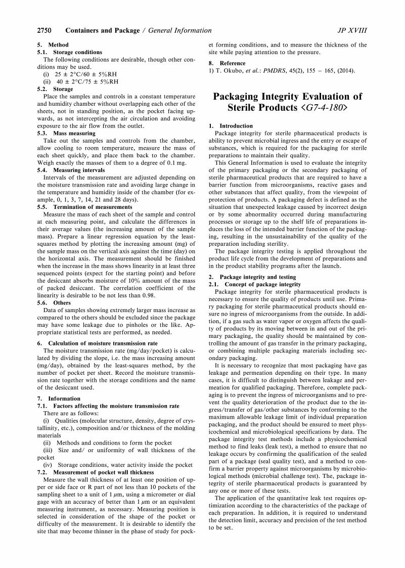
27502750 JP XVIIIContainers and Package / General Information
5. Method5.1. Storage conditions
The following conditions are desirable, though other con-ditions may be used.
(i) 25 ± 29C/60 ± 5zRH(ii) 40 ± 29C/75 ± 5zRH
5.2. StoragePlace the samples and controls in a constant temperature
and humidity chamber without overlapping each other of thesheets, not in standing position, as the pocket facing up-wards, as not intercepting the air circulation and avoidingexposure to the air flow from the outlet.5.3. Mass measuring
Take out the samples and controls from the chamber,allow cooling to room temperature, measure the mass ofeach sheet quickly, and place them back to the chamber.Weigh exactly the masses of them to a degree of 0.1 mg.5.4. Measuring intervals
Intervals of the measurement are adjusted depending onthe moisture transmission rate and avoiding large change inthe temperature and humidity inside of the chamber (for ex-ample, 0, 1, 3, 7, 14, 21 and 28 days).5.5. Termination of measurements
Measure the mass of each sheet of the sample and controlat each measuring point, and calculate the differences intheir average values (the increasing amount of the samplemass). Prepare a linear regression equation by the least-squares method by plotting the increasing amount (mg) ofthe sample mass on the vertical axis against the time (day) onthe horizontal axis. The measurement should be finishedwhen the increase in the mass shows linearity in at least threesequenced points (expect for the starting point) and beforethe desiccant absorbs moisture of 10z amount of the massof packed desiccant. The correlation coefficient of thelinearity is desirable to be not less than 0.98.5.6. Others
Data of samples showing extremely larger mass increase ascompared to the others should be excluded since the packagemay have some leakage due to pinholes or the like. Ap-propriate statistical tests are performed, as needed.
6. Calculation of moisture transmission rateThe moisture transmission rate (mg/day/pocket) is calcu-
lated by dividing the slope, i.e. the mass increasing amount(mg/day), obtained by the least-squares method, by thenumber of pocket per sheet. Record the moisture transmis-sion rate together with the storage conditions and the nameof the desiccant used.
7. Information7.1. Factors affecting the moisture transmission rate
There are as follows:(i) Qualities (molecular structure, density, degree of crys-
tallinity, etc.), composition and/or thickness of the moldingmaterials
(ii) Methods and conditions to form the pocket(iii) Size and/ or uniformity of wall thickness of the
pocket(iv) Storage conditions, water activity inside the pocket
7.2. Measurement of pocket wall thicknessMeasure the wall thickness of at least one position of up-
per or side face or R part of not less than 10 pockets of thesampling sheet to a unit of 1 mm, using a micrometer or dialgage with an accuracy of better than 1 mm or an equivalentmeasuring instrument, as necessary. Measuring position isselected in consideration of the shape of the pocket ordifficulty of the measurement. It is desirable to identify thesite that may become thinner in the phase of study for pock-
et forming conditions, and to measure the thickness of thesite while paying attention to the pressure.
8. Reference1) T. Okubo, et al.: PMDRS, 45(2), 155 „ 165, (2014).
Packaging Integrity Evaluation ofSterile Products <G7-4-180>
1. IntroductionPackage integrity for sterile pharmaceutical products is
ability to prevent microbial ingress and the entry or escape ofsubstances, which is required for the packaging for sterilepreparations to maintain their quality.
This General Information is used to evaluate the integrityof the primary packaging or the secondary packaging ofsterile pharmaceutical products that are required to have abarrier function from microorganisms, reactive gases andother substances that affect quality, from the viewpoint ofprotection of products. A packaging defect is defined as thesituation that unexpected leakage caused by incorrect designor by some abnormality occurred during manufacturingprocesses or storage up to the shelf life of preparations in-duces the loss of the intended barrier function of the packag-ing, resulting in the unsustainability of the quality of thepreparation including sterility.
The package integrity testing is applied throughout theproduct life cycle from the development of preparations andin the product stability programs after the launch.
2. Package integrity and testing2.1. Concept of package integrity
Package integrity for sterile pharmaceutical products isnecessary to ensure the quality of products until use. Prima-ry packaging for sterile pharmaceutical products should en-sure no ingress of microorganisms from the outside. In addi-tion, if a gas such as water vapor or oxygen affects the quali-ty of products by its moving between in and out of the pri-mary packaging, the quality should be maintained by con-trolling the amount of gas transfer in the primary packaging,or combining multiple packaging materials including sec-ondary packaging.
It is necessary to recognize that most packaging have gasleakage and permeation depending on their type. In manycases, it is difficult to distinguish between leakage and per-meation for qualified packaging. Therefore, complete pack-aging is to prevent the ingress of microorganisms and to pre-vent the quality deterioration of the product due to the in-gress/transfer of gas/other substances by conforming to themaximum allowable leakage limit of individual preparationpackaging, and the product should be ensured to meet phys-icochemical and microbiological specifications by data. Thepackage integrity test methods include a physicochemicalmethod to find leaks (leak test), a method to ensure that noleakage occurs by confirming the qualification of the sealedpart of a package (seal quality test), and a method to con-firm a barrier property against microorganisms by microbio-logical methods (microbial challenge test). The, package in-tegrity of sterile pharmaceutical products is guaranteed byany one or more of these tests.
The application of the quantitative leak test requires op-timization according to the characteristics of the package ofeach preparation. In addition, it is required to understandthe detection limit, accuracy and precision of the test methodto be set.
27512751JP XVIII General Information / Containers and Package
2.1.1. Leak testThe leak test guarantees ability to maintain the integrity of
packaging by qualitatively detecting or quantitatively meas-uring holes or pathways, where leaks occur, by a phys-icochemical method. There are two types of leak tests; quali-tative leak test and quantitative leak test.
Since the results of the qualitative leak test are accompa-nied by uncertainty, the test requires a large sample size andrigorous control of test conditions to obtain reliable results.The qualitative leak test is a useful mean to detect leaks, butis not suitable for the deterministic verification of packageintegrity. On the other hand, it is an effective test to locateleak positions correctly.
The quantitative leak test is a test to evaluate quantitative-ly the physicochemical changes accompanied with leaks andto obtain objective data to set a maximum allowable leakagelimit and control.
Examples of qualitative and quantitative leak test methodsare listed below. Other methods may be used according to apurpose.
<Qualitative leak test methods>Liquid immersion testLiquid leak testTracer liquid test (dye penetration test)Sniffer method (helium leak test method 1)<Quantitative leak test methods>Sealed chamber method (pressure change leak test method
1)Vacuum decay method (pressure change leak test method
2)Pressure integration method (helium leak test method 2)Vacuum chamber method (helium leak test method 3)Immersion method (helium leak test method 4)High-voltage leak test (pinhole test method)Laser-based gas headspace analysis
2.1.2. Seal quality testThe seal quality test is used to indirectly ensure ability to
maintain package integrity by confirming that parametersrelated to the container seal or fitting are valid. Conductingthe seal quality test set based on evidence is useful for thecontinuous understanding of the characteristics required forclosure and maintaining package integrity. In addition to ex-amples shown as the seal quality test methods (Table 1),various methods are used.2.1.3. Microbial challenge test
The microbial challenge test is a microbiological test to es-timate qualitatively package integrity by using live microor-ganisms or microbial spores. The microbial challenge test isuseful for acquiring the direct evidence of preventingmicrobial ingress. Microbial ingress evaluated in the test in-cludes the passage through pathways by microbial growth ormovement and the passive transport of microorganisms vialiquid.
Conducting the microbiological test is effective when ap-propriate physicochemical leak test methods, which obtainthe evidence of preventing microbial ingress, have not beenestablished, or when the maximum allowable leakage limitdepends on the possibility of microbial ingress.
The recommended general practices are as follows. For thetest, strains of microorganisms that are appropriately main-tained should be used. Other scientifically appropriatemethods can also be used.
Put a fluid medium aseptically in the primary package of apreparation to be tested, and immerse the preparation in anappropriate bacterial solution of 105 CFU/ml or more for atleast 30 minutes or more. Cultivate the preparation and con-firm the presence or absence of turbidity in the medium.
2.2. Package integrity and testing in the development andmanufacturing of preparations
Selection of test methods according to the stage of theproduct lifecycle is important to ensure package integrity forsterile pharmaceutical products.2.2.1. Design of packaging
In the packaging design of the product development stage,the maximum allowable leakage limit is required to be setbased on evaluations of not only the risk of sterility failuredue to microbial ingress but also the effect of various gasespassing through the primary packaging on the quality. Forthe evaluation, it is desirable to use the quantitative leak testmethod that has been verified to be able to detect leaks thataffect product quality. Samples used for the evaluationshould be prepared assuming the worst case in design.
If influence of other than microorganisms can be ignored,the allowable leak limit to be controlled is set by consideringthe risk of microbial ingress. This can be set by verifying bythe microbial challenge test, or by proving that there is logi-cally no ingress of microorganisms by leak tests. On theother hand, the allowable leakage limit should be set to con-trol the passage of substances in addition to preventingmicrobial ingress for products that require to keep low head-space oxygen concentration to maintain the quality of prepa-rations etc. Verification only by the qualitative microbialchallenge test should not be sufficient. Other qualitative testsare also valuable to obtain information appropriate for thepurposes.2.2.2. Manufacturing of preparations
Package integrity testing in the manufacturing of content-filled products is important to prevent the release of incom-pletely packaged pharmaceuticals. Based on packagingdefects recognized in the development stage and initial proc-ess validation, tests are established by leak tests, seal qualitytests and appropriate combination of visual inspections dur-ing manufacturing to obtain supplemental information.
Examples of leak tests used for package integrity evalua-tion of preparations in manufacturing processes include liq-uid immersion test, liquid leak test, tracer liquid test (dye in-gress method), sealed chamber method (pressure change leaktest method 1), vacuum decay method (pressure change leaktest method 2), high voltage leak test (pinhole test method),and laser-based gas headspace analysis. Moreover, examplesof the seal quality test methods are shown in Table 1.
Sampling tests using a part of a production lot as a sampleduring the process provide means to verify package integrityof the lot by ensuring that the process is maintained in a vali-dated state. For sampling frequency and the number of sam-ples, it is required to set the necessary number of samplesand demonstrate its validity based on the results of statisticalprocess controls obtained in the process validation stage andthe trend analysis of product quality after the start ofproduction. In contrast, non-destructive leak tests for allproducts of a production lot provide continuous and all-product guarantees of package integrity.
If relevance between seal quality test results and packageintegrity is verified in advance, the conduction of the sealquality test can indirectly ensure the package integrity. Forthe glass or plastic ampoules that are sealed by sealing orwelding the opening, nondestructive leak tests are usuallyperformed with all samples.
The main purpose of package integrity testing in processvalidation is to obtain high quality product packaging in theprocess which is operated with no problem within operatingparameters set and to keep the incidence of serious packag-ing defects low enough. Package integrity testing of in-proc-ess and final products complements complete packaging de-
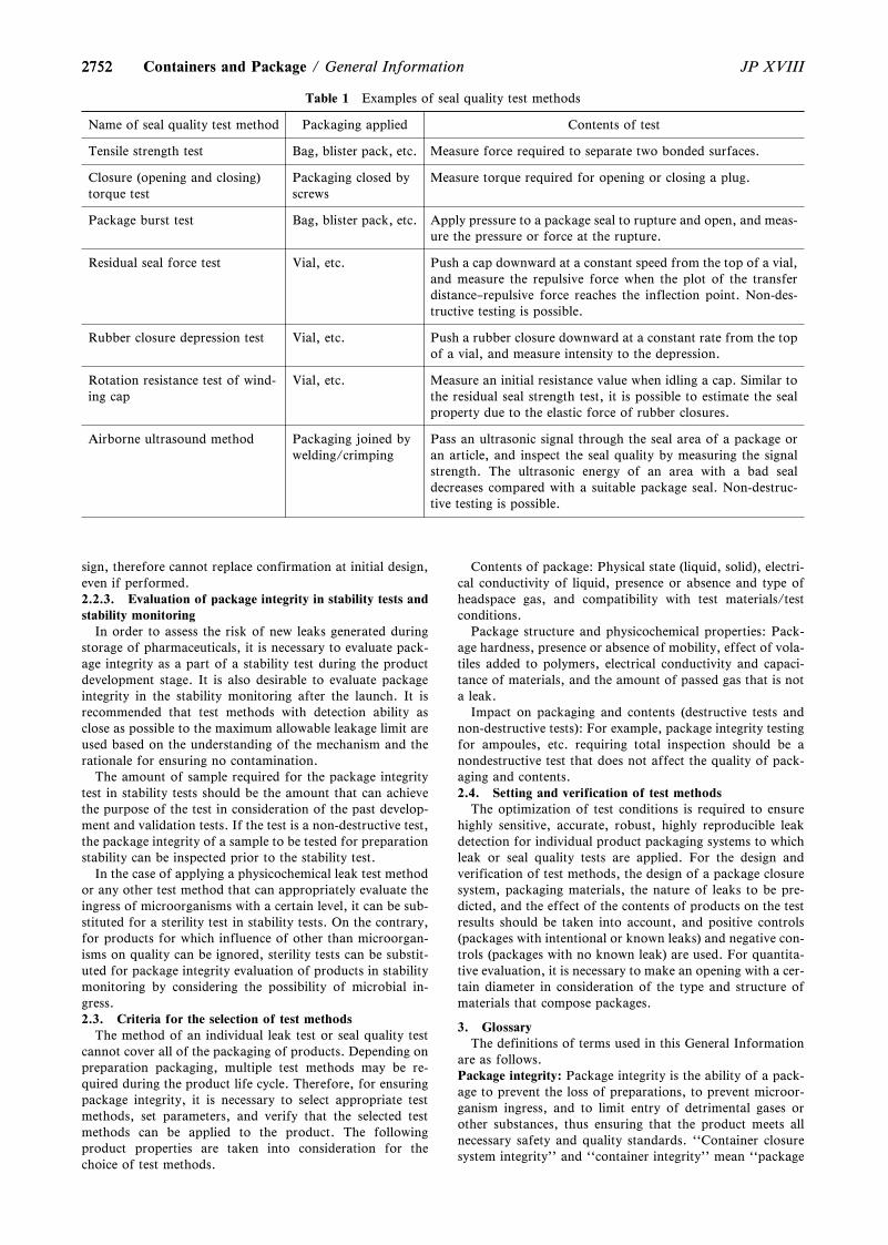
2752
Table 1 Examples of seal quality test methods
Name of seal quality test method Packaging applied Contents of test
Tensile strength test Bag, blister pack, etc. Measure force required to separate two bonded surfaces.
Closure (opening and closing)torque test
Packaging closed byscrews
Measure torque required for opening or closing a plug.
Package burst test Bag, blister pack, etc. Apply pressure to a package seal to rupture and open, and meas-ure the pressure or force at the rupture.
Residual seal force test Vial, etc. Push a cap downward at a constant speed from the top of a vial,and measure the repulsive force when the plot of the transferdistance–repulsive force reaches the inflection point. Non-des-tructive testing is possible.
Rubber closure depression test Vial, etc. Push a rubber closure downward at a constant rate from the topof a vial, and measure intensity to the depression.
Rotation resistance test of wind-ing cap
Vial, etc. Measure an initial resistance value when idling a cap. Similar tothe residual seal strength test, it is possible to estimate the sealproperty due to the elastic force of rubber closures.
Airborne ultrasound method Packaging joined bywelding/crimping
Pass an ultrasonic signal through the seal area of a package oran article, and inspect the seal quality by measuring the signalstrength. The ultrasonic energy of an area with a bad sealdecreases compared with a suitable package seal. Non-destruc-tive testing is possible.
2752 JP XVIIIContainers and Package / General Information
sign, therefore cannot replace confirmation at initial design,even if performed.2.2.3. Evaluation of package integrity in stability tests andstability monitoring
In order to assess the risk of new leaks generated duringstorage of pharmaceuticals, it is necessary to evaluate pack-age integrity as a part of a stability test during the productdevelopment stage. It is also desirable to evaluate packageintegrity in the stability monitoring after the launch. It isrecommended that test methods with detection ability asclose as possible to the maximum allowable leakage limit areused based on the understanding of the mechanism and therationale for ensuring no contamination.
The amount of sample required for the package integritytest in stability tests should be the amount that can achievethe purpose of the test in consideration of the past develop-ment and validation tests. If the test is a non-destructive test,the package integrity of a sample to be tested for preparationstability can be inspected prior to the stability test.
In the case of applying a physicochemical leak test methodor any other test method that can appropriately evaluate theingress of microorganisms with a certain level, it can be sub-stituted for a sterility test in stability tests. On the contrary,for products for which influence of other than microorgan-isms on quality can be ignored, sterility tests can be substit-uted for package integrity evaluation of products in stabilitymonitoring by considering the possibility of microbial in-gress.2.3. Criteria for the selection of test methods
The method of an individual leak test or seal quality testcannot cover all of the packaging of products. Depending onpreparation packaging, multiple test methods may be re-quired during the product life cycle. Therefore, for ensuringpackage integrity, it is necessary to select appropriate testmethods, set parameters, and verify that the selected testmethods can be applied to the product. The followingproduct properties are taken into consideration for thechoice of test methods.
Contents of package: Physical state (liquid, solid), electri-cal conductivity of liquid, presence or absence and type ofheadspace gas, and compatibility with test materials/testconditions.
Package structure and physicochemical properties: Pack-age hardness, presence or absence of mobility, effect of vola-tiles added to polymers, electrical conductivity and capaci-tance of materials, and the amount of passed gas that is nota leak.
Impact on packaging and contents (destructive tests andnon-destructive tests): For example, package integrity testingfor ampoules, etc. requiring total inspection should be anondestructive test that does not affect the quality of pack-aging and contents.2.4. Setting and verification of test methods
The optimization of test conditions is required to ensurehighly sensitive, accurate, robust, highly reproducible leakdetection for individual product packaging systems to whichleak or seal quality tests are applied. For the design andverification of test methods, the design of a package closuresystem, packaging materials, the nature of leaks to be pre-dicted, and the effect of the contents of products on the testresults should be taken into account, and positive controls(packages with intentional or known leaks) and negative con-trols (packages with no known leak) are used. For quantita-tive evaluation, it is necessary to make an opening with a cer-tain diameter in consideration of the type and structure ofmaterials that compose packages.
3. GlossaryThe definitions of terms used in this General Information
are as follows.Package integrity: Package integrity is the ability of a pack-age to prevent the loss of preparations, to prevent microor-ganism ingress, and to limit entry of detrimental gases orother substances, thus ensuring that the product meets allnecessary safety and quality standards. ``Container closuresystem integrity'' and ``container integrity'' mean ``package
27532753JP XVIII General Information / Containers and Package
integrity''.Quantitative leak test method: In the quantitative leak testmethod, the leak to be detected or measured is based on aphenomenon caused by a predictable series of events. Fur-thermore, the means of leak detection can be easily con-trolled and monitored, and is based on the physicochemicaltechniques that can obtain concrete quantitative data.Qualitative leak test method: The qualitative leak testmethod is essentially probabilistic. Qualitative tests dependon a series of continuous or simultaneous events, each ofwhich is accompanied by a random result represented by aprobability distribution. Therefore, the results have uncer-tainty and require a large sample size and the rigorous con-trol of test conditions to obtain meaningful results.Leakage: The transfer of liquid or gas through a breach in apackage material or through a gap between package mate-rials. Leakage is expressed in the measure (in mass or volumeunits) of the flow rate of gas that pass through leakage path-ways under specified temperature and pressure conditions.The leak rate has the dimension of pressure multiplied byvolume, divided by time. For example, the internationalstandard SI nomenclature is pascal cubic meter per second(Pa・m3・s-1).Leak: A leakage, or a hole, or a pathway where a leakage oc-curs.Permeation: The passage of substances through a packagematerial. Permeation of gases, including water vapor, canusually occurs in the packaging of sterile pharmaceuticals.The ``water vapor permeability test'' applies to the permea-tion of water vapor in plastic containers (mainly aqueous in-jection containers).Maximum allowable leakage limit: A maximum leakage rate(or hole, or pathway size) allowable for a product packagethat can assure no risk to product safety and no or negligibleimpact on product stability.Positive and negative controls: A package having differenttype and size of defects is used as a positive control. General-ly, packages having large size defects are used as positivecontrols during the development of test methods, and pack-ages having small size defects are used as positive controlsfor the development of test methods and for validation.
Leak Tests for Packaging of SterileProducts <G7-5-180>
This General Information describes test methods to meas-ure the entry and escape of gases and liquids in packages andcontainers of sterile pharmaceuticals, and to recognize theirunintentional fluid transfer due to leakage. The measuredvalues may indicate the presence, location and size of leakchannels as well as leak amount.
The leak tests are classified to qualitative leak tests andquantitative leak tests. This General Information describesliquid immersion test, liquid leak test, tracer liquid test (dyepenetration test) and sniffing method (helium leak testmethod 1) as qualitative leak tests, and sealed chambermethod (pressure change leak test method 1), vacuum decaymethod (pressure change leak test method 2), pressure in-tegration method (helium leak test method 2), vacuum cham-ber method (helium leak test method 3), immersion method(helium leak test method 4), high-voltage leak test (pinholetest method) and laser-based gas headspace analysis as quan-titative leak tests. Other methods that have been validatedcan also be used.
Test methods should be selected according to the charac-
teristics of samples and the purpose of the test1-6). Samples,the configuration of test apparatus, and conditions such astemperature, pressure and time, are set appropriately basedon various technical data, because they affect the validity ofresults and the safety of operations. It is desirable to use theapparatus that has been calibrated by a standard traceable tothe national measurement standard as needed. The leak testsare applied to stoppered rigid or flexible packages and con-tainers, which are empty or contain liquid or solid sterilepharmaceuticals. Specifically, ampoules, vials, syringes,containers for ophthalmic solutions, plastic bags, etc. aresubject to the tests.
1. Qualitative leak testsThe qualitative leak tests are test methods to directly ob-
serve or measure the leak phenomena, and are used to con-firm the presence, position(s) and conditions of leakage.1.1. Liquid immersion test
The liquid immersion test method is used to detect thepresence and locations of leaks by observation of gas emis-sion occurred from defect regions as bubbles, when a samplecontaining gas in its inside is immersed in liquid and theheadspace of the liquid tank is depressurized. In many cases,water is used as the liquid, and in that case, it is also called awater immersion test. It observes the generation of gas bub-bles after the completion of reduced pressure until theprescribed time, and evaluate the location(s) of leak(s), thesize and the occurrence frequency of the gas bubbles. Insome cases, bubbles are observed in a liquid tank using asample pressurized with gas. The amount of leakage can bequantified by collecting the generated gas bubbles in a liquidtank with a measuring cylinder etc. for defined time andmeasuring the amount. The amount of leakage can be ex-pressed as a function of the sampling time for collecting gasbubbles and the collected quantity being corrected with a ref-erence pressure or one atmospheric pressure. The test is per-formed at prescribed temperature as required, and the valueof reduced pressure and measurement time of the headspaceof a liquid tank are set according to the pressure resistanceof a sample and assumed defects. It is applied to rigid orflexible packages and containers.1.2. Liquid leak test
The liquid leak test methods are test methods to visualizeand observe the transfer of liquid due to leakage using an ad-ditive or a developer. The liquid leak test methods includethe method that adds liquid containing a fluorescent dye to asample to detect the leaked liquid by irradiation with ultravi-olet light, and the method that coats the surface of a samplewith a developer to observe an indication pattern generatedby a chemical reaction of the leaked liquid and the developer(Table 1).
In the fluorescent dye method, liquid containing fluores-cent dye is injected inside a sample, or is dissolved in liquidinside a sample, and leakage is detected under ultravioletlight in a dark place. The inside of the sample is pressurized,as necessary, and change due to leakage is observed. In thetest methods using a developer, the adequately stirred de-veloper is applied evenly on the surface of a sample by aspray or a brush. After drying of the developed coating film,an indication pattern due to leakage is observed under whitelight in the cases of the white development method and thecolor development method. In the fluorescent developmentmethod, an indication pattern due to leakage is observedunder ultraviolet light in a dark place. Record the indicationpattern due to leakage as the description of position, size andnumber, etc. or as an image. These test methods are appliedto rigid or flexible packages and containers.
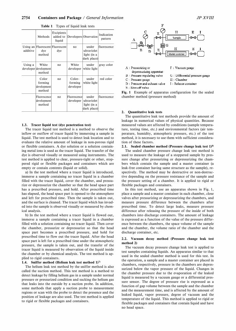
2754
Fig. 1 Example of apparatus configuration for the sealedchamber method (pressure method)
Table 1 Types of liquid leak tests
MethodsExcipientsadded to
liquidDevelopers Observation
Indicationpattern
Using anadditive
Fluorescentdye
method
Fluorescentdye
no underultravioletlight (in adark place)
fluorescence
Using adeveloper
Whitedevelopment
method
no Whitedeveloper
underwhite light
gray color
Colorforming
developmentmethod
no Color-forming
developer
underwhite light
red color
Fluorescencedevelopment
method
no Fluorescencedeveloper
underultravioletlight (in adark place)
fluorescence
2754 JP XVIIIContainers and Package / General Information
1.3. Tracer liquid test (dye penetration test)The tracer liquid test method is a method to observe the
inflow or outflow of tracer liquid by immersing a sample inliquid. The test method is used to detect leak location and toevaluate the relative amount of leakage in non-porous rigidor flexible containers. A dye solution or a solution contain-ing metal ions is used as the tracer liquid. The transfer of thedye is observed visually or measured using instruments. Thetest method is applied to clear, pressure-tight or other, stop-pered rigid or flexible packages and containers which areempty or contain contents (liquid or solid).
a) In the test method where a tracer liquid is introduced,immerse a sample containing no tracer liquid in a chamberfilled with the tracer liquid, cover the chamber, and pressu-rize or depressurize the chamber so that the head space parthas a prescribed pressure, and hold. After prescribed timehas elapsed, the head space part is opened to the atmosphereand left for prescribed time. Then the sample is taken out,and the surface is cleaned. The tracer liquid which has invad-ed into the sample is observed visually or measured by chem-ical analysis.
b) In the test method where a tracer liquid is flowed out,immerse a sample containing a tracer liquid in a chamberfilled with a solution containing no tracer liquid. Then coverthe chamber, pressurize or depressurize so that the headspace part becomes a prescribed pressure, and hold forprescribed time to flow out the tracer liquid. After the headspace part is left for a prescribed time under the atmosphericpressure, the sample is taken out, and the transfer of thetracer liquid is measured by observation of the liquid insidethe chamber or by chemical analysis. The test method is ap-plied to rigid containers.1.4. Sniffer method (Helium leak test method 1)7)
The helium leak test method by the sniffer method is alsocalled the suction method. This test method is a method todetect leakage by filling helium gas in a sample under normalpressure or pressurized condition and sucking the helium gasthat leaks into the outside by a suction probe. In addition,some methods that apply a suction probe to measurementregions or scan with the probe to detect the presence and theposition of leakage are also used. The test method is appliedto rigid or flexible packages and containers.
2. Quantitative leak testsThe quantitative leak test methods provide the amount of
leakage in numerical values of physical quantities. Becausemeasured values are affected by conditions (sample tempera-ture, testing time, etc.) and environmental factors (air tem-perature, humidity, atmospheric pressure, etc.) of the testmethod, it is necessary to use them with sufficient considera-tion of these factors.2.1. Sealed chamber method (Pressure change leak test 1)8)
The sealed chamber pressure change leak test method isused to measure the leakage of a stoppered sample by pres-sure change after pressurizing or depressurizing the cham-bers which contain the sample and a master container (aleak-free container having same structure as the sample), re-spectively. The method may be destructive or non-destruc-tive depending on the pressure resistance of the sample andthe pressure setting of a chamber. It is applied to rigid orflexible packages and containers.
In this test method, use an apparatus shown in Fig. 1,place a sample and a master container in each chamber, closevalves after pressurizing or depressurizing the chambers, andmeasure pressure difference between the chambers afterprescribed time. To detect large leaks, measure pressuredifference after releasing the pressure of the inside of bothchambers into discharge containers. The amount of leakageis expressed as a function of the value of the pressure differ-ence between the chambers, the space volume of the sampleand the chamber, the volume ratio of the chamber and thedischarge container, etc.
2.2. Vacuum decay method (Pressure change leak testmethod 2)
The vacuum decay pressure change leak test is applied totest samples containing liquids. An apparatus similar to thatused in the sealed chamber method is used for this test. Inthe operation, a sample and a master container are placed inchambers, respectively, pressure in the chambers are depres-surized below the vapor pressure of the liquid. Changes inthe chamber pressure due to the evaporation of the leakedliquid is measured by a vacuum gauge or a differential pres-sure sensor. The degree of pressure rise is expressed as afunction of gap volume between the sample and the chamberand the measurement time, and is affected by the amount ofleaked liquid, vapor pressure, degree of vacuum and thetemperature of the liquid. This method is applied to rigid orflexible packages and containers that contain liquid and haveno head space.
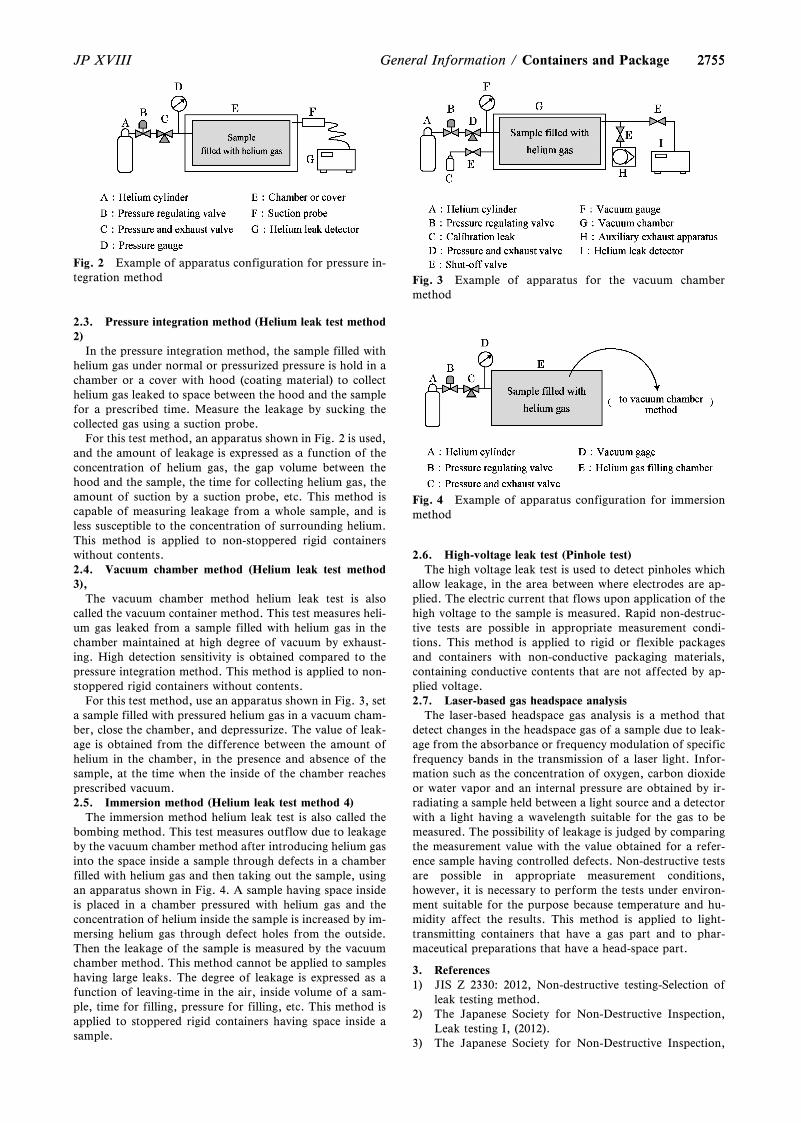
2755
Fig. 2 Example of apparatus configuration for pressure in-tegration method Fig. 3 Example of apparatus for the vacuum chamber
method
Fig. 4 Example of apparatus configuration for immersionmethod
2755JP XVIII General Information / Containers and Package
2.3. Pressure integration method (Helium leak test method2)
In the pressure integration method, the sample filled withhelium gas under normal or pressurized pressure is hold in achamber or a cover with hood (coating material) to collecthelium gas leaked to space between the hood and the samplefor a prescribed time. Measure the leakage by sucking thecollected gas using a suction probe.
For this test method, an apparatus shown in Fig. 2 is used,and the amount of leakage is expressed as a function of theconcentration of helium gas, the gap volume between thehood and the sample, the time for collecting helium gas, theamount of suction by a suction probe, etc. This method iscapable of measuring leakage from a whole sample, and isless susceptible to the concentration of surrounding helium.This method is applied to non-stoppered rigid containerswithout contents.2.4. Vacuum chamber method (Helium leak test method3),
The vacuum chamber method helium leak test is alsocalled the vacuum container method. This test measures heli-um gas leaked from a sample filled with helium gas in thechamber maintained at high degree of vacuum by exhaust-ing. High detection sensitivity is obtained compared to thepressure integration method. This method is applied to non-stoppered rigid containers without contents.
For this test method, use an apparatus shown in Fig. 3, seta sample filled with pressured helium gas in a vacuum cham-ber, close the chamber, and depressurize. The value of leak-age is obtained from the difference between the amount ofhelium in the chamber, in the presence and absence of thesample, at the time when the inside of the chamber reachesprescribed vacuum.2.5. Immersion method (Helium leak test method 4)
The immersion method helium leak test is also called thebombing method. This test measures outflow due to leakageby the vacuum chamber method after introducing helium gasinto the space inside a sample through defects in a chamberfilled with helium gas and then taking out the sample, usingan apparatus shown in Fig. 4. A sample having space insideis placed in a chamber pressured with helium gas and theconcentration of helium inside the sample is increased by im-mersing helium gas through defect holes from the outside.Then the leakage of the sample is measured by the vacuumchamber method. This method cannot be applied to sampleshaving large leaks. The degree of leakage is expressed as afunction of leaving-time in the air, inside volume of a sam-ple, time for filling, pressure for filling, etc. This method isapplied to stoppered rigid containers having space inside asample.
2.6. High-voltage leak test (Pinhole test)The high voltage leak test is used to detect pinholes which
allow leakage, in the area between where electrodes are ap-plied. The electric current that flows upon application of thehigh voltage to the sample is measured. Rapid non-destruc-tive tests are possible in appropriate measurement condi-tions. This method is applied to rigid or flexible packagesand containers with non-conductive packaging materials,containing conductive contents that are not affected by ap-plied voltage.2.7. Laser-based gas headspace analysis
The laser-based headspace gas analysis is a method thatdetect changes in the headspace gas of a sample due to leak-age from the absorbance or frequency modulation of specificfrequency bands in the transmission of a laser light. Infor-mation such as the concentration of oxygen, carbon dioxideor water vapor and an internal pressure are obtained by ir-radiating a sample held between a light source and a detectorwith a light having a wavelength suitable for the gas to bemeasured. The possibility of leakage is judged by comparingthe measurement value with the value obtained for a refer-ence sample having controlled defects. Non-destructive testsare possible in appropriate measurement conditions,however, it is necessary to perform the tests under environ-ment suitable for the purpose because temperature and hu-midity affect the results. This method is applied to light-transmitting containers that have a gas part and to phar-maceutical preparations that have a head-space part.
3. References1) JIS Z 2330: 2012, Non-destructive testing-Selection of
leak testing method.2) The Japanese Society for Non-Destructive Inspection,
Leak testing I, (2012).3) The Japanese Society for Non-Destructive Inspection,
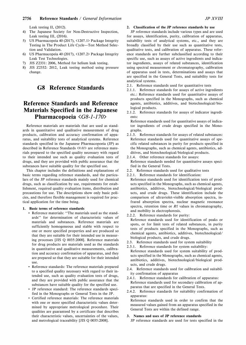
27562756 JP XVIIIReference Standards / General Information
Leak testing II, (2012).4) The Japanese Society for Non-Destructive Inspection,
Leak testing III, (2016).5) US Pharmacopeia 40 (2017), <1207.1> Package Integrity
Testing in The Product Life Cycle—Test Method Selec-tion and Validation.
6) US Pharmacopeia 40 (2017), <1207.2> Package IntegrityLeak Test Technologies.
7) JIS Z2331: 2006, Method for helium leak testing.8) JIS Z2332: 2012, Leak testing method using pressure
change.
G8 Reference Standards
Reference Standards and ReferenceMaterials Specified in the Japanese
Pharmacopoeia <G8-1-170>
Reference materials are materials that are used as stand-ards in quantitative and qualitative measurement of drugproducts, calibration and accuracy confirmation of appa-ratus, and suitability tests of analytical systems. Referencestandards specified in the Japanese Pharmacopoeia (JP) asdescribed in Reference Standards <9.01> are reference mate-rials prepared to the specified quality necessary with regardto their intended use such as quality evaluation tests ofdrugs, and they are provided with public assurance that thesubstances have suitable quality for the specified use.
This chapter includes the definitions and explanations ofbasic terms regarding reference standards, and the particu-lars of the JP reference standards mainly used for chemicaldrugs, such as classification by use, requirements for estab-lishment, required quality evaluation items, distribution andprecautions for use. The descriptions show only basic poli-cies, and therefore flexible management is required for prac-tical application for the time being.
1. Basic terms of reference standards Reference materials: ``The materials used as the stand-
ards'' for determination of characteristic values ofmaterials and substances. Reference materials aresufficiently homogeneous and stable with respect toone or more specified properties and are produced sothat they are suitable for their intended use in measur-ing processes [JIS Q 0035:2008]. Reference materialsfor drug products are materials used as the standardsin quantitative and qualitative measurements, calibra-tion and accuracy confirmation of apparatus, and theyare prepared so that they are suitable for their intendeduse.
Reference standards: The reference materials preparedto a specified quality necessary with regard to their in-tended use, such as quality evaluation tests of drugs,and they are provided with public assurance that thesubstances have suitable quality for the specified use.
JP reference standard: The reference standards speci-fied in the Monographs or General Tests in the JP.
Certified reference materials: The reference materialswith one or more specified characteristic values deter-mined by appropriate metrological procedure. Theirqualities are guaranteed by a certificate that describestheir characteristic values, uncertainties of the values,and metrological traceability [JIS Q 0035:2008].
2. Classification of the JP reference standards by useJP reference standards include various types and are used
for assays, identification, purity, calibration of apparatus,suitability tests of analytical systems, etc., and they arebroadly classified by their use such as quantitative tests,qualitative tests, and calibration of apparatus. These refer-ence standards are further subclassified according to theirspecific use, such as assays of active ingredients and indica-tor ingredients, assays of related substances, identificationusing spectral measurement or chromatography, calibrationof apparatus used in tests, determinations and assays thatare specified in the General Tests, and suitability tests foranalytical systems.2.1. Reference standards used for quantitative tests2.1.1. Reference standards for assays of active ingredients
etc.: Reference standards used for quantitative assays ofproducts specified in the Monographs, such as chemicalagents, antibiotics, additives, and biotechnological/bio-logical products.
2.1.2. Reference standards for assays of indicator ingredi-ents:Reference standards used for quantitative assays of indica-tor ingredients of crude drugs specified in the Mono-graphs.
2.1.3. Reference standards for assays of related substances:Reference standards used for quantitative assays of spe-cific related substances in purity for products specified inthe Monographs, such as chemical agents, antibiotics, ad-ditives, and biotechnological/biological products.
2.1.4. Other reference standards for assays:Reference standards needed for quantitative assays speci-fied in the General Tests.
2.2. Reference standards used for qualitative tests2.2.1. Reference standards for identification:
Reference standards used for identification tests of prod-ucts specified in the Monographs, such as chemical agents,antibiotics, additives, biotechnological/biological prod-ucts, and crude drugs. These identification include thecomparison of ultraviolet-visible absorption spectra, in-frared absorption spectra, nuclear magnetic resonancespectra, retention time or Rf values in chromatography,and mobility in electrophoresis.
2.2.2. Reference standards for purity:Reference standards used for identification of peaks orspots, or for limit tests of related substances, in puritytests of products specified in the Monographs, such aschemical agents, antibiotics, additives, biotechnological/biological products, and crude drugs.
2.3. Reference standards used for system suitability2.3.1. Reference standards for system suitability:
Reference standards used for system suitability of prod-ucts specified in the Monographs, such as chemical agents,antibiotics, additives, biotechnological/biological prod-ucts, and crude drugs.
2.4. Reference standards used for calibration and suitabil-ity confirmation of apparatus
2.4.1. Reference standards for calibration of apparatus:Reference standards used for secondary calibration of ap-paratus that are specified in the General Tests.
2.4.2. Reference standards for suitability confirmation ofapparatus:Reference standards used in order to confirm that themeasured values gained from an apparatus specified in theGeneral Tests are within the defined range.
3. Names and uses of JP reference standardsJP reference standards are used for tests specified in the
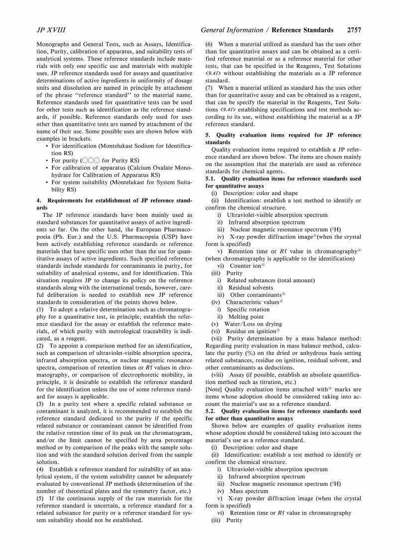
27572757JP XVIII General Information / Reference Standards
Monographs and General Tests, such as Assays, Identifica-tion, Purity, calibration of apparatus, and suitability tests ofanalytical systems. These reference standards include mate-rials with only one specific use and materials with multipleuses. JP reference standards used for assays and quantitativedeterminations of active ingredients in uniformity of dosageunits and dissolution are named in principle by attachmentof the phrase ``reference standard'' to the material name.Reference standards used for quantitative tests can be usedfor other tests such as identification as the reference stand-ards, if possible. Reference standards only used for usesother than quantitative tests are named by attachment of thename of their use. Some possible uses are shown below withexamples in brackets.
For identification (Montelukast Sodium for Identifica-tion RS)
For purity (○○○ for Purity RS) For calibration of apparatus (Calcium Oxalate Mono-
hydrate for Calibration of Apparatus RS) For system suitability (Montelukast for System Suita-
bility RS)
4. Requirements for establishment of JP reference stand-ards
The JP reference standards have been mainly used asstandard substances for quantitative assays of active ingredi-ents so far. On the other hand, the European Pharmaco-poeia (Ph. Eur.) and the U.S. Pharmacopeia (USP) havebeen actively establishing reference standards or referencematerials that have specific uses other than the use for quan-titative assays of active ingredients. Such specified referencestandards include standards for contaminants in purity, forsuitability of analytical systems, and for identification. Thissituation requires JP to change its policy on the referencestandards along with the international trends, however, care-ful deliberation is needed to establish new JP referencestandards in consideration of the points shown below.(1) To adopt a relative determination such as chromatogra-phy for a quantitative test, in principle, establish the refer-ence standard for the assay or establish the reference mate-rials, of which purity with metrological traceability is indi-cated, as a reagent.(2) To appoint a comparison method for an identification,such as comparison of ultraviolet-visible absorption spectra,infrared absorption spectra, or nuclear magnetic resonancespectra, comparison of retention times or Rf values in chro-matography, or comparison of electrophoretic mobility, inprinciple, it is desirable to establish the reference standardfor the identification unless the use of some reference stand-ard for assays is applicable.(3) In a purity test where a specific related substance orcontaminant is analyzed, it is recommended to establish thereference standard dedicated to the purity if the specificrelated substance or contaminant cannot be identified fromthe relative retention time of its peak on the chromatogram,and/or the limit cannot be specified by area percentagemethod or by comparison of the peaks with the sample solu-tion and with the standard solution derived from the samplesolution.(4) Establish a reference standard for suitability of an ana-lytical system, if the system suitability cannot be adequatelyevaluated by conventional JP methods (determination of thenumber of theoretical plates and the symmetry factor, etc.)(5) If the continuous supply of the raw materials for thereference standard is uncertain, a reference standard for arelated substance for purity or a reference standard for sys-tem suitability should not be established.
(6) When a material utilized as standard has the uses otherthan for quantitative assays and can be obtained as a certi-fied reference material or as a reference material for othertests, that can be specified in the Reagents, Test Solutions<9.41> without establishing the materials as a JP referencestandard.(7) When a material utilized as standard has the uses otherthan for quantitative assay and can be obtained as a reagent,that can be specify the material in the Reagents, Test Solu-tions <9.41> establishing specifications and test methods ac-cording to its use, without establishing the material as a JPreference standard.
5. Quality evaluation items required for JP referencestandards
Quality evaluation items required to establish a JP refer-ence standard are shown below. The items are chosen mainlyon the assumption that the materials are used as referencestandards for chemical agents.5.1. Quality evaluation items for reference standards usedfor quantitative assays
(i) Description: color and shape(ii) Identification: establish a test method to identify or
confirm the chemical structure.i) Ultraviolet-visible absorption spectrumii) Infrared absorption spectrumiii) Nuclear magnetic resonance spectrum (1H)iv) X-ray powder diffraction image※(when the crystal
form is specified)v) Retention time or Rf value in chromatography※
(when chromatography is applicable to the identification)vi) Counter ion※
(iii) Purityi) Related substances (total amount)ii) Residual solventsiii) Other contaminants※
(iv) Characteristic values※
i) Specific rotationii) Melting point
(v) Water/Loss on drying(vi) Residue on ignition※
(vii) Purity determination by a mass balance method:Regarding purity evaluation in mass balance method, calcu-late the purity (z) on the dried or anhydrous basis settingrelated substances, residue on ignition, residual solvent, andother contaminants as deductions.
(viii) Assay (if possible, establish an absolute quantifica-tion method such as titration, etc.)[Note] Quality evaluation items attached with※ marks areitems whose adoption should be considered taking into ac-count the material's use as a reference standard.5.2. Quality evaluation items for reference standards usedfor other than quantitative assays
Shown below are examples of quality evaluation itemswhose adoption should be considered taking into account thematerial's use as a reference standard.
(i) Description: color and shape(ii) Identification: establish a test method to identify or
confirm the chemical structure.i) Ultraviolet-visible absorption spectrumii) Infrared absorption spectrumiii) Nuclear magnetic resonance spectrum (1H)iv) Mass spectrumv) X-ray powder diffraction image (when the crystal
form is specified)vi) Retention time or Rf value in chromatography
(iii) Purity

27582758 JP XVIIIOthers / General Information
i) Related substances (total amount)ii) Residual solventsiii) Other contaminants
(iv) Water/Loss on drying(v) Purity determination by mass balance method(vi) Tests related to the uses of the materials
i) A reference standard for system suitability used forpeak identification needs identification of relative retentiontime of the peak under the same conditions to the testmethod that is specified in the Monographs.
ii) A reference standard for system suitability needsidentification of the resolution under the same conditions tothe test method that is specified in the Monographs.
6. Reference materials specified in the JPMaterials that correspond to reference materials are de-
scribed in the Reagents, Test Solutions <9.41> in the JP.Such materials are shown as follows:
Materials described as reagents for assays Materials used for identification that described as rea-
gents for thin-layer chromatography (some materialsdo not correspond to reference materials)
Materials specified as reagents for purity Materials described as specific related substances in the
item of Related substances in Purity in the Mono-graphs
Reference materials specified by JISIn the JP (except ``Crude Drugs''), ``reagents for assays''
is specified as reference materials for assays of active ingre-dients in drug products, and some active ingredients withquality above a certain level are specified as reagents that areused as reference materials for identification of the active in-gredients in drug products by thin-layer chromatography.However, these reference materials specified as reagents arenot officially provided. Assays should be performed usingreference standards, and it is considered appropriate that the``reagents for assays'' described as reagents in the Reagents,Test Solutions <9.41> should be established as referencestandards. Regarding new assay reagents that will be estab-lished for drug products except ``Crude Drugs,'' there is aneed to consider gradual establishment of these ``reagentsfor assays'' as reference standards.
On the other hand, it is difficult to establish referencestandards for indicator ingredients of ``Crude Drugs'';therefore, reference materials for assays of indicator ingredi-ents are specified as reagents and quantitative NMR is in-cluded in specifications of the reagents so that a specificationfor assay with metrological traceability is established.
7. Precautions for the use of JP reference standards7.1. JP reference standards are reference standards whose
uses are specified in the Monographs and General Tests inthe JP. Their detailed uses are described in the Mono-graphs and their adequate qualities as reference standardsare guaranteed when they are used for the described uses.Accordingly, their qualities for other uses are not guaran-teed.
7.2. When a JP reference standard is used for a quantita-tive test specified in the Monographs, if a correctioncoefficient is indicated on documents such as package in-sert, multiply the standard amount by the correctioncoefficient to calculate the corrected amount for the use.If a correction coefficient is not indicated, do not correctthe amount for use assuming that the purity of the refer-ence standard is 100.0z.
7.3. If there is a description of ``amount of the referencestandard, calculated on the dried basis'' or ``amount ofthe reference standard, calculated on the anhydrous
basis'' in a calculation formula for an assay method in theMonographs, extra measurement of the loss on drying orthe water content of the reference standard is required. If,however, the value of loss on drying or water content is in-dicated on the document of the reference standard such aspackage insert, use of the indicated value is permitted.
7.4. JP reference standards have no established expirationdate, therefore, obtain needed amount of a referencestandard when it is needed, and then store the referencestandard under specified conditions and use up it as quickas possible.
7.5. The quality of reference standards stored after unseal-ing of the packages are not guaranteed.
7.6. Normally, one packing unit of a reference standardcontains the amount that enables several times of repeatedtest. However, some packages of reference standardswhose raw material supply is scarce contain the amountsthat enable only one-time test.
7.7. Information of JP reference standards necessary forthe uses specified in the Monographs or General Tests isdescribed on documents such as package inserts.However, their test results are not disclosed and certifi-cates of analysis are not issued.
GZ Others
Water to be used in theTests of Drugs <GZ-1-161>
The water to be used in the tests of drugs is defined as``the water suitable for performing the relevant test'' in theparagraph 21 under General Notices of the JP. Therefore, itis necessary to confirm that the water to be used in a test of adrug is suitable for the purpose of the relevant test before itsuse.
Unless otherwise specified in the individual test method,Purified Water, Purified Water in Containers or the waterproduced by an appropriate process, such as ion exchange orultrafiltration, may be used for these purposes. Water pro-duced for these purposes at other individual facilities mayalso be used.
Examples of the water for tests specified in General Testsin the JP are as follows:
Water for ammonium limit test: <1.02> AmmoniumLimit Test (Standard Ammonium Solution)
Water used for measuring organic carbon (water formeasurement): <2.59> Test for Total Organic Carbon
Water for ICP analysis: <2.63> Inductively CoupledPlasma-Atomic Emission Spectrometry and InductivelyCoupled Plasma-Mass Spectrometry
Water for bacterial endotoxins test: <4.01> BacterialEndotoxins Test
Water for particulate matter test (for injections):<6.07> Insoluble Particulate Matter Test for Injections
Water for particulate matter test (for ophthalmic solu-tions): <6.08> Insoluble Particulate Matter Test forOphthalmic Solutions
Water for particulate matter test (for plastic contain-ers): <7.02> Test Methods for Plastic Containers
The water for tests specified in General Information in theJP is as follows:
Water for aluminum test: Test for Trace Amounts ofAluminum in Total Parenteral Nutrition (TPN) Solu-
27592759JP XVIII General Information / Others
tionsThe term ``water'' described in the text concerning tests of
drugs means ``the water to be used in the tests of drugs'' asdefined in the paragraph 21 under General Notices.
Quality Control of Water forPharmaceutical Use <GZ-2-172>
Water used for manufacturing pharmaceutical productsand for cleaning their containers and equipments used in themanufacture of the products is referred to as ``pharmaceuti-cal water.'' For assuring the quality of pharmaceuticalwater consistently, it is important to verify through ap-propriate process validation of water processing system thatwater with the quality suitable for its intended use is pro-duced and supplied, and to keep the quality of producedwater through routine works for controlling the water proc-essing system.
1. Types of Pharmaceutical Water1.1. Water
The specification for ``Water'' is prescribed in theJapanese Pharmacopoeia (JP) monograph. It is required forWater to meet the Quality Standards for Drinking Waterprovided under the Article 4 of the Japanese Water SupplyLaw. In the case that Water is produced at individual facili-ties using well water or industrial water as source water, it isnecessary for produced water to meet the Quality Standardsfor Drinking Water and an additional requirement forammonium of ``not more than 0.05 mg/L.'' Furthermore,when Water is to be used after storing for a period of time, itis necessary to prevent microbial proliferation.
Water is used as source water for Purified Water andWater for Injection. It is also used for manufacturing inter-mediates of active pharmaceutical ingredients (APIs), andfor pre-washing of the equipment used in the manufacture ofpharmaceutical products.1.2. Purified Water
The specifications for ``Purified Water'' and ``PurifiedWater in Containers'' are prescribed in the JP monographs.Purified Water is prepared by distillation, ion-exchange,reverse osmosis (RO), ultrafiltration (UF) capable of remov-ing microorganisms and substances with molecular masses ofnot less than approximately 6000, or a combination of theseprocesses from Water, after applying some adequatepretreatments if necessary. For the production of PurifiedWater, appropriate control of microorganisms is required.Particularly, in the case that Purified Water is prepared byion-exchange, RO or UF, it is necessary to apply the treat-ments adequate for preventing microbial proliferation, or tosanitize the system periodically.
When Purified Water is treated with chemical agents forsterilizing, preventing microbial proliferation, or maintain-ing the endotoxin level within an appropriate control range,a specification suitable for the intended use of treated watershould be established individually, and a process control forkeeping the quality of treated water in compliance with thespecification thus established should be performed.
``Purified Water in Containers'' is prepared from PurifiedWater by introducing it in a tight container.1.3. Sterile Purified Water
The specification for ``Sterile Purified Water in Contain-ers'' (its alternative name is Sterile Purified Water) isprescribed in the JP monograph.
Sterile Purified Water in Container is prepared from Puri-
fied Water by 1) introducing it into a hermetic container,sealing up the container, then sterilizing the product, or 2)making it sterile by using a suitable method, introducing thesterilized water into a sterile hermetic container by applyingaseptic manipulation, then sealing up the container.
Plastic containers for aqueous injections may be used inplace of hermetic containers.1.4. Water for Injection
The specifications for ``Water for Injection'' and ``SterileWater for Injection in Containers'' are prescribed in the JPmonographs.
Water for Injection is prepared by distillation or reverseosmosis and/or ultrafiltration (RO/UF), either: from thewater which is obtained by appropriate pretreatments suchas ion exchange, RO, etc. on Water; or from Purified Water.In the case of water processing systems based on distillation,it is necessary to take care for avoiding contamination ofproduced water by the impurities accompanied with the en-train. In the case of water processing system based onRO/UF, it is required to provide water with equivalent qual-ity to that prepared by distillation consistently, based onsubstantial process validation through long-term operationand elaborate routine control of the system. It is essential toensure consistent production of water suitable for Water forInjection by the entire water processing system includingpretreatment facilities, in any systems based on RO/UF. Forthe water supplied to the system, it is also required to keepthe quality suitable as source water through adequate valida-tion and routine control on the water. For the water proc-essing system based on RO/UF, routine control should beperformed by analyzing water specimens, monitoring somequality attributes using in-line apparatus and checking thevolume of water passed through the system. In addition, it isrecommended to carry out periodical appearance observa-tion and air-leak test on the membranes being currentlyused. It is also recommended to establish protocols for keep-ing the performance of membrane modules within appropri-ate control ranges and for estimating the timing to exchangethe modules, through diagnosis on the degree of deteriora-tion based on the results of tensile strength test on the usedmembrane modules, and visual observation on those mod-ules whether any leakages of membranes have occurred ornot, and to what extent they have occurred. Furthermore, itis desirable to establish the frequency of membrane exchangeconsidering with its actual condition of use.
In the case that Water for Injection is stored in the waterprocessing system temporarily, a stringent control formicroorganisms and endotoxins should be taken. An accept-able criterion of lower than 0.25 EU/mL for endotoxins isspecified in the JP monograph of Water for Injection.
``Sterile Water for Injection in Container'' is preparedfrom Water for Injection by 1) introducing it into a hermeticcontainer, sealing up the container, then sterilizing theproduct, or 2) making it sterile by using a suitable method,introducing the sterilized water into a sterile hermetic con-tainer by applying aseptic manipulation, then sealing up thecontainer. Plastic containers for aqueous injections may beused in place of hermetic containers.
2. Reverse Osmosis and/or Ultrafiltration (RO/UF)RO/UF are the methods for refining water by using mem-
brane modules based on either reverse osmosis or ultrafiltra-tion, or the modules combining them, and used as the alter-native methods for distillation in the production of PurifiedWater or Water for Injection.
When Water for Injection is produced by RO/UF, a waterprocessing system equipped with pretreatment facilities,
27602760 JP XVIIIOthers / General Information
facilities for producing Water for Injection and facilities forsupplying Water for Injection is usually used. The pretreat-ment facilities are used to remove solid particles, dissolvedsalts and colloids in source water, and placed before thefacilities for producing Water for Injection so as to reducethe load on the facilities for producing Water for Injection.They consist of apparatus properly selected from aggrega-tion apparatus, precipitation-separation apparatus, filtrationapparatus, chorine sterilization apparatus, oxidation-reduc-tion apparatus, residual chlorine-removing apparatus,precise filtration apparatus, reverse osmosis apparatus,ultrafiltration apparatus, ion exchange apparatus, etc.,depending on the quality of source water. The facilities forproducing Water for Injection consist of apparatus for sup-plying pretreated water, sterilization apparatus with ultra-violet rays, heat exchange apparatus, membrane modules,apparatus for cleaning and sterilizing the facilities, etc. Thefacilities for supplying Water for Injection consist of a reser-voir tank for storing Water for Injection in the facilities tem-porarily, pipe lines, heat exchange apparatus, a pump forcirculating Water for Injection in the facilities, pressure con-trol apparatus, etc. When Purified Water is produced byRO/UF, basic composition of water processing system isalmost the same as that for Water for Injection describedabove.
In the case that Water for Injection is stored in the waterprocessing system temporarily, it should usually be circulat-ed in a loop consisting of a reservoir tank and pipe line at atemperature not lower than 809C for preventing microbialproliferation.
When RO/UF is utilized for preparing pharmaceuticalwater, it is necessary to select the most appropriate combina-tion of membrane modules in consideration of the quality ofsource water and the quality of produced water required forits intended use. When the ultrafiltration membrane is usedto prepare Purified Water or Water for Injection, membranemodules capable of removing microorganisms and sub-stances with molecular masses not less than approximately6000 should be used.
3. Selection of Pharmaceutical WaterDepending on the intended use of pharmaceutical water,
the water suitable for assuring the quality of final productswithout causing any trouble during their manufacturingprocesses, should be selected from the above 4 types (1.1 –1.4) of pharmaceutical water specified in the JP. Table 1exemplifies a protocol for such selection.
Sterile Purified Water in Containers or Water for Injec-tion (or Sterile Water for Injection in Containers) may beused in place of Purified Water (or Purified Water in Con-tainers).3.1. Drug Products
For the manufacture of sterile drug products such as In-jections, for which endotoxins together with microorganismsshould be severely controlled, Water for Injection (or SterileWater for Injection in Containers) should be used. For themanufacture of sterile drug products such as OphthalmicPreparations and Ophthalmic Ointments, for which con-tamination with microorganisms should be paid attention,Purified Water (or Purified Water in Containers), which via-ble count level is specified at low, can also be used.
For the manufacture of non-sterile drug products, waterwith a quality not lower than that of Purified Water (orPurified Water in Containers) should be used. For the Inha-lations, Ear Preparations and Nasal Preparations, appropri-ately controlled Purified Water (or Purified Water in Con-tainers) in vial count level should be used, and for Liquids
and Solutions among Inhalations, strictly controlled PurifiedWater (or Purified Water in Containers) in vial count levelshould be used. For the Liquids and Solutions for Oral Ad-ministration, Syrups, Suppositories for Vaginal Use, Oint-ments and Creams, which require care against microbiologi-cal contamination, Purified Water (or Purified Water inContainers) adequately controlled from microbiologicalviewpoints should be used in consideration of the possibleimpacts of preservatives formulated in the drug products.
For the manufacture of drug products containing crudedrugs, it is recommended to select adequate type of waterconsidering viable counts of the crude drugs used formanufacturing the product and microbial limit required forthe product.
Water used for pre-washing of containers or equipmentsurfaces that comes in direct contact with the drug productsshould have the quality not lower than that of Water. Waterused for final rinsing should have an equivalent quality tothat of water used for manufacturing drug products.3.2. Drug Substances
Water used for manufacturing a drug substance should beselected in consideration of the characteristics of the drugproduct for which the drug substance is to be used, and itsmanufacturing process, so that the quality of the final drugproduct is assured.
Water used for manufacturing a drug substance or forcleaning containers or equipment surfaces that come indirect contact with the raw materials or drug substance inter-mediates, should have the quality not lower than that ofWater adequately controlled from the chemical andmicrobiological viewpoints, even if the water is used at anearlier stage of synthetic or extraction process in themanufacture of drug substances. Water used in the finalpurification process should have the quality equal to orhigher than that of Purified Water (or Purified Water inContainers). Water used for final rinsing of containers orequipment surfaces that comes in direct contact with thedrug substances should have an equivalent quality to that ofwater used for manufacturing the drug substances.
For manufacturing sterile drug substances, Sterile PurifiedWater in Containers or Water for Injection (or Sterile Waterfor Injection in Containers) should be used. Similarly, formanufacturing drug substances used for drug productswhere endotoxin control is required and there are no subse-quent processes capable of removing endotoxins, Water forInjection (or Sterile Water for Injection in Containers), orPurified Water (or Purified Water in Containers) for whichendotoxins are controlled at a low level, should be used.
4. Quality Control of Pharmaceutical Water4.1. Outline
Verification that water with the quality required for its in-tended use has been produced by the pharmaceutical waterprocessing system through substantial validation studies atan earlier stage of its operation, is the prerequisite for con-ducting quality control on pharmaceutical water in a routineand periodical manner. If this prerequisite is fulfilled, thefollowing methods are applicable for quality control of phar-maceutical water.
For routine control, it is very useful to control quality ofproduced water based on the monitoring of electrical con-ductivity (conductivity) and total organic carbon (TOC). Inaddition, items to be monitored periodically, such as somespecified impurities, viable counts, endotoxins, insolubleparticulate matters, etc., should be determined according tothe intended use of pharmaceutical water. The frequency ofmeasurement should be determined considering with the
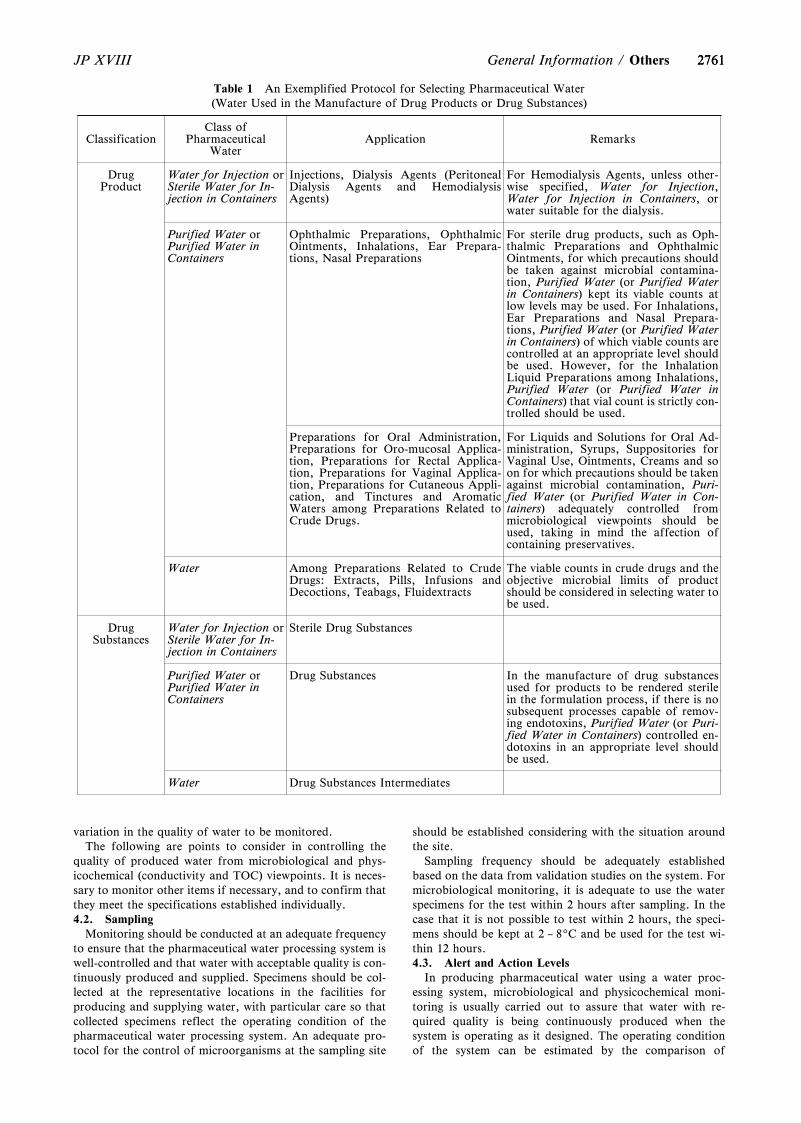
2761
Table 1 An Exemplified Protocol for Selecting Pharmaceutical Water(Water Used in the Manufacture of Drug Products or Drug Substances)
ClassificationClass of
PharmaceuticalWater
Application Remarks
DrugProduct
Water for Injection orSterile Water for In-jection in Containers
Injections, Dialysis Agents (PeritonealDialysis Agents and HemodialysisAgents)
For Hemodialysis Agents, unless other-wise specified, Water for Injection,Water for Injection in Containers, orwater suitable for the dialysis.
Purified Water orPurified Water inContainers
Ophthalmic Preparations, OphthalmicOintments, Inhalations, Ear Prepara-tions, Nasal Preparations
For sterile drug products, such as Oph-thalmic Preparations and OphthalmicOintments, for which precautions shouldbe taken against microbial contamina-tion, Purified Water (or Purified Waterin Containers) kept its viable counts atlow levels may be used. For Inhalations,Ear Preparations and Nasal Prepara-tions, Purified Water (or Purified Waterin Containers) of which viable counts arecontrolled at an appropriate level shouldbe used. However, for the InhalationLiquid Preparations among Inhalations,Purified Water (or Purified Water inContainers) that vial count is strictly con-trolled should be used.
Preparations for Oral Administration,Preparations for Oro-mucosal Applica-tion, Preparations for Rectal Applica-tion, Preparations for Vaginal Applica-tion, Preparations for Cutaneous Appli-cation, and Tinctures and AromaticWaters among Preparations Related toCrude Drugs.
For Liquids and Solutions for Oral Ad-ministration, Syrups, Suppositories forVaginal Use, Ointments, Creams and soon for which precautions should be takenagainst microbial contamination, Puri-fied Water (or Purified Water in Con-tainers) adequately controlled frommicrobiological viewpoints should beused, taking in mind the affection ofcontaining preservatives.
Water Among Preparations Related to CrudeDrugs: Extracts, Pills, Infusions andDecoctions, Teabags, Fluidextracts
The viable counts in crude drugs and theobjective microbial limits of productshould be considered in selecting water tobe used.
DrugSubstances
Water for Injection orSterile Water for In-jection in Containers
Sterile Drug Substances
Purified Water orPurified Water inContainers
Drug Substances In the manufacture of drug substancesused for products to be rendered sterilein the formulation process, if there is nosubsequent processes capable of remov-ing endotoxins, Purified Water (or Puri-fied Water in Containers) controlled en-dotoxins in an appropriate level shouldbe used.
Water Drug Substances Intermediates
2761JP XVIII General Information / Others
variation in the quality of water to be monitored.The following are points to consider in controlling the
quality of produced water from microbiological and phys-icochemical (conductivity and TOC) viewpoints. It is neces-sary to monitor other items if necessary, and to confirm thatthey meet the specifications established individually.4.2. Sampling
Monitoring should be conducted at an adequate frequencyto ensure that the pharmaceutical water processing system iswell-controlled and that water with acceptable quality is con-tinuously produced and supplied. Specimens should be col-lected at the representative locations in the facilities forproducing and supplying water, with particular care so thatcollected specimens reflect the operating condition of thepharmaceutical water processing system. An adequate pro-tocol for the control of microorganisms at the sampling site
should be established considering with the situation aroundthe site.
Sampling frequency should be adequately establishedbased on the data from validation studies on the system. Formicrobiological monitoring, it is adequate to use the waterspecimens for the test within 2 hours after sampling. In thecase that it is not possible to test within 2 hours, the speci-mens should be kept at 2 – 89C and be used for the test wi-thin 12 hours.4.3. Alert and Action Levels
In producing pharmaceutical water using a water proc-essing system, microbiological and physicochemical moni-toring is usually carried out to assure that water with re-quired quality is being continuously produced when thesystem is operating as it designed. The operating conditionof the system can be estimated by the comparison of
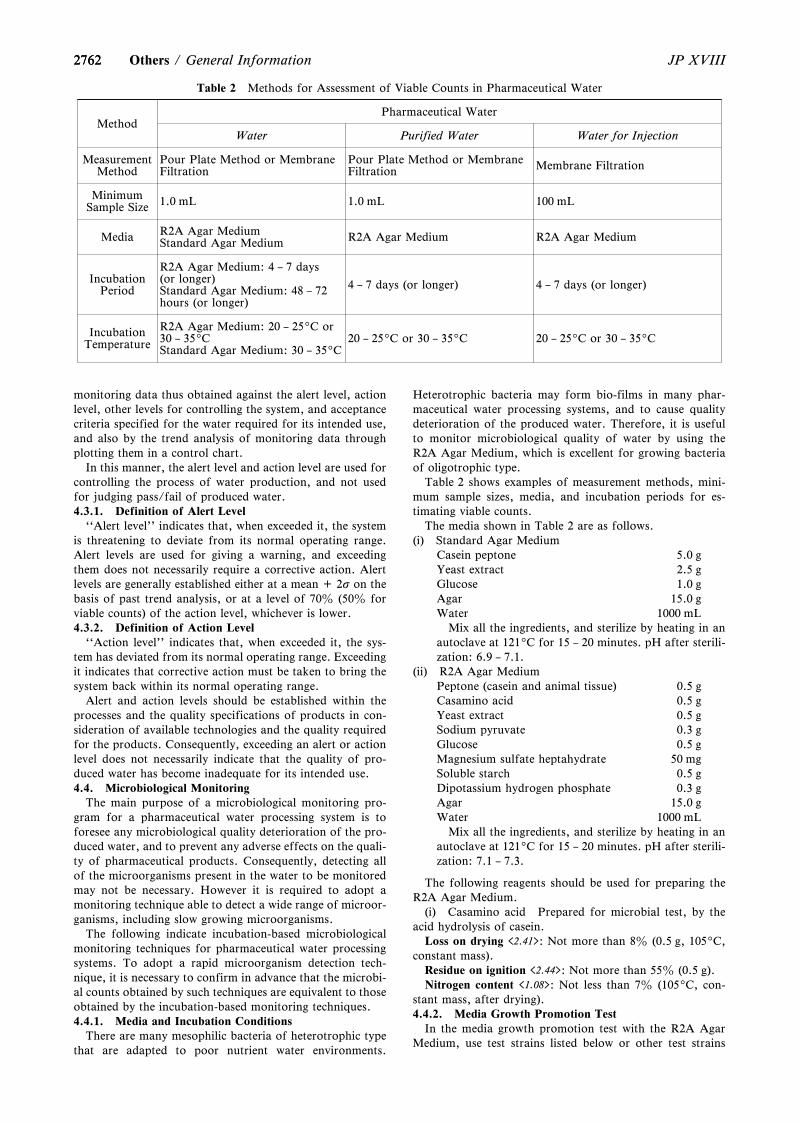
2762
Table 2 Methods for Assessment of Viable Counts in Pharmaceutical Water
MethodPharmaceutical Water
Water Purified Water Water for Injection
MeasurementMethod
Pour Plate Method or MembraneFiltration
Pour Plate Method or MembraneFiltration Membrane Filtration
MinimumSample Size 1.0 mL 1.0 mL 100 mL
Media R2A Agar MediumStandard Agar Medium R2A Agar Medium R2A Agar Medium
IncubationPeriod
R2A Agar Medium: 4 – 7 days(or longer)Standard Agar Medium: 48 – 72hours (or longer)
4 – 7 days (or longer) 4 – 7 days (or longer)
IncubationTemperature
R2A Agar Medium: 20 – 259C or30 – 359CStandard Agar Medium: 30 – 359C
20 – 259C or 30 – 359C 20 – 259C or 30 – 359C
2762 JP XVIIIOthers / General Information
monitoring data thus obtained against the alert level, actionlevel, other levels for controlling the system, and acceptancecriteria specified for the water required for its intended use,and also by the trend analysis of monitoring data throughplotting them in a control chart.
In this manner, the alert level and action level are used forcontrolling the process of water production, and not usedfor judging pass/fail of produced water.4.3.1. Definition of Alert Level
``Alert level'' indicates that, when exceeded it, the systemis threatening to deviate from its normal operating range.Alert levels are used for giving a warning, and exceedingthem does not necessarily require a corrective action. Alertlevels are generally established either at a mean + 2s on thebasis of past trend analysis, or at a level of 70z (50z forviable counts) of the action level, whichever is lower.4.3.2. Definition of Action Level
``Action level'' indicates that, when exceeded it, the sys-tem has deviated from its normal operating range. Exceedingit indicates that corrective action must be taken to bring thesystem back within its normal operating range.
Alert and action levels should be established within theprocesses and the quality specifications of products in con-sideration of available technologies and the quality requiredfor the products. Consequently, exceeding an alert or actionlevel does not necessarily indicate that the quality of pro-duced water has become inadequate for its intended use.4.4. Microbiological Monitoring
The main purpose of a microbiological monitoring pro-gram for a pharmaceutical water processing system is toforesee any microbiological quality deterioration of the pro-duced water, and to prevent any adverse effects on the quali-ty of pharmaceutical products. Consequently, detecting allof the microorganisms present in the water to be monitoredmay not be necessary. However it is required to adopt amonitoring technique able to detect a wide range of microor-ganisms, including slow growing microorganisms.
The following indicate incubation-based microbiologicalmonitoring techniques for pharmaceutical water processingsystems. To adopt a rapid microorganism detection tech-nique, it is necessary to confirm in advance that the microbi-al counts obtained by such techniques are equivalent to thoseobtained by the incubation-based monitoring techniques.4.4.1. Media and Incubation Conditions
There are many mesophilic bacteria of heterotrophic typethat are adapted to poor nutrient water environments.
Heterotrophic bacteria may form bio-films in many phar-maceutical water processing systems, and to cause qualitydeterioration of the produced water. Therefore, it is usefulto monitor microbiological quality of water by using theR2A Agar Medium, which is excellent for growing bacteriaof oligotrophic type.
Table 2 shows examples of measurement methods, mini-mum sample sizes, media, and incubation periods for es-timating viable counts.
The media shown in Table 2 are as follows.(i) Standard Agar Medium
Casein peptone 5.0 gYeast extract 2.5 gGlucose 1.0 gAgar 15.0 gWater 1000 mL
Mix all the ingredients, and sterilize by heating in anautoclave at 1219C for 15 – 20 minutes. pH after sterili-zation: 6.9 – 7.1.
(ii) R2A Agar MediumPeptone (casein and animal tissue) 0.5 gCasamino acid 0.5 gYeast extract 0.5 gSodium pyruvate 0.3 gGlucose 0.5 gMagnesium sulfate heptahydrate 50 mgSoluble starch 0.5 gDipotassium hydrogen phosphate 0.3 gAgar 15.0 gWater 1000 mL
Mix all the ingredients, and sterilize by heating in anautoclave at 1219C for 15 – 20 minutes. pH after sterili-zation: 7.1 – 7.3.
The following reagents should be used for preparing theR2A Agar Medium.
(i) Casamino acid Prepared for microbial test, by theacid hydrolysis of casein.
Loss on drying <2.41>: Not more than 8z (0.5 g, 1059C,constant mass).
Residue on ignition <2.44>: Not more than 55z (0.5 g).Nitrogen content <1.08>: Not less than 7z (1059C, con-
stant mass, after drying).4.4.2. Media Growth Promotion Test
In the media growth promotion test with the R2A AgarMedium, use test strains listed below or other test strains
27632763JP XVIII General Information / Others
considered equivalent to these test strains.Methylobacterium extorquens: NBRC 15911Pseudomonas ‰uorescens: NBRC 15842, ATCC 17386,
etc.Prior to the test, inoculate these test strains into sterile
puriˆed water and starve them at 20 – 259C for 3 days. Di-lute the ‰uid containing the test strain starved with sterilepuriˆed water to prepare microbial suspensions. When in-oculating the R2A Agar Medium with the micro-organisms(5 × 101 - 2 × 10² CFU) and incubating at 20 – 259C for 4– 7 days, su‹cient proliferation of the inoculated strainsmust be observed.
In the media growth promotion test with the StandardAgar Medium, use test strains listed below or other teststrains considered equivalent to these test strains.
Staphylococcus aureus: ATCC 6538, NCIMB 9518, CIP4.83 or NBRC 13276
Pseudomonas aeruginosa: ATCC 9027, NCIMB 8626,CIP 82.118 or NBRC 13275
Escherichia coli: ATCC 8739, NCIMB 8545, CIP 53.126or NBRC 3972
Prepare microbial suspensions containing the test strainsaccording to the procedure prescribed in Microbiological Ex-amination of Non-sterile Products <4.05>. When inoculatingthe Standard Agar Medium with a small number (not morethan 100 CFU) of the micro-organisms and incubating at 30– 359C for 48 hours, su‹cient proliferation of the inoculatedstrains must be observed.4.4.3. Action Levels for Microorganisms for Pharmaceuti-cal Water Processing System
The following action levels are considered appropriate andgenerally applicable to pharmaceutical water processing sys-tems.
Action Levels for viable counts in various types of phar-maceutical water
Water: 102 CFU/mL* (Acceptance criterion prescribed inthe Quality Standards for Drinking Water provided underthe Article 4 of the Water Supply Law)
Purified Water: 102 CFU/mL**Water for Injection: 101 CFU/100 mL**(*Viable counts obtained using the Standard Agar Medi-um, ** Viable counts obtained using the R2A Agar Medi-um)
Although the action level for Purified Water shown aboveis set at the same level as that for Water, it is recommendedfor each facility to perform a higher level of microbiologicalcontrol of water processing system based on the action levelestablished individually.
When actual counts in validation studies or routine con-trol exceed the above action levels, it is necessary to isolateand identify the microorganisms present in the water, and tosanitize or disinfect the affected system.4.5. Physicochemical Monitoring
Physicochemical monitoring of a pharmaceutical waterprocessing system is usually performed using conductivityand TOC as the indicators for water quality. By monitoringconductivity, total amounts of inorganic salts present in thewater can be estimated, and by monitoring TOC, totalamount of organic compounds present in the water can beestimated. Normally, Conductivity Measurements <2.51> andTest for Total Organic Carbon <2.59> specified in the Gener-al Tests, Processes and Apparatus of the JP should be ap-plied to these physicochemical monitoring. However, sincetests for monitoring are performed in the situations differentfrom those for judging pass/fail to the acceptance criteriaprescribed in the monographs, supplements necessary to
cover the situations to which the JP general tests cannot beapplied, are described below.
To adopt the monitoring using conductivity and TOC asthe indicators for inorganic and organic impurities at in-dividual facility, appropriate alert and action levels for eachindicator, and countermeasures against unexpected appara-tus failures should be established.4.5.1. Monitoring of Conductivity as the Indicator forInorganic Impurities
Measurement of conductivity for monitoring is usuallyconducted continuously using an in-line apparatus with aflow-through type or pipe-insertion type cell. Alternatively,offline batch testing may be performed using a dip type cellwith water specimens taken at appropriate locations of thepharmaceutical water processing system.
For the operation control of a pharmaceutical water proc-essing system, guides for judging whether it is adequate tocontinue the operation of the system or not based on theresults from monitoring of conductivity, are shown below,both for the cases of monitoring at the standard temperature(209C) by applying Conductivity Measurements <2.51> of theJP and monitoring at temperatures other than 209C byapplying <645> WATER CONDUCTIVITY of the UnitedStates Pharmacopeia (USP) with some modifications.4.5.1.1. Monitoring of Conductivity by applying Conduc-tivity Measurements <2.51> of the JP
When the monitoring of the conductivity of PurifiedWater and Water for Injection is performed at the standardtemperature (209C), measure the conductivity after confirm-ing that the measure temperature is within a range of 20 ±19C. In this case, the recommended allowable conductivity(action level) for Purified Water and Water for Injection isas follows.
Action Level 1.1 mS・cm-1 (209C)Since the above allowable conductivity is established for
in-line monitoring, an alternative action level may be usedfor the monitoring based on offline batch testing.4.5.1.2. Monitoring of Conductivity by applying <645>WATER CONDUCTIVITY of the USP with some modifi-cation
Usually, it is somewhat difficult to control the tempera-ture exactly in in-line conductivity monitoring. Therefore,the following approach can be applied for the monitoring attemperatures other than the standard temperature (209C) ofthe JP. This approach is based on the Stages 1 and 2 of thethree-stage approach described in ``<645> WATER CON-DUCTIVITY'' of the USP and in the monographs beingassociated with water for pharmaceutical use (``PurifiedWater'', ``Highly Purified Water'' and ``Water for Injec-tions'') of the European Pharmacopoeia (EP).
Stage 1 (In-line Measurement)(i) Determine the temperature and the conductivity of the
water specimens using a non-temperature-compensatedconductivity reading.
(ii) From the Table 3, find the temperature value equal toor just lower than the measured temperature. Adopt thecorresponding conductivity value on this table as theallowable conductivity at the measured temperature.
(iii) If the observed conductivity is not greater than theallowable conductivity adopted above, the water testedmeets the requirement for monitoring conductivity. Ifthe observed conductivity exceeds the allowable conduc-tivity, proceed with Stage 2.
Stage 2 (Off-line Measurement)(i) Measure the conductivity of the water specimen, by
transferring it into a container and agitating it vigorous-
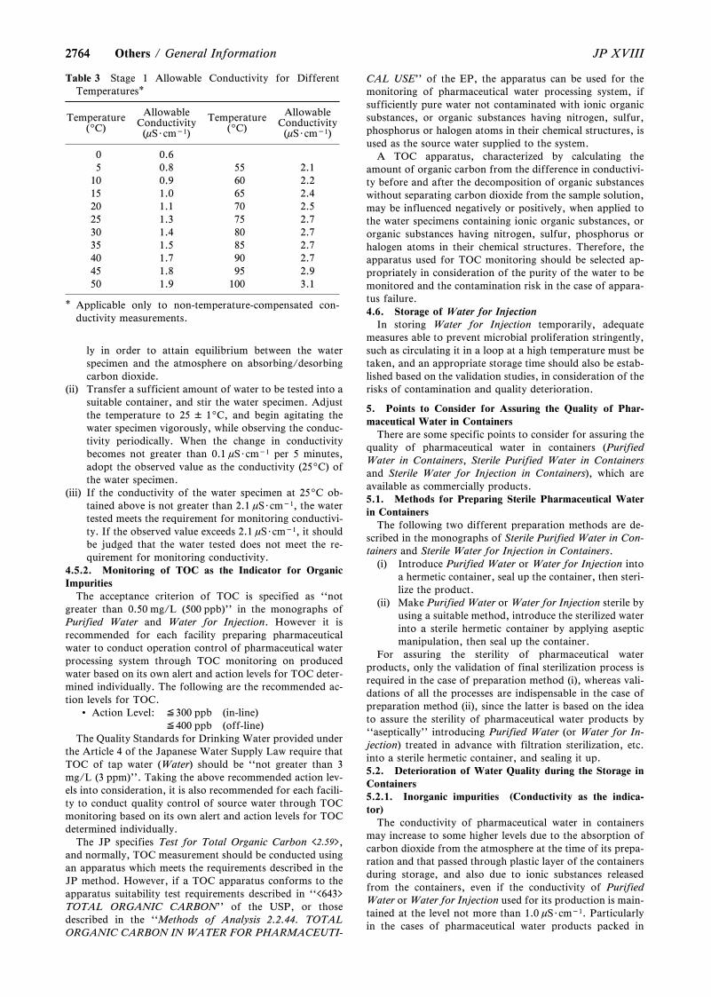
2764
Table 3 Stage 1 Allowable Conductivity for DifferentTemperatures*
Temperature(9C)
AllowableConductivity(mS・cm-1)
Temperature(9C)
AllowableConductivity(mS・cm-1)
0 0.65 0.8 55 2.1
10 0.9 60 2.215 1.0 65 2.420 1.1 70 2.525 1.3 75 2.730 1.4 80 2.735 1.5 85 2.740 1.7 90 2.745 1.8 95 2.950 1.9 100 3.1
* Applicable only to non-temperature-compensated con-ductivity measurements.
2764 JP XVIIIOthers / General Information
ly in order to attain equilibrium between the waterspecimen and the atmosphere on absorbing/desorbingcarbon dioxide.
(ii) Transfer a sufficient amount of water to be tested into asuitable container, and stir the water specimen. Adjustthe temperature to 25 ± 19C, and begin agitating thewater specimen vigorously, while observing the conduc-tivity periodically. When the change in conductivitybecomes not greater than 0.1 mS・cm-1 per 5 minutes,adopt the observed value as the conductivity (259C) ofthe water specimen.
(iii) If the conductivity of the water specimen at 259C ob-tained above is not greater than 2.1 mS・cm-1, the watertested meets the requirement for monitoring conductivi-ty. If the observed value exceeds 2.1 mS・cm-1, it shouldbe judged that the water tested does not meet the re-quirement for monitoring conductivity.
4.5.2. Monitoring of TOC as the Indicator for OrganicImpurities
The acceptance criterion of TOC is specified as ``notgreater than 0.50 mg/L (500 ppb)'' in the monographs ofPurified Water and Water for Injection. However it isrecommended for each facility preparing pharmaceuticalwater to conduct operation control of pharmaceutical waterprocessing system through TOC monitoring on producedwater based on its own alert and action levels for TOC deter-mined individually. The following are the recommended ac-tion levels for TOC.
Action Level: ≦300 ppb (in-line)≦400 ppb (off-line)
The Quality Standards for Drinking Water provided underthe Article 4 of the Japanese Water Supply Law require thatTOC of tap water (Water) should be ``not greater than 3mg/L (3 ppm)''. Taking the above recommended action lev-els into consideration, it is also recommended for each facili-ty to conduct quality control of source water through TOCmonitoring based on its own alert and action levels for TOCdetermined individually.
The JP specifies Test for Total Organic Carbon <2.59>,and normally, TOC measurement should be conducted usingan apparatus which meets the requirements described in theJP method. However, if a TOC apparatus conforms to theapparatus suitability test requirements described in ``<643>TOTAL ORGANIC CARBON'' of the USP, or thosedescribed in the ``Methods of Analysis 2.2.44. TOTALORGANIC CARBON IN WATER FOR PHARMACEUTI-
CAL USE'' of the EP, the apparatus can be used for themonitoring of pharmaceutical water processing system, ifsufficiently pure water not contaminated with ionic organicsubstances, or organic substances having nitrogen, sulfur,phosphorus or halogen atoms in their chemical structures, isused as the source water supplied to the system.
A TOC apparatus, characterized by calculating theamount of organic carbon from the difference in conductivi-ty before and after the decomposition of organic substanceswithout separating carbon dioxide from the sample solution,may be influenced negatively or positively, when applied tothe water specimens containing ionic organic substances, ororganic substances having nitrogen, sulfur, phosphorus orhalogen atoms in their chemical structures. Therefore, theapparatus used for TOC monitoring should be selected ap-propriately in consideration of the purity of the water to bemonitored and the contamination risk in the case of appara-tus failure.4.6. Storage of Water for Injection
In storing Water for Injection temporarily, adequatemeasures able to prevent microbial proliferation stringently,such as circulating it in a loop at a high temperature must betaken, and an appropriate storage time should also be estab-lished based on the validation studies, in consideration of therisks of contamination and quality deterioration.
5. Points to Consider for Assuring the Quality of Phar-maceutical Water in Containers
There are some specific points to consider for assuring thequality of pharmaceutical water in containers (PurifiedWater in Containers, Sterile Purified Water in Containersand Sterile Water for Injection in Containers), which areavailable as commercially products.5.1. Methods for Preparing Sterile Pharmaceutical Waterin Containers
The following two different preparation methods are de-scribed in the monographs of Sterile Purified Water in Con-tainers and Sterile Water for Injection in Containers.
(i) Introduce Purified Water or Water for Injection intoa hermetic container, seal up the container, then steri-lize the product.
(ii) Make Purified Water or Water for Injection sterile byusing a suitable method, introduce the sterilized waterinto a sterile hermetic container by applying asepticmanipulation, then seal up the container.
For assuring the sterility of pharmaceutical waterproducts, only the validation of final sterilization process isrequired in the case of preparation method (i), whereas vali-dations of all the processes are indispensable in the case ofpreparation method (ii), since the latter is based on the ideato assure the sterility of pharmaceutical water products by``aseptically'' introducing Purified Water (or Water for In-jection) treated in advance with filtration sterilization, etc.into a sterile hermetic container, and sealing it up.5.2. Deterioration of Water Quality during the Storage inContainers5.2.1. Inorganic impurities (Conductivity as the indica-tor)
The conductivity of pharmaceutical water in containersmay increase to some higher levels due to the absorption ofcarbon dioxide from the atmosphere at the time of its prepa-ration and that passed through plastic layer of the containersduring storage, and also due to ionic substances releasedfrom the containers, even if the conductivity of PurifiedWater or Water for Injection used for its production is main-tained at the level not more than 1.0 mS・cm-1. Particularlyin the cases of pharmaceutical water products packed in
27652765JP XVIII General Information / Others
small scale glass containers, it is necessary to pay attention tothe change of conductivity during storage.5.2.2. Organic impurities (Potassium Permanganate-reducing Substances or Total Organic Carbon (TOC) as theindicator)
The JP specifies the classical test of potassium perman-ganate-reducing substances in the monographs of PurifiedWater in Containers, Sterile Purified Water in Containersand Sterile Water for Injection in Containers for controllingorganic impurities in pharmaceutical water in containers. Itforms a remarkable contrast to the specifications of PurifiedWater and Water for Injection, in which the JP requires tocontrol organic impurities in pharmaceutical water in bulkbased on the test of TOC (acceptance criterion: not morethan 0.5 mg/L (500 ppb)). This is because that it is consi-dered difficult to establish the specification of pharmaceuti-cal water in containers for organic impurities based on thetest of TOC from the facts that there were many cases ofremarkable increases in TOC values after storage of water incontainers. Particularly in the cases of pharmaceutical waterproducts packed in small scale plastic containers, it is neces-sary to pay attention to the increase of materials releasedfrom containers during storage.
The test of potassium permanganate-reducing substancesis retained in the specifications of pharmaceutical water incontainers, not as the most suitable method for the test oforganic impurities present in the water in containers, but as acounter measure for performing the test of the water in con-tainers with the same test method despite of the material(glass, polyethylene, polypropylene, etc.) and the size (0.5 –2000 mL) of the containers, and the duration of storage.Therefore, it is recommended to adopt the test of TOC asthe alternative for the test of potassium permanganate-reducing substances, and to perform quality control of phar-maceutical water in containers based on TOC measurementsunder the responsibility of each manufacturer, if possible.
In such cases, it is recommended to adopt the followingvalues as the levels preferable to attain.
For products containing not more than 10 mL of water:TOC not greater than 1500 ppb
For products containing more than 10 mL of water:TOC not greater than 1000 ppb
As for the pharmaceutical water packed in the plastic con-tainers made of polyethylene, polypropylene, etc., in addi-tion to the concern for the release of materials such asmonomer, oligomers, plasticizers, etc. from plastics, it isnecessary to pay attention to the storage environment of theproducts to avoid the contaminations with low molecularvolatile organics such as ethanol, or low molecular air pol-lutants such as nitrogen oxides, since these plastics have theproperties of permeating various gases and water.5.2.3. Microbial Limit (Total Aerobic Viable Counts)
For Purified Water in Containers, it is not required to as-sure the sterility, but it is necessary to produce it by usingsanitary or aseptic processes in order to meet the acceptancecriterion of ``102 CFU/mL'' for total aerobic viable countsthroughout the period of their storages. It is also necessaryto take special care against microbial contamination duringits circulation. In addition, it is recommended to use them assoon as possible after opening their seals.
The acceptance criterion of ``102 CFU/mL'' for total aer-obic viable counts of Purified Water in Container is at thesame level as the action level for viable counts in the produc-tion of Purified Water (in bulk). However, different fromthe case of microbiological monitoring of Purified Water,Soybean-Casein Digest Agar Medium is used for the test of
total aerobic viable counts of Purified Water in Containersto detect microorganisms contaminated from the surround-ings during its storage.5.3. Points to consider in the case that commercially avail-able products of pharmaceutical water in containers are usedfor the manufacture of pharmaceutical products
It is allowable to use commercially available products ofpharmaceutical water in containers (Purified Water in Con-tainers, Sterile Purified Water in Containers and SterileWater for Injection in Containers) for the manufacture ofpharmaceutical products and products for clinical trial, andfor the tests of pharmaceutical products. In such cases, it isnecessary to consider the following points.
(i) Use them soon after confirming their compliances tothe requirements of the JP monograph from the testresults at the time of its receipt or those offered fromthe supplier of the products.
(ii) In the case that such products are used for manufac-turing pharmaceutical products, it is necessary to vali-date the process in which the water was used as a partof process validation of pharmaceutical products. Inthe case that they are used for manufacturingproducts for clinical trial, it is necessary to confirmthat the water doesn't give any adverse effects on thequality of the products.
(iii) The products of sterile pharmaceutical water in con-tainers should be used only once after opening theirseals, and it must be avoided to use them again afterstorage.
(iv) It is recommended to prepare a standard operationpractice (SOP) adequate for its intended use, con-sidering that the contamination and quality deteriora-tion of the water due to human and laboratory en-vironmental origins might go on rapidly immediatelyafter opening the product seal.
International HarmonizationImplemented in the Japanese
Pharmacopoeia Eighteenth Edition<GZ-3-180>
Information on items for which harmonization has beenagreed among the European Pharmacopoeia, the UnitedStates Pharmacopeia and the Japanese Pharmacopoeia isavailable on the following websites of Pharmaceuticals andMedical Devices Agency:
General chapters:https://www.pmda.go.jp/rs-std-jp/standards-develop-
ment/jp/0021.htmlMonographs:
https://www.pmda.go.jp/rs-std-jp/standards-develop-ment/jp/0020.html

Appendix
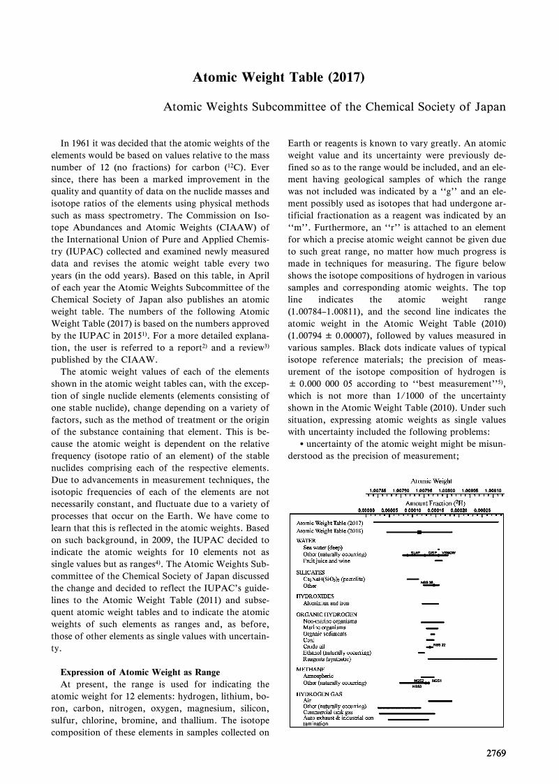
27692769
Atomic Weight Table (2017)
Atomic Weights Subcommittee of the Chemical Society of Japan
In 1961 it was decided that the atomic weights of theelements would be based on values relative to the massnumber of 12 (no fractions) for carbon (12C). Eversince, there has been a marked improvement in thequality and quantity of data on the nuclide masses andisotope ratios of the elements using physical methodssuch as mass spectrometry. The Commission on Iso-tope Abundances and Atomic Weights (CIAAW) ofthe International Union of Pure and Applied Chemis-try (IUPAC) collected and examined newly measureddata and revises the atomic weight table every twoyears (in the odd years). Based on this table, in Aprilof each year the Atomic Weights Subcommittee of theChemical Society of Japan also publishes an atomicweight table. The numbers of the following AtomicWeight Table (2017) is based on the numbers approvedby the IUPAC in 20151). For a more detailed explana-tion, the user is referred to a report2) and a review3)
published by the CIAAW.The atomic weight values of each of the elements
shown in the atomic weight tables can, with the excep-tion of single nuclide elements (elements consisting ofone stable nuclide), change depending on a variety offactors, such as the method of treatment or the originof the substance containing that element. This is be-cause the atomic weight is dependent on the relativefrequency (isotope ratio of an element) of the stablenuclides comprising each of the respective elements.Due to advancements in measurement techniques, theisotopic frequencies of each of the elements are notnecessarily constant, and fluctuate due to a variety ofprocesses that occur on the Earth. We have come tolearn that this is reflected in the atomic weights. Basedon such background, in 2009, the IUPAC decided toindicate the atomic weights for 10 elements not assingle values but as ranges4). The Atomic Weights Sub-committee of the Chemical Society of Japan discussedthe change and decided to reflect the IUPAC's guide-lines to the Atomic Weight Table (2011) and subse-quent atomic weight tables and to indicate the atomicweights of such elements as ranges and, as before,those of other elements as single values with uncertain-ty.
Expression of Atomic Weight as Range
At present, the range is used for indicating theatomic weight for 12 elements: hydrogen, lithium, bo-ron, carbon, nitrogen, oxygen, magnesium, silicon,sulfur, chlorine, bromine, and thallium. The isotopecomposition of these elements in samples collected on
Earth or reagents is known to vary greatly. An atomicweight value and its uncertainty were previously de-fined so as to the range would be included, and an ele-ment having geological samples of which the rangewas not included was indicated by a ``g'' and an ele-ment possibly used as isotopes that had undergone ar-tificial fractionation as a reagent was indicated by an``m''. Furthermore, an ``r'' is attached to an elementfor which a precise atomic weight cannot be given dueto such great range, no matter how much progress ismade in techniques for measuring. The figure belowshows the isotope compositions of hydrogen in varioussamples and corresponding atomic weights. The topline indicates the atomic weight range(1.00784–1.00811), and the second line indicates theatomic weight in the Atomic Weight Table (2010)(1.00794 ± 0.00007), followed by values measured invarious samples. Black dots indicate values of typicalisotope reference materials; the precision of meas-urement of the isotope composition of hydrogen is± 0.000 000 05 according to ``best measurement''5),which is not more than 1/1000 of the uncertaintyshown in the Atomic Weight Table (2010). Under suchsituation, expressing atomic weights as single valueswith uncertainty included the following problems:uncertainty of the atomic weight might be misun-
derstood as the precision of measurement;
27702770 JP XVIIIAppendix
distribution of atomic weight values is not alwaysa Gaussian distribution and depends on elements;
a new measured value exceeding the currentatomic weight range might cause modification of notonly the uncertainty but also the atomic weight so asto include the new value; and
discovering of a real substance having a definedatomic weight value is often difficult or rather impos-sible.
An atomic weight of such elements is representednot as a single value but as a range so as to includeatomic weights in all known samples in this revision,which clearly shows that the atomic weight is not con-stant. Furthermore, the distribution within the range isnot shown in the Atomic Weight Table and is variousdepending on elements4). The range should, therefore,be used with attention to the following points:the intermediate value of the range shall not be
expressed as the atomic weight value and the halfwidth of the range shall not be expressed as the uncer-tainty;
the upper and lower limits themselves have no un-certainty although they are determined on the basis ofvalues measured in ordinary substances on Earth in
addition to measurement errors; andthe atomic weight values are expressed in possible
digits and should be expressed fully even if the lastdigit is zero.
1) IUPAC Inorganic Chemistry Division, CIAAW: Stand-ard Atomic Weight of Ytterbium Revised, Chem. Int., 37
(5-6), 26 (2015).2) J. Meija et al.: Atomic Weights of the Elements 2015
(IUPAC Technical Report), Pure Appl. Chem., to be pub-lished. J. Meija et al.: Atomic Weights of the Elements2013 (IUPAC Technical Report), Pure Appl. Chem., 88,265 (2016).
3) J. R. De Laeter et al.: Atomic Weights of the Elements:Review 2000 (IUPAC Technical Report), Pure Appl.
Chem., 75, 683 (2003).4) M. E. Wieser and T. B. Coplen: Atomic Weights of the
Elements 2009 (IUPAC Technical Report), Pure Appl.
Chem., 83, 359 (2011).5) M. Berglund and M. E. Wieser: Isotopic Compositions
of the Elements 2009 (IUPAC Technical Report), Pure
Appl. Chem., 83, 397 (2011).
2017 Atomic Weights Subcommittee of the Chemical Soci-ety of Japan

2771
Name SymbolAtomicNumber
Atomic Weight Footnotes
Hydrogen H 1 [1.00784, 1.00811] mHelium He 2 4.002602(2) g rLithium Li 3 [6.938, 6.997] mBeryllium Be 4 9.0121831(5)Boron B 5 [10.806, 10.821] mCarbon C 6 [12.0096, 12.0116]Nitrogen N 7 [14.00643, 14.00728] mOxygen O 8 [15.99903, 15.99977] mFluorine F 9 18.998403163(6)Neon Ne 10 20.1797(6) g mSodium Na 11 22.98976928(2)Magnesium Mg 12 [24.304, 24.307]Aluminium(Aluminum)
Al 13 26.9815385(7)
Silicon Si 14 [28.084, 28.086]Phosphorus P 15 30.973761998(5)Sulfur S 16 [32.059, 32.076]Chlorine Cl 17 [35.446, 35.457] mArgon Ar 18 39.948(1) g rPotassium K 19 39.0983(1)Calcium Ca 20 40.078(4) gScandium Sc 21 44.955908(5)Titanium Ti 22 47.867(1)Vanadium V 23 50.9415(1)Chromium Cr 24 51.9961(6)Manganese Mn 25 54.938044(3)Iron Fe 26 55.845(2)Cobalt Co 27 58.933194(4)Nickel Ni 28 58.6934(4) rCopper Cu 29 63.546(3) rZinc Zn 30 65.38(2) rGallium Ga 31 69.723(1)Germanium Ge 32 72.630(8)Arsenic As 33 74.921595(6)Selenium Se 34 78.971(8) rBromine Br 35 [79.901, 79.907]Krypton Kr 36 83.798(2) g mRubidium Rb 37 85.4678(3) gStrontium Sr 38 87.62(1) g rYttrium Y 39 88.90584(2)Zirconium Zr 40 91.224(2) gNiobium Nb 41 92.90637(2)
Name SymbolAtomicNumber
Atomic Weight Footnotes
Molybdenum Mo 42 95.95(1) gTechnetium* Tc 43Ruthenium Ru 44 101.07(2) gRhodium Rh 45 102.90550(2)Palladium Pd 46 106.42(1) gSilver Ag 47 107.8682(2) gCadmium Cd 48 112.414(4) gIndium In 49 114.818(1)Tin Sn 50 118.710(7) gAntimony Sb 51 121.760(1) gTellurium Te 52 127.60(3) gIodine I 53 126.90447(3)Xenon Xe 54 131.293(6) g mCaesium(Cesium)
Cs 55 132.9054519(2)
Barium Ba 56 137.327(7)lanthanum La 57 138.90547(7) gCerium Ce 58 140.116(1) gPraseodymium Pr 59 140.90766(2)Neodymium Nd 60 144.242(3) gPromethium* Pm 61Samarium Sm 62 150.36(2) gEuropium Eu 63 151.964(1) gGadolinium Gd 64 157.25(3) gTerbium Tb 65 158.92535(2)Dysprosium Dy 66 162.500(1) gHolmium Ho 67 164.93033(2)Erbium Er 68 167.259(3) gThulium Tm 69 168.93422(2)Ytterbium Yb 70 173.045(10) gLutetium Lu 71 174.9668(1) gHafnium Hf 72 178.49(2)Tantalum Ta 73 180.94788(2)Tungsten W 74 183.84(1)Rhenium Re 75 186.207(1)Osmium Os 76 190.23(3) gIridium Ir 77 192.217(3)Platinum Pt 78 195.084(9)Gold Au 79 196.966569(5)Mercury Hg 80 200.592(3)Thallium Tl 81 [204.382, 204.385]Lead Pb 82 207.2(1) g rBismuth* Bi 83 208.98040(1)Polonium* Po 84Astatine* At 85Radon* Rn 86Francium* Fr 87Radium* Ra 88Actinium* Ac 89Thorium* Th 90 232.0377(4) gProtactinium* Pa 91 231.03588(2)Uranium* U 92 238.02891(3) g mNeptunium* Np 93Plutonium* Pu 94Americium* Am 95Curium* Cm 96Berkelium* Bk 97Californium* Cf 98Einsteinium* Es 99Fermium* Fm 100Mendelevium* Md 101Nobelium* No 102Lawrencium* Lr 103Rutherfordium* Rf 104
2771JP XVIII Appendix
Standard Atomic Weights 2017
(Scaled to Ar(12C) = 12, where 12C is a neutral atomin its nuclear and electronic ground state.)
The atomic weights, Ar(E), of many elements vary be-cause of variations in the abundances of their isotopesin normal materials. For 12 such elements, an atomic-weight interval is given with the symbol [a, b] todenote the set of atomic-weight values in normalmaterials; thus, aAr(E)b for the element E. Thesymbols a and b denote the bounds of the interval [a,b]. If a more accurate Ar(E) value for a specific mate-rial is required, it should be determined. For 72 ele-ments, Ar(E) values and their evaluated uncertainties(in parentheses, following the last significant digit towhich they are attributed) are given.
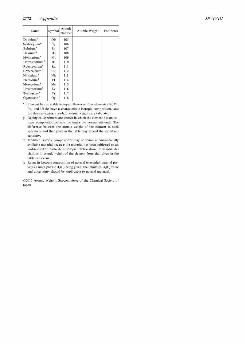
2772
Name SymbolAtomicNumber
Atomic Weight Footnotes
Dubnium* Db 105Seaborgium* Sg 106Bohrium* Bh 107Hassium* Hs 108Meitnerium* Mt 109Darmstadtium* Ds 110Roentgenium* Rg 111Copernicium* Cn 112Nihonium* Nh 113Flerovium* Fl 114Moscovium* Mc 115Livermorium* Lv 116Tennessine* Ts 117Oganesson* Og 118
*: Element has no stable isotopes. However, four elements (Bi, Th,Pa, and U) do have a characteristic isotopic composition, andfor these elements, standard atomic weights are tabulated.
g: Geological specimens are known in which the element has an iso-topic composition outside the limits for normal material. Thedifference between the atomic weight of the element in suchspecimens and that given in the table may exceed the stated un-certainty.
m: Modified isotopic compositions may be found in com-merciallyavailable material because the material has been subjected to anundisclosed or inadvertent isotopic fractionation. Substantial de-viations in atomic weight of the element from that given in thetable can occur.
r: Range in isotopic composition of normal terrestrial material pre-vents a more precise Ar(E) being given: the tabulated Ar(E) valueand uncertainty should be appli-cable to normal material.
2017 Atomic Weights Subcommittee of the Chemical Society ofJapan
2772 JP XVIIIAppendix
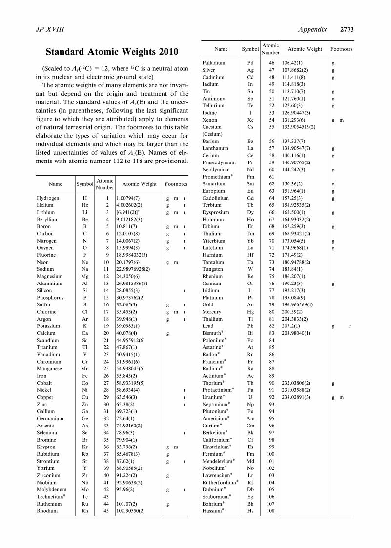
2773
Name SymbolAtomicNumber
Atomic Weight Footnotes
Hydrogen H 1 1.00794(7) g m rHelium He 2 4.002602(2) g rLithium Li 3 [6.941(2)]† g m rBeryllium Be 4 9.012182(3)Boron B 5 10.811(7) g m rCarbon C 6 12.0107(8) g rNitrogen N 7 14.0067(2) g rOxygen O 8 15.9994(3) g rFluorine F 9 18.9984032(5)Neon Ne 10 20.1797(6) g mSodium Na 11 22.98976928(2)Magnesium Mg 12 24.3050(6)Aluminium Al 13 26.9815386(8)Silicon Si 14 28.0855(3) rPhosphorus P 15 30.973762(2)Sulfur S 16 32.065(5) g rChlorine Cl 17 35.453(2) g m rArgon Ar 18 39.948(1) g rPotassium K 19 39.0983(1)Calcium Ca 20 40.078(4) gScandium Sc 21 44.955912(6)Titanium Ti 22 47.867(1)Vanadium V 23 50.9415(1)Chromium Cr 24 51.9961(6)Manganese Mn 25 54.938045(5)Iron Fe 26 55.845(2)Cobalt Co 27 58.933195(5)Nickel Ni 28 58.6934(4) rCopper Cu 29 63.546(3) rZinc Zn 30 65.38(2) rGallium Ga 31 69.723(1)Germanium Ge 32 72.64(1)Arsenic As 33 74.92160(2)Selenium Se 34 78.96(3) rBromine Br 35 79.904(1)Krypton Kr 36 83.798(2) g mRubidium Rb 37 85.4678(3) gStrontium Sr 38 87.62(1) g rYttrium Y 39 88.90585(2)Zirconium Zr 40 91.224(2) gNiobium Nb 41 92.90638(2)Molybdenum Mo 42 95.96(2) g rTechnetium* Tc 43Ruthenium Ru 44 101.07(2) gRhodium Rh 45 102.90550(2)
Name SymbolAtomicNumber
Atomic Weight Footnotes
Palladium Pd 46 106.42(1) gSilver Ag 47 107.8682(2) gCadmium Cd 48 112.411(8) gIndium In 49 114.818(3)Tin Sn 50 118.710(7) gAntimony Sb 51 121.760(1) gTellurium Te 52 127.60(3) gIodine I 53 126.90447(3)Xenon Xe 54 131.293(6) g mCaesium(Cesium)
Cs 55 132.9054519(2)
Barium Ba 56 137.327(7)Lanthanum La 57 138.90547(7) gCerium Ce 58 140.116(1) gPraseodymium Pr 59 140.90765(2)Neodymium Nd 60 144.242(3) gPromethium* Pm 61Samarium Sm 62 150.36(2) gEuropium Eu 63 151.964(1) gGadolinium Gd 64 157.25(3) gTerbium Tb 65 158.92535(2)Dysprosium Dy 66 162.500(1) gHolmium Ho 67 164.93032(2)Erbium Er 68 167.259(3) gThulium Tm 69 168.93421(2)Ytterbium Yb 70 173.054(5) gLutetium Lu 71 174.9668(1) gHafnium Hf 72 178.49(2)Tantalum Ta 73 180.94788(2)Tungsten W 74 183.84(1)Rhenium Re 75 186.207(1)Osmium Os 76 190.23(3) gIridium Ir 77 192.217(3)Platinum Pt 78 195.084(9)Gold Au 79 196.966569(4)Mercury Hg 80 200.59(2)Thallium Tl 81 204.3833(2)Lead Pb 82 207.2(1) g rBismuth* Bi 83 208.98040(1)Polonium* Po 84Astatine* At 85Radon* Rn 86Francium* Fr 87Radium* Ra 88Actinium* Ac 89Thorium* Th 90 232.03806(2) gProtactinium* Pa 91 231.03588(2)Uranium* U 92 238.02891(3) g mNeptunium* Np 93Plutonium* Pu 94Americium* Am 95Curium* Cm 96Berkelium* Bk 97Californium* Cf 98Einsteinium* Es 99Fermium* Fm 100Mendelevium* Md 101Nobelium* No 102Lawrencium* Lr 103Rutherfordium* Rf 104Dubnium* Db 105Seaborgium* Sg 106Bohrium* Bh 107Hassium* Hs 108
2773JP XVIII Appendix
Standard Atomic Weights 2010
(Scaled to Ar(12C) = 12, where 12C is a neutral atomin its nuclear and electronic ground state)
The atomic weights of many elements are not invari-ant but depend on the origin and treatment of thematerial. The standard values of Ar(E) and the uncer-tainties (in parentheses, following the last significantfigure to which they are attributed) apply to elementsof natural terrestrial origin. The footnotes to this tableelaborate the types of variation which may occur forindividual elements and which may be larger than thelisted uncertainties of values of Ar(E). Names of ele-ments with atomic number 112 to 118 are provisional.
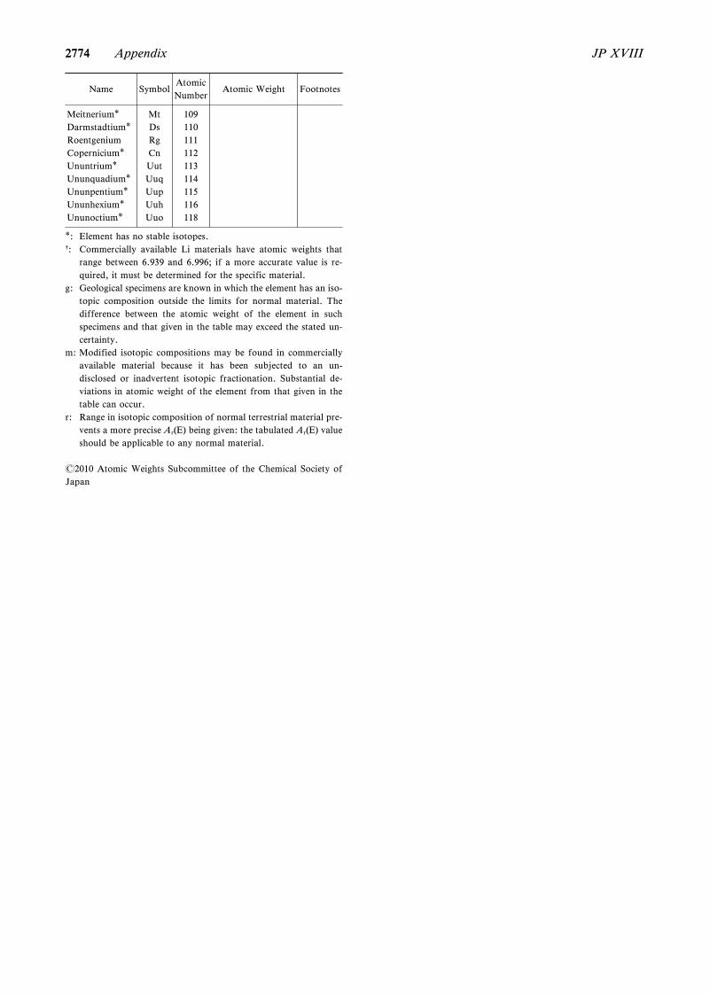
2774
Name SymbolAtomicNumber
Atomic Weight Footnotes
Meitnerium* Mt 109Darmstadtium* Ds 110Roentgenium Rg 111Copernicium* Cn 112Ununtrium* Uut 113Ununquadium* Uuq 114Ununpentium* Uup 115Ununhexium* Uuh 116Ununoctium* Uuo 118
*: Element has no stable isotopes.†: Commercially available Li materials have atomic weights that
range between 6.939 and 6.996; if a more accurate value is re-quired, it must be determined for the specific material.
g: Geological specimens are known in which the element has an iso-topic composition outside the limits for normal material. Thedifference between the atomic weight of the element in suchspecimens and that given in the table may exceed the stated un-certainty.
m: Modified isotopic compositions may be found in commerciallyavailable material because it has been subjected to an un-disclosed or inadvertent isotopic fractionation. Substantial de-viations in atomic weight of the element from that given in thetable can occur.
r: Range in isotopic composition of normal terrestrial material pre-vents a more precise Ar(E) being given: the tabulated Ar(E) valueshould be applicable to any normal material.
2010 Atomic Weights Subcommittee of the Chemical Society ofJapan
2774 JP XVIIIAppendix
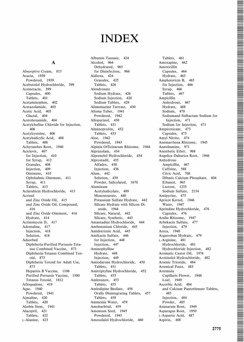
27752775
INDEX
A
Absorptive Cream, 815Acacia, 1939
Powdered, 1939Acebutolol Hydrochloride, 399Acemetacin, 399
Capsules, 400Tablets, 401
Acetaminophen, 402Acetazolamide, 403Acetic Acid, 403
Glacial, 404Acetohexamide, 404Acetylcholine Chloride for Injection,
406Acetylcysteine, 406Acetylsalicylic Acid, 488
Tablets, 488Achyranthes Root, 1940Aciclovir, 407
for Injection, 410for Syrup, 412Granules, 408Injection, 409Ointment, 410Ophthalmic Ointment, 411Syrup, 411Tablets, 413
Aclarubicin Hydrochloride, 413Acrinol
and Zinc Oxide Oil, 415and Zinc Oxide Oil, Compound,
416and Zinc Oxide Ointment, 416Hydrate, 414
Actinomycin D, 417Adrenaline, 417
Injection, 418Solution, 418
AdsorbedDiphtheria-Purified Pertussis-Teta-
nus Combined Vaccine, 873Diphtheria-Tetanus Combined Tox-
oid, 873Diphtheria Toxoid for Adult Use,
873Hepatitis B Vaccine, 1106Purified Pertussis Vaccine, 1500Tetanus Toxoid, 1812
Afloqualone, 419Agar, 1940
Powdered, 1941Ajmaline, 420
Tablets, 420Akebia Stem, 1941Alacepril, 421
Tablets, 422L-Alanine, 423
Albumin Tannate, 424Alcohol, 964
Dehydrated, 965for Disinfection, 966
Aldioxa, 424Granules, 425Tablets, 426
AlendronateSodium Hydrate, 426Sodium Injection, 428Sodium Tablets, 429
Alimemazine Tartrate, 430Alisma Tuber, 1941
Powdered, 1942Allopurinol, 430
Tablets, 431Alminoprofen, 432
Tablets, 433Aloe, 1942
Powdered, 1943Alpinia Officinarum Rhizome, 1944Alprazolam, 434Alprenolol Hydrochloride, 434Alprostadil, 435
Alfadex, 438Injection, 436
Alum, 442Solution, 439Powder, Salicylated, 1670
AluminumAcetylsalicylate, 489Monostearate, 440Potassium Sulfate Hydrate, 442Silicate Hydrate with Silicon Di-
oxide, 1944Silicate, Natural, 442Silicate, Synthetic, 443
Amantadine Hydrochloride, 444Ambenonium Chloride, 445Amidotrizoic Acid, 445Amikacin Sulfate, 446
for Injection, 448Injection, 447
AminophyllineHydrate, 448Injection, 449
Amiodarone Hydrochloride, 450Tablets, 451
Amitriptyline Hydrochloride, 452Tablets, 453
Amlexanox, 453Tablets, 455
Amlodipine Besilate, 456Orally Disintegrating Tablets, 457Tablets, 458
Ammonia Water, 459Amobarbital, 459Amomum Seed, 1945
Powdered, 1945Amosulalol Hydrochloride, 460
Tablets, 461Amoxapine, 462Amoxicillin
Capsules, 464Hydrate, 463
Amphotericin B, 465for Injection, 466Syrup, 466Tablets, 467
AmpicillinAnhydrous, 467Hydrate, 468Sodium, 470Sodiumand Sulbactam Sodium for
Injection, 471Sodium for Injection, 471
Ampiroxicam, 473Capsules, 473
Amyl Nitrite, 474Anemarrhena Rhizome, 1945Anesthamine, 971Anesthetic Ether, 968Angelica Dahurica Root, 1946Anhydrous
Ampicillin, 467Caffeine, 588Citric Acid, 768Dibasic Calcium Phosphate, 604Ethanol, 965Lactose, 1233Sodium Sulfate, 2154
Antipyrine, 475Apricot Kernel, 1946
Water, 1947Aprindine Hydrochloride, 476
Capsules, 476Aralia Rhizome, 1947Arbekacin Sulfate, 477
Injection, 479Areca, 1948Argatroban Hydrate, 479L-Arginine, 481
Hydrochloride, 481Hydrochloride Injection, 482
Aromatic Castor Oil, 1976Arotinolol Hydrochloride, 482Arsenic Trioxide, 484Arsenical Paste, 483Artemisia
Capillaris Flower, 1948Leaf, 1949
Ascorbic Acid, 484and Calcium Pantothenate Tablets,
485Injection, 484Powder, 485
Asiasarum Root, 1949Asparagus Root, 1950L-Aspartic Acid, 487Aspirin, 488
27762776 JP XVIIIIndex
Aluminum, 489Tablets, 488
Aspoxicillin Hydrate, 490Astragalus Root, 1950Atenolol, 491Atorvastatin Calcium
Hydrate, 492Tablets, 493
AtractylodesLancea Rhizome, 1951Lancea Rhizome, Powdered, 1951Rhizome, 1952Rhizome, Powdered, 1952
Atropine SulfateHydrate, 494Injection, 495
Auranofin, 496Tablets, 497
Azathioprine, 498Tablets, 499
Azelastine Hydrochloride, 500Granules, 501
Azelnidipine, 502Tablets, 502
Azithromycin Hydrate, 504Azosemide, 505
Tablets, 505Aztreonam, 506
for Injection, 507
B
Bacampicillin Hydrochloride, 508Bacitracin, 509Baclofen, 510
Tablets, 511Bakumondoto Extract, 1953Bamethan Sulfate, 512Barbital, 512Barium Sulfate, 513Bear Bile, 1955Bearberry Leaf, 1955Beclometasone Dipropionate, 514Beef Tallow, 1956Beeswax
White, 1956Yellow, 1956
Bekanamycin Sulfate, 515Belladonna
Extract, 1958Root, 1957Total Alkaloids, 1958
Benidipine Hydrochloride, 516Tablets, 516
Benincasa Seed, 1959Benoxinate Hydrochloride, 1458Benserazide Hydrochloride, 518Bentonite, 519Benzalkonium Chloride, 519
Solution, 520Solution 50, Concentrated, 520
Benzbromarone, 521Benzethonium Chloride, 522
Solution, 522Benzocaine, 971Benzoic Acid, 523Benzoin, 1960
BenzylAlcohol, 523Benzoate, 525
BenzylpenicillinBenzathine Hydrate, 525Potassium, 527Potassium for Injection, 528
Bepotastine Besilate, 529Tablets, 530
Beraprost Sodium, 531Tablets, 532
BerberineChloride Hydrate, 533Tannate, 534
Betahistine Mesilate, 535Tablets, 536
Betamethasone, 538Dipropionate, 540Sodium Phosphate, 541Tablets, 539Valerate, 542Valerate and Gentamicin Sulfate
Cream, 543Valerate and Gentamicin Sulfate
Ointment, 544Betamipron, 545Betaxolol Hydrochloride, 546Bethanechol Chloride, 547Bezafibrate, 548
Extended-release Tablets, 549Bicalutamide, 549Bifonazole, 552Biotin, 552Biperiden Hydrochloride, 553Biphasic Isophane Insulin Human (Ge-
netical Recombination) InjectableAqueous Suspension, 1159
Bisacodyl, 554Suppositories, 554
BismuthSubgallate, 555Subnitrate, 556
Bisoprolol Fumarate, 556Tablets, 557
BitterCardamon, 1960Orange Peel, 1960Tincture, 1961
BleomycinHydrochloride, 559Sulfate, 561
Bofutsushosan Extract, 1961Boiogito Extract, 1966Boric Acid, 562Bromazepam, 563Bromfenac Sodium
Hydrate, 563Ophthalmic Solution, 565
Bromhexine Hydrochloride, 565Bromocriptine Mesilate, 566Bromovalerylurea, 567Brotizolam, 568
Tablets, 568Brown Rice, 1968Bucillamine, 570
Tablets, 570Bucumolol Hydrochloride, 572
Bufetolol Hydrochloride, 572Buformin Hydrochloride, 573
Delayed-release Tablets, 574Tablets, 575
Bumetanide, 576Bunazosin Hydrochloride, 577Bupivacaine Hydrochloride Hydrate,
577Bupleurum Root, 1968Bupranolol Hydrochloride, 578Buprenorphine Hydrochloride, 579Burdock Fruit, 1969Burnt Alum, 441Busulfan, 580Butenafine Hydrochloride, 580
Cream, 581Solution, 582Spray, 583
Butropium Bromide, 583Butyl Parahydroxybenzoate, 584Byakkokaninjinto Extract, 1969
C
Cabergoline, 585Cacao Butter, 1972Cadralazine, 587
Tablets, 587Caffeine
and Sodium Benzoate, 590Anhydrous, 588Hydrate, 589
Calcitonin Salmon, 591Calcium
Chloride Hydrate, 596Chloride Injection, 596Folinate, 597Folinate Hydrate, 597Gluconate Hydrate, 598Hydroxide, 598Lactate Hydrate, 599Leucovorin, 597Levofolinate Hydrate, 600Oxide, 601Pantothenate, 602Paraaminosalicylate Granules, 604Paraaminosalicylate Hydrate, 603Polystyrene Sulfonate, 607Sodium Edetate Hydrate, 608Stearate, 609
Calumba, 1972Powdered, 1972
Camellia Oil, 1972CamostatMesilate, 610d-Camphor, 611dl-Camphor, 611Candesartan Cilexetil, 612
and Amlodipine Besylate Tablets,615
and Hydrochlorothiazide Tablets,618
Tablets, 613Capsicum, 1973
and Salicylic Acid Spirit, 1975Powdered, 1973Tincture, 1974
Capsules, 622
27772777JP XVIII Index
CapsulesAcemetacin, 400Amoxicillin, 464Ampiroxicam, 473Aprindine Hydrochloride, 476Cefaclor, 641Cefadroxil, 646Cefalexin, 649Cefdinir, 665Cefixime, 673Cinoxacin, 762Clindamycin Hydrochloride, 776Clofibrate, 783Clorazepate Dipotassium, 797Diltiazem Hydrochloride Extended-
release, 864Doxifluridine, 898Droxidopa, 906Emedastine Fumarate Extended-
release, 922Ethyl Icosapentate, 975Flopropione, 1017Fluconazole, 1019Hypromellose, 622Indometacin, 1153Lansoprazole Delayed-release,
1242Methotrexate, 1332Nifedipine Extended-release, 1422Nizatidine, 1432Pilsicainide Hydrochloride, 1519Pullulan, 622Ribavirin, 1633Rifampicin, 1640Roxatidine Acetate Hydrochloride
Extended-release, 1657Sodium Iodide (123I), 1714Sodium Iodide (131I), 1714Sulpiride, 1758Tacrolimus, 1770Teprenone, 1804Tranexamic Acid, 1851Tranilast, 1854Trientine Hydrochloride, 1870Ubenimex, 1885
Captopril, 622Carbamazepine, 623Carbazochrome Sodium Sulfonate Hy-
drate, 624Carbidopa Hydrate, 625L-Carbocisteine, 626
Tablets, 626Carbon Dioxide, 627Carboplatin, 628
Injection, 629Carboxymethylcellulose, 630
Calcium, 631Sodium, 632
Cardamon, 1975Carmellose, 630
Calcium, 631Sodium, 632
Carmofur, 634Carnauba Wax, 1975Carteolol Hydrochloride, 635Carumonam Sodium, 635Carvedilol, 637
Tablets, 638Cassia Seed, 1976Castor Oil, 1976
Aromatic, 1976Catalpa Fruit, 1976Cefaclor, 640
Capsules, 641Combination Granules, 642Fine Granules, 644
Cefadroxil, 645Capsules, 646for Syrup, 647
Cefalexin, 647Capsules, 649Combination Granules, 650for Syrup, 651
Cefalotin Sodium, 652for Injection, 653
Cefatrizine Propylene Glycolate, 654for Syrup, 655
Cefazolin Sodium, 656for Injection, 657Hydrate, 658
Cefbuperazone Sodium, 659Cefcapene Pivoxil Hydrochloride
Fine Granules, 662Hydrate, 660Tablets, 663
Cefdinir, 664Capsules, 665Fine Granules, 666
Cefditoren Pivoxil, 667Fine Granules, 668Tablets, 668
Cefepime Dihydrochloridefor Injection, 671Hydrate, 669
CefiximeCapsules, 673Fine Granules, 674Hydrate, 672
Cefmenoxime Hydrochloride, 675Cefmetazole Sodium, 677
for Injection, 678Cefminox Sodium Hydrate, 678Cefodizime Sodium, 679Cefoperazone Sodium, 681
and Sulbactam Sodium for Injection,683
for Injection, 682Cefotaxime Sodium, 684Cefotetan, 685Cefotiam
Hexetil Hydrochloride, 687Hydrochloride, 689Hydrochloridefor Injection, 690
Cefozopran Hydrochloride, 691for Injection, 692
Cefpiramide Sodium, 692Cefpirome Sulfate, 694Cefpodoxime Proxetil, 695
for Syrup, 696Tablets, 697
Cefroxadinefor Syrup, 700Hydrate, 698
Cefsulodin Sodium, 701
Ceftazidimefor Injection, 704Hydrate, 702
CefteramPivoxil, 704Fine Granules, 706Tablets, 706
Ceftibuten Hydrate, 707Ceftizoxime Sodium, 709Ceftriaxone Sodium Hydrate, 710Cefuroxime Axetil, 712Celecoxib, 714Cellacefate, 715Cellulose
Acetate Phthalate, 715Microcrystalline, 716Powdered, 719
Celmoleukin (Genetical Recombina-tion), 719
Cetanol, 722Cetirizine Hydrochloride, 723
Tablets, 724Cetotiamine Hydrochloride Hydrate,
725Cetraxate Hydrochloride, 726Chenodeoxycholic Acid, 727Cherry Bark, 1977Chloral Hydrate, 728Chloramphenicol, 728
and Colistin Sodium Methanesul-fonate Ophthalmic Solution, 731
Palmitate, 729Sodium Succinate, 730
Chlordiazepoxide, 732Powder, 733Tablets, 734
ChlorhexidineGluconate Solution, 735Hydrochloride, 735
Chlorinated Lime, 736Chlormadinone Acetate, 736Chlorobutanol, 737Chlorphenesin Carbamate, 738
Tablets, 739Chlorpheniramine Maleate, 740
Injection, 741Powder, 741Tablets, 742
d-Chlorpheniramine Maleate, 743Chlorpromazine Hydrochloride, 744
Injection, 745Tablets, 745
Chlorpropamide, 747Tablets, 747
Cholecalciferol, 748Cholesterol, 749Chorionic Gonadotrophin, 1085
for Injection, 1086Chotosan Extract, 1977Chrysanthemum Flower, 1980Cibenzoline Succinate, 750
Tablets, 750Ciclacillin, 751Ciclosporin, 752Cilastatin Sodium, 753Cilazapril
Hydrate, 755Tablets, 755
27782778 JP XVIIIIndex
Cilnidipine, 757Tablets, 758
Cilostazol, 759Tablets, 760
Cimetidine, 761Cimicifuga Rhizome, 1980Cinchocaine Hydrochloride, 846Cinnamon
Bark, 1981Bark, Powdered, 1981Oil, 1982
Cinoxacin, 762Capsules, 762
Ciprofloxacin, 763Hydrochloride Hydrate, 765
Cisplatin, 766Cistanche Herb, 1982Citicoline, 767Citric Acid
Anhydrous, 768Hydrate, 769
Citrus Unshiu Peel, 1983Clarithromycin, 770
for Syrup, 771Tablets, 772
Clebopride Malate, 773Clemastine Fumarate, 774Clematis Root, 1983Clindamycin
Hydrochloride, 775Hydrochloride Capsules, 776Phosphate, 777Phosphate Injection, 778
Clinofibrate, 779Clobetasol Propionate, 779Clocapramine Hydrochloride Hydrate,
780Clofedanol Hydrochloride, 781Clofibrate, 782
Capsules, 783Clomifene Citrate, 784
Tablets, 784Clomipramine Hydrochloride, 785
Tablets, 786Clonazepam, 787
Fine Granules, 787Tablets, 788
Clonidine Hydrochloride, 789Cloperastine
Fendizoate, 790Fendizoate Tablets, 791Hydrochloride, 792
ClopidogrelSulfate, 793Sulfate Tablets, 794
Clorazepate Dipotassium, 796Capsules, 797
Clotiazepam, 798Tablets, 798
Clotrimazole, 799Clove, 1984
Oil, 1984Powdered, 1984
Cloxacillin Sodium Hydrate, 800Cloxazolam, 801Cnidium
Monnieri Fruit, 1985
Rhizome, 1985Rhizome, Powdered, 1986
Cocaine Hydrochloride, 802Coconut Oil, 1986Codeine Phosphate
Hydrate, 803Powder, 1z, 804Powder, 10z, 805Tablets, 805
Cod Liver Oil, 803Codonopsis Root, 1986Coix Seed, 1987
Powdered, 1987Colchicine, 807Colestimide, 808
Granules, 809Tablets, 809
ColistinSodium Methanesulfonate, 810Sulfate, 811
CompoundAcrinol and Zinc Oxide Oil, 416Diastase and Sodium Bicarbonate
Powder, 843Iodine Glycerin, 1171Methyl Salicylate Spirit, 1347Oxycodone and Atropine Injection,
1460Oxycodone Injection, 1460Phellodendron Powder for
Cataplasm, 2098Rhubarb and Senna Powder, 2115Salicylic Acid Spirit, 1669Scopolia Extract and Diastase Pow-
der, 2136Thianthol and Salicylic Acid Solu-
tion, 1820Concentrated
Glycerin, 1081Glycerol, 1081
Condurango, 1987Fluidextract, 1988
Copovidone, 812Coptis Rhizome, 1988
Powdered, 1989Corn
Oil, 1990Starch, 1738
Cornus Fruit, 1990Cortisone Acetate, 814Corydalis Tuber, 1991
Powdered, 1992Crataegus Fruit, 1993Creams
Absorptive, 815Betamethasone Valerate and Gen-
tamicin Sulfate, 543Butenafine Hydrochloride, 581Hydrophilic, 815Ibuprofen Piconol, 1134Ketoconazole, 1222Lanoconazole, 1239Terbinafine Hydrochloride, 1806
Cresol, 816Solution, 816Solution, Saponated, 816
Croconazole Hydrochloride, 817
Croscarmellose Sodium, 633Crospovidone, 818Crude Glycyrrhiza Extract, 2016Curcuma Rhizome, 1993Cyanamide, 819Cyanocobalamin, 820
Injection, 821Cyclopentolate Hydrochloride, 821Cyclophosphamide
Hydrate, 822Tablets, 822
Cycloserine, 823Cyperus Rhizome, 1994
Powdered, 1994Cyproheptadine Hydrochloride Hy-
drate, 824L-Cysteine, 825
Hydrochloride Hydrate, 826L-Cystine, 826Cytarabine, 827
D
Dactinomycin, 417Daiokanzoto Extract, 1995Daisaikoto Extract, 1996Danazol, 828Dantrolene Sodium Hydrate, 828Daunorubicin Hydrochloride, 829Deferoxamine Mesilate, 831Dehydrated Alcohol, 965Dehydrocholic Acid, 832
Injection, 833Purified, 832
Demethylchlortetracycline Hydrochlo-ride, 834
DentalAntiformin, 475Iodine Glycerin, 1172Paraformaldehyde Paste, 1479Phenol with Camphor, 1508Sodium Hypochlorite Solution, 475Triozinc Paste, 1877
Deslanoside, 835Injection, 836
Dexamethasone, 836Dextran
40, 83740 Injection, 83870, 839Sulfate Sodium Sulfur 5, 840Sulfate Sodium Sulfur 18, 840
Dextrin, 841Dextromethorphan Hydrobromide Hy-
drate, 841Diagnostic Sodium Citrate Solution,
1705Diastase, 842
and Sodium Bicarbonate Powder,843
and Sodium Bicarbonate Powder,Compound, 843
Diazepam, 843Tablets, 844
DibasicCalcium Phosphate, Anhydrous,
604
27792779JP XVIII Index
Calcium Phosphate Hydrate, 605Sodium Phosphate Hydrate, 1719
Dibekacin Sulfate, 845Ophthalmic Solution, 845
Dibucaine Hydrochloride, 846Diclofenac Sodium, 846
Suppositories, 847Dicloxacillin Sodium Hydrate, 848Diethylcarbamazine Citrate, 849
Tablets, 849Difenidol Hydrochloride, 850Diflorasone Diacetate, 851Diflucortolone Valerate, 852Digenea, 1998Digoxin, 853
Injection, 854Tablets, 855
Dihydrocodeine Phosphate, 857Powder, 1z, 857Powder, 10z, 858
Dihydroergotamine Mesilate, 859Dihydroergotoxine Mesilate, 860Dilazep Hydrochloride Hydrate, 862Diltiazem Hydrochloride, 863
Extended-release Capsules, 864Dilute
Hydrochloric Acid, 1111Iodine Tincture, 1171
Diluted Opium Powder, 2082Dimemorfan Phosphate, 865Dimenhydrinate, 866
Tablets, 866Dimercaprol, 867
Injection, 868Dimorpholamine, 868
Injection, 869Dinoprost, 869Dioscorea Rhizome, 1999
Powdered, 1999Diphenhydramine, 870
and Bromovalerylurea Powder, 871Hydrochloride, 871, Phenol and Zinc Oxide Liniment,
872Tannate, 872
DiphtheriaAntitoxin, Equine, Freeze-dried,
873-Purified Pertussis-Tetanus Com-
bined Vaccine, Adsorbed, 873-Tetanus Combined Toxoid, Ad-
sorbed, 873Toxoid, 873Toxoid for Adult Use, Adsorbed,
873Dipyridamole, 874Disodium Edetate Hydrate, 1706Disopyramide, 875Distigmine Bromide, 875
Tablets, 876Disulfiram, 877Dobutamine Hydrochloride, 877Docetaxel
for Injection, 880Hydrate, 878Injection, 879
Dolichos Seed, 2000
Domperidone, 881Donepezil Hydrochloride, 882
Fine Granules, 883Tablets, 884
Dopamine Hydrochloride, 886Injection, 886
Doripenemfor Injection, 889Hydrate, 887
Dorzolamide Hydrochloride, 891and Timolol Maleate Ophthalmic So-
lution, 893Ophthalmic Solution, 892
Doxapram Hydrochloride Hydrate,95
Doxazosin Mesilate, 896Tablets, 897
Doxifluridine, 898Capsules, 898
Doxorubicin Hydrochloride, 899for Injection, 900
Doxycycline HydrochlorideHydrate, 901Tablets, 903
DriedAluminum Hydroxide Gel, 440Aluminum Hydroxide Gel Fine
Granules, 440Aluminum Potassium Sulfate, 441Sodium Carbonate, 1701Sodium Sulfite, 1727Thyroid, 1825Yeast, 1924
Droperidol, 904Droxidopa, 905
Capsules, 906Fine Granules, 906
Dydrogesterone, 907Tablets, 908
E
Ebastine, 909Orally Disintegrating Tablets, 909Tablets, 911
Ecabet SodiumGranules, 913Hydrate, 912
Ecothiopate Iodide, 914Edaravone, 915
Injection, 915Edrophonium Chloride, 917
Injection, 918Elcatonin, 919Eleutherococcus Senticosus Rhizome,
2000Emedastine Fumarate, 921
Extended-release Capsules, 922Emorfazone, 923
Tablets, 924Enalapril Maleate, 924
Tablets, 926Enflurane, 927Enoxacin Hydrate, 928Entacapone, 928
Tablets, 930Enviomycin Sulfate, 931
Epalrestat, 932Tablets, 933
Eperisone Hydrochloride, 934Ephedra Herb, 2001Ephedrine Hydrochloride, 935
Injection, 935Tablets, 937Powder, 10z, 936
Epimedium Herb, 2001Epinephrine, 417
Injection, 418Solution, 418
Epirizole, 938Epirubicin Hydrochloride, 939Eplerenone, 940
Tablets, 941Epoetin
Alfa (Genetical Recombination),942
Beta (Genetical Recombination),945
Ergocalciferol, 948Ergometrine Maleate, 949
Injection, 949Tablets, 950
Ergotamine Tartrate, 950Eribulin Mesilate, 951Erythromycin, 955
Delayed-release Tablets, 956Ethylsuccinate, 956Lactobionate, 957Stearate, 958
Estazolam, 958Estradiol Benzoate, 959
Injection (Aqueous Suspension),960
Estriol, 960Injection (Aqueous Suspension),
961Tablets, 961
Etacrynic Acid, 962Tablets, 963
Ethacridine Lactate, 414Ethambutol Hydrochloride, 964Ethanol, 964
Anhydrous, 965for Disinfection, 966
Ethenzamide, 967Ether, 967
Anesthetic, 968Ethinylestradiol, 968
Tablets, 969Ethionamide, 970Ethosuximide, 970Ethyl
Aminobenzoate, 971L-Cysteine Hydrochloride, 973Icosapentate, 974Icosapentate Capsules, 975Loflazepate, 976Loflazepate Tablets, 978Parahydroxybenzoate, 979
Ethylcellulose, 971Ethylenediamine, 974Ethylmorphine Hydrochloride Hy-
drate, 979Etidronate Disodium, 980
27802780 JP XVIIIIndex
Tablets, 981Etilefrine Hydrochloride, 982
Tablets, 983Etizolam, 984
Fine Granules, 984Tablets, 985
Etodolac, 987Etoposide, 987Eucalyptus Oil, 2002Eucommia Bark, 2002Euodia Fruit, 2003Exsiccated Gypsum, 2023Extracts
Bakumondoto, 1953Belladonna, 1958Bofutsushosan, 1961Boiogito, 1966Byakkokaninjinto, 1969Chotosan, 1977Crude Glycyrrhiza, 2016Daiokanzoto, 1995Daisaikoto, 1996Glycyrrhiza, 2015Goreisan, 2017Goshajinkigan, 2018Goshuyuto, 2021Hachimijiogan, 2024Hangekobokuto, 2027Hangeshashinto, 2028Hochuekkito, 2032Juzentaihoto, 2043Kakkonto, 2046Kakkontokasenkyushin'i, 2049Kamikihito, 2052Kamishoyosan, 2055Keishibukuryogan, 2058Maoto, 2070Mukoi-Daikenchuto, 2075Nux Vomica, 2079Orengedokuto, 2084Otsujito, 2087Rikkunshito, 2116Ryokeijutsukanto, 2119Saibokuto, 2122Saikokeishito, 2125Saireito, 2128Scopolia, 2135Shakuyakukanzoto, 2143Shimbuto, 2145Shosaikoto, 2147Shoseiryuto, 2150Tokakujokito, 2160Tokishakuyakusan, 2162Unseiin, 2169Yokukansan, 2173
F
Famotidine, 988for Injection, 990Injection, 989Powder, 991Tablets, 992
Faropenem Sodiumfor Syrup, 994Hydrate, 993Tablets, 995
Felbinac, 996Cataplasm, 997Tape, 997
Felodipine, 998Tablets, 999
Fenbufen, 1000Fennel, 2003
Oil, 2004Powdered, 2003
Fenofibrate, 1001Tablets, 1002
Fentanyl Citrate, 1003Ferrous Sulfate Hydrate, 1004Fexofenadine Hydrochloride, 1004
Tablets, 1005Filgrastim (Genetical Recombination),
1007Injection, 1009
Fine GranulesCefaclor, 644Cefcapene Pivoxil Hydrochloride,
662Cefdinir, 666Cefditoren Pivoxil, 668Cefixime, 674CefteramPivoxil, 706Clonazepam, 787Donepezil Hydrochloride, 883Dried Aluminum Hydroxide Gel,
440Droxidopa, 906Etizolam, 984Haloperidol, 1091Ifenprodil Tartrate, 1140Irsogladine Maleate, 1191Levofloxacin, 1257Nifedipine, 1422Nifedipine Delayed-release, 1420Pravastatin Sodium, 1566Precipitated Calcium Carbonate,
594Probucol, 1581Quetiapine Fumarate, 1615Risperidone, 1645Sarpogrelate Hydrochloride, 1672Tranilast, 1855Troxipide, 1878
Flavin Adenine Dinucleotide Sodium,1010
Flavoxate Hydrochloride, 1012Flecainide Acetate, 1012
Tablets, 1013Flomoxef Sodium, 1014
for Injection, 1016Flopropione, 1017
Capsules, 1017Fluconazole, 1018
Capsules, 1019Injection, 1020
Flucytosine, 1021Fludiazepam, 1022
Tablets, 1022Fludrocortisone Acetate, 1023Fluidextracts
Condurango, 1988Platycodon, 2102UvaUrsi, 2171
Flunitrazepam, 1024Fluocinolone Acetonide, 1025Fluocinonide, 1026Fluorescein Sodium, 1027Fluorometholone, 1028Fluorouracil, 1029Fluphenazine Enanthate, 1030Flurazepam Hydrochloride, 1030Flurbiprofen, 1031Flutamide, 1032Flutoprazepam, 1033
Tablets, 1033Fluvoxamine Maleate, 1034
Tablets, 1036Foeniculated Ammonia Spirit, 2004Folic Acid, 1037
Injection, 1037Tablets, 1038
Formalin, 1039Water, 1039
Formoterol Fumarate Hydrate, 1040Forsythia Fruit, 2004Fosfomycin
Calcium Hydrate, 1040Calcium for Syrup, 1042Sodium, 1043Sodium for Injection, 1044
Fradiomycin Sulfate, 1045Freeze-dried
BCG Vaccine (for PercutaneousUse), 514
Botulism Antitoxin, Equine, 563Diphtheria Antitoxin, Equine, 873Habu Antivenom, Equine, 1090Inactivated Tissue Culture Rabies
Vaccine, 1625Live Attenuated Measles Vaccine,
1301Live Attenuated Mumps Vaccine,
1390Live Attenuated Rubella Vaccine,
1662Mamushi Antivenom, Equine, 1296Smallpox Vaccine, 1696Smallpox Vaccine Prepared in Cell
Culture, 1696Fritillaria Bulb, 2005Fructose, 1046
Injection, 1046Fudosteine, 1047
Tablets, 1048Furosemide, 1049
Injection, 1050Tablets, 1050
Fursultiamine Hydrochloride, 1051
G
Gabexate Mesilate, 1052b-Galactosidase
(Aspergillus), 1053(Penicillium), 1054
Gallium (67Ga) Citrate Injection, 1055Gambir, 2005
Powdered, 2005Gardenia Fruit, 2006
Powdered, 2006
27812781JP XVIII Index
Gastrodia Tuber, 2007Gatifloxacin
Hydrate, 1055Ophthalmic Solution, 1057
Gefarnate, 1058Gefitinib, 1059Gelatin, 1060
Purified, 1062Gentamicin Sulfate, 1064
Injection, 1066Ointment, 1066Ophthalmic Solution, 1067
Gentian, 2007and Sodium Bicarbonate Powder,
2008Powdered, 2008
Geranium Herb, 2009Powdered, 2009
Ginger, 2009Powdered, 2010Processed, 2109
Ginseng, 2011Powdered, 2012
Glacial Acetic Acid, 404Glehnia Root and Rhizome, 2013Glibenclamide, 1067Gliclazide, 1068Glimepiride, 1069
Tablets, 1070Glucagon (Genetical Recombination),
1072Glucose, 1073
Hydrate, 1074Injection, 1076Purified, 1075
L-Glutamic Acid, 1077L-Glutamine, 1078Glutathione, 1079Glycerin, 1080
and Potash Solution, 1082Concentrated, 1081
Glycerol, 1080Concentrated, 1081
Glyceryl Monostearate, 1082Glycine, 1083Glycyrrhiza, 2013
Extract, 2015Extract, Crude, 2016Powdered, 2014Prepared, 2105
Gonadorelin Acetate, 1083Goreisan Extract, 2017Goshajinkigan Extract, 2018Goshuyuto Extract, 2021Granules
Aciclovir, 408Aldioxa, 425Azelastine Hydrochloride, 501Calcium Paraaminosalicylate, 604Cefaclor Combination, 642Cefalexin Combination, 650Colestimide, 809Ecabet Sodium, 913L-Isoleucine, L-Leucine and L-Valine,
1197Minocycline Hydrochloride, 1365Montelukast Sodium, 1379
Pas-calcium, 604Polaprezinc, 1548Ursodeoxycholic Acid, 1892
Guaifenesin, 1088Guanabenz Acetate, 1089Guanethidine Sulfate, 1090Gypsum, 2023
H
Hachimijiogan Extract, 2024Haloperidol, 1090
Fine Granules, 1091Injection, 1092Tablets, 1093
Halothane, 1094Haloxazolam, 1095Hangekobokuto Extract, 2027Hangeshashinto Extract, 2028Hedysarum Root, 2031Hemp Fruit, 2031Heparin
Calcium, 1096Sodium, 1100Sodium Injection, 1104Sodium Lock Solution, 1104Sodium Solution for Dialysis, 1105
L-Histidine, 1106Hydrochloride Hydrate, 1107
Hochuekkito Extract, 2032Homatropine Hydrobromide, 1107Homochlorcyclizine Hydrochloride,
1108Honey, 2035Houttuynia Herb, 2035Human
Chorionic Gonadotrophin, 1085Chorionic Gonadotrophin for Injec-
tion, 1086Menopausal Gonadotrophin, 1087Normal Immunoglobulin, 1109
Hydralazine Hydrochloride, 1109for Injection, 1109Powder, 1110Tablets, 1110
Hydrochloric Acid, 1111Dilute, 1111Lemonade, 1112
Hydrochlorothiazide, 1112Hydrocortisone, 1113
Acetate, 1114and Diphenhydramine Ointment,
1115Butyrate, 1115Sodium Phosphate, 1116Sodium Succinate, 1117Succinate, 1118
Hydrocotarnine Hydrochloride Hy-drate, 1119
Hydrogenated Oil, 1120Hydrophilic
Cream, 815Petrolatum, 1502
Hydrous Lanolin, 2061Hydroxocobalamin Acetate, 1120Hydroxyethylcellulose, 1121Hydroxypropylcellulose, 1123
HydroxyzineHydrochloride, 1125Pamoate, 1126
Hymecromone, 1127Hypromellose, 1127
Acetate Succinate, 1129Capsules, 622Phthalate, 1131
I
Ibudilast, 1132Ibuprofen, 1133
Piconol, 1133Piconol Cream, 1134Piconol Ointment, 1135
Ichthammol, 1135Idarubicin Hydrochloride, 1136
for Injection, 1137Idoxuridine, 1138
Ophthalmic Solution, 1139Ifenprodil Tartrate, 1140
Fine Granules, 1140Tablets, 1141
Imidapril Hydrochloride, 1142Tablets, 1143
Imipenemand Cilastatin Sodium for Injection,
1145Hydrate, 1144
Imipramine Hydrochloride, 1146Tablets, 1147
Immature Orange, 2036Imperata Rhizome, 2036Indapamide, 1148
Tablets, 1149Indenolol Hydrochloride, 1150Indigocarmine, 1151
Injection, 1152Indium (111In) Chloride Injection,
1152Indometacin, 1152
Capsules, 1153Suppositories, 1154
Influenza HA Vaccine, 1155Injection
Acetylcholine Chloride for, 406Aciclovir, 409Aciclovir for, 410Adrenaline, 418Alendronate Sodium, 428Alprostadil, 436Amikacin Sulfate, 447Amikacin Sulfate for, 448Aminophylline, 449Amphotericin B for, 466Ampicillin Sodium and Sulbactam
Sodium for, 471Ampicillin Sodium for, 471Arbekacin Sulfate, 479L-Arginine Hydrochloride, 482Ascorbic Acid, 484Atropine Sulfate, 495Aztreonam for, 507Benzylpenicillin Potassium for, 528Calcium Chloride, 596Carboplatin, 629
27822782 JP XVIIIIndex
Injection (continued)Cefalotin Sodium for, 653Cefazolin Sodium for, 657Cefepime Dihydrochloride for, 671Cefmetazole Sodium for, 678Cefoperazone Sodium and Sulbac-
tam Sodium for, 683Cefoperazone Sodium for, 682Cefotiam Hydrochloride for, 690Cefozopran Hydrochloride for, 692Ceftazidime for, 704Chlorpheniramine Maleate, 741Chlorpromazine Hydrochloride,
745Chorionic Gonadotrophin for,
1086Clindamycin Phosphate, 778Compound Oxycodone, 1460Compound Oxycodone and Atro-
pine, 1460Cyanocobalamin, 821Dehydrocholic Acid, 833Deslanoside, 836Dextran 40, 838Digoxin, 854Dimercaprol, 868Dimorpholamine, 869Docetaxel, 879Docetaxel for, 880Dopamine Hydrochloride, 886Doripenem for, 889Doxorubicin Hydrochloride for,
900Edaravone, 915Edrophonium Chloride, 918Ephedrine Hydrochloride, 935Epinephrine, 418Ergometrine Maleate, 949Estradiol Benzoate (Aqueous Sus-
pension), 960Estriol (Aqueous Suspension), 961Famotidine, 989Famotidine for, 990Filgrastim (Genetical Recombina-
tion), 1009Flomoxef Sodium for, 1016Fluconazole, 1020Folic Acid, 1037Fosfomycin Sodium for, 1044Fructose, 1046Furosemide, 1050Gallium (67Ga) Citrate, 1055Gentamicin Sulfate, 1066Glucose, 1076Haloperidol, 1092Heparin Sodium, 1104Human Chorionic Gonadotrophin
for, 1086Hydralazine Hydrochloride for,
1109Idarubicin Hydrochloride for, 1137Imipenem and Cilastatin Sodium for,
1145Indigocarmine, 1152Indium (111In) Chloride, 1152Insulin Human (Genetical Recombi-
nation), 1157
Insulin Glargine (Genetical Recombi-nation), 1164
Interferon Alfa (NAMALWA),1168
Iodinated (131I) Human Serum Albu-min, 1169
Iohexol, 1177Iopamidol, 1178Irinotecan Hydrochloride, 1189Isepamicin Sulfate, 1194Isoniazid, 1201Levallorphan Tartrate, 1254Levofloxacin, 1258Lidocaine, 1264Lincomycin Hydrochloride, 1267Magnesium Sulfate, 1294D-Mannitol, 1300Meglumine Iotalamate, 1311Meglumine Sodium Amidotrizoate,
1312Mepivacaine Hydrochloride, 1318Meropenem for, 1322Metenolone Enanthate, 1328Methotrexate for, 1333Minocycline Hydrochloride for,
1366Mitomycin C for, 1372Morphine and Atropine, 1385Morphine Hydrochloride, 1383Nartograstim for (Genetical Recom-
bination), 1405Neostigmine Methylsulfate, 1409Nicardipine Hydrochloride, 1410Nicotinic Acid, 1419Noradrenaline, 1433Norepinephrine, 1433Opial, 1449Opium Alkaloids and Atropine,
1450Opium Alkaloids and Scopolamine,
1451Opium Alkaloids Hydrochlorides,
1449Oxytocin, 1467Ozagrel Sodium, 1469Ozagrel Sodium for, 1470Panipenem and Betamipron for,
1473Papaverine Hydrochloride, 1476Pazufloxacin Mesilate, 1486Penicillin G Potassium for, 528Peplomycin Sulfate for, 1496Pethidine Hydrochloride, 1501Phenolsulfonphthalein, 1510Phenytoin Sodium for, 1514Piperacillin Sodium for, 1534Prednisolone Sodium Succinate for,
1576Procainamide Hydrochloride, 1543Procaine Hydrochloride, 1585Progesterone, 1590Protamine Sulfate, 1604Purified Sodium Hyaluronate,
1710Pyridoxine Hydrochloride, 1611Reserpine, 1629Riboflavin Sodium Phosphate,
1638Ritodrine Hydrochloride, 1650Roxatidine Acetate Hydrochloride
for, 1659Sivelestat Sodium for, 1695Sodium Bicarbonate, 1699Sodium Chloride, 0.9z, 1703Sodium Chloride, 10z, 1703Sodium Chromate (51Cr), 1704Sodium Citrate for Transfusion,
1704Sodium Iodohippurate (131I), 1714Sodium Iotalamate, 1714Sodium Pertechnetate (99mTc), 1719Sodium Thiosulfate, 1727Spectinomycin Hydrochloride for,
1735Sterile Water for, in Containers,
1920Streptomycin Sulfate for, 1746Sulfobromophthalein Sodium,
1756Sulpyrine, 1760Suxamethonium Chloride, 1765Suxamethonium Chloride for, 1766Tazobactam and Piperacillin for,
1782Teceleukin for (Genetical Recombi-
nation), 1789Testosterone Enanthate, 1810Testosterone Propionate, 1811Thallium (201Tl) Chloride, 1813Thiamine Chloride Hydrochloride,
1816Thiamylal Sodium for, 1819Thiopental Sodium for, 1822Tobramycin, 1838Tranexamic Acid, 1852Vancomycin Hydrochloride for,
1904Vasopressin, 1904Verapamil Hydrochloride, 1906Vinblastine Sulfate for, 1908Vitamin B1 Hydrochloride, 1816Vitamin B2 Phosphate Ester, 1638Vitamin B6, 1611Vitamin B12, 821Vitamin C, 484Voriconazole for, 1915Water for, 1920Weak Opium Alkaloids and Scopola-
mine, 1452Xylite, 1924Xylitol, 1924
InsulinHuman (Genetical Recombination),
1155Human (Genetical Recombination)
Injection, 1157Aspart (GeneticalRecombination),
1160Glargine (Genetical Recombination),
1162Glargine (Genetical Recombination)
Injection, 1164Interferon Alfa (NAMALWA), 1165Interferon Alfa (NAMALWA) Injec-

27832783JP XVIII Index
tion, 1168Iodinated (131I) Human Serum Albumin
Injection, 1169Iodine, 1170
Glycerin, Compound, 1171Glycerin, Dental, 1172, Salicylic Acid and Phenol Spirit,
1173Tincture, 1170Tincture, Dilute, 1171
Iodoform, 1174Iohexol, 1175
Injection, 1177Iopamidol, 1177
Injection, 1178Iotalamic Acid, 1179Iotroxic Acid, 1180Ipecac, 2036
Powdered, 2037Syrup, 2038
Ipratropium Bromide Hydrate, 1181Ipriflavone, 1182
Tablets, 1183Irbesartan, 1183
and Amlodipine Besilate Tablets,1185
Tablets, 1184Irinotecan Hydrochloride
Hydrate, 1187Injection, 1189
Irsogladine Maleate, 1190Fine Granules, 1191Tablets, 1192
Isepamicin Sulfate, 1193Injection, 1194
Isoflurane, 1195L-Isoleucine, 1196
, L-Leucine and L-Valine Granules,1197
Isomalt, 1198Hydrate, 1198
Isoniazid, 1200Injection, 1201Tablets, 1201
Isophane Insulin Human (GeneticalRecombination) Injectable Aque-ous Suspension, 1158
l-Isoprenaline Hydrochloride, 1202Isopropanol, 1203Isopropyl Alcohol, 1203Isopropylantipyrine, 1203Isosorbide, 1204
Dinitrate, 1205Dinitrate Tablets, 1205Mononitrate 70z/Lactose 30z,
1206Mononitrate Tablets, 1208
Isotonic Sodium Chloride Solution,1703
Isoxsuprine Hydrochloride, 1209Tablets, 1210
Itraconazole, 1211
J
JapaneseAngelica Root, 2039
Angelica Root, Powdered, 2039Gentian, 2040Gentian, Powdered, 2040Valerian, 2040Valerian, Powdered, 2041Zanthoxylum Peel, 2041Zanthoxylum Peel, Powdered,
2042Josamycin, 1212
Propionate, 1214Tablets, 1213
Jujube, 2042Seed, 2042
Juzentaihoto Extract, 2043
K
Kainic Acidand Santonin Powder, 1215Hydrate, 1215
Kakkonto Extract, 2046Kakkontokasenkyushin'i Extract,
2049Kallidinogenase, 1216Kamikihito Extract, 2052Kamishoyosan Extract, 2055Kanamycin
Monosulfate, 1218Sulfate, 1219
Kaolin, 1220Keishibukuryogan Extract, 2058Ketamine Hydrochloride, 1221Ketoconazole, 1221
Cream, 1222Lotion, 1223Solution, 1223
Ketoprofen, 1224Ketotifen Fumarate, 1225Kitasamycin, 1226
Acetate, 1227Tartrate, 1228
Koi, 2060
L
Labetalol Hydrochloride, 1230Tablets, 1231
Lactic Acid, 1232L-Lactic Acid, 1232Lactose
Anhydrous, 1233Hydrate, 1234
Lactulose, 1235Lafutidine, 1236
Tablets, 1237Lanoconazole, 1238
Cream, 1239Cutaneous Solution, 1240Ointment, 1240
LanolinHydrous, 2061Purified, 2061
Lansoprazole, 1241Delayed-release Capsules, 1242Delayed-release Orally Disintegrating
Tablets, 1243Lard, 2062
Latamoxef Sodium, 1245Lauromacrogol, 1246Lemonades
Hydrochloric Acid, 1112Lenampicillin Hydrochloride, 1246Lenograstim (Genetical Recombina-
tion), 1248Leonurus Herb, 2063L-Leucine, 1251Leuprorelin Acetate, 1252Levallorphan Tartrate, 1254
Injection, 1254Levodopa, 1255Levofloxacin
Fine Granules, 1257Hydrate, 1256Injection, 1258Ophthalmic Solution, 1258Tablets, 1259
Levomepromazine Maleate, 1261Levothyroxine Sodium
Hydrate, 1261Tablets, 1262
Lidocaine, 1263Injection, 1264
LightAnhydrous Silicic Acid, 1680Liquid Paraffin, 1478
Lilium Bulb, 2063Limaprost Alfadex, 1264Lincomycin Hydrochloride
Hydrate, 1266Injection, 1267
Lindera Root, 2064Liniments
Diphenhydramine, Phenol and ZincOxide, 872
Phenol and Zinc Oxide, 1509Liothyronine Sodium, 1267
Tablets, 1268Liquefied Phenol, 1507Liquid Paraffin, 1477Lisinopril
Hydrate, 1269Tablets, 1270
Lithium Carbonate, 1271Lithospermum Root, 2064Lobenzarit Sodium, 1273Longan Aril, 2065Longgu, 2065
Powdered, 2065Lonicera Leaf and Stem, 2066Loquat Leaf, 2066Lorazepam, 1273Losartan Potassium, 1274
and Hydrochlorothiazide Tablets,1276
Tablets, 1275Lotions
Ketoconazole, 1223Sulfur and Camphor, 1756Tacalcitol, 1767
Low Substituted Hydroxypropylcellu-lose, 1124
Loxoprofen SodiumHydrate, 1279Tablets, 1280
27842784 JP XVIIIIndex
LyciumBark, 2067Fruit, 2067
L-LysineAcetate, 1281Hydrochloride, 1282
Lysozyme Hydrochloride, 1283
M
Macrogol400, 12841500, 12844000, 12856000, 128520000, 1286Ointment, 1286
MagnesiumAluminometasilicate, 1288Aluminosilicate, 1287Carbonate, 1289Oxide, 1290Silicate, 1291Stearate, 1292Sulfate Hydrate, 1294Sulfate Injection, 1294Sulfate Mixture, 1295
MagnoliaBark, 2067Bark, Powdered, 2068Flower, 2069
Mallotus Bark, 2069Malt, 2069Maltose Hydrate, 1295Manidipine Hydrochloride, 1296
Tablets, 1297D-Mannitol, 1298
Injection, 1300Maoto Extract, 2070Maprotiline Hydrochloride, 1300Meclofenoxate Hydrochloride, 1301Mecobalamin, 1302
Tablets, 1303Medazepam, 1304Medicinal
Carbon, 1305Soap, 1306
Medroxyprogesterone Acetate, 1306Mefenamic Acid, 1307Mefloquine Hydrochloride, 1308Mefruside, 1309
Tablets, 1310Meglumine, 1310
Iotalamate Injection, 1311Sodium Amidotrizoate Injection,
1312Melphalan, 1313Menatetrenone, 1314Mentha
Herb, 2072Oil, 2072Water, 2073
dl-Menthol, 1315l-Menthol, 1315Mepenzolate Bromide, 1316Mepitiostane, 1316Mepivacaine Hydrochloride, 1317
Injection, 1318Mequitazine, 1319
Tablets, 1319Mercaptopurine Hydrate, 1320Meropenem
for Injection, 1322Hydrate, 1321
Mesalazine, 1323Extended-release Tablets, 1325
Mestranol, 1326Metenolone
Acetate, 1327Enanthate, 1328Enanthate Injection, 1328
Metformin Hydrochloride, 1329Tablets, 1329
Methamphetamine Hydrochloride,1330
L-Methionine, 1331Methotrexate, 1331
Capsules, 1332for Injection, 1333Tablets, 1334
Methoxsalen, 1335Methyl
Parahydroxybenzoate, 1343Salicylate, 1346Salicylate Spirit, Compound, 1347
Methylbenactyzium Bromide, 1336Methylcellulose, 1336Methyldopa
Hydrate, 1338Tablets, 1339
dl-Methylephedrine Hydrochloride,1340
Powder, 10z, 1341Methylergometrine Maleate, 1342
Tablets, 1342Methylprednisolone, 1344
Succinate, 1345Methyltestosterone, 1347
Tablets, 1348Meticrane, 1349Metildigoxin, 1350Metoclopramide, 1351
Tablets, 1351Metoprolol Tartrate, 1352
Tablets, 1353Metronidazole, 1354
Tablets, 1354Metyrapone, 1355Mexiletine Hydrochloride, 1356Miconazole, 1357
Nitrate, 1358Microcrystalline Cellulose, 716Micronomicin Sulfate, 1358Midecamycin, 1359
Acetate, 1360Miglitol, 1361
Tablets, 1362Migrenin, 1363Minocycline Hydrochloride, 1364
for Injection, 1366Granules, 1365Tablets, 1367
Mitiglinide CalciumHydrate, 1368
Tablets, 1369Mitomycin C, 1371
for Injection, 1372Mizoribine, 1372
Tablets, 1373Monobasic Calcium Phosphate Hy-
drate, 606Montelukast Sodium, 1334
Chewable Tablets, 1377Granules, 1379Tablets, 1380
Morphineand Atropine Injection, 1385Hydrochloride Hydrate, 1382Hydrochloride Injection, 1383Hydrochloride Tablets, 1384Sulfate Hydrate, 1386
Mosapride CitrateHydrate, 1387Powder, 1388Tablets, 1389
Moutan Bark, 2073Powdered, 2074
Mukoi-Daikenchuto Extract, 2075Mulberry Bark, 2076Mupirocin Calcium
Hydrate, 1390Ointment, 1392
N
Nabumetone, 1392Tablets, 1393
Nadolol, 1394NafamostatMesilate, 1395Naftopidil, 1396
Orally Disintegrating Tablets, 1397Tablets, 1398
Nalidixic Acid, 1399Naloxone Hydrochloride, 1400Naphazoline
and Chlorpheniramine Solution,1401
Hydrochloride, 1400Nitrate, 1401
Naproxen, 1402Nartograstim (Genetical Recombina-
tion), 1403for Injection, 1405
Natamycin, 1520Nateglinide, 1406
Tablets, 1407Natural Aluminum Silicate, 442Nelumbo Seed, 2077Neomycin Sulfate, 1045Neostigmine Methylsulfate, 1408
Injection, 1409Nicardipine Hydrochloride, 1410
Injection, 1410Nicergoline, 1411
Powder, 1412Tablets, 1413
Niceritrol, 1414Nicomol, 1415
Tablets, 1416Nicorandil, 1417Nicotinamide, 1417
27852785JP XVIII Index
Nicotinic Acid, 1418Injection, 1419
Nifedipine, 1420Delayed-release Fine Granules,
1420Extended-release Capsules, 1422Fine Granules, 1422
Nilvadipine, 1423Tablets, 1424
Nitrazepam, 1426Nitrendipine, 1426
Tablets, 1427Nitrogen, 1428Nitroglycerin Tablets, 1429Nitrous Oxide, 1430Nizatidine, 1431
Capsules, 1432Noradrenaline, 1433
Injection, 1433Norepinephrine, 1433
Injection, 1433Norethisterone, 1434Norfloxacin, 1434Norgestrel, 1435
and Ethinylestradiol Tablets, 1436Nortriptyline Hydrochloride, 1437
Tablets, 1438Noscapine, 1439
Hydrochloride Hydrate, 1439Notopterygium, 2077Nuphar Rhizome, 2077Nutmeg, 2078Nux Vomica, 2078
Extract, 2079Extract Powder, 2080Tincture, 2080
Nystatin, 1440
O
Ofloxacin, 1441Ointments
Aciclovir, 410Aciclovir Ophthalmic, 411Acrinol and Zinc Oxide, 416
Betamethasone Valerate and Gentami-cin Sulfate, 544
Gentamicin Sulfate, 1066Hydrocortisone and Diphenhydra-
mine, 1115Ibuprofen Piconol, 1135Lanoconazole, 1240Macrogol, 1286Mupirocin Calcium, 1392Polyethylene Glycol, 1286Simple, 2153Sulfur, Salicylic Acid and Thianthol,
1757Tacalcitol, 1768White, 1921Zinc Oxide, 1929
Olive Oil, 2081Olmesartan Medoxomil, 1442
Tablets, 1443Olopatadine Hydrochloride, 1444
Tablets, 1445Omeprazole, 1446
Delayed-release Tablets, 1447Ophiopogon Root, 2081Ophthalmic Solution
Bromfenac Sodium, 565Chloramphenicol and Colistin Sodi-
um Methanesulfonate, 731Dibekacin Sulfate, 845Dorzolamide Hydrochloride, 892Dorzolamide Hydrochloride and
Timolol Maleate, 893Gatifloxacin, 1057Gentamicin Sulfate, 1067Idoxuridine, 1139Levofloxacin, 1258Pemirolast Potassium, 1487Purified Sodium Hyaluronate,
1711Silver Nitrate, 1687Tranilast, 1856Zinc Sulfate, 1931
Ophthalmic OintmentAciclovir, 411
OpiumIpecac Powder, 2083Powder, Diluted, 2082Powdered, 2082Tincture, 2083
Opium Alkaloidsand Atropine Injection, 1450and Scopolamine Injection, 1451Hydrochlorides, 1448Hydrochlorides Injection, 1449
OrangeOil, 2083Peel Syrup, 2084Peel Tincture, 2084
Orciprenaline Sulfate, 1454Orengedokuto Extract, 2084Oriental Bezoar, 2086Otsujito Extract, 2087Oxapium Iodide, 1454Oxaprozin, 1455Oxazolam, 1456Oxetacaine, 1457Oxethazaine, 1457Oxprenolol Hydrochloride, 1457Oxybuprocaine Hydrochloride, 1458Oxycodone Hydrochloride Hydrate,
1459Oxydol, 1462Oxygen, 1462Oxymetholone, 1463Oxytetracycline Hydrochloride, 1464Oxytocin, 1465
Injection, 1467Oyster Shell, 2090
Powdered, 2090Ozagrel Sodium, 1468
for Injection, 1470Injection, 1469
P
Panax Japonicus Rhizome, 2090Powdered, 2091
Pancreatin, 1470Pancuronium Bromide, 1471
Panipenem, 1471and Betamipron for Injection, 1473
Pantethine, 1475Papaverine Hydrochloride, 1475
Injection, 1476Paracetamol, 402Paraffin, 1476
Light Liquid, 1478Liquid, 1477
Paraformaldehyde, 1478Paste, Dental, 1479
Parnaparin Sodium, 1480Paroxetine Hydrochloride
Hydrate, 1482Tablets, 1483
Pas-calciumGranules, 604Hydrate, 603
PasteArsenical, 483Dental Paraformaldehyde, 1479Dental Triozinc, 1877
Pazufloxacin Mesilate, 1485Injection, 1486
Peach Kernel, 2091Powdered, 2092
Peanut Oil, 2093Pemirolast Potassium, 1486
for Syrup, 1489Ophthalmic Solution, 1487Tablets, 1489
Penbutolol Sulfate, 1490Penicillin G Potassium, 527
for Injection, 528Pentazocine, 1491Pentobarbital Calcium, 1491
Tablets, 1492Pentoxyverine Citrate, 1493Peony Root, 2093
Powdered, 2094Peplomycin Sulfate, 1494
for Injection, 1496Perilla Herb, 2095Perphenazine, 1497
Maleate, 1498Maleate Tablets, 1499Tablets, 1497
Pethidine Hydrochloride, 1500Injection, 1501
Petroleum Benzin, 1503Peucedanum Root, 2095Pharbitis Seed, 2096Phellodendron
, Albumin Tannate and BismuthSubnitrate Powder, 2098
Bark, 2096Bark, Powdered, 2097Powder for Cataplasm, Compound,
2098Phenazone, 475Phenethicillin Potassium, 1503Phenobarbital, 1504
Powder, 10z, 1505Tablets, 1506
Phenol, 1507and Zinc Oxide Liniment, 1509for Disinfection, 1507
27862786 JP XVIIIIndex
Liquefied, 1507with Camphor, Dental, 1508
Phenolated Water, 1508for Disinfection, 1508
Phenolsulfonphthalein, 1509Injection, 1510
L-Phenylalanine, 1510Phenylbutazone, 1511Phenylephrine Hydrochloride, 1512Phenytoin, 1512
Powder, 1513Sodium for Injection, 1514Tablets, 1513
Phytonadione, 1515Picrasma Wood, 2099
Powdered, 2099Pilocarpine Hydrochloride, 1516
Tablets, 1516Pilsicainide Hydrochloride
Capsules, 1519Hydrate, 1518
Pimaricin, 1520Pimozide, 1521Pindolol, 1522Pinellia Tuber, 2100Pioglitazone Hydrochloride, 1522
and Glimepiride Tablets, 1524and Metformin Hydrochloride
Tablets, 1527Tablets, 1523
Pipemidic Acid Hydrate, 1530Piperacillin
Hydrate, 1530Sodium, 1532Sodiumfor Injection, 1534
PiperazineAdipate, 1534Phosphate Hydrate, 1535Phosphate Tablets, 1535
Pirarubicin, 1536Pirenoxine, 1537Pirenzepine Hydrochloride Hydrate,
1538Piroxicam, 1539Pitavastatin Calcium
Hydrate, 1540Orally Disintegrating Tablets, 1541Tablets, 1543
Pivmecillinam Hydrochloride, 1545Tablets, 1546
PlantagoHerb, 2100Seed, 2100
PlatycodonFluidextract, 2102Root, 2101Root, Powdered, 2101
Pogostemon Herb, 2102Polaprezinc, 1546
Granules, 1548Polyethylene Glycol
400, 12841500, 12844000, 12856000, 128520000, 1286Ointment, 1286
Polygala Root, 2102Powdered, 2103
Polygonatum Rhizome, 2103Polygonum Root, 2104Polymixin B Sulfate, 1543Polyoxyl 40 Stearate, 1550Polyporus Sclerotium, 2104
Powdered, 2104Polysorbate 80, 1550Poria Sclerotium, 2105
Powdered, 2105Potash Soap, 1552Potassium
Bromide, 1552Canrenoate, 1553Carbonate, 1553Chloride, 1554Clavulanate, 1554Guaiacolsulfonate, 1556Hydroxide, 1556Iodide, 1557Permanganate, 1558Sulfate, 1558
Potato Starch, 1739Povidone, 1559
-Iodine, 1561Powder
Ascorbic Acid, 485Chlordiazepoxide, 733Chlorpheniramine Maleate, 741Codeine Phosphate, 1z, 804Codeine Phosphate, 10z, 805Compound Diastase and Sodium Bi-
carbonate, 843Compound Phellodendron, for
Cataplasm, 2098Compound Rhubarb and Senna,
2115Compound ScopoliaExtract and Di-
astase, 2136Diastase and Sodium Bicarbonate,
843Dihydrocodeine Phosphate, 1z,
857Dihydrocodeine Phosphate, 10z,
858Diluted Opium, 2082Diphenhydramine and
Bromovalerylurea, 871Ephedrine Hydrochloride, 10z,
936Famotidine, 991Gentian and Sodium Bicarbonate,
2008Hydralazine Hydrochloride, 1110Kainic Acid and Santonin, 1215dl-Methylephedrine Hydrochloride,
10z, 1341Mosapride Citrate, 1388Nicergoline, 1412Nux Vomica Extract, 2080Opium Ipecac, 2083Phellodendron, Albumin Tannate
and Bismuth Subnitrate, 2098Phenobarbital, 10z, 1505Phenytoin, 1513Reserpine, 0.1z, 1630
Riboflavin, 1635Scopolia Extract and Carbon, 2136Scopolia Extract and Ethyl
Aminobenzoate, 2137Salicylated Alum, 1670Scopolia Extract, 2135Swertia and Sodium Bicarbonate,
2158Thiamine Chloride Hydrochloride,
1817Vitamin B1 Hydrochloride, 1817Vitamin B2, 1635Vitamin C, 485Zinc Oxide Starch, 1930
PowderedAcacia, 1939Agar, 1941Alisma Tuber, 1942Aloe, 1943Amomum Seed, 1945Atractylodes Lancea Rhizome,
1951Atractylodes Rhizome, 1952Calumba, 1972Capsicum, 1973Cellulose, 719Cinnamon Bark, 1981Clove, 1984Cnidium Rhizome, 1986Coix Seed, 1987Coptis Rhizome, 1989Corydalis Tuber, 1992Cyperus Rhizome, 1994Dioscorea Rhizome, 1999Fennel, 2003Gambir, 2005Gardenia Fruit, 2006Gentian, 2008Geranium Herb, 2009Ginger, 2010Ginseng, 2012Glycyrrhiza, 2014Ipecac, 2037Japanese Angelica Root, 2039Japanese Gentian, 2040Japanese Valerian, 2041Japanese Zanthoxylum Peel, 2042Longgu, 2065Magnolia Bark, 2068Moutan Bark, 2074Opium, 2082Oyster Shell, 2090Panax Japonicus Rhizome, 2091Peach Kernel, 2092Peony Root, 2094Phellodendron Bark, 2097Picrasma Wood, 2099Platycodon Root, 2101Polygala Root, 2103Polyporus Sclerotium, 2104Poria Sclerotium, 2105Processed Aconite Root, 2108Rhubarb, 2114Rose Fruit, 2118Scutellaria Root, 2139Senega, 2140Senna Leaf, 2142
27872787JP XVIII Index
Smilax Rhizome, 2154Sophora Root, 2155Sweet Hydrangea Leaf, 2156Swertia Herb, 2158Tragacanth, 2165Turmeric, 2167
Pranlukast Hydrate, 1562Pranoprofen, 1563Prasterone Sodium Sulfate Hydrate,
1564Pravastatin Sodium, 1564
Fine Granules, 1566Solution, 1567Tablets, 1568
Prazepam, 1570Tablets, 1570
Prazosin Hydrochloride, 1571Precipitated Calcium Carbonate, 594
Fine Granules, 594Tablets, 595
Prednisolone, 1572Acetate, 1574Sodium Phosphate, 1575Sodium Succinate for Injection,
1576Succinate, 1576Tablets, 1573
Prepared Glycyrrhiza, 2105Primidone, 1578Probenecid, 1578
Tablets, 1579Probucol, 1580
Fine Granules, 1581Tablets, 1582
Procainamide Hydrochloride, 1582Injection, 1543Tablets, 1584
Procaine Hydrochloride, 1585Injection, 1585
Procarbazine Hydrochloride, 1586Procaterol Hydrochloride Hydrate,
1587Processed
Aconite Root, 2106Aconite Root, Powdered, 2108Ginger, 2109
Prochlorperazine Maleate, 1588Tablets, 1588
Progesterone, 1589Injection, 1590
Proglumide, 1591L-Proline, 1591Promethazine Hydrochloride, 1593Propafenone Hydrochloride, 1593
Tablets, 1594Propantheline Bromide, 1595Propiverine Hydrochloride, 1596
Tablets, 1597Propranolol Hydrochloride, 1598
Tablets, 1599Propylene Glycol, 1600Propyl Parahydroxybenzoate, 1601Propylthiouracil, 1602
Tablets, 1603Propyphenazone, 1203Protamine Sulfate, 1603
Injection, 1604
Prothionamide, 1605Protirelin, 1605
Tartrate Hydrate, 1606Prunella Spike, 2110Pueraria Root, 2110Pullulan, 1607
Capsules, 622Purified
Dehydrocholic Acid, 832Gelatin, 1062Glucose, 1075Lanolin, 2061Shellac, 1679Sodium Hyaluronate, 1709Sodium Hyaluronate Injection,
1710Sodium Hyaluronate Ophthalmic So-
lution, 1711Water, 1919Water in Containers, 1919
Pyrantel Pamoate, 1607Pyrazinamide, 1608Pyridostigmine Bromide, 1609Pyridoxal Phosphate Hydrate, 1609Pyridoxine Hydrochloride, 1611
Injection, 1611Pyroxylin, 1612Pyrrolnitrin, 1612
Q
Quercus Bark, 2111Quetiapine Fumarate, 1613
Fine Granules, 1615Tablets, 1615
Quinapril Hydrochloride, 1617Tablets, 1618
Quinidine Sulfate Hydrate, 1620Quinine
Ethyl Carbonate, 1621Hydrochloride Hydrate, 1622Sulfate Hydrate, 1623
R
Rabeprazole Sodium, 1624Ranitidine Hydrochloride, 1625Rape Seed Oil, 2111Rebamipide, 1626
Tablets, 1627Red Ginseng, 2112Rehmannia Root, 2113Reserpine, 1628
Injection, 1629Tablets, 1630Powder, 0.1z, 1630
RetinolAcetate, 1631Palmitate, 1632
Rhubarb, 2113and Senna Powder, Compound,
2115Powdered, 2114
Ribavirin, 1632Capsules, 1633
Riboflavin, 1635Butyrate, 1636
Powder, 1635Sodium Phosphate, 1637Sodium Phosphate Injection, 1638
Ribostamycin Sulfate, 1638Rice Starch, 1740Rifampicin, 1639
Capsules, 1640Rikkunshito Extract, 2116Rilmazafone Hydrochloride
Hydrate, 1642Tablets, 1643
Ringer's Solution, 1644Risperidone, 1645
Fine Granules, 1645Oral Solution, 1647Tablets, 1648
Ritodrine Hydrochloride, 1649Injection, 1650Tablets, 1651
Rose Fruit, 2118Powdered, 2118
Rosin, 2118Rosuvastatin Calcium, 1652
Tablets, 1654Roxatidine Acetate Hydrochloride,
1656Extended-release Capsules, 1657Extended-release Tablets, 1658for Injection, 1659
Roxithromycin, 1660Tablets, 1661
Royal Jelly, 2119Ryokeijutsukanto Extract, 2119
S
Saccharated Pepsin, 1662Saccharin, 1663
Sodium Hydrate, 1664Safflower, 2121Saffron, 2122Saibokuto Extract, 2122Saikokeishito Extract, 2125Saireito Extract, 2128Salazosulfapyridine, 1666Salbutamol Sulfate, 1667Salicylated Alum Powder, 1670Salicylic Acid, 1667
Adhesive Plaster, 1668Spirit, 1669Spirit, Compound, 1669
Salvia Miltiorrhiza Root, 2131Santonin, 1671Saponated Cresol Solution, 816Saposhnikovia Root and Rhizome,
2132Sappan Wood, 2132Sarpogrelate Hydrochloride, 1671
Fine Granules, 1672Tablets, 1674
Saussurea Root, 2132Schisandra Fruit, 2133Schizonepeta Spike, 2133Scopolamine
Butylbromide, 1675Hydrobromide Hydrate, 1676
Scopolia

27882788 JP XVIIIIndex
Extract, 2135Extract and Carbon Powder, 2136Extract and Ethyl Aminobenzoate
Powder, 2137Extract and Tannic Acid Supposito-
ries, 2138Extract Powder, 2135Rhizome, 2133
Scutellaria Root, 2138Powdered, 2139
Senega, 2140Powdered, 2140Syrup, 2140
Senna Leaf, 2141Powdered, 2142
L-Serine, 1677Sesame, 2143
Oil, 2143Sevoflurane, 1677Shakuyakukanzoto Extract, 2143Shellac
Purified, 1679White, 1679
Shimbuto Extract, 2145Shosaikoto Extract, 2147Shoseiryuto Extract, 2150Silodosin, 1681
Orally Disintegrating Tablets, 1683Tablets, 1684
SilverNitrate, 1686Nitrate Ophthalmic Solution, 1687Protein, 1687Protein Solution, 1687
SimpleOintment, 2153Syrup, 1688
Simvastatin, 1688Tablets, 1689
Sinomenium Stem and Rhizome,2153
Sitagliptin PhosphateHydrate, 1691Tablets, 1692
Sivelestat Sodiumfor Injection, 1695Hydrate, 1694
Smilax Rhizome, 2153Powdered, 2154
SodiumAcetate Hydrate, 1696Aurothiomalate, 1697Benzoate, 1698Bicarbonate and Bitter Tincture Mix-
ture, 2154Bicarbonate, 1698Bicarbonate Injection, 1699Bisulfite, 1699Borate, 1700Bromide, 1700Carbonate Hydrate, 1701Chloride, 1702Chloride Injection, 0.9z, 1703Chloride Injection, 10z, 1703Chromate (51Cr) Injection, 1704Citrate Hydrate, 1704Citrate Injection for Transfusion,
1704Cromoglicate, 1705Fusidate, 1707Hyaluronate, Purified, 1709Hyaluronate Injection, Purified,
1710Hyaluronate Ophthalmic Solution,
Purified, 1711Hydrogen Carbonate, 1698Hydroxide, 1712Iodide, 1713Iodide (123I) Capsules, 1714Iodide (131I) Capsules, 1714Iodide (131I) Solution, 1714Iodohippurate (131I) Injection, 1714Iotalamate Injection, 1714L-Lactate Ringer's Solution, 1716L-Lactate Solution, 1715Lauryl Sulfate, 1718Metabisulfite, 1722Pertechnetate (99mTc) Injection,
1719Picosulfate Hydrate, 1720Polystyrene Sulfonate, 1721Pyrosulfite, 1722Risedronate Hydrate, 1722Risedronate Tablets, 1724Salicylate, 1725Starch Glycolate, 1725Sulfate, Anhydrous, 2154Sulfate Hydrate, 2155Thiosulfate Hydrate, 1727Thiosulfate Injection, 1727Valproate, 1728Valproate Extended-release Tablets
A, 1729Valproate Extended-release Tablets
B, 1730Valproate Syrup, 1731Valproate Tablets, 1731
SolutionAdrenaline, 418Alum, 439Benzalkonium Chloride, 520Benzethonium Chloride, 522Butenafine Hydrochloride, 582Chlorhexidine Gluconate, 735Compound Thianthol and Salicylic
Acid, 1820Cresol, 816Dental Sodium Hypochlorite, 475Diagnostic Sodium Citrate, 1705Epinephrine, 418Glycerin and Potash, 1082Heparin Sodium Lock, 1104Heparin Sodium, for Dialysis, 1105Isotonic Sodium Chloride, 1703Ketoconazole, 1223Lanoconazole Cutaneous, 1240Naphazoline and Chlorpheniramine,
1401Pravastatin Sodium, 1567Ringer's, 1644Risperidone Oral, 1647Saponated Cresol, 816Silver Protein, 1687Sodium Iodide (131I), 1714
Sodium L-Lactate, 1715Sodium L-Lactate Ringer's, 1716D-Sorbitol, 1733Terbinafine Hydrochloride, 1806Tolnaftate, 1845
Sophora Root, 2155Powdered, 2155
Sorbitan Sesquioleate, 1732D-Sorbitol, 1733
Solution, 1733Soybean Oil, 2156Spectinomycin Hydrochloride
for Injection, 1735Hydrate, 1734
Spiramycin Acetate, 1736Spirit
Capsicum and Salicylic Acid, 1975Compound Methyl Salicylate, 1347Compound Salicylic Acid, 1669Foeniculated Ammonia, 2004Iodine, Salicylic Acid and Phenol,
1173Salicylic Acid, 1669
Spironolactone, 1737Tablets, 1737
SprayButenafine Hydrochloride, 583Terbinafine Hydrochloride, 1807
StarchCorn, 1738Potato, 1739Rice, 1740Wheat, 1741
Stearic Acid, 1743Stearyl Alcohol, 1744Sterile
Purified Water in Containers, 1920Water for Injection in Containers,
1920Streptomycin Sulfate, 1745
for Injection, 1746Sucralfate Hydrate, 1746Sucrose, 1748Sulbactam Sodium, 1749Sulbenicillin Sodium, 1750Sulfadiazine Silver, 1751Sulfafurazole, 1754Sulfamethizole, 1752Sulfamethoxazole, 1753Sulfamonomethoxine Hydrate, 1713Sulfasalazine, 1666Sulfisoxazole, 1754Sulfobromophthalein Sodium, 1755
Injection, 1756Sulfur, 1756
and Camphor Lotion, 1756, Salicylic Acid and Thianthol Oint-
ment, 1757Sulindac, 1757Sulpiride, 1758
Capsules, 1758Tablets, 1759
SulpyrineHydrate, 1760Injection, 1760
Sultamicillin TosilateHydrate, 1761
27892789JP XVIII Index
Tablets, 1762Sultiame, 1764Suppositories
Bisacodyl, 554Diclofenac Sodium, 847Indometacin, 1154ScopoliaExtract and Tannic Acid,
2138Suxamethonium Chloride
for Injection, 1766Hydrate, 1764Injection, 1765
Sweet Hydrangea Leaf, 2156Powdered, 2156
Swertiaand Sodium Bicarbonate Powder,
2158Herb, 2157Herb, Powdered, 2158
Synthetic Aluminum Silicate, 443Syrup
Aciclovir, 411Aciclovir for, 412Amphotericin B, 466Cefadroxil for, 647Cefalexin for, 651Cefatrizine Propylene Glycolate for,
655Cefpodoxime Proxetil for, 696Cefroxadine for, 700Clarithromycin for, 771Faropenem Sodium for, 994Fosfomycin Calcium for, 1042Ipecac, 2038Orange Peel, 2084Pemirolast Potassium for, 1489Senega, 2140Simple, 1688Sodium Valproate, 1731Tranilast for, 1856Triclofos Sodium, 1869
T
TabletsAcemetacin, 401Acetylsalicylic Acid, 488Aciclovir, 413Ajmaline, 420Alacepril, 422Aldioxa, 426Alendronate Sodium, 429Allopurinol, 431Alminoprofen, 433Amiodarone Hydrochloride, 451Amitriptyline Hydrochloride, 453Amlexanox, 455Amlodipine Besilate, 458Amlodipine Besilate Orally Disin-
tegrating, 457Amosulalol Hydrochloride, 461Amphotericin B, 467Ascorbic Acid and Calcium Pan-
tothenate, 485Aspirin, 488Atorvastatin Calcium, 493Auranofin, 497
Azathioprine, 499Azelnidipine, 502Azosemide, 505Baclofen, 511Benidipine Hydrochloride, 516Bepotastine Besilate, 530Beraprost Sodium, 532Betahistine Mesilate, 536Betamethasone, 539Bezafibrate Extended-release, 549Bisoprolol Fumarate, 557Brotizolam, 568Bucillamine, 570Buformin Hydrochloride Delayed-
release, 574Buformin Hydrochloride, 575Cadralazine, 587Candesartan Cilexetil, 613Candesartan Cilexetil and Amlodi-
pine Besylate, 615Candesartan Cilexetil and
Hydrochlorothiazide, 618L-Carbocisteine, 626Carvedilol, 638Cefcapene Pivoxil Hydrochloride,
663Cefditoren Pivoxil, 668Cefpodoxime Proxetil, 697Cefteram Pivoxil, 706Cetirizine Hydrochloride, 724Chlordiazepoxide, 734Chlorpheniramine Maleate, 742Chlorpromazine Hydrochloride,
745Chlorpropamide, 747Chlorphenesin Carbamate, 739Cibenzoline Succinate, 750Cilazapril, 755Cilnidipine, 758Cilostazol, 760Clarithromycin, 772Clomifene Citrate, 784Clomipramine Hydrochloride, 786Clonazepam, 788Cloperastine Fendizoate, 791Clopidogrel Sulfate, 794Clotiazepam, 798Codeine Phosphate, 805Colestimide, 809Cyclophosphamide, 822Diazepam, 844Diethylcarbamazine Citrate, 849Digoxin, 855Dimenhydrinate, 866Distigmine Bromide, 876Donepezil Hydrochloride, 884Doxazosin Mesilate, 897Doxycycline Hydrochloride, 903Dydrogesterone, 908Ebastine, 911Ebastine Orally Disintegrating, 909Emorfazone, 924Enalapril Maleate, 926Entacapone, 930Epalrestat, 933Ephedrine Hydrochloride, 937Eplerenone, 941
Ergometrine Maleate, 950Erythromycin Delayed-release, 956Estriol, 961Etacrynic Acid, 963Ethinylestradiol, 969Ethyl Loflazepate, 978Etidronate Disodium, 981Etilefrine Hydrochloride, 983Etizolam, 985Famotidine, 992Faropenem Sodium, 995Felodipine, 999Fenofibrate, 1002Fexofenadine Hydrochloride, 1005Flecainide Acetate, 1013Fludiazepam, 1022Flutoprazepam, 1033Fluvoxamine Maleate, 1036Folic Acid, 1038Fudosteine, 1048Furosemide, 1050Glimepiride, 1070Haloperidol, 1093Hydralazine Hydrochloride, 1110Ifenprodil Tartrate, 1141Imidapril Hydrochloride, 1143Imipramine Hydrochloride, 1147Indapamide, 1149Ipriflavone, 1183Irbesartan, 1184Irbesartan and Amlodipine Besilate,
1185Irsogladine Maleate, 1192Isoniazid, 1201Isosorbide Dinitrate, 1205Isosorbide Mononitrate, 1208Isoxsuprine Hydrochloride, 1210Josamycin, 1213Labetalol Hydrochloride, 1231Lafutidine, 1237Lansoprazole Delayed-release Orally
Disintegrating, 1243Levofloxacin, 1259Levothyroxine Sodium, 1262Liothyronine Sodium, 1268Lisinopril, 1270Losartan Potassium, 1275Losartan Potassium and
Hydrochlorothiazide, 1276Loxoprofen Sodium, 1280Manidipine Hydrochloride, 1297Mecobalamin, 1303Mefruside, 1310Mequitazine, 1319Mesalazine Extended-release, 1325Metformin Hydrochloride, 1329Methotrexate, 1334Methyldopa, 1339Methylergometrine Maleate, 1342Methyltestosterone, 1348Metoclopramide, 1351Metoprolol Tartrate, 1353Metronidazole, 1354Miglitol, 1362Minocycline Hydrochloride, 1367Mitiglinide Calcium, 1369Mizoribine, 1373
27902790 JP XVIIIIndex
Tablets (continued)Montelukast Sodium Chewable,
1377Montelukast Sodium, 1380Morphine Hydrochloride, 1384Mosapride Citrate, 1389Nabumetone, 1393Naftopidil Orally Disintegrating,
1397Naftopidil, 1398Nateglinide, 1407Nicergoline, 1413Nicomol, 1416Nilvadipine, 1424Nitrendipine, 1427Nitroglycerin, 1429Norgestrel and Ethinylestradiol,
1436Nortriptyline Hydrochloride, 1438Olmesartan Medoxomil, 1443Olopatadine Hydrochloride, 1445Omeprazole Delayed-release, 1447Paroxetine Hydrochloride, 1483Pemirolast Potassium, 1489Pentobarbital Calcium, 1492Perphenazine Maleate, 1499Perphenazine, 1497Phenobarbital, 1506Phenytoin, 1513Pilocarpine Hydrochloride, 1516Pioglitazone Hydrochloride, 1523Pioglitazone Hydrochloride and
Glimepiride, 1524Pioglitazone Hydrochloride and
Metformin Hydrochloride, 1527Piperazine Phosphate, 1535Pitavastatin Calcium, 1543Pitavastatin Calcium Orally Disin-
tegrating, 1541Pivmecillinam Hydrochloride, 1546Pravastatin Sodium, 1568Prazepam, 1570Precipitated Calcium Carbonate,
595Prednisolone, 1573Probenecid, 1579Probucol, 1582Procainamide Hydrochloride, 1584Prochlorperazine Maleate, 1588Propafenone Hydrochloride, 1594Propiverine Hydrochloride, 1597Propranolol Hydrochloride, 1599Propylthiouracil, 1603Quetiapine Fumarate, 1615Quinapril Hydrochloride, 1618Rebamipide, 1627Reserpine, 1630Rilmazafone Hydrochloride, 1643Risperidone, 1648Ritodrine Hydrochloride, 1651Rosuvastatin Calcium, 1654Roxatidine Acetate Hydrochloride
Extended-release, 1658Roxithromycin, 1661Sarpogrelate Hydrochloride, 1674Silodosin, 1684Silodosin Orally Disintegrating,
1683Simvastatin, 1689Sitagliptin Phosphate, 1692Sodium Risedronate, 1724Sodium Valproate, 1731Sodium Valproate Extended-release,
A, 1729Sodium Valproate Extended-release,
B, 1730Spironolactone, 1737Sulpiride, 1759Sultamicillin Tosilate, 1762Taltirelin, 1775Taltirelin Orally Disintegrating,
1774Tamsulosin Hydrochloride Exten-
ded-release, 1779Telmisartan, 1797Telmisartan and Amlodipine Besi-
late, 1795Telmisartan and
Hydrochlorothiazide, 1798Temocapril Hydrochloride, 1801Terbinafine Hydrochloride, 1807Thiamazole, 1815Tiapride Hydrochloride, 1826Tiaramide Hydrochloride, 1828Ticlopidine Hydrochloride, 1829Tipepidine Hibenzate, 1834Tolbutamide, 1844Tosufloxacin Tosilate, 1848Tranexamic Acid, 1852Trichlormethiazide, 1865Trihexyphenidyl Hydrochloride,
1871Trimetazidine Hydrochloride, 1874Troxipide, 1879Ursodeoxycholic Acid, 1893Valaciclovir Hydrochloride, 1896Valsartan, 1899Valsartan and Hydrochlorothiazide,
1900Verapamil Hydrochloride, 1907Voglibose, 1912Voriconazole, 1916Warfarin Potassium, 1918Zaltoprofen, 1926Zolpidem Tartrate, 1932Zonisamide, 1934Zopiclone, 1936
TacalcitolHydrate, 1766Lotion, 1767Ointment, 1768
TacrolimusCapsules, 1770Hydrate, 1769
Talampicillin Hydrochloride, 1771Talc, 1772Taltirelin
Hydrate, 1773Orally Disintegrating Tablets, 1774Tablets, 1775
Tamoxifen Citrate, 1777Tamsulosin Hydrochloride, 1778
Extended-release Tablets, 1779Tannic Acid, 1780
Tartaric Acid, 1780Taurine, 1780Tazobactam, 1781
and Piperacillin for Injection, 1782Teceleukin
for Injection (Genetical Recombina-tion), 1789
(Genetical Recombination), 1784Tegafur, 1790Teicoplanin, 1791Telmisartan, 1794
and Amlodipine Besilate Tablets,1795
and Hydrochlorothiazide Tablets,1798
Tablets, 1797Temocapril Hydrochloride, 1800
Tablets, 1801Teprenone, 1802
Capsules, 1804Terbinafine Hydrochloride, 1805
Cream, 1806Solution, 1806Spray, 1807Tablets, 1807
Terbutaline Sulfate, 1808Testosterone
Enanthate, 1809Enanthate Injection, 1810Propionate, 1810Propionate Injection, 1811
Tetracaine Hydrochloride, 1812Tetracycline Hydrochloride, 1812Thallium (201Tl) Chloride Injection,
1813Theophylline, 1813Thiamazole, 1814
Tablets, 1815Thiamine Chloride Hydrochloride,
1815Injection, 1816Powder, 1817
Thiamine Nitrate, 1817Thiamylal Sodium, 1818
for Injection, 1819Thianthol, 1820
and Salicylic Acid Solution, Com-pound, 1820
Thiopental Sodium, 1821for Injection, 1822
Thioridazine Hydrochloride, 1823L-Threonine, 1823Thrombin, 1824Thymol, 1825Tiapride Hydrochloride, 1826
Tablets, 1826Tiaramide Hydrochloride, 1827
Tablets, 1828Ticlopidine Hydrochloride, 1829
Tablets, 1829Timepidium Bromide Hydrate, 1830Timolol Maleate, 1831Tincture
Bitter, 1961Capsicum, 1974Iodine, 1170Iodine, Dilute, 1171
27912791JP XVIII Index
Nux Vomica, 2080Opium, 2083Orange Peel, 2084
Tinidazole, 1832Tipepidine Hibenzate, 1833
Tablets, 1834Titanium Oxide, 1835Tizanidine Hydrochloride, 1836Toad Cake, 2159Tobramycin, 1837
Injection, 1838Tocopherol, 1838
Acetate, 1839Calcium Succinate, 1840Nicotinate, 1841
Todralazine Hydrochloride Hydrate,1842
Tofisopam, 1843Tokakujokito Extract, 2160Tokishakuyakusan Extract, 2162Tolbutamide, 1843
Tablets, 1844Tolnaftate, 1844
Solution, 1845Tolperisone Hydrochloride, 1846Tosufloxacin Tosilate
Hydrate, 1846Tablets, 1848
Tragacanth, 2165Powdered, 2165
Tramadol Hydrochloride, 1849Tranexamic Acid, 1850
Capsules, 1851Injection, 1852Tablets, 1852
Tranilast, 1853Capsules, 1854Fine Granules, 1855for Syrup, 1856Ophthalmic Solution, 1856
Trapidil, 1857Trehalose Hydrate, 1858Trepibutone, 1859Triamcinolone, 1860
Acetonide, 1861Triamterene, 1862Triazolam, 1862Tribulus Fruit, 2165Trichlormethiazide, 1864
Tablets, 1865Trichomycin, 1867Trichosanthes Root, 2166Triclofos Sodium, 1868
Syrup, 1869Trientine Hydrochloride, 1869
Capsules, 1870Trihexyphenidyl Hydrochloride, 1870
Tablets, 1871Trimebutine Maleate, 1872Trimetazidine Hydrochloride, 1873
Tablets, 1874Trimethadione, 1875Trimetoquinol Hydrochloride Hydrate,
1876Tropicamide, 1877Troxipide, 1878
Fine Granules, 1878
Tablets, 1879L-Tryptophan, 1880Tulobuterol, 1881
Hydrochloride, 1883Transdermal Tape, 1882
Turmeric, 2166Powdered, 2167
Turpentine Oil, 2168L-Tyrosine, 1883
U
Ubenimex, 1884Capsules, 1885
Ubidecarenone, 1886Ulinastatin, 1887Uncaria Hook, 2168Unseiin Extract, 2169Urapidil, 1889Urea, 1890Urokinase, 1890Ursodeoxycholic Acid, 1891
Granules, 1892Tablets, 1893
Uva Ursi Fluidextract, 2171
V
VaccineBCG, Freeze-dried, (for Percutane-
ous Use), 514Diphtheria-Purified Pertussis-Teta-
nus Combined, Adsorbed, 873Hepatitis B, Adsorbed, 1106Influenza HA, 1155Inactivated Tissue Culture Rabies,
Freeze-dried, 1625Live Attenuated Measles, Freeze-d-
ried, 1301Live Attenuated Mumps, Freeze-d-
ried, 1390Live Attenuated Rubella, Freeze-d-
ried, 1662Purified Pertussis, Adsorbed, 1500Smallpox, Freeze-dried, 1696Smallpox, Freeze-dried, Prepared in
Cell Culture, 1696Valaciclovir Hydrochloride, 1894
Tablets, 1896L-Valine, 1897Valsartan, 1898
and Hydrochlorothiazide Tablets,1900
Tablets, 1899Vancomycin Hydrochloride, 1902
for Injection, 1904Vasopressin Injection, 1904Verapamil Hydrochloride, 1905
Injection, 1906Tablets, 1907
Vinblastine Sulfate, 1907for Injection, 1908
Vincristine Sulfate, 1909Vitamin A
Acetate, 1631Oil, 1910Palmitate, 1632
Vitamin B1
Hydrochloride, 1815Hydrochloride Injection, 1816Hydrochloride Powder, 1817Nitrate, 1817
Vitamin B2, 1635Butyrate, 1636Phosphate Ester, 1637Phosphate Ester Injection, 1638Powder, 1635
Vitamin B6, 1611Injection, 1611
Vitamin B12, 820Injection, 821
Vitamin C, 484Injection, 484Powder, 485
Vitamin D2, 948Vitamin D3, 748Vitamin E, 1838
Acetate, 1839Calcium Succinate, 1840Nicotinate, 1841
Vitamin K1, 1515Voglibose, 1911
Tablets, 1912Voriconazole, 1913
for Injection, 1915Tablets, 1916
W
Warfarin Potassium, 1917Tablets, 1918
Water, 1919for Injection, 1920for Injection in Containers, Sterile,
1920in Containers, Purified, 1919in Containers, Sterile, Purified,
1920Purified, 1919
Weak Opium Alkaloids and Scopola-mine Injection, 1452
Wheat Starch, 1741White
Beeswax, 1956Ointment, 1921Petrolatum, 1501Shellac, 1679Soft Sugar, 1748
Whole Human Blood, 1921Wine, 1921Wood Creosote, 2171
X
Xylitol, 1923Injection, 1924
Y
YellowBeeswax, 1956Petrolatum, 1502
Yokukansan Extract, 2173

27922792 JP XVIIIIndex
Z
Zaltoprofen, 1925Tablets, 1926
Zidovudine, 1927Zinc
Chloride, 1928
Oxide, 1928Oxide Oil, 1929Oxide Ointment, 1929Oxide Starch Powder, 1930Sulfate Hydrate, 1930Sulfate Ophthalmic Solution, 1931
Zolpidem Tartrate, 1931Tablets, 1932
Zonisamide, 1933Tablets, 1934
Zopiclone, 1935Tablets, 1936

27932793
INDEX IN LATIN NAME
A
Achyranthis Radix, 1940Aconiti Radix Processa, 2106
Radix Processa et Pulverata, 2108Adeps Lanae Purificatus, 2061
Suillus, 2062Agar, 1940
Pulveratum, 1941Akebiae Caulis, 1941Alismatis Tuber, 1941
Tuber Pulveratum, 1942Aloe, 1942
Pulverata, 1943Alpiniae Fructus, 1960
Officinarum Rhizoma, 1944Amomi Semen, 1945
Semen Pulveratum, 1945Anemarrhenae Rhizoma, 1945Angelicae Acutilobae Radix, 2039
Acutilobae Radix Pulverata, 2039Dahuricae Radix, 1946
Apilac, 2119Araliae Cordatae Rhizoma, 1947Arctii Fructus, 1969Arecae Semen, 1948Armeniacae Semen, 1946Artemisiae Capillaris Flos, 1948
Folium, 1949Asiasari Radix, 1949Asparagi Radix, 1950Astragali Radix, 1950Atractylodis Lanceae Rhizoma, 1951
Lanceae Rhizoma Pulveratum,1951
Rhizoma, 1952Rhizoma Pulveratum, 1952
Aurantii Fructus Immaturus, 2036Pericarpium, 1960
B
Belladonnae Radix, 1957Benincasae Semen, 1959Benzoinum, 1960Bezoar Bovis, 2086Bufonis Crustum, 2159Bupleuri Radix, 1968
C
Calumbae Radix, 1972Radix Pulverata, 1972
Cannabis Fructus, 2031Capsici Fructus, 1973
Fructus Pulveratus, 1973Cardamomi Fructus, 1975Carthami Flos, 2121Caryophylli Flos, 1984
Flos Pulveratus, 1984Cassiae Semen, 1976Catalpae Fructus, 1976Cera Alba, 1956
Carnauba, 1975Flava, 1956
Chrysanthemi Flos, 1980Cimicifugae Rhizoma, 1980Cinnamomi Cortex, 1981
Cortex Pulveratus, 1981Cistanchis Herba, 1982Citri Unshiu Pericarpium, 1983Clematidis Radix, 1983Cnidii Monnieris Fructus, 1985
Rhizoma, 1985Rhizoma Pulveratum, 1986
Codonopsis Radix, 1986Coicis Semen, 1987
Semen Pulveratum, 1987Condurango Cortex, 1987Coptidis Rhizoma, 1988
Rhizoma Pulveratum, 1989Corni Fructus, 1990Corydalis Tuber, 1991
Tuber Pulveratum, 1992Crataegi Fructus, 1993Creosotum Ligni, 2171Crocus, 2122Curcumae Longae Rhizoma, 2166
Longae Rhizoma Pulveratum, 2167Rhizoma, 1993
Cyperi Rhizoma, 1994Rhizoma Pulveratum, 1994
D
Digenea, 1998Dioscoreae Rhizoma, 1999
Rhizoma Pulveratum, 1999Dolichi Semen, 2000
E
Eleutherococci senticosi Rhizoma,2000
Ephedrae Herba, 2001Epimedii Herba, 2001Eriobotryae Folium, 2066Eucommiae Cortex, 2002Euodiae Fructus, 2003
F
Fel Ursi, 1955Foeniculi Fructus, 2003
Fructus Pulveratus, 2003Forsythiae Fructus, 2004Fossilia Ossis Mastodi, 2065
Ossis Mastodi Pulveratum, 2065Fritillariae Bulbus, 2005
Fructus Hordei Germinatus, 2069
G
Gambir, 2005Pulveratum, 2005
Gardeniae Fructus, 2006Fructus Pulveratus, 2006
Gastrodiae Tuber, 2007Gentianae Radix, 2007
Radix Pulverata, 2008Scabrae Radix, 2040Scabrae Radix Pulverata, 2040
Geranii Herba, 2009Herba Pulverata, 2009
Ginseng Radix, 2011Radix Pulverata, 2012Radix Rubra, 2112
Glehniae Radix cum Rhizoma, 2013Glycyrrhizae Radix, 2013
Radix Praeparata, 2105Radix Pulverata, 2014
Gummi Arabicum, 1939Arabicum Pulveratum, 1939
Gypsum Exsiccatum, 2023Fibrosum, 2023
H
Hedysari Radix, 2031Houttuyniae Herba, 2035Hydrangeae Dulcis Folium, 2156
Dulcis Folium Pulveratum, 2156
I
Imperatae Rhizoma, 2036Ipecacuanhae Radix, 2036
Radix Pulverata, 2037
K
Kasseki, 1944Koi, 2060
L
Leonuri Herba, 2063Lilii Bulbus, 2063Linderae Radix, 2064Lithospermi Radix, 2064Longan Arillus, 2065Lonicerae Folium Cum Caulis, 2066Lycii Cortex, 2067
Fructus, 2067
M
Magnoliae Cortex, 2067Cortex Pulveratus, 2068
27942794 JP XVIIIIndex in Latin name
Flos, 2069Malloti Cortex, 2069Mel, 2035Menthae Herba, 2072Mori Cortex, 2076Moutan Cortex, 2073
Cortex Pulveratus, 2074Myristicae Semen, 2078
N
Nelumbinis Semen, 2077Notopterygii Rhizoma, 2077Nupharis Rhizoma, 2077
O
Oleum Arachidis, 2093Aurantii, 2083Cacao, 1972Camelliae, 1972Caryophylli, 1984Cinnamomi, 1982Cocois, 1986Eucalypti, 2002Foeniculi, 2004Maydis, 1990Menthae Japonicae, 2072Olivae, 2081Rapae, 2111Ricini, 1976Sesami, 2143Sojae, 2156Terebinthinae, 2168
Ophiopogonis Radix, 2081Opium Pulveratum, 2082Oryzae Fructus, 1968Ostreae Testa, 2090
Testa Pulverata, 2090
P
Paeoniae Radix, 2093Radix Pulverata, 2094
Panacis Japonici Rhizoma, 2090Japonici Rhizoma Pulveratum,
2091Perillae Herba, 2095
Persicae Semen, 2091Semen Pulveratum, 2092
Peucedani Radix, 2095Pharbitidis Semen, 2096Phellodendri Cortex, 2096
Cortex Pulveratus, 2097Picrasmae Lignum, 2099
Lignum Pulveratum, 2099Pinelliae Tuber, 2100Plantaginis Herba, 2100
Semen, 2100Platycodi Radix, 2101
Radix Pulverata, 2101Pogostemi Herba, 2102Polygalae Radix, 2102
Radix Pulverata, 2103Polygonati Rhizoma, 2103Polygoni Multiflori Radix, 2104Polyporus, 2104
Pulveratus, 2104Poria, 2105
Pulveratum, 2105Prunellae Spica, 2110Pruni Cortex, 1977Puerariae Radix, 2110
Q
Quercus Cortex, 2111
R
Rehmanniae Radix, 2113Resina Pini, 2118Rhei Rhizoma, 2113
Rhizoma Pulveratum, 2114Rosae Fructus, 2118
Fructus Pulveratus, 2118
S
Sal Mirabilis, 2155Mirabilis Anhydricus, 2154
Salviae Miltiorrhizae Radix, 2131Saposhnikoviae Radix, 2132Sappan Lignum, 2132Saussureae Radix, 2132Schisandrae Fructus, 2133
Schizonepetae Spica, 2133Scopoliae Rhizoma, 2133Scutellariae Radix, 2138
Radix Pulverata, 2139Senegae Radix, 2140
Radix Pulverata, 2140Sennae Folium, 2141
Folium Pulveratum, 2142Sesami Semen, 2143Sevum Bovinum, 1956Sinomeni Caulis et Rhizoma, 2153Smilacis Rhizoma, 2153
Rhizoma Pulveratum, 2154Sophorae Radix, 2155
Radix Pulverata, 2155Strychni Semen, 2078Swertiae Herba, 2157
Herba Pulverata, 2158
T
Tinctura Amara, 1961Tragacantha, 2165
Pulverata, 2165Tribuli Fructus, 2165Trichosanthis Radix, 2166
U
Uncariae Uncis Cum Ramulus, 2168Uvae Ursi Folium, 1955
V
Valerianae Fauriei Radix, 2040Fauriei Radix Pulverata, 2041
Z
Zanthoxyli Piperiti Pericarpium, 2041Piperiti Pericarpium Pulveratum,
2042Zingiberis Rhizoma, 2009
Rhizoma Processum, 2109Rhizoma Pulveratum, 2010
Ziziphi Fructus, 2042Semen, 2042
27952795
INDEX IN JAPANSE
ア
亜鉛華デンプン 1930亜鉛華軟膏 1929アカメガシワ 2069アクチノマイシン D 417アクラルビシン塩酸塩 413アクリノール・亜鉛華軟膏 416アクリノール水和物 414アクリノール・チンク油 415アザチオプリン 498アザチオプリン錠 499亜酸化窒素 1430アシクロビル 407アシクロビル顆粒 408アシクロビル眼軟膏 411アシクロビル錠 413アシクロビルシロップ 411アシクロビル注射液 409アシクロビル軟膏 410アジスロマイシン水和物 504アジマリン 420アジマリン錠 420亜硝酸アミル 474アスコルビン酸 484アスコルビン酸散 485アスコルビン酸注射液 484アスコルビン酸・パントテン酸カルシ
ウム錠 485アズトレオナム 506L-アスパラギン酸 487アスピリン 488アスピリンアルミニウム 489アスピリン錠 488アスポキシシリン水和物 490アセタゾラミド 403アセチルシステイン 406アセトアミノフェン 402アセトヘキサミド 404アセブトロール塩酸塩 399アセメタシン 399アセメタシンカプセル 400アセメタシン錠 401アゼラスチン塩酸塩 500アゼラスチン塩酸塩顆粒 501アゼルニジピン 502アゼルニジピン錠 502アセンヤク 2005アセンヤク末 2005アゾセミド 505アゾセミド錠 505アテノロール 491アトルバスタチンカルシウム錠 493アトルバスタチンカルシウム水和物
492アドレナリン 417アドレナリン液 418アドレナリン注射液 418アトロピン硫酸塩水和物 494
アトロピン硫酸塩注射液 495亜ヒ酸パスタ 483アプリンジン塩酸塩 476アプリンジン塩酸塩カプセル 476アフロクアロン 419アヘンアルカロイド・アトロピン注射
液 1450アヘンアルカロイド・スコポラミン注
射液 1451アヘンアルカロイド塩酸塩 1448アヘンアルカロイド塩酸塩注射液
1449アヘン散 2082アヘンチンキ 2083アヘン・トコン散 2083アヘン末 2082アマチャ 2156アマチャ末 2156アマンタジン塩酸塩 444アミオダロン塩酸塩 450アミオダロン塩酸塩錠 451アミカシン硫酸塩 446アミカシン硫酸塩注射液 447アミドトリゾ酸 445アミドトリゾ酸ナトリウムメグルミン
注射液 1312アミトリプチリン塩酸塩 452アミトリプチリン塩酸塩錠 453アミノ安息香酸エチル 971アミノフィリン水和物 448アミノフィリン注射液 449アムホテリシン B 465アムホテリシン B 錠 467アムホテリシン B シロップ 466アムロジピンベシル酸塩 456アムロジピンベシル酸塩口腔内崩壊錠
457アムロジピンベシル酸塩錠 458アモキサピン 462アモキシシリンカプセル 464アモキシシリン水和物 463アモスラロール塩酸塩 460アモスラロール塩酸塩錠 461アモバルビタール 459アラセプリル 421アラセプリル錠 422L-アラニン 423アラビアゴム 1939アラビアゴム末 1939アリメマジン酒石酸塩 430亜硫酸水素ナトリウム 1699アルガトロバン水和物 479L-アルギニン 481L-アルギニン塩酸塩 481L-アルギニン塩酸塩注射液 482アルジオキサ 424アルジオキサ顆粒 425アルジオキサ錠 426アルプラゾラム 434アルプレノロール塩酸塩 434
アルプロスタジル 435アルプロスタジル アルファデクス
438アルプロスタジル注射液 436アルベカシン硫酸塩 477アルベカシン硫酸塩注射液 479アルミノプロフェン 432アルミノプロフェン錠 433アレンドロン酸ナトリウム錠 429アレンドロン酸ナトリウム水和物
426アレンドロン酸ナトリウム注射液
428アロエ 1942アロエ末 1943アロチノロール塩酸塩 482アロプリノール 430アロプリノール錠 431安息香酸 523安息香酸ナトリウム 1698安息香酸ナトリウムカフェイン 590安息香酸ベンジル 525アンソッコウ 1960アンチピリン 475アンピシリン水和物 468アンピシリンナトリウム 470アンピロキシカム 473アンピロキシカムカプセル 473アンベノニウム塩化物 445アンモニア・ウイキョウ精 2004アンモニア水 459アンレキサノクス 453アンレキサノクス錠 455
イ
イオウ 1756イオウ・カンフルローション 1756イオウ・サリチル酸・チアントール軟膏
1757イオタラム酸 1179イオタラム酸ナトリウム注射液 1714イオタラム酸メグルミン注射液 1311イオトロクス酸 1180イオパミドール 1177イオパミドール注射液 1178イオヘキソール 1175イオヘキソール注射液 1177イクタモール 1135イコサペント酸エチル 974イコサペント酸エチルカプセル 975イセパマイシン硫酸塩 1193イセパマイシン硫酸塩注射液 1194イソクスプリン塩酸塩 1209イソクスプリン塩酸塩錠 1210イソソルビド 1204イソニアジド 1200イソニアジド錠 1201イソニアジド注射液 1201イソフェンインスリン ヒト(遺伝子
27962796 JP XVIIIIndex in Japanese
組換え)水性懸濁注射液 1158イソフルラン 1195l-イソプレナリン塩酸塩 1202イソプロパノール 1203イソプロピルアンチピリン 1203イソマル水和物 1198L-イソロイシン 1196イソロイシン・ロイシン・バリン顆粒
1197イダルビシン塩酸塩 1136一硝酸イソソルビド錠 120870z一硝酸イソソルビド乳糖末 1206イドクスウリジン 1138イドクスウリジン点眼液 1139イトラコナゾール 1211イフェンプロジル酒石酸塩 1140イフェンプロジル酒石酸塩細粒 1140イフェンプロジル酒石酸塩錠 1141イブジラスト 1132イブプロフェン 1133イブプロフェンピコノール 1133イブプロフェンピコノールクリーム
1134イブプロフェンピコノール軟膏 1135イプラトロピウム臭化物水和物 1181イプリフラボン 1182イプリフラボン錠 1183イミダプリル塩酸塩 1142イミダプリル塩酸塩錠 1143イミプラミン塩酸塩 1146イミプラミン塩酸塩錠 1147イミペネム水和物 1144イリノテカン塩酸塩水和物 1187イリノテカン塩酸塩注射液 1189イルソグラジンマレイン酸塩 1190イルソグラジンマレイン酸塩細粒
1191イルソグラジンマレイン酸塩錠 1192イルベサルタン 1183イルベサルタン・アムロジピンベシル
酸塩錠 1185イルベサルタン錠 1184イレイセン 1983インジゴカルミン 1151インジゴカルミン注射液 1152インスリン ヒト(遺伝子組換え)
1155インスリン ヒト(遺伝子組換え)注射
液 1157インスリン アスパルト(遺伝子組換
え) 1160インスリン グラルギン(遺伝子組換
え) 1162インスリン グラルギン(遺伝子組換
え)注射液 1164インダパミド 1148インダパミド錠 1149インターフェロン アルファ
(NAMALWA) 1165インターフェロン アルファ
(NAMALWA)注射液 1168インチンコウ 1948インデノロール塩酸塩 1150インドメタシン 1152インドメタシンカプセル 1153インドメタシン坐剤 1154インフルエンザ HA ワクチン 1155
インヨウカク 2001
ウ
ウイキョウ 2003ウイキョウ末 2003ウイキョウ油 2004ウコン 2166ウコン末 2167ウベニメクス 1884ウベニメクスカプセル 1885ウヤク 2064ウラピジル 1889ウリナスタチン 1887ウルソデオキシコール酸 1891ウルソデオキシコール酸顆粒 1892ウルソデオキシコール酸錠 1893ウロキナーゼ 1890ウワウルシ 1955ウワウルシ流エキス 2171温清飲エキス 2169
エ
エイジツ 2118エイジツ末 2118エカベトナトリウム顆粒 913エカベトナトリウム水和物 912液状フェノール 1507エコチオパートヨウ化物 914エスタゾラム 958エストラジオール安息香酸エステル
959エストラジオール安息香酸エステル水
性懸濁注射液 960エストリオール 960エストリオール錠 961エストリオール水性懸濁注射液 961エタクリン酸 962エタクリン酸錠 963エタノール 964エダラボン 915エダラボン注射液 915エタンブトール塩酸塩 964エチオナミド 970エチゾラム 984エチゾラム細粒 984エチゾラム錠 985エチドロン酸二ナトリウム 980エチドロン酸二ナトリウム錠 981エチニルエストラジオール 968エチニルエストラジオール錠 969L-エチルシステイン塩酸塩 973エチルセルロース 971エチルモルヒネ塩酸塩水和物 979エチレフリン塩酸塩 982エチレフリン塩酸塩錠 983エチレンジアミン 974エデト酸カルシウムナトリウム水和物
608エデト酸ナトリウム水和物 1706エーテル 967エテンザミド 967エトスクシミド 970エトドラク 987エトポシド 987エドロホニウム塩化物 917
エドロホニウム塩化物注射液 918エナラプリルマレイン酸塩 924エナラプリルマレイン酸塩錠 926エノキサシン水和物 928エバスチン 909エバスチン口腔内崩壊錠 909エバスチン錠 911エパルレスタット 932エパルレスタット錠 933エピリゾール 938エピルビシン塩酸塩 939エフェドリン塩酸塩 935エフェドリン塩酸塩散10z 936エフェドリン塩酸塩錠 937エフェドリン塩酸塩注射液 935エプレレノン 940エプレレノン錠 941エペリゾン塩酸塩 934エポエチン アルファ(遺伝子組換え)
942エポエチン ベータ(遺伝子組換え)
945エメダスチンフマル酸塩 921エメダスチンフマル酸塩徐放カプセル
922エモルファゾン 923エモルファゾン錠 924エリスロマイシン 955エリスロマイシンエチルコハク酸エス
テル 956エリスロマイシンステアリン酸塩
958エリスロマイシン腸溶錠 956エリスロマイシンラクトビオン酸塩
957エリブリンメシル酸塩 951エルカトニン 919エルゴカルシフェロール 948エルゴタミン酒石酸塩 950エルゴメトリンマレイン酸塩 949エルゴメトリンマレイン酸塩錠 950エルゴメトリンマレイン酸塩注射液
949塩化亜鉛 1928塩化インジウム(111In)注射液 1152塩化カリウム 1554塩化カルシウム水和物 596塩化カルシウム注射液 596塩化タリウム(201Tl)注射液 1813塩化ナトリウム 170210z塩化ナトリウム注射液 1703エンゴサク 1991エンゴサク末 1992塩酸 1111塩酸リモナーデ 1112エンタカポン 928エンタカポン錠 930エンビオマイシン硫酸塩 931エンフルラン 927
オ
オウギ 1950オウゴン 2138オウゴン末 2139黄色ワセリン 1502オウセイ 2103
27972797JP XVIII Index in Japanese
オウバク 2096オウバク・タンナルビン・ビスマス散
2098オウバク末 2097オウヒ 1977オウレン 1988黄連解毒湯エキス 2084オウレン末 1989オキサゾラム 1456オキサピウムヨウ化物 1454オキサプロジン 1455オキシコドン塩酸塩水和物 1459オキシテトラサイクリン塩酸塩 1464オキシトシン 1465オキシトシン注射液 1467オキシドール 1462オキシブプロカイン塩酸塩 1458オキシメトロン 1463オキセサゼイン 1457オクスプレノロール塩酸塩 1457オザグレルナトリウム 1468オザグレルナトリウム注射液 1469乙字湯エキス 2087オフロキサシン 1441オメプラゾール 1446オメプラゾール腸溶錠 1447オーラノフィン 496オーラノフィン錠 497オリブ油 2081オルシプレナリン硫酸塩 1454オルメサルタン メドキソミル 1442オルメサルタン メドキソミル錠
1443オレンジ油 2083オロパタジン塩酸塩 1444オロパタジン塩酸塩錠 1445オンジ 2102オンジ末 2103
カ
カイニン酸・サントニン散 1215カイニン酸水和物 1215ガイヨウ 1949カオリン 1220カカオ脂 1972加香ヒマシ油 1976カゴソウ 2110カシュウ 2104ガジュツ 1993加水ラノリン 2061ガチフロキサシン水和物 1055ガチフロキサシン点眼液 1057カッコウ 2102カッコン 2110根湯エキス 2046根湯加川辛夷エキス 2049カッセキ 1944過テクネチウム酸ナトリウム(99mTc)
注射液 1719果糖 1046果糖注射液 1046カドララジン 587カドララジン錠 587カナマイシン一硫酸塩 1218カナマイシン硫酸塩 1219カノコソウ 2040
カノコソウ末 2041カフェイン水和物 589カプセル 622カプトプリル 622ガベキサートメシル酸塩 1052カベルゴリン 585過マンガン酸カリウム 1558加味帰脾湯エキス 2052加味逍遙散エキス 2055カモスタットメシル酸塩 610b-ガラクトシダーゼ(アスペルギルス)
1053b-ガラクトシダーゼ(ペニシリウム)
1054カリジノゲナーゼ 1216カリ石ケン 1552カルシトニン サケ 591カルテオロール塩酸塩 635カルナウバロウ 1975カルバゾクロムスルホン酸ナトリウム
水和物 624カルバマゼピン 623カルビドパ水和物 625カルベジロール 637カルベジロール錠 638L-カルボシステイン 626L-カルボシステイン錠 626カルボプラチン 628カルボプラチン注射液 629カルメロース 630カルメロースカルシウム 631カルメロースナトリウム 632カルモナムナトリウム 635カルモフール 634カロコン 2166カンキョウ 2109カンゾウ 2013乾燥亜硫酸ナトリウム 1727カンゾウエキス 2015乾燥甲状腺 1825乾燥酵母 1924乾燥細胞培養痘そうワクチン 1696乾燥ジフテリアウマ抗毒素 873乾燥弱毒生おたふくかぜワクチン
1390乾燥弱毒生風しんワクチン 1662乾燥弱毒生麻しんワクチン 1301乾燥水酸化アルミニウムゲル 440乾燥水酸化アルミニウムゲル細粒
440カンゾウ粗エキス 2016乾燥組織培養不活化狂犬病ワクチン
1625乾燥炭酸ナトリウム 1701乾燥痘そうワクチン 1696乾燥はぶウマ抗毒素 1090乾燥 BCG ワクチン 514乾燥ボツリヌスウマ抗毒素 563カンゾウ末 2014乾燥まむしウマ抗毒素 1296乾燥硫酸アルミニウムカリウム 441カンデサルタン シレキセチル 612カンデサルタン シレキセチル・アム
ロジピンベシル酸塩錠 615カンデサルタン シレキセチル錠
613カンデサルタン シレキセチル・ヒド
ロクロロチアジド錠 618カンテン 1940カンテン末 1941含糖ペプシン 1662d-カンフル 611dl-カンフル 611肝油 803カンレノ酸カリウム 1553
キ
希塩酸 1111キキョウ 2101キキョウ末 2101キキョウ流エキス 2102キクカ 1980キササゲ 1976キジツ 2036キシリトール 1923キシリトール注射液 1924キタサマイシン 1226キタサマイシン酢酸エステル 1227キタサマイシン酒石酸塩 1228キナプリル塩酸塩 1617キナプリル塩酸塩錠 1618キニジン硫酸塩水和物 1620キニーネエチル炭酸エステル 1621キニーネ塩酸塩水和物 1622キニーネ硫酸塩水和物 1623牛脂 1956吸水クリーム 815キョウカツ 2077キョウニン 1946キョウニン水 1947希ヨードチンキ 1171金チオリンゴ酸ナトリウム 1697
ク
グアイフェネシン 1088グアナベンズ酢酸塩 1089グアネチジン硫酸塩 1090グアヤコールスルホン酸カリウム
1556クエチアピンフマル酸塩 1613クエチアピンフマル酸塩細粒 1615クエチアピンフマル酸塩錠 1615クエン酸ガリウム(67Ga)注射液 1055クエン酸水和物 769クエン酸ナトリウム水和物 1704クコシ 2067クジン 2155クジン末 2155苦味重曹水 2154苦味チンキ 1961クラブラン酸カリウム 1554クラリスロマイシン 770クラリスロマイシン錠 772グリクラジド 1068グリシン 1083グリセリン 1080グリセリンカリ液 1082クリノフィブラート 779グリベンクラミド 1067グリメピリド 1069グリメピリド錠 1070クリンダマイシン塩酸塩 775
27982798 JP XVIIIIndex in Japanese
クリンダマイシン塩酸塩カプセル776
クリンダマイシンリン酸エステル777
クリンダマイシンリン酸エステル注射液 778
グルカゴン(遺伝子組換え) 1072グルコン酸カルシウム水和物 598グルタチオン 1079L-グルタミン 1078L-グルタミン酸 1077クレゾール 816クレゾール水 816クレゾール石ケン液 816クレボプリドリンゴ酸塩 773クレマスチンフマル酸塩 774クロカプラミン塩酸塩水和物 780クロキサシリンナトリウム水和物
800クロキサゾラム 801クロコナゾール塩酸塩 817クロスカルメロースナトリウム 633クロスポビドン 818クロチアゼパム 798クロチアゼパム錠 798クロトリマゾール 799クロナゼパム 787クロナゼパム細粒 787クロナゼパム錠 788クロニジン塩酸塩 789クロピドグレル硫酸塩 793クロピドグレル硫酸塩錠 794クロフィブラート 782クロフィブラートカプセル 783クロフェダノール塩酸塩 781クロベタゾールプロピオン酸エステル
779クロペラスチン塩酸塩 792クロペラスチンフェンジゾ酸塩 790クロペラスチンフェンジゾ酸塩錠
791クロミフェンクエン酸塩 784クロミフェンクエン酸塩錠 784クロミプラミン塩酸塩 785クロミプラミン塩酸塩錠 786クロム酸ナトリウム(51Cr)注射液
1704クロモグリク酸ナトリウム 1705クロラゼプ酸二カリウム 796クロラゼプ酸二カリウムカプセル
797クロラムフェニコール 728クロラムフェニコールコハク酸エステ
ルナトリウム 730クロラムフェニコール・コリスチンメ
タンスルホン酸ナトリウム点眼液731
クロラムフェニコールパルミチン酸エステル 729
クロルジアゼポキシド 732クロルジアゼポキシド散 733クロルジアゼポキシド錠 734クロルフェニラミンマレイン酸塩
740d-クロルフェニラミンマレイン酸塩
743クロルフェニラミンマレイン酸塩散
741クロルフェニラミンマレイン酸塩錠
742クロルフェニラミンマレイン酸塩注射
液 741クロルフェネシンカルバミン酸エステ
ル 738クロルフェネシンカルバミン酸エステ
ル錠 739クロルプロパミド 747クロルプロパミド錠 747クロルプロマジン塩酸塩 744クロルプロマジン塩酸塩錠 745クロルプロマジン塩酸塩注射液 745クロルヘキシジン塩酸塩 735クロルヘキシジングルコン酸塩液
735クロルマジノン酢酸エステル 736クロロブタノール 737
ケ
ケイガイ 2133ケイ酸アルミン酸マグネシウム 1287ケイ酸マグネシウム 1291軽質無水ケイ酸 1680軽質流動パラフィン 1478桂枝茯苓丸エキス 2058ケイヒ 1981ケイヒ末 1981ケイヒ油 1982ケタミン塩酸塩 1221結晶セルロース 716ケツメイシ 1976ケトコナゾール 1221ケトコナゾール液 1223ケトコナゾールクリーム 1222ケトコナゾールローション 1223ケトチフェンフマル酸塩 1225ケトプロフェン 1224ケノデオキシコール酸 727ゲファルナート 1058ゲフィチニブ 1059ケンゴシ 2096ゲンタマイシン硫酸塩 1064ゲンタマイシン硫酸塩注射液 1066ゲンタマイシン硫酸塩点眼液 1067ゲンタマイシン硫酸塩軟膏 1066ゲンチアナ 2007ゲンチアナ・重曹散 2008ゲンチアナ末 2008ゲンノショウコ 2009ゲンノショウコ末 2009
コ
コウイ 2060コウカ 2121硬化油 1120コウジン 2112合成ケイ酸アルミニウム 443コウブシ 1994コウブシ末 1994コウベイ 1968コウボク 2067コウボク末 2068ゴオウ 2086
コカイン塩酸塩 802ゴシツ 1940牛車腎気丸エキス 2018ゴシュユ 2003呉茱萸湯エキス 2021コデインリン酸塩散 1z 804コデインリン酸塩散10z 805コデインリン酸塩錠 805コデインリン酸塩水和物 803ゴナドレリン酢酸塩 1083ゴボウシ 1969コポビドン 812ゴマ 2143ゴマ油 2143ゴミシ 2133コムギデンプン 1741コメデンプン 1740コリスチンメタンスルホン酸ナトリウ
ム 810コリスチン硫酸塩 811コルチゾン酢酸エステル 814コルヒチン 807五苓散エキス 2017コレカルシフェロール 748コレスチミド 808コレスチミド顆粒 809コレスチミド錠 809コレステロール 749コロンボ 1972コロンボ末 1972コンズランゴ 1987コンズランゴ流エキス 1988
サ
サイクロセリン 823サイコ 1968柴胡桂枝湯エキス 2125サイシン 1949柴朴湯エキス 2122柴苓湯エキス 2128酢酸 403酢酸ナトリウム水和物 1696サッカリン 1663サッカリンナトリウム水和物 1664サフラン 2122サラシ粉 736サラシミツロウ 1956サラゾスルファピリジン 1666サリチル酸 1667サリチル酸精 1669サリチル酸ナトリウム 1725サリチル酸絆創膏 1668サリチル・ミョウバン散 1670サリチル酸メチル 1346ザルトプロフェン 1925ザルトプロフェン錠 1926サルブタモール硫酸塩 1667サルポグレラート塩酸塩 1671サルポグレラート塩酸塩細粒 1672サルポグレラート塩酸塩錠 1674酸化亜鉛 1928酸化カルシウム 601酸化チタン 1835酸化マグネシウム 1290サンキライ 2153サンキライ末 2154
27992799JP XVIII Index in Japanese
サンザシ 1993三酸化二ヒ素 484サンシシ 2006サンシシ末 2006サンシュユ 1990サンショウ 2041サンショウ末 2042酸素 1462サンソウニン 2042サントニン 1671サンヤク 1999サンヤク末 1999
シ
ジアスターゼ 842ジアスターゼ・重曹散 843ジアゼパム 843ジアゼパム錠 844シアナミド 819シアノコバラミン 820シアノコバラミン注射液 821ジエチルカルバマジンクエン酸塩
849ジエチルカルバマジンクエン酸塩錠
849ジオウ 2113歯科用アンチホルミン 475歯科用トリオジンクパスタ 1877歯科用パラホルムパスタ 1479歯科用フェノール・カンフル 1508歯科用ヨード・グリセリン 1172シクラシリン 751ジクロキサシリンナトリウム水和物
848シクロスポリン 752ジクロフェナクナトリウム 846ジクロフェナクナトリウム坐剤 847シクロペントラート塩酸塩 821シクロホスファミド錠 822シクロホスファミド水和物 822シゴカ 2000ジゴキシン 853ジゴキシン錠 855ジゴキシン注射液 854ジコッピ 2067シコン 2064次硝酸ビスマス 556ジスチグミン臭化物 875ジスチグミン臭化物錠 876L-シスチン 826L-システイン 825L-システイン塩酸塩水和物 826シスプラチン 766ジスルフィラム 877ジソピラミド 875シタグリプチンリン酸塩錠 1692シタグリプチンリン酸塩水和物 1691シタラビン 827シチコリン 767シツリシ 2165ジドブジン 1927ジドロゲステロン 907ジドロゲステロン錠 908シノキサシン 762シノキサシンカプセル 762ジノプロスト 869
ジヒドロエルゴタミンメシル酸塩859
ジヒドロエルゴトキシンメシル酸塩860
ジヒドロコデインリン酸塩 857ジヒドロコデインリン酸塩散 1z
857ジヒドロコデインリン酸塩散10z
858ジピリダモール 874ジフェニドール塩酸塩 850ジフェンヒドラミン 870ジフェンヒドラミン塩酸塩 871ジフェンヒドラミン・バレリル尿素散
871ジフェンヒドラミン・フェノール・亜鉛
華リニメント 872ジブカイン塩酸塩 846ジフテリアトキソイド 873ジフルコルトロン吉草酸エステル
852シプロフロキサシン 763シプロフロキサシン塩酸塩水和物
765シプロヘプタジン塩酸塩水和物 824ジフロラゾン酢酸エステル 851ジベカシン硫酸塩 845ジベカシン硫酸塩点眼液 845シベレスタットナトリウム水和物
1694シベンゾリンコハク酸塩 750シベンゾリンコハク酸塩錠 750シメチジン 761ジメモルファンリン酸塩 865ジメルカプロール 867ジメルカプロール注射液 868ジメンヒドリナート 866ジメンヒドリナート錠 866次没食子酸ビスマス 555ジモルホラミン 868ジモルホラミン注射液 869シャカンゾウ 2105弱アヘンアルカロイド・スコポラミン
注射液 1452シャクヤク 2093芍薬甘草湯エキス 2143シャクヤク末 2094ジャショウシ 1985シャゼンシ 2100シャゼンソウ 2100臭化カリウム 1552臭化ナトリウム 1700十全大補湯エキス 2043ジュウヤク 2035シュクシャ 1945シュクシャ末 1945酒石酸 1780ショウキョウ 2009ショウキョウ末 2010小柴胡湯エキス 2147硝酸イソソルビド 1205硝酸イソソルビド錠 1205硝酸銀 1686硝酸銀点眼液 1687常水 1919ショウズク 1975小青竜湯エキス 2150
焼セッコウ 2023消毒用エタノール 966消毒用フェノール 1507消毒用フェノール水 1508ショウマ 1980ジョサマイシン 1212ジョサマイシン錠 1213ジョサマイシンプロピオン酸エステル
1214シラザプリル錠 755シラザプリル水和物 755シラスタチンナトリウム 753ジラゼプ塩酸塩水和物 862ジルチアゼム塩酸塩 863ジルチアゼム塩酸塩徐放カプセル
864シルニジピン 757シルニジピン錠 758シロスタゾール 759シロスタゾール錠 760シロップ用アシクロビル 412シロップ用クラリスロマイシン 771シロップ用セファトリジンプロピレン
グリコール 655シロップ用セファドロキシル 647シロップ用セファレキシン 651シロップ用セフポドキシム プロキセ
チル 696シロップ用セフロキサジン 700シロップ用トラニラスト 1856シロップ用ファロペネムナトリウム
994シロップ用ペミロラストカリウム
1489シロップ用ホスホマイシンカルシウム
1042シロドシン 1681シロドシン口腔内崩壊錠 1683シロドシン錠 1684シンイ 2069シンギ 2031親水クリーム 815親水ワセリン 1502診断用クエン酸ナトリウム液 1705シンバスタチン 1688シンバスタチン錠 1689真武湯エキス 2145
ス
水酸化カリウム 1556水酸化カルシウム 598水酸化ナトリウム 1712スキサメトニウム塩化物水和物 1764スキサメトニウム塩化物注射液 1765スクラルファート水和物 1746スコポラミン臭化水素酸塩水和物
1676ステアリルアルコール 1744ステアリン酸 1743ステアリン酸カルシウム 609ステアリン酸ポリオキシル40 1550ステアリン酸マグネシウム 1292ストレプトマイシン硫酸塩 1745スピラマイシン酢酸エステル 1736スピロノラクトン 1737スピロノラクトン錠 1737
28002800 JP XVIIIIndex in Japanese
スペクチノマイシン塩酸塩水和物1734
スリンダク 1757スルタミシリントシル酸塩錠 1762スルタミシリントシル酸塩水和物
1761スルチアム 1764スルバクタムナトリウム 1749スルピリド 1758スルピリドカプセル 1758スルピリド錠 1759スルピリン水和物 1760スルピリン注射液 1760スルファジアジン銀 1751スルファメチゾール 1752スルファメトキサゾール 1753スルファモノメトキシン水和物 1713スルフイソキサゾール 1754スルベニシリンナトリウム 1750スルホブロモフタレインナトリウム
1755スルホブロモフタレインナトリウム注
射液 1756
セ
成人用沈降ジフテリアトキソイド873
精製水 1919精製水(容器入り) 1919精製ゼラチン 1062精製セラック 1679精製デヒドロコール酸 832精製白糖 1748精製ヒアルロン酸ナトリウム 1709精製ヒアルロン酸ナトリウム注射液
1710精製ヒアルロン酸ナトリウム点眼液
1711精製ブドウ糖 1075精製ラノリン 2061生理食塩液 1703石油ベンジン 1503セタノール 722セチリジン塩酸塩 723セチリジン塩酸塩錠 724セッコウ 2023セトチアミン塩酸塩水和物 725セトラキサート塩酸塩 726セネガ 2140セネガシロップ 2140セネガ末 2140セファクロル 640セファクロルカプセル 641セファクロル細粒 644セファクロル複合顆粒 642セファゾリンナトリウム 656セファゾリンナトリウム水和物 658セファトリジンプロピレングリコール
654セファドロキシル 645セファドロキシルカプセル 646セファレキシン 647セファレキシンカプセル 649セファレキシン複合顆粒 650セファロチンナトリウム 652セフィキシムカプセル 673
セフィキシム細粒 674セフィキシム水和物 672セフェピム塩酸塩水和物 669セフォジジムナトリウム 679セフォゾプラン塩酸塩 691セフォタキシムナトリウム 684セフォチアム塩酸塩 689セフォチアム ヘキセチル塩酸塩
687セフォテタン 685セフォペラゾンナトリウム 681セフカペン ピボキシル塩酸塩細粒
662セフカペン ピボキシル塩酸塩錠
663セフカペン ピボキシル塩酸塩水和物
660セフジトレン ピボキシル 667セフジトレン ピボキシル細粒 668セフジトレン ピボキシル錠 668セフジニル 664セフジニルカプセル 665セフジニル細粒 666セフスロジンナトリウム 701セフタジジム水和物 702セフチゾキシムナトリウム 709セフチブテン水和物 707セフテラム ピボキシル 704セフテラム ピボキシル細粒 706セフテラム ピボキシル錠 706セフトリアキソンナトリウム水和物
710セフピラミドナトリウム 692セフピロム硫酸塩 694セフブペラゾンナトリウム 659セフポドキシム プロキセチル 695セフポドキシム プロキセチル錠
697セフミノクスナトリウム水和物 678セフメタゾールナトリウム 677セフメノキシム塩酸塩 675セフロキサジン水和物 698セフロキシム アキセチル 712セボフルラン 1677セラセフェート 715ゼラチン 1060L-セリン 1677セルモロイキン(遺伝子組換え) 719セレコキシブ 714センキュウ 1985センキュウ末 1986ゼンコ 2095センコツ 2077センソ 2159センナ 2141センナ末 2142センブリ 2157センブリ・重曹散 2158センブリ末 2158
ソ
ソウジュツ 1951ソウジュツ末 1951ソウハクヒ 2076ゾニサミド 1933ゾニサミド錠 1934
ゾピクロン 1935ゾピクロン錠 1936ソボク 2132ソヨウ 2095ソルビタンセスキオレイン酸エステル
1732ゾルピデム酒石酸塩 1931ゾルピデム酒石酸塩錠 1932D-ソルビトール 1733D-ソルビトール液 1733
タ
ダイオウ 2113大黄甘草湯エキス 1995ダイオウ末 2114大柴胡湯エキス 1996ダイズ油 2156タイソウ 2042ダウノルビシン塩酸塩 829タウリン 1780タカルシトール水和物 1766タカルシトール軟膏 1768タカルシトールローション 1767タクシャ 1941タクシャ末 1942タクロリムスカプセル 1770タクロリムス水和物 1769タゾバクタム 1781ダナゾール 828タムスロシン塩酸塩 1778タムスロシン塩酸塩徐放錠 1779タモキシフェンクエン酸塩 1777タランピシリン塩酸塩 1771タルク 1772タルチレリン口腔内崩壊錠 1774タルチレリン錠 1775タルチレリン水和物 1773炭酸カリウム 1553炭酸水素ナトリウム 1698炭酸水素ナトリウム注射液 1699炭酸ナトリウム水和物 1701炭酸マグネシウム 1289炭酸リチウム 1271単シロップ 1688タンジン 2131ダントロレンナトリウム水和物 828単軟膏 2153タンニン酸 1780タンニン酸アルブミン 424タンニン酸ジフェンヒドラミン 872タンニン酸ベルベリン 534
チ
チアプリド塩酸塩 1826チアプリド塩酸塩錠 1826チアマゾール 1814チアマゾール錠 1815チアミラールナトリウム 1818チアミン塩化物塩酸塩 1815チアミン塩化物塩酸塩散 1817チアミン塩化物塩酸塩注射液 1816チアミン硝化物 1817チアラミド塩酸塩 1827チアラミド塩酸塩錠 1828チアントール 1820
28012801JP XVIII Index in Japanese
チオペンタールナトリウム 1821チオリダジン塩酸塩 1823チオ硫酸ナトリウム水和物 1727チオ硫酸ナトリウム注射液 1727チクセツニンジン 2090チクセツニンジン末 2091チクロピジン塩酸塩 1829チクロピジン塩酸塩錠 1829チザニジン塩酸塩 1836窒素 1428チニダゾール 1832チペピジンヒベンズ酸塩 1833チペピジンヒベンズ酸塩錠 1834チメピジウム臭化物水和物 1830チモ 1945チモール 1825チモロールマレイン酸塩 1831注射用アシクロビル 410注射用アズトレオナム 507注射用アセチルコリン塩化物 406注射用アミカシン硫酸塩 448注射用アムホテリシン B 466注射用アンピシリンナトリウム 471注射用アンピシリンナトリウム・スル
バクタムナトリウム 471注射用イダルビシン塩酸塩 1137注射用イミペネ厶・シラスタチンナト
リウム 1145注射用オザグレルナトリウム 1470注射用シベレスタットナトリウム
1695注射用水 1920注射用水(容器入り) 1920注射用スキサメトニウム塩化物 1766注射用ストレプトマイシン硫酸塩
1746注射用スペクチノマイシン塩酸塩
1735注射用セファゾリンナトリウム 657注射用セファロチンナトリウム 653注射用セフェピム塩酸塩 671注射用セフォゾプラン塩酸塩 692注射用セフォチアム塩酸塩 690注射用セフォペラゾンナトリウム
682注射用セフォペラゾンナトリウム・ス
ルバクタムナトリウム 683注射用セフタジジム 704注射用セフメタゾールナトリウム
678注射用タゾバクタム・ピペラシリン
1782注射用チアミラールナトリウム 1819注射用チオペンタールナトリウム
1822注射用テセロイキン(遺伝子組換え)
1789注射用ドキソルビシン塩酸塩 900注射用ドセタキセル 880注射用ドリペネム 889注射用ナルトグラスチム(遺伝子組換
え) 1405注射用パニペネ厶・ベタミプロン
1473注射用バンコマイシン塩酸塩 1904注射用ヒト絨毛性性腺刺激ホルモン
1086
注射用ヒドララジン塩酸塩 1109注射用ピペラシリンナトリウム 1534注射用ビンブラスチン硫酸塩 1908注射用ファモチジン 990注射用フェニトインナトリウム 1514注射用プレドニゾロンコハク酸エステ
ルナトリウム 1576注射用フロモキセフナトリウム 1016注射用ペプロマイシン硫酸塩 1496注射用ベンジルペニシリンカリウム
528注射用ホスホマイシンナトリウム
1044注射用ボリコナゾール 1915注射用マイトマイシン C 1372注射用ミノサイクリン塩酸塩 1366注射用メトトレキサート 1333注射用メロペネム 1322注射用ロキサチジン酢酸エステル塩酸
塩 1659チョウジ 1984チョウジ末 1984チョウジ油 1984チョウトウコウ 2168釣藤散エキス 1977チョレイ 2104チョレイ末 2104L-チロシン 1883チンク油 1929沈降ジフテリア破傷風混合トキソイド
873沈降精製百日せきジフテリア破傷風混
合ワクチン 873沈降精製百日せきワクチン 1500沈降炭酸カルシウム 594沈降炭酸カルシウム細粒 594沈降炭酸カルシウム錠 595沈降破傷風トキソイド 1812沈降 B 型肝炎ワクチン 1106チンピ 1983
ツ
ツバキ油 1972ツロブテロール 1881ツロブテロール塩酸塩 1883ツロブテロール経皮吸収型テープ
1882
テ
テイコプラニン 1791低置換度ヒドロキシプロピルセルロー
ス 1124テオフィリン 1813テガフール 1790デキサメタゾン 836デキストラン40 837デキストラン40注射液 838デキストラン70 839デキストラン硫酸エステルナトリウム
イオウ5 840デキストラン硫酸エステルナトリウム
イオウ18 840デキストリン 841デキストロメトルファン臭化水素酸塩
水和物 841
テストステロンエナント酸エステル1809
テストステロンエナント酸エステル注射液 1810
テストステロンプロピオン酸エステル1810
テストステロンプロピオン酸エステル注射液 1811
デスラノシド 835デスラノシド注射液 836テセロイキン(遺伝子組換え) 1784テトラカイン塩酸塩 1812テトラサイクリン塩酸塩 1812デヒドロコール酸 832デヒドロコール酸注射液 833デフェロキサミンメシル酸塩 831テプレノン 1802テプレノンカプセル 1804デメチルクロルテトラサイクリン塩酸
塩 834テモカプリル塩酸塩 1800テモカプリル塩酸塩錠 1801テルビナフィン塩酸塩 1805テルビナフィン塩酸塩液 1806テルビナフィン塩酸塩クリーム 1806テルビナフィン塩酸塩錠 1807テルビナフィン塩酸塩スプレー 1807テルブタリン硫酸塩 1808テルミサルタン 1794テルミサルタン・アムロジピンベシル
酸塩錠 1795テルミサルタン錠 1797テルミサルタン・ヒドロクロロチアジ
ド錠 1798テレビン油 2168天然ケイ酸アルミニウム 442デンプングリコール酸ナトリウム
1725テンマ 2007テンモンドウ 1950
ト
桃核承気湯エキス 2160トウガシ 1959トウガラシ 1973トウガラシ・サリチル酸精 1975トウガラシチンキ 1974トウガラシ末 1973トウキ 2039当帰芍薬散エキス 2162トウキ末 2039トウジン 1986透析用ヘパリンナトリウム液 1105トウニン 2091トウニン末 2092トウヒ 1960トウヒシロップ 2084トウヒチンキ 2084トウモロコシデンプン 1738トウモロコシ油 1990ドキサゾシンメシル酸塩 896ドキサゾシンメシル酸塩錠 897ドキサプラム塩酸塩水和物 895ドキシサイクリン塩酸塩錠 903ドキシサイクリン塩酸塩水和物 901ドキシフルリジン 898
28022802 JP XVIIIIndex in Japanese
ドキシフルリジンカプセル 898ドキソルビシン塩酸塩 899ドクカツ 1947トコフェロール 1838トコフェロールコハク酸エステルカル
シウム 1840トコフェロール酢酸エステル 1839トコフェロールニコチン酸エステル
1841トコン 2036トコンシロップ 2038トコン末 2037トスフロキサシントシル酸塩錠 1848トスフロキサシントシル酸塩水和物
1846ドセタキセル水和物 878ドセタキセル注射液 879トチュウ 2002トドララジン塩酸塩水和物 1842ドネペジル塩酸塩 882ドネペジル塩酸塩細粒 883ドネペジル塩酸塩錠 884ドパミン塩酸塩 886ドパミン塩酸塩注射液 886トフィソパム 1843ドブタミン塩酸塩 877トブラマイシン 1837トブラマイシン注射液 1838トラガント 2165トラガント末 2165トラニラスト 1853トラニラストカプセル 1854トラニラスト細粒 1855トラニラスト点眼液 1856トラネキサム酸 1850トラネキサム酸カプセル 1851トラネキサム酸錠 1852トラネキサム酸注射液 1852トラピジル 1857トラマドール塩酸塩 1849トリアゾラム 1862トリアムシノロン 1860トリアムシノロンアセトニド 1861トリアムテレン 1862トリエンチン塩酸塩 1869トリエンチン塩酸塩カプセル 1870トリクロホスナトリウム 1868トリクロホスナトリウムシロップ
1869トリクロルメチアジド 1864トリクロルメチアジド錠 1865トリコマイシン 1867L-トリプトファン 1880トリヘキシフェニジル塩酸塩 1870トリヘキシフェニジル塩酸塩錠 1871ドリペネム水和物 887トリメタジオン 1875トリメタジジン塩酸塩 1873トリメタジジン塩酸塩錠 1874トリメトキノール塩酸塩水和物 1876トリメブチンマレイン酸塩 1872ドルゾラミド塩酸塩 891ドルゾラミド塩酸塩・チモロールマレ
イン酸塩点眼液 893ドルゾラミド塩酸塩点眼液 892トルナフタート 1844トルナフタート液 1845
トルブタミド 1843トルブタミド錠 1844トルペリゾン塩酸塩 1846L-トレオニン 1823トレハロース水和物 1858トレピブトン 1859ドロキシドパ 905ドロキシドパカプセル 906ドロキシドパ細粒 906トロキシピド 1878トロキシピド細粒 1878トロキシピド錠 1879トロピカミド 1877ドロペリドール 904トロンビン 1824豚脂 2062ドンペリドン 881
ナ
ナイスタチン 1440ナタネ油 2111ナテグリニド 1406ナテグリニド錠 1407ナドロール 1394ナファゾリン塩酸塩 1400ナファゾリン・クロルフェニラミン液
1401ナファゾリン硝酸塩 1401ナファモスタットメシル酸塩 1395ナフトピジル 1396ナフトピジル口腔内崩壊錠 1397ナフトピジル錠 1398ナブメトン 1392ナブメトン錠 1393ナプロキセン 1402ナリジクス酸 1399ナルトグラスチム(遺伝子組換え)
1403ナロキソン塩酸塩 1400
ニ
ニガキ 2099ニガキ末 2099ニカルジピン塩酸塩 1410ニカルジピン塩酸塩注射液 1410ニクジュヨウ 1982ニクズク 2078ニコチン酸 1418ニコチン酸アミド 1417ニコチン酸注射液 1419ニコモール 1415ニコモール錠 1416ニコランジル 1417ニザチジン 1431ニザチジンカプセル 1432二酸化炭素 627ニセリトロール 1414ニセルゴリン 1411ニセルゴリン散 1412ニセルゴリン錠 1413二相性イソフェンインスリン ヒト
(遺伝子組換え)水性懸濁注射液1159
ニトラゼパム 1426ニトレンジピン 1426
ニトレンジピン錠 1427ニトログリセリン錠 1429ニフェジピン 1420ニフェジピン細粒 1422ニフェジピン徐放カプセル 1422ニフェジピン腸溶細粒 1420乳酸 1232L-乳酸 1232乳酸カルシウム水和物 599L-乳酸ナトリウム液 1715L-乳酸ナトリウムリンゲル液 1716乳糖水和物 1234尿素 1890ニルバジピン 1423ニルバジピン錠 1424ニンジン 2011ニンジン末 2012ニンドウ 2066
ネ
ネオスチグミンメチル硫酸塩 1408ネオスチグミンメチル硫酸塩注射液
1409
ノ
濃グリセリン 1081濃ベンザルコニウム塩化物液50 520ノスカピン 1439ノスカピン塩酸塩水和物 1439ノルアドレナリン 1433ノルアドレナリン注射液 1433ノルエチステロン 1434ノルゲストレル 1435ノルゲストレル・エチニルエストラジ
オール錠 1436ノルトリプチリン塩酸塩 1437ノルトリプチリン塩酸塩錠 1438ノルフロキサシン 1434
ハ
バイモ 2005バカンピシリン塩酸塩 508バクガ 2069白色セラック 1679白色軟膏 1921白色ワセリン 1501白糖 1748バクモンドウ 2081麦門冬湯エキス 1953バクロフェン 510バクロフェン錠 511バシトラシン 509パズフロキサシンメシル酸塩 1485パズフロキサシンメシル酸塩注射液
1486バソプレシン注射液 1904八味地黄丸エキス 2024ハチミツ 2035ハッカ 2072ハッカ水 2073ハッカ油 2072パップ用複方オウバク散 2098パニペネム 1471パパベリン塩酸塩 1475
28032803JP XVIII Index in Japanese
パパベリン塩酸塩注射液 1476ハマボウフウ 2013バメタン硫酸塩 512パラアミノサリチル酸カルシウム顆粒
604パラアミノサリチル酸カルシウム水和
物 603パラオキシ安息香酸エチル 979パラオキシ安息香酸ブチル 584パラオキシ安息香酸プロピル 1601パラオキシ安息香酸メチル 1343バラシクロビル塩酸塩 1894バラシクロビル塩酸塩錠 1896パラフィン 1476パラホルムアルデヒド 1478L-バリン 1897バルサルタン 1898バルサルタン錠 1899バルサルタン・ヒドロクロロチアジド
錠 1900パルナパリンナトリウム 1480バルビタール 512バルプロ酸ナトリウム 1728バルプロ酸ナトリウム錠 1731バルプロ酸ナトリウム徐放錠 A 1729バルプロ酸ナトリウム徐放錠 B 1730バルプロ酸ナトリウムシロップ 1731バレイショデンプン 1739ハロキサゾラム 1095パロキセチン塩酸塩錠 1483パロキセチン塩酸塩水和物 1482ハロタン 1094ハロペリドール 1090ハロペリドール細粒 1091ハロペリドール錠 1093ハロペリドール注射液 1092パンクレアチン 1470パンクロニウム臭化物 1471ハンゲ 2100半夏厚朴湯エキス 2027半夏瀉心湯エキス 2028バンコマイシン塩酸塩 1902パンテチン 1475パントテン酸カルシウム 602
ヒ
ピオグリタゾン塩酸塩 1522ピオグリタゾン塩酸塩・グリメピリド
錠 1524ピオグリタゾン塩酸塩錠 1523ピオグリタゾン塩酸塩・メトホルミン
塩酸塩錠 1527ビオチン 552ビカルタミド 549ピコスルファートナトリウム水和物
1720ビサコジル 554ビサコジル坐剤 554L-ヒスチジン 1106L-ヒスチジン塩酸塩水和物 1107ビソプロロールフマル酸塩 556ビソプロロールフマル酸塩錠 557ピタバスタチンカルシウム口腔内崩壊
錠 1541ピタバスタチンカルシウム錠 1543ピタバスタチンカルシウム水和物
1540ビタミン A 油 1910ヒト下垂体性性腺刺激ホルモン 1087ヒト絨毛性性腺刺激ホルモン 1085人全血液 1921人免疫グロブリン 1109ヒドララジン塩酸塩 1109ヒドララジン塩酸塩散 1110ヒドララジン塩酸塩錠 1110ヒドロキシエチルセルロース 1121ヒドロキシジン塩酸塩 1125ヒドロキシジンパモ酸塩 1126ヒドロキシプロピルセルロース 1123ヒドロキソコバラミン酢酸塩 1120ヒドロクロロチアジド 1112ヒドロコタルニン塩酸塩水和物 1119ヒドロコルチゾン 1113ヒドロコルチゾンコハク酸エステル
1118ヒドロコルチゾンコハク酸エステルナ
トリウム 1117ヒドロコルチゾン酢酸エステル 1114ヒドロコルチゾン・ジフェンヒドラミ
ン軟膏 1115ヒドロコルチゾン酪酸エステル 1115ヒドロコルチゾンリン酸エステルナト
リウム 1116ピブメシリナム塩酸塩 1545ピブメシリナム塩酸塩錠 1546ヒプロメロース 1127ヒプロメロースカプセル 622ヒプロメロース酢酸エステルコハク酸
エステル 1129ヒプロメロースフタル酸エステル
1131ピペミド酸水和物 1530ピペラシリン水和物 1530ピペラシリンナトリウム 1532ピペラジンアジピン酸塩 1534ピペラジンリン酸塩錠 1535ピペラジンリン酸塩水和物 1535ビペリデン塩酸塩 553ビホナゾール 552ヒマシ油 1976ピマリシン 1520ヒメクロモン 1127ピモジド 1521ビャクゴウ 2063ビャクシ 1946ビャクジュツ 1952ビャクジュツ末 1952白虎加人参湯エキス 1969氷酢酸 404ピラジナミド 1608ピラルビシン 1536ピランテルパモ酸塩 1607ピリドキサールリン酸エステル水和物
1609ピリドキシン塩酸塩 1611ピリドキシン塩酸塩注射液 1611ピリドスチグミン臭化物 1609ピルシカイニド塩酸塩カプセル 1519ピルシカイニド塩酸塩水和物 1518ピレノキシン 1537ピレンゼピン塩酸塩水和物 1538ピロ亜硫酸ナトリウム 1722ピロカルピン塩酸塩 1516
ピロカルピン塩酸塩錠 1516ピロキシカム 1539ピロキシリン 1612ピロールニトリン 1612ビワヨウ 2066ビンクリスチン硫酸塩 1909ピンドロール 1522ビンブラスチン硫酸塩 1907ビンロウジ 1948
フ
ファモチジン 988ファモチジン散 991ファモチジン錠 992ファモチジン注射液 989ファロペネムナトリウム錠 995ファロペネムナトリウム水和物 993フィトナジオン 1515フィルグラスチム(遺伝子組換え)
1007フィルグラスチム(遺伝子組換え)注射
液 1009フェキソフェナジン塩酸塩 1004フェキソフェナジン塩酸塩錠 1005フェニトイン 1512フェニトイン散 1513フェニトイン錠 1513L-フェニルアラニン 1510フェニルブタゾン 1511フェニレフリン塩酸塩 1512フェネチシリンカリウム 1503フェノバルビタール 1504フェノバルビタール散10z 1505フェノバルビタール錠 1506フェノフィブラート 1001フェノフィブラート錠 1002フェノール 1507フェノール・亜鉛華リニメント 1509フェノール水 1508フェノールスルホンフタレイン 1509フェノールスルホンフタレイン注射液
1510フェルビナク 996フェルビナクテープ 997フェルビナクパップ 997フェロジピン 998フェロジピン錠 999フェンタニルクエン酸塩 1003フェンブフェン 1000複方アクリノール・チンク油 416複方オキシコドン・アトロピン注射液
1460複方オキシコドン注射液 1460複方サリチル酸精 1669複方サリチル酸メチル精 1347複方ジアスターゼ・重曹散 843複方ダイオウ・センナ散 2115複方チアントール・サリチル酸液
1820複方ヨード・グリセリン 1171複方ロートエキス・ジアスターゼ散
2136ブクモロール塩酸塩 572ブクリョウ 2105ブクリョウ末 2105ブシ 2106
28042804 JP XVIIIIndex in Japanese
フシジン酸ナトリウム 1707ブシ末 2108ブシラミン 570ブシラミン錠 570ブスルファン 580ブチルスコポラミン臭化物 1675ブテナフィン塩酸塩 580ブテナフィン塩酸塩液 582ブテナフィン塩酸塩クリーム 581ブテナフィン塩酸塩スプレー 583ブドウ酒 1921ブドウ糖 1073ブドウ糖水和物 1074ブドウ糖注射液 1076フドステイン 1047フドステイン錠 1048ブトロピウム臭化物 583ブナゾシン塩酸塩 577ブピバカイン塩酸塩水和物 577ブフェトロール塩酸塩 572ブプラノロール塩酸塩 578ブプレノルフィン塩酸塩 579ブホルミン塩酸塩 573ブホルミン塩酸塩錠 575ブホルミン塩酸塩腸溶錠 574ブメタニド 576フラジオマイシン硫酸塩 1045プラステロン硫酸エステルナトリウム
水和物 1564プラゼパム 1570プラゼパム錠 1570プラゾシン塩酸塩 1571プラノプロフェン 1563プラバスタチンナトリウム 1564プラバスタチンナトリウム液 1567プラバスタチンナトリウム細粒 1566プラバスタチンナトリウム錠 1568フラビンアデニンジヌクレオチドナト
リウム 1010フラボキサート塩酸塩 1012プランルカスト水和物 1562プリミドン 1578フルオシノニド 1026フルオシノロンアセトニド 1025フルオレセインナトリウム 1027フルオロウラシル 1029フルオロメトロン 1028フルコナゾール 1018フルコナゾールカプセル 1019フルコナゾール注射液 1020フルジアゼパム 1022フルジアゼパム錠 1022フルシトシン 1021フルスルチアミン塩酸塩 1051フルタミド 1032フルトプラゼパム 1033フルトプラゼパム錠 1033フルドロコルチゾン酢酸エステル
1023フルニトラゼパム 1024フルフェナジンエナント酸エステル
1030フルボキサミンマレイン酸塩 1034フルボキサミンマレイン酸塩錠 1036フルラゼパム塩酸塩 1030プルラン 1607プルランカプセル 622
フルルビプロフェン 1031ブレオマイシン塩酸塩 559ブレオマイシン硫酸塩 561フレカイニド酢酸塩 1012フレカイニド酢酸塩錠 1013プレドニゾロン 1572プレドニゾロンコハク酸エステル
1576プレドニゾロン酢酸エステル 1574プレドニゾロン錠 1573プレドニゾロンリン酸エステルナトリ
ウム 1575プロカインアミド塩酸塩 1582プロカインアミド塩酸塩錠 1584プロカインアミド塩酸塩注射液 1543プロカイン塩酸塩 1585プロカイン塩酸塩注射液 1585プロカテロール塩酸塩水和物 1587プロカルバジン塩酸塩 1586プログルミド 1591プロクロルペラジンマレイン酸塩
1588プロクロルペラジンマレイン酸塩錠
1588プロゲステロン 1589プロゲステロン注射液 1590フロセミド 1049フロセミド錠 1050フロセミド注射液 1050プロタミン硫酸塩 1603プロタミン硫酸塩注射液 1604プロチオナミド 1605ブロチゾラム 568ブロチゾラム錠 568プロチレリン 1605プロチレリン酒石酸塩水和物 1606プロテイン銀 1687プロテイン銀液 1687プロパフェノン塩酸塩 1593プロパフェノン塩酸塩錠 1594プロパンテリン臭化物 1595プロピベリン塩酸塩 1596プロピベリン塩酸塩錠 1597プロピルチオウラシル 1602プロピルチオウラシル錠 1603プロピレングリコール 1600プロブコール 1580プロブコール細粒 1581プロブコール錠 1582プロプラノロール塩酸塩 1598プロプラノロール塩酸塩錠 1599フロプロピオン 1017フロプロピオンカプセル 1017プロベネシド 1578プロベネシド錠 1579ブロマゼパム 563ブロムフェナクナトリウム水和物
563ブロムフェナクナトリウム点眼液
565ブロムヘキシン塩酸塩 565プロメタジン塩酸塩 1593フロモキセフナトリウム 1014ブロモクリプチンメシル酸塩 566ブロモバレリル尿素 567L-プロリン 1591粉末セルロース 719
ヘ
ベカナマイシン硫酸塩 515ベクロメタゾンプロピオン酸エステル
514ベザフィブラート 548ベザフィブラート徐放錠 549ベタキソロール塩酸塩 546ベタネコール塩化物 547ベタヒスチンメシル酸塩 535ベタヒスチンメシル酸塩錠 536ベタミプロン 545ベタメタゾン 538ベタメタゾン吉草酸エステル 542ベタメタゾン吉草酸エステル・ゲンタ
マイシン硫酸塩クリーム 543ベタメタゾン吉草酸エステル・ゲンタ
マイシン硫酸塩軟膏 544ベタメタゾンジプロピオン酸エステル
540ベタメタゾン錠 539ベタメタゾンリン酸エステルナトリウ
ム 541ペチジン塩酸塩 1500ペチジン塩酸塩注射液 1501ベニジピン塩酸塩 516ベニジピン塩酸塩錠 516ヘパリンカルシウム 1096ヘパリンナトリウム 1100ヘパリンナトリウム注射液 1104ペプロマイシン硫酸塩 1494ベポタスチンベシル酸塩 529ベポタスチンベシル酸塩錠 530ペミロラストカリウム 1486ペミロラストカリウム錠 1489ペミロラストカリウム点眼液 1487ベラドンナエキス 1958ベラドンナコン 1957ベラドンナ総アルカロイド 1958ベラパミル塩酸塩 1905ベラパミル塩酸塩錠 1907ベラパミル塩酸塩注射液 1906ベラプロストナトリウム 531ベラプロストナトリウム錠 532ペルフェナジン 1497ペルフェナジン錠 1497ペルフェナジンマレイン酸塩 1498ペルフェナジンマレイン酸塩錠 1499ベルベリン塩化物水和物 533ベンザルコニウム塩化物 519ベンザルコニウム塩化物液 520ベンジルアルコール 523ベンジルペニシリンカリウム 527ベンジルペニシリンベンザチン水和物
525ヘンズ 2000ベンズブロマロン 521ベンゼトニウム塩化物 522ベンゼトニウム塩化物液 522ベンセラジド塩酸塩 518ペンタゾシン 1491ペントキシベリンクエン酸塩 1493ベントナイト 519ペントバルビタールカルシウム 1491ペントバルビタールカルシウム錠
1492
28052805JP XVIII Index in Japanese
ペンブトロール硫酸塩 1490
ホ
ボウイ 2153防已黄耆湯エキス 1966ボウコン 2036ホウ酸 562ホウ砂 1700ボウショウ 2155抱水クロラール 728ボウフウ 2132防風通聖散エキス 1961ボクソク 2111ボグリボース 1911ボグリボース錠 1912ホスホマイシンカルシウム水和物
1040ホスホマイシンナトリウム 1043ボタンピ 2073ボタンピ末 2074補中益気湯エキス 2032ポビドン 1559ポビドンヨード 1561ホマトロピン臭化水素酸塩 1107ホミカ 2078ホミカエキス 2079ホミカエキス散 2080ホミカチンキ 2080ホモクロルシクリジン塩酸塩 1108ポラプレジンク 1546ポラプレジンク顆粒 1548ボリコナゾール 1913ボリコナゾール錠 1916ポリスチレンスルホン酸カルシウム
607ポリスチレンスルホン酸ナトリウム
1721ポリソルベート80 1550ホリナートカルシウム水和物 597ポリミキシン B 硫酸塩 1549ホルマリン 1039ホルマリン水 1039ホルモテロールフマル酸塩水和物
1040ボレイ 2090ボレイ末 2090
マ
マイトマイシン C 1371マオウ 2001麻黄湯エキス 2070マクリ 1998マクロゴール400 1284マクロゴール1500 1284マクロゴール4000 1285マクロゴール6000 1285マクロゴール20000 1286マクロゴール軟膏 1286マシニン 2031麻酔用エーテル 968マニジピン塩酸塩 1296マニジピン塩酸塩錠 1297マプロチリン塩酸塩 1300マルトース水和物 1295D-マンニトール 1298
D-マンニトール注射液 1300
ミ
ミグリトール 1361ミグリトール錠 1362ミグレニン 1363ミクロノマイシン硫酸塩 1358ミコナゾール 1357ミコナゾール硝酸塩 1358ミゾリビン 1372ミゾリビン錠 1373ミチグリニドカルシウム錠 1369ミチグリニドカルシウム水和物 1368ミツロウ 1956ミデカマイシン 1359ミデカマイシン酢酸エステル 1360ミノサイクリン塩酸塩 1364ミノサイクリン塩酸塩顆粒 1365ミノサイクリン塩酸塩錠 1367ミョウバン水 439
ム
無コウイ大建中湯エキス 2075無水アンピシリン 467無水エタノール 965無水カフェイン 588無水クエン酸 768無水乳糖 1233無水ボウショウ 2154無水リン酸水素カルシウム 604ムピロシンカルシウム水和物 1390ムピロシンカルシウム軟膏 1392
メ
メキシレチン塩酸塩 1356メキタジン 1319メキタジン錠 1319メグルミン 1310メクロフェノキサート塩酸塩 1301メコバラミン 1302メコバラミン錠 1303メサラジン 1323メサラジン徐放錠 1325メストラノール 1326メタケイ酸アルミン酸マグネシウム
1288メダゼパム 1304メタンフェタミン塩酸塩 1330L-メチオニン 1331メチクラン 1349メチラポン 1355dl-メチルエフェドリン塩酸塩 1340dl-メチルエフェドリン塩酸塩散10z
1341メチルエルゴメトリンマレイン酸塩
1342メチルエルゴメトリンマレイン酸塩錠
1342メチルジゴキシン 1350メチルセルロース 1336メチルテストステロン 1347メチルテストステロン錠 1348メチルドパ錠 1339メチルドパ水和物 1338
メチルプレドニゾロン 1344メチルプレドニゾロンコハク酸エステ
ル 1345メチルベナクチジウム臭化物 1336滅菌精製水(容器入り) 1920メテノロンエナント酸エステル 1328メテノロンエナント酸エステル注射液
1328メテノロン酢酸エステル 1327メトキサレン 1335メトクロプラミド 1351メトクロプラミド錠 1351メトトレキサート 1331メトトレキサートカプセル 1332メトトレキサート錠 1334メトプロロール酒石酸塩 1352メトプロロール酒石酸塩錠 1353メトホルミン塩酸塩 1329メトホルミン塩酸塩錠 1329メドロキシプロゲステロン酢酸エステ
ル 1306メトロニダゾール 1354メトロニダゾール錠 1354メナテトレノン 1314メピチオスタン 1316メピバカイン塩酸塩 1317メピバカイン塩酸塩注射液 1318メフェナム酸 1307メフルシド 1309メフルシド錠 1310メフロキン塩酸塩 1308メペンゾラート臭化物 1316メルカプトプリン水和物 1320メルファラン 1313メロペネム水和物 1321dl-メントール 1315l-メントール 1315
モ
木クレオソート 2171モクツウ 1941モサプリドクエン酸塩散 1388モサプリドクエン酸塩錠 1389モサプリドクエン酸塩水和物 1387モッコウ 2132モノステアリン酸アルミニウム 440モノステアリン酸グリセリン 1082モルヒネ・アトロピン注射液 1385モルヒネ塩酸塩錠 1384モルヒネ塩酸塩水和物 1382モルヒネ塩酸塩注射液 1383モルヒネ硫酸塩水和物 1386モンテルカストナトリウム 1334モンテルカストナトリウム顆粒 1379モンテルカストナトリウム錠 1380モンテルカストナトリウムチュアブル
錠 1377
ヤ
ヤクチ 1960ヤクモソウ 2063薬用石ケン 1306薬用炭 1305ヤシ油 1986
28062806 JP XVIIIIndex in Japanese
ユ
ユウタン 1955ユーカリ油 2002輸血用クエン酸ナトリウム注射液
1704ユビデカレノン 1886
ヨ
ヨウ化カリウム 1557ヨウ化ナトリウム 1713ヨウ化ナトリウム(123I)カプセル
1714ヨウ化ナトリウム(131I)液 1714ヨウ化ナトリウム(131I)カプセル
1714ヨウ化人血清アルブミン(131I)注射液
1169ヨウ化ヒプル酸ナトリウム(131I)注射
液 1714葉酸 1037葉酸錠 1038葉酸注射液 1037ヨウ素 1170ヨクイニン 1987ヨクイニン末 1987抑肝散エキス 2173ヨード・サリチル酸・フェノール精
1173ヨードチンキ 1170ヨードホルム 1174
ラ
ラウリル硫酸ナトリウム 1718ラウロマクロゴール 1246ラクツロース 1235ラタモキセフナトリウム 1245ラッカセイ油 2093ラニチジン塩酸塩 1625ラノコナゾール 1238ラノコナゾールクリーム 1239ラノコナゾール外用液 1240ラノコナゾール軟膏 1240ラフチジン 1236ラフチジン錠 1237ラベタロール塩酸塩 1230ラベタロール塩酸塩錠 1231ラベプラゾールナトリウム 1624ランソプラゾール 1241ランソプラゾール腸溶カプセル 1242ランソプラゾール腸溶性口腔内崩壊錠
1243
リ
リオチロニンナトリウム 1267リオチロニンナトリウム錠 1268リシノプリル錠 1270リシノプリル水和物 1269L-リシン塩酸塩 1282
L-リシン酢酸塩 1281リスペリドン 1645リスペリドン細粒 1645リスペリドン錠 1648リスペリドン内服液 1647リセドロン酸ナトリウム錠 1724リセドロン酸ナトリウム水和物 1722リゾチーム塩酸塩 1283六君子湯エキス 2116リドカイン 1263リドカイン注射液 1264リトドリン塩酸塩 1649リトドリン塩酸塩錠 1651リトドリン塩酸塩注射液 1650リバビリン 1632リバビリンカプセル 1633リファンピシン 1639リファンピシンカプセル 1640リボスタマイシン硫酸塩 1638リボフラビン 1635リボフラビン散 1635リボフラビン酪酸エステル 1636リボフラビンリン酸エステルナトリウ
ム 1637リボフラビンリン酸エステルナトリウ
ム注射液 1638リマプロスト アルファデクス 1264リュウガンニク 2065リュウコツ 2065リュウコツ末 2065硫酸亜鉛水和物 1930硫酸亜鉛点眼液 1931硫酸アルミニウムカリウム水和物
442硫酸カリウム 1558硫酸鉄水和物 1004硫酸バリウム 513硫酸マグネシウム水 1295硫酸マグネシウム水和物 1294硫酸マグネシウム注射液 1294リュウタン 2040リュウタン末 2040流動パラフィン 1477リュープロレリン酢酸塩 1252リョウキョウ 1944苓桂朮甘湯エキス 2119リルマザホン塩酸塩錠 1643リルマザホン塩酸塩水和物 1642リンゲル液 1644リンコマイシン塩酸塩水和物 1266リンコマイシン塩酸塩注射液 1267リン酸水素カルシウム水和物 605リン酸水素ナトリウム水和物 1719リン酸二水素カルシウム水和物 606
レ
レセルピン 1628レセルピン散0.1z 1630レセルピン錠 1630レセルピン注射液 1629レチノール酢酸エステル 1631
レチノールパルミチン酸エステル1632
レナンピシリン塩酸塩 1246レノグラスチム(遺伝子組換え) 1248レバミピド 1626レバミピド錠 1627レバロルファン酒石酸塩 1254レバロルファン酒石酸塩注射液 1254レボチロキシンナトリウム錠 1262レボチロキシンナトリウム水和物
1261レボドパ 1255レボフロキサシン細粒 1257レボフロキサシン錠 1259レボフロキサシン水和物 1256レボフロキサシン注射液 1258レボフロキサシン点眼液 1258レボホリナートカルシウム水和物
600レボメプロマジンマレイン酸塩 1261レンギョウ 2004レンニク 2077
ロ
L-ロイシン 1251ロキサチジン酢酸エステル塩酸塩
1656ロキサチジン酢酸エステル塩酸塩徐放
カプセル 1657ロキサチジン酢酸エステル塩酸塩徐放
錠 1658ロキシスロマイシン 1660ロキシスロマイシン錠 1661ロキソプロフェンナトリウム錠 1280ロキソプロフェンナトリウム水和物
1279ロサルタンカリウム 1274ロサルタンカリウム錠 1275ロサルタンカリウム・ヒドロクロロチ
アジド錠 1276ロジン 2118ロスバスタチンカルシウム 1652ロスバスタチンカルシウム錠 1654ロック用ヘパリンナトリウム液 1104ロートエキス 2135ロートエキス・アネスタミン散 2137ロートエキス・カーボン散 2136ロートエキス散 2135ロートエキス・タンニン坐剤 2138ロートコン 2133ロフラゼプ酸エチル 976ロフラゼプ酸エチル錠 978ロベンザリットナトリウム 1273ローヤルゼリー 2119ロラゼパム 1273
ワ
ワルファリンカリウム 1917ワルファリンカリウム錠 1918