Overview and General Information - Marine Transportation
152
Volume 8A: Overview and General Information - Marine Transportation ENBRIDGE NORTHERN GATEWAY PROJECT Sec. 52 Application May 2010
-
Upload
khangminh22 -
Category
Documents
-
view
3 -
download
0
Transcript of Overview and General Information - Marine Transportation

Volume 8A: Overview and General Information - Marine Transportation
ENBRIDGE NORTHERN GATEWAY PROJECT
Sec. 52 Application
May 2010

Preface to Volume 8A Northern Gateway Pipelines Limited Partnership (Northern Gateway) proposes to construct and operate:
an oil export pipeline
a condensate import pipeline
a tank terminal and marine terminal near Kitimat, British Columbia (referred to as the Kitimat Terminal)
The pipelines will be built in a common right-of-way (RoW) between an initiating pump station near Bruderheim, Alberta and the Kitimat Terminal near Kitimat, British Columbia. The marine terminal will accommodate transfer of oil into, and condensate out of, tankers.
These project components and activities are referred to collectively as the Enbridge Northern Gateway Project (the Project).
The draft Joint Review Panel Agreement identifies the need to consider the environmental effects of marine transportation of oil and condensate. This volume describes the nature and implications of vessel operations associated with the Project within the confined channel assessment area (CCAA).
For this volume, marine transportation includes all vessel movements, operations and support activities, from the time:
a vessel enters the CCAA, until it is berthed and secured at the marine terminal
a vessel departs the marine terminal, up until it exits the CCAA

Sec. 52 Application Volume 8A: Overview and General Information - Marine Transportation Table of Contents
May 2010 Page i
Table of Contents
1 Introduction (T3.1) ........................................................................................................ 1-1 1.1 Overview of Tanker Operations and Environmental Protection ..................................... 1-1 1.2 Spatial Boundaries ........................................................................................................... 1-2 1.3 Review of Vessel Operations – the TERMPOL Code .................................................... 1-4
2 Current Activities: Origin, Destination and Marine Traffic (T3.2) .......................... 2-1 2.1 Description of Marine Network ...................................................................................... 2-1 2.2 Marine Shipping Network ............................................................................................... 2-1 2.3 Classes of Marine Traffic ................................................................................................ 2-5 2.4 Characteristics of Vessels Operating in the Region ........................................................ 2-6
2.4.1 Tugs with Tow (Logs, Cargo, Containers, Bulk, Rail Cars and Oil) .......................... 2-6 2.4.2 Tugs without Tow in Transit ...................................................................................... 2-6 2.4.3 General Cargo Vessels ............................................................................................... 2-6 2.4.4 Dry-Bulk Cargo Vessels (Bulk Carriers) ................................................................... 2-6 2.4.5 Container Cargo Vessels ............................................................................................ 2-7 2.4.6 Tankers (Oil, LPG, Chemical) ................................................................................... 2-7 2.4.7 Passenger Vessels (Cruise Ships) ............................................................................... 2-7 2.4.8 Pleasure Craft (Sailing Yachts, Motor Yachts and Sports Fishing Boats) ................. 2-8 2.4.9 Government Vessels and Warships ............................................................................ 2-8 2.4.10 Commercial and Passenger Ferries ............................................................................ 2-8 2.4.11 Floatplane Activity ..................................................................................................... 2-8 2.4.12 Commercial Fishing Vessels (All Types) ................................................................... 2-9
2.5 Vessel Traffic Data Sources ............................................................................................ 2-9 2.6 Vessel Traffic Frequency .............................................................................................. 2-10 2.7 Seasonal Variations ....................................................................................................... 2-12
2.7.1 Vessels Using the Inner Passage at Wright Sound ................................................... 2-14 2.8 Types of Commercial Traffic Visiting Kitimat ............................................................. 2-15 2.9 Historical Trends ........................................................................................................... 2-18 2.10 Proposed Future Tanker Activity in the Kitimat Area from Other Projects .................. 2-19
3 Other Current Activities: Offshore Military, Exploration and Exploitation Activities (T3.4) .............................................................................................................. 3-1 3.1 Military Exercise Areas ................................................................................................... 3-1
3.1.1 Canada West Coast – Military Exercise and Firing Area ........................................... 3-1 3.1.2 Queen Charlotte Islands Subsurface Operations Areas .............................................. 3-3
3.2 Offshore Exploration and Exploitation ........................................................................... 3-4 4 Considerations due to Project-related Additional Traffic ......................................... 4-1
4.1 Tanker Specifications (T3.9) ........................................................................................... 4-2 4.1.1 Introduction ................................................................................................................ 4-2 4.1.2 Tanker Overview ........................................................................................................ 4-2 4.1.3 Tanker Specifications ................................................................................................. 4-3

Sec. 52 Application Volume 8A: Overview and General Information - Marine Transportation Table of Contents
Page ii May 2010
4.1.4 Tanker Vetting ......................................................................................................... 4-11 4.1.5 International Safety Management Code .................................................................. 4-13 4.1.6 Terminal Regulations for Vessel Acceptance .......................................................... 4-13
4.2 Route Analysis, Approach Characteristics, and Navigability Survey (T3.5) ................ 4-14 4.2.1 Tanker Routing Options .......................................................................................... 4-15 4.2.2 Northern Approach Summary ................................................................................. 4-17 4.2.3 Southern Approaches Summary .............................................................................. 4-18 4.2.4 Geographical and Geological Factors ...................................................................... 4-19 4.2.5 Existing Navigational Aids and Vessel Traffic Services ......................................... 4-19 4.2.6 Navigation Aids and Vessel Traffic Services Improvements .................................. 4-24 4.2.7 Vessel Traffic Management System Requirements ................................................. 4-27 4.2.8 Navigation Hazards ................................................................................................. 4-27 4.2.9 Physical Limitations ................................................................................................ 4-27 4.2.10 Tug Services ............................................................................................................ 4-28 4.2.11 Ocean Rescue Tug ................................................................................................... 4-29 4.2.12 Line Boats ................................................................................................................ 4-29 4.2.13 Navigation Assessment............................................................................................ 4-29 4.2.14 Pilotage Requirements ............................................................................................. 4-32
4.3 Transit Time and Delay Survey (T3.7) .......................................................................... 4-33 4.3.1 Factors Affecting Transit Time ............................................................................... 4-33 4.3.2 Potential Delay Factors ............................................................................................ 4-34 4.3.3 Speed Profile ........................................................................................................... 4-34
4.4 Anchorage Elements (T3.12) ........................................................................................ 4-36 4.4.1 Design Vessel Anchoring Requirements ................................................................. 4-36 4.4.2 Recognized Anchorages .......................................................................................... 4-37
4.5 Casualty Data Survey (T3.8) ......................................................................................... 4-39 4.5.1 Global Trend in Maritime Shipping Safety ............................................................. 4-39 4.5.2 Accidental Oil Spills ................................................................................................ 4-41 4.5.3 Review of Incidents in Canadian Waters ................................................................. 4-42 4.5.4 Oil spills in Western Region .................................................................................... 4-46 4.5.5 Review of Incidents in the Study Area .................................................................... 4-47 4.5.6 Conclusion ............................................................................................................... 4-48
4.6 Special Underkeel Clearance Survey (T3.6) ................................................................. 4-48 4.6.1 Charted Depths for the Northern and Southern Approaches ................................... 4-49 4.6.2 Tidal Variations ....................................................................................................... 4-49 4.6.3 Ship Motions ........................................................................................................... 4-50 4.6.4 Effects of Water Density Changes ........................................................................... 4-51 4.6.5 Other Depth Anomalies ........................................................................................... 4-51 4.6.6 Survey Conclusions ................................................................................................. 4-51
4.7 Operational Considerations at the Marine Terminal ..................................................... 4-51 4.7.1 Alternative Sites for the Kitimat Terminal .............................................................. 4-51 4.7.2 Site Plans and Technical Data (T3.10) .................................................................... 4-56 4.7.3 Tanker Berths .......................................................................................................... 4-56 4.7.4 Access Structures ..................................................................................................... 4-57

Sec. 52 Application Volume 8A: Overview and General Information - Marine Transportation Table of Contents
May 2010 Page iii
4.7.5 Berthing and Mooring Structures ............................................................................. 4-57 4.7.6 Containment Boom .................................................................................................. 4-58 4.7.7 Utility Berth ............................................................................................................. 4-58 4.7.8 Construction of Tanker Berths ................................................................................. 4-58 4.7.9 Decommissioning of the Marine Terminal ............................................................... 4-59 4.7.10 Berth Procedures and Provisions (T3.13) ................................................................. 4-59 4.7.11 Cargo Transfer and Transhipment Systems (T3.11)................................................. 4-61 4.7.12 Oil Handling Facilities Requirements (T3.19) ......................................................... 4-70 4.7.13 Port Information Book (T3.16) ................................................................................ 4-72 4.7.14 Terminal Operations Manual (T3.17)....................................................................... 4-74
4.8 Accident Prevention and Response ............................................................................... 4-76 4.8.1 General Risk Analysis and Intended Methods of Reducing Risks (T3.15) .............. 4-76 4.8.2 Contingency Planning (T3.18) ................................................................................. 4-87
Appendix 4A Detailed Drawings at the Marine Terminal ................................. 4A-1
5 References ....................................................................................................................... 5-1 5.1 Literature Cited ............................................................................................................... 5-1 5.2 Personal Communications ............................................................................................... 5-1 5.3 Internet Sites .................................................................................................................... 5-1
6 Abbreviations ................................................................................................................. 6-1


Sec. 52 Application Volume 8A: Overview and General Information - Marine Transportation List of Tables
May 2010 Page v
List of Tables
Table 1-1 TERMPOL Studies ......................................................................................................... 1-4 Table 1-2 TERMPOL Review Process ............................................................................................ 1-5 Table 2-1 Commercial and Passenger Ferries ................................................................................. 2-8 Table 2-2 Vessel Statistics for Prince Rupert Marine Communication and Traffic Services
Centre, July 2005 ........................................................................................................... 2-10 Table 2-3 Vessel Statistics for Prince Rupert Marine Communication and Traffic Services
Centre, October 2005 .................................................................................................... 2-11 Table 2-4 Prince Rupert Marine Communication and Traffic Services Reports ........................... 2-12 Table 4-1 Tanker Design Specifications .......................................................................................... 4-8 Table 4-2 Estimated Safe Speed Profiles and Transit Times ......................................................... 4-35 Table 4-3 Incidents near Prince Rupert for Vessels over 1000 Gross Tons, 1999 to 2008 ........... 4-47 Table 4-4 Incidents along the Northern and Southern Approaches for Vessels over 1000
Gross Tons, 1999 to 2008.............................................................................................. 4-48 Table 4-5 Tidal Variations for Ports on British Columbia's North Coast ...................................... 4-50


Sec. 52 Application Volume 8A: Overview and General Information - Marine Transportation List of Figures
May 2010 Page vii
List of Figures
Figure 1-1 Confined Channel Assessment Area ............................................................................... 1-3Figure 2-1 Regional Coastal Trade Network .................................................................................... 2-2Figure 2-2 Navigational Nodes along the Proposed Routes ............................................................. 2-3Figure 2-3 Wright Sound Overview .................................................................................................. 2-4Figure 2-4 Seasonal Variations in Monthly Traffic – Wright Sound .............................................. 2-13Figure 2-5 Estimated Seasonal Traffic – Wright Sound, 2005 ....................................................... 2-13Figure 2-6 Annual Commercial Vessel Traffic to Kitimat ............................................................. 2-16Figure 2-7 Annual Commercial Deep-Sea Vessel Traffic to Kitimat, 2000 to 2008 ...................... 2-17Figure 2-8 Average Monthly Vessel Traffic in Douglas Channel .................................................. 2-17Figure 3-1 Geographical Extent of the Vancouver Island Airspace Area ......................................... 3-2Figure 3-2 Geographical Extent of the Vancouver Island Surface Exercise Area ............................ 3-3Figure
3-3 Geographical Extent of the Queen Charlotte Islands Subsurface and Submarine
Operations Areas ............................................................................................................. 3-4Figure 4-1 Typical Double-Hulled Oil Tanker ................................................................................. 4-4Figure 4-2 Functions of Double Hulls for Tankers ........................................................................... 4-5Figure 4-3 Design Vessel Classes ..................................................................................................... 4-9Figure 4-4 General Configuration of Tanks, Pumps and Manifolds ............................................... 4-10Figure 4-5 Tanker Acceptance Program Clearance Procedure ....................................................... 4-12Figure 4-6 Existing Navigational Aids along the Proposed Routes ................................................ 4-16Figure
4-7 Marine Communication and Traffic Services Regions and Vessel Traffic
Services Zones along the Proposed Routes ................................................................... 4-23Figure 4-8 Proposed Improvements to Navigation Aids within the CCAA .................................... 4-26Figure 4-9 A Bridge Mock-Up in a Full-Mission Bridge Simulator ............................................... 4-30Figure 4-10 Anchorage Locations along the Proposed Routes ......................................................... 4-31Figure 4-11 Worldwide Incident Frequencies for Selected Ship Types, 1990 to 2006 .................... 4-40Figure
4-12 Worldwide Total Loss Incidents per 1000 Ship-Years for Selected Ship Types,
1990 to 2006 .................................................................................................................. 4-41Figure 4-13 Annual Number of Accidental Oil Spills Worldwide, 1970 to 2008 ............................ 4-42Figure 4-14 Shipping Incidents in Canadian Waters, 1994 to 2008 ................................................. 4-43Figure 4-15 Shipping Incidents in Canadian Waters by Accident Type, 2003 to 2008 .................... 4-43Figure 4-16 Shipping Incidents in Canadian Waters by Vessel Type, 2003 to 2008 ........................ 4-44Figure
4-17 Shipping Incidents in Canadian Waters Categorized by Transportation Safety
Board of Canada Region, 2003 to 2008 ........................................................................ 4-45Figure
4-18 Incidents in the Transportation Safety Board of Canada Western Region, 1995 to
2008 ............................................................................................................................... 4-45Figure
4-19 Shipping Incidents with Vessels Larger than 15 m causing Oil Spills in Canadian
Waters, Western Region, 2001 to 2009 ......................................................................... 4-46Figure
4-20 Spills at Oil Handling Facilities in the Western Region of Canadian Waters for
2001 to 2009 .................................................................................................................. 4-47Figure 4-21 Alternative Sites for the Tank Terminal and Marine Terminal ..................................... 4-53

Sec. 52 Application Volume 8A: Overview and General Information - Marine Transportation List of Figures
Page viii May 2010
Figure 4-22 Preliminary Layout of Kitimat Terminal ....................................................................... 4-64Figure 4-23 Northern and Southern Approaches and Segments for Quantitative Risk Analysis ..... 4-80Figure 4-24 Quantitative Risk Analysis Steps .................................................................................. 4-81Figure 4-25 Example of Contingency and Response Plan Integration ............................................. 4-88

Sec. 52 Application Volume 8A: Overview and General Information - Marine Transportation Section 1: Introduction (T3.1)
May 2010 Page 1-1
1 Introduction (T3.1) This volume is an overview of marine and terminal operations associated with the Project. It is intended to provide context to the National Energy Board in its consideration of Northern Gateway’s Application for a Certificate of Public Convenience and Necessity in respect of the Project, and to provide information for the environmental assessment being undertaken pursuant to the Canadian Environmental Assessment Act. Shipping in Canadian waters is subject to regulation under statutes, such as the Canada Shipping Act, as well as various international conventions. Liquid terminals such as the Kitimat Terminal are also subject to review under Transport Canada Marine Safety’s (TCMS’s) TERMPOL Review Process (TRP). TERMPOL stands for Technical Review Process of Marine Terminal Systems and Transhipment sites. Its purpose is to “objectively appraise operational ship safety, route safety, management and environmental concerns associated with the location, construction and subsequent operation of a marine terminal system for the bulk handling of oil, chemicals, liquefied gases or other cargoes.”
Northern Gateway is completing a wide range of studies for review under the TRP (see Table 1-1). This volume provides, in summary form, the results of the studies. Where applicable, section headings in this volume include a reference to the TERMPOL study number (in parentheses) that the section corresponds to, e.g. (T3.1).
1.1 Overview of Tanker Operations and Environmental Protection Northern Gateway is committed to ensuring that tankers transporting condensate to, and oil from, the marine terminal will be operated as models of world-class safety standards and in an environmentally responsible manner. The safe passage of marine traffic is essential and will be achieved through the following comprehensive strategies that bring together the best people, technology and planning:
• All vessels navigating within Canadian waters (including those calling at the Kitimat Terminal) must be in full compliance with all relevant shipping regulations and safety standards required under the Canada Shipping Act, and must be a Safety Convention ship, which is subject to other applicable International Standards (such as IMO, SOLAS, MARPOL).
• Tankers calling on the Kitimat Terminal will have double hulls and separate tanks for ballast so that ballast seawater does not come in contact with hydrocarbons.
• All shipmasters of tankers calling at the Kitimat Terminal will be required to have the highest level of mariner training and experience - the full (first class) Master Mariners licence.
• Experienced British Columbia coastal pilots will board the tankers at designated locations. These pilots will provide guidance during the voyage into and out of the confined channel assessment area (CCAA) and open water area (OWA).
• Tugs, purpose-built for Northern Gateway, which will be among the largest tugs on Canada’s west coast, will escort laden and ballasted tankers.

Sec. 52 Application Volume 8A: Overview and General Information - Marine Transportation Section 1: Introduction (T3.1)
Page 1-2 May 2010
• Safe transit speeds for vessels underway will range from 8 to 12 knots to limit shoreline disturbances and reduce the likelihood of navigational incidents. These speeds will be confirmed and identified in Northern Gateway’s Port Information Book.
• Operational safety limits will be established to cover visibility, wind and sea conditions.
Northern Gateway is also committed to environmental protection measures to safeguard coastal resources from potential maritime accidents, as demonstrated through the following examples:
• Ship vetting criteria for all tankers calling on the Kitimat Terminal will allow for the highest standards of crewing, tanker construction, maintenance and onboard navigation and communication equipment.
• Operational environmental limits will be identified in Northern Gateway’s Terminal Operations Manual for tanker and cargo handling at berth.
• Terminal personnel will be highly skilled and trained to deal effectively with operational incidents, including the use of an emergency shutdown system.
• Each tanker berth will be equipped with a containment boom. The containment boom will be deployed during all oil loading operations. The containment boom will extend from shore, out around the tanker and back to shore.
1.2 Spatial Boundaries The CCAA is where the increase in project-related marine transportation would be most noticeable. The CCAA includes those portions of the approaches that bring condensate and oil carriers near land and other resources, and where navigation to and from the marine terminal will be assisted by escort tugs. The CCAA (see Figure 1-1) includes the confined waters of the area between:
• Browning Entrance at the north end of Principe Channel (Northern Approach) and the marine terminal
• the entrance to Caamaño Sound and the marine terminal
Although the focus of analysis for the environmental assessment is the CCAA, the TRP addresses shipping and navigation matters generally and includes, where appropriate, measures to be taken to facilitate safe shipping in the Territorial Sea of Canada.

GrahamIsland
U.S.A
ALASKA
CANADA
BanksIsland
Princess RoyalIsland
AristazabalIsland
PittIsland
PorcherIsland Kitimat
Terminal
Hecate Strait
Estevan SoundSqually Channel
WrightSound
BrowningEntrance
LaredoSound
Doug
las
Channel Kitimat
Arm
Principe Channel
TripleIslands
Queen CharlotteSound
VancouverIsland
Pine Island
CaamañoSound
Dixon Entrance
Gordon Channel
KitamaatVillage
MoresbyIsland
Klemtu
ExstewSkeena
Kitimat
Terrace
Kitkatla
Hartley Bay
LakelseLakePrince Rupert
NP
Jacques Whitford AXYS Ltd.FIGURE NUMBER:
PROJECTION:
CONTRACTOR: DATE:
AUTHOR: APPROVED BY:PREPARED FOR:PREPARED BY: SCALE:
Confined Channel Assessment Area
ENB R ID GE N OR TH ER N GA TEW A Y PR OJ EC T 1-1
DATUM:
1:2,200,000 CM
NAD 83UTM 9
Pipeline RouteTunnelTerrestrial PDAConfined ChannelAssessment AreaNorthern ApproachNorthern Approach LaneSouthern Approach
International Border
0 25 50 75
Kilometres
JWA-1048334-2746
REFERENCES: NTDB Topographic Mapsheets provided by the Majesty the Queen in Right of Canada, Department of Natural Resources. All rights reserved.
20100326
R:\20
09Fis
cal\1
0483
34_N
orthe
rnGate
way_
Vol_8
A
Reference: Pipeline Route R
Queen CharlotteIslands
Southern Approach Lane(via Principe Channel)
Southern Approach(via Principe Channel)

Sec. 52 Application Volume 8A: Overview and General Information - Marine Transportation Section 1: Introduction (T3.1)
Page 1-4 May 2010
1.3 Review of Vessel Operations – the TERMPOL Code The TRP is a review by a committee regarding navigation and shipping safety issues associated with operation of a liquids terminal. Typically, the committee includes representatives of Transport Canada, as well as other federal and provincial agencies, such as the Canadian Coast Guard, Environment Canada, Fisheries and Oceans Canada, Pacific Pilotage Authority, the British Columbia Coast Pilots (BCCP), the British Columbia Chamber of Shipping and other representation that the chairperson may choose. The specific makeup of the committee is determined on a project-by-project basis, shortly after the process formally begins. The committee reviews a series of technical reports and studies prepared by the proponent according to terms of reference established by the committee. After reviewing the studies, the committee may request that the proponent respond to information requests, undertake further studies or make recommendations.
The studies prepared for a TRP can be broadly categorized as reviews of the:
• technical aspects of marine navigation and engineering • socio-environmental aspects of shipping and navigation, including risk mitigation
The TERMPOL studies relevant to this volume are listed in Table 1-1.
Table 1-1 TERMPOL Studies
Study TERMPOL Study Description Date Submitted to Transport Canada
3.1 Introduction January 2010 3.2 Origin, Destination and Marine Traffic Volume Survey January 2010 3.3 Fishery Resources Survey January 2010 3.4 Offshore Exercise and Offshore Exploration and
Exploitation Activities Survey January 2010
3.5 Route Analysis, Approach Characteristics and Navigability Survey
January 2010
3.6 Special Underkeel Clearance Survey January 2010 3.7 Transit Time and Delay Survey January 2010 3.8 Casualty Data Survey April 2010 3.9 Ship Specifications January 2010 3.10 Site Plans and Technical Data January 2010 3.11 Cargo Transfer and Transhipment Systems January 2010 3.12 Channel, Manoeuvring and Anchorage Elements January 2010 3.13 Berth Procedures and Provisions January 2010 3.14 Single Point Mooring Provisions and Procedures January 2010 3.15 General Risk Analysis and Intended Methods of Reducing
Risks April 2010
3.16 Port Information Book Six months prior to operations 3.17 Terminal Operations Manual Six months prior to operations 3.18 Contingency Planning January 2010

Sec. 52 Application Volume 8A: Overview and General Information - Marine Transportation Section 1: Introduction (T3.1)
May 2010 Page 1-5
Table 1-1 TERMPOL Studies (cont’d)
Study TERMPOL Study Description Date Submitted to Transport Canada
3.19 Oil Handling Facilities Requirements January 2010 3.20 Hazardous and Noxious Liquid Substances N/A
The data sets that support these studies are often available from a number of sources, including the various government agencies that are conducting the review. Depending on the nature of a project, some data sets may need to be compiled from primary sources, because the data has not been compiled previously, or because the available data may be outdated.
The complete set of TERMPOL studies provides a comprehensive examination of marine navigation safety concerns and operational procedures. The TRP, therefore, complements the NEB process by providing a forum for a detailed expert review of navigational issues and vessel operations, as well as the potential for adverse effects on the environment in the unlikely event of an accident. The organization of this volume is linked to the TERMPOL studies by inclusion of the TERMPOL study number in the section heading, e.g., Introduction (T3.1).
Table 1-2 provides an overview of the TERMPOL Review Process. The official TERMPOL Review Committee (TRC) was established and an introductory meeting was held by Transport Canada in May 2009.
Table 1-2 TERMPOL Review Process Stage Activity
1 TERMPOL Review Committee (TRC) constituted
1.1. Initial review of proposed project outline. 1.2. Initial discussion of surveys and studies required. 1.3. Identify departmental resources available.
2 TRC meets with proponent / proponent’s representative
• Agree on scope and depth of surveys and studies required. • Inform proponent / proponent’s representatives of
departmental information resources available. • Agree on format of proponent’s TERMPOL studies. • Establish administrative lines of communication. • Agree on schedule of progress meetings (if necessary).
3 TRC Chairperson receives proponent’s TERMPOL studies
3.1 Proponent’s TERMPOL studies distributed to TRC.
4 TRC begins review process 4.1 TRC identifies need for additional information or amplification of information provided.
4.2 TRC meets with proponent’s representatives (if necessary). 4.3 TRC may seek expert advice on matters raised in
proponent’s TERMPOL studies. 5 TRC submits report to TCMS 5.1 TCMS approves TRC report with authorities from other
departments.

Sec. 52 Application Volume 8A: Overview and General Information - Marine Transportation Section 1: Introduction (T3.1)
Page 1-6 May 2010
Northern Gateway informed Transport Canada in March 2009 of its intent to complete detailed TERMPOL studies in support of marine transportation associated with the Project. The TERMPOL studies will be submitted to the TRC in Q2, 2010.
In addition to the various TERMPOL studies currently underway, several additional studies and documents will be prepared before the start of terminal operations. The additional studies include:
• evaluations of tug fleet requirements and tug design • detailed design of the marine terminal facilities • development of a Port Information Book and Terminal Operations Plan

Sec. 52 Application Volume 8A: Overview and General Information - Marine Transportation Section 2: Current Activities: Origin, Destination and Marine Traffic (T3.2)
May 2010 Page 2-1
2 Current Activities: Origin, Destination and Marine Traffic (T3.2)
2.1 Description of Marine Network The north coast of British Columbia is home to a network of coastal and inland marine shipping routes. Many of these routes are established commercial shipping routes that have accommodated marine trade with the port of Prince Rupert from the 1920s and with Kitimat since the 1950s. See Figure 2-1 for the coastal trade routes in the region.
2.2 Marine Shipping Network The various navigational passages and routes intersect in many places, creating marine traffic convergence zones or nodes, where encounters with other marine traffic may occur. In addition to marine traffic, visiting vessels need to be aware of other regional activities that may present navigational hazards, including military operations, exploratory work, seaplane activities, commercial fisheries, and environmentally and socio-economically sensitive shoreline features. For the primary shipping route convergence zones within the area of interest, see Figure 2-2.
Wright Sound
Wright Sound is the highest density navigational node for marine traffic bound for Kitimat (see Figure 2-3). Wright Sound is the junction of six deep-water navigable channels:
• Grenville Channel • Douglas Channel • Verney Passage • McKay Reach • Whale Channel • Lewis Passage
There are also two lesser channels that must be considered within the overall Wright Sound Marine Traffic Network:
• Stewart Narrows via Coghlan Anchorage from Hartley Bay to Grenville Channel, which is used by smaller vessels
• Cridge Passage, which meets Lewis Passage between Plover Point and Block Head, near the limits of Wright Sound

GrahamIsland
U.S.A
ALASKA
CANADA
BanksIsland
Princess RoyalIsland
AristazabalIsland
PittIsland
PorcherIsland Kitimat
Terminal
Hecate Strait
Estevan SoundSqually Channel
WrightSound
BrowningEntrance
LaredoSound
Doug
las
Channel Kitimat
Arm
Principe Channel
TripleIslands
Queen CharlotteSound
VancouverIsland
Pine Island
CaamañoSound
Dixon Entrance
Gordon Channel
KitamaatVillage
MoresbyIsland
1
1
2
1
8
7
73
6
5 4
Klemtu
ExstewSkeena
Kitimat
Terrace
Kitkatla
Hartley Bay
LakelseLakePrince Rupert
NP
Jacques Whitford AXYS Ltd.FIGURE NUMBER:
PROJECTION:
CONTRACTOR: DATE:
AUTHOR: APPROVED BY:PREPARED FOR:PREPARED BY: SCALE:
Regional Coastal Trade Network
ENB R ID GE N OR TH ER N GA TEW A Y PR OJ EC T 2-1
DATUM:
1:2,200,000 CM
NAD 83UTM 9
Pipeline RouteTunnelTerrestrial PDAConfined ChannelAssessment AreaRegional Coastal TrafficInternational Border
0 25 50 75
Kilometres
JWA-1048334-2747
REFERENCES: NTDB Topographic Mapsheets provided by the Majesty the Queen in Right of Canada, Department of Natural Resources. All rights reserved.
20100324
R:\20
09Fis
cal\1
0483
34_N
orthe
rnGate
way_
Vol_8
A
Reference: Pipeline Route R
1- Inner Passage Coastal Traffic2 - Outside Passage Coastal Traffic3 - Queen Charlotte Sound to Hecate Strait through Traffic4 - Alaska Traffic5 - Prince Rupert / Asia Traffic6 - Hecate Strait Crossing Traffic7 - Queen Charlotte Coastal Traffic8 - Johnstone Strait Traffic
Queen CharlotteIslands

GrahamIsland
U.S.A
ALASKA
CANADA
BanksIsland
Princess RoyalIsland
AristazabalIsland
PittIsland
PorcherIsland Kitimat
Terminal
Hecate Strait
Estevan SoundSqually Channel
WrightSound
BrowningEntrance
LaredoSound
Doug
las
Channel Kitimat
Arm
Principe Channel
TripleIslands
Queen CharlotteSound
VancouverIsland
Pine Island
CaamañoSound
Dixon Entrance
Gordon Channel
KitamaatVillage
MoresbyIsland
Klemtu
ExstewSkeena
Kitimat
Terrace
Kitkatla
Hartley Bay
LakelseLakePrince Rupert
FE
D
B
A
G
H
C
NP
Jacques Whitford AXYS Ltd.FIGURE NUMBER:
PROJECTION:
CONTRACTOR: DATE:
AUTHOR: APPROVED BY:PREPARED FOR:PREPARED BY: SCALE:
Navigational Nodes along the Proposed Routes
ENB R ID GE N OR TH ER N GA TEW A Y PR OJ EC T 2-2
DATUM:
1:2,200,000 CM
NAD 83UTM 9
Pipeline RouteTunnelTerrestrial PDAConfined ChannelAssessment AreaNorthern ApproachSouthern Approach (Direct)Southern Approach(via Principe Channel)Navigational_Nodes
0 25 50 75
Kilometres
JWA-1048334-2748
REFERENCES: NTDB Topographic Mapsheets provided by the Majesty the Queen in Right of Canada, Department of Natural Resources. All rights reserved.
20100324
R:\20
09Fis
cal\1
0483
34_N
orthe
rnGate
way_
Vol_8
A
Reference: Pipeline Route R
International Border
A - Pilot Boarding AreaB - Dixon Island NarrowsC - Despair Point NarrowsD - Otter ChannelE - Lewis PassageF - Wright SoundG - Emilia Island NarrowsH - Caamaño Sound
Queen CharlotteIslands

Hartley Bay
To Ki
timat
Gil Island
Gribbell IslandPromiseIsland
Wright SoundDo
uglas
Chan
nel
Farrant Island
Princess Royal Island
Pitt Island
Hawkesbury Island
Campania Island
McKay ReachVer
ney Pa
ssage
Cridge Passage
Lewis Passa
ge
Whale
Chan
nel
Squally Channel
TrutchIsland
Estevan SoundOtter Sound
Grenville Channel
FinIsland
PloverPoint
BlockHead
NP
Jacques Whitford AXYS Ltd.FIGURE NUMBER:
PROJECTION:
CONTRACTOR: DATE:
AUTHOR: APPROVED BY:PREPARED FOR:PREPARED BY: SCALE:
ENB R ID GE N OR TH ER N GA TEW A Y PR OJ EC T
NAD 83DATUM:
UTM 9
CM
Inside PassageOther Route
2-3
1:300,000Wright Sound Overview
20100302
Reference: Pipeline Route R
JWA-1048334-2749
REFERENCES: NTDB Topographic Mapsheets provided by the Majesty the Queen in Right of Canada, Department of Natural Resources. All rights reserved.
R:\20
09Fis
cal\1
0483
34_N
orthe
rnGate
way_
Vol_8
A
0 2.5 5 7.5
Kilometres

Sec. 52 Application Volume 8A: Overview and General Information - Marine Transportation Section 2: Current Activities: Origin, Destination and Marine Traffic (T3.2)
May 2010 Page 2-5
The convergence of these routes can result in crossing traffic situations for vessels en route to and from Kitimat Arm. The shape of the channels also requires vessels to execute an “S-curve” manoeuvre within channels of substantial width (3.5 to 5 km), as the vessels transit Wright Sound between Lewis Passage and Douglas Channel1
2.3 Classes of Marine Traffic
.
Vessels transiting the Inner Passage use the waters of Grenville Channel and McKay Reach to Princess Royal Channel. Wright Sound separates Grenville Channel and McKay Reach (see Figure 2-3). Vessels either leaving or joining the Inner Passage route may use any of the connecting branches to Wright Sound. However, the most common branch of the Inner Passage is Douglas Channel, which is the route to the Port of Kitimat.
Because of the importance of the Wright Sound area, it is considered separately in the discussion of regional marine traffic numbers (see Section 2.6).
There are three classes of existing marine traffic that will be encountered by the design ships travelling within this area, and to and from the marine terminal:
• Piloted/Reporting Traffic – Foreign-registered ships over 350 gross registered tonnes (grt) and Canadian registered ships over 10,000 grt are required to carry a local marine pilot and to comply with the Canadian Coast Guard’s Marine Communication and Traffic Services (MCTS) Vessel Traffic Services (VTS) reporting requirements. The regional MCTS office is situated in Prince Rupert.
• Non-Piloted Reporting Traffic – Foreign-registered and Canadian-registered ships that are not required to carry a pilot, but are over certain size restrictions for their type, and are also required to comply with VTS reporting requirements.
• Non-Reporting Traffic – Vessels under specific size restrictions are not required to make any reports to VTS. These include:
• pleasure craft under 30 m in length
• all vessels under 20 m in length
• tugs with tow, where combined length is less than 45 m, or where the object towed or pushed is less than 20 m
• fishing vessels in transit that are under 24 m in length and less than 150 grt
• fishing vessels, when engaged in fishing activities
Based on estimates provided by Coast Guard staff at the Prince Rupert MCTS, up to 50% of the existing summertime traffic using the waterways of the region is categorized as being “non-reporting vessels”. By
1 Vessel manoeuvring simulation studies have identified the Wright Sound area as the most challenging portion of the route. Although the “S-curve” manoeuvre is well within the capabilities of VLCC vessels operating without escort tugs, all loaded tankers will be tethered to escort tugs throughout this navigational node.

Sec. 52 Application Volume 8A: Overview and General Information - Marine Transportation Section 2: Current Activities: Origin, Destination and Marine Traffic (T3.2)
Page 2-6 May 2010
definition, no formal records of this traffic are kept. As a result, not all of the marine traffic likely to be encountered by the design ships can be quantified.
2.4 Characteristics of Vessels Operating in the Region Commercial traffic is relatively steady year-round, while cruise ships, ferries, fishing boats and pleasure traffic are subject to seasonal variances. The highest traffic is during the summer months (see Sections 2.7 and 2.8 for a discussion of the traffic by vessel class). The types of commercial vessels operating in the region are described in the following sections.
2.4.1 Tugs with Tow (Logs, Cargo, Containers, Bulk, Rail Cars and Oil) Tugs with tow account for about 50% of the coastal commercial traffic, with about 500 to 600 movements in the region every month (Prince Rupert MCTS, pers. comm.). Tug and tow combinations vary in length from 15 to 600 m and can consist of multiple units, a single tug pulling or pushing a single barge, or several barges. Typical barge sizes vary from 1,000 m3 capacity (approximately 25 m long by 8 m wide) to 4,500 m3 capacity (approximately 40 m long by 14 m wide). Various types of tows and barges are in use, including oil and chemical barges, general cargo barges, bulk cargo, rail car barges, self-dumping log barges, and log booms.
U.S.-flagged tugs with tow are common in the area because much of Alaska’s supplies transit via British Columbia’s sheltered coastal waterways. Almost all such tug and tow combinations transit the Inner Passage during winter months; however, during spring and summer, roughly 30% transit the Outside Passage.
2.4.2 Tugs without Tow in Transit Tugs having delivered barges to a destination may then proceed without a tow to collect the next tow for re-positioning purposes, or for fuelling and provisioning. Tugs operating without tow amount to about 10% of those with tows; that is, 50 to 60 movements per month.
2.4.3 General Cargo Vessels General cargo ships call at both Kitimat and Prince Rupert and vary in type and equipment for self-loading and unloading. They have holds in which various types of cargo (such as forest products, pulp and paper, aluminum products) can be stowed. Cargo may, under some circumstances, also be carried on deck. In general, these ships range in size from about 18,000 to 30,000 grt and from 170 m to 210 m length overall (LOA), with drafts of from 9.5 to 12.5 m. In July 2005, a total of 37 general cargo vessel movements were recorded by the Prince Rupert MCTS.
2.4.4 Dry-Bulk Cargo Vessels (Bulk Carriers) Dry-bulk cargo ships specialize in non-liquid cargo in bulk form such as grain, ore, wood-chips, pulp or coal. Such cargoes may be loaded by grab or conveyor and off-loaded by grab or suction to conveyors.
The bulk carriers operating in the region range in size from about 30,000 dwt to 250,000 dwt, with

Sec. 52 Application Volume 8A: Overview and General Information - Marine Transportation Section 2: Current Activities: Origin, Destination and Marine Traffic (T3.2)
May 2010 Page 2-7
lengths up to 325 m and with drafts ranging from 8 to 12 m. In July 2005, there were about 78 dry bulk vessel movements in the region recorded by the Prince Rupert MCTS.
2.4.5 Container Cargo Vessels The new Fairview Container Terminal in Prince Rupert recently introduced a new class of container vessels operating in the area. Typically, these vessels are on trans-Pacific routes from Asia and arrive in Prince Rupert shortly after boarding a pilot at the Triple Island pilot boarding station. Container vessels currently calling at the Fairview Terminal are in the range of approximately 8,000 TEU (twenty-foot equivalent unit) (100,000 dwt, 320 m to 350 m long), although the facility is designed to accommodate ships in excess of 12,500 TEU (up to 160,000 dwt and up to 400 m long). In 2008, the first full year of operation, the terminal recorded 78 vessel calls (Prince Rupert Port Authority 2009, Internet site). Many of the container vessels recorded by the Prince Rupert VTS are in transit from Asia to container terminals in the Vancouver area and do not call at the regional ports. A few container ships (perhaps less than one per month) also operate within British Columbia’s coastal waterways serving smaller regional ports. These would generally be the smaller container vessels, with sizes similar to general cargo vessels described in Section 2.4.3.
2.4.6 Tankers (Oil, LPG, Chemical) There are different types of product tankers that suit specific types of trade, including:
• LPG tankers – built to carry liquefied petroleum gas (LPG) but can carry other liquid chemicals such as ammonia
• chemical tankers – built to carry a full range of chemicals and petro-chemicals
• oil products/petro-chemical products tankers – a multi-purpose vessel capable of bulk or parceled cargo for a variety of products. Certain classes of chemical cargoes and all LPG/LNG cargoes would be outside of this type of vessels capability
• bulk oil tankers – designed specifically for carriage of crude oils or petroleum products in large bulk quantities
In July 2005, the Prince Rupert MCTS recorded 20 tanker movements in the region, comprising eight LPG tankers, three chemical tankers and nine oil product tankers.
2.4.7 Passenger Vessels (Cruise Ships) Cruise ships operate mainly from May to September and use Hecate Strait and the Outside and Inner Passages to and from their cruising grounds in Alaskan waters. The frequency of these cruise ships varies between 10 and 50 plus, per week. The sizes of such passenger vessels vary greatly. The largest cruise ships can carry over 2,000 passengers. A number of smaller pocket cruise ships and adventure tour boats also operate in the area, with capacities ranging from of about 15 to 200 passengers. In July 2005, 345 passenger ship movements were recorded by the Prince Rupert MCTS.

Sec. 52 Application Volume 8A: Overview and General Information - Marine Transportation Section 2: Current Activities: Origin, Destination and Marine Traffic (T3.2)
Page 2-8 May 2010
2.4.8 Pleasure Craft (Sailing Yachts, Motor Yachts and Sports Fishing Boats) The majority of pleasure craft, both privately owned and chartered, operate seasonally during the summer months from May to September. Pleasure craft rarely report in to MCTS, unless they are over 30 m LOA or are requesting assistance or information. During winter, there an estimated average of one boat per day or less. During summer, there is an estimated average of 10 boats daily, or perhaps 300 per month. There may be days when traffic is notably higher than average (e.g., due to local events and holidays).
2.4.9 Government Vessels and Warships Warships and other government vessels, including Canadian Coast Guard (CCG) and government survey ships, also operate in the region. These vessels generally report to VTS, unless they are on active duty, where secrecy is required. Larger warships might include frigates and destroyers. U.S. warships also frequent the area, particularly in U.S. waters in and around Dixon Entrance. In July 2005, 244 government vessel movements were recorded by the Prince Rupert MCTS.
2.4.10 Commercial and Passenger Ferries During May to September, the Inner Passage is used daily by British Columbia Ferry Services Inc. (BC Ferries). During October to April, services are reduced to two runs per week by BC Ferries. Alaska State Ferries maintain a weekly service between Bellingham, Washington and Alaska that uses the Inner Passage.
Four large passenger and transport ferries will be encountered in the region throughout the year (see Table 2-1).
Table 2-1 Commercial and Passenger Ferries
Alaska State Ferries
LOA (m)
Passengers
Vehicles
Speed (knots)
M/V Columbia 127 625 134 17.3 M/V Malaspina 124 500 88 16.5
BC Ferries
LOA (m)
Passengers
Vehicles
Speed (knots)
M/V Northern Expedition 150 600 130 21.0 M/V Northern Adventure 117 600 101 20.5
Metlakatla Ferries also operates the 45-passenger Tsimshian Storm on bi-weekly service from Prince Rupert to the communities of Hartley Bay, Kitkatla and Metlakatla.
2.4.11 Floatplane Activity Floatplanes use federal aerodrome facilities at locations close to the port facilities in Kitimat. North Pacific Seaplanes and Harbour Air, based out of Prince Rupert, have scheduled floatplane services to Hartley Bay and Kitkatla. There are no scheduled flights to Kitimat, although some charters and private craft do use the local aerodrome.

Sec. 52 Application Volume 8A: Overview and General Information - Marine Transportation Section 2: Current Activities: Origin, Destination and Marine Traffic (T3.2)
May 2010 Page 2-9
2.4.12 Commercial Fishing Vessels (All Types) Canadian Fishing Vessels over 78 ft LOA must participate in the VTS, except when actively fishing. British Columbia Waters Fishing Areas 4 (Triple Islands and Chatham Sound) or Areas 5 and 6 (Principe Channel, Grenville Channel, Wright Sound, and Douglas Channel) are active seine and gillnet fishing areas. Various fishing season trips, which can occur two to four times per week from April through September and last from 10 to 12 hours, may involve up to 300 vessels fishing at any one time. They tend to travel in spring and autumn, though they are not seasonally restricted.
Smaller vessels are not required to participate in the VTS. Therefore, there are no data available for this class of vessel, many of which are fishing vessels. As a guide, annually up to 750 U.S. fishing vessels, ranging in length from 12 to 100 m, transit the area, and up to 90% will use the Inner Passage.
2.5 Vessel Traffic Data Sources The vessel traffic data provided in this report were obtained from a number of sources, including the Prince Rupert MCTS, the Pacific Pilotage Authority and the regional ports. Overall traffic patterns in the area are highly complex, and the data recorded by the MCTS do not capture the origin and destination of all traffic. Details regarding some of the specific traffic or vessel types must be partly inferred from available information.
Records kept by the VTS centre in Prince Rupert are currently not readily accessible in electronic form. The MCTS data contained herein were originally compiled by MCTS in 2005 and published as part of a previous TERMPOL assessment for the Methanex facility in Kitimat. Detailed records were provided by the MCTS for the months of July and October 2005, in the form of report log printouts for traffic using the Inner Passage. Although annual traffic totals for some types of traffic are known from other sources, the annual totals are not as detailed. Therefore, detailed statistics for months other than July and October 2005 must be inferred or interpolated.
In the near future, the Prince Rupert MCTS expects to begin operating a new automated vessel traffic reporting system (Automated Identification System [AIS]), which will collect much more detailed vessel movement statistics. Although the format and completeness of the data capture protocol has not yet been established, it is expected that the new AIS will eventually provide the means to examine regional traffic data in more detail. If necessary, the vessel traffic data in this report could be updated with more recent and detailed data at that time.
Recognizing the difficulty in obtaining detailed traffic from existing sources, as well as the fact that overall traffic patterns in the region have not changed radically since 2005, Transport Canada earlier agreed that Northern Gateway could use the same 2005 data for the current TRP. The vessel traffic data reported in Table 2-2 are largely based on the 2005 shipping statistics, supplemented by more recent data obtained from the regional ports (e.g., Prince Rupert Port Authority and the District of Kitimat).

Sec. 52 Application Volume 8A: Overview and General Information - Marine Transportation Section 2: Current Activities: Origin, Destination and Marine Traffic (T3.2)
Page 2-10 May 2010
Table 2-2 Vessel Statistics for Prince Rupert Marine Communication and Traffic Services Centre, July 2005
Vessel Movements Reported to Prince Rupert MCTS, July 2005 T otal P artic ipating V es s els = 1,868
Type of Vessel Inbound Outbound Transits In-Zone Total Tanker – <50,000 dwt 2 1 2 0 5 Tanker – >50,000 dwt 0 0 4 0 4 Tanker – Chemical 0 0 3 0 3 Tanker – LPG / LNG 4 4 0 0 8 Cargo – General 6 1 30 0 37 Cargo – Bulk 36 22 11 9 78 Cargo – Container 0 1 62 0 63 Tug – Light 4 3 11 46 64 Tug – Oil Barge 4 14 13 58 89 Tug – Chemical Barge 0 0 0 0 0 Tug – Tow Cargo 67 109 118 231 525 Government Vessel 84 56 10 94 244 Fishing Vessels 17 27 44 44 132 Passenger Ships 32 39 250 24 345 Others LOA over 20 m 19 11 4 55 89 Others LOA under 20 m 0 0 10 0 10 Non-reporting Ferries 0 0 0 0 0 Reporting Ferries Including Rail/Push Barges
49 54 33 259 395
Total of Movements 324 342 605 820 2,091
SOURCE: Prince Rupert MCTS, pers. comm.
2.6 Vessel Traffic Frequency Traffic reporting to the Prince Rupert MCTS is grouped as:
• inbound: vessels inbound from sea or Inner Passage to Prince Rupert Port • outbound: vessels outbound to sea or Inner Passage from Prince Rupert Port • transits: vessels passing through Prince Rupert Traffic Zone • in-zone: vessels moving between ports within Prince Rupert Traffic Zone
The Prince Rupert MCTS records only the reporting traffic. Smaller vessels, which are exempt from reporting to Prince Rupert Traffic, are not included. Traffic is higher in summer months, so the records for July 2005 represent conditions representative of peak traffic levels. Lowest traffic is typically in the mid-winter (December-January), while October and April can be considered “shoulder” seasons.

Sec. 52 Application Volume 8A: Overview and General Information - Marine Transportation Section 2: Current Activities: Origin, Destination and Marine Traffic (T3.2)
May 2010 Page 2-11
It should be noted that these records include all reports in the Prince Rupert VTS Zones 1 and 2, from Cape Caution in the South, to U.S.-Alaskan waters in the north, and not just the traffic local to the Prince Rupert area.
A summary of regional traffic by vessel class and origin for July 2005 is shown in Table 2-2 below. A similar summary for October 2005 is provided in Table 2-3.
Table 2-3 Vessel Statistics for Prince Rupert Marine Communication and Traffic Services Centre, October 2005
Vessel Movements Reported to Prince Rupert MCTS Centre, October 2005 Total Participating Vessels = 1,351
Type of Vessel Inbound Outbound Transits In-Zone Total Tanker – <50,000 dwt 0 0 0 0 0 Tanker – >50,000 dwt 0 0 1 0 1 Tanker – Chemical 0 0 0 0 0 Tanker – LPG / LNG 10 4 1 2 17 Cargo – General 12 9 28 6 55 Cargo – Bulk 48 15 29 21 113 Cargo – Container 0 1 46 1 48 Tug – Light 4 4 9 24 41 Tug – Oil Barge 3 7 14 36 60 Tug – Chemical Barge 0 0 0 0 0 Tug – Tow Cargo 47 67 141 249 504 Government Vessel 41 31 3 60 135 Fishing Vessels 12 40 52 78 182 Passenger Ships 2 7 33 2 44 Others LOA over 20 metres 0 1 1 41 43 Others LOA under 20 metres 2 0 1 0 3 Non Reporting Ferries 0 0 0 0 0 Reporting Ferries Including Rail/Push Barges
30 16 39 184 269
Total of Movements 211 202 398 704 1,515
SOURCE: Prince Rupert MCTS (pers. comm.)

Sec. 52 Application Volume 8A: Overview and General Information - Marine Transportation Section 2: Current Activities: Origin, Destination and Marine Traffic (T3.2)
Page 2-12 May 2010
These statistics represent the total reported traffic movements within the entire Prince Rupert VTS. Within the Wright Sound area, the total traffic is approximately 15% to 16% of the total, as shown in Table 2-4. Approximately 5.25% of the total annual traffic (includes non-reporting traffic) through Wright Sound consists of bulk carriers, tankers and general cargo ships.
Table 2-4 Prince Rupert Marine Communication and Traffic Services Reports
Total Reports July 2005 October 2005 To Prince Rupert MCTS 2,091 1,515 At Wright Sound 307 248
SOURCE: Prince Rupert MCTS (pers. comm.)
As noted, the statistics for reporting traffic exclude the many smaller non-reporting vessels that are not required to communicate with the MCTS. Staff at the MCTS estimate that the total number of non-reporting vessels is similar in number to the reporting traffic; that is, the total traffic is roughly double the reporting traffic.
Based on the conservative assumption that 50% of the annual traffic through Wright Sound is the smaller non-reporting vessels, about 650 vessels per month would transit the area in the peak months, half of which would be reporting vessels. Therefore, average traffic frequency of Inner Passage traffic at Wright Sound is approximately 21 vessels per day in peak periods, or less than one vessel per hour, on average. Traffic in the shoulder seasons and winter months would be correspondingly less.
2.7 Seasonal Variations Marine traffic in northern British Columbia waters is characterized by a strong seasonal variation; with summer traffic more than double that of the winter period. A graph of the typical seasonal variation by vessel class is shown in Figure 2-4.
By applying the pattern of seasonal variations in Figure 2-4 to the detailed traffic data in Table 2-2 and Table 2-3, an estimate can be made of the seasonal variations in various types of traffic (see Figure 2-5).

Sec. 52 Application Volume 8A: Overview and General Information - Marine Transportation Section 2: Current Activities: Origin, Destination and Marine Traffic (T3.2)
May 2010 Page 2-13
0
100
200
300
400
500
600
700
Jan Feb Mar Apr May Jun Jul Aug Sep Oct Nov Dec
Vess
el M
ovem
ents
per
Mon
thSeasonal Variations in BC Coastal Shipping Traffic
Sport & Tourism
USA Fish Boats
Cruise Ships
Ferries
Non Seasonal
SOURCE: Prince Rupert MCTS, 2005 data, including MCTS estimates of non-reporting traffic; pers.
comm.
Figure 2-4 Seasonal Variations in Monthly Traffic – Wright Sound
Averaged Monthly Traffic - Wright Sound
0
100
200
300
400
500
600
700
Jan Feb Mar Apr May Jun Jul Aug Sep Oct Nov Dec
Vess
el M
ovem
ents
per
Mon
th Non-reportingUSA Fish BoatsTugs onlyTug & Tow RailTug & Tow OilTug & Tow LogsTug & Tow CargoFish VesselsMotor YachtsWarshipsGovt. VesselsFerriesCruise ShipsTankersGen.CargoBulkers
SOURCE: MCTS, BCCP, PPA, pers. comm.
Figure 2-5 Estimated Seasonal Traffic – Wright Sound, 2005

Sec. 52 Application Volume 8A: Overview and General Information - Marine Transportation Section 2: Current Activities: Origin, Destination and Marine Traffic (T3.2)
Page 2-14 May 2010
The following factors affect regional marine traffic flow on a seasonal basis:
• Ferry schedules – BC Ferries and Alaska State Ferries operate a combined total of nine services per week during summer months and three services per week in winter. Ferry traffic represents approximately 5% of the total annual traffic in the region.
• Cruise industry – Approximately 50 cruise ships per week transit the region during the Alaskan cruise season, which operates from late April to early October. This component represents about 5% of total annual traffic for the region.
• The U.S. fishing industry – Around 700 U.S. fishing boats transit the British Columbia coast annually. Although some transit year round, most will limit transit to the spring and fall. This component represents about 13% of total annual traffic for the region.
• Tourism and sport – The region relies on summer tourism, which caters to sport fishing, whale watching and recreational boating. These components of the regional marine traffic are non-reporting, and quantification is difficult. In discussions with local representatives, non-reporting pleasure boats, commercial tour boats, sports fish-boats and private yachts are estimated at 29% of the total annual traffic. During winter, there is an average of one boat per day or less. During summer, there is an average of 10 boats daily, or up to 300 per month. There may be days when more traffic is apparent because of local events or holidays.
• Cargo vessels and tankers – This type of traffic provides service year round for production output from industrial facilities or ports in the region.
2.7.1 Vessels Using the Inner Passage at Wright Sound Based on the size of vessels that have traditionally called on the facilities in Kitimat Arm, Grenville Channel has been the preferred route (for smaller more manoeuvrable ships) that provided the shortest distance between the Triple Island pilot boarding station to the north and Douglas Channel. In meetings with the British Columbia Coast Pilots (BCCP), navigation of the larger tankers bound for the Kitimat Terminal was discussed and it was concluded that the BCCP will use the safer, wider, and more easily navigated route through Principe Channel. The southern Inner Passage route in Princess Royal Channel is not used by the BCCP for navigating tankers.
The project-related tankers, being larger than existing vessels in the area, will use the Principe Channel or Caamaño Sound and this will require that the tankers cross the existing traffic flow at Wright Sound.
Figure 2-5 shows representative monthly traffic counts at Wright Sound, averaged from 2005 MCTS Prince Rupert data reports, meetings and discussions with the Pacific Pilotage Authority (PPA), BCCP and MCTS. This compilation is based on the data available for reporting traffic and estimations for non-reporting traffic, in addition to accounts for seasonal non-reporting traffic from estimates provided by the MCTS staff. Since detailed records of traffic by vessel type were only provided for July and October 2005, the relative proportions of vessel classes for other months is inferred or extrapolated from other sources of information (e.g., published BC Ferry schedules). As a result, the vessels numbers for months other than July and October are representative rather than being definitive.

Sec. 52 Application Volume 8A: Overview and General Information - Marine Transportation Section 2: Current Activities: Origin, Destination and Marine Traffic (T3.2)
May 2010 Page 2-15
2.8 Types of Commercial Traffic Visiting Kitimat The commercial traffic visiting Kitimat includes tankers, general cargo vessels, bulk cargo vessels, and tugs and tow. Most of the Kitimat traffic is associated with the three existing deep-sea terminals as follows:
• Rio Tinto Alcan: Imports alumina from Australia and Brazil aboard dry bulk ships, pitch from Korea, and green coke on barges from the USA; exports aluminum ingots on general cargo vessels. Over the past several years, Alcan has accommodated an average of 50 to 60 vessels per year.
• Eurocan: Exports linerboard and kraft paper to North America, Europe and Asia. Over the past decade, Eurocan traffic has varied between 42 and 89 vessel calls annually. Eurocan announced plans to cease all operations at this facility in January 2010.
• Methanex: From 1982 to 2005, Methanex manufactured and exported methanol and ammonia, and exported methanol on behalf of Edmonton-based manufacturers. Methanex also exported the gasoline additive methyl tertiary butyl ether (MTBE) on behalf of Alberta Envirofuels. In 2005, the Methanex plant ceased production and began importing methanol to serve existing customers in the region. In 2006, Methanex also began handling imports of condensate. During 2008, the vessel count was 13 import tankers carrying methanol and 11 carrying condensate.
Based on data provided by the District of Kitimat (pers. comm.), deep-sea shipping traffic peaked in the early 1990s and has steadily declined since then (see Figure 2-6). The sharpest decline has been at the Methanex terminal, which is the result of Methanex’s halt in production in 2005 (see Figure 2-7). The recent dip in the tanker traffic to Methanex is expected to reverse and gradually increase as condensate shipments grow over time, eventually returning to pre-2006 levels. Therefore, the recent peak in data for 2004 to 2005 is considered to represent a reasonable base case in terms of local traffic against which to compare the effect of new traffic resulting from the Project.
Each vessel call has an in-bound and an out-bound leg, so the total traffic in Douglas Channel is roughly twice the number of vessel calls. The ratio of vessel transits to calls is not exactly 2:1, because some general cargo vessels call at more than one terminal while at Kitimat. For example, a general cargo vessel that visits both Alcan and Eurocan on a single voyage would be recorded as two vessel calls in Kitimat, three piloted movements and two transits of Douglas Channel. Average monthly vessel transits are shown in Figure 2-8. It should be noted that the District of Kitimat data include barge traffic that is not differentiated from deep vessels traffic data. Thus, the total vessel counts in Figures 2-6 and 2-7 are greater than the piloted vessel movements data provided by the PPA for the same period in Figure 2-8.

Sec. 52 Application Volume 8A: Overview and General Information - Marine Transportation Section 2: Current Activities: Origin, Destination and Marine Traffic (T3.2)
Page 2-16 May 2010
0
50
100
150
200
250
300
1978
1979
1980
1981
1982
1983
1984
1985
1986
1987
1988
1989
1990
1991
1992
1993
1994
1995
1996
1997
1998
1999
2000
2001
2002
2003
2004
2005
2006
2007
2008
Ann
ual V
esse
l Cal
ls
Annual Deep Sea Vessel Calls to Kitimat
Methanex
Eurocan
Alcan
SOURCE: District of Kitimat, pers. comm. Includes deep-sea vessels and tugs with tows.
Figure 2-6 Annual Commercial Vessel Traffic to Kitimat

Sec. 52 Application Volume 8A: Overview and General Information - Marine Transportation Section 2: Current Activities: Origin, Destination and Marine Traffic (T3.2)
May 2010 Page 2-17
0102030405060708090
10020
00
2001
2002
2003
2004
2005
2006
2007
2008
Annu
al V
esse
l Cal
ls
Annual Vessel Calls - 2000 to 2008
AlcanEurocanMethanex
SOURCE: District of Kitimat, pers. comm. Includes deep-sea vessels and tugs with tows.
Figure 2-7 Annual Commercial Deep-Sea Vessel Traffic to Kitimat, 2000 to 2008
Average Monthly Vessel Transits - Douglas Channel
7
12
2
24
0
5
10
15
20
25
30
Tankers GeneralCargo
Dry Bulk Tug & Tow
Mon
thly
Tra
nsits
SOURCE: PPA, MCTS, pers. comm.
Figure 2-8 Average Monthly Vessel Traffic in Douglas Channel
Sec. 52 Application Volume 8A: Overview and General Information - Marine Transportation Section 2: Current Activities: Origin, Destination and Marine Traffic (T3.2)
Page 2-18 May 2010
Based on data available for 2005, an estimate of the number of vessel transits per month in Douglas Channel is presented in Figure 2-8. Note that a single vessel call involves two transits – one arriving and one departing.
Figure 2-8 shows that on average there are 46 transits per month in Douglas Channel, which corresponds to 552 transits annually. Subtracting fishing vessels and tugs with log tows, there remain approximately 16 transits per month, or 192 annual deep sea ship transits, primarily associated with movements to and from the Rio Tinto Alcan, Eurocan and Methanex terminals in Kitimat.
Commercial traffic serving the Kitimat industries tends to be constant on a year-round basis, with little seasonal variation. Therefore, a reasonable estimate of the average monthly vessel traffic can be derived from the annual vessel traffic.
As noted, the Kitimat vessel call data includes both deep-sea (piloted) vessel traffic as well as tug and tow traffic. The relative proportions of these vessel classes cannot be determined from the data provided. For the purposes of assessing the potential demand on pilots and harbour tugs, it is useful to separate piloted traffic from non-piloted. Based on 2004 piloted vessel data from PPA, as well as MCTS call-in reports in Douglas Channel from July and October 2005, an estimated 45 reporting vessels transit Douglas Channel in an average month, as shown in Figure 2-8. It must be recognized that these average statistics are approximate because there are both annual and seasonal fluctuations in the actual vessel counts.
2.9 Historical Trends Shipping traffic in the region fluctuates throughout the year as well as from year to year, which has an effect upon the traffic density and frequency in the region. From examining historical statistics from a number of sources, the following key trends are noted:
• Annual assignments by the Pacific Pilotage Authority for pilotage along the British Columbia shows a general downward trend from a high of 14,585 in year 2000. The most recent figures for 2007 are 13,012 assignments, slightly higher than the 2002 low of 12,655. This general decline in pilotage assignments is indicative of an overall decrease in coastal trade (PPA, pers. comm.).
• There has been a general decline in the annual quantity of domestic cargo transported to/from ports on the British Columbia coast. This is indicative of a general decline in coastal marine traffic (BCCP, pers. comm.).
• There has been a recent increase in commercial traffic to the Port of Prince Rupert. The opening of the Fairview Container terminal in late 2007 introduced a new class of container vessels in the region. The capacity of the terminal is currently rated at 500,000 TEUs (twenty-foot equivalent units) per year, which could be achieved by a relatively small increase in ship traffic (by increasing the number of TEUs per ship call). In 2008 (the first full year of operations), the port handled 181,000 TEUs with 78 container vessel calls. Plans are currently underway to expand the Fairview terminal to a capacity of 2 million TEUs per year. In the long term (2020), the port plans to add a second container terminal bringing the total capacity to approximately 4 million TEUs per year. These expansions (which will only occur if there is a corresponding increase in shipping demand) would bring a corresponding increase in vessel traffic to the region.

Sec. 52 Application Volume 8A: Overview and General Information - Marine Transportation Section 2: Current Activities: Origin, Destination and Marine Traffic (T3.2)
May 2010 Page 2-19
• Since 2005, the volume of the primary bulk commodities (coal and grain) shipped out of Prince Rupert has more than doubled, resulting in a marked increase in traffic calling at Prince Rupert. Although the volume of grain shipped out of Prince Rupert in 2008 was slightly lower than the previous year, coal shipments have increased over the same period (Prince Rupert Port Authority, pers. comm.).
• Cruise ships at the Port of Vancouver have generated an increase in total passenger numbers from 519,942 in 1993 to a high of 1,125,252 in 2002. Since 2002, numbers have decreased to about 854,000 passengers for 2008. Much of this decline is attributed to vessels now sailing out of Seattle but still sailing in the Prince Rupert–Alaska area. Between 2004 and 2008, cruise passengers recorded at Prince Rupert has varied between 60,000 and 100,000 per year (Prince Rupert Port Authority, pers. comm.).
• Much of the commercial vessel traffic transiting the Prince Rupert area is generated by vessels bound to or from Vancouver, travelling on the great circle routes to Asia, which may bring them within the Prince Rupert VTS. Over the past decade or so, total traffic through Vancouver has remained relatively steady, suggesting that this component of vessel traffic also remains steady (Port Metro Vancouver, pers. comm.).
• The above historical trend information would support the view that vessel traffic frequency data acquired for the TERMPOL survey carried out in 2006 by the Methanex Corporation in the same area would represent a conservative upper bound compared to more recent net declines in shipping traffic.
2.10 Proposed Future Tanker Activity in the Kitimat Area from Other Projects
Excluding the Project, the following are other commercial proposals for Kitimat that would increase marine traffic:
• Kitimat LNG Inc. plans to export liquefied natural gas, requiring up to 60 vessels (120,000 dwt on average) annually.
• Arthon Construction Ltd. and Sandhill Materials plans to expert sand and gravel, requiring up to 96 bulk carriers (60,000 to 75,000 dwt) annually.
• Rio Tinto Alcan Smelting plans to expand its capacity, resulting in an increase from the current traffic 50 to 55 vessels annually to 75 to 80 vessels annually.
• Pacific Northern Gas plans to deliver natural gas from its pipeline to a floating terminal, requiring 14 shuttle tankers annually.


Sec. 52 Application Volume 8A: Overview and General Information - Marine Transportation Section 3: Other Current Activities: Offshore Military, Exploration and Exploitation Activities (T3.4)
May 2010 Page 3-1
3 Other Current Activities: Offshore Military, Exploration and Exploitation Activities (T3.4)
3.1 Military Exercise Areas Two military exercise locations are near the region. These include the West Coast Exercise and Firing Area and the Queen Charlotte Islands Area. There are other military exercise and practice areas on the Canadian West Coast, including the Strait of Georgia, Saanich Inlet, Haro Strait, Jervis Inlet, Juan de Fuca Strait, and the Esquimalt area. However, the Northern and Southern Approaches do not include these areas and, hence, they are not discussed further.
3.1.1 Canada West Coast – Military Exercise and Firing Area The West Coast Exercise and Firing Area (WCFA), also known as the West Coast Vancouver Island (WCVI) area, is used primarily for bombing practice from aircraft and for vessel and subsurface exercises. The surface exercises include air-to-air firing, air-to-sea or air-to-ground firing, anti-aircraft firing and firing at remote-controlled marine craft. When marine craft exercises are underway, a control craft keeps visual and radar watch up to approximately eight nautical miles, as well as additional cover from the air over a much greater range so that other shipping is not endangered.
The WCFA comprises several subareas including:
• WCFA North • WCFA South • the Vancouver Island Airspace Area CYR 101 • the Vancouver Island Airspace Area CYR 106 • the Vancouver Island Surface Exercise Area
WCFA North and WCFA South are adjacent areas located off the west coast of Vancouver Island, as shown in Figure 3-1. WCFA North is the primary firing exercise area, while WCFA South is the primary firing target area, and is the secondary firing exercise area for surface-to-air exercises.
Airborne exercises inside the WCFA are within the Vancouver Island Airspace Area. As shown in Figure 3-1, this airspace area consists of two subareas at different altitude levels, including airspace area CYR 106 from zero altitude to 23,000 feet above sea level, and airspace area CYR 101 from altitudes 23,000 to 60,000 feet above sea level.

Sec. 52 Application Volume 8A: Overview and General Information - Marine Transportation Section 3: Other Current Activities: Offshore Military, Exploration and Exploitation Activities (T3.4)
Page 3-2 May 2010
SOURCE: Transport Canada, Notices to Mariners, www.notmar.gc.ca
Figure 3-1 Geographical Extent of the Vancouver Island Airspace Area Marine exercises by surface vessels inside the WCFA are within the Vancouver Island Surface Exercise Area, shown in Figure 3-2.
Although tanker traffic routed through the Southern Approaches may enter these active military exercise areas, mariners are kept informed of specific times designated for live firing, airborne exercises and surface military exercises either through local Notices to Mariners, or through navigational warning messages on marine radio broadcasts by the local Canadian Coast Guard (CCG). All Maritime Command vessels are advised by temporary navigational warning messages, known as CANHYDROPAC messages. In addition, warning signals by exercise participants provide additional alerts to the activities. Regular exercise and firing practice times and schedules are not announced for these areas.

Sec. 52 Application Volume 8A: Overview and General Information - Marine Transportation Section 3: Other Current Activities: Offshore Military, Exploration and Exploitation Activities (T3.4)
May 2010 Page 3-3
SOURCE: Transport Canada, Notices to Mariners, www.notmar.gc.ca.
Figure 3-2 Geographical Extent of the Vancouver Island Surface Exercise Area
3.1.2 Queen Charlotte Islands Subsurface Operations Areas The entire area surrounding the Haida Gwaii2
2 The name of Queen Charlotte Islands was changed to Haida Gwaii in December 2009. However, for consistency with source information used for mapping, Queen Charlotte Islands is used on all maps.
, including Hecate Strait, comprises a Military Subsurface Operations Area or a Submarine Operations Area. This overall area comprises four subareas designated as Dixon, Hecate, Moresby and Graham, as shown in Figure 3-3.
Three of the subareas, namely Dixon, Hecate, and Moresby, lie along the vessel transit areas to and from the Kitimat Terminal. The only area that will not likely see tanker traffic under normal circumstances is Graham. The Queen Charlotte Islands Subsurface Operations Areas are rarely active. Subarea Dixon is active for approximately one week per year, or about 2% of the time, while subareas Hecate, Moresby and Graham are typically active for less than 1% of the time.

Sec. 52 Application Volume 8A: Overview and General Information - Marine Transportation Section 3: Other Current Activities: Offshore Military, Exploration and Exploitation Activities (T3.4)
Page 3-4 May 2010
SOURCE: Transport Canada, Notices to Mariners, www.notmar.gc.ca.
Figure 3-3 Geographical Extent of the Queen Charlotte Islands Subsurface and Submarine Operations Areas
All mariners operating in these areas must be aware of the possibility of submarine activity and pay attention to daily navigational warning broadcasts on marine VHF radio channel 11, which are part of MCTS Prince Rupert Vessel Traffic Services.
These areas are designated for subsurface military exercises and practice; times are announced to mariners either through local Notices to Mariners or through navigational warning messages on marine radio broadcasts by the local CCG. All Maritime Command vessels are advised by CANHYDROPAC navigational warning messages.
3.2 Offshore Exploration and Exploitation In the early 1970s, the Government of Canada imposed a moratorium on oil and gas exploration activities in British Columbia’s waters. All seismic exploration, exploration drilling and production of oil and gas has been prevented on Canada’s West Coast since then. Although the federal government has commissioned studies to determine whether the moratorium should be lifted, it still remains in force.

Sec. 52 Application Volume 8A: Overview and General Information - Marine Transportation Section 3: Other Current Activities: Offshore Military, Exploration and Exploitation Activities (T3.4)
May 2010 Page 3-5
Although no offshore oil and gas exploration currently exists, other forms of offshore exploration and exploitation may occur in British Columbia’s waters for non-petroleum based products, including:
• mineral and other sub-sea resources and aggregates mined from the ocean floor. A search of Canadian Government websites did not produce any data on ocean floor mining in British Columbia’s waters.
• wind farms and wave energy projects, which provide sources of renewable and sustainable energy. No offshore wind farms or wave energy projects currently exist off the coast of British Columbia, but the Naikun Offshore Wind Energy Project proposes to construct up to 110 wind turbines mounted on 90 m high towers in Hecate Strait off the eastern shore of Graham Island, beginning in 2012. This proposed development will be in relatively shallow water and clear of existing deep sea shipping lanes; it would have no effect on vessels in transit to or from the Kitimat Terminal.


Sec. 52 Application Volume 8A: Overview and General Information - Marine Transportation Section 4: Considerations due to Project-related Additional Traffic
May 2010 Page 4-1
4 Considerations due to Project-related Additional Traffic
The project-related tankers will increase the existing Douglas Channel marine traffic by about 220 vessels per year or an increase of 86% compared to current traffic to Kitimat. At Wright Sound, the project-related tankers will cause a 13% increase in reporting traffic. At the Prince Rupert MCTS station, project-related tankers will cause an increase of 3% for the total reporting traffic. Section 2.10 provides an overview of additional vessel traffic at Kitimat from other projects.
Vessel Transit Approaches
Tankers bound to and from the Kitimat Terminal will follow one of three main routes: the Northern Approach, the Southern Approach (Direct) through Caamaño Sound and the Southern Approach (via Principe Channel) through Browning Entrance. These approaches cross or overlap with the various existing regional traffic networks shown in Figure 2-1. Therefore, tankers calling on the Kitimat Terminal will encounter a variety of other marine traffic at various stages along the approaches.
Hecate Strait and Queen Charlotte Sound Route
This coastal route is used by some larger marine traffic during summer months, when they opt for the shorter distances offered for destinations in the Queen Charlotte Basin. The harsh environmental conditions that often prevail during winter months, result in most marine traffic (which is substantially smaller than the tanker traffic which would call at Kitimat terminal) seeking the shelter of the Outside or Inner Passages.
The Outside Passage
This is the collection of less exposed waterways that connect the northern area of Hecate Strait (including Prince Rupert), with the southern part of Queen Charlotte Sound, Johnstone Strait and ports such as Port Hardy, Vancouver and Victoria.
From the northern Hecate Strait, the Outside Passage route uses the connecting and mostly sheltered waters of Principe Channel, Nepean Sound, Estevan Sound, Caamaño Sound, Laredo Channel and Laredo Sound. An alternative is to use Otter Channel, Squally Channel, and Campania Sound to Laredo Channel. This reduces the exposure to weather at the Campania Sound and Caamaño Sound areas.
The Inner Passage
This is the coastal traffic route used by the majority of marine traffic transiting north-south off the British Columbia coast. The Inner Passage is the most sheltered route, and comprises a collection of marine waterways connecting almost the entire length of the coast from Prince Rupert in the north, to Cape Calvert in the south. Of necessity, users must cross the more exposed waters of the Queen Charlotte Strait, from Cape Calvert to the more sheltered waters between Vancouver Island and the British Columbia mainland.

Sec. 52 Application Volume 8A: Overview and General Information - Marine Transportation Section 4: Considerations due to Project-related Additional Traffic
Page 4-2 May 2010
The Inner Passage carries almost all coastal marine traffic during winter months and about 70% during summer months. The Inner Passage is not suitable for vessels of the size anticipated to call at the Kitimat Terminal.
4.1 Tanker Specifications (T3.9)
4.1.1 Introduction Tankers proposing to call at the Kitimat Terminal will be nominated by the shipper or consignee at least two weeks prior to the scheduled dated of arrival. The tankers will be vetted and will be accepted if they comply with the vetting conditions and with all Canadian and International regulations.
The ship’s agent will advise and update the terminal; pilotage authority and all appropriate government agencies of the tanker’s estimated time of arrival at the pilot boarding station and at the marine terminal.
Canadian Customs will clear the tanker; the tanker will be inspected at the marine terminal and or a third party cargo inspection organisation prior to loading or discharge of any cargo; a pre-loading or pre-discharge meeting will be held, and cargo transfer and ballasting or deballasting operations will begin.
The ship's agent will advise pilots, as well as tug and mooring crews, of the estimated time for completion of cargo transfer operations and tanker's departure from the berth.
Once cargo transfer operations are complete, the tanker will be inspected and an agreement reached on cargo transfer volumes. Pilots and crews for tugs and mooring will be ready for departure manoeuvres.
4.1.2 Tanker Overview Northern Gateway will require tankers be fitted with state-of-the-art navigation, communication, and environmental monitoring equipment, which are typical features on most modern tankers. The Kitimat Terminal will also develop mandatory operational plans for transiting tankers. Terminal operation plans are required to comply with international and domestic regulations implemented to prevent pollution from vessels operating within Canada’s coastal and inland waters.
4.1.2.1 Regulations
Canadian maritime regulations are stipulated in the Canada Shipping Act, and are developed and administered jointly by Transport Canada and Fisheries and Oceans Canada (DFO). Canadian maritime regulations are based largely on conventions adopted by the International Maritime Organization (IMO), which is an international authority of maritime safety established by the United Nations to improve safety and prevent pollution in the shipping industry.
A series of conferences and conventions conducted by the IMO—for improving ship construction and operating standards in order to prevent marine pollution from the shipping industry—resulted in the International Convention for the Prevention of Pollution from Ships, 1973, as modified by the Protocol of 1978 (MARPOL). Specifically, MARPOL Resolution A.868 (20) was created to minimize the transfer of harmful aquatic organisms and pathogens through ballast water discharge.

Sec. 52 Application Volume 8A: Overview and General Information - Marine Transportation Section 4: Considerations due to Project-related Additional Traffic
May 2010 Page 4-3
4.1.2.2 Vessel Ownership
The transportation of hydrocarbon products by sea typically involves one of two business models:
• oil shippers or receivers ship their hydrocarbon on proprietary tankers
• oil shippers or receivers ship their hydrocarbon in chartered tankers, owned by independent tanker owners
It is expected that tankers calling at the Kitimat Terminal will be chartered.
When using chartered marine transportation, there are two basic charter arrangements:
• voyage (spot) charter – The oil shipper or receiver (charterer) leases the tanker for a specific voyage from a load port to a discharge port. The tanker owner is paid according to the cargo tonnage and is responsible for all operating costs of the voyage (e.g., crew wages, food, fuel, insurance, port fees and vessel maintenance).
• time charter – The shipper or receiver (charterer) leases the tanker for a specific period of time. A time charter may be for three months or up to 10 years or more, depending on the needs of the charterer. During the charter period, the charterer directs the tanker to port destinations and pays for fuel and port fees. The tanker owner is paid according to the carrying capacity of the tanker; the owner pays for all remaining operating costs.
Under either arrangement, the tanker owner has the sole responsibility for safety of the tanker, and the oil shipper or receiver maintains title to the cargo. Each party will provide their own insurance for loss of cargo, while the vessel insurance is provided by the tanker owner.
4.1.3 Tanker Specifications Tankers are different sizes depending on their trade or the commodity they are destined to transport, but they have some common characteristics. At this stage of the Project, there is limited information regarding marketing plans, trade routes, or details of potential charterers or their tankers and, as a result, specific plans or technical documents of the design ships cannot be provided. The tankers calling at the Kitimat Terminal will be part of the world fleet. In the discussion that follows, the description of tankers is intended to be general in nature, but the tankers discussed represent those that typically trade on the types of shipping routes currently contemplated. Therefore, the characteristics are typical of tankers expected to call at the marine terminal.
Figure 4-1 shows a typical tanker. The navigation bridge, crew accommodations, engine room, auxiliary generators, propulsion, steering, and cargo pumps are all located aft. The centre portion of the tanker is occupied by the cargo and ballast tanks, while the forward part of the tanker contains additional storage spaces. Cargo manifolds (pipe connections and control valves), mooring winches, lights, and the like are centrally located on the top deck.

Sec. 52 Application Volume 8A: Overview and General Information - Marine Transportation Section 4: Considerations due to Project-related Additional Traffic
Page 4-4 May 2010
Figure 4-1 Typical Double-Hulled Oil Tanker
4.1.3.1 Inert Gas Systems
All tankers are required to use inert gas systems. These systems protect cargo tanks from explosion by reducing the oxygen content to within ranges (below 8%) that do not allow combustion, by creating an inert atmosphere. During cargo discharge operations, inert gas is pumped into the cargo tanks as they are emptied to replace the transferred liquid, displacing the oxygen (air) that might otherwise fill these spaces. Inert gas is provided either by an independent inert gas generator or by scrubbing the flue gas from the tanker boiler. As tanks are filled, the inert atmosphere is either vented or captured for processing. Northern Gateway will have a vapour recovery unit (VRU) at the marine terminal.
Upon mooring at the terminal, all oil and condensate tankers must have all empty cargo tanks pressurized with inert gas with an oxygen content of less than 8%. The tanker must have a means to measure the oxygen content in each cargo tank.
4.1.3.2 Double Hulls
Under a revised regulation 13G of Annex I of MARPOL, the final phasing-out date for Category 1 tankers (pre-MARPOL tankers) was brought forward to 2005, from 2007, and the final phasing-out date for category 2 and 3 tankers (MARPOL tankers and smaller tankers) was brought forward to 2010, from 2015. All tankers in international trade will therefore have double hulls by 2010 (see Figure 4-2).

Sec. 52 Application Volume 8A: Overview and General Information - Marine Transportation Section 4: Considerations due to Project-related Additional Traffic
May 2010 Page 4-5
Figure 4-2 Functions of Double Hulls for Tankers The cargo is carried inside the inner hull and the space between the inner and outer hulls is used for segregated ballast. The cargo space is protected on both the sides and the bottom by the double hulls. The space between the hull plates can vary from 2 to 3 m and extends the full length of the cargo carrying area. If an accident such as a collision or grounding should occur, the space between the hulls absorbs the energy of the collision and assists in preventing a hydrocarbon release.
A double-hull design contributes to the prevention of oil pollution in the following three ways:
• A hydrocarbon release may be prevented in the event of a low-energy grounding or collision with another ship or object where only the outer hull is breached.
• Inner (cargo containment) hulls may develop small cracks from thermal and mechanical stresses. In a double-hulled tanker, the outer hull will prevent hydrocarbon pollution in the event of a minor inner hull leak.
• Ballast seawater carried between the outer hull is segregated from the inner cargo tanks and, as a result, can usually be discharged into the ocean without concern of contamination from hydrocarbon residue.
4.1.3.3 Segregated and Heavy-Weather Ballast
All empty tankers must load ballast to maintain safety and stability while at sea. The ballast is typically loaded into the segregated space between the inner and outer hulls of a double-hulled tanker, and is thus kept separate from any liquids in the cargo tanks. This ballast is called segregated ballast.
Under severe weather conditions, a tanker may occasionally take additional ballast into the cargo tanks to maintain stability. This ballast is called heavy-weather ballast and it will be mixed with the hydrocarbon residue left in the cargo tanks.

Sec. 52 Application Volume 8A: Overview and General Information - Marine Transportation Section 4: Considerations due to Project-related Additional Traffic
Page 4-6 May 2010
In accordance with the Canada Shipping Act Ballast Water Control and Management Regulations (BWCMR), if heavy-weather ballast water has been taken onboard into the cargo tanks, or if there has been a minor inner hull leak into the segregated ballast hold space, the following ballast water management options will apply:
• Before segregated ballast is discharged, it must be visually inspected for hydrocarbons. If no hydrocarbon sheen is present, the ballast may be discharged into the water. Otherwise, the segregated ballast must be retained onboard the tanker.
• Heavy-weather ballast loaded during transit in locations where water depths are not less than 2,000 m, may be decanted in accordance with the requirements of the Canada Shipping Act. The decanted water must be monitored to confirm compliance with oil concentration limits, and operations must be completed at established distances from landfall. Any remaining oily residue must be retained onboard, and is either mixed with new cargo or transferred to the slop tanks. The marine terminal will have the ability to accept and treat the tankers’ slop tank mixture.
• No ballast water loaded at a foreign port will be discharged in Canadian waters. It must be retained onboard to prevent the spread of harmful aquatic organisms.
4.1.3.4 Machinery
The majority of tankers are powered by one large industrial diesel engine, though some may be equipped with two diesel engines. The engine is coupled to a single propeller by a large shaft creating a reliable drive system. Most engine rooms are controlled automatically and contain sensors and alarms throughout to notify engine personnel of malfunctions. The engine personnel monitor the overall operation of the engine and machinery from the engine control room.
Tankers will also have a boiler to power the steam turbines, which provide power to the cargo pumps. Alternately, a tanker may have electric motor-driven cargo pumps, which are powered by diesel generators. Typically, a tanker is equipped with three service generators that supply the electric power for all tanker operations. All generators need not operate simultaneously, thus providing a certain redundancy in case one breaks down. Electrical power can also be generated using steam-driven turbo-alternators if the tanker is so equipped.
Tankers are currently required to have redundancy in essential components of the steering system to prevent accidents caused by primary steering system failure. Tankers also have their own water-making, sewage treatment and trash compacting systems onboard.
4.1.3.5 Electronics
Shipboard navigational equipment includes electronic technology such as radio detection and ranging (RADAR), global positioning systems (GPS) and other navigation systems for safe passage across the ocean and into ports worldwide. Electronic chart display and information systems (ECDIS) allow navigational overview. Automated identification systems (AISs) and computer collision avoidance systems (such as automatic radar plotting aids [ARPAs]) allow navigation officers to identify approaching vessels accurately, and quickly determine the heading and speed necessary for collision avoidance.

Sec. 52 Application Volume 8A: Overview and General Information - Marine Transportation Section 4: Considerations due to Project-related Additional Traffic
May 2010 Page 4-7
Much of the navigational equipment must be duplicated for operational redundancy in the event of equipment failure.
An AIS electronically identifies a ship using data transmitted to shore stations by VHF radio. In December 2000, IMO adopted mandatory (by the year 2003) requirements for carriage of AIS. AIS capability has been required by IMO Regulation 19 (Emergency Training and Drills) of the International Convention for the Safety of Life at Sea (SOLAS chapter V) for all ships over 300 gross tonnes. AIS is required to automatically exchange information (including the ship's identity, type, position, course, speed, navigational status, and other safety-related information) with other ships, shore stations and aircraft.
Radio and internal communications equipment will include dedicated satellite communication systems that allow ships anywhere in the world to communicate with home offices, authorities and charters. Vessels can communicate with other vessels and appropriate authorities during any shipboard emergency using the global maritime distress and safety system (GMDSS). Inter-ship communications also make it possible for ships to communicate with each other, preventing any misunderstanding as to each ship’s intentions.
4.1.3.6 Firefighting Systems and Emergency Equipment
All tankers have firefighting systems that are approved by classification societies and regulatory authorities. These systems consist of water, foam and other chemical systems. Each system is located in the area where a fire would most likely begin. There are also water monitors on the deck area. Tankers must also have a fire plan, and all personnel must be trained for firefighting.
All tankers will be equipped with life-saving equipment: lifeboats, life rafts and personal life-saving vests and devices.
Every tanker is required to carry an emergency towage system that can be deployed in the event the tanker has to be towed.
4.1.3.7 Emergency and Escort Tug Towing arrangements
Since January 1996, IMO regulations (SOLAS II-1/3-4 on emergency towing arrangements on tankers) all new tankers of 20,000 dwt and above have had to be fitted with an emergency towing arrangement fitted at either end of the tanker. Existing tankers had to be fitted with such an arrangement by January 1999.
The Oil Companies International Marine Forum (OCIMF) “guidelines for ship fittings for use with tugs” relates to escort, and particularly tethered towing operations and recommend that tankers of 50,000 dwt and above will provide:
• a chock (fairlead) arrangement, with suitable reinforcement, having a minimum safe working load (SWL) of 200 tonnes
• a strong point arrangement, with suitable reinforcement, having a minimum SWL of 200 tonnes when used with a single eye towing line or grommet

Sec. 52 Application Volume 8A: Overview and General Information - Marine Transportation Section 4: Considerations due to Project-related Additional Traffic
Page 4-8 May 2010
If the strong point is not incorporated in the emergency towing arrangement:
• the minimum safety factor of major components and supporting structure to be a minimum of two times the SWL rating
• Northern Gateway will require (under the tanker vetting program) that all tankers nominated to call at the marine terminal are equipped with suitable towing points
4.1.3.8 Geometrical Characteristics
The design specifications of tankers vary widely within any particular class. However, representative values can be defined for the design ships, based on a review of the current fleet of tankers worldwide.
The complete range of tanker sizes that could call on the marine terminal are listed in Table 4-1. The design envelope thus provided is illustrated in Figure 4-3, which shows the relative hull sizes for an 80,000 dwt Aframax, 160,000 dwt Suezmax, and 320,000 dwt VLCC.
Table 4-1 Tanker Design Specifications
Design Characteristics
Oil Oil and Condensate VLCC
(Design Maximum) Suezmax
(Average Values) Aframax
(Design Minimum) Length Overall (metres) 343.7 274.0 220.8 Length Between Perpendiculars (m) 328.0 265.0 210.0 Beam (m) 70.0 48.0 32.2 Moulded depth (m) 30.5 23.1 18.6 Hull Type Double Double Double Gross Tonnage 160,000 80,000 45,000 Net Tonnage 105,000 50,000 29,000 Air Draft 67.8 50.0 47.5 Summer Load Condition – Even Keel Loaded Draft (m) 23.1 17.0 11.6 Freeboard 7.4 6.1 7.0 Deadweight (tonnes) 320,472 160,000 81,408 Displacement 365,472 185,000 96,408 Winter Load Condition – Even Keel Loaded Draft (m) 22.5 16.6 11.3 Freeboard 8.0 6.5 7.3 Deadweight (tonnes) 312,500 155,000 79,000 Displacement 357,500 180,000 94,100

Sec. 52 Application Volume 8A: Overview and General Information - Marine Transportation Section 4: Considerations due to Project-related Additional Traffic
May 2010 Page 4-9
Table 4-1 Tanker Design Specifications (cont’d)
Design Characteristics
Oil Oil and Condensate VLCC
(Design Maximum) Suezmax
(Average Values) Aframax
(Design Minimum) Ballast Load Condition Mean Draft (metres) 10.0 8.0 6.9 Mean Freeboard 20.5 15.1 12.1 Trim By Stern (m) 6.0 4.0 3.0 Maximum Draft (m) 13.0 10.0 8.4 Deadweight (tonnes) 100,000 50,000 33,000 Displacement 145,000 75,000 48,000 Lightship Load Condition Mean Draft (m) 3.2 2.5 2.3 Mean Freeboard 27.3 20.6 16.7 Trim By Stern (m) 8.0 6.0 5.0 Maximum Draft (m) 7.2 5.5 4.8 Deadweight (tonnes) 0 0 0 Displacement 45,000 25,000 15,000
Figure 4-3 Design Vessel Classes

Sec. 52 Application Volume 8A: Overview and General Information - Marine Transportation Section 4: Considerations due to Project-related Additional Traffic
Page 4-10 May 2010
4.1.3.9 Cargo Systems
Cargo transfer systems include in-tank cargo measurement systems, such that loading and discharging operations are conducted in a totally “closed” system. The closed system prevents air ingress to cargo containment tanks and prevents oil or cargo vapours from accumulating on the deck area.
The cargo system consists of oil tanks, piping and pumps as illustrated in Figure 4-4. The cargo tanks are a series of divided compartments in the inner hull. Depending on the tanker’s size and design, there may be as few as 10, or as many as 18 tanks. The cargo tanks are connected by a series of pipes located in the bottom of each tank. These pipes allow either loading or discharge of the tanks. At the end of the tank section adjacent to the engine room is a pump room that typically houses three or four large cargo pumps used to transfer the cargo from the tanks to the on-deck manifold, and then via the shore cargo arms into the onshore distribution and tankage systems.
Typical Tanker Cargo Transfer systems
Figure 4-4 General Configuration of Tanks, Pumps and Manifolds When the cargo is being loaded, it bypasses the cargo pumps and goes directly into the cargo tanks. Loading and discharging are jointly controlled by terminal control room personnel and a ship’s officer, who is usually located in the cargo control room. The system used to control cargo operations is electronic, and can provide cargo personnel with adequate warning when tanks are full or when the pumps are not operating correctly.

Sec. 52 Application Volume 8A: Overview and General Information - Marine Transportation Section 4: Considerations due to Project-related Additional Traffic
May 2010 Page 4-11
Tankers are also equipped with vapour control systems that collect the vapours from the cargo tanks during a loading operation and are either vented to atmosphere or transferred ashore to be processed or treated in a VRU.
4.1.3.10 Cargo Tank Configurations
The cargo oil tank configurations for double-hulled tankers vary in design and concept. Older tankers featured large open cargo tanks along the centre line of the tanker with the double bottom and sides being dedicated for ballast. For reasons of stability, hull stress management and cargo operations flexibility, designs that are more recent include:
• centre-line longitudinal swash bulkheads that reduced sloshing of the cargo
• centre-line longitudinal oil-tight bulkheads that reduced tank size and increased cargo options flexibility
• double longitudinal oil-tight bulkheads within the inner hull, creating port, centre and starboard cargo oil tanks, giving improved stability, increased cargo option flexibility and better hull stress management. In some tankers, the amidships wing ballast tanks are increased in capacity to reduce hull stresses in the ballasted condition.
All configurations generally have two or three small slop tanks aft, adjacent to the cargo pump room, specifically for the collection and separation of oil/water mixtures.
4.1.4 Tanker Vetting To avoid the potential for a spill, oil transporters and, in many cases, oil terminals have established extensive inspection programs such as the OCIMF Ship Inspection Report Program (SIRE), referred to as vetting.
The purpose of a vetting program is to increase safety at sea and to decrease pollution. The following issues are part of the broader perspective of ship vetting to:
• confirm that the tanker complies in every respect with regional and international legislation, with certain industrial standards and certain national laws (e.g., Oil Pollution Act (OPA) 90 - a tanker that does not comply is not allowed to enter any U.S. port)
• avoid incidents and the social, environmental and economic effects associated with such events
• increase the safety management of both the tanker and the marine terminal
• decrease the danger of explosion and/or fire and the ensuing damages for the ship or terminal installation and its surroundings
• confirm that cargo is not damaged or lost due substandard ship design or operational procedures
As noted, in addition to vetting, all ships calling at the Kitimat Terminal will be subject to Canadian and International maritime regulations and to inspection by Port State Control officials.

Sec. 52 Application Volume 8A: Overview and General Information - Marine Transportation Section 4: Considerations due to Project-related Additional Traffic
Page 4-12 May 2010
4.1.4.1 Kitimat Terminal Tanker Acceptance (Vetting) Program
The Kitimat Terminal will use a Tanker Acceptance Program (TAP) so that the tankers scheduled to berth at the marine terminal will meet the required standards.
Upon the nomination of a tanker to berth at the marine terminal, Northern Gateway will submit the tanker to a TAP. All tankers, regardless of clearances received during previous calls at the marine terminal, will be subject to a TAP, each time they intend to berth. Northern Gateway will not accept the tanker’s notice of readiness to berth or request to lay-by at the berth without a TAP clearance.
The TAP for the Project will employ the most current SIRE or an equivalent third party vetting system. SIRE was established by the Oil Companies International Marine Forum (OCIMF) in 1993 to address concerns of sub-standard vessels in the oil tanker industry. SIRE includes a standardized inspection protocol for the tankers, as well as a database for ship operators, terminal operators and government agencies. The protocol document contains extensive information needed to assess the condition of a tanker. The document may be downloaded from the following website: www.ocimf.com
SIRE will be the principal tool used to clear tankers calling at the Kitimat Terminal. This service has its own qualified inspectors.
A typical TAP clearance procedure (see Figure 4-5) and includes the following steps:
• customer nominates a tanker for docking by providing the ship’s name and IMO number
• Northern Gateway or its agent submits the tanker to the SIRE system
• Northern Gateway or its agent reviews the SIRE report for outstanding inspection reports and determines the tanker’s suitability
Figure 4-5 Tanker Acceptance Program Clearance Procedure
Accepted Discuss with Enbridge and
Charterer
SIRE Review Tanker Nomination
Not Accepted
Inspection in previous
12 months; no outstandings
No inspection in previous 12 months;
outstandings
No Previous SIRE in previous 24 months

Sec. 52 Application Volume 8A: Overview and General Information - Marine Transportation Section 4: Considerations due to Project-related Additional Traffic
May 2010 Page 4-13
On review of the SIRE, Northern Gateway or its agent may identify additional information that must be provided by the customer prior to receiving clearance from the Kitimat Terminal. For example, some questions may be as follows:
• How old is the information in the report? Out-of-date information may indicate that the tanker owner does not have a reliable inspection program or that the tanker had a previous outstanding inspection item that had not been resolved. Tankers without a SIRE filed within the previous two years will not be allowed to use the marine terminal under any circumstances.
• Are there any outstanding inspection items identified in previous SIRE? Open regulatory requirements indicate either that the tanker needs to proceed to a shipyard to correct the situation, or that there are other outstanding items which the owner is waiting to correct.
• Has the tanker changed flags (registry), classification societies, ownership, or operating agent in the last two years? If so, it may be an indication that the tanker may not be in good operating condition and requires costly repairs, or requires regulatory changes that the owner may be hesitant to complete.
At the discretion of Northern Gateway, and depending on the responses, the tanker may be cleared for arrival. Otherwise, Northern Gateway may require the ship charterer to contact the tanker owner for clarification, or a request be made for an inspection by Northern Gateway’s vetting agency or the tanker may be refused clearance. If the tanker is not cleared, it is the responsibility of the charterer to require the tanker comply for clearance, or to nominate an alternate tanker.
4.1.5 International Safety Management Code Developed by the International Maritime Organization, the International Safety Management (ISM) Code was made mandatory in 1994 by the adoption of Chapter IX of SOLAS. Implementation was mandatory for all passenger ships, tankers, chemical carriers (and gas and bulk carriers over 500 gross tons) on July 1, 1998. July 1, 2002 was the deadline for general cargo ships over 500 gross tons and offshore units.
A key element of the ISM Code stipulates that companies must develop, implement and maintain a verifiable safety management system. Once a company has developed and implemented their Safety Management System, it must be audited by an independent third party company authorized by the administration of the vessel's flag state. If the company is found to comply with the requirements of the ISM Code, it will be issued a Document of Compliance (DOC). Each vessel operated by the company must then be audited. If found to be compliant, the vessel will be issued a Safety Management Certificate (SMC).
4.1.6 Terminal Regulations for Vessel Acceptance In addition to the TAP, there will be terminal regulations the tanker will need to abide by; some examples of which are as follows:
• Tankers must be less than 20 years old with respect to the original construction completion date.
• All tankers will be double hulled.

Sec. 52 Application Volume 8A: Overview and General Information - Marine Transportation Section 4: Considerations due to Project-related Additional Traffic
Page 4-14 May 2010
• A tanker’s classification society must be a member of the International Association of Classification Societies (IACS). Currently, over 90% of the world’s cargo carrying tonnage is covered by the rules and construction standards that are set by the IACS members. Compliance with the IACS Quality System Certification Scheme (QSCS) and observance of the IACS Code of Ethics is mandatory for IACS members.
• Tankers must not have changed ownership, classification society or insurance underwriters more than once in the past two years.
• The tanker must have at least one inspection report in the SIRE database in the previous two years.
• The tanker owner must agree to allow Northern Gateway or its agent access to the tanker for inspection.
• The tanker must have English-speaking officers.
• The tanker will not have any expired or temporary certificates onboard.
• A tanker must certify that it meets all Flag and Port State requirements.
• A tanker’s owner must agree to meet all the marine terminal requirements (such as the use of tethered escort and harbour tugs and speed restrictions).
• Upon mooring at the marine terminal, a tanker must have all cargo tanks pressurized with inert gas with oxygen content of less than 8%. The tanker must have a means to measure the oxygen content in each cargo tank.
A tanker’s crew must agree to allow Northern Gateway to place representatives onboard the tanker throughout the ballast discharge and loading operations to observe safety and pollution prevention measures.
4.2 Route Analysis, Approach Characteristics, and Navigability Survey (T3.5)
A number of studies were previously completed to review the accessibility of Kitimat Arm by large tankers, including VLCCs and LNG carriers. The results of these studies are summarized in the following reports:
• December 1976 – TERMPOL studies for the Marine Terminal at Kitimat, B.C., prepared by Kitimat Pipe Line Ltd. The TERMPOL studies present the findings for the TERMPOL studies in support of a proposal to construct an oil import terminal. The proposal was based on navigation of a 320,000-dwt oil tanker.
• May 4, 1977 – TERMPOL Assessment of the Kitimat B.C. Marine Oil Terminal Proposal, prepared by the CCG. The report presents the recommendations of the TERMPOL Review Committee regarding the Kitimat Pipe Line Ltd. proposal to construct an oil import terminal.
• April 21, 2005 – Preliminary Assessment of Tanker Routes into Kitimat, British Columbia Using Simulation, prepared by the Centre for Marine Simulation. The report summarizes the findings of an operational analysis, including desktop simulations, for the proposal to construct an oil export terminal.

Sec. 52 Application Volume 8A: Overview and General Information - Marine Transportation Section 4: Considerations due to Project-related Additional Traffic
May 2010 Page 4-15
In addition, three phases of Full Mission Bridge Simulation (FMBS) were carried out with assistance from the British Columbia Coast Pilots at the Force Technologies facility in Denmark (2008 and 2009). A summary of the findings of this work will be an appendix to the TERMPOL studies. The findings show that the Northern and Southern Approaches can be safely navigated by tankers of up to VLCC size, within the environmental parameters assessed in the simulation, which assessed operations in wind speeds up to 50 knots, combined with current speeds up to 2 knots.
4.2.1 Tanker Routing Options Tankers approaching from seaward en route to the Kitimat Terminal will enter the inland channel network at either Caamaño Sound or Browning Entrance at the north end of Principe Channel. The Northern and Southern Approaches are generally deep and wide, which are characteristic of the northern portion of the British Columbia coast. Water depths along the approaches typically exceed 365 metres (200 fathoms) and the approaches are generally several kilometres wide, with the narrowest sections being approximately 1.5 km.
The following routes, as shown in Figure 4-6, are feasible for VLCC transit based on a review of nautical charts provided by the Canadian Hydrographic Service, combined with discussions with the PPA, BCCP and CCG (pers. comm.):
• The Northern Approach for tankers arriving from or departing to Asian ports. The Northern Approach passes Haida Gwaii through Dixon Entrance, and continues through Hecate Strait, Browning Entrance, Principe Channel, Nepean Sound, Otter Channel, Squally Channel, Lewis passage, Wright Sound and Douglas Channel.
• The Southern Approach (Direct) through Caamaño Sound for tankers arriving from or departing to west coast ports south of the Kitimat Terminal; the route passes through Queen Charlotte Sound, and continues through Hecate Strait, Caamaño Sound, Campania Sound, Squally Channel, Lewis Passage, Wright Sound and Douglas Channel.
• The Southern Approach (via Principe Channel) through Hecate Strait, Browning Entrance, Principe Channel, Nepean Sound, Otter Channel, Squally Channel, Lewis Passage, Wright Sound and Douglas Channel.
These represent the principal routes but it is noted that under a pilot’s advice, the shipmaster has the option of using viable alternative routes in situations that warrant their use. In addition, Northern Gateway may require that tankers proceed with particular caution at lower speeds (subject to the safety of the tanker) at periods of time and in areas where marine mammals are known to be congregating.
The Northern Approach is considered to be navigable year round. The Southern Approach (Direct) may be limited to moderate weather use (particularly in winter months) to allow safe boarding of pilots or use of escort tug services. The Southern Approach (via Principe Channel) is also considered a year round route and will be used if weather conditions in Caamaño Sound are excessive for safe operations.

GrahamIsland
U.S.A
ALASKA
CANADA
BanksIsland
Princess RoyalIsland
AristazabalIsland
PittIsland
PorcherIsland Kitimat
Terminal
Hecate Strait
Estevan SoundSqually Channel
WrightSound
BrowningEntrance
LaredoSound
Doug
las
Channel Kitimat
Arm
Principe Channel
TripleIslands
Queen CharlotteSound
VancouverIsland
Pine Island
CaamañoSound
Dixon Entrance
Gordon Channel
KitamaatVillage
MoresbyIsland
Klemtu
ExstewSkeena
Kitimat
Terrace
Kitkatla
Hartley Bay
LakelseLakePrince Rupert
67
6
54
321
8
9
34
3332
30
26
2524
23
22
1413
18
1719
20
42
4039
16
10
1112
1615
21
2728
3837
3536
29
31
41
NP
Jacques Whitford AXYS Ltd.FIGURE NUMBER:
PROJECTION:
CONTRACTOR: DATE:
AUTHOR: APPROVED BY:PREPARED FOR:PREPARED BY: SCALE:
Existing Navigational Aids along the Proposed Routes
ENB R ID GE N OR TH ER N GA TEW A Y PR OJ EC T 4-6
DATUM:
1:2,200,000 CM
NAD 83UTM 9
Pipeline RouteTunnelTerrestrial PDAConfined ChannelAssessment AreaNorthern ApproachSouthern Approach (Direct)Southern Approach(via Principe Channel)Navigational AidsInternational Border
0 25 50 75
Kilometres
JWA-1048334-2751
REFERENCES: NTDB Topographic Mapsheets provided by the Majesty the Queen in Right of Canada, Department of Natural Resources. All rights reserved.
20100324
R:\20
09Fis
cal\1
0483
34_N
orthe
rnGate
way_
Vol_8
A
Reference: Pipeline Route R
Queen CharlotteIslands

Sec. 52 Application Volume 8A: Overview and General Information - Marine Transportation Section 4: Considerations due to Project-related Additional Traffic
May 2010 Page 4-17
For two-way traffic, current TERMPOL guidelines recommend a minimum channel width of seven times the tanker beam (approximately 500 m). The widths of the Northern and Southern Approaches exceed this minimum requirement by a large margin, with the narrowest points being approximately 1,500 m wide. Although two way (passing) traffic movements have been simulated and are considered operationally viable, it is likely that pilots and shipmasters will schedule their arrivals at narrower locations to avoid passing situations.
Navigation through Lewis Passage and Wright Sound is expected to be the most challenging because of higher deflecting angle turns through a geographic S-curve. The minimum width within these areas is 4,570 m. Both fast-time and FMBS simulations of VLCCs transiting in Wright Sound have demonstrated that loaded and unloaded VLCCs could safely navigate the S-curve in winds up to 50 knots combined with a 2 knot current. Wright Sound is also the area where marine traffic bound for the Kitimat Terminal—and other terminals in the area—and marine traffic navigating the Inner Passage converge and simulation work has shown that there is adequate manoeuvring room for this type of traffic interaction.
4.2.2 Northern Approach Summary The entire route from the end of sea passage near Triple Island pilot boarding station to the Kitimat Terminal comprises a series of waterways that are considered sufficiently wide and deep for two-way navigation, easily exceeding the minimum TERMPOL clearance guidelines.
In accordance with the TRP recommendations, a minimum underkeel clearance of 15% of the ship’s loaded draft is required. For the design VLCC, with a loaded draft of 23.1 m, this equates to a recommended underkeel clearance of 3.5 m, or a minimum water depth of 26.6 m (14.6 fathoms).
Maximum dynamic vertical ship motions (under wave or swell conditions) will require an underkeel clearance of 10.1 m or a cumulative draft of 33.2 m (18 fathoms) for safe transit. This dynamic effect is applicable to the more exposed sections of the route (e.g., Hecate Strait and Dixon Entrance). In the more sheltered portions of the route, wave effects are much reduced and the required dynamic underkeel clearance is less.
The minimum water depth along the Northern Approach is equal to or greater than 35 m (19 fathoms). The shallowest areas are in Dixon Entrance, north of Haida Gwaii, with shoaling depths of 36 m (20 fathoms) and less. These shallower areas will be avoided by using the deep-water channels to the north or south of Learmonth Bank in Dixon Entrance. Limiting water depths along the route are discussed further in Section 4.6.
Given the size, beam and manoeuvrability of the largest tanker, there are (as previously noted) narrower sections of the route that warrant caution with two-way traffic flow. In practice, BCCP may communicate with MCTS Traffic Control and with other vessels, and adjust speed to avoid passing situations at the narrowest sections. Given that the average traffic frequency along the highest density (Wright Sound) section of the route has been established as less than one vessel per hour (see Section 2.6), and less than 5 movements per day (for forecast traffic), over the narrower sections avoiding two-way traffic flow should be achievable.
Northern Gateway will require that all laden tankers have tethered escort tug attendance, with capability of dynamic steering through the full length of the CCAA (Figure 1-1). This is particularly important areas

Sec. 52 Application Volume 8A: Overview and General Information - Marine Transportation Section 4: Considerations due to Project-related Additional Traffic
Page 4-18 May 2010
such as Wright Sound, where higher density and potential crossing traffic situations may require additional care in navigation.
Existing navigation marks and lights are sparse, but the steep-to-rocky coastline throughout will give excellent radar returns. Generally, the seabed shelves to depths greater than 36 m (20 fathoms) close to the shoreline. Improvements are proposed for the Navigational Aid System (navaids), as discussed in Section 4.2.6, which would enhance navigational safety.
Outbound tankers will include:
• Aframax or Suezmax that have discharged import cargo (condensate) and are sailing in a ballasted condition
• VLCC and Suezmax tankers with export cargo (oil) in loaded condition
Tankers in ballasted condition are more strongly affected by crosswinds than they are in the laden condition, because of less draft and the greater area of the hull above water.
Conversely, in the laden condition, tidal and ocean currents normally have the greatest effect because of the deep draft. The largest design vessel (VLCC tanker) will transit the CCAA fully ballasted while inbound and fully laden, in the maximum draft condition, while outbound.
4.2.3 Southern Approaches Summary Squally Channel and Campania Sound offer a reasonably straight, wide and deep channel from Lewis passage to Caamaño Sound. Thus, the Southern routes are:
• Southern Approach (Direct), routing via Lewis passage, Squally Channel, Campania Sound, Caamaño Sound and Hecate Strait in fair weather conditions only
• Southern Approach (via Principe Channel), routing via Lewis passage, Otter Channel, Principe Channel, Browning Entrance and Hecate Strait to open ocean in weather conditions where Caamaño Sound cannot be used
The following alternate routes were considered and were determined to be less viable for navigation by the tankers:
• Inner Passage (Grenville Channel) – Not viable for project-related tankers because of the narrow width of the channels.
• Whale Channel – Although navigationally viable, and assessed in the FMBS work, this route is not recommended because of marginally greater navigational complexity and the availability of a better option via Lewis Passage.
• Laredo Channel and Laredo Sound – Not recommended for larger ships because of shoal patches, which increase navigational risk.
There are no water depth constraints to navigation along the Northern and Southern Approaches for the tankers that will call at the Kitimat Terminal. Specific information on water depths is discussed in Section 4.6.

Sec. 52 Application Volume 8A: Overview and General Information - Marine Transportation Section 4: Considerations due to Project-related Additional Traffic
May 2010 Page 4-19
There are sections of the Southern Approaches that warrant caution for two-way traffic flow. Existing navigation marks and lights are sparse, but the steep-to-rocky coastline throughout will give excellent radar returns. Generally, the seabed shelves to depths greater than 36 m (20 fathoms) close in to the shoreline. The Southern Approaches are suitable for the navigation of the largest VLCC design vessel and, by default, also Aframax and Suezmax tankers.
4.2.4 Geographical and Geological Factors The CCAA region is geographically remote and has steep rocky shores with deep interconnecting fjord waterways aligned roughly southeast–northwest. The area is subject to seismic activity and may be influenced by tsunamis caused by offshore seismic events.
To mitigate these and any other navigational risks, special measures will be in place to assist vessels, such as direct communication links to the Pacific Tsunami Warning Centre and the West Coast and Alaska Tsunami Warning Centre. In the event of an advisory from these agencies, operations will be shut down and tankers removed from the berths and escorted to a safe location, with the provision of tug support, until the tsunami warning is cancelled.
Climatic and Oceanographic Factors
Extremes of temperature, visibility and wind force all have an effect on navigation in the region. The main weather hazards to shipping include sea states caused by strong winds associated with traveling storms, periodic Arctic outflow winds in winter, and sea fog that is most persistent in summer. These influences will be mitigated by development of limiting conditions for environmental factors (such as a maximum wind velocity for tanker transits or tanker berthing and unberthing, a minimum visibility required for tanker berthing and the maximum wave conditions in which viable tug operations can be achieved). As with other marine craft using the waterways of the region, other options (such as riding out storms at sea, heaving to, anchoring or drifting in selected areas, or remaining in port until bad weather has passed) will always be considerations.
4.2.5 Existing Navigational Aids and Vessel Traffic Services
4.2.5.1 Nautical (Hydrographic) Charts
The Canadian Hydrographic Service (CHS) of the Department of Fisheries and Oceans is responsible for surveying navigable waterways and publishing official hydrographic charts. The charts, along with numerous related publications, provide detailed information on, for example, water depths, navigation hazards, aids to navigation (lights, buoys, beacons, etc.) and vessel traffic control schemes.
In some areas, the published charts are based on old surveys that have a limited level of detail and accuracy compared to modern standards. However, the Project will require tankers that are larger than ships currently transiting Kitimat Arm. CHS is updating surveys of the inner coastal channels, and is reviewing the need for further updates in the more open waters of Hecate Strait.

Sec. 52 Application Volume 8A: Overview and General Information - Marine Transportation Section 4: Considerations due to Project-related Additional Traffic
Page 4-20 May 2010
4.2.5.2 Navigational Aids
The CCG manages and maintains a network of aids to navigation (navaids) to assist vessels travelling in the region. Navaids supplement the electronic navigation systems onboard the vessels by providing visual confirmation to vessel masters and pilots. The various lights, buoys and beacons identify navigational obstructions, course change locations, and other landmarks for safe navigation. The following is a partial list of the existing navigation lights in the region that are of relevance to project-related tanker traffic (see Figure 4-6):
1. Buoy C26, north of Rose Spit at the east end of Dixon Entrance 2. Buoy C25, northeast of Rose Spit at the east end of Dixon Entrance 3. Stenhouse Shoal buoy and racon3
4. Buoy D60, midway between Stenhouse Shoal and Triple Islands lighthouse , three nautical miles (nm) northwest of Triple Islands
5. Triple Islands lighthouse, close to the pilot boarding area 6. Seal Rocks, buoy and racon west of Porcher Island 7. Buoy EOB in Hecate Strait, 6 nm west of Porcher Island 8. Ocean Data Aquisition System (ODAS) Buoy in Hecate Strait west of Browning Entrance 9. Joachim Spit, south of Porcher Island to the north of Browning Entrance 10. Hankin Point in Beaver Pass near the north end of Principe Channel 11. White Rocks near the entrance to Browning Entrance 12. Larsen Harbour near the entrance to Browning Entrance 13. Northwest rocks west of Banks Island 14. Bonilla Island lighthouse 15. Keswar Point in Principe Channel 16. Wheeler Island in Principe Channel 17. Man Island, in Otter Passage between Bank Island and Trutch Island 18. Cape Saint James lighthouse, at the southern tip of Haida Gwaii 19. Block Islands, in Otter Passage between Bank Is. and Trutch Island 20. Fleishman Point Buoy, near the west end of Otter Channel 21. McCreight Point, near the east end of Otter Channel 22. Jacinto Island (light and racon) 23. Dupont Island (two lights, one on west side and one on east side) 24. Alexander Island, off the south tip of Campania Island 25. Duckers Island, at east end of Caamaño Sound near Princess Royal Island 26. Logan Rock, in Estevan Sound 27. Blackrock Point, in Squally Channel on Gill Island. 28. Fin Rock, near Keld Point, on Fin Island in Squally Channel 29. Plover Point, on Fin Island in Squally Channel 30. Block Head, south end of Farrant Island 31. Sainty Point, in Wright Sound at the south end of Grenville Channel 32. Cape Farewell, at the entrance to Douglas Channel
3 A racon (radar beacon) is a device which, when activated by a vessel’s radar, returns a coded signal to the vessel helping positively identify the location on the ship’s radar.

Sec. 52 Application Volume 8A: Overview and General Information - Marine Transportation Section 4: Considerations due to Project-related Additional Traffic
May 2010 Page 4-21
33. Point Cummings, on Gribbell Island 34. Money Point, south end Hawkesbury Island 35. A light on the west side of Hawkesbury Island opposite Kitkiata Inlet 36. Gertrude Point near Kitkiata Inlet in Douglas Channel. 37. A light just north of Grant Point on Maitland Island in Douglas Channel 38. Emilia Island in Douglas Channel 39. Kersey Point, northeast tip of Maitland Island 40. Hilton Point, west side of Douglas Channel at the Kitimat Harbour Limits 41. Nanakwa Shoal in Douglas Channel 42. Clio Point in Kitimat Arm opposite the marine terminal location
The lights listed here represent only the major lighted navaids that are closest to vessel transits, i.e. the lights most likely to be of importance to tankers. In addition to these lights, there are several others within the open water areas, in some of the smaller channels in the area, and at the head of Kitimat Arm marking the existing shipping terminals and marinas. These additional lights are intended to serve other regional vessel traffic. A complete list of lights and signals is maintained by the Canadian Coast Guard and is available online (www.notmar.gc.ca).
A review of the existing navigational aid system was conducted by Northern Gateway’s marine specialist as well as the BCCP. A number of additional navaids are recommended in conjunction with improvements to several existing navaids. The recommended improvements are described in Section 4.2.6.
4.2.5.3 Marine Communications and Traffic Services
Marine Communications and Traffic Services (MCTS) is a division of the Canadian Coast Guard that provides communication and traffic services to commercial vessels navigating in Canadian waters.
All vessels of 500 grt or greater must report to MCTS 24 hours prior to entering a Vessel Traffic Services Zone. The report from the shipmaster must include the purpose of the trip, vessel specification, operational plans, and a variety of other information prescribed by MCTS. All tankers destined for the Kitimat Terminal will be required to report to MCTS.
A traffic separation scheme (TSS) consists of separation zones and one-way lanes established in areas where navigational constraints exist. The need for separation zones is evaluated by Transport Canada in cooperation with the CCG and users of the marine network, based on operational guidelines for the area, density and frequency of marine traffic, and other considerations. At present, there are no established navigation lanes or separation zones in any of the waterways that will be used by tankers destined for the Kitimat Terminal. However, all traffic must comply with internationally recognized rules of the road or International Regulations for Avoiding Collisions at Sea (commonly called Colregs).
VTS is a radio reporting system between ships and a shore-based centre. VTS may be augmented by constant radar observation. VTS participation is mandatory for tankers. VTS has established reporting points known as calling-in-points, at which vessels must report to the regional MCTS centre to request and obtain VTS clearance. Clearance is issued by an MCTS officer after screening information about the identity, condition, cargo and intentions of the vessel.

Sec. 52 Application Volume 8A: Overview and General Information - Marine Transportation Section 4: Considerations due to Project-related Additional Traffic
Page 4-22 May 2010
On the west coast, there are five reporting centres, including a centre at Prince Rupert that is responsible for VTS within waters on which the tankers destined for the Kitimat Terminal will report. Because of the mountainous terrain of the region, Prince Rupert VTS is not at this time augmented by radar and cannot passively track vessels. Upon receiving a vessel report, VTS centre personnel convey traffic, weather and other navigation information to the vessel, often including information on other marine activities and weather information. While participation in this system is mandatory, MCTS does not attempt to navigate or manoeuvre ships from the shore-based VTS centre. Figure 4-7 identifies the geographical extent of the Prince Rupert MCTS Regions and VTS zones.

GrahamIsland
U.S.A
ALASKA
CANADA
BanksIsland
Princess RoyalIsland
AristazabalIsland
PittIsland
PorcherIsland Kitimat
Terminal
Hecate Strait
Estevan SoundSqually Channel
WrightSound
BrowningEntrance
LaredoSound
Doug
las
Channel Kitimat
Arm
Principe Channel
TripleIslands
Queen CharlotteSound
VancouverIsland
Pine Island
CaamañoSound
Dixon Entrance
Gordon Channel
KitamaatVillage
MoresbyIsland
Klemtu
ExstewSkeena
Kitimat
Terrace
Kitkatla
Hartley Bay
LakelseLakePrince Rupert
NP
Jacques Whitford AXYS Ltd.FIGURE NUMBER:
PROJECTION:
CONTRACTOR: DATE:
AUTHOR: APPROVED BY:PREPARED FOR:PREPARED BY: SCALE:
MCTS Regions and VTC along the Proposed Routes
ENB R ID GE N OR TH ER N GA TEW A Y PR OJ EC T 4-7
DATUM:
1:2,200,000 CM
NAD 83UTM 9
Pipeline RouteTunnelTerrestrial PDAConfined ChannelAssessment AreaNorthern ApproachSouthern Approach (Direct)Southern Approach(via Principe Channel)Calling in PointVTS Reporting AreaInternational Border
0 25 50 75
Kilometres
JWA-1048334-2750
REFERENCES: NTDB Topographic Mapsheets provided by the Majesty the Queen in Right of Canada, Department of Natural Resources. All rights reserved.
20100324
R:\20
09Fis
cal\1
0483
34_N
orthe
rnGate
way_
Vol_8
A
Reference: Pipeline Route R
Queen CharlotteIslands

Sec. 52 Application Volume 8A: Overview and General Information - Marine Transportation Section 4: Considerations due to Project-related Additional Traffic
Page 4-24 May 2010
4.2.6 Navigation Aids and Vessel Traffic Services Improvements
4.2.6.1 Nautical Charts
In 2009, CHS undertook a comprehensive program of re-surveying the navigation routes in the region. It is expected that the program will be largely completed by 2012 and will include new editions of most of the existing charts, as well as a few new charts covering some key areas in more detail. The new charts will be issued both in electronic forms (vector and raster format) suitable for electronic navigation systems, as well as paper versions.
To date, the CHS has issued new versions of six charts, which mostly cover the Inner Passage. Plans are in place to release six others, which will complete coverage of the Inner Passage and part of the Outer Passage. Over the next two to three years, the CHS plans to complete the remaining 12 charts covering the main navigation routes into Kitimat Arm.
Future plans will address small-scale charting needs through Hecate Strait, Queen Charlotte Sound and down to Cape Scott. CHS also intends to update some of the older Haida Gwaii charts. There are no firm dates for the completion of these projects.
4.2.6.2 Navigational Aids Based on a review of the existing charts and navaids by both the BCCP and by Northern Gateway's marine specialist, preliminary recommendations for improvements to the navaids have been suggested. The following is an abbreviated list of the proposed navaid improvements within the CCAA (see Figure 4-8).
1. Browning Entrance, east side: a light and racon with nominal range of at least 12 nm situated at Baird Point.
2. Browning Entrance, west side: a light on Deadman Island at the north tip of Banks Island opposite Baird Point.
3. Dixon Island Narrows, a light on Dark Islet.
4. Ethel Rock, southeast of Dixon Island.
5. Narrows at Anger Island, a buoy on the 5 fathom rock near Freberg Islet at the northwest side of Anger Island.
6. Narrows at Anger Island, a light on Freberg Islet.
7. Narrows at Anger Island, a light on Banks Island at Despair Point.
8. Anger Island from south, a light and racon on Sewell Islet.
9. Otter Channel, a light with racon on Pitt Island at Fleishman Point to supplement the existing buoy.
10. Otter Channel, a light on the north side of Campania Island at Paige Point.
11. Otter Channel, a light and racon on the SE side of Banks Island.

Sec. 52 Application Volume 8A: Overview and General Information - Marine Transportation Section 4: Considerations due to Project-related Additional Traffic
May 2010 Page 4-25
12. Estevan Sound, west side of Campania Island, improves the existing light at Logan Point with increased range.
13. Approaches to Caamaño Sound, a leading light and possible racon on Rennison Island.
14. Approaches to Caamaño Sound, improve the existing light at Jacinto Island to 20 nm visibility.
15. Improve the range of the existing light at Duckers Island on the SW side of Princess Royal Island.
16. Transition from Campania Sound to Squally Channel, a light on Dougan Point.
17. Transition from Lewis Passage to Wright Sound and to mark Gill Island, a light either at Blackfly Point or Turtle Point.
18. A light on the east side of Farrant Island in Wright Sound.
19. Improve the range of the existing light at Blackrock Point on the west side of Gil Island.
20. A light in Cridge Passage on the small islet at the north end of Fin Island.
21. Douglas Channel at Hartley Bay, a light on Halsey Point.
22. Douglas Channel, a light on the unnamed point at Kiskosh Inlet (53°31.2N 129°13.9W).
23. A light on the mainland shore opposite Grant Point on Maitland Island.
24. A light at the west point of Coste Island.
The list above includes only the recommended improvements within the CCAA. A complete list of the recommended navaid improvements is provided as part of TERMPOL Study 3.5. These improvements, especially the longer range lights, are recommended to be in place and operational prior to the start of tanker calls at the Kitimat Terminal. These suggested improvements are subject to consultation with other stakeholders and require final approval from the BCCP, PPA and CCG.
It is noted that the CCG intends to conduct their own Level of Service (LOS) reviews of navaids in the region in response to the numerous proposed marine projects in the Kitimat and Prince Rupert areas. The objectives of these reviews are to analyze the existing navaids and recommend improvements that will enhance their safety and efficiency. In addition to making recommendations on any shortfalls in the current systems, the reviews will also identify any redundancies or unnecessary aids to navigation.
The reviews will cover all buoys and beacons that are managed by the CCG and located between Ivory Island (latitude 52° 16' 10.22" N, longitude 128° 24' 23.90" W) in the south, and Lawyer Island North (latitude 54° 6' 57.68" N, longitude 130° 20' 46.99" W) in the north. Based upon the areas covered by a series of new charts proposed by the CHS, the area has been broken into three sites:
• outer approaches to Kitimat Arm • inner approaches to Kitimat Arm • the Inside Passage
Once the CCG has completed the reviews and installation of new aids has been completed, any required changes to the aids to navigation systems would be reflected in new charts. Any associated changes to the Prince Rupert MCTS and vessel traffic services would also be completed at this time.

GrahamIsland
U.S.A
ALASKA
CANADA
BanksIsland
Princess RoyalIsland
AristazabalIsland
PittIsland
PorcherIsland Kitimat
Terminal
Hecate Strait
Estevan SoundSqually Channel
WrightSound
BrowningEntrance
LaredoSound
Doug
las
Channel Kitimat
Arm
Principe Channel
TripleIslands
Queen CharlotteSound
VancouverIsland
Pine Island
CaamañoSound
Dixon Entrance
Gordon Channel
KitamaatVillage
MoresbyIsland
Klemtu
ExstewSkeena
Kitimat
Terrace
Kitkatla
Hartley Bay
LakelseLakePrince Rupert
9
87
65
432
124
23
2221
2017
16
13
1110
18
19
1514 12
NP
Jacques Whitford AXYS Ltd.FIGURE NUMBER:
PROJECTION:
CONTRACTOR: DATE:
AUTHOR: APPROVED BY:PREPARED FOR:PREPARED BY: SCALE:
Proposed Improvements to Navigational Aids within the CCAA
ENB R ID GE N OR TH ER N GA TEW A Y PR OJ EC T 4-8
DATUM:
1:2,200,000 CM
NAD 83UTM 9
Pipeline RouteTunnelTerrestrial PDAConfined ChannelAssessment AreaNorthern ApproachSouthern Approach (Direct)Southern Approach(via Principe Channel)Proposed Navigational AidsImproved Navigational AidsInternational Border
0 25 50 75
Kilometres
JWA-1048334-2752
REFERENCES: NTDB Topographic Mapsheets provided by the Majesty the Queen in Right of Canada, Department of Natural Resources. All rights reserved.
20100324
R:\20
09Fis
cal\1
0483
34_N
orthe
rnGate
way_
Vol_8
A
Reference: Pipeline Route R
Queen CharlotteIslands

Sec. 52 Application Volume 8A: Overview and General Information - Marine Transportation Section 4: Considerations due to Project-related Additional Traffic
May 2010 Page 4-27
4.2.7 Vessel Traffic Management System Requirements The existing vessel traffic services (VTS) system on Canada’s west coast involves reporting requirements for larger vessels at designated call-in points.
The existing VTS system on the northern coast focuses heavily on marine traffic within the Inner Passage, presumably because it has been, and remains, a vital marine transportation corridor. However, larger tankers are more frequently navigating to and from Kitimat, and the approaches include the wider Outside Passage channels (primarily Principe Channel). Based on discussions with the BCCP, a review of the existing vessel traffic management (VTM) system indicates that additional calling-in points provided within the Outside Passage channels would enhance the effectiveness of the current VTS system, and increase navigational safety in the area. Similarly, the addition of remote marine radar coverage of the principal navigational node at Wright Sound, relayed to Prince Rupert VTS Control, would greatly enhance both the overall VTS capability and the navigational safety of all vessels transiting the Wright Sound area. Northern Gateway is reviewing the requirements for suitable radar system coverage of this area.
As shown in Figure 4-10, additional calling-in points for the tankers may be as follows:
• Nepean Sound, on a line drawn across the channel from Deer Point
• Squally Channel, mid-point between Otter Channel and Lewis Passage
• Lewis Passage, on a line between Block Head Light and Blackfly Point
• Whale Channel, for any marine traffic using Whale Channel a new reporting point located in Whale Channel between Shrub Point on Gil Island and Leading Point on Princess Royal Island is suggested
In addition, tankers in Principe Channel, joining the channel from or leaving the channel to Petrel Channel and Anger Anchorage, should report to VTS. All tankers should report anchoring whether at Anger Anchorage or at other possible anchorages.
4.2.8 Navigation Hazards There are some relatively common navigational hazards (such as rock outcrops) along the Northern and Southern Approaches. The most notable hazard common to all routes, and intersecting with other designated coastal routes, is the relatively higher-density traffic nodal area at Wright Sound.
4.2.9 Physical Limitations There are no bridges, overhead or sub-sea power transmission lines on Northern and Southern Approaches and they are considered sufficiently wide and deep to safely navigate the largest design vessel.

Sec. 52 Application Volume 8A: Overview and General Information - Marine Transportation Section 4: Considerations due to Project-related Additional Traffic
Page 4-28 May 2010
4.2.10 Tug Services Tugs provide a range of services in navigable waters and harbours. These services include vessel escorting, harbour assist during berthing and un-berthing, and a variety of functional, operational and safety management provisions such as spill contingency and firefighting.
Services provided within a specific port are generally tailored to suit its particular requirements, including service demands, local metocean (meteorological and oceanographic) conditions, and vessel characteristics. In addition to the technical requirements, there are sometimes jurisdictional parameters established by government agencies that also must be considered.
Northern Gateway intends to negotiate the provisioning of escort tug, harbour tug and ship line boat services with a qualified tug company. The selected tug company will assess the service requirements based on:
• type (tethered escort, tanker berthing and ocean rescue)
• frequency of the particular service required
• forecast of ship traffic (particularly related to the Project, but also for other projects which may develop in the Kitimat area)
• with Northern Gateway, the BCCP and other stakeholders will determine the type, capacity and number of tugs for the Project
4.2.10.1 Tug Analysis
A preliminary desktop analysis of tug fleet logistics is under way, which will augment the navigation and emergency assessment in the FMBS program. This tug fleet logistics work indicates four to five escort tugs plus two harbour tugs is the fleet composition required to service the various operating scenarios.
The type and capacity of the escort tugs is dependent on the geography, oceanography and environmental conditions along the various sectors of the Northern and Southern Approaches, as well as on operational criteria that are established for the transit, such as transit speed versus steering forces.
Although the design vessels have good dynamic stability and course-keeping ability, especially at manoeuvring speeds, the tug analysis considered that the three classes of design vessels (Aframax, Suezmax and VLCC) will have different responses to engine orders and helm corrections. The capacity of the escort tug will be governed by the forces required to provide emergency steering and arrest capability to the largest design ship, which is a VLCC.
4.2.10.2 Escort Tug Services
The largest design vessels’ manoeuvrability and the characteristics of the Northern and Southern Approaches are such that the design vessels are able to navigate the routes unassisted or unescorted by tugs, and at this time, there is no mandatory requirement for tug escort services in Canadian waters. Northern Gateway intends to reduce any risk of accident by mandating that:
• Local pilots will board and assist all incoming and outgoing tankers.

Sec. 52 Application Volume 8A: Overview and General Information - Marine Transportation Section 4: Considerations due to Project-related Additional Traffic
May 2010 Page 4-29
• A close escort tug will be used for all laden and ballasted tankers beginning at the pilot boarding stations (Triple Island and proposed sites in Browning Passage and Caamaño Sound) to and from the marine terminal. The close escort tug will normally be positioned approximately 500 m astern of the tanker, or as directed by the shipmaster or pilot during the transit.
• A tethered tug, in addition to a close escort tug, will be used for all laden tankers in the CCAA. The tug will be tethered to the stern of the laden tanker at all times, ready to assist with steering or slowing down.
• During transit of the CCAA, average tanker speeds will be in the range of 8 to 12 knots.
• In the OWA, all tankers (laden and ballasted) will be accompanied by one close escort tug between the pilot boarding station and the CCAA.
The primary service provided by tethered escort tugs is to assist a disabled tanker and prevent or reduce the risk of a collision or grounding in the event that the tanker loses either engine power or steering capability. In addition, the escort tugs will be designed and equipped for emergency response and fire suppression in the unlikely event of an accident.
4.2.11 Ocean Rescue Tug At least one of the escort tugs will be designed and equipped to provide ocean rescue capability so that emergency response is available to any ship in distress along the north coast of British Columbia.
Harbour Tug Services
Tug assistance will be required for berthing and unberthing the tankers at the marine terminal. For a loaded tanker of the design size range, it is typical practice to use three or four tugs for berthing and two or three tugs for unberthing the tanker. One of these tugs could also provide escort services. It would also be normal for harbour tugs to meet an incoming tanker at a safe place toward the outer harbour limits, and escort the tanker to the berth, manoeuvre the tanker onto the berth and hold it in position until it is safely moored.
4.2.12 Line Boats Line boats will be provided to run tanker mooring lines to the mooring structures.
4.2.13 Navigation Assessment A navigational assessment for the Project has been completed. The assessment involved the development of a detailed computer simulation program, including a combination of simulation techniques used to identify critical navigational areas, develop operational criteria, provide interactive simulation of tethered towing and harbour tug operations, and, eventually, train mariners and tug operators.

Sec. 52 Application Volume 8A: Overview and General Information - Marine Transportation Section 4: Considerations due to Project-related Additional Traffic
Page 4-30 May 2010
Simulation techniques include the following:
• Desktop programs run on a PC-based computer, known as fast-time simulation, which can simulate a large combination of scenarios in a short period of time to complete a high-level review of the navigational route, and identify those areas that may require a more detailed assessment.
• Full-mission bridge simulation (FMBS), or real-time simulation, which involves the development of a detailed, three-dimensional model of the area. The visual model is projected onto screens inside a mock-up of a ship’s bridge. These real-time simulators are generally equipped with hydraulic actuators and a realistic set of vessel controls so that mariners can simulate the navigation of the along the Northern and Southern Approaches in a controlled environment (see Figure 4-9). The technology behind these simulators has made much progress in recent years and resembles that used for aviation simulation.
Figure 4-9 A Bridge Mock-Up in a Full-Mission Bridge Simulator The objective of the simulation program was to provide a proof-of-concept for navigation between the open ocean and the Kitimat Terminal. However, the simulation results also identified the viability of tethered escort tug control in emergencies, the ability to operate in upper weather condition limits, safe and efficient speed profiles, berthing strategy, and proposed improvements to the existing navigational aid and systems. As a secondary and longer-term objective, the simulator may be evaluated for regional pilot and tug master training.

GrahamIsland
U.S.A
ALASKA
CANADA
BanksIsland
Princess RoyalIsland
AristazabalIsland
PittIsland
PorcherIsland Kitimat
Terminal
Hecate Strait
Estevan SoundSqually Channel
WrightSound
BrowningEntrance
LaredoSound
Doug
las
Channel Kitimat
Arm
Principe Channel
TripleIslands
Queen CharlotteSound
VancouverIsland
Pine Island
CaamañoSound
Dixon Entrance
Gordon Channel
KitamaatVillage
MoresbyIsland
Klemtu
ExstewSkeena
Kitimat
Terrace
Kitkatla
Hartley Bay
LakelseLakePrince Rupert
NP
Jacques Whitford AXYS Ltd.FIGURE NUMBER:
PROJECTION:
CONTRACTOR: DATE:
AUTHOR: APPROVED BY:PREPARED FOR:PREPARED BY: SCALE:
Anchorage Locations along the Proposed Routes
ENB R ID GE N OR TH ER N GA TEW A Y PR OJ EC T 4-10
DATUM:
1:2,200,000 CM
NAD 83UTM 9
Pipeline RouteTunnelTerrestrial PDAConfined ChannelAssessment AreaNorthern ApproachSouthern Approach (Direct)Southern Approach(via Principe Channel)
Approved Anchorage
Possible Holding Area
Possible Temporary Anchorage
Proposed Emergency Anchorage
International Border
0 25 50 75
Kilometres
JWA-1048334-2753
REFERENCES: NTDB Topographic Mapsheets provided by the Majesty the Queen in Right of Canada, Department of Natural Resources. All rights reserved.
20100324
R:\20
09Fis
cal\1
0483
34_N
orthe
rnGate
way_
Vol_8
A
Reference: Pipeline Route R
Queen CharlotteIslands

Sec. 52 Application Volume 8A: Overview and General Information - Marine Transportation Section 4: Considerations due to Project-related Additional Traffic
Page 4-32 May 2010
4.2.14 Pilotage Requirements In accordance with the Canada Shipping Act, the Pilotage Act, and the Pacific Pilotage Regulations, it is compulsory that foreign-flag ships over 350 gross registered tonnes utilize the services of a marine pilot when they enter coastal waters in British Columbia. The marine pilot’s responsibilities are to safely navigate the vessel in coastal waters so that there is no damage to the ship, its crew or to the marine environment. Tankers transiting to and from the Kitimat Terminal will require a minimum of two pilots for the estimated 10- to 18-hour voyage to safeguard against fatigue.
Section 11 of the Pacific Pilotage Regulations states inter alia that “There shall be a pilot boarding station … at any point or place in the region that the Authority considers necessary to ensure a safe and efficient pilotage service.”
Use of the pilot boarding stations is subject to environmental and operational restrictions. During periods of good weather and during daylight, helicopters may be used by the pilots for tanker access. During moderately poor weather and periods of darkness, pilots may board from a pilot boat alongside the tanker. However, severe weather may delay boarding until the weather clears. In the latter case, the tanker may be directed to hold at a safe distance from shore until the weather clears or be escorted into more sheltered waters to facilitate pilot boarding.
At present, there are three pilot boarding stations on the northwest coast of British Columbia that could potentially be used for tankers transiting to the Kitimat Terminal:
• Triple Island pilot boarding station, situated west of Prince Rupert at the northern reach of Hecate Strait. Triple Island is currently the most active of the northern pilot boarding stations serving deep-sea traffic in the Kitimat region.
• Pine Island pilot boarding station, situated north of Vancouver Island in Gordon Channel at the entrance to Queen Charlotte Strait.
• The Cape Beale pilot boarding station, situated on southwestern Vancouver Island in Barclay Sound. Cape Beale pilot boarding station is currently used in a limited capacity and typically during summer months only. The Cape Beale station and the Pine Island station near Port Hardy are not considered suitable for tankers en route to the Kitimat Terminal because those locations are too far from the designated Northern and Southern Approaches.
The Pacific Pilotage Authority has indicated that helicopter boarding of pilots may be possible on a year-round basis anywhere from northern Vancouver Island to Browning Entrance, subject to adequate flight visibility. Helicopters would be mobilized either from Port Hardy or Prince Rupert. Night-time helicopter operations are also a possibility, but would require additional training for both helicopter pilots and vessel pilots (Obermeyer, pers. comm.).
The Pacific Pilotage Authority, in consultation with the BCCP and shipping stakeholders, will assess the requirements for establishing new pilot boarding stations at suitable locations along the Northern and Southern Approaches and size of vessels and frequency of calls being needed for the Project and other projects proposed for the region.

Sec. 52 Application Volume 8A: Overview and General Information - Marine Transportation Section 4: Considerations due to Project-related Additional Traffic
May 2010 Page 4-33
4.3 Transit Time and Delay Survey (T3.7) A transit time and delay survey was conducted to determine the safest coastal zone and inland waterway speed profile for tankers proceeding to and from the Kitimat Terminal, and identify probable causes of delays in the tanker movements through the waterways connecting the coastal approaches and the marine terminal.
4.3.1 Factors Affecting Transit Time Factors that may affect navigational speed and safety include:
• Vessels will travel at 10 to 12 knots maximum in straight channel areas such as Principe Channel and Douglas Channel. In more confined areas such as Wright Sound and Lewis Passage, referred to as the core humpback whale area (see Volume 8B, Section 10), vessels will travel at a maximum speed of 8 to 10 knots.
• Cumulative tidal currents average less than 2 knots over the majority of the CCAA, but may reach up to 3 knots in Principe Channel and, since currents generally follow the course of the waterways, they could have a bearing upon vessel speeds.
• Strong winds may assist or retard vessel motion and require engine power modification to maintain vessel speed. Wind conditions may have as much as ± 3 knots effect on the tanker’s speed.
• Narrow channels and bends in the channels are places where the navigator or pilot may reduce speed to allow additional margin of safety.
• Northern Gateway will work with fishers to identify means to reduce conflicts between tanker transits and fishing activities. The speed limits within the CCAA should help to reduce effects on fishing activity.
• The wake generated by the design vessel has been assessed and was found to have a negligible magnitude effect along the shoreline (see Volume 8B, Appendix 3B). Wind generated waves will have greater height, frequency and effect along the foreshore area.
• Areas of increased traffic density may require a reduction in tanker speed, particularly in crossing situations such as at Wright Sound.
• The safe manoeuvring speed of large tankers is the speed at which it is considered safe to make immediate changes to the vessel’s engine output without causing damage to the engine. Tankers in the CCAA will be do so at manoeuvring speeds which are typically in the order of 80% of full sea speed, or about 11 or 12 knots.
• Where escort tugs are tethered in the dynamic mode, the safe achievable speed will be in the range of 8 to 12 knots.

Sec. 52 Application Volume 8A: Overview and General Information - Marine Transportation Section 4: Considerations due to Project-related Additional Traffic
Page 4-34 May 2010
4.3.2 Potential Delay Factors Possible causes of delay to and from the Kitimat Terminal include the following:
• waiting for pilots: All vessels calling on the Kitimat Terminal will be subject to mandatory pilotage under the Pilotage Act. Delays may be caused by pilot’s travel delays or mechanical problems with a pilot vessel.
• storm delays: Successive cyclonic storms can set up prevailing conditions in Dixon Entrance or Hecate Strait that are not conducive to embarking or disembarking a pilot at a pilot boarding station, thereby causing delays.
• delays due to fog or poor visibility: There may be times when poor visibility caused by fog, heavy rain or snow will require tankers to reduce speed or to anchor, heave-to, or delay sailing from the marine terminal.
• delays for fisheries openings: Because fisheries openings are programmed for waters that in the Northern and Southern Approaches, Northern Gateway will work with fishers to identify means to limit conflicts between vessel transits and fishing activities.
• tidal delays: Tidal currents in the CCAA can flow in opposite directions with respect to tidal ebb and flood conditions. Tidal currents within the channels and adjacent to the marine terminal are not expected to have any effect on tanker operations either in transit or for berthing and unberthing.
• tug availability: Escort tugs will be required to escort tankers and possibly assist them at certain points along the Northern and Southern Approaches. Harbour tugs will also be required to assist the tankers while berthing at the marine terminal. The availability of either type of tug is a potential cause for delay.
• berth availability: The berth utilisation levels at the marine terminal will be relatively low, and although some minor delays may be experienced at peak periods, these delays are not anticipated to have an effect on tanker or terminal operations.
4.3.3 Speed Profile The safe speed profile for the tankers is the maximum allowable speed along the Northern and Southern Approaches for which all of the factors affecting navigational safety can be managed properly and safely. Within the Northern and Southern Approaches, establishing the safe speed profile for the tankers will be dependent on the factors listed in the preceding sections.
The safe speed profile for laden tankers is estimated by considering navigational safety, tug escorting capability and speed limit requirements along distinct portions of the route. In developing the safe speed profile, the following assumptions are made:
• Reduction of speed for the more constrained sections of the Northern and Southern Approaches, such as narrows, acute bends and traffic nodes would be governed by tug escorting capability and in keeping with the regulations for the prevention of collision at sea, or the ordinary safe practice of good seamanship.

Sec. 52 Application Volume 8A: Overview and General Information - Marine Transportation Section 4: Considerations due to Project-related Additional Traffic
May 2010 Page 4-35
• The lower of the range of design speed values is used in order that results are achievable by the full range of design vessels.
• Tug escort speed is 8 to 12 knots, except where a lesser speed may apply, such as approaching the berth or at the pilot boarding station, or during collision avoidance. Effects of tidal currents and wind are not considered in this analysis.
Additional restrictions will be implemented to mitigate potential effects on marine mammals (see Volume 8B, Section 10):
• A speed limit of less than 10 knots is applied for marine mammal avoidance in specified sections of the Northern and Southern Approaches.
• In more confined areas such as Wright Sound and Lewis Passage, vessels will travel at a maximum speed of 8 to 10 knots.
• Transits of the CCAA will usually occur during daylight hours.
• The Northern and Southern Approaches will include alternate routes within the core humpback whale area in the CCAA, where humpback whales are most likely to be encountered. In the core humpback whale area, a whale spotting boat is proposed to identify whales during vessel transits. If whales are observed, the whale spotting boat will notify the bridge of the tanker of the location of whales. The shipmaster will reduce speed to the minimum safe level and where practical (ensuring that human and vessel safety are not compromised) will avoid contact with any mammals. The shipmaster, in consultation with the pilot, would determine if the site-specific alternate routes should be used.
The summary of the route analyses and estimated average safe speed for of the approaches is given in Table 4-2. It is noted that while considered representative of operating practice these measures may vary with the type of tanker, the master or pilot’s assessment of safe limits, and the environmental conditions prevailing at the time of a particular transit.
Table 4-2 Estimated Safe Speed Profiles and Transit Times
Route
Distance (nautical
miles)
Averaged Safe Speed (knots)
Approximate Duration of Transit
Northern Approach Dixon Entrance, Triple Island pilot boarding station, Browning Entrance, Principe Channel, Otter Channel, Lewis Passage, Wright Sound and Douglas Channel
158 11 15h
Southern Approach (Direct) Hecate Strait, Caamaño Sound, Campania Sound, Squally Channel, Lewis Passage, Wright Sound and Douglas Channel
98 9.5 10h
Southern Approach (via Principe Channel) Hecate Strait, Browning Entrance, Principe Channel, Otter Channel, Lewis Passage, Wright Sound and Douglas Channel
133 11 12h

Sec. 52 Application Volume 8A: Overview and General Information - Marine Transportation Section 4: Considerations due to Project-related Additional Traffic
Page 4-36 May 2010
4.4 Anchorage Elements (T3.12) Although dedicated anchorage areas are marked on nautical charts, the anchorage sites themselves are not typically marked, lighted or equipped with mooring devices. If a tanker requires temporary anchorage, the shipmaster will communicate with the MCTS officer and request clearance to drop anchor at the nearest suitable coordinates.
If a suitable anchorage is not available, the tanker may be required to maintain transit within an agreed upon channel. Tankers required to maintain a holding pattern may do so under their own power or with the assistance of an escort tug.
General guidelines relating to anchorage areas are as follows:
• Anchorages and emergency containment areas be as close as practicable to the channels they serve.
• Sea bottom in anchorage areas should provide good holding ground.
• Water depth should not be less than the maximum draft of the tanker plus 15% but not more than 100 m.
• Free swing radius of each anchorage swing area should be not less than one-half nautical mile or 925 m for the largest design ship. Provision of a single point mooring system may reduce this swing radius.
4.4.1 Design Vessel Anchoring Requirements The design vessels will have approximate dimensions as described in Table 4-1. The design tanker for the classes indicated can have up to 380 or 400 m of cable (chain) per anchor, though the maximum useable in-water length will be less (about 350 m).
The largest design ship, anchored in a minimum recommended depth of 27.6 m, would require a clear swinging circle radius of 700 m (chain maximum plus LOA of the vessel) from the anchor in all directions. This is within the recommended swinging circle radius of 925 m (0.5 nm) specified in the TRP Guidelines.
Anchoring depth is regulated by the amount of cable available, the need to have the anchor and some cable on the seabed, and the ability of the tanker’s anchor winch to recover the weight of the anchor plus the weight of the cable. Having some cable on the seabed enhances the anchor’s inherent holding power. A rule of thumb for anchoring is to use sufficient cable to meet the following: length of cable required is the sum of the depth of water, the scope of the anchor cable and a safety margin, where the scope is at least twice the water depth and the safety margin is about 30 m.
Thus, with 330 m of cable available, the maximum water depth is 100 m. Modern tankers have the ability to recover their entire anchor and cable when suspended vertically in the water, so the maximum anchoring depth of 100 m, as recommended by the TRP Guidelines, is achievable.
The best holding ground is a mud or clay bottom. Sand and gravel is also suitable, but holding power is reduced. A rock or coral bottom is not good holding ground. It is also unwise to anchor where the anchor might be caught in a crevice or other irregular bottom formation.

Sec. 52 Application Volume 8A: Overview and General Information - Marine Transportation Section 4: Considerations due to Project-related Additional Traffic
May 2010 Page 4-37
4.4.2 Recognized Anchorages Anchorages within the Northern and Southern Approaches range from dedicated sites with known conditions, to sites that provide limited sheltering and holding capacities for use in emergencies only. Figure 4-10 identifies a number of possible anchorage locations, each of which is described in detail below.
4.4.2.1 Approved Anchorages
The only approved anchorage suitable for larger tankers is the Anger anchorage near the northeast end of Principe Channel. The seabed comprises a gravel, sand and clay bottom in water depths between 44 and 90 m.
Anger Anchorage extends roughly over an area of 2.8 km by 1.8 km. The area is sufficiently large for anchoring tankers of the design ship size.
4.4.2.2 Possible Temporary Anchorages
Kitimat Anchorage
In Kitimat Harbour, there is an anchorage area for vessels waiting to berth at the various terminals. Although limited in size, the anchorage area is currently used by ships visiting ship berths at Kitimat, and while the natural current normally keeps the vessels away from the shallows, the location is close to the Eurocan Terminal and the shallows of the Kitimat River estuary.
This anchorage does not meet the minimum swing circle requirements of the TRP Guidelines Appendix 2, since the maximum possible swing circle is about 400 m. If this anchorage were to be used by the design ships, tugs would attend the tanker while it is at anchor.
Kitkiata Inlet Anchorage
Kitkiata Inlet, on the west side of Douglas Channel, is about 28 km north of Wright Sound. The area is intended for, and provides, a sheltered anchorage with a mud bottom for smaller vessels.
The anchorage does not quite meet the requirements of TRP Guidelines, Appendix 2 in relation to swinging circle radius (925 m) and underkeel clearance, (draft + 15%) for the design ships.
There is potential for this anchorage to be developed for use by larger ships by installation of a conventionally anchored single point mooring buoy.
4.4.2.3 Possible Emergency Anchorages
Though not recognized or surveyed as approved anchorages, there are a number of areas that may be used to anchor a vessel independently or with tug assistance for a short time.
Approaches to Pilot Boarding Station
In the approaches to Triple Island pilot boarding station from Dixon entrance, approximately 18 km west of Stenhouse Shoal, temporary anchorage is possible on a sandy bottom in 62 m of water. Alternatively,

Sec. 52 Application Volume 8A: Overview and General Information - Marine Transportation Section 4: Considerations due to Project-related Additional Traffic
Page 4-38 May 2010
emergency anchoring in suitable water depths may be found in McIntyre Bay on the north coast of Graham Island. Use of these areas as emergency anchorages would be subject to prevailing weather conditions.
Browning Entrance
Browning entrance offers a sandy bottom for anchoring in 36 to 70 m of water.
4.4.2.4 Possible Emergency Holding Areas
A place where tankers of the design size might be hold in position under their own power, or be held in position by tugs for a period of time, is referred to as a holding area. These might be used while a tanker is waiting to berth at the marine terminal or wishes to hold position along the approaches. Locations are considered to have adequate area where tankers could, for example, safely await the passing of a heavy squall or short-term weather system are itemised in the following subsections.
Northern Approach
Coghlan Anchorage
Coghlan Anchorage is a natural sheltered area near Wright Sound. The entrance is from the south between Thom Point on Promise Island and Waterman Point on the British Columbia mainland with a useable channel width of approximately 320 m in more than 36 m (20 fathoms) of water. The channel entrance is narrow and the anchorage is not suitable to anchor tankers of the design ship size on a single anchor.
Principe Channel
The southern part of Principe Channel is wide enough to allow tankers to heave to, drift, proceed at minimum speed, or be held in position by the escort tugs, to await the passing of a weather system or to await operations.
Kitimat Arm
The broad area at the mouth of Kitimat Arm near Hilton Point may be used as a holding area for short periods. Caution must be taken to keep clear of Coste Rocks; the use of tugs in this situation is recommended.
Southern Approach (Direct)
Caamaño Sound/Laredo Channel
On the southern side of Caamaño Sound, at the northern end of Laredo Channel off Baker Point on Aristazabal Island, there is an extensive bank with charted depths of between 36 and 90 m. The seabed is characterized as a sandy and rocky bottom, so care in anchoring is required. The area would offer limited shelter from winds in the south to west quadrant, but would be exposed to south easterlies and to weather from the northwest.

Sec. 52 Application Volume 8A: Overview and General Information - Marine Transportation Section 4: Considerations due to Project-related Additional Traffic
May 2010 Page 4-39
Caamaño Sound/Estevan Sound
In the southern part of Estevan Sound, between 2.8 and 5.6 km north of Dupont Island, there is an area with charted depths of between 70 and 90 m. Here, the seabed is characterized as a sandy and gravely bottom. However, the area is exposed to gales from the southeast-to-southwest quadrant, and tankers would have to be prepared to leave at short notice should forecasts indicate that weather is worsening.
4.5 Casualty Data Survey (T3.8) A Casualty Data Survey addresses the requirements of TERMPOL Study 3.8. The survey forms the basis of the quantitative risk analysis (QRA) that is part of TERMPOL Study 3.15: “General Risk Analysis and Intended Methods of Reducing Risks”. The casualty data survey examines trends in collisions, groundings, fire and explosion, foundering and contact incidents through a review of:
• worldwide casualty data from the Lloyd’s Register Fairplay database (LRFP), considered to be one of the world’s most comprehensive casualty databases for the marine industry
• oil spills recorded by the International Tanker Owners Pollution Federation Ltd (ITOPF)
• oil spill case histories by Canada’s National Ship-source Oil Pollution Fund (SOPF) and Canadian Coast Guard Records
• incidents in Canadian waters summarized in Marine Statistics published by the Transportation Safety Board of Canada (TSB)
4.5.1 Global Trend in Maritime Shipping Safety As shown in Figure 4-11, the incident frequency for oil tankers is among the lowest of all bulk carriers (both liquid and dry cargoes). Incidents are divided into three categories:
• Minor damage - any event reported to LRFP and included in the database, not being categorized as major damage or total loss (defined below).
• Major damage - breakdown resulting in the ship being towed or requiring assistance from ashore; flooding of any compartment; or structural, mechanical or electrical damage requiring repairs before the ship can continue trading. In this context, major damage does not result in total loss.
• Total loss - where the ship sinks after an incident, either due to the ship being irrecoverable (actual total loss) or due to it being subsequently broken up (constructive total loss). The latter occurs when the cost of repair would exceed the insured value of the ship.

Sec. 52 Application Volume 8A: Overview and General Information - Marine Transportation Section 4: Considerations due to Project-related Additional Traffic
Page 4-40 May 2010
Incident frequency for selected ship types, period 1990 - 2006
0
0.01
0.02
0.03
0.04
0.05
0.06
LNG carrier Oil tanker Bulk carrier (incl. Orecarrier)
LPG carrier Tanker for Chemical
Inci
dent
freq
uenc
y (p
er s
hip
year
)
Minor damage Major damage Total loss
SOURCE: LRFP 2007
Figure 4-11 Worldwide Incident Frequencies for Selected Ship Types, 1990 to 2006
The number of total ship losses (ship sinks or is beyond repair and scrapped) is one indicator improvements in the safety record of the shipping industry. The following ship types (similar to those planned for operating to and from Kitimat) were selected to illustrate the trend in total losses:
• oil tankers • liquid natural gas (LNG) tankers • liquid petroleum gas (LPG) tankers • chemical tankers • bulk carriers
Figure 4-12 illustrates the trend of total loss incidents for the selected ship types from 1990 to 2006, plotted per 1,000 ship-years (a ship-year is defined as one ship operating for one year). The number of total losses per 1,000 ship-years has declined from an average of four (1990 to 1999) to an average of two (2000 to 2006).

Sec. 52 Application Volume 8A: Overview and General Information - Marine Transportation Section 4: Considerations due to Project-related Additional Traffic
May 2010 Page 4-41
Number of total loss incidents per 1,000 shipyears
0
1
2
3
4
5
6
7
1990 1992 1994 1996 1998 2000 2002 2004 2006
Total loss incidents per 1000 shipyears Average
SOURCE: LRFP 2007
Figure 4-12 Worldwide Total Loss Incidents per 1000 Ship-Years for Selected Ship Types, 1990 to 2006
4.5.2 Accidental Oil Spills Another indicator of the improvements in oil tanker operation is the number of oil spills recorded by the International Tanker Owners Pollution Federation Ltd (ITOPF). There has been a significant reduction in accidental incidents larger than seven tonnes since ITOPF started recording such data in the early 1970s as shown in Figure 4-13.
The average number of 7 to 700 tonnes spills per year has declined from an average of 28 (1990 to 1999) to an average of 14 (2000 to 2008). The average number of spills over 700 tonnes has also declined from an average of 8 (1990 to 1999) to an average of 3.5 (2000 to 2008).

Sec. 52 Application Volume 8A: Overview and General Information - Marine Transportation Section 4: Considerations due to Project-related Additional Traffic
Page 4-42 May 2010
Annual number of accidental oil spills, 1970 - 2008
0
10
20
30
40
50
60
70
80
90
100
1970 1972 1974 1976 1978 1980 1982 1984 1986 1988 1990 1992 1994 1996 1998 2000 2002 2004 2006 2008
Num
ber o
f spi
lls p
er y
ear
7-700 TonnesAverage>700 TonnesAverage
SOURCE: ITOPF 2009
Figure 4-13 Annual Number of Accidental Oil Spills Worldwide, 1970 to 2008
4.5.3 Review of Incidents in Canadian Waters The incident data for Canadian waters from the TSB is categorized by Region (Western, Central, Laurentian, Maritimes, Newfoundland, Arctic and Foreign). Over the past 10 years, 90% of reported incidents were attributed to vessel damage; the remaining 10% of incidents were personnel injuries.
As shown in Figure 4-14 there has been a downward trend in the number of shipping incidents in Canadian waters since 1994. Shipping incidents totalled 341 in 2008, which was a 22% reduction from the 2003-2007 average of 437. This is in line with international trends in maritime safety.
As illustrated in Figure 4-15, the most frequent types of shipping incidents in 2008 were groundings (20%) and fire/explosion (17%). Collisions totalled 15 in 2008, down by 17% from the 2003 to 2007 average.

Sec. 52 Application Volume 8A: Overview and General Information - Marine Transportation Section 4: Considerations due to Project-related Additional Traffic
May 2010 Page 4-43
Shipping incidents in Canadian waters, 1994-2008
0100200300400500600700800900
1994 1996 1998 2000 2002 2004 2006 2008
Num
ber o
f inc
iden
ts
SOURCE: TSB 2009
Figure 4-14 Shipping Incidents in Canadian Waters, 1994 to 2008
Shipping incidents by accident type, 2003-2008
0
20
40
60
80
100
120
Collisio
n
Capsiz
ing
Foun
derin
g/Sink
ing
Fire/E
xplos
ion
Ground
ing
Striking
Ice D
amag
e
Propell
er/Rud
der/S
tructu
ral D
amag
e
Flood
ingOthe
r
Num
ber o
f Inc
iden
ts
2003-2007 Average2008
SOURCE: TSB 2009
Figure 4-15 Shipping Incidents in Canadian Waters by Accident Type, 2003 to 2008

Sec. 52 Application Volume 8A: Overview and General Information - Marine Transportation Section 4: Considerations due to Project-related Additional Traffic
Page 4-44 May 2010
In 2004, there were 20,221 fishing vessels in Canada, representing 74% of all registered vessels excluding pleasure crafts (source: Transport Canada). Since 1994, approximately 50% of the vessels involved in shipping incidents have been fishing vessels (see Figure 4-16).
In 2008, there were five tankers involved in incidents, which represents almost half the number from 2007, and is a significant decrease from the five-year average of 12. Figure 4-16 shows the number of incidents per vessel type in Canadian waters.
Shipping Incidents by Vessel Type, 2003-2008
0
50
100
150
200
250
Cargo
Bulk C
arrier/O
BOTan
ker
TugBarg
eFerr
y
Passe
nger
Fishing
Service
vess
el
Non-com
mercial
Other
Num
ber o
f Inc
iden
ts
2003-2007 Average2008
SOURCE: TSB 2009
Figure 4-16 Shipping Incidents in Canadian Waters by Vessel Type, 2003 to 2008
In 2008, 31% of Canadian shipping incidents occurred in the Western Region (see Figure 4-17). Fishing vessel incidents were the most common incident type.
The majority of incidents in the region involved fishing vessels, which account for 55% of the incidents as shown in Figure 4-18. The second largest contributor is tug/barges trading in the region.

Sec. 52 Application Volume 8A: Overview and General Information - Marine Transportation Section 4: Considerations due to Project-related Additional Traffic
May 2010 Page 4-45
Shipping incidents by region, 2003-2008
0
20
40
60
80
100
120
140
Wester
n
Centra
l
Laure
ntian
Maritim
es
Newfou
ndlan
dArct
ic
Forei
gn
Num
ber o
f Inc
iden
ts 2003-2007 Average2008
SOURCE: TSB 2009
Figure 4-17 Shipping Incidents in Canadian Waters Categorized by Transportation Safety Board of Canada Region, 2003 to 2008
Incidents in Western region, 1995-2008
0
200
400
600
800
1000
1200
1400
Ferry/Pass
enge
r
Tug/Barg
e
Fishing
Other
Num
ber o
f inc
iden
ts
Cargo/B
ulk C
arrier
/
OBO/Tanke
r
Incidents in Western region, 1995-2008
0
200
400
600
800
1000
1200
1400
Ferry/Pass
enge
r
Tug/Barg
e
Fishing
Other
Num
ber o
f inc
iden
ts
Cargo/B
ulk C
arrier
/
OBO/Tanke
r
SOURCE: TSB 2009
Figure 4-18 Incidents in the Transportation Safety Board of Canada Western Region, 1995 to 2008

Sec. 52 Application Volume 8A: Overview and General Information - Marine Transportation Section 4: Considerations due to Project-related Additional Traffic
Page 4-46 May 2010
4.5.4 Oil spills in Western Region A comprehensive record of spills in Canada is maintained by the Canadian Coast Guard (CCG). The CCG database includes more than 6000 reports of incidents of different oil types in the Western Region from 2001 to 2009. One hundred sixty-three recorded events of various oil types were from vessels greater than 15 m in length, based on the following:
• only incidents relating to petroleum pollutants were counted • multiple reporting of an incident for the same vessel counted as a single incident • potential spills not counted because no contact with water occurred • incidents with no volume recorded were not counted
Figure 4-19 shows 4% of incidents result in a spill of more than 5 m3, while 86%, of spills are less than 1 m3, and 21% of spills less than 10 litres.
Incidents in Western Region with Oil Spill (vessels > 15 m)
0
5
10
15
20
25
30
35
2001 2002 2003 2004 2005 2006 2007 2008 2009
Num
ber o
f inc
iden
ts
Spill < 10 litresSpill 10 - 50 litresSpill 50 litres - 1m³Spill 1 - 5 m³Spill > 5 m³
SOURCE: CCG (2001 to 2009)
Figure 4-19 Shipping Incidents with Vessels Larger than 15 m causing Oil Spills in Canadian Waters, Western Region, 2001 to 2009
Filtering the CCG data for recorded incidents that occurred at oil handling facilities, results in 63 spills. Six incidents resulted in releases exceeding 1 m3 (see Figure 4-20).

Sec. 52 Application Volume 8A: Overview and General Information - Marine Transportation Section 4: Considerations due to Project-related Additional Traffic
May 2010 Page 4-47
Spills at oil handling facilities in Western Region
0
2
4
6
8
10
12
14
16
2001 2002 2003 2004 2005 2006 2007 2008 2009
Num
ber o
f inc
iden
ts
Spill < 10 litresSpill 10 - 50 litresSpill 50 litres - 1m³Spill 1 - 5 m³Spill > 5 m³
SOURCE: CCG (2001 to 2009)
Figure 4-20 Spills at Oil Handling Facilities in the Western Region of Canadian Waters for 2001 to 2009
4.5.5 Review of Incidents in the Study Area In order to better understand the effect local conditions may have on the overall incident frequency, Det Norske Veritas (DNV) examined incidents occurring in the study area between 1999 and 2009 in the Western Region (TSB 2009). Damage to vessels over 1,000 gross tons, more comparable in size to the vessels planned to be used for operation to and from the Kitimat Terminal.
There have been eight incidents in the area of the Port of Prince Rupert. Table 4-3 describes the incidents at Prince Rupert in more detail.
Table 4-3 Incidents near Prince Rupert for Vessels over 1000 Gross Tons, 1999 to 2008
Incident type Ship type Gross tonnage Damage severity Grounding Bulk carrier 20,433 Considerable Striking General cargo & container 30,745 Minor Taking water Barge 4,411 Considerable Striking Passenger 50,764 Minor Capsize Barge 1,617 Extensive Struck by another vessel Bulk carrier 35,899 Some Grounding and taking water Bulk carrier 87,803 Extensive Striking Barge 2,141 Minor
SOURCE: TSB 2009

Sec. 52 Application Volume 8A: Overview and General Information - Marine Transportation Section 4: Considerations due to Project-related Additional Traffic
Page 4-48 May 2010
The incidents directly related to the Northern and Southern Approaches are listed in Table 4-4. A total of five incidents have occurred over the period. Four occurred in the CCAA and one in Queen Charlotte Sound.
Table 4-4 Incidents along the Northern and Southern Approaches for Vessels over 1000 Gross Tons, 1999 to 2008
Incident type Ship type Gross tonnage Damage severity Striking Bulk carrier 28,805 Dent Grounding and sinking Ferry - passenger/vehicle 8,889 Total loss (confirmed sinking) Striking General cargo 30,745 Minor Heavy weather damage Bulk carrier 29,381 Considerable Grounding Bulk carrier 27,818 Dent
SOURCE: TSB 2009
4.5.6 Conclusion The casualty data survey shows that there has been a decline in the number of incidents both internationally and in Canadian waters between 1990 and 2006. This is illustrated by the annual number of total losses for large liquid bulk carriers: the decline is from an average of four for 1990 to 1999 compared to an average of two for 2000 to 2006.
Oil tankers and LNG carriers have seen an improvement in safety performance and have one of the lowest incident frequencies of all bulk carriers (liquid and dry bulk). This assertion is supported by the average number of oil spills over seven tonnes recorded by ITOPF, which has declined from an average of 79, over the period of 1970 to 1979, to 17 over the period of 2000 to 2008.
TERMPOL Study 3.8 concludes that incidents in the study area are so infrequent that no statistical conclusion on the historic and future trend in incidents can be made. In order to get a valid statistical foundation for the quantitative risk analysis incident data covering a larger geographical area was required. Therefore, one of the most internationally recognized casualty databases, recorded and published by Lloyd’s Register Fairplay, is used in the Quantitative Risk Analysis summarized in TERMPOL Study 3.15.
4.6 Special Underkeel Clearance Survey (T3.6) In general, the geography throughout the CCAA is characterized by deep fjords with steep banks. As a result, the water depths within the Northern and Southern Approaches are adequate to safely navigate any of the design ships for the Project.
An investigation was conducted with respect to the charted water depths within the Northern and Southern Approaches. The study included a review of nautical charts, updated bathymetric survey data, where available, and nautical publications describing the waters of the proposed Northern and Southern Approaches. A summary of the survey findings is given below.
Sec. 52 Application Volume 8A: Overview and General Information - Marine Transportation Section 4: Considerations due to Project-related Additional Traffic
May 2010 Page 4-49
4.6.1 Charted Depths for the Northern and Southern Approaches The Northern and Southern Approaches generally comprise deep and wide channels that are characteristic of northern British Columbia’s coastal fjords. Water depths along the approaches are generally in excess of 365 m (200 fathoms). The shallowest areas of the approaches are at the following locations:
• In Dixon Entrance, situated north of Haida Gwaii, with shoaling depths of 36 m (20 fathoms) and less. The shoal areas will be avoided by using the deep water channels to the north or south of Learmonth Bank.
• Within the delineated approach channel from Dixon Entrance to Triple Island pilot boarding station and in the northern Hecate Strait from Triple Islands to Cape George (Porcher Island), where charted water depth is more than 55 m (30 fathoms).
• Within the delineated approach channel to Browning Entrance, with a minimum charted depth of 42 m (23 fathoms) at lat. 52°42'N, long. 130°34'W.
• Within the delineated deep-water channel in Principe Channel, near Dixon Island with depths of approximately 88 m (48 fathoms) mid-channel and from 56 to 91 m (31 to 50 fathoms) on two significant sub-sea ledges on the northeast side of the channel. On one of these ledges in position lat. 53°33.06'N, long. 130°09.82'W there is a patch with a depth of 35 m (19 fathoms).
• Within the delineated deep-water channel in Principe Channel, near Sewell Islet, with depths of 62 to 91 m (34 to 50 fathoms) on two significant sub-sea ledges on the northeast side of the channel.
• In Caamaño Sound, with shoaling depths outside of the deep-water channel, near the entrance of 36 m (20 fathoms) and less. Within the delineated channels, the minimum depth is charted as 42 m (23 fathoms) at lat. 52°54.5'N, long. 129°42.4'W.
There is adequate water depth at these locations for safe navigation of the largest design ship. While the Northern Approach and the Southern Approach (via Principe Channel) are considered to be navigable year round, the Southern Approach (Direct) may be subject to transit limits in periods of bad weather.
4.6.2 Tidal Variations The tides along the central coast of British Columbia are classified as mixed, mainly semi-diurnal with successive highs and lows of unequal heights. The tides in the area also have a spring-neap cycle where the spring tidal ranges are approximately double those that occur during the neap tides. For the Kitimat area, the spring tide range is 6.5 m, while the neap tide range is 3.0 m. The predicted times and heights of successive high and low tides are used by mariners so that there is adequate underkeel clearances in shallow water areas for anchoring and planning of transits.
The tidal characteristics for various ports in the region are summarized in Table 4-5. All tidal measurements are in metres above or below chart datum (lowest normal tide).
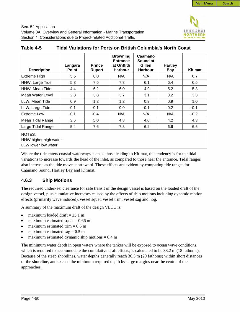
Sec. 52 Application Volume 8A: Overview and General Information - Marine Transportation Section 4: Considerations due to Project-related Additional Traffic
Page 4-50 May 2010
Table 4-5 Tidal Variations for Ports on British Columbia's North Coast
Description Langara
Point Prince Rupert
Browning Entrance at Griffith Harbour
Caamaño Sound at
Gillen Harbour
Hartley Bay Kitimat
Extreme High 5.5 8.0 N/A N/A N/A 6.7 HHW, Large Tide 5.3 7.5 7.3 6.1 6.4 6.5 HHW, Mean Tide 4.4 6.2 6.0 4.9 5.2 5.3 Mean Water Level 2.8 3.8 3.7 3.1 3.2 3.3 LLW, Mean Tide 0.9 1.2 1.2 0.9 0.9 1.0 LLW, Large Tide -0.1 -0.1 0.0 -0.1 -0.2 -0.1 Extreme Low -0.1 -0.4 N/A N/A N/A -0.2 Mean Tidal Range 3.5 5.0 4.8 4.0 4.2 4.3 Large Tidal Range 5.4 7.6 7.3 6.2 6.6 6.5
NOTES: HHW higher high water LLW lower low water
Where the tide enters coastal waterways such as those leading to Kitimat, the tendency is for the tidal variations to increase towards the head of the inlet, as compared to those near the entrance. Tidal ranges also increase as the tide moves northward. These effects are evident by comparing tide ranges for Caamaño Sound, Hartley Bay and Kitimat.
4.6.3 Ship Motions The required underkeel clearance for safe transit of the design vessel is based on the loaded draft of the design vessel, plus cumulative increases caused by the effects of ship motions including dynamic motion effects (primarily wave induced), vessel squat, vessel trim, vessel sag and hog.
A summary of the maximum draft of the design VLCC is:
• maximum loaded draft = 23.1 m • maximum estimated squat = 0.66 m • maximum estimated trim = 0.5 m • maximum estimated sag = 0.5 m • maximum estimated dynamic ship motions = 8.4 m
The minimum water depth in open waters where the tanker will be exposed to ocean wave conditions, which is required to accommodate the cumulative draft effects, is calculated to be 33.2 m (18 fathoms). Because of the steep shorelines, water depths generally reach 36.5 m (20 fathoms) within short distances of the shoreline, and exceed the minimum required depth by large margins near the centre of the approaches.

Sec. 52 Application Volume 8A: Overview and General Information - Marine Transportation Section 4: Considerations due to Project-related Additional Traffic
May 2010 Page 4-51
4.6.4 Effects of Water Density Changes The Northern and Southern Approaches are tidal saltwater waterways. However, freshwater tributaries drain into the channels and, during the spring freshet, many of the channels will include a surface layer of freshwater runoff. The maximum thickness of surface freshwater varies from just under 1 m near the entrances to the coastal channels, to approximately 5 m near Wright Sound and lower Douglas Channel and Kitimat Arm, and nearly 9 m in the middle of Douglas Channel.
A tanker will draw greater draft in a freshwater environment than in a saltwater environment. The draft of a loaded VLCC would increase by approximately 575 mm in a body of pure freshwater. For situations where the depth of the freshwater layer is less than the draft of the tanker, the draft increase because of lower density freshwater will be proportional to the depth of the freshwater layer with respect to the total draft of the tanker.
Because of the limited depth of the surface runoff, water density changes will not have an appreciable effect on the buoyancy of the tanker. The maximum estimated draft increase is 216 mm, occurring in the centre portion of Douglas Channel where the channel is known to be very deep. In the coastal approaches, including Caamaño Sound and Principe Channel/ Browning Entrance, the estimated draft increase is only 25 to 100 mm. These changes are relatively insignificant and have little practical effect on navigability in the area.
4.6.5 Other Depth Anomalies Other sources of depth anomalies in the region were investigated, including the need for updating CHS nautical charts (which is in progress), meteorological conditions that affect water depth (such as barometric pressure and storm surges), sudden depth changes in the seabed, tanker drawdown, seasonal effects and siltation. The overall effects on water depth from these sources is determined to be unimportant because of the relatively deep and open Northern and Southern Approaches.
4.6.6 Survey Conclusions Based on a review of the existing navigation charts, there is ample water depth to accommodate the largest design vessel over the entire length of approaches.
This assessment of the Northern and Southern Approaches will be revisited once the new charts are available, and additional project-specific surveys will be commissioned along any critical portions to verify that there are no navigational hazards in these areas.
4.7 Operational Considerations at the Marine Terminal
4.7.1 Alternative Sites for the Kitimat Terminal The location for the Kitimat Terminal was evaluated based on the following criteria:
• suitability of the location for the required facilities (e.g., tanks and tanker berths)
• proximity to existing infrastructure

Sec. 52 Application Volume 8A: Overview and General Information - Marine Transportation Section 4: Considerations due to Project-related Additional Traffic
Page 4-52 May 2010
• reduce pipeline lengths between the tank terminal and the marine terminal
• presence of suitable road access or other existing access corridors
• limit effects on watercourses, water bodies, marine and aquatic vegetation and habitat, and important fish areas
• reduce effects on terrestrial vegetation and wildlife habitat
• absence of substrates dominated by fine sediments, sand or cobbles, which could retain hydrocarbons in the unlikely event of an incident
• minimize potential adverse effects on communities, landowners, land users and Aboriginal groups
• avoidance of parks and recreation areas (e.g., protected areas, marine parks, ecological reserves)
The following sections describe the alternative sites considered and the rationale for selecting the current location of the Kitimat Terminal within Kitimat Arm at the head of Douglas Channel.
4.7.1.1 Tank Terminal Alternative Sites
Four potential sites were considered for the tank terminal (see Figure 4-21). Three of the sites are in an existing Kitimat industrial complex. Sites 1 and 2 are adjacent to the Rio Tinto Alcan site, and Site 3 is 4 km northwest of Kitimat. Site 4, the Kitimat Terminal site, is approximately 2 km to the south of the industrial zone in an area that the District of Kitimat has zoned for future industrial development.
Potential sites on the eastern shoreline of Kitimat Arm were also considered but were close to established communities (e.g., Kitamaat Village) and land zoned for recreational use.
Sites 1 and 2, adjacent to the Rio Tinto Alcan site, are overlain with thick overburden materials, some of which are compressible and could settle significantly under load from the tank terminal. These sites are adjacent to fish-bearing streams and are closer to Kitimat residential areas. They are located on disturbed lands with limited value as habitat for sensitive wildlife. However, tailed frogs occur south of Site 2 and between Sites 1 and 2. At Sites 1 and 2, the marine berth would be some distance from the tank terminal, creating the need for extended linear infrastructure to link the tank terminal with the marine terminal.
Subsurface information was not available for Site 3. However, examination of aerial photographs indicated that bedrock is at or near ground surface over much of the area. The topography and subsurface conditions appear to be similar to those at Site 4 (the Kitimat Terminal); however, a greater volume of rock would have to be excavated to develop Site 3 than Site 4. Site 3 extends into a floodplain close to residential areas in Kitimat and part of it is zoned as a recreation area. The site is adjacent to disturbed sites with limited value as habitat for sensitive wildlife and adjacent to fish-bearing streams. The marine berth location for Site 3 is near the existing Eurocan wharf. It was determined that the berth site is underlain by marine clays and may be prone to settlement. For Site 3, the berth would be some distance away from the tank terminal, thereby creating the need for extended linear infrastructure to link the tank terminal with the marine terminal.

SPOTREFERENCES:FIGURE NUMBER:
PREPARED FOR: SCALE:
Alternative Sites for the Tank Terminal and the Marine Terminal
E N B R I D G E N O R T H E R N G A T E W A Y P R O J E C T
Reference: Pipeline Route P: November 5, 2008
Z:\Cl
ients\
Enbr
idge\G
atewa
y\Figu
res\M
XD\JW
A-CA
L-050
...\JW
A-10
3898
3-050
-006.m
xd
4-21
NAD 83
1:125,000
JWA-1038983-035-001
UTM 9
JP2 DC
Jacques Whitford AXYS Ltd. 20100308
PROJECTION: DATUM:
AUTHOR: APPROVED BY:
DATE:CONTRACTOR:
200 m
200 m
300 m100 m
KitamaatVillage
KitimatTerminal
BishCove
EmsleyCove
MinetteBay
Site 4
Alternative Site
Alternative Site
Kitimat100
m
Site 3
Site 1
Site 2
KITAMAAT 2
KITAMAAT 1
BEES 6
JUGWEES 5
WALTH 3
HENDERSON'S RANCH 11
KITASA 7
KUASTE 8
PREPARED BY:
Reference: Pipeline Route RJWA-1038983-050-006
0 1 2 3 4
Kilometres
Terrestrial Project Development Area
Marine Project Development Area
Alternative Site
Commercial
Industrial
Institutional
Recreational
Residential
Future Industrial
Indian Reserve
Road
Bathymetry (100 m)

Sec. 52 Application Volume 8A: Overview and General Information - Marine Transportation Section 4: Considerations due to Project-related Additional Traffic
Page 4-54 May 2010
Site 4 (Kitimat Terminal) has the following characteristics:
• almost exclusively underlain by bedrock with minimal overburden
• zoned for industrial development by the district of Kitimat
• as a result of previous forestry activities, approximately 25 to 30% of the forest cover has been disturbed or removed, although some old forest remains
• coastal wildlife species that require mature forest, such as Western Screech-Owl, Northern Goshawk, and American marten, could occur at the site ,
• Pacific Great Blue Heron occurs along the coast but no known colonies nearby
• coastal tailed frog, Marbled Murrelet and grizzly bear are unlikely to occur
• contains a small watercourse that contains marginal aquatic habitat that are unlikely to support salmon or other harvested fish species
• does not directly affect any known spawning areas, concentration areas for marine birds, protected areas or designated Aboriginal lands
• does contain culturally modified trees, and the site is or was likely used for traditional purposes
• does not overlap any designated recreational areas, but is near Bish Cove, which is used informally by residents of Kitimat for recreation. Bish Cove is also a proposed development site for Kitimat LNG facilities.
• requires the smallest amount of extended linear infrastructure to link the tank terminal with the marine terminal
4.7.1.2 Marine Terminal Alternative Sites
Four potential sites were considered for the marine terminal (see Figure 4-21). Site 1 (the same as was considered for the tank terminal) is near the existing Eurocan complex. Alternative sites were considered at Bish Cove and Emsley Cove, and Site 4 (Kitimat Terminal) is approximately 2 km south of the industrial zone in an area that the District of Kitimat has zoned for future industrial development.
Site 1 for the marine terminal is underlain by marine clays and will be prone to settlement. As a result, this site was not considered further for a marine terminal.
The alternative sites (at Bish and Emsley Coves):
• are close to Aboriginal reserve lands • support important fish habitat • provide suitable habitat where marine birds concentrate • are near small fish-bearing tributaries
Also, Emsley Cove is likely to provide suitable habitat for coastal tailed frogs. There are no known occurrences of tailed frog at Bish Creek, and the likelihood of occurrence is low. Both Bish and Emsley Coves are frequented by both traditional and non-traditional users (primarily for fishing). In addition, both coves have shorelines that would be sensitive to retention of hydrocarbons (e.g., fine sediment or cobble beaches) in the unlikely event of an accidental release from the marine terminal or a tanker.

Sec. 52 Application Volume 8A: Overview and General Information - Marine Transportation Section 4: Considerations due to Project-related Additional Traffic
May 2010 Page 4-55
The alternative sites at Bish Cove and Emsley Cove not selected because of:
• relative environmental sensitivity • access and land constraints • other proposed projects were being considered at these locations
Site 4 (Kitimat Terminal) will not directly affect:
• known spawning areas • concentration areas for marine birds • protected areas • Aboriginal reserve lands
Site 4 does overlap a frequently used recreational fishing area (known as “the Wall”). The site may also be used for traditional harvesting. As is the case with the tank terminal site, coastal wildlife species that require mature forest, such as Western Screech-Owl, Northern Goshawk, and American marten, could occur.
4.7.1.3 Advantages of the Kitimat Terminal Site
Site 4, the preferred location for the Kitimat Terminal, offers the following advantages compared to the alternative sites:
• suitable foundation conditions for tanks and other major structures. Notably, the site has shallow bedrock that will provide suitable support for equipment with minimal foundation depth penetration while generating smaller volumes of disposal material. These conditions will also limit any issues associated with potential seismic activity.
• would not require development of extended linear infrastructure (i.e., pipelines, roads) to link the tank terminal with the marine terminal
• the existing cutblocks are in areas that would have project infrastructure, thereby reducing the amount of logging required to prepare the site
• the civil materials (rock, earth, clays) in situ are suitable for re-use on the site for construction, thereby reducing disposal volumes and the volume of materials required to be shipped in
• offshore area near the berths provides a turning basin diameter of greater than 2,000 m, which is more than adequate for safe manoeuvring of the tankers expected to use the marine terminal
• shoreline provides a relatively unrestricted approach, and the berths can be designed so that tankers are aligned with the prevailing winds and currents during final approach and while berthed
• seabed slopes steeply downward from the shoreline so that deep-draught VLCC tankers can approach the berths
• tank terminal will be near the tanker berths
• land rises about 180 m above the shoreline, which enables gravity loading of the oil tankers
• located away from Aboriginal reserve lands, communities, and recreational areas, spawning rivers, marine spawning areas, shorebird concentrations, and sensitive species

Sec. 52 Application Volume 8A: Overview and General Information - Marine Transportation Section 4: Considerations due to Project-related Additional Traffic
Page 4-56 May 2010
4.7.2 Site Plans and Technical Data (T3.10) The Project includes two tanker berths that will provide simultaneous oil loading at both berths and single condensate unloading from either berth. The Project also includes a utility berth that may be used to support construction activities and service tugs during operations. A site plan and general arrangement drawings of the tanker and utility berths in contained in Appendix 4A.
4.7.3 Tanker Berths The tanker berths will be designed to handle a range of tanker sizes (see Table 4-1). The statistical characteristics are given for the largest design VLCC, an average-sized Suezmax tanker and the smallest design Aframax.
The tanker berths will each have the following major components:
• loading platform with gangway tower • access trestles and catwalks • berthing and mooring structures
Several design options exist for the structure type and methodology used to construct each major component of the tanker berths. For each major component, two structural options indicative of the range of viable alternatives were evaluated and a preferred option was selected.
4.7.3.1 Loading Platforms
The loading platform at each tanker berth provides the interface for moving product between the tanker and the onshore facilities. The loading platforms are designed as independent structures that support the loading arms, and may have a deck area of approximately 35 m wide by 58 m long. In addition to the loading arms, piping and other equipment will take up approximately 50% of the deck space. The remaining area will be available for mobile service or maintenance equipment such as a crane or truck. Vehicle access will be possible through one or more main trestles connecting the loading platform and the shore, but only when loading or unloading operations are completed.
For the loading platforms, the two structural options evaluated were a jacket structure option and a pile and deck structure option.
For the jacket structure option, the concrete deck slabs of the loading platform are supported on modular steel framing and dual jacket structures. Each jacket structure consists of a four-legged, fully braced, tower-like steel assembly that is approximately 40 m high. The towers will sit on a level bench on the seabed excavated into the sloping bedrock and will be anchored to the rock to resist lateral forces.
For the pile and deck structure option, a composite concrete slab and box-girder deck is supported on individual steel pipe piles and pile caps. The individual piles will all be vertical and may be either partially or entirely filled with concrete.
The pile and deck structure option was selected as the preferred option because it requires significantly less rock blasting and associated disturbance of the marine habitat compared to the jacket structure option. It also minimizes any potential construction and operation issues associated with the quality of the rock.

Sec. 52 Application Volume 8A: Overview and General Information - Marine Transportation Section 4: Considerations due to Project-related Additional Traffic
May 2010 Page 4-57
4.7.4 Access Structures Pile-supported access trestles will provide access from the shore to the loading platforms. The access trestles will be designed to accommodate a single lane roadway and the piping and utilities that extend from the shore onto the loading platform.
Conventional pile and deck construction similar to the loading platform will be used for the access trestles.
4.7.5 Berthing and Mooring Structures The berthing structures will be independent structures located on either side of the loading platform and will be fitted with rubber fenders designed to absorb the lateral forces from a berthing tanker. Four fender locations, two on each side of each loading platform, will accommodate the range of design vessels.
For the berthing structures, the two structural options evaluated were a full jacket structure option and a buttressed (stiff-leg) structure option.
The full jacket structure option is similar to the jacket structure option evaluated for the loading platforms and uses the same member sizes and dimensions. The base of the each jacket structure will be set on flat rock benches on the seabed excavated into the sloping bedrock and then anchored to the rock.
For the buttressed or “stiff-leg” structure option, instead of individual berthing structures as proposed in the full jacket structure option, each set of side-by-side berthing structures is combined into one structure that is laterally supported by two stiff-leg space frames mounted to onshore concrete abutments.
The buttressed (stiff-leg) structure option was selected as the preferred option because it requires significantly less rock blasting and associated disturbance of the marine habitat compared to the full jacket structure option.
The decks of the berthing structures will consist of steel grating on a steel frame that is supported on the superstructure of the jackets or vertical piles. Mooring hardware will be anchored to a concrete slab cast into the deck frame of each structure. Alternative forms of construction could include either pre-cast or cast-in-place concrete caps, set on piles with mooring hardware anchored to the top surface.
A minimum of six mooring structures for each tanker berth will be required to accommodate the range of design vessels. The mooring structures will be fixed structures located inshore from the fender line by a distance of 40 m or greater (where practical) and will be used to secure the mooring lines from the bow and stern of the tanker. They will be equipped with multi-line quick release mooring hooks.
Due to the proximity of the shoreline to the tanker berths, mooring structures may be located in the water, onshore or a combination of both. An onshore mooring structure option was selected as the preferred option because it requires significantly less rock blasting and associated disturbance of the marine habitat compared to the other options. Onshore moorings result in:
• minimal disturbance of the foreshore marine environment • less drilling and blasting in the foreshore marine environment • less structural shading

Sec. 52 Application Volume 8A: Overview and General Information - Marine Transportation Section 4: Considerations due to Project-related Additional Traffic
Page 4-58 May 2010
The mooring structures will use rock-anchored concrete abutments and the mooring hardware will be cast directly into the mass concrete of the mooring structures. Fendering or standoff structures will be installed to allow mooring boats close access to the mooring structures.
A series of catwalks will be in place to provide workers with access between the loading platforms and the berthing and mooring structures.
4.7.6 Containment Boom Each tanker berth will be equipped with a containment boom. The containment boom will be deployed during all oil loading operations. The containment boom will extend from shore, out around the tanker and back to shore.
4.7.7 Utility Berth Two options were considered for the berth construction: a concrete caisson and a floating structure. The concrete caisson was rejected on the basis that it required significantly more rock blasting and disturbance of the marine environment. The utility berth will have facilities that can accommodate the mooring of harbour tugs and two utility workboats. The utility workboats will be required primarily for deployment of tanker mooring lines, maintenance of the tanker berths and deploying the containment boom. A davit system will be used to launch the utility boats from the utility berth deck and retrieve the boats for stowage and maintenance.
4.7.8 Construction of Tanker Berths Marine construction of the tanker berths will involve both underwater and above-water work, including drilling and grouting of piles, assembly and erection of steel and concrete structures, and installation of topside equipment and marine facility appurtenances. The marine construction methodology is highly dependent on the type of structure and its foundation requirements.
To facilitate construction of the marine structure foundations, as well as provide adequate underkeel clearance for moored tankers, certain areas of the marine terminal site may require dredging of overburden soil material in addition to blasting and removal of rock material. This material will be transported to an excess cut disposal area at the Kitimat Terminal, to the extent practical. However, some of the blasted rock is expected to fall to the sea bottom. If required, Northern Gateway will apply to Environment Canada for approval for this disposal at sea.
Pile and deck structures and buttressed (stiff-leg) structures are proposed for the deepwater tanker berth structures, such as loading platforms and berthing structures. Onshore structures are proposed for the mooring structures.
Marine structures supported on individual piles will typically have the piles installed using a conventional drill derrick and will be either doweled or socketed into the rock. To account for the larger placement tolerances of individual piles, cast-in-place pile caps will be installed around the individual pile heads. Deck structures consisting of pre-cast concrete beams or pre-assembled steel frames can then be efficiently erected with barge cranes onto the pile caps. Pre-cast concrete deck planks are then placed on beams or frames and finished with a cast-in-place concrete surface.

Sec. 52 Application Volume 8A: Overview and General Information - Marine Transportation Section 4: Considerations due to Project-related Additional Traffic
May 2010 Page 4-59
4.7.9 Decommissioning of the Marine Terminal Decommissioning of the Marine Terminal will include the following activities:
• Empty, clean and remove all topside equipment.
• Demolish and remove all pipe racks, trestles, gangways, buildings, instrumentation and electrical infrastructure.
• Dismantle and remove the marine berths and associated concrete and steel pile structures. These facilities will be evaluated for their use as marine habitat prior to removal and may remain for this purpose. Steel piles will be cut off at the sea floor.
• Tow the utility berth from site for either re-use or recycling.
• Return the foreshore to its natural state.
4.7.10 Berth Procedures and Provisions (T3.13)
4.7.10.1 Design Loads and Load Combinations
The marine terminal structures will be subject to a variety of loads because of both environmental forces and vessel/terminal operations. They will be designed for the various load values and load combinations, as specified by the appropriate national and international codes. The types of loading on the marine structures will include:
• dead loads • berthing loads • mooring loads • seismic loads • temperature loads • wind loads • wave loads • hydraulic and current loads • snow and rain loads • ice loads • live loads
Most of the loads on the marine structures result from either environmental effects or operations on deck. However, berthing loads and mooring loads are the most critical with respect to provisions for berthing procedures and tanker operations. As described in the following sections, berthing and mooring loads are the loads applied directly by the tanker onto the berth structures. Load combinations that include the berthing and/or mooring loads usually dictate the required lateral load carrying capacity of the berth structures. The design for these loads is critical in ensuring the structures are capable of safely accommodating the design vessels.

Sec. 52 Application Volume 8A: Overview and General Information - Marine Transportation Section 4: Considerations due to Project-related Additional Traffic
Page 4-60 May 2010
Berthing Loads Berthing loads result from the force of a tanker as it makes contact with the fender units on the berthing structures. The energy associated with the force of contact is known as the berthing energy and must be absorbed by the fender units, typically through compression of their rubber elements. As the fenders are compressed, a reaction is produced which is resisted by the berthing structures. This reaction is the design berthing load for the structure, and it is a function of the size and type of fenders selected. The kinetic energy method is commonly used to calculate the berthing energy. As such, the allowable berthing velocity is the most important factor in determining the magnitude of the berthing loads, and will greatly influence the design of the fender units and berthing structures.
Mooring Loads Mooring lines are deployed from the tanker and attached to the berth structures to provide a means of holding the tanker against the berth’s fender units and restricting the movements of the tanker while transfer operations are conducted. The mooring loads are the forces caused by wind, wave and currents acting on a tanker while it is moored at the berth. The mooring loads occur both as a tensile pull on the mooring lines and as a compressive thrust on the fender units. Since multiple mooring lines can be attached to a single mooring point on the berth structures, they can induce a considerable force. Each mooring structure will be required to resist the total load from several lines depending on the number of hooks their mooring hardware has. The berthing structures will be required to resist the compressive thrusts induced on the fender units. The berthing structure design will be governed by either the berthing loads or the mooring loads, whichever is more critical.
4.7.10.2 Berthing Strategy Synopsis The berthing strategy in terms of the tanker’s approach and departure from the terminal berth is critical, since this will determine the requirements for tug assistance, mooring assistance, and the maximum allowable berthing velocity. Tug assistance will be provided for berthing and unberthing the tankers at the marine terminal. For a loaded tanker of the design ship size range, it is typical practice to use three or four tugs for berthing and two or three tugs for unberthing the tanker. It would also be normal for harbour tugs to meet an incoming tanker of this size range at a safe place toward the outer harbour limits and escort the tanker to the berth, making lines fast and manoeuvring as required by the pilot. Approximately 4 to 5 km from the marine terminal, the pilot will order the harbour tugs to take their positions and prepare to assist in the mooring operation.
The terminal’s docking aid system will be activated prior to tanker arrival. It will indicate to the pilot the tanker’s approach speed and distance away from the berth. Using this system, the pilot will direct the harbour tugs to manoeuvre the tanker alongside the dock and push the tanker against the berth’s fender units. The tanker’s approach speed and approach angle will be kept as low as practical to prevent damage to the dock structures.

Sec. 52 Application Volume 8A: Overview and General Information - Marine Transportation Section 4: Considerations due to Project-related Additional Traffic
May 2010 Page 4-61
When the tanker is a few metres away from the fenders, the tanker crew will pass mooring lines to terminal personnel or to the line boats for securing to the mooring hooks on the berthing structures. The number and placement of the mooring lines will be determined for each size tanker during detailed design.
When all the mooring lines are secured and the tanker is held against the berthing structures, the mooring operations will be complete. The tugs and pilot will leave the tanker. The entire mooring operation should take approximately two hours. Mooring line loads will be monitored while the tanker is at berth.
4.7.11 Cargo Transfer and Transhipment Systems (T3.11)
4.7.11.1 Cargo Transfer Systems
The cargo containment and transfer system consists of a series of tanks, pipes and pumps. The cargo is contained in the tanks, which consist of a series of separate compartments within the tanker’s inner hull. Cargo can be transferred from the tanks via pipes located in the bottom of each tank compartment. The pipes run from the bottom of each tank via the pump room to pipe manifolds on the tanker’s deck, where the actual connection between the tanker and the onshore facilities is made. Tankers are typically equipped with manifolds on both their starboard and port sides to allow the tanker to berth with either a starboard-to or port-to orientation.
For imported condensate, to discharge the tanks to the shore facilities, the condensate must be pumped from the bottom of the tanks up to the pipe manifolds on the tanker’s deck. Typically, a tanker is equipped with three or four cargo pumps located in a pump room immediately forward of the engine room near the tanker’s stern and at the end of the tank section. The tanker’s pumps have the power to move the cargo from the tanks to the deck manifold and on to the shore-side distribution system. These pumps are usually steam turbines with steam generated by the tanker's boilers. The boilers burn heavy fuel oil, which would normally have a sulphur content of less than 2.7%. Recent initiatives by IMO, European countries, and more recently the emission control area (ECA) proposed for the west coast of North America are expected to result in a reduction of the sulphur content in ship’s fuel to less than 1% in the near future.
For exported oil, the cargo is loaded via gravity and bypasses the tanker’s pumps. As the tanks are loaded, the atmospheric vapours inside them, including inert gas, are displaced by the incoming cargo. These vapours may be either vented to the surrounding atmosphere or collected and processed by the VRU at the marine terminal.
4.7.11.2 Terminal Cargo Transfer Systems
The marine terminal cargo transfer system includes marine loading arms, manifolds, pipelines, booster pumps and valves. The marine loading arms, which are mounted to the decks of the loading platforms at each tanker berth, are used to make the actual connection between the tanker and the marine terminal. The loading arms feed into an adjacent onshore manifold, which controls the flow of hydrocarbons being transferred through the system. In turn, the onshore manifold is connected to pipelines installed on the platform deck and along the access trestle to the onshore tank facilities.

Sec. 52 Application Volume 8A: Overview and General Information - Marine Transportation Section 4: Considerations due to Project-related Additional Traffic
Page 4-62 May 2010
Marine loading arms are the most critical component of the cargo transfer system. They consist of articulated pipe assemblies that can swivel in all directions. The loading arms can accommodate the movements of a moored tanker while maintaining a secure seal for leak-free cargo transfer.
Each loading arm will be equipped with hydraulic emergency release couplings/powered emergency release couplings (ERC/PERC), which allow for a connection between the loading arm and various diameters of ship manifolds without the need for special adaptors. They also allow a rapid connection to begin cargo operations, or disconnection in the case of an emergency. During emergencies, the ERC/PERC system, which includes fast-acting, hydraulically actuated ball valves, will stop material flow before the arms are automatically de-coupled from the ship manifold.
Onshore booster pumps are required to help overcome the hydraulic head difference between the onshore tanks and the marine berths. Since the onshore tank facilities are at a higher elevation (180 m) than the marine berths, the cargo pumps onboard will not have enough power to transfer the cargo all the way to the tank lot when unloading. Because the discharge capability of the overall system is greatly influenced by the hydraulic head difference, the design and efficiency of the booster pumps is critical. It should be noted that the booster pumps are not required when loading cargo, since this is done by gravity feed.
4.7.11.3 Safety Monitoring and Alarm Systems
Tanker berth safety warning systems will include separate fire alarm systems and emergency alarm systems. The systems will have activation boxes throughout the marine terminal, and will be able to notify terminal personnel through both audible and visual signals. The terminal emergency response plan will outline actions to be taken when the various alarms activate, and will also include a response plan. The various monitoring, alarm and safety systems include:
• temperature sensors located in the custody transfer metering stations
• gas alarm systems located at the loading arms and at other critical positions within the terminal facilities
• heat detectors and smoke detectors located at all electrical services buildings
• smoke, heat and flame detection equipment located at all individual pump shelters and pump motor units
• fire detection provided at each oil tank, each condensate tank, the custody transfer metering station, and at all quality assurance buildings
• flame detectors and cameras monitoring all loading arms on the tanker berths
• water-supplied firefighting systems at the tanker berths designed to extinguish fire within the area of the berth platforms and within the immediate vicinity of the loading arm connection to the ship’s manifold. Water will be sourced from the firewater reservoir. Firefighting monitors and hydrants will also be provided throughout the tank terminal facilities.
• a firefighting foam supply to supplement the water-supplied system will also be provided for the firefighting systems at the tanker berths, as well as throughout the tank terminal facilities

Sec. 52 Application Volume 8A: Overview and General Information - Marine Transportation Section 4: Considerations due to Project-related Additional Traffic
May 2010 Page 4-63
• a backup seawater supply for the firefighting system will also be provided. The seawater firewater pump will be located onshore at the head of the berth trestles and will have a bypass that ties into the main ring header for the berth platform and berthing structures. An alternate foam compound will be provided for the seawater firewater source.
• an emergency power supply for the terminal facilities and infrastructure will be provided through the use of portable emergency generator units
Monitoring oversight of the entire terminal will be conducted from the terminal control room located onshore close to the southernmost tanker berth (see Figure 4-22). This control centre will receive all operating data and will have the capability of controlling valves and monitoring all security systems. The control centre will have the following communication and control systems:
• A SCADA (supervisory control and data acquisition) system to monitor and control the loading and unloading operations at the marine terminal and the associated terminal equipment. The SCADA system will also allow for control of operations by a remote backup control centre.
• A redundant communication system with a combination of wide-area-network frame relay, telephone lines and satellite communication circuits to provide main and backup communication systems to remote terminal units (RTUs) at the terminal and to facilitate the SCADA system.
• Alternate voice communications at the terminal for marine operations.
• A local Ethernet network at the pump stations to provide an interface between local computer systems and programmable logic controllers.
• Automatic and manual shut-down systems designed to fail in a fail-safe mode.
• A safety control system that allows terminal personnel to continuously monitor cargo transfer operations, tanker movements at the berth, weather information, mooring line forces, and other important tanker safety parameters.

CONTRACTOR:
PREPARED BY: PREPARED FOR:
FIGURE NUMBER:
SCALE:
PROJECTION: DATUM:
AUTHOR: APPROVED BY:
DATE:
JP2 DC
NAD 83UTM 9
200912114-22Jacques Whitford AXYS Ltd. E N B R I D G E N O R T H E R N G A T E W A Y P R O J E C TPreliminary Layout of Kitimat Terminal
Kitimat
Arm
KP 1170
KP 1169
KP 1168
KP 1172
KP 1171
KP 1170
KP 1169
KP 1172.2
1:15,000
Kilometre PostPipeline RouteMarine Project Development AreaExcess Cut Disposal AreaSecurity FencePowerline
Tank
Kitimat Terminal Bypass RoadBish Forest Service Road
Z:\Cl
ients\
Enbri
dge\G
atewa
y\Figu
res\M
XD\JW
A-CA
L-039
_Roc
k_Ar
t_Site
s_At
_Kitim
at_Te
rmina
l\JWA
-CAL
-1038
983-0
39-00
5.mxd
VLCC Tanker
Recovered Oil Tank and Pumps
Suezmax TankerUtility Berth
Proposed 287kVPowerline
Tanker Berth
Tanker Berth
Mooring Structures
Berthing Structures
Bish Forest Service Road
Pipe Racks
Potential AddtionalTank
Potential Addtional Tank
ContainmentBerms
Oil-Water Separator
Reservoir Transfer
Pumps
ImpoundmentReservoir
Firewater Reservoir
Condensate TanksOil Tanks
Control Room
Construction Trailers/Offices
Parking
Firewater PumphouseOil/Condensate Tank
Transfer Manifold
Oil/Condensate Booster/Tank Transfer Pumps
PowerlinesCondensate Booster/Transfer & Sump Pumps
Oil and CondensateSending/Receiving Traps
Oil/Condensate Pipelines
Condensate InitiatingMainline Pumps
Marine Topworks (Loading Arms, Gangway, Trestles, Etc.)
Electrical Yard and SubstationForeshore Facilities
Marine Topworks
Oil Custody Transfer Metering
0 0.1 0.2 0.3 0.4
Kilometres
Reference: Pipeline Route RJWA-CAL-1038983-039-005
Security Gate
Vapour Recovery Unit
Seawater Firewater Pumps
Seawater Firewater Pumps

Sec. 52 Application Volume 8A: Overview and General Information - Marine Transportation Section 4: Considerations due to Project-related Additional Traffic
May 2010 Page 4-65
4.7.11.4 Cargo Transfer Operations
General
The cargo transfer procedures at the marine terminal will include the import of condensate products and the export of oil products. Imported condensate will be transferred from the tankers to the tanks onshore (discharging), and exported oil will be transferred from the onshore tanks to the tankers (loading).
Cargo transfer operations involve a series of procedures designed to achieve a safe and efficient transfer of product. Some, but not all, procedures are common to both discharging and loading.
Tanker Vetting and Pre-Arrival Activities
Planning for the discharge or loading of hydrocarbons at the marine terminal will begin several months prior to the arrival of any given tanker. The marine terminal will begin to plan for the movement of a specific volume of hydrocarbon by using a nomination system. The marine terminal will have written procedures to allow shippers to nominate, or schedule, movement of hydrocarbon through the terminal at a certain time and at a fixed volume. Once a customer has reserved a spot and has nominated the type of hydrocarbon and a tanker, Northern Gateway will begin the ship vetting process through its TAP to determine if the nominated tanker meets the minimum acceptance criteria and can be authorized to call at the marine terminal.
If the tanker has been accepted by the TAP, it is entered in the scheduling system with the tanker’s estimated time of arrival. In addition to placing the tanker in the schedule, copies of the following will be made available to the Owner, the shipmaster or agent of the tanker: port information booklet (Section 4.7.13) and the terminal operations manual (Section 4.7.14).
Pre-Mooring and Mooring Activities
Prior to its approach to the pilot boarding station, the tanker will begin preparations for mooring and cargo operations including inert gas checks and bringing the steam boilers on-line.
Before arriving at the marine terminal, the shipmaster, officers and the pilot will devise a plan for the berthing and mooring operations. The berthing operation plan will include such topics as the placement of the harbour tugs, the terminal mooring plan, the sequence of mooring line connections, safety of the mooring operation, environmental limits and other pertinent issues.
Approximately 4 to 5 km from the marine terminal; the harbour tugs will meet the incoming tanker and take their positions to assist in the mooring operation. To aid the pilot and crew, the dock will be equipped with a computerized docking aid system that displays data on tanker approach speed and angle. With the assistance of the tugs, the tanker will be manoeuvred alongside the dock and mooring lines will be deployed. A shore-based mooring crew will secure the mooring lines to the dock.
The pilot and tugs will be released once the tanker is moored and the gangway is secure, at which time pre-transfer activities will begin.

Sec. 52 Application Volume 8A: Overview and General Information - Marine Transportation Section 4: Considerations due to Project-related Additional Traffic
Page 4-66 May 2010
Pre-Transfer Activities
The sequence of cargo operation events will be as follows:
1. Canadian officials board the tanker to review tanker specifications, manifest, crew list, logbook and certifications to provide official clearance for the tanker to begin cargo operations.
2. For oil loading operations, an oil containment boom will be placed around the tanker in accordance with terminal safety procedures. The boom will not be deployed during condensate discharge operations.
3. For an empty tanker that is scheduled to be loaded with oil, an independent inspector will board and examine all cargo tank-measuring instruments to assure the cargo tanks are empty. For a laden tanker scheduled to discharge condensate, the cargo will be measured and sampled, usually by an independent inspector accompanied by a ship’s officer.
4. A safety and operations conference will take place between the tanker and terminal personnel to review terminal rules and regulations, safety and emergency procedures, communications protocols, cargo operations, and any other subjects deemed necessary. The conference will be carried out in accordance with the International Safety Guide for Oil Tankers and Terminals, an internationally recognized guide to safe operations. In addition, Northern Gateway will develop rules with which the tanker will have to comply to remain at the terminal. Each party will sign a checklist to assure that all items have been covered in the conference.
5. Once the conference is complete, the parties will conduct an inspection of the tanker and its equipment to confirm that all equipment is ready for the safe transfer of cargo, with special attention to the inert gas system. For oil tankers that arrive empty, the inspection team will confirm that cargo tanks are filled with inert gas with oxygen content below 8%. For condensate tankers arriving to discharge hydrocarbon, the inspection team will confirm that the inert gas system is operable. Upon completion of the inspection, the parties will sign a Declaration of Inspection indicating that cargo transfer operations can be initiated.
6. Tanker and terminal personnel will connect cargo transfer arms once the safety inspection is complete and cargo tank volumes have been confirmed.
7. When all the above items are complete, cargo operations will begin. The operations will be carried out in accordance with the cargo transfer plan developed by the crew and agreed to by the terminal control system supervisor prior to the tanker arriving at the terminal. This plan will include segregated ballast water management at the terminal.
Discharging of Condensate
The cargo transfer operation for discharging condensate is as follows:
1. Condensate tankers arriving at the terminal will be laden and, hence, have no segregated ballast onboard.

Sec. 52 Application Volume 8A: Overview and General Information - Marine Transportation Section 4: Considerations due to Project-related Additional Traffic
May 2010 Page 4-67
2. Tanker and terminal personnel will connect cargo transfer arms once the safety inspection is complete and cargo tank volumes have been confirmed and communication is established between tanker and terminal.
3. A pre-cargo transfer circulation test will be conducted. For this test, the tanker will begin pumping at a slow rate until all systems have been checked for leaks. The flow rate will then be gradually increased to the maximum offloading rate determined by tanker and terminal personnel.
4. To mitigate explosion risk, the inert gas system will replace offloaded condensate with inert gas that contains less than 8% oxygen. To maintain low oxygen concentrations, it is necessary for the inert gas flow rate to equal that of the offloading condensate. Although the oxygen content is measured and alarmed automatically, tanker personnel will manually verify the percentage on a regular schedule as an independent check. If the oxygen content should exceed 8%, all operations will stop until it is lowered.
5. The tanker will load segregated ballast as condensate is offloaded.
6. Near the completion of the cargo transfer operation, the tanker's pumps will be slowed for discharging the last portion of cargo in the cargo tanks, a procedure known as stripping.
7. Once the cargo tanks are empty, valves will be closed, the cargo transfer system secured and loading arms drained and disconnected.
Loading of Oil
The cargo transfer operations for loading oil are as follows:
1. Oil tankers arriving at the terminal will have segregated ballast onboard that has been exchanged in deep ocean waters as per the Canadian Ballast Water Management Guidelines of the Canada Shipping Act.
2. Tanker and terminal personnel will connect cargo transfer arms once the safety inspection is complete and load volumes have been confirmed and communication is established between tanker and terminal.
3. A pre-cargo transfer circulation test will be conducted. For this test, the terminal will slowly open the valves until all systems have been checked for leaks. Once confirmation is obtained that there are no leaks, the terminal will increase the product flow rate under the direction of the tanker’s cargo officer until the tanker’s maximum allowable loading rate is reached.
4. When the cargo tanks are empty of liquid cargo, the space is occupied with vapours that must be simultaneously discharged as the oil is loaded. The Kitimat Terminal will use a VRU as part of its vapour emission control system to capture and process these vapours.
5. Generally, the tanker will discharge segregated ballast at the same rate as the oil is loaded.
6. When the cargo tanks reach approximately 90% of capacity, oil flow will be reduced to allow for the topping-off of the cargo tanks until they are full. Cargo tank monitors and alarm systems prevent overloading of tanks. The tank level sensors are connected to control interlocks which shutdown the pumping if the pre-set alarm level is exceeded.

Sec. 52 Application Volume 8A: Overview and General Information - Marine Transportation Section 4: Considerations due to Project-related Additional Traffic
Page 4-68 May 2010
Pre-Departure and Un-Mooring Activities
Upon the completion of the cargo transfer operation, the pre-departure and unberthing activities will begin as follows:
• Once cargo operations are complete, the volume of oil or condensate transferred will be verified.
• Departure paperwork will be completed by tanker and terminal personnel.
• Transfer arms will be drained and then disconnected and the gangway removed.
• Oil boom deployed around the tanker while loading cargo, will be retracted.
• The tanker’s main engine and ancillary equipment will be made ready for departure.
• Once the pilot is onboard and the harbour tugs are in position, the tanker will sequentially release all mooring lines and depart the berth with the assistance of the tugs.
4.7.11.5 Ballast, Slops and Bilge Water
Ballast Water Management
Unloaded tankers transiting between destinations require ballast water for additional weight to improve stability while at sea. A double-hulled tanker uses the space between the outer and inner hulls as a holding tank for segregated ballast water. By segregating the ballast water, contamination of the ballast water from residual hydrocarbon in cargo holds is prevented.
Preventing pollution from ballast water (whether from industrial chemical/hydrocarbons or invasive species) is controlled through various Canadian and international regulations. The IMO resolution A.868 (20), Guidelines for the Control and Management of Ships’ Ballast Water to Minimize the Transfer of Harmful Aquatic Organisms and Pathogens was established to prevent the spread of harmful aquatic organisms through the discharge of ballast water originating in foreign ports. The convention requires that vessels implement an IMO-approved Ballast Water Management Plan. Vessels also are required to possess a Ballast Water Record Book that documents the ballast water history of the vessel. The IMO resolution was finalized in 2004, but has yet to be ratified and brought into force. Northern Gateway is committed to fully implementing an IMO-approved Ballast Water Management Plan.
The management of ballast water discharge in Canadian waters falls under federal regulations outlined in the Canada Shipping Act, BWCMR, which came into force in June 2006 and effectively harmonizes Canadian regulations with rules in the United States, with the exception of allowing alternate areas to exchange ballast under exceptional circumstances. Under the current regulations, a vessel bound for a port on the northern coast of British Columbia is required to carry onboard a Ballast Water Management Plan and submit a complete ballast water report to the Prince Rupert MCTS prior to entry into Canadian waters.

Sec. 52 Application Volume 8A: Overview and General Information - Marine Transportation Section 4: Considerations due to Project-related Additional Traffic
May 2010 Page 4-69
In accordance with the BWCMR, the following Ballast Water Management Procedures will generally apply to transoceanic navigation: tankers should generally conduct ballast exchange in locations no less than 200 nautical miles from shore where water depths are not less than 2,000 m. Ballast exchange may be conducted as either:
• Sequential exchange, where all ballast water is discharged by use of onboard pumps and eductors. To maintain ship safety, this operation is limited to fair weather conditions only. Operations will be logged.
• Flow-through exchange, where, during inclement weather, tank flow-through will require three times the tank volume at a minimum. Calculations indicating the amount of water to be utilized and pumping rates required to achieve this must be recorded.
• In exceptional circumstances, where it may not be possible to exchange ballast water because of bad weather, sea conditions or any other conditions that may endanger human life or the safety of the tanker, alternative exchange zones may be utilized on notification of the appropriate MCTS officer. The use of alternative exchange zones may also be appropriate for tankers that are not able to comply with the general ballast exchange protocol, because they do not voyage into mid-ocean where water depths are greater than 2,000 m.
• While ballast water exchange is recognized as the best available means to prevent the release of invasive exotic aquatic organisms in ballast water, alternative methods of ballast water treatment that are environmentally sound and acceptable by TCMS may be utilized. In accordance with the BWMCR, alternative methods must be at least as effective in removing or killing harmful aquatic organisms and pathogens as the methods listed above.
Cargo Slops Management
Cargo slops, also known as wash slops, is a seawater and oil mixture that can result from a number of cargo-related operations including tank washing, stripping of remaining oil residues from cargo tanks, decanting of heavy-weather ballast, and oil washing. All cargo slops are held in dedicated tanks that are essentially smaller-capacity cargo tanks adjacent to the cargo pump room. The cargo slop tanks on a typical VLCC can hold up to 8,000 m3 of cargo slops.
The Kitimat Terminal will have facilities to receive, treat and recover oil from the cargo slops tanks. The terminal’s cargo slop facility will have a capacity to treat up to 10,000 m3 of cargo slops per oil tanker visit. The oil component of the cargo slop mixture can be recovered and resold as good product. As such, the cargo slops can be discharged to the terminal’s facility using the same cargo pumps and transfer arms that are used to transfer regular cargo. The cargo slop discharge operation takes approximately two to three hours and is typically conducted before regular cargo transfer operations begin.
Engine Room Slops and Bilge Water Management
Engine room slops or bilge water typically consists of a mixture of seawater, oils, detergents and other chemicals. A typical VLCC may hold 40 to 50 m3 of such liquid. These potentially noxious mixtures require special treatment and disposal methods.

Sec. 52 Application Volume 8A: Overview and General Information - Marine Transportation Section 4: Considerations due to Project-related Additional Traffic
Page 4-70 May 2010
Bilge water discharge is federally regulated by the Canada Shipping Act, Regulations for the Prevention of Pollution from Ships. These regulations specify the type of containment, storage and treatment systems required of vessels transiting Canadian waters. Specified equipment standards are mandated by the regulations to confirm compliance, so that no oil or oily mixture will be discharged from a ship in waters under Canadian jurisdiction. Vessels must discharge engine slops or bilge water to a proper treatment facility or retain it onboard.
Although the Kitimat Terminal will not provide on-site facilities to treat or dispose of engine room slops, it will offer a service provided by a third-party contractor, which will use vacuum trucks to receive and transfer the slops to an offsite facility for proper disposal.
4.7.12 Oil Handling Facilities Requirements (T3.19)
4.7.12.1 Canada Shipping Act Requirements
The Kitimat Terminal will be an oil handling facility (OHF) as defined in Section 2 of the Canada Shipping Act (2001), and will need to develop an Oil Pollution Emergency Plan (OPEP) and Oil Pollution Prevention Plan (OPPP) to comply with the Act. Oil spill response capability and associated plans is described in the following:
• Response Organizations and Oil Handling Facilities Regulations, SOR/95-405 • Oil Handling Facilities Standards 1995 (TP12402) • Environmental Response Arrangements Regulations, SOR/2008-275 • Pollutant Discharge Reporting Regulations, SOR/95-351
In addition to compliance with regulatory requirements, Northern Gateway intends to integrate all aspects of crisis management, emergency response and response operations in a project General Oil Spill Response Plan (GOSRP). This GOSRP will be the cornerstone of a hierarchy of prevention and response plans which, together, describe measures that would be implemented prior to or following an oil spill on land, at the terminal or along the marine transportation approaches to enhance the effectiveness of response and the mitigation of effects.
The GOSRP will cover any oil spill with actual or potential consequences to Project personnel, the environment, property or the public at large associated with the Project. The GORSP will include an outline of the organization, which would be established (in cooperation with government and other agencies) to manage a response.
Northern Gateway intends to further develop a Marine OSRP and a Kitimat Terminal OSRP as umbrella documents for all required plans and supporting technical reports. The Terminal OSRP is an umbrella for the subplans that relate to oil spills and will include the Terminal Operations Manual (TOM), the Oil Pollution Prevention Plan (OPPP), and the Oil Pollution Emergency Plan (OPEP).
The maximum oil transfer rate between the Kitimat Terminal and visiting tankers will exceed 2,000 m3/h. For this reason, the Kitimat Terminal would be designated a Level 4 oil handling facility (OHF) as described in the Oil Handling Facilities Standards 1995. As a Level 4 OHF, the Kitimat Terminal would be required to provide a stand-alone capability to respond to at least a 50-m3 oil pollution incident for each type of oil loaded or unloaded. The stand-alone response capability to be developed would be

Sec. 52 Application Volume 8A: Overview and General Information - Marine Transportation Section 4: Considerations due to Project-related Additional Traffic
May 2010 Page 4-71
described in Northern Gateway’s oil pollution emergency plan (OPEP). The capability would include equipment and personnel trained to deploy and operate that equipment. The response capability would include the development of response management expertise and facilities as described by the GOSRP. Northern Gateway plans to have a terminal marine response capability of at least 250 m3, greater than the 50 m3 required under the CSA standards.
As the future operator of the Kitimat Terminal, Northern Gateway intends to comply with the requirements for an OHF described in the CSA 2001 and its regulations, by developing response capabilities on several fronts:
• a stand-alone response capability at the Kitimat Terminal whereby there is the ability to respond, on its own, to a release volume of up to 250 m3
• for volumes larger than 250 m3, the capability will be developed to mount an initial response to release of hydrocarbons at the Kitimat Terminal (regardless of size), whether the source is from the Kitimat Terminal or from a tanker at berth
• creating or entering into a contractual arrangement with a Response Organization (RO) certified by Transport Canada to provide response services at the terminal and for each of the tankers or support vessels in the CCAA and in the Territorial Sea of Canada. That RO will have a 10,000-tonne response capability for the defined primary area of response (PAR).
• all tankers that berth at the Kitimat Terminal to load or offload oil cargoes will comply with all relevant elements of the Terminal OSRP
• the operator of each tanker that visits the Kitimat Terminal will comply with all relevant elements of the Marine OSRP, which will include extensive measures to prevent incidents
• outfitting escort tugs with equipment suitable for response along the Northern and Southern Approaches, and having these tugs classified as escort, firefighting and first response tugs
• preparing harbour tugs (working near the Kitimat Terminal) to be able to take response equipment onboard and to be able to deploy that equipment, and have firefighting and first response capability
• installing response equipment on land or on a floating platform at a number of locations along the Northern and Southern Approaches to improve upon the response time
• training the following in response methods:
• staff members from the Kitimat Terminal
• responders from contractors that work at the Kitimat Terminal
• responders from communities willing to be involved, adjacent to the Northern and Southern Approaches
• crew members that work on the escort tugs and harbour tugs
• conducting an annual training and exercise program
• developing maps showing sensitive areas

Sec. 52 Application Volume 8A: Overview and General Information - Marine Transportation Section 4: Considerations due to Project-related Additional Traffic
Page 4-72 May 2010
• evaluating potential oil spill pathways for response planning purposes
• participating with British Columbia Environment and others to develop Geographic Response Plans (GRPs) for selected shorelines in the Kitimat Arm area
• engaging an experienced contractor to provide an oil spill trajectory analysis service suited to the Northern Gateway project area
• participating in joint programs with government agencies, wildlife response organizations, industry and others to improve the wildlife protection and response capabilities for the northern British Columbia coastal area
• participating in joint programs with government agencies, other companies and other participants to advance the response capabilities that would be relevant to the Project
Northern Gateway intends to submit the Terminal OSRP, including the OPEP and OPPP documents, to Transport Canada and to the NEB at least six months before the Kitimat Terminal begins handling bulk oil. The required OHF declaration would be signed by an authorized Northern Gateway representative and included in the OPEP along with evidence that Northern Gateway has created or executed an arrangement with an RO certified by Transport Canada to deliver a 10,000 tonne response capability.
4.7.13 Port Information Book (T3.16) The Port Information Book is a document given to each vessel and its agent prior to calling on the Kitimat Terminal. Its main purpose is to provide ship’s personnel with all relevant information pertaining to the terminal site and its navigation routes. This book includes information about the general geographical area, navigation procedures, berthing strategy, pilots, tug assistance, vessel services, security and safety procedures, communication procedures, anchorages, weather information, marine mammal protection measures and other information relevant to vessel operations. Kitimat Terminal personnel will finalize a Port Information Book six months prior to the start up of terminal operations. Although the exact scope of the Port Information Book has not yet been established, the following is a sample table of contents from a similar documentation for other terminals.
Port Information Book - Sample Table of Contents
1. Introduction 2. General Information
2.1. Description of the general geographical area 2.2. Cultural sensitivity 2.3. Environmental sensitivity 2.4. Description of the terminal 2.5. Description of the navigation route 2.6. Bathymetry 2.7. Canadian ballast regulations
3. Important Telephone Numbers 4. Tanker Acceptance Program

Sec. 52 Application Volume 8A: Overview and General Information - Marine Transportation Section 4: Considerations due to Project-related Additional Traffic
May 2010 Page 4-73
5. Meteorological Information 5.1. Wind speed and direction 5.2. Temperature an wind chill factor 5.3. Visibility 5.4. Waves 5.5. Tides and currents 5.6. Cold weather precautions 5.7. Salinity
6. Communications 6.1. Pre-arrival 6.2. Canadian Vessel Traffic 6.3. Pilots 6.4. Terminal
7. Navigation 7.1. Pilots 7.2. Canadian traffic service 7.3. Fishing vessels 7.4. Tugs and tug escorts 7.5. Charts 7.6. Canadian coast pilot boarding procedures 7.7. Traffic expectations along route 7.8. Anchorages
8. General Vessel Services 8.1. Canadian Coast Guard 8.2. Hospital 8.3. Transportation to and from the terminal 8.4. Repair facilities 8.5. Classification Societies 8.6. Airport 8.7. Ship Chandlers 8.8. Electronic service
9. Terminal 9.1. Vessel criteria 9.2. Vessel docking system 9.3. Mooring layouts and procedures 9.4. Fire wires 9.5. Shore gangway 9.6. Transfer arms 9.7. Fire fighting capability 9.8. Emergency procedures 9.9. Pollution response capability 9.10. General cargo operations

Sec. 52 Application Volume 8A: Overview and General Information - Marine Transportation Section 4: Considerations due to Project-related Additional Traffic
Page 4-74 May 2010
10. Cargo Operations 10.1. Pre-transfer meeting and inspection 10.2. Ballast discharge procedure 10.3. Cargo operations
10.3.1. Start up 10.3.2. Topping off 10.3.3. Stripping
11. Documentation
The documentation section will have examples of every form, letter or paper the authorized ship’s representative is expected to sign.
In addition, Northern Gateway will develop and provide an informational video package (DVD) for pilots, vessel operators and crew calling on the Kitimat Terminal. Specific details will be provided on vessel procedures, whale spotting procedures and the rationale for these measures.
4.7.14 Terminal Operations Manual (T3.17) The Terminal Operations Manual is given to each vessel and its agent, along with the Port Information Book, prior to calling on the Kitimat Terminal. The Terminal Operations Manual provides the vessel with the rules that are in effect when the vessel is moored at the terminal’s berths. Although there is some redundancy with the information provided in the Port Information Book, the manual’s main purpose is to inform ship’s personnel of important issues concerning ship safety, terminal safety, emergency procedures, and terminal procedures and how they might affect the efficiency of the ship’s cargo transfer operations. The manual will delineate the complete terminal operation cycle including tanker vetting, arrival and berthing, loading and unloading operations, and vessel departure. Kitimat Terminal personnel will complete development of a Terminal Operations Manual at least six months prior to the start-up of terminal operations. The manual will be developed using the International Safety Guide for Oil Tankers and Terminals. The following is a sample table of contents.
Terminal Operations Manual – Sample Table of Contents 1. Introduction 2. Conditions of Use of Terminal 3. Communications
3.1 Official Language 3.2 Important telephone numbers 3.3 Dock Communications 3.4 Signals for Emergencies
4. General Description 4.1 Location 4.2 General Description 4.3 Docks

Sec. 52 Application Volume 8A: Overview and General Information - Marine Transportation Section 4: Considerations due to Project-related Additional Traffic
May 2010 Page 4-75
4.4 Mooring Requirements 4.5 Transfer System
4.5.1 Transfer arms 4.5.2 Pipeline sizes 4.5.3 Emergency Valves
4.6 Marine Vapour Control System 4.7 Ballast Reception Facility 4.8 Terminal Control Centre
5. Minimum Standards of Acceptance for Tankers Loading at Kitimat Terminal 6. Personnel
6.1 Terminal Personnel and Position 6.2 Required Vessel Personnel 6.3 Terminal Person In Charge – TPIC 6.4 Vessel Person In Charge – VPIC
7. Cargo Transfer 7.1 Pre Transfer Conference 7.2 Pre Transfer Inspection 7.3 Transfer Start Up 7.4 Transfer Completion 7.5 Volume Comparison Checks 7.6 Ballast Operations 7.7 Crude Oil Washing Operations 7.8 Loading/Unloading Rates 7.9 Maximum Temperature and Pressure Limits 7.10 Inert Gas Systems 7.11 Inert Gas System Failure
8. Fire and Safety 8.1 Fire Signal 8.2 Fire Equipment 8.3 Fire Shut Down 8.4 Terminal Fire Protection Plan 8.5 Harbour Fire Fighting Equipment 8.6 Emergency Towing Lines 8.7 Lighting
9. Emergencies 9.1 Emergency Signal 9.2 Emergency Equipment 9.3 Emergency Shut Down 9.4 Emergency Disconnect Procedure

Sec. 52 Application Volume 8A: Overview and General Information - Marine Transportation Section 4: Considerations due to Project-related Additional Traffic
Page 4-76 May 2010
10. Prohibited Activities 10.1 Repair Work 10.2 Other Craft Alongside 10.3 Welding 10.4 Storing
11. Pollution Incident 11.1 Pollution Incident Signal 11.2 Pollution Control Plan and procedures
12. Pollution Incident Reporting 13. Government Regulations 14. Forms Appendix
4.8 Accident Prevention and Response
4.8.1 General Risk Analysis and Intended Methods of Reducing Risks (T3.15) TERMPOL Study 3.15 is a compilation of numerous marine risk reports in one report that is focused on general risk and intended methods of reducing risk. Detailed technical studies that support TERMPOL Study 3.15 are included in TERMPOL Volume 2 and are discussed throughout the sections below. Relevant sections of TERMPOL Study 3.15 are summarized below.
4.8.1.1 Operational Measures to Prevent Hydrocarbon Spills
Preventing the accidental release of oil and other hydrocarbons is a top priority of Northern Gateway. Northern Gateway's commitment to building a model of a world-class facility includes providing the resources needed for the best preventative technologies and management systems and, in the unlikely event of an incident, a response capacity that limits detrimental environmental effects.
Northern Gateway will implement an integrated approach during the planning, execution and operation of the Kitimat Terminal and associated facilities to identify and address all applicable environmental, regulatory and statutory requirements and monitor and document compliance with response requirements. These commitments will be documented in an Oil Pollution Prevention Plan (OPPP) and Oil Pollution Emergency Plan (OPEP), which form part of the overall General Oil Spill Response Plan (GOSRP) (TERMPOL Study 3.18).
Specific terminal design measures to prevent spills will include:
• designing the marine terminal to comply with applicable codes and standards
• developing materials specifications for components to be used in construction of the marine terminal
• developing an engineering plan during the early stages of detailed design that describes the design process, specifies the need for constructability and operability assessments, and outlines the methods for design review and verification, including the process for checking produced documents (i.e., the engineering quality control process)
• developing detailed fire prevention and fighting plans
Sec. 52 Application Volume 8A: Overview and General Information - Marine Transportation Section 4: Considerations due to Project-related Additional Traffic
May 2010 Page 4-77
During operations, the following measures will be employed to avoid or reduce the risk of releases from the marine terminal:
• operational procedures for unloading and loading liquid hydrocarbons, including using trained personnel to monitor tanker loading and unloading operations
• fail-safe valves for connecting oil tankers to the transfer pipe
• automatic shut-off valves and emergency release coupling on loading and unloading arms
• mooring load monitoring systems
• secondary containment for loading and unloading arms and associated fittings
• containment boom at each tanker berth, deployed during all oil loading operations, extending out from shore, around the tanker and back to shore
• electronic sensors on arms to monitor position and engage the automatic shut-off valve, if the oil tanker drifts too far from the dock during transfer of liquid hydrocarbons
• an alarm system that provides a warning and shutdown if a release is detected
• harbour and tethered escort tugs during berthing and unberthing of oil tankers
• exclusion zone or navigational restriction while oil tankers are at berth
• wind speed monitoring during loading and unloading operations, with cargo transfer stopped when weather limitation criteria are reached
The following measures will be implemented for detection, containment and cleanups:
• continuous system monitoring with the Supervisory Control and Data Acquisition (SCADA) system • routine visual inspection • routine checks of valves • conformance to design codes • emergency response plans • capability to immediately deploy containment and response equipment at the marine terminal • emergency response equipment • emergency response training • establishment of trained response crews trained at the Kitimat Terminal
Additional details about these procedures and equipment are provided in TERMPOL Study 3.10 Site Plans and Technical Data, TERMPOL Study 3.11 Cargo Transfer Systems, and TERMPOL Study 3.17 Terminal Operations Manual.
Prevention of and response to spills from oil handling facilities is strictly regulated in Canada. An OPEP, pursuant to the Canada Shipping Act, will be in place for the marine terminal.
Key tanker design features to prevent incidents are detailed in TERMPOL Study 3.9 and include:
• the use of inert gas systems to reduce oxygen levels in tanks • requirements for double hulls on all tankers

Sec. 52 Application Volume 8A: Overview and General Information - Marine Transportation Section 4: Considerations due to Project-related Additional Traffic
Page 4-78 May 2010
• segregated ballast systems • redundancy in essential components of the steering system • electronic chart display and information systems • in-tank cargo measurement systems
Safety features proposed by Northern Gateway for the marine transportation and terminal components of the Project are:
• The Tanker Acceptance Program will ensure that the tankers scheduled to berth at the terminal will meet a model of world class standards.
• All tankers must be equipped and will be required to conform with closed loading and vapour recovery operation systems.
• All tankers will be equipped with an electronic chart display and information system (ECDIS), which integrates position information from the global positioning system (GPS) and other navigational sensors, such as radar and automatic identification systems (AIS).
• Experienced marine pilots with independent pilot carried ECDIS navigation systems will be on board to provide guidance during transits of the coastal waterways.
• Improvements to navigational aids and the provision of radar station coverage for important areas of the CCAA.
• Dock monitoring, mooring load monitoring, firefighting, gas detection, security and other safety systems will be installed and monitored during all phases of cargo handling operations.
4.8.1.2 Marine Shipping Network Analysis and Marine Terminal Incident Analysis
A quantitative risk analysis (QRA), completed as part of the TERMPOL review process, is described in TERMPOL Study 3.15. Incident scenarios considered in the QRA include:
• a two ship collision • a ship grounding (powered and drift) • a ship striking a fixed object (e.g., the loading platforms during berthing) • a ship being struck by passing vessels or tug boats while at the berth • an incident resulting from improper cargo transfer • a fire or explosion on board the vessel
The QRA examines the:
• probabilities of credible incidents that could breach the ship’s cargo containment system • risks associated with navigation to and from the marine terminal • probabilities of cargo transfer incidents at one of the two berths at the marine terminal • consequences of an incident occurring • probability that an incident becomes uncontrollable
The QRA estimates risks associated with the marine transportation of oil and condensate in tankers travelling in the CCAA and OWA. The QRA also calculates the risk of incidents occurring during loading and discharge operations at the marine terminal.
Sec. 52 Application Volume 8A: Overview and General Information - Marine Transportation Section 4: Considerations due to Project-related Additional Traffic
May 2010 Page 4-79
There are three main routes from open ocean to and from the marine terminal, portions of which are segmented for the detailed QRA analyses (see Figure 4-23):
The Northern Approach contains:
• north segments 5, 4b, 4a and 3 • common segments 1 and 2
The Southern Approach (Direct) contains:
• south segments 8, 7 and 6 • common segments 1 and 2
The Southern Approach (via Principe Channel) contains:
• south segments 8 and 9 • north segment 3 • common segments 1 and 2
Different methodologies exist for completing a QRA for marine tankers. Two methodologies were evaluated for use in the QRA: “per voyage” and “per volume of oil transported”.
The per voyage methodology calculates risk for each voyage, taking into consideration:
• the route length • local factors, such as wind and bathymetry • size of the vessels • number of voyages for each vessel category
The per volume of oil transported methodology assumes that there is a direct correlation between spill frequency and the volume of oil transported. A project that ships twice the volume of oil compared to another operation is forecast to have twice the number of incidents.
The per voyage methodology was used for the QRA for this Project. It is considered to be the most accurate method of completing a QRA and can more accurately assess the range of tanker sizes, the relatively long distances travelled, and the risk mitigation measures planned.

GrahamIsland
U.S.A
ALASKA
CANADA
BanksIsland
Princess RoyalIsland
AristazabalIsland
PittIsland
PorcherIsland Kitimat
Terminal
Hecate Strait
Estevan SoundSqually Channel
WrightSound
BrowningEntrance
LaredoSound
Doug
las
Channel
Kitimat
Arm
Principe Channel
TripleIslands
Queen CharlotteSound
CaamañoSound
Dixon Entrance
KitamaatVillage
MoresbyIsland Klemtu
Exstew
Skeena
Kitimat
Terrace
Kitkatla
Hartley Bay
LakelseLakePrince Rupert
NP
Jacques Whitford AXYS Ltd.FIGURE NUMBER:
PROJECTION:
CONTRACTOR: DATE:
AUTHOR: APPROVED BY:PREPARED FOR:PREPARED BY: SCALE:Northern and Southern Approaches and Segments for Quantitative Risk Analysis
ENB R ID GE N OR TH ER N GA TEW A Y PR OJ EC T 4-23
DATUM:
1:1,500,000 CM
NAD 83UTM 9
Pipeline RouteTunnelTerrestrial PDAConfined ChannelAssessment AreaNorthern ApproachSouthern Approach (Direct)Southern Approach(via Principe Channel)International Border
0 10 20 30 40 50
Kilometres
REFERENCES: NTDB Topographic Mapsheets provided by the Majesty the Queen in Right of Canada, Department of Natural Resources. All rights reserved.
20100505
R:\20
09Fis
cal\1
0483
34_N
orthe
rnGate
way_
Vol_8
A\MX
D
Reference: Pipeline Route R
Queen CharlotteIslands
Segment 5
Segm
ent 4
b
Segment 4a
Segment 9
Segm
ent 8
Segment 7
Segment 6
Segment 2
Segment 1Segment 3
JWA-1048334-2758

Sec. 52 Application Volume 8A: Overview and General Information - Marine Transportation Section 4: Considerations due to Project-related Additional Traffic
May 2010 Page 4-81
The steps used to complete the QRA are based on the International Maritime Organization (IMO) definition of a formal safety assessment (FSA; Source IMO [2002]; see Figure 4-24).
1. System definition
2. Hazard identification
3. Frequency assessment
4. Consequence assessment
5. Risk evaluation
6. Risk mitigation
Figure 4-24 Quantitative Risk Analysis Steps Hazards to marine transportation and loading and discharge operations at the marine terminal were identified. Hazards included in the QRA comprise known causes of worldwide marine tanker and terminal incidents (e.g., fire and explosion) as well as local factors, unique to the British Columbia and the Kitimat Area (e.g., weather). Local knowledge of potential hazards was incorporated through a hazard identification (HAZID) workshop with British Columbia Coast Pilots, local interviews, and two field tours of sections of the Northern and Southern Approaches and the marine terminal site.
The base frequency at which incidents may occur was derived from worldwide statistics catalogued in the Lloyds Register Fairplay database, one of the foremost ship casualty databases (LRFP 2007). Frequencies for incidents at the terminal are based on DNV research of terminal operations in northern Europe that are comparable to the marine terminal planned for the Project.
The casualty date survey completed for TERMPOL Study 3.8 concludes that local incidents were infrequent and could not be used to establish a statistical basis for the QRA. Therefore, the QRA uses more conservative worldwide incident frequencies from Lloyds. DNV research adapted the data to the British Columbia coast geography and traffic volumes.
The consequences resulting from incidents are defined as potential physical damage to tankers or the marine terminal and the volume of oil that may be released.
The risks of events occurring during marine transport and at the marine terminal are estimated as return periods. The comparative analysis of the risks indicates the most significant hazards and areas of greatest risk along the approaches (increased risk areas). This information provides the basis for the examination of risk mitigation strategies.

Sec. 52 Application Volume 8A: Overview and General Information - Marine Transportation Section 4: Considerations due to Project-related Additional Traffic
Page 4-82 May 2010
Baseline risks are re-calculated with risk mitigation measures in place. The major risk mitigation measures proposed by Northern Gateway include the use of tethered and close escort tugs in the CCAA, pre-booming of oil loading, and closed loading systems at the marine terminal with features that will contain oil spilled in the unlikely event cargo tanks onboard the tanker are overfilled.
Some risk mitigation measures were analyzed qualitatively due to the lack of statistical information on their efficacy. Using DNV’s experience in international maritime shipping operations the following additional items were assessed and are recommended by DNV for implementation:
• installation of enhanced navigational aids
• mandatory use of Electronic Chart Display and Information System (ECDIS) by both shipmasters and pilots
Outcomes from the QRA include:
• Weather and sea conditions in all areas of the marine transportation approaches are not more severe or unpredictable than comparable areas with moderate tanker traffic around the globe, such as Norway, the northern United Kingdom and the North Sea.
• Segments in the CCAA have a higher risk of an incident occurring during marine transportation compared to segments of near Queen Charlotte Sound, Dixon Entrance and Hecate Strait.
• The greatest unmitigated hazard related to marine traffic transiting to and from the marine terminal is from drift or powered grounding. This factor is greater for the Project because of the longer transit distances in narrow channels within the Northern and Southern Approaches. It is estimated that tethered escort tugs can reduce the frequency of an oil spill due to grounding by half.
• The greatest unmitigated hazards related to terminal loading operations are tank overfilling on the ship or the failure of a loading arm. In comparative QRAs, these two hazards were found to be the most frequent causes of spills at marine terminals. New technology and loading techniques can virtually eliminate the risk of tank overfilling leading.
• Overall risk levels are assessed as being comparable with that of other terminals located on the west coast of Norway, where DNV have completed a number of risk evaluations. Relative to terminals in Norway, the distance sailed in confined waters to reach the marine terminal is longer (by a factor of 4 to 6), but forecast traffic to Kitimat Terminal is lower (by a factor of 5 to 10).
• Overall time frame (return period) in which one incident is expected involving a tanker that results in an oil spill of any size is 350 years; for condensate, the return period is 890 years.
• For incidents during tanker transit (including grounding, collision, fire, explosion, foundering), the return period would be:
• 550 years for spills of between 5,000 m3 and 20,000 m3 • 2,800 years for spills of 20,000 m3 • 15,000 years for spills exceeding 40,000 m3.

Sec. 52 Application Volume 8A: Overview and General Information - Marine Transportation Section 4: Considerations due to Project-related Additional Traffic
May 2010 Page 4-83
• For incidents occurring during the loading oil onto a tanker at the marine terminal, the return period would be:
• 110 years for a spill of less than 10 m3 • 430 years for a spill of 10 to 1,000 m3.
• For incidents occurring during the unloading of condensate from a tanker at the marine terminal the return period would be:
• 230 years for spill of less than 10 m3 • 910 years for a spill of 10 to 1,000 m3.
• For both oil loading and condensate unloading, the maximum credible volume of a major failure would be 250 m3.
The conclusion of the QRA is that the risk of an oil spill occurring during marine transit or at the terminal can be mitigated to a level comparable with other top tier international tanker and terminal operations where operating practices include tethered and close escort operations during loaded tanker transit and closed loading systems at the marine terminal.
4.8.1.3 Properties and Weathering of Liquid Hydrocarbons
When hydrocarbons are spilled in the marine environment, the physical and chemical properties change through evaporation and emulsification. These changes affect both its and behaviour and the effectiveness of countermeasures, e.g., oil may initially be fluid and non-viscous, but become viscous within a short time. It is important to know whether this will happen and how long it will take. Detailed physical and chemical analyses of hydrocarbons are provided in two technical data reports (TDRs):
• Properties and Fate of Hydrocarbons Associated with Hypothetical Spills at the Marine Terminal and in the Confined Channel Assessment Area (S.L. Ross 2010a)
• Properties and Fate of Hydrocarbons Associated with Hypothetical Spills in the Open Water Area (S.L. Ross 2010b)
The reports also describe the weathering and fate of hydrocarbons exposed to the environment including:
• spreading • evaporation • dissolution • water-in-oil emulsions • dispersion • sedimentation • oxidation • biodegradation
Diluted bitumen was determined to be the most persistent in the marine environment and slower to evaporate in air or disperse in water. Diluted bitumen is also likely to form emulsions of water and oil. Synthetic oil is a light oil, and will evaporate and disperse much quicker than diluted bitumen. Condensate will evaporate and disperse quickly in the marine environment.
Sec. 52 Application Volume 8A: Overview and General Information - Marine Transportation Section 4: Considerations due to Project-related Additional Traffic
Page 4-84 May 2010
4.8.1.4 Incident Prevention and Response
Prevention of accidents and injuries is of primary importance to Northern Gateway, whose policy is to operate in a manner designed to prevent incidents and, if required, implement emergency response to contain, remove, and restore affected areas. In keeping with its policies on environmental protection, Northern Gateway has developed an Oil Spill Response (OSR) plan concept founded on the vision of developing a model of a world-class response capability for the Project.
Northern Gateway’s approach involves a combination of four key characteristics of a model OSR operation:
• although not a regulatory requirement, there is a corporate commitment of extended responsibility to cover the marine approaches, as well as the pipeline and terminal operations
• an overarching strategy (the General Oil Spill Response Plan or GOSRP) that provides an integrated management and operational approach for emergency response
• pre-staging of equipment and logistics support to enable a rapid oil spill response of 6 to 12 hours in the CCAA
• a robust risk reduction strategy that includes using containment booms during loading oil tankers, tanker vetting, vessel tracking, dedicated and tethered escort tugs, using additional escort tugs in the CCAA, using local pilots on all tankers within the CCAA, and requiring all tankers to be double-hulled)
The marine strategy will include the following standards:
• all tankers using the Kitimat Terminal will be modern and double-hulled
• all tankers will be under the guidance of experienced and certified British Columbia-based marine pilots to provide guidance through the CCAA
• only tankers meeting Northern Gateway’s safety and environmental standards will be permitted at the terminal
• radar will be installed along important sections of the Northern and Southern Approaches to monitor all marine traffic and provide additional guidance to pilots and other vessels in the area
• vessel travel speed will be reduced to between 8 and 12 knots in the CCAA
• operational safety limits will be established to cover visibility, wind and sea conditions
• first response stations and locally-based personnel and equipment will be located at the terminal and in areas along the Northern and Southern Approaches to enable rapid response
• while docked at the terminal, tankers offloading oil will be surrounded by a floating environmental protection system (i.e., a boom)
The contingency planning framework for the project is presented in TERMPOL Study 3.18.

Sec. 52 Application Volume 8A: Overview and General Information - Marine Transportation Section 4: Considerations due to Project-related Additional Traffic
May 2010 Page 4-85
4.8.1.5 Effects of Hydrocarbon Spills on the Biological and Human Environment
Northern Gateway is taking a proactive approach to environmental risks associated with an accidental release of hydrocarbons. The primary assumption is that all areas along the marine transportation approaches are at risk of being oiled in the unlikely event of an incident.
It is very difficult and impractical to accurately predict the trajectory of an oil slick in the marine environment, so—rather than using predictive trajectory modeling to determine the risk to marine resources—Northern Gateway is focusing on identifying key sensitivities and developing response measures to protect these sensitivities. For that reason, two technical data reports (TDRs) are available that discuss and map shoreline sensitivity information (displaying biological, human use and physical information) in the CCAA and in the open water area (OWA), which is within the 12-nautical mile Territorial Sea of Canada:
• Coastal Operations and Sensitivity Mapping for the Confined Channel Assessment Area (Polaris Applied Sciences Inc. 2010a)
• Coastal Operations and Sensitivity Mapping for the Open Water Area (Polaris Applied Sciences Inc. 2010b)
Data used to generate the shoreline coastal sensitivity information will be verified by additional field data, as well as input from participating Aboriginal groups.
The Effects of Hydrocarbon Spills on the Biological and Human Environment section in TERMPOL Study 3.15 is compiled from:
• Volume 8C – Risk Assessment and Management of Spills – Marine Transportation • Volume 7C – Risk Assessment and Management of Spills – Tank and Marine Terminals
A diluted bitumen or synthetic release would likely have more extensive effects than would a condensate release because condensate would evaporate quickly and be dispersed in the water column, then degrade, and be less likely to reach shoreline habitat. A bitumen or oil release would spread over the water surface, and could reach the shore within several hours, depending on location, and surface slicks would be detectable for days to weeks, depending on response and meteorological and oceanographic conditions. Shoreline remediation of sensitive habitats in affected areas could result in temporary (one to two years) loss of habitat complexity. Substantial adverse effects have been noted in historic oil spills elsewhere in northern waters and, without mitigation, would be anticipated in the event of a spill in the CCAA or OWA.
A large release of diluted bitumen or synthetic oil could adversely affect the human environment by interfering with use of marine resources (fish, shellfish, crustaceans) by Aboriginal, recreational and commercial fishers and by people involved in the tourism industry (e.g., fishing guides, lodge and marina operators, ecotourism operations, and accommodation and service providers). Log booming and related forestry activities could also be affected. There would be short term effects during a response; however, effects could last longer if there are tainting and contamination concerns about fisheries resources, if there is a fishery closure for consumption or for recovery of a population, or if an incident were to damage the reputation of the area for eco-tourism. Effects of a condensate release would be less, given the high

Sec. 52 Application Volume 8A: Overview and General Information - Marine Transportation Section 4: Considerations due to Project-related Additional Traffic
Page 4-86 May 2010
volatility of condensate, leading to comparatively smaller affected area and therefore potentially fewer numbers of organisms affected.
4.8.1.6 Mass Balance Plots for Response Planning
Examples of accidents have been developed for spills of hydrocarbons during tanker transit of the CCAA and OWA (see Volume 8C) and at the marine terminal (see Volume 7C). Studies on the probable behaviour and fate of hydrocarbons in the marine environment were completed (see SL Ross 2010a, 2010b) to demonstrate how an accidental release of different types of hydrocarbons might behave, depending on the time of year and the associated sea conditions and weather, to aid in response planning.
Because it is impractical to assess the potential for and effects of the full range of incidents that might occur, Volume 7C and Volume 8C use hypothetical pathway examples to develop mass balance plots to represent spill behaviour for response planning purposes. By focusing on examples likely to have the greatest consequences, and where there could be environmental effects for a range of marine and human environment components, the assessment encompasses effects of lower consequence situations. To satisfy TERMPOL requirements, the risk assessment provides descriptions of mass balance plots for example locations assessed in the HAZard IDdentification process The examples are described without response measure, to demonstrate the behaviour of a particular oil for the purpose of emergency response planning. For each of the hypothetical pathway examples the following information is provided:
• scenario description • consequence • mass balance plots • response measures • potential effects on the biophysical environment • potential effects on the human environment
4.8.1.7 Gas Plume Modelling An air dispersion model determines predicted gas plume dimensions based on the uncontrolled release of condensate at various locations. The modelling includes credible, conservative-case incidents at pre-determined locations in the Northern and Southern Approaches and at the marine terminal. Air dispersion modelling provide predicted dimensions, trajectories, and dissipation rates of condensate plumes in a QRA of casualties and property damage that is described in TERMPOL Study 3.15.
4.8.1.8 Amelioration or Mitigation of Perceived Risks
Amelioration and mitigation measures considered for the Project are described in detail in Volume 8C, which describes prevention, mitigation and emergency response measures that will be implemented for tankers in the CCAA and OWA.

Sec. 52 Application Volume 8A: Overview and General Information - Marine Transportation Section 4: Considerations due to Project-related Additional Traffic
May 2010 Page 4-87
4.8.2 Contingency Planning (T3.18) In the event of an oil spill, including third-party accidents Northern Gateway and the designated Response Organization will provide the first response capability and prepare a complete set of contingency plans for prevention of and response. These plans will cover all aspects of the Project and potentially affected areas, including the pipeline and the Kitimat Terminal. They will also address project-related vessel traffic in Canadian waters.
The cornerstone of the contingency planning process is the General Oil Spill Response Plan (GOSRP), which will be developed to describe measures that would be implemented prior to or following an oil spill on land, at the terminal or along the marine transportation approaches.
Key features of the intended GOSRP include:
• a vision statement for the Project regarding response concepts and strategies
• all aspects of response, including potentially affected areas on the land, in rivers, near coasts, in the CCAA and in the OWA
• the relationship (framework) that ties all of the various Northern Gateway documents (plans and reports) into a single cohesive program
• Northern Gateway's plans relationship to external documents, such as the Canadian Coast Guard (CCG) Pacific Response Plan, British Columbia Ministry of Environment’s Marine Oil Spill Response Plan, potential Geographic Response Plans (GRPs), and the Joint Contingency Plan (JCP) Canada-US-Dixon Entrance (JCP-CANUSDIX) Annex
• information and data to the Spill Management Team for a decision process and as a management tool
As a key element of the overall contingency and response planning process, Northern Gateway intends to develop a Marine OSRP and a Kitimat Terminal OSRP that will contain all required sub-plans and supporting technical reports. The framework of the contingency plans is shown in Figure 4-25.

Sec. 52 Application Volume 8A: Overview and General Information - Marine Transportation Section 4: Considerations due to Project-related Additional Traffic
Page 4-88 May 2010
Figure 4-25 Example of Contingency and Response Plan Integration
General Oil Spill Response Plan
Marine Area Terminal Area
Canada Coast Guard - Pacific Plan
Joint Contingency Plan, Canada-US Dixon (Entrance)
BC Ministry of Environment MARINE
OSRP
BC Geographic Response Plans
Response Organization Area Plan
Marine Oil Spill Response Plan
Vessel Contingency Plan
Tug Ship Oil Pollution
Emergency Plan
Terminal Oil Spill Response Plan
Vessel Ship Oil Pollution Emergency Plan
Oil Pollution Prevention Plan
Oil Pollution Emergency Plan
Terminal Operations Manual

Sec. 52 Application Volume 8A: Overview and General Information - Marine Transportation Section 4: Considerations due to Project-related Additional Traffic
May 2010 Page 4-89
4.8.2.1 Ship-oriented Contingency Plan
All ships carrying oil in bulk are required by MARPOL to have a contingency plan. This plan is often referred to as to as a Shipboard Oil Pollution Emergency Plan (SOPEP). The SOPEP describes procedures to be followed in the event of an oil spill. A SOPEP is based on the International Maritime Organization (IMO) Guidelines for the Development of Shipboard Marine Pollution Emergency Plans. Each inbound vessel would be required to have a contingency plan that would include the Marine OSRP.
This vessel contingency plan (CP) would include the SOPEP as well as pre-planned response procedures for other emergencies. A detailed Marine OSRP has not yet been prepared. Specifically, the plan will address:
• notification (fire, police and emergency response) • incident management • preparedness (pre-emergency planning) • training and exercises • response strategies • recovery of hydrocarbons • health and safety of response personnel
The ship-oriented contingency plan will be developed to meet Transport Canada’s requirements for Response Organizations up to a Tier 4 response capability (equivalent to 10,000 tonnes of spilled oil).
4.8.2.2 Terminal-oriented Contingency Plan
A comprehensive emergency procedures manual for the Kitimat Terminal, including the Terminal OSRP will be completed and submitted to Transport Canada and the National Energy Board (NEB) in the year before oil handling begins and at least six months before the Kitimat Terminal begins handling bulk oil. The Terminal OSRP will include an Oil Pollution Emergency Plan (OPEP) and an Oil Pollution Prevention Plan (OPPP). These plans will be directly linked to the Response Organization Oil Spill Response Plan, the tanker Contingency plans and the support tug SOPEPs under the Marine OSRP.
The OPEP will describe emergency response actions available to mitigate the effects of an oil spill from the Kitimat Terminal on the marine environment. The OPPP will describe measures that will prevent pollution during tanker transfers. The OPEP will be used by the terminal management and response staff. The OPPP will include operational procedures that must be practiced by both terminal and tanker personnel. For example, annual pressure testing of the terminal’s tanker loading arms will likely be required under new OPPP rules (expected in 2010 from Transport Canada).
At this stage in the planning process, Northern Gateway is considering the option to combine the OPEP and OPPP into one volume. Northern Gateway will comply with applicable legislation, regulations and standards including the Canada Shipping Act 2001, Response Organizations and Oil Handling Facilities Regulations (SOR-95 405) and Environmental Response Arrangements Regulations (SOR/2008-275). Specifically, the plan will address:
• terminal information (e.g., design, access) • notification (fire, police and emergency response)

Sec. 52 Application Volume 8A: Overview and General Information - Marine Transportation Section 4: Considerations due to Project-related Additional Traffic
Page 4-90 May 2010
• incident management • preparedness (pre-emergency planning) • training and exercises • response strategies • recovery of hydrocarbons • health and safety of response personnel
4.8.2.3 Terminal–Ship Communication Plan
Several circumstances will require collaboration of ship-based and terminal personnel. A terminal–ship communications plan will be included as part of the Terminal Operations Manual (TOM). A concise terminal–ship chain of command and communication standards is critical in the event of an emergency to direct response efforts. The communication protocol must be tested by both parties prior to any incident. The ship personal must also be familiar with emergency drills and procedures at the terminal.
To satisfy this critical requirement, a procedural terminal–ship communication plan will be included as part of the Terminal Operations Manual (TOM) that will be developed as required by TERMPOL Study 3.17.
4.8.2.4 Third-Party Interests
The response to a marine oil spill would follow established regulations and procedures and costs would be reimbursed following established claims procedures.
At the time of the incident, the initial response actions will be focused on limiting the size of the affected area and on the protection of pre-identified areas of sensitivity. The coastal sensitivity atlas (Polaris 2010a; 2010b) together with a comprehensive marine and shoreline database, will help decision-makers identify and prioritize areas of protection during emergency response.
Under Canadian law and international convention, the Responsible Party (RP) for a release from a tanker in transit to or from the marine terminal or from an escort or harbour tug is the vessel owner. The first response would be initiated, managed and implemented by the vessel captain who would notify and mobilize a certified RO under the direction of Northern Gateway as prescribed in the Project Marine OSRP. The first response unit will be an escort tug, which will be designed and classed for this purpose.
The RP for an incident from the Northern Gateway marine terminal or from the pipeline up to the marine terminal would be Northern Gateway who would initiate, manage and implement the response operation.
The response to a marine oil spill would be managed by the RP, as described in the Marine OSRP, and monitored on behalf of the Crown by the Canadian Coast Guard (CCG). The British Columbia Ministry of Environment (BC MoE) would monitor on behalf of the province, participate in the response and coordinate local involvement. Environment Canada (EC) would provide scientific and technical support and coordinate environmental input to the response as chair of the Regional Environmental Emergencies Team (REET).

Sec. 52 Application Volume 8A: Overview and General Information - Marine Transportation Section 4: Considerations due to Project-related Additional Traffic
May 2010 Page 4-91
The RP makes funds available, as necessary, for costs of the response and claims. For vessels, these are then claimed through their insurance carrier, a Protection and Indemnity (P&I) Club, which is part of a larger non-profit mutual insurance system for marine transportation activities, including oil spills. Agencies, authorities or private companies that participate in the response may have to bear the initial cost of their involvement or make arrangements with the RP to cover those costs. The costs associated with the response and damage or other claims are charged to the RP. In Canada, these initial response costs can be supported, in some cases, by the Canadian Ship-source Oil Pollution Fund (SOPF). These would later be charged back to the RP and/or its insurer.
Supplementary layers of compensation for oil spills from tankers are supported by international conventions, to which Canada is a signatory, if the claims against the P&I Club exceed their limit of liability. These include a three-tiered compensation system:
International Oil Pollution Compensation Fund
Under the first tier, compensation is provided under the International Convention on the Establishment of the International Oil Pollution Compensation (IOPC) Fund, as amended by the 1976 and 1992 Protocols. The IOPC provides coverage such that the maximum compensation from the IOPC Fund and the ship owner or its insurer is 203 million SDR4 (C$345 million).
Ship-Source Oil Pollution Fund
The second tier in the system is the national fund, which in Canada is the Ship-Source Oil Pollution Fund (SOPF), established under the MLA. The maximum liability of the SOPF for one incident is $100 million adjusted annually ($154.4 million during the fiscal year commencing April 1, 2009). The total compensation available from the SOPF, IOPC Fund and the ship owner, as of October 1, 2009, was $499.3 million.
International Oil Pollution Compensation Supplementary Fund
Canada recently amended the MLA to give effect to a third tier of compensation, the International Oil Pollution Compensation Supplementary Fund. The amendments to the MLA will come into effect when Canada ratifies the Supplementary Fund Convention. The Supplementary Fund makes additional compensation available so that the total amount payable for any one incident for pollution damage in Canada will be 750 million SDR (C$1,274 million on October 1, 2009), including the amount payable from the ship owner or insurer and under the IOPC and SOPF. The Supplementary Fund is administered the same way as the IOPC Fund.
4 On October 1, 2009, one special drawing right (SDR) was equivalent to C$1.69936.


Sec. 52 Application Volume 8A: Overview and General Information - Marine Transporation Appendix 4A: Detailed Drawings at the Marine Terminal
May 2010 Page 4A-1
Appendix 4A Detailed Drawings at the Marine Terminal


Sec. 52 Application Volume 8A: Overview and General Information - Marine Transportation Section 5: References
May 2010 Page 5-1
5 References
5.1 Literature Cited Polaris Applied Sciences Inc. 2010a. Coastal Operations and Sensitivity Mapping for the Confined
Channel Assessment Area Technical Data Report. Prepared for Northern Gateway Pipelines Inc. Calgary, AB.
Polaris Applied Sciences Inc. 2010b. Coastal Operations and Sensitivity Mapping for the Open Water Technical Data Report. Prepared for Northern Gateway Pipelines Inc. Calgary, AB.
S.L. Ross Environmental Research Ltd. 2010a. Properties and Fate of Hydrocarbons Associated with Hypothetical Spills at the Marine Terminal and in the Confined Channel Assessment Area Technical Data Report. Prepared for Northern Gateway Pipelines Inc. Calgary, AB.
S.L. Ross Environmental Research Ltd. 2010b. Properties and Fate of Hydrocarbons Associated with Hypothetical Spills in the Open Water Area Technical Data Report. Prepared for Northern Gateway Pipelines Inc. Calgary, AB.
5.2 Personal Communications Prince Rupert MCTS (Canadian Coast Guard, Prince Rupert Marine Communications and Traffic
Services). Data compiled by Canadian Coast Guard for the Prince Rupert VTS Zones, provided on printed and hand-written sheets. Mailed to the author via Canada Post, 2005.
Prince Rupert MCTS. Estimates of non-reporting vessel traffic provided by a MCTS duty officer. Personal communication with author in 2005.
Pacific Pilotage Authority (PPA). Data compiled by PPA for piloted vessels en route to and from the Port of Kitimat, provided to the author in coded printouts, 2005.
British Columbia Coast Pilots Ltd. (BCCP). Anecdotal information provided by various BCCP pilots. Personal communications with author in 2005.
Fisheries and Oceans Canada (DFO). Traffic for fishing vessels were obtained from DFO, 2005.
District of Kitimat. 2009. E-mail to author titled “Kitimat Vessel Counts”, with attached Excel worksheet titled “Private Port of Kitimat 1978 to 2008 Vessel Traffic Stats.xls”, May 29, 2009.
5.3 Internet Sites Prince Rupert Port Authority. 2009. News Releases. “2008 Cargo Traffic Steady, Despite Global
Economic Decline” Available at http://www.rupertport.com


Sec. 52 Application Volume 8A: Overview and General Information - Marine Transportation Section 6: Abbreviations
May 2010 Page 6-1
6 Abbreviations AIS ..................................................................................... automated identification system Aframax .............................. oil tanker per average freight rate assessment (AFRA) system ARPA ....................................................................................... automatic radar plotting aid BCCP ..................................................................................... British Columbia Coast Pilots BC Ferries ................................................................. British Columbia Ferry Services, Inc. BWCMR ............................................ Ballast Water Control and Management Regulations CCAA .............................................................................. confined channel assessment area CCG ................................................................................................... Canadian Coast Guard CHS .................................................................................... Canadian Hydrographic Service DFO ........................................................................................ Fisheries and Oceans Canada DNV ....................................................................................................... Det Norske Veritas dwt ......................................................................................................... deadweight tonnage ECDIS ....................................................... electronic chart display and information system ERC .......................................................................................... emergency release coupling ESA ............................................................... environment and socio-economic assessment FMBS ................................................................................... full-mission bridge simulation GMDSS ............................................................. global maritime distress and safety system GPS ............................................................................................... global positioning system grt ..................................................................................................... gross registered tonnes HHW ......................................................................................................... higher high water IACS ................................................... International Association of Classification Societies IMO ............................................................................. International Maritime Organization ISM .................................................................................. International Safety Management LLW ............................................................................................................ lower low water LNG ...................................................................................................... liquefied natural gas LPG ................................................................................................. liquefied petroleum gas LOA ................................................................................................................ length over all LOS .............................................................................................................. level of service MARPOL ................. International Convention for the Prevention of Pollution from Ships MCTS ............................................................ Marine Communication and Traffic Services navaid .............................................................................................. navigational aid system NEB .................................................................................................. National Energy Board OCIMF ............................................................ Oil Companies International Marine Forum OHF ....................................................................................................... oil handling facility OPA ........................................................................................................... Oil Pollution Act OPEP ..................................................................................... Oil Pollution Emergency Plan OPPP ...................................................................................... Oil Pollution Prevention Plan PERC ......................................................................... powered emergency release coupling PPA .............................................................................................. Pacific Pilotage Authority Project .......................................................................... Enbridge Northern Gateway Project

Sec. 52 Application Volume 8A: Overview and General Information - Marine Transportation Section 6: Abbreviations
Page 6-2 May 2010
QRA .............................................................................................. quantitative risk analysis QSCS ............................................................................ quality system certification scheme racon ................................................................................................................. radar beacon RO ...................................................................................................... response organization RP .............................................................................................................. responsible party SCADA ................................................................. supervisory control and data acquisition SDR ..................................................................................................... special drawing right SIRE ................................................................................................... ship inspection report SOLAS ............................................ International Convention for the Safety of Life at Sea Suezmax ................................................ largest tanker capable of transiting the Suez Canal SWL ......................................................................................................... safe working load TAP ............................................................................................ tanker acceptance program TCMS ............................................................................... Transport Canada Marine Safety TEU ........................................................................................... twenty-foot equivalent unit TOM ............................................................................. transhipment site operation manual TRC .................................................................................... TERMPOL Review Committee TRP ........................................................................................... TERMPOL Review Process TSB ......................................................................... Transportation Safety Board of Canada TSS ................................................................................................ traffic separation scheme VHF .......................................................................................................very high frequency VLCC .............................................................................................. very large crude carrier VTM ............................................................................................ vessel traffic management VTS .................................................................................................... vessel traffic services WCFA ............................................................................................. West Coast Firing Area WCVI .................................................................................... West Coast Vancouver Island