Ephemeral Exit Bridges for Tor - NSF Public Access Repository
Upload
khangminh22Category
view
3download
0
Effect of Sediment
Characteristics on Erosion
and Deposition in
Ephemeral-Stream Channels
GEOLOGICAL SURVEY PROFESSIONAL PAPER 352-C

Effect of Sediment Characteristics on Erosion and Deposition in Ephemeral-Stream Channels By S. A. SCHUMM
EROSION AND SEDIMENTATION IN A SEMIARID ENVIRONMENT
GEOLOGICAL SURVEY PROFESSIONAL PAPER 352-C
UNITED STATES GOVERNMENT PRINTING OFFICE, WASHINGTON : 1961
UNITED STATES DEPARTMENT OF THE INTERIOR
STEWART L. UDALL, Secretary
GEOLOGICAL SURVEY
Thomas B. Nolan, Director
Reprinted, 1962
For sale by the Superintendent of Documents, U.S. Government Printing Office Washington 25, D.C. - Price 45 cents (paper cover)
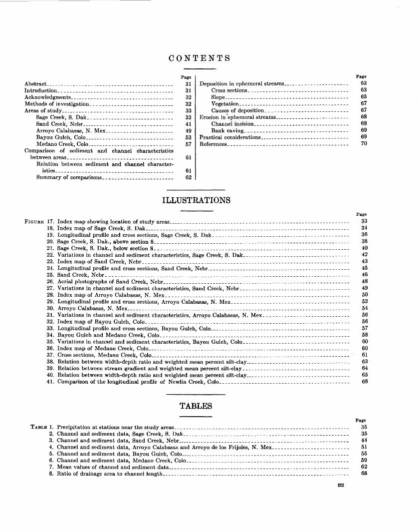
CONTENTS
Abstract __________________________________________ _ Introduction ______________________________________ _ Acknowledgments __________________________________ _ Methods of investigation ___________________________ _ Areas of study _____________________________________ _
Sage Creek, S. Dak ____________________________ _ Sand Creek, Nebr ______________________________ _ Arroyo Calabasas, N. Mex ______________________ _ Bayou Gulch, Colo _____________________________ _ Medano Creek, Colo ____________________________ _
Comparison of sediment and channel characteristics between areas ___________________________________ _
Relation between sediment and channel character-
Page
31 31 32 32 33 33 41 49 53 57
61
istics________________________________________ 61 Summary of comparisons________________________ 62
Deposition in ephemeral streams ____________ -------- __ Cross sections ______________ - ____ ---------------Slope _________________________________________ _ Vegetation ____________________________________ _ Causes of deposition ___________________________ _
Erosion in ~ephemeral streams ________________________ _ Channel incision _________________ - - - - - - - - - - - - - - -Bank caving __________________________________ _
Practical considerations _______________ ---------------References ________________________________________ _
ILLUSTRATIONS
Page
63 63 65 67 67 68 68 69 69 70
Page
FIGURE 17. Index map showing location of study areas_____________________________________________________________ 33 18. Index map of Sage Creek, S. Dak_____________________________________________________________________ 34 19. Longitudinal profile and cross sections, Sage Creek, S. Dak _______________________________ --------------- 36 20. Sage Creek, S.Dak., above section 8------------------------------------------------------------------ 38 21. Sage Creek, S.Dak., below section 8------------------------------------------------------------------ 40 22. Variations in channel and sediment characteristics, Sage Creek, S. Dak ___________________________ --- _----- 42 23. Index map of Sand Creek, N ebr _________________________________________________________________ - --- _ 43 24. Longitudinal profile and cross sections, Sand Creek, Nebr________________________________________________ 45 25. Sand Creek, Nebr__________________________________________________________________________________ 46 26. Aerial photographs of Sand Creek, N ebr _ _ _ _ _ _ _ _ _ _ _ _ _ _ _ _ _ _ _ _ _ _ _ _ _ _ _ _ _ _ _ _ _ _ _ _ _ _ _ _ _ _ _ _ _ _ _ _ _ _ _ _ _ _ _ _ _ _ _ _ _ _ _ 48 27. Variations in channel and sediment characteristics, Sand Creek, Nebr_____________________________________ 49 28. Index map of Arroyo Calabasas, N. Mex ___________________________________ :.. _ _ _ _ _ _ _ _ _ _ _ _ _ _ _ _ _ _ _ _ _ _ _ _ _ _ 50 29. Longitudinal profile and cross sections, Arroyo Calabasas, N. Mex ___________________________________ ----- 52 30. Arroyo Calabasas, N. Mex_ _ _ _ _ _ _ _ _ _ _ _ _ _ _ _ _ _ _ _ _ _ _ _ _ _ _ _ _ _ _ _ _ _ _ _ _ _ _ _ _ _ _ _ _ _ _ _ _ _ _ _ _ _ _ _ _ _ _ _ _ _ _ _ _ _ _ _ _ _ _ _ _ _ _ 54 31. Variations in channel and sediment characteristics, Arroyo Calabasas, N. Mex ________________________ ----- 56 32. Index map of Bayou Gulch, Colo_____________________________________________________________________ 56 33. Longitudinal profile and cross sections, Bayou Gulch, Colo_______________________________________________ 57 34. Bayou Gulch and Medano Creek, Colo________________________________________________________________ 58 35. Variations in channel and sediment characteristi~s, Bayou Gulch, Colo _______________________________ ----- 60 36. Index map of Medano Creek, Colo____________________________________________________________________ 60 37. Cross sections, Medano Creek, Colo___________________________________________________________________ 61 38. Relation between width-depth ratio and weighted mean percent silt-clay _________________________ - ____ ----_ 63 39. Relation between stream gradient and weighted mean percent silt-clay _______________________________ --___ 64 40. Relation between width-depth ratio and weighted mean percent silt-clay___________________________________ 65 41. Comparison of the longitudinal profile of Newlin Creek, Colo____________________________________________ 68
TABLES Page
TABLE 1. Precipitation at stations near the study areas ______________________________________________________ -- __ - 35 2. Channel and sediment data, Sage Creek, S. Dak_ _ _ _ _ _ _ _ _ _ _ _ _ _ _ _ _ _ _ _ _ _ _ _ _ _ _ _ _ _ _ _ _ _ _ _ _ _ _ _ _ _ _ _ _ _ _ _ _ _ _ _ _ _ _ _ 35 3. Channel and sediment data, Sand Creek, Nebr__________________________________________________________ 44 4. Channel and sediment data, Arroyo Calabasas and Arroyo de los Frijoles, N. Mex_ _ _ _ _ _ _ _ _ _ _ _ _ _ _ _ _ _ _ _ _ _ _ _ _ _ 51 5. Channel and sediment data, Bayou Gulch, Colo_________________________________________________________ 55 6. Channel and sediment data, Medano Creek, Colo_______________________________________________________ 59 7. Mean values of channel and sediment data_____________________________________________________________ 62 8. Ratio of drainage area to channel length __________________________________________________________ -_-__ 68
m

EROSION AND SEDIMENTATION IN A SEMIARID ENVIRONMENT
THE EFFECT OF SEDIMENT CHARACTERISTICS ON EROSION AND DEPOSITION IN EPHEMERAL STREAM CHANNELS
By S .. \. ScHUMM
ABSTRACT
This study of five semiarid valleys emphasizes the importance of physical properties of sediment in determining streamchannel shape and differences in the mechanics of erosion and deposition between areas. Prerequisites for selection of the five areas were a progressive decrease in the percent silt-clay in stream channels and banks, active aggradation or erosion within a reach of the stream channel, and nearly uniform lithology within each drainage basin.
A comparison of the data obtained from each area demonstrates that in a drainage channel composed of fine-grained, highly cohesive sediment, deposition occurs on the sides of the channel as well as on the channel floor. The result is a reduction in the ehannel width-depth ratio across an aggrading reach. Vegetation seems to aid deposition by its rapid growth on recently deposited fine alluvium, but it is not the initial cause of aggradation. Bank caving yields only small amounts of sediment and, caved blocks are often nuclei for deposition along channel sides because of their resistance to disintegration. Degradation in the finer sediments is generally by upstream headcut migration.
In contrast, those channels containing only small amounts of silt-elay are aggraded from bottom to top. No plastering of fine sediments on the banks oecurs. Less vegetation grows on these poorly cohesive, highly mobile sediments. Headcutting occurs only where the coarser sediments are capped by a layer of fine material. In general, a break in the longitudinal profile of this type channel is quickly removed by channel degradation. Bank caving seems to supply more sediment to the stream load, for the blocks of poorly cohesive alluvium disintegrate upon impact.
Deposition causes marked ehanges in the ephemeral-stream channels. As the reaeh of maximum aggradation is approached channel gradient decreases, and depending on the amount of silt-clay in channel and banks, the width-depth ratio may increase or even decrease. In all ehannels studied percent siltclay increases and median grain size decreases with aggradation. At the lower end of an aggrading reach, the gradient steepens, but sediment is still fine and vegetation generally covers the entire valley floor. The reaeh of maximum deposition may migrate upstream with time, but renewed degradation on the downstream reach of steep gradient may cause a trench to cut through the valley plug, renewing through transport of sediment and runoff.
The aggradation in the study areas is apparently a result of high sediment yields in the headwater parts of the drainage basins. Deposition in the channel occurs; however, where the
rate of increase of drainage area per mile of channel length is low. In these reaches of small tributary contribution, water loss into the alluvium and the subsequent increase in sediment concentration causes deposition.
The shape of stable cross sections, expressed as a width-depth ratio, is dependent on the weighted mean percent silt-clay in banks and channels such that width-depth ratio increases with decreased silt-clay in the alluvium. Gradient also shows an inverse relation to weighted mean percent silt-clay for these small streams of low annual discharge.
It is suggested that the relation between channel shape and silt-clay can be used as a criterion of channel stability, for aggrading channels generally pl.!)t well above the width-depth, silt-clay regression line; whereas, degrading channels plot below the line.
The study suggests that preventive conservation may be the most practical solution to some erosion problems, such as arroyo cutting. Deposition, if it is desired to fill a trenched channel, should be induced in reaches where conditions are most favorable for natural aggradation. Conservation measures should be modified depending on the character of the valley and its alluvium. Only certain critical reaches of a channel need be controlled to prevent erosion over larger areas.
INTRODUCTION
Recently there has been an increase in studies of stream morphology. Leopold and Maddock ( 1953) have discussed downstream changes in width and depth of a stream channel with increased discharge. Additional studies by Wolman ( 1955), Leopold and Miller ( 1956), and Wolman and Leopold (1957) have tended to confirm Leopold and Maddock's conclusions under diverse conditions and have revealed 1nuch about stream-channel development. The writer in another investigation introduced a parameter for sediment type and stressed the importance of the effect of sediment type on channel shape (Schumm, 1960b). All the above investigations were restricted to stable channels, or at least channels that were not rapidly aggrading or degrading._ The present study concerns some small ephemeral-stream channels that are being actively aggraded or eroded.
31
32 EFFECT OF SEDIMENT CHARACTERISTICS
A know ledge of the mechanics of deposition and erosion in semiarid valleys would not only be academically valuable, but could also provide the basis for conservation .measures aimed at restoring gullied valleys to their prior condition. Much has been written on the need for careful use of the semiarid valley floor, for it may be the only productive land within a drainage basin. For example, Peterson ( 1950), as a result of interviews with several early settlers, states that at the time of white settlement in the valley of San Simon Creek, Ariz., the valley floor was flat and unbroken. Large areas were covered with grass, luxuriant enough to be harvested for hay. Th~ creek itself was perennial throughout most of its length and lined with trees. During the 1880's, 50,000 head of cattle are said to have grazed the yalley. At present the valley floor is trenched from its confluence with the Gila River for nearly 70 miles upstream, although a reach of about 2 miles is uncut a:bout 40 miles above the mouth. The stream is now ephemeral, and barren flats and miniature badlands border the gully. Other. valleys in the West have a similar history.
Much thought has been devoted to the development of conservation measures; nevertheless, until the mechanics of sediment deposition and removal are better understood, truly effective conservation measures will not be realized. This report is a contribution toward the development of that necessary understanding of semiarid erosional and depositional processes.
Many students of stream activity have recognized that the type of sediment transported by a stream greatly influences the characteristics of that stream. Therefore, in order to form general conclusions, areas of diverse sediment types must be studied.
A study of the relation behveen sediment type and stream-channel shape (Schumm, 1960a) has shown that for stable stream channels containing less than 40 percent gravel and cobbles, the channel shape expressed as a width-depth ratio (F) bears the following relation to a weighted mean value for the percent siltclay in bank and channel samples (M) : F=255 M-1·08•
Silt-clay is defined as the sediment passing through the 200-mesh sieve, smaller than 0.074 mm.
Areas which had a wide range in the percent siltclay in channel and banks were selected for study because it was believed that such differences might be fundamental with regard to the mechanics of sediment deposition and erosion.
This report is composed of two main parts. The first contains a geographic description of each study area as well as a discussion of the changes in sediment and channel characteristics along each channel. In the second part the data collected in the five study
areas are combined to show the relations between sediment type and channel character, and the causes of, and the differences in, erosional and deposition processes in the study areas. In addition, conclusions and their practical application are discussed.
ACKNOWLEDGMENTS
During the summer of 1957 the following assisted the writer in the field: William Krummel, C. T. Sumsion, and R. H. Taylor. Irene Lapke performed the hydrometer analysis of the finer sediment sa.mples. The writer wishes to acknowledge the constructive criticism offered by J. H. Mackin, M.G. Wolman, and J. T. Hack.
John Rutter, superintendent, Badlands National Monument, and Philip Ward, ranger, Great Sand Dunes National Monument, ajded the fieldwork, and their courtesy and assistance are greatly appreciated.
METHODS OF INVESTIGATION
Five drainage basins were selected for study. Both a range in alluvial characteristics from area to area and active deposition or erosion within the channel were basic prerequisites. To eliminate as many variables as possible, areas were selected in which differences in lithology within a drainage basin did not affect the stream in any recognizable manner. This necessitated the selection of small drainage basins; the largest basin chosen had a drainage area of about 90 square miles.
The reaches of each channel in which deposition was important generally could be readily identified, perhaps most easily by the recognition of recently deposited alluvium by its fresh a.ppearance and lack of vegetative cover. Downstream changes in channel shape and gradient and sediment character, also confirmed the location of aggrading reaches. These deposition criteria will be discussed in more detail under "Deposition in ephemeral streams." Unfortunately discharge da.ta were not available for each channel studied.
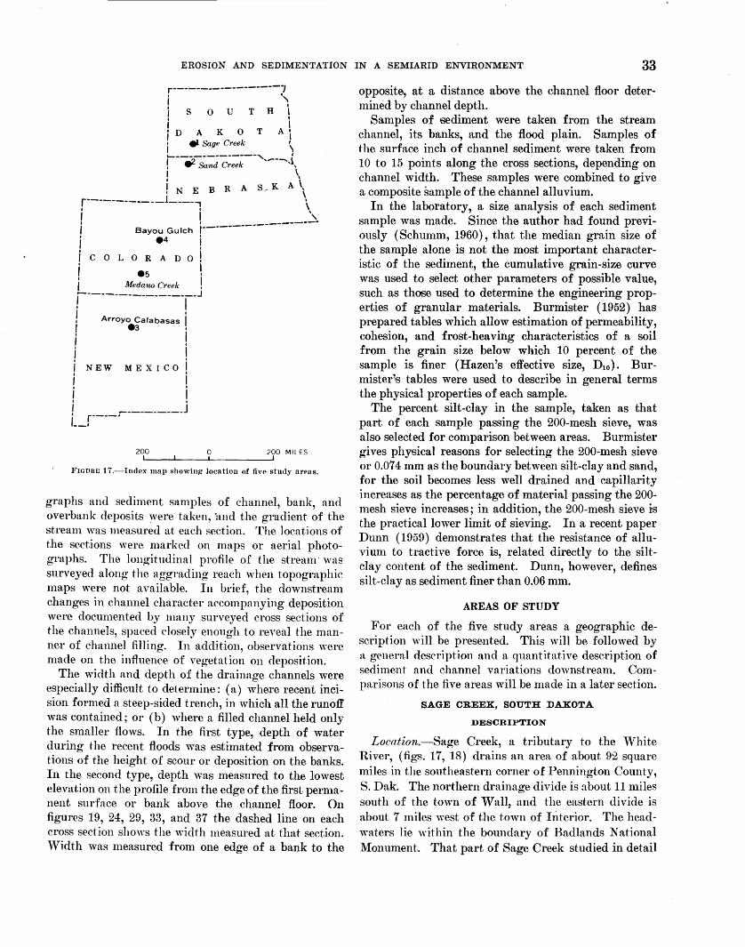
The five areas selected, although scattered from southern South Dakota to northern New Mexico (fig. 17), fulfilled all the basic requirements and were similar in annual precipitation and land use. Similar observations were made in each area. Where topographic maps of good quality, large scale, and small contour interval were available, the fieldwork was limited to the collection of data at many locations along the channel. Cross sections were chosen primarily to illustrate the changes occurring in the channel and on the flood plain as deposition or erosion became increasingly important in the downstream direction. Photo-
EROSION AND SEDIMENTATION IN A SEMIARID ENVIRONMENT 33
r------------------1 i ·~ Is 0 u TH I I I
i I i D A K 0 T Aj i el Sage Creek \
~-------------, I ! W. Sand Creek ,....---,1, I \
1 N E B R A S.- K A \
r------------1----, \ i i ·, f Bayou Gulch r------------------· i • 4 i I I I COLORADO,
i .5 ! l Medarw Creek ! ,. ________________ J
i i i i
Arroyo Calabasas eJ
j NEW MEXICO
i i i ___________ j , r----· '--1
200 0 200 MILES
FIGURE 17.-lndex map showing- location of five study areas.
graphs and sediment samples of channel, bank, and overbank deposits were taken, ·and the gradient of the stream was measured at each section. The loeations of the sections were marked on maps or aerial photographs. The longitudinal profile of the stream "'as surveyed along the aggrading reach when topographic 1na.ps were not available. In brief, the downstream changes in channel character accompanying deposition. were documented by many surveyed cross sections of the channels, spaced closely enough to reveal the manner of channel filling. In addition, observations "\Vere made on the influence of vegetation on deposition.
The width and depth of the drainage channels were especially difficult to cletennine: (a) where recent incision formed a steep-sided trench, in which all the runoff was contained; or (b) where a filled channel held only the smaller flows. In the first type, depth of water during the recent floods was estimated from observations of the height of scour or deposition on the banks. In the second type, depth was measured to the lowest elevation on the profile from the edge of the first permanent surface or bank above the channel floor. On figures 19, 24, 29, 33, and 37 the dashed line on each cross section shows the width measured at that section. Width was measured from one edge of a bank to the
opposite, at a distance above the channel floor determined by channel depth.
Samples of sediment were taken from the stream channel, its banks, and the flood plain. Samples of the surface inch of channel sediment were taken from 10 to 15 points along the cross sections, depending on channel width. These samples were combined to give a composite sample of the channel alluvium.
In the laboratory, a size analysis of each sediment sample was made. Since the author had found previously (Schumm, 1960) , that the median grain size of the sample alone is not the most important characteristic of the sediment, the cumulative grain-size curve was used to select other parameters of possible value, such as those used to determine the engineering properties of granular materials. Burmister (1952) has prepared tables which allow estimation of permeability, cohesion, and frost-heaving characteristics of a soil :from the grain size below which 10 percent of the sample is finer (Hazen's effective size, D10). Burmister'':S tables were used to describe in general terms the physical properties of each sample.
The percent silt-clay in the sample, taken as that part of each sample passing the 200-mesh sieve, was also selected for comparison between areas. Burmister gives phJ'Sical reasons for selecting the 200-mesh sieve or 0.07 4 mm as the boundary between silt-clay and sand, for the soil becomes less well drained and capillarity increases as the percentage of material passing the 200-mesh sieve increases; in addition, the 200-mesh sieve is the practical lower limit of sieving. In a recent paper Dunn (1959) demonstrates that the resistance of alluvium to tractive force is, related directly to the siltclay content of the sediment. Dunn, however, defines silt-clay as sediment finer than 0.06 mm.
AREAS. OF STUDY
For each of the five study areas a geographic description will be presented. This will be followed by a general description and a quantitative description of sediment and channel variations downstream. Comparisons of the five areas will be made in a later section.
SAGE CREEK, SOUTH DAKOTA
DESCRIPTION
Location.-Sage Creek, a tributary to the White River, (figs. 17, 18) drains an area of about 92 square miles in the southeastern corner of Pennington County, S.Dak. The northern drainage divide is about 11 miles south of the town' of Wall, and the eastern divide is about 7 miles west of the town of Interior. The headwaters lie "\vithin the boundary of Badlands National Monument. That part of Sage Creek studied in detail
34 EFFECT OF SEDIMENT CHARACTERISTICS
R.15 E. R.16 E.
EXPLANATION ~"\..__
. __ __; ~_/ N
\ T. 2 S.
( NA TIONA.l
~pS + -------, \
v~ 1
Location of cross Section +
I - .... ~ P4 ~
Location of ~ photograph station r- ___ _J
Boundary of ) : .drainage basin 1
~-- I ( r------- _j
\! \ \
\ \
Base from U.S. Geological Survey topographic maps and National Park Service surveys
+
2 0 2 MILES
T. 3 s.
T. 4 s.
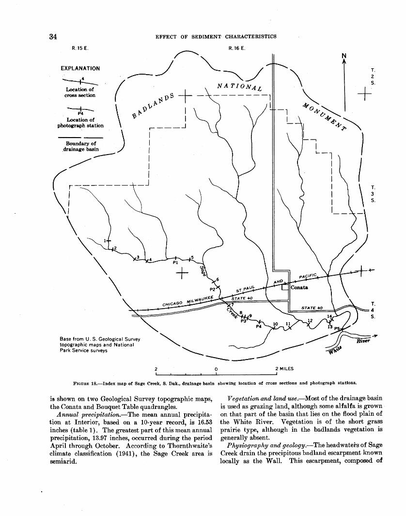
FIGDRF. 18.-Index map of Sage Creek, S. Dak., drainage basin showing location of cross sections and photograph stations.
is shown on two Geological Survey topographic maps, the Conata and Bouquet Table quadrangles.
Annual precipitation.-The mean annual precipitation at Interior, based on a 10-year record, is 16.53 inches (table 1). The greatest part of this mean annual precipitation, 13.97 inches, occurred during the period April through October. According to Thornthwaite's climate classification ( 1941), the Sage Creek area is semiarid.
Vegetation and land use.-Most of the drainage basin is used as grazing land, although some alfalfa is grown · on that part of the basin that lies on the flood plain of the White River. Vegetation is of the short grass prairie type, although in the badlands vegetation is generally absent.
Physiography and geology.-The headwaters of Sage Creek drain the precipitous badland escarpment known locally as the Wall. This escarpment, composed of
Length
EROSION A.i.~D SEDIMENTATION IN A SEMIARID ENVIRONMENT
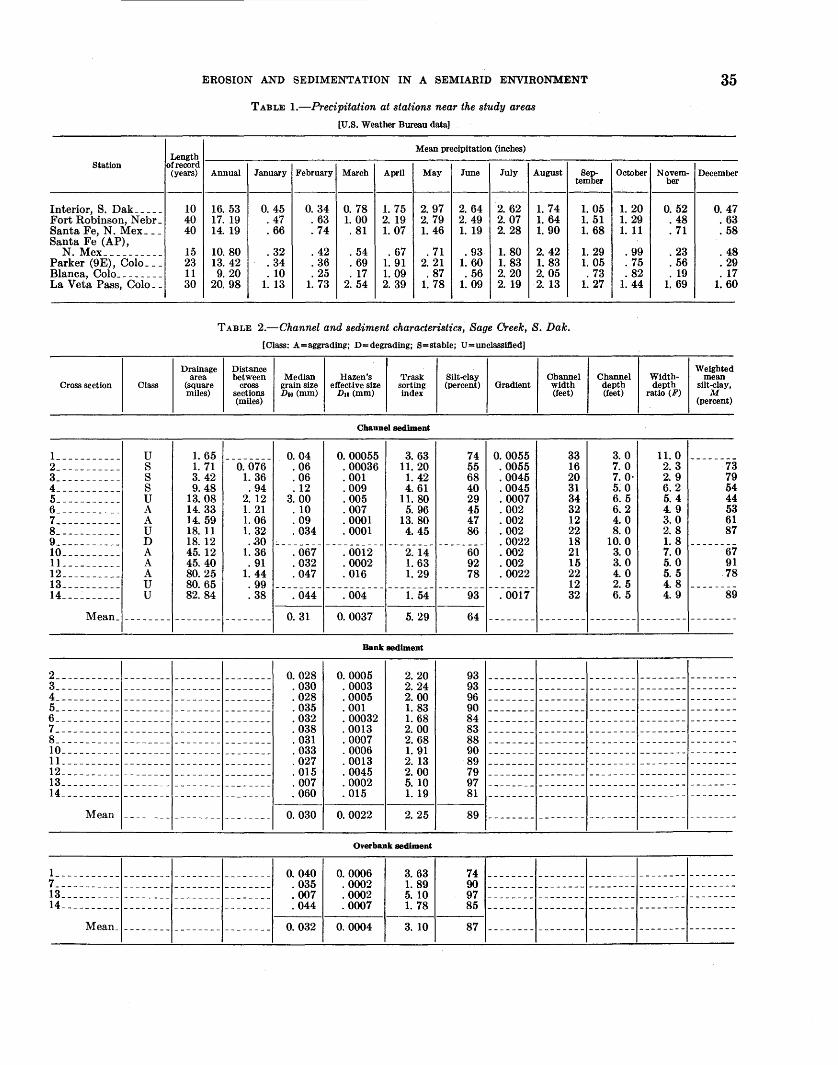
TABLE I.-Precipitation at stations near the study areas
[U.S. Weather Bureau data]
Mean precipitation (inches)
Station of record Febmacy I Mwcch
Interior, S. Dak _____ Fort Robinson, N ebr _ Santa Fe, N. Mex ___ Santa Fe (AP),
N. Mex __________ Parker (9E), Colo ___ Blanca, Colo. _______ La Veta Pass, Colo __
Cross section Class
l ___________ u 2 ___________ s 3 ___________ s 4 ___________ s 5 ___________ u 6 ___________ A 7 ___________ A g ___________ u 9 ___________ D lQ __________ A 1L _________ A 12 __________ A 13 __________ u 14---~------ u
Mean_ --------
(years) Annual January April May June July August Sep. October Novem-tember ber
10 16.53 0. 45 0. 34 0. 78 1. 75 2.97 2. 64 2. 62 1. 74 1. 05 1. 20 0. 52 40 17. 19 . 47 . 63 1. 00 2. 19 2. 79 2. 49 2. 07 1. 64 1. 51 1. 29 . 48 40 14. 19 . 66 . 74 . 81 1. 07 1. 46 1. 19 2. 28 1. 90 1. 68 1.11 .71
15 10. 80 . 32 . 42 . 54 . 67 .71 . 93 1. 80 2. 42 1. 29 . 99 . 23 23 13. 42 . 34 . 36 . 69 1. 91 2. 21 1. 60 1. 83 1. 83 1. 05 . 75 . 56 11 9. 20 . 10 . 25 . 17 1. 09 . 87 . 56 2. 20 2. 05 . 73 . 82 . 19 30 20. 98 1. 13 1. 73 2. 54 2. 39 1. 78 1. 09 2. 19 2. 13 1. 27 1. 44 1. 69
TABLE 2.-Channel and sediment characteristics, Sage Creek, B. Dak.
[Class: A=aggrading; D=degrading; S=stable; U=unclass111.ed]
Drainage Distance area between Median Hazen's Trask Silt-clay Channel Channel Width-
(square cross grain size effective size sorting (percent) Gradient width depth depth miles) sections D 60 (mm) D1o (mm) index (feet) (feet) ratio (F)
(miles)
Channel sediment
1. 65 -------- 0.04 0.00055 3. 63 74 0.0055 33 3.0 11. 0 1.71 0.076 . 06 . 00036 11. 20 55 . 0055 16 7.0 2. 3 3. 42 1. 36 . 06 . 001 1.42 68 . 0045 20 7. 0· 2. 9 9.48 . 94 .12 . 009 4.61 40 . 0045 31 5.0 6.2
13.08 2. 12 3.00 . 005 11. 80 29 . 0007 34 6. 5 5. 4 14. 33 1. 21 . 10 . 007 5. 96 45 . 002 32 6.2 4. 9 14. 59 1. 06 . 09 . 0001 13. 80 47 . 002 12 4.0 3.0 18. 11 1. 32 . 034 . 0001 4. 45 86 . 002 22 8.0 2. 8 18. 12 . .30 -------- ---------- -------- -------- . 0022 18 10.0 1.8 45. 12 1. 36 . 067 . 0012 2. 14 60 . 002 21 3.0 7.0 45. 40 . 91 . 032 . 0002 1. 63 92 . 002 15 3.0 5.0 80. 25 1. 44 . 047 . 016 1. 29 78 . 0022 22 4. 0 5. 5 80. 65 . 99 -------- ---------- -------- -------- -------- 12 2. 5 4. 8 82. 84 . 38 . 044 . 004 1. 54 93 . 0017 32 6. 5 4. 9
-------- -------- 0. 31 0.0037 5. 29 64 -------- -------- -------- --------
Bank sediment
35
December
0. 47 . 63 . 58
. 48
. 29
. 17 1. 60
Weighted mean
silt-clay, M
(percent)
-------7 7 5 4 5 6 8
-------6 9 7
-------8
-------
3 9 4 4 3 1 7
7 1 8 -9
2 ___________ -------- -------- -------- 0.028 . 030 . 028 . 035 . 032 . 038 . 031 . 033 . 027 . 015 . 007 . 060
0.0005 . 0003 . 0005 . 001
2.20 2.24 2.00 1. 83
93 - - - - - - -- - - - - - - - - - - - - - - - - - - - -- - - - - - - - - - - -3_- --------- -------- -------- --------4_ ---------- -------- -------- --------5_---------- ------ -- - ------ - ---- ----6 ___________ -------- -------- --------7 ___________ ------------------------8_- --------- -------- -------- --------10 __________ -------- -------- --------11 __________ ------------------------12 __________ -------- -------- --------13 __________ -------- -------- --------14 __________ -------- -------- --------
Mean ________________________ _
l ___________ -------- -------- --------7 ___________ ------------------------13 __________ -------- -------- --------14 __________ -------- -------- --------
Mean ________________________ _
0.030
0.040 . 035 . 007 . 044
0.032
. 00032
. 0013
. 0007
. 0006
. 0013
. 0045
. 0002
. 015
0.0022
1. 68 2. 00 2.68 1. 91 2. 13 2. 00 5. 10 1. 19
2. 25
Overbank sediment
0.0006 . 0002 . 0002 . 0007
0.0004
3. 63 1. 89 5. 10 1. 78
3. 10
93 96 90 84 83 88 90 89 79 97 81
89 - -- ----- -------- -------- -------- --------
74 -------- -------- -------- -------- --------90 97 85
87 -------- -------- -------- -------- --------
36 EFFECT OF SEDIMENT CHARACTERISTICS
the sandstones, siltstones, and claystones of the White River group of Oligocene age, is being eroded rapidly. On many of the slopes a depth of 0.5 inch of material is eroded during 1 year (Schumm, 1956). Sediment eroded from the scarp must be transported at least 10 miles across a gently sloping surface formed by the northward retreat of the badland scarp, to reach the White River. In spite of the gentle slope of this surface, about 20 feet to the mile, it is trenched by ephemeral streams. A few residuals or outliers of th~ main badland mass rise above it.
Over almost the entire drainage area the White River group is exposed at the surface, although a geologic map of the area (Ward, 1922), which unfortunately fails to cover the entire drainage basin, suggests that the Pierre shale of Cretaceous age crops out in the lower part of the Sage Creek valley. However, since the creek flows on an alluvial fill derived predominantly from the White River group; no change in valley character was recognized due to change of rock type .
.Alluvium.-The sediment derived from the erosion of the White River Badlands is fine grained (table 2). Median grain size of channel-sediment for all sections is 0.31 mm, Trask's sorting coefficient is 5.29, and Hazen's effective size is 0.0037 mm. Using Burmister's tables (1952), it is found that a soil having D 10 of 0.0037 mm is nearly impermeable. Potential capillarity of the soil is high, and it is very susceptible to frost heaving. This indicates that the alluvium in general is highly cohe!3ive, and much energy is required to detach a particle from the mass of alluvium. The mean percent silt-clay in the channel samples is 64, confirming the highly cohesive nature of this material.
Samples taken of overbank deposits and deposits on the sides of the channel contain an even greater percent silt-clay and smaller value for D1o (table 2)' indicating even higher cohesion.
Samples were taken from the recently trenched valley sides. These contained 89 percent silt-clay and D1o was 0.0022 mm, indicating that the fill is impermeable. The potential capillarity is high, and the banks are suscep· tible to frost heaving.
GENERAL CHANNEL VARIATIONS
Considering the nature of the alluvium, a general discussion will now be presented of the changes in channel characteristics at the 14 sections surveyed.
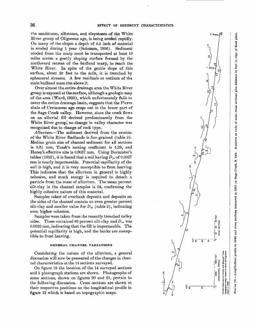
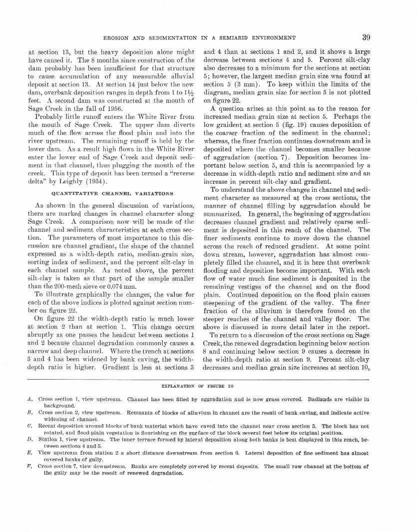
On figure 18 the location of the 14 surveyed sections and 5 photograph stations are shown. Photographs of some sections, shown on figures 20 and 21, pertain to the following discussion. Cross sections are shown at their respective positions on the longitudinal profile in figure 19· which is based on topogr.aphic maps.
EROSION AND SEDIMENTATION IN A SEMIARID ENVIRONMENT 37
The uppermost section (No. 1) has only a poorly defined channel. Past deposition has smoothed the valley floor until now flood waters cover a width of about 240 feet (fig. 20A). A short distance below section 1 is a headcut below which the valley floor is trenched. The headcut is not shown on figure 19, for its height is much less than the contour interval of the topographic maps on which figure 19 is based.
Bank caving has widened the newly incised channel between sections 2 and 3 (figs. 19, 20B), but the cohesiveness of the bank material prevents rapid disintegration of the slump blocks. Some of the la.rger fragments on which vegetation still grows are nuclei for deposition in the channel (fig. 200).
At section 3 this process has become more pronounced, and locally what seem to be incipient point bars are forming about slump blocks. The channel widens and deepens rapidly downstream as tributaries join the main chn,nnel. At section 4 an inner chn,nnel has formed; that is, deposition has built terraces along both banks (fig. 20D). The characteristic mode of deposition in this area seems to be a plastering of sediment along the sides of the channel. The recently deposited, finegrained highly cohesive sediment aids plant growth, and all recent sediment deposits are covered with grass and weeds, which in turn further increase deposition.
Midway between photograph station 1 and section 5 there is a noticeable decrease in stream gradient (fig. 19), suggesting that deposition probably increases below section 5. Downstream the inner terraces encroach on the channel proper and mount higher on the original banks of the channel until at section 6 only about 3 feet of these banks are exposed, and a short distance downstream only 1 foot (fig. 20£), and finally at section 7 (fig. 20F), the banks are completely covered. Owing to this deposition along the sides of the channel, bank caving has stopped. Overbank deposition is important at section 7, and the vegetation on the surface adjacent to the channel is partly buried. Downstream from section 7 the channel becomes shallower and narrower, approaching complete filling by building from the sides as well as from the bottom of the original channel. Thus in about 5 miles the channel of Sage Creek has been transformed from a raw trench to one almost completely aggraded. The complete filling of the channel, however, is interrupted by renewed trenching below section 8. At section 8 the channel is deeper and wider than at section 7; however, at section 8 much recently deposited alJuvium is found in the channel, suggesting that aggradation may be occurring or has occurred after channel erosion.
Figure 21A shows a reach of intense erosion accompanied by channel widening below section 8. At sec-
tion 9 the channel is at maximum depth but about 1 mile downstream at photograph station 4 (fig. 21B) deposition has begun again, especially along the sides of the channel and on slump blocks in the bottom. A short distance below this point a remnant of the old channel floor is preserved on the west wall of the new trench. It lies 6 feet below the prairie surface, suggesting that complete filling had not occurred before the renewed trenching. This may explain the absence of a headcut above section 8. Between photograph station 4 and section 10 (fig. 210), more than 1 mile downstream, channel deposition becomes increasingly important, until at section 10 the cross section most nearly resembles that of section 7 (fig. 19).
Deposition at section 10 (fig. 210) was heavy during the floods before the survey, and at this section the manner of deposition is most clearly illustrated. Just above section 10 the stream bends sharply to the north. With rapid deposition, the point bar deposit on the inside of the bend is expected, but of greater interest is the deposition on the outside of the bend where bank cutting should logically occur. Figure 21D is a view of the deposit on the outside bank. The fieldbook is at the contact between what. may be deposition by floods in the spring of 1957 and earlier floods. The sediment is la.id in against the bank, effectively narrowing the channel at this section with little or no decrease in channel depth.
A trench dug across the deposit reveals that stratification is not horizontal; rather it curves downward from the bank toward the channel. Therefore, these lateral deposits are built upward as well as outward from the bank. The deposit shown on figure 21D has been scoured by reeent. floods, but on the inside of the bend (figs. 210, E) the buildinp: of the deposit outward into the channel has not been hindered by erosion. Complete filling of the channel by a union of the laternJ deposits and deposition on the .channel floor will result. in a channel-fill deposit containing concave-up stratification (Schumm, 1960a). This type of lateral deposition could only occur in areas of fine-grained cohesive sediments containing a high percentage of silt-clay. Figure 21£ shows the growth of weeds on the recent. deposits. The c,ohesiveness, ability to hold water, and the fertility of the fine sediment aids rapid and luxurious vegetative growth.
Proceeding downstream from section 10, the water table apparently approaches the surface, for willow a.nd cottonwood saplings appear which further promote deposition. At section 12 the growth of willows is dense and at section 13 (fig. 21F) the channel is almost completely filled. A dam built in the fall of 1956 may be the cause of ponded water in the channel
38 EFFECT OF SEDIMENT CHARAC'I,'ERISTICS
A D
B E
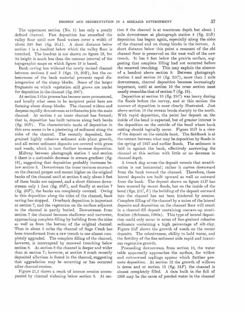
0 F FIGURE 20.-Sage Creek, S. Dak., above section 8.
EROSION AND SEDIMENTATION IN A SEMIARID ENVIRONMENT 39
at section 13, but the heavy deposition alone might have caused it. The 8 months since construction of the dam probably has been insufficient for that structure to cause accumulation of any measurable alluvial deposit at section 13. At section 14 just below the new dam, overbank deposition ranges in depth ·from 1 to 1ljz feet. A second dam was constructed at the mouth of Sage Creek in the fall of 19!\6.
Probably little runoff enters the White River from the mouth of Sage Creek. The upper dam diverts much of the flow across the flood plain a.nd into the river upstream. The remaining runoff is held by the lower dam. As a result high flows in the '~'hite River enter the lower end of Sage Creek and deposit sediment in that channel, thus plugging the mouth of the creek. This type of deposit has been termed a "reverse delta" by Leighly (1934).
QUANTITATIVE CHANNEL VARIATIONS
As shown in the general discussion of variations, there are marked changes in channel character along Sage Creek. A comparison now will be made of the channel and sediment characteristics at each cross section. The parameters of most importance to this discussion are channel gradient, the shape of the channel expressed as a width-depth ratio, median-grain size, sorting index of sediment, and the percent silt-clay in each channel sample. As noted above, the percent silt-clay is taken as that part of the sample smaller than the 200-mesh sieve or 0.074 mm.
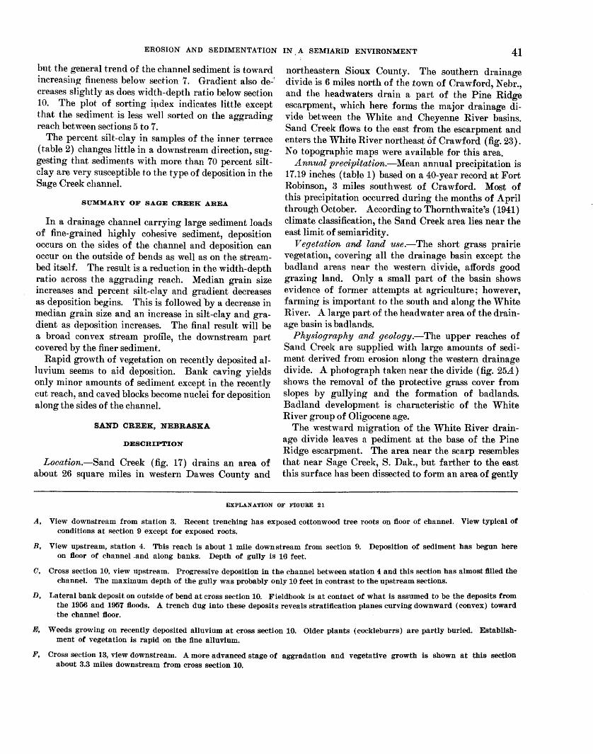
To illustrate graphically the changes, the value for each of the above indices is plotted against section number on figure 22.
On figure 22 the width-depth ratio is much lower at section 2 than at section 1. This change occurs abruptly as one passes the headcut between sections 1 and 2 because channel degradation commonly causes a narrow and deep channel. Where the trench at sections 3 and 4 has been widened by bank caving, the widthdepth ratio is higher. Gradient is less at sections 3
and 4 than at sections 1 and 2, and it shows a large decrease between sections 4 and 5. Percent silt-clay also decreases to 1;t minimum for the sections at section 5; however, the largest median grain size was found at section 5 ( 3 mm). To keep within the limits of the diagram, median grain size for section 5 is not plotted on figure 22.
A question arises at this point as to the reason for increased median grain size at section 5. Perhaps the low graident at section 5 (fig. 19) causes deposition of the coarser fraction of the sediment in the channel; whereas, the finer fraction continues downstream and is deposited where the channel becomes smaller because of aggradation (section 7). Deposition becomes important below section 5, and this is accompanied by a decrease in width-depth ratio and sediment size and an increase in percent silt-clay and gradient.
To understand the above changes in channel and sediment character as measured at the cross sections, the manner of channel filling by aggradation should be summarized. In general, the beginning of aggradation decreases channel gradient and relatively C!>arse sediment is deposited in this reach of the channel. The finer sediments continue to move down the channel across the reach of reduced gradient. At some point down stream, however, aggradation has almost completely filled the channel, and it is here that overbank flooding and deposition become important. With each flow of water much fine sediment is deposited in the remaining vestiges of the channel and on the flood plain. Continued deposition on the flood plain causes steepening of the gradient of the valley. The finer fraction of the alluvium is therefore found on the steeper reaches of the channel and valley floor. The above is discussed in more detail later in the report.
To return to a discussion of the cross sections on Sage Creek, the renewed degradation beginning below section 8 and continuing below section 9 causes a decrease in the width-depth ratio at section 9. Percent silt-clay decreases and median grain size increases at section 10,
EXPLANATION OF FIGURE 20
A, Cross section 1, view upstream. Channel has been filled by aggradation and is now grass covered. Badlands are visible in background.
B, Cross section 2, view upstream. Remnants of blocks of alluvium in channel are the result of bank caving, and indicate active widening of channel.
0, Recent deposition around blocks of bank material which have caved into the channel near cross section 3. The block has not rotated, and flood-plain vegetation is flourishing on the surface of the block several feet below its original position.
D, Station 1, view upstream. The inner terrace formed by lateral deposition along both banks is best displayed in this reach, between sections 4 and 5.
E, View upstream from station 2 a short distance downstream from section 6. Lateral deposition of fine sediment has almost covered banks of gully.
F, CroRs section 7, view downstream. Banks are completely covered by recent deposits. The small raw channel at the bottom ot the gully may be the result of renewed degradation.
40 EFFECT OF SEDIMENT CHARACTERISTICS
A D
B E
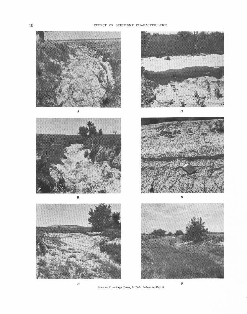
0 F FIGURE 21.-Sage Creek, S. Dak., below section 8.
EROSION AND SEDIMENTATION IN, A SEMIARID ENVIRONMENT 41
but the general trend of the channel sediment is toward increasing fineness below section 7. Gradient also de..:! creases slightly as does width-depth ratio below section 10. The plot of sorting ipdex indicates little except that the sediment is less well sorted on the aggrading reach between sections 5 to 7.
The percent silt-clay in samples of the inner terrace (table 2) changes little in a downstream direction, suggesting that sediments with more than 70 percent siltclay are very susceptible to the type of deposition in the Sage Creek channel.
SUMMARY OF SAGE CREEK AREA
In a drainage channel carrying large sediment loads of fine-grained highly cohesive sediment, deposition occurs on the sides of the channel and deposition can occur on the outside of bends as well as on the streambed itself. The result is a reduction in the width-depth ratio across the aggrading reach. Median grain size increases and percent silt-clay and gradient decreases as deposition begins. This is followed by a decrease in median grain size and an increase in silt-clay and gradient as deposition increases. The final result will be a broad convex stream profile, the downstream part covered by the finer sediment.
Rapid growth of vegetation on recently deposited alluvium seems to aid deposition. Bank caving yields only minor amounts of sediment except in the recently cut reach, and caved blocks become nuclei for deposition along the sides of the channel.
SAND CREEK, NEBRASKA
DESCRIPTION
Location.-Sand Creek (fig. 17) drains an area of about 26 square miles in western Dawes County and
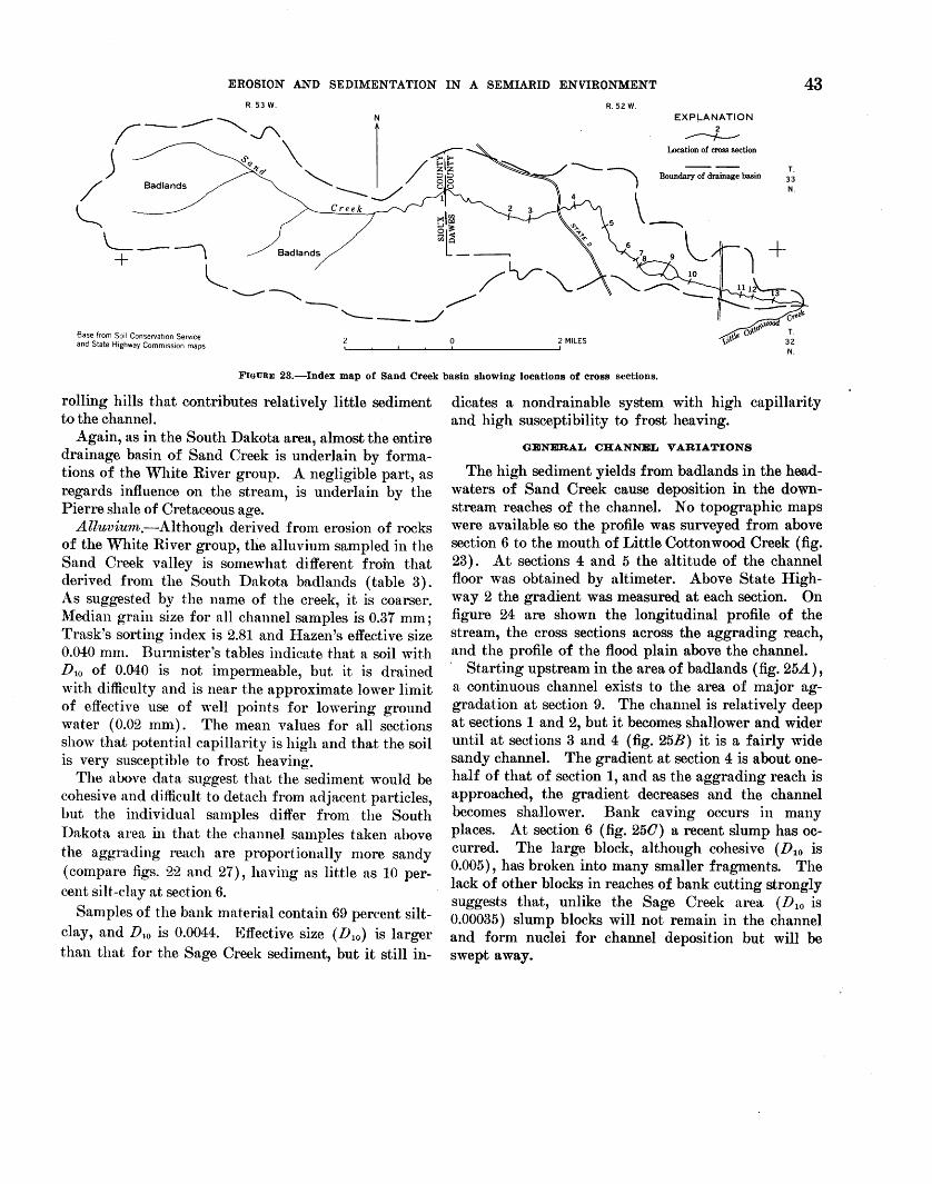
northeastern Sioux County. The southern drainage divide is 6 miles north of the town of Crawford, Nebr., and the headwaters drain a part of the Pine Ridge escarpment, whieh here forms the major drainage divide between the White and Cheyenne River basins. Sand Creek flows to the east from the escarpment and enters the White River northeast of Ora wford (fig. 23). No topographic maps were available for this area.
Annual preeipitation.-Mean annual precipitation is 17.19 inches (table 1) based on a 40-year record at Fort Robinson, 3 miles southwest of Crawford. Most of this precipitation occurred during the months of April through October. According to Thornthwaite's (1941) climate classification, the Sand Creek area lies near the east limit of semiaridity.
Vegetation and land use.-The short grass prairie vegetation, covering all the drainage basin except the badland areas near the western divide, affords good grazing land. Only a small part of the basin shows evidence of former attempts at agriculture; however, farming is important to the south and along the White River. A ]arge part of the headwater area of the drainage basin is badlands.
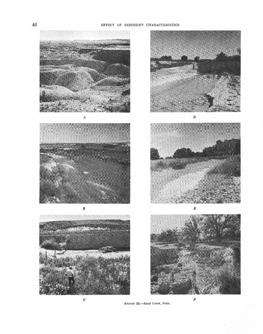
Physiography and geology.-The upper reaches of Sand Creek are supplied with large amounts of sediment derived from erosion along the western drainage divide. A photograph taken near the divide (fig. 25A) shows the removal of the proteetive grass cover from slopes by gullying and the formation of badlands. Badland development is characteristic of the White River group of Oligocene age.
The westward migration of the 'Vhite River drainage divide leaves a pediment at the base of the Pine Ridge escarpment. The area near the scarp resembles that near Sage Creek, S. Dak., but farther to the east this surface has been dissected to form an area of gently
EXPLANATION OF FIGURE 21
A, View downstream from station 3. Recent trenching has exposed cottonwood tree roots on floor of channel. View typical of conditions at section 9 except for exposed roots.
B, View upstream, station 4. This reach is about 1 mile downstream from section 9. Deposition of sediment has begun here on floor of channel .and along banks. Depth of gully is 16 feet.
C, Cross section 10, view Upstream. Progressive deposition in the channel between station 4 and this section has almost filled the channel. The maximum depth of the gully was probably only 10 feet in contrast to the upstream sections.
D, Lateral bank deposit on outside of bend at cross section 10. Fieldbook is at contact of what is assumed to be the deposits from the 1956 and 1957 ftoods. A trench dug into these deposits reveals straUfication planes curving downward (convex) toward the channel ftoor.
FJ, Weeds growing on recently deposited alluvium at cross section 10. Older plants (cockleburrs) are partly buried. Establishment of vegetation is rapid on the fine alluvium.
F, Cross section 13, view downstream. A more advanced stage of aggradation and vegetative growth is shown at this section about 3.3 miles downstream from cross section 10.
42 EFFECT OF SEDIMENT CHARACTERISTICS
CROSS SECTIONS 12 3 4 5 6 7 89 10 11 12 1314
12 1 I I I I I I I I I I
10 - -
2
i If- -:r: • li: 6 f- • -~ • • • • • b 4 f- -i • • •
2 I! • -
0 !I I I I I I J L I I I
!I I I I I I I I I I I I 0.006
• !""" - 0.005
• • - - 0.004 ~
0
- - 0.003 i ...J
"' z • • z
f- • • • • • - 0.002 ~ ()
f- - 0.001
• 11_ _l I I I I I J I I I I
100 II I I I I I I I I I ~
5 • • eor- • -I
!:; • u; 60- • -~ • w • • ~ 40- • -r
• 20 II I I I I I I I I I I I
0.12 en II I T I I I I I I I I I 0:
"' 1-
"' f- • - 0.10
~
3 • i
f- - 0.08 ~ IIi
• N u;
!e • - 0.06 2: <
• 0: 0
~ - 0.04 z • • .: iS
IJ J I I I I I ·I I I I I "' 0.02 ~
I I I I I· • I I I I I I
12 .__ • -~ • 0 ~ 8 - -0 z • ~ 4 - • • -
• • ~ T 0 I l I I l_l I I
12 3 4 s 6 7 89 10 11 12 1314 CROSS SECTIONS
FIGURE 22.-Variations in channel and sediment characteristics; Sage Creek, S. Dak. The spacing of the cross sections along the abscissa is proportional to the distances between sections in the field.
EROSION AND SEDIMENTATION IN A SEMIARID ENVIRONMENT 43 R53 W. R. 52 W.
~-----~~ Nl
j ~Q~ \ /§"1~ q "' zz
/ Badlands ----~ ~ S
EXPLANATION 2
----t--Location of cross section
Boundary of drainage basin T. 33 N.
~ ~Ira 2 3
Sri:~:: L-~ <n;3 1 Badlands
+ ~ - /v--"'-...__.....---.....--- ~
Base from Soi I Conservat1on Service and State Highway Commission maps
'---__./ 0 2 MILES
T 32 N.
FIGURE 23.-lndex map of Sand Creek basin showing locations of cross sections.
rolling hills tha.t contributes relatively little sediment to the channel.
Again, as in the South Dakota area, almost the entire drainage basin of Sand Creek is underlain by formations of the White River group. A negligible part, as regards influence on the stream, is underlain by the Pierre shale of Cretaceous age.
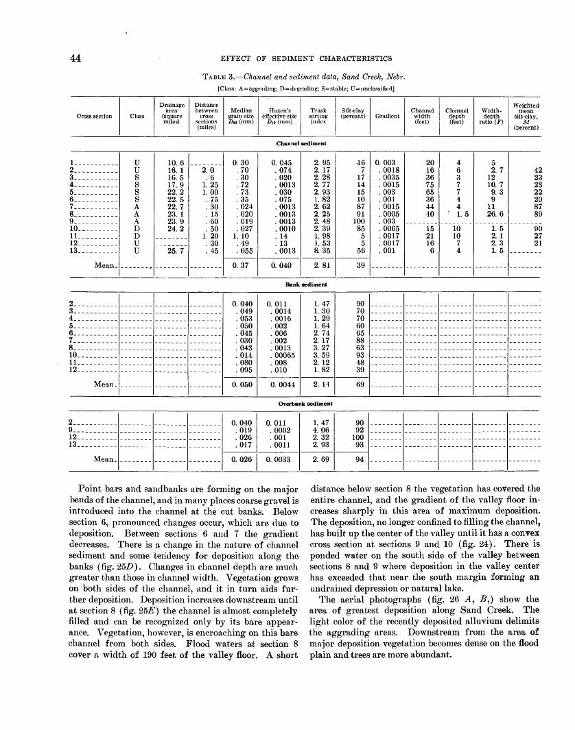
Alluvium.-Although derived from erosion of rocks of the White River group, the alluvium sampled in the Sand Creek valley is somewhat different froin that derived from the South Dakota badlands (table 3). As suggested by the name of the creek, it is coarser. Median grain size for all channel samples is 0.37 mm; Trask's sorting index is 2.81 and Hazen's effective size 0.040 mm. Burmister's tables indicate that a soil with D1o of 0.040 is not impermeable, but it is drained with difficulty and is near the approximate lower limit of effective use of well points for lowering ground water ( 0.02 mm). The mean values for all sections show that potential capillarity is high and that the soil is very susceptible to frost heaving.
The above data suggest that the sediment would be cohesive and difficult to detach from adjacent particles, but the individual samples differ from the South Dakota area in that the channel samples taken above the aggrading reach are proportionally more sandy (compare figs. 22 and 27), having as little as 10 percent silt-clay at section 6.
Samples of the bank material contain 69 percent siltclay, and D10 is 0.0044. Effective size (D10 ) is larger than that for the Sage Creek sediment, but it still in-
dicates a nondrainable system with high capillarity and high susceptibility to frost heaving.
GENERAL CHANNEL VARIATIONS
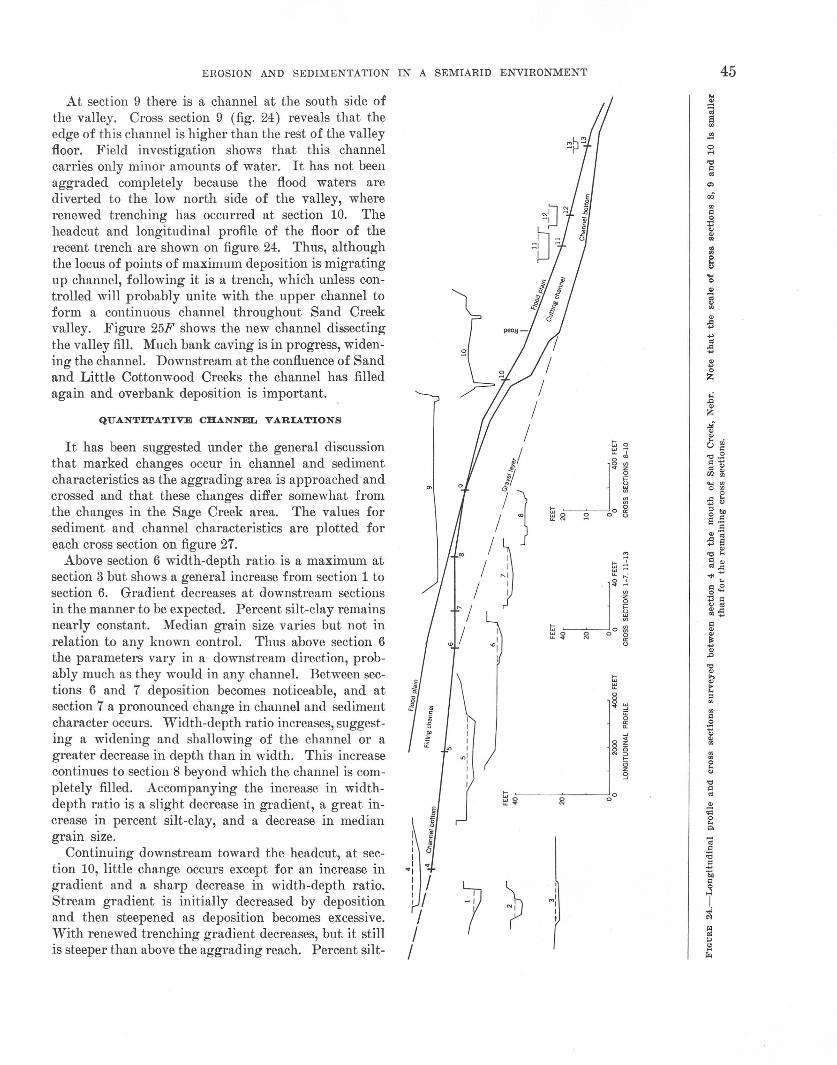
The high sediment yields from badlands in the headwaters of Sand Creek cause deposition in the downstream reaches of the channel. No topographic maps were available so the profile was surveyed from above section 6 to the mouth of Little Cottonwood Creek (fig. 23). At sections 4 and 5 the altitude of the channel floor was obtained by altimeter. Above State Highway 2 the gradient was measured at each section. On figure 24 are shown the longitudinal profile of the stream, the cross sections across the aggrading reach, and the profile of the flood plain above the channel. · Starting upstream in the area of badlands (fig. 25.A.), a continuous channel exists to the area of major aggradation at section 9. The channel is relatively deep at sections 1 and 2, but it becomes shallower and wider until at sections 3 and 4 (fig. 25B) it is a fairly wide sandy channel. The gradient at section 4 is about onehalf of that of section 1, and as the aggrading reach is approached, the gradient decreases and the channel becomes shallower. Bank caving occurs in many places. At section 6 (fig. 250) a recent slump has occurred. The l·arge block, although cohesive (D10 is 0.005), has broken into many smaller fragments. The lack of other blocks in reaches of bank cutting strongly suggests that, unlike the Sage Creek area (D10 is 0.00035) slump blocks will not remain in the channel and form nuclei for channel deposition but will be swept away.
44 EFFECT OF SEDIMENT CHARACTERISTICS
TABLE 3.-Channel and sediment data, Sand Creek, Nebr.
[Class: A=aggrading; D=degrading; S=stable; U=unclassified]
Drainage Distance Weighted area between Median Hazen's Trask Silt-clay Channel Channel Width- mean
Cross section Class (square cross grain size effective size sorting (Pt>rcent) Gradient width depth depth silt-clay, miles) sections D5o(mm) D10(mm) index (feet) (feet) ratio (F) M
(miles) (percent)
Channel sediment
1 ___________ u 10. 6 -------- 0. 30 0. 045 2. 95 2 ___________ u 16. 1 2. 0 . 70 . 074 2. 17 3 ___________ s 16. 5 .6 . 30 . 020 2. 28 4 ___________ s 17. 9 1. 25 . 72 . 0013 2. 77 5 ___________ s 22. 2 1. 00 .73 . 030 2. 93 6 ___________ s 22. 5 . 75 . 35 . 075 1. 82 7 ___________ A 22. 7 . 30 . 024 . 0013 2. 62 8 ___________ A 23. 1 . 15 . 020 . 0013 2. 25 g ___________ A 23. 9 . 60 . 019 . 0013 2. 48 10 __________ D 24.2 . 50 . 027 . 0010 2. 39 1L _________ D -------- 1. 20 1. 10 . 14 1. 98 12 __________ u -------- . 30 . 49 . 13 1. 53 13 __________ u 25. 7 . 45 . 055 . 0013 8. 35
Mean_ -------+ -------- -------- 0. 37 0.040 2. 81
·16 0. 003 20 7 . 0018 16
17 . 0035 36 14 . 0015 75 15 . 003 65 10 . 001 36 87 . 0015 44 91 . 0005 40
100 . 003 --------85 . 0065 15
5 . 0017 21 5 . 0017 16
56 . 001 6
39 -------- --------
4 6 3 7 7 4 4 1.5
--------10 10
7 4
--------
5 2. 7
12 10. 7
9. 3 9
11 26. 6
--------1.5 2. 1 2. 3 1.5
--------
4 2 2 2 2 8 8
2 3 3 2 0 7 9
--------9 2
0 7
21 --------
--------
Bank sediment
2 ___________ -------- -------- --------3_---------- -------- -------- --------4 ___________ -------- -------- --------5 ___________ -------- -------- --------6_------- --- - -- - -- -- - -- -- -- - -- -- - -- -7 ___________ ------------------------8_----- -- -- - --- ----- - -- -- --- ---- - -- -10 __________ -------- -------- --------11 __________ -------- -------- --------12 __________ -------- -------- --------
Mean_ _ _ _ _ _ _ _ _ _ _ _ _ _ _ _ _ _ ______ _
0. 040 . 049 . 053 . 050 . 045 . 030 . 043 . 014 . 080 . 095
0. 050
0. 011 . 0014 . 0016 . 002 . 006 . 002 . 0013 . 00065 . 008 . 010
0. 0044
1. 47 1. 30 1. 29 1. 64 2. 74 2. 17 3. 27 3. 59 2. 12 1. 82
2. 14
90 - - - - - - - - - - - - - - - - - - - - - - - - - - - - - - - - - - - - - - - -70 70 60 65 88 63 93 48 39
69 - - - - - - - - - - - - - - - - - - - - - - - - - - - - - - - - - - - - - - - -
Overbank sediment
2 ___________ -------- -------- --------g ___________ -------- -------- --------12 ____ ------ -------- -------- --------13 ____ ------ -------- -------- --------
0. 040 . 019 . 026 . 017
0. 011 . 0002 . 001 . 0011
Mean_ _ _ _ _ _ _ _ _ _ _ _ _ _ _ _ _ _ _ _ _ _ _ _ _ 0. 026 0. 0033
Point bars and sandbanks are forming on the major bends of the channel, and in many places coarse gravel is introduced into the channel at the cut banks. Below section 6, pronounced changes occur, which are due to deposition. Between sections 6 and 7 the gradient decreases. There is a change in the nature of channel sediment and some 'teiidency for deposition along the banks (fig. 25D). Changes in channel depth are much greater than those in channel width. Vegetation grows on both sides of the channel, and it in turn aids further deposition. Deposition increases downstream until at section 8 (fig. 25E) the channel is almost completely filled and can be recognized only by its bare appearance. Vegetation, however, is encroaching on this bare channel from both sides. Flood waters at section 8 cover a width of 190 feet of the valley floor. A short
1. 47 4. 06 2. 32 2. 93
2. 69
90 92
100 93
94 - - - - - - - - - - - - - - - - - - - - - - - - - - - - - - - - - - - - - - - -
distance below section 8 the vegetation has covered the entire channel, and the gradient of the valley floor increases sharply in this area of maximum deposition. The deposition, no longer confined to filling the channel, has built up the center of the valley until it has a convex cross section at sections 9 and 10 (fig. 24). There is ponded water on the south side of the valley between sections 8 and 9 where deposition in the valley center has exceeded that near the south margin forming an undrained depression or natural lake.
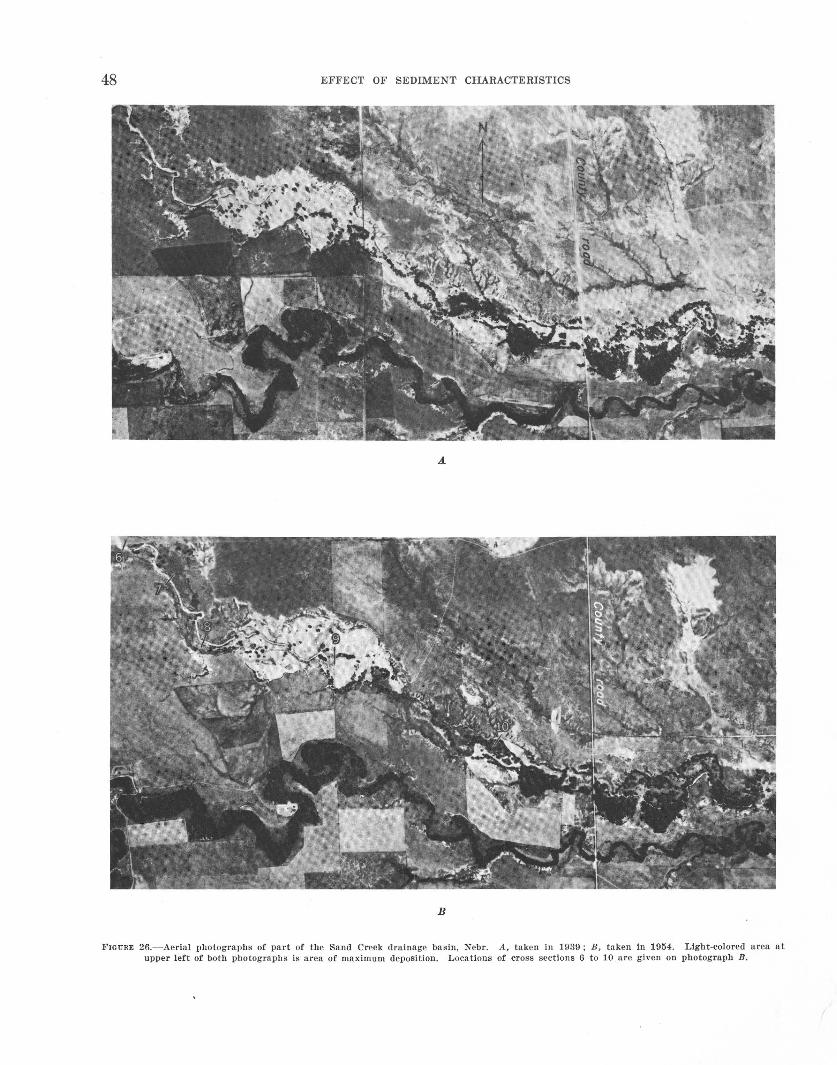
The aerial photographs (fig. 26 A, B,) show the area of greatest deposition along Sand Creek. The light color of the recently deposited alluvium delimits the aggrading areas. Downstream from the area of major deposition vegetation becomes dense on the flood plain and trees are more abundant.
EROSION AND SEDIMENTATION IN A SEMIARID ENVIRONMENT
At section 9 there is a channel at the south side of the valley. Cross section 9 (fig. 24) reveals that the edge of this channel is higher than the rest of the valley floor. Field investigation shows that this channel carries only minor amounts of water. It has not been aggraded completely because the flood waters are diverted to the low north side of the valley, where renewed trenching has occurred at section 10. The headcut and longitudinal profile of the floor of the recent trench are shown on figure 24. Thus, although the locus of points of maximum deposition is migrating up channel, following it is a trench, which unless controlled will probably unite with the upper channel to form a continuous channel throughout Sand Creek valley. Figure 25F shows the new channel dissecting the valley fill. Much bank caving is in progress, widening the channel. Downstream at the confluence of Sand and Little Cottonwood Creeks the channel has filled again and overbank deposition is important.
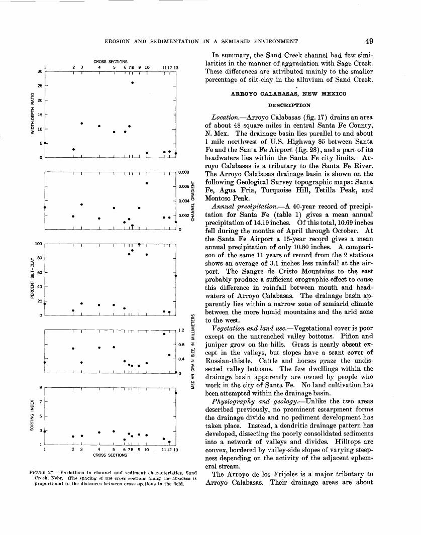
QUANTITATiv;E CHANNEL VARIATIONS
It has been suggested under the general discussion that marked changes occur in channel and sediment characteristics as the aggrading ar~a is approached and crossed and that these changes differ somewhat from the changes in the Sage Creek area. The values for sediment and channel characteristics are plotted for each cross section on figure 27.
Above section 6 width-depth ratio is a maximum at section 3 but shows a general increase from section 1 to section 6. Gradient decreases at downstream sections in the manner to be expected. Percent silt-clay remains nearly constant. Median grain size varies but not in relation to any known control. Thus above section 6 the parameters vary in a downstream direction, probably much as they would in any channel. Between sections 6 and 7 deposition becomes noticeable, and at section 7 a pronounced change in channel and sediment character occurs. ·width-depth ratio increases, suggesting a widening and shallowing of the channel or a greater decrease in depth than in width. This increase continues to section 8 beyond which the channel is completely filled. Accompanying the increase in widthdepth ratio is a slight decrease in gradient, a great increase in percent silt-clay, and a decrease in median grain size.
Continuing downstream toward the headcut, at section 10, little change occurs except for an increase in gradient and a sharp decrease in width-depth ratio. Stream gradient is initially decreased by deposition and then steepened as deposition becomes excessive. With renewed trenching gradient decreases, but it still is steeper than above the aggrading reach. Percent silt-
~I
~ I
.,I I I
I I
7 I
I ~ j 8
f " ~J I J e. g o
0
/) ~ : I :
I I
~I
I
" ]' w~o I.&.J 0 0 0 ~.. N
I I
..,I I I t
45
46 EFFECT OF SEDIMENT CHARACTERISTICS
A D
B E
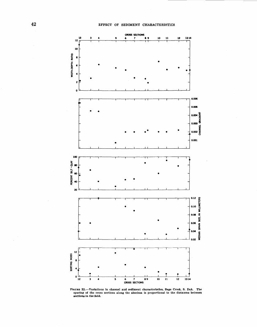
0 F' FIGURE 25.-Sand Creek, Nebr.
EROSION AND SEDIMENTATION IN A SEMIARID ENVIRONMENT 47
clay decreases and median grain size increases. Downstream from section 11 recent cutting probably has not occurred, and the channel and sediment characteristics vary accordingly.
Between sections 8 and 13 the samples of overbank material show a slight increase in the percent of siltclay (table 3). The sorting index does not change greatly between sections 1 and 12.
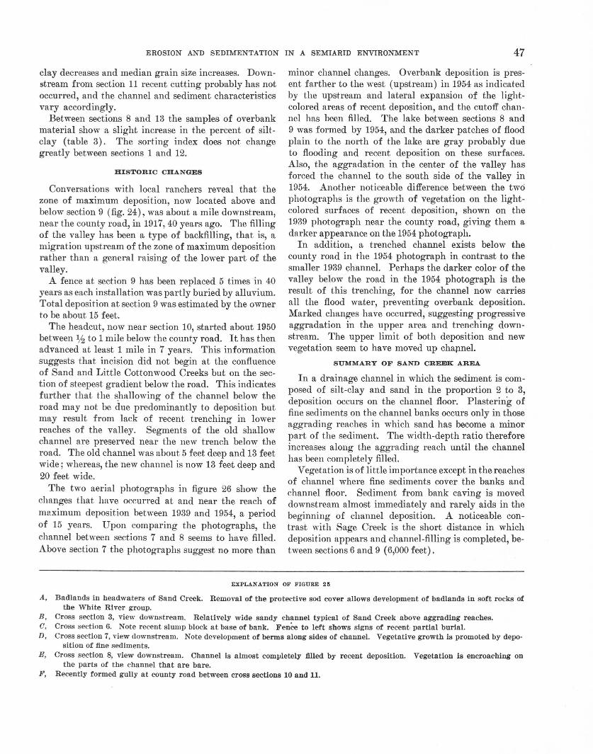
HISTORIC CHANGES
Conversations with local ranchers reveal that the zone of maximum deposition, now located above and below section 9 (fig. 24), was about a mile downstream, near the county road, in 1917, 40 years ago. The filling of the valley has been a type of backfilling, that is, a migration upstream of the zone of maximum deposition rather than a general raising of the lower part of the valley.
A fence at section 9 has been replaced 5 times in 40 years as each installation was partly buried by alluvium. Total deposition at section 9 was estimated by the owner to be about 15 feet.
The headcut, now near section 10, started about 1950 between liz to 1 mile below the county road. It has then advanced at least 1 mile in 7 years. This information suggests that incision did not begin at the confluence of Sand and Little Cottonwood Creeks but on the section of steepest gradient below the road. This indicates further that the s)1allowing of the channel below the road may not be due predominantly to deposition but may result from lack of recent trenching in lower reaches of the valley. Segments of the old shallow channel are preserved near the new trench below the road. The old channel was about 5 feet deep and 13 feet wide; whereas, the new channel is now 13 feet deep and 20 feet wide.
The two aerial photographs in figure 26 show the changes that have occurred at and near the reach of maximum deposition between 1939 and 1954, a period of 15 years. Upon comparing the photographs, the channel between sections 7 and 8 seems to have filled. Above section 7 the photographs suggest no more than
minor channel changes. Overbank deposition is present farther to the west (upstream) in 1954 as indicated by the upstream and lateral expansion of the lightcolored areas of recent deposition, and the cutoff channel has been filled. The lake between sections 8 and 9 was formed by 1954, and the darker patches of flood plain to the north of the lake are gray probably due to flooding and recent deposition on these surfaces. Also, the aggradation in the center of the valley has forced the channel to the south side of the valley in 1954. Another noticeable difference between the two photographs is the growth of vegetation on the lightcolored surfaces of recent deposition, shown on the 1939 photograph near the county road, giving them a darker appearance on the 1954 photograph.
In addition, a trenched channel exists below the county road in the 1954 photograph in contrast to the smaller 1939 channel. Perhaps the darker color of the valley below the road in the 1954 photograph is the result of this trenching, for the channel now carries all the flood water, preventing overbank deposition. Marked changes have occurred, suggesting progressive aggradation in the upper area and trenching downstream. The upper limit of both deposition and new vegetation seem to have moved up chap.nel.
SUMMARY OF SAND CREEK 4REA
In a drainage channel in which the sediment is composed of silt-clay and sand in the proportion 2 to 3, deposition occurs on the channel floor. Plastering of fine sediments on the channel banks occurs only in those aggrading reaches in which sand has become a minor part of the sediment. The width-depth ratio therefore increases along the aggrading reach until the channel has been completely filled.
Vegetation is of little importance except in the reaches of channel where fine sediments cover the banks and channel floor. Sediment from bank caving is moved downstream almost immediately and rarely aids in the beginning of channel deposition. A noticeable contrast with Sage Creek is the short distance in which deposition appears and channel-filling is completed, bet ween sections 6 and 9 ( 6,000 feet) .
EXPLANATION OF FIGURE 25
A, Badlands in headwaters of Sand Creek. Removal of the protective sod cover allows development of badlands in soft rocks of the White River group.
B, Cross section 3, view downstream. Relatively wide sandy channel typical of Sand Creek above aggrading reaches. 0, Cross section 6. Note recent slump block at base of bank. Fence to left shows signs of recent-partial burial. D, Cross section 7, view downstream. Note development of berms along sides of channel. Vegetative growth is promoted by depo
sition of fine sediments. E, Cross section 8, view downstream. Channel is almost completely filled by recent deposition. Vegetation is encroaching on
the parts of the channel that are bare. F, Recently formed gully at county road between cross sections 10 and 11.
48 EFFECT OF SEDIMENT CHARACTERISTICS
A.
B
FIGURE 26.- Aerial photographs of part of the Sand Creek drainage basin , Nebr. A, taken in 1939; B , taken In 1954. Light·colored area at upper left of both photographs is area of maximum deposition. Locations of cross sections 6 to 10 are given on photograph B.
EROSION AND SEDIMENTATION IN A SEMIARID ENVIRONMENT 49
CROSS SECTIONS 1 2 3 4 5 6 7 8 9 10 1112 13
30 .-----~,~~,---~,--~,-~,~rr~~r~r---~~~~
• 25 1- -
0
~ 20 1- -a: ::r ~ L&.l 0 -.i:. b ~
15 1- -
• • • 10 1- -• • 5 ~ -
• • • o~----~'--L-I ___ L_I __ L_I_LI~IL_IL_l~L----~~~~
.-----~,~~,---~,--~,-~,,~,~,-~,~--~,,-,0.~
1-• - - 0.006 ~ 0 < a:
> 80 ~ ()
I ~ 60 iii 1-
-•
- • • • •
•
- 0.004 ~ ...J LLI z z
•• - 0.002 :2 () •
~----~~--L-~--~~~--L-1-LILifL-L_IL_I __ ~ILLI~O
• • •
~ ~ ~
~ 2
: .____ ____ -----.J.'----.Le ----·-'------·L___•j_l -LI j_l _____t___L ____ .LI J.,___J]
r---------,,r-.--1---r-,-r-,-r-,--. IT~T~I...-----........ ,---, 1.2
(f)
a: L&.l 1-L&.I ~ :J ...J
~ - - 0.8 ~ • • •
• u.i N iii - - 0.4 z
••••• • ~----~IL-_J__I ___ L_I __ L_I_~IIIL_L_lL_l ___ ~II_JO
i:S 7 0
~ 5 ~ i= a:: 0
00 J'-------'---'----'-----'--__L_l_L___L_ ---'--.L__L_j
2 3 4 5 6 78 9 10 1112 13 CROSS SECTIONS
< a: ~
z < 0 L&.l ~
FIGUm; 27.-Variations in channPl and sediment characteristics, Sand C'rt>Pk, Nt>br. 1The spacin~ of the cross sections along the abscissa is proportionnl to the distances between cross .SfCtions in the field.
In summary, the Sand Creek channel had few similarities in the manner of aggradation with Sage Creek. These differences are attributed mainly to the smaller percentage of silt-clay in the alluvium of Sand Creek .
ARROYO CALABASAS, NEW MEXICO
DESCRIPTION
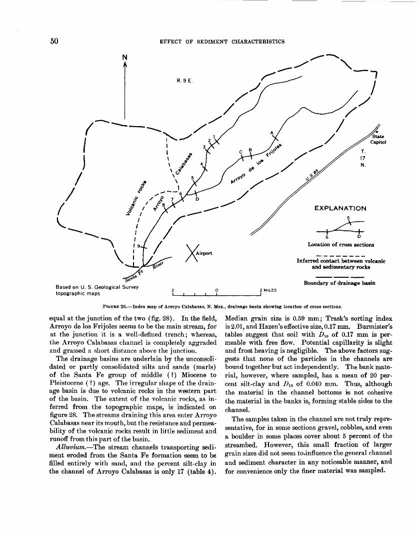
Looation.-Arroyo Calabasas (fig. 17) drains an area of about 48 square miles in central Santa Fe County, N. Mex. The drainage basin lies parallel to and about 1 mile northwest of U.S. Highway 85 between Santa F'e and the Santa Fe Airport (fig. 28), and a part of its htadwaters lies within the Santa· Fe city limits. Arroyo Calabasas is a tributary to the Santa Fe River . The Arroyo Calabasas drainage basin is shown on the following Geological Survey topographic maps: Santa Fe, Agua Fria, Turquoise Hill, Tetilla Peak, and Montoso Peak.
Annual preoipitation.-A 40-year record of precipitation for Santa Fe (table 1) gives a mean annual precipitation of 14.19 inches. Of this total, 10.69 inches fell during the months of April through October. At the Santa Fe Airport a 15-year record gives a mean annual precipitation of only 10.80 inches. A comparison of the same 11 years of record from the 2 stations shows an average of 3.1 inches less rainfall at the airport. The Sangre de Cristo Mountains to th~ east probably produce a sufficient orographic effect to cause this difference in rainfall between mouth and headwaters of Arroyo Calabasas. The drainage basin a pparently lies within a narrow zone of semiarid climate between the more humid mountains and the arid zone to the west.
Vegetation and land u.Ye.-Vegetational cover is poor except on the untrenched valley bottoms. Pinon and juniper grow on the hills. Grass is nearly absent except in the valleys, but slopes have a scant cover of Russian-thistle. Cattle and horses gra.ze the undissected valley bottoms. The few dwellings within the drainage basin apparently are owned by people who work in the city of Santa Fe. No land cultivation has been attempted within the drainage basin.
Physiography and geology.-Unlike the two areas described previously, no prominent escarpment forms the drainage divide and no pediment development has taken place. Instead, a dendritic drainage pattern has developed, dissecting the poorly consolidated sediments into a network of valleys and divides. Hilltops are convex, bordered by val1ey-side slopes of varying steepness depending on the activity of the adjacent ephemeral stream.
The Arroyo de los Frijoles is a major tributary to Arroyo Calabasas. Their drainage areas are about
50 EFFECT OF SEDIMENT CHARACTERISTICS
N
Based on U.S. Geological Survey topographic maps
2
R. 9 E.
0 2 MILES
17 N.
EXPLANATlON
Location of cross sections
Inferred contact between volcanic and sedimentary rocks
Boundary of drainage basin
FIGURE 28.-lndex map of Arroyo Calabasas, N.Mex., drainage basin showing location of cross sections.
equal at the junction of the two (fig. 28). In the field, Arroyo de los Frijoles seems to be the main stream, for at the junction it is a well-defined trench; whereas, the Arroyo Calabasas channel is completely aggraded and grassed a short distance above the junction.
The drainage basins are underlain by the unconsolidated or partly consolidated silts and sands (marls) of the Santa Fe group of middle ( ? ) Miocene to Pleistocene ( n age. The irregular shape of the drainage basin is due to volcanic rocks in the western part of the basin. The extent of the volcanic rocks, as inferred from the topographic maps, is indicated on figure 28. The streams draining this area enter Arroyo Cal·abasas near its mouth, but the resistance and permeability of the volcanic rocks result in little sediment and runoff from this part of the basin.
A.lluviu1n.-The stream channels transporting sediment eroded from the Santa Fe formation seem to be filled entirely with sand, and the percent silt-clay in the channel of Arroyo Calabasas is only 17 (table 4) .
Median grain size is 0.59 mm; Trask's sorting index is 2.01, and Hazen's effective size, 0.17 mm. Burmister's tables suggest that soil with D 10 of 0.17 mm is permeable with free flow. Potential capillarity is slight and frost heaving is negligible. The above factors suggests that none of the particles in the channels are bound together but act independently. The bank material, however, where sampled, has a mean of 20 percent silt-clay and Dto of 0.040 mm. Thus, although the material in the channel bottoms is not cohesive the material in the banks is, forming stable sides to the channel.
The samples taken in the channel are not truly representative, for in some sections gravel, cobbles, and even a boulder in some places cover about 5 percent of the streambed. However, this small fraction of larger grain sizes did not seem to.influence the general channel and sediment character in any noticeable manner, and for convenience only the finer material was sampled.
EROSION AND SEDIMENTATION IN A SEMIARID ENVIRONMENT 51
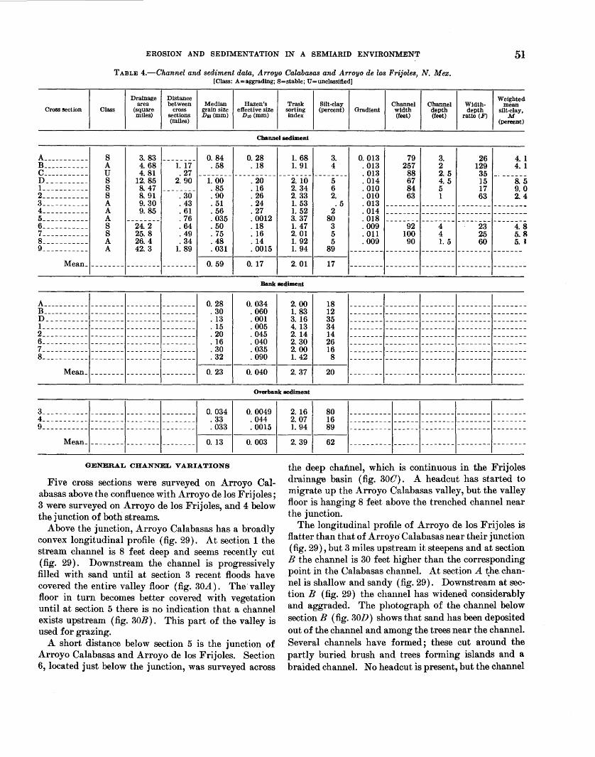
TABLE 4.-Channel and sediment data, Arroyo Calabasas and Arroyo de los Frijoles, N. Mex. [Class: A=aggrading; S=stable; U=unclassifted)
Drainage Distance Weighted area between Median Hazen's Trask Silt-clay Channel Channel Width-
Cross section Class (square cross grain size effective size mean
sorting (percent) Gradient width depth depth silt-clay, miles) sections Dso(mm) D1o (mm) index (feet)
(miles) (feet) ratio (F) M
(pereent)
Channel sediment
A ___________ s 3. 83 -------- 0. 84 0. 28 1. 68 3. 0. 013 79 3. 26 4. 1 B ___________ A 4. 68 I. I7 . 58 IS 1. 91 4 . OI3 257 2 129 4. 1 c ___________ u 4. 8I . 27 -------- ---------- -------- -------- . OI3 88 2. 5 35 -· ------n __________ s I2. 85 2. 90 I. 00 . 20 2. IO 5 . OI4 67 4. 5 I5 8. 5 I ___________ s 8. 47 -------- . 85 . 16 2. 34 6 . 010 84 5 17 9.0 2 ___________ s 8. 91 . 30 . 90 . 26 2. 33 2. . 010 63 1 63 2.4 3 ___________ A 9.30 . 43 . 51 . 24 1. 53 .5 . 013 -------- -------- -------- --------4 ___________ A 9. 85 . 61 . 56 . 27 1. 52 2 . 014 -------- -------- -------- --------5----------- A -------- . 76 . 035 . 0012 3. 37 80 . 018 -------- -------- -------- --------6 ___________ s 24. 2 . 64 . 50 . 18 1. 47 3 . 009 92 4 23 4. 8 7 ___________ s 25. 8 . 49 . 75 . 16 2.01 5 . 011 100 4 25 5. R 8 ___________ A 26. 4 . 34 . 48 . 14 1. 92 5 . 009 90 1. 5 60 5. 1 9 ___________ A 42. 3 1. 89 . 031 . 0015 1. 94 89 -------- -------- -------- -------- -------
Mean_ -------- -------- -------- 0. 59 0. 17 2. 01 I7 -------- -------- -------- -------- --------
Bank sediment
A ___________ ------------------------ 0. 28 0. 034 B ___________ -------- -------- -------- . 30 . 060 D __________ ------------------------ . 13 . 001 I ___________ ------------------------ . 15 . 005 2 ___________ -------- -------- -------- . 20 . 045 6 ___________ -------- -------- -------- . 16 . 040 7 ___________ ------------------------ . 30 . 035 8_---------- -------- -------- -------- . 32 . 090
Mean ________________________ _ 0. 23 0. 040
Overbank sediment
3 ___________ -------- -------- -------- 0. 034 0. 0049 2. I6 80 4 ___________ -------- -------- -------- . 33 . 044 2. 07 16 - - - - - - - - - - - - - - - - - - - - - - - - - - - - - - - - - - - - - - - -9 ___________ -------- -------- -------- . 033 . 0015 1. 94 89 ---------- ------ -------- -------- --------
1------1--------1-------1-------1 Mean_------------------------ 0. 13 0. 003 2. 39 62
GENERAL CHANNEL VARIATIONS
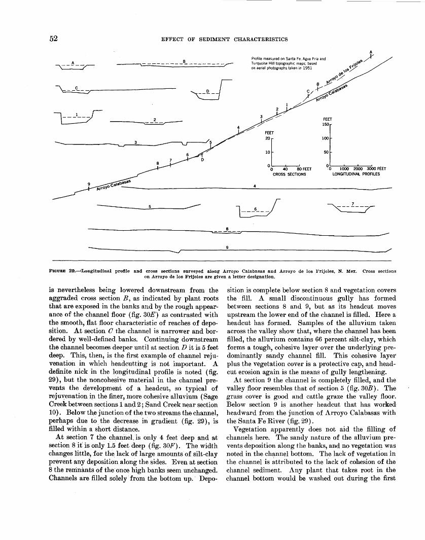
Five cross sections were surveyed on Arroyo Calabasas above the confluence with Arroyo de los Frijoles; 3 were surveyed onArroyo de los Frijoles, and 4 below the junction of both streams.
Above the junction, Arroyo Calabasas has a broadly convex longitudinal profile (fig. 29). At section 1 the stream channel is 8 feet deep and seems recently cut (fig. 29). Downstream the channel is progressively filled with sand until at section 3 recent floods have covered the entire valley floor (fig. 30A) . The· valley floor in turn becomes better covered with vegetation until at section 5 there is no indication that a channel exists upstream (fig. 30B). This part of the valley is used for grazing.
A short distance below section 5 is the junction of Arroyo Calabasas and Arroyo de los Frijoles. Section 6, located just below the junction, was surveyed across
the deep chatmel, which is continuous in the Frijoles drainage basin (fig. 300) . A headcut has started to migrate up the Arroyo Calabasas valley, but the valley floor is hanging 8 feet above the trenched channel near the junction.
The longitudinal profile of Arroyo de los Frijoles is flatter than that of Arroyo Calabasas near their junction (fig. 29), but 3 miles upstream it steepens and at section B the channel is 30 feet higher than the corresponding point in the Calabasas channel. At section A the. channel is shallow and sandy (fig. 29). Downstrea~ at section B (fig. 29) the channel has widened considerably and aggraded. The photograph of the channel below section B (fig. 30D) shows that sand has been deposited out of the channel and among the trees near the channel. Several channels have formed; these cut around the partly buried brush and trees forming islands and a braided channel. No headcut is present, but the channel
52 EFFECT OF SEDIMENT CHARACTERISTICS
~---~--/~---------------------
3
------------~5 __________ ____
8
9
Profile measured on Santa Fe, Agua Fria and Turquoise Hill topographic maps; based on aerial photographs taken in 1951
10
FEET 150
100
50 20L 0.
0 40 80 FEET 0 o 1000 2000 3000 FEET
CROSS SECTIONS LONGITUDINAL PROFILES
4
FIGURE 29 . .--lliongitudinal profile and cross sections surveyed along Arroyo Calabasas and Arroyo de los Frijoles, N. Mex. Cross sections on Arroyo de los Frijoles are given a letter designation.
is nevertheless being lowered downstream from the aggraded cross section B, as indicated by plant roots that are exposed in the banks and by the rough appearance of the channel floor (fig. 30E) as contrasted with the smooth, flat floor characteristic of reaches of deposition. At section 0 the channel is narrower and bordered by well-defined banks. Continuing downstream the channel becomes deeper until at section D it is 5 feet deep. This, then, is the first example of channel rejuvenation in which headcutting is not important. A definite nick in the longitudinal profile is noted (fig. 29), but the noncohesive material in the channel prevents the development of a headcut, so typical of reju~enation in the finer, more cohesive alluvium (Sage Creek between sections 1 a1,1d 2 ; Sand Creek near section 10). Below the junction of the two streams the channel, perhaps due to the decrease in gradient (fig. 29), is filled within a short distance.
At section 7 the chanliel. is only 4 feet deep and at section 8 it is only 1.5 feet deep (fig. 30F). The width changes little, for the. lack of large amounts of silt-clay prevent any deposition along the sides. Even at section 8 the remnants of the· once high banks seem unchanged. Channels are filled solely from the bottom up.· Depo-
sition is complete below section 8 and vegetation covers the fill. A small discontinuous gully has formed between sections 8 and 9, but as its headcut moves upstream the lower end of the channel is filled. Here a headcut has formed. Samples of the alluvium taken across the valley show that, where the channel has been filled, the alluvium contains 66 percent silt-clay, which forms a tough, cohesive layer·over the underlying predominantly sandy channel fill. This cohesive layer plus the vegetation cover is a protective cap, and headcut erosion again is the means of gully lengthening.
At section 9 the channel is completely filled, and the valley floor resembles that of section 5 (fig. 30B). The grass ~over is good and cattle graze the valley floor. Below section 9 is another headcut that has worked· headward from the junction of Arroyo Calabasas with the Santa Fe River (fig. 29).
Vegetation apparently does not aid the filling of channels here. The sandy nature of the alluvium prevents deposition along the banks, and no vegetation was noted in the channel bottom. The lack of vegetation in the channel is ~ttributed to the ·l~tck of cohesion of the channel sediment. Any plant that takes root in the channel bottom would be washed out during the first
EROSION AND SEDIMENTATION IN A SEMIARID ENVIRONMENT 53
flood as the sandy sediment is set in motion. The growth of weeds in a sandy channel downstream from a stock-water reservoir demonstrates that the channel sediments will support vegetation if undisturbed. The reservoir has retained all flow, and the seeds and plants were not washed out of the sediment by floods.
Blocks of bank-caved material were not common in the channel, probably because the low cohesion of the bank material allows crumbling and removal of fallen material by the next flood.
QUANTITATIVE CHANNEL VARIATIONS
To simplify this discussion the data obtained at the cross sections on Arroyo de los Frijoles have been plotted as if they were sections measured upstream from section 1 on Arroyo Calabasas (sections A-D, fig 31).
Moving downstream from section A (fig. 31), three areas of deposition are crossed at sections B; 3, 4, 5; and 8, 9. These sections are characterized by a high widthdepth ratio. Deposition causes filling of the channels from bottom to top without changing the width, thereby greatly increasing this ratio. Even in the trenched areas, this ratio is nearly 20, which greatly exceeds that in the areas of finer grained sediment.
Gradient is steep between sections B and 0 owing to recent incision. It is steep also at section 5 and where measured below section 9 near the Santa Fe River (X on fig. 29). These last two increases in gradient are due to the steepening of the valley floor by deposition. Each of the steeper reaches of deposition is associated with sediments of smaller grain size, although percent silt-clay is high only at sections 5 and 9. Perhaps this is because aggradation at section B is not so far advanced as at sections 5 and 9. This relation seems anomolous- finer sediment on the steepest parts of the longitudinal profile-but it.is simply the result of channel and flood-plain deposition as discussed previously.
The samples at sections 3, 4, and 8 are not so fine as those at sections 5 and 9 even though in areas of heavy aggradation, because they were taken in the last vestiges of the channels, which wen~ generally little more than sand-filled swales. However, the valley floor as a whole is characterized by finer sediments. For example, sediments adjacent to these inadequate channels contained up to 80 percent silt-clay (table 4). As mentioned above, D 50 and percent silt-clay show the greatest changes on the aggraded reaches. If the samples taken at sections 5 and 9 were not plotted on figure 31, percent silt-clay would show hardly any change; whereas, D 50 would decrease, but only slightly in a downstream direction.
The sorting index is highest at section 5 in the aggraded Arroyo Calabasas valley above the junction with Arroyo de los Frijoles.
SUMMARY OF ARROYO CALABASAS AREA
In a drainage area in which silt-clay occurs in small amounts the channels are filled from bottom to top. No plastering of fine sediments on the banks occurs, and vegetation is not an important cause of deposition. Vegetation, however, becomes important in stabilizing the deposit when flooding occurs over the entire valley floor.
Headcutting occurs only where channel-filling has been completed, and the coarser sediments are capped by a layer of fine material which supports a heavy grass cover. The suggestion here is that a channel in coarse sediment, when filled, may acquire the characteristics of an area of finer sediment.
The gradient of the valley increases on the reaches of deposition due to piling up of sediment on the valley floor. These steep gradient sections are covered with the finest sediments.
BAYOU GULCH, COLORADO
DESCRIPTION
Location.-Bayou Gulch (figs. 17, 32) drains an area of about 23 square miles in northeastern Doughts and northwestern Elbert Counties, Colo. It is a tributary of Cherry Creek, entering that stream at a point about 3 miles north of Franktown and about 5.5 miles south of Parker. State Highway 83 crosses Bayou Gulch about 0.4 mile above the mouth. The drainage basin is shown on the Castle Rock and Elizabeth quadrangles.
Annual precipitation.-Based on a 23-year record of precipitation at Parker (9E) (table 1) the mean annual precipitation is 13.42 inches. Of the total, 11.81 irtc;hes fell during the months of April through October. According to Thornth waite's climate classification ( 1941) the area is semiarid.
Vegetation and land use.-Vegetational cover is heavy. Pine trees grow on the divides and cottonwood trees are plentiful along the upper reaches of the creek. Alfalfa is raised on a terrace above the present flood plain. The rest of the drainage basin is used for grazing except for a few fields of wheat and corn on the divide.
Physiography and geology.- This drainage basin, except for the heavier vegetational cover and a general appearance of coarser sediment, resembles that of the Santa Fe area. A dendritic drainage pattern has incised the poorly consolidated sediments into a network
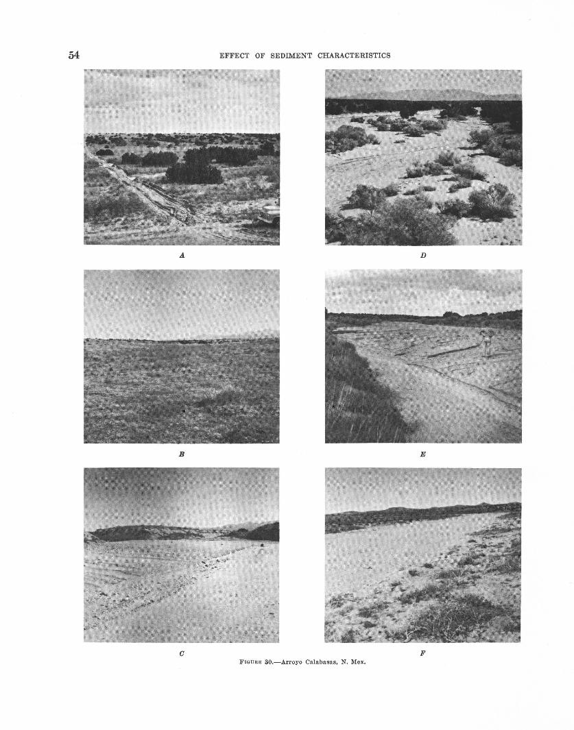
EFFECT OF SEDIMENT CHARACTERISTICS
D
B E
0 F FIGURE 30.-Arroyo Calabasas, N. Mex.
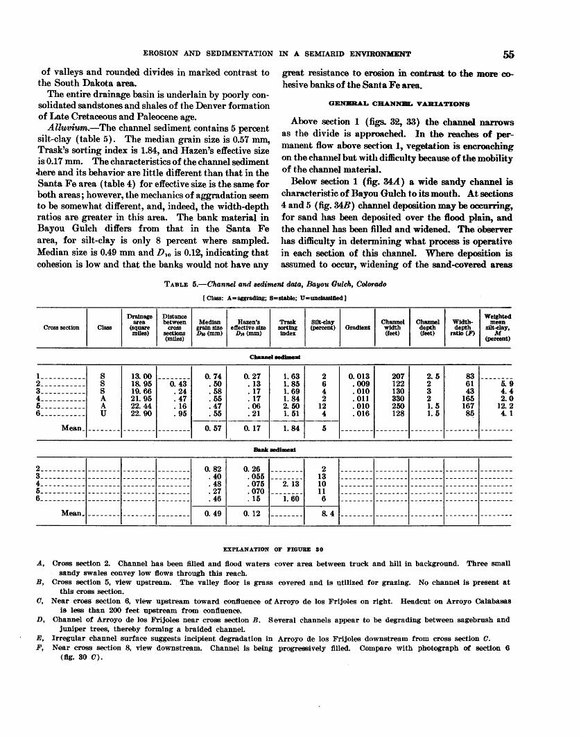
EROSION AND SEDIMENTATION IN A SEMIARID ENVIRONMENT
of valleys and rounded divides in marked contrast to the South Dakota area.
The entire drainage basin is underlain by poorly consolidated sandstones and shales of the Denver formation of Late Cretaceous and Paleocene age.
Alluvium.-The channel sediment contains 5 percent silt-clay (table 5). The median grain size is 0.57 nun, Trask's sorting index is 1.84, and Hazen's effective size is 0.17 mm. The characteristics of the channel sediment .here and its behavior are little different than that in the Santa Fe area (table 4) for effective size is the same for both areas; however, the mechanics of aggradation seem to be somewhat different, and, indeed, the width-depth ratios are greater in this area. The bank material in Bayou Gulch differs from that in the Santa Fe area, for silt-clay is only 8 percent where sampled. Median size is 0.49 mm and D 10 is 0.12, indicating that cohesion is low and that the banks would not have any
great resistance to erosion in contrast to the more· cohesive banks of the Santa Fe area.
GENJIRAL CliANNBL V ABIATIONS
Above section 1 (figs. 32, 33) the channel narrows as the divide is approached. In the reaches of permanent flow above section 1, vegetation is encroaching on the channel but with difficulty because of the mobility of the channel material.
Below section 1 (fig. 34A.) a wide sandy channel is characteristic of Bayou Gulch to its mouth. At sections 4 and 5 (fig. 34B) channel deposition may be occurring, for sand has been deposited over the flood plain, and the channel has been filled and widened. The observer has difficulty in detennining what prQCeSS is operative in each section of this channel. Where deposition is assumed to occur, widening of the sand-covered areas
TABLE 5.-Channel and sediment data, Bayou Gulch, Colorado
[Class: A=aggradlng; s-stable; U-=unelasslfled]
Drainage Distance area between
Cross section Class (square cross mOes) sections
(miles)
l ___________ s 13.00 --------2 ___________ s 18.95 0.43 3 ___________ s 19.66 . 24 4 ___________ A 21. 95 . 47 5 ___________ A 22.44 . 16 6 ___________ u 22. 90 . 95
Mean_ -------- -------- --------
2 ___________ -------- -------- --------3 ___________ -------- -------- --------4_---------- -------- ------- ·_ --------5 ___________ -------- -------- --------6_ ---------- - -- -- -- - -- -- - - - - - -- -----
Mean_ _ _ _ _ _ _ _ _ _ _ _ _ _ _ _ _ _ ______ _
Median grain siZe D50 (mm)
0. 74 .50 . 58 . 55 . 47 . 55
0.57
0. 82 . 40 . 48 . 27 . 46
0. 49
Hazen's Trask effective siZe sorting
Dto (mm) index
Channel aedbneat
0.27 1. 63 . 13 1. 85 . 17 1. 69 . 17 1. 84 . 06 2.50 . 21 1. 51
0. 17 1. 84
Balik &ediment
0.26 . 055 . 075 . 070 . 15
0. 12
2. 13
1. 60
Silt-clay (percent)
2 6 4 2
12 4
5
2 13 10 11 6
8.4
EXPLANATION OF FIGURE 80
Channel Channel Width-Weighted
mean Gradient width depth depth silt-clay,
(feet) (feet) ratio (F) M (percent)
0.013 207 2. 5 83 --------. 009 122 2 61 5.9 . 010 130 3 43 4.4 . 011 330 2 165 2.0 . 010 250 1. 5 167 12.2 . 016 128 1. 5 8~ 4.1
-------- -------- -------- -------- --------
A, Cross section 2. Channel has been filled and tlood waters cover area between truck and hill in background. Three small sandy swales convey low tlows through this reach.
B, Cross section 5, view upstream. The valley tloor is grass covered and is utilized for grazing. No channel is present at this cross section.
0, Near cross section 6, view upstream toward con.tluence of Arroyo de los Frijoles on right. Headcut on Arroyo Calabasas is less than 200 feet upstream from confluence.
D, Channel of Arroyo de los Frijoles near cross section B. Several channels appear to be degrading between sagebrush and juniper trees, thereby forming a braided channel.
E, Irregular channel surface suggests incipient degradation in Arroyo de los Frijoles downstream from cross section 0. F, Near cross section 8, view downstream. Channel is being progressively filled. Compare with photograph of section 6
(fig. 80 0).

56 EFFECT OF SEDIMENT CHARACTERISTICS
CROSS SECTIONS A Be D 12 3 4 5 678 9 X
120
100
80
60 • • 40
• 20 • •
• • 0 - -- _l__l________
• L I •• '
• • • f..-I
•• • !
80
60
40
20
0
I I "T I I I I I I I I
• • f- -• f- • -• • • • I- -
• f- -
I I • I I I
~t ~: : ~.;7 ~ ~:; :l A BC D 12 3 4 5 678 9 X
CROSS SECTIONS
0.020
0.015
0.010
0.005
VI 1.0 0::
1.1.1 1-1.1.1 :E
0.8 3 ~
0.6 ~ w N u;
0.4 z :;;: 0::
0.2 <!l z < 0
0 1.1.1 :E
FIGURE 31.-Variations in channel and sediment characteristics, Arroyo Calabasas and Arroyo de los Frijoles, N. Mex. frhe spacing of the cross sections along the abscissa is proportional to the distances betwePn cross sections in the field.
can be noted, but in contrast to the other areas investigated, there is no veneer of fine sediments over the coarser material and no encroachment of vegetation into the channel.
Below section 5, in order to confine the channel and thereby to prevent deposition of sand on the adjacent field and possible cutting around the bridge abutments, a dike has been built. The dike is sand piled in a ridge
R.66 W. R.65 W. N
EXPLANATION
Location of croes section
Boundary of drainage basin
1 MILE
FIGURE 32.-lndex map of Bayou Gulch, Colo., drainage basin showing location of cross sections.
along the channel, and although it looks unstable it seems to be effective at least for the low floodflows.
At the bridge over Bayou Creek, the gradient steepens in response to erosion (fig. 33). In contrast, the 1939 stream profile, obtained from the topographic maps, shows no such steepening. This steepening and the narrowing of the channel at section 6 (fig. 340) suggest strongly that erosion is occurring or has occurred in the past in the lower reaches of Bayou Gulch. Owing to the lack of cohesion in the sediment, no headcut is present, and as will be shown later, the only indication that erosion is occurring other than the profile change is the increase in gradient at section 6 and a decrease in the width-depth ratio. Above section 6, 2 feet of sand has been deposited on the surface adjacent to the channel, indicating recent deposition before incision.
Very little vegetation grows on what are assumed to be reaches of major deposition, sections 4 and 5. Although bank caving has contributed to channel widening, the caved material is removed by the next flood.
QUANTITATIVE CHANNEL VARIATIONS
The downstream changes are summarized in figure 35. The major change in channel width-depth ratio is at the aggrading reach where the channel becomes very wide and shallow, sections 4 and 5. Gradient varies little but it increases at section 6 where the steepening is attributed to incision of the channel. The percent
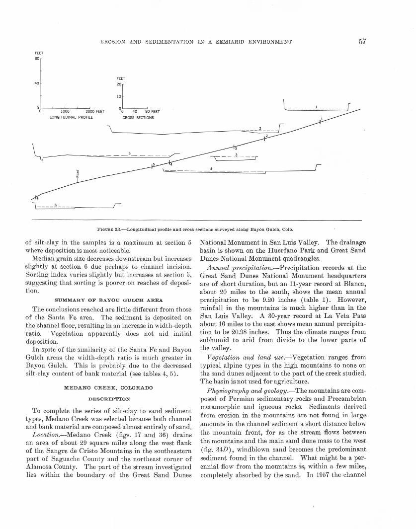
EROSION AND SEDIMENTATION IN A SEMIARID ENVIRONMENT 57 FEET
80
40
O 0:-----'--1.,.._000 _ _,_____,2000 FEET
LONGITUDINAL PROFILE
FEET
20L 10
0 0 40 80 FEET
CROSS SECTIONS
'~------------------~
FIGURE 33.- Longitudinal profile and cross sections surveyed along Bayou Gulch, Colo.
of silt-clay in the samples is a maximum at section 5 where deposition is most noticeable.
Median grain size decreases downstream but increases slightly at section 6 due perhaps to channel incision. Sorting index varies slightly but increases at section 5, suggesting that sorting is poorer on reaches of deposition.
SUMMARY OF BAYOU GULCH AREA
The conclusions reached are little different from those of the Santa Fe area. The sediment is deposited on the channel floor, resulting in an increase in width-depth ratio. Vegetation apparently does not aid initial deposition.
In spite of the similarity of the Santa Fe and Bayou Gulch areas the width-depth ratio is much greater in Bayou Gulch. This is probably due to the decreased silt-clay content of bank material (see tables 4, 5).
MEDANO CREEK, COLORADO
DESCRIPTION
To complete the series of silt-clay to sand sediment types, Medano Creek was selected because both channel and bank material are composed almost entirely of sand.
Location.-Medano Creek (figs. 17 and 36) drains an area of about 29 square miles along the west flank of the Sangre de Cristo Mountains in the southeastern part of Saguache County and the northeast corner of Alamosa County. The part of the stream investigated lies within the boundary of the Great Sand Dunes
National Monument in San Luis Valley. The drainage basin is shown on the Huerfano Park and Great Sand Dunes National Monument quadrangles.
Annual precipitation.-Precipitation records at the Great Sand Dunes National Monument headquarters are of short duration, but an 11-year record at Blanca, about 20 miles to the south, shows the mean annual precipitation to be 9.20 inches (table 1). However, rainfall in the mountains is much higher than in the San Luis Valley. A 30-year record at La Veta Pass about 16 miles to the east shows mean annual precipitation to be 20.98 inches. Thus the climate ranges from subhumid to arid from divide to the lower parts of the valley.
Vegetation and land use.- Vegetation ranges from typical alpine types in the high mountains to none on the sand dunes adjacent to the part of the creek studied. The basin is not used for agriculture.
Physiography and geology.-The mountains are composed of Permian sedimentary rocks and Precambrian metamorphic and igneous rocks. Sediments derived from erosion in the mountains are not found in large amounts in the channel sediment a short distance below the mountain front, for as the stream flows between the mountains and the main sand dune mass to the west (fig. 34D), windblown sand becomes the predominant sediment found in the channel. What might be a perennial flow from the mountains is, within a few miles, completely absorbed by the sand. In 1957 the channel
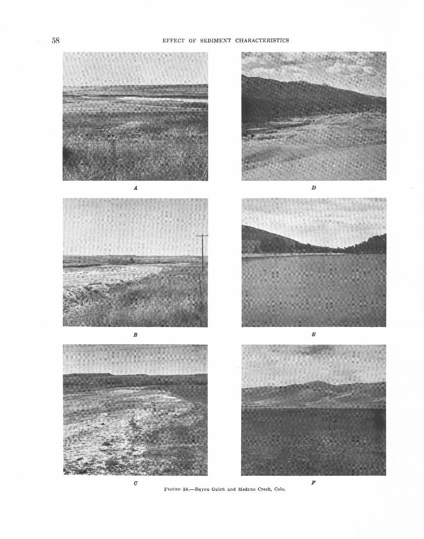
58 EFFECT OF SEDIMENT C:J;IARACTERISTICS
D
B E
0 F FIGURE 34.-Bayou Gulch nnd Medano Creek, Colo.
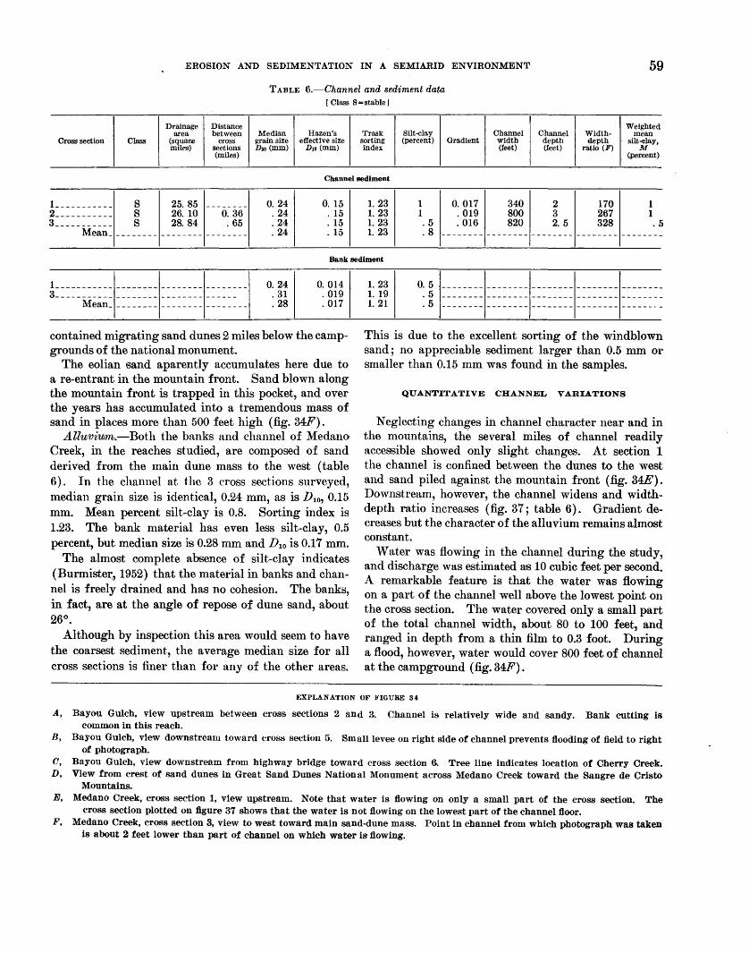
EROSION AND SEDIMENTATION IN A SEMIARID ENVIRONMENT 59
TABLE 6.-Channel and sediment data [ Class S =stable ]
Drainage Distance Weighted area between Median Hazen's Trask Silt-clay Channel Channel Width- mean
Cross section Class (squar.e cross grain size effective size sorting (percent) Gradient width depth depth silt-elay, miles) sections Dso (rom) Dro(mm) index (feet) (feet) ratio (F) M
(miles) ~ercent)
Channel sediment
L _ _ _ _ _ _ _ _ _ _ S 25. 85 _______ _ 2___________ s 26. 10 0. 36 3-- - - - - - - - - - s 28. 84 . 65
Mean _________ ----------------
0. 24 . 24 . 24 . 24
0. 15 . 15 . 15 . 15
1. 23 1. 23 1. 23 1. 23
1 1 .5 .8
0. 017 . 019 . 016
340 800 820
2 3 2. 5
170 267 328
1 1 . 5
Bank sediment
} ___________ -------- -------- --------3 ___________ -------- -------- ------
Mean ________________________ _
0. 24 . 31 . 28
0. 014 . 019 . 017
contained migrating sand dunes 2 miles below the campgrounds of the national monument.
The eolian sand aparently accumulates here due to a re-entrant in the mountain front. Sand blown along the mountain front is trapped in this pocket, and over the years has accumulated into a tremendous mass of sand in places more than 500 feet high (fig. 34F).
Alluvium.-Both the banks and channel of Medano Creek, in the reaches studied, are composed of sand derived from the main dune mass to the west (table 6). In the channel at the 3 cross sections surveyed, median grain size is identical, 0.24 mm, as is D10, 0.15 mm. Mean percent silt-clay is 0.8. Sorting index is 1.23. The bank material has even less silt-clay, 0.5 percent, but median size is 0.28 mm and D1o is 0.17 mm.
The almost complete absence of silt-clay indicates (Burmiste~, 1952) that the material in banks and channel is freely drained and has no cohesion. The banks, in fact, are at the angle of repose of dune sand, about 26°.
Although by inspection this area would seem to have the coarsest sediment, the average median size for all cross sections is finer than for any of the other areas.
1. 23 1. 19 1. 21
0. 5 . 5 .5
This is due to the excellent sorting of the windblown sand; no appreciable sediment larger than 0.5 mm or smaller than 0.15 mm was found in the samples.
QUANTITATIVE CHANNEL VARIATIONS
Neglecting changes in channel character near and in the mountains, the several miles of channel readily accessible showed only slight changes. At section 1 the channel is confined between the dunes to the west and sand piled against the mountain front (fig. 34E). Downstream, however, the channel widens and widthdepth ratio increases (fig. 37; table 6). Gradient decreases but the character of the alluvium remains almost constant.
Water was flowing in the channel during the study, and discharge was estimated as 10 cubic feet per second. A remarkable feature is that the water was flowing on a part of the channel well above the lowest point on the cross section. The water covered only a small part of the total channel width, about 80 to 100 feet, and ranged in depth from a thin film to 0.3 foot. During a flood, however, water would cover 800 feet of channel at the campground (fig. 34F).
EXPLANATION OF FIGURE 34
A, Bayou Gulch, view upstream between cross sections 2 and 3. Channel is relatively wide and sandy. Bank cutting is common in this reach.
B, Bayou Gulch, view downstream toward cross section 5. Small levee on right side of channel prevents flooding of field to right of photograph.
0, Bayou Gulch, view downstream from highway bridge toward cross section 6. Tree line indicates location of Cherry Creek. D, View from crest of sand dunes in Great Sand Dunes National Monument across Medano Creek toward the Sangre de Cristo
Mountains. E, Medano Creek, cross section 1, view upstream. Note that water is flowing on only a small part of the cross section. The
cross section plotted on figure 37 shows that the water is not flowing on the lowest part of the channel floor. F, Medano Creek, cross section 3, view to west toward main sand-dune mass. Point in channel from which photograph was taken
is about 2 feet lower than part of channel on which water is flowing.
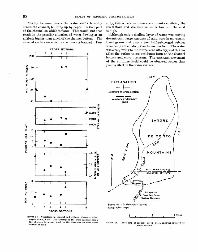
60 EFFECT OF SEDIMENT CHARACTERISTICS
Possibly between floods the water shifts laterally across the channel, building up by deposition that part of the channel on which it flows. This would and does result in the peculiar situation of water flowing at an altitude higher than much of the channel bottom. The channel surface on which water flows is braided. Pos-
0 ~ c( 0::::
I 1-0.. UJ 0
± 1-0
~
>c( ...J (.)
I 1-...J c;; 1-z UJ (.) 0:::: IJJ 0..
X IJJ 0 z C!' z ~ 0:::: 0 fJ)
200
160
120
80
-
3
2 >--
1
CROSS SECTIONS
2 3 4 5
• •
•
I I I I
• • • I I • I I
I
• I
2
I
•
I I
• •
I I I
3 4 5
CROSS SECTIONS
6
0.8
0.4
-0
6
LJ' ~(/) (/)0::::
IJJ ZI-UJ c(:::E a::_ e,...J
...J z<:::E az UJ-:::E
FIGURE 35.-Variations in channel and sediment characteristics, Bayou Gulch, Colo. The spacing of the cross sections along the abscissa is proportional to the distances between cross sections in field.
sibly, this is because there are no banks confining the small flows and also because water loss into the sand is high.
Although only a shallow layer of water was moving downstream, large a1nounts of sand were in movement. Sand grains and even a few half-submerged pebbles were being rolled along the channel bottom. The water was clear, owing to the low percent silt-clay, and this enabled the author to see antidunes form on the channel bottom and move upstream. The upstream movement of the antidune itself could be observed rather than just its effect on the water surface.
EXPLANATION 3 - I
Location of cross section
Boundary of drainage basin
N
Headquarters
National Monument
Based on U.S. Geological Survey topographic rna ps
2 0 2 MILES
FIGURE ;{~-Index map of Medano Creek, Colo., showing location of cross sections.
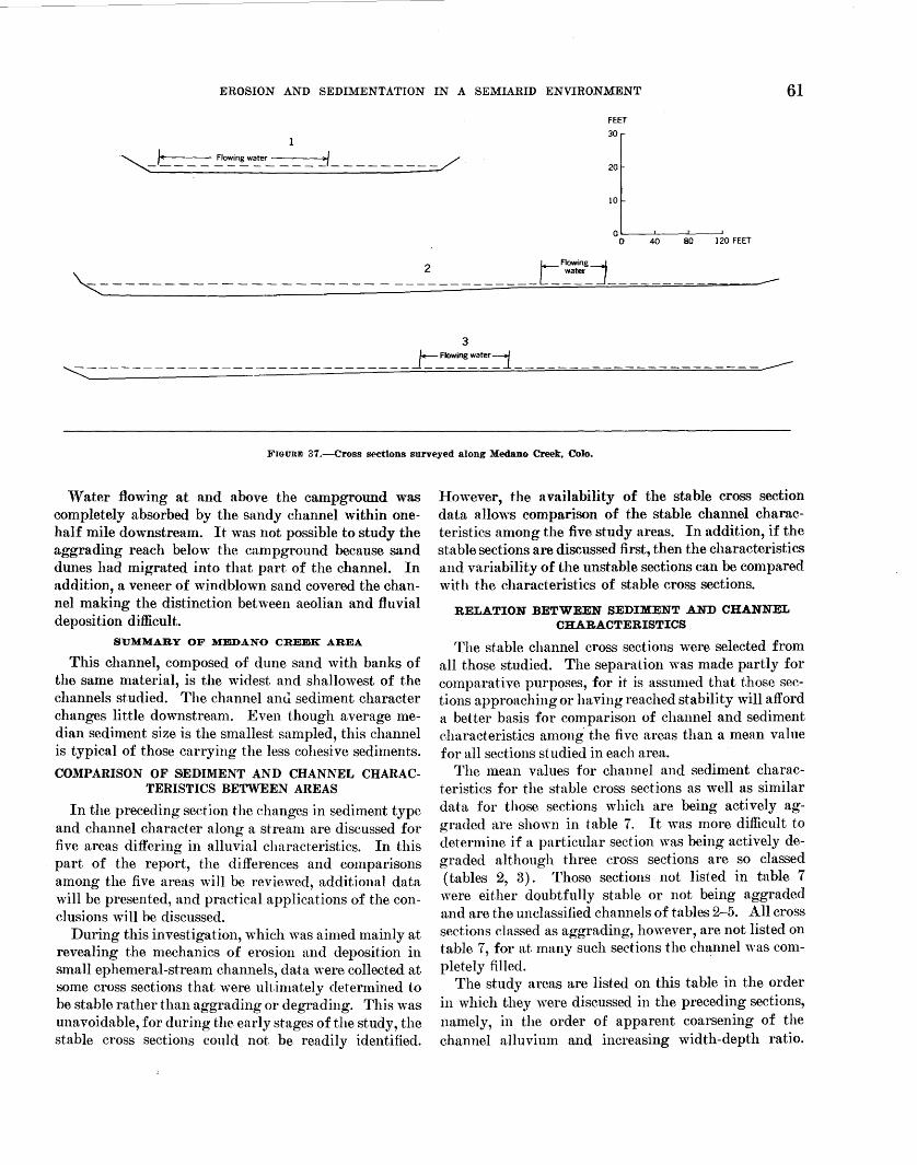
EROSION AND SEDIMENTATION IN A SEMIARID ENVIRONMENT 61
3 f+-. Flowing water~ " _____________________________ J ____ __ i_
FIGURE 37.--cross sections surveyed along Medano Creek, Colo.
Water flowing at and above the campground was completely absorbed by the sandy channel within onehalf mile downstream. It was not possible to study the aggrading reach below the campground because sand dunes had migrated into that part of the channel. In addition, a veneer of windblown sand covered the channel making the distinction between aeolian and fluvial deposition difficult.
SUMMARY OF MEDANO CREEK AREA
This channel, composed of dune sand with banks of the same material, is the widest and shallowest of the channels studied. The channel anti sediment character changes little downstream. Even though average median sediment size is the smallest sampled, this channel is typical of those carrying the less cohesive sediments.
COMPARISON OF SEDIMENT AND CHANNEL CHARAC-TERISTICS BETWEEN AREAS
In the preceding section the changes in sediment type and channel character along a stream are discussed for five areas differing in alluvial characteristics. In this part of the report, the differences and comparisons among the five areas will be reviewed, additional data will be presented, and practical applications of the conclusions will be discussed.
During this investigation, which was aimed mainly at revealing the mechanics of erosion and deposition in small ephemeral-stream ehannels,·data were eollected at some eross sections that were ultimately determined to be stable rather than aggrading or degrading. This was unavoidable, for during the early stages of the study, the stable eross seetions could not be readily identified.
However, the availability of the stable cross section data allows comparison of the stable channel characteristics among the five study areas. In addition, if the stable sections are discussed first, then the characteristics and variability of the unstable sections can be compared with the characteristics of stable cross sections.
RELATION BETWEEN SEDIMENT AND CHANNEL CHARACTERISTICS
The stable channel cross sections were selected from all those studied. The separation was made partly for comparative purposes, for it is assumed that those sections approaching or having reached stability will afford a better basis for comparison of channel and sediment eharacteristics among the five areas than a mean value for all sections studied in each area.
The mean values for channel and sediment characteristics for the stable cross sections as well as similar data for those sections which are being actively aggraded are shown in table 7. It was more difficult to determine if a particular section \Yas being actively degraded although three cross sections are so classed (tables 2, 3). Those sections not listed in table 7 were either doubtfully stable or not being aggraded and are the unclassified channels of tables 2-5. All cross sections classed as aggrading, however, are not listed on table 7, for at many such sections the cha:nnel was completely filled.
The study areas are listed on this table in the order in which they were discussed in the preceding sections, namely, in the order of apparent coarsening of the channel alluvium and increasing width-depth ratio.
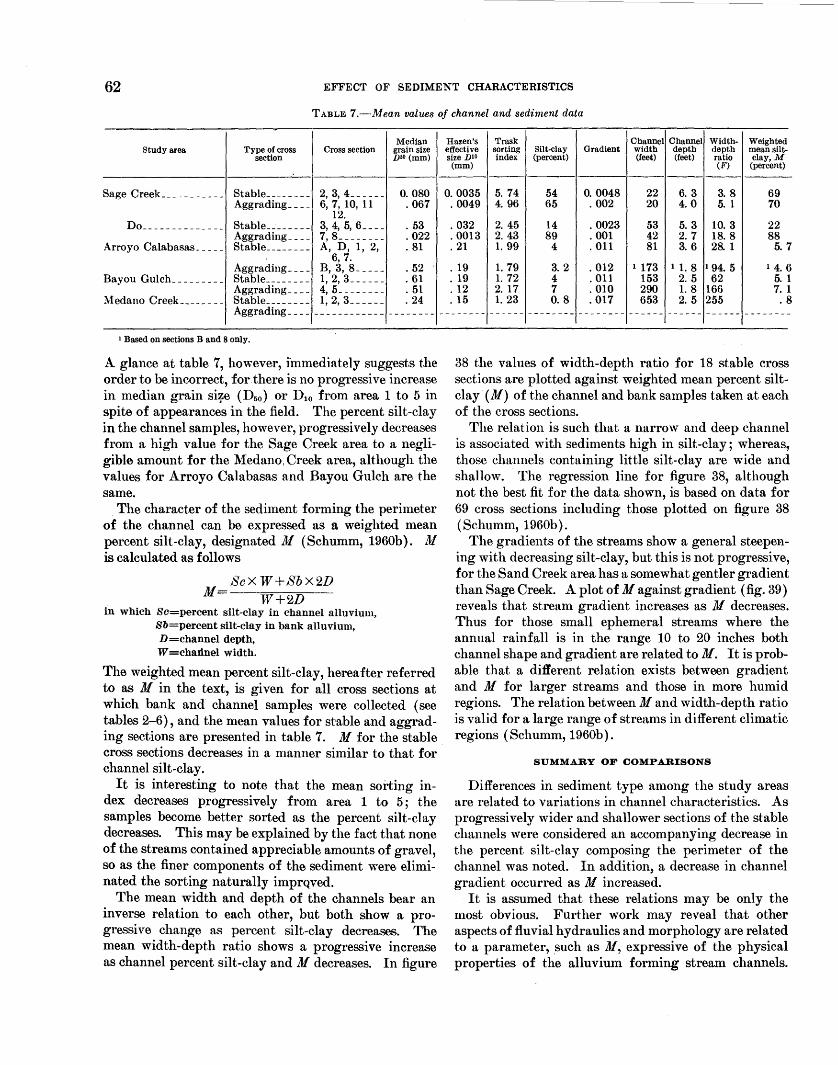
62 EFFECT OF SEDIMENT CHARACTERISTICS
TABLE 7.-·Mean values of channel and sediment data
Median Study area Type of cross Cross section grain size
section nso (mm)
Sage Creek ___________ Stable ________ 2, 3, 4_----- 0.080 Aggrading ____ 6, 7, 10, 11 . 067
12. I>o ______________ Stable ________ 3, 4, 5, 6- - - - . 53
Aggrading ____ 7, 8 ________ . 022 Arroyo Calabasas _____ Stable ________ A, I>, 1, 2, . 81
6, 7. Aggrading ____ B, 3, 8 _____ . 52
Bayou Gulch _________ Stable ________ 1, 2, 3 ______ . 61 Aggrading ____ 4, 5 ________ . 51
~fedano Creek ________ Stable ________ 1, 2, 3 ______ . 24 Aggrading ____ ------------ --------
1 Based on sections Band 8 only.
A glance at table 7, however, i'mmediately suggests the order to be incorrect, for there is no progressive increase in median grain si=?e ( Dso) or D10 from area 1 to 5 in spite of appearances in the field. The percent silt-clay in the channel samples, however, progressively decreases from a high value for the Sage Creek area to a negligible amount for the Medano, Creek area, although the values for Arroyo Calabasas and Bayou Gulch are the same.
The character of the sediment forming the perimeter of the channel can be expressed as a weighted mean percent silt-clay, designated M (Schumm, 1960b}. ~/
is calculated as follows
ScXW+SbX2D M= W+2D
in which Sc=percent silt-clay in channel alluvium, Sb=percent silt-clay in bank alluvium, D=channel depth, W =cha:d.nel width.
The weighted mean percent silt-clay, hereafter referred to as M in the text, is given for all cross sections at which bank and· channel samples were collected (see tables 2-6}, and the mean values for st·able and aggrading sections are presented in table 7. M for the stable cross sections decreases in a manner similar to that for channel silt-clay.
It is interesting to note that the mean sorting index decreases progressively from area 1 to 5; the samples become better sorted as the percent silt-clay decreases. This may be explained by the fact that none of the streams contained appreciable amounts of gravel, so as the finer components of the sediment were eliminated the sorting naturally imprqved.
The mean width and depth of the channels bear an inverse relation to each other, but both show a progressive change as percent silt-clay decreases. The mean width-depth ratio shows a progressive increase as channel percent silt-clay and A/ decreases. In figure
Hazen's Trask Channel Channel Width- Weighted effective sorting Silt-clay Gradient width depth depth mean silt-size DIO index (percent) (feet) (feet) ratio clay, M
(mm) (F) (percent)
0.0035 5. 74 54 0. 0048 22 6. 3 3. 8 69 . 0049 4~ 96 65 . 002 20 4.0 5. 1 70
. 032 2. 45 14 . 0023 53 5. 3 10.3 22
. 0013 2. 43 89 . 001 42 2. 7 18.8 88
. 21 1. 99 4 . 011 81 3. 6 28. 1 5. 7
. 19 1. 79 3. 2 . 012 1 173 11.8 1 94.5 1 4. 6
. 19 1. 72 4 . 011 153 2. 5 62 5. 1
. 12 2. 17 7 . 010 290 1.8 166 7. 1
. 15 1. 23 0. 8 . 017 653 2. 5 255 . 8 -------- ------ -------- -------- ------ ------ ------ --------
38 the values of width-depth ratio for 18 stable cross sections are plotted against weighted mean percent siltclay· ( M) of the channel and bank samples taken at each of the cross sections.
The relation is such that a narrow and deep channel is associated with sediments high in silt-clay; whereas, those channels containing little silt-clay are wide and shallow. The regression line for figure 38, although not the best fit for the data shown, is based on data for 69 cross sections including those plotted on figure 38 (Schumm, 1960b).
The gradients of the streams show a general steepening with decreasing silt-clay, but this is not progressive, for the Sand Creek area has a somewhat gentler gradient than Sage Creek. A plot of M against gradient (fig. 39) reveals that stream gradient increases as M decreases. Thus for those small ephemeral streams where the annual rainfall is in the range 10 to 20 inches both channel shape and gradient are related toM. It is probable that a different relation exists between gradient and M for larger streams and those in more humid regions. The relation between M and width-depth ratio is valid for a large range of streams in different climatic regions (Schumm, 1960b).
SUMMARY OF COMPARISONS
Differences in sediment type among the study areas are related to variations in channel characteristics. As progressively wider and shallower sections of the stable channels were considered an accompanying decrease in the percent silt-clay composing the perimeter of the channel was noted. In addition, a decrease in channel gradient occurred as M increased.
It is assumed that these relations may be only the most obvious. Further work may reveal that other aspects of fluvial hydraulics and morphology are related to a parameter, .such as lJf, expressive of the physical properties of the alluvium forming stream channels.
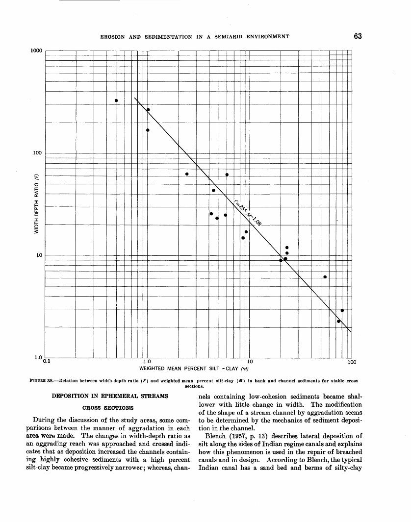
EROSION AND SEDIMENTATION IN A SEMIARID ENVIRONMENT 63
1000
• '\1\..
r-.~
•• ~ I
"" -" 100
"\. ~
• "' •• ~
•'" ' ~~~
";ss • • r\ ~' • f\ ~a
-~~ • • ~
10
"\.
"' ' • ~
r"\. I
I '\ I'\ ~
~ ~
1\
l.O 0.1 1.0 10 100 WEIGHTED MEAN PERCENT SILT -CLAY (M)
FIGURE 38.-Relation between width-depth ratio (F) and weighted mean perc~nt silt-clay (M) In bank and channel sediments for stable cross sections.
DEPOSITION IN EPHEMERAL STREAMS
CROSS SECTIONS
During the discussion of the study areas, some comparisons between the manner of aggradation in each area. were made. The changes in width -depth ratio as an aggrading reach was approached and crossed indicates that as deposition increased the channels containing highly cohesive sediments with a high percent silt-clay became progressively narrower; whereas, chan-
nels containing low-cohesion sediments became shallower with little change in width. The modification of the shape of a stream channel by aggradation seems to be determined by the mechanics of sediment deposition in the channel.
Blench (1957, p. 13) describes lateral deposition of silt along the sides of Indian regime canals and explains how this phenomenon is used in the repair of breached canals and in design. According to Blench, the typical Indian canal has a sand bed and berms of silty-clay
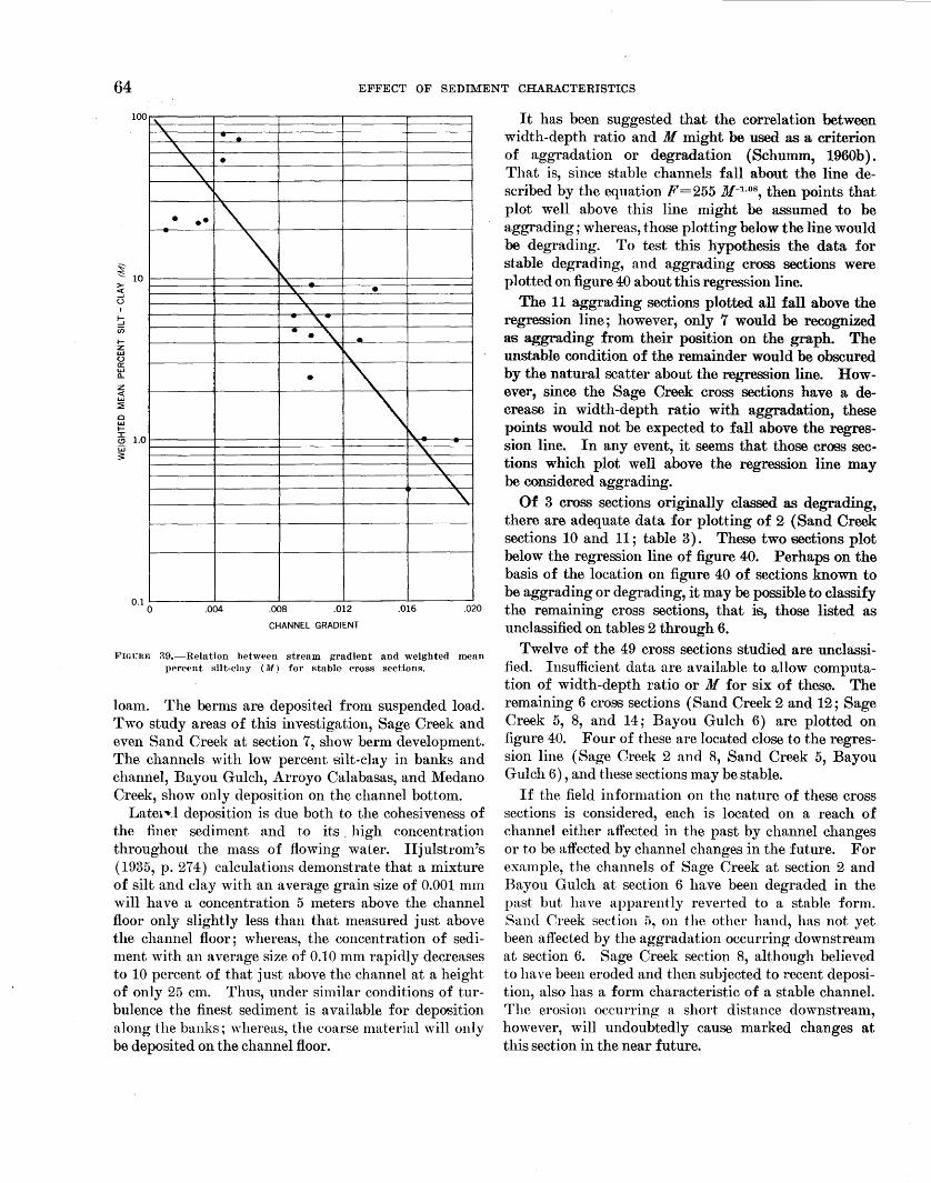
64 EF-FECT OF SEDIMENT CHARACTERISTICS
100
~ '-'- 10 >-:s 0
I
s (j)
1-z Ul 0 0: w a... z < 1J..I :2: 0 l&J 1--
ili 1.0 w ~
'" "' ' . . \.
' • '\.
"\ .....
• •• -" \
" -_'\. • ' \. .. ,-
• •"\. . "I\.
• ' \ ' " "\.
"' \. ' '\.
It has been suggested that the correlation between width-depth ratio and M might be used as a criterion of aggradation or degradation (Schumm, 1960b). That is, since stable channels fall about the line described by the equation F=255 M-1
•08
, then points that plot well above this line might be assumed to be aggrading; whereas, those plotting below the line would be degrading. To test this hypothesis the data for stable degrading, and aggrading cross sections were plotted on figure 40 about this regression line.
The 11 aggrading sections plotted all fall above the regression line; however, only 7 would be recognized as aggrading from their position on the graph. The unstable condition of the remainder would be obscured by the natural scatter about the regression line. However, since the Sage Creek cross sections have a decrease in width-depth ratio with aggradation, these points would not be expected to fall above the regression line. In any event, it seems that those cross sections which plot well above the regression line may be considered aggrading.
Of 3 cross sections originally classed as degrading, there are adequate data for plotting of 2 (Sand Creek sections 10 and 11; table 3). These two sections plot below the regression line of figure 40. Perhaps on the basis of the location on figure 40 of sections known to be aggrading or degrading, it may be possible to classify
0.1 0 .004 .008 .012
CHANNEL GRADIENT
.016 .o2o the remaining cross sections, that is, those listed as unclassified on tables 2 through 6.
FIGURE 39,-Relation between stream gradient and weighted mean percent silt-clay (M) for stable cross sectiom'l.
loam. The berms are deposited from suspended load. Two study areas of this investigation, Sage Creek and even Sand Creek at section 7, show berm development. The channels with low percent silt-clay in banks and channel, Bayou Gulch, Arroyo Calabasas, and Medano Creek, show only deposition on the channel bottom. Latm~J deposition is due both to the cohesiveness of
the finer sediment and to its . high concentration throughout the mass of flowing water. Hjulstrom's ( 1935, p. 27 4) calculations demonstrate that a mixture of silt and clay with an average grain size of 0.001 mm will have a concentration 5 meters above the channel floor only slightly less than that measured just above the channel floor; whereas, the concentration of sediment with an average size of 0.10 mm rapidly decreases to 10 percent of that just above the channel at a height of only 25 em. Thus, under similar conditions of turbulence the finest sediment is available for deposition along the banks; whereas, the coarse material will only be deposited on the channel floor.
Twelve of the 49 cross sections studied are unclassified. Insufficient data are available to allow computation of width-depth ratio or M for six of these. The remaining 6 cro86 sections (Sand Creek 2 and 12; Sage Creek 5, 8, and 14; Bayou Gulch 6) are plotted on figure 40. Four of these are located close to the regression line (Sage Creek 2 and 8, Sand Creek 5, Bayou Gulch 6), and these sections may be stable.
If the field information on the nature of these cross sections is considered, each is located on a reach of channel either affected in the past by channel changes or to be affected by channel changes in the future. For example, the channels of Sage Creek at section 2 and Bayou Gulch at section 6 have been degraded in the past but have apparently reverted to a stable form. Sand Creek section 5, on the other hand, has not yet been affected by the aggradation occurring downstream at section 6. Sage Creek section 8, although believed to have been eroded and then subjected to recent deposition, also has a form characteristic of a stable channel. The erosion occurring a short distance downstream, however, will undoubtedly cause marked changes at this section in the near future.
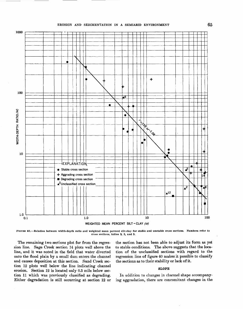
EROSION AND SEDIMENTATION IN A SEMIARID ENVIRONMENT 65 1000
100
10
1.0 0.1
-
• i\~
~-
" • ""\
EXPLANATION,
• Stable cross section
+ Aggrading cross section
• Degrading cross section
• 2unclassified cross section
1.0
~
~ ..
,-" ~
\.
• " \. ."J
' "'\
• • •
+
A'
~ "\~IS'~
i \ ~,
. ~\ • H •-~ " ~ _a
" • "\. • s ...
1'\. IT 1~
'~ .2 r\ ·.a
.12 \, • '
II
10 100
WEIGHTED MEAN PERCENT SILT-CLAY (M)
FIGURE 40.-Relation between width-depth ratio and weighted mean percent silt-clay for stable and unstable cross sections. Numbers refer to cross sections, tables 2, 3., and 5.
The remaining two sections plot far from the regression line. Sage Creek section 14 plots well above the line, and it was noted in the field that water diverted onto the flood plain by a small dam enters the channel and causes deposition at this section. Sand Creek section 12 plots well below the line indicating channel erosion. Section 12 is located only 0.3 mile below section 11 which was previously classified as degrading. Either degradation is still occurring at section 12 or
the section has not been able to adjust its form as yet to stable conditions. The above suggests that the location of the unclassified sections with regard to the regression line of figure 40 makes it possible to classify the sections as to their stability or lack of it.
SLOPE
In addition to changes in channel shape accompanying aggradation, there are concomitant changes in the
66 EFFECT OF SEDIMENT CHARACTERISTICS
longitudinal profile of the stream. As is well known and was noted in each of the study areas, stream gradient is decreased on the upstream part of the aggrading reach. The slopes n1easured at the cross sections in the field do not show this in all cases (figs. 22, 27, 31, 35) but the longitudinal profiles do (figs. 19, 24, 29, 33).
All the graphs and longitudinal profiles show an increase in gradient downstream on the aggarding reach. In all aggrading channels this steepening enables the stream to increase its capacity for sediment load. Generally, incision occurs on the steepened reach (Schumm and Hadley, 1957). Where the channel is completely filled by deposition on the steeper reach, the anom:;tlous situation arises that the finer alluvium is found on the steeper aggrading reaches. See section 10 on figure 27 and sections B, 5, and X on figure 31.
The data collected at cross sections located on the aggrading reaches of the study areas give a fairly complete picture of what might occur at one cross section during the complete filling of the channel. During the discussion of the historic changes on Sand Creek it was concluded that the upstream limit of aggradation shifted upchannel as aggradation progressed. Channel aggradation, therefore, may be somewhat analagous to backfilling of the channel, rather than to a general filling of the channel simultaneously over a long distance·.
Assuming that aggradation begins at one particular point in the channel and then progresses upstream, it is possible to outline the steps in the complete cycle of aggradation and retrenching of that channel. Gradient is decreased by the initial channel deposit, and if it is not swept away by the next flood, this alluvial deposit induces further deposition in the channel. As the channel fills, the zone where major deposition of the coarser fraction of the alluvium occurs, migrates upchannel, and progressively finer sediment is deposited over the originally coarser grained sediment at the site of initial aggradation.
In several reaches of the Sand Creek and Arroyo Calabasas channels the sediments in the banks, where exposed by trenching, show a progressive coarsening of the alluvium from top to bottom of the deposit. Thus, at any one point in an aggrading channel, sediment size generally decreases as deposition progresses, and accompanying this is a decrease in channel size. When the channel is almost filled overbank deposition becomes very important. Continued overbank deposition of fine sediment causes a steepening of the valley floor. In a short time the channel is completely filled, and floodwaters cover almost the entire valley floor. Nevertheless, a short distance upstream the channel still exists, but it is being filled. The progressive shallowing
of the channel downstream is best shown between cross sections 6 and 9 on figure 24 as is the decrease in gradient as deposition in the channel begins (fig. 24, sections 6-8). The steepening of the gradient after complete filling of the channel (fig. 24, sections 9, 10) is also clearly shown (see also Schumm and Hadley, 1957, figs. 3B, 6A). Accompanying the change in gradient, percent silt-clay increases from section 6 to a maximum for all sections at 9, and median .grain size decreases from cross section 6 to 9.
In the trench a hove the aggrading reach on Sand Creek the sediments exposed in the bank between sections 5 and 6 from bottom to top are: 2 feet coarse g:.;a vel and cobbles; 6 feet coarse-to-fine sand and silt ; 6 feet of silt and clay with some fine sand. In the trench below the aggrading reach the same type of sequence occurs. From auger holes bored in the recent sediments, the gravel layer was found at the level of the channel floor between sections 5 and 6, at a depth of 2.5 feet at section 6; at 4.0 feet at section 7; and at 9.3 feet at section 8. The gravel reappears in the channel floor just above the country road, a,p.d its inferred relation to the longitudinal profile is shown by the dashed line below the profile on figure 24. This gravel layer may be the level of the channel floor before aggradation. If this is so, the convexity on the longitudinal profile shown between sections 6 and 10 above the gravel layer (fig. 24) is probably the recent channel and valley fill. Renewed trenching has occurred on the lower end of the deposit between sections 10 and 11. This cycle of channel filling, aggradation and steepening of the valley floor, and retrenching of the alluvium has been previously discussed as the common pattern in semiarid valleys (Schumm and Hadley, 1957).
To summarize, the decrease in grain size and increase in silt-clay across an aggrading reach, as shown on figures 22, 27, 31, and 35, indicates that as one moves downstream along an aggrading ephemeral stream relatively coarse sediment will be found upstream and the finer sediments will be found on the downstream edge of the deposit. In addition, there should also be an upward decrease in grain size from bottom to top of the deposit at any one location. The change in gradient is from a decrease in the filling channel to an increase where the channel has been filled and flood-plain deposition is dominant.
In the studying of aggrading channels, it is important to recognize and to anticipate marked variations in channel character and sediment type downstream due to aggradation. In other words, the orderly relation shown in many streams will be disrupted by aggradation, and anoma~ies are to be expected. This is especially true of channels which do not have permanent
EROSION AND SEDIMENTATION IN A SEMIARID ENVIRONMENT 67
flow between floods. The generally assumed ability of a stream to adjust to changed conditions does not apply to ephemeral streams in channels that are being rapidly aggraded. The ephemeral streams, when attempts to adjust fail, follow a pattern of alternate deposition and erosion (Schumm and Hadley, 1957).
VEGETATION
Observations have shown that the influence of vegetation differed between the silty and sandy study areas. In silty sediments, typified by the Sage Creek area, growth of vegetation was rapid on the modern sediments. The photographs of the Sage Creek channel (figs. 20 0-F; 210, E, F) show vegetation on the banks, berm, and channel bottom. Figure 21E shows that vegetation quickly establishes itself after the spring floods. In a channel the vegetation grows only on areas where deposition has occurred since channel incision. V egetation, therefore, may aid deposition once it has begun, but fresh alluvium in the channel seems necessary for growth of vegetation.
The establishment of vegetation on the noncohesive, highly mobile sediments is much more difficult. These channels were remarkably free of vegetation even when aggrading (figs. 25B, 0; 300, E, F), but as soon as a veneer of finer sediment was deposited on the sand, vegetation began to encroach on the channel and (figs. 25D, E; 30A, B) eventually completely covered it.
As discussed in the description of Arroyo Calabasas, vegetation does grow in the sandy channels when undisturbed-such as below dams that have not spilled recently-but flow in the streams of high bed movement will cause washing out of seeds and plants and prevent the development of permanent vegetation. Vegetation, therefore, will accelerate deposition but in the areas studied is not the cause of it.
CAUSES OF DEPOSITION
One of the primary purposes of this investigation is to determine, if possible, the reason for aggradation in the study areas. The major part of the sediment load is derived from different sources in the different areas. In the Bayou Gulch and Arroyo Calabasas drainage basins the sediment is produced by slope erosion and by channel erosion along the dendritic patterned tributaries and main channel. The sediment is not derived from any restricted zone within the basin, but each tributary conveys sediment to the main channel. In the Sage and Sand Creek basins, most of the sediment is derived from an escarpment forming the headwater divide.
In any event, each of the study areas is one of high sediment production. No matter what its source, high
sediment yields are probably the cause of aggradation in these stream channels. The increase in sediment yields and retrenching of the Sage, Sand, and Arroyo Calabasas channels cannot be attributed to any special cause, such as climate change or overgrazing. In the absence of such evidence the channel cutting can be related only to the presence of reaches of steeper gradient in each valley, which have been built up by deposition to be inevitably trenched. This sequence of events has been proposed as the normal cycle of development of ephemeral streams (Schumm and Hadley, 1957).
Although causes for aggradation may not be completely understood, the reason for its occurrence in a particular segment of a stream channel should be considered. It seems that aggradation in these channels is associated with segments of the stream that receive only small contributions from tributaries. The loss of water into the channels of ephemeral streams (Babcock and Cushing, 1941) and its function in promoting aggradation (Schumm and Hadley, 1957) have been studied and found important. It is logical to assume that in those reaches of the channel where contributions of runoff from tributaries is minor, the concentration of sediment will increase and aggradation might occur. Other factors would undoubtedly complicate this relation, and it is know that the entrance of a steep-gradient tributary often results in deposition at and below its junction with t11e main channel.
Listed in the tables giving the basic data for each study area are the drainage area above each section and the stream channel length between each section (tables 2-5). The increase in drainage area per mile of channel length above and on the aggrading reaches are presented in table 8. A comparison of the ratios shows a marked differenee. In each area, except that of the Arroyo de los Frijoles and Arroyo Calabasas, deposition is occurring in reaches where the increase of drainage area is much less per unit length of channel than on the stable reaches. As previously noted, most of the Arroyo Calabasas drainage basin to the west of the channel, below the junction with Arroyo de los Frijoles, is composed of volcanic rocks from which little runoff and sediment reaches the stream. If most of this area is omitted from the calculation, then the ratio on the aggrading reach drops to about one-half of its value upstream, and the ratios are comparable to those for the other study areas. This relation suggests that aggradation oceurs in these small ephemeral streams on reaches of small tributary contribution, a result, perhaps, of increased sediment concentration due to water loss into the alluvium of the valley floor.
An additional important point must be the differenee in general appearance between the same valley where
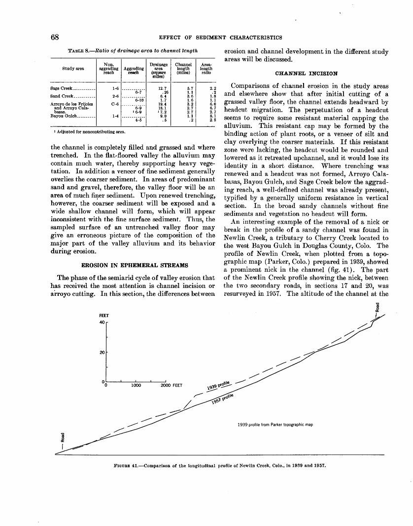
68 EFFECT OF SEDIMENT CHARACTERISTICS
TABLE 8.-Ratio of drainage area to channel length
Non. Drainage Channel Area-Study area aggrading Aggrading area length length
reach reach (square miles)
(miles) ratio
Sage Creek ____________ 1-6 12.7 5. 7 2.2 -------~7-- .26 1. 1 .2
Sand Creek __ --------- 2-6 ------------ 6.4 3. 6 1.8 6-10 1.7 1.6 1.1
Arroyo de los Frijoles C-6 ------------ 19.4 3. 2 6.0 and Arroyo Cala- 6-9 18.1 2. 7 6. 7 basas. 16-9 17.2 2. 7 2.
Bayou Gulch __________ 1-4 ------------ 9.0 1.1 8.1 4-5 .5 . 2 2 .
1 Adjusted for noncontributing area.
the channel is completely filled and grassed and where trenched. In the flat-floored valley the alluvium may contain much water, thereby supporting heavy vegetation. In addition a veneer of fine sediment generally overlies the coarser sediment. In areas of predominant sand and gravel, therefore, the valley floor will be an area of much finer sediment. Upon renewed trenching, however, the c~arser sediment will be exposed and a wide shallow channel will form, which will appear inconsistent with the fine surface sediment. Thus, the sampled surface of an untrenched valley floor may give an erroneous picture of the composition of the major part of the valley alluvium and its behavior during erosion.
EROSION IN EPHEMERAL STREAMS
The phase of the semiarid cycle of valley erosion that has received the most attention is channel incision or arroyo cutting. In this section, the differences between
FEET 40
20
erosion and channel development in the different study areas will be discussed.
CHANNEL INCISION
Comparisons of channel erosion in the study areas and elsewhere show that after initial cutting of a grassed valley floor, the channel extends head ward by headcut migration. The perpetuation of a headcut seems to require some resistant material capping the alluvium. This resistant cap may be formed by the binding action of plant roots, or a veneer of silt and clay overlying the coarser materials. If this resistant zone were lacking, the headcut would be rounded and lowered as it retreated upchannel, and it would lose its identity in a short distance. Where trenching was renewed and a headcut was not formed, Arroyo Calabasas, Bayou Gulch, and Sage Creek below the aggrading reach, a well-defined channel was already present, typified by a generally uniform resistance in vertical section. In the broad sandy channels without fine sediments and vegetation no headcut will form.
An interesting example of the removal of a nick or break in the profile of a sandy channel was found in New lin Creek, a tributary to Cherry Creek located to the west Bayou Gulch in Douglas County, Colo. The profile of Newlin Creek, when plotted from a topographic map (Parker, Colo.) prepared in 1939, showed a prominent nick in the channel (fig. 41). The part of the Newlin Creek profile showing the nick, between the two secondary roads, in sections 17 and 20, was resurveyed in 1957. The altitude of the channel at the
1939 profile from Parker topographic map
FIGURE 41.-Comparison of the longitudinal profile of Newlin Creek, Colo., in 1939 and 1957.
EROSION AND SEDIMENTATION IN A SEMIARID ENVIRONMENT 69
lower road had not changed measurably ~uring the 18-year period, but the profile between the roads had been smoothed by removal of the nick. The small break in the 1957 longitudinal profile at its upper end is due to the road crossing at that point, which 1nay have retarded further degradation, for the road acts as a small clam.
The changes occurring on Newlin Creek agree with those observed by Brush (1957) during flume experiments and suggest that in poorly cohesive material, not capped by a more resistant layer, the headward migration of the nick will be accompanied by a decrease in its height.
The change in channel characteristics along New lin Creek from above the upper road to below the original position of the nick in 1939 illustrates the changes occurring during degradation of a sandy channel. Above the upper road, the channel is 130 feet wide, and sand is being deposited over another 100 feet of the valley floor. Width-depth ratio approaches 90. Below the road degradation begins; the channel narrows to 40 or 50 feet, and width-depth ratio decreases to 17. The degradation causes erosion along many. interconnected water courses, forming vegetationcovered islands separated by degrading sandy channels. One channel probably will become dominant after eontinned erosion.
Downstream, evidence of greater erosion appears; roots of trees are exposed and cobbles and boulders appear in the channel bottom. At the site of the former nick; the gully is 10 feet deep and is 20 to 40 feet wide; width-depth ratio is about 3. Below the lower road the channel seems aggraded, shallowing and widening to its junction with Cherry Creek. Sediment samples taken in the eroding channel show only minor variation in grain size (D5o=0.60) and percent silt-elay (2.0).
BANK CAVING
Another important phenomenon that occurs during the development of a stable channel is bank caving. The relative amount of bank caving along the streams studied and its effect is markedly different in areas of cohesive and noncohesive sediment.
In poorly cohesive alluvium, or that with a small percent silt-clay, the channel widens rapidly by bank caving after initial dissection; whereas, in cohesive sediment, predominantly silt-clay, the blocks of sediment that fall into the channel are resistant and do not move· or disintegrate readily, although this will depend on velocity of water movement. They may even form the nucleus for deposition along the banks and prevent further channel widening (fig. 200). Vegetation, growing on banks before the caving, often continues to
grow on the fallen bloek if rotation of the block was not great. The vegetation in turn promotes further aggradation in the channel.
Blocks of poorly cohesive alluvium, on the other hand, disintegrate upon impact or later under the eroding action of flood waters, and the sediment adds to the bed and suspended load of the stream. Slumping or caving .of bank material into the stream channel and the function of slump blocks in sediment supply and aggradation, therefore, differ with type of bank material.
PRACTICAL CONSIDERATIONS
Because of a critical need for effective control of erosion and deposition in ephemeral streams, an attempt will be made to suggest how some of the information and conclusions stated previously might have a practical application. The differences in erosion and deposition in the study areas suggest that different types of conservation techniques may be necessary for different types of alluvium filling the valley.
Generally, in valleys where the streams are ephemeral conservation measures are not begun until improvement will require large expenditures of time and money. For example, once a gully has formed the only solution is to build either a dam or diversion structure above the headcut, to prevent its headward migration, or to plug the gully and fill it by inducing deposition in the trench (Peterson, 1950). However, if it were possible to determine at what point in the valley trenching would begin, then it might be more economical and certainly more practical to prevent the initial eroswn.
Some studies in semiarid valleys suggest that a discontinuous gully will for1n on the steeper parts of an alluvial valley (Schumm and Hadley, 1957). If good topographic maps are available for the areas concerned, it would be possible to plot the longitudinal profile of the stream and discover the steeper reaches where trenching· might begin. If maps are not available, the valley profile could be surveyed, or perhaps, the critical gradient changes could be revealed by photogrammetric methods. Once the steeper reaches have been discovered, the valley floor could be protected by restricting grazing. However, since in many areas the valley floor affords the best grazing and because the critical reach would need to be fenced, this solution may not be acceptable to the local rancher. Another possibility would be the construction of small earth diversion dikes to slow a11d spread the flow of -water- across the steeper reach. This, however, might cause deposition and further steepening on this already critical reach. This discussion of preventive conservation measures on the steeper parts of the alluvial fill empha-
70 EFFECT OF SEDIMENT CHARACTERISTICS
sizes that only certain parts of a valley need be protected to conserve the entire valley.
In three of the study areas selected for this investigation, problems of erosion and deposition are acute. Conservation measures should be directed at not maintaining but restoring the valley floor to its ungullied state. This may be possible only by inducing deposition in the gully proper, thereby filling and healing the trench. Such a project can succeed best where the method used is designed to take advantage of a natural tendency to deposition. In each valley studied deposition was shown to occur naturally where tributary contribution is small, where gain of drainage area per mile of channel is less than normal (table 8). Therefore, if these limited, observations are confirmed elsewhere, a structure placed in a valley to promote deposition should be located where the ratio of increase of drainage area to channel length is small.
Deposition also may be induced by using reverse delta deposition near the confluence of the channel with a trunk stream. If a dam is built on the tributary a short distance above its 1nouth, the retention of water will allow flood waters to enter the channel from the main stream, causing deposition below the dam and plugging of the valley. Deposition in the reservoir above the dan1 will also be important. The lower e:pd of Sage Creek has been filled in this manner. Once deposition has started, care should be exercised that renewed trenching on the toe of the alluvial deposit does not occur.
If incipent aggradation could be recognized in a channel, it might be accelerated by conservation Ineasures. As indicated by a reexamination of changes in sediment and channel character across the aggrading reaches (figs. 22, 27, 31, 35) deposition may be detected, where it is not obvious, by a decrease in gradient and an increase in percent silt-clay in the channel sediment. Perhaps width-depth ratio can be used, for width-depth ratio is increased by aggradation except for those areas of high silt-clay where initial deposition is along the channel banks for example, Sage Creek. Perhaps in similar channels if the width-depth ratio in any reach is much higher than that upstream or downstream, deposition may be expected (fig. 40).
Vegetation aids deposition only after deposition has begun. Vegetation is readily established on the fine alluvium but not in predominantly sandy material. It appears therefore if vegetation does not occur naturally in a channel, it probably cannot be induced to
grow there without great expense. Planting grass and trees in a semiarid valley would be practical only as a means of stabilizing an alluvial deposit. But care should be exercised that the conservation measure may not have an eventual adverse effect on valley stability. More work is required on this and other problems related to deposition, but it becomes increasingly apparent that a careful study of each valley should be made before conservation measures of any type are initiated.
REFERENCES
Babcock, H. M. and Cushing, E. M., 1941, Recharge to ground water from floods in a typical desert wash, Pinal County, Arizona: Am. Geophys. Union Trans., v. 22, pt. 1, p. 49-56.
Blench, T., 1957, Regime behavior of canals and rivers: London, Butterworth's Publications, 138 p.
Brush, L. M., Jr., 1957, Laboratory study of knickpoint behavior in noncohesive materials [abs.] : Geol. Soc. American Bull, v. 68, p. 1704.
Burmister, D. M., 1952, Soil mechanics: New York, Columbia Univ. Press, 155 p.
Dunn, I. S., 1959, Tractive resistance of cohesive channels : Jour. Soil Mechanics and Foundations Div., Am. Soc. Civil Engineers Proc., SM 3, p. 1-24.
. Hjulstrom, Filip, 1935, Studies of the morphological activity of rivers as illustrated by the River Fyris: Univ. Upsala Geol. Inst. Bull., v. 25, p. 221-527.
Leighly, J. B., 1934, Turbulence and the transportation of rock debris by streams: Geog. Rev., v. 24, p. 543-464.
Leopold, L. B. and Maddock, Thomas, Jr., 1953, The hydraulic geometry of stream channels and some physiographic implications: U.S. Geol. Survey Prof. Paper 252, 57 p.
Loopold, L. B. and Miller, J.P., 1956, Ephemeral streams-hydraulic factors and their relation to the drainage net: U.S. Geol. Survey Prof. Paper 282-A, p. 1-37.
Peterson, H. V., 1950, The problem of gullying in western valleys; in Trask, P. D., Applied sedimentation: New York, John 'Viley & Sons, 707 p.
Schumm, S. A., 1956, The role of creep and rainwash on the retreat of badland slopes: Am. Jour. Sci., v. 254, p. 693-706. .
--1960a, The effect of sediment type on the shape and stratification of some modern fluvial deposits: Am. Jour. Sci., v. 258, p. 177-184.
--1960b, The shape of alluvial channels in relation to sediment type: U.S. Geol. Survey Prof. Paper 352-B, p. 17-31.
Schumm, S. A. and Hadley, R. F., 1957, Arroys and the semiarid cycle of erosion: Am. Jour. Sci., v. 255, p. 161-174.
Thornthwaite, C. W., 1941, Atlas of climatic types in the United States, 1900-1939: U.S. Dept. Agr. Misc. Pub. 421, 7 p.
Ward, Freeman, 1922, Geology of a portion of the badlands: South Dakota Geol. Survey Bull. 11, p.1-59.
Wolman, M.G., 1955, The natural channel of Brandywine Creek, Pennsylvania: U.S. Geol. Survey Prof. Paper 271, 56 p.
'Volman, M. G. and Leopold, L. B., 1957, River flood plainsSome observations on their formation: U.S. Geol. Survey Prof. Paper 282-C, p. 87-109.
*U.S. GOVERNMENT PRINTING OFFICE: 196Z 0 -6Zl994
Copyright © 2022 FDOKUMEN