
Analytic Solutions of Linearized Lattice Boltzmann Equation for Simple Flows
Upload
independentCategory
view
1download
0
Journal o f Statistical Physics, Vol. 87, Nos. 1/2, 1997
Analytic Solutions of Simple Flows and Analysis of Nonslip Boundary Conditions for the Lattice Boltzmann BGK Model
Xiaoyi He, i.~_ Qisu Zou, t.3.5 Li-Shi Luo, 3'4'6 and Micah Dembo 2
Received July 14. 1995
In this paper we analytically solve the velocity of the lattice Boltzmann BGK equation [LBGK) Ibr several simple flows. The analysis provides a framework to theoretically analyze various boundary conditions. In particular, the analysis is used to derive the slip velocities generated by various schemes for the nonslip boundary condition. We find that the slip velocity is zero as long as Z=J~e~ =0 at boundaries, no matter what combination of distributions is chosen. The schemes proposed by Noble et al. and by Inamuro et aL yield the correct zero- slip velocity, while some other schemes, such as the bounce-back scheme and the equilibrium distribution scheme, would inevitably generate a nonzero slip velocity. The bounce-back scheme with the wall located halfway between a flow node and a bounce-back node is also studied Ibr the simple flows considered and is shown to produce results of second-order accuracy. The momentum exchange at boundaries seems to be highly related to the slip velocity at bound- aries. To be specific, the slip velocity is zero only when the momentum dissipated by boundaries is equal to the stress provided by fluids.
KEY WORDS: Lattice Boltzmann BGK equations; nonslip boundary condi- tions; analytic solutions of simple flows.
*Center for Nonlinear Studies (CNLS), MS-B258, Los Alamos National Laboratory, Los Alamos, New Mexico 87545.
2Theoretical Biology and Biophysics Group (T-10), MS-K710, Theoretical Division, Los Alamos l~lational Laboratory, Los Alamos, New Mexico 87545.
3Complex Systems Group (T-13), MS-B213, Theoretical Division, Los Alamos National Laboratory, Los Alamos, New Mexico 87545.
4Computational Science Methods Group (XCM), MS-F645, X Division, Los Alamos National Laboratory, Los Alamos, New Mexico 87545.
s Department of Mathematics, Kansas State University, Manhattan, Kansas 66506. ~' ICASE, Mail Stop 403, NASA Langley Research Center, Hampton, Virginia 23681.
115
0022-4715/97/0400-0115512.50/0 c. 1997 Plenum Publishing Corporation

116 He e t a l .
1. I N T R O D U C T I O N
In recent years, the lattice Boltzmann equation (LBE) c4-8~ has been success- fully applied to various hydrodynamic problems which are difficult for con- ventional numerical methods (e.g., finite-difference or fmite-element scheme). Among these problems are multiphase, multicomponent flows, tg' i0~ magneto- hydrodynamics, ~111 and reactive flows. 1121 From a computational viewpoint, the notable advantages of the LBE method are parallelism of algorithm, sim- plicity of programming, and ease of incorporating microscopic interactions.
Although it has been proved ~6-7-13~ that the LBE recovers the Navier- Stokes equation with a second order of accuracy in space in the interior of flow domain, the real hydrodynamic boundary conditions have not been fully understood. For a node near a boundary, some of its neighboring nodes may locate outside the flow domain. The distribution functions from these nonfluid nodes are therefore unknown after each streaming process. The boundary condition is responsible for determining these unknown distributions.
In general, there are two ways to define a boundary: placing the boundary on grid nodes 11-3.141 or placing the boundary on links. I ~0. ~s. 16) No matter which method is used, to find out whether a boundary condition is appropriate, one would like to know the slip velocity introduced by the boundary condition. Many of the previous studies on the velocity bound- ary condition are based on numerical experiments. In ref. 14 the distribu- tion at a boundary node is set to the equilibrium distribution plus a modification term based the Chapman-Enskog expansion, and the velocity gradient in the modification is approximated by a finite difference. In ref. 1 the unknown distributions and density at a boundary node are obtained from the known distributions and the known velocities at the boundary for the triangular lattice. In refs. 2 and 3 the unknown distributions and density at a boundary node are obtained from the known distributions and the known velocities at the boundary with some additional assumptions of the unknown distributions. With numerical experiments, one can only observe the order of the slip velocity. How this slip velocity is generated and what factors it depends on are not well known. Hence, an analytical study is necessary for a better understanding of the model and the non-slip boundary condition on stationary or moving walls.
Some theoretical studies have been carried out on the LGA or the LBE model and the non-slip boundary condition on a stationary wall was studied. ~15-181 The discussion in refs. 15 and 17 is based on a linearized lattice Boltzmann equation with a global equilibrium with constant density and isotropic velocity (zero velocity). In ref. 16 the boundary condition of the 3D FCHC lattice Boltzmann model 119"2~ with a linear collision

Lattice Boltzmann BGK Model 117
operator represented by a collision matrix A was studied for the plane Poiseuille flow and the plane stagnation flow. In that study, the first-order and second-order deviations of the distribution function from equilibrium were assumed to take an a priori form in terms of flow quantities. In ref. 18 analytical solutions of the distribution functions for Poiseuille flow and Couette flows were found for the FHP or the square LBGK models without any approximation. The study was restricted to situations that the velocity profile extends beyond the boundary in a smooth way and to the Poiseuille flow with square forcing given in ref. 21 for the FHP model. Nevertheless, all the previous theoretical studies only treated bounceback boundary conditions. The present study directly solves the LBGK equation without any approximations and hence it can handle various boundary conditions.
The paper is organized as follows. Section 2 analytically solves the nine- bit lattice Boltzmann BGK equation for the two-dimensional Poiseuille flow and the Couette flow with possible vertical injection at the boundaries. The results are further used to analyze different schemes for the non-slip boundary condition. Section 3 discusses the results and concludes the paper. The Appendix briefly discusses some results of the seven-bit (FHP) LBGK model.
2. ANALYTICAL SOLUTION AND NONSLIP BOUNDARY CONDITION
In this section, we use the square nine-bit lattice LBGK model. The procedure can be easily applied to the FHP model and some results are given in the Appendix. The nine-bit lattice BGK model is on a square lattice space with three speeds: 0, c, and v/'2c, where c=6,. /6, and 6,. and 6, are the lattice constant and the step size in time, respectively. Figure 1 shows all possible velocities of the model. With the presence of a body force F, the evolution equation of the system is
f~(x + e~6,, t + fi,)--f~(x, t ) = 1 [f~(x, t)--f~q)(p, u)] + 6'2 --~ <5.,.g~ (1)
where r is the dimensionless relaxation time, and
((o, o), e~= ~ ( c o s [ ( ~ - 1) n/2], s i n [ ( ~ - 1) n/2]) c
{ (cos [ ( ~ - 5 ) re/2 + 7r/4 ], sin [ (~ - 5 ) 1r/2 + rr/4 ] ) x/'2c
0c=0
~ = 1 ,2 ,3 ,4
0~=5,6, 7, 8
(2)

118 He e t a l .
6 2 5
\ / ,
- x 3 1 - / \ 7 4 8
Fig. 1. All possible velocities for the nine-bit lattice BGK model on a square lattice. This figure also shows the arrangement for the channel flow and the Couette flow in simulations.
are the velocity vectors. The equilibrium distribution function f~cq~(p, u) is given by
f'~qito u ) = w ~ p [ l + 3 / ' e ~ ' u ' x 9{/e~'u'~ 2 3 ( u ) 2] " ' " - 7
(3)
where Wo=4/9, wi.2.3.4 = 1/9, and w5.6.7.8 = 1/36. The local density of mass p and the local density of momentum pu in Eq. (3) are given by
p = ~ f ~ (4a) ct
pu = ~ e~f~ (4b)
Finally, the forcing term g: is given by
I 0~c or
e~.F, cr 1,2, 3,4 g: = (5)
t 1-~c e," F, ct = 5, 6, 7, 8
The evolution of the lattice BGK system consists of two steps: colli- sion and advection. First the distribution functions f : at the site x undergo

Lattice Boltzmann BGK Model 119
the collision process, prescribed by the right of Eq. (I) or otherwise. After the collision, j~ moves to the next site, x + % 5 , , according to the velocity %.
The Navier-Stoke equation can be derived from Eq. (1):
911 p ~ + pu" Vu = -V(c~p) + vpV2u + F (6)
where the kinetic viscosity is
and the speed of sound is
(2~- l)6~ 6 5,
1 Cs--~T C
In the following analysis, we will only consider steady (time-independ- ent) flows satisfying
Ou Ov ~x=O, o x - O , p =const (7)
The body force is assumed to be along the x direction, i.e., F =pGix. In this type of flow, both the velocity and the distribution functions are only functions of the y coordinate. Although being rather simple, they serve as examples for us to carry out some theoretical analyses which can be further used to study the nonslip boundary condition.
By substituting Eqs. (3) and (7) into Eq. (1), we obtain the following equations:
fJ~ - -L 1 -- 5 ~,722 + ~ ) ] (8a)
= - - + 3 -~ vj . (8b) c c- 2 75-" 3c-'
-)
f{, = P-- [ v-7~ ' - 9z[ l + 3 v j - t + 3 c c- (8c)
f { - P - [ 1 - 3 u J + 3 -s (8d) 3- -9 L C c- 2
23"-]c 5,.rpG
3c 2

1 2 0 H e e t a l .
pF ~;§ v~+t 3 u 2 + , ] ~ _ r - l . + , f~=GLI-3 +3 ~- c c- 2 c 5 J - r "4
p[ uj_, vj_, u~ v}_, uj_,vj_,] f~=3-6-~r 1 + 3 c + 3 c + 3 ~'+3c_ ~ + 9 c2
(8e)
r - 1 . OxpG + r f ~ - ' + ~ (8f)
- 3" '+3u ' c c c, +3 V,c
r - 1 3.,.pG + f ~ - ' - - - (8g) r 12c 2
P l Uj+I Vj+I /'/7+1 / )7+ Uj+II')j+I] f~=3--~r 1 - 3 c - 3 c + 3 ,c_ + 3 ,c_ + 9 c2
t - 1 fi7+, O.,.pG + - - - (8h) r 12c 2
2 . tg+lq/+t ] p uj+ I 1.)j+ I 1..Ij+ I O j+ 1 f{=3-~r 1 + 3 - 3 + 3 , +3 - 9
c c c - c 2 c -~ l
c~,.pG + r - 1 f{+ ~ + - - (8i) r 1 2 c 2
where f~ is the distribution function and (uj, uj) is the velocity vector at y=jr~,. . Equations (8) are valid for 2<~j<~n- -2 . The node j = 0 o r j = n corresponds to lower or upper boundaries, respectively, where the evolu- tion rule depends on the implementation of boundary conditions.
In the interior of the flow domain (2 < ~ j < ~ n - 2 ) , the x component of the momentum density PUJ can be rewritten as
puj = cr ( f ' ; - G ) + (G - fO + (G-f4)]
r + l 2r--1 = 3r pUj+'"~--~ p ( t ' t j - I + u j + l )
+2-~r (u:- t v : _ , - u j + iv~+ ,) +6'pG (9) �9 T

Lattice Boltzmann BGK Model
which further gives us
Uj+ll)j+l--Uj--IUj--I 25,.
121
=v uj+l +uJ-I-2Ui +G (10) 52,
The above equation is exactly the second-order finite-difference form of the simplified incompressible Navier-Stokes equation under the assumption (7) and constant pressure:
a(uv) a2u Oy =v--~y,_+G (11)
In the y direction, from pvj= c [ f { - f { +f~ + f J 6 - f ~ - f { ] , it is easy to prove
v~+, - v.~_, = (2r - 1)(v/+, + vj_, - 2vj) c (12)
8 i On the other hand, from p =Y'.i=ofi and the definition of PVi above, we can prove
v]+ i +v.7-1-2v~ = ( 2 r - 1)(vj+ i - vj_ i) c (13)
Combination of Eqs. (12) and (13) yields
vj = v,.-- const (14)
It should be noted that this result is only valid in the interior of the flow domain. Whether v,. is equal to the vertical velocity at boundaries v~ depends on the implementation of the boundary condition.
2.1. Poiseuille Flow
For the Poiseuille flow, the vertical velocity is zero and Eq. (10) has a simple solution:
4 U c uj=--Tj(n --j) + U.,., j = 1 ..... n -- 1 (15)
n -
where Uc = L2G/8v is the centerline velocity without slips at boundaries, with L = n5.,. being the width of the channel and U, is the slip velocity depending on the implementation of the boundary condition for walls in a particular scheme. The above velocity profile is a parabola with a shift on the boundaries. The slip velocity U.,. is the only term which makes the

122 H e e t al.
solution of the LBGK possibly different from the exact solution of the Poiseuille flow.
In order to find the slip velocity, we need to apply Eq. (9) at the grid line next to the bottom wall ( j = 1) (analysis for the top boundary is the same):
pu, = c[ ( f l - f ~ ) + (J~ -f~6) + (f~ - f { ) ]
= 3 - - - ~ P U t + - - ~ r p(u~ r p G + 1 - p(Uo-Uo)
which further yields
(16)
6-' 3(r-- 1) uo + uz + - .,. G -t [ fro - uo] (17)
u, = 2 2v 2 r - - 1
In the derivation, it is assumed that f (~ , f o , f o , f o follow the rules in Eqs. (8), the equilibrium distribution at j = 0 is calculated using velocity (Uo, 0), and PUo = c[(f~ o o o o - f 3 ) + ( fo - f 6 ) + ( f s - f v ) ] , w h e r e f ~ ~ depend on the boundary condition implemented. Comparing Eqs. (15) and (17), we obtain the explicit expression for the slip velocity:
U , . - 6 ( r - l ! [~o-Uo] (18) �9 2 r - 1
With this result, we can easily analyze different schemes for the nonslip boundary condition (Uo is set to be zero in what follows for the sake of sim- plicity).
1. Bounce-back scheme. For the bounce-back scheme, the particle colliding with the wall simply reverses the direction of its velocity, that is,
f ' / - - 0 I 0 I "o - f 4 , ( f5 =f7, 19) f6 -=-iS
Notice that the collision process does not occur at the boundary in this scheme, hence Eq. (18) does not apply. Using the bounce-back rule, we can derive
2U, . [ ( 2 r - 1 ) ( 4 r - 3) - 3 n ] ( 2 0 ) U,~ = 3n-'---T
Clearly, the bounce-back rule generally yields a nonzero slip velocity. Furthermore, the slip velocity is of the first order in space because it has a term of O(l/n).

Lattice Boltzmann BGK Model 123
2. Modified bounce-back scheme. By the modified bounce-back rule, we mean that collision and forcing still occur at boundary nodes. The precollision unknown distribution is set equal to the value of the distribu- tion along the opposite direction:
0 0 f , = f 4, f ~ = f ~ , o o _ f 6 = f 8 (21)
With the modified bounce-back rule, we can prove
16 r ( r - 1) U , - 3n2 U,. (22)
Clearly, the modified bounce-back boundary condition also generate a nonzero slip velocity as long as r :~ 1. However, compared to the bounce- back rule, the error is reduced and the slip velocity is of the second order in space.
3. Nonslip schemes. In the nonslip scheme proposed by Noble et aU 2~ the unknown distributions and the boundary density are calculated from the constraints given in Eq. (4) and an additional constraint given by
2pt=~,(e~-u)2f~ (23)
where e is the internal energy, which equals the square of the sound speed in the limit of low Mach number and low Knudsen number. In the nonslip scheme proposed by Inamuro et al. ~3~ it is assumed that the distributions at a horizontal boundary can be written in the following equilibrium form:
f o _ _ f ( e q ) ( / } l = - ~ , , . , u.,) (24)
- - *"(eq ) l wnere j~ is defined in Eq. (3) and u,. = (Uo + u', %). The two parameters p', u' and the density at the boundary are determined from the constraints (4).
From their definitions, it is easy to see both schemes lead to
Uo = c [ ( f , - f 0 (f0.15 __fO)j6 + ( f ~ 1 7 6 = 0 (25)
Therefore, the slip velocity is automatically zero and the nonslip boundary condition is implemented correctly. Notice that the distribution functions are different in these two schemes, and they are different from the analytical solution in ref. 18, but all three distribution functions give the correct velocity profile. In fact, any scheme which uses the knownf~~176 o o o

124 He et al.
to generate fo,fo,fo according to E ~ f ~ e ~ = 0 and ensures the correct p will give the correct velocity profile for the Poiseuille flow. For example, we have obtained the boundary density from a consistency condition in Eq. (3) as in refs. 2 and 3 and have set fo=p/fl with fl being an adjustable parameter, and the numerical simulations yielded the correct density and velocity profile of the Poiseuille flow for fl varying from 0.01 to 108.
To verify our theoretical analysis, we have further carried out numeri- cal simulations for the Poiseuille flow. Figure 2 shows the velocity profiles uj normalized by Uc for the Poiseuille flow. The system size is N,. x N,, = 16 x4. The amplitude of the uniform forcing along the x axis is 0.1. The density of the system is set to be 1.0, The initial state of the system is u = 0 and v = 0. The uj are measured at a cross section of the channel after 5000 times iteration. Shown in Fig. 2 are the velocity profiles with different values of r and with different implementations of the boundary condition for a stationary wall, i.e., the bounce-back rule, the modified bounce-back rule, and the nonslip boundary conditions in refs. 2 and 3. The result with the nonslip boundary condition is a perfect parabola without any slip velocity at the wails, while the results with the bounce-back or the modified bounce-back boundary condition have a nonzero slip velocity at the boundaries. Also, the numerical results are in excellent agreement with our
1.5
1.0
0.5
0.0
- 0 . 5
0 1 2 3 4 j
Fig. 2. The normalized velocity profile of the Poiseuille flow. Solid lines, our analytic results with various types of boundary conditions and values of r. ( + ) The numerical results of lat- tice BGK simulation with the scheme in refs. 2 and 3; ( II, [] ) the numerical results of lattice BGK simulation with the bounce-back boundary conditions; ( , t , A) the results with the modified bounce-back boundary condition. The solid and open symbols represent the numeri- cal results with r = 2.0 and 0.75, respectively.

Lattice Boltzmann BGK Model 125
0
0 I 2 3 4 5
~ 4 \
2
Fig. 3. The normalized slip velocity of the Poiseuille flow as a function of r and the number of nodes across the channel, i1, with two types of boundary conditions. Solid lines, our analytic results. I I-I + ) The numerical results by the lattice BGK simulation with the bounce- back boundary condition and with n = 4 and 8, respectively; (,~, • the numerical results with the modified bounce-back boundary condition and with n = 4 and 8, respectively.
theoretical analysis. The error in the numerical results of uJU,. is of the order o f 10 - to, which is of the order of the roundoff error.
Figure 3 shows the slip velocity Us, normalized by U,., as a function of r and n for the Poiseuille flow with the bounce-back boundary condi- tion. The analytic results are given by Eq. (20). We chose n = 4 and 8 in the simulations. The results of the simulations coincide perfectly with the analytic results.
2.2. Plane C o u e t t e F l o w w i t h Possible In ject ion at Boundar ies
For the Couet te flow with possible vertical injection at the boundaries, the body force G is zero. The lower and upper walls move along the horizontal direction at different velocities Uo and u, , respectively. In the mean time, a vertical velocity is injected at a speed of vb at both walls. Equat ion (10) can be solved in the interior of the flow domain. Th rough some simple algebraic derivations we find
M - 1 2" - 2 ./ uj - 2 " - 1 (u,, + U,~) + ~ (Uo + U ~ (26)
We have 2 = (2 + R ) / ( 2 - - R ) , where R = vc3.,./v, with vc being the vertical velocity in the interior of the flow channel. The U~ and U ~ stand for the slip velocities at the top and bo t t om walls, respectively. Once the slip
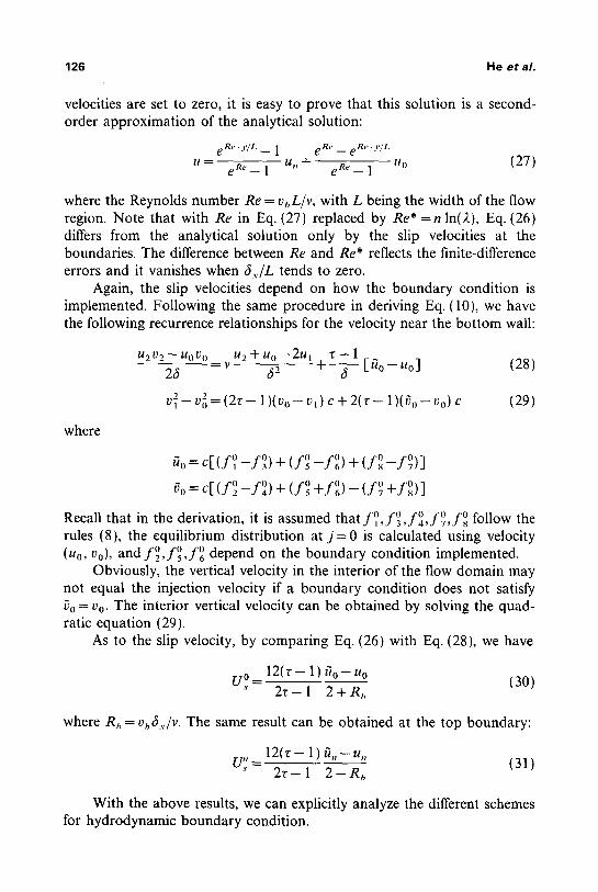
126 He e ta l .
velocities are set to zero, it is easy to prove that this solution is a second- order approximation of the analytical solution:
eRe ,y /L __ 1 eRe _ e r e . y /L
u e R ' - 1 u,, + e R e - 1 u0 (27)
where the Reynolds number Re = vbL/v, with L being the width of the flow region. Note that with Re in Eq. (27) replaced by Re* = n In(2), Eq. (26) differs from the analytical solution only by the slip velocities at the boundaries. The difference between Re and Re* reflects the finite-difference errors and it vanishes when 6,. /L tends to zero.
Again, the slip velocities depend on how the boundary condition is implemented. Following the same procedure in deriving Eq. (10), we have the following recurrence relationships for the velocity near the bottom wall:
U2[2--1,101.) 0 u,~+uo--2u I v - - 1 26 v - fi2 +----~ [~o--Uo] (28)
v { - - v o = ( 2 r - 1 ) ( v o - v t ) c + 2 ( r - - 1 ) ( O o - - V o ) C (29)
where
~o = c[ ( f ~ _ f o ) + ( f~ _ f o ) + ( f o _fo)] 0 0 '0
~ o = c [ ( f ~ 1 7 6 + f s + f ~ (f7 - +/~)]
. co r follow the Recall that in the derivation, it is assumed that f r 1 7 6 1 7 6 s rules (8), the equilibrium distribution at j - - 0 is calculated using velocity (uo, %), and f o , f o f o depend on the boundary condition implemented.
Obviously, the vertical velocity in the interior of the flow domain may not equal the injection velocity if a boundary condition does not satisfy ~o = Vo. The interior vertical velocity can be obtained by solving the quad- ratic equation (29).
As to the slip velocity, by comparing Eq. (26) with Eq. (28), we have
UO = 12(r - 1) Uo- Uo (30) 2 r - 1 2 + Rh
where RI, = vhfi,./v. The same result can be obtained at the top boundary:
12(r - 1) ~ , , - u , , U.',!= 2 r - I 2--Rh (31)
With the above results, we can explicitly analyze the different schemes for hydrodynamic boundary condition.

Lattice Boltzmann BGK Model 127
1. Equilibrhtm scheme. For a boundary condition with nonzero velocity, the bounce-back scheme is obviously not valid. A common practice in the LBE simulation is to assign the corresponding equilibrium distribu- tion to the distribution functions at a boundary node. In our case, applying this scheme at the bottom boundary gives
PI _3.oi f o = ~ 1 + 3 v ~ c-; 2c2J
f~ l + 3 U~ + 3 v~ + 3 c ~ -7+3--s+9c-v8
3 -9 f o = 1 _ 3 u o + 3 Vo+3__~+ C C C- C-
Notice that assigning the equilibrium distribution to r ~ c~ is consistent J l ~ J 3
with Eqs. (8), and the values o 0 .o o f f4 , fT , J8 are irrelevant to the flow inside. 0 0 '0 Here we use f4 , f v , J8 as given in Eqs. (8), so that Eqs. (28) and (29) are
still valid for a simpler presentation. With this information, it is easy to derive
1( 2) ~o-Vo = Vo-v l+V~ + ( v l - vo) (32)
Substitution of this into Eq. (29) leads to vt = %, and thereafter, vj = vb, Vj. In the horizontal direction, it is easy to prove
( U ~ I - ~ ( u , - u o )
and similarly at the top boundary
u',!= 1 - ~Z-ktu. ,_,- . , , )
Substituting Eq. (26) with j = 1 and j = n - 1 into above two equations, we can obtain, the final explicit expression for the slip velocities:
UO = ( ~ - 1 ) ( 2 - 1 ) ( r 2 - r - 2 ) (u,,-Uo) (33) " 2"(r2-- r + 1) + 2 ( r 2 - r - 2)
( 3 - 1)(2-- 1) 2"(T2-- r + 1) Utl s 2 , , ( r 2 _ r + l ) + 2 ( r 2 _ r _ 2 ) ( u , - u o ) (34)
822/87/I-2-9

128 He e t a / .
Obviously, the equilibrium scheme generally yields a nonzero slip velocity. Let ~,.--, 0; it is easy to prove
1 u? ~ ! u: ~- / / n
This states that the slip velocity is of first order in space.
2. Nonslip schemes. With the nonslip schemes in refs. 2 and 3 we have
uo = uo, vo = Vo, /~,, = u,,, ~,, = v,, (35)
Obviously, this boundary condition yields a zero slip velocity and hence the boundary condition can be implemented correctly.
We also carried out numerical simulations for the Couette flow with injection at boundaries. The system is exactly the same as the one used in simulations for the Poiseuille flow, i.e., N.,. • N, .= 16 • 4. The bot tom wall is fixed and the top wall moves at a speed of 0.1c. For consistency, we adjusted the value of the vertical injection velocity to yield the same Reynolds number Re = v~,L/v.
Figure 4 shows the velocity profile for Re = 2.0 with different values of r. The theoretical solutions of the Navier-Stokes equation are also included for comparison. The results with the equilibrium scheme yield a nonzero slip velocity as long as r :~ 1, while the schemes in refs. 2 and 3 yield a zero slip velocity regardless of the value of r. All the numerical results coincide with our analytical solution. Figure 5 shows the slip velocity for Re = 1.0 with the equilibrium scheme as a function of r. Again, the numerical results agree excellently with our analytic results.
2.3. Slip Velocity and Momentum Exchange
Another interesting phenomenon we found is that the slip velocity is highly related to the momentum exchange at boundaries. Let us introduce the quantity
c V A M = ~ [ " " .,, v o ,A
(36)
where V is the volume of the unit cell and A is the surface area between two adjacent cells through which the momentum is transferred. In the 2D nine-bit model, V= ~. and A = ~5.. The physical significance of A M is very

Lattice Boltzmann BGK Model 129
1.5 ,
1 .0
0 .5
0 . 0
i i i i i
0 1 2 3 4
J
Fig. 4. The normalized velocity profile of the Couette flow with Re=2.0 . Dashed line, theoretical solution of the Navier-Stokes equation; solid lines, our analytic results with two types of boundary conditions and different values of r. I D) The numerical results of lattice BGK simulation with the schernes in refs. 2 and 3; ( + ) the numerical results with the eqtfi- librium scheme and with r=0 .75 ; ( A ) the results with the equilibrium scheme and with t- = 2.0.
0 . 5
0 . 0
- 0 . 5
- l . O
0
r i
1 2 3 T
Fig. 5. The normalized slip velocity IRe = 1.0) o f the Couette f low as a function o f t and the nunlber of nodes across the channel, n, with the equilibrium scheme. Solid lines, our analytic results, i D, + ) The slip velocity in nunaerical simulations at the top wall and with n = 4 and 8, respectively: ( O, x I the slip velocity in numerical simulations at the bot tom wall and with n = 4 and 8, respectively.
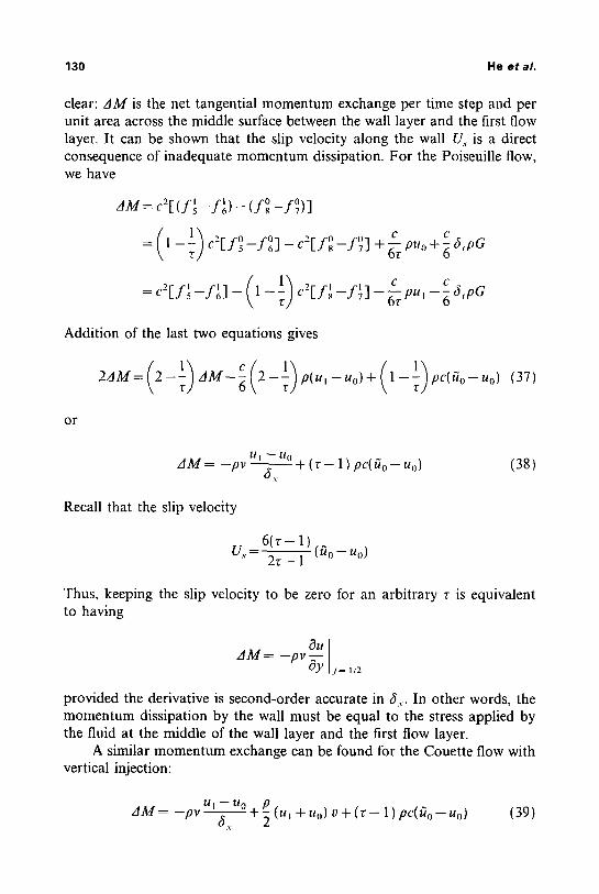
130 He e t al.
clear: 3M is the net tangential momentum exchange per time step and per unit area across the middle surface between the wall layer and the first flow layer. It can be shown that the slip velocity along the wall U., is a direct consequence of inadequate momentum dissipation. For the Poiseuille flow, we have
AM = c2[(f~ --f~) o o - ( f s - f 7 ) ]
= - c [ f 5 - f , , ] - c - ' [ f ~ - f ~ ] + g puo +-6 6,pa
- - c [ f s - f 7 ] - ~ p u , - - ~ 6 , p G
Addition of the last two equations gives
2zfM = (2--~) zfM--6 (2 - ~ ) p(u, --Uo) + (1--~) pc( ~o-- Uo) (37)
o r
L I I ~ /,l 0 AM= - p v ~ + (3- 1) pc(~o-Uo) 6
. v
Recall that the slip velocity
(38)
U~,.= 6 ( v - 1) (Uo--Uo) 2 3 - 1
Thus, keeping the slip velocity to be zero for an arbitrary r is equivalent to having
2JM~- -Pll-5f~ j= l/2
provided the derivative is second-order accurate in 6.,.. In other words, the momentum dissipation by the wall must be equal to the stress applied by the fluid at the middle of the wall layer and the first flow layer.
A similar momentum exchange can be found for the Couette flow with vertical injection:
U l - - U O . P . dM-- -pv %---7--- + ~ tuL + Uo) v + (r - 1 ) p C ( a o - Uo) (39)

Lattice Boltzmann BGK Mode l 131
Again, a zero slip velocity implies that the momentum dissipation by the wall is equal to the momentum transfer carried by the vertical velocity plus the stress applied by the fluid (evaluated at the middle of the wall layer and first flow layer).
2.4. Bounce Back with Halfway Wall
In the previous subsections, the bounce-back boundary condition has been shown to yield a nonzero, first-order slip velocity at the bounce-back row for the Poiseuille and Couette flows. On the other hand, the bounce- back boundary condition has its own merit: easy implementation, which has been considered as one of the advantages of LGA and LBE. Although being attractive, the new boundary conditions proposed in refs. 1-3 have difficulties in implementation for a complex geometry like that in porous media, in which boundaries usually do not orient in either x or y direction. Besides, some additional considerations are needed for corner nodes. If a "complete" bounce-back rule, with every distribution simply reversing its direction, can work with a halfway wall, it will be very useful in practice. By a "halfway wall" we mean a wall placed at halfway between the bounce- back row and the first flow row.
For a stationary wall, it has been proved that the bounce-back bound- ary condition with the halfway wall has a second-order accuracy for some simple flows in the cases of F H P LGA ~ ~51 and LCHC LBE 1161 for a suitable choice of the second eigenvalue of the collision matrix. This linear analysis was of the first order in gradient in ref. 15 and second order in ref. 16. In ref. 18 the theoretical result of Poiseuille flow with the square forcing ~2~) (equivalent to bounce-back boundary condition with a halfway wall) for FH P LBGK indicates a second order of accuracy. Using the results presented in previous subsections, we can prove that the bounce-back boundary con- dition with halfway wall is of second-order accuracy for the present LBGK models for the stationary walls of the simple flows considered. We will also give the explicit expression for the slip velocity.
First let us consider the bounce-back with halfway wall for the Poiseuille flow. The setup of the system is a little different from previous subsections. Nodes with j = 1 ..... n - 1 are inside the flow and nodes j = 0, n are the "bounce-back rows. After a complete bounce back, we have f21 = f 4 o, f ~ = f 7 o, i o. f 6 = f s , the exchange o f f t ~ with f o has no effect on the 3 flow. The walls are located at j = 1/2, j = n - 1/2. The evolution equation is the same as given in Eq. (1), but the width of the channel now becomes L=(n-1) fix instead of L=n~,.. It has been previously (in Section2.1) shown that with the bounce-back boundary condition at both bottom and
822/87/I-2-10

132 He et al.
top walls, the velocity profile of the LBGK model for the Poiseuille flow [Eqs. (15) and (20)] is
3G6, j(n-j)-t G6, [ ( 2 z - 1 ) ( 4 r - 3 ) - 3 n ] (40) ui = 9r - 1 2(2r - 1 ) 172
For the setup of halfway wall, the forcing G is related to the exact central velocity 0,. by U,. = L2G/8v, where L = (n - 1 ) 6.,. is the width of the chan- nel in this setup. Using 0,., we find the velocity of the LBG K model for Poiseuille flow:
4 0 , . + 2 U, . [ ( 2 r - 1 ) ( 4 r - 3 ) - - 3 1 , ) ] uj = (n - 1) 2 j(n-jJ 3 ( n - 1 )2 (41)
The exact solution of Poiseuille flow is
U,.(2j- 1 ) (2n - 2 j - 1) u: - )2 (42) ' (17 - 1
Thus, the error of the velocity from LBGK simulation is given by
U,.[4r(4r - 5) + 3] Ui - u} = 3 ( n - 1 )2 ( 4 3 )
While the error of velocity at the bounce-back row j = 0 is O ( 1 / ( n - 1 ) ) , indicating a first-order accuracy, the velocity inside the flow has a uniform error O(1/(17- 1 )2), indicating a second-order accuracy for a fixed r. There is no need to adjust parameters in the model. Notice that for a fixed lattice size, the error goes to infinity as r ~ oo. The conclusion is the same for the FH P LBGK modelJ ~t For practical purposes, there is no need to take a large value of r in a simulation. In fact, the factor 4 r ( 4 r - 5 ) + 3 in the error expression has a maximal absolute value of only 3.25 for 0.5 < r ~< 1.25. Hence the bounceback with halfway wall is an acceptable boundary condition for the Poiseuille flow. It is also noted that in this bounce back, f~ and f~ can be interchanged (a complete bounce back) without having any effect on the flow. Thus, the boundary condition is implemented in a very simple way without distinguishing flow directions and other directions.
Next let us consider the bounce back with halfway wall at the bottom for the Couette flow with zero injection velocity. We will not change the flow setup at the top wall and use a correct boundary condition like that

Lattice Boltzmann BGK Model 133
in refs. 2 and 3 there. After some algebraic manipulations we obtain the following x velocity:
u j = U 2 ( n - j ) 2 j - I U (44) 2 n ~ U = 2n---~
where U is the velocity at the top. While the velocity at the bounce-back row ( j = 0 ) is O(1/(n- 1 )), indicating a first-order accuracy, the velocity at the halfway wall ( j = 1/2) is exactly zero, indicating that the result is the exact solution! These results also hold for the F H P LBGK model as given in the Appendix. Hence the bounce back with halfway wall deserves more attention in further simulations.
3. C O N C L U S I O N A N D D I S C U S S I O N
In this paper, we have solved the lattice Boltzmann BGK equation for two simple flows under different boundary conditions. The solutions are verified by independent numerical simulations. Using these solutions, we further analyzed different schemes for implementation of the velocity boundary condition. We found that the schemes proposed in refs 1-3 give the zero slip velocity for the cases considered, and therefore are of second- order accuracy in space. Other schemes, such as bounce-back, equilibrium, etc., are only of first-order accuracy in general. The bounce-back scheme with halfway wall, however, is of second-order accuracy for the flows con- sidered. Another interesting phenomenon we found is that the slip velocity is highly related to the momentum exchange at boundaries. A boundary condition is correct only when the momentum dissipation by the boundary is equal to the stress of the fluid. We hope this work can provide some help for future studies of boundary conditions. Needless to say, our analysis is only carried out for the 2D Poiseuille flow and the 2D Couette flow with injection at the boundaries. The analytical solutions for these flows are still too simple to use as general guidance for the boundary condition analysis. Further studies on more complicated flows are necessary.
A P P E N D I X . R E S U L T S FOR FHP LBGK M O D E L
For the steady Poiseuille flow, the seven-bit BGK model on a tri- angular lattice ( F HP LBGK model) with eo = 0 and e~ = [ c o s ( ( o ( - 1) 7r/3), sin((c~-1) ~z/3)] c, ~ = 1,..., 6, can be reduced as the following recursion forms:

134 He et al.
f~ = -~rl [6(1--r)+UJc']+(1-!) f~- '+6" p 4c z pG
b,. 1 [ 6 ( I - , ' ) U J c ' ] + ( 1 - - ~ ) f ~ - ' 4c,_PG (A1, A = ~ p -
fJ4=~ p ( 1 - - r ) - 2 U g + 3 c ---~c'- rpG
f'~=gp 6 { 1 - r ) - " J c ' + 1 - -4c--~pa
1 [ 6 ( 1 - , 9 U'c ' ]+( l -~ ) f J6+t+~pG fJ6=-~rp +
( 2r - 1 ) 6.~ v = - - (A2)
8 6,
and the speed of sound
1 - - r c.,.=J-~-c (A3)
Inside the flow domain, it is easy to derive the same solution for u as in the square-lattice case:
4U,.j(n - j) us= n 2 + Us
W ") " " here Uc=L-G/8v is the central velocity as before. L=n6,., with ~,, = ~/3di,,/2 being the vertical distance between two adjacent lattice lines.
where r is the fraction of rest particle mass density out of the total mass density; it can be adjusted between 0 and 1. The body force F, with amplitude [[F[I =pG, is along the direction of e~. The system satisfies the Navier-Stokes equation (6) with the kinetic viscosity

Lattice Boltzmann BGK Model 135
The slip velocity U, depends on the boundary condition. The boundary conditions in refs. 1 and 3 generate a zero slip velocity, hence give the exact solution of the Poiseuille flow.
With the bounce-back boundary condition, for example, at the bot- tom, f ~ = f o , 1_ o f 3 - - f 6 , the slip velocity can be derived as
2U,.(n+ I) 3 ( 2 z z - 3 3 + 2 ) Us - n 2 + 2(2r - 1 ) 6,G (A4)
which is of first order in general. Similarly, for the case of bounce back with halfway wall, the error of
the velocity of the L B G K is derived as
0c(432 - 63 + 1 ) uj-u~- (n- 1) 2 (A5)
the same result as in ref. 18, which is of second-order accuracy. The factor 4 3 2 - 6 3 + 1 takes a maximal absolute value of 1.25 for 0.5 <r~.< 1.25. Notice also that a complete bounce back can be used for the bounce back with a halfway wall.
For the Couette flow with v = 0 , the model at the beginning of this appendix can be used with G = 0. Suppose that we use a correct boundary condition as in refs. 2 and 3 at the top wall and use bounce back at the bottom; then the x velocity is
u j= U 2 ( n - j ) U 2j--__~l U (A6) 2n - 1 2n - 1
where U is the velocity at the top. This is the same result as in the square- lattice case, and bounce back with halfway wall still gives the exact solution.
Other boundary conditions can be studied as well.
REFERENCES
1. D. R. Noble, S. Chen, J. G. Georgiadis, and R. O. Buckius, A consistent hydrodynamics boundary,condition for the lattice Boltzmann method, Phys. Fluids 7:203 (1995).
2. D. R. Noble, J. G. Georgiadis, and R. O. Buckius, Direct assessment of lattice Boltzmann hydrodynamics and boundary conditions for recirculating flows, J. Stat. Phys. 81:17 (1995).
3. T. Inamuro, M. Yoshino, and F. Ogino, A non-slip boundary condition for lattice Boltzmann simulations, Phys. Fluids 7:2928 (1995); Erratum, 8:1124 (1996).
4. G. McNamara and G. Zanetti, Use of the Boltzmann equation to simulate lattice-gas automata, Phys. Rev. Lett. 61:2332 (1988).

136 He et al.
5. F. Higuera and J. Jimenez, Boltzmann approach to lattice gas simnhttions, Europhys. Lett. 9:663 (1989).
6. H. Chen, S. Chen, and W. H. Matthaeus, Recovery of tile Navier Stokes equations using a lattice Boltzmann method, Phys. Rev. A 45:R5339 (1991).
7. Y. H. Qian, D. d'Humi6res, and P. Lallemand, Lattice BGK models for the Navier-Stokes equation, Europh.vs, Lett. 17:479 (1992).
8. R. Benzi, S. Succi, and M. Vergassola, The lattice Boltzmann equation: Theory and applications, Phys. Rep. 222:145 (1992).
9. X. Shan and H. Chen, Lattice Boltzmann model for simulating flows with multiple phases and components, Plo,s. Rev. E 47:1815 (1993); Simulation of non-ideal gases and liquid gas phase transitions by the lattice Boltzmann equation, Phys. Rei,. E 49:2941 (1994).
10. A. J. C. Ladd, Numerical simulations of particulate suspensions via ti discretized Boltzmann equation. Part I. Theoretical foundation, J. Fhdd Mech. 271:285 (1994): Numerical simulations of particulate suspensions via a discretized Boltzmann equation. Part II. Numerical restllts, J. Fhdd Mech. 271:311 (1994).
11. S. Chen, H. Chert, and W. H. Matthaeus. Lattice Boltzmann magnetohydrodynamics, Phys. Rev. Lett. 67:3776 11991 ).
12, S. P. Dawson, S. Chen, and G. Doolen, Lattice Boltzmann computations Ibr reaction- diffusion equations, J. Chem. Phys. 98:1514 ( 1993 ).
13. S. Hou. Q. Zou, S. Chen. G. D. Doolen, and A. Cogley, Simulation of cavity flow by the lattice Boltzmann method, J. Comp. Phys. 118:329 (1995).
14, P. A. Skordos, Initial and boundary conditions for the hittice Boltzmann method, Phys. Rev. E 48:4823 (1993).
15, R. Cornubert, D. d'Humi6res, and D. Levermore, A Knudsen hlyer theory tbr hittice gases, Physica D 47(6):241 (1991).
16. I. Ginzbourg and P. M. Adler, Boundary condition analysis for the three-dimensional lattice Boltzmann model, J. Phys. II France 4:191 (19941.
17. L-S. Luo, H. Chen, S. Chen, G. D. Doolen, and Y.-C. Lee. Generalized hydrodynamic transport in lattice-gas automata, Phys. Rev. A 43:R7097 (1991).
18. Q. Zou, S. Hou, and G. D. Doolen. Analytical solutions of the lattice Boltzmann BGK model, J. Star. Phys. 81:319 (1995).
19. U. Frisch. D. d'Humi6res. B. Hasslacher, P. Lallemand, Y. Pomeau, and J.-P. Rivet, Lattice gas hydrodynamics in two or three dimensions, Complex Systems 1:649 (1987).
20. A. K. Gunstensen and D. H. Rothman, Microscopic modeling of immiscible fluids in three dimensions by a lattice-Boltzmann method, MIT Porous Flow Project, Report No. 4, 20
1991 ). 21. L. P. Kadanoff, G, R. McNamara, and G. Zanetti, From automata to fluid flow: Com-
parisons of simulation and theory, Phys. Rer. A 40:4527 [1989).
Copyright © 2022 FDOKUMEN