Analysis of Weld Joint of DX51D Steel with AlMg3 Alloy Made ...
7
April 2018, Vol. 18, No. 2 MANUFACTURING TECHNOLOGY ISSN 1213–2489 indexed on: http://www.scopus.com 215 Analysis of Weld Joint of DX51D Steel with AlMg3 Alloy Made by CMT Welding Method David Dobrocky 1 , Petr Dostal 2 , Michal Sustr 2 , Zdenek Pokorny 1 , Zbynek Studeny 1 1 Department of Mechanical Engineering, Faculty of Military Technology, University of Defence, Kounicova 65, 662 10 Brno. Czech Republic. E-mail: [email protected], [email protected], [email protected] 2 Institute of Technics and Automotive Transport, Faculty of AgriSciences, Mendel University in Brno. Zemedelska 1/1665, 613 00 Brno. Czech Republic. E-mail: [email protected], [email protected] The combination of steel and aluminum as a constructional material brings many benefits. Steel is characterized by strength and is suitable for components exposed to high stress. Aluminum is light and is suitable for less stressed parts. However, for technical and economic reasons, the arc welding of these materials has not been possible for a long time. The development of the technology that allows welding of steel with aluminum is linked to the require- ments of the automotive industry. This is a process known as CMT – Cold Metal Transfer and refers to the low energy transition of the droplet during MIG/MAG welding. In this so-called "welding soldering", the base steel material is not melted, but merely wetted, whereas in the case of aluminum, a melt weld is formed. The advantage of this process is the lower heat input and consequently considerably less heat deformation. This paper deals with the analysis of the welded joint of the DX51D steel sheet with the Aluzinc layer and the AlMg3 alloy sheet made by CMT welding using the digitized inverter welding power from Fronius company. An AlSi5 welding wire of Ø 1.2 mm was chosen as an additive material. The used technology has led to the formation of a weld with a considerable porosity of the weld metal. Keywords: CMT welding, steel DX51D, Aluzinc, Aluminum alloy AlMg3, Porosity, AlSi5 Introduction At present, combinations of the specific properties of different materials promise interesting perspectives. The combination of materials imparts to the respective com- ponents or product the required properties of multiple ma- terials, Sun et al. (2017). This kind of joints was previ- ously possible only by mechanical means or as glued joints. But the greatest attention today is devoted the ther- mal joining of materials with different properties. The center of gravity is steel and aluminum joints. Aluminum joining with steel through the CMT process opens new design and technological possibilities, Gungor et al. (2014), Průša et al. (2015). It is mainly used in the auto- motive industry where is focused on weight reduction and increasing safety due to targeted strength improvement, Hagara (2000), Larsson (2003). Based on the different properties of steel and aluminum, their joints can provide optimal utility properties, Feng et al. (2009). The CMT process differs from other thermal techniques, such as MIG/MAG, WIG, or laser welding, in a few important parameters, by lower heat input to the welding and con- trolled reversible wire movement. The process brings about 20 – 30% less heat than MIG/MAG welding. CMT welding which was originated from the development of the of MIG/MAG welding branch, Schierl (2005), Ta- lalaev et al. (2012), is based on controlled near-wire trans- fer of welded material, Kah et al. (2013). The result is a very uniform weld. This is one of the preconditions for joining aluminum and steel. Another requirement when using the CMT method is a material – the steel sheet must be galvanized, Zhang et al. (2009), Cao et al. (2014). The advantage of CMT welding is high bridgeability without the need for a welding pad, minimal welding deformation due to low heat input, highly stable arc, practically zero spatter and minimum finishing works, Schierl (2005), Li- piński (2015). However, with the welding method being evaluated, we can encounter some welding problems and defects, e.g. the porosity of the weld metal, Ahsan et al. (2016), Cong et al. (2015), and the formation of segrega- tion cracks during solidification, Rush et al. (2010), Meško et al. (2014). The paper deals with the evaluation of the welded joint of DX51D steel with the Aluzinc layer and the AlMg3 aluminum alloy formed by CMT welding. Both materials in the form of a 1 mm thick sheet metal were welded with overlapping, using a 1.2 mm thick AlSi5 alloy welding wire. The Aluzinc layer on the steel sheet surface is formed of alloy from aluminum and zinc. Wel- ding was carried out according to the conditions and pa- rameters mentioned in Table 1. Tab. 1 Conditions and parameters of the welding process Welded materials Steel sheet metal DX51D+Aluzinc and alloy sheet AlMg3 Type of weld joint Overlapped joint Additional material Welding wire Ø 1.2 mm, AlSi5 Protective gas 100% Ar Protective gas flow 30 l·min -1 The weld joints created by the CMT method were per- formed on a welding machine from Fronius company. The entire welding process was digitally controlled, inc- luding the reverse motion of the wire, which took place at
-
Upload
khangminh22 -
Category
Documents
-
view
2 -
download
0
Transcript of Analysis of Weld Joint of DX51D Steel with AlMg3 Alloy Made ...
April 2018, Vol. 18, No. 2 MANUFACTURING TECHNOLOGY ISSN 1213–2489
indexed on: http://www.scopus.com 215
Analysis of Weld Joint of DX51D Steel with AlMg3 Alloy Made by CMT Welding Method
David Dobrocky1, Petr Dostal2, Michal Sustr2, Zdenek Pokorny1, Zbynek Studeny1
1Department of Mechanical Engineering, Faculty of Military Technology, University of Defence, Kounicova 65, 662 10 Brno. Czech Republic. E-mail: [email protected], [email protected], [email protected] 2Institute of Technics and Automotive Transport, Faculty of AgriSciences, Mendel University in Brno. Zemedelska 1/1665, 613 00 Brno. Czech Republic. E-mail: [email protected], [email protected]
The combination of steel and aluminum as a constructional material brings many benefits. Steel is characterized by strength and is suitable for components exposed to high stress. Aluminum is light and is suitable for less stressed parts. However, for technical and economic reasons, the arc welding of these materials has not been possible for a long time. The development of the technology that allows welding of steel with aluminum is linked to the require-ments of the automotive industry. This is a process known as CMT – Cold Metal Transfer and refers to the low energy transition of the droplet during MIG/MAG welding. In this so-called "welding soldering", the base steel material is not melted, but merely wetted, whereas in the case of aluminum, a melt weld is formed. The advantage of this process is the lower heat input and consequently considerably less heat deformation. This paper deals with the analysis of the welded joint of the DX51D steel sheet with the Aluzinc layer and the AlMg3 alloy sheet made by CMT welding using the digitized inverter welding power from Fronius company. An AlSi5 welding wire of Ø 1.2 mm was chosen as an additive material. The used technology has led to the formation of a weld with a considerable porosity of the weld metal.
Keywords: CMT welding, steel DX51D, Aluzinc, Aluminum alloy AlMg3, Porosity, AlSi5
Introduction
At present, combinations of the specific properties of different materials promise interesting perspectives. The combination of materials imparts to the respective com-ponents or product the required properties of multiple ma-terials, Sun et al. (2017). This kind of joints was previ-ously possible only by mechanical means or as glued joints. But the greatest attention today is devoted the ther-mal joining of materials with different properties. The center of gravity is steel and aluminum joints. Aluminum joining with steel through the CMT process opens new design and technological possibilities, Gungor et al. (2014), Průša et al. (2015). It is mainly used in the auto-motive industry where is focused on weight reduction and increasing safety due to targeted strength improvement, Hagara (2000), Larsson (2003). Based on the different properties of steel and aluminum, their joints can provide optimal utility properties, Feng et al. (2009). The CMT process differs from other thermal techniques, such as MIG/MAG, WIG, or laser welding, in a few important parameters, by lower heat input to the welding and con-trolled reversible wire movement. The process brings about 20 – 30% less heat than MIG/MAG welding. CMT welding which was originated from the development of
the of MIG/MAG welding branch, Schierl (2005), Ta-lalaev et al. (2012), is based on controlled near-wire trans-fer of welded material, Kah et al. (2013). The result is a very uniform weld. This is one of the preconditions for joining aluminum and steel. Another requirement when using the CMT method is a material – the steel sheet must be galvanized, Zhang et al. (2009), Cao et al. (2014). The advantage of CMT welding is high bridgeability without the need for a welding pad, minimal welding deformation due to low heat input, highly stable arc, practically zero spatter and minimum finishing works, Schierl (2005), Li-piński (2015). However, with the welding method being evaluated, we can encounter some welding problems and defects, e.g. the porosity of the weld metal, Ahsan et al. (2016), Cong et al. (2015), and the formation of segrega-tion cracks during solidification, Rush et al. (2010), Meško et al. (2014).
The paper deals with the evaluation of the welded joint of DX51D steel with the Aluzinc layer and the AlMg3 aluminum alloy formed by CMT welding. Both materials in the form of a 1 mm thick sheet metal were welded with overlapping, using a 1.2 mm thick AlSi5 alloy welding wire. The Aluzinc layer on the steel sheet surface is formed of alloy from aluminum and zinc. Wel-ding was carried out according to the conditions and pa-rameters mentioned in Table 1.
Tab. 1 Conditions and parameters of the welding process Welded materials Steel sheet metal DX51D+Aluzinc and alloy sheet AlMg3 Type of weld joint Overlapped joint Additional material Welding wire Ø 1.2 mm, AlSi5 Protective gas 100% Ar Protective gas flow 30 l·min-1
The weld joints created by the CMT method were per-
formed on a welding machine from Fronius company. The entire welding process was digitally controlled, inc-luding the reverse motion of the wire, which took place at
April 2018, Vol. 18, No. 2 MANUFACTURING TECHNOLOGY ISSN 1213–2489
216 indexed on: http://www.scopus.com
a frequency of 70 Hz. Chemical analysis of weld metals was performed by a spark optical emission spectrometer Q4 Tasman. The metallographic samples of the welds were prepared using MTH Micron 150 metallographic saw and Struers Labopol 60 grinder. Metallographic ana-lysis was performed on the Olympus DSX100 opto-di-gital microscope and Olympus GX51 metallographic microscope. The microhardness measurement was per-formed by the Leco LM247AT automated hardness tes-ter. The evaluated weld joint exhibited considerable po-rosity in the weld metal.
Experimental methods
2.1 Analysis of chemical composition
To analyze the chemical composition was used the Tasman Q4 spark optical emission spectrometer and the corresponding standards were selected based on the mea-sured material (standard for steel, standard for aluminum alloy). The results of the chemical analysis of the steel sheet are shown in Table 2. Table 3 shows the results of the chemical analysis of the aluminum alloy sheet.
Tab. 2 Chemical composition of DX51D steel [wt. %]
C Si Mn P S Cr Mo Ni Cu Al 0.068 0.013 0.323 <0.005 <0.15 0.0065 <0.01 0.0067 0.06 0.026
Tab. 3 Chemical composition of AlMg3 alloy [wt. %] Si Fe Cu Mn Mg Cr Ni Zn Ti Al
0.144 0.406 0.016 0.220 2.792 0.115 0.0023 0.023 0.027 96.22
2.2 Metalographic analysis
The cuts of welds were prepared using the MTH Micron 150 precision metallographic saw, then were casted into methylacrylate Duracryl Plus self-curing re-sin, and after curing, they were hand grinded on the Struers Labopol 60 metallographic grinder. Grinding was performed on Hermes abrasive paper with a particle size of 80 – 4000 μm. The polishing of the samples was carried out on the Leco Brown Technotron abrasive cloth using a Leco diamond slurry with a particle size of 1 μm. A velvet polishing disc and a diamond suspension with a particle size of 0.5 μm were used to a finish polishing. 2% Nital was used to induce the steel sheet structure, the alu-minum alloy was etched by immersion in NaOH and the surface of the sample was wipeded with a cotton swab soaked in a solution of 95% H2O + 5% HF. The structure of weld metal (AlSi5) was induced by HF. Macroscopic images were taken on an Olympus DSX100 optical microscope, the microstructure was evaluated using the Olympus GX51 inverted metallographic microscope.
2.3 Measurement of microhardness
a)
b)
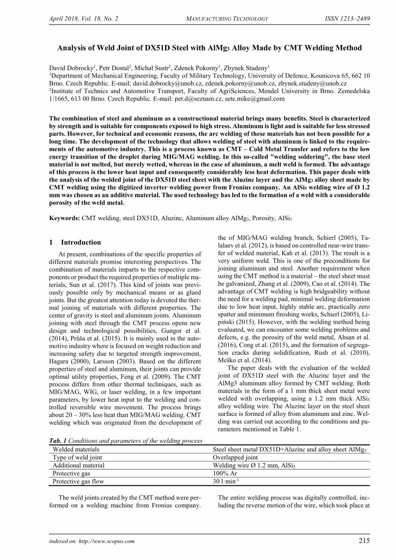
Fig. 1 Indentations after microhardness measurement. Measurement of the transition area at the contact of
DX51D steel–weld metal AlSi5 (a) and contact of AlMg3 alloy–weld metalAlSi5 (b)
The microhardness measurement was performed by
the Leco LM247AT automatic hardness tester. Measure-ment was done in 5 rows, 20 indentations, by Vickers me-thod with load 50 g (HV 0.05). The principle of micro-hardness measuring the transition area on the contact of steel sheet – the weld metal is shown in Fig. 1 (a). The principle of microhardness measuring of the transition area of contact of weld metal – Aluminum alloy is shown in Fig. 1 (b). The red arrow shows the direction of meas-urement.
Results and discussion
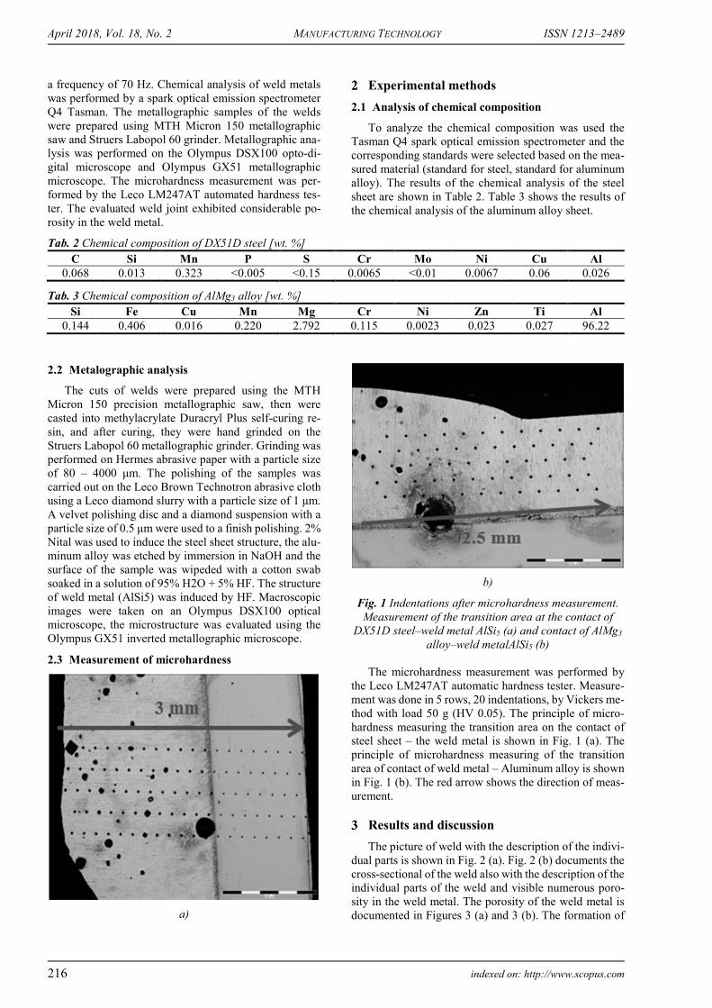
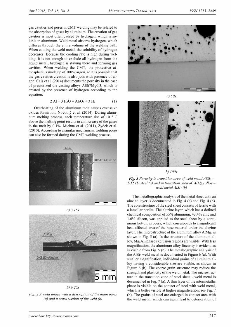
The picture of weld with the description of the indivi-dual parts is shown in Fig. 2 (a). Fig. 2 (b) documents the cross-sectional of the weld also with the description of the individual parts of the weld and visible numerous poro-sity in the weld metal. The porosity of the weld metal is documented in Figures 3 (a) and 3 (b). The formation of
April 2018, Vol. 18, No. 2 MANUFACTURING TECHNOLOGY ISSN 1213–2489
indexed on: http://www.scopus.com 217
gas cavities and pores in CMT welding may be related to the absorption of gases by aluminum. The creation of gas cavities is most often caused by hydrogen, which is so-luble in aluminum. Weld metal absorbs hydrogen, which diffuses through the entire volume of the welding bath. When cooling the weld metal, the solubility of hydrogen decreases. Because the cooling rate is high during wel-ding, it is not enough to exclude all hydrogen from the liquid metal, hydrogen is staying there and forming gas cavities. When welding the CMT, the protective at-mosphere is made up of 100% argon, so it is possible that the gas cavities creation is also join with presence of ar-gon. Cais et al. (2014) documents the porosity in the case of pressurized die casting alloys AlSi7Mg0.3, which is created by the presence of hydrogen according to the equation:
2 Al + 3 H2O = Al2O3 + 3 H2 (1)
Overheating of the aluminum melt causes excessive oxides formation, Novotný et al. (2014). During alumi-num melting process, each temperature rise of 10 ° C above the melting point results in an increase of the gases in the melt by 0.1%, Michna et al. (2011), Žydek et al. (2010). According to a similar mechanism, welding pores can also be formed during the CMT welding process.
a) 3.15x
b) 6.25x
Fig. 2 A weld image with a description of the main parts (a) and a cross section of the weld (b)
a) 50x
b) 100x
Fig. 3 Porosity in transition area of weld metal AlSi5 – DX51D steel (a) and in transition area of AlMg3 alloy –
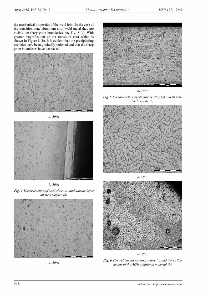
weld metal AlSi5 (b) The metallographic analysis of the metal sheet with an
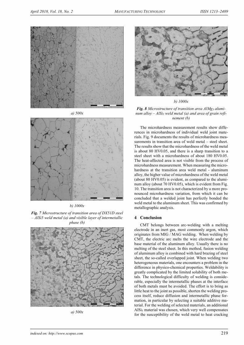
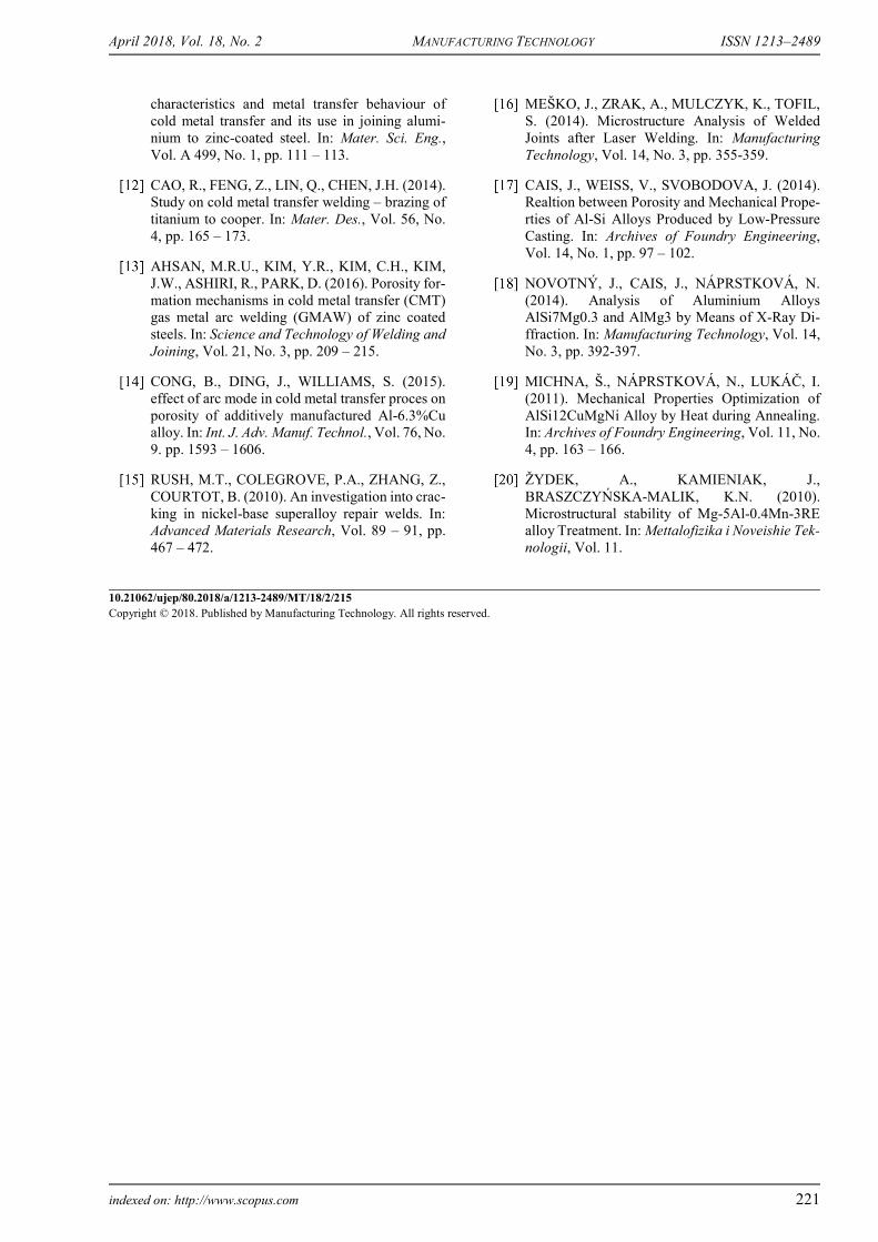
aluzinc layer is documented in Fig. 4 (a) and Fig. 4 (b). The core structure of the steel sheet consists of ferrite with a lamellar perlite. The aluzinc layer, which has a defined chemical composition of 55% aluminum, 43.4% zinc and 1.6% silicon, was applied to the steel sheet by a conti-nuous hot-dip process, which corresponds to a significant heat-affected area of the base material under the aluzinc layer. The microstructure of the aluminum alloy AlMg3 is shown in Fig. 5 (a). In the structure of the aluminum al-loy, Mg2Al3 phase exclusion regions are visible. With less magnification, the aluminum alloy linearity is evident, as is visible from Fig. 5 (b). The metallographic analysis of the AlSi5 weld metal is documented in Figure 6 (a). With smaller magnification, individual grains of aluminum al-loy having a considerable size are visible, as shown in Figure 6 (b). The coarse grain structure may reduce the strength and plasticity of the weld metal. The microstruc-ture in the transition zone of steel sheet - weld metal is documented in Fig. 7 (a). A thin layer of the intermetallic phase is visible on the contact of steel with weld metal, which is better visible at higher magnification; see Fig. 7 (b). The grains of steel are enlarged in contact area with the weld metal, which can again lead to deterioration of
April 2018, Vol. 18, No. 2 MANUFACTURING TECHNOLOGY ISSN 1213–2489
218 indexed on: http://www.scopus.com
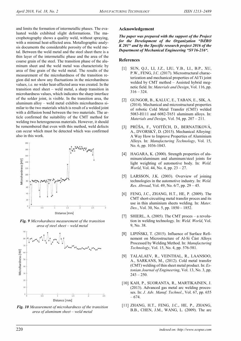
the mechanical properties of the weld joint. In the case of the transition zone aluminum alloy-weld metal they are visible the sharp grain boundaries, see Fig. 8 (a). With greater magnification of the transition area which is shown in Figure 8 (b), it is evident that the precipitating particles have been gradually softened and that the sharp grain boundaries have decreased.
a) 500x
b) 500x
Fig. 4 Microstructure of steel sheet (a) and aluzinc layer on steel surface (b)
a) 500x
b) 100x
Fig. 5 Microstructure of aluminum alloy (a) and its visi-ble linearity (b)
a) 500x
b) 500x
Fig. 6 The weld metal microstructure (a) and the visible grains of the AlSi5 additional material (b)
April 2018, Vol. 18, No. 2 MANUFACTURING TECHNOLOGY ISSN 1213–2489
indexed on: http://www.scopus.com 219
a) 500x
b) 1000x
Fig. 7 Microstructure of transition area of DX51D steel – AlSi5 weld metal (a) and visible layer of intermetallic
phase (b)
a) 500x
b) 1000x
Fig. 8 Microstructure of transition area AlMg3 alumi-num alloy – AlSi5 weld metal (a) and area of grain refi-
nement (b) The microhardness measurement results show diffe-
rences in microhardness of individual weld joint mate-rials. Fig. 9 documents the results of microhardness mea-surements in transition area of weld metal – steel sheet. The results show that the microhardness of the weld metal is about 80 HV0.05, and there is a sharp transition to a steel sheet with a microhardness of about 180 HV0.05. The heat-affected area is not visible from the process of microhardness measurement. When measuring the micro-hardness at the transition area weld metal - aluminum alloy, the higher value of microhardness of the weld metal (about 80 HV0.05) is evident, as compared to the alumi-num alloy (about 70 HV0.05), which is evident from Fig. 10. The transition area is not characterized by a more pro-nounced microhardness variation, from which it can be concluded that a welded joint has perfectly bonded the weld metal to the aluminum sheet. This was confirmed by metallographic analysis.
Conclusion
CMT belongs between arc-welding with a melting electrode in an inert gas, most commonly argon, which originates from MIG / MAG welding. When welding by CMT, the electric arc melts the wire electrode and the base material of the aluminum alloy. Usually there is no melting of the steel sheet. In this method, fusion welding of aluminum alloy is combined with hard brazing of steel sheet, the so-called overlapped joint. When welding two heterogeneous materials, one encounters a problem in the difference in physico-chemical properties. Weldability is greatly complicated by the limited solubility of both me-tals. The technological difficulty of welding is conside-rable, especially the intermetallic phases at the interface of both metals must be avoided. The effort is to bring as little heat to the joint as possible, shorten the welding pro-cess itself, reduce diffusion and intermetallic phase for-mation, in particular by selecting a suitable additive ma-terial. For the welding of selected materials, an additional AlSi5 material was chosen, which very well compensates for the susceptibility of the weld metal to heat cracking
April 2018, Vol. 18, No. 2 MANUFACTURING TECHNOLOGY ISSN 1213–2489
220 indexed on: http://www.scopus.com
and limits the formation of intermetallic phases. The eva-luated welds exhibited slight deformations. The ma-crophotography shows a quality weld, without spraying, with a minimal heat-affected area. Metallographic analy-sis documents the considerable porosity of the weld me-tal. Between the weld metal and the steel sheet there is a thin layer of the intermetallic phase and the area of the coarse grain of the steel. The transition phase of the alu-minum sheet and the weld metal was characteristic by area of fine grain of the weld metal. The results of the measurement of the microhardness of the transition re-gion did not show any fluctuations in the microhardness values, i.e. no wider heat-affected area was created. In the transition steel sheet – weld metal, a sharp transition in microhardness values, which indicates the sharp interface of the solder joint, is visible. In the transition area, the aluminum alloy – weld metal exhibits microhardness si-milar to the two materials which is result of a welded joint with a diffusion bond between the two materials. The ar-ticle confirmed the suitability of the CMT method for welding two heterogeneous materials. However, it should be remembered that even with this method, weld defects can occur which must be detected which was confirmed also in this work.
Fig. 9 Microhardness measurement of the transition area of steel sheet – weld metal
Fig. 10 Measurement of microhardness of the transition area of aluminum sheet – weld metal
Acknowledgement
The paper was prepared with the support of the Project for the Development of the Organization “DZRO K 201“ and by the Specific research project 2016 of the Department of Mechanical Engineering “SV16-216“.
References
SUN, Q.J., LI, J.Z., LIU, Y.B., LI., B.P., XU, P.W., FENG, J.C. (2017). Microstructural charac-terization and mechanical properties of Al/Ti joint welded by CMT method – Assisted hybrid meg-netic field. In: Materials and Design, Vol. 116, pp. 316 – 324.
GUNGOR, B., KALUC, E., TABAN, E., SIK, A. (2014). Mechanical and microstructural properties of robotic Cold Metal Transfer (CMT) welded 5083-H111 and 6082-T651 aluminum alloys. In: Materials and Design, Vol. 54, pp. 207 – 211.
PRŮŠA, F., VOJTĚCH, D., BERNATIKOVÁ, A., DVORSKÝ, D. (2015). Mechanical Alloying: A Way How to Improve Properties of Aluminium Alloys. In: Manufacturing Technology, Vol. 15, No. 6, pp. 1036-1043.
HAGARA, K. (2000). Strength properties of alu-minum/aluminum and aluminum/steel joints for light weighting of automotive body. In: Weld. World, Vol. 44, No. 4, pp. 23 – 27.
LARSSON, J.K. (2003). Overview of joining technologies in the automotive industry. In: Weld. Res. Abroad, Vol. 49, No. 6/7, pp. 29 – 45.
FENG, J.C., ZHANG, H.T., HE, P. (2009). The CMT short-circuiting metal transfer proces and its use in thin aluminium sheets welding. In: Mater. Des., Vol. 30, No. 5, pp. 1850 – 1852.
SHIERL, A. (2005). The CMT proces – a revolu-tion in welding technology. In: Weld. World, Vol. 9, No. 38.
LIPIŃSKI, T. (2015). Influence of Surface Refi-nement on Microstructure of Al-Si Část Alloys Processed by Welding Method. In: Manufacturing Technology, Vol. 15, No. 4, pp. 576-581.
TALALAEV, R., VEINTHAL, R., LAANSOO, A., SARKANS, M., (2012). Cold metal transfer (CMT) welding of thin sheet metal product. In: Es-tonian Journal of Engineering, Vol. 13, No. 3, pp. 243 – 250.
KAH, P., SUORANTA, R., MARTIKAINEN, J. (2013). Advanced gas metal arc welding proces-ses. In: J. Adv. Manuf. Technol., Vol. 67, pp. 655 – 674.
ZHANG, H.T., FENG, J.C., HE, P., ZHANG, B.B., CHEN, J.M., WANG, L. (2009). The arc
April 2018, Vol. 18, No. 2 MANUFACTURING TECHNOLOGY ISSN 1213–2489
indexed on: http://www.scopus.com 221
characteristics and metal transfer behaviour of cold metal transfer and its use in joining alumi-nium to zinc-coated steel. In: Mater. Sci. Eng., Vol. A 499, No. 1, pp. 111 – 113.
CAO, R., FENG, Z., LIN, Q., CHEN, J.H. (2014). Study on cold metal transfer welding – brazing of titanium to cooper. In: Mater. Des., Vol. 56, No. 4, pp. 165 – 173.
AHSAN, M.R.U., KIM, Y.R., KIM, C.H., KIM, J.W., ASHIRI, R., PARK, D. (2016). Porosity for-mation mechanisms in cold metal transfer (CMT) gas metal arc welding (GMAW) of zinc coated steels. In: Science and Technology of Welding and Joining, Vol. 21, No. 3, pp. 209 – 215.
CONG, B., DING, J., WILLIAMS, S. (2015). effect of arc mode in cold metal transfer proces on porosity of additively manufactured Al-6.3%Cu alloy. In: Int. J. Adv. Manuf. Technol., Vol. 76, No. 9. pp. 1593 – 1606.
RUSH, M.T., COLEGROVE, P.A., ZHANG, Z., COURTOT, B. (2010). An investigation into crac-king in nickel-base superalloy repair welds. In: Advanced Materials Research, Vol. 89 – 91, pp. 467 – 472.
MEŠKO, J., ZRAK, A., MULCZYK, K., TOFIL, S. (2014). Microstructure Analysis of Welded Joints after Laser Welding. In: Manufacturing Technology, Vol. 14, No. 3, pp. 355-359.
CAIS, J., WEISS, V., SVOBODOVA, J. (2014). Realtion between Porosity and Mechanical Prope-rties of Al-Si Alloys Produced by Low-Pressure Casting. In: Archives of Foundry Engineering, Vol. 14, No. 1, pp. 97 – 102.
NOVOTNÝ, J., CAIS, J., NÁPRSTKOVÁ, N. (2014). Analysis of Aluminium Alloys AlSi7Mg0.3 and AlMg3 by Means of X-Ray Di-ffraction. In: Manufacturing Technology, Vol. 14, No. 3, pp. 392-397.
MICHNA, Š., NÁPRSTKOVÁ, N., LUKÁČ, I. (2011). Mechanical Properties Optimization of AlSi12CuMgNi Alloy by Heat during Annealing. In: Archives of Foundry Engineering, Vol. 11, No. 4, pp. 163 – 166.
ŽYDEK, A., KAMIENIAK, J., BRASZCZYŃSKA-MALIK, K.N. (2010). Microstructural stability of Mg-5Al-0.4Mn-3RE alloy Treatment. In: Mettalofizika i Noveishie Tek-nologii, Vol. 11.
10.21062/ujep/80.2018/a/1213-2489/MT/18/2/215 Copyright © 2018. Published by Manufacturing Technology. All rights reserved.