
Treatment of Residual Psychotic Symptons in Ultra-Refractory ...
Upload
khangminh22Category
view
3download
0
CONF-8308130(DE84001745)January 1984
Distribution Category UC-25
DE04 001745
REFRACTORY ALLOY TECHNOLOGYFOR SPACE NUCLEAR POWER APPLICATIONS
Proceedings of a symposium held atOak Ridge, Tennessee
August 10-11,1983
Sponsored by
SP-100 Project Office
Edited by
R. H. Cooper, J r .E. E. Hoffman
January 1984
Published byTechnical Information Center
Office of Scientific and Technical InformationUnited States Department of Energy

Conference Organization
GENERAL CHAIRMAN
W. 0. Harms, Oak Ridge National Laboratory
PROGRAM ORGANIZERS AND TECHNICAL PROGRAM CHAIRMEN
R H. Cooper, Jr., Oak Ridge National LaboratoryE. E. Hoffman, U. S. Department of Energy, Oak Ridge Operations
ADVISORY COMMITTEES
Compatibility
R L. Dairies, NASA Lewis Research CenterN. J. Hoffman, Rockwell International, Energy Technology Engineering CenterP. Roy, General Electric Company. Advanced Reactor Systems DepartmentS. A. Shiels, Westinghouse Electric Corporation, Advanced Energy Systems Division
Processing and Production
G. C. Bodine, Combustion Engineering, Inc.R L. Heestand, Oak Ridge National LaboratoryR E. McDonald, ConsultantR A. Perkins, Lockheed Missiles and Space Company, Inc., Palo Alto Research LaboratoryW. E. Ray, Westinghouse Electric Corporation, Advance 1 Energy Systems Division
Welding and Component Fabrication
E. A. Franco-Ferreira, Consultant ServicesW. C. Hagel, Climax Molybdenum Company of MichiganT. A. Moss, Rockwell International, Energy Systems GiOupG. M. Slaughter, Oak Ridge National Laboratory, Metals and Ceramics Division
Mechanical and Physical Properties
R L. Amman, Westinghouse Electric Corporation, Advanced Energy Systems DivisionW. C. Hagel, Climax Molybdenum Company of MichiganH. E. McCoy, Oak Ridge National Laboratory
Effects of Irradiation
M. L. Bleiberg, Westinghouse Electric Corporation, Advanced Energy Systems DivisionJ. W. Davis, McDonnell Douglas Astronautics Company EastR E. Gold, Westinghouse Electric Corporation, Advanced Energy System? Division/. Moteff, University of Cincinnati
CONFERENCE STAFF
Mary Helen Owens, Oak Ridge National LaboratoryLyn Elrod, Oak Ridge National LaboratoryBonnie Reesor, Oak Ridge National Laboratory

CONF-8303130(DE84001745)January 1984
Distribution Category UC-25
ABOUT THE TECHNICAL INFORMATION CENTER
The Office of Scientific and Technical Information,Technical Information Center in Oak Ridge, Tennessee,has been the national center for scientific and technicalinformation for the Department of Energy (DOE) and itspredecessor agencies since 1946. In developing and manag-ing DOE's technical information program, the Centerplaces under bibliographic control not only DOE-originated information but also worldwide literature onscientific and technical advances in the energy field andannounces the source and availability of this information.Whereas the literature of science is emphasized, coverageis extended to DOE programmatic, socioeconomic, envi-ronmental, legislative/regulatory, energy analysis, andpolicy-related areas. To accomplish this mission, theGinter builds and maintain:, computerized energy-iRiormation data bases and disseminates this informationvia computerized retrieval systems and announcement pub-lications such as abstracting journals, bibliographies, andupdate journals. Direct access to the Center s most com-preiensive data base, the Energy Data Base, is availableto the public through commercial on-line bibliographicretr eval systems. The Energy Data Base and many of theCsn.er's energy-related data bases are available to DOEoffices and contractors and to other government agenciesvia 3OE/RECON, the Department's on-line informationretrieval system. The Center has developed ard maintainssystens to record and communicate energy-relatedresea'ch-in-progress information, to maintain a register ofDOE public communications publications, to track••eseai ch report deliverables from DOE contractors, and totest end make available DOE-funded computer softwareprograms with scientific and management applications.The Center also maintains a full-scale publishing capabil-ity to serve special publication needs of the Department.To e'fectively manage DOE's technical informationresources, the Center's program is one of continual devel-opmen and evaluation of new information products, sys-tems, and technologies.
UNITED STATES DEPARTMENT OF ENERGY
Donald Paul HodelSecretary
Martha O. HesseAssistant Secretary
Management and Administration
William S. HeffelfingerDirector of Administration
Joseph G. CoyneManager
Office of Scientific and Technical Information
Refractory Alloy Technology forSpace Nuclear Power Applications
ABOUT THIS PUBLICATION
Early in 1983 it became apparent to staff members at theOak Ridge National Laboratory and the DOE Oak RidgeOperations Office thai, because of the renewed interest inhigh-performance space nuclear power systems, a mecha-nism was needed to make the results of earlier researchon candidate refractory alloys for these systems availableto the SP-100 project. Because of the rapid termination ofwork on these alloys for space nuclear applications in1972 and 1973, much of the valuable data on thesematerials was only marginally documented. In many casesthe progress or topical reports received very limited distri-bution. During the period from 1973 to 1983 many of therefractory alloy technologists who were involved in thesystems development efforts of the 1960s have retired orchanged their specialty areas.
The conclusion was made that a publication comprisedof review papers by experts familiar with the work donemostly during the 1960s and including more recent workwas needed. The focus of the plan was to achieve twogoals.
• To review and document- the status of refractoryalloy technology for structural and fuel-claddingapplications in space nuclear power systems.
• To identify and document the refractory alloyresearch and development needs for the SP-100 Pro-gram in both the short and the long term.
The technical program staff and the editors of theseproceedings wish to thank the many individuals who con-tributed to the success of the symposium and to the prep-aration of these proceedings. We sincerely hope that theinformation contained herein is used to expedite progressin this challenging technology.
Technical Information Center, Office of Scientific and Technical InformationUm>ed States Department of Energy, P. O. Box 62. Oak Ridge, TN 37831

IntroductionIt has been my pleasure to serve as general chairman for the Symposium on RefractoryAlloy Technology for Space Nuclear Power Applications. The sponsor of the symposiumis the SP-100 Program, a triagency endeavor involving the Office of Aeronautics andSpace Technology of the National Aeronautics and Space Administration, the Office ofNuclear Energy of the Department of Energy, and the Defense Advanced ResearchProjects Agency of the Department of Defense. The SP-100 designation is appropriatebecause the program covers two classes of nuclear devices for space applications: a100 KW(e) class and a muitimegawatt [as high as 100 MW(e)] class. For the presenttime, the major effort by far is on the 100 KW(e) class, although planning is alreadyunde1" way on muitimegawatt concepts.
The purpose of this symposium is twofold: (1) to review and document the status ofrefractory alloy technology for structural and fuel-cladding applications in space nuclearpower systems, and (2) to identify and document the refractory alloy research anddevelopment needs for the SP-100 Program in both the short and the long term. Asindicated, the two key words are status and needs. Nuclear fuel systems, per se, are notincluded in the scope of the symposium. Only the fuel cladding has been considered,principally from the standpoints of radiation damage and compatibility with coolantsand working fluids.
In organizing the symposium, an effort was made to recapture the space reactorrefractory alloy technology that was essentially cut off in midstream around 1975 when asubstantial national space nuclear reactor program, which began in the early 1960s, wasterminated. An important product of this symposium will be the identification of theR&D needs of the SP-100 Program for both the short and the long term.
The six technical areas covered in the program are compatibility, processing and pro-duction, welding and component fabrication, mechanical and physical properties, effectsof irradiation, and machinability. The refractory alloys considered, in order of increasingrefractoriness, are niobium, molybdenum, tantalum, and tungsten.
The papers have had a rather thorough presymposium review. As shown on page ii ofthis volume, advisory committees were established for each of the technical areas. Themembers of these advisory committees are selected experts, and they had the opportu-nity to review the papers. A design needs panel, made up of representatives of industrialconcep design teams and the SP-100 Project Office, also reviewed the papers.Workshops were held the day before the symposium at the Oak Ridge National Labora-tory mainly for the purpose of developing a consensus concerning the R&D needs.
We believe that the process of bringing the symposium to fruition has been worth-while and trust that the proceedings contained herein will serve a continuing useful pur-pose in this nation's space nuclear reactor programs.
W. O. Harms, DirectorNuclear Reactor Technology ProgramsOak Ridge National Laboratory

Origin and Organization of the SP-100 Program
Judith H. AmbrusNational Aeronautics and Space Administration
INTRODUCTION
The logo of the SP-100 Program (Fig. 1) reveals itsphilosophy. TVie spirit of cooperation among theNational Aeronautics and Space Administration(NASA), the Department of Energy (DOE), and theDefense Advanced Research Projects Agency(DARPA) is part of its history and is evident in itsorganization.
BACKGROUND
During the 1960s America expended consider-able effort in space nuclear reactor power, but inthe early 1970s that program came to an abrupthalt. A number of technical efforts were eitherredirected, put on the shelf, or forgotten; peopledispersed and efforts were directed elsewhere. Thespecific reason for terminating these activities islost in history, but it may have been part of a
Fig. 1 SP-100 Program logo.
strong and vigorous reaction in this countryagainst nuclear power and other technologies. Thecountry became tired of hearing about advances intechnology, and an era came to an end by simplylanding a man on the moon.
Toward the end of the 1970s, however, a groupof us v.ere charged with examining the need foxpower in space. What had changed since the 196°3?First, the shuttle had become a reality. The poten-tial of flying into space every couple of monthsmeans we can actually go into space and do work.That open^ up quite a few possibilities about whatwe want to do in space.
Those of us concerned about energy needs inspace and how to supply these needs took a look atour future space opportunities. We first noted thatour satellites and spacecraft had either a few hun-dred watts for several years or a couple ofkilowatts for a few months. We then tried to imag-ine what future space missions and their powerrequirements might be. Quite likely we would wantto explore Saturn's rings now that we have had alook at them (Fig. 2). To go to Saturn and explorethe rings by conventional propulsion, however,would take about 20 or 25 years. If today'sengineers and not their grandchildren want to seethe spacecraft do something, we need nuclear pro-pulsion; energy demands for the trip are likely tobe in the order of 106 kWh. Other possibilities aredirect broadcast satellites (Fig. 3), which againwould require an order of magnitude more energy,and a space power distribution center, a largepower generation center in space that would beampower down.
The Program Office i3 also composed of threemembers, one from each agency. At its head is theDARPA member, Bill Wright, who has twodeputies—Steve Lanes from DOE and me fromNASA. Taking its direction from the steering

AMBRUS
Rendezvous with Saturn's Rings Manned Mars Mission
CRUISE CONFIGURATION
SPIN AXIS 4 RPM '
AlFUOi' - iS T O M M S » H ' t M l i l
STOWf U
• POWER: 100 kW
» MISSION:• ION-PROPULSION ENABLED• 8 YEARS TO SATURN. 3 YEARS EXPLORATION• 1 YEAR TITAN MAPPING,
2 YEARS RING SPIRAL
• POWFR: 6 MW
• MISSION:• 33-MONTH EARTH RETURN• 3-MAN CREW ON SURFACE
FOR 1 MONTH
Fig. 2 Potential mission applications: apace science.
Advanced Broadcast Space-Based Radar
100 kW
CONTINENTAL COVERAGE
• 100 kW
Fig. 3 Potential miMion applications: civilian/eoramerclRL

ORIGIN AND ORGANIZATION OF THE SP-100 PROGRAM
committee, the Program Office provides technicaldirection on a programmatic basis in a verybroad-brush way. It answers such vi_:;rL;:.z as:How much can we—and should we—spend on mis-sion studies? How much can we spend on systemstudies? Can we afford this particular technology?How important is one technology likely to be toanother?
The power that runs the program is delegatedto the Project Office at J?L. In the hands of theproject manager resides complete technical respon-sibility.
SUMMARY
The SP-100 Program organization wasdeveloped to be consistent with the history andcomplexity of the task. We believe this organiza-tion will be effective in directing the spirit, of coop-eration needed to make the SP-100 Program a suc-cess.
A next step for more effectively occupying spaceis to build a space station. Energy demands forsuch a project grow larger the more often we loikat them. The space station task force is now talk-ing about 65 kW for the first-generation unat-tended space station, with a mission life of fiveyears. For the second-genoration space station, tofollow a few years later, the task force is talkingabout 120 to 150 kW.
To provide such high power for long periods oftime is likely to require a nuclear reactor. The taskforce therefore looked around and asked, "Is therea space nuclear reactor?" What they found werefragments. A small effort on a new type of spacereactor, little more than a feasibility study, existedat Los Alamos National Laboratory (LANL). Therewas also a small effort in thermoelectric conver-sion at the Jet Propulsion Laboratory (JFL),funded by NASA. These were the enly two activi-ties in the co-intry that had anything at all to dowith space nuclear power, and both programs werewoefully underfunded. Recognizing that, to accom-plish something with so few funds, some specializa-tion of labor was needed, JPL and LANL startedtalking to each other, which is wonderful for twolaboratories to do.
The next step was even more unique. Two spon-soring agencies started to talk io each other aboutdeveloping an interface between the technicalrequirements of the heat 3ourc<> and the conversionsystem. This dialogue led to questions concerningthe spacecraft's requirements. At that point, themissions people became involved, and a programwas born. We had a system, we had a program,
and two agencies were talking to each other. Soona third agency, which was likely also to be a user,came around. After a lot of negotiation, the threeagencies—DOE, NASA, aad DARPA—created atri-agency program to develop space reactor powersystem technology (Table 1).
TABLE 1
The SP-100 Program
• A joint program of DARPA, DOE, and NASA' Defined in an agreement 3igned 7'eb.ruary 11,1933, in which:
• DOE is specified to chair the steering committee andname the deputy project manager for nuclear technology
• PARPA is specified to provide the progr i director• NASA/JPL is specified to manage che project
• Defined to have the DOD, DOE, and NASA charter hr allspace nuclear reactor power systems technology development
• Funded at $14.9 million in FY 1983 (including FY 1982carryover)
ORGANIZATION
Because of the complex interrelationshipbetween the heat source, power conversion, andspacecraft systems and because three agencies areinvolved, we set up a programmatic structure(Fig. 4) that will be responsive to technical and
STEERING COMMITTEE DIRECTOR OF DARPA
PROGRAMMATICDIRECTION - ' ' -REPORTING
PROGRAM DIRECTORNUCLEAR DEPUTY
SPACE DEPUTY
PROJECT MANAGER
Fig. 4 Program structure.
administrative demands. Directing the SP-100 Pro-gram is a steering committee consisting of theDirector of DARPA, the Associate Administratorfor the Office of Aeronautics and Space Technol-ogy,* and the DOE Assistant Secretary for Nuclear
*At present, no one occupies this position on a permanentbasis.

AMBRUS
Energy, who heads the committee. The steering to go forward and advocate this concept tocommittee gives programmatic policy direction and Congress." Most importantly, they are the peopleis likely to say, "This is the time to design a getting money for the program,ground engineering system," or, "This is the time

SP-100 Program Overview
Vincent C. TruscelloJet Propulsion Laboratory
INTRODUCTION
Born to meet the special needs of America's spaceeffort, the SP-100 Program testifies to the coopera-tion among government agencies. The Departmentof Energy (DOE), the National Aeronautics andSpace Administration (NASA), and the DefenseAdvanced Research Projects Agency (DARPA) areworking together to produce a 100-kW power sys-tem for use in outer space. At this point in theeffort, it is appropriate to review (1) the approachto meet program goals; (2) the status of activitiesof the Project Office, managed by the Jet Propul-sion Laboratory (JPL); and (3) because this is ameeting on materials, answers being developed bythe Project Office to vital questions on refractoryalloy technology.
APPROACH
Four major milestones (Fig. 1) emerge for theSP-100 Program. The Memorandum of Agreementbetween the three government agencies, whichreally kicked off the current phase of the effort,was completed in the second quarter (February) ofFY 1983. Approximately a year from that date theconcept(s) will be selected. The final milestone istentatively set for the fourth quarter (July) of FY1985. Af that time we will recommend to the Pro-grar Office the concept which should go forw?rd,the technologies that should be utilized, andwhether or not to begin ground testing. To deter-mine if we are on track and to ensure that we canmake a ground test decision in FY 1985, the pro-gram will be reexamined in mid-1984. At that timewe should be prepared to determine if we will needmore time, if we can m?ke the decision by late FY1985, or (and this is less likely) if we can do itsooner.
The program will probably go through threephases: phase 1, technology assessment andadvancement; phase 2, ground testing, in which wewill actually build and demonstrate hardware onthe ground; and phase 3, flight qualification. Inactuality, phase 3 may not take place. Othernuclear space programs, such as the radioisotopicthermoelectric generator program, went fromground demonstration directly into a flightprogram. We do not know, however, if that is agood idea for larger systems. Our systems contrac-tor will examine the issue and advise us. Rightnow the program is in phase 1, the two- to three-year technology assessment and advancementstage. What then are our current objectives?
Briefly, the goals of phase 1 are (1) concept def-inition, (2) technical feasibility, and (3) costs andschedule development. The first goal, concept defi-nition, includes understanding what the missionsare. A number of missions are made possible withthe use of a reactor system, and a large part of ourprogram is dedicated to trying to understand thesemissions and their requirements. A complementaryaspect is then determining which systems make themost sense and can best me^t those particularrequirements. Identifying the missions and theconcepts provides a fair understanding of the tech-nological issues that must be answered before wecan enter the ground testing phase of the effort.
Not only do we identify the technical issues butwe carry out experiments and analyses. Our secondKoal is to conduct those development activitiesrequired to address and *esolve these issues enoughto satisfy ourselves that the technical feasibility ofthe concept will not be affected. What do we meanby enough9. Very simply, we mean looking hardenough at each of these technological Issues that,once we select a particular concept and a particularset of technologies, materials, or what have you, wewill not embark on phase 2 and suddenly find that

TRUSCELLO
MEMORANDUM OF AGREEMENT
CONCEPT(s) SELECTION
INTERMEDIATE REVIEW
GROUND TEST PHASE DECISION
FY 1983
- f
V
FY 1985
H-H—!-
v
Fig. 1 Major program milestones.
we have to stop. Reasons for stopping wouldinclude discovering a major "show-stopper"; theneed for a major development effort; or that wecannot use the concept, materials, or conversiondevices initially selected. We must move into thaground demonstration phase with a high probabil-ity of completing the engineering development.
The third important goal is understanding costsand schedule. Before we can get any sponsor tofund the second and third phases of the program,we must have a thorough understanding of costs.In the present phase, we are talking about aneffort on the order of $15 million a year, or a totalr'_ about $45 million to $60 million before we moveinto phase 2. Obviously the ground demonstrationphase of the effort is going to be much moreexpensive—hundreds of millions of dollars eachyear. We could be talking about a total cost of abillion, or even several billion, dollars. Before anysponsor—or even Congress—would commit to suchfunding, we must have a good comprehension ofthe costs and schedule for completing these nextphases. Will development take two or three yearsand $0.5 to $1 billion, or will it take five or sixyears and $5 to $6 billion? Our system contractorsand in-house efforts are going to be aimed to alarge extent at trying to understand this question.We are under pressure to generate these kinds ofnumbers, because both NASA and DOE must beginto put. them into their budgets for subsequentyears.
STATUS
What is the status of the SP-100 Program?First, it is already organized and structured
(Fig. 2). The Project Office includes the manager,assistant manager, and two deputies—one forNuclear Technology and one for Aerospace Tech-nology. A coordination team established to inte-grate program resources and responsibilitiesincludes representatives from Los Alamos NationalLaboratory (LANL), JPL, and the NASA-LewisResearch Center (NASA-LeRC). They coordinateefforts, not only of these three laboratories but ofother support organizations as well [for example,DOE laboratories such as Oak Ridge NationalLaboratory (ORNL) and Hanford EngineeringDevelopment Laboratory (HEDL) and possiblyother NASA centers].
The program itself is divided into four majorareas. The Mission Analysis and Requirements andSystem Definition areas are each headed by a man-ager. The Aerospace and Nuclear Technology areasare managed by the Project Office deputies.Another area vital to the project and its viabilityis Nuclear Safety. Obviously, to get launchapproval, quite a few safety issues will have to besurmounted. Though the Nuclear Technology man-ager is responsible for this important area, we alsohave a Safety Advisory Committee (Table 1),which has begun evaluation of our activities(Table 2).
The first major area, Mission Analysis andRequirements (Fig. 3), is divided into planetarymissions, military missions, space station activi-ties, and civilian and commercial missions. In-house activities at NASA-LeRC and JPL as well ascontracted activities through the military agencieswill help generate mission requirements (Table 3)for the wide range of possible missions. The idea isto get a set of integrated requirements that can beapplied in the development of an appropriate sys-

SP-100 PROGRAM OVERVIEW
Safety AdvisoryCommi ttee
Chai man
Duane Sewell
Mi ssionAnalysis andRequirements
Manager
Dick Wallace
SP-1OO Project
Mgr - V. Truscello
Asst Mgr - H. Davi s
DMNT - J . Hanson
DMAT - J . Mondt
Coordi nationTeam
JPL - V. Truscello
LANL - J . Hanson
LeRC - R. Sovie
Admi ni s t ra t i onan.l Operations^
Manager
Kirk Gerbracht
SystemDef in i t ion
Manager
Jim French
AerospaceTechnology
Manager
Jack Mondt
Safety ancTNuclear
Technology
Manager
John Hanson
Fig. 2 SP-100 Program structure.
TABLE 1
Members of the SP-100 ProjectSafety Advisory Committee
Name Affiliation
Duane Sewell(Chairman)
Robert Bacher
Garth Cummings
R. E. SchreiberA. W. SnyderJames LeeDave Okrent
Stanley M. LuczkowskiMilton S. Plesset
Consultant
California Instituteof Technology
Lawrence LivermnreNational Laboratory
ConsultantSandia National LaboratoryUnited States Air ForceUniversity of California
(LA)Johnson Space CenterCalifoi iia Institute
of Technology
TABLE 2
Status of Nuclear Safety Activities
> Two meetings held by advisory committee• Preliminary safety plan completed and reviewed byadvisory committee
• Preliminary 3afety design requirements corrpleted andreviewed by advisory committee;, requirements issued to 3ystemcontractors
• Coordination wkn interagency nuclear safety 'eview panel(INSRP) begun

TRUSCEU.0
MILITARYMISSIONS
MANNEDSPACE
STATIONCIVILIAN/
COMMERCIALMISSIONS
PLANETARYMISSIONS
INTEGRATED REQ'TSON
POWER SYSTEM
SYSTEM DESIGN
Fig. 3 SP-100 Mission Analysis and Requirements.
TABLE 3
Summary of Mission RequirementInputs to Power System Design
> Power use profile• Mission 9urvivability• Mission duration/lifetime• Start-up/load following/shutoff• Dormancy• Attitude control•Launch vehicle compatibility (mass and size)• Deployment• interfaces (power/mechanical/control/data)• Environment (radiation, thermal)• Safety and cost implications
tem. We would like to develop a concept that meetsthe needs of a multitude of missions. That may ormay not be feasible. We may have such signifi-cantly different requirements—e.g., between mili-tary and commercial applications—that a singlepower plant design may not be possible. To theextent it is possible, however, that is our goal.Organizationally, the work is divided along theselines. The Mission Analysis and Requirements area
is headed up out of JPL. The Air Force and Navyare supplied monies to conduct military missionactivities. JPL, NASA-LeRC, and various contrac-tors are funded to do work in planetary, space sta-tion, and civil areas (Fig. 4).
To achieve the goals of the second major area,System Definition, we put out a request for bid thelatter part of 1982. Ws selected three system con-tractors: ^A Technologies teamed with MartinMarietta Corporation, Gci eral Electric, and West-inghouse teamed with Lockheed. They are rightnow going through the initial screening of the vari-ous technologies. As a result of this work, there arethree formal reviews (Fig. 5). The first oneoccurred in June, the second in September, and thefinal one in December. If hopes are realized, wewill select a contractor or contractors with one ormore concepts sometime ?.n February 1984.
W" asked the contractors to review a largearray of possible technologies with a number ofconstraints, the moit important being that thepower plant weigh les<- than 3000 kg, produce atleast 100 kW of power, Lnd fit into no mure than

SP-100 PROGRAM OVERVIEW
MILITARY0 PLANETARY9 SPACE STATIONt CIVILIAN/COMMERCIAL
Fig. 4 Organizational support in the area of Mission Analysis and Requirements.
• MILITARY
CY 1983
CONTRACT START
FIRST REVIEW
SECOND REVIEW
FINAL REVIEW
CONCEPT SELECTION
M A M l j A S O N 0
-+--H—4-—+—-1—I—I-
v
v
V
Fig. 5 Systems concept selection schedule.
one-third of the shuttle bay. We are finding thatmeeting those constraints is by no means Ln easytask.
We have a large number of options with respectto producing the electrical power from the thermalunergy of the reactor. Figure 6 shows a hypotheti-cal structural design of a concept using a dynamicheat engine. The reactor constitutes only a verysmall part of the volume and the weight of theentire power system. Most of the volume is takenup by the device that rejects the portion of powernot converted into electricity—the waste heat radi-ator. This turns out to be quite i limiting aspectfor the various design concepts being evolved. Ourhope was to design a static radiator that would nothave to be deployed ^nce it was placed in space. To
meet the requirements of power and weight, how-ever, it appears that many, though not ail, of theseconcepts will have to use a deployable radiator.
The contractors have narrowed down the list ofvarious technologies being considered (Table 4).For instance, chey initially looked at thermal,epithermal, and fast reactors but, because ofweight limitations, quickly zeroed in on a fast reac-tor. They have started looking at reactors cooledwith gas, liquid-metal, and heat-pipe systems. Asfor power conversion devices, the program has thevarious dynamic conversion options of Brayton,Stirling, and Rankine cycles. For static conversion,there are thermoelectric; thermionic; in-core andout-of-core systems; and some new technologies(which are really in their infancy state but may

10 TRUSCELLO
CABLE SUPPORT
RADIATOR PANELS
TRUSSES
PC ELECTRONICSSUPPORT RING
(TRUSSES
PC I-RADIATOR-)
Fig. 6 SP-100 Aerospace Technology: hypothetical structural design of an SP-100 concept.
TABLE 4
Candidate Subsystem Concepts
Reactor conversion
• Heat-pipe-cooledreactor (fast)
• Pumped liquid-metal-cooled reactor (fast)
• Gas-coolod reactor (fast)
•Brayton• Stirling• Rankine• Thermoelectric• Thermionic in-core• Thermionic out-of-core•AMTEC•TPV
well be good for growth versions), the alxali metalthermoelectric converter (AMTEC), and thermo-photovoltaic conversion (TPV).
The system contractors are evaluating all ofthese options. In fact, they have narrowed downthe list even further. Interestingly, each has asomewhat different view. Our job, therefore, is tocome to grips with their several answers and toevaluate what does and does not make sen3e. To dothat, we are trying to define what the technologyprogram is going to be over the next two years.
Here we run into problems: The sponsor needs anannual operating plan, and the Project Office needsa cost breakdown of exactly what is going to bedone and why. The definitive inputs from the sys-tem contractors, however, are not due untilDecember. So we have to make judgments as towhat we should start doing right now. Using thesignificant data base that already exists at the var-ious DOE laboratories and the NASA laboratories,such as JPL and NASA-LeRC, we set up a Technol-ogy Assessment Working Group (TAWG). In thepast t^ee or four months, this large team of gov-ernment people has worked together to assess theoptions, identify feasible technologies, and rank theoptions. This tc^m has pretty much accomplishedthat task.
Although the system contractors have notagreed with one another, as a community thesystems they selected do line up with those weevaluated independently and ranked at the top. TheProject Office is comfortable with the directionthat things are going right now. Whether we willbe able to move ahead with all of these technolo-gies or whether we have to downscope to an evensmaller group, only the Program Office will tell.

31--100 PROGRAM OVERVEW 11
1500
TEMPERATURE (°F)
2000 2500
STRESS (psi) 5FOR 1 % CREEP
IN 10,000 h 2
3000
800 1000 1200 i400 1600TEMPERATURE (°C)
1800
Fig. 7 SP-100 Aerospace Technology: high-temperature strength information for candi-date alloys.
In major areas 3 and 4, Aerospace and NuclearTechnology, the TAWG used the expertise of eachlaboratory. LANL, for example, examined theshield and reactor subsystems to determine wherethe technology is—the weight of the reactor perunit of power produced and the t. chnical feasibilityissues associated with those subsystems. NASA-LeRC, with romc support from ORNL, did the workon the dynamic machinery; and JPL did the workon the static subsystems.
REFRACTORY ALLOYS
Studies Dy JPL °taff and a subset of the TAWGas well as inputs from the three systems designcontractors reveal that to meet system require-ments of a 3000-kg system weight and 100-kW out-put, use of refractory alloys is imperative. Whywas this class of alloys identified? Clearly the lead-ing candidates are thosa alloys that, can operate atvery high temperatures and have suitable creepstrength (Fig. 7). For that reason we cannot livewith superalloys—and certainly not with stainlesssteels, which are applicable at very low tempera-tures compared to the types of systems we areworking on. A review of possible applications ofthe candidate tungsten-, molybdenum-, andtantalum-base alloys (Fig. 8) was conducted by theTAWG subset. As a result of this review, refrac-tory alloy feasibility issues surfaced regarding core
structural and fuel cladding applications in thenuclear subsystem as well as piping, heatexchanger, pump, turbine wheel, and Stirling cyclepiston applications in the power conversion subsys-tem.
The area of refractory alloys is important notonly for the reactor but also for the power conver-sion system. The Project Office had to make surethe SP-100 Program did not take off in all direc-tions, developing materials suitable for each partic-ular power conversion, heat transport, and nuclearreactor application. To meet that challenge, we setup a structure that meets the needs of all thesediverse applications (Fig. 9). The key is a technicalplanning team that defines materials needs. Madeup of representatives from each of the major con-tributing laboratories, this team will define therequirements, the material development needs, andthe costs and schedule to meet these needs. Asteering committee made up of the Project Ofiiceand Aerospace and Nuclear Technology managerswill act on the planning team's recommendationsfrom a programmatic standpoint to determine (1)whether or not we can afford it, (2) how it fits inwith all our other needs, and (3) when those partic-ular needs are important and should be imple-mented. A group housed at LANL will lead theeffort in implementing the actual developmentwork through the various laboratories and contrac-tors.

12
S . Candidate\ ^ Alloy
Major \ .Application*--^^by Subsystem ^ \
NUCLEAR SUBSYSTEMClad
Core Structure(weldable)
POWER CONVERSIONSUBSYSTEMPiping/HXPumps
Turbine Wheels/Pistons
Static Components
Heat Pioes
W
Yesa
NA
NA
NA
NA
NA
MoRe
Yes
Yes
NA
Yes
NA
Yes
T-111
NA*
Yes
Yes
NA
Yes
Yes
ASTAR 811C
Yes*
Yes
Yes
NA
Yes
Yes
I
TZM/TZC
NA
NA
NA
Yes
NA
NA
in-core thermionic.loy was not considered for this application.
Used with tungsten l iner.
Fig. 8 Possible application of candidate refractory alloys by major subsystem.
This planning team has identified a number offeasibility issues (Table 5) that have to beaddressed between now and the end of the currentphase of the program—which could be FY 1985. Wehave to understand chemical compatibility of thefuel, clad, and coolant; and we need a lot more dataon such matters as irradiation behavior, specifi-cally property degradation and swelling. Becausethe systems will not be operated during launch, wemust ensure that materials do not fracture. Theirtoughness at low temperatures is critical. Anothermajor concern is the potential degradation in per-formance by refractory metals as a result of con-tamination by oxygen, carbon, or nitrogen. Thesecontaminants could be picked up from the fuel orby a fluid flowing through hot regions and de-posited in colder ones. Use of inert gases as aworking and transport fluid should solv« the prob-lem, but it does not. Because inert gases do not
react with these impurities, they can transportthem from one area to another, causing a buildupand resulting in potential long-term failure of thecomponents. Lithium, on the other hand, would bebetter, because it is a sink for most of these impur-ities. We need to do enough work on all theseissues bj that, once we select a specific materialcombination and start moving ahead in engineeringdevelopment, we will not run into any concernsthat would force termination of the effort.
In summarv, we are convinced that refractoryalloys will be necessary to meet the needs of thepower systems, whether they are used as fuel clad-ding, piping, heat pipes, turbines, or pistons.Tantalum- and molybdenum-base alloys are primecandidates to meet temperature and weight con-straints. They may also be suitable for the fuelcladding, though tantalum alloys will require abarrier to the fuel. Tungsten-rhenium alloys are an

SP-100 PROGRAM OVERVIEW 13
Steering Cornmi ttee
r Impie.nentor
DOE/NASA Labs
r - - -
1.
• Trusce• Mondt• Hanson
lo
TechnicalPlanning
Team
• LANL
11 Contractor;,
• LANL• JPL• LeRC• ORNLB HEOL
TABLE 5
Feasibility Issues
Fig. 9 Materials Development management structure.
alternative for fuel cladding. For selected powerconversion system applications, tantalum- andmolybdenum-base alloys again seem to be the bestcandidates. At these high temperatures,molybdenum-TZM is an extremely t -> d candidatefor turbine wheels for either a Bra., .on or a Ran-kine system. Both the tantalum and molybdenumalloys could be used for the heat pipes. Weldabilityconcerns, on the other hand, mean molybdenumalloys may be less suitable for the reactor struc-ture. We need to ascertain how weldable themolybdenum alloys are going to be and hew muchwork is going to be necessary to prove they can beused for piping throughout the system or for thereactor structure. Clearly we must understandrefractory metals.
SUMMARY
The SP-100 Program is expected to go throughthree phases: technology assessment and advance-
CladChemical compatibility. fuel/clad/coolantIrradiation behavior (swelling, property degradation)Fracture toughness/crack growth rateBarrier integrityMechanical propertiesInert gas compatibility
Core structureIrradiation behaviorFracture toughnessMechanical properciesThick section weldInert gas compatibility
Piping/HX/pumps/heat pipesFracture toughnessMechanical propertiesThick section weldProducibility of very large diameter pipe (3 to 4 in.)Inert gas compatibilityLife testing
Turbine btadea/piatoniHigh-temperature creepFatigueFabricability of wheel/pistonInert gas compatibility
ment, ground testing, and flight qualification.Currently the program is in the two- to three-yeartechnology assessment and advancement stage.Goals are to identify the space nuclear powersystem concept that best meets anticipatedrequirements of future space missions, assess thetechnical feasibility of that concept, and establisha cost and schedule for developing the concept. TheSP-100 Project Office has begun theimplementation activities needed to meet thesegoals, and we feel comfortable with the directionthat things are going now. With regard to refrac-tory alloys, we feel a better data base will berequired before we move ahead in the programfrom technology assessment to ground demonstra-tion.

Potential Refractory Alloy Requirementsfor Space Nuclear Power Applications
H. H. Cooper, Jr.Oak Ridgi' National Laboratory"
INTRODUCTION
Going on a space mission is analogous to taking along ocean voyage in a small boat. Both spacecraftand boat components must be constructed of highquality materials designed for high reliability. Oneof the more critical components for future space-crafts will be a nuclear reactor to provide energyfor (a) powering ion propulsion systems to expeditetrips to the outer planet?, and (b) defense applica-tions such as surveillance satellites, large radarsystems, laser-based communication equipment,and laser or particle-beam weapons designed todestroy enemy missiles in flight. Because thesereactors should operate at a high temperature toensure efficient power production, refractory (heatresistant) alloys will be needed as the nuclear fuelcladding and structural materials. The purpose ofthis paper is to (1) provide an introduction to thedesign requirements for refractory alloys in spacenuclear applications and (2) briefly indicate thestatus of refractory alloy technology and anapproach to refractory alloy development.
RELATION BETWEEN ALLOfSELECTION AND SYSTEMPERFORMANCE
Discussions concerning requirements for struc-tural and fuel-cladding alloys in spac? reactor sys-tf.'iis normally center on a class of materialsknown as refractory alloys. The reason for this isthat thp high performance levels desired for thesesystems (i.e., high power outputs, high heat-to-
"Operated for the U. S. Department of Energy under con-tract W-7405-«ig-2*> with the Union Carbide Corporation.
electricity conversion efficiencies, ard low massand size) require very high operating temperatures.As a result, materials are required that, retain highstrength and other key properties at temperatureswell in excess of those for which more conventionalalloys, such as the stainless steels and the superal-loys, can be used. An approximate but useful mea-sure of refractoriness is the melting point (mp) ofthe metal upon which a system of alloys isbased—iron (mp 1535°C) for stainless steels, forexample. The refractory alloys under considerationfor space nuclear systems applications are thosebased on niobium (mp 2415°C), molybdenum (mp2620°C), tantalum (mp 2996°C), and tungsten (mp3410°C). The temperature limit for useful applica-tion of an alloy from the standpoint of strength isin the range of 50 to 60% of its absolute meltingtemperature.
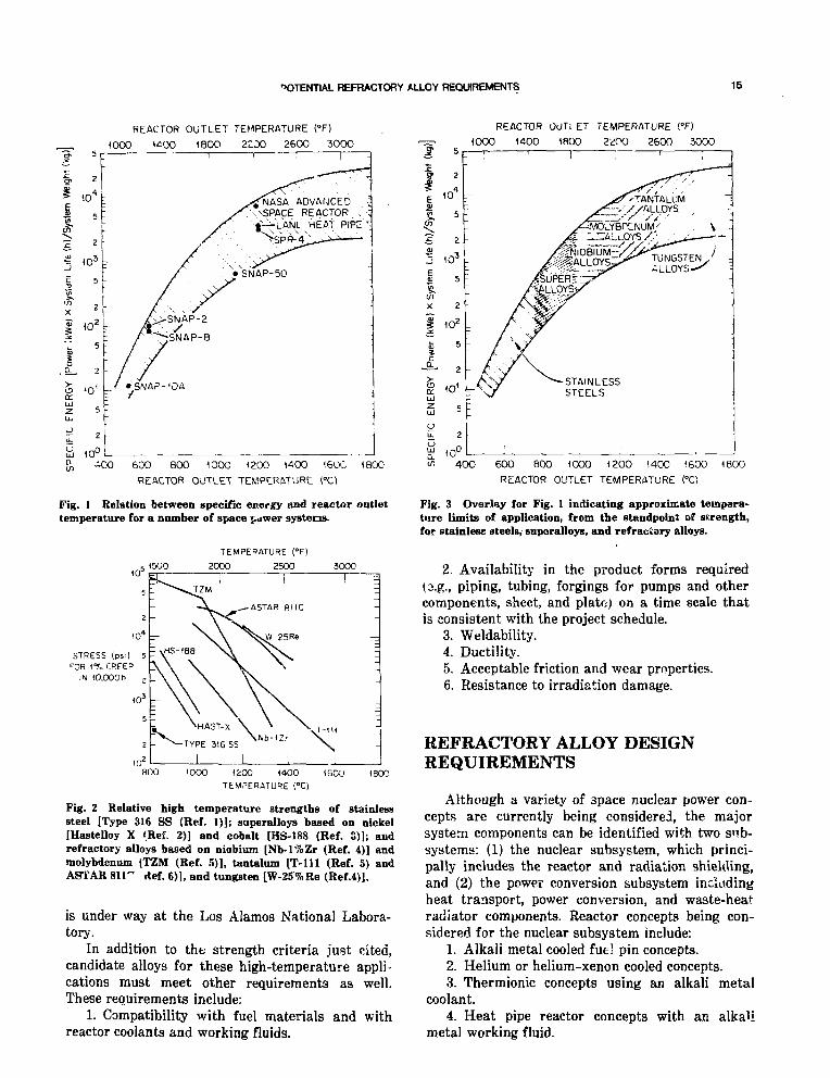
The relationship between specific energy (a use-ful performance figure of merit) and reactor outlettemperature for a number of space power systemsis presented in Fig. 1. If, as is generally conceded,the absolute upper limit for the use of stainlesssteels is about 800°C, it is apparent from this plotwhy the refractory alloys must be considered if thedesired high-performance levels are to be achieved.The relative elevated-temperature strengths ofstainless steel, the superalloys, and the selectedrefractory alloys are shown in Fig. 2 in terms ofthe stress required to produce 1% strain or defor-mation in 10,000 h. The approximate temperaturelimits for application of these alloys from thestandpoint of strength alone are indicated in theoverlay of Fig. 1 shown in Fig. 3. Limited shorttime creep data indicate that the Mo-14Re alloyshould be considered for space power applications.7
A development program on the Mo-Re alloy system
14
"OTENT1AL REFRACTORY ALLOY RECXHRQiffiNTS 15
REACTOR OUTLET TEMPERATURE (°F)
1OOO 1^00 180O 2CD0 2600 3000
NASA ADVANCED"SSPACE REACTOR .•|^H_ANL HEAT PIFc '
>SPft-4
600 800 1000 1200 1400 160C 1800
REACTOR OUTLET TEMPERATURE CO
Fig. 1 Relation between specific energy and reactor outlettemperature for a number of space power systems.
TEMPERATURE (°F)
2000 2500 3000
STRESS (psOFOR 1 % CREEP
IN lO.OOOh
800 (000 1200 1400TEMPERATURE (°C)
16CU 1800
Fig. 2 Relative high temperature strengths of stainlesssteel [Type 316 SS (Ref. 1)]; superalloys based on nickel[Hastelloy X (Ref. 2)] and cobalt [US-188 (Ref. 3)]; andrefractory alloys based on niobium [Nb-l%Zr (Ref. 4)] andmolybdenum tTZM (Ref. 5)], tantalum [T-lll (Ref. 5) andASTAR 811" tlef. 6)], and tungsten [W-25%Re (Ref.4)].
is under way at the Los Alamos National Labora-tory.
In addition to the strength criteria just cited,candidate alloys for these high-temperature appli-cations must meet other requirements as well.These requirements include:
1. Compatibility with fuel materials and withreactor coolants and working fluids.
REACTOR OUTLET TEMPERATURE !"F)
1000 1400 1800 2200 2600 3000
10"
a 5
S 2
£1OC
X
10'
15 in'IT ' OliJz ,LJ
O
a. 1O(
-STAINLESSSTEELS
2
400 600 800 1000 1200 1400 1600 1800
REACTOR OUTLET TEMPERATURE CO
Fig. 3 Overlay for Fig. 1 indicating approximate tempera-ture limits of application, from the standpoint of strength,for stainless steels, supcralloys, and refractory alloys.
2. Availability in the product forms required(3.g., piping, tubing, forgings for pumps and othercomponents, sheet, and plate; on a time scale thatis consistent with the project schedule.
3. Weldability.4. Ductility.5. Acceptable friction and wear properties.6. Resistance to irradiation damage.
REFRACTORY ALLOY DESIGNREQUIREMENTS
Although a variety of space nuclear power con-cepts are currently being considered, the majorsystem components can be identified with two sub-systems: (1) the nuclear subsystem, which princi-pally includes the reactor and radiation shielding,and (2) the power conversion subsystem includingheat transport, power conversion, and waste-heatradiator components. Reactor concepts being con-sidered for the nuclear subsystem include:
1. Alkali metal cooled fuel pin concepts.2. Helium or helium-xenon cooled concepts.3. Thermionic concepts using an alkali metal
coolant.4. Heat pipe reactor concepts with an alkali
metal working fluid.

16 COOPER
The operating temperatures for these conceptsrange from 625 to 1525°C and are summarized inTable 1. The primary application of refractoryalloys in these reactor concepts are for (1) in corestructural supports and fuel cladding for either gas
liquid metal fuel pin concepts or (2) fuel
TAB1LE1
Coolants and Operating Temperaturesfor Candidate Reactor Concepts
orsupport for heat pipe reactors vrhere the fuel is onthe outside of the heat transport system. Designrequirements for refractory alloys used in eitherapplication include effective load carrying capabil-ity at the proposed operating temperature, goodfabricability, resistance to irradiation damage, andacceptable compatibility with alkali metals or inertgases and fuels (for fuel cladding).
The power conversion subsystems include com-ponents for specific power conversion, heat trans-port, and waste heat rejection. Power conversionsystems f Ii into two groups—dynamv and static.Dynamic subsystems include Brayton, Stirling, andRankine cycles; static subsystems include ther-moelectric, alkali metal thermoelectric conversion(AMTEC), and th --malphotovoltaic (TPV). Thepossible working i.uids and range of operatingtemperatures anticipated for these candidate sys-tems are summarized in Table 2. Possible applica-tion for refractory alloys in the power conversionsubsystems include piping, pumps, and heatexchangers. With regard to specific conversiontechnologies, refractory alloys will also be requiredfor turbine blades for Brayton and Rankine sys-tems and heater heads and pistons for Stirlingcycle applications. Desihrn requirements that willbe imposed upon the refractory alloys in theseapplications will include effective load-carryingcapability, good fabricability, acceptable compati-bility with working fluids, good wear resistance,and adaptability to being coated with high-emissivity materials.
REFRACTORY ALLOYTECHNOLOGY STATUS
A review of the status of refractory alloy tech-nology provides both good and bad inputs. The pos-itive aspects are the significant accomplishmentsmade with refractory alloys during the 1960s and1970s that are directly applicable to the SP-100Program. The negative information is the fact thatrefractory alloy technology for space nuclear reac-tors has been dormant since the termination ofthese development activities in the mid-1970s. As aresult the refractory alloy nuclear technologyavailable today is not adequate to meet the SP-100Program needs.
Reactor concepts
Liquid metal cooledGas cooledThermionicHeat pipe
Coolant
Alkali metalHe or He/XeAlkali metalAlkali metal
Operatingtemperature range.
°C
625 to i52f>825 to 1325
1225 to 1525625 to 1525
Working Fluidsfor Candidate
Po\»erconversion
concepts
Dynamic cycleBraytonSterlingRankine
Static cycleThermoelectricAMTEC'TPV+
TABLK 2
and Operating TemperaturesPower Conversion
Workingfluid
He or He/XeHeAlkali metal
_Alkali meta1.
-
i Concepts
Operatingtemperature
range,°C
875 to 1375825 to 1375675 to 1325
1100 to 1325925 to 1025
1725
'Alkali metal thermoelectric conversion.+Thermalynotovoltaic.
Currently, there is nc annotated bibliography ofthis technology which integrates the past and cur-rent alloy development accomplishments of NASA,DOD, and DOE. Also, many reports on refractoryalloy activities of the 1960s and 1970s were notpublished. Moreover, in some cases insufficienttechnical detail was reported to allow interpreta-tion of the data.
APPROACH TO REFRACTORYALLOY DEVELOPMENT
Successful application of refractory alloys willrequire a strong and continuing dialogue betweenmaterial scientists and space power systems designspecialists. This dialogue typically begins with thedesign community identifying the materialsrequirements. The materials community then gen-erates the engineering data needed to assess theeffectiveness of candidate alloys with respect to thedesign requirements. Because alloys rarely measureup to all of the designer's requirements, the inter-action between the design and the materials com-munities is by necessity an iterative process.

POfENTlAL REFRACTORY Al-LOV REQUIREMENTS 17
This meeting provides a forum for initiating thedevelopment of refractory alloy nuclear technologyby involving both the refractory alloy experts ofthe 1960s and 1970s and the current experts.Through the cooperation of these experts, we hopeto develop an assessment of the current status andneeds of a refractory alloy nuclear technology.
SUMMARY
In reviewing design requirements for refractoryalloys for space nuclear applications, several keypoints are identified. First, the successful utiliza-tion of refractory alloys is considered an enablingrequirement for the successful deployment of highefficiency, lightweight, ard small spaca nuclearsystems. Second, the recapture of refractory alloynuclear technology developed in the 1960s a r iearly 1970s appears to be a pacing activity in th?successful utilization of refractory alloys. Third,the successful ppplication of refractory alloys forspace nuclear applications will present a signifi-
cant challenge to both the materials and the sys-tems design communities.
REFERENCES
1. ASME Boiler and Pressure Vessel Code, Section III, CodeCase N-47 (1982).
2. H. E. McCoy, Jr., Creep Behavior of HasteUoy X, 2HCr-lMoSteel, and Other Alloys in Simulated HTGR Helium,ORNL/TM-6822, Jun; 1969.
3. Manufacturer's Data, Stellite Division, Cabot Corporation.4. R. E. Gluyas and G K. Wa^on, Materials Technology for c.n
Advanced Space ?ower Nuclear ReacUf Concept, ProgramSummary, NASA TN D-7909, p. 39, March 1975.
5. K. D. Sheffler and R. R. Ebert, Generat'rm of Long TimeCreep Data on Refractory Alloys at Elmated Tt mperatures,NAS CR-134481, September 1973.
6. W. D. Kloop, R. H. Titran, and K. D. Sheffler, Lon-j TimeCreep Behavior of the Tantalum Alloy ASTAR- !UC. wASATP 1691, September 1980.
7. \V. D. Kloop and W. R. Witzke, Mechanical Properties ofEHectron-Beam-Melted Molybdenum and Dilute Molyb-denum-Rhenium Alloys, NASA TMX-2576, June 1972.

Refractory Alloy Component Accomplish imentsfrom 1963 to 1972
E. E. HofttnnnU. S. Department of Energy
INTRODUCTION
Many advanced technology capabilities must be h.hand in order to successfully develop nuclear elec-tric power systems for space application. Many~~Df~the rsactor/power conversion systems currentlybeing considered for SP-100 (100 kWe) applicationwould operate at temperatures sufficiently high torequire the use of refractory alloys. A technologyelement necessary to build sysiems either forground tests or launch is the ability to constructcomplicated refractory alloy components and tojoin these components into zero-leakage, durableheat transport systems of extremely high integrity.The purpose of this paper is to summarize theaccomplishments of a number of refractory alloycomponent development and testing programs con-ducted during the 1963 to 1972 time period. Thisexperience base is well documented, and effectiveutilization of this information should assist inreducing the cost and risk of future developments.
During the 10-year period, 1963 to 1972, GeneralElectric, Space Power and Propulsion Section (laterNuclear Systems Programs) located in Cincinnati,Ohio, designed, built, operated, and evaluated alarge number of refractory alloy components aspart of a long-term NASA-Lewis Research Centerspace power program. This NASA program todevelop advanced systems was focused primarily,but not exclusively, on nuclear powered Rankinesystems. This paper will provide a brief overviewof a few of the most significant componentdevelopments oi the General Electric program inthe period from 1963 until 1972 when the nationalprogram to develop advanced space power system
was abruptly t"rrw'.,;.ucu.* The General Electricportion.0 of the overall NASA-Lewis program con-centrated on component development and testing,heat transfer studies, compatibility studies, andother tasks,, such as bearing and seal development,that were requirerKto support component develop-ment.
The overall NASA-Lewis materials programduring this period was a well conceived ar.d exe-cuted program that made maximum use of the var-ious and complimentary talents of a number ofindustrial contractors and laboratories. The exten-sive alloy development and welding researchactivities of Westinghouse Astronuclear, the veryhigh quality creep program at TRW-Cleveland, andthe in-house resear-:: program at NASA-Lewis allcontributed to the success of the componentdevelopment program carried out by GE-SpacePower and Propulsion personnel.
DESCRIPTION OF REFRACTORYALLOY COMPONENTS
The specific component developments to bedescribed in this paper are listed in Table 1. All ofthese components or systems were tested andevaluated with the exception of the Nb-lZr SolarBrayton Heat Receiver. The experience and dataobtained on these systems are most relevant toadvanced Rankine applications, but much of this
*The author of this paper led a group of materials specialistsat General Electric which was responsible for the fabricationand/or testing of many of the systems described in this paperduring this time period.
18

REFRACTORY ALLOY COMPONENT ACCOMPUSH*SNTS
TABLE 1
Refractory Alloy Components and TestSystems Which Will Be Described
Mo-TZM and Mo-TZC potassium turbine componentsT-111/lithium valve test loopNb-lZr Rankine system corrosion test loopT-lll Rankine system corrosion test loopElectromagnetic (EM) pump developmentNb-lZr solar Brayton heat r<"rc--•:.-.T-lll boiler development t>«r system
inf-"-mgition, particularly the materials experienceAnd such special areas as lithium compatibility,has wide applicability to many of the systemsbeing currently considered by SP-100 contractors.Several of the systems that will be cited here arealso discussed in the paper by DeVan et al.included in these proceedings. The Nb-lZr SolarBrayton Heat Receiver and the T-lll BoilerDevelopment Test System, both listed in Table 1,were the most significant component accomplish-ments during the 10-year NASA program at Gen-eral Electric. A detailed description of the fabrica-tion of these large and complex systems is given in
"Refractory Alloy Component Fabricator" byW. R. Young in these proceedings.
A brief d^,;.iption of the various refractoryalloy components and test systems listed inTable 1 is given below.
Mo-TZM and Mo-TZC PotassiumTurbine Components
One of the most ambitious undertakings of theNASA-Lewis program at General Electric was thedevelopment, construction, and operation of a3 MW potassium turbine and the associated boilerand condenser system.'"4 The bulk of this two-phase potassium system was constructed of stain-less steel and superalloys, but the turbine rotorsand many of the rotor blades were constructed ofthe molybdenum alloys, Mo-TZM and Mo-TZC. Theturbine portions ~f the test facility are illustratedin Figs. 1 and 2. Nichols, Fink, and Zimmerman,1
in particular, give detailed guidance regarding thefabrication of the molybdenum alloy turbine bladesand rotor wheels.
UH4U5T SCROLL
2ND STJGf ROTOR
1ST STAG! ROTOR
PIVOTED PAD BEARING
DUPUX BALI BURING
FlOW
T l i BOLT
Fig. 1 Cross section of potassium test turbine. Selected rotor blades made of Mo-TZM and Mo-TZC alloys. (Three-stageversion of this test system had rotors made of Mo-TZM alloy.)
20 hOFFMAW
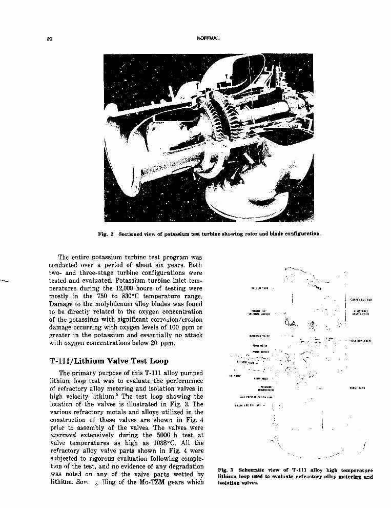
Fig. 2 Sectioned view of potassium test turbine showing rotor and blade configuration.
The entire potassium turbine test program wasconducted over a period of about six years. Bothtwo- and three-stage turbine configurations weretested and evaluated. Potassium turbine inlet tem-peratures during the 12,000 hours of testing weremostly in the 750 to 830°C temperature range.Damage to the molybdenum alloy blades was foundto be directly related to the oxygen concentrationof the potassium with significant corrosion/erosiondamage occurring with oxygen levels of 100 ppm orgreater in the potassium and essentially no attackwith oxygen concentrations below 20 ppm.
T-ll 1/Lithium Valve Test LoopThe primary purpose of this T-lll alloy pumped
lithium loop test was to evaluate the performanceof refractory alloy metering and isolation valves inhigh velocity lithium.5 The test loop showing thelocation of the valves is illustrated in Fig. 3. Thevarious refractory metals and alloys utilized in theconstruction of these valves are shown in Fig. 4prior to assembly of the valves. The valves wereexercised extensively during the 5000 h test atvalve temperatures as high as 1038°C. All therefractory alloy valve parts shown in Fig. 4 weresubjected to rigorous evaluation following comple-tion of the test, and no evidence of any degradationwas noted on any of the valve parts wetted bylithium. Son i lling of the Mo-TZM gears which
¥»CUUM t i l l -
! coi
\U,Hfli!ING YUYE
flOH It tTU
ru»r DUTLET
ISOLATION V1LVI
DIAIM *HD Fill UNI - /
Fig. 3 Schematic view of T-lll alloy high temperaturelithium loop used to evaluate refractory alloy metering andisolation valves.

REFRACTORY ALLOY COMPONENT ACCOMPUSHWeNTS 21
GUt ML. WMft'
• - - b i •
, ( 1 >. M I.' J N ' M i '• -' •
t • • . • < • • M i ' . ' •
tMP Pis ' t Nb 1 Z-
• I k • • . 1 M ' . *
=— iF . . ft
spin aiHC
PUUil BODY I I I !
}{ S U M B A S 1 I <•'
h
- SEA T B t T i l H i R T 1 H
- INLET BODY T 111
Fig. 4 Exploded view of various refractory alloy parts used in the fabrication ofthe lithium system test valves.
operated in the high vacuum environment wasnoted, and these were subsequently replaced withgears made of tool steel. Based en the successfulperformance in this test, valves of this design wereused in other test facilities built later at GeneralElectric.
Nb-lZr Rankine System CorrosionTest Loop
One of the major thrusts of the NASA-Lewissponsored program to develop advanced space elec-
tric power systems was to evaluate candidate sys-tem materials under conditions as prototypic aswas practical. For this reason a prototype corro-sion test loop system6 was developed for use in theevaluation of refractory alloys in boiling and con-densing potassium . avironments which simulatedprojected Rankine system conditions. The first testsystem developed to evaluate these alloys in atwo-loop system designed to simulate conditions inboth the heater loop (reactor coolant) and thetwo-phase Rankine loop is shown in Fig. 5. Thisphotograph was taken in the clean room prior to

22 HOFFMAN
Fig. 5 Nb-lZr Rankine system test loop mounted on vacuumchamber stainless steel spool piece prior to installation in thetest facility.
installation of the test loop and the vacuum cham-ber spool piece on which it was mounted on theultrahigh vacuum test chamber.
The prototype tesc system consisted of a two-loop Nb-lZr facility; sodium being heated by directresistance in the primary loop and used in a heatexchanger (boiler) to boil potassium in the second-ary teot loop. The method chosen to heat the boilerof the Nb-lZr Rankine System Corrosion Test Loopwas the use of a primary or heater loop in whichI2R heated sodium was to be pumped through theannulus of a tube-in-tube counterflov boiler wherethe required heat was transferred to the potassiumin the secondary two-phase circuit. One of theprincipal goals of this test program was to incorpo-rate as many components in the Nb-lZr corrosiontest loop as required to assure an accurate deter-mination of the test conditions ard, thereby, mini-mize the possibility of undetected test variations;e.g., boiling instabilities, which might compromiseloop operation or the posttest compatibility evalua-tion. Figure 6 shows the entire test facility follow-ing installation of the Nb-lZr test loop.
This test system, which was operated for 5000 hwithout difficulty and was evaluated exi,cisively,served as a prototype for the higher temperatureT-lll alloy system that will be described later inthis paper. The sodium circuit of this loop operatedat a maximum temperature of 1165°C and thepotassium circuit at a maximum temperature of1093° C during the 5000 h test. Details of thecompatibility evaluations on this loop are given inthe DeVan et al. paper in these proceedings.
T-lll Rankine System CorrosionTest Loop
This test, which followed the 5000-h Nb-lZr testdescribed aL ve, was conducted for 10,000 hours ina system constructed primarily of the T-lll alloy(90Ta-8W-2Hf). In this two-loon system7 shown inFig. 7, lithium was circulated in the heater circuit,and potassium was boiled and circulated in a two-phase secondary ioop that contained turbine simu-lator test specimens of Mo-TZC and Nb-132M alloy.Maximum and minimum temperatures in the

REFRACTORY ALLOY COMPONENT ACCOMPLISHMENTS 23
Fig. 6 Ultrahigh vacuum test chamber and supporting equipment used in testing of refractory alloyRankine test systems.
lithium circuit were 1232°C and 1137°C, respec-tively, while temperatures in the two-phasepotassium circuit ranged from 1171°C (superheatedvapor) at the boiler outlet to a minimum of 493°Cin the coolest portion of the loop.
During test startup, a leak developed in a buttweld of the potassium containment tube of theboiler. A detailed repair plan, which is extensivelydocumented by Harrison, Hoffman, and Smith,7
was developed and cairied out successfully with nosignificant contamination of the test componentsor the working fluids.
The 10,000-h test was performed in a 1.2-mdia X 3.4-m high getter-ion pumped vacuumchamber shown in Fig. 6. Total pressure of the testchamber environment with the system at tempera-ture was maintained at less than 2 X 10~8 torr(3.3 X 10~6 N/m2) for most of the test period. Asfor all refractory alloy system tests conducted aspart of the NASA program, an extensive bakeoutand outgassing procedure lasting several weekswas employed on the test chamber and loop to pre-vent contamination of the refractory alloy com-ponents. Posttest evaluation of test componentsindicated no significant contamination of the loopcomponents by the vacuum chamber environment.
Extensive chemical and metallurgical evalua-tion of the T-lll alloy containment material andthe Mo-TZC and Nb-132M turbine simulatormaterials indicated that these candidaLe materialshave suitable compatibility with these energytransfer fluids for application in future Rankinesystem electric power systems. The results of post-test evaluations on this test system are given inthe paper on compatibility lj DeVan et al.included in these proceedings.
Electromagnetic (EM) PumpDevelopment
Many helical induction EM pumps constructedof Nb-lZr and T-lll were used as faciluy pumpsduring the NASA-sponsored proscram at GeneralElectric. A typical pump of this :ype is illustratedin Fig. 8. These pumps were heavy, relatively inef-ficient, and not suitable for utilization in srsacepower systems. NASA-Lewis sponsored anextensive program at General Electric to develop,fabricate, endurance test, and evaluate an efficient,lightweight potassium boiler feed pumr for use inRankine cycle space power systems.8-9 The productof this effort was the T-lll pump illustrated

24 HOFFMAN
TURBINE
SIMULATOR
LOOPSUPPORT
COUNTERWEIGHT
• BOILER
IRON TITANATECOATED CONDENSER
Fig. 7 T-lll Rankine system test loop prior to initiation of 10,0O0-h test inultrabigh vacuum test chamber.
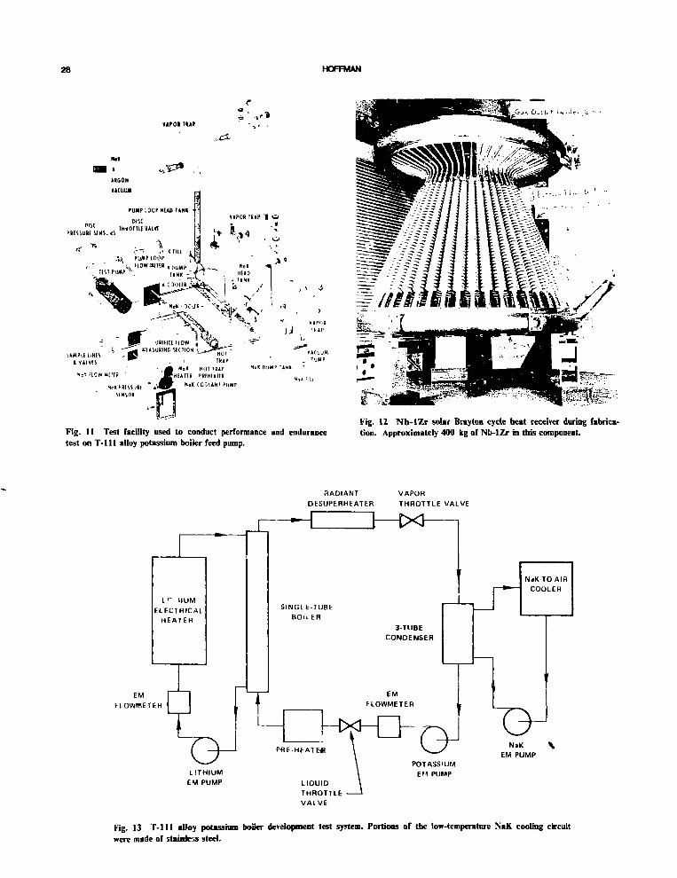
schematically in Fig. 9. A photograph of the com-pleted T-lll pump duct is shown in Fig. 10. Thetest facility in which this pump was tested isshown schematically in Fig. 11.
This T-lll alloy pump was performance testedand achieved the specified rating of 1.5 kg/secwith a developed head of 1.7 MPa at a potassiumtemperature of 540DC. The pump efficiency was16.3% and did not degrade during the 10,000-hendurance test that followed performance testing.
Nb-lZr Solar Bray tonHeat Receiver
One of the most challenging refractory alloyfabrication tasks successfully accomplished in the1963 to 1972 time period was the building of theNb-lZr Erayton cycle heat receiver. Under NASA-Lewis contract, General Electric designed and fab-
ricated this component for use in a 10-KWe Bray-ton system.10 The heat receiver was to function asan absorber of solar radiation incident on themirror-collector and as a heat, exchanger to trans-fer heat into the Brayton cycle working fluid.
The Nb-lZr heat receiver is shown in Fig. 12prior to the addition of the shell/reflector assem-bly. The 48 Nb-lZr heat storage receiver tubesshown were filled with approximately 120 kg oflithium fluoride by the Oak RiHge NationalLaboratory prior to being welded into the heatreceiver assembly. Extensive welding process andindividual welder qualification testing was doneprior to the fabrication of the Nb-lZr HeatReceiver and all other refractory alloy componentsdescribed in this paper. Typical records of thesequalification testa may be found in the Mendelson10
report.

REFRACTOHY ALLOY COMPONENT ACCOMPU&MENTS 25
Fig. 8 T-111 alloy parts of an electromagnetic pump duct before and following assemblyand welding.
Potassium
Outlet
Argon Filled '!^Sutor Civity I '
h ,
Fig. 9 Sketch of T-111 alloy electromcgnstic (EM) potassium boiler feed pump.

26 HOFFMAN
\
Fig. 10 T-lll alloy electromagnetic pump duct following completion of fabrication and application ofNb-lZr insulating foil.
The component 3hown in Fig. 12, together withthe surrounding shell and aperture structure, wasdelivered to NASA-Lewis in 1970. A completeaccount of the construction of this heat receiver isgiven in "Refractory Alloy Component Fabrication"by W. R. Young in these proceedings.
T-lll Boiler DevelopmentTest System
This system, which wa3 designed, fabricated,and tested for NASA-Lewis at GeneralElectric11"14 in the 1967 to 1971 time period wasthe culmination of the Rankine system componentdevelopment program. Its design and fabricationbenefitted greatly from the experience gained onearlier refractory alloy component programs whichhave been described in this paper.
The purpose of this program was to develop anddemonstrate the performance of a once-throughboiler in which potassium is transformed from asubcooled liquid at the boiler inlet to a superheatedvapor in a single pass through the boiler. Fig-ure 13 shows the layout of the three circuits of thetest system which included a 400 kW electricalheater in the lithium heater circuit and a 30 kW
preheater in the potassium circuit. A schematicwhich better illustrates the physical layout of thesystem is given in Fig. 14. The tertiaiy heat rejec-tion loop of this system was partially constructedof type 321 SS and used NaK as the coolant.
T-lll alloy was the principal material of con-struction used to fabricate this test system; a list-ing of the various sizes and shapes of alloyproducts used to build ihe system is given inTable 2. Also included in this figure is a similarlist of T-lll products used to build the T-lll corro-sion loop described earlier in this paper. A largenumber of demanding refractory alloy materialsand process specifications were developed underth6 General Electric/NASA-Lewis program, andmost of them were employed in the construction ofthe boiler development test system. The T-lll alloyspecification for seamless tubing and pipe was usedto obtain alloy product for the Boiler DevelopmentSystem. This specification, which was typical ofthe refractory alloy specifications used by GeneralElectric, may be found in Appendix C of the reportby Harrison, Hoffman, and Smith.7
Several of the more important refractory alloyprocess specification., which were developed byGeneral Electric and utilized in building the T-lll

REFRACTORY ALLOY COMPONENT ACCOMPLISHMENTS
TABLE 2
Listing of T- l l l Alloy Product Forms and Sizes Usedto Build Two T - l l l Alloy Test Systems
T-1I1 alloy procured by GE-NSP forNASA Contract NAS 3-6474, advanced
refractory alloy corrosion loop
T-l l l alloy procured by GE-NSP for NASAContract NAS 3-9426, devslopment
of a single tube potassium boiler
Item and size,in.
Rod0.250 dia0.500 dia0.625 dia1.000 dia1.125 dia1.500 dia2.000 dia2.500 dia3.125 dia
Bar1.0 by 1.01.0 by 2.0
Wire0.062 dia0.094 dia0.125 dia
Foil, sheet, or plate0.005 X 3.50.009 X 3.50.035 X 1.00.040 X 12.00.125 X e.O0.500 X 6.125
Tube0.375 o.d. X 0.065 wall1.00 o.d. X 0.065 wall2.25 o.d. X 0.375 wall2.50 o.d. X 0.450 wall3.00 o.d. X 0.375 wall3.25 o.d. X 0.250 wall3.25 o.d. X 0.500 wall
Total
Summary
T-lll for Rankine SystemCorrosion Loop
T-ll l for Boiler DevelopmentTest System
Total
Weight,lb
111
r
401013859374
332
30115145
138
31
52
211
295
4179
661044046504073
41B
1027
1027 lb
3261 lb
4278 ib
Item and size,in.
Kod0.125 dia0.250 dia0.690 dia0.750 dia1.000 dia1.375 dia1.500 dia2.000 dia2.250 dia2.500 dia3.063 dia3.688 dia4.438 dia4.625 dia
Wire0.062 dia0.094 dia0.125 dia
Foil, sheet, or plate0.005 X 3.50.005 X 5.50.040 X 20.50.063 X 6.00.100 X 9.00.125 X 22.0
0.250 X 8.00.400 X 6.0
Tube0.250 o.d. X 0.050 wall0.375 o.d. X 0.065 wall0.500 o.d. X 0.075 wall0.625 o.d. X 0.008 wall0.690 o.d. X 0.045 wall
0.750 o.d. X 0.04 wall
0.875 o.d. X 0.100 wall1.325 o.d. X 0.100 wall1.500 o.d. X 0.100 wall2.375 o.d. X 0.220 wail4.386 o.d. X 1.343 wall4.420 o.d. X 0.537 wall4.424 o.d. X 1.362 wall4.625 o.d. X 0.225 wall4.625 o.d. X 0.275 wall4.625 o.d. X 0.409 wall
Total
Weight,ib
44
109
38128343877
303389121163176
1494
1015
zr,51
11
553
2351
10544
283
1614188
13
17
36370
19079
18092
184455579
1423
3251
28 HOFFMAN
r•a s
«APOI TUP
VAPOR'fcAP
Fig. 11 Test facility used to conduct performance and endurancetest on T - l l l alloy potassium boiler feed pump.
Fig. 12 N b - I Z r solar Bray ton cycle heat receiver during fabrica-tion. Approximately 400 kg of Nb-IZr in this component.
RADIANTDESUPERHEATER
VAPORTHROTTLE VALVE
LI" HUMELEC1RICAL
HEATER
EMFLOWBIETER
T
SINGLE-TUBEB O I L E B
LITHIUMEM PUMP
PRE-HEATE*
LIQUIDTHROTTLEVALVE
3-TUBECONDENSER
EMFLOWMETER
\ POTASSIUMEf1 PUMP
NaKTO AIHCOOLER
NaK \EM PUMP
Fig. 13 T - l l l alloy potassium boiler development test system. Portions of tbe low-temperature NaK cooling circuitwere made of stainless steel.

REFRACTORY ALLOY COMPONENT ACCOMPLISHMENTS
PREUUil IBAHSDUCEB
VACUUM (hiMIEB -
I PBfHEATtB
1 UQUID THROTTlt
I, HUTIBPOWIB SUPP
NoH DUMP 11NK
r,"— ION PUMP *
Ti 5UBUM1IION PUMP
IURBGM01KUURBOUGHIhG PUMP
HcK TEDTIARY 1OOP
• ICHAHKA1 VKUUM P U i r
Mil IIGOD
Fig. 14 Schematic view of the potassium boiler development test rig.
Boiler Development System, were published byNASA-Lewis.15 Titles of these process specifica-tions are listed below.
Number Title of Specification
RM-1 Chemical Cleaning of Columbium,Tantalum, and Their Alloys
RM-2 Gas Tungsten Arc Welding ofColumbium, Tantalum, andTheir Alloys
RM 3 Electron Beam Welding ofColumbium, Tantalum, andTheir Alloys
RM-4 Resistance Spot Welding of RefractoryMetal Foil to Refractory MetalComponents
RM-5 Postheating of Cb-lZr and T-111(Ta-8W-2Hf) Weldments
Any future program utilizing these or similarrefractory alloys should consider utilizing orupgrading these materials and process specifica-tions as appropriate. A complete account of thefabrication of the Boiler Development System isgiven in the paper by Young in these proceedings.
Major features of the primary lithium heaterloop are given in Table 3, and similar informationfor the secondary two-phase potassium loop isgiven in Table 4. Two of the most challenging sub-system component design and fabrication tasksinvolved the lithium heater (Fig. 15) and thesingle-tube boiler shown in Fig. 16. The coils of thelithium heater were made of 6.4-m lengths of T-111pipe. The heater was designed to dissipate 400 kWat a line current of 8000 amperes with lithiumexiting the heater coils at 1200°C. The boiler wasthe most important development component in thetest system. The single-tube configuration illus-trated in Fig. 16 was designed to represent onetube of a full-scale multiple tube design for anAdvanced Rankine System.
The test facility in which the Boiler Develop-ment System was tested is illustrated in Fig. 17.The vacuum chamber shown was capable of achiev-ing a pressure of 10~9 torr. This capability wasrequired to prevent contamination of the refractoryalioy system during testing. All the General Elec-tric test systems described in this paper, includingthe Boiler Development Test Facilities, wereequipped with partial pressure analyzers to moni-

30 HOFFMAN
TABLE 3
Potassium Boiler Development Test System Primary (Lithium) Loop
Loop materialMain pipe sizeMaximum design pressure/temperatureRange of lithium temperature at boiler inletCirculating pump
Loop flow rate: -capability-range for 1-tube boile. tests
Lithium heater: -type-current/voltage-pipe size (each of 3 coil sets)
T-lll alloy1%-in. OD X 0.100-in. wall100 psi/1204t>C982 to 1204°C (for 1-tube boiler tests)Electromagnetic, T-lll alloy duct, 85 GPM
at 75 psi head5lb/sec0.1 to 1.5 lb/secAC electrical resistance (3-phase)8,000 amps/29 volts at 400 kW%-in. OD X 0.100-in. wall, 21 ft long
TABLE 4
Potassium Boiler Development Test SyBtem Secondary (Fotassiv a) Loop
Loop materialMain pipe size: vapor piping to throttle
and liquid piping from condenserMaximum design pressure/temperaturePotassium liquid temperatures at boiler inletPotassium vapor temperatures at boiler outletCirculating pumpLoop flow rate: capabilityPotassium preheater: -type
-current/voltage-coiled pipe size
Boiler ior initial testsCondenser for 1-tube boiler testsRange of potassium vapor temperatures at condenser inlet
T-lll alloy
ft-in. OD X 0.100-in. wall300 psi/1204°C371 to 982°C982 to 1149°CElectromagnetic, T-lll alloy duct, 5 HT M at 300 psi head0.5 lb/secAC electrical resistance (1-phase)3,000 amps/10 volts at 30 kWte-in. OD X 0.075-in. wall, 12 ft longSingle-tube, 87 kW-thermalThree-tube, 60 kW-thermal593 to 871°C
Li TO BOILER
ELECTRICAL SCHFHaTIC
MAX POWER
mx TEMP
AP AT i LB/SEC
LI HE CURRENT
400 KU
?Z50°F
15 PSI
oono AM
Fig- 15 T-lll alloy lithium heater for boiler developmenttest system.
tor the individual gas species responsible for thefocal test chamber pressure.
During bakeout and hot leak checking opera-tions on the test loop prior to filling of the systemwith alkali metals, vrry small leaks werediscovered in the T-lll alloy lithium heater andthe potassium preheater. Various analytical tech-niques and laboratory tests confirmed that theseleaks were caused by minute amounts of surfacecontamination by nickel picked up from weldingclamps used in the fabrication of the test system.The successful recovery efforts are described indetail by Bond12 and in the paper of Young in theproceedings of this symposium.
Detailed results of the program which involved2750 hours of testing during the July-December1970 time period are given by Deane.13 Hundreds oftest conditions were investigated during the testcampaign to verify the thermal-hydraulic perfor-mance of system components.
Liquid lithium at temperatures up to 1232° Cwas used to boil potassium at temperatures up to1174°C. The range of potassium conditions at theboiler exit ranged from wet vapor at 50% qualityto dry vapor with 167°C of superheat. Results

REFRACTORY ALLOY COMPOTCNT ACCOMPLISHMENTS 31
INSTRUMENTED CENTERBODY
HELICAL VANE WIRE COILINSERT
- 1 . 3 2 " DIAMETER0 . 1 " WALL THICKNESS
0.75" DIAMETER0.04" HALL THICXHESS
^ \
\ \
18" RADIUS
PR£SStBE TUBE
Li OUT
Li IN
K VAPORTHERMOCOUPLE WELLS ~'~'<-.-*k
K VAPOROUT
K IN
Fig. 16 T-111 alloy single-tube potassium boiler.
HIGH BAYTEST AREA
VACUUMCHAMBER BELL
INSTRUMENTATION &EQUIPMENT ROOM
CRANE
CONTROLROOM
VACUUM CHAMBER
COOLANT LOOP ENCLOSURE
Fig. 17 Schematic view of the boiler development test facility including the 6-m tall by 2-m diaultraHgh vacuum test chamber for the T-111 alloy loop.

32 HOFFMAN
5E - .
2200
2100 -
2000 -
1900 -
1440 -
1400 -
Lithium JCritical Heat Fluxjat Inflection_Point
^Initiation ofPotassiumSuperheat
End ofHeated Zone
_L
W = 0 . 9 3 lbs / secLI
W = 0.097 lbs /secK
Q = 99.8 KW
O Well ThermocouplesB Insert Thermocouples• Shell Thermocouples,
Average of Four atEach Location
0 10 20 30 40 50 60 70 30 90 100
Length From Beginning of Heated Zone, inches
Fig. 18 Boiler temperature distribution during a typical test of the T-lll alloy single-tube boiler.
obtained from measurements on the boiler testunit included: Two-Phase-Flow Pressure Drop,Boiler Heat Transfer, Average Overall BoilingHeat Transfer Coefficients, Superheated VaporHeat Transfer Coefficients, Critical Heat Fluxes,and Shell-Side Liquid-Lithium Heat Transfer Coef-ficients. Results of a typical test to evaluate theperformance of the single-tube boiler are shown inFig. 18. The potassium conditions at the condenserinlet ranged from 45 to 99% quality and from 593to 871 °C saturation temperature. Results obtainedfor the potassium condenser included: CondensingHeat Transfer Coefficients and Shell-Side NaK-78Heat Transfer Coefficients.
The program described above, which involvedthe design, fabrication, and testing of a very com-plex three-loop system, was the high-water markof the experimental program to evaluate very hightemperature refractory alloy-liquid metal systemsfor space power applications which ended when thenational programs were terminated in 1972.
SUMMARY
The refractory alloy components described inthis paper were successfully designed, fabricated,and, in mo3t cases, tested and evaluated. The expe-
rience gained during this ten-year period totallyjustified the use of the exacting quality assurancerequirements imposed both by the customer,NASA-Lewis, and the General Electric programmanagement. Detailed procurement and processspecifications vigorously implemented by theprogram personnel were in large measureresponsible for the highly successful nature of thecomponent developments described in this paper.
A consistent element of the NASA-Lewis spon-sored programs directed at advancing therefractory alloy technology was that theproblems/solutions, as well as the successes, wereextensively documented in order to optimize the"lessons-learned" aspects of this very demandingtechnology. Many of the references included inthis paper contain that type of information.Knowledge and utilization of this experience shouldbe most valuable to refraccory alloy systemdesigners, fabricators, and test operators in thedevelopment of refractory alloy systems for spaceapplication.
REFERENCES
1. H. E. Nichols, R. W. Fink, and W. F. Zimmerman,Three-Stage Potassiuvi Vapor Turbine-Fabricaticm andAssembly—Final Report, NASA-CR-72501, May 1969.
REFRACTORY ALLOY COMPONENT ACCOMPLISHMENTS 33
2. G. C. Wesling, Three-Stage Potassium Turbine PerformanceTest Summary, NASA-CR-1483, December 1969.
3. E. Schnetzer and G. M. Kaplan, Erosion Testing of aThree-Stage Potassium Turbine, ASME paper 70-Au/Sp T-37, presented at the Space Technology and Heat TransferConference, LOF Angeles, June 21-iJ4, 1970.
4. J. R. Peterson, J. A. Heller, and M. U. Gutstein, Status J /Advanced Rankine Power Conversion Technology, presentedat American Nuclear Society Meeting, Boston, MA, GeneralEkctric Report No. GESP-623, June 1971.
5. R. W. Harrison and J. Holowach, Refractory Metal Valvesfor 19OO°F Service in Alkali Metal Systems, NASA-CR-1810,April 1970.
6. E. E. Hoffman and J. Holowach, Cb-lZr Rankine SystemCorrosion Test Loop, NASA-CR-1509, June 1970.
'.. R. W. Harrison, E. E. Hoffman, and J. P. Smith, T-UlRankine System Corrosion Test Loop. Volumes I and II,NASA-CR-134816, June 1975.
8. A. H. Powell and J. C. Amos, Fabrication and Test of aSpace Power Boiler Feed Electromagnetic Pump, NASA-CR-1951, March 1972.
9. A. H. Powell and J. P. Couch, Boiler Feed EM Pump for aRankine Cycle Space Power System, in Proceedings of Fifth
Intersociety Energy Conversion Engineering Conference,Volume 1, Las Vegas, NV, Sept. 21-25, 1970.
10. I. Mendelson, Design and Fabrication of Brayton Cycle SolarHeat Receiver. Final F rjxrrt, NASA-CR-72872, July 1971.
11. J. A. Bond, Advanced Rankrne Cycle Potassium BoilerDevelopment Program, Volume I, Test Rig Design andFabrication, NASA-CR-13451, November 1975.
12. J. A. Bond, Advanced Hankine Cycle Potassium BoilerDevelopment Program, Volume II, Facility Checkout andDesign Point Demonstration, NASA-CR-135452, November1975.
13. C. W. Deane, Advanced Rankine Cycle Potassum BoilerDevelopment Program, Volume III, Potassium Boiler andCondenser: ETnerimental Results, NASA-CR-135453,November 1975.
14. J. A. Bond and M. U. Gutstein, Component and Overall Per-formance of an Advanced Rankine Cycle Test Rig. presentedat the 1971 Intersociety Energy Conversion EngineeringConference, Boston, Massachusetts, August 3-5, 1971.
15. T. J. Moore, P. E. Moorhead, and K. J. Bowles,Specifications for Cleaning, Fusion Welding and PostheatingTantalum and Columh'.um Alloys, NASA-TMX-67879, July1971.

Compatibility of Refractory Alloys with SpaceReactor System Coolants and Working Fluids
J. B. DeVan,* J. R. DiStefaao,* and E. E. Hoffmont*Oak Ridge National Laboratory^
fDepartment of Energy, Oak Ridge Operations
INTRODUCTION AND OVERVIEW
The principal compatibility issue affecting thedevelopment of refractory metals for power appli-cations concerns their corrosion resistance againstthe liquids and gases that are used as heat trans-port and working fluids. There is, however, a spe-cial compatibility concern in the case of refractorymetals that relates to the ambient environmentsurrounding the metal. This assessment reviewsthe present state of knowledge concerning theabove compatibility issues. It should be noted thatit does not address compatibility problems arisingfrom other solids in the power plant, the mostnotable being the nuclear fuel.
Extensive information exists on the compatibil-ity of select niobium- and tantalum-base alloyswith liquid lithium and boiling potassium. Thus,the bulk of this report deals with compatibilitystudies in tut latter two alkali metals. Substantialinformation is also presented concerning the reac-tivity of niobium and tantalum alloys with residualgases in high and ultrahigh vacuum atmospheres.The remaining information, which is much lessextensive, covers the compatibility behavior ofmolybdenum and tungsten alloys in alkali metalsand a qualitative assessment of the use of refrac-tory metals for containing helium in a closed Bray-ton cycle.
One of the principal objectives of this assess-ment was to document the full record of spacereactor corrosion studies insofar as they wereknown to the authors. The studies have tended tofollow a classical screening pattern, ever-narrowingin the number of materials but increasing in test
^Operated for the U. S. Department of Energy under con-tract W-7405-eng-26 with the Union Carbide Corporation.
complexity. Thus, testing routines have progressedfrom an evaluation of specimens encapsulated instatic liquid metal containers through natural cir-culation looi>s, forced convection loops, loops simu-lating reactor circuits, and large engineering exper-iments. Inevitably, the volume of data in -.uded inthis report is greatest for capsules and simple loopexperiments, but the value of the data for reactordesign purposes is greatest for the more complexloop experiments. Thus, while we have notattempted to screen or critique any of the datasources, our perceptions of the design status andresearch needs have been guided primarily bythose test results obtained under conditions thatare most representative of steady-state powerplant parameters.
We have, in this assessment, minimized report-ing liquid metal corrosion test results of refractorymetals obtained in conventional alloy loops. Someresults are included to emphasize the sensitivity ofrefractory metals to interstitial contaminationfrom conventional alloys. The reader should beaware that the effects of interstitial contaminantsin a mixed refractory metal-conventional alloy sys-tem are basically different from those in anunmixed system, and the test results frommonometallic systems should not be extended tomixed systems. Because the latter systems, in theauthors' opinion, do not appear amenable to spacereactor service, we have also omitted their consid-eration in formulating research needs.
LIQUID METALS
Liquid LithiumThe principal corrosion reactions in refractory
metal-lithium systems are due to dissolution, mass
34
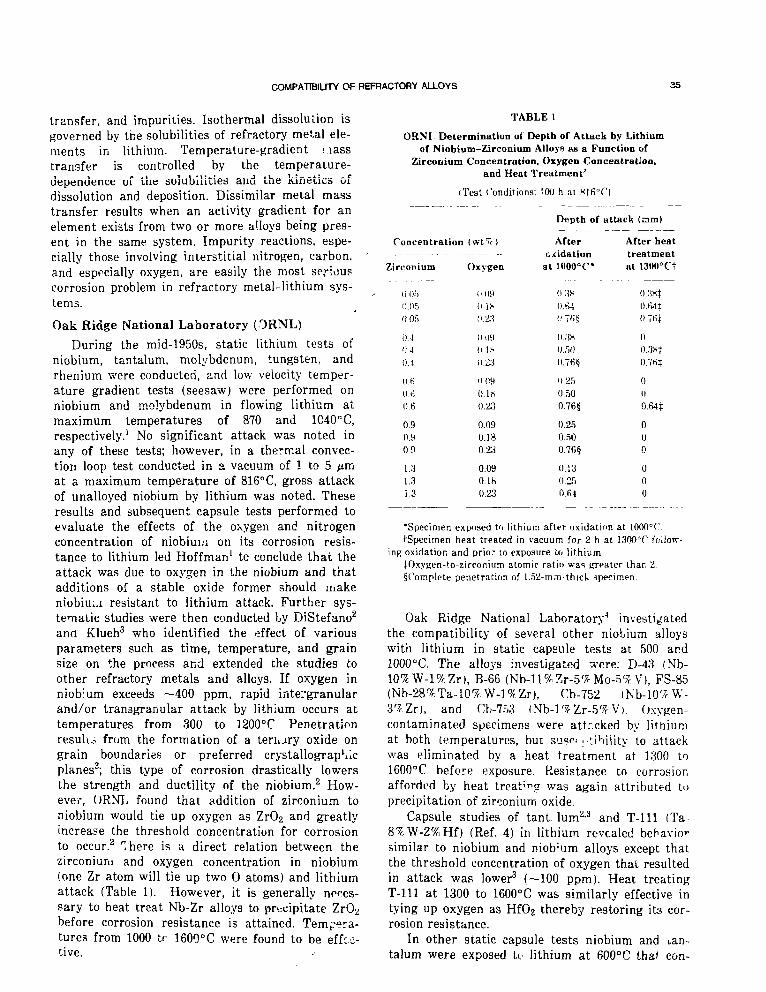
COMPATIBILITY OF REFRACTORY ALLOYS 35
transfer, and impurities. Isothermal dissolution isgoverned by the solubilities of refractory metal ele-ments in lithium. Temperature-gradient i.iasstransfer is controlled by the temperature-dtspendence of the solubilities and the Kinetics oidissolution and deposition. Dissimilar metal masstransfer results when an activity gradient for anelement exists from two or more alloys being pres-ent in the same system. Impurity reactions, espe-cially those involving interstitial nitrogen, carbon,and especially oxygen, are easily the most seriouscorrosion problem in refractory metal-lithium sys-tems.
Oak Ridge National Laboratory (3RNL)During the mid-1950s, static lithium tests of
niobium, tantalum, molybdenum, tungsten, andrhenium were conducted, and low velocity temper-ature gradient tests (seesaw) were performed onniobium and molybdenum in flowing lithium atmaximum temperatures of 870 and 1040° C,respectively.1 No significant attack was noted inany of these tests; however, in a thermal convec-tion loop test conducted in a vacuum of 1 to 5 pmat a maximum temperature of 816°C, gross attackof unalloyed niobium by lithium was noted. Theseresults and subsequent capsule tests performed toevaluate the effects of the oxygen and nitrogenconcentration of niobium on its corrosion resis-tance to lithium led Hoffman1 tc conclude that theattack was due to oxygen in the niobium and thatadditions of a stable oxide former should makeniobiui.i resistant to lithium attack. Further sys-tematic studies were then conducted by DiStefano2
ana Klueh3 who identified the effect of variousparameters such as time, temperature, and grainsize on the process and extended the studies toother refractory metals and alloys. If oxygen inniobium exceeds —400 ppm, rapid intergranularand/or transgranular attack by lithium occurs attemperatures from 300 to 1200°C Penetrationresulu from the formation of a terii^ry oxide ongrain boundaries or preferred crystallograpMcplanes3; this type of corrosion drastically lowersthe strength and ductility of the niobium.2 How-ever, URNL found that addition of zirconium toniobium would tie up oxygen as ZrO2 and greatlyincrease the threshold concentration for corrosionto occur.2 There is a direct relation between thezirconium and oxygen concentration in niobium(one Zr atom will tie up two O atoms) and lithiumattack (Table 1). However, it is generally neces-sary to heat treat Nb-Zr alloys to precipitate ZrO2before corrosion resistance is attained. Tempera-tures from 1000 tr 1600°C were found to be effec-tive.
TABLE 1
ORNI Determination ot Depth of Attack by Lithiumof Niobium-Zirconium Alloys RS a Function of
Zirconium Concentration, Oxygen Concentration,and Heat Treatment'
(Test Conditions: 10O h at Klfi°C)
Concentration
Zirconium Oxygen
0.050.05
04D40.4
OHO.rt0.6
0.90.90.9
1.31.31.3
0 IS11.23
(109(1 l.s0.23
".090.180.23
0.090.180.23
0.090.180.23
Depth of attack (am)
Afteroxidation
at 1000T*
O:IH
0 fi-l
(ITfif
After heattreatmentat 1300°Ct
O.Mx}O.ti4i0.7fii
0.50
0.250.500.76§
0.250.500.76§
0.130.25O.fil
0.7HT
0
U
0.64|
0
0
o
0
0
0
•Specimen exposed tn lithium after oxidation at lOOOT.tSpecimen heat treated in vacuum for 2 h at 1300°C follow-
ing oxidation and prior to exposure to lithium.tOxyKen-to-zirconium atomic ratio was p-pater than 2.§Complete penetration of 1.52-m;n-thicU specimen.
Oak Ridge National Laboratory4 investigatedthe compatibility of several other niobium alloyswith lithium in static capsule tests at 500 and1000°C. The alloys investigated were: D-43 (Nb-10%W-l%Zr), B-66 (Nb-ll%Zr-5f7r Mo-i? V), FS-85(Nb-28%Ta-10%W-l%Zr), Cb-752 (Nb-lO^W-3^Zr), and Cb-7F>3 (Nb-l^ Zr-5^ V). Oxygen-contaminated specimens were attr.cked by lithiumat both temperatures, but su?f .-tiMlity to attackwas eliminated by a heat treatment at 1300 to1600°C before exposure. Resistance to corrosionafforded by heat treating was again attributed toprecipitation of zirconium oxide.
Capsule studies of tant him2-3 and T-lll (Ta-8%W-2%Hf) (Ref. 4) in lithium revealed behaviorsimilar to niobium and niob'um alloys except thatthe threshold concentration of oxygen that resultedin attack was lower3 (—100 ppm). Heat treatingT-lll at 1300 to 1600°C was similarly effective intying up oxygen as HfO2 thereby restoring its cor-rosion resistance.
In other static capsule tests niobium and tan-talum were exposed to lithium at 600°C that con-

36 DEVAN. CHSTEFANO, AND HOFFMAN
tained oxygen concentrations of up to 2100 ppm.Specimens showed no weight change, were brightand shiny, and the amount of metal in the lithiumafter test was less than the limit of detection3 (<10ppm).
Oak Ridge National Laboratory also conductedseveral tests to evaluate mass transfer of niobiumand tantalum base alloys in nonisothermal lithium.See-saw test results reported by Hoffman1 s^ ->dsmall weight changes, and no deposition was notedfor molybdenum (1038°C, 445°C AT) and niobium(871°C, 278°C AT) capsules after 150 and 300 h,respectively.
In 3000 h natural circulation loop tests ofNb-l%Zr and D-43 (Table 2) at 1200°C, the smallweight changes observed were the result of trans-port of zirconium and nitrogen between the heatedand cooled regions.5-6 Transfer was greater inNb-l%Zr and resulted in a light zirconium nitridemass transfer deposit on cold-leg surfaces. In the1300°C test of Nb-l%Zr, transport of niobiumaccounted for a large fraction of the weightchanges measured, and niobium deposits contain-ing carbon and nitrogen were found on hot-legspecimens. A test of the niobium alloy FS-85operated for 500 h (Table 2) before a leak forcedtermination of the test. However, results weresimilar to those for Nb-l%Zr tested for 3000 hunder similar conditions.7
One dissimilar alloy test was conducted asshown in Table 2. A Nb-l%Zr loop with both TZMand Nb-l%Zr specimens .vas operated for 3000 hunder the conditions shown. Weight changes inboth Nb-l%Zr and TZM weie higher than in theNb-l%Zr monometallic loop test run under similarconditions. Chemical and metallographic analysesshowed that niobium and zirconium hadtransferred to the TZM, and Nb-l%Zr picked upmolybdenum, carbon, and nitrogen.
refractory metal-ORNL built andforced-circulation
T-lll (Ta-8%W-
Two dynamic tests of tantalum alloys were con-ducted by ORNL. Results of a natural circulationloop test of alloy T-222 (Ta-9.5%W-2.5%Hf) areshown in Table 2. Comparison of weight changeresults from this test8 (maximum temperature1350°C> with that of the 1297°C test of Nb-l%Zrshows that T-222 has somewhat more resistance totemperature gradient mass transfer; however, somemass transfer of hafnium from hot to cold regionsdid occur. In addition, the T-222 that was exposedto temperatures from 1220 to 12&u°C was embrit-tled due to an aging reaction.9
As a culmination of theirlithium compatibility studies,operated an engineering-scaleloop fabricated from alloy2c/< Hf).10 Tne loop is shown schematically in Fig. 1,and design information and operating conditionsare shown in Table 3. Results are summarized asfollows.
1. Mass transfer rates were small, and maxi-mum dissolution rate was <1.3 /im/y.
2. Hafnium, nitrogen, and carbon weretransferred from hot to cold regions.
3. Weight changes were similar to those in nat-ural circulation loop test of T-222 (Table 2).
4. No significant microstructural changes otherthan grain u-rowth in T-lll were found.
5. Room-temperature tensile strengths of-T-lllspecimens were lower than control specimens afterequivalent vacuum exposure, which was attributedto increased grain size and changes in interstitialimpurities (primarily decrease in oxygen content).
Pratt & Whitney Aircraft (PWAC-CANEL)
Concurrent with the early ORNL studies PWACalso investigated the compatibility of refractorymetals with lithium for compact reactor systems,11
Solubility measurements12 indicated dissolution of
TABLE 2
Natural Circulation Loop Tests of Niobium and Tantalum Alloys in Lithium Conducted at OkNL
Alloy
Nb-l%ZrNb-l%Zr
D-43FS-85T-222Nb-l%Zr/TZM
Time,h
30003000
3000500
30003000
Temperature, °C
Maximumhot leg
11901297
12001220l.?501200
Minimumcold leg
10801118
1030980
H501090
Flowvelocity
(mm/sec)
53.823.9
38.122.935.653.8
Weight change, mg/cm2
Maximum gain
+0.78+3.8
+0.21+0.79+2.1+2.7+0.9
Maximum loss
-0.34-2.6
-0.15-0.13-0.70-4.49 (TZM)-1.6(Nb-l%Zr)
TUf t ronof
deposits
ZrNNb, ZrN,
Nb(C,N)NoneZrNHf(N)Nb, Zr
Mo, C, N
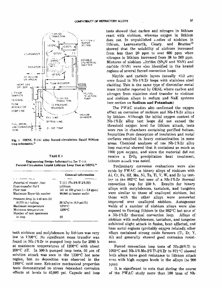
COMPATIBILITY OF REFRACTORY ALLOYS 37
/ . T-111/SS; TRANSITION
LCONOMlZKR
FILL, DRAIN, iuND EXPflNSIONF*
Fig. 1 ORNL T-lll alloy forced-circulation liquid lithiumloop schematic.10
TABIE 3
Engineering Design Information fur T-illForced-Circulation Liquid Lithium Loop Test at ORNL'°
Material of constrictionHeat-transfer flu'dFlow rateMaximum Reynolds number
Pressure drop in i).40-mm-ID(0.370 in.) tubing
Maximum temperatureMinimum temperatureNumber of test specimens
in loop
General information
T-lll (Ta-8%W-2%Hf)Lithium141 to 160 g/sec (~ 5.8 gpm)99,000 at heater outlet
20 kPa/m (0.9 psi/ft)1370°C1200°C
93
both niobium and molybdenum by lithium was verylow to 1000°C. No significant mass transfer wasfound in Nb-l%Zr in pumped loop tests for 2000 hat maximum temperatures of 1200°C with about200°C AT. In 500-h pumped loop tests, 50 m ofsolution attack was seen in the 1330°C hot zoneregion, but no deposition was observed in the1100°C cold zone. Extensive mechanical propertiestests demonstrated no stress dependent corrosioneffects at levels to 40,000 psi. Capsule and loop
tests showed that carbon and nitrogen in lithiumreact with niobium, whereas oxygen in lithiumdoes not. In unpublished studies of niobium inlithium, Leaven worth, Geary, and Bratton12
showed that the solubility of niobium increasedfrom less than 20 ppm to over 600 ppm whennitrogen in lithium increased from 38 to 260 ppm.Mixtures of niobium nitrides (Nb2N and NbN) andcarbide (NbN) were also identified in the heatedregions of several forced convection loops.
Nitride and carbide layers (usually <13 mjwere found in Nb-l%Zr loops with stainless steelcladding. This is the same type of dissimilar metalmass transfer reported by ORNL where carbon andnitrogen from stainless steel transfer to niobiumand niobium alloys in sodium and NaK systems(see section on Sodium and Potassium)
The PWAC studies also confirmed the oxygeneffect on corrosion of niobium and Nb-l%Zr alloysby lithium. Although the initial oxygen content ofNb-l%Zr alloy test loops did not exceed thethreshold oxygen level for lithium attack, testswere run in chambers containing purified helium.Impurities from desorption of insulation and metalsurfaces resulted in heavy contamination in someareas. Chemical analyses of one Nb-l%Zr alloyloop material showed that it contained as much as1900 ppm oxygen, and since the material did notreceive a ZrO2 precipitation heat treatment,lithium ai.Uck was noted.
Preliminary corrosion evaluations were alsomade by PWAC on binary alloys of niobium withAl, Cr, Fe, Hf, Mo, Ni, Ta, Ti, V, W, and Zr by test-ing in the 982°C hot zone of a Nb-l%Zr thermalconvection loop for 250 h. Results for binaryalloys with molybdenum, tantalum, and tungstenwere similar to those of unalloyed niobium, butthose with the other alloys were somewhatimproved over unalloyed niobium. Autogenouswelds of a number of niobium alloys were alsoexposed to flowing lithium in the 982° C hot zone ofa Nb-l%Zr thermal convection loop. Alloys ofniobium with molybdenum, tantalum, and tungstenexhibited slight attack in fusion, heat affected, andbase metal regions (probably oxygen related); otheralloys contained strong oxide formers (Ti, Zr, Y,Al) and generally showed good corrosion resist-ance.
Forced convection loop tests of Nb-20%Ti to1093°C and Nb-5%Mo-2%Ti-2%Zr to 871°C showedboth alloys have good resistance to lithium attackeven with high oxygen levels in the alloys (to 900ppm).
It is significant to note that during the courseof the PWAC study more than 100 tons of Nb-

38 DEVAN, CKSTEFANO, AND HOFFMAN
l%Zr in a variety of mill forms were obtainedaccording to CANEL specifications CS-1830 to CS-1838.
NASA-Lewis Research Center (LeRC)
During the 1970s much work on liquid metalcompaiibility with refractory metals was carriedout by NASA at LeRC in studies that supportednuclear space power systems. Corrosion of oxygen-doped tantalum by lithium at 1115 and 1390°C wasstudied in capsule tests.13 Results showed thatlithium getters oxygen from tantalum of low oxy-gen concentration. In contrast, lithium was foundto attack oxygen-doped tantalum both trans-granularly and intergranularly in a manner similarto that leported previously by FiStefano2 andKlueh3 at ORNL. A study14 was also made to deter-mine the effects of exposure of T-lll to low pres-sure air on its resistance to corrosion by lithium incapsule tests at 980 and 1260°C. Capsules exposedat 980°C and 2 X 10~4 torr failed, but it wasreported that no lithium corrosion occurred underany conditions even though the tantalum containedoxygen concentrations as high as 3500 ppm. Weldzone failure of one capsule after 24 h was attrib-uted to intergranular oxidation, but photomicro-graphs of the failure region showed features thatmore resemble lithium attack than oxidation. Thepurpose of this study was to determine the tolera-ble vacuum for ground testing of T-lll systems.Although the study concluded that 1-mm-thick T-111 could be safely tested at a residual air pressureof 2 X 10~5 torr for 96 h, microstructuralinterpretations upon which the conclusions arebased are open to question.
Isothermal capsule compatibility tests were con-ducted rn T-lll with uranium nitrite or TZM for2800 h at 1040°C in lithium.15 All combinationswere concluded to be compatible except for T-lllin direct contact with uranium nitride. There wasno evidence of carbon transport from TZM to T-lllin these tests.
General Electi^ (GE-Cincinnati, Ohio)
Compatibility studies covering a wide range ofrefractory alloys in contact with lithium, sodium,and potassium were carried out in the period from1962 to 1972 at General Electric. Essentially all ofthese studies were performed under contract toNASA-LeRC us a part of the overall technologybase being generated by NASA to support thedevelopment of advanced space electric power ^ys-tems.
The result of this compatibility testing will bepresented in order of increasing severity of thetesting proceeding from static, noncirculating tests
of candidate alloys utilizing capsules to low-velocity thermal convection test loops and, finally,to large high-velocity two-loop pulped systemsinvolving a primary iiquid heater circuit and a sec-ondary two-phase boiling alkali metal circuit.
Only a very limited amount of special capsuletesting was done at GE, because by 1962 there wasan extensive data base o& candidate refractoryalloys in alkali metals on which to base alloy selec-tion for system application. The major goal of theNASA/GE program was to conduct two-loop Ran-kine system tests under conditions an prototypic aswas practical.
As indicated in the introduction, the authorshave chosen to use each of the various liquidmetals as the major heading and discuss the com-patibility of the respective refractory alloys underthat heading. Therefore, the results obtained inthe lithium primary loop of the GE T-lll RankineSystem Loop will be presented in this section, andthe results obtained in the boiling potassium sec-ondary loop will be discussed in the potassium sec-tion of this paper.
The various lithium compatibility tests con-ducted by GE are discussed below. All the GEalkali metal tests used specially purified alkalimetals and were conducted in getter-ion pumpedchambers at pressures in the 10~7 to 10~9 t^-rrange.
Lithium Capsule Tests. The purpose of thesecapsule tests16 was to determine the effect of oxy-gen contamination (typical of that encounteredduring hot isostatic pressing in high pressurehelium) on the corrosion resistance of T-lll andW-30%Re-30%Mo in high temperature lithium.
The T-lll specimens contained about 2300 ppmoxygen before exposure to 1425°C lithium and 24ppm after a 100 h lithium exposure. No attack wasdetected; this is attributed to the oxygen getteringaction of the hafnium in the T-lll alloy prior toexposure to lithium.
The W-30%Re-30%Mo (a/o) specimens pickedup very little contamination during autoclavingand were unattacked by the 1425°C lithium after a100-h exposure.
A series of experiments17 were conducted todetermine the leval of welding environment purityand the postweld heat treatment required to avoidlithium attack. In these tests specimens of Nb-l%Zr, FS-85, and T-lll were exposed to 760°C for8 h. It was determined that the welding environ-ment should contain 200 ppm or less air and thatpostweld heat treatment was required to avoidlithium attack.
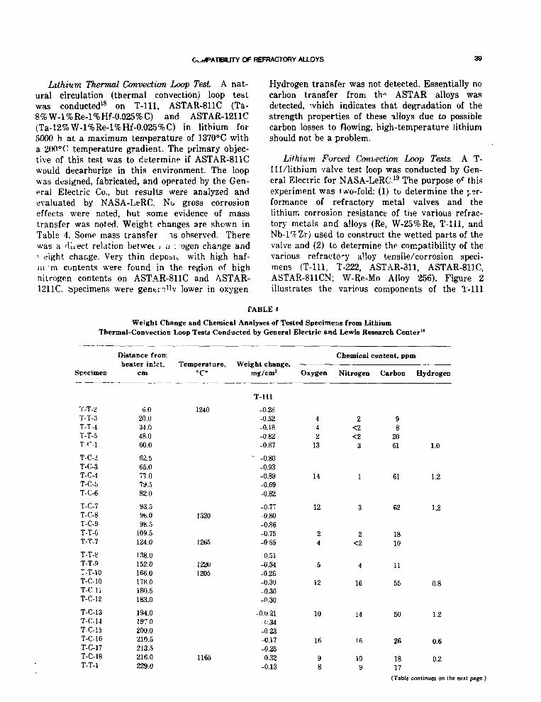
GvwvlPATlBlLJTY OF REFRACTORY ALLOYS 39
Lithium Thermal Convection Loop Test A nat-ural circulation (thermal convection) loop testwas conducted18 on T-lll, ASTAR-811C (Ta-8%W-l%Re-l%Hf-0.025%C) and ASTAR-1211C(Ta-12%W-l%Re-l%Hf-0.025%C) in lithium for5000 h at a maximum temperature of 1370°C witha 200°C temperature gradient. The primary objec-tive of this test was to determine if ASTAR-811Cwould decarburize in this environment. The loopwas designed, fabricated, and operated by the Gen-eral Electric Co., but results were analyzed andevaluated by NASA-LeRC. No gross corrosioneffects were noted, but some evidence of masstransfer was noted. Weight changes are shown inTable 4. Some mass transfer is observed. Therewas a direct relation betwet t u ..ogen change and' eight change. Very thin depobK with high haf-ni m contents were found in the region of highnitrogen contents on ASTAR-811C and ASTAR-1211C. Specimens were gentrnllv lower in oxygen.
Hydrogen transfer was not detected. Essentially nocarbon transfer from th" ASTAR alloys wasdetected, which indicates that degradation of thestrength properties of these alloys due to possiblecarbon losses to flowing, high-temperature lithiumshould not be a problem.
Lithium Forced Convection Loop Tests. A T-111/lithium valve test loop was conducted by Gen-eral Electric for NASA-LeRC.19 The purpose of thisexperiment was two-fold: (1) to determine the per-formance of refractory metal valves and thelithium corrosion resistance of the various refrac-tory metals and alloys (Re, W-25%Re, T-lll, andNb-l%Zr) used to construct the wetted parts of thevalve and (2) to determine the compatibility of thevarious refracto-y alloy tensile/corrosion speci-mens (T-lll, T-222, ASTAR-311, ASTAR-811C,ASTAR-811CN; W-Re-Mo Alloy 256). Figure 2illustrates the various components of the T-lll
TABLE 4
Weight Change and Chemical Analyses of Tested Specimens from LithiumThermal-Convection Loop Test* Conducted by General Electric and Lewis Research Center18
Distance fromheater inlet.
SpecimenTemperature,
°C*Weight change,
mg/cm2
Chemical content, ppm
Oxygen Nitrogen Carbon Hydrogen
T-lll
T-T-2T-T-3T-T-4T-T-5T-r-l
T-C-2T-C-3T-C-4T-C-5T-C-6
T-C-7T-C-8T-C-9T-T-CT-T-7
T-T-ST-T-9T-T-10T-C-10T-CliT-C-12
T-C-13T-C-l-JT-C-15T-C-16T-C-17T-C-18T-T-l
6.020.034.048.060.0
62.565.077.079.582.0
93.596.098.5
109.5124.0
138.0152.0166.0178.0180.5183.0
194.0197 0200.0210.5213.5216.0229.0
1240
1.330
1265
122U1205
1165
-0.28-0.52-0.18-0.82-0.87
' -0.80-0.93-0.39-0.69-0.82
-0.77-0.80-0.86-0.75-0 55
-0.51-0.34-0.26-0.30-0.30-0.30
-0.0.21-I.-.34
-0.23-0.17-0.25-0.32-0.13
442
13
14
12
24
5
12
10
16
98
2<2<2
3
1
3
2<2
4
16
14
16
109
98
2061
61
62
1810
11
55
50
26
1817
1.0
1.2
1.2
0.8
1.2
0.6
0.2
(Table continues on the next page.)

40 DEVAN, DISTEFANO, AND HOFFMAN
TABLE 4 (Continued)
Specimen
A-T-2A-T-3A-T-4A-T-5A-T-6
A-T-7A-T-8A-T-9A-T-10A-T-l
A-C-lA-C-2A-C-3A-C-4A-C-5
A-C-6A-C-7A-C-8A-C-10A-C-ll
A-C-12A-C-13A-C-14A-C-15A-C-16A-C-17A-C-18
Distance fromheater inlet,
cm
12.527.041.555.5
116.5
130.5145.0158.5173.0236.0
68.071.074.084.587.0
90.5101.5105.0185.5188.0
191.0202.0205.0208.0218.5221.5224.0
Temperature,°C*
1360
1220
1350
11851185
Weight change.mg/cm2
ASTAE-811C
0.44-0.13-0.18-0.27-0.14
-0.07-0.39
2.353.723.51
ASTAR-1211C
-0.421.45
-0.32-0.30-0.41
-0.3!-0.35 .-0.36
5.3G5.51
5.895.135.045.355.305.625.49
Oxygen
16655
<2
314261825
11
8
10
26
26
23
18
Chemical content, ppm
Nitrogen
392
<2<2<2
<i.2074
112163
3
2
1
108
105
117
142
Carbon
195183147172195
148201228190220
348
326
353
367
330
398
245
Hydrogen
2.1
0.8
1.4
1.6
1.6
?..O
0.4
'Measured t empera tu re s shown. Continuous tempera ture gradient between measured locations.
valve test loop. A section through the valve isgiven in Figure 3, which shows the portion of thevalve in contact with the flowing lithium. Therefractory metal valves were developed and per-formance tested to satisfy the need for both meter-ing and isolation valves of this type for subsequentuse in both liquid lithium and potassium Rankinesystems at temperatures in excess of 1040°C. Onlythe refractory alloy portions of the valves areshown in Fig. 3. The design of the metering andisolation valves was done by Hoke, Inc. GeneralElectric selected and procured the materials of con-struction and performed all the joining operations.The material initially selected for the valve seatswas TiC plus 10% Nb, but a lithium corrosion testconducted to confirm this choice revealed extensivelithium attack. Unalloyed rhenium was thenselected and tested in lithium at 1150°C for 100 hto confirm this choice before use in vaive construc-tion.
During the 5000-h test the isolation vahre wascycled for 95 cycles between the full open and fullclosed position, and the torque to open and closethe valve on each cycle was measured. The meter-ing valve was cycled between lA and % travel dur-ing this same period. The W-25%Re plugs andrhenium seats in each valve exhibited excellentperformance with no sign of wear, abrasion, bond-ing, or lithium attack observed in either valve. TheT-lll bellows and other refractory metal com-ponents of the valves performed satisfactorily dur-ing the test.
Both corrosion and tensile specimens of T-lll(Ta-8% W-2%Hf), T-222 (Ta-10.4% W-2.4%Hf-0.01 %C), ASTAR-811 (Ta-8%W-l%Hf-l%Re), AS-TAR-811C (Ta-8% W-0.7%Hf-l%Re-0.025%C), AS-TAR-811CN'Ta-8%W-I%Hf-Re-0.012%C-0.012%N),and W-Re-Mo Alloy 256 (W-29%Re-18%Mo) thatwere located in the portion of the loop circuit,which operated at a maximum temperature of

COMPATHJTY OF REFRACTORY ALLOYS 41
VACUUM U N «
IM PUMPPUMP IhLET ^ ' ; / / v ; >'
PBESSUBETBANSDUCEBS i
GAS PSiSSUSIZAIION UHl-i
DRAIN AND FILL LINE —
— COPPEB IUS BAB
BESISTAHC!HEATED COILS
ISOLATION VALVE
Fig. 2 High temperature T-Ill/lithiumvaK •-: test loop.
/ /
1150°C with a 95°C temperature drop along thelength of the specimen containment, wereevaluated following the test, and no lithium attackwas detected. The results of room temperature and1090°C tensile tests following the 5000-h exposureshowed no changes in strength or ductility thatcould be attributed to the lithium exposure.
A T-111/fuel element pumped lithium looptest20 was conducted (1) to determine the compati-bility of bolh sound- and defective-clad fuel speci-mens and (2) to determine the compatibility andposttest mechanical properties of corrosion andmechanical property specimens of T-lll , AcJTAR-811C, ASTAR-811CN, and W-Re-Mo Alloy 256. Aschematic of the loop and the fuel section of theloop is shown in Pig. 4 In addition to the three
T-l l l clad fuel specimens, tensile specimens of W-Re-Mo Alloy 256, ASTAR-811CN, and ASTAR-811Cand corrosion test specimens of T-l l l , ASTAR-811C, and ASTAR-811CN were exposed to 1040°Cflowing lithium.
The fuel element specimens were examined byNASA-LeRC staff members, and these results aswell as other compatibility information relevant tothe use of T-ll l clad UN fuel in lithium arereported in NASA-LeRC reports.2123 No corrosionof the T-lll fuel clad by the lithium or contamina-tion of the T-ll l by the UN was detected. The fuelspecimen with the machined defect* (to simulate a
*A slot 0.076 mm wide hy b.4 mm long cut through theT-* 11/tungsten cladding to the UN fuel pellet surface.

DEVAN, rxsTEFANO, AND HOFFMAN
Stem Fig. 3 Cross section of the T-lll valve showing the variousrefractory metal components in contact with flowinglithium.
:j Stainless Steel
VASCO Hypercut
T - l l lCladding
Fig. 4 Pumped lithiumloop to evaluate advancedrefractory metal alloys andT-lll clad UN fuel speci-mens.
Fuel FletwntTest Section
CorrosionSpecimenAssembly
EM Pump
LOOP SCHEMATICFlou
FUEL ELEMFNTTETT SECTION

COMPATHUTY OF REFRACTORY ALLOYS
1890
Turbine Simulator
Condenser
Fig. 5 T-1I1 Rankine system corrosiontest loop. (Note: all temperatures are in
cladding crack) showed a very slight loss of UN inthe immediate area of the defect but no evidence ofany compatibility problem between the UN and theflowing lithium. No corrosion of the Mo-TZM fuelcapsule spacer inserts (see Fig. 4) was detected.
Detailed evaluation of the 38 tensile and corro-sion test specimens exposed in the 7500-h testrevealed no attack of the specimens, no loss of car-bon or nitrogen from the ASTAR-811C or ASTAR-811CN specimens, and no lithium-related degrada-tion of the tensile properties of the alloys.
A two-loop T-lll Rankine system corrosion testloop24 was the culmination of the NACA-sponsoredGE compatibility test program in support of the
NASA Rankine space electric power developmentprogram. The test loop consisted of a T-111/lithiumprimary heater loop operating at a maximumlithium temperature of 1230°C and a mini-num of1135CC. The potassium secondary two-phase loopcircuit will be discussed in the GE/potassium sec-tion of this paper. A schematic of the test loop,including the temperatures of the various portionsof hoth the lithium and potassium circuits of theloop, is shown in Fig. 5. A photograph of the testloop mounted on the vacuum chamber spoolpieceprior to transfer to the ultrahigh vacuum testchamber is given in Fig. 6. The test loop wasoperated without interruption and terminated on

DEVAN. DBTCFANO, AND HOFFMAN
Fig. 6 T-lll RanMne system corroeion test loop and vacuum chamber spool piece prior to installation in vacuumtest chamber.
completion of the planned 10,000-h run onMarch 18, 1970. The lithium flow rate in theheater circuit wa3 106 kg/h (234 lb/h).
After the test was completed, an extensive eval-uation was performed on all loop components. Onlythe results of the evaluations on T-lll componentsin the lithium circuit will be discussed here. As
mentioned earlier, the results of the evaluation ofthe two-phase potassium circuit are included in thepotassium section of this paper.
The excellent compatibility of the T-lll alloywith lithium at elevated temperatures is attestedto by the fact that detailed metallurgical andchemical evaluations revealed no compatibility

COMPATBBJTY OF REFRACTORY ALLOYS 45
RESERVOIR
VACUUM AND ARGONVACUUM AND ARGONPRESSURE TRANSDUCER
PUMP
SUMP
Fig. 7 High velocity lithium system for Nb-l%Zr test by Jet Propulsion Laboratory.26
problems. The oxygen concentration of the T-lllcomponents exposed to lithium was reduced frominitial levels of —20 ppm to posttest values of 5 to10 ppm. On the lithium side of the potassiumboiler tube (see inset, Fig. 5) a very thin film ofhafnium nitride (maximum thickness less than0.025 mm) was detected in the very high heat fluxregion of the boiler where boiling of potassium wasoccurring on the other side of the T-lll tube wall.This surface film had no deleterious effect on themetallurgical reliability of the boiler tube.
The conclusion drawn from the GE lithiumcompatibility studies was that tantalum alloys ofthe T-lll type have excellent compatibility to highvelocity lithium at terperatures to at least 1230°C.
Others
Many other organisations have also contributedto the compatibility data base on refractory metalsin lithium. One significant study was earned outby DeMastry25 at Battelle Memorial Institute,Columbus, Ohio. Corrosion tests of W-0.9%N'o, W-10%Re, W-25%Re, TZM, Mo-50%Re, and Re werecarried out in TZM capsules containing lithium for100 and 1000 h at 1370, 1540, and 1650°C. At1370°C all materials were judged to be resistant toattack. After 1000 h at 1540°C, varying degrees ofsurface dissolution and grain boundary penetrationof the tungsten-base alloys occurred. Chemicalanalyses of the lithium showed large increases intungsten content (to 4300 ppm), but analyses of theTZM indicated no dissimilar metal mass transferhad occurred. At 1650°C there was slight dissolu-tion of the tungsten-base alloys after 100 h whichbecame rather severe after 1000 h. The molybde-num alloys were resistant to attack under all con-ditions. Rhenium was not attacked by the lithium,but there was evidence of mass transfer (surfacelayers) of molybdenum from the TZM capsules tothe Re samples.
The Jet Propulsion Laboratory evaluated thecompatibility of Nb-l%Zr in high velocity, hightemperature lithium for application in magnetohy-drodynamic power systems in space.26 A schematicof the experimental system used in this study isshown in Fig. 7. Lithium was pressurized andheated in an electromagnetic induction pump witha helical Nb-l%Zr duct and flowed through anelectromagnetic flow meter to the test sectionwhere acceleration to higher velocities occurred.The primary flow circuit of the test system wasfabricated of Nb-l%Zr and was operated within avacuum chamber. More than 20 niobium weldmentswere required for final assembly, and these wereperformed in an inert-gas weld ehamho- or byelectron-beam methods. Nb-l%Zr and Y2O3 plateswere mounted in the high velocity test section tomeasure corrosion/mass transfer effects. The sys-tem was operated for two periods at constant tem-perature. For 109 h the temperature was main-tained .it I143°C and 48.5 m/s maximum lithiumvelocity. Examination of the test section indicatedthat complete dissolution of the Y2O3 plate hadoccurred. After reinstallation of the test sectionand piping, the system was operated an additional391 h at 1073° C. Macroscopic examination showedthat Nb-l%Zr material removal was minor in thehigh-velocity flow regions, but material removalwas heavy downstream of a cavity left by dissolvedY2O3.
A pumped capsule test of W-25% Re-30% Mowas conducted by Lawrence Radiation Laboratoryas part of a study for liquid-metal-cooled spacepower reactor applications.27 The pumped capsuleconsisted of a closed tube 1.3 cm-OD X 0.1 cm wallthickness X 25 cm long containing a 0.4 mm thickplate that separated the tube into two channels.(Fig. 8). Lithium was circulated by an electromag-netic pump at 0.3 m/sec at 1400°C maximum tem-perature with a AT of 150 to 200°C. The test was

46 DEVAN, DISTEFANO, AMD HOFFMAN
Specimen from capsule-jurfoce at hot end —Micrography
J—h
Longitudinal specimen-thru butt weld —Metallography
Electropol ished spot * 1 —Surface micrography andelectron micropiobe analysis
Capsule
Splitter platt"
TLongitudinal strips fromsplitter plate midsectionMechanical propeities
ro
A
Transverse ring from capsulehot end — Metallography
Longitjdinal strips from capsulehot section containing butt weld -Mechanical properties
• Electropolished spot " 7 -Surface micrography andelectron microprobe analysis
TLonqltudinal strips from capsulemidsection — Mechanical properties
\
• Current - carrying electrodes
~ Electropol ished spot ' " -Surface micrography an^electron microprobe analysis
" Electropcloshed spot * 4 -Surface metallography andelectron microprobe analysis
I.L Transverse ring from capsule
cool end— Metallography
Fig. 8 Pumped capsule lithium corrosion test system conducted by Lawrence Radiation Laboratory.27
COMPATIBILITY O Rt-FRACTORY ALLOYS 47
operated in a vacuum of 10 8 torr for 1000 h. Nogross corrosion effects were noted; surfacemicroprobe analysis, however, showed mass trans-fer from high temperature to low temperatureregions. Unpublished data showing higher solubil-ity of molybdenum in lithium compared with tung-sten was presented to explain the higher rate ofmass transfer of molybdenum that was found com-pared with tungsten and rhenium. Grain boundaryattack or intrusions to 25 nm were noted. Oneexplanation postulated was that grain boundariesmay be enhanced in molybdenum due to kineticconsideration, and, because solubility of molybde-num is higher in lithium, preferred attack in theseregions will occur. The I esults cited by DeMastry,25
however, do not agree with such an explanationbecause molybdenum alloys were resistant to grainboundary attack by lithium after 1000 h at 1370 to1650°C. Tungsten alloys showed evidence of surfacedissolution and grain boundary attack at 1540 and1650°C. Further compatibility studies of thesematerials in lithium are required for more com-plete understanding of the corrosion mechanismsinvolved.
The mechanical strength of the W-25% Re-30%Mo alloy was unaffected by the test exposure, butductility of both hot and cold end samples wasgreater after the test.
Lithium Heat PipesBecause the boiling point of lithium is high
(1342°O) relative to space power, most of theextant corrosion data for lithium relate to convec-tive rather than evaporative heat transport. How-ever, there has been a long-standing interest inlithium as a two-phase working fluid for high tem-perature heat pipes, and performance testing ofrefractory metal wick and containment materialsfor this application has been conducted by at leastfour different investigators. Although there havebeen no parametric corrosion studies of refractorymetal-lithium heat pipes to date, metallurgicalexaminations were performed following certainlong-term (up to 10,000 h) performance tests.
Prior to 1972 the most extensive testing oflithium-filled heat pipes was reported by the Eura-totn Ispra Establishment.28 Eusse andcoworkers29'30 were the first to document corrosionproblems in Nb-l%Zr and tantalum heat pipesoperating at 1500 tc 1600°C. In initial tests of thesematerials, the evaporator wall was perforated intimes less than 10 h unless procedures wereemployed to deal with the mass transport of oxy-gen from the condenser region to the evaporatorregion. Effective procedures included deoxidation
of the Nb-l%Zr pipe wall by prior lithium expo-sure, additions of strong oxiae formers (such as Caor Y) to the lithium working fluid, and the pres-ence of small amounts of yttrium as an alloyingaddition in tantalum.
Tungsten and W-26%Re heat pipes, on theother hand, could be operated effectively withlithium at 1600°C for as long as 10,000 h with nospecial requirements for oxygen scavenging.28'31
Busse and coworkers29'30 conducted posttestexaminations of failed Nb-l%Zr and tantalum heatpipes to evaluate the oxygen distribution in theheat pipe wall and the microatructure of the fail-ure area. On the basis of these examinations, theyconcluded that the corrosion problem was directlyrelated to the initial oxygen content of the wallmaterial (i.e., oxygen was transported by therefluxing lithium from the condenser wall to theheating zone where local increases in oxygen con-tent in the liquid lithium could result from theevaporation process). He postulated that attack ofthe wall then occurred through the dissolution ofniobium or tantalum by lithium containing highoxygen levels. DiStefano and DeVan32 have ques-tioned the feasibility of the latter step and haveargued that attack of the wall can occur only bydirect chemical reaction with lithium oxide accom-panying dry out of liquid lithium in local areas ofthe evaporator. Nevertheless, the observations andoxygen control procedures of Busse and his co-workers at Ispra provide the most extensive anduseful background studies to date for the operationof refractory metal-alkali metal heat pipe systems.
The Heat Pipe Design Handbook,™ compiled byDynatherm Corp., lists four other heat pipe testswith lithium in the 1500 to 1600°C temperaturerange conducted prior to 1972. Four lithium heatpipe tests with Mo-TZM tubes were operated byRCA Electronics Components Division. Three wereterminated after approximately 10,000 h by weldfailures, and a fourth developed an evaporator leakafter 4600 h.
Lithium heat pipes operating at 1000 to 1350°Chave shown fewer corrosion problems than thoseoperating at 1500 to 1600°C. Ranken andKemme's33 examination of an Nb-l%Zr pipe with ascreen wick revea'ed no visual evidence of corro-sion after 4300 h at 1100°C; also, an Nb-l%Zr/Liheat pipe operated at 1350°C by RCA completed2300 h without evidence of macroscopic corrosion.28
Finally, Ispra workers obsarved33 that the sameNb-l%Zr pipe design that was rapidly perforatedby lithium at 1600°C (discussed above) operatedwithout failure for 3570 h at 1000°C. However,examination of the 1000°C pipe did reveal dissolu-

DEVAN. DISTEFANO. AND HOFFMAN
..ion and corrosion product buildup in the evapora-tor zone within grooves and capillaries used forwicking.
Since 1972 published data on lithium heat pipeshave narrowed to molybdenum and TZM contain-ment systems with operating conditions represent-ative of a UO2-fueled heat pipe reactor. These tests,conducted by Thermacore, Inc.3* and Los AlamosNational Laboratory,35 have investigated thehydraulic and heat transfer performance of variouswick geometries and pipe configurations. Only lim-ited corrosion information has been extracted todate from these tests, although operating times inexcess of 25,000 h at 1230 to 1430°C have beenreached without significant changes in heat trans-fer performance.
Sodium and Potassium
The compatibility of refractory metals withsodium and potassium is characterized by the samegeneral type of reactions as occur withlithium—dissolution, mass transfer, and impu-rities—but there are some important differences.Unlike lithium, oxygen in sodium and potassiumincreases corrosion Several studies have shownthat the effect of oxygen on the apparent solubili-ties of refractory metals is critical. Another impor-tant consideration results from the relativelyhigher vapor pressures of sodium and potassiumcompared with lithium. At temperatures whererefractory metal containment of sodium and potas-sium is required, Rankine cycle systems utilizetwo-phase boiling liquids. The condensing vapor insuch a system is extremely pure, and rate of disso-lution can be a principal factor in corrosion andmass transfer.
Oak Ridge National Laboratory (ORNL)
The compatibility of niobium and tantalum.vith liquid sodium and potassium has beenreported in a number of studies conducted atORNL. Klueh36 determined niobium solubility at600°C as a function of oxygen concentration insodium (Fig. 9). Similar results for theniobium-oxygen-potassium system at 400 and600°C were also reported by Litman.37 The increasein solubility noted was proposed to be the result ofinteraction between solutes (oxygen and niobium)in liquid sodium or potassium solution rather thanthe formation of a ternary-oxide phase as had beenpreviously proposed. The effect was characterizedby use of thermodynamic interaction parametersthat empirically describe the effect of oxygen inthp alkali metal on the activity coefficient ofniobium in the alkali metal.
mQ _2 E
OO
10 ? 5 10 ? 10- ? '- '0
CONCENTRATION O r OXYGEN IN SODIUM (ppm)
Fig. 9 The effect of oxygen on the solubility of niobium insodium at 600°C.!
In contrast with the results from niobium tests,tantalum exposed to sodium with increasing oxy-gen levels gained weight, picked up oxygen, anddeveloped progressively blacker scales.38 Further-more, the amount of tantalum in sodium did notshow as muc^ dependency on oxygen in sodium (upto 2000 ppm) as had been noted with niobium.However, at higher levels (to 12,000 ppm) weightlosses were noted, and tantalum in sodiumincreased markedly.
Results from studies at 600°C of tantalumexposed to potassium containing increasing oxygenlevels were similar to those for niobium, and it wasconcluded that the apparent solubility of tantalumincreases with the concentration of oxygen inpotassium.39 In contrast with niobium, oxygenredistribution is the result of the formation of aternary oxide which either flakes off during expo-sure or is dissolved when the specimen is cleanedafter the test.
In tests where oxygen in the niobium or tan-talum exceeded a threshold level, sodium andpotassium penetrated the refractory l.ietals37"39 aswas noted earlier with lithium.16"18 As the oxygenconcentration in the refractory metals is increased,the depth and amount of attack are thought to pro-ceed by formation of a ternary <™ide that formsalong grain boundaries or certain crystallographicplanes.
Dissimilar-metal interactions between niobiumor Nb-l%Zr and type 316 or 318 stainless steel insodium or NaK were investigated by ORNL instatic capsule tests40 at temperatures from 816 to982°C. The principal interaction was the transferof carbon and nitrogen from the stainless steel tothe niobium or niobium alloy. Complexcarbide-nitride layers formed on the surface of theniobium. Subsequent analysis revealed that only

COMPATBSJTY OF REFRACTORY ALLOYS
, THERMOCOUPLE FEEDTHROUGH
TO VACUUM(SEALED AFTER BAKE-OUT) A
GET ; t R 'ON
CONTAINERWALL NSERT
• £ SPECIMENS
REFRACTORYMETAL CAPSULE
:nLr-.VOCO!JPLE Ff ' DiHROUGt
Fig 10 Schematic of ORNI. refluxing capsule test Bystem."
nitrogen had diffused into the niohium. The sub-surface nitrogen pickup greatly increased tensilestrength and decreased ductility. The amount ofcarbon and nitrogen transfer increased with tem-perature, exposure time, and amount of stairlesssteel present.
Compatibility studies of refractory metals inboiling potassium were carried out by ORNL inthree types of facilities: (1) refluxing-capsi;1^ tests(Fig. 10), in which dissolution rates were deter-
mined u.\. a known condensing rate; (2) natural-circulation loop tests (Fig. 11), which provided dis-solution and deposition rates in a condenser andsubcooler, respectively, and (31 forced circulationloop tests (Fig. 12), designed tn investigate masstransfer and corrosion effects with ihe condenserat a much lower temperature than the boiler, andthe corrosion-erosion resistance of potential nozzleand turhine-biadt materials. Alloys examinedincluded Nb-1 *Zr, D-43. FS-85, C-129 Y, T-lll,
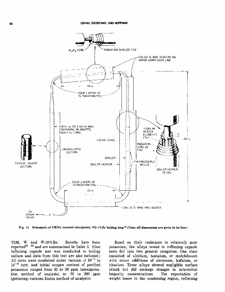
so DEVAN, DtSTEFANO, AND HOFFMAN
COILED To WIRE HEATERS ONVAPOR CARRY-OVER LINE
FOUR LAYERS OrTo RADIATION FOIL
O 9 7 b - i n . OD x 5 0 mil WALLCONTAINING 16 INSERTS,EACH I in. LONG
I
3 0 in.
TYPICAL INSERTSECTION
- COILED Tr WIRE PRE-HEATF.R
Fig. 11 Schematic of ORNL natural circulation, Nb-l%Zr boiling loop." (Note: all dimensions are given in inches.)
TZM, W and W-26%Re. Results have beenreported41"44 and are summarized in Table 5. (Onerefluxing capsule test was conducted in boilingsodium and data from this test are also included.)All tests were conducted under vacuum at 10~7 to10~9 torr, and initial oxygen content of purifiedpotassium ranged from 20 to 50 ppm (amalgama-tion method of analysis) or 70 to 200 ppm(gettering-vacuum-fusion method of analysis).
Based on their resistance to relatively purepotassium, the alloys tested in refluxing capsuletests fell into two general categories. One classconsisted of niobium, tantalum, or molybdenumwith minor additions of zirconium, hafnium, ortitanium. These alloys showed negligible surfaceattack but did undergo changes in interstitialimpurity concentrations. The expectation ofweight losses in the condensing region, reflecting

COM>A1BUTY OF REFRACTORY ALLOYS 51
TABLES
Summary of Boiling Sodium or Potassium Metal-Structural MeUlJ Compatibility Testa Completed by ORNL
Numberof
tests Material Fluid
Temperature, °C
Maxi-mum
Timeper
Condennlngrate.Mini-
mum test, h g/min ' / c m '
weightchange,rag/cm1 Results
Nb
Nb-l%Zr
Nb-l%ZrD-43
1
2
1
2
C-129 Y
TZM
T-lli
W-26%Re
Nb-l%Zr
D-43
T-lllD-43 Loop/
TZM Inserts
K
K
NaK
K
K
K
K
KK
1200
1100 to1200
12501200 *o
1400
1200
1200 to1300
1200
1200 to1250
1200
1200
12501250
1100
Refiuzing Capsules (55,000 h)*
5000 0.3 to 0.4 t
600 to5000
5000950 to
5000
5000
5000
5000
5000
0.2 to 0.4
0.170.3 to 0.6
0.3
0.3
0.3
0.3
1.1 to -2.0
+0.7 to +0.1+ 1.7 to -0.002
+0.5 to 0
+ 7 to -2
+0 to -1.7
Natural Circulation Loops (13,000 h)*
0.2 +0.7 to -0.2650 1200 to2800
835 3000
1040 30001040 3000
C 35 +0.6 to +0.2
0.53 -0.4 to +0.70.53 +0.3 (Av)
Forced-Circulation Loops (3000 h ) '
355 3000 270
Penetration of niobiumby potassium.
No evidence of penetrationby potassium. Oxygen pickupand migration from top tobottom of capsule.
Mo evidence of penetration.No evidence of penetration.
Oxygen transferred fromtop to bottom of capsule.Decarburization occurred inareas of high oxygen pickup.
No attack except to 0.03 mmon one specimen.
Increase in concentration of Tiand Mo in K but no otherevidence of attack.
No evidence of penetration.Some oxygen pickjp by T-lll .
No attack of powder productcapsule; mass transferdeposits of tungsten inarc melted capsule test
No evidence of penetration.Oxygen pickup in specimensfrom subcooler region.
No evidence of penetration.Oxygen pickup in specimensfrom subcooler region.
No evidence of corrosion.ZrO2 transferred to subcooler.TZM inserts decarburized.
0.03 mm erosion, second stageblade. Oxygen ; jkup inboiler and condenser.
*Total test hours.tNot determined.
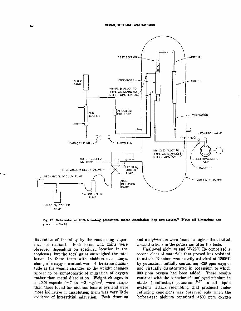
62 DEVAN. DBTB=ANO. AND HOFFMAN
DRYER
Nb-1%Zr ALLOY TOTYPE 316 STAINLESSSTEEL JUNCTION
I ZIRCONIUMMHOT TRAP
N b - l % Z r ALLOY TOTYPE 3(6 STAINLESSSTEEL JUNCTION
WATER-COOLEDOIL TRAP
ELECTROMAGNETICPUMP
AIR
FARADAY PUMP
12-in VACUUM BLC ZK VALVE
• MECHANICAL VACUUM PUMP
-VACUUM CHAMBER
4- in DIFFUSIONPUMP
TRAP
Fig. 12 Schematic of OSNL boiling potassium, forced circulation loop test system.14 (Note: all dimensions aregiven in inches.)
dissolution of the alloy by the condensing vapor,vas not realized. Both losses and gains wereobserved, depending on specimen location in thecondenser, but the total gains outweighed the totallosses. In those tests with niobium-base ahoys,changes in oxygen content were of the same magni-tude as the weight changes, so the weight changesappear to be symptomatic of migration of oxygenrather than metal dissolution. Weight changes ina TZM capsule (+7 to - 2 mg/cmz) were largerthan those found for niobium-base alloys and weremore indicative of dissolution; there; was very littleevidence of interstitial migration. Both titanium
and molybdenum were found in higher than initialconcentrations in the potassium after the tests.
Unalloyed niobium and W-26% Re comprised asecond class of materials that proved less resistantto attack. Niobium was heavily attacked at 1200° Cby potassiuiu initially containing <30 ppm oxygenand virtually disintegrated in potassium to which300 ppm oxygen had been added. These resultscontrast with the behavior of unalloyed niobium instatic (nonfluxing) potassium.36-37 In all liquidsystems, attack resembling that produced underiefluxing conditions was observed only when thebefore-test niobium contained >500 ppm oxygen

COHPATBtlTY OF REFRACTORY ALLOYS 53
and occurred irrespective of the oxygen level of thepotassium. It was concluded that attack in niobiumrefluxing capsules is the result of oxygen enteringthe boiler wall.41 Furthermore, transfer of oxygento the niobium from potassium appears to bepeculiar to a boiling system, because under staticconditions the opposite was observed.
In two otherwise similar W-26% Re refluxingcapsule tests for 5000 h at 1250° C, no measurablecorrosion was noted in a powder-metaliurgicallyproduced capsule while a ring of tungsten crystal-line deposits formed in the condenser section of anarc-melted capsule. The arc-melted W-26% Re capsule originally contained about th -ee times moreoxygen (—60 ppm) than the deposit-free powderproduct capsule (—20 ppm oxygen).
Oak Ridge National Laboratory also conducteda series of refhixing capsule tests with Nb-l%Zr at1200°C to compare the relative corrosiveness ofsodium, potassium, rubidium, and cesium.41-42 Abso-lute weight changes in Nb-l%Zr were small in alltests, and there was nc evidence of chemical inter-action other than migration of oxygen. The resultsindicated little difference in the relative corrossive-ness of the alkali metals at 1200°C.
Natural-circulation loop results43 correlated inall respects with the effects observed incorresponding refluxing-capsule tests; i.e., weightchanges, when corrected for the migration of inter-stitial elements, showed negligible dissolution ofthe condenser walls, and there was no evidence ofmass transfer of metallic elements to the sub-cooier.
One Nb-l%Zr forced-circulation loop44 withNb-l%Zr nozzle and turbine-blade specimens inthe test section has been operated under conditionsshown in Table 5. Maximum attack was 0.03 mmwhere a 915-m/sec stream of 86% -quality vaporimpinged on a simulated second-stage turbineblade. No evidence of attack or deposits wa3 foundin the boiler, condenser, or subcooler, althoughchemical analyses of the loop wall showed a slightincrease in interstitial oxygen concentration.
In the lat» 1960s, ORNL completed an analyticalcomparison of cesium and potassium as workingfluids for NASA. One phase of this work was areview of turbine biaue erosion in operating tur-bines and a review of analytical and experimentalinvestigations of erosion and related phenomena.Results of this work have been reported*5, and aseries of tables and curves summarizes the dataobtained.
NASA-Lewis Research Center (LeRC)A study of the solubility of niobium and tan-
talum in potassium containing <15 ppm oxygen at
temperatures from 780 to 1015° C was reported byLeRC.46 The data are described as being apparentsolubility because results were affected by oxygenin niobium and tantalum. From Lhis studysolubilities are described by the relation
log wt ppm Ta = 4.75 - 3048/T )
log wt ppm Nb = 5.23 - 3739/TJfnr T = 1055 to 1287K
An extensive test program to evaluate theresistance of refractory metals to refluxing potas-sium at 980 to 1315°C was also carried ^ut atLeRC.47 Refluxing capsule tests were carried out onthe following niobium- and tantalum-base alloyF.
B-33 (Nb-5%V)SCb-291 (Nb-10%Ta-S%W)Nb-1 Zr (Nb-l%Zr)As-55 (Nb-5% W-17%Zr-0.3% Y-0.07%C)B-6P 'Nb-5%V-5%Mo-l%Zr)D-4S (Nb-10%W-l%Zr-0.1%C)FS-85 (Nb-25%Ta-10%W-l%Zr)Cb-752 (Nb-10%W-3%Hf)D-14 (Nb-5% Zr-0.02%C)C-129Y (Nb-10%W-10%Hf)Ta-10%W (Ta-10%W)T-lll (Ta-8%W-2%Hf)T-222 (Ta-10.4%W-2.4%Hf-0.01%C)
Results are summarized in Table 6. The mostnoticeable trend was that the ungettered alloys(those containing no strong oxide former such asHf or Zr) were less resistant to corrosion byrefluxing potassium than were the gettered alloys.Each alloy was placed in one of three groups, inorder of decreasing corrosion resistance.
Group 1: T-lll, T-222, C-129, D-14, Cb-752.D-43, B-66, AS-55, FS-85
Group 2: Nb-l%ZrGroup 3: B-33, SCb-291, Ta-10% W
The corrosion resistance of Group 1 was judgedsufficient for consideration in space power systemsas containment materials. Nb-l%Zr in Group 2was considered marginal because one heat of mate-rial was attacked and another was not. TheGroup 3 (ungettered) alloys were judged unsatis-factory because of the large amount of attacknoted.
Brookhaven National Laboratory (BNL)
Sodium refluxing capsule studies were con-ducted with seventeen refractory metal alloys asshown in Table 7 for Jmes up to 10,000 h and tem-peratures to 1320°C.48 Comparison of severalmaterials tesied at 1315°C in boiling sodium is
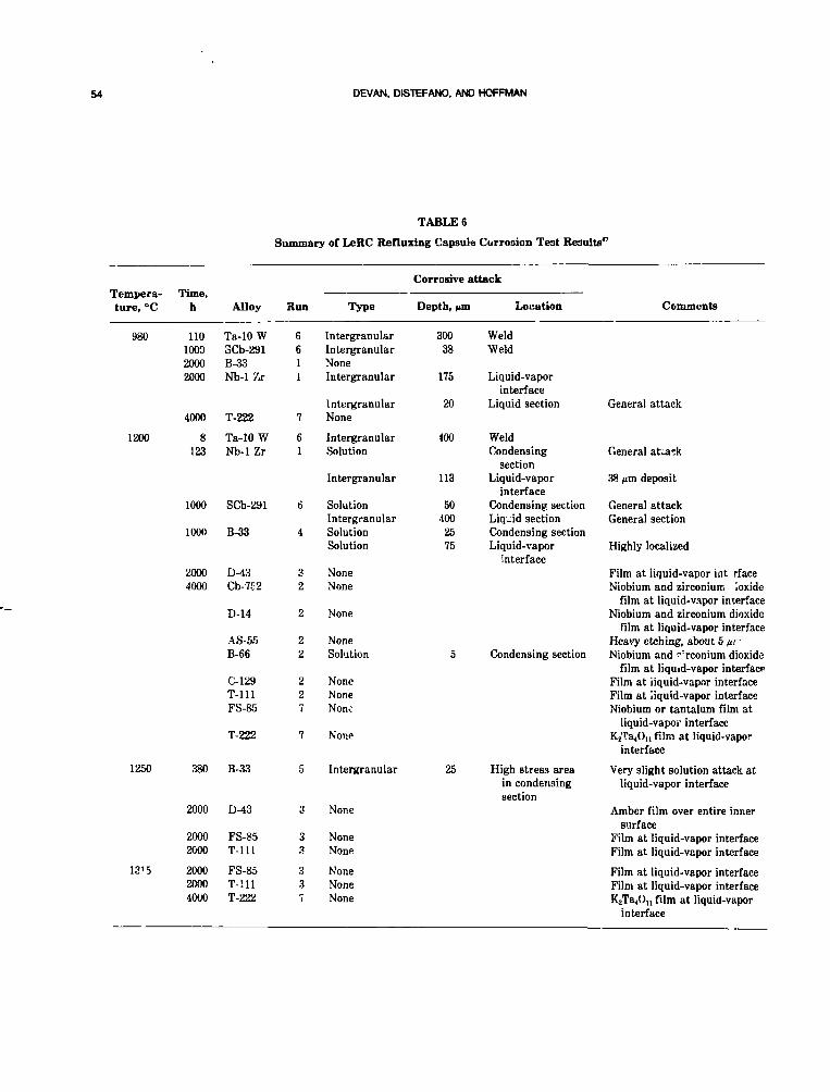
54 DEVAN, DBTEFANO, AND HOFFMAN
TABLE 6
Summary of LeRC Refluxing Capsule Currosion Test Results"
Tempera-ture, °C
980
1200
1250
Time,h
110100020002000
4000
8123
1000
1000
20004000
380
Alloy
Ta-10 W3Cb-291B-33Nb-1 Zr
T-222
Ta-10 WNb-1 Zr
SCb-291
B-33
D-43Cb-7E2
D-14
AS-55B-66
C-129T-l l lFS-85
T-222
B-33
Run
6611
7
61
6
4
32
2
22
227
7
5
Type
IntergranularIntergranularNoneIntergranular
IntergranularNone
IntergranularSolution
Intergranular
SolutionIntergranularSolutionSolution
NoneNone
None
NoneSolution
NoneNoneNone
None
Intergranular
Corrosive
Depth, M"
30038
175
20
400
113
504002575
5
25
attack
a Location
WeldWeld
Liquid-vaporinterface
Liquid section
WeldCondensing
sectionLiquid-vapor
interfaceCondensing sectionLiquid sectionCondensing sectionLiquid-vapor
interface
Condensing section
High stress areain condensingsection
Comments
General attack
General attack
38 fim deposit
General attackGeneral section
Highly localized
Film at liquid-vapor int rfaceNiobium and zirconium ioxide
film at liquid-vapor interfaceNiobium and zirconium dioxide
film at liquid-vapor interfaceHeavy etching, about 5 iu~Niobium and rrconium dioxide
film at liquid-vapor interfaceFilm at iiquid-vapor interfaceFilm at liquid-vapor interfaceNiobium or tantalum film at
liquid-vapor interfaceK2Ta40n film at Iiquid-vapor
interface
Very slight solution attack atliquid-vapor interface
2000 D-43
1315
20002000
200020004000
FS-85T-l l l
FS-85T-l l lT-222
None
NoneNone
3 None3 None7 None
Amber film over entire innersurface
Film at liquid-vapor interfaceFilm at liquid-vapor interface
Film at liquid-vapor interfaceFilm at liquid-vapor interfaceKjTa^n film at liquid-vapor
interface

COMPATBiUrY OF REFRACTORY ALLOYS 55
TABLE 7
Nominal Composition of Alloys Tested in BNL Test Program*
Alloydesignation
AS-55B-66Cb-753Cb-Ti
D-llD-14D-43F-48
FS-60FS-85S-291T-lll
T-222TZCTZMW-26 ReX-34
Nb
BalBalBalBal
BalBalBalBal
BalBal
Bal
Ta
Bal2710Bal
Bal
Mo
5
5
BalBal
Alloying
W V
555
1015
1010108
10
Bal5
element, wt %
Zr
111
15
1
1
0.350.38
0.38
Ti Hi*
10
2
2.51.40.5
C.5
C Others
0.06 0.2 Y
0.10.05
0.011.15
26 Re0.1
TABLE 8
Corrosion Results" on High-StrengthRefractory Metal Alloys Tested by BNL in
Refluxing Sodium at 1315°C
Alloydesignation
D-43FS-85
FS-60T-Ul
TZM
X-34
Monometallic capsule,test time 6271 h
No corrosion0.05-mm G.B. attack in
weld, both liquidvapor regions
No corrosion
0.01-mm G.B. attackof weld in vaporregion
No corrosion
Tested as insert inD-43 capsule for
3COOL
No corrosion0.05-mm G.B. liquid
region
No corrosion0.025-mm G.B. attack
vapor regionho corrosion
shown in Table 8. Initially, each material wasevaluated as an insert in a D-43 capsule, and thenthe tests were repeated in a monometallic capsulesystem. D-43 did not show any evidence of attack,while the other alloys showed some slight evidenceof corrosion as indicated. The authors noted thatFS-60 (Ta-10%W) was not tested as a monometal-lic capsule because previous results49 at BNL hadshown severe corrosion of this alloy. Speculationwas that FS-60 was not attacked when exposed in
the D-43 capsule because the D-43 gettered oxygenfrom the sodium and maintained it at a low levelthroughout the test.
In order to determine if prestraining the refrac-tory metai alloys would have any effect oncorrosior, several alloys wers tested in Nb-l%Zrcapsules with purified sodium for 2000 h at 1000°C,and results aio shown in Table 9. No effect of pre-
TABLE 9
Corrosion Results of Refractory Metal Alloy PrestrainedInserts Tested by BNL in Sodium at 1000°C for 2000 h'8
Alloy designation Results of metallographic examination
FS-85
T-l l lTZMS-291
AS-55B-66Cb-75?Cb-TiD-llD-14D-43F-48FS-60T-222W-26 Re
0.02-mm grain boundary attack. Nocracking.
Slight transgranular rougl uning ofpolished surfaces. No cracking.
No corrosion detected on any of theseinserts. No cracking.

56 DEVAN, DIST5FANO, ANO HOFFMAN
TABLE 10
Summary of Results at BNL on RelativeAggressiveness of Alkali Metals in Refractory
Metal Alloys" Nb-l%Zr and D-43
Alkalimetal
Cs
Rb
KNa
Li
Capsule material: Nb-l%ZrTemperature: 1150°C
Time: 6000 h
Slight attack at liquid vaporinterface
Slight attack at liquid vaporinterface
No corroaionSlight attack at liquid vapor
interfaceSlight attack at liquid vapor
interface
Capsule material: D-43Temperature: 1235°C
Time: 9437 h
No corrosion
No corrosion
No corrosionNo corrosion
No corrosion
straining was noted, and only the FS-85 alloyshowed evidence of attack as had been noted previ-ously (Table 8).
Comparison tests were run with Nb-l%Zr andD-43 in Li, Nc, K, Rb, and Cs as shown in Table 10to measure the relative corrosiveness c* the alkalimetals. Although very little attack occurred,Romano et al.,48 judged that Cs, Rb, Na, and Liwere comparable, with K being the least aggres-sive.
BNL also operated several natural convectionsodium boiling loops of Nb-l%Zr and D-43. No cor-rosion was reported in either of two Nb-l%Zrloops49 under test conditions as follows.
Temperature, Time, Mass flow rate,°C h g/mia
10951094 to 1150
80071330
1075
Four additional natural circulation loop tests wereconducted by BNL, one each of Nb-l%Zr (1100°Cmaximum) and D-43 (1200°C maximum) with liq-uid sodium and one each of Nb-I%Zr (1260°C max-imum) ar " D-43 (1350°C maximum) with boilingsodium. However, the program wa" terminatedwhile tho tests were in progress, ana no resultswere obtained.
Rocketdyne
Two types of capsule tests were conducted byRocketdyne to evaluate refractory alloys inpotassium.50 In one case the capsules were made ofa Ni-base alloy, usually Hastelloy X, and in the
other the capsule was Nb-l%Zr. There was a sig-nificant weight loss in wrought and welded No andNb-l%Zr whsn they were exposed to potassium at790 to 1090°C in Hastelloy X capsules. In addition,severe intergranular ~)enetration was noted in thewelded specimens ana X-ray diffraction tentativelyidentified NbN and NbC as the corrosion product.This is a dissimilar metal effect due to testingthese materials in a Hastelloy X capsule. Whentested in Nb-l%Zr capsules at 1090 to 1000°C, bothniobium- and molybdenum-base alloys were judgedhighly compatible with even impure potassium. Noreaction layers were found, and weight changeswere small.
A Haynes 25/type 321 stainless steel boilingpotassium loop was operated50 for 50 h with theboiler at 980°C and the condenser at 730°C. Sam-ples of Nb, Nb-l%Zr, Mo, ana Ta were suspendedin the boiler, and Nb and Nb-l%Zr were suspendedat the exit of the nozzle (vapor velocity — Mach2.5). Results are shown in Table 11. Examination ofthe boiler specimens indicated the decreasing orderof corrosion resistance to be Mo, Nb-l%Zr, Nb, and
Boilersamples
NbNb-l%ZrMo
TABLE 11Rocketdyne Low-Temperature Boiling
Potassium
Approximatetempera-ture, °C
980980980
i Loop Results50
Approximateexposuretime, h
505050
Weight-changerate,
mg/cinVday
-77-66
-7

COMPATBUTY OF REFRACTORY ALLOYS 57
Ta. The Nb and Nb-l%Zr samples downstreamfrom the nozzle wer<* not found after tests indicat-ing very severe corrosion/erosion had occurred.
General Electric (GE-Cincinnati, Ohio)
Extensive sodium and potassium compatibilitytesting was donr at General Electric (GE) undertht, sponsorship of NASA-Lewis. As a result, areview of GE's sodium and potassium compatibilitytest results will be summarized in separate sec-tions.
The principal purpose of most of the sodiumloop testing to be described in this section of thopaper was to confirm the adequacy of the manytest components, such as pumps, I2!! heaters, pres-sure transducers, valves, flow meters, thermocou-ples, etc., prior to the use of these proven com-ponents and procedures in the 10,000-h T-lll Ran-kine System Corrosion Test Loop which is coveredin the lithium and potassium sections of thispaper. Nb-l%Zr and sodium were selected as theprototypic container material and coolant, respec-tively, because of the advanced state of knowledgeof these materials at the time the GE program wasInitiated in 1963 under NASA contract NAS 3-2547.The only capsule tests conducted at GE on refrac-tory metals were sodium-potassium alloy (NaK)tests in support of the SNAP-8 program, and thesetests are described below.
Sodium Capsule Tests. Earlier work at OakRidge National Laboratory (ORNL) had indicatedthat unalloyed tantalum contaminated with oxygenwas subject to rapid attack by NaK at tempera-tures of 260 to 315°C. The SNAP-8 reactor utilizedNaK as the reactor coolant to boil mercury in thesecondary Rankine loop and because of the corro-siveness of mercury to the nonrefractory alloys ofthe reference design, tantalum was proposed as thematerial of construction for NaK-heated mercuryboiler. For these reasons Harrison51 conducted aseries of tests on tantalum specimens contaminatedto precise oxygen levels and subsequently welded inhelium environmeiits with varying air contamina-tion levels. Other uncontaminated specimens werealso welded in helium containing varying amountsof air. Harrison's tests used 22%Na-78%K a3 acoolant and were operated at 650 and 730°C forboth 100- and 1000-h tests.
The results of these experiments showed thattantalum specimens with oxygen concentrations of270 ppm or greater were attacked by NaK at 650°Cand 730° C. Uncontaminated tantalum specimenswelded in helium containing up to 250 ppm airwere not attacked by NaK. All tantalum specimens
experienced large oxygen losses as a result of expo-sure to NaK.
Sodium Thermal Convection Loop Test Thistest loop52 operated at a hot leg temperature of1305°C and a cold leg temperature of 760°C at asodium velocity of 0.1 m/sec. This loop was thefirst of a series of three Nb-l%Zr sodium thermalconvection and pumped loop tests to qualify com-ponents and materials for a 10,000-h T-lll Rankiii-System Test Loop. The primary purpose of this +estwas net only to determine the performance of the1 ^ (autoresistance) heater design but also to qual-ify instrumentation procedures and insulation tech-niques and to establish the vacuum requirementsnecessary to prevent contamination of the externalsurfaces of the test loop.
No significant corrosion of the Nb-l%Zr by thehigh temperature sodium was observed. Oxygenmigration from the hotter to the cooler regions ofthe loop was noted. Due to the very high tempera-ture in the loop heater coil, the Nb-l%Zr tubeexperienced critical strain growth resulting in oneor two grains across the entire 1.7-mm tube wall.Another significant observation was the largehydrogen pickup and associated embrittlement ofthe Nb-l%Zr tubing during the alcohol strippingprocedure used to remove residual sodium from theioop tubing. The hydrogen embrittlement was read-ily eliminated by vacuum annealing of the tubing.Alkali metal removal procedures were subsequentlydeveloped by GE and ORNL which preventedhydrogen pickup during alkali metal removaloperations.
Sodium Forced Convectitnt, Loop Test The Nb-l%Zr Pumped Sodium Test Loop^ operated with a1130°C hot leg and 1075°C cold leg and L .low rateof 188 kg/hr. The loop was built and operated toverify the performance of additional loop com-ponents beyond those evaluated in the Nb-l%Zrthermal convection loop experiment describedabove. The major additional components incor-porated into this system, which is illustrated inFig. 13, included a helical induction electromag-netic SEM) pump, metering and isolation valves,pressure transducers (%o types), and a flowmeter.
The test was operated for 2650 h. After the testthe loop was cleaned, and the various componentswere evaluated. Some loss of oxygen from the hot-test regions of the loop by the sodium wasdetected, and a modest increase (159 ppm beforetest to 404 ppm after test) in the oxygen concentra-tion of the uninsulated tube wall was noted despitethe fact that the chamber was operated at 1 X10"8 torr for 2200 h of the 2650 h. It is assumedthat the contamination occurred during the first

68 DEVAN, DBTEFANO, AND HOFFMAN
Vacuum Tatilt -
Pressure TransducersI
Resistance' Hetted Colls
- Valve BypaBfi
Surge Tank
Loo-1
Tempo ratures
T/CNo. °F
123456789
10111213l415IS171819202122232425262728
1975585800580196519501985
20202 00020352065206520502045650203020156701985188018s0505475•1551555157517201580
Fig. 13 Temperatures of the various components of the Nb-l%Zr pumped sodium loop during the 2650-h test.
400 h when the chamber pressure was in the 2 X10~8 to 2 X 10~7 torr pressure range. Detailedmetallographic e~<n; 'nation of both Nb-l%Zr basemetal tubing and To.dments from 12 different looplocations revealed no detectable corrosion.
Nb-l%Zr Rankine System Corrosion TestLoop. The Nb-l%Zr Rankine System CorrosionTest Loop*4 was designed to serve as the prototypeand reference design for future test loops inevaluating advanced refractory alloys such as T-
111 in the T-lll Rankine System Corrosion TestLoop wliich is discussed in the lithium and potas-sium sections of the paper describing the compati-bility testing done at GE. Figure 14 shows an iso-metric drawing of the two circuit systems. Thisloop was essentially identified in appearance to theT-lll alloy Rankine System Loop illustrated in theGE/lithium section of this paper. The primary orsodium heater circuit had a flow rate of 410 kg/hand provided the thermal energy to thecounterflow tube-in-tube boiler where the

ODMPATBUTY OF REFRACTORY ALLOYS 69
P K E S 5 L J K L IRANSl iuCtSLACK PIAPHhAGM
VACUUM U N k
TUR3INF SIMULA IOr.1 N - • i.-t
SECONT'ARi [M Pl:W
SODIUMP O T A S S I U MARGONE L F C T R I C A L PCWER
[ FLEX I B LE DRIVE CABLE
Fig. 14 Isometric drawing of the Nb-l%Zr RanJrine system eorronon test loop and vacuum test chamber.
potassium was vaporized. Results obtained onmaterials in the potassium circuit will be coveredlater in this paper.
The temperatures maintained in the sodiumportions of the loop during the 5000-h test areillustrated in Fig. 15. All portions of the sodiumcircuit in contact with flowing sodium were madeof Nb-l%Zr. The pressure in the vacuum chamberwas maintained at 2 X 10~8 torr during the 5000-htest to prevent oxygen pickup by the Nb-l%Zr loopcomponents.
Extensive metallographic evaluation of the ftb-l%Zr specimens taken from all portions of thesodium circuit revealed no measurable corrosion.Tensile tests were performed at room temperature
and 1095° C on tube tensile specimens machinedfrom the boiler inlet tube (oxygen concentration, 36ppm), and the boiler outlet tube (oxygen concentra-tion, 730 ppm) showed essentially no change fromthe before-test material. Deoxidation of the Nb-l%Zr tubing from the hotter regions of the loopwas noted while oxygen increases were observed inthe cooler regions of the sodium circuit. The mostsignificant oxygen increases were measured in theregions of the boiler where the heat flux to boilingpotassium section was very high resulting in arapid drop in the sodium temperature. Figure 16shows the tube-in-tube boiler and indicates theoxygen concentrations of the Nb-l%Zr followingthe test. The boiler plug detail (inset) in this figure

60 DEVAN, D1STHFANO. AND HOFFMAN
TurbineSimulalOf
1780
• Turbine Simulator
Test Chamber PressureD ..mg 5000 Hour Tesf2-5 x 10's Torr
— Condenser
(Temperature in °F)
Surye T.inksK Pump
Fig. 15 Nb-l%Zr Rankine system corrosion test looping Bhowing temperatures (°F) and flowrates of sodium and potassium during 5000-h test.

COMPATIBILITY OF REFRACTORY ALLOYS 61
' TURBINE_ _ Sll-'JLATOR
(STAG," NO. 1)
21]0°F
12130 F / _ HEATER
TUBF-l.'l-VJBE— - -BOIL IR
PLUG SECTIONOF BOILER —
177O°F
Na
WALL (?n ' jO°KK 148
WALL ( 1 9 9 0 ° F ; , 1270
OUTEK 0 .020" - L 1 ' 5MIODI E IJ.020V - 533"JMR 0 . 0 / 0 " - '.76
BOILED PLUG DETAIL
3 /8 "
WALL_- 7^0
OUTER""0.020" - 330MIDDLE 0 .020" - 455INNER 0 .020" - 1460
- Na TOEH PUMP
WALL - J 6 2
NUMBERS INDICATE OXYGENCONCENTRATIONS IN PPM
BEFORE TEST ANALYSIS
3 / 8 " TU3E - 260 PPM1 " TUBE - 245 PPM
K FhOM IPREHLATER
Fig. 16 Oxygen concentration of various regions of the boiler of the Nb-l%Zr Rankine system corrosion testloop following 5000-h operation.
and the oxygen concentrations of various sectionsof the tube wall separating the sodium from theboiling potassium show the large oxygen pickup(2445 ppm) on the sodium (outer) side of the boilertube wall. Figure 17 consists of two photographs ofthe straight region of the boiler. The very sharptransition in appearance from the depositionregion to the clean tube surface results from thesharp transition from wet to dry potassium on theother side of the tube wall and the associatedchange in heat flux through the wall in this loca-tion. Figure 18 shows metallographic cross sectionsof the Nb-l%Zr tube wall in the region oi depori-tion shown in Fig. 17. The X-ray image, logetherwith other supporting analysis, strongly suggeststhat the crystals are ZrO. These very thin depositsare of no engineering significance, but they illus-trate the importance of keeping the overall oxygen
inventory of refractory alloy/alkali metal boilingsystems at as low a 1 el as is practical.
The potassium compatibility testing done atGeneral Electric (GE) was spor.sored by NASA-LeRC in support of Rankine system technologydevelopment. The T-lll Ra"kine System Test Loopthat will be discussed in the last part of this sec-tion was the culmination of an eight-year programto document he compatibility of selected RankineSystem materials for application in space powerplants. Long-term refluxing potassium capsuletests conducted during this period are d:scussedbelow
Potassium Capsule Tests. An extensive bearingmaterials evaluation program was carried out atGE55 to identify materials suitable for use inpotassium lubricated journal bearings over the

DEVAN, DISTEFANO. AND HOFFMAN
it
POTAS
us F:TV ,
fiM
NL-lZr
Overall view of sodium side of?r boiler tube and enlargedhow the very thin deposits ofimpound on the tube surface.
temperature range from 205°C to 870°C. Testmaterials included Nb-l%Zr, Mo-TZM, W,TiC + 5%W, TiC + 10% Mo, TiC + 10% Nb,Grade 7178 (84%W-8%Mo-2%Nb-6%C). In addi-tion to potassium corrosion evaluation, all theadditional studies performed on candidate bearingmaterials included friction and wear in potassium,dimensional stability, hot hardness, thermal expan-sion, ccmpressive strength, modulus of elasticity,and potassium wetting characteristics. The corro-sion test results on the candidate materials citedabove indicated that the Mo-TZM, W,TiC + 5%W, TiC + 10%Mo, and TiC + 10%Nbhad excellent corrosion resistance but that the WC
base material (Grade 7178) lost carbon resulting inthe formation of elemental potassium on the sur-face. The conclusion of the study was that therefractory metal bonded carbides TiC + 10%Nband Grade 7178 offered promise for 650°C bearingapplications.
The Mo-TZM alloy was a candidate turbineblade material for application in Rankine spacepower systems in which the turbine blades wouldoperate in the 1095°C temwrature range. There-fore, refluxing capsule tests were conducted todetermine the corrosion resistance of the Mo-TZMalloy in a refluxing potassium environment.56 Thetest facility, which was located in an ultrahigh vac-

COMPATfBOJTY OF REFRACTORY ALLOYS 63
Fig. IK Cryptals of Zr-O found OD the sodium side of the potassium boiler tube of the Nb-I%Zr RanMne system loop.
uum chamber operated at 10" to 10 torr, isillustrated in Fig. 19. As indicated in this figure,the tubular insert specimens of the Mo-TZM alloywere located in the condensing potassium region ofa Nb l%Zr capsrle. Both the 2500- and 5000-h cap-sule tests operated at potassium condensing ratosof l.<! !:g/m2/h.
No significant weight, chemistry change, or coi-rosion was detected on the Mo-TZM specimens ineither test. The inside surfaces of the Nb-l%Zrcapsules in the boiler regions were slightly dark-ened and showed oxygen increases. Thh oxygenpickup in boiling potassium regions is consistentwith observations in other boiling potassium sys-tems.
Biaxially stressed rufluxing potassium capsuletests were conducted to determine the possibleeffects of stress on the eorrosir>n of the D-43 alloywhen the stess is sufficiently 'arge to produce sub-stantial p counts of creep. The test facility and theD-43 capsule design are illustrated in Fig. 20. Twoseparate capsule tests were conducted.5" In the firsttest, the capsule was internally pressurized to 43MPa and held at 1150°C for 1000 h. In the secondtest, the capsule was pressurized to 36 MPa andheld at 1120cC for 2000 h. The wall thickness oferch D-43 c.psule was reduced from 3.6 to —0.5m.-. in both the boiiih^ i A condensing region toachieve the desired strain levels in these locationsduring the test
No corrosion in the boiling or condensingregions of either of the capsules was detecteddespite a strain level of 5% in the second test. It isDi interest to note that the amount of creep
observed in these capsule tests was slightly higherthan would be predicted based on uniaxial creepdata.
In addition, the test facility described abovewas used to assess the response of two biaxiallystressed capsules in a refluxing potassium environ-ment. The first capsule used seamless T-lll tubing,and the second used welded and reworked tubing.Both capsules were tested for 5000 h at 1205°C.
No corrosion of either the boiling or condensingregions of the two T-lll capsules was detectedeither in the strained or unstrained regions.58 Thestrain resulting from the biaxial stress during thet'.vc tests was in substantial agreement with thepredicted strain based on uniaxial creep data.
Potassium Forced (jmvecthm Boding mid Cmi-ih'tijiw,} Lx>p 7V.sf.s. Both Mo-TZM and Mo-TZCturbine blades were utilized in the turbine of thePnfnxsiiim Turbine Test Facility as shown inFig. 21. The test facility was constructed on type31<i stainless steel and operated at a turbine inlettemperature of S40°C. Earlier test results showeddegradation of Mo-TZM and Mo-TZC turbineblades due to excessive oxygen levels in the potas-sium. The second stage turbine blades illustratedin Fig. 22 were exposed to potassium vapor in a3000-h endurance run during wh'ch very low oxy-gen concentrations were maintained in the potas-sium. As indicated in Fig. 22, no significant weightchange or corrosion or erosion was noted on theMo-TZM blades which operated at 750°C. This wasalso true for the Mo-TZC blades in thib turbine.59
These results add to the conviction that the

64 DEVAN, DISTCFANO, AMJ HOFFMAN
Thermis to r
Optical S igh t Por t S t a i n l e s s S t ee lH"oaL Sink
—TZM Allov I n s e r t s
-Nb- l l r Alloy Capsule
W-Re Thermocouple .,,
K Liquid-VaporI n t e r f a c e
Tantalum Base Support |{{
S p l i t Tantalum S t r i p Heater
— Tantalum Radia t ion Sh ie lds
Nb-lZr Alloy Spacer Wire
W-Re Thernocuuple
Fig. 19 Nb-l%Zr refluxing potassium capsule test system used ;o evaluate corrosion resistance of Mo-TZM alloytube inserts.
Mo-TZM and Mo-TZC alloys have excellentresistance to potassium liquid and vapor.
A general description of the Nb-l%Zr RankineSystem Corrosion Test Loop was given in thesodium section covering the GE compatibilitywork. Figures 14 and 15 illustrate the generalfeatures of this system and give the temperaturesand flow rates in the boiling potassium circuit. Theresults of the extensive evaluation performed onthe Nb~l%Zr loop and the components located inthe potassium circuit are given in the report ofHoffman and Holowach.60 A brief summary will begiven of the most significant compatibility observa-tions in this 5000-h test.
One of the major reasons for conducting thistest was to determine the corrosive/erosive effectof wet high velocity potassium vapor on turbine
simulator nozzles and blades made of the Rankinesystem candidate turbine blade alloy, Mo-TZM. Thelocation of the turbine simulator teat sections wereshown earlier in Figs. 14 and 15. Figure 23 showsthe appearance of the ten nozzle and blade combi-nations after the 5000-h test exposure. The nozzlediameters and the heat rejection conditions wereselected to achieve about 88% quality vapor im-pinging on the nozzle blades at velocities in the 275to 410 m/sec range. The blade and nozzle speci-mens shown in Fig. 23 were essentially identical inappearance to the before-test specimens. Cross sec-tions of several of the nozzles are shown in Fig. 24,ant; thp metallographic appearance of the nozzlesattests to the excellent resistance of the Mo-TZMalloy. No change in nozzle diameters occurred dur-ing the test. All the blade specimens were exam-

COMPATHUTY OF REFRACTORY ALLOYS 86
if<F\
Linear VariableDifferentialTransformers
SplitTantal um,Heater
\
Tl
Vapor
L i q u i d
I-Nb-lZr Alloy
Spacers
A1 2O 3 Probes
W Caps
D-S3
Capsule
I.VDT's
Tan ta 1 uir
Had i a t1 on
Shu-Ids
Boil 'ng
'''ad ea tor
Fig. 20 Biasially stressed reflating potassium capsnle test facility/D-43 (Nb-base) alloy capsule.
ined at the impingement point, and no attack wasdetected under the3e vigorous test conditions asillustrated in Fig. 25.
Extensive metallographie examinations of allNb-l%Zi regions of the potassium circuit wereperformed. No corrosion of either Nb-l%Zr basemetal tubing or weldments was observed in anyportion of the loop. Very slight surface roughness
(13 Mm) was noted in the high heat flux region ofthe boiler tube. Extensive grain growth was notedin the hottest (1095cC) regions of the boiler tubewall, but this was not related to the potassium (orsodium) environment.
The results of this test confirmed the exoellentcorrosion resistance of Nb-l%Zr to high tempera-ture sodium and the resistance of both Nb-1% Zr

6b
Fig. 21 Potassium turbine,housing, and exhaust scrollshowing second stage (rightside) where Mo-TZM andMo-TZC blades were located.
F13. 22 Mo-TZM alloy turbine bladss in the second stage of potassium turbine test system following completionof a 3000 -h endurance test.
Test conditions at second stage:Temperature, 138S°FK vapor velocity, 535 fpsK v&por velocity, 95%
Effects of 3000-h test:Weight change, -0.029%Maximum corrosion, < 1 mil

COMPATBUTY OF REFRACTORY ALLOYS 67
Fig. 23 Mo-TZM alloy turbine simulator nozzle and blade specimen* froe Nb-l%Zr Ranidne system corrosionloop following 5000-h exposure to high-velocity potassium vapor. Potassium Vk vor flow path can be seen on some ofthe blades.
CROSS SECTION AND PHOTOMICROGRAPHS OF NOZZLES FOLLOWINGEXPOSURE TO POTASSIUM FOR 5000 HOURS IN THE Cb-lZrCORROSION TEST LOOP
Fig. 24 Cross-section viowa and photomicrographs of turbine simulator nozzles following exposure to potassiumfor 5000 h in the Nb-l%Zr corrosion test loop.,

68 DEVAN, DtSTEFANO. AND HOFFMAN
RSMo-TZM TURBINE BLADE SPECIMENS FOLLOWING 5000 HOUR?EXnOSURE TO POTASSIUM IN THE Cb-lZr CORROSION TEST LOOP
. i?t ' ; !"E' l AND HOLDING 'A BLADE SPECIMEN '10. 1 , ^ r . : '"I0Z7LE I'.'LE" TLHP. , 2rj " ':MPV-rM E . ,T vE L nr ; : . - , 11 :-=:
1
flLADE SPECIMEN NO. 2 , REGION®•''V ' - L " : : T I r^ RLADr SDrc;u r ' l NOZZLE INLET TEMP., 1785OF
!V?I'ir,EMENT VELOCITY, 1350 FT/SEC
Fig. 25 Mo-TZM turbine simulator blades following 5000-h exposure to high-velocity potassium in Nb-l%ZrRankine system loop.
and Mo-TZM to both boiling and condensing potas-sium.
The T-lll Rankine System Corrosion Test Loop,61
which had a lithium primary heater circuit and aboiling potassium secondary circuit (1175°C maxi-mum and 515°C minimum operating temperature)was previously illustrated in Figs. 7 and 8. Thistest was the culmination of an eight-year NASA-Lewis program at GE to confirm the suitability ofthe refractory alloys Nb-l%Zr and T-lll as struc-tural containment materials for application inRankine space electric power plants. The superiorstrength of the tantalum base alloy, T-lll, permitsits use at significantly higher temperatures thanthe Nb-l%Zr alloy utilized in the earliersodium/potassium Rankine System Test Loop.
On startup an extremely small leak in a tubebutt weld in the middle of the potassium boilernecessitated a shutdown. Following an elaboratebut extremely effective repair cycle, the T-lll loopwas put into operation and completed a 10,000-hteat without interruption in March 1970.
The potassium circuit of this loop included tur-bine simulation test sections identical in design tothose illustrated earlier in Fig. 23. In this sectionthe potassium flow rate was 18 kg/h with a vapornozzle exit velocity of 305 m/sec at a vapor qualityat the exit of 88%. However, in this test the alloysMo-TZC and Nb-132 M (Nb-base) nozzle and bladespecimens were substituted for the M<J-TZM alloyused in the Nb-l%Zr Rankine System Test Loopdescribed earlier. Eight of the nozzle/blade combi-nations were made of Mo-TZC and two were madeof Nb-132 M. Extensive metallographic and chemi-cal analysis of the nrzzle and blade specimens inaddition to precise weight measurements anddimensional analysis revealed no significant attackof any kind. The maximum weight change of any ofthe ten 26-g blade specimens was an apparent lossof 0.002 g. Precise measurement of the nozzlediameters gave a maximum apparent change of+2.5 /ioi. An extremely thin and adherent film ofhafnium (<13 /im in thickness) was observed onthe second stage Mo-TZC blade in the potassium

COMPATBLTTY OF REFRACTORY ALLOYS 69
vapor (1030°C) impingement area. The posttestappearance of the nozzles and blades was essen-tially identical to the before-test appearance.
Metallographic evaluation was performed onT-lll loop components from all regions of thepotassium circuit. Observations on the lithium cir-cuit components were discussed earlier in the liq-uid lithium section of this paper. All regions of theloop, with the exception of the boiler regions,showed no corrosion. The high heat flux regions ofthe boiler plug section, particularly in the regionwhere the potassium was drying out, showedevidence of heavy grain boundary precipitation to adepth of 250 /im and possible grain boundaryattack to a depth of about 50 pm. The grain bound-ary precipitate was rich in hafnium, and the parti-cles were thought to be hafnium oxide. Additionalevidence of oxygen concentration in the potassiumside of the T-lll boiler tube is given below in thediscussion of the results of chemical analyses.
Extensive chemical analyses of whole wall andpartial wall specimens were performed to deter-mine the oxygen concentrations of various sectionsof the boiler and potassium circuit. Figure 26 givesthe results of these analyses. Of particular notewas the very high oxygen concentrations on thepotassium side of the boiler plug section in theregions where the potassium was boiling and dry-ing out. As indicated in the insets of Fig. 26, oxy-gen levels of 1000 ppm or greater were detected onthe potassium side of the wall in some regions,whereas the lithium side of the tube wall in theselocations contained <10 ppm oxygen. Regions ofoxygen enrichment on the potassium side wereapparently very sensitive to local boiling conditionsand the location of the swirler wire insert.
Some reduction in the ductility of the T-lllvapoi- carryover region tube shown at the top ofFig. 26 was noted. On the basis of the analyses,this cannot be attributed to oxygen pickup of thetube in this region but is tentatively attributed topossible hafnium segregation to the grain bound-aries in this region which operated at 1025°C. Theroom temperature tensile ductility of specimensfrom this region was about 12% as compared to34% in pretest specimens.
In summary, the T-lll alloy loop structuralalloy and the Mo-TZC and Nb-132 U turbine alloycandidates were very compatible with potassium inthe high-temperature long-term Rankine systemtest and should be considered as prime candidatesfor application in space power systems.
Other
Several other organizations have also conductedcorrosion studies of refractory metals in sodium
and potassium. BMI62 investigated the corrosionand creep behavior of tantalum in sodium to 650° C.The corrosion studies consisted of experiments inwhich tantalum specimens were suspended in theheated legs of type 316 stainless steel forced-convection loops circulating high purity sodium.After periods up to 1200 h, weight lossescorresponded to 2.5 /im of metal removed per yearwhen the sodium was hot gettered (<10 ppm oxy-gen). In cold trapped sodium (~40 ppm oxygen)weight losses corresponded to 75 jiw/year metalremoval. Metallographic examinations revealed nodeleterious corrosion effects except in one batch ofarc-cast tubing specimens which suffered severeintergranular attack in sodium with about 80 ppmoxygen. In the creep experiments the oxygen con-tent of the sodium was maintained at <10 ppmoxygen by gettering, and little effect of sodium onthe creep strength of tantalum was measured.
Compatibility of molybdenum in sodium vaporat 1500cC was investigated by N'rth AmericanAviation, Inc.63 Molybdenum was used as a testsample inside a molybdenum capsule (5.5 mm OD).Metallogrc.phic examination after 100 h showedsome attack to a depth of <25 /im.
Pratr and Whitney investigated the compatibil-ity of Nb-Zr, Nb-Zr-C, and TZM in four naturalcirculation boiling loop tests64 (Nb-l%Zr loopmaterial) for 3000 h at a nominal boiling tempera-ture of 1070°C. The Nb-Zr-C alloys were unaf-fected by exposure to boiling potassium, but therewas slight surface dissolution of the Nb-Zr alloys.TZM was judged to be compatible under these con-ditions, but there was some slight loss in elevatedtemperature tensile strength.
AiResearch Manufacturing Company65 con-ducted static capsule tests of Mo-0.5%Ti and tung-sten in potassium for 1000 h at 540°C. Weightchanges were greater in tungsten compared withMo-0.5%Ti, but metallography and chemical analy-ses of the potassium showed no evidence of attack.Nb-l%Zr and Mo-0.5%Ti were tested for 500 h inrefluxing potassium at 900 and 980°C boiler tem-peratures, and results again showed little evidenceof attack. An Nb-l%Zr boiling potassium forced-circulation loop was fabricated for operation at980°C maximum temperature; however, the testfailed after two hours due to an electrical short.Examination indicated that severe contaminationof the Nb-l%Zr had already occurred due to envi-ronmental impurities.
CesiumNot as much information has been generated on
the compatibility of refractory metals with cesiumas has been with lithium, sodium, and potassium.

70 DEVAN, DISTEFANO, AND HOFFMAN
VaporCarryover Line
• T o t a l Wall
+ Inner 0.020"
A Outer 0.020"
Oxygen Analysis Shown in ppraPre-Test Analysis:
3/8-inch Tube - 16.-Inch Tuba - 17
1101.
596
Fig. 26 Results of oxygen analyses of various T-Hl alloy components following the lG,CO0-h test Note the highoxygen concentrations on the potassfam side of the T-111 wall in the boiler plug section and the very low oxygenconcentrations on the lithium side.
Studies have generally been conducted inassociation with applications such as a workingfluid in heat engines or to dissipate the spacecharge in thermionic generators. Many of the earlyresults on cesium compatibility were affected byoxygen contamination, and most often impurityconcentrations were not determined. The same cor-rosion mechanisms that occur with the other alkaliliquid metals also generally occur with cesium.
In 1967 Klueh and Jansen66 at ORNL completeda literature survey on compatibility of structuralmaterial with cesium as part of the AnalyticalComparison of Cesium and Potassium on Rankine-Cycle Working Fluids for Space-Power Plants. Fewadditional compatibility studies with cesium havebeen conducted since this report; therefore, it hasbeen used as the basis for the summary presentedhere.

COMPATIBILITY OF REFRACTORY ALLOYS 71
Chandler and Hoffman67 tested niobium, Nb-l%Zr, molybdenum, tantalum, and tungsten instatic capsules containing ce3ium liquid for 300 hat 870°C and found no metallographic evidence ofattack. Similar results were found by Winslow68 formolybdenum and tungsten after 500 h at 400°C.British workers,69 on the other hand, found a sur-face scale on niobium and tarnishing of tantalumand molybdenum after 10,000 h at 570°C. Theselatter tests, however, were conducted in stainlesssteel capsules.
Tepper and Greer70'71 at Mine Safety Appliance(MSA) tested the following dissimilar metal cou-ples in cesium liquid.
1. Nb-l%Zr/"TD" Nickel (500 h at 980DC)2. Nb-l%Zr/Haynes alloy 25 (500 h at 1370°C)3. Nb-l%Zr/Mo-0.5%Ti (500 h at 137O°C)4. Mo-0.5%Ti/"TD" Nickel (500 h at 980°C)5. Mo-0.5%Ti/Haynes alloy 25 (500 h at
1370T)6. Mo-0.5%Ti/Zirconium (725 h at 1370°C)
For couples (1) through (5), considerable masstransfer of both metallic and nonmetallic constit-uents was observed. No detectable changes werenoted in the Mo-0.5%Ti/Zr couple after 725 h at1370°C; but when oxygen and carbon additionswere made to the system, measurable changes werenoted, especially in the zirconium which getteredboth species. Conclusions drawn from this investi-gation were that the utilization of dissimilar metalsystems can often lead to premature failure if oneis not cognizant of the effect of interalloying.
btudies on refractory metals with cesium vaporhave been of three types: (1) capsules containingcesium with liquid and vapor in equilibrium,(2) capsules containing only cesium vapor, and(8) test specimens in stainless steel reservoirs con-nected to an outside source of cesium vapor. In thefirst two methods, test specimens may have beensuspended in the vapor, or the capsule itself mayhave served as the specimen.
When the capsule and test specimen were of thesame material, there was generally no metallic evi-dence of attack.67-72-73 DeMastry and Griesenauer,74
in what effectively were dissimilar metal tests,used TZM as a container material for variousrefractory metal test specimens and, in someinstances, found evidence of corrosive attack andmass transfer. B-66 experienced slight surfacedissolution after 1000 h at 1370°C, and T-lll,which was resistant, to attack for 1000 h at 1370°C,exhibited surface dissolution after 100 h at 1540°C.After 100 h at 1370°C, Ta-12%W was unattackedby cesium vapor, but, showed surface dissolutionafter 1000 h and showed surface dissolution and
lamellar carbide or carbonitride precipitates after600 h at 1540 and 1700°C. The source of the carbonand nitrogen was thought to be the cesium and theTZM container. The tungsten-base alloys testedwere unattacked after 1000 h at 1700°C, but theyexperienced surface dissolution and grain boundaryattack after 1000 h at 1870°C.
Tables 12 and 13 summarize the results of therefractory alloys tested in the cesium vapor.67"69'73'76
More recently, a performance test of a thermionicconverter with a tungsten emitter was conductedby GA Technologies.77 The tungsten emitter wasexposed to cesium vapor at a pressure of 5 to 10torr for nearly five years with no evidence of deg-radation in performance. ' :
Several investigators41'67'71'78'79 have conductedrefluxing capsule experiments with cesium.Chandler and Hoffman07 found surface dissolutionand severe attack of niobium and Nb-l%Zr after720 h at 980 and 1370° C. These results, however,have been contradicted by more recent tests ofniobium alloys.41'71'78'79 Inserts removed from thecondenser section of an Nb-l%Zr capsule - sted byDiStefano41 at OKNL for 5000 h at 1200°C showedonly slight weight changes on tiie order of 10~8
mg/cm2. The only mass transfer noted was achange in oxygen concentration of the inserts.Analyses of the cesium following the test gaveniobium and zirconium concentrations of 6 and 1ppm, respectively, indicating little dissolutive cor-rosion.
Similarly, BNL78 and M3A79 found no attack ofNb-l%Zr after 6000 h at 1200°C and 886 h at1150°C, respectively. Two other niobium-baseallo'jS79 that have been tested under refluxing con-dition, D-43 (9000 h at 1200°C) and FS-85 (818 hat 1150°C)> were also unattacked.
Rocketdyne67 found surface and dissolutiveattack on refluxing capsules of tantalum tested for720 h at 970 and 1370°C. Mine SafetyAppliance,71-79 on the other hand, found no masstransfer or attack of Ta-10%W after 528 h at1170°C. Finally, severe dissolutive corrosion ofmolybdenum and Mo-0.5%Ti (Refs. 71, 79) has beenobserved. Table 14 summarizes the refluxing cap-sule tests conducted to date.
There are three references to cesium loop testsconducted for corrosion studies. Results have beenreported by Westinghouse Astronuclear Labo-ratory80 (a two-phase natural circulation loop ofT-lll), Brookhaven National Laboratory,78 andaerojet General Nucleonics.81 (The latter two weretwo-phase forced-circulation loop of Nb-l%Zr.)
The natural-circulation (two-phase) T-11I loopconlpined three tubular inserts, two in the boiler

72 DB/AN, DISTEFANO, AND HOFFMAN
TABLE 12
Corrosion of Refractory Alloys in Cesium Vapor in TZM Containers74
(Static Capsule Tests)
Material
B-66
Ta-12%W
Ta-8%W-2%Hf (T-lll)
TZM
Mo-50%Re
Tungsten
Tempere-ture, "C
1370
1540
1370L
15401700
1370
1540
1370
1540
1700
1870
1370
1540
1700
1870
1540
1700
1870
Time,h
1001000
100
1001000
100100
100
1000100
1001000
1001000
1001000100
1000
1001000100
1000100
1000100
1000
1001000100
1000100
1000
Results
No attackSlight surface
dissolutionNo attack
No attackSurface dissolutionCarbide precipitateCarbide precipitate
No attack
No attackSlight surface
dissolution
No attackNo attackNo attackNo attackNo attackNo attackNo attackNo attack
No attackNo attackNo atUckNo attackNo attackNo attackNo attackNo attack
No attackNo attackNo attackNo attackSlight surface
di 'solutionGrain boundary
penetration
Material
W-0.9%Nb
W-15%Nb
W-l0%Re
W-25%Re
Tempera-t u r e °C
1370
1540
170U
1870
1370
VAti
1700
1870
1370
1540
1700
1870
1370
1540
1700
1870
Time,h
1001000
100100100
1000100
1000
1001000100
1000100
1000100
1000
1001000100
1000100
1000100
1000
100300
1000100
1000100
1000100
1000
Results
No attackNo attackNo attackNo attackNo attackNo attackNo attackSurface dissolution
No attackNo attackNo attackNo attackNo attackNo attackNo attackSlight surface and grain
boundary dissolution
No attackNc attackNo attackNo attackNo attackNo attackNo attackGrain boundary attack
and surface dissolution
No attackNo attack
' No attackNo attackNo attackNo attackNo attackNo attackSlight surface
dissolution andgrain boundarypenetration
*J. A. DeMastry and N. M. Griesenauer, Investigation qf High-Temperature Refractory Metrte and Alloys for Thermionic Con-verters, APAPL-TR-65-29, Battelle Memorial Institute, April 1965.
and one located in the condenser section. The testwas terminated due to a high-temperatureexcursion that caused a failure in the boiler. Condi-tions during operation are given below.
Temperature, °C (max) 1370Temperature, °C (min) 1060Vapor pressure, MPa 4.2Power input, kW 3Flow, kg/h (max) 10Vapor velocity, m/s 0.7
Condenser area, cm2
Tubing sizes, mmTest duration, h at °C
5613 OD X 0.9 wall246 at 1315°C and175 at 1090°C
Posttest analyses indicated a slight increase (26to 40 ppm) of oxygen at the boiler region and a sig-nificant increase (20 to 110 ppm) at the condenserlocation. A decrease of oxygen in the cesirm wasalso noted. No evidence of corrosive attack wasfound in the loop.

COMPATESJTY OF RffRACTORY ALLOYS 73
TABLE 13
Corrosion of Refractory Alloys in Cesium Vapor"
Material
Niobium
Nb-l%Zr
D-43
FS-82PWC-33
Tantalum
Ta-in%WT-11IMolybdenum
Molybdenum
Mo-0.5%TiTungsten
W-3%ReW-5%ReW-25%Ke
Temperature,°C
570870870
1370870870
1370
J701370900870
1370
450,600570
26u 430,650870870
1370900
870,1370870, 1370
260, 430, 650400
450, 600570870870900
1370
870, 1370260, 430, 650
400870, 1370
137013701370
Time,h
10,000300720300300720300
3003C0281300300
10010,000
48300720300281
30030048
500
10010,000
.300720281300
30048
500300300300300
Remarks
Stainless steel capsule
Stainless steel container
Stainless steel capsulesStainless steel capsulesStainless steel container
Stainless steel container
Stainless steel container
Stainless steel capsuleStainless steel capsule
Stainless steel container
Stainless steel container
Results
Surf8.ce scaleNo attackNo attackNo attackNo attackNo attackNo attack
No attackNo attackReaction zone at surfaceNo attackNo attack
No attackSlight surface tarnishSurface tarniahNo attackNo attackNo attackInternal pores and pre-
cipitate near surface
h Hack•>• ack
No attackNo attack
No attackSlight surface tarnishNo attackNo attackNo attackNo attack
No attackNo attackNo attackNo attackNo attackNo attackNo attack
Reference
69736773736773
7373767373
75697673677376
73737668
756973677673
73r' j
6873737373
Operating conditions of the Brookhaven forced-circulation cesium loop,78 Fig. 27, are listed below.
Test section materialNozrles Nb-l%ZrBlades TZM, TZC
Number of stages 2Temperature, °C
Boiling 960Impingement (max) 840
Vapor quality, % 80Vapor velocity, m/s (max) 245Mass flow rate, kg/h 40Test duration, h 1100
The loop was constructed of Nb-l%Zr and con-tained a nozzle-blade test assembly with Nb-l%Zrnozzles and TZM or TZC blade specimens.
Posttest visual examination of the nozzle-bladetest section revealed a vortexing of the vapor onthe underside (opposite to the impingement side) ofthe blades. Only a darkening of the high-velocityvapor impingement region was detected on theTZM or TZC alloy blade specimens. Results ofmetallographic examination of the blades indicatedno evidence of corrosion or loss of materials but,rather, an adherent metallic layer (identified asniobium) 1 mil thick.

74 DEVAN, DISTEFANO, AND HOFFMAN
TABLE 14
Summary of Cesium Refluxing Capsules'*
Material
Niobium
Nb-l%Zr
D-43FS-85Tantalum
Ta-10%W
Molybdenum
Mo-0.5%Ti
Temper-ature,
°C
9801370980
1370120012051150
12051150980
13701150
98013701150
1370
Time,h
720720720720
50006000886
9000818720720528
720720292
1000255
Results
Surface dissolutionSevere attackSevere attackSurface dissolutionNo attackNo attackNo attack
No attackNo attackSurface dissolutionSevere attackNo attack
Severe attackSevere attackSurface dissolutionSurface dissolutionSevere attack
Refer-ence
67676767417879
78796767
71,79
6767
71,7971,7971,79
VAPOREXPANSION
TANK
TURBINE S IMULATORS (NB-ZR NOZZLFS)
S E O ' O N » : T J M SLIDE;
SECTION B ' T Z C BLADE
Fig. 27 Brookhaven forced-circulatk. .. loop operated withboiling cesium.18
RAOiANTCONDLNSER
COIL( 695'C)
AIR COOLEDHEAT EXCHANGER
AIR OUTLET
TRIM COOLER
PRESSURETRANSMITTER
INLET (B7O-C)
HELICAL INDUCTIONELECTROMAGNETIC
p U M pI ft« »/hr)
COMPATOIUTY OF REFRACTOR* ALLOYS 76
The Nb-l%Zr forced-circulation loop containingboiling cesium that was operated by Aerojet Gen-eral Nucleonics81 was stable for 2014 h with thecesium boiling and condensing at 1010° C. The per-tinent operating conditions were
Boiling temperature, °CCondensing temperature, °CVapor quality, %Cesium flow rate, gpm (lb/h)Cold-leg temperature, °CPower, kW
To preheaterTo boiler
Test duration, h
1010101010 + 30.84 (693)370
6.38.5 to 9.62014
Oxygen conLent of the cesium increased from<10 ppm before the test to 57 ± 10 ppm at theconclusion of the test (method of analysis was notspecified).
The loop did not contain nozzle and companionblade specimens but was designed to provide high-velocity vapor in various regions. Posttest exami-nation revealed no corrosion of the loop piping andno mass transfer effects.
GAS COOLANTS
Compressible gases of interest to high-temperature Brajton power cycles include hydro-gen and certain of the noble gases. Although com-patible at high temperatures, hydrogen does notappear to be a potential working fluid for closedBrayton refractory metal systems due to its rapiddiffusion rate in b.c.c. metals and reactions to formhydrides ai low temperatures. Of the noble gases,helium and helium/xenon mixtures appear bestsuited to closed cycle Brayton operation. Since theyare chemically inert, these elements present noinherent compatibility problems. In practice, how-ever, difficulties do arise because of impurityatoms that enter the gas from the various systemcomponents Juat it contacts. At the detection lim-its reached by present-day analytical methods(~-l ppb), the chemical activities of nitrogen andoxygen impurities in helium ar^ still far abovethose needed to form the lower oxides of tantalumor niobium in equilibrium with their respectivemetals.
The difficulty of maintaining helium purity lev-els commensurate with niobium or tantalum purityrequirements is shown by the following simple cal-culation. As discussed in the next section, studiesof the contamination of Nb-l%Zr in high vacuum
at high temperature show that the total residualgas pressure must be held to below 1.3 X 10~5 Pa(1 X 10~7 torr) to avoid serious deterioration ofmechanical properties in periods as short asmonths at 600°C and weeks at 1000°C. Contamina-tion rates are dependent, of course, on the residualimpurities present, but it can be reasonably arguedthat the impurity ratios in these vacuum exposuresapproximate those ratios that would be attained ina helium system purified by chemical gettering.However, to achieve and measure an equivalentpressure at 1.3 X 10~5 Pa of residual impurities inhelium is currently impossible. For example, in ahelium circuit at 5 MPa (50 atm) absolute pressure,a partial pressure of 1.3 X 10~5 Pa would repre-sent a volumetric concentration of (1.3 X10"5)/(5 X 106) or 0.0026 ppl.
Because of the obvious contamination problem,very few experiments have actually been conductedto evaluate the reaction rates of refractory metalsin helium with controlled purity levels. Testing ofrefractory metals was conducted at BattelleNorthwest Laboratories82 in the mid 1960s using aconventional alloy, recirculating helium loop with amass flow of 225 kg/h, fLw rate of 40 m/s, andpressure of 2.1 MPa (300 psi). Before each test run,the loop was charged with h!gh purity helium (<1ppm total impurities), was evacuated, and wascharged again with high purity helium. Specimensof molybdenum, tungsten, tantalum, and niobiumwere exposed for a total of 504 h at 1150°C. Mostspecimens showed some tracer of iron and chro-mium on the surface, anil niobium and tantalumspecimens showed a thin nitride case. The resultswere summarized by the Battelle workers as fol-lows.
Niobium and tantalum readily pick up impuri-ties from (helium) loop atmospheres pure enough topermit the evaporation of superalloys, whils molyb-denum and tungsten remain comparatively unaf-fected. TI:e mechanical properties of Nb and Ta canbe drastically altered by contaminant absorptionduring dean run conditions (i.e., without purposefulimpurity additions).
Migge83 addressed the relative thermodynamicstability of oxide and carbide Dhases in equilibriumwith niobium or molybdenum in helium gas con-taining CO, CO2, H2, H2O, and CH4 impurities. Notsurprisingly, he showed that, for virtually any gaschemistry that has equilibrated with graphite, car-bides (NbC and Mo2C) rather than the oxides arethe stable phases above 400° C. (However, it shouldbe noted that the equilibrium oxygen concentra-tions in solution in the Nb can be quite high if CU,CO2, or H2O is present.) Kohl84 examined the effect
76 DEVAN, D1STEFANO, AND HOFFMAN
of helium pressure on the absorption rate of oxy-gen into pure vanadium. The result, which shouldbe applicable to niobium and tantalum, was that ata constant oxygen partial pressure of 97.5 Pa andtemperatures from 600 to 900°C, the oxidation rate(in static gas) decreased by a factor of 4 as thehelium pressure increased from 8.7 X 10 ~3 MPa(0.09 atm) to 8.7 X 10"2 MPa (0.9 atm). The oxida-tion rates were constant at all helium pressuresand were directly proportional to oxygen pressure(i.e., adsorption controlled).
Japanese workers85-86 have more recently inves-tigated the oxidation rates of TZM, molybdenum,and Nb-l%Zr in commercially purified (>99.995%)helium and the same heHum containing 13 ppmoxygen. The oxygen, nitrogen, and water vapor con-centrations in the former gas were 0.1, 5, and <1ppm (by volume), respectively. Specimens wereexposed to the flowing gas at 0.12 MPa (1.15 atm)at temperatures from 700 to 1000°C. The Nb-l%Zrspecimens exhibited Nb2N surface Iayer3 afterexposure in the commercial grade helium, but exhi-bited NbO and NbO2 films in the helium with 13ppm oxygen. The oxygen and nitrogen concentra-tions of Nb-l%Zr after 250 h at 800 to 1000°C ineither test environment reached 1.0% and 0.1%,res-pectively. The oxidation rates were essentiallyconstant with time for the first 250 h at 700°C and500 h at 1000°C. Molybdenum specimens showedno measurable oxidation effects in cuuimercialgrade helium, but evaporation of molybdenumoxide occurred above 800°C in the helium contain-ing 13 ppm oxygen. The oxygen content andmicrohardness of the TZM specimens ii:c-°ased inboth environments.
Other studies that have some relevance to thecompatibility of helium coolants with refractci-ymetals are discussed in the ^ext section in the con-text of protective atmospheres for refractorymetals. In the cases cited where Nb-l%Zr wasblanketed by helium or argon, every attempt wasmade to continuously purify the blanket gasesduring use. However, the methods used provedmuch less effective than what has conventionallybeen achieved using ultrahigh vacuum systems, andthe resultant contamination levels were muchhigher than acceptable for most testing purposes.Furthermore, as discussed above, the backgroundpressures required for residual gases are impossi-ble to monitor except by vacuum technology, sothere is no procedure for controlling the quality otthe blanket gas.
It does not appear realistic that purificationmethods for removing impurities from heliumcould be achieved on a scale that would compete
with the absorption of the same impurities byrefractory metal components contacting thehelium. Rather, the approach to the use of heliumas a coolant must be to rid the circuit of accessibleimpurities prior to their reaction with refractorymetals (i.e., vacuum degassing) and then to limitthe ingress of impurities (from leaks and make-upgas) to acceptable levels. Such an approach willplace severe limitations on the nature of materialsthat can be tolerated in the circuit, particularlythermal insulation and neutron moderators. Also,it is doubtful that conventional alloys could be per-mitted in the same circuit at temperatures wherediffusion processes could bring carbon and nitrogento the alloy surfaces.
AMBIENT ENVIRONMENTALEFFECTS
The mechanical and corrosion properties ofrefractory meta s are strongly dependent on theconcentration of interstitial impurities—carbon,oxygen, nitrogen, and hydrogen. Since refractorymetals are highly reactive toward carbon, oxygen,and nitrogen at elevated temperatures, the metalsmust be maintained under ambient environmentsthat contain very low activities (or total amounts)of these elements.
Considerable analysis has been done to measurethe uptake of interstitial impurities by niobiumand tantalum alloys in dynamic vacua having vary-ing activities (partial pressures) of oxygen-,87"96
nitrogen-,97-98 and carbon-containing99 gases. Thesestudios have provided data concerning the vacuumrequirements and sfandards that must be appliedto the heat treatment and terrestrial testing ofthese refractory alloys. (The standards relating tomechanical property testing are discussed in thepaper on mechanical properties by Conway, thisvolume, and will not be covered here.) These find-ings, coupled with operating experience, ultimatelyled to the general acceptance of ultrahigh (<10~8
torr) vacuum atmospheres achieved by ion pump-ing "i a cold-wall chamber as the most effectiveservice environment for the extended testing ofrefractory metal systems at elevated temperatures.
Oxygen absorption rates in tantalum, niobium,and certain of their alloys at high temperaturesand relatively low oxygen partial pressures (<10~3
Pa) were reviewed by Inouye,100 who reported thatthe average oxygen uptake by sheet specimens isdirectly proportional to exposure time and oxygenpressure and inversely proportional to specimenthickness under pressure and temperature condi-

COMPATIBILITY OF REFRACTORY ALLOYS 77
tions that do not produce visible surface reactionproducts. He concluded that the absorption ratewas surface reaction limited and therefore wasindependent of oxyge^ mobility (diffusivity) in thematrix. Inouye90 has also studied the contamina-tion of niobium, molybdenum, tantalum, Nb-l%Zr,FS-85, D-43, Cb-752, TZM, ?nd T-i l l resulting fromtheir prolonged exposure to the residual gases in'high vacua at pressures between 1.3 X 10~4 to1.3 X 1(T6 Pa (10~6 to 10"8 torr). The residualgases were mainly hydrogen, H2O, CO, CH4, nitro-gen, and CO2. A comparison of the total chemistrychange of Nb-l%Zr, niobium, tantalum, and molyb-denum resulting from their exposure to the resid-ual gases for 1000 h at 2.7 X 10"7 torr is made inFig. 28. TTp to about 600°C, contamination was neg-ligible for all compositions. Above 600°C, thedifferences in the roauivity of these metals becameapparent and were observed to decrease in theorder Nb-l%Zr, niobium, tantalum, and molybde-num. The contribution of the specific contaminantsto the total contamination of Nb-l%Zr is shown inFig. "29. In this test, oxygen contaminationaccounted fci over 80^ of the total, while carboncontamination essentially accounted for the bal-ance. On the basis of these results, a backgroundpressure below 1.3 X 10~u Pa (10~7 torr) can beseen to be a basic operating requirement for vac-uum atn ^spheres used to protect niobium and tan-talum alloys for extended periods.
In smdies of T-lll at 1.3 X 1(T5 Fa oxygenpressure, Carpenter and Liu92'101 showed that therate of oxygen uptake by T- i l l at 1L'OO°C remainedconstant with time (i.e., that the average oxygenconcentrator increased linearly with time;. Aftercorrelating experimental observations with various
5 0 0
300
?00
•^00
4 0 0
-(00500 600 700 800 900 1000 1100 1200
TEMPERATURE ( °C )
Fig. 28 Contamination of Nb-l%Zr, niobium, tantalum, andmolybdenum Qt 2 X KT'torr.
^ too
TEST CONDITIONS HI t: NO 4
M A " I f l " A l Nb Mr J
DuTlf.T ION H V 0 h- '
PR! '..•".. i i;f ? ! > I ) ' loir i
o 0*YO? N I
a C.'.WHON |
O M I h\>C;t N
« H i ,i;vi I:,I N
o Nt 1 C.-.'...t
ZOO H'"' 900 l COO l lnO l.'OO
H V . ' i H . M • . • ' . • [ ( " C )
^ig. 29 Contamination of Nb-l%Zr by oxygen, carbon,hydrogen, and nitrogen at 2.7 X 10 ' torr.
kinetic models, these authors concluded that theoxygen absorption rate and concentration gradientin T-lll were best described by a solution of Fief'ssecond law using a constant oxygen flux into thespecimen as the external boundary condition. Theirkinetic analysis also showed that, at 1000°C, thediffusion constant for hafnium in the alloy is solow that this element is essentially immobile andthat its only effect on oxygen transport is toreduce the oxygen diffusion coefficient about anorder of magnitude below thai in pure tantalum.From the Carpenter-Liu model it follows that, upto at least 1^00°C, contamination from a low-pressure o:;ygen source will produce a significantconcentration gradient in T-lll , while pure tan-talum develops virtually no gradient if the temper-ature is above ~900°C. If the same model isapplied to niobium and Nb-l%Zr and if the oxygendiffusivities measured by Lauf102 are used, an cxy-gen gradient should not occur in niobium above—800°C but should be present in Nb-l%Zr up to atemperature of at least 1100°C. These predictionsare in reasonable accord with the observedresponses of thpse refractory metals under serviceconditions and annealing treatments.
An extensive contamination sturiv of tantalumalloys in vacua was performed by Harrison andHoffman95 under conditions directly analogous tothose used in refractory metal system and compo-nent testing. Their experiments were conducted ina large-diameter, cold-wall, ion-pumped vacuumchamber using a variable leak valve ant1 mass spec-ti meter to control the oxygen inleakage to thechamber. After initial outgassing, the rate of oxy-gen inleakage was adjusted to hold the chamberpressure at 1.3 X 10"" Pa (10~6 torr) and resulted

78 DgVAN, DISTEFANO, AND HOFFMAN
in an oxygen partial pressure that ranged from amaximum of 1.1 X 10"3 Pa (8.3 X 10~6 torr) to aminimum of 5.7 X 10"5 Pa (4.4 X 10 "7 torr). Con-taminrtion rates of 1-mm-thick T-lll strip exposedat 1316°C under these conditions averaged 47g cm""2 sec"1 Pa"1. The contamination rate ofASTAR-811C waa 56 g cm"2 sec"1 Pa"1 as com-pared to a rate of 40 g cm"2 sec"1 P a 1 for puretantalum. Calculations of sticking factors showedthat from 30 to 50% of oxygen molecules strikingthe specimens were absorbed.
A similar study103 using a cold wall, ion-pumpedvacuum chamber was conducted by Lyon at GEusing Nb-l%Zr strip as the test material. Homeasured the sticking coefficient for oxygen onNb-l%Zr at 927°C at an oxygen partial pressure of2.6 X 10"4 Pa (8.57 X 10"6 torr) and found thecoefficient to depend strongly on the prior anneal-ing treatment given the alloy. Following a 1200°Cvacuum aimeal, which removed any prior oxidefilm on the alloy, the sticking coefficient was 0.6 to0.7. Without the anneal, the coefficient was about0.16 to 0.18. The oxidation rates determined inLyons study were 90 g cm"2 sec"1 Pa~~l and 23g cm"2 sec"1 Pa"1 for the annealed and uaan-nealed specimens, respectively.
The earliest attempts to operate niobium andniobium alloy corrosion loops made use of heliumas a protective environment. During the 1950s,Pratt-Whitney CANEL examined various purifica-tion processes for large recirculating boJinjn sys-tems, but all fell short of protecting Nb-1 % Zr loopcomponents.104'105 Later Jet Propulsion Labo-ratory106 operated a Nb-l%Zr loop under recircu-lating argon using space-age seals ai.'d degassingpractices. Although make-up argon was maintainedbelow 1 ppm O2 and H2O, respectively, after 1000-hoperation at 1093°C the combined oxygen p;usnitrogen concentration of the loop walls hadincreased to 4480 ppm. These results show theimportance of low oxygen activity as an environ-mental constraint in high temperature exposures ofniobium, tantalum, and their alloys.
The only demonstrated method for protectingniobium and tantalum alloys from serious oxida-tion has been the use of bakeable, cold-wallchambers pumped by ion-sputtering, titanium sub-limation, or turbomolecular pumps. Even with thisequipment, the bakeout cycle and heating rate oftha refractory metal system are critical to the con-tamination problem. However, a number of large-scale experiments with Nb-1% Zr and/or T-lllwere carried out in the late 1960s and early 1970sfor times as long as 10,000 ii in which contamina-tion by oxygen, as well as carbon and nitrogen, was
controlled to either nondetectable or negligible lev-els. The operating procedures, vacuum histo „, andcontaminant rates for these experiments have beenwell documented107"110 and need only be referencedin t' 3 discussion. The major problem in theseexo' nents was to control the desorption of oxy-Z1- n from heater surfaces, reflective insulation, andvacuum chamber accessories so that the bulk ofthis oxygen was picked up by the vacuum pumpsand not the refractory metal test components. Inmany cases the refractory metal components werewrapped with tantalum, molybdenum, or titaniumfoil to effect a mechanical barrier between thecomponent and the chamber environment. Thebakeout cycle and heat-up of the test system werecontrolled to limit the vacuum atmosphere to<1.3 X 10~4 Pa once the system had reached atemperature of 450°C. After the system operatingtemperatures were attained, the steady-state ambi-ent pressure in the vacuum chamber was usuallywell below 1.3 X 10~6 Pa, and hydrogen was thedominant species in the residual gas.
One of the obvious contamination concernsrelates to interstitial effects on mechanical proper-ties. (See, for example, the paper by Conway, thisvolume.) However, contaminant effects are alsocritical to the resistance of tantalum and niobiumalloys to attack by lithium and boiling potassium.As discussed under the subject of lithium corro-sion, initial tests of Nb and Nb-1% Zr wereplagued by intergranular attack which was ulti-mately traced to oxygen contamination occurringduring loop fabrication. Oxygen contamination hasalso been observed U. affect the operation of thesealloys with boiling potassium. Each of these prob-lems has already been addressed in the context ofcontamination "^curring during welding or duringheat treating prior to liquid metal exposure. Whathas not been addressed is the effect of contamina-tion from supposedly protective environments dur-ing the actual operation of these liquid metal sys-tems.
In the case of lithium, the pickup of oxygen byNb and Nb-l%Zr from the ambient environmenthas led to localized penetration of the refractorymetal by lithium and the weeping or wickinf oflithium to the outside of the piping system. Such aresult is pioduced by the diffusion of oxygen fromthe external piping surface to the lithium-exposedsurface under conditions where all or a large frac-tion of the diffusing oxygen is in solid solution inthe refractory metal (i.e., at temperatures below1000°C or when the oxygen concentration hasexceeded the concentration of active alloying addi-tions such as Ti, Zr, or Hf). The penetration re&c-

COMPATIBILITY OF REFRACTORY ALLOYS 79
tion is initiated at a threshold oxygen content inthe refractory metal and is not affected by the oxy-gen content of the lithium. In the case of potas-sium, oxygen will Le pulled from the refractorymetal wall into the notassium at those surfaceswhere condensation of potassium vapor occurs. Theoxygen will be swept to the evaporator region and•••ill add to the oxygen inventory in the licjuidpotassium in that region. Given sufficient oxygenpermeation through the condenser walls, the oxy-gen content of potassium in the evaporator canreach a level where significant attack of the wall ispossible through oxidation reactions involving K2Oand the refractory metal (see the Sodium and Po-tassium section of this paper).
In addition to the environmental requirementsthat must be maintained during the high-temperature operation of refractory metals,another set of environmental practices must beinvoked during the preparation and handling ofrefractory metals at room temperature Theseinclude the avoidance of even trace contaminationof refractory metal surfaces by contact with non-refractory metals (e.g., vice-jaws, cutoff wheels,etc ) and pickup of hydrogen. Among the more det-rimental metal contaminants are nickel, copper,and platinum. Thus, contact of Pt/Pt-Rh thermo-couples with refractory metals must be avoidedabove ~800°C.
A considerable amount of work has beenreported111"118 concerning hydrogen embrittlementof refractory alloys. Experimenters atRocketdyne111"114 evaluated the compatibility ofTa 0% W and alloy B-66 with hydrogen over awioe temperature range. The investigators113-114
found that under certain conditions both B-66 andTa-10% W could be made to absorb hydrogen atroom temperature and that this absorption oftenresulted in general disintegration of the sample. Ifa completely clean or newly made surface wasexposed to hydrogen at room temperature, thesample fragmented and created new surfaces forcontinued fragmenting. Whether or not actual for-mation of hydride at room temperature wasresponsible for the cracking was not stated. How-ever, several investigators112'115'117 have reportedembrittlement of one type or another in either tan-talum or niobium alloys before formation of a visi-ble second phase. Thus, hydrogen in solutionappears to be a sufficient condition to induceembrittlement.
The Rocketdyne observations concerning frag-mentation correlate with observations of cata-strophic cracking of refractory metals during theremoval of alkali metals after corrosion testing.Sach cracking has been associated wifeh the use of
water- or alcohol-based solvents that producehydrogen when they react with alkali metals. OakRidge National Laboratory119 sfudies have shownthat the susceptibility of a given alloy to embrittle-ment is dependent on (1) the thermal historybefore decontamination, (2) the type of solventused to dissolve the alkali metal, and (3) the sur-face condition of the sample. Alloys of tantalumand niobium with high initial oxygen concentra-tions cracked worse than those with lower oxygencontents. Alloys that were oxidized, heat treated,and exposed to lithium at 1000°C were much moresusceptible to cracking than similar specimensexposed to lithium at 500°C. Cracking was alwaysassociated with an increase in the hydrogen con-tent of the alloy; however, the cracks were not arepult of hydride formation, for no hydride phasewas o' served in the microstructure. Buik hydrogenincreases of as little as 50 ppm to as high as 1200ppm were recorded for samples that showed cracks.
General Electric workers120 also found thatremoval of residual sodium from Nb-l%Zr loopsurfaces with ethyl alcohol led to hydrogen pickupthat affected the room temperature bend ductilityof the wall. Even though only a thin film of sodiumwas present and was removed in a few seconds, thebulk hydrogen content of the loop tubing increasedas much as 170 ppm. Heat treating the embrittledtube sections for four hours at 1093° C completelyrestored their room temperature ductility.
The problem of hydrogen embrittlement duringalkali metal decontamination can be overcome byseveral techniques,119'121 the most successful ofwhich is the use of anhydrous liquid ammonia,which dissolves the alkali metal without generatinghydrogen. However, if the ammonia solution isallowed to stand for a period of hours or is heatedabove room temperature under pressure, it willform amide and generate hydrogen. This reactionis also catalyzed in the presence of certain metals.Oak Ridge National Laboratory experiments, how-ever, have shown nG evidence of hydrogen pickupby tantalum or niobium alloys when continuousflushing with ammonia was used to dissolvelithium residues.
Vacuum distillation is also a feasible techniquefor removing residual films, particularly in thecase of potassium and cesium which have relativelyhigh vapor pressures. Organic solvents that reactslowly and generate hydrogen very slowly, such asbutyl cellusolve, are much less prone to producehydrogen embritt'ement than solvents that reactfast, such as alcohol and water, but the use ofthese solvents is generally not as reliable as theuse of ammonia or vacuum distillation.

80 DEVAN, KSTEFANO. AND HOFFMAN
Room temperature embrittlement of T-111,apparently related to hydrogen r <?kup, has alsobeen induced by the action of certain abrasive cut-off wheels. In cutting rings from T-111 tubes foracceptance bend tests, Harrison, Hoffman, andSmith122 at GE noted the appearance of severeradial cracking at the cut surfaces that drasticallyreduced the bend ductility of the rings. Removal ofthe cut surfaces by grinding restored the ductility.Furthermore, substitution or a silicon carbideabrasive wheel for the original aluminum oxidewheel essentially eliminated the radial surfacecracks. As a result, it is necessary to exerciseextreme care in selecting and using an abrasivewheel for cutting T-111 if surface cracking is to heavoided.
SUMMARY AND STATUS OFCOMPATIBILITY INFORMATION
Liquid lithium has beer the reference coolant invirtually ail U. S. space reactor designs using liq-uid metals above 800°C. Such concepts have con-ventionally used refractory metals to meetmechanical strength and corrosion requirements.Corrosion resistance, however, is predicated on(1) maintaining the refractory mptals under verylow oxygen and nitrogen pressures during heattreating, welding, and operating; and (2) avoidingthe use of conventional alloys within the refractorymetal circuit. Also, in the case of niobium- andtantalum-base alloys, minor amounts of hafnium,zirconium, and yttrium must be added to the alloybase to tie up oxygen in order to prevent cata-strophic lithium attack.
The evaluation of materials for lithium reactorsystems has progressed through screening corro-sion tests of niobium-, tantalum-, molybdenum-,and tungsten-base alloys; to loop testing ofniobium- and tantalum-base alloys up to 1200°C;and finally to forced flow corrosion and engineer-ing loop systems of the tantalum alloy T-111 in thetemperature range 1100 to 1370°C. Sufficient corro-sion data exist for T-111 and lithium to provide areliable design data base up to 1370°C. Corrosionresults for the alloy Nb-l%Zr, although less exten-si'e than for T-111, are qualitatively the same asthose of T-111 and also provide a reasonable designbasis for the operation of niobium-base alloy sys-tems with lithium in the 800 to 1000°C tempera-ture range. The mass transfer properties of tung-sten and molybdenum alloys in lithium have notbeen measured under forced flow conditions prima-rily becau; ^ of the difficulty and complexity in fab-ricating loop systems of these materials. However,
both metals appear highly corrosion resistant tolithium based on isothermal tests and tests oftungsten insert specimens in niobium- andtantalum-base alloy loops.
Outside of space reactor applications, liquidLodium has been used as a reactor coolant muchmore extensively than has lithium. However,sodium applications have involved conventionalsteels and superalloys much more than refractorymetals. Two long-term forced convection loop testsof Nb-l%Zr (one 5000 h and the other 10,000 h)were completed with sodium during the 1970s anddemonstrated that corrosion rates would not sig-nificantly affect the use of niobium alloys up to thepractical operating temperature limit for a sodiumheat transfer circuit (~1050°C). In comparing thecorrosion properties of sodium with lithium, thereappears to be little difference in the mass trans-port behavior of niobium and tantalum alloys inthe respective coolants at low oxygen levels. How-ever, these alloys are more readily attacked bylithium if the alloys contain dissolved oxygen and9rt more readily attacked by sodium if the sodiumcontains dissolved oxygen. The major use forsodium in space reactor applications is expected tobe in the context of auxiliary heat transfer circuitsoperating in the 600 to 1000°C temperature range,and the data available on Nb-l%Zr should sufficefor these applications.
Corrosion data relating to the use of refractorymetals for containment of boiling alkali metals aremore extensive for potassium than for sodium andare about equally divided between tantalum andniobium alloys. Both types of alloys have beenshown to be highly corrosion resistant to sodiumand potassium under boiling and condensing condi-tions up to 1100° C. Furthermore, long-term tests ofTZM nozzle-blade assemblies have demonstratedexcellent resistance of this alloy to erosion-corrosion in saturated potassium vapor. However,still longer-term tests than those completed to date(<10,000 h) will be required to assess the effects ofoxygen accumulation in the boiler regions of T-111loops on surface corrosion over a seven-year period.Also, test data are needed for actual turbine rotorassemblies operating with potassium vapor underreference flow velocity, temperature, and dropletremoval conditions.
in the case of evaporative heat transfer condi-tions, representative of heat pipe operation, testdata for refractory metals are still rather limited.Most of the data relate to lithium r-.i'.cr thansodium or potassium, since the temperature rangesapplicable to the latter are within the operatinglimits of conventional alloys. Lithium heat pipes
COMPATHLJTY OF REFRACTORY ALLOYS 81
constructed of low carbon molybdenum haveoperated with no loss in heat transfer performancefor periods as long as 25,000 h at 1423°C and10,500 h at 1500° C. However, very little analysis ofcorrosion mechanisias in these systems has beencompleted, and such analyses will be required toverify the operating capability of the system overthe intended seven-year lifetime. One of the majorcorrosion concerns in any evaporative heat transfersystem is the increase in the concentration ofinterstitial impurities that accompanies the evap-orative process. The concern is heightened by themass transfer of impurities from the condenserwalls to the evaporator and, in the case of in-coreheat pipes, the permeation of oxygen from UO2 fuelforms through the heat pipe wall and into thelithium. These interstitial impurity effects shouldbe addressed in a heat pipe testing program dedi-cated to an analysis of corrosion processes.
Among the prospective environments of impor-tance to space reactor concepts, helium is the i "ostdifficult to assess in terms of refractory mvtslcompatibility. The available test data are totallyconsistent in showing unacceptable oxidation ratesfor niobium- and tantalum-base alloys in helium atthe impuiity levels achievable by today's technol-ogy. However, it can still be argued that none ofthe data are truly definitive of conditions in aspace reactor Brayton power cycle This much isclear—if helium is to be used with niobium ortantalum alloys, then some approach that improvesupon what has been achieved by on-stream purifi-cation must be developed.
Impurities that naturally outgas from any com-ponent in the system must be removed whilerefractory metal surfaces are below 450° C. Allmetals in the circuit must be selected so that inter-stitial impurities as well as volatile species such aschromium are at very low activities. Even intersti-tial impurities in the refractory metals at the startof operation must be sufficiently low that masstransfer of these interstitials to colder regions willnot cause embrittlement of refractory matals insuch regions. Some deliberate addition of hydrogento the helium may also be required, but the addi-tion must be controlled 'c avoid low temperaturermbrittlement of the refrgrtory metals on reactorshutdown and cannot be used if graphite is in thesystem. Obviously, tests to evaluate the engineer-ing feasibility of these procedures will be requiredbefore any conclusions r garding the use of refrac-tory metals in high temperature Brayton cycles canbe drawn.
Molybdenum- and tungsten-base alloys aremuch less sensitive to oxidation by small concen-
trations of impurities in helium than are niobium-and tantalum-base alloys. Nevertheless, each of thealloy classes will react rapidly with carbon andnitrogen impurities in helium above 1000°C. Forexample, it ib doubtful that any graphite-containing component placed in the helium circuitcould be sufficiently outgassed to prevent unaccept-able carburization rates of any refractory metalabove 1000°C temperatures. Although the use oftungsten or molybdenum alloys for fuel cladding ina helium-cooled reactor circuit may ultimatelyprove feasible, confirmatory test data are lacking.
NEEDS
Research needs for refractory metals deriveboth from identified corrosion problems thatrequire further study and understanding and alsofrom gaps in the existing data base. For those sys-tems where niobium and tantalum alloys may beused to contain pressurized high temperaturehelium, compatibility tests will necessarily pacethe system selection process. In other cases, suchas parametric corrosion testing of niobium-basealloys in lithium, corrosion research would logi-cally follow the adoption anu full definition of therelevant power system.
We have attempted here to catalogue the needsas they apply to a given environment. (The priorityand timing of the research prog ams to addressthese needs are the subjects of a follow-up exer-cise.) Needs are listed without elaboration, and thereader is referred to preceding sections of thisreport for a description of the underlying' problemsand requirements.
General
• Reestablishment of alkali-metal handling andpurification systems.
• Reestablishment of ultrahigh vacuum equip-ment for refractory metal testing.
Single-Phase Alkali MetalsTantalum Alloys
• Determine effects of oxygen content and heattreatment on lithium penetration of ASTAR-811C.
• Determine effects of welding parameters(TIG and E.B.) and welding environment onlithium penetration of ASTAR-811C singleand multipass welriments.
• Expand data base on effect of welding param-eters on lithium penetration of T-lll.

82 DEVAN, DISTEFANO. AND HOFFMAN
• Derive deoxidation rate expression for T-llland ASTAR-811C in lithium and verify exper-imentally.
• Conduct long-term (10,000 h) demonstrationof ASTAR-811C forced convection heat trans-fer system with lithium that simulates proto-typic reactor circuit operating conditions(1000° to 1350°C).
Tungsten Alloys
• Determine mass transfer rates of substitu-tional and interstitial elements in T-111/tungsten and T-lll/W-26%Re dissimilarmetal loop systems between 1200 and 1650°C.
Niobium Alloys
• Long-term (>10,000 h) corrosion loop tests ofniobium-base alloys in lithium will b" neededif such alloys are to be qualified for auxiliary(<800°C) lithium heat transfer circuits.
• Determine susceptibility of 10% hafnium lev-els (as exist in C-103) to temperature gradientmass transfer in lithium and sodium.
• Determine lithium corrosion resistance ofNb-l%Zr to T-lll dissimilar metal welds as afunction of weld parameters and postweldheat treatment.
Molybdenum Alloys
• Determine mass transfer behavior of Mo-13% Re in lithium at 1000 to 1350°C.
Two-Phase Alkali MetalsTantalum Alloys
• Conduct long-term (10,000 h) demonstrationtest of ASTAR-811C forced convection boiler,condenser, and static turbine blade assem-blies with potassium under prototypic Rank-ine cj Je operating conditions.
Tungsten Alloys
• Conduct simple heat pipe experiments to eval-uate corrosion properties of tungsten and W-26% Re in lithium under evaporative heattransfer conditions.
Niobium Alloys
• Evaluate corrosion resistance of C-103 toboiling potassium and cesium in refluxingcapsule experiments.
Molybdenum Alloys
• Conduct long-term (10,000 h) demonstrationtest of small molybdenum and/or TZM tur-
bine rotor assembly in potassium vapor underprototypic Rankine cycle operating conditions.
• Conduct simple heat pipe experiments to eval-uate corrosion properties of Mo-13%Re inlithium under evaporative heat transfer con-ditions.
• Determine long-term (7 years) rates of oxy-gen diffusion from UO2 to lithium and itseffect on evaporator corrosion in molybdenumand Mo-13%Re heat pipes.
Brayton-Cycle Working FluidsTantalum Alloys
Conduct a small-scale feasibility loop experi-ment to demonstrate outgassing and helium-cleanup procedures that will achieve accept-able contamination rates of T-lll over aseven-year operating period at temper-atures up to 1200°C.
• Determine mass transport rates of L ;rsiit'?.iimpurities in T-lll from hot to cold regionsof a pressurized helium circuit.
• Determine coating and purity requirementsfor graphite moderator and fuel assemblies toachieve compatibility with T-lll in helium.
Tungsten Alleys
• Determine oxidation and carburization ratesof tungsten and W-26%Re in reactor-gradehelium at temperatures to 1350°C.
Niobium Alloys
• Based on test results for helium loop feasibil-ity ex jeriments with tantalum alloys, similarfeasibility jxperiments should be conductedon niobium alloys (particularly, Nb-l%Zr andC-103) ai temperatures to 1000°C.
Molybdenum Alloys
• Determine oxidation and carburization rate3of Mo and Mo-13%Re in reactor-grade heliumat temperatures to 1200°C.
REFERENCES1. E. E, Hoffman, Corrosion of Materials by Lithium at
Elevated Temperature, pp. 56-60, ORNL-2674 (1959), andE. E. Hoffman, The Effects of Oxygen ami Nitrogen onthe Corrosion Resistances of Columbium to Lithium atElevated Temperatures, ORNL-2675 (1959).
2. J. R. DiStefano, Corrosion qf Refractory Metals byLithium. ORNL-3551, March 1964.
3. R. L. Klueh, The Effect of Oxygen on the Corrosion qfNiobium and Tantalum by Liquid Lithium, ORNL-TM-4069, March 1973.

CGMPATHJTY OF REFRACTORY ALLOYS 83
4. 0. E. Sessions and J. H. DeVan, Effects of Oxygen, HeatTreatment, and Test Temperature on the Compatibility ofSeveral Advanced Refractory Allays With Lithium,ORNL-4430, April 1371.
5. J. H. DeVan snd C. E. Sassions, Mass Transfer ofNiobium-Base Alloys in Flowing Nonisothennal Lithium,NucL AppL, 3:102-109, February 1%7.
6. C. fc. Sessions and J. H. DeVan, Thermal Convection LoopTests of Nb-1% Zr in Lithium at 1200 and 1300°C, NucLAppL TechnoL, 9: 250-259, August 1970.
7. C. E. Sessions, High-Temperature Material ProgramQuarterly Progress Report, pp. 42-47, ORNL-iM-1520,April 30, 1966.
8. J. H. DeVan, Fuels and Materials Development ProgramQuarterly Progress Report, pp. 127-130, ORNL-4350,Sept. 30,1968.
9. J. H. DeVan, Fuels and Materials Development ProgramQuarterly Progress Report, pp. 105-106, ORNL-4420,March 31,1969.
10. J. H. DeVan and E. L. Long, Jr., Evaluation of T-lllForced-Convection Loop Teal id With Lithium ot 137n°C,ORNL-TM-4775/NASA CR-134745, April 1975.
11. Corrosion of Columbium Base and Other Structural Alloysin High Temperature Lithium, PWAC-355, June 30, 1961.
12. H. W. Leavenworth, R. V,. Heary, and H. D. Brattcn,Solubility of Some Transition Metals in Lithium,PWAC-356, June 30,1961.
13. Stephan Stecura, Corrosion of Oxygen-Doped Tanta-lum by Lithium, NASA Technical Menuvt. Mum,NASA-TM-2989, Lewis Research Center, Cleveland, Ohio,March 1974.
14. Randall F. Gahn. Effects of Low-Pressure Air on OxygenContamination and Lithium Corrosion of a TantalumAlloy, T-lll , at 980° and 12S0°C, NASA Technical Note,NASA TN D-7588, Lewis Research Center, Cleveland,Ohm, April 1974.
li). Juhn H Sinclair, Compatibility Tests of Materials for aLithium-Cooled Space Power Reactor Concept, NASATechnical Memorandum., NASA TN D-7529, LewisResearch Center, Cleveland, O1-"?, May 1973,
16. G. P. Brandenburg, E. E Hoffman, and J. P. Smith,Pumped Lithium Loop Test to Evaluate Advanced Rejrac-tory Metal Alloys and Simulated Nuclear Elements,NASA-CR-134527, August 1973.
17. R. W. Hairison, The Effects of Welding Atmosphere 1'ur-ity on the Lithium Corrosion Kesistance of RefractoryAlloys, Corrosion by Liquid Metals, J. E. Draley and J. R.Weeks (Eds.), Plenum Press, 1970.
18. Coulson M. Scheuermann, Mass Transfer in a IS7O"C(2500°F) IMhium Thermal-Ccnvection Loop, NASA-TM X-2986, Lewis Research Center, Cleveland, Ohio, February1974.
19. R. W. Harrison and J. Holovach, Refractory M^tal Valuesfor 1900°F Service in Alkali Metal Systems, NASA CR-1810, 1970.
20. G. B. Brandenburg, E. E. Hoffman, and J. P. Smith,Pumped Lithium Loop Test to Evaluate Advanced Refrac-tory Metal Alloys and Simulated Nuclear Test Elements,NASA-CR-134527, January 1974.
21. G. K. Watson, Preliminary Evaluation of T-lll Clad UNFuel Specimens Frvm 2600-Hour, lQlfiX (19O0°F) LithiumLoop Test, NASA-TM X-529S8, March 197i.
22. J. H. Sinclair, Compatibility Tests of Materials for aLithium-Cooled Space Power Reactor Concept, NASA TND-7258, May 1973.
23. R. E. Gluyas ano G. K. Watson, Materials Technology foran Admnced Space Power Nuclear Reacltr Concept-Program Summary. NASA TN D-7H09, March 1975.
24. R. W. Harrison, E. E. Hoffman, and J. P. Smith, T-lllRanHne System Corraeion Test Loop, Volumes I and II,NASA-CR-134816, June 1975.
25. J. A. DeMaatry, Corrosion Studies of Tungsten, Molybde-num, and Rhenium in Lithium, NucL AppL, Vol. 3, FebrtS*ary 1967.
26. L. G. Hays, Corrosion of Nwtoium-1% Zr Alloy and Yttriaby Lithium at High Flow Velocities, Jet PropulsionLaboratory, Technical Report 32-1233, December 1,1967.
27. G. E. Tardiff, Corrosion Damage to a Tungstetir25 AL%Rkeniuvi-SO AL% Molybdenum Containment Alloy AfterExposure to Flowing Lithium, Lawrence RadiationLaboratory, UCID-15356, September 2, 1968.
28. E. A. Skrabek, Heat Pipe Design HandbooJz, Part 2,NASA-CR-134265, Dynatherm Corporation, August 1972.
29. C. A. BuBse, Korrosion in Hochtemperatur-Lithium-Warmerohren Mit Niob-lZikon Oder Tantal Als Wand-.naterial, in Corros. £ei, 10: 65-84 (1970).
30. I. Von Didie Quataert, Investigations of the CorrosionMechanism in Tantalum-Lithium High Temperature HeatPipes by Ion Analysis, Forsch. Ing.-Wes., 37: 37-38 (1971).
31. C. A Busse, Heal Pipe Research in Europe, paperpresented at Second International Conference on Ther-mionic Electrical Power Generation, Stresa, May 27-31,1968.
SL J. R. DiStefano .cid J. H. DeVan, Refluxing CapsuleExperiments with Refractory Metals and Boiling AlkaliMetals, NucL App. TechnoL, 8: 29-44 (January 1970).
33. W. A. Ranken a^d J. E. Kemrae, Survey of LOB Alamosand Euratom Hiat Pipe Ln cstigations, pp. 325-36 inIEEE Canf. Record of 1965 Thermionic Conversion Special-ist Conf.. October 1965.
34. G. Yale, Eastmrn Thermacore, Inc., private communica-tion to J. H. I'eVan, Oak Ridge National Laboratory,January 1983.
35. M. Merrigan, Los Alamos National Laboratory, privatecommunication to J. H. DeVan, Oak Ridge NationalLaboratory, August 1983.
36. R. L. Klueh, The Effect of Oxygen in Sodium on the Com-patibility of Sodium and Niobium, in Proceedings of theliiternati'mal (hnference on Sodium Technology and LargeFast Reactor Design, ANL 7520, Part I, November 7-9, pp.171-176.
37. A. P. Litmar, ''Tie Effect of Oxygen on the Corrosion ofNiobium by JJquid Potassium, ORNL-3751, July 1965.
38 R. L. Klueh. The Effect of Oxygen on Tantalum-Sodiui.iCompatibility, ORNL-TM-3590, December 1971.
39. R. L. Klueh, The Effect of Oxygen on the Compatibility ofTantalum and Potassium, ORNL-4737, November 1971.
40. J. R. DiStef uno, Mass Transfer Effects in Some RefractoryMetal-Alkali Metal-Stainless Steel Systems, ORNL-4028,November 1MJ6.
41. J. R. DiStofano and J. H. DeVan, Refluxing CapsuleExperiment With Refractory Metals and Boiling AlkaliMetals, NwL AppL TechnoL, 8: 29-44, January 1970.
42 J. H. DeVpn, Compatibility of Structural Materials WithBoiling PoUissium, ORNL-TM-1361, April 1966.
43 D. H. Jan3i n and E. E. Hoffman, Niobivm-1% Zirconium,NaturalrCirculation, Boiling-Potassium Corrosion LoopTest, ORNL-3603, May 1964.
44. D. H. Janben et al., Ntobium-1% Zr Boiling PotassiumForced-Circulation Loop Test, ORNL-4301, December 1968.
45. A. P. Fraa.---, H. u. Young, and A. G. Grindell, Survey ofInformatior, on Turbine Bucket. Erosion, ORNL/TM 2088,July 1968.
46. S. Stecura, Apparent Solubilituji cf Commercially Pureand Oxygei^Doped Tantalum and Niobium in Liquid

84 DEVAN. DISTEFANO, AND HOFFMAN
Potassium, NASA TN D-5875, Lewis Research Center,Cleveland, Ohio, July 1970.
47. C. M. Scheuermann and C. A. Barrett, Compatibility ofColumbium and Tantalum Tubing Allays with RefluxingPotassium, NASA TN D-3429, Lewis Research Center,Cleveland, Ohio, May 1966.
48. A. J. Romano, A. H. Fleitman, and C. J. Klamut, Behaviorof Refractory Metals and Alloys in Boiling Sodium andOther Boiling Alkali Metal Coolants, in Proceedings qfthe Symposium on Alkali Metal Coolants, Vienna,November 28-December 2,1966, IAEA pp. 673-674 (1967).
49. A. J. Romano, A. II. Fleitman, and C. J. Klamut, A Sum-mary of tlie High Temperature Alkali Metal CorrosionProgram at Brookhaven National Laboratory, AEC-NASALiquid Metals Information Meeting, USAEC ReportCONF-350411, p. 234 (1966).
50. W. T. Chandler, Alkali Metal Corrosion Studies at Rocket-dyne, NASA-AEC Liquid Metals Corrosion Meeting,USAEC Report TIC-7626 (P..rt 1), pp. 42-62, April 1962.
51. R. W. Harrison, SNAPS Refractory Boiler Develop-ment—Corrosion of Oxygen Contaminated Tantalum inNaK, NASA-CR-1850, July 1H71.
52. E. E. Hoffman and J. Holowach, Cb-1% Zr Sodium Ther-mal Convection Loop, NASA-CR-1097, September 1968.
53. E. E. Hoffman and J. Holowach, Cb-1% Zr PumpedSodium loop, NASA-CR-1135, November 1968.
54. E. E. Hoffman and J. Holowach, Cb-1% Zr Rankxne Sys-tem Corrosion Test Loop, NASA-CR-1509, June 1970.
55. B. L. Moor and R. G. Frank, Friction and Wear of Materi-als in Sliding Contact from Rcom Temperature to 1200°Fin Liquid Potassium and in High Vacuum (1(T9 torr),Bearing and Seal Design in Nuclear Pow-r Machinery,Ralph Burton (Ed.), ASME, 1967.
56. E. E. Hoffman and J. Holowach, Cb-1% Zr Rankine Sys-tem Corrosion Test. Loop, NASA-CR-150S, p. 355, June1970.
57. R. W. Harrison, Compatibility of Biaxially Stressed D-USAlloy utith Refluxing Potassium, NASA-CR-807, June 1967.
58. G. P. Brandenburg and L. B. F.ngel, T-Ul Biaxial CreepTest, NASA-CR-72846, August 1971.
59. E. E. Hoffman a.nd R. W. Harrison, The Compatibility ofRefractory Metals with Liquid Metals, Refractory MetalAlloys, Metallurgy, ami Technology, I. Machlin, R. T. Beg-ley, and E. D. Weisert (Eds.), Plenum Preso, pp. 251-287(1968).
60. E. E. Hoffman and J. Holowach, Co-1% Zr Rankine Sys-tem Corrosion Test Loop, NASA-0r'-1509, June 1970.
61. R. W. Harrison, E. E. Hoffman, and J. P. Smith, T-lllRankire System Corrosion Test Loop, .NASA-CR-134816,June 1975.
62. G. E. Raines, 0. V. Weaver and J. H. Stang, CorrosionaiU Creep Behavior of Tantalum in Flowing Sodium,Batte'.ie Memorial Institute Report BMI-1284, August1S58.
63. R. Cygan and E. Reed, Molybdenum Corrosion by Sodium,North American Aviation, Inc., USAEC Report NAA-SP-161, November 20, 1951.
64. S. S. Bleckerman and J. Hodel, The Compatibility of Struc-tural and Turbo-Machinery AUnys in Boiling Potassium,USAEC Report PWAC-501,1965.
65. E. Kovacevich, Potassium Corrosion Studies, AiResearchManufacturing Company of Arizona, NASA-AEC LiquidMetals Corrosion Meeting, USAEC Report TID-7626(Part 1), pp. 63-68, April 1962.
66. R. L. Klueh and D. H. Jansen, Effects of Liquid and VaporCesium on Structural Materials, ORNL/TM-1813, June1967.
67. W. T. Chandler and N. J. Hoffman, Effects of Liquid and
Vapor Cesium on Container Metals, Report ASD-TRD-«?°-965, Rocketdyne Division of North American Aviation,inc., March 1963.
6S. P. M. Winslow, Synopsis of Cesium Compatibility Studies,CONF-650411, p. 334, April 1965.
69. F. Hargreaves, G. T. J. Mayo, and A. G. Thomas, A Studyof the Long-Term Compatibility of Thermionic ConverterMaterials with Cesium, J. Nucl Mater., 18: 212-218(1966).
70. F. Tepper and J. Greer, Factors Affecting the Compatibil-ity of Liquid Cesium with Containment Metals, ReportAFML-TR-64-327, MSA Research Corporation, November1964.
71. F. Tepper and J. Greer, Factors Affecting the Compatibil-ity of Liquid Cesium with Containment Metals,CONF-650411, p. 323, April 1965.
72. W. H. Hall and S. W. Kessler, Cesium Compatibility ofThermionic Converter Structural Materials, N65-33774,Radio Corporation of America, 1963.
73. D. V. Rigney, unpublished internal memorandum sum-marizing cesium corrosion data, Pratt and WhitneyAircraft-CANEL, July 15,1965.
74. J. A. DeMastry and N. M. Griesenauer, Investigation ofHigh Temperature Refractory Metals and Alloys forThermionic Converters, AFAPL-TR-65-29, BattelleMemorial Institute, April 1965.
75. R. G. Smith et al., A Study of the Compatibility of Ther-mionic Converter Materials with Cesium, J. Nuc. Mater.,10: 191-200 (1963).
76. M, J. Slivka, A Study of Cesium Vapor Attack onThermionic Converter Construction Materials, Advan.Energy Conversion, 3: 157-166 (1963).
77. L. Yang and R. Bruce, Fabrication and Life Testingof Thermionic Converters, NASA-CR-121180, GeneralAtomic, June 18,1973.
78. A. Romano, A. Fleitman, and C. Klamut, The Behavior ofRefractory Metals and Alloys in Boiling Sodium and OtherBoiling Alkali Metals, BNL-10723, Brookhaven NationalLaboratory, 1966.
79. F. Tepper and J. Greer, Factors Affecting the Compatibil-ity of Liquid Cesium with Containment Metals,ASD-TDR-63-824, Part I, MSA Research Corporation,September 1?<53.
80. R. L. Ammon, R. T. Fegley, and R. L. Eichinger, T-lllCesium Natural Coriection Ixxyp, CONF-650411, April1965.
81. P. F. Young and P. Achener, Operation of 1850°F PumpedLoop System and Determination of Specific Heat, Density,and Vapor Pressure of Cesium Between 174 and 1800°F,Aerojet General Nucleonics, May 1962.
82. L. A. Chariot, R. A. Thiede, and R. E. We^'jrman,Corrosion of SuperaUoys and Refractory Metals in HighTemperature Flowing Helium, BNWL-SA-1137, BattelleNorthwest Laboratories, Richland, Wash., September1967.
83. H. Migge and H. Andresen, Compatibility of Vanadium,Nirbium, and Molybdenum wKh Impure Htlium, inProceedings of 9th Symposium, on Fusion, Garisch-Partenkirchen (FRG), June U-18, pp. 605-609, PergamonPress, 1976.
84. H. K. Kohl, The Oxidation of Vanadium with Oxygen inHelium, J. Nucl Mater., 41: 231-234 (1971).
85. T. Noda, M. Okada, and R. Watanabe, The Compatibilityof First Wall M"'nllic Materials with I u ^ u . . Ilchum,J. Nuc Mater., 85-86: 329-333 (1979).
86. T. Noda, M. Okada, and R. Watanabe, CorrosionBehaviors of Iron-Base Alloy, Nickel-Base Alloy, andRefractory Me'als in High Temperature Impure Helium

CCWFATBHJTY OF REFRACTORY ALLOYS 81)
Gas, J. NucL ScL TechnoL, 17(3): 191-203, Atomic EnergySociety of Japan, 1980.
87. B. Bergenov-Hansen, N. Endow, and R. A. Pasternak,Sorptian qf Gases on Metal Surfaces in UUrahigh Vacuum,Annual Report, February 15, 1964, to February H, 1965,Stanford Research Institute, March 23,1965.
88. R. A. Pasternak, High Temperature Oxidation and Ni-tridation of Niobium in UUrahigh Vacuum, Final Report,July 1, 1963, to October 31, 1964, Stanford ResearchInstitute, November 15,1964.
89. D. T. Bourgette, High-Temperature Chemical Stability qfRefractory-Base Alloys in High Vacuum, ORNL/TM-1431,<">ak Ridge National Laboratory, Oak Ridge, Tennessee,1J66.
90. H. Tnouye, Contamination of Refractory Metals by ResidualGases in Vacuums Below 10'" Torr, ORNL-3674, OakRidge National Laboratory, Oak Ridge, Tennessee, 1964.
91. V. C. Marcotte and W. L. Larsen, Phase Studies of High-Niobium-Conteut Nb-Zr-0 Alloys, J. Less-Common Met.,10: 229-236 (1966).
tf2. R. W. Carpenter and C. T. Liu, Surface Reaction Con-trolled Oxygen Absorption in a Ta-8 W-2 Hf Alloy: Kinet-ics and Concentration Gradients, Metallurgical Transac-tions A, 6A: 2235-2241 (1975).
93. V. K. Sikka and C. J. Rosa, The Abnormal OxidationKinetics of Niobium at High Temperatures, Z. Metallkde,69: 777-780 (13?^.
94. C. T. Liu and H. Inouye Internal Oxidation and Mechani-cal Properties of TZM-Mo Alloy, Metallurgical Transac-tions, 5: 2515-2525 (1974).
95. R. W. Harrison and E. E. Hoffman, Contamination ofTantalum and Tantalum Alloys in Low Pressure OxygenEnvironments, pp. 29-57 in Transactions of the Interna-ikmal Vacuum Metallurgy Conference, R. B. Barrow andA. Simko ' (Eds.), American Vacuum Society, NewYork, 1968.
96. H. Inouye, Equilibrium SolM Sdittions oil Nitrogen inCb-1% Zr Between 1200-180O°C, ORNL/TM-1355, OakRidge National Laboratory, Oak Ridge, Tennessee, 1966.
97. H. lnouye, High-Temperature Sorption of Nitrogen byNb-1% Z: in UUrahigh Vacuum, ORNL^403, Oak RidgeNational Laboratory, Oak Ridge, Tennessee, 1969.
98. R. F. Bunshah, Contamination of Reactive Metals inVacuum Heat Treating at Various Vacuum Levels,California University, Livermore, California, July 5,1968.
99. H. E. McCoy, Carburization of Niobium- and Tantalum-Base Allo>s, J. Less-Common Metals, 12:139-145 (1967).
100. H. Inouye, Refractory Metal Alloys, Plenum Press, p. 165,1968.
101. 0. T. Liu, R. W. Carpenter, and H. Inouye, Oxygen Distri-bution in Internally-Oxidized Ta-8 Pet W-2 Pet Hf Alloy,MetalL Trans. A, 6A: 419-421 (1975).
102. R. J. Lauf, A Study of Metal-Oxygen Solid Solutions UsingSolid Electrolytic Cells, Ph.D. Thesis, University of Illinois,Urbana, Illinois, 1978.
103. T. F. Lyon, Low-Pressure Oxidation of Cb-1 Zr Alloy, J.Vac. Sd TechnoL, 8(6): VM488SS-58, June 1971.
104. J. F. Hogan, E. A. Limoncelli, and R. E. Cleary, ReactionRate of Columbium-1 Zirconium Alloy with Oxygen at Low
Pressures, TTM-901, Pratt-Whitney Aircraft, CANEL,August 1965.
105. E. A. Limoncelli, Use of Helium and Argon as ProtectiveEnvironments for SNAP-50/SPUR Program, TIM-824,Pratt-Whitney Aircraft, CANEL, November 1965.
106. W. M. Phillips, Some Alkali Metal Corrosion Effects in aRankine Cycle Test Loop, pp. 197-217, Corrosion by LiquidMetals, Plenum Press, New York, 1970.
107. D. H. Jansen and E. E. Hoffman, Niobium-1% Zirconium,Natural Circulation Boiling-Potassium Corrosion LoopTest, ORNL-3603, Oak Ridge National Laboratory, OakRidge, Tennessee, 1964.
108. E. E. Hoffman and J. Holowach, Cb-1 Zr Sodium ThermalConvection Loop, NASA CR-1097, General Electric Co.,Nuclear Systems Programs.
109. J. H. DeVan and E. L. Long, Jr., Evaluation of T-lllForced Convection Loop Tested with Lithium at 1S7O°C,NASA Cr-134745 (ORNL/TM-4775), Oak Ridge NationalLaboratory, Oak Ridge, Tennessee, 1975.
110. R. W. Harrison, E. E. Hoffman, and J. P. Smith, T-UlRankine Syste-m Corrosion Test Loop, NASA Cr-134816(Vol. 1), General Electric Co., Nuclear Systems Programs,1975.
111. R. J. Walter, The Columbium-Hydrogen System andHydrogen Embrittlement of Colwmbium, RocketdyneResearch Report 64-6, February 1964.
112. R. J. Walter, Compatibility of Tantalum and Columbiumwith Hydrogen, Rocketdyne Research Report 65-3, Febru-ary 1965.
113. R. J. Walter and J. A. Ytterhus, Compatibility of Colum-bium with Hydrogen, Quarterly Progress Report,Rocketdyne Research Report R-6345-2, January 1966.
114. R. J. Walter and W. T. Chandler, Compatibility of Tan-talum and Columbium AlloyB with Hydrogen, in AIAA J.,4(2): 304-307, February 1966.
115. B. Longson, The Hydrogen Embrittlement of Niobium,TRG-1035 (C), 1966.
116. A. G. Ingram et al., Notch Sensitivity of RefractoryMetals, ASD-TR-61-474, August 1961.
117. J. R. Stephens and R. G. Gorlick, Compatibility of Tan-talum, Colvmbium, and Their Alloys with Hydrogen inPresence of Temperature Gradient, NASA-TN D3546,August 1966.
118. J. R. Stephens, Role of Hf and Zr in th". Hydrogen Embrit-Oement ofTa and Cb Alloys, NASA-TM X-68293, ir73.
119. C. E. Sessions and J. H. DeVan, Effect of Oxygen, HeatTreatment, and Test Temperature on the Compatibility ofSeveral Advanced Refractory Alloys with Lithium, pp.43-46, ORNL-4430, Oak Ridge National Laboratory, OakRidge, Tennessee, 1971.
120. E. E. Hoffman and J. Holowach, Cb-1% Zr Sodium Ther-mal Convection Loop, pp. 64-65, NASA Cr-1097, GeneralElectric Co.
121. R. F. Gahn, Techniques for Lithium Removal from 104O"CAged Tantalum Alloy, T-lll, NASA-TM X-2775, April1973.
122. R. W. Harrison, E. E. Hoffman, and J. P. Smith, T-lllRankine System. Corrosion Test Loop, pp. 47-50, NASA-CR-134816 (Vol. II), General Electric Co., 1975.

A Review of Tantalum and Niobium Alloy Production
R. W. Buckman, Jr.Westinghouse Electric Corporation
INTRODUCTION
Materials requirements for space nuclear powersystems as embodied in the SP-10O program aregoverned by a unique set of operating require-ments: high power density, light weight, and liquidalkali metal coolant. The reactor will drive sometype of power conversion system which could beRankine cycle, Brayton cycle, thermoelectric, orthermionic. Heat rejection will be by radiation. Allof these factors inevitably lead to very high tem-peratures of operation which in turn restrict theselection of structural materials to the refractorymetal alloy systems based on tantalum, niobium,molybdenum, and tungsten.
Advanced nuclear space power systems werelast in vogue between 1965 and 1975 when exten-sive work was performed under the direction of theNational Aeronautics and Space Administration(NASAj. System requirements have not changedsignificantly since then, and the developmentsvhich took place in materials fabrication aredirectly relevant to the SP-100 program. With thecontraction of the space program, and with limitedterrestrial aerospace application (because of theneed for reliable oxidation resistant coatings), onlya few of the refractory metal alloys were producedin any commercially significant quantities.
This paper will concentrate on the current btat~of niobium- and tantalum-base alloy production. Toprovide an orderly discussion, the materialsrequirements, alloy compositions of interest, andproduction status will be discussed. Finally, a listof developments needed to support the SP 100 pro-gram will be identified.
Two key references are worthy of mention. Thefirst, A Decade of Progress in Refractory Metals, byG. M. Ault1 is a thorough historical account of the
refractory metal alloy developments that tookplace between 1955 and 1965. The second, Niobium,and Niobium Alloys in Nuclear Power, by D. C.Goldberg et al.2 is an excellent treatise on niobiumalloy development. The information is equallyapplicable to tantalum alloy development.
The appended bibliography will serve 83 asource of more details relating to niobium and tan-talum alloy production.
REQUIREMENTS
The performance required of refractory alloyswill ultimately depend on the reactor type andconversion system chosen. If a gas reactor conceptis chosen, then the structural alloys will have to becompatible with the high purity inert gas workingfluid. If the reactor is liquid metal cooled, thenlithium compatibility is a nectssary requirementfor the reactor system. In addition, resistance toboiling potassium or cesium in the conversion sys-tem will be important. Regardless of the reactorconcept chosei., however, efficiency and massrequirements dictate that maximurr operatingtemperatures will be in excess of 1200°C thusessentially eliminating all but refractory metalalloys from consideration.
Conceptual representations of a compact reactorand u 2000 kW potassium boiler for a Rankine sys-tem having an outlet temperature of 1150°C(Ref. 3) are illustrated in Figs. 1 and 2. These arevintage mid-1960s concepts but are comparable insize to those being currently considered for SP-100.The sizes of the SP-100 compact reactor systemcomponents c.re auch that the mill shapes, sheet,plate, strip, tubing, bar, rod forgings, wire, andfoil, are well within the industry's fabrication
86

REVCW OF TANTALUM AND NIOBIUM AUOY PRODUCTION 87
CORE F U a ELEMENTS
H0NEYC0W&I
O R U M F U a : , - ' ' , '
ELEMENTS^" , • '
MOLY»DENUM-TZM-' (
T - l l l ABSORBER -
III PRESSURE VESSa
TROLDRUM
NIOLYBDENUM-TZM
REF:£C'Oa
1 0.58 m '
Fig. 1 Nuclear power plant reactor.5
LITHIUM
INLE
POTASSIUMVAPCR
EXIT POTASSIUMLIQUIDINLtT
Fig. 2 200G kW thermal potassium boiler, outlet tempera-
tu~* 1150°C (Ref. 3).
capability. } typical product availability list isphown in Tabr.. 1.
ALLOY COMPOSITIONS
Niobium and tantalum allo> compositions thatreache.] commercial and/or pilot &cale productionare listed in Table 2. In 1959, the only niobiumalloy available wad Nb-iZr, and the only tantalumalloys were the tantalum-tungsten binar!os whichwer? used in the lamp industry.9 An intensive alloy
development effort occurred between 1960 and 1965in response to Air Force aerospace needs for hightemperature, oxidation resistant alloys for turbineand air frame applications. Compatibility with oxi-dation resista.it. coatings; high, short timestrength; fabricability; and weldability were ofprime importance.
These programs lod to the development of aseries of niobium alleys with B-66, C-103, FS-85,Scb 291, C-129ir, Cb-752, and D-43 being the mostprominent. Of these alloy compositions, C-103 and

88 BUCKMAN
TABLE 1
Typical Product Availability for Niobiumand Tantalum Alloys4-7'
Furm
FoilStripSheetSeamless
tubing
Thickness,mm (in.)
0.025 (0.001)0.027-0.483 (0.005-0.019)0.508-1.575 (0.020-0.062)3.175 0 .0 . X 0.254 wall
to 63.5 O.D. X 0.5 wall(0.125 O.D. X 0.010 wallto 2.5 O.D. X 0.5 wall)
Width,m(in.)
0.23 (8)0.610 (24)1.22 (48)
-
Length,m(in.)
CoilCoil3.05 (120)»3.05 (120)*
•Limited by maximum vacuu n annealing f"rnace length.
TABLE 2
Niobium and Tantalum Alloys1"2-*"'
Alloydesignation
Nb-lZrC-103C-129YCb-752D-43SCb-291
FS-85B-66Ta-2.5WTa-7.5WTa-10WKBI-Alloy 40
TillT-222ASTAR-811CASTAR-1211CASTAR-1511C
Nb
Bal.Bal.Bal.Bal.Bal.Bal.
Bal.Bal.
---
40
_----
Ta
.
0.5-__
10
27„
Bal.Bal.Bal.60
Bal.Bal.Bal.Bal.Bal.
V Mo
--
--
_5.0 5.0----
----
Element w/o
W
_0.5
10.010.010.010.0
11.0_2.57.5
10.0-
8.09.68.0
J215
Re Ti
_1.0
----
__
----_-
1.01.0 -1.0
ZT
1.00.70.72.51.0-
0.91.0----
-__-
Hf Y
_10.010.0 0.1
_--
__----
2.02.4 -0.70.7 -0.7
C
-__
0.1-
_----
_
0.0100.0250.0250.025
Status
CommerciMCommercialCommercialCommercialCommercialCommercial
CommercialCommercialCommercialCommercialCommercialCommercial
CommercialPilot plant prod.Pilot plant prod.Pilot plant prod.Pilot plant prod.
Nb-lZr are still in production for aerospace (C-103)and sodium vapor lamp applications (Nb-lZr).
The tantalum alloys T-lll and T-222 were alsodeveloped in this period under Navy sponsorshipfor aerospace applications 1(M1 However, T-lll withits demonstrated compatibility with liquid alkalimetals and combination Oi strength, fabiicability,i'-i ^eldability was selected as the baseline refer-'X.cf: alloy by N^SA for the space nuclear power
in the mid 1960s:3 ASTAR-811C wasto extend the operating temperature
r::.X\S-A of T-lll without compromising its-iyuv..;'// and/or liquid alkali metal corrosion
properties.8'12 Although significant quantities of T-i l l were produced in the 1960s, very little is inproduction today. Limited quantities are being pro-duced for radioisotope encapsulation. The primarydemand today is for the Ta-W binary alloys, whichare used extensively in the chemical industrybecause tantalum has outstanding corrosion resis-tance to strong acids such as sulphuric, nitric, andhydrochloric.5"7
* or SP-100 concepts utilizing liquid alkali metalcoolant, Nb-lZr, FS-85, T-lll, and ASTAR-811C allhave demonstrated a combination of corrosionresistance to alkali metals, adequate temperaturecreep strength, fabricability, and weldability.9'13"15
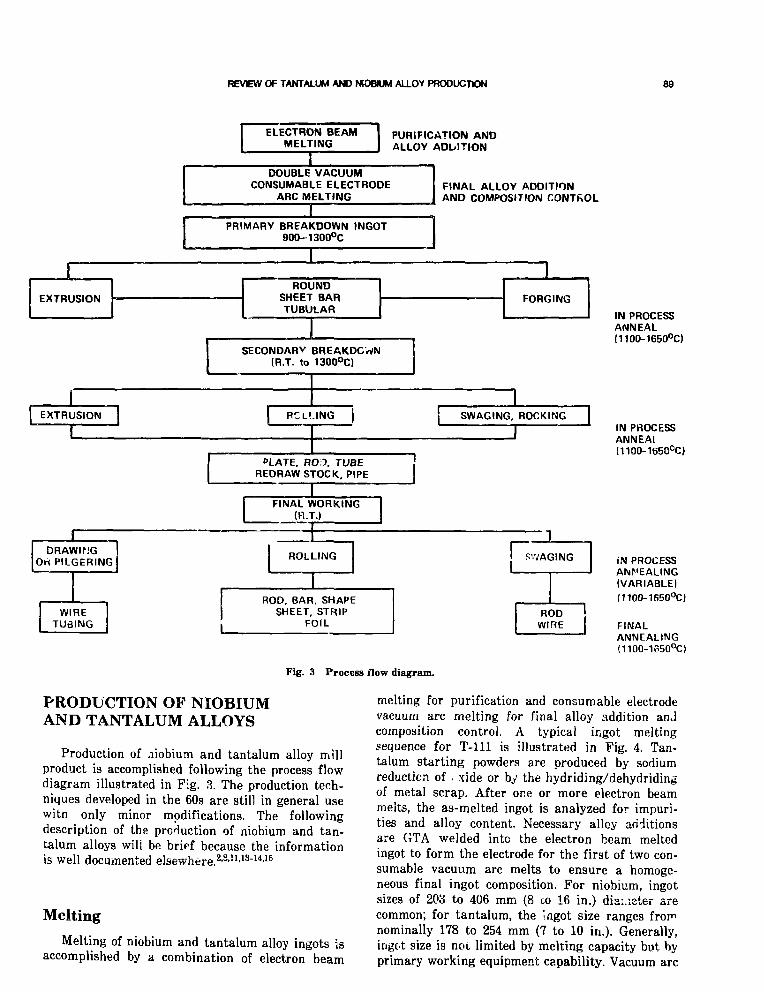
REVEW OF TANTALUM AND NIOBIUM ALLOY PRODUCTION 89
ELECTRON BEAMMELTING
PURIFICATION ANDALLOY ADDITION
DOUBLE VACUUMCONSUMABLE ELECTRODE
ARC MELTINGFINAL ALLOY ADDITIONAND COMPOSITION CONTROL
PRIMARY BREAKDOWN INGOT900-1300°C J
EXTRUSIONROUND
SHEET BARTUBULAR
FORGING
SECONDARY BREAKDOWN(R.T. to 1300°C)
EXTRUSION RCU.ING } SWAGING, ROCKING |
PLATE, ROD, TUBEREDRAW STOCK, PIPE
FINAL WORKING(R.T.)
DRAWINGOti PILGERING
WIRETUBING
ROLLING S'VAGING
ROD, BAR, SHAPESHEET, STRIP
FOILROD j
WIRE
Fig. 3 Process flow diagram.
IN PROCESSANNEAL(1100-1650°C)
iN PHOCESSANNEAI!1100-1650°C)
iN PROCESSANNEALING(VARIABLE)(11OO-165O°C)
FINALANNEALING(1100-1o50°C)
PRODUCTION OF NIOBIUMAND TANTALUM ALLOYS
Production of niobium and tantalum alloy millproduct is accomplished following the process flowdiagram illustrated in F;.g. 3. The production tech-niques developed in the 60s are still in general usewitn only minor modifications. The followingdescription of the production of niobium and tan-talum alloys will be brirf because the informationis well documented elsewhere.2-3'11'13"14'16
Melting
Melting of niobium and tantalum alloy ingots isaccomplished by a combination of electron beam
melting for purification and consumable electrodevacuum arc melting for final alloy addition andcomposition control. A typical ingot meltingsequence for T-lll is illustrated in Fig. 4. Tan-talum starting powders are produced by sodiumreduction of . xide or by the hydriding/dehydridingof metal scrap. After one or more electron beammelts, the as-melted ingot is analyzed for impuri-ties and alloy content. Necessary alloy additionsare GTA welded into the electron beam meltedingot to form the electrode for the first of two con-sumable vacuum arc melts to ensure a homoge-neous final ingot composition. For niobium, ingotsizes of 208 to 406 mm (8 co 16 in.) diameter arecommon; for tantalum, the Ingot size ranges fror"nominally 178 to 254 mm (7 to 10 in.). Generally,ingot size is not limited by melting capacity but byprimary working equipment capability. Vacuum arc

90 BUCKMAN
76.2 mm DIAMETERPRESSEDPOWDERELECTRODE
ELECTRONBEAM
1 S T
MELT
TANTALUM-102 mm DIAMETERINGOT
2ND
ELECTRON
r!<\FNIUMADDITION
102 mm DIAMETERCONSUMABLEELECTRODE
•VACUUM
CONSUMABLcARC MELT
650
152 Tim DIAMETERCONSUMABLEELECTRODE
< = •
VACUUMCONSUMABLEARC MELT
254 mm DIAMETER x 1.27 m LENGTHINGOT 2400 lb
Fig. 4 Typical ingot melting sequence for producing T-lll (Ref, 14).
melting of niobium and tantalum is accomplished Primary Workingat pressure (1 X 10 3 torr).
Aschoff17 estimated that the melting capacity ofthe refractory metals industry (circa 1961) wasapproximately 5.5 X 10⁶ kg'y (12 X 106 lb/y).The melting capacity could have easily been tripledby improving the vacuum capabilities of the thenexisting reactive metal arc melting furnaces, whichgenerally operate at 50 to 500 fim pressure. This isjust- as true today as then. An estimated 1810 kg(4000 lb) of refractory metal alloy is required forone space power system; therefore the ability ofthe industry to supply niobium and tantalum alloyingots will not be taxed by the SP-100 demands.
Primary breakdown of the ingot microstructureis accomplished either by direct forging or extru-sion and depends on the practices developed andused by a particular vendor. Nb-lZr ingot can beworked by forging or extrusion in the temperaturerange of 800 to 1000°C, but Ta-lOW, T-lll andASTAR 811-C are normally heated to ~1300°C forforging or extrusion. To prevent interaction of thebillet with the heating medium, billets are pro-tected by an evacuated mild steel hermeticallysealed or purged cladding.14 Also hafnium silicide,molybdenum, or tungsten coating can be applied toprotect the billet during heating for forging and/or

REVSEW OF TANTALUM AND HSOSUM ALLOY PRODUCTION 91
TABLE 3
Specifications for Niobium and Tantalum Alloys
Form
Alloy Ingot Sbeet Strip Plate Bar Rod Wire Tubing Specifications
Nb
Nb-lZr
Nb-lOHMTi
Nb-10W-2.5Zr
Ta
Ta-lOW
Ta-HW-2Hf (T-lll)
ASTM B-391-78ASTM B-°92-80ASTM B-393-78
ASTM B-394-70
ASTM B-652-79,AoTM B-654-79,ASTM B-655-79,AMS-7852-80,AMS-7857-80
AMS-7851A-67.AMS-7855A-67
ASTM-B-364-82,ASTM B-365-82
ASTM-K-708-82,AMS-7847A-76,AMS-7848A-75B50YA325-S1"
'General Electric specification number for "Seamless Tubing and Pipe," April 21, 1971 (Ref. 13 AppendixC, p. 281).
extrusion.18"19 Before proceeding to secondaryworking operations, billet conditioning to removecontaminated materials and/or defects is accom-plished by mechanical and chemical means. This isan extremely important step to assure maximumyield of high quality material in subsequent work-ing operations.
Secondary Working
Secondary working operations are generallycarried out at room temperatures to ~260°C.Working can be accomplished readily in this tem-perature range with minimal concern for oxidationof the billet. The Nb-lZr, T-lll, and ASTAR 811Ccan be readily worked at room temperature to allthe common mill shapes.
Heat Treatment
Proper annealing conditions are absolutelyessential in order to obtain high quality niobiumand tantalum alloy product. In-process and finalannealing should be accomplished at pressures of<1 X 10~5 torr. Cleanliness of the product priorto annealing is as important as the vacuum tight-ness of the annealing system. The interaction ofniobium and tantalum alloys with oxygen at lowpressure is well documented.20"25 Steps to minimizethis interaction include wrapping the work piece
with niobium or tantalum foil. Currently, refrac-tory metal producers have vacuum annealing fur-naces operating at pressures of —1 X 10 ~5 torr attemperatures up to 1600°C with a size limitation of-0.25 m wide X 3.05 m long (10 in. X 120 in.).This area of technology is similar to the capabilityestablished in the mid-sixties.
Specifications
Currently available ASTM and AMS specifica-tions for niobium and tantalum alloys are listed inTatle 3. During the 60s, us jr-generated specifica-tions were used to procure niobium and tantalumalloys for the space power program.26 These specifi-cations, generated and used by GE in the 1965 timeperiod under the NASA program, were generallymore stringent than the commercial specificationsin use at that time. As an example, Table 4 com-pares the limits for impurities found in the ASTMand GE specifications to the actual chemical analy-sis of as-melted ingot product. The purity of theT-lll ingot material was maintained well withinspecification.
A similar summary for the Nb-lZr alloy isshown in Table 5. Although the interstitial levelsare well within the limits established by the W64revision of the ASTM specification for reactorgrade material, the latr 't revision (1978) is not

92 BUCKMAN
TABLE 4
Chemical Analysis Results of T-lll Ingot ProducedDuring 1960 to 1970
Element
C0NHNi
CoFeCuSi
Specification limits
Current
ASTM-B-364-8220015010015
100
10010010050
Prior GE»
ASTM B-364-70300300150100200
_200
_200
50100501050
5050_-
Experience!
22 ± 1738 ± 1618 ± 55 ± 3<60
<60<60
20<60
•D. W. Miketta and R. G. Frank, SPPS-22-R1, Tantalum Alloy T-lllSpecification, Dec. 23,1964, Contract NASA-2547 (Ref. 26).
fF^ m time period 1960 to 1970, data from commercial size ingot{6Vi- to 10-in. dia), average of 13 different heats for interstitials, oneheat from Ref. 14 for metallics.
TABLE 5
Chemical Analysis Results of Nb-lZr Ingot ProducedDuring 1960 to 1970
Element
C0NHNi
CoFeCuSi
Specification limits (WPPM)
Current
ASTM B-391-78*1001501001050
20504050
Prior
ASTM B-391-64*10030030020
200
30500100300
Experience!
39 + 7154 ± 8250 ± 253 ± 1<20
Not reported<50
Not reported<50
^Reactor grade.fFor nine different heats for interstitials, metallic^ from Ref. 2
typical for E.B. melted Nb ingot
met, specifically for oxygen. It will be necessary towork with the vendors in establishing acceptableand realistic specifications that will allow materialto be produced on a commercial basis. The specifi-cation limits should be consistent with the require-ments of the end item hardware service.
The specification limits discussed were for theas-melted ingot and thus represent the lowestexpected level of impurities. Processing to finalmill form requires exposure to elevated tempera-tures, lubricants, etc., and thus, depending on finalform and degree of the chemical and chemical con-
ditioning during processing, contamination pickupin the final product can be expected. Chemicalanalysis of niobium and tantalum alloy tubing,showing interstitial content variations from ingotthrough final product, is shown in Table 6. Pro-cessing down to 9.5 mm dia X 1.57 mm wall(0.375 in. X 0.002 in.) produced very little changein interstitial content. However, significant pickupof carbon and oxygen was observed after process-ing to 0.38 mm (0.015 in.) wall. Significantly lowerpressures during annealing would be required toprevent this contamination. Current commercialannealing furnaces do not yet have this capability.

REVHEV OF TANTALUM AND NIOBIUM ALLOY PRODUCTION 93
TABLE 6
Interstitial Pickup During Processing" of B-66(Cb-5Mo-5V-lZr) and T - l l l (Ta-8W-2Hf)
Analysis, WPPM
B-66 T - l l l
Product form O N O N
Ingot-203 mm (8 in.) dia(E.B. + vac. arc melt)
Tube extrusion billet,102 mm (4 in.) O.D.*
9.5 mm (0.375 in ) O.D. X1.57 mm (0.062 in.) wallf
6.35 mm (0..250 in.) O.D. X0.38 mm (0.015 in.) wall*
40 95 70 10 25 20
35 90 60 15 80 30
35 110 60 15 30 20
65 430 80 30 125 20
*As-extruded condition (B-66 extruded 1600°C) andannealed 1 h @ 1600°C.
fFive in-process anneals @ <5 X 10⁵ torr, wrapped in Tafoil; B-66 @ 1040 to 12CO°C for 10 min to 1 h; T-lll @ 1500°Cfor 10 min to 1 h.
JSeven in-process anneals @ <5 X 10^ torr, wrapped in Tafoil; B-66 @ 1040 to 1200°C for 10 min to 1 h; T-l l l @ 1500°Cfor 10 min to 1 h.
Supply
There has been no domestic mining of niobiumor tantalum ores since 1959 (Ref. 27). Niobium oreis imported from Brazil, Canada, and Thailand;tantalum ore is imported from Thailand, Malaysia,Australia, Canada, South America, and SouthAfrica. The United States has approximately360 X 106 kg (800 X 106 lb) of niobium resourcesand 1.5 X 10⁶ kg (3.4 X 10⁶ lb) of tantalumresources in identified deposits which were consid-ered uneconomic at 1981 prices.27"29 Current priceestimated for tantalum ingot is about $240/kg($110/lb), and for niobium ingot it is about $77/kg($35/lb).18 The formation of an organization namedthe Tantalum Information Center in Brussels hashelped to stabilize the price of tantalum whichexperienced instability during the late 1970s (Refs.28 and 29). Between 1978 and 1980, the price oftantalum oxide more than tripled in price.29
Producers
There are four major suppliers of tantalum andniobium alloys in the United States. Three of thefirms are completely integrated from raw materialprocessing through primary fabrication of theniobium and tantalum ingot.28"29 No single com-pany is totally integrated through secondary fabri-cation. These four suppliers, however, do have dedi-cated facilities for melting, primary and secondaryworking, and annealing of refractory metal alloys.
Cautions
Some of the following caveats are worth notingand were a part of the Earning experience duringthe 1960s.
• The production of high quality niobium andtantalum alloy forms for space nuclear powerapplications will require development ofstringent process control and materialsspecifications. Although the situation today ismuch improved over the 1960s, there is stillno totally integrated refractory metal pro-ducer who can perform all the necessary fab-rication operations. The number of knowl-edgeable persons intimately familiar with thesubtleties of refractory metal production hassignificantly decreased over the past 15 yearsdue to lack of activity in the space nuclearpower field.
• Niobium and tantalum alloys, particularlythose containing zirconium or hafnium, areextremely sensitive to contamination by iron,copper, nickel, and cobalt. Control musttherefore be exercised to assure that this doesnot occur. For example, ingots were vacuumarc melted in furnaces normally used to meltalloy steels and superalloys. Material wasannealed in vacuum furnaces used for pro-cessing other nickel base materials and/or forbrazing. The end result was defects andfailures attributed to irace amounts of con-tamination by these critical elements.

94 BlICKMAN
• Particular attention must be given to themechanical and chemical condition of ingotsand billets, before working and or heat treat-ment to assure removal of defects or contam-inants such as lubricants from prior workingoperations.
o Vacuum annealing must be accomplished infurnaces dedicated solely to refractory metalalloys.
• Specifications will reyuire overview by knowl-edgeable persons to assure compliance withnv rial and process control requirements.
DEVELOPMENTS NEEDED TOSUPPORT SP-100
No major developments are necessary in theareas of nicbium and tantalum alloy productionand fabrication. Some consideration should begiven, however, to upgrading production capabili-ties and enhancing material quality control. Specifically, the following items should be considered:
• Increasing vacuum annealing capability andimposing more stringent pressure limits.Existing capability limits product size to1.5 m X 3.05 m (60 in. X 120 in.) at pres-sures of ~1 X 10~3 Pa (1(T5 torr) at tem-peratures to 1600°C. Consideration should begiven to limiting annealing pressures to<1 X 10~5 Pa (1 X 10~7 torr) for thin-walled products.
• Development of acceptable material and pro-cess control specifications written with dueconsideration to the end use, i.e., space powerapplications.
ACKNOWLEDGMENT
The critical review and helpful comments pro-vided by co-workers R. L. Ammon, Chris Bagnall,and Dr. Stu Shiels during the preparation of thispaper are gratefully accepted and deeply appreci-ated.
REFERENCES
1. G. Mervin Ault, A Decade of Progress in Refractory Metals,Gillette Memorial Lecture, ASTM, Philadelphia, PA, 1965.
2. D. C. Goldberg, G Dicker, and S. A. Worcester, Niobiumand Niobium Alloys in Nuclear Power, Nitcl Eng. Des., 22:95-123, North-?'illand Publishing Company, 1972.
3. T. A. Moss, R. L. Davies, and G. J. Barna, Refractory AlloyRequirements for Space Power Systems, in Recent Advances
in Refractory Alloys for Space Power Systems,NASA-SP-245, June 26,1969.
4. Anon., Columbium and Tantalum Alloys, Technical Informa-tion, Teledyne Wah Chang Corporation.
5. Anon., Columbium by KBI, Bulletin 313-PD1, Kawecki-Beryllco, Reading, PA.
6. Anon., Fansteel Production Bulletin, Fansteel Metals, NorthChicago, EL.
7. Anon., Looking into Tantalum, NRC, Newton, MA.8. R. W. Buckman, Jr., and R. C. Goodspeed, Considerations
in the Development of Tantalum Base Alloys, Metallurgyand Technology, pp. 373-394, I. Machlin, R. T. Begley. andE. D. Weisert (Eds.), Plenum Press, 1968.
9. J. R. Lane and G. Mervin Ault, The Refractory MetalsSheet Rolling Program, Metals Eng. Quart, Vol. 5, No. 3,August 1965.
10. R. L. Ammon, A. L. Field, A. J. Lewis, and L. S. Richard-son, Research and Development of Tantalum and TungstenBase Alloys, Final Report, NOw-58-852C, May 26,1961.
11. R. L. Ammon and R. T. Begley, Pilot Production andEvaluation of Tantalum Alloy Sheet, Summary Phase ReportPart 1, NOw-62-06562. June 1963.
12. R. W. Buckman, Jr., and R. T. Begley, Development of HighStrength Tantalum Base Alloys, in Recent Advances inRefractory Alloys for Space Power Systems, pp. 19-38,NASA-SP-245, June 26,1969.
13. R. W. Harrison, E. E. Hoffman, and J. P. Smith, T-lllRankine System Corrosion Test Loop, NASA-CR-134816,June 1975.
14. D. R. Stoner and R. W. Buckman, Jr., Development of largeDiameter T-lll (Tar8W-2Hf) TvJAng, Final Report, NASA-CR-72869, December 1970.
15. W. R. Young, Fabrication of T- l l l Test Loop System, inRecent Advances in Refractory Alloys for Space Power Sys-tems, pp. 165-220, NASA-SP-245, June 2fi, 1969.
16. A. W. Buckman, Jr., and J. L. Godshall, Final TechnicsReport on Development jf Hig'1 Strength Columbium antTantalum Alloy luting, WANL-PR-(N)-004, ContraciAT(30-l)3108, May 1,1964.
17. W. A. Aschoff, Current Melting Practices for Refractor}Metals Columbium, Tantalum, Molybdenum and TungstenHigh Temperature Materials, II, G. M. Ault, W. F. Barclayand H. P. Munger (Eds.), Interscience Publishers, 1961.
18. R. Marsh, Teledyne Wah Chang Corp., private communication.
19. R. MacDonald, OP.NL, private communication.20. H. Inouye, The Contamination of Refractory Metals ii
Vacuum Below 10"* Tor" Refractory Metals and Alloys IIIApplied Aspects, pp. 871-883, Robert I. Jaffee (Ed.)December 1963.
21. R. W. Buckman, Jr., Operation of Ultra High VacuunCreep Testing Laboratory, in Transactions of the VacuumMetallurgy Conference, New York City, June 1966, pp. 25-31M. A. Orehoski and R. F. Bunshah (Eds.), 1967.
22. R. F. Bunshah, Contamination of Reactive Metals i;Vacuum Heat Treating at Various Vacuum Levels, i:Transactions of the Internationcl Vacuum Metallurgy Confeience, Beverly Hills, CA, June 1968, pp. 611-619, R. B. Bairow and A. Simkovich (Eds.), 1968.
23. E Fromm, Effect of Inert Gas Atmosphere on Refractor;Metal Losses During Evaporation, No. 499233 AIX-1C444471, EDB-79: 073333 (in Russian), International Symposium on Interaction of Metals with Gases and CarborStuttgart, Germany, Sept. 1977, Fie. Khim, Obrab. Motet(USSR), 5: 61-67, Sept.-Oct 1978.
24. E. Fromm, Gas-Metal Reactions of Refractory Metals aHigh Temperature in High Vacuum, The Journal of VacantScience and Technology, Vol. 7, No. 6, AVS-VMD, 1970.

REVEW OF TANTALUM AND NIOBIUM ALLOY PRODUCTION 95
25. R. •;?. Harrison and E. E. Hoffman, Contamination of Tan-talum and Tantalum AlloyB in Low Pressure OxygenEnvironments, in Transactions qf the International VacuumMetallurgy Conference, Beverly Hills, CA, June 1968, pp.29-57, R. B. Barrow and A. Simkovich (Eds.), 1968.
26. D. W. Mikstta and R. G. Frank, Materials Specifications forAdvanced Refractory Metals, NASA-CR-54761, October 1965.
27. Thomas S. Jones, Cohimbium and Tantalum in 1981,Mineral Industry Surveys, U. S. Department of Interior,Bureau of Mines, December 31,1981.
28. Thomas S. Jones, Columbiuin, Bureau qf Mines Bulletin 671,Mineral Facts and Problems, 1980 Edition.
29. Thomas S. Jones, Tantalum, Bureau qf Mines Bulletin 671,Mineral Facts and Problems, 1980 Edition.
BIBLIOGRAPHY
Aachoff, W. A., Current Melting Practices for Refractory MetalsColumbium, Tantalum, Molybdenum, and Tungsten, PhysicalMetallurgical Works, Wah Chang Corporation, Albany, Ore-gon, in Proceedings of a Technical Conference Sponsored bythe Refractory Metals Committee, MetaUvrgieal SocietyConferences, 18: 545-556, Cleveland, OH, April 26 27, 1961,G. M. Ault, W. F. Barclay, and H. P. Munger (Eds.), 1963.
Bartlett, E. S., and F. F. Schmidt, Columbium and Tantalum,154-A, Defense Metals Information Cente-i, Review of RecentDevelopments, p. 3, January 1962., and H. R. Ogden, Summary of the Ninth. Meeting of theRefractory Composites Working Group, M01-25896 (Pam-phlet), Battelle Memorial Institute, Columbus, OH, DMICMemo No. 200, p. 14, March 1965., and F. F. Schmidt, Columbium and Tantalum, 253-A,Defense Metal? Information Center, Review of RecentDevelopments, p. 2, July 1962.
Begley, R. T., and R. L. Ammon, High-Energy Rate Extrusionof Columbium-Base Alloys, Westinghouse AstronuclearLaboratory, Pittsburgh, PA, Metallurgical Society Confer-ences, 18: 685-702, G. M. Ault, W. F. Barclay, and H. P.Munger (Eds.), 1963.
Berezin, B Ya., and V. Ya. Chekhovskoi, Tantalum Enthalpy inthe Temperature Range from 21fiO K to Melting Point, No.374777 AIX-09: 369905, EDB-78: 069180 (in Russian), Izv.Akad. Nauk SSSR, Met (USSR), 3: 63-65, May-June 1977.
Berkovich, K. G., 0. V. Zav'yalov, V. V. Kovalev, K. Yu. Natan-son, and P. N. Petrov, Simultaneous Determination of Car-bon and Nitrogen in Niobium Powders by the VacuumExtraction Method, No. 760927 AIX-12: 590986, EDB-81:069187 (in Russian), Khimiko-Meiallurgicheshij Zavad, Ust-Kairienogorsk (USSR), Zavod. Lab (USSR), 46(3): 218-219(1980).
Bertram, L. A., and F. J. Zanner, Interaction Between Computa-tional Modelling and Experiments for Vacuum CcmswmableArc RemeUing, No. 718586 ERA-06: 009413, INS-81: 003015,EDB-81: 026S39, in Conference on Modeling of Casting andWnlding Processes, Runge, NH, August 1980.
Betz, G., and M. G. Frohberg, Calorimetric Measurements ofRefractory Metals and Alloys Using the Levitation MeltingProcess, No. 873617 EDB-g2: 048458 (in German), MetalL(Berlin). 35(4): 299-303, April 1981.
Biimchi, L. M., Shape Rolling of Refractory Metals, UniversalCyclops Steel Corp., in Proceedings of the Third TechnicalConference Sponsored by the Refractory Metals Committee,Institute of Metals Division, The Metallurgical Society, Refrac-tory Metals and Alloys III: Applied Aspects, Los .Angeles, CA,
December 9-10,1963, pp. 49-5H, Robert I. Jaffee (Ed.), 1986.Bonchak, J., and W. J. McElhimey, Vacuum and Inert Atmo-
sphere Processing of Refractory Metels, Transactions qf theVacuum Metallurgy Canfertnce, New York City, June 29-30and July 1,1964, pp. 34-54, Michael A. Cocca (Ed.), 1965.
Bujard, P., R. Sanjines, E. Walker, J. Ashlenazi, and M. Peter,Elastic Constants in Nb-Mo Alloys from Zero Temperatureto the Melting Point: Experiment and Theory, No. 791032AIX-12-615674, EDB-81: 0f«297, Geneva University, Switzer-land, J. Phys. F. (UK), 11(4): 775-786, April 1981.
Burd, Byron B., Bi-Metal Tubing Cuts Cost of Using Titanium,Tantalum, Zirconium, 564-R, Chemical Praxssing, 23: 69, July1960.
Burte, Harris M., Thomas I). Cooper, and Jerome K. Elbaum,Refractory Metals—An Assessment, M01-13200 (Pamphlet),p. 15, American Institute of Aeronautics and Astronautics,Paper No. 64-530, New York, NY, 1964.
Byrer, T. G., and F. W. Boulger, Metalvmrlcing, M08-44715(Pamphlet), p. 3, Batteile Memorial Institute, Columbus, OH,DMIC Rev., July 1965.
Cai, B. C, A. Dasgupta, Y. T. Chou, New Technique for theGrowth of Bicrystals of Refractory Metals, No. 1055675AIX-14: 719032, EDB-83: 050542, Lehigh University, Beth-lehem, PA, J. less-Common Met (Switzerland), 86(1):145-151, July 1982.
Calverley, A., The Floating Method of Zone Refining with Heat-ing by Electron Bombardment, M03-55426, New Physical andChemical Properties of Metals of Very High Purity, pp.419-440, Gordon and Breach Science Publishers, Inc., NewYork, NY. 1965.
Campbell, G. L., Am Mach/MetalworL Manuf. (US), 107(21):105-107, Oct. 1963.
Chekhovskoi, V. Ya., S. A. Kats, Investigations of the Thermo-physical Properties of Refractory Metals Near the MeltingPoint, No. 1081577 AIX-14: 736487, EDB-83: 076447, MoscowInst. Vysokikh Temperatur, High Temp.—High Pressures(GB), 13(6): 611-616 (1981).
Chikanov, N. D., Interaction in Binary Chloride Systems withthe Participation of Pentachlorides, No. 903358 AIX-13:655961, EDB-82: 078203 (in Russian). Goaudarstvennyj Univ.,Russia, Zh Neorg. Khim., SU, 26(3): 752-755, Mar. 1981.
Columbium Forgings Weigh Over One-Half Ton, 69-F, Steel, 147:72, December 1960.
Cook, Charles S., Extrusion of Aerospace Materials, Light MetAge, 23(5-6): 16-19, June 1965.
Cuprikov, G. E., K. I. Epifanova, T. M. Malyutina, and G. A.Samokhin, Compatibility of Molten Rare ^arth Metals withRefractory Materials, No. 380659 AIX-09: 357259, EDE-78:075062 (in Russian), Nauchnye Trudy GIREDMETa., 52:95-100 (1974).
Developments in Metal Melting and Rolling, 97012C, Engineer,216 (No. 5626): 840-842, November 22,1963.
Efimov, V. E., V. V. Khajdarov, and A. M. Shmakov, MaximumSuperheating of Metal During Electron Beam Melting, No.1055679 AIX-14: 727309, EDB-83: 050546 (in Russian), Fiz.Khim Obrah Mater. (USSR), 1: 81-86, Jan.-Feb. 1982, Coden:FKOMA, Journal Announcement: EDB8302.
Fabian, R. J., Aerospace Materials: Where We Stand Today,B5-A, Materials in Design Engineering, 54: 94-97, Dec. J961.
Flinn, J. E., and R. M. Mayfield, Evaluation of New FabricationTechniques for High-Quality Refractory Metal Tubing, inProceedings of Conference on Refractory Metals and Alloys,3d, Los Angeles, 19C3, Refractory Metala and Alloys III:Applied Aspects, pp. 125-J-35, Robert I. Jaffee (Ed.), 1966.
Franco-Ferreira, E. A., The Fabrication of a Large Columbium-1% Zirconium Pumped Loop for Boiling-Potassium Service,in Proceedings of Conference on Refractory Metals and Alloys,

96 BUCKMAN
3d, Los Angeles, 1S63, Refractory Metals and Alloys III:Applied Aspects, pp. 623-631, Robert I. Jaffee (Ed.), 1966.
Goodhew, P. J., and S. K. Tyler, Helium Bubble Behavior inh.cc. Metals Below 0.65 Tn, No. 821923 AIX-12: 624554,EDB-81: 130194, Surrey Univ., Guidford (UK), Dept. ofMetallurgy and Materials Technology, Proc ft. Soc London,Ser. A, 377(1769): 151-184, June 1981.
Gurevich, Ya. B., A. P. Bashchenko, and V. L. Orzhekhovskii,Some Specific Features of Hot Rolling Refractory Metals ina Vacuum and in an Atmosphere of Inert Gas, M07-62220(Translation Prim. Sources), Sou J. Non-Ferrous Met, 7:87-92, July 19£5.
Hayes, D. M., Machining Data for High-Temperature Alloys,M08-28949, Metalworking Prod., 109(19): 71-75, May 1965.
Heinzel, V.,. R. Huber, I. Schub, and G. Schumacher, DelayedAttack of the Cladding Tube Melt on the Niobium Test Chan-nel Containment of the CABRI Reactor, No. 966602 EDB-82:141457 (in German), Jahrestagung Kerntechnik, 1982, Reak-tortagung, 1982, Tagungsberichte, Sektion 5, pp. 537-540,19£2; Annual Meeting on Nuclear Technology, 1982;Mannheim, Germany.. May 1982.
Holcombe, C. E., Jr., and M. K. Morrow, Refractory CeramicCompositions and Method for Preparing Same (Patent), No.244647 ERA-02: 038012, EDB-77: 082660, Patent No.: US3,969,123, Energy Research and Development Administration,p. 6, July 1976.
Hydrostatic Extrusion Technique Proved as Commercial Pro-cess, M07-45013, Light Metals Metal Ind., 29 (?32): 66-68,January 1966.
Inglis, N. P., and M. Eng, Fabrication and Properties of Someof the Newer Constructional Metals, Institute of ChemicalEngineers, Transactions, 40: A53-A73, February 1962.
Ivashina, Yu. K., G. A. Ivashina, V. F. Nemchenko, M. D. Smo-lin, and L. V. Zmievskaya, Influence of Plastic Deformationin Hydrogen Solubility in Tantalum, No. 873726 AIX-13:644853, EDB-82: 048561 (in Russian), Zk Fix. Khim. (USSR),54(ii): 2827-2830, Nov. 1980.
Jaffee, R. I., Applications of Refractory Metals, 01814F, J. Met,16(5): 410-415, May 1964., and Daniel J. Maykuth, Refractory Metals: Current Situa-tion and Probable Future, 212-A, Battelle Technical Review,11: 11-15, May 1962.
Jahnke, L. P., R. G. Frank, and T. K. Redden, ColumbiumAlloys Today—Considerations in Design and Fabrication ofStructures, 1034-Q, Met Prog., 78: 76-80, July 1960.
Kalinovich, D. F., L. L. Kovenskly, and M. D. Smolin, DiffusionMobility of Carbon in Tantalum, 11380N (Russian), Pin'kaMetallov i Metallovedenie, 18(2): 314-315 (1964).
Keeton, A. R., and L. G. Stemann, Fabrication of Fuel PinAssemblies—Phase III, Final Report No. NAS CR-120956,Westinghouse Astronuclear Laboratory, Pittsburgh, PA,December 1972.
Klopp, W. D., Fabrication of Pure Columbium, p. 6, 69-F,Defense Metals Information Center, Memo No. Si, September1959.
Kocherahinskij, Yu. A., V. I. Vasilenko, Melting Diagram ofMolybdenum-Niobium System, No. 977021 AIX-13: 677497,EDB-82: 151877 (in Russian), Kievskij Inst. SverkhtverdykhMaterialov (in Russian), DokL Akad. Nauk SSSR (USSR),257(2): 371-373 (1981).
Krupin, A. V., Uu. V. Zhikharev, N. S. Il'in, V. Ya. Solov'ev,and T. B. Yakovleva, Hydroextrusion Application forNiobium Rod Production, No. 328041 AIX-03: 340134, EDB-78:016668 (in Russian), Tsvetn. Met (USSR), 1: 72, January1977., V. Ya. Solov'ev, V. N. Chernyshev, V. M. Izotov, and V. M.Korolev, An Investigation of the Basic Characteristics ofNiobium Cold Rolling, M07-48943 (Translation-Prim.
Sources), Suv. J. Non-Ferrmts Met, 12: 74-77, December 1964.Kumashiro, Y., E. Takuma, K. T^atanabe, S. Misawa, Y. Nagai,
and II. Kato, Preparation and Characteristics of Zr-C andTaC Single Crystals Using an R. F. Floating-Zone Process,No. 873829 AIX-13: 644892, EDB-82: 048670, J. Mater. Sd(GB), 16(10): 2930-2933, October 1981.
Lane, J. R., and G. Mervin Ault, The Refractory Metsls SheetRolling Program, Met Eng. Q., 5-6: 23-29, John Parina andAllen G. Gray (Eds.), August 1965.
Lebedev, S. V., and G. I. Mozharov, Heat Capacity of Tantalumwith Rapid Pulsed Heating by a High-Density ElectricCurrent, No. 320739 ERA-03: 008794, EDB-78: 009356, HighTemperature Institute, Academy of Sciences of the USSR HighTemp., 15(1): 45-48, July 1977., and G. I. Mozharov, Measurement of the Temperature ofTantalum in the Solid and Liquid States with Rapid Heatingby an Electric Current, No. 307855 ERA-03: 001141, EDB-77:146304, High-Temperature Institute, Academy of Sciences ofthe USSR High Temp, 14: 6, 1132-1135, May 1977.
Loung, P. Y., Method of Melting Refractory Metals Using a Dou-ble Heating Process, M03-18775, U. S. Patent No. 3,; 60,497.p. 5, December 1964.
Machenschalk, R., Fabrication of Refractory Metal Sheets,M07-48990 (German), 13:106-107, March 1966.
Maier, K., M. Peo, B. Saile, H. E. Schaefer, and A. Seeger, HighTemperature Positron Annihilation and Vacancy Formationin Refractory Metals, No. 631733 AIX-11: 504823, EDB-80:071257, Philos. Mag., A (UK), 40(5): 701-728, November 1979.
Maykuth, D. J., G. S. Root, and H. R. Ogden, Tantalum AlloySheet in Pilot Production, 95097F, J. . ¥ < 16(2): 180-184,February 1964.
McKinsey, C. R., A. L. Mincher, W. F. Sheely, and M.Schussler, Processing and Properties of Columbium-BaseAlloy Cb-74, Union Carbide Metals Co., Div. of Union Car-bide, Niagara Falls, NY, in Proceedings of High TemperatureMaterials II Conference, Cleveland, OH, 18: 703-715, April26-27, 1961, G. M. Ault, W. F. Barclay, and H. P. Munger(Eds.), 1963.
Ming, L. C, M. H. Manghnani, K. D. Timmerhaus, and M. S.Barber (Eds.), Isothermal Compression of V, Nb, and Ta to100 KBar Correlation with Ultrasonic, Shock Wave andOther Static Data, in AIRAPT International High-PressureConference, Boulder, CO, July 1977, pp. 54-67, No. 532580ERA-04: 051955, EDB-79: 112045, Univ. of Hawaii, Honolulu,1979.
Mukherjee, T. K., S. P. Garg, C. K. Gupta, C. V. Sundaram,A. K. Taneja, A. D. Damodaran, M. Rapin, and M. Buf-fereau (Eds.), No. 610332 AIX-10: 481833, EDB-80: 049855,in Colloque International sur le Soudage et Fusion par Fais-ceau d'eledrons, Avignon, September 1978.
Nemy, A. S., Forcing of the Refractory Metals, Thompson RamoWooldridge, Inc., Materials Processing Department, Cleve-land, OH, in Proceedings of High Temperature Materials II,Metallurgical Society Conferences, Cleveland, OH, April 26-27,1961, G. M. Ault, W. F. Barclay, and H. P. Munger (Eds.),18: 561-571 (1963)., and R. L. Faunce, Extrusion Development for Tungsten,Tantalum, and Columbiu™ Alloys, Thompson Ramo Wool-dridge, Inc., Materials Processing Department, Cleveland.OH, in Proceedings of High Temperature Materials II, Metal-lurgical Society Conferences: April 26-27, 1961, G. M. Ault,W. F. Barclay, and H. P. Munger (Eds.), 18: 663-683 (1963).
Obrzut, J. J., Forging Technology Expands to Meet MarketNeern, M07-80300, Iron Age Metalwork Int. 6(7): 26-27 July196'..
Oden, L. L., D. K. Deardorff, M. I. Copeland, and H. Kato,Hafnium-Tantalum Equilibrium Diagram, No. 262626 EDB-77: 100760, Bureau of Mines, Albany, OR, Albany Metallurgy

REVEW OF TANTALUM AND NIOBIUM ALLOY PRODUCTION 97
Research Center, Report No. BM-RI-6521, p. 16, February1964.
Ortner, H. M., and D. Hirschfeld, Round-Robin Results on theDetermination of Hydrogen in Tantalum and Niobium, No.855988 AIX-12: 618055, EDB-82: 030827, Metallwerk PlanseeA.G., Reutte/Tyro' (Austria); Krupp (Friedr.) Q.m.b.H.,Essen (German), Forschungsinstitut, Mikrochirn. Ada(Austria) 2(5-6): 475-490,1980.
Palatnik, L. S., V. R. Kopach, I. B. Skatkov, Yu. L. Pozdeev,and I. V. Mancheno, Method of Investigation of InterfaceTopology in Laminated Ta-Nb-Ta Sheet Metal 2, No. 302112AIX-08: 337258, EDB-77: 140544 (in Russian), Zavod. Lab.,(USSR), 42(10): 1211-1212 (1976).
Palme, R., The Importance of Vacuum Technology in the Pro-duction and Processing of Refractory Metals, M03-26196(German), Vahuum Tech., 13(8): 229-232, December 1964.
Perryman, J. T., The forming of a Cb-lOW-lOTa Alloy, inProceedings c/ Conference on Refractory Metals and AUoys,3d, Los Angeles, 1963, Refractory Metals and AUoys III:Applied Aspects, pp. 67-72, Robert I. Jaffee (Ed.), 1966.
Peters, J. Irwin, How to Work Tantalum, M08-14710, Amer.Mack/Metalwork Manuf., 108(23): 105-107, November 1964.
Pirch, I. I., A. I. Pugin, and A. A. Erokhin, Enthalpy and Aver-age Metal Bath Temperature During Plasma-Arc Melting,No. 873270 AIX-12: 629090, EDB-82: 048111 (in Russian), Fix.Khim. Obrab. Mater. (USSR), 1:150-153, Jan.-Feb. 1980.
Precision Forging, 310-F, Metal Treatment and Drop Forging, 27:363-365, September 1960.
Quadt, R. A., Precision Cold Extrusion of Metals, 164, 249-G,Met Prog., 77: 121-124, May 1960.
Randall, R. N., The Planetary Ball Swager—New Tool for thrProduction of Refractory Metal Tubing, p. 9, M07-48339,ASTM, Dearborn, MI, Tech. Paper No. SP66-46 (1966).
Rostoker, W., Conversion of Refractory Metals, ArmourResearch Foundation, Chicago, IL, in Refractory Metals andAUoys II, Proceedings of a Technical Conference. 17: 379-394,Chicago, IL, April 12-13, 1962, M. Semch;shen andI. Perlmutter (Eds.), 1963.
Schmidt, F. F., D. J. Maykuth, and H. R. Ogden, The Effects ofHeal-Treating and Testing Environments on the Properties ofRefractory Metals, p. 28, M17-13014, Defense Metals Infor-mation Center, Battelle Memorial Institute Memos &Reports, Report 205, Aug. 20,1964.
Schmitt, B. F., H. U. Fusban, G. Kraft (Eds.), Photon Activa-tion Analysis of Carbon, Nitrogen and Oxygen in RefractoryMetals, No. 903160 EDB-82: 078005 (in German), inInternational Conference tm the Analysis of Non-Metals inMetals, Berlin, Germany, June 1980.
Schumacher, J. F., and W. A. Fischer. Levitation MeltingInstallation with a Large Working Scope as Regards LoadCapacity and Temperature, and also Melting of Iron,Niobium, Molybdenum and Tantalum, No. 468651 AIX-09:41<*141, EDB-79: 042750 (in German), Stahl Eisen (Germany),S3(8): 410-413, April 1978.
Schwirtlich, I. A., and H. Schultz, Quenching Experiments onNiobium, No. 773154 AIX-12: 591271, EDB-81: 081416,Stuttgart Univ., Germany, Inst. fuer Theoretische undAngewandte Physik; Max-Planck-Institut fuer Metall-forschung, Philos. Mag., (Part) A (United Kingdom), 42(5):613-620, November 1980.
Shaping Space Age Metals in Argon, 179-F, Am. Mach., 104:120-121, June 1960.
Smith, H. R., Jr., Design and Performance Parameters of Com-marcial and Laboratory-Scale Electron Beam Furnaces, inTransactions of the Vacuum Metallurgy Conference, New YorkUniversity, June 1960, pp. 255-265, Rointan F. Bunshah (Ed.),1961.
Snyder, W. B., Jr., Effects of Orientation on the Rolling andRecrystallization Behavior of Tantalum Single Crystals, No.230518 INS-77: 008046, EDB-77: 088389, Thesis (Ph.D.), Univ.of Tenn., Knoxville, pp. 228 (1976).
, Effects of Orientation on the Rolling and RecrystaUizationBehavior of Tantalum Single Crystals, No. 217552 ERA-02:025020, INS-77: 006311, EDB-77: 055354, Thesis, Report No.Y-2062, Oak Ridge Y-12 Plant, Oak Ridge, TN, p. 118, De<\1976.
Stephan, H., Present Position of Electron Beam Melting andCasting Technology, No. 355730 ERA-03: 021837, EDB-78:044358, Elektrmvaerme Int. Ed. B (Germany), 35(3): 150-153,June 1977.
Tantalum Ingots and Flat Mill Products, No. 909001 INS-82:008040, EDB-82: 083847, Anna. Book ASTM Stand. (U.S.), 45:160-163 (1981).
Tantalum Rod and Wire, No. 909002 INS-82: 008011, EDB-82:083848, Annu. Book ASTM Stand. (U.S.), 45: 164-167 (1981).
Torti, M. L., Arc-Melting Procedures for Refractory Metals, inTransactions of the Vacuum Metallurgy Conference, New YorkUniversity, June 1959, pp. 1-4, Rointan F. Bunshah (Ed.),1960.t Physical Properties and Fabrication Techniques for theTantalum 10% Tungsten Alloy, in Proceedings of HighTemperature Materials II, Metallurgical Society O- •ferences,18: 161-169, Cleveland, OH, April 26-27, 1961, G. M. Ault,W. F. Barclay, and H. P. Munger (Eds.), 1963.
Vandermeer, R. A., and W. B. Snyder, Jr., Recovery and Recrys-tallization in Rolled Tantalum Single Crystals, No. 539029ERA-04: 053430, EDB-79: 118495, MetalL Trans., A (U.S.),10(8): 10-1-1044, August 1979.
Vereschchagin, L. F., and N. S. Fateeva, Multing Temperaturesof Refractory Metals at High Pressures, No. 667442 AIX-il:546535, EDB-S0: 106968, High Temp.-High Pressures (UnitedKingdom), 9(6): 619-628, 1977.
Von Ardenne, M. and S. Schiller, Advances in Vacuum Metal-lurgy, in 1965 Transactions of the Third International VacuumCongress, Invited Pavers, 1: 137-153, Long Island City, NewYork, Pergamon Press, Inc., 1966.
Wahlster, M., and F. Sperner, Vacuum Technology and Use ofImportant Reactive Metals, No. 328033 AIX-08: 340149,EDB-78: 016660 (in German), MetalL (Germany), 31(7):781-784, July 1977.
Weisert, E. D., T'.ie Present Status of Refractory Metals andAlloys, Met. Eng. Q. 1S9-A (American Society for Metals), 2.3-15, February 1962.
Wong, J., S. S. Christopher, and S. A. Worcester, Jr.,Consolidation of Refractory Metals, Wah Chang Corporation,Albany, OR, in Refractory Metals and AUoys II, Proceedingsof a Technical Conference, 17: 351-377, Chicago, IL, April12-13,1962, M. Semchyshen and I. Perlmutter (Eds.), 1963.
Zedler, E., Dieter Knaut, and Karl Schlaulitz, On the Propertiesof Electron Beam Melted Metals, pp. 187-197, 92556C (Ger-man), Freiberger Forschungshefte, No. B76, 1963.
Zlatin, N., M. Field, and J. Gould, Machining Refractory Metals,in Proceedings of Conference on Refractory Metals and AUoys,3d, Los Angeles, 1963, Refractory Metals and AUoys III:Applied Aspects, pp. 483-496, Robert I. Jaffee (Ed.), 1966.
Zotov, Yu. P., N. N. Kroshkina, and V. E. Bukharin, Determina-tion of Composition and Melting Points of Eutectics inRefractory Metal (Alloy)-Silicon Systems, No. 749543 AIX-12: 584460, EDB-81: 057801 (in Russian), Izv. Akad. NaukSSSR. Neorg. Mater. (USSR), 16(5): 842-844, May 1980.

Processing and Production of Molybdenumand Tungsten Alloys
W. C. HageU J. A. Shields, Jr., and S. M. TuominenClimax Molybdenum Company of Michigan
INTRODUCTION
Alloy designers have relied on strain hardening,solution hardening, and strengthening by dispersedphases to achieve improved strength levels,increased low temperature ductility, and increasedrecrystallization temperatures in molybdenum andtungsten alloys. Because molybdenum and tung-sten are body-cefltered-cubic metals which donot undergo allotropic transformations, thestrengthening that can accompany such transfor-mations is unavailable for these metals. Table 1summarizes the strengthening mechanismsexploited by a number of commercial and promis-ing experimental alloys.1 ~20>22>34 Strain hardening isnot listed explicitly, though it is nearly universallyemployed to improve the low-temperature ductilityof Mo and W alloys. Solution hardening isemployed in Li« Mo-W1-2 Mo-Re,3 and W-Re15"16
systems. However, the primary reason for alloyingMo with 30% W is to obtain corrosion resistanceto liquid zinc equivalent to that of unalloyedtungsten.2 Rhenium additions to Mo and Wincrease the elevated temperatme yield strength,20
but the primary reason for alloying with rheniumis to take advantage of the well-known rhenium-ductilizing effect21 which leads to improved low-"ernperature ductility. The family of Mo alloys-:riOTrn as TZM,5-6 TZC,7"10 MHC,7-8-11-12 and the W-Hi'C alloys all employ hardening by dispersed•»a/:tive metai carbides. The tungsten-rhenium-'..if.'i'jm carbide and molybdenum-rhenium-".A/-;-J.T. ".arbide alloys noted in Table 1 (Refs. 11,'..'-. '. 'J ; are based on the same dispersed carbides!v»naf.;--:fi-ning mechanism but make use of a
fimu." addition to obtain ductile behavior at lowr.r.r»a. Doping powder metallurgy Mo or W
products with K and Si13 or Al, K, and Si,13'16
respectively, yields products with higher recrystal-Ii7-\tion temperatures and higher creep strengththan undoped material due to potassium bubblepinning of grain boundaries.23 Doping is used inthe lamp industry to improve the sag resistance offilaments and for sheet products to be used at hightemperatures. Thoriated tungsten alloys, whichhave higher electroemhaivities, recrystalliza-tion temperatures, elevated temperature tensilestrengths,24 and lower creep rates at elevatedtemperatures25 than unalloyed tungsten, are alsomanufactured for lamp and electron emissionapplications.
The high melting points of Mo and W makethem candidates for applications involving hightemperatures. Alloying is necessary to decrease theductile-brittle transition temperature (DBTT),increase creep strength, and increase recrystalliza-tion temperatures. The effectiveness of strengthen-ing and ductilizing mechanisms is highly depen-dent on the production and processing techniquesused to prepare the alloys. For example, the pri-mary difference between alloys produced byvacuum-arc casting (VAC) and powder-metallurgy(PM) techniques is the oxygen content. Accordingto ASTM Standard B387-74 the maximum allow-able oxygen content in VAC-'TZM is 30 ppm whilethat of PM-TZM may exceed 300 ppm. The higheroxygen levels in PM-TZM are attributable to thetendency of reactive metals in the PM product toform oxides du-ing sintering.26 These oxides can beexpected to decrease the volume fraction of Ti andZr available to form carbides. Vacuum-arc-cast orelectron-beam-melted Mo-Re alloys have lowerDBTTs than powder-metallurgy Mo-Re alloys, withthe difference in DBTT believed to be due to lower
98

PROCESSING AND PRODUCTION OF Mo AND W ALLOYS 99
TABLE 1
Strengthening Mechanisms in Mo end W Alloys
Mechanismemployed
Solution hardening
Intrinsic dispeisionhardening
Extrinsic dispersionhardening
Combinations of theabove
Alloy and production techniques
Molybdenum-base ulloys
Mo-30WU(VAC, PM)Mo-3 to 50Re (VAC. PM)14
TZM: Mo-0.5Ti-0.lZr-0.01 toCMC5* (VAC, PM)
TZC: Mo-1.0 to 1.5Ti-0.20 to0.35Zr-0.0fi to 0.20C" "(PM, VAC)
MHC: Mo-0.5 to 2.0Hf-0.04 to0 20C'*1IJZ(PM, VAC)
Doped Mo with K and Si13 (PM)
Mo-Re-Hf-C14 (VAC)Mo-30to45W-Hf-C16(PM)
Tungsten-base alloyB
W-3 to 50Re164718 (PM, VAC)
W-HfC' -^fPM, VAC)
W-ThO216 (PM)
Doped W with Al, K, Si13aii(PM)
W-Re-Hf-C1I16(VAC, PM)
interstitial contents in the cast alloys.42 This dif-ference in DBTT for Mo-Re alloys is very impor-tant because of the need to handle components atroom or lower temperatures during fabrication.
Before discussing future needs, includingdetailed discussions of alloy systems and potentialimprovements in properties, the technologicalmeans to produce and process Mo and W alloysmust be summarized because for many Mo and Walloy systems the mechanical properties can beoptimized only by thermomechanical processingrequiring production and processing capabilitiesthat are not widely available. First, Lhe producersof commercial Mo and W alloys will be presentedalong with currently available product forms.Second, currently disclosed standard capabilities ofproducers and processors in the United States willbe presented. The capabilities of firms th*t pro-duce special products for internal use, such as Gen-eral Electric's production of wire for lamps, are notincluded because capabilities of such firms are mngenerally disclosed and the facilities are not avail-able for other uses.
PRODUCERS OF Mo ANDW ALLOYS
The producers of commercial Mo alloys, asgiven in the 1982 Thomas Register, are listed alpha-betically in Table 2. Teledyne Wah-Chang Hunts-ville is not included in Table 2 because they pro-duce only unalloyed molybdenum products in awide variety of forms. The alloys which are avail-able upon special request, PM-TZC and PM-MHC,do not have fixed compositions in Table 1 because
standard compositions have not been developed forthese alloys.
Producers of commercial W-base alloys, a3given in the 1982 Thamas Register, are listedalphabetically in Table 3. Commercial alloys areprepared using only powder metallurgy techniquesana are available only in thin sections whichinclude rod, wire, sheet, and foil.
PRODUCTION CAPABILITIES
For the purposes of this paper, we will limit ourconsideration of production and processingcapabilities to those facilities located in the UnitedStates. The production capabilities of the commer-cial facilities in the United States listed in Table 4are of primary importance because th .re arecurrently maximum standard sizes and tempera-tures for many of the processes involved in refrac-tory alloy production. The first step in productionof Mo and W alloys is reduction of oxides to formmetal powders. Both metal powders are producedby hydrogen reduction of oxides at elevated tem-peratures. Molybdenum is usually reduced fromMoO3 or from ammonium dimolybdate which formsMOO3 when heated for the first stage of reductionto MoO2 (Ref. 27). Tungsten powder is reducedfrom ammonium paratungstate which is alsoheated in air or hydrogen to form WO3 which isreduced to WO2 in hydrogen.17 Both MoO2 and WO2are reduced to metal powders using higher tem-peratures17"27 than are used for the formation ofthe dioxides. The commercial U. S. suppliers of Mopowder, ASMC, GTE-Sylvania, and Teledyne WahChang Huntsviile, all control the reduction param-

100 HAGEL, SHIELDS, AND TUOMtNEN
TABLE 2
Producers of Commercial Mo Alloys
Source
ASMC
H. Cross, Inc.
GTE-Sylvania
Metallwerk Plansee
Philips Elmet
Re Alloys, Inc.
Ultramet
Productiontechnique
VAC
PM
PM
PM
PM
PM
PM
CVD
Alloys
TZMMo-30WTZMTZCMHC
Mo-47Re
TZMMo-30WMHC
TZMTZCMHCMo-5 to 50ReDoped Mo
Doped Mo
Mo-10 to 48Re
Mo-ReMo-W
Available forms
Wide variety*Billets, forgings, bar, rodBillets, forgings and barAvailable upon special requestAvailable upon special request
Thin sectionst and tubing
Wide variety, and pressed and sintered shapesBillets, forgings, bar, and rodAvailable upon special request
Wide varietyAvailable upon special requestAvailable upon special requestThin sectionsThin sections
Thin sections
Thin sections and tubing
Any shapeAny shape
"Includes billets, forgings, bar, rod, plate, sheet, foil, and custom fabr'cated shapes but not thin wall tubing.•("Includes rod, wire, sheet, and foil.
TABLE 3
Producers of Commercial W Alloys
Source
H. Cross, Inc.Metallwerk
Plansee
Philips Elmet
Re Alloys, Inc.
Ultramet
Productiontechnique
PMPM
PM
PM
CVD
Alloys
W-26ReW-3 to 50ReW-l to 4 ThO2
Doped WW-50MoW-l to 3 ThOz
Doped WW-5 to 26ReW-5 to 25Re
plus up to 2 ThOz
W-Re
Available forms
Thin sections*Thin sectionsThin sectionsThin sectionsRod and wireRod and wireWireThin sectionsThin sections
Any shape
'Includes rod, wire, sheet, and foil.
eters for Mo to yield powders with controlled parti-cle sizes, compactibility, and bulk density. Thecommercial suppliers of W powders, GTE-Sylvaniaand Teledyne Wah Chang Huntsville, also reduceW powders with controlled particle sizes, compact-ibility, and bulk density. ASMC is also capable ofco-reducing other powders along with molybdenumpowder to form alloyed powders. Philips Elmetreduces Mo and W powders but does not currentlysell the powders.
All domestic producers of PM Mo and W alloysor unalloyed products have isostatic compaction
capabilities. Information on in-house isostaticpress sizes are available from the producers (seeTable 5). In addition, larger isostatic presses out-side the refractory metals indastry are availablefor toll usage by refractory alloy producers. Allproducers of PM alloys have elevated temperaturesintering capability in hydrogen atmosphere fur-naces. GTE-Sylvania can produce as-sintered bil-lets up to 940 mm (37 in.) diameter.15 The onlytungsten shape sintered by ASMC is sheet bars forrolling of flat products at ASMC's Cleveland flatrolling facility. Teledyne Wah-Chang Albany has

PROCESSING AND PRODUCTION OF Mo AND W ALLOYS 101
TABLE 4
Production Capabilities of Commercial V. S. Facilities
Source
ASMCH. Cross, Inc.GNB Corp.GTE-SylvaniaPhilips Elmet
Re Alloys, Inc.Teledyne Wah-Chang
AlbanyTeledyne Wah-Chang
HuntsvilleUltramet
Powderreduction
Mo--
Mo, WMo, W
_-
Mo, W
-
Isostaticcompactionfrom oxides
Mo, WMo, W
-Mo, WMo, W
Mo, WMo, W
Mo, W
-
Production
Sintering
Mo, WMo, W
-Mo,WMo, W
Mo, WMo, W
Mo, W
-
process
Vacuumarc
easting
Mo----
_-
-
-
Electronbeam
melting
_-
Mo, W--
_Mo, W
-
-
Chemicalvapor
deposition
_----
_
Mo, W
TABLE 5
Production and Processing Sources
Firm Location Telephone
AMAX Specialty Metals Corp. (ASMC) Parsippany, NJ (201) 884-2900H. Cross, Inc. Weehawken, NJ (201) 863-1134GNB Corp. Hayward, CA (415) 537-4722GTE-Sylvania Towanda, PA (717) 265-2121Metallwerk Plansee Holliston, MA (617) 429-6801
^Schwarzkopf Development Corp.)Philips Elmet Lewiston, ML (207) 784-3591Rhenium Alloys, Inc. Elyria, OH (216) 365-7388Teledyne Wah-Chang Albany Albany, OR (503) 926-4211Teledyne Wah-Chang Huntsville Huntsville.. AL (205) 837-1311Thermo Electron Woburn, MA (517) 933-7610Ultramet Pacoima, CA (213) 899-0236
furnaces for sintering of tungsten up to 2300°Cusing a hydrogen atmosphere or vacuum. Thesefurnaces are available for toll usage. The notablefeature of these furnaces is that they do not con-tain large masses of refractory insulating brickand thus will cool relatively rapidly.
The two melting techniques available for pro-duction of Mo alloys are vacuum-arc casting (VAC)and electron-beam (EB) melting. Commercial VACMo alloys are produced using press-sinter-melt(PSM) equipment which has been described indetail by Timmons and Yingling28; this equipmentis suitable for casting some tungsten alloys.Electron-beam melting units can be used to pro-duce Mo or V/ alloy ingots, but the electrodes mustfirst be prepared using powder-metallurgytechniques. Double electron-beam-melted tungsteningots have been reported to have lower impuritylevels than arc-cast tungsten ingots.17
Solid solution strengthened molybdenum andtungsten alloys can be produced from elementalpowders directly tc a wide variety of shapes bychemical vapor deposition. This technique is usedfor producing tungsten tubing. Oak Ridge NationalLaboratory (ORNL) experience is that duplexextrusion is the best method for producing tung-sten alloy tubing.
PROCESSING CAPABILITIES
The capabilities of U. S. processors are sum-marized in Table 6. Commercial VAC molybde-num alloys are currently always processed initiallyby extrusion because the alternative technique thatwas used from 1946 to 1956, forging with a V-shaped lower die block, resulted in lower yields dueto cracking and oxidation.30 Laboratory studies are

102 HAQEL, SHELDS, AND TUOMNEN
TABLE 6
Proceailng Capabilities of Commercial U. & Facilities
Source
ASMCH. Cross, Inc.GTE-SylvaniaPhilips Elmet
Re A'.loys, Inc.Teledyne Wah-Chang
HuntsvilleThermo Electron
Extrusion Forging*
Mo Mo-
Mo, W-
_-
-
Roundroiling
Mo-
Mo-_
Mo
Mo
Procea*
Swaging
MoMo,WMo, WMo, W
Mo.WMo, W
Mo, W
Flatrolling
Mo,WMo,WMo, W
Mo
Mo,WMo, W
-
Wiredrawing
_Mo.WMo, WMo, W
Mo, WMo, W
Mo
Tubedrawing
_Mo--
Mo_
Mo
•Forging services available to sources.
seeking ways to avoid the need for extrusion whileminimizing material losses. Extrusion press capa-bilities, including liner sizes, loads, preheat tem-peratures, and feasibility of preliminary laboratoryextrusion studies, are available from ASMC (seeTable 5). The in-house forging capabilities of U. S.producers are suitable only for production of smallforgings, but the producers have access to outsideforging facilities.
Molybdenum alloys, but not tungsten alloys, arerolled as rounds. After rolling to diameters near25 mm (1 in.), round stock is swaged to smallerdiameters. All producers are capable of swagingalloys to about 3.2 mm (V6 in.) diameter. Smallerdiameters are obtained using wire drawing facili-ties.
Practically all producers have the capacity toflat roll Mo and W alloys (Table 6): Philips Elmetdoes not produce flat W alloy products. Standardrolling capabilities, including starting and finalthickness for molybdenum or tungsten, widths, andpreheat temperatures of each producer, are availa-ble from the sources in Table 5. The maximumwidth of sheet for the processors listed is 610 mm(24 in.). Molybdenum and tungsten withthicknesses of less than 0.13 mm (5 mil) and1.0 mm (40 mil), respectively, are available only innarrower widths. Minimum standard thicknessesfor molybdenum and tungsten aie 0.013 mm(0.5 mil) and 0.05 mm (2 mil), respectively.
Three firms listed in Table 6 are capable ofdrawing Mo alloy tubing; none of these firmscurrently draws tungsten tubing. Standard tubingsizes, including diameters, wall thicknesses,lengths, and alloys that are normally drawn, areavailable from the sources in Table 5. Standardtubing outside diameters range from 32 to 0.05 mm(1.26 to 0.02 in.) with corresponding wall
thicknesses ranging from 2.5 to 0.05 mm (0.10 in.to 2 mils). Lengths up to 7.6 m (25 ft) are avail-able except in very small diameters.
The alloy producers and processors listed inTables 2, 3, 4, and 6 are listed in Table 5 inalphabetical order along with locations andtelephone numbers as of June 1983. It should benoted that these firms may be capable of extendingtheir standard processing capabilities if thecustomer is willing to pay additional costs, if theeconomics of scale permits the purchase of addi-tional equipment, or if the customer is willing topay on a best-effort basis.
EFFECTS OF PRODUCTION ANDPROCESSING ON MECHANICALPROPERTIES
Processing of molybdenum and tungsten alloyscan critically influence the mechanical propertiesof the finished product. Both consolidation tech-niques and thermomechanical processing of consol-idated products must be considered in any analysisof the effects of processing.
For unalloyed molybdenum and tungsten, thetechnique used to consolidate the material has lit-tle influence on mechanical properties. Themechanical properties of vacuum-arc-cast materialand powder-metallurgy material are quite close toone another. The two routes offer different advan-tages. VAC material is lower in interstitial impuri-ties and is normally processed initially by extru-sion. Currently the maximum ingot size is limitedby available mold sizes. Powder-metallurgy tech-niques produce material which is generally lesspure, but which can be forged and rolled withoutintermediate extrusion because of the fine grain

PROCESSING AND PRODUCTION OF Mo AND W ALLOYS 103
size o? the sintered products. Powder metallurgycan also yield billets which are limited in size onlyby the capacities of available compacting andsintering equipment.
Alloys which contain reactive metal additions(and these comprise the majority of the alloys ofinterest) result in a different situation. For thesematerials, the VAC process is clearly advantageousbecause of the low oxygen content resulting fromvery efficient carbon deoxidation during the vac-uum melting process. Powder-metallurgy productsusually contain much higher levels of oxygen,resulting in microstructures containing reactivemetal oxides. These oxides are detrimental fromtwo standpoints. The inclusions themselves can actas nuclei for fracture, and they remove the reactivemetal from solution, making it unavailable forsolution strengthening or dispersion strengthening.
Thermomechanical treatment (TMT) also playsan important role in developing good mechanicalproperties in tungsten and molybdenum alloyt. Theimportance of deformation in improving the DBTTof the materials was recognized early.35 Solutiontreatment of VAC29'31"32 and PM7 material has beenshown to improve the strength, creep resistance,and recrystallization behavior of alloys employingcarbide-forming elements.
The techniques used to develop strength shouldbe specified with a mind to the final application.Processing routes which rely on deformation todevelop strength are less resistant to long-termcreep at higher strength levels than at lowerstrengths.25'33 Strain-activated precipitation ofcarbides during processing can produce outstandingtunsile and short-term rupture properties, but theresultant materials may be inferior to "lowerstrength" materials under conditions of low-stresscreep.29 Precise control of TMT is critical toobtaining the appropriate mechanical properties intungsten and molybdenum alloys and is likely tobe even more important in the future, as alloydesign becomes more sophisticated. Specific exam-ples of the influences of production and processingon properties of experimental alloys will bepresented in the following sections and related tothe feasibility of commercial production and pro-cessing.
STRENGTH AND DUCTILITY
Figures 1 and 2 illustrate the effects of alloyingon the ultimate tensile strength of severalmolybdenum3-5'7-29'35"37 and tungsten17'19-38"41 alloys,respectively. In Fig. 1, the tensile strengths ofvacuum-arc-cast molybdenum, TZM alloy and MHC
alloy are compared with those of powder metal-lurgy TZM, TZC, and MHC. Also shown are proper-ties for powder metallurgy Mo- ORe alloy. All thealloys are in the wrought or wrought and stress-relieved condition. The scatter bands shown inFig. 1 arise because data are included on materialshaving a variety of compositions and processinghistoric0. Both of these parameters strongly affectthe properties of molybdenum alloys. For example,thin sheet materials, which are highly cold worked,can have much higher strength at low tempera-tures than those given by the scatter bands. Attemperatures above -~800°C, these materials haveproperties which fall with the bands. The effects ofprocessing on strength are par lcularly evident forthe VAC MHC alloys. In a study of the effects ofprocessing and composition on properties of MHC,Raffo29 measured properties for VAC-MHC whichfell withii the PM material scatter band. However,for processing which resulted in strain-activatedprecipitation during processing, the alloy possessedproperties whicn fell within the "optimum" MHCband. Klopp et al.11 at NASA-Lewi3 ResearchCenter also studied the effects of processing on thetensile strength of VAC-MHC of various composi-tions. The processing which yielded by far thehighest tensile strength at 1315°C included extrud-ing at 2205°C and swaging at 1370°C. These pro-cess parameters, however, may not yield the sameproperties in materials larger than i-he smal1 rodsabout 3 mm (lA in.) diameter processed by Kloppet al. Another potential limitation is cnat thestrength levels shown in Fig. 1 for powdermetallurgy TZC and MHC were obtain^ uy forg-ing after solution treating at 2200°C with rapidcooling from the solution treatment temperature.7
The cooling rates obtained in the laboratory-sizeforging blanks are unlikely to be obtainable inlarger blanks, which may limit the size of productsof these alloys with the indicated strength levels.
Consolidation technique (PM vs. VAC) makeslittle difference in tensile strength for thosematerials not containing reactive elements (Mo,Mo-W, Mo-Re). Problems with processing of VACTZC and MHC ingots have limited the availabilityof these alloys as VAC material to small sizes.7
They are available upon special request as PMproducts. Our laboratory is currently working tooptimize the composition of MHC for VAC produc-tion.
The effect of alloying is shown in Fig. 1.Rhenium provides a dramatic increase in the low-temperature strength of molybdenum, but the ben-efit is greatly reduced at high temperatures. (Thealloy illustrated in the figure received 50% reduc-

104 HAGEL, SHELOS, AND TUOMNEN
15001000
TEMPERATURE,°F2000 3000
oa.2
1000toztu
(-inui
ui 500 -<2
-200
- 150
VAC-MHC (Optimal Processing)
o
tr.
at111
- 100
i -
LU
500 1000
TEMPERATURE,°C
1500Jo
2000
Fig. 1 Effect of temperature on the ultimate tensile strength of molybdscum and molybdenum-basealloys.
-i 1 r-1000—I—'
TEMPERATURE,°F
2000 3000 4000T
PM W-Hf-C
500 1000 1500
TEMPERATURE,°C2000
150
:oo
PM W-2ThO2
(As-sintered)
200
zUJCEI -
_J
2500
Fig. 2 Effect of temperature on the ultimate tensile strength of tungsten and tungsten-base alloys,alloys tested in the wrought and stress-relieved condition, except as noted.
All

PROCESSWG AND PRODUCTION OF Mo AND W ALLOYS 105
1000TEMPERATURE,1*
2000 3000
TZMMo-O.6Hf-O.5CMo-35 Re
--3T-111—aCb-752
W-3.9Re-0.41Hf-0.51CW-HfC
6 0 0
500 -
4 0 0
ID
300 J5a
(9
5 0 0 1500 20001000TEMPERATURE,°C
Fig. 3 Tensile strength/density ratio for several refractory metal alloys as a function of temperature.
tion during processing.) 'E * strength advantagesconferred by alloying with <.,tanium, zirconium, andhafnium are smaller at low temperature but per-sist to high temperatures. All the alloys app"oachone another in strength at the highest tempera-tures as recrystallization occurs, and precipitatecoarsening occurs in the carbide-strengthenedalloys. Greater amounts of precipitate-forming ele- •ments provide a larger strength increment than dolower levels (compare TZC and MHC with TZM).
Similar observations can be made for the Walloys shown in Fig. 2, although fewer alloys areillustrated than for the Mo-base systems. Solutionhardening is effective over a relatively wide tem-perature range, as illustrated by the curves fortungsten-15 molybdenum and tungsten-25 rheniumalloys. Carbide-strengthened alloys offer thegreatest improvement in strength over the widesttemperature range. The addition of thoria24 totungsten yields wrought and rtcrystallized prod-ucts with higher strength than pure tungsten overtemperatures ranging from 800 to 2400° C.
In applications where weight is important, thestrength of the material is legs important than itsstrength/density ratio. Figure 3 illustrates thestrength/density ratio for several different refrac-
tory alloys. All alloys were compared in thestress-relieved condition. Altnough this is not themost common structural condition for such alloysas T-lll, which are normally used in the recrystal-lized condition, comparisons between alloys aresimplified because all are in the sams microstruc-tural condition. At temperatures below ~1200°C,TZM is preferred over a range of tungsten, tan-talum, and niobium alloys. Above this temperature,W-Hf-C alloys are superior to TZM. The highstrength of Mo-35Re drops fairly rapidly, and thisalloy is less desirable than TZM above —700°C.The Mo-0.6Hf-0.5C alloy investigated by Raffo isthe strongest of all for temperatures below~1600°C. Figures 4 and 5 illustrate the ductilitiesof several of the alloys shown in Fig. 3. The ductil-ity of Mo and W alloys at temperatures below~1000°C is lower than the ductility of Ta and Nballoys but is still adequate for engineering applica-tion. Ductility is also important in determining analloy's fabricabiiity and It3 resistance to fractureduring use. Elevatod-temperature ductility is not aproblem for any of the W or Mo alloys consideredhere, either in the worked or recrystallized condi-tion. However, there are significant differences inthe DBTT behavior of various alloys. Figure 6

106 HAGEL. SHIELDS. AND TUOMNEN
TOO
so-80 -
70
60
50
40
30
20
10
0
1000
TEMPERATURE ,°F2000 3000
> T-111 (Stress Relievad)
. Cb-752(Stress Relieved)
5 0 0 1000
TEMPERATURE,°C
1500 2000
Fig. 4 Tensile elongation of tantalum and niobium alloys AS a function of temperature.
o
3UJ
100
90
- 80
70
60
50
40
30
20
10
1000TEMP£SATURC,°F
2000 3000
r^TZM3 5 R e 1st™..
» -.W-3.9Re-0.4lHf-0.51C As-Swaged
500 1000TEMPERATURE,°C
1500 2000
Fig. 5 Tensile elongation of molybdenum and tungaten alloys as a faction of temperature.
illustrates the DBTT behavior of vacuum-arc-castmolybdenum35 following working and either stressrelief or recrystallization. The advantage to begained by using stress-relieved materials is clearlyillustrated. The effect of alloying on the DBTTdepends upon the alloying element. Increasing thecarbon level in any alloy increases the DBTT,either for pure Mo37 or for alloys containing reac-tive metals.25 Individual lots of TZM material maypossess lower DBTTs than individual lots of puremolybdenum,35186 but in general the DBTT
incre?~es as reactive metal levels are increased. Iis difficult to compare the work of different investigators, because many different tests and transition criteria hn_ve been used to define DBTT. Commonly employed tests are IT bend, 4T bend, tensilenotched Charpy, and unnotched Charpy testsRhenium has a dramatic effect42 on the DBTT cmolybdenum, as can be seen in Fig. 7. Thirhenium ductilizing effect is not a new discovery/but it offers the promise of alloys which are resistant to fracture at low temperatures. As noted pr<

PROCESSMG AND PRODUCTION OF Mo AND W ALLOYS 107
TEMPERATURES40 80 120 160 200 220
-40 -20 0 20 40 60 80 100TEMPERATURE,
Fig. 6 Ductile-brittle transition behavior of vacuum arc-cart molybdenum.
TOO - 2 0 0
10 20 30 40RHENIUM CONTENT, Wt.%
- -300
50
Fig. 7 Effect of rhenium on the 4T bend transition temper-ature of recrystallizt r vacuum-arc-cast and powder-metallurgy molybdenum.
viously and illustrated in Fig. 7, there is a largedifference between powder-metallurgy and arc-castmaterials in the effect of rhenium on DBTT. Inthis respect, the VAC material responds muchmore strongly than PM material to the ductilizingeffects of rhenium.
The DBTT behavior of tungsten alloys is analo-gous to that of molybdenum alloys. Table 7 sum-
marizes data from a number of investigators onthe D'JJTT of several tungsten alloys.17 Similar con-clusions may be drawn for these materials as well.Mechanical working followed by stress relief sharp-ly lowers the DBTT as compared to recrystallizedmaterial. The effect of carbide-forming elements isnot so clear, although the W-4Re-Hf-C alloyappears to have an advantage over the W-2 to 3Realloys. The ductilizing effects of rhenium are alsoapparent. Arc melting produces material withlower DBTT values in the recrystallized conditionthan either EB-melting or powder metallurgy,although not quite as low as those of CVD mate-rial.
CREEP RUPTURE
Figures 8 and 9 summarize creep-rupture datafor molybdenum and its alloys7'14'34'42"45 and tung-sten and its alloys,43-45'46 respectively. TheLarson-Miller parameter, based on rupture life,assumes a constant of 13.42 and 12.28 for molybde-num alloys and tungsten alloys, respectively. Noattempt was made to optimize the constant foreach alloy. Also shown as an alternate abscissa isthe temperature at which failure occurs in 75,000hours, for a given Larson-Miller parameter value.This axis can provide an estimate of the maximumworking stress to which the alloys can be subjectedat a given temperature in a high performanceapplication such as a space nuclear power system.Alloying can dramatically improve the creepstrength of these materials. The data for molybde-num shown in Fig. 8 suggest that alloys havemuch broader scatter bands than pure molybde-num, a result of processing and composition varia-tions. Low-stress tests, which are normally per-formed for long times or at high temperatures, areprobably associated with material which hasrecrystallized during testing. The leaner-alloyedTZM material shows its greatest advantage in testsat intermediate stress levels, while TZC and MHCare significantly more creep-resistant than TZM athigh stresses. The MHC and TZC data exhibitsome curvature, probably the result of a tendencyfor the precipitate structure to coarsen at highertemperatures. It is interesting to note that,although the optimized processing employed byRaf o29 leads to dramatic improvements in tensileproperties, the creep properties of these alloys stillfall within the band of Fig. 8. As can be noted, PMmaterials also fall within the band for aix-castmaterials.7
Figure 9 includes several tungsten alloys, inaddition to pure VAC tungsten. The improvement

106 HAQEL. SHELOS, AW3 TUOMNEN
TABLE 7
4-T Find Transition Temperature for Tungsten and Tungsten Alleys*
Alloy
PureWPureWPureWPureW
PureWW-5HfWO5MoW-2 to 3Re
W-2 to 3ReW-24ReW-2ThO2
W-4Re-Hf-C
Production technique
Powder metallurgyPowder metallurgyArc-castE8 melted
Chemical vapor depositedSB meltedArc-meltedEB melted
Arc-meltedEB meltedPowder metallurgyArc melted
Microstructure
Stress-relievedRecrystallizedRecrystallizedRecrystallized
Rec.><itallizedAs-extrudedRecrystallized
RecrystallizedRecryslallizedRecrystallizedRecrystallized
ApproximateDBTTt, °C
100390340345
210260255 :235
205235350190
'Data obtained by numeroub investigEtors and summarized in Ref. 10.tAverage of several values rounded to nearest ;i°C.^Tensile elongation transition temperature.
75,000 h RUPTURE TEMPERATUREI0OO 2000 3 0 0 0 °F
5 0 0 1OOO 1500
75,000 h RUPTURE TEMPERATURE2000 3000 4000
1000
500 -
100 -
<nCOUJCEHIS,
a
2500 °C
30
T(12 .28 + log t r )
4 0
Fig. 8 Creep-rupture behavior of molybdenum andmolybdenum-base alloys. (All materials tested in thewrought and stress-relieved condition.)
Fig. 9 Creep-rupture behavior of wrought tungsten andtungsten-base alloys. (All materials tested in the wroughtand stress-relieved condition, except as noted.)
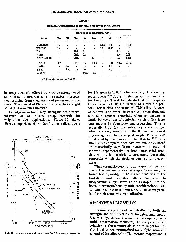
PROCESSING AMD PRODUCTION O F Mo AND W ALLOYS 109
TABLE 8
Nominal Compositions of Several Refractory Metal Alloys
Alloy
VAC-TZMPM-TZCT-1111-222ASTAR-811C
NAS-36*NWZrFS-85W-25Re
Mo
Bal.Bal.
_--
0.7---
Nb
----
_
Bal.Bal.
-
Chemical
Tft
_-
Bal.Bal.Bal.
Bal.-28-
W
_
_89.63
5.7-
10Bal.
composition,
Re
_-_
1.0
1.56-_
25
Ti
0.501.5
_--
-
-
wt%
Zr
0.080.35
_
-
0.131.01.0
-
Hf
-2.42.40.7
0.25---
C
0.0200.15
-0.010.02E
0.015---
*NA3-36 also contains 0.015N.
in creep strength offered by carbide-strengthenedalloys is ag ,;n apparent as is the scatter in proper-ties resulting from chemistry and processing varia-tions. The thoriated PM material also has a slightadvantage over pure tungsten.
Density-normalized creep strengths are a usefulmeasure of an alloy's creep strength forweight-sensitive applications. Figure 10 showsdirect comparison of the denf'ty-normalized stress
TEMPERATURE,°F1500 2000 2500 3000 3500
'10.0
0.5
50 4NAS-36
T-222
ASTAR 811C
Y,-25Re(Ref. 56)
10.0 <"
1200 1600
TEMPERATURE,°C
2000
Fig. 10 Density-normalized stress for 1% creep in 10,000 h.
for 1% creep in 10,000 h for a variety of refractorymetal alloys.43-56 Table 8 lists nominal compositionsfor the alloys. The data indicate that for tempera-tures above ~1100°C a variety of materials per-form better than the standard TZM alloy A wordof caution is in order, however. All creep data aresubject to scatter, especially when comparison ismade between lots of material which differ fromone another in chemistry and processing. This isespecially true for the refractory metal alioys,which are very sensitive to the thermomechanicalprocessing used to develop strength. This is wellillustrated by the two curves for \V-25Re.45-56 Onlywhen more complete data sets are available, basedon statistically significant numbers of tests cfmaterial representative of best commercial prac-tice, will it be possible to accurately determineproperties which the designer can use with confi-dence.
When strength/density ratio is used, alloys thatare attractive on a raw strength basis may befound less desirable. The higher densities of thetantalum and tungsten alloys compared tomolybdenum alloys serve as an example. On thebasis of strength/density ratio considerations, TZC,W-25Re, ASTAR 811C, and NAS-36 all show prom-ise for high-temperature application.
RECRYSTALLIZATION
Because a significant contribution to both thestrength and the ductility of tungsten and molyb-denum alloys depends upon the development of astable deformation structure, the recrystallizationbehavior of these materials is quite important. InFig. 11, data are summarized for molybdenum andseveral of its alloys.5-7-35 The carbide dispersions of

110 HAOEL.SHELDS.Aff
1-H ANNEALING T£MPERATURE,°F2000 3000
1000 1500 20001-H ANNfcALING TEMPERATURE,°C
Fig. 11 Recrystallization behavior of molybdenum andmolybdenum-base alloys.
these alloys are important in retaining the workedstructure. Even the TZM alloy, which has a muchlower alloy content than TZC and MHC, enjoys a300 to 400°C advantage in recrystallization tem-perature over unalloyed molybdenum. The carbideswhich form in TZM are effective in improving boththe strength and recrystallization resistance ofmolybdenum. Thc recrystallization temperature ofVAC-TZM can be increased by solution treating31
at temperatures as low as 185O°C. The TZC andMHC alloys, which contain higher alloy contentsand rely to a greater extent on dispersion harden-ing, have even higher recrystallization tempera-tures. However, the higher recrystallization tem-peratures were obtained in the powder metallurgyversions of these alloys after solution treating7 at2200°C with rapid cooling. As was observed withtensile data, MHC and TZC recrystallization datafall in approximately the same scatter band.
Less information is available for tungsten andits alloys,45-47'48 partly because there are fewertungsten alloys than molybdenum alloys producedcommercially and partly because measurements ofthe recrystallization in tungsten alloys haveemphasized hardness testing to a lesser degree. Re-crystallization behavior of tungsten alloys, sum-marized in Fig. 12, is consistent with that ofmolybdenum and molybdenum-based alloys andagain illustrates the effectiveness of carbide
dispersions in increasing the material's resistanceto recrystallization. The hafnium carbide alloy dataplotted in Fig. 12 were selected from data fromamong several heats.48 The scatter bar! in the fig-ure includes the best of the heats investigated.
Note that the data given in Figs. 11 and 12 arefor 1-h anneals. Recrystallization data are usefulfor developing processing schedules because theycan be used to set annealing and stress-reliefcycles. This information, however, is not useful forthe designer, who must know about the long-termstability of the microstructures and strengths ofths alloys under consideration. Kinetic informationon recrystallization is needed for the normally pro-cessed commercial alloys, as well as for alloyssubjected to thermoruechanieal processing varia-tions.
Doping powder-metallurgy tungsten billets withaluminum, potassium, and silicon increases therecrystallization temperature of tungsten wire.49
Figure 13 shows the comparison of the meanboundary spacing of doped and undoped tungstenwire, as determined by transmission microscopy, asa function of the annealing temperature.49 Dopingcan be seen to effectively reduce the mean bound-ary spacing after annealing. It is employed toincrease the recrystallization temperature of highlyworked, unidirectionally deformed refractorymetals. For example, the temperature for completerecrystallization can be increased from ~1200°Cfor pure molybdenum to —1700°C for dopedmolybdenum.50
zooo1H ANNEAl ING TEMPERATURE,'
3000
en 500
400
100 L^2000 3000
1H ANNEALING TEMPERAT'JRE.t
4000
Fig. 12 Recryrtallizationtungsten-base alloys.
behavior of tungsten and

PROCESSING AND PRODUCTION OF Mo AND W ALLOYS 111
19
zo2in<az3om
<UJ5
. 1 2 0 0DOp— r
5 0
1.0
0 5
0.1
-
_
1 H ANNEALING2000
1 i 1 i—
UNDOPED
/
i i i i
TEMPERATURE, F3000
-
/
.--** ^DOPED
• 1 1 i 1 , •
600 1000 15001H ANNEALING TEMPERATURE."^
I O O O
Fig. 13 Mean boundary spacing ir. doped and undopedtungsten, as a function of 1-h annes'-ing temperature.
ALLOY DL^ I iNA great variety of alloys of molybdenum and
tungsten have been investigated since research wasinitiated to understand the physical metallurgy ofthese materials. This work has been primarilyempirical, guided by sound thinking and a grasp ofthe strengthening mechanisms which might beeffectively employed in refractory alloys. In recentyears a more fundamental understanding of therelations between crystal structure, elastic proper-ties, stoichiometry, and alloy properties has beenemerging.34'51"53 Ryan et al.51"53 have successfullycorrelated the habit plane and orientation relation-ships between carbides in titanium- andzirconium-carbide-forming molybdenum alloys withthe elastic strain energy arising from crystallo-graphic mismatch across the precipitate/matrixinterface. Wadsworth34 has recently reanalyzeddata for hafnium-carbide-containing molybdenumand tungsten alloys, using an expression for car-bide mole fraction based on the solubility productof HfC, and has obtained improved correlationsbetween calculated carbide volume fraction and themechanical properties of these alloys. Analyticalmodeling effects such as these should improve ourability to design alloys which possess good high-temperature strengths and acceptable room-temperature ductilities. The work by investigatorsat NASA-Lewis Research Center11-22-29'47-48 haslaid a solid foundation for alloy design employingmultiple strengthening mechanisms, with somepromising results. Further effort i3 needed to
investigate ductilizing analogues to rhenium, suchas osmium, iridium, and platinum, and to make useof multiple alloying additions. Work at our ownlaboratory, employing combinations of severalreactive plloy additions, has identified composi-tions possessing superior strength at elevated tem-peratures. GTE-Sylvania is developing a powdermetallurgy Mo-30 to 45W-HfO alloy.15 Investiga-tions are also necessary to determine the utility ofAl and B additions, which frequently occur inSoviet alloy compositions.
FUTURE REQUIREMENTSA most important requirement in the technol-
ogy of molybdenum and tungsten alloys is theavailability of materials with acceptable ductilityat ambient and lower temperatures in the recrys-tallized condition. This requirement has long beenrecognized, and progress is apparent with the useof rhenium as a ductilizing addition. On the otherhand, the high temperature strength of alloysdepends upon the thermal stability of dispersedphases. Improvements in phase stability willenhance the applicability of alloys at high tem-peratures. A solid data base on the effects of ther-momechanical processing on the properties of bothnew and existing alloys is needed before designerscan specify the best material for a given app'ica-tion. This is particularly true in systems whichcombine alloying techniques, such as the W-Re-Hf-C and Mo-Re-Hf-C systems.
The large columnar grained structure of as-castVAC and EB melted ingots is generally brokendown by extrusion before further mechanical pro-cessing is performed. Casting processes, such asvacuum-arc-double-electrode remelt (VADER),54
which produce a very fine-grained as-cast struc-ture, may be useful in producing arc-cast ingotswhich do not require extrusion as the first step inprocessing. The VADER process works well forsuperalloys which have large liquidus-solidusspreads and may therefore be lees useful for cast-ing molybdenum and tungsten alloys which havesmall liquidus-solidus spreads. Nevertheless,casting of ingots with finer grain structures, eitherby development of advanced casting technologies orby improvements to existing technologies, is adesirable goal. Extremely low interstitial levelsappear to be beneficial to the low-temperature duc-tility of molybdenum and tungsten alloys.Emphasis is also needed on melting and castingtechniques capable of providing such high puritymaterial as a base for alloy development. The fea-sibility of a combination of casting and powdermetallurgy technology, ultra rapid solidification to
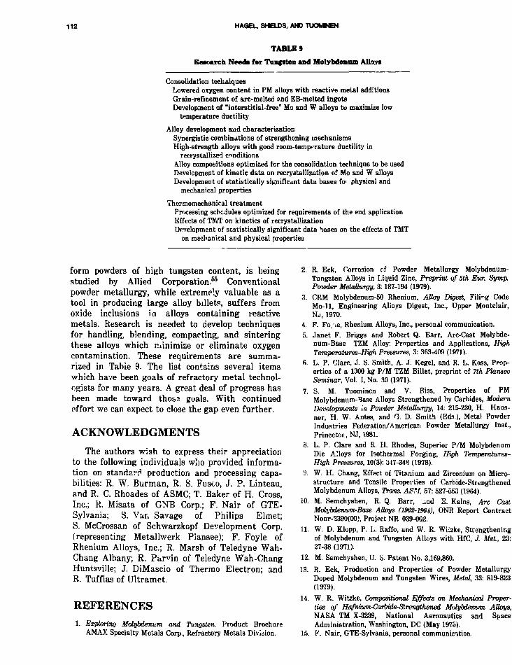
112 HAQEL. SHELOS, AND TUOMNEN
TABLES
Research Needs for Tnnfiten and Molybdenum Allo;ri
Consolidation techniquesLowered oxygen content in PM alloys with reactive metal additionsGrain-refinement of arc-melted and EB-melted ingotsDevelopment of "interstitial-free" Mo and W alloys to maximize low
temperature ductility
Alloy development aud characterizationSynergistic combinations of strengthening mechanismsHigh-strength alloys with good room-temperature ductility in
recrystallized conditionsAlloy compositions optimized for the consolidation technique to be usedDevelopment of kinetic data on recryatallization of Mo and W alloysDevelopment of statistically significant data bases fo> physical and
mechanical properties
Thermomechanical treatmentProcessing schedules optimized for requirements of the end applicationEffects of TMT on kinetics of recrystallizationDevelopment of statistically significant data bases on the effects of TMT
on mechanical and physical properties
form powders of high tungsten content, is beingstudied by Allied Corporation.55 Conventionalpowder metallurgy, while extremely valuable as atool in producing large alloy billets, suffers fromoxide inclusions in alloys containing reactivemetals. Research is needed to develop techniquesfor handling, blending, compacting, and sinteringthese alloys which minimize or eliminate oxygencontamination. These requirements are summa-rized in Table 9. The list contains several itemswhich have been goals of refractory metal technol-ogists for many years. A great deal of progress hasbeen made toward thoss goals. With continuedeffort we can expect to close the gap even further.
ACKNOWLEDGMENTS
The authors wish to express their appreciationto the following individuals wlio provided informa-tion on standard production and processing capa-bilities: R. W. Burman, R. S. Fusco, J. P. Linteau,and R. C. Rhoades of ASMC; T. Baker of H. Cross,Inc.; R. Misata of GNB Corp.; F. Nair of GTE-Sylvania; S. Van Savage of Philips Elmet;S. McCrossan of Schwarzkopf Development Corp.(representing Metallwerk Plansee); F. Foyle ofRhenium Alloys, Inc.; R. Marsh of Teledyne Wah-Chang Albany; R. Pan'in of Teledyne Wah-ChangHuntsville; J. DiMascio of Thermo Electron; andR. Tuffias of Ultramet.
REFERENCES
1. Exploring Molybdenum and Tungsten, Product BrochureAMAX Specialty Metals Corp-, Refractory Metals Division.
2. R. Eck, Corrosion of Powder Metallurgy Molybdenum-Tungsten Alloys in Liquid Zinc, Preprint of 5th Eur. Symp.Powder Metallurgy, 3:187-194 (1979).
3. CRM Molybdenum-50 Rhenium, Alloy Digest, Filing CodeMo-11, Engineering Alloys Digest, Inc., Upper Montclair,N J , 1970.
4. F. Fo.'ie, Rhenium Alloys, Inc., personal communication.5. Janet F. Briggs and Robert Q. Earr, Arc-Cast Molybde-
num-Base TZM Alloy: Properties and Applications, HighTemperatures-High Pressures, 3: 363-409 (1971).
6. L. P. Clare, J. S. Smith, A. J. Kegel, and R. L. Koss, Prop-erties of a 1300 kg P/M TZM Billet, preprint of Tth PlanseeSeminar, Vol. I, No. 30 (1971).
7. S. M. Tuominen and V. Biss, Properties of PMMolybdenum-Base Alloys Strengthened by Carbides, ModernDevelopments in. Powder Metallurgy, 14: 215-230, H. Haus-ner, H. W. Antes, and G. D. Smith (Eds), Metal PowderIndustries Federation/American Powder Metallurgy Inst.,Princetor.,NJ, 1981.
8. L. P. Clare and R. H. Rhodes, Superior P/M MolybdenumDie Alloys for Isothermal Forging, High Temperatures-High Pressures, 10(3): 347-348 (1978).
9. W. H. Chang, Effect of Titanium and Zirconium on Micro-structure and Tensile Properties of Carbide-StrengthenedMolybdenum Alloys, Trans. ASM, 57: 527-553 (1964).
10. M. Semchyshen, R. Q. Barr, -nd S. Kalns, Arc CastMolybdenwm-Base Alloys (1962-196J,), ONR Report ContractNonr-2390(00), Project NR 039-002.
11. W. D. Klopp, P. L. Raffo, and W. R. Wiizke, Strengtheningof Molybdenum and Tungsten Alloys with HfC, J. Met, 23:27-38 (1971).
12. M. Semchyshen, U. S. Patent No. 3,169,860.
13. R. Eck, Production and Properties of Powder MetallurgyDoped Molybdenum and Tungsten Wires, Metal, 33: 819-823(1979).
14. W. R. Witzke, Compositional Effects on Mechanical Proper-ties of HafniumrCarbide-Strengthened Molybdenum. Alloys,NASA TM X-3239, National Aeronautics and SpaceAdministration, Washington, DC (May 1975).
15. V. Nair, GTE-Sylvania, personal communication

PROCESSING AND PRODUCTION OF Mo AND W A'J-OYS 113
16. R. Eck, Powder Metallurgy of Refrictory Metals and Appli-cations, Int J. P/wder MetalL Powder TechrwL, 17: 201-211(1981).
17. Stephen W. H. Yih and Chun T. Wang, Tungsten: Sources,Metallurgy, Properties, and Applications, Plenum Prea9, NewYork. 1979.
18. 3. McCrossan, Schwarzkopf Development Corporation, per-sonal communication.
19. R. L. Ammon, Consolidation anH Processing of W-0.35%HfC Alloy, in Proceedings of 12th Naticnai SAMPE Confer-ence m Materials, 1980.
20. R. L. Ammon and R. W. Buckman, Jr., Vacuum Arc Melt-ing of Tungsten-Hafnium Carbon Alloy, J. Vac Sci Tech-noL, 11: 385-388 (1974).
21. G. A. Geach and J. E. Hughes, The Alloys of Rhenium withMolybdenum or with Tungsten and Ha\dng Good High Tem-perature Properties. Plansee Proc 1955, pp. 245-253,F. Bene9OV9ky (Ed.), Pergamon Press, Oxford, 1956.
22. William D. Klopp, A Review of Chromium, Molybdenum,and Tungsten AHoys, J. Less Common MeL, 42: 261-278(1975).
23. R. Eck, Production and Properties of Powder MetallurgyMolybdenum and Tungsten Doped Wires, Wire Industry, 47:523-527 (1980).
24. G. W. King and H. G. Sell, The Effect of Thoria on theElevated-Temperature Tensile Properties of RecrystallizedHigh-Purity Tungsten, Trans. AlME, 233: 1104-1113 (1965).
25. G. W. King, The Stress-Dependence of High TemperatureCreep of Tungsten and a Tungsten-2 Wt Pet ThO2 Alloy,Met Trans., 3: 941-945 (1972).
26. R. Eck, VorgSnge beim Sintern von technischen MolybdSnlegierungen insbesondere mit Ti, Zr, Cr und C und Einflussauf die Eigenschaften der Fertigprodukte, MetsU., 28:1147-1151 (1974).
27. S. M. Tuoimnen and K. H. Carpenter. Powder MetallurgyMolybdenum: Influence of Powder Redaction Process onProperties, J. MeL, 32: 23-26 (1980).
28. G. A. Timmons and R. G. Yingling, Arc Melting Molybde-num, The Metal Molybdenum, ASM, pp. 80-108 (1958).
29 P. L. Raffo, Thermomechanical Processing of Molybdenum-Hafnium-Carbon Alloys, NASA TO D-564o, NationalAeronautics and Space Administration, Washington, DC,February 1970.
30. G. A. Timmons, consultant for ASMC, personal communica-tion.
31. E. Kalns, R. Q. Barr, and M. Semchyshen, Effect of In-Process Solution Heat Treatment? on the Properties of theTZM Alloy, High Temperature Refractory Metak Part 2,Metallurgical Society Conferences, VoL Si, R. W. Fountain,Joseph Moltz., and L. S. Richardson (Eds), Gordon andBreach Science Publishers, New York, 1968.
32. W. H. Chang, The Effect of Heat Treatment on Strengt.iProperties of Molybdenum-Base Alloys, Trans. ASM,56: 107-124 (1963).
33. R. L. Stephenson, The Eftect of Fabrication Variables onthe Creep-Rupture Properties of Molybdenum-Base Alloys,Trans. AIME, 245: 997-1001 (1969).
34. J. Wadsworth.. A Reevaluation of the Mechanical Propertiesof Molybdenum- and Tungsten-Based Alloys ContainingHafnium and Carbon, Met Trans., 14A: 285-294 (1983).
35. M. Semchyshen and R. Q. Barr, Mechanical Properties ofMolybdenum and Molybdenum-Base Alloy Sheet,Symposium on Newer Metals, ASTM Special Technical Pub-lication No. 272, pp. 1-24, Amer ic . , Society for Testing andMaterials, 1959.
36. M. Semchyshen, G. D. McArdle, and R. Q. Barr, Develop-ment of Molybdenum-Base Alloys, WADC Technical Report59-780, October 1959.
37. H. Braun, M. Limchyshen, and R. Q. Barr, Recent Develop-ments in the Technology of Arc-Cast Molybdenum,Proceedings of 5th Plansee Seminor—Metals for the SpaceAge, F. Eenesovsky (Ed.), pp. 351-352 (1965).
38. M. Semchyshen, E. Kalns, D. J. Kalphaak, and R. Q. Barr,Development of High-Strength Molybdenum- and Tu'igsten-Base Alloys, Final Report, Bureau of Naval Weapons Con-tract No. NOw 65-0385-c (1966).
39. P. L. Raffo and W. D. Klopp, Mechanical Properties ofSolid-Solution and Carbide-Strengthened Arc-Melted TurnstenAUoys, NASA TN D-3248, National Aeronautics and SpaceAdministration, Washington, DC (February 1966).
40. "Oremst HPC 85W15Mo," Alloy Digest, Filing Code W-9,Engineering Alloys Digest, Inc. Upper Montclair, NJ, 1965
41. Wah Chang W-25Re, Alloy Digest, Filing Code W-15,Engineering Alloys Digest, Inc., Upper Montclair, NJ, 1970
42. I,. B. Lundberg, An Evaluation of Molybdenum and ItsAllays, Paper No. AIAA-81-llOft, Am. Inst. of Aeronauticsand Asti nautics, New York, NY (1981).
43. J. B. Ccnway and P. N. Flagella, Creep-Rupture Data forthe Refractory Metxds to High Temperatures, Gordon andBreach Science Publishers, New York, 1971.
44. J. A. Houck, Physical and Mechanical. Properties of Com-mercial Molybawm-Base Alloys, DMIC Report 140, DefenseMaterials Infornation Center, Battelle Memorial Inst.,Columbus, OH (November 30,1960).
45. M. Semchyshen and R. Q. Barr, Extrusion and MechanicalProperties of Molybdenum and Tungsten AUoys, ASD Tech-nical Report 61-193, Aeronautical Systems Div., Air ForceSystems Command, USAF, Wright-Patterson AFB, OH,June 1961.
46. L. S. Rubenstein, Effects of Composition and Heat Treat-ment on High-Temper ture Strength of Arc-MeltedTungstev-Hafniuni-Carbou Alloys, NASA TN D-4379,National Aeronautics and Space Administration, Washing-ton, DC, February 1968.
47. W. D. Klopp and W. R. Witzke, Mechanical Properties andRecrystaUization Behavior of Electron-Beam-MeltedTungsten Compared vrith Arc-Melted Tungsten, NASA TND-3232, National Aeronautics and Space Administration,Washington, DC, January 1966.
48. W. D. Klopp and W. R Witzke, Mechanical Properties ofArc-Melted Tungsten-Rhenium-Hafnium-Carbon Alloys,NASA TN D-5348, National Aeronautics and SpaceAdministration, Washington, DC, July 1969.
49. D. B. Snow, The Recrystallization of Commercially Pureand Doped Tungsten Wire Drawn to High Strain, MetalLTrans., A, 10A: 815-821 (1979).
50. Molybdenum, General Survey, Product Information Bro-chure, Metallwerk Plansee, Reutte, Austria.
51. N. E. Ryan and J. W. Martin, Hardening of SomeMolybdenum-Base Alloys by Precipitation of Nitride andCarbide Phases, Proceedings of Plansee Seminar,Reutte-Tyrol, Austria, June 1968.
52. N. E. Ryan, W. A. Soffa, and R. C. Cr.-wford, Orientationand Habit Plane Relationships for Carbide and Nitride Pre-cipitates in Molybdenum, Metallography, 1: 195-220 (1968).
53. N. E. Ryan and J. W. Martin, The Formation and Stabilityof Group IVA Carbides and Nitrides in Molybdenum,J. Less-Common Met, 17: 363-376 (1969).
54. W. J. Boesch, J. K. Tien, and T. E. Howsen, Progress inVacuum Melting, from VIM to VADER, Met Prog., 122(5):49-56, October 1982.
55. M. Skrypa, Allied Corp., personal communication.56. R. Gluyas and G. Watson, Materials Technology for an
Advanced Space Power Nuclear Reactor Concept, ProgramSummary, NASA TN D-7909, National Aeronautics andSpace Administration, Washington, DC, March 1975.

CVD Refractory Metals and Alloys forSpace Nuclear Power Application
L. Yang, T. D. Gulden, and J. F. WatsonGA Technologies, Inc.
INTRODUCTION
In space nuclear power systems, many key com-ponents have to -psirie at temperatures higherthan 1200°C for long periods of time. To ensurehigh reliability in performance and life, they haveto be made of refractory metals and alloys.Although conventional metallurgical processes canbe used to fabricate most of these components,there are special cases when other methods arebetter suited for meeting the needs. Chemicalvapor deposition (CVD), which was used exten-sively from 1963 to 1972 for the fabrication of theelectron emitters in in-core thermionic fuel ele-ments, represents one of these special cases.
In CVD, metal atoms are produced by chemicalreactions and deposited on the surface of a man-drel maintained at the desired temperature untilthe required thickness of the deposit is attained.The mandrel is then removed either mechanicallyor by using an appropriate solvent, leaving thedeposit in the shape of a replica of the mandrel.This method is thus specially suited for the fabri-cation of items with complicated shapes and rela-tively thin walls without welded or brazed joints;this can be accomplished with relatively inexpen-sive equipment. By controlling the purity of thereactan*3 and the deposition parameters, productsof desired purity, microstructures, and propertiescan be prepared for specific applications. Further-more, the CVD technique is specially suited for thedeposition of thin coatings as high temperaturediffusion barriers for compatibility consideration.Major efforts applying CVD techniques in the fab-rication of refractory alloy components for spacenuclear power systems are described in this paper.
TECHNOLOGY STATUS
CVD Electron Emitter forThermionic Space Power System
CVD Tungsten Emitter forIn-Core Thermionic System1
In an in-core thermionic system, electrons areused as the working fluid for the direct conversionof fission heat to electrical energy. Materials of lowvapor pressure and high mechanical strength areneeded as electron emitters operating in contactwith nuclear fuels at high temperature for longperiods of time. Extensive investigations of thehigh temperature compatibility between variouscarbide and oxide fuels and various refractorymetals and alloys during 1961 to 1963 led to theconclusion that tungsten is the best cnoice for theelectron emitter in a thermionic fuel element. Thereference ,' sign for the emitter is in the form of acup of 2.8 cm O.D., 6.4 cm length, and 1 to 2 mmwall thickness. Fission heat generated by thenuclear fuel contained inside the cup heats theemitter to Loil off electrons from its external sur-face. Successful fabrication of the tungsten emittercup of the desired purity, microstructures, andelectron emission properties is the key to the suc-cess of in-core thermionics. Fabrication by drillinga cylindrical tungsten billet is obviously impracti-cal. Fabrication by welding a bottom to a tungstentube runs the risk of failure at the weld. CVDappears to be the most attractive method for fabri-cating the tungsten emitter cup.
During the period of 1963 to 1970, extensiveefforts were made at GA Technologies Inc. (GA),Oak Ridge National Laboratory (ORNL), LawrenceRadiation Laboratory (LRL), General Electric
114

CVD METALS AND ALLOYS FOB SPACE APPLICATION 116
Company (GE), and San Fernando Laboratory(SFL) to study CVD tungsten deposition and theproperties and microstructure9 of CVD tH-^otendeposits. The information that was generatedhelped to lay the foundation of CVD tungstenemitter technology, which was used for the fabrica-tion of the emitters in thermionic devices testedout "pile and in-pile at GA during the periodii&3 to 1972.
Fluoride Tungsten Deposition. Tungsten depos-its prepared by the hydrogen reduction ofWF6(WF0 + 3H2 — W + 6HF) are referred toas fluoride tungsten. All the emitters tested priorto 1968 were made of fluoride tungsten. Figure 1shows schematically the deposition apparatus forfluoride tungsten. The hydrogen used is 99.999%pure and is further purified by diffusion through aPd-Ag membrane. The WF6 used is purified bycooling the gas cylinder to dry ice temperature andpumping off the volatile impurities. The depositionchamber is water-cooled and can be made of Pyrexor Teflon. Various mandrel materials have beenused; molybdenum is favored because it can be out-gassed at high temperature and it has a thermalexpansion coefficient closely matching that oftungsten. The mandrel is heated by induction,although resistance heating can also be used. Dur-ing the deposition, the chamber is continuouslyevacuated with a pump, and the pressure in thechamber can be adjusted to the desired value byvarying the opening of the valve connecting thepump to the chamber. The exhaust passes through
the NaOH traps to remove HF and any unreactedWFb.
The deposition rate of fluoride tungstenincreases with the temperature of the mandrel andthe pressure in the deposition chamber. Figure 2,taken from a paper by Holman and Huegel,2
illustrates this point. The deposit tends to berough and dendritic when the temperature of themandrel is above 550°C; therefore the mandreltemperature cannot be too high. For the prepara-tion of cylindrical fluoride tungsten emitter, thefollowing conditions have been used: mandrel tem-perature, 540°C; WF6 flow rate, lh liter per minute;hydrogen flow rate, 2 liter per minute; chamberpressure, % atmosphere. Figure 3 shows the as-deposited emitter and the emitter after it has beenground to the required dimension.
Typical fluoride tungsten deposits contain lessthan a few ppm of nitrogen or hydrogen, 5 to 10ppm oxygen, 10 to 15 ppm carbon, and very lowmetallic impurity contents. Fluoride tungsten has acolumnar grain structure which is stable at 1800°C(Fig. 4). Studies carried out at ORNL3-4 and GE5
showed that such grain structure stability is due tothe presence of fluorine-containing gas bubbles atthe grain boundaries. When the fluorine content ofthe deposit is high (>20 ppm), the deposit swellswhen heated to high temperatures (Fig. 5). On theother hand, wher the fluorine content is low(<~5 ppm), grain growth occurs readily at hightemperatures (Fig. S). A fluorine content of 10 to20 ppm is considered as optimum for stable grain
TOROUGHING PUMP
THERMOCOUPLE'GAUGE
SIGHTGLASS
/
THERMOCOUPLE
MOLYBDENUMMANDRELFOR 'UMGSTENDEPCSIT ICN
Fig. 1 Schematic diagram of fluoride tunggten deposition apparatus.

118 YANG, GULDEN. AND WATSON
1000
TEMPERATURE (deg C)
850 750 650 550 450
| 0.5
Z
o
oUJ
o 0.1
0.05
PRESSURE(rwr )
' 5B 10D 10• 10
a 20
o 40
VBO
° 400-500
FLOwRATEH 2
5001000
5001500
500
500
500
2400
W F 6
7070
7CXO
70
70
70
40-300
0.8 0.9 1.0 1.1 1.2 1.3 1.4
0.050
0.020 _
0.010
z0.005 °
0.002
0.001
Fig. 2 Effects of plating variables on fluoride tungsten deposition rate (from Ref. 2).
Fig. 3 CVD cylindrical fluoride tungsten emitter. Left, as-deposited; right, aftergrinding.

CVD SiSTALS MS) ALLOYS FOR SPACE APPLICATION 117
: 1 t '
•». V
AS-DEPOSITED
200 urn(b)
200 ym
AFTER 113 HOURS AT 1800°CIN VACUUM
Fig. 4 Microslructures of CVD fluoride tungsten.
0.03G
0.032
0.028
0.024
0.016
0.012
0.008
0.00-1
0
All Samples Between0.450- and 0.500-in. o.d.
/
' / ,
r
inoo hat 195irc
10(10 hat 1750°C
. a
0.7
O.d E
E
0.5 i
0.4 (5c
o.:i |
0.2 -H
0.1
o20 40 60 80
Fluorine Content, ppm
100 120
Fig. 5 Fluorine content vs. diametral change (from Roff. 5).

118 YAN&. GULDEN, AND WATSON
"•S- -
c
rig. 6 Effect of fluorine content on the microstructuresof S series tungsten after annealing 1 h at 25C0°C.a. S OT-0 (1-ppm F); b. S 82-1 (6-ppm F); c. S 90-1(30-ppm F); 125X (from Hef. 4).
structure and dimensional stability. Control of thefluorine content of fluoride tungsten has received agre^t deal of attention during the latter part of the1960s. Deposition at low pressure (5 to 10 torr) inchamber cooled with water jacket reduces thefluorine content.3 Increase of deposition tempera-ture to 600°C, and H2/WF6 ratio (>50/l) alsolowers the fluorine content.6 Study carried out withtime-of-flight mass spectrometer showed that th •gaseous species released from fractured CVDfluoride tungsten could be a subfluoride (e.g., WF4)
formed by partial reduction of WF6 with hydrogen,which is responsible for the observed bubble for-mation in fluoride tungsten at high temperatures.5
Ii has been shown1 that oxygen additives to WF6(2 to 5 vol %) lower the fluorine content offluoride tungsten without significantly increasingthe oxygen impurity content in the deposit,presumably by connecting the WF4 to the more vol-atile W0F4.
By exercising careful control of the purity ofthe WF6 and the deposition conditions, it was pos-sible to produce fluoride tungsten emitters withfluorine content in the range of 5 to 20 ppm. In thelatter part of 1972, fluoride tungsten emitters offluorine content equal to 15 ± 5 ppm have beenproduced consistently.
Chloride Tungsten Deposition. In the fluoridetungsten deposit, the crystal grains are orientedpreferentially with the (100) plane parallel to thesubstrate. Emitters prepared from such depositshave an electron work function of 4.5 eV. Early in1966, efforts were made to prepare CVD tungstendeposits having (110) preferred orientation.Because the (110) plane is more densely packedwith tungsten atoms than the (100) plane, it isexpected that the (110) oriented emitter shouldhave a higher electron work function, which canimprove the electrical output of the converter byreducing the cesium pressure required for optimumoperation. It was found that (110) oriented tung-sten cnuld be obtained by the hydrogen reductionof tungsten chloride under certain depositioncondHions.8 The tungsten chloride used can beWC(6 powder or tungsten chloride formed hy thechlorination of CVD fluoride tungsten chips. Figure7 shows schematically the arrangement for prepar-ing chloride tungsten deposits by the hydrogenreduction of tungsten chloride formed by the chlo-rination of fluoride tungsten chips at the top of thedeposition chamber. Extensive efforts were madein defining the deposition conditions for achievinga high degree of (110) preferred orientation in thedeposit and a high electron work function, usin^planar molybdenum mandrel. Some of the resultsare shown in Fig. 8. Chloride tungsten deposits of4.9 to 5.0 eV electron work function can be obtainedat a mandrel temperature of 1100°C, a H2/W ratioof 2.2 to 2.8, a C12/H2 ratio of 1, and a depositionchamber pressure of 4 to 6 torr. Typical chloridetungsten deposits have impurity contents (ppm) asfollows: N < 1; 0, 2 to 7; C, 6 to 10; F, <3; Cl, 6 to14; total metallic impurities, <10 ppm. Figure 9shows the microstructures of as-deposited chloridetungsten.

CVD METALS AT© .MXOYS FOR SPACE APPLICATION 119
ChlorineSupply
PressureGauge—>
NeedleValve
^NeedleValves
Needle Valve
•Flowme Lers
HydrogenSupply
Stopcock
..Liquid NitrogenCold Trap
InductionCoil
To Vacuum Pump
8
Mercury —Manometer
AbsoxuteMercury —Manometer
Thermocouple
ThreewayStopcock
GroundJoints
Tungsten ChipsNichrome
*• ResistanceFurnace
-Quartz Fibers
• Mo Mandrel
•Hohlraum
.Quartz Jacket-McDanel Tube.StainlessTransition
- McDanel Tube
GroundT '"int
.Optical Flat
Glass Prism
Fig. 7 Chloride tungsten deposition apparatus using chlorination of tungsten chips to provide tungstensource material.
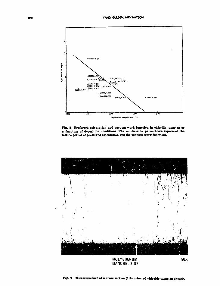
120 YANG, QULDBi AND WATSON
. (mrtlk.ay
jiioKJ.oi)
. (UOH--55)
• (U0)(k.B7)
1200 1300
CiEoaltlco Toptratur* (°C)
Fig. 8 Preferred orientation and vacuum work function in chloride tungsten asa function of deposition conditions. The numbers in parentheses represent thelattice planes of preferred orientation and the vacuum work functions.
MOLYBDENUMMANDRELSIDE
50X
Fig. 9 Microstructure of a cross section (110) oriented chloride tungsten deposit.

CVD METALS AND ALLOYS FOR SPACE APPLICATION 121
CHLORIDETUNGSTEN
FLUORIDETUNGSTEN
(a) AS-DEPOSITED 200 ym
CHLORIDETUNGSTEN
FLUORIDETUNGSTEN
(b) AFTER 1000 HR AT 1800°C 100 ym
Fig. 10 Microstructures of duplex tungsten.
Because chloride tungsten has a strong ten-dency for grain growth, the cylindrical tungstenemitters in the thermionic devices are composed ofa chloride tungsten emitting layer (—0.3 mmthick) on a fluoride tungsten substrate. The chlo-ride tungsten is used as the emitting layer becauseof its high electron work function which providesbetter electrical output. The fluoride tungsten isused as the substrate because of its stable grainstructure which provides mechanical stability. Anemitter with such a two-layer design is called theduplex tungsten emitter. In a thermionic fuel ele-ment, the tungsten emitter is diffusion bonded to a
tantalum transition piece which is then electronbeam welded to other niobium components.
Figure 10 shows the microstructures of a duplextungsten emitter before and after heating at1800°C for 1000 h and illustrates the excellentbonding between the fluoride tungsten and thechloride tungsten. While the grain structure of thefluoride tungsten layer remains stable, graingrowth has occurred in the chloride tungsten layer.However, the electron work function of the chlo-ride tungsten emitting surface did not show amsignificant change. These results obtained onplanar samples were subsequently used as a guide

122 YANG, GULDEN, AND WATSON
in the deposition of the chloride tungsten layers ofcylindrical duplex emitters. The duplex tungstenemitter is the reference emitter design for in-corethermionic fuel element and was the one tested in-pile during the late 1960s and early 1970s.
CVD Rhenium Emitter
The (0001) face of a rhenium single crystal hasan electron work function of 5.59 eV.9 A cesiatedconverter containing such a rhenium emittershowed outstanding thermionic performance.10
Because the use of a single crystal emitter inengineering devices is impractical from the point ofview of cost and the cylindrical configurationrequired, efforts were therefore made to develop(0001) oriented polycrystalline CVD rheniumemitter. A CVD polycrystalline rhenium emitterexhibiting (0001) preferred orientation wasprepared by the pyrolysis of rhenium chloride11
and yielded a vacuum electron work function of 5.1eV.12 Detailed investigations of the depositionparameters were carried out at GA in the early1970s in order to establish the conditions forachieving porosity-free rhenium deposits of a highdegree of (0001) orientation and high electron workfunction.
The deposition apparatus used (Fig. 11) is simi-lar to that for chloride tungsten deposition. Therhenium chloride used was prepared by the chlo-rination of rhenium pellets contained in a quartzreservoir located at the top of the deposition appa-ratus. These pellets were prepared by taking 200mesh rhenium powder procured from ClevelandRefractory Metals and cold pressing to 70 MPa(10.000 psi) and sintering the pressed pellets at1400°C in vacuum for 15 h. The sintered pelletswere 6.4 mm in diameter, 1.6 mm in thickness and80% dense. Prior to the deposition operation, thepellets were baked in situ in flowing hydrogen fora few hours at 900° C to rid them of any oxide pres-ent, and the molybdenum mandrel was also cleanedin hydrogen at 1200°C. The chamber was thenflushed with helium to remove the hydrogen. Themandrel and the rhenium pellets were brought tothe desired temperatures and the chamber wasevacuated before chlorine was admitted to therhenium pellet reservoir to initiate the deposition.The rhenium chloride formed was decomposed atthe hot molybdenum mandrel surface to form therhenium deposit. The chlorine released waspumped out of the chamber to maintain a residualpressure of <1 torr. A thorough evaluation of thedeposition parameters established the followingconditions for obtaining porosity-free (0001)oriented rhenium deposits of 5.17 to 5.2G eV elec-
tron work function:13 chlorine flow rate 200cc/min., rhenium pellet temperature 800°C, man-drel temperature 1200° C. Figure 12 shows themicrostructures of some CVD rhenium deposits.The impurity contents of these deposits in ppm are:C, 9 to 25; O, 25 to 48; N, 3 to 5; Cl, <1; Ca, 1 to 3;Na, 2 to 5. The conditions established were used inthe preparation of cylindrical rhenium emitters ontantalum .nandrel 11.7 cm in length and 2.2 cm indiameter. To improve the uniformity of the as-deposited thickness of the rhenium layer over theentire length, the rhenium chloride generator wasmoved from the top of the deposition chamber toits side so that the rhenium chloride vapor streamwas perpendicular to the cylindrical axis of themandrel, i.e., a cross flow configuration. In addi-tion to the rotary notion at 2 rpm, the mandrelwas also moved axially across the rhenium chloridevapor stream during the deposition. Rheniumlayers of strong (0001) preferred orientation anduniform thickness could be deposited over theentire 11.7 cm mandrel length at a rate of 0.1 to0.13 mm per h.
In spite of the high electron work function of(0001) oriented rhenium, the use of rheniumemitter is limited to out-of-core thermionicsystems because rhenium is a strong neutronabsorber.
CVD Tungsten Diffusion BarrierBetween Fuel and Cladding
T-lll and Nb-lZr clad uranium nitride fuel pinswere promising candidates as the heat source forliquid metal cooled reactors for space power appli-cations. To prevent fuel-clad interaction and loss ofnitrogen, a 0.13 mm thick CVD tungsten barrierwas deposited on the I.D. of the cladding. This bar-rier worked successfully at 1200°C cladding tem-perature during in-pile irradiation to 2% burnup.14
The adherence of CVD tungsten coating to variousmetal and alloy substrates has been discussed byBryant 15 and by Federer and Poteat.16 Good adhe-sion is achieved if the substrate surface is free ofcontaminants and does not react with the coatinggas (e.g., WF6) at the deposition conditions.
Because of its columnar grain structures andassociated grain boundary diffusion, CVD fluoridetungsten is not expected to be as good a barrier forfuel component transport as CVD chloride tung-sten. CVD chloride tungsten develops equiaxia!grain structure similar to that in recrystallizec1
wrought materials after heat treatment at hightemperatures (e.g., 1500°C).

CVD METALS AND ALLOYS FOR SPACE APPLICATION 123
MonelPressureGauge
ChlorineSupply
AbsoluteMercuryManometer
Stopcock
NeedleValves
LiquidNitrogenCold Trap
AbsoluteMercuryManometer
Thermocouple
Ground Joints
Thermocouple Well
Nichrome ResistanceFurnace
Quartz Reservoir
Rhenium ChipsQuartz Fibers
To VacuumPump
GlassWool-Trap
LiquidNitrogenCold Trap
Motor
HohlraumMandrel
3 * Induction Coil
Quartz Jacket
Mullite Ceramic Tube
Stainless StenlTube
Rubber Gasket
Stainless Ste?lGrooved Plate
• Rubber 0 Ring Seals
•Wilson Seal
Rotational WormGear Drive
Optical FlatGlass Prism
Fig. 11 Rhenium deposition apparatus.
CVD Tungsten Heat Pipe
Tungsten is one of the most promising wallmaterials for lithium heat pipe for high tempera-ture operation because of its high temperaturestrength and resistance to oxygen-induced corro-sion in lithium systems. Some of the heat pipedesigns for transferring heat from the reactor coreto the conversion system involve complicatedshapes. For instance, heat pipes designed for cross
flow heat exchanger involve both circular and rec-tangular cross sections (Fig. 13). Tungsten-lithiumheat pipe has been operated up to 2000°C for5000 h without failure.17
CVD techniques were used to fabricate thetungsten heat pipe shell for two designs, thesmooth wall heat pipe utilizing autoclaved tungstenscreen wicka in both the evaporator and the con-denser (Fig. 14a) and the channeled wall heat pipewith channels in the condenser wall and a swaged

124 YANG, GULDEN. AND WATSON
V
/ • •
RheniumDeposit
*Uuw f Molybdenum~ T Mandrel
100X
Fig. 12 "^icrostructures of CVD rhenium sample, deposited at a chlorine flow rate of 200 c.c./min, arhenium pellet temperature of 800°C, and a mandrel temperature of 1200°C.
REACTOR
HEAT PIPES
FUEL -T .
r POWER LEVELING
'\ HEAT PIPES
r- CONVERTER
,'i HEAT PIPES
Fig. 13 Cross flow heat exchanger (from Ref. 17).
tungsten screen wick in the evaporator (Fig. 14b).The smooth wall heat pipe had a total length of 32cm (18 cm evaporator, 12 cm condenser, 2.2 cm adi-abatic length), a wall thickness of 0.1 cm, a diame-ter of 1.0 cm for the evaporator, and a condensercross section of 1.3 cm X 2.0 cm. The channeledwall heat pipe had a total length of 25 cm (13 cm
evaporator, 10 cm condenser, 2.2 cm adiabaticlength), a wall thickness of 0.1 cm, a diameter of0.955 cm for the evaporator, and a condenser crossspcuon of 0.955 cm X 1.91 cm. Fabrication ofthese heat pipes was carried out at SFL for NASALewis Research Center in 1970.18 Both heat pipeshave operated to the design temperature of 1575°C.
CVD Tubing
CVD tubing has the potential of being used asfuel cladding. Both tungsten and tungsten alloytubing has been fabricated by CVD techniquesduring the 1960s and early 1970s.
CVD Tungsten Tubing
CVD can produce high-purity tungsten tubingof various • diameters and wall thicknesses inlengths up to 1.2 m. A technique using resistanceheated thin-wall stainless steel mandrels to pro-duce long tubings of uniform as-deposited wallthickness was described bv Martin et al.19 Theseauthors also concluded that for small diameter(—1.9 cm) thin wall (<1.3 mm) tubing, fabricationby CVD technique should have an economicaladvantage over fabrication by conventional metal-lurgical processes.

CVD METALS AND ALLOYS FOR SPACE APPLICATION 125
L • • , - • : • . . [ £ , • - | r •
Fig. 14a Smooth wall CVD tungsten heat pipe (from Raf.17).
Fig. 14b Channel wall tungsten heat pipe (from Ref. 17).
CVD Tungsten-Rhenium Tubing
CVD tungsten-rhenium alloy deposition byhydrogen reduction of a mixture of WF6 and ReF6has been studied both at ORNL and LRL. Holmanand Huegel2 used the apparatus shown in Fig. 15to study the effect of temperature, pressure,H2/MF6 ratio (MF6 is WF6 + ReFP), concentrationof ReF5 in MF6, and hydrogen flow rate on thecomposition, m .crostructures, and mechanical prop-erties of the deposit. The special features of thisapparatus are:
1. Accurate control of the flow rate andWFg/ReFe ratio by positive displacementmeiering of premixed liquid fluorides into aflash evaporator.
2. Cross-flow of the coating gas with respectto the rotating mandrel to improve the uni-formity of deposit thickness.
3. Provisions (not shown in Fig. 15) for rub-bing the deposit surface during the deposi-tion to break up the columnar grain struc-ture of the deposit and to change themechanical properties of the deposit.
The ranges of the deposition parameters studiedare: temperature, 600 to 1000°C; pressure, 10 to 100torr; K2/MF6 ratio = 1 to 14; MF6 flow rate 30 to530 cc/min and concentration of ReF6 inWF6 = 6.8 to 25%. It was found that lower tem-perature and pressure led to high rhenium concen-tration in the deposit. It appears that the rheniumdeposition rate was supply limited, with a deposi-tion efficiency nearly 100% in the temperaturerange studied, while the tungsten deposition ratewas limited by a surface process and therefore wastemperature dependent. The overall deposition rateof the alloy increased with temperature and foreach temperature was a maximum at the H2/MF6ratio of 3. The microstructures of the tungsten-rhenium alloy deposited on the rotating mandrelwere characterized by a chevron-like pattern super-imposed on the normal grain structure. It isbelieved that those markings were caused byfluctuations in composition as the area underobservation traveled through regions with differentcomposition, with the side facing the inlet gas hav-ing higher rhenium concentration tnan the side180° from the gas entrance. When the rheniumcontent exceeded 18% to 20%, a very hard meta-stable phase with the (3-tungsten A-15 structureappeared.20 High temperature (1400 to 1600°C)annealins is needed to achieve compositional homo-geneity, to restore the equilibrium phase relation-ship, and to improve the mechanical properties.The apparatus shown in Fig. 15 could producetubes of only 2.5 cm in length. It was later modi-fied to allow the deposition of homogeneous W-25Re alloy tubing of 0.3 m in length.21 This wasaccomplished by using a rectangular cross-sectionflue that could direct the coating gas across a10.1 cm length of the mandrel and a cam drivenratchet mechanism for slowly translating ti.erotating mandrel along its axis through the plaiingregion for a distance of 0.4 m. A schematic draw-ing of the apparatus is shown in Fig. lfi.
Federer, Schaifhauser, and Leitten22 deportedtungsten-rich alloy (7% and 22%, Re) tubings(1.9 cm O.D.) having uniform composition in boththe axial and the radial directions in a moving hotzone by the hydrogen reduction of (WF6 + ReF6).A (WF6 + ReF6) injector was used to minimizedeposition in a temperature gradient. Figure 17shows the deposition apparatus. The 22% Re alloywas deposited under the conditions: 900° C, 10 torr,

126 YANG, GULDEN, AND WATSON
MASS FLOW METERS(HASTINGS)
DISCONNECT
FLASHCHAv5i?^\
H2 GAS BLANKET(FOR OPTIC PROTECTION)
LOW POWFR MICROSCOPE
EXHAUST COLD TRAPS AMECH. PUMPS
O-RING SALL VALVE AH LOCKPACKING THERMOCOUPLEGLAr-.C .SLIP RING
INDUCTION COIL
PRESSURE GAUGE
M A N D R E L (THERMOCOUPLE ON INSIDE Su \CE)
Fig. 15 Chemical vapor deposition apparatus, for tungsten and tungsten-rhenium alloys (from Ref. 2).
/Blankef gas { H j
exhaust
Gas flow
(HP,excess H
WF,, ReFT6 6
Reactonts (H o , WF,,ReFz o o
Fig. 16 Long-tube fabrication apparatus (from Ref. 20).

CVD METALS AND ALLOYS FOR SPACE APPLICATION 127
WATER-COOLEDWF.-ReF,INJECTOR
(STATIC ^Y)
DEPOSITIONFURNACE
(STATIONARY)
DEPOSITIONMANDREL
IMOV^BLE)
VACUUM PUMP
HF SCRUBBER' DRAIN
Fig. 17 Tungsten-rhenium deposition apparatus (from Ref. 21).
and H2/(WF6 + ReF6) ratio of 15:1. The 7% Realloy was deposited under the conditions: 800°C, 5torr, and H2/(WF6 + ReF6) ratio of 20:1. Inboth cases, the mandrel traveled at a rate of 1.8in./h. The rhenium concentration uniformity alonga distance of 22.9 cm in the axial direction was±0.5% for the 7% Re alloy and ±1% for the 22%Re alloy. Deposition on the outer surface ofmandrels in a static hot zone also showed promisefor obtaining uniformity in composition.
SUMMARY OF TECHNOLOGYSTATUS
CVD technology has made significant contribu-tions to the development of space nuclear powersystems during the period 1962 to 1972.
For the in-core thermionic concept, CVD tech-nology is essential to the fabrication of the tung-sten electron emitter. The CVD fluoride tungstenprocess provides the emitter substrate for mechan-ical strength and structural stability. The CVDchloride tungsten process provides the emittinglayer of high electron work function and superiorthermionic performance. The controlling parame-ters for these processes have been thoroughlyinvestigated during the past ten years. Variousphysical and chemical methods have beendeveloped for quality control.6'23"24 These processesare ready for scaleup if needed.
For the liquid metal cooled fuel pin using ura-nium nitride as fuel and T-lll and Nb-1 Zr as clad-ding, a lungsten barrier possibly produced by CVDmethods is essential to the fuel-cladding compati-bility at the designed operating temperature. CVDtechnology is well established for fabricating tung-sten and tungsten-rhenium tubes which can beused as fuel cladding for space reactors.
Reactors for space nuclear power systems mayuse heat pipes to transfer heat from the reactorcore to the conversion system. CVD technology hasbeen used for fabricating the heat pipe used ascross-flo'.v heat exchanger, including the built-inchannels on the condenser wall for liquid lithiumreturn. CVD represents the best means forfabricating heat pipes, when the condenser and theevaporator have different shapes.
CVD capability for fabricating refractory metaland alloy components is available in a number oflaboratories. These include ORNL, Los AlamosNational Laboratory (LANL), LRL, GA, ThermalElectron Corporation (TECO), Battelle MemorialInstitute (BMI), SFL, and ULTRAMET. Thereshould be no difficulty in getting the required workdone if need arises.
TECHNOLOGY NEEDS LIST
CVD of refractory metals and alloys has abroad technological base to support the develop-

128 YANG. GULDEN, AND WATSON
ment of space nuclear power systems. To meetfuture needs, CVD technology should be applieddirectly to resolve the critical problems controllingthe life and performance of these systems.
For the thermionic space power system, theprocess for fabricating the duplex tungstenemitters is well established. However, some of thematerial proptrties of CVD tungsten remain to bestudied. The first is the creep behavior of fluoridetungsten and duplex tungsten as a function offluorine content. Excellent work has been carriedout daring the 1960s and early 1970s at ORNL25"27
in this area. These studies should be extended tostress level below 1000 psi and to the biaxial creepof duplex tungsten in contact with nuclear fuelsuch as UO2. Such information is needed for theviscoelastic analysis of the dimensional stability oftungsten emitter during in-pile operation and thelife of the thermionic fuel element. The second isthe fast neutron effect on the dimensional stabil-ity, thermal conductivity, and electrical conductiv-ity of CVD tungsten.28 Some efforts were initiatedat ORNL in 1972 ir. this area but were not contin-ued because of the termination of all space powerprograms early in 1973. Work in this area isurgently needed for the design of the thermionicfuel element.
For the liquid metal loop or heat pipe cooledreactor used as the heat source of various conver-sion systems, CVD technology should be extendedto the following two areas. The first is the fabrica-tion of long W-Re tubing as fuel cladding. The fab-rication techniques developed at LRL and ORNLhave produced W-Re tubing of 0.3 m length. Theprocess should be scaled up for the fabrication oftubing of the lengths needed in current reactordesigns and of uniform composition! and structure.The second is the development of CVD Mo-Retechnology for the fabrication of heat pip" of lowductile-to-brittle transition temperature, utilizingthe experience gained by LRL and ORNL on CVDW-Re system. It is realized that cost, geometricconfiguration (length, diameter, and shape), andmaterial quality (purity, composition, andmicrostructural uniformity) are the important fac-tors for determining whether CVD or conventionalmetallurgical processes should be used as the fabri-cation technique. These factors should be takeninto consideration in the planning of future CVDprograms for supporting the development ofspace nuclear power systems.
For the general purpose of using CVD tungstenas a corrosion resistance barrier, surface glazingby means of laser or electron beam should beinvestigated as a mean3 of surface modification toreduce defects and enhance corrosion resistance.
REFERENCES
1. L. YBng and R. G. Hudson, Evaluation of Chemically VaporDeposited Tungsten as Electron Emitters for NuclearThermionic Application, in Proceedings of the Conference onChemical Vapor Deposition of Refractory Metals, Alloys, andCompounds, pp. 329-348, A. C. Schaffhauser (Ed.), AmericanNuclear Society, Hinsdale, Illinois, 1967.
2. W. R. Holman and F. J. Huegel, CVD Tungsten andTungsten-Rhenium Alloys for Structural Applications.Part I: Process Development, in Proceedings of the Confer-ence on Chemical Vapor Deposition of Refractory Metals,Alloys, and Compounds, pp. 127-148, A. C. Schaffhauser(Ed.), American Nuclear Society, Hinsdale, Illinois, 1967.
3. A. C. Schaffhauaer and R. L. Heestand, Effect of FluorineImpurities on the Grain Stability o* ThermochemicallyDeposited Tungsten, in 1966 IEEE Conference Record of theThermionic Conversion Specialist Conference, pp. 204-211.
4. K. Farrell, J. T. Houston, and A. C. Schaffhauser, TheGrowth of Grain Boundary Gas Bubbles in ChemicallyVapor Deposited Tungsten, in Proceedings of the Conferenceon Chemical Vapor Deposition of Refractory Metals, Alloys,and Compounds, pp. 363-390, A. C. Schaffhauser (Ed.),American Nuclear Society, Hinsdale, Illinois, 1967.
5. J. V. Festa and J. C. Danko, Some Effects of Fluorine Con-tent on the Properties of Chemically Vapor DepositedTungsten, in Proceedings of the Conference on ChemicalVapor Deposition of Refractory Metals, Alloys, and Com-pounds, pp. 349-361, A. C. Schaffhauser (Ed.), AmericanNuclear Society, Hinsdale, Illinois, 1967.
6. J. Chin and J. Horsley, Chemical Vapor Deposition ofTungsten, in 1968 IEEE Conference Record of the Therm-ionic Conversion-Specialist Conference, pp. 51-59.
7. F. A. Glaski, The Use of Oxygen Additive to Control Re-sidual Fluorine in Chemical Vapor Deposited Tungsten, in1970 IEEE Conference Record of the Thermionic SpecialistConference, pp. 72-73.
8. R. G. Hudson, T. Tagami, and L. Yang, Chemical VaporDeposition of Tungsten Emitters of (110) Preferred CrystalOrientation, in Proceedings of the Second InternationalConference on Thermionic Electrical Power Generation, pp.565-573, Stresa, Italy, May 27-31 (1968).
9. R. Wichner and T. H. Pigford, Work Function of Mono-crystalline and Polycrystalline Rhenium, in 1966 IEEEConference Record of the Thermionic Conversion SpecialistConference, pp. 405-412.
10. T. H. Pigford and B. E. Thinger, Performance Characteris-tica of a 0001 Rhenium Thermionic Converter, in 1969 IEEEConference Record of the Thermionic Conversion SpecialistConference, pp. 34-38.
11. F. A. Glaski, The Formation of (0001) Oriented RheniumSurfaces by Chemical Vapor Deposition, iu 1970 ConferenceRecord of the Thermionic Conversion Specialist Conference,pp. 128-129.
12. R. G. Hudson and L. Yang, Diffusion and Electron Emis-sion Properties of Duplex Refractory Metal ThermionicEmitters, Metallurgical Society Conferences, 41, RefractoryMetals and Alloys IV, Research and Development, Volume II,pp. 1253-1268 (1969).
13. L. Yang, R. G. Hudson, and J. J. Ward, Preparation andEvaluation of Chemically Vapor Deposited Rhenium Therm-ionic Emitters, in Proceedings of the Third InternationalConference on Chemical Vapor Deposition, pp. 253-269, F. A.Glaski (Ed.), American Nuclear Society, 1972.
14. Private communication between L. Yang of GA andJ. ScotL of ORNL, June 1983.

CVD METALS AND ALLOYS FOR SPACE APPLICATION 129
15. W. A. Bryant, The Adhesion of Chemically Vapor DepositedTungsten Coatings, in Proceedings of the Second Interna-tional Conference on Chemical Vapor Deposition, pp. 409-421,J. M. Blocker, Jr., and J. C. Withers (Eds.) The Electro-chemical Society, 1970.
16. J. I. Pederer and L. E. Poteat, A Study of the Adherence ofTungsten and Molybdenum Coatings, in Proceedings of theThird International Conference on Chemical Vapor Deposi-tion, pp. 591-599, F. A. Glaski (Ed.), American NuclearSociety, 1972.
17. D. M, Ernst, He»t Pipe and Radiator Design, Direct Conver-sion Nuclear Reactor Space Power System, Appendix II,Report to Wright Patterson Air Force Laboratory by RasorAssociates, 1981.
13. R. J. Bacigalup, Fabrication and Testing of Tungsten HeatPipes for Heat Pipe Cooled Reactors, in 1971 IEEE Confer-ence Record of the Thermionic Conversion Specialist Confer-ence.
19. W. R. Martin, R. L. Heestand, R. E. McDonald, and G. A.Reimann, Application of Chemical Vapor Deposition to theProduction of Tungbten Tubing, in Proceedings of theConference on Chemical Vapor Deposition of RefractoryMetals, Alloys, and Compounds, pp. 303-314, A. C.Schaffhauser (Ed.), American Nuclear Society, Hinsdale,Illinois, 1967.
20. J. I. Federer and J. E. Spruiell, Formation and Character-ization of an A15-Type Structure in Chemically Vapor De-pos'fed Tungsten Rhenium Alloys, in Proceedings of theConference on Chemical Vapor Depositions of RefractoryMetals, Alloys, and Compounds, pp. 443-458, A. C.Schaffhauser (Ed.), American Nuclear Society, 1967.
21. I. A. Huegel and W. R. Holman, CVD Tungsten andTungsten-Rhenium Alloys for Structural Applications. PartIII: Recent Developments, in Proceedings of the Second
International Conference on Chemical Vapor Deposition, pp.171-191, J. M. Blocker, Jr., and J. C. Withers (Eds.), TheElectrochemical Society, 1970.
22. J. I. Federer, A. C. Schaffhauser, and C. F Leitten, Jr.,Thermochemical Deposition and Evaluation of Rhenium andTungsten-Rhenium Alloys, in 1966 IEEE Conference ofThermionic Conversion Rvecialists, pp. 229-228.
23. L. Yang, R. G. Hudson, T. Tagami, and J. W. R. Creagh,Preferred Crystal Orientation Evaluation and VacuumWork Function Measurements on Chemically Vapor Depos-ited Tungsten Emitters, in 1968 IEEE Conference ofThermionic Conversion Specialists.
24. L. Yang, R. G. Hudson, and J. W. R. Creagh, Evaluation ofCylindrical CVD Tungsten Emitters of (110) Preferred Crys-tal Orientation for Thermionic Application, in Proceedingsof the Second International Conference on Chemical VaporDeposition, pp. 817-837, J. M. Blocker, Jr., and J. C. Withers(Eds.), The Electrochemical Society, 1970.
25. H. E. McCoy and J. 0. Stiegler, Mechanical Behavior ofCVD Tungsten at Elevated Temperatures, in Proceedings ofthe Conference on Chemical Vapor Deposition of RefractoryMetals, Alloys, and Compounds, pp. 391-425, A. C.Schaffhauser (Ed.), American Nuclear Society, Hinsdale,Illinois, 1967.
26. R. E. Stephenson and J. I. Federer, Creep Rupture Proper-ties of CVD-Tungsten, in 1970 IEEE Conference of Therm-ionic Conversion Specialists, pp. 90-91.
27. K. Farrell, Creep Properties of CVD Tungsten, inProceedings of the Fourth Internationil Conference on Chem-ical Vapor Deposition, pp. 439-455, G. I Wakefield and J. M.Blocker, Jr. (Eds.), The Electrochemical Society, 1973.
28. F. W. Wiffen, Radiation Damage to Refractory Metals asRelated to Thermionic Applications, in 1ST: IEEE (Xvftir-ence of Thermionic Conversion Specialists, pp. 156-165.

Machining Refractory Alloys-An Overview*
John D. ChristopherMetcut Research Associates, Inc.
INTRODUCTION
The machining of refractory metals has generallybeen characterized by low metal removal rates andpoor cutting tool life. These manufacturing prob-lems have somewhat limited the widespread usageand application of this category of engineeringmaterials and their alloys. A literature search hasrevealed little, if any, new published machiningdata on traditional machining operations such asturning, milling, drilling, and tapping. Even grind-ing of these materials is difficult or tricky becauseof the susceptibility of surface damage such asheat checks or cracks.
Nontraditional machining is a generic term forthose material removal processes that differ dras-tically from the historic operations such as turn-ing, milling, drilling, tapping, and grinding. Theuse of primary energy modes other than mechani-cal, such as thermal, electrical, and chemical, setsthese operations apart and reinforces their non-traditional label. Several of these newer processeshave been very successful in machining close toler-ance parts from refractory materials.
This paper will provide a general overview ofboth traditional and nontraditional aspects ofmachining refractory materials.
DISCUSSION
Traditional Machining MethodsFigure 1 shows a comparison of the cutting
speeds used to obtain a 30-min tool life for fourrefractory materials: molybdenum TZM, tungstenat 93% density, nioDium D31 and tantalum-10tungsten alloy. Two of the refractory materials,
•Note: Metric units have not been usH in this paper.
the molybdenum TZM and the niobium D31, can bemachined at approximately 300 fpm. However, thetungsten and the tantalum both show lower cuttingspeeds. The tungsten was machined at 200 fpm, butonly a 15-min tool life was obtained. The tantalumalloy was machined at <100 fpm. These cuttingspeeds generally compare with other high tempera-ture materials that are nickel base or with highstrength steels at hardness levels above 55 Re.
A comparison with the same group of alloys onthe basis of feed rate used for a 30-min tool life isshown in Fig. 2. Only three of the materials shownexhibit the need for a low feed rate. Two of thosematerials are high strength stsels above 55 Re, andthe third is the niobium D31. This material can beturned only at 0.005 in./rev for the 30-min toollife. The other refractory materials, tantalum alloy,tungsten, and molybdenum, can all be machined atfeed rates as high as .009 ipr.
The cutting speed used for 60 linear in. of travelper tooth in face milling is shown for a variety ofmaterials in Fig. 3. The molybdenum alloys aremachined at the highest speed of any of the refrac-tory materials, approximately 300 fpm. Theniobium alloy can be face milled at approximately200 fpm and the tungsten alloys at lower speedswith lower tool life levels than 60 ipt. The tan-talum alloy was machined at the slowest cuttingspeed of any of the refractory materials, approxi-mately 75 fpm for the 60 ipt tool life level.
The feed rate to produce a 60 ipt. tool life inface milling for the various materials is shown inFig. 4. The refractory materials are grouped at thelower part of the figure. In this example, the twomolybdenum alloys were face milled at the lowestfeed rate of .005 ipt; the tungsten, niobium, andtantalum alloys were all machined as high as .010ipt feed rate. With the exception of 302 stainlesssteel, which is very easy to machine, none of the
130

MOI.Y-. 5Ti or TZH(220 BHN)
NIOBIUM D31(207 DH1!)
4340(52 He)
Ti-6A1-4V(312 BHN)
P S S TUNGSTEN(93% DENSITY)
D6AC(56 "el
Ta-lOW
(220 BHN)
INCO 700(302 BHN)
D6AC(58 Rc)
UDIMET S00
(340 BHN)
RENE 41(365 BHN)
(15 HIN LIFE IIAX. )
4340(340 BHN)
4340(52 R
D6AC(56 "-)
D6AC(58 R
302 SS(170 BHN)
RENE 41(365 BHN)
WASPALLOY(3yo BHN)
INCO 700(302 Bill!)
UDIMET 500(340 BHN)
Ti B-120VCA
Ti 6A1.-4V(312 BHN)
MOLY - TZM(220 BHN)
HOLY - .5 Ti(220 BHN)
PiS TUNGSTEN(931 DENSITY)
Ta-lOW(220 BUN)
IIIOBIIJM .031( 2 " 7 BHII)
I
RFFKAC'TOFY ALLOYS
200
CUTTIIIG SPEED - FT/KIH
.007
nxu -
.011
Fig. 1 Carbide turning aerospace alloy*, relative cutting ipeed for 30-nuntool life. Fig. 2 Carbide turning aerospace alloys, feed for 30-min tool life.

4340(340 BUN)
302 SS(170 BUN)
HOLY TZM(220 BUM)
HOLY - .5 Ti(220 BHN)
4340(52 Re)
NIOJI'JM D?L(207 M<1)
PSS TUNGSTEN(93* DENSITY)
FORGED TUNGSTEN(96* DENSITY)
Ti B-120VCA(2B5 BHN)
Ti B-120VCA(400 BUN)
Ti 6A1-4V(312 BHN)
D6AC(56 "c)
Ti B-120(36S BHN)
1NC0 700(302 BHN)
RENF. 41(365 BHN)
UDIMET 500(340 BUN)
Ta-lOW(220 BHti)
(30 IN./700TK)
(un I;I./TOOTH)
]]]
HIGH SPEED STEEL CUTTER
300 450
Cl'TTIilC, SPEED - IT/IUil
600
4340(340 BUN)
4340(52 Re I
D6AC(56 R c)
302 SS(170 Bllll)
KENE 41(365 BHN)
IHCO 700(302 HHN)
UDIMET 500(340 BUN)
Ti A-110(110 BUM)
T i G.M.-4V(312 BHN)
TI B-120 VCA(285 BUN)
Ti B-J::3 VCA(365 BHN)
PSS TUNGSTEN(<J3l DENSITY)
FORGED TUNGSTEIi(961 DENSITY)
1II0BIU" 1)31(207 BHii)
HOLY - . 5 Ti(220 BUN)
MOI.Y -TZM(220 BHN)
Ta-lOW(220 BUN)
I I
11
11
.s .s.
.s.s.
.s.s.
s.s.
~iIDZD
: • • ; • - . • : : • • , . | :
1
mi]ZT
m
1
1
DZ]•r , . - ; ; , - • | .
• • s r - • • • " ' r i ' ' " 4
REFRACTORY ALLOYS '
1 1
.005 .010 . 015
ITED - IN./TOOTH
.020
Fig. 3 Carbide face milling aerospace alloys, relative catting speed for>« 1- U..1L >M) Itf.
Fig. 4 Carbide face milling aerospace alloys, relative feed for 60 in./tootht o o l l i f e . : ' . • : •" : ' ;" ' '' : " : - . : - : ; ; v : . : , ; . > : , . ' : V ' \ ' i

MACHNNG REFRACTORY ALLOYS—AN OVERVEW 133
HOLY - TZM(220 BHNi
HOLY - .5 Tl(220 BHN)
302 SS
IIIOBIU!! D3.1(207 SKI)
Ta-lOW(220 BHN)
4340(340 BHN)
Ti 6A1-4V(312 BHN)
Ti A-110(310 BHN)
4340152 B=)
INCO 700(302 BUN)
UDIMET 500(340 BHN)
Ti B-12OVCA(285 BHN)
Ti B-120VCA(365 BHN)
RENE 41(365 BHNi
DfaAC(56 "c)
P&S TUNGSTEN(93% DENSITY)
FORGED TUNGSTEN(96* DENSITY)
11
1
1
11 (30 HOLES)
1 (30 HOLES)
SOLTD CARBIDE DRILL
SOLID CARBIDE DRILL
SOLID CARBIDE DRILL
1 125 50
CUTTING
1
1
(70 HOLES) j
(14 HOLES) |
(15 HOLES) |
1 1 175 100 125
SPEED - FT/-1I1I
Fig. 5 BLS& drilling aerospace alloy?—Vi-in.~dia X '/4-in.-deep thru hole, relativecatting speed for SO- to 100-hole drill life.
other alloys shown in this figure were machined athigher feed rates than .010 ipt. Most of the nickeland titanium alloys were machined at .005 ipt.
The relative cutting speed used to drill a varietyof alloys with both high speed steel and carbidedrills is shown in Fig. 5. The two molybdenumalloys were machined at approximately 100 fpm,compared with 75 fpm with the niobium D31 mate-rial. Both of these were machined with high speedsteel drills along with the tantalum alloy, whichwas drilled at approximately 50 fpm with the highspeed steel drills. Both of the tungsten alloys weredrilled with solid carbide drills at speeds of
approximately 125 to 135 fpm. However, the toollife obtained in these tests even with carbide drillswas quite low, only 14 to 15 holes. The feed ratesused in the same drilling tests on the same groupof materials are shown in Fig. 6. The refractoryalloys are shown at the bottom portion of the fig-ure. Molybdenum and niobium alloys were drilledat a feed rate of .005 ipr which would be theexpected feed to use on a W-in. drill. This was thefeed used on the 4340 steel at 340 BHN, the 302stainless, and on two of the titanium alloys. How-ever, the tungsten alloys at 93% and 96% densityand the tantalum alloy were both drilled at .002
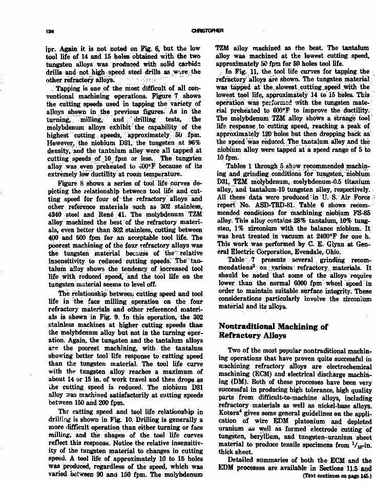
134
ipr. Again it is not noted on Fig. 6, but the lowtool life of 14 and 15 holes obtained with the twotungsten alloys was produced with solid carbidedrills and not high speed steel drills as w^re theother refractory, alloys. -.::: -';:: ~r - ip-5: ~' "
Tapping is one of the most difficult of all con-ventional machining operations. Figure 7 showsthe cutting speeds used in tapping the variety ofalloys shown in the previous figures. As in theturning, milling, and drilling tests, themolybdenum alloys exhibit the capability of thehighest cutting s speeds, f approximately 50 fpm.However, the niobium D31, the tungsten at 96%density, and the tantalum alloy were all tapped atcutting speeds of [10 fpm or less. The tungstenalloy was even preheated to •iOO°F because of itsextremely low ductility at room temperature.
Figure 8 shows a series of tool life curves de-picting the relationship between tool life and cut-ting speed for four of the refractory alloys andother reference materials such as 302 stainless,4340 steel and Rene" 41. The molybdenum TZMalloy machined the best of the refractory materi-als, even better than 302 stainless, cutting between400 and 500 fpm for an acceptable tool life. Thepoorest machining of the four refractory alloys wasthe tungsten material because of the relativeinsensitivity to reduced cutting speeds. The tan-talum alloy shows the tendency of increased toollife with reduced speed, and the tool life on thetungsten material seems to level off.
The relationship between cutting speed and toollife in the face milling operation on the fourrefractory materials and other referenced materi-als is shown in Fig. 9. In this operation, the 302stainless machines at higher cutting speeds thanthe molybdenum alloy but not in the turning oper-ation. Again, the tungsten and the tantalum alloysare the poorest machining, with the tantalumshowing better tool life response to cutting speedthan the tungsten material. The tool life curvewith the tungsten alloy reaches a maximum ofabout 14 or 15 in. of work travel and then drops asthe cutting speed is reduced. The niobium D31alloy was machined satisfactorily at cutting speedsbetween 150 and 200 fpm.
The cutting speed and tool life relationship indrilling is shown in Fig. 10. Drilling is generally amore difficult operation than either turning or facemilling, and the shapes of the tool life curvesreflect this response. Notice the relative insensitiv-ity of the tungsten material to changes in cuttingspeed. A tool life of approximately 10 to 15 holeswas produced, regardless of the speed, which wasvaried between 90 and 150 fpm. The molybdenum
TZM alloy machined as the best. The tantalumalloy was machined at the lowest cutting speed,approximately 50 fpm for 50 holes tool life.
In Fig. 11, the tool life curves for tapping therefractory alloys ate shown. The tungsten materialwas tapped at the slowest cutting speed with thelowest tool life, approximately 14 to 15 holes. Thisoperation was performed with the tungsten mate-rial preheated to 600°F to improve the ductility.The molybdenum TZM alloy shows a strange toollife response to cutting speed, reaching a peak ofapproximately 120 holes but then dropping back asthe speed was reduced. The tantalum alloy and theniobium alloy were tapped at a speed range of 5 to10 fpm.
Tables 1 through 5 show recommended machin-ing and grinding conditions for tungsten, niobiumD31, TZM molybdenum, molybdenum-0.5 titaniumalloy, and tantalum-10 tungsten alloy, respectively.All these data were produced * in U. S. Air Forcereport No. ASD-TRD-81. Table 6 shows recom-mended conditions for machining niobium FS-85alloy. This'•alloy contains 28% tantalum, 10% tung-sten, 1% zirconium with the balance niobium. Itwas heat treated in vacuum at 2400°F for one h.This work was performed by C. E. Glynn at Gen-eral Electric Corporation, Evendale, Ohio.
Table 7 presents several grinding recom-mendations3 on: various V refractory materials. Itshould be noted that some of the alloys requirelowerthan the normal 6000 fpm wheel speed inorder to maintain suitable surface integrity. Theseconsiderations particularly involve the zirconiummaterial and its alloys.
Nontraditional Machining ofRefractory Alloys
Two of the most popular nontraditional machin-ing operations that have proven quite successful inmachining refractory alloys are electrochemicalmachining (ECM) and electrical discharge machin-ing (DM). Both of these processes have been verysuccessful in producing high tolerance, high qualityparts from difficult-to-machine alloys, includingrefractory materials as well as nickel-base alloys.Kotora4 gives some general guidelines on the appli-cation of wire EDM plutonium and depleteduranium as well as formed electrode cutting oftungsten, beryllium, and tungsten-uranium sheetmaterial to produce tensile specimens from" Vu-ih.thick sheet.
Detailed summaries of both the ECM and theEDM processes are available in Sections 11.5 and
(Text continues on page 145.)

434CJ
(340 niu:)
434U(52 "cl
D6AC(56 "cl
302 SSU 7 0 BI1NI
1NCC 700
UDIMET 500(340 BUN)
RENE 41(365 WIN I
Ti 6A1-4V(312 BHN]
Ti A-110(310 BHN)
Ti B-120VCA(285 BHN)
Tr D-120VCA(365 WIN)
HOLY TZH(220 BUM)
HOLV-.5 Ti(220 BHN)
NIOBIUM D31(207 BUM)
P S S TUNGSTEN(93% DENSITY)
FORGED TUNGSTEN.95% DENSITY)
fa-1OW(220 BHN)
1
1
,
1 (14 HOLES)
Zl1 1 1
1
1
1 REFRACTORYALLOYS
1.002 .003 .004
FEED-IN./REVOLUTION
.005
KOI.Y - TZM(.!?II mini
HUI.Y - .5 TI(220 DUN)
Ti A-110(310 BHN)
Ti B-120 VCA(•100 BUN)
I I B-120 VCACB5 BHN)
Ti 6A1-4V(312 BUN)
A-286(320 BUM
4340(52 Re)
11-11(52 "c)
INCO 700(302 WIN)
UDIMET 500(340 BHN)
RENE 41(365 BHN)
NIOBIUM D31(207 BH1I)
PSS TUNGSTEN(96% DENSITY)
Ta-lOW(220 BHN)
13
V - l - 2 8 THREAD
5/16-24 THREAD, STUB TAP, 14 HOLES (400°F)
1 / 4 - 2 8 THREAD
I20 30 40
CUTTING SPEED-F7/VIN
Fig. 6 HAS. drilling aerospace alloys—Vi-ln.-dia X H-in.-deep thru hole, feedfor SO- to 100-hole drill life.
Fig. 7 Tapping aerospace alloys, relative cutting speed for tap life of 60 to100 holes, Vn-18 NC Up, 75% thread.

TABLE 1
Reoommended Conditions for Machining and Grinding Unalloyed Tungsten
Pressed and sinteredForged and reainteredArc cast
0
.005
.005
.002
Nominal Chemical Composition, %
N
.002
.001
.001
C
.010
.010
.004
Mo
.02
.02
.50
Mn
.001
.001
Si
.01
.01
Nb
.01
.01^
W
Bal.Bal.BaL
Operatior.Tool
materialTool
geometryToolused
Depth Widthof out) of cut,
in. in. Feed
Cuttingspeed,;ft/min
Toollife
Wear-land,
in.Cutting
fluid
TurningPressed and sintered93% density32-34 R,
Face millingPressed and sintered85% density90Bb
Face millingPressed and sintered93% density26 Rc
Face millingForged and reBintered96% density35 V
End mill slottingPressed and sintered93% density34 R,.
Peripheralend milling
Pressed and sintered93% density,35R,
End mill BlottingForged and resintered96% density,35 R.
C-4carbide
C-4carbide
C-4carbide
C-2carbide
C-3carbide
C-3carbide
C-3carbide
BR: -15°; SCEA: 15°SR: 0"; ECEA: 15°Relief: 5°Nfo'/atin.
AR: 0°; RR: 0°CA: 45"Clearance: 15°
AR: -15°; RR: 0°CA:45°Clearance: IS"
AR:-15°; RR: 0°CA:45°Clear ancs: 15°
AR: 0°; RR: 0"CA: 45° X .060Clearance: 12°
AR: 0"; RR: 0°CA: 45° X .060 in.Clearance: 12"
AR: 0°; RR: 0°CA: 45° X .060 in.Clearance: 12°
H-in.-squarebrazed tool bit
4-in.-diasingle-toothface mill
4-in.-diasingle-toothface mill
4-in.-diasingle-toothface mill
lK-in.-dia4-tooth carbidetipped end mill
lW-in.-dia4-tooth carbidetipped end mill
lW-in.-dia4-tooth carbidetipped end mill
.050
.080
.060
.060
.125
.125
.125
.009 in./ 200 ISmin .030 Soluble oilrev (1 : 20)
.012 in./ 100 70 in./ .016 Highly chlo-tooth tooth rinated oil i
1.250
1.5
1.250
.250
1.250
.010 in./tooth
.009 in./tooth
.003 in./tooth
.004 in./tooth
.003 in./tooth
78
142
200
140
200
27 in./tooth
39 in./tooth
45 in.
110 in.
26 in.
.030
.080
.030
.030
.030
Highly chlo-rinated oil
; ~i "w ' ' ' • ' • '
Soluble oil(1 : 20)
Soluble oil(1 :20)
End milling: done with
workpiece ternperatureof800°F
Soluble oil(1 : 20)

DrillingPressed and sintered93% density34 R,
C-2carbide
Drilling C-2Forged and resintered carbide96% density35 R,
DrillingArc east99% density31 Re
TappingPressed and sintered96% density34 R,
C-2carbide
M-10HSS
Wheel grade
32A46N5VBE32A46N5VBE
118V90" notchedpoint
7° clearance
U8V90" notchedpoint
7° clearance
118^90° notchedpoint
7° clearance
4-flute specialstub type plugtap, 76% thread
Grinding Hold
KNOjjBolutionHighly sulfuri-ied
oil
.213-in.-dia29 s helix anglesolid carbidedrill
.213-in.-dia29° helix anglesolid carbidedrill
.213-in.-dia29T helix anglesolid carbidedrill
V16-24NF
W-in.thru
fc-in.thru
W-in.thru
H-in.thru
Surface Grinding
Wheel apeed,ft/min
20002000
Table speed,ft/mln
4040
.002 in./rev
.002 in./rev
.002 in./rev
Down feed,in./pasa
.0005.0005
125
150
150
5
14 holes
15 holes
9 holes
14 holes
Crow feed,in. /pau
.050
.050
.030
.030
.030
Gratia
5.02.6
Highly chlo-rinated oil
Highly chlo-rinated oil
Highly chlo-rinated oil
- ' " ' • • •
Tapping done\ with work-
piece temper-ature of 400-F

TABLE 2
Recommended Conditions for Machining and Grinding Niobium D-31 Alloy, 207 BHN
(Nominal chemical composition: Ti, 10.0%; Mo, 10.0%; Nb, balance)
OperationTool
materialTool
geometryToolused
Depthof cut,
In.
Widthof cut,
in. Feed
Cutting•peed,ft/min
Toollife
Wear-land, Cutting
In. fluid
Turning
Turning
Face milling
Face milling
End millslotting
Drilling
Reaming
Tapping
M-2HSS
C-2carbide
SuperHSS
C-2carbide
T-15HSS
M-lHSS
M-2HSS
M-10HSS
BR: 0°; SCEA: 0°SR: 20°; ECEA: 5°Belief: 5°NR:'/«in.
BR: 0°; SCEA: 0°SR: 20°; ECEA: 5°Relief: 5°
AR: 0°; ECEA: 5°RK:20°CA:45°Clearance: 10°
AR: 0°; ECEA: 10°RR: 10°CA: 45°Clearance: 10°
Helix angle: 30°RR: 10°Clearance: 10°CA:45°
118° plain point7° clearance
10° RH helixCA: 45°Clearance: 10°
2-flute chipdriver tap,75% thread
H-in.-squaresolid HSS
H-in.-squarebrazed tool bit
4-in.-diasingle-toothface mill
4-in.-diasingle-toothface mill
Vi-in.-dia4-toothHSS end mill
125-in.-diadrilll'A-in. long
.213-in.-dia6-flute chuckingreamer
V. in. 28 NFtap
.030
.030
.030
.030
.060
tt-in.thruhole
fc-in.thruhole
V4-in.thruhole
IK
2
.500
.010depthon holeradius
-
.005 in./rev
.005 in./rev
.010 in./tooth
.010 in./tooth
.003 in./tooth
.005 in./rev
.005 in./rev
-
60
300
135
150
100
75
125
12
40+min
40+min
50+ in./tooth
90 in./tooth
200+ in.
175+holes
105holes
50 holes
.030
.010
.016
.016
.008
.008
.012
-
Soluble oil(1:20)
Soluble oil(1:20)
Highly chlo-rinated oil
Highly chlo-rinated oil
Highly chlo-rinated oil
Highly chlo-rinatedoil
HighlyRulfurizedoil
Highly chlo-rinatedoil
Wheel grade
32A46K8VBE32A46K8VBE32A46K8VBE
Grinding fluid
5% KNO8 solution5% KNOj. solutionSoluble oil (1 : 20)
Surface Grinding
Wheel ipeed,ft/min
2000*40004000
Table ipeed,ft/min
404040
Down feed,in./pau
.005
.001
.001
Cross feed,in./pas8
.025
.050.050
G ratio
7.54.53.5
•If wheel Bpeed of 2000 ft/min is not available, use conditions for wheel speed of 4000 ft/min.

MACHNNG REFRACTORY ALLOYS—AN OVERVEW 138
i/l
60. -i
56. -
40. A
ill 39. H
§
10. -
0, 200. 400. 600.CUTTING SPEED-FT/M1N
800.
Fig. 8 Relationship between tool life and cutting speed in the turning operation.
125 . -i
mJr 100. -
O
75. h^ : \/ 302 STAINLLJS STEEL
HI
1 50.i
LU
25. -oo
0 .
MOLYBDENUM TZH
4340 52 Be
200. 400. 600.CUTTING SPEED-FT/MIN
800,
Fig. 9 Relationship between cutting speed and tool life in the face milling operation.

TABLES
Recommended Conditions for Machicing and Grinding TZM Molybdenum, 217 BHN
(Nominal chemical composition: Ti, 0.50%; C, .015%; Zr, 0.08%; Mo, balance)
Operation
Turning
Turning
Face milling
Face milling
End millslotting
End millperipheralcut
Drilling
Reuming
Tapping
Toolmaterial
C-2carbide
C-2carbide
T-15HSS
C-2carbide
T-15HSS
M-3HSS
M-33HSS
M-2HSS
M-10HSS
Toolgeometry
BR: 0°; SCEA: 15°SR: 20°; ECEA: 15°Relief: 5°NR: Varin.
BR: 0°; SCEA: 15°SR: 20°; ECEA: 15°Relief: 5°NR: Vsrin.
AR: 0°; ECEA: 10°RR:20°CA:45°Clearance: 15°
AR: 0°; ECEA: 5°RR:0°CA:45°Clearance: 10°
Helix angle: 30°RR: 10°Clearance: 10°CA:45°
Helix angle: 30°RR: 10°Clearance: 10°CA:45°
118° plain point7° clearance angle
Helix angle: 0°CA:45°Clearance: 10°
4-flute plug,75% thread
Toolused
%-in.-Bquarebrazed tool kit
%-in.-squarebrazed tool bit
4-in.-diasingle-toothface mill
4-ia.-diasingle-toothface mill
«-in.-dia4-toothHSS end mill
K-in.-dia4-toothHSS end mill
.250-in.-diadrill,2V4 in. long
.272-in.-dia6-flutechucking reamer
V16in.24NFtap
Depthof cut,
in.
.030
.060
.060
.060
.125
.125
14-in.thruhole
thruhole
V4-in.thruhole
Widthof cut,
in.
-
2
2
.750
.750
"
.010-in.depthor. holeradius
-
Feed
.009 in./rev
.009 in./rev
.010 in./tooth
.005 in./tooth
.004 in./tooth
.004 in./tooth
.005 in./rev
.015 in./rev
-
Cuttingspeed,ft/min
450
350
100
350
190
190
150
60
70
Toollife
25min
20min
70 in./tooth
100 in./tooth
78 in.
142 in.
68 holes
51 holes
100+holes
Wsar-land,
in.
.010
.010
.015
.015
.012
.012
.015
.012
-
Cuttingfluid
Soluble oil(1 :20)
Soluble oil(1 : 20)
Soluble oil(1:20)
Soluble oil(1 :20)
Soluble oil(1:20)
Soluble oil(1 :20)
Highly chlo-rinated oil
Highly chlo-rinated oil
Highly chlo-rinated oil

Surface Grinding
Wheel grade
32A46N5VBE32A46L8VBE
Grinding fluid
5% KNOZ solution5% KNO2 solution
Wheel speed,ft/min
2000*4000
Table speed,ft/min
4040
Down feed,in./pass
.001
.001
Cross feed,in./pass
.050
.050
G ratio
2513
•If wheel speed of 2000 ft/min is not available, use conditions for wheel speed of 4000 ft/min.
TABLE 4Recommended Cutting Conditions for Machining and Grinding Mo-0.5 Ti Molybdenum Alloy
(Nominal chemical composition: Ti, 0.45%; C, .020%; Mo, balance)
Operation
Turning
Face milling
Drilling
Reaming
Tapping
Toolmaterial
C-2carbide
C-2carbide
M-lHSS
M-2HSS
M-10HSS
Wheel grade
32A4W8VBE
Toolgeometry
SR: 20°; SCEA: 15°BR: 0°; ECE.': 15°Relief: 7°
AR: 0°; ECEA: 10'RR: 0°; Cl: 15°CA: 45°
2-flute, 118°plain point.
7° clearance
10° RH hehx45° CA10° clearance
2-flute chipdriver tap,80% thread
Grinding fluid
Soluble oil (40 : 1)
Toolused
W-in.-squarebrazed tiptool bit
4-in.-diasingle-toothface mill
,193-in.-diadrill,2'A-m. long
6-flute straightshank chuckingreamer
M-in. 28 NF
Depthof cut,
in.
.060
.060
.500thruhole
.500thruhole
.500thruhole
S. rface Grinding
Wheel speed,ft/min
4000
Widthof cut,
in.
-
2
-
.010depthon holeradius
Table speed,ft/min
40
Feed
.009 in./rev
.005 in./tooth
.005 in./rev
.015 in./rev
Down feed,Ln./pass
.001
Cuttingspeed,ft/min
300
225
100
85
56
Cross feed,in./pass
.050
Toollife
25min
120 in.
100holes
45holes
100+holes
Wear-landin.
.010
.012
.012
.010
Tap stillcutting
G ratio
3.3
Cuttingfluid
Soluble oil(20:1)
Soluble oil(20: 1)
Highly chlo-rinated oil
Highly chlo-rinated oil
Highly chlo-rinated oil

142 OffBTOMER
125. T
50 . 100. 159.CUTTING SPEED-FT/MIN
200.
Fig. 10 Relationship between cutting apeed and tool life in the drilling operation.
LU_ lOX
IUiLL
a.a
125. -i
100. -
75.
50.
25.
0 .
MOLYBDENUM TZM
0 . 20. 10. 60.CUTTING SPEED-FT/MIN
8 0 ,
Fig. 11 Relationship between cutting gpeed and tool Ufa in the tapping operation.

TABLES
Recommended Conditions for Machining and Grinding 90 Ta-10 W Tantalum Alloy, 207-241 BHN
(Nominal chemical composition: Ta, 89%; W, 10%)
Turning
Turning
Face milling
End millslotting
End millperipheralcut
Drilling
Toolmaterial
M-2HSS
C-i.carbide
SuperHSS
T-15HSS
M-2HSS
M-lHSS
Toolgeometry
BR: 0°; SCEA: 0°SR: 20°; ECEA: 5°Relief: 5°NR: VM-in.
BR: 0"; SCEA: 0"SR: 20°; ECEA: 5°Relief: 5°NR: VM-in.
AR: 0°; ECEA: 10°RR:20°CA: 45°Clearance: 10°
Helix angle: 30°RR: 10°Clearance: 15°CA: 45° X .040 in.
Helix angle: 30°RR: 10°Clearance: 6°CA: 45° X .040 in.
118° plain point7° clearance angle
Toolused
%-in.-squareBolid HSS
%-in.-squarebrazed tool bit
4-in.-diasingle-toothface mill
V4-in.-dia4-toothHSS end mill
V^-in.-dia,4-toothHSS end mill
.125-in.-diadrill,2%-in.-long
Depth,of cut,
in.
.030
.030
.030
.060
.060
tt-in.thruhole
Widthof cut,
in.
-
1.125
.500
.500
Feed
.009 in./rev
.009 in./rev
.010 in./tooth
.002 in./tooth
.002 in./tooth
.002 in./rev
Cuttingspeed,ft/min
50
75
80
70
65
50
Toollife
44min
27min
53 in./tooth
80 in.
70 in.
125holes
We»x-land,
in.
.030
.010
.016
.012
.012
.015
Cuttingfluid
Soluble oil(1:20)
Soluble oil(1:20)
Soluble oil(1:20)
Soluble oil(1:20)
Soluble oil(1:20)
Highly chlo-rinated oil
t

TABLE 6Recommended Condition* for Machining Niobium FS-86 AUoy*
(90 Rb hardened)
Tool Tool Took Depth, Feed,Operation material geometry oied in. ipr
Patting•peod,
•fmToollife
Toolwear,
in. Fluid Eenurka
Turning
Turning
Endmilling
Drilling
Drilling
Drilling
Grinding
Carbide883
HSSM42
HSSM42
HSSM42
HSSM42
HSSM42
A1A
SR 15"; BR: 0°SCEA: 15°Relief: 6°; NR: .06
SR: 15"; BR: 0°SCEA: 15°Relief: 6°; MR: .06
30° helix25-30° axial0° radial
30° helix30° axial
30° helix30° axial
3G° helix30° axial
97A60I6VFM
ToolholderKSDR85C
ToolholderKSDR 85C
4-fluta1.0-in. diaW-in. radius
NAS907TypeJW-in.-dia
NAS907TypeJVffl-in. dia
NAS907TypeJ%,-in. dia
10-in. dia X1 in. X 3 in.
.030
.030
.020
M-in.thru
.089thru
.089thru
.0002D/F
.008
.005
.001C/T
.002
.0002
.0005
.050C/F
140
110
80
39600 rpm
.182200 rpm
291800 rpm
3120
27
24
50
35
16holes
61holes
-
.005
.015
.020
.002
.002uniform
.004local
.001
4.0G ratio
Trimsol,20 : I
Trimsol,20: 1
—
Trimsol,mist
Trimsol,miBt
Trimsol,wist
Oil,Gl&S
Higher speedsup to 400 Bfm;poor finish
Higher Bpnedsup to 150 Bfm;poor finish
No surface scratchsa with 10* axial
Rings in holes;finish may requireflooded cutting oilor reaming
Tool broke on17th hole
Stopped test;chattered;chip welding
30to50rms
•Work performed by Glynn,3 Conventional Machining Laboratory, General Electric Company, Evendale, Ohio, 1973.

MACHNNG REFRACTORY ALLOYS—AN OVERVEW 146
TABLE 7
Grinding Refractory Alloy*
Operation
CylindricalCylindricalCenterlessCenterlessCenterless
-
SuifaceCylindrical
CenterlessSurfaceSurface
SurfaceSurface
Cylindrical
Alloy
Mo-05Ti50Mo-50WPure MoPure Mo70 Mo-30 W
-
Pure WPure W
Pure W99 Nb-1 ZrZr & alloys
Zr & alloysZr & alloys
Zr & alloys
Wheelgrade
A60H9VA60H9VC36IBC320L8EC60H11VC80H11V
C3U4VC60I8V
C60J4VA60H8VC60K5V
C100N7VA80M8V
C60K4V
Wheelsneedor
work speed
6000 fpm6000 fpm650 rpm370 rpm120 rpm200 rpm
80005300/
150 rpm650060001500/3500
16C03500
1500/3500
Infeed ordownfeed,
in./pan
.001
.001---
.0005
.001
.025
.001--_
-
Crossfeed.
in./paw
.030R/.010F
.030--
-
.030-
.032-_
-
Table speed,fpm
507055 ipm30ipm60 ipm60 ipm
50 ipm-
-50
-_
-
Grindingfluid
Water baseW/B, det.
--
Water baseWater base
W/B, det., 1: 402.5% nitride
amineW/B, det.W/B or dryOil
Oil10% nitride
amine-
Surface finish,RA
13R/7F7/2090560/908
1420/40
1730/9025
_-
-
12.5 of the Machining Data Handbook5 By follow-ing the guidelines in these two process summariesand using the correct equipment, high toleranceparts can be machined using these two nontradi-tional processes from virtually any refractory alloythat is electrically conductive. [The editors havechosen not to reprint these two sections of thehandbook. Interested readers are encouraged toreview this information.]
REFERENCES1. N. Zlatin, M. Field, and J. Gould, Technical Report an
Machining Refractory Materials, Technical Documentary
Report No. ASD-TRD-581, USAF Contract 33(600)-42349,Wright Patterson Air Force Materials Laboratory, July1963.
2. C. E. Glynn, Machining of Columbium (FSS5 Alloy), FPDGeneral Electric Corporation, Evendale, Ohio.
3. Machining Difficult Alloys, Chapter 20, pp. 229-244, spon-sored by the U. S. Air Force, ° American Society forMetals, 1962.
4. John Kotora, Jr., Machining Exotic Materials with EDM,Rpt. SME (ASTME) MR68-901, Argonne National Labora-tory.
5. Machining Data Handbook, 3rd Ed., Vol. 2, Metcut ResearchAssociates Inc., Cincinnati, Ohio, 1980.

Welding of Refractory Alloys
G. G. LeasmannWestinghouse Research and Development Center
INTRODUCTION
This review primarily summarizes welding evalua-tions supported by the National Aeronautics andSpace Administration-Lewis Research Center inthe 1960s.
A literature search run in preparation for thisreview indicates that more recent work is modestby comparison. Hence, this review restates thesaaccomplishments briefly and addresses opportuni-ties which have evolved in welding technology(such as lasers) in the intervening decade.
Emphasis in this review is given to tantalum-and niobium-base alloys. These were perceivedthen, as now, as the most promising structuralmaterials for Rankine cycle space power systemsusing liquid metal working fluids. Considerablework was also done to assure that a consistentcomparison was made with tungsten. Thus, tung-sten was recognized for its potential for very hightemperature operation despite practical fabricationproblems associated with its high ductile-to-brittletransition temperature.
These evaluations were extremely thorough butin a focused and practical manner. A wide varietyof candidate alloys derived primarily from develop-ments directed at aircraft propulsion applicationswere available. Early efforts by NASA weredirected at screening studies to select promisingstructural alloys for the space power application.This objective required fine tuning of welding pro-cedures, e.g., the demonstration of stvingent stan-dards for control of welding atmosphere to assuregood co.-rosion resistance in liquid alkali metals.These guidelines remain today as definitive meth-odology for welding react'.ve and refractory metalalloys.
Eventually, the trade-off requirements for useof these materials in terms of fabricability and
creep strength (primarily) were resolved, andemphasis was given to tantalum-base alloys whichcombined fabricability, toughness, and high tem-perature creep strength. The evaluation of tungsten(and the W-25Re alloy) continued quite indepen-dent of fabricability considerations because of itshigh temperature potential. A special aspect of thiswork was the screening of these materials forlongtime structural stability (10,000 h at 1315°C).
Special tools useful to the welding engineerwere also perfected in these programs. Examplesinclude adaptation of the Varestraint test torefractory metal welding for sheet thickness;conci3e methods for using the bend test as an inex-pensive screening tool for quality and process con-trol as well as a sensitive weldability test; anappreciation for weldability trade-offs in alloydevelopment including creep strength as related tomultipass welding; and methods for control ofwelding atmosphere and the influence of materialsand component designs in inert gas handling sys-tems.
The bibliographies of this report and otherspresented at this meeting represent substantiallythe basis for the current technology status forwelding refractory metal alloys.
ALLOY TECHNOLOGY STATUS
BackgroundIt is doubtful that one would characterize the
refractory metal alleys as commercially available.Most likely, they would be supplied on a single-lotbasis with close technical following to substitutefor the confidence attributed to the more commonuse of well-established specifications. The designerand fabricator can be expected to play a more inti-
146

WELWNQ OF REFRACTORY ALLOYS 14T
TABLE 1
Alloy IdttttifUatteii
AUoy*
Nb-lZrAS-55B-66C-129YCb-752D-43FS-85SCb-291D43 + YT-HlT-222ASTAR 811CTa-lOWW-25ReWW-25Re-30Mot
Nominal eompocitioti, wt%
Nb-lZrNb-5W-lZr-O.06C -1- YNb-6Mo-W-lZrNb-lOW-lOHf + YNb-10W-£5ZrNb-lOW-lZr-O.lCNb-27Ta-10W-lZrNb-lOW-lOTaNb-10W-lZr-0.1C + YTa-8W-2HfTa-9.6W-2.4Hf-O.01CTa-8W-lBe-lHf-0.02CTa-lOWW-2SReUnalloyed
•All alloys from arc-cast and/or electronbeam melted material.
t(a/o), all other (w/o).
mate role than normal in following material fromingot to finished product. Because we can antici-pate alloy modifications in the future, the user cangain some insight into the future based on the met-allurgical background of the many alloy systemsgiven early consideration.
An early grouping of available alloys is given inTable 1. This list at first appears formidable butsimplifies very easily because of similarities iumetallurgical behavior. The list simplifies even fur-ther because the tantalum-base alloys have themost promise based on high temperature creepstrength and fabrieability. Among the niobium-base alloys, only the most fabricable and simple,such as the Nb-lZr alloy, are of interest and onlyfor lower temperature application. The two tung-sten alloys remain aloof—very difficult and riskyin fabrication.
Phase relationships in these alloys, which arebasically uncomplicated, prove helpful in under-standing these alloys. Complete solid solubility isdemonstrated by all combinations of Nb, Mo, Ta,W, and V as employed in these systems. Hence,these are mutual single-phase solid solutionstrengtheners. The predominant element of thisgroup in both the niobium and tantalum alloys istungsten. Two niobium alloys also contain tan-talum, and one contains molybdenum and vana-dium instead of tungsten.
One cr the other of the reactiveelements—zirconium or hafnium—is a necessarycomponent in all the high strength niobium and
tantalum alloys. These form complex systems withthe other elements but are alloyed at levels belowtheir equilibrium solid solubility limit Hence,wrought structures are single phase, while coredweld structures may be multiphased.Strengthening is realized through both solid solu-tion and dispersion because hafnium and zirconiumtend to form very stable precipitates with theresidual interstitials. Reactive metal additionsenhance corrosion resistance in alkali liquidmetals.
Several alloys also contain intentional carbonadditions. These alloys respond to thermal treat-ment during processing and realize their strengthin part from carbide dispersions. In this respect aknowledge of the probable phase relations isimportant, and many of these relationships havebeen investigated.
Additions of minor amounts of yttrium in sev-eral niobium alloys provide an interesting modifi-cation of mechanical properties resulting primarilyin improved ductility. Yttrium is essentially insolu-ble in niobium and is very reactive with oxygen.Hence, the most probable mechanisms forimproved ductility are an effective reduction inmatrix oxygen level by preferential combinationwith yttrium, purification during melting andwelding by slagging of the oxide, and grain refine-ment resulting from the presence of the highly sta-ble oxide. The grain refining influence of yttrium isevident in as-received material. AS-55 and C-129Yare recrystallized at the highest temperatureamong the niobium alloys yet they have the small-est grain size.
Rhenium in tungsten is an unusual solid solu-tion addition which improves ductility. Rheniumadded to ASTAR-811C is a substitute strengthenerallowing reduction in the hafnium for improvedhigh temperature creep strength.
A simplified summary indicates'that the mostpromising alloys are the family of alloys T-lll,T-222, and ASTAR-811C for high temperaturecreep. These alloys have tungsten and rhenium forsolid solution strengthening, hafnium or zirconiumfor liquid metal corrosion resistance and dispersionstrengthening, and some have additional carbon fordispersion strengthening. The Nb-lZr alloy is ofmost interest among the niobium alloys because ofgood fabricability and corrosion resistance.
Welding Processesi
The processes which have been selectedcorrectly for welding the refractory metal alloyscan be classified as the nonccmsumable electrodeprocesses. These are typified by gas tungsten arc

148 LE88MANN
welding and electron beam welding. Laser weldingcan now be added as a typical method to consider.The weld joint designs are typical of those with anautogenous chemistry. Welds are either fusionwelds joining two parts without filler metal, or, iffiller wire is used, it is of base metal composition.The exception is that several of these alloy systemsare weldable aa bimetals as discussed later. Also,special case joining processes are possible: hot iso-static pressure welding, inertia welding, explosivewelding, plasma and resistance welding.
Any welding process must provide freedomfrom interstitial and metallic contamination. Thepotential for metallic contamination is minimizedby proper joint preparation (machining followed bypickling), careful handling, and special inserts inholding fixtures. Interstitial contamination is lim-ited primarily by control of the welding atmo-sphere.
Welding Atmosphere ControlThe refractory metal alloys are extremely reac-
tive and act as getters when heated in contami-nated atmospheres. Contaminants are taken intosolution in the weld with a resultant loss in ductil-ity, liquid metal corrosion resistance, usually a lossin strength, and a change in thermal stability.Optimum shielding gas quality control reduces therisk of unpredictable behavior of welds in service.Good data are available to quantify the contamina-tion effects.1 The bend test ductile-to-brittle transi-tion temperature provides a sensitive indication ofthe effect of oxygen and nitrogen contamination.The bend test is described in Fig. 1; the sensitivityto oxygen pickup in welds and base metal is shownin Fig. 2.
With careful control of the welding atmosphere,very little contamination of welds occurs.2 As anexample, an overnight pumpdown cycle on avacuum-purged weld chamber complemented by a90°C chamber bakeout yields a vacuum of<5 X 10~6 torr and <3 X 10"5 torr/min leakrate. An ultrahigh purity helium backfill producesan atmosphere with <1 ppm total impurity leveland permits several hours of welding with oxygenand moisture each held at <5 ppm. Niobium andtantalum alloys welded in this atmosphere show nopickup of nitrogen or carbon within 95% confi-dence limits and actually show a loss in oxygencontent between 16 and 40 ppm.
The use of oxygen and moisture monitors per-mitted the development of very definitive guide-lines for management of shielding gasatmospheres.3 The basic results are unchangedtoday except that better atmosphere monitors
LONGITUDINALBEND
100
eo
60
40
20
DUCTILE BENDS
| DUCTILE-BRITTLE• BEND TRANSITION1 TEMPERATURE - 7 0 ' C
FRACTURE
200 -150 -100n i l I I
-50 50
-300 -200 -100 6 100TEST TEMPERATURE
100 °C
200 "F
NOTE: ARROWS SHOW ROLLING DIRECTION
THICKNESS, t = 0.9 mmWIDTH = 12tLENGTH - 24tTEST SPAN = 15t
PUNCH SPEED = 1 IPMTEMPERATURE - VARIABLEPUNCH RADIUS - I t
Fig. 1 Bend test description.
make atmosphere control much simpler than waspossible 20 years ago. The stability of the weldingatmosphere after backfilling of a vacuum-purgedweld chamber is summarized for various purgecycles in Figs. 3, 4, 5, and 6. The most importantconclusion that can be drawn from these results isthat control and monitoring of welding atmo-spheres is an entirely realistic requirement inwelding refractory metal alloys. Other conclusionsdrawn from this reference are:
1. By using optimum evaluation and backfill-ing techniques, a high quality weldingatmosphere having <1.25 ppm total activeimpurities can be obtained in vacuum-purged chambers. Following backfilling, the

WELDING OF RffHACTORY ALLOYS 148
1000 [-
4 X
200
0
-200
-400
4.-A- -r200
100
o
-100
-200.. I -300
| . o o o j -
z2 2X
e
£ -200
J, -400
200 <00 600 800
2
£ ;
1000
— 1(538 <
•A200 5
z100 2
o i
-100 ^
-200 ~
-300 E200 400 600 BOO
MANUAL WATER COOLED,TYGON INSULATeD TORCH INSTALLFD
ULTIMATE PRESSURE ANUIEAK SATE LISTED
BllIYIRUBBER5 * 1C"6 ion
01 t i /MIN)
I 4 6 b I? 12 14 16 IB
TIME, HOURS AFTER BACKFILLING CHAMBER
2! 24
6UJ.894A
Fig. 3 Effect of glove material on oxygen contaminationrcte.
r
200 400 600 BOO 1000 l?00 J-300
4000 6000
ATOMIC,
10.000 >2.00C
KEY
1000°f - 538°C . HIGHEST TEST TlMPf"*TU«E
-32O"F--195°C = LO*ES. TEST T!MPi»*TU«E
O = UN^ILDED
• • MELDED
1800°F - 98O°C DlP'L'S'ON AN*4:ALING TEMP.
Fig. 2 Bend ductility vs. oxygen content for 3 alloys.
Welding atmosphere gradually deteriorates,permitting 6 or more hours use dependingon the contamination limit established forthe particular run.
2. The sources of moisture and oxygen con-tamination in weld chamber atmospheresdiffer considerably. Consequently, thesecontainments are not related ard must beconsidered independently.
3. The oxygen level in the backfilled weld
24 -
n -
20
18
MANUAL WATER COO1FD TYiJ"'~1 IN5IILA7FIIIo«CH INSTALLED
ULTIMATE PRESSURE AND LEAK RATE LISTED
\
LATEX NATURAL RUBBER 7 K 10 lofr ( . 0 0 7 p / M I K
CEMENT NEOPRENE 2 « l o " 6 lorr ( .01 H / M I N )I I I I I I 1
6 8 10 12 14 16 18 20 72 24
TIME, hOURS AFTEK BACKFILLING CHAMBER 60489SA
Fig. 4 Effect of glove material on water vapor contamina-tion rate.
chamber atmosphere depends on the gasquality, weld box tightness, a moderateevacuation of 10~4 to 10~5 torr, and thebackfill techniques employed. The oxygenlevel increases following backfilling mainlyby diffusion through the weld box gloves.

160 LESSMANN
26
24
22
20
18
16
U
o 10>5 8
MANUAL WATER COOLED I Y G O N INSULATEOTORCH INSTALLED
ALL GLOVES CEMENT NEOPRENE
ULTIMATE PRESSURE, LEAK BATE, ANDEVACUATION TIME LISTED
•CORRECTED VACUUM GAGE FOR HELIUMSENSITIVITY
DOUBLE EVACUATION WITH He PURGE2.5 < I0"5 >"r (.27 H/KAIN) 1ST EVAC.
2 . 6 . 10 tor. ( ,26 , j /MIN)52 MIN.
(.01 p/MIN) 18 HOURS
I I,0 1 2 3 4 5 6
TIME, HOURS AFTER BACKFILLING CHAMBER
Fig. 5 Effect of evacuation pressure on oxygen contami-nation rate.
4. Low moisture levels in the backfilled weldchamber atmosphere are obtained by usingextended pumpdown cycles, convenientlyovernight for 16 to 18 h, to the low 10~6
torr range. Atmosphere stability withrespect to this impurity is enhanced bylonger and lower pressure pumpdownsbecause outgassing of the chamber interiorand tooling surfaces is the primary sourceof moisture.
5. The leak rate (pressure rise rate of a sealedchamber) is an excellent measure of theadequacy of a pumpdown cycle because itrepresents the sum of leakage and outgas-sing rates. Hence, a low leak rate assureslow moisture and oxygen rise rates in thebackfilled chamber. A 1 min pressure risein the evacuated chamber of 3 X 10~5 torris required for reasonably good stability ofthe backfilled chamber atmosphere. In thisrespect, double purge cycles are not benefi-cial. Contrary to a widely held opinion,welding can be accomplished under aslightly negative pressure (below 1 atm)without increasing the contamination rateif a good leak rate is obtained and soundgloves are used.
6. Nitrogen as a contaminant appears to bepresent in the weld atmosphere in roughlythe same ratio with respect to oxygen as inair. Hence, oxygen can be monitored and
DOUBLE EVACUATION WITH HePURGE2.5 x I0"5 lotr (.27 (i/VHN)
1ST EVACUATION6.5 x ID"5 loci (.60|</MIN)
•2NO EVACUATIONtO M I N . TOTAL
MANUAL WATEK COOLED, TyGONINSULATED TORCH INSTALLED
ALL GLOVES CEMENT NEOPRENE
ULTIMATE PRESSURE. LEAK RATE, ANDEVACUATION TIME LISTED
•CORRECTED VACUUM GAGE FORHe SENSITIVITY
i— ( 0 1 H / M I N )
/ 18 HC
0 1 2 3 4 5 6
TIME, HOUS5 AFTES BACKFILLING 'HAMBER
Fig. 6 Effect of evacuation pressure on water vapor con-tamination rate.
nitrogen contamination assumed by impli-cation to be 4 times the oxygen level. Thesource of nitrogen, like oxygen, must be airleaks and diffusion through gioves.
7. Other active atmospheric contaminantsthat are not generally airborne, such ashydrocarbons, are avoided by judiciousselection of materials, lubricants, andcleaning techniques for internal chambercomponents.
8. Neoprene gloves provided the best overallperformance of those tested except in spe-cial applications where sulfur contamina-tion may be detrimental. All the glovestested were permeable to air. Kence, for thesame size and thickness glove, the greaterthe number of gloves used and the smallerthe weld chamber the more rapid will bethe deterioration of a weld box atmosphere.
Weldability
The weldability of refractory metal alloys asdefined by weld quality and variability of weldproperties has been studied in some detail.2*4 A dis-cussion of the results is handled most easily bygrouping the tantalum and niobium alloys together

WB-DWQ OF REFRACTORY ALLOYS 161
as fabricable alloys and by discussing the tungstenalloys separately as special purpose high tempera-ture materials which are difficult to fabricate.
Basic weldability is defined primarily as theability to produce defect-free welds over a reason-able range of parameters, material thicknesses,and configurations. This was accomplished bywelding both sheet and plate materials in bothunrestrained and restrained configurations.
An extended but very important definition ofweldability is the sensitivity of weld properties towelding parameter variation. Alloy systems werecategorized and compared by using the bendductile-to-brittle transition temperature (Fig. 1) asa sensitive indicator.
This review avoids presentation of great detailon weldability by first presenting the conclusions ofLessmann2 and then dwelling only on selectedmajor aspects. Fabrication using most of thesealloys is very practical as can be recognized fromthe following conclusions.
• Good weldability was exhibited by theniobium and tantalum alloys as demonstratedby restrained weld tests and general accom-modation in welding both sheet and plate.Weldability limitations were exceeded for sev-eral alloys as described later. Room tempera-ture and elevated temperature weld strengthapproached base metal strength for thesealloys demonstrating joint efficiencies at alltemperatures of nearly 100%. Within therespective alloy groups, FS-85 and T-lll dem-onstrated superior combinations of strengthand fabricability.
• Welding resulted in a loss of ductility in allalloys as measured by the bend ductile-to-brittle transition temperature. The compara-tive degradation of ductility occurring withwelding provides a convenient measure ofweldability in these systems. Piste weldabil-ity was comparable to sheet weldability forthe more fabricable alloys. However, with theless weldable alloys, adverse welding charac-teristics were exaggerated in plate welding.
• Tantalum alloys were considerably less sensi-tive to welding than niobium alloys and, as aresult, have superior fabricability. Tungstenwas not easily welded because of brittlenessat room temperature: W-25Re is hot tear sen-sitive as well as brittle.
• Niobium alloy weld behavior was rationalizedwith a thermal response analysis. Weldingconditions that tend to stimulate developmentof the heat-affected zone and grain size inthis zone increase the weld ductile-to-brittle
transition temperature. Weld process andmetallurgical factors combine such that aheat input threshold for ductility impairmentis observed foi alloys which are dispersionstrengthened. With increased grain stability,as realized with the yttrium-modified alloys,this threshold occurs at a higher heat input.The solid solution alloy did not display thisthreshold but rather a continuous ductilityloss with increasing size of the heat-affectedzone.
• The thermal analysis interpreted in terms ofa heat input threshold provided a sensitiverationale to which the general improvedductility of electron beam welds can beascribed.
The differences between these alloys in terms ofsensitivity to welding are summarized in Fig. 7.Several important characteristics can be compared.
• Maximum transition temperature: lower isbetter.
• Increase in transition temperature comparedto base metal: less is better.
• Total spread in transition temperature: less isbetter because it implies less sensitivity towelding variations.
Hence, an excellent measure of weldability in theconventional sense was provided in the weldductility response study.
The inherent flexibility in selecting weldparameters which produce sound welds can begaged from the data summarized in Table 2. Thepercent of acceptable welding conditions is listedfor each alloy along with the defect source of unac-ceptable welds.
An electron beam process limitation for mostalloys at the highest welding speed of 100 ipm wasevidenced by welds having unacceptable contours.Some alloys also welded poorly at other electronbeam parameter combinations. In this respect, B-66welded with difficulty presumably because vana-dium tends to boil off more readily than otheralloying elements.
B-66 also welded with greater difficulty in bothmanual and automatic arc welding due to a hottearing tendency. This alloy is a classic example ofthis effect, which results from an excessive freez-ing point depression and liquidus-solidusseparation.5
Arc welds in C-129Y welded at the highestspeed had gross shrinkage defects indicating a lim-itation in welding this material. D-43Y tended tohot tear along the weld centerline, have porosity,and crack (transverse) during welding. Porosity

152 LHSSMANN
900
800
700
600
500
400
300
200
0
-100
-200
-300
BASE
E.B.
GTA
C-129Y
1
11
BASE
E.B.
GTA
SCb-29
r*2t
ii
BASE
E.B.
GTA
FS-B5
1/
HIGHfcbl Ibbl /TEMPERATURE — '
I
• 1
BASE
E.B.
GTA
Cb-752
_L
BASE
E. B
.GT
A
D-43Y
I11
BASE
E.B.
GTA
AS-55
BASE
E.B.
GTA
B-66
/
BASE
E.B.
GTA
D-43
(Owtai i t n,—TEMPERATURE
/ -320 °Ft-S:BA
SEE.
B.GT
AT-111
1
BASE
E.B.
GTA
To-lOW
-f-
BASE
E.B.
GTA
T-222
1\
1k
BASE
E.B.
GTA
W-25R*
>
\v-
—
n
Y
—
-
BASE
E.B.
GTA
W
— 500
— 400
- 300
200
g
100 I
- 0
- -100
= -200
* - All bends H radiui except as noted.
Fig. 7 Summary of bend test results for gas tungsten arc and (ilectron beam butt welds in 0.05-in. sheet Twelve weld-ing conditions for each alloy and process. Weld tested in both longitudinal and transverse directions.
also occurred extensively in the unmodified D-43but was controllable, as explained later in thisreport, by special joint preparation. All threeyttrium-modified alloys demonstrated a weldcenterline weakness, the source of which is notapparent but is presumed to be an effect ofyttrium.
Tungsten and W-25Re welded with difficultybecause of high transition temperatures. Thisresulted in fracturing on weld cooling to ambienttemperature. Electron beam welding was not apanacea in this respect, performing a little worsethan gas tungsten arc welding. For both processesslower speeds and. hence, higher heat inputs pro-vided solid welds. In contrast, the thermal shockassociated with faster speed, low heat input, andthe brittleness of these alloys produced defectivewelds. Cleavage cracks occurred in both the longi-tudinal and transverse directions. W-25Re gastungsten arc welds also displayed axial hot tearingalong the weld centerline and weld interface.
Except for hot tearing in B-66, plate weldingwas accomplished with relative ease with all theavailable tantalum- and niobium-base alloys.
Tungsten-Base AlloysSpecial efforts4 were made to assess the poten-
tial of improved weldability of tungsten throughalloying and through alternate base metal process-ing, namely powder-metallurgy vs. arc-cast prod-uct. Of particular interest were:
• Ductility improvements associated withrhenium and molybdenum alloying.
• Advantage of excellent atmosphere control.• Advantage of high preheat, 760°C.• Advantage of postweld annealing.• Effect of longtime high temperature expo-
sure.
The basic results of this s'udy are shown inTables 3, 4, 5, and Fig. 8. In this study all threealloys were from arc-cast base, but the ternary was

WELOWQ OF BB=RACTORY ALLOYS 153
TABLE 2
Weldability Bwillt for Sheet Weld Study
Alloy
C-129YSCb-291FS-G5Cb-752D-43YAS-55B-66D-43T-HlTa-lOWT-222WW-25Re
Parameter combinationsproducing acceptable welds, %Tungsten arc
8310010010057
1006783
1001001005062
Electron beam
'58383837583508392
10083t39
Caused)for weld rejection*
Tungsten arc
7
3,5,6
3,45
88,3
Electron beam
1111.21211
1t2,8
•Causea for weld rejection listed below by number(1) Rippled weld appearance occurring in 100 ipm welds, visual reject.(2) Coarse appearance, visual reject.(3) Hot tearing.(4) Microfissures at 60 ipm (destructive test reject).(5) Porosity.(6) Transverse cracks.(7) Shrinkage voids in 60 ipm welds.(8) Transverse and longitudinal cleavage cracks.
fFull set of weld paraRteters not developed due to interference of delamina-tions occurring at the joint during welding.
also evaluated as a powder-metallurgy product.One effect of alloying tungsten for improved ductil-ity is that the melting point is lowered. Hence, theapplication temperature limits are probably alsolowered.
Melting point, °C
Unalloyed tungstenW-25Re (w/o)W-25Re-30Mo (a/o)
341031252900
The basic conclusions of this evaluation are:• Unalloyed tungsten: The weldability of unal-
loyed tungsten is marginal because of its highdnctile-to-brittle transition temperature inthe welded or recrystallized condition. Thehigh melting point and low ductility in combi-nation make tungsten susceptible to failureby thermal shock during welding. Hence,weldability is enhanced by high weld preheat.It is not apparent that use of arc-cast tung-sten is advantageous over powder-metallurgytungsten except for absence of porosity inwelds. Postweld annealing was not particu-larly beneficial in improving ductility.
W-25Re: The weldability of W-25Re isimproved over th?t of unalloyed tungstenbecause of slightly better as-welded andrecrystallized ductility. Improved ductilitycoupled with a lower melting point makesthis alloy less susceptible to thermal shockfailures. However, the W-Rt phase relation-ships are such that this alloy exhibits a ten-dency toward hot tearing.
Preheat in welding was not beneficial inimproving as-weided ductility but permittedwelding at higher welding speeds and, hence,essentially improved weldability.
A stress-relief postweld anneal (1405°C)was beneficial for electron beam welds. Thisimplied high residual stress in electron beamwelded W-25Re tends to correlate with thethermal shock behavior observed for W elec-tron beam welds. Gas tungsten arc weldswere not improved by stress relief but insteadrequired a solution anneal (1800° C) implyingthat sigma phase develops at grain bound-aries during gas tungsten arc welding. In thisespect, electron beam welding was advanta-
geous because embrittlement by the sigmaphase and hot tearing were observed only in

164 LESSMMM
TABLES
G u Tungsten Are Weld Parameter Evaluation*
Unalloyed tungsten,arc-cast
W-25Re (w/o),arc-cast
W-2SSe-30Mo (a/o).
Weldspeed,
ipm
Powder-metallurgy Arc-cast
Nopreheat
230-315°Cpreheat
760°Cpreheat
Nopreheat
230-31S°Cpreheat
760°Cpreheat
Nopreheat
425°Cpreheat
760°Cpreheat
Nopreheat
«5°Cpreheat
760°Cpreheat
Small welds, 3.0 mm wide, nominal (2.0 mm to 3.6 mm)
3.0
7.5
15
25
30
•
*
DL370
L>540
L540
• L,T>540
• L454T425
L540
L425
L315
L425
L310
DL>540
nT54i
••L.T>540
L205
L260
L290 L230
•
•DDL.T230
•L230T175
DDL120
35 L205 L290
45
7.5
15
30
L.T425
Large welds, 4.6 mm wide, nominal (3.8 mm to 5.3 mm)
• aL370
DL370 L540
•L540
L, T425
L>540
DL>540
D1230
, sound weld; D, defective weld; 4t bend transition temperature in °C indicated for longitudinal (L) and transverse (T) bends.
gas tungsten arc welds. Both the developmentof sigma phase and hot tearing result fromconstitutional segregation on freezing whichis apparently more pronounced in gas tung-sten arc welds.W-25Re-30Mo (a/o): The W-25Re-30Mo alloydisplayed generally excellent weldabilityexcept for an extreme sensitivity to oxygencontamination which causes hot tearing.Undesirable levels of oxygen contaminationoccur &u a very low level in the base metalmaking detection difficult. Welding atmo-spheres, however, can be easily controlled ifproperly monitored to eliminate welding as apotential source of contamination.
A postweld stress relief was beneficial inimproving the ductility of welds in this alloy.Otherwise, all thermal treatments to whichthis material was exposed tended to normal-ize ductility to that of a large grain sizerecrystallized structure. This trend persistedeven through 1000-h anneals at temperaturesto 1650°C.
On aging, this alloy tends to behave quitesimply as a solid solution system. However,the powder-metallurgy material exhibitedsecondary recrystallization which could wellbe a metallurgical instability brought on bythe dissolution cf highly dispersed impurityprecipitates.
• In several checks made in this program, weldsin powder-metallurgy product always con-tained porosity, whereas arc-cast materialproduced porosity-free welds.
Thermal StabilityThe structural effects of longtime exposures at
elevated temperatures have been determined forpromising refractory metal alloys.6-7 This programprovided the needed detailed definition of the per-formance of these alloys following longtime ele-vated temperature exposures.
The alloys evaluated were primarily those con-sidered to be fabricable by welding. Hence, weldstability as well as base metal stability was

WELOMQ OF REFRACTORY ALLOYS 166
TABLE 4
Electron Beam Weld Parameter Evaluation*
Weldspeed,
ipm
15 <
25
50-1
1001
Direction of 60cycle beam de-
flection. 1.27 mmamplitude
Transverse
Zero
Longitudinal
Longitudinal
f Zero
I Longitudinal
f Zero
I Longitudinal
Unalloyed tungsten(arc-cart),no preheat
•
DL<425T>540
DL<425T>540
D
D
D
4.8
•L<540
DL.T>540
nL,;>540
D
D
•12.7
W-25Be (w/o) (arc-cart),no preheat
•L315T>540
•L230T>540
•L.T>540
•L315T>540
•L480T>5402.4
•L205T>540
•L205T>540
L260T>540
•L205T>540
•L,T315
•L,T>5406.4
W-26Bc :0Mo (iPowder-metallurgy
Nopreheat
•L95T315
L95KSO
•L105T260
42S°Cpreheat
•L135T260
•L95T315
9.5
760°Cpreheat
•L65T290
•L65T315
•L120T315
»/o)Arc-cart
Nopreheat
•L65T120
•L65T120
4.8
760°Cpreheat
•L80T65
•L65T95
9.5
*D, defective weld; • , sound weld; 4t bend transition data in °C indicated for transverse (T) and longitudinal (L) test specimens.
emphasized. The thermal stability study was pre-ceded by a weldability study in which the baselineparameters were established for use throughoutthe thermal stability study. This assured a.consis-tent basis for processing and comparing the stabil-ity of the various alloys.
The alloys were screened for thermal stabilityby exposures between 815 and 1315° C and holdtimes up to 10,000 h. Sputter ion pumped furnaceswere used exclusively providing an optimum fur-nace environment of less than j.0~8 torr total pres-sure. This assured that specimens would remainuncontaminated even after 10,000-h exposures.Further, the potential load loss in event of furnacefailure was nil, because ion pumped systems aretotally closed and do not lose vacuum with Ios3 ofpower.
Bend testing (to determine the ductile-to-brittletransition temperature) was used extensively forscreening because it provides an excellent indica-tion of a wide variety of structural interactions.Over 3000 bend tests were required. Bend testscreening was complemented by tensile testing to
1315° C for each alloy requiring over 600 tensiletests. Final analyses of instabilities were supportedwith optical and electron microscopy as required.
The alloys evaluated in this program are listedin Table 6, which shows their normal compositionrnd general metallurgical classification. All thesematerials were procured in the recrystallized con-dition and to optimum processing schedules wherethey were identified by suppliers. Hence, insofaras possible, all alloys were normalized for long lifetesting.
Of the alloys evaluated, T-lll, T-222, and FS-85eventually received the greatest emphasis becausethey were identified in the earliest welding phaseof this program and in companion creep and corro-sion test evaluation as those alloys demonstratingoptimum combinations of these characteristics.Hence, they demonstrated the greatest potentialfor advanced space power system applications.
Aging ParametersThe aging matrix for this program was as fol-
lows:

166 L£SSMANN
AUoy
WW
wW-25Re
W-25Re
W-25ReW-25ReW-25ReW-25Re
W-Re-Mo<PM)1
W-Re-Mo(PM)
W-Re-Mo(PM)
W-Re-Mo(PM)
W-Re-Mo(AC)5
Structure*
GTA weldGTA weldGTA weldGTA weld
4 GTA welds
4 GTA welds3 GTA weldsGTA weld11 EB welds
GTA welds
GTA weld
EB welds
2-oe metal
EB welds
Postw
Weldpreheat, °C
None260None2903-290
1-None1-290
3-None760760None
None
None
None
-
760
TABLES
1 h annealtemp., °C
1405140514051405
1405
1405180018001405
140511540J
1760
fl315-{1540(.1760
1540
fl315S154011760
Results
Change in 4t bendtrans, temperature
"C
+40-75Increased-1-95, in-
creased duc-tility implied
Decreased duc-tility implied
-240Questionable-295
-45 to -75
+4
-32L->32L+4L
+50+80
+10 L+10 L+40 L
Bendtypet
LLLL
Max,L&T
Max,T
L
L
T, nochange
LT
+95 T+120 T+120 T
LowestDBTT4
•C
370482370425425
425
315540260
175
220
L80T205
-100-60
L65T95
•GTA—gas tungsten arc; EB—electron beam.fBend type: L—longitudinal, T—transverse.tDBTT for annealed or unann«aled, whichever is lower.UPM—Powder-metallurgy product.§AC—Arc-cast product.
Aging times, h Aging temperatures, °C
1001,0005,000
10,000
815980
11 .11315
All alloys were tested at all temperatures through1000 h of aging. The most promising alloys werecarried through completely to 10,000 h. T-l l l ,T-222, and FS-85 were aged at all combinations;D-43 and B-66 received modest attention beyond1000 h; and all the other alloys were evaluated onlythrough 1000 h.
For each temperature-time combination, eachalloy was evaluated by determining bend transitiontemperatures of base metal, tungsten arc welds,and electron beam welds all in both the longitudi-
nal and transverse directions. In addition, roomand elevated temperature tpsts were conducted.
Typical results of the thermal stability studyare presented in Figs. 9, 10, and 11. Overall conclu-sions provide guidelines for future utilization ofthese materials:
• The evaluated alloys displayed a wide rangeof responses to the thermal exr'o iresemployed in this program. In most cases,these responses were most easily understoodin terms of the metallurgy of the respectivealloy system.
• The alloys generally displayed satisfactorystability as would typically be required foren;trneeri»g applications. Several alloys,however, are temperature limited withrespect to thermal stability. D-43 displayedloss of strength with increasing aging time

WELDING OF REFRACTORY ALLOYS 167
Fig. 8 Sammary of bend test results pertinent to thermal stability for W-25Re-30Mo (a/o).
and temperature. This would have to beaccommodated in setting design stresses forlong time applications for temperatures above1095°C. SCb-291 and B-66 were prone to lossof ductility with increasing grain size causedby high temperature aging. Hence, thesealloys should be used only at the lower tem-peratures for long time applications. Like-wise, Ta-lOW displayed similar grain growthrelated instabilities. Otherwise, the alloysinvestigated were generally acceptable forhigh temperature application from the stand-point of structural stability.The magnitude of the aging response tendedto be greatest for gas tungsten arc welds andleast for base metal specimens.An important difference in bend test fracturemode was noted for aged T-lll and T-222bend specimens compared with niobium-basealloys. Even though shifts in transitionbehavior were noted, fractures were ductile
intergranular separations which did not prop-agate from the weld metal into the basemetal. Niobium-base alloys tended to displayunarrested cracking and a classic, abrupttransition from ductile-to-brittle cleavagebehavior. Hence, the bend transition tempera-ture represents a design limit for niobiumalloys but not for the tantalum alloys.T-lll, T-222, and FS-85 displayed similarresponses to aging. These were detected onlyin measurements of the bend transition tem-perature; they were not observed in tensiletests at room temperature or elevated tem-peratures. The fact that no evidence of aresponse was seen in high temperature tensiletests demonstrated that the thermal stabilityis excellent from a design standpoint. Ofthese, FS-85 alone would be limited but onlyin an unusual situation requiring periodiccycling from the aging temperatures to belowthe bend transition temperature.

168 LESSMANN
TABLE 6
Alloys Evaluated for Thermal Stability
Alloy ClassificationNominal composition,
wt/%
Highest creep strengths(lettered alloys*Solid solution + dispersion strengthenedSolid solution strengthenedUngettered alloys*
Solid solution + dispersion strengthenedGettered alloys'
Ta-SW-ZHfTa-9.6W-2.4Hf-0.01CNb-27Ta-10W-lZr
Ta-lOWNb-lCTMOTa
Nb-5Mo-5V-lZrNb-10W-lZr-0.1CNb-lOW-lOHf+YNb-10W-2.5Zr
'Reactive element addition, Zr or Hf, provides corrosion resistance in liquid alkalimetals.
0
-100
-200
uS -3O0S
o
I -100
-no
1 - 3 0 0
3
.in
o
-100
-100
-100
• n a TO AGEk 100 HI . ACEO TOO HI . AGE& SO0O ML AGEQ 10000 ML AGE
t -f—LOWEST TEST TEMFEiATME
GAS TUNGSTEI
t
LOWS! TESTTEM««*TlK-> , , Q
_.__ _\ Alt /
ELECTION IEAM WELDS
LOWEST nST TEMPEIATUlf -
r - -^ - - "^ fc
50
0
-50
-100
-150 u
-200 5
2
aJ 1I |
" ?
-100 ?
-150 3
-200 "
-150 o
0
-50
-100
-150
-200
Fig. 9T-lll •
tOO TOO 1000 1100 1200 1300 "C
AGING TEMPERATURE
Bend ductile-to-brittle tranaition temperature of• a function of aging parameters (It bend radius).
:oo
0
-100
-no
-xo
1
-
-
' t
\>ASE METAL
i
\
• mot TO AGE
• in HI. AGE0 1000 H I . A C !A 5000 MR. AGCQ10000 HK. AGE
/-LOWEST TEST TEMPEIATUtE
1 1 1 1
0
50
-100
-150
-200
«00 900 1000 1100 1200 1300 tAGING TEMPEtJklUBE
Fig. 10 Bend ductile-to-brittle transition temperature ofT-222 as a function of aging parameters (it bend radius).

WELDNG OF REFRACTORY ALLOYS 159
411OY; FS-t5
BOO 900 IOOO
AGING TEMPISATURE
1100 1200 1300 °C
Fig. 11 Bend ductile-to-brittle transition temperature ofFS-85 as a function of aging parameters (2t bend radius).
Postweld Annealing Studies of T-lllThis investigation was initiated because T-lll
welds responded to aging with an increase in thebend transition temperature as described above.The apparent mechanism of this response did notappear to compromise the usefulness of T-lll inlong time application. However, the unquestioned;,nportance of this alloy in space power technologydictated that a more complete understanding ofthis aging response be developed. Further, theobserved behavior was found to be characteristic ofseveral other gettered refractory metal alloys.Hence, this investigation was important not only inthe application of T-lll but also on a general basisto the entire field of space power materials tech-nology. Two Dadic approaches lend themselves tothis situation.
• First, one can define a thermal treatmentsuch as a postweld anneal which eliminatesthe response entirely.
• Second, the aging response can be investi-gated in i >ater depth to demonstrate that
the alloy's usefulness is not limited by theaging or, conversely, to define any applicationlimits due to aging. This latter approach isreviewed under Multipass Waldiag in thisreport.
The particular aging and annealing responsesobserved in T-lll welds are shown in Pig. 12. Con-clusions based on these results and related sup-porting data are summarized as follows.
• The weld structure of T-lll cannot be stabi-lized with respect to aging by postweldannealing for 1 h at temperatures to 1650°F.
• The aging response observed was limited toan observed shift in the bend transition tem-perature with aging at 115CC (above 815°Gand below 1315°C). This was accomplished byweld precipitation associated with cored areasof solute enrichment.
• Neither tensile properties nor hardnesstraverses responded to aging. Weld tensileductility remained excellent irrespective ofthermal history. Hence, the engineering prop-erties of this alloy appear unaffected byaging.
• The aging response appears to be peculiar tothe It bend test which, in this case,represents a temperature sensitive test foraccommodation of an outer fiber strain of3ZVz%. This agrees with the tensile ductilityof 25% which, although excellent, was lessthan that required for It bends.
• All bend test fractures occurred by inter-granular duc+:le tearing rather than by brit-tle cleavage. Hence, the bend ductile-to-brittle transition temperature is a misnomerfor the effect observed in this program.Again, this shows that the observed agingresponse has no detrimental effect on the per-formance of this alloy.
Multipass WeldingInvestigations which fGeused primarily on eval-
uation of the most promising space power systemalloys (T-lll, T-222, ASTAR-811C) demonstratedthat multipass weld fabrication should be closelyscrutinized in the future.8'9 Problems observed alsolent themselves to substantial resolution throughcompositional control of the base metal. However,this is the type of problem requiring diligence inplanning future systems, processing, and fabricat-ing components, as recommended in the final sec-tion of this report.
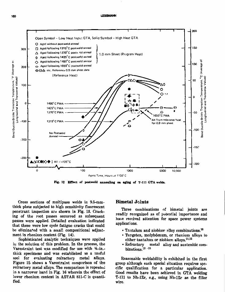
160 LESSMANN
300
200
a > ioo
I?V* is
Q
-100
-200
-300
T T
Open Symbol - Low Heat Input GTA, Solid Symbol - High Heat GTA
O Aged without postweld anneal
• Aged following 1315°C postweld anneal
A Aged following 1370°C postv.ild anneal
Q Aged following 1425°C postweld anneal
S\ Aged following 1480°C postweld anneal
O Aged following 1650°C postweld anneal
i etc. Reference 0.9 mm sheet data
(Reference Heat)
1.0 m m Sheet (Program Heat)
1480°C PWA
1425°C PWA
1370° C PWA
1315°CPWA
No PostweldAnneal
S \ 1650CPWA^ All from reference heence heat
for 05 mm sheet
A» <-1I I I
200
J50
100 «CD0)><
50 V .
2 *
-50 £ "5•r "o>
-100
-15P
-200
100 1000
Aging Time, Hours dt 1150'C
5000 10,000
Fig. 12 Effect of postweld annealing on aging of T-lll GTA welds.
Gross sections of multipass welds in 9.5-mm-thick plate subjected to high sensitivity fluorescentpenetrant inspection are shown in Fig. 13. Crack-ing of the root passes occurred as subsequentpasses were applied. Detailed evaluation indicatedthat these were low cycle fatigue cracks that couldbe eliminated with a small compositional adjust-ment in rhenium content (Fig. 14).
Sophisticated analytic techniques were appliedin the solution of this problem. In the process, theVarestraint test w,as modified for use with %-in.-thick specimens and was established as a usefulcool for evaluating refractory metal alloys.Figure 15 shows a Varestraint comparison of therefractory metal alloys. The comparison is repeatedin a narrower band in Fig. 16 wherein the effect oflower rhenium content in ASTAR 811-C is quanti-fied.
Bimetal JointsThree combinations of bimetal joints are
readily recognized as of potential importance andhave received attention for space power systemsapplications.
• Tantalum and niobium alloy combinations.10
• Tungsten, molybdenum, or rhenium alloys toeither tantalum or niobium alloys.11-12
• Refractory metal alloy and austenitic com-binations.13"15
Reasonable weldability is exhibited in the firstgroup although each special situation requires spe-cific qualification for a particular application.Good results have been achieved in GTA weldingT-lll to Nb-lZr, e.g., using Nb-lZr as the fillerwire.

WELDING OF REFRACTORY AiJ.OYS
ASTAR-8 l lC, WeidT4-A5 ASTAR-811C, Weld T4-A6
7XT-111. WeldTl-A4 T-111, Weld T1-A5
Fig. 13 High sensitivity fluorescent penetrant results for GTA plate welds. Indications of cracking in A8TAH-811C resultfrom high (oot-of-spoe) rhenium content (see Fig. 14 also). Rhenicm overstrengthening of grain volume causes grain boundarycracks.
The second group of combinations wereevaluated at great detail for thermionic applicationwith emphasis on interdiffusion behavior. Expo-sures up to 2000 h and 2000°C were investigated.Interfaces with rhenium performed very poorly as
a result of brittle zone formation. The best poten-tial was demonstrated for tungsten and tantalumalloy combinations, which were immunized againstfailure from Kirkendall void formation by special-ized methods developed in the referenced project.

162 LESSMANN
7X 7X
A5TAR-811C, Weld T4-A3
Plate - Heat Number 650056Filler - Heat Number 650068
ASTAR-811C, Wold T4-A7
Plate - Hc-ut Numbei 650056Filler - Hi;at Number 650056
Heat Number
650056
650068
Re Analysis , H/Q
1.17
1.34
Fig. 14 High sensitivity fluorescent penetrant results for two ASTAH-8UC plate welds chow no defects when plate only orboth plate and filler are within specification for rhenium, 0.8 to 1.2 wt%.
At best, these are difficult combinations from allaspects: design, fabrication, and service.
The third requirement is the transition to con-ventional alloys, particularly austenitic materials.This requirement can stem from structural design,cost, or environmental considerations. Buckmanand Goodspeed13 evaluated numerous combinationsbonded by explosive welding. In their tests, combi-nations of welding and thermal treatments produc-ing interdiffusion zones in excess of 1,3 X 10~5 mthickness would fail in 23 thermal cycles between315 and 730°C. The data are comprehensive inother properties but clearly show the difficulty ofproducing structures with materials whose inter-diffusion zonss are extremely brittle.
Kass and Stoner15 dealt with the methods ofproducing welded complex thermal loops using
bimetal tubing (refractory/austenitic). In this case,the interfaces were not metallurgies1 lly bonded.This program was quite successful in dealing withthe mechanics of joining a mechanically clad sys-tem. Such a system would have less use as a heatexchanger than as a structural component for envi-ronmental protection (in air before launch intospace).
WELDING TECHNOLOGYSUMMARY
Excellent broad-based weldability and fabrica-bility projects were supported by the NASA-LewisSpace Power Systems Division during the decade ofthe 1960s. This work provides an enormous base for

WELDING OF RBFRACTORY ALLOYS 163
1000
900
^ 800
- 700
i 600
500
400
300
200
IOC
All data for melds made at a wveldinn speed of 15 ipm.
Data for fusion zone cracks only.
A5TAH-8I1C 5
5Cfe-29Jq-lOW
10
2 3
AUGMENTED STRAIN. %
Fig. IS Comparison of total crack lengtt vs. augmentedstrain for all refractory metal alloys evaluated during thisprogram.
current plans for space power system developmentutilizing refractory metal alloys.
Weldability—Niobium- andTantalum-Base Alloys
The niobium- and tantalum-base alloys mostlikely to be selected for fabricated systems willhave excellent weldability. They will be weldedautogenously or with matching filler wire in inertatmospheres. Hence, common inert gas or vacuumwelding processes are applicable. The most easilyutilized processes are gas tungsten arc welding,electron beam welding, and laser welding. Properlyhandled, particularly to avoid metallic and atmo-spheric contamination, other processes could bequalified but at significant expense to achieve thesame degree of reliability. These processes includeplasma welding, resistance welding, explosion weld-ing, hot pressure welding, and related variants.
Tungsten-Base AlloysTungsten-base alloys will present severe weld-
ability problems indefinitely because of highductile-to-brittle transition temperatures. Weldingaggravates this problem. The use of tungsten as areliable leak-tight structural component willseverely challenge both designer and fabricator.Problems frequently will yield to expensive special-ized solutions as typified by very thin materialssuch as tungsten lamp filaments. Broad-basedgeneric welding methods, however, are not avail-
200
<
o
!00
AH data for welds made at 15 ipm.
F5-85
High Re ASTAR-811C
T - l l l
A5TAR-811C
Ta-lOW
E
b
* IH
o
a.
3r-
1 2 3
AUGMENTED STRAIN. %
Fig. 16exactlyiii-spec
Varestraint test results rank cracking sensitivityas observed in plate welding. No cracks observed for(low rhenium) ASTAR-811C or Ta-lOW.
able, and reliability constraints will severelyrestrict product design.
MolybdenumThe weldability of molybdenum is like that of
tungsten but without an application advantage forhigher temperature operation relative to the fabri-cable alloys of tantalum or niobium.
Bimetal Joints
• There is a broad range of compatibility•between niobium- and tantalum-base alloys.These elements form a continuous solid solu-tion which exhibits good fabricabilitythroughout the composition range. Eachapplication is specialized and will thereforerequire process and design qualification.
• Tungsten and molybdenum are less compati-ble with niobium, tantalum, or each other inwelding. Specialized joint designs using tran-sition pieces (or spools) produced by extru-sion, explosive welding, or hot isostatic press-ing would be useful to minimize thickness ofbrittle diffusion zones. Hence, application oftransition joints will be diffusion limited.
• Bimetal joints between any refractory metalalloy and conventional metal alloys areextremely specialized in nature. Even withspecialized methods, joint survival in servicewill be greatly impaired by thermal cyclingand diffusion. Specialized opportunities forwelding these materials have been demon-strated using coextrusion, diffusion bonding,hot isostatic pressure welding, explosionwelding, and, in thin sections, electron beam

164 LESSMANN
welding. Methods and techniques yieldingsolid state joints can produce simple shapes.These frequently have demonstrated goodsurvivability at modest temperatures. Someconfusion could develop in design applicationsince sui ival of bimetallic joints is greatlyenhanced in very thin sections such as wiresor ribbons. In these applications, leads areusually negligible, whereas in sheet or thickermaterials, joint loads are not negligib As aresult, even residual stresses can cam; frac-ture.
Contaminated Control
• Shield quality and accountability are majorconcerns in welding refractory metal alloys.There are no nondestructive methods knownfor providing product assurance. Hence, pro-cess control and monitoring are essential.Conventional welding practice is unaccept-able.
• Controlled atmosphere welding chambers aremost easily monitored. Work funded byNASA in the early 1960s provide? a classicbasis for atmosphere control and assessingshop practice. A strong case can be made formonitoring oxygen and moisture for weldatmosphere control and that both must bemonitored.
• Metallic contamination (i.e., by Ni, Fe, Cu,etc.) can be gross or insidious. Gross metalliccontamination produces a brittle structurewhich cracks on cooling or causes freezingpoint depression by constitutional segregationresulting in hot tearing. Minor contaminationcan go undetected but can result in severestructural impairment and instability, partic-ularly by segregation to grain boundaries.Loss in creep strength or low cycle fatigueresistance are classic results. A related conse-quence: multipass weldability cap suffer sig-nificantly from impairment of low cyclefatigue strength.
Joint Designs
• Wide flexibility exists in joint designs for theweldable tantalum and niobium alloys. Acces-sibility and simplicity to maximize qualityare major drivers. All joint preparationsshould be machined to final size. Machinedsurfaces for welding must be free of laps andtears to eliminate contamination.
• Joint design for bimetal joints is a complexspecial situation because of the influence ofinterdiffusion, thermal stresses, and low cyclefatigue. As an example, a good caste can bemade for keeping the interdiffusion zone fromgrowing beyond 0.013 mm between austeniticalloys and niobium or tantalum alloys.
CURRENT NEEDS FOR WELDINGREFRACTOHY METAL ALLOYS
This section addresses the special requirementsof fabricating highly reliable systems for the spacenuclear power program. The first priority require-ments are based on the need to maximize the prob-ability of success in prototype fabrication. Themost highly leveraged investment in prototypehardware fabrication is in the reliability plan. Thereliability plan must address the specializedaspects of these systems. In this regard, prototypecosts are driven hard by the nature of theenvisioned project.
• Refractory metals.• High temperatures.• Nuclear power.• System prototyping.• Operation in vacuum required (space).• Liquid metal coolants.• Severe transients.• Safety.• Reliability (design complexity vs. fabricabil-
ity).
Strategic PlanThe welding-needs list provides recommenda-
tions supporting advanced fabrication techniquesand innovation in the reliability plan with special-ized surveillance and diligent accountability.Recommendations tend to be interrelated and com-bine to yield a basic overall advancement in thistechnology. Refractory metal alloy welding require-ments are relatively well understood and aretreated accordingly.
Material Surveillance
Much of the material processing will be on aspecial order single-lot basis which necessitatesspecialized surveillance. In particular, the reactivenature of refractor/ metals makes them unusuallysusceptible to gaseous and metallic contamination.Weldabttity is a severe test for contamination andshould, therefore, be exploited for in-process

WELDING OF REFRACTORY ALLOYS 166
screening; that is, the following tests should beused to check ingots and intermediate product dur-ing material processing.
• Varestraint and TIGAMAJIG testing can be areal asset for surveillance and should beapplied at the ingot and intermediate process-ing stages.
• Multipass testing: modification of Varestraintand TIGAMAJIG tests can be envisionedwhich would be of significant value.
• Bend testing to check for atmospheric con-tamination.
• Gleeble testing can also be considered in acomprehension surveillance plan.
Although envisioned as weldability tests, threeof these are, in fact, hot ductility tests. Hence, ifanomalous behavior is identified, then processing,extrusion, rolling, forming, and service would prob-ably be compromised as well. Development of themultipass test will also detect sensitivity relativeto low cycle fatigue performance. Hence, whencombined, these test results will address material,fabrication, and system design reliability issues asearly as the ingot stage in fabrication. The proba-bility of success is greatly enhanced by this type ofspecialized probing of material response charac-teristics early in the fabrication stage. Interest-ingly, the recommended tests are relatively inex-pensive, although they require systematic and wellplanned characterization for implementation.
Contamination Control
Three issues need to be addressed in contamina-tion control:
Accountability (control and monitoring). Classicground rules were established in the NASA pro-gram of the 1960s for shield gas management.These still apply today. Moisture and oxygen moni-tors have improved considerably, so accountabilityis significantly simplified. However, accountabilitymust be formalized, because fabricators tend toview the knowledge base as optional and not essen-tial.
Detection (sensor deployment-development). Ac-tive monitoring techniques to use during weldingneed to be developed to assure freedom from weldcontamination. Real-time spectrographic analysisof the arc or weld pool is an example of thisapproach. Sensor development is receiving enor-mous industrial attention for factory automation.Hence, the probability of applying innovative sen-sor technology in welding refractory metal alloys isvery great and should be exploited.
Accessibility (eliminate vacuum-purged weldchambers). An extrapolation of advanced shieldgas monitoring and sensors leads to elimination ofvacuum-purged weld chambers. Shielding methodscan be improved to provide greater accessibility,more flexibility in design and manufacture, and agreater reliability. Investigators at the Westing-house Research and Development Center haveimplemented easily constructed displacementchambers or specialized air displacement shieldswhich have given excellent results in welding thereactive alloys of titanium and zirconium. Innova-tive design and use of monitors to map quality ofshielding leads to fully qualified designs. Weldingcan usually be initiated within minutes comparedwith hours in vacuum pumpdown cycles. Two alliedadvantages of eliminating the vacuum-purgedwelding chambers are that laser welding utilizationwill be increased leading to greater automation andquality, and that Var?straint and TIGAMAJIGtests can be easily run out-of-chamber as low costmaterial screening and production surveillancetests.
Welding Technology Improvements
Minimize use of vacuum-purged chambers.Substitution of local shielding and use ofdisplacement chambers will greatly reduce fabrica-tion cost and improve design flexibility. Asdescribed above, an appropriate contaminationcontrol plan is required.
Advanced methods and technology, (a) Lasers:The use of lasers should be exploited because laserslend themselves to local shielding methods andencourage automation and design practice whichlends itself to automation, (b) Adaptive Control:Adaptive control methods now being developed forfactory automation will have a positive impact onquality and productivity. This technology should betransferred to fabricating space power systems.Use of adaptive control as a reliability method willbe cost effective even for prototype hardware fabri-cation. This stems from the extremely high finan-cial and schedular risk associated with refractorymetal system fabrication. Welding vision andimage analysis systems now being developed forclosed-loop control represent an excellent exampleof this potential.
Materials Reliability Systems
The fabrication of refractory metal alloys needsto incorporate modern nondestructive examination(NDE) capabilities.
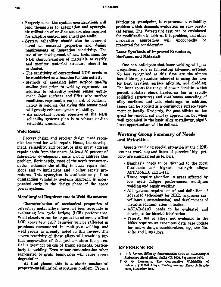
166 LESSMANN
• Properly done, the system considerations willlend themselves to automation and synergis-tic utilization of on-line sensors also requiredfor adaptive control and shield gas audit.
• System reliability should also be assessedbased on material properties and designrequirements of inspection sensitivity. Theuse of or development of new techniques forNDE characterization of materials to certifyand monitor material structure should beevaluated.
• The sensitivity of conventional NDE needs tobe established as a baseline for this activity.
• Methods of assessing joint surface qualityon-line just prior to welding represents anaddition to reliability system sensor equip-ment. Joint surfaces and filler wire surfaceconditions represent a major risk of contami-nation in welding. Satisfying this sensor needwill greatly enhance system reliability.
• An important overall objective of the NDEreliability systems plan is to achieve on-linereliability assessment.
Weld Repair
Process design and product design must recog-nize the need for weld repair. Hence, the develop-ment, reliability, and prototype plan must addressrepair needs from the onset. At least 30 percent offabrication development costs should address thisproblem. Fortunately, most of the needs recommen-dation enhances the ability to make repair deci-sions and to implement and monitor repair pro-cedures. This synergism is available only if anoutstanding reliability systems approach is incor-porated early in the design phase of the spacepower systems.
Metallurgical Requirements in Weld Structures
Characterization of mechanical properties ofrefractory metal alloys have not been adequate inevaluating low cycle fatigue (LCF) performance.Weld structure can be expected to adversely affectLCF; conversely, LCF behavior will be reflected inproblems encountered in multipass welding andweld repair as already noted in this review. Thesevere reactivity of these alloys will result in fur-ther aggravation of this problem since the poten-tial is great for pickup of tramp elements, particu-larly in welding. Even minor contamination whensegregated to grain boundaries will cause severedegradation.
At first glance, this is a classic mechanicalproperty-metallurgical structures problem. From a
fabrication standpoint, it represents a reliabilityproblem which demands evaluation on very practi-cal terms. The Varestraint test can be envisionedfor modification to address this problem, and otherinnovative approaches will undoubtedly bepresented for consideration.
Laser Synthesis of Improved Structures,Surfaces, and Materials
One can anticipate that laser welding will playa significant role in fabricating advanced systems.No less recognized at this time are the almostincredible opportunities inherent in using the laserfor heat treating, surface alloying, and cladding.The laser spans the rarge of power densities whichpermit ablative shock hardening (as in rapidlysolidified structures) and continuous annealing ofalloy surfaces and weld claddings. In addition,lasers can be applied as a continuous surface treat-ment or locally. Obviously, the possibilities are toogreat for random cut-and-try approaches, but whenwell grounded in the basic alloy metallurgy, signif-icant opportunities will be defined.
Working Group Summary of Needsand Priorities
Aspects receiving special attention at the ORNLseminar workshop and items of perceived high pri-ority are summarized as follows.
• Emphasis needs to be directed to the mostfabricable and highest strength alloys:ASTAR-811C and T-lll.
• These require attention in areas affected bylow cycle fatigue performance: multipasswelding and repair welding.
• All systems require use of and definition ofadvanced technology for NDE, in-process sur-veillance (contamination), and development ofmetallic contamination detection.
• ASTAR-811C needs to be evaluated anddeveloped for bimetal fabrication.
• Priority use of alloys not evaluated in the1960s requires an enormous data base updatefor active design consideration, e.g., the Mo-I3Re and C103 alloys.
REFERENCES1. D. R. Stoner, Effect vf Contamination Levd on Weldabiiity of
Refractory Metal AUoj/3, NASA CR-1609, September 1970.2. G. G. Lessmann, The Comparative Weldabiiity of
Refractory Metal Alloys, Welding Journal Research Supple-ment, December 1966.
WELDMQ OF REFRACTORY ALLOYS 167
3. D. R. Stoner and G. 6. Lessmann, Measurement and Con-trol of Weld Chamber Atmospheres, Welding JournalResearch Supplement, August 1965.
4. G. G. Lessmann and R. B. Gold, The Weldabllity ofTungsten Base Alloys, Welding Journal Research Supple-ment, December 1969.
5. G. G. Lessmann, Welding Evaluation of ExperimentalColumbium Alloys, Welding Journal Research Supplement,March 1964.
6. G. G. Lessmann and R. E. Gold, Long-time Temperature Sta-bility qf Refractory Metal Alloys, NASA CR-1608, September1970.
7. G. G. Lessmann, Post Weld Annealing Studies qf T-Ul,NASA CR-1610, December 1S70.
8. G. G. Lessmann and R. E. Gold, Interaction of High Tem-perature Strength and Weldability, Welding JournalResearch Supplement, July 1973.
9. G. G. Lessmann and R. E. Gold, The Varestraint Test forRefractory Metal Alloys, WeUKrtp Journal Research Supple-ment, January 1971.
10. R. W. Harrison, E. E. Hoffman, and J. P. Smith, T-lllRankine System Corrosion Test Loop, VoL 1.NASA-CR-1JM816, June 1975.
11. F. G. Arcella, Interdiffusion Behavior of tungsten onRhenium and Group V and VI Elements and Alloys qf thePeriodic Table, Part I, NASA-CR-134490, Part 1, September1974.
12. F. G. Arcella, Interdiffusion Behavior of Tungsten onRhenium and Group V and VI Elements and Alloys of thePeriodic Table, Part II (Appendices), NASA-CR-134526, PartII.
13. R. W. Buckman, Jr., and R. C. Goodspeed, Refractory/Austenitic Bimetal Combinations, WANL-PR-(EE)4X>4,August 1969.
14. D. R. Stoner, Joining Refractory/Austenitic Bimetal Tubing,NASA-CR-72275, Contract NAS-3-7621, December 1966.
15. J. N. Kass and D. R. Stoner, Joining Refractory/AusteniticBimetal Tubing, NASA-CR-72353, May 1968.
BIBLIOGRAPHYBond, J. A., Advanced Rankine Cycle Potassium Boiler Develop-
ment Program, Volume 1: Test Rig Design and Fabrication,NASA CR-135451, November, 1975.
Buckman, R. W., Comprehensive bibliography of Westinghousepublications, reports, and contracts completed between 1955and 1913, personal communication, Westinghouse AdvancedEnergy Systems Division, Large, Pennsylvania.
Ekvall, R. A., R. G. Frank, and W. R. Young, T-ll l Alloy Crack-ing Problems During Processing and Fabrication, Conferenceon Recent Advances in Refractory Alloys for Space PowerSystems, NASA-SP-245 (1970).
Gahan, J. W., A. H. Powell, P. T. Pilegg, and S. R. Thompson,Fabrication and Test qf a Space Power Boiler Feed Elec-tromagnetic Pump, Volume 1, Design and Manufacture qfPump, NASA CR-1949, April 1972.
Lyon, T. F., Purification and Analysis qf Helium for the WeldingChamber, NASA-CR-54168, July 1965.
Mendelson, I., Design and Fabrication qf Brayton Cycle SolarHeat Receiver, Final Report, NASA CR-72872, July 1971.
Michelson, D. C, J. M. Fielden, A. C. Jordan, and E. B. Lewis,Selected Publication Relevant to the Space Reactor MaterialsProgram, ORNL Document, DOE Contract W-7405-ENG-26,August 1983.
Young, W. R., Fabrication of T-lll Test Loop Systems,Conference on Recent Advances in Refractory Alloys for SpacePower Systems, NASA-SP-245 (1970).
Young, W. R., Fabrication of Refractory Alloy Components forAdvanced Space Power System Studies, in Proceedings ofEnergy 70 Intersodety Energy Conversion EngineeringConference, Volume 1 (1970).
Refractory Alloy Component Fabrication
W. R. YoungGeneral Electric Company
INTRODUCTION WELDING PROCEDURES
During the years 1962 to 1972, advanced spacepower systems which utilized tantalum- andniobium-base refractory alloys were beingdeveloped at General Electric, Nuclear SystemsPrograms (GE-NSP) for NASA. Typically,advanced Rankine systems tests involved boilingand condensing alkali metals to study heat transferor the basic compatibility between alkali metalsand the refractory alloy containment material Ineither case, system components such as pumps,boilers, condensers, heaters, valves, and pressuretransducers were required. The refractory alloy T-111 (Ta-8W-2Hf) was selected for high temperaturesystems.
During the same time, the fabrication of a solarheat receiver for use in a 10 kW(e) Brayton cyclepower system was completed.1 Because gas flowwas received at 595°C and delivered at 815°C, thestructural alloy, Nb-lZr, was selected.
The purpose of this report is to describe joiningprocedures, primarily welding techniques, whichwere developed to construct reliable refractoryalloy components and systems. An effort is madeto use a general nondetailed approach in present-ing this material in order to give those interestedin systems some insight, into the state of the art ofbuilding refractory alloy hardware. However, twosystems, the Nb-lZr Brayton Cycle Heat Receiverand the T-lll Alloy Potassium Boiler DevelopmentProgram, are used to illustrate typical systems andcomponents.2 Particular emphasis i3 given to spe-cific problems which were eliminated during thedevelopment efforts. Finally, some thoughts onapplication of more recent joining technology arepresented.
During the early 1960s, welding specificationsfor refractory alloys were generally procedural incontent. It was known that contamination of thesealloys by oxygen or nitrogen was detrimental toductility and corrosion resistance; the limits, how-ever, were not known. Most welding was conductedby trial and error, with the adequacy ui the purityat the welding environment judged by theappearance of welded test specimens preparedbefore actual welding of components. Chemicalanalysis of the weld metal for the interstitial ele-ments, oxygen, nitrogen, and carbon, was used tocertify the welding procedure.
By 1970, welding specifications reflected princi-pally the development of analytical and weldingequipment. Welding was conducted in helium hav-ing a maximum impurity content of 5 ppm oxygen,15 ppm nitrogen, and 20 ppm water vapor (10 ppmmoisture content for component to containlithium). A gas chromatograph system was utilizedto measure oxygen and nitrogen content, and anelectrolytic hydrometer was used to monitor watervapor contec'.3 These impurity levels resulted in nodetectable increase in the impurity content of therefractory alloys during the welding cycle. Actu-ally, tests conducted with up to 200 ppm air or50 ppm moisture content intentionally added tothe helium atmosphere resulted in no detectableimpurity element concentration increase. The con-trols used were intentionally conservative to avoidany alkali metal corrosion effects. Long durat'ontesting (up to 10,000 h) of both T-lll and Nb-lZralloy systems welded under the environmentalrequirements of the specification has shown nocorrosive effects on weldments. If mechanical
•66
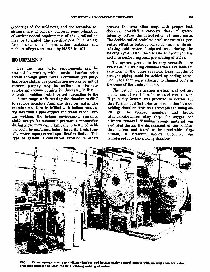
REFRACTORY ALLOY COMPONENT FABRICATION 169
properties of the weldment, and not corrosion re-sistance, are of primary concern, some relaxationof environmental requirements of the specificationmay be tolerated. The specifications for cleaning,fusion welding, and postheating tantalum andniobium alloys were issued by NASA in 1971.4
EQUIPMENT
The inert gas purity requirements can beattained by working with a sealed chamber, withaccess through glove ports. Continuous gas purg-ing, recirculating gas purification system, or initialvacuum purging may be utilized. A chamberemploying vacuum purging is illustrated in Fig. 1.A typical welding cycle involved evacuation to the10~5 torr range, while heating the chamber to 60°Cto remove moistu-e from the chamber walls. Thechamber was then backfilled with helium contain-ing less than 1 ppm oxygen and water vapor. Dur-ing welding, the helium environment remainedstatic except for automatic pressure compensationduring glove movement. Typically, 5 to 8 h of weld-ing could be performed before impurity levels (usually water vapor) exceed specification limits. Thistype of system is considered superior to others
because the evacuation step, with proper leakchecking, provided a complete check of systemintegrity before the introduction of inert gases.The double-walled stainless steel construction per-mitted effective bakeout with hot water while cir-culating cold water dissipated heat during thewelding cycle. Also, the vacuum environment wasuseful in performing local postheating of welds.
The system proved to be very versatile sincetwo 2.4-m dia welding chambers were available forextension of the basic chamber. Long lengths ofstraight piping could be welded by adding exten-sion tubes that were attached to flanged ports inthe doors of the basic chamber.
The helium purification system and deliverypiping was of welded stainless steel construction.High purity helium was procured in bottles andthen further purified prior .o introduction into thewelding chamber. This was accomplished using sil-ica gel to remove moisture and heatedtitanium/zirconium alloy chips for oxygen andnitrogen removal. Titanium sponge material wase?a'-ated during the development of the purifica-tic . ay; tem and found to be unsuitable. Mag-nesium, a titanium sponge impurity, wastransferred into the welding chamber.
Fig. 1 Vacmun-purge inert gas welding chamber and helium parity control system with welding chamber oxton-sion tank attached to 0.9-m-dia by 1.8-m-long welding chamber.

170YOUNG
Fig. 2 Automatic tungsten inert gas welding machinewith controlled welding sequence.
The welding machine used for both manual andautomatic gas tungsten arc (GTA) welding isshown in Fig. 2. This 400-amp maximum constantcurrent machine provided a complete weldsequence of upslope, weld, and downslope currentcontrol with time-delay relays to provide for inte-gration of motorized accessory equipment. Oneimportant modification was made to this equip-ment after a welding torch failure caused excessivemelting of a Brayton cycle heat receiver tube-to-header weld. Electrical circuitry was added to pro-vide presetting of maximum welding current.Above the set point, the welding sequence was ter-minated, thus providing additional protection forthe workpiece.
A large percentage of the welding was donewith the hand-held torches shown in Fig. 3. Themolded silicon rubber and aluminum insulator pro-vided complete electrical insulation of the brasstorch body.
It has been determined that certain refractoryalloys, such as T-111, may exhibit brittle behaviorwhen contaminated with minute amounts of non-refractory metals, particularly copper and nickel.To prevent such contamination, refractory alloychucks ?nd shields were incorporated into thewater-cooled torch design. Joint alignment fix-
iNA I N S J L A T J K
Fig. 3 Gu tungsten arc -elding torchw modlfled with T-111 alloy shield*.

REFRACTORY ALLOY COMPONENT FABRCATON 171
Fig. 4 Refractory alloy fixture for aliening tube joints.
tures of refractory alloys were utilized at locationswhere the refractory alloy components and the fix-ture were in direct contact. It was also speculatedthat sagging or movement during welding mightinduce weld cracking.5 The rigid refractory alloyfixture shown in Fig. 4 was designed to preventsuch movement.
Because welding was performed in an inert gaschamber, access was limited to specific work sta-tions consisting of a view port and gloves. The vis-ual access to the weld joint was a critical problemrequiring rather extensive tooling to position theworkpiece. Although automatic welding devicesalleviated this problem by movement of the torchrather than workpiece, this equipment was usuallylimited to joints of simple geometry. An internaltube-to-header automatic welding torch was usedduring Brayton cycle heat receiver fabrication andwill be discussed later.
JOINT DESIGN
The dssign of welded joints in refractory alloysmust compensate for their relatively high meltingpoint and thermal conductivity. Typical jointdesigns for niobium and tantalum alloys arepresented in Fig. 5. Multipass gas tungsten arc(GTA) welding of some refractory alloys, such asT-111, has resulted in microcracking in the fusionzone.6 This phenomenon usually occurs in an areaapproximately two weld passes below that beingwelded. Thus, thicknesses greater than 3.2 mmrequiring three weld passes may be susceptible tomicrocracking. If greater thicknesses are required
0.06 WU.
Jflilt SMOTE {OH G* BCTP SfDCSJ
(±3HMIZOKTN. PQSITIflR
DOUBLE ICC (BOTH WOES)
SIWH itf ',1& 0« MTU S1DC5)
Fig. 5 Topical weld joint designs for niobium and tantalumalloys (butt joints). (Dimensions are in inches.)
by design, alternate joining methods such as elec-tron beam welding should be considered. Singlepass electron beam welds of this type have beenmade in thicknesses up to 12.7 mm without diffi-culty.
WELDING DISSIMILARREFRACTORY ALLOYS
In the fabrication of several prototype alkalimetal containment systems, it was found to beadvantageous to utilize tantalum-base alloys suchas T-111 in the high temperature regions <»nd thsNb-lZr alloy for lower temperature components.For example, surge tanks, which are not a part of
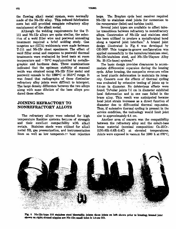
172 YOUNG)
the flowing alkali metal system, were normallymade of the Nb-lZr alloy. This reduced fabricationcosts but still provided complete refractory alloycontainment of the alkali metal.
Although the welding requirements for the T-111 and Nb-lZr alloys are quite similar, the selec-tion of a weld filler wire and postwetd annealingtreatment required a brief welding study. Gastungsten arc (GTA) weldments were made betweenT-lll and Nb-lZr sheet specimens. The effect ofweld filler metal and response to postweld thermaltreatments were evaluated by bend tests at roomtemperature and —70°C supplemented by metallo-graphic and hardness data. These examinationsindicated that the optimum stability of manualwelds was obtained using Nb-lZr filler metal andpostweld anneals in the 1260°C to 1315°C range. Itwas found that radiographs of those dissimilarrefractory alloy joints were difficult to interpret.The large density difference between the two alloysalong with some dilution of the base alloys pro-duced these effects.
JOINING REFRACTORY TONONREFRACTORY ALLOYS
The refractory alloys were selected for hightemperature Rankine systems because of strengthand their excellent compatibility with alkalimetals. Stainless steels were utilized for alkalimetal fill, gas pressurization, and instrumentationlines as well as low temperature heat rejection
loops. The Brayton cycle heat receiver requiredNb-lZr to stainless steel joints for connection tothe recuperator (inlet) and turbine (exit).
Several joint types are available to affect tubu-lar transitions between refractory to nonrefractoryalloys. Coextrusion of Nb-lZr and stainless steelhas been utilized to produce a metallurgical bondalong a tapered joint interface.7 A brazed jointdesign illustrated in Pig. 6 was developed byGE-NSP. This tongue-in-groove configuration wasapplied successfully to the tantalum/stainless steel,Nb-lZr/stainless steel, and Nb-lZr/Haynes AlloyNo. 25 (Co-base) systems.8
The basic design provides clearances to accom-modate differential expansion during the brazingcycle. After brazing, the composite structure relieson local plastic deformation to maintain its integ-rity. Concern over the effects of thermal cyclingwas evaluated by extensive testing of joints up to6.4-cm in diameter. No deleterious effects werefound. Tubular joints 7.6 cm in diameter exhibitedlocal deformation and in one case failed in thebraze alloy. This result was anticipated becauselocal joint strain increases as a direct function ofdiameter due to differential thermal expansion.Thus, if extensive thermal cycling is present in theservice condition, the technology would limit jointsize to approximately 6.4 cm.
Another area of concern was the compatibilitybetween the refractory alloy and the cobalt-basebraze material (nominal composition: Co-21Cr-21Ni-8Si-0.8B-0.4C) at elevated temperatures.Joints were exposed in vacuum for 1000 h at 870°C,
Fig. 6 Nb-IZr/type 316 stainless steel bimetallic joints; three joints on left shown prior to brazing; braced jointshown on right; slotted nipples are Nb-lZn small foint is 1.0-cm OD.

REFRACTORY ALLOY COMPONENT FABRICATION 173
the maximum use temperature of the stainlesssteel component. Metallographic examination andhardness traverses indicated a minimal and accept-able reaction zone with no evidence of joint separa-tion.
On the basis of these results, brazed bimetallicjoints between Nb-lZr and stainless steel wereused on most of the GE-NSP refractory alloy sys-tems constructed during this period.
REFRACTORY ALLOY LOOPFABRICATION
The development and application of the above-mentioned procedures and techniques transpiredduring the fabrication of both Nb-lZr and T-lilRankine system compatibility test systems whichoperated successfully for 5,000 and 10,000 h,respectively.9-10 The culmination of these activitiesoccurred during the 1966 to 1970 time period withthe design and fabrication of the Potassium BoilerDevelopment Test Rig.2 The schematic of this T-lllalloy system is shown in Fig. 7. The test facilityconsisted of three interconnected flow circuits: theT-lll alloy lithium heating loop, the T-lll alloypotassium boiling loop, and the Type 321 stainlesssteel NaK heat rejection loop.
The general fabrication procedures utilized inthe construction of this facility are shown inFig. 8. Note that critical prorasses, acid cleaning,welding, and annealing, required qualification andprocess control records. The process control forwelding and annealing required sheet coupons to beprocessed with the component. These archivecoupons were used in the event that subsequentanalysis of a particular weld or component wasneeded. The general procedures also requiredanneal of all machined parts, such as those shownin Fig. 9, to be accomplished prior to welding. Thiswas a precaution because cracking had beenobserved during subsequent forming and weldingoperations on machined parts that were not given apostmachine anneal.5
The overall fabrication sequence for the BoilerDevelopment Test Rig is shown in Fig. 10. Assystem size increased, it was no longer deemedpractical to assemble and handle the entire systemwithin the welding chamber. A small portablewelding chamber shown in Fig. 11 was thereforedeveloped. This split chamber design utilizedexpendable seals which effect a gas-tight :ointbetween the loop piping and the weld chamber. Avacuum or inert gas purge was used for both theweld chamber and the inside of the loop piping.The helium environment was continuously moni-
tored to ensure compliance to the welding purityrequirements of the basic welding specification.
Postweld annealing of entire subassemblies wa3also impractical due to size limitations of qualifiedvacuum furnaces available in the U. S. at thattime. Small refractory metal furnaces shown inFig. 12 were used for local annealing of tube jointswhich connected subassemblies or components. Insome cases, annealing was done in the weldingchamber vacuum environment. The seven fieldwelds required to join system subassemblies wereannealed locally using the test rig vacuum cham-ber.
Detailed planning for this fabrication sequencewas completed at the time system design was final-ized. /( is eoctremely important in refract<yry alloysystem construction that all fabrication proceduresbe fully documented, prior to refractory alloy pro-curement, and coordinated with the design staffduring system design. For example, field weldplacement was planned at sections of straight looppiping which would accommodate the portablewelding chamber and provide for removal and rein-stallation of the test boiler. Also, a new 1.2-m-longextension for the welding chamber was purchasedto accommodate component fabrication. Cost stud-ies were also incorporated into fabricationsequence. For example, it was more efficient toconstruct multiple local annealing furnaces so thatthe number of vacuum pumpdowns and annealingcycles in the test rig vacuum chamber could beminimized.
BOILER DEVELOPMENT LOOPCOMPONENT FABRICATIONAND ASSEMBLY
A large number of refractory alloy componentsmade mostly of the T-lll alloy were required inthe Boiler Development Test System. The fabrica-tion of several of the major components and thefinal assembly of the test rig are described below.
Slack Diaphragm PressureTransducers
Taylor Instrument Companies pressure trans-ducers were used for loop instrumentation. Eachtransducer comprised upper and lower flanges, aslack convoluted diaphragm, a process tube, and abimetallic joint between Nb-lZr and stainless steel.Taylor Instrument Companies attached stainlesssteel capillary and NaK-filled tubing.
The weld between the diaphragm and upperflange was made by the electron beam process.
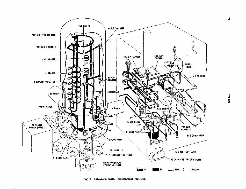
PRESSURE TRANSDUCER
VACUUM CHAMBSR
NoK TERTIARY LOOP
MECHANICAL VACUUM PUMP
II [7~1 Nit I I ARGON
Fig. 7 Potassium Boiler Development Test Rig.

REFRACTORY ALLOY COMPONENT FABRICATION 175
STRAIGHTTUBE ITEMSTRIM TOLENGTH
RAW MATERIALRELEASE
MACHINED OR• ORMEOPARTS
ACID CLEANING-PROCESS CONTROLRECORD
NASA APPROVAL
ENGINEERINGDRAWINGS
DIMENSIONAL ANDLIQUID PENETRANTINSPECTIONREPORTS
ENGINEERINGREVIEW
ACCEPT, REMAKE OR REWORKQUALITY CONTROL REPORT
MANUFACTURING INSTRUCTIONSDEFINING SEQUENCE OFSUCCEEDING EVENTS
J
ANNEAL OFMACHINEDPARTS
VACUUM FUHNACEQUALIFICATION
Fig. 8 Potassium boiler development pro-gram genertil fabrication procedures.
WELDiNG-PROCESS CONTROLRECORD
WELDING CHAMBERQUALIFICATION
VISUAL ANDRADIOGRAPHICINSPECTION
ENGINEERINGREVIEW
ACCEPTOR BEPAIH
IN PROCESSMACHINING ORFORMING
DIMENSIONALINSPECTIONREPORT
ENGINEERINGREVIEW
ACCEPTOR REWORK
POSTWELD ANNEALOF COMPONENTSASSEMBLIES ORfWIVIDUALWELOSPP.DJESS CONTROLRECORD
VACUUM fUBNACEQUALIFICATION
FINAL DIMENSIONALINSPECTION

176 YOUNG
THERMOCOUPLE WELLSPACER, BOILER
T-'EBMOCOUPLE WELLSPACER, CONDENSER
THERMOCOUPLE WELL, BOILER
NaK EXIT HEADER, CONDENSER
ORIFICES, CONDENSER
TllF.[:'"r>CnilPLE WELL HEADER, CONDENSER pr:TA.ic ' ';i ' ', HEADER,
Fig. 9 Typical T-! 11 alloy machined parts.
This weld is illustrated in Fig. 13; a trial electronbeam weld \a shown in Fig. 13a; the completedflange is shown in 13b; and a metaiiographic crosssection of this weld is shown in Fig. 13c. Typicalpressure transducers are illustrated in Fig. 14.Radiographic inspection, heat treatment, and massspectrometer leak tests were performed success-fully prior to filling of the pressure transmittingcapillary with NaK.
As discussed previously, multipass welding ofT-111 alloy induced microcracking of the rootpass.5-6 This cracking was not detected at the timeof transducer fabrication. Although it must beassumed that cracking of this type did occur,no failures occurred during the extensive test pro-gram.
Lithium and PotassiumElectromagnetic (EM) Pump Duct
The typical EM pump fabrication is illustratedin Fig. 15. Machining of the helical flow passagewas the most critical fabrication step. The outer
wrapper inside diameter was machined, honed, andinspected dimensionally. The helix was thenground to provide a 0.05-mm diametral interfer-ence fit with the wrapper. The interference fit wasproduced by chilling the helix in liquid nitrogenand inserting it into the wrapper that was at roomtemperature. The inside diameter of the wrapperwas slightly tapered at the helix entry end to pro-vide an easier start for the interference fit. Helixinsertion was a very delicate operation thatrequired a steady hand and a handy rubber malletfor gentle persuasion. After completion of mechan-ical assembly and welding, the outside diameter ofthe wrapper was machined to the proper dimensionfor fit-up with the bore of the EM pump stater.Postweld annealing at 1315°C for 1 h was thenperformed to complete the fabrication cycle.
Potassium Liquid and Vapor Valves
The electron beam welding process was used tojoin the T-111 bellows stem assembly as illustrated

REFRACTORY ALLOY COMPONENT FABRICATION 177
BOILER*
ONE SLACK*DIAPHRAGMPRESSURETRANSDUCER
CONDENSER* ["POTASSIUM*| EM PUMP DUCT
TWO DIFFERENTIAL"PRESSURETRANSDUCERS
POTASSIUM'HEAD TANK
FOUR SLACK-DIAPHRAGMPRESSURETRANSDUCERS
LITHIUM EM-PUMP DUCT
DESUPERHEATER
POTASSIUMVAPOR
SSIUM*RUNE
LITHIUM*DUMPTANK
BOILERSUBASSEMBLY
CONDENSERSUBASSEMBLY
POTASSIUMVAPOR VALVE
POTASS! JM EM IPUMP O'JCTSUBASSEMBLY
FIELDWELDNO. 1
DESUPERKF.ATER"SUBASSEMBLY
LITHIUMEM PUMP DUCTSUBASSEMBLY
FIELDWELD
NO. 2LITHIUM-HEATER
TANTALUM BUSBARS
FIELD WELD NOS. 4. 5. 6, AND 7
DASHED LINE REPRESENTS ASSEMBLYIN TEST RIG Vi..- UUM CHAMBER
TEST RIGASSFMBLY
ONE SLACK-DIAPHRAGMPRESSURETRANSDUCER
' POTASSIUM"PREHEATERSUBASSEMBLY
CONDENSEROESUPERHEATERSUBASSEMBLY
FIELDWELD
NO. 3
POTASSIUMLIQUIDVALVE
POTASSIUMSUBASSEMBLY
'These components or subassemblies were furnace annealedI prior to welding into next assembly. Assembly welds were! annealed locally in the test rig vacuum chamber.
Fig. 10 Fabrication sequence for the T-iii Boiler Development Test Rig.
Fig; 11 Portable weld chamber partially installed during qualification teat*.

178 YOUNG
Fig. 12 Refractory metal furnace for local annealing of weldmenta.
U-2.51 .:in-J
Cut Away ShowingDiaphragm and HousingConstruction
Slack DiaphragmNb-lZr Alloy
IS
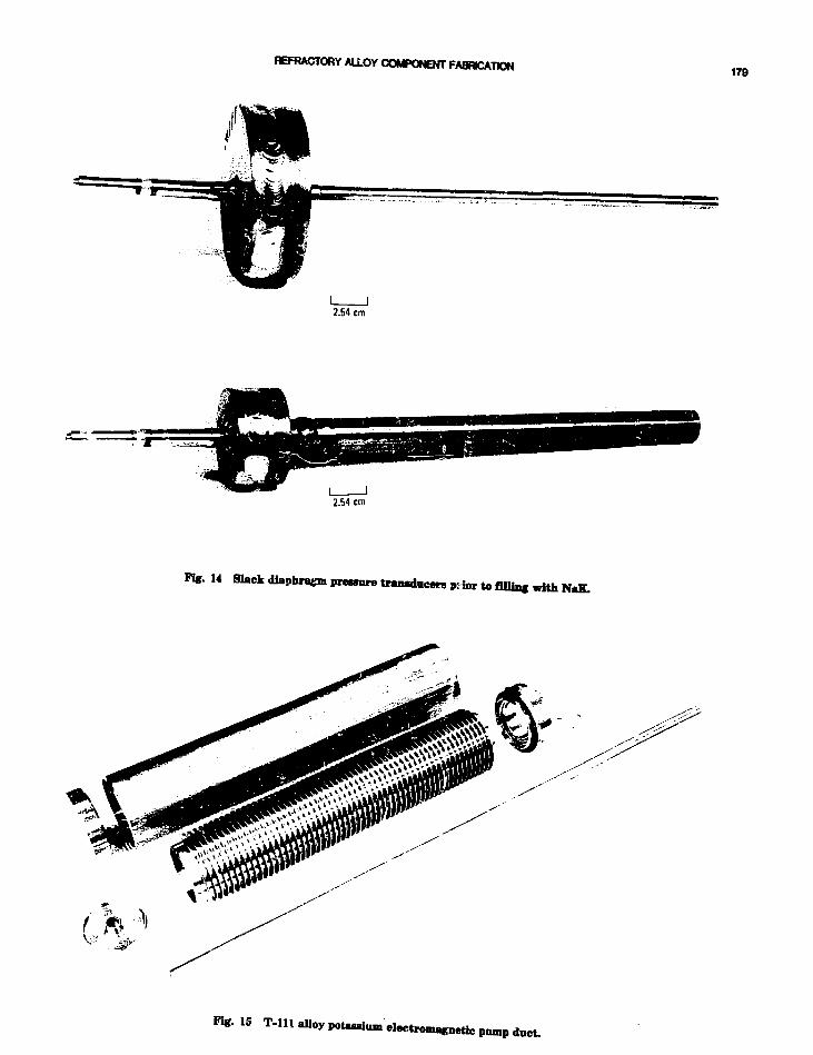
REFRACTORY ALLOY COMPONENT FABRICATION178
2.64 cm
2.54 cm
Fig. 14 Slack diaphragm pressure transducers prior to filling with NaK.
F%. 15

180 YOUNG
BACKUP RING
BELLOWS RING
BELLOWS(WALL THICKNESS 0.38 mm)
EB WELD
\EB WELD
Fig. 16 T-lll alloy bellows stem assembly of boilor development valves illustrating elec-tron beam weldments used to join the various comf
in Fig. 16. Bellows fabrication required carefulcontrol of surface finish to prevent orange peelingand tears.11 Annealing after forming was also criti-cal due to the 0.38 mm wall thickness. In one case,T-lll bellows contamination occurred becauseunalloyed tantalum foil rather than Nb-lZr foilwas used as protective wrap. Analysis indicatedthat oxygen had transferred from the unalloyedtantalum to T-lll.
The valve assemblies are shown in Figs. 17 and>'8. Both the potassium liquid throttle and vaporvaives used Mo-TZM plugs because neither valvewas required to seat during testing. Later testingindicated that rhenium seats and W-25Re plugswere suitable for metering and isolation valves forservice in 1035°C lithium.11
Lithium Heater
The lithium heater includes six heater coils.Each 27.9-cm-dia coil was formed from 2.2 cm out-side diameter by 2.5 mm wall T-lll tubing andhad a developed length of 3.1 m. Appropriate man-ifolds and electrodes were required to split thelithium flow uniformly and to provide attachmentof high current electrical buses.
A fixture was designed to hold the lithiumheater as shown in Fig. 19. A more detailed viewof the three-tube manifold joints is shown inFig. 20. The size and weight of this componentmade it difficult to handle manually within thewelding chamber. To alleviate this problem, themultipurpose weld positioner shown in Fig. 21 was

REFRACTORY ALLOY COMPONENT FABRICATION 181
Mo-TZM ALLOY PLUG
2.54 cm
Fig. 17 T-Ul alloy potassium liquid throttle valve.
2.54 cm
Fig. 18 T-lll alloy potassium vapor valve.

182 YOUNG
Kg. 19 T-lll lithium heaterpositioned in welding fixture.
utilized. This unit provided motor-driven rotationand manual translation of the workpiece withinthe 2.4-m-dia welding chamber.
The heavy vertical tantalum bus bars weremanually welded to the horizontal bus bars afterannealing. This feature plus the attachment offlexible copper conductors i i shown in Fig. 22.
Condenser
The three-tube potassium condenser was NaK-cooied on the shell bide and was a basic hockeystick design. From the welding viewpoint, this com-ponent, being of multitube design, r luired thequalification and production of -epresentative

REFRACTORY ALLOY COMPONENT FABRICATION 183
Fig. 20 T-lll lithium heater illustrating butt joints to header.
tube-to-header joints. In order to provide a fullyinspectable butt joint, internal automatic weldingwas selected. In this process, a welding torch ispositioned inside the joint and is rotated by amotor drive (Fig. 23), which is controlled by thesequence control on the previously described auto-matic welder. The three tube-to-header jointsshown in Fig. 24 were welded using this technique.After inspection of these welds, the tube bundleand support cage shown in Fig. 25 r/as slipped intothe sheli. The potassium outlet tubes were thenbent and trimmed to proper length, and a reducerwas welded to each tube, as shown in Fig. 26.These reducers * jere welded to the exit header, pro-viding the same joint design as that of the inletheader. The completed condenser ihown in Fig. 27had connections for pressure transducers in addi-
tion to the NaK and potassium lines. The installedcondenser is shown in Fig. 28.
BoilerThe potassium test boiler was C-shaped in
design and had a 1.9 cm outside diameter by1.0 ."nm wall T-lll potassium boiler tube main-tained concentric within a 3.4 cm outside diameterby 2.5 mm wall shell. A helical fin insert shown inFig. 29 extended approximately half the boilerlength. At the end of the fin a helical wire coil wasattached and continued throughout the remainderof the boiler tube. The shell and boiler tube werebent separately to provide the best assurance ofproper tube concentricity in the formed boiler.Several trials with stainless steel mockups pre-

184 YOUNG
Fig. 21 Lithiim heater fixtured for welding in the 2.4-m-dia chamber.
ceded the T-111 boiler tube bending. Initial bendingwas performed manually using a 360° machinedsteel mandrel for the inside diameter contour anda steel roll on the outside diameter. Final sizing tothe shell diameter was done on a conventionalthree-roll tube bender. Four tube spacers were thenGTA tack welded to the formed boiler tube asshown in Fig. 30. The boiler shell shown in Fig. 31was then slipped over the boiler tube. Mechanicalvibration was necessary during this operation toovercome the considerable friction between thesliding T-111 components.
The completed boiler assembly shown in Fig. 32indicates the complexity of a fully instrumentedtest boiler. Provision for pressure transducers,insert thermocouples, and bulk fluid thermocouplewells necessitated many sequential welding andinspection steps to provide high reliability in the
component. The installed boiler is shown inFig. 33.
Test Rig Assembly inthe Vacuum Chamber
Seven field welds were required to join the vari-ous subassemblies during installation. As shown inFig. 10, field welds 1, 2, and 3 were part of the per-manent installation. The four final welds installedthe boiler and were to be repeated for installationof boiler No. 2. Some of the various componentsand subassemblies are shown in Figs. 34 through38. A typical setup of local annealing furnaces isillustrated in Fig. 39. The portable welding cham-ber and setup for field welds are illustrated inFigs. 40 and 41.

REFRACTORY ALLOY COMPONENT FABRICATION 186
I
i

188 YOUNG
FLEXIBLE COPPERCONDUCTORS
INTERNALlUBE-TO-HEADERWELD
Fig. 24 T-lll three-tube condeiwar jpoturium inlet header.
Fig. 22 T-lll lithium heater installed im test rig.
T-lll ALLOY DEFECT STUDIES
A review of T-lll alloy cracking occurrences onthe Potassium Boiler Development and otherNASA-sponsored programs from 1965 to June 1969was presented at a NASA-Lewis Research Centerconference5 in June 1969. Cracking problems asso-ciated with multipass GTA welds and copper con-tamination were described in separate reports.6'12
Additional cracking problems, which occurredduring Boiler No. 2 fabrication, were documentedat the end of this program.13 It was concluded thatforeign metallic contaminants had been introducedinto T-lll tubing products. Inspection of tube hol-lows indicated visual contaminants prior to tubereduction. Analysis indicated the presence of iron,nickel, and chromium, singularly or in combina-tion. To avoid these difficulties, a specificationGE-NSP P4AYA21, Chemical Reimmd of Nonr

REFRACTORY ALLOY COMPONENT FABRICATION 187
SUPPORT CAGE
Fig. 25 T-lll three-tube roidaas?; tube bundle mud rappwt esge.
-THERMOCOUPLE WELL
Fig. 26 T-lll thres-tubeci^dencjr during fabrication.
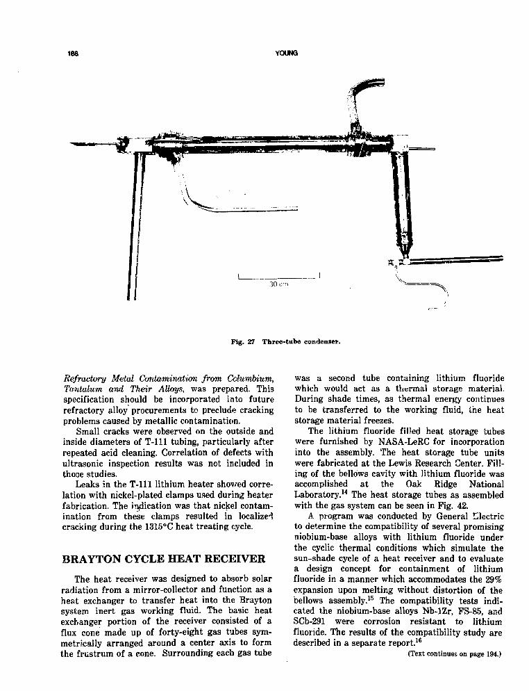
188 YOUNG
Fig. 27 Three-tube condenser.
Refractory Metal Contamination from Columbium,Tantalum and Their Alloys, was prepared. Thisspecification should be incorporated into futurerefractory alloy procurements to preclude crackingproblems caused by metallic contamination.
Small cracks were observed on the outside andinside diameters of T-lll tubing, particularly afterrepeated acid cleaning. Correlation of defects withultrasonic inspection results was not included inthooe studies.
Leaks in the T-lll lithium heater showed corre-lation with nickel-plated clamps used during heaterfabrication. The iiyiication was that nickel contam-ination from these clamps resulted in localizedcracking during the 1315°C heat treating cycle.
BRAYTON CYCLE HEAT RECEIVER
The heat receiver was designed to absorb solarradiation from a mirror-collector and function as aheat exchanger to transfer heat into the Braytonsystem inert gas working fluid. The basic heatexchanger portion of the receiver consisted of aflux cone made up of forty-eight gas tubes sym-metrically arranged around a center axis to formthe frustrum of a cone. Surrounding each gas tube
was a second tube containing lithium fluoridewhich would act as a thermal storage material.During shade times, as thermal energy continuesto be transferred to the working fluid, the heatstorage material freezes.
The lithium fluoride filled heat storage tubeswere furnished by NASA-LeRC for incorporationinto the assembly. The heat storage tube unitswere fabricated at the Lewis Research Center. Fill-ing of the bellows cavity with lithium fluoride wasaccomplished at the Oak Ridge NationalLaboratory.14 The heat storage tubes as assembledwith the gas system can be seen in Fig. 42.
A program was conducted by General Ulectricto determine the compatibility of several promisingniobium-base alloys with lithium fluoride underthe cyclic thermal conditions which simulate thesun-shade cycle of a heat receiver and to evaluatea design concept for containment of lithiumfluoride in a manner which accommodates the 29%expansion upon melting without distortion of thebellows assembly.15 The compatibility tests indi-cated the niobium-base alloys Nb-lZr, FS-85, andSCb-291 were corrosion resistant to lithiumfluoride. The results of the compatibility study aredescribed in a separate report.16
(Text continues on page 194.)
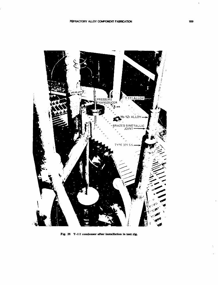
REFRACTORY ALLOY COMPONENT FABRICATION 169
BRAZED BIMETALLICJOINT
Fig. 28 T-lll condenser after installation in test rig.
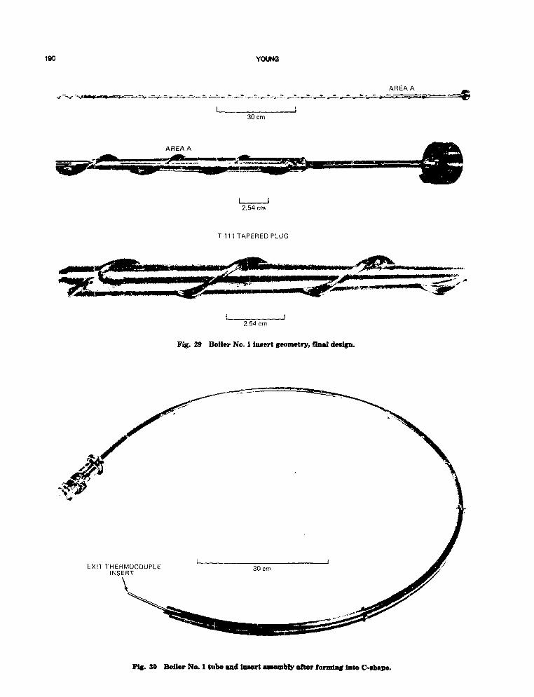
190 YOUNG
30 cm
AREA A
2.54 cm
T 111 TAPERED PLUG
J2.54 cm
Fig. 29 Boiler Nc. 1 insert geometry, final design.
AREA A
Kg. 30 Boiler No. 1 tube mnd insert awembly after forming into C-fbftpe.

REFRACTORY ALLOY COMPONENT FABRICATION 191
30 cm
LITHIUM EXITLITHIUM INLET END-
Fig. 31 T-Ul potassium boiler shell.
POTASSIUMOUTLET
-ACCELEROMETER SUPPORT
30 cm
Fig. 32 Boiler No. 1, completed assembly.

192 YOUNG
REDUNDANT PRESSURE-TRANSDUCER
Fig. 33 Boiler No. 1 installed in tert rig.
ROLLED ANDWELDEDSHELL
SPUN END CAP1
-LIQUID LEVEL PROBE
I2.54 cm
Fig. 214 T-lll alloy potassium head tank.

REFRACTORY ALLOY OOWPONENT FABRICATION 193
LIQUID THROTTLE VALVE
• UNALLOYED TANTALUMELECTRODE BARS
I f .1
30 cm
Fig. 35 T-Ill alloy potassium preheater assembly.
POTASSIUM VAPOR VALVE-
I 30 cmFROM BOILER EXIT TO CONDENSER I N L E T '
Fig. 3€ T-ll l alloy potassium desuperheater assembly.
T 111 ALLOY LINEEXTENDING TO -
BOTTOM OF TANK TO LITHIUM CIRCUIT
T-111 TO Nb-1ZrWELD
FILL AND DUMP LINE
30 cm
Fig. 37 Nb-lZr alloy lithium dump tank.

194 YOUNG
Fig. 38 Lithium EM pump duct subasaembly.
The weight summary of the Nb-lZr gas systemassembly is tabulated in Table 1 below.
TABLE 1Weight Summary of the Brayton
Solar Heat Receiver
Gas system assembly (Nb-lZr)Gas tubes (includes 266 pounds
of LiP)Inlet manifoldOutlet manifoldDucts (elbows and bimetallics)Foil insulation and thermocouples
Total
Weight,kg
2621181051614
515
WELDING DEVELOPMENTAND QUALIFICATION
Weld qualification for the Brayton cycle solarheat receiver consisted of personnel qualification
for the manual welding requirements and weldprocess qualification for each unique joint typeused in the fabrication of the heat receiver. Weldprocess qualification also included weldingequipment, fixtures, and tooling required for eachweld.
Welders were qualified for the manual weldingrequirements by making full fusion butt joints insheet and plate. The test piece illustrated inFig. 43 was fabricated to qualify the Nb-lZr alloyweldments required for gas system assembly. Asthe design progressed, additional joint types suchas the support brackets-to-manifold and shell sup-port ring-to-manifold were added. Three joints ofeach type were made and evaluated after prelimi-nary welding trials had established welding param-eters. Each type weld was made using the weldingequipment, process, and weld position intended forapplication to the heat receiver welding. Weld eval-uation consisted of radiographic inspection asapplicable, followed by sectioning and metallo-graphic examination.

REFRACTORY ALLOY COMPONENT FABRICATION 186
Fig. 39 Refractory metal furnaces set up for local annealing of weldmenta in the teat rig vacuum chamber.
The automatic weld required for the manifoldcircumferential joints was qualified by making twoweld specimens from 3.2-mm Nb-lZr sheet usingthe welding equipment and process intended forapplication to this weld. The evaluation of thesespecimens was the same as for the sheet and platemanual weld samples. A full-sized manifold mock-up, made from Type 304 stainless steel, was fabri-cated to qualify the tooling and fixtures requiredfor this weld as well as an additional qualificationof the welding equipment and process.
One of the primary purposes of the weld quali-fication task was to identify problems with weldjoint designs, welding procedures, or fixtures priorto commitment of hardware. As a result of thewelding qualification trials, five of the weld jointsused in the heat receiver required a change ineither the joint design or welding procedure.
Boss-to-Manifold Welds
The original boss-to-manifold weld joint designis illustrated schematically in Fig. 44. It was antic-ipated that full penetration would be achieved dur-ing the fusion pass applied to the OD. A secondweld pass with filler metal addition would com-plete the weld. Initial welding trials indicated thatfull penetration could be achieved; however, theweld heat input caused erratic melting of the IDedge of the manifold. Although the joint was struc-turally sound, the uneven and rough appearanceand possible adverse effects due to potentiallyexcessive geometric distortions were causes forrejection of the original welding procedure.
The new welding procedure devised for thisjoint incorporated both automatic and manualwelding techniques. Initially bosses were GTA tack

196 YOUNG
POTASSIUM EM PUMPDUCTSUBASSEMBLY
GAS CHROMATOGRAPHINERT GAS ANALYSIS
Fig. 40 Setup for field weld No. 1, potatuium subtMembiy.
welded to the manifold as shown in Fig. 45. Theroot pass was then made using the internal rotarywelding torch illustrated in Fig. 46. This procedureresulted in uniform fusion between the boss andmanifold. Weld inspection was simplified becausethe extent of penetration could be determined visu-ally at the joint OD. A manual filler pass was thenapplied to the OD of the joint.
Inlet and Exit Tube-to-Manifold WeldA problem similar to the boss-to-manifold weld
was encountered, i.e., uneven and rough melting atthe manifold ID. In this case, however, the auto-matic internal welding technique could not beapplied because a 7.6-cm dia elbow was welded
directly to the outlet manifold. This problem wasresolved by enlargement of the manifold hole asillustrated in Fig. 47. By maintaining the jointoverlap at a maximum of 0.5 mm, it was possibleto fully penetrate the joint. This resulted in com-plete fusion at the joint ID. A manual filler passwas then applied to form a reinforcing fillet.
Boss-to-Ferrule WeldThis joint was originally planned to be made
using the orbit arc welding equipment. This equip-ment, illustrated in Fig. 48, consisted of a portablewelding head with a motor-driven split-ring elec-trode holder. Thus, tube-to-tube joints could bewelded automatically without rotation of the tubu-

REFRACTORY ALLOY COMPONENT FABRICATION 197
Fig. 41 Field weld No. 2, Uthiom assembly.

198 YOUNG
COEXTRUDED JOINTTO OUTLET ELBOW
WELD
• COEXTRUDED JOINTASSEMBLY TOINLET WELD
Fig. 42 Nb-IZr thermal storage heat receive; for solar Brayton system.
lar members. This process was abandoned for theheat receiver application when, after repeatedattempts and redesigns, the equipment failed dueto breakdown of internal insulation,
During the weld fixture planning stages, designprovisions were made to allow for positioning theheat receiver for manual welding of boss-to-ferrulejoints. This approach was adopted and qualifica-tion joints were prepared. During welding, thejoint position was equivalent to that required dur-ing final assembly of the heat receiver. That is,each joint was welded in 180° increments to simu-late the two positions required on the assembly.
Tube-to-Feri-ule WeldThese joints were produced by rotation of the
tubular joint under a stationary GTA torch. Pre-
liminary trials indicated lack of weld penetration.Variation in weld parameters to obtain full pene-tration, such as increased welding current ordecreased welding speed, resulted in severe under-cutting of the tube wall.
The ferrule was redesigned to reduce the wallthickness at the socket joint by 0.25 mm. Full pen-etration welds without undercutting were thenmade without difficulty.
Support Pad-to-Tube Weld
Metallographic examination of initial jointsindicated that weld fusion zones had less cross-sectional area than the base metal. This conditionwas corrected by adding a filler pass to the weldprocedure for this joint.
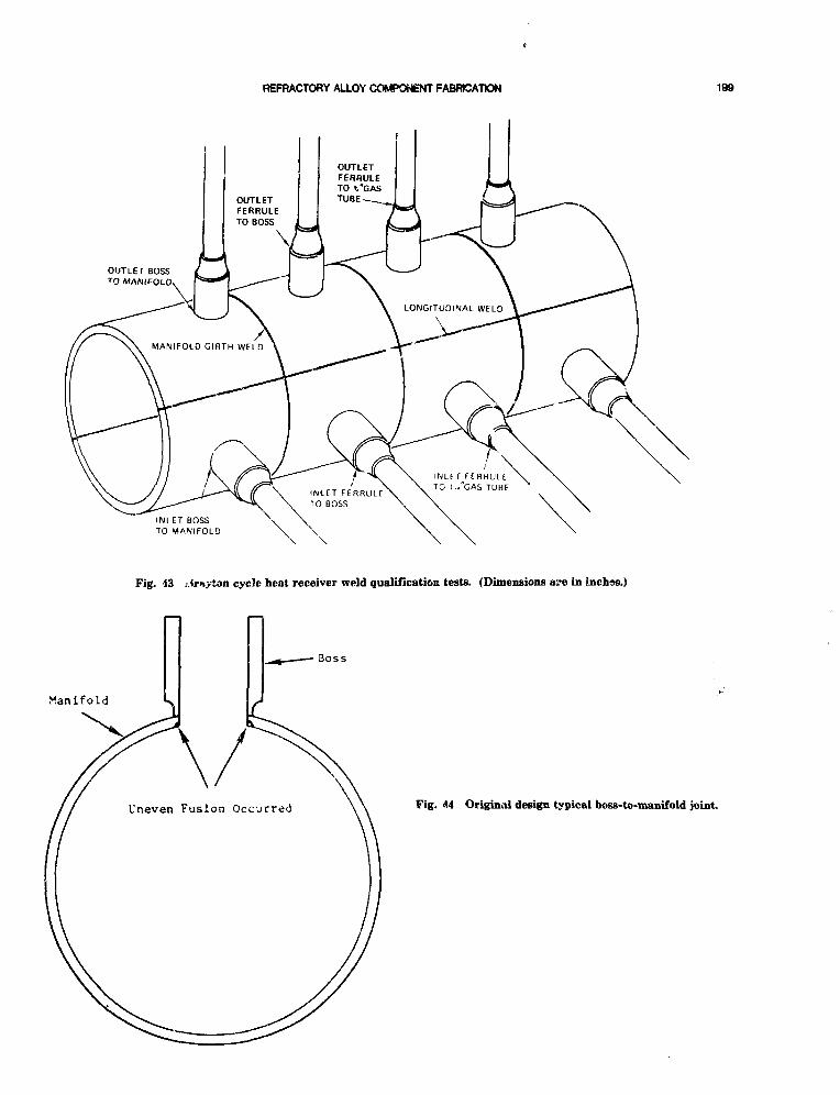
REFRACTORY ALLOY COMPONENT FABRICATION 199
Fig. 43 j.traytan cycle heat receiver weld qualification tests. (Dimensions are in inches.)
Boss
Manifold
Uneven Fusion Occurred Fig. 44 Original design typical boss-to-manifold joint.

200 YOUNG
TYPICAL TACK WELDS
30 cm
Fig. 45 Weld qualification teat specimen illustrating GTA tack weldfe used for boss positioning.
WATER AND POWER CONNECTIONS
SUPPORT FRAME
Nb-1 Zr15.2-cm DIAMETERMANIFOLD TORUS
DRIVE MOTOR
Fig. 46 Internal rotary GTA welding torch.

REFRACTORY ALLOY COMPONENT FABRICATION 201
0.5 mm MAXIMUMOVERLAP OF JOINT
Fig. 47 Design af tube-to -manifold weld joints.
FABRICATION AND ASSEMBLY
The complete fabrication sequence for the Bray-ton cycle heat receiver is depicted in Fig. 49. Forthe gas system assembly, close integration wasrequired of the four basic fabrication processes:machining or forming, cleaning, welding, andpostweld annealing. Each component fabricationand assembly was controlled by manufacturinginstructions which defined the detailed sequencesand inspection points.
The major fabrication effort involved the gassystem assembly sequences as shown schematicallyin Figs. 50 to 55. Consideration of refractory alloywelding and related sequences were of particularsignificance and are therefore discussed in detailprior to discussing the gas system fabricationeffort itself.
All gas tungsten arc (GTA) welding of the gassystem was done using the weld chamber shown inFig. 1. This welding system consisted of the basic0.9-mdia by 1.8-m-long chamber shown on the leftto which two 2.4-m-dia by 1.2-mlong chamberextensions were attached. Not shown is the univer-sal welding positioner incorporated in the two2.4-m-dia chamber extensions, which was especially
developed for welding the refractory metal gas sys-tem. Welding was conducted using the proceduresdescribed previously.
The welding sequences employed were dictatedsomewhat by the requirement for postweld annealof all weldments at 1205cC for 1 h in vacuum.Thus, during manifold welding sequences as shownin Figs. 50 to 52, the girth joints were only tackedto provide for later splitting of the manifolds forannealing. This operation was necessary becausethe complete manifolds could not be accommodatedin vacuum furnaces which could be qualified to therequirements of the specification. The remainder ofthe manifold welding followed the natural fabrica-tion sequence. Two circumferential welds producedthe basic manifold sections. After machining ofboss and nozzle holes, bosses were welded in placeby a combination of internal GTA welding of theroot pass and a second manual filler pass on theboss OD. The support brackets, shell support ring,and inlet or outlet were then welded to the mani-folds. After splitting of the manifold and postweldannealing, the halves were rejoined by a manualgirth weld. These two welds were annealed locallyusing a portable furnace specially constructed forthis purpose. The vacuum environment duringannealing was provided by the welding chamber.
The heat storage tubes were supplied by NASAwith the lithium fluoride fill of the convolutionscomplete. As shown in Fig. 53, each tube wastrimmed to the proper length prior to automaticGTA welding of the inlet ferrule and reducer to the3.18-cm OD gas tube. The 1.9-cm OD outlet tubewas then trimmed to length (long leg), and the out-let ferrule was welded. At this point, the short legof the outlet tube was trimmed to compensate forlength variations in the as-received gas tubos. Thisoperation produced a matched pair which wasmaintained by serial number until the final weldbetween the extension tube and reducer on the gastube. The two welds at the reducsr were then vac-uum postweld annealed in the voiding chamberwith the use of a specially designed furnace. Tube-to-ferrule welds were annealed later in conjunctionwith the final assembly boss-to-ferrule welds.
The welding of 48 gas tubes to the two mani-folds was accomplished with the assembly posi-tioned in the large lotatable welding fixture. Asmentioned previously, these 96 welds were origi-nally planned to be made by the orbit arc tech-nique. As shown in Figs. 54 and 55, the rotatingfixture was to be used to position each weld infront of the welding ^ .ions. Because it wasnecessary to use manual welding techniques, accessto the ID and OD of each weld was required. This

8to
TUNGSTEN ELECTRODE WATER-COOLED CONTACTOR
S P L I T ROTATING RING
/MSP,' NUCUAR SYSTEMS PROGRAMS MOTOR DRIVE UNIT
Fig. 48 Special water-cooled tube welding head.

REFRACTORY ALLOY COMPONENT FABRICATION 203
INLET FERRULE REOULfR HEAT RECEIVERTUBES
BASICMANIFOLD BOSSES
TOP ENCLOSUREBRACKETS
SUPPORTRING
OUTLETELBOW
TUBE EXTENSIONOUTIET
FERRULE
BASICMANIFOLD
SUSSES BRACKETSSHELL SUPPORT
RING
GAS TUb*S(48)
OUTLETBIMETALLIC
OUTLET MANIFOLD
INLETBIMETALLIC
GAS SYSTEMASSEMBLY
TOP ENCLOSURE
INLETOIFFUSER
INLET MANIIOLO
FINAL ASSEMBLY
FLEX PLATES SUPPORT CONE
APERTURE CONE
FLEX PLATES
Fig. 49 Breyton cycle heat receiver fabrication sequence.
was accomplished by rotating the entire fixture 90°on its trunnions so that the planes of the mani-folds were in the vertical position. One-half of eachweld joint was made in each of the four weldingpositions. To equalize weld distortions as much aspossible, welds to each manifold were made in sixgroups of eight, alternating back and forth acrossthe manifold diameter. These welds were postweldvacuum annealed using two specially designed fur-naces, each capable of accepting eight weld joints.
The gas system assembly was completed withthe welding of the bimetallic joint assemblies tothe manifolds. These welds were last in the fabri-cation sequence because with the bimetallics inposition the gas system assembly could not berotated within the welding chamber. To changewelding position, it was necessary to move theassembly onto the transfer dolly, rotate, then repo-sition in the welding chamber. Postweld annealswere done with the same furnace previously usedfor the manifold girth weld anneals.
As illustrated in Fig. 49, the inlet and outletmanifolds and the 48 gas tubes were the majorcomponents of the gas systems. These hardwarefabrications will be discussed in this section.
Manifolds
The basic manifold sections were formed byradial draw forming. Because of the high cost oftooling, this method is generally considered onlyfor parts which cannot be formed by more conven-tional methods or for production quantities. How-ever, because draw forming required significantlyless raw material than would have been requiredfor other methods being considered, the savings inmaterial costs more than offset the higher cost oftooling.
As depicted in Figs. 50 and 51, four 180° seg-ments were required for each manifold. Tool try-outs wert done with stainless steel, and these partswere later used to fabricate an inlet manifold fortooling, welding, and other checkouts.
Forming the Nb-lZr segments wa3 highlj suc-cessful in that only nine close-trimmed "pieces ofmaterial were required to produce the eight mamfold segments. Radial draw forming was done atthe Cyril Bath Co., Solon, Ohio.
After being accurately machine-trimmed at the180° center plane, the basic manifold sections
(Text continues on pasre 208.)
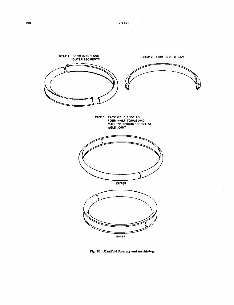
204 YOUNG
STEP 1 FORM INNER ANDOUTER SEGMENTS
STEP 2 TRIM ENDS TO SIZE
STEP 3 TACK WELD ENDS TOFORM HALF-TORUS ANDMACHINE CIRCUMFERENTIALWELD JOINT
OUTER
tNNER
Fig. 50 Manifold forming and machining.

REFRACTORY ALLOY COMPONENT FABRICATION 206
STEP 1 t/VELD INNER AND OUTERHALVES TOGETHER
STEP 2 MACHINE HOLES FORBOSSES AND NOZZLE
STEP 3 WELD BOSSES TO TORUS
STEP 4 WtLD INLET OR OUTLETTO MANIFOLD
STEP 5 WELD BRACKETS ANDSHELL SUPPORT RINGS
Fif. 51 Manifold welding.

206 YOUNG
STEP 2 WELD TIE BARSACROSS 180° SEGMENT
STEP 1 SPLIT MANIFOLD AT TACK WELDSAFTER ESTABLISHING UNSPRUNG
TORUS DIMENSION
STEP 3 POSTWELD ANNEAL AT 1205°C
DIMENSION ASDETERMINED
IN STEP 1
STEP 4 REMOVE TiE BARS, WELD PREPFIXTURE FOR GIRTH WELDS
STEP 6 FINAL MACHINING OF BOSSES,BRACKETS, AND SHELL SUPPORTRING
STEP 5 LOCAL ANNEAL GIRTH WELD
Fig. 52 Manifold annealing, final welding, and machining.

REFRACTORY ALLOY COMPONENT FABRICATION 207
1 TRIM TUBES TO LENGTH
2 WELD INLET FERRULEAND REDUCER
WELD WELD
3 TRIM OUTLET TUBETO LENGTH
4 WELD OUTLET FERRULE
WELD
5 TRIM SHORT LEi OF OUTLETTUBE TO MA I CS HEAT STORAGETUBE LENGTH i
TRIMLENGTH
7 LOCAL ANNEAL REDUCER WELDS
SPLITFURNACE
H,
6 WELD HEAT RECEIVER TUBETO OUTLET TUBE
WtLD
7l III'WWLL \
Fig. 53 Heat storage tube weld sequence.

206 YOUNG
MANIFOLD WELDING 'POSITION '
Fig. 54 Welding chamber installation, side view.
shown in Fig. 56 were GTA tack welded at thegirth joints to form 360° half shells. The weld fix-turing for a typical inner manifold section isshown in Fig. 57. The inside-the-chamber view ofthe tack welding operation for a typical outer sec-tion is shown in Figs. 58 and 59.
Each of the four 360° half sections wasmachined and weld prepped for the circumferentialweld joint. An inner section is shown beingmachined in Fig. 60.
The inner and outer manifold sections werecleaned, and both manifolds were set up for weld-ing of the circumferential joints as shown inFig. 61. The joints were aligned and GTA tackwelded during the first welding operation. Themanifolds were then removed from the welding fix-ture, reversed, and tack welded on the oppositeside. The. automatic GTA weld of one joint in eachmanifold was then made, and the manifolds againreversed to provide access to the first tack weldedside. The automatic GTA weld of one joint in each
manifold was then made, and the manifolds againreversed to provide access to the first tack weldedside. The automatic GTA welding of these jointswas done in a single pass with filler wire addition.
After completion of the circumferential welds,the boss location holes were drilled and reamed ona horizontal boring mill equipped with a rotarytable. A large Bridgeport head was mounted to themachine which enabled the machining of the holesat the proper angle with the manifolds in the hori-zontal position. The inlet nozzle and outlet elbowopenings were also machined at this time. Theinlet manifold after completion of all hole drillingis shown in Fig. 62.
The boss-to-manifold welds required threeoperations: tack weld, automatic internal root weld,and manual filler pass. Alignment of the bosses fortack welding was accomplished by a molybdenumplug which extended through each boss and themachined hole in the manifold. The alignment fix-ture is shown in Fig. 63. The manifold mounting

REFRACTORY ALLOY COMPONENT FABRICATION 209
SUPPORTSTRUCTURE
ANO -WELOINGS
POSITIONER
Fig. 55 Welding chamber installation, end view.
Fig. 56 Inner and outer manifold sections, cleanedin preparation for girth tacking.
arrangement during tack welding and subsequentoperations is shown in Fig. 64.
While performing the root pass internal boss-to-manifold welds on the outlet manifold, a failure
of the internal welding head occurred. Welding of27 bosses had been completed before the failure.The cause of failure was traced to the automaticwelding equipment. Although set for 160 amps, acurrent in excess of 400 amps was recorded, whichresulted in failure of the torch end of the internalwelding head. Primarily copper, some stainlesssteel, and Teflon melted off the end of the weldinghead, and the torch cooling water was released bythe failure.
The boss-to-manifold joint which ^as beingwelded was severely embrittled due to contamina-tion, as shown in Fig. 65. Coating-type deposits ofcopper and other materials probably carried by thesteam were more widespread. Spatter-type depositswere located at the bottom of the manifold directlybelow the boss which was welded.
The rework procedure outlined in Table 2 wasimplemented. In addition, it was determined thatloss of the feedback signal had driven the output ofthe welding machine above the 400 amp rating and

210 YOUNG
Fig. 57 Loner manifold section being loaded into weld chamber fot girth tacking.

REFRACTORY ALLOY COMPONENT FABRICATION 211
Fig. 58 Outer manifold section set up in weld chamber for tack welding of girth joints.
TABLE 2
Rework Procedure for Oitlet ManifoldBoss Weld Failure
1. Remove tack welded boss.2. Trepan machine 7.6-cm-dia hole at contaminated boss on
existing centerline.3. Perform interstitial analysis on disk removed to verify that
all contaminated Nb-lZr material has been removed.4. Perform cleaning trials on internal surface of slug to verify
adequacy of cleaning techniques. Also check out picklingmethod using foil to ensure hydrogen embrittlement willnot occur in manifold.
5. Mechanically remove local deposits from manifold.6. Nitric acid pickle and rinse (primarily to remove copper).7. Nitric HF pickle and rinse.8. Machine and weld prep insert piece to fit 7.6-cm-dia hole
with predrilled boss hole. Use piece removed from manifoldsection girth trim so as to match contour.
9. Clean, weld, and X-ray.10. Reclean bosses and retack in preparation for internal root
pass welding.
caused the welding head failure. To prevent arecurrence, a meter relay circuit was incorporatedto provide failsafe shutdown in the event that out-put current exceeds a preset value for any reason.A new internal welding head was also fabricatedand checked on trial welds prior to resuming mani-fold welding. Automatic internal welding of theremaining bosses on the outlet manifold and the 48inlet manifold bosses was then completed withoutdifficulty. Addition of the manual filler pass oneach boss OD completed the boss-to-manifold weld-ing.
The attachment of support brackets, shell sup-port rings, inlet nozzle, and outlet elbow wasaccomplished with both manifolds in the weldingchamber so that at least two welding operationscould be performed during each chamber cycle. Theshell support rings and bracket support tubesshown in Figs. 66 and 67 represent typical

212 YOUNG
Fig. 59 Tack welding girth joint of outer manifold section.
attachments. Alignment fixtures were used to posi-tion each component as illustrated in Pigs. 68 and69 for the outlet manifold support tube welds andfor the outlet manifold-shell support ring. Typicalweldments for the inlet manifold are shown inFig. 70.
Upon completion of welding, each manifolddiameter was measured at the girth tack weld areaprior to splitting the manifolds. The restraining tiebars required for postweld anneal v/ere thenmachined to dimensions which maintained theactual manifold diameters. The tie Dars, fabricatedfrom Nb-lZr alloy, tube and discs, were thenwelded to each half manifold as in Fig. 71.Postweld annealing was performed in two1205°C/l-h cycles of the Brew Model 922 vacuumfurnace, located at Stellite Division, Cabot Cor-poration, Kokomo, Indiana. The significant stressrelief achieved during the postweld anneal was evi-dent by the complete lack of manifold spring-backwhen the tie bars were removed.
The manifolds were then set up in the weldingfixture for the manual welds of the girth joints.Upon completion of this operation, the girth jointswere vacuum annealed using the local furnacesetup in the welding chamber. During the vacuumanneal of the outlet manifold, girth weld No. 1, apressure surge aborted the run after 55 min of the60-rn!n cycle. An air leak occurred in plastic tubingused to connect the sealed motor housing on theweld fixture to a vacuum feedthrough. The resultsof various tests and analyses performed to deter-mine the condition of the manifold indicated thatcontamination was superficial. Polishing withabrasive paper was used to remove surface contam-ination. The out3ide of the manifold was then acidcleaned and rinsed.
The final machining of manifolds requiredextensive setup and dimensional checks to ensuremachining features and dimensions would result.As anticipated during the design phase, distortionswere present in features and feature locations due

I
Fig. 60 Machining for circumferential weld joint on inner manifold section.

214 YOUNG
Fig. 61 Inlet aad outlet manifold being set up for automatic GTA welding.

REFRACTORY ALLOY COMPONENT FABRICATION 215
Fig. 62 Inlet manifold after machining of 48 boss holes and nozzle opening.
to general welding distortions and the need to fab-ricate the manifolds in 180° half-sections (becauseof annealing furnace limitations). Planning, tool-ing, and stock allowances proved to be both neces-sary and sufficient.
All openings were plugged or otherwise sealedto maintain internal cleanliness. Exterior surfaceswere protected when they were not involved in thespecific work area. The bosses were rough and fin-ish turned with special hollow mills again usi.igthe Bridgeport head mounted on the Lucas HBM.
The horizontal pads on the manifolds weremi!led with a right angle attachment and drilledwith the Bridgeport head. The facility mountingpads (for attachment of the receiver to the Braytonsystem) were milled and drilled with the spindle ofthe machine. The shell support rings were rotarymilled with a right angle attachment and drilledwith the machine spindle.
After final machining, cleaning, and inspection,the inlet and outlet manifolds shown in Figs. 72and 73 were ready for gas system assembly.
Gas Tube Assembly
The fabrication sequence depicted in Fig. 53was followed exactly during gas tube assemblvwelding. A typical welding operation on the heatstorage tubes is shown in Fig. 74. A typical weldjoint for inlet ferrule-to-tuLt . shown in Fig. 75.A plastic-covered wire rack was constructed tn pro-vide handling of eight tube assemblies during eachwelding chamber cycle. The typical gas tubeassemblies are shown in Fig. 76.
Gas System Assembly
The assembly fixture consisted basically ofstainless steol angle brackets which bolted to themanifolds and rotating ring of the welding fixture.The manifolds were mounted as shown in Fig. 77,aligned, and secured to correct dimensions. Thewelding fixture was then rotated with the mani-folds in the horizontal and vertical planes, anddimensions were rechecked tc ensure that no sig-

216 YOUNG
Fig. 63 Boss alignment fixture locating a boss on inlet manifold; other bosses shown have been tack welded.
Fig. 64 Inlet and outlet manifold* mounted on routine weld fixture; fixture shown with outlet manifold routedto lower position after tacking all 48 DOSIMSS.

REFRACTORY ALLOY COMPONENT FABRICATION 217
r
\
Fig. 65 Outlet manifold illustrating boss location where welding torch failure occurred.
nificant shifting would occur during final assemblywelding.
The 48 gas tubes were then installed as shownin Fig. 78. Originally, the plan was to install thesupport spider after all pas tubes were in position.However, in an attempt to slowly raise this sup-port, five gas tube extensions were dented.Although leak tight, these damaged areas werereworked by the addition of a small amount offiller metal followed by postweld anneals. X-rayand helium leak check inspections were also per-formed successfully.
The spider and its support brackets were thenmodified to eliminate the potential for damagingother tube assemblies. A heavy center disc wasremoved, and the heavy spider support bracketswere replaced by the smaller and lighter spoke-likesupport shown in Fig. 78. It was not possible toinstall all the tubes after the spider was posi-tioned. All the tubes were then reinstalled andshimmed with foil at the spider cutouts.
The 96-tube ferrule-to-manifold boss welds wereinitiated by first tack welding the 48 inlet manifoldwelds. The welding proceeded as each joint weldwas made in two half-'ircumference passes. Theelding fixture was rotated in four positions to
obtain access for the following welding sequence:(1) outlet manifold, OD side, (2) outlet manifold, IDside, (3) inlet manifold, ID side, (4) inlet manifold,OD side. At each position, welds were made ingroups of eight, rVernating back and forth acrossthe manifold diameter. After careful visual exami-nation a few joints were reweided to ensure that asufficient overlap was in evidence at adjacent weldpasses. A helium leak test indicated that all jointswere leak tight.
Postweld annealing c" these tube welds wasaccomplished using the same local furnaces thathad been used previously for gas tube anneals. Ateach joint location, there were two welds actuallyannealed: tube-to-ferrule and ferrule-to-bosj. Eachof the two furnaces covered eight tube joints suchthat 16 anneals were accomplished during eachvacuum cycle of the welding chamber Furnacelocationu were alternated back and forth across themanifold diameters for each annealing cycle.
The final gas system assembly welds were thosewhich attached the coextruded joints to the inletand outlet manifolds. These were manual welds inthe 7.6-cm-dia duct tubing as shown in Fig. 42.
(Text continues on page 224.)

218 YOUNG
Fig. 66 Shell support rings for inlet and outlet manifolds; temporary bridge shown tack welded at nozzle cutoutlocation on inlet ring.
y2.54 en.
Fig. 67 Typical manifold support tube*.

Fig. 68 Welding alignment fixture for outlet manifold support tube.
ro3

220 YOUNG
Fig. 69 Weld alignment fixture for outlet manifold shell ring.
/BOSS TO MANIFOLD MANIFOLD CIRCUMFERENTIAL WELD
FACILITY MOU'TIMC PAD TO
Fig. 70 Inlet manifold, typical weldmento required during fabrication.

BPFRACTORY ALLOY COMPONENT FABRICATION 221
Fig. 71 Inlet manifold, restraining tie bars tack welded to halves for postweld anneal.
Fig. 72 Outlet manifold prepnred for gas system assembly.

222 YOUNG
Fig. 73 Inlet manifold ready for gas system assembly.
Fig. 74 Heat iterate tube* loaded for assembly welding of inlet ferrules and reducers.

REFRACTORY ALLOY COMPONENT FABRICATION 223
Fig. 75 Closeup of typical automatic weld inlet ferrule-to-tube, as seenthrough vacuum chamber viewport.
KFUUCFR\ "7 -»— i \ . in r F R R U L L
1/ /
-GAR TUBF FXTFKSION
- - 0 U T 1 F.T FFRRULF
Fig. 76 Typical heat storage tube assemblies.

224 YOUNG
Fig. 77 Manifold mounted on rotating weld fixture.
The furnace which had been used for manifoldgirth weld anneals also accomplished the postweldanneals of these joints.
Intermediate leak checks had been performedon each component of the gas system assembly aswell as all individual assembly welds. The accep-tance mass spectrometer leak test of the entire gassystem was performed by independent evacuationof the gas system while it was positioned inside thewelding chamber. Helium was then introduced intothvi welding chamber and thus completely sur-rounded the gas system.
SUMMARY ANDRECOMMENDATIONS
The T-lll Potassium Boiler Development TestRig and the Nb-lZr Brayton cycle heat receiverrepresent the two largest, most complex systemsfabricated during r.-e first space power era.Experience gamed during the welding of refractory
alloys resulted in the development of specifications,equipment, and inspection techniques which pro-duced highly reliable, leak free hardware.17
The development of tubular joints betweenrefractory and nonrefractory alloys provideddesign flexibility in material selection. Portablefield welding procedures and equipment eliminatedsize restrictions on refractory alloy assemblies andpermitted field repairs and component modifica-tions.
One key to this success was the detailed fabri-cation planned which occurred throughout thesystem design phase. Material procurement,machining or forming, cleaning, welding (sequence,fixtures, etc.), and postweld annealing were closelyintegrated with design.
The Yielding of T-lll alloy presented moreproblems with quality assurance than previouslywelded niobium-base alloys. Weldability determi-nation gave needed insight but could not evaluateweld cracking encountered in large, complexcomponents.18 By 1972, many causes of defects liad

REFRACTORY ALLOY COMPONENT FABRICATION 225
Fig. 78 Gat system setup for assembly welding.
been found and corrected; however, more basicunderstanding is needed. In all cases, T-lll defectswere repairable by welding. It should be noted thatevery T-lll component performed successfullyafter being qualified and accepted for alkali metalservice.
Since 1972 significant advancements haveoccurred in welding processes, nondestructiveinspection techniques, and control instrumentation.The new welding processes such as laser, GTADabber, and pulsed current GTA should beevaluated for refractory alloys. Since rapidadvancement in technologj' has occurred during thepast decade, fluorescent penetrant, ultrasonic, andradiographic inspection also should be reevaluated.
REFERENCES1. I. Mendelson, Design and Fabrication of BrayUm Cycle Solar
Heat Receiver, Final Rvport, GE SP-519, N* SA-CR-72872,July 1971.
2. J. A Bond, Test Rig Desigv and Fabrication,NASA-CR-135451, Vol. I, January 1W9.
3. T. F. Lyon, Purification and AvxUysis of Helium fr • theWelding Chamber, NASA-CR-54168, July 1965.
4. T. J. Moore, P. E. Moorhead, and K. J. Bowles, Specificationfor Cleaning, Fusion Welding, and Postheatvng Tantalum andColumbium Alloy. NA.SA TMX-6787° July 1971.
5. R. A. Ekvall, R. G. Frank, and W. R. Young, T- l i l AlloyCracking Problems During Processing and Fabrication,Paper VIII, Recent Advances in Refractory Alloy for SpacePower Systems, NASP-245, June 1969. •
6. G. P. Brandenburg and W. R. Young, Evaluation of WeldFiller Materials for T-lll Alloy, GESP-3S6, R-71-NSP-1,December 1970.
7. H. M. Cameron, Thermal Cycling Test on a S-Inch DiameterColumbium-1 Percent Zirconium to 316 Stainless Steel Tran-sition Joint, NASA TMX-2118, Nov. 1970.
8. S. R. Thompson, J. D. Marble, and R. A. Ekvall,Development at Optimum Fabrication Techniq^ws for BnuedTa/Type S16 SS Tubular Transition Joints, GESP-521, Con-tract NAS-3-11846.
9. E. E. Hoffman and J. Holowach, Ch-lZr Rankine SystemCorrosion Test Loop, NASA Ck-1509, June 1970.
10. R. W. Harrison, E. E. Hoffman, and J. P £mith, T-lllRankine System Corrosion Test Loop, Volumes I an** II,NASA-CR-134816, June 1975.
228 YOUNG
11. R. W. Harrison and J. Holowach, Final Report,—High Tem-perature Alkali Metal Valve Test Program, GESP-508, April1970.
12. S. R. Thompson and W. R. Young, InvestigoMon of Crackingin T-lll Alloy Tubing Associated vrith Spot Tack Welding,GESP-384, General Electric Company, 1970.
13. W. R. Young, Advanced Rankxne Potassium Boiler Develop-ment Program, T-lll Alloy Defect Studies, General ElectricCompany, 1971, unpublished.
14. P. A. Gnadt, Fitting Heal Storage Tubes for Solar BraytonCycle Heat Receiver with Lithium Fluoride, ORNL-RM-2732,July 1970.
15. R. W. Harrison and W. H. Hendrixson, Lithium Fluoride
Bellows Capnde Tests, Topical Report No. Z, NASA ContractNAS 3-8523, GESP-436, January 1970.
16. R. W. Harrison and W. H. HendrixBon, The Compatibility ofColumbium Base Alloys ivith Lithium Fluoride, TopicalReport No. 1, NASA Contract NAS-3-8523, GESP-261, Sep-tember 1969.
17. W. R. Young, Fabrication of T-l l l Test Loop Components,Paper VII, Recent Advances in Refractory Alloys for SpicePower Systems, NASA SP 245, June 1969.
18. G. G. Leasmann, Determination of the WeldabUity andElevated Temperature Stability of Refractory Metal Alloys,I. WeldabUity of Refractory Metal Allays, NASA CR-1607,August 1970.

Mechanical and Physical Propertiesof Refractory Metals and Alloys
J. B. CoDwayMar-Test Inc.
INTRODUCTION
This paper was written to provide some discussionof the technology of refractory metals and alloysfor application to space nuclear power. Specifi-cally, this paper was designed to focus on themechanical and physical properties of this group ofmaterials with the intent of identifying the 3tatusof existing information. In addition, another objec-tive of this paper was to make some assessment ofthe existing property information and then tomake use of this assessment in determining thosefuture material property measurements that mustbe made in order to serve the needs of the spacenuclear power programs.
Any review of the existing material propertydata for the refractory metals and alloys willreveal that much has been done in this area. Sucha review will also reveal that there have beenmany fairly extensive programs devoted to theresearch and development of refractory metal andalloys. One of these was initiated in the early 1960sat the Nuclear Materials and Propulsion Operation(later known as Nuclear Systems Programs) of theGeneral Electric Company in Evendaie Ohio. Thisprogram was sponsored by the U ted StatesAtomic Energy Commission, Division of ReactorDevelopment and Technology, Fuels and MaterialsBranch, and encompassed several facets of refrac-tory metal research including development ofrefractory metal processing procedures, develop-ment of advanced refractory metal alloys, thephysical metallurgy of refractory metal alloys,development of refractory metal nuclear fuel clad-ding materials, refractory metal thermocouples,radiation effects on fast reactor cladding andstructural materials, and physical and mechanical
property evaluations of refractor, metals andalloys. Because the author was directly associatedwith property evaluations, this effort was one ofthe sources of the information used in this paper todefine the status of this subject. Other sourcesincluded NASA-sponsorea programs at Westing-house and TRW and AEC/ERDA-sponsoredmechanical property program" at the Oak RidgeNational Laboratory (ORNL).
In all the subsequent discussions attempting todefine the available material property data basefor the refractory metals, it should be recognizedthat the sources mentioned above arf some 12 to20 years old. Some consideration was given to thedevelopment of a more up-to-date description ofavailable mechanical and physical property infor-mation through the use of a detailed review ofrecent literature. Because certain time limitationsdid exist in preparing for this symposium, such anin-depth review was not pursued. It is felt, how-ever, that the review presented here is of sufficienidepth to enable a reasonable position to be definedregarding the strength capabilities of refractorymetals. Before any subsequent experimental pro-gram to address the future needs of the spacenuclear power program is initiated, a supplementalreview to update the material property data basedefined in this paper would definitely be in order.
For the purposes of this symposium it wasdecided that the review portion of this papershould focus on the following properties:
1. Thermal expansion2. Thermal conductivity3. Enthalpy and heat capacity4. Tensile strength5. Stress rupture and creep strength6. Fatigue strength
227

228 CONWAY
Each property will be discussed individually, ?<\dselected examples of available data will bepresented. In addition, numerous literature refer-ences will be cited in the event that the readerdesires more detailed information. This approach isnecessary because the great volume of availableproperty information is too extensive for inclusionin a single paper.
REVIEW OF AVAILABLEINFORMATION
Thermal ExpansionA fairly detailed study of the thermal expan-
sion characteristics of refractory metals wasreported in the GE-NMPO program.1"7 A typicalplot of thermal expansion measurements isrepresented by the data for tantalum (in helium)in Fig. 1. Another interesting plot is shown inFig. 2. It compares expansion curves for tungstenand rhenium; also included is a curve for W-25Reand some calculated data for W-25Re based on asimple volume fraction approach. A comparison ofmany of the refractory metal expansion curvesdeveloped in this program is presented in Fig. 3.Another comparison of these data is presented inTable 1 where the least squares equation constantsare listed for the curves presented in Fig. 3.
Thermal ConductivityExperimental studies conducted by A. Feith at
GE-NMPO resulted in high temperature thermalconductivity data for several of the refractorymetals.8"12 A comparison plot published by Feith12
is presented in Fig. 4 and a thermal diffusivityplot published by Feith12 is presented in Fig. 5.
High temperature thermal conductivity data forTa and Ta-lOW were listed in a summary report26
and have been added to the plot in Fig. 4 to pro-vide a comparison of data for many of therefractory metals and alloys.
Enthalpy and Heat CapacityCalorimetric studies in the GE-NMPO program
led to enthalpy and heat capacity measurementsfor many refractory metals and alloys.13"17 Sometypical enthalpy data14 for rhenium and niobiumare presented in Figs. 6 and 'i. Another interestingplot of enthalpy data is presented in Fig. 8 basedon tests of the Mo-Re system. This plot revealsgood agreement between measured and calculateddata for Mo-50Re using a weight fractionapproach.
Hoch17 has tabulated enthalpy data as follows:Nb 1004°C to 2324°CTa 1042°C to 2349°CMo 994°C to 2355°CWo 935°C to 2976°CRe 990°C to 2368°C
Enthalpy data for Ta, Ta-lOW, T-lll, and T-222ha"e been reported;20 one ploi of these results ispresented in Fig. 9. Data fur Ta-lOW calculatedfrom the Ta and W da La using weight, fractionsyield excellent agreement with the experimentalcurve in Fig. 9.
Tensile Strength
A comprehensive review of the cuength proper-ties of numerous refractory metals and alloys hasbeen published.22 Ultimate and 0.2% yield strengthdata for selected materials have been employed toyield the plots shown in Figs. 10 and 11. Trendcurves have been drawn to proviue an approximate:> mparison of material strength. Actually, if amore detailed comparison of tensile strength isdesired (and, of course, this would bn the case priorto the initiation of any further experimental pro-grams in support of the space nuclear powereffort), special attention should be given to tensilestrength properties as affected by such factors as:product form (sheet vs. rod, etc.), purity (e.g., vari-ous oxygen contents), heat treatment (annealed,stress-relieved, etc.), heat-to-heiat variations,degree of cold work, and test environment (e.g.,vacuum vs. inert gas or liquid metal).
A fairly straightforward ranking of thestrength of the selected materials can be obtainedfrom the comparison presented in Figs. 10 and 11.In terms of ultimate tensile strength at 1400°C thematerial ranking (strongest to weakest) is: T-lll,W-25Re-30Mo (data23 from GE-NMPO program),TZM, W (based on some extrapolation), and Ta-lOW (based on some extrapolation); these are fol-lowed by Nb-lZr, Ta, and Nb at much lowerstrength levels. The top three or four materialsappear to exhibit a 1400°C strength that is two tothree times that of Nb-lZr. This same type of com-parison can be made in terms of yield strength(Fig. 11) with the same general results, although itdoes appear that at 1400° C the highest yieldstrength is exhibited by the W-Re-Mo alloy.
It has been stated61 that materials consideredfor long term applications above 1100°C will proba-bly be used in the fully recrystallized condition.For this reason, it was suggested that the type ofplot shown in Fig. 10 would be more realistic if the

PROPERTES OF REFRACTORY METALS AND ALLOYS 229
H 0 ! S N V d X 3 H V 3 N I I
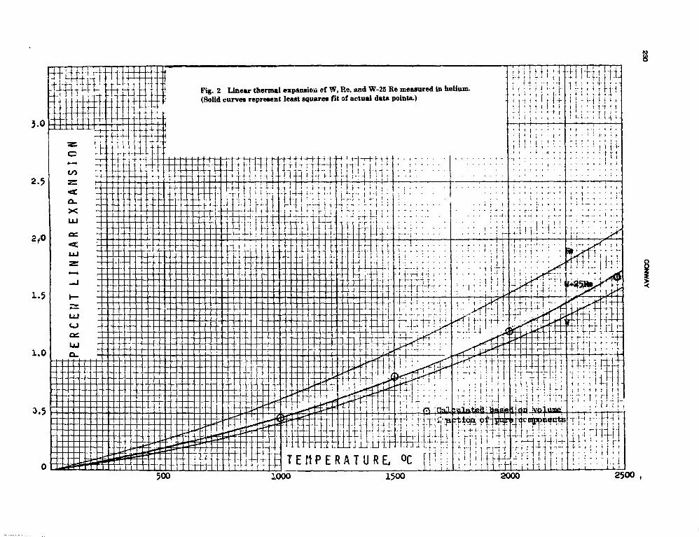
Fig. 2 Linear thermal expansion cf W, Re, and W-25 Re measured in helium.(Solid curves represent least squares fit of actual data points.)
T E M P E R A T U R E ,
! • • • ' +
i':;-ni-U:
1000 1500 2000 2500 ,

PROPERTIES OF REFRACTORY MF'ALS AND ALLOYS 231
I—I - R. H. FINCEL -A. C. LOSEKAMP-
TANTALUM10 TUNGSTEN"!
-t -ITUNGSTEN-
,25 RHENIUM -
EXPANSION TECHNIQUE. . MICROMETER TELESCOPE
\ fit12 14 16
TEMPERATURE °C x 10020 22 24 26
Fig. 3 Linear expansion rf various refractory metab tested in helium.
TABLE I
Least-Squares Equation Constants for Refractory Metal Linear- Expansion Data
Material
Tungsten
RheniumTantalumMolybdenum
NiobiumW-25ReMo-50ReTa-lOW
L- - L25-C
L25-C
Productiontechnique
PM*PMACtPMACPMPMACACPMPMAC
•Powder metallurgy.t Arc-cast.
X 100 =
Fjrm
RodSheetSheetSheetSheetRodSheetSheetSheetSheetSheetSheet
Ao+ Aj
-8.69-4.58-6.76-9.79-6.69-8.88-5.80-4.84-4.10-8.46-1.08-7.34
T + A
A«
x ioX 10X 10X 10X 10
x ioX 10X 10X 10X 10X 10X 10
LjjT^Tin'
"3 3.83-•' 3.65" J 3.91
3 5.89"3 5.40-' 3.94"4 4.59"3 4.25
3 5.964 3.91
"2 5.303 5.36
C;
A,
XXXXXXXXXXXX
all tests in helium)!
io-10"10~10"10"10"10"4
10 "4
10"10"10"
7.929.818.988.571.181.851.461.711.341.141.261.26
A,
XXXXXXXXXXXX
10"8
IO-8
io-8
io-8
io-'10"'io- '10"'10"'10"'io- '10"'
Temp, range,°C
25 to 250025 to 250025 to 250025 to 250025 to 240025 to 250025 to 225025 to 225025 tv, 210025 to 250025 to 225025 to 2350
comparison were confined to fully recrystallizedmater5 al. Such a plot is presented in Fig. 12. Whilethis comparison reveals the lower tensile strengthcharactei istic of recrystallized material, the samegeneral rankings of Fig. 10 are seen to persist. InFig. 12, however, data for ASTAR-8HC areincluded and reveal strengths comparable to thoseof the T-lll alloy. Yield strength plots based onrecrystallized material provide comparisons similarto those derived from the ultimate strength results.
Selecting a temperature of 1200°C refra torymetal strength (for recrystallized material) is suchthat an upper limit near 350 MPa (50 ksi) can Deexpected on ultimate tensile strength along with anupper limit of 210 MPa (30 ksi) on 0.2% yieldstrength.
In one other study,36 short-term tensile data fora series of niobium alloys have been reported.These results are presented in Figs. 13 and 14 andreveal that in the region above 1000°C higher
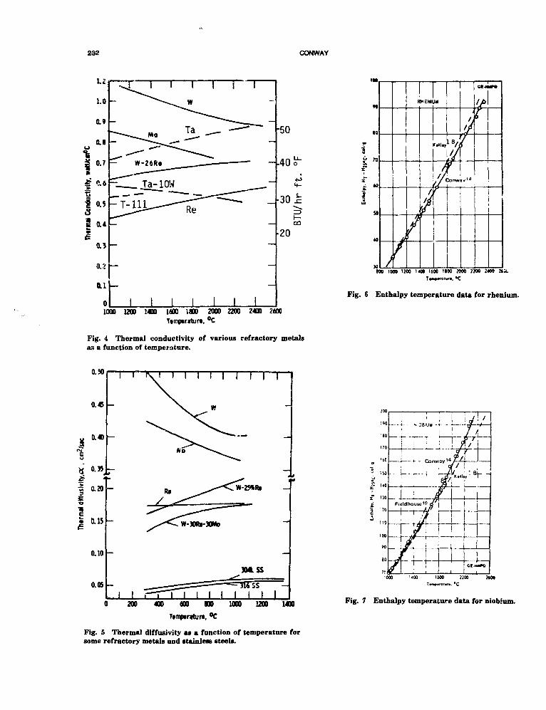
232 CONWAY
1000 1200 1400 1600 1800 2000 2200 2400 2600Ttmpariturt, °C
Fig. 4 Thermal conductivity of various refractory metalsas a function of temperature.
/ y
R
V
VENI
t
M
ftUwr
/ /ftr
/
av'4
CM-H
i
TOO 1000 WOO ! « • 1600 1100 2000 7200 2400
Fig. 6 Enthalpy temperature data for rhenium.
0.50
0.45
0.40
0.J5
« 0.20
I0.15
0.10
a 05
I I T
W-30Rt-HMo
304 SS
0 200 400 600 I B 1000 1200 1400
Timptrthin, °C
Fig. 5 Thermal diffusivity as a function of temperature forsome refractory metals and stainless steels.
Fig. 7 Enthalpy temperature data for niobium.

PROPERTES OF REFRACTORY METALS AND ALLOYS 233
180
160
120
I K'
MOLYBDENUM.
CALCULATED ALLOY DATABASED ON WEIGHT FRACTIl"
80
60
40
201000 1200 1400 1600 1800
TEMPERATURE, °C
2200 2400
Fig. 8 Enthalpy temperature data for Mo, Re, and Mo-50Re (actual alloy composition Mo-48Be).
strengths are obtained for D-43, Cb-75* ind FS-85compared to Nb-lZr (Fig. 13). A similar compari-son is obtained in terms of yield strength (Fig. 12).It is to be noted, however, that the ultimate tensilestrength data for these niobium alloys are posi-tioned just above the Ta-lCW data in Fig. 12 andsome 70 MPa (10 ksi) or so below the ASTAR-811C data.
In another fairly recent study,37 existing datafor Mo-TZM and several tantalum alloys werereviewed and evaluated in terms of Brayton-cyclepower plants for use in space applications. Tensiledata for ASTAR-811C (Ta-8W-lRe-0.7Hf-0.025C),ASTAR-1411C (Ta-14W-3Re-0.7Hf-0.025C), andASTAR-1611C (Ta-16W-lRe-0.7Hf-0.025C) werecompared in the form shown in Table 2. Viewed interms of Fig. 10, these data define strength values,at both 1092°C and 1262°C, that range from aboutthe level of tungsten for ASTAR-811C to slightlyabove the T-lll data for ASTAR-1611C.
Stress-Rupture and Creep StrengthA detailed discussion of the status of the avail-
able stress-rupture and creep data for the refrac-tory metals and the refractory metal alloys hasalready been published.24 This publicationpresented a comprehensive survey of existing liter-ature on these properties and also included ratherextensive high temperature test results obtained inthe GE-NMPO program. These data, generated inthe period from 1963 to 1969, were derived fromstudies of tungsten and selected tungsten alloys,
TABLESComparison" of Ultimate Tensile Strength
Data for Tantalum Alloys
Ultimate tensilestrength
Alloy
ASTAR-811CASTAR-1451CASTAR-1611C
ASTAR^ilCASTAR-1411CASTAR-1611C
Temperature, °C
109210921092
126212621262
MPa
390670810
29050C630
ksi
5797
118
4273Si
rhenium and selected rhenium alloys, and molybde-num and selected molybdenum alloys. In additionto being a helpful reference source, theConway-Flagella24 publication contains certain sec-tions that are devoted to meaningful comparisonsof material strength. Some of these sections havebeen used in the present paper to define asummary of what is known about the stress-rupture and creep characteristics of refractorymetals and then to use this summary to identifyareas of future v^ed. In developing this summary itwas decided to focus on the temperature regimefrom 800 to 2000°C and to employ informationfrom supplemental reference material.21"22125"27
An interesting sum n try plot based on 100-hrupture strength is presented in Fig. 15. Selectinga temperature of 1400°C from Fig. 15 and employ-ing some extrapolation of higher temperature datato 1400°C reveal that the highest strength is ex-hibited by Re, Ta-lOW, W-25Re, T-lll, and W.(Data25 for Nb-lZr are not considered to be repre-sentative of the material as the unusually highstrength is probably the result of contaminationduring test) This plot (Fig. 15) also points out atemperature regime (1200°C to ~1600°C) withinwhich the available data are limited. Because thistemperature regime is probably an important onefor space nuclear power applications, it identifiesan area of future work. Another observati >nderived from Fig. 15 relates to the attainable 100-hrupture strength for the refractory metals andalloys. For example, at 1400°C the upper limit for100-h rupture strength would appear to be in theregion of 70 to 105 MPa (10 to 15 ksi).
A parameter plot24-60 comparing the relativestrengths of several niobium alloys is presented inFig. 16. Based on 100-h rupture the AS-30 alloy(Nb-20W-lZr-0.1C) ranks close to TZM (in Fig. 15)
i,Text continues on page 238.)

234 CONWAY
LO
9C
35
80 . . _ .
75
70
65
60
55
50
15
4ff
..35
<
A
o i
> /
<
o
{i
• M HO 1. B.O E»pe
—Leas
1
o
1//<
J I
/
r
ach and H. \.. Johnston
Fieidhcu&e and J. C. Hedge
t squaie i comput ed-GE-NMPO
10
85
75
65
60
50
45
40 _ .
3;
TA-
J/
-10W
/
f
/
f
J
J
f
•
//
_oaat *c
Y*
uor&s cc
>
mputtid
"lOOO .1200 1400 1600 mo 2C00 :20C 2400 '000 1200 1400 1600 1800 2000 220O 2400
85
80
-J
tNT
ri/
75
70
65
60
55
50
45
40
35
T-
>
-111
/
f
/
J
m t— L
/
{
/
/
xp«rrmei
. ta t t sqv
/I/W
ntalarci co
f»
mputtd
90
85
ao
75
70
60
55
50
45
40
IS
T-
/
222
/
j
/
1 J
/
•
<//
-•0*1 tq
i
7/\
ntaljor»» co
/7
1000 1200 1400 1600 1800 2000 2200 2400 1000 1200 :400 1600 1800 2000 2200 2400
T , #C T , °CFig. 9 Enthalpy temperature data for unalloyed tantalum and some alloys of tantalum
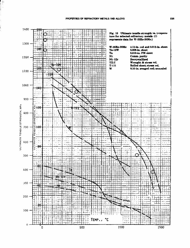
PROPERTES OF REFRACTORY METALS AND ALLOYS 236
1400
1300 — "t-
1200 —
Fig. 10 Ultimate teiuile strength vs. temperatore for selected refractory metals. (Orepresents data for W-25Re-30Mo.)
W-25Re-30Mo 0.12-in. rod and 0.012-ln. sheetTa-lOWTaNfcNb-lZrTZMT-lllW
0.060-in. sheet0.010-in. PM sheetComm. purityRecrystallizedWrought A stress rel.Rolled sheet; stress rel.0.16-in. swaged rod; annealed
"-r-r-- • -*«tr-B
Ll TEMP.y °C
1000 1500

236 CONWAY
1400_£i Fig. 11 Yield strength vs. temperature for-f- selected refractory metals. (O represents
data for W-25Re-30Mo.)
TEMP., °C
100
1000 1500

PROPERTES OF REFRACTORY METALS AND ALLOYS 237
1200 —
1100 —
1000 —
Fig. 12 Comparison of ultimate tensilestrength data" for several refractorymetals in the recrystallized condition.
tttfi-Jrr.i f . i i i T
n rrrr.

238 CONWAY
700
ksi
-100
- 80
- 60
- 20
- 10
200 400 600 800TEMPERATURE - °C
1000 1200 1400
Fig. 13 Effect of temperature on the tensile • trenfth of niobium alloys.
at 1000°C and appears to be in the strength levelas Re, Ta-lOW, etc., at 1400°C. It appears that asimilar strength ranking could also be assigned tothe F-48 alloy (Nb-15W-5Mo-lZr-0.05C).
A summary plot similar to Fig. 13 was pub-lished previously24 based on another refractorymetal survey28 and includes 1000-h rupturestrength. This plot is shown in Fig. 17 and revealssome of the same deductions made in connectionwith Figs. 15 and 16. For example, the data arelimited between —1200 and 1600°C, and the highstrength materials at 1400°C are Ta-lOW, T-lll,W-25Re, and perhaps Cb-TZM. (Sylvania A, W-0.5Hf-0.02C, is included in this 1000-h compilationand appears to be the strongest of all.) Finally,
Fig. 17 reveais that the maximum attainable1000-h rupture strength the refractory metals at1400°C is approximately 63 to 70 MPa (9 to10 ksi).
In a review of the Westinghouse and TRi» liter-ature mentioned above, no additional data wereprovided to extend the considerations of 100-h (and1000-h) rupture strength just described in connec-tion with Figs. 15, 16, and 17. For the mosl partthe more recent publications that were reviewedwere oriented toward a study of creep behaviorThese results will be treated in subsequent para-graphs.
A summary plot based on the accumulation of1% creep strain in 100 h is presented in Fig. 17
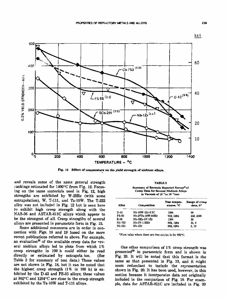
PROPERTIES OF REFRACTORY METALS AND ALLOYS 239
ksi
500
- 60
- 40
2CO 400 600 800
TEMPERATURE - °C
1000 1200
- 20
- 10
1400
Fig. 14 Effect of temperature on the yield strength of niobium alloys.
and reveals some of the same general strengthrankings estimated for 1400°C from Fig. 12. Focus-ing on the same materials used in Fig. 12, highstrengths are exhibited by W-25Re (with someextrapolation), W. T-lll, and Ta-lOW. The T-222alloy was not included in Fig. 12 but is seen hereto exhibit high creep strength along with theNAS-36 and ASTAR-811C alloys which appear tobe the strongest of all. Creep strengths of severalalloys are presented in parametric form in Fig. 15.
Some additional comments are in order in con-nection with Figs. 18 and 19 based on the morerecent publications referred to above. For example,an evaluation36 of the available creep data for °ev-eral niobium alloys led to plots from which 1%creep strengths in 100 h could either be readdirectly or estimated by extrapolation. (SeeTable 3 for summary of test data.) These valuesare not shown in Fig. 18, but it can be noted thatthe highest creep strength (1% in 100 h) is ex-hibited by the D-43 and FS-85 alloys; these valuesat 982°C and 1204°C are close to the creep strengthexhibited by the Ta-lOW and T-lll alloys.
TABLE 3
Summary of Recently Reported Survey" ofCreep Data for Several Niobium AlloyB
in Vacuum of 10"lo 10 'torr
Alloy
D-43FS-85B-66Nb-753Nb-lZr
Comimfition
Nb-lOW-lZr-O.lCNb-27Ta-10W-0.8ZrNb-5Mo-5V-lZrNb-5V-1.25ZrNb-lZr
Teat temper-ature*, °C
1204982,12041204932,1204982,1204
Range of creepdau,h*
90350.30003035,62,10
•First value where there are two entries is for 982°C.
One other comparison of 1% creep strength waspresented38 in parametric form and is shown inFig. 20. It will be noted that this format is thesame as that presented in Fig. 19, and it mightseem redundant to include the representationshown in Fig. 20. It has been used, however, in thissection because it incorporates data not originallyincluded in the comparison of Fig. 19. For exam-ple, data for ASTAR-811C are included in Fig. 20

240 CONWAY
100—Fig. 15 Comparison of iOO-h rupture data for selected refractory metals.
500 —
1 0 0 •
10
600
. "C

PROPERTIES OF REFRACTORY METALS AND ALLOYS 241
600
500
400
300
200
I00- 90<" ~-</i 80£ 70
60
50
40
30
20
10
H00°C 1200'C 1300°C 14OO°C
1 1 1 1
90 34«K>"
P = T (15 + log t R ) ; T°R, t R hrs
Fig. 16 Comparison of rupture strength of AS-5S, AS-30, F-48 and Nb-IZr.:<M
along with data for the niobium C-103 alloy (Nb-10Hf-lTi-0.7Zr) tested in vacuum over the tempera-ture range from 827 to 1204°C for durations to19,000 h. Another aspect of this commentary onFigs. 19 and 20 relates to the actual creepstrengths of some of the materials common to bothplots. It will be noted that, while the FS-85 dataappear to agree in both plots, the Nb-lZr data inFig. 19 define a much higher creep strength thanthat presented in Fig. 20 for the Nb-lZr material.On the other hand, the T-lll and T-222 data inFig. 20 define a slightly higher creep strength forthese materials than that identified in Fig. 19.
There appears* to be some question regardingthe creep strength data for Nb-lZr in Fig. 19. Asalready mentioned, it is much higher than thatreported in Fig. 20. It has also been noted that the
Nb-lZr data in Fig. 19 are much higher than the1% creep strength data cited for Nb-lZr bv Pionkeand Davis.36 Some attempt has been made to recon-cile this discrepancy as it appears that the data inFig. 19 for Nb-lZr pertain to rupture in 100 hrather than to 1% creep behavior. Until this pointcan be properly evaluated by a reassessment of thesource data, the continued use of ii:e position ofthe Nb-lZr parameter line in the Fig. 19 plot isnot recommended.
Data for ASTAR-811C in Fig. 20 have beenplotted in Fig. 18 to compare the 1% creepstrength in 100 h for this material to that of theother materials included in this plot. This compari-son shows that, Over the temperature range from-1200 to 1500°C, the ASTAR-8UC material iscreep-strength-comparable to NAS-36 and that

242 CONWAY
10,000—I
1000 —
if. 100
10
10OO 2200
TEMPERATURE («F|
2600 3000 3400 3800
T - w-ac%R(i^•".1 (POWDER MET,)
TZM (I) -STRESS RELIEVED ATI23CCTZM (2)- RECRYSTALLIZED AT IS40«CT ZM (3) - 1540 'C. WARM WORKED AT IO4O*C,
ANO STRESS RELIEVED AT123O*CTZM(4)-ANNEALED 2093*C, RE-EXTRUDEO,
AND WARM WORKED AT 13I5*CCb-TZM (5)-ANNEALED 2O95«C. RE-EXTRUDEO,
AND WARM WORKED AT I31S'CCb-TZM (6) ANNEALED 1927*C AND WARM WORKED
AT1370*CSU-l6o-1hr ATI200*CSU-16b-1hr ATt600*C, 3hrATI2OO'CT-222-2hr AT1315-CW-25%R«(ARC MELTED)-lhr AT 1700*CW-25% R«(POWDER MET.)-.hr AT 1600°CFS-85o-1hrAT137O*CFS-85b- lh r AT 1595'CD-43 -STRESS RELIEVED 10mm AT1205«CD-43M-V 2 hr ATI650'C, 25% COLD WO'K,
AND Ihr AT1425°CCb-752o-lhr ATI3I5*CCb-752b-1hrAT1S95#CB-66-C0LD WORKED 50%Cb-753- ih r ATI2O5«CNb-l%Zr-COLD WORKEDMo-0 5 % T i - STRESS RELIEVEDTo -10% W-COLO WORKEDT-IH -COLD WORKEDSYLVANIA A-UNKNOWNW-2%ThO2-WARM WORKEDUNALLOYED W- 5min AT II5O*CUNALLOYED Ta-COLD WORKED
- 4 —i
±W-2% ThOo
UNALLOYED WI POWDER MET.)
5»10'9 0 0 1100 1300 1500
TEMPERATURE
1700 1900 i'00 2300
Fig. 1? Stress to produce rupture in 1000 h for selected refractory metals and refractory metal alloys.28
these two materials are stronger than T-222, Ta-10W, W, and T-lll. Data for W-25Re are limited,but it would appear that in this temperature rangeof 1200 to 15OO°C this material would be creep-strength-comparable to UAS-36 and ASTAR- 811C.
Perhaps the most extensive source of long-term,high-temperature creep data for the refractorymetals has resulted from the NASA-sponsoredprogram at TRW Materials TechnologyLaboratories.39"45 This progr-.m reported creepdata for W-25Re, Mo-TZC, Mo-T7M, Ta, T-lll,Ta-lOW, ASTAR-811C, ASTAR-1411C, andASTAR-1611C tested in vacuum (10~8 to 10~u
torr) at temperatures to 1593°C (for ASTAR-81KT
and, for some materials, to test durations clos: to20,000 h. Other NASA-sponsored publications thatare pertinent to the creep behavior of refractorymetals are: ASTAR-SilO,46 Mo and Mo-3% to7% Re,47 C-103,48 FS-85,49 Ta-lOW,50 and T-222.51
In a recent review of existing data, English37
cited several factors that were considered impor-tant in the choice of materials for high-performance, long-lived Brayton-cycle power plantsfor use in space. One of these factors was associ-ated with the impressive data base that existed fortwo refractory alloys (Mo-TZM and ASTAR-811C;some 344,000 test hours of creep data). It was alsonoted that each of these alloys is compatible with

PROPERTIES OF REFRACTORY METALS AND ALLOYS 243
500 —
100 —I
100—3
8
-— Fig. 18 Compar'son of stretiea to give 1% creep in 100 fa far selected refractory metale.'" 1
1 0 —
600 800 1000 1200 1400 1630 1G00 2000

244 CONWAY
1000 —i
1% Creep in 10,000 !irs
iooo°c noo°c i2oo°c
39 41 43 45 47 49 5] *J
P = T (15 + Log t ) x 10"3 (T°R, t hrs)
•IAS-36 Ta-a. 7W-1.56Re-O. 7Po-0.25Hf-f>. 13Zr-_015C-0.015N
T - I11 Ta-8W-2"f
•-222 Ta-10.4W-2.4Hf-0.01C
F:-85 'ltj-28Td-10.5W-0.9Zr
Fig. 19 Comparison of 1 % creep strength of various alloys.32
both inert gases and the alkali metals (lithium andsodium). Furthermore, the ASTAR-811C alloy wascited as being weldable and ductile in the postweldcondition (Mo-TZM, on the other hand, was foundto be brittle in the postweld condition). Englishreported on a Larson-Miller analysis (see Fig. 21)of the ASTAR-811C data (time to 1^ creep), iden-tified 2-sigma :imits, and then used these indefining allowable design stresses for \% creep in40,000 h. A simila • analysis for Mo-TZM data wasalso reported.
Creep behavior cf the T-111 alloy hat, beennoted44 to be affected by preexposures to vacuumor to liquiu lithium particularly in the temperatureregime below 1100°C. However, no significanteffect was noted in specimens tested at 1316°C fol-lowing a 5,000-h preexposure to lithium.
A detailed analysis of refractory meta' data hasbeen reported24"29 based on parametric correlation.One example from this work is presented inFig. 22 where the data for tungsten and molybde-num are normalized in terms of the homologoustemperature. Another example is presented inFig. 23 for tungsten data and involves creep aswell as rupture information. Another example of
the parametric analysis of refractory metal data29
is presented in Fig. 24 where a comparison is madeusing data for several materials.
Fatigue Strength
Very little has been accomplished in the evalua-tion of the fatigue characteristics of the refractorymetals and alloys. Some load-control studies havebeen reported for Ta,25 Ta-lOW,26 and Nb25 butthese have involved tests at room temperature.Only two studies of strain-controlled fatiguebehavior at temperatures above 800°C were identi-fied in this limited survey. The one study30 involvedT-111 and ASTAR-811C (Ta-8W-J Re-0.7Hf-0.025C)at 11.5O°C tested in vacuum in diametral straincontrol; the other56 involved cross-rolled tungstentested in diametral strain control at 815°C in avacuum of 1 X 10~6 torr. Obviously, if fatigue isjudged to be an important consideration fornuclear space power applications, much remains tobe done in this area.
Using room temperature tensile properties inconjunction with the Universal Slopes31 equations,Collins, Moteff, and Chandler21 have made predic-tions to yield life values for a strain range of 2%.This evaluation provided the following:
Material
NbNb-lZrMoTZMTaT-lllTa-lOW
Cycles to failureat room temperature
1100ctOOO900
100016001300900
FUTURE NEEDS
Before any of the specifics of additional prop-erty information that might be required in order toachieve the objectives of the nuclear space powerprogram are discussed, it is important to considertwo general aspects of refractory metal behavior.These have both been alluded to, if not actuallymentioned, in the previous section of this paper butwarrant special attention in this section prior toany detailed definition of future needs. Actually,both of these points are all too familiar to thoseassociated with refractory metal technology, but itis felt *hat some reiteration of these responsecharacteristics is warranted.

PF 0PERT1ES OF REFRACTORY METALS AND ALLOYS 246
1% CREEP IN 1000 HRS
1000°C ' 1100°C 1200°C 1300°C 1400°C
Alloy
NbiZrNb10H»FS85T 1111222ASTAR411C
Spec.NcGravity Ig/en
8.68.8
10.616716.816.7
.3 -
200
100
J I I I L I "
a.
o."
V)c/3
10
36 38 40 42 44 46 48 50 52 54 56 58 60 62 64 66 63 70
PLM - (T + 460) x TO 3 (15 + log t)
Fig. 20 Comparison of the creep strengths of sime refractory metal alloys.
The first observation evolves from the discus-sion of tensile properties presented in connectionwith Figs. 10 and 11. It was noted that many fac-tors (product form, method of manufacture, etc.)can have a pronounced effect on the magnitude ofthe property being n. asured. It is not very mean-ingful to cite a /alue for a tensile property (or anyproperty for that matter) of a refractory withoutan accompanying definition of the material and thetest procedures employed. Numerous investigatorshave reported on the type of property variabilitythat can be expected for refractory metals. Forexample, ten^i'e liata for niobium have beenreported25 that ir.v,lve tensile strengths rangingfrom ~7 to 40 ksi at <70°C; yield strength data forniobium25 have been found to range from ~140 to385 MPa (20 to 55 ksi) at 650°C; and tensilestrength data for different forms of tantalumtested at room temperature have been reported26 torange from 190 to 1260 MPa (27 to 180 ksi). Thisphenomenon must be carefully dealt with in anyfuture program dealing with the generation of
design information for the refractory metals.Therefore, test procedures and material historymust be considered in any interpretations that aremade or conclusions that are formed based on thecomparison plots presented in the previous sec-tions.
The second important aspect of refractorymetal response relates to heat-to-heat variation.This is not unique to refractory metals because itis a continuing item of interest in connection withfhe materials associated with ASME Boiler andPressure /essel Code activities. The few studies ofrefractor' metals involving multiple heats haveshown that it is indeed an important consideration.For example, data have been reported33 for five dif-ferent lots of sintered tungsten tested in vacuum at2650°C. Strength variations from heat-to-heat areshown in Fig. 25.
In organizing this discussion of specific mate-rial property needs of the future, the subject wasdivided into physical and mechanical properties.Then, in the case of mechanical properties, some

246 CONWAY
400
300
: 200
inL±Jor
100
TWO - SIGMA VALUES FOR 1 PERCENTCREEP IN 400(0 HOURS
1300 K. 72 M 154 MPa1400 K. 14 ks 98 MPa1500 K. 5ksl 35 MPa
Iksi 7 MPa
r><- 845 50 55U 9 S 0 N - MLLER PARAMETER
60KIO3
T°R (15 + log t R ) ; time i n hours
Fig. 21 1% creep of ASTAR-811C including 21 testsfor a total of 149,084 h.
100
o
s• " '
1J
or 10t -j >
1
y-K»\
* Mo 2283°K
T u (or W - 3A83°K
P " ^ ( 1 1 . 9 5 < l o 9 l R )
I R ,n hou. •
T ,n °K
• Mo 1200° lo 2400°r
0.08 to 133 h,
A W 1600° io 3000°C
0.78 ro 256 h<
•
\
V
*
—
[
—
20.000
10.0W
6,000
4.000
2.000 in
or
1.000'
600
400
2 4 6 8 10 12 14
Larson-Mi l ler parumeier, P
Fig. 22 Larson-Miller parameter plot for stress rupturedata for Mo and W using homologous temperatures.
general needs are listed, followed by a description 2.of needs within each alloy category (tantalum base,etc.).
Physical Properties a-
This effort should be initiated by first evaluat-ing the need ftr any additional data. It is possiblethat sufficient accurate information is available to 4.satisfy the needs in this area; it is also importantto note that with the exception of thermal conduc-tivity enough is known about these properties thatgood estimates of property information can beobtained from measured and reported data ofclosely relat-jd materials. (In other words, the vol-ume fraction and weight fraction approaches notedin connection with Figs. 2 and 8 might lead to esti-mates of physical property uata that are reliableenough to make further testing unnecessary.) 5.
Mechanical Properties*
General
1. Reestablish creep-rupture test systems forevaluations in ultrahigh vacuum (10~8 to10 ~10 torr); a goal should be set to acquire 20systems.
•In thiB discussion it has been assumed that allowablestresses will be established using creep strain data; on the basisof this assumption the generation of rupture data is not neces-sary.
Establish low-cycle/high-cycle fatigue testsystems for evaluations in ultrahigh vacuum(10"8 to 1CT10 torr); a goal should be set toacquire 6 systems.Perform a study to e/aluate the need forfracture toughness and crack growth mea-surements, and, if these are needed, plan toestablish appropriate test facilities.Due to the many discrepancies that havebeen noted (the widely different strengthproperties reported for Nb-lZr is but oneexample) in the existing literature onmechanical properties, a detailed reassess-ment of all existing data should be per-formed; emphasis should be given to the twomost likely candidate alloys in thetantalum-, molybdenum-, tungsten-, andniobium-base systems.As a final general need, the topic of dataanalysis deserves special attention Sinceabout 1970, an in-depth study of parametricmethods for creep and rupture data analysishas been in progress in connection withwhat was called the Parameter Task Force.A major objective of this effort was toreview existing parametric methods, evalu-ate their effectiveness, and identify and rec-ommend a standard practice for such analy-sis. While the latter was not fully achieved,the developments57 of the task force weresubstantial and have contributed to a deeperunderstanding of data analysis in general.
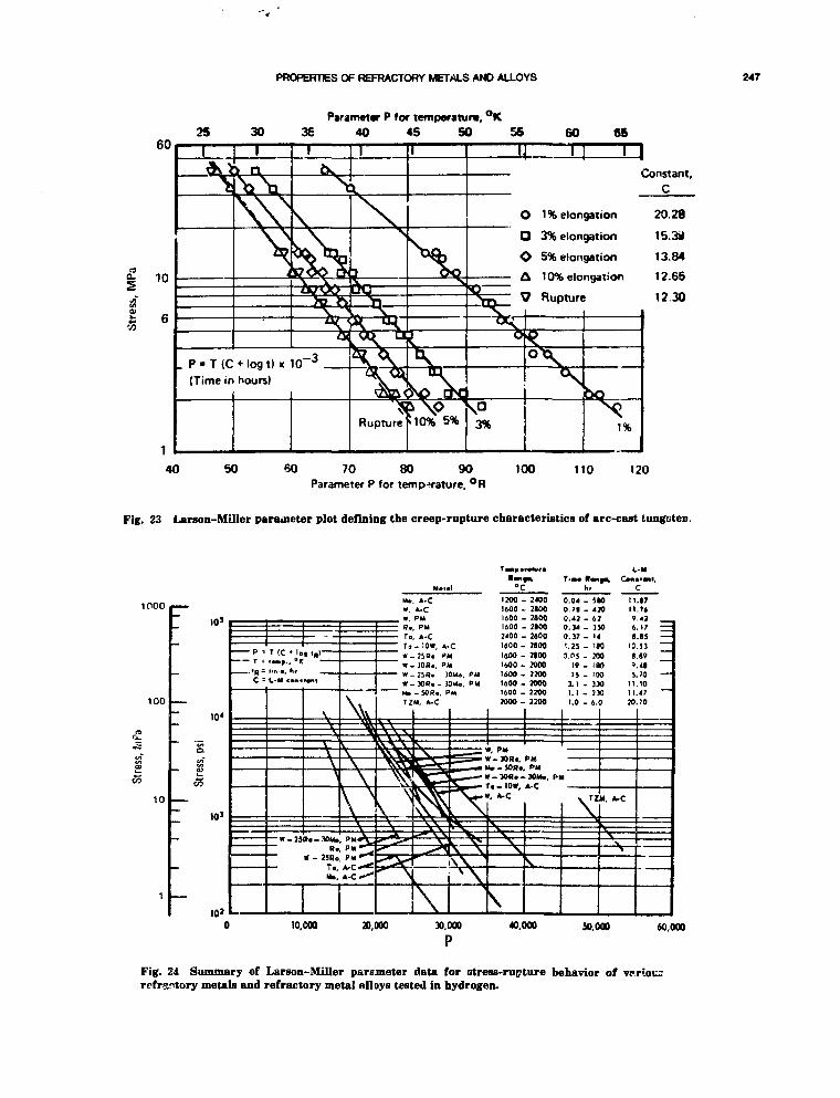
PROPERTIES OF REFRACTORY METALS AND ALLOYS 247
25Parameter P fof temperature, °K
3E 40 45 50 56
oaoa
1% elongation
3% elongation
5% elongation
10% elongation
Rupture
Constant,C
20.28
15.3*
13.84
12.65
1230
40 50 60 70 80 90 100 110 120Parameter P for temp-mature, °R
Fig. 23 Larson-Miller parameter plot defining the creep-rupture characteristics of arc-cast tungsten.
1000
100
10
sSi
10s
10'
10'
T =
C =
T (C • lo. « . . . , °Kim.a, h,t - M cai>>
_ - _
•ant
V
\
A
S»a-30UaRa
« - 23H»Ta,Ha.
\ \v
\1 \
PM w*^
MaW,
loW
w-
w .**>TZ
\
A-C '200 - 3 4 0 0 0 . 0 4 - 5 * 0 I IA-C 1600 - 2100 0.71 - 420 I IPM 1600 - 2900 0.4] - 62 9
. PM 1600 - 2100 0 . 3 4 - 3 5 0 6, A-C 7'00 - 2600 0.37 - 14 9- 10*, A-C 1600 - 2900 1.23 - >M 10
. 2SQ. ->M 1600 - 3100 0.05 - M O 8
. JORr, PM 1600.2000 1 9 - 1 9 0 0-25S. 30Mo, PM 1600-2300 1 5 - 1 0 0 5.• 30R>-30Mo. PM I6O0.20O0 3.1 . 330 11
M, A-C
\ "
M
7000 -
1, PM
23W2200
H—_ — M* - 50R«. Pit
—Wl\\ '
X.
t. A-C
1.1-231.0 - 6.
1
0 I I0 20
», A-C
y
.97
42
.95 —53894170 —104770
10,000 20,000 30,000
P40,000 50.000 60.000
Fig. 24 Summary of Larson-Miller parameter data for atress-rupture behavior ofrefractory metals and refractory metal alloys tested in hydrogen.

248 CONWAY
CO
3 0
20
10
8
4000
2000
1000
800
600
, Cl -
-
_—-
0o
X
—
• -
T
• •
rs
V . — — — •
^ — •
— •
—
. —
— — •
^ - |
. — —
M.Lot j
O AO Bo ctf D0 E H
"5 Ref.34,
I I
i
2650°<
ffl
\
10"
3 0
1 0
Creep rate, es, sec"110" 10-3
4000
2000
<= 1000
600
400 -
200
V
T
• * *
• ^ ,
oaoVD
"<q— Re» Gr(
nc
n
-Ot
AacoE
f.sat
o~——
i4,2650°Cer than tii.iexed
"
^
.
1 .
• * —
—
- » .
* ^
— .
— • .
•* o~—'V
D— • — .
O
1— •
• « ^—
[
10 20 40 60 80 100
Rupture life, t r, min400 600 800 1000
Fig. 25 Creep-rupture data for five different lots of sintered tungsten sheet tested in vacuum at 2650°C.
As examples, the minimum commitmentmethod of Manson and Ensign, the general-ized regression model approach of Booker,the heat-separation approach of Sjodahl formultiheat analysis, and the preanalysisassessment concept of Conway all form apart of what might be termed the data anal-ysis approach of the 80s. Much of this tech-nology has been employed in ASME Boilerand Pressure Vessel Code activities directedtoward the determination of allowablestresses. It is recommended, therefore, thatfull advantage be taken of this past experi-ence in all analyses of any new data gen-erated (or any reanalysis of existing data) inconnection with the space nuclear powerprogram. An application of these recentlydeveloped concepts is certain to yield a bet-ter interpretation of material behavior and amore reliable definition of long-term projec-tions; furthermore, the suggestions made inconnection with the preanalysis assessmentconcept could prove useful in guiding experi-
mental programs to generate creep and rup-ture information.
Tantalum-Base Alloys
1. Supplement existing short-term tensile datafor ASTAR-811C and T-lll by performingadditional tests to cover the temperaturerange from 1200 to 1500°C.
2. Further amplify the data base for short-term tensile behavior of ASTAR-811C andT-lll by evaluating four heats of each mate-rial.
3. Perform short-term tensile tests to evaluatestrain-rate effects using at least two heatsof ASTAR-811C and T-lll; strain rates of8 X 10~5, 8 X KT4, and 4 X HT3 sec"1
are suggested. Temperature range is to befrom room temperature to 1500°C.
4. Evaluate existing creep data for ASTAR-811C and T-lll with the objective of estab-lishing creep strengths for 0.5, 1.0, and 2.0%creep strain. This evaluation will suggest

PROPERTIES OF REFRACTORY METALS AND ALLOYS 249
any additional new data that must be gen-erated in order to develop reliable defini-tions of creep strength. Temperature rangeto be covered is 800 to 1500°C, with stresslevels selected to yield test durations to10,000 h.
5. Expand on the need defined in (4) byevaluating four heats of each alloy.
6. Review existing information on the low cycleand high-cycle fatigue characteristic? ofASTAR-811C and T-lll and determine theadditional tests that are needed to providean accurate definition of fatigue life over theregime from a few hundred cycles to about1 X 106 cycles. Testing should include atleast two heats of material for each alloyand strain rates of 4 X 10~4 and 4 X 10~3
sec~'. Test temperatures to be employed areroom temperature, 600, 1000, and 1500°C.
7. Data for fracture toughness and cyclic crackgrowth to be generated for ASTAR-811C andT-lll as design needs dictate.
Niobium-Base Alloys
1. A detailed reevaluation of the existing ten-sile and creep data for niobium-base alloysis recommended in order to address the dis-crepancies that have been discussed in previ-ous sections of this report.
2. Use the results obtained in (1) and selectthree alloys for further testing; Nb-lZi, D-43, and C-103 are recommended. Evaluateshort-term tensile behavior of two heatseach of these alloys and cover the tempera-ture range from room temperature to1100°C.
3. On the basis of the results obtained in (2),select the two alloys that appear to be themost promising and perform an in-depthevaluation of these materials. This in-depthevaluation should involve two additionalheats, the strain-rate study described initem 3 under tantalum-base alloys, thecreep-strength study proposed in item 4, andthe fatigue-strength determination proposedin item 5. Test temperatures to be ut.ed iithis in-depth evaluation are to be in the,range from room temperature to 1100°C. !
Molybdenum-Base Alloys
1. Further evaluation of Mo-TZM should bepursued through the short-term tensile test-ing of three additional heats of the material.
On the basis of the potential that is judgedto exist for this alloy after this testing isconcluded, tests should be performed to eval-uate strain rate effects as outlined in item 3(tantalum-base alloys); then the creep-strength studies described in item 4 shouldbe performed, and, if necessary, the fatigueevaluations of item 6 should be initiated.
2. Evaluate the existing short-term tensile datafor the series cf alloys containing 5 to 15%Re; the Mo-50Re alloy should also beincluded in this evaluation. Perform addi-tional short-term tensile tests that appear tobe required to establish a reliable appraisalof the potential of these materials.
3. Based on the results obtained in (2), selectthe most promising Mo-Re alloy and ouclinea detailed experimental program to furnishthe necessary design information. Multiple-heat evaluation, strain-rate effects, creep-strength determination, and fatigue-strengthidentification should all be made a part ofthis experimental effort. The temperaturerange to be covered in all the Mo-base alloyevaluations is from room temperature to1500°C.
Tungsten-Base Alloys1. This evaluation should follow that discussed
in items 2 and 3 under molybdenum-basealloys but with W-25Re and W-25Re-30Mo ascandidate materials. Another difference isthat the upper temperature limit should be1800°C.
As a final comment on future needs, the proper-ties of welded material should be mentioned alongwith the su, ;ect of the effect of radiatic "n mate-rial properties. Neither of these topics was coveredin this discussion, but both these issues are impor-ts at and should be given special consideration inail future program plans.
REFERENCES
1. J. 3. Conway and A. C. Losekamp, Thermal ExpansionCharacteristics of Several Refractory Metals to 2500°C,TAIME, 236: 702 (1966)
2. J. B. Conway and A. C. Losekamp, Refraction Error in aComparator Method for Measuring Thermal Expansion,Rev. So. Inst, 36(8): 1245-1246 (1965).
3. J. B. Conway, R. M. Fincel, Jr., and A. C. Losekamp, Effectsof Contaminants on the Thermal Expansion of Tantalum,TAIME, 233: 841-842 (1965).
4. J. A. Edwards, Thermal Expansion of Various Materials,TM 04-2-9 (1964).
5. J. B. Conway, Properties of Refractory Metals, III—ThermalExpansion Characteristics of Tungsten, Rhenium, Tantalum,,

250 CONWAY
Molybdenum, Niobium, W-iSRe, Ta-lOW and MoSORe, GE-NMPO, GEMP-375, June 29,1965.
6. J. B. Conway, R. M. Fincel, Jr., and A. C. Losekamp, TheLinear Thermal Expansion of Niobium, TAIME, 233:844-845 (1965).
7. High Temperature Materials Program Progress Report No.6S, GEMP-63, Dec. 30, 1966.
8. A. D. Feith, Thermal Conductivity and Electrical Resistivityof Molybdenum, GE-NMPO, CE-TM 65-10-1.
9. A. D. Feith, The Thermal Conductivity and ElectricalResistivity of Tungsten-06 Weight Percent Rhenium, GE-NMPO, GEMP-562, November 1967.
10. A. D. Feith, The Thermal Conductivity and Electrical Resis-tivity of Tungsten-26 Weight Percent Rhenium, inProceedings of the Seventh Conference on Tkei-mal Conduc-tivity, National Bureau of Standards Spec. Tech. Pub. 302,f.. 371-380, September 1968.
11. A. D. Feith, Thermal Conductivity and Electrical Resistivityof Molybdenum, GE-NSP, GE-TM 65-10-1, October 1965.
12. Eighth Annual Report—AEC Fuels and Materials Develop-ment Program, GEMP-1012 Part I, March 31,1969.
13. M. Hoch and H. L. Johnston, A High Temperature DropCalorimeter; The Heat Capacities of Tantalum andTungsten Between 1000° and 3000°K, J. Phys. Chem., 65: 855(1961).
14. J. B. Conway and R. A. Hein, E;ithalpy Measurements ofSolid Materials to 2400°C by Means of a Drop Technique, inAdvances in Thennophysica' Properties at Extreme Tem-peratures and Pressures, ASME, 1965.
15. R. A. Hein and P. N. Flhgella, Enthalpy Measurements ofUO, and Tungsten to S260"K, General Electric Company,NSP, GEMP-578, Feb. 16, 1968.
16. J. B. Conway, R. A. Hein, R. M. Fincel, Jr., and A. C.Losekamp, Enthalpy and Thermal Expansion of SeveralRefractory Metals to 25WC, General Electric Company,NSP, TM 64-?-8.
17. M. Hoch, The High Temperature Specific Heat of Body-Centered Cubic Refractory Metals, GEMP-696, February 7,1969.
18. K. K. Kelley, Contributions to the Data on Th rretical Metal-lurgy; XIII High-Temperatvre Heat Content, Heat Capacityand Enthalpy Data for the Elevienti and Inorganic Com-pounds, Bureau of Mines Bull.. No. 584, 1960.
19. I. B. Fieldhouse, J. C. Hedge, and J. I. Lang, Measurementsof Thermal Properties, WADC TR-58-274, November 1958.
20. Sixth Annual Report—High Temperature Program, Part A,GEMP-475A, March 31, 1967.
21. C. G. Collins, J. Moteff, and B. A. Chandler, Evaluation ofthe Potential of Selected Alloys for Use as a Fuel CladdingMaterial in an LMFBR, General Electric Company, GEMP-573, November 1967.
22. Aerospace Structural Metals Handbook, Vols. I & II: ASD-TDR-64-741, March 1963, and Supplements 1 & 2, December1963 and March 1965; revisions through 193».
23. High-Temperature Materials Program Progress Report No.5S, Part A, GEMP-53A, November 26,19bC.
24. J. B. Conway and P. N. Flagella, Creep-Rupture Data for theRefractory Metals to High Temperatures, Gordon and BreachPublishers, 1971.
25. The Engineering Properties of Columbium and ColumbiumAlloys, DMIC Report 188, September 6,1963.
26. The Engineering Properties of Tantalum and TantalumAlloys, DMIC Report 189, September 13,1963.
27. The Engineering Properties of Molybdenum and Molybdenur-Alloys, DMIC Report 190, September 20,1963.
28. ORNL Metals and Ceramics Division Annual ProgressReport For Period Ending June SO, 1967, ORNL-4170,November 1967.
29. J. B. Conway, Stress-Rupture Parameters for the RefractoryMetals—Time-Temperature Parameters for Creep-RuptureAnalysis, pp. 175-198, ASM No. DS-100, American Societyfor Metals, 1968.
30. K. D. Sheffler and G. S. Doble, Thermal Fatigue Behaviorof T-lll and ASTAR 811C in Ultrahigh Vacuum, Fatigue atElevated Temperatures, pp. 491-499, ASTM STP 520, Ameri-can Society for Testing and Materials, 1973.
31 S. S. Manson, Fatipiie: A Complex Subject—Some SimpleApproximations, Exp. Meek, 193, Jnly 1965.
32. T. A. Moss, Materials Technology Presently Available forAdvanced Ranldne Systems, Nuc AppL, 3(2): 71 (1967).
33. E. C. Sutherland and W. D. Klopp, Observations of Proper-ties of Sintered WrougfU Tungsten Sheet at Very High Tem-peratures, NASA TN D-1310, February 1963.
34. W. V. Green, Short-Time Creep-Rupture Behavior of"hjngsten at 2250-C to 2800°C, Trans. AIME, 215: 1057-1060,December 1959.
35. R. L. Stephenson, Creep-Rupture Properties of UnalloyedTantalum, Ta-10%W and T-lll Alloys, ORNL-TM-1994,December 1967.
36. L. J. Pionke and J. W. Davis, Technical Assessment ofNiobium Alloys Data Bast' far Fusion Reactor Applications,COO-4247-2, U.S. Dept. of Energy Contract No.EG-77-02-4247, McDonnell Douglas Astronautics Co., St.Louis, Missouri, August 1979.
37. Private communication from NASA-Lewis Research Centerto E. E. Hoffman; excerpt from unpublished paper entitle^"Refractory Alloys and Advanced Materials for BraytCytle Application" by R. E. English of NASA-LewisResearch Center.
38. SP-100 Conceptual Design Studies First Interim Briefing,Jet Propulsion Laboratory Contract No. 956474; Westing-house Electric Corporation, Advanced Energy Systems Divi-sion, Madison, PA, June 8,1983.
39. Creep Behavior of T-lll Alloy Under the Influence of Con-tivuously Varying Stresses, Topical Report No. 2, TRW-ER-7373, NASA Contract NAS 3-9439; TRW EquipmentLaboratories, Cleveland, Clio.
40 Generation qf Long Time Creep Data on Refractory Alloys atElevated Temiteratu, es. Final Report, TRW-ER-7442, NASAContract NAS 3-9439; TRW Material Technology Labora-tories, Cleveland, Ohio.
41. Generation of Long Time Creep Data on Refractory Alloys atElevated Temperatures, Twenty-Seamd Quarter; NumericalCreep Data, NAS 3-9439, NASA Contract NAS 3-9439; TRWMaterials Technology Laboratories, Cleveland, Ohio, Sep-tember 19,1969 to May 7,1970.
42. Analytical Studies of the Variable-Stress, Variable-femperaticre Creep Behavior of T-lll Alloy, Topical Report,NASA-CR-72771, NASA Contract NAS 3-13469; TRWMaterials Technology Laboratories, Cleveland, Ohio.
43. Generation of Long Time Creep Data on Refractory Alloys atElevated Temperatures, Final Report, NAS CR-72997, NASAContract NAS 3-13469; TRW Materials Technology Labora-tories, Cleveland, Ohio.
V Generation of Long Time Creep Data on Refracton' Alloys atElevated Temperatures, Final Report, NAS CR-134481,NASA Contract NAS 3-15554; TRW Materials TechnologyLaboratories, Cleveland, Ohio.
45. K. D. Sheffler and R. R. Ebert, Generation of Long TimeCreep Data on Refractory Alloys at Elevated Temperatures,TRW, Cleveland, OH, TRW-ER-7648, September 1973; alsoNASA CR-134481,1973.
46. W. D. Klopp, R. H. Titran, and K. D. Sheffler, Long TimeCreep Behavior of the Tantalum Alloy ASTAR 8UC, NASA-TP-1691 (1980).

PROPERTIES OF REFRACTORY METALS AND ALLOYS 261
47. W. D. Klopp and W. R. Witzke, Mechanical Properties ofElectron Beam Melted Molybdenum and DiluteMolybdenum-Rhenium Alloys, NASA TMX 2576 (Mo, Mo-3Re, Mo-5Re, Mo-7Re), June 1972.
48. R. H. Titran and W. D. Klopp, Long Time Creep Behavior ofthe Niobium Alloy C-1OS, NASA-TP 1727 (C-103: NB-10HMT: -0.7Zr), October 1980.
49. Zyde D. White, Apollo Experience Report—Electrical WiringSubsystem, NASA-TN-D-7885, March 1975 (Alloy ?S-85).
50. R. H. Titran and W. D. Klopp, Long Time Creep Behavior ofTantalum-10 Tungsten in High Vacuum, NASA-TN-D-6044,October 1970 (Ta-lOW).
51. R. H. Titran, Creep Behavior of Tantalum Alloy T-2S2 at1S65 to 1700°K, NASA-TN-D-7673, June 1974 (T-222).
52. M. Schussler, Properties of Columbium Alloy Cb-753, inRefractnry Metal", and Alloys IV—Research and Develop-ment, Metallurgical Society Conference, Vol. 41, pp. 387-404,Gordon and Breach Science Publishers, 1967.
53. G. G. Lessmann and R. E. Gold, Determination of the Weld-ibility and Elevated Temperature Stability oj RefractoryMetal Alloys. Task Ill—Long-Time Elevated TemperatureStability of K>fractory Metal Alloys, WANL-PR-P014, Wes-tinghouse Astronuclear Laboratory, October i960.
54. V. C. Davis, Elevated Temperature Tensile Properties ofRecrystallized Nb-lZr, Fansteel Research Report datedDecember 12,1966, Far.steel Inc.
55. V. T. Bates, TensOe Properties of Fansteel "991" MetalrRecrystallized Sheet, Fansteel Researcn Report datedDecember 12,1966, Fansteel Inc.
56. R. E. Schmunk and G. E. Korth, Tensile and Low-CycleFatigue Measurements on Croe- Rolled Tungsten, J. of NuclMater., 103 and 104: 943-948, North Holland PublishingCompany, 1981.
57. Characterization of Materials for Service at Elevated Tem-peratures, pp. 247-536, MPC-7, The American Society ofMechanical Engineers, 1978.
58. Fifth Annual Report High-Temperature Materials PrtQram,GE-NMPO, GEMP-400A, February 28,1966.
59. Sixth Annual Report High-Temperature Materials Program,GE-NMPO, GEMP-475A, February 28, 1967.
60. Recent General Electric Developments in Columbium-BaseAlloys, FPLD, Cincinnati, Ohio, February 1962.
61. R. L. Ammon, comments made during review of originalmanuscript.
62. L. J. Pionke and J. W. Davis, Technical Assessme-.a ofNiobium Alloys Data Base for Fusion Reactor Applications,COO-4247-2, August 1979.

Effects of Irradiation on Properties of Refractory Alloyswith Emphasis on Space Power Reactor Applications
F. W. WiffcinOak Ridge National Laboratory*
INTRODUCTION
High service temperatures in a nuclear reactorcore, above — 700°C, will require the use of refrac-tory metal alleys for containment, support, andfuel-coolant interfaces. Use of these alloys in theprojected neutron flux can lead to changes in manyof the properties that govern successful reactoroperation. These can include changes in the physi-cal properties, mechanical properties, dimensionalstability, and thermodynamic stabili^.
The refractory metal alloys are based on V, Nb,Mo, Ta, and W. While the vanadium alloys mayhave too low a temperature capability for use in ahigh-temperaf.ure reactor, the similarity of thisa!)oy system to •' » other mentioned alloys make3data on v&r. diun. useful in projecting the behaviorof alloys for which data are not available. Simi-larly, data on unalloyed .r.etal must often be usedto inf jr the r>robab!e behavior of alloys. The metalsand alloys t >nsidered in this report are listed inTable 1, anr! their nominal compositions are given.
The p.obable effects of irradiation on niobiumand tungsten alloys . i use as components ofthermionic converters in a space reactor were^viewed by the author in 1971, based on data
available at that time.1 While cons.:!1 rnbly moredata on refractory metals have been generatedsince that time, the data have not been reviewedwith respect to space reactor applications. Thispaper attempts such a review. However, noattempt has been made to cite all relevant work.The approach used is to work from the mostrecently available review of irradiation effects for
each alloy system (where such a review is avail-able) and to discuss that review and more recentdata judged to be the most useful in establishinglikely behavior in high-temperature reactor service.
Alloys 1
TABLE 1
Considered in Evaluating theEffects of Neutron
Alloy
VV-20 TiV-10 CrVANSTAR 7
NbNb-1 Zr
MoMo-0.5 TiTZM
Mo-Rp
TaTa-10 WT-lllASTAR-811C
vVW-Re
Refractory
AlloyaUtu3*
ModelModelModelMode!
ModelCandidate
ModelModelModel
Candidate
ModelModelCandidateCandidate
ModelCandidate
Irradiation onMetals
Nominalcomposition,
wt.%
V, unalloyedV-20 TiV-10 CrV-9 Cr-3.3
Fe-1.3Zr-0.05 C
Nb, unalloyedNb-1 Zr
Mo, unalloyedMo-0.5 TiMo-0.5 Ti-
0.08 Zr-0.015 CMo, with range
of Re to 50%
Ta, unalloyedTa-10 WTa-8 W-2 HfTa-8 W-l Re-
1 Hf-0.025 C
W, unalloyedW, with rpnge of
Re to 25%
•Operated for the U. S. Departmeni of Energy under con-tract W-7405-eng-26 with the Union Carbide Corporation.
*Mode' systems are alloys for which radiationeffects data are available. Candidate alleys arethose considered for use as space nuclear r-actorcomponents
252

EFFECTS OF IRRADIATION ON REFRACTORY ALLOYS 253
The United States has never mounted a focused,sustained program to evaluate the effects of reac-tor irradiation on the properties of refractorymetals and alloys. There have been short-lived pro-grams to evaluate these candidate alloys for vari-ous space reactor concepts, for thermocouple use,for fast breeder reactor core internals, and forfusion reactor structures. There has also been asmall but continuing fundamental radiation effectsprogram interest in the bcc refractory metals. Bypiecing together the data generated by theseprograms and evaluating that data within theframework of the much more extensive body ofdata and understanding on the austenitic stainlesssteels and selected other materials, some projec-tions can be made of the probable behavior of therefractory alloys. Evaluation by analogy with morethoroughly studied systems will frequently be usedin reviewing the irradiation effects data in thesealloys.
REACTOR PARAMETERS
Radiation effects in metals are a strong func-tion of temperature and neutron fluence. Thisdependence requires that the projected range ofreactor operating conditions be known to define theparameter ranges over vhich a material's responseis to be estimated. A general set of parametersestimated for a space reactor is given in Table 2.In most cases theao values are assumed and are notprovided by designers. Since the purpose of thislisting is to establish conditions within which toexamine radiation effects in refractory metalalloys, precision is not required.
For purposes of this document the shutdowntemperature is assumed to be 20°C The actualshutdown temperature will be set by the ability ofthe system to dispose of the decay heat of the reac-tor core, shut down after some period of operation,and may be far from 20°C. Based on the assump-tion that stainlass steels or n'ckel-based superal-loys world be used in a lower temperature system,the minimum operating temperature will he near800°C for a refractory metal system. Maximumtemperatures will be set by the particular alloy, bythe stress requirements on components, and bycompatibility with the rest of the system. The goalof near-term designs is near 1100°C, and moreadvanced reactors may attempt to use upper limitsof 1400°C. If an in-core thermionic power conver-sion system is used, the goal temperatures fortungsten emitters may be 1300 to 1600°C or higher.
The in-core flux for a fast spectrum space reac-tor will probably be in the range 0.2 to 2 X 10¹⁴
TABLE 2Envelope of Irradiation Condition for Space
Reactor Refractory Met*' Components
Temperatures:Cold shutdownMinimum operatingMaximum operating
Near-term goalAdvanced goalThermionic converter
Operating environment:Liquid metals—Li, KInert gas—HeVacuum, with Cs vaporFuel—LOa UN, with barriers
Operating mode:Load followingPeriodic restart
Reactor lifetime:2 to 7 years
Reactor neutronics:
Near termAdvanced
20°C800°C(These will be material
limited.)1100°C1400°C1300 to 1700-C
Flux, Fluence,n/(cm!-s) n/cm*
2 X 10¹³ 4 X 10²¹
2 X 10" 4 X 10²²
neutrons/(cm2-s) with lifetime fluences of 0.4 to4 X 1022 neutrons/cm2. Out-of-core componentswill be subjected to lower fluences.
The reactor will not necessarily be operatedcontinuously for its full lifetime. It may beoperated for times .it a fraction of full power andmay be subject to periodic shutdown and restart.This results in some concern for low-cycle fatigueproperties and for low temperature properties, aswfll as for operating temperature properties of thecandidate materials for reactor components.
Other assumed reactor conditions are listed inTable 2 for completeness. These parameters are ofless interest in evaluating the potential effects ofirradiation on the properties of refractory metalalloys.
EFFECTS OF REACTORIRRADIATION ON THEPROPERTIES OF METALS
Neutron Interactions with aCrystalline Metal
The basic response of a metal to neutron irradi-ation is either the displacement of lattice atoms,through the transfer of the kinetic energy of the

WIFFEN
neutron to the struck atom, or the capture of theneutron by the target atom and the transmutationof thi.t atom either to a new isotope or a newatomic species. Characterizing the neutron fluencein terms of these effects provides a useful mea-sure of the fluence that can be used in comparingresults produced in reactors with quite differentneutron spectra. The accumulated experience inradiation effects experimentation has establishedthe validity of this measure of exposure and deter-mined the limits on its usefulness.
The measure of displacement events is the num-ber of displacements per atom, dpa, calculated forthe flux and energy distribution of neutrons. Thismeasure, which incorporates the experimentallydetermined average energy required to displace anatom from its lattice sito, accounts* for all elasticand nonelastic interactions between the neutronsand host atoms.
The transmutation reactions of greatest generalimportance are the gas-producing (n,p) and (n,a)reactions. These generally h«ve energy-dependentcross sections and are of much greater importanceat neutron energies in the MeV range than atlower energies. In some particular cases the solidproducts of the transmutation reactions may alsobe of importance. Ono example of technical impor-tance in a refractory meta1 alloy :s the transmuta-tion of tungsten to rhenium and rhenium toosmium, which can lead to decalibration of W-Rethermocouples in service in a reactor.2
These measures of neutron fluence. calculatedby Gabriel et al.,3 are given in Table 3 fo,- several
TABLE 3
Irradiation Response of Refractory Metalsin a Fast Reactor Neutron Spectrum
Response* per fluence unitof 1022 neutrons/cm2
Element
VNbMoTaW
dpa
5.433.293.431.261.24
At. ppm He
0.0590.1690.170- 0~0
At. ppm H
2.071.180.3290.1410.0036
•Response calculated for the neutronspectrum at the horizontal midplane of row ?of EBR-II. [From Gabriel, Bishop, andWiffen.3]
of the refractory metals of interest. The responsehas been calculated for a fast neutron spectrum,using the core center spectrum of the EBR-II reac-tor. A total neutron fluence of 1022 neutrons/cm2
was used for the response numbers given.
Defect Clustering and Effects onProperties
High fluence, high temperature radiationeffects that are of concern in evaluating the performance of reactor structural materials includeswelling, strengthening, loss of ductility, andchanges in phase stability. These phenomena andother effects of irradiation are all temperaturedependent. Except for strengthening, these effectsusually become important at temperatures abovesome lower limit at v.rhi>h the point defect • beginto have significant mobility (i.e., thermal energy isadequate for rapid vacancy migration through thelattice), 30, once created, both vacancies and inter-stitials move rapidly. An upper temperature limitfor some effects occurs when thermal energy isadequate to overcome binding energies of defects indefect clusters, and thus all vacancies and intersti-tials migrate until they recombine and annihilate.
For the range of temperatures where pointdefects are mobile but can be bouina stronglyenough to resist further motion, defect clusters cannucleate and grow. While most point defects areannihilated by defects of opposite sign (vacanciesand interrtitials recombine), a few cluster withtheir own kind to form dislocation loops, to add toexisting dislocations, or to form voids.
For most reactor applications, the use tempera-ture of structural alloys is within the window inwhich irradiation effects are of importance. Effi-ciencies of heat transfer and of the power conver-sion system favor temperatures as high as possible.The same processes that set an upper temperaturelimit on sever, l of the irradiation effects limit theuse of metals at higher temperatures. Most oftenthis is a creep strength limit. At temperatureswhere the thermal energies allow rapid vacancyrelease from defect clusters (such as voids), thecreep rate is usually too high for structural use atsignificant stress.
Swelling by Cavity Formation
Structural alloys can swell under neutron irra-diation This volume increase results when the twopoint defects created by irradiation go to differentsinks, with a net flow of self-interstitial atoms todislocations or dislocation loops and a net flux ofvacancies to cavities or voids. This process mayinvolve helium from (n,a) reactions or possiblyimpurity gas atoms in the metal. These insolublegases may be of special significance in the nuclea-tion stage of cavity formation by stabilizing threedimensional vacancy clusters.

EFFECTS OF IRRADIATION ON REFRACTORY ALLOYS 256
06
05
0.4 j-
0.3
02
O.I
0
DOPPLER BROADENING "| _
VOID VOLUME v-CdpoFROM TEM a lldpa
* I9dpo
0 7
300 600 900 1200 1500 I80CIRRAOIAT'ON TEMPERATURE (°C)
0.5 |o
0 4 >a
0.2
O.I
0.0
Fig. 1 The void volume <s determined by TEM is plottedas a function of neutron irradiation tem)<erature formolybdenum. For comparison the solid line is the result ofswelling doterinined by positron annihilation measure-ments. (From Snead at al.4)
A typical swelling-irradiation temperature rela-tionship, determined by Snead et al.,4 is shown inFig. 1, for molybdenum irradiated to fluencesranging from 0.4 to 4 X 10²² neutrons/cm2 (>0.1MeV). A maximum swelling of under 1% is shownfor this condition. Swelling values of several per-cent have been reported in bcc refractory metals,although swelling values near 1% have been com-monly observed for neutron exposures in the low1022 n/cm2 range. The shape of the swelling-temperature relationship is representative of allrefractory metals. The range of temperatures atwhich swelling is observed is usually approxi-mately 0.25 Tn, < T < 0.5 Tm for neutron flux lev-els typical of fission reactors. While narrower tem-perature ranges may be suggested by some datasets, this guideline is useful in projecting behaviorwhere experimental data are not available. Thetemperature ranges are defined for the unalloyedmetals in Table 4.
TABLE 4
Melting Point and Eey Temperatures forRefractory Metals
VNbMoTaW
°C
19002468261029S.3410
0.5 T m,°C
8141098116913621569
0.25 T m ,°C
270412448544648
Alloying of the bcc refractory metah may affectthe swelling, although a range of effects has beenobserved. In some cases the alloying may be inef-
fective in controlling swelling, but several data setshave shown that alloying with a more reactive ele-ment may narrow the range of swelling tempera-tures, as for zirconium additions to niobium, ormay completely suppress swelling, as demonstratedfor titanium additions to vanadium.
Short-Time Strength and DuctilityThe strength properties of the refractory metals
are affected by irradiation at all temperatures upto near 0.5 Tm. While all defect clusters can pro-duce strength changes, the most potent strengthen-ing results for dislocation loops, with small loopsproviding the greatest strengthening increment.Examples of the strengthening observed in refrac-tory metals, for irradiation at temperatures near0.25 Tm, are shown in Fig. 2. The strengthincreases are near the largest seen in any metah,with strengths of irradiated material several timesthe values of unirradiated, solution-annealed mate-rial.
The most important effect >-f the irradiation onthe mechanical properties is in the reduction ofductility. Three important classes of ductilityreduction produced by irradiation are illustrated inFig. 2. These stress-strain curves from uniaxialtensile tests show reductions in both uniform andtotal tensile elongation. If no other change results,ductility and strength usually follow an inverserelationship. The strength increase produced byirradiation-induced changes in the microsti uctureis accompanied by a loss of ductility (Fig. 2a). Ifthe hardening results mainly from a population ofsmall dislocation loops, the first deformation cantrigger a clearing of deformation paths throughthis microstructure. The i ~sult is a plastic instabil-ity (Fig. 2b), with lead drop at the yield point andfurther deformation to failure at continuallydecreasing load.
In some materials, especially Mo, W, and theiralloys, strengthening of the matrix can raise thedeformation stress above the cleavage stress of thealloy, and brittle fracture occurs at very high load(Fig. 2c). This fracture mode is not preceded bymeasurable deformation. The fracture path usuallyincludes both grain boundary separation and cleav-age fracture through grains. A simplifiedmechanistic understanding of the process is givenin Fig. 3, which shows the role of flow, decohesion,and cleavage stresses in determining the failuremode. The effect of irradiation is to raise the flowstress, with little or no effect on the two fracturestress values. The result is to shift T2, the bound-ary between ductile flow and brittle fracture, tohigher temperatures.
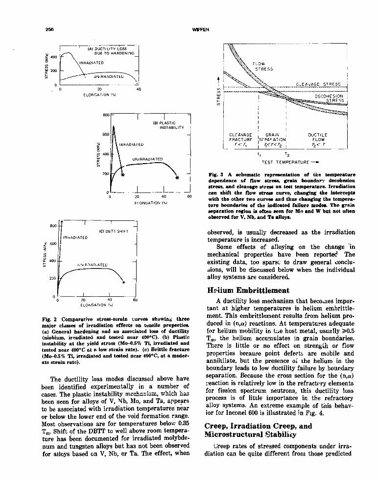
256 WFFEN
IAI DUCTILITY LOSSDUE TO HARDENING
IRRADIATED
UNIRHADIATED
20
ELONGATION 1%)
800 R
20 40 60
E1ONGATION l%]
800
600
400
200
f 1 1
(C) DBTT SHIFT
IRHADIATED
UNIRHADIATED
1
-
-
-
-
0 20 40 60ELONGATION (%)
Fig. 2 Comparative stress-strain curves showing' threemajor classes of irradiation effects on tensile properties,(a) General hardening and an associated loss of ductility(niobium, irradiated and tested near 400°C). (b) Plasticinstability at the yield stress (Mo-0.5% Ti, irradiated andtested near 400°C at a low strain rate), (c) Brittle fracture(Mo-0.5% Ti, irradiated and tested near 400°C, at a moder-ate strain rate).
The ductility loss modes discussed above havebeen identified experimentally in a number ofcases. The plastic instability mechanism, which hasbeen seen for alloys of V, Nb, Mo, and Ta, appearsto be associated with irradiation temperatures nearor below the lower end of the void formation range.Most observations are for temperatures below 0.35Tm. Shift of the DBTT to well above room tempera-ture has been documented for irradiated molybde-num and tungsten alloys but has not been observedfor alloys based on V, Nb, or Ta. The effect, when
'( '2TEST TEMPERATURE —»•
Fig. 3 A schematic representation of the temperaturedependence of flow stress, grain boundary decohesionstress, and cleavage stress on test temperature. Irradiationcan shift the flow stress curve, changing the interceptswith the other two curves and thus changing the tempera-ture boundaries of the indicated failure modes. The grainseparation region is often seen for Mo and W but not oftenobserved for V, Nb, and Ta alloys.
observed, is usually decreased as the irradiationtemperature is increased.
Some effects of alloying on the change inmechanical properties have been reported Theexisting data, too sparse to draw general conclu-sions, will be discussed below when the individualalloy systems are considered.
Hfiium EmbrittlementA ductility loss mechanism that becomes impor-
tant at higher temperatures is helium embrittle-ment. This embrittlement results from helium pro-duced in (n,a) reactions. At temperatures adequatefor helium mobility in t:ie host metal, usually >0.5Tm, the helium accumulates in grain boundaries.There is little or no effect on strength or flowproperties because point defects are mobile andannihilate, but the presence oi the helium in theboundary leads to low ductility failure by boundaryseparation. Because the cross section for the (n,a)reaction is relatively low in the refractory elementsfor fission spectrum neutrons, this ductility lossprocess is of little importance in the refractoryalloy systems. An extreme example of this behav-ior for Inconel 600 is illustrated in Fig. 4.
Creep, Irradiation Creep, andMicrostructural Stability
(Jreep rates of stressed components under irra-diation can be quite different from those predicted

EFFECTS OF IRRADIATION ON REFRACTORY ALLOYS 257
500
400
S= 300
H 200
100
HELIUMEMBRITTLEMENT
UNIRRADIATED
IRRADIATED
5 10ELONGATION (%!
15
Fig. 4 An extreme example oi loss of ductil-ity due to helium embrittlement. This exam-ple is for Inconel 600, irradiated after coldwork. Irradiation and 'tensile tests were at700°C.
by thermal creep data. Irradiation creep is usuallyof importance at temperatures below the range atwhich thermal creep is important, <0.5 Tm, and hassome of the characteristics of superplaatic behav-ior. Figure 5, which depicts the results of creepmeasurements on an austenttic stainless steelunder light-ion bombardment,5 shows marked devi-ation froir thermal creep behavior at the lowertemperatures. Three general characteristics of irra-diation creep are a weak temperature dependence(shown in Fig. 5), a linear dependence of the creeprate on damage rate (flux), and a slow increase inrate with increasing fluence at a fixed flux. Thedependence of the creep rate on composition andmicrostructural variables is not well established.The ductility to rupture in creep under irradiationhas been demonstrated to be much greater thanmeasured in postirradiation creep tests. There arevery few data available on irradiation creep ir therefractory alloys.
Available data on austenitir stainless steel coldworked before irradiation indicate that thtr- maybe a small effect of irradiation on recovery andrecrystallization. These results suggest that adepression of the recovery temperature may existbut that the effect does not exceed ~50°C.
Precipitation and Phase Stability
The question of the stability of alloy phasesunder irradiation can be of concern to the behaviorof structural materials during reactor service. Theconcern arises from the demonstrated tendency ofsome solute or impurity species to pref-erentially couple to the flux of either vacancies or
interstitials. These atoms then move through thelattice with the defect, species and concentrate atthe sink where che defects have either clustered orbeen annihilated. The possible results can includeformation of phases not predicted from equilibriumphase diagrams or the concentrations of impurityatoms. The formation of precipitate phases (films)on grain boundaries or the concentration of surfaceactive species at the boundaries can result inembrittlement and susceptibility to grain boundaryfracture. There is a possible synergism with heliumeffects on grain boundaries, but conclusive evidenceis not available.
DATA FIELD ON IRRADIATEDREFRACTORY METAL ALLOYS
Few data are available for irradiation effects inrefractory metals, especially at conditions of inter-est for space power reactors. However, the datathat are available can be used to guide applicationof the existing knowledge of irradiation effects topredictions on refractory metals. This approachcan also serve to identify critic?.! questions thatmust be answered in future experiments.
Similarities in the irradiation response of therefractory metals are greatest for elements in the
DAMAGE. » i ' [ n . iO " f j I po s '
i 10"4
1O" 6
II 12 13 14 15
RECIPROCAL TEMPERATURE I K " ' X I 0 4 I
Fig. 5 Temperature dependence of irradiation creep in60%-cold worked 321 stainless steel. (From Hudson et al.')

258 WFFEN
same group of the periodic table, rather than foradjacent elements. Therefore, the material will bepresented in the order V, Nb, Ta, Mo, and W.
Vanadium AlloysVanadium alloys we -e evaluated in both the
United States and West Germany as candidatecladding materials for LMFBRs and are currentlyunder evaluation for use in fusion reactors. As aresult of these two interests there are more vana-dium alloy irradiation effects data at elevated tem-peratures and moderate-to-high fluences than forother refractory metal alloys. Similarities inbehavior of the several refractory metals make thedata useful in predicting the probable response ofthe other systems.
The effects of irradiation on vanadium alloys,with emphasis on the V-15Cr-5Ti alloy, were re-viewed in 1982 for a fusion reactor design project.6
A more complete review was published in 1978 byGold et al.7 Few data have been generated sincethese reviews.
Experimental data have been reported forswelling in unalloyed vanadium irradiated to fastfluences up to about 3 X 10²² neutrons/cm2. Irra-diation temperatures have covered the range fromabout 385 to 700°C. Maximum swelling values havegenerally been 1.5 to 2% and occur, dependingsomewhai on purity, for irradiations at 550 to600°C. The trends are the same as those observedin other pure metals, with void concentrations andsizes dependent on both fluence and irradiationtemperature. Voids are cubic in shape with cubeperfection increasing with an increase in irradia-tion temperature. Void ordering on a superlattine,which has been reported in other bec metals suchas Nb, Ta, and Mo, has not been observed in vana-dium.
Several vanadium-base alloys h /e now beeninvestigated to determine the swelling behaviorunder neutron irradiation. These studies, whichhave concentrated on the V-Ti- Cr system, haveshown a general resistance to void formation andswelling in the alloys containing titanium. AV-10% Cr alloy, neutron irradiated at about 700and 800°C, showed8 near 1% swelling for a fluenceof 1.5 X 10²² neutrons/cm2. There wasinsignificant swelling at lower temperatures,although a low concentration of small voidsformed. In a more complex alloy, VANSTAR-7,some void formation occurred, but swelling wasvery slight. In alloys containing titanium,irradiation at 470 to 780°C to fluences as high as6 X 1022 neutrons/cm2 produced little or no swell-ing detected by immersion density measurements.8
TEM examination showed that there had been novoid formation. The TEM observations showed con-siderable development of a dislocation microstruc-ture during the irradiation. There may also havebeen some change in the precipitate structure.
The V-20Ti composition has been the moststudied of the vanadium alloy family. The resis-tance to void formation and swelling is well es-tablished for a wide range of neutron fluences andirradiation temperatures. However, Tanaka et al.9
showed that injection at room temperature of auniform distribution of helium to concentrations of90 and 200 at. ppm resulted in void formation dur-ing subsequent neutron irradiation to 3 X 10²²
neutrons/cm2 (>0.1 MeV) in EBR-II. Void forma-tion occurred for these conditions over the exam-ined range of irradiation temperatures, 400 to700°C. In spite of this helium-promoted cavity for-mation, the resulting swelling was negligibly smallof the order of 0.03%.
More recent ion bombardment experiments tosimulate neutron irradiation have confirmed andextended knowledge of the swelling behavior ofvanadium alloys. Work by Loomis and Ayrault10
illustrated in Fig. 6 shows high damage levelresults at 700°C. This shows that a V-Cr binaryalloy is not swelling resistant—in fact swelling atmore than twice the rate of che unalloyed
^ [ T ! i i i rION e.-MBflRDMENT AT 7OO°C
A V,3 2-MeV 5 8 N i *A v ,3 .0 -MeV 5 ' v +
_ • v - 1 5 C f , 3 . 5 - M e V 5 1V
• V-! Ti, 3.0- MeV 51V +
O V-
/
r i I I |fs.5%-20% _
I I I I I I I I I I I20 30 40
DOSE (dpol6 0 70
Fig. 6 Swelling produced by heavy ion bombardment ofvanadium alloys at 700°C. (Frc Loomis and Ayrault.")

EFFECTS OF IRRADIATION ON REFRACTORY ALLOYS 259
900
800
100
600
bOO -
300
200
100
1 ' '
/ \ o . 9 5 dpa
j 0.0095 dpa \
/ A
J,'IUNCORRECTED FOR/MACHINE MODULUS)
1 1
"~l 1
0.095 dpa
— r~
i i
i 1 i r r I iVANf.lAR 7
IRRADIATED IN HFIR AT 70°CTO DISPLACEMENT LEVEL SHOWN
TENSI_fc TESTS AT 25°C
0.00095 dpa
- \ CONTROL
1 1 1 1 1 1
:
Y-
2 4 6 10 12 14ELONGATION l%!
16 18 20 22 24
Fig. 7 Load-elongation curves for VANSTAR-7 irradiated at 70°C to neutron fluences up to1.0 X 1025 neutrons/m*. Plastic instability is observed for fluences producing 0.0095 •'.pa orgreater.
metal—while two alloys containing titanium werecompletely resistant to void formation. Thisconfirms the swelling resistance of the titanium-containing alloys, established by nontron irradia-tion, for the range of ion bombardment tempera-tures 400 to 720°C, damage levels to 50 dpa, and arange of He : dpa ratios. Confirmation by neutronirradiation to high fluences is still required.
The low level of cavity formation noted previ-ously for the neutron-irradiated VANSTAR-7 alloyspecimens suggests that zirconium alloy additionsmay convey the same beneficial effects as titaniumadditions, but verification is required. It is to behoped that analogs of the Ti (in V) swelling sup-pression can be developed in other bcc refractoryalloy systems.
Irradiation of vanadium alloys at temperaturesnear room temperature results in an appreciableincrease in the yield and ultimate tensile strengthand a loss of ductility, as measured by elongation.11
The strengthening probably results from disloca-tion loop hardening, and the loss of ductilityresults from the channeling deformation mecha-nism discussed earlier. The rates of hardening andductility loss are shown in Pig. 7 as a function ofneutron fluence for the VANSTAK-7 alloy irradi-ated at 70°C and tested at 25°C. A number ofV-Cr-Ti ternary alloys have been irradiated to aconstant fluence of 1.4 X 10²¹ neutrons/cm2 (>0.1MeV) at 100°C and then tensile tested at a series
of higher temperatures.12 The results, in Figs. 8and 9, show that the marked hardening producedby the irradiation and observed in low temperaturetests is gradually lost as the test temperature isincreased. At 750°C the properties of irradiated
a.5
It-O2u_a:\-inO
\C\J\J
•000
800
6 0 0
4 0 0
200
n
\•
—
-
1NEUTRON iRRAOIATiON
1.4 KI
100°C
N
1
D neu*ron/m^
IRRAOIATION ""
• -1 dpo
• V - 2 C r - I O T . _
| A v - 5 C r - 5 T i
• V-5Cr-10T,V-l5Cr-5Ti
i i i200 400 600 800
TEST TEMPERATURE CO1000
Fig. 8 Effect of neutron-irradiation on the yield strengthof vanadium-base alloys. (From Abdou et al.')

260 WFFEN
4 0
- 3 0
5 <?ob
10
1 I ' INEUTRON IRRADIAT'ON1.4xiO25 NEUTRON/M2
~100°C IRRADIATION(-1dpa)
• V 2 Cr -10 TiA V-5Cr-5Cr• V-5Cr-10TiD V-I5U-5TI
• n
200 400 600 800TEST TEMPERATURE (°C)
1000
Fig. 9 Effect of neutron irradiation on the total elongation ofvanadium-base alloys. (From Abdou et al.')
and unirradiated material were equal. Total elon-gation values of the irradiated alloys were low intests at room temperature to 400°C. Recoveryoccurred in tests above 400°C, with elongationapproximately equal to unirradiated material intests at 650 to 750°C (not shown in these figures).
Even though significant hardening waa pro-duced by these irradiations at 70 to 100°C, therewas no indication of cleavage or grain decohesionfractures. All reported fractures were of the ductilemode, and the ductile-to-brittle transition tempera-ture (DBTT) characteristic of bcc metals remainedbelow room temperature for tensile tests. Impactor high strain rate tests, which could raise theDBTT, have not been conducted on irradiated vana-dium alloys.
Several experiment? <•;* have reported the resultsof irradiation of vanadium alloys at temperaturesin the range 400 to 750°C to fluences exceeding1 X 1052 neutrons/cm2 (>0.! MeV). The alloyshave included V-20 Ti, V-15 Ti-7.5 Cr, V-10 Cr,V-3 Ti-1 Si, and VANSTAR-7, with tensile tests attemperatures from room temperature to about750°C. These results are reviewed in detail by Goldand Harrod.7 The trends indicated for these irradi-ations are somewhat different from those observedfor low fluence, low temperature irradiations. Inthe V-Ti or V-Ti-Cr alloy, modest hardeningresults for irradiation in the lower part of thistemperature range, but little strength increaseresults if the irradiation temperature is above—500°C. Ductility values are usually close to those
of unirradiated material throughout this tempera-ture range.
The V-10 Cr, V-3 Ti-1 Si, and VANSTAR-7results show mucn greater strengthening producedby the irradiation, even for irradiation and testtemperatures near 700°C. The ductility was alsorpluced by irradiation, with uniform elongationvalues in the range 1.5 to 4%. There was, however,no indication of a brittle failure mode in any ofthese experiments. The few reports of creep-rupture testing on irradiated vanadium alloys indi-cate little or no effect on either rupture life orelongation at fracture.
Vanadium alloys are not immune to heliumembrittlcment. It has been amply demonstratedthat helium implanted by accelerator bombard-ment or by tritium decay can result in a loss oftensile elongation for test temperatures above 650to 750°C. Tanaka et al.9 have also examined theeffect of 90 and 200 at. ppm He prt Injected beforeneutron irradiation of the V-20 Ti alloy. Materialwas irradiated at 400, 575, and 700°C and then ten-sile tested at the irradiation temperatuie. Theseresults showed a factor of 2 loss of ductility inhelium-free V-20 Vi irradiated and tested at 400°Cbut little effect for irradiation and test at 575 and700°C. In the helium-preinjected material a severeloss of ductility resulted for irradiation and testsat 700°C. The helium had little effect at the twolower irradiation temperatures of 400 and 575°C.
Three vanadium-base VANSTAR alloys wereirradiated at 410 to 450°C to fluences in the range

EFFECTS OF IRRADIATION ON REFRACTORY ALLOYS 261
0.18 to 6.37 X 10²¹ neutrons/cm2 (>0.1 MeV). Lowcycle fatigue tests at 400° C showed the irradiationto have little or no effect on the fatigue life.13 Forthese irradiation temperatures, the authors reportthat radiation hardening saturates near a fluenceof 1 X 10²¹ neutrons/cm2.
In summary, the response of vanadium-basealloys to low to moderate fluences of fast neutronslooks encouraging. The effects of radiation are pri-marily to increase the short-time mechanicalstrength. This appears to occur at little cost interms of compromising the ductility. The similarityof vanadium-base alloys to Nb and Ta alloys justi-fies the hope for the development of radiation-resistant alloys based on either Nb or Ta.
Niobium AlloysNiobium and niobium alloys have been irradi-
ated and evaluated at conditions of interest tospace reactor applications with support from fis-sion reactor, fusion reactor, and basic studies pro-grams. However, none of this has been a focused,mission-oriented program, so, as with the otherrefractory metals, data are sparse and uncon-nected. Much of the recent data comes from thefusion reactor program, where niobium alloys havebeen considered for first wall and blanket struc-tures and continue to be candidates for specializedcomponents in the high neutron flux zone of thereactor. There is some overlap between conditionsexamined in these programs and the application inspace power system, although a large portion ofavailable data was generated for temperatures andneutron fluences below the range of current inter-est.
Relevant radiation effects data on niobium-basealloys were reviewed by Pionke and Davis14 in 1978,for potential fusion reactor applications. Severalresearchers have also reported related data sircethat time.
The experimental data on neutron irradiated,unalloyed niobium indicate that the temperaturerange over which swelling will result extends fromat least 400 to 1050°C. While these may not be theactual extremes of the swelling range, data are notavailable outside this range. The scant data avail-able from neutron irradiation experiments indicatethat the temperature of peak swelling is near600°C [Wiffen;15-16 Michel and Moteff;17 Adda;18
E!en et al.;19 Fischer20]. Bartlett et al.21 did notfind a peak swelling for irradiation at 450, 550, and650°C. Jang and Moteff22 found a slight local maxi-mum at 600°C but found the greatest swelling at1050°C for a fluenca of 5 X 10²² neutrons/cm2
(>0.1 MeV).
The magnitude of swelling reported by differentinvestigators, for closely comparable conditions,shows considerable scatter. While much of thismay be due to differences in material, especiallyimpurity content, and in irradiation conditions,some may also be due to difficulty in examiningthe material. Wiffen15-16 and Michel and Moteff17
used TEM to examine material cut from the sameneutron-irradiated coupons and calculated swellingvalues that differed by more than an order of mag-nitude. The problem was probably due to inaccura-cies in determining foil thickness and in measuringthe diameter of very small voids. Comparisonmeasurements of cavity volume fraction in a singlemicroscope sample were made in a round-robinanalysis program, where the same sample was cir-culated to eight different sites.23 The result showeda spread of 70% between highest and lowestswelling values determined in this sample. Thesecomparisons emphasize the importance of develop-ing adequate techniques for TEM determination ofswelling and suggest caution in the use of any sin-gle datum, or single data set.
Fischer20 has showr that void concentration is astrong function of flux. He reported an increase invoid concentration by a factor of 4 to 7 for a factorof 4 ! acreise in flux, at constant fluence. The aver-age void size decreased with the same fluxincrease, resulting in reduced swelling at thehigher flux. Loomis and Gerber24"25 have shown astrong dependence on material purity, especially onoxygen content. Many of the apparent inconsisten-cies that arise in comparing earlier work from dif-ferent sources are probably related to these unin-tentional variables.
The only niobium alloy to be investigated to anyextent is the Nb-1 Zr composition. The generalfinding has been that swelling occurs over a mvihnarrower range of irradiation temperature in Nb-1 Zr than in Nb, with a peak swelling temperaturenear 800°C. One set of alloy samples has been car-ried to very high fluences, 1 to 2 X 10²³
neutrons/cm2 (>0.1 MeV), in the EBR-II reactor.26
At this high fluence the immersion density indi-cated swelling in the temperature range 400 to600°C to be between 0.18 and 0.71%. The swellingdependence on irradiation temperature was slightin this data set. Most other swelling data on thisalloy resulted from TEM examination. The swellingdata are summarized in Fig. 10.
Bartlett et al. reported21 on the examination ofNb-5 Zr and Nb-10 Zr, irradiated to a fluence of3.6 X 1022 neutrons/cm2 at 450, 550, and 600°C.They found no significant amount of swelling inany condition, although a few voids were observed
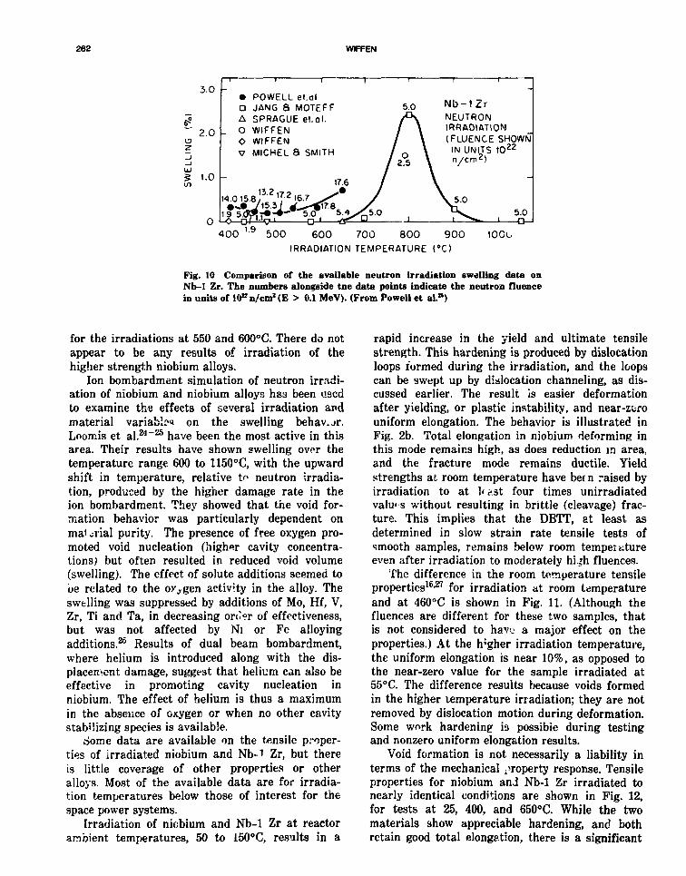
262 WFFEN
3.0 -
2.0 -
g 1.0in
0 •-
• POWELL et.dlD JANG a MOTEFFA SPRAGUE et.Ql.
. O WIFFENO WIFFENV MICHEL 8 SMITH
17.6
-O—oJ-UrjJ rvJ gr D
5.0
A/ \/ \/ o V
/ 2 5 )
/
/
-
1Mb — 1 Z rNEUTRONIRRADIATION(FLUENCE SHOWNIN UNITS 1O22
n/cm2)
\
\ 5.0•^S^ 5.01 X 1 o_J
400 1l9 500 600 700 800 900IRRADIATION TEMPERATURE (°C)
100U
Fig. 10 Comparison of the available neutron irradiation swelling data onNb-1 Zr. The numbers alongside tne data points indicate the neutron fluencein units of lO^n/cm2 (E > 0.1 MeV). (From Powell et al.s)
for the irradiations at 550 and 600°C. There do notappear to be any results of irradiation of thehigher strength niobium alloys.
Ion bombardment simulation of neutron irradi-ation of niobium and niobium alloys hss been usedto examine the effects of several irradiation andmaterial variable? on the swelling behav.jr.Loomis et al.24"25 have been the most active in thisarea. Their results have shown swelling over thetemperature range 600 to 1150°C, with the upwardshift in temperature, relative t^ neutron -irradia-tion, produced by the higher damage rate in theion bombardment. They showed that the void for-mation behavior was particularly dependent onma< jiial purity. The presence of free oxygen pro-moted void nucleation (higher cavity concentra-tions) but often resulted in reduced void volume(swelling). The effect of solute additions seemed tobe related to the oxygen activity in the alloy. Theswelling was suppressed by additions of Mo, Hf, V,Zr, Ti and Ta, in decreasing onW of effectiveness,but was not affected by Ni or Fe alloyingadditions.25 Results of dual beam bombardment,where helium is introduced along with the dis-placement damage, suggest that helium can also beeffective in promoting cavity nucleation inniobium. The effect of helium is thus a maximumin the absence of oxygen or when no other cavitystabilizing species is available.
dome data are available on the tensile proper-ties of irradiated niobium and Nb-1 Zr, but thereis little coverage of other properties or otheralloys. Most of the available data are for irradia-tion temperatures below those of interest for thespace power systems.
Irradiation of niobium and Nb-1 Zr at reactorambient temperatures, 50 to 150°C, results in a
rapid increase in the yield and ultimate tensilestrength. This hardening is produced by dislocationloops formed during the irradiation, and the loopscan be swept up by dislocation channeling, as dis-cussed earlier. The result is easier deformationafter yielding, or plastic instability, and near-zerouniform elongation. The behavior is illustrated inFig. 2b. Total elongation in niobium deforming inthis mode remains high, as does reduction in area,and the fracture mode remains ductile. Yieldstrengths at room temperature have been raised byirradiation to at 1< &st four times unirradiatedvalues without resulting in brittle (cleavage) frac-ture. This implies that the DBTT, at least asdetermined in slow strain rate tensile tests ofsmooth samples, remains below room temperatureeven after irradiation to moderately hi^h fluences.
The difference in the room temperature tensileproperties16127 for irradiation at room temperatureand at 460°C is shown in Fig. 11. (Although thefluences are different for these two samples, thatis not considered to have a major effect on theproperties.) At the h'gher irradiation temperature,the uniform elongation is near 10%, as opposed tothe near-zero value for the sample irradiated at55°C. The difference results because voids formedin the higher temperature irradiation; they are notremoved by dislocation motion during deformation.Some work hardening is possible during testingand nonzero uniform elongation results.
Void formation is not necessarily a liability interms of the mechanical property response. Tensileproperties for niobium and Nb-1 Zr irradiated tonearly identical conditions are shown in Fig. 12,for tests at 25, 400, and 650°C. While the twomaterials show appreciable hardening, and bothretain good total elongation, there is a significant
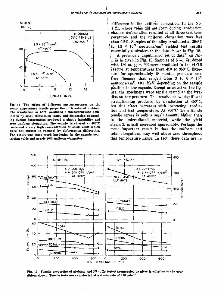
EFFECTS OF IRRADIATION ON REFRACTORY ALLOYS 263
STRESSno3
Psi)
80
40
3.0 X 1026/?/m2
AT 460°C
7.5 X 1C124 nlm2
AT 55°C
NIOBIUM25°C TENSILE
0.02 min-1
8 12
ELONGATION (%)
16
Fig. 11 The effect of different uiic. ostructurea on theroom-temperature tensile properties of irradiated niobium.The irradiation at 55°C produced a micro&tructure dom-inateri by small dislocation loops, and dislocation channel-ing during deformation produced a plastic instability andzero uniform elongation. The sample irrcdiatsd at 460°Ccontained a very high concentration of small voids whichwere not subject to removal by deformation dislocation.The result was some work hardening in the sample ecu*taining voids and nearly 10% uniform elongation.
difference in the uniform elongation. In the Nb-1 Zr, where voids did not form during irradiation,channel deformation resulted at all three test tem-peratures and the uniform elongation was lessthan 0.2%. Samples of the alloy irradiated at 394°Cto 1.9 X 10²² neutrons/cm2 yielded test resultsessentially equivalent to the data shown in Pig. 12.\ A previously unpublished set of data28 on Nb-1,1 Zr is given in Fig. 13. Samples of Nb-1 Zr, dopedwith 130 at. ppm 10B were irradiated in the HFIRReactor at temperatures from 450 to 950°C. Expo-sure for apnroximately 18 months produced neu-tron fluences that ranged from 3 to 6 X 10²²
nteutrons/cm2, >0.1 MeV, depending on the sampleposition in the capsule. Except as noted on the fig-ure, the specimens were tensile tested at the irra-diation temperature. The results show significantstrengthening produced by irradiation at 450°O,but this effect decreases with increasing irradia-tion and test temperature. At 800°C the ultimatetensile stress is only a small amount higher thanin the unirradiated material, while the yieldstrength is still increased appreciably. Perhaps themost important result is that the uniform andtotal elongations stay well above zero throughoutthis temperaiure range. In fact, these data are in
120
1OO
ooo
60
<fl 6 0
inUJIX.
in 40
20
60
Z 40Oit
i 2pUJ
NIOB'UM
c o CONIriOL* • 3.0M022 n/cm2
AT 460°C
> o CONTROL• 3.7MO22 n/cm2-
AT 450°C
800
600
200
200 4 0 0 600 0 200TEST TEMPERATURE (°C)
4 0 0 600
Fig. 12 Tensile properties of niobium and Nb-1 Zr tested as-annealed or after irradiation to the con-ditions shown. Tensile tests were conducted at a Eitrain rate of 0.02 min~'.

264 WIFFEN
(IRRADIATED)
I 0.2% YIELD STRENGTHNb-IXZr
(~13Ooppm IOB)
100.2% YIELD STRENGTH
J 1_
400
300 "3s
200
100
30
o
—' 1 r" - ^CONTROL)
AATOTAL ELONGATIONVTUNIFORM ELONGATION
200 400 6OOTEST TEMPERATURE (*C)
800
Fig. 13 Tensile properties of Nb-1% Zr irradiated in HFIR to a fastneutron fluence of 3 to 6 X 10" neutrons/cm2, >0.i MeV, which pro-duced 14 to 28 dpa. Samples contain —133 at. ppm He from 10B burnup.This is produced r t temperature during the first ~3 to 10 days of irradi-ation. Irradiation temperature same as test temperature, except for onetest noted at 800°C and for the 25°C data which was for a sample irra-diated at 550° C.
conflict with the data presented for Nb-1 Zr inFig. 12, in that irradiation at 450°C has notreduced the uniform elongation to zero, but about1% remains. Whether this result is due to thehelium produced by burnup of the 10B early in theradiation exposure, or whether some other explana-tion prevails is not clear at this time. (If thehelium is responsible, it may be because bubbles orvoids promoted by the insoluble gas prevent chan-neling.) Electror microscopy of the sample set maybe completed in the future, to search for hints inthis apparent contradiction in the data.
The good ductility retention at 800°C, for sam-ples irradiated at 800 and 950°C, indicates promisefor higher temperature applications of this! alloy.However, little hardening can be expected at theseVrmperatures, and designers will have to workv.-.hin the limits of the strength level of fullyi.r.r.*2.lwl material.
A <y-.riV.rn in very high temperature service of>.-. i.oy system is the embrittling effects of the.".>.. i.r.vint& of helium produced by (n,a) trans-iiiv^..,.v-. r<ci/:V.om. The production rate of helium
in niobium, as in all the refractory metals, is quitelow (see Table 3), so the concern is only for heliumcontents below ~2 at. ppm. For the Nb-1 Zr,Fig. 13 shows that helium embrittlement is not aconcern at 800°C. Other results29"30 showed noeffect of accelerator-injected helium in tests at1000, 1020, and 1200°C, unless helium contentsexceeded i t least 200 at. ppm.
There do not appear to be any data on phasestability or on 'rradiation creep in niobium-basealloys.
Tantalum AlloysMost of the irradiation effects data available on
tantalum and tantalum-base alloys resulted fromthe consideration of using these materials as con-trol elements in fast breeder reactors. Examina-tion of irradiated material wa3 limited by the highactivity levels generated by the irradiation. Theprojected use focused the interest on irradiationtemperatures near 600°C.
Voids form and swelling results fc- unalloyedtantalum irradiated above 400°C but below 1000°C.

EFFECTS OF IRRADIATION ON REFRACTORY ALLOYS 266
TANTALUMFLUENCE
2.5*1O22 n/cr
(>0.1 MeV)
TABLE 5
Swelling of Tantalum and T-l l l Produced byIrradiation in EBR-1I
600 800 1000IRRADIATION TEMPERATURE (°C)
Fig. 14 Swelling data and empirically drawn swellingcurve for neutron-irradiated tantalum as a function oftemperature of irradiation.
Figure 14 shows an empirically drawn swellingcurve31 based on transmission electron microscopy(TEM) examination of specimens irradiated inEBR-II. A somewhat similar definition of theswelling-irradiation temperature relationship wasproduced by Bates and Pitner,32 based on densitychange results. Their analysis predicts a somewhatbroader temperature range for swelling than isshown in Fig. '4. Difficulties in determining exactirradiation temperatures may contribute to thisdiscrepancy. Murgatroyd et al.33 confirmed thevoid formation during irradiation at 500°C by TEMexamination. Their linear dimension measurementsof swelling are in approximate agreement withFig. 14, but chey found a reduction inswelling in going to higher fluences. They attrib-uted the recovery of swelling as possibly resultingfrom shrinkage due to the transmutation of Ta toW, with a resulting reduction in latticeparameter.33 (A similar effect has been examinedin Mo and TZM irradiated at 450°C and will bediscussed in the section, Molybdenum Alloys. Theresponsible mechanism is tentatively identified asimpurity segregation to void surfaces, leading tovoid shrinkapj.34)
Swelling in tantalum alloys has received littleattention. Geometry and density measurements onT-lll irradiated nt 450 and 600°C indicated noswelling'6 but perhaps some densification duringirradiation (see Table 5). These specimens were notexamined by TEM to establish whether or notvoids had been produced by the irradiation. Quali-tative comparison by TEM of a set of irradiated
Material
TaT i nTaT-lll
Fluence,>0.1 MeV
X UP n/cm'
1 '.1.91.91.9
Irradiationtemperature,
°C
390415640640
Swelling,* %
Volumeincrease.
ALL
0.37-0.11
0.27-0.36
Densitydecrease.
ApP
0.76-0.024
0.36-0.34
'Uncertainty in volume increase, determined from length mea-
surements, 3-z—, is .rO.08%. Scatter in density decrease is
±0.25%.
Ta-10 W specimens is given in Table 6, whichshows that voids weio formed in the alloy, as inthe unalloyed metal, but that swei^ng was proba-bly less in the alloy.35
The available data on the effects of neutronirradiation on the mechanical properties oftantalum alloys are scarce. Irradiation of Ta-10 Wat 70°C, t . falum at 70 or 400°C, and T-lll at400°C res. '^u 16 in increases in room tempera-ture strengtn prope ties, and reduction of uniformtensile elongation co 0.1 to 0.2%. Total elongationvalues remained higher—i. the range 8 to 10% forthe material irradiated at 400°C. The low uniformelongation results from the dislocation channelingand plastic instability discussed earlier. Similarstrength increases occurred in Ta and T i l l irradi-ated at 640°C, but elongation values were higherfor this irradiation temperature16 'iecause themicrostructure produced by the higher temperatureirradiations is dominated by voids, not by disloca-tion loops, and dislocation channeling does notoccur. The full data set for the 400 and 640°C irra-diation of Ta and T-lll is given in Fig. 15, whichshows that tensile tests to 650°C show a decreasingeffect of the irradiation for the samples irradiatedat 400°C. Significant effects of the irradiation canstill be seen. Samples irradiated at G40°C showedno effect of test temperature between 400 and650°C.
There are no mechanical properties data avail-able for material irradiated and tested at tempera-tures above 650°C. No data exist for irradiationcreep or for phase stability of tantalum alloysunder irradiation.
Molybdenum Alloys
Almost every new, high-temperature technologystarts by specifying a molybdenum alloy as the ref-

266 W1FFEN
TABLE 6
Comparison of Main Microstructural Features Observedin TEM of Irradiated Tantalum and Ta-10% W
Irradiationtemperature,
°C
425
585
790
950 to1050
Fluence,>0.1 MeV
XKPn/cm2
2.5
2.5
2.5
4.4
Microstructureof tantalum
Small black spots (loops),about 2 X 10"cm"3, diam20 to 100 A
No voids identified
Few dislocation segments
Cleared channels resulted fromdeformation in handling
Swelling of 2.4% calculatedfrom 1.9 X 10" voids/cm3,average diameter 61 A
Voids ordered on bccsuperlattice, parameter205 A
Random dislocationsegments
Swelling of 0.65% calculatedfrom 6.1 X 10¹⁶ voids/cm3,average diameter 117 A
Void distribution random
Random dislocation seg-ments, ..iany pinned byvoids
Swelling >0.03%, from3 X 10" voids/cm3,average diameter 130 A
Dislocations in networks
Microstructure ofTa-10% W,
compared to tantalum
Similar concentration ofsmall loops (black spots)
No voids identified
Few dislocation segments
Similar channeling
Fewer voids, but voidparameters cannot yetbe determined
Much higher contents ofdislocation segments, loops.May also be a componentof very small loops(black spots)
Probably fewer voids
More dislocations, innetworks
Fewer voids
Dislocations in networks
Higher dislocationconcentrations
erence structural material. As a result, limitedirradiation effects programs have been conductedto test the feasibility of using molybdenum or amolybdenum alloy ai, fast reactor cladding, spacereactor core components, and fusion reactor firstwall and blanket structures. Unfortunately, in eachcase the molybdenum candidate has not survivedbeyond initial scoping studies, and irradiation pro-grams have been abandoned. As a result, variousdata sets have little overlap in material purity,material condition, irradiation condition, testmethods, or program goals. Assembling a clear andconsistent picture of the irradiation response ofmolybdenum and molybdenum alloys from thisdata base is a difficult, or perhaps impossible, task.
The most thorough review of the effects of irra-diation on molybdenum and its alloys was done forthe UWMAK-IH fusion reactor study. Thl3 resultedin the 1976 publication of an annotated bibliogra-phy to the literature and a discussion and analysisof the reported radiation effects data.37"38 Some300 sources of data were i lentified, but fewer than20 covered the effects of neutron irradiation to flu-ences above 1 X 10²² neutrons/cm2 and tempera-tures above 600°C. Important data have also beenpublished in the years since this review.
The data field identified in the 1976 review formicrostructural observations and swelling mea-surements is shown in Fig. 16. Although thecoverage shown is large, only the region with lower

EFFECTS OF IRRADIATION ON REFRACTORY ALLOYS 267
240
200 -
"5 '60a
Oo§ 120
IE
1 1 • 1 -
TANTALUMi i i
o a CONTROL• » 1.5»IO2? n/cm2 AT 390°C• » 1.9x10²² n/cm2 AT 640°C
•
I
YIELD AND ULTIMATE
" 1 i- .
-ULTIMATE ..
_ _ Y I E L D
I I
~—.T YIELD
h _ 4 - . -
°—__ _.a—
TC
TAL
UNIFORM
! TOTAL -CT*™-».TAL I
UNIFC
i
T-111i
o c CONTROL• * \3M^2i n/cm2 |
—
AT415°C i--».JJLTIMATE• » l.9«io?2 n/c
AT 640°C
i
ULTIMATE:
YIE ' .D"^
— 1 -y
-sr TOTAL1 I •
i UNIFORM
• — .
m*-
• — .
YIELDULTIM/
YIELD
4
*
—-4—- 4 ^ ,
— •
—
UNIFORM - i
r—^=
— 1600
.— 4200
Q.
5
inIT
v— 40040
060
40
20
200 400 600 0 200TEST TEMPERATURE (°C)
400 600
Fig. 15 Tensile properties of tantalum and T-lll (Ta-8% V.'-2% Hf). Results for innealed samplesand for two irradiation temperatures are shown for each material. Uniform elongations wore less than0.3% for the lowest irradiation temperature for both materials and these values are not shewn.
bounds 600°C and 1 X 10²² neutrons/cm2 is ofinterest to space reactors, and few data fall intothis zone.
An attempt was made to develop a singlesweUing-temperature relationship for unalloyedmolybdenum from ihe available swelling data.37 Todo this, swelling was assumed to be proportional tofluencf to the 0.6 pow«ir, a juggesHon derived fromion bombardment data. The result of this analysisis shown in Fig. 17, with a spread in swelling ofgreater than one order of magnitude. It should alsobe noted that the higher swelling bound is definedby upward extrapolation of low-fluence data, whichsuggests that the simple fluence dependenceassumed in tho analysis is not correct.
More recent data on the swelling produced byneutron irradiation of molybdenum falls within thebounds shown in Fig. 17. The highest fluence dataon unalloyed molybdenum is that reported bySprague et al.39 for irradiation at 650°C. Fluencesof 5.4 and 8.4 X 10²² neutrons/cm2 producedswelling of 3.0 and 2.3%, respectively. These valuesconfirm that the upper limit on swelling shown inFig. 17 is too great. Bentley and Wiffen40 producedlower fluence data that showed swelling of 0.27%
at 130U°C and <0.05% at 1500°C. This suggests anupper temperature limit on swelling near 1500°C;however, the tempera' ures quoted are experimentdesign temperatures, for gas-gap controlled tem-peratures, and uncertainties are large.
Evans34 has reported a decrease in swellingwith inc-easing fluence for Mo and TZM irradiatedat 450°C. In both materials swelling decreasedmarkedly in the fluence interval from 3.5 X 10²²
to 8.0 X 10²² neutrons/ cm2 (>0.1 MeV). The segre-gation of an unidentified impurity species to voidsurfaces was tentatively suggested as the control-ling mechanism. In any case, the result was notobserved for higher temperature irradiations onthe same two materials.
These more recent results do not change fhegeneral conclusions on swelling of molybdenum.Swelling is expected for neutron irradiation attemperatures between a lower limit that is 300 to400°C and to continue to temperatures above atleast 1300°C as shown in Fig. 1. The swelling-temperature relationship has a broad maximumthat extends from about 600 to 900°C. Maximumvalues of swelling below 4% are expected for flu-ences to at least 1 X 10²³ neutrons/cm2.

268 WIFFEN
1 0 "
LLIozUJ
zo
Z
1 0 "
io21
O E > I MeV• E > 0 I MaV
27O
-,20
IO1!.
8O
-273
21O
31O
28O
t»20TlTiOAL CTR .
CONDITIONS
_ 204 | °
36 O 2 -2|O
17O38
35 3517 17 170 O OTO 38 38
173°e
17o38
22 •* 2
3*7
O
3 e • n37 37 37
37 37
23© 14
2• • O • • • O3 7 2 2 2 37 37 37 37 37
e2! eo30 o o
o
400
T (IRRADIATION)
800 1200
FiR. i6 Map of the fluence-irradiation-temperature coverage of dataavailable in 1976 on the microstructure and swelling of molybdenum and itsalloys. Identifying numbers refer to tiie UWMAK-HI report.37
Swelling in the alloys Mo-0.5% Ti and TZM hasbeen reported by several experimenters. The gen-eral result is that the temperature dependence ofswelling for these alloys is nearly identical to thatof unalloyed molybdenum. However, where directcomparisons have been made, the swelling in thealloys is equal to or greater than that in molybde-num. At 1000°C Bentley and Wiffen41 foundswelling near 1.0% in the two alloys, compared to0.6% in molybdenum. Sprague et al.39 reported4.0% swelling in TZM irradiated to 5.4. X 1022
neutrons/cm2 at 650°C, a condition that producedonly 3.0% swelling in molybdenum.
Gelles et ai.42 and Powell et al.26 have reportedon the temperature and fluence dependence ofswelling in TZM, for fluences up to almost2 X 1023 neutrons/cm2. Their resu'ts are shown inFig. 18, and again a maximum spelling of le&sthan 4% resulted. Unfortunately, the range oftemperatures in this experiment extended only to
650°C, and high temperature-high fluer.se swellingdata are still needed.
Stubbins and Moteff43 have reported swellingresults determined by ion bombardment ofMo-0.5% Ti and TZM, for the temperature range750 to 1450°C, probably equivalent to the approxi-mate temperature range 450 to 1150°C for neutronirradiation. Their results confirmed the modestswelling values anu the weak temperature depen-d ,:e of swelling in this temperature range.
Relatively little attention has been given to theMo-Re alloys. Wiffen16 reported 0.44% swelling,measured by immersion density, in Mo-50% Reirradiated to 5.3 X 10²² neutrons/cm2 (>0.1 MeV)at a temperature that increased from 855 to 1056°Cduring the irradiation. It is likely that some pre-cipitation had occurred during the irradiation, butthere was no TEM to determine whether precipita-tion and/or void formation had resulted duringthis irradiation. Igata et al.44 have used irradiation

EFFECTS OF IRRADIATION ON REFRACTORY ALLOYS 269
z r
z_J_ lLLJ
5
0.1
1 1MOLYBDEN.. MSWELLING
o FAST RFACTORSA THERMAL RCAC TORD BENTLL'Y (THERMAL REACTORS'
'^00 40C 600 BOO 1000 1200 1400
IRRADIATION TEMPERATURE (°C)
Fig. 17 Swelling data for unalloyed molybdenum irradi-ated under a range of conditions. Data are plotted for afluence of 2.5 X 10" neutrons/cm' (>0.1 MeV) after nor-muiazatioD assuming the sv oiling depends on (the O.S powerof fluence. (From Badger et al.37)
5
T Z M NEUTRON IRRADI• 17.8
4 0 0 4 5 0 5 0 0 5 5 0 6 0 0 6 5 0IRRAOWT'ON TEMPERATURE <°C)
Fig. 18 The swelling response of TZM. The peak fluencesare in licated in the legend. (From Geiles et al.")
with electrons in a high voltage electron micro-scope to investigate swelling processes in Mo ai JMo-Re alloys. They found that in a Mo-2.6 at.% Realloy the peak swelling temperature was shifted
upward by approximately 100°C and that the peakswelling for equivalent fluences was reduced by atleast one order of magnitude. Verification of thisadvantageous effect of rhenium additions usingneutron irradiation is needed.
A map from the 1976 review37 showing the irra-diation conditions for samples on which mechanicalproperties measurements have been made is givenin Fig. 19. As with swelling, this shows sparse cov-erage in the high fluence-high temperature region.The problem is oven greater than shown, sincesamples were often tested at temperatures wellbelow the irradiation temperature.
Essentially ali available data on irradiatedmolybdenum and molybde* um alloys show that aprincipal effect of neutron irradiation is to raisethe DBTT. This has been demonstrated at least forMo, Mo-0.5% Ti, and TZM, for irradiation tem-peratures ranging from room temperature to1000°C. A set of results45 for these three alloys,irradiated at four different temperatures to a flu-ence of 2.5 X 10²² neutrons/cm2 (>0.1 MeV), isshown in Fig. 20. These results were produced byslow three-point bend tests of coupons 2.5 X 3mm and define the DBTT as the temperatureboundary between cracking and bending. Tests onunirradiated material showed that, by this mea-sure, all three alloys were ductile at room tempera-ture. However, the DBTT of irradiated materialwas as high as 650° C for one condition and aboveroom temperature for all irradiation conditions.For temperatures of 585°C and higher, the DBTTdecreased as the irradiation temperature increased.Other test results by Wiffen,16 Webster et al.,46
Steicken,47 and others confirm the DBTT increase,usually as determined in tensile tests of smoothspecimens. Where yield strength values have beenmeasured in these DBTT determinations, thevalues in irradiated materials are in the range oftwo to three times the values for unirradiatedmaterial at the same test conditions.
Tensile tests at test temperatures above theDBTT usually show very low values of uniformelongation in irradiated material. Total elongationsin irradiated material are commonly in the range 2to 10%, for test temperatures above the DBTT.
Data generated in the USSR on TZM48 irradi-ated to a fluence of 1.2 to 1.6 X 10²¹ neutrons/cm51
at 550 and 950°C are shown in Figs. 21 and 22.These show properties are strongly affected byirradiation at the lower temperature, for testsbetween 20 and 800°C, but little affected by the950°C irradiation. The results also suggest that formaterial irradiated at 550°C, the DBTT may benear room temperature and, for material irradi-

270 WFFEN
1 0 "
1 0 "
oLU3
gcei -LJ
z
|02
I O Z O
10"
O TENSILE '© M1CR0HAR0NESSO HOT HARDNESSX CREEP a°• FATIGUE '* OO
46O
TYPICAL CTRCONDITIONS
. 3 2<>43
V4S
X4S
817,44 917.2144
3 0
J _ _L _ l _0^7 200 400 600 600 1000 1200 1400 1600
T (IRRADIATION) °C
Fig. 19 Map of the fluence-irradiation-temperatiure coverage of mechanical prop-erty data available for molybdenum and its alloys as of 1976. Iden.ifying numbersrefer to tbe UWMAK-HI report.3*
ated at 950°C, the DBTT remains below room tem-perature.
The Mo-50 Re alloy irradiated at 393°C and ata temperature that increased from 855 to 1066°Cduring irradiation has been tensile tested at tem-peratures of 400, 650, and 800°C. Brittle failures atvery high stresses resulted for all tests.16
Postirradiation creep tests have been conductedon few samples, ^fiffen49 tested two irradiatedspecimens in creep at 750 and 1200°C after irradia-tion to a fluence of 6.1 X 10²² neutrons/cro2
(E > 0.1 MeV) at a temperature which increasedfrom 860 to 1140°C during irradiation. Comparedto control specimens the creep life was lengthenedconsiderably with only a small decrease in ductil-ity. Moteff50 and co-workers irradiated specimensat 70, 700, and 1000°C to a fast neutron fbaence of1.4 X 1020 neutrons/cm2 (E > 1 MeV), after whichthe specimens were creep-rupture tested at 750°C.They observed increased creep life, particularly forthe higher irradiation temperatures, although notto the extent observed by Wiffen. The difference
may be due to irradiation temperature or to thehigher neutron fluence in Wiffen's experiment.
The fatigue properties of TZM at 427°C havebeen investigated by Smith and Michel.51 Theyshowed that irradiation to 5 X 10²² neutrons/cm2
at 427°C increased the fatigue life by approxi-mately a factor of 2 and reduced crack growthrates. Furthermore, samples which were injectedwith an additional 10 at. ppm He injection beforethe irradiation showed a further increase infatigue life. Quantitative results show that for1 X 1022 neutrons/cm2 at 427°C (without heliuminjection) the fatigue life was increased by 60 to100% in the strain per cycle range of 0.12 to 0.16%.
Molybdenum and TZM are probably the onlyrefractory alloys in which the irradiation creeprate has been determined. Mosedale et al.62 havemeasured the creep of stressed helices in theDounreay Fast Reactor and show that the creeprate, given as strain per unit stress as a function offluence, overlaps the upper bound of data for thesame measurement of stainless steels.

EFFECTS OF IRRADIATION ON REFRACTORY ALLOYS 271
9 0 0
_ 600
tn 300
Mo 0.5 Ti TZM
- o -
§f
- o -
o o
o
o
I•
- o -
I™
*
)
-m-
A
*
—LJ—
A
0
Mo 0.5 Ti T7M
SUMMARY OF BCND TESTSIRRADIATED Mo ALLOYS
NOSEM SEM
O •a •A0 •
BEHAVIOR
FU.L DUCTILE BENDCRACK. DUCTILE .MTIATIONFULLY BRITTLE CRACKCOMPLETE BREAK
1
Mo 0.5 Ti TZM Mo 05 Ti TZM
585 790IRRADIATION TEMPERATURE ( °C )
Fig. 20 Bead ductility determinations on 3 mm X 2.5 mm tabs cut from sheetirradiated to 2.5 X 10" neutrons/cm2 (>0.1 MeV) in EBR-II. The shaded zonedefines the DBTT. (From Hef. 45.)
1200
_ 1000oa.2
I 800
£ 600
a
f "00
o 200
ALLOY
;
95u°c
• ^ - ^
1
• — •
• C O N T R O
1 .
^ - '
]
1 oi 550°C
\ -
0 100 200 300 400 ")0C 600 ?0O 800
TEST TEMPERATURE C O
100 200 300 40'J 500 oOO 700 800TEST TEMPERATURE |°c)
Fig. 21 Effect of irradiation and test temperature on 0.2%yield strength of TZM. (See Ref. 48.)
Fig. 22 Effect of irradiation and test temperature on totalelongation of TZM. (See Ref. 48.)

272 WIFFEN
Data on phase stability during the irradiationof molybdenum are generally not available beyondthe qualitative observation that very complexprecipitation is observed in TZM.
Tungsten Alloys.
Tungsten alloy radiation effects at reactov rele-vant conditions have received the least attention ofthe five refractory alloy system*. Applicationsthat have been the focus of these few studiesinclude in-core fuel center-line thermocouples,thermionic diode emitters, and protective com-ponents in fast reactors. Because all of these poten-tial applications were of interest for only a shorttime, probably less than half of the material irra-diated under the programs was examined, and fewdata were reported.
Elec'.ron microscopy examination of neutron-irradiated tungsten showed that swelling extendedat least between the limits of 450 to 1500°C, andthe swelling value reported at 1300°C suggestedthat fhis was not nea- the upper temperaturelimit. The highest fluence data and the most com-plete temperature coverage were reported byMatolich et al.,53 and their results are shown inFig. 23.
The shape of the swelling curve given inFig. 23, as plotted by Matolich ot al., suggests thepossibility of a second swelling peak at higher iem-
2.5
2.0 r T
0.5
I
EBR -El IRRADIATIONc 5 x 4O22
O TUNGSTEN
n w - 2 5 Re
300 GOO 900
IRRADIATION TEMPERATURE (°CI
1200
Fig. 23 Observed swelling of irradiated tungsten andtungsten-25 rhenium, based on immersion density measure-ments. The neutron fluence for EBU-II irradiation was5.5 X 1022 neutrons/cm2 (>0.1 MeV). (From Matolichet aI.M)
• MATOI.ICH, MAHMAMD MCTEFF
* WIFFEN
600 900 1200
IRRADIATION TEMPERATURE (°C)1500
Fig. 24 Swelling in irradiated tungsten, measured byimmersion density. The results for tungsten from Fig. 23are replotted with unpublished result of Wiffen" for mate-rial irradiated to 4 to 6 X 10" neutrons/cm1 <>0.1 MeV).
peratures. Swelling at higher temperatures couldbecome irnpo?' int in tungsten emitters for in-corethermionic diodes. However, an unpublished set ofdata a1 lower fluence [4 to 6 X 10²¹ neutrons/cm2
(>0.1 MeV)], but with overlapping irradiation tem-peratures, does not indicate a second swellingpeak.54 Immersion density measurements ofswelling from this data set are plotted with theMatolich et al.53 data in Fig. 24. The smooth curvedrawn approximately fits the data, but a curvewith a shoulder on the high-temperature side ofthe peak could be used with this combined data set.Geometry measurements and qualitative TEMexamination confirmed the general slope of theswelling curve, although the magnitude of swellingis still not established.54 The immersion densityresults plotted in Fig. 24 for the Wiffen data setare believed to be an upper limit on the actualmagnitude of swelling.
Other isolated data points showing voidformation18-55 or other measures of swelling56 gen-erally confirm the sv.elling of tungsten presentedabove.
Tungsten-rhenium alloys have also been exam-ined after a range of irradiation conditions.Matolich et al.53 found little or no swelling in theW-25% Re alloy (Fig. 23). Williams et al.2 exam-ined a range of W-Re alloys, with 5 to 25% Re,irradiated to fluences of 4 to 6 X 10²'neutrons/cm^ (>0.1 MeV) at tempera' •: 6 from 600to 1500°C. There was no void formaiion for any ofthese conditions.

EFFECTS OF IRRADIATION ON REFRACTORY ALLOYS 273
2 0 0
160
UJ
a:i -cno
120
? 90 -
800 1000
Fig. 25 Temperature dependence of the strength and duc-tility of unirradieted and irradiated tungsten. (FromSteichen.'7)
The microscopy examination of W-Re alloys didshow the precipitation of a rhenium-rich phase notpredicted by available phase diagrams,2 This pre-cipitation .occurred even in the 5% Re alloy, whichis far from any previously reported two-phaseregions of the phase diagram.
Tensile res alts on stress-relieved tungsten irra-diated at 371 or 382°C to fluences of 5 to 9 X 10²¹
neutrons/cm2 have been reported for a range oftest temperatures.'17 These results are shown inFig. 25. Postirradiation tensile tests, conducted inthe range 20 to 927°C. indicated thai the tensileyield strength was approximately doubl&d by irra-diation for the full test temperature range. Theductile-to-brittle transition temperature, as mea-sured by the values of the tensile ductility (i.e.,percent elongation or reduction in area), was raisedfrom an initial value of —65 to -230°C by theirradiation.
Postirradiation creep-rupture test results areavailable on tungsten and W 25% Re irradiated tomodest fluences at elevated temperatures.57 Fg-ure 26 shows the effect of the irradiation on creepductility, and Fig. 27 shows ereep curves. Creepductility of the alloy is given in Fig. 28.
I I IO CONTROL
IRRADIATEDi* <250<T<)350• IRRADIATED;* H 0 0 < T < <25O°C _ JA IRRADIATED;* PLUS 30 hr, 4700 °C
ANNEAL
x 10 Z 0 NEUTRONS/cm2l>iMeV)
TUNGSTEN CREEPRUPTURE DUCTILITY
800 1000 <?00 1400 1600
TEST TEMPERATURE C O<800 2000
Fig. 26 Creep-rupture ductility of tungsten as a functionof test temp»vuture for specimens irradiated at elevatedtemperature and control specimens. (See Ref. 57.)
I I I I I I/IRRADIATION TEMPERATURE: 1200<T< «35O"C
:~1.4 jH0?0NEUTR0NS/cm3 —
5 _ /CONTROL
/ . IRRADIATED
oL^y__J L
1400 °C
0 20 40 60 80 100 120 140 160TIME (hrl
1700 °C
— .IRRADIATED — i —
1 T1900 °C —
?0 40TIME (hrl
IRRADIATED r o N T R O L
- 4—- - ^1 I
20 40 60
TIME (hrl80
Fig. 27 Creep curves for control and irradiated poly-crystalline tungsten specimens tested at various tempera-ture and stress levels. (See Ref. 57.)

274 WIFFEN
70I I
W-25Re
CREEP SUPTURE— DUCTILITY
£050EE
z
2 30
oo
20
O UNIRRADIATED CONTROL SPECHl^N
• IRRADIATED 4 2 x 1 0 1 9 n/cm2 ( >1 MeV)
A IRRADIATED 2.7 x 1 0 1 9 n/cm2
m IRRADIATED \.2 x 1019 n / cm '
I I700 80C 900 1000 1100
TEMPERATURE C O1200
Fig. 28 Ductility vs. test temperature for unirradiatedand irradiated W-25 Re creep-rupture specimens. Irradia-tions conducted at reactor ambient temperature to a fast(>0.1 MeV) neutron fluence range of 1.2 to 4.2 X 10"neutrons/cm2. (See Ref. 57.) •
No data on irradiation creep in tmgsten ortungsten alloys are available, and no TEM resultson phase stability exist except for the W-Re sys-tem.
SUMMARY OF THE STATUSOF TECHNOLOGY ONIRRADIATION EFFECTS
Irraulation effects data on candidate alloys forspace reactor applications at relevant irradiationand test conditions are almost nonexistent. The fewexistent data on refractory metals are either forunalloyed metal or simple alloys. The availabledata on these alloy systems and the guidance pro-vided by experience with stainless steel and othermetals are adequate to predict general classes ofirradiation effects that may be of importance. Thisapproach can be used to provide a relative rankingof the several alloys of interest and can be used toestimate the magnitude of property changes. Thisbody of information, however, is not adequate forthe detailed prediction of the behavior of com-ponents during service in a space reactor.
Swelling due to cavity formation will result forrefractory metal alloy components during serviceat the proposed operating conditions. At most,swelling near 5% can be anticipated (and thus anincrease of 1.7% in linear dimensions). However,data on several of the refractory metal alloys indi-cate swelling resistance. In these systems, alloyinghas either narrowed the range of irradiation tem-peratures over which swelling will occur or ha3decreased the amount of swelling relative to theunalloyed base metal.
In any case, swelling is not expected to be aproblem in the reactor designs tentatively identi-fied for space applications. Since maximum dimen-sions of these reactor designs are of order 0.5 to
m, swelling increases in linear dimensions of lessiian 2% do not suggest any operational or reactor
fe-limiting problems.Experience with the refractory metals identifies
the greatest potential problem to be the loss ofductility that results from irradiation. Strengthvalues of all candidate alloys will be increased byirradiation. In alloys based on molybdenum andtungsten, both a shift in DBTT to well above roomtemperature and a general reduction of elongationat temperatures above the DBTT are anticipated.In the niobium and tantalum alloys, it is expectedthat the DB ""1 of irradiated material will remainwell below i jm temperature. However, severereduction in uniform elongation ai;H some reduc-tion in total elongation will result.
Where postirradiation fatigue tests have beenconducted, they have shown only small effects ofirradiation. There have been no in situ measure-ments of fatigue properties during irradiation.
Littl'1 is known about the effects of irradiationon the creep behavior of the refractory metals.There ?re *nme indications that the hardening pro-duced by irradiation can reduce the creep rate inpostirradiation tests. There is also the expectation,supported by a single experiment, that irradiationcreep will result in deformation rates in-reactorthat exceed those measured during out-of-reactortests.
Phase stability under irradiation can also resultin property changes. This effect has not beenexamined in most of the candidate alloy systems.
Of the refractory alloy systems based on V, Nb,Ta, Mo, and W, the largest data base for irradia-tion effects is for the vanadium-base alloys. In thissystem, emphasis has been on alloys containingtitanium, and the coverage of irradiation condi-tions includes temperatures to 750°C and fluencesto 6 X 10²² neutrons/cm2 (>0.1 MeV). The alloyscontaining titanium have been found to be resis-

EFFECTS OF IRRADIATION ON REFRACTORY ALLOYS 275
tant to void formation and swelling and to retainadequate postirradiation ductility in tensile testsconducted over the range room temperature to theirradiation temperature. Changes in the amountand distribution of precipitate phases occur duringirradiation, but these have not been characterizedin detail.
Niobium alloys have been studied extensively byusing ion bombardment to simulate neutron irradi-ation. These results have established the role ofoxygen in promoting swelling in this system andhave shown that Nb-Zr alloys are swelling resis-tant relative to unalloyed niobium. Neutron irradi-ation results show the s1 elling of Nb-1 Zr to berestricted to a narrow temperature range near800°C. Tensile tests of irradiated Nb and Nb-1 Zrshow that large strength increases result for arange of irradiation conditions, includirg irradia-tion temperature up to 9JO°C. Total tensile elonga-tion after irradiation is frequently in the 5 to 10%range, but zero uniform elongation has beenobserved for irradiation conditions that producepopulations of dislocation loops but few or novoids. This usually results for irradiation temperatures below the void formation temperature range.
Little study has been given to tantalum alloys,but strong similarities to niobium alloy systemsare observed. The peak swelling temperature forunalloyed tantalum is near 600°C, and alloyingwith tungsten reduces the amount of swelling.Tensile properties of Ta and T-lll irradiated af.about 400 and 640°C are quite similar to theresults for Nb and Nb-1 Zr discussed above.
Molybdenum and the alloys Mo-0.5 Ti and TZMhave been studied by a number of different investi-gators. The results show quite similar behavior forthe three materials. Swelling peaks for irradiationtemperatures between 600 and 800°C but continuesfor irradiation temperature.? at least as high as1500°C. Swelling in the TZM alloy seems to begreater than in unalloyed Mo. The most importanteffect of irradiation or. mechanical properties isthe hardening that produces an increase in theDETT. Irradiations at temperatures in the range400 to 1000°C have all been shown to shift theDBTT to well above room temperature, with thegreatest shift produced by irradiation at ~600°C.Molybdenum-rhenium alloys have received too lit-tle attention to allow prediction of their behaviorunder irradiation at conditions of interest.
The few data available on tungsten alloys showswelling of tungsten for irradiation at tempera-tures between 425 and 1500°C, with a prob.iblepe^k swelling rate near 800°C. No swelling hasbeen detected for W-Re alloys irradiated under thesame experimental conditions. One experiment has
demonstrated that the same DBTT shift observedfor molybdenum occurs during irradiation of tung-sten. Postirradiation creep testing of W and W-Reshows that the creep rate and the elongation tofracture are generally reduced by the irradiation.Irradiation of W-Re alloys has also been shown toresult in the precipitation of a phase not predictedby available phase diagrams.
TECHNOLOGY NEEDS ONIRRADIATION EFFECTS
The few data that do exist for irradiationeffects on candidate alloys for space reactor appli-cations can be us«d to predict probable behaviorbut are not adequate either to confirm or to rejecta potential candidate alloy. Steps to improve thedata base and th? ability to predict reactor compo-nent behavior are given below.
Reactor desipuers need to provide information toallow more precise evaluation of the needed irradi-ation effects data. These include:
• Specificatio I of lifetime fluences on reactorcomponent? in conceptual designs.
• Identification of operating temperatures andshutdown temperatures.
• Identification of critical and desirable proper-ties and allowable ranges of uncertainty inthe data I ase.
Near-term experiments must be identified andevaluated to provide scoping data by the end ofFY 85. These will be restricted to irradiationexperiments that have completed exposure (or arenow in-reactor) and can yield critical data on can-didate alloys.
• Irradiated but unexamined EBR-II tantalumalloy experiments can provide tensile proper-ties, including ductility data for T-lll irradi-ated to ~1 X 10²² neutrons/cm2 in the range450 to 1000°C. Lesser coverage of ASTAR-811C H included, and swelling data will alsobe produced.
• Similar experiments with other candidatealloys may be identified in storage at otherDOE sites.
New experiments are required to provide datathat adequately cover the range of reactoroperating parameters and candidate alloys. Theseexperiments cannot yield data by the end of FY 85,but the lov>g time involved in reactor irradiationexperiments mandate an early start. The followingconsiderations should be included in planning oneor more major experiments.

276 WIFFEN
• The experiment design-construction-irradia-tion-evaluation cycle will be a minimum ofthree years, probably longer.A multiparameter experiment can include:
1. Several candidate alloys.2. Base metal and weldments.3. A range of irradiation temperatures.4. Sample types for several critical property
measurements (e.g., tubes for irradiationcreep and sheet tensile specimens).
End-of-life fluences are easily attained inEBR-II or FFTF.
REFERENCES
1. F. W. Wiffen, Radiation Damage to Refractory Metals asRelated t' Thermionic Applications, Oak Ridge NationalLaboratory Report ORNL-TM-3629 (February 1972), andpp. 156-165 in Thermionic Conversion Specialists Confer-ence, IEEE, New York, 1971.
2. R. K. Williams, F. W. Wiffen, J. Bentley, and J. 0.Stiegler, Irradiation Induced Precipitation in TungstenBased W-Re Alloys, Met Trans., 14A: 655 (1983).
3. T. A. Gabriel, B. L. Bishop, and F. W. Wiffen, CalculatedIrradiati'jn Response of Materials Using Fission Reactor(HFIR, ORR and EBR-II) Neutron Spectra, Oak RidgeNational Laboratory Repor; ORNL/TM-6361, August 1979.
4. C. L. Snearf, K. G. Lynn, Y. Jean, P. W. Wiffen, anaP. Schultz, Positron Annihilation Study of Voids andOther Neutron-Produced Microstructural Features in Moand Mo-0.5 at.% Ti, pp. 443-459, Advanced Te<:hniques forCharacterizing Microstructures, TMS/AIME, 1982.
5. J. A. Hudson, R. S. Nelson, and R. J. McElroy, The Irradia-tion Creep of Nickel and AISI 321 Stainless Steel During 4MJV Proton Bombardment, J. NucL Mater., 65: 279-294(1977).
6. M. A. Abdou et al., Impurity Control and First WallEngineering, Chap. VII in W. M. Stacey et al., V. S. FED-INTOR Activity and II S Contributiuns to the InternationalTukamok Reactor Phase-zA Workshop 'Vritical Issues,"USA FED-INTOR/82-1, October 1982.
',. R. E Gold and D. L. Harrod, Radiation Effects in Vana-dium and Vanadium-Base Alloys, in Int. Met Rev., Nos. 5and G: 232-254 (1980).
8. J. Bentley and F. W. Wiffen, Swelling and MicrostructuralCimnges in Irradiated Vanadium Alloys, NucL TechnoL, 30:37fi-384 (1976).
9. M. P. Tanaka, E. E. Bloom, and J. A. Horak, TensileProperties and Microstructure of Heli'im-lnjectfd andReactor-Irradiated V-20 Ti, J. NucL Mater., 103-104:895-900 (1081).
10. B. A. Loomis and G. Ayrault, Cavity Formation in Single-anri Dual-Ion Irradiated V-15 Cr-5 Ti Alloy, pp. 194-205,in Damage Analysis and Fundamental Studies QuarterlyProgress Report October-December 1982, DOE/ER-0046/12,February 1983.
11. F. W. Wiffen, The Effect of 70°C Irradiation on the TensileProperties of VANSTAR-7, pp. 145-152 in Alloy Develop-ment for Irradiation Performance Semiann. Progr. ReptSeptember SO, 1981, DOE/ER-0045/7, M*.:-cii 1982.
12. H. Bohm, W. Dienct, H. Hauck and H. J. Laue, IrradiationEffects on the Mechanical Properties of Vanadium-BaseAlloys, Effects of Radiation on Structural Metals, pp.95-106, ASTM-STP-426 (1967).
13. G E. Korth and R. E. Schmunk, Low-Cycle Fatigue ofThree Irradiated and Unirradiated VANSTAR AHoys,Effects of Radiation on Structural Materials, pp. 466-476,ASTM-STP-683 (1979).
14. L. J. Pionke and J. W. Dads, Technical Assessment ofNiobium Alloys Dati, Base for Fusion Reactor Applications,McDonnell Douglas Astronautics Company-St. Louis,Report COO-4247-2, Decomber 1978.
15. F. W. Wiffen, The Effect of Alloying and Purity on theFormation and Ordering of Voids in BCC Metals, inProceedings of the 1971 International Conference on Radia-tion Induced Voids in Metals, Albany, NY, pp. 386-396,USAEC Symposium Series 26, April 1982.
16. F. W. Wiffen, The Tensile Properties of Fast Reactor Neu-tron Irradiated BCC Metals and Alloys, pp. 176-196,Defects and Defect Clusters in B.C.C. Metals and TheirAlloys, National Bureau of Standards, Gaithersburg,Maryland, 1973.
17. D. J. Michel and J. Moteff, Rod. Eff., 21: 235 (1974).18. Y. Adda, Report on the CEA Program of Investigations of
Radiation-Induced Cavities in M3tals: Presentation ofSome Results, in Proceedings of the 1971 Conference onRadiation-Induced Voids in Metala, Albany, NY, pp. 31-83,USAEC Symposium Series 26, April 1982.
19. J. D. Elcn, G. Hamburg, and A. Maotenbroeli, Voids inVanadium, Niobium and Molybdenum by Fast NeutronIrradiation at High Temperatures, J. NucL Mater., 39:J 94-202 (1971).
20. C. Fischer, Contribution a Pe'tude, par raicroscopie 61ec-tronique, de l'agglomdration des lacunes sous forme devides: niobium irradie' aux neutrons, trempe du nickel,these a I'UniversiW Scientifiqiie et MSdicale de Grenoble,January 1973, English Translation BNWL-TR-108. Feb.1974.
21. A. F. Bartlett, J. H. Evans, B. L. Eyre, E. A. Terry, andT. M. Williams, High Temperature Irradiation DamageStructures in Fast Re-.ctor Irradiated Niobium and Vana-dium Alloys, CONF-" o0989, pp. 1-122-129, PMiation Effectsand Tnuum Teckn ilogyfor Fusion Reactors, March 1976.
22. H. Jang and J. Moteff, The Influence of Neutron Irradia-tion Temperatjre and on Use Void Characteristics ofNiobium and Niobium-1% Zirconium Alloy, CONF-75098S,pp. 1-106-121, Radiation Effects and Tritium Technology forFusion Reactors, March 1976.
23. J. L. Brimhall, Body-Centered Cubic Ion Correlation Experi-ment, BNWL-2293 (April 1977).
24. B. A. Loomis and S. B. Gerber, Swelling of ^V and 3He+
ion-Irradiated Nb and Nb Alloys, J. NucL Mater., 103-104:1193-1198 (1981).
25. B. A. Loomis and S. B. Gerber, Void Formation and SoluteSegregation in Ion-Irradiated Niobium-Base Alloys,J. NucL Mater., 117: 224-233 (1983).
26. R. W. Powell, D. T. Peterson, M. K. Zimmerschiec, andJ. F. Bates, Swelling of Several Commercial Alloys Follow-ing High Fluence Neutron Irradiation, J. NucL Mater.,103-104: 969-374 (1981).
27. F. W. Wiffen, Plastic Instability in Neutron-IrradiatedNiobium Alloys, DOE/ET-0058/1, pp. 142-152, ADIPQuart Prog X°rp. March SI, 1978.
28. F. W. Wiffen, Oak Ridge National Laboratory, unpublishedresults from a niobium alloy irradiation experiment inHFIR.

EFFECTS OF IRRADIATION ON REFRACTORY ALLOYS 277
29. F. W. Wiffen, Creep and Tensile Properties of HeliumInjected Nb-1% Zr, CONF-750989, pp. 11-344-361,Radiation Effects and Tritium Technology for fusion Reac-tors, March 1976.
30. J. R. Remark, A. B. Johnson, H. Farrar, and D. G.Atteridge, Helium Charging of Metals by Tritium Decay,NucL TecknoL, 29: 369-377 (1976).
31. F. W. Wiffen, The Microstructure and Swelling of NeutronIrradiated Tantalum, J. NucL Mater., 67:119-130 (1977).
32. J. F. Bates and A. L. Pitner, NucL TecknoL, 16: 406 (1972).33. R. A. Murgatroyd, I. P. Bell, and J. T. Bland, Dimer i >• al
Stability of Tantalum During Fast Neutron Irradiati ., inProperties of Reactor Structure Alloys After Neutron orParticle Irradiation, ASTM STP 570, pp. 421-432, AmericanSociety for Trsting and Materials, 1975.
34. J. H. Evans, Void Swelling and Irradiation-Induced \oidshrinkage in Neutron Irradiated Molybdenum and TZM,J. Nucl Mater., 88: 3L-41 (19S0).
3J. F. W. Wiffen, Swelling of Irradiated Tantalum and Tan-talum Alloys, HEDL-TME 72-144; Quart Prog. Rep. Irradi-ation Effects ~H Reactor Structural Materials,August-October 1972; also Oak Ridge National Laboratory,Report ORNL-TM-4055, pp. 30-34, February 1972.
36. T. T. Claudson and H. J. Pessl, Irradiation Effects on HighTemperature Reactor Structural Materials, BNWL-23.February 1965.
37. B. Badger et al., Radiation Damage and Materials,UWFDM-150, Chap. IX UWMAK-III, A NondrcularTokamak Power Reictor Design, University of Wisconsin,Madison, WI, July 1976,
38. R. E. Schmunk and G. L. Kulciuski, Survey of IrradiationData on Molybdenum, University of Wisconsin ReportUW*'DM-J61, June 1976.
39. J A. Sprague, F. A. Sniidt, Jr., and J. R. Reed, The Micro-structures of Some Refractory Metals and Alloys FollowingNeutrr Irradiation at 650°C, J. NucL Mater., 85-86:739-743 u979).
40. J. Bentley and F. W. Wiffen, unpublished data on irradia-tion of molybdenum in EBR-II, 1978.
41. J. Bentley and F. W. Wiffen, Neutron-Irradiation Effectsin Molybdenum and Molybdenum Alloys, in Proceedings oftht Second Topical Meeting on the Technology of ControlledNuclear Fusion, pp. 209-218, CONF-760935-P1 (1976).
42. D. S. Gelles, D. T. Peterson, and J. F. Bates, Void Swellingin the Molybdenum Alloy TZM Irradiated to High Fluence,J. NucL Mater., 103-104: 1141-1146 (1981).
iC. •!. F. Stubbins and J Moteff, Swelling Behavior of Mo-O.o Ti and TZM Bombarded with Heavy Ions at Tempera-tures Between 750 and 1450°C, J. NucL Mater., 103-104:1163-1168(1981).
44. N. Igata, A. Kohyama, and S. Nomura, In-Situ Observationof Void Swelling in Molybdenum Alloys by Means of HighVoltage Electron Microscopy, J. NucL Mater., 103-104:1157-1162 (1981).
45. B. L. Cox and F. W. Wiffen, The Ductility in Bending of
Molybdenum Alloys Irradiated Between 425 and lOOCC,J. NucL Mater., 85-86: 901-905 (1979).
46. T. H. We ..ter, B. L. Eyre, and E. A. Terry, The Effect ofFr.dt Neutron Irradiation on the Structure and TensileProperties of Molybdenum and TZM, in Proceedings of theOmference on Irradiation Embrittlement and Creep in FuelCladding and Core Components, organized by the BritishNuclear Energy Society, London, November 9-10, 1972,p. 61, The British Nuclear Energy Society, London.
47. J. M. Steichen, Tensile Properties of Neutron IrradiatedTZM and Tungsten, J. NucL Mater., 60: 13-19 (1976).
48. V. A. Kasakov, A. N. Kolesnikov, V. A. Krassnoselov, Z. E.Ostrowsky, A. S. Pokrowsky, V. I. Prchopov, E. M.Loboda, A. V. Smirnoff, V. K. Shamardin, Effect of Neu-tron Irradiation on Properties of Potential StructuralMaterials for Thermonuclear Reactors, paper distributed atUSSR-US Exchange on CTR Materials, Nov. 1974.
19. F. W. Wiffen, Mechanical Properties of Irradiated Molybde-num, pp. 27-48, ORNL-TM-4156, Fusion Technology StudiesP. igress Report for Period Ending Dec. 31, 1972, May1973.
50. J. Moteff, P. C. Rau, and F. D. Kingsbury, Influence ofIrradiation Temperature on the Creep-Rupture Propertiesof Foij crystalline Molybdenum, in Radiation Damage inReactor Materials, Vol. II: 269-281,1969.
51. H. H. Smith and D. J. Michel, The Effect of Irradiation onthe Fatigue and Flow Behavior of TZM Alloy, J. NucLMater., 66:125-142 (1977).
52. D. Mosedale, G. W. Lewthwaite, and I. Ramsay, IrradiationCreep of Fast Reactor Materials, in Proceedings of anInternational Conference on the Physical Metallurgy ofReader Fuel Elements, held at Berkeley Castle and Berke-ley Nuclear Laboratories, Glouceatershire, Sept. 2-7, 1973,pp. 132-135, J. E. Harris and E. C. Sykes (Eds.), TheMetals Society, London.
53. J. Matolich, N. Nahm, and J. Moteff, Swelling in NeutronIrradiated Tungsten and Tungsten-25 Percent Rhenium,Scripta Met, 8: 837-S42 (i974).
54. F. W. Wiffen, Oak Ridge National Laboratory, unpublishedresults from a tungsten irradiation experiment in EBR-II.
55. R. C. Rau, R. L. Ladd, and J. Moteff, Voids in IrradiatedTungsten and Molybdenum, General Electric CompanyNuclear Systems Programs, GEMP-692, (1969), GeneralElectric Company, Cincinnati, Ohio; also J. NucL Mater.,33: 324 (1969).
56. V. :j. Bykov, G. A. Birzhevoi, and M. I. Zakharova, Changein the Density of Single-Crystal Tungsten Curing NeutronIrradiation, translated from At Ehnerg., 32(4): 323-324,April 1972.
57. F. D. Kingbbury and J. Moteff, Effects of Neutron Irradia-tion on Creep-Rupture Properties of W-25Re Alloy,ASTM-STP-426, The Effects of Radiation on StructuralMetals, pp. 512-533, (1967), and Progress Report No. 74,GEMP-1006, pp. 37-40, General Electric Company Missileand Space Division, AEC Fuels and Materials DevelopmentProgram, June 29,1968.

Summary of Key Needs for Further Researchand Development on Refractory Alloysfor Space Nuclear Power Applications
W. O. HarmsOak Ridge National Laboratory*
As stated in the Introduction, the principalobjective of this symposium is the identificationand documentation of the refractory alloy researchand development needs for the SP-100 Program.The purpose of this paper is to summarize theseneeds, principally as they were developed in theworkshops held in connection v.'ith the symposium.The key needs are listed according to the technicalareas addressed in the symposium.
COMPATIBILITY
• Experimental assessment of the feasibility ofusing refractory alloys in inert-gas environ-ments for Brayton cycle applications.
• Reestablishment of systems frr handling,purification, and analysis of alkali metals.
• Reestablishment of ultrahigh vacuum equip-ment for compatibility testing of refractorymetals.
• Evaluation of corrosion behavior of ASTAS-811C in lithium, including effects of oxygencontent, heat treatment, and welding parame-ters.
• Determinatirn of mass transfer rates in theT-lll/W-2fFe dissimilar metal loop system.
• Determination of mass transfer oehavior ??Mo-13Re in circulating lithium and underconditions of evaporative heat transfer.
• Assessment of long-term behavior ofASTAR-811C as boiler, condenser, and staticturbine blade material under prototypicpotassium Rankine cycle conditions.
•Operated for the U. S- Department of Energy under con-Tact W-7405-eng-26 with the Union Carbide Corporation.
PROCESSING AND PRODUCTION• Integrated iacility for producing refractory
alloy hardware.• Designation of a knowledgeable group to take
responsibility for procurement and fabrica-tion of an inventory of refractory alloys.
• Large ultrahigh (ion-pumped) vacuumannealing facility, particularly for tubing.
• Facilities for surface conditioning of fabri-cated products prior to annealing of welding.
• Additional fabrication experience and productevaluation data for ASTAR-811C alloy.
• Determination of the effect of ther-momechanical processing on the long-termrecrystallization behavior of molybdenumalloys.
• Development of fabrication processes forelectron-beam-melted and arc-cast Mo-Realloys.
WELDING AND COMPONENTFABRICATION
• Development of methods for precludingcracks in multipass welds of tantalum alloys.
• Weld repair methods for Nb-lZr, C-103, andASTAR-811C.
• In-process screening test for assessing weld-ability (tramp elements, airborne contam-inants, heat-'o-heat variations).
• Assessment of state of NDE technology forrefractory alloy weldments.
• Development of brazinp alloys and braze-jointdesigns for joining of refractory alloys.
278

SUMMARY OF KEY NEEDS 279
MECHANICAL AND PHYSICALPROPERTIES
Mechanical Properties Need*
Material
Nh-lZrPostweld
C-103Postweld
FS-85Postv.e'J
Mo-base T?,M
Mo-RePostweld
T-111Postweld
811-CPostweld
W-RePostweld
Application and/orcomponent
Secondary and tertiary loopsand components
Secondary and tertiary loopsand components
Primary and secondary loopsand components
Turbines and compressors
Heat pipes
Fuel clad and primary loops
Fuel ciad and primary loops
Heat pipe and emitters
5000-b creepstrength
_
-X_
X-
XX-
-XXX
Fatigue
Lowcycle
XA
XXV
XX
XXXXXXXX
Highcycle
XXXXXXX
XXXXXXXX
Tensilestrength
_X-X-
X
XX-_-XXX
LaunchMirvivability*
XXXJCXXX
XXXXXXXX
'Fracture toughness including high cycle fatigue and crack growth,flnrlicates insufficient data to assess feasibility in the 900 to 1250°C range.
EFFECTS OF IRRADIATION
Guidance from concept design teams on life-time fluences, operating and shutdown tem-peratures, and critical properties.Evaluation of effects of 1 X 10²² n/cm2 expo-sure on T-111 and ASTAR-811C specimens
previously irradiated in EBR-II at 450 to1000°C (ductility and swelling).Complete design-construction-irradiation-evaluation experiment cycle (estimated torequire a minimum of three years).
. GOVERNMENT PRINTING OFFICE 1984-746-013/2436

Contents
Page
Origin and Organization of the SP-100 Program 1J. Ambrus
SP-100 Program Overview 5V. C. Truscello
Potential Refractory Alloy Requirements for Space Nuclear 14Power Applications
H. H. Cooper, Jr.
Refractory Alloy Component Accomplishments from 1963 to 1972 18E. E. Hoffman
Compatibility of Refractory Alloys with Space Reactor 34System Coolants and Working Fluids
J. H. DeVan, J. R. DiStefano, and E. E. Hoffman
A Review of Tantalum and Niobium Alloy Production 86R. W. Buckman, Jr.
Processing and Production of Molybdenum and Tungsten Alloys 98W C. Hagel ,!. A. Shields, Jr., and S M Tuominen
CVD Refractory Metals and Alloys for Space Nuclear Power Application 114 ''L. Yang, T. D. Gulden, and J. F. Watson
Machining Refractory Alloys—An Overview 130J. D. Christopher
Welding of Refractory Alloys 146G. G. Lessmann
Refractory Alloy Component Fabrication 168W. R. Young
Mechanical and Physical Properties of Refractory Metals and Alloys 227 <J. B. Conway
Effects of Irradiation on Properties of Refractory Alloys wi h Emphasis 252 von Space Power Reactor Applications
F. W. Wiffen
Summary of Key Needs for Further Research and Development 278 'on Refractory Alloys for Space Nuclear Power Applications
W. O. Harms

TEMPERATURE CONVERSION TABLES
°F K °C °C K °F K °C
1000 811 538110r 866 5931200 922 6491300 977 7041400 1033 7601500 1089 8161600 1144 8711700 1200 9271800 1255 9821900 1311 10382000 1366 10932100 1422 11492200 1477 12''2300 1533 12602400 158r> 13162500 1614 13712600 1700 14272700 1755 1482
600650700750SPO<'5OHC)950100010501 i 0011501200IL'01300135014001450
873923973102310731123117312^1273i:i231373142314731523i573162"16731723
111212021292138214721562165217421832192220122102219222822372246225522642
850900950
. 10001050110"1150120012501300135014001450150015501 0016501700
577627677727777827877927977102710771127117712271277132713771427
1071llfil125113411431152116111701179118811971206121512241:!331242125112601
Copyright © 2022 FDOKUMEN