Consequences of Humid Refractory in Vacuum Metallurgy*
12
refractories WORLDFORUM 5 (2013) [4] 93 1 Level of cleanliness Steam in the furnace atmosphere decreases the degree of purity, because the oxygen, absorbed by the cast, reacts under the cre- ation of liquid slags and/or solid oxides. The latter is easiest presentable by the deoxida- tion equilibria of the dissolved metals (Fig. 1). Activity and concentration of oxygen are equal at low contents and can be con- verted into oxygen partial pressures. With the reaction of the dissolution of oxygen in liquid iron [1] 1 2 – O 2 =[O ],∆ G 0 = –13 118 + 7,79 · T [J / FU ] (1.1) we receive with lnK =-∆ G 0 /R · T at 1600 °C K [O] = 2,62 · 10 +3 and P O2 = 1,54 · 10 -7 ·[O ] 2 [atm ]. (1.2) The oxygen partial pressures of the deoxida- tion products are certainly lower.The oxygen content can be further decreased under re- duced pressure. The marked reaction of the dissolved oxygen with the dissolved carbon can serve as an extent for this (black lines). As lower the par- tial pressure of CO as easier the oxides are reduced. That’s the principal of vacuum me- tallurgy. 2 Humidity in the lining 2.1 Steam explosion The crucible has to be dry. Otherwise reac- tions may result which are dangerous. We take a simple example: 18 g liquid water at room temperature (300 K) have a volume of 18 cm 3 . Vaporized, this are 22,4 l. Heating it up to 1500 °C (~1800 K) results in a volume of Consequences of Humid Refractory in Vacuum Metallurgy* J. Pötschke Jürgen Pötschke 45219 Essen-Kettwig, Germany E-mail: [email protected] Keywords: steam explosion, metal infiltra- tion and cleanliness, hydrogen formation, blowholes, brucite, graphite, ice, castables drying *Paper presented at the Saveway-Vacuum Conference, 12–13 June 2012, Ilmenau, Germany Humidity in the vessel of a vacuum induction furnace is dangerous, affects the cleanliness of the alloy and corrodes the lining. Therefore the drying of the lining has to be conducted very carefully. This paper adds the basic principles for a better understanding of the conse- quences of humid refractory in vacuum metallurgy. (2.1.1) If in a very short time 134 l steam is formed from 18 cm 3 liquid water. This may destroy the refractory material (Fig. 2). An example from praxis is the explosion of a brick (m = 100 kg) during its heating up which contains only a small amount of hu- midity. The open porosity is negligible small why the humidity cannot escape fast enough and the pressure P of steam builds up. The energy is P · V [Pa · m 3 ]. The whole brick is . l . 134 300 18 1800 400 22 18 = ⋅ ⋅ ⋅ = ) K ( T . ) g ( m V O H 400 22 300 18 2 = ⋅ ⋅ ⋅ = Fig. 1 Deoxidation equilibria in liquid iron at 1600 °C Fig. 2 Damage of a brick by steam explo- sion (source: pers. memo. D. Lenzner, 2012)
-
Upload
khangminh22 -
Category
Documents
-
view
1 -
download
0
Transcript of Consequences of Humid Refractory in Vacuum Metallurgy*

refractories WORLDFORUM 5 (2013) [4] 93
1 Level of cleanliness
Steam in the furnace atmosphere decreasesthe degree of purity, because the oxygen,absorbed by the cast, reacts under the cre-ation of liquid slags and/or solid oxides. Thelatter is easiest presentable by the deoxida-tion equilibria of the dissolved metals(Fig. 1). Activity and concentration of oxygenare equal at low contents and can be con-verted into oxygen partial pressures. Withthe reaction of the dissolution of oxygen inliquid iron [1]
12– O2 = [O],∆G0 =–13 118 + 7,79 · T [J / FU] (1.1)
we receive with lnK = -∆G0 /R · T
at 1600 °C K[O] = 2,62 · 10+3 andPO2
= 1,54 · 10-7 · [O ]2 [atm]. (1.2)
The oxygen partial pressures of the deoxida-tion products are certainly lower. The oxygencontent can be further decreased under re-duced pressure.The marked reaction of the dissolved oxygenwith the dissolved carbon can serve as anextent for this (black lines).As lower the par-tial pressure of CO as easier the oxides arereduced. That’s the principal of vacuum me-tallurgy.
2 Humidity in the lining
2.1 Steam explosion
The crucible has to be dry. Otherwise reac-tions may result which are dangerous. Wetake a simple example: 18 g liquid water atroom temperature (300 K) have a volume of18 cm3. Vaporized, this are 22,4 l. Heating itup to 1500 °C (~1800 K) results in a volumeof
Consequences of Humid Refractory in Vacuum Metallurgy*
J. Pötschke
Jürgen Pötschke
45219 Essen-Kettwig, Germany
E-mail: [email protected]
Keywords: steam explosion, metal infiltra-
tion and cleanliness, hydrogen formation,
blowholes, brucite, graphite, ice, castables
drying
*Paper presented at the Saveway-Vacuum
Conference, 12–13 June 2012, Ilmenau,
Germany
Humidity in the vessel of a vacuum induction furnace is dangerous,affects the cleanliness of the alloy and corrodes the lining. Thereforethe drying of the lining has to be conducted very carefully. This paperadds the basic principles for a better understanding of the conse-quences of humid refractory in vacuum metallurgy.
(2.1.1)
If in a very short time 134 l steam is formedfrom 18 cm3 liquid water. This may destroythe refractory material (Fig. 2).An example from praxis is the explosion of abrick (m = 100 kg) during its heating upwhich contains only a small amount of hu-midity. The open porosity is negligible smallwhy the humidity cannot escape fast enoughand the pressure P of steam builds up. Theenergy is P · V [Pa · m3]. The whole brick is
.l.
13430018
18004002218 =⋅
⋅⋅=
)K(T.)g(m
V OH 4002230018
2 =⋅⋅⋅
=
FFiigg.. 11 Deoxidation equilibria in liquid iron at 1600 °C
2
low contents and can be converted into oxygen partial pressures. With the reaction of the dissolution of oxygen in liquid iron / 1 / 1 0
2 , 137118 7,79 /= ∆ = − + ⋅ (2.1)
we receive with 0
at 1600°C [ ]OK = ⋅ and [ ]2
27O
−= ⋅ ⋅ (2.2)
The oxygen partial pressures of the deoxidation products are certainly lower.
The oxygen content can be further decreased under reduced pressure. The marked reaction of the dissolved oxygen with the dissolved carbon can serve as an extent for this (black lines). As lower the partial pressure of CO as easier the oxides are reduced. That’s the principal of vacuum metallurgy.
FFiigg.. 22 Damage of a brick by steam explo-sion (source: pers. memo. D. Lenzner, 2012)
3
3. Humidity in the Lining 3.1 Steam Explosion The crucible has to be dry. Otherwise reactions may result which are dangerous. We take a simple example: 18 g liquid water at room temperature (300 K) have a volume of 18 cm³. Vaporized, this are 22,4 l. Heating it up to 1500 °C (~ 1800 K) results in a volume of
.l.
)K(T.)g(m
V OH 13430018
1800400221840022
300182 =
⋅=⋅⋅
⋅= (3.1.1)
If in a very short time 134 l steam is formed from 18 cm³ liquid water. This may destroy the refractory material.
Fig. 3.1: Damage of a brick by steam explosion, pers. memo. D. Lenzner (2012) An example from praxis is the explosion of a brick (m = 100kg) during its heating up which contains only a small amount of humidity. The open porosity is negligible small why the humidity cannot escape fast enough and the pressure P of steam builds up. The energy is P·V [Pa·m3]. The whole brick is pushed forward by the explosion x = 2,5m at which it fells down h = 2m. Because of the conservation of energy the brick flies (horizontal) with the speed u until it hits the ground:

94 refractories WORLDFORUM 5 (2013) [4]
Both movements overlay each other, so thatt = x/u = th = h/uh. Therefore from (2.1.2)and (2.1.3) follows
(2.1.4)
The pressure of the steam depends on thetemperature [2]:
(2.1.5)
Lets estimate that the explosion occurs at200 °C, that is P = 1,6 · 106 Pa. The volumeof steam which is necessary to bring up therequired energy is
1,9 · 10–3 m3 = 30 l at 1 atm. (2.1.6)
From (2.1.1) we get the amount of liquidwater in the refractory at room temperature(300 K) as
(2.1.7)
This is a calculated humidity of only 0,002 %which needs an explanation: During heatingup the liquid water (humidity) is pushed bythe steam in the direction of the cold face orcentre of the brick. There it accumulates,with preference in cavities. If this water isoverheated it forms steam with high pres-sure which results in an explosion. Heatingup should be conducted very slowly (com-pare chapter 5: Drying of refractory).
2.2 Formation of hydrogen
Another point is the chemical effect of wateron the melt. Taking as a first example an alu-minium melt. The first step is a chemical re-action. At 800 °C we obtain [3]:
3H2O + 2Al = Al2O3 + 3H2∆G° = –7,4 · 105 J (2.2.1)
That is, the steam is quantitatively getteredby the melt. The aluminium melt dissolveshydrogen. Several effects may result duringcooling (Fig. 3):• The melt starts to boil, because at1000 °C 2 cm3 hydrogen/100 g are sol -
4
m
. (3.1.2)
2h . (3.1.3)
(2) and (3) follows
2
3[ ]m g x
P V Pa mh
⋅ ⋅⋅ = ⋅ (3.1.4)
2 10 2257
C
P Pa Kg msT°
≡ = ⋅ ⋅ −⋅ +
(3.1.5)
(3.1.6)
2
2
3,8 18 / 300
22,4 22,4 / 473H O KR
H OK
V M T L g mol K
T L mol K
⋅ ⋅= = =⋅ ⋅
. (3.1.7)
This is a calculated humidity of only 0,002% which needs an explanation: During heating up the liquid water (humidity) is pushed by the steam in the direction of the cold face or centre of the brick. There it accumulates, with preference in cavities. If this water is overheated it forms steam with high pressure which results in an explosion. Heating up should be conducted very slowly (compare chapter 6: Drying of Refractory). 3.2 Formation of Hydrogen Another point is the chemical effect of water on the melt. Taking as a first example an aluminium melt. The first step is a chemical reaction. At 800 °C we obtain /2/:
3H2O + 2Al = Al2O3 + 3H2. ∆G° = - 7,4 · 105 J. (3.2.1)
That is, the steam is quantitatively gettered by the melt. The aluminium melt dissolves hydrogen. Several effects may result during cooling (Fig. 3.2.1):
2 23 3
6 2
100 9,81 / (2,5 )
1,6 10 / 2
kg m s m
kg ms m−⋅ ⋅= = ⋅ =
⋅ ⋅
4
m
. (3.1.2)
2h . (3.1.3)
(2) and (3) follows
2m g x⋅ ⋅⋅ = ⋅ (3.1.4)
2 10 2257[ / ] 5 10 exp( )
0.46 ( 273)C
P Pa Kg msT°
≡ = ⋅ ⋅ −⋅ +
(3.1.5)
(3.1.6)
2
2
3,8 18 / 300
22,4 22,4 / 473H O KR
H OK
V M T L g mol K
T L mol K
⋅ ⋅= = =⋅ ⋅
. (3.1.7)
This is a calculated humidity of only 0,002% which needs an explanation: During heating up the liquid water (humidity) is pushed by the steam in the direction of the cold face or centre of the brick. There it accumulates, with preference in cavities. If this water is overheated it forms steam with high pressure which results in an explosion. Heating up should be conducted very slowly (compare chapter 6: Drying of Refractory). 3.2 Formation of Hydrogen Another point is the chemical effect of water on the melt. Taking as a first example an aluminium melt. The first step is a chemical reaction. At 800 °C we obtain /2/:
3H2O + 2Al = Al2O3 + 3H2. ∆G° = - 7,4 · 105 J. (3.2.1)
That is, the steam is quantitatively gettered by the melt. The aluminium melt dissolves hydrogen. Several effects may result during cooling (Fig. 3.2.1):
2 23 3
6 2
100 9,81 / (2,5 )
1,6 10 / 2
kg m s m
kg ms m−⋅ ⋅= = ⋅ =
⋅ ⋅
4
m
. (3.1.2)
2h . (3.1.3)
(2) and (3) follows
2m g x⋅ ⋅⋅ = ⋅ (3.1.4)
2 10 2257[ / ] 5 10 exp( )
C
P Pa Kg msT°
≡ = ⋅ ⋅ −⋅ +
(3.1.5)
(3.1.6)
2
2
3,8 18 / 300
22,4 22,4 / 473H O KR
H OK
V M T L g mol K
T L mol K
⋅ ⋅= = =⋅ ⋅
. (3.1.7)
This is a calculated humidity of only 0,002% which needs an explanation: During heating up the liquid water (humidity) is pushed by the steam in the direction of the cold face or centre of the brick. There it accumulates, with preference in cavities. If this water is overheated it forms steam with high pressure which results in an explosion. Heating up should be conducted very slowly (compare chapter 6: Drying of Refractory). 3.2 Formation of Hydrogen Another point is the chemical effect of water on the melt. Taking as a first example an aluminium melt. The first step is a chemical reaction. At 800 °C we obtain /2/:
3H2O + 2Al = Al2O3 + 3H2. ∆G° = - 7,4 · 105 J. (3.2.1)
That is, the steam is quantitatively gettered by the melt. The aluminium melt dissolves hydrogen. Several effects may result during cooling (Fig. 3.2.1):
2 23 3
6 2
100 9,81 / (2,5 )
1,6 10 / 2
kg m s m
kg ms m−⋅ ⋅= = ⋅ =
⋅ ⋅
Gl.2.1.6 : 1,9·10-3m3 = 30L at 1atm. Gl.2.1.7:
2
2
30 18 / 300
22,4 22,4 / 473H O KR
H OK
V M T L g mol Km g
T L mol K
⋅ ⋅ ⋅ ⋅= = =⋅ ⋅
4
m
. (3.1.2)
2h . (3.1.3)
(2) and (3) follows
2m g x⋅ ⋅⋅ = ⋅ (3.1.4)
2 10 2257
C
P Pa Kg msT°
≡ = ⋅ ⋅ −⋅ +
(3.1.5)
(3.1.6)
2
2
3,8 18 / 300
22,4 22,4 / 473H O KR
H OK
V M T L g mol K
T L mol K
⋅ ⋅= = =⋅ ⋅
. (3.1.7)
This is a calculated humidity of only 0,002% which needs an explanation: During heating up the liquid water (humidity) is pushed by the steam in the direction of the cold face or centre of the brick. There it accumulates, with preference in cavities. If this water is overheated it forms steam with high pressure which results in an explosion. Heating up should be conducted very slowly (compare chapter 6: Drying of Refractory). 3.2 Formation of Hydrogen Another point is the chemical effect of water on the melt. Taking as a first example an aluminium melt. The first step is a chemical reaction. At 800 °C we obtain /2/:
3H2O + 2Al = Al2O3 + 3H2. ∆G° = - 7,4 · 105 J. (3.2.1)
That is, the steam is quantitatively gettered by the melt. The aluminium melt dissolves hydrogen. Several effects may result during cooling (Fig. 3.2.1):
2 23 3
6 2
100 9,81 / (2,5 )1,9 10 3.8
1,6 10 / 2
kg m s mV m L
kg ms m−⋅ ⋅= = ⋅ =
⋅ ⋅
Gl.2.1.6 : 1,9·10-3m3 = 30L at 1atm. Gl.2.1.7:
2
2
30 18 / 30015
22,4 22,4 / 473H O KR
H OK
V M T L g mol Km g
T L mol K
⋅ ⋅= = =⋅ ⋅
pushed forward by the explosion x = 2,5 mat which it fells down h = 2 m. Because ofthe conservation of energy the brick flies(horizontal) with the speed u until it hits theground:
(2.1.2)
The speed of its (vertical) drop is
(2.1.3)
4
m
. (3.1.2)
2hu g h= ⋅ . (3.1.3)
(2) and (3) follows
2m g x⋅ ⋅⋅ = ⋅ (3.1.4)
2 10 2257
C
P Pa Kg msT°
≡ = ⋅ ⋅ −⋅ +
(3.1.5)
(3.1.6)
2
2
3,8 18 / 300
22,4 22,4 / 473H O KR
H OK
V M T L g mol K
T L mol K
⋅ ⋅= = =⋅ ⋅
. (3.1.7)
This is a calculated humidity of only 0,002% which needs an explanation: During heating up the liquid water (humidity) is pushed by the steam in the direction of the cold face or centre of the brick. There it accumulates, with preference in cavities. If this water is overheated it forms steam with high pressure which results in an explosion. Heating up should be conducted very slowly (compare chapter 6: Drying of Refractory). 3.2 Formation of Hydrogen Another point is the chemical effect of water on the melt. Taking as a first example an aluminium melt. The first step is a chemical reaction. At 800 °C we obtain /2/:
3H2O + 2Al = Al2O3 + 3H2. ∆G° = - 7,4 · 105 J. (3.2.1)
That is, the steam is quantitatively gettered by the melt. The aluminium melt dissolves hydrogen. Several effects may result during cooling (Fig. 3.2.1):
2 23 3
6 2
100 9,81 / (2,5 )
1,6 10 / 2
kg m s m
kg ms m−⋅ ⋅= = ⋅ =
⋅ ⋅
4
2
2
mP V u⋅ = ⋅ . (3.1.2)
2h . (3.1.3)
(2) and (3) follows
2m g x⋅ ⋅⋅ = ⋅ (3.1.4)
2 10 2257
C
P Pa Kg msT°
≡ = ⋅ ⋅ −⋅ +
(3.1.5)
(3.1.6)
2
2
3,8 18 / 300
22,4 22,4 / 473H O KR
H OK
V M T L g mol K
T L mol K
⋅ ⋅= = =⋅ ⋅
. (3.1.7)
This is a calculated humidity of only 0,002% which needs an explanation: During heating up the liquid water (humidity) is pushed by the steam in the direction of the cold face or centre of the brick. There it accumulates, with preference in cavities. If this water is overheated it forms steam with high pressure which results in an explosion. Heating up should be conducted very slowly (compare chapter 6: Drying of Refractory). 3.2 Formation of Hydrogen Another point is the chemical effect of water on the melt. Taking as a first example an aluminium melt. The first step is a chemical reaction. At 800 °C we obtain /2/:
3H2O + 2Al = Al2O3 + 3H2. ∆G° = - 7,4 · 105 J. (3.2.1)
That is, the steam is quantitatively gettered by the melt. The aluminium melt dissolves hydrogen. Several effects may result during cooling (Fig. 3.2.1):
2 23 3
6 2
100 9,81 / (2,5 )
1,6 10 / 2
kg m s m
kg ms m−⋅ ⋅= = ⋅ =
⋅ ⋅ 5
• The melt starts to boil, because at 1000 °C 2cm³ hydrogen /100g are soluble in liquid Aluminium and at the melting point (660°C) only 0,7cm³/100g.
• Boiling starts seriously during solidification, because then the solubility drops rapidly down to 0,04 cm³/100 g.
• The solidified metal contains a lot of blow holes, because the gas cannot escape quantitatively from the interdendritic area of the cast.
• Last, not least skins of Al2O3 are formed and may be spoiled into the cast
As a second example an iron (steel) melt is taken. As we can see from the reaction at 1600 °C
[Fe] + {H2O} = (FeO) + {H2}; ∆G° = - 5 kJ/Fu. (3.2.2)
The steam is partially reduced forming H2 and FeO. Comparison with the Richardson-Ellingham Diagram/3, 4/, Fig.5.3 /4/, shows, that H2O/H2 ≈ 1 (violet/orange lines). In connection with oxygen gas an oxyhydrogen explosion may result and in a closed environment a steam explosion. All the other effects described for aluminium may occur as well. In addition the well known hydrogen-brittleness may occur. If, at about 100 °C, the atomically dissolved hydrogen forms molecular hydrogen, the structure may burst due to the high pressure of formation. From Fig.3.1.2 we take the information, that at 1 atm partial pressure the solubility of hydrogen at least drops by a factor of 15 cooling down the iron. That means that the pressure amounts to 15atm if the hydrogen cannot diffuse because it has recombinated according to
FFiigg.. 33 Solubility of hydrogen in aluminium (source: TRIMET Comp. 2005)
FFiigg.. 44 Richardson-Ellingham diagram (FeO, SiO2, Al2O3, MgO, CO) [5]
4
Fig. 5.3: Richardson – Ellingham diagram /4/ (FeO, SiO2, Al2O3, MgO, CO) “Cracking” of carbon hydrides under chemical deposition of graphite happens gradually in many steps, therefore the result is an atmosphere, which contains a multitude of carbon hydrides. Methane (CH4) is the lightest compound in series. It is likely that methane breaks down during an increase of temperature. On the contrary, it is unlikely that CO breaks down during an increase of temperature, it becomes more stable (Fig. 5.4).

refractories WORLDFORUM 5 (2013) [4] 95
uble in liquid aluminium and at the melt-ing point (660 °C) only 0,7 cm3/100 g.
• Boiling starts seriously during solidifica-tion, because then the solubility drops rap-idly down to 0,04 cm3/100 g.
• The solidified metal contains a lot of blowholes, because the gas cannot escapequantitatively from the interdendritic areaof the cast.
• Last, not least skins of Al2O3 are formedand may be spoiled into the cast resultingin inclusions.
As a second example an iron (steel) melt istaken. As we can see from the reaction at1600 °C
[Fe] + {H2O} = (FeO) + {H2}; ∆G° = –5 kJ/FU (2.2.2)
The steam is partially reduced forming H2and FeO. Comparison with the Richardson-Ellingham diagram [4, 5], Fig. 4 [4], shows,that H2O/H2 ≈ 1 (violet/orange lines). In con -nection with oxygen gas an oxyhydrogen ex-plosion may result and in a closed en -vironment a steam explosion. All the othereffects described for aluminium may occuras well. In addition the well known hydro-gen-brittleness may occur. If, at about100 °C, the atomically dissolved hydrogenforms molecular hydrogen, the structure may burst due to the high pressure of for-mation. From Fig. 5 we take the information,that at 1 atm partial pressure the solubilityof hydrogen at least drops by a factor of15 cooling down the iron. That means thatthe pressure amounts to 15 atm if the hy-drogen cannot diffuse because it has recom-binated according to 2[H] → {H2}. This re-combination happens easily at defects of thestructure.
2.3 Formation of brucite
MgO material, such as for rammings, whichcomes in contact with moisture becomes de-composed, because brucite is formed:
MgO + H2O = Mg(OH)2; ∆G° (300 K) =–35 567 J/mol (2.3.1)
KH2O = 1/PH2O = 1,57 · 106 is the equilibriumconstant of the reaction (2.3.1) at roomtemperature, i.e. PH2O = 6,37 · 10–7 atm. Thepartial pressure of the steam at equilibriumwith liquid water at 300 K amountsP0 = 0,0354 atm [3].
(VMg(OH)2 – VMgO) = 13,3 cm3/mol is thechange of the volume and the crystallisationpressure follows with R1 = 8,31 J/mol · K,R2 = 84,8 atm · cm3/mol · K and∆Go = R1 · T · lnP0:
(2.3.2)
That high pressure destroys the refractorymaterial (compare chapter 4: Formation ofgraphite).Fig. 6 demonstrates that the formation ofbrucite depends on temperature and thepartial pressure of steam in the atmosphere.At room temperature brucite is stable ifPH2O ≥ 5 · 10–7 atm, that means a very small
6
This recombination happens easily at defects of the structure.
3.3 Formation of brucite MgO material, such as for rammings, which comes in contact with moisture becomes decomposed, because brucite is formed: MgO + H2O = Mg(OH)2; ∆G° (300 K) = - 35567 J/mol. (3.3.1) KH2O = 1/PH2O = 1,57·106 is the equilibrium constant of the reaction (3.2.1) at room temperature, i.e. PH2O = 6,37·10-7atm. The partial pressure of the steam at equilibrium with liquid water at 300K amounts P0 = 0,0354atm /2/. (VMg(OH)2 – VMgO) = 13,3cm3/mol is the change of the volume and the crystallisation pressure follows with R1 =8.31 J/mol·K, R2=84.8 atm·ccm/mol·K and �Go = R1·T·lnP0 :
71 0 32
( ) 1 22
ln / 8,3 300 ln(0,035 / 6.4 10 )1 20 10 [ ]
( ) / 13,3 0,1H O
Mg OH MgO
R T P Patm
V V R Rπ
−⋅ ⋅ ⋅− = = = ⋅− ⋅ ⋅
(3.3.2) That high pressure destroys the refractory material. (compare chapter 5: Formation of Graphite)
6
This recombination happens easily at defects of the structure.
3.3 Formation of brucite MgO material, such as for rammings, which comes in contact with moisture becomes decomposed, because brucite is formed: MgO + H2O = Mg(OH)2; ∆G° (300 K) = - 35567 J/mol. (3.3.1) KH2O = 1/PH2O = 1,57·106 is the equilibrium constant of the reaction (3.2.1) at room temperature, i.e. PH2O = 6,37·10-7atm. The partial pressure of the steam at equilibrium with liquid water at 300K amounts P0 = 0,0354atm /2/. (VMg(OH)2 – VMgO) = 13,3cm3/mol is the change of the volume and the crystallisation pressure follows with R1 =8.31 J/mol·K, R2=84.8 atm·ccm/mol·K and �Go = R1·T·lnP0 :
71 0 32
( ) 1 22
ln / 8,3 300 ln(0,035 / 6.4 10 )1 20 10 [ ]
( ) / 13,3 0,1H O
Mg OH MgO
R T P P
V V R Rπ
−⋅ ⋅ ⋅ ⋅ ⋅− = = = ⋅− ⋅ ⋅
(3.3.2) That high pressure destroys the refractory material. (compare chapter 5: Formation of Graphite)
amount of steam is required to disintegratepericlas. Even if the atmosphere contains1 atm steam above 267 °C no brucite is stable. Therefore MgO-linings have to beheated up as soon as possible.The kinetic of the formation of brucite canbe estimated by the assumption that the dif-fusion of steam is rate controlling. The dens-ity of its mass flow is [7]
(2.3.3)
The diffusion coefficient of steam is given by[7]:
(2.3.4)
7
Fig. 3.1.3 demonstrates that the formation of brucite depends on temperature and the partial pressure of steam in the atmosphere. At room temperature brucite is stable if PH2O � 5·10-7atm, that means a very small amount of steam is required to disintegrate periclas. Even if the atmosphere contains 1 atm steam above 267°C no brucite is stable. Therefore MgO – linings have to be heated up as soon as possible. The kinetic of the formation of brucite can be estimated by the assumption
2R H Ostst
R
DJ
µ θ� �
= ⋅ ⋅� �⋅ ⋅ � � . (3.3.3)
1,8
5 23,3 10 /273stT
D m s− � � � �= ⋅ ⋅ � � � � . (3.3.4)
2
2
583600 3600 0,0175 200 /
18Br
Br H OH O
M
M . (3.3.5)
2 7
Fig. 3.1.3 demonstrates that the formation of brucite depends on temperature and the partial pressure of steam in the atmosphere. At room temperature brucite is stable if PH2O � 5·10-7atm, that means a very small amount of steam is required to disintegrate periclas. Even if the atmosphere contains 1 atm steam above 267°C no brucite is stable. Therefore MgO – linings have to be heated up as soon as possible. The kinetic of the formation of brucite can be estimated by the assumption
2
/ 2R H Ost
stR
D PJ
R T L
θ θµ θ
−� � ∆= ⋅ ⋅� �⋅ ⋅ � � . (3.3.3)
1,8
5 2
273stT− � �= ⋅ ⋅ � �
� � . (3.3.4)
2
2
583600 3600 0,0175 200 /
18Br
Br H OH O
M
M . (3.3.5)
2
6
This recombination happens easily at defects of the structure.
3.3 Formation of brucite MgO material, such as for rammings, which comes in contact with moisture becomes decomposed, because brucite is formed: MgO + H2O = Mg(OH)2; ∆G° (300 K) = - 35567 J/mol. (3.3.1) KH2O = 1/PH2O = 1,57·106 is the equilibrium constant of the reaction (3.2.1) at room temperature, i.e. PH2O = 6,37·10-7atm. The partial pressure of the steam at equilibrium with liquid water at 300K amounts P0 = 0,0354atm /2/. (VMg(OH)2 – VMgO) = 13,3cm3/mol is the change of the volume and the crystallisation pressure follows with R1 =8.31 J/mol·K, R2=84.8 atm·ccm/mol·K and �Go = R1·T·lnP0 :
71 0 32
( ) 1 22
ln / 8,3 300 ln(0,035 / 6.4 10 )
( ) / 13,3 0,1H O
Mg OH MgO
R T P P
V V R Rπ
−⋅ ⋅ ⋅− = = = ⋅− ⋅ ⋅
(3.3.2) That high pressure destroys the refractory material. (compare chapter 5: Formation of Graphite)
FFiigg.. 55 Solubility of hydrogen in iron at 1 atm H2 [6]
7
Fig. 3.1.3 demonstrates that the formation of brucite depends on temperature and the partial pressure of steam in the atmosphere. At room temperature brucite is stable if PH2O � 5·10-7atm, that means a very small amount of steam is required to disintegrate periclas. Even if the atmosphere contains 1 atm steam above 267°C no brucite is stable. Therefore MgO – linings have to be heated up as soon as possible. The kinetic of the formation of brucite can be estimated by the assumption
2R H Ostst
R
DJ
µ θ� �
= ⋅ ⋅� �⋅ ⋅ � � . (3.3.3)
1,8
5 2
273stT− � �= ⋅ ⋅ � �
� � . (3.3.4)
2
2
583600 3600 0,0175 200 /
18Br
Br H OH O
M
M . (3.3.5)
2
FFiigg.. 66 Formation of brucite according to temperature and steam pressure
96 refractories WORLDFORUM 5 (2013) [4]
At T = 373 K we get Dst = 5,8 · 10–5 m2/s.The diffusion resistance coefficient takinginto account the flow resistances of thesteam in the capillaries is µ ≈ 10 [7]. R = 0,46 kJ/kg · K; the open porosity of thedry material should be θR = 20 % and theamount of water θH2O = 5 %. If we take ∆Pas the water pressure at 100 °C, which is105 N/m2 and the thickness of the partL = 0,2 m, we get Jst = 2,5 · 10–5 kg/s · m2.One mole H2O results in one mole bruciteand therefore
(2.3.5)
The weight of the plate isG = ρR · L = 2700 · 0,2 = 540 kg/m2. Toconvert the whole MgO into Mg(OH)2 the total time t = 540/0,3 = 1840 h is required.If the partial pressure of the steam is lower,i.e. 0,035 · 105 N/m2 at room temperature,the time is about 57 · 103 h.
3 Infiltration
The dissolved oxygen changes the surfacetension of the liquid metal significantly. Tocalculate the content of oxygen at 1600 °Cwe start with the reaction [3]
2 {H2} + {O2} = 2 {H2O}; ∆GO (1873 K) =–286 kJ/FU (3.1)
The vessel of the furnace is cooled by waterand the refractory material contains liquid
At T = 373K we get Dst = 5,8·10-5m2/s. The diffusion resistance coefficient taking into account the flow resistances of the steam in the capillaries is � � 10 /7/. R = 0,46 kJ/kg·K. The open porosity of the dry material should be �R = 20% and the amount of water �H2O = 5%. If we take the pressure of water at 100°C which is 105N/m2 as �P and the thickness of the part L = 0,2m we get Jst = 2,5·10-5 kg/s·m2. One mole H2O results in one mole brucite and therefore
5 2
2
583600 3600 2,5 10 0,3 /
18Br
Br stH O
MJ J kg h m
M−= ⋅ = ⋅ ⋅ = ⋅ . (2.3.5)
The weight of the plate is = ⋅ = ⋅ =ρ To convert the whole MgO into Mg(OH)2 the total time t = 540/0,3 = 1840h is required. If the partial pressure of the steam is lower, i.e. 0,035·105N/m2 at room temperature, the time is about 57·103 hours.
At T = 373K we get Dst = 5,8·10-5m2/s. The diffusion resistance coefficient taking into account the flow resistances of the steam in the capillaries is � � 10 /7/. R = 0,46 kJ/kg·K. The open porosity of the dry material should be �R = 20% and the amount of water �H2O = 5%. If we take the pressure of water at 100°C which is 105N/m2 as �P and the thickness of the part L = 0,2m we get Jst = 2,5·10-5 kg/s·m2. One mole H2O results in one mole brucite and therefore
2
583600 3600 2,5 10 0,3 /
18Br
Br stH O
MJ J kg h m
M−= ⋅ = ⋅ ⋅ = ⋅ . (2.3.5)
The weight of the plate is = ⋅ = ⋅ =ρ To convert the whole MgO into Mg(OH)2 the total time t = 540/0,3 = 1840h is required. If the partial pressure of the steam is lower, i.e. 0,035·105N/m2 at room temperature, the time is about 57·103 hours.
water. Therefore the lowest partial pressureof water at about 25 °C is PH2O= 0,035 atm[3]. The partial pressure of oxygen in the at-mosphere at 1600 °C results from
∆GOP = ∆GO + RT · 2 · ln0,035 =
–286 000 + (8,31 · 1873 · 2 (–3,35)) =–390 356 J/FU (3.2)
and the equilibrium constant
(3.3)
The oxygen content of liquid iron at 1600 °Cis given by the reaction [1]
{O2} = 2[O];∆GO = –236 610 J/FU; (3.4)
(3.5)
The surface tension of liquid iron at this tem-perature has be measured to be [8]
σFe-1600 °C = 542 – 464 · log[%O][mN/m](3.6)
that are σFe = 1536 mN/m. Young (1804)linked up the specific free interfacial en -ergies of three phases in contact with eachother to be
σR –σFe,li = σFe,R · cosθFe,R (3.7)
For refractory materials we can takeσR = 900 mN/m and for the interface withthe steel σFe/R = 1900 mN/m. From this weget for the wetting angle θFe/R = 110°. Thatis, the melt does not wet the refractory. The highest partial pressure of water steam may be 1 atm. Then the partial pres-sure of oxygen is 10–8 atm, the melt is sat -urated by 0,2 mass-% oxygen and liquidFeO is formed. The surface tension of themelt follows to be σFe = 866 mN/m andθFe/R = 89°. The melt wets the refractory.We can see from this simple calculations,that water steam in an induction furnace fa-cilitates the infiltration of steel. The same
8
4. Infiltration The dissolved oxygen changes the surface tension of the liquid metal significantly. To calculate the content of oxygen at 1600°C we start with the reaction /2/ 2 2 2 2 2 ; (1873 ) 286 /o+ = ∆ = − (4.1)
The vessel of the furnace is cooled by water and the refractory material contains liquid water. Therefore the lowest partial pressure of water at about 25°C is PH2O= 0,035atm /2/. The partial pressure of oxygen in the atmosphere at 1600°C results from
2 0,035 286000 (8,31 1873 2 ( 3,35)) 390356 /o o∆ = ∆ + ⋅ ⋅ = − + ⋅ ⋅ ⋅ − = − (4.2) and the equilibrium constant
2
2 2
22 2
210 11
2
1 1 390356exp 7,8 10 ; 1,3 10 .
1 8,31 1873H O
H O OOH O
PK P atm
PP P−−� �= = ⋅ = − = ⋅ = ⋅� �⋅⋅ � �
(4.3) The oxygen content of liquid iron at 1600°C is given by the reaction /1/
2 2[ ];O O G -236610J/FU; (4.4)
2
2[ ] 236610
8,31 1873eqO
OK
P
−� �= = − = ⋅� �⋅� �
[ ]2
6 3 6O
−= ⋅ ⋅ = ⋅ ⋅ ⋅ = = (4.5)
The surface tension of liquid iron at this temperature has be measured to be /6/
Fe 1600 C− ° , (4.6)
that are �Fe = 1536mN/m. Young (1804) linked up the specific free interfacial energies of three phases in contact with each other to be
cos . (4.7)
For refractory materials we can take �R = 900mN/m and for the interface with the steel �Fe/R = 1900mN/m. From this we get for the wetting angle �Fe/R = 110°. That is, the melt does not wet the refractory. 8
4. Infiltration The dissolved oxygen changes the surface tension of the liquid metal significantly. To calculate the content of oxygen at 1600°C we start with the reaction /2/ 2 2 2 2 2 ; (1873 ) 286 /o+ = ∆ = − (4.1)
The vessel of the furnace is cooled by water and the refractory material contains liquid water. Therefore the lowest partial pressure of water at about 25°C is PH2O= 0,035atm /2/. The partial pressure of oxygen in the atmosphere at 1600°C results from
2 0,035 286000 (8,31 1873 2 ( 3,35)) 390356 /o o∆ = ∆ + ⋅ ⋅ = − + ⋅ ⋅ ⋅ − = − (4.2) and the equilibrium constant
2
2 2
22 2
210 11
2
1 1 390356
1 8,31 1873H O
H O OOH O
PK P atm
PP P−−� �= = ⋅ = − = ⋅ = ⋅� �⋅⋅ � �
(4.3) The oxygen content of liquid iron at 1600°C is given by the reaction /1/
2 2[ ];O O G -236610J/FU; (4.4)
2
2[ ] 236610
8,31 1873eqO
OK
P
−� �= = − = ⋅� �⋅� �
[ ]2
6 3 6O
−= ⋅ ⋅ = ⋅ ⋅ ⋅ = = (4.5)
The surface tension of liquid iron at this temperature has be measured to be /6/
Fe 1600 C− ° , (4.6)
that are �Fe = 1536mN/m. Young (1804) linked up the specific free interfacial energies of three phases in contact with each other to be
cos . (4.7)
For refractory materials we can take �R = 900mN/m and for the interface with the steel �Fe/R = 1900mN/m. From this we get for the wetting angle �Fe/R = 110°. That is, the melt does not wet the refractory.
8
4. Infiltration The dissolved oxygen changes the surface tension of the liquid metal significantly. To calculate the content of oxygen at 1600°C we start with the reaction /2/ 2 2 2 2 2 ; (1873 ) 286 /o+ = ∆ = − (4.1)
The vessel of the furnace is cooled by water and the refractory material contains liquid water. Therefore the lowest partial pressure of water at about 25°C is PH2O= 0,035atm /2/. The partial pressure of oxygen in the atmosphere at 1600°C results from
2 0,035 286000 (8,31 1873 2 ( 3,35)) 390356 /o o∆ = ∆ + ⋅ ⋅ = − + ⋅ ⋅ ⋅ − = − (4.2) and the equilibrium constant
2
2 2
22 2
210 11
2
1 1 390356
1 8,31 1873H O
H O OOH O
P
PP P−−� �= = ⋅ = − = ⋅ = ⋅� �⋅⋅ � �
(4.3) The oxygen content of liquid iron at 1600°C is given by the reaction /1/
2 2[ ];O O G -236610J/FU; (4.4)
2
2[ ] 236610
8,31 1873eqO
OK
P
−� �= = − = ⋅� �⋅� �
[ ]2
6 3 64 10 2 10 3,6 10 0.0072 % 72 .OO P wt ppm−= ⋅ ⋅ = ⋅ ⋅ ⋅ = = (4.5)
The surface tension of liquid iron at this temperature has be measured to be /6/
Fe 1600 C− ° , (4.6)
that are �Fe = 1536mN/m. Young (1804) linked up the specific free interfacial energies of three phases in contact with each other to be
cos . (4.7)
For refractory materials we can take �R = 900mN/m and for the interface with the steel �Fe/R = 1900mN/m. From this we get for the wetting angle �Fe/R = 110°. That is, the melt does not wet the refractory. 8
4. Infiltration The dissolved oxygen changes the surface tension of the liquid metal significantly. To calculate the content of oxygen at 1600°C we start with the reaction /2/ 2 2 2 2 2 ; (1873 ) 286 /o+ = ∆ = − (4.1)
The vessel of the furnace is cooled by water and the refractory material contains liquid water. Therefore the lowest partial pressure of water at about 25°C is PH2O= 0,035atm /2/. The partial pressure of oxygen in the atmosphere at 1600°C results from
2 0,035 286000 (8,31 1873 2 ( 3,35)) 390356 /o o∆ = ∆ + ⋅ ⋅ = − + ⋅ ⋅ ⋅ − = − (4.2) and the equilibrium constant
2
2 2
22 2
210 11
2
1 1 390356
1 8,31 1873H O
H O OOH O
P
PP P−−� �= = ⋅ = − = ⋅ = ⋅� �⋅⋅ � �
(4.3) The oxygen content of liquid iron at 1600°C is given by the reaction /1/
2 2[ ];O O G -236610J/FU; (4.4)
2
2[ ] 236610
8,31 1873eqO
OK
P
−� �= = − = ⋅� �⋅� �
[ ]2
6 3 64 10 2 10 3,6 10 0.0072 % 72 .OO P wt ppm−= ⋅ ⋅ = ⋅ ⋅ ⋅ = = (4.5)
The surface tension of liquid iron at this temperature has be measured to be /6/
Fe 1600 C− ° , (4.6)
that are �Fe = 1536mN/m. Young (1804) linked up the specific free interfacial energies of three phases in contact with each other to be
cos . (4.7)
For refractory materials we can take �R = 900mN/m and for the interface with the steel �Fe/R = 1900mN/m. From this we get for the wetting angle �Fe/R = 110°. That is, the melt does not wet the refractory.
8
4. Infiltration The dissolved oxygen changes the surface tension of the liquid metal significantly. To calculate the content of oxygen at 1600°C we start with the reaction /2/ 2 2 2 2 2 ; (1873 ) 286 /o+ = ∆ = − (4.1)
The vessel of the furnace is cooled by water and the refractory material contains liquid water. Therefore the lowest partial pressure of water at about 25°C is PH2O= 0,035atm /2/. The partial pressure of oxygen in the atmosphere at 1600°C results from
2 0,035 286000 (8,31 1873 2 ( 3,35)) 390356 /o o∆ = ∆ + ⋅ ⋅ = − + ⋅ ⋅ ⋅ − = − (4.2) and the equilibrium constant
2
2 2
22 2
210 11
2
1 1 390356
1 8,31 1873H O
H O OOH O
P
PP P−−� �= = ⋅ = − = ⋅ = ⋅� �⋅⋅ � �
(4.3) The oxygen content of liquid iron at 1600°C is given by the reaction /1/
2 2[ ];O O G -236610J/FU; (4.4)
2
26[ ] 236610
exp 4 10 ;8,31 1873eq
O
OK
P
−� �= = − = ⋅� �⋅� �
[ ]2
6 3 6O
−= ⋅ ⋅ = ⋅ ⋅ ⋅ = = (4.5)
The surface tension of liquid iron at this temperature has be measured to be /6/
Fe 1600 C− ° , (4.6)
that are �Fe = 1536mN/m. Young (1804) linked up the specific free interfacial energies of three phases in contact with each other to be
cos . (4.7)
For refractory materials we can take �R = 900mN/m and for the interface with the steel �Fe/R = 1900mN/m. From this we get for the wetting angle �Fe/R = 110°. That is, the melt does not wet the refractory.
tendency is true for copper and other liquidmetals.In an induction furnace the dome shapedmeniscus of the liquid metal of height hü isformed as the result of the magnetic pressurePm on the total lateral surface of the melt [9]:
Pm = ρ · g · hü [N/m2] (3.8)
This pressure counteracts the infiltration ofthe refractory material increasingly with in-creasing distance from the bottom. A wet-ting angle θ > 90° takes effect in the samedirection, which is practically always given inmetal melts/refractory. The equilibrium (aver-age static pressure = capillary pressure) isobtained [10]:
(3.9)
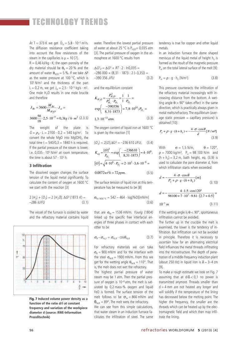
With σ = 1,5 N/m, θ = 120°,ρ = 7000 kg/m3, Pa = 98 100 N/m and(h + hü) = 3,2 m, bath height, eq. (3.9) isused to calculate the pore diameter d, fromwhich infiltration starts when exceeded:
(3.10)
(3.11)
If the wetting angle is θ < 90°, spontaneousinfiltration cannot be avoided.The further up in the crucible the melt is examined, the lower is the tendency of in -filtration. But infiltration can not be avoidedin principle. Therefore it is necessary to as certain how far an alternating electricalfield influences the metal threads infiltratinginto the microstructure. The depth of pene-tration of a middle-frequency induction plant(about 250 Hz) in liquid iron is δ ≈ 3–4 cm[9]. To make a rough estimate we look on Fig. 7assuming that at d/δ < 0,1 no power istransmitted anymore. Threads smaller thand = 4 mm are not heated any longer andwill solidify if the temperature of the lininghas decreased below the melting point. Thehigher the frequency, the smaller are thethreads which can be heated up by the elec-tromagnetic field and which then may infil-trate the lining.
9
The highest partial pressure of water steam may be 1atm. Then the partial pressure of oxygen is 10-8atm, the melt is saturated by 0,2wt% oxygen and liquid FeO is formed. The surface tension of the melt follows to be �Fe = 866mN/m and �Fe/R = 89°. The melt wets the refractory.
We can see from this simple calculations, that water steam in an induction furnace facilitates the infiltration of steel. The same tendency is true for copper and other liquid metals. In an induction furnace the dome shaped meniscus of the liquid metal of height hü is formed as the result of the magnetic pressure Pm on the total lateral surface of the melt /7/:
Pm = ρ · g · hü [N/m2]. (4.8) This pressure counteracts the infiltration of the refractory material increasingly with increasing distance from the bottom. A wetting angle θ > 90° takes effect in the same direction, which is practically always given in metal melts/refractory. The equilibrium ( average static pressure = capillary pressure) is obtained /8/:
²]/[
cos4)( mN
dhhgP üa
θσρ ⋅⋅−=+⋅⋅+ (4.9)
With σ = 1.5 N/m, θ = 120°, � = 7000 kg/m3, Pa = 98100 N/m and (h + hü) = 3,2 m, bath height, eq. (4.9) is used to calculate the pore diameter d, from which infiltration starts when exceeded:
][
)(
cos4m
hhgPd
üa +⋅⋅+−=
ρ (4.10)
( ) md 53 10
5.07.281.910798100120cos5.14 −=
+⋅⋅⋅+−=
. (4.11) If the wetting angle is θ < 90°, spontaneous infiltration cannot be avoided. The further up in the crucible the melt is examined, the lower is the tendency of infiltration. But infiltration can not be avoided in principle. Therefore it is necessary to ascertain how far an alternating electrical field influences the metal threads infiltrating into the microstructure. The depth of penetration of a middle-frequency induction plant (about 250Hz) in liquid iron is � � 3 - 4 cm /7/.
9
The highest partial pressure of water steam may be 1atm. Then the partial pressure of oxygen is 10-8atm, the melt is saturated by 0,2wt% oxygen and liquid FeO is formed. The surface tension of the melt follows to be �Fe = 866mN/m and �Fe/R = 89°. The melt wets the refractory.
We can see from this simple calculations, that water steam in an induction furnace facilitates the infiltration of steel. The same tendency is true for copper and other liquid metals. In an induction furnace the dome shaped meniscus of the liquid metal of height hü is formed as the result of the magnetic pressure Pm on the total lateral surface of the melt /7/:
Pm = ρ · g · hü [N/m2]. (4.8) This pressure counteracts the infiltration of the refractory material increasingly with increasing distance from the bottom. A wetting angle θ > 90° takes effect in the same direction, which is practically always given in metal melts/refractory. The equilibrium ( average static pressure = capillary pressure) is obtained /8/:
²]/[
cos4)( mNhhgP üa ρ −=+⋅⋅+
(4.9) With σ = 1.5 N/m, θ = 120°, � = 7000 kg/m3, Pa = 98100 N/m and (h + hü) = 3,2 m, bath height, eq. (4.9) is used to calculate the pore diameter d, from which infiltration starts when exceeded:
][
)(
cos4m
hhgPd
üa +⋅⋅+−=
ρ (4.10)
( ) md 53 10
5.07.281.910798100120cos5.14 −=
+⋅⋅⋅+°⋅⋅−=
. (4.11) If the wetting angle is θ < 90°, spontaneous infiltration cannot be avoided. The further up in the crucible the melt is examined, the lower is the tendency of infiltration. But infiltration can not be avoided in principle. Therefore it is necessary to ascertain how far an alternating electrical field influences the metal threads infiltrating into the microstructure. The depth of penetration of a middle-frequency induction plant (about 250Hz) in liquid iron is � � 3 - 4 cm /7/.
9
The highest partial pressure of water steam may be 1atm. Then the partial pressure of oxygen is 10-8atm, the melt is saturated by 0,2wt% oxygen and liquid FeO is formed. The surface tension of the melt follows to be �Fe = 866mN/m and �Fe/R = 89°. The melt wets the refractory.
We can see from this simple calculations, that water steam in an induction furnace facilitates the infiltration of steel. The same tendency is true for copper and other liquid metals. In an induction furnace the dome shaped meniscus of the liquid metal of height hü is formed as the result of the magnetic pressure Pm on the total lateral surface of the melt /7/:
Pm = ρ · g · hü [N/m2]. (4.8) This pressure counteracts the infiltration of the refractory material increasingly with increasing distance from the bottom. A wetting angle θ > 90° takes effect in the same direction, which is practically always given in metal melts/refractory. The equilibrium ( average static pressure = capillary pressure) is obtained /8/:
²]/[
cos4)( mNhhgP üa ρ −=+⋅⋅+
(4.9) With σ = 1.5 N/m, θ = 120°, � = 7000 kg/m3, Pa = 98100 N/m and (h + hü) = 3,2 m, bath height, eq. (4.9) is used to calculate the pore diameter d, from which infiltration starts when exceeded:
][
)(
cos4m
hhgPd
üa +⋅⋅+⋅⋅−=
ρθσ
(4.10)
( ) md 53 10
5.07.281.910798100120cos5.14 −=
+⋅⋅⋅+−=
. (4.11) If the wetting angle is θ < 90°, spontaneous infiltration cannot be avoided. The further up in the crucible the melt is examined, the lower is the tendency of infiltration. But infiltration can not be avoided in principle. Therefore it is necessary to ascertain how far an alternating electrical field influences the metal threads infiltrating into the microstructure. The depth of penetration of a middle-frequency induction plant (about 250Hz) in liquid iron is � � 3 - 4 cm /7/.
10
To make a rough estimate we look on Fig 4.1 assuming that at d/� < 0.1 no power is transmitted anymore. Threads smaller than d = 4 mm are not heated any longer and will solidify if the temperature of the lining has decreased below the melting point. The higher the frequency, the smaller are the threads which can be heated up by the electromagnetic field and which then may infiltrate the lining. Integration of the equation of Hagen-Poiseuille /8/ leads to the penetration depth l in relation to the time t:
][16
)((²
4
cosmt
hhgPddl
S
üSa
S
S ⋅���
����
�⋅
+⋅⋅+⋅+
⋅⋅⋅
=η
ρη
θσ
(4.12) The dynamic viscosity of steel is S = 0.003 Pas. The total ferrostatic height in our example is (h+hü) = 3.2 m at the bottom of the furnace. With the very small diameter of the thread d = 10-5 m and the external pressure Pa = 98100 N/m
l cm t . If the electromagnetic field couples the threads they may be heated up in very short time to high temperature. The refractory may be destroyed by temperature shock and its melting. In addition, the infiltrated metal has another coefficient of thermal expansion as the refractory, it may oxidise and it may form new compounds with the lining material. Therefore pressure may develop which destroys the lining resulting in the liquid metals breaking through.
FFiigg.. 77 Induced volume power density as afunction of the ratio d/δ at constant frequency and variation of the workpiecediameter d (source: RWE-InformationProzeßtechnik)

refractories WORLDFORUM 5 (2013) [4] 97
Integration of the equation of Hagen-Poiseuille [10] leads to the penetrationdepth l in relation to the time t:
(3.12)
The dynamic viscosity of steel isηS = 0,003 Pa ∙ s. The total ferrostaticheight in our example is (h + hü) = 3,2 m atthe bottom of the furnace. With the verysmall diameter of the thread d = 10–5 m andthe external pressure Pa = 98 100 N/m(1 atm) we can see, that in one minute 5 cmsteel are infiltrated if the temperature re-mains sufficiently high. That is
If the electromagnetic field couples thethreads they may be heated up in very shorttime to high temperature. The refractory maybe destroyed by temperature shock and itsmelting. In addition, the infiltrated metal hasanother coefficient of thermal expansion asthe refractory, it may oxidise and it may formnew compounds with the lining material.Therefore pressure may develop which des -troys the lining resulting in the liquid metalsbreaking through.
4 Formation of graphite
Ramming materials contain natural bondingclay, in which organic components are exist -ent. Refractory castables can contain organ-ic liquefiers or organic fibres. Both materialsare used for the lining of induction furnaces.The occurrence of “black“ coats under thesurface or inside of cores can be occasional-ly observed during an increase of tempera-ture. Conditions are:• High temperatures• Organic parts in the refractory material • No aerial oxygen • Impermeable closed surfaces, e.g. by rapidsintering, respectively.
Fig. 8 shows two examples. As a result, the refractory material is uselesssince it deforms or even loses its stability.The colour change occurs because of thechemical deposition of graphite. Graphitegenerates because of the disaggregation ofhydrocarbon to graphite and hydrogen, under the absence of air. The organics wouldburn to CO2 and H2O, if the reaction would
10
To make a rough estimate we look on Fig 4.1 assuming that at d/� < 0.1 no power is transmitted anymore. Threads smaller than d = 4 mm are not heated any longer and will solidify if the temperature of the lining has decreased below the melting point. The higher the frequency, the smaller are the threads which can be heated up by the electromagnetic field and which then may infiltrate the lining. Integration of the equation of Hagen-Poiseuille /8/ leads to the penetration depth l in relation to the time t:
][16
)((²
4
cosmt
hhgPddl
S
üSa
S
S ⋅���
����
�⋅
+⋅⋅+⋅+
⋅⋅⋅
=η
ρη
θσ
(4.12) The dynamic viscosity of steel is S = 0.003 Pas. The total ferrostatic height in our example is (h+hü) = 3.2 m at the bottom of the furnace. With the very small diameter of the thread d = 10-5 m and the external pressure Pa = 98100 N/m
/ 5 / minl cm t� . If the electromagnetic field couples the threads they may be heated up in very short time to high temperature. The refractory may be destroyed by temperature shock and its melting. In addition, the infiltrated metal has another coefficient of thermal expansion as the refractory, it may oxidise and it may form new compounds with the lining material. Therefore pressure may develop which destroys the lining resulting in the liquid metals breaking through.
10
To make a rough estimate we look on Fig 4.1 assuming that at d/� < 0.1 no power is transmitted anymore. Threads smaller than d = 4 mm are not heated any longer and will solidify if the temperature of the lining has decreased below the melting point. The higher the frequency, the smaller are the threads which can be heated up by the electromagnetic field and which then may infiltrate the lining. Integration of the equation of Hagen-Poiseuille /8/ leads to the penetration depth l in relation to the time t:
][16
)((²
4
cosmt
hhgPddl
S
üSa
S
S ⋅���
����
�⋅
+⋅⋅+⋅+
⋅⋅⋅
=η
ρη
θσ
(4.12) The dynamic viscosity of steel is S = 0.003 Pas. The total ferrostatic height in our example is (h+hü) = 3.2 m at the bottom of the furnace. With the very small diameter of the thread d = 10-5 m and the external pressure Pa = 98100 N/m
l cm t . If the electromagnetic field couples the threads they may be heated up in very short time to high temperature. The refractory may be destroyed by temperature shock and its melting. In addition, the infiltrated metal has another coefficient of thermal expansion as the refractory, it may oxidise and it may form new compounds with the lining material. Therefore pressure may develop which destroys the lining resulting in the liquid metals breaking through.
alumina (Al2O3 red) and periclase (MgOgreen) at 1 atm CO are reduced by carbonnot before 1580 °C as the Richardson-Ellingham diagram [5], Fig. 4, shows.Though, this equilibrium temperature dropsnotably under reduced pressure. The figure[5] compares the thermochemical stability ofdifferent oxides to the stability of thegraphite. The black straight lines describe thereaction according to the CO-partial pres-sure.
2 ⟨C ⟩ + {O2} = 2{CO}. ∆GO (1850 K, 1atm) =–130 000 cal/FU (4.1)
(Note: 1 kcal = 4,2 kJ.) The equilibrium con-stant is (for 1580 °C, 1 atm)
(4.2)
2
At the beginning a pre-condition about the configuration of the furnace atmosphere is made, whereas the residual moisture should be considered. The hydrocarbons are reacting with steam resulting in a complex atmosphere containing primarily CH4, H2O, H2, CO2 and CO. Therefore the first general information which is contemplated is the so-called equilibrium of water - gas. Fig. 5.2: Below 800°C the balance, independent of the total pressure, is predominately (CO2 + H2), above the stability of gases (CO + H2O) predominate, due to the increase of temperature. Taking into account the refractory, the percentage of carbon monoxide should be marginal, because the oxides silica (SiO2 blue), alumina (Al2O3 red) and periclase (MgO green) at 1atm CO are reduced by carbon not before 1580°C as the Richardson – Ellingham diagram /4/, Fig 5.3, shows. Though, this equilibrium temperature drops notably under reduced pressure. The figure /4/ compares the thermochemical stability of different oxides to the stability of the graphite. The black straight lines describe the reaction according to the CO – partial pressure.
22 2 . (1850 ,1 ) 130000 /o∆ = − (5.1)
(Note: 1kcal = 4,2kJ.) The equilibrium constant is (for 1580°C, 1atm)
2
215
1
130000exp exp 2 10
2 1850
oCO
C O
P GKeq
a P R T+� �∆ � �= = − = + = ⋅� � � �⋅ ⋅ ⋅� �� �
(5.2)
If the pressure of the CO at 1900K is reduced from 1atm to e.g. PCO = 10-4 atm, the (new) free enthalpy generates to
2
At the beginning a pre-condition about the configuration of the furnace atmosphere is made, whereas the residual moisture should be considered. The hydrocarbons are reacting with steam resulting in a complex atmosphere containing primarily CH4, H2O, H2, CO2 and CO. Therefore the first general information which is contemplated is the so-called equilibrium of water - gas. Fig. 5.2: Below 800°C the balance, independent of the total pressure, is predominately (CO2 + H2), above the stability of gases (CO + H2O) predominate, due to the increase of temperature. Taking into account the refractory, the percentage of carbon monoxide should be marginal, because the oxides silica (SiO2 blue), alumina (Al2O3 red) and periclase (MgO green) at 1atm CO are reduced by carbon not before 1580°C as the Richardson – Ellingham diagram /4/, Fig 5.3, shows. Though, this equilibrium temperature drops notably under reduced pressure. The figure /4/ compares the thermochemical stability of different oxides to the stability of the graphite. The black straight lines describe the reaction according to the CO – partial pressure.
22 2 . (1850 ,1 ) 130000 /o∆ = − (5.1)
(Note: 1kcal = 4,2kJ.) The equilibrium constant is (for 1580°C, 1atm)
2
2
1
130000exp exp 2 10
2 1850
oCO
C O
P GKeq
a P R T
� �∆ � �= = − = + = ⋅� � � �⋅ ⋅ ⋅� �� � (5.2)
If the pressure of the CO at 1900K is reduced from 1atm to e.g. PCO = 10-4 atm, the (new) free enthalpy generates to
be possible with aerial oxygen. No graphitewould originate. The same can happen in an induction fur-nace while heating-up under vacuum or pro-tective gas. Here; oxygen is missing as well.We will now report on the outcome. At the beginning a pre-condition about theconfiguration of the furnace atmosphere ismade, whereas the residual moisture shouldbe considered. The hydrocarbons are react-ing with steam resulting in a complex at-mosphere containing primarily CH4, H2O, H2,CO2 and CO. Therefore the first general in-formation which is contemplated is the so-called equilibrium of water – gas. Fig. 9: Be-low 800 °C the balance, independent of thetotal pressure, is predominately (CO2 + H2),above the stability of gases (CO + H2O) pre-dominate, due to the increase of tempera-ture. Taking into account the refractory, the per-centage of carbon monoxide should be mar-ginal, because the oxides silica (SiO2 blue),
1
5. Formation of graphite Ramming materials contain natural bonding clay, in which organic components are existent. Refractory castables can contain organic liquefiers or organic fibres. Both materials are used for the lining of induction furnaces. The occurrence of “black“ coats under the surface or inside of cores can be occasionally observed during an increase of temperature. Conditions are
• High temperatures • Organic parts in the refractory material • No aerial oxygen and • Impermeable closed surfaces, e.g. by rapid sintering, respectively
As a result, the refractory material is useless since it deforms or even loses its stability. The colour change occurs because of the chemical deposition of graphite. Graphite generates because of the disaggregation of hydrocarbon to graphite and hydrogen, under the absence of air. The organics would burn to CO2 and H2O, if the reaction would be possible with aerial oxygen. No graphite would originate. The same can happen in an induction furnace while heating-up under vacuum or protective gas. Here; oxygen is missing as well. We will now report on the outcome.
FFiigg.. 88 ULCC on the basis of “fused silica“ (l.); ramming material approx. 1300 °C (r.)(source: pers. memo. R. Krebs, 2012)
2
At the beginning a pre-condition about the configuration of the furnace atmosphere is made, whereas the residual moisture should be considered. The hydrocarbons are reacting with steam resulting in a complex atmosphere containing primarily CH4, H2O, H2, CO2 and CO. Therefore the first general information which is contemplated is the so-called equilibrium of water - gas. Fig. 5.2: Below 800°C the balance, independent of the total pressure, is predominately (CO2 + H2), above the stability of gases (CO + H2O) predominate, due to the increase of temperature. Taking into account the refractory, the percentage of carbon monoxide should be marginal, because the oxides silica (SiO2 blue), alumina (Al2O3 red) and periclase (MgO green) at 1atm CO are reduced by carbon not before 1580°C as the Richardson – Ellingham diagram /4/, Fig 5.3, shows. Though, this equilibrium temperature drops notably under reduced pressure. The figure /4/ compares the thermochemical stability of different oxides to the stability of the graphite. The black straight lines describe the reaction according to the CO – partial pressure.
22 2 . (1850 ,1 ) 130000 /o∆ = − (5.1)
(Note: 1kcal = 4,2kJ.) The equilibrium constant is (for 1580°C, 1atm)
2
2
1
130000
2 1850
oCO
C O
P GKeq
a P R T
� �∆ � �= = − = + = ⋅� � � �⋅ ⋅ ⋅� �� � (5.2)
If the pressure of the CO at 1900K is reduced from 1atm to e.g. PCO = 10-4 atm, the (new) free enthalpy generates to
FFiigg.. 99 Balance of water – gas [3]

98 refractories WORLDFORUM 5 (2013) [4]
If the pressure of the CO at 1900 K is re-duced from 1 atm to e.g. PCO = 10–4 atm,the (new) free enthalpy ∆GO
P generates to
∆GOP = –130 000 + 2 · R1T · ln10–4 =
–198 000 cal/FU (4.3)
(By connecting the point [198 kcal/1580 °C], via a line, with the data of the en-thalpy ∆HO = 55 kcal at T = -273 °C, it ispossible to directly read off the stabilities ofall oxide-reduction-reactions through carbonat PCO = 10–4 atm from the diagram).The coloured lines describe the reactions ofsilicium (blue), aluminium (red) and magne-sium (green) with oxygen to their solid ox-ides, i.e.
(Si ) + {O2} = ⟨SiO2⟩ (4.4)
The subtraction of both reaction equations(4.1–4.4) results in the balance reaction.
⟨SiO2⟩ + 2⟨C ⟩ =(Si ) + 2 {CO }, ∆GO (1850 K) = –130 kcal/FU (4.5)
In equilibrium is
∆G = ∆GO + RTlnKp = 0 (4.6)
Graphite reduces silica (SiO2) above1580 °C, while the CO-partial pressure isPCO = 1 atm. SiO2 is already reduced bygraphite at a temperature of approx.1080 °C at a CO-partial pressure of
10–4 atm, i.e. in a vacuum. The same appliesto corundum (2050 °C/1450 °C) and peri-clase (1840 °C/1480 °C). It should be con-sidered that at this example for periclase ap-plies
because besides CO, magnesium originatesas a gas and not as a condensed phase: ⟨MgO ⟩ + ⟨C ⟩ = {CO} + {Mg}, KP = PCO · PMg = P2CO .Hence, it is possible that during the vacuumprocess CO constitutes as well as from thegas reaction.“Cracking” of carbon hydrides under chem -ical deposition of graphite happens gradual-ly in many steps, therefore the result is an at-mosphere, which contains a multitude ofcarbon hydrides. Methane (CH4) is the light-est compound in series. It is likely thatmethane breaks down during an increase oftemperature. On the contrary, it is unlikelythat CO breaks down during an increase oftemperature, it becomes more stable(Fig. 10).It is noticeable that the stability of the car-bon hydrides decreases with an increasingmolecular weight, increasing temperatureand decreasing pressure because Keq be-comes greater. Hence, it seems to be obviousthat especially the “cracking” of the carbonhydrides is responsible for the chemical de -pos ition of graphite. Conversely, the stability of the carbonmonoxide increases with increasing tem-pera ture and pressure.
3
4130000 2 ln10 198000 /o −∆ = − + ⋅ ⋅ = − (5.3) (By connecting the point (198kcal / 1580°C), via a line, with the data of the enthalpy �Ho = 55kcal at T = -273°C, it is possible to directly read off the stabilities of all oxide – reduction – reactions through carbon at PCO = 10-4 atm from the diagram.) The coloured lines describe the reactions of silicium (blue), aluminium (red) and magnesium (green) with oxygen to their solid oxides, i.e.
. (5.4)
The subtraction of both reaction equations (5.1 - 5.4) results in the balance reaction. 2 2 2 , �Go (1850K) = -130kcal/FU. (5.5)
In equilibrium is �G =�Go + RTlnKp = 0. (5.6) Graphite reduces silica (SiO2) above 1580°C, while the CO – partial pressure is PCO = 1atm. SiO2 is already reduced by graphite at a temperature of approx. 1080°C at a CO – partial pressure of 10-4 atm, i.e. in a vacuum. The same applies to corundum (2050°C / 1450°C) and periclase (1840°C / 1480°C). It should be considered that at this example for periclase applies
( ) ( )CO COactuel figureP P= = 10-2 atm, because besides CO, magnesium originates
as a gas and not as a condensed phase:
{ } { },+ = + = ⋅ = .
Hence, it is possible that during the vacuum process CO constitutes as well as from the gas reaction.
The immediate result of the chemical de pos-ition of graphite is the loss of stability of thestructure. This is approved by the followingthermochemical examination: An example for a reaction equation can be
{CH4} = ⟨C ⟩ + 2 {H2 }. ∆GO (1000K, 1 atm) =–19395 J/FU (4.7)
(4.8)
In balance is
∆G = ∆GO + R1T ·1nKeq + (1 – π) · ∆VC = O(4.9)
∆GO is the base potential of the reaction,which needs to be calculated with the tabu -lated values of standard potentials [11].RT · lnKeq is the relative potential of the gasreaction for aC = 1. Given that∂G / ∂π ≡ ∆V [4] is defined, the relative po-tential of the graphite results in(1 – π) · ∆VC. (This element is omitted forπ = 1 atm). The equilibrium constant of the gas reaction is defined as Keq = P2H2 / PCH4 = 1.Hence, the result of equ. (4.8) is the supersaturation of the graphite as activity aC = 10,3. The molar volume of the graphite is ∆V = 5,3 cm3/mol and thegas constants are R1 = 8,31 J/mol · K andR2 = 84,8 atm · cm3/mol · K. Thus we re-ceive the crystallization pressure of thegraphite at 727 °C to be
(4.10)
The structure cannot cope with such anenormous pressure, it degenerates.
Fig. 11 compares the crystallization pres-sures of the graphite with different reac-tions. The CO-disaggregation ends above700 °C. The pressure reaches approx.105 atm at 400 °C. Experimentally it shows[12] that the strongest separation takes
6
The equilibrium constant of the gas reaction is defined as4
22eq H CHK P P .
Hence, the result of equ. (5.8) is the supersaturation of the graphite as activity aC = 10,3. The molar volume of the graphite is �V = 5,3cm3/mol and the gas constants are R1 = 8.31J/mol·K and R2 = 84, 8 atm·cm3/mol·K. Thus we receive the crystallization pressure of the graphite at 727°C to be
1 3
1 2
ln 19395 8,31 1000 ln1( 1) 36 10 .
/ 5,3 0,1
oeqG R T K
atmV R R
π−∆ − ⋅ + − ⋅ ⋅− = = = ⋅
∆ ⋅ ⋅ (5.10)
The structure cannot cope with such an enormous pressure, it degenerates. Fig. 5.5 compares the crystallization pressures of the graphite with different reactions. The CO – disaggregation ends above 700°C. The pressure reaches approx. 105atm at 400°C. Experimentally it shows /10/ that the strongest separation takes place between 500 and 550°C, given that disaggregation tendency and disaggregation kinetics are ideal. Metallic iron works as most intensive catalyst, but hydrogen as well /10/ . Crystallization pressure of CO drops with decreasing gas pressure.
The conditions for the carbon hydrides are inverted. Crystallisation pressure increases with an increase of temperature. The higher their molecular weight, the higher increases the pressure at a similar temperature. The decrease of gas pressure increases the crystallisation pressure of graphite.
6
The equilibrium constant of the gas reaction is defined as4
22eq H CHK P P .
Hence, the result of equ. (5.8) is the supersaturation of the graphite as activity aC = 10,3. The molar volume of the graphite is �V = 5,3cm3/mol and the gas constants are R1 = 8.31J/mol·K and R2 = 84, 8 atm·cm3/mol·K. Thus we receive the crystallization pressure of the graphite at 727°C to be
1 3
1 2
ln 19395 8,31 1000 ln1( 1) 36 10 .
/ 5,3 0,1
oeqG R T K
V R Rπ
−∆ − ⋅ + − ⋅ ⋅− = = = ⋅∆ ⋅ ⋅
(5.10)
The structure cannot cope with such an enormous pressure, it degenerates. Fig. 5.5 compares the crystallization pressures of the graphite with different reactions. The CO – disaggregation ends above 700°C. The pressure reaches approx. 105atm at 400°C. Experimentally it shows /10/ that the strongest separation takes place between 500 and 550°C, given that disaggregation tendency and disaggregation kinetics are ideal. Metallic iron works as most intensive catalyst, but hydrogen as well /10/ . Crystallization pressure of CO drops with decreasing gas pressure.
The conditions for the carbon hydrides are inverted. Crystallisation pressure increases with an increase of temperature. The higher their molecular weight, the higher increases the pressure at a similar temperature. The decrease of gas pressure increases the crystallisation pressure of graphite. 6
The equilibrium constant of the gas reaction is defined as4
22eq H CHK P P .
Hence, the result of equ. (5.8) is the supersaturation of the graphite as activity aC = 10,3. The molar volume of the graphite is �V = 5,3cm3/mol and the gas constants are R1 = 8.31J/mol·K and R2 = 84, 8 atm·cm3/mol·K. Thus we receive the crystallization pressure of the graphite at 727°C to be
1 3
1 2
ln 19395 8,31 1000 ln1( 1) 36 10 .
/ 5,3 0,1
oeqG R T K
V R Rπ
−∆ − ⋅ + − ⋅ ⋅− = = = ⋅∆ ⋅ ⋅
(5.10)
The structure cannot cope with such an enormous pressure, it degenerates. Fig. 5.5 compares the crystallization pressures of the graphite with different reactions. The CO – disaggregation ends above 700°C. The pressure reaches approx. 105atm at 400°C. Experimentally it shows /10/ that the strongest separation takes place between 500 and 550°C, given that disaggregation tendency and disaggregation kinetics are ideal. Metallic iron works as most intensive catalyst, but hydrogen as well /10/ . Crystallization pressure of CO drops with decreasing gas pressure.
The conditions for the carbon hydrides are inverted. Crystallisation pressure increases with an increase of temperature. The higher their molecular weight, the higher increases the pressure at a similar temperature. The decrease of gas pressure increases the crystallisation pressure of graphite.
5
It is noticeable that the stability of the carbon hydrides decreases with an increasing molecular weight, increasing temperature and increasing pressure because Keq becomes greater. Hence, it seems to be obvious that especially the “cracking” of the carbon hydrides is responsible for the chemical deposition of graphite. Conversely, the stability of the carbon monoxide increases with increasing temperature and pressure. The immediate result of the chemical deposition of graphite is the loss of stability of the structure. This is approved by the following thermochemical examination: An example for a reaction equation can be (1000 ,1 ) 19395 /o∆ = − (5.7)
2
4
2
1
19395exp exp 10.3
8.31 1000
oH C
eqCH
P a GK
P R T
⋅ � �∆ � �= = − = − =� � � �⋅ ⋅� �� � . (5.8)
In balance is 1
oeq CG G R T K Vπ . (5.9)
�Go is the base potential of the reaction, which needs to be calculated with the tabulated values of standard potentials /9/. RT·lnKeq is the relative potential of the gas reaction for aC= 1. Given that /3/ is defined, the relative potential of the graphite results in (1 – �)·�VC. (This element is omitted for � = 1atm.)
FFiigg.. 1100 Thermochemical stability of the compounds C2H6, CH4 and CO (source: FactSage)

refractories WORLDFORUM 5 (2013) [4] 99
place between 500 and 550 °C, given thatdisaggregation tendency and disaggregationkinetics are ideal. Metallic iron works asmost intensive catalyst, but hydrogen as well[12]. Crystallization pressure of CO dropswith decreasing gas pressure. The conditions for the carbon hydrides areinverted. Crystallisation pressure increaseswith an increase of temperature. The highertheir molecular weight, the higher increasesthe pressure at a similar temperature. Thedecrease of gas pressure increases the crys-tallisation pressure of graphite.To avoid black cores in clay bonded materialit would be recommended to conduct thedrying in a humid atmosphere. The poresstay open and the organics are oxidized. Inaddition shrinkage cracks are avoided. Thepartial pressure of the water is reduced veryslowly to carry out drying.
5 Drying of refractory
5.1 Basic information
The drying of ceramic materials containingwater is a complex process. The drying oftiles, for example, differs considerably fromthat of refractory castable. A clay tile bodycontains around 15 mass-% water, an UltraLow Cement Castable (ULCC) around5 mass-%. For tiles, there is a danger ofshrinkage cracks, while ULCC is prone to ex-plosive spalling if dried improperly. Fig. 12demonstrates an example from an inductionfurnace.In both cases, a programmed time/tem pera -ture curve is preferred. Here tiles are heatedslowly to around 110 °C, while refractorymaterial is heated to more than 600 °C.Mathematical models facilitate definition ofthe temperature/time programme. For thetile industry, K. Junge, U. Telljohann and A.Tretau [13, 14] have developed a numericalcalculation model. For the drying of refrac -tory castables, I. Grosswendt [15] has alsocome up with such a model.Objective of this research is to develop asimple and user-friendly analytical model forthe drying of refractory castables on the basis of available experience.Refractory castables consist – in chemicalterms – of Al2O3, CaO and SiO2, but can add -itionally contain ZrO2 and MgO. The focus ofthis study is ULCC, which besides Al2O3 con-tains only small percentages of CaO (calciumaluminate) and SiO2 to improve hydraulic
of moisture transport in the microstructure.Usually the distribution of open pores is de-termined after predrying at 110 °C, as it isassumed that after the long curing time allhydrates have been formed. A typical poresize distribution of a ULCC is shown in
6
The equilibrium constant of the gas reaction is defined as4
22eq H CHK P P .
Hence, the result of equ. (5.8) is the supersaturation of the graphite as activity aC = 10,3. The molar volume of the graphite is �V = 5,3cm3/mol and the gas constants are R1 = 8.31J/mol·K and R2 = 84, 8 atm·cm3/mol·K. Thus we receive the crystallization pressure of the graphite at 727°C to be
1 3
1 2
ln 19395 8,31 1000 ln1
/ 5,3 0,1
oeqG R T K
V R Rπ
−∆ − ⋅ + − ⋅ ⋅− = = = ⋅∆ ⋅ ⋅
(5.10)
The structure cannot cope with such an enormous pressure, it degenerates. Fig. 5.5 compares the crystallization pressures of the graphite with different reactions. The CO – disaggregation ends above 700°C. The pressure reaches approx. 105atm at 400°C. Experimentally it shows /10/ that the strongest separation takes place between 500 and 550°C, given that disaggregation tendency and disaggregation kinetics are ideal. Metallic iron works as most intensive catalyst, but hydrogen as well /10/ . Crystallization pressure of CO drops with decreasing gas pressure.
The conditions for the carbon hydrides are inverted. Crystallisation pressure increases with an increase of temperature. The higher their molecular weight, the higher increases the pressure at a similar temperature. The decrease of gas pressure increases the crystallisation pressure of graphite.
FFiigg.. 1111 Crystallization pressures of the chemical deposition of graphite [3]
1
6. Drying of Refractory 6.1 Basic Information The drying of ceramic materials containing water is a complex process. The drying of tiles, for example, differs considerably from that of refractory castable. A clay tile body contains around 15 wt. % water, an Ultra Low Cement Castable (ULCC) around 5 wt. %. For tiles, there is a danger of shrinkage cracks, while ULCC is prone to explosive spalling if dried improperly. Fig. 6.1.1 demonstrates an example from an induction furnace.
Fig. 6.1.1: Demage of refraction wall due to evaporation pressure of water, pers. memo. K.-E. Granitzki (2005) In both cases, a programmed time/temperature curve is preferred. Here tiles are heated slowly to around 110 °C, while refractory material is heated to more than 600 °C. Mathematical models facilitate definition of the temperature/time programme. For the tile industry, K. Junge, U. Telljohann and A. Tretau /11, 12/ have developed a numerical calculation model. For the drying of refractory castables, I. Grosswendt /13/ has also come up with such a model. Objective of this research is to develop a simple and user-friendly analytical model for the drying of refractory castables on the basis of available experience. Refractory castables consist – in chemical terms – of Al2O3, CaO and SiO2, but can additionally contain ZrO2 and MgO. The focus of this study is Ultra Low Cement Castable (ULCC), which besides Al2O3 contains only small percentages
FFiigg.. 1122 Demage of refraction wall due toevaporation pressure of water (source: pers. memo. K.-E. Granitzki, 2005)
FFiigg.. 1133 Pore size distribution of an ULCC (source: Calderys)
bonding. Main components are spinel/ corundum or andalusite. The particle sizedistribution of the matrix is bimodal, approx.50 mass-% being classified as coarse grain(1–100 µm Ø) and 50 mass-% as fine grain(10–2–1 µm Ø). The coarse grains againstwear go up to 6 mm Ø.The dry mass has an apparent density ofaround 2700 kg/m3. To this is added around5 mass-% water so that after a mixing timeof around 5 min and densification a fresh re-fractory castable with an apparent density of2835 kg/m3 is produced.After this processing, the castable rests≥24 h, during which curing time hydraulicbinder phases are formed. These are mainlygibbsite (Al(OH)3), monocalcium aluminatehydrate (CaO · Al2O3 · 10H2O) and, at slight-ly increased temperature, tricalcium alu -minate hydrate (3CaO · Al2O3 · 6H2O) [16].These hydrates clog up especially the finepore channels, leading to a distinct restraint
3
Open Porosity of ULCC
0
10
20
30
40
50
60
70
80
90
100
0,01 0,10 1,00 10,00 100,00size of pores / micron
sum
freq
uenc
y dist
ribut
ion
/ %
dried 110°C48 h burned 1300°C / OP 10,6%100 h burned 1600°C / OP 9,8%
Fig.6.1.1: Pore size distribution of an ULCC (Calderys) 6.2 Drying Model In accordance with field practice, control of the temperature determines the drying process of refractory castable. For example, the following heating instruction is given to the customers of an ULCC refractory castable (H. Dünnes, Calderys, private memo): after curing and form removal, heating at 15 K/h with a holding time of 1 h/0.01 m wall thickness at 150 °C, 350 °C and 600 °C. The holding time aids temperature balancing. Conversely, in laboratory tests, heating rates > 10 K/min are set to provoke spalling and to investigate this. In no case the location and the temperature of the drying plane are known. They can only be calculated with numerical models /11, 12, 13/. In the following, a simple model for drying refractory castable is developed. This is based on four assumptions: 1. Not the mass transport, but the temperature course defines the drying process
/3, 13, 14/. 2. The first and the second drying stages of refractory castable can be treated
the same, as the former is comparatively short /13/. 3. As soon as the water has been largely removed, there is no danger for the
castable during any further increase of the temperature (> 350 °C)/14, 15/.
size of pores [micron]
sum
fre
quen
cy d
istrib
utio
n [%
]
Open Porosity of ULCC

100 refractories WORLDFORUM 5 (2013) [4]
Fig. 13. According to this, 90 % of the openpores are smaller than 0,1 µm. The largestopen pores measure 3–5 µm.The discharge of water is devided in threesections:• Adsorbed water evaporates (≤110 °C).• Calcium aluminate hydrates with a lowcontent of hydrate (CAH10, C2AH8, C3AH6)decompose; the liberated water boils(<250 °C). There are indications that up to200 °C further hydrates can be formed(Krebs, R., priv. memo).
• The remaining hydrates, particularly gibb-site (Al(OH)3), decompose (≤400 °C).Minute traces in interstices remain toaround 600 °C [17].
The first drying stage is followed by the sec-ond when the outer surface becomes dry
and the drying plane starts to penetrate thebody.Curing should take place at increased tem-perature (<100 °C) and therefore as com-pletely as possible so as to avoid the devel-opment of stable hydrates at higher tem -pera tures (up to 200 °C). Although they con-tain less water they decompose at evenhigher temperatures. That could lead to avapour explosion (Krebs, R., private memo).Around 50 % of the added water is boundas hydrate; the rest is present free in the micro structure and bonds the grains bymeans of van der Waals forces.
5.2 Drying model
In accordance with field practice, control ofthe temperature determines the drying
process of refractory castable. For example,the following heating instruction is given tothe customers of an ULCC refractory castable(H. Dünnes, Calderys, private memo): aftercuring and form removal, heating at 15 K/hwith a holding time of 1 h/0,01 m wall thick-ness at 150 °C, 350 °C and 600 °C. Theholding time aids temperature balancing.Conversely, in laboratory tests, heating rates>10 K/min are set to provoke spalling and toinvestigate this. In no case the location andthe temperature of the drying plane areknown. They can only be calculated with nu-merical models [13–15].In the following, a simple model for dryingrefractory castable is developed. This isbased on four assumptions:• Not the mass transport, but the tempera-ture course defines the drying process [4,15–16].
• The first and the second drying stages ofrefractory castable can be treated thesame, as the former is comparatively short[15].
• As soon as the water has been largely re-moved, there is no danger for the cast ableduring any further increase of the tem -pera ture (>350 °C) [16, 17].
• The integral mean value of the tempera -ture ϑimv, formed over the total thickness Lof the castable layer, is a value that ap-proximately replaces knowledge of the exact location of the drying plane and cantherefore be used as a basic value for thecalculation of the time-temperature curvein the castable. Empirical findings [16–21]support this assumption insofar that thetemperature gradient is steep at this pointLimv, so that in the hot, already dried areathere is no longer a danger of vapour ex-plosion and this very quickly decreases inthe still moist area on account of the cool-ing. The greatest danger therefore existsjust behind the drying front, i.e. close tothe integral mean temperature ϑimv and itslocation Limv.
Fig. 14 shows the temperature curve in thecastable layer as an example [2]. Fig. 15 shows as an example the course ofthe integral mean value of the temperatureand its location over time (ϑa = 30 °C,L = 0,5 m; k = 15 K/h; a = 9 · 10–7 m2/s).With the increasing location Limv, the tem-perature ϑimv rises steadily. To make these calculations easier, two ap-proximations can be used [2].
FFiigg.. 1144 Curve of the temperature in the castable layer (drying in field practice)(ϑϑa = 30 °C; L = 0,2 m; k = 15 K · min; a = 9 · 10–7 m2/s)
4
4. The integral mean value of the temperature imv, formed over the total thickness L of the castable layer, is a value that approximately replaces knowledge of the exact location of the drying plane and can therefore be used as a basic value for the calculation of the time-temperature curve in the castable. Empirical findings /14 -19/ support this assumption insofar that the temperature gradient is steep at this point L imv, so that in the hot, already dried area there is no longer a danger of vapour explosion and this very quickly decreases in the still moist area on account of the cooling. The greatest danger therefore exists just behind the drying front, i.e. close to the integral mean temperature imv and its location L imv.
Fig. 6.2.1 shows the temperature curve in the castable layer as an example /20/.
T(x,t)
0
50
100
150
200
250
300
350
400
450
500
0 0,1 0,2 0,3 0,4 0,5
x/m
T/°C
32 h Heating
24 h Heating
16 h Heating
8 h Heating
4 h Heating
End ofSample
Limv
Fig. 6.2.1: Curve of the temperature in the castable layer (drying in field practice) 7 2
aϑ = ° = = = ⋅
Fig. 6.2.2 shows as an example the course of the integral mean value of the temperature and its location over time ( a = 30 °C, L = 0.5 m; k = 15 K/h; a = 9 ⋅ 10-7 m2/s). With the increasing location L imv, the temperature rises steadily.
FFiigg.. 1155 Course of the integral mean value of the temperature ϑϑIMV and the location LIMV
as a function of time t
5
Timv(t) and Limv(t)
0
50
100
150
200
250
300
350
0 10 20 30 40 50
t/h
Tim
v/ °C
0
0,05
0,1
0,15
0,2
0,25
0,3
0,35
Limv/m
Timv/h
Limv/m
Fig. 6.2.2: Course of the integral mean value of the temperature and the location LIMV as a function of time t
To make these calculations easier, two approximations can be used /20/. In short-term tests, therefore in the laboratory, with a run time up to 3 h, the following numerical value equation applies:
imv aa tϑ ϑ ⋅
(6.2.1)
For long-term tests with slow heating, i.e. field practice, the numerical value equation applies:
[ ]3 0,25
3imv
3 10(3,7 10 33,5)a
aϑ ϑ −⋅ ⋅ . (6.2.2)
describes the integral mean value (imv) of the temperature distribution in
the material better, the thicker the layer of castable is, as the solutions only apply precisely for an infinitely thick layer of castable. From this, a slice is cut out. This procedure has the practical advantage that thermal conduction in the area behind the wear layer, e.g. in the safety lining, can also be approximately considered. The result is the approximate solution:
00.25 3
imv
a
a
L t
a t
ϑ ϑϑ ϑ −
− = ⋅− ⋅ ⋅ ⋅ −
(6.2.3)
T [°C]
x [m]
T [x, t]
t [h]
T im
v[°C]
Timv [t] and Limv [t]
L im
v[°C]
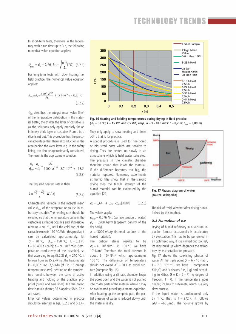
refractories WORLDFORUM 5 (2013) [4] 101
In short-term tests, therefore in the labora -tory, with a run time up to 3 h, the followingnumerical value equation applies:
(5.2.1)
For long-term tests with slow heating, i.e.field practice, the numerical value equationapplies:
(5.2.2)
ϑimv describes the integral mean value (imv)of the temperature distribution in the mater -ial better, the thicker the layer of castable is,as the solutions only apply precisely for anin finitely thick layer of castable. From this, aslice is cut out. This procedure has the practi-cal advantage that thermal conduction in thearea behind the wear layer, e.g. in the safetylining, can also be approximately considered.The result is the approximate solution:
(5.2.3)
The required heating rate is then
(5.2.4)
Characteristic variable is the integral meanvalue ϑimv of the temperature course in re-fractory castable. The heating rate should beselected so that the temperature curve in thecastable is as flat as possible and, if possible,remains <200 °C, until the cold end of thecastable exceeds 110 °C. With this proviso, kcan be calculated approximately: letϑa = 30 °C, ϑimv = 150 °C; L = 0,2 m;t = 86 400 s (24 h); a = 9 · 10–7 m2/s (tem-perature conductivity of the castable), sothat according to eq. (5.2.3) ϑO = 210 °C. Itfollows from eq. (5.2.4) that the heating ratek = 0,0021 K/s (7,5 K/h) (cf. Fig. 16 orangetemperature curve). Heating on the tem pera -ture remains between the curve of activeheating and holding of the practical pro -posal (green and blue lines). But the dryingtime is much shorter, 36 h against 58 h. 22 hare saved.Empirical values determined in practiceshould be inserted in eqs. (5.2.3 and 5.2.4).
6
The required heating rate is then
[ ]0 /ak K st
ϑ ϑ−= . (6.2.4)
Characteristic variable is the integral mean value of the temperature course in refractory castable. The heating rate should be selected so that the temperature curve in the castable is as flat as possible and, if possible, remains < 200 °C, until the cold end of the castable exceeds 110 °C. With this proviso, k can be calculated approximately: let = 30 °C, = 150 °C; L =
0.2 m; t = 86400 s (24 h); a = 9 ⋅ 10-7 m²/s (temperature conductivity of the castable), so that according to eq. (6.2.3) = 210 °C. It follows from eq. (6.2.4) that the heating rate k = 0.0021 K/s (7.5 K/h) (cf. Fig. 6.2.3 orange temperature curve). Heating on the temperature remains between the curve of active heating and holding of the practical proposal (green and blue lines). But the drying time is much shorter, 36 hours against 58 hours. 22 hours are saved.
050
100150200250300350
0 0,1 0,2 0,3 0,4 0,5x [m]
T [°C
]
End of Sample
Integr. MeanValue0-8 h Heat 15K/h
8-28 h Hold
28-38hHeat15K/min38-58 h Hold
0-16 h Heat7,5K/h0-24 h Heat7,5K/h0-36 h Heat7,5K/h0-44 h Heat7,5K/h
Fig. 6.2.3: Heating and holding temperatures during drying in field practice 7 2
imvϑ −= ° = = ⋅ = =
5
Timv(t) and Limv(t)
0
50
100
150
200
250
300
350
0 10 20 30 40 50
t/h
Tim
v/ °C
0
0,05
0,1
0,15
0,2
0,25
0,3
0,35
Limv/m
Timv/h
Limv/m
Fig. 6.2.2: Course of the integral mean value of the temperature and the location LIMV as a function of time t
To make these calculations easier, two approximations can be used /20/. In short-term tests, therefore in the laboratory, with a run time up to 3 h, the following numerical value equation applies:
imv aa tϑ ϑ ⋅
(6.2.1)
For long-term tests with slow heating, i.e. field practice, the numerical value equation applies:
[ ]3 0,25
3imv
3 10(3,7 10 33,5)a
aϑ ϑ −⋅ ⋅ . (6.2.2)
describes the integral mean value (imv) of the temperature distribution in
the material better, the thicker the layer of castable is, as the solutions only apply precisely for an infinitely thick layer of castable. From this, a slice is cut out. This procedure has the practical advantage that thermal conduction in the area behind the wear layer, e.g. in the safety lining, can also be approximately considered. The result is the approximate solution:
00.25 3
imv 3000 3,7 10 33,5a
a
L t
a t
ϑ ϑϑ ϑ −
− = ⋅− ⋅ ⋅ ⋅ −
(6.2.3)
5
Timv(t) and Limv(t)
0
50
100
150
200
250
300
350
0 10 20 30 40 50
t/h
Tim
v/ °C
0
0,05
0,1
0,15
0,2
0,25
0,3
0,35
Limv/m
Timv/h
Limv/m
Fig. 6.2.2: Course of the integral mean value of the temperature and the location LIMV as a function of time t
To make these calculations easier, two approximations can be used /20/. In short-term tests, therefore in the laboratory, with a run time up to 3 h, the following numerical value equation applies:
imv aa tϑ ϑ ⋅
(6.2.1)
For long-term tests with slow heating, i.e. field practice, the numerical value equation applies:
[ ]3 0,25
3imv
3 10(3,7 10 33,5)a
ak t C
Lϑ ϑ −⋅ ⋅≅ + ⋅ ⋅ ⋅ ⋅ − ° . (6.2.2)
describes the integral mean value (imv) of the temperature distribution in
the material better, the thicker the layer of castable is, as the solutions only apply precisely for an infinitely thick layer of castable. From this, a slice is cut out. This procedure has the practical advantage that thermal conduction in the area behind the wear layer, e.g. in the safety lining, can also be approximately considered. The result is the approximate solution:
00.25 3
imv
a
a
L t
a t
ϑ ϑϑ ϑ −
− = ⋅− ⋅ ⋅ ⋅ −
(6.2.3)
5
Timv(t) and Limv(t)
0
50
100
150
200
250
300
350
0 10 20 30 40 50
t/h
Tim
v/ °C
0
0,05
0,1
0,15
0,2
0,25
0,3
0,35
Limv/m
Timv/h
Limv/m
Fig. 6.2.2: Course of the integral mean value of the temperature and the location LIMV as a function of time t
To make these calculations easier, two approximations can be used /20/. In short-term tests, therefore in the laboratory, with a run time up to 3 h, the following numerical value equation applies:
imv2,66 [ ]a
a tk t C
Lϑ ϑ ⋅= + ⋅ ⋅ ⋅ ° (6.2.1)
For long-term tests with slow heating, i.e. field practice, the numerical value equation applies:
[ ]3 0,25
3imv
3 10(3,7 10 33,5)a
aϑ ϑ −⋅ ⋅ . (6.2.2)
describes the integral mean value (imv) of the temperature distribution in
the material better, the thicker the layer of castable is, as the solutions only apply precisely for an infinitely thick layer of castable. From this, a slice is cut out. This procedure has the practical advantage that thermal conduction in the area behind the wear layer, e.g. in the safety lining, can also be approximately considered. The result is the approximate solution:
00.25 3
imv
a
a
L t
a t
ϑ ϑϑ ϑ −
− = ⋅− ⋅ ⋅ ⋅ −
(6.2.3)
The risk of residual water after drying is min-imized by this method.
5.3 Formation of ice
Drying of humid refractory in a vacuum in-duction furnace occasionally is acceleratedby evacuation. This has to be performed inan optimised way. If it is carried out too fast,ice may build up which degrades the refrac-tory by its crystallisation pressure.Fig. 17 shows the coexisting phases of water. At the triple point (P = 6 · 10–3 atm,T = 7,5 · 10–3 °C) we have 1 componentK (H2O) and 3 phases P (s, l, g) and accord-ing to Gibbs (F = K + 2 – P) no degree offreedom, F = 0. If the temperature goesdeeper, ice has to sublimate, which is a veryslow process. If the liquid water is undercooled only by 1 °C, that is T = 272 K, it follows ∆G0 = –63 J/mol. The volume grows by
They only apply to slow heating and times>3 h, that is for practice.A special procedure is used for fine pored or big sized parts which are sensitiv to drying. They are heated up slowly in an atmosphere which is held water saturated.The pressure in the climatic chamber therefore equals that inside the material. If the difference becomes too big, the material ruptures. Numerous experiments at humid tiles show that in the second drying step the tensile strength of the humid material can be estimated by theequation [22]
σt = 0,64 · a · ρR · σH2O [N/m2] (5.2.5)
The values apply:σH2O
= 0,076 N/m (surface tension of water) ρR = 2700 kg/m3 (apparent density of thedry body), a ~_ 3000 m2/kg (internal surface of the humid material).The critical stress results to beσt = 4 · 105 N/m2. At 100 °C we have105 N/m2. Therefore the total pressure isabout 5 · 105 N/m2 which approximates150 °C. The difference of temperatureshould not exeed ∆T = 50 K to avoid rup-ture (compare Fig. 16).In addition using a climatic chamber keepsthe pores open and the water is not pushedinto colder parts of the material where it maybe overheated provoking a steam explosion.After heating up the complete part, the par-tial pressure of water is reduced slowly untilthe material is dry.
FFiigg.. 1166 Heating and holding temperatures during drying in field practice (ϑϑO = 30 °C; k = 15 K/h and 7,5 K/h; resp., a = 9 · 10–7 m2/s; L = 0,2 m; Limv = 0,09 m)
6
The required heating rate is then
[ ]0 a= . (6.2.4)
Characteristic variable is the integral mean value of the temperature course in refractory castable. The heating rate should be selected so that the temperature curve in the castable is as flat as possible and, if possible, remains < 200 °C, until the cold end of the castable exceeds 110 °C. With this proviso, k can be calculated approximately: let = 30 °C, = 150 °C; L =
0.2 m; t = 86400 s (24 h); a = 9 ⋅ 10-7 m²/s (temperature conductivity of the castable), so that according to eq. (6.2.3) = 210 °C. It follows from eq. (6.2.4) that the heating rate k = 0.0021 K/s (7.5 K/h) (cf. Fig. 6.2.3 orange temperature curve). Heating on the temperature remains between the curve of active heating and holding of the practical proposal (green and blue lines). But the drying time is much shorter, 36 hours against 58 hours. 22 hours are saved.
050
100150200250300350
0 0,1 0,2 0,3 0,4 0,5x [m]
T [°C
]
End of Sample
Integr. MeanValue0-8 h Heat 15K/h
8-28 h Hold
28-38hHeat15K/min38-58 h Hold
0-16 h Heat7,5K/h0-24 h Heat7,5K/h0-36 h Heat7,5K/h0-44 h Heat7,5K/h
Fig. 6.2.3: Heating and holding temperatures during drying in field practice 7 2
imvϑ −= ° = = ⋅ = =
x [m]
T [°C]
1
6.3 Formation of Ice Drying of humid refractory in a vacuum induction furnace occasionally is accelerated by evacuation. This has to be performed in an optimised way. If it is carried out too fast, ice may build up which degrades the refractory by its crystallisation pressure. Fig 6.3.1 shows the coexisting phases of water. At the triple point (P = 6·10-3
atm, T = 7,5·10-3 °C) we have 1component K (H2O) and 3 phases P (sol, li, g) and according to Gibbs (F = K + 2 – P) no degree of freedom, F = 0. If the temperature goes deeper, ice has to sublimate, which is a very slow process.
If the liquid water is undercooled only by 1°C, that is T = 272K, it follows �G0 = - 63J/mol. The volume grows by �V = 1,6ccm/mol forming ice and we
1 2
63
/ 1,6 0,1
oG
V R Rπ −∆− = = =
∆ ⋅ ⋅ (6.3.1)
�T). Its
compressibility is given by 10Vκ = − −
⋅ ∆� . The cubic coefficient of
1,5 10Vβ = ⋅
⋅ ∆� /8/. It results
4
5
1,5 10P βκ
−
−∆ ⋅= − = =∆
. (6.3.2)
FFiigg.. 1177 Phases diagram of water (source: Wiki pedia)
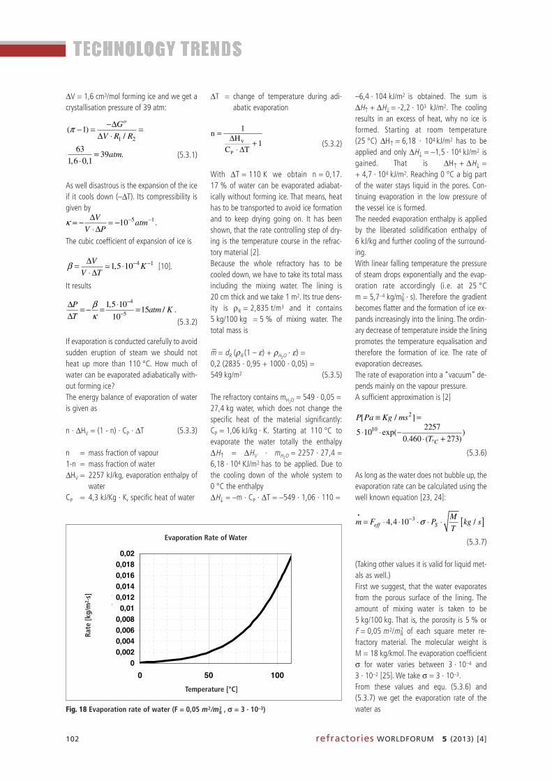
102 refractories WORLDFORUM 5 (2013) [4]
∆V = 1,6 cm3/mol forming ice and we get acrystallisation pressure of 39 atm:
(5.3.1)
As well disastrous is the expansion of the iceif it cools down (–∆T). Its compressibility isgiven by
The cubic coefficient of expansion of ice is
[10].
It results
(5.3.2)
If evaporation is conducted carefully to avoidsudden eruption of steam we should notheat up more than 110 °C. How much ofwater can be evaporated adiabatically with-out forming ice?The energy balance of evaporation of wateris given as
n · ∆HV = (1 - n) · CP · ∆T (5.3.3)
n = mass fraction of vapour1-n = mass fraction of water∆HV = 2257 kJ/kg, evaporation enthalpy of
waterCP = 4,3 kJ/Kg · K, specific heat of water
1
6.3 Formation of Ice Drying of humid refractory in a vacuum induction furnace occasionally is accelerated by evacuation. This has to be performed in an optimised way. If it is carried out too fast, ice may build up which degrades the refractory by its crystallisation pressure. Fig 6.3.1 shows the coexisting phases of water. At the triple point (P = 6·10-3
atm, T = 7,5·10-3 °C) we have 1component K (H2O) and 3 phases P (sol, li, g) and according to Gibbs (F = K + 2 – P) no degree of freedom, F = 0. If the temperature goes deeper, ice has to sublimate, which is a very slow process.
If the liquid water is undercooled only by 1°C, that is T = 272K, it follows �G0 = - 63J/mol. The volume grows by �V = 1,6ccm/mol forming ice and we
1 2
63( 1) 39 .
/ 1,6 0,1
oGatm
V R Rπ −∆− = = =
∆ ⋅ ⋅ (6.3.1)
�T). Its
compressibility is given by 10Vκ = − −
⋅ ∆� . The cubic coefficient of
1,5 10Vβ = ⋅
⋅ ∆� /8/. It results
4
5
1,5 10P βκ
−
−∆ ⋅= − = =∆
. (6.3.2)
1
6.3 Formation of Ice Drying of humid refractory in a vacuum induction furnace occasionally is accelerated by evacuation. This has to be performed in an optimised way. If it is carried out too fast, ice may build up which degrades the refractory by its crystallisation pressure. Fig 6.3.1 shows the coexisting phases of water. At the triple point (P = 6·10-3
atm, T = 7,5·10-3 °C) we have 1component K (H2O) and 3 phases P (sol, li, g) and according to Gibbs (F = K + 2 – P) no degree of freedom, F = 0. If the temperature goes deeper, ice has to sublimate, which is a very slow process.
If the liquid water is undercooled only by 1°C, that is T = 272K, it follows �G0 = - 63J/mol. The volume grows by �V = 1,6ccm/mol forming ice and we
1 2
63( 1) 39 .
/ 1,6 0,1
oG
V R Rπ −∆− = = =
∆ ⋅ ⋅ (6.3.1)
�T). Its
compressibility is given by 10Vκ = − −
⋅ ∆� . The cubic coefficient of
1,5 10Vβ = ⋅
⋅ ∆� /8/. It results
4
5
1,5 10P βκ
−
−∆ ⋅= − = =∆
. (6.3.2)
1
6.3 Formation of Ice Drying of humid refractory in a vacuum induction furnace occasionally is accelerated by evacuation. This has to be performed in an optimised way. If it is carried out too fast, ice may build up which degrades the refractory by its crystallisation pressure. Fig 6.3.1 shows the coexisting phases of water. At the triple point (P = 6·10-3
atm, T = 7,5·10-3 °C) we have 1component K (H2O) and 3 phases P (sol, li, g) and according to Gibbs (F = K + 2 – P) no degree of freedom, F = 0. If the temperature goes deeper, ice has to sublimate, which is a very slow process.
If the liquid water is undercooled only by 1°C, that is T = 272K, it follows �G0 = - 63J/mol. The volume grows by �V = 1,6ccm/mol forming ice and we
1 2
63
/ 1,6 0,1
oG
V R Rπ −∆− = = =
∆ ⋅ ⋅ (6.3.1)
�T). Its
compressibility is given by 10Vκ = − −
⋅ ∆� . The cubic coefficient of
1,5 10V
V Tβ = ⋅
⋅ ∆� /8/. It results
4
5
1,5 1015 /
10
Patm K
T
βκ
−
−∆ ⋅= − = =∆
. (6.3.2)
1
6.3 Formation of Ice Drying of humid refractory in a vacuum induction furnace occasionally is accelerated by evacuation. This has to be performed in an optimised way. If it is carried out too fast, ice may build up which degrades the refractory by its crystallisation pressure. Fig 6.3.1 shows the coexisting phases of water. At the triple point (P = 6·10-3
atm, T = 7,5·10-3 °C) we have 1component K (H2O) and 3 phases P (sol, li, g) and according to Gibbs (F = K + 2 – P) no degree of freedom, F = 0. If the temperature goes deeper, ice has to sublimate, which is a very slow process.
If the liquid water is undercooled only by 1°C, that is T = 272K, it follows �G0 = - 63J/mol. The volume grows by �V = 1,6ccm/mol forming ice and we
1 2
63
/ 1,6 0,1
oG
V R Rπ −∆− = = =
∆ ⋅ ⋅ (6.3.1)
�T). Its
compressibility is given by 10Vκ = − −
⋅ ∆� . The cubic coefficient of
4 11,5 10V
KV T
β − −∆= ⋅⋅ ∆
� /8/. It results
4
5
1,5 10P βκ
−
−∆ ⋅= − = =∆
. (6.3.2)
1
6.3 Formation of Ice Drying of humid refractory in a vacuum induction furnace occasionally is accelerated by evacuation. This has to be performed in an optimised way. If it is carried out too fast, ice may build up which degrades the refractory by its crystallisation pressure. Fig 6.3.1 shows the coexisting phases of water. At the triple point (P = 6·10-3
atm, T = 7,5·10-3 °C) we have 1component K (H2O) and 3 phases P (sol, li, g) and according to Gibbs (F = K + 2 – P) no degree of freedom, F = 0. If the temperature goes deeper, ice has to sublimate, which is a very slow process.
If the liquid water is undercooled only by 1°C, that is T = 272K, it follows �G0 = - 63J/mol. The volume grows by �V = 1,6ccm/mol forming ice and we
1 2
63
/ 1,6 0,1
oG
V R Rπ −∆− = = =
∆ ⋅ ⋅ (6.3.1)
�T). Its
compressibility is given by 5 110V
atmV P
κ − −∆= − −⋅ ∆
� . The cubic coefficient of
1,5 10Vβ = ⋅
⋅ ∆� /8/. It results
4
5
1,5 10P βκ
−
−∆ ⋅= − = =∆
. (6.3.2)
∆T = change of temperature during adi -abatic evaporation
(5.3.2)
With ∆T = 110 K we obtain n = 0,17.17 % of water can be evaporated adiabat -ically without forming ice. That means, heathas to be transported to avoid ice formationand to keep drying going on. It has beenshown, that the rate controlling step of dry-ing is the temperature course in the refrac-tory material [2].Because the whole refractory has to becooled down, we have to take its total massincluding the mixing water. The lining is20 cm thick and we take 1 m2. Its true dens-ity is ρR = 2,835 t/m3 and it contains5 kg/100 kg = 5 % of mixing water. The total mass is
m– = dR (ρR (1 – ε) + ρH2O· ε) =
0,2 (2835 · 0,95 + 1000 · 0,05) =549 kg/m2 (5.3.5)
The refractory contains mH2O= 549 · 0,05 =
27,4 kg water, which does not change thespecific heat of the material significantly:CP = 1,06 kJ/kg · K. Starting at 110 °C toevaporate the water totally the enthalpy∆H↑ = ∆HV · mH2O
= 2257 · 27,4 =6,18 · 104 KJ/m2 has to be applied. Due tothe cooling down of the whole system to0 °C the enthalpy∆H↓ = –m · CP · ∆T = –549 · 1,06 · 110 =
2
If evaporation is conducted carefully to avoid sudden eruption of steam we should not heat up more than 110°C. How much of water can be evaporated adiabatically without forming ice? The energy balance of evaporation of water is given as n · ∆HV = (1 - n) · CP · ∆T (6.3.3) n = Mass fraction of vapour 1-n = Mass fraction of water ∆HV = 2257 kJ/kg, evaporation enthalpy of water CP = 4,3 kJ/Kg · K, specific heat of water
ion
1
1
+∆⋅
∆=
TC
Hn
P
V
. (6.3.4) evaporated
adiabatically without forming ice. That means, heat has to be transported to avoid ice formation and to keep drying going on. It has been shown, that the rate controlling step of drying is the temperature course in the refractory material /20/. Because the whole refractory has to be cooled down, we have to take its total mass including the mixing water. The lining is 20 cm thick and we take 1 m². Its true density is ρR = 2,835 t/m³ and it contains 5kg/100kg = 5% of mixing water. The total mass is
2 R R H Om d ρ ε ρ ε= − + ⋅ = ⋅ + ⋅ = (6.3.5)
The refractory contains mH2O = 549·0,05 = 27,4 kg water, which does not change the specific heat of the material significantly: CP = 1,06 kJ/kg·K. Starting at 110°C to evaporate the water totally the enthalpy
2V H OH H m↑∆ = ∆ ⋅ = ⋅ = ⋅ has to be applied. Due to the
cooling down of the whole system to 0°C the enthalpy
p↓ = − ⋅ ⋅ = − ⋅ ⋅ = − ⋅ is obtained. The sum is
+ = - 2,2·103 . The cooling results in an excess of heat, why no
ice is formed. Contrary starting at room temperature (25°C) H↑∆ = ⋅ has to be applied and only = -1,5·104 is
gained. That is + = + 4,7·104 . Reaching 0°C a big part of the
water stays liquid in the pores. Continuing evaporation in the low pressure of the
–6,4 · 104 kJ/m2 is obtained. The sum is∆H↑ + ∆H↓= -2,2 · 103 kJ/m2. The coolingresults in an excess of heat, why no ice isformed. Starting at room temperature(25 °C) ∆H ↑ = 6,18 · 104 kJ/m2 has to beapplied and only ∆H↓ = –1,5 · 104 kJ/m2 isgained. That is ∆H ↑ + ∆H↓ =+ 4,7 · 104 kJ/m2. Reaching 0 °C a big partof the water stays liquid in the pores. Con-tinuing evaporation in the low pressure ofthe vessel ice is formed. The needed evap oration enthalpy is appliedby the liberated solidification enthalpy of6 kJ/kg and further cooling of the surround-ing. With linear falling temperature the pressureof steam drops exponentially and the evap-oration rate accordingly (i.e. at 25 °Cm = 5,7–4 kg/m2
R · s). Therefore the gradientbecomes flatter and the formation of ice ex-pands increasingly into the lining. The ordin -ary decrease of temperature inside the liningpromotes the temperature equalisation andtherefore the formation of ice. The rate ofevaporation decreases. The rate of evaporation into a “vacuum” de-pends mainly on the vapour pressure. A sufficient approximation is [2]
(5.3.6)
As long as the water does not bubble up, theevaporation rate can be calculated using thewell known equation [23, 24]:
(5.3.7)
(Taking other values it is valid for liquid met-als as well.)First we suggest, that the water evaporatesfrom the porous surface of the lining. Theamount of mixing water is taken to be5 kg/100 kg. That is, the porosity is 5 % orF = 0,05 m2/m2
R of each square meter re-fractory material. The molecular weight isM = 18 kg/kmol. The evaporation coefficientσ for water varies between 3 · 10–4 and3 · 10–2 [25]. We take σ = 3 · 10–3.From these values and equ. (5.3.6) and(5.3.7) we get the evaporation rate of thewater as
3
vessel ice is formed. The needed evaporation enthalpy is applied by the liberated solidification enthalpie of 6 kJ/kg and further cooling of the surrounding. The balance = in our example is existent if �T = 106°C .
With linear falling temperature the pressure of steam drops exponentially and
the evaporation rate accordingly (i.e. at 25°C 4 2R
− ). Therefore the gradient becomes flatter and the formation of ice expands increasingly into the lining. The ordinary decrease of temperature inside the lining promotes the temperature equalisation and therefore the formation of ice. The rate of evaporation decreases. The rate of evaporation into a “vacuum” depends mainly on the vapour pressure.
2 10 2257
C
P Pa Kg msT°
≡ = ⋅ ⋅ −⋅ +
. (6.3.6)
As long as the water does not bubble up, the evaporation rate can be calculated using the well known equation /22,23/:
[ ]34,4 10 /eff SM
m F P kg sT
σ−= ⋅ ⋅ ⋅ ⋅ ⋅�
. (6.3.7)
(Taking other values it is valid for liquid metals as well.) First we suggest, that the water evaporates from the porous surface of the lining. The amount of mixing water is taken to be 5kg/100kg. That is, the porosity is 5 % or = of each square meter refractory material. The molecular weight is M = 18kg/kmol. The evaporation coefficient � for water varies between 3·10-4 and 3·10-2 /24/. We take � = 3·10-3. From these values and equ. (6.3.6) and (6.3.7) we get the evaporation rate of the water as
5 1/2
exp( )KK
BA
TT
= = = ⋅ ⋅⋅
. (6.3.8)
Fig. 6.3.1 shows the calculated result from TKU= 383K to TKL= 273K for our example. 3
vessel ice is formed. The needed evaporation enthalpy is applied by the liberated solidification enthalpie of 6 kJ/kg and further cooling of the surrounding. The balance = in our example is existent if �T = 106°C .
With linear falling temperature the pressure of steam drops exponentially and
the evaporation rate accordingly (i.e. at 25°C 4 2R
− ). Therefore the gradient becomes flatter and the formation of ice expands increasingly into the lining. The ordinary decrease of temperature inside the lining promotes the temperature equalisation and therefore the formation of ice. The rate of evaporation decreases. The rate of evaporation into a “vacuum” depends mainly on the vapour pressure.
2 10 2257[ / ] 5 10 exp( )
0.460 ( 273)C
P Pa Kg msT°
≡ = ⋅ ⋅ −⋅ +
. (6.3.6)
As long as the water does not bubble up, the evaporation rate can be calculated using the well known equation /22,23/:
[ ]3eff S
Mσ−= ⋅ ⋅ ⋅ ⋅ ⋅�
. (6.3.7)
(Taking other values it is valid for liquid metals as well.) First we suggest, that the water evaporates from the porous surface of the lining. The amount of mixing water is taken to be 5kg/100kg. That is, the porosity is 5 % or = of each square meter refractory material. The molecular weight is M = 18kg/kmol. The evaporation coefficient � for water varies between 3·10-4 and 3·10-2 /24/. We take � = 3·10-3. From these values and equ. (6.3.6) and (6.3.7) we get the evaporation rate of the water as
5 1/2
exp( )KK
BA
TT
= = = ⋅ ⋅⋅
. (6.3.8)
Fig. 6.3.1 shows the calculated result from TKU= 383K to TKL= 273K for our example.
3
vessel ice is formed. The needed evaporation enthalpy is applied by the liberated solidification enthalpie of 6 kJ/kg and further cooling of the surrounding. The balance = in our example is existent if �T = 106°C .
With linear falling temperature the pressure of steam drops exponentially and
the evaporation rate accordingly (i.e. at 25°C 4 2R
− ). Therefore the gradient becomes flatter and the formation of ice expands increasingly into the lining. The ordinary decrease of temperature inside the lining promotes the temperature equalisation and therefore the formation of ice. The rate of evaporation decreases. The rate of evaporation into a “vacuum” depends mainly on the vapour pressure.
2 10 2257[ / ] 5 10 exp( )
C
P Pa Kg msT°
≡ = ⋅ ⋅ −⋅ +
. (6.3.6)
As long as the water does not bubble up, the evaporation rate can be calculated using the well known equation /22,23/:
[ ]3eff S
Mσ−= ⋅ ⋅ ⋅ ⋅ ⋅�
. (6.3.7)
(Taking other values it is valid for liquid metals as well.) First we suggest, that the water evaporates from the porous surface of the lining. The amount of mixing water is taken to be 5kg/100kg. That is, the porosity is 5 % or = of each square meter refractory material. The molecular weight is M = 18kg/kmol. The evaporation coefficient � for water varies between 3·10-4 and 3·10-2 /24/. We take � = 3·10-3. From these values and equ. (6.3.6) and (6.3.7) we get the evaporation rate of the water as
5 1/2
exp( )KK
BA
TT
= = = ⋅ ⋅⋅
. (6.3.8)
Fig. 6.3.1 shows the calculated result from TKU= 383K to TKL= 273K for our example.
FFiigg.. 1188 Evaporation rate of water (F = 0,05 m2/m2R , σσ = 3 · 10–3)
4
Evaporation Rate of Water
00,0020,0040,0060,0080,01
0,0120,0140,0160,0180,02
0 50 100Temperature / °C
Rate
/ kg
/qm
.s
Representative for the whole process is the evaporation rate at the integral mean
2
imv1 KU
KL
T
RKU KL T
T T− �� �
(6.3.9)
Numerical integration results in Timv = 343K (70°C) with an evaporation rate of
m = 4,7·10-3 2/ . The representative time to evaporate all the water at
70°C is given by 2
3imvH O
−= = ⋅ = �
To check if the heat flow λ inside the refractory is adequate to the required total heat of evaporation we compare both. Starting at the surface
due to the evaporation the thermal gradient is positive. At 70°C we obtain
(compare fig. 6.3.1) 3 24,7 10 / R− . The thermal conductivity may be
/21/. A constant vacuum in the vessel is proposed. The gradient is
34,7 10 2257
2V
R
m HT
x λ
−⋅ ∆∆ ⋅ ⋅= = = +∆
(6.3.10)
Temperature [°C]
Rate
[kg/
m2 ·s]
Evaporation Rate of Water

refractories WORLDFORUM 5 (2013) [4] 103
with A = 4907 K and
B = 1,4 · 105 kg · K1/2/s (5.3.8)
Fig. 18 shows the calculated result fromTKU = 383 K to TKL = 273 K for our example. Representative for the whole process is theevaporation rate at the integral mean valueof the temperature. From equ. (5.3.8) we get
(5.3.9)
Numerical integration results in Timv = 343 K(70 °C) with an evaporation rate ofmimv = 4,7 · 10–3 kg/m2
R · s. The represen ta -tive time to evaporate all the water at 70 °C is given by t = mH2O
/m imv =27,4/4,7 · 10–3 = 5708 s � 1,6 h.To check if the heat flow q = λ · ∆T/∆xinside the refractory is adequate to the re-quired total heat of evaporation ∆H ↑ wecompare both. Starting at the surface due tothe evaporation the thermal gradient is posi -tive. At 70 °C we obtain (compare Fig. 18)m = 4,7 · 10–3 kg /m2
R · s. The thermal con-ductivity may be λ = 2 kJ/s · m · K [26]. Aconstant vacuum in the vessel is proposed. The gradient is
(5.3.10)
The heat flow results to beq = 10,7 kJ /m2 · s. Therefore the quotientis
(5.3.11)
Comparing this result with that of equ.(5.3.9) shows that the heat flow is sufficienthigh to bring up the enthalpy of evap -oration. That is always the case because thegradient itself is determined by the rate ofevaporation.
6 Conclusion
Water in a vessel of a vacuum – inductionfurnace has to be avoided. There are twomain “leaks”, humid refractory and hydro-carbon in the lining. The first one can be
3
vessel ice is formed. The needed evaporation enthalpy is applied by the liberated solidification enthalpie of 6 kJ/kg and further cooling of the surrounding. The balance = in our example is existent if �T = 106°C .
With linear falling temperature the pressure of steam drops exponentially and
the evaporation rate accordingly (i.e. at 25°C 4 2R
− ). Therefore the gradient becomes flatter and the formation of ice expands increasingly into the lining. The ordinary decrease of temperature inside the lining promotes the temperature equalisation and therefore the formation of ice. The rate of evaporation decreases. The rate of evaporation into a “vacuum” depends mainly on the vapour pressure.
2 10 2257
C
P Pa Kg msT°
≡ = ⋅ ⋅ −⋅ +
. (6.3.6)
As long as the water does not bubble up, the evaporation rate can be calculated using the well known equation /22,23/:
[ ]3eff S
Mσ−= ⋅ ⋅ ⋅ ⋅ ⋅�
. (6.3.7)
(Taking other values it is valid for liquid metals as well.) First we suggest, that the water evaporates from the porous surface of the lining. The amount of mixing water is taken to be 5kg/100kg. That is, the porosity is 5 % or = of each square meter refractory material. The molecular weight is M = 18kg/kmol. The evaporation coefficient � for water varies between 3·10-4 and 3·10-2 /24/. We take � = 3·10-3. From these values and equ. (6.3.6) and (6.3.7) we get the evaporation rate of the water as
5 1/2, 4907 1,4 10 /exp( )K
K
Bm with A K and B kg K s
AT
T
= = = ⋅ ⋅⋅
�. (6.3.8)
Fig. 6.3.1 shows the calculated result from TKU= 383K to TKL= 273K for our example.
5
The heat flow results to be 210,7 / . Therefore the quotient is
46,18 10
5765 1,610,7
Hs h
q
↑∆ ⋅= =� � . (6.3.11)
Comparing this result with that of equ. (6.3.9) shows that the heat flow is sufficient high to bring up the enthalpy of evaporation. That is always the case because the gradient itself is determined by the rate of evaporation. 7. Conclusion Water in a vessel of a vacuum – induction furnace has to be avoided. There are two main “leaks”, humid refractory and hydrocarbon in the lining. The first one can be avoided by carefully drying, for which a simple model is presented. The drying has to be operated slowly to avoid steam explosion and the formation of ice respectively. Both may destroy the lining which is shown by calculation. Hydrocarbons principally should not be used, because they might form graphite whose crystallisation pressure destroys the lining. Water in the vessel reacts with the melt forming hydrogen and can therefore result in an oxyhydrogen explosion, at least if the furnace is opened. The steam reacts with the metal melt which takes over the oxygen. The dissolved oxygen is capillary active and therefore lowers the surface energies of the boundaries and increases the wetting which favours infiltration. The melt often contains deoxidising elements which form slag and solid oxides with the dissolved oxygen affecting the level of cleanliness.
8. Acknowledgements Dr. H. Hopf, Saveway raised this topic and supported its adaptation for what sincere thanks are given to him. R. Krebs, St. Augustin and H. Dünnes, Calderys have given valuable practical information about drying for which I am very grateful as well. For its critical revision I thank very much Dr. A. Eschner, Osterode. This paper was presented first at the Saveway- Vacuum Conference 2012. June 12./13. Ilmenau, Germany.
4
Evaporation Rate of Water
00,0020,0040,0060,0080,01
0,0120,0140,0160,0180,02
0 50 100Temperature / °C
Rate
/ kg
/qm
.s
Representative for the whole process is the evaporation rate at the integral mean
2
imv1 KU
KL
T
RKU KL T
T T− �� �
(6.3.9)
Numerical integration results in Timv = 343K (70°C) with an evaporation rate of
m = 4,7·10-3 2/ . The representative time to evaporate all the water at
70°C is given by 2
3imvH O
−= = ⋅ = �
To check if the heat flow λ inside the refractory is adequate to the required total heat of evaporation we compare both. Starting at the surface
due to the evaporation the thermal gradient is positive. At 70°C we obtain
(compare fig. 6.3.1) 3 24,7 10 / R− . The thermal conductivity may be
/21/. A constant vacuum in the vessel is proposed. The gradient is
34,7 10 2257
5,4 /2
V
R
m HTK m
x λ
−⋅ ∆∆ ⋅ ⋅= = = +∆
�
(6.3.10)
4
Evaporation Rate of Water
00,0020,0040,0060,0080,01
0,0120,0140,0160,0180,02
0 50 100Temperature / °C
Rate
/ kg
/qm
.s
Representative for the whole process is the evaporation rate at the integral mean
2
imv1
m [ / ]KU
KL
T
RKU KL T
mdT Kg m sT T
= ⋅− �
� � (6.3.9)
Numerical integration results in Timv = 343K (70°C) with an evaporation rate of
m = 4,7·10-3 2/ . The representative time to evaporate all the water at
70°C is given by 2
3imvH O
−= = ⋅ = �
To check if the heat flow λ inside the refractory is adequate to the required total heat of evaporation we compare both. Starting at the surface
due to the evaporation the thermal gradient is positive. At 70°C we obtain
(compare fig. 6.3.1) 3 24,7 10 / R− . The thermal conductivity may be
/21/. A constant vacuum in the vessel is proposed. The gradient is
34,7 10 2257
2V
R
m HT
x λ
−⋅ ∆∆ ⋅ ⋅= = = +∆
(6.3.10)
buch der Fertigungstechnik. Bd. 1, Dortmund
1981
[10] Gerthsen, C.; Meschede, D.: Physik. Berlin
2005
[11] Knacke, O.; Kubaschewski, O.; Hesselmann, K.:
Thermochemical properties of inorganic sub-
stances I/II. 2nd ed. Düsseldorf 1991
[12] Baukloh, R.; Knacke, O.; Löscher, W.: Der
Wachstumsdruck des Kohlenstoffs. Arch. Eisen-
hüttenwesen 27 (1956) [2] 95–99
[13] Junge, K.; Telljohann, U.: Trocknung von Ziegel-
rohlingen – Einfluß der Feuchteleitfähigkeit auf
Schwindungsfortschritt und Trocknungsverlauf.
ZI-Jahrbuch 2005, 21 ff.
[14] Junge, K.; Tretau, A.: Energieaufwand zur Roh-
lingstrocknung in Kammertrocknern. ZI-Jahr-
buch 2007, 25 ff.
[15] Großwendt, I.: Modell zur Beschreibung der
Trocknung von Feuerbetonen. Diss. RWTH Aa-
chen 2007
[16] Akiyoshi, M.M.; et al.: Key properties for
the optimization of refractory castable drying.
Refr. Applications and News 9 (2004) [4]
14–16
[17] Innocenti, M.D.M.; et al.: Vaporization process
and pressure bild-up during dewatering of
dense refractory castable. J. Amer. Ceram. Soc.
86 (2003) 1500–1503
[18] Abe, H.: Drying mechanism of castable refrac -
tories. J. Techn. Ass. Refractories, Japan 23
(2003) [3] 164–170
[19] Abe, H.: The effect of permeability on the ex-
plosion of castables during drying. J. Techn.
Ass. Refractories Japan, 24 (2004) [2] 115–
119
[20] Block, F.R.; et al.: Temperatur und Trocknungs-
überwachung bei der Herstellung monolithi-
scher Bauteile. Proc. 37. Int. Coll. Refractories,
Aachen (1994) 210–217
[21] Schmitz, W.; et al.; Meßtechnische Überwa-
chung des Aufheizens und Trocknens der feu-
er festen Zustellung. Proc. 38. Int. Coll. Refrac -
tories, Aachen, 1995, 48–56
[22] Junge, K.; Tretau, A.; Jung, D.: Einfluss der in-
neren Oberfläche trocknender keramischer
Rohlinge auf deren feuchteabhängige Zugfes -
tigkeit. ZI-Jahrbuch (2010) 18–30
[23] Wutz, M.: Theorie und Praxis der Vakuumtech-
nik. Braunschweig 1965
[24] Winkler, O.: Theory and Practice of Vacuum
Melting: Metallurgical Rev. 17 (1960) [5] 1–33
[25] Grassmann, P.: Grundlagen der Chemischen
Technik. Frankfurt/M. 1983
[26] Routschka, G.; Wuthnow, H.: Praxishandbuch
Feuerfeste Werkstoffe. 5th Ed. Essen 2011
avoided by carefully drying, for which a sim-ple model is presented. The drying has to beoperated slowly to avoid steam explosionand the formation of ice respectively. Bothmay destroy the lining which is shown bycalculation. Hydrocarbons principally shouldnot be used, because they might formgraphite whose crystallisation pressure des -troys the lining. Water in the vessel reacts with the meltforming hydrogen and can therefore result inan oxyhydrogen explosion, at least if the fur-nace is opened. The steam reacts with themetal melt which takes over the oxygen. Thedissolved oxygen is capillary active andtherefore lowers the surface energies of theboundaries and increases the wetting whichfavours infiltration. The melt often containsdeoxidising elements which form slag andsolid oxides with the dissolved oxygen af-fecting the level of cleanliness.
Acknowledgement
Dr H. Hopf, Saveway, raised this topic andsupported its adaptation for what sincerethanks are given to him. R. Krebs, St. Au-gustin, and H. Dünnes, Calderys, have givenvaluable practical information about dryingfor which the author is very grateful as well.For its critical revision the author thanks verymuch Dr A. Eschner, Osterode.
References
1] Hohlfeld, J.; Janke, D.: Schicht-Keramik-Senso-
ren zur Überwachung metallurgischer
Schmelz- und Raffinationsverfahren. Veitsch-
Radex Rundschau 1 (1999) 40–56
[2] Pötschke, J.: A novel model for drying refrac -
tory castables. refractories WORLDFORUM 2
(2010) 99–106
[3] Hack, K.M.: FACTSage, Thermfact & GTT Tech-
nologies 2007, www.factsage.com
[4] Frohberg, M.G.: Thermodynamik für Werkstoff-
ingenieure und Metallurgen. 2nd Ed., Leipzig
1994
[5] Eisenhütte: 5th Ed., Berlin 1961, 79
[6] Schumann, H.: Metallographie. Leipzig 1962
[7] Grunewald, J.: Vorlesung Bauphysik, TU Dres-
den 2009
[8] Borgmann, F.O.: Zur Beeinflussung der Ober-
flächenspannung von kohlenstoffgesättigten
Eisenschmelzen durch Zusatzelemente. Diss.
Berlin 1971
[9] Neumann, F.: Technologie des Schmelzens
für Eisen und Stahlguss. Sonderdruck Hand-