An investigation on the performance of a FTS fixed-bed reactor using CFD methods
6
An investigation on the performance of a FTS fixed-bed reactor using CFD methods ☆ Mohammad Irani a , Asghar Alizadehdakhel b, ⁎, Ali Nakhaei Pour a , Pierre Proulx c , Ahmad Tavassoli a a Gas Division, Research Institute of Petroleum Industry (RIPI), Tehran, Iran b Process Engineering Development Division, Research Institute of Petroleum Industry (RIPI), Tehran, Iran c Department of Chemical Engineering, Université de Sherbrooke, Sherbrooke, Que., Canada J1K 2R1 abstract article info Available online 19 May 2011 Keywords: Fischer–Tropsch synthesis Iron-based catalyst CFD simulation Saturated water In the present work, a numerical model was developed and validated in order to simulate and improve the conversion of synthesis gas (CO + H 2 ) to higher hydrocarbons in a Fischer–Tropsch Synthesis (FTS) fixed-bed reactor. The reactor was a 3.1 cm diameter and 2.75 m length steel tube in which saturated water was employed to control the peak temperature within the catalyst bed. A 2-D CFD model with an optimized mesh of 22,016 square cells was developed to model hydrodynamics, chemical reaction, non-ideality of the mixture, heat and mass transfer in the reactor. Good agreement was achieved between pilot experimental data and the model. The result showed that adjusting the boiling water flow rate in the range of 25–250 g.min – 1 allows maintaining the FTS temperature at suitable values. An optimum value of 573 K was obtained for feed temperature. © 2011 Elsevier Ltd. All rights reserved. 1. Introduction Fischer–Tropsch Synthesis (FTS) is a set of catalytic chemical reactions that convert a mixture of carbon monoxide and hydrogen (so-called synthesis gas) into liquid hydrocarbons. Fixed-bed is one of the most competing reactor technologies for FT [1]. Bi-functional catalysts are used to promote the yield and quality of the gasoline from FTS [2]. Although the reaction scheme has been studied and used for a long time, its study today is still of interest because of the high pressure on hydrocarbon prices all over the planet. Butt et al. [3] prepared and characterized Fe and FeCo catalysts on ZSM-5 support for FTS. Schulz et al. [4] studied the selective conversion of syngas to gasoline on iron/HZSM5 catalysts. Calleja et al. [5] carried out some experiments to investigate the effects of process variables including temperature, space velocity; CO/H 2 feed ratio and pressure on the activity of a Co/HZSM5 zeolite bifunctional catalyst. They reported that their catalyst exhibits higher selectivity and yield in comparison with conventional catalysts. Liu et al. [6] used a two-dimensional heterogeneous model to simulate steady and unsteady behavior of a fixed bed FTS reactor. They also reported the impact of feed temperature, flow rate and the wall temperature on the steady state behavior of the reactor [7]. Wang et al. [8] developed a one- dimensional heterogeneous model to predict the performance of fixed-bed Fischer–Tropsch reactors. Marvast et al. [9] simulated the behavior of the FT fixed-bed reactor using a two-dimensional heterogeneous model at steady state condition. In the recent years the remarkable increases in computation speed made CFD a powerful and effective tool to model and understand complex processes [10–12]. Selma et al. [13,14] and Bannari et al. [15] developed advanced methods for describing gas–liquid hydrodynam- ics in bubble column reactors. Troshko and Zdravistch [16] employed an Eulerian multifluid formulation CFD method to model Fischer– Tropsch synthesis in bubble column reactors. They applied their experimentally validated model to an industrial scale bubble column reactor. Their model was qualitatively successful in predicting the hydrodynamic effects, but heat transfer effects were not considered. Arzamendi et al. [17] developed a three dimensional CFD model to model heat transfer in a low-temperature Fischer–Tropsch synthesis microchannel reactor. In their experiments, boiling water was used as coolant. Arzamendi et al. [18] formulated a kinetic model for describing the preferential oxidation of CO (CO-PrOx) in H 2 rich streams with CO 2 and H 2 O in the feed. They studied the influence of the operating variables on the CO-PrOx in microchannels and microslits by implementing the rate equations in CFD codes. In the present work, a CFD model was developed to model FTS in a fixed bed reactor. Adequate equation of state was employed to model the non-ideality of the gas mixture. A heat sink was defined to model the performance of boiling water which was used to establish isothermal condition in the reactor. The model predictions were validated with pilot experimental data. International Communications in Heat and Mass Transfer 38 (2011) 1119–1124 ☆ Communicated by W.J. Minkowycz ⁎ Corresponding author at: Process Engineering Development Division, Research Institute of Petroleum Industry (RIPI), West Blvd., Near Azadi Sports Complex, Tehran, Iran. E-mail addresses: [email protected], [email protected] (A. Alizadehdakhel). 0735-1933/$ – see front matter © 2011 Elsevier Ltd. All rights reserved. doi:10.1016/j.icheatmasstransfer.2011.05.005 Contents lists available at ScienceDirect International Communications in Heat and Mass Transfer journal homepage: www.elsevier.com/locate/ichmt
-
Upload
independent -
Category
Documents
-
view
4 -
download
0
Transcript of An investigation on the performance of a FTS fixed-bed reactor using CFD methods

International Communications in Heat and Mass Transfer 38 (2011) 1119–1124
Contents lists available at ScienceDirect
International Communications in Heat and Mass Transfer
j ourna l homepage: www.e lsev ie r.com/ locate / ichmt
An investigation on the performance of a FTS fixed-bed reactor using CFD methods☆
Mohammad Irani a, Asghar Alizadehdakhel b,⁎, Ali Nakhaei Pour a, Pierre Proulx c, Ahmad Tavassoli a
a Gas Division, Research Institute of Petroleum Industry (RIPI), Tehran, Iranb Process Engineering Development Division, Research Institute of Petroleum Industry (RIPI), Tehran, Iranc Department of Chemical Engineering, Université de Sherbrooke, Sherbrooke, Que., Canada J1K 2R1
☆ Communicated by W.J. Minkowycz⁎ Corresponding author at: Process Engineering De
Institute of Petroleum Industry (RIPI), West Blvd., NearIran.
E-mail addresses: [email protected], A_Alizade(A. Alizadehdakhel).
0735-1933/$ – see front matter © 2011 Elsevier Ltd. Aldoi:10.1016/j.icheatmasstransfer.2011.05.005
a b s t r a c t
a r t i c l e i n f oAvailable online 19 May 2011
Keywords:Fischer–Tropsch synthesisIron-based catalystCFD simulationSaturated water
In the present work, a numerical model was developed and validated in order to simulate and improve theconversion of synthesis gas (CO+H2) to higher hydrocarbons in a Fischer–Tropsch Synthesis (FTS) fixed-bedreactor. The reactor was a 3.1 cm diameter and 2.75 m length steel tube in which saturated water wasemployed to control the peak temperature within the catalyst bed. A 2-D CFD model with an optimized meshof 22,016 square cells was developed tomodel hydrodynamics, chemical reaction, non-ideality of themixture,heat andmass transfer in the reactor. Good agreement was achieved between pilot experimental data and themodel. The result showed that adjusting the boiling water flow rate in the range of 25–250 g.min–1 allowsmaintaining the FTS temperature at suitable values. An optimum value of 573 K was obtained for feedtemperature.
velopment Division, ResearchAzadi Sports Complex, Tehran,
l rights reserved.
© 2011 Elsevier Ltd. All rights reserved.
1. Introduction
Fischer–Tropsch Synthesis (FTS) is a set of catalytic chemicalreactions that convert a mixture of carbon monoxide and hydrogen(so-called synthesis gas) into liquid hydrocarbons. Fixed-bed is one ofthe most competing reactor technologies for FT [1]. Bi-functionalcatalysts are used to promote the yield and quality of the gasolinefrom FTS [2]. Although the reaction scheme has been studied and usedfor a long time, its study today is still of interest because of the highpressure on hydrocarbon prices all over the planet. Butt et al. [3]prepared and characterized Fe and FeCo catalysts on ZSM-5 supportfor FTS. Schulz et al. [4] studied the selective conversion of syngas togasoline on iron/HZSM5 catalysts. Calleja et al. [5] carried out someexperiments to investigate the effects of process variables includingtemperature, space velocity; CO/H2 feed ratio and pressure on theactivity of a Co/HZSM5 zeolite bifunctional catalyst. They reportedthat their catalyst exhibits higher selectivity and yield in comparisonwith conventional catalysts. Liu et al. [6] used a two-dimensionalheterogeneous model to simulate steady and unsteady behavior of afixed bed FTS reactor. They also reported the impact of feedtemperature, flow rate and the wall temperature on the steady state
behavior of the reactor [7]. Wang et al. [8] developed a one-dimensional heterogeneous model to predict the performance offixed-bed Fischer–Tropsch reactors. Marvast et al. [9] simulated thebehavior of the FT fixed-bed reactor using a two-dimensionalheterogeneous model at steady state condition.
In the recent years the remarkable increases in computation speedmade CFD a powerful and effective tool to model and understandcomplex processes [10–12]. Selma et al. [13,14] and Bannari et al. [15]developed advanced methods for describing gas–liquid hydrodynam-ics in bubble column reactors. Troshko and Zdravistch [16] employedan Eulerian multifluid formulation CFD method to model Fischer–Tropsch synthesis in bubble column reactors. They applied theirexperimentally validated model to an industrial scale bubble columnreactor. Their model was qualitatively successful in predicting thehydrodynamic effects, but heat transfer effects were not considered.Arzamendi et al. [17] developed a three dimensional CFD model tomodel heat transfer in a low-temperature Fischer–Tropsch synthesismicrochannel reactor. In their experiments, boiling water was used ascoolant. Arzamendi et al. [18] formulated a kinetic model fordescribing the preferential oxidation of CO (CO-PrOx) in H2 richstreams with CO2 and H2O in the feed. They studied the influence ofthe operating variables on the CO-PrOx in microchannels andmicroslits by implementing the rate equations in CFD codes.
In the present work, a CFD model was developed to model FTS in afixed bed reactor. Adequate equation of state was employed to modelthe non-ideality of the gas mixture. A heat sink was defined to modelthe performance of boiling water which was used to establishisothermal condition in the reactor. The model predictions werevalidated with pilot experimental data.
Nomenclature
Ci concentration, kmol.m3
D total Diffusivity Coefficient, m2.s−1
Ei Activation Energy, kJ.kmol−1
f fugacity, barg gravity acceleration, m.s−2
h enthalpy of species, kJ.kg−1
H Total enthalpy, kJ.kg−1
j Mass flux, kg.m−2.s−1
ki kinetic constant, mol.h−1.g−1.bar−1
km thermal conductivity, kJ.m−1.K−1
Mi molecular weight, kg.kmol−1
P pressure, barq heat flux, kJ.m−2.s−1
R global gas factor, kJ.kmol−1.K−1
S momentum source term, kg.m−2.s−2
T temperature, Kv velocity, m.s−1
V volume, m3
xi mass fractionZ compressibility Factor
Greek lettersρ density, kg.m−3
μ viscosity, kg.m−1.s−1
φi fugacity coefficient
Subscripti species numberj second species numberm mixture
1120 M. Irani et al. / International Communications in Heat and Mass Transfer 38 (2011) 1119–1124
2. Material and methods
2.1. Process description
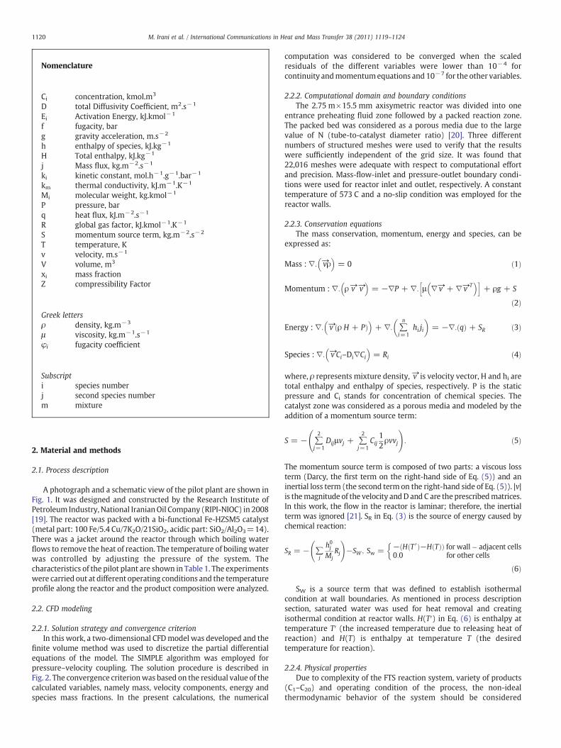
A photograph and a schematic view of the pilot plant are shown inFig. 1. It was designed and constructed by the Research Institute ofPetroleum Industry, National IranianOil Company (RIPI-NIOC) in 2008[19]. The reactor was packed with a bi-functional Fe-HZSM5 catalyst(metal part: 100 Fe/5.4 Cu/7K2O/21SiO2, acidic part: SiO2/Al2O3=14).There was a jacket around the reactor through which boiling waterflows to remove the heat of reaction. The temperature of boiling waterwas controlled by adjusting the pressure of the system. Thecharacteristics of the pilot plant are shown in Table 1. The experimentswere carried out at different operating conditions and the temperatureprofile along the reactor and the product composition were analyzed.
2.2. CFD modeling
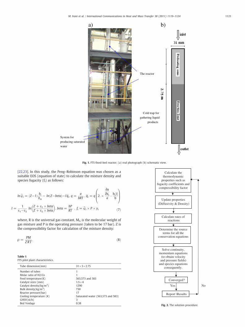
2.2.1. Solution strategy and convergence criterionIn this work, a two-dimensional CFDmodel was developed and the
finite volume method was used to discretize the partial differentialequations of the model. The SIMPLE algorithm was employed forpressure–velocity coupling. The solution procedure is described inFig. 2. The convergence criterionwas based on the residual value of thecalculated variables, namely mass, velocity components, energy andspecies mass fractions. In the present calculations, the numerical
computation was considered to be converged when the scaledresiduals of the different variables were lower than 10−4 forcontinuity andmomentumequations and 10−7 for the other variables.
2.2.2. Computational domain and boundary conditionsThe 2.75 m×15.5 mm axisymetric reactor was divided into one
entrance preheating fluid zone followed by a packed reaction zone.The packed bed was considered as a porous media due to the largevalue of N (tube-to-catalyst diameter ratio) [20]. Three differentnumbers of structured meshes were used to verify that the resultswere sufficiently independent of the grid size. It was found that22,016 meshes were adequate with respect to computational effortand precision. Mass-flow-inlet and pressure-outlet boundary condi-tions were used for reactor inlet and outlet, respectively. A constanttemperature of 573 C and a no-slip condition was employed for thereactor walls.
2.2.3. Conservation equationsThe mass conservation, momentum, energy and species, can be
expressed as:
Mass : ∇: →vρ� �
= 0 ð1Þ
Momentum : ∇: ρ→v →v� �
= −∇P + ∇: μ ∇→v + ∇→v T� �h i
+ ρg + S
ð2Þ
Energy : ∇: →v ρ H + Pð Þ� �
+ ∇: ∑n
i=1hi ji
� �= −∇: qð Þ + SR ð3Þ
Species : ∇: →v Ci–Di∇Ci
� �= Ri ð4Þ
where, ρ represents mixture density,→v is velocity vector, H and hi aretotal enthalpy and enthalpy of species, respectively. P is the staticpressure and Ci stands for concentration of chemical species. Thecatalyst zone was considered as a porous media and modeled by theaddition of a momentum source term:
S = − ∑2
j=1Dijμvj + ∑
2
j=1Cij
12ρvvj
!: ð5Þ
The momentum source term is composed of two parts: a viscous lossterm (Darcy, the first term on the right-hand side of Eq. (5)) and aninertial loss term (the second term on the right-hand side of Eq. (5)). |v|is themagnitude of the velocity andD and C are the prescribedmatrices.In this work, the flow in the reactor is laminar; therefore, the inertialterm was ignored [21]. SR in Eq. (3) is the source of energy caused bychemical reaction:
SR = − ∑j
h0jMj
Rj
!−SW ; Sw = − H T′ð Þ−H Tð Þð Þ for wall� adjacent cells
0:0 for other cells
�
ð6Þ
SW is a source term that was defined to establish isothermalcondition at wall boundaries. As mentioned in process descriptionsection, saturated water was used for heat removal and creatingisothermal condition at reactor walls. H(T′) in Eq. (6) is enthalpy attemperature T′ (the increased temperature due to releasing heat ofreaction) and H(T) is enthalpy at temperature T (the desiredtemperature for reaction).
2.2.4. Physical propertiesDue to complexity of the FTS reaction system, variety of products
(C1–C20) and operating condition of the process, the non-idealthermodynamic behavior of the system should be considered
I =
a) b)
The reactor
Cold trap for
gathering liquid
products
System for
producing saturated
water
Fig. 1. FTS fixed-bed reactor; (a) real photograph (b) schematic view.
Determine the source terms for all the
conservation equations
Update properties (Diffusivity & Density)
Calculate rates of reactions
Calculate the thermodynamic
properties such as fugacity coefficients and
compressibility factor
1121M. Irani et al. / International Communications in Heat and Mass Transfer 38 (2011) 1119–1124
[22,23]. In this study, the Peng–Robinson equation was chosen as asuitable EOS (equation of state) to calculate the mixture density andspecies fugacity (fi) as follows:
ln⌢φi = Z−1ð Þ bibm
− ln Z−betað Þ−I qi; q =a
bRT; qi = q 2: ×
∂a∂xia
�bi½i�b
0BB@
1CCA
1ε1−ε2
lnZ + ε1 × betaZ + ε2 × beta
� �; beta =
bPRT
; fi =⌢φi × P × yi ð7Þ
where, R is the universal gas constant, MG is the molecular weight ofgas mixture and P is the operating pressure (taken to be 17 bar). Z isthe compressibility factor for calculation of the mixture density:
ρ =PMZRT
: ð8Þ
Table 1FTS pilot plant characteristics.
Tube dimension(mm) 31×3×2.75
Number of tubes 1Molar ratio of H2/Co 1Feed temperature(K) 563,573 and 583Catalyst sizes (mm) 1.5×4Catalyst density(kg/m3) 1290Bulk density(kg/m3) 730Reactor pressure(bar) 17Cooling temperature (K) Saturated water (563,573 and 583)GHSV(nl/h) 3Bed Voidage 0.38
Converged?
Yes No
Solve continuity, momentum equations
(to obtain velocity and pressure fields)
and species equations consequently.
Report \Results
Fig. 2. The solution procedure.

Table 2Parameters of Peng–Rabinson EOS.
σ ε Ω Ψ
1 +ffiffiffi2
p1−
ffiffiffi2
p0.07779 0.45724
α Tr;ωð Þ = 1 + 0:37464 + 1:54226ω−0:26992ω2� �
1−Tr1=2
!" #2
Z = β + Z + εβð Þ Z + σβð Þ 1 + β−Zqβ
� �; β = Ω
PrTr
; q =α Trð ÞψΩTr
Table 4Rates parameters for reactions 1 to 7 in Table3.
Reaction No. K1(mol s−1 kgcat−1/kPa) E1(J mol−1)
1 2.044e-2 15,6932 6.255 e-5 20.3843 3.423 e-4 1.56074 5.972 e-6 164.065 6.482 e-6 86.9346 6. 482e-6 81.7537 3.168e-5 738.78
0.92
0.93
0.94
0.95
0.96
0.97
0.98
0.99
1
1.01
0 0.5 1 1.5 2 2.5 3
Reactor length(m)
Z F
acto
r
1122 M. Irani et al. / International Communications in Heat and Mass Transfer 38 (2011) 1119–1124
The parameters of Eq. (7) are listed in Table 2. The specific heat ofeach species was defined as piecewise-polynomial function oftemperature. Other thermal properties of the mixture such asmolecular viscosity, thermal conductivity and diffusivity coefficientwere calculated from Poling et al. [24].
2.2.5. Reaction rate expressionsTwelve chemical species including CO, H2, CO, CO2, H2O, CH4, C2H4,
C2H6, C3H8, n-C4H10, i-C4H10 and C5+were considered as reactants andproducts of the FTS reactions. The leading Fischer–Tropsch chemicalreactions are listed in Table 3. The general form of rate equations forreactions 1–7 are expressed as:
Rimol=hr:grcat
!= ki exp
−EiRT
� � f 2h2fco
ð9Þ
The kinetic parameters of these equations are given in Table 4 [25].Reaction (8) is known as water–gas shift reaction and its rate can beexpressed as [26]:
Rwgs =15:7 exp −45080= RTð ÞðPCOPH2O
= P0:5H2
−PCO2P0:5H2
= KWGS
1 + 1:13 × 10−3 PCOPH2O= P0:5
H2
� � ð10Þ
where, KWGS is the equilibrium constant and can be calculated asfollows:
KWGS =5078:0
T−5:8972 + 13:959 × 10−4T−27:593 × 10−8T2
: ð11Þ
3. Result and discussion
The predicted fluid compressibility factor along the reactor isdrawn in Fig. 3. The figure interprets that due to formation of C5+ andH2O, the system deviates from ideal gas so that Z descends below 0.94,thus employing a real-gas equation of state is necessary. The predictedvalues of C5+ selectivity and COmole percent in the reactor outlet andtemperature at three points along the reactor (point 1: beginning ofcatalytic bed; point 2: middle of catalytic bed; point 3: end of catalyticbed) were compared with experimental measurements and theresults are given in Table 5. The values in this table show that the errorvalues are less than 4% for all of the compared variables. That is to say,
Table 3List of FTS reactions.
Num. Reaction stoichiometry
1 CO + 3H2 →CH4 + H2O2 2CO + 4H2 →C2H4 + 2H2O3 2CO + 5H2 →C2H6 + 2H2O4 3CO + 7H2 →C3H8 + 3H2O5 4CO + 9H2 →n� C4H10 + 4H2O6 4CO + 9H2 → i� C4H10 + 4H2O7 8:96CO + 18:05H2 →C8:96H12:36 C5 +
� + 8:96H2O
8 CO + H2O↔ CO2 + H2
the model in this work can successfully describe the fixed-bed FTprocess. The distribution of temperature inside the reactor ispresented in Fig. 4. The figure shows that the inside temperature ofthe reactor was well fixed at the desired inlet temperature using theconstant temperature with heat sink applied at wall boundaries.However, there is a temperature raise of about 17 K in the beginningof the reaction zone due to the high concentration of the reactants andthe consequent high rate of exothermic reactions in this region. Fig. 5shows the mass fraction profiles of product species along the reactorlength for the case with the inlet gas temperature of 573 K. The figureinterprets that the main changes in the concentrations of reactantsand products occur in the first 25 cm of the reaction zone. Therefore,the effective length of the reactor length is about 25 cm. It should bementioned that usually longer reactors are employed in order toextend the overhaul time of the reactor. In other words, whencatalysts in the first part of reactor are deactivated, the catalyst in theremaining length will convert the reactants to products. Due to theconsumption of reactants, the reduction of the concentrationsdecreases the rate of reactions and consequently the slopes ofconcentration curves along the reactor decrease. Fig. 6 shows thatthe mixture density increases along the reactor length due to theproduction of heavier hydrocarbons. Fig. 7 presents the contours ofvelocity in the reactor. As can be seen, the radial velocity distributionand zero velocity near the walls due to the non-slip wall boundarycondition are well predicted, as is naturally expected. Pressure drop inthe porous region causes the gas velocity to become almost uniform inthe radial direction. In addition, because of the production of heavyproducts, the velocity magnitude significantly reduces by entering thereaction region. In order to investigate the effect of temperature on
Fig. 3. Fluid compressibility factor along the reactor.
Table 5Comparison between measured and predicted values for the pilot-scale FTS processes.
Experimental Simulation Error (%)
CO conversion (%) 60.7 58.59 3.476112C5+ selectivity (g/g feed) 18 17.29 3.944444Temperature at point 1(K) 588 590 0.34014Temperature at point 2(K) 575 573 0.347826Temperature at point 3(K) 573 573 0

Fig. 6. Contour of density (operating condition: T=573, P=17 bar).Fig. 4. Contour of temperature (operating condition: T=573, P=17 bar).
1123M. Irani et al. / International Communications in Heat and Mass Transfer 38 (2011) 1119–1124
the reactor performance, the reactor operation was modeled at threedifferent temperatures. In all cases, reactor pressure andH2/CO ratio arekept constant at 17 bar and 1, respectively. The C5+ selectivity (g C5+/gfeed) along the reactor for three different temperatures are drawn inFig. 8. As depicted in this figure, increasing the temperature from 563 to
0
0.1
0.2
0.3
0.4
0.5
0.6
0.7
0.8
0.9
1
reactor length, m
com
pone
nt d
ry m
ass
frac
tion
COH2
a) Reactants
0
0.02
0.04
0.06
0.08
0.1
0.12
0.14
0.16
0.18
0.2
0 0.5 1 1.5 2 2.5
0 0.5 1 1.5 2 2.5 3
reactor length, m
com
pone
nt d
ry m
ass
frac
tion
BUTANEC5+EthaneEthyleneMethanePropane
b) Products
Fig. 5. Mass fraction of species along the reactor length at T=573.
573 K increases the C5+ selectivity. However, further increasing thetemperature to 583 K decreases C5+ selectivity. It should be noted thatincreasing the reactor temperature has, as a consequence, two oppositeeffects: firstly it increases the rate of reactions and secondly, it shiftsWGS reaction into reactants. In increasing the temperature from 573 to583 K, the second effect is dominant and the production of C5+ reducesdue to the reduction in the concentration of H2.
Fig. 7. Contour of velocity (operating condition: T=573, P=17 bar).

0
5
10
15
20
25
30
35
0 0.5 1 1.5 2 2.5Reactor length (m)
C5+
Sel
ectiv
ity T=563T=573T=583
Fig. 8. Selectivity of C5+ at different temperatures along the reactor length.
1124 M. Irani et al. / International Communications in Heat and Mass Transfer 38 (2011) 1119–1124
4. Conclusions
A two-dimensional CFD model was developed to model fluid flow,chemical reaction, heat and mass transfer in a fixed bed reactor. Thenon-ideal thermodynamic behavior of mixture was correlated usingPeng–Robinson EOS. The temperature runaway of the process hasbeen quenched using saturated boiling water. The model wasvalidated against the measured data from a pilot-scale FTS reactorand satisfactory agreements were found between predictions of themodel and the experimental results. The results showed that thereactor temperature significantly affects the C5+ yield and anoptimum temperature can be found to reach the maximum yield.For the conditions of operating pressure, feed composition and flowrate, it was found that an optimum temperature exists between 563and 583 K. The model has proven to be in good agreement with theexperimental data and it could be used in further studies to find amore accurate value for the optimum temperature.
References
[1] A.P. Steynberg, M.E. Dry, B.H. Havis, B.B. Berman, Chapter 2 Fischer–Tropschreactors, Studies in Surface Science and Catalysis 152 (2004) 64.
[2] Pour Nakhaei, Y. Zamani, A. Tavasoli, S.M.K. Shahri, S.A. Taheri, Fuel 87 (2004).[3] J.B. Butt, T. Lin, L.H. Schwartz, Iron alloy Fischer–Tropsch catalysts. VI. FeCo on
ZSM-5, Journal of catalysis 97 (1) (1986) 261–263.[4] H. Schulz, H.L. Niederberger, M. Kneip, F. Weil, Synthesis gas conversion on
Fischer–Tropsch Iron/HZSM5 composite catalysts, Studies in Surface Science andCatalysis 61 (1991) 313–323.
[5] G. Calleja, A.D. Lucas, R.V. Grieken, Co/HZSM-5 catalyst for syngas conversion:influence of process variables, Fuel 74 (3) (1995) 445–451.
[6] Q.S. Liu, Z.X. Zhang, J.L. Zhou, Steady state and dynamic behaviour of fixed bedcatalytic reactor for Fiscer–Tropsch senthesis. I. mathematical model andnumerical method, Journal of Natural Gas Chemistry 8 (2) (1999) 137–180.
[7] Q.S. Liu, Z.X. Zhang, J.L. Zhou, Steady state and dynamic behaviour of fixed bedcatalytic reactor for Fiscer–Tropsch senthesis. II. steady state and dynamicsimulation results, Journal of Natural Gas Chemistry 8 (3) (1999) 238–265.
[8] Y. Wang, Y. Xu, y. Li, Y. Zhao, B. Zhang, Heterogeneous modeling for fixed-bedFischer–Tropsch synthesis: reactor model and its applications, Chemical Engi-neering Science 58 (3–6) (2003) 867–875.
[9] M.A. Marvast, M. Sohrabi, S. Zarrinpashneh, G. Baghmisheh, Chemical Engineeringand Technology 28 (1) (2005) 78–86.
[10] A. Alizadehdakhel, M. Rahimi, A.A. Alsairafi, CFD and experimental studies on theeffect of valve weight on performance of a valve tray column, Computers andChemical Engineering 48 (1) (2009) 145–151.
[11] A. Parvareh, M. Rahimi, A. Alizadehdakhel, A.A. Alsairafi, CFD and ERT in-vestigations on two-phase flow regimes in vertical and horizontal tubes,International Communications in Heat and Mass Transfer 37 (3) (2010) 304–311.
[12] A. Alizadehdakhel, M. Rahimi, J. Sanjari, A.A. Alsairafi, CFD modelling of flow andheat transfer in a thermosyphon, International Communications in Heat and MassTransfer 37 (3) (2010) 312–318.
[13] B. Selma, R. Bannari, P. Proulx, A full integration of a dispersion and interfaceclosures in the standard k− εmodel of turbulence, Chemical Engineering Science65 (20) (2010) 5417–5428.
[14] B. Selma, R. Bannari, P. Proulx, Simulation of bubbly flows: comparison betweendirect quadrature method of moments (DQMOM) and method of classes (CM),Chemical Engineering Science 65 (6) (2010) 1925–1941.
[15] R. Bannari, A. Bannari, B. Selma, P. Proulx, Mass transfer and shear in an airliftbioreactor: using a mathematical model to improve reactor design andperformance, Chemical Engineering Science 66 (10) (2011) 2057–2067.
[16] A.A. Troshko, F. Zdravistch, CFD modeling of slurry bubble column reactors forFisher–Tropsch synthesis, Chemical Engineering Science 64 (5) (2009) 892–903.
[17] G. Arzamendi, P.M. Diéguez, M. Montes, J.A. Odriozola, E.F. Sousa-Aguiar, L.M.Gandía, Computational fluid dynamics study of heat transfer in a microchannelreactor for low-temperature Fischer–Tropsch synthesis, Chemical EngineeringJournal 160 (3) (2010) 915–922.
[18] G. Arzamendi, I. Uriz, P.M. Diéguez, O.H. Laguna, W.Y. Hernández, A. Álvarez, M.A.Centeno, J.A. Odriozola, M. Montes, L.M. Gandía, Selective CO removal over Au/CeFe and CeCu catalysts in microreactors studied through kinetic analysis andCFD simulations, Chemical Engineering Journal 167 (2–3) (2011) 588–596.
[19] Fischer–Tropsch pilot plant of Research Institute of Petroleum Industry andNational Iranian Oil Company (RIPI-NIOC), Tehran 18745–4163, Iran, 2004.
[20] E.A. Foumeny, H.A. Moallemi, C. Mcgreavy, J.A.A. Castro, Elucidation of meanvoidage in packed beds, Canadian Journal of Chemical Engineering 69 (4) (1991)1010–1015.
[21] Fluent, Incorporated: FLUENT 6 USER Manual, Fluent Inc., Lebanon (NH), 2001.[22] M. Irani, R.B. Bozorgmehry, M.R. Pishvaie, A. Tavasoli, Investigating the effects of
mass transfer and mixture non-ideality on multiphase flow hydrodynamics usingCFD methods, Iranian Journal of Chemistry and Chemical Engineering 29 (1)(2010) 51–60.
[23] M. Irani, R.B. Bouzarjomehri, M.R. Pishvaei, Impact of thermodynamic non-idealitiesand mass transfer on multi-phase hydrodynamics, Scientia Iranica 17 (1) (2010)55–64.
[24] B.E. Poling, J.M. Prausnitz, J.P. O'Connell, The Properties of Gases & Liquids, 5th ed.McGraw-Hill, New York, 2000.
[25] Marvast MA, Ph.D. thesis, Amirkabir University of Technology: Tehran–Iran, 2005.[26] M.R. Rahimpour, M.H. Khademi, A.M. Bahmanpour, A comparison of conventional
and optimized thermally coupled reactors for Fischer–Tropsch synthesis in GTLtechnology, Chemical Engineering Science 65 (23) (2010) 6206–6214.