An Investigation of the Miyagi-ken-oki, Japan, earthquake of ...
236
A111D3 D731M1 NATL INST OF STANDARDS & TECH R.I.C. A1 1103073141 /An Investigation of the Miyagi-ken-okl QC100 .U5? NO.592, 1980 C.I NBS-PUB-C 1£ a NBS SPECIAL PUBLICATION 592 U.S. DEPARTMENT OF COMMERCE / National Bureau of Standards An Investigation of the Miyagi-ken-oki, Japan, Earthquake of June 12, 1978
-
Upload
khangminh22 -
Category
Documents
-
view
1 -
download
0
Transcript of An Investigation of the Miyagi-ken-oki, Japan, earthquake of ...

A111D3 D731M1
NATL INST OF STANDARDS & TECH R.I.C.
A1 1103073141/An Investigation of the Miyagi-ken-oklQC100 .U5? NO.592, 1980 C.I NBS-PUB-C 1£
a NBS SPECIAL PUBLICATION 592
U.S. DEPARTMENT OF COMMERCE / National Bureau of Standards
An Investigation of the
Miyagi-ken-oki, Japan, Earthquake
of June 12, 1978

NATIONAL BUREAU OF STANDARDS
The National Bureau of Standards' was established by an act of Congress on March 3, 1901
.
The Bureau's overall goal is to strengthen and advance the Nation's science and technology
and facilitate their effective application for public benefit. To this end, the Bureau conducts
research and provides: (1) a basis for the Nation's physical measurement system, (2) scientific
and technological services for industry and government, (3) a technical basis for equity in
trade, and (4) technical services to promote public safety. The Bureau's technical work is per-
formed by the National Measurement Laboratory, the National Engineering Laboratory, and
the Institute for Computer Sciences and Technology.
THE NATIONAL MEASUREMENT LABORATORY provides the national system of
physical and chemical and materials measurement; coordinates the system with measurement
systems of other nations and furnishes essential services leading to accurate and uniform
physical and chemical measurement throughout the Nation's scientific community, industry,
and commerce; conducts materials research leading to improved methods of measurement,
standards, and data on the properties of materials needed by industry, commerce, educational
institutions, and Government; provides advisory and research services to other Government
agencies; develops, produces, and distributes Standard Reference Materials; and provides
calibration services. The Laboratory consists of the following centers:
Absolute Physical Quantities 2 — Radiation Research — Thermodynamics and
Molecular Science — Analytical Chemistry — Materials Science.
THE NATIONAL ENGINEERING LABORATORY provides technology and technical ser-
vices to the public and private sectors to address national needs and to solve national
problems; conducts research in engineering and applied science in support of these efforts;
builds and maintains competence in the necessary disciplines required to carry out this
research and technical service; develops engineering data and measurement capabilities;
provides engineering measurement traceability services; develops test methods and proposes
engineering standards and code changes; develops and proposes new engineering practices;
and develops and improves mechanisms to transfer results of its research to the ultimate user.
The Laboratory consists of the following centers:
Applied Mathematics — Electronics and Electrical Engineering-' — Mechanical
Engineering and Process Technology 2 — Building Technology — Fire Research —Consumer Product Technology — Field Methods.
THE INSTITUTE FOR COMPUTER SCIENCES AND TECHNOLOGY conducts
research and provides scientific and technical services to aid Federal agencies in the selection,
acquisition, application, and use of computer technology to improve eflectiveness and
economy in Government operations in accordance with Public Law 89-306 (40 U.S.C. 759),
relevant Executive Orders, and other directives; carries out this mission by managing the
Federal Information Processing Standards Program, developing Federal ADP standards
guidelines, and managing Federal participation in ADP voluntary standardization activities;
provides scientific and technological advisory services and assistance to Federal agencies; and
provides the technical foundation for computer-related policies of the Federal Government.
The Institute consists of the following centers:
Programming Science and Technology — Computer Systems Engineering.
'Headquarters and Laboratories at Gaithersburg, MD, unless otherwise rioted;
mailing address Washington, DC 20234.
-Some divisions within the center are located at Boulder, CO 80303.

aUTlOJVAL BUBBAl:Or STANDARD?_ LIBRARYAPR 1 7 1981
An Investigation of the
Miyagi-ken-oki, Japan, Earthquake
of June 12, 1978
c
Issued under the auspices of the United States—Japan Programin Natural Resources (UJNR) Panel on Wind and Seismic Effects
Bruce R. Ellingwood, Editor
Center for Building Technology
National Engineering Laboratory
National Bureau of Standards
Washington, DC 20234
Contributing authors:
A. Gerald Brady, U.S. Geological Survey, Menlo Park, CAJames D. Cooper, Federal Highway Administration, Washington, DCBruce R. Ellingwood, National Bureau of Standards, Washington, DCHugh H. Fowler, Federal Emergency Management Agency, Bethell, WAEdwin L. Harp, U.S. Geological Survey, Menlo Park, CADavid K. Keefer, U.S. Geological Survey, Menlo Park, CACarl M. Wentworth, U.S. Geological Survey, Menlo Park, CAPeter I. Yanev, URS/John A. Blume & Associates, San Francisco, CA
U.S. DEPARTMENT OF COMMERCE, Philip M. Klutznick, Secretary
Luther H. Hodges, Jr., Deputy Secretary
Jordan J. Baruch, Assistant Secretary for Productivity, Technology and Innovation
NATIONAL BUREAU OF STANDARDS, Ernest Ambler, Director
Issued October 1980

Library of Congress Catalog Card Number: 80-6001 16
National Bureau of Standards Special Publication 592Nat. Bur. Stand. (U.S.), Spec. Pub!. 592, 232 pages (Oct. 1980)
CODEN: XNBSAV
U.S. GOVERNMENT PRINTING OFFICE
WASHINGTON: 1980
For sale by the Superintendent of Documents, U.S. Government Printing Office, Washington, D.C. 20402
Price $6.50
(Add 25 percent for other than U.S. mailing)

FOREWORD
I am very pleased that a report on the investigation of the Miyagi-ken-oki, Japan
earthquake of June 12, 1978, has been prepared by U.S. engineers and scientists as anactivity of the joint program of the UJNR Panel on Wind and Seismic Effects.
I hope this report will play an important role not only in improving understanding of theMiyagi-ken-oki earthquake and other circumstances about earthquakes in Japan but also incontributing to the earthquake research of your country.
Through the field survey conducted by U.S. members at the sites where damage occurred fromthis earthquake, the importance of cooperating research activities in our panel wasreaffirmed.
Finally, I deeply respect the effort to compile the report and hope our relationship willcontinue.
Yoshijiro Sakagami , Chairman (Japan)UJNR Panel on Wind and Seismic EffectsDirector GeneralPublic Works Research InstituteMinistry of Construction
A part of the mission of the U.S. -Japan Panel on Wind and Seismic Effects of UJNR" is to
carry out joint projects on the investigation of natural disasters. Immediately after the
Miyagi-ken-oki, Japan earthquake of June 12, 1978, a team of U.S. panel members and otherengineers and scientists was dispatched to Miyagi Prefecture. The investigation wascoordinated by members of the Japan Panel on Wind and Seismic Effects.
This document is the result of the investigation by the U.S. team on the earthquake. It
describes geologic features of the earthquake-stricken area, and damage to human-madestructures. It is hoped the information presented in this document will add to the know-ledge of seismology and earthquake engineering.
The U.S. Panel expresses its sincere appreciation to the Japan Panel for their cooperationin arranging the investigation and the fullest assistance given to the U.S. team. We lookforward to the continuation of these cooperative efforts.
Edward 0. Pfrang, Chairman (U.S.)
UJNR Panel on Wind and Seismic EffectsCenter for Building TechnologyNational Bureau of Standards
U.S. -Japan Cooperative Program in Natural Resources
iii

ABSTRACT
On June 12, 1978, a destructive earthquake with Richter magnitude of 7.4 occurred off the
east coast of Miyagi Prefecture, Japan. Preliminary estimates by the National Land Agencyof Japan indicated that the earthquake caused an equivalent of $800 million in totaldamage. There is a cooperative agreement between the governments of the United States andJapan termed the U.S. -Japan Program in Natural Resources (UJNR) . Following the earthquake,it was arranged through UJNR that teams of U.S. structural engineers and geologists wouldvisit Miyagi Prefecture and inspect the damage caused by the earthquake. This reportassembles the information and collective experiences of the investigation team so as to
describe the earthquake and document its effects. Field investigations conducted bygeologists and structural engineers are described in detail and some of the implicationsfor seismic resistant design and construction of structures in the United States are alsodiscussed.
Key Words: Bridges; buildings; dikes; earthquakes; foreign engineering; geology; highways;housing; landslides; liquefaction; power plants; railroads; rockslides;seismicity; structural engineering.
Lv

Table of Contents
Page
1. Introduction 1
1.1 General Situation 1
1.2 Acknowledgments 3
2. Social Effects and Government Response 4
2 . 1 Damage 4
2.2 Response 8
2.3 Reconstruction 10
2.4 Insurance 10
2.5 Conclusions 11
3. Tectonic and Geologic Setting 12
3.1 Introduction 12
3.2 Tectonic Setting 12
3.3 Seismic Gap and Precursors 19
3.4 Miyagi-ken-oki Earthquake of June 12
3.5 Location of Energy Source 25
3.6 Geology of the Damage Region 25
3.7 References 33
4. Strongmotion Records and Data 36
4.1 Introduction 36
4.2 The SMAC Accelerograph 36
4.3 Acceleration Records at Ground Level 37
4.4 Intensities 40
4.5 Records from Structures 43
4.6 A Comparison with Recorded Results of the San FernandoEarthquake 1971 47
4.7 Tohoku University Engineering Building 48
4.8 Tracing of Records 48
4.9 References 48
5. Earthquake Performance of Buildings ^1
5.1 Introduction 61
5.2 Seismic Engineering and Construction Practice 61
5.3 Commercial and Retail Establishments5.4 Schools 96
5.5 Residences H35.6 Summary5.7 References H"7
1206. Effects to Industrial Facilities and Lifelines
i in6.1 Introduction
1 206.2 Fukushima Nuclear Power Plant Complex6.3 New Sendai Power Plant, Tohoku Electric Power Company6.4 Sendai Substation, Tohoku Electric Power Company 132
6.5 Haranomachi Plant of Sendai City Gas Bureau 137
6.6 Sendai Refinery, Tohoku Oil Co., Ltd 137
6.7 Concrete Batch Plant, Sendai 154
v

Page
7. Earthquake Performance of Transportation Lifelines . 158
7.1 Introduction 158
7.2 Bridge Design Criteria 158
7.3 Bridge Damage 159
7.4 Highway Damage 186
7.5 Railroad Damage 186
7.6 Tunnel Performance 190
7.7 Conclusion 190
7.8 References , 190
8. Liquefaction and Damage to Dikes 195
8.1 Introduction 195
8.2 Summary of Dike Damage 195
8.3 Geologic Setting 195
8 . 4 Field 0 bservations of Dike Damage 198
8.5 Liquefaction in the Port of Ishinomaki 206
8.6 Conclusion 206
8.7 References 206
9. Seismic-Induced Landslides 209
9.1 Introduction 209
9.2 Rock falls and Rock slides in Natural Slopes 209
9.3 Rock falls and Rock slides in Cut Slopes 213
9.4 Landslides in Artificial Fill 219
9.5 Summary of Findings 223
9.6 References 223
10. General Conclusions 224
vi

1. INTRODUCTION
1 . 1 GENERAL SITUATION
Sendai City, located in Miyagi Prefecture, Japan, is a modern industrial and commercial citylocated some 350 km northeast of Tokyo (Figure 1.1). Miyagi Prefecture has a population of
about 1.9 million, of which approximately 600,000 reside in Sendai City. Another millionare found in the suburbs of Sendai or in nearby cities and villages. This section of Japanis quite mountainous, and the population is restricted to coastal plains and mountainvalleys. The population density is much more concentrated than in the United States. Forinstance, Sendai City occupies an area that is probably about one-third the size of Seattle,
Washington, which has a similar population. There are about 6,500 business/manufacturingfirms in Miyagi Prefecture and about 452,000 households (homes and apartments). Criticalfacilities within the area of damage include police, fire, power plants (nuclear and fossilfuel), oil and gas processing and storage, dams, hospitals, schools, and prefectural andmunicipal buildings.
On Monday, June 12, 1978, at 1714 hours local time, a destructive earthquake with Richter mag-nitude of 7 . 4 occurred off the east coast of Miyagi Prefecture. The earthquake hypocenterwas located at 38° 9'N latitude, 142° 13'E longitude, at a depth of 30 km. This places the
epicenter at a point approximately 120 km ESE from Sendai City and 95 km SE of the fishingtown of Ishinomaki. The distance to the nearest instrumented recordings is about 70 km.
Historically, this is a seismically active area; in fact, an earthquake of Richter magnitude6.7 occurred as recently as February 20, 1978. Although the effects were felt as far away
as Tokyo, where a window fell from a new high-rise building, major damage was confined pri-marily to Miyagi Prefecture. The intensity of ground shaking was reported to be V on the
Japan Meterological Agency (JMA) scale in an area approximately 180 km by 60 km along thecoast which includes the cities of Ofunato, Ishinomaki, Shiogama, Sendai, and Fukushima. JMAintensity V is approximately equivalent to a Modified Mercalli intensity in the range VII-VIII. It is partially described as "Very strong - cracks in walls, overturning of tomb-
stones and stone lanterns; damage to masonry chimneys and mud-plastered warehouses." Themain earthquake was preceded by a smaller shock at 1703 hours; several aftershocks were felt
during the following 4 days.
As of July 1, 1978, 27 deaths had been attributed to the earthquake in Miyagi Prefecture, of
which 17 were caused by collapsing walls, nearly 1,600 people were injured. Electrical power
was lost in Sendai for approximately 6 hours, and was not completely restored for severaldays. Damage to the natural gas distribution system upon which much of the city relies was
a significant problem, and some areas of Sendai were still without gas 2 weeks followingthe earthquake. Other critical services were disrupted, but not to the extent that disasterrecovery operations could not begin immediately following the earthquake. Preliminary esti-mates by the National Land Agency indicate that the earthquake caused an equivalent of about$800 million in total damage.
There exists, between the Governments of the United States and Japan, a cooperative agree-ment termed the U.S. -Japan Program in Natural Resources (UJNR) . The principals for the UNJRPanel on Wind and Seismic Effects are the U.S. National Bureau of Standards (NBS) and thePublic Works Research Institute (PWRI) of the Japanese Ministry of Construction. Other Gov-ernment agencies are also involved in the program, including the U.S. Geological Surveyand Federal Highway Administration on the U.S. panel and the Building Research Institute and
the National Research Center for Disaster Prevention on the Japanese panel. Following theearthquake, it was arranged through UJNR that teams of U.S. structural engineers and geolo-
gists should visit Miyagi Prefecture and inspect the damage. Concurrently, the Federal Disas-ter Assistance Administration arranged for the visit of their representative through theAmerican Embassy in Tokyo.
Team members traveled as individuals or as groups as their interests and circumstances dic-tated. Mr. Brady arrived June 19th and spent 2 days in the Sendai area viewing general damage.
Messrs. Cooper, Ellingwood, and Yanev arrived on June 22nd and spent 5 days in Miyagi Prefec-ture inspecting damage to buildings, industrial facilities, and transportation structures.Messrs. Harp, Keefer, and Wentworth arrived on June 23rd; their primary interests were in
geology, seismicity, liquefaction and dike damage, and landslides and rock falls. Mr. Fowlerarrived on June 24th to investigate the social effects of the earthquake and how the Japaneseauthorities responded to the disaster.
1

Map of Japan showing locations ofMiyagi Prefecture, Sendai City andepicenters of 1978 earthquakes.
2

The purpose of this report is to assemble the information and collective experiences of theteam members so as to describe the earthquake and document its effects. The field investi-gations conducted by geologists and structural engineers are described in detail, and someof the implications for the seismic resistant design and construction of structures in theUnited States are discussed.
1 .2 Acknowledgments
The investigation of the Off-Miyagi earthquake would not have been possible without theassistance of numerous Japanese engineers, geologists, and Government officials who handledlogistics and provided U.S. team members with unpublished data. Thanks first of all aredue to Mr. Kazuto Nakazawa, former Director-General of the Public Works Research (PWKI) andformer Chairman of the Japan panel of UJNR, for enabling us to work with his staff at a verybusy and inopportune time for them. In particular, Dr. Tadayoshi Okubo, former Director ofthe Planning and Research Administration Division within PWRI and now Assistant Director-General, who also served as secretary for the Japan Panel of UJNR, arranged itineraries,made travel arrangements within Japan, arranged meetings with Japanese engineers and geolo-gists, and facilitated entrance to sites of damage that otherwise would have been inaccess-ible. Mr. Toshio Iwasaki, Head of the Ground Vibration Division in PWRI, accompaniedMessrs. Cooper, Ellingwood and Yanev on their field investigation trip to Fukushima, Sendaiand Ishinomaki, while Dr. Masamitsu Ohashi, former Director of the Earthquake DisasterPrevention Department of PWRI, accompanied Mr. Brady for 2 days. Mr. Toyokazu Shimizu ofthe Tohoku Regional Construction Bureau spent 2 days escorting team members to sites of
damaged buildings in Sendai City while Mr. Kunimatsu Hoshihata of the same Bureau hosted thevisit to Ishinomaki. Representatives from the U.S. Geological Survey were hosted by
Mr. Tadayuki Tazaki and were accompanied to Miyagi Prefecture by Mr. Eiichi Kuribayashi,both of the Earthquake Engineering Division, PWRI.
Dr. Hiroshi Tanaka of Tokyo Electric Power Company conducted the tour of the Fukushima powerplant and later was available for discussions in Tokyo. Dr. Shinsuke Nakata of the Struc-tural Engineering Division, Building Research Institute, was available for discussion on
damage to building structures following our return to Tokyo. Mr. Hajime Tsuchida of thePort and Harbour Research Institute made some of the strong motion records available to
the team and provided information on damage in the port of Ishinomaki.
In addition to those already mentioned, acknowledgments are due Mr. Keiichi Ohtani of theNational Research Center for Disaster Prevention, Science, and Technology Agency; Mssrs.
Haruo Yoshikoshi and Yasou Watanabe of the Sendai Construction Office, Ministry of Construc-tion; Mr. Shigeyoshi Shima, Tohoku Regional Construction Bureau, Ministry of Construction,
Messrs. Kunimatsu Hoshihata, Chutaro Chiba and Tsuyoshi Soto of the Kitakami-Karyu Construc-tion Office, Ministry of Construction; Mr. Kazuhiko Kawashima of PWRI, Messrs. NagahisaIkuta, Masaki Takahashi and Osamu Yotsuyanagi of the National Land Agency, Messrs. HidenaoMiyamoto and Toshio Shono of Tohoku Petroleum Co., Ltd., Mr. Chunchiro Kiowa of the City of
Sendai, Messrs. Masashige Sasaki, Tokashi Shibuya, Yokio Matsuzaki and Akira Tokano of
Miyagi Prefecture; and Professors Akio Takagi, Ishii, Hisao Nakagawa, Akenori Shibata andToshio Shiga of Tohoku University, Messrs. Takashi Hirai, Yoichi Fujii, and Noboru Inouchi of
the Geographical Survey Institute in Tokyo.
On the U.S. side, Drs. Edward 0. Pfrang and H. S. Lew of NBS , chairman and secretary,
respectively, of the U.S. Panel of UJNR, made the initial arrangements which were necessaryto facilitate the visit of the U.S. structural engineers to Miyagi Prefecture. Mr. Yanev'svisit was supported, in part, by the Earthquake Engineering Research Institute. Mr. Louis
Cattaneo of the National Bureau of Standards assisted in assembling the material for this
report. Mr. Justin L. Bloom, Counselor for Scientific and Technological Affairs of the U.S.
Embassy and his assistant, Mr. Bruce Carter assisted Mr. Fowler in his visit.
3

2. SOCIAL EFFECTS AND GOVERNMENT RESPONSE*
2.1 DAMAGE
There are about 6,500 business and manufacturing firms and about 452,000 households (homesand apartments) in Miyagi Prefecture. In Miyagi Prefecture, 803 dwellings were destroyed(309 in Sendai). Major causes of the destruction were landslides, inadequate foundations,and inadequate lateral bracing. A number of 2- to 4-story apartment buildings were rendereduninhabitable when their first-floors, housing shops or parking space, collapsed.
According to data compiled by the National Land Agency, the earthquake caused damage amount-ing to 166 billion yen ($830 million). A detailed outline of the various types of damage
and the economic loss that resulted is presented at the end of this chapter. In some casesthe amounts listed represent the cost of replacing a building or facility with a modernstructure even though the damage caused by the earthquake could be repaired at a lower cost.
Almost half of the total damage estimate represents the cost of repairing or replacing fac-tories, stores, and other business establishments as shown in Table 2.1.
Most buildings in Japan have tile roofs. Literally thousands were damaged, this was themost apparent type of damage in the area. (Tile falling from roofs caused a number of
injuries.) Item 9 of the damage indicates that 20,634 structures were flooded. Sendai Cityand Miyagi Prefecture officials reported that four homes were flooded as a direct result of
the earthquake. Because of the extensive roof damage, and because the area received heavyrains after June 12, it may be that secondary water damage is reflected in the table.
In considering the damage, one must understand the topography and construction siting areasin and near Sendai. Sendai has three distinct areas: the old (original) city, which is
centrally situated on solid level ground, a new section on the eastern side, toward thecoast, much of which is constructed on soft, flat ground (some of which includes fillareas), and an area of hills to the north and west, where people have constructed homes andbuildings on terraces. Damage and losses were much greater in the soft and hill areas thanin the old section.
In the hill areas, unstable fill surfaces in combination with saturated soil caused manylandslides. Cracks, mostly associated with the landslides, formed in the terraced groundwhere houses and apartment buildings were built. According to officials, a total of 337landslides occurred throughout the prefacture.
Liquefaction in conjunction with inadequate foundations contributed to heavy damage in theflat (soft) area. Reports of dike and levee subsidence were verified in many areas alongstreams. At Nokahura, which is near Sendai, a dike that was originally 7 to 8 m highsettled 1.5 m because of liquefaction.
Reinforced concrete buildings, bridge piers, and bridge abutments settled and sustaineddamage in many areas due to liquefaction and inadequate footings. Soft soil layers underreinforced concrete structures contributed to much of the damage. It is interesting tonote that damage to buildings from north-south shaking motion was often noticeably moresevere and extensive than damage from east-west movement. Steel-frame buildings by andlarge survived the earthquake better than reinforced concrete structures. Some lost facadesand windows, and only one collapsed. Older buildings constructed of wood frames were dam-aged because of inadequate lateral bracing.
A major oil refinery in the port area of Sendai, containing 98 storage tanks of varyingsizes, suffered damage when three large tanks containing fuel oil sprang leaks. Severalmillion gallons of oil flooded the refinery area, and some reached the waterway servingthe port.
The major cause of deaths and injuries from the earthquake was collapsing or falling wallsmade of stone or cinderblock. These structures serve as fences, privacy walls, and noisebarriers. There is a National Code that requires that walls of this kind that are over
Prepared by Hugh H. Fowler, Emergency Management Agency, Bothell, Washington.
4

Table 2.1 Outline of Preliminary Damage from June 12, 1978, Miyagi-ken-oki Earthquake
1. Dead2. Missing3. Injured4. Households suffering damage5. Individuals suffering damage6. Buildings wholly destroyed or burned or washed away7. Partially destroyed buildings8. Partially damaged buildings9. Flooded building
Subtotal10. Hospitals11. Clinics12. Medical equipment13. Water Works14. Sanitation facilities15. Other sanitation facilities
Subtotal16. Factories and stores17. Other business establishments
Subtotal18. Paddy fields (ha)
19. Fields or farms (ha)
20. Agricultural facilitiesSubtotal
21. Farm produce (ha)
22. Joint-use facilitiesSubtotal
23. Livestock24. Livestock facilities25. Livestock products
Subtotal26. Sericultural (silkworm) facilities27. Fishing boats28. Fishing port facilities29. Fishery and aquaculture facilities30. Fishery products31. Fishing equipment
Subtotal32. Forest land, roads33. Forestry facilities34. Forestry products
Subtotal35. Primary schools36. Middle schools37. High schools38. Other schools39. Cultural assets
Subtotal40. Roads (sites of damage)41. Bridges42. Rivers (sites of damage)43. Shores44. Erosion control facilities45. Ports and harbors
Subtotal46. Railways47. Electrical facilities48. Communications facilities (sites of damage)
Quantity
27
0
1 ,052
3,47713,768
8035,227
58,927
20,634
119
194
735
29
33
55,078
5.5
535
541 .1
424
2,10035
3
12
17
109
341
64
56
38
b
367
170
102
32322
720
65115
5
12
85
Value(million $)
108.7
31.0139.0
1.7
0.2
1.04.8
5.37.4
20. 4
455.0
455.0
0.3
24.124.51 .
1
5.8
6.9
0.6
O.b
13.5
5.00.2
la.
9
1.60.90.1
2.D
7.02.1
7.0
14.71.2
2
8
1
6
1
7
6
2,660
33
16
32
6
1
1
7
66.034.8
13.7
2.3
5

QuantityValue
(million $)
49. Social welfare facilities 166 3.050. Urban facilities 76 4.1
51. Gas facilities 53 2.052. Other facilities 231 3.1
Subtotal 62.8
Total loss 830.0
Number of people evacuated by order orrecommendation 26,017
Number of communities where headquartersfor disaster countermeasures were set up 56
6

1-1/2 m high must be reinforced in both directions with steel bars. (The bars must be atleast 9 mm in diameter and must consist of an 80 cm grid across and down the wall.) Some of
the walls that fell contained inadequate reinforcing and were more of a danger thanthose with none: those with no reinforcement tended to crumble, while those with inade-quate reinforcing toppled on people who were nearby or who held onto them for stability asthe earthquake occurred.
2.1.1 Public Facilities, Services, and Lifelines
Effects of the earthquake on so-called critical facilities, on public services, and on othervital activities were varied. In some cases, functioning was interrupted only temporarily,in other cases, the impact on segments of the population lasted for several weeks.
2.1.2 Law Enforcement and Emergency Services
Only slight damage was sustained by police facilities. The police communication systemplayed a vital role in maintaining order and dispersing factual information immediatelyafter the earthquake. Fire service facilities, also, received little damage, and units hadno difficulty coping with the few (10) fires that started.
Of the 41 hospitals in the Prefecture (27 in Sendai), several sustained varying amounts ofdamage. The natural gas and electricity outage interfered with medical services. However,there were no reported problems with overloading because of the influx of injured to the
city for treatment.
2.1.3 Transportation
The National Railway stopped all train service in the area immediately after the earthquaketo insure against accidents and to assess damage to the system. Service was restored quitesoon after repairs were made, and the safety of the line and its control systems wasascertained. Public bus service in Sendai was hampered in the hours immediately followingthe earthquake because of traffic light failure. Air service between Sendai and otherpoints was quickly restored after airport officials assessed damage and found that safeservice could commence.
2.1.4 Utilities
Damage to the natural gas distribution system in Miyagi Prefecture was a major recoveryproblem. Gas distribution systems in six cities were severely affected. About 60% of
the 200,000 households in Sendai are dependent on gas for heating and cooking. As of
June 28, 1978, 22,000 of those households as well as 10,419 households in other cities of
the prefecture were still without gas.
Electrical service to 419,100 homes in the prefecture was interrupted. For the most part,service was restored within a day or two. Few distribution line poles were toppled. Twoelectrical generating plants serving Sendai were out of operation. One of those plants,
located near the oil refinery at the port, depended upon fuel from the one refinery that
was rendered inoperative. The other, located in north Sendai, was rendered inoperativewhen the city's storage plant for low-pressure gas caught fire and service had to be termin-ated. Electrical power from other areas and facilities was diverted and at the time of the
reconnaissance was meeting the needs of Sendai, although several factories in the prefecturewere still without power.
Within the prefecture, there are about 50 separate water and sewage conveyance systems,most of which are publicly owned. Prefecture officials estimated the damage to these sys-
tems, all of which had been restored by June 25, 1978, at about $30,000,000. Several lift
station pumps had to be replaced. Damage to sewer lines in Sendai was minimal, however,
until electricity had been restored, the system was partially inoperative. Several nuclearelectrical generating plants are located near Miyagi Prefecture. It is interesting to note
that none experienced any significant earthquake-related problems or damage.
7

2.1.5 Communications
All telephone service in Sendai and in the surrounding areas was interrupted from 5:14 p.m.
until 8:00 p.m. on June 12, 1978. By 8:00 p.m., 50% of the service in the Sendai areaand 75% of the service in areas north of Tokyo had been restored. The disruption extendedas far south as Tokyo.
With the loss of electricity, all television and radio stations were unable to broadcast.Several came back on the air soon afterwards by using emergency generators and performedan important service by broadcasting factual information provided by the police and localgovernment officials. However, because most of the population was without electrical ser-vice, only those people with battery-operated transistor radios could receive emergencyinformation. (No formal emergency broadcast system exists in Japan.
)
2 . 2 RESPONSE
Immediately after the earthquake, government officials in Tokyo (national), in Sendai(prefecture and city), and in other communities met to take emergency-response action andto plan recovery measures. Sendai established a Disaster Countermeasures Headquartersheaded by the mayor. Included in this group were representatives of the National Railway,water, gas, and electric utilities; the police and fire departments, the Red Cross, andothers. This headquarters remained operational for 24 hours a day immediately after theearthquake. It was still in operation of June 27, 1978. Actual response activities are theCity of Sendai's responsibility. If an emergency is beyond the means of their resources,City officials may request additional services or financial help from the prefecture or
national government.
With regard to food and supplies and distribution of emergency rations, the Governor of thePrefecture activated a Headquarters for Self-Suf f iciency for the purpose of monitoring foodsupplies and prices as well as to insure the availability of other items necessary for the
populace to survive and recover. Among the tasks the Headquarters performed were:
° Checking on regional and central wholesale markets
° Checking on bread and dairy products
° Checking department and food stores
° Arranging for additional propane bottles and burners
° Monitoring the supply of electric cells (batteries) for flashlights
° Requesting cooperation from the sales industry to maintain stable prices (pricesof some critical items actually were lowered during the emergency period)
° Receiving and considering consumer complaints
° Providing propane burners and fuel to handicapped centers
° Providing coordination with producers and suppliers of lumber, glass s concrete, andother building supplies to insure that adequate stocks were available where needed
Coordinating with National Government officials in Tokyo when necessary.
The headquarters used the media to the fullest extent possible to broadcast factual infor-mation concerning supplies and prices. Close daily contact was maintained with 30 desig-nated stores in the area to monitor events.
The police force played a key role in maintaining order and providing information to thepopulace. Because the lack of electric power limited the effectiveness of the mass media,police used loudspeakers on vehicles. By 8:30 p.m. on June 12, more than 7,000 people hadgathered at the Sendai train station (all trains had stopped after the earthquake). Thepolice moved in portable generators, set up lights, and used loudspeakers to provide infor-

mation. By keeping them informed about the likelihood of tsunami or another earthquake andabout the damage situation, authorities were able to calm the public and avert panic. By9:30 p.m., all but 600 of the crowd had dispersed.
A traffic control center was set up immediately after the earthquake to handle the severetraffic problem. Crowds of people and vehicles had gathered at crossings. To deal withthis the following measures were taken:
° All available police were ordered to duty
° The traffic control center monitored critical areas and dispatched police to handleproblems
° Loudspeakers were used effectively to inform the public.
The damage caused by the earthquake had been judged not great enough for the Prime Ministerto issue a National State of Emergency declaration for the Miyagi Prefecture. Article 105
of the Disaster Countermeasures Basic Law provides the basis for issuance of such a declara-tion. Officials of the Ministry of Construction have visited Miyagi Prefecture to assessthe damage caused by the earthquake. On the basis of their assessment, the National Govern-ment will determine the amount of national funds to be provided (usually two-thirds of thecost, with the remaining third to be borne by the prefecture).
Japan has a Disaster Relief Act, which is administered by the Ministry of Health and Wel-fare. Under this authority, which does not require a declaration by the Prime Minister of a
National State of Emergency in order to act, relief was approved for two cities and fourtowns. Each municipality (or prefecture) submits a request, accompanied by data, photo-graphs, and loss statistics to the National Government. Included as benefits under the Actare low interest loans (5.05%) to replace buildings of wood construction. The period ofrepayment can be extended to 25 years. Homeowners with existing loans on their property arenot eligible for much assistance under the Disaster Relief Act other than a low-interestloan. This means that they would need to carry two loan payments, City of Sendai and MiyagiPrefecture officials are trying to get National funding to cover the initial load balance.
The prefecture disaster plan provides that local government heads can request military sup-port and assistance (from the Self-Defense Force). Between June 12 and June 19, such helpwas requested by the provided to six cities and seven towns. A total of 2,117 military per-sonnel were involved in supplying water to people in areas where normal systems were notoperative. They were also instrumental in saving three lives.
Two factors influenced the need for evacuation: the danger of a Tsunami and the unsafe con-ditions caused by the earthquake damage.
A Tsunami warning was issued at 5:21 p.m. on June 12. The actual order to evacuate must be
given by a Mayor or head of government. The Sendai Mayor did not order an evacuation but
did issue a warning. Local officials in other coastal communities did issue evacuationorders, and more than 20,000 people moved inland. The "all clear" was received at 8:15
p.m., and those who had left their homes were permitted to return.
Evacuation was necessary to protect people whose homes had been destroyed or judged unsafefor habitation. Approximately 70 families were ordered from their homes in the hill areas
of Sendai because of continuing danger of landslides.
Most displaced, evacuated individuals and families stayed with relatives and friends. riow-
ever, the city and prefecture response plans provide for the use of schools, hospitals, andother public buildings as shelters. Under extreme conditions, the National Defense Forcecan provide tents or other types of shelter for transient population.
Little search-and-rescue activity was associated with the earthquake. Life-saving measureswere performed as necessary by fire and police forces working in the Fire Defense Head-quarters, established in affected municipalities immediately after the quake. Two apartmentbuildings were involved when their first floors collapsed, and evacuation of the occupantsof other floors required the assistance of fire departments. The National Self-Defense
9

Force assisted in locating the body of a missing person. Two other bodies were recovered by
neighborhood groups.
The City of Sendai has five rescue teams on alert at all times. When the earthquake occur-red and electrical power was lost, the traffic signal system (there are more than 40U signalsin the city) became inoperative. Major traffic congestion developed at most intersections,and ambulances were able to respond to only 2 4 of the more than 200 calls for aid. A centralemergency facility, where people could obtain medical treatment, was quickly established inSendai. Hospitals activated an emergency medical information center, which consisted of
computerized data on doctors, hospital bed space, ambulances, etc.
On June 25, only 705 people (in three cities and nine towns) remained in shelters. Sitesused for shelters included school gymnasiums, citizens halls, and other public facilities.Emergency rations were distributed by volunteer agencies. The Japanese Red Cross was notasked to participate in the emergency-response or recovery phases of this disaster.
Because both gas and electricity were lacking in many homes, people bought food that didnot require cooking. Stores received additional quantities of precooked foods from areasnot affected by the earthquake. Fortunately, most grocery stores and markets in the arearemained intact, and there was ready access for shopping. Food prices remained stabledespite the heavy demand for particular types of food. Because most homes depend upon gasfor cooking and heating, the Sendai Gas Company (public) distributed portable gas heatersfor purchase at less than cost.
More than 300 homes in Sendai were destroyed. Under certain conditions, the local and pre-fectural governments may construct prefabricated dwellings for those who lose their homes.
Approximately 70 such dwellings were under construction in Sendai to provide shelter tothose who did not have other means.
Neither the City of Sendai nor Miyagi Prefecture attempted to establish or maintain a loca-ter service for missing persons. As soon as the radio and television stations resumed ser-vice, selected stations set aside an hour each day to broadcast names and messages. Thetelephone company also liberalized its use of phones to assist victims.
2.3 RECONSTRUCTION
New construction in Japan must conform with the Architectural Law, which contains specialrequirements to mitigate earthquake damage and is administered by the Ministry of Construc-tion. Builders must submit plans to prefectural or larger municipal governments for reviewand approval before starting construction. With very few exceptions, buildings destroyedor seriously damaged had been constructed before the law was in effect.
The Sendai City and Miyagi Prefecture government formed a Reconstruction Planning Committeeto ensure that building replacement and repair will contribute toward safety. The committeeincludes representatives of higher education institutions, commercial and business concerns,industry, and the architectural profession. The Sendai Construction Bureau will insure thatnew construction in the city meets the requirements of the National Building Code.
2 . 4 INSURANCE
2.4.1 Unemployment Insurance
Although manufacturing firms and business were hard hit by the earthquake, a large majorityof those whose jobs were affected were back at work soon after the earthquake. Some manu-facturers who were operating on a marginal basis had not reopened at the time of the recon-naissance; the workers affected were drawing unemployment insurance.
2.4.2 Earthquake Insurance
There are at least two types of earthquake insurance available in Japan. Both are expen-sive .
10

One type of protection, available to a farmers association, covers 100% of the damage up toa maximum of 25,000,000 yen. Lesser amounts of coverage can be obtained.
The other (major) type of earthquake insurance, is a plan that is endorsed and guaranteed by
the government. This program was initiated five years ago but has not met with generalacceptance. What appear to be major limitations are its high cost and the limitations oncoverage. The maximum coverage for goods is 1.5 million yen ($7,500), the maximum coveragefor homes is 2.4 million yen ($12,000). (The average home in Japan cost 15 to 20 millionyen.) Both city and prefecture officials in Sendai stated they felt that there is a needto equalize the program. It was their consensus that the insurance program will become pop-ular if coverage can be increased and rates adjusted. This type of insurance is required of
those who request and receive low-interest disaster-relief loans.
2.5 CONCLUSIONS
The 1977 Disaster Countermeasures Act of Japan, administered by the National Land Agency,requires that each level of government have a plan and a competent organization for dealingwith disasters. The rapid and effective response by all levels of government (national,prefectural, and municipal) towards alleviating the affects of the earthquake was the resultof a unified, integrated program of disaster preparedness and response.
The amount of recovery work accomplished or under way within two weeks after the earthquakeoccurred was impressive. The speed and efficiency with which a vast amount of work had
been performed was most admirable. Officials responsible for directing operations andothers working to accomplish the monumental task of recovery exhibited unusual industry andknowledge about the problems they faced and how to solve them. All, without exception,
devoted their efforts exclusively to serving the needs of the people and communities thatwere adversely affected.
11

3. TECTONIC AND GEOLOGIC SETTING
3.1 INTRODUCTION
The Miyagi-ken-oki earthquake of June 12, 1978 occurred in the outer zone of seismicity in
Japan, along the subduction zone that bounds the east side of northeast Honshu. This was
only one of the many damaging earthquakes that Japan experiences because of its activetectonic setting, and the third in 1978. Most of the larger earthquakes are directlyassociated with the subduction zone along which the margin of the westward drifting litho-
sphere under the Pacific Ocean is plunging beneath Japan at a long-term rate of about 10
cm per year. The area where damage occurred in the June 12 earthquake lies on the east
coast of northeast Honshu about 300 km north of Tokyo, in a region of low, flat alluvialplains, local alluvial terraces, and steep bedrock terrain of largely moderate relief.
This chapter describes the Miyagi-ken-oki earthquake and its setting as background for themore detailed reports on the effects of the earthquake. The tectonic setting of the earth-quake is described, together with the reason that a larger earthquake following the June 12
event was (and still is) a serious, although uncertain, possibility. The June earthquakeand its pattern of aftershocks are described, and this pattern is used to illustrate the
important distinction between epicentral and fault distance in attenuation studies. Fin-ally, the geology of the affected region is summarized, because of its influence on the
distribution, character, and severity of earthquake damage.
This chapter is based on the literature (in English) available in Menlo Park, and on infor-mation gained from discussions with, and documents and maps provided by, Japanese officials
and scientists during the author's visit to Japan as a U.S. Geological Survey representativeon the U.S. team in June 1978. The information is necessarily incomplete because only two
weeks had been available for study of the earthquake by the Japanese at the time of the
visit to Japan by the U.S. team, and time for discussion and observation during the visit
was brief. More thorough accounts will undoubtedly result from the Japanese studies.
3.2 TECTONIC SETTING
Japan is located along the leading overthrust margin of Asia against subducting sea floorof the Pacific plate (inset, Figure 3.1). That plate is drifting northwestward toward
the nearly stationary Asian continent, as recorded over the past 40 million years by the
Hawiian chain of volcanoes strung out northwest of the eruptive source now beneath Hawaii.The subduction zone beneath northeast Honshu is marked at the surface by the Japan deep-seatrench and associated island arc, one of several extending around the perimeter of the
northwest Pacific (Aleutian, Kurile, Northeast Honshu, Izu-Bonin, and Mariana arcs).
The northeast Honshu arc system consists of a concentric sequence of tectonic elements(Figures 3.1 and 3.2): from east to west, (a) the subducting oceanic plate and deep-sea
trench, (b) a submerged forearc terrane consisting largely of the inner-trench slope and
a broad deep-sea terrace underlain by more than 2 km of Tertiary sediments, (c) the emerg-
ent frontal arc, (d) a volcanic chain atop the front of (e) a deformed backarc geosyncline,and (f) a backarc basin. Most of the arc system is underlain by ancient continental base-ment, which is bounded on the east and west by thinner oceanic crust, on the east by the
Pacific plate, and on the west by the crust of the backarc basin, formed during the early
Tertiary opening of the sea of Japan.
This pattern of tectonic features concentric with the Japan trench was established about 25million years ago, when the Mizuho orogeny began in northeast Honshu with block faulting,
subsidence, and extensive volcanism west of the Morioka-Shirakawa tectonic line
(Figure 3.1). The Miocene faults broke obliquely across the older north-northwesterlytrending structure, such as the Tanakura tectonic line (Figure 3.2). The present tectonicregime is a later phase of that orogeny, in which Quarternary compressional deformationmarked by northeast-trending reverse faults and overturned folds has supplanted the earlierextensional regime.
Prepared by Carl Wentworth, U.S. Geological Survey, Menlo Park, California
.12

Explanation of Symbols for Figure 3.1
Quaternary sediments, consisting of alluvium, terrace deposits and lake beds
Neogene sediments and Cenozoic volcanics, including the extensive EarlyMiocene green tuff, folded younger sediments, and Quaternary volcanics
Pre-Neogene rocks, including Paleogene and Mesozoic rocks, metamorphicrocks, and Cretaceous or older plutonic rocks; exposed rocks as oldas Silurian are recognized. Abukuma block largely plutonic rocks;Kitakami block largely late Paleozoic and early Mesozoic metasedimentsand scattered plutonic masses
Active volcano
Morioka-Shirakawa tectonic line (MSTL, approximate location) and theboundary in early Miocene rocks between thick, mainly marine, alteredtuff (the green tuff) on the west and thin, mainly terrestrial volcanicrocks on the east
Contact, dashed offshore where location very approximate, dotted alonglimits of information offshore
Major fault, including the Itoigawa-Shizuoka tectonic line (ISTL) alongthe west margin of the Fossa Magna zone of deformation and low topography,the Median tectonic line (MTL) of Southwest Japan, and the Tanakuratectonic line (TTL) . Dashed where approximately located; dotted whereconcealed
Quaternary fault, longer than 10 km, which offsets or deforms latePliocene or Quaternary deposits
Arc (inset): A - Aleutian; K Kurile; H - Northeast Honshu; I-B -
Izu-Bonin; M - Mariana. Teeth on upper plate
13

Figure 3.1 Geologic map of northeast Honshu region and plate tectonic
setting, compiled from Dickinson (1979), Geological Surveyof Japan (1964), Ishiwada and Ogawa (1976), Isomi (1968),Research Group for Quaternary Tectonic Map of Japan (1969)
,
and Yoshida (1975)
.
14

Explanation of Symbols for Figure 3.2
Qu Quaternary volcanic rocks
Qs Quaternary sediments
N Neogene sediments and volcanic rocks
Pe Paleogene sediments
Mz Mesozoic rocks
Pz Paleozoic rocks
b Basement rocks (pre-Silurian)
a Accretionary wedge - deformed sediment presumably scraped from oceanicplate during subduction
Envelope of seismicity along and above top of subducting slab,
from Figure 3.4
0 Location of hypocenter and apparent dip of focal mechanism for
June 12, 1978 earthquake
—— Approximate extent of June 12 fault rupture in section
6.1 Seismic velocity in km/s
15

cr
UJcro
zd
" zO CO> o
UJaocr<o<DO
ocr
o<a00
4-1 00 00CO 1—
1
r-~
0) CTi
IS reH
4-1 0 cCO 00 CO ucd H (-1 cu
0) UH he St
c E 4J cd
roO CU
•
00 4-1 X) CO
c 3 J3 3o cd O orH d) c •H
cd a CU 4-1
•H orH CO 4J <U
cd CO
Cd CO a HHn o CU
O 3 oo CU CO >J
H a C3 34-1 0) o 0
0 cd 3 H CO
e S3 4-1
cd M cd 1-1
O C3 o (U
3 M-l O c 4J
3 > iJ cn
CO H •Hc u-l 60o ,3 O CU
p-; u !-i
•H rH r~-
4J !3 r-- oCO CU 4-1
CU ^4,3
- u3
O 00O -H
(H
o rO
•Hu-i g nO U N
^S> ONco cd i—
i
30H4J
u
•H
0) 3
CO 4-1 OCO XICO 00 3O 3 n3
l-i oo s-4 cd
,3O 4-1 3h e4-i cu cd
Cd rH 4-1
CU UH.3 OCJ >H MHCO ft O
CU
U300H
o 3o
XI M3 uhcd
o•H -H00 3cd cd
^ oCd rHH O
>MHo -a
3vD 3
cu «
m cu
3 300 -H•H rHMH CU
J-l
X) O3 .3a) co
16

The known reverse faults in northeast Honshu are short, scattered, and few relative to thenumerous Quaternary faults of varied style in central Honshu and the 800-km-long strike-slip fault along the Median tectonic line in southeast Honshu (Matsuda, 1977). Most of thefaults occur along and west of the Morioka-Shirakawa tectonic line and in the Sendai regionbetween the Abukuma and Kitakami structural blocks. Some of these faults have undergonequite recent movement, but apparently none were involved in the June 12 event.
Most of the present relief in northeastern Honshu has formed during this Quaternary compres-sional phase of the Mizuho orogeny. Beginning 1 to 3 million years ago, the average rate of
the vertical movements that accomplished these changes increased tenfold to the order of 1
to 10 mm/yr (Matsuda, 1976). Concurrently, renewed volcanism built the modern volcanoesalined just west of the frontal arc.
This third and current phase of the Mizuho orgeny, following the initial volcanism anddevelopment of the backarc geosyncline and its subsequent breakup and gradual uplift,suggests some change in the subduction regime that drives the system. One possibility is a
change in subduction rate. Based on study of the ages and positions of volcanoes in the
Emperor-Hawaiian chain, Shaw, Jackson, and Bargar (1979) suggest that a threefold increasein the rate of west-northwestward drift of the Pacific plate relative to the magma sourceoccurred about 1.3 million years ago.
Modern seismicity indicates that subductive underthrusting continues along the northwestPacific island arcs. The regularity of great thrust earthquakes in space and time thatcharacterizes the Aleutian and Kurile arcs decreases along the northeast Honshu arc, how-ever, and such earthquakes appear to be lacking along the Izu-Bonin and Mariana arcs to thesouth. The degree to which the convergence rate of the plates is expressed in major thrustearthquakes also seems to decrease southwestward: in the Aleutian arc, probably all theplate convergence is accounted for by faulting associated with major earthquakes, whereasonly about one fourth is accounted for at the southwestern end of the Kurile arc and almostnone at the southern end of the northeast Honshu arc (Kanamori, 1976, 1978).
Decoupling between the converging plates seems required to permit subduction along theNorthwest Honshu arc without the crustal strain that produces major earthquakes. Thisdecoupling may be associated with the anomalously small accretionary wedge found at thetrench off northeast Honshu by Von Huene, Nasu, and others (1978). They indicated that thevolume of sediment brought to the trench atop subducting oceanic lithosphere in the lateCenozoic has far exceeded that now caught in the accretionary wedge. Most of it must havebeen subducted, therefore, either to cause, or more likely, to result from, decouplingbetween the plates. This lack of close coupling is attributed by Kanamori (1976) to activesinking of the subducting slab away from the Asian continent. By this argument, the sub-ducting plate is not only plunging westward beneath Honshu and the Sea of Japan but is
bodily sinking, so that the downward bend beneath the forearc terrane is migrating eastward.
The Miyagi-ken-oki earthquake occurred beneath the forearc terrane midway between the endsof the Northeast Honshu arc. Its setting is thus largely independent of the structuralnodes at the junctions with adjoining arcs in the Tokyo-Fossa Magna region and south of
Hokkaido. As shown in the schematic cross section representing structure across the centerof the arc system (Figure 3.2), the subduction zone extends westward beneath the forearcterrane at an initial shallow angle of about 3-1/2°. Beneath the forearc basin, where thetop of the subducting plate abuts the lower crust of northeast Honshu, the subduction zonegradually steepens until, free of the continental crust at about 30 km, it extends into themantle at a dip of about 25°.
The full extent of the subduction zone is best shown by the three-dimensional pattern of
earthquakes in the region (Figure 3.3). The earthquakes occur at greater and greater depthto the west, defining a Benioff zone that extends westward for more than 1,000 km beneathnortheast Honshu and the Sea of Japan at an angle of about 25°, reaching depths greater than500 km near the coast of Korea.
In greater detail (Figures 3.4 and envelope of seismicity in Figure 3.2), microearthquakesmore precisely define the upper part of the subducting plate. The upper boundary of thesubducting slab is clearly defined as dipping westward at about 25° beneath northeastHonshu, with a second westward-dipping zone of earthquakes within the slab about 40 km
17

Figure 3.3 Earthquake hypocenters beneath Japan for theperiod 1964-1974. Epicenter symbols show depthof hypocenter, depth contours in kilometers.From Coordinating Committee on EarthquakePrediction (1978).
Figure 3.4 Distribution of micro-earthquakes (dots) beneath north-east Honshu in vertical, east-westsection in the vicinity of 39-40degrees north latitude, andsubducting oceanic lithosphere.Horizontal line above sectionrepresents land, the uprighttriangle the volcanic front, andthe overturned triangle the JapanTrench. From figure 6 of Takagiand others (1977)
.

beneath the first (Hasegawa and others, 1978, Takagi and others 1977). A zone of high acti-vity is also shown above the subduction zone beneath the forearc terrane. The frontal arc
is nearly aseismic, and a shallow zone of earthquakes extends westward from the edge of thefrontal arc beneath the backarc geosyncline.
Analysis of the sense of first motions of microearthquakes recorded by the northeast Honshuseismographic network has been made by Hasegawa and others (1978) to determine the styleof faulting associated with the earthquakes. These composite focal-mechanism solutions,although varied in detail, indicate that thrust faulting with compression nearly perpendicu-lar to the trench is underway at and above the upper boundary of the subducting slab, as
would be expected from the plate motions. In contrast, the band of seismicity within the
slab involves extension along its dip direction.
Historic damaging earthquakes along the northeast Honshu arc form three groups evident in a
compilation of damaging earthquakes that have occurred in and near Japan over the past one
and a third millenia (Japan Meterological Agency, no date, and Figure 3.5). A modest numberof great earthquakes have occurred with epicenters near the trench, largely involvingfaulting along the gently dipping part of the subduction zone. Closer to shore, more numer-ous intermediate-size damaging earthquakes have occurred with epicenters in a band along the
forearc basin trend. These earthquakes appear to involve faulting along the top of the
steeper part of the subduction zone. A scattering of generally smaller damaging earthquakeshas occurred with epicenters onshore, along and west of the Morioka-Shirakawa tectonic line.
The frontal arc appears to be nearly free of damaging earthquakes, except in the gap betweenthe Abukuma and Kitakami highlands near Sendai.
3.3 SEISMIC GAP AND PRECURSORS
The Miyagi-ken-oki earthquake of June 12 occurred adjacent to an area for which there wassome evidence to suggest a forthcoming major earthquake. Gaps of uncertain significanceexisted in the pattern of both major and smaller earthquakes. The following summary is
based on discussions held during the team visit in Japan and on Abe (1977), CoordinatingCommittee on Earthquake Prediction (1978), Mogi (1968), Kanamori (1976, 1978), and Shimazaki(1978).
The regularity with which great thrust earthquakes have occurred along subduction zones hasled to the use of gaps in the pattern of fault rupture areas as a basis for identifyingexpectable earthquakes. The focal areas of the earthquakes tend to fill the length of the
subduction zone with little or no overlap between adjacent events, and gaps in the patternof the most recent earthquakes tend to be filled in. This regular pattern of repeatedearthquakes extends around the northwest Pacific as far as the junction between the Kurileand Northeast Honshu arcs (Figure 3.6). At that junction, interpretation of tsunami datasuggests that major thrust faulting and associated earthquakes occurred in 1677, 1763, 1856,
and 1968, or about every hundred years.
The latest earthquake in that sequence, the Tokachi-oki earthquake of 1968 (Figures 3.5 and3.6), is also the southwesternmost in the latest round of great earthquakes along the Kurilearc. East of the Kitakami block (or Sanriku region), the repeat history of major earth-quakes seems less regular. And farther south, between latitude 36° and 38° N east of the
Abukuma block, the 1938 Shioya-oki series of five large earthquakes (three thrust, two
normal) seems to have been the only major earthquake event in at least the past 800 years.The transition along the Northeast Honshu arc from regular behavior of great thrust earth-quakes at the north to almost no major earthquakes at the south complicates the applicationof seismic gap theory to the region east of Sendai. It is not clear whether or when the on-going subduction involves sufficient straining of the lithosphere to produce major earth-quakes.
The last major subduction-zone faulting east of the Kitakami block between latitude 38° and40°N occurred in 1896-1897, when the focal areas of the 1896 Sanriku and associated largeearthquakes extended from within the focal area of the 1968 Tokachi-oki earthquake southwardto about 38°. Only three earlier major earthquakes are known from the area—in 869, 1611,and 1677—although the historic record is incomplete. Thus the regular, hundred-year repe-tition of major earthquakes that characterizes the southwest Kurile arc does not persistsouth of about 40°. If strain has been accumulating since the Sanriku earthquakes of the
19

4140° o O
A
136*
7,5-7.9
7,0-7,4
6.5-6,9
DATE
\ %> % %* % \ % % %
A VA VA V
0 200KmI—i
—
i—i- i I i i i I
Figure 3.5 Historic damaging earthquakes in the northeast Honshuregion. Compiled from 1:2,000,000 map. DisastrousEarthquakes in and near Japan, covering the period 599to 1975. Older historic data are incomplete. Age classesare based on null points in temporal frequency of earth-quakes throughout map area.
20

Figure 3.6 Source areas of recent major earthquakes alongthe subduction zone off Japan, with date and
magnitude, and potential great earthquake at
latitude 38. From Coordinating Committee on
Earthquake Prediction (1978).
21

late 1890's, it has yet to be relieved by major thrust earthquakes. The role of the 1933
Sanriku earthquake is not clear. Apparently it was not a subduction-zone thrust event, but
rather the product of normal faulting within the oceanic plate along a steeply west-dippingplane that extended through the oceanic crust.
Many large earthquakes seem to be preceded, for a period of years, by a lack of smallerearthquakes in the epicentral region. The absence of small earthquakes in the forearcterrane between about 37° and 39° (Figure 3.3) for a period of at least ten years amounts to
such a gap in seismicity. This reinforces the uncertain suggestion from the pattern of
major earthquakes that the region east of Miyagi may be about due for another major earth-quake (Figure 3.6). Because the Miyagi-ken-oki earthquake of June 12 occurred adjacent to,
but not within, this gap, a major earthquake may yet occur in the gap.
Particularly because of the seismic gap, other indications of the imminence of a largeearthquake have been of interest. Spirit leveling had demonstrated an eastward tilt of the
land opposite the gap, but no short-term precursors were recognized prior to the June 12
earthquake. Abundant data from the seismic network of Tohoku University showed no clearchange in seismic velocities. Similarly, no indications of imminent earthquakes were evi-dent from the extensometers and tiltmeters that are part of each station in that network.
Comparisons of measurements along two east-west level lines run by the Geographical SurveyInstitute that end at Sendai and Kamaisi show relative downward tilt to the east of 2 to 5
cm between the center of the island and the east coast in a 7-to-8-year period beginning in1966. The tilt is greater at Sendai than farther north, an additional 3 cm of decline at
Sendai may be related to withdrawal of ground water. Detailed tidal records in the areashowed no evident changes with a resolution of a few centimeters within hours after the mainshock of June 12, so that little or no coastal uplift accompanied that earthquake.
3.4 MIYAGI-KEN-OKI EARTHQUAKE OF JUNE 12
The magnitude 7.4 Miyagi-ken-oki earthquake occurred on June 12, 1978 at 5:14 PM local time,with its hypocenter at a depth of 30 km at latitude 38.2°N longitude 142. 2°E (NationalResearch Center for Disaster Prevention, 1978b). It followed by about 4 months a magnitude6.7 earthquake that occurred 65 km to the north (latitude 38.7°N, longitude 142. 2°E) at a
depth of 60 km (National Research Center for Disaster Prevention, 1978a). The February 20earthquake had a pattern of aftershocks distinct from that of the June 12 earthquake(Figure 3.7) and therefore was not simply a foreshock of the larger earthquake. The mainJune 12 shock was preceded by one foreshock a few minutes earlier, and was followed by manyaftershocks, which were recorded by the seismographic network of Tohoku University(Figure 3.8). Figure 3.9 shows the hypocenter of the main shock and aftershocks throughthe first 7 hours (A) and aftershocks for the first 10 days following the main shock (B).
A focal-mechanism solution for the main shock, using worldwide data, indicates thrust move-ment along a preferred plane dipping to the west-northwest at 20° (Figure 3.10, Otsuka andothers, 1978). Figure 3.2 shows this solution at the appropriate depth and position rela-tive to the trench and volcanic front. Within the crude accuracy limits of the schematiccross section, the focal plane lies at the top of the subducting oceanic slab.
The aftershock pattern supports and extends this association. The two aftershock patternsof Figure 3.9 are nearly identical, indicating relative stability through time, and suggestmainshock rupture on a west-dipping plane that extends to a depth of about 50 km. Theaftershock pattern of Figure 3.9B_ lies entirely within the equivalent pattern of Figure 3.4,at and above the top of the subducting slab.
The extent of the fault rupture zone can be estimated from the early aftershock pattern(Figure 3.9A). In the dip direction, it extends from at or somewhat above the mainshockhypocenter to a depth of about 50 km (Figure 3.2). This represents a fault width (or down-dip dimension of the focal area) of about 70 km, down which the rupture propagated fromthe up-dip hypocenter location. The lower end of the fault rupture is here estimated fromthe depth of the aftershocks, whereas the upper end is estimated from the relative positionsof the mainshock epicenter and the eastern end of the aftershock pattern. The strike lengthof the aftershock pattern, although less well constrained than the east-west directionbecause of its position offshore of the seismic network, suggests a rupture-zone length of
22

<• $
K Principal affersfioclcs of earthq^uaicz
lj X FEBRUART 20
• JUNE 12
A JUNE 16imaist
-3<?°
c
Istnomakt* JY
/?AC/r/C OC£AA/
• •
. „ . June It
Mi*- 3«°—
Figure 3.7 Epicenters of the earthquakes of February 20 andJune 12, 1978 and principal aftershocks. FromCoordinating Committee on Earthquake Prediction (1978)
.
Figure 3.8 Numbers of aftershocks of the June 12 earthquakethrough time. Arrow shows time of largest aftershock.From Coordinating Committee on Earthquake Prediction (1978) .
23

•rl
CCO
x
0)
s-i
360
S-4 0)
O 13
g t3CO i—
I
S-l S-4
00 OCO 3•H13 00
ae -hCO CO
•H 3PcB *X ^
co pa -ho co
Oi—I a)
• 0PI 3
>->
CD
S-l 01
3 X00 4->
•H
I
CO
CD •
P, 00
o
4-1
P CO
CD S-l
CO 0)
(1) X5-i 4-1
p. oCD
S-i 13P
CO CO
CD
i-l CO
O ^S-i 3H CO
O 4-1
CO
cO P4-) OCO -rl
13 CO
COIs-
X!oo3os-i a.x cO
4-> g
co P
ao CO
X uCO CD
5-l 4J
CD P4-1 CD
14-4 OCO OP
13C XCO
O CO
X CCD OP -H•H 4-1
CO Og CDnCM OtH S-i
Pa
p co
>-> OX!
14-4 CO
I
MCD
UX M-4
4-1 CO
30 -oco P1 cO
X4-) ^-v5-4 woP 13
CD
13 i—
I
P rHCO CD
X* co
P i—
l
o ^•I-l
4-1 X0CD 4-1
co cO
r-H ^5cO oa o•h x4-1 CO
5-l
CD P> -H
X!00
OO 3£3 O•H S-i
4-1 XCO
a•H CO
13o ao ou x
CO
g ^O CD
Sj 4-1
Pn M-lw cO
CO
• 5X o4-1 Xa, co
a)
i3 m
1^O CO
C3>
O i-l
S-l
CD
4-1
aCD
Oco•rl
4-J
cd
>5-i
•
CD
CO COX r-o o>
i—
i
x -
13 i-)
rl> -
O f=^
S-l 4-1
a* -hCO
CD S-l
S-l CD
3 >00 -H•h a
co cO
S-i S-l
CD 004-1 CO
P -rl
CD 13OO ^Pj o
oP3 i—
I
PQ
C3> •
. CMro CM
CD CD
^ P3 300 <->
co
CD CO
I o4-1 XCO CO
CO
CD <S
CO PS-i oCD -H4-1 4-1
P oCD CD
O CO
rlp, I-l
CD cO^ u•H
5 4-1
CD S-l
•H CD
> >
<-} 1301
4-4 S-l
O P-i
4-1 CD
X X00 cO
•H 3P CT1
13 Xrl 4-1
g s-i
cO
X W603 Po o5-i
X 01
g 3Os-i o
14-1 Xw oHX
4-1
Pi CCD O13 -H
4-1
S O-H13
O CD
CM S-l
i—! O-i
O 0)
4-1
CO
CM 3cm crX
o go gx oCO CJ> 1-3 W
24

about 50 km. These dimensions are similar to the focal dimensions reported by Kobayashi andothers (1978), a fault width of 80 km and a length of 30 km.
The June 12 earthquake thus occurred along the subduction boundary where it steepens beforeextending to depth in the mantle. Inasmuch as the focal area of the earthquake lies west of
the seismic gap (Figure 3.6), the faulting did not encroach upon the area of unrelievedstrain suggested by the gap. The locations of the June 12 earthquake and the earlierearthquake in February raised the possibility that they were precursors of a larger earth-quake that would fill the gap. On June 16 several earthquakes as large as magnitude 5.9
did occur in the gap area (Figure 3.7). The aftershock train of the June 12 earthquakedecayed rapidly, however, perturbed only by one aftershock somewhat larger than magnitude 6
and an associated increase in activity on June 14 (Figure 3.8).
3.5 LOCATION OF ENERGY SOURCE
The location of the source of seismic energy is an important parameter in studies of the
attenuation of seismic shaking. The earthquake epicenter is commonly used as an approxima-tion of this location, largely because epicentral locations are available for most modernearthquakes. Despite the convenience, however, measurement of attenuation distances from theepicenter of an earthquake can be highly misleading, as implied by Page and others (1972) in
their discussion of peak acceleration and described by Youd and Perkins (1978) in theirdiscussion of liquefaction.
Strike-slip rupture, for example, can pass close to a site of interest, even where the epi-center of the associated earthquake is far distant. This difference can be accommodated by
using the shortest distance to the rupture trace rather than the longer epicentral distance.In the reverse faulting at San Fernando, California in 1971, the epicenter lay far north of
the damage area in the San Fernando Valley. The inclined rupture surface extended to the
ground surface within the damage area, however, so that distances to the nearby fault couldbe readily measured.
The fault rupture surface in the Miyagi-ken-oki earthquake of June 12 is less obvious,because the epicenter is offshore and the damage area on land lies in the down-dip directionof the inclined rupture surface. The epicenter of this earthquake is about 115 km east of
the city of Sendai. The down-dip extent of the early aftershock pattern, however, lies 60
km west of the mainshock epicenter at a depth of about 50 km beneath the Osika Peninsula(Figure 3.9A). If these early aftershocks delineate the mainshock rupture surface, as is
probable, then the faulting reached within about 75 km of Sendai in three dimensions andwithin 55 km in plan view.
3.6 GEOLOGY OF THE DAMAGE REGION
Most of the damage resulting from the June 12 earthquake occurred within the Miyagi region(shown in Figure 3.11), which consists of a broad central lowland bounded east and west by
low mountains. To a considerable extent, the distribution and character of the damage wererelated to the geology of the region (see, for example, chapters 5 through 9 of this
volume). The following discussion is compiled largely from the sources of Figures 3.11,
3.12, and 3.13 and Table 3.1, and discussions during the team visit in Japan, includinginformation provided by H. Nakagawa (written communication, 1978).
The broad central lowland, in which much of the damage occurred, consists of low bedrockhills and extensive alluvial plains. It is bounded east and west by north-trending mountainranges and on the southeast by Sendai Bay. Bedrock in the region consists of granitic andlow-grade inetamorphic basement, exposed almost exclusively in the southern Kitakami block
and the northern tip of the Abukuma block, and a complex sequence of Miocene and Pliocenevolcanic rocks and nonmarine to marine clastic rocks that overlie basement in the gap
between the two highlands in the Sendai-Ishinoraaki area. West of the Morioka-Shirakawatectonic line, similar rocks are capped by Quaternary volcanoes. Uplift of the region dur-ing Quaternary time placed the Pliocene rocks well above sea level and raised the Abukumaand Kitakami blocks even further. Concurrent oscillation of sea level, as the world's gla-ciers waxed and waned, produced a sequence of coastal and river terraces that is well repre-sented in the vicinity of Sendai. The alluvial plains of the central lowland represent the
youngest deposits in the region, formed during recovery of sea level from the last glacialmaximum 18,000 years ago.
25

Explanation for Figure 3.11
Oa Quaternary alluvium
Qt Quaternary terrace deposits
Qv Quaternary volcanic rocks
Tp Pliocene sedimentary and volcanic rocks
Tm Miocene sedimentary and volcanic rocks
pN pre-Neogene basement rocks: slate, sandstone, and schist
Rifu-Nagamachi tectonic line; dotted where concealed
—-40— Contour on late Pleistocene erosion surface beneath alluviumcontour interval 20 m, sea-level datum
—5 Limit of bedrock information
26

Figure 3.11 Geology of the Miyagi region. See Figure 1.1 for location.Compiled from 1 : 200 , 000-scale topographic maps published bythe Geological Survey Institute of Japan, Geologic Map of
Miyagi Prefecture at 1:200,000, Geological Survey of Japan(1968) and Hase (1967)
.
27

Explanation for Figure 3.12
Quaternary peat; in part overlaps alluvial fan deposits
Quaternary alluvium; much silt and clay, coarser along rivers
Quaternary alluvial fan deposits; sand and gravel
Quaternary terrace deposits; sand and gravel; numbered 1 to 4 withincreasing age
Pliocene sedimentary and volcanic rocks
Miocene sedimentary and volcanic rocks
Contour on late Pleistocene surface buried by Quaternary alluvium;contour interval 10 m, sea-level datum
Selected topographic contours, in meters
Boundary of area of artificial cut and fill, superimposed ongeology; hachures on inside
2?.

Figure 3.12 Geologic map of the Sendai area. Geology enlarged and
generalized from discordant sources: Geologic Map of
Miyagi Prefecture at 1:200,000, Geological Survey of
Japan (1968), Hase (1967), and Shibata (1962). Base from1 : 25 , 000-scale topographic map. See Figure 3.11 for
location
.
29

AI25m
r
a'
Rifu-Nagamachi
tectonic line
Bedrock Gravel Sand Silt Clay
Figure 3.13 Cross section of surficial geology across Sendaiterrace and coastal plain. Compiled from Hase
(1967), Geological Survey of Japan (1968), andl:50,000-scale topographic map. See Figure 3.11for location.
30
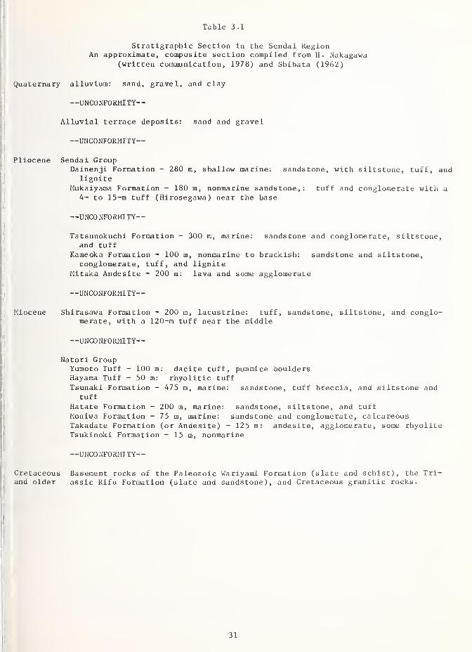
Table 3.1
Stratigraphic Section in the Sendai RegionAn approximate, composite section compiled from H. Nakagawa
(written communication, 1978) and Shibata (1962)
Quaternary alluvium: sand, gravel, and clay
—UNCONFORMITY
—
Alluvial terrace deposits: sand and gravel
—UNCONFORMITY
—
Pliocene Sendai GroupDainenji Formation - 280 m, shallow marine: sandstone, with siltstone, tuff, and
ligniteMukaiyama Formation - 180 m, nonmarine sandstone, : tuff and conglomerate with a
4- to 15-m tuff (Hirosegawa) near the base
—UNCONFORMITY
—
Tatsunokuchi Formation - 300 m, marine: sandstone and conglomerate, siltstone,and tuff
Kameoka Formation - 100 m, nonmarine to brackish: sandstone and siltstone,conglomerate, tuff, and lignite
Mitaka Andesite - 200 m: lava and some agglomerate
—UNCONFORMITY
—
Miocene Shirasawa Formation - 200 m, lacustrine: tuff, sandstone, siltstone, and conglo-merate, with a 120-m tuff near the middle
—UNCONFORMITY
—
Natori GroupYumoto Tuff - 100 m: dacite tuff, pummice bouldersHayama Tuff - 50 m: rhyolitic tuff
Tsunaki Formation - 475 m, marine: sandstone, tuff breccia, and siltstone andtuff
Hatate Formation - 200 m, marine: sandstone, siltstone, and tuffMoniwa Formation - 75 m, marine: sandstone and conglomerate, calcareousTakadate Formation (or Andesite) - 125 m: andesite, agglomerate, some rhyoliteTsukinoki Formation - 15 m, nonmarine
—UNCONFORMITY
—
Cretaceous Basement rocks of the Paleozoic wariyami Formation (slate and schist), the Tri-and older assic Rifu Formation (slate and sandstone), and Cretaceous granitic rocks.
31

Uplands throughout the region are eroded into intricate, steep-sided ridges, but differencesin altitude and relief and in the extent of alluviated lowland distinguish three north-trending topographic belts. (1) On the east, facing the sea, the southern end of the Kita-kami block stands 200 to 500 m above sea level, with most slopes inclined between 30 and50 percent. (2) West of this bulwark, across the south-flowing Kitakarai River that marksits western edge, extend the alluvial plains and intervening areas of low, steep-sided hillsthat form the Kitakami lowland. The heads of the east-trending flood plains on the north-west and the inland edge of the coastal plain facing Sendai Bay on the southwest mark thewestern limit of this central belt. (3) The lowland is bounded on the west by hills thatare nearly everywhere higher than 200 m. Southwest of Sendai, however, a wedge of lower,steep-sided hills extends northward off the end of the Abukuma block. At the northern endof this wedge, the hills bordering the Sendai terrace have valley walls commonly no steeperthan 20 to 30 percent and a local relief generally less than 100 m.
The south end of the Kitakami block consists largely of hard, fractured slate and beddedsandstone of Triassic and Jurassic age that very locally contain Cretaceous graniticintrusions. Natural exposures seem nearly absent except along the coast, but the con-sistantly steep slopes of this topographic belt bear only a very thin soil mantle overbedrock where observed in quarries and road cuts.
Most of the bedrock exposed in the region (Table 3.1) accumulated during Neogene time in astructural low in the Sendai region that crosses the frontal arc between the persistentlyemergent Abukuma and Kitakami blocks. The north-northwest trend of the boundaries of thisgap suggests that it was controlled by pre-Mizuho basement structure. Andesitic to rhyo-litic volcanism associated with the Mizuho orogeny extended through the Neogene, producingvarious flows, agglomerates, tuff breccias, and abundant tuffs. Superimposed on the spora-dic eruption and erosion of these volcanic rocks was a sequence of three marine transgres-sions from the southeast and the accumulation of associated terrestrial to marine clasticsequences, separated by intervals of erosion. The limited areal distribution of individualvolcanic units, erosion between times of accumulation, facies changes, and onlap relationsof the transgressive sequences all combine to produce a complicated arrangement of geologicunits
.
The Quaternary deposits in the region, on which much of the earthquake damage occurred,consist of extensive young alluvial deposits in the lowlands and a sequence of late Pleis-tocene terrace deposits. The terrace deposits occur along the upper reaches of the east-flowing rivers near the margin of the western highland and in the Sendai area, where theyunderlie parts of the city.
The old part of Sendai City was built on the complex Sendai terrace, which consists largelyof sand and gravel some 5 to 7 m thick overlying Neogene bedrock (Figure 3.12). These sedi-ments are slightly consolidated, and yield N values of 20 to 60 (Kobayashi and others,
1978). Recent growth of. the city led to expansion into the adjacent hills, where higherterrace deposits as well as Neogene bedrock were encountered, and eastward onto the Holocenecoastal plain.
The alluvial sediments of the Sendai coastal plain and the other plains of the central low-land bury a late Pleistocene topography that consists of river valleys, flanking terraces,and divides (Figures 3.11 and 3.13). At the coastline, the bottoms of these valleys lie 60
to 90 m below sea level; they extend upstream approximately along the courses of the presentsurface drainage. From Ishinomaki, a deep, buried gorge extends northwestward for more than10 km. North of Matsushima Bay, bedrock is 20 to 40 m deep along the Yoshida River for
nearly 10 km above its junction with the Naruse River, and farther north, the paleo-Narusevalley beneath the center of the Osaki plain 30 km from the coast is still 40 m below sealevel. In contrast, the valleys buried beneath the Sendai plain shallow rather abruptlyfrom 50 to 60 m to less than 10 m below sea level within 6 to 8 km of the coast, near theRifu-Nagamachi techtonic line
•
The late Pleistocene topography was buried by alluvium in the past 18,000 years as the con-tinental ice sheets of the last glaciation melted and sea level rose more than 100 m to itspresent position. The rise in sea level proceeded about an order of magnitude faster thanthe average rate of Quaternary uplift in the region, so that the rivers draining the uplandsto the west and north found their progress gradually blocked by the rising sea. This caused
32

their sediment load to be deposited along their lower reaches, resulting in an effectivedrowning of the late Pleistocene topography that left upland islands and headlands floodedin a sea of alluvium. Along the outer side of the Kitakami block, the intricate drownedcoastline misleadingly suggests major tectonic depression of the block.
As sea level rose, gravel and sand began to accumulate within the deep channels, and nearthe coast, ultimately filled them. Then, toward the middle of the liolocene, a central clayzone that ranges from 5 to 35 m thick was deposited across most of the alluvial terrane.Finally, a sand unit 10 to 20 m thick and an overlying sequence of clay and sand of similarthickness were deposited. This generalized alluvial section varies in detail from place to
place in the central lowland. It closely represents the section beneath the Sendai plain,except that the central clay zone is limited to the shoreward part of the plain (Figure
3.13). The Osaki plain tends to lack the shallow sand unit, whereas in the Ishinomaki areathe surface section is dominantly sand, giving way to thick clay sections in the easternembayments
.
The uppermost part of the alluvial section consists of an intricate assemblage of sedimenttypes produced as the rivers migrated about on the aggrading plain. Under such circumstan-ces, broad ribbons of channel sand and gravel are left as the rivers change their positionfrom time to time, finer sand and silt are deposited in flanking natural levees in time offlood, and organic silt and clay accumulate in the intervening backmarsh areas. Low ridgesof beach sand form along the shore. The sediment is soft and water-saturated, because it
is young and the water table is very shallow.
The surface of the alluvial deposits is quite flat, and is still crossed by the severalrivers responsible for depositing the sediment. Where not used for housing, much of the
alluvial surface is covered with rice paddies. Surface geologic mapping distinguishes thefour facies described: active and abandoned river channels, levees, intervening backmarshpeats and silts, and coastal beach sands (H. Nakagawa, oral communication, 1978). N valuesrange from 1 to 10 in the Ishinomaki region, and to 20 on the Sendai plain. Frequent flooding of the rivers has led to the construction of many dikes, some of which were damaged in
the June 12th earthquake.
3.7 REFERENCES
3.1 Abe, K., 1977, Tectonic implications of the large Shioya-oki earthquakes of 1933:
Tectonophysics , v. 41, p. 269-289.
3.2 Coordinating Committee on Earthquake Prediction, 1978, Unpublished packet of informa-tion used by the Japan Coordinating Committee on Earthquake Prediction in its consideration on June 21, 1978 of the off-Miyagi earthquake of June 12, 1978, various payings.
3.3 Dickinson, W. R. , 1979, Plate tectonic evolution of north Pacific rim: Journal ofPhy sics of the Earth, in press.
3.4 Geological Survey of Japan, 1964, Geological map of Japan: Geological Survey of Japanscale 1:2,000,000.
3.5 Hase, K. , 1957, Geology of the alluvial plains of Miyagi Prefecture: Contributionsfrom the Institute of Geology and Paleontology, Tohoku University, no. 64, p. 1-45
(in Japanese, with abstract and figure captions in English)-
3.6 Hasegawa, A., Umino, N. , and Takagi, A., 1978, Double-planed structure of the deepseismic zone in the northeastern Japan arc: Tectonophysics, v. 47, p. 43-58.
3.7 Ishiwada, Y. , and Ogawa, K. , 1976, Petroleum geology of offshore areas around the
Japanese islands: United Nations Economic and Social Commission for Asia and Pacific,Committee for Co-ordination of Joint Prospecting for Mineral Resources in Asian Off-shore Areas, Technical Bulletin v. 10, p. 23-34.
3.8 Isomi, H., 1968, Tectonic map of Japan, II, Geologic provinces: Geological Survey of
Japan, 1:1,000,000 Map Series No. 12, sheet 2 of 2.
33

3.9. Japan Meteorological Agency, no date, Disastrous earthquakes in and near Japan: JapanMeteorological Agency scale 1:2,000,000 (publication recent but no date given).
3.10. Kanamori, H. , 1976, Seismic and aseismic slip along subduction zones and their tec-tonic implications in Talwani, Manik, and Pitman, W. C. Ill (eds) Island arcs, deepsea trenches and back-arc basins: American Geophysical Union, Maurice Ewing Series1, p, 168-174.
3.11. , 1978, Nature of seismic gaps and foreshocks, in_ Evernden, J. F., Isacks, B. L.
,
and Plafker, George (convenor and coorganizers ) Methodology for identifying seismicgaps and soon-to-break gaps: U.S. Geological Survey Open File Report 78-943, p. 319-334 and 904-906.
3.12. Kitamura, N., and Onuki, Y., 1973, Geological and crustal sections of the A-zone,northeast Japan rn Japanese National Committee for Upper Mantle Project 1973, Thecrust and upper mantle of the Japanese area, part II, geology and geochemistry,Geological Survey of Japan, p. 38-60.
3.13. Kitamura, Shin, no date, Geologic map of Miyagi Prefecture: Tohoku University,scale 1:200,000. Publication recent but no date given.
3.14. Kobayashi, H. , and others, 1978, A report on the Miyagi-ken-oki, Japan earthquakeof June 12, 1978: National Science Foundation and others, Proceedings of the SecondInternational Conference on Microzonation, v. 1, p. 587-614.
3.15. Matsuda, T., 1976, Empirical rules on sense and rate of recent crustal movements:Journal of the Geodetic Society of Japan, v. 22, no. 4., p. 252-263.
3.16.,
1977, Estimation of future destructive earthquakes from active faults on landin Japan: Journal of Physics of the Earth, v. 25, suppl. p. s251-s260.
3.17. Mogi, K., 1968, Some features of recent seismic activity in and near Japan (1):
Earthquake Research Institute Bulletin, v. 46, p. 1225-1236.
3.18. National Research Center for Disaster Prevention, 1978a, February 20, 1978 Miyagi-ken-oki earthquake: National Research Center for Disaster Prevention, Science andTechnology Agency Japan, Prompt Report on Strong-Motion Accelerograms No. 14.
3.19. National Research Center for Disaster Prevention, 1978b, June 12, 1978 Miyagi-ken-oki earthquake: National Research Center for Disaster Prevention, Science and Techn-ology Agency [Japan], Prompt Report on Strong-Motion Accelerograms No. 15.
3.20. Okutsu, Haruo, 1968, Hydrogeological map of the coastal region of Bay of Sendai:Geological Survey of Japan, map scale 1:100,000.
3.21. Otsuka, Michio, Sudo, Ken, Seno, Tetsuo, and Eguchi, Takao, 1978, Study of focalmechanism of the earthquake on the east coast of Miyagi Prefecture, Japan: Interna-tional Institute of Seismology and Earthquake Engineering, Building Research Insti-tute, and Faculty of Science, Tokyo University, unpublished report, 3 pages, 5 fig-ures .
3.22. Page, R. A., Boore, D. M., Joyner, W. B., and Coulter, H. W., 1972, Ground motion
values for use in the seismic design of the Trans-Alaska pipeline system: U.S. Geo-logical Survey Circular 672, 23 p.
3.23. Research Group for Quaternary Tectonic Map, 1969, Quaternary tectonic map of Japan:Japanese National Research Center for Disaster Prevention, Science and TechnologyAgency, scale 1:2,000,000, 6 sheets (1 - Vertical displacements estimated withgeomorphological method, 2 - Vertical displacements estimated with geological method,
3 - Vertical displacements compiled from the maps Nos. 1 and 2,4- Distribution of
faults, 5 - Distribution of folds, 6 - Gipfelflur).
34

3.24. , 1973, Explanatory text of the Quaternary tectonics map of Japan: JapaneseNational Research Center for Disaster Prevention, Science and Technology Agency,167 p.
3.25. Shaw, H. R., Jackson, E. D., and Bargar, 1979, Volcanic periodicity along theHawaiian-Emperor Chain: American Journal of Science, Jackson volume, in press.
3.26. Shibata, 1962, Geology of the Sendai and Nanakita-Sambongi areas Miyagi Prefecture,Science Rep. Tohoku University, 2nd Series, v. 34, p. 239-301.
3.27. Shimazaki, K. , 1978, Correlation between intraplate seismicity and interplate earth-quakes in Tohoku, northeast Japan: Seismological Society of America, v. 68,
no. 1, p. 181-192.
3.28. Takagi, Hasegawa, Akira, and Umino, Norihito, 1977, Seismic activity in the northeastJapan arc: Journal of the Physics of the Earth, v. 25, Supplement p. S95-S104.
3.29. Von Huene, R., Nasu, N. , and others, 1978, Japan trench transected: Geotimes,April 1978, p. 16-21.
3.30. Yoshida, T. (ed.), 1975, An outline of the geology of Japan: Geological Survey of
Japan, 61 p.
3.31. Youd, T. L. , and Perkins, D. M., 1978, Mapping liquefaction-induced ground failurepotential: Proceedings of the American Society of Civil Engineers, Journal of
the Geotechnical Engineering Division, v. 104, no. GT4 , p. 433-446.
35

4. STRONGMOTTON RECOPJ)S AND DATA*
4.1 INTRODUCTION
In Japan, several government agencies are responsible for independent networks of strong-motion instruments located throughout the country. Among the larger of these accelerographnetworks are those operated by the following agencies:
Railway Technical Research Institute (RTRI), Japanese National Railways
Strong Earthquake Motion Observation Center, Earthquake Research Institute (ERI),University of Tokyo
Port and Harbor Research Institute (PHRI), Ministry of Transport
International Institute of Seismology and Earthquake Engineering, Building ResearchInstitute (BRI), Ministry of Construction
Public Works Research Insititute (PWRI), Ministry of Construction
Other organizations with interest in strong-motion recording include:
National Research Institute of Agricultural Engineering, Ministry of Agriculture andForestry
Nippon Telegraph and Telephone Public Corporation
Japan Building Center Foundation (JBC)
The Strong-Motion Earthquake Observation Council was established in 1967 within the NationalResearch Center for Disaster Prevention (NRCDP) of the Science and Technology Agency.
Records recovered from particular earthquakes by the various government agencies are madeavailable to the public in the council's "Prompt Report" publication, which describes the
records, gives peak accelerations and epicentral distances, and contains copies of some of
the more interesting records. These and other earthquake records are published in the
council's annual report. The agencies responsible for the accelerograph networks alsoreport on digitization and analysis of the records collected by them that they considersignificant.
4.2 THE SMAC ACCELEROGRAPH
The SMAC strong-motion accelerograph in its various versions has been the main Japanesestrong-motion recording instrument since its development between 1951 and 1953 by the
Japanese Committee for the Standard Strong Motion Accelerograph. In its earliest form (the
SMAC-A), it consisted of a set of three mechanical oscillators which, through a series of
linkages, scribed analog traces on a waxed-paper record that was driven past the recordingpens at lcm/sec by a hand-wound spring motor. The natural period of the transducer was 0.1
sec (frequency, 10 cps), and critical damning was provided with an air piston mechanism. Asensitivity of 25 gal/mm (i.e., 25 cm/sec per mm), corresponding to approximately 4cm/g,was arranged for in the mechanical linkage and allowed recording of accelerations of lg
amplitude without the pens moving off-scale. Some of the models developed after the SMAC-Aare listed with their important characteristics in the following table.
Prepared by A. Gerald Brady, U.S. Geological Survey, Menlo Park, California.
36

Damping(fraction
of critical)
Naturalperiod(sec)
Sensitivity(cra/g)
Recordingspeed
(cm/sec)Approximate
Number
SMAC-ASMAC-BSMAC-B2SMAC-CSMAC-DSMAC-E2SMAC-Q
1.01.0
1.01.0
1.0
0.600.60
0.10.1
0.140.1
0.050.050.05
4.04.0
8.04.0
1.0
1.0
0.5
1.01.0
1 .0
1.0
0.50.250.5
3390
24018
21
45
1 I
The last column indicates the distribution of the various models in 1975 obtained from the
response to a questionnaire from the author while at the International Seismological Centrein Edinburgh. An additional 400 strong motion instruments were not included in this
response and the total in March of 1974 was actually about 850 (Kuribayashi and others,
1977). By March of 1978 the number of SMAC-type instruments installed throughout Japan in
structures or at ground level had reached 1200 (Iwaskai and others, 1978). Additionalinstrumentation, for example electromagnetic recorders, and special downhole systems arenot included.
It is important to note from this table that the majority of the instruments of the SMACtype that are operated in Japan at this time have frequency-response characteristics that
are different from the most common modern United States instruments that record on 70-mmor 7-in. film. In particular, the SMAC response at frequencies higher than 7 cps (for
the SMAC-B2) or 10 cps (for the SMAC-A, -B, and -C) has been designed to be much less thanwe are used to seeing with United States instruments such as the SMA-1 or RFT-250. Aglance at recordings from these earlier SMAC instruments confirms this lack of high-frequency content.
Another feature of the records made by SMAC-type instruments is that the pens draw arc-shaped curves that have constant radius which are obvious in the higher-amplitude motions.Although peak accelerations can be scaled off without requiring significant correction, it
is evident that after digitizing a record with high amplitudes correction procedures mustbe adopted to handle this instrumental behavior before arriving at true time histories.
Recent developments in Japanese instrumentation have included higher natural frequencies (inthe SMAC-D, -E2 , and -Q instruments), the use of moving-coil electromagnetic transducers(in the ERS accelerograph developed by the Earthquake Resistant Structures Laboratory,Port and Harbor Research Institute), and recording on analog magnetic tape (in the SMAC-MInstrument). The two instruments in the Engineering Building at Tohoku University, whichrecorded 240 gal (240 cm/sec 2
, or 0.24g) and 980 gal (lg) at ground level and at the9th floor, respectively, are SMAC-M instruments operated by the Building Research Institute.
4.3 ACCELERATION RECORDS AT GROUND LEVEL
Figure 4.1 shows the northern part of Japan and the locations of the strong-motion accelero-graph stations that provided ground level, basement, or free-field records of the June 12,
1978, earthquake. The codes for the stations are indicated (for example, TH020) and theirpertinent characteristics have been obtained from National Research Center for DisasterPrevention (1976) and are reproduced in Table 4.1. In addition to the records shown on themap, there exist 61 additional records taken at basement, first-floor, or ground level,mostly in Tokyo or its vicinity. Of these 61 records, the highest peak acceleration is0.045g at an epicentral distance of 305 km.
The epicenter was provided by the Japan Meteorological Agency (JMA) and published by theNational Research Center for Disaster Prevention, (1978). We have chosen to use theseepicenter coordinates, namely, 38°09'N, and 142°13'E, in the sections of this report thatdiscuss the epicenter and epicentral distances.
Figure 4.1 also shows the peak accelerations recorded at ground level, or at the basementof first-floor level in structures. The cities of Sendai and Miyako each have more thanone recording. Each set of the three numbers shown gives the peak acceleration recorded
37

n
o
TH020 Aomori21,21,9 (F)
TH006 Akita 1°
25,23,13 (F)
THOI5 Yuhei Br
25,34,13 (F)
O
TH033 Shiogama266,288,166 (F)
TH030 Tohoku Univ
240, 190 , 150
TH038 Sumitomo253
,227, 120
TH0I8 Sendai Kokutetsu438 , 238 , 100
100 KM
TH029 Hachinohe
65,60, 31 (F)
TH032 Mazaki Br~
104, 75, 30
TH009 Miyako80,92,90TH0I4 Miyako150, 113,47 (F)
TH0I9 Ofunato126,170,61 (F)
TH0I6 Kaihoku Br
200, 294, 113 (F)
Epicenter
June 12 . 1978
TH02I Taira Br
75, 88, 38 (F)
TH0I3 Onahama48, 50, 21 (F)
KTOOI Tokai
88, 125, 30Ibaraki
138' 140' 142'
Figure 4.1 Locations of stations providing ground level, basement, or
free-field records of the June 12, 1978 earthquake. Peakvalues in the two horizontal and the vertical directions are
given in cm/sec/sec. An (F) following these values indicates
an approximate free-field station.
38

39

in two perpendicular horizontal directions and in the vertical direction. For most ground-level stations the two horizontal directions referred to are north-south and east-west, inthat order, whereas the instruments at the lowest level of a structure are generally alignedin the longitudinal and transverse directions of the structure and acceleration values arereported in that order. The acceleration units used are cm/sec^, commonly called a gal.Conversion to g units is simply, if slightly inaccurately, accomplished by dividing by
1,000. An (F) following the acceleration levels indicates that the recording could be con-sidered a free-field recording, although it must be realized that any instrumental housingdisturbs the true free-field motion.
The section on seismicity indicates that, although the epicentral distance to Sendai is
about 110 km to 115 km, it might be inferred from the aftershock pattern that the main shockrupture plane actually reached a point within about 75 km of Sendai, measured in three dimen-sions, or within a distance of 55 km, measured in plan. Such a conclusion would play a sig-nificant part in studies of the attenuation of peak accelerations for this earthquake, par-ticularly for those stations within latitude 37.5° and 38.5° north that lie approximately duewest of both the epicenter and the closest point on the rupture plane. Other stations on theeast coast would not be affected because, for each of these, the epicentral distance is
approximately equal to the distance to the closest point of the inferred rupture surface.
To illustrate this point in rather elementary fashion, Figure 4.2 shows the peak horizontalaccelerations for three groups of ground-level records plotted against epicentral distance.A distinction is made between stations on the coast in a generally northern direction fromthe epicenter, those generally to the west, and those on the coast to the southwest. Acurve labelled "Attenuation to the north" passes through the first group to the north andis a satisfactory approximation for the points of the third group, those to the southwest.Accelerations for the records lying to the west are higher than this curve would indicate,but on moving the points so that their plotted distance is the distance in plan, to the
nearest point of the rupture, 60 km to the west of the indicated epicenter, a better fit
is possible to an extrapolated attenuation curve. This curve only shows the trend of peakaccelerations attenuating with distance - the scatter is evident and its explanation in
individual cases will have to wait for detailed study.
4.4 INTENSITIES
Intensities for earthquakes in Japan are prepared by the JMA from information received attheir headquarters from observational stations throughout the country. Like their ModifiedMercalli equivalents used in the United States, JMA intensities are generally expressed in
Roman numerals, but in the tables and figures of this report we have used Arabic numeralsfor clarity in their presentation.
A brief description of the JMA intensity levels is given in Table 4.2. A comparison of thesedescriptions with those of the Modified Mercalli Intensity Scale (Wood and Newman, 1931), the
standard intensity scale in use in the United States, allows an approximate translation fromJMA to MMI values. Considerable engineering judgment regarding the dynamic behavior of the
various buildings and other structures in both cultures would be required for such a compari-son to be accurate and useful. One possible comparison is shown in the following (Trifunac& Brady, 1975).
JMA 0 1 2 3 4 5 6 7
MMI 1 2 3 4 5 6 7 8 9 10 11 12
Figure 4.3 is a highly idealized isoseismal map constructed from the plotted JMA intensitiesat specific locations. The indicated elongation of the isoseismals in the north-south dire-tion is controlled by the locations of the lines as they pass over the land area, whereobservations are possible. Dashed lines across the Sea of Japan serve only to connect thetwo portions of the several isoseismals. No attempt is made to estimate the locations inthe Pacific Ocean to the east.
The boundary between JMA 4 and 5 is reasonably well constrained to the north and west butless so to the south. The other isoseismals are more arbitrarily chosen. If a circulararea were approximated to the JMA 5 region, its center would lie close, in plan, to the
40

I Cxi
>" <CO h-
i— £ °
H 00 to
i ilu = i . «J n
oo oo <2 00
o o " o °-LkJ LU UJ Q Q _Q£ OC OC KCflZ
• 4
T
//
/
1
CO
CM
00
y
c•H o =
J. 4-1 4J
c U-l
c ri >-l-
— .d uw 03 4-1
e 4-1
S-l MH !U Si
tu o a z—
i
•H wqj -—
1
a oo a a) —u onj —
14-1 —J*! 0) 4-1
ccj ~J
0) li
a. .e O o— -J— 4-1
to 1)
> 0) oc— a rrj
e X 4-1
t3 co Ti c/>
dd cn
o *H
MrH
o >-i
yt to -aoai ai
!-4 J=4-1
uo o
4J u_, j_j j_l
d do o>
•H O4J 'rH
CO ft3 01
da; -d4-1 4-1
4-1 -H<; s
d
•Hfa
ill 34-i d rd
d o u-i
•H Cuc w ai
a. a) .c>J 4-1
0) !-J
x; o d4-1 o o
LT5 CO CM
(708S/LU0) NOIIVHHIBDOV W3d
41

Figure 4.3 Isoseismal map for the June 12, 1978 earthquake.
42

Table 4.2 JMA Intensity Scale
0: Not felt. Shocks too weak to be felt by humans and registered only by seismographs.
1: Slight. Extremely feeble shocks felt only by persons at rest, or by those who areobservant of earthquakes.
2: Weak. Shocks felt by most persons; slight shaking of doors and Japanese latticedsliding doors (shoji).
3: Rather strong. Slight shaking of houses and buildings, rattling of doors and shoji,swinging of hanging objects like electric lamps, and moving of liquids in vessels.
4: Strong. Strong shaking of houses and buildings, overturning of unstable objects, andspilling of liquids out of vessels.
5: Very strong. Cracks in sidewalks, overturning of gravestones and stone lanterns, etc.;damage to chimneys and mud and plaster warehouses.
6: Disastrous. Demolition of houses, but of less that 30% of the total, landslides,fissures in the ground.
7: Very disastrous. Demolition of more than 30% of the total number of houses, intenselandslides, large fissures in the ground and faults.
westernmost down-dip end of the inferred rupture surface mentioned above. This lends cre-dence to the conclusion that for this earthquake the distance from points on the ground sur-face to the nearest point of the rupture surface is the distance of importance in attenuationand related studies.
4.5 RECORDS FROM STRUCTURES
The Prompt Report (NRCDP, 1978) lists 191 strong motion records of the earthquake at epicen-tral distances ranging from 80 km (TH016 - Kaihoku Bridge) to almost 600 km, and includesrecords from 46 multi-instrumented structures such as buildings, bridges, and dams. About100 of these records are from multi-instrumented buildings in the Tokyo area, at epicentraldistances between 355 and 370 km. Although ground level accelerations here are low, somestructural records have peaks of 10 percent g.
A selection of 22 instrumented structures are listed in Tables 4.3 to 4.6 with their instru-ment locations and peak accelerations at the various levels. Table 4.3 lists two low-risebuildings with less than six stories, Table 4.4 lists five medium height buildings betweensix and fifteen stories, Table 4.5 lists nin high-rise buildings with more than 15 stories,and Table 4.6 lists five bridges and a dam. All structures included in the tables have anassociated ground level or basement record, and some of these have been included in Table 4.1in the earlier section on ground level records.
The lists include the names, addresses and coordinates of the stations. Buildings aredescribed by the number of stories above and below ground, while bridges, and the dam, havetheir length and width listed. The instrument locations in the buildings are indicated by
story, including basement and penthouse or roof. For the bridges and dam the ground levelrecording station is usually off to one side of the structure on firm ground, while thestructural recording station is usually on a pier cap, effectively at deck height. The peakaccelerations at the listed instrument locations are given in cm/sec/sec (or gals) in groupsof three - two horizontal and vertical component. Although the horizontal components areoften listed as N-S and E-W in Japanese literature, these component names may actually betranslated to mean the longitudinal and transverse axes of the recorder, and therefore alsothe longitudinal and transverse directions of the structure.
43

44

2 *
2 u<D U
11" +
J
5 S5 S
Si
11
5 5
o o
t5- g,
r.fi'g
g 3
I!
Is
II
S3
If
I!
II
£ "2
Is Is.
fi H IE-1
li li= 5 5,3
Ij ||
II si
S -
-A
53
II
45

If.
%n
an)
CO
o00-aHM
<t
1—
I
H
C 3
0000
ro
5CM
o"Oo CO
(-1
m" XI CM*
?? CO o
£* 00CO
o-T
^*LA* to in*
oo
CO
a.
3
1
3o u
Li u 5 u
-3-
V
Q. o. o. cd 00
GL, u* u"_Tu u o
*e
CO CO CO o
eD X V
in in
II
E
f3
V3 3
J 3 3
e-J
CO
ii
CO r^. ,o 00 c^l
IT* OCM CO<J- o o c
—' CO
-J r-t
O O140°
37°
<r r-
a
o03 n
3CO
-
E 3 -
O rfl
3
Hcf £
3
H t-< a •H l-t H >.
o 3 -H 5iH
v £ 0)c^ >>
«c & <£
e *i? * H U a t § £
aa
£CO
>,
00 Itq
-a
"u
CO 00
s?
M
COD
O
o
1
3
00
C
s 1 I
oin
OO
X
46
...

The investigating team inspected three of the structures on these lists: the Faculty of
Engineering Building at Tohoku University, Aramaki, Sendai, described in a later section of
this chapter; the Sumitomo Sendai Building, Chuodori, Sendai, described in the chapter onearthquake performance of buildings; and the Kaihoku Bridge, Inai, Ishinomaki, described indamage to transportation structures.
4.6 A Comparison with the Recorded Results of the San Fernando Earthquake, 1971 .
An overall comparison, from an engineering viewpoint, of the recorded strong-motion data fromthe San Fernando, 1971, and Miyagi-ken-oki, 1978, earthquakes can be based on the followinginformation.
1. The San Fernando magnitude was 6.4 with a focus at a depth of 13 km, the rupture propaga-ting to the surface at the northern edge of the large metropolitan area of the city of
Los Angeles and its surrounding cities and communities. The tall buildings of the citylie between 21 and 50 km from the epicenter.
The Miyagi-ken-oki magnitude was 7.4 with a focus at a depth of 30 km, the ruptureprobably travelling deeper but at a shallow angle towards the metropolitan area of Sen-dai. The aftershock pattern indicates that the rupture on the fault possibly approachedas close as 75 km to Sendai. The high rise buildings of Tokyo are 350 km and more fromthe epicenter and from the nearest part of the fault rupture.
2. The closest recording to the San Fernando epicenter was at Pacoima Dam, at 8 km, or 4 kmfrom the surface faulting, where the topography is extremely complicated.
The closest recording to the Miyagi-ken-oki epicenter was the ground level instrument atKaihoku Bridge at 80 km. The closest distance to the rupture, at depth, however, is
closer to 60 km and this distance in plan is 20 km. The peak acceleration recorded herewas 0.29g.
3. At San Fernando, the next closest record was a 7-story building, the Holiday Inn at 8244Orion, Los Angeles, with ground level accelerations of 0.27g.
At Miyagi-ken-oki the two buildings with complete instrumentation, that is at least tworecorders including the lowest level of the structure, are at epicentral distances of 115km, which reduce to 75 km to the nearest fault rupture, or 55 km in plan. Peak accelera-tions at ground level range up to 0.25g. None of these buildings, in either earthquake,suffered any severe structural damage; minor cracks in columns was the extent of theobserved damage to structural members.
4. A total of 35 buildings higher than six stories produced complete sets of records fromthe San Fernando event at epicentral distances from 24 to 50 km, and ground accelerationsranging from 0.26g down to 0.04g. Minor cracking of structural members and extensivedamage to nonstructural components were common.
The Miyaki-ken-oki event produced no further sets of records from tall buildings untilthe Tokyo area was reached, at epicentral distances of 340 to 370 km where accelerationamplitudes were .03g and less.
5. Recordings sufficient to give a useful engineering indication of ground accelerations andassociated structural performance exist for San Fernando at epicentral distances from 20km out to 75 km.
The same type of information for Miyagi-ken-oki ranges in distance from 80 km (reduced to60 km, see above) out to about 200 km. Structures involved here are bridges, with groundlevel and pier cap accelerations, and various harbor installations.
6. The San Fernando records have been the basis for a large number of engineering and seis-mological studies, particularly, of course, the digitized versions of the records. Evennow, there are still complete sets of building records that could be analyzed to studyparticular building behavior.
47

4 . 7 Tohoku University, Engineering Building
Tohoku University is situated in the northwest part of Sendai, in the district of Aramaki, anarea of hills and steep terrain. The Engineering Building is a reinforced concrete framedstructure and is built on a reasonably flat area, but a steep cliff falls off close to therear of the building. Figure 4.4 is a photograph of the central 9-story tower and also showsthe two lower levels which cover a larger plan area. A floor plan and two elevations are
shown in Figure 4.5. Two SMAC-M instruments are installed in the building, at ground level(there is no basement), and at the 9th floor level. They are on the same vertical line,
against an exterior wall of the central tower, as shown in Figure 4.5. These instrumentsrecord on FM analog tape, and functioned correctly during the earthquake.
The analog tape recordings were recovered and analyzed by the Building Research Institute,which was responsible for the instruments. After analog-to-digital conversion, a computeranalysis was possible, and was completed within seven days (Watabe, 1978). The followingfigures are reproduced from the preliminary work.
Figure 4.6 shows a 25-sec portion of the record from the ground level instrument, after A/Dconversion. The peak horizontal accelerations are 240 and 190 cm/sec/sec, and the peak ver-tical acceleration is 150 cm/sec/sec, as indicated in Table 4.1. Figure 4.7 shows a similarplot of the 9th floor record peak values of 980, 480, and 300 cm/sec/sec (Table 4.4). A
preliminary analysis of the high-amplitude oscillations in the horizontal directions at this
level indicate that the corresponding displacements are approximately 10 in (25.4 cm). Thisis consistent with the damage in the interior of the building, (discussed in Chapter 5), andindicates the building was approaching the structural damage state.
Figures 4.8, 4.9 and 4.10 show the correction procedures applied to the three ground levelcomponents. Acceleration velocity and displacement are plotted. Figures 4.11, 4.12, and4.13 show spectral analyses performed on these records. The analyses include absolute accel-eration response, relative velocity response, relative displacement response, and pseudovelocity response, the last being plotted in the tripartite 3-way response spectrum style.
4.8 Tracings of Records
Tracings of sections of the records from some of the closer stations are included. Figure4.14 is the ground level record on the premises of Shiogama Harbor Office, site No. TH033
,
with peak values scaling off at 266, 288 and 166 cm/sec/sec. The arc-shaped curves drawn by
the hinged arms are clearly evident on the high-amplitude excursions. Figure 4.15 shows the
ground level record for site No. T11019, the breakwater of Ofunato Harbor, with peak valuesof 126, 170 and 61 cm/sec/sec. The amplitudes here are sufficiently high in a few instancesto show their arc-shaped character. Figure 4.16 shows the first basement record at the J Nit
building at Sendai. The peak NS reading of 438 cm/sec/sec is the highest ground level ampli-tude in the city. The building has six stories, but no record was recovered from the stationat the sixth floor. Consequently it is difficult to analyze this basement record and to
ascertain the extent of the interaction between building and ground.
4 . 9 References
4.1. National Research Center for Disaster Prevention; Science and Technology Agency(Japan), March 1976, Strong-motion earthquake records in Japan, 1974, vol. 19.
4.2. National Research Center for Disaster Prevention, July 1978, June 12, 197b, Miyagi-ken-oki Earthquake: National Research Center for Disaster Prevention; Science and Tech-nology Agency (Japan), Proupt Report on Strong-Motion Accelerograms No. 15.
4.3. Wood, ii. 0., an.l Newman, K. (1931). Modified Mercalli Intensity Scale of 1931, bull.Seism. Soc. Am., 21, 27 7-283.
4.4. Trifunac, M. 0. , ami Brady, A.G. (1975). on the correlation of seismic intensityscales with the peaks of recorded strong ground motion, Bull. Seism. Soc. Am., o5, 1,
139-162.
48

Figure 4.4
Engineering Building,Tohoku University,Aramaki, Sendai.
.EXPANSION JOINT
Wtt" v? firip fn? Yin?
ni6 @ 3.3 m
I
— 8 (S) 8.0 m
72.0 m
Figure 4.5
Floor plan and sections of
the Engineering Building
SECTION A-
A
49

5()0
uV tr AT'V -v >•"\
D
Time 0. 5. 10. 15. 20. (sec)
5()0
N /V
fs
—= V V V V r
5C)0
Time 0. 5. 10. 15. 20. (sec)
5()0
E
—
»-< ft/ k,/Af V r\
5< )0_
——
1
—r
Figure 4.6 Three components, after analog-to-digitalconversion, at 1st floor level, EngineeringBuilding
.
1000-
-1000-
Time 0.
1000-
-1000-
Time 0.
1000-
--1000-
Figure 4.7 Three components at 9th floor level,Engineering Building.
50

51

Mc
u Ho •HmM
4J
c too
0) c0 •HCD
<j 0)
0),—
|
^H
CO 60H p3W
n•H <U
CJ cO orH a,CD e> Q
u
C XIo 4-J
HU Ottf COV-J 1
0) ,crH 4J
Q)
a Ou a
i-i
<u oo
O Hcu muu 4J
o COu rH
a)
soH
I
NOiivaaaaoov xNawaovadsia
52

uwtn
ooo
CJwin
oo0>
uw
ooCM
OCOo
CH -HO 13
4-1 rH•H
C M0)
o
•H -HT3 60
d
co•H 4-1
4-i cn
CO CD
t—I 4JCD CD
O CO
O CD
cO
CU O4-1 O
S-J 4-1
o wU f-H
3be
| Z09S/U10 |
j_
° OBS/lLlO°
I
AiiDcnaA iNawaovaasia
53

V:


56

tu
U3bO•H
5 7


oLUCO
.1
T
CO&fl
COOCM
HCH
4-1
£ ao jn Bm 0)
'J3
cti
u0o 4-*
0) Wi-j Hmo H
cd
a 13o c•H
0ft CO
d14-1 Ho -a
CJ3 Hc 3-H pqUrd
i-l
H >"3
u3c£•H
59

4.5. Kuribayashi, E., Tsuchida, H. , and Watabes
M. (1975). Maintenance of the Strong MotionAccelerograph and Data Processing of Records Obtained, Proc. 7th Conference UJNR Windand Seismic Effects, May 1975, Tokyo, Japan.
4.6. Iwasaki, T. ,Katayama, T.
,Kawashima, K. , and Saeki, (1978), Statistical Analysis of
Strong Motion Acceleration Records Obtained in Japan. Proc. 2nd Int. Conf. on Micro-zonation, November 1978, San Francisco, Calif., USA.
4.7. Watabe, M. , 1978. Personal communication, and tentative report by Building ResearchInstitute.
60

5. EARTHQUAKE PERFORMANCE OF BUILDINGS*
5 . 1 Introduction
As shown in the aerial photograph in Figure 5.1 and in Figure 5.2, Sendai is a large moderncity. It is the center for commerce and industry for Miyagi Prefecture. Many buildings in
the city can be considered to be modern highrises, in excess of five to six stories. In
particular, the downtown center of the city has a multitude of modern buildings in the 10- to
20-story range. The map in Figure 5.3 shows the metropolitan Sendai area; Table 5.1 identi-fies the points of interests on the map.
The U.S. team arrived in Sendai June 23rd, 11 days after the earthquake. The first impres-sion upon entering the city was that a significant earthquake had not even occurred. This
was due in part to the speed with which the Japanese authorities had responded to the disas-ter. Evidences of damage that would have otherwise impeded the normal operations of the cityhad already been cleared away. Upon closer inspection, minor facade damage became obvious(Figures 5.4, 5.5, 5.6, and 5.7. This sort of damage was not widespread by any means and
numerous modern buildings did not show any damage to their architectural veneers or glazing.It was reported that many chimneys and stacks had collapsed or were severely damaged (e.g.,
Figures 5.8 through 5.10).
As the investigation proceeded, it became obvious that numerous pockets of damage existedthroughout the city. These apparently are correlated to the local geological and soil condi-tions, discussed in Chapter 3. Soil conditions in the downtown Sendai area (Figure 5.3,within 2 km N and W of the railway station) generally are quite good. Many highrises in thisarea have raft foundations and are situated on a gravel-type soil. The area to the west andsouth of the Hirose river are stable terrace deposits. However, the area to the east of therailroad and to the south of Japan National Highway 45 is a former agricultural area. Theunderlying soil is a young alluvial deposit, and from an engineering point of view, the soilconditions are quite poor.
This chapter begins with an overview of seismic engineering and construction practices inJapan. This will be followed by a discussion of investigations of commercial and retailestablishments, schools, apartment buildings, and single family residences. Industrialfacilities are covered in Chapter 6.
5.2 Seismic Engineering and Construction Practice
The general seismic design philosophy in Japan is that it is not economically feasible toprovide complete protection against all earthquakes. Prevention of loss of life is the over-riding concern. Thus, the design criteria are aimed at preventing structural damage audminimizing damage due to moderate earthquakes, and avoiding collapse or serious structuraldamage due to severe, infrequent earthquakes.
The Japan Building Code governs the design of buildings and related structures such as chim-neys and elevated water towers. The method of seismic coefficients is similar in concept to
the U.S. equivalent lateral force method recommended by the Uniform Building Code (1976) andother standards. It is still commonly used in Japan, particularly for buildings five storiesand less in height, but it is recognized as being unsuitable for many flexible structures.Dynamic analyses are required for buildings over five stories in height.
There are a number of general guidelines and requirements, which are discussed in furtherdetail in Refs. 5.1 - 5.4. For example seismic calculations are required in buildings ofmore than 100 m^ floor area used for schools, hospitals, and places of public assembly, andin structures having more than two stories or 200 m floor area. No buildings with totalfloor areas exceeding 3000 m^ can be wood, nor can buildings in excess of 13 m in heightbe wood or unreinforced stone, brick or concrete block masonry, or concrete. There areadditional detailing requirements that depend on the construction material.
*Prepared by Bruce Ellingwood, Center for Building Technology, National Bureau of Standards,Washington, D.C.
61

Figure 5.1 View of the downtown area of Sendai (Tohoku Electric
Power Company photograph)
.
62

Figure 5.2 Typical buildings of the downtown Sendai area.
63

Figure 5.3 Map of Sendai City, showing major landmarks
and sites of damaged structures. See Table 5.1
for identification
64

Table 5.1 - Numbered sites in Figures 5.3 and 6.1
1
.
Sendai railway station2
.
Second government building3. 77 Bank building4
.
Sumitomo Insurance Building5
.
Japan National Railway bui lding6
.
Maruyoshi building7
.
Obisan building8
.
Kinoshita building9
.
Maruhon building10
.
Yazaki Industries11
.
Taiyo Fisheries Plant12. Paloma Sendai building13. Tonan High School14. Haronamachi Gas Plant15. Cement plant16
.
Hirose Bashi Bridge17. Tohoku Institute of Technology18
.
Aoba Castle19
.
Tohoku University20. Sendai Substation, Tohoku Electric Power Company21
.
Izumi City High School22. Yuriage Bridge23. Abukuma Bridge24. New Sendai Power Plant, Tohoku Electric Power Company25. Tohoku Oil Company, Ltd . refinery26
.
Ono Bridge27
.
Kimazuka Bridge28. Eaigawa Railway bridge29. Kaihoku Bridge30. Tenno Bridge31
.
Iinogawa Bridge32. Yanaizu Bridge33. Toyoma Ohashi Bridge34. Maiya Ohashi Bridge35. Kin-no Bridge36. Kitakami Ohashi Bridge37. Sendai Ohashi Bridge38. Sunny Heights Apartment building
b5

Figure 5.4 Minami Machidori Building,
Sendai. The cracking to the
brick veneer is typical for
many similar buildings in
the city.
Figure 5.5 Minami Machidori Building. Closeup o
the lower floors of the building.

Figure 5.6 Second Eastern Building Company Building, Sendai. Atypical modern building in Sendai; the only apparantdamage to the glazed tile veneer on the exterior wascracking on spandrels and shear walls
.
Figure 5.7 Second Eastern Building Company Building. Closeup of exteriorwall
.

13a>
ouo
C•HO
•H Ol
01 -H
3O 0)
u C£ S
OQ O
0)
3
H

The seismic base shear V is calculated by multiplying the sum of dead and a portion of thelive load by a seismic coefficient k that is calculated as the product of a standard seismiccoefficient k a site seismicity coefficient k-^ and a soil and building type coefficient,k2 . Coefficient ki is determined from a map, and takes into account the intensity and fre-quency of earthquakes anticipated for the location. For Sendai and environs, k-^ = 0.9.Coefficient k
2accounts for the characteristics of the ground at the site and the probable
mode of behavior of the building. The product of k^k2
is in no case taken as less than 0.5.
This procedure is summarized as follows:
V = kW
W = Dead plus a portion of live load
k = kQk1k2
k = standard seismic coefficiento
=0.2 for heights less than 16m
= 0.2 + ^~ (h-16) for heights greater than 16m4
= 0.3 for wood structures on soft ground (alluvium greaterthan 30m thick, reclaimed marshes, etc.)
k-^ = Site seismicity coefficient (map provided)
1<2 = Soil and building coefficient
Values of k->
Rock Wood Steel R/C Masonry
Sand-Gravel 0.6 0.6 0.8 1.0
Sandy Clay 0.8 0.8 0.9 1.0
Note that kQ
varies with the height of the building; however, building period does not enterthe seismic force equation explicitly.
The Japan Building Code permits the allowable stresses to be increased by a factor of 100percent for earthquake, while most standards in the U.S. permit only 33 percent increase.However, U.S. standards (e.g., Uniform Building Code, 1976 Edition) do not include live loadin determining W, except for warehouse and storage occupancies. The basic force coefficientkQ
is larger than the factor C in the Uniform Building Code, to which it is analogous.
Unreinforced masonry buildings are generally two stories or less in height. A reinforcedconcrete collar beam must be provided at the top of each story wall, and the height-thicknessratio of walls must be less than 15.
Earthquake resistance of wooden buildings is generally provided by specifying minimum lengthsof walls and diagonal bracing. The Japanese Building Code requires a minimum length of wallor a framework with diagonal bracing for wooden buildings over 50 m^ in floor area and two ormore stories in height. The required bracing or length of wall depends on the floor area.Bracing must be provided for horizontal floor diaphragms also. These requirements result in
a structural frame that is stiffer than those found in single family dwellings in the U.S.
Earthquake resistance in steel buildings is provided either through the use of moment-resisting frames or through diagonal bracing. When braces are used as earthquake resistingelements, it is normal practice to design them so as to carry all of the horizontal force.An example of such a structure is a steel framed furniture warehouse on the outskirts ofSendai shown in Figure 5.11. There were many examples where the bracing members buckledunder stress reversal or the connections failed. A number of the transverse diagonal bracesused in this warehouse sheared at their bolted cross connections (Figure 5.12).
69


Many modern high-rise buildings in Sendai have steel frames, and these generally performedvery well during the earthquake. One example is the Sendai Second Government Building in
the downtown area (No. 2 in Figure 5.3), a 17-story structure built in 1973 (Figures 5.13and 5.14.) The building is situated on a raft foundation, where the underlying soil condi-tions are good. The frame was designed by dynamic analysis for a maximum base accelerationof 0.2 g. The building is instrumented with strong motion accelerometers at the 15th floorand second basement levels, and a downhole at 40 m below grade. The building suffered vir-tually no damage, although there was some minor diagonal cracking in the concrete stairwellsleading to the basement.
A number of changes were made to the Japan Building Code in 1971, many of which relate to thedesign of reinforced concrete buildings. While the standard seismic coefficient remained
0.2, requirements for minimum spacing of column ties became more stringent in the 1971 edi-tion. In the pre-1971 code, the maximum tie spacing in normal weight concrete columns was300 mm or 15 times the diameter of the main reinforcement; in the new code, the maximum spac-ing permitted is 100 mm. The minimum allowable bar cover is 30 mm. Section A. 6. 5. 3 of ACIStandard 318-77 (Ref. 5.7) and Chapter 11 of Ref. 5.6 have similar requirements that limitvertical spacing of ties in columns to 4 in (100 mm) at locations above and below beam-columnconnections. Undeformed reinforcing bars were commonly used in Japan until about 10 yearsago. The 1971 Japan Building Code requires the use of deformed bars, however.
Numerous modern buildings in Japan, particularly those between six and fifteen stories, usethe SRC (Steel and Reinforced Concrete) system, in which the reinforcement is provided by
embedded steel shapes in conjunction with conventional reinforcing bars. The fire resistanceand safety against buckling are high, while the the cross sectional dimensions of the struc-tural members can be made smaller than in conventional reinforced concrete structures. Thesystems is quite ductile. The Sumitomo Insurance Building in downtown Sendai (No. 4 in
Figure 5.3) is an example of such a structure (Figures 5.15 - 5.17). This is a modern 18-
story SRC building with continuous reinforced concrete shear walls around the elevator coreand on the outside transverse walls. The interior shear walls around the elevator core andsome of the construction joints in the stairwells and nonstructural partitions showed minordiagonal cracking. However, the main structural elements are believed to be undamaged. Itwas reported that after the February 1978 earthquake, the Sumitomo Insurance building haddiagonal cracking in secondary walls and that after the June earthquake, these had becomemore extensive. Vibration tests conducted before and after the February earthquake showedthat the fundamental frequency decreased from 1.2 Hz to 1.0 Hz due to cracking. The struc-tural damping also increased. The Sumitomo Insurance Building had strong motion instrumen-tation in the 2nd basement, the 9th and 18th floors (see Chapter 4). Peak accelerations of
0.26 g (2nd basement) and 0.56 g (18th floor) were recorded during the June 12 earthquake.
The 77 Bank Building is located in downtown Sendai not far from the train station (No. 3 inFigure 5.3). An exterior elevation and a floor plan are shown in Figures 5.18 and 5.19.
The basements and first three stories are SRC, while the remainder has a steel frame. Likemany of the high-rises in the main area of the city, it has a raft foundation. As shown inthe plan, the building has an eccentrically located elevator core, surrounded with rein-forced concrete shear walls. A quick walk-through inspection revealed no signs of damageto interior columns, their stucco panel facing, or the marble veneer in lower story corri-dors. The building was completed in 1977 (hence its name), and was designed according tothe 1971 seismic code.
5 . 3 Commercial and Retail Establishments
The map of Sendai in Figure 5.3 shows a shaded area east of the railroad tracks and south ofJapan National Highway 45. Until about 10 years ago, this was an agricultural area that wasmainly rice paddies. The water table is known to be quite high and, from an engineeringpoint of view, the soil conditions are poor. There are numerous buildings in the two- tofour-story range which are used for small business, retail, and other commercial establish-ments. These buildings typically have a ground-story used to display merchandise with largeopen areas and few walls. The upper floors are used for offices and for storage. This typeof building layout creates a structure in which walls are not placed symmetrically withrespect to the center of the structure and in which the first-story lateral force-resistingelements are relatively flexible when compared with the upper portions of the structure.

72

Figure 5.15 Sumitomo Insurance Building, Sendai, plan view.The building has continuous shear walls aroundthe elevator core and on the transverseoutside walls.
7 3

Figure 5.16 Sumitomo Insurance Building.
Exterior Elevation
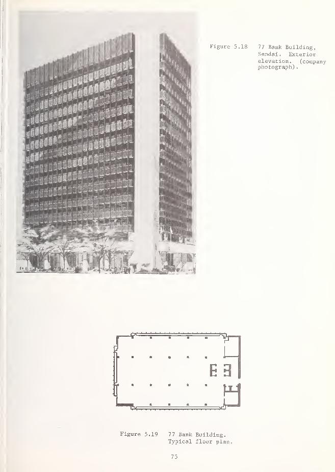
75

In this general area, referred to as Oroshicho, numerous buildings suffered extensive damageand there were several reinforced concrete structures which collapsed. The latter were all
in the two to four-story range. Most of the buildings in this area were reported to be
built on pile foundations, although no particulars for specific buildings were obtained. The
collapsed reinforced concrete structures were all designed and built in the middle 1960'sprior to the adoption of the 1971 seismic building code.
There were no acceleration records obtained in this area. However, shaking in the N-S direc-tion apparently was stronger than in the E-W direction, at least in the area visited, since
most of the damage observed to buildings resulted from strong motion in the N-S direction.
There was extensive evidence of ground settlement in the Oroshicho area, including settlementof asphaltic concrete sidewalks and slumping around building foundation walls, as in Figures5.20, and 5.21.
Maruyoshi Building (No. 6, Figure 5.3). This was a three-story reinforced concrete framebuilding, one span by three, with the long axis of the building running in the E-W direction.There was a 2 m overhang on the north side of the structure (Figure 5.22). The wall shownat the west end was continuous from the second-story on up. The building had a flexiblefirst-story. The building suffered extensive damage to the first-story (Figure 5.23) and,
as shown in Figure 5.24 was tilting toward the north. The first story columns on the southside of the building failed in shear due to the strong N-S motion. A detail of the beam-
column joint where the second-story floor beam frames into the first-story column is shownin Figure 5.25. Column ties appeared to be spaced at about 300 mm. The shear wall on the
west end of the structure appeared to be undamaged. Unfortunately, this caused the struc-ture to behave as an inverted pendulum and caused the first-story columns to accept even moreshear. Note the use of the undeformed bars in the beam-column joint (Figure 5.25).
The building was being demolished at the time it was visited.
Obisan Building (No. 7, Figure 5.3) . This was a three-story reinforced concrete frame build-ing with one span in each direction (Figure 5.26). The portion of the building which overhungthe column line by about 2 m contained a heavy stairwell. There were no openings in the over-hanging part of the building, which added to the eccentric mass. Coupled with the strong N-Smotion, this caused a failure in torsion as the columns at the west end of the building wereunable to withstand the forces resulting from the large eccentric mass. Figures 5.27 and5.28 show the Obisan Building after the earthquake viewed from the north and south, respec-tively. It may be observed that the upper stories rotated almost as a rigid body when the
first floor columns failed. The first-story of the building had been used as a display area,
and was completely open. A detail of the SE column is shown in Figure 5.29 and in the plan.
As shown in Figure 5.30, the first floor support beams were practically resting on the groundat the west end of the building. The walls above the first-story suffered extensive crackingduring the earthquake, but remained intact (Figure 5.31). The reinforcing bars that can be
seen are undeformed.
Kinoshita Building (No. 8, Figure 5.3) . This three-story reinforced concrete frame building,two spans by six, had its main axis in the N-S direction. As shown in Figure 5.32, there wasextensive diagonal cracking on the east face. The first floor on the west side of the build-ing, Figure 5.33, was used as a showroom. Unlike the backside of the building, where the
columns were stiffened by spandrels, the columns on the west side were relatively flexible,and there appeared to be very little damage on that side of the building. The brick facingon the west side remained intact. The interior columns on the east side of the buildingshowed large shear cracks and buckling of exposed undeformed bars. A reinforced masonry par-tition wall also failed here. It is apparent that most of the seismic force was attracted to
the relatively stiff east side of the building. In addition, there appeared to be significantsettlement of about 100 - 150 mm in the interior of the building on the east side. This,along with the relative stiffness of the east face, would explain the diagonal cracking pat-tern observed on the east face as well as cracking patterns observed in columns and panels.Failures of this sort were also observed following the Niigata earthquake (Okamoto, 1973).
Maruhon Building (No. 9, Figure 5.3) . This six-story reinforced concrete frame building islocated one block of west of the Kinoshita Building. There was a construction gap of approxi-mately 30 mm between the two parts of the building and no evidence of pounding. There is
7 6

77

1 1 1 1B- 1
2.2 m
r
1 1 1 1
6.2 m
—1
| 1.0 m
—< 7.0 m ^» — 7. 0 m7. 0 m 1»-
PLAN
Figure 5.22 Plan view of Maruyoshi Building, Oroshicho area. Noteoverhang to the north.
78

« 3
1)
3CJJ
•H
• T34-1 0)
CO (-1
cd }-i
a) 3o
<u oX o
ce
HOo
>,uo
00 03
C•H +-i
tO
rH H•H -H3 4-1
pq4-1
•H O •
X Mto cu n)
o 5-1 tu
>> 3 X!3 H 01
o) ca cS
a)
3ooH

-83
1
2
-m1.8 m 9.2 m
PLAN
1.8 m
7.2 m
COLUMN I DETAIL
600
COLUMN 2 DETAIL
+ 9 x 100
600
700
ALL BARS - 22
700
10 BARS - 252 BARS - 22
<fi
DETAILS (ALL DIMENSIONS IN MM)
Figure 5.26 Plan and column details of Obisan Building, Oroshicho area
80

Figure 5.27 Obisan Building, viewed from the North. This three storyreinforced concrete frame building had a heavy eccentric stairwellcantilevered over the column line at the right end of the building.
Figure 5.28 Obisan Building, viewed from the south. The upper stories rotatedas a rigid body when the first floor column support was lost.

M-l
o 4->
c-I 0)
•h aa) nj
U n
" Sd 3
o •
o ooc
4-> n)
o
a)
u
60
F34
C 3•H iHT3 Or-H O•H3 4->
w 4->
H 3^ oO w

Figure 5.31 Obisan Building, south face. Walls above first story
remained essentially intact.
83

Figure 5.32 Kinoshita Building, Oroshicho area, of Sendai. Extensivediagonal cracking was observed on the east face (rear) of thebuilding
.
Figure 5.33 Kinoshita Building. The brick facing on the west side of thestructure showed little sign of damage.
1
84

extensive diagonal cracking in the panels between window openings on both east (Figure 5.34)and west faces (Figure 5.35); this damage is especially severe on the west face, as shown in
the detail in Figure 5.36. The decorative ceramic brick facing on the north side of the
building did not appear to be damaged.
Despite the level of damage in the Oroshicho area, many buildings performed quite well. As
an example, Figure 5.37 illustrates a 9-story building which was only slightly damaged. No
details about its construction are known.
Yazaki Industries (No. 10, Figure 5.3) . Figure 5.38 shows portions of the three Yazakibuildings. The building on the left has a steel frame with diagonal bracing used as a ware-house. The middle building (tilted) has a four story reinforced concrete frame, 3 spans by
5, which was used as an office building. It was built around 1970. The design accelerationwas 0.2 g. The two-story building on the right, a steel frame completed in 1973, was used
as a showroom. The buildings are aligned in the N-S direction.
I The strong N-S component of the earthquake caused shear failures in the first story concretecolumns in the middle building and a collapse at the ground story, causing the entire build-
Iing to tilt north. This racked the two-story steel frame building forward, causing extensivedamage to the steel frame and popping glass panes from showroom windows. The area of impact
between the two buildings is shown in Figures 5.39 and 5.40 and 5.41. Figure 5.42 shows a
detail of the beam-column joint at the top of the first-story column on the east side of the1 middle building. The column shear failure extended up into the beam. A detail of the column
on the northeast corner of the middle building in Figure 5.43 shows the gross vertical dis-placement and badly distorted bars in the columns. Unlike the other collapsed buildings in the
Oroshicho area, deformed reinforcing bars were used in the Yazaki building. The building ser-
vice systems between the two impacted buildings were damaged.
The steel frame warehouse behind the collapsed building (Figure 5.38) did not appear to be
' damaged. The warehouse contained numerous heavy tubular steel frame storage racks withdiagonal braces, as shown in Figure 5.44. The storage racks stand approximately 7 m in
height and are anchored to the concrete floor by being bolted or welded to steel plates in
j
the floor. Although none of the racks had collapsed, the bottom diagonal braces appeared to1 have buckled on several racks, as shown in Figure 5.45.
On an adjacent site to the south of the warehouse, there are two five-story reinforced con-' crete frame apartment buildings with shear walls oriented in the N-S direction. There was no
apparent damage to either of these buildings, one of which is shown in Figure 5.46.
Paloma Building (No. 12, Figure 5.3) . This reinforced concrete frame structure faced northand was located on Japan National Highway 45. It was a three-story rectangular building, two
spans by three, with a shear wall on the west end of the building. The first floor was usedfor display, and had a large open area on the north and east side of the first floor. Themain axis of the building ran in the E-W direction. Figures 5.4 and 5.48 show the Paloma
Building viewed from the east following the earthquake. Failure occurred in the columns atthis end of the building, causing the building to tilt toward the east. However, the shearwall at the west end of the building was also badly damaged (Figures 5.49 and 5.50). It is
likely that the eccentricity caused by the presence of the shear wall on only one end of the
building caused a torsional mode of failure for the structure.
I The exposed reinforcing bars in the columns were undeformed. The columns at the east end
j
measured 500 mm by 500 mm. The column ties were 9 mm in diameter and were spaced at 300 mm,
I at least where the reinforcing was exposed. There was less than 25 mm concrete cover for the
reinforcing bars in may instances. We were informed that this building was completed in
1963, making it one of the oldest buildings investigated.
Taiyo Fisheries Plant (No. 11, Figure 5.3) . This was a three-story building with a rein-forced concrete frame, one span by five, the main axis of which was in the N-S direction.There were shear walls on the north and south ends of the structure. As shown in Figures5.51 and 5.52, the first-story columns in the middle of the building failed, causing the
central portion of the building to collapse but leaving the ends standing. The shear wallsat the north end of the structure (running in the E-W direction) were badly cracked. At the
time the site was visited, the building was being demolished.
85

Figure 5.34 Maruhon Building, Oroshicho area, showing shear cracking in thepanels on the east face between window openings.
Figure 5.35 Maruhon Building, west face, showing cracking of curtainwall panels.
86


Figure 5.38 Yazaki Industries Buildings, viewed from the northeast, Oroshichoarea. Portions of three Yazaki buildings are shown. Failure of
the reinforced concrete middle building caused it to rack forwardagainst the front steel structure.
Figure 5.39 Yazaki Industries Building, viewed from the east.
88

aE
O 3•u r-(
oa) oooto 01
6 4->
to ai
T3 >J
uM C3 O•H O
O 'O
to OM
- oCO H-i
tO
H^ ucO 01
N >CO o
DU3MH
u cCO -H
OJ
00 UG•H3 CO CO
x:CO ,H
QJ
- 0)
CO u0) to
to
u c tu
u Hi EU) 0) to
3 ^ Ht3 4-1 <4-l
3 Ol
M XI 01
4JHUH^ a i-i
cO to tj
to 6 o>-* *H CJ
o
0)
3to
89

o o>
i—I o•H 2CO
4-J
<D •
Q <U
T)•H
• 0)
CO
00 4J
3 CO
•H cd
t3 0)
3 CU CO
m m m|3
CO i-H
CU -Hn-1 Cd TJlj
w e\
CO U MM3 fl 0|T3 CU 4-1:;
C X! 0)11—I CO T3
I
•H C 4-11
^ S Ocd 3N i-H
cd O>-i CJ
01
d•H 4J
3 CD
0 i-l
HCO 4-1
4-1
Oc•H ftX) Oi—
1
4->
H3 Um cd
CO 4J
cu c•H •Hu ou I-)
CO
3ID
1aH 1—
1
o•H oa;
icd
Ncd CU
CU
u360•H
90


Figure 5.46 Apartment building adjacent to Yazaki Industries warehousebuilding to the south. The building was undamaged.
Figure 5.47 Paloma Building - Viewed from the east. Collapse occurred at
the east end of the building.
9 2

Figure Paloma Building. Detail of first story, eastend, showing inferior quality concrete.
Figure 5.49 Paloma Building,west face.
93

Figure 5.50 Paloma Building, detail of shear wall on westend of building.
Figure 5.51 Taiyo Fisheries Plant, viewed from the west. Thefirst story columns in the center portion of the
building failed, leaving the ends of the buildingstanding. (Japan National Land Agency photograph)
94

Taiyo Fisheries Plant, viewed from the northeast. Thereinforced concrete shear wall on the north end was badlydamaged
.
95

5.4 Schools
Four schools and university campuses were visited: (1) Tonan High School (two buildings),(2) Izumi Prefectural High School (four buildings), (3) Tohoku University, and (4) TohokuInstitute of Technology (two buildings). As may be seen from the map in Figure 5.3, thesefacilities are spread out over the Sendai metropolitan area, and they represent only a smallprecentage of the total number of school buildings.
Tonan High School (No. 13, Figure 5.3) . This was a three-story reinforced concrete framebuilding oriented in the N-S direction with shear walls in the E-W direction. The school wasbuilt about 12 years ago using the pre-1971 code.
The school is located on the east side of the city where the soil conditions are relativelypoor. The east side of the building sits on a small bluff approximately 6 m in height. Thismay have amplified the ground motion at the site. The school was badly damaged by the earth-quake and has been closed.
The west face elevation and the school yard are shown in Figures 5.53 and 5.54. The exteriorfirst-story columns were all severely damaged, the shear cracks occurring just above the in-fill panels, (Figures 5.55 and 5.56). In many cases the width of the cracks was over 20 mm.
The upper story columns showed less shear cracking. The interior columns did not appear tobe damaged. They lacked the stiffening provided by the infill panels. A corridor ran alongthe length of the building in the middle, and the shear walls were not continuous across thewidth of the building. Undeformed reinforcing bars were used in the columns. The ties in
the exterior columns were spaced at roughly one-half the maximum dimension of the column.
Much of the damage at Tonan High School may be attributed to the unfavorable orientation ofthe shear walls with respect to the direction of strongest shaking (N-S). A building adja-cent to the school but oriented perpendicular to it, which was constructed about the sametime and in which the shear walls run in the N-S direction, was undamaged, aside from a fewbroken windows.
Izumi High School (No. 21, Figure 5.3). The school campus is located in the suburb north of
Sendai, approximately 2 km from the Tohoku Electric Power Company Substation, which is dis-cussed in Chapter 7. The buildings were completed in 1973, and their design was based on the1971 building code. The school was occupied at the time of our visit. Several other schoolsin the same general area, also designed according to the new standard, suffered less damagethan Izumi High School. We were informed that relative to Tonan High School, the soil condi-tions at the Izumi site were better.
The building plan in Figure 5.57 shows three interconnected classroom buildings, and a steelframe assembly hall (auditorium or gymnasium). The steel frame building appeared to be onlylightly damaged from the outside. The classroom buildings are three-story reinforced con-crete frame structures with transverse shear walls (not shown, but coinciding with the endclassroom walls and stairwells). Classroom corridors extend along the north side of eachbuilding.
Figure 5.58 shows the east elevation of the three classroom buildings, and Figure 5.59 showsthe front entrance on the north side of building 1. The badly cracked panel above the
entrance is not connected to the ground floor. The interior corridor walls in the buildinghad extensive diagonal cracks, as shown in Figure 5.60. Figure 5.61 shows the northeastcorner of building 2 along the foundation. The diagonal crack at the corner of the exteriorwall indicates that either uplifting or settlement of the foundation took place. Figures5.62 and 5.63 show typical damage on the north and south sides of one of the classroombuildings. Damage was relatively greater on the north side of the building where the col-umns were stiffened by the infill panels. Although there were numerous diagonal cracks
emanating from window openings on the north side, the main columns did not appear to be
badly cracked.
Note from Figure 5.57 that the interior shear walls do not run the width of the building, asthey are interrupted by the corridor on the north side of the building. The cracking wasless severe on the open side of the building, where the shear walls connect to the columns.

Figure 5.53 Tonan High School, west face. A small bluff on theopposite side of the building may have amplifiedground motion. The adjacent structures were undamaged.
Figure 5.54 Tonan High School - Detail of damage to west face.
97

01
Q0)
• S-l
rHo ooO C
*HO CO
CZ) o
OJ
C 60
C EO nj
H XI
01
360•Hfa
CO 111
01 Oi u> nj
0]ho
4-1
4-1 Cfl 4-1
0 CO
a rO
t-H
!01
•HTO a4-> O oa) oQ 0)
n 1—
1
o OJ
H Ci—
1
rt
o 01 a,o 4-1
ja y, Hu 0J rHw H
G 4-4
rfl •rH C60 •H•H 60
c rH•H cd
c •Hcfl -U
a CTJ 1-1
o Ct)
H u &
in
O)
60
98
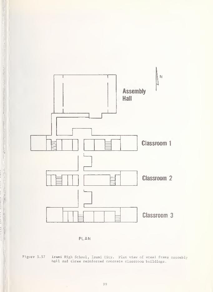
mi
Classroom 1
Classroom 2
Classroom 3
PLAN
Figure 5.57 Izumi High School, Izumi City. Plan view of steel frame assemblyhall and three reinforced concrete classroom buildings.
99

Figure 5.59 Izumi High School. Detail of panel over north entrance
to building 1.
100

101

x> ugumO *H i—
(
O & *Hk eCO Wcn qj co
ca oH CJ HI
O M-l S-l
0)
i—I i—I IS
o <3 co
•H rHft Qj
>> • cu cu cd
o &,•> cd
.H m rHO t-H
O £ 'H£ -U IHO UC/5 O -H
Cx; m00 CD
•H M M •
ffi C M X)•H cd 0)
•rl H MB h nj
3 -H 0J gn 3 .c cdH ,D U -d
CO
a)
00
co
m xO H•Hft>, •
•U 0)
o- cfl
iH 4-1
OO &X *->
O 3c/1 o
0)
>•H •
U CD
03 00.H cd
a) gs-i cfl
CO
•HrH4J
CJ -M•H -H
13-
13- CU
60 S-l
3 <D
H M-l
M-l
3COH
3
Pi
0) 0)
P.U o
QJ
M3ooH
102

Tohoku Institute of Technology (No. 17, Figure 5.3) . The campus consists of several buildingslocated southwest of the downtown area of Sendai. The building layout is illustrated in
Figure 5.64. The underlying soil conditions are reasonably good, being older terrace depos-its. All building are situated on sand and have pile foundations. As may be observed fromthe contour map in Figure 3.12, this area of the city is quite hilly. Buildings No. 3 and 5
(labeled on Figure 5.64), constructed in 1965, were inspected in some detail. There were no
strong motion instruments at the campus; however, ground accelerations at the site were esti-mated as 0.25g.
Figure 5.65 shows a partial view of the northeast facade on Building 5. Building 5 is situ-ated on a steep hill running to the southwest and the northeast side entrance is actuallylocated on the fourth-story of the eight-story reinforced concrete frame building. The upperfive floors contain large classrooms and open spaces. Damage to building 5 was substantial,particularly on the northeast side. Light fixtures were shaken down and bookcases, woodenlecterns, and statues were overturned. Surprisingly, the elevator remained functional. Wallpanels and floor diaphragms were cracked, (Figure 5.66). Such cracking was particularlynoticeable near shear walls of the stairwell on the northeast side of Building 5.
The columns on the northeast side of building 5 were seriously damaged. Figure 5.67 and 5.68show typical damage to exterior columns on the upper stories (stories 6-8). The infillpanels stiffened the exterior columns on the northeast side of building 5. In contrast,the exterior columns on the southwest side and the interior columns had no such stiffening,were relatively flexible (Figure 5.69) and suffered no apparent damage. The lower storycolumns on the northeast side showed significant shear cracking and spalling, as illustratedin figure 5.70 for one exterior column on story four. Crack widths exceeded 10 mm in severalinstances. Visible column ties were spaced 250 mm apart and were wrapped around the cornerlongitudinal bars without hooks. Interior transverse shear walls also showed diagonalcracks. In at least one case where the transverse wall was connected to a column, thediagonal crack in the wall continued on into the column. The transverse walls were connectedto the columns on the north side with the tie beams. Figure 5.71 shows one of these tiebeams following the earthquake.
Adjacent to building 5 on the northwest is a three-story reinforced concrete frame buildingcompleted in 1972. Figures 5.72 and 5.73 show this building and its walkway connection tobuilding 5. It was constructed according to the post-1971 building code. Although thebuilding was not entered, an inspection of its exterior revealed no signs of damage.
The northeast facade of building 3 is shown in Figure 5.74. This is a four-story reinforcedconcrete frame building, ten spans by two. While the relatively flexible interior columnswere undamaged, all of the exterior columns on the first-story cracked in shear just abovethe infill panels, as shown in Figure 5.75. Figure 5.76 illustrates this more clearly atone of the first-story columns on the northeast side of building 3. As can be seen, thereinforcement is undeformed. We were informed that core samples taken out of the spandrelsshowed no apparent damage to the concrete.
Around the entrance on the east side of building 3 and the southeast corner of its first-story, large areas of the tile facing and concrete underneath had spalled off, exposing thereinforcement (Figure 5.77). At this location, the vertical reinforcing bars were bentmanually during construction in order to force them to conform to the building working draw-ings. The reinforcement appeared to have less than 10 mm concrete cover. The interiorwalls of building 3 showed extensive diagonal cracking (Figure 5.78). However the interiorcolumns were apparently not damaged.
Figure 5.79 shows the area between walkway along the northeast side of building 5 (see alsoFigure 5.65). The backfill along the northeast side of building 5 has settled, causing dam-age to the stairs to the entrance of building 5 and adjacent retaining walls. Ground settle-ment also has caused the paving of the walkway to crack.
It was reported that building 3 will be demolished and building 5 will be repaired. Esti-mates of the costs of repair for these structures were unavailable.
Tohoku University Engineering and Architecture Building (No. 19, Figure 5.3) . Tohoku Univer-sity is located west of the downtown area. As may be observed from the contour map in Figure
103

Figure 5.64 Tohoku Institute of Technology, Sendai, plan of campus.
Hatching along walls of buildings 3 and 5 shows locationof severely damaged columns.
104

Tohoku Institute of Technology. Partial view of the
entrance and north facade of building 5. Most seriousdamage to columns occurred on this side of the building.
Figure 5.66 Tohoku Institute of
Technology. Typicalcracking of floor dia-phragms at the sixth floor
level, building 5.
105

0>
60cfl
Bnj
60 C° §O iHC O
O0) <4-l
H O
<4-l rHO -H
cd
0) -U4J 0)
3 Q
cn inS
CO
D60H
00
cd
o•H 0)
>-> 4-J
H
^ c60 gO 3HH •
O o uoS or£ 60
5^ ^ C
H O XI4-J rHCO -rl
O 3.
0) 4J
3 CD o4J >•H 0) 01
•U CO T3
CooHum4-1
3 0)
^ 60,£O cfl jj
6 uo cd oHt3 c
r-.
360
106

107

Figure 5.71 Tohoku Institute of Technology, Building 5. The tie beamover a sixth floor corridor connecting two shear wallsshows diagonal cracks at both ends.

Figure 5.73 Tohoku Institute of Technology. Passage between Building 5
and the building to its west.
Figure 5.74 Tohoku Institute of Technology, Building 3. General viewof the north elevation.
109

Figure 5.75 Tohoku Institute of Technology, Building 3.
Damage to the ground floor columns on the southside of the building. Similar damage is presenton the opposite side of the building.
Figure 5.76 Tohoku Institute of Tech-nology, Building 3. Typicadamage to ground story ex-terior column on north sideof building.
110

o o
H Uo
o u
0) 4-1
4-1 C3 M
co en
I—I 60 >-l 60CO C
xi x)(0 r-H
HO X
0)
S-l
360•H
0)
cn X-U
Ma m-i
•H oX) 4Ji
—
CO CO
•H c MH 1—1
3 0 O HM 3 cd
H 0! 4-1
o -a 0)
u H TJ60 CO
O -a 60H 01 X eo 60 4J •Hc rfl 3 aX f3 O Mo rt CO 001 M-l
H 0) C0) XI •H
4-1 4-J OJ
O 4J
aH
il) o 604-1 0 C3 GJ •H4-1 o £•H c o4J o M XI01 CO
H oor
60c
d H •H •H•H !~ -a
o rtj IU i—
i
Xi J 4-1 •Hc 0) 3H p OJ X<
<u
V4
360•H
111

Figure 5.79 Tohoku Institute of Technology, walkway and north entranceof building 5 shows settlement of backfill along length of
building
.
112

3.12 this area of Sendai is quite hilly. The underlying stable terrace deposits provide a
good foundation for buildings. The Engineering and Architecture Building on the Campus is a
nine-story reinforced concrete frame structure with pile foundation approximately 10 years
old. The structure was designed for a peak ground acceleration of 0.2g. A general view is
shown in Figure 4.4 and plans and elevations are shown in Figure 4.5. The building is
instrumented with two strong motion accelerometer instruments on the ground floor and theninth floor. The records are discussed in detail in Chapter 4. The maximum accelerations
jrecorded were 0.24 g at the ground floor and l.Og on the ninth floor, both in the N-S direc-tion.
i
The building performed very well in the earthquake. The February 1978 earthquake causedsome cracking in shear walls and window breakage. The maximum ground floor accelerationmeasured then was 170 gal. After the June earthquake, the diagonal cracks had widened, but'they still can be easily repaired. Figure 5.80 shows an interior transverse wall at the
ground floor. The decorative glazed tile veneer has cracked and spalled along a diagonalcrack in this wall. A number of windows on the upper stories were broken out and bookcases
! and filing cabinets were overturned. The main structural elements of the building appearedto be intact; however, minor cracks in the structural frame were reported at the lowest
levels. Assuming that the first mode dominated the dynamic response, the maximum displacementamplitude at the ninth-story, computed from A/(2nf)^ in which A = 980 cm/sec^ and f = 1 Hz,was about 25 cm (10 in).
5.5 Residences
Sunny Heights Apartment Building (No. 38, Figure 5.3) . This 190-unit private apartmentbuilding (Figure 5.81) is located on the east side of Sendai city on soft ground. It is a
14-story steel and reinforced concrete structure with a pile foundation, L-shaped in plan,
which was built in two sections about two years ago. The L-shaped plan is not conducive
jto earthquake resistance because torsional effects may be amplified. The earthquake causednumerous diagonal cracks throughout the height of the building, particularly around doorwaysand window openings, as shown on the east face of the building in Figure 5.82. The extensivecracking in the nonstructural panels adjacent to doorways created major problems for occu-pants attempting to open doors and windows in the first ten stories. The most severely dam-aged panels were oriented in the N-S direction. Despite the extensive damage to nonstruc-tural elements, the main loadbearing structural members appeared to be undamaged by the
earthquake.
There was extensive evidence of ground cracking and settlement adjacent to the foundation and
j
the walkway surrounding the building, as can be seen in Figure 5.83, where the support postbelow the bottom rail of the fence is exposed. The ground adjacent to the foundation sub-sided several inches in some cases. Portions of the parking area around the buildingappeared to have settled about 18 in (460 mm). There was a large water shortage tank located
I on top of the roof. It was shaken loose from its anchorage when the anchor bolts failed and
|the horizontal movement also caused the supply pipe to be damaged.
Single Family Dwellings . Major causes of the destruction to dwellings were landslides androckfalls, inadequate foundations, and construction which lacked lateral bracing. Manyhomes in the Sendai vicinity have heavy tile roofs, and literally thousands of buildings
' had damaged roofs of varying degrees. Falling tile resulted in some injuries.
A major cause of deaths and injuries was collapsing or falling walls made of stone or con-,
crete cinderblock. These walls serve as fences, for privacy, and as noise barriers. The
fJapan Building Code requires that walls over 1.5 m in height be reinforced in both direc-tions. Although some of the walls that failed contained reinforcing, in most cases theycontained less reinforcing than called for by the modern code. More fatalities resulted fromfalling walls containing inadequate reinforcing than from walls with none. Those with noreinforcing tended to crumble while those with reinforcing toppled as units on people whowere nearby or who held onto them for stability when the earthquake occurred. In some cases,the masonry block cores were grouted but the reinforcing steel had been omitted.
Figure 5.84 shows an example of the ground cracking resulting from subsidence in one of thehilly areas in Sendai. The loss of foundation support has caused extensive cracking in thebuilding walls. In Figure 5.85, the front steps and breezeway have separated some 30 cm
113

i iiiiwiignwii
Figure 5.80 Tohoku University Engineering Building. Damage to glazedtile veneer of shear wall at ground level.
Figure 5.81 Sunny Heights Apartment Building, Sendai. General view fromthe southwest.

Figure 5.82 Sunny Heights ApartmentBuilding. Detail of crack-ing of panels adjacent to
doorways . Such cracking wastypical at all levels on theeast facade of the structure.
Sunny Heights Apartment Building. Ground cracking and
settlement adjacent to walkway surrounding the building,
115


from the remainder of the structure due to ground settlement. There were many instanceswhere tile roofs were badly damaged even when the structure remained standing (Figure 5.86).
Two examples of collapsed masonry-unit walls are shown in Figures 5.87 and 5.88. The wallshown in Figure 5.87 was not reinforced, and crumbled during the earthquake. The wall inFigure 5.88 contained reinforcement but was not anchored adequately to its foundation andtoppled over practically as a unit.
Many single family dwellings were undamaged by the earthquake and, perhaps surprisingly,undamaged homes were found adjacent to larger engineered buildings that had been damaged.In a residential neighborhood at the bottom of the slope south of building 5 at TohokuInstitute of Technology, there was no visible damage to walls or tile roofs in any of thehouses. Similarly, only minor damage could be observed to homes at the bottom of the bluffnext to Tonan High School.
5.6 Summary
Considered collectively, severe damaged or collapsed reinforced concrete buildings shared a
number of common features. Probably most significant, they were all designed prior to the1971 revisions to the building code, at which time detailing requirements became more strin-gent. These older structures probably had little ductility and energy-absorbing capacitydue to the use of undeformed bars and widely spaced column ties, insufficient ties andanchorage of reinforcement at beam-column joints, failure to provide hooks on ties, etc.
None of the columns in failed buildings appeared to be spirally reinforced, which would bemore ductile in their behavior. Damaged buildings frequently had flexible first stories andrigid upper stories. Building layouts were irregular and caused structural discontinuities.Partial infilled spandrel walls between columns contributed to many column failures. Insome cases, the fate of an entire building rested on the integrity of a single column orwall. Mechanisms for load transfer following local failure through good floor plans, logi-tudinal spline walls and returns on shear walls would reduce the occurrence of completecollapse following failure of a single element. Stiffer structures with shear walls tendedto have less damage than more flexible buildings.
It should be borne in mind that many of the buildings investigated have been through tworecent major earthquakes (February 20 and June 12, 1978) without suffering damage. Thetotal damage due to the June 12th earthquake constitutes a small percentage of the totalcapital investment in buildings and structures, despite recorded ground accelerations of ashigh as 0.25g to 0.30g.
5.7 References
j 5.1 Okamoto, S., Introduction to Earthquake Engineering , John Wiley, 1973 (Chapter 8, esp)
5.2 Standards for Aseismic Civil Engineering Construction in Japan,Ministry of Construc-
tion Standard No. 1074.
,5.3 Watabe, M., "Summary of Present Codes and Standards in the World," 1978.
j5.4 "Design Essentials in Earthquake Resistant Buildings," published by the ArchitecturalInstitute of Japan, Elsevier Publishing Co., London, 1970.
:5.5 Uniform Building Code , 1976 Edition, International Conference of Building Officials,Whittier, CA. 1976.
5.6 "Tentative Provisions for the Development of Seismic Regulations for Buildings,"Nat. Bur. of Stand. Special Publication SP510 (ATC 3-06), Washington, D.C., June 1978.
5.7 "Building Code Requirements for Reinforced Concrete," (ACI 318-77), American ConcreteInstitute, Detroit, MI, 1977.
117

Figure 5.86 Typical damage to tile roofs in Sendai (Japan National LandAgency photograph)
Figure 5.87 Failure of unreinforced concrete masonry wall in Sendai (JapanNational Land Agency photograph)

119

6. EFFECTS ON INDUSTRIAL FACILITIES AND LIFELINES
6.1 Introduction
As discussed in Chapter 2, the preliminary Japanese estimates of damage at the end of June,1978 amounted to approximately $830 million. Of this total $455 million was to factories,stores and other business establishments. This represents about 55 percent of the total
damage. Damage to transportation, electrical, gas, and other lifeline facilities also repre-sents a substantial proportion of the remaining damage. Of course, these figures do not
include secondary types of damage, such as lost production for factories, lost revenue forpower and gas utilities, etc. Thus, losses to industry and other business establishmentsdominate the damage statistics from the Miyagi-ken-oki earthquake of June 12, 1978. Inthis respect, the earthquake is very different from the majority of damaging earthquakesthat have been reported in the literature.
Most of the significant structures in the Sendai area are modern structures, designed underadvanced earthquake engineering concepts. The construction and inspection practices alsoappear to be of generally excellent quality. However, most of the capital investment inindustrial facilities is concentrated in equipment systems, which typically are not protec-
ted against earthquakes to the same degree as the buildings which house them. This lowerlevel of seismic resistance may explain why a high proportion of the total damage was causedto factories, stores and other business establishments.
A small number of industrial facilities and lifeline structures were briefly inspected.Damage varied from negligible, at the Fukushima Nuclear Power Plant, to severe, at the SendaiGas Facility. Sendai is a large industrial city, with more than 6,500 business/manufacturingfirms. The investigated sample of facilities represents a small fraction of the damagecaused by the earthquake and of the facilities that were affected.
At the time of the reconnaissance, Japanese engineers were already conducting investigationsof some of the facilities mentioned herein, and detailed reports will be available in thefuture. This is particularly true of the power facilities in and near Sendai. Let us hopethat much of this important information will be translated into English.
This section of the report contains observations that were collected and recorded in a verybrief time, and undoubtedly contains some data errors. In addition, no attempt is made hereto analyze the structures and equipment or their performance. The primary objective of thisreport, and of the reconnaissance investigation, is to observe the performance of earthquake-resistant and other buildings, structures, and equipment.
The maps of Figures 1.1, 5.3 and 6.1 show the sites and facilities treated in this sectionof the report.
6 .2 Fukushima Nuclear Power Plant Complex
The Fukushima Nuclear Power Plant Complex is owned and operated by the Tokyo Electric PowerCompany. It is located on the Pacific coast of Fukushima Prefecture, about 7 km south ofthe town of Namie, and is southeast of the town of Fukushima. The site is approximately 140km from the epicenter of the earthquake. According to Chapter 3, faulting may have extendedas much as 60 km west of the epicenter. In that case, the plant site may be located about80 km (50 mi) from the nearest location of the source of energy, as shown in Figure 1.1
The complex has six nuclear units, as shown in Figure 6.2, for a total of approximately 4,700#MW, and is the largest nuclear power complex in the world. The site is heavily instrumentedwith strong motion accelerometers. Numerous records were made; the peak ground accelerationwas 0.125 g and the duration of strong motion was in excess of 30 seconds. Because most U.S.nuclear power plants are designed to criteria that is similar to the seismic motion to whichthe Fukushima site was exposed, this earthquake represents a unique event. This is the first J
*Prepared by Peter I. Yanev, URS/John A. Blume and Associates, San Francisco, California.
120


cu
xs uEh -H
C
U 3•H cd
33 «
COX•ri 4-1
CO vH3
cu 3>
4-1 •>
CM603 4-1
•H -H
O t=>
Xicn -
cd *
u mcu
3 4-1
cu -Hoo 3
00•H
vD »
Xi4-1 4-1 Cuc H nf
C8 3 MrH P t>0
P-lto
u 4-1 oCO m X!& 0) p.o HCm
o 0U 4-1 anj
0) UJ oH •H t
U bO M3 H 4-1 ]
K 1-4ec
1
cfl ee o W |H f-l
X, '4-1 o I
Cfl >>3 ^^ CU o3 M H t
a)f
122

time that a modern nuclear power plant was exposed to strong ground motion with long dura-tion. In addition, the presence of six units at one site represents a good statisticalsample.
Table 6.1 summarizes some of the pertinent data for this six-unit complex:
At the time of the UJNR team visit, June 23, 1978, 11 days after the earthquake, Units 1, 2,
3 and 5 were operating; Unit 6 was still under construction, but was essentially completed,
and it is believed that Unit 4 was scheduled to go into commercial operation soon. The abovetable indicates that the expected date of commercial operation for the unit was sometime inOctober of 1978.
Units 1 through 5 have a Mark 1 (light-bulb-torus) type of containment structure; Unit 6 hasa Mark 2 (over /under) type of containment (see Figures 6.3 and 6.4). USR/Blume Engineers
• formulated the seismic design criteria for the plant and performed the original seismicanalyses for the General Electric Company and the Tokyo Electric Power Company.
The plants are founded on a competent soft mudstone formation with a thickness in excess ofi 300 m. Extensive cuts were necessary to level the site and to reach the mudstone, which has
a shear wave velocity of about 600 m/sec.
jUnit 1 was designed for a peak ground acceleration of 0.18g and a response spectrum based on
' the Taft record from the Southern California (Kern County) earthquake of 1952.
The reconnassiance team inspected the exterior of Unit 1 and the exterior and interior ofUnit 6, including the containment structure, the reactor vessel pedestal, some of the equip-ment on the refueling floor, some of the equipment in the reactor building, the underside
L of the control rod drive in the containment, miscellaneous critical and non-critical piping,
I various critical and non-critical cable trays, the reactor building, the turbine building,the turbine overhead crane, and various auxiliary structures, equipment and tanks (see Fig-ures 6.5 through 6.9)- There was no damage or evidence of working of connections in any
2 of the inspected areas. The only reported damage to the complex was to some non-critical
a Ielectrical insulators, shown in Figure 6.10, some distance to the west of Units 1 and 2
(see the following discussion on the effects to electrical insulators at the Sendai Substa-j
i
tion in Izumi, near the city of Sendai).
Units 1 and 6 are instrumented with between 20 and 30 strong motion accelerometers and much
j :valuable information was obtained from the earthquake. The peak ground acceleration, whichcould be considered to be a "free-field" acceleration (see Figure 6.11) is 0.125g. (EW
direction). The corresponding accelerations in the NS direction and Up/Down directions areO.lOOg and 0.050g. The strong motion exceeds 30 sec in duration. The reported maximum
i response acceleration in the buildings is reported to be about 0.5g. Higher accelerations
~i would be expected in instrumented equipment or piping systems. It is interesting that
0 records were obtained from instruments located on the base slabs of the two units and at
1 downhole instruments, about 30 to 40 m below two of the containments. Thus, it may be pos-: sible to conduct a detailed soil-structure interaction study for the plant.
[Tokyo Electric Power Company is also conducting model studies of the plant at the site. Al/15th scale model of the containment has been constructed a few hundred yards away from thenuclear units. The model, shown in Figure 6.12, was also instrumented, including anotherdownhole instrument, and additional records are available from the study. At the time of theinvestigation the company was beginning to evaluate the recorded data.
6.3 New Sendai Power Plant, Tohoku Electric Power Company
The New Sendai Power Plant, owned and operated by the Tohoku Electric Power Company, is
located on the Pacific shore, 15 km east of the center of Sendai. The site is adjacent to
the Sendai refinery of the Tohoku Oil Company which suffered extensive damage from theearthquake (as discussed elsewhere in this chapter). The plant shown in Figure 6.13, has
two Mitsubishi oil-fired boilers. Unit 1 was completed in 1971 and has a capacity of 350
MW; the 600-MW Unit 2 was completed in 1973 and is the largest unit of the company. Thetotal capacity of the Tohoku Electric Power Company is 5,715 MW, this plant representingabout 17 percent of that capacity.
123

cfl
HCJ
uCU cfl
a ua oi
o a,o o
—
1
|
cfl at rH <r X) X C^3 CU 4-1
4-1 o \CJ ij CU i—
.
ro <r oCtJ o f"),
—
4
,—
i
• 1
oo -a D XiH 01 01 r—
,
!-l .c ^o o 3 o"
Cfl r-l r-H
C 0)
O so ^ o o CN X> 00H nj if"?
4-) 4J r—
)
CO
uo4-1
cj cfl cd 2a a a a E au H H •H H •H4J *
Cfl
.
CO Cfl CtJ cu
c -M K>
OCJ)
4-1
o wOJ
4-1 01 H'H c o 0 J3 Xl OJ= •H (J cj (j 'H CJ
u 60 CO Cfl cfl _C CO
i-l c CTJ 4J gj cfl
<3 M X) o -H cPrl [V] £-1 33 f—
j
fa]
!-J •H cfl cfl
O .C XI -O4-J 0) fj •H n3 •rH rrj H«J •H 03 X! rO X Xl XIl-l rH 4_) CO •r-i CJ CO01 D. o r". Cfl oc Q. 'fi u CO fHCU 3 o •H o'J CO fa1 E—
i
j-Jr__(
o
CTJ
(J XICU •H rrj H Cfl
o •H x: -O XI XI4-) rH co •H rj •Ho a- Q _C o3 r- wCfl &. U] 4_l CO CJ)
01 3 o H Qoi CO H H
0) ^a. Oi c^; ^H cv; aj>. 3 s 3 3 SH 03 SQ pq aa
<-j> <]- <j- -1' o4_) 0) \£) X 'O XI CO o'-2 ,—
)
ca cfl CtJ cfl cd cfl
g g g g g•H •H •H •H H •Hx: XJ x: X! x:co co w CO CO COrj
v;
3 3 3 3 3fa fa &4 fa fa fa
."i
_
CD 0) CU 01 01 0)rj
O Q Q Ocd cfl Cfl 03 cd cfl
0 E s e E a•H •H H •rH H •Hx: X! x: X Xi x:co CO CO CO CO co
3 3 3 3 3 3^C
3 3 3 3 3 3fa fa fa fa fa fa
S-i
13
3S-4
XICU
faI
-a
va•H3OCO
>-l d)
0 >>•u 3a mcfl
0) cfl
01 3CU
S-4 2cu
4-1 >-l
Cfl Cfl
S CU
rHoo oa 3
•H0 ••
to 01
o1 »-l
3p3 oS CO05 w
124

125

>
Figure 6.4 Fukushima Nuclear Power Plant: Typical elevation view throughthe reactor/containment building and the turbine building and
a plan view across the refueling floor of the reactor buildingand the operating floor of the turbine building.
126

Figure 6.5 Fukushima Nuclear Power Plant:
large, undamaged safety relatedwater storage tanks that arelocated between units 1 and 5.
Figure 6.6 Fukushima Nuclear Power Plant: a view of the bracedsteel frame roof and the overhead crane of the turbinebuilding of Unit 6.
127

Figure 6.7 Fukushima Nuclear Power Plant: a partial view of the Unit 6 controlrod drive and its supports. The unit is still under construction and
was more than 95% completed at the time of the reconnaissance. Therewas no apparent damage or any evidence of working connections at thissystem or at the other systems of Unit 6 that were examined.
Figure 6.8 Fukushima Nuclear Power Plant: a typical view of massive seismicand/or pipe whip bracing of critical piping inside the reactor buildingof Unit 6. The equipment showed no evidence of damage. This unit is
still under construction.
128

Figure 6.9 Fukushima Nuclear Power Plant: a partial view of the controlroom of Unit 5. At the time of the visit on June 23, 1978,11 days after the earthquake, this unit was operating.
Figure 6.10 Fukushima Nuclear Power Plant. Broken ceramic insulatorswere the only damage reported for the site. The damagedinsulators had been replaced, as illustrated above, withinhours after the earthquake and before the reconnaissance visit.
129

Figure 6.11 Fukushima Nuclear Power Plant: a view of some of theauxiliary structures to the north of Unit 1. Free-fieldacceleration was recorded in the water treatment building(the white, 1-story building in the middle of the photograph),which is located approximately 100 m from the Unit 1 contain-ment structure. The SMAC instrument recorded a peak groundacceleration of approximately 0.125g.
Figure 6.12 Fukushima Nuclear Power Plant:
view of the l/15th scale model
of the containment of one of
the nuclear units. The free
field and downhole instrumenta-
tion is located away from the
test structure (note the cables
to the right)
.
130

Figure 6.13 New Sendai Power Plant, Tohoku Electric Power Company: a generalview of the two-unit, oil-fired power plant. The turbine buildingis in the foreground, and the two boiler structures are in the back-ground. Unit 2, the large unit, has a 600-MW capacity. Unit 1has a capacity of 350 MW. Note the massive seismic bracing to thecombined stacks and to the boiler support frames. (Tohoku ElectricPower Co. photograph)
131

Because the SMAC accelerograph at the station was being inspected at the time of the earth-quake, no records were obtained. However, the plant's seismic alarm, located at the levelof the turbine operating floor, was triggered at approximately 0.15g. Because the plantis closer to the epicenter of the earthquake and the assumed area of faulting (as discussedin Chapter 3), it may be assumed that the ground motion at the plant was somewhat strongerthan in the city of Sendai where the recorded peak ground accelerations varied between 0.20and 0.40g.
The plant is located in an area of recent alluvium and on filled land; the depth of uncon-solidated sand is approximately 15 m (45 ft).
Both of the units were damaged during the earthquake, and the plant was shut down for 6 daysfor repairs. Total damage to the facilities of the Tohoku Electric Power Company is approx-imately $15 million; estimated damage to the plant accounts for about 10 percent of the
loss. The total assets of the company in property, plant and equipment for Fiscal Year 1976were $3,840 million. Damage from this earthquake caused a loss of about 0.4 percent of
those assets. The plant was operating at the time of the investigation of June 24th, 12
days after the earthquake.
Three types of damage occurred at the plant: (1) damage due to local, minor settlement, (2)damage to the structural and architectural elements of buildings, which was minor, and (3)
damage to the equipment, which constituted the bulk of the loss.
Minor settlement occurred throughout the site. Much of this settlement occurred in thevicinity of buried piping (Figure 6.14 ). About 1 cm of settlement occurred at the intakestructure and the paving around the structures was cracked; however the structure was opera-tional and did not seem to require repairs (Figure 6.15).
Building damage was limited to some of the interior walls of the administration building andto the facing precast panels of the turbine buildings (Figure 6.16). Some of these panelswere loosened; presumably the attachments to the steel framing were damaged.
Both Unit 1 and Unit 2 suffered damage to tubing inside the boilers (Figure 6.17). A smallfurnace platen cooler tube inside the slag screen was sheared in the Unit 1 boiler (Figure6.18). A similar failure occurred in the boiler of Unit 2 to one of the reheater spacertubes. The suspended boilers and their structural supports also pounded against one anotherand also sustained some damage (Figure 6.19).
There was no other reported damage. The turbine pedestals and the operating floor of theturbine buildings in Japan are usually separated by a 3 to 4 inch gap and, in this case,
there was no pounding between the two structures.
6.4 Sendai Substation, Tohoku Electric Power Company
The Sendai Substation of the Tohoku Electric Power Company is located on a low hill in thecity of Izumi, about 7 km north-northeast of the center of Sendai. The substation is a
large, multilevel complex. It was constructed during the last few years to the currentJapanese seismic code, which specifies a minimum design acceleration of 0.20g for low-risestructures
.
Figure 6.20 shows a general layout of the complex. The upper portion of the substation is
the high-side 274 KV bus, and the lower portion of the substation is the low-side bus whichis 154 KV. Locations of damage to equipment are circled in the figure.
Extensive cuts and fill were necessary because of the topography of the hill on which thestation was located. The filled areas are indicated in Figure 6.20. Some of the fills, allof which were engineered, were as deep as 15 m (45 ft). The underlying bedrock is a compe-tent, soft mudstone which was left exposed with slopes exceeding 60°. Due to seismic consi-derations, the most important electric components of the station were placed on the cutportions of the site, over a mudstone foundation. For example, all of the main transformerswere placed on the cut sites, as shown in Figure 6.20. According to utility engineers,there seemed to be no difference in the amount of damage sustained by equipment whether onfills or on cuts. There was extensive damage to equipment in all parts of the facility. It
132

igure 6.14 New Sendai Power Plant; Tohoku Electric Power Company: Aview of the entrance area to the power plant showing settle-ment of fill and subsequent repair work to the pavement.The pavement settled approximately 15 cm (6 in) and wasprimarily in the vicinity of a backfilled undergroundpipeline
.
gure 6.15 New Sendai Power Plant, Tohoku Electric Power Company: damagearound the water intake structure from minor settlement. Otherexamples of minor settlement were observed throughout the site.
133

Figure 6.16 New Sendai Power Plant, Tohoku Electric Power Company: a loosenedexterior facing panel in the turbine building. This was the onlyobvious damage to the exterior of the structure. The shear wallsof the adjacent administration building showed extensive cracking.
Figure 6.17 New Sendai Power Plant, Tohoku Electric Power Company. The arrowpoints to the location of the damaged horizontal spacer tubes in the600-MW boiler of Unit No. 2. (See Figure 6.18).
134

Figure 6.18 New Sendai Power Plant, Tohoku Electric Power Company: damage to
the two boilers consisted of shearing of spacer tubes for thefurnace platen cooler tubes inside the boiler. (Tohoku ElectricPower Company photograph)
Figure 6.19 New Sendai Power Plant, Tohoku Electric Power Company: a view of
the exterior of the boiler walls showing evidence that the suspendedboiler had pounded against the surrounding support structure.(Tohoku Electric Power Company photograph)
135

Sendai Substation, Izumi: plan of the facility showing the
location of damaged equipment (circled) . The solid contour
lines indicate areas that were filled.
136

was immediately apparent during the investigation (June 24, 12 days after the earthquake),that all of the equipment was adqequately anchored to its foundations, or braced. No over-turning or other structural bracing failures were noted. Apparently, the damage was limitedto various ceramic insulators in lightening arresters, potential devices, circuit breakers,transformers, bushings, reactors or line traps, switches, etc. Thus, there was a strikingdifference between the damage to this substation, as compared to the damage at the SylmarConvertor Station from the San Fernando, California earthquake of February 9, 1971. In thelatter case much of the damage was caused by the overturning of equipment with inadequateanchorages or supports.
By June 24th much of the damage to the substation had been repaired (Figures 6.21 and 6.22),and the damaged equipment (Figures 6.23 through 6.27) had been dumped in piles on the peri-phery of the substation (Figure 6.28). Repairs were still going on to the bushings andlightening arresters of some of the main transformers (Figure 6.29), and various pieces of
equipment had not yet been replaced. The total damage at the substation is estimated to be
on the order of $15 million.
A Japanese team has been assembled to conduct a special investigation of the performance ofthe substation during the earthquake.
6 .5 Haranomachi Plant of Sendai City Gas Bureau
The Sendai City Gas Bureau's Haranomachi Plant, located approximately 3.7 km northwest of thecenter of Sendai, suffered major damage. The total collapse of a large propane gas holder(Figure 6.30) was partially responsible for the stoppage of gas for the city. It was esti-mated that gas services for the city would not be restored until the end of June, some threeweeks after the earthquake. At the time of the investigation (June 25, 13 days after theearthquake) many restaurants in Sendai were closed because of lack of gas. According to
Chapter 2 about 60 percent of the 200,000 households in Sendai are dependent on gas forheating and cooling, and as of June 28, 1978, 22,000 of these households were still without
|
gas. An additional 10,400 households elsewhere in the prefecture were also without gas.
The holder diameter was 38 m; its height was 27 m. At the time of the earthquake, the holdercontained 14,000 m of propane gas, at the relatively low pressure of 1 kg/m , and held waterin a 9-m section at the bottom of the structure. The tank had at least two, but more prob-ably three, telescoping sections constructed of riveted plate, 1 cm (3/8 in.) thick, stif-fened with ring stiffeners at approximately 2 to 3 m. The tank was surrounded by an outsidecontainment dike also constructed of riveted steel plate.
The collapsed holder caught on fire shortly after failure, and all of the stored gas wasconsumed. The fire burned out, or was extinguished, about 25 minutes later, and did notspread to the nearby high pressure propane tanks. The most serious damage to the gasfacility was caused by the collapsing holder. It struck the nearby pipeway for many of the
tanks at the plant, causing much damage to the piping systems and other associated equipment.Figure 6.31 shows the collapsed holder and the damaged pipeway just after the earthquake.At the time of the investigation a new pipeway had been erected on the concrete pedestals ofthe old pipeway, and repairs of the pipelines were proceeding, Figure 6.32. These pipes
|service the remaining undamaged gas tanks.
There was evidence of damage throughout the facility (Figures 6.33 through 6.38); however,
j none of the other tanks at the facility are believed to have suffered major damage. Some
j
damage was due to pounding between buildings and pipes that penetrated the building wallsJ (Figure 6.39). Unanchored pipe supports often moved on their pedestals, and reinforcedconcrete block structures suffered damage to their structural elements.
6.6 Sendai Refinery, Tohoku Oil Company Ltd.
Figures 6.40 through 6.49 give an overview of damage to the Sendai Refinery of the Tohoku OilCompany, Ltd., which is located on shore about 15 km east of the center of Sendai and adja-cent to the New Sendai Power Plant. A plan of the refinery, which is a major installationand was completed in 1971, is shown in Figure 6.40. The refinery covers an area of 1,600,000
j
. Its capacity is approximately 100,000 barrels/day.
137

Figure 6.21 Sendai Substation, Izumi: a general view of a portion of one of
the buses. Damage was not reported to these steel structures.
Figure 6.22 Sendai Substation, Izumi: three replaced 3-phase circuitbreakers. This type of T-shaped circuit breaker suffered a
high percentage of damage. Often the three symmetrical guidesbroke before the main stem. In all cases the structural steelsupports appeared to be undamaged.
138

Figure 6.23 Sendai Substation, Izumi: typical damage to 3-phase T-shapedcircuit breakers (as shown in previous figure) . Note the completefailure of one and the damage to the three guides of the secondcircuit breaker. All steel supports appear to be undamaged. Thephotograph was taken immediately after the earthquake before repairswere initiated. (Tohoku Electric Power Co. photograph)
Figure 6.24 Sendai Substation, Izumi: another three failed 3-phase, T-shapedcircuit breakers. Note the failed main stems, the loose guide wiresand the undamaged steel supports which are attached to their founda-tions. (Tohoku Electric Power Co. photograph)
139

Figure 6.25 Sendai Substation, Izumi:damage to a circuit breaker(right), and two lighteningarresters (center) . Thebushings of the transformerin the background appear to
be undamaged; however, thelightening arrester is lean-ing. (Tohoku Electric PowerCo. photograph)
Figure 6.26 Sendai Substation, Izumi: Severe damage to circuitbreakers (center of photograph - note the failed columnsof live tank design, probably with gas reservoirs), currenttransformers (with the tapered bushings - some of the stemsare also damaged) , and reactors (to the left) with presumablybroken connections. (Tohoku Electric Power Co. photograph)
140

igure 6.27 Sendai Substation, Izumi. Severe damage to several
circuit breakers of live tank design. Note the lackof damage to the structural steel supports and the
steel components of the equipment. (Tohoku ElectricPower Co. photograph)
igure 6.28 Sendai Substation, Izumi; one of several piles of brokenequipment, including several line traps or reactors in
the back (note the damaged base of the left stem) and
the horizontal tanks of several circuit breakers of the
live tank type (in the foreground are the failed columnsof the circuit breakers and of other equipment)
.

Figure 6.29 Sendai Substation, Izumi; a repaired but still disconnectedtransformer. All of the transformers at the substationlost some bushings or lightening arrestors. Some damagedparts were being replaced at the time of the investigation.
Figure 6.30 Haranomachi Plant, Sendai City Gas Bureau: an overallview of a collapsed propane gas holder and some of thesurrounding propane storage tanks and affected pipewayand equipment. (Kahoku Newspaper Co. photograph)
142

K~
Figure 6.31 Haranomachi Plant, Sendai Gas Bureau; collapsed gasholder and the damaged adjacent pipeway structure justafter the earthquake, (Sendai Gas Bureau Photograph)
Figure 6.32 Haranomachi Plant, Sendai City Gas Bureau: The newlyerected pipeway, with the collapsed holder in the back-ground. Note the undamaged pressurized propane gassphere in the back.

Haranomachi Plant , Sendai City Gas Bureau
:
damage to piping and other equipment and supportscaused by impact from the collapsed gas holderand the adjacent pipeway. The newly erectedpipeway is to the right.
Figure 6.34 Haranomachi Plant, SendaiCity Gas Bureau: damage to
the telescoping gas holderand to some of the nearbypipeways and equipment . Thetrusses are portions of theoriginal support structurethat had surrounded the tank.
144

Figure 6.35 Haranomachi Plant , Sendai CityGas Bureau: buckling damageto the lower portion of onesegment of the gas holder.
Figure 6.36 Haranomachi Plant, Sendai City Gas Bureau:a fracture of the 3/8-in. plate wall of thecollapsed gas holder. The length of thefracture is approximately 1.5 m (5 ft).
145


Figure 6.39 Haranomachi Plant, Sendai City Gas Bureau: a damagedreinforced concrete block structure. Some of the damagewas due to pounding between the large diameter pipe andthe structure at the pipe penetration.
Figure 6.40 Plan of the Sendai Refinery, Tohoku Oil Company, Ltd.Tanks are shown as circles in the plan. The circlesthat represent the three failed TC tanks have beenblackened; ones that represent the three other damagedtanks are marked with an X. The refinery structuresare located to the right of the tank farms.
147

Figure 6.41 Sendai Refinery, Tohoku Oil Company, Ltd.: an overallview of the refinery's tank farm. The spilled oilappears as the dark area of the photograph. (TohokuOil Company photograph)
Figure 6.42 Sendai Refinery, Tohoku Oil Company, Ltd.: one of thethree failed storage tanks. The damage illustrated is
due to suction caused by rapid evacuation of the oilthrough the ruptured connection of the base and wallof the tank. The several tanks, of similar size, inthe foreground are thought to be undamaged.
I \

Figure 6.43 Sendai Refinery, Tohoku Oil Company, Ltd. Two otherfailed TC oil storage tanks.
149

Ml**"
0) M00 Crt tu rt
u -c 4-1
o uV CD
w 4-1 60% O rt
0) 0) oo CJ 4J
rt u o CO
-ci 4-1 U01 'U O H)
M l-l 4-1
u rt rt
rt CD 4-1 ISrH
00 cu
<! rt •AU th
X• 0)
X) rH4-1 P.-i e
o« o
>>C!
rt >-i
a. a)
6 cO -HC_> 4-)
a)
i—i w•i-i
o c•H
3 rt
^ eo,c a)
o siEH 4-1
« !-i
rt
5-i cu
0) cs•H ^4-1 4-1
a) 4-1
OS QJ
•Hrt to
4J 4J
01 t-H
Q O
• t-J
oo o
•H O^ So rt
o
•H
a00•H ^CO O
rt
t3 ^c cai rt
C/3 4-1
0 3e o0) I
•H X)U 0)
0) r-l
C4 rHX 301 a. co
o
01
M300
150

Figure 6.46 Sendai Refinery, Tohoku OilCompany, Ltd. : an undamagedLPG storage tank. Note theheavy diagonal bracing inthe supporting structure.
Figure 6.47 Sendai Refinery, Tohoku Oil Company, Ltd.:
a partial view of the refinery.
151

Figure 6.48 Sendai Refinery, Tohoku Oil Company, Ltd.: ground
settlement at the refinery.

As illustrated in Figure 6.40, the complex is divided in two parts by a river and some portfacilities. The new Sendai Power Plant is to the east (right). The tank farms and the
refinery complex itself are located on the eastern portion, adjacent to the port facilities,which can handle super tankers. The gas producing and pumping facilities are located on the
western half of the complex. The land transportation facilities are also located on the
west side.
The damage of the refinery and the lost oil represent one of the major losses from the
Miyagi-ken-oki earthquake. At the time of the investigation (June 24, 12 days after the
earthquake) the total amount of damage was unknown, as investigations were still continuing.It was expected that the damage investigations and evaluations by the company and the localfire authorities would continue well into July. The reported intensity at the site was 5 onthe JMA scale, and the epicentral distance is approximately 100 km. The adjacent powerplant had an accelerometer , which did not operate, and a 'seismic alarm, located at the tur-bine building operating floor, which was triggered by the earthquake. As the alarm was set
at approximately 0.15 g, the motion was probably in excess of 0.15 g. In all probability,the motion exceeded 0.25 g.
The investigation revealed that the complex had been designed to reasonable seismic cri-teria. All of the observed tanks, equipment and piping systems were anchored and no over-
I
turning failures were observed. As discussed further, some of the tanks were designed for a
0.30 g peak ground acceleration. Major portions of the facility were located on engineered| fill. There was some evidence of settlement, however it could not be determined if the
settlement had occurred in filled areas.
There are at least 87 storage tanks in the facility. The tanks have different designs, anddifferent functions; some stored oil, others stored liquid propane gas (LPG); some had fixedroofs, others had movable roofs. Three large tanks containing refined fuel called Top Crude(TC) failed, spilling approximately 68,100 kl of oil. The capacity of the tanks was 85,000kl. The surrounding reinforced concrete dike could accomodate only 35,000 kl. The oilovertopped the dike, inundated much of the refinery area, and spilled over into the port(Figure 6.41). Because the surface soils are sandy, it is believed that much of the oilthat was contained in the dike subsequently leaked under the walls and contributed to thespill.
At the time of the investigation a thick film of oil still covered much of the refinerygrounds. Thus, the fire hazard was great, and the investigating team was unable to observethe details of the damage to the tanks. It is believed that the tanks shown in Figures 6.42through 6.44 failed at their bases. The oil drained rapidly, causing a vacuum inside,which imploded the tanks. Three other tanks suffered damage and will need repair.
Another large water storage tank experienced interesting damage (Figure 6.45). The weldedsteel plate tank was anchored with bolts, spaced at approximately 6 ft (2 m), and embeddedin a continuous concrete pad. The bolts around the entire circumference were stretched,or more likely, pulled out from their embedment from 1 to 6 in (2.5 to 15 cm). However,there was no apparent buckling or other damage to the steel base of the tank.
Visual inspection of several of the LPG tanks at the refinery, revealed no damage. Therewere minor cracks in the concrete supports and some spalling of paint in the steel connec-tions due to working. The tanks were designed for 0.30g peak ground acceleration. As
illustrated in Figure 6.46, the tanks were heavily braced with diagonal braces with circularcross-sections.
Figure 6.47 shows a partial view of the refinery, including several towers, heaters, boilersand a heavily braced steel stack. These structures are reportedly undamaged. The team wasable to view some of the lower structures; no structural damage was observed. At the timeof the reconnaissance, most of the equipment within the refinery complex had not yet beenchecked for operability. There was concern that some of the control equipment, and otherminor operating equipment might have been damaged. Local settlements may have damaged someequipment, as illustrated in Figure 6.48. The pipeway support structures that were examinedshowed no significant damage.
153

Most of the refinery was shut down during the earthquake for its annual inspection. Thus aserious fire hazard from the spilled oil fortuitously was averted. During the investiga-tion, the company was checking much of the equipment throughout the complex for damage, anda large scale clean-up effort was under way. The seriously damaged tanks were still notapproachable because of the spilled oil.
6 . 7 Concrete Batch Plant, Sendai
This concrete batch plant is probably a representative small facility for the many thousandsof similar (in size) industrial or manufacturing establishments in the metropolitan area ofSendai. It was operating at the time of the investigation. The facility sustained varioustypes of structural damage to equipment and tank supports, buckling of storage tank walls,damage to structural steel framing, etc. It is very possible that this damage (and damageto similar small facilities), was not reported and is not included in the preliminary damagestatistics that were available to the UJNR team members. The plant was inoperable for two
days after the earthquake while repairs were being carried out. Because most of the damagewas to structural steel braces, it apparently was easily repairable. In many cases thebolted connections of the braces to the vertical load carrying supports were sheared.Repairs were usually of two types: (1) the undamaged braces were realigned and the braceswere welded to the gusset plates (in lieu of the previous bolting) and (2) damaged (presum-ably buckled) braces were replaced with new members, which were also welded in place (Fig-ures 6.50 and 6.51). The most remarkable feature of the repairs was how quickly the workwas completed, particularly at a time when skilled labor was presumably in short supply.Some serious structural damage had not yet been corrected at the time of the investigation;however, that damage was not to operating equipment and did not affect the day-to-day pro-duction. Except for some of the foundations and lower supporting structures, which werenot damaged, all of the structures, tanks, and equipment at the site are made of steel.
A large welded steel plate storage tank, containing sand and gravel, and reportedly fullduring the earthquake, which was supported on a massive concrete pedestal, suffered bucklingalong several locations at the base of the steel plate (Figures 6.52 and 6.53). It seemsapparent that the buckling was caused by overturning forces, rather then by sloshing of thecontents. The tank and its superstructure and support structure did not experience anyother damage.
One of the light steel-framed structures at the plant was damaged, as shown in Figure 6.54,apparently because of inadequate lateral bracing. The differential displacement caused by
the failure of the structure was responsible for damage to a connecting vertical steel stackand associated piping. The stiffer first floor reinforced concrete structure was undamaged.A similar structure, Figure 6.55, located in the immediate vicinity of the plant and pro-perly braced with light steel cable or rod braces, did not suffer damage. The latter typeof construction is quite common in Sendai, and generally appeared to experience no signifi-cant damage.
154

Figure 6.50 Concrete Batch Plant, Sendai: view of therepaired supporting substructure of a cementbin and related equipment . The sheared boltsat the brace connections have been removed andthe braces have been welded to the gusset plates.Some of the buckled braces have been replacedentirely.
155

Figure 6.52 Concrete Batch Plant, Sendaia large gravel-and-sand-storage tank experiencedbuckling of the welded steelplate at its base.
Figure 6.53 Concrete Batch Plant, Sendai: a detailed view of thedamaged base of the sand and gravel storage tank.
Note the closely spaced anchor bolts. Similar damageoccurred at several locations along the circumference
A
156

Figure 6.54 Concrete Batch Plant, Sendai:displacement due to damage to
the light, unbraced steelsuperstructure damaged thevertical stack and the con-veyor belt structure.
Figure 6.55 Concrete Batch Plant, Sendai: a typical undamagedlight steel-framed structure braced with cable or
rod braces.
157

7. EARTHQUAKE PERFORMANCE OF TRANSPORTATION LIFELINES*
7.1 INTRODUCTION
The Japanese Ministry of Construction (JMOC) reported that 78 highway bridges had been dam-aged as a result of the June 12, 1978, Miyagi-ken-oki earthquake. There were, however, no
reports of damage to a multitude of pedestrian bridges in Miyagi prefecture. Only thosebridges having an estimated repair cost of 1 million yen ($5,000) or more were included in
an inventory of damaged highway structures. Although damage to bridges was principally con-fined to those structures within Miyagi prefecture, some bridges sustained moderate damagein Iwate and Fukushima Prefectures also. Of approximately 100 bridges in Sendai, only fourwere reported as having been damaged. Two of those bridges were inspected by UJNR teammembers. The majority of damaged bridges were located in an area extending about 90 kilom-eters northeast of Sendai (see Table 5.1 and Figures 5.3 and 6.1).
The UJNR inspection team visited 13 highway bridge and four rail bridge sites, viewingrepresentative damage. Typical types of damage included flexural and torsional cracking of
concrete piers, displaced of dislodged girder bearing devices, settlements of abutments orpiers, and vibratory induced settlements of fills at bridge approaches.
Significant strong motion records were obtained from the Kaihoku Bridge, 65 km northeast ofSendai and the Date Bridge about 75 km southwest of Sendai (just north of Fukushima City).Only the Kaihoku Bridge site was visited by UJNR team members. Maximum ground accelerationat Kaihoku was 294 gal, while maximum pier acceleration was greater than 500 gal. No
ground record was obtained from the Date Bridge site. Maximum pier acceleration was 475gal.
The Japanese National Railways stopped all trains following the earthquake until safetyinspections could be made. Most damage was caused by blockage of track, by landsliding, andmost train service was restored within 3 days following the earthquake. Heavy pier damageoccurred at a rail bridge site which required 10 days to reopen.
There was no reported damage to highway tunnels in Miyagi prefecture. Only one railwaytunnel on the New Sendai Shinkansen Line (fast train) northeast of Sendai was reported to
have suffered minor, hairline cracks in its concrete lining.
The public bus system in Sendai was not adversely affected by the earthquake.
It is reported that airline traffic to and from Sendai was interrupted only briefly while a
quick inspection of the airport was made by airport officials. Minor damage of the terminalwas reported.
No major damage was reported at Shiogama Port 18 km northeast of Sendai. Some pavementsettlement was noted. One free field strong motion record obtained from a SMAC B2 instru-ment at Shiogama Port recorded maximum accelerations of 266 gal in the N-S direction, 288
gal in the E-W direction, and 166 gal vertical component. For further discussion of strongmotion records, see Chapter 4 of this report.
7.2 BRIDGE DESIGN CRITERIA
A comparison of current (1978) seismic bridge design criteria used in the United States andin Japan is presented prior to the documentation of bridge damage.
The bridges which were damaged in the June 12 earthquake in Japan were designed and con-structed using pre-1971 design criteria. Most of the damaged bridges are two-lane struc-tures, situated in rural areas northeast of Sendai. The most noticeable difference in theconstruction of bridges is the use of massive substructure elements. Most Japanese bridgepiers are very large, massive appearing structures which are designed to resist seismicforces. Subtructures in the United States are designed for lower seismic force levelsand rely on ductile behavior of columns.
*Prepared by James D. Cooper, Federal Highway Administration Washington, D.C.
158

For purposes of comparing current U.S. and Japanese seismic design criteria the 1977 Ameri-can Association of State Highway and Transportation Officials (AASHTO) and the 1971 JapanRoad Association (JRA), "Specifications for the Earthquake-Resistant Design of HighwayBridges" are considered (see Refs. 7.1 and 7.2). The 1977 AASHTO criteria is an adaptationof the criteria developed by the California Department of Transportation in 1973. The 1971JRA criteria superseded provisions found in several different Japanese bridge codes, andwere established in order to give a common basis for the seismic design of bridges. Theyemphasize the method of evaluating seismic forces, the basic principles to be exercisedfor testing site soil conditions, and general provisions to be observed in structuraldetailing
.
Both criteria allow for the use of three alternate approaches for determining design earth-quake force levels. The most commonly used is the equivalent static force method. For morecomplex bridges, either a response spectrum analysis or full dynamic analysis can be per-formed. The more common, equivalent static force method used by both countries is compared.
Table 7.1 summarizes the 1977 AASHTO and 1971 JRA criteria.
The approach is similar in that the lateral force design coefficient is comprised of fac-tors relating to location (A and v^'kg), soil conditions (S and V2), and structure response(R/Z, F, and 6). In addition, the JRA criteria incorporates an importance factor, v^. Thevertical seismic force is generally not considered in either criteria, except in the JRAcriteria for the design of bearings at the connection of the super and substructures. Thevertical design seismic coefficient of k
v= 0.1 is used.
Use of either criteria requires the computation of the fundamental period of the bridge.The AASHTO criteria specifies the following formula to approximate the period (T) of thestructure
:
T = 0.32/ W/P
which W is the dead load and P is the total uniform force required to cause a 1-inch maximumhorizontal deflection of the total bridge. The JRA presents several alternate equations for
use in estimating the period of the bridge which are dependent on the type of structuralsystem, type of foundation, material of the pier, and direction of motion. The methods usedto calculate period give slightly varying values which, when used in conjunction with a
design spectra, give greatly varying values for design force levels.
For purposes of comparing the AASHTO and JRA criteria, the lateral force design coefficientsare plotted in Figure 7.1. The comparison is made for a site having a depth of alluviumbetween 24 and 46 meters (80 and 150 feet), in a highly seismic area. For this condition,AASHTO requires A = 0.5g and JRA requires v^ = 1.0. Additionally, the JP^A importancefactor, v^ , which is 1.0 for bridges on expressways, general national highways, and princi-pal prefectural highways, etc., and 0.8 for all others, is assumed to be 1.0.
For the conditions assumed, the value of the JRA lateral force design coefficient (k^) var-ies between 1.6 and 2.6 times the value given by the AASHTO criteria. The AASHTO criteriaare applicable to structures having a period less than or equal to 3 seconds while the JRAcriteria are applicable to structures having a natural period less than 5 seconds. Thediscontinuity of k^ at T = 0.5 is due to the increase of the modification factor (6) toreflect structural dynamic response and ground conditions. The larger JRA lateral forcedesign coefficients would thus require the use of large substructure designs to resistearthquake forces when compared to designs using AASHTO criteria.
Seismic design criteria for highway bridges are currently (1979) under review by both the
Japanese Ministry of Construction and the Federal Highway Administration. Both countriesare in the process of revising requirements for determining seismic design force levelsand structural details to provide improved resistance to earthquake induced ground motion.
7.3 BRIDGE DAMAGE
Significant bridge damage occurred during the June 12 earthquake. Given, however, the mag-nitude of the earthquake and the fact that most bridges damaged were pre-1960 vintage,
159

Criteria
TABLE 7.1
Equivalent Static Force Method Code Comparison
1975 AASHTO 1971 JRA
Lateral Force(EQ) CFW k
hW
Lateral ForceDesign Coefficient
C = ARSZ
Graphs of C as a function of bridgeperiod and depth of alluvium aregiven where:
A = max. expected to bedrock.
acceleration and related to 3
U.B.C. seismic zones.
R = normalized rock response as a
function of bridge period.
S = soil amplification spectralratio as a function of bridgeperiod.
Z = reduction factor for ductilityand risk.
kh
= (v lV2v3k0 )3
k = 0.2
3 is a modificationfactor used when thebridge period is > 0.5sec. and is a functionof period and groundcondition, where:
v^ = seismic zone factor.v2
= soil factor based ondepth of alluvium.
v.j = importance factorbased on qualitativedefinition.
kg = standard horizontaldesign seismiccoefficient = 0.2.
6 = modification factoras a function of
bridge period whenperiod > 0.5 sec.
Framing Factor F = 1.0 for single columns.F = 0.8 for continuous frames.
None
Vertical ForceDesign Coeff.
None ky= 0.1 for design of
bearing between suband superstructure.
Design Force forSeismic EarthPressure
No Yes
HydrodynamicPressure DuringEarthquake
Mo Yes
160

BRIDGE PERIOD-SECONDS (Tj
Figure 7.1 Comparison of AASHTO and JRA LateralForce Design Coefficients
161

some dating back to 1930, bridges performed relatively well. The area of bridges affectedextended from 20 km south of Sendai to 90 km northeast of Sendai. Refer to Figure 6.1 forlocation of bridges discussed. Table 7.2 summarizes the performance of those bridgesinspected following the earthquake.
The UJNR inspection team arrived in Japan 10 days following the earthquake. The responseplan to repair damage and open bridges incorporated by the Japanese Government was mostimpressive. Three bridges in or near Sendai which suffered major pier damage were in theprocess of being repaired and open to traffic. Other bridges in outlying areas were eitherin various stages of repair or plans were being made to build replacement structures.Following is a description of damage to those visited by the UJNR inspection team.
Kin-noh Bridge
The Kin-noh Bridge, (Figures 7.2 - 7.10) located about 65 km northeast of Sendai on NationalHighway, Route 346, is a two-lane, 15 span multi-configuration structure that is 575 meterslong. The structure was constructed in 1956 and is comprised of nine simply supported plategirder spans, each 28 m in length; four of the spans are totally suspended; five are simply
supported through-truss spans, each 60 m in length; and one is a simply supported plate gir-der span, 23 m in length. Three major earthquakes have occured in the region since con-struction of the Kin-noh Bridge: (1) in 1962 (2) on February 20, 1978, in which significantdamage occurred at one of the abutments and to the bearing devices; and (3) the currentearthquake in which one of the suspended spans dropped. Repair work from the February 20earthquake was underway at the time of the June 12 earthquake and had included the replace-ment of bearings on the five truss spans and tying the truss spans together with restrainersThe abutment at the end of the nine plate girder spans had been shored, but not repaired.Miyagi Prefecture has proposed replacing the bridge at an estimated cost of 16 million dol-lars (3.2 billion yen).
Yuriage Bridge
The 10-span Yuriage Bridge (Figures 7.11 - 7.18), constructed in 1962, is located 1.2 kmfrom the mouth of the Natori River on the outskirts of Sendai and is 107 km from the epi-center. It has seven prestressed concrete T-girders each 45 m in length and three mainspans which are twin cell, segmentally constructed, post-tensioned concrete box girders, 60,90, 60 meters in length. The bridge was open to one lane of traffic because of heavy columndamage. No damage was reported to the three-span box structure. Excavation at the firstpier at the opposite side of the bridge was being done to determine the extent, if any, of
foundation damage.
Sendai Ohashi Bridge
The Sendai Ohashi Bridge over the Hirose River on Japan National Highway, Route 4, con-structed in 1965, suffered heavy pier damage (Figures 7.19 - 7.27). The structure is a
nine-span, simply supported composite concrete and steel plate girder bridge with 34 m spanlengths. The bridge had been retrofitted at points across the joints at the piers withsteel restraining plates bolted to the girder webs. The bridge was closed to traffic the
night of June 12 while temporary pier supports were constructed at two of the more severelydamaged piers.
Although the UJNR team inspected the bridge site only 11 days after the earthquake, repairefforts were well underway, making it impossible to view much of the original damage.
Abukuma Bridge
The Abukuma Bridge (Figure 7.28), located about 20 km south of Sendai on National Highway,Route 6, near the junction of Route 4, is a two-lane, 17-span structure 571 meters long.The structure is comprised of eight plate girder approach spans, each 18 m in length, seventhrough truss-spans, each 55 m in length, which cross the Abukuma River, and two 18 m plategirder spans. Significant damage occurred to the portal frame piers which were beingrepaired at the time of the inspection (Figures 7.29 and 7.30).
162

TABLE 7.2
Summary of Highway Bridges Inspected
Name Map Location No. Type Main Damagefrom Fig. 6 .
1
Kin-noh 35
Yuriage 22
Sendai 37
Abukuma 23
Kaihoku 29
Tenno 30
Kitakami 36
Kimazuka 27
Maiya 34
Toyoma 33
Ono 26
Iinogawa 31
Yanaizu 32
Steel Plate Girder,Through Truss
Prestressed ConcreteI-Girders and ConcreteBox Girder
Steel Plate Girder
Steel Plate Girder
Steel Box Girder
Steel Plate Girderand Tied Arch
Steel Deck Truss
Steel Plate Girder
Steel Gerber Truss
Concrete T-Beam
Steel Plate Girder
Steel Box Girder
Steel Deck Truss
Down-in span dropped out,bearings dislodged.
Massive pier cracking,bearing dislodgment;pier settlement,abutment cracking.
Massive pier crackingfooting damage, bearingsdislodged, abutmentdamage.
Pier cracking.
None. Settlement ofroadway at abutment.
Pier cracking.
None. Apron settlementat abutment.
Bearing dislodgement
;
possible pier tilting.
Brittle fracture of topchord member and bucklingof top lateral truss
bracing.
Flexural cracking of
T-beams and shear crack-ing of hinge seats;abutment cracking.
Abutment damage, bearingdamage, and possible piertilting.
Bearing dislodged.
Abutment settlement andbearing damage.
163


Kin-noh Bridge. View of the collapsedsuspended plate girder span. Similardamage occurred to bridges in the 1971San Fernando and 1976 Guatemala earthquakesbecause of lack of superstructure restraintand small bearing seats. Suspended spansare no longer used in seismically activeareas. (Courtesy J.M.O.C.)
Kin-noh Bridge. The onlyvisible pier damage occurredat Pier 8, which is adjacentto the collapsed suspendedspan. Shear cracking extended125 cm through the 152 cm deeppier, approximately one-fourththe way up the column fromgrade
.
j
165
Figure 7.4

Figure 7.5 Kin-noh Bridge. The girders at Pier 8 displacedlongitudinally toward the abutment 55 cm allowingthe unrestrained suspended span to drop off the 45 cmhinge seat. The movable girder bearing plate came to
rest at the edge of the pier cap. The fixed bearingon Pier 7, the opposite side of the suspended span,displaced longitudinally 0.5 cm.
Figure 7.6 Kin-noh Bridge. Evidence of minor transverse displace-ment of the main girder with broken keeper. Thisreportedly occurred at the time of the February 20
earthquake
.
166

Figure 7.7 Kin-noh Bridge. Damaged abutment from the February 20,
1978, 6.7 magnitude earthquake. New web stiff ener at
point of temporary shoring.
Figure 7.8 Kin-noh Bridge. Detail of bearing damage and abutmentledge failure, from February earthquake. Note extensionof anchor bolt caused by 20 cm displacement of spantowards abutment.
167

Figure 7.9 Kin-noh Bridge. Extension of anchor bolts at Pier 6.
The foreground shows a portion of repaired lowerchord truss member
•
Figure 7.10 Kin-noh Bridge. Bearing restraining device used onthe repaired bearing supports of the truss spans. Therestrainers were placed before the June 12 event.
168
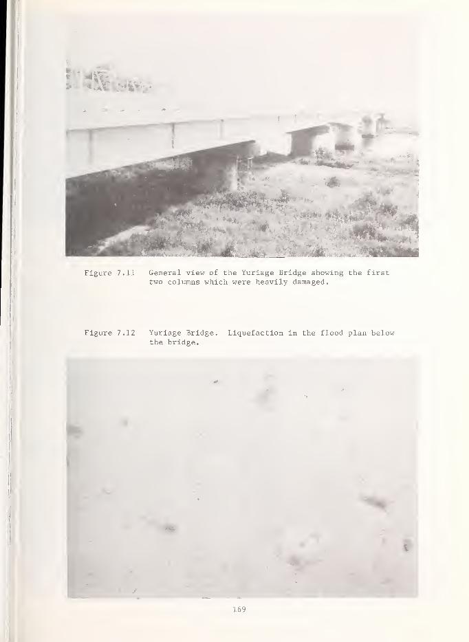
Figure 7.11 General view of the Yuriage Bridge showing the firsttwo columns which were heavily damaged.
Figure 7.12 Yuriage Bridge. Liquefaction in the flood plan belowthe bridge.
169

Yuriage Bridge. Evidence of light girderimpacting with the abutment and pronouncedshear cracking of exterior girder at the
bearing
.
Figure 7.14 Yuriage Bridge. Pier 1,
founded on a caisson 19 mdeep and 2 m by 4 m in plan,suffered heavy shear cracking,The pier cap was reported to
have settled uniformly 5 cm.
170

.15 Yuriage Bridge. The face of Pier 1 showingsevere distress. The plaster of paris patchworkis used to determine if additional pier crackinghas occurred.
Figure 7.16 Yuriage Bridge. Detailshowing 1 cm offset of
cracking, indicating torsionin pier
.
171

Figure 7.17 Yuriage Bridge. Temporary girder supports at Pier 1.
Bearings showed evidence of girder displacement - brokenkeeper and containment plates.
Figure 7.18 Yuriage Bridge. Evidence of 8 cm of longitudinal move-ment as shown at the handrail expansion joint, Pier 2.
However, there was no evidence of damage to the girdersor the second pier.
172

Figure 7.19 General view of the Sendai Ohashi Bridge . The deck archbridge in the background, which is comprised of two
steel plate girders with cross bracing and supported onslender circular columns, carries an industrial waterpipeline and was reportedly undamaged.
Figure 7.20 Sendai Ohashi Bridge. Temporary cribbing used to supportthe steel plate girders.
173

Figure 7.21 Sendai Ohashi Bridge,cross pier dimensionsthe massive pier caps
Typical pier configuration,are approximately 5 m x 2 m.
(Courtesy J.M.O.C.
)
TheNote
Figure 7.22 Sendai Ohashi Bridge. Typical pier damage at the con-struction joint between pier and cap. The vertical rebarsare buckled across the joint. Significant concrete spall-ing is evident. Horizontal cracking around the pier wasdiscovered upon excavation of soil around the piers.(Courtesy J.M.O.C.)

Figure 7.23 Sendai Ohashi Bridge. Detail showing buckled verticalrebar at the construction joint. Strong motion recordsin Sendai indicated approximately 100 gal. verticalaccelerations. (Courtesy J.M.O.C.)
Figure 7.24 Sendai Ohashi Bridge. Typical damage to the base of a
pier before repair.
175

Figure 7.25 Sendai Ohashi Bridge. Typical damage beingrepaired at the base of the pier. Note theoutward buckling of the underformed verticalrebar. The concrete cover had been roughened,the footing strengthened, and additional rebarplaced to strengthen the pier.
Figure 7.26 Sendai Ohashi Bridge. Detailsshowing the added reinforcingconcrete form work. The pierthickness will be increased oneach side by 50 cm at the top,tapering to 70 cm at the base.
176

Figure 7.27 Sendai Ohashi Bridge. Abutment damage. Bearing platebroken and evidence of girder impact at abutment.
Figure 7.28 General view of the Abukuma Bridge. Note the trace of
pier cracking on the pier in the foreground and scaffold-ing at and surface preparation of the pier in the background.
177

r.r'
tioi
hm
Figure 7.29 Abukuma Bridge. Outward buckling of verticalrebar at one of the damaged piers.
Figure 7.30 Abukuma Bridge. Typicalrepair of a damaged pier in-cludes epoxy injection of
cracks, epoxy covering of
buckled rebar, preparation of
existing concrete surface to
accept fresh concrete, em-placement of vertical rebarinto the footing and horizon- ,
tal rebar into the pier, and
an increase of the gross cross
sectional area of the pierwith new concrete. The tech-nique is similar to that usedon the Yuriage and SendaiOhashi bridges.
178

Caihoku Bridge
The Kaihoku Bridge, located on Principal Route 51, approximately 45 km northeast of Sendai,Ls a two-lane, five-span continuous single cell steel box girder, 285 m in total length(Figure 7.31).
The bearings are movable at all piers except Pier 2, Figures 7.32, where a SMAC-B typestrong motion accelerograph is located. Hydraulic dampers acting in the longitudinal direc-tion have been incorporated into the bearing system. All piers and the abutments areskewed. A free field SMAC-B instrument was located on rock between Pier 1 and Pier 2,
approximately 30 meters from the structure. The axes of the pier and free field instrumentsrfere aligned with principal axes of the bridge. The peak recorded accelerations are:
Longitudinal Vertical Transverse
Free Field 200 gal 113 gal 294 gal
Pier 500 gal or more (off scale) 138 gal 338 gal
The only damage noted was minor settlement of an abutment wing wall. Closer inspection bythe Japanese revealed detachment of mortar near anchor bolts of the dampers. There was notvisible damage to the piers or bearings, and no evidence of girder impacting with the eastabutment.
Tenno Bridge
flhe Tenno Bridge, Figure 7.33, located approximately 50 km northeast of Sendai on NationaljRoute 45, is comprised of several steel plate girder approach spans with a tied arch mainspan. The total bridge length is 367 meters. The only damage occurred at the southwestwall pier where a 45° crack extended from the pier cap to a point one-third the way down thepier. Traffic was limited to one lane at the damaged pier.
Kitamami Ohashi Bridge and Dike
The seven-span, 400 m Kitakami Ohashi Deck Truss Bridge, completed in 1976, crosses theKitakami River, 60 km northeast of Sendai on Principal Route 23 (Figure 7.34). The struc-ture suffered no visible structure damage although there was minor settlement of the abut-ment apron. The structure was designed with the latest Japanese criteria and incorporatednew abutment bearing details (Figure 7.35). Significant damage occurred to the dike androadway along the Kitakami River south of the bridge site, (Figure 7.36). The most severedamage occurred along the approximately one-half kilometer length in which the roadwayon top of the dike settled about 1.5 m. The roadway was closed to traffic, the dike sand-bagged, and continuous steel sheet piling was being driven to stabilize the dike.
Kimazuka Bridge
The Kimazuka Bridge, constructed in 1931, is located on Principal Route 32, approximately 35km northeast of Sendai (Figure 7.37). It is a 19-span, simple supported, steel plate girderstructure 236 m in length. Damage occurred to the top of the piers where bearing shoespulled out of the top of the portal frame (Figures 7.38, 7.39). Longitudinal movement of
the girders almost exceeded the bearing area of the bent cap. Sand boils and ground crack-ing were noted at the bridge site.
Maiya Ohashi Bridge
The Maiya Ohashi Bridge, Figure 7.40, is a three-span Gerber-truss bridge located onNational Highway Route 342 approximately 62 km northeast of Sendai. The 181 meter longtruss bridge, constructed in 1928, was closed to traffic because of a brittle fracturethrough the rivet holes of the top chord channel members at the first pier, Figure 7.41.Four steel plates had been welded around the top chord members. Some of the small steelangle top lateral bracing members were buckled in the vicinity of the pier, Figure 7.42.No damage was reported to either of the piers or abutments. The Maiya Bridge is scheduledto be replaced.
179

Figure 7.31 General view of the Kaihoku Bridge. (Courtesy J.M.O.C.)
Figure 7.32 Kaihoku Bridge. Pier 2 showing the SMAC-B2 instru-ment (which recorded a peak acceleration greaterthan 500 gal. in the longitudinal direction) andthe fixed bearing and hydraulic damper system.
180

Figure 7.33 The main tied arch span of the Tenno Bridge with the
cracked wall pier in the foreground. Note the smaller,pedestrian bridge in the background.
Figure 7.34 Kitakami Ohashi Bridge. No structural damage wasreported
.


Figure 7.37 Spalled concrete at bent cap of Kimazuka Bridge.
183

Figure 7.39 Vertical displacement of dislodged span.
Figure 7.40 The Maiya Ohashi Bridge.

Figure 7.41 Maiya Ohashi Bridge. Steel plates welded to the top
chord channel members. Note the clean fracture at a
line passing through the centerline of the rivet holesof the lattice bracing and the permanent 2.5 cm
separation.
Figure 7.42 Maiya Ohashi Bridge. Buckled lateral bracing of the
overhead truss.
185

Toyoma Bridge
The Toyoma Bridge is a 13-span concrete T-beam bridge constructed in 1945, (Figure 7.43).Prior to the earthquake, the bridge, located about 60 km northeast of Sendai, was restrictedto automobile traffic because of damage suffered during the February 20, 1978, earthquake.The bridge was closed following the June earthquake. Flexural induced cracking of the gir-ders occurred at the center of the spans and at the haunched ends over the piers. Shearcracking was also noted at the corners of the concrete hinge seats of several suspendedspans. The ground motion, between 0.1 and 0.2g, was sufficient enough to induce pavementcracking of the roadway.
7.4 HIGHWAY DAMAGE
Widespread highway damage (e.g., Figure 7.44) occurred in the region north and east of Sen-dai. Typical damage included settlement of bridge approaches, cracking of pavements, fail-ure of roadway embankments, and blockage of roads from rockslides. This type of damage hasbeen documented in reports on previous large earthquakes in Alaska, Japan, California, andGuatemala and is virtually impossible to design against.
A major toll road expressway, owned and operated by the Japan Highway Public Corporation,experienced pavement cracking in numerous spots where fill material was used. Additionalsettlement occurred at the approach to bridges along the expressway which was closed fromthe time of the earthquake until 7:00 a.m., June 15, while temporary repairs were made.
Reinforced concrete approach settlement slabs were used at many of the bridge abutments.Use of the slabs forced settlement to occur at the end of the slab instead of at the abut-ment, as illustrated in Figure 7.45.
In areas of rugged terrain, particularly along thetected against earthquake induced landslides by st
way with a covering of shotcrete. Rockslides aremesh screening which is anchored and hung from the
the roadway or by the construction of rock bins at
7.46 and 7.47). These techniques worked quite welbut were not utilized in the area affected by the
West Coast of Japan, roadways are pro-abilizing the steep slopes above the road-
contained or controlled by emplacing wirecrest of the slope and extends down to
the base of the roadway cut (see Figures1 in the January 1978 Off-Izu earthquake,June earthquake.
7.5 RAILROAD DAMAGE
The Japanese electric railroad serves a vital role in Japan. The train is relied upon by
most Japanese in major cities such as Sendai as the means of commuting between home andwork. The train is also the most popular form of intercity travel within Japan. Major dam-age was reported at one rail station when the retaining wall supporting the boarding plat-form collapsed, resulting in track blockage. The main Sendai train station, including thestructural portion of the electrification system, was reportedly undamaged. However, the
trains were inoperative because of massive power failures. Several rail bridges wereseverely damaged and are discussed below.
Eai River Rail Bridge
The Eai River Bridge (Figure 7.48), owned by the Japanese National Railways (JNR), is a dualeight-span steel plate girder structure 160 m in length, which is located 40 km northeastof Sendai. The superstructure is supported by massive unreinforced concrete gravity pierson caisson foundations. Ground acceleration in the area was estimated by the Ministry ofConstruction to be 200-250 gal. Two piers were severely damaged when large wedged shapedsections of concrete dropped out below a construction joint.
The JNR New Sendai Shinkansen Trunkline
JNR is constructing the New Sendai Shinkansen Trunkline, a series of elevated structures forthe fast train, extending through Miyagi Prefecture to the northern tip of Honshu. Theline is scheduled for completion in 1981. The majority of the elevated structures, a seriesof prestressed concrete T, I, and box girders with varying configurations of single andmultiple column bents, are completed and experienced varying degrees of damage, namely to thf
186

Figure 7.43 General view of the Toyoma Bridge which wasclosed to traffic. The columns in the back-ground support an independent steel box girderpedestrian structure which was undamaged.
Figure 7.44 Typical Road Fill Failure.
187

~ 10 cm SETTLEMENT
R/C SETTLEMENT SLAB
I
7 m
GIRDER
ABUTMENT
Figure 7.45 Detail of Reinforced Concrete Approach Settlement Slabs,
Figure 7.46 Wire mesh screening used to contain land and rockslides alonghighways
.
188

Cu Cu0
T3 CD
CD HMe •
a <u
Q 60X)•H
• >-l
CD «60-O rH•H -H
cO
m Pi
U ucu cu
> >•H -Hpi Pi
nj cO
T3 •HCU 3
O3)-i •
4J 0)
CO Jsi
C co
o 3O O"
CU —
'
cu co
S cu
CO cu
u xi-i -p
ocu cu;
CU C3 -HCO S
O
CU i-l
•H OCU IH
CO
'J
3c:
cu
j-i
T3 4-1
CU
CO cu
•H J-l
h xhXi co
CO4-> CO
CO
CU CO
CO
CO OS «—
I
CU >•,
U rHCUJ-) CU
CO ^£e «•H 3X o*O XU VCu )-i
CU CO
CO CU
189

bearing shoes and columns (see Figures 7.49 - 7.54). Damage was concentrated to those newstructures located approximately 30 to 40 kilometers northeast of Sendai. All structureswere designed using the 1971 Japanese seismic code.
7.6 TUNNEL PERFORMANCE
Five short, unreinforced concrete-lined highway tunnels through rock, located about 20 kmnortheast of Sendai on National Highway Route 45, suffered no apparent damage (e.g., Figure7.55). The Japanese National Railways reported that one concrete-lined tunnel on the SendaiNew Shinkansen Line about 40 km northeast of Sendai had hairline cracking.
7.7 CONCLUSION
The June 12 Miyagi-ken-oki earthquake demonstrated the ability of the Japanese Government,both local and national, to respond to the adverse conditions created by a major natural di-saster. Specifically, the prompt enactment of their disaster response plan alleviated majorproblems which could have resulted from the prolonged loss of major transportation routes.The plan allowed for the immediate identification of damaged structures, emergency temporaryrepairs, and initiation of permanent repair within a matter of days after the earthquake*Major routes, although severely damaged, were opened to traffic within three days after theearthquake.
Bridge substructures which were severely damaged were massive reinforced concrete piers,which responded essentially as non-ductile, rigid bodies to the earthquake motion. In spiteof the major damage of these elements, the designs proved satisfactory in that collapse wasavoided and the bridges remained operational for emergency use. Although this type of con-struction proved successful, it would be prohibitively expensive for use in the UnitedStates where the philosophy is to utilize more ductile, energy absorbing designs.
Evidence of pier tilting and abutment movement existed which probably caused rather exten-sive damage to bridge bearing devices. This type of movement is exceptionally difficult to
control. This damage indicates the need to perform in-depth site investigations in areaswhere high water tables exist and to make special considerations in foundation design.
The Kin-noh Bridge was being repaired as a result of damage induced by the February 20earthquake. Bearings were being strengthened and spans were being restrained at their
expansion joints. The failure of the suspended span which had not been retrofitted couldbe expected and demonstrates once again the need to provide for continuity of the super-structure across all joints.
Damage to bridges inflicted by this and past earthquakes reinforces the need to consider anagressive retrofit program for those structures built under older seismic design criteria.The most vulnerable components requiring retrofit are bearings and columns, including con-nections into the foundation. Modest investments can significantly reduce future damage andhelp to avoid collapse of older, important structures.
As in previous earthquakes, significant damage occurred to roads in the area of strongground shaking. Embankments fail, fill material settles, and land- and rockslides blockroads and trackage. These types of damage are difficult to control, although stabilizationand control techniques utilized by the Japanese do help. Special consideration, includingthe use of control and stabilization techniques described earlier in this chapter and/orthe development of specific emergency response plans in susceptible areas, should be givento those important routes which must remain open following a major earthquake.
Given the magnitude of the Miyagi-ken-oki earthquake, transportation structures in generalperformed very adequately. Air, train, bus, and highway travel, although temporarily inter-rupted, did not adversely hinder emergency operations or affect the general movement of
commerce or people.
7 .8 REFERENCES
7.1 "Earthquake Resistant Design for Civil Engineering Structures, Earth Structures, andFoundations in Japan," compiled by the Japan Society of Civil Engineers, Tokyo, Japan,1977.
7.2 "Standard Specifications for Highway Bridges," Twelfth Edition, American Associationof State Highway and Transportation Officials, Washington, D.C., 1977.
190
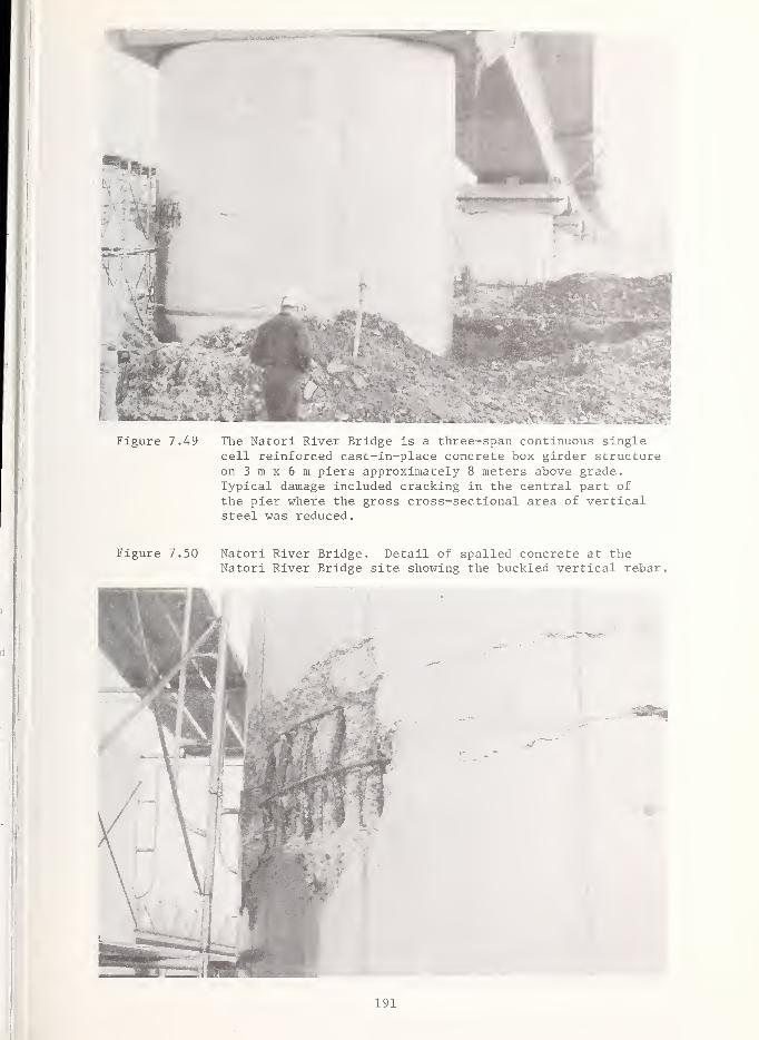
The Natori River Bridge is a three-span continuous singlecell reinforced cast-in-place concrete box girder structureon 3 m x 6 m piers approximately 8 meters above grade.Typical damage included cracking in the central part of
the pier where the gross cross-sectional area of verticalsteel was reduced.
Natori River Bridge. Detail of spalled concrete at theNatori River Bridge site showing the buckled vertical rebar.
191

Figure 7.51 Typical structures which experienced pier crackingnear the Rifu Construction Office of the SendaiShinkansen Construction Bureau, JNR.
Figure 7.52 Shear cracking in the relatively lightly reinforcedupper portion of the pier.

193

Typical undamaged highway tunnel on Route 45 alongthe coast between Sendai and Ishinomaki to thenorth.
194

8. LIQUEFACTION AND DAMAGE TO DIKES
8.1 INTRODUCTION
The June 12, 1978, Miyagi-ken-oki earthquake caused soils to liquefy at several sites on the
coastal flood plain bordering the Bay of Sendai. The engineering structures most exten-sively damaged by liquefaction were flood-control dikes composed of earth fill. The damageiconsisted primarily of cracking, settlement, and minor lateral spreading and slumping. Dur-
ling a trip to Miyagi Prefecture on June 26, 1978, six sites were visited where dike damagehad occurred (Figure 8.1). Additional information on earthquake-induced dike damage was
! provided by officials of the Public Works Research Institute (PWRI), the Japanese governmentI agency charged with building and maintaining river works. Liquefaction-induced damage alsooccurred in an uncompacted sand fill in the port of Ishinomaki.
18.2 SUMMARY OF DIKE DAMAGE
Reported damage sites are scattered in an arc extending from the Abukuma River on the south-west to the mouth of the New Kitakami River on the northeast (Figure 8.1). Within this
IIregion, damage occurred along parts of the Abukuma, Natori, Hirose, Yoshida, Eai, Naruse,
'old Kitakami, and New Kitakami rivers (Figure 8.1, Table 8.1). Most or all sites are under-
J
lain by unconsolidated Holocene coastal flood plain deposits; a few may be underlain by
Holocene alluvial fan deposits (Geological Survey of Japan, 1968; Geologic Map of MiyagiPrefecture). Many of the damaged dikes are founded on river channel deposits less than 500
l
years old. Because of the proximity of all dikes to rivers, the water tables under them are
I close to the ground surface at all times. A total of 28 linear kilometers of dikes was dam-aged in this earthquake, and total repair costs of dikes and other river works amounted to
about 10 billion yen (approximately $50 million) (Ministry of Construction of Japan, unpub-lished data). Most of this damage was caused by liquefaction.
The dikes are composed chiefly of compacted sand. They are built directly on alluvial fan1 or flood plain sediments with little or no ground improvement. Most dikes are severalmeters high, several meters wide at the crest, and have side slopes of 2 Horizontal: 1 Ver-
S tical or less. At the time of the visit, repairs to the dikes were already well advanced.' The repairs consisted of regrading and filling cracks, placing sand bags, and driving steelsheet piles to reduce seepage under the dikes.
8.3 GEOLOGIC SETTING
Most sites of damage are on the coastal plain bordering the Bay of Sendai; a few are on themargin of Natori River alluvial fan and may be underlain by alluvial fan deposits (Geologi-
j
cal Survey of Japan, 1968; Geologic Map of Miyagi Prefecture). The coastal plain sedimentsare unconsolidated Holocene gravels, sands, silts, and clays primarily deposited by rivers;
beneath most dikes these deposits are several tens of meters thick (Hase, 1967). The riverdeposits are of three main types: channel, natural levees, and back marsh deposits (TohokuRegional Construction Bureau, MoC
,unpublished data; H. Nakagawa, Tohoku University, unpub-
lished data). Engineering structures including dikes founded on channel or back marshdeposits performed relatively poorly during the earthquake. Liquefaction occurred most com-monly in channel deposits.
Performance of engineered structures founded on natural levee deposits varied from place toplace. These deposits are generally thin, and the performance of structures was thereforestrongly influenced by the materials underlying the natural levees (H. Nakagawa, TohokuUniversity, oral communication). Structures near the coast, founded on beach ridge anddune sand deposits sustained little damage in the earthquake. Natori River alluvial fanmaterials consist primarily of gravel but also contain a few thin layers of sand and silt(Hase, 1967).
Prepared by David K. Keefer, U.S. Geological Survey, Menlo Park, California.
195

Figure 8.1 Dike Damage in Miyagi Prefecture
196

TABLE 8.1
DIKE DAMAGE IN MIYAGI PREFECTURE
Total length of dikeaffected by cracking,settlement, lateral
Number of spreading, or slumpingRiver Bank 1 damage sites (kilometers)
Abukuma left 2 0.38r i eh t 5 0.68
Natori left 11 1.87
right 6 2.17ni lUbL left o o
right 5 0.38Yoshida left 9 0.51
right 12 5.50Eai left 5 2.90
right 6 0.21
Naruse left 13 0.79
right 10 1.08
Old Kitakami left 3 0.15right 9 0.29
New Kitakami left 16 7.13
right 17 4.13
TOTAL 129 28.17
Information furnished by the Tohoku Regional Construction Bureau.
Right or left relative to an observer facing downstream.
197

8.4 FIELD OBSERVATIONS OF DIKE DAMAGE
8.4.1 Natori River (Sites 1 and 2)
Lateral spreads, fissures, and sand boils were apparently widespread along the Natori Riverfor 3 km upstream from its mouth (T. Tazaki, PWRI, oral communication). In this area theflood plain is underlain by fluvial sand that extends to a depth of 15 m or greater (Hase,
1967). Two damaged dikes in this area (Figure 8.1) were visited.
At Site I, liquefaction caused slumping, lateral spreading, and settlement of up to 1.5 malong a 160-m-long section of the dike (Figures 8.2, 8.3, and 8.4). Longitudinal cracksseveral tens of meters long opened in the dike crest. Between the dike and the river,
fissures striking obliquely to the dike formed, and sand was ejected from them (Figure 8.5).Other fissures trending parallel to the dike and the river formed near the river bank, morethan 100 m from the base of the dike. The occurrence of fissures and sand boils in groundaway from the dike indicates that liquefaction took place primarily in material beneath the
dike and not in the dike material itself.
The configuration (Figure 8.4) and composition of this dike are typical of those seenthroughout Miyagi Prefecture. The dike is composed primarily of compacted, fine to mediumsand. It rises 2 m above the high water level of the river and is 4 m wide at its crest.Its riverward flank has a slope of 2H: IV. The opposite flank descends as a series of
slopes (2H: IV) and benches to the agriculture land beyond.
The damaged section is built on a former channel abandoned by the river less than 500 yearsago. Beneath the dike, fluvial sand extends to a depth of at least 60 m (Hase, 1967), andmuch of the top 15 m of sand is fine grained, loose, and well sorted (poorly graded) (TohokuRegional Construction Bureau, MoC, unpublished data).
Liquefaction previously took place at this site during a M 6.7 earthquake in February 1978(T. Tazaki, PWRI, oral communication). The same section of dike was affected and the samematerials liquefied in both the February and June earthquakes.
At Site 2 (Figure 8.1), the dike is contained by a concrete retaining wall (Figures 8.6,
8.7, 8.8, and 8.9). A section of the retaining wall several hundred meters long moved about30 cm toward the river. Longitudinal fissures opened in the dike behind the retaining walland in a concrete pavement along part of the dike. The dike also settled by as much as
30 cm. This site, at the mouth of the river, is underlain by at least 20 m of sand (Hase,
8.4.2 Yoshida River (Site 3)
This was one of the most severely damaged sections of dike in Miyagi Prefecture. Settle-ments of up to 1 m occurred over a distance of 5 km, longitudinal cracks and scraps formedin the dike crest, bulges appeared in the lower slopes, and sand boils occurred along somecracks (Figures 8.10, 8.11, 8.12, and 8.13). The cracks and bulges indicate that lateralspreading and slumping took place. The damaged section rests on the fan-delta of a small
stream, and a boring near this site penetrated 15 m of silt, 2 m of fine sand, and 5 mof coarse sand (Tohoku Regional Construction Bureau, MoC, unpublished data; Hase, 1967).Bedrock lies at an average depth of 35 m.
8.4.3 Eai River (Site 4)
Sand boils were common in an old river channel at Site 4, on the right bank of the Eai River(Figure 8.14). A concrete block fence near this channel was cracked by lateral spreadingtoward the old channel bank (Figure 8.15). Damage to the dike on this side of the river wasminor. Across the river from Site 4, cracks up to 80 cm deep and 10 cm wide occurred in thedike. On both sides of the river, the foundation material contains much soft clay. Somelayers of silt and sand may also be present. It was reported that the dikes were builtrelatively slowly, and significant settlement took place during construction (K. Kawashima,PWRI, oral communication).
1967).
198

Figure 8.2 Site 1, Natori River, view downstream (southeast) alongrepaired portion of dike. Dike is made of compactedsand. It rises 2 m above the high water level of theriver and has side slopes of 2H:1V. Natori River incenter-left background.
Figure 8.3 Site 1, Natori River. Slumping of dike on flank awayfrom river. View north. (Photo courtesy Tohoku RegionalConstruction Bureau)
199

Figure 8.4 Site 1, Natori River—cracking, settlement, slumping, and lateralspreading induced by liquefaction. (From Tohoku Regional Con-struction Bureau, MOC, unpublished data)
v H.W.L
Pre-earthquake outline of dike
Post-earthquake outline of dike
I i l
0 12 34m
Figure 8.5 Site 1, Natori River. Liquefaction-induced cracks and sandboils in ground between river and dike indicate that lique-faction took place in materials beneath the dike. Sand incenter-ground to left of crack is from sand boil. Sand bagson dike were placed after the earthquake as a repair measure,View is south.
,
200

Figure 8.6 Site 2, Natori River. Viewis west along repaired portionof dike. Note patch acrossoffset in retaining wall offsetcaused by lateral spreadingduring earthquake. Retainingwall rises approximately 1 mabove roadway
.

Figure 8.8 Site 2, Natori River. View is westacross tributary of Natori River,Dike section shown in Figs. 8.6 and
8.7 is to right of houses in back-ground of this figure. Note crackin concrete pavement in foregroundis aligned with crack in retainingwall in background.
Figure 8.9 Site 2, Natori River—Retaining wallmoved laterally and dike crest settled(From Tohoku Regional ConstructionBureau, MOC, unpublished data)
area of cracking and settlement
3m
crack
202

Figure 8.10 Site 3, Yoshida River. View east (downstream)
along section of dike where repairs are underwayDike crest settled as much as 1 m over a lengthof 5 km. Sand bags have been placed as part of
repair process.
Site 3, Yoshida River.Cracks in dike caused byslumping and lateral spread-ing. Cracks are 10-30 cmwide. View is west. (Photo
courtesy K. Kawashima, PWRI)
203
Figure 8.11

Figure 8.12 Site 3, Yoshida River. Scarps in dike caused by slumping.Note man in background for scale. (Photo courtesyK. Kawashima, PWRI)
Figure 8.13 Site 3, Yoshida River. Steel sheet piles being placed byvibratory driver as part of repair process. Purpose of
sheet piles is to reduce seepage under part of dike weakenedby earthquake.
204

s
.<5 *?
W RIVER
100—*-
200—h-
300 meters1
LEGEND
Q Sand boil
ZT.'Z Dike
Old river channel
Figure 8.14
nrrrn
1Ground crack caused by lateral spreading
Concrete block fence
Site 4, Eai River—Mostsand boils occurred in oldriver channel. Minorcracking of dike apparentlyoccurred where dike crossesold channel, but crackswere repaired prior to
visit. (After TohokuRegional ConstructionBureau, MOC, unpublisheddata)
n igure 8.15 Site 4, Eai River - View southwest from crest of
dike. Crack (indicated by heavy line) in fenceand rice field caused by lateral spreading toward
bank of old channel in background.
205

8.4.4 Old Kitakami River (Site 5)
Sand boils occurred in the rice field adjacent to the dike (Figure 8.16), but damage to the
dike itself was apparently minor. Subsurface material at Site 5 consists of alternatinglayers of silty sand and clay to a depth of 15 m. (T. Tazaki, PWRI, oral communication).
8.4.5 New Kitakami River (Site 6)
The dike and paved roadway at Site 6 settled up to 1.5 m and cracked over a distance of 4 km(Figures 8.17 and 8.18), and sand boils formed on both flanks of the dike, which is builtover an old river channel. According to data from borings completed by the Tohoku RegionalConstruction Bureau, MoC , the soil under the damaged part of the dike is similar to the soilunder an adjacent, undamaged section. To a depth of 8 in, the soils consist of gravels,
sands, and silts with a few thin layers of clay. N-values (blows/foot from a standard pene-tration test) for most soil layers under both sections are less than 10. Reasons for the
differences in behavior between damaged and undamaged sections are currently under studyby Japanese engineers.
8.5 LIQUEFACTION IN THE PORT OF ISHINOMAKI 1
In the port of Ishinomaki, a fine-sand fill liquefied, causing severe damage to anchoredsteel-sheet-pile bulkheads. The fill material had been dredged from the seafloor andplaced hydraulically with no compaction. It was placed next to old beach deposits, and
the boundary of the liquefaction damage followed the contact very closely; the beach depos-its were not involved in the liquefaction.
8.6 CONCLUSION
The Miyagi-ken-oki earthquake caused cracking, settlement, lateral spreading, and slumpingof man-made dikes along several rivers in the prefecture. Most of the damage was due to
liquefaction. A total of 28 linear km of dikes were damaged, and total damage to dikes andother river works was approximately $50 million. Liquefaction also occurred in hydraulicfill composed of fine sand in the port of Ishinomaki. These effects are currently beinginvestigated by several Japanese scientists and engineers; some reports have already beenpublished (Yoshimi and others, 1978; Okubo and Ohashi, 1979; Tatsuoka and others, 1979;Yamamura and others, 1979), and other reports should be forthcoming in the near furture.
8.7 REFERENCES
1. Geological Survey of Japan, 1968, Hydrogeological Map of the Coastal Region of Bay ofSendai. Hydrogeological Maps of Japan 16, 1 map, scale 1: 100,000.
2. Geologic Map of Miyagi Prefecture, scale 1: 200,000 (legend in Japanese).
3. Hase, Kotaro, 1967, Geology of the Alluvial Plains of Miyagi Prefecture (in Japanesewith English figure captions), Contributions from the Institute of Geology and Paleon-tology, Tohoku University, No. 64, 45 p.
4. Okubo, T., and Ohashi, M. , 1979, Miyagi-ken-oki, Japan earthquake of June 12, 1978, gen-eral aspects and damage, Report distributed at 2nd U.S. National Conference on Earth-quake Engineering, Stanford, California, 15 p. (In English)
5. Tatsuoka, F., Ohkochi, Y., Fukushima, S., Igarashi, H., and Yamada, S., 1979, Soilliquefaction and damage to soil structure during the earthquake off Miyagi Prefectureon June 12, 1978, Institute of Industrial Science, University of Tokyo, Bulletin ofEarthquake Resistant Structure Research Center, No. 12, p. 3-13. (In English)
6. Yamamura, K. , Iwasaki, T., Sasaki, Y. , Koga, Y., Taniguchi, E., and Tokida, K. , 1979,Ground failures and damage to soil structures from the Miyagi-ken-oki, Japan earthquakeof June 12, 1978, Report distributed at 2nd U.S. National Conference on EarthquakeEngineering, Stanford, California, 16 p. (In English)
7. Yoshimi, Y., Tohno, I., and Tokimatsu, K. , 1978, A report on the Miyagi-ken-oki, Japan,earthquake of June 12, 1978: Part II: Geotechnical aspects of damage, InternationalConference on Microzonation, 2nd, San Francisco, Proc, v. 1, p. 600-605. (In English)
1 Data kindly provided by Mr. Hajime Tsuchida, Chief, Earthquake Resistant Structures Lab,Port and Harbor Research Institute, Ministry of Construction.
206

Figure 8.16 Site 5, Old Kitakami River - Sand boils in rice field.Plants are several centimeters tall. Damage to thedike at this site was minor. (Photo courtesyK. Kawashima, PWRI)
Figure 8.17 Site 6, New Kitakami River. View east along crest of
dike and highway that are being repaired. Unevennature of highway surface is due to liquefaction-induceddifferential settlement. Settlements of up to 1.5 moccurred along a distance of 4 km.
207

Figure 8.18 Site 6, New Kitakami River. Crackingof dike crest and roadway due to
liquefaction-induced slumping.(Photo courtesy K. Kawashima, PWRI)
208

9. SEISMIC-INDUCED LANDSLIDES
9.1 INTRODUCTION
Several thousand landslides were triggered by the June 12, 1978, Miyagi-ken-oki earthquake.Landslides were concentrated within Miyagi and northern Fukushima Prefectures. The land-slide distribution was densest along the coast nearest the epicenter from Sendai northeastto the area around Matsushima. Landslides were responsible for 1 death, 1 injury, 2 housesdestroyed and 13 houses damaged (Y. Tsuruya, 1978, unpublished data; Tohoku University
i
report, 1979).
Small rock falls and rock slides issuing from steep slopes /ere the most abundant landslides.Along the mountainous roads of the Ojika Peninsula, these landslides were generally less than
J 10 mJ in volume and occurred in closely fractured Triassic and Jurassic slate and interbedded
j
quartzite. The largest contained several thousand cubic meters of debris and occurred on
natural slopes in tuffaceous deposits near Matsushima and eastward on slopes near the mouthof the Naruse River (Figure 9.1).
Although fewer in number, rotational slumps in artificial fill were larger than most rockfalls and slides and caused significant damage to highways and buildings. Such slumps with-in the city limits of Sendai were responsible for damage and destruction to houses. Thepoor seismic performance of fills indicates that they could be hazards in future earthquakes.
jThe author spent approximately three days surveying seismic-induced landslides and theireffects from south of Sendai along the Natori River to the mouth of the New Kitakami River.Data included within this report comprises observations from the author's reconnaissance,information provided by Mr. Y. Tsuruya of the Japanese Ministry of Construction, and datafrom a report published by Tohoku University (1979).
The following descriptions of seismic-induced landslides are presented at site observations
,(referring to Figure 9.1 for locations of individual landslide sites and local geography).The landslide sites depict noteworthy and representative examples of the different kinds oflandslides that occurred in this earthquake. Sites 1 and 4 through 8 are described with the
aid of supplemental data and photographs provided by Mr. Y. Tsuruya of the Slope Protection
J
Division, Ministry of Construction, Tokyo.
9.2 ROCK FALLS AND ROCK SLIDES ON NATURAL SLOPES
9.2.1 Site No. 1
Two of the largest rock falls from the earthquake occurred near Takayamashita in Matsushimatown west of the Takagi River on steep (greater than 45°) natural slopes. The larger of
these rock falls (Figure 9.2) occurred in a deeply weather and closely jointed Miocene tuffbreccia (Geologic Map of Miyagi Prefecture) exposed in a 45-m scarp. The slope affected is
approximately 110 m wide, and the volume of debris is about 6,000 m^. The rock fall damagedfour houses built next to the slope. A close view of some of the damage to the house secondfrom the left in Figure 9.2 is shown in Figure 9.3.
About 0.5 km to the north, a smaller rock fall occurred on a steep slope in dark brown vol-canic rocks (Miocene tuffs (?)). The scarp is about 20 m high and about 50 m wide (Figure
9.4). The debris is blocky and includes boulders up to 2 m in diameter. The scarp revealsextensively fractured bedrock. The fractured surfaces probably provided planes of weakness
jalong which the rock failed.
' 9.2.2 Site No. 2
Three rock falls occurred on steep east-facing bluffs flanking a broad flood plain near themouth of the Naruse River. All three were narrow failures, about 15 m wide, that occurredin dark brown volcanic rock similar to the smaller rock fall at Site No. 1. The slides
extended from near the crest of the bluffs to the base, a height of approximately 30 m. Two
jof the slides are shown in Figure 9.5.
Prepared by Edwin L. Harp, U.S. Geological Survey, Menlo Park, California.
209

Figure 9.1 Sendai area showing sites of landslides described in text (dots).
210

Figure 9.2 Rock fall on steep slopes of Miocene pumiceous tuff breccianear Takayamasuita . This rock fall damaged four housesclose to the base of the slope. (Photograph courtesy ofY. Tsuruya, Slope Protection Division, Ministry of
Construction)
.
Figure 9.3 Closeup of rock fall damage to houses shown in left portionof figure 9.2. (Photograph courtesy of Y. Tsuruya)
211

Figure 9.4 Rock fall on steep slopes in volcaniclastic sediments.
Figure 9.5 Rock falls (arrows) in steep bluffs bordering flood plainnear mouth of Naruse River
.
212

(9.2. 3 Site No. 3
'A small rock fall south of the New Kitakami River occurred on the end of a narrow ridge of
Triassic slate and quartzite. Slopes adjacent to this end of the ridge showed no failure,suggesting that this point, which was the narrowest part of the ridge, experienced strongershaking than adjacent slopes. This phenomenon has been documented in other earthquakes(Bonilla, 1959; Nason, 1971; Harp and others, 1978) and has been attributed to the topogra-phic focusing of seismic energy.
9.3 ROCK FALLS AND ROCK SLIDES IN CUT SLOPES
9.3.1 Site No. 4
Near Atago in Matsushima, approximately 1.0 km east of the Site No. 1, rock falls from tuff,similar to the tuff forming the larger rock fall at Site No. 1, damaged outbuildings nearthree houses. About 500 m of debris was shaken from cut slopes 15 m in high beneath whichhouses and storage buildings were closely juxtaposed (Figure 9.6). Most of the damage wasnot to the houses proper but to attached storage sheds and outbuildings as shown in Figure9.7.
9.3.2 Site No. 5
Approximately 3 km east of Atago in Mototetaru, Matsushima, small rock falls occurred intuff-breccia deposits, damaging several storage buildings adjacent to houses. Failuresoccurred along a section of cut slope about 100 m in long and produced about 200 m^ ofdebris. The slope is 10-13 m high and is inclined at about 60°. One rock fall and a scarpexposing tuff breccia is shown in Figure 9.8.
9.3.3 Site No. 6
3At Kakinoura in Matsushima, about 100 m of blocky debris was produced by a seismic-inducedrock fall in tuff that damaged a concrete wall adjacent to a house. This rock fall occurredon the nose of a narrow ridge of about 35 m local relief. The slope failed along pre-existing fractures or joints and produced blocks of debris as long as 1.0 m. The size of
the blocks reflects the fracture spacing of the rock. The rock fall and the house adjacentto the damaged concrete wall are shown in Figure 9.9. Two other small rock falls nearby didminor damage to walls of three other houses.
l|
9.3.4 Site No. 7
j
At Kitashionai, Murata, 25 km southwest of Sendai, another steep slope in tuff failed, gen-i
erating a small rock fall damaging one house. Figure 9.10 shows several houses near the
nearly vertical cut slope about 15 m high. One of these houses suffered damage to a retain-jl ing fence and part of the roof. A closeup of the rock fall and roof damage is shown in[I, Figure 9.11.
1 9.3.5 Site No. 8
3l
A rock fall of approximately 1000 m occurred at Hebinumayama, Sanbongi, on a 20 m high, 110; m long, nearly vertical cut-slope no more than 10 m from five houses at the base of the
;jslope (Figure 9.12). The falling rock did minor damage to two houses and attached storagesheds (Figure 9.13). Rock fall occurred along the entire length of the slope which is
composed of a bedded tuff containing numerous fractures. Here, as at Kakinoura, failure
j,took place along the pre-existing fracture surfaces. Block size of the debris ranged fromseveral centimeters to several meters.
9.3.6 Site No. 9
A typical roadcut failure (Figure 9.14) was derived from weakly cemented sandstone along a
valley west of the Naruse River. The rock fall is less than 1 m thick, and slope heightis about 10 m.
213

Figure 9.6 Panoramic view of houses damaged by rock fall from adjacent cut slopein tuff*. Rightmost arrow points to area shown in figure 9.7.(Photograph courtesy of Y. Tsuruya)
.
* Arrows point to failure scarps.
Figure 9.7 Closeup of rock fall and damage to buildings shown in right-handportion of figure 9.6. (Photograph courtesy of Y. Tsuruya)
214

Figure 9.8 Rock fall from steep slope inpumiceous tuff breccia nearMotot^taru. Failure was about200 m in volume. (Photographcourtesy of Y. Tsuruya)
Figure 9.9 Rock fall in Miocene tuff causing damage to concretewall adjacent to house. (Photograph courtesy of
Y. Tsuruya)
215

Figure 9.10 Panorama of cut slope near Kitashiona in Miocene tuff which producedrock falls during earthquake damaging nearby houses. Arrow points to
damaged house shown in closer view in figure 9.11. (Photographcourtesy of Y. Tsuruya)
216

Figure 9.12 Steep slope near Hebinumayama in heavily fractured tuff whichunderwent failure as rock falls damaging portions of housesin front of the slope.
Figure 9.13 Rock fall from slope shown in figure 9.12 impinging onstorage shed next to slope.
217

Figure 9.14 Rock fall from roadcut in weakly cemented sandstone.
218

3.3.6 Site No. 10
k rock fall in Triassic slate and fine-grained quartzite occurred on a steep roadcut slopeon the north side of the New Kitakami River. The scarp of the rock fall is inclined at
about 60° and is formed by prominent slaty cleavage planes (Figure 9.15). The blocky debrisbroke into pieces of up to 30 cm in longest dimension. Almost all of the debris consistedpf blocks that had separated along pre-existing fractures.
|9.3.7 Ojika Peninsula
(Reconnaissance of the Ojika Peninsula and area immediately to the north was along windingmountain roads that traversed heavily vegetated slopes. The slopes had a thin soil mantle,[generally less than 0.5 m thick. Numerous small rock falls were derived from the nearvertical roadcuts in these slopes. None contained more than a few cubic meters of debris.
9.4 LANDSLIDES IN ARTIFICIAL FILL
9.4.1 Site No. 11
|
Several artificial fill failures occurred on roads on the Ojika Peninsula; one such failureis shown in Figure 9.16. The fill material slumped away from beneath the road surface and(formed a scarp cutting about 2 m into the highway. The fill appeared to be either uncom-
ipacted or poorly compacted sandy clay derived from adjacent bedrock and soil. This failure
Joccurred at a site where rainfall-induced slumping had occurred repeatedly before the earth-quake (T. Tazaki, 1978, oral communication). At the time of the visit, plastic sheets hadbeen spread over the extensively cracked pavement to prevent or minimize rainfall infiltra-tion into the scarp area. During observation, heavy rainfall was mobilizing the debris into
! small mudf lows.
: 9.4.2 Site No. 12
Many slope failures in artificial fill took place within the city limits of Sendai. Thesefailures were mainly slumps. In the neighborhood of Midorigaoka, a large rotational slumpoccurred in a fill slope of about 15°, composed of gravelly clay. From the headwall scarpto toe, the slump extends approximately 70 m horizontally and 20 m vertically (Y. Matsuzaki,1978, unpublished data); it is approximately 30 m wide and about 14 m in maximum thickness,thus the approximate volume is 30,000 m"^. Most of the slump was above and to the right ofone of the 1400 concrete slope-protection dams (sabo works) in Sendai (Figure 9.17). Theslump-mass had been covered with nylon tarps before the photograph was taken to prevent
|j
infiltration of rainfall.
Many houses had been removed from this slope in previous years due to rainfall-induced slump-i ing; as a result, only one house near the headwall scarp was severely damaged by the seismic-
j
induced sliding. Figure 9.18 shows this house, which was being undercut by the multiple
|
scarps at the head of the slump. The fence in the figure shows the rotational component of
|.slump movement.
About 5 m of horizontal displacement (Y. Matsuzaki, 1978, unpublished data) occurred, plac-ing the toe of the landslide mass only a few meters from houses below. One such house,which had been evacuated because of the threat of recurrent movement is shown in Figure
!
9 * 19 '
At the time of observation,' engineers from the Sabo Section of the Miyagi PrefecturalI
government were engaged in a geotechnical investigation of the slump mass and surroundingarea. Boreholes had been drilled in the slide material to establish the depth of the fail-ure surface, to provide samples for strength testing, and to emplace slope inclinometersto monitor any continuing movement. Adjoining areas were also being drilled and monitoredto detect any movement that might be precipitated by the slide, such as deformation down-slope from the toe in response to the weight of the encroaching slide mass or retrogressiveslumping upslope from the headwall scarp.
Many other artificial fill slopes in Sendai underwent similar failure. At a site about 0.5km east of Midorigaoka, six houses were condemned by the mayor of Sendai because of cracking
219

Figure 9.15 Rock fall in roadcut . Noteslaty cleavage planes thatform the rock fall scarp.
Figure 9.16 Slump in artificial fill along a highway on the
Aj ika Peninsula
.

Figure 9.17 Rotational slump in artificial fill in Sendai (area coveredby tarps) which destroyed one house and is threateningothers. To left of slump is concrete slope protection dam(sabo works)
.
Figure 9.18 House near head of slump. House was removed due to under-cutting by headwall scarp (Photograph courtesy of Y. Tsuruya)
.
221

Figure 9.19 Toe of slump and house below in danger of
being overridden by slide mass. House has
been evacuated.
222

beneath and around the houses within the fill area. The decision to destroy the houses wasmade to protect the houses downslope because the failure of the slope was judged to be
imminent unless the weight of the damaged houses was removed (T. Tazaki, 1978, oral communi-cation) .
A large, spectacular slump in artificial fill, derived from Miocene ash-flow tuff, occurredin Shiroishi City, about 35 km southwest of Sendai. One fatality occurred from this failure.This slump took place in a planned residential area under conditions of a high water table.
The slump movement was accompanied by mudflow (Tohoku Univ. report, 1979). This landslidewas not seen by the author, but is described by the Tohoku University report (1979).
Judging from the extensive failure of artificial fill slopes, as compared to the few notice-able landslides on the many steep natural slopes in the same areas, the artificial fill is
particularly susceptible to seismic-induced failure. These artificial-fill slopes are
j
likely to be hazards in future earthquakes.
9.5 SUMMARY OF FINDINGS
The June 12, 1978, Miyagi-ken-oki earthquake triggered several thousand landslides in Miyagiand Fukushima Prefectures. A field reconnaissance of the coastal region nearest the epi-center two weeks after the earthquake led to the following general findings:
(1) Most landslides were rock falls and rock slides and occurred on natural and cut slopesi steeper than 45°. Damage to houses and other structures was a result of the close proximityof houses to the base of steep slopes.
(2) Many slopes and roadways constructed on artificial fill failed during the earthquake.The slumping of artificial slopes also caused extensive damage to houses. The heaviestdamage from these failures occurred in areas occupied by housing developments in Sendai andin Shiroishi.
(3) Many slopes composed of artificial fill were more susceptible to seismic-induced fail-|ure than steep natural slopes. This susceptibility is probably a result of insufficientcompaction of the fill material. Artificial fill slopes could constitute a significant haz-ard in future earthquakes.
9.6 REFERENCES
9.1. Bonilla, M. C, 1959, Geologic observations in the epicentral area of the San Francis-co earthquake of March 22, 1957, in Oakeshott, G. B., ed. , The San Francisco earthquakeof March 1957: California Division of Mines Special Report No. 57, p. 25-37.
9.2. Geologic Map of Miyagi Prefecture, legend in Japanese.
9.3. Harp, E. F., Wieczorek, G. F., and Wilson, R. C, 1978, Earthquake-induced landslidesfrom the February 4, 1976 Guatemala earthquake and their implications for landslidehazard reduction: International Symposium on the February 4, 1976 Guatemalan Earth-quake and the Reconstruction Process, Guatemala City, Proceedings.
9.4. Nason, R. D., 1971, Shattered earth at Wallaby Street, Sylmar, in the San Fernando,
California earthquake of February 9, 1971: U.S. Geological Survey Prof. Paper 773,
p. 97-98.
9.5. Tohoku University Report, 1979, Phenomena and disasters associated with the Miyagi-ken-oki earthquake of 1978 in the East-central part of Northeast Honshu, Japan:
Institute of Geology and Paleontology, Tohoku University, no. 80, 97p., 34 figs.,2 tables, 7 pis., (summary and captions in english).
223

10. GENERAL CONCLUSIONS
The effect of the Miyagi-ken-oki earthquake of June 12, 1978 on the Sendai area was quitemoderate, considering its magnitude and the potential for disaster. This was in large meas-ure due to good engineering practice and the extremely quick and comprehensive response of
the Japanese authorities to the earthquake. At the time of the team investigation beginning11 days following the earthquake, much of the debris had been cleared away and repair andrecovery operations were well underway. The approaching rainy season gave a sense of urgencyto these tasks. With the exception of a few establishments still without city gas service,the situation in Sendai was essentially normal. It was obvious that the response to theearthquake was well planned and that the disaster mitigation and relief activities are wellcoordinated among the different levels of government. The fact that the main energy releaseoccurred some distance from any inhabited areas lessened the impact that an earthquake of
this magnitude otherwise would have had.
Subsequent investigation showed that modern structures and facilities suffered little dam-age. In particular, structures designed subsequent to the promulgation of the new seismicdesign provisions of 1971 performed exceedingly well. The successful performance of mostmodern multistory buildings shows that modern seismic engineering practices can provideresistance to strong earthquake motions at reasonable cost. The total damage due to Miyagi-ken-oki earthquake constituted a small percentage of the total capital investment in build-ings and structures, despite recorded ground accelerations in the range 0.25g - 0.40g in
the Sendai area, and accelerations as high as l.Og in upper stories of high rise buildings.
Numerous pockets of damage existed throughout the city that apparently were correlated to
the local geology and soil conditions. Acceleration magnitudes across Sendai varied consi-derably with location. The eastern part of the city, where many of the damaged structureswere located, is built on alluvial deposits which, from a foundation standpoint, are poorerthan the remaining portion of the city. Soil conditions in the central portion of Sendaiare considerably better, and the damage was limited.
Analyses of the earthquake and the performance of structures are currently being conductedor recently have been completed by Japanese engineers and seismologists. One of the firstof these is the report on strong motion records and data issued by the Strong Motion Earth-quake Observation Council, National Research Center for Disaster Prevention of Japan.Digitization of some of the traces has been performed by the Building Research Insituteand Public Works Research Institute. Tokyo Electric Power Company engineers are conductinga comprehensive analysis of the strong motion data gathered at the Fukushima nuclear powerplant. When this information is released, probably within the next year or so, it will be
of considerable value to engineers and licensing officials in the U.S. as well as Japan.
These reactors and containments are similar to those operating in the U.S. and they sufferedno damage in the earthquake.
Although similar observations have been made in the aftermath of previous earthquakes, it
seems worthwhile to reemphasize the following points about achieving earthquake resistantdesign:
(1) Structure should be laid out so that they are as symmetrical as is consistent with theirfunction. Practically all severely damaged or collapsed engineered structures exhibiteda significant asymmetry of some kind in the form of an eccentric mass or placement of
shear walls.
(2) When infill panels or spandrels are used, particular attention should be paid to
detailing and to the design of structural members connected to them. When used on onlyone side of a building, their stiffening effect causes most of the damage to occur to
that side.
(3) The apparent correlation of structure damage to local soil and geologic conditions sug-gests that this factor should receive additional attention in the design of structuresof even moderate size and cost. Seismic regulations in codes should include a soilsparameter in their load criteria.
(4) Performance of buildings clearly is related to quality control and design detailing.There were cases of failures where column ties appeared to be minimal and improperly
224

anchored. In other instances, they appeared to be adequate. The question ariseswhether discrepancies exist between the structure as built and the code recommenda-tions.
Post earthquake investigation of damaged bridges has taught many lessons. The 1964Niigata and 1971 San Fernando earthquakes pointed to the importance of providing 1)
restraining devices across hinges and joints and 2) proper column reinforcement detailsincluding the foundation connections. The 1976 Guatemala earthquake demonstrated that
the longitudinal restraining devices across hinges can provide the continuity requiredto keep spans from falling. The Miyagi-ken-oki earthquake has provided incentive to
further investigate the need for and performance of transverse restraining devices andto examine the philosophy behind ductile and non-ductile column/pier design. Anothertopic of interest is correlation of soil type to foundation/substructure damage.
The collapse of the Kin-noh bridge, which was previously damaged in a February 1978
earthquake, indicates that structural damage may occur due to either strong aftershocks
or multiple event excitation.
In regions of high seismicity, critical and important structures should be identifiedand additional care should be taken in detail design and in field inspection (qualityassurance) during construction.
225

U.S. DEPT. OF COMM.
BIBLIOGRAPHIC DATASHEET
1. PUBLICATION OR REPORT NO.
NBS SP 592
2.Gov't Accession No, 3. Recipient's Accession No.
1
4. TITLE AND SUBTITLE
An Investigation of the Miyagi-ken-oki ,Japan
Earthquake of June 12, 1978
5. Publication Date
uctoDer lytsu
6. Performing Organization Code
7. AUTHOR(S)
Bruce R. Ellingwood
8. Performing Organ. Report No.
9. PERFORMING ORGANIZATION NAME AND ADDRESS
NATIONAL BUREAU OF STANDARDSDEPARTMENT OF COMMERCEWASHINGTON, DC 20234
10. Project/Task/Work Unit No.
11. Contract/Grant No.
12. SPONSORING ORGANIZATION NAME AND COMPLETE ADDRESS (Street. City. State. ZIP)
Same as item 9.
13. Type of Report & Period Covered
Final
14. Sponsoring Agency Code
15. SUPPLEMENTARY NOTES
Library of Congress Catalog Card Number: 80-600116
| |Document describes a computer program; SF-185, FiPS Software Summary, is attached.
IS. ABSTRACT (A 200-word or less tactual summary of most significant information. If document includes a significant bibliography or
literature 3urvey. mention it here.)
On June 12, 1978, a destructive earthquake with Richter magnitude of 7.4 occurredoff the east coast of Miyagi Perfecture, Japan. Preliminary estimates by theNational Land Agency of Japan indicated that the earthquake caused an equivalentof $800 million in total damage. There is a cooperative agreement between the Gov-ernments of the United States and Japan termed the U.S. -Japan Program in NaturalResources (UJNR) . Following the earthquake, it was arranged through UJNR that teams
of U.S. structural engineers and geologists would visit Miyagi Prefecture and inspect
the damage caused by the earthquake. This report assembles the information and
collective experiences of the investigation team 10 as to describe the earthquake
and document its effects. Field investigations conducted by geologists and structuraengineers are described in detail and some of the implications for seismic resistant
design and construction of structures in the United States are also discussed.
17. KEY WORDS (six to twelve entries; alphabetical order; capitalize only the first letter of the first key word unless a proper name;
separated by semicolons)
Bridges; buildings; dikes; earthquakes; foreign engineering; geology; highways;
housing; landslides; liquefaction; power plants; railroads; rock slides; seismicity
structural engineering.19. SECURITY CLASS
(THIS REPORT)
UNCLASSIFIED
21. NO. OFPRINTED PAGE5
232
20. SECURITY CLASS(THIS PAGE)
UNCLASSIFIED
22. Price
18. AVAILABILITY j^} Unlimited
I IFor Official Distribution. Do Not Release to NTIS
^y] Order From Sup. of Doc, U.S. Government Printing Office, Washington, DC20402.
I IOrder From National Technical Information Service (NTIS), Springfield,
VA. 22161
USCOMM-DC

NBS TECHNICAL PUBLICATIONS
ms
pectd
PERIODICALS
OURNAL OF RESEARCH—The Journal of Research of the
ational Bureau of Standards reports NBS research and develop-
lent in those disciplines of the physical and engineering sciences in
hich the Bureau is active. These include physics, chemistry,
igineering, mathematics, and computer sciences. Papers cover a
road range of subjects, with major emphasis on measurement
lelhodology and the basic technology underlying standardization.
.Iso included from time to time are survey articles on topics
iosely related to the Bureau's technical and scientific programs.
,s a special service to subscribers each issue contains complete
ilalions to all recent Bureau publications in both NBS and non-
JBS media. Issued six times a year. Annual subscription: domestic
3: foreign $16.25. Single copy, $3 domestic: $3.75 foreign.
JOTE: The Journal was formerly published in two sections: See-
on A "Physics and Chemistry" and Section B "Mathematical
ciences."
pIMENSIONS/NBS—This monthly magazine is published to in-
prm scientists, engineers, business and industry leaders, teachers,
tudents, and consumers of the latest advances in science and
chnology, with primary emphasis on work at NBS. The magazine
lighlights and reviews such issues as energy research, fire protec-
ion, building technology, metric conversion, pollution abatement,
ealth and safety, and consumer product performance. In addi-
ion, it reports the results of Bureau programs in measurement
landards and techniques, properties of matter and materials,
ngineering standards and services, instrumentation, and
lUtomatic data processing. Annual subscription: domestic $11;
oreign $13.75.
NONPERIODICALS
Monographs— Major contributions to the technical literature on
/arious subjects related to the Bureau's scientific and technical ac-
ivities.
Handbooks— Recommended codes of engineering and industrial
practice (including safety codes) developed in cooperation with in-
erested industries, professional organizations, and regulatory
todies.
Special Publications— Include proceedings of conferences spon-
sored by NBS, NBS annual reports, and other special publications
appropriate to this grouping such as wall charts, pocket cards, andbibliographies.
Applied Mathematics Series— Mathematical tables, manuals, andstudies of special interest to physicists, engineers, chemists,
[biologists, mathematicians, computer programmers, and others
engaged in scientific and technical work.
National Standard Reference Data Series— Provides quantitative
jdata on the physical and chemical properties of materials, com-piled from the world's literature and critically evaluated.
^Developed under a worldwide program coordinated by NBS underthe authority of the National Standard Data Act (Public Law90-396).
NOTE: The principal publication outlet for the foregoing data is
the Journal of Physical and Chemical Reference Data (JPCRD)published quarterly for NBS by the American Chemical Society
(ACS) and the American Institute of Physics (AIP). Subscriptions,
reprints, and supplements available from ACS, I 155 Sixteenth St.,
NW, Washington, DC 20056.
Building Science Series— Disseminates technical information
developed at the Bureau on building materials, components,systems, and whole structures. The series presents research results,
test methods, and performance criteria related to the structural andenvironmental functions and the durability and safety charac-
teristics of building elements and systems.
Technical Notes—Studies or reports which are complete in them-
selves but restrictive in their treatment of a subject. Analogous to
monographs but not so comprehensive in scope or definitive in
treatment of the subject area. Often serve as a vehicle for final
reports of work performed at NBS under the sponsorship of other
government agencies.
Voluntary Product Standards— Developed under procedures
published by the Department of Commerce in Part 10, Title 15, of
the Code of Federal Regulations. The standards establish
nationally recognized requirements for products, and provide all
concerned interests with a basis for common understanding of the
characteristics of the products. NBS administers this program as a
supplement to the activities of the private sector standardizing
organizations.
Consumer Information Series— Practical information, based on
N BS research and experience, covering areas of interest to the con-
sumer. Easily understandable language and illustrations provide
useful background knowledge for shopping in today's tech-
nological marketplace.
Order the above NBS publications from: Superintendent of Docu-
ments, Government Printing Office. Washington. DC 20402.
Order the following NBS publications—FIPS and NBSlR's—fromthe National Technical Information Services. Springfield. VA 22161
.
Federal Information Processing Standards Publications (FIPS
PUB)— Publications in this series collectively constitute the
Federal Information Processing Standards Register. The Register
serves as the official source of information in the Federal Govern-
ment regarding standards issued by NBS pursuant to the Federal
Property and Administrative Services Act of 1949 as amended.
Public Law 89-306 (79 Stat. 1127), and as implemented by Ex-
ecutive Order 1 1717 (38 FR 12315. dated May II, 1973) and Part 6
of Title 15 CFR (Code of Federal Regulations).
NBS Interagency Reports (NBSIR)—A special series of interim or
final reports on work performed by NBS for outside sponsors
(both government and non-government). In general, initial dis-
tribution is handled by the sponsor; public distribution is by the
National Technical Information Services, Springfield, VA 22161.
in paper copy or microfiche form.
BIBLIOGRAPHIC SUBSCRIPTION SERVICES
4
The following current-awareness and literature-survey bibliographies
are issued periodically by the Bureau:
( ryogenic Data Center Current Awareness Service. A literature sur-
vey issued biweeklv. Annual subscription: domestic $35; foreign
$45.
Liquefied Natural Cas. A literature survey issued quarterly. Annualsubscription: $30.
Superconducting Devices and Materials. A literature survey issued
quarterly. Annual subscription: $45. Please send subscription or-
ders and remittances for the preceding bibliographic services to the
National Bureau of Standards, Cryogenic Data Center (736)
Boulder, CO 80303.

U.S. DEPARTMENT OF COMMERCENational Bureau of StandardsWashington. D C, 20234
OFFICIAL BUSINESS
Penalty for Private Use. $300
POSTAGE AND FEES PAIDU.S. DEPARTMENT OF COMMERCE
COM-2 1 5
SPECIAL FOURTH-CLASS RATEBOOK