AN INTERPRETATION OF LIVER CELL MEMBRANE AND JUNCTION STRUCTURE BASED ON OBSERVATION OF...
12
ANINTERPRETATIONOFLIVERCELL MEMBRANEANDJUNCTIONSTRUCTUREBASED ONOBSERVATIONOFFREEZE-FRACTURE REPLICASOFBOTHSIDESOFTHEFRACTURE J .P .CHALCROFT and S .BULLIVANT FromtheDepartmentofCellBiology,UniversityofAuckland,Auckland,NewZealand ABSTRACT Amodificationofthefreeze-fracturingtechniquetopermitobservationofreplicasofboth sidesofthefractureisdescribed .Ithasbeenusedtostudymouselivercellmembranestruc- ture .Membranesbreaktogivetwofaceswiththree-dimensionalcomplementarity,although thereissomesmall-scalemismatchingwhichisdiscussed .Sincethetwodistinctivesetsof membranefacesarecomplementarysets,theycannotbethetwooutsidesurfaces .Inpar- ticular,structures(suchasparticles)seenonthesefacesarewithinthemembrane .Itisnot possiblefromthisworktosaypreciselywherethefractureplanegoeswithrespecttoa plasmamembrane,onlythatitmustbeclosetotheinterfacebetweenmembraneandcyto- plasm,oratthatinterface .Models,consistentwiththeappearanceofthematchingreplicas, arederivedforthreeregionsoftheplasmamembrane :(a)Thenonjunctionalplasmamem- brane,whichcontainsmanyscatteredparticles .Exceptfortheseparticles,theotherwiseflat fracturefaceisnotatvariancewithabimolecularleafletstructure .(b)Gapjunctions .Each ofthetwomembranescomprisingagapjunctioncontainsaclose-packedarrayofparticles . (c)Tightjunctions .Heremembraneshaveridgeswithinthem . INTRODUCTION Inthinsectionsobservedwiththeelectronmicro-andfreeze-fracturing,sometermswillbedefined . scopetheplasmamembraneofacellshowstheTheterm"surface"willonlybeusedtomeanthe characteristictrilaminarunitmembranestruc-truemembranesurface,borderingoneithercyto- ture(Robertson,1959) .Gapjunctionsshowa20plasmorextracellularspace .Theterm"face"will Aspacebetweenthetwoapposedplasmamem-beusedtomeanafracturefaceparalleltothe branes,andlanthanumhydroxideappliedduringplaneofthemembrane .Freeze-fracturingof fixationpenetratesthisintercellularspacetoshowplasmamembranesproducestwodistincttypesof a90Acenter-to-centerarrayofparticlesinthefaces :onetypehasfracturefacescoveredwith planeofthejunction(RevelandKarnovsky,1967 ;manysmallparticles,theotherhasfaceswith BrightmanandReese,1969) .Thetightjunctionfewerparticles(WeinsteinandSomeda,1967 ; showseitherextendedorpunctatefusionsoftheBranton,1969 ;Bullivant,1969a ;Meyerand outerleafletsoftheplasmamembranesofthetwoWinkelmann,1969) .Thesetwofacesareasfol- adjoiningcells(FarquharandPalade,1963 ;Revel,lows : 1968 ;Matteretal .,1969) . (a)Aconvexfacecoveredwithmanysmall Beforediscussionoftheresultsoffreeze-etchingparticles,whichgivestheappearance,infreeze- THEJOURNALOFCELLBIOLOGY • VOLUME47,1970 . pages 49-60 49 on October 7, 2014 jcb.rupress.org Downloaded from Published October 1, 1970
Transcript of AN INTERPRETATION OF LIVER CELL MEMBRANE AND JUNCTION STRUCTURE BASED ON OBSERVATION OF...

AN INTERPRETATION OF LIVER CELL
MEMBRANE AND JUNCTION STRUCTURE BASED
ON OBSERVATION OF FREEZE-FRACTUREREPLICAS OF BOTH SIDES OF THE FRACTURE
J . P . CHALCROFT and S . BULLIVANT
From the Department of Cell Biology, University of Auckland, Auckland, New Zealand
ABSTRACT
A modification of the freeze-fracturing technique to permit observation of replicas of bothsides of the fracture is described . It has been used to study mouse liver cell membrane struc-ture. Membranes break to give two faces with three-dimensional complementarity, althoughthere is some small-scale mismatching which is discussed . Since the two distinctive sets ofmembrane faces are complementary sets, they cannot be the two outside surfaces . In par-ticular, structures (such as particles) seen on these faces are within the membrane . It is notpossible from this work to say precisely where the fracture plane goes with respect to aplasma membrane, only that it must be close to the interface between membrane and cyto-plasm, or at that interface . Models, consistent with the appearance of the matching replicas,are derived for three regions of the plasma membrane : (a) The nonjunctional plasma mem-brane, which contains many scattered particles . Except for these particles, the otherwise flatfracture face is not at variance with a bimolecular leaflet structure . (b) Gap junctions . Eachof the two membranes comprising a gap junction contains a close-packed array of particles .(c) Tight junctions . Here membranes have ridges within them .
INTRODUCTION
In thin sections observed with the electron micro- and freeze-fracturing, some terms will be defined .scope the plasma membrane of a cell shows the The term "surface" will only be used to mean thecharacteristic trilaminar unit membrane struc- true membrane surface, bordering on either cyto-ture (Robertson, 1959) . Gap junctions show a 20 plasm or extracellular space . The term "face" willA space between the two apposed plasma mem- be used to mean a fracture face parallel to thebranes, and lanthanum hydroxide applied during plane of the membrane . Freeze-fracturing offixation penetrates this intercellular space to show plasma membranes produces two distinct types ofa 90 A center-to-center array of particles in the faces : one type has fracture faces covered withplane of the junction (Revel and Karnovsky, 1967; many small particles, the other has faces withBrightman and Reese, 1969). The tight junction fewer particles (Weinstein and Someda, 1967 ;shows either extended or punctate fusions of the Branton, 1969 ; Bullivant, 1969 a ; Meyer andouter leaflets of the plasma membranes of the two Winkelmann, 1969) . These two faces are as fol-adjoining cells (Farquhar and Palade, 1963 ; Revel, lows :1968 ; Matter et al ., 1969) .
(a) A convex face covered with many smallBefore discussion of the results of freeze-etching particles, which gives the appearance, in freeze-
THE JOURNAL OF CELL BIOLOGY • VOLUME 47, 1970 . pages 49-60
49
on October 7, 2014
jcb.rupress.orgD
ownloaded from
Published October 1, 1970

fracture replicas, of being seen from outside thecell. This face is the face of membrane-associatedmaterial left adhering to the cytoplasm afterfracturing. In the terminology of Meyer andWinkelmann (1969), it will be referred to as a (+)face . (b) A concave face with fewer particles, whichgives the appearance of being seen from inside thecell . This face is the face of membrane-associatedmaterial left adhering to the extracellular ice . Itwill be referred to as a (-) face .
Moor and Miihlethaler (1963) originally be-lieved that in some cases the fracture revealed onlyone surface of a membrane and its complementaryice face. The more recent view of Moor's group(Moor, 1969; Miihlethaler et al ., 1965) is thatboth surfaces of membranes are seen and thatparticles on fracture faces are attached to a mem-brane surface . On this interpretation, the (+)face is the true outer surface and the (-) face thetrue inner surface of the membrane . Branton (1966,1969) has presented the view that the fracturesplits the membrane, and hence that the particlesare within it . In his view, the two faces seen repre-sent complementary sets .Workers who have studied cell junctions by
freeze-fracturing and freeze-etching have generallyagreed with Moor's interpretation. For example,the gap junction shows a 90 A center-to-centerarray of particles on the (+) face of the mem-brane and a similarly spaced array of depressionsvisible in the (-) face; and it has been supposedthat the particle array is sandwiched between thetwo membranes of the junction, the array of de-pressions being on the cytoplasmic surface of eachmembrane (Kreutziger, 1968 a ; McNutt andWeinstein, 1969; Bullivant, 1969 a, 1969 b) . Thetight junction (+) face shows a series of inter-connected concertina-like ridges, while the (-)face shows a similar pattern of furrows . The inter-pretation has been that the ridges are sandwichedbetween the membranes, with the furrows beingon the cytoplasmic surface of each membrane(Kreutziger, 1968 a ; Staehelin et al ., 1969) .Bullivant (1969 a), adopting Branton's (1966)
hypothesis, suggested that, for membranes ingeneral, the two distinct particle-bearing andsmoother surfaces may represent the complemen-tary sets produced by fracturing. This suggestionwas not specifically applied to junctions . If it didapply, previous interpretations would be inverted,for the particles and depressions, or ridges andfurrows, could not be on opposite sides of a mem-brane if they were complementary sets. An obvious
50 THF JOURNAL OF CELL BIOLOGY • VOLUME 47, 1970
way to decide which interpretation is correct is tofreeze-fracture such junctions and look at replicastaken from both sides of the fracture . A techniquefor obtaining replicas of both sides by using a par-ticular kind of freeze-etch device has already beenpublished by Steere and Moseley (1969). Thoseauthors showed complementary faces in myelinsheath, but made no interpretation of the mem-brane structure. We have used a different tech-nique to obtain complementary replicas of themembranes of cells in mouse liver and have paidparticular attention to the junctional and non-junctional plasma membranes in the region of thebile canaliculus .
MATERIALS AND METHODS
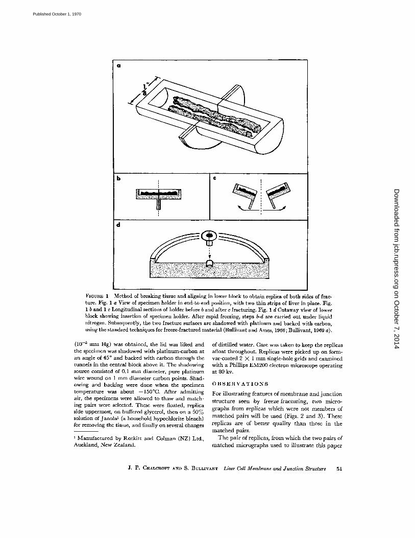
Freeze-fracturing was carried out with a standardtype II device (Bullivant and Ames, 1966 ; Bullivantet al ., 1968 ; Bullivant, 1969 a) in which shadowingand backing were done through tunnels in a coldblock, thus protecting the cold specimen surfaceagainst contamination . A modified brass specimenholder was used (Fig . 1 a) . This consisted of twostandard cylindrical holders filed lengthwise untilsemicylindrical halves, with the specimen holes ex-posed, were left . Semicircular copper wings wereadded to the holders to facilitate handling and orien-tation.
Small pieces of liver from C3H mice were fixed in6% glutaraldehyde in phosphate buffer and storedfor at least 1 hr at 4 ° C in 25°70 v/v glycerol in thebuffer . (It should be noted that glutaraldehyde fixa-tion does not significantly alter the fracturing char-acteristics of membranes .) Very fine strips (0 .1 X0.1 X 2 mm) of the liver were cut in the glycerolsolution . Several of these strips, always moistenedwith glycerol solution, were laid lengthwise in thespecimen holder, held in its end-to-end orientation(Fig. 1 a-b) with locking forceps . The holder andspecimens were frozen in this orientation by plunginginto melted Freon 12 at -155 °C. The holder wasquickly blotted dry of Freon and dropped into theliquid nitrogen bath containing the precooled blocksof the freeze-fracture device . The liver was fracturedby gripping the holder with two pairs of cooled for-ceps and bending and pulling (Fig. 1 c). The twohalves were then placed fracture side uppermost inthe hole in the lower brass block of the freeze-fracturedevice so that the dividing line between halves wasat right angles to the direction of platinum-carbonshadowing (Fig. 1 d) . This orientation ensures thatcomplementary faces are shadowed at the same angle .Previously described operating procedure for thetype II device was followed (Bullivant and Ames,1966 ; Bullivant et al ., 1968 ; Bullivant, 1969 a) . Thedevice was assembled under liquid nitrogen and car-ried over to the evaporator . After a suitable vacuum
on October 7, 2014
jcb.rupress.orgD
ownloaded from
Published October 1, 1970
a
b C
d
FiGERE 1 Method of breaking tissue and aligning in lower block to obtain replica of both sides of frac-ture . Fig. 1 a View of specimen holder in end-to-end position, with two thin strips of liver in place . Fig .1 b and 1 c Longitudinal sections of holder before b and after c fracturing . Fig . 1 d Cutaway view of lowerblock showing insertion of specimen holder . After rapid freezing, steps b-d are carried out under liquidnitrogen. Subsequently, the two fracture surfaces are shadowed with platinum and backed with carbon,using the standard techniques for freeze-fractured material (Bullivant and Ames, 1966 ; Bullivant, 1969 a) .
(10-5 mm Hg) was obtained, the lid was lifted and of distilled water . Care was taken to keep the replicasthe specimen was shadowed with platinum-carbon at afloat throughout . Replicas were picked up on form-an angle of 45 ° and backed with carbon through the var-coated 2 X 1 mm single-hole grids and examinedtunnels in the central block above it. The shadowing with a Phillips EM200 electron microscope operatingsource consisted of 0.1 mm diameter, pure platinum at 80 kv .wire wound on 1 mm diameter carbon points . Shad-owing and backing were done when the specimen OBSERVATIONStemperature was about -150°C . After admitting For illustrating features of membrane and junctionair, the specimens were allowed to thaw and match- structure seen by freeze-fracturing, two micro-ing pairs were selected . These were floated, replica
graphs from replicas which were not members ofside uppermost, on buffered glycerol, then on a 50%solution of Janolal (a household hypochlorite bleach) matched pairs will be used (Figs . 2 and 3) . Thesefor removing the tissue, and finally on several changes replicas are of better quality than those in the
matched pairs.1 Manufactured by Reckitt and Colman (NZ) Ltd .,
The pair of replicas, from which the two pairs ofAuckland, New Zealand.
matched micrographs used to illustrate this paper
J. P. CHALCROFT AND S . BULLIVANT Liver Cell Membrane and Junction Structure
51
on October 7, 2014
jcb.rupress.orgD
ownloaded from
Published October 1, 1970

FIGURES 2-5 Freeze-fracture replicas from the region of the bile canaliculus in mouse liver, showingmembrane faces revealed by fracturing . The line L-L' on Figs . 2-4 refers to the models of Fig . 6 . Themagnifications are all the same (X 110,000), and the shadowing direction is from below . These are indi-cated in each figure, with a scale line for magnification and an encircled arrow for shadowing direction .The micrographs are printed as positives .
FIGURE 2 A replica which is relatively free from contamination and thus shows to advantage the differ-ence between the smoother (-) face of the plasma membrane of one cell and the more particulate (+)face of the plasma membrane of the adjoining cell . Depressions in the smoother (-) surface are ringed .The array of depressions of one gap junction (GE) and the array of particles (G2) of another are seen . Thefracture plane of GI steps to the other face (arrowhead), and this shows that the face with depressionsis superimposed on top of the particle array within a particular junction .
52
on October 7, 2014
jcb.rupress.orgD
ownloaded from
Published October 1, 1970
were taken, were the best we have so far obtained,and they showed correspondence over an areacovering about 10 cells . Examination of these twopairs of matched micrographs (Figs . 4 a-b and5 a-b) shows that the main features of one havetheir three-dimensional complements in the other .Large-scale contaminants are easily detected forthey appear on one member of a pair only . Threemain areas of membrane face will be describedwith respect to the single replicas and the matchingpairs . These areas are the general plasma mem-brane, the gap junction, and the tight junction .They will be described only in terms of fracturefaces ; no judgment will be passed on which sur-faces the faces represent until the Discussion .
(a) The general plasma membrane of a cellshows a (+) face (Fig. 2) covered with manysmall 100-150 A particles . The (-) face issmoother but may bear a few particles and a fewdepressions . Several authors have commented onthe asymmetry of distribution of these particles(Weinstein and Someda, 1967; Branton, 1969 ;Bullivant, 1969 a ; Meyer and Winkelmann, 1969) .
The general plasma membrane breaks so thatthe smoother (-) face (A in Figs . 4 a, 5 b) is thecomplement of the particle-covered (+) face (A' inFigs . 4 b, 5 a) .
(b) Gap junctions are found as differentiatedpatches on the membrane faces of adjoining cellsin the region of the bile canaliculus, but only rarelyimmediately adjacent to it . The gap junction isseen as a close-packed array of particles (G2, Fig .2) on the (+) face of one cell membrane and aclose-packed array of depressions (G 1) on the (-)face of the adjoining cell membrane. The depres-sions often appear as a 90 A center-to-center hex-agonal array, but this regular packing is not so ap-parent for the particles .
The gap junction membrane breaks so that thedepression-covered (-) face (B, C; Figs . 4 a-b and5 a-b) is the complement of the particle-covered(+) face (B', C'). The large-scale matching ofthese two surfaces is striking. One point deservescomment here . The arrays of depressions (B, C)may give the impression of being arrays of parti-cles. Where the array is less ordered, it is obviousthat the array really does consist of depressions,when one takes into account the direction ofshadow (Fig . 2) . Where there is close packing anda low shadowing angle, the shadow side of one de-pression may be associated with the platinum-covered side of its next neighbor, thus giving theimpression that one is seeing a particle . From aclose study of these and other gap junction repli-
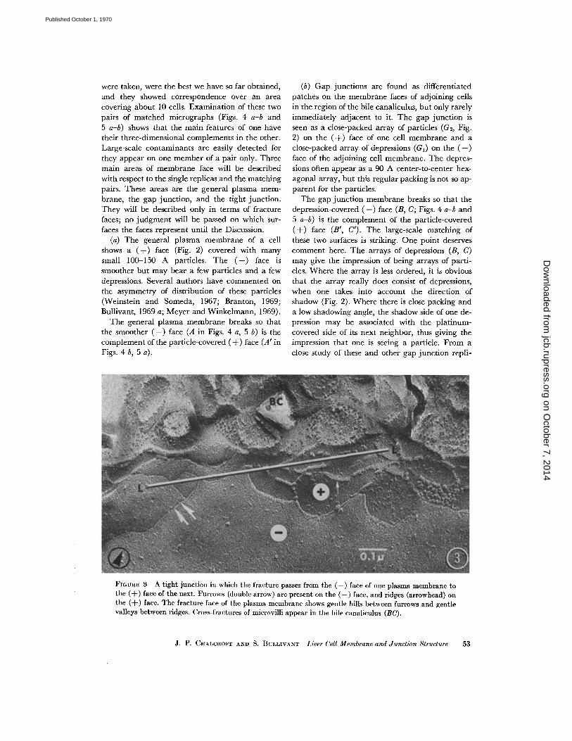
FIGURE 3 A tight junction in which the fracture passes from the (-) face of one plasma membrane tothe (-F) face of the next . Furrows (double arrow) are present on the (-) face, and ridges (arrowhead) onthe (-}-) face . The fracture face of the plasma membrane shows gentle hills between furrows and gentlevalleys between ridges . Cross-fractures of microvilli appear in the bile canaliculus (BC) .
J. P. CHALCRGFT AND S. BULLIVANT Liver Cell Membrane and Junction Structure
53
on October 7, 2014
jcb.rupress.orgD
ownloaded from
Published October 1, 1970

cas, we are convinced that the arrays on the (-)faces of membranes in these paired replicas areactually arrays of depressions .
(c) Tight junctions form continuous seals be-tween adjoining cells and are immediately adja-cent to the bile canaliculus. Within the tight junc-tion, the (+) face (Fig. 3) of one cell membrane iscovered with an interconnected series of concer-tina-like ridges (about 70 A high) . The (-) faceof the adjoining cell membrane shows a similarinterconnected array of furrows. If the break jumpsfrom the (+) face of one membrane to the (-)face of the other, it is seen that the ridges and fur-rows show continuity in direction and it is, there-fore, presumed that the furrows on a (-) face arein register with the ridges on the (+) face below it .Between the ridges the (+) face shows gentlevalleys, and between the furrows the ( -) face showsgentle hills, giving the tight junction area a quiltedappearance .
The tight junction breaks so that the (-) face(with furrows) (D, Fig. 4 a) is the complement ofthe (+) face (with ridges) (D', Fig . 4 b) . The pat-tern of furrows is reflected exactly in the pattern ofridges . In addition, the valleys between the ridgesfind their exact counterpart in the hills betweenfurrows .
DISCUSSION
The three main areas of membranes referred toearlier will now be discussed .
General Plasma Membrane
The paired replicas show some contamination ofthe faces possibly due to condensation of oil orwater vapor on the cold fracture faces before repli-cation. Even on relatively clean faces, such asthose seen in Fig . 2, there is an excess of particleson the (+) face compared with depressions out ofwhich similar particles might have pulled from the(-) face .
If the fracture had proceeded without distortionof the faces, and there had been no subsequentalteration prior to or during replication, then thetwo faces produced would have been exactly com-plementary. In particular, there would have beensufficient depressions to accommodate all the par-ticles. This is not so . In our opinion, the mostlikely explanation is that the particles are realstructures, and not artifacts of preparation, al-though they may be deformed plastically to some
54
THE JOURNAL OF CELL BIOLOGY • VoLumF. 47, 1970
extent during fracturing (Clark and Branton,1968) . Our reasoning is as follows : (a) It is notice-able that depressions are seen in general plasmamembrane fracture faces only when there is littleevidence of contamination ; therefore, slight con-tamination could account for the disappearance ofmany depressions . (b) There could be slight etch-ing or melting of the sharp edges of holes, makingthem more difficult to see . Heating during plati-num evaporation could cause this, even though thebulk specimen temperature is about -150°C .(c) All other things being equal, isolated holes arealways more difficult to see than projections in ashadowed preparation .
In the next section it will be shown that, in thegap junction, the fracture goes either near to or atthe interface between membrane and cytoplasm,revealing particles within the membrane . There isno step on the fracture face between the planebearing the depressions of the gap junction (G I ,Fig. 2) and the smoother general plasma mem-brane (-) face; nor is there a step between theplane on which the particles of the gap junction sit(G2) and the surrounding particle-bearing planeof the general plasma membrane (+) face. Hencethe fracture plane probably proceeds at the samelevel within both gap junction membrane andgeneral plasma membrane. Accordingly we canconstruct a model of the two plasma membranes ofadjoining cells and the probable path of the frac-ture (Fig . 6 a). Each membrane contains particleswithin it . This diagram is related to a particularline on Fig. 2 (see legend to Fig. 6 a) . The fracturegoes around particles within the membrane, butwe do not know whether it goes within the mem-brane or at the interface between membrane andcytoplasm when it is not in the region of particles .This will be discussed in the next section . We have,so far, ignored particles which appear on thesmoother (-) face. There are always some presenteven in the best preparations . These particles areless prominent than the particles of the (+) face .A likely explanation is that they are revealed whenthe fracture plane goes around the other side of theparticle, leaving it attached to and slightly pro-truding above the (-) face . This kind of fracturewould appear to be less common than that whichleaves particles attached to the (+) face . The par-ticles observed on the (-) face may differ struc-turally from those of the (+) face, and this differ-ence may be reflected in the way they fracture
on October 7, 2014
jcb.rupress.orgD
ownloaded from
Published October 1, 1970
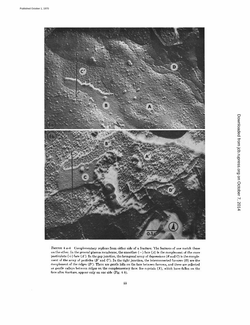
FIGURE 4 a-b Complementary replicas from either side of a fracture . The features of one match thoseon the other. In the general plasma membrane, the smoother (-) face (A) is the complement of the moreparticulate (+) face (A') . In the gap junction, the hexagonal array of depressions (B and C) is the comple-ment of the array of particles (B' and C') . In the tight junction, the interconnected furrows (D) are thecomplement of the ridges (D') . There are gentle hills on the face between furrows, and these are reflectedas gentle valleys between ridges on the complementary face . Ice crystals (X), which have fallen on theface after fracture, appear only on one side (Fig . 4 b) .
5 5
on October 7, 2014
jcb.rupress.orgD
ownloaded from
Published October 1, 1970
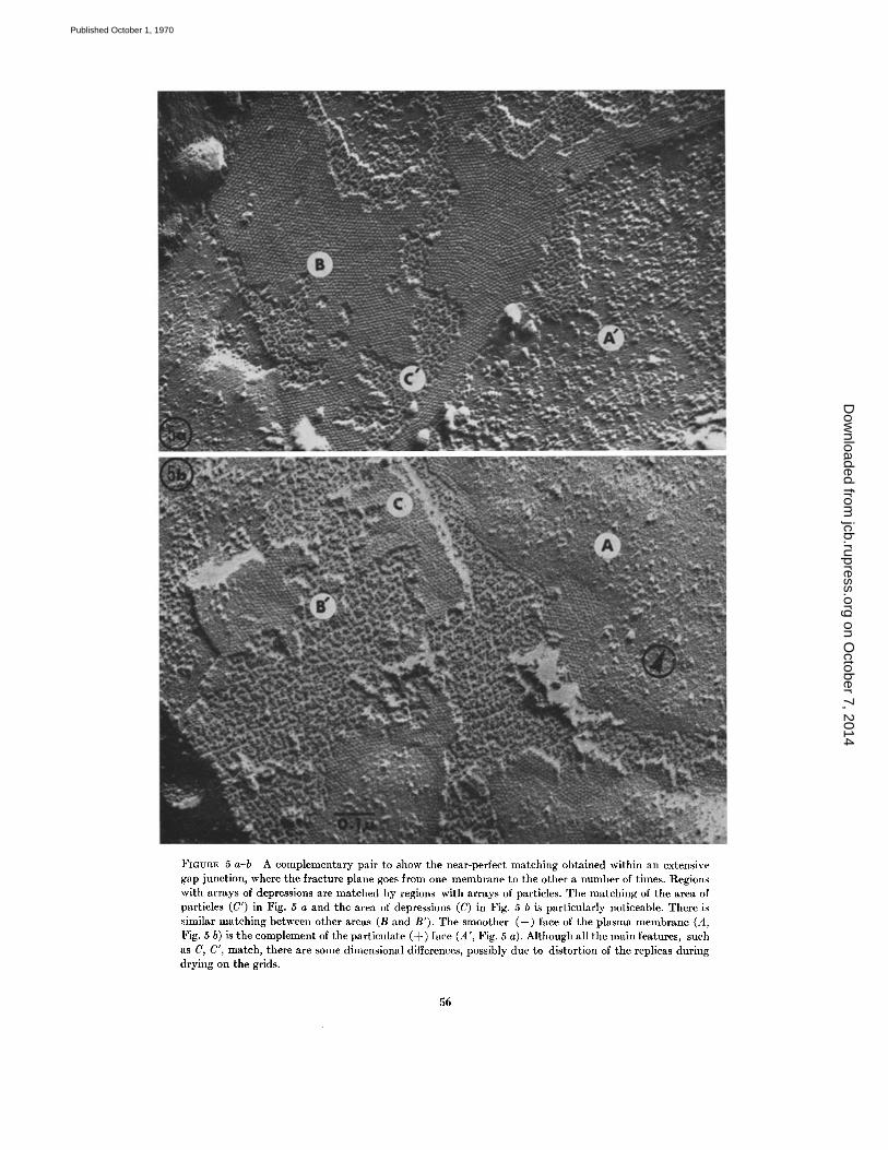
FIGURE 5 a-b A complementary pair to show the near-perfect matching obtained within an extensivegap junction, where the fracture plane goes from one membrane to the other a number of times. Regionswith arrays of depressions are matched by regions with arrays of particles . The matching of the area ofparticles (C') in Fig . 5 a and the area of depressions (C) in Fig . 5 b is particularly noticeable . There issimilar matching between other areas (B and B'). The smoother (-) face of the plasma membrane (A,Fig . 5 b) is the complement of the particulate (+) face (A', Fig . 5 a) . Although all the main features, suchas C, C', match, there are some dimensional differences, possibly due to distortion of the replicas duringdrying on the grids .
56
on October 7, 2014
jcb.rupress.orgD
ownloaded from
Published October 1, 1970
L
` ~ ----
6 (a)
C 2
6(b)
C1
---------- ----------------------
(
C1
6 (C)
C2
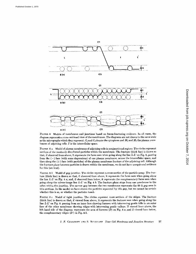
FIGURE 6 Models of membranes and junctions based on freeze-fracturing evidence. In all cases, thediagram represents a cross-sectional view of the membranes . The diagrams are not drawn to the same scaleas the micrographs which they represent. CI and C2 denote the cytoplasm and M1 and M2 the plasma mem-branes of adjoining cells . I is the intercellular space .
FIGURE 6 a Model of plasma membranes of adjoining cells in nonjunctional regions . The circles representsections of the randomly distributed particles within the membrane . The fracture (thick line) is drawn sothat, if observed from above, it represents the faces seen when going along the line L-L' on Fig. 2, passingfrom the (-) face (with some depressions) of one plasma membrane, across the intercellular space, andthen along the (+) face (with particles) of the plasma membrane fracture of the adjoining cell . Althoughthe fracture plane between particles is drawn within the membrane, we do not have unequivocal evidencefor this (see text) .
FIGURE 6 b Model of gap junction . The circles represent a cross-section of the particle array . The frac-ture (thick line) is drawn so that, if observed from above, it represents the faces seen when going alongthe line L-L' on Fig . 4 a ; and, if observed from below, it represents the complementary faces seen whengoing along the mirror-image line L-L' on Fig . 4 b. The fracture plane steps from one membrane to theother within the junction . The narrow gap between the two membranes represents the 20 A gap seen inthin sections . In the model we have shown the particles separated by this gap, but we cannot be certainwhether this is so, or whether the particles touch .
FIGURE 6 c Model of tight junction . The circles represent cross-sections of the ridges . The fracture(thick line) is drawn so that, if viewed from above, it represents the features seen when going along theline L-L' on Fig. 8, passing from an inner face showing furrows with intervening gentle hills to an outerface of the other membrane showing ridges with intervening gentle valleys . If viewed from above, theleft hand side of the diagram represents the area of furrows (D) on Fig . 4 a ; and if viewed from below,the complementary ridges (D') in Fig. 4 b.
1
L
J. P. CRALCROFT AND S. BlLLIVNT Liver Cell Membrane and Junction Structure
57
on October 7, 2014
jcb.rupress.orgD
ownloaded from
Published October 1, 1970

Gap Junction
It is notable that depressions in an array of thegap junction are more readily found than thescattered depressions of the (-) face of the generalplasma membrane. Kreutziger (1968 b) has ob-served that these arrayed depressions are obscuredunder contaminating conditions, and we confirmthat this can happen with both the arrayed andthe scattered depressions. Arrays are obviouslymore easily seen than scattered depressions, but itis also possible that the array region is less suscepti-ble to the effects of contamination .We have shown that the surfaces are the com-
plementary ones produced by fracturing ; yet theparticles on one face are not in such a regular arrayas the depressions on the other . It seems unlikelythat the depressions could have become arrayedduring fracturing or subsequently . We must, there-fore, assume that the particles were originally in anarray which fitted the depressions . On average,these particles have the same 90 A center-to-centerspacing as the depressions and do have some ap-pearance of ordered array . The departure fromorder may be due to deformation of the particles,resulting from energy produced during fracturing .
An interpretation of gap junction fracture pairsis crucial in deciding the location of not only gap
junction particles, but also general plasma mem-brane particles and tight junction ridges. In Fig .4 a, there is a step up from the top of the particlesC' to the depression-covered face B . It can alsobe seen that the layer of particles (B') in Fig . 4 bis complementary to B and was thus originallyabove it before fracture . Similar relationships be-tween the faces are also seen in Fig . 5 a-b . Theremust, therefore, be two layers of particles situatedat different levels and separated by a layer whichhas depressions (out of which the particles came)in each side. Because the particles have a heightof about 70 A and we know from thin sectioningthat the two membranes approach within 20 A,the only type of model which fits is one shown as adiagram in Fig . 6 b . This diagram shows a fractureplane related to particular mirror-image linesdrawn on Fig . 4 a-b . Each membrane contains anarray of particles which, in all probability, are inregister with each other. (This seems likely be-cause we have observed in other gap junctions thatthe array of depressions on the (-) face can beseen to be continuous and in line with the arrayof particles where the fracture jumps to the (+)face of the adjoining membrane .) Sandwiched be-
58
THE JOURNAL OF CELL BIOLOGY • VOLUME 47, 1970
tween the two arrays of particles is the layer ofmaterial which shows depressions when the parti-cles are fractured out of it. If this central layerwere permeable to water, our model would becompatible with the micrographs of similar junc-tions produced both by Revel and Karnovsky(1967), using lanthanum staining, and by Bene-detti and Emmelot (1968), using negative stain-ing. The particles would be outlined in negativecontrast by the stain . Our model is quite similarto the one constructed by Benedetti and Emmelot .
We are certain that the particles are within themembrane, but uncertain about two other aspectsof the model. Firstly, step heights are difficult tomeasure accurately and thus we cannot determinewhether the particles are in contact across the gapor whether there is a 20 A space . Secondly, sincewe know that the particles are about 70 A high,the fracture face on which they sit must be nearor even at the interface between membrane andcytoplasm. It is not possible to be more definite .
Branton's original (Branton, 1966) work on theappearance of ridges on cross-fractured and face-fractured membranes provided good evidencethat the fracture plane goes within the membrane .We have thus placed the plane within the mem-brane in our models, but we do not believe themembrane is split into equal halves.
Tight Junction
We have not obtained a matching pair of repli-cas in which the fracture jumps from one face tothe other within the tight junction, as it does withinthe gap junction in Figs . 4 a-b and 5 a-b . However,by considering the two faces of the tight junctionbreak relative to one membrane in the matchedpair (Fig. 4 a-b) and the two faces seen when afracture crosses from face to face in a single replica(Fig. 3), it is possible to construct a model of thetight junction (Fig. 6 c) ; and this is related to thefracture plane along a particular line in Fig . 3 .The model shows a set of ridges within each mem-brane, and the two sets of ridges are in register .Where it is not going over a ridge, the fractureplane is again placed in the membrane near theinterface between membrane and cytoplasm . Thispositioning of the fracture plane relies only on thefact that the fracture face is continuous and with-out steps from a gap junction, where the situationis known, to the tight junction . It is not possibleto place the fracture plane purely by examinationof replicas of the tight junctions .
on October 7, 2014
jcb.rupress.orgD
ownloaded from
Published October 1, 1970
In the tight junction model, the two membranescome together only at the line where two ridgesmeet. In between, they are bowed away towards thecytoplasm. This is a consequence of the matchinggentle valleys and hills. This aspect of the model issupported by micrographs of thin sections pub-lished by other workers . Farquhar and Palade(1963) showed some micrographs in which therewere "several focal splittings of the fusion linewithin the junction, followed by their re-fusion ."Revel (1968) and Brightman and Reese (1969)showed punctate pentalaminar junctions . In astudy of the same junction as we are describing,that surrounding the bile canaliculus, Matter etal. (1969) showed the two membranes looping fromone punctate fusion point to the next . Sections atright angles to the line of a number of approxi-mately parallel ridges in our model would showpunctate fusions, while sections parallel to ridgesand containing them would show extended fusionsof the type more typically associated with tightjunctions. This latter picture would be more usual,for a 500 A thick section would generally includerelatively long pieces of ridge, as can be seen byexamining the disposition of the ridges (Figs . 3,4 b)
CONCLUSIONS
To sum up, the scattered particles of the generalplasma membrane, the packed particles of the gapjunction, and the ridges of the tight junction areall seen on the (+) face of the fracture plane . Wehave shown this to be complementary with the(-) face, which shows occasional depressions inthe general plasma membrane, arrayed depres-sions in the gap junction, and furrows in the tightjunction. Models for these three types of mem-branes all have particles or ridges within the spacewhich would be occupied by the membrane inthin sections . In the models and in the discussion,we have related our observations to the full thick-ness of the membrane rather than to the compo-nent layers put forward in the "unit membrane"hypothesis (Robertson, 1959) . While our resultsshow that there are particles within membranes,there are extensive areas in which the fracturesurface is smooth and would not be at variancewith a bimolecular leaflet structure, both betweenparticles in the general plasma membrane andbetween the ridges of the tight junction .
The particles seen in array in the gap junctioncan be related to those seen either in thin sectionsof lanthanum-treated material (Revel and
Karnovsky, 1967) or in negatively stained material(Benedetti and Emmelot, 1968) . Nothing com-parable either to the scattered particles of thegeneral plasma membrane or to the ridges of thetight junction has been visualized by such tech-niques. The fact that these structures do not showthe order found in the gap junction may be a par-tial explanation. In addition, denaturation duringfixation and negative staining may lead to theiralteration and incorporation into the generallyobserved triple-layered structure . The particles inthe gap junction membranes are presumably in-volved in cell-to-cell communication . The func-tion of the particles in other types of membrane isnot yet known . Although this paper has been con-cerned with the plasma membrane and its special-izations, intracellular membranes fracture in thesame way, the (+) face with more particles beingthe complement of the smoother (-) face. Wehave observed that this applies to membranes ofthe endoplasmic reticulum, the nuclear envelope,and to both inner and outer mitochondrial mem-branes. Thus, the particles concerned must alsobe located within the respective membranes.
This work was supported by a grant from the Auck-land Division, Cancer Society of New Zealand andby United States Public Health Service grant No .GM 14365 . We are indebted to Mr. John Fieldsfor preparing the diagrams and the photographicprints .Received for publication 20 October, 1969, and in revisedform 10 May 1970.
REFERENCES
BENEDETTI, E. L ., and P. EMMELOT. 1968. Hexagonalarray of subunits in tight junctions separated fromisolated rat liver plasma membranes . J . Cell Biol.38 :15 .
BRANTON, D. 1966 . Fracture faces of frozen mem-branes . Proc. Nat . Acad. Sci. U.S.A . 55:1048.
BRANTON, D. 1969 . Membrane structure . Ann . Rev.Plant Physiol . 20:209.
BRIGHTMAN, M. W ., and T. S . REESE. 1969. Junc-tions between intimately apposed cell membranesin the vertebrate brain . J. Cell Biol . 40:648 .
BULLIVANT, S. 1969 a . Freeze-fracturing of biologicalmaterials . Micron . 1 :46 .
BULLIVANT, S . 1969 b . Particles seen in freeze-fracturepreparations . In Proceedings Electron MicroscopySociety of America. Claitor's Publishing Division,Baton Rouge . 206.
BULLIVANT, S ., and A . AMES, III. 1966. A simple
J. P. CHALCROFr AND S. BULLIVANT Liver Cell Membrane and Junction Structure
59
on October 7, 2014
jcb.rupress.orgD
ownloaded from
Published October 1, 1970
freeze-fracture replication method for electronmicroscopy . J. Cell Biol . 29 :435 .
BULLIVANT, S., R. S. WEINSTEIN, and K. SOMEDA .1968. The type II simple freeze-cleave device .J. Cell Biol . 39 :19a . (Abstr.) .
CLARK, A. W., and D. BRANTON . 1968. Fracturefaces in frozen outer segments from the guinea pigretina. Z. Zellforsch . 91:586 .
FARQUHAR, M. G., and G . E. PALADE . 1963 . Junc-tional complexes in various epithelia . J. Cell Biol .17 :375 .
KREUTZIGER, G. 0. 1968 a . Freeze-etching of inter-cellular junctions of mouse liver . In ProceedingsElectron Microscopy Society of America . Claitor'sPublishing Division, Baton Rouge . 234.
KREUTZIGER, G. 0. 1968 b . Specimen surface con-tamination and the loss of structural detail in freeze-fracture and freeze-etch preparations . In Proceed-ings Electron Microscopy Society of America .Claitor's Publishing Division, Baton Rouge . 138 .
MCNUTT, N. S., and R . S. WEINSTEIN. 1969 . Inter-locking subunit arrays forming nexus membranes .In. Proceedings Electron Microscopy Society ofAmerica. Claitor's Publishing Division, BatonRouge. 330.
MATTER, A., L. ORci, and C. ROUILLER. 1969. Astudy on the permeability barriers between Disse'sspace and the bile canaliculus. J. Ultrastruct. Res .Suppl . 11 .
MEYER, H. W., and H. WINKELMANN. 1969. Die
60 THE JOURNAL OF CELL BIOLOGY . VOLUME 47, 1970
Gefrieratzung and die Struktur biologischerMembranen. Protoplasma . 68 :253 .
MOOR, H. 1969 . Freeze-etching . Int . Rev . Cytol . 25 :391 .
MOOR, H., and K. MUHLETHALER. 1963 . Fine struc-ture in frozen-etched yeast cells . J. Cell Biol. 17 :609 .
MUHLETHALER, K ., H. MOOR, and J . W. SZARKOW-SKI. 1965 . The ultrastructure of the chloroplastlamellae . Planta (Berlin) . 67 :305 .
REVEL, J-P . 1968 . Studies on the fine structure ofintercellular junctions . In Proceedings ElectronMicroscopy Society of America. Claitor's Publish-ing Division, Baton Rouge . 40 .
REVEL, J-P ., and M . J . KARNOVSKY. 1967 . Hexagonalarray of subunits in intercellular junctions of themouse heart and liver. J. Cell Biol. 33 :07 .
ROBERTSON, J . D. 1959 . The ultrastructure of cellmembranes and their derivatives . Biochem . Soc .Symp . 16 :1 .
STAEHELIN, L. A ., T. M. MUKHERJEE, and A . WYNN-WILLIAMS . 1969. Freeze-etch appearance of thetight junctions in the epithelium of small and largeintestine of mice. Protoplasma . 67 :165 .
STEERE, R . L., AND M . MOSELEY. 1969. New dimen-sions in freeze-etching . In Proceedings ElectronMicroscopy Society of America. Claitor's Publish-ing Division, Baton Rouge . 202 .
WEINSTEIN, R . S., and K . SOMEDA . 1967 . The freeze-cleave approach to the ultrastructure of frozentissues. Cryobiology . 4 :116 .
on October 7, 2014
jcb.rupress.orgD
ownloaded from
Published October 1, 1970