Intelligent Traffic Prediction by Multi-sensor Fusion using Multi ...
IOP PUBLISHING MEASUREMENT SCIENCE AND TECHNOLOGY
Meas. Sci. Technol. 22 (2011) 114025 (12pp) doi:10.1088/0957-0233/22/11/114025
An intelligent multi-sensor system for firstresponder indoor navigationA Amanatiadis, A Gasteratos and D Koulouriotis
Laboratory of Robotics and Automation, Department of Production and Management Engineering,Democritus University of Thrace, 12 Vas. Sofias Str, GR-67100, Xanthi, Greece
E-mail: [email protected], [email protected] and [email protected]
Received 10 January 2011, in final form 26 August 2011Published 14 October 2011Online at stacks.iop.org/MST/22/114025
AbstractThis paper presents an indoor navigation system based on sensor data from first responderwearable modules. The system combines an inertial measurement unit, a digital camera and aradio frequency identification device in a way that allows the advantages of each sensor to befully exploited. The key to this synergy is the extracted qualitative criteria which characterizethe performance of each sensor subsystem at various first responder activities and operationalconditions under certain time intervals. The accuracy of the detected walking pattern throughmeasurements of the acceleration magnitude from the inertial sensor is utilized for theperformance evaluation of the dead-reckoning algorithm. The amount of correct featurematches is linked to the three-dimensional scene representation from the camera navigationsubsystem and finally, the degree of probability of each radio frequency identification locationestimate is exploited as a straightforward qualitative criterion. The final fused locationestimation is extracted after applying fuzzy if–then rules at each time interval. Since theinertial sensor suffers from accumulated drift, the rules of the fuzzy inference system drop themeasurements from the inertial measurement unit whenever the other two subsystems performadequately. Extensive comparison and experimental results based on the proposed architecturehave shown not only better navigation effectiveness and lower positioning error compared withother first responder navigation systems but also increased accuracy in various and challengingoperational conditions.
Keywords: indoor navigation, pedestrian localization, sensor fusion, first responder
(Some figures in this article are in colour only in the electronic version)
1. Introduction
First responder missions require robust and precise indoorpositioning systems. The objective of such a system ismultifold: to be lightweight, modular, power efficient andto provide accurate location estimates even in first responderoperational conditions (Rantakokko et al 2011). Furthermore,robustness in critical operational environments such as fire,smoke and darkness should be one of the main technicalchallenges in creating such systems.
Since electromechanical accelerometers and gyros arebecoming smaller, cheaper and more power efficient, newpositioning and accurate systems are emerging. Their sizeand wireless interface permit placement in any part of thefirst responders’ body, even on their boots (Foxlin 2005).
For these reasons, inertial navigation with foot-mountedsensors has been chosen to comprise the core of an indoornavigation system in global positioning system (GPS)-deniedenvironments, since it can yield meter-level accuracies formore than 15 min. However, there is still a need for additionalsupporting sensors to keep the accuracy at acceptable levelsthroughout the duration of typical first responder operations.Complementary sensors can be magnetometers, imagingsensors, ultrasonic and radio-based sensors. A system thatwill utilize some of these sensors efficiently requires carefulsensor fusion design and tuning.
Simultaneous localization and mapping (SLAM) triesto estimate the trajectory of a person’s movement in anunknown environment, while it also tries to create a map ofthe surrounding area (Davison et al 2007). Recent SLAM
0957-0233/11/114025+12$33.00 1 © 2011 IOP Publishing Ltd Printed in the UK & the USA
Meas. Sci. Technol. 22 (2011) 114025 A Amanatiadis et al
algorithms have been proposed trying to recover the structureof a scene using multiple frames (Tomono 2005). Givenfeature correspondences, the geometric constraints among thedifferent views can be established. Commonly used sensorsinclude digital cameras and laser range finders. The powerconsumption of camera-based SLAM is to date one of themain challenges. Furthermore, additional imaging sensors,such as night vision or infrared, are required if we need tohave a stand alone SLAM system. Despite these drawbacks,image aiding is currently integrated into indoor positioningsystems.
Radio-based ranging positioning approaches can achieveadequate performance during long-term operations. Pre-installed equipment in the form of access points or RFIDtags would be the ideal solution, but currently this solution isconsidered infeasible. Recently, critical infrastructures suchas hospitals and airports tend to provide such pre-deploymentdue to the wide use of wireless access points (Fischer andGellersen 2010). In the case that no a priori mapping isavailable, portable infrastructures are brought to the scene ofoperations. The mapping of the vast number of Wi-Fi stationsin metropolitan areas can also be exploited in order to enableWi-Fi positioning.
In our system, we used the three heterogeneous butcomplementary approaches of inertial, camera and Wi-Fipositioning in order to satisfy most of the first responderrequirements. The system combines the widely used inertialsensor navigation system with the two most promisingindoor navigation systems: the image aiding and radio-basedpositioning. More precisely, a digital camera and a radiofrequency identification device were utilized in a way thatallows the advantages of each sensor to be fully exploited.The key to this synergy is the extracted qualitative criteriawhich characterize the performance of each sensor subsystemat various first responder activities and operational conditionsunder certain time intervals. Since the inertial measurementunit (IMU) suffers from accumulated drift, the system dropsthe measurements from the IMU sensor whenever the other twosubsystems are performing adequately. Fuzzy if-then rules areapplied to all three subsystem measurements along with theirqualitative criteria at each time interval, in order to carry outthe fusion process.
The structure of this paper is as follows. In section 2,we examine the first responder environmental and operationalconditions in order to assess the performance of eachsubsystem under such constraints. In section 3, we describein detail the overall architecture of the proposed navigationsystem. In section 4, we present each navigation subsystemindividually and their qualitative criteria. The fuzzy inferencesystem for the fusion process is presented in section 5. Insection 6, we present the performance evaluation of theproposed indoor navigation technique. Finally, we provideconcluding remarks in section 7.
2. The first responder case
The typical operation and activity of a first responder cannotbe characterized by routine occurrences and scenarios. A first
responder must respond to incidents and events, the cause,severity and consequences of which are not a priori defined.Furthermore, these incidents rarely occur at predeterminedplaces and structures. Operations inside critical infrastructurescan conceal high risks with potential life threatening situations.Indoor navigation data could significantly improve the safetyof the responders operating in such critical infrastructures(Renaudin et al 2007).
Indoor navigation of a first responder is a very demandingand challenging task since the conditions and movement typesare described by high complexity and high variety. Thus,first responder indoor navigation systems must be more robustthan conventional pedestrian navigation systems (Sawyer et al2004).
The first challenge corresponds to the variety of themovements that the first responder executes. Apart fromthe typical walking movement, other types of movementsare executed from first responders, such as going up- ordownstairs, crawling, side stepping, duck walking, runningand climbing.
Real-time SLAM using a single camera has beenextensively used in robot navigation (Davison 2003). Severalapproaches have also been proposed for pedestrian localizationusing mounted digital cameras (Kourogi and Kurata 2003a,Jirawimut et al 2003). The challenging task using thisapproach is the environmental conditions, which are differentfrom those where robots operate. Smoke, fire or low lightningconditions are very often in operational scenarios of firstresponders. Thus, stand alone camera navigation systemshave been proved to be inefficient in such cases.
Utilizing protocols that provide location estimation basedon the received signal strength indication of wireless accesspoints is the best solution for RFID first responder trackingsystems. The main benefit of such measurement is thatthe first responders must carry only one Wi-Fi tag whichreceives the signals from the pre-deployed wireless accesspoints. However, in order to estimate location from thereceived signal strength readings, it is necessary to have aspatial statistical representation of the received signal strengthsfrom the critical infrastructure access points (Chen et al 2006).Currently, most critical infrastructures do not provide suchrepresentations based on off-line measurements, a necessityfor probabilistic location systems. Thus, this training phasemust be carried out by the first responder units. Research forfast and reliable calibration procedures based on the receivedsignal strength indication is currently one of the most activefields in probabilistic positioning community (Narzullaevet al 2010). Battery-operated beacons can be used insteadof wireless access points for cases when power supply isnot available. Unfortunately, even in an ideal calibrationprocedure, many factors that are met in first responder eventscan deteriorate the accuracy of the RFID measurements. Someof the radio attenuation factors that can affect the transmissionand strength of radio signals inside a building are humidity,smoke, high temperature and thermal layers that could reflector refract radio waves. What is more, when the buildingsuffers from inside collapses the accuracy of the RFID locationsystems is even more deteriorated.
2
Meas. Sci. Technol. 22 (2011) 114025 A Amanatiadis et al
(a) (b)
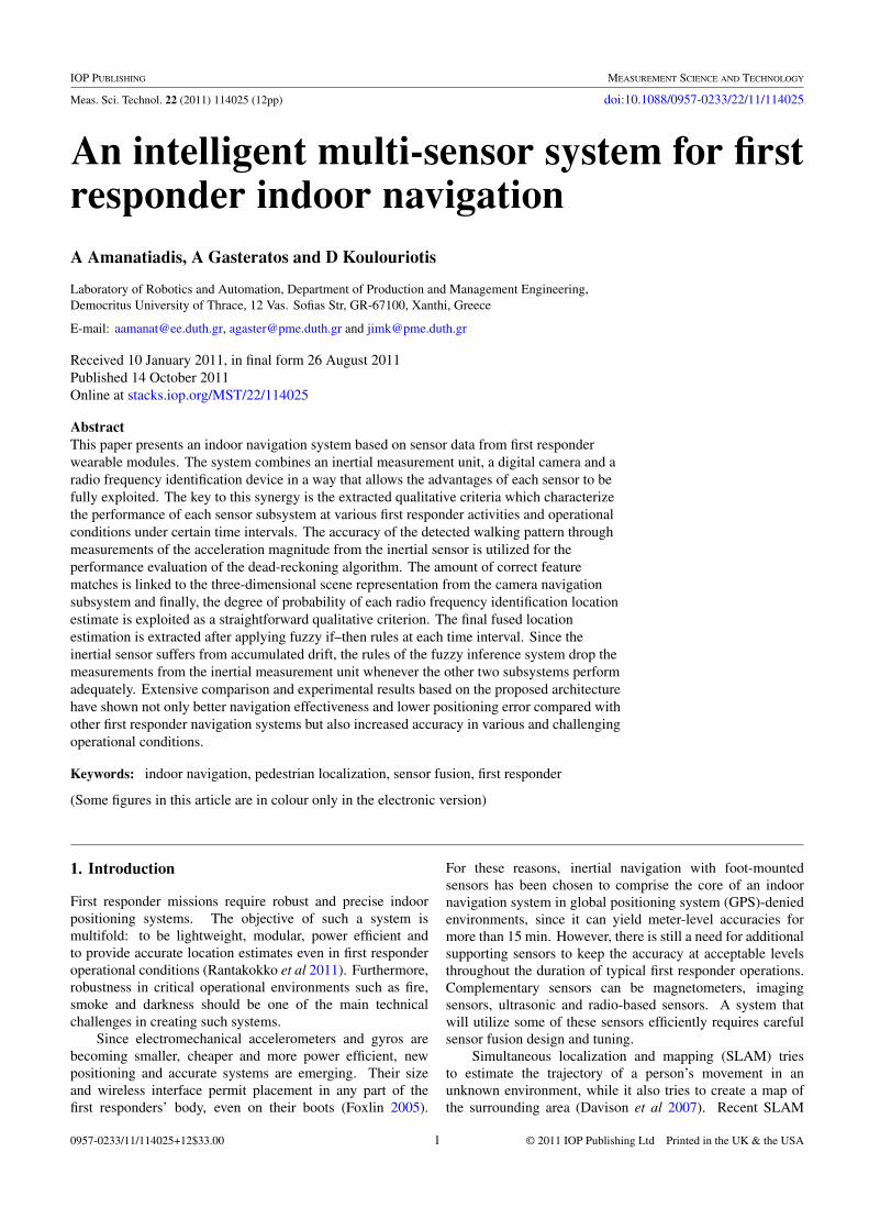
Figure 1. Components of the indoor navigation system include: (a) an RFID tag, a digital camera and an inertial sensor attached to apersonal digital assistant, (b) deployable wireless communication nodes.
Table 1. Summary of the sensors used and their specifications.
Sensor Name Vendor Specifications
Accelerometer MTi Xsens Full scale: 50 m s−2 Bandwidth: 30 HzGyro MTi Xsens Full scale: 1200 deg s−1 Bandwidth: 50 HzRFID T301BD Ekahau Wi-Fi standard: 802.11b Direct sequence spread spectrumCamera FL2G-13S2C Point Grey Max. Res.: 1288 × 964 Sensor: 1/3′′ EXview CCDLens DF6HA-1B FUJINON Focal length: 6 mm Angle of view: 1/2′′
All the aforementioned first responder activities andoperational conditions make indoor navigation a verydemanding and challenging task. In our implementation, wehave first examined all these conditions separately trying toestimate and evaluate qualitative characteristics for optimalsubsystem operation (Amanatiadis et al 2010). Subsequently,the multi-sensor architecture will exploit these attributes inorder to carry out the integration and fusion task.
3. Multi-sensor architecture
The wearable sensors include a digital camera, an RFID tagand an IMU attached to a personal digital assistant (PDA) asshown in figure 1. Table 1 summarizes the specifications ofthe aforementioned sensors used in the navigation system.
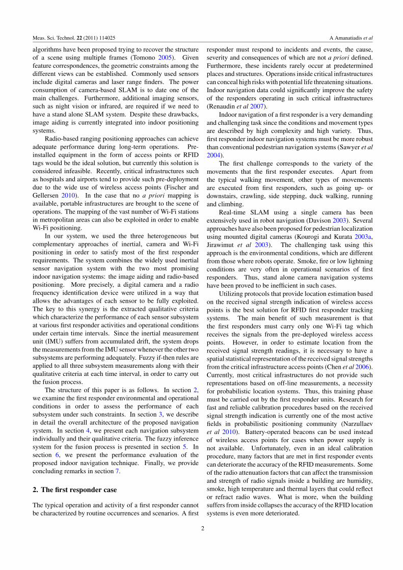
The wireless communication nodes are deployed bythe first responders in the critical infrastructure in orderto establish the communication backbone. However, thesenodes also operate as beacons for the indoor navigationsystem. The functions of the indoor navigation system areseparated into video processing, RFID processing, inertialsensor processing and graphical user interface support. Allfunctions are processed and implemented with the use of twohost computers. The first host computer is the personal digitalassistant, carried by the first responder in operations. Thesecond host computer comprises the command center unit andis placed where the command post is deployed. Both units areequipped with a graphical user interface for better interaction.
The flowchart of the first responder indoor navigation systemcan be seen in figure 2.
The two host computers are connected together with awireless high speed network. The communication protocolbetween the computers uses a higher level abstraction, builton top of sockets, meeting the requirements for low latency andpriority handling. Apart from the libraries, the communicationprotocol consists of a server daemon residing on each side ofboth hosts and acts as a gateway to the other side. Each serverdaemon is in charge of delivering the messages received bythe remote end to the clients in its network, and forwarding themessages received by clients in its network to the remote end,through the wireless link. The priority handling is realizedby means of the cooperation between the server protocol andquality of service features such as packet identification rules,service flow classes for bandwidth reservation, latency andjitter control on the identified packets and quality of serviceclasses with associated service flow classes.
The data received by the inertial sensor at the PDA arefirstly filtered by a complementary Kalman filter (Roetenberget al 2005). The errors in the force measurements introducedby the accelerometer and the errors in the measurementof angular change in the orientation with respect to theinertial space introduced by gyroscopes are two fundamentalerror sources which affect the performance of the inertialsensor. These constant offset errors represent the abilityof the sensor to reproduce the sensed rate of accelerationor turn and measured as parts per million (ppm) of
3
Meas. Sci. Technol. 22 (2011) 114025 A Amanatiadis et al
Wearable Sensors
Digital Camera Radio Frequency Identification
Localization
ApplicationLayer Device Driver
FFmpeg Received Signal Intensity
TransportLayer
CompressionEncapsulation
XML Parsing
Network Layer
UDP BasedHigh Priority
UDP Based High Priority
TransportLayer
DecodingSynchronization
XML Parsing
ApplicationLayer
VLC Player
Video Driver
Location and Event Stream
Data Fusion
Command Center
Wearable Modules
Inertial Sensor
Device Driver
Kalman Filtering
Event Mode
UDP BasedHigh Priority
Free Streaming
PDA Graphical User Interface
UDP BasedLow Priority
Sensor Data Processing
Structure from Motion
FeatureExtraction
ProbabilisticModel
Received Signal Intensity
Graphical User Interface
Zero Velocity Update
ActivityClassification
XML Parsing
Daemon
Thread Handling
XML Parsing
Thread Handling
Daemon
SignalProcessing
Figure 2. Flowchart of the indoor navigation system.
scale-factor stability. Moving bias error sources, randomerror sources, misalignment and nonorthogonality errors mustalso be investigated in order to reproduce a more advancederror model. Furthermore, all inertial measurements arecorrupted by additive white zero-mean Gaussian noise (Ovaskaand Valiviita 1998). The complementary Kalman filter isnot based on the model of the process, but on a model oferrors. The advantages are that this structure maintains thehigh dynamic response necessary for attitude state variablesand most error processes in the IMUs can be described bylinear processes (Brown and Hwang 1997). The four partsof the complementary filter are the a priori model predictionof the state, the error model, the Kalman filter and the statecorrection yielding the a posteriori state estimate (Luinge andVeltink 2005). The filtering is implemented on the PDA wherethe inertial sensor is attached.
The video streaming and processing present highcomputational burden and resource demand while requiringthe full usage of certain instruction sets of a modernmicroprocessor. Thus, a high performance PDA was chosenwith the necessary interface for a digital camera. For all thevideo streaming tasks, the FFmpeg video open source libraries
(Amanatiadis et al 2008) were selected. The PDA videoserver allows multicast transmission while it sends the videostream to a fixed-destination multicast address. The servicesdealing with the video stream like the video player in thecommand center only have to listen to the appropriate multicastaddress, so several services can receive the same video streamwithout increasing bandwidth consumption. The compressionwas done using MPEG-4 codec, and the transmission of thevideo streams using the MPEG Transport Stream (Gringeriet al 1998). MPEG-TS provides many features found in datalink layers, such as packet identification, synchronization,timing (clock references and timestamps), multiplexing andsequencing information. In the architecture chosen, eachprocessing tree is executed within its own thread and isprocessed in parallel with other source nodes, like RFID andinertial sensor loops. In the command center, an open sourcevideo player VLC was chosen for the playback service of thevideo streams (Amanatiadis et al 2008). VLC is an open sourcecross-platform media player which supports a large number ofmultimedia formats and it is based on the FFmpeg libraries.The same FFmpeg libraries can decode and synchronize thereceived UDP packets.
4
Meas. Sci. Technol. 22 (2011) 114025 A Amanatiadis et al
Kalman Filtering
Fuzzy Inference System
Wearable Modules
Inertial Sensor
Digital Camera
Acceleration Stride Detection
Active RFID Tag
Orientation
Frames
Radio Signal Strength Information
Features
Accelaration
Orientation
FeatureFrame
Coordinates
Position Estimation
Position Estimation
Probabilistic Model
Navigation System
(x,y,θ,t)
Calibrated Model
Position Estimation
Location Probability
RINS
RSFM
RRFID
Feature Extraction
Feature Matching
Magnetic Field
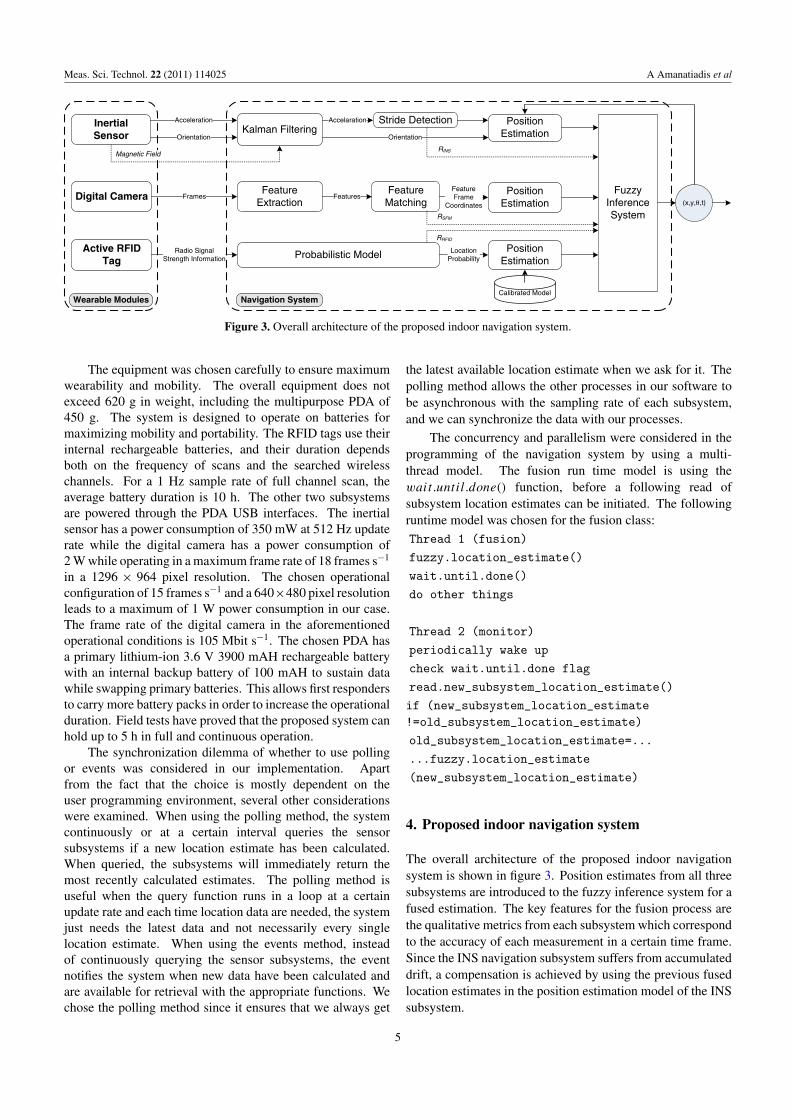
Figure 3. Overall architecture of the proposed indoor navigation system.
The equipment was chosen carefully to ensure maximumwearability and mobility. The overall equipment does notexceed 620 g in weight, including the multipurpose PDA of450 g. The system is designed to operate on batteries formaximizing mobility and portability. The RFID tags use theirinternal rechargeable batteries, and their duration dependsboth on the frequency of scans and the searched wirelesschannels. For a 1 Hz sample rate of full channel scan, theaverage battery duration is 10 h. The other two subsystemsare powered through the PDA USB interfaces. The inertialsensor has a power consumption of 350 mW at 512 Hz updaterate while the digital camera has a power consumption of2 W while operating in a maximum frame rate of 18 frames s−1
in a 1296 × 964 pixel resolution. The chosen operationalconfiguration of 15 frames s−1 and a 640×480 pixel resolutionleads to a maximum of 1 W power consumption in our case.The frame rate of the digital camera in the aforementionedoperational conditions is 105 Mbit s−1. The chosen PDA hasa primary lithium-ion 3.6 V 3900 mAH rechargeable batterywith an internal backup battery of 100 mAH to sustain datawhile swapping primary batteries. This allows first respondersto carry more battery packs in order to increase the operationalduration. Field tests have proved that the proposed system canhold up to 5 h in full and continuous operation.
The synchronization dilemma of whether to use pollingor events was considered in our implementation. Apartfrom the fact that the choice is mostly dependent on theuser programming environment, several other considerationswere examined. When using the polling method, the systemcontinuously or at a certain interval queries the sensorsubsystems if a new location estimate has been calculated.When queried, the subsystems will immediately return themost recently calculated estimates. The polling method isuseful when the query function runs in a loop at a certainupdate rate and each time location data are needed, the systemjust needs the latest data and not necessarily every singlelocation estimate. When using the events method, insteadof continuously querying the sensor subsystems, the eventnotifies the system when new data have been calculated andare available for retrieval with the appropriate functions. Wechose the polling method since it ensures that we always get
the latest available location estimate when we ask for it. Thepolling method allows the other processes in our software tobe asynchronous with the sampling rate of each subsystem,and we can synchronize the data with our processes.
The concurrency and parallelism were considered in theprogramming of the navigation system by using a multi-thread model. The fusion run time model is using thewait.until.done() function, before a following read ofsubsystem location estimates can be initiated. The followingruntime model was chosen for the fusion class:
Thread 1 (fusion)
fuzzy.location_estimate()
wait.until.done()
do other things
Thread 2 (monitor)
periodically wake up
check wait.until.done flag
read.new_subsystem_location_estimate()
if (new_subsystem_location_estimate!=old_subsystem_location_estimate)
old_subsystem_location_estimate=...
...fuzzy.location_estimate
(new_subsystem_location_estimate)
4. Proposed indoor navigation system
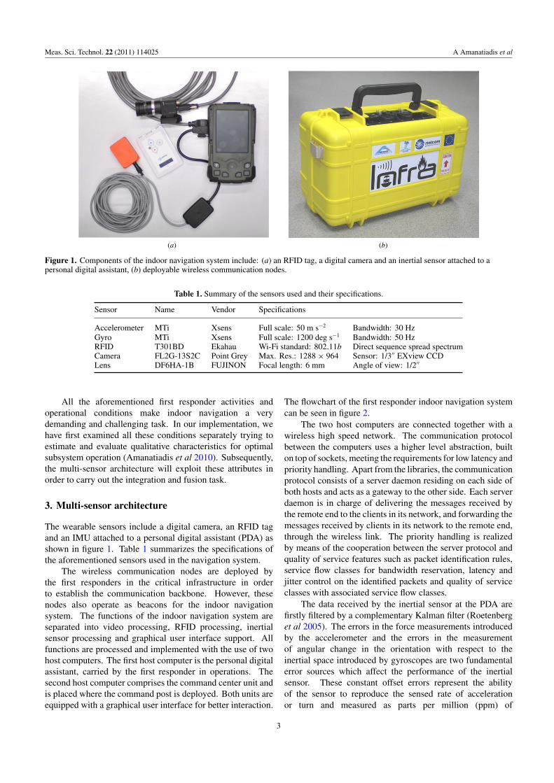
The overall architecture of the proposed indoor navigationsystem is shown in figure 3. Position estimates from all threesubsystems are introduced to the fuzzy inference system for afused estimation. The key features for the fusion process arethe qualitative metrics from each subsystem which correspondto the accuracy of each measurement in a certain time frame.Since the INS navigation subsystem suffers from accumulateddrift, a compensation is achieved by using the previous fusedlocation estimates in the position estimation model of the INSsubsystem.
5
Meas. Sci. Technol. 22 (2011) 114025 A Amanatiadis et al
ts t2 tk
Δ t
Calculated velocity from IMU acceleration data
Figure 4. Key phases and timestamps in a stride.
4.1. Inertial sensor subsystem
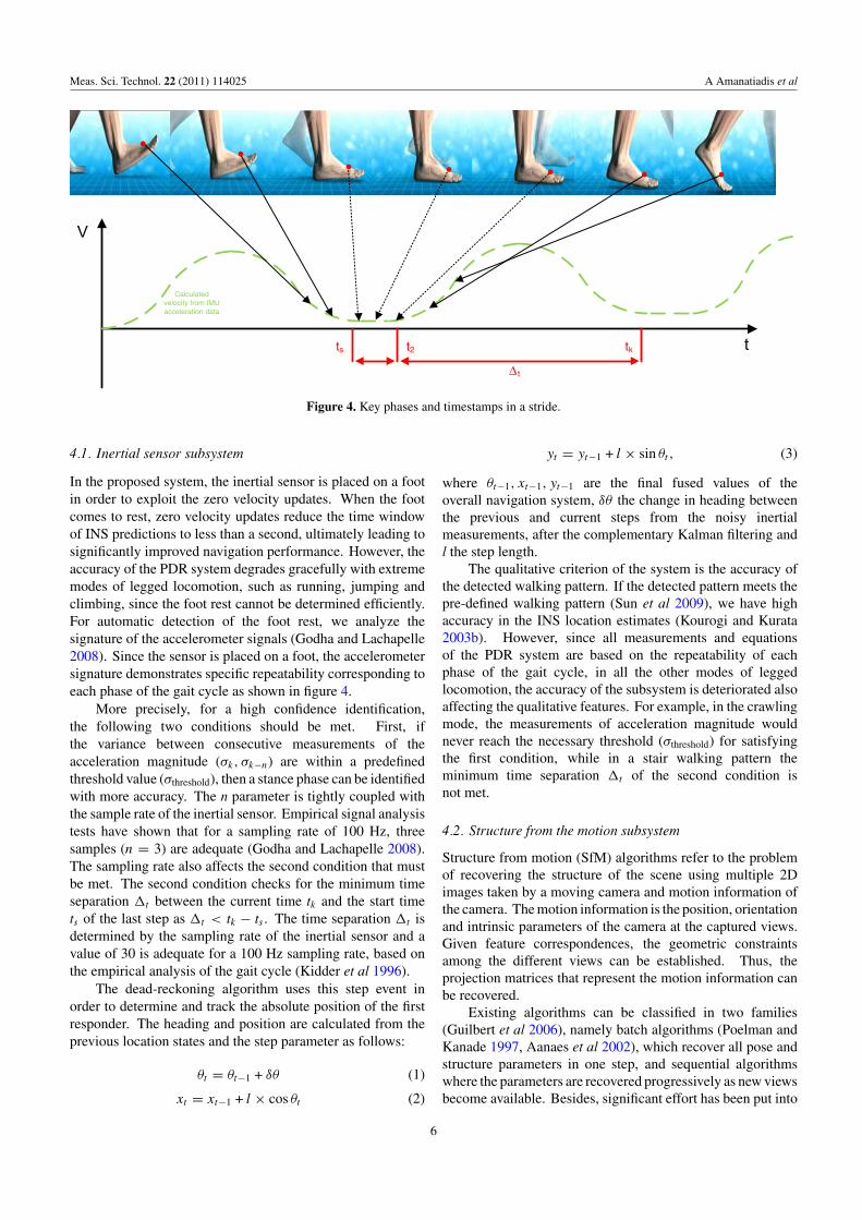
In the proposed system, the inertial sensor is placed on a footin order to exploit the zero velocity updates. When the footcomes to rest, zero velocity updates reduce the time windowof INS predictions to less than a second, ultimately leading tosignificantly improved navigation performance. However, theaccuracy of the PDR system degrades gracefully with extrememodes of legged locomotion, such as running, jumping andclimbing, since the foot rest cannot be determined efficiently.For automatic detection of the foot rest, we analyze thesignature of the accelerometer signals (Godha and Lachapelle2008). Since the sensor is placed on a foot, the accelerometersignature demonstrates specific repeatability corresponding toeach phase of the gait cycle as shown in figure 4.
More precisely, for a high confidence identification,the following two conditions should be met. First, ifthe variance between consecutive measurements of theacceleration magnitude (σk, σk−n) are within a predefinedthreshold value (σthreshold), then a stance phase can be identifiedwith more accuracy. The n parameter is tightly coupled withthe sample rate of the inertial sensor. Empirical signal analysistests have shown that for a sampling rate of 100 Hz, threesamples (n = 3) are adequate (Godha and Lachapelle 2008).The sampling rate also affects the second condition that mustbe met. The second condition checks for the minimum timeseparation �t between the current time tk and the start timets of the last step as �t < tk − ts . The time separation �t isdetermined by the sampling rate of the inertial sensor and avalue of 30 is adequate for a 100 Hz sampling rate, based onthe empirical analysis of the gait cycle (Kidder et al 1996).
The dead-reckoning algorithm uses this step event inorder to determine and track the absolute position of the firstresponder. The heading and position are calculated from theprevious location states and the step parameter as follows:
θt = θt−1 + δθ (1)
xt = xt−1 + l × cos θt (2)
yt = yt−1 + l × sin θt , (3)
where θt−1, xt−1, yt−1 are the final fused values of theoverall navigation system, δθ the change in heading betweenthe previous and current steps from the noisy inertialmeasurements, after the complementary Kalman filtering andl the step length.
The qualitative criterion of the system is the accuracy ofthe detected walking pattern. If the detected pattern meets thepre-defined walking pattern (Sun et al 2009), we have highaccuracy in the INS location estimates (Kourogi and Kurata2003b). However, since all measurements and equationsof the PDR system are based on the repeatability of eachphase of the gait cycle, in all the other modes of leggedlocomotion, the accuracy of the subsystem is deteriorated alsoaffecting the qualitative features. For example, in the crawlingmode, the measurements of acceleration magnitude wouldnever reach the necessary threshold (σthreshold) for satisfyingthe first condition, while in a stair walking pattern theminimum time separation �t of the second condition isnot met.
4.2. Structure from the motion subsystem
Structure from motion (SfM) algorithms refer to the problemof recovering the structure of the scene using multiple 2Dimages taken by a moving camera and motion information ofthe camera. The motion information is the position, orientationand intrinsic parameters of the camera at the captured views.Given feature correspondences, the geometric constraintsamong the different views can be established. Thus, theprojection matrices that represent the motion information canbe recovered.
Existing algorithms can be classified in two families(Guilbert et al 2006), namely batch algorithms (Poelman andKanade 1997, Aanaes et al 2002), which recover all pose andstructure parameters in one step, and sequential algorithmswhere the parameters are recovered progressively as new viewsbecome available. Besides, significant effort has been put into
6
Meas. Sci. Technol. 22 (2011) 114025 A Amanatiadis et al
the so-called auto-calibration (VanGool et al 1998), wherethe initially unknown intrinsic parameters of the camera arerecovered together with the pose.
The method used in our system belongs to sequentialalgorithms where the parameters are recovered progressivelyas new views become available and consists of the followingsteps.
• Extract and track feature points through the imagesequence. A fast, invariant and robust feature descriptionframework that consists of a detector and a descriptor(Bay et al 2008) is used together with a correlation-basedtracker, similar to the KLT tracker (Baker and Matthews2004).
• Eliminate outliers using the constraints imposed by theepipolar geometry. For sequences where the matchingof the individual frames is difficult, for instance dueto excessive noise, the RANSAC paradigm is used toeliminate the outliers.
• Recover the structure and motion parameters usingthe factorization scheme (Poelman and Kanade 1997),achieving an initial estimation of Euclidean structure andmotion parameters.
• Refine the Euclidean structure and motion using bundleadjustment (Strasdat et al 2010).
Since video transmission is a prerequisite for firstresponder missions, we had to choose a configuration thatsatisfies the tradeoffs between quality in the transmittedvideo, accuracy in the feature extraction algorithm and limitedprocessing power. A camera resolution of 640 × 480 pixels at15 frames s−1 was transmitted to command center. However,the extraction of feature points at such frame rates would leadto a potential lack of processing power. Thus, only 2 frames s−1
were used for the feature extraction algorithm resulting in anaverage of 79% of correct matches.
The qualitative criterion, which will determine theefficiency of this subsystem, is the number of correct matchesalong the image sequence. Since the geometric constraintsamong the different views are tightly coupled with the numberof correct matches, this metric can be defined as a fine qualitymeasure.
4.3. Radio-frequency identification subsystem
In order to overcome the RFID aforementioned problems, weused a probabilistic positioning framework, where the worldis taken to be probabilistic and not deterministic, acceptingthe fact that the measured signals are inherently noisy. Oursolution can be applied in infrastructures that provide spatialstatistical representations of their indoor signal strengths. Theformula used is an example of an application of a mathematicaltheorem known as the Bayes rule (Ekahau 2003). Basedon probability theory, the theorem gives a formal way toquantify uncertainty, and it defines a rule for refining ahypothesis by factoring in additional evidence and backgroundinformation, and leads to a number representing the degreeof probability that the hypothesis of the location estimate istrue.
The probabilistic model which assigns the probabilityfor each possible location L , in continuous space, givenobservations O consisting of the RSSI of each channel is asfollows:
P(L|O) = P(O|L) × P(L)
P (O), (4)
where P(O|L) is the conditional probability of obtainingobservations O at location L, P(L) is the prior probabilityof location L and P(O) is a normalizing constant.
The final location in such techniques is strictly definedby the highest calculated probability. However, even in caseswith poor quality signals and calculations, the location systemmust choose a final position based on the overall highestprobability. The fact that the chosen location is defined by thehighest probability among possible low overall estimationsis transparent to the user; however, it identifies a higheruncertainty. This leads to the conclusion that the measureof the calculated probability can be used as a metric to theoverall accuracy of the positioning RFID method.
5. Fuzzy inference system
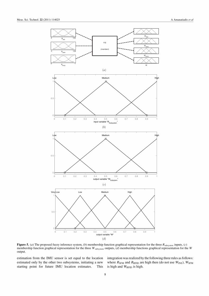
We first define as RINS, RSfM and RRFID, the qualitativemeasures of inertial sensor, structure from motion and radio-frequency identification subsystems, respectively. In orderto derive the weight which will define the proportionalcontribution of the current location estimate, we present thequalitative components as three separate inputs to a fuzzyMamdani-type inference system. The fuzzy inference systemconsists of three triangular membership functions (TMFs) forall the input components, three TMFs for the three subsystemoutput weights and five TMFs for the overall system weightoutput, as shown in figure 5. The first input variable is theRINS which indicates the similarity of the pre-defined walkingpattern from the estimated one and ranges from 0 to 100. Theinput variable RSfM denotes the number of features used inthe image sequences, and its value ranges between 0 and 128.The input variable RRFID is the highest probability extractedby the probabilistic positioning technique of the RFIDsubsystem and ranges from 0 to 1.
The parameterization was developed in a way that onlytwo membership functions will overlap for any input variable.The overlapping TMFs are tightly coupled with the overalltiming performance since a three-function overlap would makethe design more complicated and time demanding. Thedefuzzification method utilized is that of the centroid. Thethree inputs are cross-connected to the output through a setof 27 if-then rules as presented in table 2. The linguisticrule premises were attained after extensive comparisons withresults from straightforward calculations.
Since Wi-Fi and image sensor technologies do not sufferfrom accumulated errors, we designed the rules of the fuzzyinference system in order to integrate INS measurement. Moreprecisely, when both the Wi-Fi and camera subsystems areperforming accurately, based on their qualitative attributes,we drop the location estimation from the IMU sensor andapply the final weighted averaging method only to RFID andSFM location estimates. At this timestamp, the location
7
Meas. Sci. Technol. 22 (2011) 114025 A Amanatiadis et al
RINS
RSFM
RRFID
WINS
WSFM
WRFID
W
FIS
(mamdani)
0010
8210
10
(a)
0 0.1 0.2 0.3 0.4 0.5 0.6 0.7 0.8 0.9 1
0
0.5
1
input variable "RSubsystem
"
Low Medium High
(b)
0 0.1 0.2 0.3 0.4 0.5 0.6 0.7 0.8 0.9 1
0
0.5
1
output variable "WSubsytem
"
Low Medium High
(c)
0 0.1 0.2 0.3 0.4 0.5 0.6 0.7 0.8 0.9 1
0
0.5
1
output variable "W"
Very-Low MediumLow High
(d)
Figure 5. (a) The proposed fuzzy inference system, (b) membership function graphical representation for the three Rsubsystem inputs, (c)membership function graphical representation for the three W subsystem outputs, (d) membership functions graphical representation for the Woutput.
estimation from the IMU sensor is set equal to the locationestimated only by the other two subsystems, initiating a newstarting point for future IMU location estimates. This
integration was realized by the following three rules as follows:where RSFM and RRFID are high then (do not use WINS), WSFM
is high and WRFID is high.
8
Meas. Sci. Technol. 22 (2011) 114025 A Amanatiadis et al
Table 2. Extracted rules for the proportional performance for each subsytem separately and for the overall quality measure. The threeinputs, RINS: inertial subsystem, RSfM: structure from motion subsystem, RRFID: radio-frequency identification subsystem. The four outputs,WINS: inertial subsystem weight, WSfM: structure from motion subsystem weight, WRFID: radio-frequency identification subsystem weightand W : overall localization technique weight.
If RINS is and RSfM is and RRFID is then WINS is, then WSfM is, then WRFID is, then W is
Low Low Low Low Low Low Very lowLow Low Medium Low Low Medium Very lowLow Low High Low Low High LowLow Medium Low Low Medium Low Very lowLow Medium Medium Low Medium Medium MediumLow Medium High Low Medium High MediumLow High Low Low High Low MediumLow High Medium Low High Medium MediumLow High High High High High
... ... ... ... ... ... ...High High Low High High Low HighHigh High Medium High High Medium Very highHigh High High High High Very high
The current localization estimation in PDR(t) is given by
FusedM(t) =∑
Msubsystem(t) × Wsubsystem(t)∑
Wsubsystem(t)(5)
for all subsystem ∈ {‘INS’, ‘SfM’, ‘RFID’}.The final localization technique weight W represents the
efficiency of the overall location estimates and determinesthe accuracy of the estimated location in each time state t. Aproportional weight of the previous location estimation is usedin order to maintain the consistency of the position, when thecurrent state estimation suffers from high uncertainty. Theformula used is as follows:
FinalFusedM(t) = W × FusedM(t)
+ (1 − W)FinalFusedM(t − 1), (6)
where t represents the current time state and 0 < W < 1.
6. Experimental results
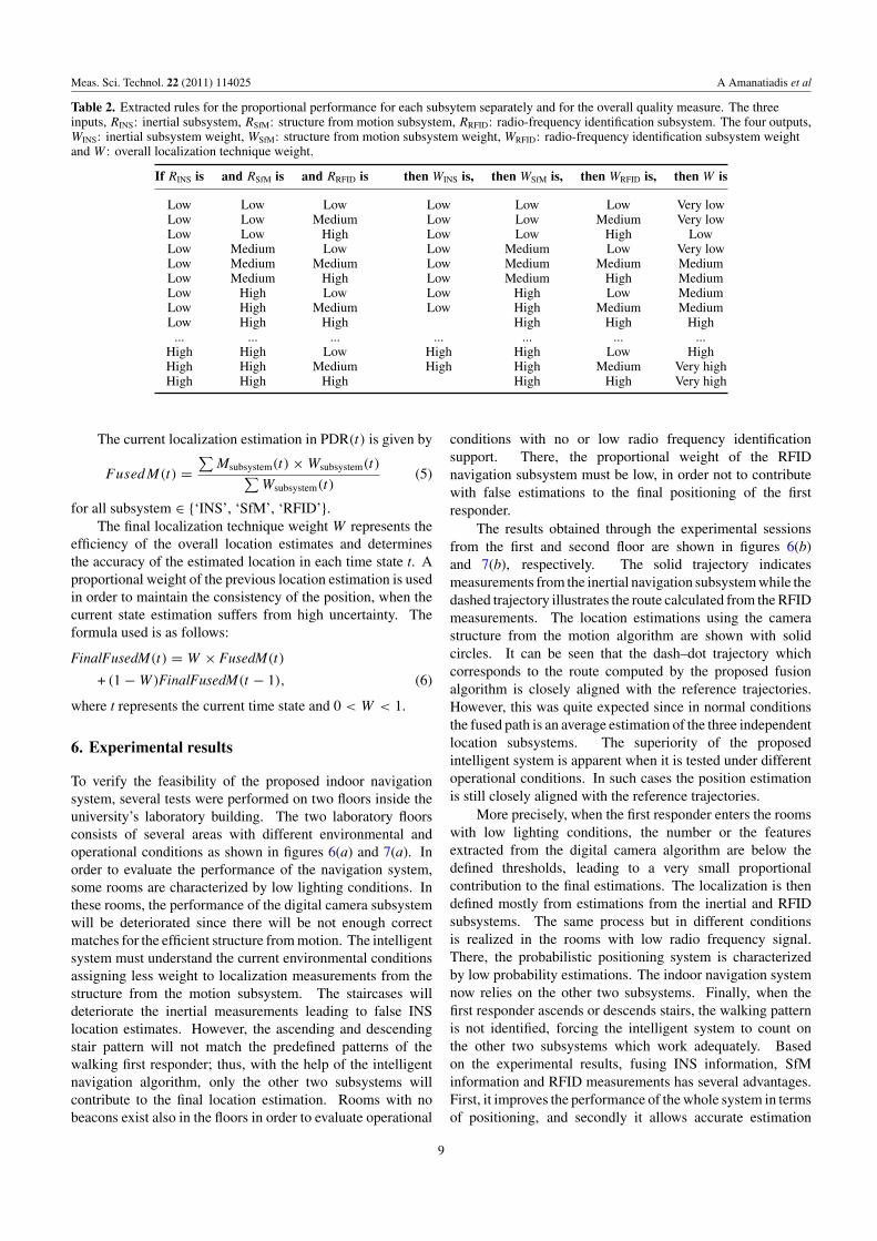
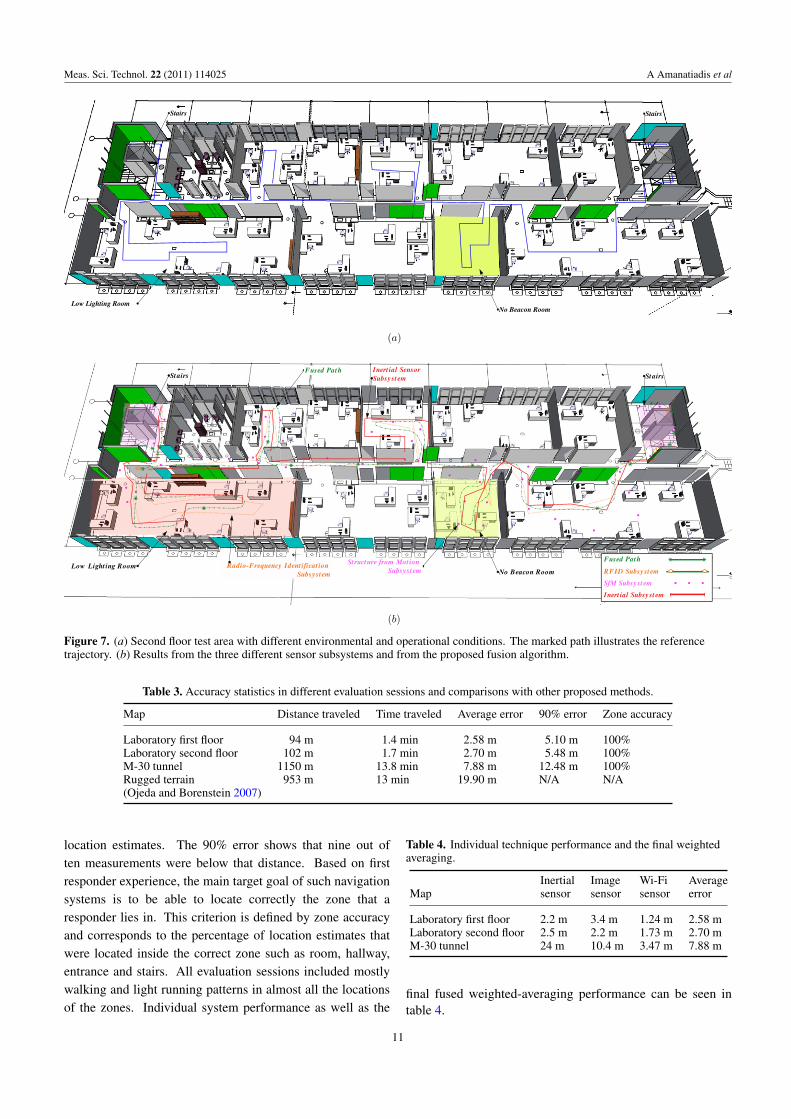
To verify the feasibility of the proposed indoor navigationsystem, several tests were performed on two floors inside theuniversity’s laboratory building. The two laboratory floorsconsists of several areas with different environmental andoperational conditions as shown in figures 6(a) and 7(a). Inorder to evaluate the performance of the navigation system,some rooms are characterized by low lighting conditions. Inthese rooms, the performance of the digital camera subsystemwill be deteriorated since there will be not enough correctmatches for the efficient structure from motion. The intelligentsystem must understand the current environmental conditionsassigning less weight to localization measurements from thestructure from the motion subsystem. The staircases willdeteriorate the inertial measurements leading to false INSlocation estimates. However, the ascending and descendingstair pattern will not match the predefined patterns of thewalking first responder; thus, with the help of the intelligentnavigation algorithm, only the other two subsystems willcontribute to the final location estimation. Rooms with nobeacons exist also in the floors in order to evaluate operational
conditions with no or low radio frequency identificationsupport. There, the proportional weight of the RFIDnavigation subsystem must be low, in order not to contributewith false estimations to the final positioning of the firstresponder.
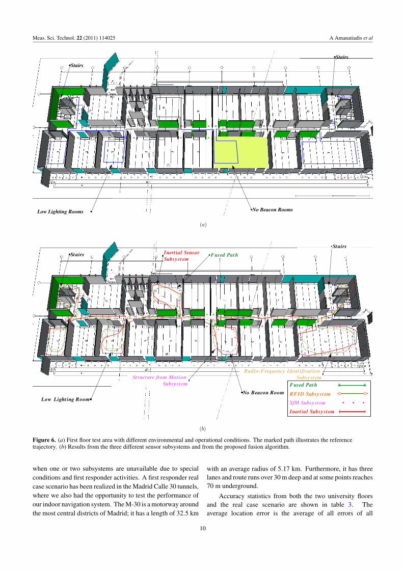
The results obtained through the experimental sessionsfrom the first and second floor are shown in figures 6(b)and 7(b), respectively. The solid trajectory indicatesmeasurements from the inertial navigation subsystem while thedashed trajectory illustrates the route calculated from the RFIDmeasurements. The location estimations using the camerastructure from the motion algorithm are shown with solidcircles. It can be seen that the dash–dot trajectory whichcorresponds to the route computed by the proposed fusionalgorithm is closely aligned with the reference trajectories.However, this was quite expected since in normal conditionsthe fused path is an average estimation of the three independentlocation subsystems. The superiority of the proposedintelligent system is apparent when it is tested under differentoperational conditions. In such cases the position estimationis still closely aligned with the reference trajectories.
More precisely, when the first responder enters the roomswith low lighting conditions, the number or the featuresextracted from the digital camera algorithm are below thedefined thresholds, leading to a very small proportionalcontribution to the final estimations. The localization is thendefined mostly from estimations from the inertial and RFIDsubsystems. The same process but in different conditionsis realized in the rooms with low radio frequency signal.There, the probabilistic positioning system is characterizedby low probability estimations. The indoor navigation systemnow relies on the other two subsystems. Finally, when thefirst responder ascends or descends stairs, the walking patternis not identified, forcing the intelligent system to count onthe other two subsystems which work adequately. Basedon the experimental results, fusing INS information, SfMinformation and RFID measurements has several advantages.First, it improves the performance of the whole system in termsof positioning, and secondly it allows accurate estimation
9
Meas. Sci. Technol. 22 (2011) 114025 A Amanatiadis et al
Stairs
Low Lighting Rooms No Beacon Rooms
Stairs
(a)
Stairs
Low Light ing RoomNo Beacon Room
Stairs Inert ial SensorSubsystem
Fused Path
Structure from Mot ion Subsystem
Radio-Frequency Ident ificat ion Subsystem
Fused Path
RFID Subsystem
SfM Subsystem
Inert ial Subsystem
(b)
Figure 6. (a) First floor test area with different environmental and operational conditions. The marked path illustrates the referencetrajectory. (b) Results from the three different sensor subsystems and from the proposed fusion algorithm.
when one or two subsystems are unavailable due to specialconditions and first responder activities. A first responder realcase scenario has been realized in the Madrid Calle 30 tunnels,where we also had the opportunity to test the performance ofour indoor navigation system. The M-30 is a motorway aroundthe most central districts of Madrid; it has a length of 32.5 km
with an average radius of 5.17 km. Furthermore, it has threelanes and route runs over 30 m deep and at some points reaches70 m underground.
Accuracy statistics from both the two university floorsand the real case scenario are shown in table 3. Theaverage location error is the average of all errors of all
10
Meas. Sci. Technol. 22 (2011) 114025 A Amanatiadis et al
Low Lighting Room
Stairs Stairs
No Beacon Room
(a)
Low Light ing Room
Stairs
No Beacon Room
StairsInert ial SensorSubsystem
Fused Path
Structure from Mot ion Subsystem
Radio-Frequency Ident ificat ion Subsystem
Fused PathFused Path
Fused Path
RFID Subsystem
SfM Subsystem
Inert ial Subsystem
(b)
Figure 7. (a) Second floor test area with different environmental and operational conditions. The marked path illustrates the referencetrajectory. (b) Results from the three different sensor subsystems and from the proposed fusion algorithm.
Table 3. Accuracy statistics in different evaluation sessions and comparisons with other proposed methods.
Map Distance traveled Time traveled Average error 90% error Zone accuracy
Laboratory first floor 94 m 1.4 min 2.58 m 5.10 m 100%Laboratory second floor 102 m 1.7 min 2.70 m 5.48 m 100%M-30 tunnel 1150 m 13.8 min 7.88 m 12.48 m 100%Rugged terrain 953 m 13 min 19.90 m N/A N/A(Ojeda and Borenstein 2007)
location estimates. The 90% error shows that nine out often measurements were below that distance. Based on firstresponder experience, the main target goal of such navigationsystems is to be able to locate correctly the zone that aresponder lies in. This criterion is defined by zone accuracyand corresponds to the percentage of location estimates thatwere located inside the correct zone such as room, hallway,entrance and stairs. All evaluation sessions included mostlywalking and light running patterns in almost all the locationsof the zones. Individual system performance as well as the
Table 4. Individual technique performance and the final weightedaveraging.
Inertial Image Wi-Fi AverageMap sensor sensor sensor error
Laboratory first floor 2.2 m 3.4 m 1.24 m 2.58 mLaboratory second floor 2.5 m 2.2 m 1.73 m 2.70 mM-30 tunnel 24 m 10.4 m 3.47 m 7.88 m
final fused weighted-averaging performance can be seen intable 4.
11
Meas. Sci. Technol. 22 (2011) 114025 A Amanatiadis et al
7. Conclusion
In this paper, we used three heterogeneous but complementarytechnologies along with a weighted averaging technique whichled to an enhanced system in terms of positioning performance.The system is designed to meet most of the first responderneeds; thus, different types of first responder activities andoperational conditions were examined and classified accordingto extracted qualitative attributes. In order to derive aproportional contribution of each navigation subsystem, wepresent the calculated qualitative components to a fuzzyinference system. The final location estimate is calculatedby applying different weights to each subsystem’s coordinatesdepending on their current time state performance quality.Laboratory and field tests have shown better navigationeffectiveness and lower positioning error compared with thestand alone navigation systems used.
Acknowledgments
This work was supported by the EC under the FP7research project for Innovative and Novel First RespondersApplications, ‘INFRA’, ICT-SEC-2007-1.0-04.
References
Aanaes H, Fisker R, Astrom K and Carstensen J M 2002 Robustfactorization IEEE Trans. Pattern Anal. Mach. Intell.24 1215–25
Amanatiadis A, Gasteratos A, Georgoulas C, Kotoulas Land Andreadis I 2008 Development of a stereo vision systemfor remotely operated robots: a control and video streamingarchitecture Proc. IEEE Conf. on Virtual Environments,Human–Computer Interfaces and Measurement Systemspp 14–9
Amanatiadis A, Chrysostomou D, Koulouriotis D and Gasteratos A2010 A fuzzy multi-sensor architecture for indoor navigationProc. 2010 IEEE Int. Conf. on Imaging Systems andTechniques pp 452–7
Baker S and Matthews I 2004 Lucas–Kanade 20 years on: aunifying framework Int. J. Comput. Vis. 56 221–55
Bay H, Ess A, Tuytelaars T and Van Gool L 2008 Speeded-up robustfeatures (SURF) Comput. Vis. Image Understanding 110 346–59
Brown R G and Hwang P Y C 1997 Introduction to Random Signalsand Applied Kalman Filtering vol 2 (New York: Wiley)
Chen Y, Yang Q, Yin J and Chai X 2006 Power-efficientaccess-point selection for indoor location estimation IEEETrans. Knowl. Data Eng. 18 877–88
Davison A J 2003 Real-time simultaneous localisation and mappingwith a single camera Proc. Int. Conf. on Computer Vision vol 2,pp 1403–10
Davison A J, Reid I D, Molton N D and Stasse O 2007MonoSLAM: real-time single camera SLAM IEEE Trans.Pattern Anal. Mach. Intell. 29 1052–67
Ekahau, Inc. 2003 The Ekahau positioning engine: whitepapers,www.ekahau.com
Fischer C and Gellersen H 2010 Location and navigation support foremergency responders: a survey IEEE Pervasive Comput.9 38–47
Foxlin E 2005 Pedestrian tracking with shoe-mounted inertialsensors IEEE Comput. Graph. Appl. 25 38–46
Godha S and Lachapelle G 2008 Foot mounted inertial system forpedestrian navigation Meas. Sci. Technol. 19 075202
Gringeri S, Khasnabish B, Lewis A, Shuaib K, Egorov R and BaschB 1998 Transmission of MPEG-2 video streams over ATMIEEE Multimedia 5 58–71
Guilbert N, Bartoli A and Heyden A 2006 Affine approximation fordirect batch recovery of Euclidian structure and motion fromsparse data Int. J. Comput. Vis. 69 317–33
Jirawimut R, Prakoonwit S, Cecelja F and Balachandran W 2003Visual odometer for pedestrian navigation IEEE Trans.Instrum. Meas. 52 1166–73
Kidder S M, Abuzzahab F S Jr, Harris G F and Johnson J E 1996 Asystem for the analysis of foot and ankle kinematics during gaitIEEE Trans. Rehabil. Eng. 4 25–32
Kourogi M and Kurata T 2003a A method of personal positioningbased on sensor data fusion of wearable camera andself-contained sensors Proc. IEEE Int. Conf. on MultisensorFusion and Integration for Intelligent Systems pp 287–92
Kourogi M and Kurata T 2003b Personal positioning based onwalking locomotion analysis with self-contained sensors and awearable camera Proc. 2nd IEEE/ACM Int. Symp. on Mixedand Augmented Reality p 103
Luinge H J and Veltink P H 2005 Measuring orientation of humanbody segments using miniature gyroscopes and accelerometersMed. Biol. Eng. Comput. 43 273–82
Narzullaev A, Park Y, Yoo K and Yu J 2011 A fast and accuratecalibration algorithm for real-time locating systems based onthe received signal strength indication Int. J. Electron.Commun. 65 305–11
Ojeda L and Borenstein J 2007 Non-GPS navigation for securitypersonnel and first responders J. Navig. 60 391–407
Ovaska S J and Valiviita S 1998 Angular acceleration measurement:a review IEEE Trans. Instrum. Meas. 47 1211–7
Poelman C J and Kanade T 1997 A paraperspective factorizationmethod for shape and motion recovery IEEE Trans. PatternAnal. Mach. Intell. 19 206–18
Rantakokko J, Rydell J, Callmer J, Gustafsson F and Jobs M 2011Accurate and reliable soldier and first responder indoorpositioning: multisensor systems and cooperative localizationIEEE Wirel. Commun. 18 10–8
Renaudin V, Yalak O, Tome P and Merminod B 2007 Indoornavigation of emergency agents Eur. J. Navig. 5 36–45
Roetenberg D, Luinge H J, Baten C T M and Veltink P H 2005Compensation of magnetic disturbances improves inertial andmagnetic sensing of human body segment orientation IEEETrans. Neural Syst. Rehabil. Eng. 13 395–405
Sawyer S, Tapia A, Pesheck L and Davenport J 2004 Mobility andthe first responder Commun. ACM 47 62–5
Strasdat H, Montiel J M M and Davison A J 2010 Scale drift-awarelarge scale monocular SLAM Proc. Robotics: Science andSystems (Zaragoza, Spain, June)
Sun Z, Mao X, Tian W and Zhang X 2009 Activity classificationand dead reckoning for pedestrian navigation with wearablesensors Meas. Sci. Technol. 20 015203
Tomono M 2005 3D localization and mapping using a single camerabased on structure-from-motion with automatic baselineselection Proc. IEEE Int. Conf. on Robotics and Automationpp 3342–7
VanGool L, Pollefeys M and Proesmans M 1998 Self-calibrationand metric reconstruction in spite of varying and unknowninternal camera parameters Proc. Int. Conf. on ComputerVision pp 90–5
12
Copyright © 2022 FDOKUMEN