Magnetization Control of Magnetic Liquids for Sink-Float ...

Optimal Multi-sink Positioningand Energy-efficient Routingin Wireless Sensor Networks ?
Haeyong Kim, Yongho Seok, Nakjung Choi,Yanghee Choi, and Taekyoung Kwon
School of Computer Science and EngineeringSeoul National University
San 56-1, Shillim-dong, Gwanak-gu, Seoul, Korea{hykim, yhseok, fomula, yhchoi, tk}@mmlab.snu.ac.kr
Abstract. In wireless sensor networks, the sensors collect data and de-liver it to a sink node. Most of the existing proposals deal with the trafficflow problem to deliver data to the sink node in an energy-efficient man-ner. In this paper, we extend this problem into a multi-sink case. Tomaximize network lifetime and to ensure fairness, we propose (i) how toposition multiple sink nodes in a sensor network and (ii) how to routetraffic flow from all of the sensors to these multiple sink nodes. Both ofthe problems are formulated by the linear programming model to findoptimal locations of the multiple sink nodes and the optimal traffic flowrate of routing paths in wireless sensor networks. The improved lifetimeand fairness of our scheme are compared with those of the multi-sinkaware minimum depth tree scheme.
1 Introduction
In a wireless sensor network, each sensor node has a small sensing coverageand a small communication range because increasing the sensing coverage andcommunication range would consume more battery power. Since each sensornode has a small communication range, each sensor node relays the sensed eventsto a sink node [1]. As the number of sink nodes is increased, the path lengthfrom sensor node to sink node is decreased and the lifetime of the sensor nodes isincreased. However, the number of sink node is constrained financially becausethe cost of the sink node is more expensive than the sensor node.
There has been much research done on traffic engineering in wired networks.The main purpose of traffic engineering is to increases the link utilization byequally balancing the traffic over the network. It is also possible to apply thetraffic engineering in a wireless sensor network. However, the purpose shouldbe to increase the network lifetime instead of improving the link utilization,? This work was supported in part by the Brain Korea 21 project of Ministry of
Education and in part by the National Research Laboratory project of Ministry ofScience and Technology, 2004, Korea.

because the critical resource of wireless sensor networks is the battery power ofthe sensor node instead of the link bandwidth although the sink nodes do nothave an energy constraint since they are connected to a wired network.
In the past, most researches focused on the energy conservation [2][3] or dataaggregation [5][6]. Recently, several studies [7][8][9] handle locating the multiplesinks in large-scale wireless sensor networks and optimizing the placement ofintegration points in multi-hop wireless networks, but any of papers did notconsider traffic engineering.
In this paper, a formulation is proposed to improve the lifetime and thefairness of wireless sensor network with multiple sink nodes. We assume that thewireless sensor network shows the cluster architecture [2][3]. In this architecture,the cluster header has data forwarding functionality. The proposed formulationssolve two problems, the location of sink nodes and the traffic flow rates of routingpaths in the wireless sensor network. We formulate this problem into two typesof LP (linear programs). In the first LP formulation, it is assumed that thelocation and the number of the sink nodes are fixed. The solution of the first LPformulation shows the optimal traffic flow rates of routing paths in the wirelesssensor network. In the second LP formulation, instead of assuming the pre-fixedlocation and number of the sink nodes, the constraint of the maximum numberof sink nodes is only assumed. In this case, the solution of the LP formulationfinds both the optimal location of sink nodes and the optimal traffic flow ratesof routing paths in wireless sensor network. Our main focus is the second LPformulation. It is shown that the proposed formulation increases the lifetime andthe fairness of a wireless sensor network by using CPLEX [4] program that is atype of ILP (Integer Linear Programming) solver.
The organization of the paper is as follows: In Section 2, related work isshown such as the sink node location problem in multi-hop wireless networkand wireless sensor network. The assumed wireless sensor network model andthe proposed LP formulations are presented in Section 3 and in Section 4. InSection 5, the performance of the proposed LP formulation is evaluated by usingthe CPLEX tool. The conclusion of the paper is in Section 6.
2 Problem Definition
The wireless sensor network model used in this paper refers to [10]. Fig. 1 il-lustrates the layered sensor model. There are Application Sensor Nodes (ASNs)that collect data at the bottom layer. An ASN is a very low cost sensor, andthere is a cluster of ASNs that belong to a clusterhead, or Aggregation and For-warding Node (AFN). AFNs are logically located at the higher layer than thelower layer consisting of ASNs only. The AFN aggregates data from a group ofASNs and reduces redundancy of data. AFNs also relay data to sink nodes (orbase stations).
Most previous schemes related to the layered sensor networks assume thatthe location of a sink node is fixed and seek to find the optimal routing pathsand traffic flow rates. To the best of our knowledge, there is no work on finding
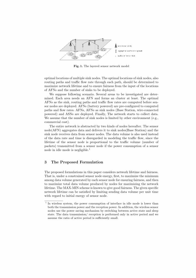
Fig. 1. The layered sensor network model
optimal locations of multiple sink nodes. The optimal locations of sink nodes, alsorouting paths and traffic flow rate through each path, should be determined tomaximize network lifetime and to ensure fairness from the input of the locationsof AFNs and the number of sinks to be deployed.
We suppose following scenario. Several areas to be investigated are deter-mined. Each area needs an AFN and forms an cluster at least. The optimalAFNs as the sink, routing paths and traffic flow rates are computed before sen-sor nodes are deployed. AFNs (battery powered) are pre-configured to computedpaths and flow rates. AFNs, AFNs as sink nodes (Base Station, wire-connectedpowered) and ASNs are deployed. Finally, The network starts to collect data.We assume that the number of sink nodes is limited by other environment (e.g.,commercial cost).
The entire network is abstracted by two kinds of nodes hereafter. The sensornode(AFN) aggregates data and delivers it to sink nodes(Base Station) and thesink node receives data from sensor nodes. The data volume is also used insteadof the data rate and time is disregarded in modeling the traffic flow, since thelifetime of the sensor node is proportional to the traffic volume (number ofpackets) transmitted from a sensor node if the power consumption of a sensornode in idle mode is negligible.1
3 The Proposed Formulation
The proposed formulations in this paper considers network lifetime and fairness.That is, under a constrained sensor node energy, first, to maximize the minimumamong data volume generated by each sensor node for ensuring fairness, and thento maximize total data volume produced by nodes for maximizing the networklifetime. The MAX-MIN scheme is known to give good fairness. The given specificnetwork lifetime can be satisfied by limiting sending data volume per unit timewith regard to initial energy of sensor node.
1 In wireless system, the power consumption of interface in idle mode is lower thanboth the transmission power and the reception power. In addition, the wireless sensornodes use the power saving mechanism by switching between active state and sleepstate. The data transmission/ reception is performed only in active period and weassume the ratio of active period is sufficiently small.

If the location of sink nodes is fixed, routing paths of each sensor node andthe data volume through each path can be obtained by Formulation 1.
Formulation 1.Maximize
First, V olmin
Second, V oltotal
Subject To∑j∈N∪S,j 6=i
Xij−∑
j∈N,j 6=i
Xji = ∆i (∀i ∈ N) (1)
∆i ≥ 0 (∀i ∈ N) (2)Xi,j = 0 (∀i ∈ S) (3)V olmin ≤ ∆i (∀i ∈ N) (4)V oltotal =
∑i:i∈N
∆i (5)∑
j∈N,j 6=i
(P t
ij ·Xij
)+
∑j∈N,j 6=i
(P r ·Xji
) ≤ Einit (∀i ∈ N) (6)
Variables∆i : Data volume that node i produceV olmin : The minimum of ∆i
V oltotal : Thetotal sum of ∆i
Xij : Data volume transmitted from node i to node jConstants
N : Set of sensor nodesS : Set of sink nodesP t
ij : Transmission power per unit data volume from node i to node jP r : Recieve power per unit data volumeEinit : Initial energy of a seonsor node
Each line means,
(1) Define ∆i which is data volume produced by node(i).(2) A sensor node should transmit data more than 0 bit.(3) A sink node should not transmit any data to other sensor nodes.(4) The V olmin is the minimum among data volume produced by each sensor
node.(5) The V oltotal is total data volume produced by sensor nodes.(6) A sensor node consumes power when send or receive data. The consumed
power cannot be larger than initial energy. Idle power is assumed to benegligible.
The Formulation 1 is an LP (Linear Programming) problem because the locationof sink nodes is fixed, so it can be solved in polynomial time by using LP solver.Formulation 1 guarantees the network performance of two type.

Fairness - When the V olmin is maximized, all sensor nodes are guaranteed togenerate the data volume of at least V olmin and to communicate with sinknodes. Consequently, the each sensor node can produce the data volume ofV olmin regardless of the data volume produced by other sensor nodes.
Lifetime - When the idle power of sensor node is negligible, the lifetime of sen-sor network is dependent on the data volume of transmission and reception.Therefore, if the V oltotal is maximized, the lifetime of sensor network is alsomaximized. Here, the network lifetime means the duration that the batteriesof all sensor node have been depleted.
Formulation 1 is modified to apply to cases in which the location of sink nodesis not fixed to get Formulation 2.
Formulation 2. (for CPLEX)Maximize
C · V olmin + V oltotal (C · V olmin À V oltotal)
Subject To∑j∈N,j 6=i,k
Xkij −
∑j∈N,j 6=i
Xkji = ∆k
i (∀i, ∀k ∈ N,i 6= k) (7)∑
j∈N,j 6=i
Xiij = ∆i
i (∀i ∈ N) (8)∑
k∈N,k 6=i
∆ki ≥ −C · Si (∀i ∈ N) (9)
V olmin ≤ ∆ii+C·Si (∀i ∈ N) (10)
V oltotal =∑
i∈N
∆ii (11)
∑i:i∈N
Si ≤ Nsink (12)
∑j∈N,j 6=i
(P t
ij ·∑
k∈N,k 6=j
Xkij + P r · ∑
k∈N,k 6=i
Xkji
)≤ Einit + C · Si
(∀i ∈ N) (13)Xk
ij ≤ C·(1−Si) (∀i,∀j, ∀k ∈ N,i 6= j, j 6= k, ) (14)
Bounds0 ≤ ∆i
i ≤ C (∀i ∈ N)− C ≤ ∆k
i ≤ 0 (∀i, ∀k ∈ N,i 6= k)0 ≤ Xk
ij ≤ C (∀i, ∀j, ∀k ∈ N,i 6= j, j 6= k,node j is in the transmission range of node i)
BinariesSi (∀i ∈ N)
VariablesV olmin : The minimum data volume generated by each sensor nodeV oltotal : The total data volume generated by sensor nodesXk
ij : Data volume transmitted from node i to node j,

node k is the source of data∆k
i : Data volume that node i produce, node k is the source of dataSi : If node i is a sinknode, Si = 1. else Si = 0
ConstantsN : Set of all nodes in networkC : Infinite constantNsink : The maximum number of sink nodesP t
ij : Transmission power from node i to node jper unit data volume (bit)P r : Recieve power per unit data volume (bit)Einit : Initial energy of a sensor node
A binary variable Si is added to distinguish which node is selected as a sinknode or not because the sink nodes is not decided yet. Variable k in Xk
ij , ∆ki
means source node of data. It is just used to reduce useless equations to solve aproblem more quickly and to distinguish the data source for debugging. It willalso be used for advanced formulation (e.g., limiting hop-count of transmitteddata) as future work. Each line means,
(7) ∆ki is data volume relayed by node i when the source of data is k.
(8) ∆ii is data volume produced by sensor node i.
(9) Only sink nodes can receive data of other nodes. If node i is a sensor node,it should relay received data to other nodes. (see also 2nd line of Bounds)
(10) V olmin is the minimum among data volume produced by each sensor node.(11) V oltotal is total data volume produced by sensor nodes.(12) Nsink is the maximum number of sink nodes.(13) A sensor node consumes power when send or receive data. The consumed
power cannot be larger than initial energy. Idle power is assumed to benegligible. The energy of sink node is not limited.
(14) Sink nodes do not send data to other nodes. (see also 3rd line of Bounds)
The Formulation 2 is an M-ILP (Mixed-Integer Linear Program) problem be-cause of integer variable Si which is used to select sensor nodes for the role ofsink nodes. Since M-ILP problems are NP-hard, it will take a long time to solvea problem if the wireless sensor network is huge. However, if the wireless sensornetwork consists of about 30 sensor nodes, we can get a solution quickly for that.Moreover, 30 sensor nodes (AFNs) will cover very large area in cluster architec-ture (layered sensor networks). In this paper, Formulation 2 was applied to asample wireless sensor network and the result is shown in Section 5. Proposingan approximate algorithm that finds a solution in polynomial time will be leftto future works.
4 Performance Evaluation
In this chapter, the result of a simulation by Formulation 2 is analyzed. Fig. 2 isa sample network that is used for simulation. 20 nodes are deployed randomly

Fig. 2. A sample sensor network
Table 1. The node’s number selected as sink node in fully-connected sample network
The number of sink nodes Formulation 2 m-MDT
1 5 52 11, 16 9, 143 0, 11, 17 8, 11, 174 4, 10, 11, 17 1, 8, 11, 125 1, 4, 10, 11, 13 1, 4, 5, 10, 11
in 200 x 200(m). The parameters of Formulation 2 are |N| = 20 (the number ofnodes), C = 7000, Nsink = 1, 2, 3, 4 or 5, P t
ij = 0.5+0.00013∗dist(i, j)4(nJ/bit)[11], P r = 0.5(nJ/bit), Einit = 100(nJ). For the comparison with the proposedformulation, m-MDT (multi-sink aware Minimum Depth Tree) is used. The linkcost is energy that is consumed when unit data is transmitted through the link.It has been known that MDT can route packets with minimal energy consump-tion.[12]
The simulation result in the sample network are compared in Table 1 andTable 2. We simulate two cases, one in fully-connected network and the other
Table 2. The node’s number selected as sink node in sample network, the transmissionrange of a node is 60m
The number of sink nodes Formulation 2 m-MDT
1 5 52 7, 12 6, 93 4, 11, 17 0, 13, 144 4, 10, 11, 17 4, 10, 11, 175 1, 4, 10, 11, 13 1, 4, 5, 10, 11

Fig. 3. The comparison of V olmin in fully-connected network
Fig. 4. The comparison of V olmin when the transmission range of sensor node is 60m
in which the transmission range of a sensor node is 60m. Although the node’snumber to be selected as sink node is the same as No.5 when there is only onesink node, the result shows that there is a difference in selected sensor nodes assink nodes between Formulation 2 and m-MDT in case that the number of sinknodes is 2,3,4 or 5.
Fig. 3 and Fig. 4 show that V olmin by Formulation 2 is much bigger thanthat by m-MDT though both select the same sensor node as sink node whenthere is only one sink node in the network. This is because m-MDT allowsa sensor node to select only one path which is the shortest path (low energyconsumption) to communicate with the sink node. In the m-MDT algorithm,sensor nodes around sink node always consume more energy than nodes far fromthe sink node. Therefore, sensor nodes far from the sink node cannot send data tothe sink node even if they have a lot of energy. On the other hand, Formulation

Fig. 5. Routing paths and data volume by Formulation 2 in fully-connected network,the number is data volume produced by each sensor node
Fig. 6. Routing paths and data volume by Formulation 2 when the transmission rangeof node is 60m, xx.x is data volume produced by each sensor node, xx.x is data volumeof each path
2 considers not only the shortest path but also other available paths when asensor node communicates with the sink node, so the maximum of V olmin canbe found by Formulation 2. Fig. 5 and Fig. 6 are detailed figures to show thatFormulation 2 allows many paths unlike m-MDT, which allows only the shortestpath of the tree architecture.
The proposed formulation in this paper significantly increases V olmin byusing many paths for communications and by admitting determined data volumeto each link. In case there is only one sink node in a fully-connected network, theV olmin by proposed formulation, 82.97, is about 3 times bigger than the V olmin
by m-MDT, 28.56. The reason that the location of the sink node selected byeach algorithm is different is also caused by whether multi-path is available ornot. Moreover, most of the nodes transmit almost the same data volume in Fig.5 and Fig. 6. This means that the MAX-MIN scheme works well for fairness in

this scenario, and network fairness is increased to compare with m-MDT. Sincem-MDT organizes the network into a tree architecture, there is a wide differenceof the data volume produced by each node.
5 Conclusion
In this paper, the formulation to find the optimal locations of the multiple sinknodes and to find the optimal traffic flow rate is proposed. Maximizing networklifetime and ensuring fairness are the main objectives of this linear programmingformulation. The proposed scheme is compared with m-MDT (multi-sink awareMinimum Depth Tree), and the results show that the proposed scheme improvesnetwork lifetime and fairness significantly. The proposed formulation allows sen-sor nodes to communicate with the one or more sink nodes through multiplepaths. The numerical results reveal that the number of the sink nodes is vitalin the performance evaluation, so that the trade-off between the performanceimprovements and the deployment cost of the sink nodes should be taken intoaccount carefully.
References
1. C. Intanagonwiwat, R. Govindan and D. Estrin, “Directed diffusion: A Scalableand robust communication paradigm for sensor networks,” ACM MOBICOM 2000.
2. S. Bandyopadhyay and E. Coyle, “An Energy Efficient Hierarchical ClusteringAlgorithm for Wireless Sensor Networks,” IEEE INFOCOM 2003.
3. B. Chen, K. Jamieson, H. Balakrishnan, R. Morris, “Span: An Energy-EfficientCoordination Algorithm for Topology Maintenance in Ad Hoc Wireless Networks”Proc. of the 6th ACM MOBICOM , Rome, Italy, July 2001.
4. ILOG CPLEX, http://www.cplex.com5. Bhaskar Krishanamachari, Deborah Estrin and Stephen Wicker, “The Impact of
Data Aggregation in Wireless Sensor Networks,” In International Workshop ofDistributed Event Based Systems (DEBS), Vienna, Austria, July 2002.
6. S. Chatterjea and P. Havinga, “A Dynamic Data Aggregation Scheme for WirelessSensor Networks,” ProRISC 2003, Veldhoven, Netherlands, November 2003.
7. E. I. Oyman and C. Ersoy, “Multiple Sink Network Design Problem in LargeScale Wireless Sensor Networks,” Proceedings of the International Conference onCommunications (ICC), Paris, France, June 2004.
8. L. Qiu, R. Chandra, K. Jain, and M. Mahdian, “Optimizing the Placement of Inte-gration Points in Multi-hop Wireless Networks,” Proceedings of the InternationalConference on Network Protocols (ICNP), Berlin, Germany, October 2004.
9. M. Younis, M. Bangad and K. Akkaya, “Base-Station Repositioning For Opti-mized Performance of Sensor Networks,” Proceedings of the Vehicular TechnologyConference (VTC), Orlando, Florida, October 2003.
10. Thomas Hou, Yi Shi, Hanif Sherali, “On Rate Allocation in Wireless Sensor Net-works with Network Lifetime Requirement,” MobiHoc2004.
11. W.Heinzelman, “Application-specific Protocol Architectures for Wireless Net-works,” PH.D. thesis, MIT, 2000.
12. Patrick Y.H. Cheung, and Nicholas F. Maxemchuk, “Alpha Tree in Sensor Net-work,” IEEE Technical Report, Aug 2003.
Copyright © 2022 FDOKUMEN