Multi-Agent Intelligent Planning Architecture for People Location and Orientation Using RFID
20
1 Multi-Agent Intelligent Planning Architecture for People Location and Orientation using RFID María D. R-Moreno 1 , Bonifacio Cataño 2 , Melquiades Carbajo 1 , Angel Moreno 1 , David F. Barrero 1 , Pablo Muñoz 1 1 Departamento de Automática. Universidad de Alcalá. {mdolores,angel, mcm}@aut.uah.es 2 Departamento de Matemáticas. Universidad de Alcalá. Madrid, Spain. [email protected] Abstract The new advances in the Information Communications Technology (ICT) allow expanding the electronic communication networks into an objective environment. These techniques can be used to help users that have to go to a building with several floors, corridors and departments, to get its right location and orientation. The problem gets more complicated when there are a high number of visitors with temporal constraints. Typically the lack of information and signs to guide the user complicates this task. A typical example is a hospital where the patients have scheduled doctor’s appointments and in some cases severe movement difficulties. A possibility for solving this problem is to equip the building with an intelligent system for user detection and orientation. In this paper we present a solution that uses a detection and a location system based on wireless technology and Artificial Intelligent techniques to plan and inform about the paths the user can follow. 1 Introduction The development of new Information and Communication Technologies has originated new posi- bilities for changing the traditional way of performing business, commerce or education. The consequence of the application of such technologies is a change on the way of thinking, living or
-
Upload
independent -
Category
Documents
-
view
7 -
download
0
Transcript of Multi-Agent Intelligent Planning Architecture for People Location and Orientation Using RFID
1
Multi-Agent Intelligent Planning Architecture for People
Location and Orientation using RFID
María D. R-Moreno1, Bonifacio Cataño2, Melquiades Carbajo1, Angel Moreno1 , David F.
Barrero1, Pablo Muñoz1
1Departamento de Automática. Universidad de Alcalá.
{mdolores,angel, mcm}@aut.uah.es
2Departamento de Matemáticas. Universidad de Alcalá. Madrid, Spain.
Abstract
The new advances in the Information Communications Technology (ICT) allow expanding the electronic
communication networks into an objective environment. These techniques can be used to help users that have to
go to a building with several floors, corridors and departments, to get its right location and orientation. The
problem gets more complicated when there are a high number of visitors with temporal constraints. Typically the
lack of information and signs to guide the user complicates this task. A typical example is a hospital where the
patients have scheduled doctor’s appointments and in some cases severe movement difficulties. A possibility for
solving this problem is to equip the building with an intelligent system for user detection and orientation.
In this paper we present a solution that uses a detection and a location system based on wireless technology and
Artificial Intelligent techniques to plan and inform about the paths the user can follow.
1 Introduction
The development of new Information and Communication Technologies has originated new posi-
bilities for changing the traditional way of performing business, commerce or education. The
consequence of the application of such technologies is a change on the way of thinking, living or
2
working. One of the recent research areas is focusing on the integration of different technologies to the
environments where we live. Places such as the houses, the offices or public institutions will be able to
recognize us and to adapt to our taste, needs and preferences as soon as we come inside them.
When the Artificial Intelligence (AI) is framed in the environment of the Ubiquitous
Computing [9] (also called Pervasive Computing or Ambient Intelligence), to its characteristics and
habitual challenges one must add an additional function, the experience of the user. To the typical
objectives of an AI approach one must add the maximization of this new function. It is a highly
subjective function, very related to the comfort and the perception of the user. The processing of the
problem is even more interesting when we apply this kind of technologies not to a user, but to a group
of them, many times with completely different needs.
Although the concept of Ubiquitous Computing can seem futuristic, there are already some
academic and industrial initiatives that begin to show the strong current tendency to incorporate this
type of techniques. Among the objectives it intends to obtain, we can mention:
• Facilitate the use of devices to people that find some difficulty in using them. One of the barriers
that most of the person of average and high age have is the difficulty to use the ICTs. The
Ubiquitous Computing intends to facilitate its use by means of the voice or the view as
replacement to the keyboards.
• Offer greater comfort to the users incorporating new technologies.
• Offer security thanks to the fact that the environment is capable to recognize them. It can
guarantee the security set against possible intrusions.
• Personalization of their inclinations: the environment adapts to them and not the other way
round.
One of the main problems that one has to face when visiting large surfaces of high affluence
level of people, as for example hospitals or public administrations, is the lack of information and signs
that can guide them in a customized, efficient, and fast way to the place they have to go. Generally,
the user has to face by him/herself an immense and unknown environment in which he feels
unprotected. The queues around the information desk as well as the frequent stops along the way to
3
ask the location of the place, they are sure in the mind of all. In this paper we present a solution to this
type of problems.
The application to solve this problem, called SIGUEME (Sistema Inteligente de GUiado para
Entornos Multiusuario Extensos - Intelligent Monitoring System in Big Multiuser Enviroments)1
integrates both software and hardware elements. We have used the RFID passive technology [4] and
AI techniques, in particular planning and a scheduling [13] for the orientation and the guiding of the
patients. All these elements are combined within a global system that coordinates and controls all the
assembly of elements. This system has been implemented satisfactorily in a scale prototype that has
successfully proved its viability and good performance.
The paper is structured as follows. Section 2 describes the scenario where we have tested our
system. Then, section 3 presents basic concepts of the RFID technology. Next, section 4 describes the
philosophy we have followed to located the RFID sensors. In section 5 the architecture of our system
is presented. Then, experimental results are shown. Finally, related work and conclusions are outlined.
2 The Scenario
We have chosen a concrete example of a big surface with people going back and forward: a medical
centre. This framework covers most of the situations than can be found when testing with people
inside a building.
From a general point of view the scenario is as follows. When a patient arrives to the medical
centre, he usually goes directly to the information desk. There, the receptionist identifies him and
verifies in the computer the appointment(s) for the day. Once checked, the user data are introduced
into the system and the patient is provided with an individual RFID card. He is informed about the
path he has to follow to get to the corresponding waiting room. The user is also pointed out on the
different elements in the building, for helping him to reach the destination (usually a waiting room).
At the same time, the system generates a track for the visitor to get his objective in the best way
1 In Spanish SIGUEME means Follow Me

4
possible.
After that, when the person walks inside the building, it goes across the doors, corridors, stairs
and so on and it passes through the different RFID detectors without realizing it. But, each time he
goes through a RFID arch the system detects him and calculates his position. Considering the
sequence of detections, the system gets the directions and checks if it is adequate or not. Since the
program knows the position of the patient, it can provide the information needed to help him to reach
his destination. This information is displayed on several screens located at geographically strategic
points. When a person gets the destination (the right waiting room) the system warns of his arrival to
the corresponding medical service and incorporates him into the correct waiting list.
At this point, the program will wait until the patient exits the practice room to point him again
to a new surgery room or to the way out. The user will be guided as many times as necessary until he
ends all the appointments scheduled for that day. After that, the system will steer the patient to the
building exit. There, he will give the RFID card back to the hospital clerk and he will be taken out of
the cycle.
During the movements inside the building, the visitor can get lost. In that case, the system will
detect this situation and will correct the mistake. In order to solve that problem the system will be
called again, and a new plan for the lost patient will be generated. Then, it will be reported in the usual
manner.
To deal with all of these tasks, we have developed and tested a complete system. It is composed
of five subsystems that are described in section 5. Before that, we describe how RFID works and how
we distribute the RFID sensors along a building.
3 RFID
Radio-frequency identification (RFID) is an automatic identification method, relying on storing and
remotely retrieving data using devices called RFID tags or transponders.
An RFID tag is an object that can be applied to or incorporated into a product, animal, or

5
person for the purpose of identification using radio waves. RFID tags come in three general varieties.
Passive tags require no internal power source, thus being pure passive devices (they are only
active when a reader is nearby to power them), whereas semi-passive and active tags require a power
source, usually a small battery. Passive tags have practical read distances ranging from about 10 cm
up to a few meters, depending on the chosen radio frequency and antenna design/size. Due to their
simplicity in design they are also suitable for manufacture with a printing process for the antennas.
The lack of an onboard power supply means that the device can be quite small: commercially
available products exist that can be embedded in a sticker, or even under the skin.
Active tags due to their on board power supply, may transmit at higher power levels than
passive tags. Communications from active tags to readers is typically much more reliable. In turn,
active tags are generally bigger and more expensive to manufacture. Many active tags today have
operational ranges of hundreds of meters, and a battery life of up to 10 years.
Active tags may include larger memories than passive tags, and may include the ability to store
additional information received from the reader.
Semi-passive tags (also known as battery-assisted), are similar to active tags in that they have
their own power source, but the battery only powers the microchip and does not power the
broadcasting of a signal. An additional application for the battery is to power data storage. Semi-
passive tags have three main advantages: (1) Greater sensitivity than passive tags. (2) Longer battery
powered life cycle than active tags and (3) It can perform active functions (such as temperature
logging) under its own power, even when no reader is present for powering the circuitry.
RFID is becoming increasingly prevalent as the price of the technology decreases. RFID tags
are being used in passports issued by many countries, transportation payments, product tracking as a
replacement for barcode tags, inventory systems and supply chain management, and many more.
Intensive effort is being put in exploring RFID capabilities as a replacement for barcodes, telemetry
applications, and people identification (i.e. patients and hospital staff [5]). There are also some
problems and concerns associated with RFID. For instance, the frequencies used in the USA are
currently incompatible with those of Europe or Japan and no emerging standard has yet become
6
universal. Also, there is a primary security concern surrounding technology, posing a risk to both
personal location privacy and corporate security. A big controversy has been created around
implantable RFID tags; now they are used for animal identification and some administrations have
approved their use in humans.
4 The Building Description
In this section we present the way we have used to describe a building and how to divide it into
different parts. The main idea is to make small rooms in the building and follow the movements of the
people across them. Like that, we can know where each person is and what are their moves.
In order to follow the people movements inside a building, we use a set of RFID detectors placed at
strategic points. It is very important to choose the suitably detectors locations for covering the whole
building. In addition, for economic reasons, it is mandatory that the number of detectors is as small as
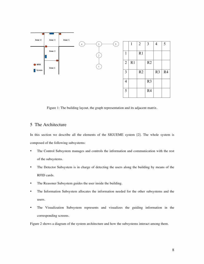
possible. Figure 1 shows the building layout. When the RFID frame is completely decided and each
detector is located at the correct place, the building is divided in zones (rooms between the detectors).
Not all the zones are equal. They can have different features and functions. In this work, we have
considered three different zones: input zones, transition zones and destination zones.
Input zones (Zone 1 in Figure 1) These are the first ones reached by the patients when they
arrive to the hospital. They are outside any detector and they house the admission office. Our
experience recommends only one of these zones and consequently a unique registration desk. So, in
our prototype there is only one input zone with a computer terminal where all the system information
and assistance facilities are installed. When a patient arrives at this zone, a hospital clerk identifies the
person, provides him a RFID card and introduces the user into the system.
Transition zones (Zones 2 and 3 in Figure 1) These are intermediate zones between two or
more RFID detectors and they contain the information screens. The patients have to go across them to
get their destinations. They are typically corridors, stairs or crossing sectors. In these zones the system
detects the input and output of each RFID card and consequently, can identify the person who carries
7
it. This information allows the program to know the location and even the movement direction of the
card owner. These two data are crucial to elaborate the information needed for guiding the user
towards its destination. This information is provided to the patient by means of the screens located in
these transition zones.
Destination Zones (Zones 4 and 5 in Figure 1) These areas represent the medical services
waiting rooms. Besides, when a user is on its way out, the input zone plays the role of a destination
one. All these zones should have enough local information so that a patient realizes that he has
reached the destination. When this happens, the program adds the user information into the doctor
waiting list and the system assumes that the visitor will stay there until the doctor sees him. When the
doctor calls the patient, the system provides the whole information about that person. Then, it is up to
the doctor to update the patient medical background. Before the patient leaves the practice room, the
program will require a new destination. This could be: the hospital exit or another medical service for
the same day or another day. If the next destination is the exit or an immediate appointment, the
system will provide a new path plan in order to guide the user to its destination. Our system will
manage all the data and will control the movements and instructions for each patient. There is not
limitation on the amount of RFID cards the program can handle.
Once the building is divided into zones by the RFID detectors we can describe it by a graph. In
this graph, zones are the vertexes and detectors are the edges. That is, two vertices/zones are
connected if there is a RFID arch between them. The graph is an undirected one and it could not be
simple. It has not isolated vertexes and all the vertexes corresponding to transition zones have degree
equal or bigger than two. A vertex with degree one is normally the input zone or a destination one. We
use the adjacency matrix to store this graph in the system. But, instead of using the number of edges
connecting two different vertexes (which is always one), we use the RFID detector number between
the corresponding zones.
For example, let’s consider the part of the building represented in the right side of Figure 1. The
resultant graph is shown in the middle of the figure and the corresponding adjacent matrix on the
right.
8
1 2 3 4 5
1 R1
2 R1 R2
3 R2 R3 R4
4 R3
5 R4
Figure 1: The building layout, the graph representation and its adjacent matrix.
5 The Architecture
In this section we describe all the elements of the SIGUEME system [2]. The whole system is
composed of the following subsystems:
• The Control Subsystem manages and controls the information and communication with the rest
of the subsystems.
• The Detector Subsystem is in charge of detecting the users along the building by means of the
RFID cards.
• The Reasoner Subsystem guides the user inside the building.
• The Information Subsystem allocates the information needed for the other subsystems and the
users.
• The Visualization Subsystem represents and visualizes the guiding information in the
corresponding screens.
Figure 2 shows a diagram of the system architecture and how the subsystems interact among them.

9
Figure 2: The SIGUEME architecture.
5.1 The Control Subsystem
The Control Subsystem is in charge of controlling the other subsystems. Besides, it has to control the
every day patient data and prepare a daily doctor’s appointments list. It also knows the RFID available
cards and the ones in use at every moment. This subsystem is operated in a computer with its main
terminal placed at the admissions office desktop. At the beginning of a working day this program
creates a list with all the patients with appointments for that day. When one of these patients arrives to
the hospital, this subsystem has already available all its data. At that moment, when the visitor arrives
to the admission desk, the operator identifies him and introduces him into the system. Simultaneously,
a RFID card, with a unique number, is given to him. The card number is also notified to this
subsystem and it identifies unambiguously its owner inside the building. The patient must keep this
card the whole time he stays inside the building and he should return it when he definitely exits.
At the same time, this subsystem finds out the patient destination and asks the Reasoner
Subsystem for the path, across the hospital, for the user. When the Reasoner Subsystem gives its
answer, the Control Subsystem records it and, from that moment on, it takes care of guiding the
person towards its destination.
To deal with this task the Control Subsystem registers and distinguishes each one of the
patient’s RFID card. This strategy provides the program with the information about where all the

10
persons inside the hospital are located, and even what are their moves. That is, this subsystem controls
the patient’s activity in the medical centre. When a user goes through a RFID detector the Control
Subsystem calculates if he is in the right way or not. If a patient loses its track, the subsystem
recognizes the situation and call the Reasoner subsystem to generate a new plan.
When a person arrives to the destination point, the system finishes its orientation job, includes
him into the corresponding patient list and waits for the user to be done with the appointment. After
that, a new destination is given to him. This can be the hospital exit or a different medical service
either for today or for another day. In any case, the Reasoner Subsystem will guide the person to the
new medical service or towards the centre way out. On his way out, he will return the RFID card and
the operator will take him out of the system. Finally all the information produced by the person will be
recorded. If a new appointment for another day was given to the patient, the system will update its
corresponding database. Figure 3 shows the Control Subsystem main window.
Figure 3: Control Subsystem main window.
5.2 The Detector Subsystem
The aim of this subsystem is to detect the persons moving in the building. It consists of a group of
RFID detectors placed at several points in the building and based on passive tags (see section 3 for
11
more information about RFID types). They give a signal when a patient with a RFID card passes
closed to them. This signal is decoded and sent to the Control Subsystem.
In this work we have developed two different detector subsystems. The first one is a hardware
prototype that scales an actual building with one input zone, two transition zones and two destination
ones. This scale model uses four RFID short range detectors and is connected to the main computer by
RS232/RS485 port. This allows us to set the detectors a thousand meters away from
the Control Subsystem. Reproducing the patient’s movements inside the building is as easy as passing
the RFID cards over the small detectors and recording the signal produced. The figure 1 shows a
sketch of this scale building layout.
Although this strategy reproduces very faithfully the detection process, it is not useful at all if
we want a statistically significant amount of data for testing our system. With this aim we have
developed a Montecarlo simulation program that generates patient movements across the RFID
detectors and works in the same way that the scale hardware model does. It has even the advantage
that it can be adapted to a new building topology in a faster and easier way that the hardware
prototype (see section 6).
5.3 The Reasoner Subsystem
This subsystem is composed of PIPSS (Parallel Integrated Planning and Scheduling System) [13]. It is
a system that integrates AI planning and scheduling techniques. It is based on HPP (Heuristic
Progressive Planner) [14] and scheduling algorithms [3]. Its open architecture using object oriented
interfaces allows the implementation and execution of different planning algorithms, scheduling
methods and planning and scheduling integration schemes. PIPSS has two kinds of planning searches:
enforced hill-climbing and greedy best-first search. One type of scheduling algorithm called ISES [3]
or the possibility to disable scheduling. And also, two types of planning and scheduling integration
schemes: scheduling after planning or scheduling inside planning. Although this planner can perfectly
handle temporal and resource constraints, in this first prototype we haven’t considered deadlines for
the patient appointments.

12
The Information Subsystems translates all the patient and building information into a suitable
format for input to the Reasoner Subsystem. That is, the initial zone, the RFID Id given to the patient,
the target zone and the connections between the different parts of the hospital. So, if a person gets lost
inside the building, the system is able to detect the situation. At that moment, the Reasoner Subsystem
is called and a new plan is generated for the lost patient. This new plan will be translated in new
screen messages managed by the Visualization Subsystem to guide the patient. The Reasoner
Subsystem will produce as many times guiding plans as needed until each patient achieves the
destination target. Finally, when a patient has accomplished its whole medical schedule, the Reasoner
Subsystem will generate a new guiding plan to guide him right to the exit.
5.4 The Information Subsystem
This subsystem is in charge of keeping the whole information of patients, destination goals and
building information in the format understandable for each subsystem. It uses two data sources: the
building description and the patient information. It is very important that these data can be given by
means of external files (although it can be introduced/modified by hand to the system), because it
makes possible to change either the building or the patients information without modifying the
software. The first file basically consists of the graph building adjacent matrix, where all the zones
and detectors are recorded. The second one consists of a file with all the information about patients
and their doctor’s appointments. The application allows importing this file with a predefined
structured that will be saved in the database. This database is a stable one and grows when new
patients are added.
This subsystem also saves the following data: every signal produced by the RFID detectors, the
doctor appointments for each patient, the guiding plans for each patient and the messages given by the
Visualization Subsystem. Later on, we can analyze the system behavior and find deficiencies on i.e.
the messages sent to the users or in the localization of the detectors inside the building thanks to the
saved information.

13
5.5 The Visualization Subsystem
It is in charge of sending the corresponding guiding information to the screens where the user is close
to. It must be able to send the right messages to the correct places to help all the visitors
simultaneously. It is composed of a set of screens located at the building transition zones. In these
devices appear the appropriate information for guiding the patients within that zone. The messages in
the screen show to each user the direction he has to follow according to the guiding plan generated by
the Reasoner Subsystem. The information he visualizes is: the patient’s name and the direction. In our
prototype we have chosen four different instructions: straight, turn right, turn left and go backwards,
followed by the corresponding arrow. Any other indications for the same patient will be erased from
any previous display devices.
In massive transition zones (i.e. zones very closed to the hospital entrance and used by almost
everybody), screens can show information about how to reach the different areas of the building,
instead of repetitive specific guidance information of tons of individual patients.
The performance of the screens depends on the number of display lines the monitor has. If the
number of patients in a transition zone is bigger than the monitor capacity, the monitor will be
properly refreshed so that all people can get their respective information. The Visualization Subsystem
will take care of which monitor has to show a specific message and when a particular monitor needs to
be refreshed.
6 Experimental Results
In this section we describe the simulator built to test the SIGUEME architecture and the results
obtained by PIPSS in the hospital domain when it is compared to other planners.
6.1 The simulator
It is a program that simulates the patient passage through the different RFID detectors located in a
concrete set of places inside a building. It is based on the Montecarlo method [15, 16] and it only
14
needs the building subdivision on zones. That is, the building graph adjacent matrix.
It has been developed to provide exactly the same detection data the hardware RFID device
would supply. We can very easily collect a statistical significant amount of patient interactions and
without moving by hand, the RFID cards over the short range hardware prototype detectors. Software
simulation allows us to avoid errors that could occur by hand simulation such as to forget a RFID card
during the experimentation or to go across two different not contiguous detectors. In this first
approximation we have presumed that there are no lost detections. The program assumes that the
patients are able to find and understand the messages supplied by the information screens without
demanding any other kind of assistance. Nevertheless, there is a certain chance that the person loses
the information provided by the monitors and there is a lack on orientation that, in some cases, could
get him out of the planned track. This situation can be tested by the simulation program with several
levels of disorientation probabilities.
The simulator takes into account two different orientation sources. (1) The building layout
(what we call ”geographical orientation”). This means that if a person is walking along a corridor
there is a higher probability to follow the same direction than to go backward. In the same way, when
the person reaches an intersection, there will be different probabilities for each possible way. To deal
with the geographical source, we have assumed a fixed probability distribution for each building zone
that has two or more contiguous one. (2) The set of the information screens. We can easily admit that
a patient has a certain probability of misunderstanding the information the system provides him.
Obviously, this situation will depend on the particular person and the monitor position. However, in
our first model we have assumed that all the patients in all zones have the same probability P of
getting the right direction. The two information sources are linearly combined in such a way that when
P=0 we only have the geographical probability distribution, and if P=100 the patient never loses his
track. The visitor movements are simulated applying the Montecarlo method on that probability
distribution.
The simulation program begins when a patient is introduced into the system. A new item in the
simulator list is added containing the personal information, the time the person entered the building or

15
passed through the last detector, and the estimation time to pass the next RFID detector. This
estimated time is the addition of a fixed minimum time between detectors and a random extra one.
When the program achieves this point a new zone is assigned to the patient by the Montecarlo method
described previously. Then, the corresponding simulator list item is updated and a new estimated time
is calculated. This process goes on until the patient either arrives to the proper waiting room or gets
the admission desk before leaving the medical centre. In the former the system will take again care of
the visitor’s new destination. In the latter, the user will be removed from the simulator list.
6.2 Results
The Hospital domain is a simple path planning domain where people move among the different parts
of a building. Then, the building graph adjacent matrix is used to set the problems. The action of
moving from one room to another is durative, so all the people can independently move in parallel.
Four planners have been tested against PIPSS. We have also used four different PIPSS settings, so it
can be said that there is a total of eight planners. They are explained as follows:
• PIPSS-A: PIPSS with all the possible operators instantiated in the domain, enforced hill-
climbing, ISES and sequential search.
• PIPSS-B: PIPSS with the operators instantiated in the relaxed GraphPlan heuristic [10], greedy
best-first search, ISES and integrated search.
• PIPSS-C: PIPSS with the operators instantiated in the hadd heuristic [1], greedy best-first search,
ISES and sequential search.
• PIPSS-ABC: PIPSS running three threads like the previous three configurations.
• LPG-speed [6]: non-deterministic planner LPG trying to achieve a solution as fast as possible.
• LPG-quality: non-deterministic planner LPG trying to achieve a solution with the lowest
makespan (this modality cannot be launched more than once to get a better solution).
• CPT1 [20]: planning system for optimal temporal STRIPS planning with a distinguished
Performance in Optimal Planning (Temporal Domains) at IPC’06.
• CRIKEY [8]: a temporal planner written in java.

16
There are two blocks of problems of ten problems each. In the first block, there is a map formed
by a square of zones, with a length of 5 zones per side and they are connected in a such a way that it is
possible for any person inside it to move between any two zones needing a maximum of 8
movements, so it can be assured that a solution with this value as its makespan could be found for any
problem. The number of people in the first problem is 2 and 2 more people are added to any new
problem of the block till there are 26 people in the tenth problem. The second block is similar to the
first one, but its sides have a length of 25 zones. In this case, any problem could be completed with a
makespan value of less than 49. The number of people in the eleventh problem is 8 and the last
problem will have 32 people. All PIPSS modalities and LPG speed found a solution to all the
problems, LPG quality solved 75% of them, CPT solved 50% and, finally, CRIKEY solved 45%.
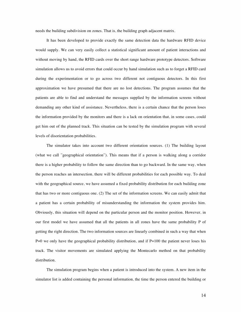
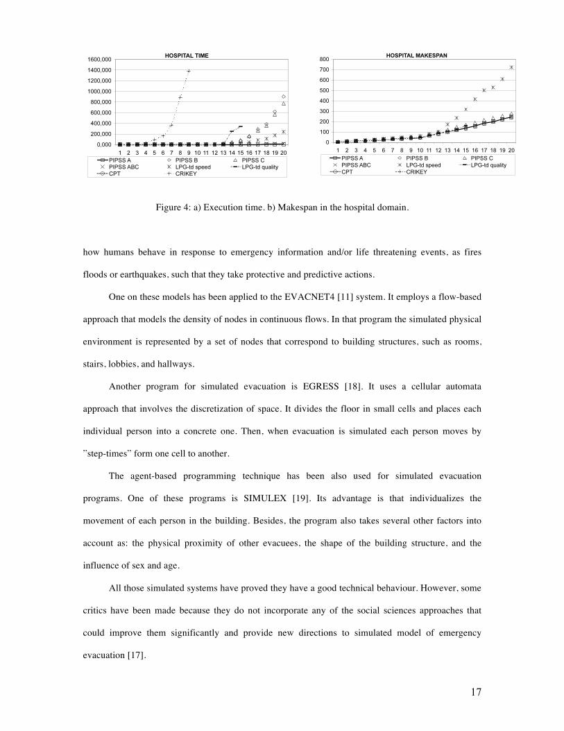
The left part of the Figure 4 shows the accumulated execution times. CPT (until problem ten),
PIPSS A and PIPSS ABC are the fastest performers, before LPG speed. Then comes PIPSS C, PIPSS
B, LPG quality and CRIKEY.
The right part of the Figure 4 shows the accumulated makespan of the solutions. CPT and
CRIKEY do not obtain enough results to be compared to the other planners. In this domain, PIPSS A,
PIPSS B and PIPSS ABC are the best. LPG quality is nearly as good as them, but gets stuck in the
problem fifteen. Then comes PIPSS C, which is near the first four. LPG speed is the last, getting quite
big values. So we can conclude that PIPSS is the best performer (in time and makespan) in the
hospital domain.
7 Related Work
There are several approaches to the problem of people moving inside a concrete environment [7].
Most of them are focused on representing emergency evacuations from buildings, aircrafts, ships or
even cities. They are related to different simulation models based on the knowledge we have about
17
Figure 4: a) Execution time. b) Makespan in the hospital domain.
how humans behave in response to emergency information and/or life threatening events, as fires
floods or earthquakes, such that they take protective and predictive actions.
One on these models has been applied to the EVACNET4 [11] system. It employs a flow-based
approach that models the density of nodes in continuous flows. In that program the simulated physical
environment is represented by a set of nodes that correspond to building structures, such as rooms,
stairs, lobbies, and hallways.
Another program for simulated evacuation is EGRESS [18]. It uses a cellular automata
approach that involves the discretization of space. It divides the floor in small cells and places each
individual person into a concrete one. Then, when evacuation is simulated each person moves by
”step-times” form one cell to another.
The agent-based programming technique has been also used for simulated evacuation
programs. One of these programs is SIMULEX [19]. Its advantage is that individualizes the
movement of each person in the building. Besides, the program also takes several other factors into
account as: the physical proximity of other evacuees, the shape of the building structure, and the
influence of sex and age.
All those simulated systems have proved they have a good technical behaviour. However, some
critics have been made because they do not incorporate any of the social sciences approaches that
could improve them significantly and provide new directions to simulated model of emergency
evacuation [17].
18
One simulated system that incorporates this information about actual human social behaviour is
EXODUS [12]. It is a agent-based system that furnishes the most complete set of social psychological
attributes and characteristics for each one of its personal-agents. This set includes age, name, sex,
breathing rate and running speed, among others. These agents also have a certain degree of familiarity
with the building, agility, and even patience. The model deals with the movements of large numbers of
persons inside a building towards the exits. It can also take into account the eventual delay of
movement due to extreme heat or effect of toxic gases.
Our program is not related to people movements in hazard conditions but it can be adapted to
include that performance if it were needed. In that case detecting evacuee movements, planning their
paths and informing them about the building egress could be very useful.
8 Conclusions
In this paper we have described an application based on AI Planning and Scheduling techniques to
solve the problem of guiding persons through large surfaces of high affluence level of people, as for
example hospitals or public administrations. We have used the RFID passive technology to detect the
users movements and to know in each instant their positions. This system has been implemented
satisfactorily in a scale prototype that has successfully proved its viability and good performance. A
simulator based on the Montecarlo method has been used to test the whole architecture.
In the future we want to optimize the problem of the number of detectors inside the building.
We want to also add temporal constraints to the patient appointments.
Acknowledgments
This work has been founded by the project PEII09-0266-6640.

19
References
[1] B. Bonet and H. Geffner. Planning as Heuristic Search: New results. In Procs. of the ECP-99.
Springer, 1999.
[2] B. Castano and M. D. R-Moreno. An Artificial Intelligence and RFID System for People Detection
and Orientation in Big Surfaces. In Procs of the 6th International Conference on Computing,
Communications and Control Technologies (CCT2008). Florida, USA, 2008.
[3] A. Cesta, A. Oddi, and S. F. Smith. An Iterative Sampling Procedure for Resource Constrained
Project Scheduling with Time Windows. In Proceedings of the 16th Int. Joint Conference on Artificial
Intelligence (IJCAI-99), 1999.
[4] D. V. Engels. RFID: The technical Reality. In Proceedings of Workshop on Radio Frequency
Identification: Applications and Implications for Consumers. Washington D.C., 2004.
[5] D. V. Engels. Indoor Positioning and Digital Management: Emerging Surveillance Regimes in
Hospitals. In Surveillance and Security: Technological Politics and Power in Everyday Life., pages
77–88. T. Monahan (Ed), 2006.
[6] Saetti A. Gerevini, A. and I. Serina. An Approach to Temporal Planning and Scheduling in
Domains with Predicatable Exogenous Events. jair, 25:187–213, 2006.
[7] S. Gwynne, E. Galea, M. Owen, P. Lawrence, and Filippidis L. A Review Of The Methodologies
Used In The Computer Simulation Of Evacuation From The Built Environment. Building and
Environment Journal, 34:742–749, 1999.
[8] K. Halsey, D. Long, and M. Fox. CRIKEY - A Planner Looking at the Integration of Scheduling
and Planning. In Procs. of the Workshop on Integration Scheduling Into Planning at 13th International
Conference on Automated Planning and Scheduling (ICAPS’03), pages 46–52, 2004.
[9] Jessica Heesen. Universalisation, Totality and ICT, or: Are there any reasons for demanding ICT-
free areas? International Journal of Information Ethics, 2(11), 2004.
[10] J. Hoffmann and B. Nebel. The ff Planning System: Fast Plan Generation Through Heuristic
Search. Journal of Artificial Intelligence Research, 14:253–302, 2001.
20
[11] T. M. Kisko, R. L. Francis, and C. R. Nobel. EVACNET4 User’s Guide. In University of Florida,
1998.
[12] M. Owen, E. Galea, and P. Lawrence. The EXODUS Evacuation Model Applied to Building
Evacuation Scenarios. In AEA Technology, Warrington, UK., 2003.
[13] J. Plaza, M. D. R-Moreno, B. Castano, M. Carbajo, and A. Moreno. PIPSS: Parallel Integrated
Planning and Scheduling System. In The 27th Annual Workshop of the UK Planning and Scheduling
Special Interest Group (PLANSIG05). London (UK), 2008.
[14] M. D. R-Moreno, D. Camacho, and A. Moreno. HPP: A Heuristic Progressive Planner. In The
24th Annual Workshop of the UK Planning and Scheduling Special Interest Group (PLAN- SIG05).
London (UK)., 2005.
[15] R. Y. Rubinstein and D. P. Kroese. Simulation and the Monte Carlo Method. Wiley Series in
Probability and Statistics, John Wiley and Sons, 2008.
[16] K. K. Sabelfeld. Monte Carlo Methods in Boundary Value Problems. Springer-Verlag, 1991.
[17] G. Santos and B. E. Aguire. A critical Review of Emergency Evacuation Simulation Models. In
Procs. of the NIST Workshop on Building Occupant Movement during Fire Emergencies.
Gaithersburg, Maryland., 2004.
[18] AEA Technology. A Technical Summary of the AEA EGRESS Code. In AEA Technology,
Warrington, UK., 1998.
[19] P. A. Thompson, J. Wu, and Marchant E. W. Modelling Evacuation in Multi-storey Buildings
with Simulex. Fire Engineers Journal, 56:6–11, 1996.
[20] V. Vidal and H. Geffner. Branching and Pruning: An Optimal Temporal POCL Planner based on
Constraint Programming. Artificial Intelligence, 3(170):298–335, 2006.