rfid controller build in reader manual
43
RFID CONTROLLER BUILD IN READER MANUAL AR-721HV3 AR-721HV3-1356 2005/06/01 Downloaded from www.Manualslib.com manuals search engine
-
Upload
khangminh22 -
Category
Documents
-
view
1 -
download
0
Transcript of rfid controller build in reader manual

RFID CONTROLLER BUILD IN READER
MANUAL AR-721HV3
AR-721HV3-1356
2005/06/01
Downloaded from www.Manualslib.com manuals search engine

Table of Contents
Page
1 Introduction ---------------------------------------------------------------------------- 2
2 Features ---------------------------------------------------------------------------- 2
3 Specification --------------------------------------------------------------------------- 3
4 Installation Notice -------------------------------------------------------------------------- 4
5 Front Panel Indicators ----------------------------------------------------------------------- 7
6 Access Mode -------------------------------------------------------------------------- 8
User can select one of the following access modes ----------------------------- 8
AR-721HV3/1356 --------------------------------------------------------------------- 8
Duress function --------------------------------------------------------------------- 9
Force on/off Code (4 sets, 4 digits) ----------------------------------------------- 9
7 Function Default Value ---------------------------------------------------------------------- 11
8 Wiring ---------------------------------------------------------------------- 12
9 Installation Diagram ----------------------------------------------------------------------- 13
10 Installation ----------------------------------------------------------------------- 24
11 Troubleshooting ---------------------------------------------------------------------- 24
12 Return of Products ----------------------------------------------------------------------- 24
13 Warranty ------------------------------------------------------------------------ 25
※ Removable CPU ----------------------------------------------------------------------- 25
14 Mode 4 Easy Guide ------------------------------------------------------------------------- 26
15 Mode 8 Easy Guide ------------------------------------------------------------------------- 30
16 Mode 6 Easy Guide ------------------------------------------------------------------------- 31
17 Mode 7 Easy Guide ------------------------------------------------------------------------- 33
18 Special Design ------------------------------------------------------------------------- 35
19 Transponder Record Table ---------------------------------------------------------------- 38
19.1 For AR-721H4, AR-721H7 and AR-721H8 ------------------------------------ 38
19.2 For AR-721H6 ------------------------------------------------------------------------- 39
20 FAQ ------------------------------------------------------------------------ 40
1Downloaded from www.Manualslib.com manuals search engine
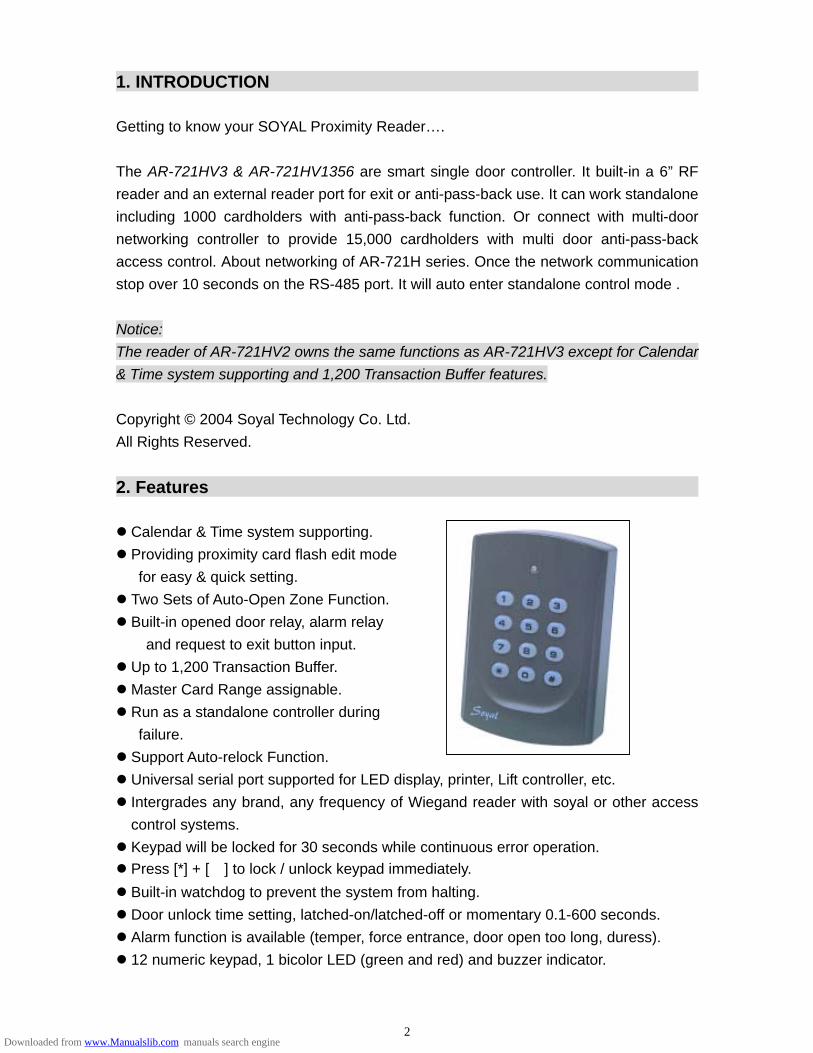
1. INTRODUCTION Getting to know your SOYAL Proximity Reader…. The AR-721HV3 & AR-721HV1356 are smart single door controller. It built-in a 6” RF reader and an external reader port for exit or anti-pass-back use. It can work standalone including 1000 cardholders with anti-pass-back function. Or connect with multi-door networking controller to provide 15,000 cardholders with multi door anti-pass-back access control. About networking of AR-721H series. Once the network communication stop over 10 seconds on the RS-485 port. It will auto enter standalone control mode . Notice: The reader of AR-721HV2 owns the same functions as AR-721HV3 except for Calendar & Time system supporting and 1,200 Transaction Buffer features. Copyright © 2004 Soyal Technology Co. Ltd. All Rights Reserved. 2. Features Calendar & Time system supporting. Providing proximity card flash edit mode
for easy & quick setting. Two Sets of Auto-Open Zone Function. Built-in opened door relay, alarm relay
and request to exit button input. Up to 1,200 Transaction Buffer. Master Card Range assignable. Run as a standalone controller during failure. Support Auto-relock Function. Universal serial port supported for LED display, printer, Lift controller, etc. Intergrades any brand, any frequency of Wiegand reader with soyal or other access control systems. Keypad will be locked for 30 seconds while continuous error operation. Press [*] + [#] to lock / unlock keypad immediately. Built-in watchdog to prevent the system from halting. Door unlock time setting, latched-on/latched-off or momentary 0.1-600 seconds. Alarm function is available (temper, force entrance, door open too long, duress). 12 numeric keypad, 1 bicolor LED (green and red) and buzzer indicator.
2Downloaded from www.Manualslib.com manuals search engine
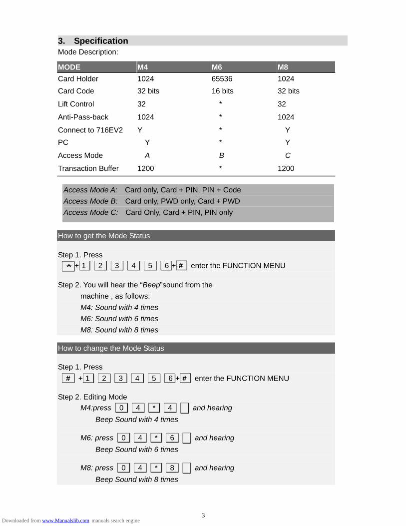
3. Specification Mode Description:
Access Mode A: Card only, Card + PIN, PIN + Code Access Mode B: Card only, PWD only, Card + PWD Access Mode C: Card Only, Card + PIN, PIN only
How to get the Mode Status Step 1. Press * + 1 2 3 4 5 6 + # enter the FUNCTION MENU Step 2. You will hear the “Beep”sound from the
machine , as follows: M4: Sound with 4 times M6: Sound with 6 times M8: Sound with 8 times
MODE M4 M6 M8 Card Holder 1024 65536 1024 Card Code 32 bits 16 bits 32 bits
Lift Control 32 * 32
Anti-Pass-back 1024 * 1024
Connect to 716EV2 Y * Y PC Y * Y
Access Mode A B C
Transaction Buffer 1200 * 1200
How to change the Mode Status Step 1. Press # + 1 2 3 4 5 6 + # enter the FUNCTION MENU Step 2. Editing Mode
M4:press 0 4 * 4 # and hearing Beep Sound with 4 times
M6: press 0 4 * 6 # and hearing
Beep Sound with 6 times M8: press 0 4 * 8 # and hearing
Beep Sound with 8 times
3Downloaded from www.Manualslib.com manuals search engine
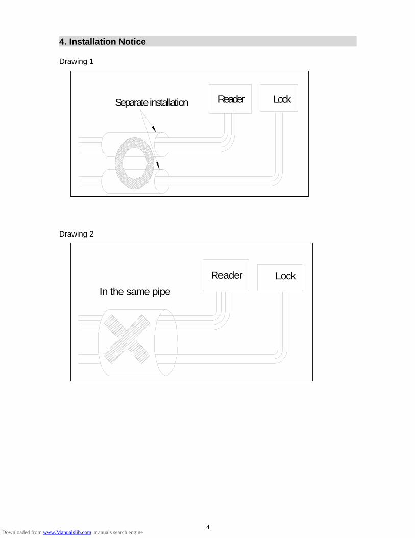
4. Installation Notice Drawing 1
Separate installation Reader Lock
Drawing 2
LockIn the same pipe
Reader
4Downloaded from www.Manualslib.com manuals search engine
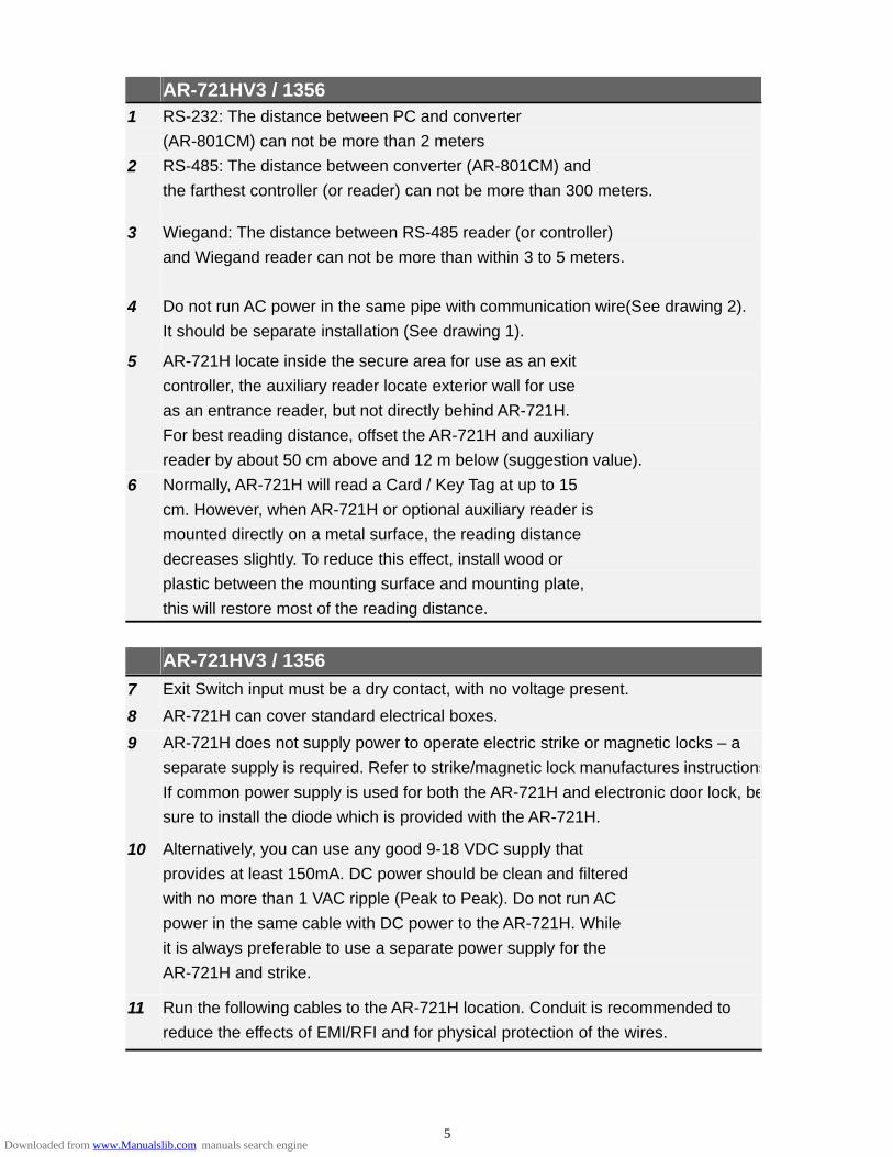
AR-721HV3 / 1356 1 RS-232: The distance between PC and converter
(AR-801CM) can not be more than 2 meters 2 RS-485: The distance between converter (AR-801CM) and
the farthest controller (or reader) can not be more than 300 meters.
3 Wiegand: The distance between RS-485 reader (or controller) and Wiegand reader can not be more than within 3 to 5 meters.
4 Do not run AC power in the same pipe with communication wire(See drawing 2). It should be separate installation (See drawing 1).
5 AR-721H locate inside the secure area for use as an exit controller, the auxiliary reader locate exterior wall for use as an entrance reader, but not directly behind AR-721H. For best reading distance, offset the AR-721H and auxiliary reader by about 50 cm above and 12 m below (suggestion value).
6 Normally, AR-721H will read a Card / Key Tag at up to 15 cm. However, when AR-721H or optional auxiliary reader is mounted directly on a metal surface, the reading distance decreases slightly. To reduce this effect, install wood or plastic between the mounting surface and mounting plate, this will restore most of the reading distance.
AR-721HV3 / 1356 7 Exit Switch input must be a dry contact, with no voltage present. 8 AR-721H can cover standard electrical boxes. 9 AR-721H does not supply power to operate electric strike or magnetic locks – a
separate supply is required. Refer to strike/magnetic lock manufactures instructionsIf common power supply is used for both the AR-721H and electronic door lock, besure to install the diode which is provided with the AR-721H.
10 Alternatively, you can use any good 9-18 VDC supply that provides at least 150mA. DC power should be clean and filtered with no more than 1 VAC ripple (Peak to Peak). Do not run AC power in the same cable with DC power to the AR-721H. While it is always preferable to use a separate power supply for the AR-721H and strike.
11 Run the following cables to the AR-721H location. Conduit is recommended to reduce the effects of EMI/RFI and for physical protection of the wires.
5Downloaded from www.Manualslib.com manuals search engine
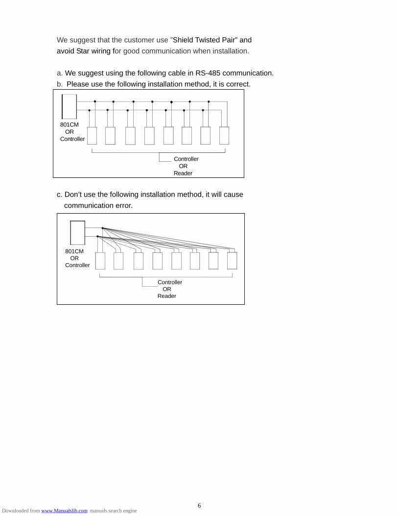
We suggest that the customer use ”Shield Twisted Pair” and avoid Star wiring for good communication when installation. a. We suggest using the following cable in RS-485 communication. b. Please use the following installation method, it is correct. c. Don’t use the following installation method, it will cause
communication error.
801CM ORController
Controller ORReader
801CM ORController
Controller ORReader
6Downloaded from www.Manualslib.com manuals search engine
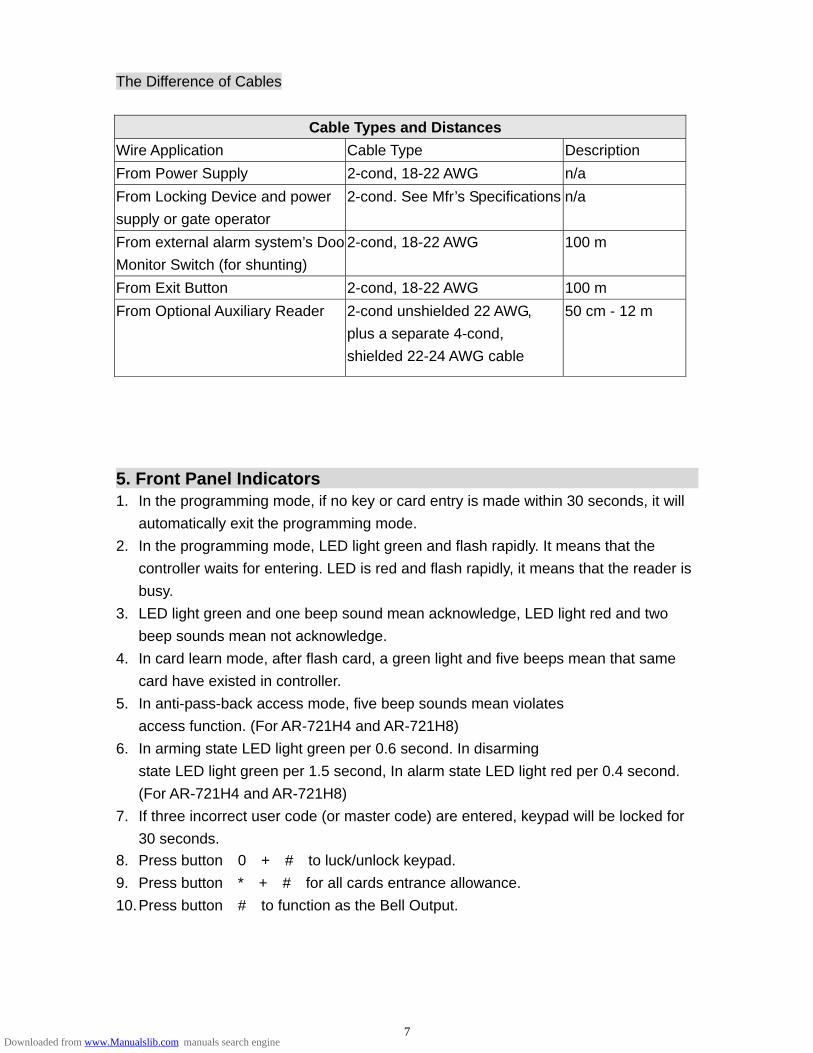
The Difference of Cables
Cable Types and Distances Wire Application Cable Type Description From Power Supply 2-cond, 18-22 AWG n/a From Locking Device and power supply or gate operator
2-cond. See Mfr’s Specifications n/a
From external alarm system’s DooMonitor Switch (for shunting)
2-cond, 18-22 AWG 100 m
From Exit Button 2-cond, 18-22 AWG 100 m From Optional Auxiliary Reader 2-cond unshielded 22 AWG,
plus a separate 4-cond, shielded 22-24 AWG cable
50 cm - 12 m
5. Front Panel Indicators 1. In the programming mode, if no key or card entry is made within 30 seconds, it will
automatically exit the programming mode. 2. In the programming mode, LED light green and flash rapidly. It means that the
controller waits for entering. LED is red and flash rapidly, it means that the reader is busy.
3. LED light green and one beep sound mean acknowledge, LED light red and two beep sounds mean not acknowledge.
4. In card learn mode, after flash card, a green light and five beeps mean that same card have existed in controller.
5. In anti-pass-back access mode, five beep sounds mean violates access function. (For AR-721H4 and AR-721H8)
6. In arming state LED light green per 0.6 second. In disarming state LED light green per 1.5 second, In alarm state LED light red per 0.4 second. (For AR-721H4 and AR-721H8)
7. If three incorrect user code (or master code) are entered, keypad will be locked for 30 seconds.
8. Press button【0】+【#】to luck/unlock keypad. 9. Press button【*】+【#】for all cards entrance allowance. 10. Press button【#】to function as the Bell Output.
7Downloaded from www.Manualslib.com manuals search engine

6. Access Mode
How to program ---2222 Duress Code (network) ---1111 Force On/Off Code (network) ---5678 Door Access User Code (network/standalone) ---1234 Arming and Disarming (network/standalone)
User can select one of the following access modes AR-721HV3 /1356 Card only
User can access the door by flashing card on the unit. Arming / Disarming: After flashing card ok, press 1 2 3 4 # Then the unit will trigger the arming/disarming mode.
Card or PWD
User can access the door by just either flash card or entering 5 digit the user number+ entering 4 digit user code + # Arming/Disarming: After flashing card ok, press 1 2 3 4 # . Then the unit will trigger the arming/disarming mode. Arming/Disarming: entering 5 digit the user number+ entering 4 digit user code + # , then press 1 2 3 4 # . Then the unit will trigger the arming/disarming mode.
Card or 4-digit User Code
User can access the door by just either flash card or entering 4 - digit user code. Arming/Disarming: After flashing card ok, press 1 2 3 4 # . Then the unit will trigger the arming/disarming mode. Arming/Disarming: entering 4 digit user code, then press 1 2 3 4 # . Then the unit will trigger the arming/disarming mode.
User can change user code any time
a. AR-721H connects with controller and PC, running 701 client and set user code variable.
By user: After accessed ok, press 4-digit new user code twice and press # By 701 client \ setting \ user card b. Not connecting with PC After accessed ok, press 4-digit new user code twice and press #
8Downloaded from www.Manualslib.com manuals search engine

Duress function This function could help users to send a message to the computer asking for help. Only available in networking state, running 701 Server and setting 4 sets of Duress code on PC. (Anyone of these 4 sets is workable.) This function is not available for CARD ONLY and USER CODE ONLY (AR-721H8) access.
Access Mode Command Format
Card Only Not available
Card + user code Flash card, then press Duress code & #
User code Only Not available
User no. + user code Press user no., then Duress code & #
Note: User can access door by duress code instead of user code under card or user code access mode, but it will be shown ask for help message in 701 Client \ Daily Transaction Record.
Force on/off Code (4 sets, 4 digits) Only workable in networking system, running 701 Server and setting 4 sets of Force code on PC. (Anyone of these 4 sets is workable.) User could press related code to turn on / off its connected equipment, diagram as below.
PC boad of Controller AR-716EV2 / AR-727E
COM
JP4
V12CN5
DI.4
DI.2DI.1
DI.3
COM
D10D9
D11
K4RELAY
K3
D12
RELAY
JP3
K1
K3K4
K2K2
RELAYRELAYK1
Relay Code K1 16 K2 17 K3 18 K4 19
9Downloaded from www.Manualslib.com manuals search engine

After access OK, press following order to turn on / off its connected equipment.
Access mode ON/Off Order
ON Flashing card+Force code+Code+0+#
Card only Off
Flashing card+Force code+Code+1+#
ON Flashing card+User code +Force code+Code+ 0+# Card + user
code Off
Flashing card+User code +Force code+Code+1+#
ON User no. +User code +Force code+Code+ 0+# User no. +
user code (Mode 4) Off
User no. +User code +Force code+Code+ 1+#
ON User code +Force code+Code+0+#
User code only
(Mode 8) Off User code +Force code+Code+1+#
This function can be connected with force control television, air conditioning, audio, etc. by Relay-1, 2, 3, 4 on the multi-door networking controller. To avoid the conflict of the use of each controller relay, it is user responsibility to define each controller relay for one purpose use only.
10Downloaded from www.Manualslib.com manuals search engine
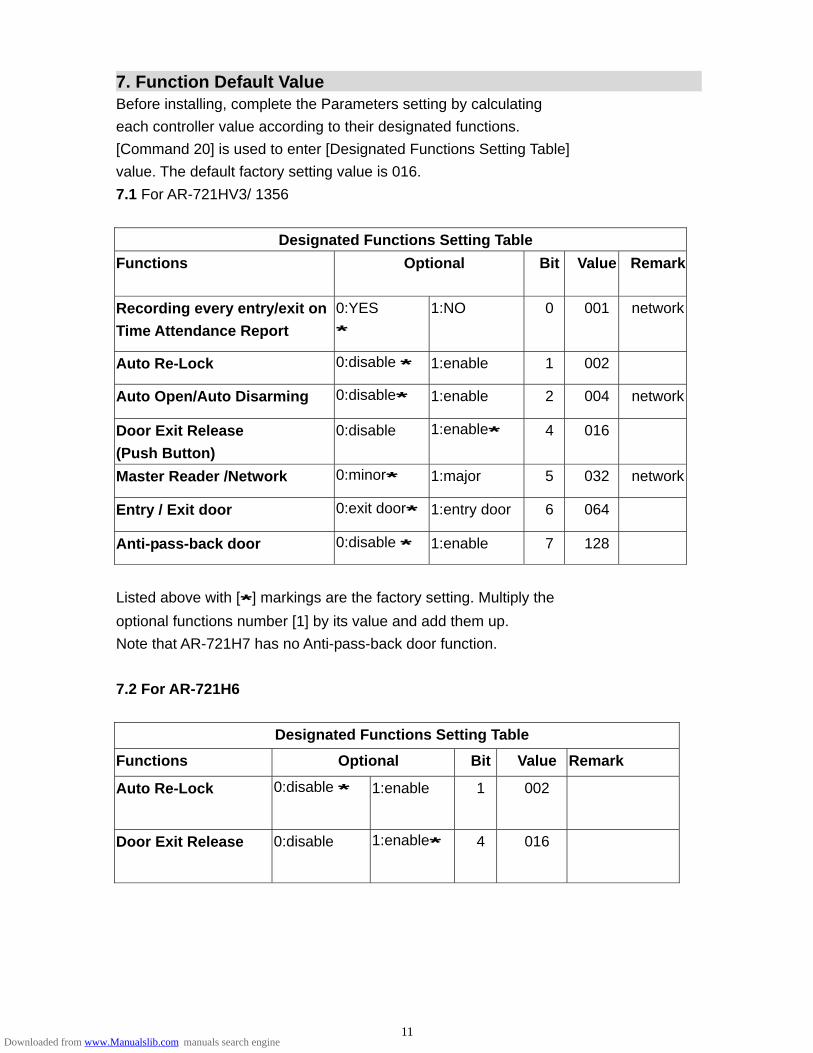
7. Function Default Value Before installing, complete the Parameters setting by calculating each controller value according to their designated functions. [Command 20] is used to enter [Designated Functions Setting Table] value. The default factory setting value is 016. 7.1 For AR-721HV3/ 1356
Designated Functions Setting Table Functions Optional Bit Value Remark
Recording every entry/exit on Time Attendance Report
0:YES *
1:NO 0 001 network
Auto Re-Lock 0:disable * 1:enable 1 002
Auto Open/Auto Disarming 0:disable* 1:enable 2 004 network
Door Exit Release (Push Button)
0:disable 1:enable* 4 016
Master Reader /Network 0:minor* 1:major 5 032 network
Entry / Exit door 0:exit door* 1:entry door 6 064
Anti-pass-back door 0:disable * 1:enable 7 128
Listed above with [*] markings are the factory setting. Multiply the optional functions number [1] by its value and add them up. Note that AR-721H7 has no Anti-pass-back door function.
7.2 For AR-721H6
Designated Functions Setting Table
Functions Optional Bit Value Remark
Auto Re-Lock 0:disable * 1:enable 1 002
Door Exit Release 0:disable 1:enable* 4 016
11Downloaded from www.Manualslib.com manuals search engine

8. Wiring
Table 1 - Connector P1 Color Coding Wire Application Wire Color Description
1 Blue White (N.O.)DC24V1Amp
2 Purple White (N.C.)DC24V1Amp
Door Relay
3 White (COM)DC24V1Amp Door Sensor 4 Orange Negative Trigger Input
Exit Switch 5 Purple Negative Trigger Input
Alarm Output 6 Grey Transistor Output (Open Collector Active Low )
7 Thick Red DC Power 12V Power
8 Thick Black DC Power 0V
Table 2 - Connector P2 Color Coding ( Wiegand Read Head )
Wire Application Wire Color Description
1 Thin Blue Wiegand DAT:1 Input Wiegand
2 Thin Green Wiegand DAT:0 Input Beeper 3 Pink Beeper Output 5V/100mA, Low
4 Brown LED Green Output 5V/20mA, Max LED
5 Yellow LED Red Output 5V/20mA, Max
Table 3 - Connector P3 Color Coding (Tamper Switch )
Wire Application Wire Color Description
1 Red N.C. 2 Orange COM
Tamper Switch
3 Yellow N.O.
Table 4 - Connector P4 Color Coding
Wire Application Wire Color Description
1 Thick Green RS-485(B-) Networking Module
2 Thick Blue RS-485(A+)
12Downloaded from www.Manualslib.com manuals search engine
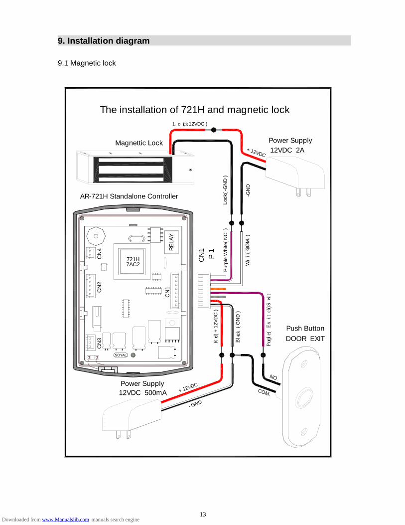
9. Installation diagram 9.1 Magnetic lock
Purple
(Exit Swit
ch)
The installation of 721H and magnetic lock
+12VDC
AR-721H Standalone Controller
Lock(+12VDC )
Magnettic Lock
Lock
( -G
ND
)
-GN
D
721HCN
4 RE
LAY
7AC2
CN
2
CN
1
White
( C
OM
. )
Pur
ple
Whi
te( N
C. )
P 1
CN
1
Power Supply12VDC 2A
COM.
- GND
CN
3
SOYAL
12VDC 500mAPower Supply
Red
( +
12V
DC
)
Black( -
GN
D )
+12VDC
Push ButtonDOOR EXIT
NO.
13Downloaded from www.Manualslib.com manuals search engine
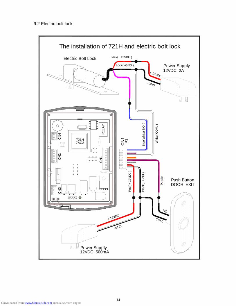
9.2 Electric bolt lock
The installation of 721H and electric bolt lock
Electric Bolt Lock
721HCN
4C
N2
7AC2
Lock(+12VDC )
Lock( -GND ) Power Supply12VDC 2A+12VDC
- GND
CN
1P
1
RE
LAY
CN
1
Blu
e W
hite
( N
O. )
Whi
te(
CO
M. )
Power Supply12VDC 500mA
CN
3
SOYAL
- GND
Bla
ck(
- GN
D )
Red
( +
12V
DC
)
+12VDC
Pur
ple
DOOR EXITPush Button
NO.
COM.
14Downloaded from www.Manualslib.com manuals search engine
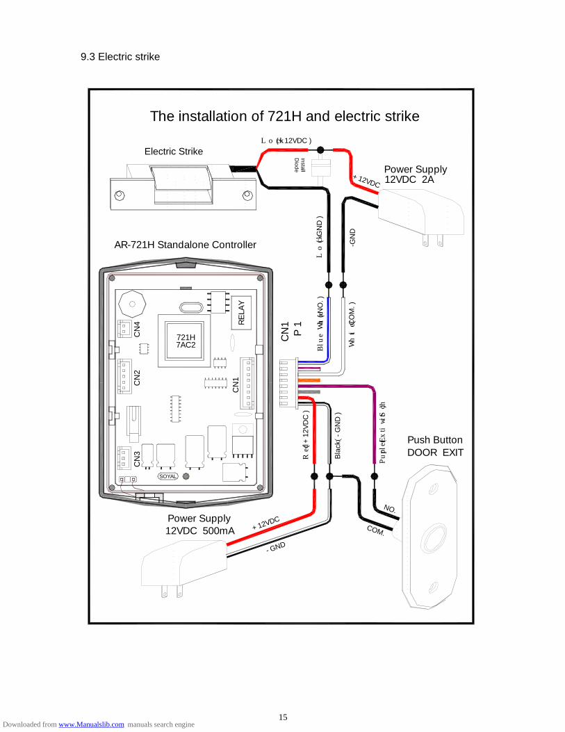
9.3 Electric strike
+12VDC
The installation of 721H and electric strike
AR-721H Standalone Controller
Electric Strike
12VDC 500mAPower Supply
+12VDC
- GND
Purple(
Exit Switch
)
Push ButtonDOOR EXIT
NO.
Lock(+12VDC )
InstallD
iode
721H7AC2
CN
4 RE
LAY
-GN
D
Lock
( -G
ND
)
CN
1P
1
Blue
Whi
te( N
O. )
White(
CO
M. )
Power Supply12VDC 2A
COM.
CN
2
CN
1
CN
3
SOYAL
Bla
ck(
- GN
D )
Red( +
12V
DC
)
15Downloaded from www.Manualslib.com manuals search engine
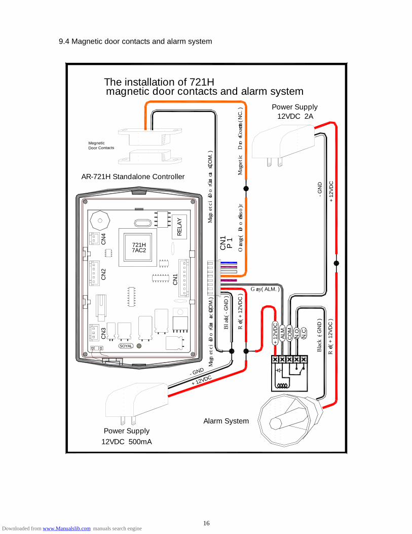
9.4 Magnetic door contacts and alarm system
CN
2C
N3
SOYAL
Power Supply12VDC 500mA
Magneti
c Door Contac
ts(
CO
M.)
Blac
k( -
GN
D )
Red(
+12
VD
C )
CN
1
Gray( ALM. )C
OM
.A
LM.
+12
VD
C
Black(
- G
ND
)
Red(
+12
VD
C )
N.O
.N
.C.
Alarm System
- GND
+12VDC
magnetic door contacts and alarm system
AR-721H Standalone Controller
The installation of 721H
MegneticDoor Contacts
CN
4
721H7AC2
Magnet
ic Doo
r Cont
acts( N
C. )
Magneti
c Door Contacts(
CO
M. )
12VDC 2APower Supply
RE
LAY
Orange(D
oor Sensor
)
CN
1P
1
+12
VD
C
- GN
D
16Downloaded from www.Manualslib.com manuals search engine
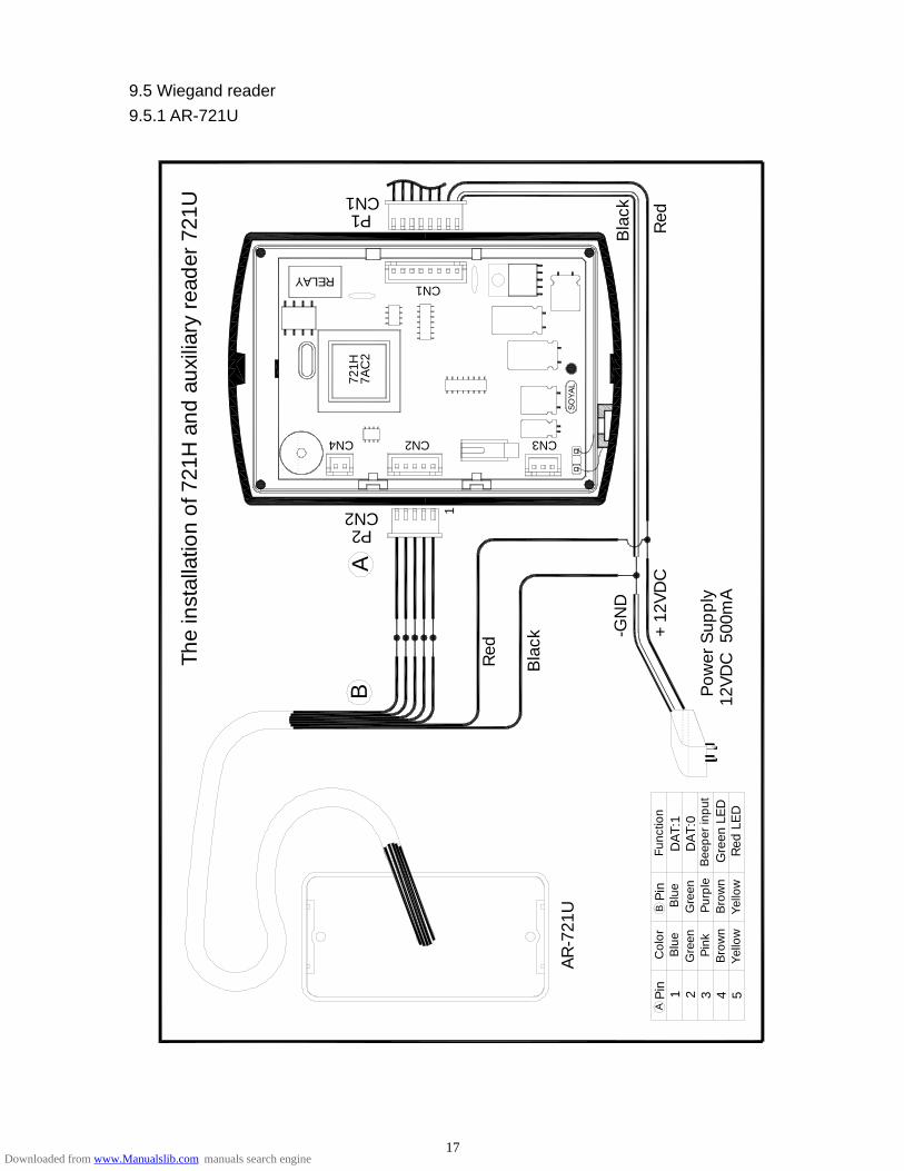
9.5 Wiegand reader 9.5.1 AR-721U
-GN
D
+12
VD
C
Pow
er S
uppl
y12
VD
C 5
00m
A
The
inst
alla
tion
of 7
21H
and
aux
iliar
y re
ader
721
U
CN3
SO
YA
L
Red
Bla
ck
A
CN2P2
1
7AC
2
CN2CN4
721H
CN1P1
CN1RELAY
Yel
low
Bro
wn
Pin
kG
reen
Col
orB
lue
2 4 531Pin
A
Pur
ple
Yel
low
Bro
wn
Gre
enB
lue
Pin
B
AR
-721
U
Gre
en L
ED
Red
LE
D
Bee
per
inpu
tD
AT:
0D
AT:
1Fu
nctio
n
Bla
ck
Red
B
17Downloaded from www.Manualslib.com manuals search engine
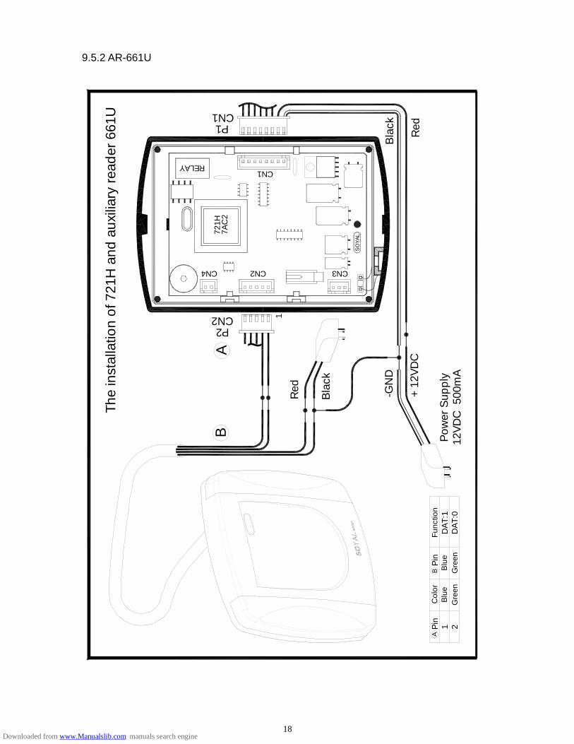
9.5.2 AR-661U
The
inst
alla
tion
of 7
21H
and
aux
iliar
y re
ader
661
U
12V
DC
500
mA
Pow
er S
uppl
y
+12
VD
C
-GN
D
Bla
ck
CN1RELAY
CN1P1
Blu
eP
in
Gre
enB
lue
Col
or
Gre
en2P
in 1A
BFu
nctio
n
DA
T:0
DA
T:1
Red
B
Red
Bla
ck~
1
SO
YA
L
CN3CN2
P2
A
CN2
CN4
721H
7AC
2
18Downloaded from www.Manualslib.com manuals search engine

9.5.3 AR-737U
Red
+12
VD
CB
Pin
Pin
Col
orA
Func
tion
SO
YA
L
The
inst
alla
tion
of 7
21H
and
aux
iliar
y re
ader
737
U
CN2P2
AB
CN4
AR
-737
U
1
CN2
Red
CN3
-GN
D
Bla
ck
P1CN1
RELAY
7AC
2
CN1
Bla
ck
Gre
en2
Gre
enB
lue
Blu
e1
Bro
wn
Pur
ple
Pin
k43
Bro
wn
Yel
low
5Y
ello
w
Pow
er S
uppl
yD
AT:
0D
AT:
1
12V
DC
500
mA
Gre
en L
ED
Red
LE
D
Bee
per
inpu
t
19Downloaded from www.Manualslib.com manuals search engine
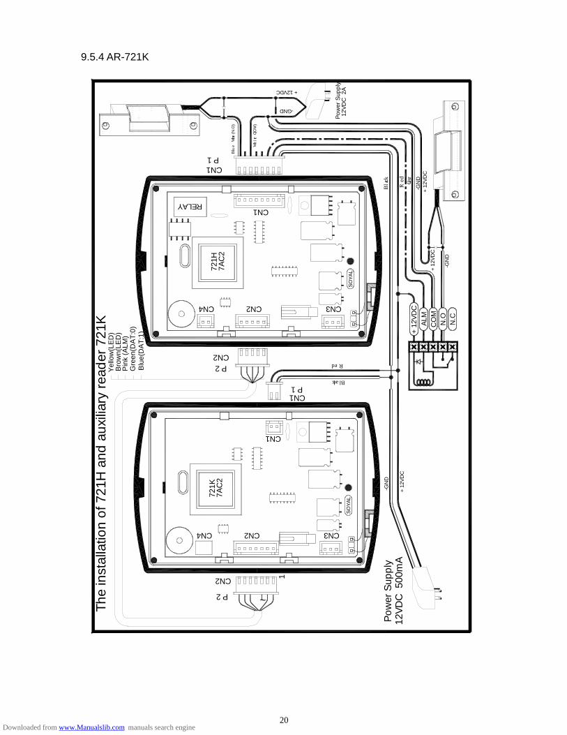
9.5.4 AR-721K
+12
VD
C
12V
DC
2A
Pow
er S
uppl
y
Red
Gray
-GN
D
Black
1
~
CN2
ALM
CO
MN
.ON
.C
+12
VD
C
-GN
D
Black
Red
CN1
P 1CN1
CN3+
12V
DC
SO
YA
L
CN2
The
inst
alla
tion
of 7
21H
and
aux
iliar
y re
ader
721
K
7AC
272
1K
P 2
CN2
CN4
Yel
low
(LED
)B
row
n(LE
D)
Gre
en(D
AT:0
) B
lue(
DAT
:1)
Pin
k (A
LM)
CN2P 2
CN4
721H
7AC
2
-GN
D
+12
VD
C12
VD
C 5
00m
AP
ower
Sup
ply
CN3
SO
YA
L
CN1
-GND
White (CO
M)
+12VDC
P 1
RELAY
CN1
Blue White (N
.O)
20Downloaded from www.Manualslib.com manuals search engine
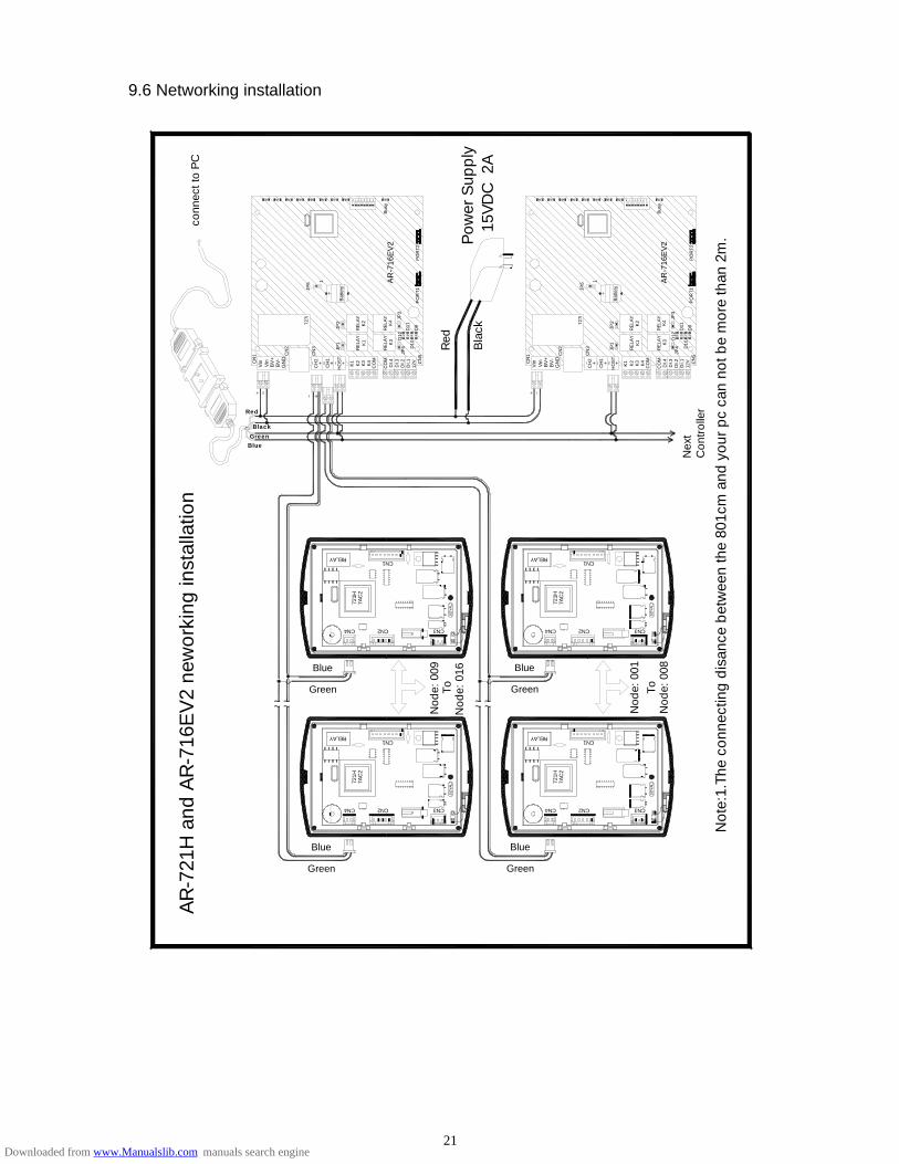
9.6 Networking installation
JP2
Bat
tery
Busy
3 245 168 7
conn
ect t
o P
C
727i
JP5 1
CN1RELAY
CH
2
CN1
CN3
Nod
e: 0
08
Nod
e: 0
01To
SO
YA
L
Con
trol
ler
Nex
t
CO
M CN
5
DI.2
12V
DI.1
DI.3
DI.4K1 K4 C
OM
K2
K3
HO
ST
CH
1
Nod
e: 0
16
CN4 CN2
Green
Blue
~~~~
7AC
272
1H
RELAY
CN4 CN3CN2
Nod
e: 0
09To
CN
3
CN
2
JP4JP
1
RE
LAY
RE
LAY
Not
e:1.
The
conn
ectin
g di
sanc
e be
twee
n th
e 80
1cm
and
you
r pc
can
not
be
mor
e th
an 2
m.
CH
1
Green
Blue
Blue
Green
CN1
SO
YA
L
CN3
Blue
Green
7AC
2
CN2CN4
721H
RELAY
SO
YA
L
CN37A
C2
CN2CN472
1H
Bla
ck
Red
CN
2
CN
3 RE
LAY
JP1
RE
LAY
JP4
RE
LAY
K2
K1
JP2
Bat
tery
1
Busy
2 158 67 34
15V
DC
2A
Pow
er S
uppl
y
727i
JP5A
R-7
16E
V2
POR
T2
K3
POR
T1
D11
D9
D10
D12
JP3
RE
LAY
K4
K2
RE
LAY
K1
~~~~
Blue
Vin
BlackGreen
CH
2
BV
-G
ND
BV
+V
in
Red
CN
1
POR
T2
AR
-716
EV
2R
ELA
Y
POR
T1D
9K4
D11
D12
D10K
3
JP3
SO
YA
L7AC
272
1H
CN1RELAY
CN
1
GN
D
Vin
BV
-B
V+
Vin
DI.4
DI.1
12V CN
5
DI.2
DI.3K2
CO
M
K3 K4 CO
M
K1
HO
ST
AR
-721
H a
nd A
R-7
16E
V2 n
ewor
king
inst
alla
tion
21Downloaded from www.Manualslib.com manuals search engine
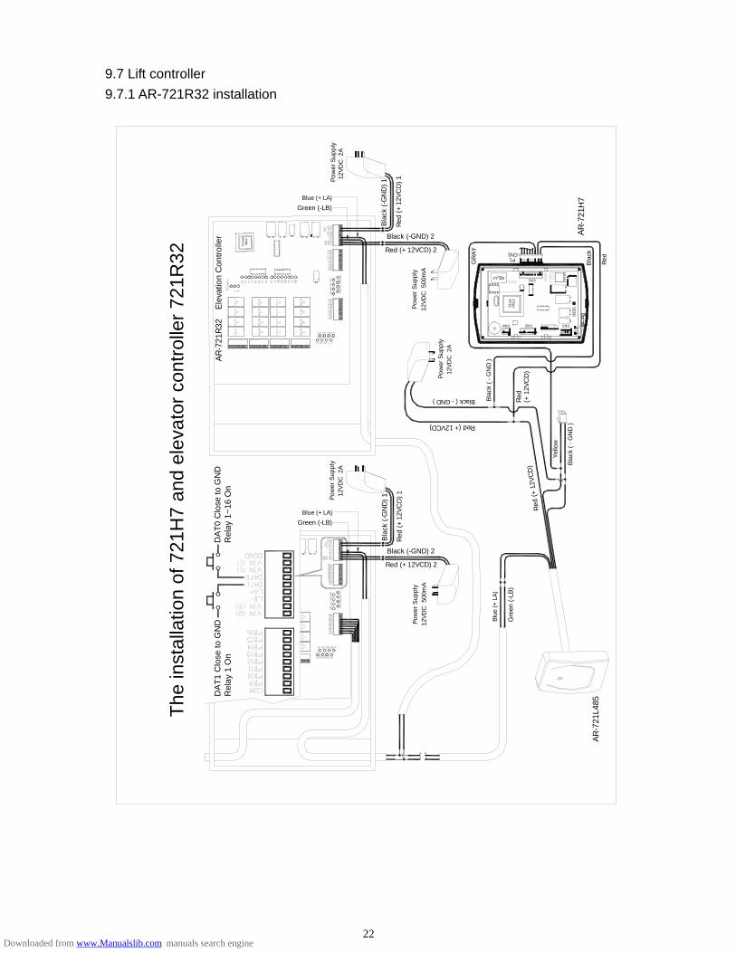
9.7 Lift controller 9.7.1 AR-721R32 installation
The
inst
alla
tion
of 7
21H
7 an
d el
evat
or c
ontro
ller 7
21R
32
DA
T1 C
lose
to G
ND
Rel
ay 1
On
~~
~~
12V
DC
500
mA
Pow
er S
uppl
y
Gre
en (
-LB
)
Blu
e (+
LA)
AR
-721
L485
(+12
VC
D)
CN2
Red
(+12
VC
D)
AR
-721
R32
E
leva
tion
Con
trol
ler
Pow
er S
uppl
y12
VD
C 5
00m
A
Pow
er S
uppl
y
Green (-LB)
Blue (+LA)
DA
T0 C
lose
to G
ND
Rel
ay 1
~16
On
Red (+12VCD) 2
Black (-GND) 2
Red
(+
12V
CD
) 1
Bla
ck (
-GN
D)
1
SO
YAL
CN3
AR
-721
H7
CN1
Red
Bla
ck
12V
DC
2A
Red (+12VCD)
Bla
ck (
- G
ND
)
12V
DC
2A
Pow
er S
uppl
y
Black ( - GND ) Red
CN4
7AC
272
1H
Green (-LB)
Blue (+LA)
Pow
er S
uppl
y
721R
32 8
FF3
12V
DC
2A
Black (-GND) 2
Red (+12VCD) 2
Red
(+
12V
CD
) 1
Bla
ck (
-GN
D) 1
GR
AY
P1
RELAY
CN1
Bla
ck (
- G
ND
)
Yel
low
22Downloaded from www.Manualslib.com manuals search engine

9.7.2 AR-401RO16 installation
Diagram for AR-721H7 and AR-821L485
AR-721H7 AR-821L485 Red Red
Black Black Gray Yellow
AR-721H7
Wire Description:
Red: +12V
Black: GND
Yellow: TX
White: RTS
Orange: RX
AR-821L485
AR-401RO16
23Downloaded from www.Manualslib.com manuals search engine
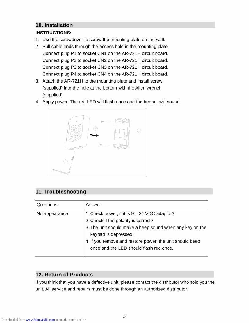
10. Installation
INSTRUCTIONS: 1. Use the screwdriver to screw the mounting plate on the wall. 2. Pull cable ends through the access hole in the mounting plate. Connect plug P1 to socket CN1 on the AR-721H circuit board. Connect plug P2 to socket CN2 on the AR-721H circuit board. Connect plug P3 to socket CN3 on the AR-721H circuit board. Connect plug P4 to socket CN4 on the AR-721H circuit board. 3. Attach the AR-721H to the mounting plate and install screw (supplied) into the hole at the bottom with the Allen wrench (supplied). 4. Apply power. The red LED will flash once and the beeper will sound. 11. Troubleshooting
Questions Answer
No appearance 1. Check power, if it is 9 – 24 VDC adaptor? 2. Check if the polarity is correct? 3. The unit should make a beep sound when any key on the
keypad is depressed. 4. If you remove and restore power, the unit should beep
once and the LED should flash red once.
12. Return of Products
If you think that you have a defective unit, please contact the distributor who sold you the unit. All service and repairs must be done through an authorized distributor.
24Downloaded from www.Manualslib.com manuals search engine

13. Warranty
SOYAL warrants that the product(s) shall be free from manufacturing defects in materials and workmanship for a period of fifteen (15) month from the date of delivery provided that the product was properly installed and used. The foregoing warranty shall not apply to defects resulting from abuse, misuse, accident, unauthorized alteration or repair, neglect, acts of God (such as floods, fire, etc.). SOYAL shall, at its option, either repair or replace product(s) which prove to be defective within the warranty period. SOYAL will replace any product found to be defective within the first three months of purchase provided said product was properly installed and used. Distributor agrees to insure the product or assume the risk of loss or damage in transit to prepay shipping charges and to use the original shipping container or equivalent. Customers shall seek assistance from the distributor who sold you product(s). Repaired or replaced product(s) are warranted for ninety (90) days from the date of repair or replacement, or for the remainder of the original product’s warranty period, whichever is longer. Note: Don’t tear a paster such as S/N: 721H4-08336 on the PCB board, because it is SOYAL warranty. ※ Removable CPU The CPU of this generation version of AR-721H series can be removable. If the master code is forgotten it can be restored to the factory default (123456). Remove the AR-721H series from the mounting plate, disconnect power, remove AR-721H CPU, install AR-721H-CLE CPU, and restore power about 10 seconds. Then disconnect power, remove AR-721H-LCE CPU, install AR-721H CPU, and restore power.
1) If CPU at hand as above stand for The CPU of first generation version of AR-721H series. You can refer the above step to restoremaster code to the factory default (123456).
2) You can know item no. and CPU version of the device from CPU paster of left picture. So, this device is AR-721H4, CPU version 3V4 and checksum 472B
25Downloaded from www.Manualslib.com manuals search engine
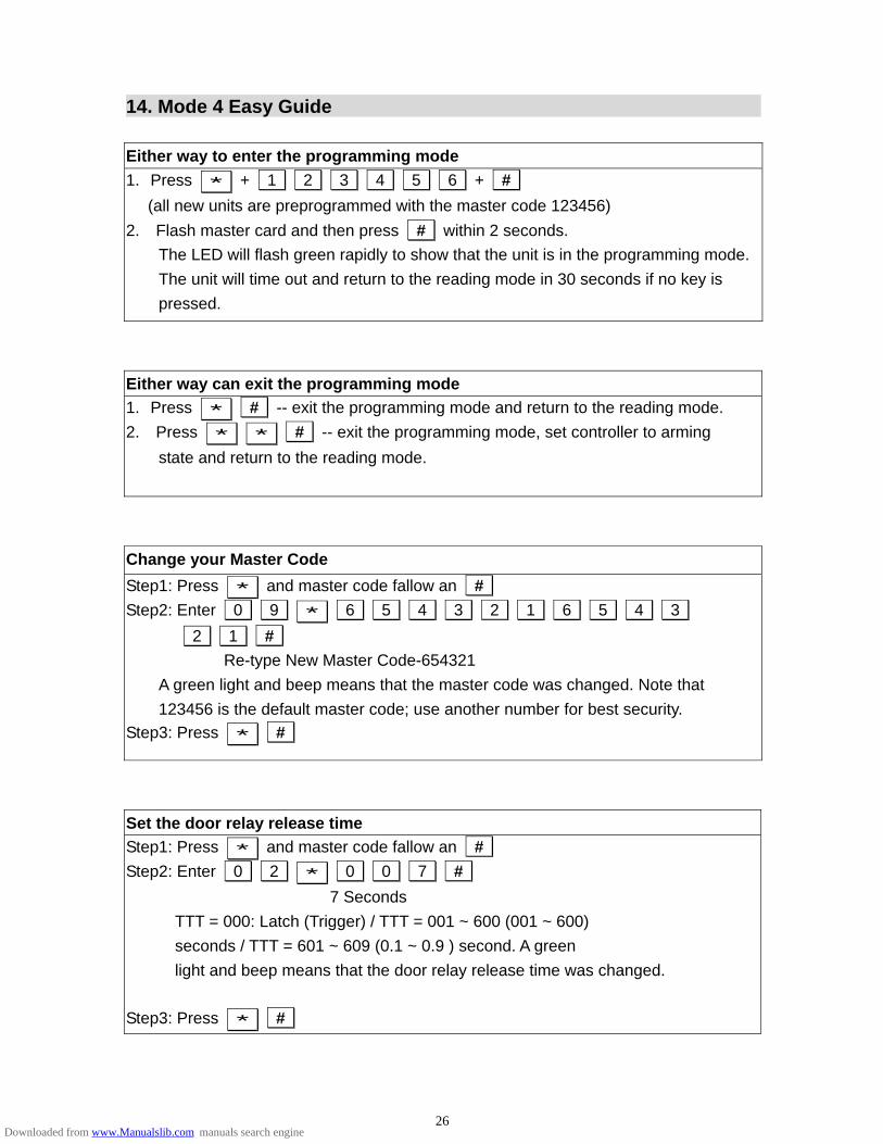
14. Mode 4 Easy Guide Either way to enter the programming mode 1. Press * + 1 2 3 4 5 6 + #
(all new units are preprogrammed with the master code 123456) 2. Flash master card and then press # within 2 seconds.
The LED will flash green rapidly to show that the unit is in the programming mode. The unit will time out and return to the reading mode in 30 seconds if no key is pressed.
Either way can exit the programming mode 1. Press * # -- exit the programming mode and return to the reading mode. 2. Press * * # -- exit the programming mode, set controller to arming
state and return to the reading mode.
Change your Master Code Step1: Press * and master code fallow an # Step2: Enter 0 9 * 6 5 4 3 2 1 6 5 4 3
2 1 # Re-type New Master Code-654321 A green light and beep means that the master code was changed. Note that 123456 is the default master code; use another number for best security.
Step3: Press * #
Set the door relay release time Step1: Press * and master code fallow an # Step2: Enter 0 2 * 0 0 7 #
7 Seconds TTT = 000: Latch (Trigger) / TTT = 001 ~ 600 (001 ~ 600)
seconds / TTT = 601 ~ 609 (0.1 ~ 0.9 ) second. A green light and beep means that the door relay release time was changed.
Step3: Press * #
26Downloaded from www.Manualslib.com manuals search engine
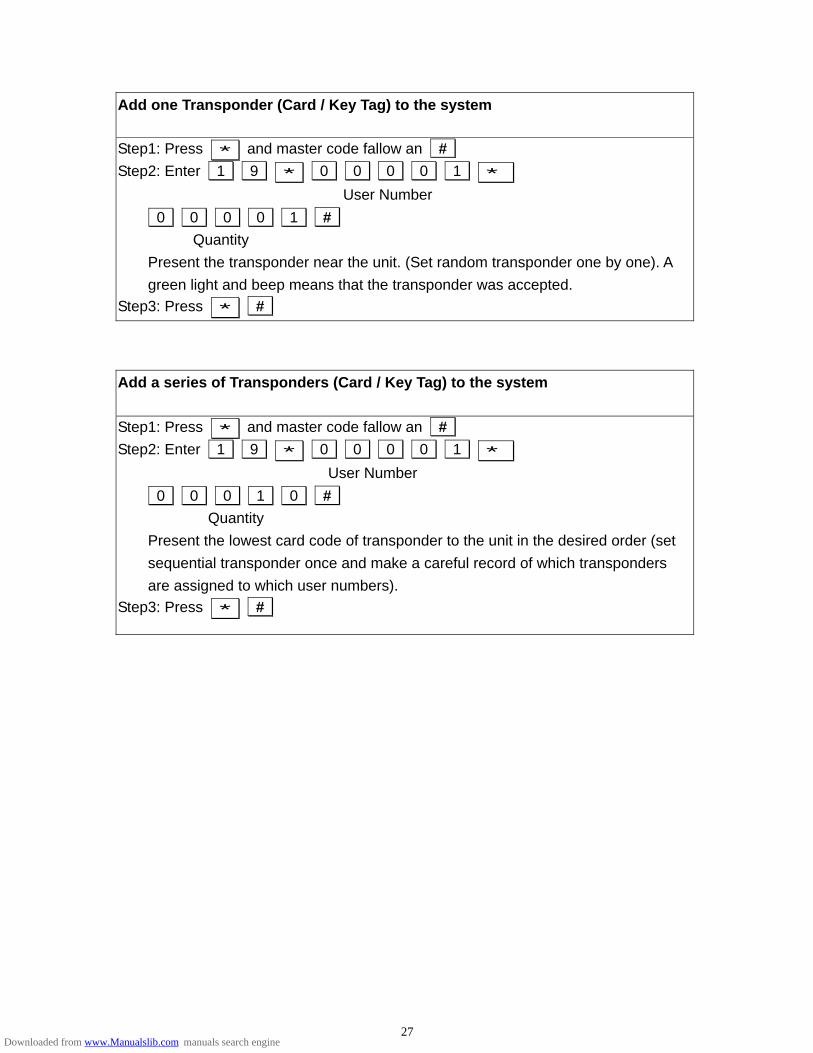
Add one Transponder (Card / Key Tag) to the system
Step1: Press * and master code fallow an # Step2: Enter 1 9 * 0 0 0 0 1 *
User Number 0 0 0 0 1 # Quantity Present the transponder near the unit. (Set random transponder one by one). A green light and beep means that the transponder was accepted.
Step3: Press * #
Add a series of Transponders (Card / Key Tag) to the system
Step1: Press * and master code fallow an # Step2: Enter 1 9 * 0 0 0 0 1 *
User Number 0 0 0 1 0 # Quantity Present the lowest card code of transponder to the unit in the desired order (set sequential transponder once and make a careful record of which transponders are assigned to which user numbers).
Step3: Press * #
27Downloaded from www.Manualslib.com manuals search engine
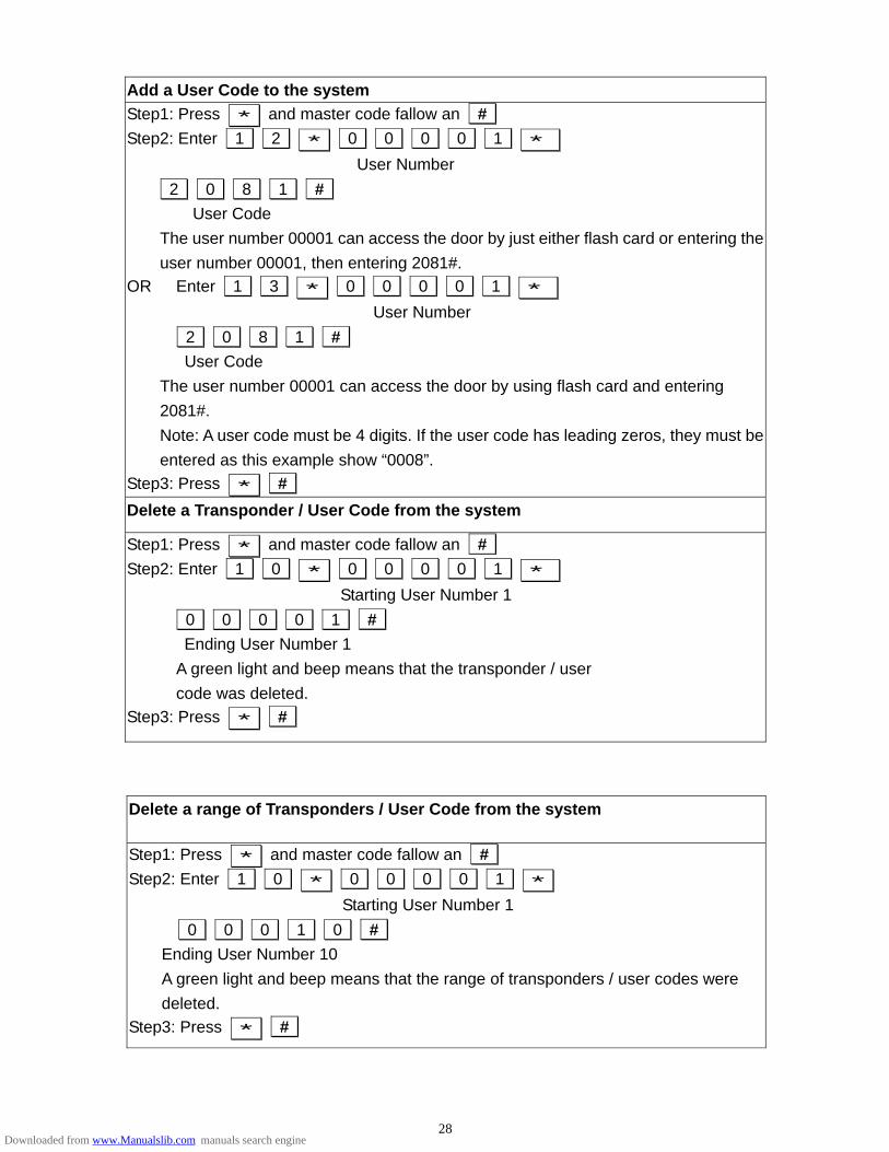
Add a User Code to the system Step1: Press * and master code fallow an # Step2: Enter 1 2 * 0 0 0 0 1 *
User Number 2 0 8 1 # User Code The user number 00001 can access the door by just either flash card or entering the user number 00001, then entering 2081#.
OR Enter 1 3 * 0 0 0 0 1 * User Number
2 0 8 1 # User Code The user number 00001 can access the door by using flash card and entering 2081#. Note: A user code must be 4 digits. If the user code has leading zeros, they must be entered as this example show “0008”.
Step3: Press * # Delete a Transponder / User Code from the system
Step1: Press * and master code fallow an # Step2: Enter 1 0 * 0 0 0 0 1 *
Starting User Number 1 0 0 0 0 1 #
Ending User Number 1 A green light and beep means that the transponder / user
code was deleted. Step3: Press * #
Delete a range of Transponders / User Code from the system
Step1: Press * and master code fallow an # Step2: Enter 1 0 * 0 0 0 0 1 *
Starting User Number 1 0 0 0 1 0 #
Ending User Number 10 A green light and beep means that the range of transponders / user codes were deleted.
Step3: Press * #
28Downloaded from www.Manualslib.com manuals search engine

Delete all Transponders Step1: Press * and master code fallow an # Step2: Enter 2 9 * 2 9 * #
The LED flash red during 10 seconds to mean that the system is deleting all transponders / user codes. Then a green light and beep means that all transponder/ user codes were deleted.
Step3: Press * #
Enable a Transponder to the system Step1: Press * and master code fallow an # Step2: Enter 1 1 * 0 0 0 0 1 *
Starting User Number 1 0 0 0 0 1 # Ending User Number 1 A green light and beep means that the transponder is enabled.
Step3: Press * #
Enable a range of Transponder to the system
Step1: Press * and master code fallow an # Step2: Enter 1 1 * 0 0 0 0 1 *
Starting User Number 1 0 0 0 1 0 #
Ending User Number 10 A green light and beep means that the range of transponders are enabled.
Step3: Press * #
29Downloaded from www.Manualslib.com manuals search engine

15. Mode 8 Easy Guide Add one Transponder (Card / Key Tag) to the system
Step1: Press * and master code fallow an # Step2: Enter 1 9 * 0 0 0 0 1 *
User Number 0 0 0 0 1 # Quantity Present the transponder near the unit. (Set random transponder one by one). A green light and beep means that the transponder was accepted.
Step3: Press * #
Add a User Code to the system Step1: Press * and master code fallow an # Step2: Enter 1 2 * 0 0 0 0 1 *
User Number 2 0 8 1 # User Code The user number 00001 can access the door by just either flash card or entering 2081.
OR Enter 1 3 * 0 0 0 0 1 * User Number
2 0 8 1 # User Code The user number 00001 can access the door by using flash card and entering 2081#. Note: A user code must be 4 digits. If the user code has leading zeros, they must be entered as this example show “0008”.
Step3: Press * #
Other operation is same as AR-721H4 Easy Guide, for example, enter/ exit the programming mode, change master code, door relay release time, add / delete / enable one or many transponder and so on.
30Downloaded from www.Manualslib.com manuals search engine
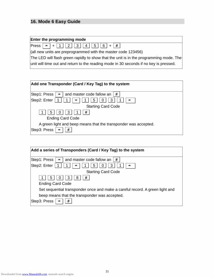
16. Mode 6 Easy Guide Enter the programming mode Press * + 1 2 3 4 5 6 + # (all new units are preprogrammed with the master code 123456) The LED will flash green rapidly to show that the unit is in the programming mode. The unit will time out and return to the reading mode in 30 seconds if no key is pressed.
Add one Transponder (Card / Key Tag) to the system
Step1: Press * and master code fallow an # Step2: Enter 1 1 * 1 5 0 3 1 *
Starting Card Code 1 5 0 3 1 # Ending Card Code A green light and beep means that the transponder was accepted.
Step3: Press * #
Add a series of Transponders (Card / Key Tag) to the system
Step1: Press * and master code fallow an # Step2: Enter 1 1 * 1 5 0 3 1 *
Starting Card Code 1 5 0 3 8 # Ending Card Code Set sequential transponder once and make a careful record. A green light and beep means that the transponder was accepted.
Step3: Press * #
31Downloaded from www.Manualslib.com manuals search engine
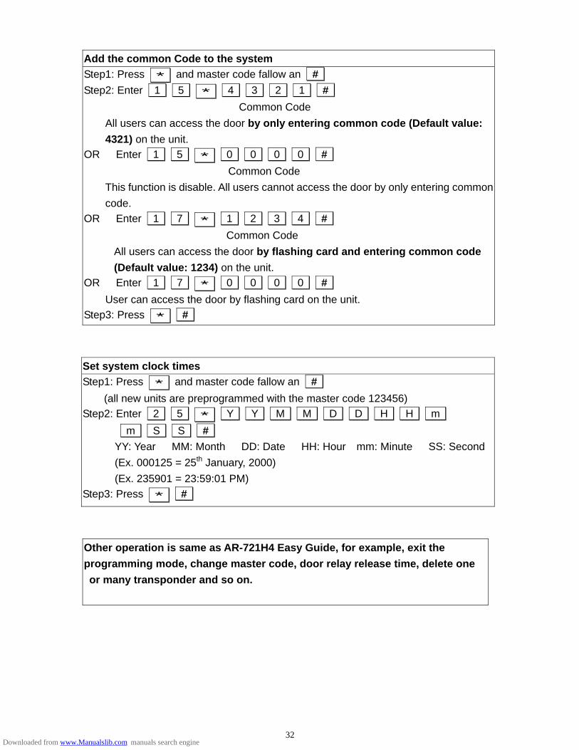
Add the common Code to the system Step1: Press * and master code fallow an # Step2: Enter 1 5 * 4 3 2 1 #
Common Code All users can access the door by only entering common code (Default value: 4321) on the unit.
OR Enter 1 5 * 0 0 0 0 # Common Code This function is disable. All users cannot access the door by only entering common code.
OR Enter 1 7 * 1 2 3 4 # Common Code All users can access the door by flashing card and entering common code (Default value: 1234) on the unit.
OR Enter 1 7 * 0 0 0 0 # User can access the door by flashing card on the unit.
Step3: Press * #
Set system clock times Step1: Press * and master code fallow an #
(all new units are preprogrammed with the master code 123456) Step2: Enter 2 5 * Y Y M M D D H H m
m S S # YY: Year MM: Month DD: Date HH: Hour mm: Minute SS: Second (Ex. 000125 = 25th January, 2000) (Ex. 235901 = 23:59:01 PM)
Step3: Press * #
Other operation is same as AR-721H4 Easy Guide, for example, exit the programming mode, change master code, door relay release time, delete one or many transponder and so on.
32Downloaded from www.Manualslib.com manuals search engine

17. Mode 7 Easy Guide To exit the programming mode Press * # -- exit the programming mode and return to the reading mode.
Set a user number arrive one floor Step1: Press * and master code fallow an # Step2: Enter 2 7 * 0 0 0 0 1 *
User Number 3 1 # Access 31st floor A green light and beep means that the setting was accepted.
Step3: Press * #
Set a user number arrive many floor Step1: Press * and master code fallow an # Step2: Enter 2 1 * 0 0 1 *
User Number 0 * 1 1 0 0 0 0 1 1 # Group Access 8th, 7th, 2nd, and 1st floors
A green light and beep means that the setting was accepted.
Step3: Press * #
Group Floor address 0 8 7 6 5 4 3 2 1
1 16 15 14 13 12 11 10 9
2 24 23 22 21 20 19 18 17
3 32 31 30 29 28 27 26 25
33Downloaded from www.Manualslib.com manuals search engine
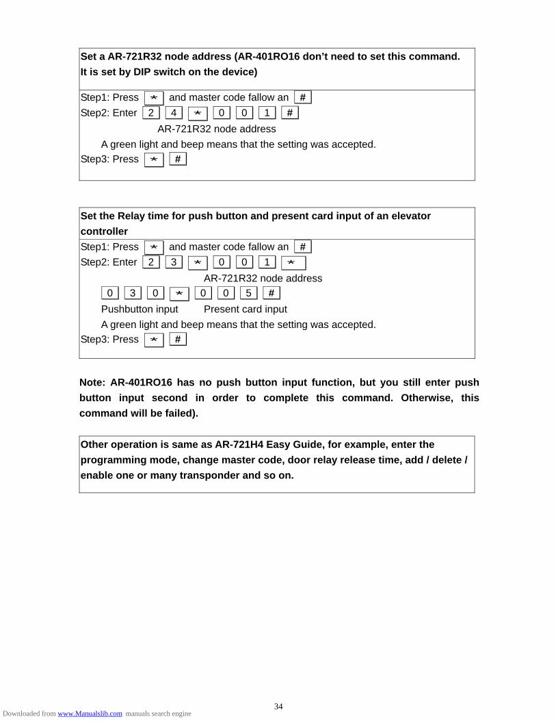
Set a AR-721R32 node address (AR-401RO16 don’t need to set this command. It is set by DIP switch on the device)
Step1: Press * and master code fallow an # Step2: Enter 2 4 * 0 0 1 #
AR-721R32 node address A green light and beep means that the setting was accepted.
Step3: Press * #
Set the Relay time for push button and present card input of an elevator controller Step1: Press * and master code fallow an # Step2: Enter 2 3 * 0 0 1 *
AR-721R32 node address 0 3 0 * 0 0 5 # Pushbutton input Present card input A green light and beep means that the setting was accepted.
Step3: Press * #
Note: AR-401RO16 has no push button input function, but you still enter push button input second in order to complete this command. Otherwise, this command will be failed). Other operation is same as AR-721H4 Easy Guide, for example, enter the programming mode, change master code, door relay release time, add / delete / enable one or many transponder and so on.
34Downloaded from www.Manualslib.com manuals search engine

18. Special Design
18.1 How to set anti-pass-back? Card and on-line reader (or standalone controller) must be both set anti-pass-back. Set card to have anti-pass back checking
Step1: Press * and master code fallow an # (all new units are preprogrammed with the master code 123456)
Step2: Enter 2 6 * S S S S S * E E E E E * X # SSSSS: Starting User Number EEEEE: Ending User Number X: 1 - disable anti-pass-back
0 - enable anti-pass-back 2 - Initiating use (when user number violates anti-pass-back, the user number can access either entry door or exit door by initiating setting)
Step3: Press * # For example: If enter 26*00005*00008*1#, user number from 5 ~ 8 do not have anti-pass-back feature. If enter 26*00005*00008*0# or 26*00005*00008*2#, user number from 5 ~ 8 have anti-pass-back feature. Set on-line reader’s (or standalone controller) anti-pass-back function
CASE 1: AR-721H do anti-pass-back with its auxiliary reader (AR-721U, AR-721K or AR-661U)
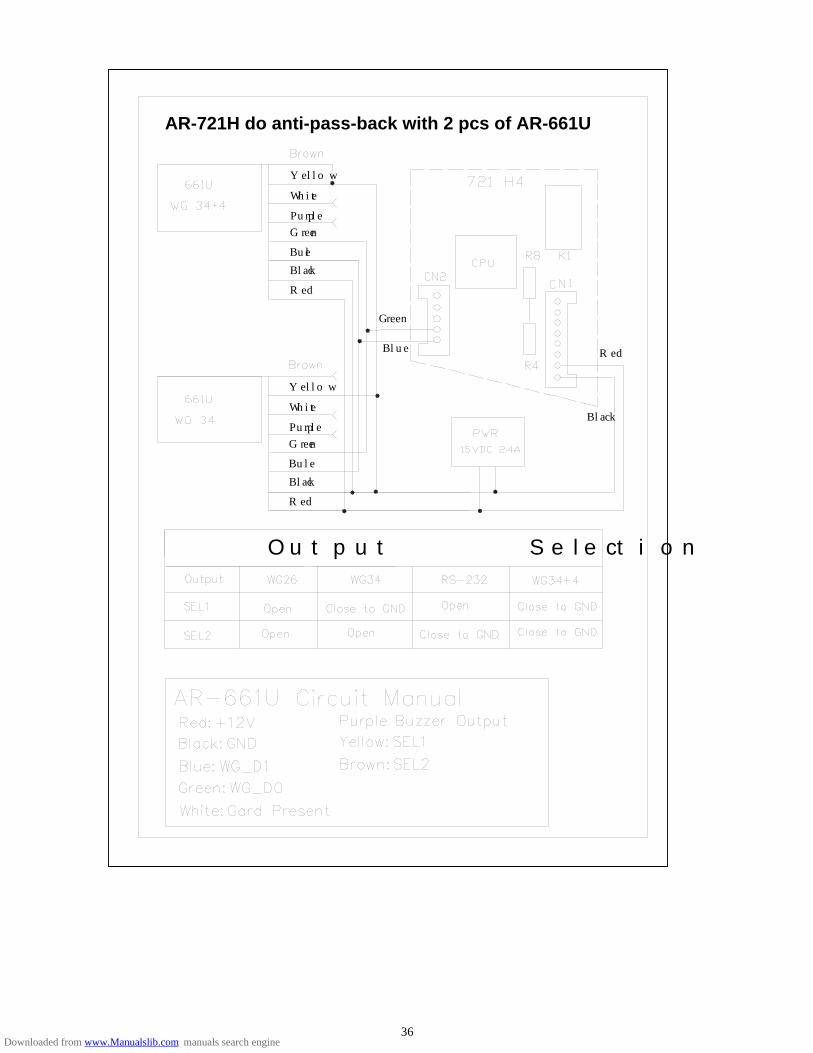
Step1: Press * and master code fallow an # Step2: Enter 2 0 * 1 2 8 # Step3: Press * # CASE 2: AR-721H do anti-pass-back with 2 pcs of AR-661U long-range reader (Set one
AR-661U being Exit reader and the other one being Entry reader). This special design is especially suitable for car parking control. CPU version is at least 3.1V. Set one AR-661U with wiegand 34 bit format output and the other one with 38 bit. (Please refer to the following diagram)
Step1: Press * and master code fallow an # Step2: Enter 2 0 * 1 2 8 # Step3: Press * #
35Downloaded from www.Manualslib.com manuals search engine
36
Blue
Green
Yellow
White
Purple
Green
Bule
Black
Red
Output Selection
AR-721H do anti-pass-back with 2 pcs of AR-661U
Black
Red
Black
Bule
Green
Purple
White
Yellow
Red
Downloaded from www.Manualslib.com manuals search engine
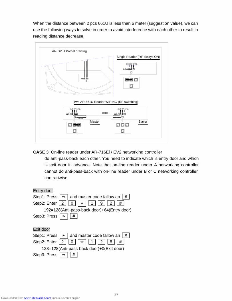
When the distance between 2 pcs 661U is less than 6 meter (suggestion value), we can use the following ways to solve in order to avoid interference with each other to result in reading distance decrease.
Single Reader (RF always ON)
GND SYNLRF
Two AR-661U Reader WIRING (RF switching)
Output
Master
Cable
GND SYNLRF
Slaver
RFGND SYNL
AR-661U Partial drawing
CASE 3: On-line reader under AR-716Ei / EV2 networking controller
do anti-pass-back each other. You need to indicate which is entry door and which is exit door in advance. Note that on-line reader under A networking controller cannot do anti-pass-back with on-line reader under B or C networking controller, contrariwise.
Entry door Step1: Press * and master code fallow an # Step2: Enter 2 0 * 1 9 2 #
192=128(Anti-pass-back door)+64(Entry door) Step3: Press * # Exit door Step1: Press * and master code fallow an # Step2: Enter 2 0 * 1 2 8 #
128=128(Anti-pass-back door)+0(Exit door) Step3: Press * #
37Downloaded from www.Manualslib.com manuals search engine
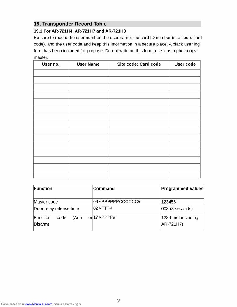
19. Transponder Record Table
19.1 For AR-721H4, AR-721H7 and AR-721H8 Be sure to record the user number, the user name, the card ID number (site code: card code), and the user code and keep this information in a secure place. A black user log form has been included for purpose. Do not write on this form; use it as a photocopy master.
User no. User Name Site code: Card code User code
Function Command Programmed Values
Master code 09*PPPPPPCCCCCC# 123456 Door relay release time 02*TTT# 003 (3 seconds)
Function code (Arm or Disarm)
17*PPPP# 1234 (not including AR-721H7)
38Downloaded from www.Manualslib.com manuals search engine

19.2 For AR-721H6 Be sure to record the user number, the user name, the card ID number (card code), and the user code and keep this information in a secure place. A black user log form has been included for purpose. Do not write on this form; use it as a photocopy master.
User no. User Name Card code User code
Function Command Programmed Values
Master code 09*PPPPPPCCCCCC# 123456
Door relay release time 02*TTT# 003 (3 seconds)
Common code (1) 15*PPPP# 4321
Common code (2) 17*PPPP# 1234
39Downloaded from www.Manualslib.com manuals search engine

20. F.A.Q. Q : How to input Duress Code in your SOYAL reader? Step1. Setting the Duress :
Press * 1 2 3 4 5 6 # button into Editing mode. When in editing mode, enter 1 5 # You can enter 4 numbers to be as Duress Code. Step2. Start the operation : Press 4 numbers of Duress Code and flashing card. The Duress will be switched up ! Q : How to configure alarm relay time when the door open too long?
Before this procedure, you have to configure the function “ALARM RELAY TM” , “DOOR CLOSE TM” , and “FORCE OPEN”.
Step1. In editing mode, press 0 3 * and enter the time for alarm relay time
setting. Step2. In edit mode, press 1 8 * and enter the time for alarm triggered setting. Step3. In edit mode, press 2 8 * and enter 3 numbers.
Close Force-Open order: press 0 0 0
Function Force-Open order :press 1 2 8
Press * * # to quit the edit mode and keep arming.
40Downloaded from www.Manualslib.com manuals search engine
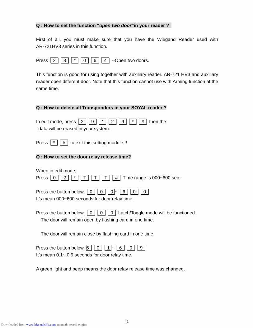
Q : How to set the function “open two door”in your reader ? First of all, you must make sure that you have the Wiegand Reader used with AR-721HV3 series in this function. Press 2 8 * 0 6 4 --Open two doors. This function is good for using together with auxiliary reader. AR-721 HV3 and auxiliary reader open different door. Note that this function cannot use with Arming function at the same time. Q : How to delete all Transponders in your SOYAL reader ? In edit mode, press 2 9 * 2 9 * # then the data will be erased in your system. Press * # to exit this setting module !! Q : How to set the door relay release time? When in edit mode, Press 0 2 * T T T # Time range is 000~600 sec. Press the button below, 0 0 0 ~ 6 0 0 It’s mean 000~600 seconds for door relay time. Press the button below, 0 0 0 Latch/Toggle mode will be functioned. The door will remain open by flashing card in one time.
The door will remain close by flashing card in one time. Press the button below, 6 0 1 ~ 6 0 9 It’s mean 0.1~ 0.9 seconds for door relay time. A green light and beep means the door relay release time was changed.
41Downloaded from www.Manualslib.com manuals search engine
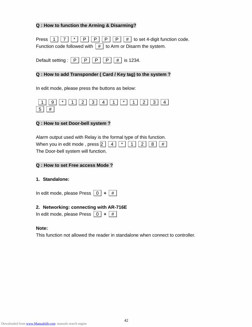
Q : How to function the Arming & Disarming? Press 1 7 * P P P P # to set 4-digit function code. Function code followed with # to Arm or Disarm the system. Default setting : P P P P # is 1234. Q : How to add Transponder ( Card / Key tag) to the system ? In edit mode, please press the buttons as below: 1 9 * 1 2 3 4 1 * 1 2 3 4 5 # Q : How to set Door-bell system ? Alarm output used with Relay is the formal type of this function. When you in edit mode , press 2 4 * 1 2 8 # The Door-bell system will function. Q : How to set Free access Mode ? 1. Standalone: In edit mode, please Press 0 + # 2. Networking: connecting with AR-716E In edit mode, please Press 0 + # Note: This function not allowed the reader in standalone when connect to controller.
42Downloaded from www.Manualslib.com manuals search engine