
AUTOMATED SHOPPING CHECKOUT SYSTEM – RFID READER ...
92
AUTOMATED SHOPPING CHECKOUT SYSTEM – RFID READER CIRCUIT AND COMPUTER INTERFACE LEE HONG CHUN A progress project report submitted in partial fulfilment of the requirements for the award of the degree of Bachelor (Hons.) of Electrical and Electronic Engineering Faculty of Engineering and Science Universiti Tunku Abdul Rahman April 2011
-
Upload
khangminh22 -
Category
Documents
-
view
0 -
download
0
Transcript of AUTOMATED SHOPPING CHECKOUT SYSTEM – RFID READER ...
AUTOMATED SHOPPING CHECKOUT SYSTEM – RFID READER
CIRCUIT AND COMPUTER INTERFACE
LEE HONG CHUN
A progress project report submitted in partial fulfilment of the
requirements for the award of the degree of
Bachelor (Hons.) of Electrical and Electronic Engineering
Faculty of Engineering and Science
Universiti Tunku Abdul Rahman
April 2011

ii
DECLARATION
I hereby declare that this project report is based on my original work except for
citations and quotations which have been duly acknowledged. I also declare that it
has not been previously and concurrently submitted for any other degree or award at
UTAR or other institutions.
Signature : _________________________
Name : Lee Hong Chun
ID No. : 07UEB06592
Date : 15 April 2011

iii
APPROVAL FOR SUBMISSION
I certify that this project report entitled “AUTOMATED SHOPPING
CHECKOUT SYSTEM – RFID READER CIRCUIT AND COMPUTER
INTERFACE” was prepared by LEE HONG CHUN has met the required standard
for submission in partial fulfilment of the requirements for the award of Bachelor of
Engineering (Hons.) Electrical and Electronic at Universiti Tunku Abdul Rahman.
Approved by,
Signature : _________________________
Supervisor : Dr. Yong Thian Khok
Date : _________________________
iv
The copyright of this report belongs to the author under the terms of the
copyright Act 1987 as qualified by Intellectual Property Policy of University Tunku
Abdul Rahman. Due acknowledgement shall always be made of the use of any
material contained in, or derived from, this report.
© 2011,Lee Hong Chun All right reserved.

v
ACKNOWLEDGEMENTS
In this section, I would like to thank everyone who had supported and also
contributed to the successful completion of this project. First of all, I would like to
express my gratitude to my research supervisor, Dr. Yong Thian Khok for his
invaluable advice, guidance and his enormous patience throughout the development
of the research.
In addition, I would like to show gratitude to my partner, Lim Jee Loong who
had shared the project title with me and work out this project together a team. He had
provide full cooperative and support to me throughout the process
Finally, I would also like to express my gratitude to my loving parent and my
fellow friends who had helped, support and given me encouragement to face this
challenging project until to the end

vi
AUTOMATED SHOPPING CHECKOUT SYSTEM – RFID READER
CIRCUIT AND COMPUTER INTERFACE
ABSTRACT
Nowadays, the demand for low cost and effectiveness is increase for most services.
This had motivate us to carry out automated shopping checkout system project which
is believe can significantly meet the demand. In this project, an automated shopping
checkout system designed based on the use of RFID technology are proposed to
improve the effectiveness and flexibility for current shopping checkout system. The
design of this automated shopping checkout system is using a 13.56 MHz operating
frequency RFID reader module which believe to be the suitable specification for the
system from the aspect of scanning speed, scanning accuracy and also overall cost of
the system This report will also present some literature research of some related
technology for the designed system and also task and components that had been
carried out to carried out and implemented in this project to achieve the objective.
Several test also been carried out in analyse the performance of the designed system
such as effective UART transmission delay experiment, system RF switching delay
time testing, system read time experiment, tag attachment material experiment and
system GUI program testing. The outcome of all the testing experiment is interpreted
in discussion and result section of this report. Finally, this report also includes the
discussion on several limitation and possible future enhancement for the current
system design.
vii
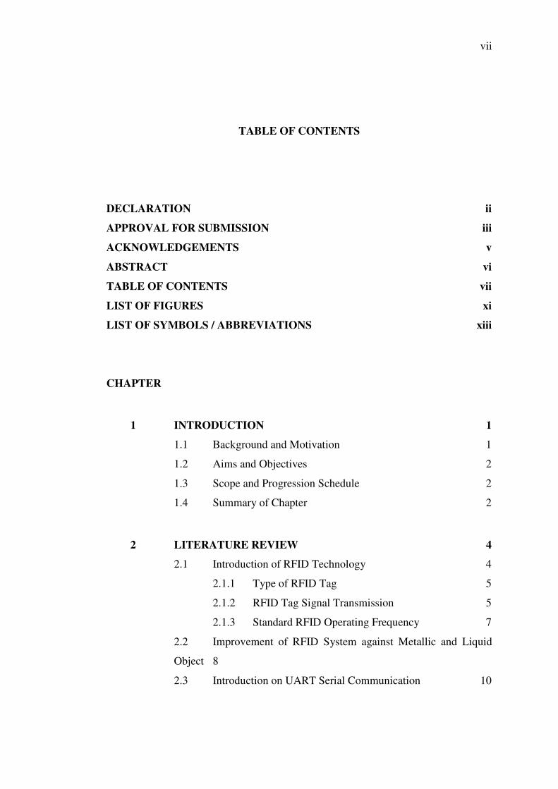
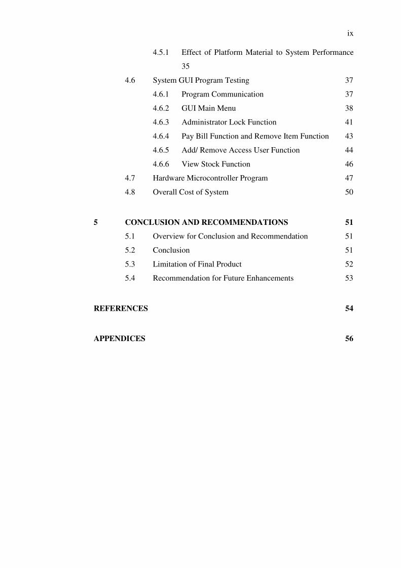
TABLE OF CONTENTS
DECLARATION ii
APPROVAL FOR SUBMISSION iii
ACKNOWLEDGEMENTS v
ABSTRACT vi
TABLE OF CONTENTS vii
LIST OF FIGURES xi
LIST OF SYMBOLS / ABBREVIATIONS xiii
CHAPTER
1 INTRODUCTION 1
1.1 Background and Motivation 1
1.2 Aims and Objectives 2
1.3 Scope and Progression Schedule 2
1.4 Summary of Chapter 2
2 LITERATURE REVIEW 4
2.1 Introduction of RFID Technology 4
2.1.1 Type of RFID Tag 5
2.1.2 RFID Tag Signal Transmission 5
2.1.3 Standard RFID Operating Frequency 7
2.2 Improvement of RFID System against Metallic and Liquid
Object 8
2.3 Introduction on UART Serial Communication 10

viii
3 METHODOLOGY 12
3.1 System Logical Structure 12
3.2 Scope Specification 13
3.3 Difficulty and Problem 14
3.4 Hardware Components and Circuit Design 15
3.4.1 SL013 RFID Reader Module 16
3.4.2 UC00A USB to UART converter 17
3.4.3 PIR Motion Sensor 18
3.4.4 PIC18F452 Microcontroller 19
3.5 GUI Program Design 19
3.6 Use of Software 20
3.6.1 Microsoft Visual Basic 2008 20
3.6.2 DipTrace 21
3.6.3 PICKit 2 and MPLab 21
3.7 Planning For FYP Part 2 22
4 RESULTS AND DISCUSSIONS 25
4.1 Result and Discussion Overview 25
4.2 Effective UART Transmission Delay Experiment 25
4.2.1 Result of Effective UART Transmission Delay
Experiment 26
4.2.2 Effect of UART Transmit Delay for Continuous
Transmission 28
4.3 RF Switching Delay Time Testing 28
4.3.1 Result of System RF Switching Delay Time Testing
29
4.3.2 Analysis Cause of RF Switching Delay 30
4.3.3 Consequential and Solutions for RF Switching
Delay 30
4.4 System Average Read Time Testing 31
4.4.1 System Average Read Time Analysis 31
4.4.2 Interpretation System Read Time Data 33
4.5 RFID Tag Attach Material Experiment and Result 33
ix
4.5.1 Effect of Platform Material to System Performance
35
4.6 System GUI Program Testing 37
4.6.1 Program Communication 37
4.6.2 GUI Main Menu 38
4.6.3 Administrator Lock Function 41
4.6.4 Pay Bill Function and Remove Item Function 43
4.6.5 Add/ Remove Access User Function 44
4.6.6 View Stock Function 46
4.7 Hardware Microcontroller Program 47
4.8 Overall Cost of System 50
5 CONCLUSION AND RECOMMENDATIONS 51
5.1 Overview for Conclusion and Recommendation 51
5.2 Conclusion 51
5.3 Limitation of Final Product 52
5.4 Recommendation for Future Enhancements 53
REFERENCES 54
APPENDICES 56
x
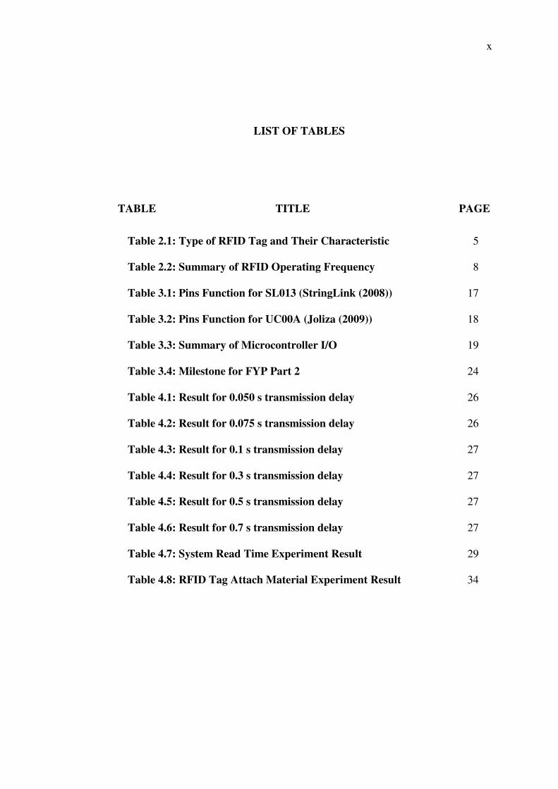
LIST OF TABLES
TABLE TITLE PAGE
Table 2.1: Type of RFID Tag and Their Characteristic 5
Table 2.2: Summary of RFID Operating Frequency 8
Table 3.1: Pins Function for SL013 (StringLink (2008)) 17
Table 3.2: Pins Function for UC00A (Joliza (2009)) 18
Table 3.3: Summary of Microcontroller I/O 19
Table 3.4: Milestone for FYP Part 2 24
Table 4.1: Result for 0.050 s transmission delay 26
Table 4.2: Result for 0.075 s transmission delay 26
Table 4.3: Result for 0.1 s transmission delay 27
Table 4.4: Result for 0.3 s transmission delay 27
Table 4.5: Result for 0.5 s transmission delay 27
Table 4.6: Result for 0.7 s transmission delay 27
Table 4.7: System Read Time Experiment Result 29
Table 4.8: RFID Tag Attach Material Experiment Result 34
xi
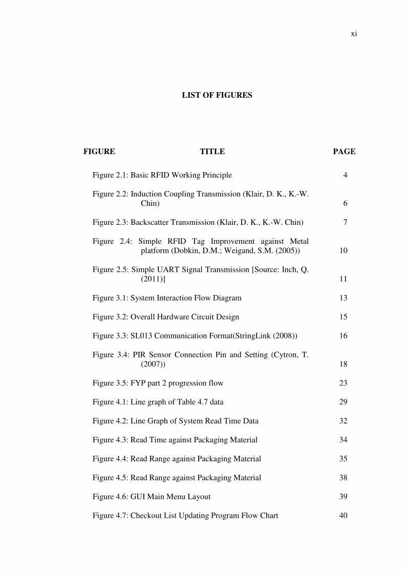
LIST OF FIGURES
FIGURE TITLE PAGE
Figure 2.1: Basic RFID Working Principle 4
Figure 2.2: Induction Coupling Transmission (Klair, D. K., K.-W. Chin) 6
Figure 2.3: Backscatter Transmission (Klair, D. K., K.-W. Chin) 7
Figure 2.4: Simple RFID Tag Improvement against Metal platform (Dobkin, D.M.; Weigand, S.M. (2005)) 10
Figure 2.5: Simple UART Signal Transmission [Source: Inch, Q. (2011)] 11
Figure 3.1: System Interaction Flow Diagram 13
Figure 3.2: Overall Hardware Circuit Design 15
Figure 3.3: SL013 Communication Format(StringLink (2008)) 16
Figure 3.4: PIR Sensor Connection Pin and Setting (Cytron, T. (2007)) 18
Figure 3.5: FYP part 2 progression flow 23
Figure 4.1: Line graph of Table 4.7 data 29
Figure 4.2: Line Graph of System Read Time Data 32
Figure 4.3: Read Time against Packaging Material 34
Figure 4.4: Read Range against Packaging Material 35
Figure 4.5: Read Range against Packaging Material 38
Figure 4.6: GUI Main Menu Layout 39
Figure 4.7: Checkout List Updating Program Flow Chart 40
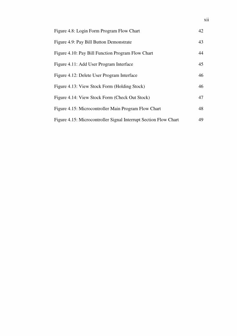
xii
Figure 4.8: Login Form Program Flow Chart 42
Figure 4.9: Pay Bill Button Demonstrate 43
Figure 4.10: Pay Bill Function Program Flow Chart 44
Figure 4.11: Add User Program Interface 45
Figure 4.12: Delete User Program Interface 46
Figure 4.13: View Stock Form (Holding Stock) 46
Figure 4.14: View Stock Form (Check Out Stock) 47
Figure 4.15: Microcontroller Main Program Flow Chart 48
Figure 4.15: Microcontroller Signal Interrupt Section Flow Chart 49
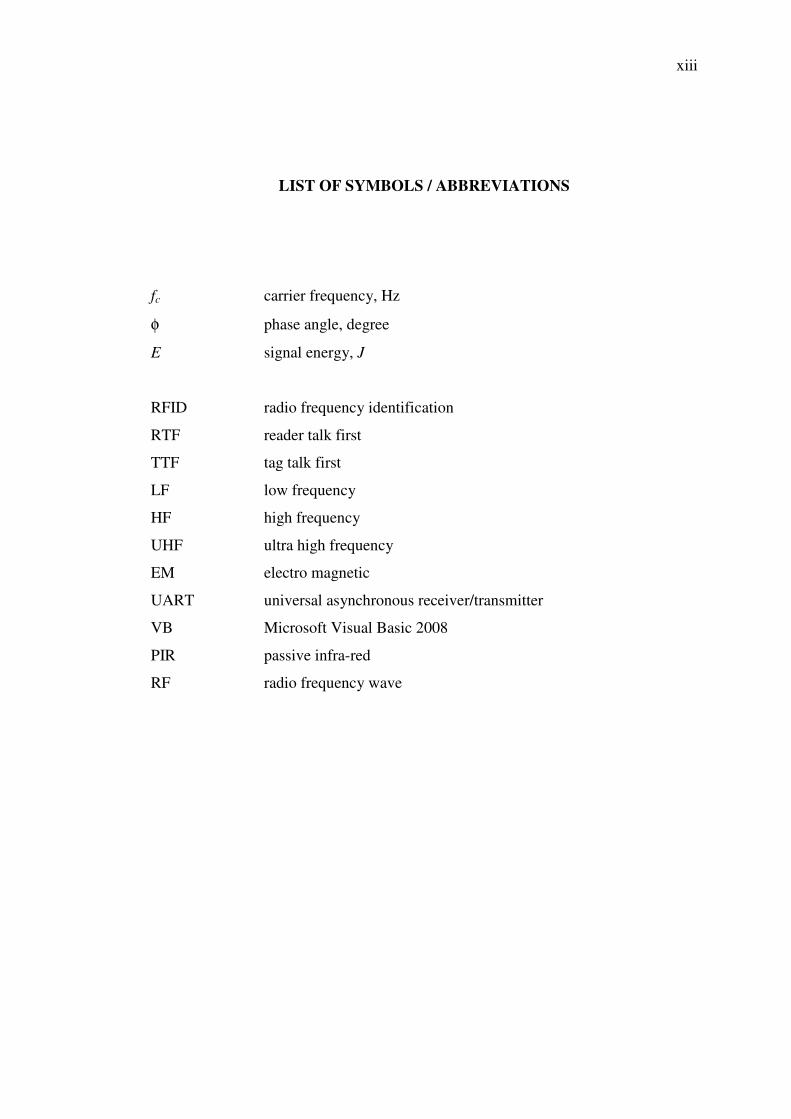
xiii
LIST OF SYMBOLS / ABBREVIATIONS
fc carrier frequency, Hz
φ phase angle, degree
E signal energy, J
RFID radio frequency identification
RTF reader talk first
TTF tag talk first
LF low frequency
HF high frequency
UHF ultra high frequency
EM electro magnetic
UART universal asynchronous receiver/transmitter
VB Microsoft Visual Basic 2008
PIR passive infra-red
RF radio frequency wave
CHAPTER 1
1 INTRODUCTION
1.1 Background and Motivation
Spending 5 to 15 minute queues up and waiting for the items to be scanned is
commonly involved in shopping of present day. This phenomenon not only result
time wasting for the customers but also a sign of ineffectiveness performance of
current barcodes checkouts technology. Besides that, high setup cost for
conventional shopping checkout system also pert of the motivation for this project. In
the effort to solve this problem, introduce and implementation of other technologies
that believe can improve the overall cost and performance of shopping checkout
process is a must. One of the technologies that hold great potential for the automated
shopping checkout is the 13.56 MHz operating frequency RFID technology.
Even though the implementation if RFID technologies as an automated
checkout system is long been introduced, yet it is not widely employ in the retail
sector. Most retailers did not realize the RFID automated checkout systems hold a
great promise in the retailer world for both the customer and also the retailer itself.
These motivate us to come out with a low cost and high accuracy automated
checkout system based on RFID technology.

2
1.2 Aims and Objectives
The main aim and objective of this project is to design an automated shopping
checkout system using RFID technology that increase the effectiveness of shopping
checkout system through enable indirect tag scanning feature. The designed RFID
automated shopping checkout system is aim to be more energy saving than
conventional shopping checkout system by using 5 V supply to power up. Lastly, the
designed system should come with lower cost than most of the shopping checkout
system available in the market through the usage of 13.56 MHz operating frequency
RFID technology.
1.3 Scope and Progression Schedule
This automated shopping checkout system is divided into two sections as following
Part 1 (RFID reader circuit and computer interface)
i. Microcontroller program writing
ii. Sensor circuitry implementation
iii. RFID reader hardware implementation
iv. System GUI program design
Part 2 (RFID system antenna design)
i. Antenna Analysis
ii. Antenna design and testing
1.4 Summary of Chapter
Basically this section will briefly go through summarize contain of each chapter that
included in this report.

3
Chapter 1 is the introduction of the report. The detail will mostly touch on
some of the background, motivation, aim and objective of this project. Summary of
each chapter will also be included.
Chapter 2 is the section that contains the literature review and research of this
project. Most of the research and literature review from external source that relate to
the development of this project is placed in this section.
Chapter 3 is the methodology part of the project. This section will focus on
the work scope is justify, verification of main task of this project, explanation of tool
usage, experiment technique and FYP part two millstone.
Chapter 4 is the result and discussion section of the report. This section will
be the place that most of the experiment data and project result will be present. The
interpretation of outcome will also carry out in this section.
Chapter 5 is the last chapter of this report which is the conclusion and
recommendation section. Essentially this chapter will cover up the conclusion
obtained from the project. Limitation of our outcome and also future enhancement
for it will also be included.
CHAPTER 2
2 LITERATURE REVIEW
2.1 Introduction of RFID Technology
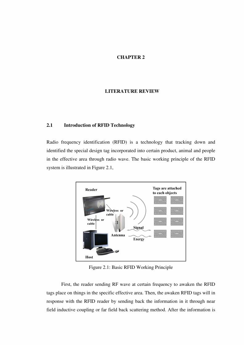
Radio frequency identification (RFID) is a technology that tracking down and
identified the special design tag incorporated into certain product, animal and people
in the effective area through radio wave. The basic working principle of the RFID
system is illustrated in Figure 2.1,
Figure 2.1: Basic RFID Working Principle
First, the reader sending RF wave at certain frequency to awaken the RFID
tags place on things in the specific effective area. Then, the awaken RFID tags will in
response with the RFID reader by sending back the information in it through near
field inductive coupling or far field back scattering method. After the information is
5
retrieve at the reader, it will be send to microprocessor or computer database for data
processing and update. The RFID technology is widely apply at various applications
such as animal tracking, human identification, ware housing stock management, and
traffic toll collection.
2.1.1 Type of RFID Tag
Basically, the special design tag use in RFID system is normally known as RFID tag
or transponder. It is an electronic component that consist some integrated circuit,
memory and an antenna to detect and transmit radio wave. The RFID tag can be
read- only and read-write depend on the memory setting during manufacturing.
Generally, there are three categories of RFID tag can be found commonly in the
market, which are passive tag, active tag and semi-passive tag. Table 2.1 briefly
descript the different and characteristic of these three categories of RFID tag,
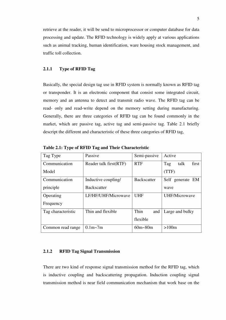
Table 2.1: Type of RFID Tag and Their Characteristic
Tag Type Passive Semi-passive Active
Communication
Model
Reader talk first(RTF) RTF Tag talk first
(TTF)
Communication
principle
Inductive coupling/
Backscatter
Backscatter Self generate EM
wave
Operating
Frequency
LF/HF/UHF/Microwave UHF UHF/Microwave
Tag characteristic Thin and flexible Thin and
flexible
Large and bulky
Common read range 0.1m~7m 60m~80m >100m
2.1.2 RFID Tag Signal Transmission
There are two kind of response signal transmission method for the RFID tag, which
is inductive coupling and backscattering propagation. Induction coupling signal
transmission method is near field communication mechanism that work base on the
6
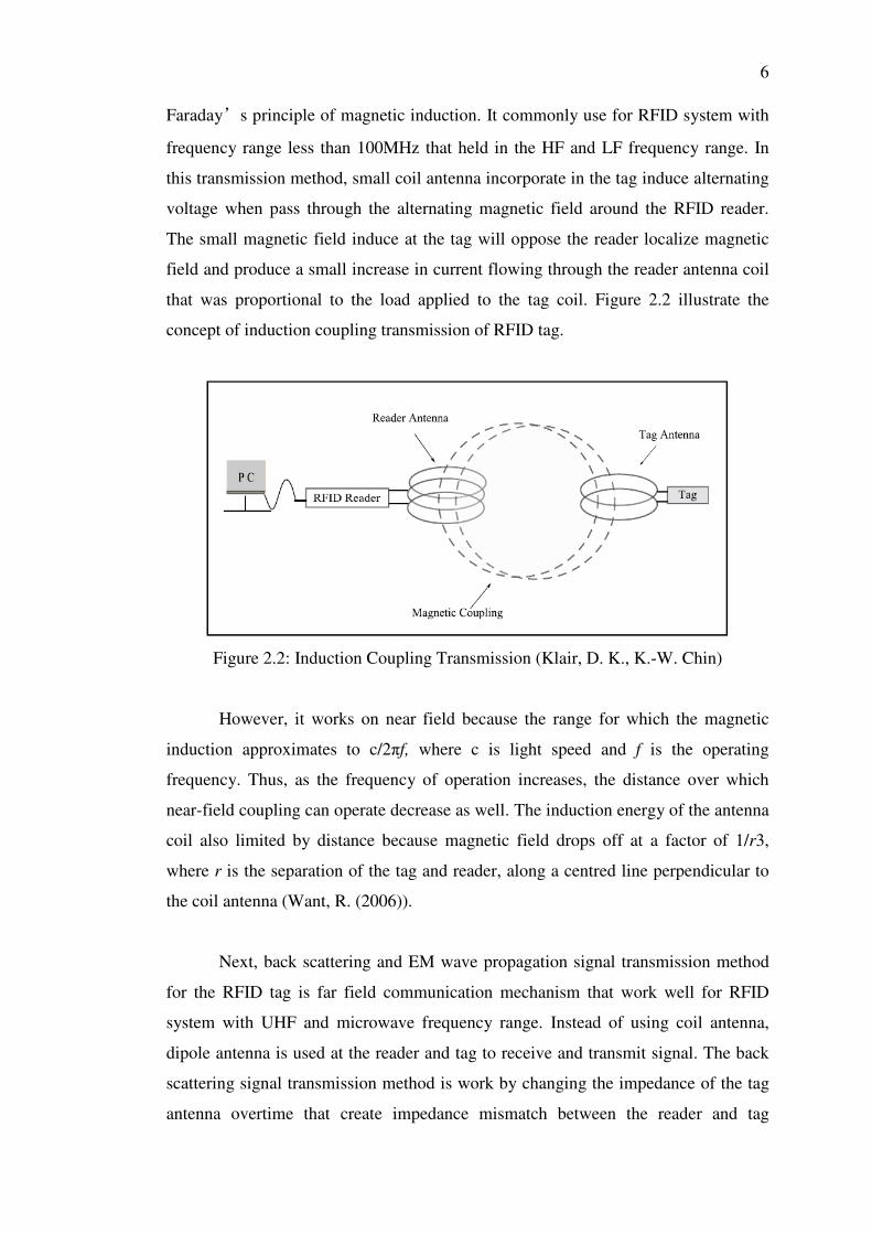
Faraday’s principle of magnetic induction. It commonly use for RFID system with
frequency range less than 100MHz that held in the HF and LF frequency range. In
this transmission method, small coil antenna incorporate in the tag induce alternating
voltage when pass through the alternating magnetic field around the RFID reader.
The small magnetic field induce at the tag will oppose the reader localize magnetic
field and produce a small increase in current flowing through the reader antenna coil
that was proportional to the load applied to the tag coil. Figure 2.2 illustrate the
concept of induction coupling transmission of RFID tag.
Figure 2.2: Induction Coupling Transmission (Klair, D. K., K.-W. Chin)
However, it works on near field because the range for which the magnetic
induction approximates to c/2πf, where c is light speed and f is the operating
frequency. Thus, as the frequency of operation increases, the distance over which
near-field coupling can operate decrease as well. The induction energy of the antenna
coil also limited by distance because magnetic field drops off at a factor of 1/r3,
where r is the separation of the tag and reader, along a centred line perpendicular to
the coil antenna (Want, R. (2006)).
Next, back scattering and EM wave propagation signal transmission method
for the RFID tag is far field communication mechanism that work well for RFID
system with UHF and microwave frequency range. Instead of using coil antenna,
dipole antenna is used at the reader and tag to receive and transmit signal. The back
scattering signal transmission method is work by changing the impedance of the tag
antenna overtime that create impedance mismatch between the reader and tag

7
antenna to reflect back certain incoming signal in a pattern that encodes the tag
response. Figure 2.3 illustrate the concept of back scattering and EM wave
propagation transmission of RFID tag.
Figure 2.3: Backscatter Transmission (Klair, D. K., K.-W. Chin)
Hence, it can achieve further transmission distance than induction coupling method
However, it also limited by the amount of energy that reaches the tag from the reader
and sensitivity of reader to the reflected signal. The backscatter transmission
introduce to two attenuations that based on the inverse square law. The first
attenuation when signal transmit from reader to tag and second attenuation is occurs
when the reflected signal is travel back to the reader. The return energy of the RFID
tag is approximately 1/r4, where r is the distance between the reader and tag (Want, R.
(2006)).
2.1.3 Standard RFID Operating Frequency
Various type of radio wave frequency range are utilize in RFID system for different
application field based on their characteristic. Low frequency (LF), high frequency
(HF), ultra high frequency (UHF) and microwave are the four common frequency
range categories for RFID system. All four kind of operating frequency range of
RFID system is summarized in Table 2.2.
8
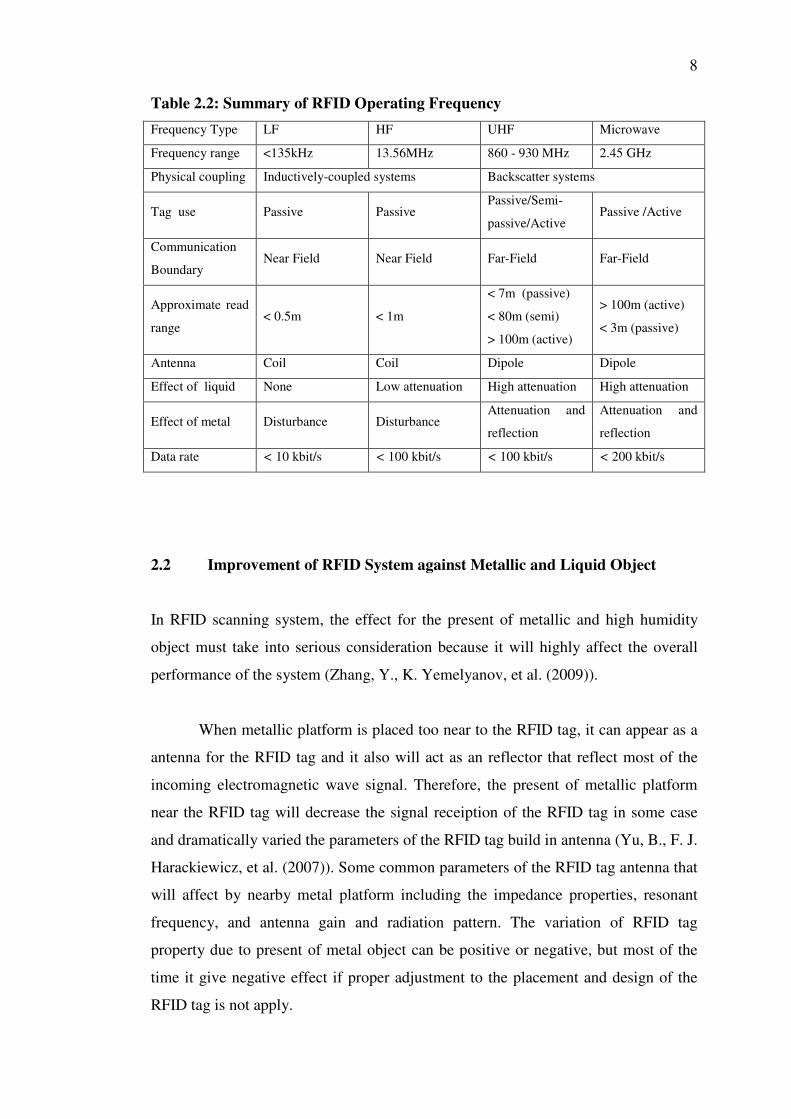
Table 2.2: Summary of RFID Operating Frequency
Frequency Type LF HF UHF Microwave
Frequency range <135kHz 13.56MHz 860 - 930 MHz 2.45 GHz
Physical coupling Inductively-coupled systems Backscatter systems
Tag use Passive Passive Passive/Semi-
passive/Active Passive /Active
Communication
Boundary Near Field Near Field Far-Field Far-Field
Approximate read
range < 0.5m < 1m
< 7m (passive)
< 80m (semi)
> 100m (active)
> 100m (active)
< 3m (passive)
Antenna Coil Coil Dipole Dipole
Effect of liquid None Low attenuation High attenuation High attenuation
Effect of metal Disturbance Disturbance Attenuation and
reflection
Attenuation and
reflection
Data rate < 10 kbit/s < 100 kbit/s < 100 kbit/s < 200 kbit/s
2.2 Improvement of RFID System against Metallic and Liquid Object
In RFID scanning system, the effect for the present of metallic and high humidity
object must take into serious consideration because it will highly affect the overall
performance of the system (Zhang, Y., K. Yemelyanov, et al. (2009)).
When metallic platform is placed too near to the RFID tag, it can appear as a
antenna for the RFID tag and it also will act as an reflector that reflect most of the
incoming electromagnetic wave signal. Therefore, the present of metallic platform
near the RFID tag will decrease the signal receiption of the RFID tag in some case
and dramatically varied the parameters of the RFID tag build in antenna (Yu, B., F. J.
Harackiewicz, et al. (2007)). Some common parameters of the RFID tag antenna that
will affect by nearby metal platform including the impedance properties, resonant
frequency, and antenna gain and radiation pattern. The variation of RFID tag
property due to present of metal object can be positive or negative, but most of the
time it give negative effect if proper adjustment to the placement and design of the
RFID tag is not apply.
9
Besides that, present of high liquid contain object around the RFID tag will
also cause degradation of performance for the RFID system (Dobkin, D.M.; Weigand,
S.M. (2005)). The degradation level of the RFID system due to the present of liquid
is highly depending on the properties of the liquid. Normally oil based liquid will
tend to give less impact to the RFID system compare to water base liquid due to the
electromagnetic wave absorption properties of it (Sweeney, P. J. (2005)). The
absorption of signal from nearby liquid contain cause the RFID tag unable to receive
sufficient signal from RFID reader to power up and transmit feedback signal. The
liquid may also absorb part of the transmitting signal from the RFID tag that cause
the reader having difficulty in detect the weak signal from RFID tag.
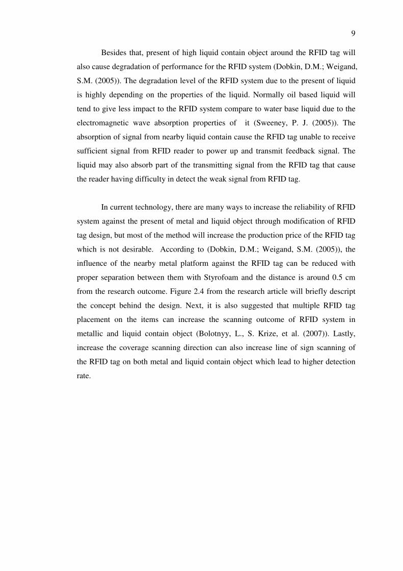
In current technology, there are many ways to increase the reliability of RFID
system against the present of metal and liquid object through modification of RFID
tag design, but most of the method will increase the production price of the RFID tag
which is not desirable. According to (Dobkin, D.M.; Weigand, S.M. (2005)), the
influence of the nearby metal platform against the RFID tag can be reduced with
proper separation between them with Styrofoam and the distance is around 0.5 cm
from the research outcome. Figure 2.4 from the research article will briefly descript
the concept behind the design. Next, it is also suggested that multiple RFID tag
placement on the items can increase the scanning outcome of RFID system in
metallic and liquid contain object (Bolotnyy, L., S. Krize, et al. (2007)). Lastly,
increase the coverage scanning direction can also increase line of sign scanning of
the RFID tag on both metal and liquid contain object which lead to higher detection
rate.
10
Figure 2.4: Simple RFID Tag Improvement against Metal platform (Dobkin, D.M.;
Weigand, S.M. (2005))
2.3 Introduction on UART Serial Communication
The main key communication of the automated shopping checkout system will
utilize the UART serial communication. UART serial communication is normally
configure as full duplex asynchronous system which mean communication between
devices at both end at the same time is possible for it.
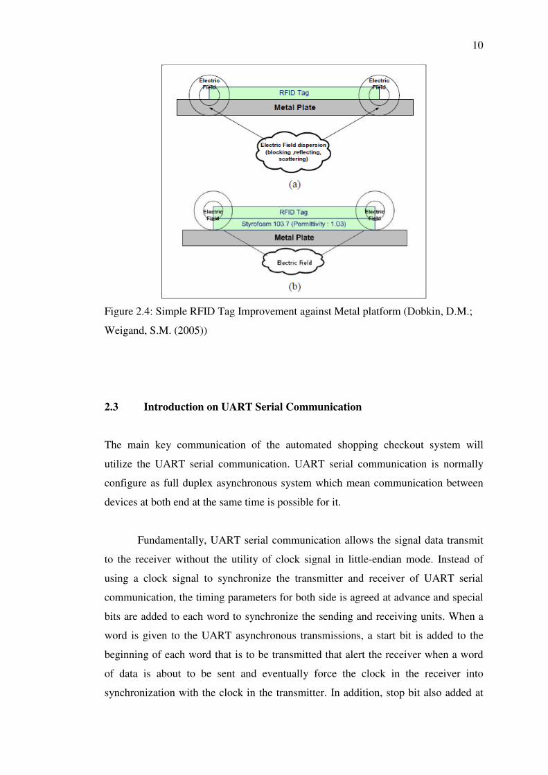
Fundamentally, UART serial communication allows the signal data transmit
to the receiver without the utility of clock signal in little-endian mode. Instead of
using a clock signal to synchronize the transmitter and receiver of UART serial
communication, the timing parameters for both side is agreed at advance and special
bits are added to each word to synchronize the sending and receiving units. When a
word is given to the UART asynchronous transmissions, a start bit is added to the
beginning of each word that is to be transmitted that alert the receiver when a word
of data is about to be sent and eventually force the clock in the receiver into
synchronization with the clock in the transmitter. In addition, stop bit also added at
11
the end of the word data to inform the receiver it is the end of data and prepare for
incoming of next start bit (Durda, F. (1996)). Figure 2.5 shows the concept of simple
UART signal transmission.
Figure 2.5: Simple UART Signal Transmission [Source: Inch, Q. (2011)]
Since the data transmission in UART serial communication is “self synchronization”,
the transmission line will go into idle state when no data is transmit.
Slightly mismatch in the sender and receiver speed will cause several
problems to the UART serial communication such as overrun error and framing error.
Overrun error occur when there is a lag in receiver to handle the receive data which
cause next package of data arrive before the current data is process. For framing error
is cause by the missing of the start bit or stop bit in the UART transmission data
word. An optional of parity bit function can be added into the transmission if the
hardware is supported and also both receiver and transmitter agree. The extra parity
bits can use to check the present of overrun error and framing error in the UART
serial communication and let the user to determine what action to be taken.
CHAPTER 3
3 METHODOLOGY
3.1 System Logical Structure
The project start with come out a logical structure for the RFID automated shopping
checkout system that suits the requirement.
Firstly, the system should equip with an high performance antenna that
capable to effectively detect and capture the response signal transmit from the RFID
tags attach on each item that pass through the scanning zone. Next, tag response will
be passing into the reader module to identify the tag unique and pass through the
microcontroller for further data processing. Furthermore, motion sensor is added into
to control the on and off of the RFID reader module by sense the present of moving
object pass through it detection region. This function is added in objective to
minimize system power consumption and also reduce the EM wave pollution to the
surrounding.
The main data processor in this system is the microcontroller. All instruction
signal and logic signal from the host computer and motion sensor will pass into the
microcontroller for action determination. Moreover, four LED will be use to indicate
the status of system power up indicator, system on/off indicator, RF on/off indicator
and motion present indicator. This will simplified the process of troubleshooting by
observe the status of LED and also easier for user to determine the current state of
system.
13
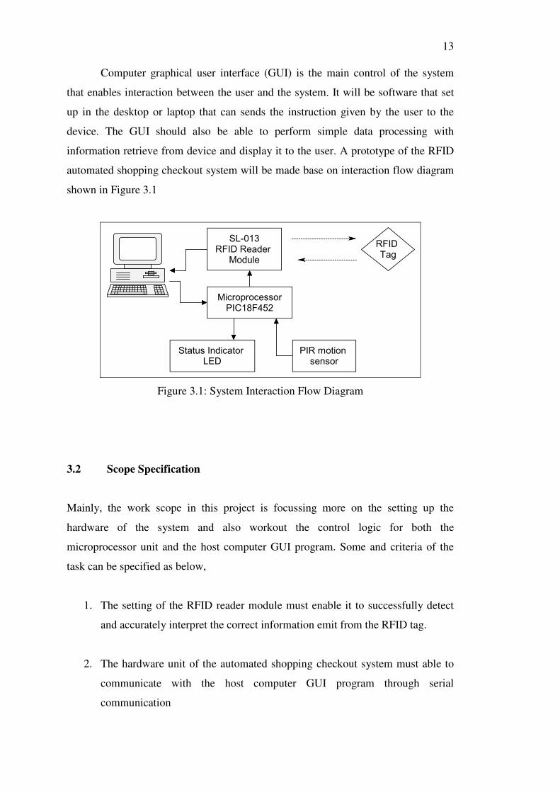
Computer graphical user interface (GUI) is the main control of the system
that enables interaction between the user and the system. It will be software that set
up in the desktop or laptop that can sends the instruction given by the user to the
device. The GUI should also be able to perform simple data processing with
information retrieve from device and display it to the user. A prototype of the RFID
automated shopping checkout system will be made base on interaction flow diagram
shown in Figure 3.1
RFIDTag
SL-013RFID Reader
Module
MicroprocessorPIC18F452
Status IndicatorLED
PIR motionsensor
Figure 3.1: System Interaction Flow Diagram
3.2 Scope Specification
Mainly, the work scope in this project is focussing more on the setting up the
hardware of the system and also workout the control logic for both the
microprocessor unit and the host computer GUI program. Some and criteria of the
task can be specified as below,
1. The setting of the RFID reader module must enable it to successfully detect
and accurately interpret the correct information emit from the RFID tag.
2. The hardware unit of the automated shopping checkout system must able to
communicate with the host computer GUI program through serial
communication

14
3. The microcontroller in hardware unit must able to process the information
and instructions from computer and delicate precise task to the RFID reader
module.
4. The PIR motion sensor circuit must operate correctly by turn on the reader
RF transmission if sense the present of motion and turn off the reader RF
after certain period without the present of motion in the scanning zone.
5. The GUI program should be worked well in 32 bits Microsoft XP, Microsoft
Vista and Microsoft 7 operating system host computer with all requirement
software installed.
6. The GUI program has to accurately interpret the information and instruction
from the system hardware unit and execute correct operation based on them.
7. SQL database must successfully accessed by the GUI program to retrieve and
update the information in the database.
3.3 Difficulty and Problem
While carry out this project, there are several difficulty and problem faced to carry
out portion of the task in this project.
The main problem in this project is facing choosing a suitable RFID reader
module for our system needed in this project. It is difficult to obtain a suitable
specification 13.56 MHz RFID reader module from the local market due to low
demand for the product. Next, the price of RFID reader module that meet the
specification of this project also come with expensive price which cost more than
the budget provided for this project due to the low production unit.

15
Besides that, the RFID reader communication protocol for most of the unit
also comes out to be different. Therefore, it cost some time for me to find a module
with user friendly communication protocol that I can operate with it.
3.4 Hardware Components and Circuit Design
The overall circuit layout for the RFID automated shopping checkout system
designed in this project can presented as given in Figure 3.4. The circuit will contain
the main hardware components such as PIC18F452 microcontroller, PIR motion
sensor, an IRFZ44N n-channel MOSFET, UC00A UART to USB converter and
SL-013 13.56 MHz RFID reader module.
Figure 3.2: Overall Hardware Circuit Design
10MHz
C1
22pF
C2
22pF
+5V
GND
RX
TX
R1
10kΩ RX
TVSS
TXD
RXD
TX1
TX2
GND
VOC
RX
TVSS
TX1
TX2
UC00A Antenna
Q1
IRFZ44N
R2
1.0MΩ
Power_On RF_On System_On Detect VCC
Output
GND
PIR Motion Sensor
PIC18F452 SL013
16
3.4.1 SL013 RFID Reader Module
SL013 is the model of RFID reader module use in this project. The reason I choose
this model of RFID reader is because it is operate at 13.56 MHz frequency that
satisfied the specification needed for the system. Besides that, it also designs with
simple communication protocol that can easily understand and work it out.
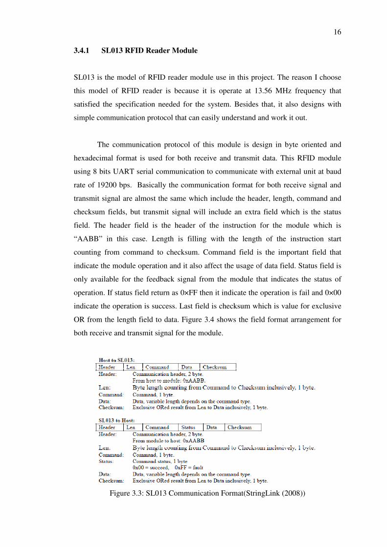
The communication protocol of this module is design in byte oriented and
hexadecimal format is used for both receive and transmit data. This RFID module
using 8 bits UART serial communication to communicate with external unit at baud
rate of 19200 bps. Basically the communication format for both receive signal and
transmit signal are almost the same which include the header, length, command and
checksum fields, but transmit signal will include an extra field which is the status
field. The header field is the header of the instruction for the module which is
“AABB” in this case. Length is filling with the length of the instruction start
counting from command to checksum. Command field is the important field that
indicate the module operation and it also affect the usage of data field. Status field is
only available for the feedback signal from the module that indicates the status of
operation. If status field return as 0×FF then it indicate the operation is fail and 0×00
indicate the operation is success. Last field is checksum which is value for exclusive
OR from the length field to data. Figure 3.4 shows the field format arrangement for
both receive and transmit signal for the module.
Figure 3.3: SL013 Communication Format(StringLink (2008))
17
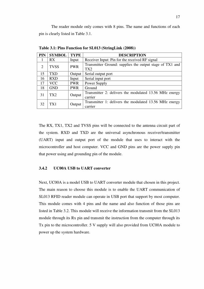
The reader module only comes with 8 pins. The name and functions of each
pin is clearly listed in Table 3.1.
Table 3.1: Pins Function for SL013 (StringLink (2008))
PIN SYMBOL TYPE DESCRIPTION 1 RX Input Receiver Input: Pin for the received RF signal
2 TVSS PWR Transmitter Ground: supplies the output stage of TX1 and TX2
15 TXD Output Serial output port 16 RXD Input Serial input port 17 VCC PWR Power Supply 18 GND PWR Ground
31 TX2 Output Transmitter 2: delivers the modulated 13.56 MHz energy carrier
32 TX1 Output Transmitter 1: delivers the modulated 13.56 MHz energy carrier
The RX, TX1, TX2 and TVSS pins will be connected to the antenna circuit part of
the system. RXD and TXD are the universal asynchronous receiver/transmitter
(UART) input and output port of the module that uses to interact with the
microcontroller and host computer. VCC and GND pins are the power supply pin
that power using and grounding pin of the module.
3.4.2 UC00A USB to UART converter
Next, UC00A is a model USB to UART converter module that chosen in this project.
The main reason to choose this module is to enable the UART communication of
SL013 RFID reader module can operate in USB port that support by most computer.
This module comes with 4 pins and the name and also function of those pins are
listed in Table 3.2. This module will receive the information transmit from the SL013
module through its Rx pin and transmit the instruction from the computer through its
Tx pin to the microcontroller. 5 V supply will also provided from UC00A module to
power up the system hardware.

Table 3.2: Pins Function for UC00A (
Pin Label Definition
1 + 5V output from UC00A
2 – Ground or negative
3 TX UC00A UARTTransmit pin
4 RX UC00A UARTReceive pin
3.4.3 PIR Motion Sensor
PIR (Passive Infra-Red)
the on and off of the system RF transmission. This motion comes with three pin
option, two jumper setting option and a variab
in Figure 3.5. The three pin
last pin is the output pin that give
Next, the two jumpers setting give the retrigger function and normal function.
If retrigger function is choose
repeatedly and normal function give output
The jumper setting will be set to retrigger function
signal due to present of crowd motion
the delay time setting variable resistor is use to
sensor.
Figure 3.4: PIR Sensor Connection Pin and Setting
Pins Function for UC00A (Joliza (2009))
Definition Function Power
from UC00A
5V supply from USB, optional for user to power external device, maximum current 200mA.
Ground or negative
Ground of power and signal. This pin should be connected to device’s GND pin.
UC00A UART Transmit pin
This is UC00A’s transmitter pin (5V TTL). It should be connected to device’s receiver pin.
UC00A UART Receive pin
This is UC00A’s receiver pin (5V TTL). It shouldconnected to device’s transmitter pin.
PIR Motion Sensor
Red) is the model motion sensor that use in this project to control
the on and off of the system RF transmission. This motion comes with three pin
option, two jumper setting option and a variable resistor delay time setting as shown
The three pin option are the 5 V power up pin, grounding pin and the
last pin is the output pin that give 5 V logic high output whenever motion is detected.
Next, the two jumpers setting give the retrigger function and normal function.
If retrigger function is choose, the output remains HIGH when sensor is retriggered
and normal function give output goes HIGH then LOW when triggered
he jumper setting will be set to retrigger function in this project
signal due to present of crowd motion that will affect the RF on/off setting.
the delay time setting variable resistor is use to control the ‘ON’ delay
PIR Sensor Connection Pin and Setting (Cytron, T.
18
5V supply from USB, optional for user to power external device, maximum current 200mA.
Ground of power and signal. This pin should be
UC00A’s transmitter pin (5V TTL). It should be
This is UC00A’s receiver pin (5V TTL). It should be connected to device’s transmitter pin.
use in this project to control
the on and off of the system RF transmission. This motion comes with three pin
le resistor delay time setting as shown
V power up pin, grounding pin and the
high output whenever motion is detected.
Next, the two jumpers setting give the retrigger function and normal function.
utput remains HIGH when sensor is retriggered
goes HIGH then LOW when triggered.
in this project to avoid unstable
that will affect the RF on/off setting. Lastly,
control the ‘ON’ delay time for the
Cytron, T. (2007))
19
3.4.4 PIC18F452 Microcontroller
PIC18F452 is the model of microcontroller use in this project. The reason
PIC18F452 microcontroller is used in this system is because it is supported by
PICKit 2 software. Besides that, it also comes with large program memory which is
around 32kB. Besides that it also support up to maximum five I/O port. These two
features are an advantage for future upgrading the program control of the system.
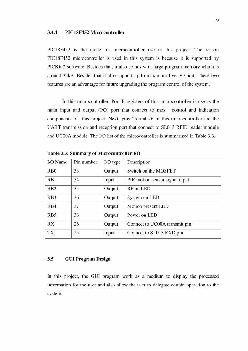
In this microcontroller, Port B registers of this microcontroller is use as the
main input and output (I/O) port that connect to most control and indication
components of this project. Next, pins 25 and 26 of this microcontroller are the
UART transmission and reception port that connect to SL013 RFID reader module
and UC00A module. The I/O list of the microcontroller is summarized in Table 3.3.
Table 3.3: Summary of Microcontroller I/O
I/O Name Pin number I/O type Description
RB0 33 Output Switch on the MOSFET
RB1 34 Input PIR motion sensor signal input
RB2 35 Output RF on LED
RB3 36 Output System on LED
RB4 37 Output Motion present LED
RB5 38 Output Power on LED
RX 26 Output Connect to UC00A transmit pin
TX 25 Input Connect to SL013 RXD pin
3.5 GUI Program Design
In this project, the GUI program work as a medium to display the processed
information for the user and also allow the user to delegate certain operation to the
system.

20
The basic design concept of the GUI program should possibly include the following
function in the main menu,
1. Display the individual name of item checkout
2. Display the individual price of item checkout
3. Display Item Quantity
4. Total price of checkout item
5. Pay Bill button
6. System on/off button
7. Remove item button
8. Add/remove access user button
9. Login button
10. Stock view button
11. Show hardware connection status
12. Exit button
The computer interface software should be constructed with all criterion listed above
and well organized in a systematic method and design.
3.6 Use of Software
In this project, some of the software is used to carry out this project such as
Microsoft Visual Basic 2008, DipTrace, PICKit2 and MPlab.
3.6.1 Microsoft Visual Basic 2008
The GUI program for the automated RFID shopping checkout system in this project
will be designed Visual Basic 2008 software (VB). VB is chosen as the development
software that use to write the GUI program for this system because it is an object
oriented based software that is easy to learn and apply in short period of time.
Besides that, the application created through VB can implement on
Microsoft .NET Framework that available in most Microsoft operating system
computer. VB also provide simple solution to connecting and interact to the external
21
source such as SQL database and also computer serial port communication through
special build in class library such as SerialPort Class and SQL data provider Class.
3.6.2 DipTrace
DipTrace is a schematic and PCB design software that use in this project to design
PCB board of the hardware circuit. It is a free software that available download from
their homepage at www.diptrace.com.
Even though it is free software, it is still very useful in designing simple PCB
board for beginner. The software supports a lot of libraries for many common
components use in the circuit. The software provide the function to enable user
convert the schematic diagram of their circuit draw in DipTrace Scematic to PCB
layout which is very convenient. Another advantage of this software is include the
function to auto arrange the components and wiring of PCB layout to the size of PCB
board provided, which can save up a lot of time from it.
3.6.3 PICKit 2 and MPLab
Generally, PICKit 2 is free software that come together with the PIC programming
when purchase. It is important software to enable the user to burn the Hex file
program to the microcontroller through the programmer. It supports wide range of
PIC microcontroller that is commonly used.
Next MPlab is the main program used in this project to write the program of
PIC microcontroller. The software itself support the machine language code writing
and extra free Mplab C18 compiler can be installed to the software to enable it
compile the C programming program to hex file. Stimulation function also provided
in MPlab to troubleshooting the microcontroller program written with it.

22
3.7 Planning For FYP Part 2
In FYP part 2, the main aim is to carrying out all the preparation work that already
well planned and decided during the FYP part 1. In preparation for FYP part 2,
activity planning and schedule also had been built to estimate and coordinate the
FYP part 2 progressions.
Some of the estimated activity that will be involve in FYP part 2 are
determined and listed as given below.
1. Components experimental testing
2. PCB circuit board design
3. Components assemble and soldering
4. Circuitry board testing and troubleshooting
5. Tag and Microcontroller program writing
6. Computer Interface Software Programming
7. Overall Prototype Assemble
8. Prototype Testing and Troubleshooting
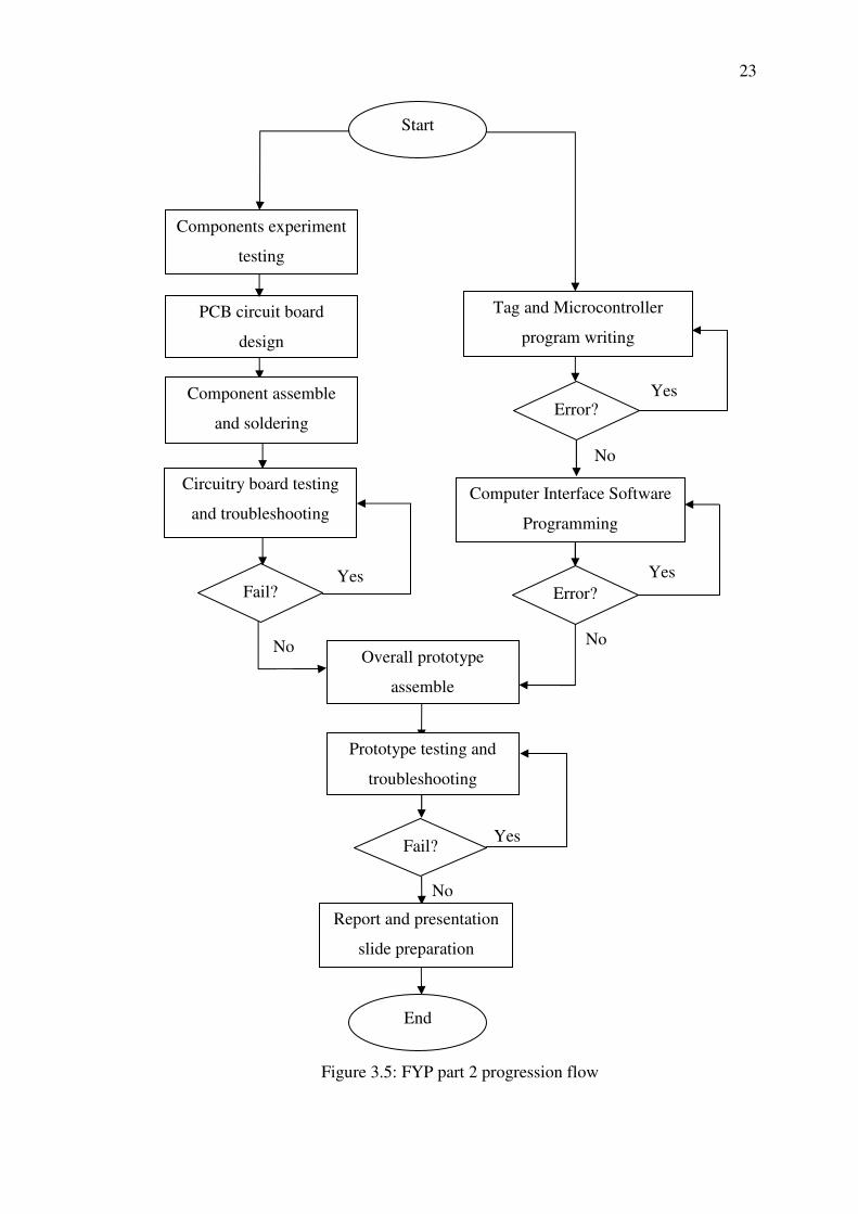
The prediction main activity progression flow for FYP part 2 will be approximately
shown in the flow chart prepared as Figure 4.1. In overall, most of the tasks that will
be engage in the FYP part 2 will lead to the outcome and result we had been plan in
during FYP part 1.
The milestone planning for FYP 2 had been prepared to well plan the time
management for all the prediction activities that will be carry out. The schedule is
roughly stated in the Grant chart Table 4.1.
23
Figure 3.5: FYP part 2 progression flow
Start
End
Overall prototype
assemble
Report and presentation
slide preparation
Fail?
Yes
Yes
Yes
No
No
No
Error?
Circuitry board testing
and troubleshooting
Fail?
No
Yes
Component assemble
and soldering
PCB circuit board
design
Components experiment
testing
Tag and Microcontroller
program writing
Error?
Computer Interface Software
Programming
Prototype testing and
troubleshooting

Table 3.4: Milestone for FYP Part 2
Week 1 2 3 4 5 6 7 8 9 10 11 12 13 14 15
Task
Components experimental testing
PCB circuit board design
Components assemble and soldering
Circuitry board testing and troubleshooting
Tag and Microcontroller program writing
Computer Interface Software Programming
Overall Prototype Assemble
Prototype Testing and Troubleshooting
Thesis Report writing
First summition checking
Second summition checking
Thesis Report Summition
Thesis Report Presentation Slide Preparation
Thesis Report Presentation
CHAPTER 4
4 RESULTS AND DISCUSSIONS
4.1 Result and Discussion Overview
In this chapter, all the result of experiments carries out in this project and
interpretation experiments data are presented. Effective UART transmission delay
experiment, system RF switching delay time testing, system read time experiment,
tag attachment material experiment and system GUI testing are some of the core
experiment that contributing the result and discussion in this chapter.
4.2 Effective UART Transmission Delay Experiment
The effective UART transmission delay experiment is carried out in this project to
obtain the optimize transmission delay setting for the microcontroller.
The experiment is starting by setting the delay of microcontroller 0.050 s.
After that, the system is run to enable the microcontroller to send the instruction to
the reader module with the new delay. As reader module receives certain instruction
from the microcontroller, it will transmit a feedback to host computer. This
experiment is run until twenty instructions is executed and a count program in the
host computer will count number error feedback signal transmit to the host computer.
The previous step is run for thirty times to obtain thirty observation of
outcome. After that, the experiment is repeated with microcontroller instruction
transmit delay set to 0.075
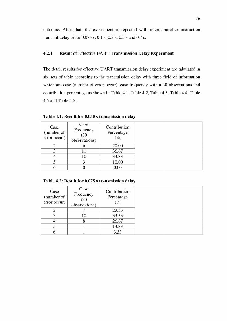
4.2.1 Result of Effective
The detail results for effective UART transmission delay experiment
six sets of table according to the transmission delay with three field of information
which are case (number of error occur), case frequency within 30 observations and
contribution percentage as shown in Table 4.1, Table 4.2, Table 4.3, Table 4.4,
4.5 and Table 4.6.
Table 4.1: Result for 0.050
Case (number of error occur)
Case Frequency
(30 observations)
2 3 114 105 6
Table 4.2: Result for 0.0
Case (number of error occur)
Case Frequency
(30 observations)
2 3 104 5 6
outcome. After that, the experiment is repeated with microcontroller instruction
transmit delay set to 0.075 s, 0.1 s, 0.3 s, 0.5 s and 0.7 s.
Effective UART Transmission Delay Experiment
for effective UART transmission delay experiment
six sets of table according to the transmission delay with three field of information
which are case (number of error occur), case frequency within 30 observations and
contribution percentage as shown in Table 4.1, Table 4.2, Table 4.3, Table 4.4,
Result for 0.050 s transmission delay
Case Frequency
(30 vations)
Contribution Percentage
(%)
6 20.00 11 36.67 10 33.33 3 10.00 0 0.00
Result for 0.075 s transmission delay
Case Frequency
(30 observations)
Contribution Percentage
(%)
7 23.33 10 33.33 8 26.67 4 13.33 1 3.33
26
outcome. After that, the experiment is repeated with microcontroller instruction
Transmission Delay Experiment
for effective UART transmission delay experiment are tabulated in
six sets of table according to the transmission delay with three field of information
which are case (number of error occur), case frequency within 30 observations and
contribution percentage as shown in Table 4.1, Table 4.2, Table 4.3, Table 4.4, Table

Table 4.3: Result for 0.
Case (number of error occur)
Case Frequency
(30 observations)
2 153 4 5 6
Table 4.4: Result for 0.3
Case (number of error occur)
Case Frequency
(30 observations)
2 193 4 5 6
Table 4.5: Result for 0.5
Case (number of error occur)
Case Frequency
(30 observations)
2 3 144 5 6
Table 4.6: Result for 0.7
Case (number of error occur)
Case Frequency
(30 observations)
2 153 4 105 6
Result for 0.1 s transmission delay
Case Frequency
(30 observations)
Contribution Percentage
(%)
15 50.00 5 16.67 8 26.67 1 3.33 1 3.33
Result for 0.3 s transmission delay
Case Frequency
(30 observations)
Contribution Percentage
(%)
19 63.33 8 26.67 3 10.00 0 0.00 0 0.00
Result for 0.5 s transmission delay
Case Frequency
(30 observations)
Contribution Percentage
(%)
3 10.00 14 46.67 8 26.67 3 10.00 2 6.67
Result for 0.7 s transmission delay
Case Frequency
(30 observations)
Contribution Percentage
(%)
15 50.00 3 10.00
10 33.33 2 6.67 0 0.00
27

28
4.2.2 Effect of UART Transmit Delay for Continuous Transmission
In this project, some time some error will occurs when signal sent from the reader
module to host computer. The number of error occurrence is considerate high when
the signal is sending continuously from the reader module without any delay is
introduced. This may cause by the slightly mismatch of synchronization between
transmit and receive unit.
In order to reduce the occasion of error during signal transmission form the
RFID reader module to the host computer, certain amount of delay which is less than
one second is added to the instruction sending of microcontroller. The delay will
slightly slow the instruction send to the RFID module and also lead to slowing down
of reader module feedback. This will provide some extra interval time for the each
feedback signal to transmit in continuous process.
The delay time show improvement for the signal reception accuracy at the
host computer side, but yet small amount of error is still present. In order to further
improve the accuracy of system, few sets of delay time is chosen between 0.05 s to
0.7 s and tested to obtain the optimize choice among them. From the experiment, we
can conclude 0.3 s delay give the best performance with less error introduces in
average compare to others. Delay time which less than 0.1 s is show less
improvement for the system with average of 2 errors occur every 20 feedback signal
receive. When the delay time is too large, the feed signal error tend to be less
consistence which can fluctuate up to 4 errors sometimes for each 20 feedback signal
received.
4.3 RF Switching Delay Time Testing
To test the RF switching delay time of the system, a simple test can be taken by
recording the time consume for the RF to turn on each time the motion sensor is
triggered to logic high state. The state of RF can be easily determined through the RF
on LED implement to the system and an assumption of no delay introduce to switch
on the LED is made. For accuracy purpose, the testing is carried out in ten
observations
29
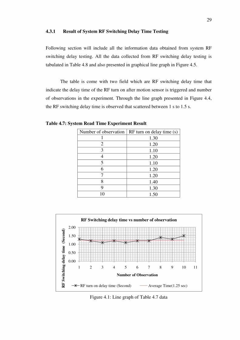
4.3.1 Result of System RF Switching Delay Time Testing
Following section will include all the information data obtained from system RF
switching delay testing. All the data collected from RF switching delay testing is
tabulated in Table 4.8 and also presented in graphical line graph in Figure 4.5.
The table is come with two field which are RF switching delay time that
indicate the delay time of the RF turn on after motion sensor is triggered and number
of observations in the experiment. Through the line graph presented in Figure 4.4,
the RF switching delay time is observed that scattered between 1 s to 1.5 s.
Table 4.7: System Read Time Experiment Result
Number of observation RF turn on delay time (s) 1 1.30 2 1.20 3 1.10 4 1.20 5 1.10 6 1.20 7 1.20 8 1.40 9 1.30
10 1.50
Figure 4.1: Line graph of Table 4.7 data
0.00
0.50
1.00
1.50
2.00
1 2 3 4 5 6 7 8 9 10 11
RF
Sw
itch
ing
del
ay
tim
e (
Sec
on
d)
Number of Observation
RF Switching delay time vs number of observation
RF turn on delay time (Second) Average Time(1.25 sec)
30
4.3.2 Analysis Cause of RF Switching Delay
The average of RF switching delay is found to be 1.25 s. Through statistical analysis
calculation, the standard deviation of the experiment data is 0.12 s. This mean the
average RF switch in delay time will deviate around 0.12 s from average of RF
switching delay, which give a average range of around 1.13 second to 1.37 s. The
results obtained from the experiment come out to be different from the expected
hypothesis. In the hypothesis made, the RF switching of the system is assume to be
executed instantly but in real case, some delay which range within couple of second
is introduce in the process.
Through analyse the working principle of the system process, the delay time
that introduced to the RF switching process is more likely cause by looping process
of the system program. In this system design, the microprocessor is programmed that
once motion sensor is triggered, it will start looping RF on instruction sent to RFID
module until a feedback signal that confirm the switching of RF was sent to the
microprocessor. Therefore, the process consumes certain time for the instruction or
feedback signal to send among process unit such as from microcontroller to RFID
module, from RFID module to host computer and from host computer to the
microcontroller.
Next, the RF switching delay can also influence by the switching speed of the
MOSFET that implement in the system to switch on and off the RFID module. When
the PIR motion sensor signal was delivered to microcontroller, microcontroller will
first turn on the RFID module by switching the MOSFET to on state. However,
switching of MOSFET is not instantaneous and it cause some delay to fully turn on
the MOSFET. The delay time for this case is highly effect by the switching
characteristic of the MOSFET itself and but normally is very small.
4.3.3 Consequential and Solutions for RF Switching Delay
The RF switching delay of the system is very important for the system overall
performance and important factor to be considered. High RF switching delay will
prolong the time taken for the system to complete the task in each work cycle and

31
directly decrease the performance of the system. Some RFID also may miss out from
scan process due to the delay in RF turn on which lower the accuracy of the system.
RF switching delay problem will always exist and cannot be fully terminated but it
can be reduced to a considerable value.
Some common way to minimize the time delay problem is decrease the signal
transmission path from each processing unit and also using MOSFET with good
switching characteristic. Another way to compromise the RF switching problem is
properly adjust the sensor location from the scan zone of the system. This can make
sure the item take some time to reach the scanning zone once the sensor is triggered
to make sure the RF of the system is fully turn on. For the system design in this
project take average of 1.5 s to turn on the RF once the sensor I triggered and it is
tested around 10 cm separation distance between the sensor and the scan zone can be
sufficient to compromise the delay issues of system.
4.4 System Average Read Time Testing
In order to obtain the average read time of the system, a simple test is carry out in
this project. First of all the RFID tag is placed at the scanning zone of the system and
use the GUI program to turn on the system and measure the time taken for the GUI
show the information of tag. After that, repeat the process by removing the scanned
tag information from the GUI program and determine how long it takes for the tag to
redetect by the system. Repeat the experiments for thirty times to collect thirty
observations to increase the accuracy of outcome.
4.4.1 System Average Read Time Analysis
From the system average read time analysis experiment, the data is plotted in line
graph of Figure 4.5. The data elements from the experiment are number of
observation and read time of RFID tag for the system. There are total of thirty
observations taken in the experiment, so it will give thirty sets of read time for
analysis.
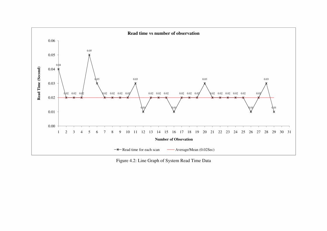
Figure 4.2: Line Graph of System Read Time Data
0.04
0.02 0.02 0.02
0.05
0.03
0.02 0.02 0.02 0.02
0.03
0.01
0.02 0.02 0.02
0.01
0.02 0.02 0.02
0.03
0.02 0.02 0.02 0.02 0.02
0.01
0.02
0.03
0.01
0.00
0.01
0.02
0.03
0.04
0.05
0.06
1 2 3 4 5 6 7 8 9 10 11 12 13 14 15 16 17 18 19 20 21 22 23 24 25 26 27 28 29 30 31
Rea
d T
ime
(Sec
on
d)
Number of Obsevation
Read time vs number of observation
Read time for each scan Average/Mean (0.02Sec)

33
4.4.2 Interpretation System Read Time Data
Basically, the scan time of the system is found to be very fast and close to
instantaneous with very small delay which is around average of 20 ms. The
fluctuation of the collected read time data may cause by the instability of the system
or human error when conducting the experiments.
Through statistical analysis, the mean of the system read time is found to be
20 ms and the standard deviation of the data is 8ms. With both the mean and standard
deviation obtained, I can conclude the average read time of the system is fall within
12 ms to 28 ms. Since the deviation range of the read time is very small, it provides
the information about the system have a very fast and accurate scan performance.
The read time of the system is very crucial in determine that work cycle time
consumption of the system. However, this experiment result is obtained from RFID
tag without attaching any item, so it is the original read time that requires reading an
unattached RFID tag.
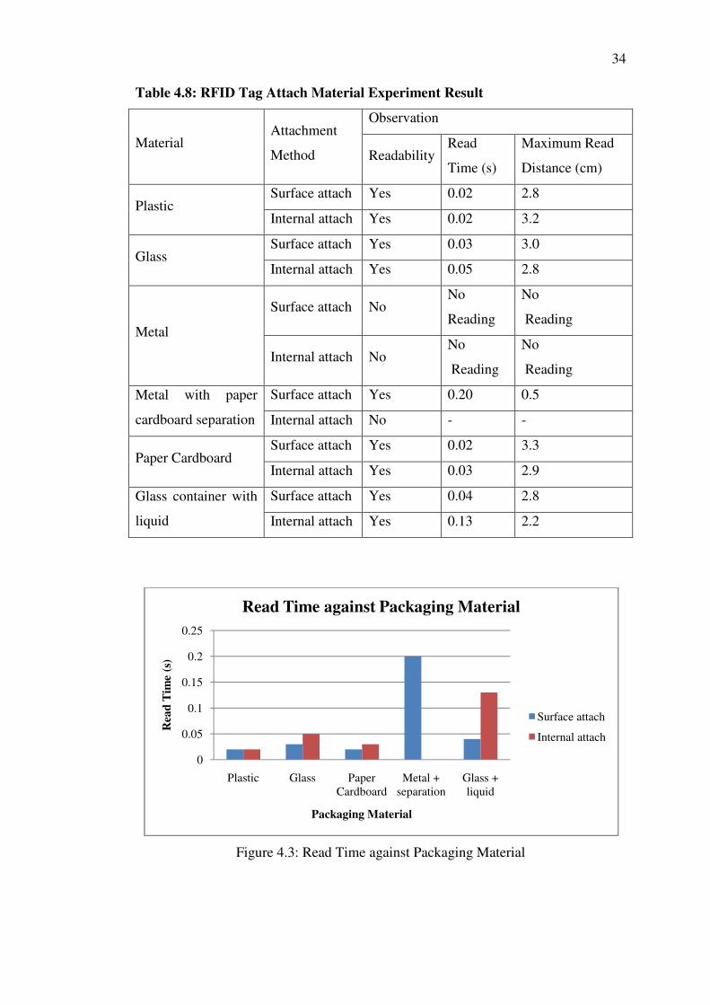
4.5 RFID Tag Attach Material Experiment and Result
In this experiment, the system is tested on scanning the RFID tag attached on
different material platform such as metal, glass, cardboard paper and plastic. All the
platform is chose to have around thickness of 0.2 mm to obtain a clearer result. When
this experiment is carrying out, criteria such as read times change, maximum
detection range and readability of the system is observed. Same method previously
used in determines the average read time of system is use again in this experiment to
obtain the read time and readability of system. The maximum read range of the
system is obtained through slowly moving the RFID tag away from scanning antenna
in horizontal distance until the tag is not detected by the system.
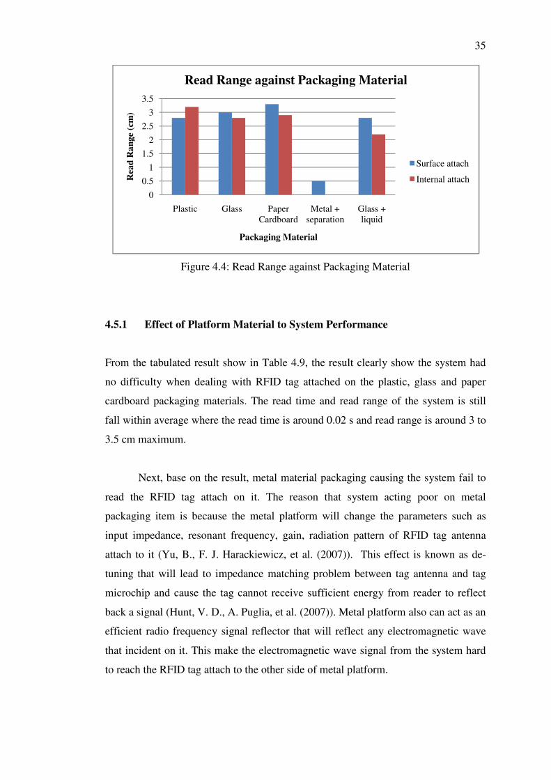
The outcome result of the experiment is clearly presented in Table 4.8 in
detail. Simplification of result is also presented in the form of column chart as shown
in Figures 4.3 and 4.4.
34
Table 4.8: RFID Tag Attach Material Experiment Result
Material Attachment
Method
Observation
Readability Read
Time (s)
Maximum Read
Distance (cm)
Plastic Surface attach Yes 0.02 2.8
Internal attach Yes 0.02 3.2
Glass Surface attach Yes 0.03 3.0
Internal attach Yes 0.05 2.8
Metal
Surface attach No No
Reading
No
Reading
Internal attach No No
Reading
No
Reading
Metal with paper
cardboard separation
Surface attach Yes 0.20 0.5
Internal attach No - -
Paper Cardboard Surface attach Yes 0.02 3.3
Internal attach Yes 0.03 2.9
Glass container with
liquid
Surface attach Yes 0.04 2.8
Internal attach Yes 0.13 2.2
Figure 4.3: Read Time against Packaging Material
0
0.05
0.1
0.15
0.2
0.25
Plastic Glass Paper Cardboard
Metal + separation
Glass + liquid
Rea
d T
ime
(s)
Packaging Material
Read Time against Packaging Material
Surface attach
Internal attach
35
Figure 4.4: Read Range against Packaging Material
4.5.1 Effect of Platform Material to System Performance
From the tabulated result show in Table 4.9, the result clearly show the system had
no difficulty when dealing with RFID tag attached on the plastic, glass and paper
cardboard packaging materials. The read time and read range of the system is still
fall within average where the read time is around 0.02 s and read range is around 3 to
3.5 cm maximum.
Next, base on the result, metal material packaging causing the system fail to
read the RFID tag attach on it. The reason that system acting poor on metal
packaging item is because the metal platform will change the parameters such as
input impedance, resonant frequency, gain, radiation pattern of RFID tag antenna
attach to it (Yu, B., F. J. Harackiewicz, et al. (2007)). This effect is known as de-
tuning that will lead to impedance matching problem between tag antenna and tag
microchip and cause the tag cannot receive sufficient energy from reader to reflect
back a signal (Hunt, V. D., A. Puglia, et al. (2007)). Metal platform also can act as an
efficient radio frequency signal reflector that will reflect any electromagnetic wave
that incident on it. This make the electromagnetic wave signal from the system hard
to reach the RFID tag attach to the other side of metal platform.
0
0.5
1
1.5
2
2.5
3
3.5
Plastic Glass Paper Cardboard
Metal + separation
Glass + liquid
Rea
d R
an
ge
(cm
)
Packaging Material
Read Range against Packaging Material
Surface attach
Internal attach

36
In order to improve the reception of RFID tag signal attached to metal
platform, some separation space between the metal platform and the RFID can
implement (Park, C. R. and K. H. Eom (2011)). With paper cardboard thick around
0.5cm as separation between the tag and the metal platform, system become capable
to read the RFID tag from direct scan but outcome is highly degraded from the aspect
of reading speed and range as presented in the result. Besides that, the increase
separation between the RFID tag and metal platform just can solve direct scanning
problem and can solve indirectly scanning problem of the system. The indirect
scanning problem of RFID tag mount on metal platform can only solve by increase
the scanning direction of reader which will lead to increase the chance of direct scan
of RFID tag.
Beside metal platform, from the result shown in previous section, it is also
noticeable that liquid give slightly influence to the performance of the system. Even
though the effect is not significant but the result shows the read range and speed of
the system slightly fall when scanning a RFID tag place next to a glass containing
water. This can be cause by the electromagnetic wave absorption characteristic of
liquid which causing the RFID tag to have insufficient energy to power up and
backscatter information to the reader. Different liquid react differently to
electromagnetic wave and normally water base liquid will have higher absorption
characteristic than oil based liquid.
Some simplest method to reduce the effect of liquid absorption for the RFID
tag is increase the separation distance between liquid and the tag like implemented to
metal platform. This can reduce the amount of receive and transmit signal from
RFID tag absorbed by the liquid contain (Technology, A. (2007)). Increase the
system read direction will also work in reduces the affect of liquid absorption
problem.

37
4.6 System GUI Program Testing
This section will cover all the description and testing of the graphical user interface
(GUI) for the automated shopping checkout system.
4.6.1 Program Communication
In the GUI program designed for the automated shopping checkout system, serial
port communication plays an important role in enable the communication between
the host computer with the other processing unit such as microcontroller and RFID
module. An UART to USB converter hardware is used to enable the UART
transmission access through the USB port of computer, but it still present as a serial
port in the host computer where can be link up with the GUI program using serial
port class in VB.
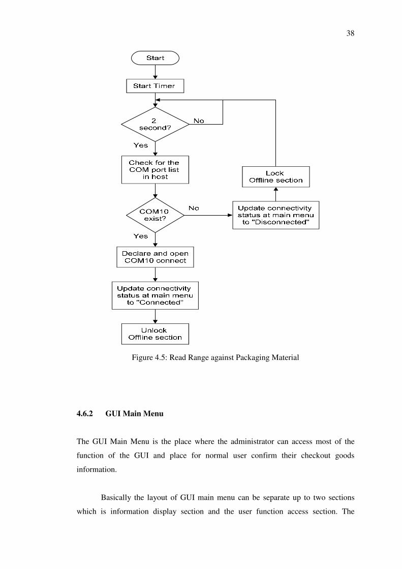
When the program start, it will trigger a timer that repeat to count up to two
second and trigger a sub function to check for the present of COM port connection
for the system (In this project COM10 is used) in the COM port list of host computer.
If COM10 present in the list, program will create and open a serial port that link
directly with COM10. Update the connection status in GUI main menu to “connected”
and unlock system on/off button will also be executed. If COM10 is not present the
program will update the connectivity status to “Disconnected” and lock system
on/off button. Even with present of administrator user login, the system on/off button
will be disabled when the system is in disconnected state. This is to prevent the user
from access system on/off button while the hardware is not connected which will
lead to error in program flow. The program flow of the system hardware connection
checking can be illustrated as given in Figure 4.5.
38
Figure 4.5: Read Range against Packaging Material
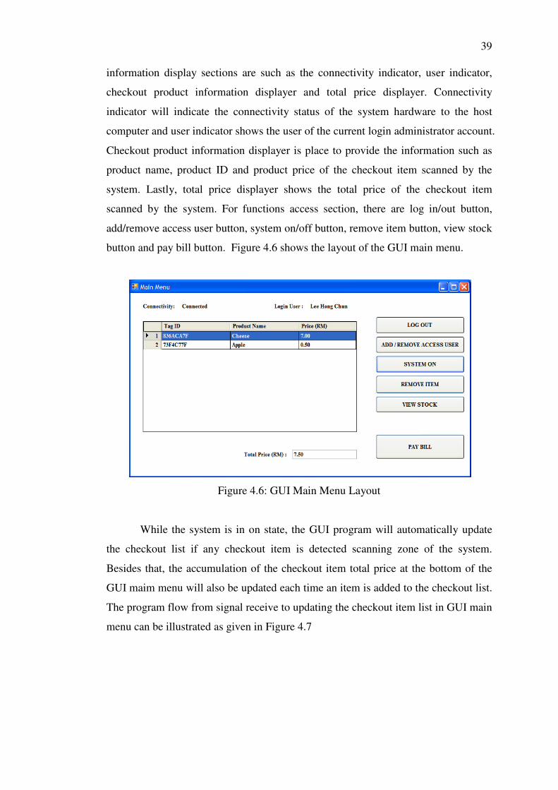
4.6.2 GUI Main Menu
The GUI Main Menu is the place where the administrator can access most of the
function of the GUI and place for normal user confirm their checkout goods
information.
Basically the layout of GUI main menu can be separate up to two sections
which is information display section and the user function access section. The
39
information display sections are such as the connectivity indicator, user indicator,
checkout product information displayer and total price displayer. Connectivity
indicator will indicate the connectivity status of the system hardware to the host
computer and user indicator shows the user of the current login administrator account.
Checkout product information displayer is place to provide the information such as
product name, product ID and product price of the checkout item scanned by the
system. Lastly, total price displayer shows the total price of the checkout item
scanned by the system. For functions access section, there are log in/out button,
add/remove access user button, system on/off button, remove item button, view stock
button and pay bill button. Figure 4.6 shows the layout of the GUI main menu.
Figure 4.6: GUI Main Menu Layout
While the system is in on state, the GUI program will automatically update
the checkout list if any checkout item is detected scanning zone of the system.
Besides that, the accumulation of the checkout item total price at the bottom of the
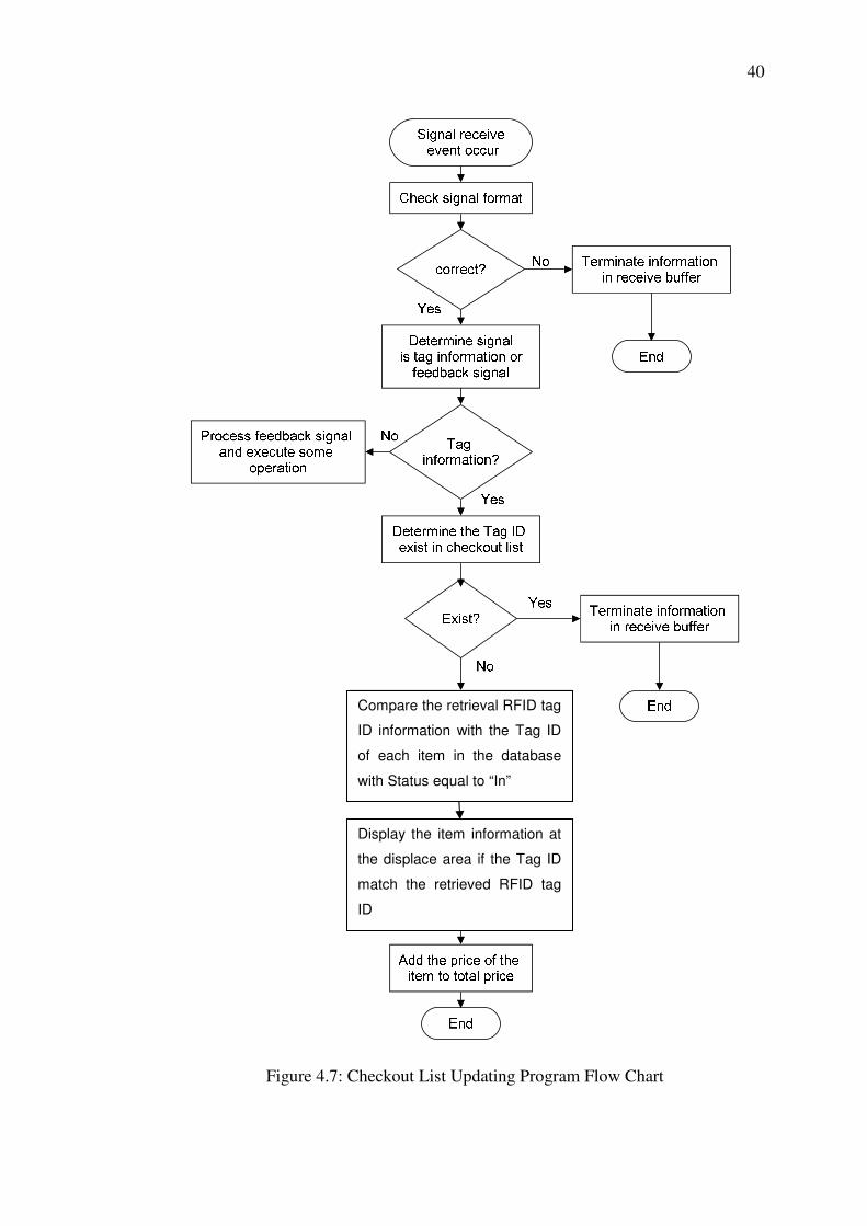
GUI maim menu will also be updated each time an item is added to the checkout list.
The program flow from signal receive to updating the checkout item list in GUI main
menu can be illustrated as given in Figure 4.7
40
Figure 4.7: Checkout List Updating Program Flow Chart
Compare the retrieval RFID tag
ID information with the Tag ID
of each item in the database
with Status equal to “In”
Display the item information at
the displace area if the Tag ID
match the retrieved RFID tag
ID
41
4.6.3 Administrator Lock Function
The administrator lock function is implemented to the GUI program to lock certain
function of the program that is not accessible by normal user and also prevent normal
user to change the GUI setting.
When the program is first launch, a login form will pop up to request the user
to login as administrator user. If user did not login, the program will proceed to the
GUI with certain functions locked. If user is not log in when the program is first
launce, a log in button is available in the GUI form to enable the user to log in
anytime. Functions that only accessible by administrator user are such as add
/remove access user, system on/off, remove item and view stock. If the program is
not log in, the user only can access log in and pay bill function. The program flow
chart of the log in form is presented in Figure 4.8.

42
Figure 4.8: Login Form Program Flow Chart
43
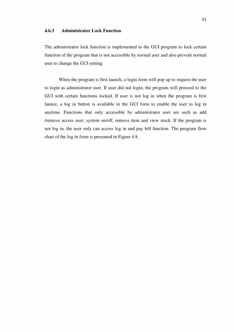
4.6.4 Pay Bill Function and Remove Item Function
In this system, the pay bill function is included to allow the user to checkout their
items. When the pay bill button is press, the GUI program will pop up a message box
that shows the total amount of purchase for all the checkout goods and let user to
decide whether want to proceed or not as shown in Figure 4.9.
Figure 4.9: Pay Bill Button Demonstrate
If users confirm to checkout their items, the program will search through the
database for all the in stock items with the same tag ID with the items displayed in
GUI main menu and update their status to checkout. After that, the program will
clear the checkout items display and total price display section of the GUI main
menu. Figure 4.10 will demonstrate the program flow of the pay bill function.
Next, the remove item function is provided to enable the scanned checkout
items to be removed from the checkout list when unwanted item is accidently add
into the checkout item. This function is restricted to administrator user to ensure the
scanned checkout item is not purposely removed from the checkout list.

44
Figure 4.10: Pay Bill Function Program Flow Chart
4.6.5 Add/ Remove Access User Function
This function is implemented in the system in order to insert or withdraw any access
user to the system data base. However, this function also restricted to administrator
to administrator user with master password. This is to restrict the action to avoid
violation the usage of the add/remove access user function of the system. Basically,
when this function is access, user will jump into an add/remove access user form
45
which give user the option to add a new administrator user, remove an existing
administrator user and also the exit the function.
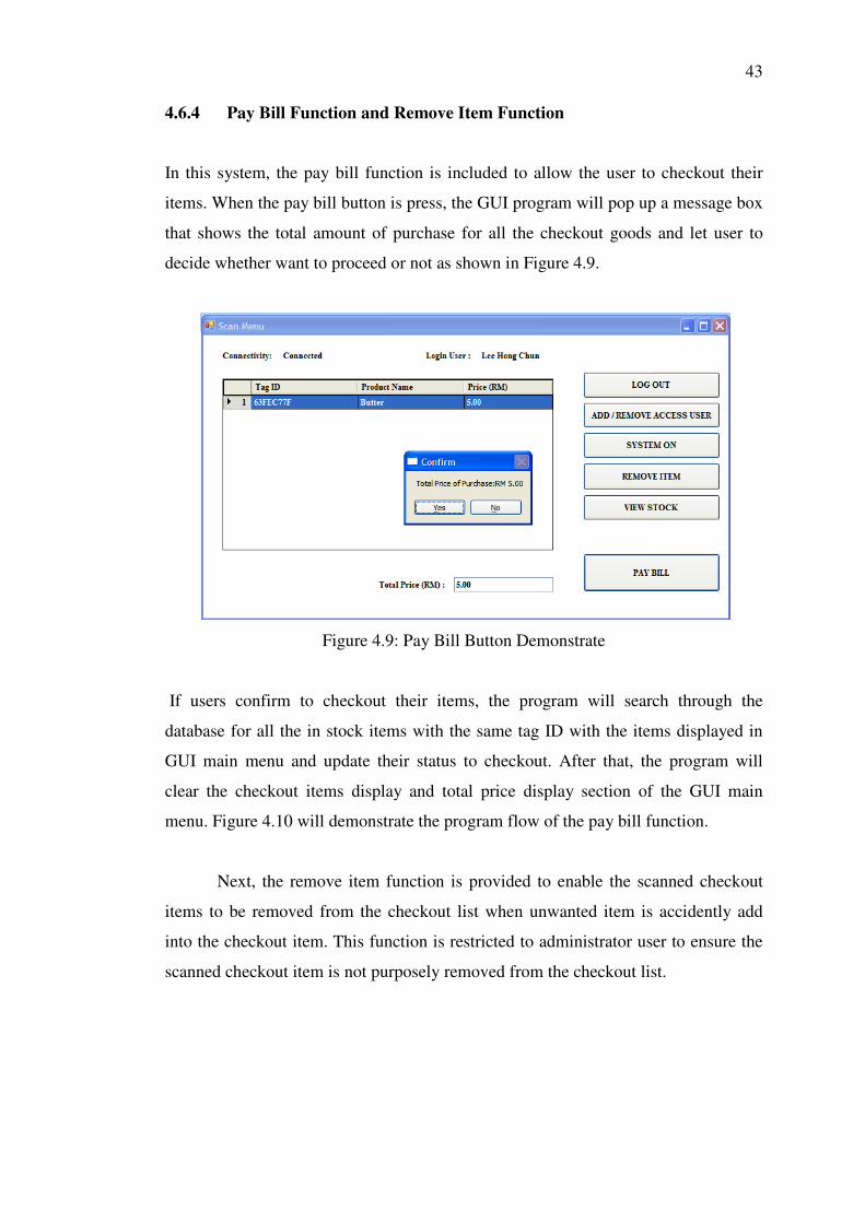
The add/remove access user is initially load with add new user ID function
when initiated as shown in Figure 4.11. From Figure 4.11, we can see that in order to
add a new user, user need to fill up the new user ID, new password, confirmation of
new password and also the master password. The new admin ID should only include
characters or numbers that no longer than 15 words. Once the new user is added, it
can be use for the next log in.
Figure 4.11: Add User Program Interface
When the delete ID button on the add/remove access user form is pressed,
add new ID section will swap with the Delete ID section as shown in Figure 4.12.
From the delete ID section, a combo box will be provided to user to choose which
existing ID that will be deleted. After user choose the admin ID to be delete and
master password is fill, user can proceed to confirm the action. When the action is
taking, the program will check whether the master password filled and after that the
program makes sure the deleting admin ID is not the one currently in use. If the
admin ID is successfully removed, a message box will pop up to confirm with user.
46
Figure 4.12: Delete User Program Interface
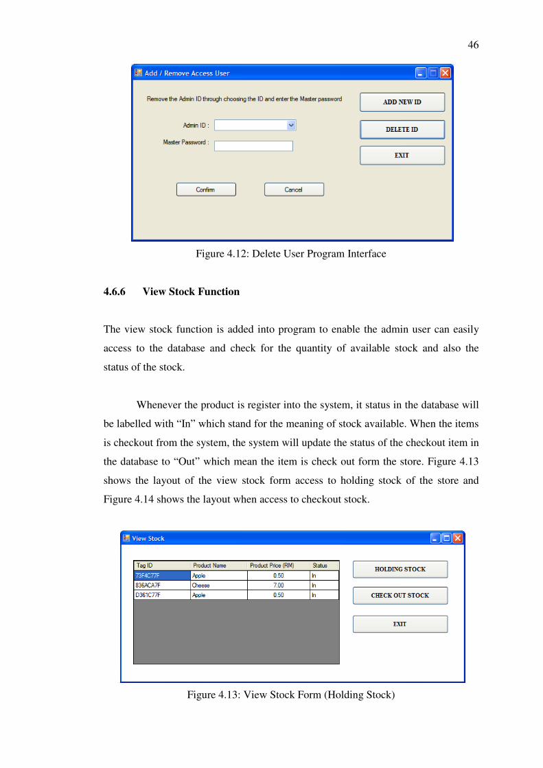
4.6.6 View Stock Function
The view stock function is added into program to enable the admin user can easily
access to the database and check for the quantity of available stock and also the
status of the stock.
Whenever the product is register into the system, it status in the database will
be labelled with “In” which stand for the meaning of stock available. When the items
is checkout from the system, the system will update the status of the checkout item in
the database to “Out” which mean the item is check out form the store. Figure 4.13
shows the layout of the view stock form access to holding stock of the store and
Figure 4.14 shows the layout when access to checkout stock.
Figure 4.13: View Stock Form (Holding Stock)

47
Figure 4.14: View Stock Form (Check Out Stock)
4.7 Hardware Microcontroller Program
Besides host computer as the data processing unit, some operation is executed
through the microcontroller included in the hardware section of the system.
Mainly, the microcontroller is involving more at the sensor controlling part.
The microcontroller will receive simple instruction from the host computer and
decide which action will take base on the state of the PIR motion sensor. When the
system on/off button is press, the host computer sends a “01” or “02” instruction to
the microcontroller. The “01” instruction tell the microcontroller go into standby on
state where once the PIR motion sensor is triggered, it will start power up the module,
on the module RF and scan for RFID tag. In the other hand, the “02”instruction
request the microcontroller go into off state where the system will not execute any
scanning even sensor is triggered. Furthermore, as the microcontroller is switching
the RF of the reader module, feedback signal will send from the module to host
computer as a prove of RF turning on, then host computer will send “03”instruction
to tell the microcontroller the RF of the module is successfully turn on and next
operation can be carry out. Next, most of the LED lighting is controlled by the
microcontroller as certain operation is carried out in it. This is to make the user easy
to determine the condition of the system and also make the trouble shooting work
easier.

48
The whole program flow of the microcontroller can be simplified into flow
chart shown in Figure 4.15 and Figure 4.16.
Figure 4.15: Microcontroller Main Program Flow Chart
49
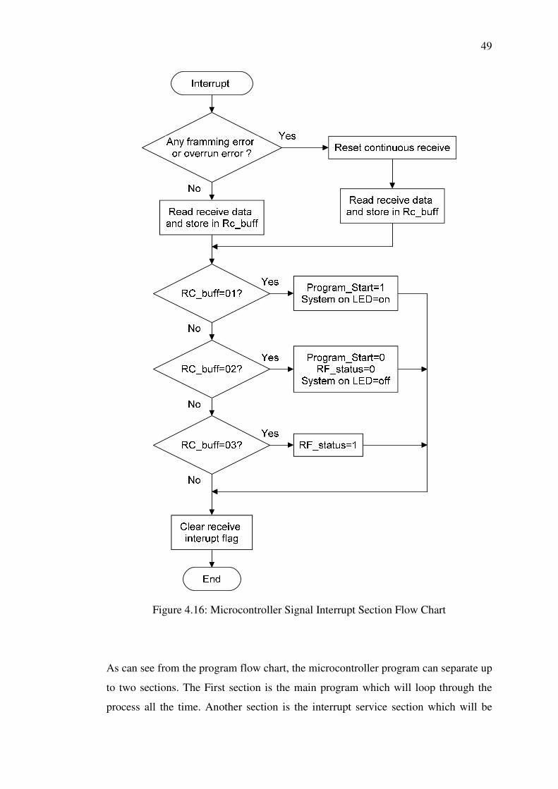
Figure 4.16: Microcontroller Signal Interrupt Section Flow Chart
As can see from the program flow chart, the microcontroller program can separate up
to two sections. The First section is the main program which will loop through the
process all the time. Another section is the interrupt service section which will be
50
execute once the receive interrupt flag of the microcontroller is triggered. In brief,
the main program section is function to check through each status bit declare in the
program and carry out certain operation accordingly, while interrupt program are
mainly function to update the status bit in the microcontroller program once
instruction is receive from host computer.
4.8 Overall Cost of System
In overall, the automated shopping checkout system designed in this project cost
around RM411. The cost of the system considers low compare to other shopping
checkout system available in current market which normally cost up to thousand of
ringgit. Most of the cost of the system is spend on the RFID reader and converter
module of this system. Some other electronic components such as resistors,
capacitors, oscillator and many others are cost around RM50.00. The cost of some
main components can be listed as following.
SL013 RFID Reader Module RM250.00
PIC18F452 Microcontroller RM 20.00
UC00A USB to UART converter RM 58.00
PIR Motion Sensor RM 33.00
Other electronic components RM50.00

CHAPTER 5
5 CONCLUSION AND RECOMMENDATIONS
5.1 Overview for Conclusion and Recommendation
The final section of this report will outline the final outcome obtained from this
project. The limitation of the final product of this project and recommendation for
possible future enhancements of current final product will also included in this
section.
5.2 Conclusion
In conclusion, the aim and objective of this project which is design a low cost
automated shopping checkout system using RFID technology that suitable for most
shopping checkout application and compatible with conventional bar code system
had been achieved.
Next, all the criteria’s set up to meet up the standard of this project is also
accomplished. Firstly, the automated shopping checkout system designed in this
project is capable to read and interpret the correct information transmit from the
RFID tag attach to checkout items. Secondly, the hardware unit of the automated
shopping checkout system can successfully communicate with the host computer
GUI program through serial communication. The microcontroller which is the core
processing and control unit in the system hardware also manages to process the
information and instructions from computer and delicate precise task to the RFID

52
reader module. The PIR motion sensor of the system hardware unit can also operate
well as expected without much problem.
Moreover, the GUI program also work according to the expected
performance which operate in 32 bits Microsoft XP, Microsoft Vista and Microsoft 7
operating system host computer with all requirement software installed. The program
also able to accurately interpret the information and instruction from the system
hardware unit and execute correct operation based on them. Lastly, retrieving and
updating the information to the local host computer SQL database is also not a
problem for the GUI program.
5.3 Limitation of Final Product
Even though the prototype final product of this project had been successfully carried,
but there are still some limitations exist in it.
First of all, the automated shopping checkout system design in this project is
still cannot support multiple RFID tag scanning which is a crucial criteria for
efficient shopping checkout system. Subsequently, the automated shopping checkout
system designed is still in sensitive in scanning RFID tag that mount on metal and
high humidity material platform.
In addition, the UART serial communication that use as the primary signal
communication method of this automated shopping checkout system is still lack of
reliability. Lastly, the GUI program is districted to host computer with keyboard and
mouse which consume quite some spacing.
All these limitations are the drawback for the final product designed in this
project that makes this system far away from the standard of become a real time
useful system in the market.

53
5.4 Recommendation for Future Enhancements
There are bunch of possible idea to enhance the current final product of this project
to the next level which is more close to practical usage of the system.
At first, the current automated shopping checkout system can using a higher
performance RFID reader module that support real time multiple RFID tag scanning.
Through including this feature in the system, it enable the system to detect and
scanning information of multiple tag at once which can be a huge improve in
performance and also increase the practically usage of the system.
Instead of using asynchronous serial communication as primary
communication method in this automated shopping checkout system, synchronous
serial communication can provide higher data transfer reliability to the system in
medium rage. Other than using hard wire, wireless communication can be the
optional secondary transmission medium for longer range transmission between the
hardware unit and host computer. This can probability removes the troublesome
wiring problem of the system.
Finally, touch screen technology which is gaining popularity can be
implementing at the host computer site to exclude the usage of mouse and keyboard.
User can directly interact with the GUI program through touch screen for all the
functions they want and on screen keyboard program can be implemented for section
where input is text is needed. These not only save up a lot of space and also reduce
the complexity of using the GUI program.
54
REFERENCES
Ali, K., H. Hassanein, et al. (2007). RFID Anti-collision Protocol for Dense Passive Tag Environments. Local Computer Networks, 2007. LCN 2007. 32nd IEEE Conference on.
ASYNCHRONOUS SERIAL COMMUNICATION OVERVIEW." Retrieved 5
March 2011, 2011, from http://www.quatech.com/support/comm-over-asyncserial.php.
Bolotnyy, L., S. Krize, et al. (2007) The Practicality of Multi-Tag RFID Systems.
Volume, 10 DOI: Cytron, T. (2007). "PIR (Passive Infra-Red) Sensor User Manual." Retrieved July
25, 2010, from http://www.cytron.com.my. Dobkin, D.M.; Weigand, S.M.; , "Environmental effects on RFID tag antennas,"
Microwave Symposium Digest, 2005 IEEE MTT-S International , vol., no., pp. 4 pp., 12-17 June 2005
Durda, F. (1996) Serial and UART Tutorial. Volume, DOI: Elisabeth, Z KEMÉNY, et al. (2006). "The RFID Technology and Its Current
Applications." Hunt, V. D., A. Puglia, et al. (2007). Liquids and Metals. RFID: A Guide to Radio
Frequency Identification. New Jersey, Wiley-Interscience 214. Inch, Q. (2011). " Joliza (2009). UC00A User Manual. Johor: 19. Klair, D. K., K.-W. Chin, et al. "A Survey and Tutorial of RFID Anti-Collision
Protocols." Communications Surveys & Tutorials, IEEE 12(3): 400-421. Moscatiello, R. (2007). "Basic Concepts in RFID Technology." Retrieved August
10, 2010, from www.mountainviewsystems.net/Basic%20Concepts%20of%20RFID.pdf.
Park, C. R. and K. H. Eom (2011) RFID Label Tag Design for Metallic Surface Environment. Metal Mountable RFID
Tag Design Volume, 11 DOI:

55
Roussos, G. (2006). "Enabling RFID in retail." Computer 39(3): 25-30. Sorrells, P. (1998). "Passive RFID Basics." Retrieved August 21, 2010, from
http://www.microchip.com/stellent/idcplg?IdcService=SS_GET_PAGE&nodeId=1824&appnote=en011768.
Sounderpandian, J., R. V. Boppana, et al. (2007). "Models for Cost-Benefit Analysis
of RFID Implementations in Retail Stores." Systems Journal, IEEE 1(2): 105-114. StringLink (2008). SL013 User Manual: 7. Sweeney, P. J. (2005). RFID For Dummies. Canada, Wiley Publishing Inc. Technology, A. (2007). "“Tag Feng Shui” A Practical Guide to Selecting and
Applying RFID Tags." 2011. Vinko, D., T. Svedek, et al. (2009). Effects of power consumption and modulation of
the passive RFID tag on the transmission range of backscattered signal. ELMAR, 2009. ELMAR '09. International Symposium.
Want, R. (2006). "An introduction to RFID technology." Pervasive Computing, IEEE
5(1): 25-33. White, G. R. T., G. Gardiner, et al. (2007). "A Comparison of Barcoding and RFID
Technologies in Practice." 2. Yu, B., F. J. Harackiewicz, et al. (2010) RFID Tag Antennas Mountable on Metallic
Platforms. Effects of metallic platforms on RFID tag antenna Volume, DOI: Zhang, Y., K. Yemelyanov, et al. (2009) Effect of Metallic Objects and Liquid
Supplies on RFID Links. Volume, 4 DOI:
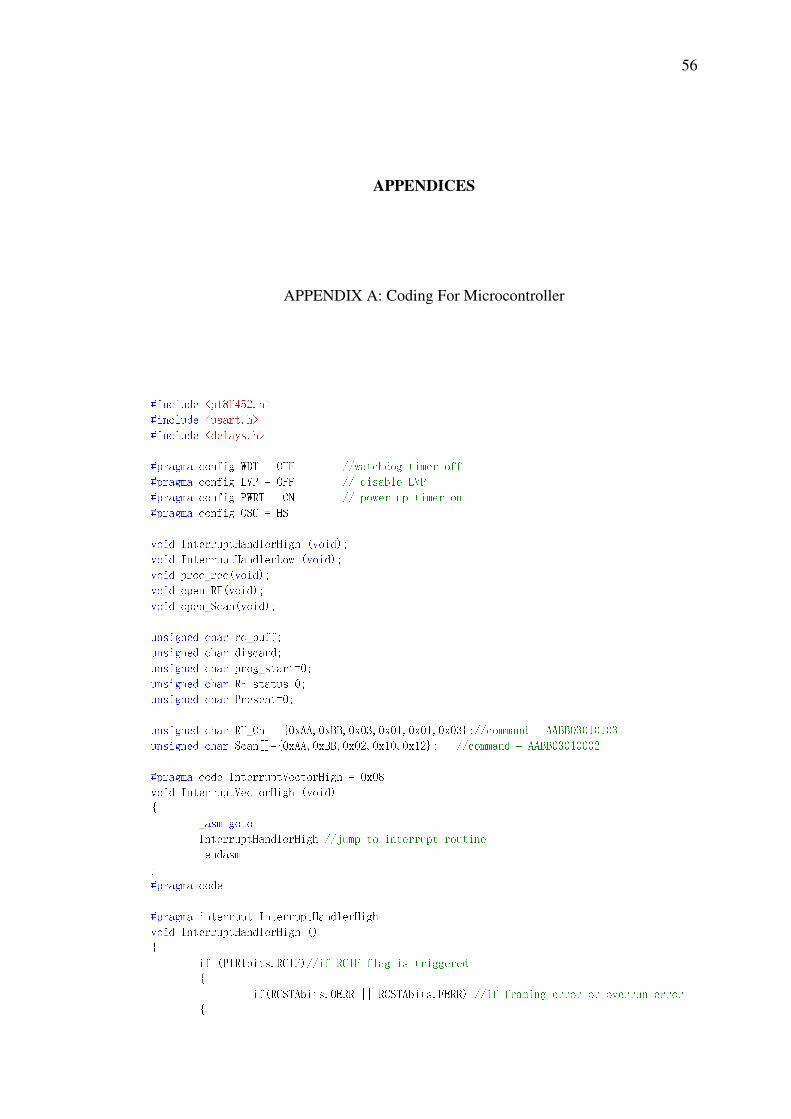
56
APPENDICES
APPENDIX A: Coding For Microcontroller
#include <p18F452.h> #include <usart.h> #include <delays.h> #pragma config WDT = OFF //watchdog timer off #pragma config LVP = OFF // disable LVP #pragma config PWRT = ON // power up timer on #pragma config OSC = HS void InterruptHandlerHigh (void); void InterruptHandlerLow (void); void proc_rec(void); void open_RF(void); void open_Scan(void); unsigned char rc_buff; unsigned char discard; unsigned char prog_start=0; unsigned char RF_status=0; unsigned char Present=0; unsigned char RF_On[]=0xAA,0xBB,0x03,0x01,0x01,0x03;//command = AABB03010103 unsigned char Scan[]=0xAA,0xBB,0x02,0x10,0x12; //command = AABB03010002 #pragma code InterruptVectorHigh = 0x08 void InterruptVectorHigh (void) _asm goto InterruptHandlerHigh //jump to interrupt routine _endasm #pragma code #pragma interrupt InterruptHandlerHigh void InterruptHandlerHigh () if (PIR1bits.RCIF)//if RCIF flag is triggered if(RCSTAbits.OERR || RCSTAbits.FERR) //if framing error or overrun error

57 RCSTAbits.CREN = 0; //reset continuouse receive to fix overrun error rc_buff=ReadUSART(); //read RCREG to fix framing error RCSTAbits.CREN = 1; else //if no error then read and store the data normally rc_buff=ReadUSART(); proc_rec();//process rec_buff data PIR1bits.RCIF=0;//reset the RCIF flag after read void main(void) unsigned char data[]; int i; //initialize the microcontroller input and output setting TRISB = 0x02; PORTBbits.RB0=0; PORTBbits.RB2=0; PORTBbits.RB3=0; PORTBbits.RB4=0; INTCONbits.RBIF = 0; //make sure the RBIF is reset at start // Configure USART OpenUSART( USART_TX_INT_OFF & USART_RX_INT_ON & USART_ASYNCH_MODE & USART_EIGHT_BIT & USART_CONT_RX & USART_BRGH_LOW,7 ); RCONbits.IPEN = 1; //Enable interrupt priority INTCONbits.GIEH = 1; //Enable all high priority interrupts //Setting up the UART receive interrupt flag IPR1bits.RCIP = 1; //Make receive interrupt high priority INTCONbits.PEIE = 1; //Enables all peripheral interrupts PORTBbits.RB5=1; //on PORTB RB5 to indicate system is power up while(1) switch (PORTBbits.RB1) //check for sensor signal input case 1: Present=1;//if sensor triggered, set present=1 PORTBbits.RB4=1;//light up the motion present LED break; case 0: Present=0;//if sensor is not triggered,set present=0

58 PORTBbits.RB4=0; //turn off motion present LED RF_status=0;//set RF_Status=0 break; if (prog_start==1 && Present==1)//Detemine is program_Start and Present is equal 1 PORTBbits.RB0=1; //on supply to the module while(!RF_status) //do while RF_status=0 open_RF(); //call sub function open_RF() open_Scan();//call sub function open_Scan() else PORTBbits.RB0=0;//off suppply to module switch (RF_status) //check RF_status case 1: PORTBbits.RB2=1; //light up RF on LED if equal 1 break; case 0: PORTBbits.RB2=0; //turn off RF on LED if equal 0 break; //CloseUSART(); void proc_rec(void)//check the rec_data range and content if (rc_buff>0x00 && rc_buff <=0x09)//check received data in range? switch (rc_buff) //check rc_buff content case 0x01: prog_start=1; //if rc_buff=0x01 then set prog_start=1 PORTBbits.RB3=1; break; case 0x02: prog_start=0; //if rc_buff=0x02 then set prog_start=0 PORTBbits.RB3=0; RF_status=0; //reset the RF_status memory break; case 0x03: RF_status=1; //set RF_status=1

59 void open_RF(void)//send the RF on command to module int i; for (i=0; i<= ((sizeof RF_On)-1); i++) while( BusyUSART() ); WriteUSART( RF_On[i]); Delay10KTCYx( 300 ); void open_Scan(void)//send the scan command to module int i; for (i=0; i<= ((sizeof Scan)-1); i++) while( BusyUSART() ); WriteUSART( Scan[i]); Delay10KTCYx( 300 );
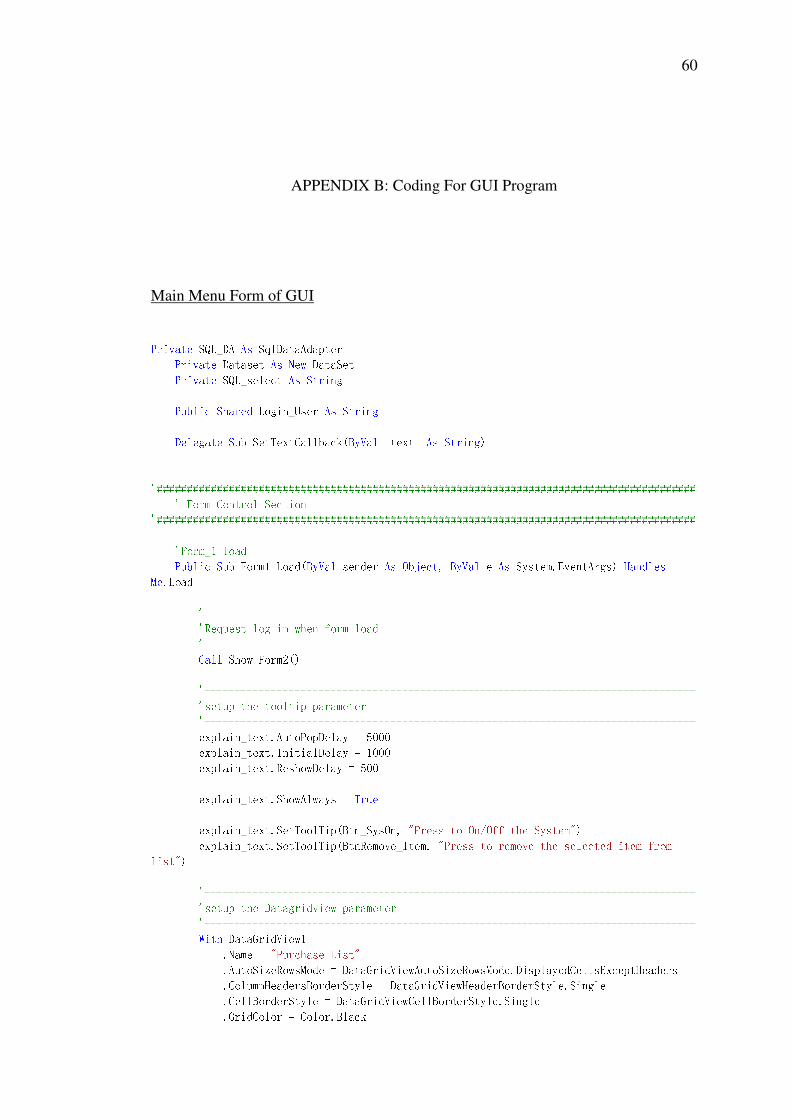
60
APPENDIX B: Coding For GUI Program
Main Menu Form of GUI
Private SQL_DA As SqlDataAdapter Private Dataset As New DataSet Private SQL_select As String Public Shared Login_User As String Delegate Sub SetTextCallback(ByVal [text] As String) '########################################################################################## ' Form Control Section '########################################################################################## 'Form_1 load Public Sub Form1_Load(ByVal sender As Object, ByVal e As System.EventArgs) Handles Me.Load '---------------------------------------------------------------------------------- 'Request log in when form load '---------------------------------------------------------------------------------- Call Show_Form2() '---------------------------------------------------------------------------------- 'setup the tooltip parameter '---------------------------------------------------------------------------------- explain_text.AutoPopDelay = 5000 explain_text.InitialDelay = 1000 explain_text.ReshowDelay = 500 explain_text.ShowAlways = True explain_text.SetToolTip(Btn_SysOn, "Press to On/Off the System") explain_text.SetToolTip(BtnRemove_Item, "Press to remove the selected item from list") '---------------------------------------------------------------------------------- 'setup the Datagridview parameter '---------------------------------------------------------------------------------- With DataGridView1 .Name = "Purchase List" .AutoSizeRowsMode = DataGridViewAutoSizeRowsMode.DisplayedCellsExceptHeaders .ColumnHeadersBorderStyle = DataGridViewHeaderBorderStyle.Single .CellBorderStyle = DataGridViewCellBorderStyle.Single .GridColor = Color.Black
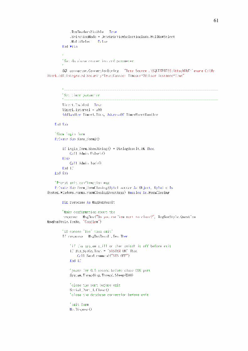
61 .RowHeadersVisible = True .SelectionMode = DataGridViewSelectionMode.FullRowSelect .MultiSelect = False End With '---------------------------------------------------------------------------------- 'Set database connection and parameter '---------------------------------------------------------------------------------- SQL_connector.ConnectionString = "Data Source=.\SQLEXPRESS;AttachDbFilename=C:\My Stock.mdf;Integrated Security=True;Connect Timeout=30;User Instance=True" '---------------------------------------------------------------------------------- 'Set timer parameter '---------------------------------------------------------------------------------- Timer1.Enabled = True Timer1.Interval = 500 AddHandler Timer1.Tick, AddressOf TimerEventHandler End Sub 'Show login form Private Sub Show_Form2() If Login_form.ShowDialog() = DialogResult.OK Then Call Admin_Unlock() Else Call Admin_lock() End If End Sub 'Prompt exit confirmation msg Private Sub Form_FormClosing(ByVal sender As Object, ByVal e As System.Windows.Forms.FormClosingEventArgs) Handles Me.FormClosing Dim response As MsgBoxResult 'Make confirmation about the response = MsgBox("Do you confirm want to close?", MsgBoxStyle.Question + MsgBoxStyle.YesNo, "Confirm") 'if choose "Yes" then exit" If response = MsgBoxResult.Yes Then 'if the system still on then switch it off before exit If Btn_SysOn.Text = "SYSTEM ON" Then Call Send_command("SYS_OFF") End If 'pause for 0.5 second before close COM port System.Threading.Thread.Sleep(500) 'close the port before exit Serial_Port_1.Close() 'close the database connection before exit 'exit form Me.Dispose()

62 'if choose "No" then cancel" ElseIf response = MsgBoxResult.No Then e.Cancel = True Exit Sub End If End Sub '<System on/off> button Private Sub Btn_SysOn_Click_1(ByVal sender As System.Object, ByVal e As System.EventArgs) Handles Btn_SysOn.Click 'call to control the RF on/off sub function If Btn_SysOn.Text = "SYSTEM ON" Then 'clear the seriel port input and output buffer before close the system If detect Then Serial_Port_1.DiscardInBuffer() Serial_Port_1.DiscardOutBuffer() End If Call Send_command("SYS_OFF") Btn_SysOn.Text = "SYSTEM OFF" Else Call Send_command("SYS_ON") Btn_SysOn.Text = "SYSTEM ON" End If End Sub '<Delete Item> button Private Sub BtnRemove_Item_Click_1(ByVal sender As System.Object, ByVal e As System.EventArgs) Handles BtnRemove_Item.Click If DataGridView1.Rows.Count <> 0 Then Dim RowToDelete As Integer = DataGridView1.Rows.GetFirstRow(DataGridViewElementStates.Selected) Total_Price = Total_Price - CDbl(Val(DataGridView1.Rows(RowToDelete).Cells(2).Value)) Update_textbox3(Format(Total_Price, "0.00")) If RowToDelete > -1 Then DataGridView1.Rows.RemoveAt(RowToDelete) End If Else Exit Sub End If End Sub '<Show stock status> button Private Sub Btn_ViewStock_Click_1(ByVal sender As System.Object, ByVal e As System.EventArgs) Handles Btn_ViewStock.Click ViewStock_form.ShowDialog() End Sub
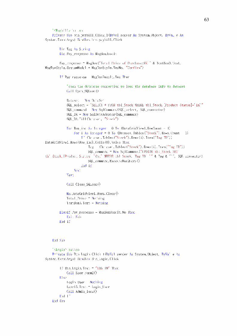
63 '<Paybill> button Private Sub btn_paybill_Click_1(ByVal sender As System.Object, ByVal e As System.EventArgs) Handles btn_paybill.Click Dim Tag As String Dim Pay_response As MsgBoxResult Pay_response = MsgBox("Total Price of Purchase:RM " & TextBox3.Text, MsgBoxStyle.SystemModal + MsgBoxStyle.YesNo, "Confirm") If Pay_response = MsgBoxResult.Yes Then 'open the database connection to load the database info to dataset Call Open_SQLcon() Dataset = New DataSet SQL_select = "SELECT * FROM tbl_Stock WHERE tbl_Stock.[Product Status]='In'" SQL_command = New SqlCommand(SQL_select, SQL_connector) SQL_DA = New SqlDataAdapter(SQL_command) SQL_DA.Fill(Dataset, "Stock") For Row_inc As Integer = 0 To (DataGridView1.RowCount - 1) For i As Integer = 0 To (Dataset.Tables("Stock").Rows.Count - 1) If (Dataset.Tables("Stock").Rows(i).Item("Tag ID")) = DataGridView1.Rows(Row_inc).Cells(0).Value Then Tag = (Dataset.Tables("Stock").Rows(i).Item("Tag ID")) SQL_command = New SqlCommand("UPDATE tbl_Stock SET tbl_Stock.[Product Status]='Out' WHERE tbl_Stock.[Tag ID]='" & Tag & "'", SQL_connector) SQL_command.ExecuteNonQuery() End If Next Next Call Close_SQLcon() Me.DataGridView1.Rows.Clear() Total_Price = Nothing TextBox3.Text = Nothing ElseIf Pay_response = MsgBoxResult.No Then Exit Sub End If End Sub '<Login> button Private Sub Btn_Login_Click_1(ByVal sender As System.Object, ByVal e As System.EventArgs) Handles Btn_Login.Click If Btn_Login.Text = "LOG IN" Then Call Show_Form2() Else Login_User = Nothing Label5.Text = Login_User Call Admin_lock() End If End Sub

64 '<Add login> button Private Sub btn_Adduser_Click(ByVal sender As System.Object, ByVal e As System.EventArgs) Handles btn_Adduser.Click AddLogin_form.ShowDialog() End Sub '#UPDATE# textbox 1 Private Sub Update_textbox1(ByVal [text] As String) If TextBox1.InvokeRequired Then Dim Temp As New SetTextCallback(AddressOf Update_textbox1) Invoke(Temp, New Object() [text]) Else TextBox1.Text = [text] End If End Sub '#UPDATE# textbox 2 Private Sub Update_textbox2(ByVal [text] As String) If TextBox2.InvokeRequired Then Dim Temp As New SetTextCallback(AddressOf Update_textbox2) Invoke(Temp, New Object() [text]) Else TextBox2.Text = [text] End If End Sub '#UPDATE# textbox 3 Private Sub Update_textbox3(ByVal [text] As String) If TextBox3.InvokeRequired Then Dim Temp As New SetTextCallback(AddressOf Update_textbox2) Invoke(Temp, New Object() [text]) Else TextBox3.Text = [text] End If End Sub '#UPDATE# Datagrid row num Private Sub Auto_Row_Numbering(ByVal sender As System.Object, ByVal e As System.EventArgs) Handles DataGridView1.RowsAdded, DataGridView1.RowsRemoved Dim RowNumber As Integer = 1 For Each Row As DataGridViewRow In DataGridView1.Rows If Row.IsNewRow Then Continue For Row.HeaderCell.Value = RowNumber.ToString RowNumber = RowNumber + 1 Next End Sub 'Match the detected tag id with database and display datagridview Private Sub Match_Display(ByVal Receive_ID As String) Call Open_SQLcon() 'open the database connection to load the database info to dataset Dataset = New DataSet SQL_select = "SELECT * FROM tbl_Stock WHERE tbl_Stock.[Product Status]='In'" SQL_command = New SqlCommand(SQL_select, SQL_connector)

65 SQL_DA = New SqlDataAdapter(SQL_command) SQL_DA.Fill(Dataset, "Stock") Call Close_SQLcon() 'scan through the ID colunm to check the match ID For Row_Inc = 0 To ((Dataset.Tables("Stock").Rows.Count) - 1) If Receive_ID = (Dataset.Tables("Stock").Rows(Row_Inc).Item("Tag ID")) Then 'if the item already in the list then exit sub without add the item in list For i As Integer = 0 To (DataGridView1.RowCount - 1) If Receive_ID = DataGridView1.Rows(i).Cells(0).Value Then Exit Sub End If Next If DataGridView1.InvokeRequired Then Dim Temp As New SetTextCallback(AddressOf Match_Display) Invoke(Temp, New Object() Receive_ID) Else DataGridView1.Rows.Add(Dataset.Tables("Stock").Rows(Row_Inc).Item("Tag ID"), _ Dataset.Tables("Stock").Rows(Row_Inc).Item("Product Name"), _ Dataset.Tables("Stock").Rows(Row_Inc).Item("Product Price")) Total_Price = Total_Price + CDbl(Val(Dataset.Tables("Stock").Rows(Row_Inc).Item("Product Price"))) Call Beep() Update_textbox3(Format(Total_Price, "0.00")) End If End If Next Row_Inc End Sub 'lock control if no device connected Private Sub Offline_Lock() 'lock all other button other than those in initialize setting, except <Check Connectivity> Btn_SysOn.Text = "SYSTEM OFF" Btn_SysOn.Enabled = False End Sub 'unlock control if device connected Private Sub Offline_Unlock() If Login_status = True Then Btn_SysOn.Enabled = True End If End Sub 'lock certain control if no admind login Private Sub Admin_Unlock() Btn_Login.Text = "LOG OUT" Login_status = True Label5.Text = Login_User
66 If detect = True Then Btn_SysOn.Enabled = True End If BtnRemove_Item.Enabled = True Btn_ViewStock.Enabled = True btn_Adduser.Enabled = True End Sub 'unlock control if admind login Private Sub Admin_lock() Btn_Login.Text = "LOG IN" Login_status = False Btn_SysOn.Enabled = False BtnRemove_Item.Enabled = False Btn_ViewStock.Enabled = False btn_Adduser.Enabled = False End Sub 'check for device connectivity Private Sub Connectivity_Checker() Dim ports_detect As String() = SerialPort.GetPortNames() Dim port As String 'Check the available port detected for "COM10" For Each port In ports_detect If port = "COM10" Then detect = True Exit For Else detect = False End If Next port 'selection case for detect variable Select Case detect Case True 'make sure the port is really close If Serial_Port_1.IsOpen = False Then Try With Serial_Port_1 .PortName = "COM10" 'Portname call "COM10" .BaudRate = 19200 'Baudrate is 19200 .DataBits = 8 'Databit is 8bits .StopBits = StopBits.One 'Stopbit is one .Parity = Parity.None 'No parity .ReadTimeout = 300 'Data read timeout is 300ms End With Serial_Port_1.Open() Catch ex As Exception MsgBox(ex.Message) End Try End If

67 Label2.Text = "Connected" Call Offline_Unlock() Case False Label2.Text = "Disconnected" Call Offline_Lock() Case Else MsgBox("Error in detect variable") End Select End Sub 'Translate the string commnad to hex string command array Public Function command_translate(ByVal command As String) Dim hex_command As String Select Case command Case "SYS_ON" 'if command is "SYS_ON", set the hex_command to 01 hex_command = "01" Case "SYS_OFF" 'if command is "SYS_OFF", set the hex_command to 02 hex_command = "02" Case "RF_SUCCESS" 'if command is "RF_SUCCESS" , set the hex_command to 03 hex_command = "03" Case Else hex_command = Nothing End Select Return hex_command End Function 'Decode feedback signal and take feedback action Public Sub Decode_feedback(ByVal Feedback As String) Select Case Feedback Case "AABB03010002" Call Send_command("RF_SUCCESS") Case "AABB0301FF02" MsgBox("Fail to control RF") Case Else Exit Sub End Select End Sub 'Check for feedback signal format Public Function Format_Checker(ByVal return_code As String) Dim Char_Counter As Integer Dim Char_Array() As Char Dim Feeback_Header As String = Nothing Char_Array = return_code.ToCharArray

68 'Iterate through the string. If return_code.Length >= 4 Then For Char_Counter = 0 To 3 Feeback_Header = Feeback_Header + Char_Array(Char_Counter) Next End If If Feeback_Header = "AABB" Then Return True Else Return False End If End Function '########################################################################################## 'Serial port control section '########################################################################################## 'Send command signal through COM10 Public Sub Send_command(ByVal command As String) Dim transmit_buffer() As Byte Hex_command = command_translate(command) 'if command corrupt then ignore the command If Hex_command = Nothing Then Exit Sub Else transmit_buffer = convert_byte(Hex_command) End If If Serial_Port_1.IsOpen Then Try 'Write this data to port Serial_Port_1.Write(transmit_buffer, 0, transmit_buffer.Length) Catch ex As Exception MsgBox(ex.Message) End Try Else MsgBox("The system connection is lose") End If End Sub 'Convert the Hex command to byte Private Function convert_byte(ByVal Hex_char As String) 'remove any spaces from the string Hex_char = Hex_char.Replace(" ", "") If Hex_char.Length Mod 2 <> 0 Then Hex_char = "0" + Hex_char End If 'create a byte array the length of the divided by 2 (Hex is 2 characters in length)
69 Dim combuffer As Byte() = New Byte(Hex_char.Length / 2 - 1) For i As Integer = 0 To Hex_char.Length - 1 Step 2 Try 'convert the hex character to byte and store in combuffer combuffer(i / 2) = CByte(Convert.ToByte(Hex_char.Substring(i, 2), 16)) Catch ex As Exception MsgBox(ex.Message) End Try Next Convert_status = True '--------------------------------------------------------------------------- 'check for the convertion accuracy '--------------------------------------------------------------------------- Dim x As String = "" For i = 0 To (combuffer.Length - 1) x = x + combuffer(i).ToString If i <> (combuffer.Length - 1) And x <> "" Then x = x + ", " End If Next Try Update_textbox1(x) Catch ex As Exception MsgBox("display fail") End Try '------------------------------------------------------------------------- 'return the combuffer array Return combuffer End Function 'Convert the byte array back to Hex string Private Function convert_hex(ByVal Hex_byte As Byte()) Dim hex_char As String = "" For Each byte_data As Byte In Hex_byte Dim Temp_store As String = Convert.ToString(byte_data, 16) If Temp_store.Length = 1 Then Temp_store = "0" + Temp_store End If hex_char = hex_char + Temp_store Next Return hex_char.ToUpper End Function
70 'Trigger this function when the COM10 seriel port receive any data Public Sub Receiver(ByVal sender As Object, ByVal e As SerialDataReceivedEventArgs) Handles Serial_Port_1.DataReceived Dim read_byte As Integer = 11 Dim receive_buffer As Byte() = New Byte(read_byte - 1) Dim return_hex_code As String = "" Dim Format_Identify As Boolean = Nothing Dim Tag_ID As String = Nothing Dim Return_Comm As String Try Serial_Port_1.Read(receive_buffer, 0, read_byte) System.Threading.Thread.Sleep(100) Catch ex As Exception MsgBox(ex.Message) End Try 'convert the receive data from byte to ASCII hex return_hex_code = convert_hex(receive_buffer) 'check for the return_hex_code header Format_Identify = Format_Checker(return_hex_code) If Format_Identify = True Then Return_Comm = return_hex_code.Substring(6, 2) Select Case (Return_Comm) Case "01" return_hex_code = return_hex_code.Substring(0, 12) Try Call Decode_feedback(return_hex_code) Catch ex As Exception MsgBox(ex.Message) End Try Case "10" Tag_ID = return_hex_code.Substring(10, 8) Call Match_Display(Tag_ID) End Select End If End Sub 'Trigger this function to check connection status every time the timer1 is tick Private Sub TimerEventHandler(ByVal obj As Object, ByVal ergs As EventArgs) Call Connectivity_Checker() End Sub Private Sub Open_SQLcon() If SQL_connector.State = ConnectionState.Closed Then SQL_connector.Open() End If
71 End Sub Private Sub Close_SQLcon() If SQL_connector.State = ConnectionState.Open Then SQL_connector.Close() End If End Sub Private Sub Panel1_Paint(ByVal sender As System.Object, ByVal e As System.Windows.Forms.PaintEventArgs) Handles Panel1.Paint End Sub End Class
User Login Form
Imports System.Data.SqlClient Public Class Form2 Private SQL_connector As New SqlConnection Private SQL_command As New SqlCommand Private SQL_DA As SqlDataAdapter Private Dataset As New DataSet Private SQL_select As String Private Ref_pass As String = Nothing Private Max_row As Integer 'Form_2 load Private Sub Form2_Load(ByVal sender As System.Object, ByVal e As System.EventArgs) Handles MyBase.Load 'TODO: This line of code loads data into the 'My_StockDataSet.tbl_Admin' table. You can move, or remove it, as needed. Me.Tbl_AdminTableAdapter.Fill(Me.My_StockDataSet.tbl_Admin) '---------------------------------------------------------------------------------- 'Bind the database admin ID to combo box '---------------------------------------------------------------------------------- 'TODO: This line of code loads data into the 'My_StockDataSet.tbl_Admin' table. You can move, or remove it, as needed. Me.Tbl_AdminTableAdapter.Fill(Me.My_StockDataSet.tbl_Admin) '---------------------------------------------------------------------------------- 'Set database connection and parameter '---------------------------------------------------------------------------------- SQL_connector.ConnectionString = "Data Source=.\SQLEXPRESS;AttachDbFilename=C:\My Stock.mdf;Integrated Security=True;Connect Timeout=30;User Instance=True" SQL_connector.Open()

72 'open the database connection to load the database info to dataset Dataset = New DataSet SQL_select = "SELECT * FROM tbl_Admin" SQL_command = New SqlCommand(SQL_select, SQL_connector) SQL_DA = New SqlDataAdapter(SQL_command) SQL_DA.Fill(Dataset, "ID") SQL_connector.Close() '---------------------------------------------------------------------------------- 'Initialize set up '---------------------------------------------------------------------------------- Call Clear_txb() Ref_pass = Nothing cbx_ID.Text = Nothing Max_row = Dataset.Tables("ID").Rows.Count End Sub '<ok> button click Private Sub btn_ok_Click(ByVal sender As System.Object, ByVal e As System.EventArgs) Handles btn_ok.Click If tbx_pass.Text = Nothing Or cbx_ID.Text = Nothing Then MsgBox("Please key in the password to log in!!!") Exit Sub Else If tbx_pass.Text = Ref_pass Then Form1.Login_User = cbx_ID.Text Call Clear_txb() Me.DialogResult = DialogResult.OK Else MsgBox("Incorrect password!!!") Call Clear_txb() Exit Sub End If End If End Sub '<Cancel> button click Private Sub btn_Cancel_Click(ByVal sender As System.Object, ByVal e As System.EventArgs) Handles btn_Cancel.Click Me.DialogResult = DialogResult.Cancel End Sub 'clear text box Private Sub Clear_txb() Me.tbx_pass.Text = Nothing End Sub 'Trigger when item is selected from combo box Private Sub cbx_ID_SelectedIndexChanged(ByVal sender As System.Object, ByVal e As System.EventArgs) Handles cbx_ID.SelectedIndexChanged Dim Row_count As Integer
73 If Max_row = 1 Then Ref_pass = (Dataset.Tables("ID").Rows(0).Item("Password")).ToString Else For Row_count = 0 To (Max_row - 1) If cbx_ID.Text = (Dataset.Tables("ID").Rows(Row_count).Item("Admin_ID")) Then Ref_pass = (Dataset.Tables("ID").Rows(Row_count).Item("Password")).ToString End If Next End If End Sub End Class
View Stock Form
Imports System.Data.SqlClient Public Class Form3 Private SQL_connector As New SqlConnection Private SQL_command As New SqlCommand Private SQL_DA As SqlDataAdapter Private Dataset As New DataSet Private SQL_select As String 'Form_3 load Private Sub Form3_Load(ByVal sender As System.Object, ByVal e As System.EventArgs) Handles MyBase.Load '---------------------------------------------------------------------------------- 'setup the Datagridview parameter '---------------------------------------------------------------------------------- With Me.DataGridView1 .Name = "Stock List" .AutoSizeRowsMode = DataGridViewAutoSizeRowsMode.DisplayedCellsExceptHeaders .ColumnHeadersBorderStyle = DataGridViewHeaderBorderStyle.Single .CellBorderStyle = DataGridViewCellBorderStyle.Single .GridColor = Color.Black .SelectionMode = False .MultiSelect = False .Rows.Clear() End With '---------------------------------------------------------------------------------- 'Set database connection and parameter '---------------------------------------------------------------------------------- SQL_connector.ConnectionString = "Data Source=.\SQLEXPRESS;AttachDbFilename=C:\My Stock.mdf;Integrated Security=True;Connect Timeout=30;User Instance=True"

74 '---------------------------------------------------------------------------------- 'Load the in stock item list when first load the form '---------------------------------------------------------------------------------- Call Show_Stock() End Sub '<Keep Stock> button click Private Sub btn_Keepstock_Click_1(ByVal sender As System.Object, ByVal e As System.EventArgs) Handles btn_Keepstock.Click Me.DataGridView1.Rows.Clear() Call Show_Stock() End Sub '<Check Out> button click Private Sub btn_COStock_Click_1(ByVal sender As System.Object, ByVal e As System.EventArgs) Handles btn_COStock.Click Me.DataGridView1.Rows.Clear() Call Check_Out() End Sub '<Exit>button click Private Sub btn_exit_Click_1(ByVal sender As System.Object, ByVal e As System.EventArgs) Handles btn_exit.Click Me.DialogResult = DialogResult.Cancel End Sub 'Show keep_stock to datagrid Private Sub Show_Stock() SQL_connector.Open() 'open the database connection to load the database info to dataset Dataset = New DataSet SQL_select = "SELECT * FROM tbl_Stock WHERE tbl_Stock.[Product Status]='In'" SQL_command = New SqlCommand(SQL_select, SQL_connector) SQL_DA = New SqlDataAdapter(SQL_command) SQL_DA.Fill(Dataset, "Stock") For Row_count = 0 To ((Dataset.Tables("Stock").Rows.Count) - 1) Me.DataGridView1.Rows.Add(Dataset.Tables("Stock").Rows(Row_count).Item("Tag ID"), _ Dataset.Tables("Stock").Rows(Row_count).Item("Product Name"), _ Dataset.Tables("Stock").Rows(Row_count).Item("Product Price"), _ Dataset.Tables("Stock").Rows(Row_count).Item("Product Status")) Next SQL_connector.Close() End Sub ''Show Checkout_stock to datagrid Private Sub Check_Out() SQL_connector.Open() 'open the database connection to load the database info to dataset Dataset = New DataSet SQL_select = "SELECT * FROM tbl_Stock WHERE tbl_Stock.[Product Status]='Out'" SQL_command = New SqlCommand(SQL_select, SQL_connector) SQL_DA = New SqlDataAdapter(SQL_command)
75 SQL_DA.Fill(Dataset, "Stock") For Row_count = 0 To ((Dataset.Tables("Stock").Rows.Count) - 1) Me.DataGridView1.Rows.Add(Dataset.Tables("Stock").Rows(Row_count).Item("Tag ID"), _ Dataset.Tables("Stock").Rows(Row_count).Item("Product Name"), _ Dataset.Tables("Stock").Rows(Row_count).Item("Product Price"), _ Dataset.Tables("Stock").Rows(Row_count).Item("Product Status")) Next SQL_connector.Close() End Sub End Class Add/Remove Access User Form
Imports System.Data.SqlClient Public Class Form4 Private SQL_connector As New SqlConnection Private SQL_command As New SqlCommand Private SQL_DA As SqlDataAdapter Private Dataset As New DataSet Private SQL_select As String Private Selected_ID As String Private Master_pass As String = "1234" Private Sub Form4_Load(ByVal sender As System.Object, ByVal e As System.EventArgs) Handles MyBase.Load 'TODO: This line of code loads data into the 'My_StockDataSet.tbl_Admin' table. You can move, or remove it, as needed. Me.Tbl_AdminTableAdapter.Fill(Me.My_StockDataSet.tbl_Admin) pnl_addID.Visible = True pnl_RomoveID.Visible = False SQL_connector.ConnectionString = "Data Source=.\SQLEXPRESS;AttachDbFilename=C:\My Stock.mdf;Integrated Security=True;Connect Timeout=30;User Instance=True" cbx_f4_adminID.Text = Nothing End Sub '<ADD NEW ID> button click Private Sub btn_addID_Click_1(ByVal sender As System.Object, ByVal e As System.EventArgs) Handles btn_addID.Click If pnl_addID.Visible = False Then pnl_RomoveID.Visible = False pnl_addID.Visible = True End If
76 End Sub '<DELETE ID> button click Private Sub btn_delID_Click_1(ByVal sender As System.Object, ByVal e As System.EventArgs) Handles btn_delID.Click If pnl_RomoveID.Visible = False Then pnl_addID.Visible = False pnl_RomoveID.Visible = True End If End Sub '<EXIT> button click Private Sub btn_f4_exit_Click(ByVal sender As System.Object, ByVal e As System.EventArgs) Handles btn_f4_exit.Click Me.DialogResult = DialogResult.Cancel End Sub '<REMOVE-CONFIRM> button click Private Sub btn_f4_rom_ok_Click(ByVal sender As System.Object, ByVal e As System.EventArgs) Handles btn_f4_rom_ok.Click If Selected_ID = Form1.Login_User Then MsgBox("The Admin user is currently in use, please log in with other user to proceed!!") Exit Sub End If If Selected_ID = Nothing Then MsgBox("ERROR!!") Exit Sub End If If tbx_masterID.Text = Master_pass Then Dim Confirmation_msg As MsgBoxResult Confirmation_msg = MsgBox("Do you confirm want delete the user?", MsgBoxStyle.Question + MsgBoxStyle.YesNo, "Confirm") If Confirmation_msg = MsgBoxResult.Yes Then SQL_connector.Open() Dataset = New DataSet SQL_select = "SELECT * FROM tbl_Admin" SQL_command = New SqlCommand(SQL_select, SQL_connector) SQL_DA = New SqlDataAdapter(SQL_command) SQL_DA.Fill(Dataset, "ID") If (Dataset.Tables("ID").Rows.Count) = 1 Then MsgBox("This is the last user ID, cannot be romoved") Exit Sub Else For i As Integer = 0 To ((Dataset.Tables("ID").Rows.Count) - 1) If (Dataset.Tables("ID").Rows(i).Item("Admin_ID")) = Selected_ID Then SQL_command = New SqlCommand("DELETE FROM tbl_Admin WHERE tbl_Admin.[Admin_ID]='" & Selected_ID & "'", SQL_connector) SQL_command.ExecuteNonQuery()
77 MsgBox("The user is succesfully removed") End If Next SQL_connector.Close() Call Clear_MP() End If ElseIf Confirmation_msg = MsgBoxResult.No Then Call Clear_MP() Exit Sub End If Else MsgBox("Please input the correct Master password!!") Call Clear_MP() Exit Sub End If End Sub '<REMOVE-CANCEL> button click Private Sub Button3_Click(ByVal sender As System.Object, ByVal e As System.EventArgs) Handles Button3.Click Call Clear_MP() End Sub '<ADD-CONFIRM> button click Private Sub btn_f4_add_ok_Click(ByVal sender As System.Object, ByVal e As System.EventArgs) Handles btn_f4_add_ok.Click Dim Admin_ID As String = tbx_AdminID.Text Dim password As String = tbx_pass.Text If Check_Fill Then SQL_connector.Open() SQL_command = New SqlCommand("INSERT INTO tbl_Admin (Admin_ID,Password) VALUES ('" & Admin_ID & "', '" & password & "')", SQL_connector) SQL_command.ExecuteNonQuery() SQL_connector.Close() MsgBox("New user is succesfully inserted into the record") Call Clear_Add_ALL() Else Call Clear_Add_ALL() Exit Sub End If End Sub '<ADD-CANCEL> button click Private Sub btn_f4_add_cancel_Click(ByVal sender As System.Object, ByVal e As System.EventArgs) Handles btn_f4_add_cancel.Click Call Clear_MP() End Sub

78 '@Triger@ whenever the admin id combobox selection change, the ID is load to the Selected_ID Private Sub cbx_f4_adminID_SelectedIndexChanged(ByVal sender As System.Object, ByVal e As System.EventArgs) Handles cbx_f4_adminID.SelectedIndexChanged Selected_ID = cbx_f4_adminID.Text End Sub '!CALL! to clear tbx_masterID text box Private Sub Clear_MP() tbx_masterID.Text = Nothing End Sub Private Sub Clear_Add_ALL() tbx_AdminID.Text = Nothing tbx_pass.Text = Nothing tbx_re_pass.Text = Nothing tbx_masterID_2.Text = Nothing End Sub Private Function Check_Fill() If tbx_AdminID.Text <> Nothing And tbx_pass.Text <> Nothing And tbx_re_pass.Text <> Nothing And tbx_masterID_2.Text = Master_pass <> Nothing Then If tbx_masterID_2.Text = Master_pass Then For Each Character As Char In tbx_AdminID.Text If Char.IsSymbol(Character) Then MsgBox("Incorrect Input!!!") Return False End If Next For Each Character As Char In tbx_pass.Text If Char.IsSymbol(Character) Or Char.IsWhiteSpace(Character) Then MsgBox("Incorrect Input!!!") Return False End If Next If tbx_pass.Text = tbx_re_pass.Text Then Return True Else MsgBox("Incorrect password confirm!!!") Return False End If Else MsgBox("Please fill in the Admin ID and Password!!!") Return False End If Else MsgBox("Please Key in the Master password!!!") Return False End If

79 End Function Private Sub Panel2_Paint(ByVal sender As System.Object, ByVal e As System.Windows.Forms.PaintEventArgs) Handles Panel2.Paint End Sub End Class