STUDENT ATTENDANCE SYSTEM USING RFID - UTPedia
67
STUDENT ATTENDANCE SYSTEM USING RFID By MUHAMMAD HAEKAL BIN MD HALED DISSERTATION Submitted to the Electrical & Electronics Engineering Programme in Partial Fulfillment of the Requirements for the Degree Bachelor of Engineering (Hons) (Electrical & Electronics Engineering) Universiti Teknologi Petronas Bandar Seri Iskandar 31750 Tronoh Perak Darul Ridzuan Copyright 2014 by Muhammad Haekal Bin Md Haed, 2014
-
Upload
khangminh22 -
Category
Documents
-
view
0 -
download
0
Transcript of STUDENT ATTENDANCE SYSTEM USING RFID - UTPedia

STUDENT ATTENDANCE SYSTEM
USING RFID
By
MUHAMMAD HAEKAL BIN MD HALED
DISSERTATION
Submitted to the Electrical & Electronics Engineering Programme
in Partial Fulfillment of the Requirements
for the Degree
Bachelor of Engineering (Hons)
(Electrical & Electronics Engineering)
Universiti Teknologi Petronas
Bandar Seri Iskandar
31750 Tronoh
Perak Darul Ridzuan
Copyright 2014
by
Muhammad Haekal Bin Md Haed, 2014

i
CERTIFICATION OF APPROVAL
STUDENT ATTENDANCE SYSTEM
USING RFID
by
Muhammad Haekal Bin Md Haled
A project dissertation submitted to the
Electrical & Electronics Engineering Programme
in partial fulfilment of the requirement for the
Bachelor of Engineering (Hons)
(Electrical & Electronics Engineering)
Approved:
__________________________
Mr. Abu Bakar Sayuti Bin Hj Mohd Saman
Project Supervisor
UNIVERSITI TEKNOLOGI PETRONAS
TRONOH, PERAK
May 2014

ii
CERTIFICATION OF ORIGINALITY
This is to certify that I am responsible for the work submitted in this project, that the
original work is my own except as specified in the references and
acknowledgements, and that the original work contained herein have not been
undertaken or done by unspecified sources or persons.
__________________________
Muhammad Haekal Bin Md Haled
iii
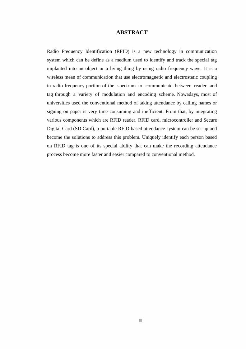
ABSTRACT
Radio Frequency Identification (RFID) is a new technology in communication
system which can be define as a medium used to identify and track the special tag
implanted into an object or a living thing by using radio frequency wave. It is a
wireless mean of communication that use electromagnetic and electrostatic coupling
in radio frequency portion of the spectrum to communicate between reader and
tag through a variety of modulation and encoding scheme. Nowadays, most of
universities used the conventional method of taking attendance by calling names or
signing on paper is very time consuming and inefficient. From that, by integrating
various components which are RFID reader, RFID card, microcontroller and Secure
Digital Card (SD Card), a portable RFID based attendance system can be set up and
become the solutions to address this problem. Uniquely identify each person based
on RFID tag is one of its special ability that can make the recording attendance
process become more faster and easier compared to conventional method.

iv
ACKNOWLEDGEMENT
In the name of Allah, the Most Beneficent, the Most Merciful, I would like to
express my gratitude to all person which contributes great experience and learning
opportunities in working on my Final Year Project. I would like to express my
deeply sincere gratitude and thank to my supervisor Mr. Abu Bakar Sayuti Bin Hj
Mohd Saman for aiding me through this whole project with excellent support.
Besides that, my appreciation goes to the Electrical & Electronic Engineering
Laboratory Technician, Mr. Musa for sharing some technical knowledge regarding
this project. Lastly, I also would like to thank my family member and friends for
assisting me technically or mentally when I am working on this project. A warmth
gratitude for everyone and may all the goodness and memories blessed by Allah.

v
TABLE OF CONTENT
CERTIFICATION OF APPROVAL ...................................................................................... i
CERTIFICATION OF ORIGINALITY ................................................................................ ii
ABSTRACT ............................................................................................................................. iii
ACKNOWLEDGEMENT ...................................................................................................... iv
TABLE OF CONTENT ........................................................................................................... v
LIST OF FIGURES ............................................................................................................... vii
LIST OF TABLES .................................................................................................................. ix
ABBREVIATION .................................................................................................................... x
CHAPTER 1: PROJECT BACKGROUND .......................................................................... 1
1.1 Backgroud Study ................................................................................................ 1
1.2 Problem Statement ............................................................................................. 1
1.3 Objectives ........................................................................................................... 1
1.4 Scope of Study .................................................................................................... 2
CHAPTER 2: LITERATURE REVIEW ............................................................................... 3
2.1 Radio Frequency Identification .......................................................................... 3
2.2 Embedded System .............................................................................................. 5
2.3 Storage On SD .................................................................................................... 7
CHAPTER 3: METHODOLOGY .......................................................................................... 8
3.1 Project Flow ....................................................................................................... 8
3.2 System Architecture ........................................................................................... 9
3.3 Key Milestones ................................................................................................. 13
3.4 Gantt Chart ....................................................................................................... 14
3.5 Tool & Software Required ............................................................................... 15
CHAPTER 4: RESULT AND DISCUSSION ...................................................................... 16
4.1 Module Testing ................................................................................................. 16

vi
4.2 Prototype Development .................................................................................... 19
4.3 Final Prototype Representation ........................................................................ 29
4.4 Problem Encountered ....................................................................................... 32
CHAPTER 5: CONCLUSION AND RECOMMENDATION .......................................... 33
REFERENCES ....................................................................................................................... 34
APPENDICES ........................................................................................................................... I
Appendix A ............................................................................................................... I
Appendix B ............................................................................................................ VII
Appendix C ............................................................................................................ XII
vii
LIST OF FIGURES
NO. TITLE PAGE
Figure 1: Detection and Storing Data Part 2
Figure 2: Uploading Data Part 2
Figure 3: A Schematic of Power and Data Flow in a UHF RFID System 4
Figure 4: Passive RFID System 5
Figure 5: Active RFID System 5
Figure 6: Embedded System Design Process 6
Figure 7: SPI BUS ( single master and single slave ) 7
Figure 8: Project Flow Chart 8
Figure 9: Basic Block Diagram of the system 10
Figure 10: Event-driven flow of the project 12
Figure 11: Arduino Mega and RFID shield 16
Figure 12: Serial monitor Display 16
Figure 13: Flow chart of RFID integration (coding) 16
Figure 14: Arduino Mega with MicroSD card shield 17
Figure 15: Serial Monitor Display for write task 17
Figure 16: Serial Monitor Display for list file 17
Figure 17: Flow chart of MicroSD card integration (coding) 17
Figure 18: Arduino Mega with 4x20 LCD 18
Figure 19: Schematic Diagram of LCD wiring 18
Figure 20: Flow chart of 4x20 LCD integration (coding) 18
Figure 21: Hardware Installation of Initial Prototype 19
Figure 22: Initial Flow Diagram of the System 21
Figure 23: Student’s Database Window 22
Figure 24: Serial Monitor Display before Swipping Milfare Card 22
viii
Figure 25: Serial Monitor Display after swipping milfare card of Initial Phase (ID
exist) 23
Figure 26: Serial Monitor Display after swipping milfare card of Initial Phase (ID
not exist) 23
Figure 27: Final Flow Diagram of the System 25
Figure 28: Serial Monitor Display before swipping mifare card of Final Phase 26
Figure 29: Serial Monitor Display after swipping mifare card of Final Phase (ID
exist) 27
Figure 30: Serial Monitor Display after swipping mifare card of Final Phase (ID not
exist) 27
Figure 31: Serial Monitor Display when swipping mifare card repeatedly 28
Figure 32: Serial Monitor Display after On/Off switch turn on 28
Figure 33: The Updated Database 29
Figure 34: Prototype Features 30
Figure 35: Schematic Diagram of the prototype 30
Figure 36: Swipping Registered Card 31
Figure 37: Swipping Registered Card Repeteadly 31
Figure 38: Swipping Unregistered Card 32

ix
LIST OF TABLES
NO. TITLE PAGE
Table 1: Basic Range of RFID 3
Table 2: Key Milestone of Final Year Project 1 13
Table 3: Key Milestone of Final Year Project 2 13
Table 4: Gantt Chart of Final Year Project 1 14
Table 5: Gantt Chart of Final Year Project 2 15
Table 6: Summary of Module Arrangement for Initial Phase 20
Table 7: Additional Module Arrangement in Final Phase 24

x
ABBREVIATION
The following abbreviations are used in this report:
RFID Radio Frequency Identification
UTP Universiti Teknologi Petronas
USB Universal Serial Bus
SD Secure Digital
UART Universal Asynchronous
Receiver/Transmitter
SRAM Static Random Acces Memory
LCD Liquid Cristal Display
IDE Integrated Development Environment
SPI Serial Peripheral Interface
SDO Serial Data Out/ Error
SDI Serial data in
SCK Serial Clock
CSN Chip Select Not
CPU Central Processing Unit
ASIC Application Specific Integrated Circuit
IC Integrated Circuit
FPGA Field Programmable Gate Array
UHF Ultra High Frequency
ISR Interrupt Service Routine
1
CHAPTER 1: PROJECT BACKGROUND
1.1 Backgroud Study
Recording the attendance of students using RFID cards requires a portable recording
device to be designed and built. Several components need to be integrated into a
robust portable device that can read the RFID cards and store key data on board
which can be transferred to a personal computer later. The RFID system have two
important features. First, the RFID card i.e the microchip having the capacity to store
information with authentication and second is RFID module for reading and writing
identity information from/to RFID card.
This portable device have a storage part which is Secure Digital (SD) card to store
the data that can be prevent the data from damage. Attendance can be recorded by
swiping student identification card onto a portable device that contain a
microcontroller equipped with Radio Frequency Identification (RFID) reader and
recorded into on-board memory. Then, the data will be transferred to a personal
computer either using a memory card or through Universal Serial Bus (USB) cable.
1.2 Problem Statement
Universiti Teknologi PETRONAS (UTP) is one of educational instituition that use
manual method in recording the attendance which is by writing name on paper.
Basically, recording of student attendance can be tedious and time consuming if done
manually, especially for large classes. There are a few latest technology that also
involve in recording students attendence such as bar code system and fingerprint
system but all of them are very high maintenance and costly. If a portable computer
assisted system with affordable cost is used, data can be recorded and stored
accurately, so that time consuming problem can be avoided.
1.3 Objectives
The objectives of the project are:
1. To design and build a portable RFID reader with data storage for the purpose
of recording students attendance.
2. To enable the communication between ATmega 2560 and a computer via
serial port Universal Asynchronous Receiver/Transmitter (UART)
2
RFID module
swipping
uploading
3. To build a device that can be implemented in UTP in order to improve
management system especially in recording student’s attendance.
1.4 Scope of Study
In this project, there are several limitations that involve which are duration time to
complete, the sources of knowledge and respondance contribution. A perfect
planning must be created to eliminate all the limitations. From that, the first
important step need to do is studying the fundamentals of RFID and embedded
system from any trusted sources such as published articles, journals, books and
conference papers. By doing that, deeper understanding especially in theory can be
gained and practical studies can be made.
In order to set up the device, embedded system is used and also can be called as
Hardware/Software Co-design. The main objective of the system is to uniquely
identify and to mark attendance for a students. This requires a distinct feature
having the capability of distinguishing different person uniquely. This is possible
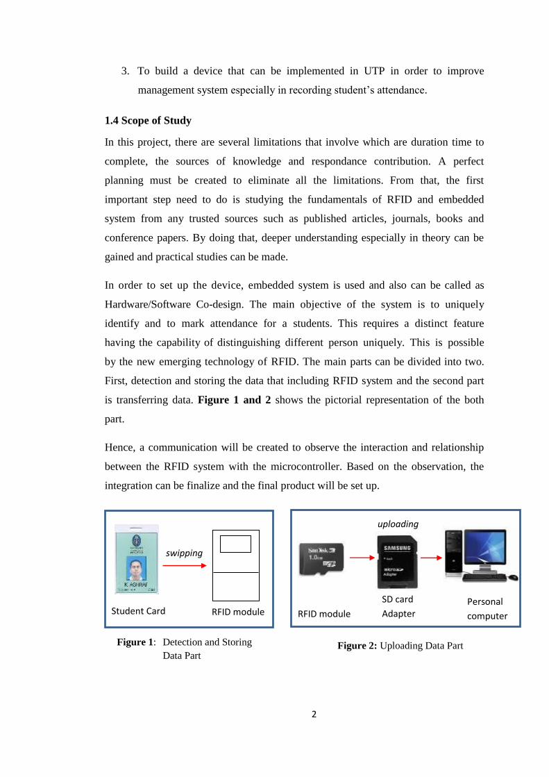
by the new emerging technology of RFID. The main parts can be divided into two.
First, detection and storing the data that including RFID system and the second part
is transferring data. Figure 1 and 2 shows the pictorial representation of the both
part.
Hence, a communication will be created to observe the interaction and relationship
between the RFID system with the microcontroller. Based on the observation, the
integration can be finalize and the final product will be set up.
Student Card RFID module SD card
Adapter Personal
computer
Figure 1: Detection and Storing
Data Part Figure 2: Uploading Data Part

3
CHAPTER 2: LITERATURE REVIEW
2.1 Radio Frequency Identification
In this world, there are a lot of methods can be used to transfer a data. One of them is
using radio frequency electromagnetic field. The famous tool that use this method is
Radio Frequency Identification (RFID). It is the wireless non-contact devices created
for the purpose of automatically identifying and tracking the information inside
programmable tags or card. The tags or card have an ability to read at a short range
via magnetic field that also call as electromagnetic induction. Then, it will act as a
passive transponder to emit microwaves or UHF radiowaves.
On the other hand, the limitation of other automatic identification approach which
are used light to communicate (infrared and bar codes technology) can be overcomes
from this technology. It is proven when the RFID tag or card are invisible to the eye
and can be used in dirty environment. Without labor-intensive manual scanning,
RFID readers can be set to remotely and automatically read [1]. Radio frequency of
this system can be categorised into four basic range and are given in Table 1 below:
Symbol Type of Frequency Range Uses
LF Low Frequency 30 kHz to
300 kHz
125 kHz
HF High Frequency 3 MHz to
30 MHz
13.56 MHz
VHF Very
High Frequency
30 MHz to
300 MHz
Not used for
RFID
UHF Ultra
High Frequency
300 MHz to 3 GHz 866 MHz, 915
MHz
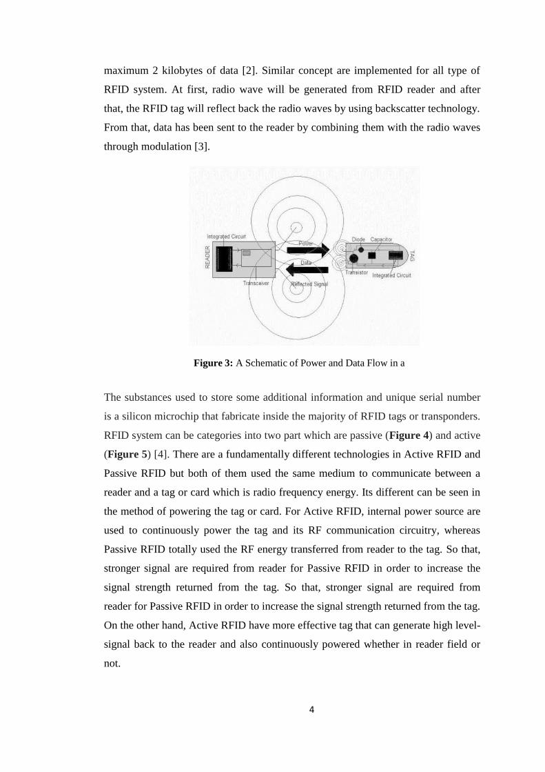
Basically, there are two components that involve in RFID system which are RFID
reader and RFID tags. The system contain a coil that act as antenna for transmitting
and receiving signal as shown in Figure 3. In the same time, the signal can store
Table 1: Basic range of RFID [1]
4
maximum 2 kilobytes of data [2]. Similar concept are implemented for all type of
RFID system. At first, radio wave will be generated from RFID reader and after
that, the RFID tag will reflect back the radio waves by using backscatter technology.
From that, data has been sent to the reader by combining them with the radio waves
through modulation [3].
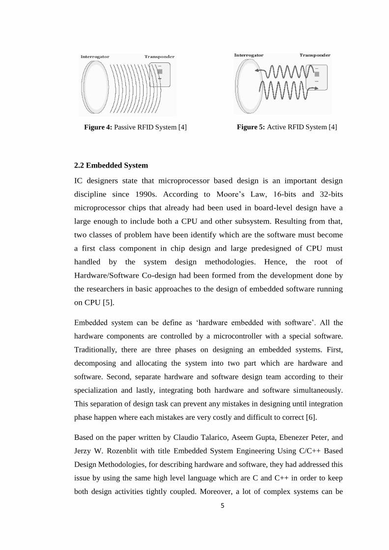
The substances used to store some additional information and unique serial number
is a silicon microchip that fabricate inside the majority of RFID tags or transponders.
RFID system can be categories into two part which are passive (Figure 4) and active
(Figure 5) [4]. There are a fundamentally different technologies in Active RFID and
Passive RFID but both of them used the same medium to communicate between a
reader and a tag or card which is radio frequency energy. Its different can be seen in
the method of powering the tag or card. For Active RFID, internal power source are
used to continuously power the tag and its RF communication circuitry, whereas
Passive RFID totally used the RF energy transferred from reader to the tag. So that,
stronger signal are required from reader for Passive RFID in order to increase the
signal strength returned from the tag. So that, stronger signal are required from
reader for Passive RFID in order to increase the signal strength returned from the tag.
On the other hand, Active RFID have more effective tag that can generate high level-
signal back to the reader and also continuously powered whether in reader field or
not.
Figure 3: A Schematic of Power and Data Flow in a
UHF RFID System.[4]
5
2.2 Embedded System
IC designers state that microprocessor based design is an important design
discipline since 1990s. According to Moore’s Law, 16-bits and 32-bits
microprocessor chips that already had been used in board-level design have a
large enough to include both a CPU and other subsystem. Resulting from that,
two classes of problem have been identify which are the software must become
a first class component in chip design and large predesigned of CPU must
handled by the system design methodologies. Hence, the root of
Hardware/Software Co-design had been formed from the development done by
the researchers in basic approaches to the design of embedded software running
on CPU [5].
Embedded system can be define as ‘hardware embedded with software’. All the
hardware components are controlled by a microcontroller with a special software.
Traditionally, there are three phases on designing an embedded systems. First,
decomposing and allocating the system into two part which are hardware and
software. Second, separate hardware and software design team according to their
specialization and lastly, integrating both hardware and software simultaneously.
This separation of design task can prevent any mistakes in designing until integration
phase happen where each mistakes are very costly and difficult to correct [6].
Based on the paper written by Claudio Talarico, Aseem Gupta, Ebenezer Peter, and
Jerzy W. Rozenblit with title Embedded System Engineering Using C/C++ Based
Design Methodologies, for describing hardware and software, they had addressed this
issue by using the same high level language which are C and C++ in order to keep
both design activities tightly coupled. Moreover, a lot of complex systems can be
Figure 4: Passive RFID System [4] Figure 5: Active RFID System [4]
6
built by using hardware/software co-design technique. In any co-design tool or
platform, the important thing need to do and sometimes called as primary task is
divided a given application specification between hardware (typically ASIC or
FPGA) and software (mapped to the CPU). From that, the application at hand blends
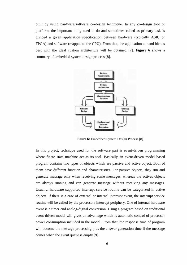
best with the ideal custom architecture will be obtained [7]. Figure 6 shows a
summary of embedded system design process [8].
In this project, technique used for the software part is event-driven programming
where finate state machine act as its tool. Basically, in event-driven model based
program contains two types of objects which are passive and active object. Both of
them have different function and characteristics. For passive objects, they run and
generate message only when receiving some messages, whereas the actives objects
are always running and can generate message without receiving any messages.
Usually, hardware supported interrupt service routine can be categorized in active
objects. If there is a case of external or internal interrupt event, the interrupt service
routine will be called by the processors interrupt periphery. One of internal hardware
event is a timer end analog-digital conversion. Using a program based on traditional
event-driven model will gives an advantage which is automatic control of processor
power consumption included in the model. From that, the response time of program
will become the message processing plus the answer generation time if the message
comes when the event queue is empty [9].
Figure 6: Embedded System Design Process [8]

7
2.3 Storage On SD
In data storage application, flash memory which is one of non-volatile devices are
most widely used today. Its abilities in fast accesing, multiple write characteristics,
low-power consumption and also compact are the reasons why this type of memory
have been chosen. Based on a comparison between flash memory and mechanical
magnetic or optical media was carried out by researcher in the past, flash memory is
much better because they do not have all of these desired features [10]. Besides, due
to its portable design, stored data in flash memory can be transferred to a personal
computer easily. It is also capable on storing sensitive data because of its security
features inherent in the SD card [11].
MicroSD is one of removable flash memory card with smallest size (about the size of
fingernail) that used for storing data. Its size also can be equated as quarter size of a
normal SD card and have a read/write speed between 3 to 5 MBps. In application,
transflash and microSD are in the same proceedings but microSD has support
Secured Digital Input Output (SDIO) mode. From that, non-memory card like near
field communication (NFC), bluetooth and Global Positioning System (GPS) devices
to use the card also.
Normally, Serial Peripheral Interface (SPI) is used by SD card as its communication
protocol with embedded microcontroller because it supports only a 3.3-volt interface
and also does not require a host license. This protocol communicate
in master/slave mode where the master initiates the data frame. The presence of
individual slave select lines can allowed the functioning of multiple slave devices.
Occasionally, four-wire serial bus, contrasting with three-, two-, and one-wire serial
bus also referred to SPI. There are a few numbers of standard SPI interface structure
used which are SDO (Serial Data Out/ Error), SDI (Serial data in), SCK (Serial
Clock) signal line and CSN (Chip Select Not) [12]. Figure 7 shows SPI bus with
single master and single slave.
Figure 7 : SPI BUS ( single master and single slave )
[12]

8
CHAPTER 3: METHODOLOGY
3.1 Project Flow
A specific approach of executing is required in this project like any other software
hardware integrated project. This approach emphasizes on step-by-step development
by finishing one step before advancing to the other until it reaches the final stages of
prototyping. Figure 8 shows the project flow chart.
1. Project Start: In this phase, the project title had confirmed and then
specify the problem statement work will be done. The
problem statement for this project is ‘How to create a
device that used RFID system to record student attendance
efficiently ?’
2. Research: After done the specifying problem statement, research on
the theory and concept from any trusted sources will be
made. Deeper understanding is very important to make
sure the project follow all the basic theory.
Figure 8: Project Flow Chart

9
3. Initial Design: There are several designs had listed down such as
RFID attendance design stick at the wall, RFID
attendance design using bluetooth and many more.
Then, the final design had decide which is portable
RFID attendance design that can store data and
using USB as a medium in transferring data to
personal computer.
4. Hardware Procurement: In this phase, the list of components used had
finalized. Then, all the components will be bought
from the manufacturer.
5. Hardware Integration: Hardware Integration can be divided into four part
which are integration between Arduino Mega with
RFID shield, Arduino Mega with MicroSD card
shield, Arduino Mega with USB shield and
combination three of them.
6. Software Development: Each part of the hardware integration need to be
completed with the presence of software
development that also called as coding part.
7. Hardware & Software
Development: This is the crucial part in this project where author
need to combine all the modules become one
device and also adjusting coding simulteneously.
In the same time, testing and troubleshooting work
must be done repeteadly.
8. Final Prototype: After the combined module integration completed,
a marketable prototype will be setting up in the
form of permanent circuit board.
9. End of Project: In this phase, the report will be submitted
3.2 System Architecture
The system architecture of this project based on hardware-software codesign which
can be subdivided into two distinct category i.e. is Software and Hardware.

10
HARDWARE ARCHITECTURE
The system hardware is based on a Atmega2560 microcontroller. This
microcontroller has 256 KB of which 8 KB used by bootloade Flash program
memory & 8KB Static Random Acces Memory (SRAM). The entire hardware can
be divided into four parts like Liquid Cristal Display (LCD) display interface
section, RFID module interface section, real time clock interface section and SD
Card interface section. All these sections are controlled by the ATmega2560
microcontroller and the required software to control the sections are Arduino
Integrated Development Environment (IDE). The basic building blocks are shown in
the diagram below (Figure 9).
RFID Reader Module
The main function of RFID reader module is to read the data installed inside the
card. Its working flow started by sending a command from Arduino Mega 2560
(microcontroller) to the reader module together with authorization key where UART
interface is used as a medium. In addition, the presence of authorization key can
avoid any unauthorized access. If there are two possible cases happen which is
involve an authorized card and another unauthorized card, the reader will sent the
data to the microcontroller for the authorized card only. The rest, ‘’card error’’ will
display at the serial monitor.
Microcontroller
ATmega2560
RFID MODULE
PN532 RFID/NFC
Shield
MicroSD CARD
1GB Sandisk
REAL-TIME
CLOCK
DS3231 rtc
SWITCH
LCD DISPLAY
4x20 lcd
Figure 9: Basic Block Diagram of the system project

11
LCD Display Interface
Liquid Cristal Display (LCD) is an electronic display module that provide 4bit user
interface with 5x7 pixel matrix. This LCD has two registers which are command and
data where SPI protocol is used to connect it with microcontroller. In this project, if
the authorized RFID card was swiped, LCD display will shows the identification
number and student’s name with date and time whereas “CARD ERROR” will
shows when the system unable to detect the card. For the case of unauthorized card,
the system shows “UNKNOWN CARD” on the LCD display.
MicroSD Card Interface
A 1GB Micro SD Card is used as a storage part which is connected together with
microcontroller through SPI protocol powered by 3.3v power supply. Its format is
FAT32 file system and this routine implemented on the microcontroller. Due to the
different power supply required for Micro SD card and microcontroller, voltage
divider network inserted between them. Besides, the database stored inside this card
is in text file called database.txt and templog.txt. Normally, microcontroller stored
data in the templog.txt file temporarily and in this project, it stored all the card
punched records which is student’s name and identification number. Microcontroller
will erase all the temporary templog.txt file database right after it receives
acknowledgment from remote computer and also when the database completely save
the database into Micro SD card in form of database.txt file.
Real-Time clock
The DS3231 serial real-time clock (RTC) is a module that provide I2C interface with
standard and fast integration. It is so easy to connect with microcontroller due to its
simple behaviour and powered by onboard coin cell battery which can make it run
for years. The time at +- 2ppm accuracy will be kept constantly from the presence of
integrated temperature compensated crystal of the clock. Furthermore, this RTC not
only for the time saver but it also stored the years, months, weeks, and days. From
that, it will automatically correcting for month with less than 31 days, including
correction for leap year. It provide AM/PM indicator with format used either 24-hour
or 12-hour.
12
SOFTWARE ARCHITECTURE
Making the hardware is not sufficient for proper utilization of the system. The
embedded Software also plays a major role for proper functioning of the
hardware. In this project, the computer programming used is Event-Driven
Programming. The language used is C programming which is followed the type of
microcontroller, Atmega2560. After completing design and development of the
embedded system, an application software will be developed. There are two main
group of application software need to considered. First, the swiped card process on
the portable device and the other one is uploading the swiped data into the PC [13].
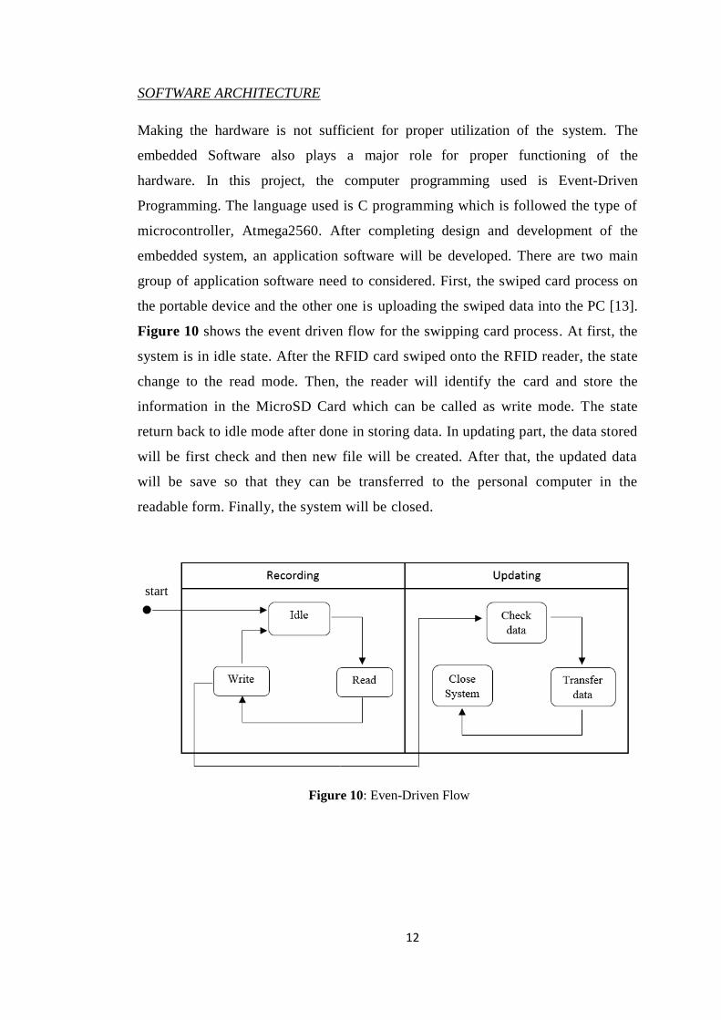
Figure 10 shows the event driven flow for the swipping card process. At first, the
system is in idle state. After the RFID card swiped onto the RFID reader, the state
change to the read mode. Then, the reader will identify the card and store the
information in the MicroSD Card which can be called as write mode. The state
return back to idle mode after done in storing data. In updating part, the data stored
will be first check and then new file will be created. After that, the updated data
will be save so that they can be transferred to the personal computer in the
readable form. Finally, the system will be closed.
start
Figure 10: Even-Driven Flow

13
Table 2: Key Milestone of Final Year Project 1
111111Project 1
Table 3: Key Milestone of Final Year Project 2
Project 1
3.3 Key Milestones
FINAL YEAR PROJECT 1 KEY-MILESTONE
No. ACTIVITIES WEEKS
1 2 3 4 5 6 7 8 9 10 11 12 13 14
1 Title Selection x
2 Preliminary Research &
Literature Review
x
3 Initial Design x
4 Hardware Procurement x
5 Hardware Integration x
6 Software Development x
FINAL YEAR PROJECT 2 KEY-MILESTONE
No. ACTIVITIES WEEKS
1 2 3 4 5 6 7 8 9 10 11 12 13 14
1 Prototype
Development and
Testing
x
2 Troubleshooting and
Improvement
x
3 Completing Final
Prototype
x
4 Electrex x
5 Preparing Report/
Thesis
x
6 Final Viva x
14
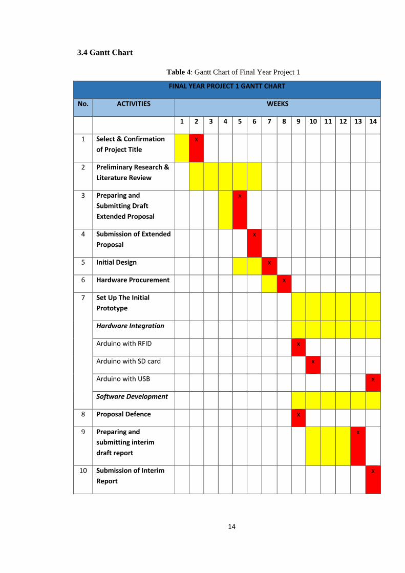
Table 4: Gantt Chart of Final Year Project 1
3.4 Gantt Chart
FINAL YEAR PROJECT 1 GANTT CHART
No. ACTIVITIES WEEKS
1 2 3 4 5 6 7 8 9 10 11 12 13 14
1 Select & Confirmation
of Project Title
x
2 Preliminary Research &
Literature Review
3 Preparing and
Submitting Draft
Extended Proposal
x
4 Submission of Extended
Proposal
x
5 Initial Design x
6 Hardware Procurement x
7 Set Up The Initial
Prototype
Hardware Integration
Arduino with RFID x
Arduino with SD card x
Arduino with USB x
Software Development
8 Proposal Defence x
9 Preparing and
submitting interim
draft report
x
10 Submission of Interim
Report
x

15
Table 5: Gantt Chart of Final Year Project 2
FINAL YEAR PROJECT 2 GANTT CHART
No. ACTIVITIES WEEKS
1 2 3 4 5 6 7 8 9 10 11 12 13 14
1 Prototype
Development and
Testing
x
2 Submission of Progress
Report
x
3 Troubleshooting and
Improvement
x
4 Completing Final
Prototype
x
5 Electrex x
6 Submission of Technical
Paper
x
5 Preparing Final Report/
Thesis
x
6 Final Viva x
3.5 Tool & Software Required
Tools & softwares that will be used throughout the project are:
Microcontroller board (Arduino Mega 2560)
RFID reader module (Adafruit PN532 RFID/NFC Shield)
RFID cards (Mifare card)
Memory card module (Sparkfun MicroSD shield)
1GB Sandisk MicroSD card
4x20 LCD screen
DS 3231 Real Time Clock
Arduino Integrated Development Environment (IDE) software

16
CHAPTER 4: RESULT AND DISCUSSION
4.1 Module Testing
Module testing is one of important phase in this project. The main objective on
running this testing is to ensure that all the module are in good condition and
working as expected. The module involes are RFID module, MicroSD card module
and LCD module.
Arduino Mega 2560 with PN532 RFID/NFC shield
The hardware integration between PN532 RFID/NFC module and Arduino Mega
2560 start by reading and understanding the datasheet of both items. Every i/o stack
have different function. If there is a wrong connection, the possibality of the
components to be broken very high. So, safety precaution must be taking carefully.
In order to configure these components, RFID module will stack on the arduino and
then USB B type cable is used to connect them with personel computer (Figure 11).
Arduino Integrated Development Environment (IDE) is a software used in
Figure 11: Arduino Mega and RFID
shield
Figure 13: Flow chart of RFID integration
(coding)
Figure 12: Serial monitor Display
(Output)
17
configuring any Arduino product. Figure 13 shows a coding flow of scanning
database inside the Arduino and Figure 12 shows the serial monitor display after
swipe a card.
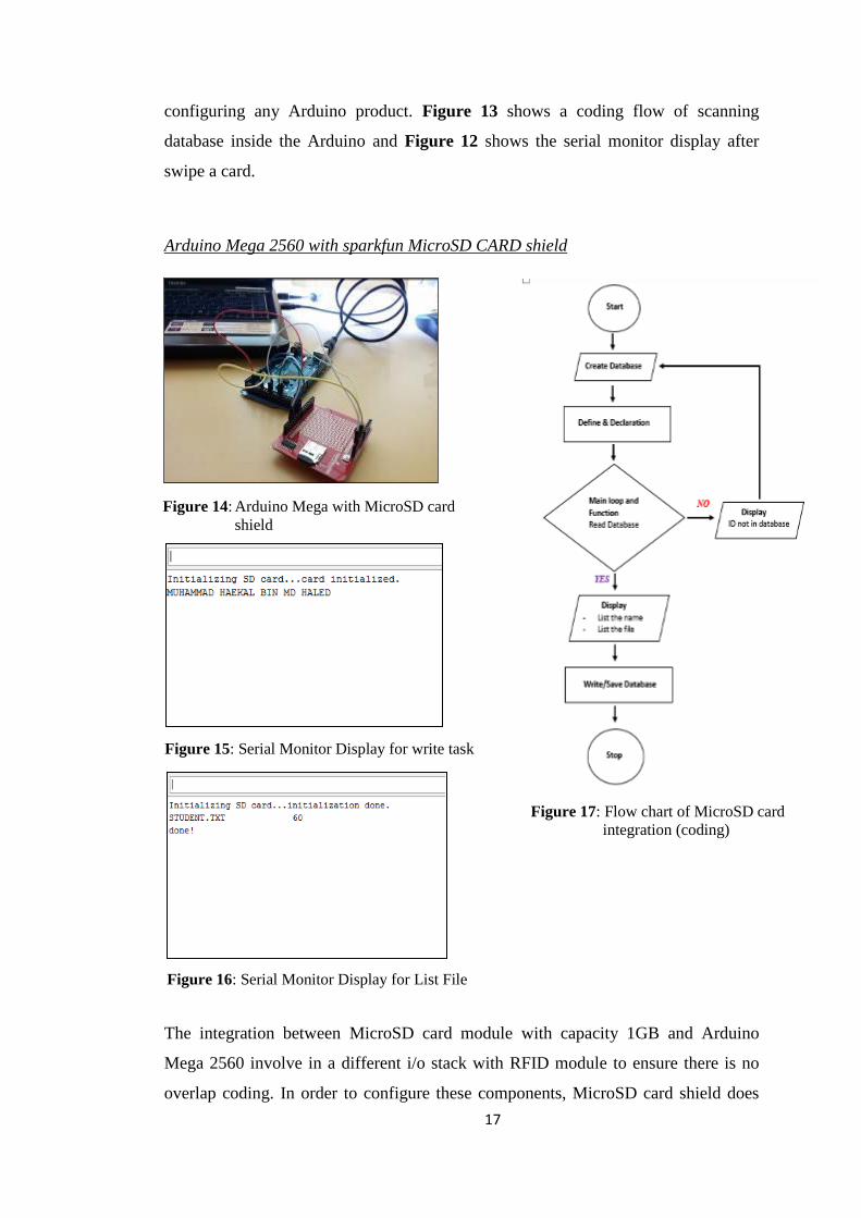
Arduino Mega 2560 with sparkfun MicroSD CARD shield
The integration between MicroSD card module with capacity 1GB and Arduino
Mega 2560 involve in a different i/o stack with RFID module to ensure there is no
overlap coding. In order to configure these components, MicroSD card shield does
Figure 14: Arduino Mega with MicroSD card
shield
Figure 17: Flow chart of MicroSD card
integration (coding)
Figure 15: Serial Monitor Display for write task
Figure 16: Serial Monitor Display for List File
18
not stack on the arduino but using male to male jumper and then USB B type cable is
used to connect them with personel computer (Figure 14). 7-pin involve in this
integration which are SD 8 chip select to digital 8, SD 12 MOSO to digital 50, SD
11 MOSI to digital 51, SD 13 CLK to digital 52, SD 10 to digital 53, SD ground to
digital ground and SD +3.3v to digital +3.3v. Figure 17 shows coding flow whereas
Figure 15 and 16 shows the serial monitor display (output).
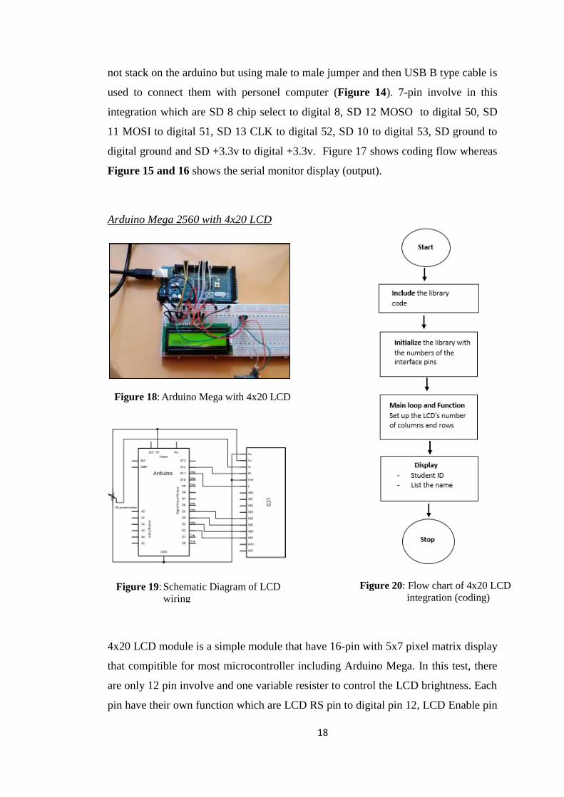
Arduino Mega 2560 with 4x20 LCD
4x20 LCD module is a simple module that have 16-pin with 5x7 pixel matrix display
that compitible for most microcontroller including Arduino Mega. In this test, there
are only 12 pin involve and one variable resister to control the LCD brightness. Each
pin have their own function which are LCD RS pin to digital pin 12, LCD Enable pin
Figure 18: Arduino Mega with 4x20 LCD
Figure 20: Flow chart of 4x20 LCD
integration (coding)
Figure 19: Schematic Diagram of LCD
wiring
D
19
to digital pin 11, LCD D4 pin to digital pin 5, LCD D5 pin to digital pin 4, LCD D6
pin to digital pin 3, LCD D7 pin to digital pin 2, LCD R/W pin to ground, LCD 2 and
15 to digital +5v, and lastly LCD 1,5,16 to Ground. In Figure 16 shows the pictorial
wiring integration arrangement of Arduino Mega and LCD module where the
schematic diagram in Figure 17 as a reference. For the software part the flow of
LCD system can be visualized in a form flow chart (Figure 18). All module test
coding are attached in Appendix A.
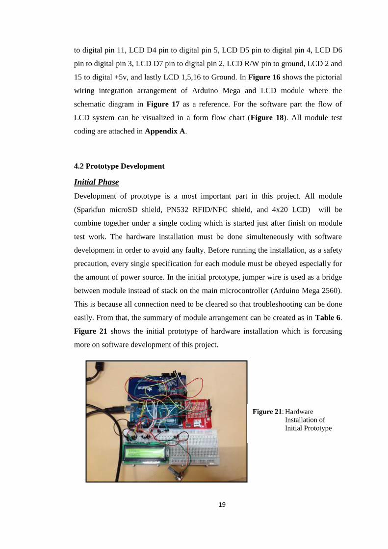
4.2 Prototype Development
Initial Phase
Development of prototype is a most important part in this project. All module
(Sparkfun microSD shield, PN532 RFID/NFC shield, and 4x20 LCD) will be
combine together under a single coding which is started just after finish on module
test work. The hardware installation must be done simulteneously with software
development in order to avoid any faulty. Before running the installation, as a safety
precaution, every single specification for each module must be obeyed especially for
the amount of power source. In the initial prototype, jumper wire is used as a bridge
between module instead of stack on the main microcontroller (Arduino Mega 2560).
This is because all connection need to be cleared so that troubleshooting can be done
easily. From that, the summary of module arrangement can be created as in Table 6.
Figure 21 shows the initial prototype of hardware installation which is forcusing
more on software development of this project.
Figure 21: Hardware
Installation of
Initial Prototype
D

20
Table 6: Summary of Module Arrangement for Initial Phase
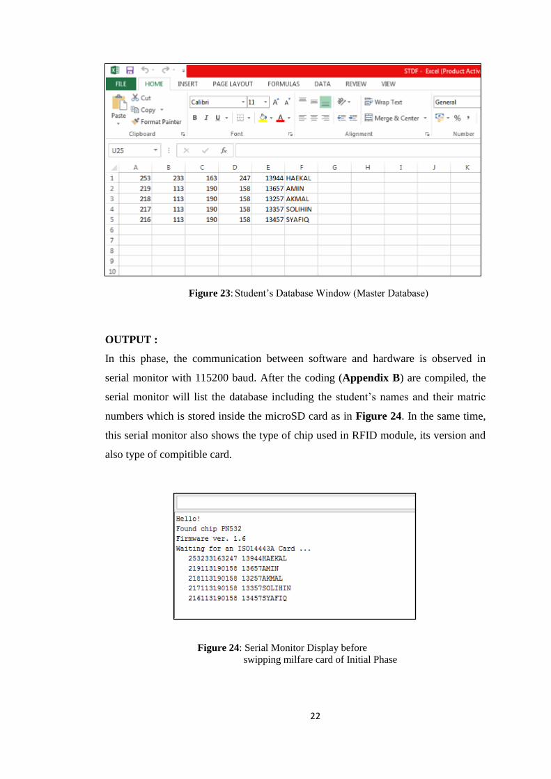
In every coding/ software construction, the first things need to do is creating and
drawing the flow chart of the process. It is very important to ensure the perfection
and smoothness of process on designing a coding. This phase project’s coding can be
divided into two tasks which are scanning card ID on RFID module and comparing
card ID with master database inside microSD card (Appendix B). For the
information, the database used is created in text.csv file which is can be represent in
microsoft excell. It can be stored up to 100 to 200 students ID number together with
name. Figure 22 shows the coding process flow chart of initial prototype and Figure
23 shows the database window saved in microSD card.

21
Figure 22: Initial Flow Diagram of the System
22
OUTPUT :
In this phase, the communication between software and hardware is observed in
serial monitor with 115200 baud. After the coding (Appendix B) are compiled, the
serial monitor will list the database including the student’s names and their matric
numbers which is stored inside the microSD card as in Figure 24. In the same time,
this serial monitor also shows the type of chip used in RFID module, its version and
also type of compitible card.
Figure 23: Student’s Database Window (Master Database)
D
Figure 24: Serial Monitor Display before
swipping milfare card of Initial Phase
23
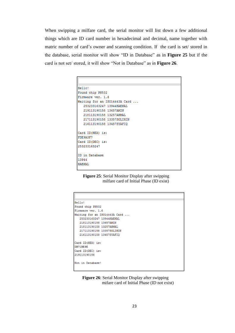
When swipping a milfare card, the serial monitor will list down a few additional
things which are ID card number in hexadecimal and decimal, name together with
matric number of card’s owner and scanning condition. If the card is set/ stored in
the database, serial monitor will show “ID in Database” as in Figure 25 but if the
card is not set/ stored, it will show “Not in Database” as in Figure 26.
Figure 25: Serial Monitor Display after swipping
milfare card of Initial Phase (ID exist)
Figure 26: Serial Monitor Display after swipping
mifare card of Initial Phase (ID not exist)
24
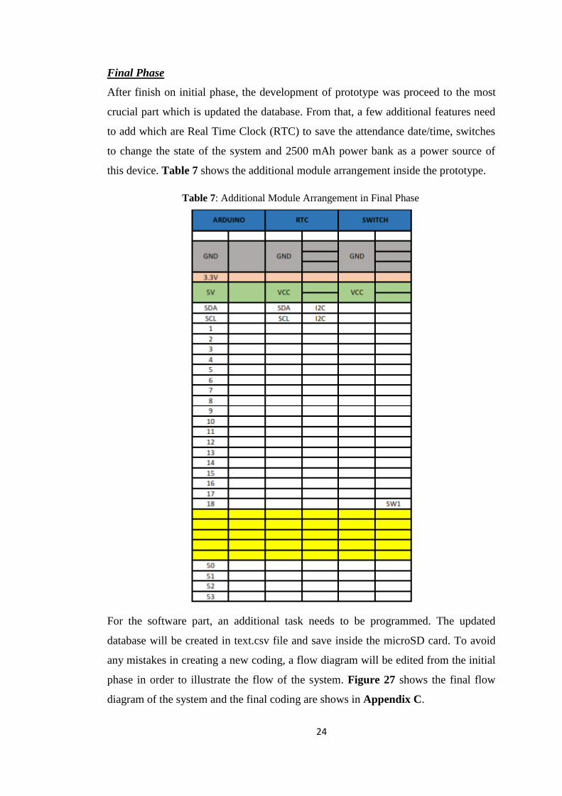
Table 7: Additional Module Arrangement in Final Phase
Final Phase
After finish on initial phase, the development of prototype was proceed to the most
crucial part which is updated the database. From that, a few additional features need
to add which are Real Time Clock (RTC) to save the attendance date/time, switches
to change the state of the system and 2500 mAh power bank as a power source of
this device. Table 7 shows the additional module arrangement inside the prototype.
For the software part, an additional task needs to be programmed. The updated
database will be created in text.csv file and save inside the microSD card. To avoid
any mistakes in creating a new coding, a flow diagram will be edited from the initial
phase in order to illustrate the flow of the system. Figure 27 shows the final flow
diagram of the system and the final coding are shows in Appendix C.
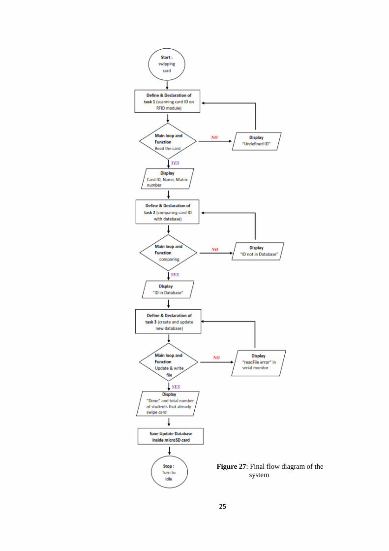
25
Figure 27: Final flow diagram of the
system

26
OUTPUT :
In final phase, the communication between software and hardware is also observed in
serial monitor with 115200 baud. After the coding (Appendix C) are compiled, the
serial monitor will listed the master database including the student’s names and their
matric numbers which is stored inside the microSD card as in Figure 28. In the same
time, the LCD will display “Please scan..” to give a message that the system is ready
to operate. In this serial monitor also shows the type of chip used in RFID module,
its version, type of compitible card and also file name which is “List_D.CSV”. The
new file can be created by pressing the push button switch at the prototype’s body.
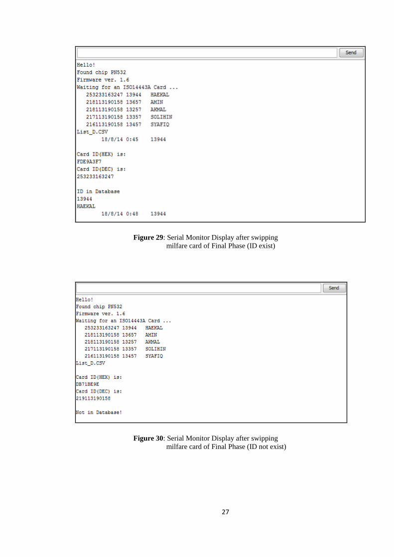
After swipping a mifare card, the serial monitor will list down a few details which
are ID card number in hexadecimal and decimal, name together with matric number
of card’s owner and scanning condition. If the card is set/ stored in the database,
serial monitor will show “ID in Database” as in Figure 29 but if the card is not set/
stored, it will show “Not in Database” as in Figure 30. The card can be swiped and
save only for a once and if it is swipped repeatedly, the serial monitor will display
“Already Updated Attendance” as in Figure 31. Besides, a new feature is added in
this prototype which is the time and date record. From that, the file become more
easy to keep track.
Figure 28: Serial Monitor Display before swipping
mifare card of Final Phase
27
Figure 29: Serial Monitor Display after swipping
milfare card of Final Phase (ID exist)
Figure 30: Serial Monitor Display after swipping
milfare card of Final Phase (ID not exist)

28
In addition, this prototype is also added with an on/off switch. After record the
attendance, it can be stop working by pressing that switch. When turned on the
switch back, all the data stored inside microSD card will be displayed as Figure 32.
This additional feature is a very useful in order to save the power source storage
which is the power bank.
Figure 31: Serial Monitor Display when swipping
mifare card repeatedly
Figure 32: Serial Monitor Display after On/Off switch turn on

29
Figure 33: The Updated Database
The last part of this system is creating and updating a new database. When pressing a
push button, the new file of database will be created. This prototype can be create
new file up to 200 files. There are three details will be updated which are date, time
and id number. Figure below shows the database that already update.
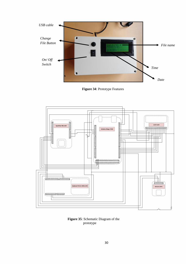
4.3 Final Prototype Representation
Portable RFID student attendance system prototype has 7.8 inch length, 4.7 inch
width and 2.9 inch depth dimention. It has a few features which are On/Off button,
Change File Button, LCD Display and USB cable as in Figure 34. Its design is
simple so that easy to handle and bring everywhere. In assembling process, all the
connection and position of components are arranged according to the schematic
diagram prepared in designing process. The schematic diagram is designed online at
digikey.com. Figure 35 shows the schematic diagram of the system.
30
On/ Off
Switch
Change
File Button
Figure 34: Prototype Features
USB cable
Figure 35: Schematic Diagram of the
prototype
File name
Time
Date
31
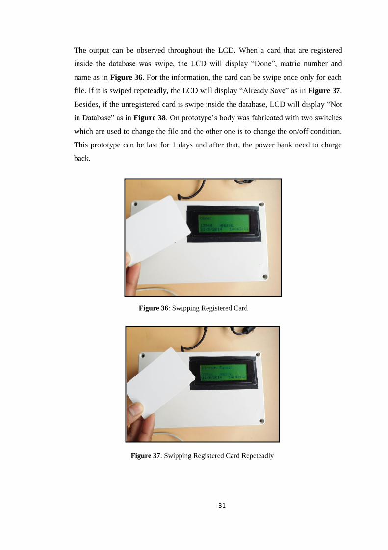
Figure 36: Swipping Registered Card
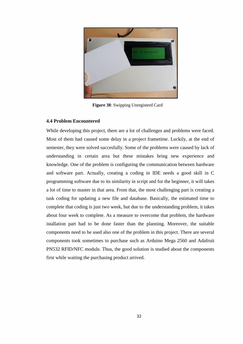
The output can be observed throughout the LCD. When a card that are registered
inside the database was swipe, the LCD will display “Done”, matric number and
name as in Figure 36. For the information, the card can be swipe once only for each
file. If it is swiped repeteadly, the LCD will display “Already Save” as in Figure 37.
Besides, if the unregistered card is swipe inside the database, LCD will display “Not
in Database” as in Figure 38. On prototype’s body was fabricated with two switches
which are used to change the file and the other one is to change the on/off condition.
This prototype can be last for 1 days and after that, the power bank need to charge
back.
Figure 37: Swipping Registered Card Repeteadly
32
4.4 Problem Encountered
While developing this project, there are a lot of challenges and problems were faced.
Most of them had caused some delay in a project frametime. Luckily, at the end of
semester, they were solved succesfully. Some of the problems were caused by lack of
understanding in certain area but these mistakes bring new experience and
knowledge. One of the problem is configuring the communication between hardware
and software part. Actually, creating a coding in IDE needs a good skill in C
programming software due to its similarity in script and for the beginner, it will takes
a lot of time to master in that area. From that, the most challenging part is creating a
task coding for updating a new file and database. Basically, the estimated time to
complete that coding is just two week, but due to the understanding problem, it takes
about four week to complete. As a measure to overcome that problem, the hardware
istallation part had to be done faster than the planning. Moreover, the suitable
components need to be used also one of the problem in this project. There are several
components took sometimes to purchase such as Arduino Mega 2560 and Adafruit
PN532 RFID/NFC module. Thus, the good solution is studied about the components
first while waiting the purchasing product arrived.
Figure 38: Swipping Unregisterd Card

33
CHAPTER 5: CONCLUSION AND RECOMMENDATION
The Student Attendance System Using RFID is developed with the purpose to
automate and improve the current processes and procedured of manual attendance
recording. In developing the system, the student had to prepare 3 major scopes of
functions which include the Arduino microcontroller, RFID module and microSD
Card module. The system is developed using Arduino Integrated Development
Environment (IDE) software as its main platform. IDE is used because of its open
source and a very easy to program user interface. Overall, the objectives of this
project are achieved. A portable RFID reader with data storage for the purpose of
recording students attendance where enable the communication between ATmega
2560 and a computer via serial port Universal Asynchronous Receiver/Transmitter
(UART) is managed to build. From that, this device can be propose to be
implemented in UTP in order to improve management system especially in recording
student’s attendance.
There are several recommendations to be made regarding this project.
Recommendation are not meant to be used to change this project wholly, but to allow
improvements in certain espects and to put some factor into consideration. One of the
recommendations for future plan is to develop the design of the prototype become
smaller and lighter so that the prototype can be commercialized. On the other hand,
the system is recommended to improvise in the uploading the data directly to the
personal computer. A thorough research is needed to be made in order to make it
succesful.
34
REFERENCES
[1] Aysha Qaiser and Shoab A Khan, “Automation of Time and Attendance Using RFID
System” IEE-ICET 2nd International Conference on Imaging Technology, 2006
[2] Grant Hornback, Alex Babu, Bobby Martin, Ben Zoghi, Madhav Pappu, and Rohit
Singhal, Automatic Attendance System Journal, from RFIDSensNet Lab; 2001
[3] Sato DCS & Labeling Worldwide, “The RFID Guidebook (Revision 8)”, 2004.
[4] M. K. Yeop Sabri, M. Z. A. Abdul Aziz, M. S. R. Mohd Shah, M. F. Abd Kadir,
‘’Smart Atttendance System By Using RFID’’ Asia Pacific Conference on Applied
Electromagnetics Proceedings, 2007
[5] Wayne Wolf, ‘’A Decade of Hardware/ Software Co-design’’ IEEE 5th International
Symposium Multimedia Software Engineering (MSE), 2003
[6] Claudio Talarico, Aseem Gupta, Ebenezer Peter, Jerzy W. Rozenblit, “Embedded
System Engineering Using C/C++ Based Design Methodologies” 12th IEEE
International Conference And Workshop on The Engineering of Computer-Base
System, 2005
[7] Yuanrui Zhang and Mahmut Kandemir, ‘’A Hardware-Software Codesign Strategy
for LoopIntensive Applications’’ IEEE 7th Symposium on Application Specific
Processors (SASP), 2009
[8] http://www.embedded.com/design/debug-and-optimization/4216254/HW-SW-co-
verification-basics--Part-1---Determining-what---how-to-verify
[9] József Kopják and János Kovács, ‘’Event Driven Software Modeling of Combinational
Logic Network Based Control Programs’’ IEEE 16th International Conference on
Intelligent Engineering System, 2012
[10] Mohammed Abdallah, and Omar Elkeelany, “Simultaneous Multi-channel Data
Acquisition and Storing System,” ICC, pp.233-236, 2009 International Conference on
Computing, Engineering and Information.
[11] Omar Elkeelany and Vivekanand S. Todakar, ‘’Data Concentration and Archival to SD
Card via Hardware Description Language’’ 3rd IEEE International Workshop on
Management of Emerging Network and Service
[12] ST Microelectronics, TN 0897 Technical Note, ST SPI Protocol, 2013
[13] Subhabrata Mazumder, Vineet Kumar Rakesh and Tapas Samanta, ‘’Design and
Development of a Hand-held RFID Reader for Recording Attendance’’ 5th International
Conference on Computers and Devices for Communication (CODEC)
I
APPENDICES
Appendix A
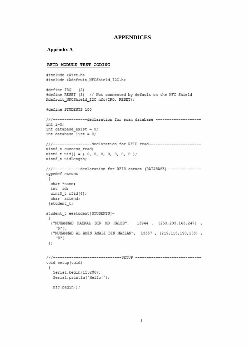
RFID MODULE TEST CODING

II
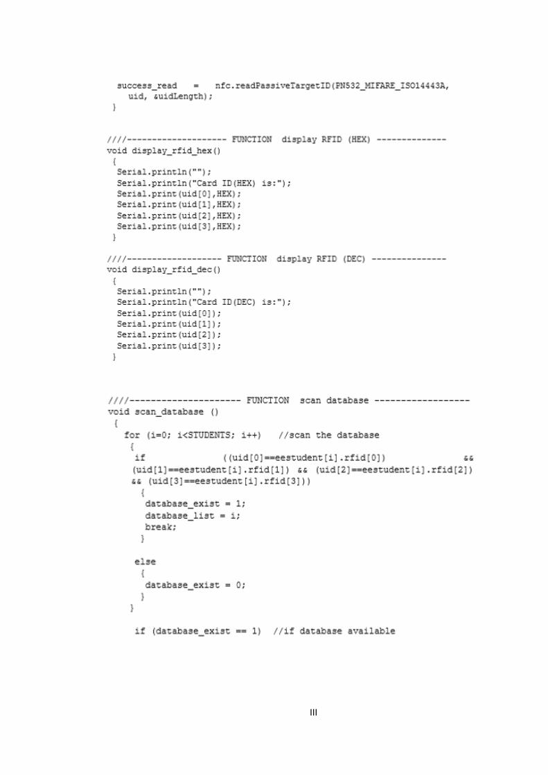
III
IV
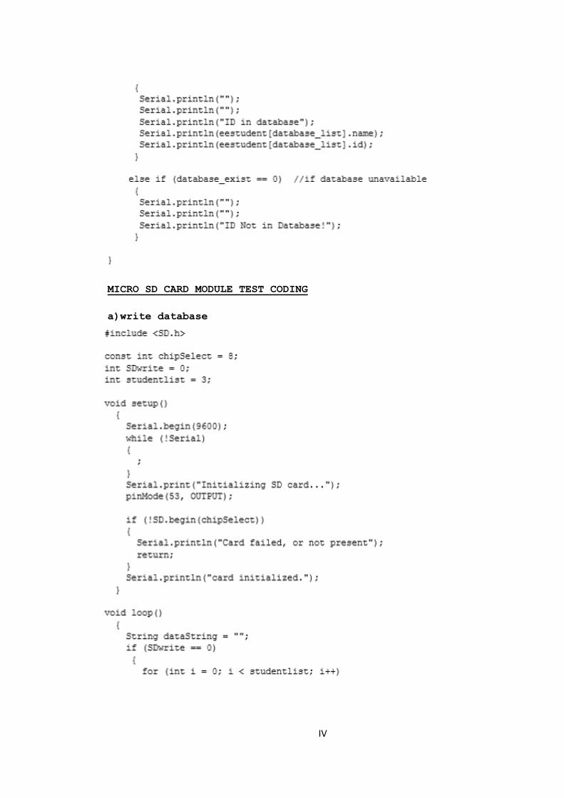
MICRO SD CARD MODULE TEST CODING
a)write database

V
b)list file
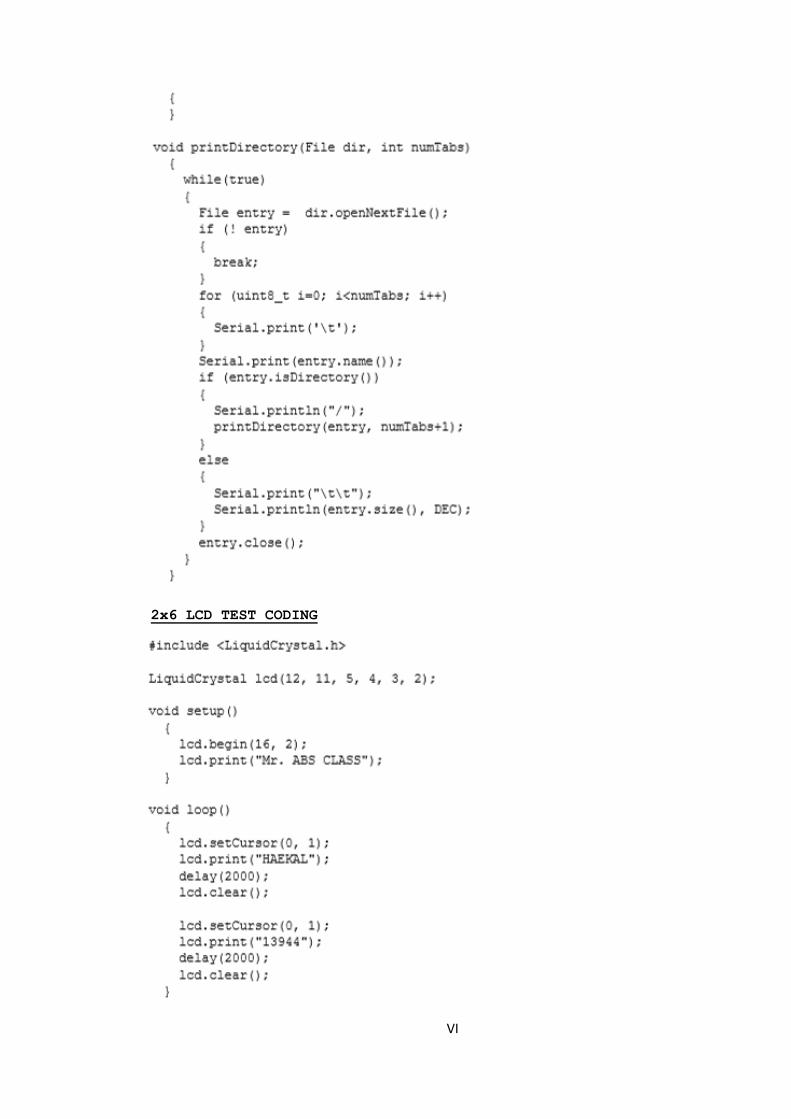
VI
2x6 LCD TEST CODING
VII
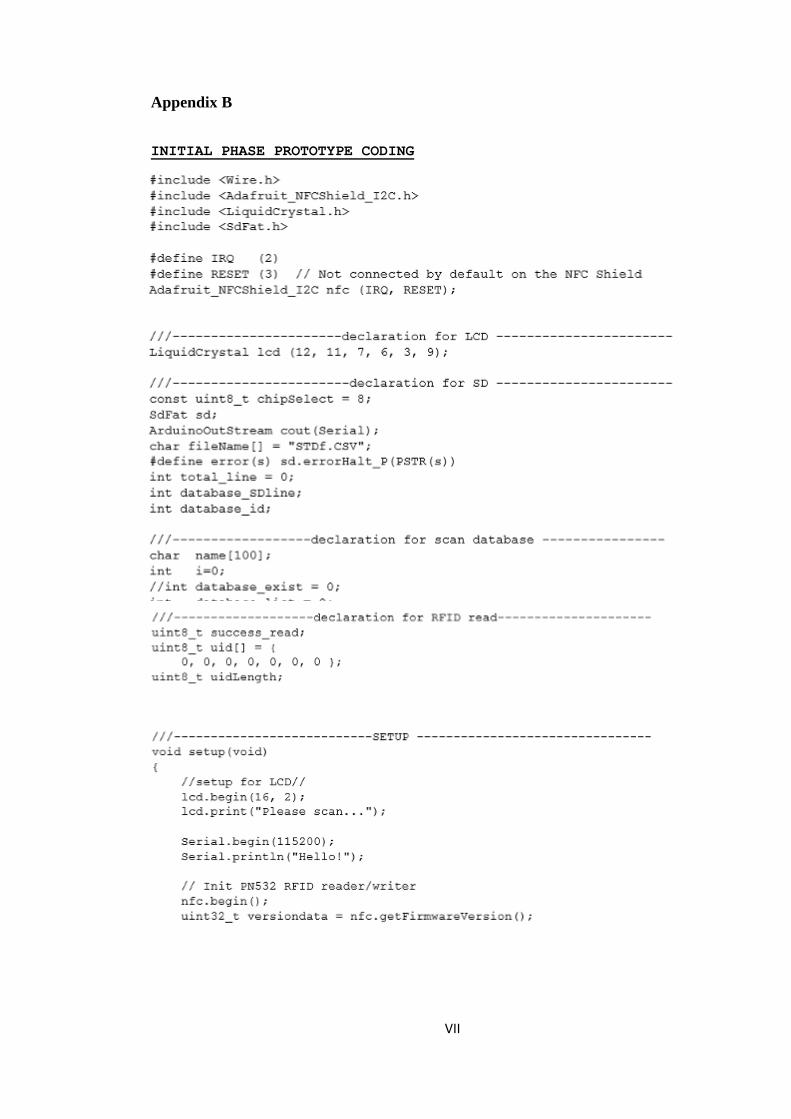
Appendix B
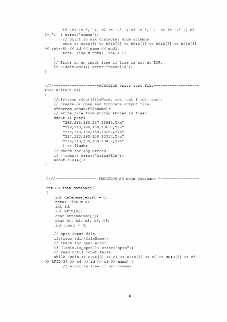
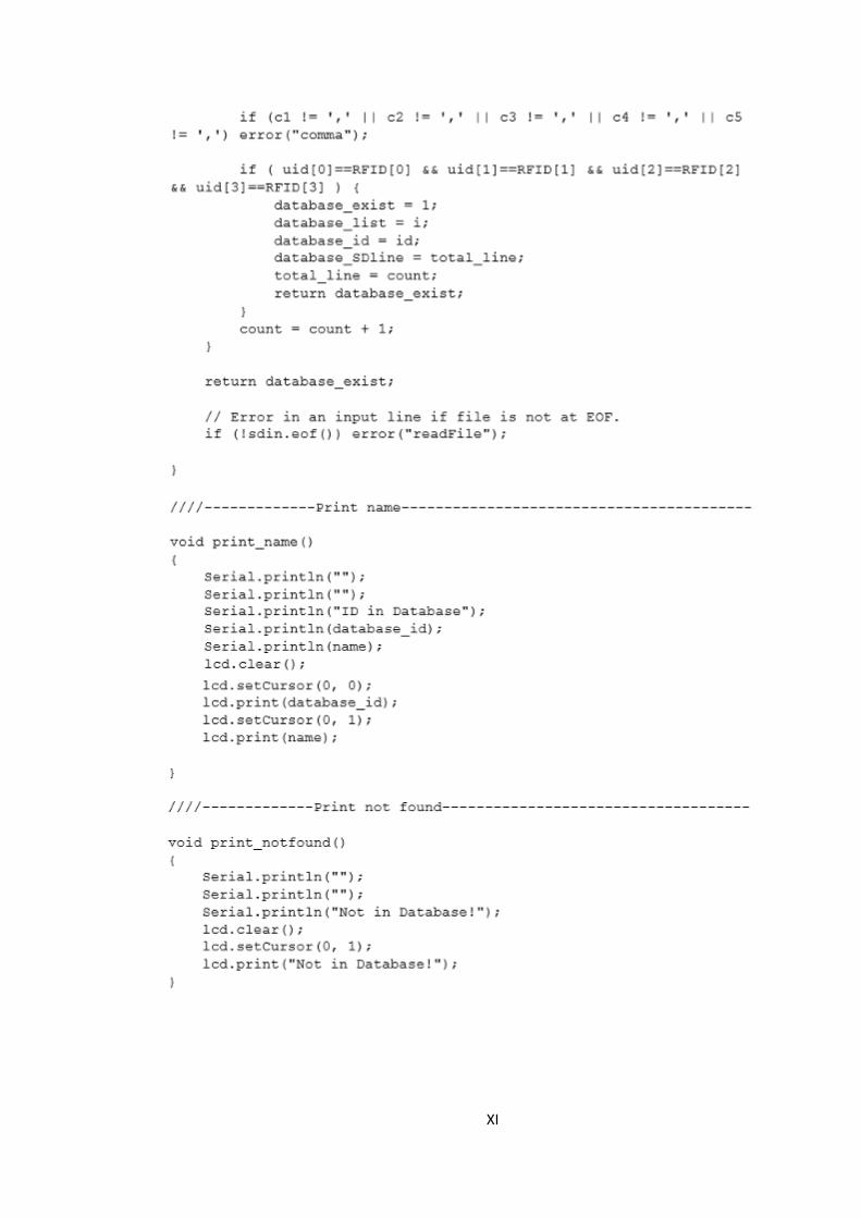
INITIAL PHASE PROTOTYPE CODING
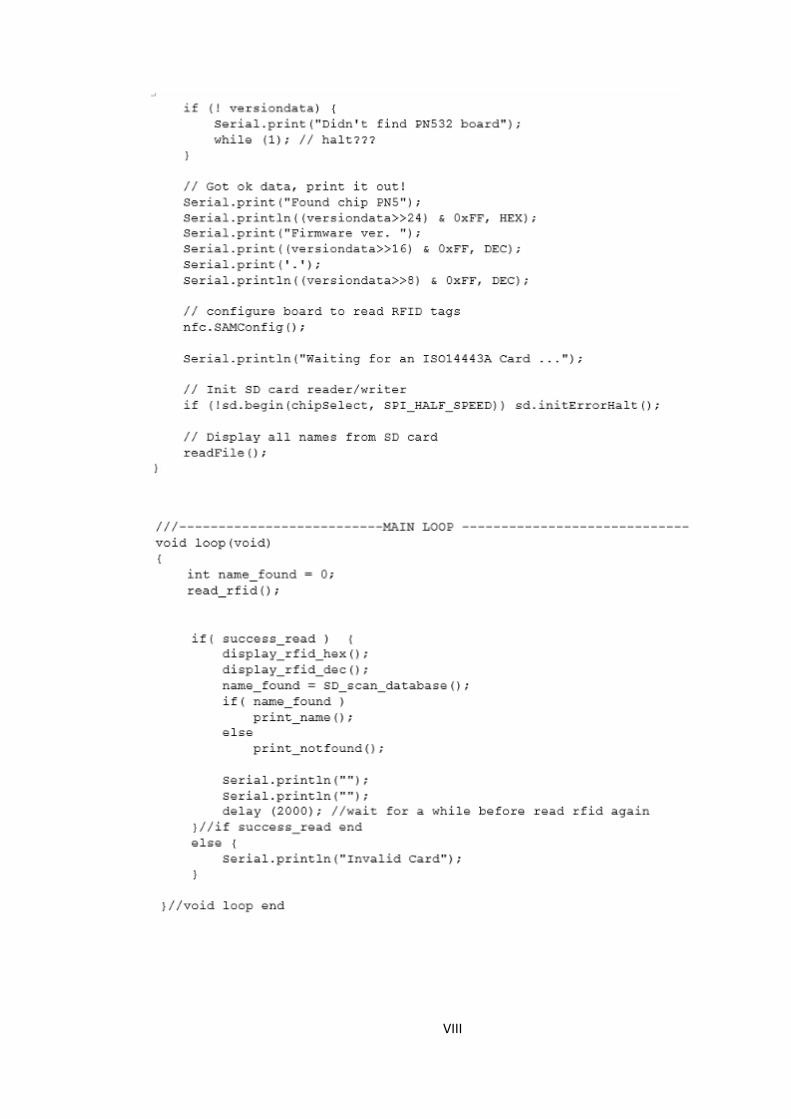
VIII

IX
X
XI
XII
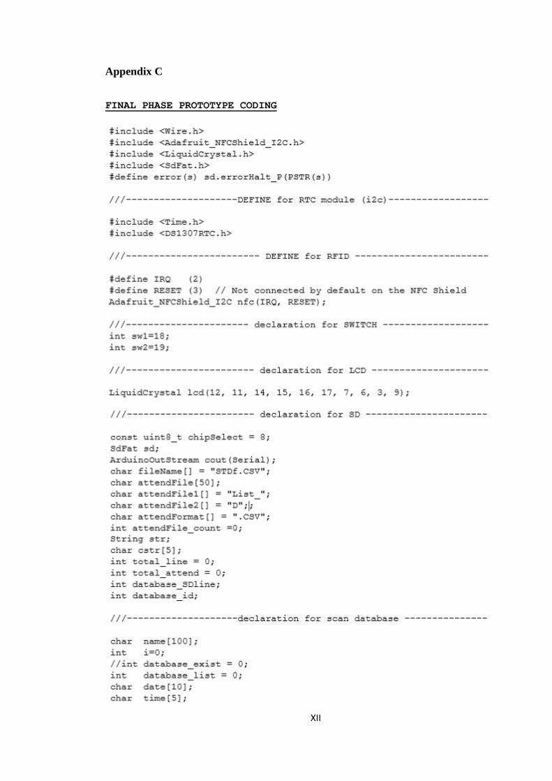
Appendix C
FINAL PHASE PROTOTYPE CODING
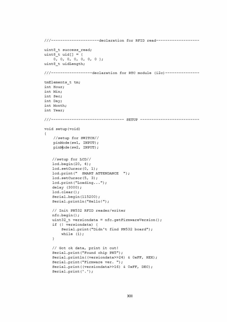
XIII

XIV
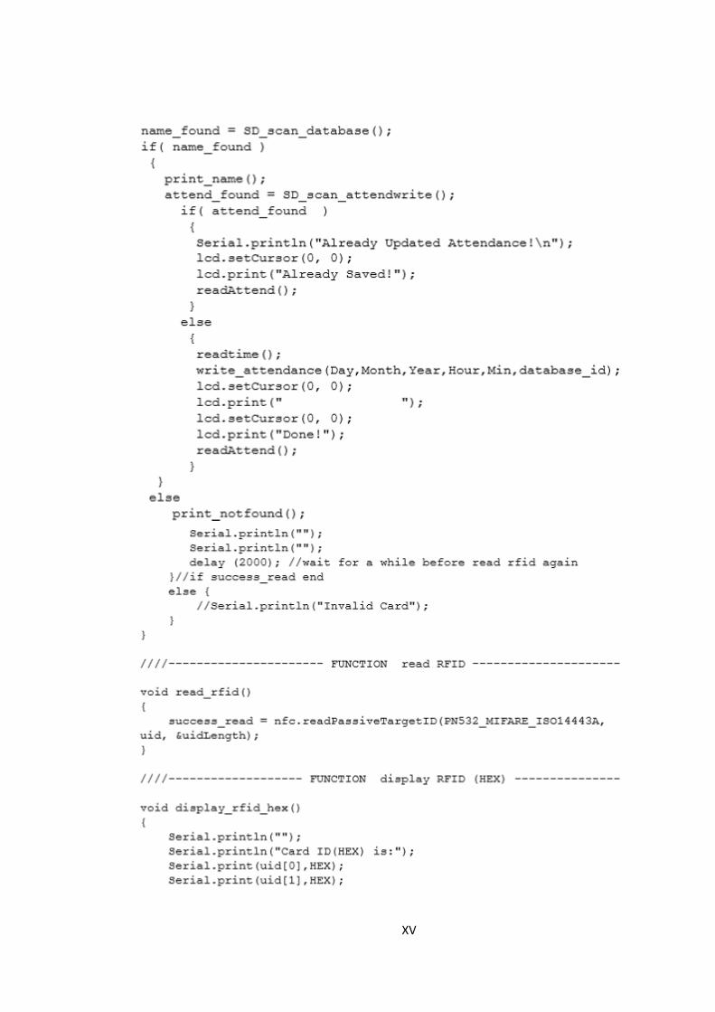
XV
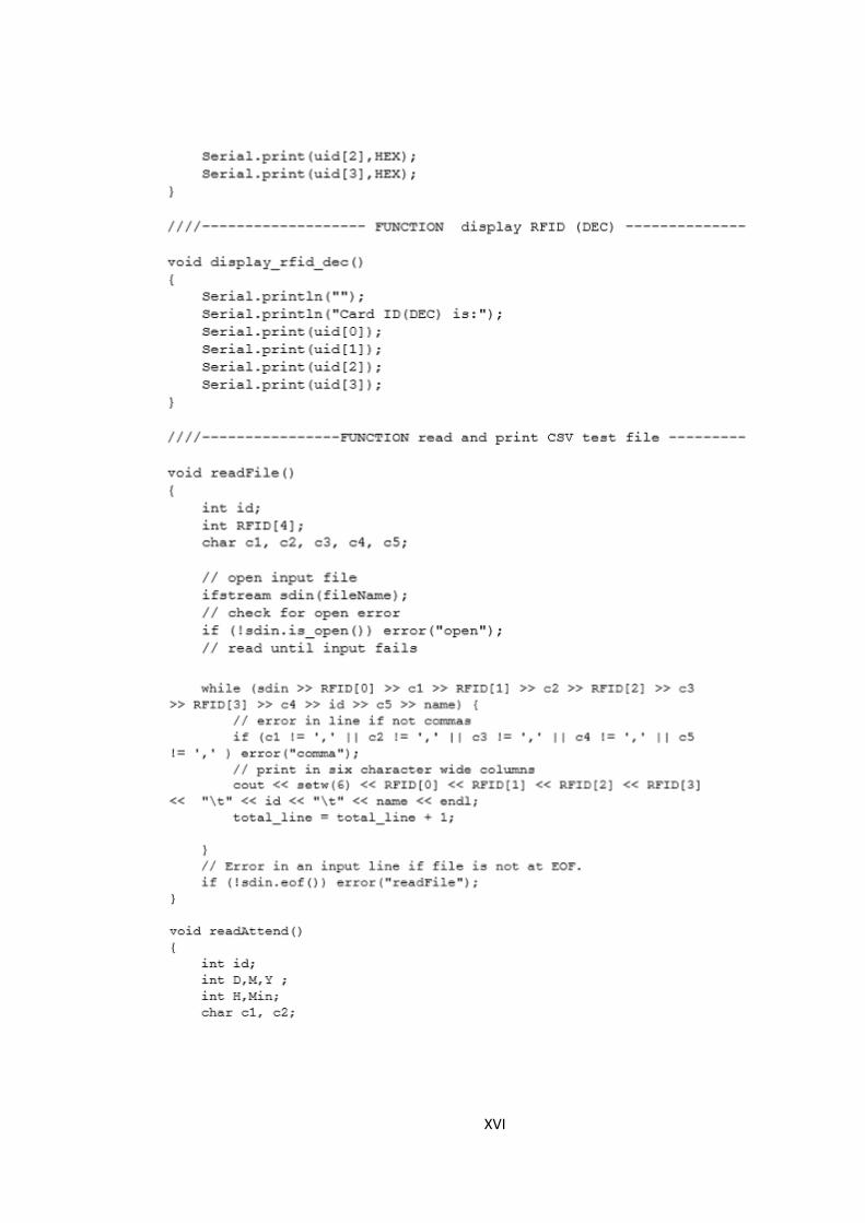
XVI
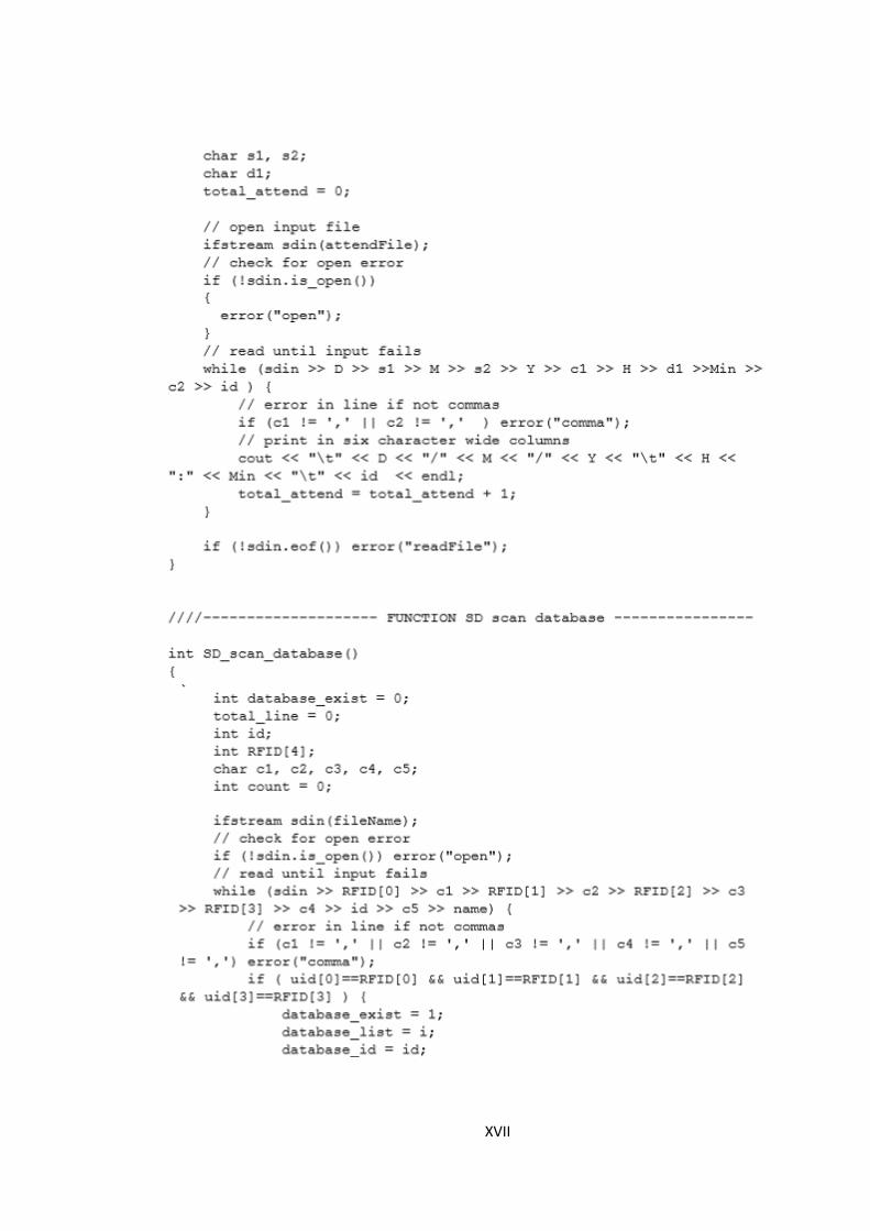
XVII

XVIII

XIX

XX

XXI

XXII