Untitled - UTPedia
45
-
Upload
khangminh22 -
Category
Documents
-
view
0 -
download
0
Transcript of Untitled - UTPedia

COMPARATIVE STUDY OF A LOW RISE BUILDING
DESIGN USING EC2 AND BS8110
by
DUONG VANNAK
Dissertation submitted in partial fulfillment of the requirements for the
Bachelor of Engineering (Hons) (Civil Engineering)
JANUARY 2010
Supervisor: Assoc. Prof. Dr. Nasir Shafiq Universiti Teknologi PETRONAS Bandar Seri Iskandar
31750 Tronoh Perak Darul Ridzuan
CERTIFICATION OF APPROVAL
COMPARATIVE STUDY OF A LOW RISE BUILDING
DESIGN USING EC2 AND BS8110
by
DUONG VANNAK
A project dissertation submitted to the
Civil Engineering Programme
Universiti Teknologi PETRONAS
in partial fulfillment of the requirement for the
BACHELOR OF ENGINEERING (Hons)
(CIVIL ENGINEERING)
Approved by
Assoc. Prof. Dr. Nasir Shafiq
UNIVERSITI TEKNOLOGI PETRONAS
TRONOH, PERAK
January 2010

CERTIFICATION OF ORIGINALITY
This is to certify that I am responsible for the work submitted in this project, that the
original work is my own except as specified in the reference and acknowledgements,
and that the original work contained herein have not been undertaken or done by
unspecified sources or persons.
DUONG VANNAK

ABSTRACT
This report is intended to raise awareness amongst the Structural Engineering Profession
of the forthcoming Eurocode for the Design of Concrete Structures EC2 which will in a
few years replace the existing British code BS8110.
The two codes are compared in the context of design of primary structural elements and
information is given on the availability of design aids to assist the practitioner in
becoming familiar with and using the new code.
I

ACKNOWLEDGEMENT
Firstly, I would like deeply thank to my supervisor AP Dr Nashir shafiq for his
commitment on guiding, advising, sharing his own knowledge for my FYP to be a
successful one. I also would like to give my thanks to AP Ir Dr Mohd Shahir Liew for
his guide for on this project as well. I got a lot of help, sharing, caring from all the stuff from Faculty of civil engineering, lecturers and my course mate and thank them for all
the things they have done. I would like to thank the authors of the books I referred and
the staffs of library in Universiti Teknologi PETRONAS for assisting us in getting these
hooks.
Last but not least, I appreciate all the people who lent their hands directly or indirectly throughout the project. Without the help from all, I wouldn't be able to
accomplish my FYP successfully as so far. It is my honor to say thank to all the people helping me in my FYP. Finally I have to say my very great gratitude to PETRONAS for
supporting throughout my undergraduate studies.
ii

TABLE OF CONTENTS
ABSTRACT .........................................................................................
ACKNOWLEDGEMENT ......................................................................... TABLE OF CONTENTS ......................................................................... iii LIST OF FIGURES ................................................................................ v LIST OF TABLES ................................................................................. v ABBREVIATION AND NOMENCLATURE ................................................. vi CHAPTER 1: INTRODUCTION ............................................................... I
1.1 BACKGROUND OF STUDY .............................................. 1
1.2 PROBLEM STATEMENT ................................................... 2
1.3 OBJECTIVES ................................................................. 2
1.4 SCOPE OF STUDY ............................................................. 2
CHAPTER 2: LITERATURE REVIEW AND/OR THEORY ............................... 3
2.1 MICROSOFT EXCEL ................................. .... 3
2.2 EC2 & BS8110 ............................................................... 4
CHAPTER 3: METHODOLOGY/PROJECT WORK ....................................... 9
3.1 RESEARCH METHODOLOGY ........................................ 9
3.2 BUILDING SELECTION FOR DESIGN IN THE PROJECT...... 10
3.3 BUILDING DESIGN PROCEDURE OF EC2 AND BS8110....... 11
3.4 BEAM DESIGN (EC2) ..................................................... 12
3.5 DESIGN FOR BEAM SHEAR (EC2) .................................... 13
3.6 DESIGN FOR PUNCHING SHEAR IN SLAB (EC2) ................ 13
3.7 COLUMN DESIGN (EC2) ................................................ 14
3.8 GANTT CHART ............................................................ 16
3.9 TOOL REQUIRED ......................................................... 18
CHAPTER 4: RESULT AND DISCUSSION .................................................. 19
CHAPTER 5: CONCLUSION AND RECOMMENDATION .............................. 21
CHAPTER 6: ECONOMIC BENEFITS ...................................................... 22
6.1 ELECTRICITY............................................................. 22
iii

6.2 DOCUMENTS .............................................................. 22
6.3 ECONOMIC BENEFITS ................................................... 23
24 REFERENCE ...................................................................................... APPENDIX 1: PRACTICAL USE OF EUROCODE 2 .......................................
26
iv

LIST OF FIGURES
Figure]: Diagram of Eurocode ........................................................................ 5
Figure 2: Diagram of European Standards or Complementary British Standards..... 5
Figure 3: Flow Chart Of Activities ............................................................... 9
Figure 4: Building Plan ........................................................................ 10
LIST OF TABLES
Table 1: The basic different between BS 8110 and EC2 ................................. 16
Table 2: Steel weight and concrete volumes using under mild exposure............... 20
Table 3: Steel weight and concrete volumes using under severe exposure............ 20
V

ABBREVIATION AND NOMENCLATURE
ENV Eurocode Version of Eurocode published by CEN as a pre-standard ENV (for subsequent conversion into EN)
NAD National Application Document for the use of ENV Eurocodes at the National level
EN Eurocode Version of Eurocode approved by CEN as a European standard EC European Commission services
As Area of tension reinforcement. As' Area of compression reinforcement.
d Effective depth of the tension reinforcement. d'/2 Depth to the compression reinforcement.
x Depth to the neutral axis.
z Lever arm. Ac Area of concrete section.
Asv Total cross-section of links at the neutral axis, at a section. d Effective depth.
M Design ultimate moment at the section considered. N Design axial force.
sv Spacing of links along the member. Sb Spacing of bent-up bars.
V Design shear force due to ultimate loads.
Vb Design shear resistance of bent-up bars.
v Design shear stress at a cross-section.
Design concrete shear stress vc
As, prov Area of tension reinforcement provided
As', prov Area of compression reinforcement.
As req Area of tension reinforcement required to resist the moment due to design
ultimate loads
fs Estimated design service stress in the tension reinforcement.
vi

CHAPTER I
INTRODUCTION
1.1 BACKGROUND OF STUDY Reinforced concrete is a strong durable building material that can be formed in to many
varied shapes and sizes ranging from a simple rectangular column, to a slender curved dome or shell. Its utility and versatility are achieved by combining the best features of
concrete and steel.
The complete building structure can be broken down into the following elements: 1. Beams (Horizontal members carrying lateral loads),
2. Slabs (Horizontal plate elements carrying lateral loads),
3. Columns (Vertical members carrying primarily axial load but generally
subjected to axial load and moment),
4. Walls (Vertical plate elements resisting vertical, lateral or in-plane loads),
5. Base and foundations (pads or strips supported directly o the ground that
spread the lads from columns or walls so that they can be supported by the
ground without excessive settlement, alternatively the bases may be
supported on piles)
There are two design codes currently using for the reinforced concrete building
structures: BS81 10 and EC2 (Eurocode 2). But BS 8110 is due to be superseded by EC2 by
March 2010.
Microsoft Excel (full name Microsoft Office Excel) is a spreadsheet-application
written and distributed by Microsoft for Microsoft Windows and Mac OS X. It features
calculation, graphing tools, pivot tables and a macro programming language called VBA
(Visual Basic for Applications). It has been the most widely used spreadsheet
application available for these platforms since version 5 in 1993.
1

1.2 PROBLEM STATEMENT
Since EC2 is going to implement from this year (March 2010), therefore the concrete
practitioners are required to gain knowledge and understanding of EC2.
This project is aimed to compare the two codes and bring forward the critical issues and differences between EC2 and BS8110.
1.3 OBJECTIVE
The main objective of this project is
To compare the two codes and bring forward the critical issues and differences
between EC2 and BS8110.
1.4 SCOPE OF STUDY
The scope of this study will cover the designs of the Beams, Slabs and Columns of the
3-storey building using EC2 and BS81 10 in Microsoft Excel Worksheet Software for
analyzing and comparing the two design schemes under the Mild Exposure and Severe
Exposure.
2

CHAPTER 2
LITERATURE REVIEW
2.1 MICROSOFT EXCEL: Microsoft Excel offers users the useful ability to write code using the programming language Visual Basic for Applications (VBA). Programmers write this code using an
editor viewed separately from the spreadsheet. Manipulation of the spreadsheet entries is
controlled using objects. With this code any function or subroutine that can be set up in a Basic- or Fortran-like language can be run using input taken from the spreadsheet proper,
and the results of the code are instantaneously written to the spreadsheet or displayed on
charts (graphs). The spreadsheet becomes an interface or window to the code, enabling
easy interaction with the code and what it calculates. VBA also supports simple GUI
forms based programming embedded in the spreadsheet so that entire forms based
applications can be written in Excel.
Accuracy: Due to Excel's foundation on floating point calculations, the statistical
accuracy of Excel has been criticized, as lacking certain statistical tools.
Excel MOD function error: Excel has issues with modulo operations. In the case of
excessively large results, Excel will return the incorrect answer of #NUM! error.
Date Problems: Excel incorrectly treats 1900 as a leap year. The bug originated from
Lotus 1-2-3, and was purposely implemented in Excel for the purpose of backward
compatibility. This legacy has later been carried over into Office Open XML file format.
Excel also supports the second date format based on year 1904 epoch. The Excel DATED
function causes problems with a year value prior to 1900.
Excel is frequency of percentage of using software although it only normal computer software not structure engineering software but a lot of company like to use it in design
structure. This is because Excel's software is easily practiced and anyone is capable to
3

control it because it is easy to be applied during production in the calculation data with
the simple calculation.
Microsoft Excel not only facilitates most operation which involves storage record and
information, and also can make calculation operation able to be carried out with faster
and effective than traditional method, and it also enables to producing the chart or
various forms graph easily.
2.2 EC2 & BS8110:
The implementation of the new Eurocodes is a significant event for the UK construction industry. BS EN 1992, Eurocode 2: Design of Concrete Structures will affect all
concrete design once the current British Standards, BS 8110 for Design of Reinforced
Concrete Structures, BS8007 Design of Concrete Structures for Retaining Aqueous
Liquids and BS5400 Steel and Concrete Bridge Design have been withdrawn. This is
due to happen by 2010, but BS 8110 may be withdrawn as early as January 2008.
Eurocode 2 (EC2) published in the UK as BS EN 1992 is one of 10 Eurocodes that will form into a uniform process of design. It applies to the design of buildings and civil
engineering works in concrete. It complies with the principles and requirements for the
safety and serviceability of structures, the basis of their design and verification that are
given in EN 1990 - Basis of structural design. Eurocode 2 is only concerned with
requirements for resistance, serviceability, durability and fire resistance concrete
structures. Other requirements, e. g. concerning thermal or sound insulation, are not
considered.
There are four parts to BS EN 1992, Eurocode 2 (Design of concrete structures)
Part 1-1 (General - Common rules for building and civil engineering structures)
was published in December 2004.
- Part 1-2 (General - Structural fire design) was published in February 2005: the
relevant National Annexes were published in December 2005.
- Part 2 (Bridges) was published in December 2005.
Part 3(Liquid retaining and containment structures) was published in July 2006 and
their respective National Annexes in December 2007 and October 2007.
4

Each part deals with design alone, so the basis of design, loads, materials and
workmanship. Materials and workmanship are covered by European Standards or
complementary British Standards as indicated below:
41 BS B+ 1« furocodt Bun of suucual &w
I BS 1N 1991 Ewocode 1 Actmon swcwres
T
Stru. wrol safety senkea1ity and durawq
Attqns on f111NNftS
BS B+ 1992 Euaode 2 Cmaete BS EN 1993 Ersocode 3: Sted BS EN 1991 Euocode l CmpsRe 85 EN M5 Euocode S Trrdtr BS EN 199ö Eurocode 6: Nawny BS EN 1999 Eurocode 9: Almrlrum
Despand detAnt
BS EN W. Euocode 1 BS EN 1996 Euocodr B Weirr: ai deso I' 'I Saurc deugn
4 ý
GeotKhlKg
and klsmt "r
Figure l: Diagram of Eurocode
BS EN 1497 BS EN 1990 Geaadrrsal ,i Baps of strrcwal
401V 4-V
I 6S EN 206 SMý mg CGIKIm
OS EN UM actaru on wuca. ".
1 \ý d es 8K0 sperr COW0t4
ES EN 13670 Executlon w stuctsns
9S Bi 1992 FUIDCODE 2
BS IN 1998 S«trc
d"W
Decii of comet. . wcve.
Part $-1. G"Wal "'"for* . fracture. Pat 1--2 Sv%octwal
he de>"m
is EN im j [--es m 149! Part 3. Ptacatt caw Me
aaucur. a stardarda UMqis ý
a-
Figure 2: Diagram of European Standards or complementary British Standards
Ultimately Eurocode 2 will become the one design code for all concrete structures in the
UK and Europe and bring reinforced concrete design up-to-date. National Annexes
(NAs) give specific rules for the use of Eurocode 2 in a specific country. The UK
annexes for Parts 1-1 and 1-2 should be available for use from January 2006. Once these
are published it will then be possible to use Eurocode 2.
The design process will not change as a result of using Eurocode 2. Eurocode 2 is laid
out to deal with phenomena rather than elements. There are also specific rules dealing
with beams, slabs, flat slabs, columns, walls, deep beams, foundations, tying systems
and precast concrete. In the long term, it is anticipated that Eurocode 2 will result in
more economic structures (expected material cost savings of between 0 and 5%
compared to using I3S 8110 in building structures)so conceptual design done to, say, BS8100 may confidently be taken through to detail design using Eurocode 2. . In
common with all EU countries, Public Authorities will have to accept Eurocode 2 as a
valid method of design on major works. In some countries adoption of Eurocodes is
7 BS EN 13369
hK7R COIQ411
II
5

embodied in their legal system. Although there continues to be a transition period,
eventually Eurocode 2 will replace all national codes dealing with the design of
structural concrete (such as BS 8110, BS 8007, BS 5400 in the UK). All the parts of
Eurocodes relevant to the design of concrete have been published. The final relevant UK
National Annex (for wind loads) was due to be published in late May 2008.
The UK construction industry faces a major challenge with the replacement of British
Standards by Eurocodes. The Concrete Centre is making available a range of resources
that will assist with the interpretation and use of Eurocode 2 and associated Eurocodes.
With these resources, design offices can start introducing Eurocodes through concrete design.
The following are the benefits of the new Eurocodes 2.
- Eurocode 2 should result in more economic concrete structures
- Eurocode 2 is less restrictive than British Standards
- Eurocode 2 is extensive and comprehensive
- The new Eurocodes are claimed to be the most technically advanced codes in the
world
- In Europe, all public works must allow the Eurocodes to be used for structural design.
- Use of the Eurocodes will provide more opportunity for designers to work
throughout Europe and for Europeans to work in the UK
- The Eurocodes are logical and organised to avoid repetition.
Part 1-1 of Eurocode 2 gives a general basis for the design of structures in plain,
reinforced and prestressed concrete made with normal and light weight aggregates
together with specific rules for buildings.
The following subjects are dealt with in Part I -1. Section 1: General
Section 2: Basis of design
Section 3: Materials (Concrete, Reinforcement steel and Prestressing steel) Section 4: Durability and cover to reinforcement
6

Section 5: Structural analysis Section 6: Ultimate limit states Section 7: Serviceability limit states Section 8: Detailing of reinforcement and prestressing tendons - General
Section 9: Detailing of members and particular rules Section10: Additional rules for precast concrete elements and structures Section 11: Lightweight aggregate concrete structures Section 12: Plain and lightly reinforced concrete structures
This Part 1-I does not cover:
- The use of plain reinforcement
- Resistance to fire;
- Particular aspects of special types of building (such as tall buildings);
- Particular aspects of special types of civil engineering works (such as
viaducts, bridges, dams, pressure vessels, offshore platforms or liquid-
retaining structures);
- No-fines concrete and aerated concrete components, and those made with
heavy aggregate or containing structural steel sections (see Eurocode 4 for
composite steel-concrete structures).
Part 1-2 of Eurocode 2 deals with the design of concrete structures for the accidental
situation of fire exposure and is intended to be used in conjunction with EN 1992-1-1
(Eurocode 2: Design of concrete structures - Part 1-1: General - Common rules for
building and civil engineering structures) and EN 1991-1-2 (Eurocode 1: Actions on
structures - Part 1-2: General actions - Actions on structures exposed to fire). This part
1-2 only identifies differences from, or supplements to, normal temperature design.
The following subjects are dealt with in Part 1-2.
- Deals only with passive methods of lire protection. Active methods are not
covered.
- Applies to concrete structures that are required to fulfil certain functions when
exposed to fire.
7

- Avoiding premature collapse of the structure (load bearing function)
- Limiting fire spread (flame, hot gases, excessive heat) beyond designated
areas (separating function)
Gives principles and application rules (see EN 1991-1-2) for designing structures for specified requirements in respect of the aforementioned functions and the levels of performance.
Applies to structures, or parts of structures, that are within the scope of EN 1992-
1-1 and are designed accordingly. However, it does not cover:
- Structures with prestressing by external tendon, shell structures, Applicable to normal weight concrete up strength class C90/105 and for
lightweight concrete up to strength class LC55/60 and alternative rules for
strength classes above 050/60.
For more information about the EC2 and BS81 10, Please refer to the Appendix 1.
8

CHAPTER 3
METHODOLOGY/PROJECT WORK
3.1 RESEARCH METHODOLOGY
The general sequence of methodology showed as in Figure 1 below:
Background of Study Literature Review
Data Analysis I
Research for Reference Documents and Data Gathering
1 Building Model Selected for Design i
Study on Excel Function
jr Design Building based on BS8110 for
Beams, Slabs and Columns
J Design Building based on EC2 for Beams,
Slabs and Columns
I
Compare the two design schemes
Conclusion and Recommendations 1
Figure 3: Flow Chart of Activities
9

3.2 BUILDING SELECTION FOR DESIGN IN THE PROJECT
Following figure shows the typical plan and section of a 3-storey building. 1 S`, 2nd and 3`d floors are carrying similar loading as shown in the plan and section. Except roof beams, all beams support 175 mm thick masonry wall, the unit weight of masonry wall is l8kN/m3.
Design:
S1
B:
B:
H:
81
BI
a. Under Mild and Severe Exposure
b. f,,, = 40MPa, fy= 460Mpa for BS8110
c. ff,, = 32/40MPa, fy= 50OMpa for EC2
w EV m a ;i SI 1 1
S7 ;1
s.. ýr.... 11G ý
?3
Q
J 12 Si
3m
B: CaoeawuBrm; H1-4; 51-1; Cl-4; S: SYb; S: - E; S: - B; C- 1:; C: Co: m; 53. +; C3.9:
Tiptal Floor Plan
:z 3 S W.
5
9 m
--B
9R
ds
--- E EM
Figure 4: Building Plan
Ift Fsaz vin: - of ih" Boiaxing
m
f-- m0 ." tit..
. ""r ,
10
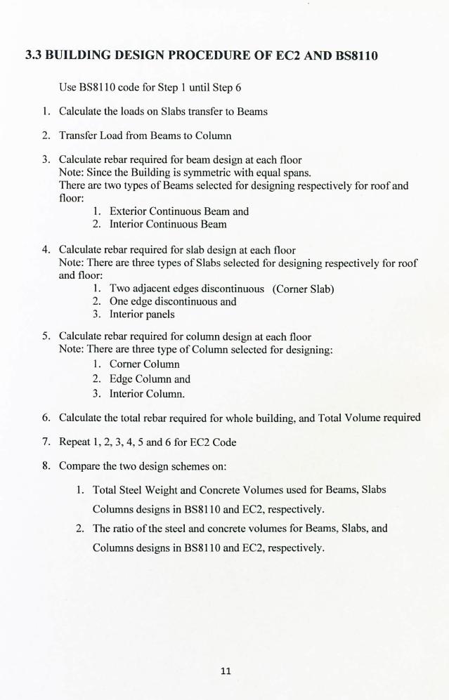
3.3 BUILDING DESIGN PROCEDURE OF EC2 AND BS8110
Use BS81 10 code for Step 1 until Step 6
1. Calculate the loads on Slabs transfer to Beams
2. Transfer Load from Beams to Column
3. Calculate rebar required for beam design at each floor Note: Since the Building is symmetric with equal spans. There are two types of Beams selected for designing respectively for roof and floor:
1. Exterior Continuous Beam and 2. Interior Continuous Beam
4. Calculate rebar required for slab design at each floor Note: There are three types of Slabs selected for designing respectively for roof and floor:
1. Two adjacent edges discontinuous (Corner Slab) 2. One edge discontinuous and 3. Interior panels
5. Calculate rebar required for column design at each floor Note: There are three type of Column selected for designing:
1. Corner Column 2. Edge Column and 3. Interior Column.
6. Calculate the total rebar required for whole building, and Total Volume required
7. Repeat 1,2,3,4,5 and 6 for EC2 Code
8. Compare the two design schemes on:
1. Total Steel Weight and Concrete Volumes used for Beams, Slabs
Columns designs in ßS8110 and EC2, respectively. 2. The ratio of the steel and concrete volumes for Beams, Slabs, and
Columns designs in BS8110 and EC2, respectively.
11

3.4 BEAM DESIGN (EC2)
I. i'Cf111. ti1CIlt . 1111I V. 11'111I)IC al'tll)tl`
1.35(; k -I. 5(1k iablc A. ä n. IIrIIRIUrII . UV. rn Ot rcintorccrnrnt
Tension reinforcement In beams (n. r, relr , 1, i 1, (l.. - SOON irrnY )
and slabs
r" d
.1
Secondary reinfr, r-ment 7n ni. un reinforcement
U. SS/
Lnngitudinal rCintorccrnCnl in colurnm 10 'v,,. 0 ö/r.
_ 0 00IA wlirrr 'V',., n the" axial comprClf, nn turco
Vertical reinforcement In walls A, ,,,, 0 002A,
Continuous beams with approximately equal spans and uniform loading
Illtl SI). 111 1111ý"ýlýýr SIý. Ii1 01 IFf 1). 1nFf O I()ff
("1) Brnding Ivloniýnlt
(Ib) Shr. mnrl Fc. rces
c ý ýý ý-ýJ
O. O9Fl 0.07Ff
0.451 0 55F
(). 6UF
1- iutal ulUmatc load on apan 1 35G, . I. SOQ. ) kN L- Ell-ti- apan
T. tl>, la" A. ') I nlJtrlltt ( I, ntit. nit v. tlu("ti
1 rnniuu) r.. ý,
Ar,.; Iunrl. ny A I rrnrluul J' r/ M. rxrnýum Fýr"rct"n[eyo ". lot"1 . rrc. r 1OOAr,,,,
_ In/
ýr r'r ;
Hgurr 4.8
0 1h (0001 i) 0001 3 0.0015
00
ý
�ý, ý "ý
C25130 C30,35
I .a-
. "e m \tn"" tn: " .
11�ih 40 45d
41 wi? 1 7.
I 'I
i, i ./
n x7/,
C40"SO C50/60
0.0018 0.0021
( -a>rrt rcte" closý " CSO/6O
04S O 8.1,1 0.1(, 7 0.171
%k Jill -, ,
_InPIN MI
ý). 171.,: r,, : l; ' l). h7f, k
1 I. ti? 41.
12

3.5 DESIGN FOR BEAM SHEAR (EC2)
ý ,. ti º<.: ,. ý� ,"
_.. I'. ,,,. ) I-';.;
() Ish,. cl; 1 r,, 2511 1,
H U. 5. In
+ li. i`r/! I i; d rl
U -. It
--\ 1, ýi ýti' ,, n o, 1 01 %ý
ýV--i vrrtKaI v+ea, rnntprcament
3.6 DESIGN FOR PUNCHING SHEAR IN SLAB (EC2)
4.: .,
.. Sill
n, = length of the pumhing shear penntete, u; _'cu -h 1-J Figure 81
:1u I"..
: 1. .
u m?, r,,,
ýN, f , ýý
"
- 1,
I
V,
uhrre I F, , :1, '
'rN(I ( 41;
Strut Indlnatbn n,. thod
Conc-lr strut n CO, 1 )'t St on
.6
I hr in. nnn; uii hrnni. I ithIk hiai I, 1t. r I hr uni . hcat
ti F: d .,, II 5: ý,. 1Id (1-51', J.
º Is III/
P, m<., n, > , hear
. ,,..,. ý, ,, ý
V, 11. (l I
4--! %º
999 II _-
-"
L. I-
I-" Lwg-td, nal rn. ntornmtnt in t*nNOn
1, 'illi. lhc oUCn}"11 reduction factor
iI
ý ýIJ17 . ''"
lýý. lýi"U
1'('. 1
ý H,! .= 1*R. 1 gill
(4. t, - d-I rltc: n%c depth _
ºº
ý "ºý f'. r. i! '.. n
/l"
ir"i. canr:
Btid110 ulI41
k-, ä/e/ttirmrn Rcýr. rrrXulw
13

PUNCHING SHEAR LAYOUT (EC2)
s, : 0.750 Outer control
%0.50 I
perimeter ks
IN SectLCn A-A
3.7 COLUMN DESIGN (EC2)
Effective height t" of 0 column [lie rllr. tn: h. ý_hl
! u}! 1. ;'I{
I nr unhr. r: J nx"mlkr. ihe lit go rd
!,, ft (i " IUýi
ý,
Jlkl
�, rti L I' 4, and 4. ate the iclatnc Ilcuhilme... t the rotational tc. trarnt.
end. 'I" an. l n1 the "uhmm rc. pratt. ek OI11111n . t111ne.. L/ !
L
Table 9.1 Column cttc<II c icnythn
I1 l'-.. -k0
00623 0 125 0.25 0 30 to 1.5 2.0 41k.,. (lard rnQ)
to - taaceA -- - -- -- ---- --
(equation 9-2) 1 . 1} O. SD S6 061 0.68 0.76 0.84 0.88 0.91
In - unbraced (equalron 9.3(a) 101 14 1 21 1.50 1 87 2.45 2.92 3 32
and 9.3(b)). Use
greater value (. lf 1.0 1 12 1,13 1.44 178 2.2S 2. S6 2 78
\; teem 'I'l Inc..
Howe. it a qpi: aI colmon in a %)mmorical frame with yin, u( aprrounulolý equal lrnglh. a. Qhuwn in li? uro H�1 anJ 1: can tt cal: ulJICJ a%
!II; 1 li ýýý column . ntlnr.. II ýýtxam, I ittiW%' '_.! 1u _' !14
nýn. lýdn9 co'.. "º
1M4n9 coiwý, º
non. l«Npca.,, ý� .
Note the etleclne cow, out on o, t7,, n, r, I, i, i ng column to the pM tilMnett may be gnaed
14
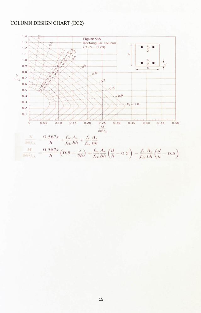
COLUMN DESIGN CHART (EC2)
.1
13
1.2
I1
1o 09
08
-1,0 7
06
0.5
04 O3
02 01
G
yý 0 oý, f
ý! ) ý?
I _a__ . lzlý 0y'
f iqurc 9.8
Ri<idnqul, lr tcriunM h 0201
ý R! ý.
IV 0
" uý -I U.
S
- 0'
. G.., ..
ý -- f t' .
r -ý . _ý
-, ý. _.
0
,ý ' .. '. ¼. -'---
. _.
ký N
- -i A
ui
h" UM
ý
i 1-0.9
-K; 10
0 05 0 10 O1'0 20 0 2S 0 30 0 35 Il f
ýý" ,. !. 1.1 1
1, ý I'll 1.: hh
ýº _('_i . '1. ( (I ý()
.1ý -- ` I, '!, /,;. 1º11 1º
(). 507, % !ý
,, ýý
40
0
0
"
040 045 0.50
/. 1, j 1r U. S
Li. b/1 \ !Iý
15

3.8 GANTT CHART
For Semester 1 (July 2009) W1 W2 HD W3 W4 W5 W6 W7 W8 W9 MSB W10 Wll W12 W13 W14
20- Jul
27- Jul
3- Au
10- Aug
17- Aug
24- Aug
31- Aug
7- 14- 21- Se
28- Sep
5- Oct
12- Oct
19- Oct
26- Oct
2- Nov
Final Year Project I (Overall Activities) Briefing Session 20/7
Selection of Topic
Project Proposal Due 24/7
Submission of Progress Report l& 2 03/9
Submission of Interim Report 30/1 0
Oral Presentation
Seminar IEM Talk 12/8
IRC Workshop 17/8 Technical Writing 1 17/8 Technical Writing 2 24/8
Laboratory Workshop 24/8 Referencing 14/9
HSE Talk 09/9
FYP I Activities Project understanding Concept and Theo Literature review Research for reference documents Study Ms. Excel Function Design
Template Layout Progress For
- Beam (BS81 10)
16

For Semester 2 (January 2010)
WI W2 W3 W4 W5 W6 W7 MSB W8 W9 W10 W11 W12 W13 W14 W15 25- Jan
1- Feb
8- Feb
15- Feb
22- Feb
1- Mar
8- Mar
15- Mar
22- Mar
29- Mar
5- Apr
12- Apr
19- Apr
26- Apr
3- Ma y
10- Ma y
Final Year Project II (Overall Activities)
Talk on Statistical Analysis 24/2
Submission Progress Report I &II 12/3
Poster Exhibition 14/4
Submission of Dissertation (Soft bound)**
26/4
Submission of Dissertation (Hard Bound) 30/4
Oral Presentations** - 7/610/6
FYP 11 Activities
- Slab (BS8110)
- Column (BS8110)
- Beam (EC2)
- Slab (EC2)
- Column (EC2) EC2 and BS81 10 Compared
17

3.9 TOOLS REQUIRED
1. Microsoft Excel Worksheet Software
With the help of following software to improve and double check on any
errors that could be occurred by any mean.
- Microsoft Work
- Notepad,
- MathType
- Graph 2D,
- Beamax,
- RC Slab Design Application etc
18

CHAPTER 4
EXPECTED FINDING/RESULTS
For the expected finding/result will be calculated and showed in the Microsoft Excel
Worksheet. The result based on the following criteria. 1. Total Steel Weight and Concrete Volumes used for Beams, Slabs, and
Columns designs in BS81 10 and EC2, respectively. 2. The ratio of the steel and concrete volumes for Beams, Slabs, and Columns
designs in BS8110 and EC2, respectively.
TABLE 1: THE BASIC DIFFERENT BETWEEN BS8110 AND EC2
BS8110 EC2 Concrete partial factor 1.5 1.15 Steel partial factor 1.05 1.15 Yield Strength fy = 460 N/mm fyk=SOON/mm
0.95f, � 0.87fck Design Strength, st, i (=0.95*460=437N/mm2) (=0.87*500=435N/mm2) Concrete Strength feu = 40 N/mm fck = 32 N/mm
Design Strength, oncretý 0.45feu (=18N/mm2 )
0.567fck (=18.144N/mm2)
S 0.9x 0.8x Level arm, Z 0.775d 0.82d
2 0.156bd feu 2 0.167bd fck Mu, concrete 2 (=6.24bd) 2 (=5.344bd )
0.95fy. As. z 0.87fy. k. As. z Mu, Steel (For SR) (= 0.95*460*As*0.95d (= 0.87*500*As*0.95d
= 415.15As. d) = 413.25As. d) 0.95fy. As. z 0.87fyk. As. z
Mu, Steel (For DR) (= 0.95*460*As*0.775d (= 0.87*500*As*0.82d = 338.675As. d) = 356.7As. d)
Coefficient: Dead Load : 1.4 Dead Load : 1.35 On Load Span Live Load : 1.6 Live Load : 1.5 Coefficient:
Dead Load : 1.0 Dead Load :1 35 On Unload Span .
19

The following is the result of steel and concrete volumes using under mild and severe
exposure, respectively.
- Ws : Steel Weight in t, Tones
- Vc : Concrete Volume in m3
- WsNc : Ratio of steel and concrete in t/m3
TABLE 2:
STEEL WEIGHT AND CONCRETE VOLUMES USING UNDER MILD EXPOSURE
BS8110 EC2 Beam Size, (mm) 500x700 500x700 Slab Thickness, (mm) 250 250 Column Size, (mm) 400x400 400x400
Beams Slabs Columns Beams Slabs Columns Ws, (t) 7.835 40.072 7.718 7.443 40.237 6.709 Vc, (m 336 576 39.6 336 576 39.6 WsNs, (t/m) 0.0233 0.0696 0.195 0.0222 0.0699 0.1694 Total Ws 55.625 54.389 Total Vc 951.6 951.6 Total WsNc 0.05845 0.05715 % differentWs EC21'lBS81 BS810 10 (54.389-55.625)/ 55.625* 100 = -2.22%
More Cost Saving
TABLE 3:
STEEL WEIGHT AND CONCRETE VOLUMES USING UNDER SEVERE EXPOSURE
BS8110 EC2 Beam Size, (mm) 500x700 500x700 Slab Thickness, (mm) 250 250 Column Size, (mm) 400x400 400x400
Beams Slabs Columns Beams Slabs Columns Ws, t) 8.068 46.013 10.073 7.463 40.783 7.235 Vc, (m) 336 576 39.6 336 576 39.6 WsNs, (t/m 0.0240 0.0799 0.254 0.0224 0.0708 0.1827 Total Ws 64.154 55.481 Total Vc 951.6 951.6 Total WsNc 0.06742 0.05830 % different, Ws (EC2-BS81 l 0)/BS8110 (55.481-64.154)/64. 154* 100=-13.52%
More Cost Saving
20

CHAPTER 5
CONCLUSION AND RECOMMENDATION
IN CONCLUSION:
Microsoft worksheet is a very good program with long-term advantage and
time saving but there are risks that need to he well managed and
organization. EC2 is not wildly different from BS8110 in term of Design Approach but it
provided with the more economical than BS8110.
y EC2 provided more flexible strength comparing with BS8110
RECOMMENDATION:
It is good to look at the few different points below in order to make ourselves ready for
the EC2.
For the beam and slab design in both codes are similar and the main different
are the partial safety factor and level arm z, especially on checking o the
deflection.
r For punching shear reinforcement design have different formula for define
the required and have different distance of failure zone.
- BS811 Osimilar to the stirrup design for the beam
- EC2 new approach formula to be used. For EC2 column design is different from BS8110 on effective length le, and
condition for biaxial bending of short columns design.
ir(e 1h)/(ej1b)>0.2 or (ey/b)/(e, /h) > 0.2 then the column must be designed
for the biaxial bending, which not stated in the BS8100.
21

CHAPTER 6
ECONOMIC BENEFITS
6.1 ELECTRICITY
Since the project is the software simulation based, so it's electricity consumption and the
electricity supply is provided in the Laboratory and consumption cost is covered by the
department during the project periods.
6.2 DOCUMENTS
Below are the description and cost of the materials which are not provided in the lab and
they aided in the completion of the project. The following are the standard codes' price that needed to spend for the project.
No Description Purpose Quantity Price (RM. ) I BS EN 1992-1- Design of concrete structures - part 1- RM 595 1: 2004 1 General requirements - All concrete 1 (£124)
structures 2 UK National All concrete structures RM 287.70
Annex to BS EN (£60) 1992-1-1: 2004
3 BS 8110-1: 1997 Structural use of concrete. Code of RM 841.60 practice for design and construction 1 (£ 175.50)
4 BS 8110-2: 1985 Structural use of concrete. Code of RM 618.60 practice for special circumstances I (£ 129.00)
5 BS 8110-3: 1985 Structural use of concrete. Design RM 669.00 charts for singly reinforced beams. 1 (£ 139.50) doubly reinforced beams and rectangular columns
RM 3011.90 Total Amount (£ 62S)
Note: 1£= RM 4.7955
22

6.3 ECONOMIC BENEFITS
According to the EC, Eurocode 2 is introduced in early 2003 have been assured by most
engineers that it can be used as a practical concrete design tool, as well as producing
economic results more structures. It is expected that in building structures there will be
material cost savings of between 0 and 5% compared to using BS8110.
The economic advantages of EC2 for flexural design are far greater than can be assessed by looking at the partial factors for loading and materials alone.
" For similar characteristic loading, ULS loading can be 10% to 15% less.
" Rebar design stresses are almost identical, in spite of the differing 7 factor.
" The difference in pattern loading may marginally increase support moments but
reduce span moments.
" For the same concrete mix, EC2 gives a concrete stress 19.4% higher than BS
8110, which in turn increases the lever arm z.
" More generous span-to-depth ratios can lead to shallower members.
These economies would seem very significant. Shear and column design do not appear
to have been trimmed in the same way, but this must reflect our increasing
understanding of concrete design. Slabs are by far the most economically critical
elements, and here there is advantage.
23

REFERENCE
1. S. C. Bloch, (2003), Excel for Engineers and Scientists, 2"d Edition.
2. Bernard V Liengme, (2002) A Guide to Microsoft Excel 2002 for Scientists and Engineers, 3`d Edition/
3. John Baker & Steve Sugden, (2003) Spreadsheets in Education (eJSiE) - The First
25 Years, Volume 1, Issue 1,2003, Article 2.
4. Dr. Kum S. Elliott, (2009) The Design of Reinforced and Prestressed Concrete
Structures to Eurocodes, March 2009, Conference at Plain Garden Hotel, 101 Resort
Putrajaya.
5. The Institution of Structural Engineers, (2000) Manual for design of reinforced
concrete building structures to EC2, March 2000.
6. W. H. Mosley. J. H. Bugney & R. Hulse, (1999) Reinforced Concrete Design, 5`h
Edition.
7. David A. FAnella and S. K. Ghosh, (1993) Simplified Design Reinforced Concrete
Building of Moderate Size and Height, 2nd Edition.
8. T. J. MacGinley and B. S. CHOO, (1990) Reinforced Concrete Design and Theory
and Examples, 2nd Edition.
9. R. S. Kurmi & J. K. Gupta, Civil Engineering (Conventional and Objective Type),
Reinforced Cement Concrete Structures, page 522-571.
10. Structural use of concrete l. BS 8110-1: 1997 Structural use of concrete. Code of practice for design and
construction Superseded by EN 1992
2. BS 8110-2: 1985 Structural use of concrete. Code of practice for special
circumstances Superseded by EN 1992
3. BS 8110-3: 1985 Structural use of concrete. Design charts for singly
reinforced beams, doubly reinforced beams and rectangular columns Superseded by EN 1992
11. G. Ruuso, G. Somma and P. Angeli, (2004)Department of Civil Engineering,
Univerity of Udine, Udine, Italy, Material and Structures, Vol. 37, December 2004,
page 680-688.
12. http: //www. eurocode2. info/main. asp? page=1151
24

13. http: //www. eurocodes. co. uk/EurocodeDetail. aspx? Eurocode=2
14. http: //en. wikipedia. org/wiki/Concrete cover 1 5. http: //en. wikipedia. org/wiki/Rebar
16. Implementation of Structural Eurocodes in the UK, Produced by the Office of the Deputy
Prime Minister, 3 February 2003,
17. R. S. Narayanan (1994), Concrete Structures: Eurocode EC2 & Bs81 10 Compared.
25

APPENDIX 1
26
The practical use of Eurocode 2
I Introduction When or before Eurocode 2 is introduced in early 2003, most engineers will need to be assured that it can be used as a practical concrete design tool, as well as producing economic results. If they are not assured of this, practices will continue to use BS 8110 in preference to adopting the new code.
Necessary guidance in the form of explanatory literature, process flowcharts, spreadsheets and other software etcetera is in preparation. This brief report will attempt to summarise the principal design procedures required by EC2, compare them with their BS 8110 counterparts, and demonstrate that the transition to EC2 need not be a difficult process.
2 Comparisons with BS 8110
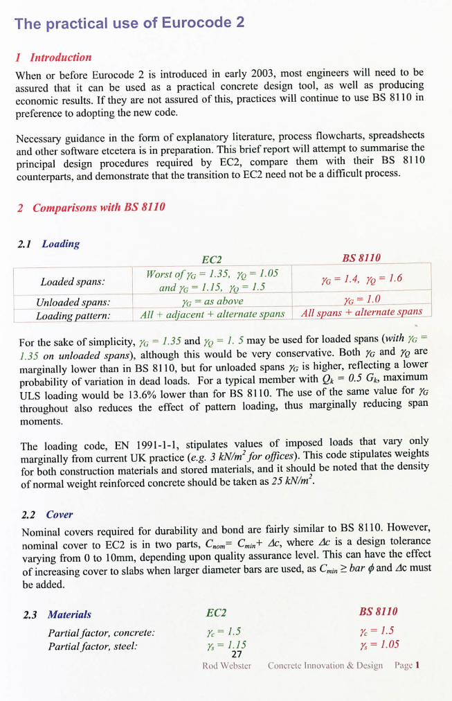
2.1 Loading
EC2 BS 8110
Loaded spans: Worst qJ' ya = 1.35, yQ = 1.05
yG = 1.4, yQ = 1.6 and yc=1.15, yQ=1.5
Unloaded spans: y(, = as above y(; = 1.0 Loading pattern: All + adjacent + alternate spans All spans + alternate spans
For the sake of simplicity, y,; - 1.3 5 and ;,, = 1.5 may be used for loaded spans (with ; /(; = 1.35 on unloaded spans), although this would be very conservative. Both yG and yQ are marginally lower than in BS 81 10, but for unloaded spans yG is higher, reflecting a lower
probability of variation in dead loads. For a typical member with Qk = 0.5 Gk, maximum ULS loading would be 13.6% lower than for BS 8110. The use of the same value for yG throughout also reduces the effect of pattern loading, thus marginally reducing span moments.
The loading code, EN 1991-1-1, stipulates values of imposed loads that vary only marginally from current UK practice (e. g. 3 kN/m' for offices). This code stipulates weights for both construction materials and stored materials, and it should be noted that the density of normal weight reinforced concrete should be taken as 25 kN/m2.
2.2 Cover
Nominal covers required for durability and bond are fairly similar to BS 8110. However, nominal cover to EC2 is in two parts, Cno, �= C,,;,, + dc, where At, is a design tolerance varying from 0 to 10mm, depending upon quality assurance level. This can have the effect of increasing cover to slabs when larger diameter bars are used, as C�,;,, ? bar 0 and do must be added.
2.3 Materials EC2 BS 8110
Partial factor, concrete: y,. = 1.5 yý. = 1.5 Partial. factor, steel: y, = 1.1 yT = 1.05
27 Rod cl,,:,.: n,:, InnOVation fi W, I'; t !el
The practical use of Eurocode 2
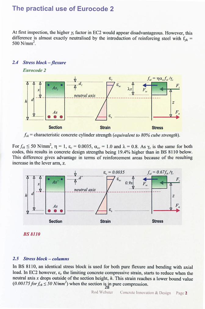
At first inspection, the higher y. S factor in EC2 would appear disadvantageous. However, this difference is almost exactly neutralised by the introduction of reinforcing steel with fyk _ 500 N/mm`'.
2.4 Stress block -flexure Eurocode 2
" As,
As """
Section Strain Stress
Jýk = characteristic concrete cylinder strength (equivalent to 80% cube strength).
For fck <_ 50 N/mm2, rl = 1, c,. = 0.0035, a,.,. = 1.0 and A=0.8. As yc is the same for both
codes, this results in concrete design strengths being 19.4% higher than in BS 8110 below. This difference gives advantage in terms of reinforcement areas because of the resulting increase in the lever arm, z.
- -ý ý- A
h ýb d
BS 8110
"" As'
neutral axis ---------------
As """
E, = 0.0035 f,, - 0.6 7f, ry,
Ej
Section Strain
ES(' 0.9x A
Stress
Z
I'
Lýll
2.5 Stress block - columns In BS 81 10, an identical stress block is used for both pure flexure and bending with axial load. In EC2 however, i, the limiting concrete compressive strain, starts to reduce when the neutral axis x drops outside of the section height, h. This strain reaches a lower bound value (0.00175 for fk< 50 N/mm) when the section i 28n pure compression.
Rod \\ I .; l uncrýtr Innuý itIun ýý I )cicn I'; ilL 2

The practical use of Eurocode 2
The diagram below demonstrates this procedure. Effectively, the strain diagram has a "hinge point", which falls at h/2 for normal strength concretes. This process is easily automated, but is not suited to hand calculation, so it is best accomplished by spreadsheet.
As few columns are very close to being in pure compression, this gradual reduction in strain, and hence compressive stress, has less effect than one might imagine.
e;
h d
0.0035 max
h1l i-
-L; binge
i point
0.00175 min General relationship
0.00175x /(x- h/2) 0.00175
x
Whenx>h
EC2 strain relationship at L'LS (%x < 50 N/mm
2.6 Redistribution
0.00175
Pure compression
EC2 BS 8110 Neutral axis limit: x/d <b-0.4 x/d <_ A-0.4 Redistribution limit: 30% classes B&C 30% generally
20% Jor class A rebar 10% sway frames >4 storeys 0% in columns 0% in columns
Limitations: Adjacent spans ratio <2
The EC2 x/d limit reduces for concrete with fck > 50 N/mm`, otherwise both codes are very similar.
2.7 Beam shear A strut-and-tie model is used for shear reinforcement to EC2, which can have a varying angle 0 between the compressive struts and main tension chord. Cot 0 is normally taken as the maximum value of 2.5, but may be as low as 1.0 if required for high shear forces.
For UD loading, EC2 BS 8110 Shear resistance: v=0.7 - /, k/200 > 0.5
k=1 +J(200/d)2 v,. =from Table 3.8 p, = A_s, /b�d < 0.02
At support face: Vkd,,,,, « = 0.9b�d. fd /(Cot 0+ tan 0) Vmnr = 0.8'ffu <5
At d from support: VRd, C., = 0.12k(100ptf. 1)''j Vc = vt.. b, d If VRd,
cf ? VFd nominal links IJ Vc c, >_ V, nominal links
29 Rod 11 ýh t,: l nt, r, L Innuý; ttiun Dr; i n I'a ý3

The practical use of Eurocode 2 Links: A,,,. Is = VFr /(0.9d. v. fd cot 0) A,,. Is, =1.05 b� (v-v j /f v Nominal links: A,,,. /. s ? 0.5 /f,.,, d A,., Is, ? 0.42b,. /r.,.
Understandably, these approaches are somewhat different although both methods are simple enough to apply. One can see from the above formulae that when more than nominal links are required, EC2 ignores any contribution from the concrete. The strut-and-tie method produces an additional tension in the main steel where the compression strut meets this steel. This effect is catered for by applying the "shift rule" when detailing (see Section 3).
2.8 Punching shear
The calculation of punching shear is basically similar to BS 8110, except that the control perimeter is at 2d, rather than /. 5d from the column face, and follows a locus from the column face, rather than being rectangular in shape.
..............
2d
.................
............... ..
1.5d
............................
EC2 BS 8110 Basic control perimeter: At 2d at 1.5d Control perimeter shape: Rounded corners Rectangular Flat slab shear enhancement factors
Internal: 1.15 1.15 Edges: 1.4 1.4 or 1.25
Corners: 1.5 1.25
When links are required, EC2 allows a contribution of 75% of the concrete shear resistance (unlike beam shear), and a radial distribution of links is assumed. An outer perimeter, at which no further links are required, is based upon the link arrangement rather than the basic control perimeter.
The much higher enhancement factor of 1.5 for corner columns may prove critical in some circumstances, when sizing flat slabs for shear. However, the method as a whole seems very logical and may result in fewer links and be simpler to detail than the BS81 10 method.
30

The practical use of Eurocode 2
2.9 Span to depth ratios
Busic Lid ratios:
Tension steel modifier:
Compression steel modifier:
Flanged sections:
Long span modifier:
Service stress modifier:
EC2 K factors fi"onr Table 7.4 used in
equations 7.14a &h
BS 8110
From Table 3.9
In equations From Table 3.10
In equations From Table 3.11
I>1-0.2b�/bl/3>0.8 Only used if there are brittle partitions
Flat slabs: 8.5 /L <I Otherwise: 7 /L <I
310 /cr, (srrýl srrri<"t, sfr"'csl
Interpolated between Table 3.9 values
10/L <I
Formulae included in Table 3.10
These two methods are very similar, but in practice, Eurocode 2 effectively allows marginally shallower members than BS 8110. This is likely to be because the EC2 ratios have made no allowance for early age overloading during construction, which can increase the degree of cracking, particularly in slabs.
2.10 Maximum bar spacing For normal internal exposure, EC2 recommends a maximum crack width of 0.4mm compared to 0.3mm in BS 8110. However, the maximum bar spacings in Table 7.3 are somewhat less than those now commonly used in the UK. This will tend towards the use of slightly smaller diameter bars in slabs. The actual calculation of crack widths to clause 7.3.4 allows more flexibility.
Z 11 Beam flange widths To both codes, effective flange widths may be calculated directly from the distances between points of contraflexure, but the default values below give an indication of comparative values.
F. C2 BS 8110 Simple supports, L Simple supports, L
Effective span, spans: End span, 0.85L End span, 0.85L
Effective span, supports:
Internal span, 0.7L Internal span, 0.7L Cantilever, L.
Not applicable Others, 0.15L either side of support. [h, /5+Lq1-/10] L.,, /5
Effective bf T-beam: plus [h2/5+Lefl /I0]L, yj15 h,,. +L f- /S < h�, +ht+b, < b,,. +b, +b,
Effective hf, L-beam: h,,. +{[ht/i+L,. ýý /IOJSLei1/5} < h,,. +h, h,,. +Lep/10 < b,,. +bt b, and b2 are the actual flange o4 lands on either side of the web
I)c, jL"n I''wc 5

The practical use of Eurocode 2
It should be noted that EC2 requires a portion of beam support steel to be spread across the width of flange. This is why a method is also provided for assessing the widths of tension flanges.
2.12 Flat slabs
For flat slabs, the two codes are almost identical, the relevant EC2 clauses having been drafted in Britain. Slightly more latitude is suggested however, for the apportioning of moments between column strips and middle strips.
the limit on moment transfer into edge/corner columns, is approximately 10% lower than for BS 8110.
2.13 Columns Some of the terminology in Eurocode 2 relating to column design may be slightly unfamiliar, with minimum eccentricities being described under "imperfections" and buckling etcetera falling within "second order effects". Alternative design methods are given, but the "curvature" method is similar in approach to current practice. As with BS 81 10, the column design process is quite tedious to perform manually, but is relatively easy to automate. The simplified method given for carrying out biaxial bending checks is more logical than in BS 8110, and is simple to apply.
A comparison between the EC2 and BS column design processes is shown in the flowcharts below.
BS 8110
. A.. OAt lri. JJ! I SneESS ecaar Lmdma w+<ý. e o:. nn
ti_ " 676. d Yß /t l. p. .. ý: w: \" OSS.
., ,J -1
lMPERfECI/OWS
lA#- 6 ., i. r.
\/ wynýLtelýAr: li
ý ýYý1Y b Yý . Ea++ 1ýoY1
ý ltl1..
sýawess CMeý: wr n.. ýýs. t_ ýk .. Aerc
ý, ý ý. ý. m ý. ý ,, ý
85 811O & E02 draft EN cooped., on Dc +i i Flowcharts
BRACED COLUMNS
ý. ý p.:. y. V... vý. v.
I/- ý ; )ICM14TC" ýitg l, Ri
Ill4ýhl. b . rNI ýa, cN, L; i J. AI. J
14/
BEMNAC
ý ,.. ý. n.. . -a (
... ý" , ., a"
.F.
1A. fJ
; fV4uaf Mf V(VM:
Ie.. Niýw" V; P.
fM. knw J: ý Gh'"9n N N. M, w+t"r
N O. C V. (), 441 - 0.4N N
aM ý... r x{usýte s; ns l:. a ýt ý
c,. natwr lldltJ
' .y/V.. ' t. ',. V..
.I ýe. t.. ýte"/ f
"iý
y... e 2. nw.. w. ct. rt L 2! 1«"091( ý' %. 1
. ewe(.. rJJn n, l
tr; ^va vý,. . r. .. u LA. '.. --
32 IZoulllrlýý(ýi
EC? LM? f7 EN
SrRzss stoat
red�cee r. -, ý" ... ý. V;
cýo. ^ý_ ... -, T-,. a. ý i. i, nr
M1PERlECT/G{MS
,.,., , I. 1.1! rr. r» ., UO. %. L /f
wherc iý raf. us of
ýF w: f -' '2I3. I9. l\ ý. ýy ar a. sfýt. rW M cl P: aVý
...... . nf f*rra.
Ns yWM "Yý tM-ý. !'. frpwa. MrarWºar /ýlNf ý
aczwýmvas EMoct+cera"t.. 0.5Lý
0. J/t-.
.;;: I nncivutiun & Design Payr 6
AaV. 1lýý'
"" OA07H 9f. /dJ7 "
^_ . fý a Dl at tpa, I JJ gJ r
r++apc. y..? D. wNMýý .. -+ur.. dAwa1ODra: r.. r ,
BCNDUG
V cfJr" rrý"r"r:. :'.. -( sK14, crKk. d It :R 5l5
l. a. A t
. f"Jr 1, " 1J
_N"N
, ... IJ _; 7(. N "? dN >-J.! J

The practical use of Eurocode 2
3 Detailing
3.1 General
BC2dctailing rules are slightly more complex than for BS 8110. It will no longer be possible to make simple assumptions, such 35 or 40 diameters for an anchorage length, and technicians will need to learn the necessary skills, as there are differing anchorage rules for different types of member. There are also many small changes to be learned, such as the detailing of beam support steel within flanges, minimum reinforcement percentages, and new rules regarding the staggering of laps.
3.2 The shift rule This is the recommended method for working out curtailment points for beam reinforcement, which at the same time ensures the provision of sufficient steel near to supports, to accommodate the additional tensile forces generated by the strut-and-tie shear action described in 2.7.
Basically, the bending moment envelope is "shifted" a distance between 0.45d and 1.125d and bars should have an anchorage length beyond their relevant "shifted" point of being no longer required.
4 Unfamiliar processes 4.1 Strut-and-tie models The strut-and-tic method should be used for the design of D-regions, which are described as "discontinuities in geon: etrv or action". Some such discontinuities are frame corners, corbels, or abrupt changes in section. It is also important to note that this method is implied within the shear design process described in 2.7 and 2.8 above.
Typical node model for a corbel
33 Rod \\'eh. "trr l OmCrctr Innovation & Ur; ion ['ayr 7

The practical use of Eurocode 2
Although widely used in other European countries, this approach, while not being particularly complex, will be unfamiliar to many designers in the UK, so both engineers and technicians are likely to require guidance.
5 EC2 overview
5.1 General
The areas covered by this document are not exhaustive; only what are considered to be the more important and commonly used procedures have been discussed. Eurocode 2 is a very comprehensive code and also includes rules for precast concrete, post-tensioned members etcetera, but the focus here has been on everyday insitu reinforced concrete design.
5.2 Code philosophy The general philosophy of EC2 is quite different from that found in BS 8110. The Eurocode is less empirical and more logical in its approach. For example, variables such as partial factors for materials are shown within formulae, rather than being "built in" as part of an obscure number. If one wishes to go into greater detail, there are appendices to the code that give derivation formulae for items such as creep coefficients and shrinkage strains, which are most helpful when attempting to automate the design process.
EC2 makes no attempt to be a design "guide"; it is a code giving general rules. There are no simplified tables of moment or shear factors for example, as one would be expected to look for these in separate design guides or standard textbooks.
In my view, EC2 has great potential of being accepted as a very good replacement for BS 8110. Inevitably there will be those who wish to resist any change, but I am sure that, after an initial learning period, the superiority and economic advantages of EC2 will universally recognised.
5.3 What is needed? To smooth the transition to EC2, the following tools will be required; preferably to be available before the predicted formal release of the new code in early 2003.
" General design guides " Worked examples "A "Concise EC2" "A full set of design spreadsheets " Comparative and calibration studies " An EC2 version of "Economic Frame Elements"
Hopefully, specialist software houses can also be encouraged to update their programs in due time. Of prime importance will be the availability of updated finite element software, as moments generated by programs written to the ENV version of EC2 will not be correct.
34 Po pp kl 8
The practical use of Eurocode 2
5.4 "Factors of safety" There has been recent discussion regarding comparative `factors of safety" between BS 8110 and EC2 (also CP49! ), which shows a massive misunderstanding of the basic principles of limit state design.
"A true factor of safety can only be determined by comparing design loading with that at collapse. " Partial factors for materials and loading are not safety factors; they only reflect degrees of
confidence. " Any basic understanding of statistics proves that to simply multiply together sets of factors or
probabilities is completely meaningless.
The economic advantages of EC2 for flexural design are far greater than can be assessed by looking at the partial factors for loading and materials alone.
" For similar characteristic loading, ULS loading can be 10% to 15% less.
" Rebar design stresses are almost identical, in spite of the differing y factor.
" The difference in pattern loading may marginally increase support moments but reduce span moments.
" For the same concrete mix, EC2 gives a concrete stress 19.4% higher than BS 81 10, which in turn increases the lever arm z.
" More generous span-to-depth ratios can lead to shallower members.
These economies would seem very significant. Shear and column design do not appear to have been trimmed in the same way, but this must reflect our increasing understanding of concrete design. Slabs are by far the most economically critical elements, and here there is advantage. z
lyd4
35 \\ HR: Il,, iýýil I'ýý '9