
Error estimates for the Scaled Boundary Finite Element Method
Upload
independentCategory
view
2download
0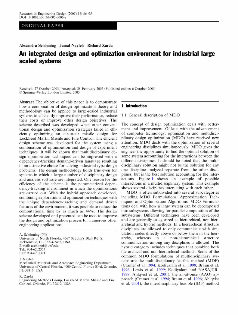
ORIGINAL PAPER
Alexandra Schonning Æ Jamal Nayfeh Æ Richard Zarda
An integrated design and optimization environment for industrial largescaled systems
Received: 27 October 2003 / Accepted: 28 February 2005 / Published online: 6 October 2005� Springer-Verlag London Limited 2005
Abstract The objective of this paper is to demonstratehow a combination of design optimization theory andmethodology can be applied to large-scaled industrialsystems to efficiently improve their performance, reducetheir costs or improve other design objectives. Thescheme described was developed when other conven-tional design and optimization strategies failed in effi-ciently optimizing an air-to-air missile design forLockheed Martin Missile and Fire Control. The efficientdesign scheme was developed for the system using acombination of optimization and design of experimenttechniques. It will be shown that multidisciplinary de-sign optimization techniques can be improved with adependency-tracking demand-driven language resultingin an attractive choice for solving industrial type designproblems. The design methodology holds true even forsystems in which a large number of disciplinary designand analysis software are integrated. One reason for theefficiency of the scheme is the parameterized depen-dency-tracking environment in which the optimizationsare carried out. With the hybrid approach developed,combining exploration and optimization techniques withthe unique dependency-tracking and demand drivenfeatures of the environment, it was possible to reduce thecomputational time by as much as 44%. The designscheme developed and presented can be used to improvethe design and optimization process for numerous otherengineering applications.
1 Introduction
1.1 General description of MDO
The concept of design optimization deals with better-ment and improvement. Of late, with the advancementof computer technology, optimization and multidisci-plinary design optimization (MDO) have received newattention. MDO deals with the optimization of severalengineering disciplines simultaneously. MDO gives theengineer the opportunity to find the optimal solution ofsome system accounting for the interactions between thedifferent disciplines. It should be noted that the multi-disciplinary solution might not be the solution for anyone discipline analyzed separate from the other disci-plines, but is the best solution accounting for the inter-actions. Figure 1 shows an example of possibleinteractions in a multidisciplinary system. This exampleshows several disciplines interacting with each other.
MDO is often subdivided into several subcategoriesincluding MDO Formulations, Approximation Tech-niques, and Optimization Algorithms. MDO Formula-tions deal with how a large system can be decomposedinto subsystems allowing for parallel computation of thesubsystems. Different techniques have been developedand are generally categorized as hierarchical, non-hier-archical and hybrid methods. In a hierarchical structuredisciplines are allowed to only communicate with sim-ulation codes directly above or below them in the hier-archy, whereas in a non-hierarchical structurecommunication among any disciplines is allowed. Thehybrid category includes techniques that combine bothhierarchical and non-hierarchical methods. Some of thecommon MDO formulations of multidisciplinary sys-tems are the multidisciplinary feasible method (MDF)(Cramer et al. 1994; Kodiyalam et al. 1998; Braun et al.1996; Lewis et al. 1999; Kodiyalam and NASA/CR-1998; Ahlqvist et al. 2001), the all-at-once (AAO) ap-proach (Cramer et al. 1994; Braun et al. 1996; Ahlqvistet al. 2001), the interdisciplinary feasible (IDF) method
A. Schonning (&)University of North Florida, 4567 St John’s Bluff Rd. S,Jacksonville, FL 32224-2465, USAE-mail: [email protected].: 904-6202357Fax: 904-6201391
J. NayfehMechanical Materials and Aerospace Engineering Department,University of Central Florida, 4000 Central Florida Blvd, Orlando,FL 32816, USA
R. ZardaEngineering Methods Group, Lockheed Martin Missile and FireControl, Orlando, FL 32819, USA
Research in Engineering Design (2005) 16: 86–95DOI 10.1007/s00163-005-0006-y
(Cramer et al. 1994; Kodiyalam et al. 1998; Lewis et al.1999; Ahlqvist et al. 2001), the concurrent subspaceoptimization (CSSO) formulation (Haftka et al. 1996;Braun et al. 1996; Ahlqvist et al. 2001), the collaborativeoptimization (CO) formulation (Kodiyalam et al. 1998;Braun et al. 1996; Lewis et al. 1999; Kodiyalam andNASA/CR- 1998; Ahlqvist et al. 2001), and the Bi-LevelIntegrated System Synthesis (BLISS) formulation (Ah-lqvist et al. 2001; Sobieszczanski-Sobieski et al. 1998;Sobieszczanski-Sobieski et al. 1999).
Due to the complexity of the multidisciplinary designsystems, it is often necessary to replace the simulationcodes by approximations to reduce the computationaltime. There are several approximation methods availablewhere some of the more common include Design ofExperiment in conjunction with Response SurfaceApproximations (1995), Variable Complexity Models(Engineous Software 1999; Golovidov et al. 1998), TaylorSeries Approximations (VR&D 1999), and ArtificialNeural Networks (Turban 1992). In each of theseapproximation techniques, an approximate equation orsystem is developed to mimic the original (more compu-tationally involved) system. In order to develop theapproximate system or equation, training of theapproximate system/equation is performed. For example,in design of experiment and response surface approxi-mations, the design space is probed at a specified numberof locations. For these locations the values of the objec-tive function and constraints are determined using thehigh fidelity system. Regression analysis is then applied tothe data and approximate equations for the objectivefunction and constraints, called response surfaces aredeveloped. The optimization can then be performed onthese response surfaces instead of on the high fidelitysystem, reducing the overall optimization time. Theoptimal solution obtained from the approximate tech-nique should always be verifiedwith the high fidelity code.
The third category of MDO is the selection ofappropriate optimization algorithms. Typically, thesealgorithms are divided into three categories: gradient-based algorithms, population based algorithms, andhill-climbing algorithms. In gradient-based algorithms,
the optimum is found by searching the design region in asteepest decent direction. The optimization processstarts at an initial location in the design space, and thenthe algorithm moves the design point in a direction inwhich the gradient is largest. Variations of this steepestdecent algorithm exist. At the optimal location, thegradient of the objective function should be zero and theHessian matrix, a matrix of second derivatives, shouldbe positive definite. For constrained problems, theKhun-Tucker necessary conditions are used (VR&D1999). Population-based algorithms are often used fordiscrete design problems while gradient-based methodswork well for continuous problems. Population basedmethods mimic biological evolution where several po-tential designs are compared to each other, the bestdesigns are then combined and a few new designs aredeveloped. The next sets of designs are then comparedand the process continues. Genetic Algorithms is themost commonly used population-based algorithm. Thethird type of optimization algorithms is the hill-climbingalgorithms, where the most common is SimulatedAnnealing (Levine 2005). The simulated annealingalgorithm randomly suggests a change in the designvariables. If that change produces a lower value (im-proved) of the objective function, then the variables arechanged. If on the contrary, the suggested change in-creases the value of the objective function, then the de-sign variables may still change to the suggested values.The likelihood of changing in a direction producing ahigher objective function value is based on statistics, andis greater in the beginning of the iterative process thantowards the end of the process.
In summary, MDO utilizes a collection of techniquesin optimizing multidisciplinary designs, including dif-ferent frameworks, approximation techniques, andoptimization algorithms.
1.2 MDO evolution and challenges
The MDO field has become vital in design environmentsin the past decades as designs are becoming more andmore complex. The hope is that MDO will both improveproducts and reduce the cost to produce them (Crameret al. 1994). Optimization techniques have been appliedto multidisciplinary systems before the concept of MDOwas developed. However, the optimization techniquesused were not specifically designed for multidisciplinarysystems (Kroo 1995). For example, parameter studieswere performed in which one, two or a few variableswere varied to study the effect these variables had on theobjective. This method is time consuming and does notaccurately account for the interactions amongst allvariables.
As mentioned in (Haftka et al. 1996), ‘‘the two mainchallenges of MDO are computational expense andorganizational complexity.’’ The MDO theory is thusheavily based on solving these problems. While MDOtechniques have come far in solving academic type
Fig. 1 Potential interactions in a multidisciplinary system (Ahlq-vist et al. 2001)
87
problems, the MDO technology has been under-utilizedin solving industrial problems. One improvement nec-essary in making the MDO techniques more attractivewhen solving industrial problems is to reduce the com-putational intensity involved in solving them (Messac1996).
The method presented in this paper was developedwith the computational intensity challenge in mind. Thiswork focuses primarily on a modified optimization for-mulation based on MDF and an improved data struc-ture using demand-driven and dependency-trackingfeatures. This modified formulation is named MDF-DTfor MultiDisciplinary-Feasible-Dependency-Tracking.MDF-DT shows that MDO techniques can be improvedwith a dependency-tracking demand-driven languageresulting in an attractive choice for solving industrialtype design problems. The optimization formulation wastested on a missile design, provided by Lockheed MartinMissile and Fire Control.
2 Interactive missile design environment
Before describing the optimization scheme, an intro-duction to the Interactive Missile Design (IMD) envi-ronment is presented. IMD was developed to design,analyze, and optimize missiles or other large-scaledsystems. Since the design of missiles integrate a largenumber of disciplines, it was necessary to develop anenvironment which is able to automatically communi-cate between the disciplines. The design system devel-oped integrates disciplines such as geometry,aerodynamics, propulsion, trajectory, lethality, thermal,weight, structural analysis, controls, packaging of com-
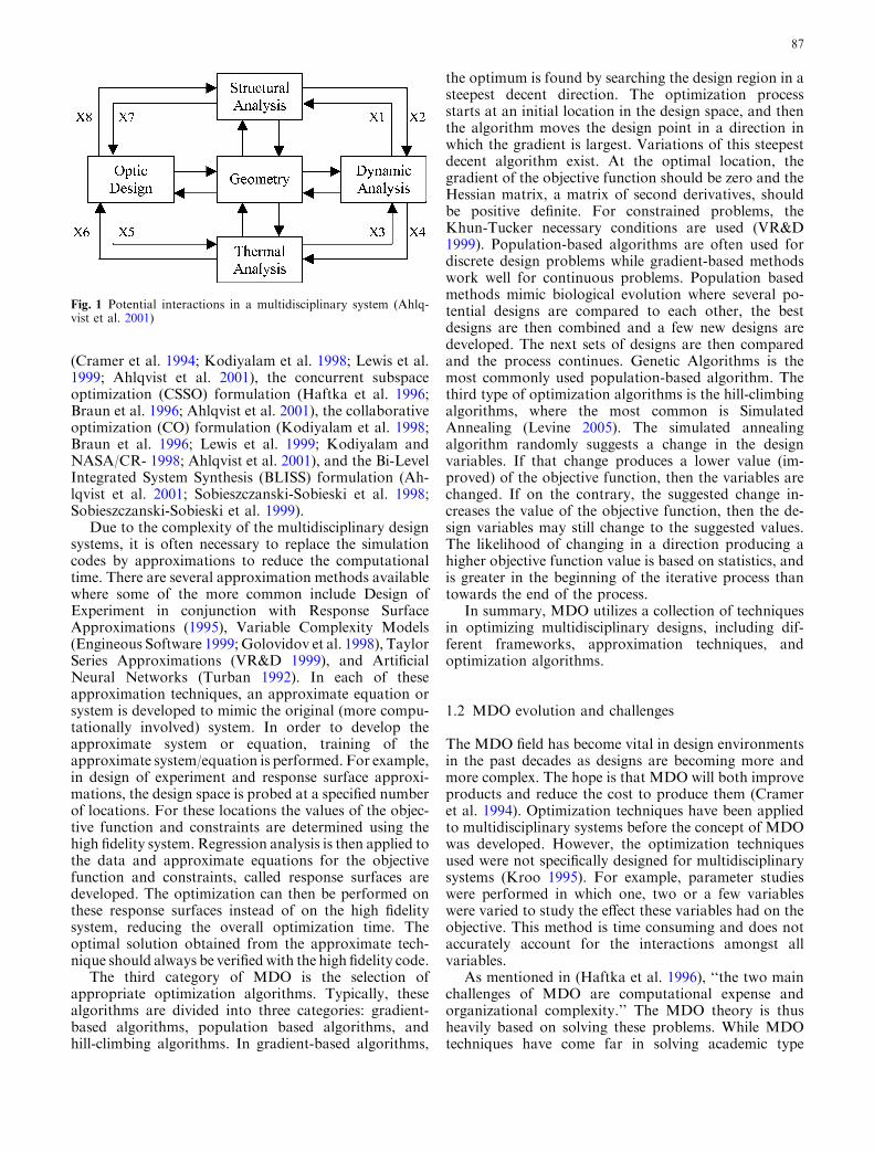
ponents, and cost estimation. The organizational schemeof this environment is not limited to the missile designon which the system was tested. It can be used in thedesign, analysis and optimization of other large scaledsystems. Figure 2 shows a schematic of the disciplinesintegrated to the design, analysis and optimizationenvironment. It should be noted that the environment ismodular and that disciplines can be added and removedas needed.
2.1 Underlying code and its dependency-trackingfeature
The key to the effectiveness of this environment is itsunderlying code called AML (Adaptive Modeling Lan-guage) (TechnoSoft Inc. 2005). This code is object en-abled with special features. The hierarchical structure ofthe language reduces the organizational complexity byorganizing the data in a tree-like structure. The languageis a parametric environment advanced by a dependency-tracking feature.
The dependency-tracking feature includes the inheri-tance capability common to most object-enabled lan-guages. In addition to this feature, it also provides afunctionality that keeps track of whether or not the datahas been computed previously. This feature is calleddemand-driven calculations. The demand-driven calcu-lations ensures that only necessary computations becarried out (TechnoSoft Inc. 2005) and it also ensuresthat computations that have previously been performednot be carried out again so long as the input to thesecomputations have not changed. Until a value isdemanded, an internal flag refers to the property value
Fig. 2 Design, analysis andoptimization environment(Ahlqvist et al. 2001; Schonninget al. 2002)
88

as being unbound or the property being smashed.Several properties that affect a certain property can bemodified, but the affected property need not be recal-culated every time, but needs to be done only when it isfinally needed. Dependency backtracking is the mecha-nism that actually propagates constraint changesthroughout the part model. When a property is modi-fied, all the properties in its effect list are smashed. Whena property is smashed, it further smashes all propertiesin its effect list. Smashed properties need to be recalcu-lated only when demanded (White Paper, TechnoSoftInc. 2005).
2.2 Dependency-tracking feature and optimization
In the case of optimization, the special features of theunderlying code are of extreme importance when itcomes to reducing the computational time. For example,in two successive iteration steps, if information whichaffects only one of the analysis codes has changed, thenonly that analysis code will be executed when using thedependency-tracking feature. Also, if changing onevariable only affects one equation within a system ofequations, then the feature will ensure that only thenecessary equation is computed. If however, a languagewhich does not include the dependency-tracking de-mand-driven feature were used, no knowledge would beavailable to indicate that some of the analysis wouldneed not to be executed. Computational time can bereduced when using an object-oriented dependency-tracking language with demand-driven calculations.More importantly, in the case of optimization, thisfeature reduces the computational effort significantlysince a larger number of iterations are required and thecomputational time can be reduced for each of thoseiterations.
3 Optimization strategy
3.1 Optimization problem definition
The objective of this research was to incorporate opti-mization functionality to the IMD environment whichconsists of numerous disciplines. Once the optimizationfunctionality had been developed it was tested on an air-to-air sparrow-like missile. For this verification study,the range of the missile was optimized, while satisfyingseveral constraints. The constraints included the cost,mass, center of gravity location, length of the missile,Mach number at end of flight, and the nose-finess ratio.The nose-finess ratio of the missile is the ratio of thenose length to its radius. The design variables of themissile were the mid-body diameter, mid-body length,nose length, case length, web fraction, expansion ratio,gamma, and type of propellant used. The mid-bodydiameter and the length help define the mid-bodygeometry and similarly the nose length helps define the
nose geometry. The case length is the length ofthe rocket motor case; the web fraction is the ratio of thedifference of the outer and inner radii of the grain to theinner radius of the propellant grain; the expansion ratiois the ratio of the exit area to the throat area of thenozzle; and gamma is the angle of the velocity vector ofthe missile. The optimization problem is expressedmathematically below and the missile components andsome of the design variables are shown in Fig. 3.
Maximize F ðX Þ ¼ range
With respect to Xi; i ¼ 1 to 8
Subject to gj � 0; j ¼ 1 to 9ðnormalized physical constraintsÞ
where the physical constraints are:
– Mass £ 238 kg (525 lb)– C.G. £ 56 % of total length– C.G. ‡51% of total length– Total length £ 388.6 cm (153 in)– Total length ‡337.8 cm (133 in)– Mach ‡0.5– Nose finess ratio £ 4– Nose finess ratio ‡3– Cost £ $ 104,000
The grain type used in the propulsion system was theonly discrete design variable and was evaluated at twolevels.
3.2 Utilization and adaptation of MDO techniquesfor a large scaled system
In optimizing the missile design, be it the range as inthis case or any other parameter, it is necessary tochoose an MDO formulation, approximation method,and optimization algorithm, then combine these into anoptimization scheme. For the problem at hand, severaldifferent MDO formulations were tested on both the
Fig. 3 Geometric variables of missile (Schonning et al. 2002)
89
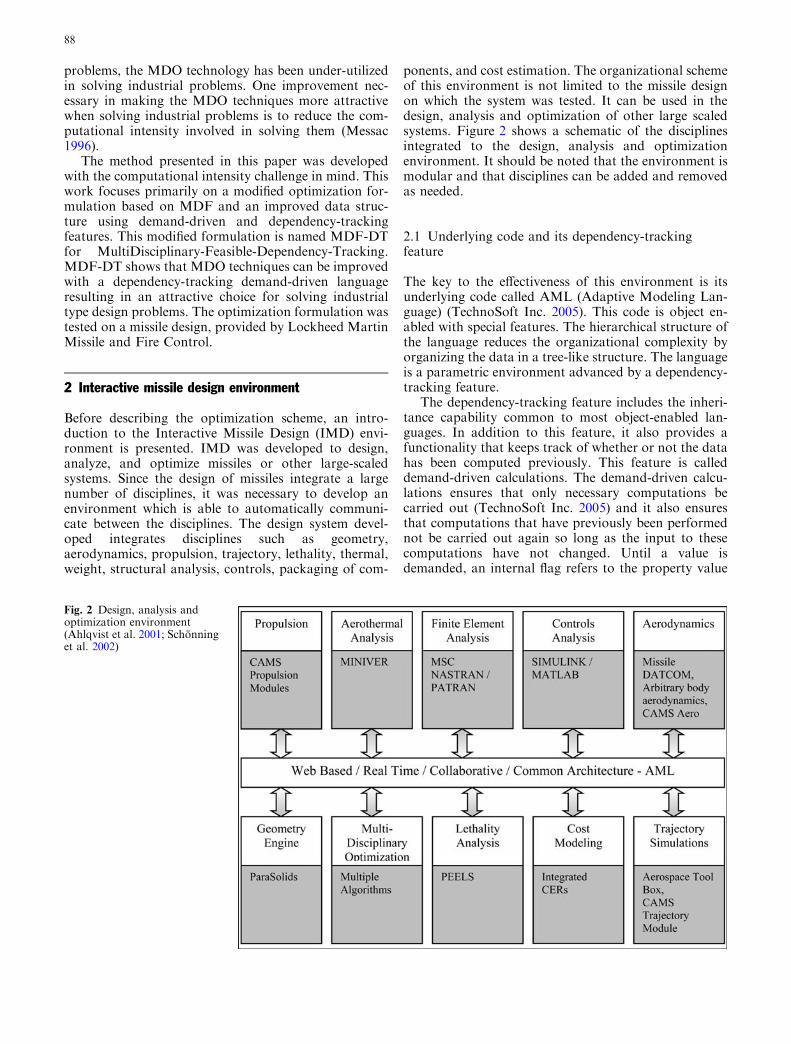
missile design and other smaller scaled problems. It washowever found that some of the hierarchical formula-tions resulted in convergence difficulties. The well-known MultiDisciplinary Feasible (MDF) formulation,shown in Fig. 4, however did not encounter this prob-lem as it applies an optimization algorithm around asystem that is already integrated and does not need anyauxiliary design variables or constraints to ensureinterdisciplinary convergence. The interdisciplinaryconvergence is instead ensured within the multidisci-plinary analysis system, in this case within IMD. In adifferent system, the analysis system may be a finiteelement code in which convergence will be ensuredwithin the finite element analysis software. Convergenceof the MDF formulation, if a gradient-based algorithmis used, follows the well-known Khun-Tucker condi-tions (VR&D 1999). Additional information on theMDF formulation can be found in (Cramer et al. 1994;Kodiyalam et al. 1998; Braun et al. 1996; Lewis et al.1999; Kodiyalam and NASA/CR-1998; Ahlqvist et al.2001).
The disadvantage of using the MDF formulation,however, is that it requires a complete multidisciplinaryanalysis at each iteration step in the optimization cycle(Cramer et al. 1994; Kodiyalam et al. 1998; Kodiyalamand NASA/CR-1998), resulting in expensive run time.In order to overcome this disadvantage, a program-ming language with Dependency-Tracking (DT) fea-tures was used in integrating the disciplines. As theintegration of the disciplines occurs within an analysissystem, in this case within the IMD environment, itdoes not affect the convergence of the optimizationalgorithms nor the framework. By activating thedependency-tracking capabilities of the programminglanguage, a complete multidisciplinary analysis at eachiteration step in the optimization cycle is no longerneeded. The dependency-tracking feature ensures thatonly those codes and computations necessary at eachiteration step are executed. Details on how this
dependency-tracking feature reduces computationaltime are discussed in Sect. 3.4.1. The MDO techniquedescribed herein will be referred to as MDF-DT as itutilizes the MDF formulation in conjunction with theDependency-Tracking features. The MDF-DT tech-nique is hence not a completely new formulation butrather a combination of an existing formulation and asmart programming language. The combination of theMDF-formulation and the exceptionally efficient DT-feature had never previously been used to solvemultidisciplinary design optimization problems. TheMDF-DT formulation can reduce the computationaltime significantly making it an attractive choice whenoptimizing industrial type designs. A more in-depthdescription of the dependency-tracking feature isavailable in Sects. 2.1 and 2.2.
3.3 Overall optimization data flow
The optimization scheme developed (MDF-DT) utilizesdesign of experiment data, response surface approxi-mations, gradient-based optimization techniques on theresponse surface approximations as well as on the highfidelity model.
Figure 5 shows the steps in the optimization scheme.
(1) The problem is first defined;(2) The Design of Experiment (DOE) object creates a
list of design points to analyze and sends thesepoints to the integrated multidisciplinary design andanalysis system, IMD, which evaluates theresponses;
(3) IMD sends the values of the responses back to theDOE object;
(4) The data is then transferred to VisualDoc by Van-derplaats R&D, 2005 through a soft coupling;
(5) VisualDoc creates a response surface approximation(RSA) of the objective function and the constraints.The response surface approximations are then loa-ded into a gradient-based optimization task thatdetermines an optimum solution of the approximateproblem using Design Optimization Tools (DOT);
(6) The optimum solution is then transferred to theDOT object as an initial starting point for the highfidelity optimizations;
(7) In this last step DOT is directly integrated withIMD. The solution obtained from this optimizationloop between IMD and DOT is considered theoptimum solution for the system.
The optimization scheme in Fig. 5 shows the dataflow of the optimizations. The sketch shows two loops ofthe MDF formulation. The first loop is for tasks 2 and 3and the second is the loop at task 7. The sketch does notshow how the dependency-tracking feature is workingwithin the loops. Section 3.4.1 will illustrate the detailsof the dependency-tracking feature and how it savescomputational time.
Fig. 4 MultiDisciplinary Feasible Formulation (MDF)
90

3.4 Design of experiment
Design of Experiments (DOE) was used to gain responsedata over the entire design region. A central compositeface centered design was used. The primary reason forusing this design is that it allows for sequential experi-mentation. Using a sequential design allows the user tofirst perform a section of the experiments and then addadditional experiments if needed. For example, first afractional factorial analysis may be performed and thedata may later be used towards a second-order design(such as the central composite design). The other reasonthis type of deign was chosen was that it generally has(1) good A-optimality, (2) a good scaled predictionvariance, (3) is nearly an orthogonal design, and (4) hascenter points and axial points which allow for estimationof curvature and pure quadratic terms (Montgomery1995). The face-centered version of the central com-posite design, rather than a spherical version, was usedsince the ranges on the design variables were given to bewithin a hypercube. Since only one discrete design var-iable of two distinct levels was to be optimized (inaddition to continuous variables), a central compositedesign was generated for each of the discrete levels.Additional information on design of experiment isavailable in (Montgomery 1995).
3.4.1 DOE in conjunction with a dependency-trackinglanguage
In order to reduce the computational time to a minimumwhen performing the evaluations, the order in which thecomputations are carried out is important. While it isgenerally recommended to carry out experiments in arandom order, it is not necessary to do so when the samecomputer and software is being used in the experimentsand when the value of the responses are known to beindependent of the order in which they are run. It wasdetermined that the value of the responses evaluated isnot sensitive to the order in which the computations arecarried out. However, due to the dependency-trackingfeature of the language, the order in which the compu-tations are carried out affects the number and type ofcomputations necessary. From one iteration step to thenext, if a parameter changes that only affects one of theintegrated software, then only that software will beexecuted. On the other hand, if from one iteration stepto the next the input to all software is affected, thenmore time-consuming computations will be necessary.For the problem at hand, one of the design parameters,the angle of the velocity vector, only affects the trajec-tory discipline. In order to speed up the computationaltime, the designs were carried out in such an order that
Fig. 5 Optimization data flow(Ahlqvist et al. 2001; Schonninget al. 2002)
Table 1 Codes executed whenDOE is setup to minimizenecessary runs (Ahlqvist et al.2001; Schonning et al. 2003)
X1 X2 X3 X4 X5 X6 X7 Codesexecuted
Averagetime (s)
+1 +1 +1 +1 +1 +1 +1 All 59.53+1 +1 +1 +1 +1 +1 �1 Trajectory 0.73+1 +1 +1 +1 +1 �1 +1 All 59.53+1 +1 +1 +1 +1 �1 �1 Trajectory 0.73+1 +1 +1 +1 �1 +1 +1 All 59. 53+1 +1 +1 +1 �1 +1 �1 Trajectory 0.73+1 +1 +1 +1 �1 �1 +1 All 59. 53+1 +1 +1 +1 �1 �1 �1 Trajectory 0.73+1 +1 +1 �1 +1 +1 +1 All 59. 53
Total time 300.57
91

this design variable was changed at every design pointfor the fractional factorial portion of the design. Ta-bles 1 and 2 in conjunction with the text, explains theconcept of how the order in which the computationswere carried out can save computational time. Pleasenote that the table is not a complete design.
In Table 1 the first seven columns represent thenormalized level of the design variables and the nextcolumn shows which codes are executed. Note that forevery other iteration the only parameter that is changedis X7, the angle of the velocity vector. Since this designvariable only affects the trajectory analysis, only thisdiscipline will be executed. The time to carry out thetrajectory analysis took on average 0.73 s while carryingout the complete system took 59.53 s on an average, ona Pentium III at 800 MHz. The computational timeassociated with the trajectory discipline is thereforeinsignificant when compared to the other disciplines’computational time. Hence, by carefully ordering thecomputations it was possible to reduce the computa-tional time significantly. It is worth noting that if thedesigned experiments were not set up to save computa-tional time, the full benefit of the dependency-trackingfeature would not be utilized. For example, if the missile
body diameter, X1 (instead of gamma, X7) was changedfrom one iteration step to the next, as seen in Table 2,each of the analysis codes would have to be executed ateach iteration step. The total time in Table 1 is drasti-cally lower than the time in Table 2, as a result ofordering the analysis in a fashion which will utilize thedependency-tracking language to its fullest. The tablesshow that the dependency-tracking language can beespecially beneficial during the DOE if the analyses arecarried out in an order that will effectively utilize thedependency-tracking feature. The computational timesaved when using the dependency-tracking feature willvary from one problem to another depending on howthe design variables are related to the responses of thedisciplines.
3.4.2 Determination of optimal order of runs
In determining the order of runs, one should determinethe time it takes to perform an analysis when eachdesign variable is modified. These variables should thenbe listed in the first row of a table with the designvariable requiring the most amount of computationaltime to the left and the other design variables should be
Table 2 Codes executed whenDOE is not setup to minimizenecessary runs
X1 X2 X3 X4 X5 X6 X7 Codesexecuted
Averagetime (s)
+1 +1 +1 +1 +1 +1 +1 All 59.53�1 +1 +1 +1 +1 +1 +1 All 59.53+1 �1 +1 +1 +1 +1 +1 All 59.53�1 �1 +1 +1 +1 +1 +1 All 59.53+1 +1 �1 +1 +1 +1 +1 All 59.53�1 +1 �1 +1 +1 +1 +1 All 59.53+1 �1 �1 +1 +1 +1 +1 All 59.53�1 �1 �1 +1 +1 +1 +1 All 59.53+1 +1 +1 �1 +1 +1 +1 All 59.53
Total time 535.77
Table 3 Computational efficiency table (Ahlqvist et al. 2001; Schonning et al. 2003)
Full factorialCCD & RSA &one verification run
½ factorialCCD & RSA &gradient-basedoptimization
CCD & RSA &one verification run &one verification run
CCD & RSA &gradient-basedoptimization
1/4 Factorial &one verification run& one verificationrun
Factorial pts 128 128 64 64 32Axial pts 14 14 14 14 14Center points 1 1 1 1 1Verification pts 1 1 1 1 1Gradient-based pts 0 8 8Total evaluations 144 152 80 88 48Time to run all codes (s) 59.53 59.53 59.53 59.53 59.53Time to run trajectory (s) 0.73 0.73 0.73 0.73 0.73
Case 1: Using dependency-tracking featureTimes all codes executed 80 88 48 56 32Total time to execute (s) 4809 5285 2881 3357 1917
Case 2: Using non-dependency-tracking featureTimes all codes executed 144 152 80 88 48Total time to execute (s) 8572 9049 4762 5239 2857
Percent time reduction using a dependency-tracking feature44 42 40 36 33
92
listed in a time-declining order to the right, as inTable 1. The rows below should then indicate the levelof each design variable. The last column should changefrom a high to a low value for each row; the nextcolumn (second most to the right) should change froma high to a low value after two rows; the third columnfrom the right should change from a high to a lowvalue every fourth row and so on. Ordering the runs inthis fashion should result in best utilization of thedependency-tracking feature.
3.5 Types of analysis performed
To determine the amount of reduction in computationaltime achieved by utilizing the parametric demand-drivenand dependency-tracking feature while optimizing anindustrial missile, optimization analysis were first per-formed with the dependency-tracking feature and thenfollowed by the same analysis without the dependency-tracking feature. The optimization algorithm used for allanalysis was the Modified Method of Feasible Direc-tions available in DOT from Vanderplaats Research andDevelopment Inc.
Different fidelity models were analyzed and arereported in Table 3. These are:
1. Full Factorial Face Centered Central CompositeDesign (FC-CCD) followed by a verification run;
2. Full Factorial FC-CCD followed by a verificationrun and a gradient-based optimization run startingfrom the approximate optimum;
3. Half factorial FC-CCD followed by a verificationrun;
4. Half factorial FC-CCD followed by a verification runand a gradient-based optimization run starting fromthe approximate optimum;
5. Quarter factorial FC-CCD followed by a verificationrun.
The following section will discuss the performance ofthe different optimization runs.
4 Results
It was determined that the value of the design variablesand the responses at the optimum design point variedonly slightly between the different fidelity models basedon the dependable response surface approximations(those based on the full factorial CCDs and half fac-torial CCDs). The quarter factorial CCDs were foundto be unreliable and no higher fidelity analyses werecarried out from the approximate optimum of thequarter models. The optimization results show that thevalues of the design variables did not change signifi-cantly during the higher fidelity gradient-based opti-mizations starting from the approximate optimum. Infact, it was found that the optimization of the higherfidelity model when starting from the approximate
optimum, as determined from the response surfacemodel, converged directly following one initial evalua-tion and a gradient evaluation for each of the designvariables. It was found that the gradients were zero,within a small tolerance, and hence a usable searchdirection was not available. This indicates that thereliability of the response surfaces were high, and inthis case high fidelity optimizations were not necessaryafter the optimization of the response surface approx-imations. However, a verification run should always beperformed after a solution has been obtained by opti-mizing a set of response surface approximations.
In determining the computational advantage of theMDF-DT strategy over the MDF strategy, each analysiswas carried out both using the dependency-trackingfeature and not using this feature. A significant reduc-tion in computational time was realized. The computa-tional time was reduced by 33 to 44 % during theevaluations. A larger reduction was achieved for the fullfactorial CCD than for the half factorial CCD. Table 3shows the computational time for the analyses as well asthe reduction in time when the dependency-trackingfeature was utilized.
5 Implementation procedure to other large-scaledsystems
This paper has described an MDO strategy, MDF-DT,and how it was applied to a missile design system atLockheed Martin Missile and Fire Control. It should beemphasized that the strategy developed can be applied toother multidisciplinary systems using the steps below:
1. Create the analysis environment using a dependency-tracking language. In this step the disciplines will beintegrated. A dependency-tracking language shouldbe chosen for this integration such that programs(and portions of programs) will only be executed ifthe change in the design variables from the previ-ous iteration affects the output of a particularprogram.
2. Select an experimental design. The experimental de-sign will be used to probe the design space for valuesof the objective function and the constraints. A pos-sible choice is the Central Composite Design used forthe missile design herein.
3. Order the factorial potion of the design to minimizerun-time. To best utilize the dependency-trackingfeature of the design, the experiments should be or-dered according to Sect. 3.4.2.
4. Run the experiments on the high fidelity model createdin step 1. For each experiment, determine the valuefor the objective function and each optimizationconstraint. This will require development of a codethat can start the analysis environment at particularvalues for the design variables. Another option wouldbe to have a person manually start the runs.Throughout this process, store the values of the
93
design variables and the values of the objectivefunction and constraints.
5. Create response surfaces for the objective function andfor each of the constraints. Use regression analysis todetermine a response surface function for the objec-tive function and for each of the constraints.
6. Define an approximate optimization problem using theresponse surface approximations. Specify the designvariables, which equation is the objective function, ifit is desired to maximize or minimize the objectivefunction, and specify the upper and lower limits ofyour optimization constraints.
7. Loop a gradient-based optimizer around the approxi-mate optimization problem. Optimize the approximateproblem to find an approximate optimum. It is con-sidered the approximate optimum as it is based on theresponse surface equations and not the high-fidelityanalysis system.
8. Integrate a gradient-based optimizer around the high-fidelity system developed in step 1. Write a programthat calls the high-fidelity system with inputs of thedesign variables and returns values of the objectivefunction and the constraints. These values are thensent to the optimization algorithm which determinesnew values for the design variables and the processshould be repeated until the optimization algorithmdetermines that a better solution cannot be obtained.
9. Perform a gradient-based optimization on the high-fidelity system starting at the approximate solution.
6 Conclusion
The optimization strategy presented herein, MDF-DT,shows that the multidisciplinary feasible formulationtogether with a dependency-tracking language is apractical formulation in optimizing large-scaled sys-tems. The advantages of the multidisciplinary feasibleformulation are utilized in the MDT-DT formulation.The parametric demand-driven and dependency-track-ing features of the underlying language reduce thecomputational time significantly making it even moreattractive when performing optimization. The optimi-zation strategy described herein for the approximationmodel reduced the computational time between 33 to44 % for the case when the dependency-tracking fea-ture was utilized during the design of experimentanalyses. While the computational time was stronglyrelated to the strategy presented, the performance ofthe objective function was not heavily dependent on theoptimization strategy used. The objective value variedonly 3 % at the optimum design point for the reliableresponse surface approximation models and the higherfidelity model. It has been shown how advancing aparametric environment with demand-driven anddependency-tracking features results in a more com-putationally efficient environment in solving large-scalemultidisciplinary design problems.
It should be noted that in developing the optimizationscheme, one of the goals was to keep the design envi-ronment modular. With that in mind, specific disciplin-ary systems can be added and removed as needed. Inconclusion, the efficient optimization scheme developedcan be used in optimizing other large-scaled systems.
Acknowledgements This work was supported, in part, by LockheedMartin Missiles and Fire Control-Orlando, and Wright PattersonAir Force Base, Air Force Research Laboratory, under a TechnicalInvestment Agreement, TIA No. F33615-99-2-5704, designatedWeb-Based Design Environment (WDE), under Technical Con-tract Manager Dr. Steve La Clair. Technical support has beenprovided by TechnoSoft Inc.
References
Adaptive Modeling Language Reference Manual - TechnoSoftInc., (2005) http://www.technosoft.com/
Ben Levine. (2005) Simulated Annealing: a report for EE562, theMetropolis Algorithm. University of Tennessee. Available:http://microsys6.engr.utk.edu/�levine/EE652/ (accessed on 2/14/00)
Cramer, Dennis, Frank, Lewis, Shubin, (1994) ‘‘Problem Formu-lation for Multidisciplinary Optimization,’’ Society for Indus-trial and Applied Mathematics. Vol 4, No4. November
Efraim Turban (1992) Expert Systems and Applied ArtificialIntelligence. Macmillan Publishing Company, New York
Ilan Kroo (1995) MDO for Large-Scale Design. Proceedings of theICASE/NASA Langley Workshop on Multidisciplinary DesignOptimization. Hampton, Virginia, March pp 13–16
Jaroslaw Sobieszczanski-Sobieski and Raphael T. Haftka, ‘‘Mul-tidisciplinary Aerospace Design Optimization: Survey of RecentDevelopments,’’ 34th AIAA Aerospace Sciences Meeting andExhibit, Reno, Nevada, AIAA Paper No. 96-0711, January 15–18, 1996.
Jaroslaw Sobieszczanski-Sobieski, Jeremy S. Agte, and Robert R.Sandusky Jr. Bi-Level Integrated System Synthesis (BLISS).Proceedings, 7th AIAA/USAF/NASA/ISSMO Symposium onmultidisciplinary Analysis and Optimization, AIAA, St. Louis,Missouri, September 1998, AIAA Paper No. 98–4916
Jaroslaw Sobieszczanski-Sobieski, and Srinivas Kodiyalam.BLISS/S: A new method for two-level structural optimization.Presented at the 40th AIAA/ASME/ASCE/AHS/ASC Struc-tures, Structural Dynamics and Materials Conference, St.Louis, MO April 12–15, 1999. AIAA Paper 99–1345
Alexandra Ahlqvist M (2001) Dependency-Tracking Object-Ori-ented Multidisciplinary Design Optimization (MDO) Formu-lation on a Large-Scaled System. PhD Thesis, University ofCentral Florida
Messac A (1996) Physical Programming: Effective Optimization forComputational Design. AIAA Journal, Vol. 34, No. 1, Jan
Myers, Montgomery, (1995) Response Surface Methodology Pro-cess and Product Optimization Using Designed Experiments.John Wiley & Sons, Inc, New York, NY
Alexandrov NM, Lewis RM (1999) Comparative Properties ofCollaborative Optimization and Other Approaches to MDO.In: Proceedings of the First ASMO UK / ISSMO Conferenceon Engineering Design Optimization, July 8–9, 1999
Natalia M. Alexandrov and Srinivas Kodiyalam, ‘‘Initial Results ofan MDO Method Evaluation Study,’’ Proceedings of the 7thAIAA/USAF/NASA/ISSMO Symposium on MultidisciplinaryAnalysis and Optimization, AIAA, St. Louis, Missouri, Sep-tember 2–4, 1998, Paper No. AIAA 98–4884
Oleg Golovidov, Srinivas Kodiyalam, and Peter Marineau,‘‘Flexible Implementation of Approximation Concepts in anMDO framework’’, Proceedings of the 7th AIAA/USAF/
94

NASA/ISSMO Symposium on Multidisciplinary Analysis andOptimization, AIAA, St. Louis, Missouri, September 2–4, 1998,Paper No. 98–4959
Robert D. Braun, ‘‘Collaborative Optimization: An architecturefor large-scale distributed design,’’ Ph.D. Thesis, StanfordUniversity, May 1996
Schonning MA, Nayfeh JF, Zarda PR (2002) Using response sur-face approximations to cover holes in the design space: con-ceptual design of a missile. J Comput Inf Sci Eng 2(3):141–244
Schonning MA, Nayfeh JF, Zarda PR (2003) Utilization of adependency-tracking language to reproduce computationaltime during multidisciplinary design optimization. Adv EngSoftw 34:115–122
Srinivas Kodiyalam, ‘‘Evaluation of Methods for MultidisciplinaryDesign Optimization (MDO),’’ Phase I. NASA/CR-1998-208716, September 1998
The Adaptive Modeling Language Reference Manual - White Pa-per, TechnoSoft Inc., (2005) http://www.technosoft.com/
VR&D, ‘‘DOT - Design Optimization Tools’’, Vanderplaats Re-search and Development Inc., Copyright 1999, ColoradoSprings, CO
Vanderplaats Research & Development. (2005) Available: http://www.vrand.com/visualdoc2.pdf
iSIGHT Introduction to Application Development, TrainingGuide. Engineous Software Inc. Nov 19,1999
95
Copyright © 2022 FDOKUMEN